Download this - Civil Engineering Journal
13
Available online at www.CivileJournal.org Civil Engineering Journal Vol. 6, No. 1, January, 2020 85 Abstract The elevated tanks are considered as very sensitive structures in seismic movement condition. Moreover, the conical steel tank manufacturing without local geometric imperfection seems to be too difficult. In generally, the latter is the most responsible factor to define the shell structures buckling capacity. For this reason, several theoretical and experimental researchers studied the performance of this type of structure under seismic loading. The present study aims to demonstrate the local geometric imperfection effect on dynamic buckling of elevated water tank. Using the three dimensions finite element technique to study the seismic response of perfect and imperfect elevated water tank was established taking into account the following factors; the interaction fluid structure (FSI), the wall flexibility, the local geometric imperfection, the nonlinear time history analysis, the material and geometric nonlinearity, and this by the application of three different instability criteria for the critical PGA estimate. The critical PGA of the imperfect elevated water tank numerical models decreased by 45, 45% compared to the elevated water tank numerical model without local geometric imperfection. The obtained results confirm the local geometric imperfection effect on dynamic buckling of elevated water tanks. Keywords: Elevated Tank; Fluid Structure Interaction; Finite Elements; Dynamic Analysis; Geometric Imperfection; Instability Criteria. 1. Introduction Storage tanks are strategic structures. They are generally used as water storage in our daily lives and as well as hydrocarbon storage in the industry field. The water tanks are generally installed on steel or reinforced concrete tower supports to avoid the use of pumping installations. Several tanks have been severely damaged and some have collapsed with disastrous results. For example, the severe damage sustained during the earthquake, namely; Alaska 1964, Niigata 1964, Parkfield 1966, San Fernando 197, Imperial County 1979, Northridge 1994 and Asnam 1980. Many researchers have studied the dynamic behaviour of elevated tank. Housner (1963) has allowed practicing engineers to perform the seismic responses analysis of the elevated rigid tanks by using the two-mass method. The liquid was assumed to be incompressible and non-viscous. The model has been adopted in many codes [1]. Joshi (2000) presented an equivalent mechanical model for the seismic analysis of Intze-type tanks under horizontal seismic acceleration. The model parameters were evaluated and compared to those of equivalent cylindrical tanks. The fluid was assumed to be non-viscous and incompressible and the sloshing height was assumed to be small. However, to develop the mechanical model, only the first mode of sloshing was taken into account. It was concluded that the associated errors due to the equivalent cylindrical reservoir model used in place of the Intze-type tanks were negligible [2]. * Corresponding author: [email protected] http://dx.doi.org/10.28991/cej-2020-03091455 © 2019 by the authors. Licensee C.E.J, Tehran, Iran. This article is an open access article distributed under the terms and conditions of the Creative Commons Attribution (CC-BY) license (http://creativecommons.org/licenses/by/4.0/). Received 16 September 2019; Accepted 28 November 2019 a FIMAS Laboratory, University of Tahri Mohammed, Bechar B.P 417, Bechar , 08000 Algeria. N. Hadj-Djelloul a* , M. Djermane a Water Tanks Effect of Geometric Imperfection on the Dynamic of Elevated
-
Upload
khangminh22 -
Category
Documents
-
view
7 -
download
0
Transcript of Download this - Civil Engineering Journal

Available online at www.CivileJournal.org
Civil Engineering Journal
Vol. 6, No. 1, January, 2020
85
Abstract
The elevated tanks are considered as very sensitive structures in seismic movement condition. Moreover, the conical steel
tank manufacturing without local geometric imperfection seems to be too difficult. In generally, the latter is the most
responsible factor to define the shell structures buckling capacity. For this reason, several theoretical and experimental
researchers studied the performance of this type of structure under seismic loading. The present study aims to demonstrate
the local geometric imperfection effect on dynamic buckling of elevated water tank. Using the three dimensions finite
element technique to study the seismic response of perfect and imperfect elevated water tank was established taking into
account the following factors; the interaction fluid structure (FSI), the wall flexibility, the local geometric imperfection,
the nonlinear time history analysis, the material and geometric nonlinearity, and this by the application of three different
instability criteria for the critical PGA estimate. The critical PGA of the imperfect elevated water tank numerical models
decreased by 45, 45% compared to the elevated water tank numerical model without local geometric imperfection. The
obtained results confirm the local geometric imperfection effect on dynamic buckling of elevated water tanks.
Keywords: Elevated Tank; Fluid Structure Interaction; Finite Elements; Dynamic Analysis; Geometric Imperfection; Instability Criteria.
1. Introduction
Storage tanks are strategic structures. They are generally used as water storage in our daily lives and as well as
hydrocarbon storage in the industry field. The water tanks are generally installed on steel or reinforced concrete tower
supports to avoid the use of pumping installations. Several tanks have been severely damaged and some have collapsed
with disastrous results. For example, the severe damage sustained during the earthquake, namely; Alaska 1964, Niigata
1964, Parkfield 1966, San Fernando 197, Imperial County 1979, Northridge 1994 and Asnam 1980.
Many researchers have studied the dynamic behaviour of elevated tank. Housner (1963) has allowed practicing
engineers to perform the seismic responses analysis of the elevated rigid tanks by using the two-mass method. The liquid
was assumed to be incompressible and non-viscous. The model has been adopted in many codes [1].
Joshi (2000) presented an equivalent mechanical model for the seismic analysis of Intze-type tanks under horizontal
seismic acceleration. The model parameters were evaluated and compared to those of equivalent cylindrical tanks. The
fluid was assumed to be non-viscous and incompressible and the sloshing height was assumed to be small. However, to
develop the mechanical model, only the first mode of sloshing was taken into account. It was concluded that the
associated errors due to the equivalent cylindrical reservoir model used in place of the Intze-type tanks were negligible
[2].
* Corresponding author: [email protected]
http://dx.doi.org/10.28991/cej-2020-03091455
© 2019 by the authors. Licensee C.E.J, Tehran, Iran. This article is an open access article distributed under the terms and conditions of the Creative Commons Attribution (CC-BY) license (http://creativecommons.org/licenses/by/4.0/).
Received 16 September 2019; Accepted 28 November 2019
a FIMAS Laboratory, University of Tahri Mohammed, Bechar B.P 417, Bechar , 08000 Algeria.
N. Hadj-Djelloul a*, M. Djermane a
Water Tanks
Effect of Geometric Imperfection on the Dynamic of Elevated

Civil Engineering Journal Vol. 6, No. 1, January, 2020
86
Dutta et al. (2000a, 2000b) made a comparison between raised tanks support systems and that proposed an
approximate empirical equation for lateral, horizontal and torsional stiffness evaluation of different support systems [4-
6].
Livaoglur. R. and Dogangun A. (2006) studied the effects of soil structure interaction on the seismic behaviour of
elevated tank with a structural frame supporting system. It was concluded that the interaction soil structure has more
influences on shear stress, overturning moments, axial forces and lateral displacement [3].
Shell buckling mode is one of the most common forms of damage in steel tanks generally classified as elastic buckling
“diamond shape” and elastic-plastic buckling “elephant foot”. Usually, this instability appears in around the bottom of
tanks. For this reason several theoretical and experimental research studies were performed such as: Liu and Lam (1983),
Nagashima et al. (1987), Virella et al (2006) and Djermane et al. 2014) [7-10].
In a recent study conducted by Pole and Khedikar (2017), three different types of supporting systems have been
analyzed using tank at different capacities and they made a comparison between displacement and base shear of each
supporting systems [11].
Based on the research presented above, it can be concluded that most of the published literature studied the tank
dynamic buckling and the dynamic behaviour of elevated water tank. There is no investigation concerning the geometric
imperfection effect on dynamic buckling of elevated water tank. Unlike the most research that have been done in this
filed, where in the present paper, the fluid domain was modeled by three dimensional elements that allowed a more
suitable consideration for fluid-structure interaction, and under earthquake excitation, enhanced the information about
the geometric imperfection effect on the dynamic buckling of elevated tanks.
2. Theoretical Simplified Model
The Housner method used in many codes divide the fluid into two parts, the first is called impulsive that is rigidly
fixed to the structure, and the second is called convective that is freely vibrate to the structure. The masse and rigidity
of these components are done respectively by [12, 13, 20-22]:
kc = mc
g
R1.84 tanh (
1.84 h
R) (1)
mc = me
R
h0.318 tanh (
1.84 h
R) (2)
hc = [1 −cosh(1.84 h R⁄ ) − 1
1.84 h R⁄ sinh (1.84 h R⁄ )] h (3)
mi = me
tanh (1.74 R h⁄ )
(1.74 R h⁄ ) (4)
hi =3
8h (5)
Where; h, R, kc, mc, mi, me and hc are the fluid height, radius tank, convective rigidity, convective mass, impulsive mass,
total mass and convective height respectively.
Figure 1. Elevated tank model: Equivalent two DOF model
By the method of Rayleigh, the rigidity of a tower with a constant section (Figure 2) is given by [15]:
ki =P
P′ 3 E I
l3 (6)
Mi
Mc
Kc
Ki
K=∞
=

Civil Engineering Journal Vol. 6, No. 1, January, 2020
87
I = π R3 e (7)
P′ = P + 33
140 p l
(8)
E, I, l, P and p are the Young modulus, the inertia of the cross section, the height of the tower, the weight of the
concentrated mass and linear weight of the tower respectively.
Figure 2. Console (constant section)
3. Methodology
In high seismicity areas and high population density, a tank rupture following an earthquake can cause enormous
property damage and human life loss. In the present work, an efficient 3D finite element analysis method was used to
evaluate the dynamic behaviour of elevated tanks.
In the first part, the free vibration analysis was carried out on the elevated tank. In this section, the validity of the
proposed finite element model in both free vibration (Impulsive and convective components) is verified by
comparing the results with current code requirements.
In the second part, transient analysis was performed on an elevated tank under horizontal component effect of
earthquake using the direct integration method for investigating dynamic buckling of this elevated tank Figure 3.
In the third part in order to clearly show the local geometric imperfection effect on the dynamic response of the
elevated tanks, the PGAcr of elevated tank is calculated for imperfect model (with local geometric imperfection)
and the obtained results are compared to the perfect model (without local geometric imperfection) Figure 3.
Figure 3. Flowchart of the research methodology
4. Numerical Model
To illustrate the effect of the local geometric imperfection of dynamic behaviour of the elevated tanks, we used two
elevated tanks (perfect and imperfect shell). The finite element technique was used.
In this study, the wall and roof are modeled by using Shell63 for modal analysis, and shell181 “plastic capability” for
transient analysis. The two elements have six degrees of freedom at each node: translations in the nodal x, y, and z
directions and rotations about the nodal x, y, and z-axes [16-23].
The fluid and wall structure model was done using ANSYS software
EI l
P
PGASmall
PGASmall + PGAn+1
Stability
Yes
No
Start
End

Civil Engineering Journal Vol. 6, No. 1, January, 2020
88
(a) Shell63
(b) Shell181
Figure 4. Finite elements geometries (a) shell 63, (b) shell 181
4.1. Fluid Domain
FLUID80 is used to model fluids contained within vessels having no net flow rate. This fluid element is particularly
well suited for calculating hydrostatic pressures and fluid/solid interactions, acceleration effects, such as in sloshing
problems. The element is defined by eight nodes having three degrees of freedom at each node: translation in the nodal
x, y, and z directions. The stress-strain relationships used to develop the stiffness matrix and thermal load vector are as
follows [16-23]:
{
𝜀𝐵𝑢𝑙𝑘𝛾𝑥𝑦𝛾𝑦𝑧𝛾𝑥𝑧𝑅𝑥𝑅𝑦𝑅𝑧 }
=
[ 1
K0 0 0 0 0 0
01
S0 0 0 0 0
00000
00000
1
S0 0 0 0
01
S0 0 0
0 01
B0 0
0 0 01
B0
0 0 0 01
B ]
=
{
PτxyτyzτxzMx
My
Mz}
Where:
4
K
KL
J I Triangular Option
8
3 1
2
4
5
6
L
L
7
3
6
2
J
5
l
1
y
Z
Zlj
Ylj
x
XIJ
Z
Y
X
X0
X
Z
Z0
Y
Y0
Triangular Option
(not recommended)
4
K
KL
J I
8
3 1
2
4
5
6
L
L
7
3
6
2
J
5
l
1
Z
Y
X

Civil Engineering Journal Vol. 6, No. 1, January, 2020
89
εBulk =∂u
∂x+∂v
∂y+∂w
∂z= Bulk strain
K = fluid elastic (bulk) modulus
P = pressure
γ = shear strain
S = K×10−9 (arbitrarily small number to give element some shear stability)
τ = shear stress
Ri = rotation about axis i
B = K×10−9 (arbitrarily small number to give element some rotational stability)
Mi = twisting force about axis i
A damping matrix is also developed based on:
{
εBulkγxy
γyz
γxz
RxRy
Rz }
=
[ 0 0 0 0 0 0 00 1/η 0 0 0 0 0
00000
00000
1/η 0 0 0 00 1/η 0 0 00 0 1/C 0 00 0 0 1/C 0
0 0 0 0 1/C]
=
{
PτxyτyzτxzMx
My
Mz}
Where η= viscosity and C = 0.00001η
Figure 5. Finite elements geometries Fluid 80
4.2. Fluid Structure Interaction
The effect of the fluid-structure interaction is taken into account by properly coupling the nodes that lies in the
common faces of these two domains [16].
5. Presentation of Stability Criteria
5.1. Budiansky and Ruth Criterion
The first and most used criterion of stability is due to Budiansky and Ruth [17]. It was formulated as an engineering
application of the Liapunov stability criteria. In this criterion, the time displacement curve is plotted for several values
of the PGA. The PGA value corresponding to a curve which gives a “jump” relatively to its neighboring curves indicates
the dynamic buckling critical value.
Figure 6. Critical load: criteria of Ari Gur and Simonetta
Umax
P
Pmax
N
1
P O
M
J I
K L
4
3
6
5
2
Z
Y X
Civil Engineering Journal Vol. 6, No. 1, January, 2020
90
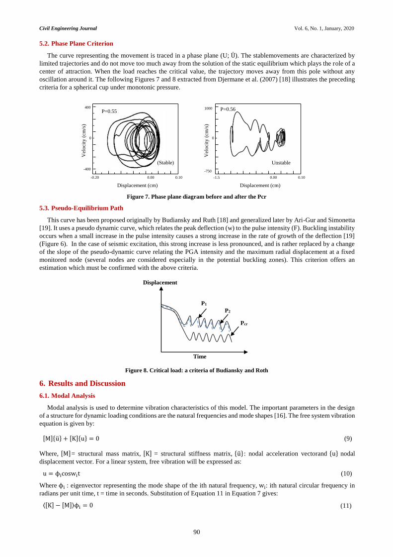
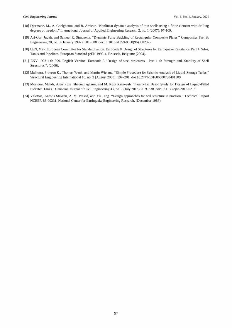
5.2. Phase Plane Criterion
The curve representing the movement is traced in a phase plane (U; U). The stablemovements are characterized by
limited trajectories and do not move too much away from the solution of the static equilibrium which plays the role of a
center of attraction. When the load reaches the critical value, the trajectory moves away from this pole without any
oscillation around it. The following Figures 7 and 8 extracted from Djermane et al. (2007) [18] illustrates the preceding
criteria for a spherical cup under monotonic pressure.
Figure 7. Phase plane diagram before and after the Pcr
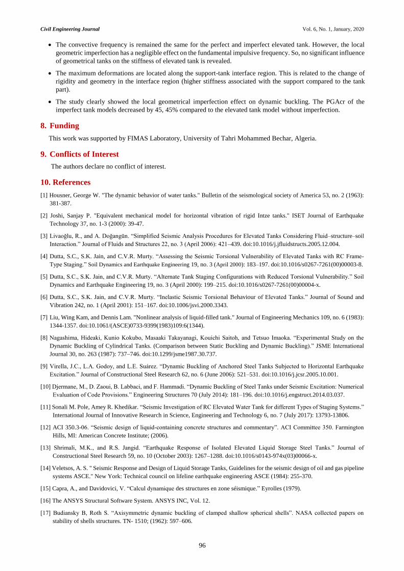
5.3. Pseudo-Equilibrium Path
This curve has been proposed originally by Budiansky and Ruth [18] and generalized later by Ari-Gur and Simonetta
[19]. It uses a pseudo dynamic curve, which relates the peak deflection (w) to the pulse intensity (F). Buckling instability
occurs when a small increase in the pulse intensity causes a strong increase in the rate of growth of the deflection [19]
(Figure 6). In the case of seismic excitation, this strong increase is less pronounced, and is rather replaced by a change
of the slope of the pseudo-dynamic curve relating the PGA intensity and the maximum radial displacement at a fixed
monitored node (several nodes are considered especially in the potential buckling zones). This criterion offers an
estimation which must be confirmed with the above criteria.
Figure 8. Critical load: a criteria of Budiansky and Roth
6. Results and Discussion
6.1. Modal Analysis
Modal analysis is used to determine vibration characteristics of this model. The important parameters in the design
of a structure for dynamic loading conditions are the natural frequencies and mode shapes [16]. The free system vibration
equation is given by:
[M]{u} + [K]{u} = 0 (9)
Where, [M]= structural mass matrix, [K] = structural stiffness matrix, {u}: nodal acceleration vectorand {u} nodal
displacement vector. For a linear system, free vibration will be expressed as:
u = ϕicoswit (10)
Where ϕi : eigenvector representing the mode shape of the ith natural frequency, wi: ith natural circular frequency in
radians per unit time, t = time in seconds. Substitution of Equation 11 in Equation 7 gives:
⟨[K] − [M]⟩ϕi = 0 (11)
Time
P1
P2
Pcr
Displacement
0
0.00
Displacement (cm)
400
-400
-0.20 0.10
Vel
oci
ty (
cm/s
)
P=0.55
(Stable)
0
0.00
Displacement (cm)
-1.5 0.10
Vel
oci
ty (
cm/s
)
P=0.56
Unstable
1000
-750

Civil Engineering Journal Vol. 6, No. 1, January, 2020
91
6.2. Perfect Elevated Tank
The frequency and the mass participation factors are obtained by using the finite element and the analytical methods
(EC8) for impulsive and convective modes are presented in Table 1.
Table 1. Frequency and effective mass fraction
Finite elements Eurocode 8
Type Order Frequency Effective mass fraction Frequency
1* 0.156 0.54 0.157
Convective 2 0.29 0.016 -
3 0.35 0.00013 -
1* 2.87 0.37 3.5
Impulsive 2 9.99 0.033 -
3 15.37 0.027 -
* Fundamental mode
Deformation of fundamental convective mode Deformation of fundamental impulsive mode
Figure 9. Elevated tank mode shapes
The obtained mode showed that the fundamental mode shapes involve sloshing of the contained liquid without any
participation of the shell walls (given by Veletsos) [14-24]. The fundamental impulsive mode is a column mode type. It
can be observed that the calculated FE results are in reasonable agreement with current practice values. The fundamental
convective and impulsive modes were identified as those with the largest participation factors in the horizontal direction.
These results indicate the validity of the proposed FE method.
6.2.1. Imperfect Elevated Tank
The local geometric imperfections play an important role to define the buckling capacity of shell structures. In this
work, Initial dimple of circumferential welding seam is considered. This local imperfection is shown in Figure 11
according to the EC3 Across welds, where in both the circumferential direction, the gauge length should be used [21]:
lgw = 25 t or lgw = 25tmin with lgw ≤ 500 mm U0w = Δw0w /lgw
Figure 10. The position of the dimple

Civil Engineering Journal Vol. 6, No. 1, January, 2020
92
Figure 11. Measurement of depths of initial dimples
Values for the dimple tolerance parameter are obtained from the Table 2.
Table 2. Recommended values for dimple tolerance parameter 𝐔𝟎𝐦𝐚𝐱
Fabrication tolerance quality class Description Recommended value of 𝐔𝟎𝐦𝐚𝐱
Class A Excellent 0,006
Class B High 0,010
Class C Normal 0,016
The obtained results show that the convective frequency of the fundamental mode remains unchanged due to the local
geometric imperfection. However, the natural frequency of the fundamental impulsive mode is decreased negligibly
from 2.87 s (perfect) to 2.86 s (imperfect).
6.3. Transient Analysis
The temporal analysis is carried out Elevated thanks to an explicit diagram of integration of the equations of the
movement. The transient dynamic analysis solves the basic equation of motion [16]:
[M]{u} + [C]{u} + [K]{u} = {F(t)} (12)
Where: [C] = damping matrix, {u} = nodal velocity vector and {F(t)}= load vector.
In order to analyze the effect of the earthquake on the elevated tank’s dynamic behavior, the two elevated tanks are
subjected to the horizontal excitation of El Centro 1940 earthquake.
Figure 12. Accelerograms: El Centro PGA =3.41 m/s²
0 2 4 6 8 104
2
0
2
4
El Centro 1940
Time (sec)
Acc
eler
atio
n (
m/s
²)
lgw
∆w0w
Weld
t

Civil Engineering Journal Vol. 6, No. 1, January, 2020
93
6.4.1. Perfect Elevated Tank
Figure 13 shows the pseudo equilibrium path for this excitation. The discontinuity on curve indicates that the (PGA)cr
occurs at 0.93775 g.
Figure 13. Pseudo-Equilibrium path for the perfect elevated tank
Figure 14 shows several history curves corresponding to different levels of excitation. This Figure shows clearly the
difficulty in using the Budiansky-Ruth criterion for determining the (PGA)cr which requires, in fact, a lot of experience
and attention. At level at 0.93775 g, a disproportionate increase in displacements is distinguished.
Figure 14. Time history curves before and after PGAcr for the perfect elevated tank
This increase does not correspond to a monotonic jump for the above mentioned reasons. The phase planes criterion
illustrated in Figure 15 shows more easily in this case the instability in the vicinity of the (PGA). The difficulty for using
this criterion is, in some cases, the same as that reported for Budiansky and Ruth one, but the use of the two criteria
simultaneously can be more illustrative.
0 0.5 1 1.5 20
0.2
0.4
0.6
0.8
1
1.2
Displacement [m]
PG
Acr
(g)
0 1 2 3 4 50.1
0.05
0
0.05
0.1
0.0341 g
0.1705g
0.341 g
0.5115 g
0.682 g
0.93775 g
Time (sec)
Dis
pla
cem
ent (m
)
0 1 2 3 4 52
1.5
1
0.5
0
0.5
0.93775 g
1.023 g
Time (sec)
Dis
plac
emen
t (m
)

Civil Engineering Journal Vol. 6, No. 1, January, 2020
94
Figure 15. Phase plane before and after PGAcr for the perfect elevated tank
Figure 16. Dynamic buckling of the perfect elevated tank under El Centro
The nature of the obtained dynamic buckling response can be evaluated by studying the deformation around the
excitation critical level. Figure 16 shows the tank’s deformed shape that accuses a swelling at its base indicating an
plastic buckling type.
6.4.2. Imperfect Elevated Tank
The effect of local geometric imperfection on dynamic buckling of elevated water tanks is considered in this section.
Figure 17 gives the PGAcr for Imperfect model. Using an estimation given by the pseudo dynamic path, the Budiansky–
Ruth and phase plane criteria are then used to confirm the obtained value (Figures 18 and 19).
Figure 17. Pseudo-Equilibrium path for the imperfect elevated tank
0.1 0.05 0 0.05 0.11
0.5
0
0.5
1
PGA=0.93775 g
Displacement (m)
Velo
city
(m
/s)
2 1.5 1 0.5 0 0.52
1
0
1
2
3
4
PGA=1.023 g
Displacement (m)
Velo
city
(m
/s)
0 0.2 0.4 0.60
0.2
0.4
0.6
0.8
Displacement [m]Displacement (m)
PG
Acr
(g)

Civil Engineering Journal Vol. 6, No. 1, January, 2020
95
Figure 18. Time history curves before and after PGAcr for the imperfect elevated tank
Figure 19. Phase plane before and after PGAcr for the imperfect elevated tank
According to the Figure 10, the dimple position is closer to the support-tank interface region, and the surface
undergoes maximum damages in the case of perfect tank. As indicated in Figures 17, 18 and 19, the local geometric
imperfection effect on dynamic buckling of elevated tank is clearly revealed. Additionally, it can be observed that PGAcr
is significantly reduced due to the local geometric imperfection.
7. Conclusions
In the present work, an efficient 3D finite element method analysis was analyzed using ANSYS software to know the
dynamic behaviour of elevated tank, considering into the nonlinear temporal analysis, the walls flexibility, the material
and geometric nonlinearity, and the fluid-structure interactions, as factors. Firstly, a modal analysis was carried out and
compared with the Eurocode Code 8 to confirm the numerical models. Secondly, the dynamic buckling analysis of the
two elevated tanks was performed to review also the local geometric imperfection effect on the dynamic behaviour of
elevated tanks, the obtained results showed that:
0 1 2 3 4 50.1
0.05
0
0.05
0.1
0.0341 g
0.1705 g
0.341 g
0.5115 g
Time (sec)
Dis
pla
cem
ent (m
)
0 1 2 3 4 50.6
0.4
0.2
0
0.2
0.5115 g
0.682 g
Time (sec)
Dis
pla
cem
ent (m
)
0.1 0.05 0 0.05 0.11
0.5
0
0.5
1
0.5115 g
Displacement (m)
Velo
city
(m
/s)
0.6 0.4 0.2 0 0.210
5
0
5
0.682 g
Displacement (m)
Velo
city
[m
/s]
Civil Engineering Journal Vol. 6, No. 1, January, 2020
96
The convective frequency is remained the same for the perfect and imperfect elevated tank. However, the local
geometric imperfection has a negligible effect on the fundamental impulsive frequency. So, no significant influence
of geometrical tanks on the stiffness of elevated tank is revealed.
The maximum deformations are located along the support-tank interface region. This is related to the change of
rigidity and geometry in the interface region (higher stiffness associated with the support compared to the tank
part).
The study clearly showed the local geometrical imperfection effect on dynamic buckling. The PGAcr of the
imperfect tank models decreased by 45, 45% compared to the elevated tank model without imperfection.
8. Funding
This work was supported by FIMAS Laboratory, University of Tahri Mohammed Bechar, Algeria.
9. Conflicts of Interest
The authors declare no conflict of interest.
10. References
[1] Housner, George W. "The dynamic behavior of water tanks." Bulletin of the seismological society of America 53, no. 2 (1963):
381-387.
[2] Joshi, Sanjay P. "Equivalent mechanical model for horizontal vibration of rigid Intze tanks." ISET Journal of Earthquake
Technology 37, no. 1-3 (2000): 39-47.
[3] Livaoğlu, R., and A. Doğangün. “Simplified Seismic Analysis Procedures for Elevated Tanks Considering Fluid–structure–soil
Interaction.” Journal of Fluids and Structures 22, no. 3 (April 2006): 421–439. doi:10.1016/j.jfluidstructs.2005.12.004.
[4] Dutta, S.C., S.K. Jain, and C.V.R. Murty. “Assessing the Seismic Torsional Vulnerability of Elevated Tanks with RC Frame-
Type Staging.” Soil Dynamics and Earthquake Engineering 19, no. 3 (April 2000): 183–197. doi:10.1016/s0267-7261(00)00003-8.
[5] Dutta, S.C., S.K. Jain, and C.V.R. Murty. “Alternate Tank Staging Configurations with Reduced Torsional Vulnerability.” Soil
Dynamics and Earthquake Engineering 19, no. 3 (April 2000): 199–215. doi:10.1016/s0267-7261(00)00004-x.
[6] Dutta, S.C., S.K. Jain, and C.V.R. Murty. “Inelastic Seismic Torsional Behaviour of Elevated Tanks.” Journal of Sound and
Vibration 242, no. 1 (April 2001): 151–167. doi:10.1006/jsvi.2000.3343.
[7] Liu, Wing Kam, and Dennis Lam. "Nonlinear analysis of liquid-filled tank." Journal of Engineering Mechanics 109, no. 6 (1983):
1344-1357. doi:10.1061/(ASCE)0733-9399(1983)109:6(1344).
[8] Nagashima, Hideaki, Kunio Kokubo, Masaaki Takayanagi, Kouichi Saitoh, and Tetsuo Imaoka. “Experimental Study on the
Dynamic Buckling of Cylindrical Tanks. (Comparison between Static Buckling and Dynamic Buckling).” JSME International
Journal 30, no. 263 (1987): 737–746. doi:10.1299/jsme1987.30.737.
[9] Virella, J.C., L.A. Godoy, and L.E. Suárez. “Dynamic Buckling of Anchored Steel Tanks Subjected to Horizontal Earthquake
Excitation.” Journal of Constructional Steel Research 62, no. 6 (June 2006): 521–531. doi:10.1016/j.jcsr.2005.10.001.
[10] Djermane, M., D. Zaoui, B. Labbaci, and F. Hammadi. “Dynamic Buckling of Steel Tanks under Seismic Excitation: Numerical
Evaluation of Code Provisions.” Engineering Structures 70 (July 2014): 181–196. doi:10.1016/j.engstruct.2014.03.037.
[11] Sonali M. Pole, Amey R. Khedikar. “Seismic Investigation of RC Elevated Water Tank for different Types of Staging Systems.”
International Journal of Innovative Research in Science, Engineering and Technology 6, no. 7 (July 2017): 13793-13806.
[12] ACI 350.3-06. “Seismic design of liquid-containing concrete structures and commentary”. ACI Committee 350. Farmington
Hills, MI: American Concrete Institute; (2006).
[13] Shrimali, M.K., and R.S. Jangid. “Earthquake Response of Isolated Elevated Liquid Storage Steel Tanks.” Journal of
Constructional Steel Research 59, no. 10 (October 2003): 1267–1288. doi:10.1016/s0143-974x(03)00066-x.
[14] Veletsos, A. S. " Seismic Response and Design of Liquid Storage Tanks, Guidelines for the seismic design of oil and gas pipeline
systems ASCE." New York: Technical council on lifeline earthquake engineering ASCE (1984): 255-370.
[15] Capra, A., and Davidovici, V. “Calcul dynamique des structures en zone séismique.” Eyrolles (1979).
[16] The ANSYS Structural Software System. ANSYS INC, Vol. 12.
[17] Budiansky B, Roth S. “Axisymmetric dynamic buckling of clamped shallow spherical shells”. NASA collected papers on
stability of shells structures. TN- 1510; (1962): 597–606.
Civil Engineering Journal Vol. 6, No. 1, January, 2020
97
[18] Djermane, M., A. Chelghoum, and B. Amieur. "Nonlinear dynamic analysis of thin shells using a finite element with drilling
degrees of freedom." International Journal of Applied Engineering Research 2, no. 1 (2007): 97-109.
[19] Ari-Gur, Judah, and Samuel R. Simonetta. “Dynamic Pulse Buckling of Rectangular Composite Plates.” Composites Part B:
Engineering 28, no. 3 (January 1997): 301–308. doi:10.1016/s1359-8368(96)00028-5.
[20] CEN, May. European Committee for Standardization. Eurocode 8: Design of Structures for Earthquake Resistance. Part 4: Silos,
Tanks and Pipelines, European Standard prEN 1998-4. Brussels, Belgium; (2004).
[21] ENV 1993-1-6:1999. English Version. Eurocode 3 “Design of steel structures - Part 1–6: Strength and. Stability of Shell
Structures.”, (2009).
[22] Malhotra, Praveen K., Thomas Wenk, and Martin Wieland. “Simple Procedure for Seismic Analysis of Liquid-Storage Tanks.”
Structural Engineering International 10, no. 3 (August 2000): 197–201. doi:10.2749/101686600780481509.
[23] Moslemi, Mehdi, Amir Reza Ghaemmaghami, and M. Reza Kianoush. “Parametric Based Study for Design of Liquid-Filled
Elevated Tanks.” Canadian Journal of Civil Engineering 43, no. 7 (July 2016): 619–630. doi:10.1139/cjce-2015-0218.
[24] Veletsos, Anestis Stavrou, A. M. Prasad, and Yu Tang. “Design approaches for soil structure interaction.” Technical Report
NCEER-88-00331, National Center for Earthquake Engineering Research, (December 1988).