Rohini College of Engineering & Technology
18
ROHINI COLLEGE OF ENGINEERING & TECHNOLOGY EC8691 MICROPROCESSORS AND MICROCONTROLLERS 1.3 INSTRUCTION SET The 8086 instructions are categorized into the following main types. 1. Data Copy / Transfer Instructions 2. Arithmetic and Logical Instructions 3. Shift and Rotate Instructions 4. Loop Instructions 5. Branch Instructions 6. String Instructions 7. Flag Manipulation Instructions 8. Machine Control Instructions DATA COPY / TRANSFER INSTRUCTIONS: The data transfer instructions move data between memory and the general-purpose and segment registers, and perform operations such as conditional moves, stack access, and data conversion. There are four basic 8086 instructions for transferring quantities to and/or fromthe registers and memory such as, General purpose data transfer instructions I/O transfer instruction Special address transfer instruction Flag transfer instruction General purpose data transfer instructions MOV PUSH POP XCHG XLAT MOV: This instruction copies a word or a byte of data from some source to a destination. The destination can be a register or a memory location. The source can be a register, a memory
-
Upload
khangminh22 -
Category
Documents
-
view
1 -
download
0
Transcript of Rohini College of Engineering & Technology

ROHINI COLLEGE OF ENGINEERING & TECHNOLOGY
EC8691 MICROPROCESSORS AND MICROCONTROLLERS
1.3 INSTRUCTION SET
The 8086 instructions are categorized into the following main types.
1. Data Copy / Transfer Instructions
2. Arithmetic and Logical Instructions
3. Shift and Rotate Instructions
4. Loop Instructions
5. Branch Instructions
6. String Instructions
7. Flag Manipulation Instructions
8. Machine Control Instructions
DATA COPY / TRANSFER INSTRUCTIONS:
The data transfer instructions move data between memory and the general-purpose and
segment registers, and perform operations such as conditional moves, stack access, and data
conversion.
There are four basic 8086 instructions for transferring quantities to and/or from the registers
and memory such as,
General purpose data transfer instructions
I/O transfer instruction
Special address transfer instruction
Flag transfer instruction
General purpose data transfer instructions
MOV
PUSH
POP
XCHG
XLAT
MOV:
This instruction copies a word or a byte of data from some source to a destination. The
destination can be a register or a memory location. The source can be a register, a memory

ROHINI COLLEGE OF ENGINEERING & TECHNOLOGY
EC8691 MICROPROCESSORS AND MICROCONTROLLERS
location, or an immediate number.
Syntax:
Depending on the addressing modes it can transfer information from
S.No. Type of Transfer Instruction Description
1. Register to register MOV AX,BX MOV r1, r2
(Move Data; Move the content of the one
register to another).
[r1] <-- [r2]
2. Immediate operand to
a register
MOV AX,5000H MOV r, data.
(Move immediate data to register).
[r] <-- data.
3. Immediate operand to
a memory location
MOV
[8010H],5000H
MOV M, data.
(Move immediate data to memory). M <--
data.
4. Memory location to
register
MOV AX,[8010H] MOV r, m
(Move the content of memory register).
r <-- [M]
5. Register to Memory
location
MOV [8010H],AX MOV M, r.
(Move the content of register to memory).
M <-- [r]
6. Register to segment
register(except CS)
MOV [BX],AX
MOV sr, r.
(Move the content of register to segment
register).
[sr] <-- [r]
7. segment register to
register
MOV AX,[BX] MOV sr, m.
(Move the content of segment register to
register).
MOV destination, source

ROHINI COLLEGE OF ENGINEERING & TECHNOLOGY
EC8691 MICROPROCESSORS AND MICROCONTROLLERS
SPECIAL ADDRESS TRANSFER
LEA: Load Effective Address
Load effective address of the operand into specified register
Eg: LEA BX,ADR :effective address of label ADR
LDS: Load DS register and other specified register from memory.
Eg. LDS BX,5000H
LES: Load ES register and other specified register from memory.
Eg. LES BX,5000H
Flag transfer instructions: LAHF:
Load (copy to) AH with the low byte the flag register. [AH] [ Flags low byte]
SAHF:
Store (copy) AH registers to low byte of flag register. [Flags low byte] [AH]
PUSHF:
Copy flag register to top of stack.
POPF:
Copy word at top of stack to flag register.
Arithmetic Instructions:
The 8086 provides many arithmetic operations: addition, subtraction, negation, increment,
decrement multiplication and comparing two values.
Addition Instruction:
Add contents of two registers with or without carry
[r] <-- [sr]
8. Segment register to
memory
MOV [8010H],[BX] MOV sr, m.
(Move the content of segment register to
memory).
[M] <-- [sr]

ROHINI COLLEGE OF ENGINEERING & TECHNOLOGY
EC8691 MICROPROCESSORS AND MICROCONTROLLERS
Add contents of a registers and a memory with or without carry
Add immediate data to a registers or a memory with or without carry
Increment the content of a register or a memory location
To perform ASCII adjustment after addition
To perform decimal adjustment after addition
ADD:
The add instruction adds the contents of the source operand to the destination operand.
Syntax: ADD oper1, oper2
ADD AX, 0100H Add immediate value to the content of AX
ADD AX, BX Add contents of AX and BX and result in AX
ADD AX, [SI] Add word from memory at offset [SI] in DS to the content of DX
ADD AX, [5000H] Add content of data whose address is 5000H with AX and result in
AX
ADD [5000H], 0100H Add immediate value to the content of data whose address
is 5000H and result in 5000H
ADC: Add with Carry
This instruction performs the same operation as ADD instruction, but adds the carry flag to the
result.
ADC AX, 0100H Add immediate value plus carry status to the content of
AX
ADC AX, BX Add contents of AX and BX plus carry status and result
in AX
ADC AX, [SI] Add word from memory at offset [SI] in
DS plus carry status to the content of DX
ADC AX, [5000H] Add content of data whose address is 5000H plus carry
status with AX and result in AX
ADC [5000H], 0100H Add immediate value to the content of data whose
address is 5000H plus carry status and result in 5000H

ROHINI COLLEGE OF ENGINEERING & TECHNOLOGY
EC8691 MICROPROCESSORS AND MICROCONTROLLERS
INC: Increment
This instruction increases the contents of the specified Register or memory location.
Immediate data cannot be operand of this instruction. Eg. INCAX
INC [BX] INC [5000H]
AAA: ASCII Adjust After Addition
The AAA instruction is executed after an ADD instruction that add two ASCII coded
operand to give a byte of result in AL.
The AAA instruction converts the resulting contents of AL to a unpacked decimal
digits.
After the addition it will check the lower 4 bits of AL is a valid BCD number in the
range of 0 to 9
If it is between 0 to 9 the AF is zero and AAA sets AH=0
If lower digit of AL is between 0 to 9 AF is set,06 is added to AL. The upper 4 bits
of AL are cleared and AH is incremented by one
If lower digit of AL greater than 9, then 06 is added to AL. The upper 4 bits of AL
are cleared and AH is incremented by one.
DAA: Decimal Adjust After Addition
The DAA instruction is executed after an ADD instruction that add two ASCII coded
operand to give a byte of result in AL.
The DAA instruction converts the resulting contents of AL to a unpacked decimal
digits.
If lower nibble is greater than 9, after addition it will add 06 to the lower nibble in
AL.
After adding 06 to lower nibble of AL, if upper nibble of AL is greater than 9, then
adds 60H to AL.
Subtraction Instruction:
Subtract contents of two registers with or without carry
Subtract contents of a registers and a memory with or without carry
Subtract immediate data to a registers or a memory with or without carry

ROHINI COLLEGE OF ENGINEERING & TECHNOLOGY
EC8691 MICROPROCESSORS AND MICROCONTROLLERS
Decrement the content of a register or a memory location
To perform ASCII adjustment after Subtract
To perform decimal adjustment after Subtract
SUB: Subtract
The subtract instruction subtracts the source operand from the destination operand and the
result is left in the destination operand.
SUB AX, 0100H Subtract immediate value to the content of AX
SUB AX, BX Subtract contents of AX and BX and result in AX
SUB AX, [SI] Subtract word from memory at offset
[SI] in DS to the content of DX
SUB AX, [5000H] Subtract content of data whose address is 5000H with AX
and result in AX
SUB [5000H], 0100H Subtract immediate value to the content of data whose
address is 5000H and result in 5000H
SBB: Subtract with Borrow
The subtract with borrow instruction subtracts the source operand and the borrow flag (CF)
which may reflect the result of the previous calculations, from the destination operand
SBB AX, 0100H Subtract immediate value plus carry status to the content
of
AX
SBB AX, BX Subtract contents of AX and BX plus carry status and
result in AX
SBB AX, [SI] Subtract word from memory at offset
[SI] in DS plus carry status to the content of DX
SBB AX, [5000H] Subtract content of data whose address is 5000H plus
carry
status with AX and result in AX
SBB [5000H], 0100H Subtract immediate value to the content of data whose
address is 5000H plus carry status and result in5000H

ROHINI COLLEGE OF ENGINEERING & TECHNOLOGY
EC8691 MICROPROCESSORS AND MICROCONTROLLERS
DEC: Decrement
The decrement instruction subtracts 1 from the contents of the specified register or memory
location.
Eg. DEC AX DEC [5000H]
AAS: ASCII Adjust After Subtraction
The AAA instruction is executed after an SUB instruction that subtracts two ASCII
coded operand to give a byte of result in AL.
The AAA instruction converts the resulting contents of AL to a unpacked decimal digits.
After the addition it will check the lower 4 bits of AL is a valid BCD number in the
range of 0 to9
If it is between 0 to 9 the AF is zero and AAA sets AH=0
If lower digit of AL is between 0 to 9 AF is set,06 is subtracted to AL. The upper 4 bits
of AL are cleared and AH is incremented by one.
If lower digit of AL greater than 9, then 06 is subtracted to AL. The upper 4 bits of AL
are cleared and AH is incremented by one.
DAS: Decimal Adjust After Subtraction
The DAA instruction is executed after an SUB instruction that subtract two ASCII coded
operand to give a byte of result in AL.
The DAA instruction converts the resulting contents of AL to a unpacked decimal digits.
If lower nibble is greater than 9, after subtraction it will subtract 06 to the lower nibble
in AL.
After subtracting 06 to lower nibble of AL, if upper nibble of AL is greater than 9, then
subtract 60H to AL.
NEG: Negate
The negate instruction forms 2’s complement of the specified destination in the instruction.
The destination can be a register or a memory location. This instruction can be implemented
by inverting each bit and adding 1 to it.
ROHINI COLLEGE OF ENGINEERING & TECHNOLOGY
EC8691 MICROPROCESSORS AND MICROCONTROLLERS
Eg. NEG AL
AL = 0011 0101 35H
Replace number in AL with its 2’s complement AL = 1100 1011 = CBH
CMP: Compare
This instruction compares the source operand, which may be a register or an immediate data
or a memory location, with a destination operand that may be a register or a memory location
Eg. CMP BX, 0100H CMP AX, 0100H CMP [5000H], 0100H CMP BX, [SI] CMP BX, CX
Multiplication Instruction:
MUL: Unsigned Multiplication Byte or Word
This instruction multiplies an unsigned byte or word by the contents of AL. Eg. MUL BH;
(AX) (AL) x (BH)
MUL CX; (DX)(AX) (AX) x (CX)
MUL WORD PTR [SI]; (DX)(AX) (AX) x ([SI])
IMUL: Signed Multiplication
This instruction multiplies a signed byte in source operand by a signed byte in AL or a signed
word in source operand by a signed word in AX.
Eg. IMUL BH IMUL CX IMUL [SI]
AAM: ASCII Adjust after Multiplication
This instruction, after execution, converts the product available In AL into unpacked BCD
format.
Eg. MOV AL, 04; AL = 04 MOV BL ,09; BL = 09
MUL BL; AX = AL*BL; AX=24H AAM; AH = 03, AL=06

ROHINI COLLEGE OF ENGINEERING & TECHNOLOGY
EC8691 MICROPROCESSORS AND MICROCONTROLLERS
Division Instruction: DIV: Unsigned division
This instruction is used to divide an unsigned word by a byte or to divide an unsigned double
word by a word.
Eg. DIV CL; Word in AX / byte in CL; Quotient in AL, remainder in AH
DIV CX; Double word in DX and AX / word; in CX, and Quotient in AX; remainder in DX
IDIV: Unsigned division
This instruction is used to divide an signed word by a byte or to divide an unsigned double
word by a word.
Eg. IDIV CL; Word in AX / byte in CL; Quotient in AL, remainder in AH IDIV CX; Double
word in DX and AX / word; in CX, and Quotient inAX;
remainder in DX
AAD: ASCII Adjust before Division
This instruction converts two unpacked BCD digits in AH and AL to the equivalent binary
number in AL. This adjustment must be made before dividing the two unpacked BCD digits
in AX by an unpacked BCD byte. In the instruction sequence, this instruction appears before
DIV instruction.
Eg. AX 05 08
AAD result in AL 00 3A 58D = 3A H in AL
The result of AAD execution will give the hexadecimal number 3A in AL and 00 in AH where
3A is the hexadecimal Equivalent of 58(decimal).
CBW: Convert Signed Byte to Word
This instruction copies the sign of a byte in AL to all the bits in AH. AH is then said to be sign
extension of AL.
Eg. CBW
AX= 0000 0000 1001 1000 Convert signed byte in AL signed word in AX. Result in AX
= 1111 1111 1001 1000

ROHINI COLLEGE OF ENGINEERING & TECHNOLOGY
EC8691 MICROPROCESSORS AND MICROCONTROLLERS
CWD: Convert Signed Word to Double Word
This instruction copies the sign of a byte in AL to all the bits in AH. AH is then said to be sign
extension of AL.
Eg. CWD
Convert signed word in AX to signed double word in DX: AX DX= 1111 1111 1111 1111
Result in AX = 1111 0000 1100 0001
Logical instructions AND: Logical AND
This instruction bit by bit ANDs the source operand that may be an immediate register or
a memory location to the destination operand that may a register or a memory location. The
result is stored in the destination operand.
Syntax:
Eg. AND AX, 0008H AND AX, BX
If the Content of AX is 3A0F
AX 0011 1010 0000 1111
AND
0008 0000 0000 0000 1000
AX 0000 0000 0000 1000
OR: Logical OR
This instruction bit by bit ORs the source operand that may be an immediate, register or
a memory location to the destination operand that may a register or a memory location. The
result is stored in the destination operand.
Syntax:
OR destination, source
AND destination, source

ROHINI COLLEGE OF ENGINEERING & TECHNOLOGY
EC8691 MICROPROCESSORS AND MICROCONTROLLERS
NOT: Logical Invert
This instruction complements the contents of an operand register or a memory location, bit by
bit.
Syntax:
XOR: Logical Exclusive OR
This instruction bit by bit XORs the source operand that may be an immediate, register or a
memory location to the destination operand that may a register or a memory location. The
result is stored in the destination operand.
Syntax:
Eg. XOR AX, 0098H XOR AX,BX
TEST: Logical Compare Instruction
The TEST instruction performs a bit by bit logical AND operation on the two operands. The
result of this ANDing operation is not available for further use, but flags are affected.
Syntax:
Eg. TEST [0500], 06H
Shift and Rotate Instructions SAL/SHL:
SAL and SHL are two mnemonics for the same instruction.
This instruction shifts each bit in the specified destination to the left and 0
is stored at LSB position.
The MSB is shifted into the carry flag.
The destination can be a byte or a word.
It can be in a register or in a memory location.
The number of shifts is indicated by count. Syntax:
SAL / SHL destination, count.
XOR destination, source
NOT destination
TEST destination, source
ROHINI COLLEGE OF ENGINEERING & TECHNOLOGY
EC8691 MICROPROCESSORS AND MICROCONTROLLERS
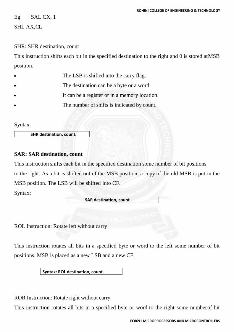
Eg. SAL CX, 1
SHL AX, C L
SHR: SHR destination, count
This instruction shifts each bit in the specified destination to the right and 0 is stored at MSB
position.
The LSB is shifted into the carry flag.
The destination can be a byte or a word.
It can be a register or in a memory location.
The number of shifts is indicated by count.
Syntax:
SAR: SAR destination, count
This instruction shifts each bit in the specified destination some number of bit positions
to the right. As a bit is shifted out of the MSB position, a copy of the old MSB is put in the
MSB position. The LSB will be shifted into CF.
Syntax:
ROL Instruction: Rotate left without carry
This instruction rotates all bits in a specified byte or word to the left some number of bit
positions. MSB is placed as a new LSB and a new CF.
ROR Instruction: Rotate right without carry
This instruction rotates all bits in a specified byte or word to the right some number of bit
SHR destination, count.
SAR destination, count
Syntax: ROL destination, count.

ROHINI COLLEGE OF ENGINEERING & TECHNOLOGY
EC8691 MICROPROCESSORS AND MICROCONTROLLERS
positions. LSB is placed as a new MSB and a new CF.
RCL Instruction: Rotate left with carry
This instruction rotates all bits in a specified byte or word some number of bit positions to the
left along with the carry flag. MSB is placed as a new carry and previous carry is place as new
LSB.
RCR Instruction: Rotate right with carry
This instruction rotates all bits in a specified byte or word some number of bit positions to the
right along with the carry flag. LSB is placed as a new carry and previous carry is place as
new MSB.
Loop Instructions:
Unconditional LOOP Instructions
LOOP: LOOP Unconditionally
This instruction executes the part of the program from the Label or Address specified in the
instruction upto the LOOP instruction CX number of times. At each iteration, CX is
decremented automatically and JUMP IF NOT ZERO structure.
Example: MOV CX, 0004H
Conditional LOOP Instructions
LOOPZ / LOOPE Label
Loop through a sequence of instructions from label while ZF=1 and CX=0.
LOOPNZ / LOOPENE Label
Loop through a sequence of instructions from label while ZF=1 and CX=0.
Branch Instructions:
Branch Instructions transfers the flow of execution of the program to a new Address specified
in the instruction directly or indirectly. When this type of instruction is executed, the CS and
IP registers get loaded with new values of CS and IP corresponding to the location to be
transferred. The Branch Instructions are classified into two types
Syntax: ROR destination, count
Syntax: RCR destination, count.
Syntax: RCL destination, count.

ROHINI COLLEGE OF ENGINEERING & TECHNOLOGY
EC8691 MICROPROCESSORS AND MICROCONTROLLERS
i. Unconditional Branch Instructions.
ii. Conditional Branch Instructions.
Unconditional Branch Instructions:
In Unconditional control transfer instructions, the execution control is transferred to the
specified location independent of any status or condition. The CS and IP are unconditionally
modified to the new CS and IP.
CALL: Unconditional Call
This instruction is used to call a Subroutine (Procedure) from a main program. Address of
procedure may be specified directly or indirectly. There are two types of procedure depending
upon whether it is available in the same segment or in another segment.
i. Near CALL i.e., ±32Kdisplacement.
ii. For CALL i.e., anywhere outside the segment.
On execution this instruction stores the incremented IP & CS onto the stack and loads the CS
& IP registers with segment and offset Addresses of the procedure to be called.
RET: Return from the Procedure.
At the end of the procedure, the RET instruction must be executed. When it is executed,
the previously stored content of IP and CS along with Flags are retrieved into the CS, IP and
Flag registers from the stack and execution of the main program continues further.
INT N: Interrupt Type N.
In the interrupt structure of 8086, 256 interrupts are defined corresponding to the types from
00H to FFH. When INT N instruction is executed, the type byte N is multiplied by 4 and the
contents of IP and CS of the interrupt service routine will be taken from memory block in
0000 segment.
INTO: Interrupt on Overflow
This instruction is executed, when the overflow flag OF is set. This is equivalent to a Type
4 Interrupt instruction.
JMP: Unconditional Jump
This instruction unconditionally transfers the control of execution to the specified Address
using an 8-bit or 16-bit displacement. No Flags are affected by this instruction.
IRET: Return from ISR
When it is executed, the values of IP, CS and Flags are retrieved from the stack to continue the

ROHINI COLLEGE OF ENGINEERING & TECHNOLOGY
EC8691 MICROPROCESSORS AND MICROCONTROLLERS
execution of the main program.
Conditional Branch Instructions
When this instruction is executed, execution control is transferred to theAddressspecified
relatively in the instruction, provided the condition implicit in the Opcode is satisfied.
Otherwise execution continues sequentially.
JZ/JE Label
Transfer execution control to Address ‘Label’, if ZF=1.
JNZ/JNE Label
Transfer execution control to Address ‘Label’, if ZF=0
JS Label
Transfer execution control to Address ‘Label’, if SF=1.
JNS Label
Transfer execution control to Address ‘Label’, if SF=0.
JO Label
Transfer execution control to Address ‘Label’, if OF=1.
JNO Label
Transfer execution control to Address ‘Label’, if OF=0.
JNP Label
Transfer execution control to Address ‘Label’, if PF=0.
JP Label
Transfer execution control to Address ‘Label’, if PF=1.
JB Label
Transfer execution control to Address ‘Label’, if CF=1.
JNB Label
Transfer execution control to Address ‘Label’, if CF=0.
JCXZ Label
Transfer execution control to Address ‘Label’, if CX=0
String Manipulation Instructions
A series of data byte or word available in memory at consecutive locations, to be referred as
Byte String or Word String. A String of characters may be located in consecutive memory
locations, where each character may be represented by its ASCII equivalent. The 8086

ROHINI COLLEGE OF ENGINEERING & TECHNOLOGY
EC8691 MICROPROCESSORS AND MICROCONTROLLERS
supports a set of more powerful instructions for string manipulations for referring to a string,
two parameters are required.
Starting and End Address of the String.
Length of the String.
The length of the string is usually stored as count in the CX register. The incrementing or
decrementing of the pointer, in string instructions, depends upon the Direction Flag (DF)
Status. If it is a Byte string operation, the index registers are updated by one. On the other
hand, if it is a word string operation, the index registers are updated bytwo.
REP: Repeat Instruction Prefix
This instruction is used as a prefix to other instructions, the instruction to which the
REP prefix is provided, is executed repeatedly until the CX register becomes zero (at each
iteration CX is automatically decremented by one).
REPE / REPZ - repeat operation while equal / zero.
REPNE / REPNZ - repeat operation while not equal / not zero.
These are used for CMPS, SCAS instructions only, as instruction prefixes.
MOVSB / MOVSW: Move String Byte or String Word
Suppose a string of bytes stored in a set of consecutive memory locations is to be moved to
another set of destination locations. The starting byte of source string is located in the memory
location whose Address may be computed using SI (Source Index) and DS (Data Segment)
contents. The starting Address of the destination locations where this string has to be relocated
is given by DI (Destination Index) and ES (Extra Segment) contents.
CMPS: Compare String Byte or String Word
The CMPS instruction can be used to compare two strings of byte or words. The length
of the string must be stored in the register CX. If both the byte or word strings are equal, zero
Flag is set.
The REP instruction Prefix is used to repeat the operation till CX (counter) becomes zero or
the condition specified by the REP Prefix is False.
SCAN: Scan String Byte or String Word
This instruction scans a string of bytes or words for an operand byte or word specified in the
register AL or AX. The String is pointed to by ES: DI register pair. The length of the string
stored in CX. The DF controls the mode for scanning of the string. Whenever a match to the
ROHINI COLLEGE OF ENGINEERING & TECHNOLOGY
EC8691 MICROPROCESSORS AND MICROCONTROLLERS
specified operand is found in the string, execution stops and the zero Flag is set. If no match
is found, the zero flag is reset.
LODS: Load String Byte or String Word
The LODS instruction loads the AL / AX register by the content of a string pointed to by DS:
SI register pair. The SI is modified automatically depending upon DF, If it is a byte transfer
(LODSB), the SI is modified by one and if it is a word transfer (LODSW), the SI is modified
by two. No other Flags are affected by this instruction.
STOS: Store String Byte or String Word
The STOS instruction Stores the AL / AX register contents to a location in the string pointer
by ES: DI register pair. The DI is modified accordingly, No Flags are affected by this
instruction.
The direction Flag controls the String instruction execution, the source index SI and
Destination Index DI are modified after each iteration automatically. If DF=1, then the
execution follows auto decrement mode, SI and DI are decremented automatically after each
iteration. If DF=0, then the execution follows auto increment mode. In this mode, SI and DI
are incremented automatically after each iteration.
Flag Manipulation and Processor Control Instructions
These instructions control the functioning of the available hardware inside the processor chip.
These instructions are categorized into two types:
Flag Manipulation instructions.
Machine Control instructions.
Flag Manipulation instructions
The Flag manipulation instructions directly modify some of the Flags of 8086.
i. CLC – Clear Carry Flag.
ii. CMC – Complement Carry Flag.
iii. STC – Set Carry Flag.
iv. CLD – Clear Direction Flag.
v. STD – Set Direction Flag.
vi. CLI – Clear Interrupt Flag.
vii. STI – Set Interrupt Flag.

ROHINI COLLEGE OF ENGINEERING & TECHNOLOGY
EC8691 MICROPROCESSORS AND MICROCONTROLLERS
Machine Control instructions
The Machine control instructions control the bus usage and execution
i. WAIT – Wait for Test input pin to go low.
ii. HLT – Halt the process.
iii. NOP – No operation.
iv. ESC – Escape to external device like NDP
v. LOCK – Bus lock instruction prefix.