Galgotias College of Engineering & Technology
71
1 Galgotias College of Engineering & Technology 1, Knowledge Park II, Greater Noida – 201 306 (UP) INDIA 1. VISION OF INSTITUTE To be a leading educational institution recognized for excellence in engineering education & research producing globally competent and socially responsible technocrats. 2. MISSION OF INSTITUTE To provide state of the art infrastructural facilities that support achieving academic excellence. To provide a work environment that is conducive for professional growth of faculty & staff. To collaborate with industry for achieving excellence in research, consultancy and entrepreneurship development.
-
Upload
khangminh22 -
Category
Documents
-
view
0 -
download
0
Transcript of Galgotias College of Engineering & Technology

1
Galgotias College of Engineering & Technology 1, Knowledge Park II, Greater Noida – 201 306 (UP) INDIA
1. VISION OF INSTITUTE
To be a leading educational institution recognized for excellence in engineering education & research
producing globally competent and socially responsible technocrats.
2. MISSION OF INSTITUTE
To provide state of the art infrastructural facilities that support achieving academic excellence.
To provide a work environment that is conducive for professional growth of faculty & staff.
To collaborate with industry for achieving excellence in research, consultancy and entrepreneurship
development.

2
Galgotias College of Engineering & Technology 1, Knowledge Park II, Greater Noida – 201 306 (UP) INDIA
3. PROGRAMME OUTCOMES (POs)
PO1 Engineering knowledge: Apply the knowledge of mathematics, science, engineering
fundamentals, and an engineering specialization to the solution of complex engineering
problems.
PO2 Problem analysis: Identify, formulate, review research literature, and analyze complex
electronics & communication engineering problems reaching substantiated conclusions using
first principles of mathematics, natural sciences, and engineering sciences.
PO3 Design/development of solutions: Design solutions for complex electronics &
communication engineering problems and design system components or processes that meet
the specific needs with appropriate considerations for the public health and safety, and the
cultural, societal, and environmental considerations.
PO4 Conduct investigations of complex problems: Use research-based knowledge and research
methods including design of experiments, analysis an d interpretation of data, and synthesis
of the information to provide conclusions.
PO5 Modern tool usage: Create, select, and apply appropriate techniques, resources, and modern
engineering and IT tools including prediction and modeling to complex engineering activities
with an understanding of the limitations.
PO6 The engineer and society: Apply reasoning informed by the contextual knowledge to assess
societal, health, safety, legal and cultural issues and the consequent relevant to the
professional engineering practices.
PO7 Environment and sustainability: Understand the impact of the professional engineering
solutions in societal and environmental contexts, and demonstrate the knowledge of, and need
for sustainable development.
PO8 Ethics: Apply ethical principles and commit to professional ethics and responsibilities and
norm of the engineering practices.
PO9 Individual and team work: Function effectively as an individual, and as a member or leader
in diverse teams, and in multidisciplinary settings.
PO10 Communications: Communicate effectively on complex engineering activities with the
engineering community and with society at large, such as, being able to comprehend and
write effective reports and design documentation, make effective presentations, and give and
receive clear instructions.
PO11 Project management and finance: Demonstrate knowledge and understanding of the
engineering and management principles and apply these to one’s own work, as a member and
leader in a team, to manage projects and in multidisciplinary environments.

3
Galgotias College of Engineering & Technology 1, Knowledge Park II, Greater Noida – 201 306 (UP) INDIA
PO12 Life-long learning: Recognize the need for, and have the preparation and ability to engage in
independent and life learning in the broadest context of technological change.
4
Galgotias College of Engineering & Technology 1, Knowledge Park II, Greater Noida – 201 306 (UP) INDIA
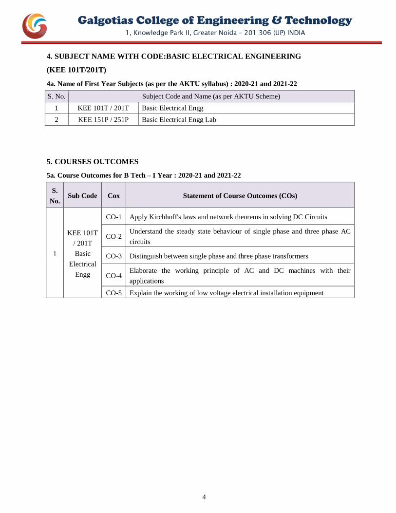
4. SUBJECT NAME WITH CODE:BASIC ELECTRICAL ENGINEERING
(KEE 101T/201T)
4a. Name of First Year Subjects (as per the AKTU syllabus) : 2020-21 and 2021-22
S. No. Subject Code and Name (as per AKTU Scheme)
1 KEE 101T / 201T Basic Electrical Engg
2 KEE 151P / 251P Basic Electrical Engg Lab
5. COURSES OUTCOMES
5a. Course Outcomes for B Tech – I Year : 2020-21 and 2021-22
S.
No. Sub Code Cox Statement of Course Outcomes (COs)
1
KEE 101T
/ 201T
Basic
Electrical
Engg
CO-1 Apply Kirchhoff's laws and network theorems in solving DC Circuits
CO-2 Understand the steady state behaviour of single phase and three phase AC
circuits
CO-3 Distinguish between single phase and three phase transformers
CO-4 Elaborate the working principle of AC and DC machines with their
applications
CO-5 Explain the working of low voltage electrical installation equipment

5
Galgotias College of Engineering & Technology 1, Knowledge Park II, Greater Noida – 201 306 (UP) INDIA
6. MAPPING OF COs WITH POs (COURSE-WISE, DETAILED)
6a. CO-PO Mapping for Academic Session 2020-21 and 2021-22
1. Slight (low) 2. Moderate (medium) 3. Substantial (high)
S.
No
Sub Code COx
Kx PO1 PO2 PO3 PO4 PO5 PO6 PO7 PO8 PO9 PO10 PO11 PO12
Blo
om
’s K
no
wle
dg
e
Lev
el
Eng
inee
ring
know
ledg
e
Pro
blem
Ana
lysi
s
Des
ign/
deve
lopm
ent
of
solu
tions
Con
duct
inve
stig
atio
ns o
f
com
plex
pro
blem
s
Mod
ern
tool
usa
ge
The
Eng
inee
r an
d S
ocie
ty
Env
ironm
ent a
nd
sust
aina
bilit
y
Eth
ics
Indi
vidu
al a
nd t
eam
wor
k
Com
mun
icat
ions
Pro
ject
man
agem
ent
and
finan
ce
Life
Lon
g Le
arni
ng
1
KEE 101T / 201T
Basic Electrical
Engg
CO-1 K3 3 3 3 2
CO-2 K2 3 3 3 2
CO-3 K2 3 2 3 2
CO-4 K2 3 2
CO-5 K2 3 3
KEE101 3.00 2.67 3.00 2.20
2
KEE 151P / 251P
Basic Electrical
Engg Lab
CO-1 K3 3 3 2 3 3 3
CO-2 K2 3 3 2 3 3 3
CO-3 K3 3 3 2 3 3 3
KEE101P 3.00 3.00 2.00 3.00 3.00 3.00
7. CO-PO MAPPING (COURSE-WISE, COMPILED)
7. Compiled CO-PO Mapping : 2020-21 and 2021-22
S.
No.
Sub
Code Course Code
PO1 PO2 PO3 PO4 PO5 PO6 PO7 PO8 PO9 PO10 PO11 PO12
Eng
inee
ring
know
ledg
e
Pro
blem
Ana
lysi
s
Des
ign/
deve
lopm
ent
of
solu
tions
Con
duct
inve
stig
atio
ns o
f
com
plex
pro
blem
s
Mod
ern
tool
usa
ge
The
Eng
inee
r an
d S
ocie
ty
Env
ironm
ent a
nd s
usta
inab
ility
Eth
ics
Indi
vidu
al a
nd t
eam
wor
k
Com
mun
icat
ions
Pro
ject
man
agem
ent
and
finan
ce
Life
Lon
g Le
arni
ng
1 KEE 101T / 201T
Basic Electrical Engg 3.00 2.67 3.00 2.20
2 KEE 151P / 251P
Electrical Engg Lab 3.00 3.00 2.00 3.00 3.00 3.00
Average Value of CO-PO Mapping
(PO-wise) 3.00 2.70 2.83
3.00 2.37 2.00 2.86 2.86 3.00 2.00 2.93
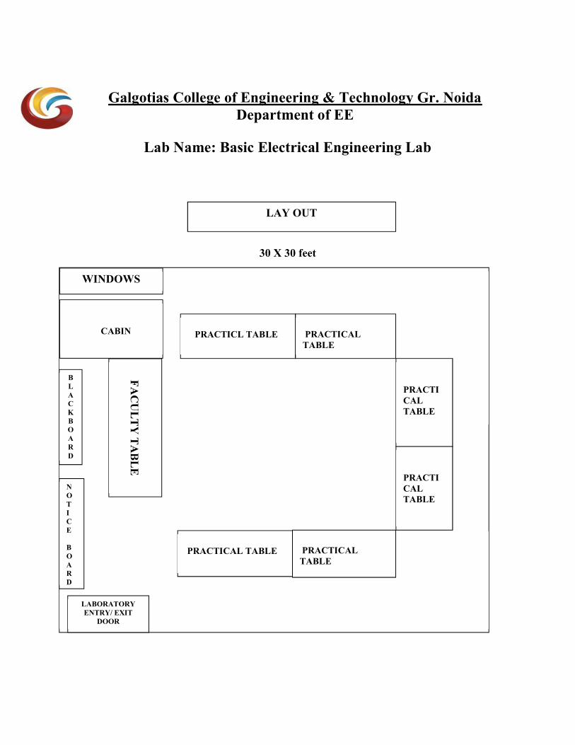
Galgotias College of Engineering & Technology Gr. Noida Department of EE
Lab Name: Basic Electrical Engineering Lab
30 X 30 feet
LAY OUT
PRACTICL TABLE
PRACTICAL TABLE
PRACTICAL TABLE
PRACTICAL TABLE
PRACTICAL TABLE
PRACTICAL TABLE
LABORATORY ENTRY/ EXIT
DOOR
WINDOWS
NO T I C E BOARD
BLACK BOARD
CABIN
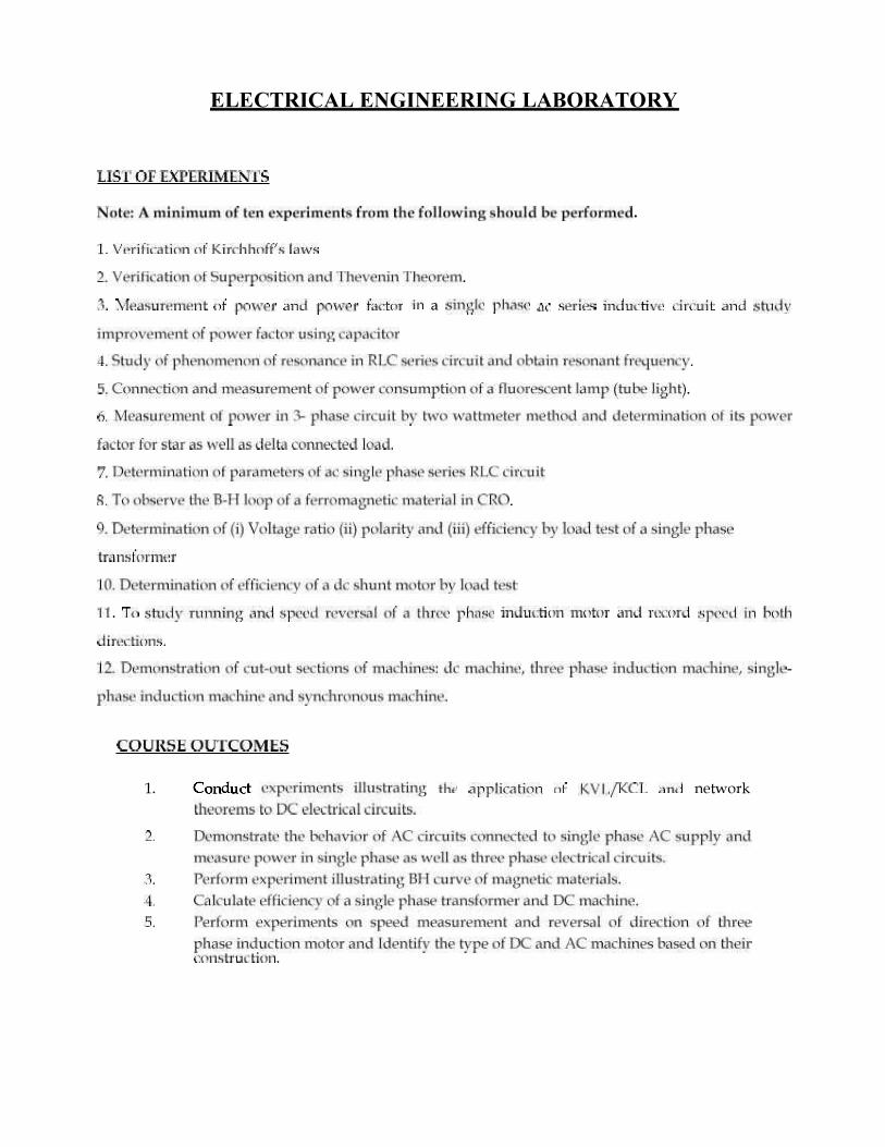
Electrical Engineering Lab 1st Year
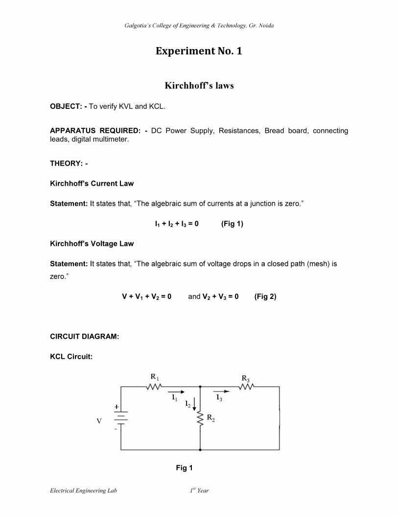
Experiment No. 1
OBJECT: - To verify KVL and KCL.
APPARATUS REQUIRED: - DC Power Supply, Resistances, Bread board, connecting leads, digital multimeter.
THEORY: -
Statement:
I1 + I2 + I3 = 0 (Fig 1)
Statement:
V + V1 + V2 = 0 and V2 + V3 = 0 (Fig 2)
CIRCUIT DIAGRAM:
KCL Circuit:
V
Fig 1

Electrical Engineering Lab 1st Year
KVL Circuit:
PROCEDURE:
1. Connections are made as per the circuit diagram.
2. For a circuit shown in figure 1 apply voltage and measure currents I1, I2 and I3.
3. For a circuit shown in figure 2 apply voltage and measure voltage V1, V2 and V3.
4. Two sets of reading are taken.
OBSERVATION TABLE:
S No. I1 I2 I3 V V1 V2 V3
1
2
V
V1 V3
V2
Fig 2

Electrical Engineering Lab 1st Year
CALCULATION:
For KCL: I1 + I2 + I3 = 0
For KVL: V + V1 + V2 = 0 and V2 + V3 = 0
RESULT:
1) It is found that the algebraic sum of currents at a junction is coming to be zero.
2) It is found that the algebraic sum of voltages drop in a closed path (mesh) is zero.
Hence KCL and KVL is verified.
PRECAUTION:
1. All connections should be tight.
2. Readings are taken carefully with accuracy.
3. Connections are made carefully, i.e. ammeter is always connected in series and
voltmeter in parallel.
4.
XXXXXXXXXXXXXXXXXXX
Galgotia
Electrical Engineering Lab 1st
Year
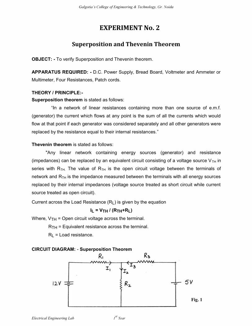
EXPERIMENT No. 2
Superposition and Thevenin Theorem OBJECT: - To verify Superposition and Thevenin theorem.
APPARATUS REQUIRED: - D.C. Power Supply, Bread Board, Voltmeter and Ammeter or
Multimeter, Four Resistances, Patch cords.
THEORY / PRINCIPLE:-
Superposition theorem is stated as follows:
a network of linear resistances containing more than one source of e.m.f.
(generator) the current which flows at any point is the sum of all the currents which would
flow at that point if each generator was considered separately and all other generators were
replaced by the resistance equal to their internal resistances.
Thevenin theorem is stated as follows:
"Any linear network containing energy sources (generator) and resistance
(impedances) can be replaced by an equivalent circuit consisting of a voltage source VTH in
series with RTH. The value of RTH is the open circuit voltage between the terminals of
network and RTH is the impedance measured between the terminals with all energy sources
replaced by their internal impedances (voltage source treated as short circuit while current
source treated as open circuit).
Current across the Load Resistance (RL) is given by the equation
IL = VTH / (RTH+RL)
Where, VTH = Open circuit voltage across the terminal.
RTH = Equivalent resistance across the terminal.
RL = Load resistance.
CIRCUIT DIAGRAM: - Superposition Theorem
Fig. 1

Galgotia
Electrical Engineering Lab 1st
Year
CIRCUIT DIAGRAM: - Thevenin Theorem
Fig. 1(a) shows the circuit arrangement of two port linear active network. Fig. 1(b) shows
the equivalent circuit for calculating Thevenin voltage VTH.
Fig. 1(c) shows the circuit arrangement for calculating Thevenin resistance and fig. 1(d)
shows Thevenin equivalent circuit.
Fig. 2 Fig. 3

Galgotia
Electrical Engineering Lab 1st
Year
PROCEDURE: - Superposition Theorem
1. Short circuit the 5 volts supply and connect the 12 volts supply to the circuit.
Measure the current flowing in all the branches and note down the readings.
2. Now short circuit the 12 volts supply and connect the 5 volts supply to the circuit.
Again, measure the currents flowing in all the branches and note down the
readings.
3. Now connect both the supplies 12 volts and 5 volts to the circuit and measure the
current flowing in all the branches.
Thevenin equivalent circuit is as follows:
1. Remove the resistance (RL) through which current is to be found.
2. Connect the 12 volts supply and find the open circuit voltage VOC which appears
across the two terminals from where resistance is removed as per Fig 1(b).It is also
called Thevenin voltage.
3. Short circuit the input voltage and compute the resistance of the whole network as
looked into from these two terminals as per Fig 1(c) .Make sure all sources of emf
are short circuited while all current sources are open circuited.
4. Connect RL back to its terminals from where previously it was removed.
5. Finally, calculate the current flowing through RL
OBSERVATION TABLE: For Superposition Theorem
12 Volt source only 5 Volt source only Considering both sources
I1 (mA) I2 (mA) I3 (mA) I1 (mA) I2 (mA) I3 (mA) I1 (mA) I2 (mA) I3 (mA)
For Thevenin Theorem
VTH (Volts) RTH (ohms) IL (mA)
Galgotia
Electrical Engineering Lab 1st
Year
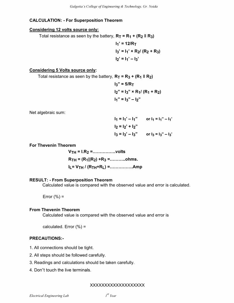
CALCULATION: - For Superposition Theorem
Considering 12 volts source only:
Total resistance as seen by the battery, RT = R1 + (R2 3)
I1 T
I3 1 2/ (R2 + R3)
I2 1 I3
Considering 5 Volts source only:
Total resistance as seen by the battery, RT = R3 + (R1 2)
I3 /RT
I2 3 1/ (R1 + R2)
I1 3 I2
Net algebraic sum:
I1 = I1 I1 or I1 = I1 I1
I2 = I2 2
I3 = I3 I3 or I3 = I3 I3
For Thevenin Theorem
VTH = I.R2
RTH = (R1||R2) +R3
IL= VTH / (RTH+RL)
RESULT: - From Superposition Theorem Calculated value is compared with the observed value and error is calculated.
Error (%) =
From Thevenin Theorem
Calculated value is compared with the observed value and error is
calculated. Error (%) =
PRECAUTIONS:-
1. All connections should be tight.
2. All steps should be followed carefully.
3. Readings and calculations should be taken carefully.
4.
XXXXXXXXXXXXXXXXXXX

Electrical Engineering Lab 1st
Year
EXPERIMENT No. 3
Power and Power Factor in a Single Phase AC Series Circuit
OBJECT: - Measurement of power and power factor in a single phase AC series Inductive
circuit and study of improvement of power factor using Capacitor. APPARATUS REQUIRED: -
Serial No. Equipment Specification Quantity 1 AC ammeter 0-5A 3 2 AC voltmeter 0-300V 1 3 single phase 1 inductive load 4 variac 10A,250V 1 5 non-inductive 1 resistor 6 capacitor 1 7 Connecting wire.
THEORY / PRINCIPLE: - Real power (P) in a single phase ac series inductive circuit can be measured either by wattmeter or with the help of three ammeters.
three ammeters.
CIRCUIT DIAGRAM:-
PROCEDURE:-
Keeping the variac at its minimum position, supply is switched on Variac position is
gradually varied to increase the voltage applied to the circuit so that the reading of the
ammeter A3 and voltmeter are appreciable. Reading of ammeter A1, A2 and A3 are noted
Electrical Engineering Lab 1st
Year
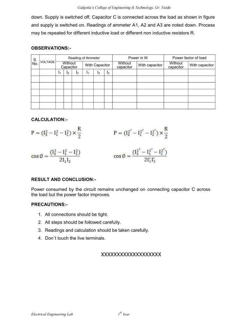
down. Supply is switched off, Capacitor C is connected across the load as shown in figure
and supply is switched on. Readings of ammeter A1, A2 and A3 are noted down. Process
may be repeated for different inductive load or different non inductive resistors R.
OBSERVATIONS:-
S. No. VOLTAGE
Reading of Ammeter Power in W Power factor of load
Without Capacitor With Capacitor Without
capacitor With capacitor Without capacitor With capacitor
I1 I2 I3 I1 I2 I3
CALCULATION:-
RESULT AND CONCLUSION:-
Power consumed by the circuit remains unchanged on connecting capacitor C across the load but the power factor improves.
PRECAUTIONS:-
1. All connections should be tight.
2. All steps should be followed carefully.
3. Readings and calculation should be taken carefully.
4. Don`t touch the live terminals.
XXXXXXXXXXXXXXXXXXX

Galgotia
Electrical Engineering Lab 1st
Year
EXPERIMENT No. 4
Resonant Frequency of a series RLC circuit
OBJECT: - Study of phenomenon of resonance in RLC series circuit and obtain resonant
frequency. APPARATUS REQUIRED: - Series RLC kit, Function generator, or resistor, inductor (0-
10mH), capacitor (0- 0.1uF), voltmeter, ammeter.
THEORY / PRINCIPLE: - When a series RLC circuit is in resonance, it possesses minimum
impedance (Z = R). Hence, the current flowing in the circuit is maximum and current and
voltage are in phase. The frequency at which the net reactance of the series circuit is zero
is called resonant frequency.
XL XC = 0
XL = XC
oL oC)
o2 = 1 / (LC)
4 2fo
2 = 1 / (LC)
fo LC
CIRCUIT DIAGRAM:- PROCEDURE:-
1. Take any combination of R, L, and C and connect them in series.
2. Give A.C. supply to the network through the function generator.
3. Connect an ammeter as shown in the circuit.
Galgotia
Electrical Engineering Lab 1st
Year
4. Change the frequency of alternating voltage with the help of function generator and
note down the reading of the ammeter.
5. Plot the graph between frequency and current.
6. Repeat the above experiment for different combination of R, L, and C.
OBSERVATIONS:-
f ( KHz ) I (mA )
GRAPH:- Draw a graph between f (KHz) vs I (mA).
CALCULATION:-
Determine the value of resonant frequency using the formula: fo = 1 / LC
RESULT:-
fo(calculated)
fo
% ERROR = fo (calculated) - fo (observed) x 100 fo (calculated)
PRECAUTIONS:-
1. All connections should be tight.
2. All steps should be followed carefully.
3. Readings and calculation should be taken carefully.
4. Don`t touch the live terminals.
XXXXXXXXXXXXXXXXXXX
Electrical Engineering Lab 1st
Year
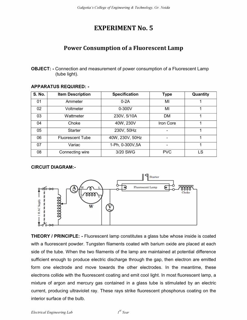
EXPERIMENT No. 5
Power Consumption of a Fluorescent Lamp
OBJECT: - Connection and measurement of power consumption of a Fluorescent Lamp
(tube light). APPARATUS REQUIRED: -
S. No. Item Description Specification Type Quantity
01 Ammeter 0-2A MI 1
02 Voltmeter 0-300V MI 1
03 Wattmeter 230V, 5/10A DM 1
04 Choke 40W, 230V Iron Core 1
05 Starter 230V, 50Hz - 1
06 Fluorescent Tube 40W, 230V, 50Hz - 1
07 Variac 1-Ph, 0-300V,5A - 1
08 Connecting wire 3/20 SWG PVC LS
CIRCUIT DIAGRAM:-
THEORY / PRINCIPLE: - Fluorescent lamp constitutes a glass tube whose inside is coated
with a fluorescent powder. Tungsten filaments coated with barium oxide are placed at each
side of the tube. When the two filaments of the lamp are maintained at potential difference
sufficient enough to produce electric discharge through the gap, then electron are emitted
form one electrode and move towards the other electrodes. In the meantime, these
electrons collide with the fluorescent coating and emit cool light. In most fluorescent lamp, a
mixture of argon and mercury gas contained in a glass tube is stimulated by an electric
current, producing ultraviolet ray. These rays strike fluorescent phosphorus coating on the
interior surface of the bulb.
Electrical Engineering Lab 1st
Year
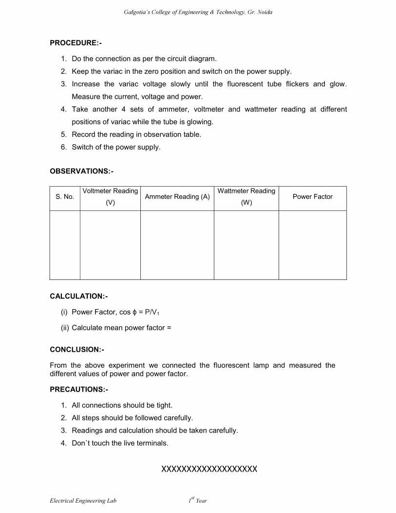
PROCEDURE:-
1. Do the connection as per the circuit diagram.
2. Keep the variac in the zero position and switch on the power supply.
3. Increase the variac voltage slowly until the fluorescent tube flickers and glow.
Measure the current, voltage and power.
4. Take another 4 sets of ammeter, voltmeter and wattmeter reading at different
positions of variac while the tube is glowing.
5. Record the reading in observation table.
6. Switch of the power supply.
OBSERVATIONS:-
S. No. Voltmeter Reading
(V) Ammeter Reading (A)
Wattmeter Reading
(W) Power Factor
CALCULATION:-
(i) Power Factor, cos = P/V1
(ii) Calculate mean power factor =
CONCLUSION:-
From the above experiment we connected the fluorescent lamp and measured the different values of power and power factor.
PRECAUTIONS:-
1. All connections should be tight.
2. All steps should be followed carefully.
3. Readings and calculation should be taken carefully.
4. Don`t touch the live terminals.
XXXXXXXXXXXXXXXXXXX
Galgotia
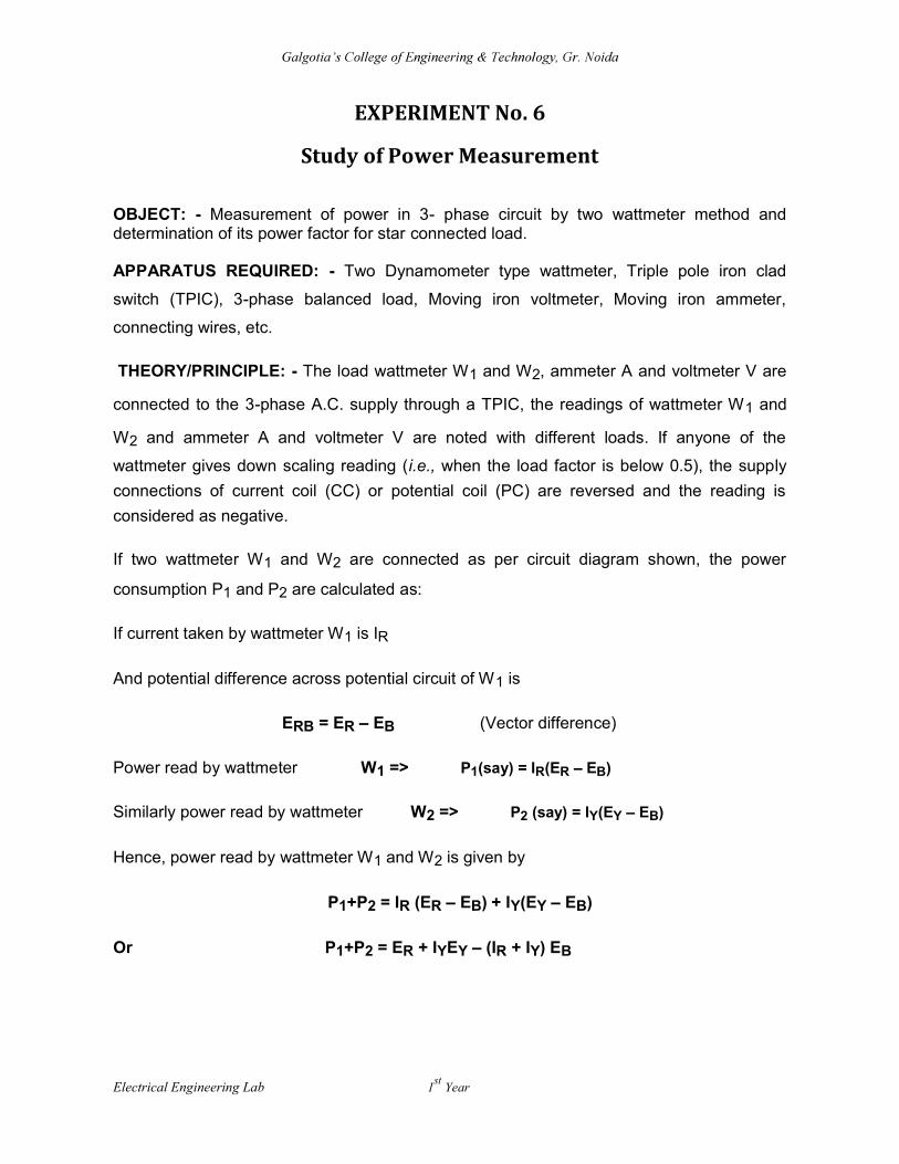
EXPERIMENT No. 6
Study of Power Measurement OBJECT: - Measurement of power in 3- phase circuit by two wattmeter method and determination of its power factor for star connected load. APPARATUS REQUIRED: - Two Dynamometer type wattmeter, Triple pole iron clad
switch (TPIC), 3-phase balanced load, Moving iron voltmeter, Moving iron ammeter,
connecting wires, etc. THEORY/PRINCIPLE: - The load wattmeter W1 and W2, ammeter A and voltmeter V are
connected to the 3-phase A.C. supply through a TPIC, the readings of wattmeter W1 and
W2 and ammeter A and voltmeter V are noted with different loads. If anyone of the
wattmeter gives down scaling reading (i.e., when the load factor is below 0.5), the supply
connections of current coil (CC) or potential coil (PC) are reversed and the reading is
considered as negative.
If two wattmeter W1 and W2 are connected as per circuit diagram shown, the power
consumption P1 and P2 are calculated as:
If current taken by wattmeter W1 is IR
And potential difference across potential circuit of W1 is
ERB = ER EB (Vector difference)
Power read by wattmeter W1 => P1(say) = IR(ER EB)
Similarly power read by wattmeter W2 => P2 (say) = IY(EY EB)
Hence, power read by wattmeter W1 and W2 is given by
P1+P2 = IR (ER EB) + IY(EY EB)
Or P1+P2 = ER + IYEY (IR + IY) EB Electrical Engineering Lab 1
st Year

Galgotia
Also, we know that
IR + IY + IB = 0
IR + IY = -IB
Putting the value in equation (a), we get:
P1+P2 = ER + IYEY + IBEB
P1+P2 = P
Total Power P = P1 + P2 = LIL
Power Factor = P/ LIL
CIRCUIT DIAGRAM: -
PROCEDURE: -
1. Connect the circuit as per circuit diagram.
2. Vary the inductive load.
3. Note down all readings carefully.
4. If one wattmeter reads negative or gives reversed reading, the reading of the
wattmeter is taken by reversing the current coil terminal.
Electrical Engineering Lab 1st
Year
Galgotia
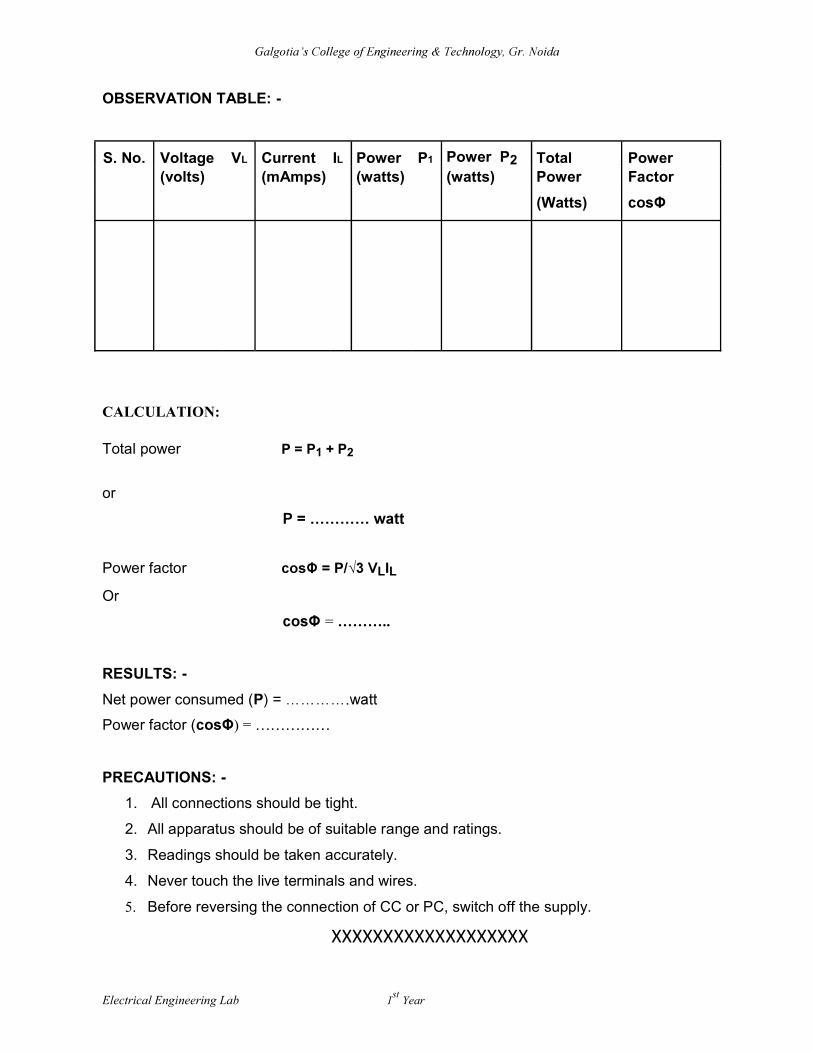
OBSERVATION TABLE: -
S. No. Voltage VL Current IL Power P1 Power P2 Total Power (volts) (mAmps) (watts) (watts) Power Factor
(Watts)
CALCULATION:
Total power P = P1 + P2 or
Power factor = P/ LIL Or
= ..
RESULTS: - Net power consumed (P
Power factor (
PRECAUTIONS: -
1. All connections should be tight.
2. All apparatus should be of suitable range and ratings.
3. Readings should be taken accurately.
4. Never touch the live terminals and wires.
5. Before reversing the connection of CC or PC, switch off the supply.
XXXXXXXXXXXXXXXXXXX
Electrical Engineering Lab 1st
Year
Galgotia
EXPERIMENT No. 7(a)
Turns Ratio and Polarity tests of a Single Phase Transformer OBJECT: - To study the Polarity and Voltage ratio test of a single phase Transformer.
APPARATUS REQUIRED: - Single phase Transformer, Voltmeter, Connecting leads.
THEORY/PRINCIPLE: -
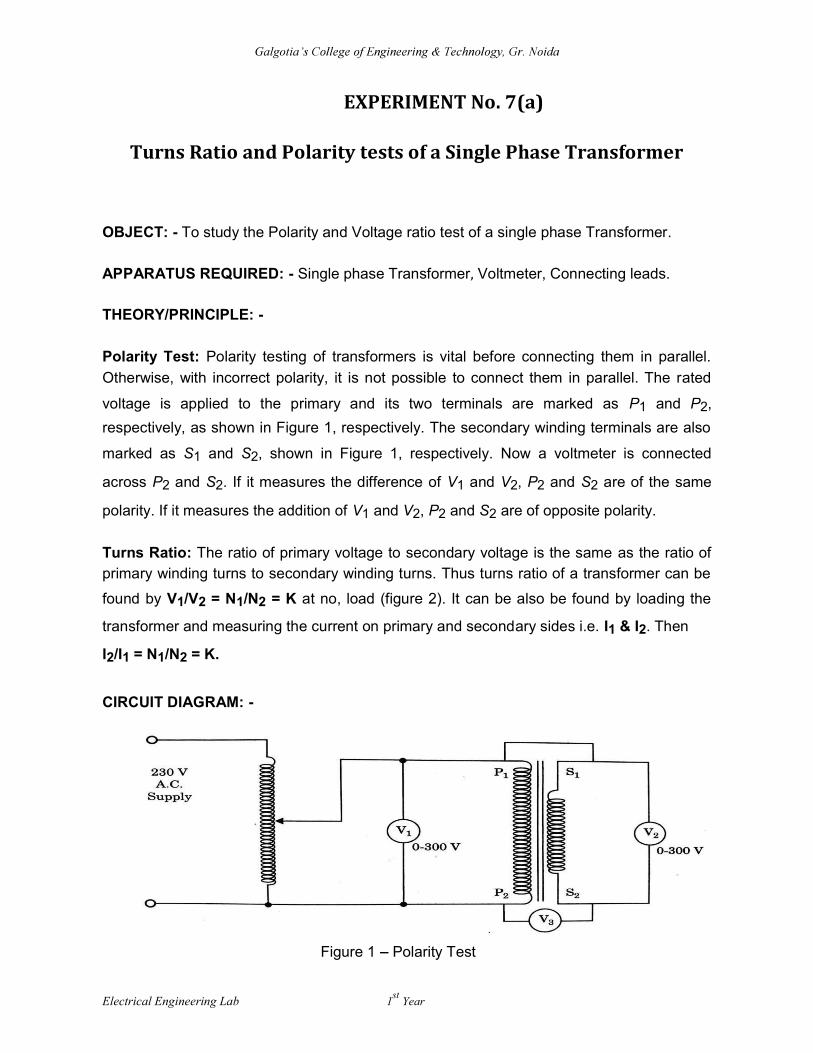
Polarity Test: Polarity testing of transformers is vital before connecting them in parallel.
Otherwise, with incorrect polarity, it is not possible to connect them in parallel. The rated
voltage is applied to the primary and its two terminals are marked as P1 and P2,
respectively, as shown in Figure 1, respectively. The secondary winding terminals are also
marked as S1 and S2, shown in Figure 1, respectively. Now a voltmeter is connected
across P2 and S2. If it measures the difference of V1 and V2, P2 and S2 are of the same
polarity. If it measures the addition of V1 and V2, P2 and S2 are of opposite polarity.
Turns Ratio: The ratio of primary voltage to secondary voltage is the same as the ratio of primary winding turns to secondary winding turns. Thus turns ratio of a transformer can be
found by V1/V2 = N1/N2 = K at no, load (figure 2). It can be also be found by loading the
transformer and measuring the current on primary and secondary sides i.e. I1 & I2. Then I2/I1 = N1/N2 = K. CIRCUIT DIAGRAM: -
Figure 1 Polarity Test Electrical Engineering Lab 1
st Year

Galgotia
Figure 2 Turns Ratio Test
PROCEDURE: -
Polarity Test:
1. Connect the circuit as per figure 1.
2. Switch on the supply. 3. Record the voltage V1, V2 and V3. In case V3 < V1, the polarity is subtractive. 4. Repeat step 3, after connecting the terminal P1 & S2. The transformer should be
disconnected before making. This change in case V3 > V1, the polarity is additive.
5. Switch off the supply.
Voltage Ratio Test:
1. Connect the circuit as per figure 2.
2. Switch on the supply. 3. Record the voltage V1 across various tapping of the secondary.
4. Switch off the supply.
OBSERVATION TABLE: -
Polarity Test:
S. No. V1 (volts) V2 (volts) V3 (volts) Polarity
Electrical Engineering Lab 1st
Year
Galgotia
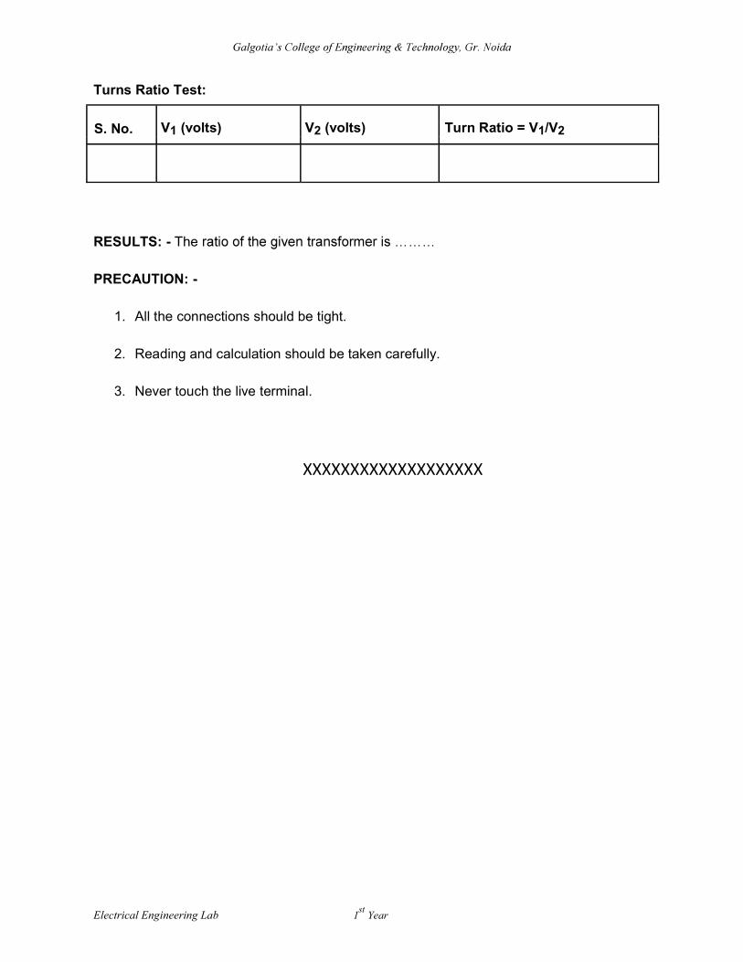
Turns Ratio Test:
S. No. V1 (volts) V2 (volts) Turn Ratio = V1/V2
RESULTS: - The
PRECAUTION: -
1. All the connections should be tight.
2. Reading and calculation should be taken carefully.
3. Never touch the live terminal.
XXXXXXXXXXXXXXXXXXX
Electrical Engineering Lab 1st
Year

Galgotia
EXPERIMENT No. 7(b)
Load Test on Transformer
OBJECT: - Determine the efficiency of a single phase transformer by direct load test.
APPARATUS REQUIRED: - Single phase isolation transformer, Ammeter (0-10 Amp),
Voltmeter (0-300V), wattmeter, load, connecting wires, etc.
THEORY/PRINCIPLE: -
Load test: The input to the transformer is observed with the help of wattmeter. Let it be
W1. The output of the transformer is calculated from the product of the voltage (V) and
current (I) in the secondary of the transformer. The load is taken a resistive and therefore
power factor is unity. Hence
(efficiency) of transformer = output/ input x 100
= (V * I) x 100/w1
CIRCUIT DIAGRAM: -
Electrical Engineering Lab 1st
Year
Galgotia
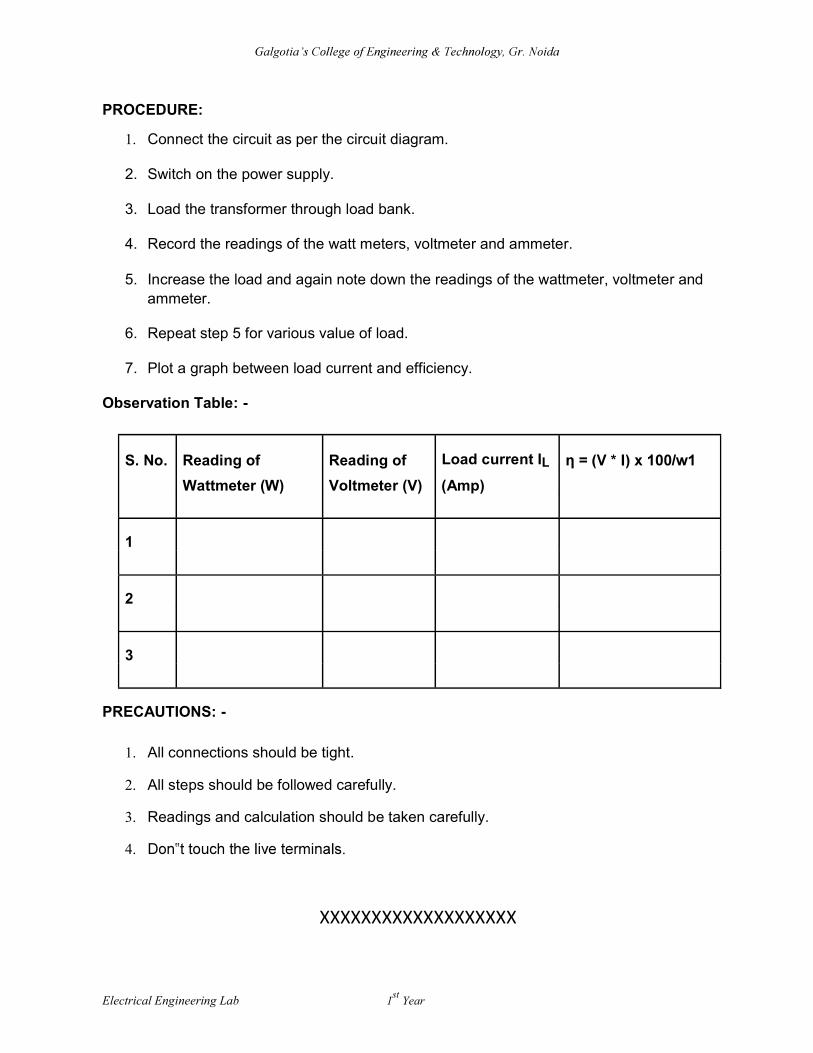
PROCEDURE:
1. Connect the circuit as per the circuit diagram.
2. Switch on the power supply.
3. Load the transformer through load bank.
4. Record the readings of the watt meters, voltmeter and ammeter.
5. Increase the load and again note down the readings of the wattmeter, voltmeter and ammeter.
6. Repeat step 5 for various value of load.
7. Plot a graph between load current and efficiency.
Observation Table: -
S. No. Reading of Reading of Load current IL
Wattmeter (W) Voltmeter (V) (Amp)
1
2
3
PRECAUTIONS: -
1. All connections should be tight.
2. All steps should be followed carefully.
3. Readings and calculation should be taken carefully.
4.
XXXXXXXXXXXXXXXXXXX
Electrical Engineering Lab 1st
Year
Galgotia
EXPERIMENT No. 8
Running and Reversing of 3-Phase Induction Motor OBJECT: - To study running and speed reversal of a three phase induction motor and record speed in both directions. APPARATUS REQUIRED: - Three phase Induction Motor, D.O.L. starter, TPIC switch,
connecting wires.
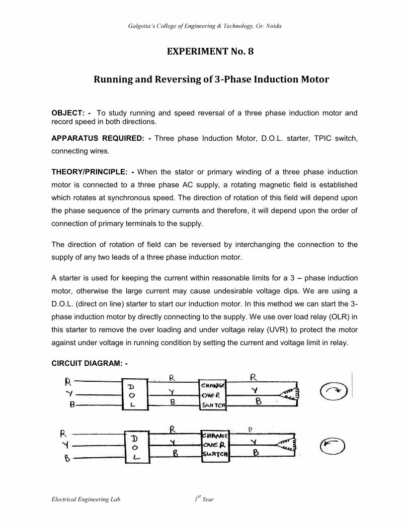
THEORY/PRINCIPLE: - When the stator or primary winding of a three phase induction
motor is connected to a three phase AC supply, a rotating magnetic field is established
which rotates at synchronous speed. The direction of rotation of this field will depend upon
the phase sequence of the primary currents and therefore, it will depend upon the order of
connection of primary terminals to the supply.
The direction of rotation of field can be reversed by interchanging the connection to the
supply of any two leads of a three phase induction motor.
A starter is used for keeping the current within reasonable limits for a 3 phase induction
motor, otherwise the large current may cause undesirable voltage dips. We are using a
D.O.L. (direct on line) starter to start our induction motor. In this method we can start the 3-
phase induction motor by directly connecting to the supply. We use over load relay (OLR) in
this starter to remove the over loading and under voltage relay (UVR) to protect the motor
against under voltage in running condition by setting the current and voltage limit in relay.
CIRCUIT DIAGRAM: - Electrical Engineering Lab 1
st Year
Galgotia
PROCEDURE: -
1. Switch on the A.C. Supply.
2. Note down the direction of rotation of induction motor and speed.
3. Change the phase sequence of supply with the help of the changeover switch.
4. Again note down the direction of rotation of the induction motor. OBSERVATION TABLE: - Direction of rotation of motor on giving A.C.
Supply and speed in RPM
Direction of rotation of motor after changing
phase of A.C. supply and speed in RPM
RESULT: - We observe that the direction of induction motor is reversed after we do phase reversal. Speed in both directions is as follow: PRECAUTIONS: -
1. All connections should be tight.
2. Never touch the live terminals.
3. Before changing the connections, switch off the supply properly.
4. Increase the load gradually.
5. Always use starter of proper rating.
XXXXXXXXXXXXXXXXXXX Electrical Engineering Lab 1
st Year
GALGOTIAS COLLEGE OF ENGINEERING & TECHNOLOGY 1, Knowledge Park-II, Greater Noida (UP) India 201306
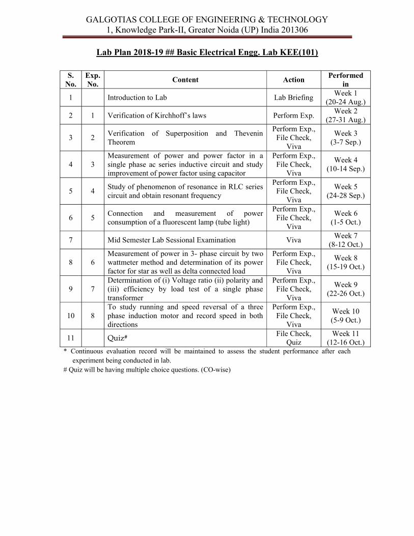
Lab Plan 2018-19 ## Basic Electrical Engg. Lab KEE(101)
S.
No. Exp. No.
Content Action Performed
in
1 Introduction to Lab Lab Briefing Week 1
(20-24 Aug.)
2 1 Verification of Kirchhoff s laws Perform Exp. Week 2
(27-31 Aug.)
3 2 Verification of Superposition and Thevenin Theorem
Perform Exp., File Check,
Viva
Week 3 (3-7 Sep.)
4 3 Measurement of power and power factor in a single phase ac series inductive circuit and study improvement of power factor using capacitor
Perform Exp., File Check,
Viva
Week 4 (10-14 Sep.)
5 4 Study of phenomenon of resonance in RLC series circuit and obtain resonant frequency
Perform Exp., File Check,
Viva
Week 5 (24-28 Sep.)
6 5 Connection and measurement of power consumption of a fluorescent lamp (tube light)
Perform Exp., File Check,
Viva
Week 6 (1-5 Oct.)
7 Mid Semester Lab Sessional Examination Viva Week 7
(8-12 Oct.)
8 6 Measurement of power in 3- phase circuit by two wattmeter method and determination of its power factor for star as well as delta connected load
Perform Exp., File Check,
Viva
Week 8 (15-19 Oct.)
9 7 Determination of (i) Voltage ratio (ii) polarity and (iii) efficiency by load test of a single phase transformer
Perform Exp., File Check,
Viva
Week 9 (22-26 Oct.)
10 8 To study running and speed reversal of a three phase induction motor and record speed in both directions
Perform Exp., File Check,
Viva
Week 10 (5-9 Oct.)
11 Quiz# File Check, Quiz
Week 11 (12-16 Oct.)
* Continuous evaluation record will be maintained to assess the student performance after each experiment being conducted in lab.
# Quiz will be having multiple choice questions. (CO-wise)
Galgotias College of Engineering & Technology Department of Electrical Engineering Sub: Basic Electrical Engineering Lab
Subject Code: REE-151/251
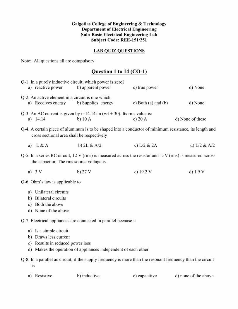
LAB QUIZ QUESTIONS
Note: All questions all are compulsory
Question 1 to 14 (CO-1)
Q-1. In a purely inductive circuit, which power is zero? a) reactive power b) apparent power c) true power d) None
Q-2. An active element in a circuit is one which. a) Receives energy b) Supplies energy c) Both (a) and (b) d) None
Q-3. An AC current is given by i=14.14sin ( t + 30). Its rms value is:
a) 14.14 b) 10 A c) 20 A d) None of these
Q-4. A certain piece of aluminum is to be shaped into a conductor of minimum resistance, its length and cross sectional area shall be respectively
a) L & A b) 2L & A/2 c) L/2 & 2A d) L/2 & A/2
Q-5. In a series RC circuit, 12 V (rms) is measured across the resistor and 15V (rms) is measured across the capacitor. The rms source voltage is
a) 3 V b) 27 V c) 19.2 V d) 1.9 V
Q-6
a) Unilateral circuits b) Bilateral circuits c) Both the above d) None of the above
Q-7. Electrical appliances are connected in parallel because it
a) Is a simple circuit b) Draws less current c) Results in reduced power loss d) Makes the operation of appliances independent of each other
Q-8. In a parallel ac circuit, if the supply frequency is more than the resonant frequency than the circuit is
a) Resistive b) inductive c) capacitive d) none of the above

Q-9. An alternating voltage is given by v= 20 sin157 t, the frequency of alternating voltage is
a) 50 Hz b) 25 Hz c) 100 Hz d) 75 Hz
Q-10. The RLC series circuit is ________ at resonance
a) Inductive b) capacitive c) resistive d) none of the above
Q-11. A voltage v (t) = 170Sin (377t +10°) is applied to a circuit. It causes a steady state current i(t) = 14.14 sin(377t -20°) The power factor of the circuit :
a) cos 10 b) cos30 c) cos20 d) 1
Q-12. Conductance (G) equals the reciprocal of:
a) Z b) R c) B d)none of these
Q-13. The power factor of a circuit at resonance is:
a) 0.5 b) 1 c) 0.866 d) 0
Question 14 to 29 (CO-2)
Q-14. The purpose of load in an electric circuit is to
a) Increase the circuit current b) Utilize electrical energy c) Decrease the circuit current d) None of the above
Q-15. An AC generator having 10 poles and running at 600 rpm will generate an alternating voltage of frequency
a) 25 Hz b) 100 Hz c) 50 Hz d) 200 Hz
Q-16. In a 3- phase balanced load, the power consumed is given by the relation
a) L IL b) 3 Vph Iph c) both a) & b) d) none of the above
Q-17. A 4- pole 50 Hz Induction Motor operates at 5% slip, the frequency of emf induced in the rotor will be
a) 25 Hz b) 50 Hz c) 2.5 Hz d) None of the abov
Q-18. A 2000/200 V, 20 KVA ideal transformer has 66 turns in the secondary. The number of primary turns is
a) 440 b) 660 c) 550 d) 330
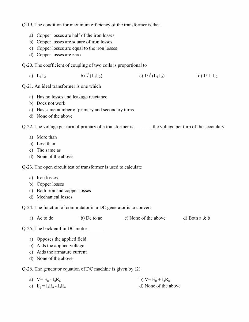
Q-19. The condition for maximum efficiency of the transformer is that
a) Copper losses are half of the iron losses b) Copper losses are square of iron losses c) Copper losses are equal to the iron losses d) Copper losses are zero
Q-20. The coefficient of coupling of two coils is proportional to
a) L1L2 (L1L2) (L1L2) d) 1/ L1L2
Q-21. An ideal transformer is one which
a) Has no losses and leakage reactance b) Does not work c) Has same number of primary and secondary turns d) None of the above
Q-22. The voltage per turn of primary of a transformer is _______ the voltage per turn of the secondary
a) More than b) Less than c) The same as d) None of the above
Q-23. The open circuit test of transformer is used to calculate
a) Iron losses b) Copper losses c) Both iron and copper losses d) Mechanical losses
Q-24. The function of commutator in a DC generator is to convert
a) Ac to dc b) Dc to ac c) None of the above d) Both a & b
Q-25. The back emf in DC motor ______
a) Opposes the applied field b) Aids the applied voltage c) Aids the armature current d) None of the above
Q-26. The generator equation of DC machine is given by (2)
a) V= Eg - IaRa b) V= Eg + IaRa c) Eg = IaRa - IaRa d) None of the above

Q-27. The rotor speed of 4 pole, 50Hz three phase induction motor is 1450 RPM, the percentage slip is:
a) 5 % b)6.5% c)3.33% d)1 % Q-28. In a 4 pole, Lap wound dc machine have 760 conductors and running at 1200 rpm with 20mWb flux per pole, the induced voltage would be:
a) 304V b) 76V c) 912V d) 1000 V Q-29. Permanent magnets are made up of:
a) Alnico alloys b) aluminium c) cast iron d) wrought iron
Question 30 to 31 (CO 3)
Q-30. In a two phase generator the electrical displacement between two phases or windings is _____ electrical degrees
a) 120 b) 90 c) 180 d) none of the above
Q-31. The power factor for a RL circuit lies between
a) 0 & 1 b) -1 & 1 c) -1 & 0 d) more than unity

Roll No.-----------------------------
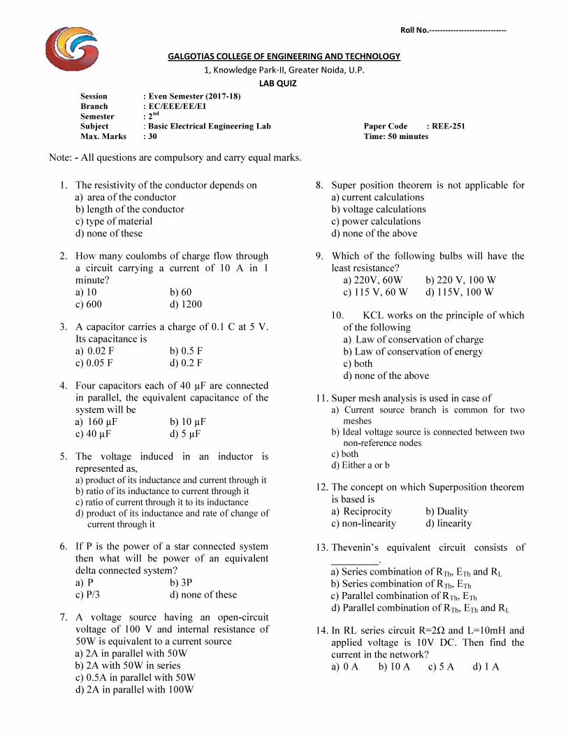
GALGOTIAS COLLEGE OF ENGINEERING AND TECHNOLOGY 1, Knowledge Park-II, Greater Noida, U.P.
LAB QUIZ Session : Even Semester (2017-18) Branch : EC/EEE/EE/EI Semester : 2nd Subject : Basic Electrical Engineering Lab Paper Code : REE-251 Max. Marks : 30 Time: 50 minutes
Note: - All questions are compulsory and carry equal marks.
1. The resistivity of the conductor depends on a) area of the conductor b) length of the conductor c) type of material d) none of these
2. How many coulombs of charge flow through a circuit carrying a current of 10 A in 1 minute? a) 10 b) 60 c) 600 d) 1200
3. A capacitor carries a charge of 0.1 C at 5 V. Its capacitance is
a) 0.02 F b) 0.5 F c) 0.05 F d) 0.2 F
4. Four capacitors each of 40 µF are connected in parallel, the equivalent capacitance of the system will be a) 160 µF b) 10 µF c) 40 µF d) 5 µF
5. The voltage induced in an inductor is represented as, a) product of its inductance and current through it b) ratio of its inductance to current through it c) ratio of current through it to its inductance d) product of its inductance and rate of change of
current through it
6. If P is the power of a star connected system then what will be power of an equivalent delta connected system?
a) P b) 3P c) P/3 d) none of these
7. A voltage source having an open-circuit voltage of 100 V and internal resistance of 50W is equivalent to a current source a) 2A in parallel with 50W b) 2A with 50W in series c) 0.5A in parallel with 50W d) 2A in parallel with 100W
8. Super position theorem is not applicable for a) current calculations b) voltage calculations c) power calculations d) none of the above
9. Which of the following bulbs will have the least resistance?
a) 220V, 60W b) 220 V, 100 W c) 115 V, 60 W d) 115V, 100 W
10. KCL works on the principle of which of the following a) Law of conservation of charge b) Law of conservation of energy c) both d) none of the above
11. Super mesh analysis is used in case of a) Current source branch is common for two
meshes b) Ideal voltage source is connected between two
non-reference nodes c) both d) Either a or b
12. The concept on which Superposition theorem is based is a) Reciprocity b) Duality c) non-linearity d) linearity
13. _________. a) Series combination of RTh, ETh and RL b) Series combination of RTh, ETh c) Parallel combination of RTh, ETh d) Parallel combination of RTh, ETh and RL
14. applied voltage is 10V DC. Then find the current in the network?
a) 0 A b) 10 A c) 5 A d) 1 A
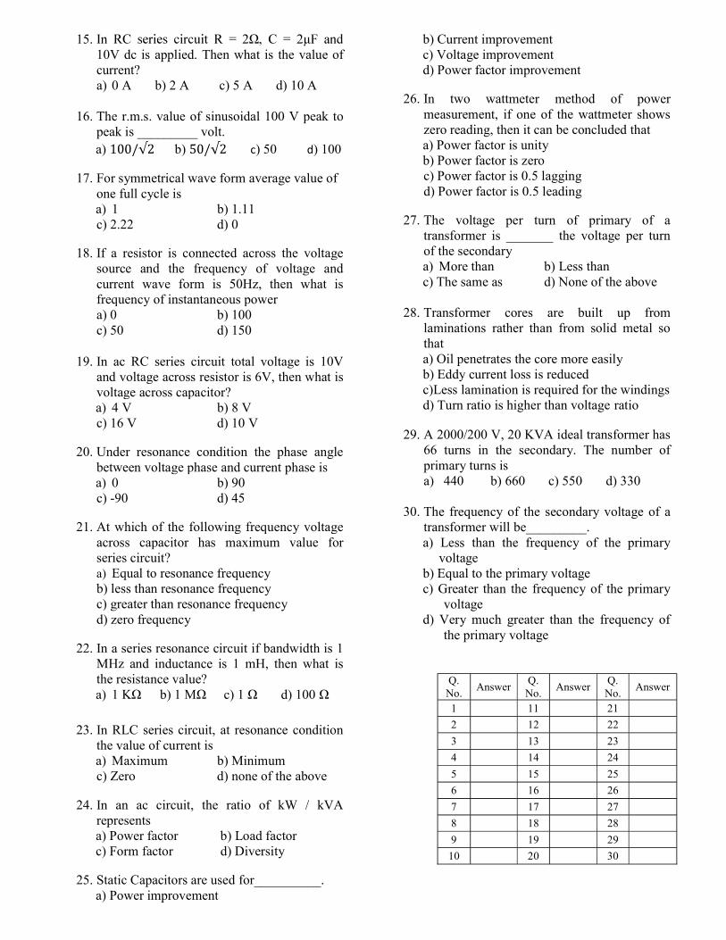
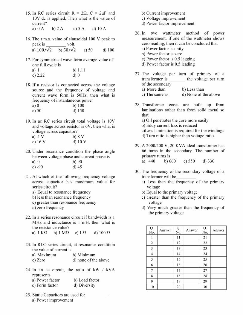
15. 10V dc is applied. Then what is the value of current?
a) 0 A b) 2 A c) 5 A d) 10 A
16. The r.m.s. value of sinusoidal 100 V peak to peak is _________ volt. a) b) c) 50 d) 100
17. For symmetrical wave form average value of one full cycle is a) 1 b) 1.11 c) 2.22 d) 0
18. If a resistor is connected across the voltage source and the frequency of voltage and current wave form is 50Hz, then what is frequency of instantaneous power a) 0 b) 100 c) 50 d) 150
19. In ac RC series circuit total voltage is 10V and voltage across resistor is 6V, then what is voltage across capacitor? a) 4 V b) 8 V c) 16 V d) 10 V
20. Under resonance condition the phase angle between voltage phase and current phase is
a) 0 b) 90 c) -90 d) 45
21. At which of the following frequency voltage across capacitor has maximum value for series circuit? a) Equal to resonance frequency b) less than resonance frequency c) greater than resonance frequency d) zero frequency
22. In a series resonance circuit if bandwidth is 1 MHz and inductance is 1 mH, then what is the resistance value? a) 1 K b) 1 M c) 1 d) 100
23. In RLC series circuit, at resonance condition
the value of current is
a) Maximum b) Minimum c) Zero d) none of the above
24. In an ac circuit, the ratio of kW / kVA represents a) Power factor b) Load factor c) Form factor d) Diversity
25. Static Capacitors are used for__________. a) Power improvement
b) Current improvement c) Voltage improvement d) Power factor improvement
26. In two wattmeter method of power measurement, if one of the wattmeter shows zero reading, then it can be concluded that a) Power factor is unity b) Power factor is zero c) Power factor is 0.5 lagging d) Power factor is 0.5 leading
27. The voltage per turn of primary of a transformer is _______ the voltage per turn of the secondary a) More than b) Less than c) The same as d) None of the above
28. Transformer cores are built up from laminations rather than from solid metal so that a) Oil penetrates the core more easily b) Eddy current loss is reduced c)Less lamination is required for the windings d) Turn ratio is higher than voltage ratio
29. A 2000/200 V, 20 KVA ideal transformer has 66 turns in the secondary. The number of primary turns is a) 440 b) 660 c) 550 d) 330
30. The frequency of the secondary voltage of a
transformer will be_________. a) Less than the frequency of the primary
voltage b) Equal to the primary voltage c) Greater than the frequency of the primary
voltage d) Very much greater than the frequency of
the primary voltage
Q. No.
Answer Q. No.
Answer Q. No.
Answer
1 11 21
2 12 22
3 13 23
4 14 24
5 15 25
6 16 26
7 17 27
8 18 28
9 19 29
10 20 30

QUESTION BANK 4
1. If the speed of rotation of a separately excited dc machine is halved and the filed strength
is also reduced to half of the original. Then the emf induced in the armature
a) reduces to 1/4th of original
b) reduces to half of original
c) remains same
d) doubles (Ans:A)
2. If the speed of rotation for a four pole, 220V dc machine is 1 m/s, flux density as 2T
having length of bore as 0.1m and radius of 0.5m.
The emf induced under pole faces will be
a) 0.2 V
b) 0.1 V
c) 0.2*pi V
d) 220 V (Ans:A)
3. The induced emf in the armature of a 4-pole dc machine is
a) directly proportional to speed and field strength applied to it
b) directly proportional to speed
c) directly proportional to field strength applied to it
d) inversely proportional to speed and inversely proportional to field strength applied to it
(Ans:A)
4. If the armature current is by mistake increased to 50% for the dc machine,
a) then the induced emf remains unchanged
b) then the induced emf doubles
c) then the induced emf halves
d) none of the mentioned (Ans:A)
5. For a four pole, 16 slot armature with two coil-side/slot having lap connected progressive
winding has single turn coils. The same machine is then wave wound, the emf induced in the
lap wound dc machine to that of wave wound will be
a) 2
b) 0.5
c) 1
d) 4 (Ans:B)
6. A duplex lap wound armature is used in six pole dc machine with six brush set. The
number of current paths in this machine is
a) 12
b) 6
c) 3
d) 2 (Ans:A)
7. For a four pole, 16 slot armature with two coil-side/slot having wave connected
progressive winding has single turn coils has simplex winding.
The number of current paths
a) 2
b) 6
c) 3
d) 4 (Ans:A)
8. For a four pole, 200 V dc shunt generator having armature resistance of 1 ohms. The
current flowing in the armature is 10 A. What is the back emf generated if the terminal
voltage of 220 V supply is fed?
a) 230 Volts
b) 210 Volts
c) 190 Volts
d) 200 Volts (Ans:A)
9. For a 4 pole 200 V, 20 A dc generator running at the rated rpm with no load will be
a) zero no load losses
b) 4000 W no load losses
c) negligible no load losses
d) none of the mentioned (Ans:A)
10. Which of the following cannot reduce the terminal voltage of a dc shunt generator?
a) Commutation
b) Armature reaction
c) Armature ohmic losses
d) Any of the mentioned (Ans:A)
11. What is the principle of torque production in a dc machine?
a) Lorentz’s law
b) Lenz’s law
c) Faraday’s law
d) Self inductance (Ans: A)
12. The torque induced beyond the pole shoes in the DC machine is
a) 0
b) 2/pi *phi *i
c) 4/pi *phi *i
d) none of the mentioned (Ans: A)
13. The simple rotating loop between pole faces connected to a battery and resistor through a
switch, the specifications of this machine are radius = 0.5m, length 1m, resistance = 0.3 ohms
and magnitude strength = 0.25T is supplied with 120V. Suddenly the switch is closed at t=0,
what is observed in the circuit?
a) Current will flow but zero induced EMF
b) Current will not flow and zero induced EMF
c) Current will not flow but EMF is induced
d) Current will flow and EMF will also be induced (Ans: A)
14. The simple rotating loop between pole faces connected to a battery and resistor through a
switch, the specifications of this machine are radius = 0.5m, length 1m, resistance = 0.3 ohms
and magnitude strength = 0.25T is supplied with 120V. What will be the magnitude of the
following current at t=0+?
a) 400A

b) 200A
c) 0
d) any of the mentioned (Ans: A)
15. If the torque induced is zero in the dc machine, it can be said that
a) current is zero
b) flux can be zero
c) current or flux=0
d) any of the mentioned (Ans:A)
16. The simple rotating loop between pole faces connected to a battery and resistor through a
switch, the specifications of this machine are radius = 0.5m, length 1m, resistance = 0.3 ohms
and magnitude strength = 0.25T is supplied with 120V. What is the steady state angular
velocity at no-load?
a) 480 rad/s
b) 960 rad/s
c) 320 rad/s
d) 490 rad/s (Ans: A)
17. If the torque is in the direction of rotation, the DC machine acts as
a) generator
b) motor
c) amplidyne
d) any of the mentioned (Ans: A)
18. The cogging torque is absent in the permanent magnet dc machine is due to
a) non-magnetic nature of rotor
b) magnetic nature of rotor
c) absence of ac supply
d) any of the mentioned (Ans: A)
19. DC Motor torque depends on
a) geometry
b) magnetic properties
c) any of the mentioned
d) both geometry and magnetic properties of the structure (Ans:D)
20. While comparing potential transformer to an auto transformer, a potential transformer
transfers power ________
a) conductively
b) inductively
c) both conductively as well as inductively
d) electromagnetic induction (Ans: A)
21. The statements which support the points that auto transformers are advantageous
I. Weight of conductor reduces
II. Ohmic losses reduces
III. Leakage reactance reduces
IV. Lower short-circuit current
a) I,II,III
b) II,III,IV
c) I,II,III,IV
d) I,IV (Ans: A)
22. The statements which support the points that auto transformers are advantageous
I. Weight of conductor reduces
II. Direct electrical contacts
III. Leakage reactance reduces
IV. Lower short-circuit current
a) I,III
b) II,III
c) I,II,III,IV
d) I,IV (Ans: A)
23. The statements which support the points that auto transformers are disadvantageous as
compared to 2-winding transformer
I. Weight of conductor reduces
II. Direct electrical contacts
III. Leakage reactance reduces
IV. Lower short-circuit current
a) I,III
b) II,III
c) II,IV
d) I,II,IV (Ans: C)
24. I. KVA rating : 1/(1-k)
II. Losses : (1-k)
III. Impedance drop = 1/(1-k)
Which of the above are correct for an auto transformer when compared to the identical rating
two winding transformer?
a) I,II
b) II,III
c) 1,III
d) I,II,III,IV (Ans: A)
25. The voltage regulation of a transformer at full-load 0.8 p.f leading is -2%. Its voltage
regulation at full load 0.8 p.f lagging
a) will be positive
b) will be negative
c) may be positive
d) may be negative (Ans: A)
26. The voltage regulation of a transformer depends on its
(A)equivalent reactance (B) equivalent resistance
(C)load power factor (D)transformer size
(E) load current
a) A,B,C,E
b) A,B,C,D,E
c) A,B,D,E
d) A,B,C,D (Ans: A)
27. Three transformers having identical dimensions but with core of iron, aluminium and
wood are wound with same number of turns and have same supply.
Then choose the order for hysteresis losses.
a) wood > aluminium > iron
b) aluminium > iron > wood
c) iron > wood > aluminium
d) iron > aluminium > wood (Ans: D)
28. Three transformers having identical dimensions but with core of iron, aluminium and
wood are wound with same number of turns and have same supply.
Then choose the order for eddy current losses.
a) wood > aluminium > iron
b) aluminium > iron > wood
c) iron > wood > aluminium
d) iron > aluminium > wood (Ans: A)
29. Maximum efficiency of a transformer for a constant load current , occurs at
a) at any p.f
b) zero p.f leading
c) zero p.f lagging
d) unity p.f (Ans: D)
30. A 1-phase tranformer has a leakage impedance of 1+ j4 Ω for primary and 3+ j11 Ω for
secondary windings. This transformer has
a) H.V primary
b) Medium voltage primary
c) L.V primary
d) L.V secondary (Ans: C)
31. If a transformer is at no load , then it will act like
a) a resistor at p.f =0
b) an inductive reactor at 0.2 lagging
c) a capacitive reactor at0.2 leading
d) an inductive reactor at 0.8 lagging (Ans:B)
PREPARED BY: Ms. SURBHI SINGH
QUESTION BANK
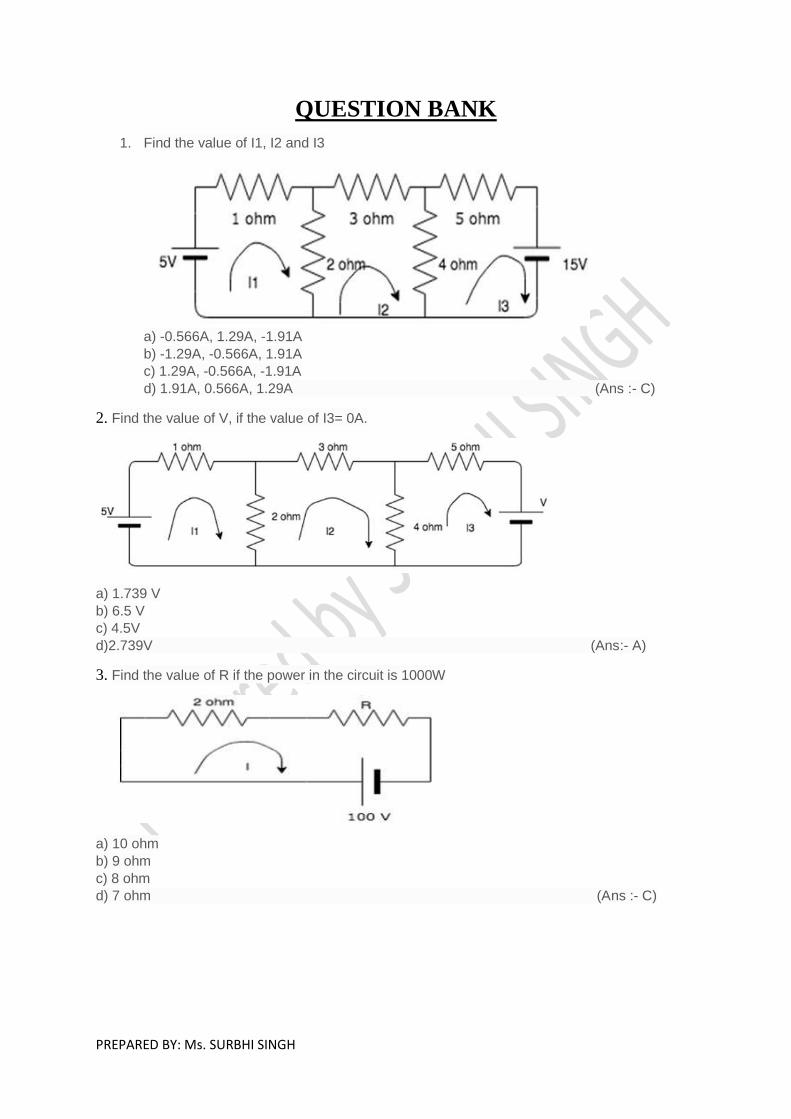
1. Find the value of I1, I2 and I3
a) -0.566A, 1.29A, -1.91A
b) -1.29A, -0.566A, 1.91A
c) 1.29A, -0.566A, -1.91A
d) 1.91A, 0.566A, 1.29A (Ans :- C)
2. Find the value of V, if the value of I3= 0A.
a) 1.739 V
b) 6.5 V
c) 4.5V
d)2.739V (Ans:- A)
3. Find the value of R if the power in the circuit is 1000W
a) 10 ohm
b) 9 ohm
c) 8 ohm
d) 7 ohm (Ans :- C)

PREPARED BY: Ms. SURBHI SINGH
4. Find the current in the 4 ohm resistor.
a) 5A
b) 0A
c) 2.2A
d) 20A (Ans:- B)
5. Nodal analysis is generally used to determine______
a) Voltage
b) Current
c) Resistance
d) Power (Ans:- A)
6. Mesh analysis is generally used to determine_________
a) Voltage
b) Current
c) Resistance
d) Power (Ans:-B)
7. What is the current in the circuit?
a) 0A
b) 15A
c) 5A
d) 10A (Ans:- A)
8. Does the 15A source have any effect on the circuit?
a) Yes
b) No
PREPARED BY: Ms. SURBHI SINGH
c) Cannot be determined
d) Yes, only when the 10V source is removed (Ans:-B)
9.KVL is associated with____________
a) Mesh analysis
b) Nodal analysis
c) Both mesh and nodal
d) Neither mesh nor nodal (Ans:-A)
10. KCL is associated with_________
a) Mesh analysis
b) Nodal analysis
c) Both mesh and nodal
d) Neither mesh nor nodal (Ans:-B)
11.It is preferable to connect bulbs in series or in parallel?
a) Series
b) Parallel
c) Both series and parallel
d) Neither series nor parallel (Ans:-B)
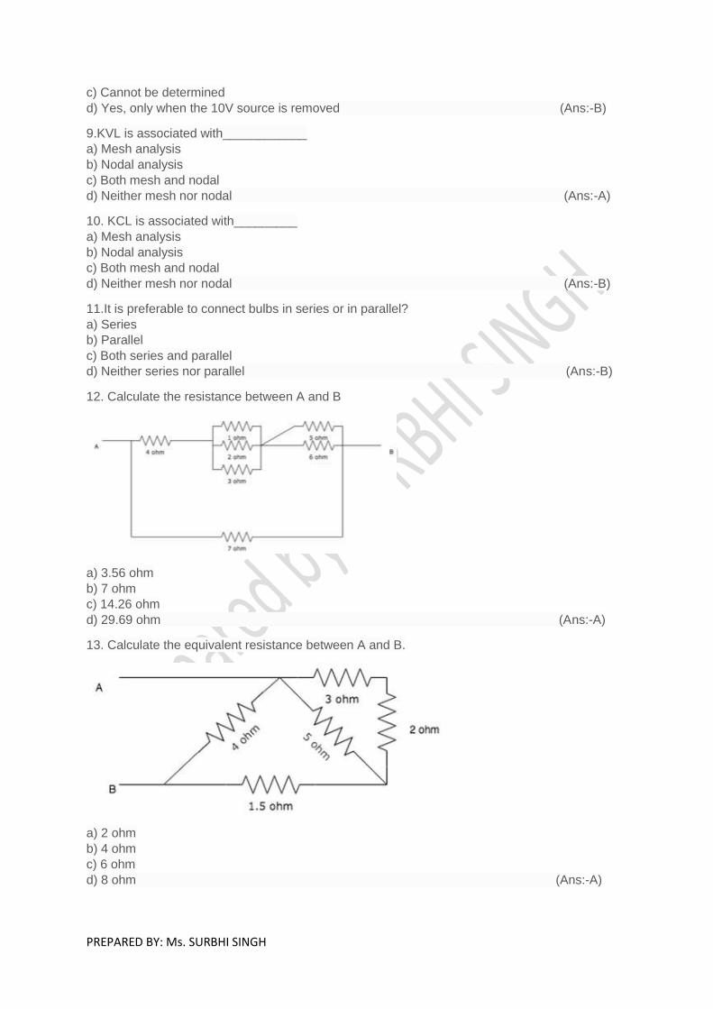
12. Calculate the resistance between A and B
a) 3.56 ohm
b) 7 ohm
c) 14.26 ohm
d) 29.69 ohm (Ans:-A)
13. Calculate the equivalent resistance between A and B.
a) 2 ohm
b) 4 ohm
c) 6 ohm
d) 8 ohm (Ans:-A)
PREPARED BY: Ms. SURBHI SINGH
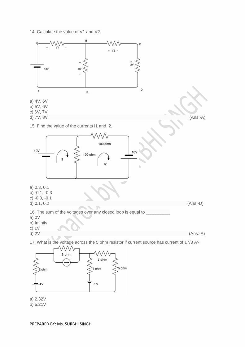
14. Calculate the value of V1 and V2.
a) 4V, 6V
b) 5V, 6V
c) 6V, 7V
d) 7V, 8V (Ans:-A)
15. Find the value of the currents I1 and I2.
a) 0.3, 0.1
b) -0.1, -0.3
c) -0.3, -0.1
d) 0.1, 0.2 (Ans:-D)
16. The sum of the voltages over any closed loop is equal to __________
a) 0V
b) Infinity
c) 1V
d) 2V (Ans:-A)
17. What is the voltage across the 5 ohm resistor if current source has current of 17/3 A?
a) 2.32V
b) 5.21V

PREPARED BY: Ms. SURBHI SINGH
c) 6.67V
d) 8.96V (Ans:-B)
18. Which of the following is not an expression power?
a) P=VI
b) P=I2R
c) P=V2/R
d) P=I/R (Ans:-D)
19. 4. Kilowatt-hour(kWh) is a unit of?
a) Current
b) Power
c) Energy
d) Resistance (Ans:-C)
20. Find the value of the node voltage V.
a) -60V
b) 60V
c) 40V
d) -40V (Ans:-A)
21. Find the node voltage V.
a) 1V
b) 2V
c) 3V
d) 4V (Ans:-D)
PREPARED BY: Ms. SURBHI SINGH
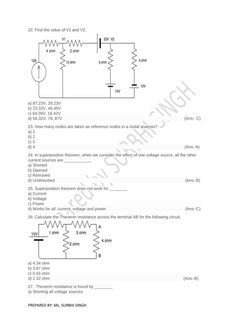
22. Find the value of V1 and V2.
a) 87.23V, 29.23V
b) 23.32V, 46.45V
c) 64.28V, 16.42V
d) 56.32V, 78, 87V (Ans:- C)
23. How many nodes are taken as reference nodes in a nodal analysis?
a) 1
b) 2
c) 3
d) 4 (Ans:-A)
24. In superposition theorem, when we consider the effect of one voltage source, all the other
current sources are ____________
a) Shorted
b) Opened
c) Removed
d) Undisturbed (Ans:-B)
25. Superposition theorem does not work for ________
a) Current
b) Voltage
c) Power
d) Works for all: current, voltage and power (Ans:-C)
26. Calculate the Thevenin resistance across the terminal AB for the following circuit.
a) 4.34 ohm
b) 3.67 ohm
c) 3.43 ohm
d) 2.32 ohm (Ans:-B)
27. Thevenin resistance is found by ________
a) Shorting all voltage sources
PREPARED BY: Ms. SURBHI SINGH
b) Opening all current sources
c) Shorting all voltage sources and opening all current sources
d) Opening all voltage sources and shorting all current sources (Ans:-C)
28. Thevenin’s theorem is true for __________
a) Linear networks
b) Non-Linear networks
c) Both linear networks and nonlinear networks
d) Neither linear networks nor non-linear networks (Ans:-A)
29. Which of the following is also known as the dual of Thevenin’s theorem?
a) Norton’s theorem
b) Superposition theorem
c) Maximum power transfer theorem
d) Millman’s theorem (Ans:-A)
30. Norton resistance is found by?
a) Shorting all voltage sources
b) Opening all current sources
c) Shorting all voltage sources and opening all current sources
d) Opening all voltage sources and shorting all current sources (Ans:-C)
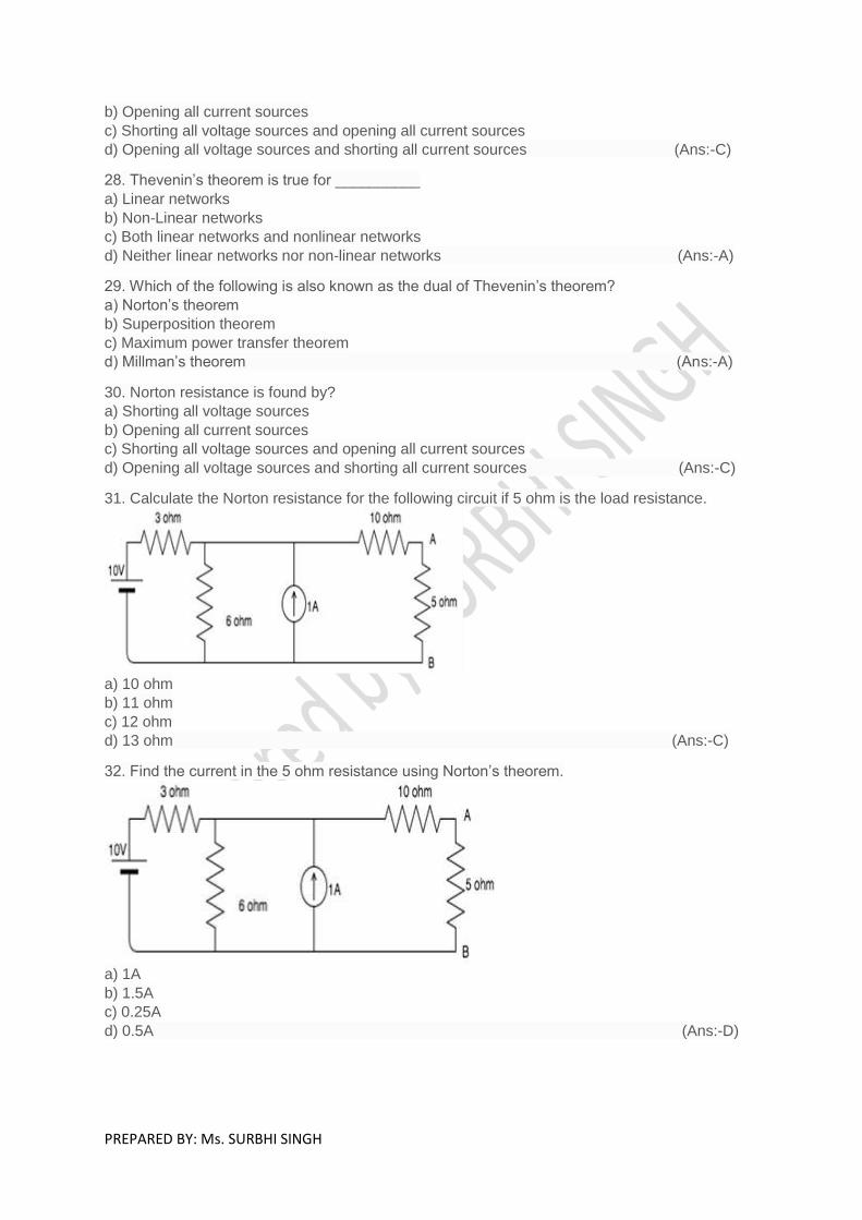
31. Calculate the Norton resistance for the following circuit if 5 ohm is the load resistance.
a) 10 ohm
b) 11 ohm
c) 12 ohm
d) 13 ohm (Ans:-C)
32. Find the current in the 5 ohm resistance using Norton’s theorem.
a) 1A
b) 1.5A
c) 0.25A
d) 0.5A (Ans:-D)

PREPARED BY: Ms. SURBHI SINGH
33. Find the equivalent delta circuit.
a) 9.69 ohm, 35.71 ohm, 6.59 ohm
b) 10.69 ohm, 35.71 ohm, 6.59 ohm
c) 9.69 ohm, 34.71 ohm, 6.59 ohm
b) 10.69 ohm, 35.71 ohm, 7.59 ohm (Ans:-A)
34. Which, among the following is the correct expression for star-delta conversion?
a) R1=Ra*Rb/(Ra+Rb+Rc), R2=Rb*Rc/(Ra+Rb+Rc), R3=Rc*Ra/(Ra+Rb+Rc)b)
b) R1=Ra/(Ra+Rb+Rc), R2=Rb/(Ra+Rb+Rc), Rc=/(Ra+Rb+Rc)
c) R1=Ra+Rb+Ra*Rb/Rc, R2=Rc+Rb+Rc*Rb/Ra, R3=Ra+Rc+Ra*Rc/Rb
d) R1=Ra*Rb/Rc, R2=Rc*Rb/Ra, R3=Ra*Rc/Rb (Ans:-C)
35. Find the equivalent resistance between X and Y.
a) 3.33 ohm
b) 4.34 ohm
c) 5.65 ohm
d) 2.38 ohm (Ans:-D)
36. Find the equivalent resistance between A and B.
a) 32ohm
b) 31ohm
c) 30ohm
d) 29ohm (Ans:-D)

PREPARED BY: Ms. SURBHI SINGH
37.

1. What is the relation between current and voltage in a capacitor?
a) I=1/C*integral(Vdt)
b) I=CdV/dt
c) I=1/CdV/dt
d) I=Ct (Ans:- B) 2. If 2V is supplied to a 3F capacitor, calculate the charge stored in the capacitor.
a) 1.5C
b) 6C
c) 2C
d) 3C (Ans:-B) 3. A 4microF capacitor is charged to 120V, the charge in the capacitor would be?
a) 480C
b) 480microC
c) 30C
d) 30microC (Ans:-B) 4. For high frequencies, capacitor acts as _________
a) Open circuit
b) Short circuit
c) Amplifier
d) Rectifier (Ans:-B) 5. Capacitance increases with ________
a) Increase in plate area
b) Decrease in plate area
c) Increase in distance between the plates
d) Increase in density of the material (Ans:-A) 6. What is the voltage across a capacitor at the time of switching, that is, when t=0?
a) Infinity
b) 0V
c) Cannot be determined
d) 1V (Ans:-B) 7. What is the voltage across the capacitor if the switch is closed and steady state is
reached?
a) 8V
b) 0V
c) 10V
d) Infinity (Ans:-C) 8. What happens to the current flow in a fully charged capacitor?
a) Current flow stops
b) Current flow doubles
c) Current flow becomes half its original value
d) Current flow becomes one-fourth its original value (Ans:-A)

9. What is the voltage across the 2F capacitor?
a) 240V
b) 200V
c) 220V
d) 120V (Ans:-D) 10. A capacitor does not allow sudden changes in _________
a) Current
b) Voltage
c) Resistance
d) Inductance (Ans:-B) 11. What is the magnetic field outside a solenoid?
a) Infinity
b) Half the value of the field inside
c) Double the value of the field inside
d) Zero (Ans:-D) 12. If the flow of electric current is parallel to the magnetic field, the force will be ______
a) Zero
b) Infinity
c) Maximum
d) Half the original value (Ans:-A) 13. What is the strength of magnetic field known as ________
a) Flux
b) Density
c) Magnetic strength
d) Magnetic flux density (Ans:-D) 14. Magnetic Field lines move from _______
a) North to south
b) South to north
c) West to east
d) East to west (Ans:-A) 15. Magnetic field lines form _________ loops from pole to pole.
a) Open
b) Closed
c) Branched
d) Either closed or branched (Ans:-B) 16. Do magnetic flux lines intersect?
a) Yes
b) No
c) Depends on the situation
d) Cannot be determined (Ans:-B) 17. More the number of magnetic flux lines _______ is the force of the magnet.
a) Greater
b) Lesser
c) Either greater or lesser
d) Neither greater nor lesser (Ans:-A)

18. The force existing between two infinite parallel conductors is inversely proportional to
________
a) Radius of the conductors
b) Current in one of the conductors
c) The product of the current in the two conductors
d) The distance between the two conductors (Ans:-D) 19. When the distance of operation between the two conductors increases, what happens to
the force between the two conductors?
a) Increases
b) Decreases
c) Remains the same
d) Becomes zero (Ans:-B) 20. Magnetic field at a point d distance away from long wire due to electric current i in it is
____________
a) µ0i/2r
b) µ0i/r
c) µ0i/2πr
d) µ0i/πr (Ans:-C) 21. Find the average value of current when the current that are equidistant are 4A, 5A and
6A.
a) 5A
b) 6A
c) 15A
d) 10A (Ans:-A) 22. What is the current found by finding the current in an equidistant region and dividing by
n?
a) RMS current
b) Average current
c) Instantaneous current
d) Total current (Ans:-B) 23. RMS stands for ________
a) Root Mean Square
b) Root Mean Sum
c) Root Maximum sum
d) Root Minimum Sum (Ans:-A) 24. __________ current is found by dividing the area enclosed by the half cycle by the length
of the base of the half cycle.
a) RMS current
b) Average current
c) Instantaneous current
d) Total current (Ans:-B) 25. In a sinusoidal wave, average current is always _______ rms current.
a) Greater than
b) Less than
c) Equal to
d) Not related (Ans:-B) 26. For a rectangular wave, average current is ______ rms current.
a) Greater than
b) Less than
c) Equal to
d) Not related (Ans:-C)
27. Peak value divided by the rms value gives us?
a) Peak factor
b) Crest factor
c) Both peak and crest factor
d) Neither peak nor crest factor (Ans:-C)
28. Calculate the crest factor if the peak value of current is 10A and the rms value is 2A.
a) 5
b) 10
c) 5A
d) 10A (Ans:-A)
29. If maximum value of current is 5√2 A, what will be the value of RMS current?
a) 10 A
b) 5 A
c) 15 A
d) 25 A (Ans:-B)
30. If Im is the maximum value of a sinusoidal voltage, what is the instantaneous value?
a) i=Im/2
b) i=Imsinθ
c) i=Imcosθ
d) i=Imsinθ or i=Imcosθ (Ans:-D)
31. What is the correct expression for the form factor?
a) Irms * Iav
b) Irms / Iav
c) Irms + Iav
d) Irms – Iav . (Ans:-B)
32. For a direct current, the rms current is ________ the mean current.
a) Greater than
b) Less than
c) Equal to
d) Not related to (Ans:-C)
33. If the maximum value of the current is 5√2 A, what will be the value of the average
current?
a) 10/π A
b) 5/π A
c) 15/π A
d) 25/π A (Ans:-A)
34. For addition and subtraction of phasors, we use the _________ form.
a) Rectangular
b) Polar
c) Either rectangular or polar
d) Neither rectangular nor polar (Ans:-A)
35. For multiplication and division of phasors, we use ____________ form.
a) Rectangular
b) Polar

c) Either rectangular or polar
d) Neither rectangular nor polar (Ans:-B)
36. If a voltage of 2+5j and another voltage of 3+ 6j flows through two different resistors,
connected in series, in a circuit, find the total voltage in the circuit.
a) 2+5j V
b) 3+6j V
c) 5+11j V
d) 5+10j V (Ans:-C)
37. What is the correct expression of ω?
a) ω=2π
b) ω=2πf
c) ω=πf
d) ω=2f2 (Ans:-B)
38. Find the value of ω if the frequency is 5Hz?
a) 3.14 rad/s
b) 31.4 rad/s
c) 34 rad/s
d) 341 rad/s (Ans:-B)
39. When one sine wave passes through the zero following the other, it is _________
a) Leading
b) Lagging
c) Neither leading nor lagging
d) Either leading or lagging (Ans:-B)
40. The time axis of an AC phasor represents?
a) Time
b) Phase angle
c) Voltage
d) Current (Ans:-B)
41. A phasor has frozen at 30 degrees, find the value of the phase angle.
a) 30 degrees
b) 60 degrees
c) 120 degrees
d) 180 degrees (Ans:-A)
42. The length of the phasor represents?
a) Magnitude of the quantity
b) Direction of the quantity
c) Neither magnitude nor direction
d) Either magnitude or direction (Ans:-A)
43. Ammeters and voltmeters are calibrated to read?
a) RMS value
b) Peak value
c) Average value
d) Instantaneous value (Ans:-A)
44. The rms value is 0.707 times the _________ value.
a) Peak
b) Instantaneous
c) Average
d) DC (Ans:-A)
45. If the phasors are drawn to represent the maximum values instead of the rms values,
what would happen to the phase angle between quantities?
a) Increases
b) Decreases
c) Remains constant
d) Becomes zero (Ans:-C)
46. Usually phasor diagrams are drawn representing?
a) RMS value
b) Peak value
c) Average value
d) Instantaneous value (Ans:-A)
47. At resonance, the capacitive energy is ___________ inductive energy.
a) Greater than
b) Less than
c) Equal to
d) Depends on the circuit (Ans:-C)
48. At resonance, electrostatic energy is ___________ the magnetic energy.
a) Greater than
b) Less than
c) Equal to
d) Depends on the circuit (Ans:-C)
49. The maximum magnetic energy stored in an inductor at any instance is?
a) E=LIm2/2
b) E=LIm/2
c) E=LIm2
d) E=LIm2*2 (Ans:-A)
50. Q is the ratio of?
a) Active power to reactive power
b) Reactive power to active power
c) Reactive power to average power
d) Reactive power to capacitive power (Ans:-C)
51. Find the value of Q if the reactive power is 10W and the average power is 5W.
a) 10
b) 5
c) 2
d) 1 (Ans:-C)
52. Find the reactive power when the average power is 5W and Q=2.
a) 10W
b) 5W

c) 2W
d) 1W (Ans:-A)
53. The SI unit for bandwidth is?
a) Hz
b) Watt
c) kHz
d) kW (ANS:-A)
54. At bandwidth frequency range, the value of the current I is?
a) I=Im/2
b) I=Im2
c) I=Im
d) I=Im/√2 (Ans:-D)

QUESTION BANK 3
1. What is the magnetic field outside a solenoid?
a) Infinity
b) Half the value of the field inside
c) Double the value of the field inside
d) Zero (Ans: D)
2. Can we see magnetic flux lines?
a) Yes
b) No
c) Depends on the strength of the field
d) Only when the field strength is very large (Ans:B)
3. The B/H curve can be used to determine?
a) Iron loss
b) Hysteresis loss
c) Voltage loss
d) Eddy current loss (Ans:B)
4. Hysteresis loss is determined from _______
a) B/H curve
b) H/B curve
c) BH curve
d) B2H curve (Ans:C)
5. A transformer cannot work on the DC supply because __________________
a) There is no need to change the DC voltage
b) A DC circuit has more losses
c) Faraday’s laws of electromagnetic induction are not valid since the rate of change of flux is
zero
d) Cannot be determined (Ans:C)
6. An ideal transformer has infinite primary and secondary inductances.
a) True
b) False
(Ans:B)
7. In a transformer the resistance between its primary and secondary is ______________
a) Zero
b) Very small
c) Cannot be predicted
d) Infinite (Ans:B)
8. Identify the correct statement relating to the ideal transformer.
a) no losses and magnetic leakage
b) interleaved primary and secondary windings
c) a common core for its primary and secondary windings
d) core of stainless steel and winding of pure copper metal (Ans:A)
9. An ideal transformer will have maximum efficiency at a load such that _____________
a) copper loss = iron loss
b) copper loss < iron loss
c) copper loss > iron loss
d) cannot be determined (Ans:A)
10. Which of the following statement regarding an ideal single-phase transformer is
incorrect? Transformer is having a turn ratio of 1: 2 and drawing a current of 10 A from 200
V AC supply is incorrect?
a) It’s a step-up transformer
b) Its secondary voltage is 400 V
c) Its rating is 2 kVA
d) Its secondary current is 20 A (Ans:D)
11. Ideal transformer core has permeability equal to _____
a) Zero
b) Non-zero finite
c) Negative
d) Infinite (Ans:D)
12.Turns ratio of the transformer is directly proportional to ____________
a) Resistance ratio
b) Currents ratio
c) Voltage ratio
d) Not proportional to any terms (Ans: C)
13. Which of the following statement is correct regarding turns ratio?
a) Current ratio and turns ratio are inverse of each other
b) Current ratio is exactly same to the voltage ratio
c) Currents ratio is exactly same to the turns ratio
d) Voltage ratio and turns ratio are inverse of each other (Ans: A)
14. Which of the following is the expression for emf induced in primary with voltage applied
to primary of an ideal transformer?
a) e=V
b) V= √2*e*cos ωt
c) e= √2*V*cos ωt
d) Cannot say (Ans:C)
15. Which of the following is the wrong expression?
a) i1N1=i2N2
b) i1v1=i2v2
c) i1N2=i2N1
d) v2N1=v1N2 (Ans:C)
16. For transformer given, turns ratio is equal to a, what will be the impedance of primary
with respect to secondary?

a) a2 times the secondary impedance
b) a times secondary impedance
c) secondary impedance/a
d) secondary impedance/a2 (Ans:D)
17. 13. Power transformed in the ideal transformer with turns ratio a is _______
a) a2 times primary
b) a times primary
c) primary power/ a2
d) primary power (Ans:D)
18. For a transformer with primary turns 100, secondary turns 400, if 200 V is applied at
primary we will get ___________
a) 80 V at secondary
b) 800 V at secondary
c) 1600 V at secondary
d) 3200 V at secondary (Ans:B)
19. For a transformer with primary turns 400, secondary turns 100, if 20A current is flowing
through primary, we will get ___________
a) 80A at secondary
b) 5A at secondary
c) 800A at secondary
d) 40A at secondary (Ans:A)
20. A transformer transforms ________________
a) voltage
b) current
c) power
d) frequency (Ans: C)
21. Greater the secondary leakage flux ___________
a) less will be the secondary induced emf
b) less will be the primary induced emf
c) less will be the primary terminal voltage
d) cannot be determined (Ans:A)
22. Which of the following is not the purpose of iron core in a step-up transformer?
a) to provide coupling between primary and secondary
b) to increase the magnitude of mutual flux
c) to decrease the magnitude of magnetizing current
d) to provide all above features (Ans:C)
23. In a transformer the tappings are generally provided on
a) Primary side
b) Secondary side
c) Low voltage side
d) Can be connected to any side (Ans:D)
24. Helical coils can be used at _____________
a) low voltage side of high kVA transformers
b) high frequency transformers
c) high voltage side of small capacity transformer
d) high voltage side of high kVA rating transformers (Ans:A)
25. In real transformer, primary winding has _________
a) Infinite resistance
b) Zero resistance
c) Some finite resistance
d) Cannot say (Ans:C)
26. Both resistances and leakage reactances of the transformer windings are __________
a) Series effects
b) Parallel effects
c) Series-parallel effects
d) Cannot say (Ans:A)
27. To convert an ideal transformer into a practical transformer we add ____________
a) Primary winding resistance and secondary winding resistance
b) Primary winding leakage reactance and secondary winding leakage reactance
c) Primary winding resistance, leakage and secondary winding leakage reactance
d) Cannot be determined (Ans:C)
28. Parallel parameters in a transformer equivalent circuit contains ___________
a) Gi and Bm
b) R1 and X1
c) R2 and X2
d) Cannot be determined (Ans:A)
29. When does capacitor is included in equivalent circuit of transformer?
a) Transformer of very high VA rating
b) Transformer with very high frequency operation
c) Transformer with less VA
d) Never (Ans:B)
30. The size of a transformer core will depend on _____________
a) frequency
b) area of the core
c) flux density of the core material
d) frequency and area of the core (Ans:D)

QUIZ (CO5)
1.) To reduce Electrical energy bill, power factor should be kept
a. as less as possible c. equal
b. as high as possible d. as close to unity as possible
2) Earth pit value resistance is measures in which type of meter a. Insulation megger c. Earth megger b. volt meter d. Am meter
3) Insulation value resistance of a cable is measures in which type of meter
a. Clip on meter c. Lux meter b. Insulation megger d. Earth megger
4) How many neutrals earth pits are there for one transformer in a sub-
station a. One c. Two b. Three d. Four
5) Minimum how many earth pits are there in a 11 KVsub-station a. Four c. Six
b. Eight d. Ten
6) Schedule maintenance for CLS panel is done
a. Weekly c. Fortnightly
b. Monthly d. Yearly
7) What is the earth resistance value for residential quarters
a. 1 Ohm c. 8 Ohms
b. 6 Ohms d. 10 Ohms
8) What type of earthing is found in 11 KV sub-station
a. plate type c. strip type
b. pipe type d. none of the above
9) Which type fire extinguisher is used for electrical fire
a. Water c. Foam
b. Co2 & dry powder d. None of the above

G Galgotias College of Engineering& Technology Gr. NoidaDepartment of EE
Lab Name: Basic Electrical Engineering Lab
LAY OUJT
30 X 30 feet
WINDOWS
CABIN PRACTICL TABLE PRACTICAL TABLE
PRACTICAL
TABLE
PRACTI CAL TABLE
PRACTICAL TABLE PRACTICAL TABLE
LABORATORY ENTRY/ EXIT
DOOR
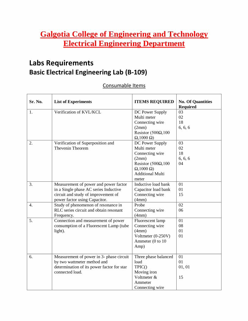
Galgotia College of Engineering and Technology
Electrical Engineering Department
Labs Requirements Basic Electrical Engineering Lab (B-109)
Consumable Items
Sr. No. List of Experiments ITEMS REQUIRED No. Of Quantities
Required
1. Verification of KVL/KCL DC Power Supply
Multi meter Connecting wire
(2mm)
Resistor (500Ω,100 Ω,1000 Ω)
03
02 18
6, 6, 6
2. Verification of Superposition and
Thevenin Theorem
DC Power Supply
Multi meter
Connecting wire (2mm)
Resistor (500Ω,100
Ω,1000 Ω) Additional Multi
meter
03
02
18 6, 6, 6
04
3. Measurement of power and power factor
in a Single phase AC series Inductive circuit and study of improvement of
power factor using Capacitor.
Inductive load bank
Capacitor load bank Connecting wire
(4mm)
01
01 15
4. Study of phenomenon of resonance in
RLC series circuit and obtain resonant Frequency.
Probe
Connecting wire (4mm)
02
06
5. Connection and measurement of power
consumption of a Fluorescent Lamp (tube light).
Fluorescent lamp
Connecting wire (4mm)
Voltmeter (0-250V)
Ammeter (0 to 10
Amp)
01
08 01
01
6. Measurement of power in 3- phase circuit
by two wattmeter method and determination of its power factor for star
connected load.
Three phase balanced
load TPIC()
Moving iron
Voltmeter &
Ammeter Connecting wire
01
01 01, 01
15
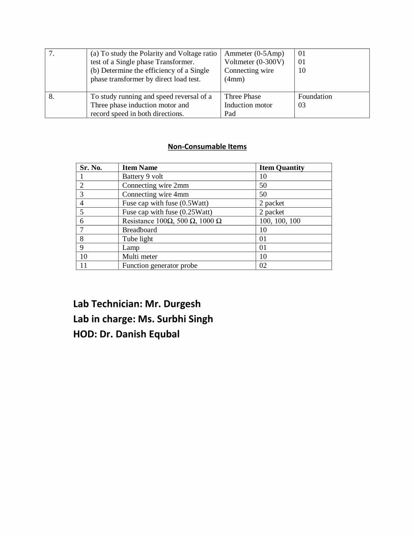
7. (a) To study the Polarity and Voltage ratio test of a Single phase Transformer.
(b) Determine the efficiency of a Single
phase transformer by direct load test.
Ammeter (0-5Amp) Voltmeter (0-300V)
Connecting wire
(4mm)
01 01
10
8. To study running and speed reversal of a
Three phase induction motor and
record speed in both directions.
Three Phase
Induction motor
Pad
Foundation
03
Non-Consumable Items
Sr. No. Item Name Item Quantity
1 Battery 9 volt 10
2 Connecting wire 2mm 50
3 Connecting wire 4mm 50
4 Fuse cap with fuse (0.5Watt) 2 packet
5 Fuse cap with fuse (0.25Watt) 2 packet
6 Resistance 100Ω, 500 Ω, 1000 Ω 100, 100, 100
7 Breadboard 10
8 Tube light 01
9 Lamp 01
10 Multi meter 10
11 Function generator probe 02
Lab Technician: Mr. Durgesh
Lab in charge: Ms. Surbhi Singh
HOD: Dr. Danish Equbal