INSTRUCTION MANUAL STRENGTH TRAINING SYSTEM
13
QUESTION? As a quality home gym supplier we are committed to your complete satisfaction. If you have questions, or find missing or damaged parts, we will guarantee your complete satisfaction through our authorized dealer service centers or our home office customer service department. Please call your local dealer for assistance or RSI at 800-990-5556 (9:00 AM - 5:00 PM). Our trained technicians will provide immediate assistance to you, free of charge. We stand behind our products. Every piece, every part of this BODYCRAFT strength training system is guaranteed for as long as you own it. We will repair or replace anything that goes wrong. Bodycraft is a division of Recreation Supply Inc. P.O. BOX 181 Sunbury, OH 43074 INSTRUCTION MANUAL STRENGTH TRAINING SYSTEM Press X
-
Upload
khangminh22 -
Category
Documents
-
view
3 -
download
0
Transcript of INSTRUCTION MANUAL STRENGTH TRAINING SYSTEM
QUESTION?
As a quality home gym supplier we are committed to your complete satisfaction. If you have questions,
or find missing or damaged parts, we will guarantee your complete satisfaction through our authorized
dealer service centers or our home office customer service department. Please call your local dealer
for assistance or RSI at 800-990-5556 (9:00 AM - 5:00 PM). Our trained technicians will provide
immediate assistance to you, free of charge.
We stand behind our products. Every piece, every part of this BODYCRAFT strength training system
is guaranteed for as long as you own it. We will repair or replace anything that goes wrong.
Bodycraft is a division of Recreation Supply Inc.P.O. BOX 181Sunbury, OH 43074
INSTRUCTION MANUAL
STRENGTH TRAINING SYSTEMPressX


PARTS CHARTNO. DESCRIPTION QTY.123456789101112131415161718192021222324252627282930313233343536373839404142434445464748495051525354555657585960
111112111111111111212234111211221222444481116244422211142222
BASE FRAMEREAR STABILIZERREAR UPRIGHTFRONT UPRIGHTTOP FRAMEGUIDE RODTOP GUIDE ROD RETAINERPRESS ARM SELECTORPRESS ARMFRONT STABILIZERSEAT FRAMELEG EXTENSION ARMLOW ROW CONNECTORFOOT PLATEFOOT PLATE ROLLERCHROME SEAT ADJUSTERSEAT BACK ADJUSTERLAT BAR HOLDERMETAL HINGECABLE ARM ASSEMBLYCABLE ARMSWIVEL CABLE TOPFOAM ROLLERPULLEY GUIDE BRACKETADJUSTABLE PULLEY BLOCKDOUBLE PULLEY BLOCKSINGLE PULLEY BLOCKWEIGHT SHROUDLAT BARLOW ROW BARPIVOT AXLECABLE ARM COLLARLEG EXTENSION AXLESLEEVESTEEL SPACERAXLE COLLARBEARING BASINBEARINGBEARING COVER50mm SQ. CAP50mm SQ. PLUG38mm SQ. PLUG30mm X 60mm RECT. PLUG25mm X 50mm RECT. PLUG1"ID FOAM ROLLER PLUG1" ROUND PLUGPLASTIC GUIDE ROD HOLDER1" STEEL BUSHING28.6 mm STEEL BUSHING1/2" STEEL BUSHINGPOP PIN (LONGER)POP PIN (SHORTER)SPRING KNOBSELECTOR PINL PIN1-1/2" X120mm HAND GRIP1" X 200mm HAND GRIP1" X 140mm HAND GRIP1" X 70mm PRESS ARM STOPPERGRIP OF LAT BAR HOLDER (95mm)
3
1 2
3
4
11
16
18
20
21 22
17
19
12
13 14 15
28
24
2523
26 27
31 32
29 30
33 34
35 36 37 38 39
56 57 58 59 60
48 49 51 5350 52 54 55
40 41 43 4542 44 46 47
5
6
7
8
9
10

PARTS CHART
0(inch)
1" 2" 3"1/21/4 3/4 1/2 1/2 4" 5" 6"1/2 1/2 1/2
NO. DESCRIPTION QTY.616263646566676869707172737475767778798081828384858687888990919293949596979899100101102103104105106107108109110111
3122221119146121611111114241113442123482255244104228442111
BIG PULLEYSMALL PULLEY OF SWIVEL ARMRUBBER DONUTADJUSTABLE STOPPERFOOT PLATE STOPPERBACK BRACKET STOPPERTOP PLATE10 LB. PLATESELECTOR RODNON SLIPSNAP HOOKLOW ROW CHAINHAND GRIP OF CABLE ARMAB CRUNCHFOAM PADBACK PADSEAT PADAB CRUNCH CABLE (4420mm)CABLE ARM CONNECTING CABLE (4710mm)TOP CABLE (4630mm)CABLE ARM CABLE (5410mm)HEAD OF CABLE ARM CABLEBINDING OF WEIGHT SHROUD1/2" X 4" HEX HEAD BOLT1/2" X 3" HEX HEAD BOLT3/8" X 5-3/4" HEX HEAD BOLT3/8" X 4-1/2" HEX HEAD BOLT3/8" X 3" HEX HEAD BOLT3/8" X 2-3/4" HEX HEAD BOLT3/8" X 2-1/2" HEX HEAD BOLT3/8" X 1-3/4" HEX HEAD BOLT3/8" X 1-3/4" HEX HEAD BOLT (ALL)3/8" X 1" HEX HEAD BOLT (ALL)3/8" X 1/2" ROUND BOLT 5/16" X 1/2" HEX HEAD BOLT (ALL)5/16" X 1-1/2" SET SCREW5/16" X 5/8" SET SCREW3/8" X 13mm SET SCREW5/16" X 1/4" SET SCREW1/2" WASHER3/8" WASHER5/16" WASHER3/8" SPRING WASHER5/16" SPRING WASHER 24mm NYLON NUT1/2" NYLON NUT3/8" NYLON NUT5/16" NYLON NUTTOP PLATE BOLT3/8" X 3/4" SET SCREWANKLE STRAP
4
78
79
82
83
86
80
76
74
77
69
67 68
75
81
878584
72 737170
63 64 65 666261
90 918988
94 959392
105 106 107 108 109
100 101 102 103 104
11096 97 98 99
111

1
4
5
3
7
2
46
15
46
85
85 10
40
88
40
40
54
88
69
47
84 84
41
85
8543
89
67
68
63
6
6
47
13
14
65
65
40
98
106
100
101
106 106
101107
106
107 107 101
109101
101
101106
106
STEP 1 ASSEMBLE MAIN FRAME
5
To ease the assembly process, do not tighten bolts until instructed.
1. Attach Rear Stabilizer(2) to Base Frame(1) using two 3/8"X3" Bolts(88), four 3/8" Washers(101) and two Nuts(107). Attach Front Stabilizer(10) and Low Row Connector(13) to Base Frame(1) using two 1/2"X3" Bolts(85), and two Nuts(106). Cap Rear Stabilizer and Front Stabilizer with four 50mm SQ. Cap(40).
2. Attach two Foot Plate Stoppers(65) onto Low Row Connector(13). Attach the Foot Plate(14) to Low Row Connector(13) by aligning the holes and inserting Foot Plate Roller(15).Insert two 1" Round Plug (46) into the Foot Plate Roller(15).
3. Attach Rear Upright(3) to Rear Stabilizer(2) using two 1/2" Washer(100) and Nuts(106).4. Attach Front Upright(4) to Base Frame(2) using two 3/8"X3" Bolts(88), four Washers(101) and two Nuts
(107).5. Attach Top Frame(5) to Front Upright(4) using two 1/2"X4" Bolts(84) and two Nuts(106). Attach Top
Frame(5) to Rear Upright(3) using two 1/2"X3" Bolts(85) and two Nuts(106).6. Insert four Plastic Guide Rod Holders(47) into Base Frame and Top Guide Rod Retainer(7) as shown.
Slide a Rubber Donut(63) onto one end of each Guide Rod(6) and then insert the Guide Rods into the Plastic Guide Rod Holders in Base Frame as shown.
7. Slide each 10 Lb. Plate(68) over guide rods. Make certain that each plate is oriented with selector hole on bottom and facing forward. Attach Top Plate(67) to Selector Rod(69) using Top Plate Bolt(109). Slide Top Plate and Selector Rod(69) onto Guide Rods(6).
8. Slide Top Guide Rod Retainer(7) over top of Guide Rods(6) and attach Top Guide Rod Retainer(7) to Top Frame(5), using two 3/8"X2-3/4" Bolts, four 3/8" Washers and two Nuts(107). Attach 50mm Plug onto Rear Upright(3) and 30mmX60mm Plug onto rear of Top Frame
31
98
8898
18
9
5
8
4
1
31
49
49
41
4141
41
41
49
49
3548
35
48
48 36
99
88
88
21
4836
99
20
2181
41
101
101
107
101
101
107
101
101
107
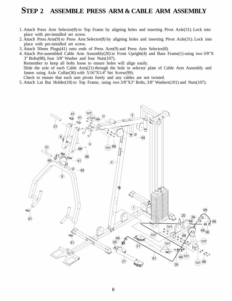
STEP 2 ASSEMBLE PRESS ARM & CABLE ARM ASSEMBLY
6
1. Attach Press Arm Selector(8) to Top Frame by aligning holes and inserting Pivot Axle(31). Lock into place with pre-installed set screw.
2. Attach Press Arm(9) to Press Arm Selector(8) by aligning holes and inserting Pivot Axle(31). Lock into place with pre-installed set screw.
3. Attach 50mm Plugs(41) onto ends of Press Arm(9) and Press Arm Selector(8).4. Attach Pre-assembled Cable Arm Assembly(20) to Front Upright(4) and Base Frame(1) using two 3/8"X
3" Bolts(88), four 3/8" Washer and four Nuts(107). Remember to keep all bolts loose to ensure holes will align easily. Slide the axle of each Cable Arm(21) through the hole in selector plate of Cable Arm Assembly and
fasten using Axle Collar(36) with 5/16"X1/4" Set Screw(99). Check to ensure that each arm pivots freely and any cables are not twisted.5. Attach Lat Bar Holder(18) to Top Frame, using two 3/8"X3" Bolts, 3/8" Washers(101) and Nuts(107).

28
87
75
45
75
97
23
4
97
16
88
99
99
99
23
5588
44
17
93
23
45
75
45
7545
12 11
33
4292
41
28
1
7
95
95
101
102101
104
102
104101
101
107
107
101
101
107
102
102
95
95
102
102
75
77
76
75
19
45
45
STEP 3 ASSEMBLE SEAT FRAME AND SEAT BACK
7
1. Attach Seat Frame(11) to Front Upright(4) using two 3/8"X3" Bolts(88) four 3/8" Washers(101) and two Nuts(107). Attach Seat Frame(11) to Base Frame(1) using one 3/8"X4-1/2" Bolt(87), two 3/8" Washers (101) and one Nut(107).
2. Attach Leg Extension Arm(12) to Seat Frame(11) by aligning holes and then inserting Leg Extension Axle(33). Fasten Leg Extension Axle(33) using two 5/16" Spring Washers(104), 5/16" Washers(102), and two 5/16"X5/8" Set Screws(97). Check to ensure that the Leg Extension Arm(12) pivots freely.
Note: The L Pin(55) is used to lock the Leg Extension Arm(12) into place when using the low cable for exercises such as arm curls, leg kicks, upright rows, etc. Remove the L Pin when performing leg extensions and leg curls.3. Insert Foam Roller(23) into hole in Seat Adjuster(16) and into hole in Leg Extension Arm(12). Moisten
Foam Pad(75) with water and slide onto each end of Foam Rollers(23). Attach 1" large Round Plug (45) to Foam Roller(23). A rubber mallet is useful. Lock into place with pre-installed set screw.
4. Attach Seat Pad(77) to Seat Adjuster(16) using two 3/8" Washers(101), and two 3/8"X1-3/4" Bolts(92). Attach 25mmX50 Plug(44) to Seat Adjuster and 50mm SQ. Plug(40) to Seat Frame(11). Insert Chromed Seat Adjuster(16) into Seat Frame(11) and lock into place with Pop Pin(53).
5. Attach Seat Back Adjuster(17) to Front Upright(4), using one 3/8"X3" Bolt(88) and 3/8" Nut(107). It may be necessary to tighten this bolt, then lossen just enough to let Seat Back Adjuster pivot freely. Attach Pop Pin(53) for Seat Back Adjuster to Front Upright(4). Attach two Metal Hinges(19) to top of Seat Back Adjuster(17), then attach Back Pad(76) to Metal Hinges(19) using two 3/8"X1-3/4" Bolts(93) and 3/8" Washers(101). Insert Foam Roller(23) into hole in Seat Back Adjuster(17). Moisten two Foam Pads(75) with water and slide onto each end of Foam Roller, then cap Foam Roller(23) with 1" large Round Plug(45). Lock into place with pre-installed set screw.
6. Attach Weight Shroud(28) to Base Frame(1) and Top Guide Rod Retainer(7) using four 5/16"X1/2" Bolts (95) and Washers(102).

FIG 10
FIG 1
FIG 5
FIG 3FIG 6
FIG 4
FIG 2
FIG 5
FIG 8
FIG 7
FIG 9
FIG 1 FIG 2 FIG 3 FIG 3
FIG 4 FIG 5
FIG 6 FIG 7
FIG 8
FIG 10
FIG 9
STP 1 STP 2
61
61
61
80
80
61
2580
71
80
69
61
61
101
101
101
101
107
90
91
89
91
2957 57
90
107 107
107
107
80 61
101
101
107
904
4
5
8
6164
5
80
26
91
TOP CABLE 182" (4630mm) length
8
Assemble cables and pulleys simultaneously.
Insert threaded end of Top Cable(80) into the slot in front of Top Frame(5)(Fig 1) and route over top oftwo pulleys mounted in Top Frame (Fig 1, 2), over left side (as if sitting on seat) pulley in Press Arm Selector (8) (Fig 3, Step 1), under pulley mounted in Front Upright, over right side pulley in Press ArmSelector (Fig 3, Step 2), then over pulley mounted in Front Upright (Fig 3, Fig 4), down to top Double Pulley Block(26)(Fig 6), up and over left side pulley on Top Frame(Fig 7), down and around top pulley in Adjustable Pulley Block(25)(Fig 8), up and over twoTop Frame pulleys leading to weight stack. Screw cable end into Selector Rod(69)(Fig 9).

Route the AB Crunch Cable(78) through slot and over pulley on Front Upright(Fig 1), down to the frontpulley on top of Cable Arm Assembly(Fig 2), then up to lower pulley on double pulley block(26)(Fig 3),down through the rear pulley on Cable Arm Assembly (Fig 4) to pulley on Base Frame (Fig 2), then forward toward Leg Extension Arm. Route AB Crunch Cable under both pulleys on Base Frame and under pulley on Leg Extension Arm.
61
61
61
61
74
6178
26
91
91
9130
58
58
9189
78
78
71
72
71
78
12
7871
107
107
107
107
107
101
101
FIG 1
FIG 5 FIG 7
FIG 6
FIG 2 FIG 3 FIG 4
FIG 3
FIG 6
FIG 1
FIG 2FIG 5
FIG 7
FIG 2
FIG 2FIG 4
AB CRUNCH CABLE 174" (4420mm) length
9

Attach pulley on base frame near weight stack as shown Fig 1 with ball end of cable toward weightstack. Route cable up to low pulley of adjustable pulley block (Fig 2), then down to pulley on BaseFrame (Fig 3), up to right side pulley in Top Frame (Fig 4) and thread into the Single Pulley Block(27)(Fig 5).
79
61
61
25
91
79
91
107
107
79
27
79
61
61
61
61
89
91
91
107
107
107
FIG 1
FIG 2
FIG 3
FIG 4FIG 5
FIG 4
FIG 2
FIG 5
FIG 3
FIG 1
CABLE ARM CONNECTING CABLE 185" (4710mm) length
10

Attach pulley and Pulley Guide Bracket(24) to Cable Arm Assembly as shown in Fig 3 and Fig 4, Becertain that, when tightened, the Pulley Guide Brackets do not interfere with the cable movement.Route Cable Arm Cable (81) around these pulleys as shown and around pulley in the Single PulleyBlock (27)(Fig 5).
27
81
96 61
61
91
22 62383238
81 71 73
39 37 37 3991
34
94
8182
24
24
86
61
61
107
107
103
108105 107
101
101
96
36 4848
20 35 21
61
22 6261
6120
9124383238
39 37 37 3991
34
9994
8191
103
108105 107107
107
FIG 1 FIG 2 FIG 3
FIG 4 FIG 5
FIG 6
FIG 7
FIG 5
FIG 6
FIG 7
FIG 7
FIG 2
FIG 2
FIG 3
FIG 1
FIG 4
CABLE ARM CABLE 213" (5410mm) length
11