
gjadi-fix-mmm-link PDF - MicroEJ Documentation
420
MicroEJ Documentation MicroEJ Corp. Revision 1ee Nov , Copyright -, MicroEJ Corp. Content in this space is free for read and redistribute. Except if otherwise stated, modification is subject to MicroEJ Corp prior approval. MicroEJ is a trademark of MicroEJ Corp. All other trademarks and copyrights are the property of their respective owners.
-
Upload
khangminh22 -
Category
Documents
-
view
3 -
download
0
Transcript of gjadi-fix-mmm-link PDF - MicroEJ Documentation

MicroEJ Documentation
MicroEJ Corp.
Revision 1e46e643
Nov 25, 2020Copyright 2008-2020, MicroEJ Corp. Content in this space is free for read and redistribute. Except if otherwise stated,
modification is subject to MicroEJ Corp prior approval. MicroEJ is a trademark of MicroEJ Corp. All other trademarks andcopyrights are the property of their respective owners.

CONTENTS
1 MicroEJ Glossary 2
2 Overview 42.1 MicroEJ Editions . . . . . . . . . . . . . . . . . . . . . . . . . . . . . . . . . . . . . . . . . . . . . 4
2.1.1 Introduction . . . . . . . . . . . . . . . . . . . . . . . . . . . . . . . . . . . . . . . . . . 42.1.2 Determine the MicroEJ Studio/SDK Version . . . . . . . . . . . . . . . . . . . . . . . . . . 5
2.2 MicroEJ Runtime . . . . . . . . . . . . . . . . . . . . . . . . . . . . . . . . . . . . . . . . . . . . . 72.2.1 Language . . . . . . . . . . . . . . . . . . . . . . . . . . . . . . . . . . . . . . . . . . . . 72.2.2 Scheduler . . . . . . . . . . . . . . . . . . . . . . . . . . . . . . . . . . . . . . . . . . . . 72.2.3 Garbage Collector . . . . . . . . . . . . . . . . . . . . . . . . . . . . . . . . . . . . . . . 72.2.4 Foundation Libraries . . . . . . . . . . . . . . . . . . . . . . . . . . . . . . . . . . . . . . 7
2.3 MicroEJ Libraries . . . . . . . . . . . . . . . . . . . . . . . . . . . . . . . . . . . . . . . . . . . . 82.4 MicroEJ Central Repository . . . . . . . . . . . . . . . . . . . . . . . . . . . . . . . . . . . . . . . 82.5 Embedded Specification Requests . . . . . . . . . . . . . . . . . . . . . . . . . . . . . . . . . . . 92.6 MicroEJ Firmware . . . . . . . . . . . . . . . . . . . . . . . . . . . . . . . . . . . . . . . . . . . . 9
2.6.1 Bootable Binary with Core Services . . . . . . . . . . . . . . . . . . . . . . . . . . . . . . 92.6.2 Specification . . . . . . . . . . . . . . . . . . . . . . . . . . . . . . . . . . . . . . . . . . 10
2.7 Introducing MicroEJ SDK . . . . . . . . . . . . . . . . . . . . . . . . . . . . . . . . . . . . . . . . 102.8 Introducing MicroEJ Studio and Virtual Devices . . . . . . . . . . . . . . . . . . . . . . . . . . . . 112.9 Perform Online Getting Started . . . . . . . . . . . . . . . . . . . . . . . . . . . . . . . . . . . . . 122.10 GitHub Repositories . . . . . . . . . . . . . . . . . . . . . . . . . . . . . . . . . . . . . . . . . . . 132.11 System Requirements . . . . . . . . . . . . . . . . . . . . . . . . . . . . . . . . . . . . . . . . . . 18
3 Application Developer Guide 193.1 Introduction . . . . . . . . . . . . . . . . . . . . . . . . . . . . . . . . . . . . . . . . . . . . . . . 193.2 Licenses . . . . . . . . . . . . . . . . . . . . . . . . . . . . . . . . . . . . . . . . . . . . . . . . . 19
3.2.1 Overview . . . . . . . . . . . . . . . . . . . . . . . . . . . . . . . . . . . . . . . . . . . . 193.2.2 Installation . . . . . . . . . . . . . . . . . . . . . . . . . . . . . . . . . . . . . . . . . . . 203.2.3 Evaluation Licenses . . . . . . . . . . . . . . . . . . . . . . . . . . . . . . . . . . . . . . 203.2.4 Production Licenses . . . . . . . . . . . . . . . . . . . . . . . . . . . . . . . . . . . . . . 21
3.3 Local Workspaces and Repositories . . . . . . . . . . . . . . . . . . . . . . . . . . . . . . . . . . . 243.4 Standalone Application . . . . . . . . . . . . . . . . . . . . . . . . . . . . . . . . . . . . . . . . . 24
3.4.1 Download and Install a MicroEJ Platform . . . . . . . . . . . . . . . . . . . . . . . . . . . 243.4.2 Build and Run an Application . . . . . . . . . . . . . . . . . . . . . . . . . . . . . . . . . 273.4.3 Build Output Files . . . . . . . . . . . . . . . . . . . . . . . . . . . . . . . . . . . . . . . 323.4.4 MicroEJ Launch . . . . . . . . . . . . . . . . . . . . . . . . . . . . . . . . . . . . . . . . . 333.4.5 Application Options . . . . . . . . . . . . . . . . . . . . . . . . . . . . . . . . . . . . . . 373.4.6 SOAR . . . . . . . . . . . . . . . . . . . . . . . . . . . . . . . . . . . . . . . . . . . . . . 64
3.5 Sandboxed Application . . . . . . . . . . . . . . . . . . . . . . . . . . . . . . . . . . . . . . . . . 653.5.1 Sandboxed Application Structure . . . . . . . . . . . . . . . . . . . . . . . . . . . . . . . 65
i

3.5.2 Application Publication . . . . . . . . . . . . . . . . . . . . . . . . . . . . . . . . . . . . 663.5.3 Shared Interfaces . . . . . . . . . . . . . . . . . . . . . . . . . . . . . . . . . . . . . . . . 66
3.6 Virtual Device . . . . . . . . . . . . . . . . . . . . . . . . . . . . . . . . . . . . . . . . . . . . . . 703.6.1 Using a Virtual Device for Simulation . . . . . . . . . . . . . . . . . . . . . . . . . . . . . 703.6.2 Runtime Environment . . . . . . . . . . . . . . . . . . . . . . . . . . . . . . . . . . . . . 70
3.7 MicroEJ Module Manager . . . . . . . . . . . . . . . . . . . . . . . . . . . . . . . . . . . . . . . . 713.7.1 Introduction . . . . . . . . . . . . . . . . . . . . . . . . . . . . . . . . . . . . . . . . . . 713.7.2 Specification . . . . . . . . . . . . . . . . . . . . . . . . . . . . . . . . . . . . . . . . . . 723.7.3 Module Project Skeleton . . . . . . . . . . . . . . . . . . . . . . . . . . . . . . . . . . . . 723.7.4 Module Description File . . . . . . . . . . . . . . . . . . . . . . . . . . . . . . . . . . . . 733.7.5 MicroEJ Module Manager Configuration . . . . . . . . . . . . . . . . . . . . . . . . . . . 733.7.6 Build Kit . . . . . . . . . . . . . . . . . . . . . . . . . . . . . . . . . . . . . . . . . . . . . 773.7.7 Former MicroEJ SDK Versions . . . . . . . . . . . . . . . . . . . . . . . . . . . . . . . . . 77
3.8 Module Natures . . . . . . . . . . . . . . . . . . . . . . . . . . . . . . . . . . . . . . . . . . . . . 793.8.1 Module Repository . . . . . . . . . . . . . . . . . . . . . . . . . . . . . . . . . . . . . . . 79
3.9 MicroEJ Classpath . . . . . . . . . . . . . . . . . . . . . . . . . . . . . . . . . . . . . . . . . . . . 833.9.1 Application Classpath . . . . . . . . . . . . . . . . . . . . . . . . . . . . . . . . . . . . . 833.9.2 Classpath Load Model . . . . . . . . . . . . . . . . . . . . . . . . . . . . . . . . . . . . . 843.9.3 Classpath Elements . . . . . . . . . . . . . . . . . . . . . . . . . . . . . . . . . . . . . . 85
3.10 Application Resources . . . . . . . . . . . . . . . . . . . . . . . . . . . . . . . . . . . . . . . . . . 883.10.1 Images . . . . . . . . . . . . . . . . . . . . . . . . . . . . . . . . . . . . . . . . . . . . . 883.10.2 Fonts . . . . . . . . . . . . . . . . . . . . . . . . . . . . . . . . . . . . . . . . . . . . . . 933.10.3 Native Language Support . . . . . . . . . . . . . . . . . . . . . . . . . . . . . . . . . . . 94
3.11 Development Tools . . . . . . . . . . . . . . . . . . . . . . . . . . . . . . . . . . . . . . . . . . . 953.11.1 Testsuite with JUnit . . . . . . . . . . . . . . . . . . . . . . . . . . . . . . . . . . . . . . 963.11.2 Font Designer . . . . . . . . . . . . . . . . . . . . . . . . . . . . . . . . . . . . . . . . . . 993.11.3 Stack Trace Reader . . . . . . . . . . . . . . . . . . . . . . . . . . . . . . . . . . . . . . . 1073.11.4 Code Coverage Analyzer . . . . . . . . . . . . . . . . . . . . . . . . . . . . . . . . . . . . 1143.11.5 Heap Dumper & Heap Analyzer . . . . . . . . . . . . . . . . . . . . . . . . . . . . . . . . 1173.11.6 ELF to Map File Generator . . . . . . . . . . . . . . . . . . . . . . . . . . . . . . . . . . . 1283.11.7 Serial to Socket Transmitter . . . . . . . . . . . . . . . . . . . . . . . . . . . . . . . . . . 1303.11.8 Memory Map Analyzer . . . . . . . . . . . . . . . . . . . . . . . . . . . . . . . . . . . . . 1313.11.9 Event Tracing . . . . . . . . . . . . . . . . . . . . . . . . . . . . . . . . . . . . . . . . . . 134
3.12 Advanced Tools . . . . . . . . . . . . . . . . . . . . . . . . . . . . . . . . . . . . . . . . . . . . . 1363.12.1 MicroEJ Linker . . . . . . . . . . . . . . . . . . . . . . . . . . . . . . . . . . . . . . . . . 1363.12.2 Testsuite Engine . . . . . . . . . . . . . . . . . . . . . . . . . . . . . . . . . . . . . . . . 149
4 Platform Developer Guide 1534.1 Introduction . . . . . . . . . . . . . . . . . . . . . . . . . . . . . . . . . . . . . . . . . . . . . . . 153
4.1.1 Scope . . . . . . . . . . . . . . . . . . . . . . . . . . . . . . . . . . . . . . . . . . . . . . 1534.1.2 Intended Audience . . . . . . . . . . . . . . . . . . . . . . . . . . . . . . . . . . . . . . . 1534.1.3 MicroEJ Architecture Modules Overview . . . . . . . . . . . . . . . . . . . . . . . . . . . 153
4.2 MicroEJ Platform . . . . . . . . . . . . . . . . . . . . . . . . . . . . . . . . . . . . . . . . . . . . 1554.2.1 Process Overview . . . . . . . . . . . . . . . . . . . . . . . . . . . . . . . . . . . . . . . . 1554.2.2 Concepts . . . . . . . . . . . . . . . . . . . . . . . . . . . . . . . . . . . . . . . . . . . . 1564.2.3 MicroEJ Platform Creation . . . . . . . . . . . . . . . . . . . . . . . . . . . . . . . . . . . 161
4.3 MicroEJ Core Engine . . . . . . . . . . . . . . . . . . . . . . . . . . . . . . . . . . . . . . . . . . . 1714.3.1 Functional Description . . . . . . . . . . . . . . . . . . . . . . . . . . . . . . . . . . . . . 1714.3.2 Architecture . . . . . . . . . . . . . . . . . . . . . . . . . . . . . . . . . . . . . . . . . . . 1724.3.3 Capabilities . . . . . . . . . . . . . . . . . . . . . . . . . . . . . . . . . . . . . . . . . . . 1724.3.4 Implementation . . . . . . . . . . . . . . . . . . . . . . . . . . . . . . . . . . . . . . . . 1734.3.5 Generic Output . . . . . . . . . . . . . . . . . . . . . . . . . . . . . . . . . . . . . . . . . 1754.3.6 Link . . . . . . . . . . . . . . . . . . . . . . . . . . . . . . . . . . . . . . . . . . . . . . . 1764.3.7 Dependencies . . . . . . . . . . . . . . . . . . . . . . . . . . . . . . . . . . . . . . . . . 176
ii

4.3.8 Installation . . . . . . . . . . . . . . . . . . . . . . . . . . . . . . . . . . . . . . . . . . . 1764.3.9 Use . . . . . . . . . . . . . . . . . . . . . . . . . . . . . . . . . . . . . . . . . . . . . . . 176
4.4 Multi-Sandbox . . . . . . . . . . . . . . . . . . . . . . . . . . . . . . . . . . . . . . . . . . . . . . 1774.4.1 Principle . . . . . . . . . . . . . . . . . . . . . . . . . . . . . . . . . . . . . . . . . . . . 1774.4.2 Functional Description . . . . . . . . . . . . . . . . . . . . . . . . . . . . . . . . . . . . . 1774.4.3 Firmware Linker . . . . . . . . . . . . . . . . . . . . . . . . . . . . . . . . . . . . . . . . 1784.4.4 Memory Considerations . . . . . . . . . . . . . . . . . . . . . . . . . . . . . . . . . . . . 1784.4.5 Dependencies . . . . . . . . . . . . . . . . . . . . . . . . . . . . . . . . . . . . . . . . . 1784.4.6 Installation . . . . . . . . . . . . . . . . . . . . . . . . . . . . . . . . . . . . . . . . . . . 1784.4.7 Use . . . . . . . . . . . . . . . . . . . . . . . . . . . . . . . . . . . . . . . . . . . . . . . 178
4.5 Tiny application . . . . . . . . . . . . . . . . . . . . . . . . . . . . . . . . . . . . . . . . . . . . . 1794.5.1 Principle . . . . . . . . . . . . . . . . . . . . . . . . . . . . . . . . . . . . . . . . . . . . 1794.5.2 Installation . . . . . . . . . . . . . . . . . . . . . . . . . . . . . . . . . . . . . . . . . . . 1794.5.3 Limitations . . . . . . . . . . . . . . . . . . . . . . . . . . . . . . . . . . . . . . . . . . . 179
4.6 Native Interface Mechanisms . . . . . . . . . . . . . . . . . . . . . . . . . . . . . . . . . . . . . . 1794.6.1 Simple Native Interface (SNI) . . . . . . . . . . . . . . . . . . . . . . . . . . . . . . . . . 1794.6.2 Shielded Plug (SP) . . . . . . . . . . . . . . . . . . . . . . . . . . . . . . . . . . . . . . . 1834.6.3 MicroEJ Java H . . . . . . . . . . . . . . . . . . . . . . . . . . . . . . . . . . . . . . . . . 186
4.7 External Resources Loader . . . . . . . . . . . . . . . . . . . . . . . . . . . . . . . . . . . . . . . 1874.7.1 Principle . . . . . . . . . . . . . . . . . . . . . . . . . . . . . . . . . . . . . . . . . . . . 1874.7.2 Functional Description . . . . . . . . . . . . . . . . . . . . . . . . . . . . . . . . . . . . . 1874.7.3 Implementations . . . . . . . . . . . . . . . . . . . . . . . . . . . . . . . . . . . . . . . . 1874.7.4 External Resources Folder . . . . . . . . . . . . . . . . . . . . . . . . . . . . . . . . . . . 1884.7.5 Dependencies . . . . . . . . . . . . . . . . . . . . . . . . . . . . . . . . . . . . . . . . . 1884.7.6 Installation . . . . . . . . . . . . . . . . . . . . . . . . . . . . . . . . . . . . . . . . . . . 1884.7.7 Use . . . . . . . . . . . . . . . . . . . . . . . . . . . . . . . . . . . . . . . . . . . . . . . 188
4.8 Serial Communications . . . . . . . . . . . . . . . . . . . . . . . . . . . . . . . . . . . . . . . . . 1884.8.1 ECOM . . . . . . . . . . . . . . . . . . . . . . . . . . . . . . . . . . . . . . . . . . . . . . 1894.8.2 ECOM Comm . . . . . . . . . . . . . . . . . . . . . . . . . . . . . . . . . . . . . . . . . . 190
4.9 Graphics User Interface . . . . . . . . . . . . . . . . . . . . . . . . . . . . . . . . . . . . . . . . . 1984.9.1 Principle . . . . . . . . . . . . . . . . . . . . . . . . . . . . . . . . . . . . . . . . . . . . 1984.9.2 MicroUI . . . . . . . . . . . . . . . . . . . . . . . . . . . . . . . . . . . . . . . . . . . . . 2014.9.3 Static Initialization . . . . . . . . . . . . . . . . . . . . . . . . . . . . . . . . . . . . . . . 2044.9.4 LEDs . . . . . . . . . . . . . . . . . . . . . . . . . . . . . . . . . . . . . . . . . . . . . . . 2074.9.5 Inputs . . . . . . . . . . . . . . . . . . . . . . . . . . . . . . . . . . . . . . . . . . . . . . 2084.9.6 Display . . . . . . . . . . . . . . . . . . . . . . . . . . . . . . . . . . . . . . . . . . . . . 2104.9.7 Images . . . . . . . . . . . . . . . . . . . . . . . . . . . . . . . . . . . . . . . . . . . . . 2274.9.8 Fonts . . . . . . . . . . . . . . . . . . . . . . . . . . . . . . . . . . . . . . . . . . . . . . 2384.9.9 Simulation . . . . . . . . . . . . . . . . . . . . . . . . . . . . . . . . . . . . . . . . . . . 245
4.10 Networking . . . . . . . . . . . . . . . . . . . . . . . . . . . . . . . . . . . . . . . . . . . . . . . . 2484.10.1 Principle . . . . . . . . . . . . . . . . . . . . . . . . . . . . . . . . . . . . . . . . . . . . 2484.10.2 Network Core Engine . . . . . . . . . . . . . . . . . . . . . . . . . . . . . . . . . . . . . . 2484.10.3 SSL . . . . . . . . . . . . . . . . . . . . . . . . . . . . . . . . . . . . . . . . . . . . . . . 249
4.11 File System . . . . . . . . . . . . . . . . . . . . . . . . . . . . . . . . . . . . . . . . . . . . . . . . 2504.11.1 Principle . . . . . . . . . . . . . . . . . . . . . . . . . . . . . . . . . . . . . . . . . . . . 2504.11.2 Functional Description . . . . . . . . . . . . . . . . . . . . . . . . . . . . . . . . . . . . . 2504.11.3 Dependencies . . . . . . . . . . . . . . . . . . . . . . . . . . . . . . . . . . . . . . . . . 2504.11.4 Installation . . . . . . . . . . . . . . . . . . . . . . . . . . . . . . . . . . . . . . . . . . . 2514.11.5 Use . . . . . . . . . . . . . . . . . . . . . . . . . . . . . . . . . . . . . . . . . . . . . . . 251
4.12 Hardware Abstraction Layer . . . . . . . . . . . . . . . . . . . . . . . . . . . . . . . . . . . . . . . 2514.12.1 Principle . . . . . . . . . . . . . . . . . . . . . . . . . . . . . . . . . . . . . . . . . . . . 2514.12.2 Functional Description . . . . . . . . . . . . . . . . . . . . . . . . . . . . . . . . . . . . . 2514.12.3 Identifier . . . . . . . . . . . . . . . . . . . . . . . . . . . . . . . . . . . . . . . . . . . . 2524.12.4 Configuration . . . . . . . . . . . . . . . . . . . . . . . . . . . . . . . . . . . . . . . . . . 253
iii

4.12.5 Dependencies . . . . . . . . . . . . . . . . . . . . . . . . . . . . . . . . . . . . . . . . . 2534.12.6 Installation . . . . . . . . . . . . . . . . . . . . . . . . . . . . . . . . . . . . . . . . . . . 2534.12.7 Use . . . . . . . . . . . . . . . . . . . . . . . . . . . . . . . . . . . . . . . . . . . . . . . 253
4.13 Device Information . . . . . . . . . . . . . . . . . . . . . . . . . . . . . . . . . . . . . . . . . . . 2534.13.1 Principle . . . . . . . . . . . . . . . . . . . . . . . . . . . . . . . . . . . . . . . . . . . . 2534.13.2 Dependencies . . . . . . . . . . . . . . . . . . . . . . . . . . . . . . . . . . . . . . . . . 2534.13.3 Installation . . . . . . . . . . . . . . . . . . . . . . . . . . . . . . . . . . . . . . . . . . . 2534.13.4 Use . . . . . . . . . . . . . . . . . . . . . . . . . . . . . . . . . . . . . . . . . . . . . . . 254
4.14 Simulation . . . . . . . . . . . . . . . . . . . . . . . . . . . . . . . . . . . . . . . . . . . . . . . . 2544.14.1 Principle . . . . . . . . . . . . . . . . . . . . . . . . . . . . . . . . . . . . . . . . . . . . 2544.14.2 Functional Description . . . . . . . . . . . . . . . . . . . . . . . . . . . . . . . . . . . . . 2544.14.3 Dependencies . . . . . . . . . . . . . . . . . . . . . . . . . . . . . . . . . . . . . . . . . 2554.14.4 Installation . . . . . . . . . . . . . . . . . . . . . . . . . . . . . . . . . . . . . . . . . . . 2554.14.5 Use . . . . . . . . . . . . . . . . . . . . . . . . . . . . . . . . . . . . . . . . . . . . . . . 2554.14.6 Mock . . . . . . . . . . . . . . . . . . . . . . . . . . . . . . . . . . . . . . . . . . . . . . 2564.14.7 Shielded Plug Mock . . . . . . . . . . . . . . . . . . . . . . . . . . . . . . . . . . . . . . 2604.14.8 Front Panel Mock . . . . . . . . . . . . . . . . . . . . . . . . . . . . . . . . . . . . . . . . 2614.14.9 Bluetooth LE Mock . . . . . . . . . . . . . . . . . . . . . . . . . . . . . . . . . . . . . . . 269
4.15 Limitations . . . . . . . . . . . . . . . . . . . . . . . . . . . . . . . . . . . . . . . . . . . . . . . . 2754.16 Appendices . . . . . . . . . . . . . . . . . . . . . . . . . . . . . . . . . . . . . . . . . . . . . . . . 275
4.16.1 Appendix A: Low Level API . . . . . . . . . . . . . . . . . . . . . . . . . . . . . . . . . . . 2754.16.2 Appendix B: MicroEJ Foundation Libraries . . . . . . . . . . . . . . . . . . . . . . . . . . 2864.16.3 Appendix C: Tools Options and Error Codes . . . . . . . . . . . . . . . . . . . . . . . . . . 2974.16.4 Appendix D: Architectures MCU / Compiler . . . . . . . . . . . . . . . . . . . . . . . . . . 315
5 Kernel Developer Guide 3195.1 Overview . . . . . . . . . . . . . . . . . . . . . . . . . . . . . . . . . . . . . . . . . . . . . . . . . 319
5.1.1 Introduction . . . . . . . . . . . . . . . . . . . . . . . . . . . . . . . . . . . . . . . . . . 3195.1.2 Terms and Definitions . . . . . . . . . . . . . . . . . . . . . . . . . . . . . . . . . . . . . 3195.1.3 Overall Architecture . . . . . . . . . . . . . . . . . . . . . . . . . . . . . . . . . . . . . . 3205.1.4 Firmware Build Flow . . . . . . . . . . . . . . . . . . . . . . . . . . . . . . . . . . . . . . 3245.1.5 Virtual Device Build Flow . . . . . . . . . . . . . . . . . . . . . . . . . . . . . . . . . . . . 325
5.2 Kernel & Features Specification . . . . . . . . . . . . . . . . . . . . . . . . . . . . . . . . . . . . . 3255.3 Getting Started . . . . . . . . . . . . . . . . . . . . . . . . . . . . . . . . . . . . . . . . . . . . . . 326
5.3.1 Online Getting Started . . . . . . . . . . . . . . . . . . . . . . . . . . . . . . . . . . . . . 3265.3.2 Create an Empty Firmware from Scratch . . . . . . . . . . . . . . . . . . . . . . . . . . . 3265.3.3 MicroEJ Demo VEE Flavors . . . . . . . . . . . . . . . . . . . . . . . . . . . . . . . . . . . 329
5.4 Build Firmware . . . . . . . . . . . . . . . . . . . . . . . . . . . . . . . . . . . . . . . . . . . . . . 3305.4.1 Workspace Build . . . . . . . . . . . . . . . . . . . . . . . . . . . . . . . . . . . . . . . . 3325.4.2 Headless Build . . . . . . . . . . . . . . . . . . . . . . . . . . . . . . . . . . . . . . . . . 3345.4.3 Runtime Environment . . . . . . . . . . . . . . . . . . . . . . . . . . . . . . . . . . . . . 3355.4.4 Resident Applications . . . . . . . . . . . . . . . . . . . . . . . . . . . . . . . . . . . . . 3355.4.5 Advanced . . . . . . . . . . . . . . . . . . . . . . . . . . . . . . . . . . . . . . . . . . . . 336
5.5 Writing Kernel APIs . . . . . . . . . . . . . . . . . . . . . . . . . . . . . . . . . . . . . . . . . . . 3385.5.1 Default Kernel APIs Derivation . . . . . . . . . . . . . . . . . . . . . . . . . . . . . . . . . 3385.5.2 Build a Kernel API Module . . . . . . . . . . . . . . . . . . . . . . . . . . . . . . . . . . . 3395.5.3 Kernel API Generator . . . . . . . . . . . . . . . . . . . . . . . . . . . . . . . . . . . . . . 339
5.6 Communication between Features . . . . . . . . . . . . . . . . . . . . . . . . . . . . . . . . . . . 3415.6.1 Kernel Type Converters . . . . . . . . . . . . . . . . . . . . . . . . . . . . . . . . . . . . 341
5.7 API Documentation . . . . . . . . . . . . . . . . . . . . . . . . . . . . . . . . . . . . . . . . . . . 3415.8 Multi-Sandbox Enabled Libraries . . . . . . . . . . . . . . . . . . . . . . . . . . . . . . . . . . . . 341
5.8.1 MicroUI . . . . . . . . . . . . . . . . . . . . . . . . . . . . . . . . . . . . . . . . . . . . . 3415.8.2 ECOM . . . . . . . . . . . . . . . . . . . . . . . . . . . . . . . . . . . . . . . . . . . . . . 3425.8.3 ECOM-COMM . . . . . . . . . . . . . . . . . . . . . . . . . . . . . . . . . . . . . . . . . . 342
iv

5.8.4 FS . . . . . . . . . . . . . . . . . . . . . . . . . . . . . . . . . . . . . . . . . . . . . . . . 3425.8.5 NET . . . . . . . . . . . . . . . . . . . . . . . . . . . . . . . . . . . . . . . . . . . . . . . 3425.8.6 SSL . . . . . . . . . . . . . . . . . . . . . . . . . . . . . . . . . . . . . . . . . . . . . . . 342
5.9 Setup a KF Testsuite . . . . . . . . . . . . . . . . . . . . . . . . . . . . . . . . . . . . . . . . . . . 3425.9.1 Enable the Testsuite . . . . . . . . . . . . . . . . . . . . . . . . . . . . . . . . . . . . . . 3425.9.2 Add a KF Test . . . . . . . . . . . . . . . . . . . . . . . . . . . . . . . . . . . . . . . . . . 3435.9.3 KF Testsuite Options . . . . . . . . . . . . . . . . . . . . . . . . . . . . . . . . . . . . . . 345
6 Tutorials 3466.1 Understand How to Build a MicroEJ Firmware and its Dependencies . . . . . . . . . . . . . . . . . 346
6.1.1 The Components . . . . . . . . . . . . . . . . . . . . . . . . . . . . . . . . . . . . . . . . 3466.1.2 How to Build . . . . . . . . . . . . . . . . . . . . . . . . . . . . . . . . . . . . . . . . . . 3496.1.3 Get Support . . . . . . . . . . . . . . . . . . . . . . . . . . . . . . . . . . . . . . . . . . . 351
6.2 Create a MicroEJ Platform for a Custom Device . . . . . . . . . . . . . . . . . . . . . . . . . . . . 3516.2.1 Introduction . . . . . . . . . . . . . . . . . . . . . . . . . . . . . . . . . . . . . . . . . . 3516.2.2 A MicroEJ Platform Project is already available for the same MCU/RTOS/C Compiler . . . . 3526.2.3 A MicroEJ Platform Project is not available for the same MCU/RTOS/C Compiler . . . . . . 3536.2.4 Platform Validation . . . . . . . . . . . . . . . . . . . . . . . . . . . . . . . . . . . . . . . 3546.2.5 Further Assistance Needed . . . . . . . . . . . . . . . . . . . . . . . . . . . . . . . . . . . 354
6.3 Create a MicroEJ Firmware From Scratch . . . . . . . . . . . . . . . . . . . . . . . . . . . . . . . . 3546.3.1 Intended Audience . . . . . . . . . . . . . . . . . . . . . . . . . . . . . . . . . . . . . . . 3546.3.2 Introduction . . . . . . . . . . . . . . . . . . . . . . . . . . . . . . . . . . . . . . . . . . 3546.3.3 Prerequisites . . . . . . . . . . . . . . . . . . . . . . . . . . . . . . . . . . . . . . . . . . 3556.3.4 Overview . . . . . . . . . . . . . . . . . . . . . . . . . . . . . . . . . . . . . . . . . . . . 3556.3.5 Setup the Development Environment . . . . . . . . . . . . . . . . . . . . . . . . . . . . . 3566.3.6 Get Running BSP . . . . . . . . . . . . . . . . . . . . . . . . . . . . . . . . . . . . . . . . 3566.3.7 FreeRTOS Hello World . . . . . . . . . . . . . . . . . . . . . . . . . . . . . . . . . . . . . 3586.3.8 Create a MicroEJ Platform . . . . . . . . . . . . . . . . . . . . . . . . . . . . . . . . . . . 3606.3.9 Create MicroEJ Application HelloWorld . . . . . . . . . . . . . . . . . . . . . . . . . . . . 3646.3.10 Configure BSP Connection in MicroEJ Application . . . . . . . . . . . . . . . . . . . . . . 3676.3.11 MicroEJ and FreeRTOS Integration . . . . . . . . . . . . . . . . . . . . . . . . . . . . . . 369
6.4 Setup an Automated Build using Jenkins and Artifactory . . . . . . . . . . . . . . . . . . . . . . . 3806.4.1 Intended Audience . . . . . . . . . . . . . . . . . . . . . . . . . . . . . . . . . . . . . . . 3806.4.2 Introduction . . . . . . . . . . . . . . . . . . . . . . . . . . . . . . . . . . . . . . . . . . 3806.4.3 Prerequisites . . . . . . . . . . . . . . . . . . . . . . . . . . . . . . . . . . . . . . . . . . 3816.4.4 Overview . . . . . . . . . . . . . . . . . . . . . . . . . . . . . . . . . . . . . . . . . . . . 3816.4.5 Install the Build Tools . . . . . . . . . . . . . . . . . . . . . . . . . . . . . . . . . . . . . 3826.4.6 Get a Module Repository . . . . . . . . . . . . . . . . . . . . . . . . . . . . . . . . . . . . 3826.4.7 Setup Artifactory . . . . . . . . . . . . . . . . . . . . . . . . . . . . . . . . . . . . . . . . 3836.4.8 Setup Jenkins . . . . . . . . . . . . . . . . . . . . . . . . . . . . . . . . . . . . . . . . . 3866.4.9 Build a newModule using Jenkins . . . . . . . . . . . . . . . . . . . . . . . . . . . . . . . 3886.4.10 Appendix . . . . . . . . . . . . . . . . . . . . . . . . . . . . . . . . . . . . . . . . . . . . 391
6.5 Improve the Quality of Java Code . . . . . . . . . . . . . . . . . . . . . . . . . . . . . . . . . . . . 3926.5.1 Intended Audience . . . . . . . . . . . . . . . . . . . . . . . . . . . . . . . . . . . . . . . 3926.5.2 Readable Code . . . . . . . . . . . . . . . . . . . . . . . . . . . . . . . . . . . . . . . . . 3926.5.3 Best Practices . . . . . . . . . . . . . . . . . . . . . . . . . . . . . . . . . . . . . . . . . . 3956.5.4 Related Tools . . . . . . . . . . . . . . . . . . . . . . . . . . . . . . . . . . . . . . . . . . 398
6.6 Optimize the Memory Footprint of an Application . . . . . . . . . . . . . . . . . . . . . . . . . . . 3986.6.1 Intended Audience . . . . . . . . . . . . . . . . . . . . . . . . . . . . . . . . . . . . . . . 3986.6.2 Introduction . . . . . . . . . . . . . . . . . . . . . . . . . . . . . . . . . . . . . . . . . . 3996.6.3 How to Analyze the Footprint of an Application . . . . . . . . . . . . . . . . . . . . . . . . 3996.6.4 How to Reduce the Image Size of an Application . . . . . . . . . . . . . . . . . . . . . . . 4006.6.5 How to Reduce the Runtime Size of an Application . . . . . . . . . . . . . . . . . . . . . . 405
6.7 Explore Data Serialization Formats . . . . . . . . . . . . . . . . . . . . . . . . . . . . . . . . . . . 407
v

6.7.1 Intended Audience . . . . . . . . . . . . . . . . . . . . . . . . . . . . . . . . . . . . . . . 4086.7.2 XML . . . . . . . . . . . . . . . . . . . . . . . . . . . . . . . . . . . . . . . . . . . . . . . 4086.7.3 JSON . . . . . . . . . . . . . . . . . . . . . . . . . . . . . . . . . . . . . . . . . . . . . . 409
Index 413
vi

MicroEJ Documentation, Revision 1e46e643
Welcome toMicroEJ developer documentation. Browse the following chapters to familiarize yourself withMicroEJTechnology and understand the principles of app and platform development with MicroEJ.
• The Glossary chapter describes MicroEJ terminology.
• The Overview chapter introduces MicroEJ products and technology.
• The Application Developer Guide presents Java applications development and debugging tools.
• The Platform Developer Guide teaches you how to integrate a C Board Support as well as simulation config-urations.
• The Kernel Developer Guide introduces you to advanced concepts, such as partial updates and dynamic applife cycle workflows.
• The Tutorials chapter covers a variety of topics related to developing with the MicroEJ ecosystem.
CONTENTS 1

CHAPTER
ONE
MICROEJ GLOSSARY
This glossary defines the technical terms upon which the MicroEJ Virtual Execution Environment is built.
Add-On Library AMicroEJ Add-On Library is a puremanaged code (Java) library. It runs over one ormoreMicroEJFoundation Libraries.
Application A MicroEJ Application is a so�ware program that runs on a Powered by MicroEJ device.
Standalone Application MicroEJ Standalone Application is a MicroEJ Application that is directlylinked to the C code to produce aMicroEJMono-Sandbox Firmware. It is edited usingMicroEJSDK.
Sandboxed Application A MicroEJ Sandboxed Application is a MicroEJ Application that can runover a MicroEJ Multi-Sandbox Firmware. It can be linked either statically or dynamically.
System Application A MicroEJ System Application is a MicroEJ Sandboxed Application that isstatically linked to a MicroEJ Multi-Sandbox Firmware, as it is part of the initial image andcannot be removed.
Kernel Application AMicroEJ Kernel Application is aMicroEJ Standalone Application that imple-ments the ability to be extended to produce a MicroEJ Multi-Sandbox Firmware.
Architecture A MicroEJ Architecture is a so�ware package that includes the MicroEJ Core Engine port to a targetinstruction set and a C compiler, core MicroEJ Foundation Libraries (EDC, [BON], [SNI], [KF]) and the MicroEJSimulator. MicroEJ Architectures are distributed either as evaluation or production version.
Core Engine MicroEJ Core Engine is a scalable runtime for resource-constrained embedded devices running on32-bit microcontrollers or microprocessors. MicroEJ Core Engine allows devices to run multiple and mixedJava and C so�ware applications.
Firmware A MicroEJ Firmware is the result of the binary link of a MicroEJ Standalone Application with a MicroEJPlatform. The firmware is a binary program that can be programmed into the flash memory of a device.
Mono-Sandbox Firmware AMicroEJMono-Sandbox Firmware is aMicroEJ Firmware that imple-ments an unmodifiable set of functions. (previously MicroEJ Single-app Firmware)
Multi-Sandbox Firmware A MicroEJ Multi-Sandbox Firmware is a MicroEJ Firmware that imple-ments theability tobeextended, by exposinga set of APIs andamemory space to linkMicroEJSandboxed Applications. (previously MicroEJ Multi-app Firmware)
Foundation Library AMicroEJFoundation Library is a library that provides coreor hardware-dependent function-alities. A Foundation Library combines managed code (Java) and low-level APIs (C) implemented by one ormore Abstraction Layers through a native interface (SNI).
Mock A MicroEJ Mock is a mockup of a Board Support Package capability that mimics an hardware functionalityfor the MicroEJ Simulator.
2

MicroEJ Documentation, Revision 1e46e643
Module Manager MicroEJ Module Manager downloads, installs and controls the consistency of all the dependen-cies and versions required to build and publish a MicroEJ asset. It is based on Semantic Versioning specifi-cation.
Platform A MicroEJ Platform integrates a MicroEJ Architecture, one or more Foundation Libraries with their re-spective Abstraction Layers and the board support package (BSP) for the target Device. It also includes asso-ciated MicroEJ Mocks for the MicroEJ Simulator.
SDK MicroEJ SDK allows MicroEJ Firmware developers to build a MicroEJ-ready device, by integrating a MicroEJArchitecture with both Java and C so�ware on their device.
Simulator MicroEJ Simulator allows running MicroEJ Applications on a target hardware simulator on the devel-oper’s desktop computer. The MicroEJ Simulator runs one or more MicroEJ mock that mimics the hardwarefunctionality. It enables developers to develop their MicroEJ Applications without the need of hardware.
Studio MicroEJ Studio allows application developers towrite aMicroEJ Sandboxed Application, run it on a VirtualDevice, deploy it on a MicroEJ-ready device, and publish it to a MicroEJ Forge instance.
Virtual Device A MicroEJ Virtual Device is a so�ware package that includes the simulation part of a MicroEJFirmware: runtime, libraries and application(s). It can be run on any PC without the need of MicroEJ Stu-dio. In case a MicroEJ Multi-Sandbox Firmware, it is also used for testing a MicroEJ Sandboxed Applicationin MicroEJ Studio.
3

CHAPTER
TWO
OVERVIEW
2.1 MicroEJ Editions
2.1.1 Introduction
MicroEJ o�ers a comprehensive toolset to build the embedded so�ware of a device. The toolset covers two levelsin device so�ware development:
• MicroEJ SDK for device firmware development
• MicroEJ Studio for application development
The firmware will generally be produced by the device OEM, it includes all device drivers and a specific set of Mi-croEJ functionalities useful for application developers targeting this device.
Fig. 1: MicroEJ Development Tools Overview
Using the MicroEJ SDK tool, a firmware developer will produce two versions of the MicroEJ binary, each one ableto run applications created with the MicroEJ Studio tool:
• A MicroEJ Firmware binary to be flashed on OEM devices;
4

MicroEJ Documentation, Revision 1e46e643
• A Virtual Device which will be used as a device simulator by application developers.
Using the MicroEJ Studio tool, an application developer will be able to:
• Import Virtual Devices matching his target hardware in order to develop and test applications on the Simu-lator;
• Deploy the application locally on an hardware device equipped with the MicroEJ Firmware;
• Package and publish the application on a MicroEJ Forge Instance, enabling remote end users to install it ontheir devices. Formore information aboutMicroEJ Forge, please consult https://www.microej.com/product/forge.
2.1.2 Determine the MicroEJ Studio/SDK Version
In MicroEJ Studio/SDK, go to Help > About MicroEJ SDK menu.
In case of MicroEJ SDK 4.1.x , the MicroEJ SDK version is directly displayed, such as 4.1.5 :
In case of MicroEJ SDK 5.x , the value displayed is the MicroEJ SDK distribution, such as 19.05 or 20.07 :
2.1. MicroEJ Editions 5

MicroEJ Documentation, Revision 1e46e643
To retrieve theMicroEJ SDK version that is currently installed in this distribution, proceedwith the following steps:
• Click on the Installation Details button,
• Click on the Installed Software tab,
• Retrieve the version of entry named MicroEJ SDK (or MicroEJ Studio ).
2.1. MicroEJ Editions 6

MicroEJ Documentation, Revision 1e46e643
2.2 MicroEJ Runtime
2.2.1 Language
MicroEJ is compatible with the Java language version 7.
Java source code is compiled by the Java compiler1 into the binary format specified in the JVM specification2. Thisbinary code needs to be linked before execution: .class files and some other application-related files (see MicroEJClasspath) are compiled to produce the final application that the MicroEJ Runtime can execute.
MicroEJ complies with the deterministic class initialization (<clinit>) order specified in [BON]. The application isstatically analyzed from its entry points in order to generate a clinit dependency graph. The computed clinit se-quence is the result of the topological sort of the dependency graph. An error is thrown if the clinit dependencygraph contains cycles.
2.2.2 Scheduler
The MicroEJ Architecture features a green thread platform that can interact with the C world [SNI]. The (green)thread policy is as follows:
• preemptive for di�erent priorities,
• round-robin for same priorities,
• “priority inheritance protocol” when priority inversion occurs.3
MicroEJ stacks (associatedwith the threads) automatically adapt their sizes according to the thread requirements:Once the thread has finished, its associated stack is reclaimed, freeing the corresponding RAMmemory.
2.2.3 Garbage Collector
The MicroEJ Architecture includes a state-of-the-art memory management system, the Garbage Collector (GC).It manages a bounded piece of RAM memory, devoted to the Java world. The GC automatically frees dead Javaobjects, anddefragments thememory in order to optimizeRAMusage. This is done transparentlywhile theMicroEJApplications keep running.
2.2.4 Foundation Libraries
Embedded Device Configuration (EDC)
The Embedded Device Configuration specification defines theminimal standard runtime environment for embed-ded devices. It defines all default API packages:
• java.io
• java.lang
• java.lang.annotation
• java.lang.ref
• java.lang.reflect1 The JDT compiler from the Eclipse IDE.2 Tim Lindholm & Frank Yellin, The Java™ Virtual Machine Specification, Second Edition, 19993 This protocol raises the priority of a thread (that is holding a resource needed by a higher priority task) to the priority of that task.
2.2. MicroEJ Runtime 7

MicroEJ Documentation, Revision 1e46e643
• java.util
Beyond Profile (BON)
[BON] defines a suitable and flexible way to fully control both memory usage and start-up sequences on deviceswith limited memory resources. It does so within the boundaries of Java semantics. More precisely, it allows:
• Controlling the initialization sequence in a deterministic way.
• Defining persistent, immutable, read-only objects (that may be placed into non-volatile memory areas), andwhich do not require copies to be made in RAM to bemanipulated.
• Defining immortal, read-write objects that are always alive.
• Defining and accessing compile-time constants.
2.3 MicroEJ Libraries
A MicroEJ Foundation Library is a MicroEJ Core library that provides core runtime APIs or hardware-dependentfunctionality. A Foundation library is divided into an API and an implementation. A Foundation library API is com-posed of a name and a 2 digits version (e.g. EDC-1.3 ) and follows the semantic versioning (http://semver.org)specification. A Foundation Library API only contains prototypes without code. Foundation Library implementa-tions are provided by MicroEJ Platforms. From a MicroEJ Classpath, Foundation Library APIs dependencies areautomaticallymapped to the associated implementations provided by the Platform or the Virtual Device onwhichthe application is being executed.
A MicroEJ Add-On Library is a MicroEJ library that is implemented on top of MicroEJ Foundation Libraries (100%full Java code). A MicroEJ Add-On Library is distributed in a single JAR file, with a 3 digits version and provides itsassociated source code.
Foundation and Add-On Libraries are added to MicroEJ Classpath by the application developer as module depen-dencies (seeMicroEJ Module Manager).
Fig. 2: MicroEJ Foundation Libraries and Add-On Libraries
MicroEJ Corp. provides a large number of libraries through the MicroEJ Central Repository. To consult its librariesAPIs documentation, please visit https://developer.microej.com/microej-apis/.
2.4 MicroEJ Central Repository
TheMicroEJCentral Repository is thebinary repositorymaintainedbyMicroEJCorp. It contains FoundationLibraryAPIs andnumerousAdd-OnLibraries. FoundationLibraries APIs aredistributedunder theorganization ej.api andcom.microej.api . All other artifacts are Add-On Libraries.
2.3. MicroEJ Libraries 8

MicroEJ Documentation, Revision 1e46e643
Bydefault,MicroEJSDK is configured toconnectonlineMicroEJCentralRepository. TheMicroEJCentralRepositorycan be downloaded locally for o�line use. Please follow the steps described at https://developer.microej.com/central-repository/.
To consult its libraries APIs documentation, please visit https://developer.microej.com/microej-apis/.
2.5 Embedded Specification Requests
MicroEJ implements the following ESR Consortium specifications:
[BON] http://e-s-r.net/download/specification/ESR-SPE-0001-BON-1.2-F.pdf[SNI] http://e-s-r.net/download/specification/ESR-SPE-0012-SNI_GT-1.2-H.pdf[SP] http://e-s-r.net/download/specification/ESR-SPE-0014-SP-2.0-A.pdf[MUI] http://e-s-r.net/download/specification/ESR-SPE-0002-MICROUI-2.0-B.pdf[KF] http://e-s-r.net/download/specification/ESR-SPE-0020-KF-1.4-F.pdf
2.6 MicroEJ Firmware
2.6.1 Bootable Binary with Core Services
A MicroEJ Firmware is a binary so�ware program that can be programmed into the flash memory of a device. AMicroEJ Firmware includes an instance of a MicroEJ runtime linked to:
• underlying native libraries and BSP + RTOS,
• MicroEJ libraries and application code (C and Java code).
2.5. Embedded Specification Requests 9

MicroEJ Documentation, Revision 1e46e643
Fig. 3: MicroEJ Firmware Architecture
2.6.2 Specification
The set of libraries included in the firmware and its dimensioning limitations (maximum number of simulta-neous threads, open connections, . . . ) are firmware specific. Please refer to https://developer.microej.com/5/getting-started-studio.html for evaluation firmware release notes.
2.7 Introducing MicroEJ SDK
MicroEJ SDK provides tools based on Eclipse to develop so�ware applications for MicroEJ-ready devices. MicroEJSDK allows application developers to write MicroEJ Applications and run them on a virtual (simulated) or real de-vice.
This document is a step-by-step introduction to application development with MicroEJ SDK. The purpose ofMicroEJ SDK is to develop for targeted MCU/MPU computers (IoT, wearable, etc.) and it is therefore a cross-development tool.
Unlike standard low-level cross-development tools, MicroEJ SDK o�ers unique services like hardware simulationand local deployment to the target hardware.
Application development is based on the following elements:
• MicroEJ SDK, the integrated development environment for writing applications. It is based on Eclipse and isrelies on the integrated Java compiler (JDT). It also provides a dependency manager for managing MicroEJLibraries (see MicroEJ Module Manager). The current distribution of MicroEJ SDK ( 19.05 ) is built on top ofEclipse Oxygen (https://www.eclipse.org/oxygen/).
• MicroEJ Platform, a so�ware package including the resources and tools required for building and testing anapplication for a specific MicroEJ-ready device. MicroEJ Platforms are imported into MicroEJ SDK within a
2.7. Introducing MicroEJ SDK 10

MicroEJ Documentation, Revision 1e46e643
local folder called MicroEJ Platforms repository. Once a MicroEJ Platform is imported, an application can belaunched and tested on Simulator. It also provides a means to locally deploy the application on a MicroEJ-ready device.
• MicroEJ-ready device, an hardware device that will be programmed with a MicroEJ Firmware. A MicroEJFirmware is a binary instance of MicroEJ runtime for a target hardware board.
Starting fromscratch, the steps togo through thewholeprocessaredetailed in the followingsectionsof this chapter:
• Download and install a MicroEJ Platform
• Build and run your first application on Simulator
• Build and run your first application on target hardware
2.8 Introducing MicroEJ Studio and Virtual Devices
MicroEJ Studio provides tools based on Eclipse to develop so�ware applications for MicroEJ-ready devices. Mi-croEJ Studio allows application developers to write MicroEJ Applications, run them on a virtual (simulated) or realdevice, and publish them to a MicroEJ Forge instance.
This document is an introduction to application development with MicroEJ Studio. The purpose of MicroEJ Studiois to develop for targeted MCU/MPU computers (IoT, wearable, etc.) and it is therefore a cross-development tool.
Unlike standard low-level cross-development tools, MicroEJ Studio o�ers unique services like hardware simula-tion, deployment to the target hardware and final publication to a MicroEJ Forge instance.
Application development is based on the following elements:
• MicroEJ Studio, the integrated development environment for writing applications. It is based on Eclipse andrelies on the integrated Java compiler (JDT). It also provides a dependency manager for managing MicroEJLibraries (seeMicroEJModuleManager). The current distribution of MicroEJ Studio ( 19.05 ) is built on top ofEclipse Oxygen (https://www.eclipse.org/oxygen/).
• MicroEJ Virtual Device, a so�ware package including the resources and tools required for building and test-ing an application for a specific MicroEJ-ready device. A Virtual Device will simulate all capabilities of thecorresponding hardware board:
– Computation and Memory,
– Communication channels (e.g. Network, USB . . . ),
– Display,
– User interaction.
Virtual Devices are imported into MicroEJ Studio within a local folder called MicroEJ Repository. Once a Vir-tual Device is imported, an application can be launched and tested on Simulator. It also provides a mean tolocally deploy the application on a MicroEJ-ready device.
• MicroEJ-ready device, a hardware device that has been previously programmed with a MicroEJ Firmware. AMicroEJ Firmware is a binary instance ofMicroEJ runtime for a target hardware board. MicroEJ-ready devicesare built using MicroEJ SDK. MicroEJ Virtual Devices andMicroEJ Firmwares share the same version (there isa 1:1 mapping).
The following figure gives an overview of MicroEJ Studio possibilities:
2.8. Introducing MicroEJ Studio and Virtual Devices 11

MicroEJ Documentation, Revision 1e46e643
Fig. 4: MicroEJ Application Development Overview
2.9 Perform Online Getting Started
MicroEJ Studio Getting Started is available on https://developer.microej.com/5/getting-started-studio.html.
Starting from scratch, the steps to go through the whole process are:
1. Setup a board and test a MicroEJ Firmware:
• Select between one of the available boards;
• Download and install a MicroEJ Firmware on the target hardware;
• Deploy and run a MicroEJ demo on board.
2. Setup and learn to use development tools:
• Download and install MicroEJ Studio;
• Download and install the corresponding Virtual Device for the target hardware;
• Download, build and run your first application on Simulator;
• Build and run your first application on target hardware.
The following figure gives an overview of the MicroEJ so�ware components required for both host computer andtarget hardware:
2.9. Perform Online Getting Started 12

MicroEJ Documentation, Revision 1e46e643
Fig. 5: MicroEJ Studio Development Imported Elements
2.10 GitHub Repositories
A large number of examples, libraries, demos and tools are sharedonMicroEJGitHubaccount: https://github.com/MicroEJ.
Most of these GitHub repositories contain projects ready to be imported in MicroEJ SDK. This section explains thesteps to import them in MicroEJ SDK, using the MWT Examples repository.
Note: MicroEJ SDK Distribution includes the Eclipse plugin for Git.
First, from the GitHub page, copy the repository URI (HTTP address) from the dedicated field in the right menu(highlighted in red):
2.10. GitHub Repositories 13

MicroEJ Documentation, Revision 1e46e643
In MicroEJ SDK, to clone and import the project from the remote Git repository into the MicroEJ workspace, selectFile > Import > Git > Projects from Git wizard.
2.10. GitHub Repositories 14

MicroEJ Documentation, Revision 1e46e643
Click Next , select Clone URI , click Next and paste the remote repository address in the URI field. Forthis repository, the address is https://github.com/MicroEJ/ExampleJava-MWT.git. If the HTTP address is a validrepository, the other fields are filed automatically.
2.10. GitHub Repositories 15

MicroEJ Documentation, Revision 1e46e643
Click Next , select the master branch, click Next and accept the proposed Local Destination by clicking Nextonce again.
2.10. GitHub Repositories 16

MicroEJ Documentation, Revision 1e46e643
Click Next once more and finally Finish . The Package Explorer view now contains the imported projects.
2.10. GitHub Repositories 17

MicroEJ Documentation, Revision 1e46e643
If you want to import projects from another (GitHub) repository, you simply have to do the same procedure usingthe Git URL of the desired repository.
2.11 System Requirements
MicroEJ SDK and MicroEJ Studio
• Intel x64 PCwithminimum :
– Dual-core Core i5 processor
– 4GB RAM
– 2GB Disk
• Operating Systems :
– Windows 10, Windows 8.1 or Windows 8
– Linux distributions (tested on Ubuntu 16.04, 18.04 and 20.04)
– Mac OS X (tested on version 10.13 High Sierra, 10.14 Mojave)
• Java :
– JRE or JDK 8 (OpenJDK or Oracle JDK)
2.11. System Requirements 18

CHAPTER
THREE
APPLICATION DEVELOPER GUIDE
3.1 Introduction
The following sectionsof this document shall proveuseful as a referencewhendevelopingapplications forMicroEJ.They cover concepts essential to MicroEJ Applications design.
In addition to these sections, by going to https://developer.microej.com/, you can access a number of helpful re-sources such as:
• Libraries from the MicroEJ Central Repository (https://developer.microej.com/central-repository/);
• Application Examples as source code fromMicroEJ Github Repositories (https://github.com/MicroEJ);
• Documentation (HOWTOs, Reference Manuals, APIs javadoc. . . ).
MicroEJ Applications are developed as standard Java applications on Eclipse JDT, using Foundation Libraries. Mi-croEJ SDK allows you to run / debug / deploy MicroEJ Applications on a MicroEJ Platform.
Two kinds of applications can be developed on MicroEJ: MicroEJ Standalone Applications and MicroEJ SanboxedApplications.
A MicroEJ Standalone Application is a MicroEJ Application that is directly linked to the C code to produce a Mi-croEJ Firmware. Such application must define a main entry point, i.e. a class containing a public static voidmain(String[]) method. MicroEJ Standalone Applications are developed using MicroEJ SDK.
A MicroEJ Sandboxed Application is a MicroEJ Application that can run over a Multi-Sandbox Firmware. It can belinked either statically or dynamically. If it is statically linked, it is then called a System Application as it is part ofthe initial image and cannot be removed. MicroEJ Sandboxed Applications are developed using MicroEJ Studio.
3.2 Licenses
3.2.1 Overview
MicroEJ Architectures are distributed in two di�erent versions:
• Evaluation Architectures, associated with a so�ware license key
• Production Architectures, associated with an hardware license key stored on a USB dongle
Licenses list is available in MicroEJ preferences dialog page in Window > Preferences > MicroEJ
19

MicroEJ Documentation, Revision 1e46e643
Fig. 1: MicroEJ Licenses View
Note that :
• Evaluation licenses will be shown only if architectures requiring an evaluation license are detected in yourMicroEJ repository.
• Production licenses will be shown only if architectures requiring a production license are detected in yourMicroEJ repository.
See section Installation for more information.
3.2.2 Installation
For more information about the licenses protection, please refer to section Overview.
3.2.3 Evaluation Licenses
This section should be considered when using evaluation platforms, which use so�ware license keys.
Installing License Keys
License keys can be added and removed from MicroEJ preferences main page. License keys are added to MicroEJrepository key-store using the Add. . . button. A dialog prompts for entering a license key. If an error messageappears, the license key could not be installed. (see section License Keys Troubleshooting). A license key can beremoved from key-store by selecting it and by clicking on Remove button.
Generating Machine UID
To activate an evaluation platform, a machine UID needs to be provided to the key server. This information isavailable from the Window > Preferences > MicroEJ > Architectures or Window > Preferences >MicroEJ > Platforms preferences page. Click on Get UID button to get the generated machine identifier.
3.2. Licenses 20

MicroEJ Documentation, Revision 1e46e643
Fig. 2: Generated Machine Identifier for Evaluation License
License Keys Troubleshooting
Consider this section when an error message appears while adding the license key. Before contacting MicroEJsupport, please check the following conditions:
• Key is corrupted (wrong copy/paste, missing characters or extra characters)
• Key has not been generated for the installed environment
• Key has not been generated with the machine UID
• Machine UID has changed since submitting license request and no longer matches license key
• Key has not been generated for one of the installed platforms (no license manager able to load this license)
Fig. 3: Invalid License Key Error Message
3.2.4 Production Licenses
This section should be considered when using production platforms, which use hardware license keys.
USB Dongles Update
This section contains instructions that will allow to flash your hardware dongle with the proper activation key.
You shall ensure that the following prerequisites are met :
3.2. Licenses 21

MicroEJ Documentation, Revision 1e46e643
• The USB dongle is plugged and recognized by your operating system (see USB Dongles Recognition section)
• Nomore than one dongle is plugged to the computer while running the update tool
• The update tool is not launched from a Network drive or from a USB key
• The activation key you downloaded is the one for the dongle UID on the sticker attached to the dongle (eachactivation key is tied to the unique hardware ID of the dongle).
You can then proceed to the dongle update by running the activation key executable. Just press Update (no keyis required).
Fig. 4: Dongle Update Tool
On success, an Update successfully message shall appear. On failure, an Error key or no proper rockeymessage may appear.
Fig. 5: Successful dongle update
Once you have successfully updated your dongle, from MicroEJ, go to Window > Preferences > MicroEJ >Platforms . You shall see that the license status for the platforms you installed with the License tag matchingthe one on the sticker attached to your USB dongle has turned from a red cross to a green tick.
3.2. Licenses 22

MicroEJ Documentation, Revision 1e46e643
Fig. 6: Platform License Status OK
USB Dongles Recognition
This section contains instructions that will allow to check that your hardware dongle is actually recognized by youroperating system
GNU/Linux Troubleshooting
For GNU/Linux Users (Ubuntu at least), by default, the dongle access has not been granted to the user, you have tomodify udev rules. Please create a /etc/udev/rules.d/91-usbdongle.rules file with the following contents:
ACTION!="add", GOTO="usbdongle_end"SUBSYSTEM=="usb", GOTO="usbdongle_start"SUBSYSTEMS=="usb", GOTO="usbdongle_start"GOTO="usbdongle_end"
LABEL="usbdongle_start"
ATTRS{idVendor}=="096e" , ATTRS{idProduct}=="0006" , MODE="0666"
LABEL="usbdongle_end"
Then, restart udev: /etc/init.d/udev restart
You can check that the device is recognized by running the lsusb command. The output of the command shouldcontain a line similar to the one below for each dongle : Bus 002 Device 003: ID 096e:0006 FeitianTechnologies, Inc.
Windows Troubleshooting
For Windows users, each dongle shall be recognized with the following hardware ID :
HID\VID_096E&PID_0006&REV_0109
OnWindows 8.1, go to Device Manager > Human Interface Devices and check among the USB Input Device
entries that the Details > Hardware Ids property match the ID mentioned before.
3.2. Licenses 23

MicroEJ Documentation, Revision 1e46e643
VirtualBox Troubleshooting
In a VirtualBox virtualmachine, USB drivesmust be enabled to be recognized correctly. Somake sure to enable theUSB dongle by clicking on it in the VirtualBox menu Devices > USB .
In order to make this setting persistent, go to Devices > USB > USB Settings... and add the USB dongle in theUSB Devices Filters list.
3.3 Local Workspaces and Repositories
When starting MicroEJ SDK, it prompts you to select the last used workspace or a default workspace on the firstrun. A workspace is a main folder where to find a set of projects containing MicroEJ source code.
When loading a new workspace, MicroEJ SDK prompts for the location of the MicroEJ repository, where the Mi-croEJ Architectures, Platforms or Virtual Devices will be imported. By default, MicroEJ SDK suggests to point tothe default MicroEJ repository on your operating system, located at ${user.home}/.microej/repositories/[version] . You can select an alternative location. Another common practice is to define a local repository relativeto the workspace, so that the workspace is self-contained, without external file system links and can be sharedwithin a zip file.
3.4 Standalone Application
3.4.1 Download and Install a MicroEJ Platform
MicroEJ SDK being a cross development tool, it does not build so�ware targeted to your host desktop platform.In order to run MicroEJ Applications, a target hardware is required. Several commercial targets boards frommainMCU/MPU chip manufacturers can be prepared to run MicroEJ Applications, you can also run your applicationswithout one of these boards with the help of a MicroEJ Simulator.
A MicroEJ Platform is a so�ware package including the resources and tools required for building and testing anapplication for a specific MicroEJ-ready device. MicroEJ Platforms are available at https://developer.microej.com/5/getting-started-sdk.html.
A�er downloading the MicroEJ Platform, launch MicroEJ SDK on your desktop to start the process of Platform in-stallation :
• Open the Platform view in MicroEJ SDK, select Window > Preferences > MicroEJ > Platforms . Theview should be empty on a fresh install of the tool
3.3. Local Workspaces and Repositories 24

MicroEJ Documentation, Revision 1e46e643
Fig. 7: MicroEJ Platform Import
• Press Import. . . button.
• Choose Select File. . . and use the Browse option to navigate to the .jpf file containing your MicroEJPlatform, then read and accept the license agreement to proceed.
3.4. Standalone Application 25

MicroEJ Documentation, Revision 1e46e643
Fig. 8: MicroEJ Platform Selection
• The MicroEJ Platform should now appear in the Platforms view, with a green valid mark.
3.4. Standalone Application 26

MicroEJ Documentation, Revision 1e46e643
Fig. 9: MicroEJ Platform List
3.4.2 Build and Run an Application
Create a MicroEJ Standalone Application
• Create a project in your workspace. Select File > New > MicroEJ Standalone Application Project .
Fig. 10: NewMicroEJ Standalone Application Project
• Fill in the application template fields, the Project name field will automatically duplicate in the followingfields. Click on Finish . A template project is automatically created and ready to use, this project alreadycontains all folders wherein developers need to put content:
– src/main/java : Folder for future sources
– src/main/resources : Folder for future resources (images, fonts etc.)
3.4. Standalone Application 27

MicroEJ Documentation, Revision 1e46e643
– META-INF : Sandboxed Application configuration and resources
– module.ivy : Ivy input file, dependencies description for the current project
• Right clickon the source folder src/main/java andselect New > Package . Giveaname: com.mycompany
. Click on Finish .
Fig. 11: New Package
• The package com.mycompany is available under src/main/java folder. Right click on this package andselect New > Class . Give a name: Test and check the box public static void main(String[]
args) . Click on Finish .
3.4. Standalone Application 28

MicroEJ Documentation, Revision 1e46e643
Fig. 12: New Class
• The new class has been created with an empty main() method. Fill the method body with the followinglines:
System.out.println("hello world!");
3.4. Standalone Application 29

MicroEJ Documentation, Revision 1e46e643
Fig. 13: MicroEJ Application Content
The test application is now ready to be executed. See next sections.
Run on the Simulator
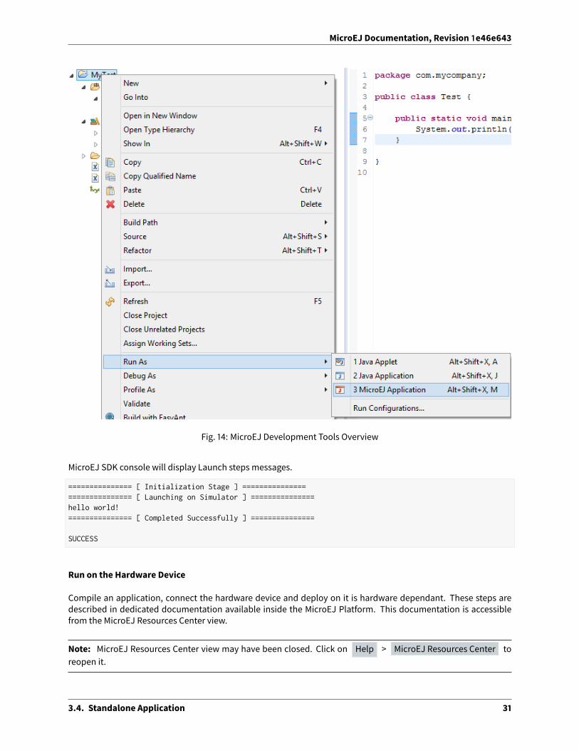
To run the sample project on Simulator, select it in the le� panel then right-click and select Run > Run as >MicroEJ Application .
3.4. Standalone Application 30
MicroEJ Documentation, Revision 1e46e643
Fig. 14: MicroEJ Development Tools Overview
MicroEJ SDK console will display Launch steps messages.
=============== [ Initialization Stage ] ============================== [ Launching on Simulator ] ===============hello world!=============== [ Completed Successfully ] ===============
SUCCESS
Run on the Hardware Device
Compile an application, connect the hardware device and deploy on it is hardware dependant. These steps aredescribed in dedicated documentation available inside the MicroEJ Platform. This documentation is accessiblefrom the MicroEJ Resources Center view.
Note: MicroEJ Resources Center view may have been closed. Click on Help > MicroEJ Resources Center toreopen it.
3.4. Standalone Application 31

MicroEJ Documentation, Revision 1e46e643
Open the menu Manual and select the documentation [hardware device] MicroEJ Platform , where[hardware device] is the name of the hardware device. This documentation features a guide to run a built-inapplication on MicroEJ Simulator and on hardware device.
Fig. 15: MicroEJ Platform Guide
3.4.3 Build Output Files
When building aMicroEJ Application, multiple files are generated next to the ELF file. These files are generated in afolderwhich is named like themain typeandwhich is located in theoutput folder specified in the run configuration.
The following image shows an example of output folder:
Fig. 16: Build Output Files
3.4. Standalone Application 32

MicroEJ Documentation, Revision 1e46e643
The SOARMap File
The SOAR.map file lists every embedded symbol of the application (section, Java class ormethod, etc.) and its sizein ROM or RAM. This file can be opened using theMemory Map Analyzer.
The embedded symbols are grouped intomultiple categories. For example, the Object class and its methods aregrouped in the LibFoundationEDC category. For each symbol or each category, you can see its size in ROM ( ImageSize ) and RAM ( Runtime Size ).
TheSOARgroups all the Java strings in the same section,which appears in the ApplicationStrings category. Thesameapplies to the static fields ( Statics category), the types ( Types category), and the class names ( ClassNamescategory).
The SOAR Information File
The soar/<main class>.xml file can be opened using any XML editor.
This file contains the list of the following embedded elements:
• method (in selected_methods tag)
• resource (in selected_resources tag)
• system property (in java_properties tag)
• string (in selected_internStrings tag)
• type (in selected_types tag)
• immutable (in selected_immutables tag)
3.4.4 MicroEJ Launch
TheMicroEJ launch configuration sets up theMicroEJ Applications environment (main class, resources, target plat-form, and platform-specific options), and then launches a MicroEJ launch script for execution.
Execution is done on either the MicroEJ Platform or the MicroEJ Simulator. The launch operation is platform-specific. It may depend on external tools that the platform requires (such as target memory programming). Referto the platform-specific documentation for more information about available launch settings.
Main Tab
The Main tab allows you to set in order:
1. The main project of the application.
2. The main class of the application containing the main method.
3. Types required in your application that are not statically embedded from the main class entry point. Mostrequired types are those that may be loaded dynamically by the application, using the Class.forName()method.
4. Binary resources that need to be embedded by the application. These are usually loaded by the applicationusing the Class.getResourceAsStream() method.
5. Immutable objects’ description files. See the [BON 1.2] ESR documentation for use of immutable objects.
3.4. Standalone Application 33

MicroEJ Documentation, Revision 1e46e643
Fig. 17: MicroEJ Launch Application Main Tab
Execution Tab
The next tab is the Execution tab. Here the target needs to be selected. Choose between execution on a MicroEJPlatform or on a MicroEJ Simulator. Each of themmay providemultiple launch settings. This page also allows youto keep generated, intermediate files and to print verbose options (advanced debug purpose options).
3.4. Standalone Application 34

MicroEJ Documentation, Revision 1e46e643
Fig. 18: MicroEJ Launch Application Execution Tab
Configuration Tab
The next tab is the Configuration tab. This tab contains all platform-specific options.
3.4. Standalone Application 35

MicroEJ Documentation, Revision 1e46e643
Fig. 19: Configuration Tab
JRE Tab
The next tab is the JRE tab. This tab allows you to configure the Java Runtime Environment used for running theunderlying launch script. It does not configure the MicroEJ Application execution. The VM Arguments text fieldallows you to set vm-specific options, which are typically used to increase memory spaces:
• Tomodify heap space to 1024MB, set the -Xmx1024M option.
• To modify string space (also called PermGen space) to 256MB, set the -XX:PermSize=256M-XX:MaxPermSize=256M options.
• To set thread stack space to 512MB, set the -Xss512M option.
Other Tabs
The next tabs ( Source and Common tabs) are the default Eclipse launch tabs. Refer to Eclipse help for moredetails on how to use these launch tabs.
3.4. Standalone Application 36

MicroEJ Documentation, Revision 1e46e643
3.4.5 Application Options
Introduction
To run a MicroEJ Standalone Application on a MicroEJ Platform, a set of options must be defined. Options can beof di�erent types:
• Memory Allocation options (e.g set the Java Heap size). These options are usually called link-time options.
• Simulator & Debug options (e.g. enable periodic Java Heap dump).
• Deployment options (e.g. copy microejapp.o to a suitable BSP location).
• Foundation Library specific options (e.g. embed UTF-8 encoding).
The following section describes options provided byMicroEJ Architecture. Please consult the appropriate MicroEJPack documentation for options related to other Foundation Libraries (MicroUI, NET, SSL, FS, . . . ) integrated to thePlatform.
Notice that some options may not be available, in the following cases:
• Option is specific to theMicroEJ Core Engine capability (tiny/single/multi) which is integrated in the targetedPlatform.
• Option is specific to the target (MicroEJ Core Engine on Device or Simulator).
• Option has been introduced in a newer version of theMicroEJ Architecturewhich is integrated in the targetedPlatform.
• Options related to Board Support Package (BSP) connection.
Defining an Option
A MicroEJ Standalone Application option can be defined either from a launcher or from a properties file. It is alsopossible to use both together. Each MicroEJ Architecture and MicroEJ Pack option comes with a default value,which is used if the option has not been set by the user.
Using a Launcher
To set an option in a launcher, perform the following steps:
1. In MicroEJ Studio/SDK, select Run > Run Configurations. . . ,
2. Select the launcher of the application under MicroEJ Application or create a new one,
3. Select the Configuration tab,
4. Find the desired option and set it to the desired value.
It is recommended to index the launcher configuration to your version control system. To export launcher optionsto the filesystem, perform the following steps:
1. Select the Common tab,
2. Select the Shared file: option and browse the desired export folder,
3. Press the Apply button. A file named [launcher_configuration_name].launch is generated in the ex-port folder.
3.4. Standalone Application 37

MicroEJ Documentation, Revision 1e46e643
Using a Properties File
Options can be also be defined in properties files.
When aMicroEJ Standalone Application is built using the firmware-singleapp skeleton, options are loaded fromproperties files located in the build folder at the root of the project.
The properties files are loaded in the following order:
1. Every file matching build/sim/*.properties , for Simulator options only (Virtual Device build). These filesare optional.
2. Every file matching build/emb/*.properties , for Device options only (Firmware build). These files areoptional.
3. Every filematching build/*.properties , both forSimulator andDeviceoptions. At leastone file is required.
Usually, the build folder contains a single file named common.properties .
In case an option is defined in multiple properties files, the option of the first loaded file is taken into account andthe same option defined in the other files is ignored (a loaded option cannot be overridden).
The figure below shows the expected tree of the build folder:
Fig. 20: Build Options Folder
It is recommended to index the properties files to your version control system.
To set an option in a properties file, open the file in a text editor and add a line to set the desired option to thedesired value. For example: soar.generate.classnames=false .
To use the options declared in properties files in a launcher, perform the following steps:
1. In MicroEJ Studio/SDK, select Run > Run Configurations. . . ,
2. Select the launcher of the application,
3. Select the Execution tab,
4. Under Option Files , press the Add. . . button,
5. Browse the sim.properties file for Simulator or the emb.properties file for Device (if any) and pressOpen button,
6. Add the common.properties file and press the Open button.
Note: An option set in a properties file can not be modified in the Configuration tab. Options are loaded in theorder the properties files are added (you can use Up and Down buttons to change the file order). In Configuration
3.4. Standalone Application 38

MicroEJ Documentation, Revision 1e46e643
tab, hovering the pointer over an option field will show the location of the properties file that defines the option.
Generating a Properties File
In order to export options defined in a .launch file to a properties file, perform the following steps:
1. Select the [launcher_configuration_name].launch file,
2. Select File > Export > MicroEJ > Launcher as Properties File ,
3. Browse the desired output .properties file,
4. Press the Finish button.
Category: Runtime
Group: Types
Option(checkbox): Embed all type names
Option Name: soar.generate.classnames
Default value: true
Description:
Embed the name of all types. When this option is disabled, only names of declared required types are embedded.
3.4. Standalone Application 39

MicroEJ Documentation, Revision 1e46e643
Group: Assertions
Option(checkbox): Execute assertions on Simulator
Option Name: core.assertions.sim.enabled
Default value: false
Description:
When this option is enabled, assert statements are executed. Please note that the executed code may produceside e�ects or throw java.lang.AssertionError .
Option(checkbox): Execute assertions on Device
Option Name: core.assertions.emb.enabled
Default value: false
Description:
When this option is enabled, assert statements are executed. Please note that the executed code may produceside e�ects or throw java.lang.AssertionError .
Group: Trace
Option(checkbox): Enable execution traces
Option Name: core.trace.enabled
Default value: false
Option(checkbox): Start execution traces automatically
Option Name: core.trace.autostart
Default value: false
3.4. Standalone Application 40

MicroEJ Documentation, Revision 1e46e643
Category: Memory
Group: Heaps
Option(text): Java heap size (in bytes)
Option Name: core.memory.javaheap.size
Default value: 65536
Description:
Specifies the Java heap size in bytes.
A Java heap contains live Java objects. An OutOfMemory error can occur if the heap is too small.
Option(text): Immortal heap size (in bytes)
Option Name: core.memory.immortal.size
Default value: 4096
Description:
Specifies the Immortal heap size in bytes.
The Immortal heap contains allocated Immortal objects. An OutOfMemory error can occur if the heap is too small.
Group: Threads
Description:
3.4. Standalone Application 41

MicroEJ Documentation, Revision 1e46e643
This group allows the configuration of application and library thread(s). A thread needs a stack to run. This stackis allocated from a pool and this pool contains several blocks. Each block has the same size. At thread startup thethread uses only one block for its stack. When the first block is full it uses another block. Themaximum number ofblocks per thread must be specified. When the maximum number of blocks for a thread is reached or when thereis no free block in the pool, a StackOverflow error is thrown. When a thread terminates all associated blocks arefreed. These blocks can then be used by other threads.
Option(text): Number of threads
Option Name: core.memory.threads.size
Default value: 5
Description:
Specifies the number of threads the application will be able to use at the same time.
Option(text): Number of blocks in pool
Option Name: core.memory.threads.pool.size
Default value: 15
Description:
Specifies the number of blocks in the stacks pool.
Option(text): Block size (in bytes)
Option Name: core.memory.thread.block.size
Default value: 512
Description:
Specifies the thread stack block size (in bytes).
Option(text): Maximum size of thread stack (in blocks)
Option Name: core.memory.thread.max.size
Default value: 4
Description:
Specifies themaximum number of blocks a thread can use. If a thread requires more blocks a StackOverflow errorwill occur.
3.4. Standalone Application 42

MicroEJ Documentation, Revision 1e46e643
Category: Simulator
Group: Options
Description:
This group specifies options for MicroEJ Simulator.
Option(checkbox): Use target characteristics
Option Name: s3.board.compliant
Default value: false
Description:
When selected, this option forces the MicroEJ Simulator to use the MicroEJ Platform exact characteristics. It setsthe MicroEJ Simulator scheduling policy according to the MicroEJ Platform one. It forces resources to be explicitlyspecified. It enables log trace and gives information about the RAMmemory size the MicroEJ Platform uses.
Option(text): Slowing factor (0means disabled)
Option Name: s3.slow
Default value: 0
Description:
Format: Positive integer
This option allows the MicroEJ Simulator to be slowed down in order to match the MicroEJ Platform executionspeed. The greater the slowing factor, the slower the MicroEJ Simulator runs.
3.4. Standalone Application 43

MicroEJ Documentation, Revision 1e46e643
Group: HIL Connection
Description:
This group enables the control of HIL (Hardware In the Loop) connection parameters (connection betweenMicroEJSimulator and the Mocks).
Option(checkbox): Specify a port
Option Name: s3.hil.use.port
Default value: false
Description:
When selected allows the use of a specific HIL connection port, otherwise a random free port is used.
Option(text): HIL connection port
Option Name: s3.hil.port
Default value: 8001
Description:
Format: Positive integer
Values: [1024-65535]
It specifies the port used by the MicroEJ Simulator to accept HIL connections.
Option(text): HIL connection timeout
Option Name: s3.hil.timeout
Default value: 10
Description:
Format: Positive integer
It specifies the time the MicroEJ Simulator should wait before failing when it invokes native methods.
Group: Shielded Plug server configuration
Description:
This group allows configuration of the Shielded Plug database.
Option(text): Server socket port
Option Name: sp.server.port
Default value: 10082
Description:
3.4. Standalone Application 44

MicroEJ Documentation, Revision 1e46e643
Set the Shielded Plug server socket port.
Category: Code Coverage
Group: Code Coverage
Description:
This group is used to set parameters of the code coverage analysis tool.
Option(checkbox): Activate code coverage analysis
Option Name: s3.cc.activated
Default value: false
Description:
When selected it enables the code coverage analysis by the MicroEJ Simulator. Resulting files are output in the ccdirectory inside the output directory.
Option(text): Saving coverage information period (in sec.)
Option Name: s3.cc.thread.period
Default value: 15
Description:
It specifies the period between the generation of .cc files.
3.4. Standalone Application 45

MicroEJ Documentation, Revision 1e46e643
Category: Debug
Group: Remote Debug
Option(text): Debug port
Option Name: debug.port
Default value: 12000
Description:
Configures the JDWP debug port.
Format: Positive integer
Values: [1024-65535]
3.4. Standalone Application 46

MicroEJ Documentation, Revision 1e46e643
Category: Heap Dumper
Group: Heap Inspection
Description:
This group is used to specify heap inspection properties.
Option(checkbox): Activate heap dumper
Option Name: s3.inspect.heap
Default value: false
Description:
When selected, this option enables a dump of the heap each time the System.gc() method is called by the MicroEJApplication.
3.4. Standalone Application 47

MicroEJ Documentation, Revision 1e46e643
Category: Logs
Group: Logs
Description:
This group defines parameters for MicroEJ Simulator log activity. Note that logs can only be generated if theSimulator > Use target characteristics option is selected.
Some logs are sent when the platform executes some specific action (such as start thread, start GC, etc), other logsare sent periodically (according to defined log level and the log periodicity).
Option(checkbox): system
Option Name: console.logs.level.low
Default value: false
Description:
When selected, System logs are sent when the platform executes the following actions:
start and terminate a thread
start and terminate a GC
exit
Option(checkbox): thread
Option Name: console.logs.level.thread
3.4. Standalone Application 48

MicroEJ Documentation, Revision 1e46e643
Default value: false
Description:
When selected, thread information is sent periodically. It gives information about alive threads (status, memoryallocation, stack size).
Option(checkbox): monitoring
Option Name: console.logs.level.monitoring
Default value: false
Description:
When selected, threadmonitoring logs are sent periodically. It gives information about time execution of threads.
Option(checkbox): memory
Option Name: console.logs.level.memory
Default value: false
Description:
When selected, memory allocation logs are sent periodically. This level allows to supervise memory allocation.
Option(checkbox): schedule
Option Name: console.logs.level.schedule
Default value: false
Description:
When selected, a log is sent when the platform schedules a thread.
Option(checkbox): monitors
Option Name: console.logs.level.monitors
Default value: false
Description:
When selected, monitors information is sent periodically. This level permits tracing of all thread state by tracingmonitor operations.
Option(text): period (in sec.)
Option Name: console.logs.period
Default value: 2
Description:
Format: Positive integer
3.4. Standalone Application 49

MicroEJ Documentation, Revision 1e46e643
Values: [0-60]
Defines the periodicity of periodical logs.
Category: Device
Group: Device Architecture
Option(checkbox): Use a custom device architecture
Option Name: s3.mock.device.architecture.option.use
Default value: false
Option(text): Architecture Name
Option Name: s3.mock.device.architecture.option
Default value: (empty)
Group: Device Unique ID
Option(checkbox): Use a custom device unique ID
Option Name: s3.mock.device.id.option.use
Default value: false
3.4. Standalone Application 50

MicroEJ Documentation, Revision 1e46e643
Option(text): Unique ID (hexadecimal value)
Option Name: s3.mock.device.id.option
Default value: (empty)
Category: Com Port
3.4. Standalone Application 51

MicroEJ Documentation, Revision 1e46e643
Category: Libraries
Category: EDC
Group: Java System.out
3.4. Standalone Application 52

MicroEJ Documentation, Revision 1e46e643
Option(checkbox): Use a custom Java output stream
Option Name: core.outputstream.disable.uart
Default value: false
Description:
Select this option to specify another Java System.out print stream.
If selected, the default Java output stream is not used by the Java application. the JPFwill not use the default Javaoutput stream at startup.
Option(text): Class
Option Name: core.outputstream.class
Default value: (empty)
Description:
Format: Java class like packageA.packageB.className
Defines the Java class used to manage System.out .
At startup the JPF will try to load this class using the Class.forName() method. If the given class is not available,the JPF will use the default Java output stream as usual. The specified class must be available in the applicationclasspath.
Group: Runtime options
Description:
Specifies the additional classes to embed at runtime.
Option(checkbox): Embed UTF-8 encoding
Option Name: cldc.encoding.utf8.included
Default value: true
Description:
Embed UTF-8 encoding.
Option(checkbox): Enable SecurityManager checks
Option Name: com.microej.library.edc.securitymanager.enabled
Default value: false
Description:
Enable the security manager runtime checks.
3.4. Standalone Application 53

MicroEJ Documentation, Revision 1e46e643
Category: Shielded Plug
Group: Shielded Plug configuration
Description:
Choose the database XML definition.
Option(browse): Database definition
Option Name: sp.database.definition
Default value: (empty)
Description:
Choose the database XML definition.
3.4. Standalone Application 54

MicroEJ Documentation, Revision 1e46e643
Category: ECOM
Group: Device Management
Option(checkbox): Enable registration event notifications
Option Name: com.is2t.ecom.eventpump.enabled
Default value: false
Description:
Enables notification of listeners when devices are registered or unregistered. When a device is registered or un-registered, a new ej.ecom.io.RegistrationEvent is added to an event queue. Then events are processed by adedicated thread that notifies registered listeners.
Option(text): Registration events queue size
Option Name: com.is2t.ecom.eventpump.size
Default value: 5
Description:
Specifies the size (in number of events) of the registration events queue.
3.4. Standalone Application 55

MicroEJ Documentation, Revision 1e46e643
Category: CommConnection
Group: CommConnection Options
Description:
This group allows comm connections to be enabled and application-platformmappings set.
Option(checkbox): Enable comm connections
Option Name: use.comm.connection
Default value: false
Description:
When checked application is able to open a CommConnection .
Group: Device Management
Option(checkbox): Enable dynamic commports registration
Option Name: com.is2t.ecom.comm.registryPump.enabled
Default value: false
Description:
Enables registration (or unregistration) of ports dynamically added (or removed) by the platform. A dedicatedthread listens for ports dynamically added (or removed) by the platform and adds (or removes) their CommPortrepresentation to the ECOM DeviceManager .
3.4. Standalone Application 56

MicroEJ Documentation, Revision 1e46e643
Category: External Resources Loader
Group: External Resources Loader
Description:
This group allows to specify the external resources input folder. The content of this folder will be copied in anapplication output folder and used by SOAR and the Simulator. If empty, the default location will be [outputfolder]/externalResources, where [output folder] is the location defined in Execution tab.
Option(browse):
Option Name: ej.externalResources.input.dir
Default value: (empty)
Description:
Browse to specify the external resources folder..
3.4. Standalone Application 57

MicroEJ Documentation, Revision 1e46e643
Category: Device
Category: Core Engine
Group: Memory
3.4. Standalone Application 58

MicroEJ Documentation, Revision 1e46e643
Option(text):
Option Name: core.memory.thread.max.nb.monitors
Default value: 8
Description:
Specifies the maximum number of monitors a thread can own at the same time.
Option(text):
Option Name: core.memory.oome.nb.frames
Default value: 5
Description:
Specifies the maximum number of stack frames that can be dumped to the standard output when Core Enginethrows an OutOfMemoryError.
Category: Kernel
Option(checkbox): Check APIs allowed by Kernel
Option Name: apis.check.enable
Default value: true
3.4. Standalone Application 59

MicroEJ Documentation, Revision 1e46e643
Group: Threads
Option(text):
Option Name: core.memory.feature.max.threads
Default value: 5
Description:
Specifies the maximum number of threads a Feature is allowed to use at the same time.
Group: Installed Features
Option(text):
Option Name: core.memory.installed.features.max
Default value: 0
Description:
Specifies the maximum number of installed Features that can be added to this Kernel.
Option(text):
Option Name: core.memory.installed.features.text.size
Default value: 0
Description:
Specifies the size in bytes reserved for installed Features code.
Option(text):
Option Name: core.memory.installed.features.bss.size
Default value: 0
Description:
Specifies the size in bytes reserved for installed Features runtimememory.
3.4. Standalone Application 60

MicroEJ Documentation, Revision 1e46e643
Category: Watchdog
Option(checkbox): Enable watchdog support
Option Name: enable.watchdog.support
Default value: true
Group: Watchdog
Option(text):
Option Name: maximum.active.watchdogs
Default value: 4
Description:
Specifies the maximum number of active watchdogs at the same time.
3.4. Standalone Application 61

MicroEJ Documentation, Revision 1e46e643
Category: Deploy
Description:
Configures theoutput locationwhere store theMicroEJApplication, theMicroEJplatform libraries andheader files.
Group: Configuration
Option(checkbox): Deploy the compiled MicroEJ Application in a folder in MicroEJ Application main classproject
Default value: true
Description:
Deploy the compiled MicroEJ Application in a folder in MicroEJ Application’s main class project.
Option(browse): Output file
Option Name: deploy.copy.filename
Default value: (empty)
Description:
Choose an output file location where copy the compiled MicroEJ Application.
3.4. Standalone Application 62

MicroEJ Documentation, Revision 1e46e643
Category: Feature
Description:
Specify Feature options
3.4. Standalone Application 63

MicroEJ Documentation, Revision 1e46e643
Category: Dynamic Download
Group: Dynamic Download
Option(text): Output Name
Option Name: feature.output.basename
Default value: application
Option(browse): Kernel
Option Name: kernel.filename
Default value: (empty)
3.4.6 SOAR
SOAR complies with the deterministic class initialization ( <clinit> ) order specified in [BON]. The application isstatically analyzed from its entry points in order to generate a clinit dependency graph. The computed clinit se-quence is the result of the topological sort of the dependency graph. An error is thrown if the clinit dependencygraph contains cycles.
An explicit clinit dependency can be declared by creating an XML file with the .clinitdesc extension in the ap-plication classpath. The file has the following format:
<?xml version='1.0' encoding='UTF-8'?><clinit>
(continues on next page)
3.4. Standalone Application 64

MicroEJ Documentation, Revision 1e46e643
(continued from previous page)
<type name="T1" depends="T2"/></clinit>
where T1 and T2 are fully qualified names on the form a.b.C . This explicitly forces SOAR to create a dependencyfrom T1 to T2 , and therefore cuts a potentially detected dependency from T2 to T1 .
A clinit map file (endingwith extension .clinitmap ) is generated beside the SOAR object file. It describes for eachclinit dependency:
• the types involved
• the kind of dependency
• the stack calls between the two types
3.5 Sandboxed Application
3.5.1 Sandboxed Application Structure
Application Skeleton Creation
The first step to explore a Sandboxed Application structure is to create a new project.
First select File > New > MicroEJ Sandboxed Application Project :
Fill in the application template fields, the Project name field will automatically duplicate in the following fields.
A template project is automatically created and ready to use, this project already contains all folders wherein de-velopers need to put content:
src/main/java Folder for future sources;
src/main/resources Folder for future resources (images, fonts etc.);
META-INF Sandboxed Application configuration and resources;
module.ivy Ivy input file, dependencies description for the current project.
Sources Folder
The project source folder ( src/main ) contains two subfolders: java and resources . java folder will contain all*.java files of the project, whereas resources folder will contain elements that the application needs at runtimelike raw resources, images or character fonts.
META-INF Folder
The META-INF folder contains several folders and amanifest file. They are described herea�er.
certificate (folder) Contains certificate information used during the application deployment.
libraries (folder) Contains a list of additional libraries useful to the application and not resolved through theregular transitive dependency check.
properties (folder) Contains an application.properties file which contains application specific propertiesthat can be accessed at runtime.
3.5. Sandboxed Application 65

MicroEJ Documentation, Revision 1e46e643
services (folder) Contains a list of files that describe local services provided by the application. Each file namerepresents a service class fully qualified name, and each file contains the fully qualified nameof the providedservice implementation.
wpk (folder) Contains a set of applications ( .wpk files) that will be started when the application is executed onthe Simulator.
MANIFEST.MF (file) Contains the information given at project creation, extra information can be added to this fileto declare the entry points of the application.
module.ivy File
The module.ivy file describes all the libraries required by the application at runtime. The Ivy classpath containerlists all the modules that have been automatically resolved from the content of module.ivy . SeeMicroEJ ModuleManager for more informations about MicroEJ Module Manager.
3.5.2 Application Publication
Build the WPK
When the application is ready for deployment, the last step in MicroEJ Studio is to create theWPK (Wadapps PacK-age) file that is intended to be published on a MicroEJ Forge instance for end users.
In MicroEJ Studio, right-click on the Sandboxed Application project name and select Build Module .
The WPK build process will display messages in MicroEJ console, ending up the following message:
[echo] project hello published locally with version 0.1.0-RC201907091602
BUILD SUCCESSFUL
Total time: 1 minute 6 seconds
Publish on a MicroEJ Forge Instance
The WPK file produced by the build process is located in a dedicated target~/artifacts folder in the project.
The .wpk file is ready to be uploaded to a MicroEJ Forge instance. Please consult https://community.microej.comfor more information.
3.5.3 Shared Interfaces
Principle
The Shared Interfacemechanism provided byMicroEJ Core Engine is an object communication bus based on plainJava interfaces wheremethod calls are allowed to cross MicroEJ Sandboxed Applications boundaries. The SharedInterface mechanism is the cornerstone for designing reliable Service Oriented Architectures on top of MicroEJ.Communication is based on the sharing of interfaces defining APIs (Contract Oriented Programming).
The basic schema:
• A provider application publishes an implementation for a shared interface into a system registry.
• A user application retrieves the implementation from the system registry and directly calls the methods de-fined by the shared interface.
3.5. Sandboxed Application 66
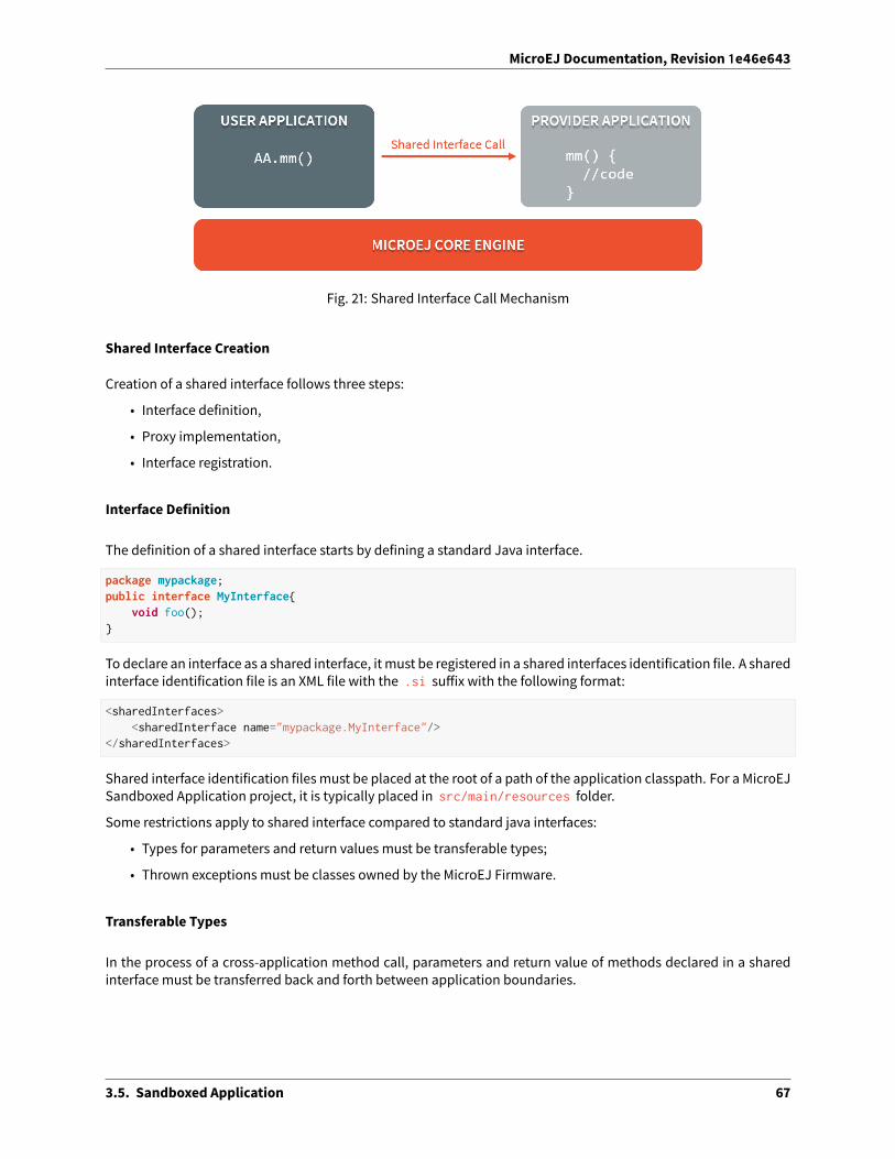
MicroEJ Documentation, Revision 1e46e643
Fig. 21: Shared Interface Call Mechanism
Shared Interface Creation
Creation of a shared interface follows three steps:
• Interface definition,
• Proxy implementation,
• Interface registration.
Interface Definition
The definition of a shared interface starts by defining a standard Java interface.
package mypackage;public interface MyInterface{
void foo();}
To declare an interface as a shared interface, itmust be registered in a shared interfaces identification file. A sharedinterface identification file is an XML file with the .si su�ix with the following format:
<sharedInterfaces><sharedInterface name="mypackage.MyInterface"/>
</sharedInterfaces>
Shared interface identification filesmust be placed at the root of a path of the application classpath. For a MicroEJSandboxed Application project, it is typically placed in src/main/resources folder.
Some restrictions apply to shared interface compared to standard java interfaces:
• Types for parameters and return values must be transferable types;
• Thrown exceptions must be classes owned by the MicroEJ Firmware.
Transferable Types
In the process of a cross-application method call, parameters and return value of methods declared in a sharedinterface must be transferred back and forth between application boundaries.
3.5. Sandboxed Application 67

MicroEJ Documentation, Revision 1e46e643
Fig. 22: Shared Interface Parameters Transfer
Shared Interface Types Transfer Rules describes the rules applied depending on the element to be transferred.
Table 1: Shared Interface Types Transfer RulesType Owner Instance
OwnerRule
Base type N/A N/A Passing by value. ( boolean , byte , short, char , int , long , double , float )
Any Class, Array or Inter-face
Kernel Kernel Passing by reference
Any Class, Array or Inter-face
Kernel Application Kernel specific or forbidden
Array of base types Any Application Clone by copyArrays of references Any Application Clone and transfer rules applied again on
each elementShared Interface Application Application Passing by indirect reference (Proxy cre-
ation)Any Class, Array or Inter-face
Application Application Forbidden
Objects created by an application which class is owned by the Kernel can be transferred to another applicationif this has been authorized by the Kernel. The list of eligible types that can be transferred is Kernel specific, soyou have to consult the firmware specification. MicroEJ Evaluation Firmware Example of Transfer Types lists Kerneltypes allowed to be transferred through a shared interface call. When an argument transfer is forbidden, the call isabruptly stopped and a java.lang.IllegalAccessError is thrown by MicroEJ Core Engine.
Table 2: MicroEJ Evaluation Firmware Example of Transfer TypesType Rule
java.lang.StringClone by copy
java.io.InputStreamProxy reference creation
java.util.Map<String,String>Clone by deep copy
Proxy Class Implementation
The Shared Interface mechanism is based on automatic proxy objects created by the underlying MicroEJ Core En-gine, so that each application can still be dynamically stopped and uninstalled. This o�ers a reliable way for usersand providers to handle the relationship in case of a broken link.
Once a Java interface has been declared as Shared Interface, a dedicated implementation is required (called theProxy class implementation). Its main goal is to perform the remote invocation and provide a reliable implemen-tation regarding the interface contract even if the remote application fails to fulfill its contract (unexpected excep-
3.5. Sandboxed Application 68

MicroEJ Documentation, Revision 1e46e643
tions, application killed. . . ). The MicroEJ Core Engine will allocate instances of this class when an implementationowned by another application is being transferred to this application.
Fig. 23: Shared Interfaces Proxy Overview
A proxy class is implemented and executed on the client side, each method of the implemented interface must bedefined according to the following pattern:
package mypackage;
public class MyInterfaceProxy extends Proxy<MyInterface> implements MyInterface {
@Overridepublic void foo(){
try {invoke(); // perform remote invocation
} catch (Throwable e) {e.printStackTrace();
}}
}
Each implemented method of the proxy class is responsible for performing the remote call and catching all errorsfrom the server side and to provide an appropriate answer to the client application call according to the interfacemethod specification (contract). Remote invocationmethods are defined in the super class ej.kf.Proxy and arenamed invokeXXX() where XXX is the kind of return type. As this class is part of the application, the applicationdeveloper has the full control on the Proxy implementation and is free to insert additional code such as loggingcalls and errors for example.
Table 3: Proxy Remote Invocation Built-in MethodsInvocation Method Usagevoid invoke() Remote invocation for a proxy method that returns voidObject invokeRef() Remote invocation for a proxymethod that returns a referenceboolean invokeBoolean(), byte invokeByte(),char invokeChar(), short invokeShort(), int in-vokeInt(), long invokeLong(), double invoke-Double(), float invokeFloat()
Remote invocation for aproxymethod that returns abase type
3.5. Sandboxed Application 69

MicroEJ Documentation, Revision 1e46e643
3.6 Virtual Device
3.6.1 Using a Virtual Device for Simulation
The Virtual Device includes the same custom MicroEJ Core, libraries and System Applications as the real device.The Virtual Device allows developers to run their applications either on the Simulator, or directly on the real devicethrough local deployment.
The Simulator runs a mockup board support package (BSP Mock) that mimics the hardware functionality. An ap-plication on the Simulator is run as a Standalone Application.
Before an application is locally deployed on device, MicroEJ Studio ensures that it does not depend on any API thatis unavailable on the device.
Fig. 24: MicroEJ Virtual Device Architecture
3.6.2 Runtime Environment
The set of MicroEJ APIs exposed by a Virtual Device (and therefore provided by its associated firwmare) is docu-mented in Javadoc format in theMicroEJ Resource Center ( Window > Show View > MicroEJ Resource Center).
3.6. Virtual Device 70

MicroEJ Documentation, Revision 1e46e643
Fig. 25: MicroEJ Resource Center APIs
3.7 MicroEJ Module Manager
3.7.1 Introduction
Modern electronic device design involvesmanyparts and teams to collaborate to finally obtain a product to be soldon its market. MicroEJ encourages modular design which involves various stake holders: hardware engineers, UXdesigners, graphic designers, drivers/BSP engineers, so�ware engineers, etc.
Modular design is a design technique that emphasizes separating the functionality of an application into inde-pendent, interchangeable modules. Each module contains everything necessary to execute only one aspect ofthe desired functionality. In order to have team members collaborate internally within their team and with otherteams, MicroEJ provides a powerful modular design concept, with smart module dependencies, controlled by theMicroEJModule Manager (MMM). MMM frees engineers from the di�icult task of computingmodule dependencies.Engineers specify the bare minimum description of the module requirements.
The following schema introduces the main concepts detailed in this chapter.
3.7. MicroEJ Module Manager 71

MicroEJ Documentation, Revision 1e46e643
Fig. 26: MMMOverview
MMM is based on the following tools:
• Apache Ivy (http://ant.apache.org/ivy) for dependencies resolution andmodule publication;
• Apache EasyAnt (https://ant.apache.org/easyant/history/trunk/reference.html) for module build fromsource code.
3.7.2 Specification
MMM provides a non ambiguous semantic for dependencies resolution. Please consult the MMM specificationavailable on https://developer.microej.com/packages/documentation/TLT-0831-SPE-MicroEJModuleManager-2.0-D.pdf.
3.7.3 Module Project Skeleton
In MicroEJ SDK, a newMicroEJ module project is created as following:
• Select File > New > Project. . . ,
• Select MicroEJ > MicroEJ Module Project 1,
• Fill the module information (project name, module organization, name and revision),
• Select one of the suggested skeletons depending on the desiredmodule nature,
• Click on Finish .
1 If using MicroEJ SDK versions lower than 5.2.0 , please refer to the following section.
3.7. MicroEJ Module Manager 72

MicroEJ Documentation, Revision 1e46e643
The project is created and a set of files and directories are generated from the selected skeleton.
Note: When an empty Eclipse project already exists or when the skeleton has to be created within an existingdirectory, the MicroEJ module is created as following:
• In the Package Explorer, click on the parent project or directory,
• Select File > New > Other. . . ,
• Select EasyAnt > EasyAnt Skeleton .
3.7.4 Module Description File
Amoduledescription file is an Ivy configuration filenamed module.ivy , locatedat the rootof eachMicroEJmoduleproject. It describes themodule nature (also called build type) and dependencies to other modules.
<ivy-module version="2.0" xmlns:ea="http://www.easyant.org" xmlns:m="http://ant.apache.org/ivy/extra"xmlns:ej="https://developer.microej.com" ej:version="2.0.0">
<info organisation="[organisation]" module="[name]" status="integration" revision="[version]"><ea:build organisation="com.is2t.easyant.buildtypes" module="[buildtype_name]" revision=
→˓"[buildtype_version]"><ea:property name="[buildoption_name]" value="[buildoption_value]"/>
</ea:build></info>
<configurations defaultconfmapping="default->default;provided->provided"><conf name="default" visibility="public"/><conf name="provided" visibility="public"/><conf name="documentation" visibility="public"/><conf name="source" visibility="public"/><conf name="dist" visibility="public"/><conf name="test" visibility="private"/>
</configurations>
<publications></publications>
<dependencies><dependency org="[dep_organisation]" name="[dep_name]" rev="[dep_version]"/>
</dependencies></ivy-module>
3.7.5 MicroEJ Module Manager Configuration
By default, when starting an empty workspace, MicroEJ SDK is configured to import dependencies fromMicroEJ Central Repository and to publish built modules to a local folder. The repository configura-tion is stored in a settings file ( ivysettings.xml ), and the default one is located at $USER_HOME\.microej\microej-ivysettings-[VERSION].xml
Preferences Page
The MMM preferences page is available at Window > Preferences > MicroEJ > Module Manager 1.
3.7. MicroEJ Module Manager 73

MicroEJ Documentation, Revision 1e46e643
Fig. 27: MMM Preferences Page
This page allows to configure the following elements:
1. Settings File : the file describing how to connectmodule repositories. See the settings file section.
2. Options : files declaring MMM options. See the Options section.
3. Use Module repository as Build repository : the settings file for connecting thebuild repository in placeof the one bundled in MicroEJ SDK. This option shall not be enabled by default and is reserved for advancedconfiguration.
4. Build repository Settings File : the settings file for connecting the build repository in place of the onebundled in MicroEJ SDK. This option is automatically initialized the first time MicroEJ SDK is launched. Itshall not be modified by default and is reserved for advanced configuration.
5. Set verbose mode : to enable advanced debug traces when building a module.
6. Runtime JRE : the Java Runtime Environment that executes the build process.
7. Max build history size : the maximum number of previous builds available in Build Module shortcutlist:
3.7. MicroEJ Module Manager 74

MicroEJ Documentation, Revision 1e46e643
Settings File
The settings file is an XML file that describes howMMMconnects local or onlinemodule repositories. The file formatis described in Apache Ivy documentation.
To configure MMM to a custom settings file (usually from an o�line repository):
1. Set Settings file to a custom ivysettings.xml settings file1,
2. Click on Apply and Close button
If the workspace is not empty, it is recommended to trigger a full resolution and rebuild all the projects using thisnew repository configuration:
1. Clean caches
• In the Package Explorer, right-click on a project;
• Select Ivy > Clean all caches .
2. Resolve projects using the new repository
To resolve all the workspace projects, click on the Resolve All button in the toolbar:
To only resolve a subset of the workspace projects:
• In the Package Explorer, select the desired projects,
• Right-click on a project and select Ivy > Clean all caches .
3. Trigger Add-On Library processors for automatically generated source code
• Select Project > Clean. . . ,
• Select Clean all projects ,
• Click on Clean button.
Options
Options can be used to parameterize amodule description file or a settings file. Options are declared as key/valuepairs in a standard Java properties file, and are expanded using the ${my_property} notation.
A typical usage in a settings file is for extracting repository server credentials, such as HTTP Basic access authenti-cation:
1. Declare options in a properties file
3.7. MicroEJ Module Manager 75

MicroEJ Documentation, Revision 1e46e643
2. Register this property file to MMM options
3. Use this option in a settings file
A typical usage in amodule description file is for factorizing dependency versions acrossmultiplemodules projects:
1. Declare an option in a properties file
2. Register this property file to MMM options
3. Use this option in amodule description file
3.7. MicroEJ Module Manager 76

MicroEJ Documentation, Revision 1e46e643
3.7.6 Build Kit
The Module Manager build kit is the consistent set of tools and scripts required for building modules.
It is bundled with MicroEJ SDK and can be exported to run in headless mode using the following steps:1
• Select File > Export > MicroEJ > Module Manager Build Kit ,
• Choose an empty Target directory ,
• Click on the Finish button.
Once the build kit is fully exported, the directory content shall look like:
To go further with headless builds, please consult Tool-CommandLineBuild for command line builds, and this tu-torial to setup MicroEJ modules build in continuous integration environments).
3.7.7 Former MicroEJ SDK Versions
This section describes MMM configuration elements for MicroEJ SDK versions lower than 5.2.0 .
NewMicroEJ Module Project
TheNewMicroEJModuleProjectwizard is available at File > New > Project. . . , EasyAnt > EasyAnt Project.
Preferences Pages
MMM Preferences Pages are located in two dedicated pages. The following pictures show the options mappingusing the same options numbers declared in Preferences Page.
Ivy Preferences Page
The Ivy Preferences Page is available at Window > Preferences > Ivy > Settings .
3.7. MicroEJ Module Manager 77

MicroEJ Documentation, Revision 1e46e643
Easyant Preferences Page
The Easyant Preferences Page is available at Window > Preferences > EasyAnt4Eclipse .
Export the Build Kit
• Create an empty directory (e.g. mmm_sdk_[version]_build_kit ),
• Locate your SDK installation plugins directory (by default, C:\Program Files\MicroEJ\MicroEJSDK-[version]\rcp\plugins on Windows OS),
• Open the file com.is2t.eclipse.plugin.easyant4e_[version].jar with an archive manager,
• Extract the directory lib to the target directory,
• Open the file com.is2t.eclipse.plugin.easyant4e.offlinerepo_[version].jar with an archive man-ager,
• Navigate to directory repositories ,
3.7. MicroEJ Module Manager 78

MicroEJ Documentation, Revision 1e46e643
• Extract the filenamed microej-build-repository.zip forMicroEJSDK 5.x or is2t_repo.zip forMicroEJSDK 4.1.x to the target directory.
3.8 Module Natures
The following table describes the project skeleton name for most common MicroEJ Module Natures.
Table 4: MicroEJ Module Natures SummaryModule Nature Skeleton
NameDirect Wizard
Add-On Library microej-javalib
File > New > MicroEJ Add-On Library Project
Mock microej-mock
Module Repository artifact-repository
Sandboxed Application application File > New > MicroEJ Sandboxed Application Project
Standalone Application firmware-singleapp
File > New > MicroEJ Standalone Application Project
3.8.1 Module Repository
A module repository is a module that bundles a set of modules in a portable ZIP file. It is a tree structure wheremodules organizations and names are mapped to folders.
3.8. Module Natures 79

MicroEJ Documentation, Revision 1e46e643
Fig. 28: Example of MicroEJ Module Repository Tree
Amodule repository takes its input modules from other repositories, usually theMicroEJ Central Repository whichis itself built by MicroEJ Corp. as a module repository.
3.8. Module Natures 80

MicroEJ Documentation, Revision 1e46e643
A module repository is o�en called an o�line repository as it includes the settings file for a local configuration inMicroEJ SDK. It can also be imported in MicroEJ Forge.
Create a Repository Project
In MicroEJ SDK, first create a newmodule project using the artifact-repository skeleton.
• The ivysettings.xml settings file describes how to import the modules of this repository when it is ex-tracted locally on file system. This file will be packaged at the root of the zip file and does not need to bemodified.
• The module.ivy file describes how to build repository and lists the module dependencies that will be in-cluded in this repository.
Configure Resolver for Input Modules
MicroEJ Module Manager (MMM) needs to import dependencies to build the module repository. The locationfetched by MMM is defined by a resolver. The resolver is configured with the parameter bar.populate.from.resolver . The preset value is the resolver provided by default in MicroEJ SDK configuration, which is connectedtoMicroEJ Central Repository.
<ea:property name="bar.populate.from.resolver" value="MicroEJChainResolver"/>
The MicroEJChainResolver is a URL resolver defined in $USER_HOME\.microej\microej-ivysettings-[VERSION].xml that points to MicroEJ Central Repository.
To ensure the repository will be compliant with theMMM specification, add the following option:
<ea:property name="bar.check.as.v2.module" value="true"/>
There are other advanced options that do not need to be modified by default. These options are described in themodule.ivy generated by the skeleton.
Include Modules
Modules bundled into the module repository must be declared in the dependencies element of the module.ivyfile.
Include a Single Module
To add amodule, declare the module dependency using the artifacts configuration:
<dependencies><dependency conf="artifacts->*" transitive="false" org="[module_org]" name="[module_name]" rev=
→˓"[module_version]" />
<!-- ... other dependencies ... --></dependencies>
For example, to add the ej.api.edc library version 1.2.3 , write the following line:
<dependency conf="artifacts->*" transitive="false" org="ej.api" name="edc" rev="1.2.3" />
3.8. Module Natures 81

MicroEJ Documentation, Revision 1e46e643
Note: We recommended to manually describe each dependency of the module repository, in order to keep fullcontrolof the includedmodulesaswell as includedmodulesversions. Moduledependencies canstill be transitivelyincluded by setting the dependency attribute transitive to true . In this case, the includedmodule versions arethose that have been resolved when the module was built.
Multiple versions of the same module can be included by declaring each dependency using a di�erent configura-tion. The artifacts configurationhas tobederivedwith anewnameasmany times as there aredi�erent versionsto include.
<configurations defaultconfmapping="default->default;provided->provided"><conf name="artifacts" visibility="private"/><conf name="artifacts_1" visibility="private"/><conf name="artifacts_2" visibility="private"/>
<!-- ... other configurations ... --></configurations>
<dependencies><dependency conf="artifacts->*" transitive="false" org="[module_org]" name="[module_name]" rev=
→˓"[module_version_1]" /><dependency conf="artifacts_1->*" transitive="false" org="[module_org]" name="[module_name]" rev=
→˓"[module_version_2]" /><dependency conf="artifacts_2->*" transitive="false" org="[module_org]" name="[module_name]" rev=
→˓"[module_version_3]" />
<!-- ... other dependencies ... --></dependencies>
Include a Module Repository
To add all themodules already included in an othermodule repository, declare themodule repository dependencyusing the repository configuration:
<dependencies><dependency conf="repository->*" transitive="false" org="[repository_org]" name="[repository_name]"␣
→˓rev="[repository_version]" />
<!-- ... other dependencies ... --></dependencies>
Build the Repository
In the Package Explorer, right-click on the repository project and select Build Module .
The build consists of two steps:
1. Gathers all module dependencies. The whole repository content is created under target~/mergedArtifactsRepository folder.
2. Checks the repository consistency. For each module, it tries to import it from this repository and fails thebuild if at least one of the dependencies cannot be resolved.
Themodule repository .zip file is built in the target~/artifacts/ folder. This file may be published along witha CHANGELOG.md , LICENSE.txt and README.md .
3.8. Module Natures 82

MicroEJ Documentation, Revision 1e46e643
Use the O�line Repository
By default, when starting an empty workspace, MicroEJ SDK is configured to import dependencies from MicroEJCentral Repository.
To configure MicroEJ SDK to import dependencies from a local module repository:
1. Unzip the module repository .zip file to the folder of your choice,
2. ConfigureMMMsettings file using the ivysettings.xml file located at the root of the folderwhere the repos-itory has been extracted.
3.9 MicroEJ Classpath
MicroEJ Applications run on a target device and their footprint is optimized to fulfill embedded constraints. Thefinal execution context is an embedded device that may not even have a file system. Files required by the appli-cation at runtime are not directly copied to the target device, they are compiled to produce the application binarycode which will be executed by MicroEJ Core Engine.
As a part of the compile-time trimming process, all types not required by the embedded application are eliminatedfrom the final binary.
MicroEJ Classpath is a developer defined list of all places containing files to be embedded in the final applicationbinary. MicroEJ Classpath is made up of an ordered list of paths. A path is either a folder or a zip file, called a JARfile (JAR stands for Java ARchive).
• Application Classpath explains how the MicroEJ Classpath is built from a MicroEJ Application project.
• Classpath Load Model explains how the application contents is loaded fromMicroEJ Classpath.
• Classpath Elements specifies the di�erent elements that can be declared in MicroEJ Classpath to describethe application contents.
3.9.1 Application Classpath
The following schema shows the classpath mapping from a MicroEJ Application project to the MicroEJ Classpathordered list of folders and JAR files. The classpath resolution order (le� to right) follows the project appearanceorder (top to bottom).
3.9. MicroEJ Classpath 83

MicroEJ Documentation, Revision 1e46e643
Fig. 29: MicroEJ Application Classpath Mapping
3.9.2 Classpath Load Model
A MicroEJ Application classpath is created via the loading of :
• an entry point type,
• all *.[extension].list files declared in a MicroEJ Classpath.
Thedi�erentelements that constituteanapplicationaredescribed inClasspathElements. Theyare searchedwithinMicroEJ Classpath from le� to right (the first file found is loaded). Types referenced by previously loaded MicroEJClasspath elements are loaded transitively.
3.9. MicroEJ Classpath 84

MicroEJ Documentation, Revision 1e46e643
Fig. 30: Classpath Load Principle
3.9.3 Classpath Elements
The MicroEJ Classpath contains the following elements:
• An entrypoint described in section Application Entry Points;
• Types in .class files, described in section Types;
• Raw resources, described in section Raw Resources;
• Immutables Object data files, described in Section Immutable Objects;
• Images, Fonts and Native Language Support (NLS) resources, described in Application Resources;
• *.[extension].list files, declaring contents to load. Supported list file extensions and format is specificto declared application contents and is described in the appropriate section.
At source level, Java types are stored in src/main/java folder of the module project, any other kind of resourcesand list files are stored in the src/main/resources folder.
Application Entry Points
MicroEJ Application entry point declaration di�ers depending on the application kind:
• In case of a MicroEJ Standalone Application, it is a class that contains a public static voidmain(String[]) method, declared using the option application.main.class .
3.9. MicroEJ Classpath 85

MicroEJ Documentation, Revision 1e46e643
• In case of a MicroEJ Sandboxed Application, it is a class that implements ej.kf.FeatureEntryPoint , de-clared in the Application-EntryPoint entry in META-INF/MANIFEST.MF file.
Types
MicroEJ types (classes, interfaces) are compiled from source code ( .java ) to classfiles ( .class ). When a type isloaded, all types dependencies found in the classfile are loaded (transitively).
A type can be declared as a Required type in order to enable the following usages:
• to be dynamically loaded from its name (with a call to Class.forName(String) );
• to retrieve its fully qualified name (with a call to Class.getName() ).
A type that is not declared as a Required typemay not have its fully qualified name (FQN) embedded. Its FQN canbe retrieved using the stack trace reader tool (see Stack Trace Reader).
Required Types are declared in MicroEJ Classpath using *.types.list files. The file format is a standard Javaproperties file, each line listing the fully qualified name of a type. Example:
# The following types are marked as MicroEJ Required Typescom.mycompany.MyImplementationjava.util.Vector
Raw Resources
Raw resources are binary files that need to be embedded by the application so that they may be dynamically re-trieved with a call to Class.getResourceAsStream(java.io.InputStream) . Raw Resources are declared in Mi-croEJ Classpath using *.resources.list files. The file format is a standard Java properties file, each line is arelative / separated name of a file in MicroEJ Classpath to be embedded as a resource. Example:
# The following resource is embedded as a raw resourcecom/mycompany/MyResource.txt
Others resources types are supported in MicroEJ Classpath, see Application Resources for more details.
Immutable Objects
Immutables objects are regular read-only objects that can be retrieved with a call to ej.bon.Immutables.get(String) . Immutables objects are declared in files called immutable objects data files, which format is de-scribed in the [BON] specification. Immutables objects data files are declared in MicroEJ Classpath using *.immutables.list files. The file format is a standard Java properties file, each line is a / separated name of arelative file in MicroEJ Classpath to be loaded as an Immutable objects data file. Example:
# The following file is loaded as an Immutable objects data filescom/mycompany/MyImmutables.data
System Properties
System Properties are key/value string pairs that can be accessed with a call to System.getProperty(String) .System properties are declared in MicroEJ Classpath *.properties.list files. The file format is a standard Javaproperties file. Example:
3.9. MicroEJ Classpath 86

MicroEJ Documentation, Revision 1e46e643
Listing 1: Example of Contents of a MicroEJ Properties File
# The following property is embedded as a System propertycom.mycompany.key=com.mycompany.valuemicroedition.encoding=ISO-8859-1
System Properties are resolved at runtime, and all declared keys and values are embedded as intern Strings.
System Properties can also be defined using Applications Options. This can be done by setting the option with aspecific prefix in their name:
• Properties for both the MicroEJ Core Engine and the MicroEJ Simulator : name starts with microej.java.property.*
• Properties for the MicroEJ Simulator : name starts with sim.java.property.*
• Properties for the MicroEJ Core Engine : name starts with emb.java.property.*
For example, to define the property myProp with the value theValue , set the following option :
Listing 2: Example of MicroEJ Property Definition in Launch Configura-tion
microej.java.property.myProp=theValue
Option can also be set in the VM arguments field of the JRE tab of the launch using the -D option (e.g. -Dmicroej.java.property.myProp=theValue ).
Constants
Note: This feature require [BON] version 1.4 which is available in MicroEJ Runtime starting from MicroEJ Archi-tecture version 7.11.0 .
Constants are key/value string pairs that can be accessed with a call to ej.bon.Constants.get[Type](String) ,where Type if one of:
• Boolean,
• Byte,
• Char,
• Class,
• Double,
• Float,
• Int,
• Long,
• Short,
• String.
Constants are declared inMicroEJ Classpath *.constants.list files. The file format is a standard Java propertiesfile. Example:
3.9. MicroEJ Classpath 87

MicroEJ Documentation, Revision 1e46e643
Listing 3: Example of Contents of a BON constants File
# The following property is embedded as a constantcom.mycompany.myconstantkey=com.mycompany.myconstantvalue
Constants are resolved at binary level without having to recompile the sources.
At link time, constants are directly inlined at the place of Constants.get[Type] method calls with no cost.
The String key parameter must be resolved as an inlined String:
• either a String literal "com.mycompany.myconstantkey"
• or a static final String field resolved as a String constant
The String value is converted to the desired type using conversion rules described by the [BON] API.
A boolean constant declared in an if statement condition can be used to fully remove portions of code. Thisfeature is similar to C pre-processors #ifdef directive with the di�erence that this optimization is performed atbinary level without having to recompile the sources.
Listing 4: Example of if code removal using a BON boolean constant
if (Constants.getBoolean("com.mycompany.myconstantkey")) {System.out.println("this code and the constant string will be fully removed when the constant is␣
→˓resolved to 'false'")}
Note: InMulti-Sandbox environment, constants are processed locally within each context. In particular, constantsdefined in the Kernel are not propagated to Sandboxed Applications.
3.10 Application Resources
Application resources are the following Classpath Elements:
• Images
• Fonts
• Native Language Support
3.10.1 Images
Overview
Images are graphical resources that can be accessed with a call to ej.microui.display.Image.createImage(). To be displayed, these images have to be converted from their source format to the display raw format. Theconversion can either be done at :
• build-time (using the image generator tool),
• run-time (using the relevant decoder library).
Images thatmustbeprocessedby the imagegenerator tool aredeclared inMicroEJClasspath *.images.list files.The file format is a standard Java properties file, each line representing a / separated resource path relative to the
3.10. Application Resources 88

MicroEJ Documentation, Revision 1e46e643
MicroEJ classpath root referring to a standard image file (e.g. .png , .jpg ). The resource may be followed by anoptional parameter (separated by a : ) which defines and/or describes the image output file format (raw format).When no option is specified, the image is embedded as-is and will be decoded at run-time (although listing fileswithout format specifier has no impact on the image generator processing, it is advised to specify them in the *.images.list files anyway, as it makes the run-time processing behavior explicit). Example:
# The following image is embedded# as a PNG resource (decoded at run-time)com/mycompany/MyImage1.png
# The following image is embedded# as a 16 bits format without transparency (decoded at build-time)com/mycompany/MyImage2.png:RGB565
# The following image is embedded# as a 16 bits format with transparency (decoded at build-time)com/mycompany/MyImage3.png:ARGB1555
Output Formats
No Compression
When no output format is set in the images list file, the image is embeddedwithout any conversion / compression.This allows you to embed the resource aswell, in order to keep the source image characteristics (compression, bppetc.). This option produces the same result as specifiying an image as a resource in the MicroEJ launcher.
Advantages:
• Preserves the image characteristics.
Disadvantages:
• Requires an image runtime decoder;
• Requires some RAM in which to store the decoded image.
image1
Display Output Format
This format encodes the image into the exact display memory representation. If the image to encode containssome transparent pixels, the output file will embed the transparency according to the display’s implementationcapacity. When all pixels are fully opaque, no extra information will be stored in the output file in order to free upsomememory space.
Advantages:
• Drawing an image is very fast;
• Supports alpha encoding.
Disadvantages:
• No compression: the image size in bytes is proportional to the number of pixels.
image1:display
3.10. Application Resources 89
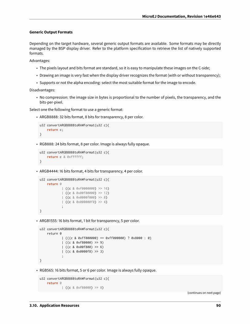
MicroEJ Documentation, Revision 1e46e643
Generic Output Formats
Depending on the target hardware, several generic output formats are available. Some formats may be directlymanaged by the BSP display driver. Refer to the platform specification to retrieve the list of natively supportedformats.
Advantages:
• The pixels layout and bits format are standard, so it is easy to manipulate these images on the C-side;
• Drawing an image is very fast when the display driver recognizes the format (with or without transparency);
• Supports or not the alpha encoding: select the most suitable format for the image to encode.
Disadvantages:
• No compression: the image size in bytes is proportional to the number of pixels, the transparency, and thebits-per-pixel.
Select one the following format to use a generic format:
• ARGB8888: 32 bits format, 8 bits for transparency, 8 per color.
u32 convertARGB8888toRAWFormat(u32 c){return c;
}
• RGB888: 24 bits format, 8 per color. Image is always fully opaque.
u32 convertARGB8888toRAWFormat(u32 c){return c & 0xffffff;
}
• ARGB4444: 16 bits format, 4 bits for transparency, 4 per color.
u32 convertARGB8888toRAWFormat(u32 c){return 0
| ((c & 0xf0000000) >> 16)| ((c & 0x00f00000) >> 12)| ((c & 0x0000f000) >> 8)| ((c & 0x000000f0) >> 4);
}
• ARGB1555: 16 bits format, 1 bit for transparency, 5 per color.
u32 convertARGB8888toRAWFormat(u32 c){return 0
| (((c & 0xff000000) == 0xff000000) ? 0x8000 : 0)| ((c & 0xf80000) >> 9)| ((c & 0x00f800) >> 6)| ((c & 0x0000f8) >> 3);
}
• RGB565: 16 bits format, 5 or 6 per color. Image is always fully opaque.
u32 convertARGB8888toRAWFormat(u32 c){return 0
| ((c & 0xf80000) >> 8)
(continues on next page)
3.10. Application Resources 90

MicroEJ Documentation, Revision 1e46e643
(continued from previous page)
| ((c & 0x00fc00) >> 5)| ((c & 0x0000f8) >> 3);
}
• A8: 8 bits format, only transparency is encoded. The color to apply when drawing the image, is the currentGraphicsContext color.
u32 convertARGB8888toRAWFormat(u32 c){return 0xff - (toGrayscale(c) & 0xff);
}
• A4: 4 bits format, only transparency is encoded. The color to apply when drawing the image, is the currentGraphicsContext color.
u32 convertARGB8888toRAWFormat(u32 c){return (0xff - (toGrayscale(c) & 0xff)) / 0x11;
}
• A2: 2 bits format, only transparency is encoded. The color to apply when drawing the image, is the currentGraphicsContext color.
u32 convertARGB8888toRAWFormat(u32 c){return (0xff - (toGrayscale(c) & 0xff)) / 0x55;
}
• A1: 1 bit format, only transparency is encoded. The color to apply when drawing the image, is the currentGraphicsContext color.
u32 convertARGB8888toRAWFormat(u32 c){return (0xff - (toGrayscale(c) & 0xff)) / 0xff;
}
• C4: 4 bits format with grayscale conversion. Image is always fully opaque.
u32 convertARGB8888toRAWFormat(u32 c){return (toGrayscale(c) & 0xff) / 0x11;
}
• C2: 2 bits format with grayscale conversion. Image is always fully opaque.
u32 convertARGB8888toRAWFormat(u32 c){return (toGrayscale(c) & 0xff) / 0x55;
}
• C1: 1 bit format with grayscale conversion. Image is always fully opaque.
u32 convertARGB8888toRAWFormat(u32 c){return (toGrayscale(c) & 0xff) / 0xff;
}
• AC44: 4 bits for transparency, 4 bits with grayscale conversion.
u32 convertARGB8888toRAWFormat(u32 c){return 0
| ((color >> 24) & 0xf0)
(continues on next page)
3.10. Application Resources 91

MicroEJ Documentation, Revision 1e46e643
(continued from previous page)
| ((toGrayscale(color) & 0xff) / 0x11);
}
• AC22: 2 bits for transparency, 2 bits with grayscale conversion.
u32 convertARGB8888toRAWFormat(u32 c){return 0
| ((color >> 28) & 0xc0)| ((toGrayscale(color) & 0xff) / 0x55);
}
• AC11: 1 bit for transparency, 1 bit with grayscale conversion.
u32 convertARGB8888toRAWFormat(u32 c){return 0
| ((c & 0xff000000) == 0xff000000 ? 0x2 : 0x0)| ((toGrayscale(color) & 0xff) / 0xff);
}
image1:ARGB8888image2:RGB565image3:A4
RLE1 Output Format
The imageengine candisplayembedded images that are encoded intoa compressed formatwhichencodes severalconsecutive pixels into one ormore 16-bits words. This encodingmanages amaximumalpha level of 2 (alpha levelis always assumed to be 2, even if the image is not transparent).
• Several consecutive pixels have the same color (2 words):
– First 16-bit word specifies howmany consecutive pixels have the same color;
– Second 16-bit word is the pixels’ color.
• Several consecutive pixels have their own color (1 + n words):
– First 16-bit word specifies howmany consecutive pixels have their own color;
– Next 16-bit word is the next pixel color.
• Several consecutive pixels are transparent (1 word):
– 16-bit word specifies howmany consecutive pixels are transparent.
Advantages:
• Supports 0 & 2 alpha encoding.
• Good compression when several consecutive pixels respect one of the three previous rules.
Disadvantages:
• Drawing an image is slightly slower than when using Display format.
3.10. Application Resources 92

MicroEJ Documentation, Revision 1e46e643
image1:RLE1
3.10.2 Fonts
Overview
Fonts are graphical resources that can be accessed with a call to ej.microui.display.Font.getFont() . To bedisplayed, these fonts have to be converted at build-time from their source format to the display raw format by thefont generator tool. Fonts that must be processed by the font generator tool are declared in MicroEJ Classpath *.fonts.list files. The file format is a standard Java properties file, each line representing a / separated resourcepath relative to the MicroEJ classpath root referring to a MicroEJ font file (usually with a .ejf file extension). Theresource may be followed by optional parameters which define :
• some ranges of characters to embed in the final raw file;
• the required pixel depth for transparency.
By default, all characters available in the input font file are embedded, and the pixel depth is 1 (i.e 1 bit-per-pixel).Example:
# The following font is embedded with all characters# without transparencycom/mycompany/MyFont1.ejf
# The following font is embedded with only the latin# unicode range without transparencycom/mycompany/MyFont2.ejf:latin
# The following font is embedded with all characters# with 2 levels of transparencycom/mycompany/MyFont2.ejf::2
MicroEJ font files conventionally end with the .ejf su�ix and are created using the Font Designer (see Font De-signer).
Font Range
The first parameter is for specifying the font ranges to embed. Selecting only a specific set of characters to embedreduces the memory footprint. Several ranges can be specified, separated by ; . There are two ways to specify acharacter range: the custom range and the known range.
Custom Range
Allows the selection of raw Unicode character ranges.
Examples:
• myfont:0x21-0x49 : Embed all characters from 0x21 to 0x49 (included);
• myfont:0x21-0x49,0x55 : Embed all characters from 0x21 to 0x49 and character 0x55;
• myfont:0x21-0x49;0x55 : Same as previous, but done by declaring two ranges.
3.10. Application Resources 93

MicroEJ Documentation, Revision 1e46e643
Known Range
A known range is a range defined by the “Unicode Character Database” version 9.0.0 available on https://home.unicode.org/. Each range is composed of sub ranges that have a unique id.
• myfont:basic_latin : Embed all Basic Latin characters;
• myfont:basic_latin;arabic : Embed all Basic Latin characters, and all Arabic characters.
Transparency
The second parameter is for specifying the font transparency level ( 1 , 2 , 4 or 8 ).
Examples:
• myfont:latin:4 : Embed all latin characters with 4 levels of transparency
• myfont::2 : Embed all characters with 2 levels of transparency
3.10.3 Native Language Support
Native Language Support (NLS) allows the application to facilitate internationalization. It provides support to ma-nipulate messages and translate them in di�erent languages. Each message to be internationalized is referencedby a key, which can be used in the application code instead of using the message directly.
Messages must be defined in PO files in the MicroEJ Classpath of the application. Here is an example:
msgid ""msgstr """Language: en_US\n""Language-Team: English\n""MIME-Version: 1.0\n""Content-Type: text/plain; charset=UTF-8\n"
msgid "Label1"msgstr "My label 1"
msgid "Label2"msgstr "My label 2"
These PO files have to be converted to be usable by the application. In order to let the build system knowwhich POfiles to process, they must be referenced in MicroEJ Classpath *.nls.list files. The file format of these *.nls.list files is a standard Java properties file. Each line represents the Full Qualified Name of a Java interface thatwill be generated and used in the application. Here is an example, let’s call it i18n.nls.list:
com.mycompany.myapp.Labelscom.mycompany.myapp.Messages
For each line, PO files whose name starts with the interface name ( Messages and Labels in the example) areretrieved from the MicroEJ Classpath and used to generate:
• a Java interface with the given FQN, containing a field for each msgid of the PO files
• a NLS binary file containing the translations
So, in the example, the generated interface com.mycompany.myapp.Labels will gather all the translations fromfiles named Labels*.po and located in the MicroEJ Classpath. PO files are generally su�ixed by their locale (
3.10. Application Resources 94
MicroEJ Documentation, Revision 1e46e643
Labels_en_US.po ) but it is only for convenience since the su�ix is not used, the locale is extracted from the POfile’s metadata.
Once the generation is done, the application can use the Java interfaces to get internationalized messages, forexample:
import com.mycompany.myapp.Labels;
public class MyClass {
String label = Labels.Label1;
...
The generation is triggered when building the application or a�er a change done in any PO or *.nls.list files.This allows to always have the Java interfaces up-to-date with the translations and to use them immediately.
The NLS API module must be added to themodule.ivy of the MicroEJ Application project, in order to allow accessto the NLS library.
<dependency org="ej.library.runtime" name="nls" rev="3.0.1"/>
3.11 Development Tools
MicroEJprovidesanumberof tools toassistwith variousaspectsof development. Someof these tools are runusingMicroEJ Tool configurations, and created using the Run Configurations dialog of the MicroEJ SDK. A configurationmust be created for the tool before it can be used.
3.11. Development Tools 95
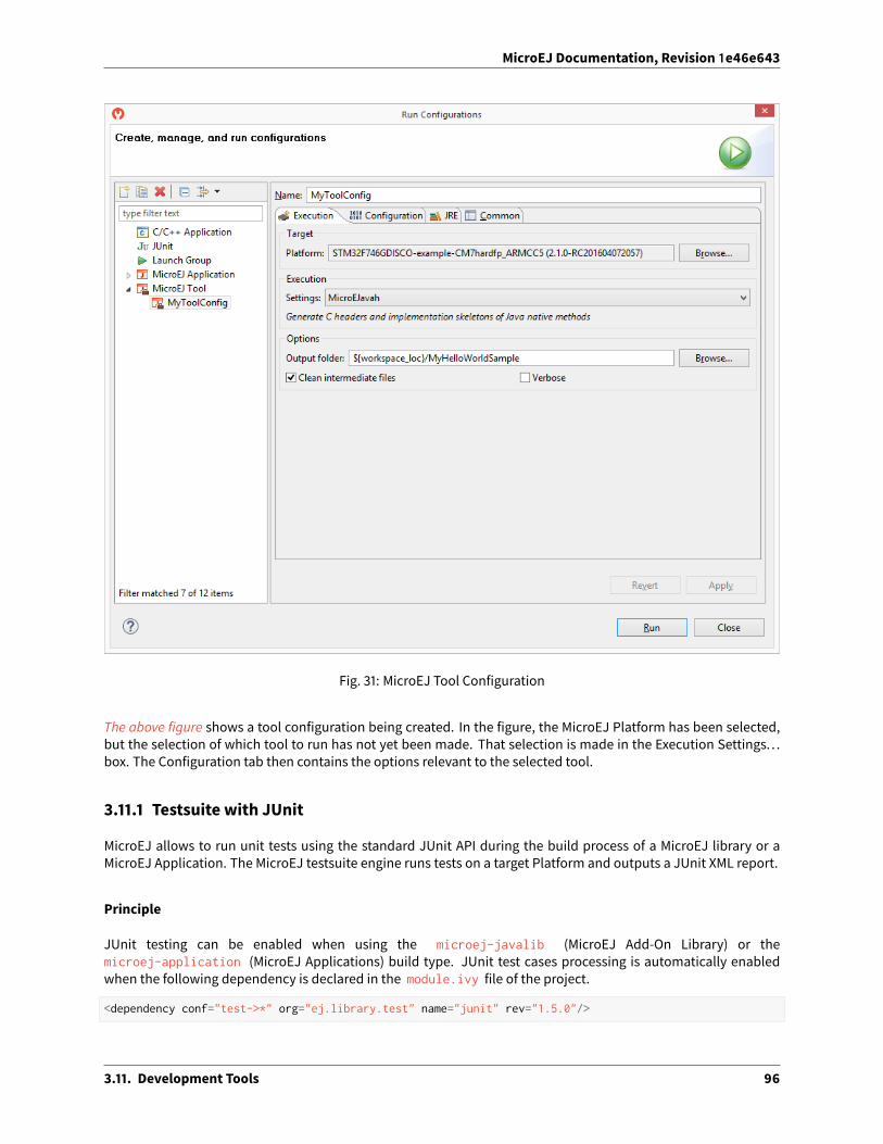
MicroEJ Documentation, Revision 1e46e643
Fig. 31: MicroEJ Tool Configuration
The above figure shows a tool configuration being created. In the figure, the MicroEJ Platform has been selected,but the selection of which tool to run has not yet been made. That selection is made in the Execution Settings. . .box. The Configuration tab then contains the options relevant to the selected tool.
3.11.1 Testsuite with JUnit
MicroEJ allows to run unit tests using the standard JUnit API during the build process of a MicroEJ library or aMicroEJ Application. The MicroEJ testsuite engine runs tests on a target Platform and outputs a JUnit XML report.
Principle
JUnit testing can be enabled when using the microej-javalib (MicroEJ Add-On Library) or themicroej-application (MicroEJ Applications) build type. JUnit test cases processing is automatically enabledwhen the following dependency is declared in the module.ivy file of the project.
<dependency conf="test->*" org="ej.library.test" name="junit" rev="1.5.0"/>
3.11. Development Tools 96

MicroEJ Documentation, Revision 1e46e643
WhenanewJUnit test case class is created in the src/test/java folder, a JUnit processor generatesMicroEJ com-pliant classes into a specific source folder named src-adpgenerated/junit/java . These files are automaticallymanaged andmust not be edited manually.
JUnit Compliance
MicroEJ is compliant with a subset of JUnit version 4. MicroEJ JUnit processor supports the following annotations:@After , @AfterClass , @Before , @BeforeClass , @Ignore , @Test .
Each test case entry point must be declared using the org.junit.Test annotation ( @Test before amethod dec-laration). Please refer to JUnit documentation to get details on usage of other annotations.
Setup a Platform for Tests
Before running tests, a target platformmust be configured in the MicroEJ workspace. The following steps assumethat a platform has been previously imported into the MicroEJ Platform repository.
Go to Window > Preferences > MicroEJ > Platforms and select the desired platform on which to run thetests.
Press F2 to expand the details.
Select the the platform path and copy it to the clipboard.
Go to Window > Preferences > Ant > Runtime and select the Properties tab.
Click on Add Property. . . button and set a new property named target.platform.dir with the platform pathpasted from the clipboard.
Setup a Project with a JUnit Test Case
This section describes how to create a new JUnit Test Case starting from a newMicroEJ library project.
First createanewmoduleprojectusing the microej-javalib skeleton. Anewprojectnamed mylibrary is createdin the workspace.
Right-click on the src/test/java folder and select New > Other. . . menu item.
Select the Java > JUnit > New JUnit Test Case wizard. Enter a test name and press Finish . A new JUnittest case class is created with a default failing test case.
Build and Run a JUnit Testsuite
Right-click on the mylibrary project and select Build Module . A�er the library is built, the testsuite enginelaunches available test cases and the build process fails in the console view.
On the mylibrary project, right-click and select Refresh .
A target~ folder appears with intermediate build files. The JUnit report is available attarget~\test\xml\TEST-test-report.xml .
Double-click on the file to open the JUnit testsuite report.
Modify the test case by replacing
3.11. Development Tools 97

MicroEJ Documentation, Revision 1e46e643
fail("Not yet implemented");
with
Assert.assertTrue(true);
Right-click again on the mylibrary project and select Build Module . The test is now successfully executed onthe target platform so the MicroEJ Add-On Library is fully built and published without errors.
Double-click on the JUnit testsuite report to see the test has been successfully executed.
Advanced Configurations
Autogenerated Test Classes
The JUnit processor generates test classes into the src-adpgenerated/junit/java folder. This folder contains:
_AllTestClasses.java file A single classwith amain enty point that sequentially calls all declared testmethodsof all JUnit test case classes.
_AllTests_[TestCase].java files For each JUnit test case class, a class with a main entry point that sequen-tially calls all declared test methods.
_SingleTest_[TestCase]_[TestMethod].java files For each test method of each JUnit test case class, a classwith a main entry point that calls the test method.
JUnit Test Case to MicroEJ Test Case
The MicroEJ testsuite engine allows to select the classes that will be executed, by setting the following property inthe project module.ivy file.
<ea:property name="test.run.includes.pattern" value="[MicroEJ Test Case Include Pattern]"/>
The following line consider all JUnit testmethodsof the sameclassasa singleMicroEJ test case (default behaviour).If at least one JUnit test method fails, the whole test case fails in the JUnit report.
<ea:property name="test.run.includes.pattern" value="**/_AllTests_*.class"/>
The following line consider each JUnit test method as a dedicated MicroEJ test case. Each test method is viewedindependently in the JUnit report, but this may slow down the testsuite execution because a new deployment isdone for each test method.
<ea:property name="test.run.includes.pattern" value="**/_SingleTest_*.class"/>
Run a Single Test Manually
Each test can be run independently as each class contains a main entry point.
In the src-adpgenerated/junit/java folder, right-click on the desired autogenerated class (_SingleTest_[TestCase]_[TestMethod].java ) and select Run As > MicroEJ Application .
The test is executed on the selected Platform and the output result is dumped into the console.
3.11. Development Tools 98

MicroEJ Documentation, Revision 1e46e643
Testsuite Options
The MicroEJ testsuite engine can be configured with specific options which can be added to the module.ivy fileof the project running the testsuite, within the <ea:build> XML element.
• Application Option Injection
It is possible to inject an Application Option for all the tests, by adding to the original option the microej.testsuite.properties. prefix:
<ea:property name="microej.testsuite.properties.[application_option_name]" value="[application_→˓option_value]"/>
• Retry Mechanism
A test execution may not be able to produce the success trace for an external reason, for example an unre-liable harness script that may lose some trace characters or crop the end of the trace. For all these unlikelyreasons, it is possible to configure the number of retries before a test is considered to have failed:
<ea:property name="microej.testsuite.retry.count" value="[nb_of_retries]"/>
By default, when a test has failed, it is not executed again (option value is set to 0 ).
Test Specific Options
The MicroEJ testsuite engine allows to define MicroEJ Launch options specific to each test case. This can be doneby defining a file with the same name as the generated test case file with the .properties extension instead ofthe .java extension. The file must be put in the src/test/resources folder and within the same package thanthe test case file.
Consult theApplicationLaunchOptionsAppendixof theDeviceDeveloper’sGuide toget the list of availableoptionsproperties.
3.11.2 Font Designer
Principle
The Font Designermodule is a graphical tool (Eclipse plugin) that runswithin theMicroEJWorkbench used to buildand edit MicroUI fonts. It stores fonts in a platform-independent format.
3.11. Development Tools 99

MicroEJ Documentation, Revision 1e46e643
Functional Description
Fig. 32: Font Generation
Font Management
Create a MicroEJ Font
To create a MicroEJ font, follow the steps below:
1. Open the Eclipse wizard: File > New > Other > MicroEJ > MicroEJ Font .
2. Select a directory and a name.
3. Click Finish.
Once the font is created, a new editor is opened: the MicroEJ Font Designer Editor.
Edit a MicroEJ Font
You can edit your font with the MicroEJ Font Designer Editor (by double-clicking on a *.ejf file or a�er runningthe newMicroEJ Font wizard).
This editor is divided into three main parts:
• The top le� part manages the main font properties.
• The top right part manages the character to embed in your font.
• The bottom part allows you to edit a set of characters or an individual character.
Main Properties
Themain font properties are:
• font size: height and width (in pixels).
• baseline (in pixels).
• space character size (in pixels).
3.11. Development Tools 100
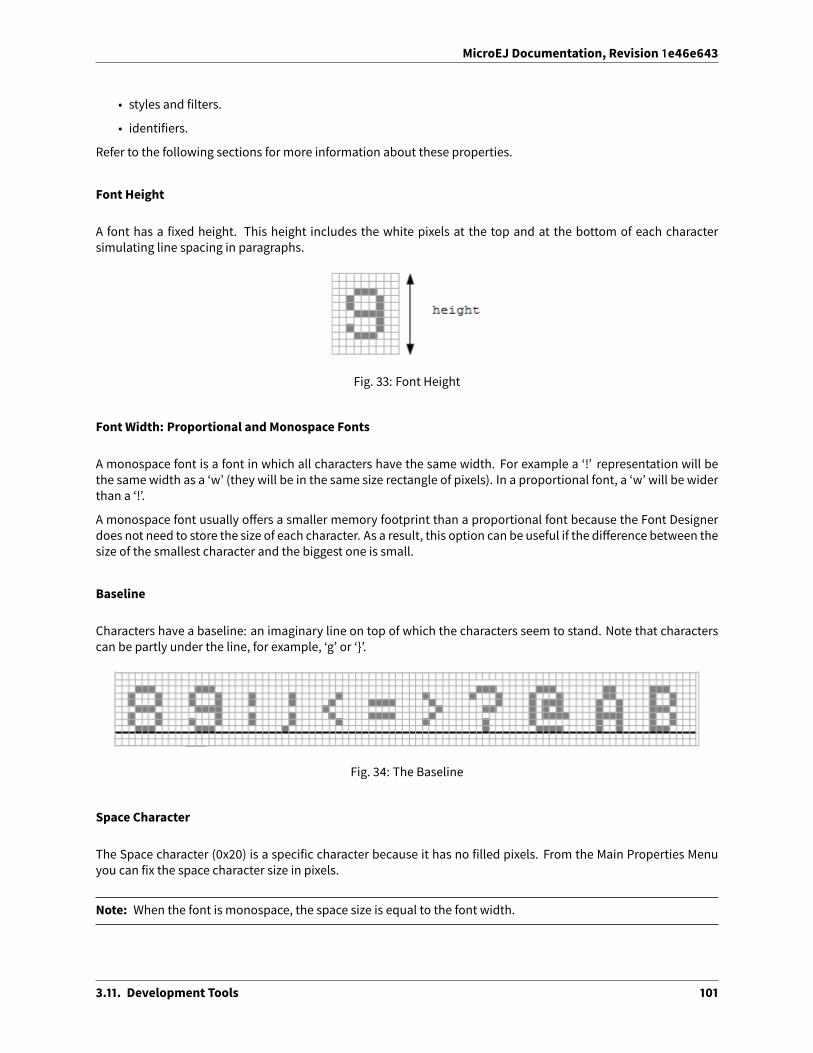
MicroEJ Documentation, Revision 1e46e643
• styles and filters.
• identifiers.
Refer to the following sections for more information about these properties.
Font Height
A font has a fixed height. This height includes the white pixels at the top and at the bottom of each charactersimulating line spacing in paragraphs.
Fig. 33: Font Height
Font Width: Proportional and Monospace Fonts
A monospace font is a font in which all characters have the same width. For example a ‘!’ representation will bethe same width as a ‘w’ (they will be in the same size rectangle of pixels). In a proportional font, a ‘w’ will be widerthan a ‘!’.
A monospace font usually o�ers a smaller memory footprint than a proportional font because the Font Designerdoes not need to store the size of each character. As a result, this option can be useful if the di�erence between thesize of the smallest character and the biggest one is small.
Baseline
Characters have a baseline: an imaginary line on top of which the characters seem to stand. Note that characterscan be partly under the line, for example, ‘g’ or ‘}’.
Fig. 34: The Baseline
Space Character
The Space character (0x20) is a specific character because it has no filled pixels. From the Main Properties Menuyou can fix the space character size in pixels.
Note: When the font is monospace, the space size is equal to the font width.
3.11. Development Tools 101

MicroEJ Documentation, Revision 1e46e643
Styles and Filters
A MicroUI font holds a style: PLAIN, BOLD, ITALIC, UNDERLINED, and the combinations between BOLD, ITALIC andUNDERLINED. Font Designer can use one file to describe several MicroUI fonts.
For example, a font file that describes a PLAIN font can also describe an UNDERLINED font because the MicroUIimplementation just has to draw a line under the characters. In this way, fromadeveloper’s point of view, there aretwo fonts: a PLAIN font and an UNDERLINED font. From the Font Designer point of view, there are also two fonts,but they use the same data file. Font Designer adds a tag to describe the UNDERLINED font in the generated fontfile.
This tag is a filter. When a file contains one or more filters, MicroUI implementation knows that it has to performpost processing to obtain a specific MicroUI font from the encoded font.
Alternatively, the user can create two distinct files to describe the two fonts. From the MicroUI application point ofview, there are always two fonts: a PLAIN font and an UNDERLINED font, but no post-processing step is required(no filter tag).
Examples:
1. A font file contains the styles PLAIN and UNDERLINED and the filters PLAIN and UNDERLINED. The MicroUIimplementation detects two MicroUI fonts. To draw each font, the PLAIN filter or the UNDERLINED filter isused accordingly.
2. A font file contains the styles PLAIN and UNDERLINED and the filter PLAIN. The MicroUI implementation de-tects two MicroUI fonts. To draw the underlined font, it will not apply the underlining process (the filter UN-DERLINED is absent). So the MicroUI underlined font will have the same rendering as the MicroUI plain font.
Font Designer features three drop-downs, one for each of BOLD, ITALIC and UNDERLINED. Each drop-down hasthree options:
• None – Font Designer will not set this style, nor include a filter for it.
• Built-in – Font Designer will set this style, but not include a filter for it.
• Dynamic – Font Designer will set this style, and include a filter for it.
If all three drop-downs are set to None, only a plain font is generated.
The number of fonts that will result is shown below the drop-downs.
Identifiers
A number of identifiers can be attached to a MicroUI font. At least one identifier is required to specify the font.Identifiers are a mechanism for specifying the contents of the font – the set or sets of characters it contains. Theidentifier may be a standard identifier (for example, LATIN) or a user-defined identifier. Identifiers are numbers,but standard identifiers, which are in the range 0 to 80, are typically associated with a handy name. A user-definedidentifier is an identifier with a value of 81 or higher.
Character List
The list of characters can be populated through the import button, which allows you to import characters fromsystem fonts, images or another MicroEJ font.
3.11. Development Tools 102

MicroEJ Documentation, Revision 1e46e643
Import from System Font
This page allows you to select the system font to use (le� part) and the range of characters. There are predefinedranges of characters below the font selection, as well as a custom selection picker (for example 0x21 to 0xfe forLatin characters).
The right part displays the selected characters with the selected font. If the background color of a displayed char-acter is red, it means that the character is too large for the defined height, or in the case of a monospace font, itmeans the character is too high or too wide. You can then adjust the font properties (font size and style) to ensurethat characters will not be truncated.
When your selection is done, click the Finish button to import this selection into your font.
Import from Images
This page allows the loading of images from a directory. The images must be named as follows: 0x[UTF-8].[extension] .
When your selection is done, click the Finish button to import the images into your font.
Character Editor
When a single character is selected in the list, the character editor is opened.
3.11. Development Tools 103

MicroEJ Documentation, Revision 1e46e643
Fig. 35: Character Editor
You can define specific properties, such as le� and right space, or index. You can also draw the character pixel bypixel - a le�-click in the grid draws the pixel, a right-click erases it.
The changes are not saved until you click the Apply button. When changes are applied to a character, the editorshows that the font has changed, so you can now save it.
The same part of the editor is also used to edit a set of characters selected in the top right list. You can then editthe common editable properties (le� and right space) for all those characters at the same time.
Working With Anti-Aliased Fonts
By default, when characters are imported from a system font, each pixel is either fully opaque or fully transparent.Fully opaque pixels show as black squares in the character grid in the right-hand part of the character editor; fullytransparent pixels show as white squares.
However, thepixels stored in an ejf file can takeoneof 256grayscale values. A fully-transparent pixel has the value255 (the RGB value for white), and a fully-opaque pixel has the value 0 (the RGB value for black). These grayscalevalues are shown in parentheses at the endof the text in the Current alpha fieldwhen themouse cursor hovers overa pixel in the grid. That field also shows the transparency level of the pixel, as a percentage, where 100% meansfully opaque.
It is possible to achieve better-looking characters by using a combination of fully-opaque and partially-transparentpixels. This technique is calledanti-aliasing. Anti-aliasedcharacters canbe imported fromsystemfontsbychecking
3.11. Development Tools 104

MicroEJ Documentation, Revision 1e46e643
the anti aliasing box in the import dialog. The ‘&’ character shown in the screenshot abovewas imported using antialiasing, and you can see the various gray levels of the pixels.
When the Font Generator converts an ejf file into the raw format used at runtime, it can create fonts with char-acters that have 1, 2, 4 or 8 bits-per-pixel (bpp). If the raw font has 8 bpp, then no conversion is necessary and thecharacters will render with the same quality as seen in the character editor. However, if the raw font has less than8 bpp (the default is 1 bpp) any gray pixels in the input file are compressed to fit, and the final rendering will be oflower quality (but less memory will be required to hold the font).
It is useful to be able to see the e�ects of this compression, so the character editor provides radio buttons that allowthe user to preview the character at 1, 2, 4, or 8 bpp. Furthermore, when 2, 4 or 8 bpp is selected, a slider allows theuser to select the transparency level of the pixels drawn when the le�mouse button is clicked in the grid.
Previewing a Font
You can preview your font by pressing the Preview. . . button, which opens the Preview wizard. In the Previewwizard, press the Select File button, and select a text file which contains text that you want to see rendered usingyour font. Characters that are in the selected text file but not available in the font will be shown as red rectangles.
3.11. Development Tools 105

MicroEJ Documentation, Revision 1e46e643
Fig. 36: Font Preview
3.11. Development Tools 106

MicroEJ Documentation, Revision 1e46e643
Removing Unused Characters
In order to reduce the size of a font file, you can reduce the number of characters in your font to be only those char-acters used by your application. To do this, create a file which contains all the characters used by your application(for example, concatenating all your NLS files is a good starting point). Then open the Previewwizard as describedabove, selecting that file. If you select the check box Delete unused on finish, then those characters that are in thefont but not in the text filewill be deleted from the fontwhen youpress the Finish button, leaving your font contain-ing theminimumnumber of characters. As this font will contain only characters used by a specific application, it isbest to prepare a “complete” font, and then apply this technique to a copy of that font to produce an applicationspecific cut-down version of the font.
Use a MicroEJ Font
A MicroEJ Font must be converted to a format which is specific to the targeted platform. The Font Generator toolperforms this operation for all fonts specified in the list of fonts configured in the application launch.
Dependencies
No dependency.
Installation
The FontDesignermodule is already installed in theMicroEJ environment. Themodule is optional for the platform,and allows the platform user to create new fonts.
Note: When the platform user already has a MicroEJ environment which provides the Font Designer module,he/she will able to create a new font even if the platform does not provide the Font Designer module.
In the platform configuration file, check UI > Font Designer to install the Font Designer module.
Use
Create a new ejf font file or open an existing one in order to open the Font Designer plugin.
3.11.3 Stack Trace Reader
Principle
Stack Trace Reader is a MicroEJ tool which reads and decodes the MicroEJ stack traces. When an exception occurs,theMicroEJ Core Engine prints the stack trace on the standard output System.out . The class names, non requiredtypes (see Types) names and method names obtained are encoded with a MicroEJ internal format. This internalformat prevents the embedding of all class names andmethod names in the flash, in order to save somememoryspace. The Stack Trace Reader tool allows you to decode the stack traces by replacing the internal class names andmethod names with their real names. It also retrieves the line number in the MicroEJ Application.
3.11. Development Tools 107

MicroEJ Documentation, Revision 1e46e643
Functional Description
The Stack Trace Reader reads the debug info from the fully linked ELF file (the ELF file that contains the MicroEJCore Engine, the other libraries, theBSP, theOS, and the compiledMicroEJ Application). It prints the decoded stacktrace.
Dependencies
No dependency.
Installation
This tool is a built-in platform tool.
Use
Write a new line to dump the currently executed stack trace on the standard output.
Fig. 37: Code to Dump a Stack Trace
Write a new line to dump the currently executed stack trace on the standard output.
Fig. 38: Code to Dump a Stack Trace
To be able to decode an application stack trace, the stack trace reader tool requires the application binary file withdebug information ( application.fodbg in the output folder). Note that the file which is uploaded on the deviceis application.fo (stripped version without debug information).
3.11. Development Tools 108

MicroEJ Documentation, Revision 1e46e643
Fig. 39: Application Binary File with Debug Information
On successful deployment, the application is started on the device and the following trace is dumped on standardoutput.
Fig. 40: Stack Trace Output
To create a new MicroEJ Tool configuration, right-click on the application project and click on Run As. . . >Run Configurations. . . .
In Execution tab, select the Stack Trace Reader tool.
3.11. Development Tools 109

MicroEJ Documentation, Revision 1e46e643
Fig. 41: Select Stack Trace Reader Tool
In Configuration tab, browse the previously generated application binary file with debug information (application.fodbg in case of a Sandboxed Application or application.out in case of a Standalone Applica-tion)
Fig. 42: Stack Trace Reader Tool Configuration (Sandboxed Application)
3.11. Development Tools 110

MicroEJ Documentation, Revision 1e46e643
Fig. 43: Stack Trace Reader Tool Configuration (Standalone Application)
Click on Run button and copy/paste the trace into the Eclipse console. The decoded trace is dumped and theline corresponding to the application hook is now readable.
Fig. 44: Read the Stack Trace
The stack trace reader can simultaneously decode heterogeneous stack traces with lines owned by di�erent ap-plications and the firmware. Other debug information files can be appended using the Additional object filesoption. Lines owned by the firmware can be decoded with the firwmare debug information file (optionally madeavailable by your firmware provider).
3.11. Development Tools 111

MicroEJ Documentation, Revision 1e46e643
The following section explains MicroEJ tool options.
Category: Stack Trace Reader
Group: Application
Option(browse): Executable file
Option Name: application.file
Default value: (empty)
Description:
Specify the full path of a full linked elf file.
Option(list): Additional object files
Option Name: additional.application.files
Default value: (empty)
Group: “Trace port” interface for Eclipse
Description:
This group describes the hardware link between the device and the PC.
3.11. Development Tools 112

MicroEJ Documentation, Revision 1e46e643
Option(combo): Connection type
Option Name: proxy.connection.connection.type
Default value: Console
Available values:
Uart (COM)
Socket
File
Console
Description:
Specify the connection type between the device and PC.
Option(text): Port
Option Name: pcboardconnection.usart.pc.port
Default value: COM0
Description:
Format: port name
Specifies the PC COM port:
Windows - COM1 , COM2 , ... , COM*n*
Linux - /dev/ttyS0 , /dev/ttyS1 , ... , /dev/ttyS*n*
Option(combo): Baudrate
Option Name: pcboardconnection.usart.pc.baudrate
Default value: 115200
Available values:
9600
38400
57600
115200
Description:
Defines the COM baudrate for PC-Device communication.
Option(text): Port
Option Name: pcboardconnection.socket.port
Default value: 5555
Description:
3.11. Development Tools 113

MicroEJ Documentation, Revision 1e46e643
IP port.
Option(text): Address
Option Name: pcboardconnection.socket.address
Default value: (empty)
Description:
IP address, on the form A.B.C.D.
Option(browse): Stack trace file
Option Name: pcboardconnection.file.path
Default value: (empty)
3.11.4 Code Coverage Analyzer
Principle
TheMicroEJSimulator features anoption tooutput .cc (CodeCoverage) files that represent theuse rateof functionsof an application. It traces how the opcodes are really executed.
Functional Description
The Code Coverage Analyzer scans the output .cc files, and outputs anHTML report to ease the analysis ofmethodscoverage. The HTML report is available in a folder named htmlReport in the same folder as the .cc files.
3.11. Development Tools 114
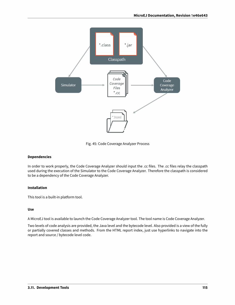
MicroEJ Documentation, Revision 1e46e643
Fig. 45: Code Coverage Analyzer Process
Dependencies
In order to work properly, the Code Coverage Analyzer should input the .cc files. The .cc files relay the classpathused during the execution of the Simulator to the Code Coverage Analyzer. Therefore the classpath is consideredto be a dependency of the Code Coverage Analyzer.
Installation
This tool is a built-in platform tool.
Use
A MicroEJ tool is available to launch the Code Coverage Analyzer tool. The tool name is Code Coverage Analyzer.
Two levels of code analysis are provided, the Java level and the bytecode level. Also provided is a view of the fullyor partially covered classes and methods. From the HTML report index, just use hyperlinks to navigate into thereport and source / bytecode level code.
3.11. Development Tools 115

MicroEJ Documentation, Revision 1e46e643
Category: Code Coverage
Option(browse): *.cc files folder
Option Name: cc.dir
Default value: (empty)
Description:
Specify a folder which contains the cc files to process (*.cc).
Group: Classes filter
Option(list): Includes
Option Name: cc.includes
Default value: (empty)
Description:
List packages and classes to include to code coverage report. If no package/class is specified, all classes found inthe project classpath will be analyzed.
Examples:
packageA.packageB.* : includes all classes which are in package packageA.packageB
packageA.packageB.className : includes the class packageA.packageB.className
3.11. Development Tools 116

MicroEJ Documentation, Revision 1e46e643
Option(list): Excludes
Option Name: cc.excludes
Default value: (empty)
Description:
List packages and classes to exclude to code coverage report. If no package/class is specified, all classes found inthe project classpath will be analyzed.
Examples:
packageA.packageB.* : excludes all classes which are in package packageA.packageB
packageA.packageB.className : excludes the class packageA.packageB.className
3.11.5 Heap Dumper & Heap Analyzer
Introduction
Heap Dumper is a tool that takes a snapshot of the heap. Generated files (with the .heap extension) are availableon the application output folder. Note that it works only on simulations. It is a built-in platform tool and has nodependencies.
The Heap Analyzer is a set of tools to help developers understand the contents of the Java heap and find problemssuch as memory leaks. For its part, the Heap Analyzer plug-in is able to open dump files. It helps you analyze theircontents thanks to the following features:
• memory leaks detection
• objects instances browse
• heap usage optimization (using immortal or immutable objects)
The Heap
The heap is a memory area used to hold Java objects created at runtime. Objects persist in the heap until they aregarbage collected. An object becomes eligible for garbage collection when there are no longer any references to itfrom other objects.
Heap Dump
A heap dump is an XML file that provides a snapshot of the heap contents at the moment the file is created. Itcontains a list of all the instances of both class and array types that exist in the heap. For each instance it records:
• The time at which the instance was created
• The thread that created it
• Themethod that created it
For instances of class types, it also records:
• The class
• The values in the instance’s non-static fields
For instances of array types, it also records:
3.11. Development Tools 117

MicroEJ Documentation, Revision 1e46e643
• The type of the contents of the array
• The contents of the array
For each referenced class type it records the values in the static fields of the class.
Heap Analyzer Tools
The Heap Analyzer is an Eclipse plugin that adds three tools to the MicroEJ environment.
Tool name Number ofinput files
Purpose
Heap Viewer 1 Shows what instances are in the heap, when they were created,and attempts to identify problem areas
ProgressiveHeap Usage
1 or more Shows how the number of instances in the heap has changed overtime
Compare 2 Compares two heap dumps, showing which objects were created,or garbage collected, or have changed values
Heap Dumper
When the Heap Dumper option is activated, the garbage collector process ends by performing a dump file thatrepresent a snapshot of the heap at this moment. Thus, to generate such dump files, you must explicitly call theSystem.gc() method in your code, or wait long enough for garbage collector activation.
The heap dump file contains the list of all instances of both class and array types that exist in the heap. For eachinstance it records:
• the time at which the instance was created
• the thread that created it
• the method that created it
For instances of class types, it also records:
• the class
• the values in the instance’s non-static fields
For instances of array types, it also records:
• the type of the contents of the array
• the contents of the array
For each referenced class type, it records the values in the static fields of the class.
3.11. Development Tools 118

MicroEJ Documentation, Revision 1e46e643
Category: Heap Dumper
Group: Application
Option(browse): Executable file
Option Name: application.filename
Default value: (empty)
Description:
Specify the full path of a full linked ELF file.
Option(list): Resident application files
Option Name: additional.application.filenames
Default value: (empty)
Description:
Specify the full path of resident applications .out files linked by the Firmware Linker.
Group: Memory
Option(browse): Heapmemory file
Option Name: heap.filename
Default value: (empty)
3.11. Development Tools 119

MicroEJ Documentation, Revision 1e46e643
Description:
Specify the full path of heapmemory dump, in Intel Hex format.
Group: Output
Option(text): Heap file name
Option Name: output.name
Default value: application.heap
Heap Viewer
To open the Heap Viewer tool, select a heap dump XML file in the Package Explorer , right-click on it and select
Open With > Heap Viewer
Alternatively, right-click on it and select Heap Analyzer > Open heap viewer
This will open a Heap Viewer tool window for the selected heap dump1 .
The Heap Viewer works in conjunction with two views:
1. The Outline view
2. The Instance Browser view
These views are described below.
The Heap Viewer tool has three tabs, each described below.
Outline View
The Outline view shows a list of all the types in the heap dump, and for each type shows a list of the instances ofthat type. When an instance is selected it also shows a list of the instances that refer to that instance. The Outlineview is opened automatically when an Heap Viewer is opened.
1 Although this is an Eclipse ‘editor’, it is not possible to edit the contents of the heap dump.
3.11. Development Tools 120

MicroEJ Documentation, Revision 1e46e643
Fig. 46: Outline View
Instance Browser View
The Instance Browser view opens automatically when a type or instance is selected in the Outline view. It has twomodes, selected using the buttons in the top right corner of the view. In ‘Fields’ mode it shows the field values forthe selected type or instance, andwhere those fields hold references it shows the fields of the referenced instance,and so on. In ‘Reference’ mode it shows the instances that refer to the selected instance, and the instances thatrefer to them, and so on.
Fig. 47: Instance Browser View - Fields mode
3.11. Development Tools 121

MicroEJ Documentation, Revision 1e46e643
Fig. 48: Instance Browser View - References mode
Heap Usage Tab
TheHeapusage page of theHeap Viewer displays four bar charts. Each chart divides the total time spanof the heapdump (from the time stampof the earliest instance creation to the time stampof the latest instance creation) into anumber of periods along the x axis, and shows, bymeans of a vertical bar, the number of instances created duringthe period.
• The top-le� chart shows the total number of instances created in each period, and is the only chart displayedwhen the Heap Viewer is first opened.
• When a type or instance is selected in the Outline view the top-right chart is displayed. This chart shows thenumber of instances of the selected type created in each time period.
• When an instance is selected in the Outline view the bottom-le� chart is displayed. This chart shows thenumber of instances created in each time period by the thread that created the selected instance.
• When an instance is selected in the Outline view the bottom-right chart is displayed. This chart shows thenumber of instances created in each time period by the method that created the selected instance.
3.11. Development Tools 122

MicroEJ Documentation, Revision 1e46e643
Fig. 49: Heap Viewer - Heap Usage Tab
Clicking on the graph area in a chart restricts the Outline view to just the types and instances that were createdduring the selected time period. Clicking on a chart but outside of the graph area restores the Outline view toshowing all types and instances2 .
The button Generate graphViz file in the top-right corner of the Heap Usage page generates a file compatible withgraphviz (www.graphviz.org).
Dominator Tree Tab
The Dominator tree page of the Heap Viewer allows the user to browse the instance reference tree which containsthe greatest number of instances. This can be useful when investigating a memory leak because this tree is likelyto contain the instances that should have been garbage collected.
The page contains two tree viewers. The top viewer shows the instances that make up the tree, starting with theroot. The le� column shows the ids of the instances – initially just the root instance is shown. The Shallow instancescolumn shows the number of instances directly referenced by the instance, and the Referenced instances columnshows the total number of instances below this point in the tree (all descendants).
2 The Outline can also be restored by selecting the All types and instances option on the drop-downmenu at the top of the Outline view.
3.11. Development Tools 123

MicroEJ Documentation, Revision 1e46e643
Thebottomviewergroups the instances thatmakeup the treeeither according to their type, the thread that createdthem, or the method that created them.
Double-clicking an instance in either viewer opens the Instance Browser view (if not already open) and shows de-tails of the instance in that view.
Fig. 50: Heap Viewer - Dominator Tree Tab
Leak Suspects Tab
The Leak suspects page of the Heap Viewer shows the result of applying heuristics to the relationships betweeninstances in the heap to identify possible memory leaks.
The page is in three parts.
• The top part lists the suspected types (classes). Suspected types are classes which, based on numbers ofinstances and instance creation frequency, may be implicated in a memory leak.
• Themiddle part lists accumulation points. An accumulation point is an instance that references a high num-ber of instances of a type that may be implicated in a memory leak.
• The bottom part lists the instances accumulated at an accumulation point.
3.11. Development Tools 124

MicroEJ Documentation, Revision 1e46e643
Fig. 51: Heap Viewer - Leak Suspects Tab
Progressive Heap Usage
To open the Progressive HeapUsage tool, select one ormore heap dumpXML files in the Package Explorer , right-
click and select Heap Analyzer > Show progressive heap usage
This tool is much simpler than the Heap Viewer described above. It comprises three parts.
• The top-right part is a line graph showing the total number of instances in the heap over time, based on thecreation times of the instances found in the heap dumps.
• The le� part is a pane with three tabs, one showing a list of types in the heap dump, another a list of threadsthat created instances in the heap dump, and the third a list of methods that created instances in the heapdump.
• The bottom-le� is a line graph showing the number of instances in the heap over time restricted to thoseinstances that match with the selection in the le� pane. If a type is selected, the graph shows only instancesof that type; if a thread is selected the graph shows only instances created by that thread; if a method isselected the graph shows only instances created by that method.
3.11. Development Tools 125

MicroEJ Documentation, Revision 1e46e643
Fig. 52: Progressive Heap Usage
Compare Heap Dumps
The Compare tool compares the contents of two heap dump files. To open the tool select two heap dump XML filesin the Package Explorer, right-click and select Heap Analyzer > Compare
The Compare tool shows the types in the old heap on the le�-hand side, and the types in the new heap on theright-hand side, andmarks the di�erences between them using di�erent colors.
Types in the old heapdumpare colored red if there are one ormore instances of this typewhich are in the old dumpbut not in the new dump. Themissing instances have been garbage collected.
Types in the new heap dump are colored green if there are one or more instances of this type which are in the newdump but not in the old dump. These instances were created a�er the old heap dumpwas written.
Clicking to the right of the type name unfolds the list to show the instances of the selected type.
3.11. Development Tools 126

MicroEJ Documentation, Revision 1e46e643
Fig. 53: Compare Heap Dumps
The combo box at the top of the tool allows the list to be restricted in various ways:
• All instances – no restriction.
• Garbage collected and new instances – showonly the instances that exist in the old heap dumpbut not in thenew dump, or which exist in the new heap dump but not in the old dump.
• Persistent instances – show only those instances that exist in both the old and new dumps.
• Persistent instanceswith value changed– showonly those instances that exist inboth theoldandnewdumpsand have one or more di�erences in the values of their fields.
Instance Fields Comparison View
TheCompare toolworks in conjunctionwith the InstanceFieldsComparisonview,whichopensautomaticallywhenan instance is selected in the tool.
The view shows the values of the fields of the instance in both the old and new heap dumps, and highlights anydi�erences between the values.
3.11. Development Tools 127

MicroEJ Documentation, Revision 1e46e643
Fig. 54: Instance Fields Comparison view
3.11.6 ELF to Map File Generator
Principle
The ELF to Map generator takes an ELF executable file and generates a MicroEJ compliant .map file. Thus, any ELFexecutable file produced by third party linkers can be analyzed and interpreted using theMemory Map Analyzer.
Functional Description
Fig. 55: ELF To Map Process
3.11. Development Tools 128
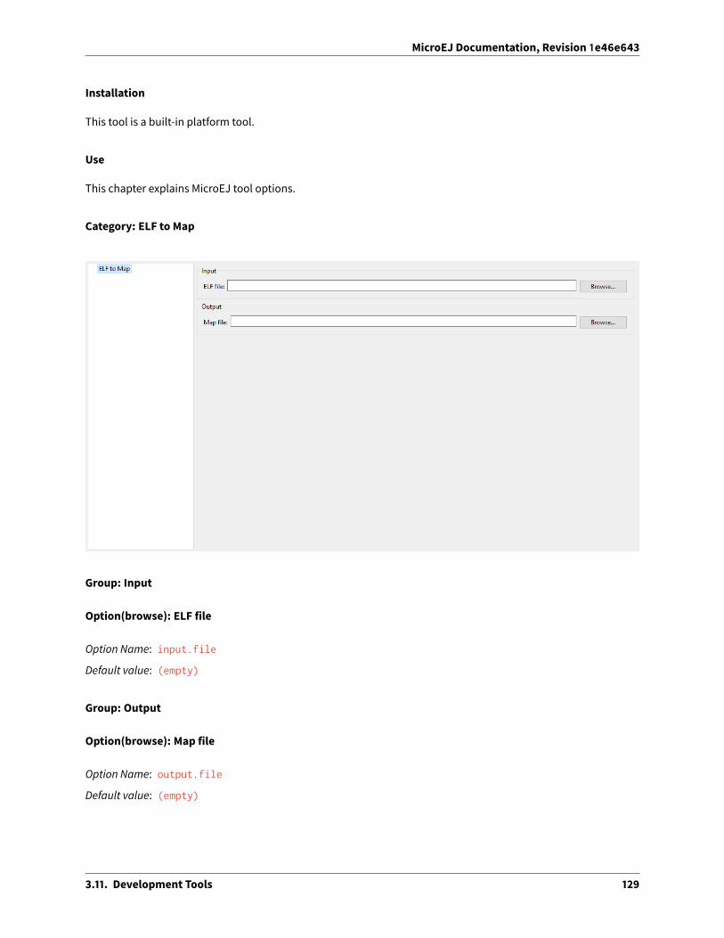
MicroEJ Documentation, Revision 1e46e643
Installation
This tool is a built-in platform tool.
Use
This chapter explains MicroEJ tool options.
Category: ELF to Map
Group: Input
Option(browse): ELF file
Option Name: input.file
Default value: (empty)
Group: Output
Option(browse): Map file
Option Name: output.file
Default value: (empty)
3.11. Development Tools 129

MicroEJ Documentation, Revision 1e46e643
3.11.7 Serial to Socket Transmitter
Principle
The MicroEJ serialToSocketTransmitter is a piece of so�ware which transfers all bytes from a serial port to a tcpclient or tcp server.
Installation
This tool is a built-in platform tool.
Use
This chapter explains MicroEJ tool options.
Category: Serial to Socket
Group: Serial Options
Option(text): Port
Option Name: serail.to.socket.comm.port
Default value: COM0
Description: Defines the COM port:
Windows - COM1 , COM2 , ... , COM*n*
Linux - /dev/ttyS0 , /dev/ttyUSB0 , ... , /dev/ttyS*n* , /dev/ttyUSB*n*
3.11. Development Tools 130

MicroEJ Documentation, Revision 1e46e643
Option(combo): Baudrate
Option Name: serail.to.socket.comm.baudrate
Default value: 115200
Available values:
9600
38400
57600
115200
Description: Defines the COM baudrate.
Group: Server Options
Option(text): Port
Option Name: serail.to.socket.server.port
Default value: 5555
Description: Defines the server IP port.
3.11.8 Memory Map Analyzer
Principle
When a MicroEJ Application is linked with the MicroEJ Workbench, a Memory MAP file is generated. The MemoryMap Analyzer (MMA) is an Eclipse plug-in made for exploring the map file. It displays the memory consumption ofdi�erent features in the RAM and ROM.
3.11. Development Tools 131

MicroEJ Documentation, Revision 1e46e643
Functional Description
Fig. 56: Memory Map Analyzer Process
In addition to the executable file, the MicroEJ Platform generates a map file. Double click on this file to open theMemory Map Analyzer.
Dependencies
No dependency.
Installation
This tool is a built-in platform tool.
Use
Themap file is available in the MicroEJ Application project output directory.
3.11. Development Tools 132

MicroEJ Documentation, Revision 1e46e643
Fig. 57: Retrieve Map File
Select an item (or several) to show the memory used by this item(s) on the right. Select “All” to show the memoryused by all items. This special item performs the same action as selecting all items in the list.
Fig. 58: Consult Full Memory
Select an item in the list, and expand it to see all symbols used by the item. This view is useful in understandingwhy a symbol is embedded.
3.11. Development Tools 133

MicroEJ Documentation, Revision 1e46e643
Fig. 59: Detailed View
3.11.9 Event Tracing
Description
Event Tracing allows to record integer based events for debugging and monitoring purposes without a�ecting ex-ecution performance too heavily. Basically, it gives access to Tracer objects that are named and can produce alimited number of di�erent event types.
A record is an event type identified by an eventID and can have a list of values. It can be a single event or a periodof time with a start and an end.
Event Tracing can be accessed from two APIs:
• A Java API, provided by the Trace API module. The following dependency must be added to themodule.ivyof the MicroEJ Application project:
<dependency org="ej.api" name="trace" rev="1.1.0"/>
• A C API, provided by the Platform header file named LLTRACE_impl.h .
Events are recorded if and only if:
• the MicroEJ Core Engine trace system is enabled,
• and trace recording is started.
To enable the MicroEJ Core Engine trace system, set the Application Option named core.trace.enabled to true(see also launch configuration).
Then, multiple ways are available to start and stop the trace recording:
3.11. Development Tools 134

MicroEJ Documentation, Revision 1e46e643
• by setting the Application Option named core.trace.autostart to true to automatically start at startup(see also launch configuration),
• using the Java API methods ej.trace.Tracer.startTrace() and ej.trace.Tracer.stopTrace() ,
• using the C API functions LLTRACE_IMPL_start(void) and LLTRACE_IMPL_stop(void) .
Java API Usage
The detailed Trace API documentation is available here.
First, you need to instantiate a Tracer object by calling its constructor with two parameters. The first parameter,name , is a String that will represent the Tracer object group’s name. The second parameter, nbEventTypes , is aninteger representing the maximum number of event types available for the group.
Tracer tracer = new Tracer("MyGroup", 10);
Then, you can record an event by calling the recordEvent(int eventId) method. The event ID needs to be inthe range 0 to nbEventTypes-1 with nbEventTypes the maximum number of event types set when initializingthe Tracer object. Methods named recordEvent(...) always needs the event ID as the first parameter and canhave up to ten integer parameters as custom values for the event.
To record the end of an event, call the method recordEventEnd(int eventID) . It will trace the duration of anevent previously recorded with one of the recordEvent(int) methods. The recordEventEnd(...) method canalso have another integer parameter for a customvalue for the event end. One can use it to trace the returned valueof a method.
The Trace API also provides a String constant Tracer.TRACE_ENABLED_CONSTANT_PROPERTY representing the Con-stant value of core.trace.enabled option. This constant can be used to remove at build time portions of codewhen the trace system is disabled. To do that, just surround tracer record calls with a if statement that checks theconstant’s state. When the constant is set to false , the code inside the if statement will not be embedded withthe application and thus will not impact the performances.
if(Constants.getBoolean(Tracer.TRACE_ENABLED_CONSTANT_PROPERTY)) {// This code is not embedded if TRACE_ENABLED_CONSTANT_PROPERTY is set to false.tracer.recordEventEnd(0);
}
Examples:
• Trace a single event:
private static final Tracer tracer = new Tracer("Application", 100);
public static void main(String[] args) {Tracer.startTrace();tracer.recordEvent(0);
}
Standard Output:
VM START[TRACE] [1] Declare group "Application"[TRACE] [1] Event 0x0
• Trace a method with a start event showing the parameters of the method and an end event showing theresult:
3.11. Development Tools 135

MicroEJ Documentation, Revision 1e46e643
private static final Tracer tracer = new Tracer("Application", 100);
public static void main(String[] args) {Tracer.startTrace();int a = 14;int b = 54;add(a, b);
}
public static int add(int a, int b) {tracer.recordEvent(1, a, b);int result = a + b;tracer.recordEventEnd(1, result);return result;
}
Standard Output:
VM START[TRACE] [1] Declare group "Application"[TRACE] [1] Event 0x1 (14 [0xE],54 [0x36])[TRACE] [1] Event End 0x1 (68 [0x44])
Platform Implementation
By default, when enabled, the Trace API displays a message in the standard output for every recordEvent(...)and recordEventEnd(...) method calls.
It does not print a timestampwhen displaying the tracemessage because it can drastically a�ect execution perfor-mances. It only prints the ID of the recorded event followed by the values given in parameters.
A Platform can connect its own implementation by overriding the functions defined in the LLTRACE_impl.h file.
MicroEJ provides an implementation for SEGGER SystemView tool. Please contact MicroEJ Support formore infor-mation about how to integrate this Platformmodule.
3.12 Advanced Tools
3.12.1 MicroEJ Linker
Overview
MicroEJ Linker is a standard linker that is compliant with the Executable and Linkable File format (ELF).
MicroEJ Linker takes one or several relocatable binary files and generates an image representation using a descrip-tion file. The process of extracting binary code, positioning blocks and resolving symbols is called linking.
Relocatable object files are generated by SOAR and third-party compilers. An archive file is a container of Relocat-able object files.
The description file is called a Linker Specific Configuration file (lsc). It describeswhat shall be embedded, andhowthose things shall be organized in the program image. The linker outputs :
3.12. Advanced Tools 136

MicroEJ Documentation, Revision 1e46e643
• An ELF executable file that contains the image and potential debug sections. This file can be directly used bydebuggers or programming tools. It may also be converted into a another format (Intel* hex, Motorola* s19,rawBinary, etc.) using external tools, such as standard GNU binutils toolchain (objcopy, objdump, etc.).
• A map file, in XML format, which can be viewed as a database of what has been embedded and resolved bythe linker. It can be easily processed to get a sort of all sizes, call graphs, statistics, etc.
• The linker is composed with one or more library loaders, according to the platform’s configuration.
ELF Overview
An ELF relocatable file is split into several sections:
• allocation sections representing a part of the program
• control sections describing the binary sections (relocation sections, symbol tables, debug sections, etc.)
An allocation section can hold some image binary bytes (assembler instructions and raw data) or can refer to aninterval of memory which makes sense only at runtime (statics, main stack, heap, etc.). An allocation section is anatomic block and cannot be split. A section has a name that by convention, represents the kind of data it holds.For example, .text sections hold binary instructions, .bss sections hold read-write static data, .rodata holdread-only data, and .data holds read-write data (initialized static data). Thename is used in the .lsc file to organizesections.
A symbol is an entity made of a name and a value. A symbol may be absolute (link-time constant) or relative to asection: Its value is unknown until MicroEJ Linker has assigned a definitive position to the target section. A symbolcan be local to the relocatable file or global to the system. All global symbol names should be unique in the system(the name is the key that connects an unresolved symbol reference to a symbol definition). A sectionmay need thevalue of symbols to be fully resolved: the address of a function called, address of a static variable, etc.
Linking Process
The linking process can be divided into three main steps:
1. Symbols and sections resolution. Starting from root symbols and root sections, the linker embeds all sec-tions targeted by symbols and all symbols referred by sections. This process is transitive while new symbolsand/or sections are found. At the endof this step, the linkermay stop andoutput errors (unresolved symbols,duplicate symbols, unknown or bad input libraries, etc.)
2. Memory positioning. Sections are laid out in memory ranges according to memory layout constraints de-scribed by the lsc file. Relocations are performed (in other words, symbol values are resolved and sectioncontents are modified). At the end of this step, the linker may stop and output errors (it could not resolveconstraints, such as not enoughmemory, etc.)
3. An output ELF executable file andmap file are generated.
A partial map file may be generated at the end of step 2. It provides useful information to understand why the linkphase failed. Symbol resolution is the process of connecting a global symbol name to its definition, found in one ofthe linker input units. The order the units are passed to the linker may have an impact on symbol resolution. Therules are :
• Relocatable object files are loaded without order. Two global symbols defined with the same name result inan unrecoverable linker error.
• Archive files are loaded on demand. When a global symbolmust be resolved, the linker inspects each archiveunit in the order it was passed to the linker. When an archive contains a relocatable object file that declaresthe symbol, the object file is extracted and loaded. Then the first rule is applied. It is recommended that yougroup object files in archives asmuch as possible, in order to improve load performances. Moreover, archivefiles are the only way to tie with relocatable object files that share the same symbols definitions.
3.12. Advanced Tools 137

MicroEJ Documentation, Revision 1e46e643
• A symbol name is resolved to a weak symbol if - and only if - no global symbol is found with the same name.
Linker Specific Configuration File Specification
Description
A Linker Specific Configuration (Lsc) file contains directives to link input library units. An lsc file is written in an XMLdialect, and its contents can be divided into two principal categories:
• Symbols and sections definitions.
• Memory layout definitions.
Listing 5: Example of Relocation of Runtime Data from FLASH to RAM
<?xml version="1.0" encoding="UTF-8"?><!--
An example of linker specific configuration file--><lsc name="MyAppInFlash">
<include name="subfile.lscf"/><!--
Define symbols with arithmetical and logical expressions--><defSymbol name="FlashStart" value="0"/><defSymbol name="FlashSize" value="0x10000"/><defSymbol name="FlashEnd" value="FlashStart+FlashSize-1"/><!--
Define FLASH memory interval--><defSection name="FLASH" start="FlashStart" size="FlashSize"/>
<!--Some memory layout directives
--><memoryLayout ranges ="FLASH">
<sectionRef name ="*.text"/><sectionRef name ="*.data"/>
</memoryLayout></lsc>
File Fragments
An lsc file can be physically divided into multiple lsc files, which are called lsc fragments. Lsc fragments may beloaded directly from the linker path option, or indirectly using the include tag in an lsc file.
Lsc fragments start with the root tag lscFragment . By convention the lsc fragments file extension is .lscf . Fromhere to the end of the document, the expression “the lsc file” denotes the result of the union of all loaded (directlyand indirectly loaded) lsc fragments files.
Symbols and Sections
A new symbol is defined using defSymbol tag. A symbol has a name and an expression value. All symbols definedin the lsc file are global symbols.
3.12. Advanced Tools 138

MicroEJ Documentation, Revision 1e46e643
A new section is defined using the defSection tag. A section may be used to define a memory interval, or definea chunk of the final image with the description of the contents of the section.
Memory Layout
A memory layout contains an ordered set of statements describing what shall be embedded. Memory positioningcan be viewed asmoving a cursor into intervals, appending referenced sections in the order they appear. A symbolcan be defined as a “floating” item: Its value is the value of the cursor when the symbol definition is encountered.In the example below, the memory layout sets the FLASH section. First, all sections named .text are embedded.Thematching sections are appended in a undefined order. To reference a specific section, the section shall have aunique name (for example a reset vector is commonly called .reset or .vector , etc.). Then, the floating symboldataStart is set to the absolute address of the virtual cursor right a�er embedded .text sections. Finally allsections named .data are embedded.
A memory layout can be relocated to a memory interval. The positioning works in parallel with the layout ranges,as if there were two cursors. The address of the section (used to resolve symbols) is the address in the relocatedinterval. Floating symbols can refer either to the layout cursor (by default), or to the relocated cursor, using therelocation attribute. A relocation layout is typically used to embed data in a program image that will be usedat runtime in a read-write memory. Assuming the program image is programmed in a read only memory, one ofthe first jobs at runtime, before starting the main program, is to copy the data from read-only memory to RAM ,because the symbols targeting the data have been resolvedwith the address of the sections in the relocated space.To perform the copy, the program needs both the start address in FLASH where the data has been put, and thestart address in RAM where the data shall be copied.
Listing 6: Example of Relocation of Runtime Data from FLASH to RAM
<memoryLayout ranges="FLASH" relocation="RAM" image="true"><defSymbol name="DataFlashStart" value="."/><defSymbol name="DataRamStart" value=" ." relocation="true"/><sectionRef name=".data"/><defSymbol name="DataFlashLimit" value="."/>
</memoryLayout>
Note: the symbol DataRamStart is defined to the start address where .data sections will be inserted in RAMmemory.
Tags Specification
Here is the complete syntactical and semantical description of all available tags of the .lsc file.
Table 5: Linker Specific Configuration TagsTags Attributes Description
defSectionDefines a new section. A floating section only holds a declared sizeattribute. A fixed section declares at least one of the start / end at-tributes. When this tag is empty, the section is a runtime section, andmust define at least one of the start , end or size attributes. Whenthis tag is not empty (when it holds a binary description), the sectionis an image section.
Continued on next page
3.12. Advanced Tools 139

MicroEJ Documentation, Revision 1e46e643
Table 5 – continued from previous pageTags Attributes Description
name Name of the section. The section name may not be unique. However,it is recommended that you define a unique name if the section mustbe referred separately for memory positioning.
start Optional. Expression defining the absolute start address of the sec-tion. Must be resolved to a constant a�er the full load of the lsc file.
end Optional. Expression defining the absolute end address of the section.Must be resolved to a constant a�er the full load of the lsc file.
size Optional. Expression defining the size in bytes of the section. Invari-ant: (end-start)+1=size . Must be resolved to a constant a�er thefull load of the lsc file.
align Optional. Expression defining the alignment in bytes of the section.rootSection Optional. Boolean value. Sets this section as a root section to be em-
bedded even if it is not targeted by any embedded symbol. See alsorootSection tag.
symbolPrefix Optional. Used in collaboration with symbolTags . Prefix of symbolsembedded in the auto-generated section. See Auto-generated Sec-tions.
symbolTags Optional. Used in collaboration with symbolPrefix . Comma sepa-rated list of tags of symbols embedded in the auto-generated section.See Auto-generated Sections.
defSymbolDefines a new global symbol. Symbol name must be unique in thelinker context
name Name of the symbol.type Optional. Type of symbol usage. Thismay be necessary to set the type
of a symbol when using third party ELF tools. There are three types: -none : default. No special type of use. - function : symbol describesa function. - data : symbol describes some data.
value The value "." defines a floating symbol that holds the current cur-sor position in a memory layout. (This is the only form of this tag thatcan be used as a memoryLayout directive) Otherwise value is an ex-pression. A symbol expression must be resolved to a constant a�ermemory positioning.
relocation Optional. The only allowed value is true . Indicates that the valueof the symbol takes the address of the current cursor in the memorylayout relocation space. Only allowed on floating symbols.
rootSymbol Optional. Boolean value. Sets this symbol as a root symbol that mustbe resolved. See also rootSymbol tag.
weak Optional. Boolean value. Sets this symbol as a weak symbol.
group memoryLayout directive. Defines a named group of sections. Groupnamemay be used in expressionmacros START , END , SIZE . All mem-oryLayout directives are allowed within this tag (recursively).
name The name of the group.
includeIncludes an lsc fragment file, semantically the same as if the fragmentcontents were defined in place of the include tag.
name Name of the file to include. When the name is relative, the file sepa-rator is / , and the file is relative to the directory where the currentlsc file or fragment is loaded. When absolute, the name describes aplatform-dependent filename.
lscRoot tag for an .lsc file.
name Name of the lsc file. The ELF executable output will be {name}.out ,and the map file will be {name}.map
Continued on next page
3.12. Advanced Tools 140

MicroEJ Documentation, Revision 1e46e643
Table 5 – continued from previous pageTags Attributes DescriptionlscFragment Root tag for an lsc file fragment. Lsc fragments are loaded from the
linker path option, or included from a master file using the includetag.
memoryLayoutDescribes the organization of a set of memory intervals. The memorylayouts are processed in the order in which they are declared in thefile. The same interval may be organized in several layouts. Each lay-out starts at the value of the cursor the previous layout ended. The fol-lowing tags are allowedwithin amemoryLayout directive: defSymbol(under certain conditions), group , memoryLayoutRef , padding , andsectionRef .
ranges Exclusivewithdefault. Comma-separatedordered list of fixed sectionsto which the layout is applied. Sections represent memory segments.
image Optional. Boolean value. false if not set. If true , the layout de-scribes a part of the binary image: Only image sections can be embed-ded. If false , only runtime sections can be embedded.
relocation Optional. Name of the section to which this layout is relocated.name Exclusive with ranges. Defines a named memoryLayout directive in-
stead of specifying a concrete memory location. May be included in aparent memoryLayout using memoryLayoutRef.
memoryLayoutRefmemoryLayout directive. Provides an extension-point mechanism toinclude memoryLayout directives defined outside the current one.
name All directives of memoryLayout defined with the same name are in-cluded in an undefined order.
paddingmemoryLayout directive. Append padding bytes to the current cursor.Either size or align attributes should be provided.
size Optional. Expressionmust be resolved to a constant a�er the full loadof the lsc file. Increment the cursor position with the given size.
align Optional. Expressionmust be resolved to a constant a�er the full loadof the lsc file. Move the current cursor position to thenext address thatmatches the given alignment. Warning: when used with relocation,the relocation cursor is also aligned. Keep in mind this may increasethe cursor position with a di�erent amount of bytes.
address Optional. Expressionmust be resolved to a constant a�er the full loadof the lsc file. Move the current cursor position to the given absoluteaddress.
fill Optional. Expressionmust be resolved to a constant a�er the full loadof the lsc file. Fill padding with the given value (32 bits).
rootSectionReferences a section name that must be embedded. This tag is not adefinition. It forces the linker to embed all loaded sections matchingthe given name.
name Name of the section to be embedded.
rootSymbolReferences a symbol thatmust be resolved. This tag is not a definition.It forces the linker to resolve the value of the symbol.
name Name of the symbol to be resolved.
sectionRefMemory layout statement. Embeds all sections matching the givenname starting at the current cursor address.
file Select only sections defined in a linker unit matching the given filename. The file name is the simple namewithout any file separator, e.g.bsp.o or mylink.lsc . Link units may be object files within archiveunits.
Continued on next page
3.12. Advanced Tools 141

MicroEJ Documentation, Revision 1e46e643
Table 5 – continued from previous pageTags Attributes Description
name Name of the sections to embed. When the name ends with *, all sec-tions starting with the given name are embedded (name completion),except sections that are embedded in another sectionRef using the ex-act name (without completion).
symbol Optional. Only embeds the section targeted by the given symbol. Thisis the only way at link level to embed a specific section whose name isnot unique.
force Optional. Deprecated. Replaced by the rootSection tag. The onlyallowed value is true . By default, for compaction, the linker embedsonly what is needed. Setting this attribute will force the linker to em-bed all sections that appear in all loaded relocatable files, even sec-tions that are not targeted by a symbol.
sort Optional. Specifies that the sections must be sorted in memory. Thevalue can be: - order : the sections will be in the same order as theinput files - name : the sections are sorted by their file names - unit: the sections declared in an object file are grouped and sorted in theorder they are declared in the object file
u4Binary section statement. Describes the four next raw bytes of thesection. Bytes are organized in the endianness of the target ELF ex-ecutable.
value Expression must be resolved to a constant a�er the full load of the lscfile (32 bits value).
fileBinary section statement. Fills the section with the given expression.Bytes are organized in the endianness of the target ELF executable.
size Expression defining the number of bytes to be filled.value Expression must be resolved to a constant a�er the full load of the lsc
file (32 bits value).
Expressions
An attribute expression is a value resulting from the computation of an arithmetical and logical expression. Sup-ported operators are the same operators supported in the Java language, and follow Java semantics:
• Unary operators: + , - , ~ , !
• Binary operators: + , - , * , / , % , << , >>> , >> , < , > , <= , >= , == , != , &, | , ^ ,&& , ||
• Ternary operator: cond ? ifTrue : ifFalse
• Built-in macros:
– START(name) : Get the start address of a section or a group of sections
– END(name) : Get the end address of a section or a group of sections
– SIZE(name) : Get the size of a section or a group of sections. Equivalent to END(name)-START(name)
– TSTAMPH() , TSTAMPL() : Get 32 bits linker time stamp (high/low part of system time in milliseconds)
– SUM(name,tag) : Get the sum of an auto-generated section (Auto-generated Sections) column. The col-umn is specified by its tag name.
An operand is either a sub expression, a constant, or a symbol name. Constantsmay bewritten in decimal ( 127 ) orhexadecimal form ( 0x7F ). There are no boolean constants. Constant value 0 means false , and other constants’values mean true . Examples of use:
3.12. Advanced Tools 142

MicroEJ Documentation, Revision 1e46e643
value="symbol+3"value="((symbol1*4)-(symbol2*3)"
Note: Ternary expressions can be used to define selective linking because they are the only expressions that mayremain partially unresolved without generating an error. Example:
<defSymbol name="myFunction" value="condition ? symb1 : symb2"/>
No error will be thrown if the condition is true and symb1 is defined, or the condition is false and symb2 isdefined, even if the other symbol is undefined.
Auto-generated Sections
TheMicroEJ Linker allows you to define sections that are automatically generatedwith symbol values. This is com-monly used to generate tables whose contents depends on the linked symbols. Symbols eligible to be embeddedin an auto-generated section are of the form: prefix_tag_suffix . An auto-generated section is viewed as a tablecomposed of lines and columns that organize symbols sharing the same prefix. On the same column appear sym-bols that share the same tag. On the same line appear symbols that share the same su�ix. Lines are sorted in thelexical order of the symbol name. The next line defines a sectionwhichwill embed symbols startingwith zeroinit. The first column refers to symbols starting with zeroinit_start_ ; the second column refers to symbols startingwith zeroinit_end_ .
<defSectionname=".zeroinit"symbolPrefix="zeroInit"symbolTags="start,end"
/>
Consider there are four defined symbols named zeroinit_start_xxx , zeroinit_end_xxx ,zeroinit_start_yyy and zeroinit_end_yyy . The generated section is of the form:
0x00: zeroinit_start_xxx0x04: zeroinit_end_xxx0x08: zeroinit_start_yyy0x0C: zeroinit_end_yyy
If there are missing symbols to fill a line of an auto-generated section, an error is thrown.
Execution
MicroEJ Linker can be invoked through an ANT task. The task is installed by inserting the following code in an ANTscript
<taskdefname="linker"classname="com.is2t.linker.GenericLinkerTask"classpath="[LINKER_CLASSPATH]"
/>
[LINKER_CLASSPATH] is a list of path-separated jar files, including the linker and all architecture-specific libraryloaders.
The following code shows a linker ANT task invocation and available options.
3.12. Advanced Tools 143

MicroEJ Documentation, Revision 1e46e643
<linkerdoNotLoadAlreadyDefinedSymbol="[true|false]"endianness="[little|big|none]"generateMapFile="[true|false]"ignoreWrongPositioningForEmptySection="[true|false]"lsc="[filename]"linkPath="[path1:...pathN]"mergeSegmentSections="[true|false]"noWarning="[true|false]"outputArchitecture="[tag]"outputName="[name]"stripDebug="[true|false]"toDir="[outputDir]"verboseLevel="[0...9]"
><!-- ELF object & archives files using ANT paths / filesets --><fileset dir="xxx" includes="*.o"><fileset file="xxx.a"><fileset file="xxx.a">
<!-- Properties that will be reported into .map file --><property name="myProp" value="myValue"/>
</linker>
3.12. Advanced Tools 144

MicroEJ Documentation, Revision 1e46e643
Table 6: Linker Options DetailsOption Description
doNotLoadAlreadyDefinedSymbolSilently skip the load of a global symbol if it has alreadybeen loaded before. ( false by default. Only the firstloaded symbol is taken into account (in the order inputfiles are declared). This option only a�ects the load se-mantic for global symbols, and does not modify the se-mantic for loading weak symbols and local symbols.
endiannessExplicitly declare linker endianness [little, big] or[none] for auto-detection. All input files must declarethe same endianness or an error is thrown.
generateMapFileGenerate the .map file ( true by default).
ignoreWrongPositioningForEmptySectionSilently ignore wrong section positioning for zero sizesections. ( false by default).
lscProvideamaster lsc file. Thisoption ismandatoryunlessthe linkPath option is set.
linkPathProvide a set of directories into which to load link filefragments. Directories are separated with a platform-path separator. This option ismandatory unless the lscoption is set.
noWarningSilently skip the output of warning messages.
mergeSegmentSections(experimental). Generate a single section per segment.Thismay speed up the load of the output executable fileinto debuggers or flasher tools. ( false by default).
outputArchitectureSet the architecture tag for the output ELF file (ELF ma-chine id).
outputNameSpecify the output name of the generated files. By de-fault, take the name provided in the lsc tag. The outputELF executable filenamewill be name.out. Themap file-name will be name.map.
stripDebugRemove all debug information from the output ELF file.A stripped output ELF executable holds only the binaryimage (no remaining symbols, debug sections, etc.).
toDirSpecify the output directory in which to store generatedfiles. Output filenames are in the form: od + separator+ value of the lsc name attribute + suffix .By default, without this option, files are generated in thedirectory fromwhich the linker was launched.
verboseLevelPrint additionalmessages on the standard output aboutlinking process.
Error Messages
This section lists MicroEJ Linker error messages.
Table 7: Linker-Specific Configuration TagsMessage ID Description0 The linker has encountered an unexpected internal error. Please contact the support hot-
line.Continued on next page
3.12. Advanced Tools 145

MicroEJ Documentation, Revision 1e46e643
Table 7 – continued from previous page1 A library cannot be loaded with this linker. Try verbose to check installed loaders.2 No lsc file provided to the linker.3 A file could not be loaded. Check the existence of the file and file access rights.4 Conflicting input libraries. Aglobal symboldefinitionwith thesamenamehasalreadybeen
loaded from a previous object file.5 Completion (*) could not be used in association with the force attribute. Must be an exact
name.6 A required section refers to an unknown global symbol. Maybe input libraries are missing.7 A library loader has encountered an unexpected internal error. Check input library file in-
tegrity.8 Floating symbols can only be declared inside memoryLayout tags.9 Invalid value format. For example, the attribute relocation in defSymbol must be a
boolean value.10 Missing one of the following attributes: address , size , align .11 Toomany attributes that cannot be used in association.13 Negative padding. Memory layout cursor cannot decrease.15 Not enough space in the memory layout intervals to append all sections that need to be
embedded. Check the output map file to get more information about what is required asmemory space.
16 A block is referenced but has already been embedded. Most likely a block has been espe-cially embedded using the force attribute and the symbol attribute.
17 A block that must be embedded has nomatching sectionRef statement.19 An IO error occurred when trying to dump one of the output files. Check the output direc-
tory option and file access rights.20 size attribute expected.21 The computed size does not match the declared size.22 Sections defined in the lsc file must be unique.23 One of the memory layout intervals refers to an unknown lsc section.24 Relocation must be done in one and only one contiguous interval.25 force and symbol attributes are not allowed together.26 XML char data not allowed at this position in the lsc file.27 A section which is a part of the program image must be embedded in an image memory
layout.28 A section which is not a part of the program image must be embedded in a non-image
memory layout.29 Expression could not be resolved to a link-time constant. Some symbols are unresolved.30 Sections used in memory layout ranges must be sections defined in the lsc file.31 Invalid character encountered when scanning the lsc expression.32 A recursive include cycle was detected.33 An alignment inconsistency was detected in a relocation memory layout. Most likely one
of the start addresses of the memory layout is not aligned on the current alignment.34 An error occurs in a relocation resolution. In general, the relocation has a value that is out
of range.35 symbol and sort attributes are not allowed together.36 Invalid sort attribute value is not one of order , name , or no .37 Attribute start or end in defSection tag is not allowedwhendefining a floating section.38 Autogenerated section can build tables according to symbol names (see Auto-generated
Sections). A symbol is needed to build this section but has not been loaded.39 Deprecated featurewarning. Remains for backward compatibility. It is recommended that
you use the new indicated feature, because this feature may be removed in future linkerreleases.
Continued on next page
3.12. Advanced Tools 146

MicroEJ Documentation, Revision 1e46e643
Table 7 – continued from previous page40 Unknownoutput architecture. Either the architecture ID is invalid, or the library loader has
not been loaded by the linker. Check loaded library loaders using verbose option.41. . .43 Reserved.44 Duplicate group definition. A group name is unique and cannot be defined twice.45 Invalid endianness. The endianness mnemonic is not one of the expected mnemonics (
little,big,none ).46 Multiple endiannesses detected within loaded input libraries.47 Reserved.48 Invalid type mnemonic passed to a defSymbol tag. Must be one of none , function , or
data .49 Warning. A directory of link path is invalid (skipped).50 No linker-specific description file could be loaded from the link path. Check that the link
path directories are valid, and that they contain .lsc or .lscf files.51 Exclusive options (these options cannot be used simultaneously). For example,
-linkFilename and -linkPath are exclusive; either select amaster lsc file or a path fromwhich to load .lscf files.
52 Name given to a memoryLayoutRef or a memoryLayout is invalid. It must not be empty.53 A memoryLayoutRef with the same name has already been processed.54 A memoryLayout must define ranges or the name attribute.55 Nomemory layout foundmatching the name of the current memoryLayoutRef .56 A named memoryLayout is declaredwith a relocation directive, but the relocation interval
is incompatible with the relocation interval of the memoryLayout that referenced it.57 A named memoryLayout has not been referenced. Every declared memoryLayout must
be processed. A named memoryLayout must be referenced by a memoryLayoutRef state-ment.
58 SUM operator expects an auto-generated section.59 SUM operator tag is unknown for the targetted auto-generated section.60 SUM operator auto-generated section name is unknown.61 An option is set for an unknown extension. Most likely the extension has not been set to
the linker classpath.62 Reserved.63 ELF unit flags are inconsistent with flags set using the -forceFlags option.64 Reserved.65 Reserved.66 Found an executable object file as input (expected a relocatable object file).67 Reserved.68 Reserved.69 Reserved.70 Not enough memory to achieve the linking process. Try to increase JVM heap that is run-
ning the linker (e.g. by adding option -Xmx1024M to the JRE command line).
Map File Interpretor
The map file interpretor is a tool that allows you to read, classify and display memory information dumped bythe linker map file. The map file interpretor is a graph-oriented tool. It supports graphs of symbols and allowsstandard operations on them (union, intersection, subtract, etc.). It can also dump graphs, compute graph totalsizes, list graph paths, etc.
The map file interpretor uses the standard Java regular expression syntax.
It is used internally by the graphicalMemory Map Analyzer tool.
Commands:
3.12. Advanced Tools 147

MicroEJ Documentation, Revision 1e46e643
• createGraph graphName symbolRegExp ... section=regexp
createGraph all section=.*
Recursively create a graph of symbols from root symbols and sections described as regular expressions. Forexample, to extract the complete graph of the application:
• createGraphNoRec symbolRegExp ... section=regexp
The above line is similar to the previous statement, but embeds only declared symbols and sections (withoutrecursive connections).
• removeGraph graphName
Removes the graph for memory.
• listGraphs
Lists all the created graphs in memory.
• listSymbols graphName
Lists all graph symbols.
• listPadding
Lists the padding of the application.
• listSections graphName
Lists all sections targeted by all symbols of the graph.
• inter graphResult g1 ... gn
Creates a graph which is the intersection of g1/\ ... /\gn .
• union graphResult g1 ... gn
Creates a graph which is the union of g1\/ ...\/ gn .
• substract graphResult g1 ... gn
Creates a graph which is the substract of g1\ ... \ gn .
• reportConnections graphName
Prints the graph connections.
• totalImageSize graphName
Prints the image size of the graph.
• totalDynamicSize graphName
Prints the dynamic size of the graph.
3.12. Advanced Tools 148

MicroEJ Documentation, Revision 1e46e643
• accessPath symbolName
The above line prints one of the paths from a root symbol to this symbol. This is very useful in helping youunderstand why a symbol is embedded.
• echo arguments
Prints raw text.
• exec commandFile
Execute the given commandFile. The path may be absolute or relative from the current command file.
3.12.2 Testsuite Engine
Definition
The MicroEJ Testsuite is an engine made for validating any development project using automatic testing. The Mi-croEJ Testsuite engine allows the user to test any kind of projects within the configuration of a generic ant file.
Using the MicroEJ Testsuite Ant tasks
Multiple Ant tasks are available in the testsuite-engine provided jar:
• testsuite allows the user to run a given testsuite and to retrieve an XML report document in a JUnit format.
• javaTestsuite is a subtask of the testsuite task, used to run a specialized testsuite for Java (will only runJava classes).
• htmlReport is a task which will generate an HTML report from a list of JUnit report files.
The testsuite Task
This task have somemandatory attributes to fill:
• outputDir : the output folder of the testsuite. The final report will be generated at [outputDir]/[label]/[reportName].xml , see the testsuiteReportFileProperty and testsuiteReportDirProperty at-tributes.
• harnessScript : the harness script must be an Ant script and it is the script which will be called for each testby the testsuite engine. It is calledwith a basedir located at output locationof the current test. The testsuiteengine will provide to it some properties giving all the informations to start the test:
– testsuite.test.name : The output name of the current test in the report. Default value is the relativepath of the test. It can bemanually set by the user. More details on the output name are available in thesection Specific Custom Properties.
– testsuite.test.path : The current test absolute path in the filesystem.
– testsuite.test.properties : The absolute path to the custom properties of the current test (see theproperty customPropertiesExtension )
– testsuite.common.properties : The absolute path to the common properties of all the tests (see theproperty commonProperties )
– testsuite.report.dir : The absolute path to the directory of the final report.
3.12. Advanced Tools 149

MicroEJ Documentation, Revision 1e46e643
Some attributes are optional, and if not set by the user, a default value will be attributed.
• timeOut : the time in seconds before any test is considerated as unknown. Set it to 0 to disable the time-out.Will be defaulted as 60.
• verboseLevel : the required level to output messages from the testsuite. Can be one of those values: error,warning, info, verbose, debug. Will be defaulted as info.
• reportName : the final report name (without extension). Default value is testsuite-report .
• customPropertiesExtension : the extension of the custom properties for each test. For instance, if it isset to .options , a test named xxx/Test1.class will be associated with xxx/Test1.options . If a fileexists for a test, the property testsuite.test.properties is set with its absolute path and given to theharnessScript . If the test path references a directory, then the customproperties path is the concatenationof the test path and the customPropertiesExtension value. By default, custom properties extension is.properties .
• commonProperties : the properties to apply to every test of the testsuite. Those optionsmight be overriddenby the customproperties of each test. If this option is set and the file exists, theproperty testsuite.common.properties is set to the absolute path of the harnessScript file. By default, there is not any commonproperties.
• label : the build label. Will be generated as a timestamp by the testsuite if not set.
• productName : the name of the current tested product. Default value is TestSuite .
• jvm : the location of your Java VM to start the testsuite (the harnessScript is called as is: [jvm] [...]-buildfile [harnessScript] ). Will be defaulted as your java.home location if the property is set, or tojava .
• jvmargs : the arguments to pass to the Java VM started for each test.
• testsuiteReportFileProperty : the nameof the Ant property inwhich is stored the path of the final report.Default value is testsuite.report.file and path is [outputDir]/[label]/[reportName].xml
• testsuiteReportDirProperty : the name of the Ant property in which is store the path of the directory ofthe final report. Default value is testsuite.report.dir and path is [outputDir]/[label]
• testsuiteResultProperty : the name of the Ant property in which you want to have the result of the test-suite (true or false), depending if every tests successfully passed the testsuite or not. Ignored tests do nota�ect this result.
Finally, you have to give as nested element the path containing the tests.
• testPath : containing all the file of the tests which will be launched by the testsuite.
• testIgnoredPath (optional): Any test in the intersection between testIgnoredPath and testPath will beexecuted by the testsuite, but will not appear in the JUnit final report. It will still generate a JUnit report foreach test, which will allow the HTML report to let them appears as “ignored” if it is generated. Mostly usedfor known bugs which are not considered as failure but still relevant enough to appears on the HTML report.
The javaTestsuite Task
This task extends the testsuite task, specializing the testsuite to only start real Java class. This task will retrievethe classname of the tests from the classfile and will provide new properties to the harness script:
• testsuite.test.class : The classname of the current test. The value of the property testsuite.test.name is also set to the classname of the current test.
• testsuite.test.classpath : The classpath of the current test.
3.12. Advanced Tools 150

MicroEJ Documentation, Revision 1e46e643
The htmlReport Task
This task allow the user to transform a given path containing a sample of JUnit reports to anHTML detailled report.Here is the attributes to fill:
• A nested fileset containing all the JUnit reports of each test. Take care to exclude the final JUnit report gen-erated by the testsuite.
• A nested element report
– format : The format of the generated HTML report. Must be noframes or frames . When noframesformat is choosen, a standalone HTML file is generated.
– todir : The output folder of your HTML report.
– The report tag accepts the nested tag param with name and expression attributes. These tags canpass XSL parameters to the stylesheet. The built-in stylesheets support the following parameters:
* PRODUCT : the product name that is displayed in the title of the HTML report.
* TITLE : the comment that is displayed in the title of the HTML report.
Note: Tip : It is advised to set the format to noframes if your test suite is not a Java testsuite. If the format is set toframes , with a non-JavaMicroEJ Testsuite, the name of the links will not be relevant because of the non-existencyof packages.
Using the Trace Analyzer
This section will shortly explains how to use the Trace Analyzer . The MicroEJ Testsuite comes with an archivecontaining the Trace Analyzer which can be used to analyze the output trace of an application. It can be usedfrom di�erent forms;
• The FileTraceAnalyzer will analyze a file and research for the given tags, failing if the success tag is notfound.
• The SerialTraceAnalyzer will analyze the data from a serial connection.
The TraceAnalyzer Tasks Options
Here is the common options to all TraceAnalyzer tasks:
• successTag : the regular expression which is synonym of success when found (by default .*PASSED.* ).
• failureTag : the regular expression which is synonym of failure when found (by default .*FAILED.* ).
• verboseLevel : int value between 0 and 9 to define the verbose level.
• waitingTimeAfterSuccess : waiting time (in s) a�er success before closing the stream (by default 5).
• noActivityTimeout : timeout (in s) with no activity on the stream before closing the stream. Set it to 0 todisable timeout (default value is 0).
• stopEOFReached : boolean value. Set to true to stop analyzing when input stream EOF is reached. If false, continue until timeout is reached (by default false ).
• onlyPrintableCharacters : boolean value. Set to true to only dumpASCII printable characters (by defaultfalse ).
3.12. Advanced Tools 151

MicroEJ Documentation, Revision 1e46e643
The FileTraceAnalyzer Task Options
Here is the specific options of the FileTraceAnalyzer task:
• traceFile : path to the file to analyze.
The SerialTraceAnalyzer Task Options
Here is the specific options of the SerialTraceAnalyzer task:
• port : the comm port to open.
• baudrate : serial baudrate (by default 9600).
• databits : databits (5|6|7|8) (by default 8).
• stopBits : stopbits (0|1|3 for (1_5)) (by default 1).
• parity : none | odd | event (by default none ).
Appendix
The goal of this section is to explain some tips and tricks thatmight be useful in your usage of the testsuite engine.
Specific Custom Properties
Some customproperties are specifics and retrieved from the testsuite engine in the customproperties file of a test.
• The testsuite.test.name property is the output name of the current test. Here are the steps to computethe output name of a test:
– If the custom properties are enabled and a property named testsuite.test.name is find on the cor-responding file, then the output name of the current test will be set to it.
– Otherwise, if the running MicroEJ Testsuite is a Java testsuite, the output name is set to the class nameof the test.
– Otherwise, from the path containing all the tests, a common prefix will be retrieved. The output namewill be set to the relative path of the current test from this common prefix. If the common prefix equalsthe name of the test, then the output name will be set to the name of the test.
– Finally, if multiples tests have the same output name, then the current name will be followed by _XXX, an underscore and an integer.
• The testsuite.test.timeout property allow the user to redefine the time out for each test. If it is negativeor not an integer, then global timeout defined for the MicroEJ Testsuite is used.
Dependencies
No dependency.
Installation
This tool is a built-in platform tool.
3.12. Advanced Tools 152

CHAPTER
FOUR
PLATFORM DEVELOPER GUIDE
4.1 Introduction
4.1.1 Scope
This document explains how the core features of MicroEJ Architecture are accessed, configured and used by theMicroEJ Platform builder. It describes the process for creating and augmenting a MicroEJ Architecture. This doc-ument is concise, but attempts to be exact and complete. Semantics of implemented Foundation Libraries aredescribed in their respective specifications. This document includes an outline of the required low level drivers(LLAPI) for porting the MicroEJ Architectures to di�erent real-time operating systems (RTOS).
MicroEJ Architecture is state-of-the-art, with embedded MicroEJ runtimes for MCUs. They also provide simulatedruntimes that execute on workstations to allow so�ware development on “virtual hardware.”
4.1.2 Intended Audience
The audience for this document is so�ware engineers who need to understand how to create and configure a Mi-croEJ Platform using the MicroEJ Platform builder. This document also explains how a MicroEJ Application caninteroperate with C code on the target, and the details of the MicroEJ Architecture modules, including their APIs,error codes and options.
4.1.3 MicroEJ Architecture Modules Overview
MicroEJ Architecture features theMicroEJCore Engine: a tiny and fast runtime associatedwith aGarbageCollector.It provides four built-in Foundation Libraries :
• [BON]
• EDC
• [SNI]
• [SP]
The following figure shows the components involved.
153
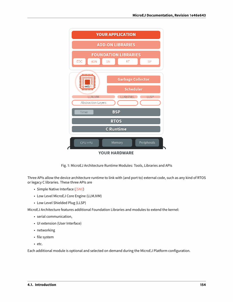
MicroEJ Documentation, Revision 1e46e643
Fig. 1: MicroEJ Architecture Runtime Modules: Tools, Libraries and APIs
Three APIs allow the device architecture runtime to link with (and port to) external code, such as any kind of RTOSor legacy C libraries. These three APIs are
• Simple Native Interface ([SNI])
• Low Level MicroEJ Core Engine (LLMJVM)
• Low Level Shielded Plug (LLSP)
MicroEJ Architecture features additional Foundation Libraries andmodules to extend the kernel:
• serial communication,
• UI extension (User Interface)
• networking
• file system
• etc.
Each additional module is optional and selected on demand during the MicroEJ Platform configuration.
4.1. Introduction 154

MicroEJ Documentation, Revision 1e46e643
4.2 MicroEJ Platform
4.2.1 Process Overview
This section summarizes the steps required to build a MicroEJ Platform and obtain a binary file to deploy on aboard.
The following figure shows the overall process. The first three steps are performed within the MicroEJ Platformbuilder. The remaining steps are performed within the C IDE.
Fig. 2: Overall Process
1. Step 1 consists in creating a new MicroEJ Platform configuration project. This project describes the MicroEJ
4.2. MicroEJ Platform 155

MicroEJ Documentation, Revision 1e46e643
Platform (MicroEJ architecture, metadata, etc.).
2. Step 2 allows you to select which modules available in MicroEJ Architecture will be installed in the MicroEJPlatform.
3. Step 3 builds the MicroEJ Platform according to the choices made in steps 1 and 2.
4. Step 4 compiles a MicroEJ Application against the MicroEJ Platform in order to obtain an application file tolink in the BSP.
5. Step 5 consists in compiling the BSP and linking it with the MicroEJ Application that was built previously, instep 4.
6. Step 6 is the final step: Deploy the binary application onto a board.
4.2.2 Concepts
MicroEJ Platform
A MicroEJ Platform includes development tools and a runtime environment.
The runtime environment consists of:
• A MicroEJ Core Engine.
• Some Foundation Libraries.
• Some C libraries.
The development tools are composed of:
• Java APIs to compile MicroEJ Application code.
• Documentation: this guide, library specifications, etc.
• Tools for development and compilation.
• Launch scripts to run the simulation or build the binary file.
• Eclipse plugins.
MicroEJ Platform Configuration
A MicroEJ Platform is described by a .platform file. This file is usually called [name].platform , and is stored atthe root of a MicroEJ Platform configuration project called [name]-configuration .
The configuration file is recognized by the MicroEJ Platform builder. The MicroEJ Platform builder o�ers a visual-ization with two tabs:
4.2. MicroEJ Platform 156

MicroEJ Documentation, Revision 1e46e643
Fig. 3: MicroEJ Platform Configuration Overview Tab
This tab groups the basic platform information used to identify it: its name, its version, etc. These tags can beupdated at any time.
4.2. MicroEJ Platform 157

MicroEJ Documentation, Revision 1e46e643
Fig. 4: MicroEJ Platform Configuration Content Tab
This tab shows all additional modules (see Modules) which can be installed into the platform in order to augmentits features. The modules are sorted by groups and by functionality. When amodule is checked, it will be installedinto the platform during the platform creation.
Modules
The primary mechanism for augmenting the capabilities of aMicroEJ Platform is to addmodules to it.
A MicroEJ module is a group of related files (Foundation Libraries, scripts, link files, C libraries, Simulator, tools,etc.) that together provide all or part of a platform capability. Generally, these files serve a common purpose. Forexample, providing an API, or providing a library implementation with its associated tools.
The list of modules is in the second tab of the platform configuration tab. A module may require a configurationstep to be installed into the platform. The Modules Detail view indicates if a configuration file is required.
Low Level API Pattern
Principle
Each time the usermust supply C code that connects a platformcomponent to the target, a LowLevel API is defined.There is a standard pattern for the implementation of these APIs. Each interface has a name and is specified by two
4.2. MicroEJ Platform 158

MicroEJ Documentation, Revision 1e46e643
header files:
• [INTERFACE_NAME].h specifies the functions that make up the public API of the implementation. In somecases the user code will never act as a client of the API, and so will never use this file.
• [INTERFACE_NAME]_impl.h specifies the functions that must be coded by the user in the implementation.
The user creates implementations of the interfaces, each captured in a separate C source file. In the simplest formof this pattern, only one implementation is permitted, as shown in the illustration below.
Fig. 5: Low Level API Pattern (single implementation)
The following figure shows a concrete example of an LLAPI. The Cworld (the board support package) has to imple-ment a send function andmust notify the library using a receive function.
4.2. MicroEJ Platform 159

MicroEJ Documentation, Revision 1e46e643
Fig. 6: Low Level API Example
Multiple Implementations and Instances
When a Low Level API allows multiple implementations, each implementation must have a unique name. At run-time theremaybe one ormore instances of each implementation, and each instance is represented by a data struc-ture that holds information about the instance. The address of this structure is the handle to the instance, and thataddress is passed as the first parameter of every call to the implementation.
The illustration below shows this form of the pattern, but with only a single instance of a single implementation.
4.2. MicroEJ Platform 160

MicroEJ Documentation, Revision 1e46e643
Fig. 7: Low Level API Pattern (multiple implementations/instances)
The #define statement in MYIMPL.c specifies the name given to this implementation.
4.2.3 MicroEJ Platform Creation
This section describes the steps to create a new MicroEJ Platform in MicroEJ SDK, and options to connect it to anexternal Board Support Package (BSP) as well as a third-party C toolchain.
MicroEJ SDKmust be started on a new emptyworkspace.
MicroEJ Architecture Import
The first step is to choose and import a MicroEJ Architecture. MicroEJ Architectures for most common microcon-troller instructions sets and compilers can be downloaded from https://repository.microej.com/architectures/1.
MicroEJ Architecture files ends with the .xpf extension, and are classified using the following folder naming con-vention:
com/microej/architecture/[ISA]/[TOOLCHAIN]/[UID]/[VERSION]/[UID]-[VERSION]-[USAGE].xpf
• ISA : instruction set architecture (e.g. CM4 for Arm® Cortex®-M4, ESP32 for Espressif ESP32, . . . ).
• TOOLCHAIN : C compilation toolchain (e.g. CM4hardfp_GCC48 ).1 MicroEJ Architectures for production can be retrieved from the license server.
4.2. MicroEJ Platform 161

MicroEJ Documentation, Revision 1e46e643
• VERSION : module version (e.g. 7.12.0 ).
• UID : Architecture unique ID (e.g. flopi4G25 ).
• USAGE = eval for evaluation Architectures, prod for production Architectures.
For example, MicroEJ Architecture versions for Arm®Cortex®-M4microcontrollers compiledwith GNUCC toolchainis available at https://repository.microej.com/architectures/com/microej/architecture/CM4/CM4hardfp_GCC48/flopi4G25/.
Once you downloaded a MicroEJ Architecture file, proceed with the following steps to import it in MicroEJ SDK:
• Select File > Import > MicroEJ > Architectures .
• Browse an .xpf file or a folder that contains one or more an .xpf files.
• Check the I agree and accept the above terms and conditions. . . box to accept the license.
• Click on Finish button.
Note: A MicroEJ Architecture can be imported using MicroEJ Module Manager, by adding the following line in amodule description file:
<dependency org="com.microej.architecture.[ISA].[TOOLCHAIN]" name="[UID]" rev="[VERSION]" conf="default→˓"><artifact name="[UID]" m:classifier="[USAGE]" ext="xpf"/>
</dependency>
MicroEJ Platform Configuration
The next step is to create a MicroEJ Platform configuration:
• Select File > New > MicroEJ Platform Project. . . .
• Click on Next button. TheConfigure Target Architecture page allows to select theMicroEJ Architecture thatcontains aminimalMicroEJ Platformand a set of compatiblemodules targeting a processor architecture anda compilation toolchain. This environment can be changed later.
– Click on Browse. . . button to select one of the installed MicroEJ Architecture.
– Check the Create from a platform reference implementation box to use one of the available imple-mentation. Uncheck it if you want to provide your own implementation or if no reference implementa-tion is available.
• Click on Next button. The Configure platform properties page contains the identification of theMicroEJ Platform to create. Most fields aremandatory, you should therefore set them. Note that their valuescan bemodified later on.
• Click on Finish button. A new project [device]-[name]-[toolchain] is being created containing a[name].platform file. A Platform description editor shall then open.
• Install Platform Configuration Additions. Files within the content folder have to be copied tothe configuration project folder, by following instructions described at https://github.com/MicroEJ/PlatformQualificationTools/blob/master/framework/platform/README.rst.
You should get a MicroEJ Platform configuration project that looks like:
4.2. MicroEJ Platform 162
https://repository.microej.com/architectures/com/microej/architecture/CM4/CM4hardfp_GCC48/flopi4G25/

MicroEJ Documentation, Revision 1e46e643
Fig. 8: MicroEJ Platform Configuration Project Skeleton
Groups / Modules Selection
From the Platform description editor, select the Content tab to access the Platform modules selection. Modulescan be selected/deselected from the Modules frame.
Modules are organized into groups. When a group is selected, by default, all its modules are selected. To view themodules making up a group, click on the Show/Hide modules icon on the top-right of the frame. This will let youselect/deselect on a per module basis. Note that individual module selection is not recommended.
The description and contents of an item (group or module) are displayed beside the list on item selection.
All the checkedmodules will be installed in the Platform.
4.2. MicroEJ Platform 163

MicroEJ Documentation, Revision 1e46e643
Fig. 9: MicroEJ Platform Configuration Modules Selection
Modules Customization
Each selectedmodule canbecustomizedbycreatinga [module] foldernameda�er themodulebeside the [name].platform definition. It may contain:
• An optional [module].properties file named a�er the module name. These properties will be injected in theexecution context prefixed by the module name. Some properties might be needed for the configuration ofsomemodules. Please refer to the modules documentation for more information.
• Optional module specific files and folders.
Modifying one of these files requires to build the Platform again.
Platform Customization
Platforms can be customized by creating a configuration.xml Ant file beside the [name].platform file. ThisAnt script can extend one or several of the extension points available. By default, you should not have to changethe default configuration script.
Here is a template for a configuration.xml Ant file:
4.2. MicroEJ Platform 164

MicroEJ Documentation, Revision 1e46e643
<?xml version="1.0" encoding="UTF-8"?><project name="configuration">
<!--Define "project.dir" property that references the directorywhere this file is located.
--><dirname property="project.dir" file="${ant.file.configuration}"/>
</project>
Configuration project (the project which contains the [name].platform file) can contain an optional dropinsfolder. The contents of this folder will be copied integrally into the final Platform. This feature allows to add someadditional libraries, tools etc. into the Platform.
The dropins folder organization should respect the final Platform files and folders organization. For instance, thetools are located in the sub-folder tools . Launch a Platform build without the dropins folder to see how thePlatform files and folders organization is. Then fill the dropins folder with additional features and build again thePlatform to obtain an advanced Platform.
The dropins folder files are kept in priority. If one file has the same path and name as another file already installedinto the Platform, the dropins folder file will be kept.
Modifying one of these files requires to build the Platform again.
BSP Connection
Principle
Using a MicroEJ Platform, the user can compile a MicroEJ Application on that Platform. The result of this compila-tion is a microejapp.o file.
This file has to be linked with the MicroEJ Platform runtime file ( microejruntime.a ) and a third-party C project,called the Board Support Package (BSP) , to obtain the final binary file (MicroEJ Firmware). For more information,please consult theMicroEJ build process overview.
The BSP connection can be configured by defining 4 folders where the following files are located:
• MicroEJ Application file ( microejapp.o ).
• MicroEJ Platform runtime file ( microejruntime.a , also available in the Platform lib folder).
• MicroEJ Platform header files ( *.h , also available in the Platform include folder).
• BSP project build script file ( build.bat or build.sh ).
Once the MicroEJ Application file ( microejapp.o ) is built, the files are then copied to these locations and thebuild.bat or build.sh file is executed to produce the final executable file ( application.out ).
Note: The final build stage to produce the executable file can be done outside of MicroEJ SDK, and thus the BSPconnection configuration is optional.
BSP connection configuration is only required in the following cases:
• Use MicroEJ SDK to produce the final executable file of a Mono-Sandbox Firmware (recommended).
• Use MicroEJ SDK to run aMicroEJ Testsuite on device.
• Build a Multi-Sandbox Firmware.
4.2. MicroEJ Platform 165

MicroEJ Documentation, Revision 1e46e643
MicroEJ provides a flexible way to configure the BSP connection to target any kind of projects, teams organizationsand company build flows. To achieve this, the BSP connection can be configured either at MicroEJ Platform levelor at MicroEJ Application level (or a mix of both).
The 3 most common integration cases are:
• Case 1: No BSP connection
The MicroEJ Platform does not know the BSP at all.
BSP connection can be configured when building the MicroEJ Application (absolute locations).
Fig. 10: MicroEJ Platform with no BSP connection
This case is recommended when:
– the MicroEJ Firmware is built outside MicroEJ SDK.
– the same MicroEJ Platform is intended to be reused on multiple BSP projects which do not share thesame structure.
• Case 2: Partial BSP connection
The MicroEJ Platform knows how the BSP is structured.
BSP connection is configuredwhenbuilding theMicroEJ Platform (relative locationswithin theBSP), and theBSP root location is configured when building the MicroEJ Application (absolute directory).
Fig. 11: MicroEJ Platform with partial BSP connection
This case is recommended when:
– the MicroEJ Platform is used to build one MicroEJ Application on top of one BSP.
4.2. MicroEJ Platform 166

MicroEJ Documentation, Revision 1e46e643
– the Application and BSP are slightly coupled, thus making a change in the BSP just require to build thefirmware again.
• Case 3: Full BSP connection
The MicroEJ Platform includes the BSP.
BSP connection is configured when building MicroEJ Platform (relative locations within the BSP), as well asthe BSP root location (absolute directory). No BSP connection configuration is required when building theMicroEJ Application.
Fig. 12: MicroEJ Platform with full BSP connection
This case is recommended when:
– the MicroEJ Platform is used to build various MicroEJ Applications.
– the MicroEJ Platform is validated using MicroEJ testsuites.
– the MicroEJ Platform and BSP are delivered as a single standalonemodule (same versioning), perhapssubcontracted to a team or a company outside the application project(s).
Options
BSP connection options can be specified as Platform options or as Application options or a mix of both.
The following table describes Platform options, configured in bsp > bsp.properties file of the Platform config-uration project.
4.2. MicroEJ Platform 167

MicroEJ Documentation, Revision 1e46e643
Table 1: MicroEJ Platform Options for BSP ConnectionOptionName
Description Example
microejapp.relative.dir
The path relative to BSP root.dir where to deploy the Mi-croEJ Application file ( microejapp.o ). MicroEJ/lib
microejlib.relative.dir
The path relative to BSP root.dir where to deploy the Mi-croEJ Platform runtime file ( microejruntime.a ). MicroEJ/lib
microejinc.relative.dir
The path relative to BSP root.dir where to deploy the Mi-croEJ Platform header files ( *.h ). MicroEJ/inc
microejscript.relative.dir
The path relative to BSP root.dir where to execute the BSPbuild script file ( build.bat or build.sh ). Project/MicroEJ
root.dir
The 3rd-party BSP project absolute directory, to be includedto the Platform. c:\\Users\\user\\mybsp onWin-
dows systems or /home/user/bspon Unix systems.
The following table describes Application options, configured as regularMicroEJ Application Options.
Table 2: MicroEJ Application Options for BSP ConnectionOption Name Description
deploy.bsp.microejapp
Deploy the MicroEJ Application file ( microejapp.o ) to the location defined by the Platform(defaults to true when Platform option microejapp.relative.dir is set).
deploy.bsp.microejlib
Deploy the MicroEJ Platform runtime file ( microejruntime.a ) to the location defined bythe Platform (defaults to true when Platform option microejlib.relative.dir is set).
deploy.bsp.microejinc
Deploy the MicroEJ Platform header files ( *.h ) to the location defined by the Platform (de-faults to true when Platform option microejinc.relative.dir is set).
deploy.bsp.microejscript
Execute the BSP build script file ( build.bat or build.sh ) present at the location definedby the Platform. (defaults to false and requires microejscript.relative.dir Platformoption to be set).
deploy.bsp.root.dir
The 3rd-party BSP project absolute directory. This option is required if at least one the 4options described above is set to true and the Platform does not includes the BSP.
deploy.dir.microejapp
Deploy the MicroEJ Application file ( microejapp.o ) to this absolute directory. An emptyvalue means no deployment.
deploy.dir.microejlib
Deploy theMicroEJ Platform runtime file ( microejruntime.a ) to this absolute directory. Anempty value means no deployment.
deploy.dir.microejinc
Deploy the MicroEJ Platform header files ( *.h ) to this absolute directory. An empty valuemeans no deployment.
deploy.bsp.microejscript
Execute theBSPbuild script file ( build.bat or build.sh ) present in this absolute directory.An empty value means no deployment.
4.2. MicroEJ Platform 168

MicroEJ Documentation, Revision 1e46e643
Note: It is also possible to configure the BSP root directory using the build option named toolchain.dir , insteadof the application option deploy.bsp.root.dir . This allow to configure a MicroEJ Firmware by specifying boththe Platform (using the target.platform.dir option) and the BSP at build level, without having to modify theapplication options files.
For each Platform BSP connection case, here is a summary of the options to set:
• No BSP connection, executable file built outside MicroEJ SDK
Platform Options:[NONE]
Application Options:[NONE]
• No BSP connection, executable file built using MicroEJ SDK
Platform Options:[NONE]
Application Options:deploy.dir.microejapp=[absolute_path]deploy.dir.microejlib=[absolute_path]deploy.dir.microejinc=[absolute_path]deploy.bsp.microejscript=[absolute_path]
• Partial BSP connection, executable file built outside MicroEJ SDK
Platform Options:microejapp.relative.dir=[relative_path]microejlib.relative.dir=[relative_path]microejinc.relative.dir=[relative_path]
Application Options:deploy.bsp.root.dir=[absolute_path]
• Partial BSP connection, executable file built using MicroEJ SDK
Platform Options:microejapp.relative.dir=[relative_path]microejlib.relative.dir=[relative_path]microejinc.relative.dir=[relative_path]microejscript.relative.dir=[relative_path]
Application Options:deploy.bsp.root.dir=[absolute_path]deploy.bsp.microejscript=true
• Full BSP connection, executable file built using MicroEJ SDK
Platform Options:microejapp.relative.dir=[relative_path]microejlib.relative.dir=[relative_path]microejinc.relative.dir=[relative_path]microejscript.relative.dir=[relative_path]root.dir=[absolute_path]
(continues on next page)
4.2. MicroEJ Platform 169

MicroEJ Documentation, Revision 1e46e643
(continued from previous page)
Application Options:deploy.bsp.microejscript=true
Build Script File
The BSP build script file is responsible to invoke the third-party C toolchain (compiler and linker) to produce thefinal executable file ( application.out ).
The build script must implement the following specification:
• OnWindows operating system, it is a Windows batch file named build.bat .
• On Mac OS X or Linux operating systems, it is a shell script named build.sh , with execution permissionenabled.
• On build error, the script must end with a non zero exit code.
• On success
– The executable must be copied to the file application.out in the folder from where the script hasbeen executed.
– The script must end with zero exit code.
Many build script templates are available formost commonly used C toolchains in the PlatformQualification Toolsrepository.
Low Level APIs Implementation Files
Some MicroEJ Architecture modules require some additional information about the BSP implementation of LowLevel APIs.
This information must be stored in eachmodule’s configuration folder, in a file named bsp.xml .
This file must start with the node <bsp> . It can contain several lines like this one: <nativeName="A_LLAPI_NAME"nativeImplementation name="AN_IMPLEMENTATION_NAME"/> where:
• A_LLAPI_NAME refers to a Low Level API native name. It is specific to theMicroEJ C librarywhich provides theLow Level API.
• AN_IMPLEMENTATION_NAME refers to the implementation name of the Low Level API. It is specific to the BSP;andmore specifically, to the C file which does the link between the MicroEJ C library and the C driver.
Example:
<bsp><nativeImplementation name="COMM_DRIVER" nativeName="LLCOMM_BUFFERED_CONNECTION"/>
</bsp>
These files will be converted into an internal format during the MicroEJ Platform build.
MicroEJ Platform Build
To build the MicroEJ Platform, click on the Build Platform link on the Platform configuration Overview tab.
4.2. MicroEJ Platform 170

MicroEJ Documentation, Revision 1e46e643
It will create a MicroEJ Platform in the workspace available for the MicroEJ Application project to run on. TheMicroEJ Platform will be available in: Window > Preferences > MicroEJ > Platforms in workspace .
4.3 MicroEJ Core Engine
The MicroEJ Core Engine (also called the platform engine) and its components represent the core of the platform.It is used to compile and execute at runtime the MicroEJ Application code.
4.3.1 Functional Description
The following diagram shows the overall process. The first two steps are performedwithin theMicroEJWorkbench.The remaining steps are performed within the C IDE.
Fig. 13: MicroEJ Core Engine Flow
1. Step 1 consists inwriting aMicroEJ Application against a set of Foundation Libraries available in the platform.
2. Step 2 consists in compiling the MicroEJ Application code and the required libraries in an ELF library, usingthe SOAR.
3. Step 3 consists in linking the previous ELF file with theMicroEJ Core Engine library and a third-party BSP (OS,drivers, etc.). This step may require a third-party linker provided by a C toolchain.
4.3. MicroEJ Core Engine 171

MicroEJ Documentation, Revision 1e46e643
4.3.2 Architecture
The MicroEJ Core Engine and its components have been compiled for one specific CPU architecture and for usewith a specific C compiler.
The architecture of the platform engine is called green thread architecture, it runs in a single RTOS task. Its be-havior consists in scheduling MicroEJ threads. The scheduler implements a priority preemptive scheduling policywith round robin for the MicroEJ threads with the same priority. In the following explanations the term “RTOStask” refers to the tasks scheduled by the underlying OS; and the term “MicroEJ thread” refers to the Java threadsscheduled by the MicroEJ Core Engine.
Fig. 14: A Green Threads Architecture Example
The activity of the platform is defined by the MicroEJ Application. When the MicroEJ Application is blocked (whenall MicroEJ threads are sleeping), the platform sleeps entirely: The RTOS task that runs the platform sleeps.
The platform is responsible for providing the time to the MicroEJ world: the precision is 1 millisecond.
4.3.3 Capabilities
MicroEJ Core Engine defines 3 exclusive capabilities:
• Mono-sandbox : capability to produce a monolithic firmware (default one).
• Multi-Sandbox : capability to produce a extensible firmware on which new applications can be dynamicallyinstalled. See sectionMulti-Sandbox.
• Tiny application : capability to produce a compacted firmware (optimized for size). See section Tiny applica-tion.
All MicroEJ Core Engine capabilities may not be available on all architectures. Refer to section Supported MicroEJCore Engine Capabilities by Architecture Matrix for more details.
4.3. MicroEJ Core Engine 172

MicroEJ Documentation, Revision 1e46e643
4.3.4 Implementation
The platform implements the [SNI] specification. It is created and initialized with the C function SNI_createVM. Then it is started and executed in the current RTOS task by calling SNI_startVM . The function SNI_startVMreturns when the MicroEJ Application exits. The function SNI_destroyVM handles the platform termination.
The file LLMJVM_impl.h that comes with the platform defines the API to be implemented. The file LLMJVM.h thatcomes with the platform defines platform-specific exit code constants. (See LLMJVM: MicroEJ Core Engine.)
Initialization
The Low Level MicroEJ Core Engine API deals with two objects: the structure that represents the platform, and theRTOS task that runs the platform. Two callbacks allow engineers to interact with the initialization of both objects:
• LLMJVM_IMPL_initialize : Called once the structure representing the platform is initialized.
• LLMJVM_IMPL_vmTaskStarted : Called when the platform starts its execution. This function is called withinthe RTOS task of the platform.
Scheduling
To support the green thread round-robinpolicy, theplatformassumes there is anRTOS timer or someothermecha-nism that counts (down) and fires a call-backwhen it reachesa specified value. Theplatform initializes the timerus-ing the LLMJVM_IMPL_scheduleRequest functionwith one argument: the absolute time atwhich the timer shouldfire. When the timer fires, it must call the LLMJVM_schedule function, which tells the platform to execute a greenthread context switch (which gives another MicroEJ thread a chance to run).
Idle Mode
When the platform has no activity to execute, it calls the LLMJVM_IMPL_idleVM function, which is assumed to putthe RTOS task of the platform into a sleep state. LLMJVM_IMPL_wakeupVM is called to wake up the platform task.When theplatformtask really starts toexecuteagain, it calls the LLMJVM_IMPL_ackWakeup function toacknowledgethe restart of its activity.
Time
The platform defines two times:
• the application time: Thedi�erence,measured inmilliseconds, between the current time andmidnight, Jan-uary 1, 1970, UTC.
• the system time: The time since the start of the device. This time is independent of any user considerations,and cannot be set.
The platform relies on the following C functions to provide those times to the MicroEJ world:
• LLMJVM_IMPL_getCurrentTime : Depending on the parameter ( true / false ) must return the applicationtime or the system time. This function is called by the MicroEJmethod System.currentTimeMillis() . It isalso used by the platform scheduler, and should be implemented e�iciently.
• LLMJVM_IMPL_getTimeNanos : must return the system time in nanoseconds.
• LLMJVM_IMPL_setApplicationTime : must set the di�erence between the current time and midnight, Jan-uary 1, 1970, UTC.
4.3. MicroEJ Core Engine 173

MicroEJ Documentation, Revision 1e46e643
Example
The following example shows how to create and launch the MicroEJ Core Engine from the C world. This function (mjvm_main ) should be called from a dedicated RTOS task.
#include <stdio.h>#include "mjvm_main.h"#include "LLMJVM.h"#include "sni.h"
void mjvm_main(void){
void* vm;int32_t err;int32_t exitcode;
// create VMvm = SNI_createVM();
if(vm == NULL){
printf("VM initialization error.\n");}else{
printf("VM START\n");err = SNI_startVM(vm, 0, NULL);
if(err < 0){
// Error occurredif(err == LLMJVM_E_EVAL_LIMIT){
printf("Evaluation limits reached.\n");}else{
printf("VM execution error (err = %d).\n", err);}
}else{
// VM execution ends normallyexitcode = SNI_getExitCode(vm);printf("VM END (exit code = %d)\n", exitcode);
}
// delete VMSNI_destroyVM(vm);
}}
Debugging
The internalMicroEJCore Engine function called LLMJVM_dump allows you todump the state of allMicroEJ threads:name, priority, stack trace, etc. This function can be called at any time and from an interrupt routine (for instancefrom a button interrupt).
4.3. MicroEJ Core Engine 174

MicroEJ Documentation, Revision 1e46e643
This is an example of a dump:
============ VM Dump ============2 java threads---------------------------------Java Thread[3]name="SYSINpmp" prio=5 state=WAITING
java/lang/Thread:at com/is2t/microbsp/microui/natives/NSystemInputPump.@134261800
[0x0800AC32]at com/is2t/microbsp/microui/io/SystemInputPump.@134265968
[0x0800BC80]at ej/microui/Pump.@134261696
[0x0800ABCC]at ej/microui/Pump.@134265872
[0x0800BC24]at java/lang/Thread.@134273964
[0x0800DBC4]at java/lang/Thread.@134273784
[0x0800DB04]at java/lang/Thread.@134273892
[0x0800DB6F]---------------------------------Java Thread[2]name="DISPLpmp" prio=5 state=WAITING
java/lang/Thread:at java/lang/Object.@134256392
[0x08009719]at ej/microui/FIFOPump.@134259824
[0x0800A48E]at ej/microui/io/DisplayPump.134263016
[0x0800B0F8]at ej/microui/Pump.@134261696
[0x0800ABCC]at ej/microui/Pump.@134265872
[0x0800BC24]at ej/microui/io/DisplayPump.@134262868
[0x0800B064]at java/lang/Thread.@134273964
[0x0800DBC4]at java/lang/Thread.@134273784
[0x0800DB04]at java/lang/Thread.@134273892
[0x0800DB6F]=================================
See Stack Trace Reader for additional info related to working with VM dumps.
4.3.5 Generic Output
The System.err stream is connected to the System.out print stream. See below for how to configure the desti-nation of these streams.
4.3. MicroEJ Core Engine 175

MicroEJ Documentation, Revision 1e46e643
4.3.6 Link
Several sections are defined by the MicroEJ Core Engine. Each section must be linked by the third-party linker.
Table 3: Linker SectionsSection name Aim Location Alignment (in bytes)
.bss.features.installedResident applications statics RW 4
.bss.soarApplication static RW 8
.bss.vm.stacks.javaApplication threads stack blocks RW 8
ICETEA_HEAPMicroEJ Core Engine internal heap Internal RW 8
_java_heapApplication heap RW 4
_java_immortalsApplication immortal heap RW 4
.rodata.resourcesApplication resources RO 16
.rodata.soar.featuresResident applications code and resources RO 4
.shieldedplugShielded Plug data RO 4
.text.soarApplication and library code RO 16
Note: Sections ICETEA_HEAP , _java_heap and _java_immortals are zero-initialized at MicroEJ Core Enginestartup.
4.3.7 Dependencies
The MicroEJ Core Engine requires an implementation of its low level APIs in order to run. Refer to the chapterImplementation for more information.
4.3.8 Installation
The MicroEJ Core Engine and its components are mandatory. In the platform configuration file, checkMulti Applications to install the MicroEJ Core Engine in “Multi-Sandbox” mode. Otherwise, the “Single appli-cation” mode is installed.
4.3.9 Use
The EDC API Module must be added to themodule.ivy of the MicroEJ Application Project. This MicroEJ module isalways required in the build path of a MicroEJ project; and all others libraries depend on it. This library provides aset of options. Refer to the chapter Application Optionswhich lists all available options.
<dependency org="ej.api" name="edc" rev="1.3.3"/>
The BONAPI Modulemust also be added to themodule.ivy of theMicroEJ Application project in order to access the[BON] library.
4.3. MicroEJ Core Engine 176

MicroEJ Documentation, Revision 1e46e643
<dependency org="ej.api" name="bon" rev="1.4.0"/>
4.4 Multi-Sandbox
4.4.1 Principle
TheMulti-Sandbox capability of theMicroEJCore Engine allows amain application (called Standalone Application)to install and execute at runtime additional applications (called sandboxed applications).
The MicroEJ Core Engine implements the [KF] specification. A Kernel is a Standalone Application generated on aMulti-Sandbox-enabled platform. A Feature is a sandboxed application generated against a Kernel.
A sandboxed application may be dynamically downloaded at runtime or integrated at build-time within the exe-cutable application.
Note that the Multi-Sandbox is a capability of the MicroEJ Core Engine. The MicroEJ Simulator always runs anapplication as a Standalone Application.
4.4.2 Functional Description
The Multi-Sandbox process extends the overall process described in the overview of the platform process.
Fig. 15: Multi-Sandbox Process
Once a Kernel has been generated, additional MicroEJ Application code (Feature) can be built against the Kernelby :
• Creating one launch configuration per feature.
• Setting the Settings field in the Execution tab of each feature launch configuration to
Build Dynamic Feature .
4.4. Multi-Sandbox 177

MicroEJ Documentation, Revision 1e46e643
• Setting the Kernel field in the Configuration tab of each feature launch configuration to the . . . .
using the MicroEJ Application launch named Build Dynamic Feature. The binary application file produced (application.fo ) is compatible only for the Kernel on which it was generated. Generating a new Kernel requiresthat you generate the Features again on this Kernel.
The Features built can be deployed in the following ways:
• Downloaded and installed at runtime by so�ware. Refer to the [KF] specification for ej.kf.Kernel installAPIs.
• Linked at build-time into the executable application. Features linked this way are then called Installed Fea-tures. The Kernel should have been generatedwith options for dimensioning themaximum size (code, data)for such Installed Features. Features are linked within the Kernel using the Firmware linker tool.
4.4.3 Firmware Linker
A MicroEJ tool is available to link Features as Installed Features within the executable application. The tool nameis Firmware Linker. It takes as input the executable application file and the Feature binary code into which to belinked. It outputs a newexecutable application file, including the Installed Feature. This tool canbeused to appendmultiple Features, by setting as the input file the output file of the previous pass.
4.4.4 Memory Considerations
Multi-Sandbox memory overhead of MicroEJ Core Engine runtime elements are described in the table below.
Table 4: Multi-Sandbox Memory OverheadRuntime element Memory DescriptionObject RW 4 bytesThread RW 24 bytesStack Frame RW 8 bytesClass Type RO 4 bytesInterface Type RO 8 bytes
4.4.5 Dependencies
• LLKERNEL_impl.h implementation (see LLKERNEL: Multi-Sandbox).
4.4.6 Installation
Multi-Sandbox is an additional module, disabled by default.
To enable Multi-Sandbox of the MicroEJ Core Engine, in the platform configuration file, check Multi Applications.
4.4.7 Use
The KF API Module must be added to themodule.ivy of the MicroEJ Application project in order to allow access to[KF] library.
4.4. Multi-Sandbox 178

MicroEJ Documentation, Revision 1e46e643
<dependency org="ej.api" name="kf" rev="1.4.4"/>
This library provides a set of options. Refer to the chapter Application Optionswhich lists all available options.
4.5 Tiny application
4.5.1 Principle
The Tiny application capability of the MicroEJ Core Engine allows to build a main application optimized for size.This capability is suitable for environments requiring a small memory footprint.
4.5.2 Installation
Tiny application is an option disabled by default. To enable Tiny application of the MicroEJ Core Engine, set theproperty mjvm.standalone.configuration in configuration.xml file as follows:
<property name="mjvm.standalone.configuration" value="tiny"/>
See section Platform Customization for more info on the configuration.xml file.
4.5.3 Limitations
In addition to general Limitations:
• The maximum application code size (classes and methods) cannot exceed 256KB . This does not includeapplication resources, immutable objects and internal strings which are not limited.
• The option SOAR > Debug > Embed all type names has no e�ect. Only the fully qualified names oftypes marked as required types are embedded.
4.6 Native Interface Mechanisms
TheMicroEJ Core Engine provides twoways to link MicroEJ Application code with native C code. The twoways arefully complementary, and can be used at the same time.
4.6.1 Simple Native Interface (SNI)
Principle
[SNI] provides a simple mechanism for implementing native Java methods in the C language.
[SNI] allows you to:
• Call a C function from a Java method.
• Access an Immortal array in a C function (see the [BON] specification to learn about immortal objects).
[SNI] does not allow you to:
• Access or create a Java object in a C function.
• Access Java static variables in a C function.
4.5. Tiny application 179

MicroEJ Documentation, Revision 1e46e643
• Call Java methods from a C function.
[SNI] provides some Java APIs to manipulate some data arrays between Java and the native (C) world.
Functional Description
[SNI] defines how to cross the barrier between the Java world and the native world:
• Call a C function from Java.
• Pass parameters to the C function.
• Return a value from the C world to the Java world.
• Manipulate (read & write) sharedmemory both in Java and C : the immortal space.
Fig. 16: [SNI] Processing
The above illustration shows both Java and C code accesses to shared objects in the immortal space, while alsoaccessing their respective memory.
4.6. Native Interface Mechanisms 180

MicroEJ Documentation, Revision 1e46e643
Example
package example;
import java.io.IOException;
/*** Abstract class providing a native method to access sensor value.* This method will be executed out of virtual machine.*/public abstract class Sensor {
public static final int ERROR = -1;
public int getValue() throws IOException {int sensorID = getSensorID();int value = getSensorValue(sensorID);if (value == ERROR) {
throw new IOException("Unsupported sensor");}return value;
}
protected abstract int getSensorID();
public static native int getSensorValue(int sensorID);}
class Potentiometer extends Sensor {
protected int getSensorID() {return Constants.POTENTIOMETER_ID; // POTENTIOMETER_ID is a static final
}}
// File providing an implementation of native method using a C function#include <sni.h>#include <potentiometer.h>
#define SENSOR_ERROR (-1)#define POTENTIOMETER_ID (3)
jint Java_example_Sensor_getSensorValue(jint sensor_id){
if (sensor_id == POTENTIOMETER_ID){
return get_potentiometer_value();}return SENSOR_ERROR;
}
Synchronization
A call to a native function uses the same RTOS task as the RTOS task used to run all Java green threads. So duringthis call, the MicroEJ Core Engine cannot schedule other Java threads.
[SNI] defines C functions that provide controls for the green threads’ activities:
4.6. Native Interface Mechanisms 181

MicroEJ Documentation, Revision 1e46e643
• int32_t SNI_suspendCurrentJavaThread(int64_t timeout) : Suspends the execution of the Java threadthat initiated the current C call. This function does not block theC execution. The suspension is e�ective onlyat the end of the native method call (when the C call returns). The green thread is suspended until either anRTOS task calls SNI_resumeJavaThread , or the specified number of milliseconds has elapsed.
• int32_t SNI_getCurrentJavaThreadID(void) : Permits retrieval of the ID of the current Java threadwithinthe C function (assuming it is a “native Java to C call”). This IDmust be given to the SNI_resumeJavaThreadfunction in order to resume execution of the green thread.
• int32_t SNI_resumeJavaThread(int32_t id) : Resumes the green thread with the given ID. If the threadis not suspended, the resume stays pending.
Fig. 17: Green Threads and RTOS Task Synchronization
The above illustration shows a green thread (GT3) which has called a native method that executes in C. The C codesuspends the thread a�er having provisioned its ID (e.g. 3). Another RTOS task may later resume the Java greenthread.
Dependencies
No dependency.
Installation
The [SNI] library is a built-in feature of the platform, so there is no additional dependency to call native code fromJava. In the platform configuration file, check Java to C Interface > SNI API to install the additional Java APIsin order to manipulate the data arrays.
Use
The SNI API module must be added to themodule.ivy of the MicroEJ Application project, in order to allow accessto the [SNI] library.
4.6. Native Interface Mechanisms 182

MicroEJ Documentation, Revision 1e46e643
<dependency org="ej.api" name="sni" rev="1.3.1"/>
4.6.2 Shielded Plug (SP)
Principle
The Shielded Plug [SP] provides data segregation with a clear publish-subscribe API. The data-sharing betweenmodules uses the concept of shared memory blocks, with introspection. The database is made of blocks: chunksof RAM.
Fig. 18: A Shielded Plug Between Two Application (Java/C) Modules.
Functional Description
The usage of the Shielded Plug (SP) starts with the definition of a database. The implementation of the [SP] for theMicroEJ Platformuses an XML file description to describe the database; the syntax follows the one proposed by the[SP] specification.
Once this database is defined, it can be accessed within the MicroEJ Application or the C application. The [SP]Foundation Library is accessible from the [SP] API Module. This library contains the classes and methods to readand write data in the database. See also the Java documentation from the MicroEJ Workbench resources center(“Javadoc” menu). The C header file sp.h available in the MicroEJ Platform source/MICROJVM/include foldercontains the C functions for accessing the database.
To embed the [SP]database in your binary file, the XML file descriptionmust beprocessedby the [SP] compiler. Thiscompiler generates a binary file ( .o ) that will be linked to the overall application by the linker. It also generatestwodescriptions of the block ID constants, one in Java andone in C. These constants can be used by either the Javaor the C application modules.
Shielded Plug Compiler
A MicroEJ tool is available to launch the [SP] compiler tool. The tool name is Shielded Plug Compiler. It outputs:
• A description of the requested resources of the database as a binary file ( .o ) that will be linked to the over-all application by the linker. It is an ELF format description that reserves both the necessary RAM and thenecessary Flash memory for the Shielded Plug database.
• Twodescriptions, one in Javaandone inC, of theblock ID constants tobeusedbyeither JavaorCapplicationmodules.
4.6. Native Interface Mechanisms 183

MicroEJ Documentation, Revision 1e46e643
Fig. 19: Shielded Plug Compiler Process Overview
Example
Below is an example of using a database [SP]. The code that publishes the data is written in C, and the code thatreceives the data is written in Java. The data is transferred using two memory blocks. TEMP is a scalar value,THERMOSTAT is a boolean.
Database Description
The database is described as follows:
<shieldedPlug><database name="Forecast" id="0" immutable="true" version="1.0.0">
<block id="1" name="TEMP" length="4" maxTasks="1"/><block id="2" name="THERMOSTAT" length="4" maxTasks="1"/>
</database></shieldedPlug>
Java Code
From the database description we can create an interface.
public interface Forecast {public static final int ID = 0;public static final int TEMP = 1;public static final int THERMOSTAT = 2;
}
Below is the task that reads the published temperature and controls the thermostat.
public void run(){ShieldedPlug database = ShieldedPlug.getDatabase(Forecast.ID);while (isRunning) {
//reading the temperature every 30 seconds//and update thermostat statustry {
int temp = database.readInt(Forecast.TEMP);print(temp);//update the thermostat status
(continues on next page)
4.6. Native Interface Mechanisms 184

MicroEJ Documentation, Revision 1e46e643
(continued from previous page)
database.writeInt(Forecast.THERMOSTAT,temp>tempLimit ? 0 : 1);}catch(EmptyBlockException e){
print("Temperature not available");}sleep(30000);
}}
C Code
Here is a C header that declares the constants defined in the XML description of the database.
#define Forecast_ID 0#define Forecast_TEMP 1#define Forecast_THERMOSTAT 2
Below, the code shows the publication of the temperature and thermostat controller task.
void temperaturePublication() {ShieldedPlug database = SP_getDatabase(Forecast_ID);int32_t temp = temperature();SP_write(database, Forecast_TEMP, &temp);
}
void thermostatTask(){int32_t thermostatOrder;ShieldedPlug database = SP_getDatabase(Forecast_ID);while(1){
SP_waitFor(database, Forecast_THERMOSTAT);SP_read(database, Forecast_THERMOSTAT, &thermostatOrder);if(thermostatOrder == 0) {
thermostatOFF();}else {
thermostatON();}
}}
Dependencies
• LLSP_impl.h implementation (see LLSP: Shielded Plug).
Installation
The [SP] library and its relative tools are anoptional featureof theplatform. In theplatformconfiguration file, checkJava to C Interface > Shielded Plug to install the library and its relative tools.
4.6. Native Interface Mechanisms 185
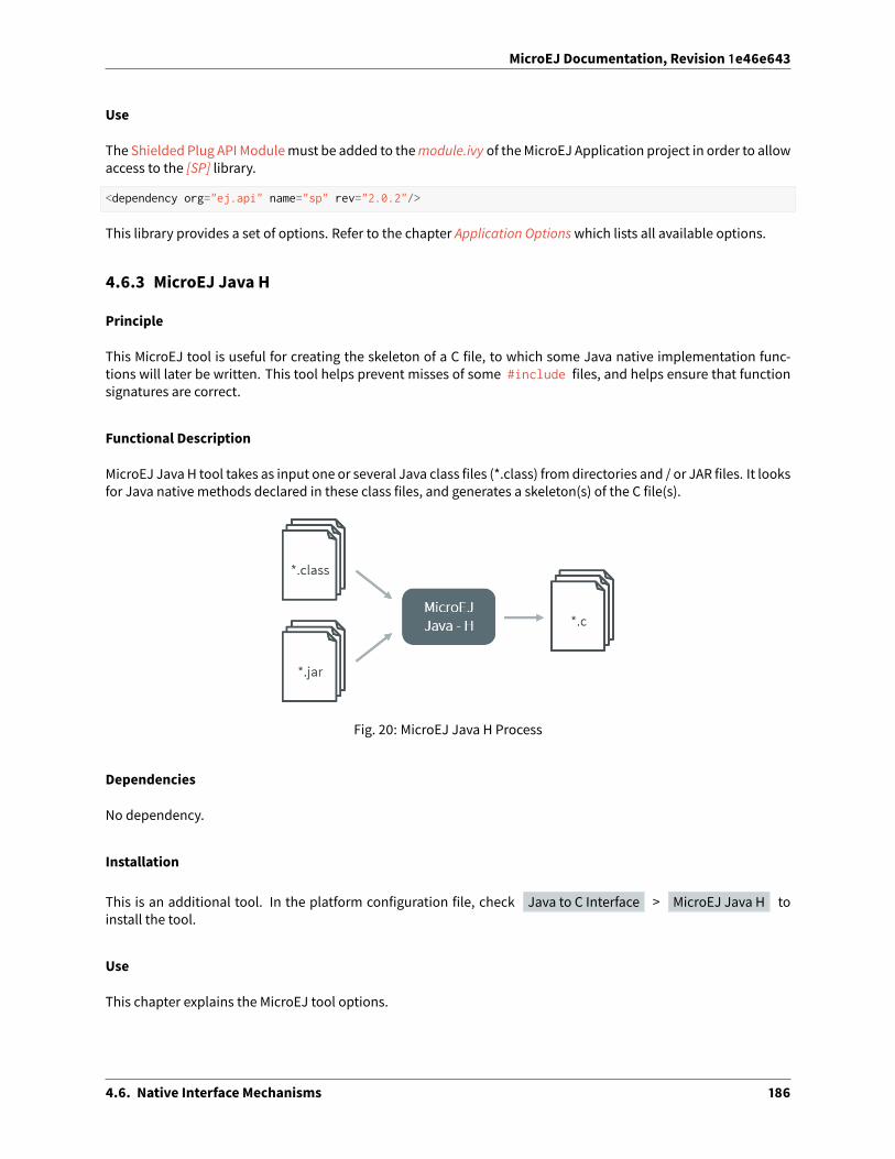
MicroEJ Documentation, Revision 1e46e643
Use
The Shielded Plug API Modulemust be added to themodule.ivy of theMicroEJ Application project in order to allowaccess to the [SP] library.
<dependency org="ej.api" name="sp" rev="2.0.2"/>
This library provides a set of options. Refer to the chapter Application Optionswhich lists all available options.
4.6.3 MicroEJ Java H
Principle
This MicroEJ tool is useful for creating the skeleton of a C file, to which some Java native implementation func-tions will later be written. This tool helps prevent misses of some #include files, and helps ensure that functionsignatures are correct.
Functional Description
MicroEJ Java H tool takes as input one or several Java class files (*.class) fromdirectories and / or JAR files. It looksfor Java native methods declared in these class files, and generates a skeleton(s) of the C file(s).
Fig. 20: MicroEJ Java H Process
Dependencies
No dependency.
Installation
This is an additional tool. In the platform configuration file, check Java to C Interface > MicroEJ Java H toinstall the tool.
Use
This chapter explains the MicroEJ tool options.
4.6. Native Interface Mechanisms 186

MicroEJ Documentation, Revision 1e46e643
4.7 External Resources Loader
4.7.1 Principle
A resource is, for a MicroEJ Application, the contents of a file. This file is known by its path (its relative path fromtheMicroEJ Application classpath) and its name. The filemay be stored in RAM, flash, or external flash; and it is theresponsibility of the MicroEJ Core Engine and/or the BSP to retrieve and load it.
MicroEJ Platformmakes the distinction between two kinds of resources:
• Internal resource: The resource is taken into consideration during the MicroEJ Application build. The SOARstep loads the resource and copies it into the same C library as the MicroEJ Application. Like the MicroEJ Ap-plication, the resource is linked into theCPUaddress space range (internal devicememories, external parallelmemories, etc.).
The available list of internal resources to embed must be specified in the MicroEJ Application launcher (Mi-croEJ launch). Under the “Resources” tab, select all internal resources to embed in the final binary file.
• External resource: The resource is not taken into consideration by MicroEJ. It is the responsibility of the BSPproject to manage this kind of resource. The resource is o�en programmed outside the CPU address spacerange (storage media like SD card, serial NOR flash, EEPROM, etc.).
The BSPmust implement some specific Low Level API (LLAPI) C functions: LLEXT_RES_impl.h . These func-tions allow the MicroEJ Application to load some external resources.
4.7.2 Functional Description
The External Resources Loader is an optional module. When not installed, only internal resources are availablefor the MicroEJ Application. When the External Resources Loader is installed, the MicroEJ Core Engine tries first toretrieve the expected resource from its available list of internal resources, before asking the BSP to load it (usingLLEXT_RES_impl.h functions).
4.7.3 Implementations
External Resources Loader module provides some Low Level API (LLEXT_RES) to let the BSP manage the externalresources.
Open a Resource
The LLAPI to implement in the BSP are listed in the header file LLEXT_RES_impl.h . First, the framework tries toopen an external resource using the open function. This function receives the resources path as a parameter. Thispath is the absolute path of the resource from the MicroEJ Application classpath (the MicroEJ Application sourcebase directory). For example, when the resource is located here: com.mycompany.myapplication.resource.MyResource.txt , the given path is: com/mycompany/myapplication/resource/MyResource.txt .
Resource Identifier
This open function has to return a unique ID (positive value) for the external resource, or returns an error code(negative value). This ID will be used by the framework to manipulate the resource (read, seek, close, etc.).
Several resources can be opened at the same time. The BSP does not have to return the same identifier for tworesources living at the same time. However, it can return this ID for a new resource as soon as the old resource isclosed.
4.7. External Resources Loader 187

MicroEJ Documentation, Revision 1e46e643
Resource O�set
The BSP must hold an o�set for each opened resource. This o�set must be updated a�er each call to read andseek .
Resource Inside the CPU Address Space Range
An external resource can be programmed inside the CPU address space range. This memory (or a part of memory)is not managed by the SOAR and so the resources inside are considered as external.
Most of time the content of an external resource must be copied in a memory inside the CPU address space rangein order to be accessible by the MicroEJ algorithms (draw an image etc.). However, when the resource is alreadyinside the CPU address space range, this copy is useless. The function LLEXT_RES_getBaseAddress must returna valid CPU memory address in order to avoid this copy. The MicroEJ algorithms are able to target the externalresource bytes without using the other LLEXT_RES APIs such as read , mark etc.
4.7.4 External Resources Folder
The External Resource Loader module provides an option (MicroEJ launcher option) to specify a folder for the ex-ternal resources. This folder has two roles:
• It is the output folder used by some extra generators during the MicroEJ Application build. All output filesgenerated by these tools will be copied into this folder. This makes it easier to retrieve the exhaustive list ofresources to program on the board.
• This folder is taken into considerationby theSimulator inorder to simulate theavailability of these resources.When the resources are located in another computer folder, the Simulator is not able to load them.
If not specified, this folder is created (if it does not already exist) in the MicroEJ project specified in the MicroEJlauncher. Its name is externalResources .
4.7.5 Dependencies
• LLEXT_RES_impl.h implementation (see LLEXT_RES: External Resources Loader).
4.7.6 Installation
The External Resources Loader is an additional module. In the platform configuration file, checkExternal Resources Loader to install this module.
4.7.7 Use
The External Resources Loader is automatically used when the MicroEJ Application tries to open an external re-source.
4.8 Serial Communications
MicroEJprovides someFoundationLibraries to instantiate somecommunicationswith external devices. Each com-municationmethod has its own library. A global library called ECOM provides support for abstract communicationstreams (communication framework only), and a generic devices manager.
4.8. Serial Communications 188

MicroEJ Documentation, Revision 1e46e643
4.8.1 ECOM
Principle
The Embedded COMmunication Foundation Library (ECOM) is a generic communication library with abstract com-munication stream support (a communication framework only). It allows you to open and use streams on commu-nication devices such as a COMM port.
This libraryalsoprovidesadevicemanager, includingagenericdevice registryandanotificationmechanism,whichallows plug&play-based applications.
This library does not provide APIs to manipulate some specific options for each communication method, but itdoes provide some generic APIs which abstract the communication method. A�er the opening step, the MicroEJApplication can use every communications method (COMM, USB etc.) as generic communication in order to easilychange the communication method if needed.
Functional Description
The diagram below shows the overall process to open a connection on a hardware device.
Fig. 21: ECOM Flow
1. Step 1 consists of opening a connection on a hardware device. The connection kind and its configuration arefixed by the parameter String connectionString of the method Connection.open .
2. Step 2 consists of opening an InputStream on the connection. This stream allows the MicroEJ Applicationto access the “RX” feature of the hardware device.
3. Step 3 consists of using the InputStream APIs to receive in theMicroEJ Application all hardware device data.
4. Step 4 consists of opening an OutputStream on the connection. This stream allows the MicroEJ Applicationto access the “TX” feature of the hardware device.
5. Step 5 consists of using the OutputStream APIs to transmit some data from the MicroEJ Application to thehardware device.
4.8. Serial Communications 189

MicroEJ Documentation, Revision 1e46e643
Note that steps 2 and 4may be performed in parallel, and do not depend on each other.
Device Management API
A device is defined by implementing ej.ecom.Device . It is identified by a name and a descriptor ( ej.ecom.HardwareDescriptor ), which is composed of a set of MicroEJ properties. A device can be registered/unregisteredin the ej.ecom.DeviceManager .
A device registration listener is defined by implementing ej.ecom.RegistrationListener . When a device is reg-istered to or unregistered from the device manager, listeners registered for the device type are notified. The notifi-cationmechanism is done in a dedicated Java thread. Themechanism can be enabled or disabled (see ApplicationOptions).
Dependencies
No dependency.
Installation
ECOMFoundation Library is an additional library. In the platform configuration file, check Serial Communication> ECOM to install the library.
Use
The ECOM API Module must be added to themodule.ivy of the MicroEJ Application project in order to allow accessto the ECOM library.
<dependency org="ej.api" name="ecom" rev="1.1.4"/>
This foundation library is always requiredwhen developing aMicroEJ Applicationwhich communicates with someexternal devices. It is automatically embedded as soon as a sub communication library is added in the classpath.
4.8.2 ECOM Comm
Principle
The ECOM Comm Java library provides support for serial communication. ECOM Comm extends ECOM to al-low stream communication via serial communication ports (typically UARTs). In the MicroEJ Application, theconnection is established using the Connector.open() method. The returned connection is a ej.ecom.io.CommConnection , and the input and output streams can be used for full duplex communication.
The use of ECOM Comm in a custom platform requires the implementation of an UART driver. There are two di�er-ent modes of communication:
• In Bu�ered mode, ECOM Commmanages so�ware FIFO bu�ers for transmission and reception of data. Thedriver copies data between the bu�ers and the UART device.
• In Custom mode, the bu�ering of characters is not managed by ECOM Comm. The driver has to manage itsown bu�ers to make sure no data is lost in serial communications because of bu�er overruns.
This ECOM Comm implementation also allows dynamic add or remove of a connection to the pool of availableconnections (typically hot-plug of a USB Comm port).
4.8. Serial Communications 190

MicroEJ Documentation, Revision 1e46e643
Functional Description
The ECOM Comm process respects the ECOM process. Please refer to the illustration “ECOM flow”.
Component Architecture
The ECOMCommCmodule relies on a native driver to performactual communication on the serial ports. Each portcan be bound to a di�erent driver implementation, but most of the time, it is possible to use the same implemen-tation (i.e. same code) for multiple ports. Exceptions are the use of di�erent hardware UART types, or the need fordi�erent behaviors.
Five C header files are provided:
• LLCOMM_impl.h
Defines the set of functions that the driver must implement for the global ECOM comm stack, such as syn-chronization of accesses to the connections pool.
• LLCOMM_BUFFERED_CONNECTION_impl.h
Defines the set of functions that the driver must implement to provide a Bu�ered connection
• LLCOMM_BUFFERED_CONNECTION.h
Defines the set of functions provided by ECOM Comm that can be called by the driver (or other C code) whenusing a Bu�ered connection
• LLCOMM_CUSTOM_CONNECTION_impl.h
Defines the set of functions that the driver must implement to provide a Custom connection
• LLCOMM_CUSTOM_CONNECTION.h
Defines the set of functions provided by ECOM Comm that can be called by the driver (or other C code) whenusing a Custom connection
The ECOM Comm drivers are implemented using standard LLAPI features. The diagram below shows an exampleof the objects (both Java and C) that exist to support a Bu�ered connection.
Fig. 22: ECOM Comm components
The connection is implemented with three objects1 :
• The Java object used by the application; an instance of ej.ecom.io.CommConnection
• The connection object within the ECOM CommCmodule
• The connection object within the driver1 This is aconceptualdescription toaidunderstanding - the reality is somewhatdi�erent, although that is largely invisible to the implementor
of the driver.
4.8. Serial Communications 191

MicroEJ Documentation, Revision 1e46e643
Each driver implementation provides one or more connections. Each connection typically corresponds to a physi-cal UART.
CommPort Identifier
Each serial port available for use in ECOM Comm can be identified in three ways:
• An application port number. This identifier is specific to the application, and should be used to identify thedata stream that the port will carry (for example, “debug traces” or “GPS data”).
• A platform port number. This is specific to the platform, andmay directly identify an hardware device2 .
• A platform port name. This is mostly used for dynamic connections or on platforms having a file-systembased device mapping.
When the Comm Port is identified by a number, its string identifier is the concatenation of “com” and the number(e.g. com11).
Application Port Mapping
The mapping from application port numbers to platform ports is done in the application launch configuration.This way, the application can refer only to the application port number, and the data stream can be directed to thematching I/O port on di�erent versions of the hardware.
Ultimately, the application port number is only visible to the application. The platform identifier will be sent to thedriver.
Opening Sequence
The following flow chart explains Comm Port opening sequence according to the given Comm Port identifier.
Fig. 23: Comm Port Open Sequence2 Some drivers may reuse the same UART device for di�erent ECOM ports with a hardware multiplexer. Drivers can even treat the platform
port number as a logical id andmap the ids to various I/O channels.
4.8. Serial Communications 192

MicroEJ Documentation, Revision 1e46e643
Dynamic Connections
The ECOMCommstack allows to dynamically add and remove connections from theDriver API. When a connectionis added, it can be immediately open by the application. When a connection is removed, the connection cannot beopen anymore and java.io.IOException is thrown in threads that are using it.
In addition, adynamic connection canbe registeredandunregistered inECOMdevicemanager (seeDeviceManage-ment API). The registration mechanism is done in dedicated thread. It can be enabled or disabled, see ApplicationOptions.
A removed connection is alive until it is closed by the application and, if enabled, unregistered from ECOM devicemanager. A connection is e�ectively uninstalled (and thus eligible to be reused) only when it is released by thestack.
The following sequence diagram shows the lifecycle of a dynamic connection with ECOM registration mechanismenabled.
Fig. 24: Dynamic Connection Lifecycle
4.8. Serial Communications 193

MicroEJ Documentation, Revision 1e46e643
Java API
Opening a connection is done using ej.ecom.io.Connector.open(String name) . The connection string (thename parameter) must start with “comm:”, followed by the Commport identifier, and a semicolon-separated list ofoptions. Options are the baudrate, the parity, the number of bits per character, and the number of stop bits:
• baudrate=n (9600 by default)
• bitsperchar=n where n is in the range 5 to 9 (8 by default)
• stopbits=n where n is 1, 2, or 1.5 (1 by default)
• parity=x where x is odd, even or none (none by default)
All of these are optional. Illegal or unrecognized parameters cause an IllegalArgumentException .
Driver API
The ECOM Comm Low Level API is designed to allowmultiple implementations (e.g. drivers that support di�erentUART hardware) and connection instances (see Low Level API Pattern chapter). Each ECOM Commdriver defines adata structure that holds information about a connection, and functions take an instance of this data structure asthe first parameter.
The name of the implementation must be set at the top of the driver C file, for example3:
#define LLCOMM_BUFFERED_CONNECTION MY_LLCOMM
This defines the name of this implementation of the LLCOMM_BUFFERED_CONNECTION interface to be MY_LLCOMM .
The data structure managed by the implementation must look like this:
typedef struct MY_LLCOMM{struct LLCOMM_BUFFERED_CONNECTION header;// extra data goes here
} MY_LLCOMM;
void MY_LLCOMM_new(MY_LLCOMM* env);
In this example the structure contains only the default data, in the header field. Note that the header must be thefirst field in the structure. The name of this structure must be the same as the implementation name ( MY_LLCOMMin this example).
The driver must also declare the “new” function used to initialize connection instances. The name of this functionmust be the implementation namewith _new appended, and it takes as its sole argument a pointer to an instanceof the connection data structure, as shown above.
The driver needs to implement the functions specified in the LLCOMM_impl.h file and for each kind of connection,the LLCOMM_BUFFERED_CONNECTION_impl.h (or LLCOMM_CUSTOM_CONNECTION_impl.h ) file.
The driver defines the connections it provides by adding connection objects using LLCOMM_addConnection. Connections can be added to the stack as soon as the LLCOMM_initialize function is called. Connec-tions added during the call of the LLCOMM_impl_initialize function are static connections. A static con-nection is registered to the ECOM registry and cannot be removed. When a connection is dynamically addedoutside the MicroJVM task context, a suitable reentrant synchronization mechanism must be implemented (seeLLCOMM_IMPL_syncConnectionsEnter and LLCOMM_IMPL_syncConnectionsExit ).
3 The following examples use Bu�ered connections, but Custom connections follow the same pattern.
4.8. Serial Communications 194

MicroEJ Documentation, Revision 1e46e643
Whenopening a port from theMicroEJ Application, each connection declared in the connections poolwill be askedabout its platform port number (using the getPlatformId method) or its name (using the getName method)depending on the requested port identifier. The first matching connection is used.
The life of a connection starts with the call to getPlatformId() or getName() method. If the the connectionmatches the port identifier, the connectionwill be initialized, configured and enabled. Notifications and interruptsare then used to keep the stream of data going. When the connection is closed by the application, interrupts aredisabled and the driver will not receive any more notifications. It is important to remember that the transmit andreceive sides of the connection are separate Java stream objects, thus, theymay have a di�erent life cycle and oneside may be closed long before the other.
The Bu�ered CommStream
InBu�eredmode, twobu�ers areallocatedby thedriver for sendingand receivingdata. TheECOMCommCmodulewill fill the transmit bu�er, and get bytes from the receive bu�er. There is no flow control.
When the transmit bu�er is full, an attempt to write more bytes from the MicroEJ Application will block the Javathread trying to write, until some characters are sent on the serial line and space in the bu�er is available again.
When the receive bu�er is full, characters coming from the serial line will be discarded. The driver must allocate abu�er big enough to avoid this, according to the UART baudrate, the expected amount of data to receive, and thespeed at which the application can handle it.
The Bu�ered Cmodule manages the characters sent by the application and stores them in the transmit bu�er. Onnotification of available space in the hardware transmit bu�er, it handles removing characters from this bu�er andputting them in the hardware bu�er. On the other side, the driver notifies the C module of data availability, andthe Cmodule will get the incoming character. This character is added to the receive bu�er and stays there until theapplication reads it.
The driver should take care of the following:
• Setting up interrupt handlers on reception of a character, and availability of space in the transmit bu�er. TheCmodulemaymask these interruptswhen it needs exclusive access to the bu�ers. If no interrupt is availablefrom the hardware or underlying so�ware layers, it may be faked using a polling thread that will notify the Cmodule.
• Initialization of the I/O pins, clocks, and other things needed to get the UART working.
• Configuration of the UART baudrate, character size, flow control and stop bits according to the settings givenby the Cmodule.
• Allocation of memory for the transmit and receive bu�ers.
• Getting the state of the hardware: is it running, is there space le� in the TX and RX hardware bu�ers, is it busysending or receiving bytes?
The driver is notified on the following events:
• Opening and closing a connection: the driver must activate the UART and enable interrupts for it.
• A newbyte is waiting in the transmit bu�er and should be copied immediately to the hardware transmit unit.The Cmodulemakes sure the transmit unit is not busy before sending the notification, so it is not needed tocheck for that again.
The driver must notify the Cmodule on the following events:
• Data has arrived that should be added to the receive bu�er (using theLLCOMM_BUFFERED_CONNECTION_dataReceived function)
• Space available in the transmit bu�er (using the LLCOMM_BUFFERED_CONNECTION_transmitBufferReadyfunction)
4.8. Serial Communications 195

MicroEJ Documentation, Revision 1e46e643
The Custom CommStream
In custommode, the ECOMCommCmodulewill not doanybu�ering. Readandwrite requests from theapplicationare immediately forwarded to the driver.
Since there is no bu�er on the C module side when using this mode, the driver has to define a strategy to storereceived bytes that were not handed to the C module yet. This could be a fixed or variable side FIFO, the olderreceived but unread bytesmay be dropped, or amore complex priority arbitration could be set up. On the transmitside, if the driver does not do any bu�ering, the Java thread waiting to send something will be blocked and waitfor the UART to send all the data.
In Custom mode flow control (eg. RTS/CTS or XON/XOFF) can be used to notify the device connected to the serialline and so avoid losing characters.
BSP File
The ECOMCommCmodule needs to know,when theMicroEJ Application is built, the nameof the implementation.This mapping is defined in a BSP definition file. The name of this file must be bsp.xml andmust be written in theECOM comm module configuration folder (near the ecom-comm.xml file). In previous example the bsp.xml filewould contain:
Listing 1: ECOM CommDriver Declaration (bsp.xml)
<bsp><nativeImplementation
name="MY_LLCOMM"nativeName="LLCOMM_BUFFERED_CONNECTION"
/></bsp>
where nativeName is the name of the interface, and name is the name of the implementation.
XML File
The Java platform has to know the maximum number of Comm ports that can be managed by the ECOM Commstack. It also has to know each Commport that can bemapped from an application port number. Such Commportis identified by its platform port number and by an optional nickname (The port and its nicknamewill be visible inthe MicroEJ launcher options, see Application Options ).
A XML file is so required to configure the Java platform. The name of this file must be ecom-comm.xml . It has to bestored in the module configuration folder (see Installation).
This file must start with the node <ecom> and the sub node <comms> . It can contain several time this kind of line:<comm platformId="A_COMM_PORT_NUMBER" nickname="A_NICKNAME"/> where:
• A_COMM_PORT_NUMBER refers the Comm port the Java platform user will be able to use (see Application PortMapping).
• A_NICKNAME is optional. It allows to fix a printable name of the Comm port.
The maxConnections attribute indicates the maximum number of connections allowed, including static and dy-namic connections. This attribute is optional. By default, it is the number of declared Comm Ports.
Example:
4.8. Serial Communications 196

MicroEJ Documentation, Revision 1e46e643
Listing 2: ECOM CommModule Configuration (ecom-comm.xml)
<ecom><comms maxConnections="20">
<comm platformId="2"/><comm platformId="3" nickname="DB9"/><comm platformId="5"/>
</comms></ecom>
First Comm port holds the port 2, second “3” and last “5”. Only the second Comm port holds a nickname “DB9”.
ECOM CommMock
In the simulation environment, no driver is required. The ECOM Comm mock handles communication for all theserial ports and can redirect each port to one of the following:
• An actual serial port on the host computer: any serial port identified by your operating system can be used.The baudrate and flow control settings are forwarded to the actual port.
• A TCP socket. You can connect to a socket on the local machine and use netcat or telnet to see the output, oryou can forward the data to a remote device.
• Files. You can redirect the input and output each to a di�erent file. This is useful for sending precomputeddata and looking at the output later on for o�line analysis.
When using the socket and file modes, there is no simulation of an UART baudrate or flow control. On a file, datawill always be available for reading and will be written without any delay. On a socket, you can reach the maximalspeed allowed by the network interface.
Dependencies
• ECOM (see Serial Communications).
• LLCOMM_impl.h and LLCOMM_xxx_CONNECTION_impl.h implmentations (see LLCOMM: Serial Communica-tions).
Installation
ECOM-CommJava library is an additional library. In the platform configuration file, check Serial Communication> ECOM-COMM to install it. When checked, the xml file ecom-comm > ecom-comm.xml is required duringplatform creation to configure the module (see XML File).
Use
The ECOM CommAPI Modulemust be added to themodule.ivy of the MicroEJ Application project in order to allowaccess to the ECOM Comm library.
<dependency org="ej.api" name="ecom-comm" rev="1.1.4"/>
This FoundationLibrary is always requiredwhendevelopingaMicroEJApplicationwhich communicateswith someexternal devices using the serial communication mode.
This library provides a set of options. Refer to the chapter Application Optionswhich lists all available options.
4.8. Serial Communications 197

MicroEJ Documentation, Revision 1e46e643
4.9 Graphics User Interface
4.9.1 Principle
TheUser Interface Extension features oneof the fastest graphical engines, associatedwith aunique int-based eventmanagement system. It provides [MUI] library implementation. The following diagram depicts the componentsinvolved in its design, along with the provided tools:
4.9. Graphics User Interface 198

MicroEJ Documentation, Revision 1e46e643
Fig. 25: The User Interface Extension Components along with a Platform
Thediagrambelow shows a simplified viewof the components involved in theprovisioning of a Javauser interface.
4.9. Graphics User Interface 199

MicroEJ Documentation, Revision 1e46e643
Fig. 26: Overview
Stacks are the native parts of MicroUI. They connect the MicroUI library to the user-supplied drivers code (coded inC).
Drivers for input devices must generate events that are sent, via a MicroUI Event Generator, to the MicroEJ Appli-cation. An event generator accepts notifications from devices, and generates an event in a standard format thatcan be handled by the application. Depending on theMicroUI configuration, there can be several di�erent types ofevent generator in the system, and one or more instances of each type. Each instance has an unique id.
Drivers may either interface directly with event generators, or they can send their notifications to a Listener, alsowritten in C, and the listener passes the notifications to the event generator. This decoupling has twomajor bene-fits:
• The drivers are isolated from the MicroEJ libraries – they can even be existing code.
• The listener can translate the notification; so, for example, a joystick could generate pointer events.
For the MicroEJ Simulator, the platform is supplied with a set of so�ware widgets that generically support a range
4.9. Graphics User Interface 200

MicroEJ Documentation, Revision 1e46e643
of input devices, such as buttons, joysticks and touchscreens, and output devices such as pixelated displays andLEDs. With the help of the Front Panel Designer tool that forms part of theMicroEJWorkbench the usermust definea front panelmock-up using thesewidgets. The usermust provide a set of listeners that connects the inputwidgetsto event generators. The user may choose to simulate events that will ultimately come from a special-purposeinput device using one of the standard input widgets; the listener will do the necessary translation. The user mustalso supply, in Java, a display extension that adapts the supplied display widget to the specifics of the hardwarebeing simulated.
4.9.2 MicroUI
Principle
The MicroUI module defines a low-level UI framework for embedded devices. This module allows the creation ofbasic Human-Machine-Interfaces (HMI), with output on a pixelated screen. For more information, please consultthe [MUI] Specification.
Architecture
MicroUI is not a standalone library. It requires a configuration step and several extensions to drive I/O devices(display, inputs, LEDs, etc.).
Fig. 27: MicroUI Elements
AtMicroEJ Application startup all MicroUI objects relative to the I/O devices are created and accessible. The follow-ing MicroUI methods allow you to access these internal objects:
• Display.getDefaultDisplay() : returns the instance of the default display which drives the main LCDscreen.
• Leds.getNumberOfLeds() : returns the numbers of available LEDs.
4.9. Graphics User Interface 201

MicroEJ Documentation, Revision 1e46e643
First, MicroUI requires a configuration step in order to create these internal objects before the call to the main()method. The chapter Static Initialization explains how to perform the configuration step.
Note: This configuration step is the same for both embedded and simulation platforms.
The embedded platform requires some additional C libraries to drive the I/O devices. Each C library is dedicated toa specific kind of I/O device. A specific chapter is available to explain each kind of I/O device.
Table 5: MicroUI C librariesI/O devices Extension Name ChapterGraphical / pixelated display (LCD screen) Display DisplayInputs (buttons, joystick, touch, pointers etc.) Input InputsLEDs LEDs LEDs
The simulation platform uses a mock which simulates all I/O devices. Refer to the chapter Simulation.
Threads
Principle
TheMicroUI implementation forMicroEJuses internal threads. These threadsare createdduring theMicroUI initial-ization step, and are started by a call to MicroUI.start() . Refer to theMicroUI specification for more informationabout internal threads.
List
• DisplayPump: This threadmanagesall displayevents (repaint , show() , etc. There isone threadperdisplay.
• InputPump: This thread reads the I/O devices inputs and dispatches them into the display pump(s).
Memory
The threads are always running. The user has to count them to determine the number of concurrent threads theMicroEJ Core Engine can run (see Memory options in Application Options).
Exceptions
The threads cannot be stopped with a Java exception: The exceptions are always checked by the framework.
When an exception occurs in a user method called by an internal thread (for instance paint() ), the currentUncaughtExceptionHandler receives the exception. The behavior of the default handler is to print the stack trace.
Transparency
MicroUI provides several policies to use the transparency. These policies depend on several factors, including thekind of drawing and the LCD pixel rendering format. The main concept is that MicroUI does not allow you to drawsomething with a transparency level di�erent from 255 (fully opaque). There are two exceptions: the images andthe fonts.
4.9. Graphics User Interface 202

MicroEJ Documentation, Revision 1e46e643
Images
Drawing an image (a pre-generated image or an image decoded at runtime) which contains some transparencylevels does not depend on the LCD pixel rendering format. During the image drawing, each pixel is converted into32 bits by pixel format.
This pixel format contains 8 bits to store the transparency level (alpha). This byte is used to merge the foregroundpixel (image transparent pixel) with the backgroundpixel (LCDbu�er opaquepixel). The formula to obtain the pixelis:
𝛼𝑀𝑢𝑙𝑡 = 𝛼𝐹𝐺 * 𝛼𝐵𝐺)/255
𝛼𝑂𝑢𝑡 = 𝛼𝐹𝐺+ 𝛼𝐵𝐺− 𝛼𝑀𝑢𝑙𝑡
𝐶𝑂𝑢𝑡 = (𝐶𝐹𝐺 * 𝛼𝐹𝐺+ 𝐶𝐵𝐺 * 𝛼𝐵𝐺− 𝐶𝐵𝐺 * 𝛼𝑀𝑢𝑙𝑡)/𝛼𝑂𝑢𝑡
where:
• 𝛼FG is the alpha level of the foreground pixel (layer pixel)
• 𝛼BG is the alpha level of the background pixel (working bu�er pixel)
• 𝛼xx is a color component of a pixel (Red, Green or Blue).
• 𝛼Out is the alpha level of the final pixel
Fonts
A font holds only a transparency level (alpha). This fixed alpha level is defined during the pre-generation of a font(see Fonts).
• 1 means 2 levels are managed: fully opaque and fully transparent.
• 2 means 4 levels are managed: fully opaque, fully transparent and 2 intermediate levels.
• 4 means 16 levels are managed: fully opaque, fully transparent and 14 intermediate levels.
• 8 means 256 levels are managed: fully opaque, fully transparent and 254 intermediate levels.
Dependencies
• MicroUI initialization step (see Static Initialization).
• MicroUI C libraries (see Architecture).
Installation
The MicroUI library is an additional module. In the platform configuration file, check UI > MicroUI to installthe library. When checked, the XML file microui > microui.xml is required during platform creation in orderto configure the module. This configuration step is used to extend the MicroUI library. Refer to the chapter StaticInitialization for more information about the MicroUI Initialization step.
4.9. Graphics User Interface 203

MicroEJ Documentation, Revision 1e46e643
Use
TheMicroUI APImodulemust be added to themodule.ivy of theMicroEJApplicationproject in order to allowaccessto the [MicroUI] library:
<dependency org="ej.api" name="microui" rev="2.4.0"/>
This library provides a set of options. Refer to the chapter Application Optionswhich lists all available options.
4.9.3 Static Initialization
Principle
MicroUI requires a configuration step (also called extension step) to customize itself before MicroEJ Applicationstartup (see Architecture). This configuration step uses an XML file. In order to save both runtime execution timeand flash memory, the file is processed by the Static MicroUI Initializer tool, avoiding the need to process the XMLconfiguration file at runtime. The tool generates appropriate initialized objects directly within the MicroUI library,as well as Java and C constants files for sharing MicroUI event generator IDs.
This XML file (also called the initialization file) defines:
• TheMicroUI event generators thatwill exist in the application in relation to low level drivers that provide datato these event generators (see Inputs).
• Whether the application has a display; and if so, it provides its logical name.
• Which fonts will be provided to the application.
Functional Description
The Static MicroUI Initializer tool takes as entry point the initialization file which describes the MicroUI library ex-tension. This tool is automatically launched during the MicroEJ platform build (see Installation ).
The Static MicroUI Initializer tool is able to output two files:
• A Java library which extends MicroUI library. This library is automatically added to the MicroEJ Applicationclasspath when MicroUI API library is fetched. This library is used at MicroUI startup to create all instancesof I/O devices ( Display , EventGenerator etc.) and contains the fonts described into the configuration file(these fonts are also called “system fonts”).
Warning: This MicroUI extension library is always generated andMicroUI library cannot runwithout this exten-sion.
• ACheader file ( *.h ) file. This H file contains some IDswhich are used tomake a link between an input device(buttons, touch) and its MicroUI event generator (see Inputs).
Note: The front panel project does not need a configuration file (like C header file for embedded platform).
4.9. Graphics User Interface 204

MicroEJ Documentation, Revision 1e46e643
Fig. 28: MicroUI Process
Root Element
The initialization file root element is <microui> and contains component-specific elements.
<microui>[ component specific elements ]
</microui>
Display Element
The display component augments the initialization file with:
• The configuration of the display.
• Fonts that are implicitly embedded within the application (also called system fonts). Applications can alsoembed their own fonts.
<display name="DISPLAY"/>
<fonts><font file="resources\fonts\myfont.ejf">
<range name="LATIN" sections="0-2"/><customrange start="0x21" end="0x3f"/>
</font><font file="C:\data\myfont.ejf"/>
</fonts>
Event Generators Element
The event generators component augments the initialization file with:
• the configuration of the predefined MicroUI Event Generator : Command , Buttons , States , Pointer ,Touch
• the configuration of the generic MicroUI Event Generator
4.9. Graphics User Interface 205

MicroEJ Documentation, Revision 1e46e643
<eventgenerators><!-- Generic Event Generators --><eventgenerator name="GENERIC" class="foo.bar.Zork">
<property name="PROP1" value="3"/><property name="PROP2" value="aaa"/>
</eventgenerator>
<!-- Predefined Event Generators --><command name="COMMANDS"/><buttons name="BUTTONS" extended="3"/><buttons name="JOYSTICK" extended="5"/><pointer name="POINTER" width="1200" height="1200"/><touch name="TOUCH" display="DISPLAY"/><states name="STATES" numbers="NUMBERS" values="VALUES"/>
</eventgenerators>
<array name="NUMBERS"><elem value="3"/><elem value="2"/><elem value="5"/>
</array>
<array name="VALUES"><elem value="2"/><elem value="0"/><elem value="1"/>
</array>
Example
This common MicroUI initialization file initializes MicroUI with:
• a display
• a Command event generator
• a Buttons event generator which targets n buttons (3 first buttons having extended features)
• a Buttons event generator which targets the buttons of a joystick
• a Pointer event generator which targets a touch panel
• a DisplayFont whose path is relative to this file
<microui>
<display name="DISPLAY"/>
<eventgenerators><command name="COMMANDS"/><buttons name="BUTTONS" extended="3"/><buttons name="JOYSTICK" extended="5"/><touch name="TOUCH" display="DISPLAY"/>
</eventgenerators>
<fonts><font file="resources\fonts\myfont.ejf"/>
(continues on next page)
4.9. Graphics User Interface 206

MicroEJ Documentation, Revision 1e46e643
(continued from previous page)
</fonts>
</microui>
Dependencies
No dependency.
Installation
The Static Initialization tool is part of the MicroUI module (see MicroUI). Install the MicroUI module to install theStatic Initialization tool and fill all properties in MicroUI module configuration file (whichmust specify the name ofthe initialization file).
Use
The Static MicroUI Initializer tool is automatically launched during the MicroUI module installation.
4.9.4 LEDs
Principle
The LEDs module contains the C part of the MicroUI implementation which manages LED devices. This module iscomposed of two elements:
• the C part of the MicroUI LEDs API (a built-in C archive),
• an implementation of a low level API for the LEDs (LLLEDS) whichmust be provided by the BSP (see LLLEDS:LEDs).
Implementations
The LEDs module provides only one implementation which exposes some low level API (LLLEDS) that allow theBSP to manage the LEDs. This implementation of the MicroUI Leds API provides some low level API. The BSP hasto implement these LLAPI, making the link between the MicroUI C library leds and the BSP LEDs drivers.
The LLAPI to implement are listed in the header file LLLEDS_impl.h . First, in the initialization function, the BSPmust return the available number of LEDs the board provides. The others functions are used to turn the LEDs onand o�.
The LLAPI are the same for the LED which is connected to a GPIO ( 0 or 1 ) or via a PWM . The BSP has the respon-sibility of interpreting the MicroEJ Application parameter intensity .
Typically, when the LED is connected to a GPIO , the intensity “0”means “OFF,” and all others values “ON.”Whenthe LED is connected via a PWM , the intensity “0” means “OFF,” and all others values must configure the PWMsignal.
The BSP should be able to return the state of an LED. If it is not able to do so (for example GPIO is not accessible inreadmode), the returned value may be wrong. The MicroEJ Application may not be able to know the LEDs states.
When there is no LED on the board, a stub implementation of C library is available. This C library must be linked bythe third-party C IDE when the MicroUI module is installed in the MicroEJ Platform.
4.9. Graphics User Interface 207

MicroEJ Documentation, Revision 1e46e643
Dependencies
• MicroUI module (seeMicroUI)
• LLLEDS_impl.h implementation if standard implementation is chosen (see Implementations and LLLEDS:LEDs).
Installation
LEDs is a sub-part of MicroUI library. When the MicroUI module is installed, the LEDs module must be installed inorder to be able to connect physical LEDs with MicroEJ Platform. If not installed, the stubmodule will be used.
In the platform configuration file, check UI > LEDs to install LEDs.
Use
The MicroUI LEDs APIs are available in the class ej.microui.led.Leds .
4.9.5 Inputs
Principle
The Inputs module contains the C part of the MicroUI implementation which manages input devices. This moduleis composed of two elements:
• the C part of MicroUI input API (a built-in C archive)
• an implementation of a low level API for the input devices (LLINPUT) that must be provided by the BSP (seeLLINPUT: Inputs)
Functional Description
The Inputs module implements the MicroUI int -based event generators’ framework. LLINPUT specifies the lowlevel API that send events to the Java world.
EachMicroUI Event Generator represents one sideof a pair of collaborative components that communicate usinga shared bu�er:
• The producer: the C driver connected to the hardware. As a producer, it sends its data into the communica-tion bu�er.
• The consumer: the MicroUI Event Generator . As a consumer, it reads (and removes) the data from thecommunication bu�er.
4.9. Graphics User Interface 208

MicroEJ Documentation, Revision 1e46e643
Fig. 29: Drivers and MicroUI Event Generators Communication
The LLINPUT API allows multiple pairs of <driver - event generator> to use the same bu�er, and associatesdrivers and event generators using an int ID. The ID used is the event generator ID held within the MicroUI globalregistry [MUI]. Apart from sharing the ID used to “connect” one driver’s data to its respective event generator, bothentities are completely decoupled.
A Java green thread, called the InputPump thread, waits for data to be published by drivers into the “input bu�er,”and dispatches to the correct (according to the ID) event generator to read the received data. This “driver-specific-data” is then transformed into MicroUI events by event generators and sent to objects that listen for input activity.
Fig. 30: MicroUI Events Framework
Implementation
The implementationof theMicroUI Event Generator APIsprovides some low levelAPIs. TheBSPhas to implementthese LLAPI, making the link between the MicroUI C library inputs and the BSP input devices drivers.
4.9. Graphics User Interface 209

MicroEJ Documentation, Revision 1e46e643
The LLAPI to implement are listed in the header file LLINPUT_impl.h . It allows events to be sent to theMicroUI im-plementation. The input drivers are allowed to add events directly using the event generator’s unique ID (see StaticInitialization). The drivers are fully dependent on the MicroEJ framework (a driver cannot be developed withoutMicroEJ because it uses the header file generated during the MicroUI initialization step).
When there is no input device on the board, a stub implementation of C library is available. This C library must belinked by the third-party C IDE when the MicroUI module is installed in the MicroEJ Platform.
Generic Event Generators
On the application side, the UI extension provides an abstract class GenericEventGenerator (package ej.microui.event ) thatmustbe implementedby clientswhowant todefine their ownevent generators. Twoabstractmethods must be implemented by subclasses:
• eventReceived : The event generator received an event from a C driver through the low level API sendEventfunction.
• eventsReceived : The event generator received an event made of several int s.
• setProperty : Handle a generic property (key/value pair) set from the static initialization file (see MicroUIStatic Initializer)
The event generator is responsible for converting incoming data into a MicroUI event and sending the event to itslistener.
Dependencies
• MicroUI module (seeMicroUI)
• Static MicroUI initialization step (see section_static_init). This step generates a header file which containssome unique event generator IDs. These IDs must be used in the BSP to make the link between the inputdevices drivers and the MicroUI Event Generator s.
• LLINPUT_impl.h implementation (see LLINPUT: Inputs).
Installation
Inputs is a sub-part of the MicroUI library. When the MicroUI module is installed, the Inputs module must be in-stalled in order to be able to connect physical input deviceswithMicroEJ Platform. If not installed, the stubmodulewill be used. In the platform configuration file, check UI > Inputs to install Inputs.
Use
The MicroUI Input APIs are available in the class ej.microui.EventGenerator .
4.9.6 Display
Principle
The Display module contains the C part of the MicroUI implementation which manages graphical displays. Thismodule is composed of two elements:
• the C part of MicroUI Display API (a built-in C archive)
4.9. Graphics User Interface 210

MicroEJ Documentation, Revision 1e46e643
• an implementation of a low level API for the displays (LLDISPLAY) that the BSPmust provide (see LLDISPLAY:Display)
Display Configurations
The Display modules provides a number of di�erent configurations. The appropriate configuration should be se-lected depending on the capabilities of the screen and other related hardware, such as LCD controllers.
The modes can vary in three ways:
• the bu�er mode: double-bu�er, simple bu�er (also known as “direct”)
• the memory layout of the pixels
• pixel format or depth
The supplied configurations o�er a limited range of combinations of the options.
Bu�er Modes
Overview
When using the double bu�ering technique, the memory into which the application draws (called graphics bu�eror back bu�er) is not the memory used by the screen to refresh it (called frame bu�er or display bu�er). Wheneverything has been drawn consistently from the application point of view, the back bu�er contents are synchro-nizedwith the display bu�er. Double bu�ering avoids flickering and inconsistent rendering: it is well suited to highquality animations.
For more static display-based applications, and/or to savememory, an alternative configuration is to use only onebu�er, shared by both the application and the screen.
Displays addressed by one of the standard configurations are called generic displays. For these generic displays,there are three bu�ermodes: switch, copy and direct. The following flow chart provides a handy guide to selectingthe appropriate bu�er mode according to the hardware configuration.
4.9. Graphics User Interface 211

MicroEJ Documentation, Revision 1e46e643
Fig. 31: Bu�er Modes
Implementation
The display module (or stack) does not depend on type of bu�er mode. At the end of a drawing, the display stackcalls the LLAPI LLDISPLAY_IMPL_flush to let the implementation to update the LCD data. This function should beatomic and the implementationhas to return thenewgraphics bu�er address (backbu�er address). In direct andcopy modes, this address never changes and the implementation has always to return the back bu�er address. Inswitch mode, the implementation has to return the old LCD frame bu�er address.
The next sections describe the work to do for eachmode.
4.9. Graphics User Interface 212
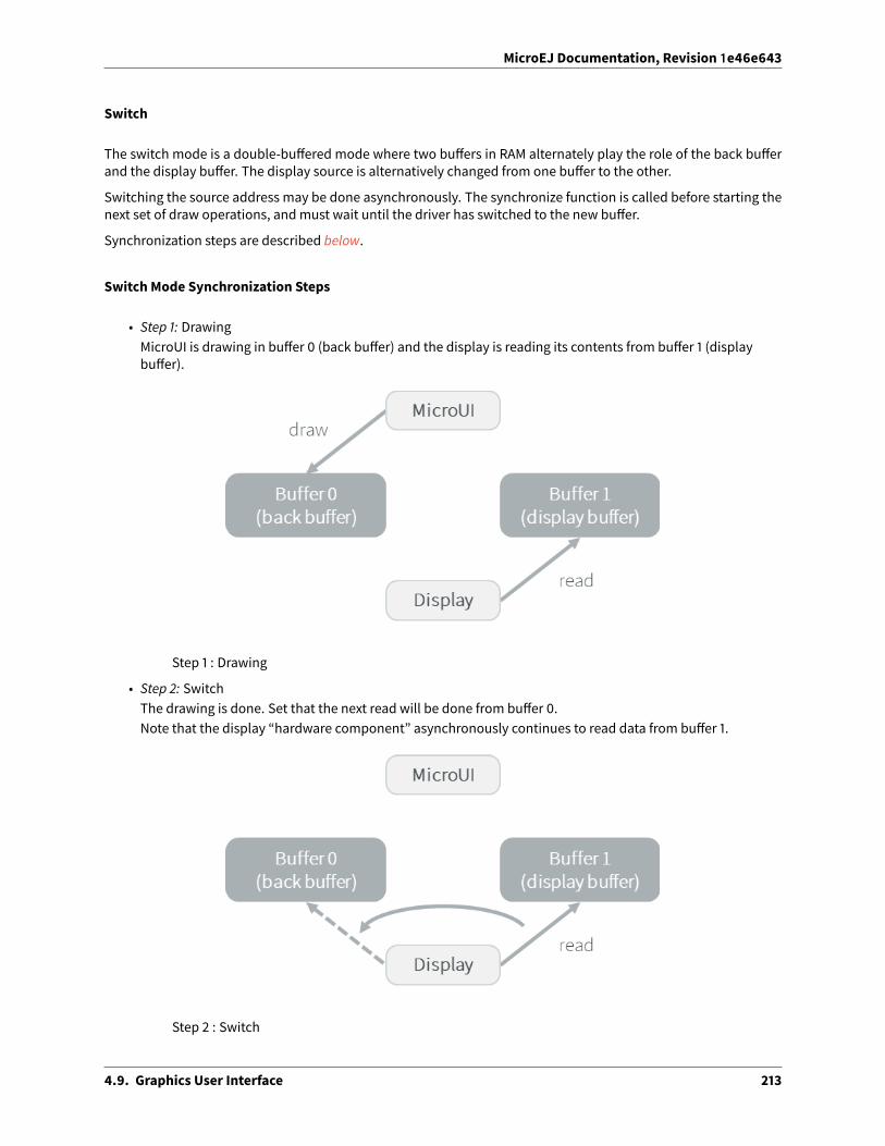
MicroEJ Documentation, Revision 1e46e643
Switch
The switch mode is a double-bu�ered mode where two bu�ers in RAM alternately play the role of the back bu�erand the display bu�er. The display source is alternatively changed from one bu�er to the other.
Switching the source address may be done asynchronously. The synchronize function is called before starting thenext set of draw operations, andmust wait until the driver has switched to the new bu�er.
Synchronization steps are described below.
Switch Mode Synchronization Steps
• Step 1: DrawingMicroUI is drawing in bu�er 0 (back bu�er) and the display is reading its contents from bu�er 1 (displaybu�er).
Step 1 : Drawing
• Step 2: SwitchThe drawing is done. Set that the next read will be done from bu�er 0.Note that the display “hardware component” asynchronously continues to read data from bu�er 1.
Step 2 : Switch
4.9. Graphics User Interface 213

MicroEJ Documentation, Revision 1e46e643
• Step 3: CopyA copy from the bu�er 0 (new display bu�er) to the bu�er 1 (new back bu�er) must be done to keep thecontents of the current drawing. The copy routine must wait until the display has finished the switch, andstart asynchronously by comparison with the MicroUI drawing routine (see next step).This copy routine can be done in a dedicated RTOS task or in an interrupt routine. The copy should starta�er the display “hardware component” has finished a full bu�er read to avoid flickering.Usually a tearing signal from the LCD at the end of the read of the previous bu�er (bu�er 1) or at thebeginning of the read of the new bu�er (bu�er 0) throws an interrupt. The interrupt routine starts the copyusing a DMA.If it is not possible to start an asynchronous copy, the copy must be performed in the MicroUI drawingroutine, at the beginning of the next step.Note that the copy is partial: only the parts that have changed need to be copied, lowering the CPU load.
Step 3 : Copy
• Step 4: SynchronisationWaits until the copy routine has finished the full copy.If the copy has not been done asynchronously, the copy must start a�er the display has finished the switch.It is a blocking copy because the next drawing operation has to wait until this copy is done.
• Step 5: Next draw operationSame behavior as step 1 with bu�ers reversed.
Step 5 : Next draw operation
4.9. Graphics User Interface 214

MicroEJ Documentation, Revision 1e46e643
Copy
The copy mode is a double-bu�ered mode where the back bu�er is in RAM and has a fixed address. To update thedisplay, data is sent to the display bu�er. This can be done either by a memory copy or by sending bytes using abus, such as SPI or I2C.
Synchronization steps are described below.
Display Copy Mode
• Step 1: DrawingMicroUI is drawing in the back bu�er and the display is reading its content from the display bu�er.
• Step 2: CopyThe drawing is done. A copy from the back bu�er to the display bu�er is triggered.Note that the implementation of the copy operation may be done asynchronously – it is recommended towait until the display “hardware component” has finished a full bu�er read to avoid flickering. At theimplementation level, the copy may be done by a DMA, a dedicated RTOS task, interrupt, etc.
• Step 3: SynchronizationThe next drawing operation waits until the copy is complete.
4.9. Graphics User Interface 215

MicroEJ Documentation, Revision 1e46e643
Direct
The directmode is a single-bu�eredmodewhere the samememory area is used for the back bu�er and the displaybu�er (See illustration below). Use of the directmode is likely to result in “noisy” rendering and flickering, but savesone bu�er in runtimememory.
Fig. 32: Display Direct Mode
Byte Layout
This chapter concerns only LCD with a number of bits-per-pixel (BPP) smaller than 8. For this kind of LCD, a bytecontains several pixels and the display module allows to customize how to organize the pixels in a byte.
Two layouts are available:
• line: The byte contains several consecutive pixels on same line. When the end of line is reatched, a paddingis added in order to start a new line with a new byte.
• column: The byte contains several consecutive pixels on same column. When the end of column is reatched,a padding is added in order to start a new column with a new byte.
When installing the displaymodule, a property byteLayout is required to specify the kind of pixels representation(see Installation).
4.9. Graphics User Interface 216

MicroEJ Documentation, Revision 1e46e643
Table 6: Byte Layout: lineBPP MSB LSB4 pixel 1 pixel 02 pixel 3 pixel 2 pixel 1 pixel 01 pixel 7 pixel 6 pixel 5 pixel 4 pixel 3 pixel 2 pixel 1 pixel 0
Table 7: Byte Layout: columnBPP 4 2 1MSB pixel 1 pixel 3 pixel 7
pixel 6pixel 2 pixel 5
pixel 4pixel 0 pixel 1 pixel 3
pixel 2pixel 0 pixel 1
LSB pixel 0
Memory Layout
For the LCDwith a number of bits-per-pixel (BPP) higher or equal to 8, the displaymodule supports the line-by-linememory organization: pixels are laid out from le� to right within a line, startingwith the top line. For a displaywith16 bits-per-pixel, the pixel at (0,0) is stored at memory address 0, the pixel at (1,0) is stored at address 2, the pixelat (2,0) is stored at address 4, and so on.
Table 8: Memory Layout for BPP >= 8BPP @ + 0 @ + 1 @ + 2 @ + 3 @ + 432 pixel 0 [7:0] pixel 0 [15:8] pixel 0 [23:16] pixel 0 [31:24] pixel 1 [7:0]24 pixel 0 [7:0] pixel 0 [15:8] pixel 0 [23:16] pixel 1 [7:0] pixel 1 [15:8]16 pixel 0 [7:0] pixel 0 [15:8] pixel 1 [7:0] pixel 1 [15:8] pixel 2 [7:0]8 pixel 0 [7:0] pixel 1 [7:0] pixel 2 [7:0] pixel 3 [7:0] pixel 4 [7:0]
For the LCD with a number of bits-per-pixel (BPP) lower than 8, the display module supports the both memoryorganizations: line by line (pixels are laid out from le� to right within a line, starting with the top line) and columnby column (pixels are laid out from top to bottomwithin a line, starting with the le� line). These byte organizationsconcern until 8 consecutive pixels (seeByte Layout). When installing the displaymodule, a property memoryLayoutis required to specify the kind of pixels representation (see Installation).
Table 9: Memory Layout ‘line’ for BPP < 8 and byte layout ‘line’BPP @ + 0 @ + 1 @ + 2 @ + 3 @ + 44 (0,0) to (1,0) (2,0) to (3,0) (4,0) to (5,0) (6,0) to (7,0) (8,0) to (9,0)2 (0,0) to (3,0) (4,0) to (7,0) (8,0) to (11,0) (12,0) to (15,0) (16,0) to (19,0)1 (0,0) to (7,0) (8,0) to (15,0) (16,0) to (23,0) (24,0) to (31,0) (32,0) to (39,0)
Table 10: Memory Layout ‘line’ for BPP < 8 and byte layout ‘column’BPP @ + 0 @ + 1 @ + 2 @ + 3 @ + 44 (0,0) to (0,1) (1,0) to (1,1) (2,0) to (2,1) (3,0) to (3,1) (4,0) to (4,1)2 (0,0) to (0,3) (1,0) to (1,3) (2,0) to (2,3) (3,0) to (3,3) (4,0) to (4,3)1 (0,0) to (0,7) (1,0) to (15,7) (2,0) to (23,7) (3,0) to (31,7) (4,0) to (39,7)
4.9. Graphics User Interface 217

MicroEJ Documentation, Revision 1e46e643
Table 11: Memory Layout ‘column’ for BPP < 8 and byte layout ‘line’BPP @ + 0 @ + 1 @ + 2 @ + 3 @ + 44 (0,0) to (1,0) (0,1) to (1,1) (0,2) to (1,2) (0,3) to (1,3) (0,4) to (1,4)2 (0,0) to (3,0) (0,1) to (3,1) (0,2) to (3,2) (0,3) to (3,3) (0,4) to (3,4)1 (0,0) to (7,0) (0,1) to (7,1) (0,2) to (7,2) (0,3) to (7,3) (0,4) to (7,4)
Table 12: Memory Layout ‘column’ for BPP < 8 andbyte layout ‘column’BPP @ + 0 @ + 1 @ + 2 @ + 3 @ + 44 (0,0) to (0,1) (0,2) to (0,3) (0,4) to (0,5) (0,6) to (0,7) (0,8) to (0,9)2 (0,0) to (0,3) (0,4) to (0,7) (0,8) to (0,11) (0,12) to (0,15) (0,16) to (0,19)1 (0,0) to (0,7) (0,8) to (0,15) (0,16) to (0,23) (0,24) to (0,31) (0,32) to (0,39)
Pixel Structure
TheDisplaymodule provides pre-built display configurationswith standard pixelmemory layout. The layout of thebitswithin thepixelmaybe standard (seeMicroUIGraphicsContext pixel formats) or driver-specific. When installingthe display module, a property bpp is required to specify the kind of pixel representation (see Installation).
When the value is one among this list: ARGB8888 | RGB888 | RGB565 | ARGB1555 | ARGB4444 | C4 | C2 | C1, the display module considers the LCD pixels representation as standard. According to the chosen format, somecolor data can be lost or cropped.
• ARGB8888: the pixel uses 32 bits-per-pixel (alpha[8], red[8], green[8] and blue[8]).
u32 convertARGB8888toLCDPixel(u32 c){return c;
}
u32 convertLCDPixeltoARGB8888(u32 c){return c;
}
• RGB888: the pixel uses 24 bits-per-pixel (alpha[0], red[8], green[8] and blue[8]).
u32 convertARGB8888toLCDPixel(u32 c){return c & 0xffffff;
}
u32 convertLCDPixeltoARGB8888(u32 c){return 0
| 0xff000000| c;
}
• RGB565: the pixel uses 16 bits-per-pixel (alpha[0], red[5], green[6] and blue[5]).
u32 convertARGB8888toLCDPixel(u32 c){return 0
| ((c & 0xf80000) >> 8)| ((c & 0x00fc00) >> 5)| ((c & 0x0000f8) >> 3);
(continues on next page)
4.9. Graphics User Interface 218

MicroEJ Documentation, Revision 1e46e643
(continued from previous page)
}
u32 convertLCDPixeltoARGB8888(u32 c){return 0
| 0xff000000| ((c & 0xf800) << 8)| ((c & 0x07e0) << 5)| ((c & 0x001f) << 3);
}
• ARGB1555: the pixel uses 16 bits-per-pixel (alpha[1], red[5], green[5] and blue[5]).
u32 convertARGB8888toLCDPixel(u32 c){return 0
| (((c & 0xff000000) == 0xff000000) ? 0x8000 : 0)| ((c & 0xf80000) >> 9)| ((c & 0x00f800) >> 6)| ((c & 0x0000f8) >> 3);
}
u32 convertLCDPixeltoARGB8888(u32 c){return 0
| ((c & 0x8000) == 0x8000 ? 0xff000000 : 0x00000000)| ((c & 0x7c00) << 9)| ((c & 0x03e0) << 6)| ((c & 0x001f) << 3);
}
• ARGB4444: the pixel uses 16 bits-per-pixel (alpha[4], red[4], green[4] and blue[4]).
u32 convertARGB8888toLCDPixel(u32 c){return 0
| ((c & 0xf0000000) >> 16)| ((c & 0x00f00000) >> 12)| ((c & 0x0000f000) >> 8)| ((c & 0x000000f0) >> 4);
}
u32 convertLCDPixeltoARGB8888(u32 c){return 0
| ((c & 0xf000) << 16)| ((c & 0xf000) << 12)| ((c & 0x0f00) << 12)| ((c & 0x0f00) << 8)| ((c & 0x00f0) << 8)| ((c & 0x00f0) << 4)| ((c & 0x000f) << 4)| ((c & 0x000f) << 0);
}
• C4: the pixel uses 4 bits-per-pixel (grayscale[4]).
4.9. Graphics User Interface 219

MicroEJ Documentation, Revision 1e46e643
u32 convertARGB8888toLCDPixel(u32 c){return (toGrayscale(c) & 0xff) / 0x11;
}
u32 convertLCDPixeltoARGB8888(u32 c){return 0xff000000 | (c * 0x111111);
}
• C2: the pixel uses 2 bits-per-pixel (grayscale[2]).
u32 convertARGB8888toLCDPixel(u32 c){return (toGrayscale(c) & 0xff) / 0x55;
}
u32 convertLCDPixeltoARGB8888(u32 c){return 0xff000000 | (c * 0x555555);
}
• C1: the pixel uses 1 bit-per-pixel (grayscale[1]).
u32 convertARGB8888toLCDPixel(u32 c){return (toGrayscale(c) & 0xff) / 0xff;
}
u32 convertLCDPixeltoARGB8888(u32 c){return 0xff000000 | (c * 0xffffff);
}
When the value is one among this list: 1 | 2 | 4 | 8 | 16 | 24 | 32 , the display module considers the LCDpixel representation as generic but not standard. In this case, the driver must implement functions that convertMicroUI’s standard 32 bits ARGB colors to LCD color representation (see LLDISPLAY: Display). This mode is o�enused when the pixel representation is not ARGB or RGB but BGRA or BGR instead. This mode can also be usedwhen the number of bits for a color component (alpha, red, green or blue) is not standard or when the value doesnot represent a color but an index in an LUT.
Antialiasing
Fonts
The antialiasing mode for the fonts concerns only the fonts with more than 1 bit per pixel (see Font Generator).
Background Color
For each pixel to draw, the antialiasing process blends the foreground color with a background color. This back-ground color is static or dynamic:
• static: The background color is fixed by theMicroEJ Application ( GraphicsContext.setBackgroundColor()).
• dynamic: The background color is the original color of the destination pixel (a “read pixel” operation is per-formed for each pixel).
Note that the dynamic mode is slower than the static mode.
4.9. Graphics User Interface 220

MicroEJ Documentation, Revision 1e46e643
LUT
The displaymodule allows to target LCDwhich uses a pixel indirection table (LUT). This kind of LCD are consideredasgenericbutnot standard (seePixel Structure). By consequence, thedrivermust implement functions that convertMicroUI’s standard 32 bits ARGB colors (see LLDISPLAY: Display) to LCD color representation. For each applicationARGB8888 color, the display driver has to find the corresponding color in the table. The display module will storethe index of the color in the table instead of using the color itself.
When an application color is not available in the display driver table (LUT), the display driver can try to find thenearest color or return a default color. First solution is o�en quite di�icult to write and can cost a lot of time atruntime. That’s why the second solution is preferred. However, a consequence is that the application has only touse a range of colors provided by the display driver.
MicroUI and the display module uses blending when drawing some texts or anti-aliased shapes. For eachpixel to draw, the display stack blends the current application foreground color with the targeted pixel cur-rent color or with the current application background color (when enabled). This blending creates some in-termediate colors which are managed by the display driver. Most of time the default color will be returnedand so the rendering will be wrong. To prevent this use case, the display module o�ers a specific LLAPILLDISPLAY_EXTRA_IMPL_prepareBlendingOfIndexedColors(void* foreground, void* background) . ThisAPI is only used when a blending is required and when the background color is enabled. Display module calls theAPI just before theblending andgives as parameter the pointers on thebothARGBcolors. Thedisplay driver shouldreplace the ARGB colors by the LUT indexes. Then the display module will only use the indexes between the bothindexes. For instance, when the returned indexes are 20 and 27 , the display stack will use the indexes 20 to 27 ,where all indexes between 20 and 27 target some intermediate colors between the both original ARGB colors.
This solution requires several conditions:
• Background color is enabled and it is an available color in the LUT.
• Application can only use foreground colors provided by the LUT. The platform designer should give to theapplication developer the available list of colors the LUTmanages.
• The LUT must provide a set blending ranges the application can use. Each range can have its own size (dif-ferent number of colors between two colors). Each range is independent. For instance if the foregroundcolor RED ( 0xFFFF0000 ) can be blended with two background colors WHITE ( 0xFFFFFFFF ) and BLACK (0xFF000000 ), two ranges must be provided. The both ranges have to contain the same index for the colorRED .
• Application can only use blending ranges provided by the LUT. Otherwise the display driver is not able to findthe range and the default color will be used to perform the blending.
• Rendering of dynamic images (images decoded at runtime) may be wrong because the ARGB colors may beout of LUT range.
Hardware Accelerator
Overview
The display module allows to use an hardware accelerator to perform some drawings: fill a rectangle, draw an im-age, rotate an image etc. Some optional functions are available in LLDISPLAY_EXTRA.h file (see LLDISPLAY_EXTRA:Display Extra Features). These functions are not automatically call by the displaymodule. Thedisplaymodulemustbe configured during the MicroEJ Platform construction specifying which hardware accelerator to use. It uses theproperty hardwareAccelerator in display/display.properties file to select a hardware accelerator (see In-stallation).
The following table lists the available hardware accelerators supported by MicroEJ, their full names, short names(used in the next tables) and the hardwareAccelerator property value (see Installation).
4.9. Graphics User Interface 221

MicroEJ Documentation, Revision 1e46e643
Table 13: Hardware AcceleratorsShort name Property
Renesas Graphics Library RGA1 RGA rgaRenesas TES Dave/2d Dave2D dave2dSTMicroelectronics Chrom-ART Graphics Accelerator DMA2D dma2dCustom Hardware Accelerator Custom custom2
Note: It is possible to target an hardware accelerator which is not supported by MicroEJ yet. Set the propertyhardwareAccelerator to custom to force display module to call all drawing functions which can be accelerated.The LLDISPLAY implementation is able or not to implement a function. If not, the so�ware algorithmwill be used.
The available list of supported hardware accelerators is MicroEJ Architecture dependent. For instance, the STMi-croelectronics Chrom-ART Graphics Accelerator is only available for the MicroEJ Architecture for Cortex-M4 andCortex-M7. The Renesas Graphics Library RGA is only available for the MicroEJ Architecture for Cortex-A9. The fol-lowing table shows in which MicroEJ Architecture an hardware accelerator is available.
Table 14: Hardware Accelerators according MicroEJ ArchitecturesRGA Dave2D DMA2D Custom
ARM Cortex-M0+ IAR •
ARM Cortex-M4 ARMCC • •
ARM Cortex-M4 GCC • • •
ARM Cortex-M4 IAR • •
ARM Cortex-M7 ARMCC • •
Note: Some hardware accelerators may not be available in o�-the-self architectures . However they are availableon some specific architectures. Please consult the engineering services page on MicroEJ website.
All hardware accelerators are not available for each number of bits-per-pixel configuration. The following tableillustrates in which display stack according bpp , an hardware accelerator can be used.
1 hardware or so�ware implementation2 see next note
4.9. Graphics User Interface 222

MicroEJ Documentation, Revision 1e46e643
Table 15: Hardware Accelerators according BPPRGA Dave2D DMA2D Custom
1 BPPC12 BPPC24 BPPC48 BPP16 BPP •
RGB565 • • • •
ARGB1555 • • • •
ARGB4444 • • • •
24 BPP •
RGB888 • •
32 BPP •
ARGB8888 • • • •
Features and Limits
Each hardware accelerator has a list of features (list of drawings the hardware accelerator can perform) and someconstraints. When the display module is configured to use an hardware accelerator, it takes in consideration thesefeatures and limits. If a drawing is detected by the display module as a drawing to be hardware accelerated, theLLDISPLAY implementationmust configure and use the hardware accelerator to perform the full drawing (not justa part of drawing).
Note: The custom hardware generator does not have any limit by default. This is the LLDISPLAY implementationwhich fixes the limits.
The following table lists the algorithms accelerated by each hardware accelerator.
4.9. Graphics User Interface 223

MicroEJ Documentation, Revision 1e46e643
Table 16: Hardware Accelerators AlgorithmsRGA Dave2D DMA2D
Fill a rectangle • • •
Draw an image • • •
Scale an image •
Rotate an image •
Images
The available list of supported image formats is not the same for all hardware accelerators. Furthermore somehardware accelerators require a custom header before the RAW pixel data, require a padding between each lineetc.. MicroEJmanages these contraints for supported hardware accelerators. For custom hardware accelerator, noimage header can be added and no padding can be set.
The following table illustratres the RAW image formats supported by each hardware accelerator.
Table 17: Hardware Accelerators RAW Image FormatsRGA Dave2D DMA2D
A1• 3
A2A4
• 4 •
A8• 5 •
C1C2C4AC11AC22AC44RGB565 • • •
ARGB1555 • • •
ARGB4444 • • •
RGB888 •
ARGB8888 • • •
4.9. Graphics User Interface 224

MicroEJ Documentation, Revision 1e46e643
The RAW image given as parameter (in input and/or in output) respects the hardware accelerator specification. Forinstance a RAW image with 4BPP must be o�en aligned on 8 bits, even if its size is odd. The RAW image size givenas parameter is the so�ware size. That means it is the size of the original image.
Example for a A4 image with required alignment on 8 bits:
• Original image width in pixels (== width in MicroEJ Application): 47
• Hardware image width in pixels (== line width in pixels in RAW image data): 48
• Width in pixels available in LLDISPLAY ( ((LLDISPLAY_SImage*)src)->width ): 48
• Hardware width in bytes (== line width in bytes in RAW image data): 48 / 2 = 24
The hardware size may be higher than the so�ware size (like in the example). However the number of pixels todraw ( ((LLDISPLAY_SDrawImage*)drawing)->src_width ) is always smaller or equal to the so�ware area size.That means the display module never asks to draw the pixels which are outside the so�ware area. The hardwaresize is only useful to be compatible with the hardware accelerator restrictions about memory alignment.
Implementations
The implementation of the MicroUI Display API targets a generic display (see Display Configurations): Switch,Copy and Direct. It provides some low level API. The BSP has to implement these LLAPI, making the link betweenthe MicroUI C library display and the BSP display driver. The LLAPI to implement are listed in the header fileLLDISPLAY_impl.h .
When there is no display on the board, a stub implementation of C library is available. This C librarymust be linkedby the third-party C IDE when MicroUI module is installed in the MicroEJ Platform.
Dependencies
• MicroUI module (seeMicroUI)
• LLDISPLAY_impl.h implementation if standard or custom implementation is chosen (see Implementationsand LLDISPLAY: Display).
Installation
Display is a sub-part of the MicroUI library. When the MicroUI module is installed, the Display module must beinstalled in order to be able to connect the physical display with the MicroEJ Platform. If not installed, the stubmodule will be used.
In the platform configuration file, check UI > Display to install the Display module. When checked, the prop-
erties file display > display.properties is required during platform creation to configure the module. Thisconfiguration step is used to choose the kind of implementation (see Implementations).
The properties file must / can contain the following properties:
• bpp [mandatory]: Defines the number of bits per pixels the display device is using to render a pixel. Expectedvalue is one among these both list:
Standard formats:
– ARGB8888 : Alpha 8 bits; Red 8 bits; Green 8 bits; Blue 8 bits3 maximum size <= display width4 maximum size <= display width5 maximum size <= display width
4.9. Graphics User Interface 225

MicroEJ Documentation, Revision 1e46e643
– RGB888 : Alpha 0 bit; Red 8 bits; Green 8 bits; Blue 8 bits (fully opaque)
– RGB565 : Alpha 0 bit; Red 5 bits; Green 6 bits; Blue 5 bits (fully opaque)
– ARGB1555 : Alpha 1 bit; Red 5 bits; Green 5 bits; Blue 5 bits (fully opaque or fully transparent)
– ARGB4444 : Alpha 4 bits; Red 4 bits; Green 4 bits; Blue 4 bits
– C4 : 4 bits to encode linear grayscale colors between 0x�000000 and 0x���� (fully opaque)
– C2 : 2 bits to encode linear grayscale colors between 0x�000000 and 0x���� (fully opaque)
– C1 : 1 bit to encode grayscale colors 0x�000000 and 0x���� (fully opaque)
Custom formats:
– 32 : until 32 bits to encode Alpha, Red, Green and/or Blue
– 24 : until 24 bits to encode Alpha, Red, Green and/or Blue
– 16 : until 16 bits to encode Alpha, Red, Green and/or Blue
– 8 : until 8 bits to encode Alpha, Red, Green and/or Blue
– 4 : until 4 bits to encode Alpha, Red, Green and/or Blue
– 2 : until 2 bits to encode Alpha, Red, Green and/or Blue
– 1 : 1 bit to encode Alpha, Red, Green or Blue
All others values are forbidden (throw a generation error).
• byteLayout [optional, default value is “line”]: Defines the pixels data order in a byte the display device isusing. A byte can contain several pixels when the number of bits-per-pixels (see ‘bpp’ property) is lower than8. Otherwise this property is useless. Two modes are available: the next bit(s) on same byte can target thenext pixel on same line or on same column. In first case, when the end of line is reatched, the next byte con-tains the first pixels of next line. In second case, when the end of column is reatched, the next byte containsthe first pixels of next column. In both cases, a new line or a new column restarts with a new byte, even if itremains some free bits in previous byte.
– line : the next bit(s) on current byte contains the next pixel on same line (x increment)
– column : the next bit(s) on current byte contains the next pixel on same column (y increment)
Note:
– Default value is ‘line’.
– All others modes are forbidden (throw a generation error).
– When thenumberof bits-per-pixels (see ‘bpp’ property) is higheror equal than8, this property is uselessand ignored.
• memoryLayout [optional, default value is “line”]: Defines the pixels data order in memory the display deviceis using. This option concerns only the LCD with a bpp lower than 8 (see ‘bpp’ property). Two modes areavailable: when the bytememory address is incremented, the next targeted group of pixels is the next groupon the same line or the next group on same column. In first case, when the end of line is reached, the nextgroup of pixels is the first group of next line. In second case, when the end of column is reached, the nextgroup of pixels is the first group of next column.
– line : the next memory address targets the next group of pixels on same line (x increment)
– column : the next memory address targets the next group of pixels on same column (y increment)
4.9. Graphics User Interface 226

MicroEJ Documentation, Revision 1e46e643
Note:
– Default value is ‘line’.
– All others modes are forbidden (throw a generation error).
– When thenumberof bits-per-pixels (see ‘bpp’ property) is higheror equal than8, this property is uselessand ignored.
Use
The MicroUI Display APIs are available in the class ej.microui.display.Display .
4.9.7 Images
The Image Engine is composed of:
• The “Image Engine Core” module which is able to load and drawing simultaneously some pre-generatedimages and some dynamic images.
• An “Image Generator” module, for converting standard image formats into the display image format beforeruntime (pre-generated images).
• A set of “Image Decoder” modules, for converting standard image formats into the display image format atruntime. Each Image Decoder is an additional module of the main module “Image Engine”.
Image Engine Core
Principle
The Image Engine Core module is a built-in module of the MicroUI module (see MicroUI) for the application side,and a built-in module of the Display module (see Display) for the C side.
Functional Description
Fig. 33: Image Engine Core Principle
4.9. Graphics User Interface 227

MicroEJ Documentation, Revision 1e46e643
Process overview:
1. The user specifies the pre-generated images to embed (see Image Generator) and / or the images to embedas regular resources (see Image Decoder)
2. The files are embedded as resources with the MicroEJ Application. The files’ data are linked into the FLASHmemory.
3. When theMicroEJApplication creates aMicroUI Imageobject, the ImageEngineCore loads the image, callingthe right sub Image Enginemodule (see ImageGenerator and ImageDecoder) to decode the specified image.
4. When the MicroEJ Application draws this MicroUI Image on the display (or on another image), the decodedimage data is used, and nomore decoding is required, so the decoding is done only once.
5. When the MicroUI Image is no longer needed, it is garbage-collected by the platform; and the Image EngineCore asks the right sub Image Engine module (see Image Generator and Image Decoder) to free the imageworking area.
External Resources
The Image Engine Core is able to load some images located outside the CPU addresses’ space range. It uses theExternal Resource Loader.
When an image is located in such memory, the Image Engine Core copies it into RAM (into the CPU address spacerange). Then it calls the right sub Image Engine module (see Image Generator and Image Decoder) to decode thespecified image.
TheRAMsectionused to load theexternal image is automatically freedwhen the ImageEngineCoreand itsmodulesdo not need it again.
Dependencies
• MicroUI module (seeMicroUI)
• Display module (see Display)
Installation
Image Engine Coremodules are part of the MicroUImodule and Displaymodule. Install them in order to be able touse some images.
Use
The MicroUI image APIs are available in the class ej.microui.display.Image .
Image Generator
Principle
The Image Generator module is an o�-board tool that generates image data that is ready to be displayed withoutneeding additional runtimememory. The twomain advantages of this module are:
• A pre-generated image is already encoded in the format known by the display stack. The image loading isvery fast and does not require any RAM.
4.9. Graphics User Interface 228

MicroEJ Documentation, Revision 1e46e643
• No extra support is needed (no runtime decoder).
Functional Description
Fig. 34: Image Generator Principle
Process overview (see too Functional Description)
1. The user defines, in a text file, the images to load.
2. The Image Generator outputs a raw file for each image to convert (the raw format is display device-dependent).
3. The raw files are embedded as (hidden) resources within the MicroEJ Application. The raw files’ data arelinked into the FLASHmemory.
4. When the MicroEJ Application creates a MicroUI Image object which targets a pre-generated image, the Im-age Engine Core has only to create a link from the MicroUI image object to the data in the FLASH memory.Therefore, the loading is very fast; only the image data from the FLASHmemory is used: no copy of the imagedata is sent to the RAM first.
5. When the MicroUI Image is no longer needed, it is garbage-collected by the platform, which just deletes theuseless link to the FLASHmemory.
Extensions Purpose
The output representation of the images in the same format as the LCD (samepixel representation, seeDisplayOut-put Format) is dependent on the drivers that run the underlying screen. Indeed, the output raw format is specific toeachdisplaydevice. The ImageGenerator tool provided is expandablebyextensions, eachextension implementinga dedicated display device layout.
Standard Extension
When the LCDpixels representation is standard ( ARGB8888 or RGB565 etc., seePixel Structure) the image generatordoes not need an extension. The formulas of conversions ARGB8888 to RAW formats are the same as described in
4.9. Graphics User Interface 229

MicroEJ Documentation, Revision 1e46e643
the chapter Pixel Structure.
Generic Extension
When the LCD pixel representation is generic ( 1 | 2 | 4 | 8 | 16 | 24 | 32 , see Pixel Structure) the imagegenerator requires an extension in order to understand how to convert ARGB pixels into LCD pixel representations.
The Displaymodule provides generic display implementation according the number of bits-per-pixels (1, 2, 4, 8, 16,24 and 32). The Image Generator tool provides a simple extension to implement in order to target these kinds ofdisplays: GenericDisplayExtension .1
Amethodmust be implemented in relation to theway the driver has built the layout of the display bu�ers inmem-ory: The convertARGBColorToDisplayColor method is used to convert a 32-bits ARGB color into the display pixelmemory representation.
Note: The Image Generator automatically uses the right number of bits to represent a pixel (BPP) and respect thememory bu�er layout using the result of the installation of the Display module.
Create an Extension
Follow the steps below to create an Image Generator extension:
1. First, create a new J2SE project, called (for example) imageGeneratorExtension .
2. In the project’s Java build path (project’s property window, select Java Build Path > Libraries tab ),add the variable IMAGE-GENERATOR-x.y .
3. Create the package com.is2t.microui.generators.extension .
4. Create a class in the package whose namemust be: MicroUIGeneratorExtension .
5. The Java class must implement the extension interface available in the library IMAGE-GENERATOR-x.y (seeprevious chapters). Fill the required methods.
The Java project should now look like this:
Fig. 35: Image Generator Extension Project1 Package com.is2t.microej.microui.image
4.9. Graphics User Interface 230

MicroEJ Documentation, Revision 1e46e643
With a Java class like this:
Listing 3: Image Generator Extension Implementation Example
package com.is2t.microui.generators.extension;
import com.is2t.microej.microui.image.GenericDisplayExtension;
public class MicroUIGeneratorExtensionMyLCD implements GenericDisplayExtension{
public int convertARGBColorToDisplayColor(int color) {return (char)
((color & 0xf80000) >>> 8) |((color & 0x00fc00) >>> 5) |((color & 0x0000f8) >>> 3);
}
}
Configuration File
The Image Generator uses a configuration file (also called the “list file”) for describing images that need to be pro-cessed. The list file is a text file in which each line describes an image to convert. The image is described as aresource path, and should be available from the application classpath.
Note: The list file must be specified in the MicroEJ Application launcher (see Application Options). However, allfiles in application classpath with su�ix .images.list are automatically parsed by the Image Generator tool.
Each line can add optional parameters (separated by a ‘:’) which define and/or describe the output file format (rawformat). When no option is specified, the image is converted into the default format.
Note: See Image Generator to understand the list file grammar.
Below is an example of a list file for the Image Generator:
Listing 4: Image Generator Configuration File Example
image1image2:RGB565
The next chapters describe the available output formats.
Generic Output Formats
Several generic output formats are available. Some formats may be directly managed by the display driver. Refersto the platform specification to retrieve the list of better formats.
Advantages:
• The pixels layout and bits format are standard, so it is easy to manipulate these images on the C-side.
• Drawing an image is very fast when the display driver recognizes the format (with or without transparency).
• Supports or not the alpha encoding: select the better format according to the image to encode.
4.9. Graphics User Interface 231

MicroEJ Documentation, Revision 1e46e643
Disadvantages:
• No compression: the image size in bytes is proportional to the number of pixels, the transparency, and thebits-per-pixel.
Select one the following format to use a generic format:
• ARGB8888: 32 bits format, 8 bits for transparency, 8 per color.
u32 convertARGB8888toRAWFormat(u32 c){return c;
}
• RGB888: 24 bits format, 8 per color. Image is always fully opaque.
u32 convertARGB8888toRAWFormat(u32 c){return c & 0xffffff;
}
• ARGB4444: 16 bits format, 4 bits for transparency, 4 per color.
u32 convertARGB8888toRAWFormat(u32 c){return 0
| ((c & 0xf0000000) >> 16)| ((c & 0x00f00000) >> 12)| ((c & 0x0000f000) >> 8)| ((c & 0x000000f0) >> 4);
}
• ARGB1555: 16 bits format, 1 bit for transparency, 5 per color.
u32 convertARGB8888toRAWFormat(u32 c){return 0
| (((c & 0xff000000) == 0xff000000) ? 0x8000 : 0)| ((c & 0xf80000) >> 9)| ((c & 0x00f800) >> 6)| ((c & 0x0000f8) >> 3);
}
• RGB565: 16 bits format, 5 or 6 per color. Image is always fully opaque.
u32 convertARGB8888toRAWFormat(u32 c){return 0
| ((c & 0xf80000) >> 8)| ((c & 0x00fc00) >> 5)| ((c & 0x0000f8) >> 3);
}
• A8: 8 bits format, only transparency is encoded. The color to apply when drawing the image, is the currentGraphicsContext color.
u32 convertARGB8888toRAWFormat(u32 c){return 0xff - (toGrayscale(c) & 0xff);
}
• A4: 4 bits format, only transparency is encoded. The color to apply when drawing the image, is the currentGraphicsContext color.
4.9. Graphics User Interface 232

MicroEJ Documentation, Revision 1e46e643
u32 convertARGB8888toRAWFormat(u32 c){return (0xff - (toGrayscale(c) & 0xff)) / 0x11;
}
• A2: 2 bits format, only transparency is encoded. The color to apply when drawing the image, is the currentGraphicsContext color.
u32 convertARGB8888toRAWFormat(u32 c){return (0xff - (toGrayscale(c) & 0xff)) / 0x55;
}
• A1: 1 bit format, only transparency is encoded. The color to apply when drawing the image, is the currentGraphicsContext color.
u32 convertARGB8888toRAWFormat(u32 c){return (0xff - (toGrayscale(c) & 0xff)) / 0xff;
}
• C4: 4 bits format with grayscale conversion. Image is always fully opaque.
u32 convertARGB8888toRAWFormat(u32 c){return (toGrayscale(c) & 0xff) / 0x11;
}
• C2: 2 bits format with grayscale conversion. Image is always fully opaque.
u32 convertARGB8888toRAWFormat(u32 c){return (toGrayscale(c) & 0xff) / 0x55;
}
• C1: 1 bit format with grayscale conversion. Image is always fully opaque.
u32 convertARGB8888toRAWFormat(u32 c){return (toGrayscale(c) & 0xff) / 0xff;
}
• AC44: 4 bits for transparency, 4 bits with grayscale conversion.
u32 convertARGB8888toRAWFormat(u32 c){return 0
| ((color >> 24) & 0xf0)| ((toGrayscale(color) & 0xff) / 0x11);
}
• AC22: 2 bits for transparency, 2 bits with grayscale conversion.
u32 convertARGB8888toRAWFormat(u32 c){return 0
| ((color >> 28) & 0xc0)| ((toGrayscale(color) & 0xff) / 0x55);
}
• AC11: 1 bit for transparency, 1 bit with grayscale conversion.
4.9. Graphics User Interface 233

MicroEJ Documentation, Revision 1e46e643
u32 convertARGB8888toRAWFormat(u32 c){return 0
| ((c & 0xff000000) == 0xff000000 ? 0x2 : 0x0)| ((toGrayscale(color) & 0xff) / 0xff);
}
Listing 5: Generic Output Format Examples
image1:ARGB8888image2:RGB565image3:A4
Display Output Format
The default embedded image data format provided by the Image Generator tool when using a generic extension isto encode the image into the exact displaymemory representation. If the image to encode contains some transpar-ent pixels, the output file will embed the transparency according to the display’s implementation capacity. Whenall pixels are fully opaque, no extra information will be stored in the output file in order to free up some memoryspace.
Advantages:
• Drawing an image is very fast.
• Supports alpha encoding.
Disadvantages:
• No compression: the image size in bytes is proportional to the number of pixels.
Listing 6: Display Output Format Example
image1:display
RLE1 Output Format
The imageengine candisplayembedded images that are encoded intoa compressed formatwhichencodes severalconsecutive pixels into one ormore 16-bits words. This encodingmanages amaximumalpha level of 2 (alpha levelis always assumed to be 2, even if the image is not transparent).
• Several consecutive pixels have the same color (2 words).
– First 16-bit word specifies howmany consecutive pixels have the same color.
– Second 16-bit word is the pixels’ color.
• Several consecutive pixels have their own color (1 + n words).
– First 16-bit word specifies howmany consecutive pixels have their own color.
– Next 16-bit word is the next pixel color.
• Several consecutive pixels are transparent (1 word).
– 16-bit word specifies howmany consecutive pixels are transparent.
Advantages:
4.9. Graphics User Interface 234

MicroEJ Documentation, Revision 1e46e643
• Supports 0 & 2 alpha encoding.
• Good compression when several consecutive pixels respect one of the three previous rules.
Disadvantages:
• Drawing an image is slightly slower than when using Display format.
Listing 7: RLE1 Output Format Example
image1:RLE1
No Compression
When no output format is set in the images list file, the image is embeddedwithout any conversion / compression.This allows you to embed the resource aswell, in order to keep the source image characteristics (compression, bppetc.). This option produces the same result as specifying an image as a resource in the MicroEJ launcher.
Advantages:
• Conserves the image characteristics.
Disadvantages:
• Requires an image runtime decoder.
• Requires some RAM in which to store the decoded image
Listing 8: Unchanged Image Example
image1
External Resources
The ImageGeneratormanages twoconfiguration fileswhen theExternal Resources Loader is enabled. The first con-figuration file lists the images which will be stored as internal resources with the MicroEJ Application. The secondfile lists the images the Image Generator must convert and store in the External Resource Loader output directory.It is the BSP’s responsibility to load the converted images into an external memory.
Dependencies
• Image Engine Core module (see Image Engine Core).
• Displaymodule (seeDisplay): Thismodule gives the characteristics of the graphical display that are useful inconfiguring the Image Generator.
Installation
The Image Generator is an additional module for the MicroUI library. When the MicroUI module is installed, alsoinstall this module in order to be able to target pre-generated images.
In the platform configuration file, check UI > Image Generator to install the Image Generator module. Whenchecked, the properties file imageGenerator > imageGenerator.properties is required during platform cre-ation to configure the module, only when the LCD pixel representation is not standard (see Pixel Structure). Thisconfiguration step is used to identify the extension class name (see Create an Extension).
4.9. Graphics User Interface 235

MicroEJ Documentation, Revision 1e46e643
Use
TheMicroUI Image APIs are available in the class ej.microui.display.Image . There are no specific APIs that usea pre-generated image. When an image has been pre-processed, the MicroUI Image APIs createImage* will loadthe image.
Refer to the chapter Application Options ( Libraries > MicroUI > Image ) for more information about specifyingthe image configuration file.
Image Decoder
Principle
The Image Engine provides runtime decoders which allow the dynamic loading of images without using the ImageGenerator (see Image Generator). The twomain advantages are:
• The original image is embedded as a resource with the MicroEJ Application.
• The original image size in bytes is o�en smaller than a pre-generated image (especially in PNGmode).
Functional Description
Fig. 36: Image Decoder Principle
Process overview (see too Functional Description)
1. The user specifies the images to embed as regular resources.
2. The original files are embedded as resources with the MicroEJ Application. The original files’ data are linkedinto the FLASHmemory.
3. When the Image Engine Core calls the decoder to load an image, it transforms the image into a raw formatthat is compatible with the display format. It may need some additional RAM to store someworking bu�ers.At the end of the decoding step, the working bu�ers are freed: Only the decoded imagememory needs to beretained.
4. When the Image Engine Core calls the decoder to free the image resources, the decoder frees the decodedimage bu�er area.
4.9. Graphics User Interface 236

MicroEJ Documentation, Revision 1e46e643
Internal Decoders
The UI extension provides two internal Image Decoders modules:
• PNGDecoder: a full PNG decoder that implements the PNG format ( https://www.w3.org/Graphics/PNG ).Regular, interlaced, indexed (palette) compressions are handled. The RAM used by the decoder is allocatedoutside the Java heap.
• BMPMonochromeDecoder: .bmp format files that embedonly 1 bit per pixel canbedecodedby this decoder.The RAM used by the decoder to store the decoded image is outside the Java heap.
External Decoders
Some additional decoders can be added. Implement the function LLDISPLAY_EXTRA_IMPL_decodeImage to adda new decoder (see LLDISPLAY_EXTRA: Display Extra Features).
The implementation must respect the following rules:
• Fills the LLDISPLAY_SImage structure with the image characteristics: width, height and format.
Note: The output image format might be di�erent than the expected format (given as argument). In thisway, the display module will perform a conversion a�er the decoding step. During this conversion, an out ofmemory error can occur because the final RAW image cannot be allocated.
• Allocates the RAW image data calling the function LLDISPLAY_UTILS_allocateRawImage . This functionwillallocates the RAW image data space in the display working bu�er according the RAW image format and size.
• Decodes the image in the allocated bu�er.
• Waiting the end of decoding step before returning.
Dependencies
• Image Engine Core module (see Image Engine Core)
Installation
The ImageDecodersmodules are someadditionalmodules to theDisplaymodule. The decoders belong to distinctmodules, and either or several may be installed.
In the platform configuration file, check UI > Image PNG Decoder to install the runtime PNG decoder. Check
UI > Image BMP Monochrome Decoder to install the runtime BMPmonochrom decoder.
Use
The MicroUI Image APIs are available in the class ej.microui.display.Image . There is no specific API that usesa runtime image. When an image has not been pre-processed (see Image Generator), the MicroUI Image APIscreateImage* will load this image.
4.9. Graphics User Interface 237

MicroEJ Documentation, Revision 1e46e643
4.9.8 Fonts
The Font Engine is composed of:
• The “Font Engine Core” module which decodes and prints at application runtime the platform-dependentfonts files generated by the “Font Generator.”
• A “Font Designer” module: a graphical tool which runs within the MicroEJWorkbench used to build and editMicroUI fonts; it stores fonts in a platform-independent format.
• A “Font Generator” module, for converting fonts from the platform-independent format into a platform-dependent format.
The three modules are complementary: a MicroUI font must be created and edited with the Font Designer beforebeing integrated as a resource by the Font Generator. Finally the Font Engine Core uses the generated fonts atruntime.
The Font Designermodule and Font Generatormodule options are the direct consequence of the Font Engine Corecapacities. Youmust understand the Font Engine Core capacities in order to correctly use the modules.
Font Engine Core
Principle
The Font Engine Coremodule is a built-inmodule of the MicroUImodule (seeMicroUI) for the application side; andis a built=in module of the Display module (see Display) for the C side.
Functional Description
Fig. 37: Font Generation
Process overview:
1. User uses the Font Designer module to create a new font, and imports characters from system fonts ( *.ttffiles) and / or user images ( *.png , *.jpg , *.bmp , etc.).
2. Font Designer module saves the font as a MicroEJ Font ( *.ejf file).
3. The user defines, in a text file, the fonts to load.
4. The Font Generator outputs a raw file for each font to convert (the raw format is display device-dependent).
4.9. Graphics User Interface 238

MicroEJ Documentation, Revision 1e46e643
5. The raw files are embedded as (hidden) resources within the MicroEJ Application. The raw files’ data arelinked into the FLASHmemory.
6. When the MicroEJ Application creates a MicroUI DisplayFont object which targets a pre-generated image,the Font Engine Core only has to link from the MicroUI DisplayFont object to the data in the FLASHmemory.Therefore, the loading is very fast; only the font data from the FLASHmemory is used: no copy of the imagedata is sent to RAMmemory first.
7. When theMicroUI DisplayFont is no longer needed, it is garbage-collected by the platform,which just deletesthe useless link to the FLASHmemory.
Font Engine
Font Format
The font enginemodule provides fonts that conform to the Unicode Standard. The .ejf files hold font properties:
• Identifiers: Fonts hold at least one identifier that can be one of the predefined Unicode scripts or a user-specified identifier. The intention is that an identifier indicates that the font contains a specific set of charac-ter codes, but this is not enforced.
• Font height andwidth, in pixels. A font has a fixed height. This height includes thewhite pixels at the top andbottom of each character, simulating line spacing in paragraphs. A monospace font is a font where all char-acters have the same width; for example, a ‘!’ representation has the same width as a ‘w’. In a proportionalfont, ‘w’ will be wider than a ‘!’. No width is specified for a proportional font.
Fig. 38: Font Height
• Baseline, in pixels. All characters have the same baseline, which is an imaginary line on top of which thecharacters seem to stand. Characters can be partly under the line, for example ‘g’ or ‘}’. The number of pixelsspecified is the number of pixels above the baseline.
Fig. 39: Font baseline
• Space character size, in pixels. For proportional fonts, the Space character ( 0x20 ) is a specific characterbecause it has no filled pixels, and so its width must be specified. For monospace, the space size is equal tothe font width (and hence the same as all other characters).
• Styles: A font holds either a combination of these styles: BOLD, ITALIC, UNDERLINED, or is said to be PLAIN.
• Runtime filters: Some fonts may allow the font engine to apply a transformation (in other words, a filter)on characters before they are displayed in order to provide some visual e�ect on characters (BOLD, ITALIC,UNDERLINED). Unless specified, a font allows the font engine to apply any of its filters.
4.9. Graphics User Interface 239

MicroEJ Documentation, Revision 1e46e643
• When the selected font does not have a graphical representation of the required character, a rectangle isdisplayed instead. For proportional fonts, the width is one third of the height of the font.
Fig. 40: Default Character
Font Selection
The font engine implements the [MUI] selection semantics, and also tries to select fonts for which styles are built in,instead of applying a runtime filter. The font is selected based on the following process:
1. Select fonts that define the specified identifier.
2. Select within the step1 fonts, those whose height is the closest to the specified height.
3. Select within the step2 fonts, those with built-in styles that match the specified styles.
4. If more than one font is selected by the steps above, select those fonts that have the most built-in styles. Ifthere is still more than one font, one is selected arbitrarily.
Runtime Transformation: Filters
The user interface extension font engine provides three runtime filters that may apply if the (currently selected)font allows it. The filters are:
4.9. Graphics User Interface 240

MicroEJ Documentation, Revision 1e46e643
Table 18: The Three Font Runtime Style Transformations (filters).Name Description Rendering sample
ITALIC Pixels on upper rows are shi�ed right. The highera pixel is relative to the base line, the more it isright-shi�ed.
BOLD 1 pixel is added to the right of each original pixel.
UN-DER-LINED
A line is displayed two pixels below the baselineposition.
Multiple filters may apply at the same time, combining their transformations on the displayed characters.
Pixel Transparency
The font engine renders the font according the the value stored for each pixel. If the value is 0, the pixel is notrendered. If the value is the maximum value (for example the value 3 for 2 bits-per-pixel), the pixel is renderedusing the current foreground color, completely overwriting the current value of the destination pixel. For othervalues, the pixel is rendered by blending the selected foreground color with the current color of the destination.
If n is the number of bits-per-pixel, then the maximum value of a pixel (pmax) is 2^n – 1. The value of each colorcomponent of the final pixel is equal to:
foreground \* pixelValue / pmax + background \* (pmax - pixelValue) / pmax + adjustment
where adjustment is an adjustment factor specified in the board support package of the platform.
Arabic Support
The font engine manages the ARABIC font specificities: the diacritics and contextual letters. Contrary to the LATINfonts, some ARABIC characters can overlap another character. When a charactermust overlap the previous charac-
4.9. Graphics User Interface 241

MicroEJ Documentation, Revision 1e46e643
ter in the text, the font engine repositions the X coordinate before rendering the new character (instead of placingthe next character just a�er the previous one).
To render an Arabic text, the font engine requires several points:
• To determinate if a character has to overlap the previous character, the font engine uses a specific range ofARABIC characters: from 0xfe70 to 0xfefc . All others characters (ARABIC or not) outside this range areconsidered classic and no overlap is performed. Note that several ARABIC characters are available outsidethis range, but the same characters (same representation) are available inside this range.
• The application strings must use the UTF-8 encoding. Furthermore, in order to force the use of char-acters in the range 0xfe70 to 0xfefc , the string must be filled with the following syntax: ‘\ufee2\ufedc\ufe91\u0020\ufe8e\ufe92\ufea3\ufeae\ufee3 ’; where \uxxxx is theUTF-8 character en-coding.
• The application string and its rendering are always performed from le� to right. However the string contentsare managed by the application itself, and so can be filled from right to le�. To write the text:
the string characters must be : ‘ \ufee2\ufedc\ufe91\u0020\ufe8e\ufe92\ufea3\ufeae\ufee3 ’. The fontengine will first render the character ‘ \ufee2 ’, then ‘ \ufedc ,’ and so on.
• Each character in the font (in the ejf file) must have a rendering compatible with the character position.The character will be rendered by the font engine as-is. No support is performed by the font engine to obtaina linear text.
External Resources
TheFont EngineCore is able to load some fonts locatedoutside theCPUaddresses’ space range. It uses theExternalResource Loader.
When a font is located in suchmemory, the Font Engine Core copies a very short part of the resource (the font file)into a RAM memory (into CPU addresses space range): the font header. This header stays located in RAM duringthe full MicroEJ Application time. Then, on MicroEJ Application demand, the Font Engine Core loads some extrainformation from the font into the RAMmemory (the font meta data, the font pixels, etc.). This extra information isautomatically unloaded from RAMwhen the Font Engine Core no longer needs them.
Dependencies
• MicroUI module (seeMicroUI)
• Display module (see Display)
Installation
The Font Engine Core modules are part of the MicroUI module and Display module. Youmust install them in orderto be able to use some fonts.
Use
The MicroUI font APIs are available in the class ej.microui.display.Font .
4.9. Graphics User Interface 242

MicroEJ Documentation, Revision 1e46e643
Font Generator
Principle
The Font Generator module is an o�-board tool that generates fonts ready to be displayed without the need foradditional runtimememory. It outputs a raw file for each converted font.
Functional Description
Fig. 41: Font Generator Principle
Process overview:
1. The user defines, in a text file, the fonts to load.
2. The Font Generator outputs a raw file for each font to convert.
3. The raw files are embedded as (hidden) resourceswithin theMicroEJ Application. The raw file’s data is linkedinto the FLASHmemory.
4. When the MicroEJ Application draws text on the display (or on an image), the font data comes directly fromthe FLASHmemory (the font data is not copied to the RAMmemory first).
Pixel Transparency
Asmentionedabove, eachpixelof eachcharacter inan .ejf filehasoneof256di�erentgray-scalevalues. HoweverRAWfiles canhave 1, 2, 4or8bits-per-pixel (respectively 2, 4, 16or 256gray-scale values). The requiredpixel depth isdefined in the configuration file (see next chapter). The Font Generator compresses the input pixels to the requireddepth.
The following tables illustrates the conversion “grayscale to transparency level”. The grayscale value ‘0x00’ is blackwhereas value ‘0x�’ is white. The transparency level ‘0x0’ is fully transparent whereas level ‘0x1’ (bpp == 1), ‘0x3’(bpp == 2) or ‘0xf’ (bpp == 4) is fully opaque.
Table 19: Font 1-BPP RAW ConversionGrayscale Ranges Transparency Levels0x00 to 0x7f 0x10x80 to 0x� 0x0
4.9. Graphics User Interface 243

MicroEJ Documentation, Revision 1e46e643
Table 20: Font 2-BPP RAW ConversionGrayscale Ranges Transparency Levels0x00 to 0x1f 0x30x20 to 0x7f 0x20x80 to 0xdf 0x10xe0 to 0x� 0x0
Table 21: Font 4-BPP RAW ConversionGrayscale Ranges Transparency Levels0x00 to 0x07 0xf0x08 to 0x18 0xe0x19 to 0x29 0xd0x2a to 0x3a 0xc0x3b to 0x4b 0xb0x4c to 0x5c 0xa0x5d to 0x6d 0x90x6e to 0x7e 0x80x7f to 0x8f 0x70x90 to 0xa0 0x60xa1 to 0xb1 0x50xb2 to 0xc2 0x40xc3 to 0xd3 0x30xd4 to 0xe4 0x20xe5 to 0xf5 0x10xf6 to 0x� 0x0
For 8-BPP RAW font, a transparency level is equal to 255 - grayscale value .
Configuration File
The Font Generator uses a configuration file (called the “list file”) for describing fonts that must be processed. Thelist file is a basic text file where each line describes a font to convert. The font file is described as a resource path,and should be available from the application classpath.
Note: The list file must be specified in the MicroEJ Application launcher (see Application Options). However, allfiles in application classpath with su�ix .fonts.list are automatically parsed by the Font Generator tool.
Each line can have optional parameters (separated by a ‘:’) which define some ranges of characters to embed in thefinal raw file, and the required pixel depth. By default, all characters available in the input font file are embedded,and the pixel depth is 1 (i.e 1 bit-per-pixel).
Note: See Font Generator to understand the list file grammar.
Selecting only a specific set of characters to embed reduces the memory footprint. There are two ways to specifya character range: the custom range and the known range. Several ranges can be specified, separated by “;” .
Below is an example of a list file for the Font Generator:
4.9. Graphics User Interface 244

MicroEJ Documentation, Revision 1e46e643
Listing 9: Fonts Configuration File Example
myfontmyfont1:latinmyfont2:latin:8myfont3::4
External Resources
The Font Generator manages two configuration files when the External Resources Loader is enabled. The first con-figuration file lists the fonts whichwill be stored as internal resourceswith theMicroEJ Application. The second filelists the fonts the Font Generator must convert and store in the External Resource Loader output directory. It is theBSP’s responsibility to load the converted fonts into an external memory.
Dependencies
• Font Engine Core module (see Font Engine Core)
Installation
The Font Generator module is an additional tool for MicroUI library. When the MicroUI module is installed, installthis module in order to be able to embed some additional fonts with the MicroEJ Application.
If the module is not installed, the platform user will not be able to embed a new font with his/her MicroEJ Appli-cation. He/she will be only able to use the system fonts specified during the MicroUI initialization step (see StaticInitialization).
In the platform configuration file, check UI > Font Generator to install the Font Generator module.
Use
In order to be able to embed ready-to-be-displayed fonts, youmust activate the fonts conversion feature and spec-ify the fonts configuration file.
Refer to the chapter Application Options ( Libraries > MicroUI > Font ) for more information about specifyingthe fonts configuration file.
4.9.9 Simulation
Principle
The graphical user interface uses the Front Panel mock (see Front Panel Mock) and some extensions (widgets) tosimulate the user interactions. It is the equivalent of the three embeddedmodules (Display, Inputs and LED) of theMicroEJ Platform (seeMicroUI).
The Front Panel enhances the development environment by allowing User Interface applications to be designedand tested on the computer rather than on the target device (whichmay not yet be built). Themock interacts withthe user’s computer in two ways:
• output: LEDs, graphical displays
4.9. Graphics User Interface 245

MicroEJ Documentation, Revision 1e46e643
• input: buttons, joystick, touch, haptic sensors
Note: This chapter completes the notions described in Front Panel Mock chapter.
Module Dependencies
The Front Panel project requires the dependency ej.tool.frontpanel#widget . This library provides some wid-gets which have been designed to be compatible with the graphical engine: the MicroUI natives are implementedin these widgets and the widgets behavior matches with MicroUI implementation.
<ivy-module version="2.0" xmlns:ea="http://www.easyant.org" xmlns:ej="https://developer.microej.com"␣→˓ej:version="2.0.0"><info organisation="com.mycompany" module="examplePanel" status="integration" revision="1.0.0"/>
<configurations defaultconfmapping="default->default;provided->provided"><conf name="default" visibility="public" description="Runtime dependencies to other artifacts"/><conf name="provided" visibility="public" description="Compile-time dependencies to APIs provided␣
→˓by the platform"/></configurations>
<dependencies><dependency org="ej.tool.frontpanel" name="widget" rev="1.0.0"/>
</dependencies></ivy-module>
Widget Display
By default, a display area is rectangular. Some displays can have another appearance (for instance: circular). Thefront panel is able to simulate that using a filter (see Widget) . This filter defines the pixels inside and outside thereal display area. The filter imagemust have the same size than display rectangular area. A display pixel at a givenposition will be not rendered if the pixel at the same position in mask is fully transparent.
Inputs Extensions
The inputdevicewidgets (button, joystick, touchetc.) requirea listener toknowhowto reacton input events (press,release, move etc.). The aim of this listener is to generate an event compatible with MicroUI EventGenerator .Thereby, a button press action can become a MicroUI Buttons press event or a Command event or anything else.
A MicroUI EventGenerator is known by its name. This name is fixed during the MicroUI static initialization (seeStatic Initialization). To generate an event to a specific event generator, the widget has to use the event generatorname as identifier.
A front panel widget can:
• Force the behavior of an input action: the associated MicroUI EventGenerator type is hardcoded ( Buttons, Pointer etc.), the event is hardcoded (for instance: widget button press actionmay be hardcoded on eventgenerator Buttons and on the event pressed). Only the event generator name (identifier) should be editableby the front panel extension project.
• Propose a default behavior of an input action: contrary to first point, the front panel extension project is ableto change the default behavior. For instance a joystick can simulate a MicroUI Pointer .
4.9. Graphics User Interface 246

MicroEJ Documentation, Revision 1e46e643
• Donothing: thewidget requires the frontpanel extensionproject togive a listener. This listenerwill receive allwidgets action (press, release, etc.) and will have to react on it. The action should be converted on a MicroUIEventGenerator event or might be dropped.
This choice of behavior is widget dependant. Please refer to the widget documentation to have more informationabout the chosen behavior.
Heap Simulation
Graphical engine is using two dedicated heaps: for the images and the external fonts. Front panel simulates partlysimulates the heaps usage.
• Images heap: Front Panel simulates the heap usage when the application is creating a BufferedImage ,when it loads and decodes an image (PNG, BMP etc.), when it converts an image inMicroEJ format in anotherMicroEJ format. However it does not simulate the external image copy in heap.
• External fonts heap: Front Panel does not simulate this heap.
Image Decoders
Front Panel uses its own internal image decoders when the internal image decoders related modules have beenselected (see Internal Decoders).
Front Panel can add some additional decoders like the C-side for the embedded platform (see External Decoders).However, the exhaustive list of additional decoders is limited (Front Panel is using the Java AWT ImageIO API).To add an additional decoder, specify the property hardwareImageDecoders.list in front panel configurationproperties file (see Installation) with one or several property values:
Table 22: Front Panel Additional Image DecodersType Property valueGraphics Interchange Format (GIF) gifJoint Photographic Experts Group (JPEG) jpeg | jpgPortable Network Graphics (PNG) pngWindows bitmap (BMP) bmp
The decoders list is comma (,) separated. Example:
hardwareImageDecoders.list=jpg,bmp
Dependencies
• MicroUI module (seeMicroUI).
• Display module (see Display): This module gives the characteristics of the graphical display that are usefulfor configuring the Front Panel.
Installation
Front Panel is an additional module for MicroUI library. When the MicroUI module is installed, install this modulein order to be able to simulate UI drawings on the Simulator. See Installation to install the module.
The properties file can additional properties:
4.9. Graphics User Interface 247

MicroEJ Documentation, Revision 1e46e643
• hardwareImageDecoders.list [optional, default value is “” (empty)]: Defines the available list of additionalimage decoders provided by the hardware. Use comma (‘,’) to specify several decoders among this list: bmp,jpg, jpeg, gif, png. If empty or unspecified, no image decoder is added.
Use
Launch a MicroUI application on the Simulator to run the Front Panel.
4.10 Networking
4.10.1 Principle
MicroEJ provides some Foundation Libraries to initiate raw TCP/IP protocol-oriented communications and securethis communication by using Secure Socket Layer (SSL) or Transport Layer Security (TLS) cryptographic protocols.
The diagram below shows a simplified view of the components involved in the provisioning of a Java networkinterface.
Fig. 42: Overview
Net and SSL low level parts connects the Net and SSL libraries to the user-supplied drivers code (coded in C).
The MicroEJ Simulator provides all features of Net and SSL libraries. This one takes part of the network settingsstored in the operating system on which the Simulator will be launched.
4.10.2 Network Core Engine
Principle
TheNetmodule defines a low-level network framework for embedded devices. Thismodule allows you tomanageconnection (TCP)- or connectionless (UDP)-oriented protocols for client/server networking applications.
4.10. Networking 248

MicroEJ Documentation, Revision 1e46e643
Functional Description
The Net library includes two sub-protocols:
• UDP: a connectionless-oriented protocol that allows communication with the server or client side in a non-reliable way. No handshake mechanisms, no guarantee on delivery, and no order in packet sending.
• TCP: a connection-oriented protocol that allows communication with the server or client side in a reliableway. Handshakes mechanism used, bytes ordered, and error checking performed upon delivery.
Dependencies
• LLNET_CHANNEL_impl.h , LLNET_SOCKETCHANNEL_impl.h , LLNET_STREAMSOCKETCHANNEL_impl.h, LLNET_DATAGRAMSOCKETCHANNEL_impl.h , LLNET_DNS_impl.h , LLNET_NETWORKADDRESS_impl.h ,LLNET_NETWORKINTERFACE_impl.h (see LLNET: Network).
Installation
Network is an additional module. In the platform configuration file, check NET to install this module. Whenchecked, the properties file net > net.properties is required during platform creation to configure themodule.This configuration step is used to customize the kind of TCP/IP native stack used and the Domain Name System(DNS) implementation.
The properties file must / can contain the following properties:
• stack [optional, default value is “custom”]: Defines the kind of TCP/IP interface used in the C project.
– custom : Select this configuration tomakea“fromscratch” implementationgluebetween theCNetworkCore Engine and the C project TCP/IP interface.
– bsd : Select this configuration to use a BSD-like library helper to implement the glue between the CNet-work Core Engine and the C project TCP/IP interface. This property requires that the C project providesa TCP/IP native stack with a Berkeley Sockets API and a select mechanism.
• dns [optional, default value is “native”]: Defines the kind of Domain Name System implementation used.
– native : Select this configuration to implement the glue between the C Network Core Engine DNS partand the C project TCP/IP interface.
– soft : Select this configuration if you want a so�ware implementation of the DNS part. Only the IPs listof the DNS server must be provided by the C Network Core Engine glue.
Use
The Net API Modulemust be added to themodule.ivy of the MicroEJ Application project in order to allow access tothe Net library.
<dependency org="ej.api" name="net" rev="1.1.1"/>
This library provides a set of options. Refer to the chapter Application Optionswhich lists all available options.
4.10.3 SSL
4.10. Networking 249

MicroEJ Documentation, Revision 1e46e643
Principle
SSL (Secure Sockets Layer) library provides APIs to create and establish an encrypted connection between a serverand a client. It implements the standard SSL/TLS (Transport Layer Security) protocol thatmanages client or serverauthentication and encrypted communication. Mutual authentication is supported since SSL API 2.1.0.
Functional Description
The SSL/TLS process includes two sub-protocols :
• Handshake protocol : consists that a server presents its digital certificate to the client to authenticate theserver’s identity. The authentication process uses public-key encryption to validate the digital certificateand confirm that a server is in fact the server it claims to be.
• Recordprotocol : a�er the server authentication, the client and the server establish cipher settings to encryptthe information they exchange. This provides data confidentiality and integrity.
Dependencies
• Network core module (see Network Core Engine).
• LLNET_SSL_CONTEXT_impl.h and LLNET_SSL_SOCKET_impl.h implementations (see LLNET_SSL: SSL).
Installation
SSL is an additional module. In the platform configuration file, check SSL to install the module.
Use
The SSL API module must be added to themodule.ivy of the MicroEJ Application project, in order to allow accessto the SSL library.
<dependency org="ej.api" name="ssl" rev="2.2.0"/>
4.11 File System
4.11.1 Principle
The FSmodule defines a low-level File System framework for embedded devices. It allows you tomanage abstractfiles and directories without worrying about the native underlying File System kind.
4.11.2 Functional Description
The MicroEJ Application manages File System elements using File/Directory abstraction. The FS implementationmade for each MicroEJ Platform is responsible for surfacing the native File System specific behavior.
4.11.3 Dependencies
• LLFS_impl.h and LLFS_File_impl.h implementations (see LLFS: File System).
4.11. File System 250

MicroEJ Documentation, Revision 1e46e643
4.11.4 Installation
FS is an additionalmodule. In the platform configuration file, check FS to install it. When checked, the propertiesfile fs > fs.properties are required during platform creation in order to configure the module.
The properties file must / can contain the following properties:
• fs [optional, default value is “Custom”]: Defines the kind of File System native stack used in the C project.
– Custom : select this configuration to make a specific File System portage.
– FatFS : select this configuration to use FatFS native File System-compliant settings.
• root.dir [optional, for a FatFS File System. Mandatory, for a Custom File System.]: Defines the native FileSystem root volume (default value is “/” for FatFS).
• user.dir [optional, for a FatFS File System. Mandatory, for a Custom File System.]: Defines the native FileSystem user directory (default value is “/usr” for FatFS).
• tmp.dir [optional, for a FatFS File System. Mandatory, for a Custom File System.]: Defines the native FileSystem temporary directory (default value is “/tmp” for FatFS).
• file.separator [optional, for a FatFS File System. Mandatory, for a CustomFile System.]: Defines the nativeFile System file separator (default value is “/” for FatFS).
• path.separator [optional, for a FatFS File System. Mandatory, for a CustomFile System.]: Defines the nativeFile System path separator (default value is “:” for FatFS).
4.11.5 Use
The FS API Module must be added to themodule.ivy of the MicroEJ Application project in order to allow access tothe FS library.
<dependency org="ej.api" name="fs" rev="2.0.6"/>
4.12 Hardware Abstraction Layer
4.12.1 Principle
The Hardware Abstraction Layer (HAL) library features API that target IO devices, such as GPIOs, analog to/fromdigital converters (ADC / DAC), etc. The API are very basic in order to be as similar as possible to the BSP drivers.
4.12.2 Functional Description
The MicroEJ Application configures and uses some physical GPIOs, using one unique identifier per GPIO. The HALimplementationmade for each MicroEJ Platform has the responsibility of verifying the veracity of the GPIO identi-fier and the valid GPIO configuration.
Theoretically, a GPIO can be reconfigured at any time. For example a GPIO is configured in OUTPUT first, and laterin ADC entry. However the HAL implementation can forbid the MicroEJ Application from performing this kind ofoperation.
4.12. Hardware Abstraction Layer 251

MicroEJ Documentation, Revision 1e46e643
4.12.3 Identifier
Basic Rule
MicroEJ Application manipulates anonymous identifiers used to identify a specific GPIO (port and pin). The iden-tifiers are fixed by the HAL implementationmade for each MicroEJ Platform, and so this implementation is able tomake the link between the MicroEJ Application identifiers and the physical GPIOs.
• A port is a value between 0 and n - 1 , where n is the available number of ports.
• A pin is a value between 0 and m - 1 , where m is the maximum number of pins per port.
Generic Rules
Most of time the basic implementationmakes the link between the port / pin and the physical GPIO following theserules:
• The port 0 targets all MCU pins. The first pin of the first MCU port has the ID 0 , the second pin has 1 ; thefirst pin of the next MCUport has the ID m (where m is themaximumnumber of pins per port), etc. Examples:
/* m = 16 (16 pins max per MCU port) */mcu_pin = application_pin & 0xf;mcu_port = (application_pin >> 4) + 1;
/* m = 32 (32 pins max per MCU port) */mcu_pin = application_pin & 0x1f;mcu_port = (application_pin >> 5) + 1;
• The port from 1 to n (where n is the available number of MCU ports) targets the MCU ports. The first MCUport has the ID 1 , the second has the ID 2 , and the last port has the ID n .
• The pin from 0 to m - 1 (where m is the maximum number of pins per port) targets the port pins. The firstport pin has the ID 0 , the second has the ID 1 , and the last pin has the ID m - 1 .
The implementation can also normalize virtual and physical board connectors. A physical connector is a connectoravailable on the board, and which groups several GPIOs. The physical connector is usually called JPn or CNn ,where n is the connector ID. A virtual connector represents one or several physical connectors, and has a name;for example ARDUINO_DIGITAL .
Using a unique ID to target a virtual connector allows you tomake an abstraction between theMicroEJ Applicationand the HAL implementation. For exmaple, on a board A, the pin D5 of ARDUINO_DIGITAL port will be connectedto the MCU portA , pin12 (GPIO ID = 1 , 12 ). And on board B, it will be connected to the MCU port5 , pin0 (GPIOID = 5 , 0 ). From the MicroEJ Application point of view, this GPIO has the ID 30 , 5 .
Standard virtual connector IDs are:
ARDUINO_DIGITAL = 30;ARDUINO_ANALOG = 31;
Finally, the available physical connectors can have a number from 64 to 64 + i - 1 , where i is the availablenumberof connectors on theboard. This allows theapplication toeasily target aGPIO that is availableonaphysicalconnector, without knowing the corresponding MCU port and pin.
JP3 = 64;JP6 = 65;JP11 = 66;
4.12. Hardware Abstraction Layer 252

MicroEJ Documentation, Revision 1e46e643
4.12.4 Configuration
A GPIO can be configured in any of five modes:
• Digital input: The MicroEJ Application can read the GPIO state (for example a button state).
• Digital inputpull-up: TheMicroEJApplicationcan read theGPIOstate (for exampleabutton state); thedefaultGPIO state is driven by a pull-up resistor.
• Digital output: The MicroEJ Application can set the GPIO state (for example to drive an LED).
• Analog input: The MicroEJ Application can convert some incoming analog data into digital data (ADC). Thereturned values are values between 0 and n - 1 , where n is the ADC precision.
• Analog output: The MicroEJ Application can convert some outgoing digital data into analog data (DAC). Thedigital value is a percentage (0 to 100%) of the duty cycle generated on selected GPIO.
4.12.5 Dependencies
• LLHAL_impl.h implementation (see LLHAL: Hardware Abstraction Layer).
4.12.6 Installation
HAL is an additional module. In the platform configuration file, check HAL to install the module.
4.12.7 Use
The HAL API Modulemust be added to themodule.ivy of theMicroEJ Application project in order to allow access tothe ECOM library.
<dependency org="ej.api" name="hal" rev="1.0.4"/>
4.13 Device Information
4.13.1 Principle
The Device library provides access to the device information. This includes the architecture name and a uniqueidentifier of the device for this architecture.
4.13.2 Dependencies
• LLDEVICE_impl.h implementation (see LLDEVICE: Device Information).
4.13.3 Installation
Device Information is anadditionalmodule. In theplatformconfiguration file, check Device Information to installit. When checked, the property file device > device.properties may be defined during platform creation tocustomize the module.
The properties file must / can contain the following properties:
4.13. Device Information 253

MicroEJ Documentation, Revision 1e46e643
• architecture [optional, default value is “Virtual Device”]: Defines the value returned by the ej.util.Device.getArchitecture() method on the Simulator.
• id.length [optional]: Defines the size of the ID returned by the ej.util.Device.getId() method on theSimulator.
4.13.4 Use
The Device API Modulemust be added to themodule.ivy of theMicroEJ Application project in order to allow accessto the Device library.
<dependency org="ej.api" name="device" rev="1.0.2"/>
4.14 Simulation
4.14.1 Principle
The MicroEJ Platform provides an accurate MicroEJ Simulator that runs on workstations. Applications execute inan almost identical manner on both the workstation and on target devices. The MicroEJ Simulator features IOsimulation, JDWP debug coupled with Eclipse, accurate Java heap dump, and an accurate Java scheduling policy(the same as the embedded one).1
4.14.2 Functional Description
In order to simulate external stimuli that come from the nativeworld (that is, “the Cworld”), theMicroEJ Simulatorhas a Hardware In the Loop interface, HIL, which performs the simulation of Java-to-C calls. All Java-to-C calls arererouted to an HIL engine. Indeed HIL is a replacement for the [SNI] interface.
1 Only the execution speed is not accurate. The Simulator speed can be set to match the average MicroEJ Platform speed in order to adaptthe Simulator speed to the desktop speed.
4.14. Simulation 254

MicroEJ Documentation, Revision 1e46e643
Fig. 43: The HIL Connects the MicroEJ Simulator to the Workstation.
The “simulated C world” is made of Mocks that simulate native code (such as drivers and any other kind of C li-braries), so that the MicroEJ Application can behave the same as the device using the MicroEJ Platform.
The MicroEJ Simulator and the HIL are two processes that run in parallel: the communication between them isthrough a socket connection. Mocks run inside the process that runs the HIL engine.
Fig. 44: A MicroEJ Simulator connected to its HIL Engine via a socket.
4.14.3 Dependencies
No dependency.
4.14.4 Installation
The Simulator is a built-in feature of MicroEJ Platform architecture.
4.14.5 Use
To run an application in the Simulator, create a MicroEJ launch configuration by right-clicking on themain class ofthe application, and selecting Run As > MicroEJ Application .
4.14. Simulation 255

MicroEJ Documentation, Revision 1e46e643
This will create a launch configuration configured for the Simulator, and will run it.
4.14.6 Mock
Principle
The HIL engine is a Java standard-based engine that runs Mocks. A Mock is a jar file containing some Java classesthat simulate natives for the Simulator. Mocks allow applications to be run unchanged in the Simulator while still(apparently) interacting with native code.
Functional Description
As with [SNI], HIL is responsible for finding the method to execute as a replacement for the native Java methodthat the MicroEJ Simulator tries to run. Following the [SNI] philosophy, the matching algorithm uses a namingconvention. When a native method is called in the MicroEJ Simulator, it requests that the HIL engine execute it.The corresponding Mock executes the method and provides the result back to the MicroEJ Simulator.
Fig. 45: The MicroEJ Simulator Executes a Native Java Method foo() .
Example
package example;
import java.io.IOException;
/*** Abstract class providing a native method to access sensor value.* This method will be executed out of virtual machine.*/public abstract class Sensor {
public static final int ERROR = -1;
public int getValue() throws IOException {int sensorID = getSensorID();int value = getSensorValue(sensorID);if (value == ERROR) {
(continues on next page)
4.14. Simulation 256

MicroEJ Documentation, Revision 1e46e643
(continued from previous page)
throw new IOException("Unsupported sensor");}return value;
}
protected abstract int getSensorID();
public static native int getSensorValue(int sensorID);}
class Potentiometer extends Sensor {
protected int getSensorID() {return Constants.POTENTIOMETER_ID; // POTENTIOMETER_ID is a static final
}}
To implement the nativemethod getSensorValue(int sensorID) , you need to create aMicroEJ standard projectcontaining the same Sensor class on the same example package. To do so, open the Eclipse menu File > New> Project... > Java > Java Project in order to create a MicroEJ standard project.
The following code is the required Sensor class of the created Mock project:
package example;
import java.util.Random;
/*** Java standard class included in a Mock jar file.* It implements the native method using a Java method.*/public class Sensor {
/*** Constants*/private static final int SENSOR_ERROR = -1;private static final int POTENTIOMETER_ID = 3;
private static final Random RANDOM = new Random();
/*** Implementation of native method "getSensorValue()"** @param sensorID Sensor ID* @return Simulated sensor value*/public static int getSensorValue(int sensorID) {
if( sensorID == POTENTIOMETER_ID ) {// For the simulation, Mock returns a random valuereturn RANDOM.nextInt();
}return SENSOR_ERROR;
}
}
4.14. Simulation 257

MicroEJ Documentation, Revision 1e46e643
Mocks Design Support
Interface
TheMicroEJ Simulator interface is defined by static methods on the Java class com.is2t.hil.NativeInterface .
Array Type Arguments
Both [SNI] and HIL allow arguments that are arrays of base types. By default the contents of an array are NOT sentover to theMock. An “empty copy” is sent by theHIL engine, and the contents of the arraymust be explicitly fetchedby the Mock. The array within the Mock can be modified using a regular assignment. Then to apply these changesin the MicroEJ Simulator, the modifications must be flushed back. There are two methods provided to supportfetch and flush between the MicroEJ Simulator and the HIL:
• refreshContent : initializes the array argument from the contents of its MicroEJ Simulator counterpart.
• flushContent : propagates (to the MicroEJ Simulator) the contents of the array that is used within the HILengine.
Fig. 46: An Array and Its Counterpart in the HIL Engine.
Below is a typical usage.
public static void foo(char[] chars, int offset, int length){NativeInterface ni = HIL.getInstance();//inside the Mockni.refreshContent(chars, offset, length);chars[offset] = 'A';ni.flushContent(chars, offset, 1);
}
Blocking Native Methods
Some native methods block until an event has arrived [SNI]. Such behavior is implemented in native using thefollowing three functions:
• int32_t SNI_suspendCurrentJavaThread(int64_t timeout)
• int32_t SNI_getCurrentJavaThreadID(void)
• int32_t SNI_resumeJavaThread(int32_t id)
This behavior is implemented in a Mock using the following methods on a lock object:
4.14. Simulation 258

MicroEJ Documentation, Revision 1e46e643
• Object.wait(long timeout) : Causes the current thread towait until another thread invokes the notify()method or the notifyAll() method for this object.
• Object.notifyAll() : Wakes up all the threads that are waiting on this object’s monitor.
public static byte[] data = new byte[BUFFER_SIZE];public static int dataLength = 0;private static Object lock = new Object();
//Mock native methodpublic static void waitForData(){
//inside the Mock//wait until the data is receivedsynchronized (lock) {
while(dataLength == 0) {try {
lock.wait(); // equivalent to lock.wait(0)} catch (InterruptedException e) {
Thread.currentThread().interrupt();// Use the error code specific to your librarythrow new NativeException(-1, "InterruptedException", e);
}}
}}
//Mock data reader threadpublic static void notifyDataReception() {
synchronized (lock) {dataLength = readFromInputStream(data);lock.notifyAll();
}}
Resource Management
In Java, every class canplay the roleof a small read-only file systemroot: The stored files are called “Java resources”and are accessible using a path as a String.
The MicroEJ Simulator interface allows the retrieval of any resource from the original Java world, using thegetResourceContent method.
public static void bar(byte[] path, int offset, int length) {NativeInterface ni = HIL.getInstance();ni.refreshContent(path, offset, length);String pathStr = new String(path, offset, length);byte[] data = ni.getResourceContent(pathStr);...
}
Synchronous Terminations
To terminate the whole simulation (MicroEJ Simulator and HIL), use the stop() method.
4.14. Simulation 259

MicroEJ Documentation, Revision 1e46e643
public static void windowClosed() {HIL.getInstance().stop();
}
Dependencies
The HIL Engine API is automatically provided by the microej-mock project skeleton.
Installation
First create a newmodule project using the microej-mock skeleton.
Once implemented, right-click on the repository project and select Build Module .
Once the module is built, the mock can be installed in a Platform in one of the two ways:
• byadding themockmodule as a regular Platformmoduledependency (if your Platformconfigurationprojectcontains a module.ivy file),
• or by manually copying the JAR file [mock_project]\target~\rip\mocks\[mock_name].jar to the Plat-form configurationmock dropins folder dropins/mocks/dropins/ .
Use
Once installed, a Mock is used automatically by the Simulator when the MicroEJ Application calls a native methodwhich is implemented into the Mock.
4.14.7 Shielded Plug Mock
General Architecture
The Shielded Plug Mock simulates a Shielded Plug [SP] on desktop computer. This mock can be accessed from theMicroEJ Simulator, the hardware platform or a Java J2SE application.
4.14. Simulation 260

MicroEJ Documentation, Revision 1e46e643
Fig. 47: Shielded Plug Mock General Architecture
Configuration
Themock socket port can be customized for J2SE clients, even though several Shielded Plugmocks with the samesocket port cannot run at the same time. The default socket port is 10082.
The Shielded Plug mock is a standard MicroEJ Application. It can be configured using Java properties:
• sp.connection.address
• sp.connection.port
4.14.8 Front Panel Mock
Principle
Amajor strengthof theMicroEJ environment is that it allowsapplications tobedevelopedand tested in aSimulatorrather than on the target device, which might not yet be built. To make this possible for devices that controlsoperated by the user, the Simulatormust connect to a “mock” of the control panel (the “Front Panel”) of the device.The Front Panel generates a graphical representation of the device, and is displayed in a window on the user’sdevelopment machine when the application is executed in the Simulator.
The Front Panel has been designed to be an implementation of MicroUI library (see Simulation). However it can beuse to show a hardware device, blink a LED, interact with user without using MicroUI library.
Functional Description
1. Creates a new Front Panel project.
2. Creates an image of the required Front Panel. This could be a photograph or a drawing.
3. Defines the contents and layout of the Front Panel by editing an XML file (called an fp file). Full details aboutthe structure and contents of fp files can be found in chapter Front Panel.
4.14. Simulation 261

MicroEJ Documentation, Revision 1e46e643
4. Creates images to animate the operation of the controls (for example button down image).
5. CreatesWidgets that make the link between the application and the user interactions.
6. Previews the Front Panel to check the layout of controls and the events they create, etc.
7. Exports the Front Panel project into a MicroEJ Platform project.
The Front Panel Project
Creating a Front Panel Project
A Front Panel project is created using the New Front Panel Project wizard. Select:
New > Project... > MicroEJ > Front Panel Project
The wizard will appear:
Fig. 48: New Front Panel Project Wizard
Enter the name for the new project.
4.14. Simulation 262

MicroEJ Documentation, Revision 1e46e643
Project Contents
Fig. 49: Project Contents
A Front Panel project has the following structure and contents:
• The src/main/java folder is provided for the definition of Widgets . It is initially empty. The creation ofthese classes will be explained later.
• The src/main/resources folder holds the file or files that define the contents and layout of the Front Panel,with a .fp extension (the fp file or files), plus images used to create the Front Panel. A newly created projectwill have a single fp file with the same name as the project, as shown above. The contents of fp files aredetailed later in this document.
• The JRE System Library is referenced, because a Front Panel project needs to support the writing of Javafor the Listeners (and DisplayExtensions ).
• The Modules Dependencies contains the libraries for the Front Panel simulation, the widgets it supportsand the types needed to implement Listeners (and DisplayExtensions ).
• The lib contains a local copy of Modules Dependencies .
Module Dependencies
The Front Panel project is a regular MicroEJ Module project. Its module.ivy file should look like this example:
<ivy-module version="2.0" xmlns:ea="http://www.easyant.org" xmlns:ej="https://developer.microej.com"␣→˓ej:version="2.0.0"><info organisation="com.mycompany" module="examplePanel" status="integration" revision="1.0.0"/>
<configurations defaultconfmapping="default->default;provided->provided"><conf name="default" visibility="public" description="Runtime dependencies to other artifacts"/><conf name="provided" visibility="public" description="Compile-time dependencies to APIs provided␣
→˓by the Platform"/></configurations>
<dependencies><dependency org="ej.tool.frontpanel" name="widget" rev="1.0.0"/>
(continues on next page)
4.14. Simulation 263

MicroEJ Documentation, Revision 1e46e643
(continued from previous page)
</dependencies></ivy-module>
The dependency ej.tool.frontpanel#widget is only useful forMicroUI application (see Simulation). The depen-dencies block must be manually updated to depend only on the Front Panel framework. This framework containsthe Front Panel core classes:
<dependencies><dependency org="ej.tool.frontpanel" name="framework" rev="1.0.0"/>
</dependencies>
The Front Panel framework does not provide any widgets. Widgets have to be added to simulate user interactions.
Front Panel File
File Content
The Front Panel engine takes an XML file (the .fp file) as input. It describes the panel usingwidgets: they simulatethe drivers, sensors and actuators of the real device. The Front Panel engine generates the graphical representa-tion of the real device, and is displayed in a window on the user’s development machine when the application isexecuted in the Simulator.
The following example file describes a simple board with one LED:
<?xml version="1.0"?><frontpanel
xmlns:xsi="http://www.w3.org/2001/XMLSchema-instance"xmlns="https://developer.microej.com"xsi:schemaLocation="https://developer.microej.com .widget.xsd">
<device name="MyBoard" skin="myboard.png"><ej.fp.widget.LED x="131" y="127" skin="box_led.png"/>
</device></frontpanel>
The device skin must refer to a png file in the src/main/resources folder. This image is used to render thebackground of the Front Panel. The widgets are drawn on top of this background.
The device contains the elements that define the widgets that make up the Front Panel. The name of the widgetelement defines the type of widget. The set of valid types is determined by the Front Panel Designer. Every widgetelement defines a label , whichmust be unique for widgets of this type (optional or not), and the x and y coordi-nates of the position of the widget within the Front Panel (0,0 is top le�). Theremay be other attributes dependingon the type of the widget.
The file and tags specifications are available in chapter Front Panel.
Note: The .fp file grammar has changed since the UI Pack version 12.0.0 (Front Panel core has been movedto MicroEJ Architecture 7.11.0 ). A quick migration guide is available here: open Platform configuration file .Platform , go to Content tab, click onmodule Front Panel . The migration guide is available in Details box.
4.14. Simulation 264

MicroEJ Documentation, Revision 1e46e643
Editing Front Panel Files
Toedit a .fp file, open it using the Eclipse XMLeditor (right-click on the .fp file, select Open With > XML Editor ).This editor features syntax highlighting and checking, and content-assist basedon the schema (XSD file) referencedin the fp file. This schema is a hidden file within the project’s definitions folder. An incremental builder checks thecontents of the fp file each time it is saved and highlights problems in the Eclipse Problems view, andwithmarkerson the fp file itself.
Apreviewof theFrontPanel canbeobtainedbyopening theFrontPanelPreview (Window > Show View > Other...> MicroEJ > Front Panel Preview ).
The preview is updated each time the .fp file is saved.
A typical working layout is shown below.
Fig. 50: Working Layout Example
Within theXMLeditor, content-assist is obtainedbypressing CTRL + SPACE keys. Theeditorwill list all theelementsvalid at the cursor position, and insert a template for the selected element.
Multiple Front Panel Files
A Front Panel project can contain multiple .fp files. All fp files are compiled when exporting the Front Panelproject in a Platform (or during Platform build). It is useful to have two or more representation of a board (size,devices layout, display sizeetc.). Bydefault theSimulatorwill chooses thedefault .fp filedeclaredby thePlatform,or will defaults to a random one. To choose a specific one, set the Application Option frontpanel.file to a FrontPanel simple file name included in the Platform (e.g. mycompany.fp ).
Widget
4.14. Simulation 265

MicroEJ Documentation, Revision 1e46e643
Description
A widget is a subclass of Front Panel framework class ej.fp.Widget . The library ej.tool.frontpanel#widgetprovides a set of widgets which are graphical engine compatible (see Simulation). To create a new widget (or asubclass of an existing widget), have a look on available widgets in this library.
A widget is recognized by the fp file as soon as its class contains a @WidgetDescription annotation. The anno-tation contains several @WidgetAttribute . An attribute has got a name and tells if it is an optional attribute ofwidget (by default an attribute is mandatory).
This is the description of the widget LED :
@WidgetDescription(attributes = { @WidgetAttribute(name = "x"),@WidgetAttribute(name = "y"), @WidgetAttribute(name = "skin")})
As soon as a widget is created (with its description) in Front Panel project, the fp file can use it. Close and reopenfp file a�er creating a newwidget. In device group, press CTRL + SPACE keys to visualize the available widgets:the new widget can be added.
<ej.fp.widget.LED x="170" y="753" skin="box_led.png" />
Each attribute requires the set methods in the widget source code. For instance, the widget LED (or its hierarchy)contains the following methods for sure:
• setX(int) ,
• setY(int) ,
• setskin(Image) .
The set method parameter’s type fixes the expected value in fp file. If the attribute cannot match the expectedtype, an error is throw when editing fp file. Widget master class already provides a set of standard attributes:
• setFilter(Image) : apply a filtering image which allows to crop input area (Input Device Filters).
• setWidth(int) and setHeight(int) : limits the widget size.
• setLabel(String) : specifies an identifier to the widget.
• setOverlay(boolean) : draws widget skin with transparency or not.
• setSkin(Image) : specifies the widget skin.
• setX(int) and setY(int) : specifies widget position.
Notes:
• Widget class does not specify if an attribute is optional or not. It it the responsability to the subclass.
• The label is o�en used as identifier. It also allows to retrieve a widget calling Device.getDevice().getWidget(Class<T>, String) . Some widgets are using this identifier as an integer label. It is the re-sponsability to the widget to fix the signification of the label.
• The widget size is o�en fixed by the its skin (which is an image). See Widget.finalizeConfiguration(): it sets the widget size according the skin if the skin has been set; even if methods setWidth() andsetHeight() have been called before.
Runtime
The Front Panel engine parsing the fp file at application runtime. The widget methods are called in two times.First, engine creates widget by widget:
4.14. Simulation 266

MicroEJ Documentation, Revision 1e46e643
1. widget’s constructor: Widget should initialize its own fields which not depend on widget attributes (not val-orized yet).
2. setXXX() : Widget should check if given attribute value matches the expected behavior (the type has beenalready checked by caller). For instance if a width is not negative. On error, implementation can throw anIllegalArgumentException . These checks must not depend on other attributes because they may havenot already valorized.
3. finalizeConfiguration() : Widget should check the coherence between all attributes: they are now val-orized.
During these three calls, all widgets are not created yet. And so, by definition, the main device (which is awidget) not more. By consequence, the implementation must not try to get the instance of device by callingDevice.getDevice() . Furthermore, a widget cannot try to get another widget by calling Device.getDevice().getWidget(s) . If a widget depend on another widget for any reason, the last checks can be performed in start()method. This method is called when all widgets and main device are created. Call to Device.getDevice() isallowed.
Themethod showYourself() is only useful when visualizing the fp file during its editing (use Eclipse view FrontPanel Preview ). This method is called when clicking on button Outputs .
Example
The following code is a simplewidget LED. MicroEJ Application can interact with it using nativemethods on() andoff() of class ej.fp.widget.LED :
package ej.fp.widget;
import ej.fp.Device;import ej.fp.Image;import ej.fp.Widget;import ej.fp.Widget.WidgetAttribute;import ej.fp.Widget.WidgetDescription;
/*** Widget LED declaration. This class must have the same package than* <code>LED</code> in MicroEJ application. This is required by the simulator to* retrieve the implementation of native methods.*/@WidgetDescription(attributes = { @WidgetAttribute(name = "x"), @WidgetAttribute(name = "y"),
@WidgetAttribute(name = "skin") })public class LED extends Widget {
boolean on; // false init
/*** Called by the plugin when clicking on <code>Outputs</code> button from Front* Panel Preview.*/@Overridepublic void showYourself(boolean appearSwitchedOn) {
update(appearSwitchedOn);}
/*** Called by framework to render the LED.*/
(continues on next page)
4.14. Simulation 267

MicroEJ Documentation, Revision 1e46e643
(continued from previous page)
@Overridepublic Image getCurrentSkin() {
// when LED is off, hide its skin returning nullreturn on ? getSkin() : null;
}
/*** MicroEJ application native*/public static void on() {
update(true);}
/*** MicroEJ application native*/public static void off() {
update(false);}
private static void update(boolean on) {
// retrieve the LED (there is only one LED on device)LED led = Device.getDevice().getWidget(LED.class);
// update its stateled.on = on;
// ask to repaint itled.repaint();
}}
Empty Widget
By definition a widget may not contain an attribute. This kind of widget is useful to perform something at FrontPanel startup, for instance to start a thread to pick up data somewhere.
The widget description is @WidgetDescription(attributes = { }) . In start() method, a custom behaviorcan be performed. In fp file, the widget declaration is <com.mycompany.Init/> (where Init is an example ofwidget name).
Input Device Filters
The widgets which simulate the input devices use images (or “skins”) to show their current states (pressed andreleased). The user can change the state of the widget by clicking anywhere on the skin: it is the active area. Thisactive area is, by default, rectangular.
These skins can be associated with an additional image called a filter . This image defines the widget’s activearea. It is useful when the widget is not rectangular.
4.14. Simulation 268

MicroEJ Documentation, Revision 1e46e643
Fig. 51: Active Area
The filter imagemust have the same size as the skin image. The active area is delimited by the fully opaque pixels.Every pixel in the filter image which is not fully opaque is considered not part of the active area.
Installation
In the platform configuration file, check Front Panel to install the Front Panel module. When checked, the prop-erties file frontpanel > frontpanel.properties is required during platform creation to configure the module.This configuration step is used to identify and configure the Front Panel.
The properties file must / can contain the following properties:
• project.name [mandatory]: Defines the name of the Front Panel project (same workspace as the platformconfiguration project). If the project name does not exist, a new project will be created.
• fpFile.name [optional, default value is “” (empty)]: Defines the Front Panel file (*.fp) the application has touse by default when several fp files are available in project.
To test a Front Panel project without rebuilding the platform or without exporting manually the project, add theApplication Option ej.fp.project to a Front Panel Project absolute path (e.g. c:\\mycompany\\myfrontpanel.fp ). The Simulator will use the specified Front Panel project prior to the one included by the Platform.
Note: This feature works only if the Platform has been built with the Front Panel module enabled.
Warning: This feature is useful to test locally some changes in Front Panel project. The Platform does notcontain the changes until a new Platform is built.
Use
Launch an application on the Simulator to run the Front Panel.
4.14.9 Bluetooth LE Mock
Overview
To runaMicroEJApplication thatuses theBluetoothLEFoundationLibrary (ej.api.bluetooth)onMicroEJSimulator,a Bluetooth LEmock controller must be set up first:
4.14. Simulation 269

MicroEJ Documentation, Revision 1e46e643
The Bluetooth LE mock controller is a hardware mock of the Bluetooth LE library. It means the Simulator uses arealBluetoothLEdevice to scanotherdevices, advertise, discover services, connect, pair, etc. . . This designenablestesting of apps in a real-world environment.
The Bluetooth LE mock controller implementation is provided for the ESP32-DevKitC board reference. Other im-plementations or sources can be provided on request.
Requirements
• A ESP32-DevKitC board.
• A Bluetooth LEmock controller firmware.
• A tool to flash the firmware like https://www.espressif.com/en/tools-type/flash-download-tools.
Usage
To simulate a Bluetooth LE application, follow these three steps:
• Set up the controller
• Set up the network configuration
• Run the application on the Simulator
If your are facing any issues, check the Troubleshooting section.
Controller Setup
To set up the controller, follow these steps:
• Plug-in the ESP32-DevKitC board to your computer,
• Find the associated COM port,
• In the flash tool:
– select the chip “ESP32 DownloadTool”
– browse for the firmware file
– set the o�set to 0x000000
– set the COM port
4.14. Simulation 270

MicroEJ Documentation, Revision 1e46e643
– set the baudrate to 921 600
– start the flash download
With the flash download tool from Espressif, you should end with something similar to this :
Fig. 52: Bluetooth LE Flash Download Tool Configuration
Network Setup
To configure the network:
4.14. Simulation 271

MicroEJ Documentation, Revision 1e46e643
1. Connect your computer to the Wi-Fi network “BLE-Mock-Controller-[hexa device id]” mounted by the con-troller.
2. Open a browser and connect to http://192.168.4.1/ to access the Wi-Fi setup interface :
3. Select the desired network and provide the required information if asked. If an error occurs during the con-nection, retry this step.
4. In case the device is successfully connected to the desired network, the web page should looks like this:
Additionally, the serial output of the device shows connection status.
5. Connect your computerback to thisnetwork : your computerand thecontrollermustbe in the samenetwork.
Simulation
It is possible to run the Simulator as many times as necessary using the same setup. Also, rebooting the controllerwill automatically set up the network with the saved configuration.
The IP address of the controller is available in the logs :
4.14. Simulation 272

MicroEJ Documentation, Revision 1e46e643
Before running your Bluetooth LE application on the Simulator, in the Run configuration panel, set the simulationmode to “Controller (over net)” and configure the Bluetooth LEmock settings.
4.14. Simulation 273

MicroEJ Documentation, Revision 1e46e643
Fig. 53: Bluetooth LE Mock Configuration
Launching theapplicationon theSimulatorwill restore thecontroller to its initial state (theBLEadapter isdisabled).
Troubleshooting
Network Setup Errors
I can’t find the “BLE-Mock-Controller-[hexa device id]” access point
The signal of this Wi-Fi access point may be weaker than the surrounding access points. Try to reduce the distancebetween the controller and your computer; and rescan. If it’s not possible, try using a smartphone instead (only abrowser will be required to set up the network configuration).
I want to override the network configuration
If the Wi-Fi credentials are not valid anymore, the controller restarts the network setup phase. Yet, in case thecredentials are valid but you want to change them, erase the flash and reflash the firmware.
Simulation Errors
4.14. Simulation 274

MicroEJ Documentation, Revision 1e46e643
Error during the simulation : mock could not connect to controller
This errormeans themock process (Simulator) could not initialize the connectionwith the controller. Please checkthat the device is connected to the network (see logs in the serial port output) and that your computer is in thesame network.
4.15 Limitations
Table 23: Platform LimitationsItem EVAL DEVNumber of Classes 4000 4000Number of methods per class 3000 65000Total number of methods 4000 unlimitedClass / Interface hierarchy depth 127 max 127 maxNumber of monitors1 per thread 8max 8maxNumbers of exception handlers per method 63max 63maxNumber of fields Base type 65000 65000
References 65000 65000Number of statics boolean + byte limited 65000
short + char limited 65000int + float limited 65000long + double limited 65000References limited 65000
Method size 65000 65000Time limit 60 minutes unlimitedNumber of threads 62 62
4.16 Appendices
4.16.1 Appendix A: Low Level API
This chapter describes succinctly the available Low Level API, module by module. The exhaustive documentationof each LLAPI function is available in the LLAPI header files themselves. The required header files to implement areautomatically copied in the folder include of MicroEJ Platform at platform build time.
LLMJVM: MicroEJ Core Engine
Naming Convention
The Low Level MicroEJ Core Engine API, the LLMJVM API, relies on functions that need to be implemented. Thenaming convention for such functions is that their names match the LLMJVM_IMPL_* pattern.
Header Files
Three C header files are provided:1 Nomore than n di�erent monitors can be held by one thread at any time.
4.15. Limitations 275

MicroEJ Documentation, Revision 1e46e643
• LLMJVM_impl.h
Defines the set of functions that the BSPmust implement to launch and schedule the virtual machine
• LLMJVM.h
Defines the set of functions provided by virtual machine that can be called by the BSPwhen using the virtualmachine
• LLBSP_impl.h
Defines the set of extra functions that the BSPmust implement.
LLKERNEL: Multi-Sandbox
Naming Convention
The Low Level Kernel API, the LLKERNEL API, relies on functions that need to be implemented. The naming con-vention for such functions is that their names match the LLKERNEL_IMPL_* pattern.
Header Files
One C header file is provided:
• LLKERNEL_impl.h
Defines the set of functions that the BSP must implement to manage memory allocation of dynamically in-stalled applications.
LLSP: Shielded Plug
Naming Convention
The Low Level Shielded Plug API, the LLSP API, relies on functions that need to be implemented. The namingconvention for such functions is that their names match the LLSP_IMPL_* pattern.
Header Files
The implementation of the [SP] for the MicroEJ Platform assumes some support from the underlying RTOS. It ismainly related to provide some synchronization when reading / writing into Shielded Plug blocks.
• LLSP_IMPL_syncWriteBlockEnter and LLSP_IMPL_syncWriteBlockExit are used as a semaphore byRTOS tasks. When a task wants to write to a block, it “locks” this block until it has finished to write in it.
• LLSP_IMPL_syncReadBlockEnter and LLSP_IMPL_syncReadBlockExit are used as a semaphore by RTOStasks. When a task wants to read a block, it “locks” this block until it is ready to release it.
The [SP] specification provides a mechanism to force a task to wait until new data has been provided to a block.The implementation relies on functions LLSP_IMPL_wait and LLSP_IMPL_wakeup to block the current task andto reschedule it.
4.16. Appendices 276

MicroEJ Documentation, Revision 1e46e643
LLEXT_RES: External Resources Loader
Principle
This LLAPI allows to use the External Resource Loader. When installed, the External Resource Loader is notifiedwhen the MicroEJ Core Engine is not able to find a resource (an image, a file etc.) in the resources area linked withthe MicroEJ Core Engine.
When a resource is not available, theMicroEJ Core Engine invokes the External Resource Loader in order to load anunknown resource. The External Resource Loader uses the LLAPI EXT_RES to let the BSP loads or not the expectedresource. The implementation has to be able to load several files in parallel.
Naming Convention
The Low Level API, the LLEXT_RES API, relies on functions that need to be implemented. The naming conventionfor such functions is that their names match the LLEXT_RES_IMPL_* pattern.
Header Files
One header file is provided:
• LLEXT_RES_impl.h
Defines the set of functions that the BSPmust implement to load some external resources.
LLCOMM: Serial Communications
Naming Convention
The Low Level Comm API (LLCOMM), relies on functions that need to be implemented by engineersin a driver. The names of these functions match the LLCOM_BUFFERED_CONNECTION_IMPL_* or theLLCOM_CUSTOM_CONNECTION_IMPL_* pattern.
Header Files
Four C header files are provided:
• LLCOMM_BUFFERED_CONNECTION_impl.h
Defines the set of functions that the driver must implement to provide a Bu�ered connection
• LLCOMM_BUFFERED_CONNECTION.h
Defines the set of functions provided by ECOM Comm that can be called by the driver (or other C code) whenusing a Bu�ered connection
• LLCOMM_CUSTOM_CONNECTION_impl.h
Defines the set of functions that the driver must implement to provide a Custom connection
• LLCOMM_CUSTOM_CONNECTION.h
Defines the set of functions provided by ECOM Comm that can be called by the driver (or other C code) whenusing a Custom connection
4.16. Appendices 277

MicroEJ Documentation, Revision 1e46e643
LLINPUT: Inputs
LLINPUT API is composed of the following files:
• the file LLINPUT_impl.h that defines the functions to be implemented
• the file LLINPUT.h that provides the functions for sending events
Implementation
LLINPUT_IMPL_initialize is the first function called by the input stack, and it may be used to initialize the un-derlying devices and bind them to event generator IDs.
LLINPUT_IMPL_enterCriticalSection and LLINPUT_IMPL_exitCriticalSection need to provide the stackwith a critical sectionmechanism for synchronizing devices when sending events to the internal event queue. Themechanism used to implement the synchronization will depend on the platform configuration (with or withoutRTOS), and whether or not events are sent from an interrupt context.
LLINPUT_IMPL_getInitialStateValue allows the input stack to get the current state for devices connected to theMicroUI States event generator, such as switch selector, coding wheels, etc.
Sending Events
The LLINPUT API provides two generic functions for a C driver to send data to its associated event generator:
• LLINPUT_sendEvent : Sends a 32-bit encoded event to a specific event generator, specified by its ID. If theinput bu�er is full, the event is not added, and the function returns 0; otherwise it returns 1.
• LLINPUT_sendEvents : Sends event data to a specific event generator, specified by its ID. If the input bu�ercannot receive the whole data, the event is not added, and the function returns 0; otherwise it returns 1.
Eventswill be dispatched to the associated event generator thatwill be responsible for decoding them (seeGenericEvent Generators).
The UI extension provides an implementation for each of MicroUI’s built-in event generators. Each one has dedi-cated functions that allows a driver to send them structured data without needing to understand the underlyingprotocol to encode/decode the data. The following table shows the functions provided to send structured eventsto the predefined event generators:
4.16. Appendices 278

MicroEJ Documentation, Revision 1e46e643
Table 24: LLINPUT API for predefined event generatorsFunction name Default event
generatorkind1
Comments
LLINPUT_sendCommandEventCommand Constants are provided that define all stan-
dard MicroUI commands [MUI].
LLINPUT_sendButtonPressedEventLLINPUT_sendButtonReleasedEventLLINPUT_sendButtonRepeatedEvent
Buttons In the case of chronological sequences (forexample, a RELEASE that may occur onlya�er a PRESSED), it is the responsibility ofthe driver to ensure the integrity of such se-quences.
LLINPUT_sendPointerPressedEventLLINPUT_sendPointerReleasedEvent
LLINPUT_sendPointerMovedEvent
Pointer In the case of chronological sequences (forexample, a RELEASE that may occur onlya�er a PRESSED), it is the responsibility ofthe driver to ensure the integrity of such se-quences. Depending on whether a button ofthe pointer is pressed while moving, a DRAGand/or a MOVE MicroUI event is generated.
LLINPUT_sendStateEventStates The initial value of each state machine
(of a States) is retrieved by a call toLLINPUT_IMPL_getInitialStateValuethat must be implemented by the device. Al-ternatively, the initial value can be specifiedin the XML static configuration.
LLINPUT_sendTouchPressedEventLLINPUT_sendTouchReleasedEventLLINPUT_sendTouchMovedEvent
Pointer In the case of chronological sequences (forexample, a RELEASE that may only occura�er a PRESSED), it is the responsibility ofthe driver to ensure the integrity of such se-quences. These APIswill generate a DRAGMi-croUI event instead of aMOVEwhile they rep-resent a touch pad over a display.
Event Bu�er
The maximum usage of the internal event bu�er may be retrieved at runtime using theLLINPUT_getMaxEventsBufferUsage function. This is useful for tuning the size of the bu�er.
LLDISPLAY
LLDISPLAY: Display
Principle & Naming Convention
Each display stack provides a low level API in order to connect a display driver. The file LLDISPLAY_impl.h definesthe API headers to be implemented. For the APIs themselves, the naming convention is that their namesmatch the*_IMPL_* pattern when the functions need to be implemented.
1 The implementation class is a subclass of the MicroUI class of the column.
4.16. Appendices 279

MicroEJ Documentation, Revision 1e46e643
Initialization
Each display stack gets initialized the same way:
• First, the function LLDISPLAY_IMPL_initialize is called: It asks its display driver to initialize itself.
• Second, the functions LLDISPLAY_IMPL_getWidth and LLDISPLAY_IMPL_getHeight are called to retrievethe size of the physical screen.
Working Bu�er
Thedisplay drivermust allocate a runtimememory bu�er for creating dynamic imageswhenusingMicroUI Image.createImage() methods that explicitly create mutable images.
The display driver may choose to return an empty bu�er. Thus, calling MicroUI Image.createImage() methodswill result in a java.lang.OutOfMemoryError exception.
LLDISPLAY_getWorkingBufferStartAddress returns the bu�er start address.LLDISPLAY_getWorkingBufferEndAddress returns the next address a�er the bu�er (end-start is the bu�erlength).
Flush and Synchronization
Function LLDISPLAY_getGraphicsBufferAddress returns the address of the graphics bu�er (back bu�er) forthe very first drawing. The content of this bu�er is flushed to the external display memory by the functionLLDISPLAY_flush . The parameters define the rectangular area of the content which has changed during the lastdrawing action, and which must be flushed to the display bu�er (dirty area).
LLDISPLAY_synchronize is called before the next drawing a�er a call to the flush function, in order to avoid flick-ering on the display device.
LLDISPLAY_EXTRA: Display Extra Features
Principle
Anadditional low level API allows you to connect display extra features. The files LLDISPLAY_EXTRA_impl.h definethe API headers to be implemented. For the APIs themselves, the naming convention is that their names matchthe *_IMPL_* pattern when the functions must be implemented. These LLAPIs are not required. When they arenot implemented, a default implementation is used (weak function).
Display Characteristics
Function LLDISPLAY_EXTRA_IMPL_isColor directly implements the method from the MicroUI Display class ofthe same name. The default implementation always returns LLDISPLAY_EXTRA_OK .
Function LLDISPLAY_EXTRA_IMPL_getNumberOfColors directly implements the method from the MicroUIDisplay class of the same name. The default implementation returns a value according to the number of bitsby pixels, without taking into consideration the alpha bit(s).
Function LLDISPLAY_EXTRA_IMPL_isDoubleBuffered directly implements themethod from theMicroUI Displayclass of the same name. The default implementation returns LLDISPLAY_EXTRA_OK . When LLAPI implementationtargets a LCD in direct mode, this functionmust be implemented and return LLDISPLAY_EXTRA_NOT_SUPPORTED.
4.16. Appendices 280

MicroEJ Documentation, Revision 1e46e643
Contrast
LLDISPLAY_EXTRA_IMPL_setContrast and DISPLAY_EXTRA_IMPL_getContrast are called to set/get the currentdisplay contrast intensity. The default implementations don’t manage the contrast.
BackLight
LLDISPLAY_EXTRA_IMPL_hasBackLight indicates whether the display has backlight capabilities.
LLDISPLAY_EXTRA_IMPL_setBackLight and DISPLAY_EXTRA_IIMPL_getBackLight are called to set/get the cur-rent display backlight intensity.
LLDISPLAY_EXTRA_IMPL_backlightOn and LLDISPLAY_EXTRA_IMPL_backlightOff enable/disable thebacklight.The default implementations don’t manage the backlight.
Color Conversions
LLDISPLAY_EXTRA_IMPL_convertARGBColorToDisplayColor is called to convert a 32-bit ARGB MicroUI color in0xAARRGGBB format into the “driver” display color.
LLDISPLAY_EXTRA_IMPL_convertDisplayColorToARGBColor is called to convert a display color to a 32-bit ARGBMicroUI color.
Drawings
Synchronization
The display stack calls the functions LLDISPLAY_EXTRA_IMPL_enterDrawingMode andLLDISPLAY_EXTRA_IMPL_exitDrawingMode to enter / leave a critical section. This is useful when some drawingsare performed in C-side using the LLDISPLAY_UTILS API. This function implementation can stay empty whenthere is no call from C-side, or when the calls from C-side are performed in the same OS task, rather than in theMicroEJ Core Engine task. By default these functions do nothing.
LUT
The function LLDISPLAY_EXTRA_IMPL_prepareBlendingOfIndexedColors is called when drawing an image withindexed color. See LUT to have more information about indexed images.
Hardware Accelerator
Some functions allow you to use an hardware accelerator to perform some drawings:LLDISPLAY_EXTRA_IMPL_fillRect , LLDISPLAY_EXTRA_IMPL_drawImage , LLDISPLAY_EXTRA_IMPL_scaleImageand LLDISPLAY_EXTRA_IMPL_rotateImage . When called, the LLDISPLAY must perform the drawing (see Hard-ware Accelerator). Otherwise a call to LLDISPLAY_EXTRA_IMPL_error will be performed with an error code asparameter (see LLDISPLAY_EXTRA). Furthermore, the drawing will be not performed by so�ware.
A drawing may be executed directly during the call of the relative function (synchronous execution), maybe executed by a hardware peripheral like a DMA (asynchronous execution), or may be executed by a ded-icated OS task (asynchronous execution). When the drawing is synchronous, the function must return
4.16. Appendices 281

MicroEJ Documentation, Revision 1e46e643
LLDISPLAY_EXTRA_DRAWING_COMPLETE , which indicates the drawing is complete. When the drawing is asyn-chronous, the functionmust return LLDISPLAY_EXTRA_DRAWING_RUNNING , which indicates that the drawing is run-ning. In this case, the very next drawing (with or without hardware acceleration) will be preceded by a specific callin order to synchronize the display stack work with the end of hardware drawing. The function used to wait for theend of drawing is LLDISPLAY_EXTRA_IMPL_waitPreviousDrawing .
The default implementations call the error function.
Structures
The drawing functions are using some struct to specify the drawing to perform. These structures are listed inLLDISPLAY_EXTRA_drawing.h . Refer to this h file have the exhaustive list of structures and structures elements.
• int32_t LLDISPLAY_EXTRA_IMPL_fillRect(LLDISPLAY_SImage* dest, int32_t destAddr,LLDISPLAY_SRectangle* rect, int32_t color)
• int32_t LLDISPLAY_EXTRA_IMPL_drawImage(LLDISPLAY_SImage* src, int32_t srcAddr,LLDISPLAY_SImage* dest, int32_t destAddr, LLDISPLAY_SDrawImage* drawing)
• int32_t LLDISPLAY_EXTRA_IMPL_scaleImage(LLDISPLAY_SImage* src, int32_t srcAddr,LLDISPLAY_SImage* dest, int32_t destAddr, LLDISPLAY_SScaleImage* drawing)
• int32_t LLDISPLAY_EXTRA_IMPL_rotateImage(LLDISPLAY_SImage* src, int32_t srcAddr,LLDISPLAY_SImage* dest, int32_t destAddr, LLDISPLAY_SRotateImage* drawing)
Image Decoders
The API LLDISPLAY_EXTRA_IMPL_decodeImage allows to add some additional image decoders (see External De-coders). This LLAPI uses some structures as parameter:
int32_t LLDISPLAY_EXTRA_IMPL_decodeImage(int32_t address, int32_t length, int32_texpected_format, LLDISPLAY_SImage* image, LLDISPLAY_SRawImageData* image_data)
LLDISPLAY_UTILS: Display Utils
Principle
This header file lets some APIs in C-side perform some drawings in the same bu�ers used by the display stack. Thisis very useful for reusing legacy code, performing a specific drawing, etc.
Synchronization
Every drawing performed in C-side must be synchronized with the display stack drawings. The idea is to force thedisplay stack to wait the end of previous asynchronous drawings before drawing anything else. Use the functionsenterDrawingMode and exitDrawingMode to enter / leave a critical section.
Bu�er Characteristics
A set of functions allow retrieval of several characterics of an image (or the display bu�er itself). These func-tions use a parameter to identify the image: the image Java object hash code ( myImage.hashCode() ormyGraphicsContext.hashCode() ).
4.16. Appendices 282

MicroEJ Documentation, Revision 1e46e643
The function getBufferAddress returns theaddressof the imagedatabu�er. This bu�er canbe located in runtimememory (RAM, SRAM, SDRAM, etc.) or in read-only memory (internal flash, NOR, etc.).
The functions getWidth and getHeight return the size of the image / graphics context.
The function getFormat returns the format of the image / graphics context. The formats list is available in MicroUIGraphicsContext class.
The functions getClipX1 , getClipX2 , getClipY1 and getClipY2 return the current clip of the image / graphicscontext. The C-side drawing can use the clip limits (this is optional).
Drawings
Aset of functionsallowsyou touse internal display stack functions todrawsomethingonan image (or in thedisplaybu�er itself). These functions use a parameter to identify the image: the image Java object hash code ( myImage.hashCode() or myGraphicsContext.hashCode() ).
The basic functions drawPixel and readPixel are useful for drawing or reading a pixel. The function blendallows you to blend two colors and a global alpha.
The C-side can change the current clip of an image / graphics context only in the display stack. The clip is notupdated in MicroUI. Use the function setClip to do this.
A C-side drawing has to update the drawing limits (before or a�er the drawing itself), using the functionsetDrawingLimits when the drawing is made in the display back bu�er. This allows you to update the size ofthe dirty area the display stack has to flush. If it is not updated, the C-side drawing (available in back bu�er) maynever be flushed to the display graphical memory.
Allocation
When decoding an image with an external image decoder (see External Decoders), the C-side has to allocate a RAWimage in the working bu�er. The function LLDISPLAY_UTILS_allocateRawImage takes as parameter a strucutrewhich describes the image (size and format) and an output structure where it stores the image allocation data:
int32_t LLDISPLAY_UTILS_allocateRawImage(LLDISPLAY_SImage* image, LLDISPLAY_SRawImageData*image_data)
This function canalsobeusedbyC-side to allocate aRAW image in theworkingbu�er. This imagewill not be knownby MicroUI but this image can be used in C-side.
LLLEDS: LEDs
Principle
The LEDs stack provides a Low Level API for connecting LED drivers. The file LLLEDS_impl.h , which comes withthe LEDs stack, defines the API headers to be implemented.
Naming Convention
The Low Level API relies on functions thatmust be implemented. The naming convention for such functions is thattheir names match the *_IMPL_* pattern.
4.16. Appendices 283

MicroEJ Documentation, Revision 1e46e643
Initialization
The first function called is LLLEDS_IMPL_initialize , which allows the driver to initialize all LED devices. Thismethodmust return the number of LEDs available.
Each LED has a unique identifier. The first LED has the ID 0, and the last has the ID NbLEDs – 1.
This UI extensionprovides support to e�iciently implement the set ofmethods that interactwith the LEDs providedby a device. Below are the relevant C functions:
• LLLEDS_IMPL_getIntensity : Get the intensity of a specific LED using its ID.
• LLLEDS_IMPL_setIntensity : Set the intensity of an LED using its ID.
LLNET: Network
Naming Convention
The Low Level API, the LLNET API, relies on functions that need to be implemented. The naming convention forsuch functions is that their names match the LLNET_IMPL_* pattern.
Header Files
Several header files are provided:
• LLNET_CHANNEL_impl.h
Defines a set of functions that the BSPmust implement to initialize the Net native component. It also definessome configuration operations to setup a network connection.
• LLNET_SOCKETCHANNEL_impl.h
Defines a set of functions that the BSP must implement to create, connect and retrieve information on anetwork connection.
• LLNET_STREAMSOCKETCHANNEL_impl.h
Defines a set of functions that the BSP must implement to do some I/O operations on connection orientedsocket (TCP). It also defines function to put a server connection in accepting mode (waiting for a new clientconnection).
• LLNET_DATAGRAMSOCKETCHANNEL_impl.h
Defines a set of functions that theBSPmust implement todo some I/Ooperationsonconnectionless orientedsocket (UDP).
• LLNET_DNS_impl.h
Defines a set of functions that the BSPmust implement to request host IP address associated to a host nameor to request Domain Name Service (DNS) host IP addresses setup in the underlying system.
• LLNET_NETWORKADDRESS_impl.h
Defines a set of functions that the BSP must implement to convert string IP address or retrieve specific IPaddresses (lookup, localhost or loopback IP address).
• LLNET_NETWORKINTERFACE_impl.h
Defines a set of functions that the BSPmust implement to retrieve information on a network interface (MACaddress, interface link status, etc.).
4.16. Appendices 284

MicroEJ Documentation, Revision 1e46e643
LLNET_SSL: SSL
Naming Convention
The Low Level API, the LLNET_SSL API, relies on functions that need to be implemented. The naming conventionfor such functions is that their names match the LLNET_SSL_* pattern.
Header Files
Three header files are provided:
• LLNET_SSL_CONTEXT_impl.h
Defines a set of functions that the BSP must implement to create a SSL Context and to load CA (CertificateAuthority) certificates as trusted certificates.
• LLNET_SSL_SOCKET_impl.h
Defines a set of functions that the BSP must implement to initialize the SSL native components, to createan underlying SSL Socket and to initiate a SSL session handshake. It also defines some I/O operations suchas LLNET_SSL_SOCKET_IMPL_write or LLNET_SSL_SOCKET_IMPL_read used for encrypted data exchangebetween the client and the server.
• LLNET_SSL_X509_CERT_impl.h
Defines a function named LLNET_SSL_X509_CERT_IMPL_parse for certificate parsing. This function checks ifa given certificate is an X.509 digital certificate and returns its encoded format type : Distinguished EncodingRules (DER) or Privacy-Enchanced Mail (PEM).
LLFS: File System
Naming Convention
The Low Level File SystemAPI (LLFS), relies on functions that need to be implemented by engineers in a driver. Thenames of these functions match the LLFS_IMPL_* and the LLFS_File_IMPL_* pattern.
Header Files
Two C header files are provided:
• LLFS_impl.h
Defines a set of functions that the BSPmust implement to initialize the FS native component. It also definessome functions to manage files, directories and retrieve information about the underlying File System (freespace, total space, etc.).
• LLFS_File_impl.h
Defines a set of functions that the BSPmust implement to do some I/O operations on files (open, read, write,close, etc.).
4.16. Appendices 285

MicroEJ Documentation, Revision 1e46e643
LLHAL: Hardware Abstraction Layer
Naming Convention
The Low Level API, the LLHAL API, relies on functions that need to be implemented. The naming convention forsuch functions is that their names match the LLHAL_IMPL_* pattern.
Header Files
One header file is provided:
• LLHAL_impl.h
Defines the set of functions that the BSPmust implement to configure and drive some MCU GPIO.
LLDEVICE: Device Information
Naming Convention
The Low Level Device API (LLDEVICE), relies on functions that need to be implemented by engineers in a driver. Thenames of these functions match the LLDEVICE_IMPL_* pattern.
Header Files
One C header file is provided:
• LLDEVICE_impl.h
Defines a set of functions that the BSP must implement to get the platform architecture name and uniquedevice identifier.
4.16.2 Appendix B: MicroEJ Foundation Libraries
EDC
Error Messages
When an exception is thrown by the runtime, the error message
Generic:E=<messageId>
is issued, where <messageId> meaning is defined in the next table:
Table 25: Generic Error MessagesMessage ID Description1 Negative o�set.2 Negative length.3 O�set + length > object length.
When an exception is thrown by the implementation of the EDC API, the error message
EDC-1.2:E=<messageId>
4.16. Appendices 286

MicroEJ Documentation, Revision 1e46e643
is issued, where <messageId> meaning is defined in the next table:
Table 26: EDC Error MessagesMessageID
Description
-4 No native stack found to execute the Java native method.-3 Maximum stack size for a thread has been reached. Increase themaximum size of the thread stack
parameter.-2 No Java stack block could be allocated with the given size. Increase the Java stack block size.-1 The Java stack space is full. Increase the Java stack size or the number of Java stack blocks.1 A closed stream is being written/read.2 The operation Reader.mark() is not supported.3
lock is null in Reader(Object lock) .4 String index is out of range.5 Argument must be a positive number.6 Invalid radix used. Must be from Character.MIN_RADIX to Character.MAX_RADIX .
Exit Codes
The RTOS task that runs theMicroEJ runtimemay end, especially when theMicroEJ Application calls System.exitmethod. By convention, a negative value indicates abnormal termination.
Table 27: MicroEJ Platform exit codesMessage ID Meaning0 The MicroEJ Application ended normally.-1 The SOAR and the MicroEJ Platform are not compatible.-2 Incompatible link configuration ( lsc file) with either the SOAR or the MicroEJ Platform.-3 Evaluation version limitations reached: termination of the application.-5 Not enough resources to start the very first MicroEJ thread that executes main method.-12 Maximum number of threads reached.-13 Fail to start the MicroEJ Platform because the specified MicroEJ heap is too large.-14 Invalid stack space due to a link placement error.-15 The application has toomany static (the requested static head is too large).-16 The MicroEJ Core Engine cannot be restarted.
SNI
Error Messages
The following error messages are issued at runtime.
Table 28: [SNI] Run Time Error Messages.Message ID Description-1 Not enough blocks.-2 Reserved.-3 Max stack blocks per thread reached.
4.16. Appendices 287

MicroEJ Documentation, Revision 1e46e643
KF
Definitions
Feature Definition Files
A Feature is a group of types, resources and [BON] immutables objects defined using two files that shall be in ap-plication classpath:
• [featureName].kf , a Java properties file. Keys are described in the “Feature definition file properties” tablebelow.
• [featureName].cert , an X509 certificate file that uniquely identifies the Feature
Table 29: Feature definition file propertiesKey Usage DescriptionentryPoint Mandatory The fully qualified name of the class that implements ej.kf.
FeatureEntryPointimmutables Optional Semicolon separated list of paths to [BON] immutable files owned by the
Feature. [BON] immutable file is defined by a / separated path relativeto application classpath
resources Optional Semicolon separated list of resource names owned by the Feature. Re-source name is defined by Class.getResourceAsStream(String)
requiredTypes Optional Comma separated list of fully qualified names of required types. (Typesthat may be dynamically loaded using Class.forName() ).
types Optional Comma separated list of fully qualified names of types ownedby the Fea-ture. Awildcard is allowed as terminal character to embed all types start-ing with the given qualified name ( a.b.C,x.y.* )
version Mandatory String version, that can retrieved using ej.kf.Module.getVersion()
Kernel Definition Files
Kernel definition files are mandatory if one or more Feature definition file is loaded and are named kernel.kfand kernel.cert . kernel.kf must only define the version key. All types, resources and immutables areautomatically owned by the Kernel if not explicitly set to be owned by a Feature.
Kernel API Definition
Kernel types, methods and static fields allowed to be accessed by Features must be declared in kernel.api file.Kernel API file is an XML file (see example “Kernel API XML Schema” and table “XML elements specification”).
Listing 10: Kernel API XML Schema
<xs:schema xmlns:xs='http://www.w3.org/2001/XMLSchema'><xs:element name='require'>
<xs:complexType><xs:choice minOccurs='0' maxOccurs='unbounded'>
<xs:element ref='type'/><xs:element ref='field'/><xs:element ref='method'/>
</xs:choice></xs:complexType>
(continues on next page)
4.16. Appendices 288

MicroEJ Documentation, Revision 1e46e643
(continued from previous page)
</xs:element>
<xs:element name='type'><xs:complexType>
<xs:attribute name='name' type='xs:string' use='required'/></xs:complexType>
</xs:element>
<xs:element name='field'><xs:complexType>
<xs:attribute name='name' type='xs:string' use='required'/></xs:complexType>
</xs:element>
<xs:element name='method'><xs:complexType>
<xs:attribute name='name' type='xs:string' use='required'/></xs:complexType>
</xs:element></xs:schema>
Table 30: XML elements specificationTag Attributes Descriptionrequire The root elementfield Static fielddeclaration. Declaringa fieldasaKernelAPI automatically sets thedeclaring
type as a Kernel APIname Fully qualified name on the form [type].[fieldName]
method Method or constructor declaration. Declaring amethod or a constructor as a Kernel APIautomatically sets the declaring type as a Kernel API
name Fully qualified name on the form [type].[methodName]([typeArg1,...,typeArgN)typeReturned . Types are fully qualified names or one of a base type as described bythe Java language ( boolean , byte , char , short , int , long , float , double ) Whendeclaring a constructor, methodName is the single type name. When declaring a voidmethod or a constructor, typeReturned is void
type Type declaration, allowed to be loaded from a Feature using Class.forName()name Fully qualified name on the form [package].[package].[typeName]
Access Error Codes
When an instruction is executed thatwill break a [KF] insulation semantic rule, a java.lang.IllegalAccessErroris thrown, with an error code composed of two parts: [source][errorKind] .
• source : a single character indicating the kind of Java element on which the access error occurred (Table“Error codes: source”)
• errorKind : an error number indicating the action on which the access error occurred (Table “Error codes:kind”)
4.16. Appendices 289

MicroEJ Documentation, Revision 1e46e643
Table 31: Error codes: sourceCh aracter DescriptionA Error thrown when accessing an arrayI Error thrown when calling a methodF Error thrown when accessing an instance fieldM Error thrown when entering a synchronized block or methodP Error thrown when passing a parameter to a method callR Error thrown when returning from amethod callS Error thrown when accessing a static field
Table 32: Error codes: kindId Description1 An object owned by a Feature is being assigned to an object owned by the Kernel, but the current context
is not owned by the Kernel2 An object owned by a Feature is being assigned to an object owned by another Feature3 An object owned by a Feature is being accessed from a context owned by another Feature4 A synchronize on an object owned by the Kernel is executed in a method owned by a Feature5 A call to a feature code occurs while owning a Kernel monitor
Loading Features Dynamically
Features may be statically embedded with the Kernel or dynamically built against a Kernel. To build a Featurebinary file, select Build Dynamic FeatureMicroEJPlatformExecution tab. Thegenerated file canbedynamicallyloaded by the Kernel runtime using ej.kf.Kernel.load(InputStream) .
ECOM
Error Messages
When an exception is thrown by the implementation of the ECOM API, the error message
ECOM-1.1:E=<messageId>
is issued, where <messageId> meaning is defined in the next table:
Table 33: ECOM Error MessagesMessage ID Description1 The connection has been closed. Nomore action can be done on this connection.2 The connection has already been closed.3 The connection description is invalid. The connection cannot be opened.4 The connection stream has already been opened. Only one stream per kind of stream (input or
output stream) can be opened at the same time.5 Toomany connections have been opened at the same time. The platform is not able to open a new
one. Try to close useless connections before trying to open the new connection.
ECOM Comm
4.16. Appendices 290

MicroEJ Documentation, Revision 1e46e643
Error Messages
When an exception is thrown by the implementation of the ECOM-COMM API, the error message
ECOM-COMM:E=<messageId>
is issued, where <messageId> meaning is defined in the next table:
Table 34: ECOM-COMM error messagesMessage ID Description1 The connection descriptor must start with "comm:"2 Reserved.3 The Comm port is unknown.4 The connection descriptor is invalid.5 The Comm port is already open.6 The baudrate is unsupported.7 The number of bits per character is unsupported.8 The number of stop bits is unsupported.9 The parity is unsupported.10 The input stream cannot be opened because native driver is not able to create a RX bu�er to
store the incoming data.11 The output stream cannot be opened because native driver is not able to create a TX bu�er to
store the outgoing data.12 The given connection descriptor option cannot be parsed.
MicroUI
Error Messages
When an exception is thrownby the implementation of theMicroUI API, the exception MicroUIException with theerror message
MicroUI:E=<messageId>
is issued, where the meaning of <messageId> is defined in Table “MicroUI Error Messages”.
4.16. Appendices 291

MicroEJ Documentation, Revision 1e46e643
Table 35: MicroUI Error MessagesMessage ID Description1 Deadlock. Cannot wait for an event in the same thread that runs events. Display.
waitForEvent() must not be called in the display pump thread (for example in paintmethods).
3 Out of memory. Not enough memory to allocate the Image ’s bu�er. Try to remove ref-erences on useless images and retry opening the new image, or increase the size of theMicroUI working bu�er.
4 A polygon cannot have more than 16 sides.5 The platform cannot allocate memory to create a dynamic image.6
Image ’s path is limited to 100 characters.7 The platform cannot decode this kind of image, because the required runtime image de-
coder is not available in the platform.8 Another EventGenerator cannot be added into the system pool (max 254).9 Font’s path is limited to 100 characters.10 Invalid font path: cannot load this font.11 MicroUI is not started; call MicroUI.start() before using a MicroUI API.15
FIFOPump size must be positive16
FlyingImage feature is disabled in MicroEJ launch options; cannot use this feature in ap-plication.
17 Out of memory. There is not enoughmemory to open a new FlyingImage Try to increasethe number of concurrent flying images in the MicroEJ launcher.
19 Font’s path must be relative to the classpath.20 Unknown event generator class name.21 The font data cannot be loaded for an unknown reason (font is stored outside the CPU
address space range).
Exceptions
Someother exceptions canbe thrownby theMicroUI framework in addition to the generic MicroUIException (seeprevious chapter).
Table 36: MicroUI ExceptionsMessage ID DescriptionOutOfEventsException This exception is thrownwhen the pump of the internal thread DisplayPump is
full. In this case, no more event (such as repaint , input events etc.) can beadded into it.Most of time this error occurs when:
• There is a user threadwhichperforms toomany calls to themethod paintwithout waiting for the end of the previous drawing.
• Too many input events are pushed from an input driver to the displaypump (for example some touch events).
FS
4.16. Appendices 292

MicroEJ Documentation, Revision 1e46e643
Error Messages
When an exception is thrown by the implementation of the FS API, the error message
FS:E=<messageId>
is issued, where <messageId> meaning is defined in the next table:
Table 37: File System Error MessagesMessage ID Description-1 End of File (EOF).-2 An error occurred during a File System operation.-3 File System not initialized.
Net
Error Messages
When an exception is thrown by the implementation of the Net API, the error message
NET-1.1:E=<messageId>
is issued, where <messageId> meaning is defined in the next table:
Table 38: Net Error MessagesMessage ID Description-2 Permission denied.-3 Bad socket file descriptor.-4 Host is down.-5 Network is down.-6 Network is unreachable.-7 Address already in use.-8 Connection abort.-9 Invalid argument.-10 Socket option not available.-11 Socket not connected.-12 Unsupported network address family.-13 Connection refused.-14 Socket already connected.-15 Connection reset by peer.-16 Message size to be sent is too long.-17 Broken pipe.-18 Connection timed out.-19 Not enough free memory.-20 No route to host.-21 Unknown host.-23 Native method not implemented.-24 The blocking request queue is full, and a new request cannot be added now.-25 Network not initialized.-255 Unknown error.
4.16. Appendices 293

MicroEJ Documentation, Revision 1e46e643
SSL
Error Messages
When an exception is thrown by the implementation of the SSL API, the error message
SSL-2.0:E=<messageId>
is issued, where <messageId> meaning is defined in the next table:
Table 39: SSL Error MessagesMessage ID Description-2 Connection reset by the peer.-3 Connection timed out.-5 Dispatch blocking request queue is full, and a new request cannot be added now.-6 Certificate parsing error.-7 The certificate data size bigger than the immortal bu�er used to process certificate.-8 No trusted certificate found.-9 Basic constraints check failed: Intermediate certificate is not a CA certificate.-10 Subject/issuer name chaining error.-21 Wrong block type for RSA function.-22 RSA bu�er error: Output is too small, or input is too large.-23 Output bu�er is too small, or input is too large.-24 Certificate AlogID setting error.-25 Certificate public-key setting error.-26 Certificate date validity setting error.-27 Certificate subject name setting error.-28 Certificate issuer name setting error.-29 CA basic constraint setting error.-30 Extensions setting error.-31 Invalid ASN version number.-32 ASN get int error: invalid data.-33 ASN key init error: invalid input.-34 Invalid ASN object id.-35 Not null ASN tag.-36 ASN parsing error: zero expected.-37 ASN bit string error: wrong id.-38 ASN OID error: unknown sum id.-39 ASN date error: bad size.-40 ASN date error: current date before.-41 ASN date error: current date a�er.-42 ASN signature error: mismatched OID.-43 ASN time error: unknown time type.-44 ASN input error: not enough data.-45 ASN signature error: confirm failure.-46 ASN signature error: unsupported hash type.-47 ASN signature error: unsupported key type.-48 ASN key init error: invalid input.-49 ASN NTRU key decode error: invalid input.-50 X.509 critical extension ignored.-51 ASN no signer to confirm failure (no CA found).-52 ASN CRL signature-confirm failure.
Continued on next page
4.16. Appendices 294

MicroEJ Documentation, Revision 1e46e643
Table 39 – continued from previous pageMessage ID Description-53 ASN CRL: no signer to confirm failure.-54 ASN OCSP signature-confirm failure.-60 ECC input argument is wrong type.-61 ECC ASN1 bad key data: invalid input.-62 ECC curve sum OID unsupported: invalid input.-63 Bad function argument provided.-64 Feature not compiled in.-65 Unicode password too big.-66 No password provided by user.-67 AltNames extensions too big.-70 AES-GCM Authentication check fail.-71 AES-CCM Authentication check fail.-80 Cavium Init type error.-81 Bad alignment error, no alloc help.-82 Bad ECC encrypt state operation.-83 Bad padding: message wrong length.-84 Certificate request attributes setting error.-85 PKCS#7 error: mismatched OID value.-86 PKCS#7 error: no matching recipient found.-87 FIPS mode not allowed error.-88 Name constraint error.-89 Random Number Generator failed.-90 FIPS Mode HMACminimum key length error.-91 RSA Padding error.-92 Export public ECC key in ANSI format error: Output length only set.-93 In Core Integrity check FIPS error.-94 AES Known Answer Test check FIPS error.-95 DES3 Known Answer Test check FIPS error.-96 HMAC Known Answer Test check FIPS error.-97 RSA Known Answer Test check FIPS error.-98 DRBG Known Answer Test check FIPS error.-99 DRBG Continuous Test FIPS error.-100 AESGCM Known Answer Test check FIPS error.-101 Process input state error.-102 Bad index to key rounds.-103 Out of memory.-104 Verify problem found on completion.-105 Verify mac problem.-106 Parse error on header.-107 Weird handshake type.-108 Error state on socket.-109 Expected data, not there.-110 Not enough data to complete task.-111 Unknown type in record header.-112 Error during decryption.-113 Received alert: fatal error.-114 Error during encryption.-116 Need peer’s key.-117 Need the private key.
Continued on next page
4.16. Appendices 295

MicroEJ Documentation, Revision 1e46e643
Table 39 – continued from previous pageMessage ID Description-118 Error during RSA private operation.-119 Server missing DH parameters.-120 Build message failure.-121 Client hello not formed correctly.-122 The peer subject namemismatch.-123 Non-blocking socket wants data to be read.-124 Handshake layer not ready yet; complete first.-125 Premaster secret version mismatch error.-126 Record layer version error.-127 Non-blocking socket write bu�er full.-128 Malformed bu�er input error.-129 Verify problem on certificate and check date/time on your device.-130 Verify problem based on signature.-131 PSK client identity error.-132 PSK server hint error.-133 PSK key callback error.-134 Record layer length error.-135 Can’t decode peer key.-136 The peer sent close notify alert.-137 Wrong client/server type.-138 The peer didn’t send the certificate.-140 NTRU key error.-141 NTRU DRBG error.-142 NTRU encrypt error.-143 NTRU decrypt error.-150 Bad ECC Curve Type or unsupported.-151 Bad ECC Curve or unsupported.-152 Bad ECC Peer Key.-153 ECC Make Key failure.-154 ECC Export Key failure.-155 ECC DHE shared failure.-157 Not a CA by basic constraint.-159 Bad Certificate Manager error.-160 OCSP Certificate revoked.-161 CRL Certificate revoked.-162 CRLmissing, not loaded.-165 OCSP needs a URL for lookup.-166 OCSP Certificate unknown.-167 OCSP responder lookup fail.-168 Maximum chain depth exceeded.-171 Suites pointer error.-172 No PEM header found.-173 Out of order message: fatal.-174 Bad KEY type found.-175 Sanity check on ciphertext failed.-176 Receive callback returnedmore than requested.-178 Need peer certificate for verification.-181 Unrecognized host name error.-182 Unrecognized max fragment length.
Continued on next page
4.16. Appendices 296

MicroEJ Documentation, Revision 1e46e643
Table 39 – continued from previous pageMessage ID Description-183 Key Use digitalSignature not set.-185 Key Use keyEncipherment not set.-186 Ext Key Use server/client authentication not set.-187 Send callback out-of-bounds read error.-188 Invalid renegotiation.-189 Peer sent di�erent certificate during SCR.-190 Finishedmessage received from peer before receiving the Change Cipher message.-191 Sanity check onmessage order.-192 Duplicate handshake message.-193 Unsupported cipher suite.-194 Can’t match cipher suite.-195 Bad certificate type.-196 Bad file type.-197 Opening random device error.-198 Reading random device error.-199 Windows cryptographic init error.-200 Windows cryptographic generation error.-201 No data is waiting to be received from the random device.-202 Unknown error.
4.16.3 Appendix C: Tools Options and Error Codes
SOAR
When a generic exception is thrown by the SOAR, the error message
SOAR ERROR [M<messageId>] <message>
is issued, where <messageId> and <message> meanings are defined in the next table.
Table 40: SOAR Error Messages.Message ID Description0 The SOAR process has encountered some internal limits.1 Unknown option.2 An option has an invalid value.3 A mandatory option is not set.4 A filename given in options does not exist .5 Failed towrite theoutput file (access permissions required for -toDir and -root options).6 The given file does not exist.7 I/O error while reading a file.8 An option value refers to a directory, instead of a file.9 An option value refers to a file, instead of a directory or a jar file.10 Invalid entry point class or no main() method.11 An information file can not be generated in its entirety.12 Limitations of the evaluation version have been reached.13 I/O rrror while reading a jar file.14 IO Error while writing a file.15 I/O error while reading a jar file: unknown entry size.16 Not enoughmemory to load a jar file.
Continued on next page
4.16. Appendices 297

MicroEJ Documentation, Revision 1e46e643
Table 40 – continued from previous pageMessage ID Description17 The specified SOAR options are exclusive.18 XML syntax error for some given files.19 Unsupported float representation.23 A clinit cycle has been detected. The clinit cycle can be cut either by simplifying the ap-
plication clinit code or by explicitly declaring clinit dependencies. Check the generated .clinitmap file for more information.
50 Missing code: Java code refers to a method not found in specified classes.51 Missing code: Java code refers to a class not found in the specified classpath.52 Wrong class: Java code refers to a field not found in the specified class.53 Wrong class: A Java classfile refers to a class as an interface.54 Wrong class: An abstract method is found in a non-abstract class.55 Wrong class: illegal access to a method, a field or a type.56 Wrong class: hierarchy inconsistency; an interface cannot be a superclass of a class.57 Circularity detected in initializion sequence.58 Option refers twice to the same resource. The first reference is used.59 Stack inconsistency detected.60 Constant pool inconsistency detected.61 Corrupted classfile.62 Missing native implementation of a native method.63 Cannot read the specified resource file.64 The same property name cannot be defined in two di�erent property files.65 Bad license validity.66 Classfiles do not contain debug line table information.67 Same as 51.150 SOAR limit reached: The specified method uses toomany arguments.151 SOAR limit reached: The specified method uses toomany locals.152 SOAR limit reached: The specified method code is too large.153 SOAR limit reached: The specified method catches toomany exceptions.154 SOAR limit reached: The specified method defines a stack that is too large.155 SOAR limit reached: The specified type defines too manymethods.156 SOAR limit reached: Your application defines too many interfaces.157 SOAR limit reached: The specified type defines too many fields.158 SOAR limit reached: your application defines too many types.159 SOAR limit reached: Your application defines too many static fields.160 SOAR limit reached: The hierarchy depth of the specified type is too high.161 SOAR limit reached: Your application defines too many bundles.162 SOAR limit reached: Your application defines too deep interface hierarchies.163 SOAR limit reached: Your application defines too many cnocrete types.251 Error in converting an IEE754 float(32) or double(64) to a fixed-point arithmetic number300 Corrupted class: invalid dup_x1 instruction usage.301 Corrupted class: invalid dup_x2 instruction usage.302 Corrupted class:invalid dup_x2 instruction usage.303 Corrupted class:invalid dup2_x1 instruction usage.304 Corrupted class:invalid dup2_x1 instruction usage.305 Corrupted class:invalid dup2_x2 instruction usage.306 Corrupted class: invalid dup2 instruction usage.307 Corrupted class:invalid pop2 instruction usage.308 Corrupted class:invalid swap instruction usage.309 Corrupted class: Finally blocks must be inlined.
Continued on next page
4.16. Appendices 298

MicroEJ Documentation, Revision 1e46e643
Table 40 – continued from previous pageMessage ID Description350 SNI incompatibility: Some specified type should be an array.351 SNI incompatibility: Some type should define some specified field.352 SNI incompatibility: The specified field is not compatible with SNI.353 SNI incompatibility: The specified type must be a class.354 SNI incompatibility: The specified static field must be defined in the specified type.355 SNI file error: The data must be an integer.356 SNI file error : unexpected tag357 SNI file error : attributes<name>, <descriptor>, <index>and<size>areexpected in the spec-
ified tag.358 SNI file error : invalid SNI tag value.359 Error parsing the SNI file.360 XML Error on parsing the SNI file.361 SNI incompatibility : illegal call to the specified data.362 No stack found for the specified native group.363 Invalid SNI method: The argument cannot be an object reference.364 Invalid SNI method: The array argument must only be a base type array.365 Invalid SNI method: The return type must be a base type.366 Invalid SNI method: The methodmust be static.
Immutable Files Related Error Messages
The following error messages are issued at SOAR time (link phase) and not at runtime.
Table 41: Errors when parsing immutable files at link time.MessageID
Description
0 Duplicated ID in immutable files. Each immutable object should have a unique ID in the SOARimage.
1 An immutable file refers to an unknown field of an object.2 Tried to assign the same object field twice.3 All immutable object fields should be defined in the immutable file description.4 The assigned value does not match the expected Java type.5 An immutable object refers to an unknown ID.6 The length of the immutable object does not match the length of the assigned object.7 The type defined in the file doesn’t match the Java expected type.8 Generic error while parsing an immutable file.9 Cycle detected in an alias definition.10 An immutable object is an instance of an abstract class or an interface.11 Unknown XML attribute in an immutable file.12 A mandatory XML attribute is missing.13 The value is not a valid Java literal.14 Alias already exists.
SNI
The following error messages are issued at SOAR time and not at runtime.
4.16. Appendices 299

MicroEJ Documentation, Revision 1e46e643
Table 42: [SNI] Link Time Error Messages.Message ID Description363 Argument cannot be a reference.364 Argument can only be from a base type array.365 Return type must be a base type.366 Methodmust be a static method.
SP Compiler
Options
Table 43: Shielded Plug Compiler Options.Option name Description
-verbose[e...e]Extra messages are printed out to the console according to the number of ‘e’.
-descriptionFilefile
XML Shielded Plug description file. Multiple files allowed.
-waitingTaskLimitvalue
Maximum number of task/threads that can wait on a block: a number between 0 and7. -1 is for no limit; 8 is for unspecified.
-immutableWhen specified, only immutable Shielded Plugs can be compiled.
-output dirOutput directory. Default is the current directory.
-outputName nameOutput name for the Shielded Plug layout description. Default is “shielded_plug”.
-endianness nameEither “little” or “big”. Default is “little”.
-outputArchitecturevalue
Output ELF architecture. Only “ELF” architecture is available.
-rwBlockHeaderSizevalue
Read/Write header file value.
-genIdsCWhen specified, generate a C header file with block ID constants.
-cOutputDir dirOutput directory of C header files. Default is the current directory.
-cConstantsPrefixprefix
C constants name prefix for block IDs.
-genIdsJavaWhen specified, generate Java interfaces file with block ID constants.
-jOutputDir dirOutput directory of Java interfaces files. Default is the current directory.
-jPackage nameThe name of the package for Java interfaces.
4.16. Appendices 300

MicroEJ Documentation, Revision 1e46e643
Error Messages
Table 44: Shielded Plug Compiler Error Messages.Message ID Description0 Internal limits reached.1 Invalid endianness.2 Invalid output architecture.3 Error while reading / writing files.4 Missing a mandatory option.
NLS Immutables Creator
Table 45: NLS Immutables Creator Errors MessagesID Type Description1 Error Error reading the nls list file : invalid path, input/output error, etc.2 Error Error reading the nls list file: The file contents are invalid.3 Error Specified class is not an interface.4 Error Invalid message ID. Must be greater than or equal to 1.5 Error Duplicate ID. Both messages use the samemessage ID.6 Error Specified interface does not exist.7 Error Specified message constant is not visible (must be public).8 Error Specified message constant is not an integer.9 Error No locale file is defined for the specified header.10 Error IO error: Cannot create the output file.11 Warning Missing message value.12 Warning There is a gap (or gaps) in messages constants.13 Warning Specified property does not denote a message.14 Warning Invalid properties header file. File is ignored.15 Warning Nomessage is defined for the specified header.16 Warning Invalid property.
MicroUI Static Initializer
Inputs
The XML file used as input by theMicroUI Static Initialization Toolmay contain tags related to the Input componentas described below.
Listing 11: Event Generators Description
<eventgenerators><!-- Generic Event Generators -->
<eventgenerator name="GENERIC" class="foo.bar.Zork"><property name="PROP1" value="3"/><property name="PROP2" value="aaa"/>
</eventgenerator>
<!-- Predefined Event Generators --><command name="COMMANDS"/>
(continues on next page)
4.16. Appendices 301

MicroEJ Documentation, Revision 1e46e643
(continued from previous page)
<buttons name="BUTTONS" extended="3"/><buttons name="JOYSTICK" extended="5"/><pointer name="POINTER" width="1200" height="1200"/><touch name="TOUCH" display="DISPLAY"/><states name="STATES" numbers="NUMBERS" values="VALUES"/>
</eventgenerators>
<array name="NUMBERS"><elem value="3"/><elem value="2"/><elem value="5"/>
</array>
<array name="VALUES"><elem value="2"/><elem value="0"/><elem value="1"/>
</array>
Table 46: Event Generators Static DefinitionTag Attributes Description
eventgeneratorsThe list of event generators.
priority Optional. An integer value. Defines the internal display thread priority. De-fault value is 5.
eventgeneratorDescribes a generic event generator. See also Generic Event Generators.
name The logical name.class Theevent generator class (must extend the ej.microui.event.generator.
GenericEventGenerator class). This class must be available in the MicroEJApplication classpath.
listener Optional. Default listener’s logical name. Only a display is a valid listener. Ifno listener is specified the listener is the default display.
propertyA generic event generator property. The generic event generator will receivethis property at startup, via the method setProperty .
name The property key.value The property value.
commandThe default event generator Command .
name The logical name.listener Optional. Default listener’s logical name. Only a display is a valid listener. If
no listener is specified, then the listener is the default display.
buttonsThe default event generator Buttons .
name The logical name.extended Optional. An integer value. Defines the number of buttonswhich support the
MicroUI extended features (elapsed time, click and double-click).listener Optional. Default listener’s logical name. Only a display is a valid listener. If
no listener is specified, then the listener is the default display.
pointerThe default event generator Pointer .
name The logical name.width An integer value. Defines the pointer area width.height An integer value. Defines the pointer area heigth.
Continued on next page
4.16. Appendices 302

MicroEJ Documentation, Revision 1e46e643
Table 46 – continued from previous pageTag Attributes Description
extended Optional. An integer value. Defines the number of pointer buttons (rightclick, le� click, etc.) which support the MicroUI extended features (elapsedtime, click and double-click).
listener Optional. Default listener’s logical name. Only a display is a valid listener. Ifno listener is specified, then the listener is the default display.
touchThe default event generator Touch .
name The logical name.display Logical name of the Display with which the touch is associated.listener Optional. Default listener’s logical name. Only a display is a valid listener. If
no listener is specified, then the listener is the default display.
statesAn event generator that manages a group of state machines. The state of amachine is changed by sending an event using LLINPUT_sendStateEvent .
name The logical name.numbers The logical name of the array which defines the number of state machines
for this States generator, and their range of state values. The IDs of the statemachines start at 0. The number of state machines managed by the Statesgenerator is equal to the size of the numbers array, and the value of eachentry in the array is the number of di�erent values supported for that statemachine. State machine values for state machine i can be in the range 0 tonumbers[i] -1.
values Optional. The logical name of the array which defines the initial state valuesof the state machines for this States generator. The values array must bethe same size as the numbers array. If initial state values are specified usinga values array, then the LLINPUT_IMPL_getInitialStateValue functionis not called; otherwise that function is used to establish the initial values1
listener Optional. Default listener’s logical name. Only a display is a valid listener. Ifno listener is specified, then the listener is the default display.
array An array of values.name The logical name.
elemA value.
value An integer value.
Display
The display component augments the static initialization file with:
• The configuration of each display.
• Fonts that are implicitly embedded within the application (also called system fonts). Applications can alsoembed their own fonts.
<display name="DISPLAY"/>
<fonts><font file="resources\fonts\myfont.ejf">
<range name="LATIN" sections="0-2"/><customrange start="0x21" end="0x3f"/>
</font>
(continues on next page)
1 Exception: When using MicroEJ Platform, where there is no equivalent to the LLINPUT_IMPL_getInitialStateValue function. If novalues array is provided, and the MicroEJ Platform is being used, all state machines take 0 as their initial state value.
4.16. Appendices 303

MicroEJ Documentation, Revision 1e46e643
(continued from previous page)
<font file="C:\data\myfont.ejf"/></fonts>
Table 47: Display Static Initialization XML Tags DefinitionTag Attributes Description
displayThe display element describes one display.
nameThe logical name of the display.
priorityOptional. An integer value. Defines the internal display thread priority. De-fault value is 5.
default true or false . Defines this display to be the default display. By default thevery first display described in the XML file is the default display.
fontsThe list of system fonts. The system fonts are available for all displays.
fontA system font.
fileThe font file path. The path may be absolute or relative to the XML file.
range A font generic range.
nameThe generic range name ( LATIN , HAN , etc.)
sectionsOptional. Defines one or several sub parts of the generic range.“1”: add only part 1 of the range“1-5”: add parts 1 to 5“1,5”: add parts 1 and 5These combinations are allowed:“1,5,6-8” add parts 1, 5, and 6 through 8By default, all range parts are embedded.
customrangeA font-specific range.
startUTF16 value of the very first character to embed.
endUTF16 value of the very last character to embed.
Font Generator
Configuration File
ConfigFile ::= Line [ 'EOL' Line ]*Line ::= FontPath [ ':' [ Ranges ] [ ':' BitsPerPixel ] ]FontPath ::= Identifier [ '/' Identifier ]*Ranges ::= Range [ ';' Range ]*Range ::= CustomRangeList | KnownRangeCustomRangeList ::= CustomRange [ ',' CustomRange ]*CustomRange ::= Number | Number '-' NumberKnownRange ::= Name [ SubRangeList ]?SubRangeList ::= '(' SubRange [ ',' SubRange ]* ')'SubRange ::= Number | Number - NumberIdentifier ::= 'a-zA-Z_$' [ 'a-zA-Z_$0-9' ]*Number ::= Number16 | Number10Number16 ::= '0x' [ Digit16 ]+Number10 ::= [ Digit10 ]+Digit16 ::= 'a-fA-F0-9'
(continues on next page)
4.16. Appendices 304

MicroEJ Documentation, Revision 1e46e643
(continued from previous page)
Digit10 ::= '0-9'BitsPerPixel ::= '1' | '2' | '4' | '8'
Custom Range
Allows the selection of raw Unicode character ranges.
Examples:
• myfont:0x21-0x49 : Embed all characters from 0x21 to 0x49 (included).
• myfont:0x21-0x49,0x55 : Embed all characters from 0x21 to 0x49 and character 0x55
• myfont:0x21-0x49;0x55 : Same as previous, but done by declaring two ranges.
Known Range
A known range is a range available in the following table.
Examples:
• myfont:basic_latin : Embed all Basic Latin characters.
• myfont:basic_latin;arabic : Embed all Basic Latin characters, and all Arabic characters.
The following table describes the available list of ranges and sub-ranges (processed from the “Unicode CharacterDatabase” version 9.0.0 available on the o�icial unicode website https://www.unicode.org ).
Table 48: RangesName Tag Start EndBasic Latin basic_latin 0x0 0x7fLatin-1 Supplement latin-1_supplement 0x80 0x�Latin Extended-A latin_extended-a 0x100 0x17fLatin Extended-B latin_extended-b 0x180 0x24fIPA Extensions ipa_extensions 0x250 0x2afSpacing Modifier Letters spacing_modifier_letters 0x2b0 0x2�Combining Diacritical Marks combining_diacritical_marks 0x300 0x36fGreek and Coptic greek_and_coptic 0x370 0x3�Cyrillic cyrillic 0x400 0x4�Cyrillic Supplement cyrillic_supplement 0x500 0x52fArmenian armenian 0x530 0x58fHebrew hebrew 0x590 0x5�Arabic arabic 0x600 0x6�Syriac syriac 0x700 0x74fArabic Supplement arabic_supplement 0x750 0x77fThaana thaana 0x780 0x7bfNKo nko 0x7c0 0x7�Samaritan samaritan 0x800 0x83fMandaic mandaic 0x840 0x85fArabic Extended-A arabic_extended-a 0x8a0 0x8�Devanagari devanagari 0x900 0x97fBengali bengali 0x980 0x9�
Continued on next page
4.16. Appendices 305

MicroEJ Documentation, Revision 1e46e643
Table 48 – continued from previous pageName Tag Start EndGurmukhi gurmukhi 0xa00 0xa7fGujarati gujarati 0xa80 0xa�Oriya oriya 0xb00 0xb7fTamil tamil 0xb80 0xb�Telugu telugu 0xc00 0xc7fKannada kannada 0xc80 0xc�Malayalam malayalam 0xd00 0xd7fSinhala sinhala 0xd80 0xd�Thai thai 0xe00 0xe7fLao lao 0xe80 0xe�Tibetan tibetan 0xf00 0x�fMyanmar myanmar 0x1000 0x109fGeorgian georgian 0x10a0 0x10�Hangul Jamo hangul_jamo 0x1100 0x11�Ethiopic ethiopic 0x1200 0x137fEthiopic Supplement ethiopic_supplement 0x1380 0x139fCherokee cherokee 0x13a0 0x13�Unified Canadian Aboriginal Syllabics unified_canadian_aboriginal_syllabics 0x1400 0x167fOgham ogham 0x1680 0x169fRunic runic 0x16a0 0x16�Tagalog tagalog 0x1700 0x171fHanunoo hanunoo 0x1720 0x173fBuhid buhid 0x1740 0x175fTagbanwa tagbanwa 0x1760 0x177fKhmer khmer 0x1780 0x17�Mongolian mongolian 0x1800 0x18afUnified Canadian Aboriginal SyllabicsExtended
unified_canadian_aboriginal_syllabics_extended 0x18b0 0x18�
Limbu limbu 0x1900 0x194fTai Le tai_le 0x1950 0x197fNew Tai Lue new_tai_lue 0x1980 0x19dfKhmer Symbols khmer_symbols 0x19e0 0x19�Buginese buginese 0x1a00 0x1a1fTai Tham tai_tham 0x1a20 0x1aafCombiningDiacriticalMarks Extended combining_diacritical_marks_extended 0x1ab0 0x1a�Balinese balinese 0x1b00 0x1b7fSundanese sundanese 0x1b80 0x1bbfBatak batak 0x1bc0 0x1b�Lepcha lepcha 0x1c00 0x1c4fOl Chiki ol_chiki 0x1c50 0x1c7fCyrillic Extended-C cyrillic_extended-c 0x1c80 0x1c8fSundanese Supplement sundanese_supplement 0x1cc0 0x1ccfVedic Extensions vedic_extensions 0x1cd0 0x1c�Phonetic Extensions phonetic_extensions 0x1d00 0x1d7fPhonetic Extensions Supplement phonetic_extensions_supplement 0x1d80 0x1dbfCombining Diacritical Marks Supple-ment
combining_diacritical_marks_supplement 0x1dc0 0x1d�
Latin Extended Additional latin_extended_additional 0x1e00 0x1e�Greek Extended greek_extended 0x1f00 0x1�f
Continued on next page
4.16. Appendices 306

MicroEJ Documentation, Revision 1e46e643
Table 48 – continued from previous pageName Tag Start EndGeneral Punctuation general_punctuation 0x2000 0x206fSuperscripts and Subscripts superscripts_and_subscripts 0x2070 0x209fCurrency Symbols currency_symbols 0x20a0 0x20cfCombining Diacritical Marks for Sym-bols
combining_diacritical_marks_for_symbols 0x20d0 0x20�
Letterlike Symbols letterlike_symbols 0x2100 0x214fNumber Forms number_forms 0x2150 0x218fArrows arrows 0x2190 0x21�Mathematical Operators mathematical_operators 0x2200 0x22�Miscellaneous Technical miscellaneous_technical 0x2300 0x23�Control Pictures control_pictures 0x2400 0x243fOptical Character Recognition optical_character_recognition 0x2440 0x245fEnclosed Alphanumerics enclosed_alphanumerics 0x2460 0x24�Box Drawing box_drawing 0x2500 0x257fBlock Elements block_elements 0x2580 0x259fGeometric Shapes geometric_shapes 0x25a0 0x25�Miscellaneous Symbols miscellaneous_symbols 0x2600 0x26�Dingbats dingbats 0x2700 0x27bfMiscellaneous MathematicalSymbols-A
miscellaneous_mathematical_symbols-a 0x27c0 0x27ef
Supplemental Arrows-A supplemental_arrows-a 0x27f0 0x27�Braille Patterns braille_patterns 0x2800 0x28�Supplemental Arrows-B supplemental_arrows-b 0x2900 0x297fMiscellaneous MathematicalSymbols-B
miscellaneous_mathematical_symbols-b 0x2980 0x29�
Supplemental Mathematical Opera-tors
supplemental_mathematical_operators 0x2a00 0x2a�
Miscellaneous Symbols and Arrows miscellaneous_symbols_and_arrows 0x2b00 0x2b�Glagolitic glagolitic 0x2c00 0x2c5fLatin Extended-C latin_extended-c 0x2c60 0x2c7fCoptic coptic 0x2c80 0x2c�Georgian Supplement georgian_supplement 0x2d00 0x2d2fTifinagh tifinagh 0x2d30 0x2d7fEthiopic Extended ethiopic_extended 0x2d80 0x2ddfCyrillic Extended-A cyrillic_extended-a 0x2de0 0x2d�Supplemental Punctuation supplemental_punctuation 0x2e00 0x2e7fCJK Radicals Supplement cjk_radicals_supplement 0x2e80 0x2e�Kangxi Radicals kangxi_radicals 0x2f00 0x2fdfIdeographic Description Characters ideographic_description_characters 0x2�0 0x2�fCJK Symbols and Punctuation cjk_symbols_and_punctuation 0x3000 0x303fHiragana hiragana 0x3040 0x309fKatakana katakana 0x30a0 0x30�Bopomofo bopomofo 0x3100 0x312fHangul Compatibility Jamo hangul_compatibility_jamo 0x3130 0x318fKanbun kanbun 0x3190 0x319fBopomofo Extended bopomofo_extended 0x31a0 0x31bfCJK Strokes cjk_strokes 0x31c0 0x31efKatakana Phonetic Extensions katakana_phonetic_extensions 0x31f0 0x31�Enclosed CJK Letters and Months enclosed_cjk_letters_and_months 0x3200 0x32�
Continued on next page
4.16. Appendices 307

MicroEJ Documentation, Revision 1e46e643
Table 48 – continued from previous pageName Tag Start EndCJK Compatibility cjk_compatibility 0x3300 0x33�CJK Unified Ideographs Extension A cjk_unified_ideographs_extension_a 0x3400 0x4dbfYijing Hexagram Symbols yijing_hexagram_symbols 0x4dc0 0x4d�CJK Unified Ideographs cjk_unified_ideographs 0x4e00 0x9�fYi Syllables yi_syllables 0xa000 0xa48fYi Radicals yi_radicals 0xa490 0xa4cfLisu lisu 0xa4d0 0xa4�Vai vai 0xa500 0xa63fCyrillic Extended-B cyrillic_extended-b 0xa640 0xa69fBamum bamum 0xa6a0 0xa6�Modifier Tone Letters modifier_tone_letters 0xa700 0xa71fLatin Extended-D latin_extended-d 0xa720 0xa7�Syloti Nagri syloti_nagri 0xa800 0xa82fCommon Indic Number Forms common_indic_number_forms 0xa830 0xa83fPhags-pa phags-pa 0xa840 0xa87fSaurashtra saurashtra 0xa880 0xa8dfDevanagari Extended devanagari_extended 0xa8e0 0xa8�Kayah Li kayah_li 0xa900 0xa92fRejang rejang 0xa930 0xa95fHangul Jamo Extended-A hangul_jamo_extended-a 0xa960 0xa97fJavanese javanese 0xa980 0xa9dfMyanmar Extended-B myanmar_extended-b 0xa9e0 0xa9�Cham cham 0xaa00 0xaa5fMyanmar Extended-A myanmar_extended-a 0xaa60 0xaa7fTai Viet tai_viet 0xaa80 0xaadfMeetei Mayek Extensions meetei_mayek_extensions 0xaae0 0xaa�Ethiopic Extended-A ethiopic_extended-a 0xab00 0xab2fLatin Extended-E latin_extended-e 0xab30 0xab6fCherokee Supplement cherokee_supplement 0xab70 0xabbfMeetei Mayek meetei_mayek 0xabc0 0xab�Hangul Syllables hangul_syllables 0xac00 0xd7afHangul Jamo Extended-B hangul_jamo_extended-b 0xd7b0 0xd7�High Surrogates high_surrogates 0xd800 0xdb7fHigh Private Use Surrogates high_private_use_surrogates 0xdb80 0xdb�Low Surrogates low_surrogates 0xdc00 0xd�fPrivate Use Area private_use_area 0xe000 0xf8�CJK Compatibility Ideographs cjk_compatibility_ideographs 0xf900 0xfa�Alphabetic Presentation Forms alphabetic_presentation_forms 0xfb00 0xfb4fArabic Presentation Forms-A arabic_presentation_forms-a 0xfb50 0xfd�Variation Selectors variation_selectors 0xfe00 0xfe0fVertical Forms vertical_forms 0xfe10 0xfe1fCombining Half Marks combining_half_marks 0xfe20 0xfe2fCJK Compatibility Forms cjk_compatibility_forms 0xfe30 0xfe4fSmall Form Variants small_form_variants 0xfe50 0xfe6fArabic Presentation Forms-B arabic_presentation_forms-b 0xfe70 0xfe�Halfwidth and Fullwidth Forms halfwidth_and_fullwidth_forms 0x�00 0x�efSpecials specials 0x�f0 0x��
4.16. Appendices 308

MicroEJ Documentation, Revision 1e46e643
Error Messages
Table 49: Static Font Generator Error MessagesID Type Description0 Error The static font generator has encountered an unexpected internal error.1 Error The Fonts list file has not been specified.2 Error The static font generator cannot create the final, raw file.3 Error The static font generator cannot read the fonts list file.4 Warning The static font generator has found no font to generate.5 Error The static font generator cannot load the fonts list file.6 Warning The specified font path is invalid: The font will be not converted.7 Warning There are toomany arguments on a line: The current entry is ignored.8 Error The static font generator has encountered an unexpected internal error.9 Error The static font generator has encountered an unexpected internal error.10 Warning The specified entry is invalid: The current entry is ignored.11 Warning The specified entry does not contain a list of characters: The current entry is ignored.12 Warning The specified entry does not contain a list of identifiers: The current entry is ignored.13 Warning The specified entry is an invalid width: The current entry is ignored.14 Warning The specified entry is an invalid height: the current entry is ignored.15 Warning The specified entry does not contain the characters’ addresses: The current entry is
ignored.16 Warning The specified entry does not contain the characters’ bitmaps: The current entry is ignored.17 Warning The specified entry bits-per-pixel value is invalid: The current entry is ignored.18 Warning The specified range is invalid: The current entry is ignored.19 Error There are toomany identifiers. The output RAW format cannot store all identifiers.20 Error The font’s name is too long. The output RAW format cannot store all name characters.
Image Generator
Configuration File
ConfigFile ::= Line [ 'EOL' Line ]*Line ::= ImagePath [ ':' ImageOption ]*ImagePath ::= Identifier [ '/' Identifier ]*ImageOption ::= [^:]*Identifier ::= Letter [ LetterOrDigit ]*Letter ::= 'a-zA-Z_$'LetterOrDigit ::= 'a-zA-Z_$0-9'
4.16. Appendices 309

MicroEJ Documentation, Revision 1e46e643
Error Messages
Table 50: Static Image Generator Error MessagesID Type Description0 Error The static image generator has encountered an unexpected internal error.1 Error The images list file has not been specified.2 Error The static image generator cannot create the final, raw file.3 Error The static image generator cannot read the images list file. Make sure the system allows
reading of this file.4 Warning The static image generator has found no image to generate.5 Error The static image generator cannot load the images list file.6 Warning The specified image path is invalid: The image will be not converted.7 Warning There are toomany or too few options for the desired format.8 Error A static image generator extension class is unknown.9 Error The static image generator has encountered an unexpected internal error.10 Warning The specified output format is unknown: The image will be not converted.11 Warning The specified format is not managed by the static image generator: The image will be not
converted.12 Warning The specified alpha level is invalid: The image will be not converted.13 Warning The specified alpha level is not compatible with the specified format: The image will be not
converted.14 Warning A specified attribute is undefined for the specified format.
Front Panel
FP File
XML Schema
<?xml version="1.0"?><frontpanel
xmlns:xsi="http://www.w3.org/2001/XMLSchema-instance"xmlns="https://developer.microej.com"xsi:schemaLocation="https://developer.microej.com .widget.xsd">
<device name="example" skin="example-device.png"><ej.fp.widget.[type] x="22" y="51" [widget-attributes]/><ej.fp.widget.[type] x="30" y="125" [widget-attributes]/><!-- ... -->
</device></frontpanel>
4.16. Appendices 310

MicroEJ Documentation, Revision 1e46e643
File Specification
Table 51: FP File SpecificationTag Attributes Description
frontpanelThe root element.
xmlns:xsiInvariant tag1
xmlnsInvariant tag2
xsi:schemaLocationInvariant tag3
deviceThe device’s root element.
nameThe device’s logical name.
skinRefers to a PNG file which defines the device background.
ej.fp.widget.xxxDefines the widget to use. Refer to the widget documentation.
labelAll widget should provide this identifier. Sometimes it is usedas string, sometimes as integer
xThe widget x-coordinate.
yThe widget y-coordinate.
LLDISPLAY_EXTRA
Error Messages
Display module calls the function LLDISPLAY_EXTRA_IMPL_error when the LLDISPLAY implementation has toperform a drawing but does not.
Table 52: LLDISPLAY_EXTRA Error MessagesID Description-10 A call to LLDISPLAY_EXTRA_IMPL_fillRect has been performed but the implementation has not per-
formed the drawing.-11 A call to LLDISPLAY_EXTRA_IMPL_drawImage has been performed but the implementation has not per-
formed the drawing.-12 A call to LLDISPLAY_EXTRA_IMPL_scaleImage has been performed but the implementation has not per-
formed the drawing.-13 A call to LLDISPLAY_EXTRA_IMPL_rotateImage has been performed but the implementation has not
performed the drawing.
HIL Engine
Below are the HIL Engine options:1 Must be ” http://www.w3.org/2001/XMLSchema-instance ”2 Must be ” https://developer.microej.com ”3 Must be ” https://developer.microej.com .widget.xsd ”
4.16. Appendices 311

MicroEJ Documentation, Revision 1e46e643
Table 53: HIL Engine OptionsOption name Description
-verbose[e....e]Extra messages are printed out to the console (add extra e to get more messages).
-ip <address>MicroEJ Simulator connection IP address (A.B.C.D). By default, set to localhost.
-port <port>MicroEJ Simulator connection port. By default, set to 8001.
-connectTimeout<timeout>
timeout in s for MicroEJ Simulator connections. By default, set to 10 seconds.
-excludes<name[sep]name>
Types that will be excluded from the HIL Engine class resolution provided mocks. Bydefault, no types are excluded.
-mocks<name[sep]name>
Mocks are either .jar file or .class files.
Heap Dumping
XML Schema
Below is the XML schema for heap dumps.
Table 54: XML Schema for Heap Dumps
<?xml version='1.0' encoding='UTF-8'?><!--
Schema
Copyright 2012 IS2T. All rights reserved.
IS2T PROPRIETARY/CONFIDENTIAL. Use is subject to license terms.-->
<xs:schema xmlns:xs="http://www.w3.org/2001/XMLSchema"><!-- root element : heap --><xs:element name="heap">
<xs:complexType><xs:choice minOccurs="0" maxOccurs="unbounded">
<xs:element ref="class"/><xs:element ref="object"/><xs:element ref="array"/><xs:element ref="stringLiteral"/>
</xs:choice></xs:complexType>
</xs:element>
Continued on next page
4.16. Appendices 312

MicroEJ Documentation, Revision 1e46e643
Table 54 – continued from previous page
<!-- class element --><xs:element name="class">
<xs:complexType><xs:choice minOccurs="0" maxOccurs="unbounded">
<xs:element ref="field"/></xs:choice><xs:attribute name="name" type="xs:string" use = "required"/><xs:attribute name="id" type="xs:string" use = "required"/><xs:attribute name="superclass" type="xs:string"/>
</xs:complexType></xs:element>
<!-- object element--><xs:element name="object">
<xs:complexType><xs:choice minOccurs="0" maxOccurs="unbounded">
<xs:element ref="field"/></xs:choice><xs:attribute name="id" type="xs:string" use = "required"/><xs:attribute name="class" type="xs:string" use = "required"/><xs:attribute name="createdAt" type="xs:string" use = "optional"/><xs:attribute name="createdInThread" type="xs:string" use = "optional"/><xs:attribute name="createdInMethod" type="xs:string"/><xs:attribute name="tag" type="xs:string" use = "required"/>
</xs:complexType></xs:element>
<!-- array element--><xs:element name="array" type = "arrayTypeWithAttribute"/><!-- stringLiteral element--><xs:element name="stringLiteral">
<xs:complexType><xs:sequence>
<xs:element minOccurs ="4" maxOccurs="4" ref="field "/></xs:sequence><xs:attribute name="id" type="xs:string" use = "required"/><xs:attribute name="class" type="xs:string" use = "required"/>
</xs:complexType></xs:element>
Continued on next page
4.16. Appendices 313

MicroEJ Documentation, Revision 1e46e643
Table 54 – continued from previous page
<!-- field element : child of class, object and stringLiteral--><xs:element name="field">
<xs:complexType><xs:attribute name="name" type="xs:string" use = "required"/><xs:attribute name="id" type="xs:string" use = "optional"/><xs:attribute name="value" type="xs:string" use = "optional"/><xs:attribute name="type" type="xs:string" use = "optional"/>
</xs:complexType></xs:element>
<xs:simpleType name = "arrayType"><xs:list itemType="xs:integer"/>
</xs:simpleType>
<!-- complex type "arrayTypeWithAttribute". type of array element--><xs:complexType name = "arrayTypeWithAttribute">
<xs:simpleContent><xs:extension base="arrayType">
<xs:attribute name="id" type="xs:string" use = "required"/><xs:attribute name="class" type="xs:string" use = "required"/><xs:attribute name="createdAt" type="xs:string" use = "optional"/><xs:attribute name="createdInThread" type="xs:string" use = "optional"/><xs:attribute name="createdInMethod" type="xs:string" use = "optional"/><xs:attribute name="length" type="xs:string" use = "required"/><xs:attribute name="elementsType" type="xs:string" use = "optional"/><xs:attribute name="type" type="xs:string" use = "optional"/>
</xs:extension></xs:simpleContent>
</xs:complexType>
</xs:schema>
File Specification
Types referenced in heapdumps are represented in the internal classfile format (Internal classfile Format for Types).Fully qualified names are names separated by the / separator (For example, a/b/C ).
4.16. Appendices 314

MicroEJ Documentation, Revision 1e46e643
Listing 12: Internal classfile Format for Types
Type = <BaseType> | <ClassType> | <ArrayType>BaseType: B(byte), C(char), D(double), F(float), I(int), J(long), S(short), Z(boolean),ClassType: L<ClassName>;ArrayType: [<Type>
Tags used in the heap dumps are described in the table below.
Table 55: Tag DescriptionsTags Attributes Description
heapThe root element.
classElement that references a Java class.
name Class type ( <ClassType> )
idUnique identifier of the class.
superclassIdentifier of the superclass of this class.
objectElement that references a Java object.
idUnique identifier of this object.
classFully qualified name of the class of this object.
array Element that references a Java array.
idUnique identifier of this array.
classFully qualified name of the class of this array.
elementsTypeType of the elements of this array.
lengthArray length.
stringLiteralElement that references a java.lang.String literal.
idUnique identifier of this object.
classId of java.lang.String class.
fieldElement that references the field of an object or a class.
name Name of this field.
idObject or Array identifier, if it holds a reference.
typeType of this field, if it holds a base type.
valueValue of this field, if it holds a base type.
4.16.4 Appendix D: Architectures MCU / Compiler
Principle
The MicroEJ C libraries have been built for a specific processor (a specific MCU architecture) with a specific C com-piler. The third-party linkermustmake sure to link C libraries compatible with the MicroEJ C libraries. This chapterdetails the compiler version, flags and options used to build MicroEJ C libraries for each processor.
Some processors include an optional floating point unit (FPU). This FPU is single precision (32 bits) and is compli-ant with IEEE 754 standard. It can be disabled when not in use, thus reducing power consumption. There are twosteps to use the FPU in an application. The first step is to tell the compiler and the linker that the microcontroller
4.16. Appendices 315

MicroEJ Documentation, Revision 1e46e643
has an FPUavailable so that theywill produce compatible binary code. The second step is to enable the FPUduringexecution. This is done by writing to CPAR in the SystemInit() function. Even if there is an FPU in the proces-sor, the linker may still need to use runtime library functions to deal with advanced operations. A program mayalso define calculation functions with floating numbers, either as parameters or return values. There are severalApplication Binary Interfaces (ABI) to handle floating point calculations. Hence, most compilers provide options toselect one of these ABIs. This will a�ect how parameters are passed between caller functions and callee functions,and whether the FPU is used or not. There are three ABIs:
• So� ABI without FPU hardware. Values are passed via integer registers.
• So�ABIwith FPUhardware. The FPU is accesseddirectly for simple operations, butwhena function is called,the integer registers are used.
• Hard ABI. The FPU is accessed directly for simple operations, and FPU-specific registers are used when afunction is called, for both parameters and the return value.
It is important to note that code compiled with a particular ABI might not be compatible with code compiled withanother ABI. MicroEJ modules, including the MicroEJ Core Engine, use the hard ABI.
Supported MicroEJ Core Engine Capabilities by Architecture Matrix
The following table lists the supported MicroEJ Core Engine capabilities by MicroEJ Architectures.
Table 56: Supported MicroEJ Core Engine Capabilities by MicroEJ Ar-chitecture Matrix
MicroEJ Core Engine Architectures CapabilitiesMCU Compiler Single application Tiny application Multi applicationsARM Cortex-M0 GCC YES YES NOARM Cortex-M4 IAR Embedded Workbench
for ARMYES YES YES
ARM Cortex-M4 GCC YES NO YESARM Cortex-M4 Keil uVision YES NO YESARM Cortex-M7 IAR Embedded Workbench
for ARMYES NO YES
ARM Cortex-M7 GCC YES NO YESARM Cortex-M7 Keil uVision YES NO YESESP32 ESP-IDF YES NO YES
ARM Cortex-M0
Table 57: ARM Cortex-M0 CompilersCompiler Version Flags and Options ModuleGCC 4.8
-mabi=aapcs -mcpu=cortex-m0 -mlittle-endian -mthumbflopi0G22
4.16. Appendices 316

MicroEJ Documentation, Revision 1e46e643
ARM Cortex-M4
Table 58: ARM Cortex-M4 CompilersCompiler Version Flags and Options ModuleKeil uVi-sion
5.18.0.0--cpu Cortex-M4.fp --apcs=/hardfp --fpmode=ieee_no_fenv
flopi4A20
GCC 4.8-mabi=aapcs -mcpu=cortex-m4 -mlittle-endian-mfpu=fpv4-sp-d16 -mfloat-abi=hard -mthumb
flopi4G25
IAR Em-beddedWork-bench forARM
8.32.1.18631--cpu Cortex-M4F --fpu VFPv4_sp
flopi4I35
Note: Since MicroEJ 4.0, Cortex-M4 architectures are compiled using hardfp convention call.
ARM Cortex-M7
Table 59: ARM Cortex-M7 CompilersCompiler Version Flags and Options ModuleKeil uVi-sion
5.18.0.0--cpu Cortex-M7.fp.sp --apcs=/hardfp--fpmode=ieee_no_fenv
flopi7A21
GCC 4.8-mabi=aapcs -mcpu=cortex-m7 -mlittle-endian-mfpu=fpv5-sp-d16 -mfloat-abi=hard -mthumbb
flopi7G26
IAR Em-beddedWork-bench forARM
8.32.1.18631--cpu Cortex-M7 --fpu VFPv5_sp
flopi7I36
4.16. Appendices 317
https://repository.microej.com/architectures/com/microej/architecture/CM4/CM4hardfp_GCC48/flopi4G25/
https://repository.microej.com/architectures/com/microej/architecture/CM4/CM4hardfp_IAR83/flopi4I35/

MicroEJ Documentation, Revision 1e46e643
ESP32
Table 60: Espressif ESP32 CompilersCompiler Version Flags and Options Module
NameModule Version
GCC(ESP-IDF)
5.2.0(crosstool-ng-1.22.0-80-g6c4433a)
-mlongcallssimikou1 Any
GCC(ESP-IDF)
5.2.0(crosstool-ng-1.22.0-80-g6c4433a)
-mlongcalls -mfix-esp32-psram-cache-issuesimikou2 Up to 7.13.0 (in-
cluded)
GCC(ESP-IDF)
5.2.0(crosstool-ng-1.22.0-96-g2852398)
-mlongcalls -mfix-esp32-psram-cache-issuesimikou2
7.13.1 or higher
IAR Linker Specific Options
This section lists options thatmust bepassed to IAR linker for correctly linking theMicroEJobject file ( microejapp.o ) generated by the SOAR.
--no_range_reservations
MicroEJ SOAR generates ELF absolute symbols to define some link-time options (0 based values). By default, IARlinker allocates a 1 byte section on the fly, which may cause silent sections placement side e�ects or a sectionoverlap error whenmultiple symbols are generated with the same absolute value:
Error[Lp023]: absolute placement (in [0x00000000-0x000000db]) overlaps with absolute symbol[. . . ]
The option --no_range_reservations tells IAR linker to manage an absolute symbol as described by the ELFspecification.
--diag_suppress=Lp029
MicroEJSOARgenerates internal veneers thatmaybe interpreted as illegal codeby IAR linker, causing the followingerror:
Error[Lp029]: instruction validation failure in section "C:\xxx\microejapp.o[.text.__icetea__virtual___1xxx#1126]": nested IT blocks. Code in wrong mode?
The option --diag_suppress=Lp029 tells IAR linker to ignore instructions validation errors.
4.16. Appendices 318

CHAPTER
FIVE
KERNEL DEVELOPER GUIDE
5.1 Overview
5.1.1 Introduction
The Kernel Developer’s Guide describes how to create a MicroEJ Multi-Sandbox Firmware, i.e. a firmware that canbe extended (statically or dynamically) to run and control the execution of new applications (called SandboxedApplications).
The intended audience of this document are java developers and system architects who plan to design and buildtheir own firmware.
Here is a non-exhaustive list of the activities to be done by Multi-Sandbox Firmware Developers:
• Defining a list of APIs that will be exposed to applications
• Managing lifecycles of applications (deciding when to install, start, stop and uninstall them)
• Integrating applications (called resident applications)
• Defining and applying permissions on system resources (rules & policies)
• Managing connectivity
• Controlling andmonitoring resources
This document takes as prerequisite that a MicroEJ Platform is available for the target device (see Platform De-veloper Guide). This document also assumes that the reader is familiar with the development and deployment ofMicroEJ Applications (see Application Developer Guide) and specifics of developing Sandboxed Applications (seeSandboxed Application).
5.1.2 Terms and Definitions
A Resident Application is a Sandboxed Application that is linked into a Multi-Sandbox Firmware.
AMulti-Sandbox Platform is a Platform with the Multi Sandbox capability of the MicroEJ Core Engine enabled (seethe chapter Multi-Sandbox of the Platform Developer Guide). A Multi-Sandbox Firmware can only be built with aMulti-Sandbox Platform.
AMono-Sandbox Firmware is produced by building and linking a Standalone Application with a Platform.
A Virtual Device is the Multi-Sandbox Firmware counterpart for developing a Sandboxed Application in MicroEJStudio. It provides the firmware functional simulation part. Usually it also provides a mean to directly deploy aSandboxed Application on the target device running a Multi-Sandbox Firmware (this is called Local Deployment).In case of dynamic application deployment, the Virtual Device must be published on MicroEJ Forge instance inorder to execute an internal batch applications build for this device.
319

MicroEJ Documentation, Revision 1e46e643
5.1.3 Overall Architecture
Fig. 1: Firmware Boundary Overview
5.1. Overview 320

MicroEJ Documentation, Revision 1e46e643
Fig. 2: Firmware Input and Output Artifacts
Firmware Implementation Libraries
Firmware implementations must cover the following topics:
• The firmware’s kernel entry point implementation, that deals with configuring the di�erent policies, regis-tering kernel services and converters, and starting applications.
• The storage infrastructure implementation: mapping the Storage service on an actual data storage imple-mentation. There are multiple implementations of the data storage, provided in di�erent artifacts that willbe detailed in dedicated sections.
• The applicationsmanagement infrastructure: how application code is stored inmemory and how the lifecy-cle of the code is implemented. Again, this has multiple alternative implementations, and the right modulemust be selected at build time to cover the specific firmware needs.
• The simulation support: how the Virtual Device implementation reflects the firmware implementation, withthe help of specific artifacts.
• The Kernel API definition: not all the classes andmethods used to implement the firmware’s kernel are actu-ally exposed to the applications. There are some artifacts available that expose some of the libraries to theapplications, these ones can be picked when the firmware is assembled.
• The Kernel types conversion and other KF-related utilities: Kernel types instances owned by one applicationcan be transferred to another application through a Shared Interface. For that to be possible, a conversionproxy must be registered for this kernel type.
• Tools libraries: tools that plug into MicroEJ Studio or SDK, extending them with feature that are specific tothe firmware, like deployment of an application, a management console, . . .
• SystemApplications: pre-built applications that can be embedded as resident apps into a firmware. Someofthem are user-land counter parts of the Kernel, implementing the application lifecycle for the firmware’s ap-
5.1. Overview 321

MicroEJ Documentation, Revision 1e46e643
plication framework (e.g. theWadapps Framework). These “Kernel SystemApplications” rely on a dedicatedset of interfaces to interact with the Kernel, this interface being defined in a dedicated module.
5.1. Overview 322

MicroEJ Documentation, Revision 1e46e643
5.1. Overview 323

MicroEJ Documentation, Revision 1e46e643
5.1.4 Firmware Build Flow
Fig. 3: Firmware Build Flow (Kernel + Resident Applications)
5.1. Overview 324

MicroEJ Documentation, Revision 1e46e643
5.1.5 Virtual Device Build Flow
The Virtual Device is automatically built at the same time than the firmware when using thebuild-firmware-multiapp build type (see Headless Build). The Virtual Device builder performs the follow-ing steps:
• Remove the embedded part of the platform (compiler, linker and runtime).
• Append Add-On Libraries and Resident Applications into the runtime classpath. (See Ivy Configurations) forspecifying the dependencies).
• Turn the Platform (MicroEJ SDK) license to Virtual Device (MicroEJ Studio) license so that it can be freelydistributed.
• Generate the Runtime Environment from the Kernel APIs.
Fig. 4: Virtual Device Build Flow
5.2 Kernel & Features Specification
Kernel & Features semantic (KF) allows an application code to be split betweenmultiples parts: the main applica-tion, called the Kernel and zero or more sandboxed applications called Features.
The Kernel part is mandatory and is assumed to be reliable, trusted and cannot be modified. If there is only oneapplication, i.e only one main entry point that the system starts with, then this application is considered as theKernel and called a Standalone Application. Even if there are more applications in the platform, there is still onlyone entry point. This entry point is the Kernel. Applications (downloaded or preinstalled) are “code extensions”(called “Features”), that are called by the Kernel. These Features are fully controlled by the Kernel: they can beinstalled, started, stopped and uninstalled at any time independently of the system state (particularily, a Featurenever depends on an other Feature to be stopped).
The complete [KF] specification is available at http://www.e-s-r.net/download/specification/ESR-SPE-0020-KF-1.4-F.pdf
5.2. Kernel & Features Specification 325

MicroEJ Documentation, Revision 1e46e643
5.3 Getting Started
5.3.1 Online Getting Started
The MicroEJ Multi-Sandbox Firmware Getting Started is available on MicroEJ GitHub repository, at https://github.com/MicroEJ/Example-MinimalMultiAppFirmware.
The file README.md provides a step by step guide to produce aminimal firmware on an evaluation board onwhichnew applications can be dynamically deployed through a serial or a TCP/IP connection.
5.3.2 Create an Empty Firmware from Scratch
Create a new Firmware Project
First create a newmodule project using the build-firmware-multiapp skeleton.
A new project is generated into the workspace:
5.3. Getting Started 326

MicroEJ Documentation, Revision 1e46e643
Setup a Platform
Before building the firmware, a target platform must be configured. The easiest way to do it is to copy a platformfile into the myfirmware > dropins folder. Such file usually ends with .jpf . For other ways to setup the inputplatform to build a firmware see Change the Platform used to Build the Firmware and the Virtual Device.
Build the Firmware
In the Package Explorer, right-click on the firmware project and select Build Module . The build of the Firmwareand Virtual Device may take several minutes. When the build is succeed, the folder myfirmware > target~ >artifacts contains the firmware output artifacts (see Firmware Input and Output Artifacts) :
• mymodule.out : The Firmware Binary to be programmed on device.
• mymodule.kpk : The Firmware Package to be imported in a MicroEJ Forge instance.
• mymodule.vde : The Virtual Device to be imported in MicroEJ Studio.
• mymodule-workingEnv.zip : This file contains all files produced by the build phasis (intermediate, debugand report files).
5.3. Getting Started 327

MicroEJ Documentation, Revision 1e46e643
5.3. Getting Started 328

MicroEJ Documentation, Revision 1e46e643
5.3.3 MicroEJ Demo VEE Flavors
This set of APIs is proposed as examples of industrial or commercial typical products APIs.
What is a MicroEJ Demo Runtime Environment?
A MicroEJ Runtime Environment defines a set of MicroEJ APIs exposed to a MicroEJ Sandboxed Application. Hereare the default runtimes provided for evaluation by MicroEJ. Any runtime can be customized with MicroEJ SDK fora specific product.
MicroEJ Demo Run-time Environment
EDC/B-ON/KF
COMP/WADAPPSMI-CROUI/MWT
LEDS/BUTTONSNET/CONNECT/SSLBLE HAL ECOM/COMM
MicroEJ-DeveloperMicroEJ-UIMicroEJ-HeadlessMicroEJ-BLE
You can find below what are the di�erent APIs included in the Runtime Environment:
API PurposeEDC Core APIs for the execution.B-ON Memory Usage control and Sequences start-up.KF Required by the implementation of Shared Interfaces, an inter-application com-
munication process.COMP or COMPONENTS Lightweight Services Framework.WADAPPS Wadapps Application Framework.MICROUI/MWT Main UI library for MicroEJ and the Widgets framework based on MicroUI.LEDS or MICROUI-LEDS UI library specific to LEDs.BUTTONS or MICROUI-BUTTONS
UI library specfic to buttons.
NET Socket (TCP/UDP) library.CONNECT or CONNECTIV-ITY
Network connectivity detection library.
SSL Secure Socket Layer.BLE Bluetooth Low Energy support.HAL GPIO Access (digital and analog)ECOM Device access framework.COMM or ECOM-COMM Serial ports support for the ECOM.
What is a MicroEJ Demo Flavor?
A MicroEJ Demo Flavor is a composition of a set of runtime services, resident applications and a given MicroEJRuntime Environment. Any flavor can be customized with MicroEJ SDK for a specific product.
5.3. Getting Started 329

MicroEJ Documentation, Revision 1e46e643
MicroEJDemoFlavor
MicroEJ RuntimeEnvironment
Services Resident Apps UI Resident Apps
Man-age-ment
App-Metadata-Storage
CommandServer-Socket
NTP About Ap-pList
ForgeConnect
Green MicroEJ-Developer
Blue MicroEJ-Developer
Red MicroEJ-UIPurple MicroEJ-HeadlessBlack MicroEJ-BLE
You can find below what are the di�erent System Apps included in the Flavor:
System Apps PurposeManagement Contains the implementation of Wadapps framework services, required by all VEE.App-Metadata-Storage
Stores some Applications Metadata (icons, descriptions) so that it can be locally used by aMicroEJ Companion.
CommandServer-Socket
Allows the deployment of MicroEJ Applications through a local network connection.
NTP Synchronizes the time of the device.About Displays version information about the VEE.AppList An application browser, can be used to start, stop or uninstall the applications, or display
their descriptions and version information.Forge Connect Displays a desktop that allows themanagement ofMicroEJ Applications using a connection
to MICROEJ FORGE.Settings Displays the VEE parameters and settings.
5.4 Build Firmware
Prerequisite of this chapter: minimum understanding ofMicroEJ Module Manager.
5.4. Build Firmware 330

MicroEJ Documentation, Revision 1e46e643
5.4. Build Firmware 331

MicroEJ Documentation, Revision 1e46e643
5.4.1 Workspace Build
Fig. 5: Firmware Build Flow in MicroEJ SDKWorkspace5.4. Build Firmware 332

MicroEJ Documentation, Revision 1e46e643
5.4. Build Firmware 333

MicroEJ Documentation, Revision 1e46e643
5.4.2 Headless Build
5.4. Build Firmware 334

MicroEJ Documentation, Revision 1e46e643
5.4.3 Runtime Environment
A Firmware define a runtime environment which is the set of classes, methods and fields all applications are al-lowed to use. In most of the cases the runtime environment is an aggregation of several kernel APIs built withmodule project build-runtime-api skeleton.
<info organisation="myorg" module="mymodule" status="integration"revision="1.0.0">
<ea:build organisation="com.is2t.easyant.buildtypes" module="build-runtime-api" revision="2.+"><ea:plugin org="com.is2t.easyant.plugins" module="clean-artifacts" revision="2.+" /><ea:property name="clean.artifacts.max.keep" value="2" /><ea:property name="runtime.api.name" value="RUNTIME"/><ea:property name="runtime.api.version" value="1.0"/></ea:build>
</info>
The runtime.api.name property define the name of the runtime environment (it is required by the build type) ,and the runtime.api.version property define it version. If the property runtime.api.version is not providedthe build type computes it using the revision of the ivy module.
<dependencies><dependency org="com.microej.kernelapi" name="edc" rev="[1.0.4-RC0,1.0.5-RC0[" transitive="false"/><dependency org="com.microej.kernelapi" name="kf" rev="[2.0.1-RC0,2.0.2-RC0[" transitive="false"/><dependency org="com.microej.kernelapi" name="bon" rev="[1.0.4-RC0,1.0.5-RC0[" transitive="false"/><dependency org="com.microej.kernelapi" name="wadapps" rev="[1.2.2-RC0,1.2.3-RC0[" transitive="false
→˓"/><dependency org="com.microej.kernelapi" name="components" rev="[1.2.2-RC0,1.2.3-RC0[" transitive=
→˓"false"/></dependencies>
This runtimeenvironment aggregate all classes,methods and fields definedby edc,kf,bon,wadapps,componentskernel APIs.
The documentation of a runtime environment is packaged into the Virtual Device as HTML javadoc ( Help >
MicroEJ Resource Center > Javadoc ).
Specify the Runtime Environment of the Firmware
While building a firmware, two ways exist to specify the runtime environment:
• Byusingoneormore ivydependencies of kernel API artifacts. In this casewemust set properties runtime.api.name and runtime.api.version .
• By using the ivy dependency runtimeapi module.
5.4.4 Resident Applications
A MicroEJ Sandboxed Application can be dynamically installed from a MicroEJ Forge instance or can be directlylinked into the Firmware binary at built-time. In this case, it is called a Resident Application.
The user can specify the Resident Applications in two di�erent ways:
• Set the property build-systemapps.dropins.dir to a folder with contains all the resident applications.
• Add ivy dependencyy on each resident application:
5.4. Build Firmware 335

MicroEJ Documentation, Revision 1e46e643
<dependency org="com.microej.app.wadapps" name="management"rev="[2.2.2-RC0,3.0.0-RC0[" conf="systemapp->application"/>
All Resident Applications are also available for the Virtual Device, if a resident application should only be availablefor the Firmware, use an ivy dependency with the ivy configuration systemapp-fw instead of systemapp , like:
<dependency org="com.microej.app.wadapps" name="management" rev="[2.2.2-RC0,3.0.0-RC0[" conf="systemapp-→˓fw->application"/>
5.4.5 Advanced
MicroEJ Firmware module.ivy
The following section describes module description file ( module.ivy ) generated by thebuild-firmware-multiapp skeleton.
Ivy info
<info organisation="org" module="module" status="integration"revision="1.0.0">
<ea:build organisation="com.is2t.easyant.buildtypes" module="build-firmware-multiapp" revision="2.+→˓"/>
<ea:property name="application.main.class" value="org.Main" /><ea:property name="runtime.api.name" value="RUNTIME" /><ea:property name="runtime.api.version" value="0.1.0" />
</info>
The property application.main.class is set to the fully qualified name of the main java class. The firmwaregenerated from the skeleton defines its own runtime environment by using ivy dependencies on several kernelAPI instead of relying on a runtime environmentmodule. As consequence, the runtime.api.name and runtime.api.version properties are specified in the firmware project itself.
Ivy Configurations
The build-firmware-multiapp build type requires the following configurations, used to specify thedi�erent kindof firmware inputs (see Firmware Input and Output Artifacts) as Ivy dependencies.
<configurations defaultconfmapping="default->default;provided->provided"><conf name="default" visibility="public"/><conf name="provided" visibility="public"/><conf name="platform" visibility="public"/><conf name="vdruntime" visibility="public"/><conf name="kernelapi" visibility="private"/><conf name="systemapp" visibility="private"/><conf name="systemapp-fw" visibility="private"/>
</configurations>
The following table lists the di�erent configuration mapping usage where a dependency line is declared:
<dependency org="..." name="..." rev="..." conf="[Configuration Mapping]"/>
5.4. Build Firmware 336

MicroEJ Documentation, Revision 1e46e643
Table 1: ConfigurationsMapping for build-firmware-multiapp BuildType
Configuration Mapping Dependency Kind Usage
provided->providedFoundation Library (JAR )
Expected to be provided by the platform. (e.g. ej.api.* module)
default->defaultAdd-On Library ( JAR)
Embedded in the firmware only, not in the Virtual De-vice
vdruntime->defaultAdd-On Library ( JAR)
Embedded in the Virtual Device only, not in thefirmware
default->default;vdruntime->default
Add-On Library ( JAR)
Embedded in both the firmware and the Virtual Device
platform->platformDevPlatform ( JPF ) Platform dependency used to build the firmware and
the Virtual Device. There are other ways to select theplatform (see Change the Platform used to Build theFirmware and the Virtual Device)
kernelapi->defaultRuntime Environ-ment ( JAR )
See Runtime Environment
systemapp->applicationApplication ( WPK ) Linked into both the firmware and the Virtual Device as
resident application. There are otherways to select res-ident applications (see Resident Applications)
systemapp-fw->applicationApplication ( WPK ) Linked into the firmware only as resident application.
Example of minimal firmware dependencies.
The following example firmware contains one systemapp ( management ), anddefines anAPI that contains all types,methods, and fields from edc,kf,wadapps,components .
<dependencies><dependency org="ej.api" name="edc" rev="[1.2.0-RC0,2.0.0-RC0[" conf="provided" /><dependency org="ej.api" name="kf" rev="[1.4.0-RC0,2.0.0-RC0[" conf="provided" /><dependency org="ej.library.wadapps" name="framework" rev="[1.0.0-RC0,2.0.0-RC0[" /><dependency org="com.microej.library.wadapps.kernel" name="common-impl" rev="[3.0.0-RC0,4.0.0-RC0["␣
→˓/><dependency org="com.microej.library.wadapps" name="admin-kf-default" rev="[1.2.0-RC0,2.0.0-RC0[" /><!-- Runtime API (set of Kernel API files) --><dependency org="com.microej.kernelapi" name="edc" rev="[1.0.0-RC0,2.0.0-RC0[" conf="kernelapi->
→˓default"/><dependency org="com.microej.kernelapi" name="kf" rev="[2.0.0-RC0,3.0.0-RC0[" conf="kernelapi->
→˓default"/><dependency org="com.microej.kernelapi" name="wadapps" rev="[1.0.0-RC0,2.0.0-RC0[" conf="kernelapi->
→˓default"/><dependency org="com.microej.kernelapi" name="components" rev="[1.0.0-RC0,2.0.0-RC0[" conf=
→˓"kernelapi->default"/><!-- System apps --><dependency org="com.microej.app.wadapps" name="management"rev="[2.2.2-RC0,3.0.0-RC0[" conf="systemapp->application"/>
</dependencies>
Change the set of Properties used to Build a Firmware
The build use the file build/common.properties to configure the build process.
5.4. Build Firmware 337

MicroEJ Documentation, Revision 1e46e643
Change the Platform used to Build the Firmware and the Virtual Device
To build a firmware and a Virtual Device a platformmust be specified. Four di�erent ways are possible to do so:
• Use an Ivy dependency.
<dependency org="myorg" name="myname" rev="1.0.0" conf="platform->platformDev" transitive="false"/→˓>
• Copy/Paste a platform file into the folder defined by the property platform-loader.target.platform.dropins (by default it value is dropins ).
• Set the property platform-loader.target.platform.file .
<ea:property name="platform-loader.target.platform.file" value="/path-to-a-platform-file/" />
• Set the property platform-loader.target.platform.dir .
<ea:property name="platform-loader.target.platform.dir" value="/path-to-a-platform-folder/" />
Build only a Firmware
Set the property skip.build.virtual.device
<ea:property name="skip.build.virtual.device" value="SET" />
Build only a Virtual Device
Set the property virtual.device.sim.only
<ea:property name="virtual.device.sim.only" value="SET" />
Build only a Virtual Device with a pre-existing Firmware
Copy/Paste the .kpk file into the folder dropins
5.5 Writing Kernel APIs
This section lists di�erent ways to help to write kernel.api files.
5.5.1 Default Kernel APIs Derivation
MicroEJ provides predefined kernel API files for the most common libraries provided by a Kernel. These files arepackaged as MicroEJ modules under the com/microej/kernelapi organisation.
The packaged file kernel.api can be extracted from the JAR file and edited in order to keep only desired types,methods and fields.
5.5. Writing Kernel APIs 338
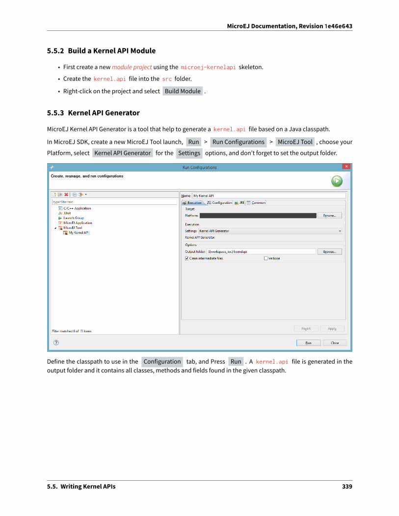
MicroEJ Documentation, Revision 1e46e643
5.5.2 Build a Kernel API Module
• First create a newmodule project using the microej-kernelapi skeleton.
• Create the kernel.api file into the src folder.
• Right-click on the project and select Build Module .
5.5.3 Kernel API Generator
MicroEJ Kernel API Generator is a tool that help to generate a kernel.api file based on a Java classpath.
In MicroEJ SDK, create a new MicroEJ Tool launch, Run > Run Configurations > MicroEJ Tool , choose your
Platform, select Kernel API Generator for the Settings options, and don’t forget to set the output folder.
Define the classpath to use in the Configuration tab, and Press Run . A kernel.api file is generated in theoutput folder and it contains all classes, methods and fields found in the given classpath.
5.5. Writing Kernel APIs 339

MicroEJ Documentation, Revision 1e46e643
Category: Kernel API Generator
Group: Classpath
Option(list):
Option Name: kernel.api.generator.classpath
Default value: (empty)
Group: Types Filters
Option(text): Includes Patterns
Option Name: kernel.api.generator.includes.patterns
Default value: **/*.class
Description: Comma separated list of ANT Patterns for types to include.
Option(text): Excludes Patterns
Option Name: kernel.api.generator.excludes.patterns
Default value: (empty)
Description: Comma separated list of ANT Patterns for types to exclude.
5.5. Writing Kernel APIs 340

MicroEJ Documentation, Revision 1e46e643
5.6 Communication between Features
Features can communicate together through the use of shared interfaces. The mechanism is described in ChapterShared Interfaces of the Application Developer’s Guide.
5.6.1 Kernel Type Converters
The shared interfacemechanismallows to transfer an object instance of a Kernel type fromone Feature to an other.To do that, the Kernel must register a new converter (See API Documentation Kernel.addConverter() method).
5.7 API Documentation
The full API documentation of the Kernel & Features Foundation Library is available in MicroEJ SDK ( Help >
MicroEJ Resource Center > Javadoc > KF [version] ).
5.8 Multi-Sandbox Enabled Libraries
A multi-Sandbox enabled library is a foundation or Add-On Library which can be embedded into the kernel andexposed as API.MicroEJ Foundation Libraries provided inMicroEJ SDKare alreadymulti-Sandbox enabled. A state-less library - i.e. a library that does not contain any method modifying an internal global state - is multi-Sandboxenabled by default.
This section details themulti-Sandbox semantic that have been added to MicroEJ Foundation Libraries in order tobe multi-Sandbox enabled.
5.8.1 MicroUI
Physical Display Ownership
The physical display is owned by only one context at a time (the Kernel or one Feature). The following cases maytrigger a physical display owner switch:
• during a call to ej.microui.display.Displayable.show() : a�er the successful permission check, it isassigned to the context owner.
• during a call to ej.microui.display.Display.callSerially(java.lang.Runnable) : a�er the successfulpermission check it is assigned to owner of the Runnable instance.
The physical display switch performs the following actions:
• If a Displayable instance is currently shown on the Display , the method Displayable.becomeHidden()is called.
• All pending events (input events, display flushes, call serially runnable instances) are removed from the dis-play event serializer
• System Event Generators handlers are reset to their default ej.microui.util.EventHandler instance.
5.6. Communication between Features 341

MicroEJ Documentation, Revision 1e46e643
Automatically Reclaimed Resources
Instances of ej.microui.display.Image , ej.microui.display.Font are automatically reclaimed when a Fea-ture is stopped.
5.8.2 ECOM
The ej.ecom.DeviceManager registry allows to share devices across Features. Instances of ej.ecom.Device thatare registered with a shared interface type are made accessible through a Proxy to all other Features that embedthe same shared interface (or an upper one of the hierarchy).
5.8.3 ECOM-COMM
Instances of ej.ecom.io.CommConnection are automatically reclaimed when a Feature is stopped.
5.8.4 FS
Instances of java.io.FileInputStream , java.io.FileOutputStream are automatically reclaimed when a Fea-ture is stopped.
5.8.5 NET
Instances of java.net.Socket , java.net.ServerSocket , java.net.DatagramSocket are automatically re-claimed when a Feature is stopped.
5.8.6 SSL
Instances of javax.net.ssl.SSLSocket are automatically reclaimed when a Feature is stopped.
5.9 Setup a KF Testsuite
A KF testsuite can be executed when building a Foundation Library or an Add-On library, and usually extends thetests written for the default library testsuite to verify the behavior of this library when its APIs are exposed by aKernel.
A KF testsuite is composed of a set of KF tests, each KF test itself is a minimal MicroEJ Multi-Sandbox Firmwarecomposed of a Kernel and zero or more Features.
5.9.1 Enable the Testsuite
In an existing library project:
• Create the src/test/projects directory,
• Edit the module.ivy and insert the following line within the <ea:build> XML element:
<ea:plugin organisation="com.is2t.easyant.plugins" module="microej-kf-testsuite" revision="+" />
5.9. Setup a KF Testsuite 342

MicroEJ Documentation, Revision 1e46e643
5.9.2 Add a KF Test
A KF test is a structured directory placed in the src/test/projects directory.
• Create a new directory for the KF test
• Within this directory, create the sub-projects:
– Create a newmodule project for the Kernel using the microej-javalib skeleton,
– Create a newmodule project for the Feature using the application skeleton,
– Create a newmodule project for the Firmware using the firmware-multiapp skeleton.
The names of the project directories are free, however MicroEJ suggests the following naming convention, assum-ing the KF test directory is [TestName] :
• [TestName]-kernel for the Kernel project,
• [TestName]-app[1..N] for Feature projects,
• [TestName]-firmware for the Firmware project.
The KF Testsuite structure shall be similar to the following figure:
5.9. Setup a KF Testsuite 343

MicroEJ Documentation, Revision 1e46e643
Fig. 6: KF Testsuite Overall Structure
All the projects will be built automatically in the right order based on their dependencies.
5.9. Setup a KF Testsuite 344

MicroEJ Documentation, Revision 1e46e643
5.9.3 KF Testsuite Options
It is possible to configure the same options defined by Testsuite Options for the KF testsuite, by using the prefixmicroej.kf.testsuite.properties instead of microej.testsuite.properties .
5.9. Setup a KF Testsuite 345
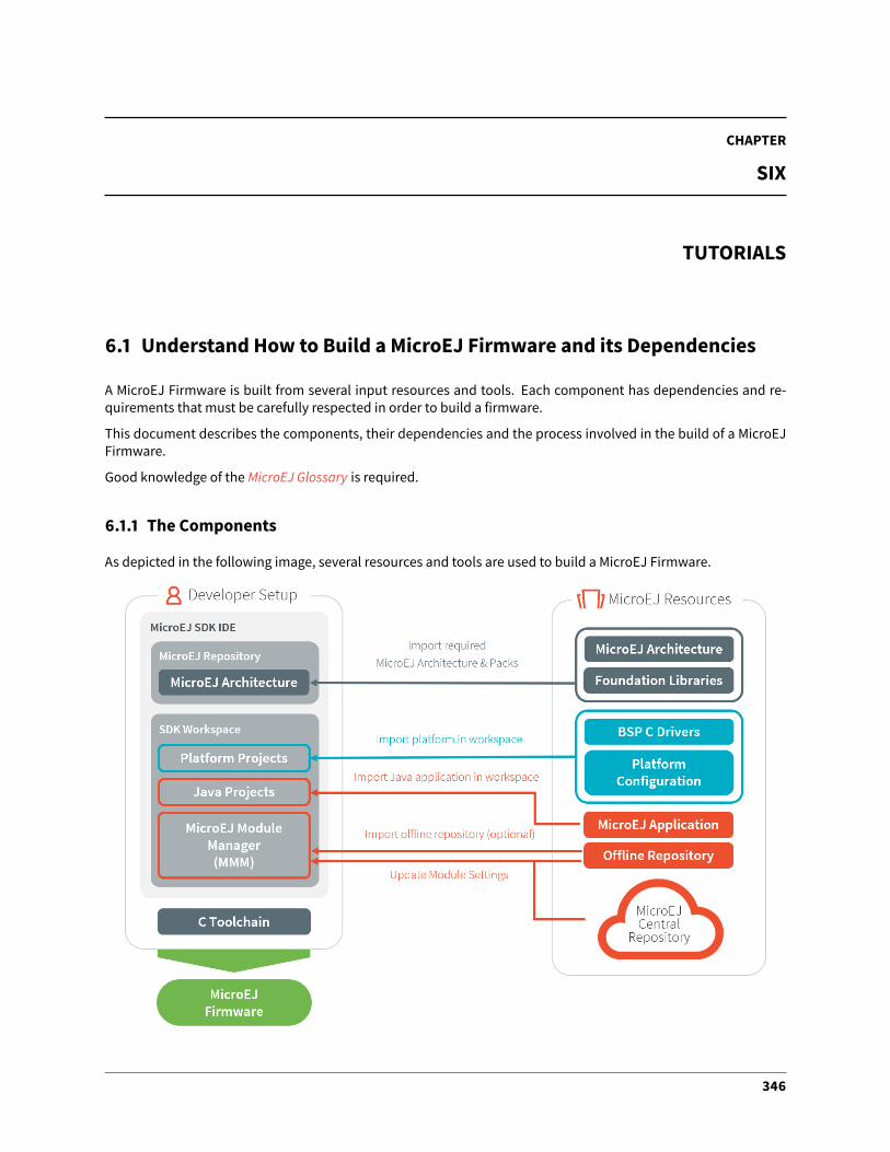
CHAPTER
SIX
TUTORIALS
6.1 Understand How to Build a MicroEJ Firmware and its Dependencies
A MicroEJ Firmware is built from several input resources and tools. Each component has dependencies and re-quirements that must be carefully respected in order to build a firmware.
This document describes the components, their dependencies and the process involved in the build of a MicroEJFirmware.
Good knowledge of theMicroEJ Glossary is required.
6.1.1 The Components
As depicted in the following image, several resources and tools are used to build a MicroEJ Firmware.
346

MicroEJ Documentation, Revision 1e46e643
MicroEJ Architecture (.xpf, .xpfp)
AMicroEJ Architecture contains the runtime port to a target instruction set (ISA) and a C compiler (CC) andMicroEJFoundation Libraries.
The MicroEJ Architectures are distributed into two formats:
• EVAL: evaluation license with runtime limitations (explained in SDK developer guide).
• PROD: production license (only MicroEJ sales & Customer Care team distribute this version).
The supported MicroEJ Architectures are listed here https://developer.microej.com/mej32-embedded-runtime-architectures/#arch
The MicroEJ Architecture is either provided from:
• For EVAL license only: the MicroEJ Repository at https://repository.microej.com/architectures/
• For PROD license only: SDK license site https://license.microej.com/ ( MyProduct >
Download additional products will list the downloads available). See Production Licenses for helpwith PROD license.
• MicroEJ sales or customer care team if the requested architecture is not listed as available.
SeeMicroEJ Architecture Import for a description on how to import a MicroEJ Architecture.
MicroEJ Platform Source (.zip)
This package includes:
• a C Board Support Package (BSP) with C drivers and an optional RTOS
• a MEJ32 Architecture
• the abstraction layers implementation of the platform architecture and foundations libraries
• the MicroEJ Simulator and its associated MicroEJ Mocks
The platform .zip files contain:
• <platform>-configuration : The configuration of the MicroEJ Platform
• <platform>-bsp : The C code for the board-specific files (drivers).
• <platform>-fp : Front panel mockup for the simulator.
SeeMicroEJ Platform Creation to learn how to create a MicroEJ Platform using a MicroEJ Platform Source project.
Depending on the project’s requirements, the MicroEJ Platform can be connected in various ways to the BSP; seeBSP Connection for more information on how to do it.
MicroEJ Application
A MicroEJ Application is a Java project that can be configured (in the Run configurations . . . properties):
1. to either run on:
• a simulator (computer desktop),
• a device (actual embedded hardware).
2. to setup:
6.1. Understand How to Build a MicroEJ Firmware and its Dependencies 347

MicroEJ Documentation, Revision 1e46e643
• memory (example: Java heap, Java stack),
• foundation libraries,
• etc.
To run on a device, the application is compiled and optimized for a specific MicroEJ Platform. It generates amicroejapp.o (native object code) linked with the <platform>-bsp project.
To import an existing MicroEJ Application as a zipped project in the SDK:
• Go to File > Import. . . > General > Existing Projects into Workspace > Select archive file >
Browse. . . .
• Select the zip of the project (e.g. x.zip ).
• And select Finish import.
See Create a MicroEJ Standalone Application for more information on how to create, configure, and develop a Mi-croEJ Application.
C Toolchain (GCC, KEIL, IAR, . . . )
Used to compile and link the following files into the final firmware (binary, hex, elf, . . . that will be programmed onthe hardware):
• the microejapp.o (application),
• the microejruntime.lib or microejruntime.a (platform),
• the BSP C files (drivers).
Module Repository
A Module Repository provides the modules required to build MicroEJ Platforms and MicroEJ Applications.
• The MicroEJ Central Repository is an online repository of so�ware modules (libraries, tools, etc.), see https://repository.microej.com/. This repository can also be used as an o�line repository, see https://developer.microej.com/central-repository/.
• (Optional) It can be extended with an o�line repository ( .zip ) that can be imported in the workspace (seeUse the O�line Repository):
SeeModule Repository for more information.
Dependencies Between Components
• A MicroEJ Architecture targets a specific instruction set (ISA) and a specific C compiler (CC).
– The C toolchain used for theMicroEJ Architecturemust be the same as the one used to compile and linkthe BSP project and the MicroEJ Firmware.
• A MicroEJ Platform consists of the aggregation of both a MicroEJ Architecture and a BSP with a C toolchain.
– Changing either theMicroEJ Architecture or the C toolchain results in a change of theMicroEJ Platform.
• A MicroEJ Application is independent of the MicroEJ Architecture.
– It can run on any MicroEJ Platform as long the platform provides the required APIs.
6.1. Understand How to Build a MicroEJ Firmware and its Dependencies 348

MicroEJ Documentation, Revision 1e46e643
– To run a MicroEJ Application on a new device, create a new MicroEJ Platform for this device with theexact same features. The MicroEJ Application will not require any change.
6.1.2 How to Build
The process to build a MicroEJ Firmware is two-fold:
1. Build a MicroEJ Platform
2. Build a MicroEJ Application
The MicroEJ Application is compiled against the MicroEJ Platform to produce the MicroEJ Firmware deployed onthe target device.
Note: The MicroEJ Application also runs onto the MicroEJ Simulator using the mocks provided by the MicroEJPlatform.
Build a MicroEJ Platform
The next schema presents the components and process to build a MicroEJ Platform.
Build a MicroEJ Firmware
The next schema presents the steps to build a MicroEJ Mono-Sandbox Firmware (previously known as MicroEJSingle-app Firmware). The steps are:
1. Build the MicroEJ Application into a microejapp.o using MicroEJ SDK
2. Compile the BSP C sources into .o using the C toolchain
3. the BSP ( .o ) and the MicroEJ Application ( microejapp.o ) and the MicroEJ Platform ( microejruntime.a )are linkedby theC toolchain toproducea final ELForbinary calledMicroEJFirmware (e.g. application.out).
6.1. Understand How to Build a MicroEJ Firmware and its Dependencies 349

MicroEJ Documentation, Revision 1e46e643
See BSP Connection for more information on how to connect the MicroEJ Platform to the BSP.
Dependencies Between Processes
• Rebuild the MicroEJ Platform:
– When the MicroEJ Architecture ( .xpf ) changes.
– When a MicroEJ Foundation Library ( .xpfp ) changes.
– When a Foundation Library changes, either when
* The public API ( .java or .h ) changes.
* The front-panel or mock implementation ( .java ) changes.
• Rebuild of the MicroEJ Platform is not required:
– When the implementation ( .c ) of a Foundation Library changes.
– When the BSP ( .c ) changes.
– When the MicroEJ Application changes.
• Rebuild MicroEJ Application:
– When it changes.
– When the MicroEJ Platform changes.
• Rebuild the BSP:
– When it changes.
– When the MicroEJ Platform changes.
• Rebuild the MicroEJ Firmware:
6.1. Understand How to Build a MicroEJ Firmware and its Dependencies 350

MicroEJ Documentation, Revision 1e46e643
– When the MicroEJ Application ( microejapp.o ) changes.
– When the BSP ( *.o ) changes.
– When the MicroEJ Platform ( microejruntime.a ) changes.
6.1.3 Get Support
If any questions, feel free to contact our support teamwith the following information (the table below is an exam-ple):
Delivery NameMicroEJ SDK Distribution 20.07 / Version 5.2.0 (see Determine the MicroEJ Studio/SDK
Version)MEJ32 XPF ARM Cortex-M4 / IAR DEVPlatform 1.0.0Application 1.2.4Module Repository https://repository.microej.com/packages/repository/2.5.0/microej-5_
0-2.5.0.zipC compiler IAR 8.40.1
6.2 Create a MicroEJ Platform for a Custom Device
6.2.1 Introduction
AMicroEJ Architecture is a so�ware package that includes theMicroEJ Runtime port to a specific target InstructionSet Architecture (ISA) and C compiler. It contains a set of libraries, tools and C header files. The MicroEJ Architec-tures are provided by MicroEJ SDK.
A MicroEJ Platform is a MicroEJ Architecture port for a custom device. It contains the MicroEJ configuration andthe BSP (C source files).
MicroEJ Corp. provides MicroEJ Evaluation Architectures at https://repository.microej.com/architectures/, andMicroEJ Platform demo projects for various evaluation boards at https://repository.microej.com/index.php?resource=JPF.
We recommend reading theMicroEJ Firmware section to get an overview of MicroEJ Firmware build flow.
The following document assumes the reader is familiar with the Platform Developer Guide.
Each MicroEJ Platform is specific to:
• a MicroEJ Architecture (MCU ISA and C compiler)
• an optional RTOS (e.g. FreeRTOS - note: the MicroEJ OS can run bare metal)
• adevice: theOSbringupcode that is device specific (e.g. theMCUspecific code/IO/RAM/Clock/Middleware. . .configurations)
In this document we will address the following items:
• MicroEJ Platform Configuration project (in MicroEJ SDK)
• MicroEJ Simulator (in MicroEJ SDK)
• Platform BSP (in a C IDE/Compiler like GCC/KEIL/IAR)
6.2. Create a MicroEJ Platform for a Custom Device 351

MicroEJ Documentation, Revision 1e46e643
TheMicroEJ Platform relies on Cdrivers (aka low level LL drivers) for each of the platform feature. These drivers areimplemented in the platform BSP project. This project is edited in the C compiler IDE/dev environment (e.g. KEIL,GCC, IAR). E.g. the MicroUI library LED feature will require a LLLEDS.c that implements the native on/o� IO drive.
The following sections explain how to create a MicroEJ Platform for a custom device starting from an existing Mi-croEJ Platform project whether it is configured for the same MCU/RTOS/C Compiler or not.
In the following, we assume that the new device hardware is validated and at least a trace output is available. It isalso a good idea to run basic hardware tests like:
• Internal and external flash programming and verification
• RAM 8/16/32 -bit read/write operations (internal and external if any)
• EEMBC Coremark benchmark to verify the CPU/buses/memory/compiler configuration
• See the Platform Qualification Tools used to qualify MicroEJ Platforms.
6.2.2 A MicroEJ Platform Project is already available for the sameMCU/RTOS/C Compiler
This is the fastest way: the MicroEJ Platform is usually provided for a silicon vendor evaluation board. Import thisplatform in MicroEJ SDK.
As the MCU, RTOS and compiler are the same, only the device specific code needs to be changed (external RAM,external oscillator, communication interfaces).
Platform
In MicroEJ SDK
• modify the .platform fromtheMicroEJPlatform(xxx-configuration project) tomatch thedevice featuresand its associated configuration (e.g. UI->Display ).
More details on available modules can be found in the Platform Developer Guide.
BSP
Required actions:
• modify the BSP C project to match the device specification
6.2. Create a MicroEJ Platform for a Custom Device 352

MicroEJ Documentation, Revision 1e46e643
– edit the scatter file/link options
– edit the compilation options
• create/review/change the platform Low Level C drivers. They must match the device components and theMCU IO pin assignment
Note: A number of LL*.h files are referenced from the project. Implement the function prototypes declaredthere so that the JVM can delegate the relevant operations to the provided BSP C functions.
Simulator
In MicroEJ SDK
• modify the existing Simulator front panel xxx-fp project
6.2.3 A MicroEJ Platform Project is not available for the sameMCU/RTOS/C Compiler
Look for an available MicroEJ Platform that will match in order of priority:
• same MCU part number
• same RTOS
• same C compiler
At this point, consider either to modify the closest MicroEJ Platform
• In MicroEJ SDK: modify the platform configuration.
• in the C IDE: start from an empty project that match with the MCU.
Or to start from scratch a newMicroEJ Platform
• In MicroEJ SDK: create theMicroEJ Platform and refer to the selectedMicroEJ Platform as amodel for imple-mentation. (refer toMicroEJ Platform Configuration)
• in the C IDE: start from an empty project and implement the drivers of each of the LL drivers API.
Make sure to link with:
– the microejruntime.a that runs the JVM for the MCU Architecture
– the microejapp.o that contains the compiled Java application
MCU
The MCU specific code can be found:
• in the C project IDE properties
• in the linker file
• the IO configuration
• in the low level driver (these drivers are usually provided by the silicon vendor)
6.2. Create a MicroEJ Platform for a Custom Device 353

MicroEJ Documentation, Revision 1e46e643
RTOS
The LL driver is named LLMJVM_RTOS.c/.h . Modify this file to match the selected RTOS.
C Compiler
The BSP project is provided for a specific compiler (that matches the selected platform architecture). Start a newproject with the compiler IDE that includes the LL drivers and start the MicroEJ Platform in the main() function.
6.2.4 Platform Validation
Use the Platform Qualification Tools to qualify the MicroEJ Platform built.
6.2.5 Further Assistance Needed
Pleasenote that portingMicroEJ to anewdevice is also something that is part of our engineering services. Considercontacting [email protected] to request a quote.
6.3 Create a MicroEJ Firmware From Scratch
This tutorial explains how to create a MicroEJ Firmware from scratch. It goes trough the typical steps followed bya Firmware developer integrating MicroEJ with a C Board Support Package (BSP) for a target device.
In this tutorial, the target device is a a Luminary Micro Stellaris. Though this device is no longer available on themarket, it has two advantages:
• The QEMU PC System emulator can emulate the device.
• FreeRTOS provides an o�icial Demo BSP.
Consequently, no board is required to follow this tutorial. Everything is emulated on the developer’s PC.
The tutorial should take 1hour to complete (excluding the installation timeofMicroEJSDKandWindowsSubsystemLinux (WSL)).
6.3.1 Intended Audience
The audience for this document is Firmware engineers who want to understand how MicroEJ is integrated to a CBoard Support Package.
In addition, this tutorial should be of interest to all developers wishing to familiarize themselves with the low levelcomponents of a MicroEJ Firmware such as: MicroEJ Architecture,MicroEJ Platform, Low Level API and BSP connec-tion.
6.3.2 Introduction
The following steps are usually followed when starting a new project:
1. Pick a target device (that meets the requirements of the project).
2. Setup a RTOS and a toolchain that support the target device.
3. Adapt the RTOS port if needed.
6.3. Create a MicroEJ Firmware From Scratch 354

MicroEJ Documentation, Revision 1e46e643
4. Install aMicroEJ Architecture that matches the target device/RTOS/toolchain.
5. Setup a newMicroEJ Platform connected to the Board Support Package (BSP).
6. Implement Low Level API.
7. Validate the resulting MicroEJ Platform with the Platform Qualification Tools (PQT).
8. Develop theMicroEJ Application.
This tutorial describes step by step how to go from the FreeRTOS BSP to a MicroEJ Application that runs on theMicroEJ Platform and prints the classic "Hello, World!" .
In this tutorial:
• The target device is a Luminary Micro Stellaris which is emulated by QEMU (QEMU Stellaris boards).
• The RTOS is FreeRTOS and the toolchain is GNU CC fo ARM.
All modifications to FreeRTOS BSP made for this tutorial are available at https://github.com/MicroEJ/FreeRTOS/tree/tuto-microej-firmware-from-scratch.
Note: The implementation of the Low Level API and their validation with the Platform Qualification Tools (PQT)will be the topic of another tutorial.
6.3.3 Prerequisites
• MicroEJ SDK version 5.1.0 or higher (distribution 19.05). Can be downloaded fromhttps://developer.microej.com/ (direct link)
• Windows 10 with Windows Subsystem for Linux (WSL). See the installation guide.
• A Linux distribution installed on WSL (Tested on Ubuntu 19.10 eoan and Ubuntu 20.04 focal).
Note: In WSL, use the command lsb_release -a to print the current Ubuntu version.
A code editor such as Visual Studio Code is also recommended to edit BSP files.
6.3.4 Overview
Thenext sectionsdescribe stepby stephowtobuild aMicroEJFirmware that runsaHelloWorldMicroEJApplicationon the emulated device.
The steps to follow are:
1. Setup the development environment (assuming the prerequisites are satisfied).
2. Get a running BSP
3. Build the MicroEJ Platform
4. Create the HelloWorld MicroEJ Application
5. Implement the minimum Low Level API to run the application
This tutorial goes through trials and errors every Firmware developers may encounter. It provides a solution a�ereach error rather than providing the full solution in one go.
6.3. Create a MicroEJ Firmware From Scratch 355

MicroEJ Documentation, Revision 1e46e643
6.3.5 Setup the Development Environment
This section assumes the prerequisites have been properly installed.
In WSL:
1. Update apt’s cache: sudo apt-get update
2. Install qemu-system-arm and GNU CC toolchain for ARM: sudo apt-get install -y qemu-system-armgcc-arm-none-eabi build-essential subversion
3. The rest of this tutorial will use the folder src/tuto-from-scratch/ in the Windows home folder.
4. Create the folder: mkdir -p /mnt/c/Users/${USER}/src/tuto-from-scratch (the -p option ensures allthe directories are created).
5. Go into the folder: cd /mnt/c/Users/${USER}/src/tuto-from-scratch/
6. Clone FreeRTOS and its submodules: git clone -b V10.3.1 --recursive https://github.com/FreeRTOS/FreeRTOS.git (this may takes some time)
Note: Use the right-click to paste from the Windows clipboard into WSL console. The right-click is also used tocopy from the WSL console into the Windows clipboard.
6.3.6 Get Running BSP
This section presents how to get running BSP based on FreeRTOS that boots on the target device.
1. Go into the target device sub-project: cd FreeRTOS/FreeRTOS/Demo/CORTEX_LM3S811_GCC
2. Build the project: make
Ignoring the warnings, the following error appears during the link:
CC hw_include/osram96x16.cLD gcc/RTOSDemo.axfarm-none-eabi-ld: section .text.startup LMA [0000000000002b24,0000000000002c8f] overlaps section .→˓data LMA [0000000000002b24,0000000000002b27]make: *** [makedefs:191: gcc/RTOSDemo.axf] Error 1
Insert the following fixes in the linker script file named standalone.ld (thanks to http://roboticravings.blogspot.com/2018/07/freertos-on-cortex-m3-with-qemu.html).
Note: WSL can start the editor Visual Studio Code. type code . in WSL. . represents the current directoryin Unix.
diff --git a/FreeRTOS/Demo/CORTEX_LM3S811_GCC/standalone.ld b/FreeRTOS/Demo/CORTEX_LM3S811_GCC/→˓standalone.ld
index 8ee3fe2f8..b771ff834 100644--- a/FreeRTOS/Demo/CORTEX_LM3S811_GCC/standalone.ld+++ b/FreeRTOS/Demo/CORTEX_LM3S811_GCC/standalone.ld@@ -42,7 +42,15 @@ SECTIONS
_etext = .;} > FLASH
(continues on next page)
6.3. Create a MicroEJ Firmware From Scratch 356

MicroEJ Documentation, Revision 1e46e643
(continued from previous page)
- .data : AT (ADDR(.text) + SIZEOF(.text))+ .ARM.exidx :+ {+ *(.ARM.exidx*)+ *(.gnu.linkonce.armexidx.*)+ } > FLASH++ _begin_data = .;++ .data : AT ( _begin_data )
{_data = .;*(vtable)
This is the output of the git diff command. Lines startingwith a - should be removed. Lines startingwitha + should be added.
Note: The patch(1) can be used to apply the patch. Assuming WSL shell is in FreeRTOS/Demo/CORTEX_LM3S811_GCC directory:
1. Install dos2unix utility: sudo apt install dos2unix
2. Convert all files to unix line-ending: find -type f -exec dos2unix {} \;
3. Copy the content of the code block in a file named linker.patch (every lines of the code block mustbe copied in the file).
4. Apply the patch: patch -l -p4 < linker.patch .
It is also possible to paste the di� directly into the console:
1. In WSL, invoke patch -l -p4 . The command starts, waiting for input on stdin (the standard input).
2. Copy the di� and paste it in WSL
3. Press enter
4. Press Ctrl-d Ctrl-d (press the Control key + the letter d twice).
3. Run the build again: make
4. Run the emulator with the generated kernel: qemu-system-arm -M lm3s811evb -nographic -kernelgcc/RTOSDemo.bin
The following error appears and then nothing:
ssd0303: error: Unknown command: 0x80ssd0303: error: Unexpected byte 0xe3ssd0303: error: Unknown command: 0x80ssd0303: error: Unexpected byte 0xe3ssd0303: error: Unknown command: 0x80ssd0303: error: Unexpected byte 0xe3ssd0303: error: Unknown command: 0x80ssd0303: error: Unexpected byte 0xe3ssd0303: error: Unknown command: 0x80ssd0303: error: Unexpected byte 0xe3ssd0303: error: Unknown command: 0x80ssd0303: error: Unexpected byte 0xe3ssd0303: error: Unknown command: 0x80
(continues on next page)
6.3. Create a MicroEJ Firmware From Scratch 357

MicroEJ Documentation, Revision 1e46e643
(continued from previous page)
ssd0303: error: Unexpected byte 0xe3ssd0303: error: Unknown command: 0x80ssd0303: error: Unexpected byte 0xe3ssd0303: error: Unknown command: 0x80ssd0303: error: Unexpected byte 0xe3
5. Press Ctrl-a x (press Control + the letter a , release, press x ) to the end the QEMU session. The sessionends with QEMU: Terminated .
Note: The errors can be safely ignored. They occur because the OLED controller emulated receive incorrectcommands.
At this point, the target device is successfully booted with the FreeRTOS kernel.
6.3.7 FreeRTOS Hello World
This section describes how to configure the BSP to print text on the QEMU console.
The datasheet of the target device (LM3S811 datasheet) describes how to use the UART device and an exampleimplementation for QEMU is available here).
The following code implements the putchar(3) and puts(3) functions:
#define UART0BASE ((volatile int*) 0x4000C000)
int putchar (int c){(*UART0BASE) = c;return c;
}
int puts(const char *s) {while (*s) {
putchar(*s);s++;
}return putchar('\n');
}
And here is the patch that implements both functions and prints Hello World .
diff --git a/FreeRTOS/Demo/CORTEX_LM3S811_GCC/main.c b/FreeRTOS/Demo/CORTEX_LM3S811_GCC/main.cindex 107517c00..3ea4c23a4 100644--- a/FreeRTOS/Demo/CORTEX_LM3S811_GCC/main.c+++ b/FreeRTOS/Demo/CORTEX_LM3S811_GCC/main.c@@ -134,9 +134,25 @@ SemaphoreHandle_t xButtonSemaphore;QueueHandle_t xPrintQueue;
/*-----------------------------------------------------------*/+#define UART0BASE ((volatile int*) 0x4000C000)++int putchar (int c){+ (*UART0BASE) = c;+ return c;+}
(continues on next page)
6.3. Create a MicroEJ Firmware From Scratch 358

MicroEJ Documentation, Revision 1e46e643
(continued from previous page)
++int puts(const char *s) {+ while (*s) {+ putchar(*s);+ s++;+ }+ return putchar('\n');+}
int main( void ){+ puts("Hello, World! puts function is working.");+
/* Configure the clocks, UART and GPIO. */prvSetupHardware();
Rebuild and run the newly generated kernel: make && qemu-system-arm -M lm3s811evb -nographic -kernelgcc/RTOSDemo.bin (press Ctrl-a x to interrupt the emulator).
make: Nothing to be done for 'all'.Hello, World! puts function is working.ssd0303: error: Unknown command: 0x80ssd0303: error: Unexpected byte 0xe3ssd0303: error: Unknown command: 0x80ssd0303: error: Unexpected byte 0xe3ssd0303: error: Unknown command: 0x80ssd0303: error: Unexpected byte 0xe3ssd0303: error: Unknown command: 0x80ssd0303: error: Unexpected byte 0xe3ssd0303: error: Unknown command: 0x80ssd0303: error: Unexpected byte 0xe3ssd0303: error: Unknown command: 0x80ssd0303: error: Unexpected byte 0xe3ssd0303: error: Unknown command: 0x80ssd0303: error: Unexpected byte 0xe3ssd0303: error: Unknown command: 0x80ssd0303: error: Unexpected byte 0xe3ssd0303: error: Unknown command: 0x80ssd0303: error: Unexpected byte 0xe3QEMU: Terminated
With this two functions implemented, printf(3) is also available.
diff --git a/FreeRTOS/Demo/CORTEX_LM3S811_GCC/main.c b/FreeRTOS/Demo/CORTEX_LM3S811_GCC/main.cindex 76440e60e..f24007597 100644--- a/FreeRTOS/Demo/CORTEX_LM3S811_GCC/main.c+++ b/FreeRTOS/Demo/CORTEX_LM3S811_GCC/main.c@@ -149,9 +149,11 @@ int puts(const char *s) {
return putchar('\n');}
+#include <stdio.h>+int main( void ){- puts("Hello, World! puts function is working.");
(continues on next page)
6.3. Create a MicroEJ Firmware From Scratch 359

MicroEJ Documentation, Revision 1e46e643
(continued from previous page)
+ printf("Hello, World! printf function is working.\n");
/* Configure the clocks, UART and GPIO. */prvSetupHardware();
At this point, the character output on the UART is implemented in the FreeRTOS BSP. The next step is to create theMicroEJ Platform and MicroEJ Application.
6.3.8 Create a MicroEJ Platform
This section describes how to create and configure aMicroEJ Platform compatiblewith the FreeRTOSBSP andGCCtoolchain.
• A MicroEJ Architecture is a so�ware package that includes the MicroEJ Runtime port to a specific target In-struction Set Architecture (ISA) and C compiler. It contains a set of libraries, tools and C header files. TheMicroEJ Architectures are provided by MicroEJ SDK.
• AMicroEJ Platform is a port of a MicroEJ Architecture for a custom device. It contains the MicroEJ configura-tion and the BSP (C source files).
When selecting a MicroEJ Architecture, special care must be taken to ensure the compatibility between thetoolchain used in the BSP and the toolchain used to build the MicroEJ Core Engine included in the MicroEJ Ar-chitecture.
The list of MicroEJ Architectures supported is listed at https://docs.microej.com/en/latest/PlatformDeveloperGuide/appendix/toolchain.html. MicroEJ Evaluation Architectures provided by MicroEJCorp. can be downloaded fromMicroEJ Architectures Repository.
There is no CM3 in MicroEJ Architectures Repository and the Arm® Cortex®-M3 MCU is not mentioned in the ca-pabilities matrix. This means that the MicroEJ Architectures for Arm® Cortex®-M3 MCUs are no longer distributedfor evaluation. Download the latest MicroEJ Architecture for Arm® Cortex®-M0 instead (the Arm® architectures arebinary upward compatible from Arm®v6-M (Cortex®-M0) to Arm®v7-M (Cortex®-M3)).
Import the MicroEJ Architecture
This step describes how to import aMicroEJ Architecture.
1. Start MicroEJ SDK on an empty workspace. For example, create an empty folder workspace next to theFreeRTOS git folder and select it.
2. Keep the default MicroEJ Repository
3. Download the latest MicroEJ Architecture for Arm® Cortex®-M0 instead: https://repository.microej.com/architectures/com/microej/architecture/CM0/CM0_GCC48/flopi0G22/7.11.0/flopi0G22-7.11.0-eval.xpf
4. Import the MicroEJ Architecture in MicroEJ SDK
1. File > Import > MicroEJ > Architectures
2. select the MicroEJ Architecture file downloaded
3. Accept the license and click on Finish
6.3. Create a MicroEJ Firmware From Scratch 360

MicroEJ Documentation, Revision 1e46e643
Install an Evaluation License
This step describes how to create and activate an Evaluation License for the MicroEJ Architecture previously im-ported.
1. Select the Window > Preferences > MicroEJ > Architectures menu .
2. Click on the architectures and press Get UID .
3. Copy the UID. It will be needed when requesting a license.
4. Go to https://license.microej.com.
5. Click on Create a new account link.
6. Create an account with a valid email address. A confirmation email will be sent a fewminutes a�er. Click onthe confirmation link in the email and login with the account.
7. Click on Activate a License .
8. Set Product P/N: to 9PEVNLDBU6IJ .
9. Set UID: to the UID generated before.
6.3. Create a MicroEJ Firmware From Scratch 361

MicroEJ Documentation, Revision 1e46e643
10. Click on Activate .
• The license is being activated. Anactivationmail shouldbe received in less than5minutes. If not, pleasecontact [email protected].
• Once received by email, save the attached zip file that contains the activation key.
11. Go back to Microej SDK.
12. Select the Window > Preferences > MicroEJ menu.
13. Press Add. . . .
14. Browse the previously downloaded activation key archive file.
15. Press OK . A new license is successfully installed.
16. Go to Architectures sub-menu and check that all architectures are now activated (green check).
17. Microej SDK is successfully activated.
Create the MicroEJ Platform
This step describes how to create a newMicroEJ Platform using the MicroEJ Architecture previously imported.
1. Select File > New > MicroEJ Platform Project .
6.3. Create a MicroEJ Firmware From Scratch 362

MicroEJ Documentation, Revision 1e46e643
2. Ensure the Architecture selected is the MicroEJ Architecture previously imported.
3. Ensure the Create from a platform reference implementation box is unchecked.
4. Click on Next button.
5. Fill the fields:
• Set Device: to lm3s811evb
• Set Name: to Tuto
Setup the MicroEJ Platform
This step describes how to configure the MicroEJ Platform previously created.
The Platform Configuration Additions provide a flexible way to configure the BSP connection between the Mi-croEJ Platform and MicroEJ Application to the BSP. In this tutorial, the Partial BSP connection is used. That is,the MicroEJ SDK will output all MicroEJ files (C headers, MicroEJ Application microejapp.o , MicroEJ Runtimemicroejruntime.a , . . . ) in a location known by the BSP. The BSP is configured to compile and link with those files.
For this tutorial, that means that the final binary is produced by invoking make in the FreeRTOS BSP.
1. Install the Platform Configuration Additions by copying all the files within the content folder in the MicroEJPlatform folder.
6.3. Create a MicroEJ Firmware From Scratch 363

MicroEJ Documentation, Revision 1e46e643
Note: The content directory contains files thatmust be installed in aMicroEJ Platform configuration direc-tory (thedirectory that contains the .platform file). It canbeautomatically downloadedusing the followingcommand line:
svn checkout https://github.com/MicroEJ/PlatformQualificationTools/trunk/framework/platform/→˓content [path_to_platform_configuration_directory]
2. Edit the file bsp/bsp.properties as follow:
# Specify the MicroEJ Application file ('microejapp.o') parent directory.# This is a '/' separated directory relative to 'bsp.root.dir'.microejapp.relative.dir=microej/lib
# Specify the MicroEJ Platform runtime file ('microejruntime.a') parent directory.# This is a '/' separated directory relative to 'bsp.root.dir'.microejlib.relative.dir=microej/lib
# Specify MicroEJ Platform header files ('*.h') parent directory.# This is a '/' separated directory relative to 'bsp.root.dir'.microejinc.relative.dir=microej/inc
3. Open the .platform file and click on Build Platform . TheMicroEJ Platformwill appear in theworkspace.
At this point, the MicroEJ Platform is ready to be used to build MicroEJ Applications.
6.3.9 Create MicroEJ Application HelloWorld
1. Select File > New > MicroEJ Standalone Application Project .
2. Set the name to HelloWorld and click on Finish
6.3. Create a MicroEJ Firmware From Scratch 364

MicroEJ Documentation, Revision 1e46e643
3. Run theapplication in Simulator to ensure it isworkingproperly. Right-click onHelloWorldproject > Run as> MicroEJ Application
6.3. Create a MicroEJ Firmware From Scratch 365

MicroEJ Documentation, Revision 1e46e643
The following message appears in the console:
6.3. Create a MicroEJ Firmware From Scratch 366

MicroEJ Documentation, Revision 1e46e643
=============== [ Initialization Stage ] ============================== [ Launching on Simulator ] ===============Hello World!=============== [ Completed Successfully ] ===============
SUCCESS
6.3.10 Configure BSP Connection in MicroEJ Application
This step describes how to configure the BSP connection for the HelloWorld MicroEJ Application and how to buildthe MicroEJ Application that will run on the target device.
For aMicroEJApplication, theBSP connection is configured in the PROJECT-NAME/build/common.properties file.
1. Create a file HelloWorld/build/emb.properties with the following content:
core.memory.immortal.size=0core.memory.javaheap.size=1024core.memory.threads.pool.size=4core.memory.threads.size=1core.memory.thread.max.size=4deploy.bsp.microejapp=truedeploy.bsp.microejlib=truedeploy.bsp.microejinc=truedeploy.bsp.root.dir=[absolute_path] to FreeRTOS\\FreeRTOS\\Demo\\CORTEX_LM3S811_GCC
Note: Assuming the WSL current directory is FreeRTOS/FreeRTOS/Demo/CORTEX_LM3S811_GCC , use thefollowing command to find the deploy.bsp.root.dir path with proper escaping:
pwd | sed -e 's|/mnt/c/|C:\\\\|' -e 's|/|\\\\|g'
2. Open Run > Run configurations. . .
3. Select the HelloWorld launcher configuration
6.3. Create a MicroEJ Firmware From Scratch 367
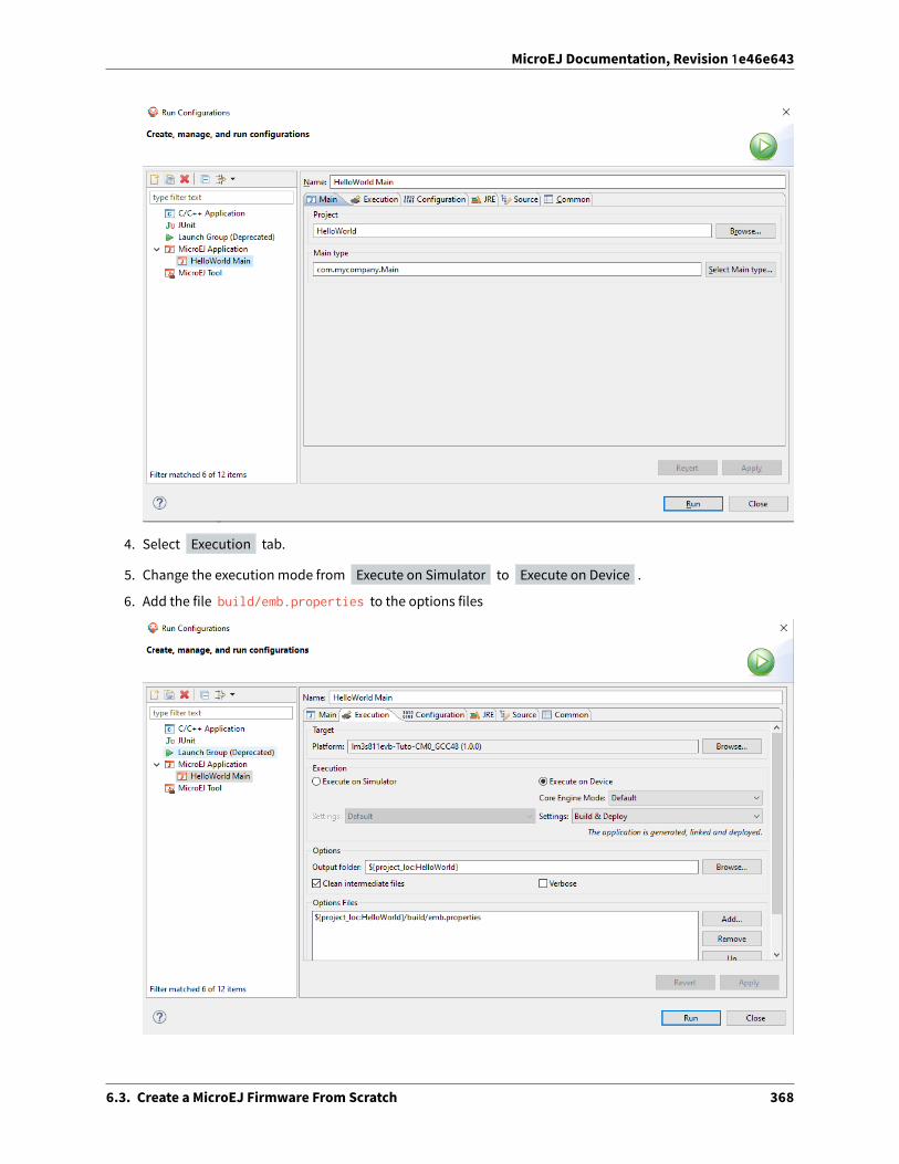
MicroEJ Documentation, Revision 1e46e643
4. Select Execution tab.
5. Change the execution mode from Execute on Simulator to Execute on Device .
6. Add the file build/emb.properties to the options files
6.3. Create a MicroEJ Firmware From Scratch 368

MicroEJ Documentation, Revision 1e46e643
7. Click on Run
=============== [ Initialization Stage ] ===============Platform connected to BSP location 'C:\Users\user\src\tuto-from-scratch\FreeRTOS\FreeRTOS\Demo\CORTEX_→˓LM3S811_GCC' using application option 'deploy.bsp.root.dir'.=============== [ Launching SOAR ] ============================== [ Launching Link ] ============================== [ Deployment ] ===============MicroEJ files for the 3rd-party BSP project are generated to 'C:\Users\user\src\tuto-from-→˓scratch\workspace\HelloWorld\com.mycompany.Main\platform'.The MicroEJ application (microejapp.o) has been deployed to: 'C:\Users\user\src\tuto-from-→˓scratch\FreeRTOS\FreeRTOS\Demo\CORTEX_LM3S811_GCC\microej\lib'.The MicroEJ platform library (microejruntime.a) has been deployed to: 'C:\Users\user\src\tuto-from-→˓scratch\FreeRTOS\FreeRTOS\Demo\CORTEX_LM3S811_GCC\microej\lib'.The MicroEJ platform header files (*.h) have been deployed to: 'C:\Users\user\src\tuto-from-→˓scratch\FreeRTOS\FreeRTOS\Demo\CORTEX_LM3S811_GCC\microej\inc'.=============== [ Completed Successfully ] ===============
SUCCESS
At this point, the HelloWorld MicroEJ Application is built and deployed in the FreeRTOS BSP.
6.3.11 MicroEJ and FreeRTOS Integration
This section describes how to finalize the integration between MicroEJ and FreeRTOS to get a working firmwarethat runs the HelloWorld MicroEJ Application built previously.
In the previous section, when the MicroEJ Application was built, several files were added to a new folder namedmicroej/ .
$ pwd/mnt/c/Users/user/src/tuto-from-scratch/FreeRTOS/FreeRTOS/Demo/CORTEX_LM3S811_GCC$ tree microej/microej/
incBESTFIT_ALLOCATOR.hBESTFIT_ALLOCATOR_impl.hLLBSP_impl.hLLMJVM.hLLMJVM_MONITOR_impl.hLLMJVM_impl.hLLTRACE_impl.hMJVM_MONITOR.hMJVM_MONITOR_types.hintern
BESTFIT_ALLOCATOR.hBESTFIT_ALLOCATOR_impl.hLLBSP_impl.hLLMJVM.hLLMJVM_impl.htrace_intern.h
sni.htrace.h
libmicroejapp.omicroejruntime.a
(continues on next page)
6.3. Create a MicroEJ Firmware From Scratch 369

MicroEJ Documentation, Revision 1e46e643
(continued from previous page)
3 directories, 19 files
• The microej/lib folder contains the HelloWorld MicroEJ Application object file ( microejapp.o ) and theMicroEJ Runtime. The final binary must be linked with these two files.
• The microej/inc folder contains several Cheader filesused toexposeMicroEJLowLevel APIs. The functionsdefined in files ending with the _impl.h su�ix should be implemented by the BSP.
To summarize, the following steps remain to complete the integration between MicroEJ and the FreeRTOS BSP:
• Implement minimal Low Level APIs
• Invoke the MicroEJ Core Engine
• Build and link the firmware with the MicroEJ Runtime and MicroEJ Application
Minimal Low Level APIs
The purpose of this tutorial is to demonstrate how to develop aminimal MicroEJ Architecture, it is not to develop acomplete MicroEJ Architecture. Therefore this tutorial implements only the required functions and provides stubimplementation for unused features. For example, the following implementation does not support scheduling.
The two headers that must be implemented are LLBSP_impl.h and LLMJVM_impl.h .
1. In the BSP, create a folder named microej/src (next to the microej/lib and microej/inc folders).
2. Implement LLBSP_impl.h in LLBSP.c :
Listing 1: microej/src/LLBSP.c
#include "LLBSP_impl.h"
extern void _etext(void);uint8_t LLBSP_IMPL_isInReadOnlyMemory(void* ptr){
return ptr < &_etext;}
/*** Writes the character <code>c</code>, cast to an unsigned char, to stdout stream.* This function is used by the default implementation of the Java <code>System.out</code>.*/void LLBSP_IMPL_putchar(int32_t c){
putchar(c);}
• The implementation of LLBSP_IMPL_putchar reuses the putchar implemented previously.
• The rodata section is defined in the linker script standalone.ld . The flash memory starts at 0 andthe end of the section is stored in the _etex symbol.
3. Implement LLMJVM_impl.h in LLMJVM_stub.c (all functions are stubbed with a dummy implementation):
6.3. Create a MicroEJ Firmware From Scratch 370

MicroEJ Documentation, Revision 1e46e643
Listing 2: microej/src/LLMJVM_stub.c
#include "LLMJVM_impl.h"
int32_t LLMJVM_IMPL_initialize(){
return LLMJVM_OK;}
int32_t LLMJVM_IMPL_vmTaskStarted(){
return LLMJVM_OK;}
int32_t LLMJVM_IMPL_scheduleRequest(int64_t absoluteTime){
return LLMJVM_OK;}
int32_t LLMJVM_IMPL_idleVM(){
return LLMJVM_OK;}
int32_t LLMJVM_IMPL_wakeupVM(){
return LLMJVM_OK;}
int32_t LLMJVM_IMPL_ackWakeup(){
return LLMJVM_OK;}
int32_t LLMJVM_IMPL_getCurrentTaskID(){
return (int32_t) 123456;}
void LLMJVM_IMPL_setApplicationTime(int64_t t){
}
int64_t LLMJVM_IMPL_getCurrentTime(uint8_t system){
return 0;}
int64_t LLMJVM_IMPL_getTimeNanos(){
return 0;}
int32_t LLMJVM_IMPL_shutdown(void){
return LLMJVM_OK;
(continues on next page)
6.3. Create a MicroEJ Firmware From Scratch 371

MicroEJ Documentation, Revision 1e46e643
(continued from previous page)
}
The microej folder in the BSP has the following structure:
$ pwd/mnt/c/Users/user/src/tuto-from-scratch/FreeRTOS/FreeRTOS/Demo/CORTEX_LM3S811_GCC$ tree microej/microej/
incBESTFIT_ALLOCATOR.hBESTFIT_ALLOCATOR_impl.hLLBSP_impl.hLLMJVM.hLLMJVM_MONITOR_impl.hLLMJVM_impl.hLLTRACE_impl.hMJVM_MONITOR.hMJVM_MONITOR_types.hintern
BESTFIT_ALLOCATOR.hBESTFIT_ALLOCATOR_impl.hLLBSP_impl.hLLMJVM.hLLMJVM_impl.htrace_intern.h
sni.htrace.h
libmicroejapp.omicroejruntime.a
srcLLBSP.cLLMJVM_stub.c
4 directories, 21 files
Invoke MicroEJ Core Engine
The MicroEJ Core Engine is created and initialized with the C function SNI_createVM . Then it is started and ex-ecuted in the current RTOS task by calling SNI_startVM . The function SNI_startVM returns when the MicroEJApplication exits. Both functions are declared in the C header sni.h .
diff --git a/FreeRTOS/Demo/CORTEX_LM3S811_GCC/main.c b/FreeRTOS/Demo/CORTEX_LM3S811_GCC/main.cindex d5728f976..644710120 100644--- a/FreeRTOS/Demo/CORTEX_LM3S811_GCC/main.c+++ b/FreeRTOS/Demo/CORTEX_LM3S811_GCC/main.c@@ -150,11 +150,14 @@ int puts(const char *s) {}
#include <stdio.h>+#include "sni.h"
int main( void ){
printf("Hello, World! printf function is working.\n");
(continues on next page)
6.3. Create a MicroEJ Firmware From Scratch 372

MicroEJ Documentation, Revision 1e46e643
(continued from previous page)
+ SNI_startVM(SNI_createVM(), 0, NULL);+
/* Configure the clocks, UART and GPIO. */prvSetupHardware();
Build and Link the Firmware with the MicroEJ Runtime and MicroEJ Application
To build and link the firmware with the MicroEJ Runtime and MicroEJ Application, the BSP port must be modifiedto:
1. Use the MicroEJ header files in folder microej/inc
2. Use the source files folder microej/src that contains the Low Level API implementation LLBSP.c andLLMJVM_stub.c
3. Compile and link LLBSP.o and LLMJVM_stub.o
4. Link with MicroEJ Application ( microej/lib/microejapp.o ) and MicroEJ Runtime ( microej/lib/microejruntime.a )
The following patch updates the BSP port Makefile to do it:
index 814cc6f7e..bbcad47b3 100644--- a/FreeRTOS/Demo/CORTEX_LM3S811_GCC/Makefile+++ b/FreeRTOS/Demo/CORTEX_LM3S811_GCC/Makefile@@ -29,8 +29,10 @@ RTOS_SOURCE_DIR=../../SourceDEMO_SOURCE_DIR=../Common/Minimal
CFLAGS+=-I hw_include -I . -I ${RTOS_SOURCE_DIR}/include -I ${RTOS_SOURCE_DIR}/portable/GCC/ARM_CM3 -I␣→˓../Common/include -D GCC_ARMCM3_LM3S102 -D inline=+CFLAGS+= -I microej/inc
VPATH=${RTOS_SOURCE_DIR}:${RTOS_SOURCE_DIR}/portable/MemMang:${RTOS_SOURCE_DIR}/portable/GCC/ARM_CM3:$→˓{DEMO_SOURCE_DIR}:init:hw_include+VPATH+= microej/src
OBJS=${COMPILER}/main.o \${COMPILER}/list.o \
@@ -44,9 +46,12 @@ OBJS=${COMPILER}/main.o \${COMPILER}/semtest.o \${COMPILER}/osram96x16.o
+OBJS+= ${COMPILER}/LLBSP.o ${COMPILER}/LLMJVM_stub.o+INIT_OBJS= ${COMPILER}/startup.o
LIBS= hw_include/libdriver.a+LIBS+= microej/lib/microejruntime.a microej/lib/microejapp.o
Then build the firmware with make . The following error occurs at link time.
CC microej/src/LLMJVM_stub.cLD gcc/RTOSDemo.axf ␣
→˓ ␣→˓ arm-none-eabi-ld: error: microej/lib/microejruntime.a(sni_vm_startup_→˓greenthread.o) uses VFP register arguments, gcc/RTOSDemo.axf does not
(continues on next page)
6.3. Create a MicroEJ Firmware From Scratch 373

MicroEJ Documentation, Revision 1e46e643
(continued from previous page)
arm-none-eabi-ld: failed to merge target specific data of file microej/lib/microejruntime.a(sni_vm_→˓startup_greenthread.o)arm-none-eabi-ld: gcc/RTOSDemo.axf section `ICETEA_HEAP' will not fit in region `SRAM'arm-none-eabi-ld: region `SRAM' overflowed by 4016 bytesmicroej/lib/microejapp.o: In function `_java_internStrings_end':
The RAM requirements of the BSP (with printf), FreeRTOS, the MicroEJ Application and MicroEJ Runtime do not fitin the 8k of SRAM. It is possible to link within 8k of RAM by customizing a MicroEJ Tiny Application on a baremetaldevice (without a RTOS) but this is not the purpose of this tutorial.
Instead, this tutorial will switch to another device, the LuminaryMicro Stellaris LM3S6965EVB. This device is almostidentical as the LM3S811EVB but it has 256k of flash memory and 64k of SRAM. Updating the values in the linkerscript standalone.ld is su�icient to create a valid BSP port for this device.
Instead of continuing to work with the LM3S811 port, create a copy, named CORTEX_LM3S6965_GCC:
$ cd ..$ pwd/mnt/c/Users/user/src/tuto-from-scratch/FreeRTOS/FreeRTOS/Demo$ cp -r CORTEX_LM3S811_GCC/ CORTEX_LM3S6965_GCC$ cd CORTEX_LM3S6965_GCC
The BSP path defined by the property deploy.bsp.root.dir in the MicroEJ Applicationmust be updated as well.
The rest of the tutorial assumes that everything is done in the CORTEX_LM3S6965_GCC folder.
Then update the linker script standlone.ld :
diff --git a/FreeRTOS/Demo/CORTEX_LM3S6965_GCC/standalone.ld b/FreeRTOS/Demo/CORTEX_LM3S6965_GCC/→˓standalone.ldindex b771ff834..e3719ea30 100644--- a/FreeRTOS/Demo/CORTEX_LM3S6965_GCC/standalone.ld+++ b/FreeRTOS/Demo/CORTEX_LM3S6965_GCC/standalone.ld@@ -28,8 +28,8 @@
MEMORY{- FLASH (rx) : ORIGIN = 0x00000000, LENGTH = 64K- SRAM (rwx) : ORIGIN = 0x20000000, LENGTH = 8K+ FLASH (rx) : ORIGIN = 0x00000000, LENGTH = 256K+ SRAM (rwx) : ORIGIN = 0x20000000, LENGTH = 64K}
SECTIONS
The new command to run the firmware with QEMU is: qemu-system-arm -M lm3s6965evb -nographic -kernelgcc/RTOSDemo.bin .
Rebuild the firmware with make . The following error occurs:
CC microej/src/LLMJVM_stub.cLD gcc/RTOSDemo.axf ␣
→˓ ␣→˓ microej/lib/microejapp.o: In function `_java_internStrings_end':C:\Users\user\src\tuto-from-scratch\workspace\HelloWorld\com.mycompany.Main\SOAR.o:(.text.soar+0x1b3e):␣→˓undefined reference to `ist_mowana_vm_GenericNativesPool___com_1is2t_1vm_1support_1lang_→˓1SupportNumber_1parseLong'C:\Users\user\src\tuto-from-scratch\workspace\HelloWorld\com.mycompany.Main\SOAR.o:(.text.soar+0x1cea):␣→˓undefined reference to `ist_mowana_vm_GenericNativesPool___com_1is2t_1vm_1support_1lang_→˓1SupportNumber_1toStringLongNative' C:\Users\user\src\tuto-from-→˓scratch\workspace\HelloWorld\com.mycompany.Main\SOAR.o:(.text.soar+0x1e3e): undefined reference to␣→˓`ist_mowana_vm_GenericNativesPool___com_1is2t_1vm_1support_1lang_1Systools_1appendInteger'
(continues on next page)
6.3. Create a MicroEJ Firmware From Scratch 374

MicroEJ Documentation, Revision 1e46e643
(continued from previous page)
C:\Users\user\src\tuto-from-scratch\workspace\HelloWorld\com.mycompany.Main\SOAR.o:(.text.soar+0x1f2a):␣→˓undefined reference to `ist_mowana_vm_GenericNativesPool___java_1lang_1System_1getMethodClass'C:\Users\user\src\tuto-from-scratch\workspace\HelloWorld\com.mycompany.Main\SOAR.o:(.text.soar+0x1e3e):␣→˓undefined reference to `ist_mowana_vm_GenericNativesPool___com_1is2t_1vm_1support_1lang_1Systools_→˓1appen... skip ...C:\Users\user\src\tuto-from-scratch\workspace\HelloWorld\com.mycompany.Main\SOAR.o:(.text.soar+0x31d6):␣→˓undefined reference to `ist_mowana_vm_GenericNativesPool___java_1lang_1System_1initializeProperties'C:\Users\user\src\tuto-from-scratch\workspace\HelloWorld\com.mycompany.Main\SOAR.o:(.text.soar+0x37b6):␣→˓undefined reference to `ist_mowana_vm_GenericNativesPool___java_1lang_1Thread_1storeException'C:\Users\user\src\tuto-from-scratch\workspace\HelloWorld\com.mycompany.Main\SOAR.o:(.text.soar+0x37c8):␣→˓undefined reference to `ist_microjvm_NativesPool___java_1lang_1Thread_1execClinit'microej/lib/microejapp.o: In function `__icetea__getSingleton__com_is2t_microjvm_mowana_VMTask':C:\Users\user\src\tuto-from-scratch\workspace\HelloWorld\com.mycompany.Main\SOAR.o:(.text.__icetea__→˓getSingleton__com_is2t_microjvm_mowana_VMTask+0xc): undefined reference to `com_is2t_microjvm_mowana_→˓VMTask___getSingleton'microej/lib/microejapp.o: In function `__icetea__getSingleton__com_is2t_microjvm_IGreenThreadMicroJvm':... skip ...microej/lib/microejapp.o: In function `TRACE_record_event_u32x3_ptr':C:\Users\user\src\tuto-from-scratch\workspace\HelloWorld\com.mycompany.Main\SOAR.o:(.rodata.TRACE_→˓record_event_u32x3_ptr+0x0): undefined reference to `TRACE_default_stub'microej/lib/microejapp.o: In function `TRACE_record_event_u32x4_ptr':C:\Users\user\src\tuto-from-scratch\workspace\HelloWorld\com.mycompany.Main\SOAR.o:(.rodata.TRACE_→˓record_event_u32x4_ptr+0x0): undefined reference to `TRACE_default_stub'microej/lib/microejapp.o:C:\Users\user\src\tuto-from-scratch\workspace\HelloWorld\com.mycompany.→˓Main\SOAR.o:(.rodata.TRACE_record_event_u32x5_ptr+0x0): more undefined references to `TRACE_default_→˓stub' followmake: *** [makedefs:196: gcc/RTOSDemo.axf] Error 1
This error occurs because microejruntime.a refers to symbols in microejapp.o but is declared a�er in the linkercommand line. By default, the GNU LD linker does not search unresolved symbols into archive files loaded previ-ously (see man ld for a description of the start-group option). To solve this issue, either invert the declarationof LIBS (put microejapp.o first) or guard the libraries declaration with --start-group and --end-group inmakedefs . This tutorial uses the later.
diff --git a/FreeRTOS/Demo/CORTEX_LM3S6965_GCC/makedefs b/FreeRTOS/Demo/CORTEX_LM3S6965_GCC/makedefsindex 1a8f4dab5..66b482804 100644--- a/FreeRTOS/Demo/CORTEX_LM3S6965_GCC/makedefs+++ b/FreeRTOS/Demo/CORTEX_LM3S6965_GCC/makedefs@@ -196,13 +196,13 @@ ifeq (${COMPILER}, gcc)
echo ${LD} -T ${SCATTER_${notdir ${@:.axf=}}} \--entry ${ENTRY_${notdir ${@:.axf=}}} \${LDFLAGSgcc_${notdir ${@:.axf=}}} \
- ${LDFLAGS} -o ${@} ${^} \- '${LIBC}' '${LIBGCC}'; \+ ${LDFLAGS} -o ${@} --start-group ${^} \+ '${LIBC}' '${LIBGCC}' --end-group; \
fi@${LD} -T ${SCATTER_${notdir ${@:.axf=}}} \
--entry ${ENTRY_${notdir ${@:.axf=}}} \${LDFLAGSgcc_${notdir ${@:.axf=}}} \
- ${LDFLAGS} -o ${@} ${^} \- '${LIBC}' '${LIBGCC}'+ ${LDFLAGS} -o ${@} --start-group ${^} \+ '${LIBC}' '${LIBGCC}' --end-group
@${OBJCOPY} -O binary ${@} ${@:.axf=.bin}
(continues on next page)
6.3. Create a MicroEJ Firmware From Scratch 375

MicroEJ Documentation, Revision 1e46e643
(continued from previous page)
endif
Rebuild with make . The following error occurs:
LD gcc/RTOSDemo.axfmicroej/lib/microejruntime.a(VMCOREMicroJvm__131.o): In function `VMCOREMicroJvm__1131____1_11046':_131.c:(.text.VMCOREMicroJvm__1131____1_11046+0x20): undefined reference to `fmodf'microej/lib/microejruntime.a(VMCOREMicroJvm__131.o): In function `VMCOREMicroJvm__1131____1_11045':_131.c:(.text.VMCOREMicroJvm__1131____1_11045+0x2c): undefined reference to `fmod'microej/lib/microejruntime.a(iceTea_lang_Math.o): In function `iceTea_lang_Math___cos':Math.c:(.text.iceTea_lang_Math___cos+0x2a): undefined reference to `cos'microej/lib/microejruntime.a(iceTea_lang_Math.o): In function `iceTea_lang_Math___sin':Math.c:(.text.iceTea_lang_Math___sin+0x2a): undefined reference to `sin'microej/lib/microejruntime.a(iceTea_lang_Math.o): In function `iceTea_lang_Math___tan':Math.c:(.text.iceTea_lang_Math___tan+0x2a): undefined reference to `tan'microej/lib/microejruntime.a(iceTea_lang_Math.o): In function `iceTea_lang_Math___acos__D':Math.c:(.text.iceTea_lang_Math___acos__D+0x18): undefined reference to `acos'microej/lib/microejruntime.a(iceTea_lang_Math.o): In function `iceTea_lang_Math___acos(void)':Math.c:(.text.iceTea_lang_Math___acos__F+0x12): undefined reference to `acosf'microej/lib/microejruntime.a(iceTea_lang_Math.o): In function `iceTea_lang_Math___asin':Math.c:(.text.iceTea_lang_Math___asin+0x18): undefined reference to `asin'microej/lib/microejruntime.a(iceTea_lang_Math.o): In function `iceTea_lang_Math___atan':Math.c:(.text.iceTea_lang_Math___atan+0x2): undefined reference to `atan'microej/lib/microejruntime.a(iceTea_lang_Math.o): In function `iceTea_lang_Math___atan2':Math.c:(.text.iceTea_lang_Math___atan2+0x2): undefined reference to `atan2'microej/lib/microejruntime.a(iceTea_lang_Math.o): In function `iceTea_lang_Math___log':Math.c:(.text.iceTea_lang_Math___log+0x2): undefined reference to `log'microej/lib/microejruntime.a(iceTea_lang_Math.o): In function `iceTea_lang_Math_(...)(long long, *)':Math.c:(.text.iceTea_lang_Math___exp+0x2): undefined reference to `exp'microej/lib/microejruntime.a(iceTea_lang_Math.o): In function `iceTea_lang_Math_(char,...)(int, long)':Math.c:(.text.iceTea_lang_Math___ceil+0x2): undefined reference to `ceil'microej/lib/microejruntime.a(iceTea_lang_Math.o): In function `iceTea_lang_Math___floor':... skip ...
This erroroccursbecause theMath library ismissing. The rule for linking the firmware isdefined in the file makedefs. Replicating how the libc is managed, the following patch finds the libm.a library and add it at link time:
diff --git a/FreeRTOS/Demo/CORTEX_LM3S6965_GCC/makedefs b/FreeRTOS/Demo/CORTEX_LM3S6965_GCC/makedefsindex 66b482804..80f812829 100644--- a/FreeRTOS/Demo/CORTEX_LM3S6965_GCC/makedefs+++ b/FreeRTOS/Demo/CORTEX_LM3S6965_GCC/makedefs@@ -102,6 +102,11 @@ LIBGCC=${shell ${CC} -mthumb -march=armv6t2 -print-libgcc-file-name}#LIBC=${shell ${CC} -mthumb -march=armv6t2 -print-file-name=libc.a}
+#+# Get the location of libm.a from the GCC front-end.+#+LIBM=${shell ${CC} -mthumb -march=armv6t2 -print-file-name=libm.a}+## The command for extracting images from the linked executables.#@@ -197,12 +202,12 @@ ifeq (${COMPILER}, gcc)
--entry ${ENTRY_${notdir ${@:.axf=}}} \${LDFLAGSgcc_${notdir ${@:.axf=}}} \
(continues on next page)
6.3. Create a MicroEJ Firmware From Scratch 376

MicroEJ Documentation, Revision 1e46e643
(continued from previous page)
${LDFLAGS} -o ${@} --start-group ${^} \- '${LIBC}' '${LIBGCC}' --end-group; \+ '${LIBM}' '${LIBC}' '${LIBGCC}' --end-group; \
fi@${LD} -T ${SCATTER_${notdir ${@:.axf=}}} \
--entry ${ENTRY_${notdir ${@:.axf=}}} \${LDFLAGSgcc_${notdir ${@:.axf=}}} \${LDFLAGS} -o ${@} --start-group ${^} \
- '${LIBC}' '${LIBGCC}' --end-group+ '${LIBM}' '${LIBC}' '${LIBGCC}' --end-group;
@${OBJCOPY} -O binary ${@} ${@:.axf=.bin}endif
Rebuild with make . The following error occurs:
CC microej/src/LLMJVM_stub.cLD gcc/RTOSDemo.axf
/usr/lib/gcc/arm-none-eabi/6.3.1/../../../arm-none-eabi/lib/thumb/libc.a(lib_a-sbrkr.o): In function `_→˓sbrk_r':/build/newlib-jo3xW1/newlib-2.4.0.20160527/build/arm-none-eabi/thumb/newlib/libc/reent/../../../../../..→˓/newlib/libc/reent/sbrkr.c:58: undefined reference to `_sbrk'make: *** [makedefs:196: gcc/RTOSDemo.axf] Error 1
Instead of implementing a stub _sbrk function, this tutorial uses the libnosys.a which provides stub implemen-tation for various functions.
diff --git a/FreeRTOS/Demo/CORTEX_LM3S6965_GCC/makedefs b/FreeRTOS/Demo/CORTEX_LM3S6965_GCC/makedefsindex 80f812829..9de8150a5 100644--- a/FreeRTOS/Demo/CORTEX_LM3S6965_GCC/makedefs+++ b/FreeRTOS/Demo/CORTEX_LM3S6965_GCC/makedefs@@ -107,6 +107,11 @@ LIBC=${shell ${CC} -mthumb -march=armv6t2 -print-file-name=libc.a}#LIBM=${shell ${CC} -mthumb -march=armv6t2 -print-file-name=libm.a}
+#+# Get the location of libnosys.a from the GCC front-end.+#+LIBNOSYS=${shell ${CC} -mthumb -march=armv6t2 -print-file-name=libnosys.a}+## The command for extracting images from the linked executables.#@@ -202,12 +207,12 @@ ifeq (${COMPILER}, gcc)
--entry ${ENTRY_${notdir ${@:.axf=}}} \${LDFLAGSgcc_${notdir ${@:.axf=}}} \${LDFLAGS} -o ${@} --start-group ${^} \
- '${LIBM}' '${LIBC}' '${LIBGCC}' --end-group; \+ '${LIBNOSYS}' '${LIBM}' '${LIBC}' '${LIBGCC}' --end-group; \
fi@${LD} -T ${SCATTER_${notdir ${@:.axf=}}} \
--entry ${ENTRY_${notdir ${@:.axf=}}} \${LDFLAGSgcc_${notdir ${@:.axf=}}} \${LDFLAGS} -o ${@} --start-group ${^} \
- '${LIBM}' '${LIBC}' '${LIBGCC}' --end-group;+ '${LIBNOSYS}' '${LIBM}' '${LIBC}' '${LIBGCC}' --end-group;
@${OBJCOPY} -O binary ${@} ${@:.axf=.bin}endif
6.3. Create a MicroEJ Firmware From Scratch 377

MicroEJ Documentation, Revision 1e46e643
Rebuild with make . The following error occurs:
CC microej/src/LLMJVM_stub.cLD gcc/RTOSDemo.axf
/usr/lib/gcc/arm-none-eabi/6.3.1/../../../arm-none-eabi/lib/thumb/libnosys.a(sbrk.o): In function `_sbrk→˓':/build/newlib-jo3xW1/newlib-2.4.0.20160527/build/arm-none-eabi/thumb/libgloss/libnosys/../../../../../→˓libgloss/libnosys/sbrk.c:21: undefined reference to `end'make: *** [makedefs:201: gcc/RTOSDemo.axf] Error 1
The _sbrk implementation needs the end symbol to be defined. Looking at the implementation, the end symbolcorresponds to the beginning of the C heap. This tutorial uses the end of the .bss segment as the beginning of theC heap.
diff --git a/FreeRTOS/Demo/CORTEX_LM3S6965_GCC/standalone.ld b/FreeRTOS/Demo/CORTEX_LM3S6965_GCC/→˓standalone.ldindex e3719ea30..e86294b5f 100644--- a/FreeRTOS/Demo/CORTEX_LM3S6965_GCC/standalone.ld+++ b/FreeRTOS/Demo/CORTEX_LM3S6965_GCC/standalone.ld@@ -64,5 +64,6 @@ SECTIONS
*(.bss)*(COMMON)_ebss = .;
+ end = .;} > SRAM
}
Then rebuild with make . There should be no error. Finally, run the firmware in QEMUwith the following command:
qemu-system-arm -M lm3s6965evb -nographic -kernel gcc/RTOSDemo.bin
Hello, World! printf function is working.Hello World!QEMU: Terminated // press Ctrl-a x to end the QEMU session
The first Hello, World! is from the main.c and the second one from the MicroEJ Application.
To make this more obvious:
1. Update the MicroEJ Application to print Hello World! This is my first MicroEJ Application
2. Rebuild the MicroEJ Application
6.3. Create a MicroEJ Firmware From Scratch 378

MicroEJ Documentation, Revision 1e46e643
On success, the following message appears in the console:
=============== [ Initialization Stage ] ===============Platform connected to BSP location 'C:\Users\user\src\tuto-from-→˓scratch\FreeRTOS\FreeRTOS\Demo\CORTEX_LM3S6965_GCC' using application option 'deploy.bsp.root.→˓dir'.=============== [ Launching SOAR ] ============================== [ Launching Link ] ============================== [ Deployment ] ===============MicroEJ files for the 3rd-party BSP project are generated to 'C:\Users\user\src\tuto-from-→˓scratch\workspace\HelloWorld\com.mycompany.Main\platform'.The MicroEJ application (microejapp.o) has been deployed to: 'C:\Users\user\src\tuto-from-→˓scratch\FreeRTOS\FreeRTOS\Demo\CORTEX_LM3S6965_GCC\microej\lib'.The MicroEJ platform library (microejruntime.a) has been deployed to: 'C:\Users\user\src\tuto-→˓from-scratch\FreeRTOS\FreeRTOS\Demo\CORTEX_LM3S6965_GCC\microej\lib'.The MicroEJ platform header files (*.h) have been deployed to: 'C:\Users\user\src\tuto-from-→˓scratch\FreeRTOS\FreeRTOS\Demo\CORTEX_LM3S6965_GCC\microej\inc'.=============== [ Completed Successfully ] ===============
SUCCESS
3. Then rebuild and run the firmware:
$ make && qemu-system-arm -M lm3s6965evb -nographic -kernel gcc/RTOSDemo.bin
LD gcc/RTOSDemo.axfHello, World! printf function is working.Hello World! This is my first MicroEJ ApplicationQEMU: Terminated
6.3. Create a MicroEJ Firmware From Scratch 379

MicroEJ Documentation, Revision 1e46e643
Congratulations!
At this point of the tutorial:
• The MicroEJ Platform is connected to the BSP (BSP partial connection).
• The MicroEJ Application is deployed within a known location of the BSP (in microej/ folder).
• The FreeRTOS LM3S6965 port:
– provides the minimal Low Level API to run the MicroEJ Application
– compiles and links FreeRTOS with the MicroEJ Application and MicroEJ Runtime
– runs on QEMU
The next steps recommended are:
• Complete the implementation of the Low Level APIs (implement all functions in LLMJVM_impl.h ).
• Validate the implementation with the PQT Core.
6.4 Setup an Automated Build using Jenkins and Artifactory
This tutorial explains how to setup an environment for automating MicroEJ Module build and deployment usingJenkins and JFrog Artifactory.
Such environment setup facilitates continuous integration (CI) and continuous delivery (CD), which improves pro-ductivity across your development ecosystem, by automatically:
• building modules when source code changes
• saving build results
• reproducing builds
• archiving binary modules
The tutorial should take 2 hours to complete.
6.4.1 Intended Audience
The audience for this document is engineers who are in charge of integrating MicroEJ Module Manager (MMM) totheir continuous integration environment.
In addition, this tutorial should be of interest to all developers wishing to understand how MicroEJ works withheadless module builds.
For those who are only interested by command line module build, consider using the CommandLineBuild tool.
6.4.2 Introduction
The overall build and deployment flow of a module can be summarized as follows:
1. Some event triggers the build process (i.e module source changed, user action, scheduled routine, etc.)
2. The module source code is retrieved from the Source Control System
3. The module dependencies are imported from the Repository Manager
4. The Automation Server then proceeds to building the module
6.4. Setup an Automated Build using Jenkins and Artifactory 380

MicroEJ Documentation, Revision 1e46e643
5. If the build is successful, the module binary is deployed to the Repository Manager
6.4.3 Prerequisites
• MicroEJ SDK 4.1.5 or higher.
• Git 2.x installed, with Git executable in path. We recommend installing Git Bash if your operating system isWindows (https://git-for-windows.github.io/).
• Apache Ant 1.9.x installed (https://ant.apache.org/bindownload.cgi).
• Java Development Kit (JDK) 1.8.x .
This tutorial was tested with Jenkins 2.235.3 and Artifactory 6.20.1 .
6.4.4 Overview
The next sections describe step by step how to setup the build environment and build your first MicroEJ module.
The steps to follow are:
1. Install and setup MicroEJ build tools, Jenkins and Artifactory
2. Create a Jenkins job template for MMM builds
3. Create a simple MicroEJ module (Hello World)
4. Create a new Jenkins job for the Hello World module
5. Build the module
For the purposes of simplifying the steps, this tutorial will be performed locally on a single machine.
Artifactory will host MicroEJ modules, divided in 3 repositories:
• microej-module-repository : repository initialized with pre-built MicroEJmodules, amirror of the CentralRepository
• microej-build-repository : repository initialized with build scripts and tools exported fromMicroEJ SDK
• libs-snapshot-local : repository where will be published custommodules
6.4. Setup an Automated Build using Jenkins and Artifactory 381

MicroEJ Documentation, Revision 1e46e643
6.4.5 Install the Build Tools
This section assumes the prerequisites have been properly installed.
1. Locate your JDK installation directory (typically something like C:\Program Files\Java\jdk1.8.0_[version] on Windows).
2. Set the environment variable JAVA_HOME to point to the bin directory (for example C:\ProgramFiles\Java\jdk1.8.0_[version]\bin ).
3. Set the environment variable JRE_HOME to point to the jre directory (for example C:\ProgramFiles\Java\jdk1.8.0_[version]\jre ).
4. Download the pre-configured settings file by cloning the following git repository:
git clone --recursive https://github.com/MicroEJ/Tool-CommandLineBuild.git
5. Create a directory named buildKit in the Tool-CommandLineBuild directory.
6. Export theMicroEJ build kit fromyourMicroEJ SDK version to the buildKit directory, by following the stepsdescribed here.
7. Set the environment variable MICROEJ_BUILD_TOOLS_HOME to point to the Tool-CommandLineBuild direc-tory
Note: At this point, the content of the directory Tool-CommandLineBuild should look like the following:
Tool-CommandLineBuildbuildKit
antlib
ant.jarant-launcher.jar...
microej-build-repository.zip (or is2t_repo.zip)easyant
...ivy
ivysettings-artifactory.xml...
...
6.4.6 Get a Module Repository
A Module Repository is a portable ZIP file that bundles a set of modules for extending the MicroEJ developmentenvironment. Please consult theModule Repository section for more information.
In the following,wewill use theMicroEJCentral Repository, which is theModule Repository usedbyMicroEJSDK tofetch dependencies when starting an emptyworkspace. It bundles Foundation Library APIs and numerous Add-OnLibraries.
Next step is to download a local copy of this repository:
1. Visit the Central Repository on the MicroEJ Developer website.
2. Navigate to the Working O�line section.
3. Click on the o�line repository link. This will download the Central Repository as a ZIP file.
6.4. Setup an Automated Build using Jenkins and Artifactory 382

MicroEJ Documentation, Revision 1e46e643
6.4.7 Setup Artifactory
Install and Start Artifactory
1. Download Artifactory here: https://api.bintray.com/content/jfrog/artifactory/jfrog-artifactory-oss-\protect\T1\textdollarlatest.zip;bt_package=jfrog-artifactory-oss-zip.
2. Unzip downloaded archive, then navigate to bin directory (by default artifactory-oss-[version]/bin ).
3. Run artifactory.bat or artifactory.sh depending on your operating system. A�er initialization, theterminal should print the message Artifactory successfully started . In case an error occurs, check thatJAVA_HOME and JRE_HOME environment variables are correct.
4. Go to http://localhost:8081/.
5. Login to Artifactory for the first time using the default admin account (Username: admin , Password:password ).
6. On the Welcome wizard, set the administrator password, then click Next ,
7. Configure proxy server (if any) then click Next , or click Skip .
8. On Create Repositories page, select Maven then click on Create .
9. Click on Finish .
Artifactory is up and running.
Configure Artifactory
For demonstration purposes we will allow anonymous users to deploy modules in the repositories.
1. Go to Admin > Security > Security Configuration .
2. In the General Security Settings section, check Allow Anonymous Access . Click Save .
3. Go to Admin > Security > Permissions .
4. Click on Anything entry (do not check the line), then go to Users tab, click on Anonymous and check
Deploy/Cache permission. Click Save and finish .
Next steps will involve uploading large files, so we have to augment the file uploadmaximum size accordingly:
1. Go to Admin > General Configuration .
2. In the General Settings section, change the value of File Upload Max Size (MB) to 1024 then click on
Save .
Configure Repositories
First step is to configure to pre-defined repository for the future snapshot modules built.
1. Go to Admin > Repositories > Local .
2. Clickon libs-snapshot-local repository, then check Handle Releases anduncheck Handle Snapshots
. Click Save and finish .
6.4. Setup an Automated Build using Jenkins and Artifactory 383

MicroEJ Documentation, Revision 1e46e643
Next step is to create the repositories that will hold the MicroEJ modules.
1. Go to Admin > Repositories > Local .
2. Click on New , and select Maven .
3. Set Repository Key field to microej-module-repository , then uncheck Handle Snapshots . Click on
Save and finish .
4. Click on New , and select Maven .
5. Set Repository Key field to microej-build-repository , then uncheck Handle Snapshots . Click on
Save and finish .
6. Make these two repositories accessible by default:
1. Go to Admin > Security > Permissions .
2. Click on Anything entry (do not check the line)
3. On the Resources tab, drag repositories microej-module-repository andmicroej-build-repository fromthe Available repositories area to the Included Repositoriesarea.
4. Click on Save & Finish .
Import MicroEJ Repositories
In this section, wewill import MicroEJ repositories into Artifactory repositories tomake themavailable to the buildserver.
1. Go to Admin > Import & Export > Repositories .
2. Scroll to the Import Repository from Zip section.
3. Import the MicroEJ Module Repository:
1. As Target Local Repository , select microej-module-repository in the list.
2. As Repository Zip File , select MicroEJ module repository zip file ( microej-[MicroEJ
version]-[version].zip ) that you downloaded earlier (please refer to section Get a ModuleRepository).
6.4. Setup an Automated Build using Jenkins and Artifactory 384
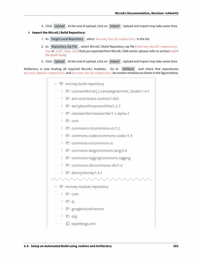
MicroEJ Documentation, Revision 1e46e643
3. Click Upload . At the end of upload, click on Import . Upload and import may take some time.
4. Import the MicroEJ Build Repository:
1. As Target Local Repository , select microej-build-repository in the list.
2. As Repository Zip File , select MicroEJ Build Repository zip file ( microej-build-repository.zip or is2t_repo.zip ) that you exported fromMicroEJ SDK earlier (please refer to section Installthe Build Tools).
3. Click Upload . At the end of upload, click on Import . Upload and import may take some time.
Artifactory is now hosting all required MicroEJ modules. Go to Artifacts and check that repositoriesmicroej-module-repository and microej-build-repository docontainmodulesas shown in the figurebelow.
6.4. Setup an Automated Build using Jenkins and Artifactory 385

MicroEJ Documentation, Revision 1e46e643
6.4.8 Setup Jenkins
Install Jenkins
1. Download Jenkins WAR (Web Archive) here: http://mirrors.jenkins.io/war-stable/latest/jenkins.war
2. Open a terminal and type the following command: java -jar [path/to/downloaded/jenkinswar]/
jenkins.war . A�er initialization, the terminal will print out Jenkins is fully up and running .
3. Go to http://localhost:8080/.
4. To unlock Jenkins, copy/paste the generated password that has been written in the terminal log. Click onContinue .
5. Select option Install suggested plugins and wait for plugin installation.
6. Fill in the Create First Admin User form. Click Save and continue .
7. Click on Save and finish , then on Start using Jenkins .
Configure Jenkins
First step is to configure JDK and Ant installations:
1. Go to Manage Jenkins > Global Tool Configuration .
2. Add JDK installation:
1. Scroll to JDK section.
2. Click on Add JDK .
3. Set Name to JDK [jdk_version] (for example JDK 1.8 ).
4. Uncheck Install automatically .
5. Set JAVA_HOME to path/to/jdk[jdk_version] (for example C:\Program Files\Java\jdk1.
8.0_[version] on Windows).
3. Add Ant installation:
1. Scroll to Ant section.
2. Click on Add Ant .
3. Set Name to Ant 1.9 .
4. Uncheck Install automatically .
5. Set ANT_HOME to path/to/apache-ant-1.9.[version] .
4. Click on Save .
Create a Job Template
1. Go to Jenkins dashboard.
2. Click on New item to create a job template.
6.4. Setup an Automated Build using Jenkins and Artifactory 386

MicroEJ Documentation, Revision 1e46e643
3. Set item name to Template - MMM from Git .
4. Select Freestyle project .
5. Click on Ok .
In General tab:
1. Check This project is parametrized andadd String parameter named easyant.module.dir withdefaultvalue to $WORKSPACE/TO_REPLACE . This will later point to the module sources.
In Source Code Management tab:
1. Select Git source control:
2. Set Repository URL value to TO_REPLACE ,
3. Set Branch Specifier value to origin/master ,
4. In Additional Behaviours , click on Add , select Advanced sub-modules behaviors , then checkRecursively update submodules .
In Build tab:
1. Add build step Invoke Ant :
• As Ant version , select Ant 1.9 .
• Set Targets to value -lib ${MICROEJ_BUILD_TOOLS_HOME}/buildKit/ant/lib .
• In Advanced , set Build file to value $MICROEJ_BUILD_TOOLS_HOME/easyant/build-module.ant .
• In Advanced , expand Properties text field then add the following Ant properties:
personalBuild=falsejenkins.build.id=$BUILD_IDjenkins.node.name=$NODE_NAMEuser.ivysettings.file=$MICROEJ_BUILD_TOOLS_HOME/ivy/ivysettings-artifactory.xml
6.4. Setup an Automated Build using Jenkins and Artifactory 387

MicroEJ Documentation, Revision 1e46e643
Finally, click on Save .
6.4.9 Build a newModule using Jenkins
Since your environment is now setup, it is time to build your first module from Jenkins and check it has been pub-lished to Artifactory. Let’s build an “Hello World” Sandboxed Application project.
Create a newMicroEJ Module
In this example,wewill create a very simplemoduleusing theSandboxApplicationbuildtype (build-application) that we’ll push to a Git repository.
Note: For demonstration purposes, we’ll create a new project and share it on a local Git bare repository. You canadapt the following sections to use an existing MicroEJ project and your own Git repository.
1. Start MicroEJ SDK.
2. Go to File > New > MicroEJ Sandboxed Application Project .
3. Fill in the template fields, set Project name to com.example.hello-world .
6.4. Setup an Automated Build using Jenkins and Artifactory 388

MicroEJ Documentation, Revision 1e46e643
4. Click Finish . This will create the project files and structure.
5. Right-click on source folder src/main/java and select New > Package . Set a name to the package and
click Finish .
6. Right-click on the new package and select New > Class . Set a name to the class and check public
static void main(String[] args) , then click Finish .
6.4. Setup an Automated Build using Jenkins and Artifactory 389

MicroEJ Documentation, Revision 1e46e643
7. Locate the project files
1. In the Package Explorer view, right-click on the project then click on Properties .
2. Select Resource menu.
3. Click on the arrow button on line Location to show the project in the system explorer.
8. Open a terminal from this directory and type the following commands:
git init --bare ~/hello_world.gitgit initgit remote add origin ~/hello_world.gitgit add com.example.hello-worldgit commit -m "Add Hello World application"git push --set-upstream origin master
Note: For more details about MicroEJ Applications development, refer to the Application Developer Guide.
Create a New Jenkins Job
Start by creating a new job, from the job template, for building our application.
1. Go to Jenkins dashboard.
2. Click on New Item .
3. Set item name to Hello World .
4. In Copy from field, type Template - MMM from Git (autocomplete enabled).
5. Validate with Ok button.
The job configurationpageopens, let’s replace all the TO_REPLACE placeholders from the job templatewith correctvalues:
1. In General tab, set easyant.module.dir to value $WORKSPACE/com.example.hello-world .
2. In Source Code Management , edit Repository URL to ~/hello_world.git .
6.4. Setup an Automated Build using Jenkins and Artifactory 390

MicroEJ Documentation, Revision 1e46e643
3. Click on Save .
Build the “Hello World” Application
Let’s run the job!
In Jenkins’ Hello World dashboard, click on Build with Parameters , then click on Build .
Note: You can check the build progress by clicking on the build progress bar and showing the Console Output .
At the end of the build, the module is published to http://localhost:8081/artifactory/list/libs-snapshot-local/com/example/hello-world/.
Congratulations!
At this point of the tutorial:
• Artifactory is hosting your module builds and MicroEJ modules.
• Jenkins automates the build process usingMicroEJ Module Manager.
The next steps recommended are:
• Adapt Jenkins/Artifactory configuration to your ecosystem and development flow.
6.4.10 Appendix
This section discusses some of the customization options.
Customize Jenkins
Jenkins jobs are highly configurable, following options and values are recommended by MicroEJ, but they can becustomized at your convenience.
In General tab:
1. Check Discard old builds and set Max # of builds to keep value to 15 .
2. Click on Advanced button, and check Block build when upstream project is building .
6.4. Setup an Automated Build using Jenkins and Artifactory 391

MicroEJ Documentation, Revision 1e46e643
In Build triggers tab:
1. Check Poll SCM , and set a CRON-like value (for example H/30 * * * * to poll SCM for changes every 30minutes).
In Post-build actions tab:
1. Add post-build action Publish JUnit test result report :
2. Set Test report XMLs to **/target~/test/xml/**/test-report.xml, **/target~/test/xml/**/
*Test.xml .
3. Check Retain long standard output/error .
4. Check Do not fail the build on empty test results
Add a Self-Signed Certificate
In case your Artifactory instance uses a self-signed SSL certificate, you might fall into this error when fetching de-pendencies:
HttpClientHandler: sun.security.validator.ValidatorException: PKIX path building failed: sun.security.→˓provider.certpath.SunCertPathBuilderException: unable to find valid certification path to requested␣→˓target url=[artifactory address]
The authority has to be added to the trust store of the JRE/JDK that is running Artifactory. Here is a way to do it:
1. Install Keystore Explorer.
2. Start Keystore Explorer, and open file [JDK home]/jre/lib/security/cacerts with the passwordchangeit . You may not have the right to modify this file. Edit rights if needed before opening it.
3. Click on Tools , then Import Trusted Certificate .
4. Select your certificate.
5. Save the cacerts file.
6.5 Improve the Quality of Java Code
This tutorial describes some rules and tools aimed at improving the quality of a Java code to simplify its mainte-nance. It makes up aminimum consistent set of rules which can be applied in any situation, especially on embed-ded systems where performance and lowmemory footprint matter.
6.5.1 Intended Audience
The audience for this document is engineers who are developing any kind of Java code (application or library).
6.5.2 Readable Code
This section describes rules to get a readable code, in order to facilitate:
• the maintenance of an existing code with multiple developers contributions (e.g. merge conflicts, reviews).
• the landing to a new code base when the same rules are applied across di�erent modules and components.
6.5. Improve the Quality of Java Code 392

MicroEJ Documentation, Revision 1e46e643
Naming Convention
Naming of Java elements (package, class, method, field and local) follows the Camel Case convention.
• Package names are written fully in lower case (no underscore).
• Package names are singular (e.g. ej.animal instead of ej.animals ).
• Class names are written in upper camel case.
• Method and instance field names are written in lower camel case.
• Static field names are written in lower camel case.
• Constant names are written in fully upper case with underscore as word separator.
• Enum constant names are written in fully upper case with underscores as word separators.
• Local (and parameter) names are written in lower camel case.
• When a name contains an acronym, capitalize only the first letter of the acronym (e.g. for a local with theHTTP acronym, use myHttpContext instead of myHTTPContext ).
It is also recommended to use full words instead of abbreviations (e.g. MyProxyReference instead of MyProxyRef).
Visibility
Here is a list of the usage of each Java element visibility:
• public : API.
• protected : API for subclasses.
• package : component intern API (collaboration inside a package).
• private : internal structure, cache, lazy, etc.
By default, all instance fields must be private.
Package visibility can be used by writing the comment /*default*/ in place of the modifier.
Javadoc
Javadoc comments convention is based on the o�icial documentation.
Note: Javadoc is written in HTML format and doesn’t accept XHTML format: tagsmust not be closed. For example,use only a <p> between two paragraphs.
Here is a list of the rules to follow when writing Javadoc:
• All APIs (see Visibility) must have a full Javadoc (classes, methods, and fields).
• Add a dot at the end of all phrases.
• Add @since tag when introducing a new API.
• Do not hesitate to use links to help the user to navigate in the API ( @see , @link ).
• Use the @code tag in the following cases:
– For keywords (e.g. {@code null} or {@code true} ).
6.5. Improve the Quality of Java Code 393

MicroEJ Documentation, Revision 1e46e643
– For names and types (e.g. {@code x} or {@code Integer} ).
– For code example (e.g. {@code new Integer(Integer.parseInt(s))} ).
Here is a list of additional rules for methods:
• The first sentence starts with the third person (as if there is This method before).
• All parameters and returned values must be described.
• Put as much as possible information in the description, keep @param and @return minimal.
• Start @param with a lower case and usually with the or a.
• Start @return with a lower case as if the sentence starts with Returns.
• Avoid naming parameters anywhere other than in @param . If the parameter is renamed a�erward, the com-ment is not changed automatically. Prefer using the given xxx.
Code Style and Formatting
MicroEJ defines a formatting profile for .java files, which is automatically set up when creating a new ModuleProject Skeleton.
Note: MicroEJ SDK automatically applies formatting when a .java file is saved. It is also possible to manuallyapply formatting on specific files:
• In Package Explorer , select the desired files, folders or projects,
• then go to Source > Format . The processed files must not have any warning or error.
Here is the list of formatting rules included in this profile:
• Indentation is done with 1 tab.
• Braces are mandatory with if , else , for , do , and while statements, even when the body is empty orcontains only a single statement.
• Braces follow the Kernighan and Ritchie style (Egyptian brackets) described below:
– No line break before the opening brace.
– Line break a�er the opening brace.
– Line break before the closing brace.
– Line break a�er the closing brace, only if that brace terminates a statement or terminates the body of amethod, constructor, or named class. For example, there is no line break a�er the brace if it is followedby else or a comma.
• One statement per line.
• Let the formatter automatically wraps your code when a statement needs to be wrapped.
Here is a list of additional formatting rules that are not automatically applied:
• Class and member modifiers, when present, must appear in the order recommended by the Java LanguageSpecification: public protected private abstract default static final transient volatilesynchronized native strictfp .
• Avoid committing commented code (other than to explain an optimization).
• All methods of an interface are public. There is no need to specify the visibility (easier to read).
6.5. Improve the Quality of Java Code 394

MicroEJ Documentation, Revision 1e46e643
• The parts of a class or interface declaration must appear in the order suggested by the Code Convention forthe Java Programming Language:
– Class (static) fields. First, the public class fields, then the protected, then package level (no accessmod-ifier), and then the private.
– Instance fields. First, the public class fields, then the protected, thenpackage level (no accessmodifier),and then the private.
– Constructors
– Methods
Note: Most of these rules are checked by Code Analysis with SonarQube™.
6.5.3 Best Practices
This sectiondescribes rulesmadeof best practices andwell-known restrictions of the JavaProgramming Languageandmore generally Object Oriented paradigm.
Common Pitfalls
• Object.equals(Object) and Object.hashCode() methods must be overridden in pairs. See Equals and Hash-code.
• Do not assign fields in field declaration but in the constructor.
• Do not use non-final method inside the constructor.
• Do not overburden the constructor with logic.
• Do not directly store an array given by parameter.
• Do not directly return an internal array.
• Save object reference from a field to a local before using it (see Local Extraction).
Simplify Maintenance
• Extract constants instead of using magic numbers.
• Use parenthesis for complex operation series; it simplifies the understanding of operator priorities.
• Write short lines. This can be achieved by extracting locals (see Local Extraction).
• Use a limited number of parameters in methods (or perhaps a new type is needed).
• Create small methods with little complexity. When amethod gets too complex, it should be split.
• Use + operator only for single-line string concatenation. Use an explicit StringBuilder otherwise.
• Use component-oriented architecture to separate concerns. If a class is intended to be instantiated usingClass.newInstance(), add a default constructor (without parameters).
6.5. Improve the Quality of Java Code 395

MicroEJ Documentation, Revision 1e46e643
Basic Optimizations
• Avoid explicitly initializing fields to 0 or null , because they are zero-initialized by the runtime. A //VM_DONEcomment can be written to understand the optimization.
• The switch/case statements are generated by the Java compiler in twoways depending on the cases density.Prefer declaring consecutive cases (table_switch) for performance ( O(1) ) and slightly smaller codememoryfootprint instead of lookup_switch ( O(log N) ).
• Avoid using built-in thread safe types (Vector, Hashtable, StringBu�er, etc.). Usually synchronization has tobe done at a higher level.
• Avoid serializing/deserializing data from byte arrays using manual bitwise operations, use ByteArray utilitymethods instead.
Local Extraction
Local extraction consists of storing the result of an expression before using it, for example:
Object myLocale = this.myField;if (myLocale != null) {myLocale.myMethod();
}
It improves the Java code in many ways:
• self documentation: gives a name to a computed result.
• performance andmemory footprint: avoids repeated access to same elements and extract loop invariants.
• thread safety: helps to avoid synchronization issues or falling into unwanted race conditions.
• code pattern detection: helps automated tools such as Null Analysis.
Equals and Hashcode
The purpose of these methods is to uniquely and consistently identify objects. The most common use of thesemethods is to compare instances in collections (list or set elements, map keys, etc.).
TheObject.equals(Object)method implements an equivalence relation (defined in the Javadoc)with the followingproperties:
• It is reflexive: for any reference value x, x.equals(x) must return true .
• It is symmetric: for any reference values x and y, x.equals(y) must return true if and only if y.equals(x)returns true .
• It is transitive: for any reference values x, y, and z, if x.equals(y) returns true and y.equals(z) returnstrue , then x.equals(z) must return true .
• It is consistent: for any reference values x and y, multiple invocations of x.equals(y) consistently returntrue or consistently return false , provided no information used in equals comparisons on the object ismodified.
• For any non-null reference value x, x.equals(null) must return false .
Avoid overriding the equals(Object) method in a subclass of a class that already overrides it; it could break thecontract above. See E�ective Java book by Joshua Bloch for more information.
If the equals(Object) method is implemented, the hashCode() method must also be implemented. ThehashCode() method follows these rules (defined in the Javadoc):
6.5. Improve the Quality of Java Code 396

MicroEJ Documentation, Revision 1e46e643
• It must consistently return the same integer when invoked several times.
• If two objects are equal according to the equals(Object) method, then calling the hashCode() method oneach of the two objects must produce the same integer result.
• In the same way, it should return distinct integers for distinct objects.
The equals(Object) method is written that way:
• Compare the argument with this using the == operator. If both are equals, return true . This test is forperformance purposes, so it is optional andmay be removed if the object has a few fields.
• Use an instanceof to check if the argument has the correct type. If not, return false . This check alsovalidates that the argument is not null.
• Cast the argument to the correct type.
• For each field, check if that field is equal to the same field in the casted argument. Return true if all fieldsare equal, false otherwise.
@Overridepublic boolean equals(Object o) {
if (o == this) {return true;
}if (!(o instanceof MyClass)) {
return false;}MyClass other = (MyClass)o;return field1 == other.field1 &&
(field2 == null ? other.field2 == null : field2.equals(other.field2));}
The Object.hashCode() method is written that way:
• Choose a prime number.
• Create a result local, whatever the value (usually the prime number).
• For each field, multiply the previous result with the prime plus the hash code of the field and store it as theresult.
• Return the result.
Depending on its type, the hash code of a field is:
• Boolean: (f ? 0 : 1) .
• Byte, char, short, int: (int) f) .
• Long: (int)(f ^ (f >>> 32)) .
• Float: Float.floatToIntBits(f) .
• Double: Double.doubleToLongBits(f) and the same as for a long.
• Object: (f == null ? 0 : f.hashCode()) .
• Array: add the hash codes of all its elements (depending on their type).
private static final int PRIME = 31;
@Overridepublic int hashCode() {
(continues on next page)
6.5. Improve the Quality of Java Code 397

MicroEJ Documentation, Revision 1e46e643
(continued from previous page)
int result = PRIME;result = PRIME * result + field1;result = PRIME * result + (field2 == null ? 0 : field2.hashCode());return result;
}
6.5.4 Related Tools
This section points to tools aimed at helping to improve code quality.
Unit Testing
Here is a list of rules when writing tests (see Testsuite with JUnit):
• Prefer black-box tests (with a maximum coverage).
• Here is the test packages naming convention:
– Su�ix package with .test for black-box tests.
– Use the same package for white-box tests (allow to use classes with package visibility).
Code Analysis with SonarQube™
SonarQube is an open source platform for continuous inspection of code quality. SonarQube o�ers reports onduplicated code, coding standards, unit tests, code coverage, code complexity, potential bugs, comments, andarchitecture.
To set it uponyourMicroEJapplicationproject, please refer to this documentation. It describes the following steps:
• How to run a SonarQube server locally.
• How to run an analysis using a dedicated script.
• How to run an analysis during a module build.
6.6 Optimize the Memory Footprint of an Application
This tutorial explains how to analyze the memory footprint of an application and provides a set of common rulesaimed at optimizing both ROM and RAM footprint.
6.6.1 Intended Audience
The audience for this document is Java engineers and Firmware integrators who are going to execute a MicroEJApplication on amemory-constrained device.
6.6. Optimize the Memory Footprint of an Application 398

MicroEJ Documentation, Revision 1e46e643
6.6.2 Introduction
Usually, the application development is already startedwhen the developer starts thinking about itsmemory foot-print. Before jumping into code optimizations, it is recommended to list every area of improvement and estimatefor each area howmuchmemory can be saved and howmuch e�ort it requires.
Without performing the memory analysis first, the developer might start working on a minor optimization thattakes a lot of e�ort for little improvements. In contrast, he could work on amajor optimization, allowing faster andbigger improvements. Moreover, each optimization described herea�er may allow significant memory savings foran application while it may not be relevant for another application.
6.6.3 How to Analyze the Footprint of an Application
This section explains the process of analyzing the footprint of a MicroEJ Application and the tools used during theanalysis.
Suggested footprint analysis process:
1. Build the MicroEJ Application
2. Analyze SOAR.map with theMemory Map Analyzer
3. Analyze soar/*.xml with an XML editor
4. Link the MicroEJ Application with the BSP
5. Analyze the map file generated by the third-party linker with a text editor
Footprint analysis tools:
• The Memory Map Analyzer allows to analyze the memory consumption of di�erent features in the RAM andROM.
• TheHeapDumper&HeapAnalyzer allow tounderstand the contents of the Java heap and findproblems suchas memory leaks.
• The Dependency Discoverer allows to analyze a piece of code to detect all its dependencies.
How to Analyze the Files Generated by the MicroEJ Linker
TheMicroEJ Application linker generates files useful for footprint analysis, such as the SOARmap file and the SOARinformation file. To understand how to read these files, please refer to the Build Output Files documentation.
How to Analyze a Map File Generated by a Third-Party Linker
A <firmware>.map file is generated by the C toolchain a�er linking the MicroEJ Application with the BSP. Thissection explains how amap file generated by GCC is structured and how to browse it. The structure is not the sameon every compiler, but it is o�en similar.
File Structure
This file is composed of 5 parts:
• Archive member included to satisfy reference by file . Each entry contains two lines. The first linecontains the referenced archive file location and the compilation unit. The second line contains the compi-lation unit referencing the archive and the symbol called.
6.6. Optimize the Memory Footprint of an Application 399

MicroEJ Documentation, Revision 1e46e643
• Allocating common symbols . Eachentry contains thenameofaglobal variable, its size, and thecompilationunit where it is defined.
• Discarded input sections . Each entry contains the name and the size of a section that has not beenembedded in the firmware.
• Memory Configuration . Each entry contains the name of a memory, its address, its size, and its attributes.
• Linker script and memory map . Each entry contains a linewith the nameand compilation unit of a sectionand one line per symbol defined in this section. Each of these lines contains the name, the address, and thesize of the symbol.
Finding the Size of a Section or Symbol
For example, to know the thread stacks’ size, search for the .bss.vm.stacks.java section in the Linker scriptand memory map part. The size associated with the compilation unit is the size used by the thread stacks.
The following snippet shows that the .bss.vm.stacks.java section takes 0x800 bytes.
.bss.vm.stacks.java0x20014070 0x800 ..\..\..\..\..\..\..\.microej\CM4hardfp_
→˓GCC48\application\microejapp.o0x20014070 __icetea___6bss_6vm_6stacks_6java$$Base0x20014870 __icetea___6bss_6vm_6stacks_6java$$Limit
See Core Engine Link documentation for more information on MicroEJ Core Engine sections.
6.6.4 How to Reduce the Image Size of an Application
Generic coding rules can be found in the following tutorial: Improve the Quality of Java Code.
This section provides additional coding rules and good practices to reduce the image size (ROM) of an application.
Application Resources
Resources such as images and fonts take a lot of memory. For every .list file, make sure that it does not embedany unused resource.
Only resources declared in a .list file will be embedded. Other resources available in the application classpathwill not be embedded and will not have an impact on the application footprint.
Fonts
Default Font
By default, in aMicroEJ Platform configuration project, a so-called system font is declared in the microui.xml file.
When generating the MicroEJ Platform, this file is copied from the configuration project to the actual MicroEJ Plat-form project. It will later be converted to binary format and linked with your MicroEJ Application, even if you usefonts di�erent from the system font.
Therefore, you can comment the system font from the microui.xml file to reduce the ROM footprint of your Mi-croEJ Application if this one does not rely on the system font. Note that you will need to rebuild the MicroEJ Plat-form and then the application to benefit from the footprint reduction.
6.6. Optimize the Memory Footprint of an Application 400

MicroEJ Documentation, Revision 1e46e643
See the Display Element section of the Static Initialization documentation for more information on system fonts.
Character Ranges
When creating a font, you can reduce the list of characters embedded in the font at several development stages:
• On font creation: see the Removing Unused Characters section of Font Designer documentation.
• On application build: see the Fonts section ofMicroEJ Classpath documentation.
Pixel Transparency
You can also make sure that the BPP encoding used to achieve transparency for your fonts do not exceed the fol-lowing values:
• The pixel depth of your display device.
• The required alpha level for a good rendering of your font in the application.
See the Fonts section ofMicroEJ Classpath documentation for more information on how to achieve that.
External Storage
To save storage on internal flash, you can access fonts from an external storage device.
See the External Resources section of the Font Generator documentation for more information on how to achievethat.
Internationalization Data
Implementation
MicroEJ provides the Native Language Support (NLS) library to handle internationalization.
See https://github.com/MicroEJ/Example-NLS for an example of the use of the NLS library.
External Storage
The default NLS implementation fetches text resources from internal flash, but you can replace it with your ownimplementation to fetch them from another location.
See External Resources Loader documentation for additional information on external resources management.
Compression
The default NLS implementation relies on text resources that are not compressed, but you can use your own en-coding to load them from compressed resources.
6.6. Optimize the Memory Footprint of an Application 401

MicroEJ Documentation, Revision 1e46e643
Images
Encoding
If you are tight on ROM but have enough RAM and CPU power to decode PNG images on the fly, consider storingyour images as PNG resources. If you are in the opposite configuration (lots of ROM, but little RAM and CPU power),consider storing your images in raw format.
See Image Generator documentation for more information on how to achieve that.
Color Depth (BPP)
Make sure to use images with a color depth not exceeding the one of your display to avoid the following issues:
• Waste of memory.
• Di�erences between the rendering on the target device and the original image resource.
External Storage
To save storage on internal flash, the application can access the images from an external storage device.
See External Resources Loader documentation for more information on how to achieve that.
Application Code
The following application code guidelines are recommended in order to minimize the size of the application:
• Check libraries versions and changelogs regularly. Latest versions may bemore optimized.
• Avoid manipulating String objects:
– For example, prefer using integers to represent IDs.
– Avoid overridingObject.toString() for debugging purposes. Thismethodwill always be embedded evenif it is not called explicitly.
– Avoid using Logger or System.out.println() , use the trace library instead. The logging library usesstrings, while the trace library only uses integer-based error codes.
– Avoid using the string concatenation operator ( + ), use an explicit StringBuilder instead. The code gen-erated by the + operator is not optimal and is bigger than when usingmanual StringBuilder opera-tions.
• Avoid manipulating wrappers such as Integer and Long objects, use primitive types instead. Such objectshave to be allocated in Java heapmemory and require additional code for boxing and unboxing.
• Avoid using the service library, use singletons or Constants.getClass() instead. The service library requiresembedding class reflection methods and the type names of both interfaces and implementations.
• Avoid using the JavaCollections Framework. ThisOpenJDK standard library has not beendesigned formem-ory constrained devices.
– Use raw arrays instead of List objects. The ArrayTools class provides utility methods for common arrayoperations.
– Use PackedMap objects instead of Map objects. It provides similar APIs and features with lower Javaheap usage.
6.6. Optimize the Memory Footprint of an Application 402

MicroEJ Documentation, Revision 1e46e643
• Use ej.bon.Timer instead of deprecated java.util.Timer . When both class are used, almost all the code isembedded twice.
• Use BON constants in the following cases if possible:
– whenwriting debug code or optional code, use the if (Constants.getBoolean()) { ... } pattern.That way, the optional code will not be embedded in the production firmware if the constant is set tofalse .
– replace theuseofSystemPropertiesbyBONconstantswhenbothkeysandvaluesareknownat compile-time. System Properties should be reserved for runtime lookup. Each property requires embedding itskey and its value as intern strings.
• Check for useless or duplicate synchronization operations in call stacks, in order reduce the usage ofsynchronized statements. Each statement generates additional code to acquire and release the monitor.
• Avoid declaring exit statements ( break , continue , throw or return ) that jump out of a synchronizedblock. At each exit point, additional code is generated to release the monitor properly.
• Avoid declaring exit statements ( break , continue , throw or return ) that jump out of a try/finallyblock. At each exit point, the code of the finally block is generated (duplicated). This also applies on everytry-with-resources block since a finally block is generated to close the resource properly.
• Avoid overridingObject.equals(Object) andObject.hashCode(), use == operator instead if it is su�icient. Thecorrect implementation of these methods requires significant code.
• Avoid calling equals() and hashCode() methods directly on Object references. Otherwise, the methodof every embedded class which overrides the method will be embedded.
• Avoid creating inlined anonymous objects (such as new Runnable() { ... } objects), implement theinterface in a existing class instead. Indeed, a new class is created for each inlined object. Moreover, eachenclosed final variable is added as a field of this anonymous class.
• Replace constant arrays and objects initialization in static final fields by immutables objects. Indeed,initializing objects dynamically generates code which takes significant ROM and requires execution time.
• Check if some features available in so�ware libraries are not already provided by the device hardware. Forexample, avoid using java.util.Calendar (full Gregorian calendar implementation) if the application only re-quires basic date manipulation provided by the internal real-time clock (RTC).
MicroEJ Platform Configuration
The following configuration guidelines are recommended in order to minimize the size of the application:
• Check MicroEJ Architecture and Packs versions and changelogs regularly. Latest versionsmay bemore opti-mized.
• Configure the Platform to use the tiny capability of the MicroEJ Core Engine. It reduces application code sizeby ~20%, provided that the application code size is lower than 256KB (resources excluded).
• Disable unnecessarymodules in the .platform file. For example, disable the Image PNG Decoder moduleif the application does not load PNG images at runtime.
• Don’t embed unnecessary pixel conversion algorithms. This can save up to ~8KB of code size but it requiresknowing the format of the resources used in the application.
• Select your embeddedC compilation toolchainwith care, prefer onewhichwill allow lowROM footprintwithoptimal performance. Check the compiler options:
– Check documentation for available optimization options ( -Os onGCC). These options can also be over-ridden per source file.
6.6. Optimize the Memory Footprint of an Application 403

MicroEJ Documentation, Revision 1e46e643
– Separate each function and data resource in a dedicated section ( -ffunction-sections-fdata-sections on GCC).
• Check the linker optimization options. The linker command line can be found in the project settings, and itmay be printed during link.
– Only embed necessary sections ( --gc-sections option on GCC/LD).
– Some functions, such as the printf function, can be configured to only implement a subset of the pub-lic API (for example, remove -u _printf_float option on GCC/LD to disable printing floating pointvalues).
• In the map file generated by the third-party linker, check that every embedded function is necessary. Forexample, hardware timers or HAL components may be initialized in the BSP but not used in the application.Also, debug functions such as SystemViewmay be disconnected when building the production firmware.
Application Configuration
The following application configuration guidelines are recommended in order to minimize the size of the applica-tion:
• Disable class names generation by setting the soar.generate.classnames option to false . Class namesare only required when using Java reflection. In such case, the name of a specific class will be embeddedonly if is explicitly required. See Stripping Class Names from an Application section for more information.
• Remove UTF-8 encoding support by setting the cldc.encoding.utf8.included option to false . Thedefault encoding ( ISO-8859-1 ) is enough for most applications.
• Remove SecurityManager checks by setting the com.microej.library.edc.securitymanager.enabledoption to false . This feature is only useful for Multi-Sandbox firmwares.
For more information on how to set an option, please refer to the Defining an Option section.
Stripping Class Names from an Application
By default, when a Java class is used, its name is embedded too. A class is used when one of its methods is called,for example. Embedding the name of every class is convenient when starting a new MicroEJ Application, but it israrely necessary and takes a lot of ROM. This section explains how to embed only the required class names of anapplication.
Removing All Class Names
First, the default behavior is inverted by defining the Application option soar.generate.classnames to false .
For more information on how to set an option, please refer to the Defining an Option section.
Listing Required Class Names
Some class namesmay be required by an application to work properly. These class namesmust be explicitly spec-ified in a *.types.list file.
The code of the application must be checked for all uses of the Class.forName(), Class.getName() andClass.getSimpleName() methods. For each of these method calls, if the class name if absolutely required and cannot be known at compile-time, add it to a *.types.list file. Otherwise, remove the use of the class name.
The following sections illustrates this on concrete use cases.
6.6. Optimize the Memory Footprint of an Application 404

MicroEJ Documentation, Revision 1e46e643
Case of Service Library
The ej.service.ServiceLoader class of the service library is a dependency injection facility. It can be used to dynam-ically retrieve the implementation of a service.
The assignment between a service API and its implementation is done in *.properties.list files. Both the ser-vice class name and the implementation class namemust be embedded (i.e., added in a *.types.list file).
For example:
# example.properties.listcom.example.MyService=com.example.MyServiceImpl
# example.types.listcom.example.MyServicecom.example.MyServiceImpl
Case of Properties Loading
Some propertiesmay be loaded by using the name of a class to determine the full name of the property. For exam-ple:
Integer.getInteger(MyClass.class.getName() + ".myproperty");
In this case, it can be replaced with the actual string. For example:
Integer.getInteger("com.example.MyClass.myproperty");
Case of Logger and Other Debugging Facilities
Logging mechanisms usually display the name of the classes in traces. It is not necessary to embed these classnames. The Stack Trace Reader can decipher the output.
6.6.5 How to Reduce the Runtime Size of an Application
You can find generic coding rules in the following tutorial: Improve the Quality of Java Code.
This section provides additional coding rules and good practices in order to reduce the runtime size (RAM) of anapplication.
Application Code
The following application code guidelines are recommended in order to minimize the size of the application:
• Avoidusing thedefault constructorof collectionobjects, use constructors that allow to set the initial capacity.For example, use the ArrayList(int initialCapacity) constructor instead of the default one which will allocatespace for ten elements.
• Adjust the type of int fields (32 bits) according to the expected range of values being stored ( byte for 8 bitssigned integers, short for 16 bits signed integers, char for 16 bits unsigned integers).
6.6. Optimize the Memory Footprint of an Application 405

MicroEJ Documentation, Revision 1e46e643
• When designing a generic and reusable component, allow the user to configure the size of any bu�er allo-cated internally (either at runtime using a constructor parameter, or globally using a BON constant). Thatway, the user can select the optimal bu�er size depending on his use-case and avoid wasting memory.
• Avoidallocating immortal arrays to call nativemethods, use regular arrays instead. Immortal arrays areneverreclaimed and they are not necessary anymore when calling a native method.
• Reduce themaximumnumber of parallel threads. Each thread require a dedicated internal structure and VMstack blocks.
– Avoid creating threads on the fly for asynchronous execution, use shared thread instances instead(Timer, Executor, MicroUI.callSerially(Runnable), . . . ).
• When designing Graphics User Interface:
– Avoidcreatingmutable images (Bu�eredImage instances) todraw in themand render them later, rendergraphics directly on the display instead. Mutable images require allocating a lot of memory from theimages heap.
– Make sure that your Widget hierarchy is as flat as possible (avoid any unnecessary Container). Deepwidget hierarchies take more memory and can reduce performance.
MicroEJ Platform Configuration
The following configuration guidelines are recommended in order tominimize the runtime size of the application:
• Check the size of the stack of each RTOS task. For example, 1.0KB may be enough for the MicroJVM task butit can be increased to allow deep native calls. See Debugging Stack Overflows section for more information.
• Check the size of the heap allocated by the RTOS (for example, configTOTAL_HEAP_SIZE for FreeRTOS).
• Check that the size of the back bu�er matches the size of the display. Use a partial bu�er if the back bu�erdoes not fit in the RAM.
Debugging Stack Overflows
If the size you allocate for a given RTOS task is too small, a stack overflowwill occur. To be aware of stack overflows,proceed with the following steps when using FreeRTOS:
1. Enable the stack overflow check in FreeRTOS.h :
#define configCHECK_FOR_STACK_OVERFLOW 1
2. Define the hook function in any file of your project ( main.c for example):
void vApplicationStackOverflowHook(TaskHandle_t xTask, signed char *pcTaskName) { }
3. Add a new breakpoint inside this function
4. When a stack overflow occurs, the execution will stop at this breakpoint
For further information, please refer to the FreeRTOS documentation.
Application Configuration
The following application configuration guidelines are recommended in order to minimize the size of the applica-tion.
For more information on how to set an option, please refer to the Defining an Option documentation.
6.6. Optimize the Memory Footprint of an Application 406

MicroEJ Documentation, Revision 1e46e643
Java Heap and Immortals Heap
• Configure the immortals heap option to be as small as possible. You can get the minimum value by callingImmortals.freeMemory() a�er the creation of all the immortal objects.
• Configure the Java heap option to fit the needs of the application. You can get the maximum heap usageby calling Runtime.freeMemory() a�er System.gc() at di�erent moments in the application’s lifecycle. Theprofiling library can be used for this.
Thread Stacks
• Configure themaximum number of threads option. This number can be known accurately by counting in thecode how many Thread and Timer objects may run concurrently. You can call Thread.getAllStackTraces()or Thread.activeCount() to knowwhat threads are running at a given moment.
• Configure the number of allocated thread stack blocks option. This can be done empirically by startingwith alow number of blocks and increasing this number as long as the application throws a StackOverflowError.
• Configure the maximum number of blocks per thread option. The best choice is to set it to the number ofblocks required by the most greedy thread. Another acceptable option is to set it to the same value as thetotal number of allocated blocks.
• Configure the maximum number of monitors per thread option. This number can be known accurately bycounting the number of concurrent synchronized blocks. This can also be done empirically by startingwith a low number of monitors and increasing this number as long as no exception occurs. Either way, it isrecommended to set a slightly higher value than calculated.
VM Dump
The LLMJVM_dump() function declared in LLMJVM.h may be called to print information on alive threads such astheir current andmaximum stack block usage. This functionmay be called from the application by exposing it in anative function. See Debugging section for usage.
More specifically, the Peak java threads count valueprinted in thedumpcanbeused to configure themaximumnumber of threads. The max_java_stack and current_java_stack values printed for each thread can be usedto configure the number of stack blocks.
MicroUI Images Heap
• Configure the images heap to be as small as possible. You can compute the optimal size empirically. It canalso be calculated accurately by adding the size of every image that may be stored in the images heap ata given moment. One way of doing this is to inspect every occurrence of Bu�eredImage() allocations andResourceImage usage of loadImage() methods.
6.7 Explore Data Serialization Formats
This tutorial highlights some data serialization formats that are provided on MicroEJ Central Repository and theirusage through basic code samples.
6.7. Explore Data Serialization Formats 407

MicroEJ Documentation, Revision 1e46e643
6.7.1 Intended Audience
The audience for this document is Application engineers who want to implement data serialization. In addition,this tutorial should be of interest to so�ware architectswho are looking for a suitable data format for their use case.
6.7.2 XML
XML (EXtensibleMarkup Language) is used to describe data and text. It allows flexible development of user-defineddocument types. The format is robust, non-proprietary, persistent and is verifiable for storage and transmission.To parse this data format, the XMLPull parser KXmlParser from the Java community has been integrated toMicroEJCentral Repository.
XML Parser Use In MicroEJ SDK
The XML API Modulemust be added to themodule.ivy of theMicroEJ Application project in order to allow access tothe KXML library.
<dependency org="org.kxml2" name="kxml2" rev="2.3.2"/>
Example Of Use
An example available at https://github.com/MicroEJ/Example-XML. It presents how to use XML data exchange foryour MicroEJ Application. It also details how to use the KXmlParser module.
The example parses a short poemwritten in XML and prints the result on the standard output. The project can runon any MicroEJ Platform (no external dependencies).
<?xml version="1.0" encoding="UTF-8"?><poem xmlns="http://www.megginson.com/ns/exp/poetry">
<title>Roses are Red</title><l>Roses are red,</l><l>Violets are blue;</l><l>Sugar is sweet,</l><l>And I love you.</l>
</poem>
Running the ReadPoem Java application should print the following trace :
=============== [ Initialization Stage ] ============================== [ Launching on Simulator ] ===============Roses are Red_____________
Roses are red,Violets are blue;Sugar is sweet,And I love you.
=============== [ Completed Successfully ] ===============
SUCCESS
Running MyXmlPullApp gives more details on the XML parsing and should print this trace :
6.7. Explore Data Serialization Formats 408

MicroEJ Documentation, Revision 1e46e643
=============== [ Initialization Stage ] ============================== [ Launching on Simulator ] ===============parser implementation class is class org.kxml2.io.KXmlParserParsing simple sample XMLStart documentStart element: {http://www.megginson.com/ns/exp/poetry}poemCharacters: "\n"Start element: {http://www.megginson.com/ns/exp/poetry}titleCharacters: "Roses are Red"End element: {http://www.megginson.com/ns/exp/poetry}titleCharacters: "\n"Start element: {http://www.megginson.com/ns/exp/poetry}lCharacters: "Roses are red,"End element: {http://www.megginson.com/ns/exp/poetry}lCharacters: "\n"Start element: {http://www.megginson.com/ns/exp/poetry}lCharacters: "Violets are blue;"End element: {http://www.megginson.com/ns/exp/poetry}lCharacters: "\n"Start element: {http://www.megginson.com/ns/exp/poetry}lCharacters: "Sugar is sweet,"End element: {http://www.megginson.com/ns/exp/poetry}lCharacters: "\n"Start element: {http://www.megginson.com/ns/exp/poetry}lCharacters: "And I love you."End element: {http://www.megginson.com/ns/exp/poetry}lCharacters: "\n"End element: {http://www.megginson.com/ns/exp/poetry}poem=============== [ Completed Successfully ] ===============
SUCCESS
6.7.3 JSON
As described on the JSON o�icial site, JSON (JavaScript Object Notation) is a lightweight data-interchange format.It is widely used in many applications such as:
• as a mean of data serialization for lightweight web services such as REST
• for server interrogation in Ajax to build dynamic webpages
• or even databases.
JSON is easily readable by humans compared to XML. To parse this data format, several JSON parsers are availableon the o�icial JSON page, such as JSONME, which has been integrated to MicroEJ Central Repository.
JSON Parser Use In MicroEJ SDK
The JSON API Module must be added to themodule.ivy of the MicroEJ Application project in order to allow accessto the JSON library.
<dependency org="org.json.me" name="json" rev="1.3.0"/>
The instantiation anduseof theparser is pretty straightforward. First youneed to get the JSONcontent as a String, and then create a org.json.me.JSONObject instancewith the string. If the string content is a valid JSONcontent,you should have an workable JSONObject to browse.
6.7. Explore Data Serialization Formats 409

MicroEJ Documentation, Revision 1e46e643
Example Of Use
In the following example we will parse this JSON file that represents a simple abstraction of a file menu:
{"menu": {
"id": "file","value": "File","popup": {
"menuitem": [{"value": "New", "onclick": "CreateNewDoc()"},{"value": "Open", "onclick": "OpenDoc()"},{"value": "Close", "onclick": "CloseDoc()"}
]}
}}
First, we need to include this file in our project by adding it to the src/main/resources folder and creating a.resources.list properties file to declare this resource for our application to be able to retrieve it (see Raw Re-sources for more details).
This .resources.list file (here named json.resources.list ) should contain the path to our JSON file as such:
resources/menu.json
The example below will parse the file, browse the resulting data structure ( org.json.me.JSONObject ) and printthe value of the menuitem JSON array.
package com.microej.examples.json;
import java.io.DataInputStream;import java.io.IOException;
import org.json.me.JSONArray;import org.json.me.JSONException;import org.json.me.JSONObject;
/*** This example uses the org.json.me parser provided by json.org to parse and* browse a JSON content.** The JSON content is simple abstraction of a file menu as provided here:* http://www.json.org/example.html** The example then tries to list all the 'menuitem's available in the popup
(continues on next page)
6.7. Explore Data Serialization Formats 410

MicroEJ Documentation, Revision 1e46e643
(continued from previous page)
* menu. It is assumed the user knows the menu JSON file structure.**/public class MyJSONExample {
public static void main(String[] args) {
// get back an input stream from the resource that represents the JSON// contentDataInputStream dis = new DataInputStream(
MyJSONExample.class.getResourceAsStream("/resources/menu.json"));
byte[] bytes = null;
try {
// assume the available returns the whole content of the resourcebytes = new byte[dis.available()];
dis.readFully(bytes);
} catch (IOException e1) {// something went wronge1.printStackTrace();return;
}
try {
// create the data structure to exploit the content// the string is created assuming default encodingJSONObject jsono = new JSONObject(new String(bytes));
// get the JSONObject named "menu" from the root JSONObjectJSONObject o = jsono.getJSONObject("menu");
o = o.getJSONObject("popup");
JSONArray a = o.getJSONArray("menuitem");
System.out.println("The menuitem content of popup menu is:");System.out.println(a.toString());
} catch (JSONException e) {// a getJSONObject() or a getJSONArray() failed// or the parsing failede.printStackTrace();
}
}
}
The execution of this example on the MicroEJ Simulator should print the following trace:
=============== [ Initialization Stage ] ===============
(continues on next page)
6.7. Explore Data Serialization Formats 411

MicroEJ Documentation, Revision 1e46e643
(continued from previous page)
=============== [ Launching Simulator ] ===============The menuitem content of popup menu is:[{"value":"New","onclick":"CreateNewDoc()"},{"value":"Open","onclick":"OpenDoc()"},{"value":"Close",→˓"onclick":"CloseDoc()"}]=============== [ Completed Successfully ] ===============
SUCCESS
6.7. Explore Data Serialization Formats 412

INDEX
AAdd-On Library, 2Application, 2Architecture, 2
CCore Engine, 2
FFirmware, 2Foundation Library, 2
MMock, 2Module Manager, 3
PPlatform, 3
SSDK, 3Simulator, 3Studio, 3
VVirtual Device, 3
413