OpenROAD's documentation!
206
OpenROAD OpenROAD Team Mar 26, 2022
-
Upload
khangminh22 -
Category
Documents
-
view
6 -
download
0
Transcript of OpenROAD's documentation!

OpenROAD
OpenROAD Team
Mar 26, 2022

CONTENTS
1 Code of conduct 3
2 Documentation 52.1 Application . . . . . . . . . . . . . . . . . . . . . . . . . . . . . . . . . . . . . . . . . . . . . . . . 52.2 Flow . . . . . . . . . . . . . . . . . . . . . . . . . . . . . . . . . . . . . . . . . . . . . . . . . . . 5
3 How to contribute 7
4 How to get in touch 9
5 Site Map 115.1 Contributor Covenant Code of Conduct . . . . . . . . . . . . . . . . . . . . . . . . . . . . . . . . . 115.2 Getting Involved . . . . . . . . . . . . . . . . . . . . . . . . . . . . . . . . . . . . . . . . . . . . . 135.3 Developer Guide . . . . . . . . . . . . . . . . . . . . . . . . . . . . . . . . . . . . . . . . . . . . . 155.4 OpenROAD . . . . . . . . . . . . . . . . . . . . . . . . . . . . . . . . . . . . . . . . . . . . . . . . 485.5 Getting Started with OpenROAD Flow . . . . . . . . . . . . . . . . . . . . . . . . . . . . . . . . . 1455.6 FAQs . . . . . . . . . . . . . . . . . . . . . . . . . . . . . . . . . . . . . . . . . . . . . . . . . . . 1605.7 OpenROAD Flow Scripts Tutorial . . . . . . . . . . . . . . . . . . . . . . . . . . . . . . . . . . . . 161
i

ii

OpenROAD
The OpenROAD (“Foundations and Realization of Open, Accessible Design”) project was launched in June 2018 withinthe DARPA IDEA program. OpenROAD aims to bring down the barriers of cost, expertise and unpredictability thatcurrently block designers’ access to hardware implementation in advanced technologies. The project team (Qualcomm,Arm and multiple universities and partners, led by UC San Diego) is developing a fully autonomous, open-sourcetool chain for digital SoC layout generation, focusing on the RTL-to-GDSII phase of system-on-chip design. Thus,OpenROAD holistically attacks the multiple facets of today’s design cost crisis: engineering resources, design toollicenses, project schedule, and risk.
The IDEA program targets no-human-in-loop (NHIL) design, with 24-hour turnaround time and zero loss of power-performance-area (PPA) design quality.
The NHIL target requires tools to adapt and auto-tune successfully to flow completion, without (or, with minimal)human intervention. Machine intelligence augments human expertise through efficient modeling and prediction offlow and optimization outcomes throughout the synthesis, placement and routing process. This is complemented bydevelopment of metrics and machine learning infrastructure.
The 24-hour runtime target implies that problems must be strategically decomposed throughout the design process,with clustered and partitioned subproblems being solved and recomposed through intelligent distribution and manage-ment of computational resources. This ensures that the NHIL design optimization is performed within its available[threads * hours] “box” of resources. Decomposition that enables parallel and distributed search over cloud re-sources incurs a quality-of-results loss, but this is subsequently recovered through improved flow predictability andenhanced optimization.
For a technical description of the OpenROAD flow, please refer to our DAC-2019 paper: Toward an Open-SourceDigital Flow: First Learnings from the OpenROAD Project. The paper is also available from ACM Digital Library.Other publications and presentations are linked here.
CONTENTS 1

OpenROAD
2 CONTENTS

CHAPTER
ONE
CODE OF CONDUCT
Please read our code of conduct here.
3

OpenROAD
4 Chapter 1. Code of conduct

CHAPTER
TWO
DOCUMENTATION
The OpenROAD Project has two releases:
2.1 Application
The application is a standalone binary capable of performing RTL-to-GDSII SoC design, from logic synthesis andfloorplanning through detailed routing with metal fill insertion, signoff parasitic extraction and timing analysis.
See documentation for the application here.
2.2 Flow
The flow is a set of integrated scripts that allow for RTL-to-GDSII flow using open-source tools.
See documentation for the flow here.
5

OpenROAD
6 Chapter 2. Documentation

CHAPTER
THREE
HOW TO CONTRIBUTE
If you are willing to contribute, see the Getting Involved section.
If you are a developer with EDA background, learn more about how you can use OpenROAD as the infrastructure foryour tools in the Developer Guide section.
7

OpenROAD
8 Chapter 3. How to contribute

CHAPTER
FOUR
HOW TO GET IN TOUCH
We maintain the following channels for communication:
• Project homepage and news: https://theopenroadproject.org
• Twitter: https://twitter.com/OpenROAD_EDA
• Issues and bugs:
– OpenROAD: https://github.com/The-OpenROAD-Project/OpenROAD/issues
– OpenROAD Flow: https://github.com/The-OpenROAD-Project/OpenROAD-flow-scripts/issues
• Discussions:
– OpenROAD: https://github.com/The-OpenROAD-Project/OpenROAD/discussions
– OpenROAD Flow: https://github.com/The-OpenROAD-Project/OpenROAD-flow-scripts/discussions
• Inquiries: [email protected]
See also our FAQs.
9

OpenROAD
10 Chapter 4. How to get in touch
CHAPTER
FIVE
SITE MAP
5.1 Contributor Covenant Code of Conduct
5.1.1 Our Pledge
We as members, contributors, and leaders pledge to make participation in our community a harassment-free experiencefor everyone, regardless of age, body size, visible or invisible disability, ethnicity, sex characteristics, gender identityand expression, level of experience, education, socio-economic status, nationality, personal appearance, race, religion,or sexual identity and orientation.
We pledge to act and interact in ways that contribute to an open, welcoming, diverse, inclusive, and healthy community.
5.1.2 Our Standards
Examples of behavior that contributes to a positive environment for our community include:
• Demonstrating empathy and kindness toward other people
• Being respectful of differing opinions, viewpoints, and experiences
• Giving and gracefully accepting constructive feedback
• Accepting responsibility and apologizing to those affected by our mistakes, and learning from the experience
• Focusing on what is best not just for us as individuals, but for the overall community
Examples of unacceptable behavior include:
• The use of sexualized language or imagery, and sexual attention or advances of any kind
• Trolling, insulting or derogatory comments, and personal or political attacks
• Public or private harassment
• Publishing others’ private information, such as a physical or email address, without their explicit permission
• Other conduct which could reasonably be considered inappropriate in a professional setting
11

OpenROAD
5.1.3 Enforcement Responsibilities
Community leaders are responsible for clarifying and enforcing our standards of acceptable behavior and will takeappropriate and fair corrective action in response to any behavior that they deem inappropriate, threatening, offensive,or harmful.
Community leaders have the right and responsibility to remove, edit, or reject comments, commits, code, wiki edits, is-sues, and other contributions that are not aligned to this Code of Conduct, and will communicate reasons for moderationdecisions when appropriate.
5.1.4 Scope
This Code of Conduct applies within all community spaces, and also applies when an individual is officially representingthe community in public spaces. Examples of representing our community include using an official e-mail address,posting via an official social media account, or acting as an appointed representative at an online or offline event.
5.1.5 Enforcement
Instances of abusive, harassing, or otherwise unacceptable behavior may be reported to the community leaders respon-sible for enforcement at [email protected]. All complaints will be reviewed and investigated promptly andfairly.
All community leaders are obligated to respect the privacy and security of the reporter of any incident.
5.1.6 Enforcement Guidelines
Community leaders will follow these Community Impact Guidelines in determining the consequences for any actionthey deem in violation of this Code of Conduct:
1. Correction
Community Impact: Use of inappropriate language or other behavior deemed unprofessional or unwelcome in thecommunity.
Consequence: A private, written warning from community leaders, providing clarity around the nature of the violationand an explanation of why the behavior was inappropriate. A public apology may be requested.
2. Warning
Community Impact: A violation through a single incident or series of actions.
Consequence: A warning with consequences for continued behavior. No interaction with the people involved, includ-ing unsolicited interaction with those enforcing the Code of Conduct, for a specified period of time. This includesavoiding interactions in community spaces as well as external channels like social media. Violating these terms maylead to a temporary or permanent ban.
12 Chapter 5. Site Map
OpenROAD
3. Temporary Ban
Community Impact: A serious violation of community standards, including sustained inappropriate behavior.
Consequence: A temporary ban from any sort of interaction or public communication with the community for aspecified period of time. No public or private interaction with the people involved, including unsolicited interactionwith those enforcing the Code of Conduct, is allowed during this period. Violating these terms may lead to a permanentban.
4. Permanent Ban
Community Impact: Demonstrating a pattern of violation of community standards, including sustained inappropriatebehavior, harassment of an individual, or aggression toward or disparagement of classes of individuals.
Consequence: A permanent ban from any sort of public interaction within the community.
5.1.7 Attribution
This Code of Conduct is adapted from the Contributor Covenant, version 2.0, available at https://www.contributor-covenant.org/version/2/0/code_of_conduct.html.
Community Impact Guidelines were inspired by Mozilla’s code of conduct enforcement ladder.
For answers to common questions about this code of conduct, see the FAQ at https://www.contributor-covenant.org/faq.Translations are available at https://www.contributor-covenant.org/translations.
5.2 Getting Involved
Thank you for taking the time to read this document and to contribute. The OpenROAD project will not reach all of itsobjectives without help!
Possible ways to contribute:
• Open-source PDK information
• Open-source Designs
• Useful scripts
• Tool improvements
• New tools
• Improvements to documentation, including this document
• Star our project and repos so we can see the number of people who are interested
5.2. Getting Involved 13
OpenROAD
5.2.1 Licensing Contributions
As much as possible, all contributions should be licensed using the BSD3 license. You can propose another license ifyou must, but contributions made with BSD3 fit best with the spirit of OpenROAD’s permissive open-source philos-ophy. We do have exceptions in the project, but over time we hope that all contributions will be BSD3, or some otherpermissive license such as MIT or Apache2.0.
5.2.2 Contributing Open Source PDK information and Designs
If you have new design or PDK information to contribute, please add this to the repo OpenROAD-flow-scripts. In theflow directory you will see a directory for designs with Makefiles to run them, and one for PDK platforms used by thedesigns. If you add a new PDK platform, be sure to add at least one design that uses it.
5.2.3 Contributing Scripts and Code
We follow the Google C++ style guide. If you find code in our project that does not follow this guide, then within eachfile that you edit, follow the style in that file.
Please pay careful attention to the [tool checklist](DeveloperGuide.md#Tool Checklist) for all code. If you want to addor improve functionality in OpenROAD, please start with the top-level app repo. You can see in the src directory thatsubmodules exist pointing to tested versions of the other relevant repos in the project. Please look at the tool workflowin the developer guide document to work with the app and its submodule repos in an efficient way.
Please run clang-format on all the C++ source files that you change, before committing. In the root directory of theOpenROAD repository there is the file .clang-format that defines all coding formatting rules.
Please pay attention to the test directory and be sure to add tests for any code changes that you make, using open-sourcePDK and design information. We provide the nangate45 PDK in the OpenROAD-flow-scripts repo to help with this.Pull requests with code changes are unlikely to be accepted without accompanying test cases. There are many examplestests. Each repo has a test directory as well with tests you should run and add to if you modify something in one of thesubmodules.
For changes that claim to improve QoR or PPA, please run many tests and ensure that the improvement is notdesign-specific. There are designs in the OpenROAD-flow-scripts repo which can be used unless the improvementis technology-specific.
Do not add runtime or build dependencies without serious thought. For a project like OpenROAD with many applicationsubcomponents, the software architecture can quickly get out of control. Changes with lots of new dependencies whichare not necessary are less likely to be integrated.
If you want to add Tcl code to define a new tool command, look at pdngen as an example of how to do so. Take a lookat the cmake file which automatically sources the Tcl code and the Tcl file itself.
To accept contributions, we require each commit to be made with a DCO (Developer Certificate of Origin) attached.When you commit you add the -s flag to your commit. For example:
git commit -s -m "test dco with -s"
This will append a statement to your commit comment that attests to the DCO. GitHub has built in the -s option to itscommand line since use of this is so pervasive. The promise is very basic, certifying that you know that you have theright to commit the code. Please read the full statement here.
14 Chapter 5. Site Map
OpenROAD
5.2.4 Questions
Please refer to our FAQs.
5.3 Developer Guide
5.3.1 Tool Philosophy
OpenROAD is a tool to build a chip from synthesizable RTL (Verilog) to completed physical layout (manufacturable,tapeout-clean GDSII).
The unifying principle behind the design of OpenROAD is for all of the tools to reside in one tool, with one process,and one database. All tools in the flow should use Tcl commands exclusively to control them instead of external“configuration files”. File-based communication between tools and forking processes is strongly discouraged. Thisarchitecture streamlines the construction of a flexible tool flow and minimizes the overhead of invoking each tool in theflow.
5.3.2 Tool File Organization
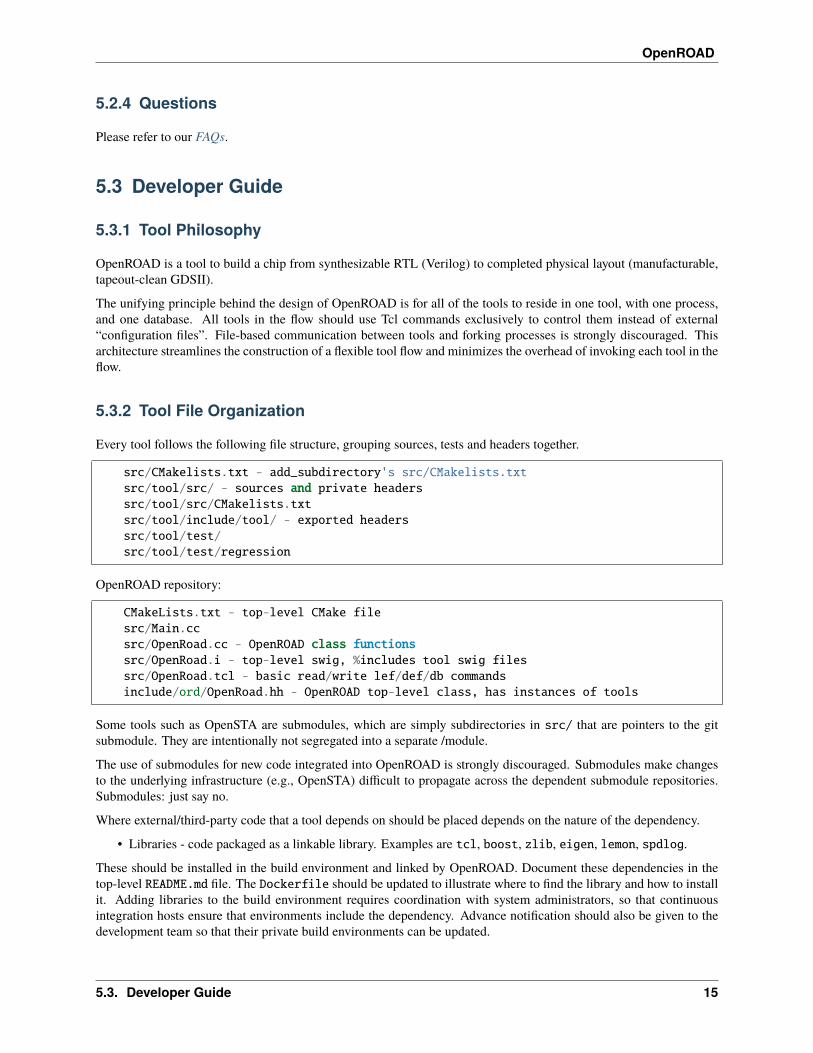
Every tool follows the following file structure, grouping sources, tests and headers together.
src/CMakelists.txt - add_subdirectory's src/CMakelists.txtsrc/tool/src/ - sources and private headerssrc/tool/src/CMakelists.txtsrc/tool/include/tool/ - exported headerssrc/tool/test/src/tool/test/regression
OpenROAD repository:
CMakeLists.txt - top-level CMake filesrc/Main.ccsrc/OpenRoad.cc - OpenROAD class functionssrc/OpenRoad.i - top-level swig, %includes tool swig filessrc/OpenRoad.tcl - basic read/write lef/def/db commandsinclude/ord/OpenRoad.hh - OpenROAD top-level class, has instances of tools
Some tools such as OpenSTA are submodules, which are simply subdirectories in src/ that are pointers to the gitsubmodule. They are intentionally not segregated into a separate /module.
The use of submodules for new code integrated into OpenROAD is strongly discouraged. Submodules make changesto the underlying infrastructure (e.g., OpenSTA) difficult to propagate across the dependent submodule repositories.Submodules: just say no.
Where external/third-party code that a tool depends on should be placed depends on the nature of the dependency.
• Libraries - code packaged as a linkable library. Examples are tcl, boost, zlib, eigen, lemon, spdlog.
These should be installed in the build environment and linked by OpenROAD. Document these dependencies in thetop-level README.md file. The Dockerfile should be updated to illustrate where to find the library and how to installit. Adding libraries to the build environment requires coordination with system administrators, so that continuousintegration hosts ensure that environments include the dependency. Advance notification should also be given to thedevelopment team so that their private build environments can be updated.
5.3. Developer Guide 15
OpenROAD
Each tool CMake file builds a library that is linked by the OpenROAD application. The tools should not define amain() function. If the tool is Tcl only and has no C++ code, it does not need to have a CMake file. Tool CMake filesshould not include the following:
• cmake_minimum_required
• GCC_COVERAGE_COMPILE_FLAGS
• GCC_COVERAGE_LINK_FLAGS
• CMAKE_CXX_FLAGS
• CMAKE_EXE_LINKER_FLAGS
None of the tools have commands to read or write LEF, DEF, Verilog or database files. For consistency, these functionsare all provided by the OpenROAD framework.
Tools should package all state in a single class. An instance of each tool class resides in the top-level OpenROADobject. This allows multiple tools to exist at the same time. If any tool keeps state in global variables (even static), thenonly one tool can exist at a time. Many of the tools being integrated were not built with this goal in mind and will onlywork on one design at a time.
Each tool should use a unique namespace for all of its code. The same namespace should be used for Tcl functions,including those defined by a swig interface file. Internal Tcl commands stay inside the namespace, and user visibleTcl commands should be defined in the global namespace. User commands should be simple Tcl commands such as‘global_placement’ that do not create tool instances that must be based to the commands. Defining Tcl commands fora tool class is fine for internal commands, but not for user visible commands. Commands have an implicit argument ofthe current OpenROAD class object. Functions to get individual tools from the OpenROAD object can be defined.
5.3.3 Initialization (C++ tools only)
The OpenROAD class has pointers to each tool, with functions to get each tool. Each tool has (at a minimum) a functionto make an instance of the tool class, an initialization function that is called after all of the tools have been made, and afunction to delete the tool. This small header does not include the class definition for the tool so that the OpenROADframework does not have to know anything about the tool internals or include a gigantic header file.
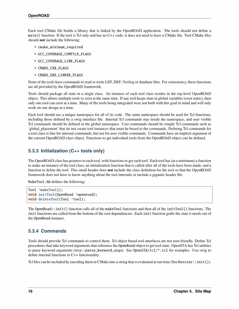
MakeTool.hh defines the following:
Tool *makeTool();void initTool(OpenRoad *openroad);void deleteTool(Tool *tool);
The OpenRoad::init() function calls all of the makeTool functions and then all of the initTool() functions. Theinit functions are called from the bottom of the tool dependencies. Each init function grabs the state it needs out ofthe OpenRoad instance.
5.3.4 Commands
Tools should provide Tcl commands to control them. Tcl object based tool interfaces are not user-friendly. Define Tclprocedures that take keyword arguments that reference the OpenRoad object to get tool state. OpenSTA has Tcl utilitiesto parse keyword arguments (sta::parse_keyword_args). See OpenSTA/tcl/*.tcl for examples. Use swig todefine internal functions to C++ functionality.
Tcl files can be included by encoding them in CMake into a string that is evaluated at run time (See Resizer::init()).
16 Chapter 5. Site Map
OpenROAD
5.3.5 Errors
Tools should report errors to the user using the ord::error function defined in include/openroad/Error.hh. ord::error throws ord::Exception. The variables ord::exit_on_error andord::file_continue_on_error control how the error is handled. If ord::exit_on_error is true thenOpenROAD reports the error and exits. If the error is encountered while reading a file with the source or read_sdccommands and ord::file_continue_on_error is false then no other commands are read from the file. Thedefault value is false for both variables.
5.3.6 Test
Each “tool” has a /test directory containing a script named regression to run “unit” tests. With no arguments itshould run default unit tests.
No database files should be in tests. Read LEF/DEF/Verilog to make a database.
The regression script should not depend on the current working directory. It should be able to be run from any directory.Use filenames relative to the script name rather the current working directory.
Regression scripts should print a concise summary of test failures. The regression script should return an exit code of 0if there are no errors and 1 if there are errors. The script should not print thousands of lines of internal tool information.
Regression scripts should pass the -no_init option to openroad so that a user’s init file is not sourced before thetests runs.
Regression scripts should add output files or directories to .gitignore so that running does not leave the sourcerepository “dirty”.
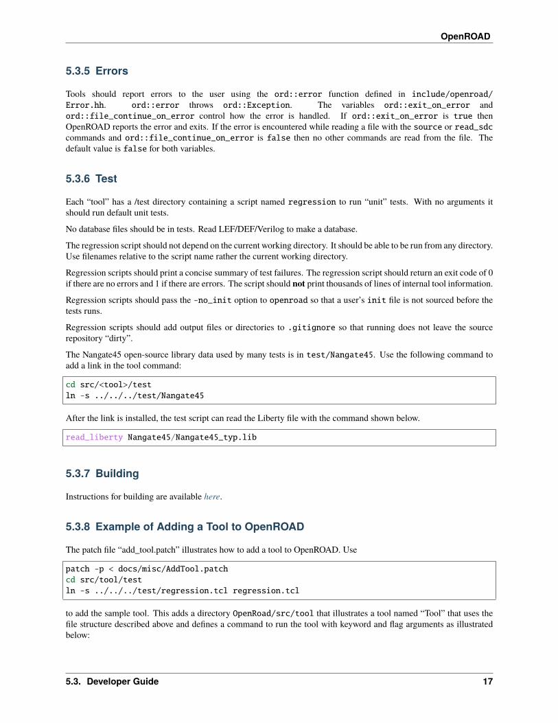
The Nangate45 open-source library data used by many tests is in test/Nangate45. Use the following command toadd a link in the tool command:
cd src/<tool>/testln -s ../../../test/Nangate45
After the link is installed, the test script can read the Liberty file with the command shown below.
read_liberty Nangate45/Nangate45_typ.lib
5.3.7 Building
Instructions for building are available here.
5.3.8 Example of Adding a Tool to OpenROAD
The patch file “add_tool.patch” illustrates how to add a tool to OpenROAD. Use
patch -p < docs/misc/AddTool.patchcd src/tool/testln -s ../../../test/regression.tcl regression.tcl
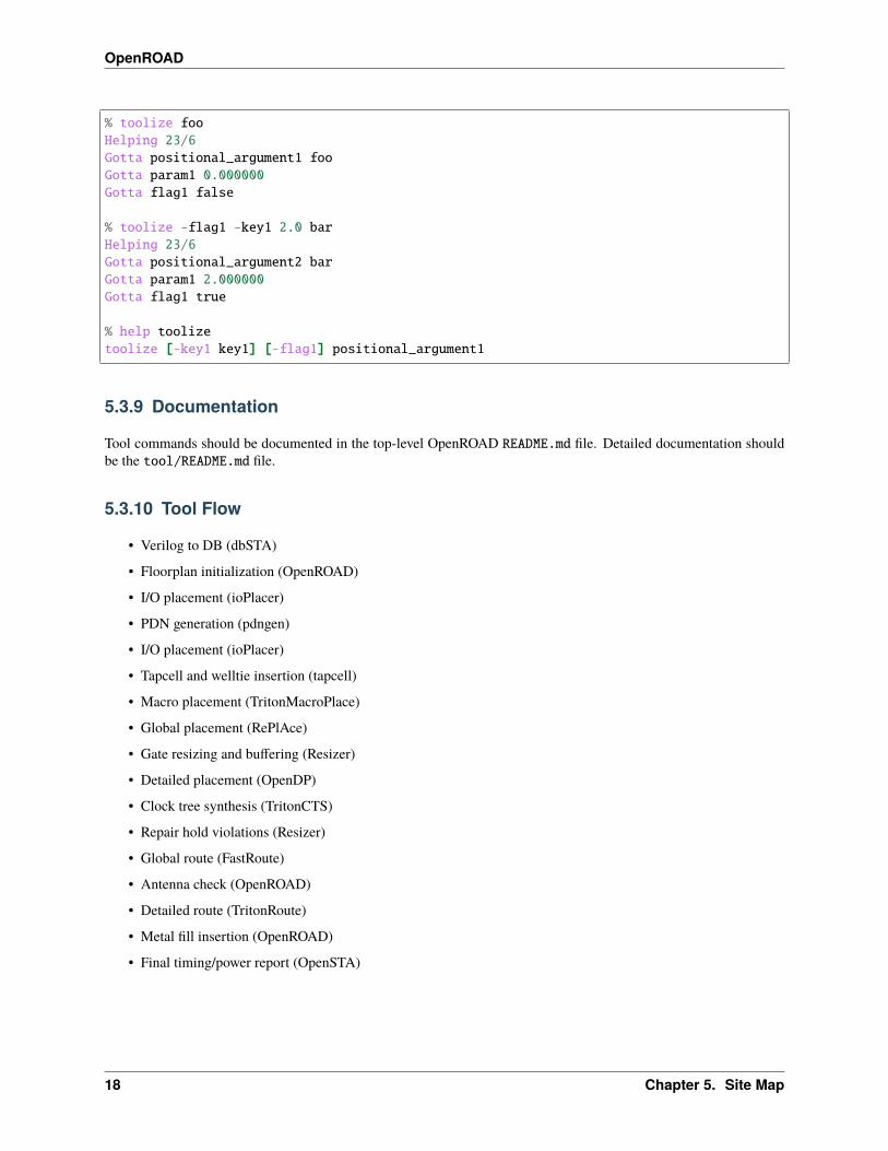
to add the sample tool. This adds a directory OpenRoad/src/tool that illustrates a tool named “Tool” that uses thefile structure described above and defines a command to run the tool with keyword and flag arguments as illustratedbelow:
5.3. Developer Guide 17
OpenROAD
% toolize fooHelping 23/6Gotta positional_argument1 fooGotta param1 0.000000Gotta flag1 false
% toolize -flag1 -key1 2.0 barHelping 23/6Gotta positional_argument2 barGotta param1 2.000000Gotta flag1 true
% help toolizetoolize [-key1 key1] [-flag1] positional_argument1
5.3.9 Documentation
Tool commands should be documented in the top-level OpenROAD README.md file. Detailed documentation shouldbe the tool/README.md file.
5.3.10 Tool Flow
• Verilog to DB (dbSTA)
• Floorplan initialization (OpenROAD)
• I/O placement (ioPlacer)
• PDN generation (pdngen)
• I/O placement (ioPlacer)
• Tapcell and welltie insertion (tapcell)
• Macro placement (TritonMacroPlace)
• Global placement (RePlAce)
• Gate resizing and buffering (Resizer)
• Detailed placement (OpenDP)
• Clock tree synthesis (TritonCTS)
• Repair hold violations (Resizer)
• Global route (FastRoute)
• Antenna check (OpenROAD)
• Detailed route (TritonRoute)
• Metal fill insertion (OpenROAD)
• Final timing/power report (OpenSTA)
18 Chapter 5. Site Map

OpenROAD
5.3.11 Tool Checklist
Tools should make every attempt to minimize external dependencies. Linking libraries other than those currently in usecomplicates the builds and sacrifices the portability of OpenROAD. OpenROAD should be portable to many differentcompiler/operating system versions and dependencies make this vastly more complicated.
1. OpenROAD submodules reference tool openroad branch head. No git develop, openroad_app, oropenroad_build branches.
2. Submodules used by more than one tool belong in src/, not duplicated in each tool repo.
3. CMakeLists.txt does not use add_compile_options include_directories link_directories link_libraries. Usetarget_ versions instead. See https://gist.github.com/mbinna/c61dbb39bca0e4fb7d1f73b0d66a4fd1
4. CMakeLists.txt does not use glob. Use explicit lists of source files and headers instead.
5. CMakeLists.txt does not define CFLAGS CMAKE_CXX_FLAGS CMAKE_CXX_FLAGS_DEBUGCMAKE_CXX_FLAGS_RELEASE. Let the top level and defaults control these.
6. No main.cpp or main procedure.
7. No compiler warnings for GCC or Clang with optimization enabled.
8. Does not call flute::readLUT (called once by openroad).
9. Tcl command(s) documented in top level README.md in flow order.
10. Command line tool documentation in tool README.
11. Conforms to Tcl command naming standards (no camel case).
12. Does not read configuration files. Use command arguments or support commands.
13. .clang-format at tool root directory to aid foreign programmers.
14. No jenkins/, Jenkinsfile, Dockerfile in tool directory.
15. regression script named test/regression with no arguments that runs tests. Not tests/regression-tcl.sh, not test/run_tests.py etc.
16. regression script should run independent of current directory. For example, ../test/regression shouldwork.
17. regression should only print test results or summary, not belch 1000s of lines of output.
18. Test scripts use OpenROAD tcl commands (not itcl, not internal accessors).
19. regression script should only write files in a directory that is in the tool’s .gitignore so the hierarchy doesnot have modified files in it as a result or running the regressions.
20. Regressions report no memory errors with valgrind (stretch goal).
21. Regressions report no memory leaks with valgrind (difficult).
James Cherry, Dec 2019
5.3. Developer Guide 19
OpenROAD
5.3.12 Coding Practices
List of coding practices.
NOTE
This is a compilation of many idioms in OpenROAD code that I consider undesirable. Obviously other programmershave different opinions or they would not be so pervasive. James Cherry 04/2020
C++
Practice #1
Don’t comment out code. Remove it. git provides a complete history of the code if you want to look backwards. Hugechunks of commented-out code that are stunningly common in student code make it nearly impossible to read.
FlexTa.cpp has 220 lines of code and 600 lines of commented-out code.
Practice #2
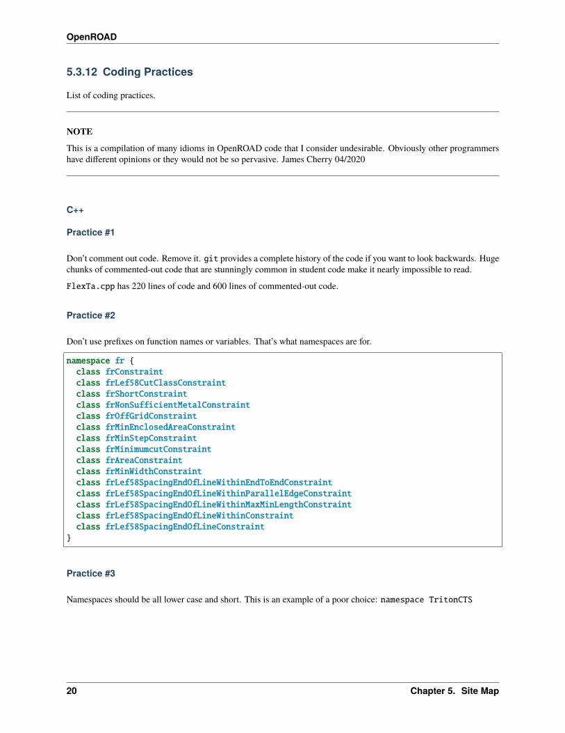
Don’t use prefixes on function names or variables. That’s what namespaces are for.
namespace fr {class frConstraintclass frLef58CutClassConstraintclass frShortConstraintclass frNonSufficientMetalConstraintclass frOffGridConstraintclass frMinEnclosedAreaConstraintclass frMinStepConstraintclass frMinimumcutConstraintclass frAreaConstraintclass frMinWidthConstraintclass frLef58SpacingEndOfLineWithinEndToEndConstraintclass frLef58SpacingEndOfLineWithinParallelEdgeConstraintclass frLef58SpacingEndOfLineWithinMaxMinLengthConstraintclass frLef58SpacingEndOfLineWithinConstraintclass frLef58SpacingEndOfLineConstraint
}
Practice #3
Namespaces should be all lower case and short. This is an example of a poor choice: namespace TritonCTS
20 Chapter 5. Site Map
OpenROAD
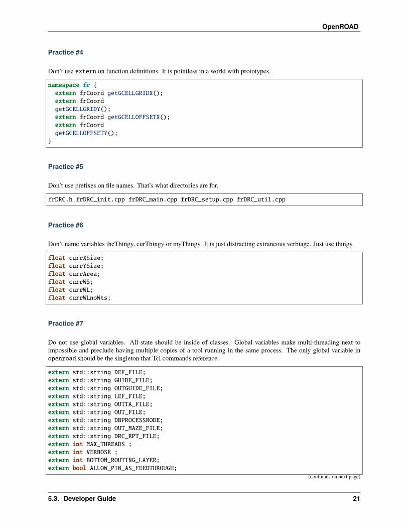
Practice #4
Don’t use extern on function definitions. It is pointless in a world with prototypes.
namespace fr {extern frCoord getGCELLGRIDX();extern frCoordgetGCELLGRIDY();extern frCoord getGCELLOFFSETX();extern frCoordgetGCELLOFFSETY();
}
Practice #5
Don’t use prefixes on file names. That’s what directories are for.
frDRC.h frDRC_init.cpp frDRC_main.cpp frDRC_setup.cpp frDRC_util.cpp
Practice #6
Don’t name variables theThingy, curThingy or myThingy. It is just distracting extraneous verbiage. Just use thingy.
float currXSize;float currYSize;float currArea;float currWS;float currWL;float currWLnoWts;
Practice #7
Do not use global variables. All state should be inside of classes. Global variables make multi-threading next toimpossible and preclude having multiple copies of a tool running in the same process. The only global variable inopenroad should be the singleton that Tcl commands reference.
extern std::string DEF_FILE;extern std::string GUIDE_FILE;extern std::string OUTGUIDE_FILE;extern std::string LEF_FILE;extern std::string OUTTA_FILE;extern std::string OUT_FILE;extern std::string DBPROCESSNODE;extern std::string OUT_MAZE_FILE;extern std::string DRC_RPT_FILE;extern int MAX_THREADS ;extern int VERBOSE ;extern int BOTTOM_ROUTING_LAYER;extern bool ALLOW_PIN_AS_FEEDTHROUGH;
(continues on next page)
5.3. Developer Guide 21
OpenROAD
(continued from previous page)
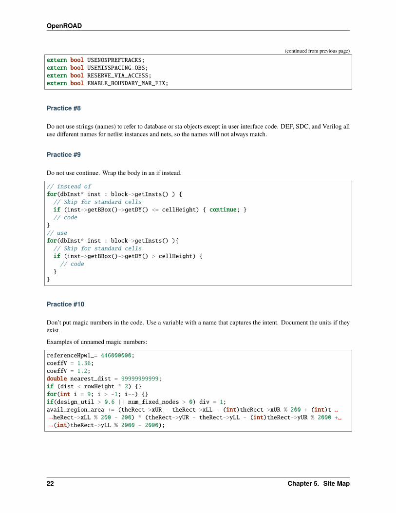
extern bool USENONPREFTRACKS;extern bool USEMINSPACING_OBS;extern bool RESERVE_VIA_ACCESS;extern bool ENABLE_BOUNDARY_MAR_FIX;
Practice #8
Do not use strings (names) to refer to database or sta objects except in user interface code. DEF, SDC, and Verilog alluse different names for netlist instances and nets, so the names will not always match.
Practice #9
Do not use continue. Wrap the body in an if instead.
// instead offor(dbInst* inst : block->getInsts() ) {// Skip for standard cellsif (inst->getBBox()->getDY() <= cellHeight) { continue; }// code
}// usefor(dbInst* inst : block->getInsts() ){// Skip for standard cellsif (inst->getBBox()->getDY() > cellHeight) {// code
}}
Practice #10
Don’t put magic numbers in the code. Use a variable with a name that captures the intent. Document the units if theyexist.
Examples of unnamed magic numbers:
referenceHpwl_= 446000000;coeffV = 1.36;coeffV = 1.2;double nearest_dist = 99999999999;if (dist < rowHeight * 2) {}for(int i = 9; i > -1; i--) {}if(design_util > 0.6 || num_fixed_nodes > 0) div = 1;avail_region_area += (theRect->xUR - theRect->xLL - (int)theRect->xUR % 200 + (int)t ␣→˓heRect->xLL % 200 - 200) * (theRect->yUR - theRect->yLL - (int)theRect->yUR % 2000 +␣→˓(int)theRect->yLL % 2000 - 2000);
22 Chapter 5. Site Map

OpenROAD
Practice #11
Don’t copy code fragments. Write functions.
// 10xint x_pos = (int)floor(theCell->x_coord / wsite + 0.5);// 15xint y_pos = (int)floor(y_coord / rowHeight + 0.5);
// Thisnets[newnetID]->netIDorg = netID;nets[newnetID]->numPins = numPins;nets[newnetID]->deg = pinInd;nets[newnetID]->pinX = (short *)malloc(pinInd* sizeof(short));nets[newnetID]->pinY = (short *)malloc(pinInd* sizeof(short));nets[newnetID]->pinL = (short *)malloc(pinInd* sizeof(short));nets[newnetID]->alpha = alpha;
// Should factor out the array lookup.Net *net = nets[newnetID];net->netIDorg = netID;net->numPins = numPins;net->deg = pinInd;net->pinX = (short*)malloc(pinInd* sizeof(short));net->pinY = (short *)malloc(pinInd* sizeof(short));net->pinL = (short *)malloc(pinInd* sizeof(short));net->alpha = alpha;
// Same here:if (grid[j][k].group != UINT_MAX) {if (grid[j][k].isValid) {if (groups[grid[j][k].group].name == theGroup->name)area += wsite * rowHeight;
}}
Practice #12
Don’t use logical operators to test for null pointers.
if (!net) {// code
}
// should beif (net != nullptr) {// code
}
5.3. Developer Guide 23

OpenROAD
Practice #13
Don’t use malloc. Use new. We are writting C++, not C.
Practice #14
Don’t use C style arrays. There is no bounds checks for them so they invite subtle memory errors to unwitting pro-grammers who fail to use valgrind. Use std::vector or std::array.
Practice #15
Break long functions into smaller ones, preferably that fit on one screen.
• 162 lines void DBWrapper::initNetlist()
• 246 lines static vector<pair<Partition, Partition>> GetPart()
• 263 lines void MacroCircuit::FillVertexEdge()
Practice #16
Don’t reinvent functions like round, floor, abs, min, max. Use the std versions.
int size_x = (int)floor(theCell->width / wsite + 0.5);
Practice #17
Don’t use C stdlib.h abs, fabs or fabsf. They fail miserably if the wrong arg type is passed to them. Use std::abs.
Practice #18
Fold code common to multiple loops into the same loop. Each of these functions loops over every instance like this:
legal &= row_check(log);legal &= site_check(log);for(int i = 0; i < cells.size(); i++) {cell* theCell = &cells[i];legal &= power_line_check(log);legal &= edge_check(log);legal &= placed_check(log);legal &= overlap_check(log);
}// with this loopfor(int i = 0; i < cells.size(); i++) {cell* theCell = &cells[i];
}
Instead make one pass over the instances doing each check.
24 Chapter 5. Site Map

OpenROAD
Practice #19
Don’t use == true, or == false. Boolean expressions already have a value of true or false.
if(found.first == true) {// code
}// is simplyif(found.first) {// code
}// andif(found.first == false) {// code
}// is simplyif(!found.first) {// code}
Practice #20
Don’t nest if statements. Use && on the clauses instead.
if(grid[j][k].group != UINT_MAX)if(grid[j][k].isValid == true)if(groups[grid[j][k].group].name == theGroup->name)
is simply
if(grid[j][k].group != UINT_MAX&& grid[j][k].isValid&& groups[grid[j][k].group].name == theGroup->name)
Practice #21
Don’t call return at the end of a function that does not return a value.
Practice #22
Don’t use <>’s to include anything but system headers. Your project’s headers should NEVER bein <>’s. - https://gcc.gnu.org/onlinedocs/cpp/Include-Syntax.html - https://stackoverflow.com/questions/21593/what-is-the-difference-between-include-filename-and-include-filename
These are all wrong:
#include <odb/db.h>#include <sta/liberty/Liberty.hh>#include <odb/db.h>#include <odb/dbTypes.h>
(continues on next page)
5.3. Developer Guide 25
OpenROAD
(continued from previous page)
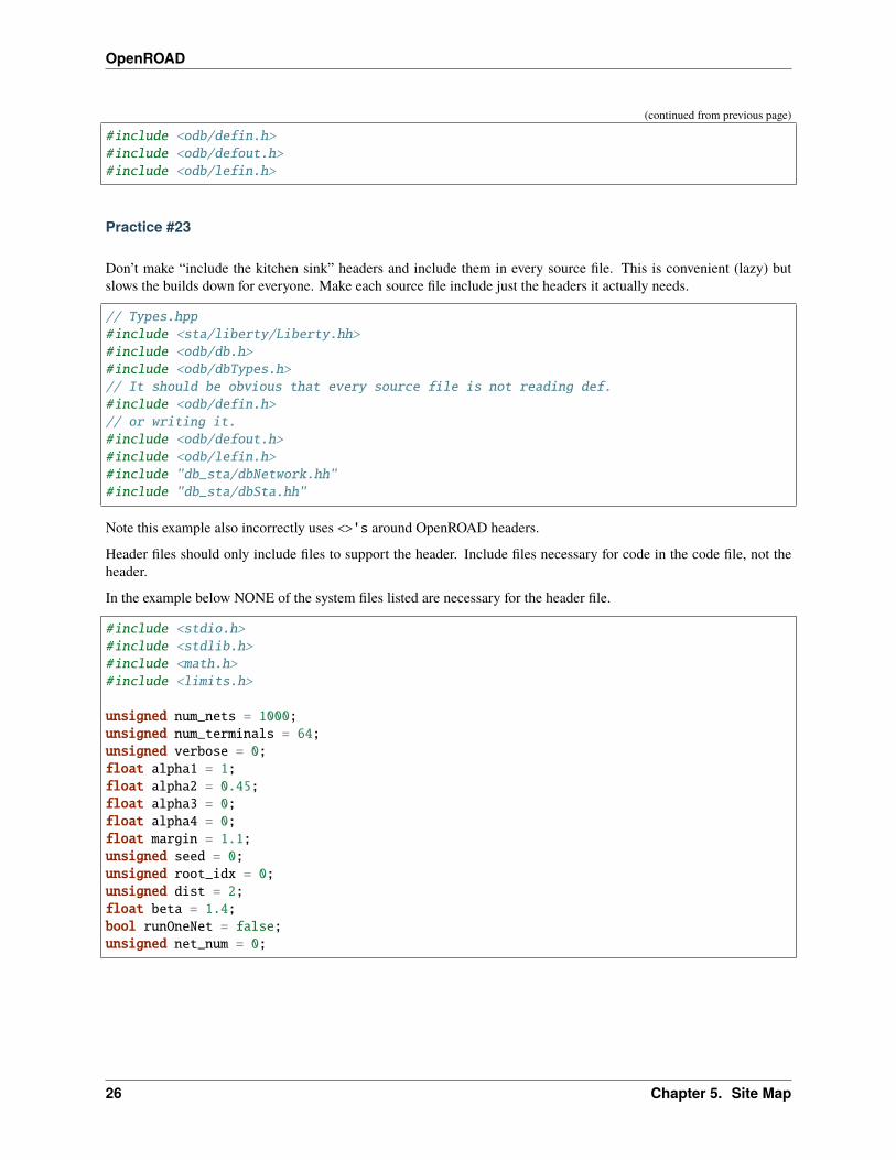
#include <odb/defin.h>#include <odb/defout.h>#include <odb/lefin.h>
Practice #23
Don’t make “include the kitchen sink” headers and include them in every source file. This is convenient (lazy) butslows the builds down for everyone. Make each source file include just the headers it actually needs.
// Types.hpp#include <sta/liberty/Liberty.hh>#include <odb/db.h>#include <odb/dbTypes.h>// It should be obvious that every source file is not reading def.#include <odb/defin.h>// or writing it.#include <odb/defout.h>#include <odb/lefin.h>#include "db_sta/dbNetwork.hh"#include "db_sta/dbSta.hh"
Note this example also incorrectly uses <>'s around OpenROAD headers.
Header files should only include files to support the header. Include files necessary for code in the code file, not theheader.
In the example below NONE of the system files listed are necessary for the header file.
#include <stdio.h>#include <stdlib.h>#include <math.h>#include <limits.h>
unsigned num_nets = 1000;unsigned num_terminals = 64;unsigned verbose = 0;float alpha1 = 1;float alpha2 = 0.45;float alpha3 = 0;float alpha4 = 0;float margin = 1.1;unsigned seed = 0;unsigned root_idx = 0;unsigned dist = 2;float beta = 1.4;bool runOneNet = false;unsigned net_num = 0;
26 Chapter 5. Site Map
OpenROAD
Practice #24
Use class declarations if you are only referring to objects by pointer instead of including their complete class definition.This can vastly reduce the code the compiler has to process.
class Network;// instead of#include "Network.hh"
Practice #25
Use pragma once instead of #define to protect headers from being read more than once. The #define symbol has to beunique, which is difficult to guarantee.
// Instead of:#ifndef __MACRO_PLACER_HASH_UTIL__#define __MACRO_PLACER_HASH_UTIL__#endif// use#pragma once
Practice #26
Don’t put “using namespace” inside a function. It makes no sense whatsoever but I have seen some very confusedprogrammers do this far too many times.
Practice #27
Don’t nest namespaces. We don’t have enough code to justify that complication.
Practice #28
Don’t use using namespace It is just asking for conflicts and doesn’t explicity declare what in the namespace is beingused. Use using namespace::symbol; instead. And especially NEVER EVER EVER using namespace std. Itis HUGE.
The following is especially confused because it is trying to “use” the symbols in code that are already in the MacroPlacenamespace.
using namespace MacroPlace;
namespace MacroPlace { }
5.3. Developer Guide 27
OpenROAD
Practice #29
Use nullptr instead of NULL. This is the C++ approved version of the ancient C #define.
Practice #30
Use range iteration. C++ iterators are ugly and verbose.
// Instead ofodb::dbSet::iterator nIter;for (nIter = nets.begin(); nIter != nets.end(); ++nIter) {odb::dbNet* currNet = *nIter;// code
}// usefor (odb::dbNet* currNet : nets) {// code
}
Practice #34
Don’t use end of line comments unless they are very short. Don’t assume that the person reading your code has a 60”monitor.
for (int x = firstTile._x; x <= lastTile._x; x++) { // Setting capacities of edges␣→˓completely inside the adjust region according the percentage of reduction// code
}
Practice #35
Don’t std::pow for powers of 2 or for decimal constants.
// Thisdouble newCapPerSqr = (_options->getCapPerSqr() * std::pow(10.0, -12));// Should bedouble newCapPerSqr = _options->getCapPerSqr() * 1E-12;
// Thisunsigned numberOfTopologies = std::pow(2, numberOfNodes);// Should beunsigned numberOfTopologies = 1 << numberOfNodes;
28 Chapter 5. Site Map
OpenROAD
Git
Practice #31
Don’t put /’s in .gitignore directory names. test/
Practice #32
Don’t put file names in .gitignore ignored directories. test/results test/results/diffs
Practice #33
Don’t list compile artifacts in .gitignore. They all end up in the build directory so each file type does not have toappear in .gitignore.
All of the following is nonsense that has propagated faster than COVID in student code:
Compiled Object files
*.slo *.lo *.o *.obj
Precompiled Headers
*.gch *.pch
Compiled Dynamic libraries
*.so *.dylib *.dll
Fortran module files
*.mod *.smod
Compiled Static libraries
*.lai *.la *.a *.lib
CMake
Practice #35
Don’t change compile flags in cmake files. These are set at the top level and should not be overridden.
set(CMAKE_CXX_FLAGS "-O3")set(CMAKE_CXX_FLAGS_DEBUG "-g -ggdb")set(CMAKE_CXX_FLAGS_RELEASE "-O3")
5.3. Developer Guide 29

OpenROAD
Practice #36
Don’t put /’s in CMake directory names. CMake knows they are directories.
target_include_directories( ABKCommon PUBLIC ${ABKCOMMON_HOME} src/ )
Practice #37
Don’t use glob. Explictly list the files in a group.
# Instead offile(GLOB_RECURSE SRC_FILES ${CMAKE_CURRENT_SOURCE_DIR}/src/*.cpp)# should belist(REMOVE_ITEM SRC_FILES ${CMAKE_CURRENT_SOURCE_DIR}/src/Main.cpp)list(REMOVE_ITEM SRC_FILES ${CMAKE_CURRENT_SOURCE_DIR}/src/Parameters.h)list(REMOVE_ITEM SRC_FILES ${CMAKE_CURRENT_SOURCE_DIR}/src/Parameters.cpp)
5.3.13 Database Math 101
DEF defines the units it uses with the units command.
UNITS DISTANCE MICRONS 1000 ;
Typically the units are 1000 or 2000 database units (DBU) per micron. DBUs are integers, so the distance resolutionis typically 1/1000u or 1nm.
OpenDB uses an int to represent a DBU, which on most hardware is 4 bytes. This means a database coordinate canbe +/-2147483647, which is about 2 billion units, corresponding to 2 million microns or 2 meters.
Since chip coordinates cannot be negative, it would make sense to use an unsigned int to represent a distance. Thisconveys the fact that it can never be negative and doubles the maximum possible distance that can be represented.The problem, however, is that doing subtraction with unsigned numbers is dangerous because the differences can benegative. An unsigned negative number looks like a very very big number. So this is a very bad idea and leads to bugs.
Note that calculating an area with int values is problematic. An int * int does not fit in an int. My suggestion isto use int64_t in this situation. Although long “works”, its size is implementation-dependent.
Unfortunately, I have seen multiple instances of programs using a double for distance calculations. A double is 8bytes, with 52 bits used for the mantissa. So, the largest possible integer value that can be represented without loss is5e+15, 12 bits less than using an int64_t. Doing an area calculation on a large chip that is more than sqrt(5e+15)= 7e+7 DBU on a side will overflow the mantissa and truncate the result.
Not only is a double less capable than an int64_t, but using it tells any reader of the code that the value can be a realnumber, such as 104.23. So it is extremely misleading.
Circling back to LEF, we see that unlike DEF the distances are real numbers like 1.3 even though LEF also has adistance unit statement. I suspect this is a historical artifact of a mistake made in the early definition of the LEF fileformat. The reason it is a mistake is because decimal fractions cannot be represented exactly in binary floating-point.For example, 1.1 = 1.00011001100110011. . . , a continued fracion.
OpenDB uses int to represent LEF distances, just as with DEF. This solves the problem by multiplying distances bya decimal constant (distance units) to convert the distance to an integer. In the future I would like to see OpenDB usea dbu typedef instead of int everywhere.
30 Chapter 5. Site Map
OpenROAD
Unfortunately, I see RePlAce, OpenDP, TritonMacroPlace and OpenNPDN all using double or float to representdistances and converting back and forth between DBUs and microns everywhere. This means they also need to roundor floor the results of every calculation because the floating-point representation of the LEF distances is a fractionthat cannot be exactly represented in binary. Even worse is the practice of reinventing round in the following idiom.
(int) x_coord + 0.5
Even worse than using a double is using float because the mantissa is only 23 bits, so the maximum exactly repre-sentable integer is 8e+6. This makes it even less capable than an int.
When a value has to be snapped to a grid such as the pitch of a layer, the calculation can be done with a simple divideusing ints, which floors the result. For example, to snap a coordinate to the pitch of a layer the following can beused:
int x, y;inst->getOrigin(x, y);int pitch = layer->getPitch();int x_snap = (x / pitch) * pitch;
The use of rounding in existing code that uses floating-point representations is to compensate for the inability to rep-resent floating-point fractions exactly. Results like 5.99999999992 need to be “fixed”. This problem does not exist iffixed-point arithmetic is used.
The only place that the database distance units should appear in any program should be in the user interface, becausehumans like microns more than DBUs. Internally, code should use int for all database units and int64_t for all areacalculations.
James Cherry, 2019
5.3.14 Using the Logging Infrastructure
OpenROAD uses spdlog as part of logging infrastructure in order to ensure a clear, consistent messaging and completemessaging interface. A wrapper formats the prefix in the recommended messaging style and limit. A message formatis as follows:
<tool id>-<message id> <Message body>.
For example,
[INFO ODB-0127] Reading DEF file: ./results/asap7/aes/base/4_cts.def
All output from OpenROAD tools should be directed through the logging API to ensure that redirection, file loggingand execution control flow are handled consistently. This also includes messages from any third-party tool. Use the‘ord’ message ID for third-party tools.
The logging infrastructure also supports generating a JSON file containing design metrics (e.g., area or slack). Thisoutput is directed to a user-specified file. The OpenROAD application has a -metrics command line argument tospecify the file.
5.3. Developer Guide 31

OpenROAD
Handling Messages
OpenROAD supports multiple levels of severity for message outputs: critical, error, warning, information and debug.These are supported by automatic calls to the logger which will then prefix the appropriate severity type to the message.
Messaging Guidelines
In addition to the proper use of message types, follow the guidelines below to compose messages for clarity, consistencyand other guidelines:
Grammar
Start with a capital letter and end with a period, besides well-known exceptions. Use capital letters for file formats andtool proper names, e.g., LEF, DEF, SPICE, FLUTE.
After the first word’s capitalization, do not use capital letters (aside from obvious exceptions, such as RSMT, hCut,etc.).
Do not use exclamations. Severity must be communicated by message severity and clear implied or explicit action.
Avoid long, verbose messages. Use commas to list and separate clauses in messages.
Spellcheck all messages using American English spellings.
Use ellipsis ... only to indicate a pause, as when some tool is running or being initialized.
Abbreviations and Shortcuts
Use single-word versions when well-accepted / well-understood by users and developers. Examples: stdcell,cutline, wirelength, flipchip, padring, bondpad, wirebond, libcell, viarule.
Do not abbreviate or truncate English words; expand for the sake of clarity.
Incorrect: Num, #; Tot.
Correct: Number; Total
Use acceptable, well-understood abbreviations for brevity. Examples: db, tech, lib, inst, term, params,etc.
Avoid contractions of action words:
Incorrect: Can't, Can not; Don't
Correct: Cannot; Do not
32 Chapter 5. Site Map
OpenROAD
Actionability
Messages should communicate a clear, implied or explicit action that is necessary for flow continuation or improvedquality of results.
Example:A value for core_area must be specified in the footprint specification, or in the␣→˓environment variable CORE_AREA.
Clarity
Messages must be clear and complete, so as to communicate necessary and sufficient information and actions. Elaboratespecific variables, options, and/or parameters to avoid any ambiguity.
Example:Unrecognized argument $arg, should be one of -pitch, -bump_pin_name, -spacing_to_edge, -→˓cell_name, -bumps_per_tile, -rdl_layer, -rdl_width, -rdl_spacing.
Specify objects clearly in the local context:
Example:cutWithin is smaller than cutSpacing for ADJACENTCUTS on layer {}. Please check your␣→˓rule definition.
Incomplete:Warning: {} does not have viaDef aligned with layer.
Make any assumptions or use of default values explicit:
Example:No net slacks found.Timing-driven mode disabled.
Incomplete, missing default:Utilization exceeds 100%.
Use simple language, and avoid repetitions:
Example:Missing orientation for cell $cell_ref.
Incorrect:No orientation available for orientation of $cell_ref.
5.3. Developer Guide 33
OpenROAD
Message Types
OpenROAD supports the following levels of severity through the logger: report, debug, information, warning, errorand critical.
Report
Report messages are output by the tool in the form of a report to the user. Examples include timing paths or poweranalysis results.
Example report message:
Path startpoint: $startpoint
Debug
Debug messages are only of use to tool developers and not to end users. These messages are not shown unless explicitlyenabled.
Information
Information messages may be used to report metrics, quality of results, or program status to the user. Any messagewhich indicates runtime problems, such as potential faulty input or other internal program issues, should be issued ata higher status level.
Example information messages:
Number of input ports: 47
Running optimization iteration 2
Current cell site utilization: 57.1567%
Warning
Warnings should be used to indicate atypical runtime conditions that may affect quality, but not correctness, of theoutput. Any conditions that affect correctness should be issued at a higher status level.
Example warning messages:
Core area utilization is greater than 90%. The generated cell placement may not be␣→˓routable.
14 outputs are not constrained for max capacitance.
Pin 'A[0]' on instance 'mem01' does not contain antenna information and will not be␣→˓checked for antenna violations.
34 Chapter 5. Site Map

OpenROAD
Error
Error messages should be used to indicate correctness problems. Problems with command arguments are a goodexample of where error messages are appropriate. Errors exit the current command by throwing an exception that isconverted to an error in Tcl. Errors that occur while reading a command file stop execution of the script commands.
Example error messages:
Invalid selection: net 'test0' does not exist in the design.
Cell placement cannot be run before floorplanning.
Argument 'max_routing_layer' expects an integer value from 1 to 10.
Critical
Critical messages should be used to indicate correctness problems that the program is not able to work around or ignore,and that require immediate exiting of the program (abort).
Example critical messages:
Database 'chip' has been corrupted and is not recoverable.
Unable to allocate heap memory for array 'vertexIndices'. The required memory size may␣→˓exceed host machine limits.
Assertion failed: 'nodeVisited == false' on line 122 of example.cpp. Please file a␣→˓Github issue and attach a testcase.
Coding
Each status message requires:
• The three letter tool ID
• The message ID
• The message string
• Optionally, additional arguments to fill in placeholders in the message string
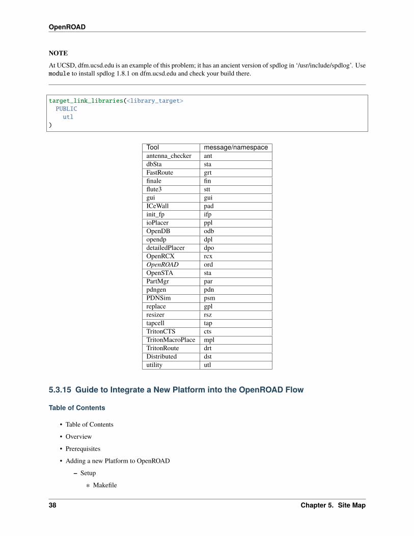
Reporting is simply printing and does not require a tool or message ID. The tool ID comes from a fixed enumerationof all the tools in the system. This enumeration is in Logger.h. New abbreviations should be added after discussionwith the OpenROAD system architects. The abbreviation matches the C++ namespace for the tool.
Message IDs are integers. They are expected to be unique for each tool. This has the benefit that a message can bemapped to the source code unambiguously even if the text is not unique. Maintaining this invariant is the tool owner’sresponsibility. To ensure that the IDs are unique, each tool should maintain a file named ‘messages.txt’ in the top-leveltool directory, listing the message IDs along with the format string. When code that uses a message ID is removed,the ID should be retired by removing it from ‘messages.txt’. See the utility etc/find_messages.py to scan a tooldirectory and write a messages.txt file.
Spdlog comes with the fmt library which supports message formatting in a python or C++20 like style.
The message string should not include the tool ID or message ID which will automatically be prepended. A trailingnewline will automatically be added, and hence messages should not end with one. Messages should be written ascomplete sentences and end in a period. Multi-line messages may contain embedded new lines.
5.3. Developer Guide 35
OpenROAD
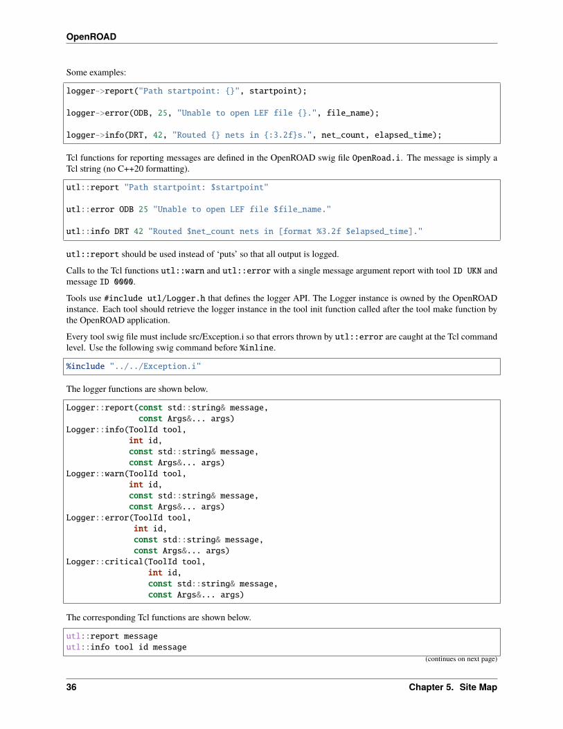
Some examples:
logger->report("Path startpoint: {}", startpoint);
logger->error(ODB, 25, "Unable to open LEF file {}.", file_name);
logger->info(DRT, 42, "Routed {} nets in {:3.2f}s.", net_count, elapsed_time);
Tcl functions for reporting messages are defined in the OpenROAD swig file OpenRoad.i. The message is simply aTcl string (no C++20 formatting).
utl::report "Path startpoint: $startpoint"
utl::error ODB 25 "Unable to open LEF file $file_name."
utl::info DRT 42 "Routed $net_count nets in [format %3.2f $elapsed_time]."
utl::report should be used instead of ‘puts’ so that all output is logged.
Calls to the Tcl functions utl::warn and utl::error with a single message argument report with tool ID UKN andmessage ID 0000.
Tools use #include utl/Logger.h that defines the logger API. The Logger instance is owned by the OpenROADinstance. Each tool should retrieve the logger instance in the tool init function called after the tool make function bythe OpenROAD application.
Every tool swig file must include src/Exception.i so that errors thrown by utl::error are caught at the Tcl commandlevel. Use the following swig command before %inline.
%include "../../Exception.i"
The logger functions are shown below.
Logger::report(const std::string& message,const Args&... args)
Logger::info(ToolId tool,int id,const std::string& message,const Args&... args)
Logger::warn(ToolId tool,int id,const std::string& message,const Args&... args)
Logger::error(ToolId tool,int id,const std::string& message,const Args&... args)
Logger::critical(ToolId tool,int id,const std::string& message,const Args&... args)
The corresponding Tcl functions are shown below.
utl::report messageutl::info tool id message
(continues on next page)
36 Chapter 5. Site Map
OpenROAD
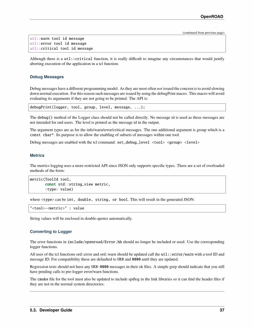
(continued from previous page)
utl::warn tool id messageutl::error tool id messageutl::critical tool id message
Although there is a utl::critical function, it is really difficult to imagine any circumstances that would justifyaborting execution of the application in a tcl function.
Debug Messages
Debug messages have a different programming model. As they are most often not issued the concern is to avoid slowingdown normal execution. For this reason such messages are issued by using the debugPrint macro. This macro will avoidevaluating its arguments if they are not going to be printed. The API is:
debugPrint(logger, tool, group, level, message, ...);
The debug() method of the Logger class should not be called directly. No message id is used as these messages arenot intended for end users. The level is printed as the message id in the output.
The argument types are as for the info/warn/error/critical messages. The one additional argument is group which is aconst char*. Its purpose is to allow the enabling of subsets of messages within one tool.
Debug messages are enabled with the tcl command: set_debug_level <tool> <group> <level>
Metrics
The metrics logging uses a more restricted API since JSON only supports specific types. There are a set of overloadedmethods of the form:
metric(ToolId tool,const std::string_view metric,<type> value)
where <type> can be int, double, string, or bool. This will result in the generated JSON:
"<tool>-<metric>" : value
String values will be enclosed in double-quotes automatically.
Converting to Logger
The error functions in include/openroad/Error.hh should no longer be included or used. Use the correspondinglogger functions.
All uses of the tcl functions ord::error and ord::warn should be updated call the utl::error/warn with a tool ID andmessage ID. For compatibility these are defaulted to UKN and 0000 until they are updated.
Regression tests should not have any UKN-0000 messages in their ok files. A simple grep should indicate that you stillhave pending calls to pre-logger error/warn functions.
The cmake file for the tool must also be updated to include spdlog in the link libraries so it can find the header files ifthey are not in the normal system directories.
5.3. Developer Guide 37
OpenROAD
NOTE
At UCSD, dfm.ucsd.edu is an example of this problem; it has an ancient version of spdlog in ‘/usr/include/spdlog’. Usemodule to install spdlog 1.8.1 on dfm.ucsd.edu and check your build there.
target_link_libraries(<library_target>PUBLICutl
)
Tool message/namespaceantenna_checker antdbSta staFastRoute grtfinale finflute3 sttgui guiICeWall padinit_fp ifpioPlacer pplOpenDB odbopendp dpldetailedPlacer dpoOpenRCX rcxOpenROAD ordOpenSTA staPartMgr parpdngen pdnPDNSim psmreplace gplresizer rsztapcell tapTritonCTS ctsTritonMacroPlace mplTritonRoute drtDistributed dstutility utl
5.3.15 Guide to Integrate a New Platform into the OpenROAD Flow
Table of Contents
• Table of Contents
• Overview
• Prerequisites
• Adding a new Platform to OpenROAD
– Setup
∗ Makefile
38 Chapter 5. Site Map
OpenROAD
∗ Platform Directory
∗ Design Directory
– Platform Configuration
– Design Configuration
∗ config.mk
∗ constraint.sdc
∗ Liberty, LEF, and GDS Files
– Behavioral Models
∗ Gated Clock
∗ Latch
– FastRoute Configuration
– Metal Tracks Configuration
– PDN Configuration
– Tapcell Configuration
– setRC Configuration
– KLayout
∗ KLayout properties file
∗ KLayout tech file
• Validating the New Platform
• Authors/Contributors
Overview
This document is a guide for foundry and third party IP providers to easily integrate and test a new technology in tothe OpenROAD RTL to GDS flow. OpenROAD allows you to integrate any PDK (Process Design Kit) for any featuresize and implement a fully open-sourced RTL-GDSII flow (synthesizable Verilog to merged GDSII). The OpenROADflow has been validated for feature sizes down to 7nm and used to design and tapeout over 100 ASIC and SoCs to date.
Prerequisites
To build and add a new platform for OpenROAD, key technology and library components must be provided basedon the technology node. These are generally available as part of the standard design kit provided by a foundry or athird-party IP provider.
They include :
• A standard cell library
– GDS files of all standard cells in the library (or a way to generate them from the layout files, e.g., MagicVLSI layout tool).
• A technology LEF file of the PDK being used that includes all relevant information regarding metal layers, vias,and spacing requirements.
– See flow/platforms/nangate45/lef/NangateOpenCellLibrary.tech.lef as an example techLEF file.
5.3. Developer Guide 39
OpenROAD
• A macro LEF file of the standard cell kit that includes MACRO definitions of every cell, pin designations (in-put/output/inout).
– See flow/platforms/nangate45/lef/NangateOpenCellLibrary.macro.lef as an example macroLEF file.
• A Liberty file of the standard cell library with PVT characterization, input and output characteristics, timing andpower definitions for each cell.
– See flow/platforms/nangate45/lib/NangateOpenCellLibrary_typical.lib as an example lib-erty file.
• For KLayout: A mapping from LEF/DEF to GDS layers:datatypes
Adding a new platform additionally requires the following:
• A validated installation of the OpenROAD flow scripts is available. See instructions here.:
• A general knowledge of VLSI design and RTL to GDS flows. OpenROAD implements a fully-automated RTL-GDSII but it requires familiarity with the OpenROAD flow scripts to debug problems.
Adding a New Platform to OpenROAD
Setup
This section describes the necessary files and directories needed to build the platform. All files and directoriesmade/edited are independent of each other unless otherwise stated.
Makefile
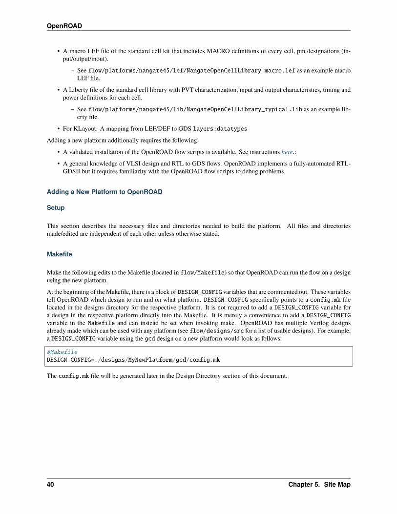
Make the following edits to the Makefile (located in flow/Makefile) so that OpenROAD can run the flow on a designusing the new platform.
At the beginning of the Makefile, there is a block of DESIGN_CONFIG variables that are commented out. These variablestell OpenROAD which design to run and on what platform. DESIGN_CONFIG specifically points to a config.mk filelocated in the designs directory for the respective platform. It is not required to add a DESIGN_CONFIG variable fora design in the respective platform directly into the Makefile. It is merely a convenience to add a DESIGN_CONFIGvariable in the Makefile and can instead be set when invoking make. OpenROAD has multiple Verilog designsalready made which can be used with any platform (see flow/designs/src for a list of usable designs). For example,a DESIGN_CONFIG variable using the gcd design on a new platform would look as follows:
#MakefileDESIGN_CONFIG=./designs/MyNewPlatform/gcd/config.mk
The config.mk file will be generated later in the Design Directory section of this document.
40 Chapter 5. Site Map
OpenROAD
Platform Directory
Create a directory for the new technology inside flow/platforms to contain the necessary files for the OpenROADflow.
$ mkdir flow/platforms/MyNewPlatform
Design Directory
The design directory contains the configuration files for all the designs of a specific platform. Create a directory for thenew platform in flow/designs to contain the relevant files and directories for all the designs for the flow in that specificplatform. Each design requires its own config.mk and constraint.sdc files.
Follow the steps below to create the necessary directories and files. NOTE: gcd is just an example and not a requiredname.:
$ mkdir -p flow/designs/MyNewPlatform/gcd$ touch flow/designs/MyNewPlatform/gcd/config.mk$ touch flow/designs/MyNewPlatform/gcd/constraint.sdc
This creates two directories MyNewPlatform and gcd and two empty files config.mk and constraint.sdc in flow/designs/MyNewPlatform/gcd.
Platform Configuration
This section describes the necessary files in the platform directory needed for the OpenROAD flow. Specificallythe config.mk file in the platform directory has all of the configuration variables that the flow uses. Refer to theOpenROAD-flow-scripts documentation for a full list of configuration variables that can be set. Refer to the Flow vari-ables document for details on how to use environment variables in OpenROAD-flow-scripts to configure platform anddesign specific parameters.
For an example of a platform config.mk file, refer to flow/platforms/sky130hd/config.mk.
Design Configuration
This section describes files in the design directory.
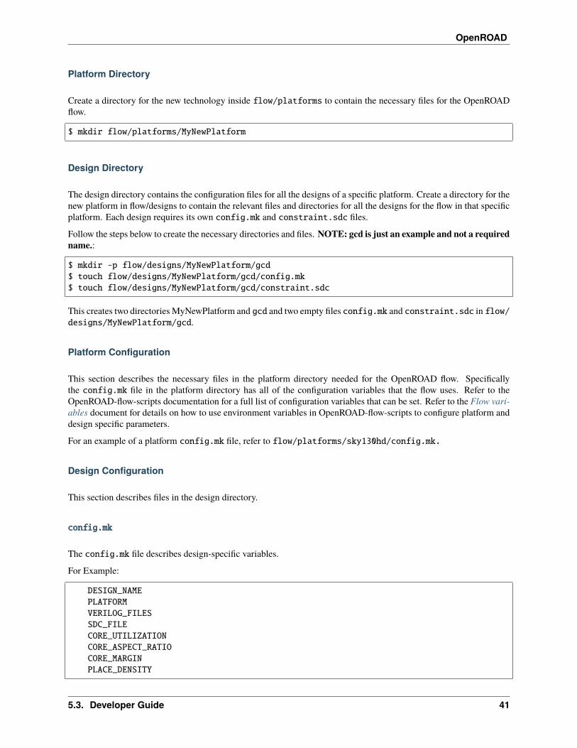
config.mk
The config.mk file describes design-specific variables.
For Example:
DESIGN_NAMEPLATFORMVERILOG_FILESSDC_FILECORE_UTILIZATIONCORE_ASPECT_RATIOCORE_MARGINPLACE_DENSITY
5.3. Developer Guide 41
OpenROAD
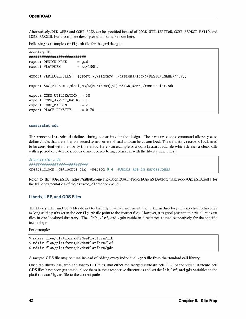
Alternatively, DIE_AREA and CORE_AREA can be specified instead of CORE_UTILIZATION, CORE_ASPECT_RATIO, andCORE_MARGIN. For a complete descriptor of all variables see here.
Following is a sample config.mk file for the gcd design:
#config.mk###########################export DESIGN_NAME = gcdexport PLATFORM = sky130hd
export VERILOG_FILES = $(sort $(wildcard ./designs/src/$(DESIGN_NAME)/*.v))
export SDC_FILE = ./designs/$(PLATFORM)/$(DESIGN_NAME)/constraint.sdc
export CORE_UTILIZATION = 30export CORE_ASPECT_RATIO = 1export CORE_MARGIN = 2export PLACE_DENSITY = 0.70
constraint.sdc
The constraint.sdc file defines timing constraints for the design. The create_clock command allows you todefine clocks that are either connected to nets or are virtual and can be customized. The units for create_clock needto be consistent with the liberty time units. Here’s an example of a constraint.sdc file which defines a clock clkwith a period of 8.4 nanoseconds (nanoseconds being consistent with the liberty time units).
#constraint.sdc############################create_clock [get_ports clk] -period 8.4 #Units are in nanoseconds
Refer to the [OpenSTA][https://github.com/The-OpenROAD-Project/OpenSTA/blob/master/doc/OpenSTA.pdf] forthe full documentation of the create_clock command.
Liberty, LEF, and GDS Files
The liberty, LEF, and GDS files do not technically have to reside inside the platform directory of respective technologyas long as the paths set in the config.mk file point to the correct files. However, it is good practice to have all relevantfiles in one localized directory. The .lib, .lef, and .gds reside in directories named respectively for the specifictechnology.
For example:
$ mdkir flow/platforms/MyNewPlatform/lib$ mdkir flow/platforms/MyNewPlatform/lef$ mdkir flow/platforms/MyNewPlatform/gds
A merged GDS file may be used instead of adding every individual .gds file from the standard cell library.
Once the liberty file, tech and macro LEF files, and either the merged standard cell GDS or individual standard cellGDS files have been generated, place them in their respective directories and set the lib, lef, and gds variables in theplatform config.mk file to the correct paths.
42 Chapter 5. Site Map
OpenROAD
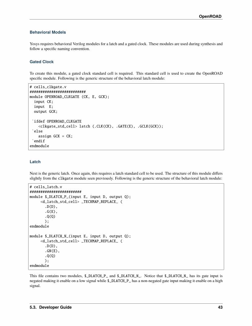
Behavioral Models
Yosys requires behavioral Verilog modules for a latch and a gated clock. These modules are used during synthesis andfollow a specific naming convention.
Gated Clock
To create this module, a gated clock standard cell is required. This standard cell is used to create the OpenROADspecific module. Following is the generic structure of the behavioral latch module:
# cells_clkgate.v##########################module OPENROAD_CLKGATE (CK, E, GCK);input CK;input E;output GCK;
`ifdef OPENROAD_CLKGATE<clkgate_std_cell> latch (.CLK(CK), .GATE(E), .GCLK(GCK));
`elseassign GCK = CK;
`endifendmodule
Latch
Next is the generic latch. Once again, this requires a latch standard cell to be used. The structure of this module differsslightly from the clkgate module seen previously. Following is the generic structure of the behavioral latch module:
# cells_latch.v########################module $_DLATCH_P_(input E, input D, output Q);
<d_latch_std_cell> _TECHMAP_REPLACE_ (.D(D),.G(E),.Q(Q));
endmodule
module $_DLATCH_N_(input E, input D, output Q);<d_latch_std_cell> _TECHMAP_REPLACE_ (.D(D),.GN(E),.Q(Q));
endmodule
This file contains two modules, $_DLATCH_P_ and $_DLATCH_N_. Notice that $_DLATCH_N_ has its gate input isnegated making it enable on a low signal while $_DLATCH_P_ has a non-negated gate input making it enable on a highsignal.
5.3. Developer Guide 43
OpenROAD
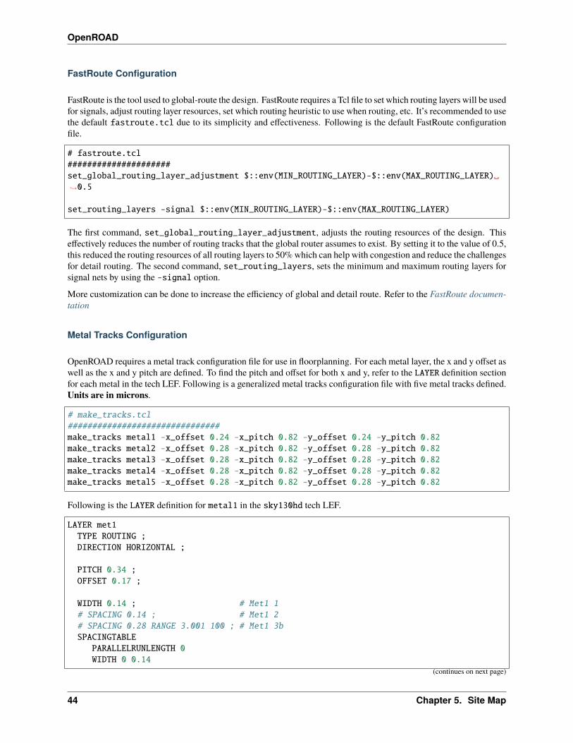
FastRoute Configuration
FastRoute is the tool used to global-route the design. FastRoute requires a Tcl file to set which routing layers will be usedfor signals, adjust routing layer resources, set which routing heuristic to use when routing, etc. It’s recommended to usethe default fastroute.tcl due to its simplicity and effectiveness. Following is the default FastRoute configurationfile.
# fastroute.tcl#####################set_global_routing_layer_adjustment $::env(MIN_ROUTING_LAYER)-$::env(MAX_ROUTING_LAYER)␣→˓0.5
set_routing_layers -signal $::env(MIN_ROUTING_LAYER)-$::env(MAX_ROUTING_LAYER)
The first command, set_global_routing_layer_adjustment, adjusts the routing resources of the design. Thiseffectively reduces the number of routing tracks that the global router assumes to exist. By setting it to the value of 0.5,this reduced the routing resources of all routing layers to 50% which can help with congestion and reduce the challengesfor detail routing. The second command, set_routing_layers, sets the minimum and maximum routing layers forsignal nets by using the -signal option.
More customization can be done to increase the efficiency of global and detail route. Refer to the FastRoute documen-tation
Metal Tracks Configuration
OpenROAD requires a metal track configuration file for use in floorplanning. For each metal layer, the x and y offset aswell as the x and y pitch are defined. To find the pitch and offset for both x and y, refer to the LAYER definition sectionfor each metal in the tech LEF. Following is a generalized metal tracks configuration file with five metal tracks defined.Units are in microns.
# make_tracks.tcl###############################make_tracks metal1 -x_offset 0.24 -x_pitch 0.82 -y_offset 0.24 -y_pitch 0.82make_tracks metal2 -x_offset 0.28 -x_pitch 0.82 -y_offset 0.28 -y_pitch 0.82make_tracks metal3 -x_offset 0.28 -x_pitch 0.82 -y_offset 0.28 -y_pitch 0.82make_tracks metal4 -x_offset 0.28 -x_pitch 0.82 -y_offset 0.28 -y_pitch 0.82make_tracks metal5 -x_offset 0.28 -x_pitch 0.82 -y_offset 0.28 -y_pitch 0.82
Following is the LAYER definition for metal1 in the sky130hd tech LEF.
LAYER met1TYPE ROUTING ;DIRECTION HORIZONTAL ;
PITCH 0.34 ;OFFSET 0.17 ;
WIDTH 0.14 ; # Met1 1# SPACING 0.14 ; # Met1 2# SPACING 0.28 RANGE 3.001 100 ; # Met1 3bSPACINGTABLE
PARALLELRUNLENGTH 0WIDTH 0 0.14
(continues on next page)
44 Chapter 5. Site Map
OpenROAD
(continued from previous page)
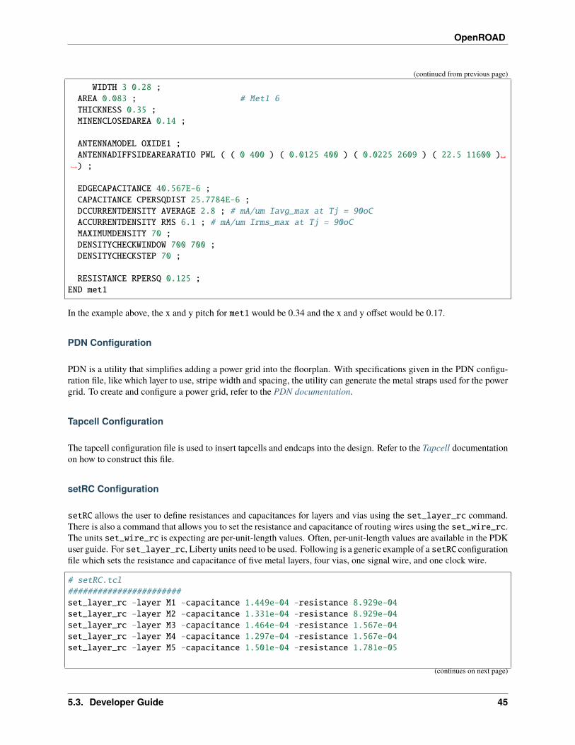
WIDTH 3 0.28 ;AREA 0.083 ; # Met1 6THICKNESS 0.35 ;MINENCLOSEDAREA 0.14 ;
ANTENNAMODEL OXIDE1 ;ANTENNADIFFSIDEAREARATIO PWL ( ( 0 400 ) ( 0.0125 400 ) ( 0.0225 2609 ) ( 22.5 11600 )␣
→˓) ;
EDGECAPACITANCE 40.567E-6 ;CAPACITANCE CPERSQDIST 25.7784E-6 ;DCCURRENTDENSITY AVERAGE 2.8 ; # mA/um Iavg_max at Tj = 90oCACCURRENTDENSITY RMS 6.1 ; # mA/um Irms_max at Tj = 90oCMAXIMUMDENSITY 70 ;DENSITYCHECKWINDOW 700 700 ;DENSITYCHECKSTEP 70 ;
RESISTANCE RPERSQ 0.125 ;END met1
In the example above, the x and y pitch for met1 would be 0.34 and the x and y offset would be 0.17.
PDN Configuration
PDN is a utility that simplifies adding a power grid into the floorplan. With specifications given in the PDN configu-ration file, like which layer to use, stripe width and spacing, the utility can generate the metal straps used for the powergrid. To create and configure a power grid, refer to the PDN documentation.
Tapcell Configuration
The tapcell configuration file is used to insert tapcells and endcaps into the design. Refer to the Tapcell documentationon how to construct this file.
setRC Configuration
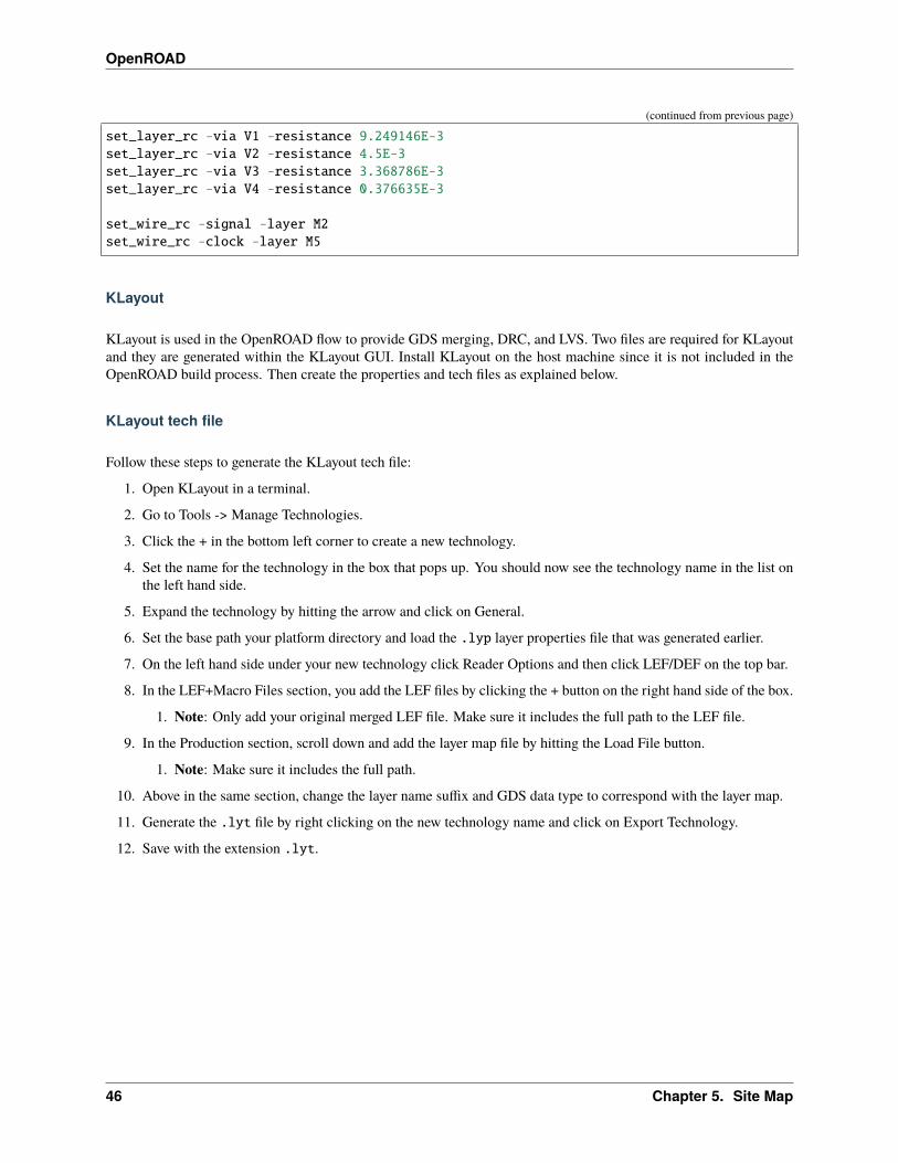
setRC allows the user to define resistances and capacitances for layers and vias using the set_layer_rc command.There is also a command that allows you to set the resistance and capacitance of routing wires using the set_wire_rc.The units set_wire_rc is expecting are per-unit-length values. Often, per-unit-length values are available in the PDKuser guide. For set_layer_rc, Liberty units need to be used. Following is a generic example of a setRC configurationfile which sets the resistance and capacitance of five metal layers, four vias, one signal wire, and one clock wire.
# setRC.tcl#######################set_layer_rc -layer M1 -capacitance 1.449e-04 -resistance 8.929e-04set_layer_rc -layer M2 -capacitance 1.331e-04 -resistance 8.929e-04set_layer_rc -layer M3 -capacitance 1.464e-04 -resistance 1.567e-04set_layer_rc -layer M4 -capacitance 1.297e-04 -resistance 1.567e-04set_layer_rc -layer M5 -capacitance 1.501e-04 -resistance 1.781e-05
(continues on next page)
5.3. Developer Guide 45
OpenROAD
(continued from previous page)
set_layer_rc -via V1 -resistance 9.249146E-3set_layer_rc -via V2 -resistance 4.5E-3set_layer_rc -via V3 -resistance 3.368786E-3set_layer_rc -via V4 -resistance 0.376635E-3
set_wire_rc -signal -layer M2set_wire_rc -clock -layer M5
KLayout
KLayout is used in the OpenROAD flow to provide GDS merging, DRC, and LVS. Two files are required for KLayoutand they are generated within the KLayout GUI. Install KLayout on the host machine since it is not included in theOpenROAD build process. Then create the properties and tech files as explained below.
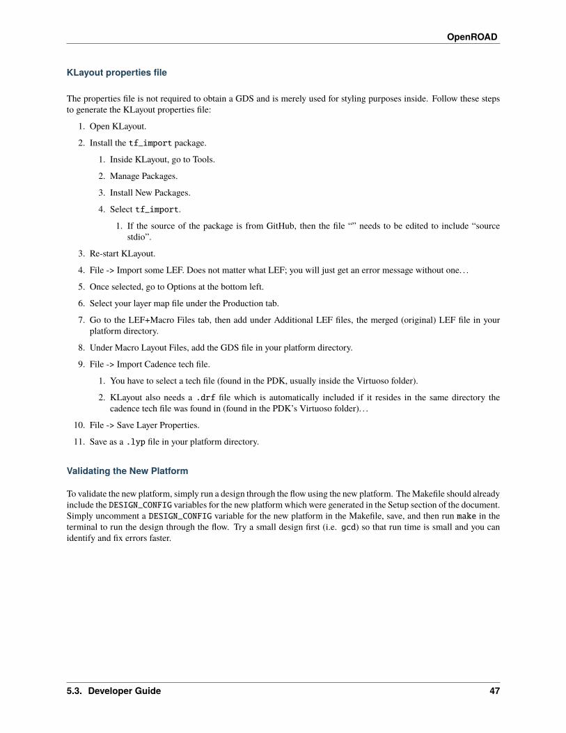
KLayout tech file
Follow these steps to generate the KLayout tech file:
1. Open KLayout in a terminal.
2. Go to Tools -> Manage Technologies.
3. Click the + in the bottom left corner to create a new technology.
4. Set the name for the technology in the box that pops up. You should now see the technology name in the list onthe left hand side.
5. Expand the technology by hitting the arrow and click on General.
6. Set the base path your platform directory and load the .lyp layer properties file that was generated earlier.
7. On the left hand side under your new technology click Reader Options and then click LEF/DEF on the top bar.
8. In the LEF+Macro Files section, you add the LEF files by clicking the + button on the right hand side of the box.
1. Note: Only add your original merged LEF file. Make sure it includes the full path to the LEF file.
9. In the Production section, scroll down and add the layer map file by hitting the Load File button.
1. Note: Make sure it includes the full path.
10. Above in the same section, change the layer name suffix and GDS data type to correspond with the layer map.
11. Generate the .lyt file by right clicking on the new technology name and click on Export Technology.
12. Save with the extension .lyt.
46 Chapter 5. Site Map
OpenROAD
KLayout properties file
The properties file is not required to obtain a GDS and is merely used for styling purposes inside. Follow these stepsto generate the KLayout properties file:
1. Open KLayout.
2. Install the tf_import package.
1. Inside KLayout, go to Tools.
2. Manage Packages.
3. Install New Packages.
4. Select tf_import.
1. If the source of the package is from GitHub, then the file “” needs to be edited to include “sourcestdio”.
3. Re-start KLayout.
4. File -> Import some LEF. Does not matter what LEF; you will just get an error message without one. . .
5. Once selected, go to Options at the bottom left.
6. Select your layer map file under the Production tab.
7. Go to the LEF+Macro Files tab, then add under Additional LEF files, the merged (original) LEF file in yourplatform directory.
8. Under Macro Layout Files, add the GDS file in your platform directory.
9. File -> Import Cadence tech file.
1. You have to select a tech file (found in the PDK, usually inside the Virtuoso folder).
2. KLayout also needs a .drf file which is automatically included if it resides in the same directory thecadence tech file was found in (found in the PDK’s Virtuoso folder). . .
10. File -> Save Layer Properties.
11. Save as a .lyp file in your platform directory.
Validating the New Platform
To validate the new platform, simply run a design through the flow using the new platform. The Makefile should alreadyinclude the DESIGN_CONFIG variables for the new platform which were generated in the Setup section of the document.Simply uncomment a DESIGN_CONFIG variable for the new platform in the Makefile, save, and then run make in theterminal to run the design through the flow. Try a small design first (i.e. gcd) so that run time is small and you canidentify and fix errors faster.
5.3. Developer Guide 47

OpenROAD
Authors/Contributors
• James Stine - Oklahoma State University
• Teo Ene - Oklahoma State University
• Ricardo Hernandez - Oklahoma State University
• Ryan Ridley - Oklahoma State University
• Indira Iyer - OpenROAD Project Consultant
5.4 OpenROAD
The documentation is also available here.
5.4.1 Install dependencies
For a limited number of configurations the following script can be used to install dependencies. The script etc/DependencyInstaller.sh supports Centos7 and Ubuntu 20.04. You need root access to correctly install the depen-dencies with the script.
./etc/DependencyInstaller.sh -help
Usage: ./etc/DependencyInstaller.sh -run[time] # installs dependencies to run a pre-→˓compiled binary
./etc/DependencyInstaller.sh -dev[elopment] # installs dependencies to compile␣→˓the openroad binary
5.4.2 Build
The first step, independent of the build method, is to download the repository:
git clone --recursive https://github.com/The-OpenROAD-Project/OpenROAD.gitcd OpenROAD
OpenROAD git submodules (cloned by the --recursive flag) are located in src/.
The default build type is RELEASE to compile optimized code. The resulting executable is in build/src/openroad.
Optional CMake variables passed as -D<var>=<value> arguments to CMake are show below.
Argument ValueCMAKE_BUILD_TYPE DEBUG, RELEASECMAKE_CXX_FLAGS Additional compiler flagsTCL_LIBRARY Path to Tcl libraryTCL_HEADER Path to tcl.hZLIB_ROOT Path to zlibCMAKE_INSTALL_PREFIX Path to install binary
48 Chapter 5. Site Map
OpenROAD
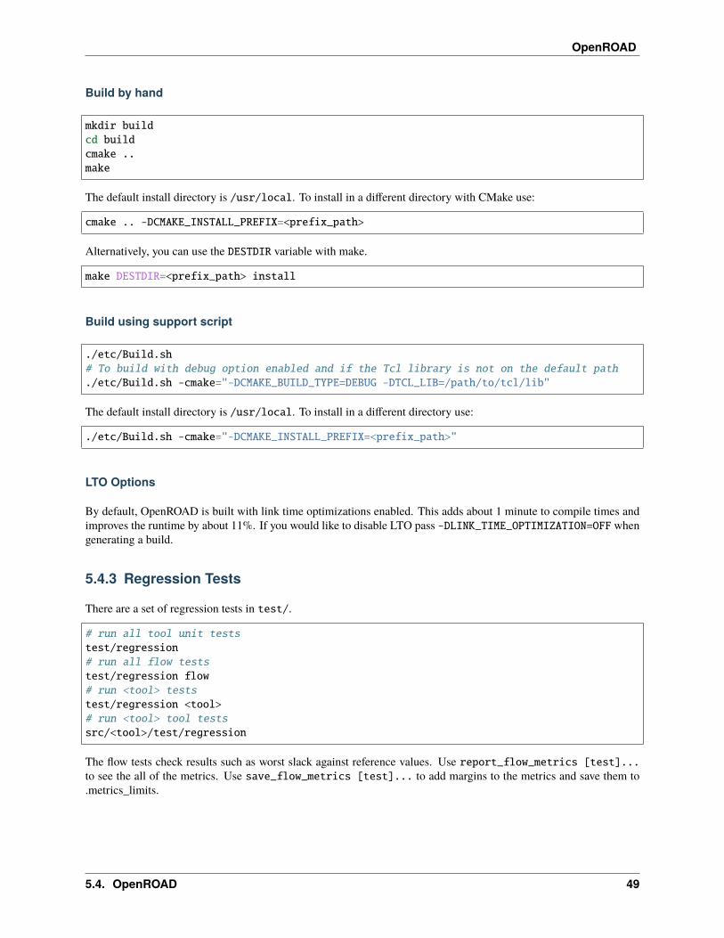
Build by hand
mkdir buildcd buildcmake ..make
The default install directory is /usr/local. To install in a different directory with CMake use:
cmake .. -DCMAKE_INSTALL_PREFIX=<prefix_path>
Alternatively, you can use the DESTDIR variable with make.
make DESTDIR=<prefix_path> install
Build using support script
./etc/Build.sh# To build with debug option enabled and if the Tcl library is not on the default path./etc/Build.sh -cmake="-DCMAKE_BUILD_TYPE=DEBUG -DTCL_LIB=/path/to/tcl/lib"
The default install directory is /usr/local. To install in a different directory use:
./etc/Build.sh -cmake="-DCMAKE_INSTALL_PREFIX=<prefix_path>"
LTO Options
By default, OpenROAD is built with link time optimizations enabled. This adds about 1 minute to compile times andimproves the runtime by about 11%. If you would like to disable LTO pass -DLINK_TIME_OPTIMIZATION=OFF whengenerating a build.
5.4.3 Regression Tests
There are a set of regression tests in test/.
# run all tool unit teststest/regression# run all flow teststest/regression flow# run <tool> teststest/regression <tool># run <tool> tool testssrc/<tool>/test/regression
The flow tests check results such as worst slack against reference values. Use report_flow_metrics [test]...to see the all of the metrics. Use save_flow_metrics [test]... to add margins to the metrics and save them to.metrics_limits.
5.4. OpenROAD 49

OpenROAD
% report_flow_metrics gcd_nangate45insts area util slack_min slack_max tns_max clk_skew max_slew␣
→˓max_cap max_fanout DPL ANT drvgcd_nangate45 368 564 8.8 0.112 -0.015 -0.1 0.004 0␣→˓ 0 0 0 0 0
5.4.4 Run
openroad [-help] [-version] [-no_init] [-exit] [-gui][-threads count|max] [-log file_name] cmd_file
-help show help and exit-version show version and exit-no_init do not read .openroad init file-threads count|max use count threads-no_splash do not show the license splash at startup-exit exit after reading cmd_file-gui start in gui mode-python start with python interpreter [limited to db operations]-log <file_name> write a log in <file_name>cmd_file source cmd_file
OpenROAD sources the Tcl command file ~/.openroad unless the command line option -no_init is specified.
OpenROAD then sources the command file cmd_file if it is specified on the command line. Unless the -exit com-mand line flag is specified it enters and interactive Tcl command interpreter.
Below is a list of the available tools/modules included in the OpenROAD app.
OpenROAD (global commands)
• OpenROAD
Database
• OpenDB
Parasitics Extraction
• OpenRCX
Synthesis
• Restructure
50 Chapter 5. Site Map

OpenROAD
Initialize Floorplan
• Floorplan
Pin placement
• ioPlacer
Chip level connections
• ICeWall
Macro Placement
• TritonMacroPlacer
Tapcell
• Tapcell
PDN analysis
• PDN
• PDNSim
Global Placement
• RePlAce
Timing Analysis
• OpenSTA
Gate Resizer
• Resizer
Detailed Placement
• OpenDP
5.4. OpenROAD 51
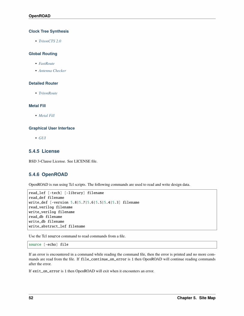
OpenROAD
Clock Tree Synthesis
• TritonCTS 2.0
Global Routing
• FastRoute
• Antenna Checker
Detailed Router
• TritonRoute
Metal Fill
• Metal Fill
Graphical User Interface
• GUI
5.4.5 License
BSD 3-Clause License. See LICENSE file.
5.4.6 OpenROAD
OpenROAD is run using Tcl scripts. The following commands are used to read and write design data.
read_lef [-tech] [-library] filenameread_def filenamewrite_def [-version 5.8|5.7|5.6|5.5|5.4|5.3] filenameread_verilog filenamewrite_verilog filenameread_db filenamewrite_db filenamewrite_abstract_lef filename
Use the Tcl source command to read commands from a file.
source [-echo] file
If an error is encountered in a command while reading the command file, then the error is printed and no more com-mands are read from the file. If file_continue_on_error is 1 then OpenROAD will continue reading commandsafter the error.
If exit_on_error is 1 then OpenROAD will exit when it encounters an error.
52 Chapter 5. Site Map
OpenROAD
OpenROAD can be used to make a OpenDB database from LEF/DEF, or Verilog (flat or hierarchical). Once thedatabase is made it can be saved as a file with the write_db command. OpenROAD can then read the database withthe read_db command without reading LEF/DEF or Verilog.
The read_lef and read_def commands can be used to build an OpenDB database as shown below. The read_lef-tech flag reads the technology portion of a LEF file. The read_lef -library flag reads the MACROs in the LEFfile. If neither of the -tech and -library flags are specified they default to -tech -library if no technology hasbeen read and -library if a technology exists in the database.
read_lef liberty1.lefread_def reg1.def# Write the db for future runs.write_db reg1.db
The read_verilog command is used to build an OpenDB database as shown below. Multiple Verilog files for ahierarchical design can be read. The link_design command is used to flatten the design and make a database.
read_lef liberty1.lefread_verilog reg1.vlink_design top# Write the db for future runs.write_db reg1.db
Example scripts
Example scripts demonstrating how to run OpenROAD on sample designs can be found in /test. Flow tests takingsample designs from synthesizable RTL Verilog to detail-routed final layout in the open-source technologies Nangate45and Sky130HD are shown below.
gcd_nangate45.tclaes_nangate45.tcltinyRocket_nangate45.tclgcd_sky130hd.tclaes_sky130hd.tclibex_sky130hd.tcl
Each of these designs use the common script flow.tcl.
Abstract LEF Support
OpenROAD contains an abstract LEF writer that can take your current design and emit an abstract LEF representingthe external pins of your design and metal obstructions.
read reg1.dbwrite_abstract_lef reg1_abstract.lef
5.4. OpenROAD 53
OpenROAD
Limitations of the Abstract LEF Writer
Currently the writer will place an obstruction over the entire block area on any metal layer if there is any object on thatmetal layer.
TCL functions
Get the die and core areas as a list in microns: llx lly urx ury
ord::get_die_areaord::get_core_area
FAQs
Check out GitHub discussion about this tool.
License
BSD 3-Clause License.
5.4.7 OpenDB
OpenDB is a design database to support tools for physical chip design. It was originally developed by Athena DesignSystems. Nefelus, Inc. acquired the rights to the code and open-sourced it with BSD-3 license in 2019 to support theDARPA OpenROAD project.
The structure of OpenDB is based on the Cadence Design Systems text file formats LEF (library) and DEF (design)formats version 5.6. OpenDB supports a binary file format to save and load the design much faster than using LEF andDEF.
OpenDB is written in C++ 98 with standard library style iterators. The classes are designed to be fast enough to basean application on without having to copy them into application-specific structures.
Directory structure
include/odb/db.h - public header for all database classessrc/db - private/internal database representationssrc/lefin - LEF readersrc/lefout - LEF writersrc/defin - DEF readersrc/defout - DEF writer
54 Chapter 5. Site Map
OpenROAD
Database API
We are still working on documenting the APIs. We have over 1,800 objects and functions that we are still documenting(for both TCL and Python). Contributions are very welcome in this effort. Find starting points below.
TCL
After building successfully, run OpenDB Tcl shell using ./build/src/swig/tcl/opendbtcl. An example usage:
set db [dbDatabase_create]set lef_parser [new_lefin $db true]set tech [lefin_createTech $lef_parser ./src/odb/test/data/gscl45nm.lef]
You can find examples on using the API from Tcl under test/tcl/ directory.
The full set of the Tcl commands exposed can be found under ./build/src/swig/tcl/opendb_wrapper.cpp.Search for SWIG_prefix.
Python
After building successfully, run openroad -python to enable the Python interpreter. You can find examples on usingthe API from Python under test/python/ directory.
To list the full set of the Python classes exposed run openroad -python then:
import openroadimport odbprint(', '.join(dir(openroad)))print(', '.join(dir(odb)))
C++
All public database classes are defined in db.h. These class definitions provide all functions for examining and modi-fying the database objects. The database is an object itself, so multiple database objects can exist simultaneously (noglobal state).
dbTypes.h defines types returned by database class member functions.
All database objects are in the odb namespace.
• dbChip
• dbBlock
• dbTech
• dbLib
All database objects have a 32bit object identifier accessed with the dbObject::getOID base class member functionthat returns a uint. This identifier is preserved across save/restores of the database so it should be used to referencedatabase object by data structures instead of pointers if the reference lifetime is across database save/restores. OIDsallow the database to have exactly the same layout across save/restores.
The database distance units are nanometers and use the type uint.
5.4. OpenROAD 55
OpenROAD
Example scripts
Regression tests
There are a set of regression tests in /test.
./test/regression-tcl.sh
./test/regression-py.sh
Database Internals
The internal description included here is paraphrased from Lukas van Ginneken by James Cherry.
The database separates the implementation from the interface, and as a result, each class becomes two classes, a publicone and a private one. For instance, dbInst has the public API functions, while class _dbInst has the private datafields.
The objects are allocated in dynamically resizable tables, the implementation of which is in dbTable.hpp. Each tableconsists of a number of pages, each containing 128 objects. The table contains the body of the struct, not a set ofpointers. This eliminates most of the pointer overhead while iteration is accomplished by stepping through the table.Thus, grouping these objects does not require a doubly-linked list and saves 16 bytes per object (at the cost of sometable overhead). Each object has an id, which is the index into the table. The lowest 7 bits are the index in the page,while the higher bits are the page number. Object id’s are persistent when saving and reading the data model to disk,even as pointer addresses may change.
Everything in the data model can be stored on disk and restored from disk exactly the way it was. An extensive setof equality tests and diff functions make it possible to check for even the smallest deviation. The capability to savean exact copy of the state of the system makes it possible to create a checkpoint. This is a necessary capability fordebugging complex systems.
The code follows the definition of LEF and DEF closely and reflects many of the idiosyncrasies of LEF and DEF. Thecode defines many types of objects to reflect LEF and DEF constructs although it sometimes uses different terminology,for instance, the object to represent a library cell is called dbMaster while the LEF keyword is MACRO.
The data model supports the EEQ and LEQ keywords (i.e., electrically equivalent and logically equivalent Masters),which could be useful for sizing. However, it does not support any logic function representation. In general, there isvery limited support for synthesis-specific information: no way to represent busses, no way to represent logic function,very limited understanding of signal flow, limited support of timing information, and no support for high level synthesisor test insertion.
The db represents routing as in DEF, representing a trace from point to point with a given width. The layout for a netis stored in a class named dbWire and it requires a special dbWireDecoder (which works like an iterator) to unpackthe data and another dbWireEncoder to pack it. The data model does not support a region query and objects that arein the same layer are scattered about the data model and are of different classes.
This means that whatever tool is using the layout information will have to build its own data structures that are suitableto the layout operations of that tool. For instance, the router, the extractor, and the DRC engine would each have tobuild their unique data structures. This encourages batch mode operation (route the whole chip, extract the whole chip,run DRC on the whole chip).
56 Chapter 5. Site Map
OpenROAD
Limitations
FAQs
Check out GitHub discussion about this tool.
LICENSE
BSD 3-Clause License. See LICENSE file.
Automatic Code Generator
This is an automatic code generation tool for OpenDB objects and Iterators. To test the tool you can use the followingcommand
python3 gen.py --json schema.json --src_dir ../db --include_dir ../../include/odb --impl␣→˓impl
Where schema.json is the json file that includes the requirements, src is the source files directory, include is the includedirectory, and impl is the directory including the jinja templates for the classes.
Python Unit Tests
Running tests
For running the python unit tests you will need to install first testtools and unittest-parallel which enables concurrentunit testing
pip3 install testtoolspip3 install unittest-parallel
Then, you can run the unit tests in sequence by running
../unitTests.sh
or in parallel by running
../unitTests.sh parallel
Note: The test cases within each Unit Test run in parallel in both situations
5.4. OpenROAD 57
OpenROAD
Tests Structure
The directory unitTestsPython includes unit tests for OpenDB Python APIs. Any test file starts with ‘Test’ followed bythe test target.
odbUnitTest.py:
This includes TestCase class which inherits from unittest.TestCase with additional functionalities:
• changeAndTest(self,obj,SetterName,GetterName,expectedVal,*args)which is a function forchanging a value and testing for the effect of that change where:
– obj is the object to be tested
– SetterName is the name of the function to be called for changing a value
– GetterName is the name of the function to be called for testing the effect
– expectedVal is the expected value for the testing
– *args are the arguments passed to the SetterName function
So, in the end, the expected behavior is:
obj.SetterName(*args)
assert(obj.GetterName()==expectedVal)
• check(self,obj,GetterName,expectedVal,*args) which tests against expected value
• change(self,obj,SetterName,*args) which changes a value in the object
• main() runs the TestCase in sequential order
• mainParallel(Test) runs the passed Test class in parallel
helper.py:
A set of functions for creating simple db instances to be used for testing. You can find the description of each functionin the comments
TestNet.py:
Unit test class for testing dbNet. It inherits from odbUnitTest.TestCase . it consists of
• setUp(self) function to be called before each test case. Here, we create the database with the desired chip,block, masters, instances and nets.
• tearDown(self) function to be called after each test case. Here, we destroy our db.
• test_*(self) the test cases functions. Their names should start with test for the unittest suite to recognize.
58 Chapter 5. Site Map

OpenROAD
TestDestroy.py:
Integration test class for testing the destroy(*args) function on OpenDB.
• test_destroy_net destroying net and testing for the effect on the block,inst, iterms and bterms
• test_destroy_inst destroying instance and testing for the effect on block, iterms, net, bterms
• test_destroy_bterm destroying bterm and testing for the effect on block and net
• test_destroy_block destroying block and testing for the effect on block(parent and child relation), and chip
• test_destroy_bpin destroying bpin and testing for the effect on bterm
• test_create_destroy_wire destroying wire and test for the effect on net
• test_destroy_capnode destroying capnode and test for the effect on net(node and connected ccsegs)
• test_destroy_ccseg destroying ccseg and test for the effect on node,block and net
• test_destroy_lib destroying lib and test for the effect on db
• test_destroy_obstruction destroying obstruction and test for the effect on block
• test_create_regions creating regions and test for the effect on block and region(parent and child relation)
• test_destroy_region_child destroying _ and test for the effect on block and region(parent)
• test_destroy_region_parent destroying _ and test for the effect on block
TestBlock.py:
Unit Test for dbBlock
• test_find testing the find function with BTerm, Child, Inst, Net, ITerm, ExtCornerBlock, nonDefaultRule,Region
• Testing the ComputeBBox() function through the first call of getBBox:
– test_bbox0 testing empty block box
– test_bbox1 testing block box with Inst placed
– test_bbox2 testing block box with Inst and BPin placed
– test_bbox3 testing block box with Inst, BPin and Obstruction placed
– test_bbox3 testing block box with Inst, BPin, Obstruction and SWire placed
TestBTerm.py:
Unit Test for dbBTerm
• test_idle testing for idle disconnected BTerm behavior
• test_connect testing connect function of BTerm on BTerm and Net
• test_disconnect testing disconnect function of BTerm on BTerm and Net
5.4. OpenROAD 59

OpenROAD
TestInst.py:
Unit Test for dbInst
• test_swap_master testing swap master function
TestITerm.py:
Unit Test for dbITerm
• test_idle testing for disconnected ITerm without a net
• test_connection_from_iterm testing the connect(ITerm,. . . ) and disconnect functions of ITerm and theireffect on ITerm and Net
• test_connection_from_inst testing the connect(Inst,. . . ) and disconnect functions of ITerm and their effecton ITerm and Net
• Testing for getAvgXY() function
– test_avgxy_R0 testing with default orientation R0
– test_avgxy_R90 testing with different orientation R90 for transformation
Problems Found In Testing
• multiple core dumps that leads to aborting the process:
– dbNet.get1st*() (when nothing on top of the list)
– childRegion.getParent() (after destroying the parent region)
• Implementation of ComputeBBox() is flawed and needs to be reconsidered
Adding new fields in DB Object
For example add_pitchDiag in object DbTechLayer.
60 Chapter 5. Site Map
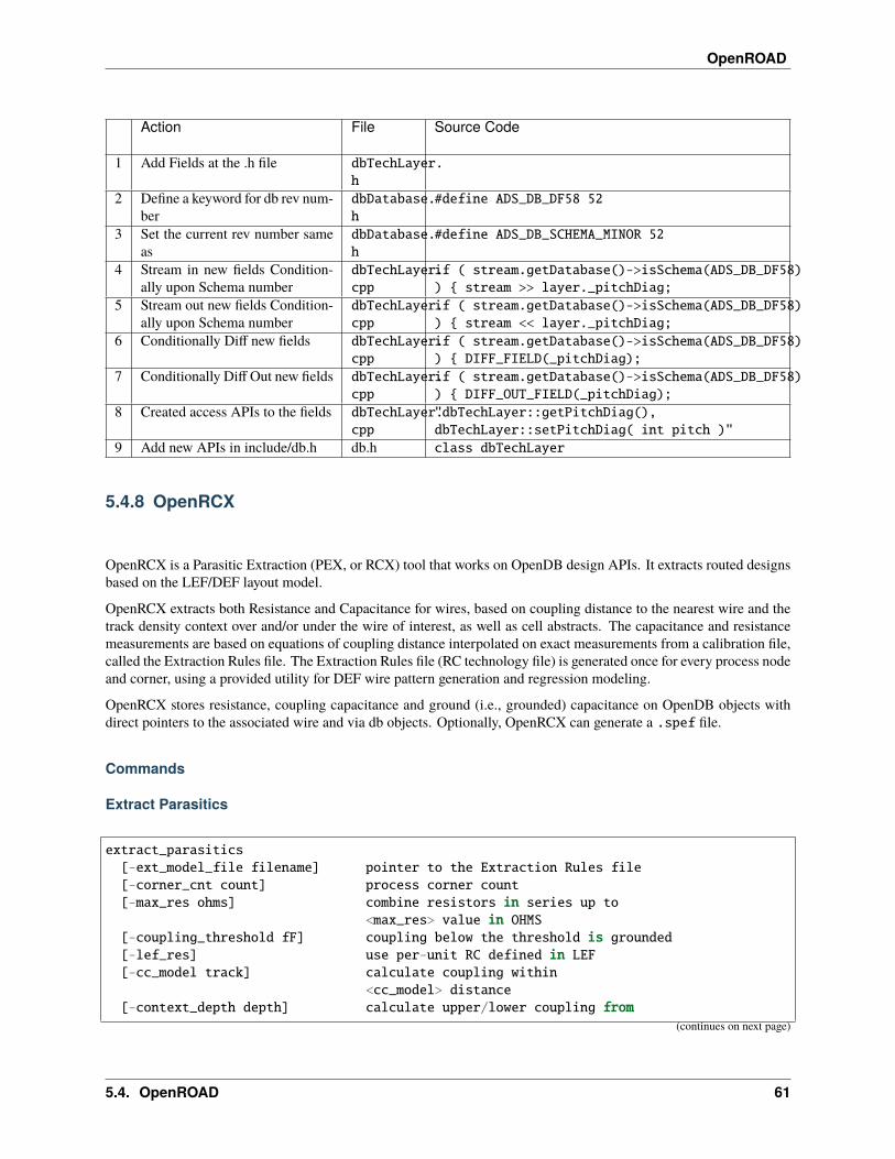
OpenROAD
Action File Source Code
1 Add Fields at the .h file dbTechLayer.h
2 Define a keyword for db rev num-ber
dbDatabase.h
#define ADS_DB_DF58 52
3 Set the current rev number sameas
dbDatabase.h
#define ADS_DB_SCHEMA_MINOR 52
4 Stream in new fields Condition-ally upon Schema number
dbTechLayer.cpp
if ( stream.getDatabase()->isSchema(ADS_DB_DF58)) { stream >> layer._pitchDiag;
5 Stream out new fields Condition-ally upon Schema number
dbTechLayer.cpp
if ( stream.getDatabase()->isSchema(ADS_DB_DF58)) { stream << layer._pitchDiag;
6 Conditionally Diff new fields dbTechLayer.cpp
if ( stream.getDatabase()->isSchema(ADS_DB_DF58)) { DIFF_FIELD(_pitchDiag);
7 Conditionally Diff Out new fields dbTechLayer.cpp
if ( stream.getDatabase()->isSchema(ADS_DB_DF58)) { DIFF_OUT_FIELD(_pitchDiag);
8 Created access APIs to the fields dbTechLayer.cpp
"dbTechLayer::getPitchDiag(),dbTechLayer::setPitchDiag( int pitch )"
9 Add new APIs in include/db.h db.h class dbTechLayer
5.4.8 OpenRCX
OpenRCX is a Parasitic Extraction (PEX, or RCX) tool that works on OpenDB design APIs. It extracts routed designsbased on the LEF/DEF layout model.
OpenRCX extracts both Resistance and Capacitance for wires, based on coupling distance to the nearest wire and thetrack density context over and/or under the wire of interest, as well as cell abstracts. The capacitance and resistancemeasurements are based on equations of coupling distance interpolated on exact measurements from a calibration file,called the Extraction Rules file. The Extraction Rules file (RC technology file) is generated once for every process nodeand corner, using a provided utility for DEF wire pattern generation and regression modeling.
OpenRCX stores resistance, coupling capacitance and ground (i.e., grounded) capacitance on OpenDB objects withdirect pointers to the associated wire and via db objects. Optionally, OpenRCX can generate a .spef file.
Commands
Extract Parasitics
extract_parasitics[-ext_model_file filename] pointer to the Extraction Rules file[-corner_cnt count] process corner count[-max_res ohms] combine resistors in series up to
<max_res> value in OHMS[-coupling_threshold fF] coupling below the threshold is grounded[-lef_res] use per-unit RC defined in LEF[-cc_model track] calculate coupling within
<cc_model> distance[-context_depth depth] calculate upper/lower coupling from
(continues on next page)
5.4. OpenROAD 61
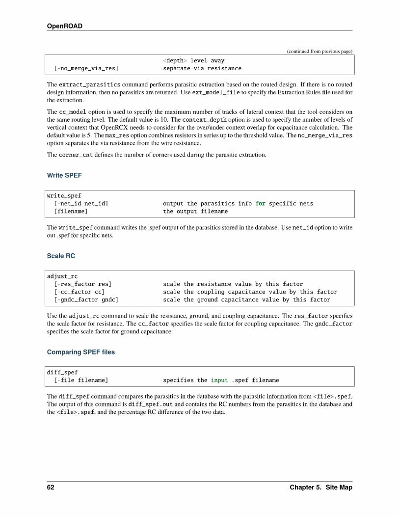
OpenROAD
(continued from previous page)
<depth> level away[-no_merge_via_res] separate via resistance
The extract_parasitics command performs parasitic extraction based on the routed design. If there is no routeddesign information, then no parasitics are returned. Use ext_model_file to specify the Extraction Rules file used forthe extraction.
The cc_model option is used to specify the maximum number of tracks of lateral context that the tool considers onthe same routing level. The default value is 10. The context_depth option is used to specify the number of levels ofvertical context that OpenRCX needs to consider for the over/under context overlap for capacitance calculation. Thedefault value is 5. The max_res option combines resistors in series up to the threshold value. The no_merge_via_resoption separates the via resistance from the wire resistance.
The corner_cnt defines the number of corners used during the parasitic extraction.
Write SPEF
write_spef[-net_id net_id] output the parasitics info for specific nets[filename] the output filename
The write_spef command writes the .spef output of the parasitics stored in the database. Use net_id option to writeout .spef for specific nets.
Scale RC
adjust_rc[-res_factor res] scale the resistance value by this factor[-cc_factor cc] scale the coupling capacitance value by this factor[-gndc_factor gndc] scale the ground capacitance value by this factor
Use the adjust_rc command to scale the resistance, ground, and coupling capacitance. The res_factor specifiesthe scale factor for resistance. The cc_factor specifies the scale factor for coupling capacitance. The gndc_factorspecifies the scale factor for ground capacitance.
Comparing SPEF files
diff_spef[-file filename] specifies the input .spef filename
The diff_spef command compares the parasitics in the database with the parasitic information from <file>.spef.The output of this command is diff_spef.out and contains the RC numbers from the parasitics in the database andthe <file>.spef, and the percentage RC difference of the two data.
62 Chapter 5. Site Map
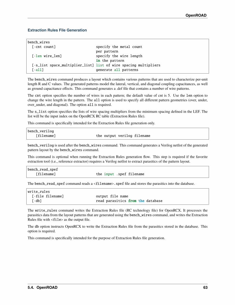
OpenROAD
Extraction Rules File Generation
bench_wires[-cnt count] specify the metal count
per pattern[-len wire_len] specify the wire length
in the pattern[-s_list space_multiplier_list] list of wire spacing multipliers[-all] generate all patterns
The bench_wires command produces a layout which contains various patterns that are used to characterize per-unitlength R and C values. The generated patterns model the lateral, vertical, and diagonal coupling capacitances, as wellas ground capacitance effects. This command generates a .def file that contains a number of wire patterns.
The cnt option specifies the number of wires in each pattern; the default value of cnt is 5. Use the len option tochange the wire length in the pattern. The all option is used to specify all different pattern geometries (over, under,over_under, and diagonal). The option all is required.
The s_list option specifies the lists of wire spacing multipliers from the minimum spacing defined in the LEF. Thelist will be the input index on the OpenRCX RC table (Extraction Rules file).
This command is specifically intended for the Extraction Rules file generation only.
bench_verilog[filename] the output verilog filename
bench_verilog is used after the bench_wires command. This command generates a Verilog netlist of the generatedpattern layout by the bench_wires command.
This command is optional when running the Extraction Rules generation flow. This step is required if the favoriteextraction tool (i.e., reference extractor) requires a Verilog netlist to extract parasitics of the pattern layout.
bench_read_spef[filename] the input .spef filename
The bench_read_spef command reads a <filename>.spef file and stores the parasitics into the database.
write_rules[-file filename] output file name[-db] read parasitics from the database
The write_rules command writes the Extraction Rules file (RC technology file) for OpenRCX. It processes theparasitics data from the layout patterns that are generated using the bench_wires command, and writes the ExtractionRules file with <file> as the output file.
The db option instructs OpenRCX to write the Extraction Rules file from the parasitics stored in the database. Thisoption is required.
This command is specifically intended for the purpose of Extraction Rules file generation.
5.4. OpenROAD 63
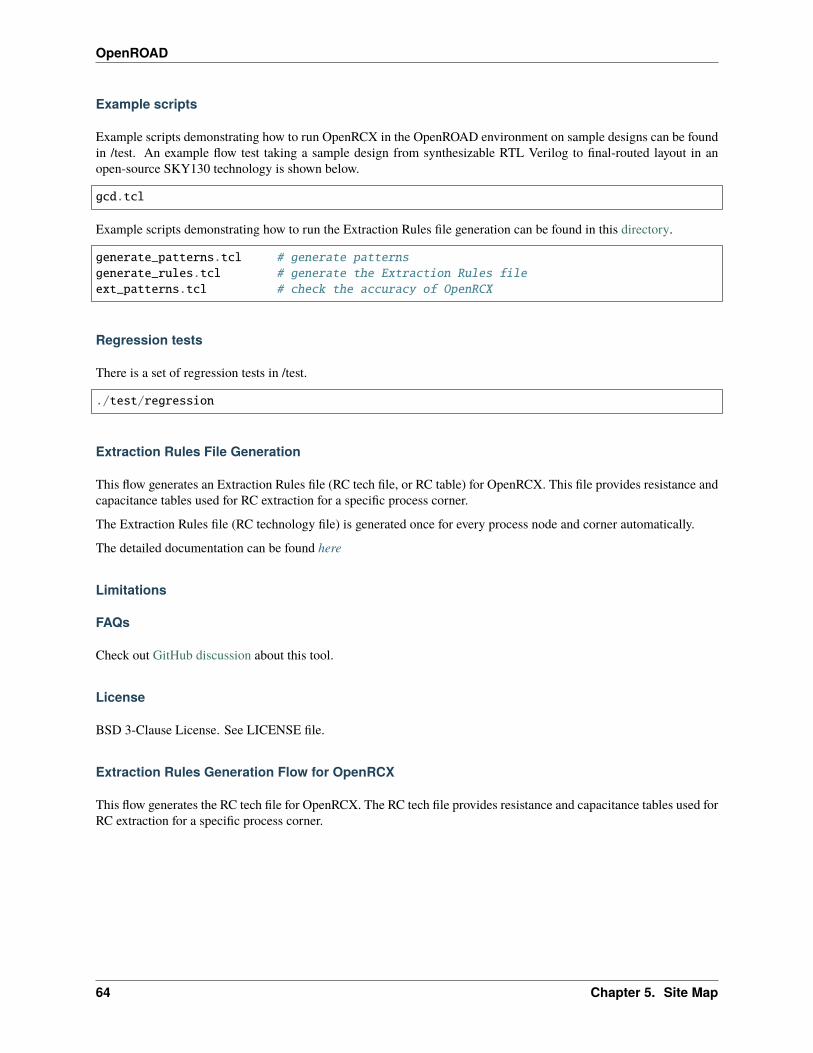
OpenROAD
Example scripts
Example scripts demonstrating how to run OpenRCX in the OpenROAD environment on sample designs can be foundin /test. An example flow test taking a sample design from synthesizable RTL Verilog to final-routed layout in anopen-source SKY130 technology is shown below.
gcd.tcl
Example scripts demonstrating how to run the Extraction Rules file generation can be found in this directory.
generate_patterns.tcl # generate patternsgenerate_rules.tcl # generate the Extraction Rules fileext_patterns.tcl # check the accuracy of OpenRCX
Regression tests
There is a set of regression tests in /test.
./test/regression
Extraction Rules File Generation
This flow generates an Extraction Rules file (RC tech file, or RC table) for OpenRCX. This file provides resistance andcapacitance tables used for RC extraction for a specific process corner.
The Extraction Rules file (RC technology file) is generated once for every process node and corner automatically.
The detailed documentation can be found here
Limitations
FAQs
Check out GitHub discussion about this tool.
License
BSD 3-Clause License. See LICENSE file.
Extraction Rules Generation Flow for OpenRCX
This flow generates the RC tech file for OpenRCX. The RC tech file provides resistance and capacitance tables used forRC extraction for a specific process corner.
64 Chapter 5. Site Map

OpenROAD
The flow involves:
A. Running OpenRCX generate_patterns.tcl to generate layout patterns.
• Input: tech LEF
• Output: patterns.def, patterns.v
• Script: generate_patterns.tcl
• Desc: OpenRCX generates many pattern geometries to model various types of capacitance and resistance (i.e.,multi-conductor) geometric configurations.
B. Running your favorite extraction tool (i.e., reference extractor) to extract parasitics of the layout patterns.
• Input: patterns.def, patterns.v (if required), and additional files required by the reference extractor.
• Output: patterns.spef
• Script: Not provided
• Desc: Extract parasitics of the patterns generated by OpenRCX using a reference extractor. This one-time stepprovides the parasitics of various types of pattern geometries as reference for fitted per-unit length R, C calcula-tion.
C. Running OpenRCX to convert patterns.spef to RC tech file.
• Input: patterns.spef
• Output: RC tech file
• Script: generate_rules.tcl
• Desc: OpenRCX takes the .spef from the reference extractor and performs calculations to produce capacitanceand resistance tables for a wide range of wire geometries. The output of this flow is a custom RC tech file forOpenRCX.
D. Benchmarking - test the accuracy of OpenRCX on the patterns layout.
• Input: patterns.def and RC tech file
• Output: rcx.spef, diff_spef.out
• Script: ext_patterns.tcl
• Desc: Perform parasitic extraction on pattern layout for the calibration using the generated RC tech file. Open-RCX then compares the extracted parasitics with the golden parasitics that had been extracted by the referenceextractor in Step (B) above.
How to run:
1. Go to OpenRCX home directory (./OpenROAD/src/rcx).
2. cd calibration.
3. Modify the user_env.tcl script in the script directory.
• TECH_LEF: points to the directory of the tech LEF
• PROCESS_NODE: the technology node
• extRules: the name and the location of the OpenRCX tech file
4. Run the executable script run.sh –> run Steps (A) through (D) of the flow above.
• source run.sh or
5.4. OpenROAD 65
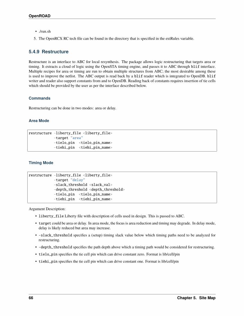
OpenROAD
• ./run.sh
5. The OpenRCX RC tech file can be found in the directory that is specified in the extRules variable.
5.4.9 Restructure
Restructure is an interface to ABC for local resynthesis. The package allows logic restructuring that targets area ortiming. It extracts a cloud of logic using the OpenSTA timing engine, and passes it to ABC through blif interface.Multiple recipes for area or timing are run to obtain multiple structures from ABC; the most desirable among theseis used to improve the netlist. The ABC output is read back by a blif reader which is integrated to OpenDB. blifwriter and reader also support constants from and to OpenDB. Reading back of constants requires insertion of tie cellswhich should be provided by the user as per the interface described below.
Commands
Restructuring can be done in two modes: area or delay.
Area Mode
restructure -liberty_file <liberty_file>-target "area"-tielo_pin <tielo_pin_name>-tiehi_pin <tiehi_pin_name>
Timing Mode
restructure -liberty_file <liberty_file>-target "delay"-slack_threshold <slack_val>-depth_threshold <depth_threshold>-tielo_pin <tielo_pin_name>-tiehi_pin <tiehi_pin_name>
Argument Description:
• liberty_file Liberty file with description of cells used in design. This is passed to ABC.
• target could be area or delay. In area mode, the focus is area reduction and timing may degrade. In delay mode,delay is likely reduced but area may increase.
• -slack_threshold specifies a (setup) timing slack value below which timing paths need to be analyzed forrestructuring.
• -depth_threshold specifies the path depth above which a timing path would be considered for restructuring.
• tielo_pin specifies the tie cell pin which can drive constant zero. Format is lib/cell/pin
• tiehi_pin specifies the tie cell pin which can drive constant one. Format is lib/cell/pin
66 Chapter 5. Site Map

OpenROAD
Example scripts
Regression tests
Limitations
FAQs
Check out GitHub discussion about this tool.
Authors
• Sanjiv Mathur
• Ahmad El Rouby
License
BSD 3-Clause License. See LICENSE file.
5.4.10 Initialize Floorplan
Commands
Initialize Floorplan
initialize_floorplan[-site site_name] LEF site name for ROWS-die_area "lx ly ux uy" die area in microns[-core_area "lx ly ux uy"] core area in microns
or-utilization util utilization (0-100 percent)[-aspect_ratio ratio] height / width, default 1.0[-core_space spaceor "bottom top left right"] space around core, default 0.0 (microns).
Should be either one value for all marginsor 4 values, one for each margin.
The die area and core area used to write ROWs can be specified explicitly with the -die_area and -core_area arguments.Alternatively, the die and core areas can be computed from the design size and utilization as shown below:
core_area = design_area / (utilization / 100)core_width = sqrt(core_area / aspect_ratio)core_height = core_width * aspect_ratiocore = ( core_space_left, core_space_bottom )
( core_space_left + core_width, core_space_bottom + core_height )die = ( 0, 0 )
( core_width + core_space_left + core_space_right,core_height + core_space_bottom + core_space_top )
5.4. OpenROAD 67

OpenROAD
Make Tracks
The initialize_floorplan command removes existing tracks. Use the make_tracks command to add routingtracks to a floorplan.
make_tracks [layer][-x_pitch x_pitch][-y_pitch y_pitch][-x_offset x_offset][-y_offset y_offset]
With no arguments make_tracks adds X and Y tracks for each routing layer. With a -layer argument make_tracksadds X and Y tracks for layer with options to override the LEF technology X and Y pitch and offset.
Place pins around core boundary
auto_place_pins pin_layer_name
This command only allow for pins to be on the same layer. For a more complex pin placement strategy please see thepin placement documentation here.
Example scripts
Regression tests
Limitations
FAQs
Check out GitHub discussion about this tool.
License
BSD 3-Clause License. See LICENSE file.
5.4.11 ioPlacer
Place pins on the boundary of the die on the track grid to minimize net wirelengths. Pin placement also creates a metalshape for each pin using min-area rules.
For designs with unplaced cells, the net wirelength is computed considering the center of the die area as the unplacedcells’ position.
68 Chapter 5. Site Map
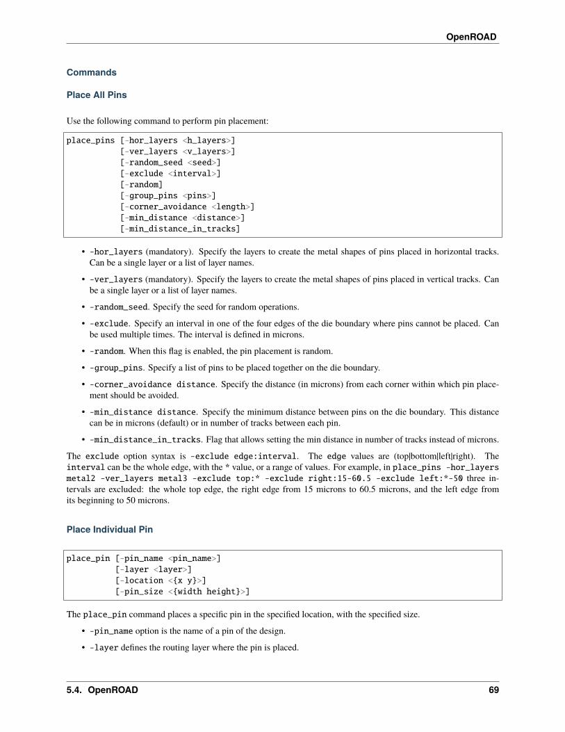
OpenROAD
Commands
Place All Pins
Use the following command to perform pin placement:
place_pins [-hor_layers <h_layers>][-ver_layers <v_layers>][-random_seed <seed>][-exclude <interval>][-random][-group_pins <pins>][-corner_avoidance <length>][-min_distance <distance>][-min_distance_in_tracks]
• -hor_layers (mandatory). Specify the layers to create the metal shapes of pins placed in horizontal tracks.Can be a single layer or a list of layer names.
• -ver_layers (mandatory). Specify the layers to create the metal shapes of pins placed in vertical tracks. Canbe a single layer or a list of layer names.
• -random_seed. Specify the seed for random operations.
• -exclude. Specify an interval in one of the four edges of the die boundary where pins cannot be placed. Canbe used multiple times. The interval is defined in microns.
• -random. When this flag is enabled, the pin placement is random.
• -group_pins. Specify a list of pins to be placed together on the die boundary.
• -corner_avoidance distance. Specify the distance (in microns) from each corner within which pin place-ment should be avoided.
• -min_distance distance. Specify the minimum distance between pins on the die boundary. This distancecan be in microns (default) or in number of tracks between each pin.
• -min_distance_in_tracks. Flag that allows setting the min distance in number of tracks instead of microns.
The exclude option syntax is -exclude edge:interval. The edge values are (top|bottom|left|right). Theinterval can be the whole edge, with the * value, or a range of values. For example, in place_pins -hor_layersmetal2 -ver_layers metal3 -exclude top:* -exclude right:15-60.5 -exclude left:*-50 three in-tervals are excluded: the whole top edge, the right edge from 15 microns to 60.5 microns, and the left edge fromits beginning to 50 microns.
Place Individual Pin
place_pin [-pin_name <pin_name>][-layer <layer>][-location <{x y}>][-pin_size <{width height}>]
The place_pin command places a specific pin in the specified location, with the specified size.
• -pin_name option is the name of a pin of the design.
• -layer defines the routing layer where the pin is placed.
5.4. OpenROAD 69
OpenROAD
• -location defines the center of the pin (in microns).
• -pin_size option defines the width and height of the pin (in microns).
• -force_to_die_boundary. When this flag is enabled, the pin will be snapped to the nearest routing track, nextto the die boundary.
It is recommended that the placement of individual pins be done before the place_pins command, as the routingtracks occupied by these individual pins will be blocked, preventing overlaps.
Pin Constraints
Set IO Pin Constraint
The set_io_pin_constraint command sets region constraints for pins according to the pin direction or the pinname. This command can be called multiple times with different constraints. Only one condition should be used foreach command call.
The -direction argument is the pin direction (input, output, inout, or feedthrough). The -pin_names argument is alist of names. The -region syntax is the same as that of the -exclude syntax.
Note that if you call define_pin_shape_pattern before set_io_pin_constraint, the edge values are (up, top,bottom, left, right). Where up relates to the layer created by define_pin_shape_pattern. To restrict pins to the pinplacement grid defined with define_pin_shape_pattern use:
• -region up:{llx lly urx ury} to restrict the pins into a specific region in the grid. The region is definedin microns.
• -region up:* to restrict the pins into the entire region of the grid.
set_io_pin_constraint -direction <direction>-pin_names <names>-region <edge:interval>
Define Pin Shape Pattern
The define_pin_shape_pattern command defines a pin placement grid on the specified layer. This grid has posi-tions inside the die area, not only at the edges of the die boundary.
define_pin_shape_pattern [-layer <layer>][-x_step <x_step>][-y_step <y_step>][-region <{llx lly urx ury}>][-size <{width height}>][-pin_keepout <dist>]
• The -layer option defines a single top-most routing layer of the placement grid.
• The -region option defines the {llx, lly, urx, ury} region of the placement grid in microns.
• The -x_step and -y_step options define the distance (in microns) between each valid position on the grid, inthe x- and y-directions, respectively.
• The -size option defines the width and height (in microns) of the pins assigned to this grid. The centers of thepins are placed on the grid positions. Pins may have half of their shapes outside the defined region.
70 Chapter 5. Site Map
OpenROAD
• The -pin_keepout option defines the boundary (in microns) around existing routing obstructions that the pinsshould avoid; this defaults to the layer minimum spacing.
Face-to-Face direct-bonding IOs
The define_pin_shape_pattern command can be used to place pins in any metal layer with the minimum allowedspacing to facilitate 3DIC integration of chips using face-to-face packaging technologies. These technologies includemicro bumps and hybrid bonding for high density face-to-face interconnect.
Clear IO Pin Constraints
The clear_io_pin_constraints command clears all the previously-defined constraints and pin shape patterns cre-ated with set_io_pin_constraint or define_pin_shape_pattern.
clear_io_pin_constraints
Pin dimension
Set Pin Length
The set_pin_length command defines the length of all vertical and horizontal pins.
set_pin_length [-hor_length h_length][-ver_length v_length]
• The -hor_length option defines the length (in microns) of the horizontal pins.
• The -ver_length option defines the length (in microns) of the vertical pins.
Set Pin Extension
The set_pin_length_extension command defines the an extension of the length of all vertical and horizontal pins.Note that this command may generate pins partially outside the die area.
set_pin_length_extension [-hor_extension h_extension][-ver_extension v_extension]
• The -hor_extension option defines the extension length (in microns) for the horizontal pins.
• The -ver_extension option defines the extension length (in microns) for the vertical pins.
5.4. OpenROAD 71
OpenROAD
Set Pin Thick Multiplier
The set_pin_thick_multiplier command defines a multiplier for the thickness of all vertical and horizontal pins.
set_pin_thick_multiplier [-hor_multiplier h_mult][-ver_multiplier v_mult]
• The -hor_multiplier option defines the thickness multiplier for the horizontal pins.
• The -ver_multiplier option defines the thickness multiplier for the vertical pins.
Example scripts
Regression tests
Limitations
External references
• This code depends on Munkres.
FAQs
Check out GitHub discussion about this tool.
License
BSD 3-Clause License. See LICENSE file.
5.4.12 Graphical User Interface
The graphical user interface can be access by launching OpenROAD with -gui or by opening it from the command-linewith gui::show.
Commands
Add buttons to the toolbar
create_toolbar_button [-name name]-text button_text-script tcl_script[-echo]
Returns: name of the new button, either name or buttonX.
Options description:
• button_text: The text to put on the button.
• tcl_script: The tcl script to evaluate when the button is pressed.
• name: (optional) name of the button, used when deleting the button.
72 Chapter 5. Site Map
OpenROAD
• echo: (optional) indicate that the commands in the tcl_script should be echoed in the log.
To remove the button:
gui::remove_toolbar_button name
Add items to the menubar
create_menu_item [-name name][-path menu_path]-text item_text-script tcl_script[-shortcut key_shortcut][-echo]
Returns: name of the new item, either name or actionX.
Options description:
• item_text: The text to put on the item.
• tcl_script: The tcl script to evaluate when the button is pressed.
• name: (optional) name of the item, used when deleting the item.
• menu_path: (optional) Menu path to place the new item in (hierarchy is separated by /), defaults to “CustomScripts”, but this can also be “Tools” or “New menu/New submenu”.
• key_shortcut: (optional) key shortcut to trigger this item.
• echo: (optional) indicate that the commands in the tcl_script should be echoed in the log.
To remove the item:
gui::remove_menu_item name
Save screenshot of layout
This command can be both be used when the GUI is active and not active.
save_image [-resolution microns_per_pixel][-area {x0 y0 x1 y1}][-display_option {option value}]filename
Options description:
• filename path to save the image to.
• x0, y0 first corner of the layout area (in microns) to be saved, default is to save what is visible on the screenunless called when gui is not active and then it selected the whole block.
• x1, y1 second corner of the layout area (in microns) to be saved, default is to save what is visible on the screenunless called when gui is not active and then it selected the whole block.
• ``microns_per_pixel` resolution in microns per pixel to use when saving the image, default will match what theGUI has selected.
5.4. OpenROAD 73
OpenROAD
• option specific setting for a display option to show or hide specific elements. For example, to hide metal1-display_option {Layers/metal1 false}, to show routing tracks -display_option {Tracks/Preftrue}, or to show everthing -display_option {* true}.
Selecting objects
select -type object_type[-name glob_pattern][-case_insensitive][-highlight group]
Returns: number of objects selected.
Options description:
• object_type: name of the object type. For example, Inst for instances, Net for nets, and DRC for DRCviolations.
• glob_pattern: (optional) filter selection by the specified name. For example, to only select clk nets *clk*.Use -case_insensitive to filter based on case insensitive instead of case sensitive.
• group: (optional) add the selection to the specific highlighting group. Values can be 0 to 7.
Displaying timing cones
display_timing_cone pin[-fanin][-fanout][-off]
Options description:
• pin: name of the instance or block pin.
• fanin: (optional) display the fanin timing cone.
• fanout: (optional) display the fanout timing cone.
• off: (optional) remove the timing cone.
Limit drawing to specific nets
focus_net net[-remove][-clear]
Options description:
• pin: name of the net.
• remove: (optional) removes the net from from the focus.
• clear: (optional) clears all nets from focus.
74 Chapter 5. Site Map
OpenROAD
TCL functions
Support
Determine is the GUI is active:
gui::enabled
Announce to the GUI that a design was loaded (note: this is only needed when the design was loaded through the odbAPI and not via read_def or read_db):
gui::design_created
To load the results of a DRC report:
gui::load_drc filename
Opening and closing
To open the GUI from the command-line (this command does not return until the GUI is closed):
gui::showgui::show scriptgui::show script interactive
Options description:
• script TCL script to evaluate in the GUI.
• interactive indicates if true the GUI should open in an interactive session (default), or if false that the GUIwould execute the script and return to the terminal.
To close the GUI and return to the command-line:
gui::hide
Layout navigation
To fit the whole layout in the window:
gui::fit
To zoom in our out to a specific region:
gui::zoom_to x0 y0 x1 y1
Options description:
• x0, y0 first corner of the layout area in microns.
• x1, y1 second corner of the layout area in microns.
To zoom in the layout:
5.4. OpenROAD 75
OpenROAD
gui::zoom_ingui::zoom_in x y
Options description:
• x, y new center of layout.
To zoom out the layout:
gui::zoom_outgui::zoom_out x y
Options description:
• x, y new center of layout.
To move the layout to new area:
gui::center_at x y
Options description:
• x, y new center of layout.
To change the resolution to a specific value:
gui::set_resolution resolution
Options description:
• resolution database units per pixel.
Selections
To add a single net to the selected items:
gui::selection_add_net name
Options description:
• name name of the net to add.
To add several nets to the selected items:
gui::selection_add_nets name_regex
Options description:
• name_regex regular expression of the net names to add.
To add a single instance to the selected items:
gui::selection_add_inst name
Options description:
• name name of the instance to add.
To add several instances to the selected items:
76 Chapter 5. Site Map
OpenROAD
gui::selection_add_insts name_regex
Options description:
• name_regex regular expression of the instance names to add.
To add items at a specific point or in an area:
gui::select_at x ygui::select_at x y appendgui::select_at x0 y0 x1 y1gui::select_at x0 y0 x1 y1 append
Options description:
• x, y point in the layout area in microns.
• x0, y0 first corner of the layout area in microns.
• x1, y1 second corner of the layout area in microns.
• append if true (the default value) append the new selections to the current selection list, else replace the selec-tion list with the new selections.
To navigate through multiple selected items:
gui::select_nextgui::select_previous
Returns: current index of the selected item.
To clear the current set of selected items:
gui::clear_selections
To get the properties for the current selection in the Inspector:
gui::get_selection_property name
Options description:
• name name of the property. For example, Type for object type or bbox for the bounding box of the object.
To animate the current selection in the Inspector:
gui::selection_animategui::selection_animate repeat
Options description:
• repeat: indicate how many times the animation should repeat, default value is 0 repeats. If the value is 0, theanimation will repeat indefinitely.
5.4. OpenROAD 77

OpenROAD
Highlighting
To highlight a net:
gui::highlight_net namegui::highlight_net name highlight_group
Options description:
• name name of the net to highlight.
• highlight_group group to add the highlighted net to, defaults to 0, valid groups are 0 - 7.
To highlight an instance:
gui::highlight_inst namegui::highlight_inst name highlight_group
Options description:
• name name of the instance to highlight.
• highlight_group group to add the highlighted instance to, defaults to 0, valid groups are 0 - 7.
To clear the highlight groups:
gui::clear_highlightsgui::clear_highlights highlight_group
Options description:
• highlight_group group to clear, defaults to 0, valid groups are -1 - 7. Use -1 to clear all groups.
Rulers
To add a ruler to the layout:
1. either press k and use the mouse to place it visually. To disable snapping for the ruler when adding, hold theCtrl key, and to allow non-horizontal or vertical snapping when completing the ruler hold the Shift key.
2. or use the command:
gui::add_ruler x0 y0 x1 y1gui::add_ruler x0 y0 x1 y1 labelgui::add_ruler x0 y0 x1 y1 label name
Returns: name of the newly created ruler.
Options description:
• x0, y0 first end point of the ruler in microns.
• x1, y1 second end point of the ruler in microns.
• label text label for the ruler.
• name name of the ruler.
To remove a single ruler:
78 Chapter 5. Site Map
OpenROAD
gui::delete_ruler name
Options description:
• name name of the ruler.
To remove all the rulers:
gui::clear_rulers
Heat Maps
The currently availble heat maps are:
• Power
• Routing
• Placement
• IRDrop
To control the settings in the heat maps:
gui::set_heatmap name optiongui::set_heatmap name option value
Options description:
• name is the name of the heatmap.
• option is the name of the option to modify. If option is rebuild the map will be destroyed and rebuilt.
• value is the new value for the specified option. This is not used when rebuilding map.
These options can also be modified in the GUI by double-clicking the underlined display control for the heat map.
To save the raw data from the heat maps ins a comma separated value (CSV) format:
gui::dump_heatmap name filename
Options description:
• name is the name of the heatmap.
• filename path to the file to write the data to.
GUI Display Controls
Control the visible and selected elements in the layout:
gui::set_display_controls name display_type value
Options description:
• name is the name of the control. For example, for the power nets option this would be Signals/Power or couldbe Layers/* to set the option for all the layers.
• display_type is either visible or selectable
5.4. OpenROAD 79
OpenROAD
• value is either true or false
To check the visibility or selectability of elements in the layout:
gui::check_display_controls name display_type
Options description:
• name is the name of the control. For example, for the power nets option this would be Signals/Power or couldbe Layers/* to set the option for all the layers.
• display_type is either visible or selectable
When performing a batch operation changing the display controls settings, the following commands can be used tosave the current state of the display controls and restore them at the end.
gui::save_display_controlsgui::restore_display_controls
GUI Controls
To request user input via the GUI:
gui::input_dialog title question
Returns: a string with the input, or empty string if canceled.
Options description:
• title is the title of the input message box.
• question is the text for the message box.
Pause the execution of the script:
gui::pausegui::pause timeout
Options description:
• timeout is specified in milliseconds, if it is not provided the pause will last until the user presses the Continuebutton.
To open or close a specific layout widget:
gui::show_widget namegui::hide_widget name
Options description:
• name of the widget. For example, the display controls would be “Display Control”.
80 Chapter 5. Site Map
OpenROAD
License
BSD 3-Clause License. See LICENSE file.
5.4.13 ICeWall
At the top level of the chip, special padcells are use to connect signals to the external package. Additional commandsare provided to specify the placement of padcells, bondpads and bumps
The definition of the padring is split into three separate parts:
• A library definition which contains additional required information about the IO cells being used
• A package description which details the location of IO cells around the periphery of the design
• A signal mapping file that associates signals in the design with the IO cells placed around the periphery
The separation of the package description from the signal mapping file allows the same IO padring to be reused fordifferent designs, reducing the amount of rework needed.
For more details refer to doc/README.md
ICeWall
Introduction
ICeWall is a utility to place IO cells around the periphery of a design, and associate the IO cells with those present inthe netlist of the design.
Additional data is required to define the IO cells in the library over and above that specified in the LEF description,e.g., to:
• Define the orientation of IO cells on each side.
• Allow different cell types to be used for the same type of signal depending upon which side of the die the IO cellis to be placed on. Technologies that require the POLY layer to be aligned in the same direction across the wholedie require different cell variants for left/right edges and top/bottom edges.
• Define the pins that connect by abutment through the sides of the padcells.
• Define cells that are used as breaker cells around the padring, defining the signals that they break.
• Define the filler cells and corner cells to be used.
In order to allow for a given padring to be reused across multiple designs, the definition of the placement of padcells isdone independently of the signals associated with the IO cells. It is expected that the incoming design will instantiateIO cells for all IO cells that include discrete devices, i.e., including signal IO as well as power/ground pads.
The package data file defines where padcells are to be placed, but the association between the placement and the netlistis not made until the signal mapping file is read in. This separation of placement and netlist information allows thesame IO placement to be reused for multiple designs. A package data file can also be extracted from an existing DEFfile to allow padrings of existing designs to be reused.
The signal mapping file associates signals in the netlist with locations in the padring.
5.4. OpenROAD 81
OpenROAD
Data definitions
ICeWall acts upon the information provided in the data files to produce a padring layout. The required data is splitacross 3 files to allow for the anticipated use models.
Library data
The library data is defined by calling the Footprint library function. This function takes a single argument, which is aTCL dictionary structure that defines the needed definitions of the cells.
The following keys need to be defined in the dictionary:
• types
• connect_by_abutment
• pad_pin_name
• pad_pin_layer
• breakers
• cells
The types entry associates types used in the package data file with cells defined in the cells section, and in additionrequires the definition of the corner cell to be used and the list of pad filler cells to be used, ordered by cell width.
The connect_by_abutment key defines the list of pins on the edges of the IO cells that are connected by abutment informing a ring of these signals around the die. ICeWall will connect these abutted signals together into SPECIAL nets,so that the router will not try to add wiring for these pins.
The pad_pin_name key defines the name of the pin of the IO cell that is connected to the chip package.
The pad_pin_layer key defines the layer that will be used to create a physical pin on the die that is coincident with thelocation of the external connection to the chip package.
The breakers key defines the list of cell types in the types definition that act as signal breakers for the signals thatconnect by abutment.
The cells key defines additional data for each IO cell. Each type defined in the types key must have a matching definitionin the list of cells. Within a cell definition, the following keys may be used:
• cell_name
• orient
• physical_only
• breaks
• signal_type
• power_pad
• ground_pad
• pad_pin_name
82 Chapter 5. Site Map

OpenROAD
Key Descriptioncell_nameCan be either the name of the LEF macro to use, or else a dictionary allowing a different cell name to be
specified for each side of the die. Sides are denoted by bottom, right, top, and left.ori-ent
A dictionary that specifies the orientation of the cell for each side of the die.
phys-i-cal_only
Cells that are not associated with cells in the design, primarily used for physical connections through thepadring.
breaks For breaker cells, defines the abutment signals which are broken by the presence of this cell. Each signalbroken requires a list of pins on the breaker cell for the left and right hand side of the cell. (An empty listmay be provided if there are no pins for the broken signals.)
sig-nal_type
Set to 1 if this cell is to be regarded as a signal type.
power_padOptional. Set to 1 to define this cell as a power pad.ground_padOptional. Set to 1 to define this cell as a ground pad.pad_pin_nameOptional. Define the name of the pin on the macro that connects to the chip package.
TCL Command Reference
Details on the TCL command interface
Package data
As an alternative to using TCL commands, the definition of the padring can be made using a padring strategy file,which allows for batch loading of the padcell data all at once.
For an example of what a padring strategy file looks like, please refer to. . . /test/soc_bsg_black_parrot_nangate45/bsg_black_parrot.package.strategy .
Signal mapping
Assignment of signals to padcells can be done via a signal mapping file. This file consists of multiple lines, with eachline mapping a named padcell to a signal in the design.
For power and ground pads, the same power/ground signal will likely be associated with multiple padcells.
Example
sig132 ddr_dq_10_iosig133 ddr_dq_9_iosig134 ddr_dq_8_iov18_0 DVDD_0v18_1 DVDD_0v18_2 DVDD_0v18_3 DVDD_0
5.4. OpenROAD 83
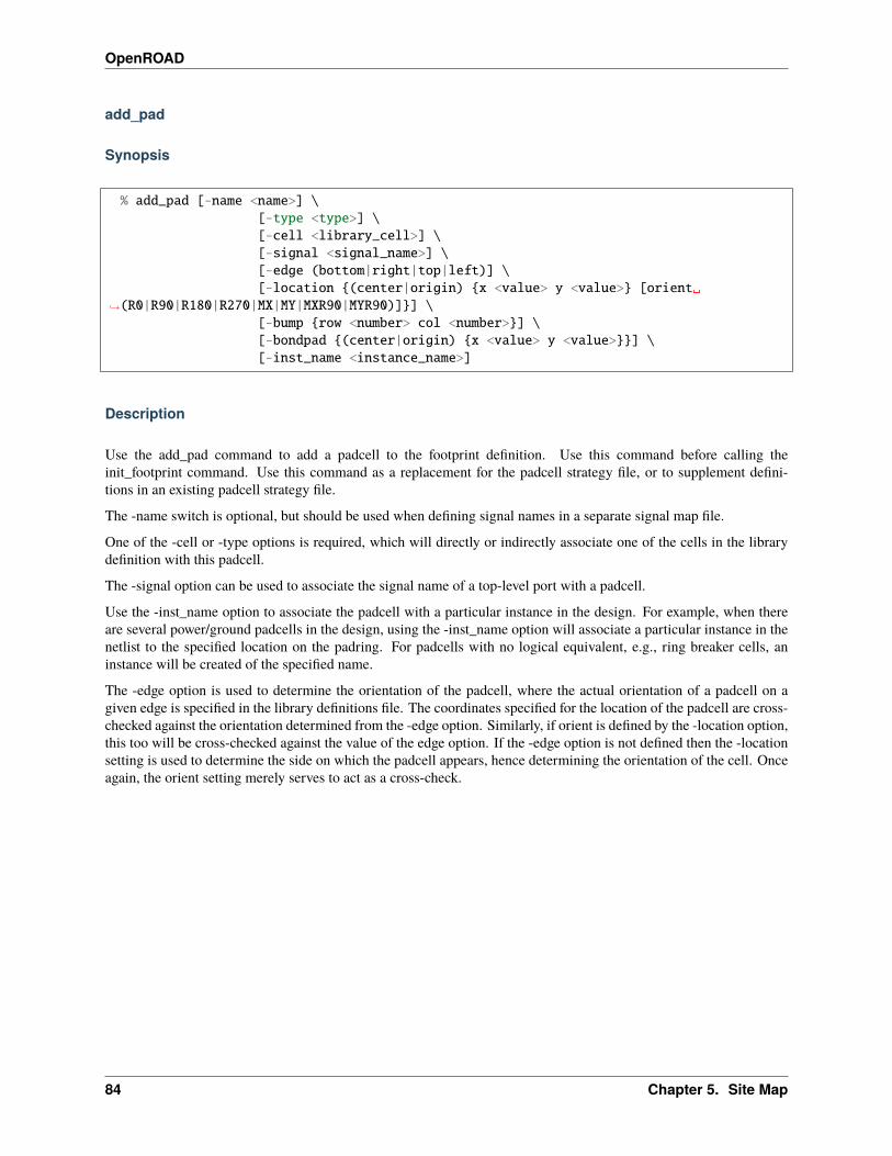
OpenROAD
add_pad
Synopsis
% add_pad [-name <name>] \[-type <type>] \[-cell <library_cell>] \[-signal <signal_name>] \[-edge (bottom|right|top|left)] \[-location {(center|origin) {x <value> y <value>} [orient␣
→˓(R0|R90|R180|R270|MX|MY|MXR90|MYR90)]}] \[-bump {row <number> col <number>}] \[-bondpad {(center|origin) {x <value> y <value>}}] \[-inst_name <instance_name>]
Description
Use the add_pad command to add a padcell to the footprint definition. Use this command before calling theinit_footprint command. Use this command as a replacement for the padcell strategy file, or to supplement defini-tions in an existing padcell strategy file.
The -name switch is optional, but should be used when defining signal names in a separate signal map file.
One of the -cell or -type options is required, which will directly or indirectly associate one of the cells in the librarydefinition with this padcell.
The -signal option can be used to associate the signal name of a top-level port with a padcell.
Use the -inst_name option to associate the padcell with a particular instance in the design. For example, when thereare several power/ground padcells in the design, using the -inst_name option will associate a particular instance in thenetlist to the specified location on the padring. For padcells with no logical equivalent, e.g., ring breaker cells, aninstance will be created of the specified name.
The -edge option is used to determine the orientation of the padcell, where the actual orientation of a padcell on agiven edge is specified in the library definitions file. The coordinates specified for the location of the padcell are cross-checked against the orientation determined from the -edge option. Similarly, if orient is defined by the -location option,this too will be cross-checked against the value of the edge option. If the -edge option is not defined then the -locationsetting is used to determine the side on which the padcell appears, hence determining the orientation of the cell. Onceagain, the orient setting merely serves to act as a cross-check.
84 Chapter 5. Site Map

OpenROAD
Options
Switch_NameDescription-name
Specify the name of the padcell when using a separate signal assignment file. A name is automaticallygenerated if not specified.
-type The type of cell specified in the library data.-cell
-signal
The name of the signal in the design that is connected to the bondpad/bump of the padcell. Except for netswhich have been defined as power or ground nets, only padcell can be associated with a particular signal,and this signal must be a pin at the top level of the design.
-edge Specify which edge of the design the padcell is to be placed on. Valid choices are bottom, right, top or left.-location
Specify the location of the center or origin of the padcell.
-bump
For flipchip designs, declare that the padcell is associated with the bump at the specified row/col locationon the die.
-bondpad
For wirebond designs where the padcells have separate bondpad instances, use this option to specify thelocation of the associated bondpad.
-inst_name
Specify the name of the padcell instance in the design. This takes precedence over the -pad_inst_patternmethod described in the set_padring_options command.
Examples
add_pad -edge bottom -signal p_ddr_dm_2_o -type sig -location→˓{center {x 2742.000 y 105.000}} -bondpad {center {x 2742.000 y 63.293}}
add_pad -edge bottom -inst_name u_vss_0 -signal VSS -type vss -location→˓{center {x 397.000 y 105.000}} -bondpad {center {x 397.000 y 149.893}}
add_pad -edge top -inst_name u_brk0 -type fbk -location→˓{center {x 1587.500 y 2895.000}}
define_pad_cell
Synopsis
% define_pad_cell \[-name name] \[-type cell_type|-fill|-corner|-bump|-bondpad] \[-cell_name cell_names_per_side] \[-orient orientation_per_side] \[-pad_pin_name pad_pin_name] \[-break_signals signal_list] \[-physical_only]
5.4. OpenROAD 85
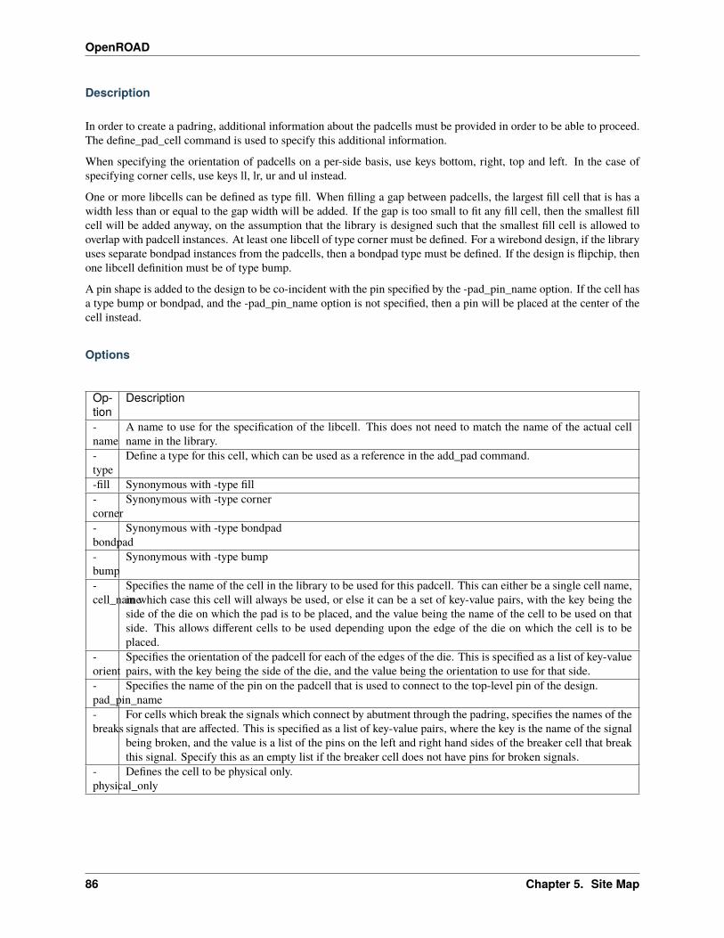
OpenROAD
Description
In order to create a padring, additional information about the padcells must be provided in order to be able to proceed.The define_pad_cell command is used to specify this additional information.
When specifying the orientation of padcells on a per-side basis, use keys bottom, right, top and left. In the case ofspecifying corner cells, use keys ll, lr, ur and ul instead.
One or more libcells can be defined as type fill. When filling a gap between padcells, the largest fill cell that is has awidth less than or equal to the gap width will be added. If the gap is too small to fit any fill cell, then the smallest fillcell will be added anyway, on the assumption that the library is designed such that the smallest fill cell is allowed tooverlap with padcell instances. At least one libcell of type corner must be defined. For a wirebond design, if the libraryuses separate bondpad instances from the padcells, then a bondpad type must be defined. If the design is flipchip, thenone libcell definition must be of type bump.
A pin shape is added to the design to be co-incident with the pin specified by the -pad_pin_name option. If the cell hasa type bump or bondpad, and the -pad_pin_name option is not specified, then a pin will be placed at the center of thecell instead.
Options
Op-tion
Description
-name
A name to use for the specification of the libcell. This does not need to match the name of the actual cellname in the library.
-type
Define a type for this cell, which can be used as a reference in the add_pad command.
-fill Synonymous with -type fill-corner
Synonymous with -type corner
-bondpad
Synonymous with -type bondpad
-bump
Synonymous with -type bump
-cell_name
Specifies the name of the cell in the library to be used for this padcell. This can either be a single cell name,in which case this cell will always be used, or else it can be a set of key-value pairs, with the key being theside of the die on which the pad is to be placed, and the value being the name of the cell to be used on thatside. This allows different cells to be used depending upon the edge of the die on which the cell is to beplaced.
-orient
Specifies the orientation of the padcell for each of the edges of the die. This is specified as a list of key-valuepairs, with the key being the side of the die, and the value being the orientation to use for that side.
-pad_pin_name
Specifies the name of the pin on the padcell that is used to connect to the top-level pin of the design.
-breaks
For cells which break the signals which connect by abutment through the padring, specifies the names of thesignals that are affected. This is specified as a list of key-value pairs, where the key is the name of the signalbeing broken, and the value is a list of the pins on the left and right hand sides of the breaker cell that breakthis signal. Specify this as an empty list if the breaker cell does not have pins for broken signals.
-physical_only
Defines the cell to be physical only.
86 Chapter 5. Site Map
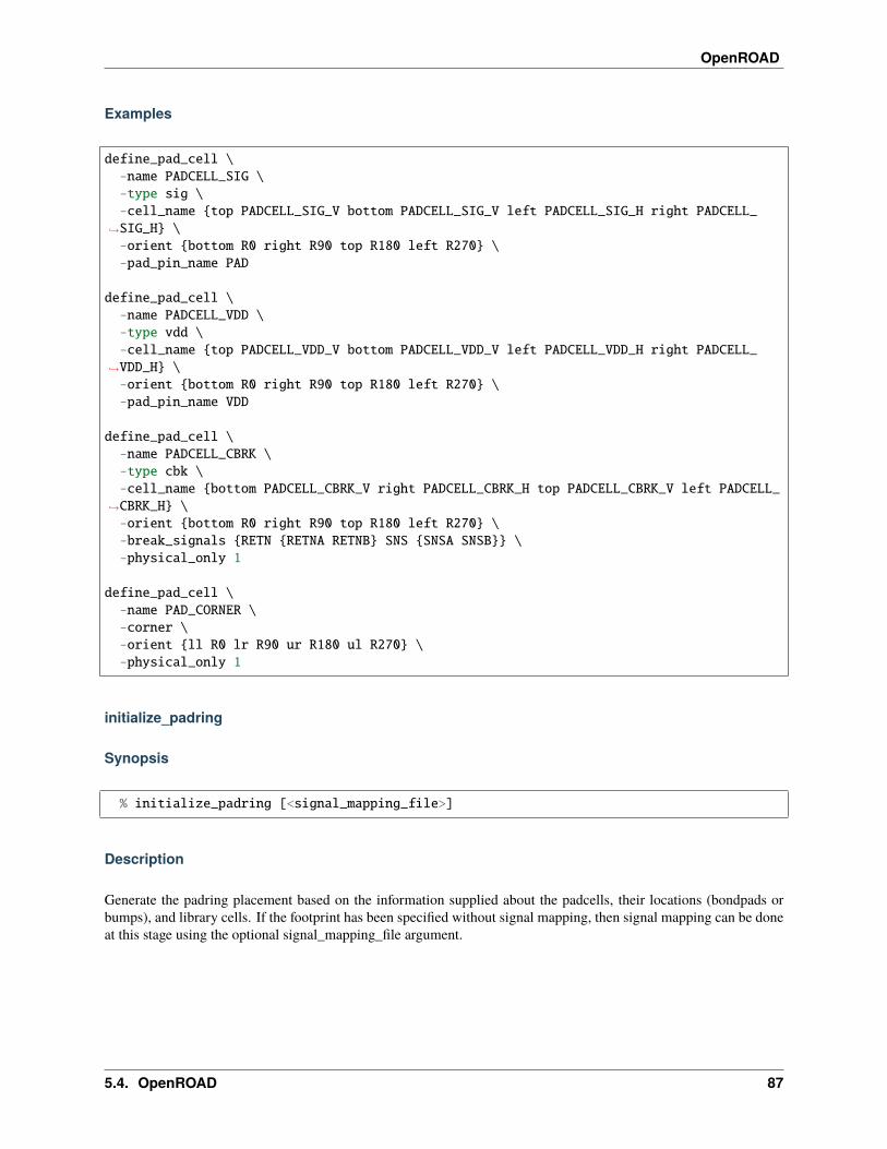
OpenROAD
Examples
define_pad_cell \-name PADCELL_SIG \-type sig \-cell_name {top PADCELL_SIG_V bottom PADCELL_SIG_V left PADCELL_SIG_H right PADCELL_
→˓SIG_H} \-orient {bottom R0 right R90 top R180 left R270} \-pad_pin_name PAD
define_pad_cell \-name PADCELL_VDD \-type vdd \-cell_name {top PADCELL_VDD_V bottom PADCELL_VDD_V left PADCELL_VDD_H right PADCELL_
→˓VDD_H} \-orient {bottom R0 right R90 top R180 left R270} \-pad_pin_name VDD
define_pad_cell \-name PADCELL_CBRK \-type cbk \-cell_name {bottom PADCELL_CBRK_V right PADCELL_CBRK_H top PADCELL_CBRK_V left PADCELL_
→˓CBRK_H} \-orient {bottom R0 right R90 top R180 left R270} \-break_signals {RETN {RETNA RETNB} SNS {SNSA SNSB}} \-physical_only 1
define_pad_cell \-name PAD_CORNER \-corner \-orient {ll R0 lr R90 ur R180 ul R270} \-physical_only 1
initialize_padring
Synopsis
% initialize_padring [<signal_mapping_file>]
Description
Generate the padring placement based on the information supplied about the padcells, their locations (bondpads orbumps), and library cells. If the footprint has been specified without signal mapping, then signal mapping can be doneat this stage using the optional signal_mapping_file argument.
5.4. OpenROAD 87

OpenROAD
Example
initialize_padring soc_bsg_black_parrot_nangate45/soc_bsg_black_parrot.sigmap
place_cell
Synopsis
% place_cell -inst_name <inst_name> \[-cell <library_cell>] \-origin <point>] \-orient (R0|R90|R180|R270|MX|MY|MXR90|MYR90) \[-status (PLACED|FIRM)]
Description
Use the place_cell command to place an instance at a specific location within the design. This can be used to pre-placemarker cells, ESD cells, etc. which have a known, fixed location in the design and should not be moved by the automaticmacro placer.
One of the -inst_name, -origin and -orient options is required. If there is no instance <inst_name> in the netlist of thedesign, then the -cell option is required, and an instance of the specified <library_cell> will be added to the design. Ifan instance <inst_name> does exist in the design and the -cell option is specified, it is an error if the instance in thenetlist does not match the specified <library_cell>.
Options
Switch_NameDescription-inst_name Specify the name of the padcell instance in the design.-name Specify the name of the padcell when using a separate signal assignment file. A name is automatically
generated if not specified.-cell Specify the name of the cell in the library to be added as an instance in the design.-origin Specify the origin of the cell as a point, i.e., a list of two numbers.-orient Specify a valid orientation for the placement of the cell.
Example
place_cell -cell MARKER -inst_name u_marker_0 -origin {1197.5 1199.3} -orient R0 -status␣→˓FIRM
88 Chapter 5. Site Map

OpenROAD
set_bump_options
Synopsis
% set_bump \-row row \-col col \[(-power|-ground|-net) net_name] \[-remove] \
Description
The set_bump command is used to provide additional information about specific bumps in the bump array.
The -row and -col options are required and identify the row and column of a specific bump location in the bump array.The bump in the top left corner of the array is row 1, column 1.
The -net, -power and -ground options are mutually exclusive and are used to specify the name of the net connected toa bump and whether it is of type signal, power or ground.
The -remove option is used to specify that no bump should be placed at the specified position in the bump array.
Options
Option Description-row Specifies the row of a specific bump.-col Specifies the column of a specific bump.-net Specifies the name of the signal net connected to the specified bump.-power Specifies the name of the power net connected to the specified bump.-ground Specifies the name of the ground net connected to the specified bump.-remove Removes the specified bump from the bump array.
Examples
set_bump -row 8 -col 8 -power VDD1
set_bump -row 9 -col 8 -remove
set_bump -row 10 -col 8 -power VDD2
5.4. OpenROAD 89
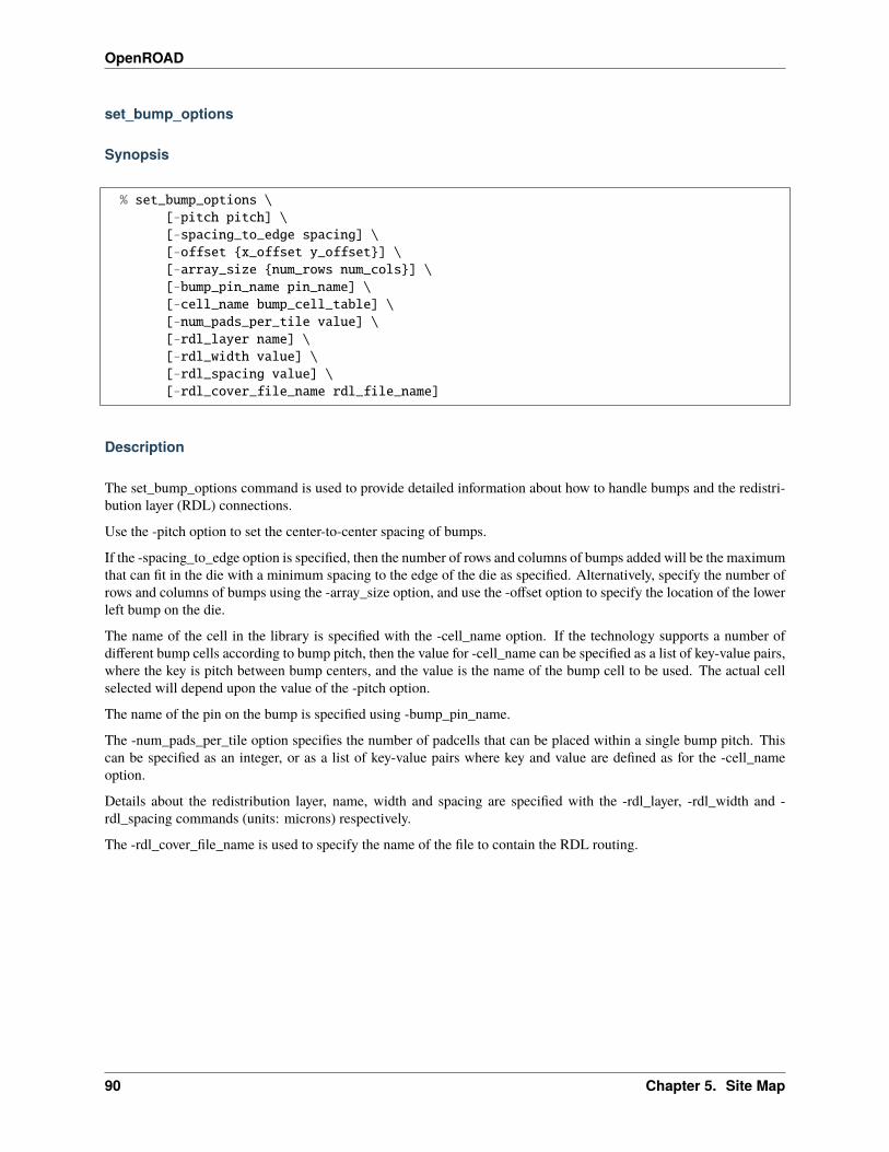
OpenROAD
set_bump_options
Synopsis
% set_bump_options \[-pitch pitch] \[-spacing_to_edge spacing] \[-offset {x_offset y_offset}] \[-array_size {num_rows num_cols}] \[-bump_pin_name pin_name] \[-cell_name bump_cell_table] \[-num_pads_per_tile value] \[-rdl_layer name] \[-rdl_width value] \[-rdl_spacing value] \[-rdl_cover_file_name rdl_file_name]
Description
The set_bump_options command is used to provide detailed information about how to handle bumps and the redistri-bution layer (RDL) connections.
Use the -pitch option to set the center-to-center spacing of bumps.
If the -spacing_to_edge option is specified, then the number of rows and columns of bumps added will be the maximumthat can fit in the die with a minimum spacing to the edge of the die as specified. Alternatively, specify the number ofrows and columns of bumps using the -array_size option, and use the -offset option to specify the location of the lowerleft bump on the die.
The name of the cell in the library is specified with the -cell_name option. If the technology supports a number ofdifferent bump cells according to bump pitch, then the value for -cell_name can be specified as a list of key-value pairs,where the key is pitch between bump centers, and the value is the name of the bump cell to be used. The actual cellselected will depend upon the value of the -pitch option.
The name of the pin on the bump is specified using -bump_pin_name.
The -num_pads_per_tile option specifies the number of padcells that can be placed within a single bump pitch. Thiscan be specified as an integer, or as a list of key-value pairs where key and value are defined as for the -cell_nameoption.
Details about the redistribution layer, name, width and spacing are specified with the -rdl_layer, -rdl_width and -rdl_spacing commands (units: microns) respectively.
The -rdl_cover_file_name is used to specify the name of the file to contain the RDL routing.
90 Chapter 5. Site Map

OpenROAD
Options
Op-tion
Description
-pitch
Specifies the center-to-center spacing of bumps.
-spacing_to_edge
Specifies the spacing from the edge of the die to the edge of the bumps.
-array_size
Specifies the numbers of rows and columns of bumps as a 2-element list.
-offset
Specifies the location of the center of the lower left bump on the die.
-bump_pin_name
Specifies the name of the pin on the bump cell.
-cell_name
Specifies the name of the bump cell, or a list of key-value pairs giving different values of bump cell namewith the value of -pitch used as a key.
-num_pads_per_tile
The maximum number of externally connected padcells placed within a bump pitc.h
-rdl_layer
Name of the redistribution layer.
-rdl_width
The width of the RDL layer to use when connecting bumps to padcells.
-rdl_spacing
The required spacing between RDL wires.
-rdl_cover_file_name
Specifies the name of the file to which the routing of the redistribution layer is to be written. If not specified,the default value is cover.def. In an earlier release, the OpenROAD database did not support 45-degreegeometries used by RDL routing, and this cover.def allowed for the RDL to be added at the end of the flow,without being added to the database. Now that the database will allow 45-degree geometries, this commandwill be deprecated once ICeWall has been modified to write RDL layout directly into the database.
Examples
set_bump_options \-pitch 160 \-bump_pin_name PAD \-spacing_to_edge 165 \-cell_name {140 BUMP_small 150 BUMP_medium 180 BUMP_large} \-num_pads_per_tile 5 \-rdl_layer metal10 \-rdl_width 10 \-rdl_spacing 10
set_bump_options \-pitch 160 \-bump_pin_name PAD \-array_size {17 17} \-offset {210.0 215.0} \-cell_name DUMMY_BUMP \-num_pads_per_tile 5 \
(continues on next page)
5.4. OpenROAD 91

OpenROAD
(continued from previous page)
-rdl_layer metal10 \-rdl_width 10 \-rdl_spacing 10
set_padring_options
Synopsis
% set_padring_options \-type (flipchip|wirebond) \[-power power_nets] \[-ground ground_nets] \[-offsets offsets] \[-pad_inst_pattern pad_inst_pattern] \[-pad_pin_pattern pad_pin_pattern] \[-pin_layer pin_layer_name] \[-connect_by_abutment signal_list] \[-allow_filler_overlap]
Description
This command is used to specify general options used to define the padring for a chip. The -type option is required; allothers are optional.
The -power and -ground options are used to define the external power and ground nets that will be connected to thepads.
The -offsets option is used to define the offset of the edge of the pads from the edge of the die area. This can be specifiedas a single number, in which case the offset is applied to all four sides, or as a list of 2 numbers that are respectivelyapplied to the top/bottom and left/right edges, or as a list of 4 numbers that are respectively applied to the bottom, right,top and left edges.
The -pad_inst_pattern option allows a format string to be used to define a default instance name for the padcell connectedto a top-level pin of the design.
The -pad_pin_pattern option is used to define a pattern that is to be used to derive the actual signal name in the designfrom the signal specified with the add_pad command.
The -connect_by_abutment option is used to define the list of signals that are connected by abutment through thepadring. The placement of breaker cells within the padring can result in these signals being split into a number ofdifferent nets.
The -allow_filler_overlap option allows the smallest filler cell to be inserted into a space which is smaller than its width,resulting in overlaping with padcells. Use this option if you library cells are designed such that the smallest filler cellwill not cause DRC violation when overlapping the edge of the pad cells. By default overlapping filler cells is notallowed.
92 Chapter 5. Site Map

OpenROAD
Options
Option Description-type Specify whether the chip is wirebond or flipchip.-power Define the nets to be used as power nets in the design. It is not required that these nets exist in the design
database; they will be created as necessary. Once a power net is defined, it can be used as the -signalargument for the add_pad command to enable the addition of power pads to the design.
-ground Define the nets to be used as ground nets in the design, it is not required that these nets exist in the designdatabase, they will be created as necessary. Once a ground net is defined, it can be used as the -signalargument for the add_pad command to enable the addition of ground pads to the design.
-core_area
Specify the coordinates, as a list of 4 numbers (in microns), of the chip core. This area is reserved forstdcell placements. Placement of padcells should be made outside this core area, but within the specifieddie area.
-die_area
Specify the coordinates, as a list of 4 numbers (in microns), for the chip die area.
-offsets Specifies the offset, in microns, from the edges of the die area to corresponding edges of the padcells.-pad_inst_pattern
Specify the name of padcell instances based upon the given format string. The format string is expectedto include %s somewhere within the string, which will be replaced by the signal name associated witheach pad instance.
-pad_pin_pattern
Specify the name of the signal to connect to the padcell based upon the given format string. The formatstring is expected to include %s somewhere within the string, which will be replaced by the signal nameassociated with the pad instance.
-pin_layer
Specify the layer which is to be used to create a top level pin over the pin of the padcell. The creation ofa physical pin at this location identifies pin locations for LVS (layout-versus-schematic) verification.
-connect_by_abutment
Specify the list of signals that connect by abutment in the padring. The placement of breaker cells in thepadring will split these signals into separate nets as required.
-allow_filler_overlap
Allow the insertion of the smallest IO filler cell to overlap with padcells. Only use when this is supportedby the IO library you are using.
Examples
set_padring_options \-type wirebond \-power {VDD DVDD_0 DVDD_1} \-ground {VSS DVSS_0 DVSS_1} \-offsets 35 \-pad_inst_pattern "u_%s" \-pad_pin_pattern "p_%s" \-pin_layer metal10 \-connect_by_abutment {SNS RETN DVDD DVSS} \-allow_filler_overlap
5.4. OpenROAD 93

OpenROAD
TCL Commands to build chip level padrings
The following commands can be used from the command prompt to define the padring structure for the chip.
• add_pad
• define_pad_cell
• set_padring_options
• set_bump_options
• set_bump
Once the padcells have been added, the padring can be built using the initialize_padring command.
• initialize_padring
Use the place_cell command to pre-place additional cells in the floorplan.
• place_cell
Full examples of how to use these commands together to build a chip:
• Example for chip with wirebond padring
• Example for chip with flipchip bumps
Alternatively, the information needed to build chip-level padrings can be bundled up into a separate file and loaded inbatch fashion
5.4.14 Macro Placement
ParquetFP-based macro cell placer, “TritonMacroPlacer”. The macro placer places macros/blocks honoring halos,channels and cell row “snapping”. Run global_placement before macro placement.
Approximately ceil((#macros/3)^(3/2)) sets corresponding to quadrisections of the initial placed mixed-size layout areexplored and packed using ParquetFP-based annealing. The best resulting floorplan according to a heuristic evaluationfunction is kept.
Commands
macro_placement [-halo {halo_x halo_y}][-channel {channel_x channel_y}][-fence_region {lx ly ux uy}][-snap_layer snap_layer_number]
• -halo horizontal/vertical halo around macros (microns)
• -channel horizontal/vertical channel width between macros (microns)
• -fence_region - restrict macro placements to a region (microns). Defaults to the core area.
• -snap_layer_number - snap macro origins to this routing layer track
Macros will be placed with max(halo * 2, channel) spacing between macros, and between macros and thefence/die boundary. If no solutions are found, try reducing the channel/halo.
94 Chapter 5. Site Map
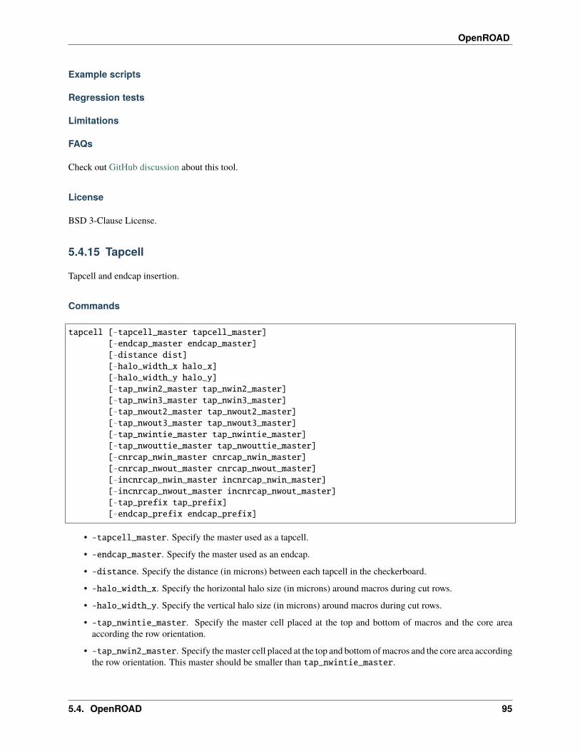
OpenROAD
Example scripts
Regression tests
Limitations
FAQs
Check out GitHub discussion about this tool.
License
BSD 3-Clause License.
5.4.15 Tapcell
Tapcell and endcap insertion.
Commands
tapcell [-tapcell_master tapcell_master][-endcap_master endcap_master][-distance dist][-halo_width_x halo_x][-halo_width_y halo_y][-tap_nwin2_master tap_nwin2_master][-tap_nwin3_master tap_nwin3_master][-tap_nwout2_master tap_nwout2_master][-tap_nwout3_master tap_nwout3_master][-tap_nwintie_master tap_nwintie_master][-tap_nwouttie_master tap_nwouttie_master][-cnrcap_nwin_master cnrcap_nwin_master][-cnrcap_nwout_master cnrcap_nwout_master][-incnrcap_nwin_master incnrcap_nwin_master][-incnrcap_nwout_master incnrcap_nwout_master][-tap_prefix tap_prefix][-endcap_prefix endcap_prefix]
• -tapcell_master. Specify the master used as a tapcell.
• -endcap_master. Specify the master used as an endcap.
• -distance. Specify the distance (in microns) between each tapcell in the checkerboard.
• -halo_width_x. Specify the horizontal halo size (in microns) around macros during cut rows.
• -halo_width_y. Specify the vertical halo size (in microns) around macros during cut rows.
• -tap_nwintie_master. Specify the master cell placed at the top and bottom of macros and the core areaaccording the row orientation.
• -tap_nwin2_master. Specify the master cell placed at the top and bottom of macros and the core area accordingthe row orientation. This master should be smaller than tap_nwintie_master.
5.4. OpenROAD 95
OpenROAD
• -tap_nwin3_master. Specify the master cell placed at the top and bottom of macros and the core area accordingthe row orientation. This master should be smaller than tap_nwin2_master.
• -tap_nwouttie_master. Specify the master cell placed at the top and bottom of macros and the core areaaccording the row orientation.
• -tap_nwout2_master. Specify the master cell placed at the top and bottom of macros and the core area ac-cording the row orientation. This master should be smaller than tap_nwouttie_master.
• -tap_nwout3_master. Specify the master cell placed at the top and bottom of macros and the core area ac-cording the row orientation. This master should be smaller than tap_nwout2_master.
• -incnrcap_nwin_master. Specify the master cell placed at the corners of macros, according the row orienta-tion.
• -incnrcap_nwout_master. Specify the master cell placed at the corners of macros, according the row orien-tation.
• -cnrcap_nwin_master. Specify the macro cell placed at the corners the core area according the row orienta-tion.
• -cnrcap_nwout_master. Specify the macro cell placed at the corners the core area according the row orienta-tion.
• -tap_prefix. Specify the name prefix for the tapcell instances. The default prefix is TAP_.
• -endcap_prefix. Specify the name prefix for the endcaps instances. The default prefix is PHY_.
The figures below show two examples of tapcell insertion. When only the -tapcell_master and -endcap_mastermasters are given, the tapcell placement is similar to Figure 1. When the remaining masters are give, the tapcellplacement is similar to Figure 2.
Figure 1: Tapcell insertion representation Figure 2: Tapcell insertion around macro representation
Example scripts
You can find script examples for both 45nm and 14nm in tap/etc/scripts
Limitations
FAQs
Check out GitHub discussion about this tool.
License
BSD 3-Clause License. See LICENSE file.
96 Chapter 5. Site Map
OpenROAD
5.4.16 pdn
This utility aims to simplify the process of adding a power grid into a floorplan. The aim is to specify a small set ofpower grid policies to be applied to the design, such as layers to use, stripe width and spacing, then have the utilitygenerate the actual metal straps. Grid policies can be defined over the stdcell area, and over areas occupied by macros.
For more details refer to doc/README.md
OpenROAD-pdn
This utility aims to simplify the process of adding a power grid into a floorplan. The aim is to specify a small set ofpower grid policies to be applied to the design, such as layers to use, stripe width and spacing, then have the utilitygenerate the actual metal straps. Grid policies can be defined over the stdcell area, and over areas occupied by macros.
Installation and Setup
This package runs as a utility within the openroad application.
Usage
From inside the openroad application, the Power Delivery Network Generation utility can be invoked as follows:
% pdngen <configuration_file> [-verbose]
All inputs and power grid policies are specified in a TCL format in the configuration file.
% pdngen PDN.cfg -verbose
Configuration File
For further information on the configuration file, and to review an example configuration see the following:
• PDN configuration help
• Sample configuration - PDN.cfg
• Sample grid configuration - grid_strategy-M1-M4-M7.cfg
Assumptions and Limitations
Currently the following assumptions are made:
1. The design is rectangular
2. The input floorplan includes the stdcell rows, placement of all macro blocks and IO pins.
3. The stdcells rows will be cut around macro placements
5.4. OpenROAD 97
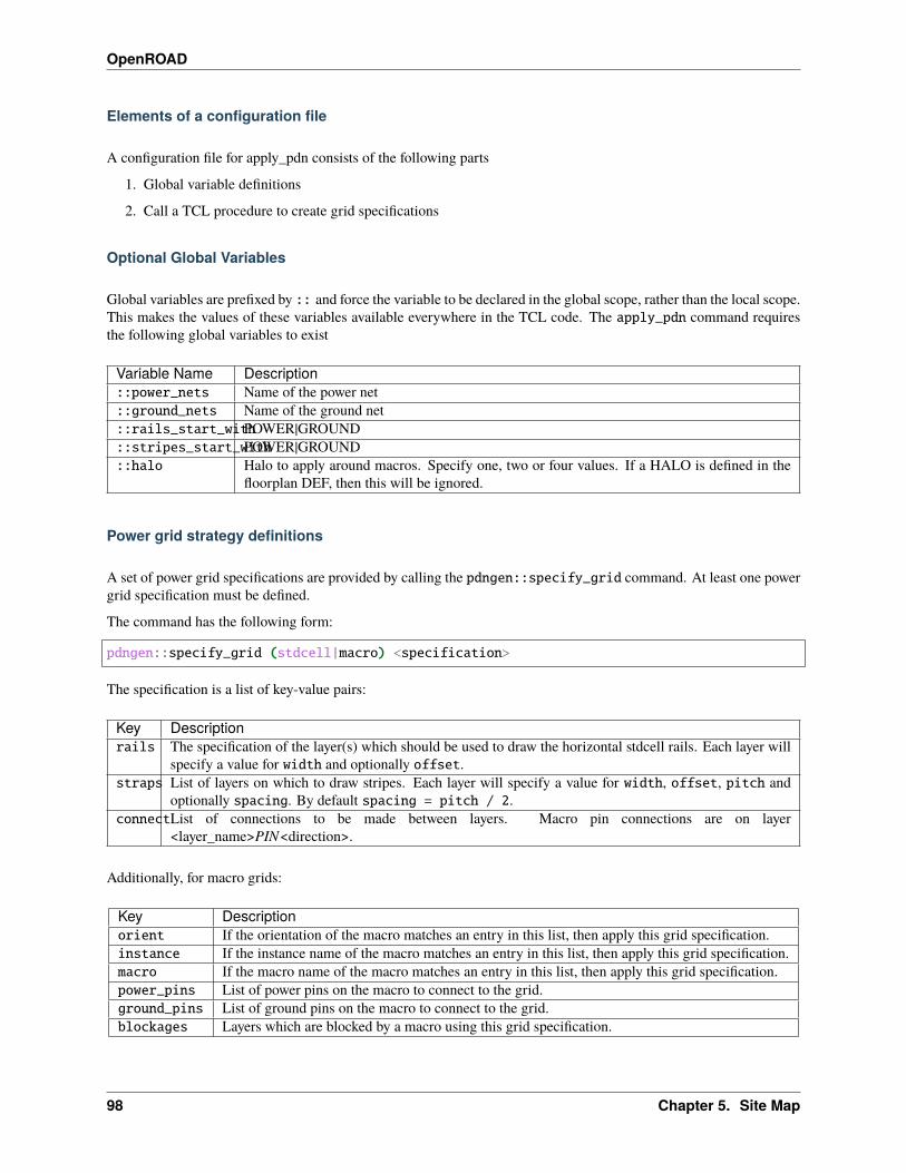
OpenROAD
Elements of a configuration file
A configuration file for apply_pdn consists of the following parts
1. Global variable definitions
2. Call a TCL procedure to create grid specifications
Optional Global Variables
Global variables are prefixed by :: and force the variable to be declared in the global scope, rather than the local scope.This makes the values of these variables available everywhere in the TCL code. The apply_pdn command requiresthe following global variables to exist
Variable Name Description::power_nets Name of the power net::ground_nets Name of the ground net::rails_start_withPOWER|GROUND::stripes_start_withPOWER|GROUND::halo Halo to apply around macros. Specify one, two or four values. If a HALO is defined in the
floorplan DEF, then this will be ignored.
Power grid strategy definitions
A set of power grid specifications are provided by calling the pdngen::specify_grid command. At least one powergrid specification must be defined.
The command has the following form:
pdngen::specify_grid (stdcell|macro) <specification>
The specification is a list of key-value pairs:
Key Descriptionrails The specification of the layer(s) which should be used to draw the horizontal stdcell rails. Each layer will
specify a value for width and optionally offset.straps List of layers on which to draw stripes. Each layer will specify a value for width, offset, pitch and
optionally spacing. By default spacing = pitch / 2.connectList of connections to be made between layers. Macro pin connections are on layer
<layer_name>PIN<direction>.
Additionally, for macro grids:
Key Descriptionorient If the orientation of the macro matches an entry in this list, then apply this grid specification.instance If the instance name of the macro matches an entry in this list, then apply this grid specification.macro If the macro name of the macro matches an entry in this list, then apply this grid specification.power_pins List of power pins on the macro to connect to the grid.ground_pins List of ground pins on the macro to connect to the grid.blockages Layers which are blocked by a macro using this grid specification.
98 Chapter 5. Site Map
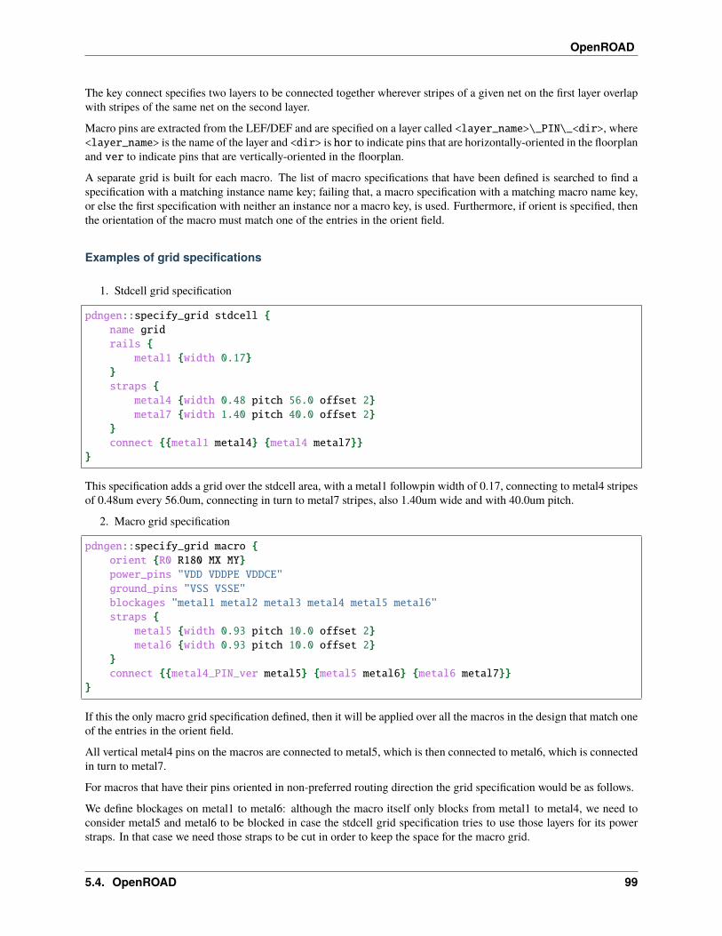
OpenROAD
The key connect specifies two layers to be connected together wherever stripes of a given net on the first layer overlapwith stripes of the same net on the second layer.
Macro pins are extracted from the LEF/DEF and are specified on a layer called <layer_name>\_PIN\_<dir>, where<layer_name> is the name of the layer and <dir> is hor to indicate pins that are horizontally-oriented in the floorplanand ver to indicate pins that are vertically-oriented in the floorplan.
A separate grid is built for each macro. The list of macro specifications that have been defined is searched to find aspecification with a matching instance name key; failing that, a macro specification with a matching macro name key,or else the first specification with neither an instance nor a macro key, is used. Furthermore, if orient is specified, thenthe orientation of the macro must match one of the entries in the orient field.
Examples of grid specifications
1. Stdcell grid specification
pdngen::specify_grid stdcell {name gridrails {
metal1 {width 0.17}}straps {
metal4 {width 0.48 pitch 56.0 offset 2}metal7 {width 1.40 pitch 40.0 offset 2}
}connect {{metal1 metal4} {metal4 metal7}}
}
This specification adds a grid over the stdcell area, with a metal1 followpin width of 0.17, connecting to metal4 stripesof 0.48um every 56.0um, connecting in turn to metal7 stripes, also 1.40um wide and with 40.0um pitch.
2. Macro grid specification
pdngen::specify_grid macro {orient {R0 R180 MX MY}power_pins "VDD VDDPE VDDCE"ground_pins "VSS VSSE"blockages "metal1 metal2 metal3 metal4 metal5 metal6"straps {
metal5 {width 0.93 pitch 10.0 offset 2}metal6 {width 0.93 pitch 10.0 offset 2}
}connect {{metal4_PIN_ver metal5} {metal5 metal6} {metal6 metal7}}
}
If this the only macro grid specification defined, then it will be applied over all the macros in the design that match oneof the entries in the orient field.
All vertical metal4 pins on the macros are connected to metal5, which is then connected to metal6, which is connectedin turn to metal7.
For macros that have their pins oriented in non-preferred routing direction the grid specification would be as follows.
We define blockages on metal1 to metal6: although the macro itself only blocks from metal1 to metal4, we need toconsider metal5 and metal6 to be blocked in case the stdcell grid specification tries to use those layers for its powerstraps. In that case we need those straps to be cut in order to keep the space for the macro grid.
5.4. OpenROAD 99
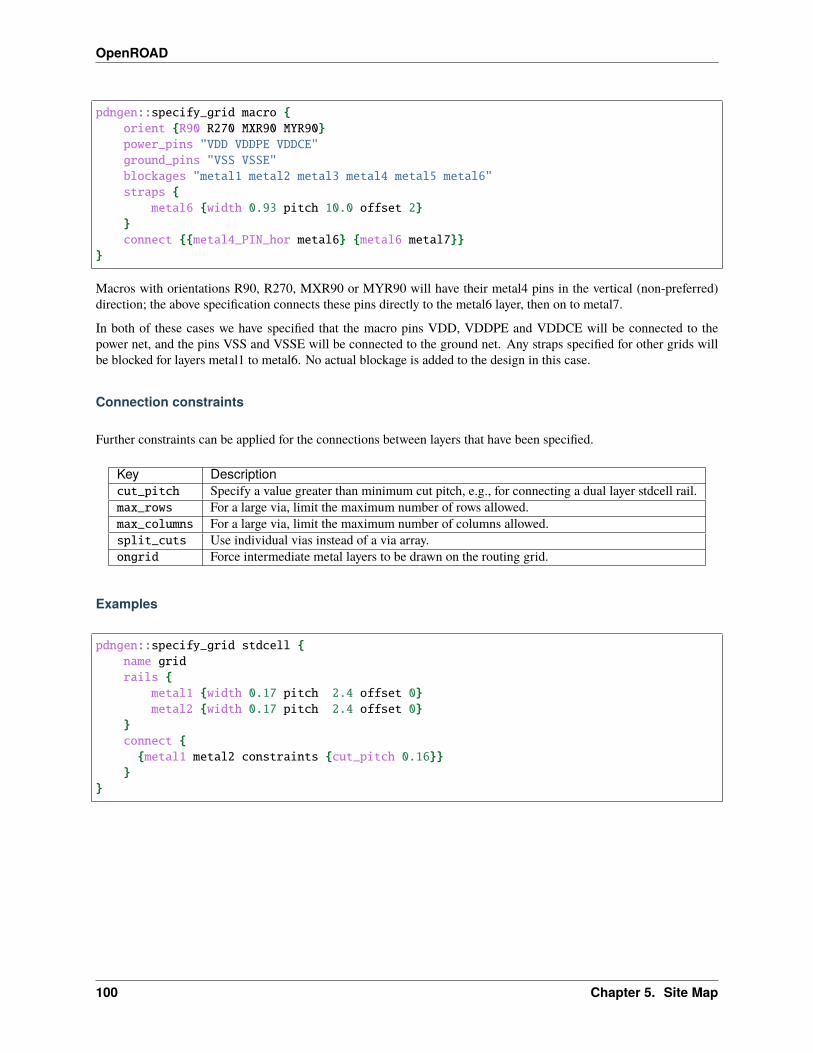
OpenROAD
pdngen::specify_grid macro {orient {R90 R270 MXR90 MYR90}power_pins "VDD VDDPE VDDCE"ground_pins "VSS VSSE"blockages "metal1 metal2 metal3 metal4 metal5 metal6"straps {
metal6 {width 0.93 pitch 10.0 offset 2}}connect {{metal4_PIN_hor metal6} {metal6 metal7}}
}
Macros with orientations R90, R270, MXR90 or MYR90 will have their metal4 pins in the vertical (non-preferred)direction; the above specification connects these pins directly to the metal6 layer, then on to metal7.
In both of these cases we have specified that the macro pins VDD, VDDPE and VDDCE will be connected to thepower net, and the pins VSS and VSSE will be connected to the ground net. Any straps specified for other grids willbe blocked for layers metal1 to metal6. No actual blockage is added to the design in this case.
Connection constraints
Further constraints can be applied for the connections between layers that have been specified.
Key Descriptioncut_pitch Specify a value greater than minimum cut pitch, e.g., for connecting a dual layer stdcell rail.max_rows For a large via, limit the maximum number of rows allowed.max_columns For a large via, limit the maximum number of columns allowed.split_cuts Use individual vias instead of a via array.ongrid Force intermediate metal layers to be drawn on the routing grid.
Examples
pdngen::specify_grid stdcell {name gridrails {
metal1 {width 0.17 pitch 2.4 offset 0}metal2 {width 0.17 pitch 2.4 offset 0}
}connect {{metal1 metal2 constraints {cut_pitch 0.16}}
}}
100 Chapter 5. Site Map
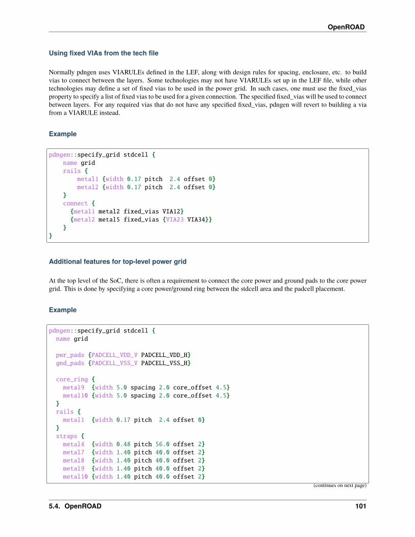
OpenROAD
Using fixed VIAs from the tech file
Normally pdngen uses VIARULEs defined in the LEF, along with design rules for spacing, enclosure, etc. to buildvias to connect between the layers. Some technologies may not have VIARULEs set up in the LEF file, while othertechnologies may define a set of fixed vias to be used in the power grid. In such cases, one must use the fixed_viasproperty to specify a list of fixed vias to be used for a given connection. The specified fixed_vias will be used to connectbetween layers. For any required vias that do not have any specified fixed_vias, pdngen will revert to building a viafrom a VIARULE instead.
Example
pdngen::specify_grid stdcell {name gridrails {
metal1 {width 0.17 pitch 2.4 offset 0}metal2 {width 0.17 pitch 2.4 offset 0}
}connect {{metal1 metal2 fixed_vias VIA12}{metal2 metal5 fixed_vias {VIA23 VIA34}}
}}
Additional features for top-level power grid
At the top level of the SoC, there is often a requirement to connect the core power and ground pads to the core powergrid. This is done by specifying a core power/ground ring between the stdcell area and the padcell placement.
Example
pdngen::specify_grid stdcell {name grid
pwr_pads {PADCELL_VDD_V PADCELL_VDD_H}gnd_pads {PADCELL_VSS_V PADCELL_VSS_H}
core_ring {metal9 {width 5.0 spacing 2.0 core_offset 4.5}metal10 {width 5.0 spacing 2.0 core_offset 4.5}
}rails {metal1 {width 0.17 pitch 2.4 offset 0}
}straps {metal4 {width 0.48 pitch 56.0 offset 2}metal7 {width 1.40 pitch 40.0 offset 2}metal8 {width 1.40 pitch 40.0 offset 2}metal9 {width 1.40 pitch 40.0 offset 2}metal10 {width 1.40 pitch 40.0 offset 2}
(continues on next page)
5.4. OpenROAD 101
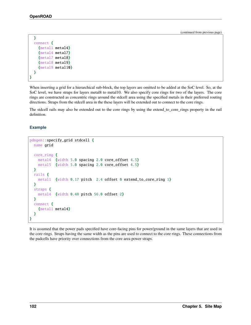
OpenROAD
(continued from previous page)
}connect {{metal1 metal4}{metal4 metal7}{metal7 metal8}{metal8 metal9}{metal9 metal10}
}}
When inserting a grid for a hierarchical sub-block, the top layers are omitted to be added at the SoC level. So, at theSoC level, we have straps for layers metal8 to metal10. We also specify core rings for two of the layers. The corerings are constructed as concentric rings around the stdcell area using the specified metals in their preferred routingdirections. Straps from the stdcell area in the these layers will be extended out to connect to the core rings.
The stdcell rails may also be extended out to the core rings by using the extend_to_core_rings property in the raildefinition.
Example
pdngen::specify_grid stdcell {name grid
core_ring {metal4 {width 5.0 spacing 2.0 core_offset 4.5}metal5 {width 5.0 spacing 2.0 core_offset 4.5}
}rails {metal1 {width 0.17 pitch 2.4 offset 0 extend_to_core_ring 1}
}straps {metal4 {width 0.48 pitch 56.0 offset 2}
}connect {{metal1 metal4}
}}
It is assumed that the power pads specified have core-facing pins for power/ground in the same layers that are used inthe core rings. Straps having the same width as the pins are used to connect to the core rings. These connections fromthe padcells have priority over connections from the core area power straps.
102 Chapter 5. Site Map

OpenROAD
TCL Commands to build ithe power grid
The following commands can be used from the command prompt to define the padring structure for the chip.
• add_global_connection
• set_voltage_domain
• define_pdn_grid
• add_pdn_stripe
• add_pdn_ring
• add_pdn_connect
Once the power grid has been fully inserted, the power grid can be inserted with the pdngen command.
• pdngen
Examples of how to use these commands together.
• Nangate45 example
add_global_connection
Synopsis
% add_global_connection \-net net_name \[-inst_pattern inst_regular_expression] \-pin_pattern pin_regular_expression \(-power|-ground)
Description
The add_global_connection command is used to connect power and ground pins on design instances to the appro-priate supplies.
Options
Switch Name Description-net Specifies the name of the net in the design to which connections are to be added-inst_pattern Optional specifies a regular expression to select a set of instances from the design. (Default: .*)-pin_pattern Species a regular expression to select pins on the selected instances to connect to the specified
net-power Specifies that the net it a power net-ground Specifies that the net is a ground net
5.4. OpenROAD 103
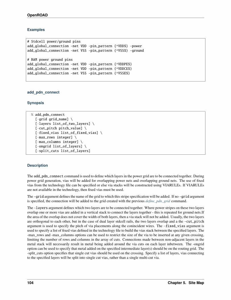
OpenROAD
Examples
# Stdcell power/ground pinsadd_global_connection -net VDD -pin_pattern {^VDD$} -poweradd_global_connection -net VSS -pin_pattern {^VSS$} -ground
# RAM power ground pinsadd_global_connection -net VDD -pin_pattern {^VDDPE$}add_global_connection -net VDD -pin_pattern {^VDDCE$}add_global_connection -net VSS -pin_pattern {^VSSE$}
add_pdn_connect
Synopsis
% add_pdn_connect[-grid grid_name] \[-layers list_of_two_layers] \[-cut_pitch pitch_value] \[-fixed_vias list_of_fixed_vias] \[-max_rows integer] \[-max_columns integer] \[-ongrid list_of_layers] \[-split_cuts list_of_layers]
Description
The add_pdn_connect command is used to define which layers in the power grid are to be connected together. Duringpower grid generation, vias will be added for overlapping power nets and overlapping ground nets. The use of fixedvias from the technology file can be specified or else via stacks will be constructed using VIARULEs. If VIARULEsare not available in the technology, then fixed vias must be used.
The -grid argument defines the name of the grid to which this stripe specification will be added. If no -grid argumentis specified, the connection will be added to the grid created with the previous define_pdn_grid command.
The -layers argument defines which two layers are to be connected together. Where power stripes on these two layersoverlap one or more vias are added in a vertical stack to connect the layers together - this is repeated for ground nets.Ifthe area of the overlap does not cover the width of both layers, then a via stack will not be added. Usually, the two layersare orthogonal to each other, but in the case of dual layer stdcell rails, the two layers overlap and a the -cut_pitchargument is used to specify the pitch of via placements along the conincident wires. The -fixed_vias argument isused to specify a list of fixed vias defined in the technology file to build the vias stack between the specified layers. The-max_rows and -max_columns options can be used to restrict the size of the via to be inserted at any given crossing,limiting the number of rows and columns in the array of cuts. Connections made between non-adjacent layers in themetal stack will necessarily result in metal being added around the via cuts on each layer inbetween. The -ongridoption can be used to specify that metal added on the specified intermediate layer(s) should be on the routing grid. The-split_cuts option specifies that single cut vias should be used on the crossing. Specify a list of layers, vias connectingto the specified layers will be split into single cut vias, rather than a single multi-cut via.
104 Chapter 5. Site Map

OpenROAD
Options
SwitchName
Description
-grid Specifies the name of the grid definition to which this connection will be added. (Default: Last gridcreated by define_pdn_grid)
-layers Layers to be connected where there are overlapping power or overlapping ground nets-cut_pitch When the two layers are parallel e.g. overlapping stdcell rails, specify the distance between via cuts-fixed_vias list of fixed vias to be used to form the via stack-max_rows Specify a limit to the maximum number of rows in the via connection between the two layers-max_columnsSpecify a limit to the maximum number of columns in the via connection between the two layers-ongrid Force intermediate metal layers in a via stack to be on the routing grid-split_cuts A number of single cut vias will be used instead of a single multi-cut via
Examples
add_pdn_connect -grid main_grid -layers {metal1 metal2} -cut_pitch 0.16add_pdn_connect -grid main_grid -layers {metal2 metal4}add_pdn_connect -grid main_grid -layers {metal4 metal7}
add_pdn_connect -grid ram -layers {metal4 metal5}add_pdn_connect -grid ram -layers {metal5 metal6}add_pdn_connect -grid ram -layers {metal6 metal7}
add_pdn_connect -grid rotated_rams -layers {metal4 metal6}add_pdn_connect -grid rotated_rams -layers {metal6 metal7}
add_pdn_ring
Synopsis
% add_pdn_ring[-grid grid_name] \-layers layer_name \-widths (width_value|list_of_2_values) \-spacings (spacing_value|list_of_2_values) \[-core_offset offset_value] \[-pad_offset offset_value] \[-power_pads list_of_core_power_pads][-ground_pads list_of_core_ground_pads]
5.4. OpenROAD 105
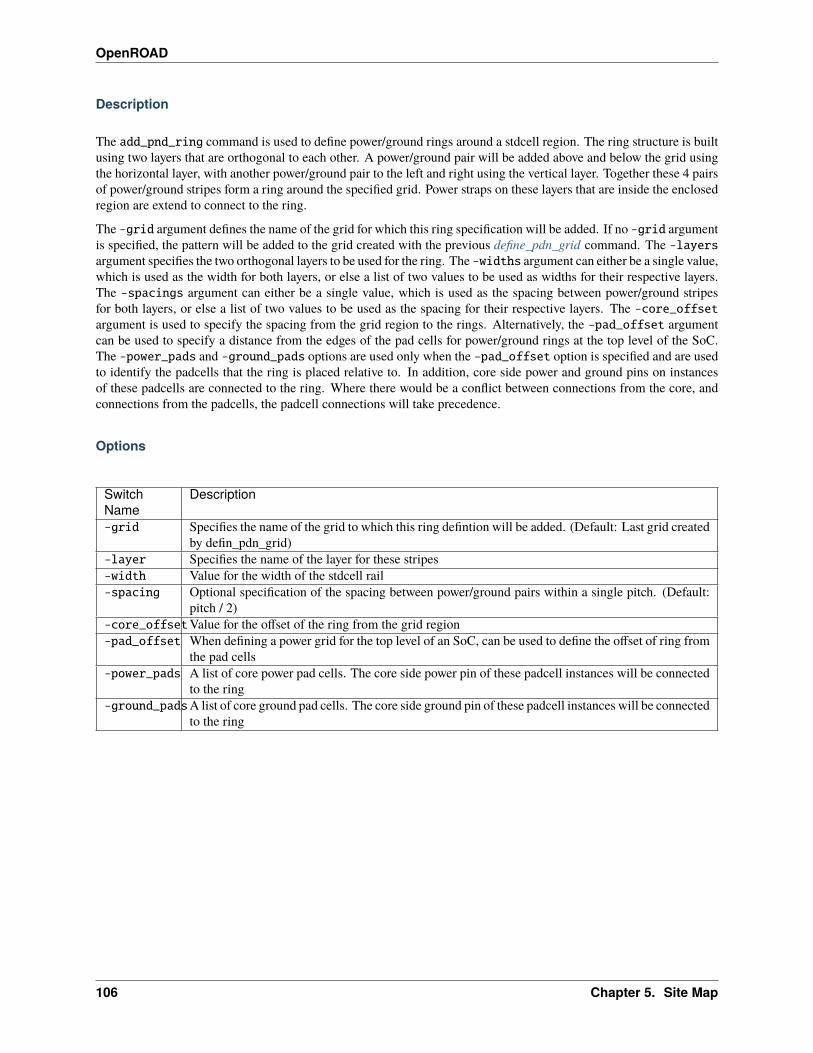
OpenROAD
Description
The add_pnd_ring command is used to define power/ground rings around a stdcell region. The ring structure is builtusing two layers that are orthogonal to each other. A power/ground pair will be added above and below the grid usingthe horizontal layer, with another power/ground pair to the left and right using the vertical layer. Together these 4 pairsof power/ground stripes form a ring around the specified grid. Power straps on these layers that are inside the enclosedregion are extend to connect to the ring.
The -grid argument defines the name of the grid for which this ring specification will be added. If no -grid argumentis specified, the pattern will be added to the grid created with the previous define_pdn_grid command. The -layersargument specifies the two orthogonal layers to be used for the ring. The -widths argument can either be a single value,which is used as the width for both layers, or else a list of two values to be used as widths for their respective layers.The -spacings argument can either be a single value, which is used as the spacing between power/ground stripesfor both layers, or else a list of two values to be used as the spacing for their respective layers. The -core_offsetargument is used to specify the spacing from the grid region to the rings. Alternatively, the -pad_offset argumentcan be used to specify a distance from the edges of the pad cells for power/ground rings at the top level of the SoC.The -power_pads and -ground_pads options are used only when the -pad_offset option is specified and are usedto identify the padcells that the ring is placed relative to. In addition, core side power and ground pins on instancesof these padcells are connected to the ring. Where there would be a conflict between connections from the core, andconnections from the padcells, the padcell connections will take precedence.
Options
SwitchName
Description
-grid Specifies the name of the grid to which this ring defintion will be added. (Default: Last grid createdby defin_pdn_grid)
-layer Specifies the name of the layer for these stripes-width Value for the width of the stdcell rail-spacing Optional specification of the spacing between power/ground pairs within a single pitch. (Default:
pitch / 2)-core_offsetValue for the offset of the ring from the grid region-pad_offset When defining a power grid for the top level of an SoC, can be used to define the offset of ring from
the pad cells-power_pads A list of core power pad cells. The core side power pin of these padcell instances will be connected
to the ring-ground_padsA list of core ground pad cells. The core side ground pin of these padcell instances will be connected
to the ring
106 Chapter 5. Site Map
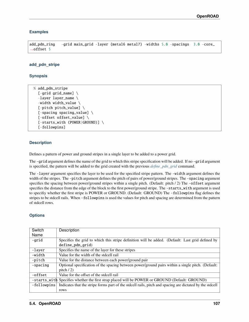
OpenROAD
Examples
add_pdn_ring -grid main_grid -layer {metal6 metal7} -widths 5.0 -spacings 3.0 -core_→˓offset 5
add_pdn_stripe
Synopsis
% add_pdn_stripe[-grid grid_name] \-layer layer_name \-width width_value \[-pitch pitch_value] \[-spacing spacing_value] \[-offset offset_value] \[-starts_with (POWER|GROUND)] \[-followpins]
Description
Defines a pattern of power and ground stripes in a single layer to be added to a power grid.
The -grid argument defines the name of the grid to which this stripe specification will be added. If no -grid argumentis specified, the pattern will be added to the grid created with the previous define_pdn_grid command.
The -layer argument specifies the layer to be used for the specified stripe pattern. The -width argument defines thewidth of the stripes. The -pitch argument defines the pitch of pairs of power/ground stripes. The -spacing argumentspecifies the spacing between power/ground stripes within a single pitch. (Default: pitch / 2) The -offset argumentspecifies the distance from the edge of the block to the first power/ground stripe. The -starts_with argument is usedto specifiy whether the first stripe is POWER or GROUND. (Default: GROUND) The -followpins flag defines thestripes to be stdcell rails. When -followpins is used the values for pitch and spacing are determined from the patternof stdcell rows.
Options
SwitchName
Description
-grid Specifies the grid to which this stripe definition will be added. (Default: Last grid defined bydefine_pdn_grid)
-layer Specifies the name of the layer for these stripes-width Value for the width of the stdcell rail-pitch Value for the distance between each power/ground pair-spacing Optional specification of the spacing between power/ground pairs within a single pitch. (Default:
pitch / 2)-offset Value for the offset of the stdcell rail-starts_with Specifies whether the first strap placed will be POWER or GROUND (Default: GROUND)-followpins Indicates that the stripe forms part of the stdcell rails, pitch and spacing are dictated by the stdcell
rows
5.4. OpenROAD 107
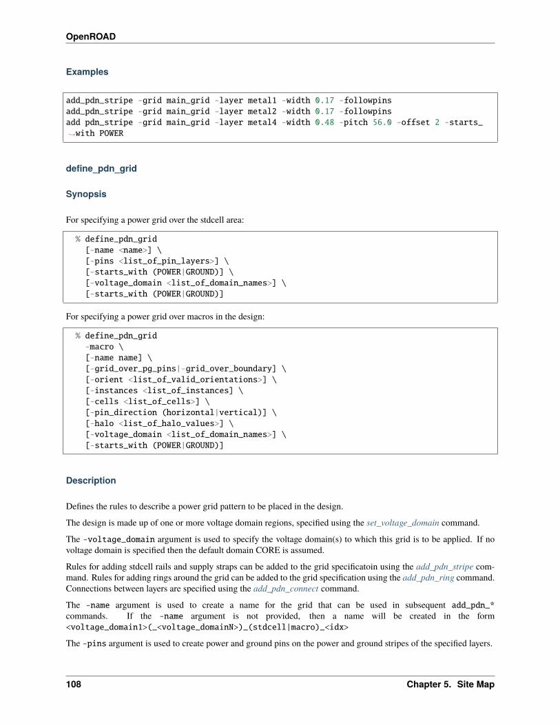
OpenROAD
Examples
add_pdn_stripe -grid main_grid -layer metal1 -width 0.17 -followpinsadd_pdn_stripe -grid main_grid -layer metal2 -width 0.17 -followpinsadd pdn_stripe -grid main_grid -layer metal4 -width 0.48 -pitch 56.0 -offset 2 -starts_→˓with POWER
define_pdn_grid
Synopsis
For specifying a power grid over the stdcell area:
% define_pdn_grid[-name <name>] \[-pins <list_of_pin_layers>] \[-starts_with (POWER|GROUND)] \[-voltage_domain <list_of_domain_names>] \[-starts_with (POWER|GROUND)]
For specifying a power grid over macros in the design:
% define_pdn_grid-macro \[-name name] \[-grid_over_pg_pins|-grid_over_boundary] \[-orient <list_of_valid_orientations>] \[-instances <list_of_instances] \[-cells <list_of_cells>] \[-pin_direction (horizontal|vertical)] \[-halo <list_of_halo_values>] \[-voltage_domain <list_of_domain_names>] \[-starts_with (POWER|GROUND)]
Description
Defines the rules to describe a power grid pattern to be placed in the design.
The design is made up of one or more voltage domain regions, specified using the set_voltage_domain command.
The -voltage_domain argument is used to specify the voltage domain(s) to which this grid is to be applied. If novoltage domain is specified then the default domain CORE is assumed.
Rules for adding stdcell rails and supply straps can be added to the grid specificatoin using the add_pdn_stripe com-mand. Rules for adding rings around the grid can be added to the grid specification using the add_pdn_ring command.Connections between layers are specified using the add_pdn_connect command.
The -name argument is used to create a name for the grid that can be used in subsequent add_pdn_*commands. If the -name argument is not provided, then a name will be created in the form<voltage_domain1>(_<voltage_domainN>)_(stdcell|macro)_<idx>
The -pins argument is used to create power and ground pins on the power and ground stripes of the specified layers.
108 Chapter 5. Site Map
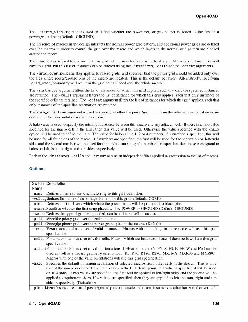
OpenROAD
The -starts_with argument is used to define whether the power net, or ground net is added as the first in apower/ground pair (Default: GROUND)
The presence of macros in the design interupts the normal power grid pattern, and additional power grids are definedover the macros in order to control the grid over the macro and which layers in the normal grid pattern are blockedaround the macro.
The -macro flag is used to declare that this grid definition is for macros in the design. All macro cell instances willhave this grid, but this list of instances can be filtered using the -instances, -cells and/or -orient arguments
The -grid_over_pg_pins flag applies to macro grids, and specifies that the power grid should be added only overthe area where power/ground pins of the macro are located. This is the default behavior. Alternatively, specifying-grid_over_boundary will result in the grid being placed over the whole macro.
The -instances argument filters the list of instances for which this grid applies, such that only the specified instancesare retained. The -cells argument filters the list of instance for which this grid applies, such that only instances ofthe specified cells are retained. The -orient argument filters the list of instances for which this grid applies, such thatonly instances of the specified orientation are retained.
The -pin_direction argument is used to specifiy whether the power/ground pins on the selected macro instances areoriented in the horizontal or vertical direction.
A halo value is used to specify the minimum distance between this macro and any adjacent cell. If there is a halo valuespecified for the macro cell in the LEF, then this value will be used. Otherwise the value specified with the -halooption will be used to define the halo. The value for halo can be 1, 2 or 4 numbers; if 1 number is specified, this willbe used for all four sides of the macro; if 2 numbers are specified, the first will be used for the separation on left/rightsides and the second number will be used for the top/bottom sides; if 4 numbers are specified then these correspond tohalos on left, bottom, right and top sides respectively.
Each of the -instances, -cells and -orient acts as an independent filter applied in succession to the list of macros.
Options
SwitchName
Description
-name Defines a name to use when referring to this grid definition.-voltage_domainDefines the name of the voltage domain for this grid. (Default: CORE)-pins Defines a list of layers which where the power straps will be promoted to block pins.-starts_withSpecifies whether the first strap placed will be POWER or GROUND (Default: GROUND)-macro Defines the type of grid being added, can be either stdcell or macro.-grid_over_boundaryPlace the power grid over the entire macro.-grid_over_pg_pinsPlace the power grid over the power grond pins of the macro. (Default)-instancesFor a macro, defines a set of valid instances. Macros with a matching instance name will use this grid
specification.-cells For a macro, defines a set of valid cells. Macros which are instances of one of these cells will use this grid
specification.-orientFor a macro, defines a set of valid orientations. LEF orientations (N, FN, S, FS, E, FE, W and FW) can be
used as well as standard geometry orientations (R0, R90, R180, R270, MX, MY, MXR90 and MYR90).Macros with one of the valid orientations will use this grid specification.
-halo Specifies the default minimum separation of selected macros from other cells in the design. This is onlyused if the macro does not define halo values in the LEF description. If 1 value is specified it will be usedon all 4 sides, if two values are specified, the first will be applied to left/right sides and the second will beapplied to top/bottom sides, if 4 values are specified, then they are applied to left, bottom, right and topsides respectively. (Default: 0)
-pin_directionSpecifies the direction of power/ground pins on the selected macro instances as eiher horizontal or vertical.
5.4. OpenROAD 109
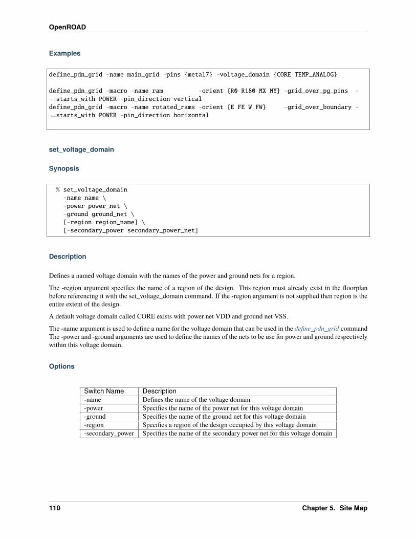
OpenROAD
Examples
define_pdn_grid -name main_grid -pins {metal7} -voltage_domain {CORE TEMP_ANALOG}
define_pdn_grid -macro -name ram -orient {R0 R180 MX MY} -grid_over_pg_pins -→˓starts_with POWER -pin_direction verticaldefine_pdn_grid -macro -name rotated_rams -orient {E FE W FW} -grid_over_boundary -→˓starts_with POWER -pin_direction horizontal
set_voltage_domain
Synopsis
% set_voltage_domain-name name \-power power_net \-ground ground_net \[-region region_name] \[-secondary_power secondary_power_net]
Description
Defines a named voltage domain with the names of the power and ground nets for a region.
The -region argument specifies the name of a region of the design. This region must already exist in the floorplanbefore referencing it with the set_voltage_domain command. If the -region argument is not supplied then region is theentire extent of the design.
A default voltage domain called CORE exists with power net VDD and ground net VSS.
The -name argument is used to define a name for the voltage domain that can be used in the define_pdn_grid commandThe -power and -ground arguments are used to define the names of the nets to be use for power and ground respectivelywithin this voltage domain.
Options
Switch Name Description-name Defines the name of the voltage domain-power Specifies the name of the power net for this voltage domain-ground Specifies the name of the ground net for this voltage domain-region Specifies a region of the design occupied by this voltage domain-secondary_power Specifies the name of the secondary power net for this voltage domain
110 Chapter 5. Site Map

OpenROAD
Examples
set_voltage_domain -name CORE -power VDD -ground VSSset_voltage_domain -name TEMP_ANALOG -region TEMP_ANALOG -power VIN -ground VSSset_voltage_domain -name test_domain -power VDD -ground VSS -secondary_power VREG
pdngen
Synopsis
% pdngen [config_file] [-verbose]
Description
Build a power grid in accordance with the information specified by the define_pdn_grid command, or else provide aconfig_file which defines the power grid.
5.4.17 PDNSim
PDNSim is an open-source static IR analyzer.
Features:
• Report worst IR drop.
• Report worst current density over all nodes and wire segments in the power distribution network, given a placedand PDN-synthesized design.
• Check for floating PDN stripes on the power and ground nets.
• Spice netlist writer for power distribution network wire segments.
5.4. OpenROAD 111
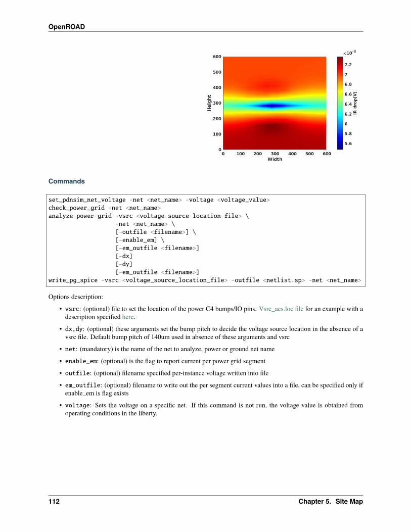
OpenROAD
Commands
set_pdnsim_net_voltage -net <net_name> -voltage <voltage_value>check_power_grid -net <net_name>analyze_power_grid -vsrc <voltage_source_location_file> \
-net <net_name> \[-outfile <filename>] \[-enable_em] \[-em_outfile <filename>][-dx][-dy][-em_outfile <filename>]
write_pg_spice -vsrc <voltage_source_location_file> -outfile <netlist.sp> -net <net_name>
Options description:
• vsrc: (optional) file to set the location of the power C4 bumps/IO pins. Vsrc_aes.loc file for an example with adescription specified here.
• dx,dy: (optional) these arguments set the bump pitch to decide the voltage source location in the absence of avsrc file. Default bump pitch of 140um used in absence of these arguments and vsrc
• net: (mandatory) is the name of the net to analyze, power or ground net name
• enable_em: (optional) is the flag to report current per power grid segment
• outfile: (optional) filename specified per-instance voltage written into file
• em_outfile: (optional) filename to write out the per segment current values into a file, can be specified only ifenable_em is flag exists
• voltage: Sets the voltage on a specific net. If this command is not run, the voltage value is obtained fromoperating conditions in the liberty.
112 Chapter 5. Site Map
OpenROAD
Example scripts
See the file test/Vsrc_aes_vdd.loc for an example with a description specified here.
Regression tests
Limitations
FAQs
Check out GitHub discussion about this tool.
Cite this Work
If you find PDNSim useful, please use the following bibtex to cite it:
@misc{pdnsim,author = "V. A. Chhabria and S. S. Sapatnekar",title={{PDNSim}},note= "\url{https://github.com/The-OpenROAD-Project/OpenROAD/tree/master/src/PDNSim}"}
License
BSD 3-Clause License. See LICENSE file.
Voltage source location file description
This file specifies the description of the C4 bump configurations file. The file is a csv as described below:
<x_coordinate>, <y_coordinate>, <octagonal_c4_bump_edge_length>, <voltage_value>
The x and y coordinate specify the center location of the voltage C4 bumps in micro meter.
The octagonal c4_edge_length specifies the edge length of the C4 to determine the pitch of the RDL layer in micron
Voltage_value specifies the value of voltage source at the C4 bump. In case there is a need to specify voltage drop inmicron
Example file
250,250,20,1.1130,170,20,1.1370,410,10,1.1410,450,10,1.1
5.4. OpenROAD 113
OpenROAD
5.4.18 RePlAce
RePlAce: Advancing Solution Quality and Routability Validation in Global Placement
Features:
• Analytic and nonlinear placement algorithm. Solves electrostatic force equations using Nesterov’s method. (link)
• Verified with various commercial technologies and research enablements using OpenDB(7/14/16/28/45/55/65nm).
• Verified deterministic solution generation with various compilers and OS.
• Supports Mixed-size placement mode.
• Supports fast image drawing modes with CImg library.
Visualized examples from ISPD 2006 contest; adaptec2.inf Real-world Design: Coyote (TSMC16 7.5T)
Commands
global_placement[-timing_driven][-routability_driven][-skip_initial_place][-disable_timing_driven][-disable_routability_driven][-incremental][-bin_grid_count grid_count][-density target_density][-init_density_penalty init_density_penalty][-init_wirelength_coef init_wirelength_coef][-min_phi_coef min_phi_conef][-max_phi_coef max_phi_coef][-overflow overflow][-initial_place_max_iter initial_place_max_iter][-initial_place_max_fanout initial_place_max_fanout][-routability_check_overflow routability_check_overflow][-routability_max_density routability_max_density][-routability_max_bloat_iter routability_max_bloat_iter][-routability_max_inflation_iter routability_max_inflation_iter][-routability_target_rc_metric routability_target_rc_metric][-routability_inflation_ratio_coef routability_inflation_ratio_coef][-routability_pitch_scale routability_pitch_scale][-routability_max_inflation_ratio routability_max_inflation_ratio][-routability_rc_coefficients routability_rc_coefficients][-timing_driven_net_reweight_overflow][-pad_left pad_left][-pad_right pad_right][-verbose_level level]
114 Chapter 5. Site Map
OpenROAD
Tuning Parameters
• -timing_driven: Enable timing-driven mode
• -skip_initial_place : Skip the initial placement (BiCGSTAB solving) before Nesterov placement. IP im-proves HPWL by ~5% on large designs. Equal to ‘-initial_place_max_iter 0’
• -incremental : Enable the incremental global placement. Users would need to tune other parameters (e.g.,init_density_penalty) with pre-placed solutions.
• -bin_grid_count: set bin grid’s counts. Default value is defined by internal heuristic. Allowed values are[64,128,256,512,..., int].
• -density: set target density. Default value is 0.70. Allowed values are [0-1, float].
• -init_density_penalty: set initial density penalty. Default value is 8e-5. Allowed values are [1e-6 -1e6, float].
• -init_wirelength_coef: set initial wirelength coefficient. Default value is 0.25. Allowed values are[unlimited, float].
• -min_phi_coef: set pcof_min(µ_k Lower Bound). Default value is 0.95. Allowed values are [0.95-1.05,float].
• -max_phi_coef: set pcof_max(µ_k Upper Bound). Default value is 1.05. Allowed values are [1.00-1.20,float].
• -overflow: set target overflow for termination condition. Default value is 0.1. Allowed values are [0-1,float].
• -initial_place_max_iter: set maximum iterations in initial place. Default value is 20. Allowed values are[0-MAX_INT, int].
• -initial_place_max_fanout: set net escape condition in initial place when ‘fanout >= ini-tial_place_max_fanout’. Default value is 200. Allowed values are [1-MAX_INT, int].
• -timing_driven_net_reweight_overflow: set overflow threshold for timing-driven net reweighting. Al-lowed values are tcl list of [0-100, int].
• -verbose_level: set verbose level for RePlAce. Default value is 1. Allowed values are [0-5, int].
-timing_driven does a virtual repair_design to find slacks and weight nets with low slack. Use the set_wire_rccommand to set resistance and capacitance of estimated wires used for timing.
Example scripts
Regression tests
Limitations
FAQs
Check out GitHub discussion about this tool.
5.4. OpenROAD 115
OpenROAD
External references
• C.-K. Cheng, A. B. Kahng, I. Kang and L. Wang, “RePlAce: Advancing Solution Quality and Routability Vali-dation in Global Placement”, IEEE Transactions on Computer-Aided Design of Integrated Circuits and Systems,38(9) (2019), pp. 1717-1730.
• J. Lu, P. Chen, C.-C. Chang, L. Sha, D. J.-H. Huang, C.-C. Teng and C.-K. Cheng, “ePlace: Electrostatics basedPlacement using Fast Fourier Transform and Nesterov’s Method”, ACM TODAES 20(2) (2015), article 17.
• J. Lu, H. Zhuang, P. Chen, H. Chang, C.-C. Chang, Y.-C. Wong, L. Sha, D. J.-H. Huang, Y. Luo, C.-C. Teng andC.-K. Cheng, “ePlace-MS: Electrostatics based Placement for Mixed-Size Circuits”, IEEE TCAD 34(5) (2015),pp. 685-698.
• The timing-driven mode has been implemented by Mingyu Woo (only available in legacy repo in standalonebranch.)
• The routability-driven mode has been implemented by Mingyu Woo.
• Timing-driven mode re-implementation is ongoing with the current clean-code structure.
Authors
• Authors/maintainer since Jan 2020: Mingyu Woo (Ph.D. Advisor: Andrew. B. Kahng)
• Original open-sourcing of RePlAce: August 2018, by Ilgweon Kang (Ph.D. Advisor: Chung-Kuan Cheng),Lutong Wang (Ph.D. Advisor: Andrew B. Kahng), and Mingyu Woo (Ph.D. Advisor: Andrew B. Kahng).
• Also thanks to Dr. Jingwei Lu for open-sourcing the previous ePlace-MS/ePlace project code.
License
BSD 3-Clause License. See LICENSE file.
OpenROAD Tcl Usage (global_placement)
global_placement[-skip_initial_place][-incremental][-bin_grid_count grid_count][-density density][-init_density_penalty init_density_penalty][-init_wirelength_coef init_wirelength_coef][-min_phi_coef min_phi_coef][-max_phi_coef max_phi_coef][-overflow overflow][-initial_place_max_iter max_iter][-initial_place_max_fanout max_fanout][-verbose_level verbose_level]
116 Chapter 5. Site Map
OpenROAD
Flow Control
• skip_initial_place : Skip the initial placement (BiCGSTAB solving) before Nesterov placement. IP improvesHPWL by ~5% on large designs.
• incremental : Enable the incremental global placement. Users would need to tune other parameters (e.g.init_density_penalty) with the pre-placed solutions.
Tuning Parameters
• bin_grid_count : Set bin grid’s count manually. Default: Defined by internal algorithm. [64,128,256,512,. . . ,int]
• density : Set target density. Default: 0.70 [0-1, float]
• init_density_penalty : Set initial density penalty. Default : 8e-5 [1e-6 - 1e6, float]
• min_phi_coef : Set pcof_min(µ_k Lower Bound). Default: 0.95 [0.95-1.05, float]
• max_phi_coef : Set pcof_max(µ_k Upper Bound). Default: 1.05 [1.00-1.20, float]
• overflow : Set target overflow for termination condition. Default: 0.1 [0-1, float]
Other Options
• verbose_level [0-10, int] : Set verbose level for RePlAce. Default: 1
Note that all of the TCL commands are defined in the . . . /src/replace.tcl and . . . /src/replace.i.
5.4.19 Parallax Static Timing Analyzer
OpenSTA is a gate level static timing verifier. As a stand-alone executable it can be used to verify the timing of a designusing standard file formats.
• Verilog netlist
• Liberty library
• SDC timing constraints
• SDF delay annotation
• SPEF parasitics
OpenSTA uses a TCL command interpreter to read the design, specify timing constraints and print timing reports.
Clocks
• Generated
• Latency
• Source latency (insertion delay)
• Uncertainty
• Propagated/Ideal
• Gated clock checks
5.4. OpenROAD 117
OpenROAD
• Multiple frequency clocks
Exception paths
• False path
• Multicycle path
• Min/Max path delay
• Exception points
• -from clock/pin/instance -through pin/net -to clock/pin/instance
• Edge specific exception points
• -rise_from/-fall_from, -rise_through/-fall_through, -rise_to/-fall_to
Delay calculation
• Integrated Dartu/Menezes/Pileggi RC effective capacitance algorithm
• External delay calculator API
Analysis
• Report timing checks -from, -through, -to, multiple paths to endpoint
• Report delay calculation
• Check timing setup
Timing Engine
OpenSTA is architected to be easily bolted on to other tools as a timing engine. By using a network adapter, OpenSTAcan access the host netlist data structures without duplicating them.
• Query based incremental update of delays, arrival and required times
• Simulator to propagate constants from constraints and netlist tie high/low
See doc/OpenSTA.pdf for command documentiaton. See doc/StaApi.txt for timing engine API documentiaton. Seedoc/ChangeLog.txt for changes to commands.
Build
OpenSTA is built with CMake.
118 Chapter 5. Site Map

OpenROAD
Prerequisites
The build dependency versions are show below. Other versions may work, but these are the versions used for develop-ment.
from Ubuntu Xcode18.04.1 11.3
cmake 3.10.2 3.10.2 3.16.2clang 9.1.0 11.0.0gcc 3.3.2 7.3.0tcl 8.4 8.6 8.6.6swig 1.3.28 3.0.12 4.0.1bison 1.35 3.0.4 3.5flex 2.5.4 2.6.4 2.5.35
Note that flex versions before 2.6.4 contain ‘register’ declarations that are illegal in c++17.
These packages are optional:
libz 1.1.4 1.2.5 1.2.8cudd 2.4.1 3.0.0
CUDD is a binary decision diageram (BDD) package that is used to improve conditional timing arc handling. OpenSTAdoes not require it to be installed. It is available here or here.
Note that the file hierarchy of the CUDD installation changed with version 3.0. Some changes to CMakeLists.txt arerequired to support older versions.
Use the USE_CUDD option to look for the cudd library. Use the CUDD_DIR option to set the install directory if it isnot in one of the normal install directories.
When building CUDD you may use the --prefix option to configure to install in a location other than the default(/usr/local/lib).
cd $HOME/cudd-3.0.0mkdir $HOME/cudd./configure --prefix $HOME/cuddmakemake install
cd <opensta>/buildcmake .. -DUSE_CUDD=ON -DCUDD_DIR=$HOME/cudd
The Zlib library is an optional. If CMake finds libz, OpenSTA can read Verilog, SDF, SPF, and SPEF files compressedwith gzip.
5.4. OpenROAD 119
OpenROAD
Installing with CMake
Use the following commands to checkout the git repository and build the OpenSTA library and excutable.
git clone https://github.com/The-OpenROAD-Project/OpenSTA.gitcd OpenSTAmkdir buildcd buildcmake ..make
The default build type is release to compile optimized code. The resulting executable is in app/sta. The librarywithout a main() procedure is app/libSTA.a.
Optional CMake variables passed as -D= arguments to CMake are show below.
CMAKE_BUILD_TYPE DEBUG|RELEASECMAKE_CXX_FLAGS - additional compiler flagsTCL_LIBRARY - path to tcl libraryTCL_HEADER - path to tcl.hCUDD - path to cudd installationZLIB_ROOT - path to zlibCMAKE_INSTALL_PREFIX
If TCL_LIBRARY is specified the CMake script will attempt to locate the header from the library path.
The default install directory is /usr/local. To install in a different directory with CMake use:
cmake .. -DCMAKE_INSTALL_PREFIX=<prefix_path>
If you make changes to CMakeLists.txt you may need to clean out existing CMake cached variable values by deletingall of the files in the build directory.
Bug Reports
Use the Issues tab on the github repository to report bugs.
Each issue/bug should be a separate issue. The subject of the issue should be a short description of the problem. Attacha test case to reproduce the issue as described below. Issues without test cases are unlikely to get a response.
The files in the test case should be collected into a directory named YYYYMMDD where YYYY is the year, MM is themonth, and DD is the day (this format allows “ls” to report them in chronological order). The contents of the directoryshould be collected into a compressed tarfile named YYYYMMDD.tgz.
The test case should have a tcl command file recreates the issue named run.tcl. If there are more than one commandfile using the same data files, there should be separate command files, run1.tcl, run2.tcl etc. The bug report can referto these command files by name.
Command files should not have absolute filenames like “/home/cho/OpenSTA_Request/write_path_spice/dump_spice”in them. These obviously are not portable. Use filenames relative to the test case directory.
120 Chapter 5. Site Map
OpenROAD
Authors
• James Cherry
• William Scott authored the arnoldi delay calculator at Blaze, Inc which was subsequently licensed to Nefelus,Inc that has graciously contributed it to OpenSTA.
Contributions
External code contributions are not supported.
https://en.wikipedia.org/wiki/Contributor_License_Agreement https://opensource.google/docs/cla/
License
OpenSTA is dual licensed. It is released under GPL v3 as OpenSTA and is also licensed for commerical applicationsby Parallax Software without the GPL’s requirements.
OpenSTA, Static Timing Analyzer Copyright © 2022, Parallax Software, Inc.
This program is free software: you can redistribute it and/or modify it under the terms of the GNU General PublicLicense as published by the Free Software Foundation, either version 3 of the License, or (at your option) any laterversion.
This program is distributed in the hope that it will be useful, but WITHOUT ANY WARRANTY; without even theimplied warranty of MERCHANTABILITY or FITNESS FOR A PARTICULAR PURPOSE. See the GNU GeneralPublic License for more details.
You should have received a copy of the GNU General Public License along with this program. If not, see https://www.gnu.org/licenses/.
5.4.20 Gate Resizer
Gate Resizer commands are described below. The resizer commands stop when the design area is-max_utilization util percent of the core area. util is between 0 and 100. The resizer stops and reportsan error if the max utilization is exceeded.
Commands
Set Wire RC
set_wire_rc [-clock] [-signal][-layer layer_name][-resistance res][-capacitance cap]
The set_wire_rc command sets the resistance and capacitance used to estimate delay of routing wires. Separate val-ues can be specified for clock and data nets with the -signal and -clock flags. Without either -signal or -clockthe resistance and capacitance for clocks and data nets are set. Use -layer or -resistance and -capacitance. If-layer is used, the LEF technology resistance and area/edge capacitance values for the layer are used for a minimum-width wire on the layer. The resistance and capacitance values are per length of wire, not per square or per square mi-cron. The units for -resistance and -capacitance are from the first Liberty file read, resistance_unit/distance_unit(typically kohms/micron) and Liberty capacitance_unit/distance_unit (typically pf/micron or ff/micron). If distanceunits are not specified in the Liberty file, microns are used.
5.4. OpenROAD 121
OpenROAD
Set Layer RC
The set_layer_rc command can be used to set the resistance and capacitance for a layer or via. This is useful if thesevalues are missing from the LEF file, or to override the values in the LEF.
set_layer_rc [-layer layer][-via via_layer][-capacitance cap][-resistance res][-corner corner]
For layers the resistance and capacitance units are the same as set_wire_rc (per length of minimum-width wire).layer must be the name of a routing layer.
Via resistance can also be set with the set_layer_rc command, using the -via keyword. -capacitance is notsupported for vias. via_layer is the name of a via layer. Via resistance is per cut/via, not area based.
Remove Buffers
remove_buffers
Use the remove_buffers command to remove buffers inserted by synthesis. This step is recommended before usingrepair_design so that there is more flexibility in buffering nets.
Estimate Parasitics
estimate_parasitics -placement|-global_routing
Estimate RC parasitics based on placed component pin locations. If there are no component locations, then no parasiticsare added. The resistance and capacitance values are per distance unit of a routing wire. Use the set_units commandto check units or set_cmd_units to change units. The goal is to represent “average” routing layer resistance andcapacitance. If the set_wire_rc command is not called before resizing, then the default_wireload model specified in thefirst Liberty file read or with the SDC set_wire_load command is used to make parasitics.
After the global_route command has been called, the global routing topology and layers can be used to estimateparasitics with the -global_routing flag.
Set Don’t Use
set_dont_use lib_cells
The set_dont_use command removes library cells from consideration by the resizer. lib_cells is a list of cellsreturned by get_lib_cells or a list of cell names (wildcards allowed). For example, DLY* says do not use cellswith names that begin with DLY in all libraries.
122 Chapter 5. Site Map
OpenROAD
Buffer Ports
buffer_ports [-inputs] [-outputs] [-max_utilization util]
The buffer_ports -inputs command adds a buffer between the input and its loads. The buffer_ports -outputsadds a buffer between the port driver and the output port. The default behavior is -inputs and -outputs if neither isspecified. Inserting buffers on input and output ports makes the block input capacitances and output drives independentof the block internals.
Repair Design
repair_design [-max_wire_length max_length][-slew_margin slew_margin][-cap_margin cap_margin][-max_utilization util]
The repair_design command inserts buffers on nets to repair max slew, max capacitance and max fanout violations,and on long wires to reduce RC delay in the wire. It also resizes gates to normalize slews. Use estimate_parasitics-placement before repair_design to estimate parasitics considered during repair. Placement-based parasiticscannot accurately predict routed parasitics, so a margin can be used to “over-repair” the design to compensate.Use -slew_margin to add a margin to the slews, and -cap_margin to add a margin to the capacitances. Use-max_wire_length to specify the maximum length of wires. The maximum wirelength defaults to a value that min-imizes the wire delay for the wire resistance/capacitance values specified by set_wire_rc.
Set Max Fanout
Use the set_max_fanout SDC command to set the maximum fanout for the design.
set_max_fanout <fanout> [current_design]
Repair Tie Fanout
repair_tie_fanout [-separation dist][-verbose]lib_port
The repair_tie_fanout command connects each tie high/low load to a copy of the tie high/low cell. lib_port isthe tie high/low port, which can be a library/cell/port name or object returned by get_lib_pins. The tie high/lowinstance is separated from the load by dist (in Liberty units, typically microns).
5.4. OpenROAD 123
OpenROAD
Repair Timing
repair_timing [-setup][-hold][-slack_margin slack_margin][-allow_setup_violations][-max_utilization util][-max_buffer_percent buffer_percent][-max_passes passes]
The repair_timing command repairs setup and hold violations. It should be run after clock tree synthesis withpropagated clocks. While repairing hold violations buffers are not inserted that will cause setup violations unless ‘-allow_setup_violations’ is specified. Use -slack_margin to add additional slack margin. To specify different slackmargins use separate repair_timing commands for setup and hold. Use -max_buffer_percent to specify a maxi-mum number of buffers to insert to repair hold violations as a percentage of the number of instances in the design. Thedefault value for buffer_percent is 20, for 20%.
The `-max_passes’ keyword is for debugging.
Report Design Area
report_design_area
The report_design_area command reports the area of the design’s components and the utilization.
Report Floating Nets
report_floating_nets [-verbose]
The report_floating_nets command reports nets with only one pin connection. Use the -verbose flag to see thenet names.
Example scripts
A typical resizer command file (after a design and Liberty libraries have been read) is shown below.
read_sdc gcd.sdc
set_wire_rc -layer metal2
set_dont_use {CLKBUF_* AOI211_X1 OAI211_X1}
buffer_portsrepair_design -max_wire_length 100repair_tie_fanout LOGIC0_X1/Zrepair_tie_fanout LOGIC1_X1/Z# clock tree synthesis...repair_timing
Note that OpenSTA commands can be used to report timing metrics before or after resizing the design.
124 Chapter 5. Site Map
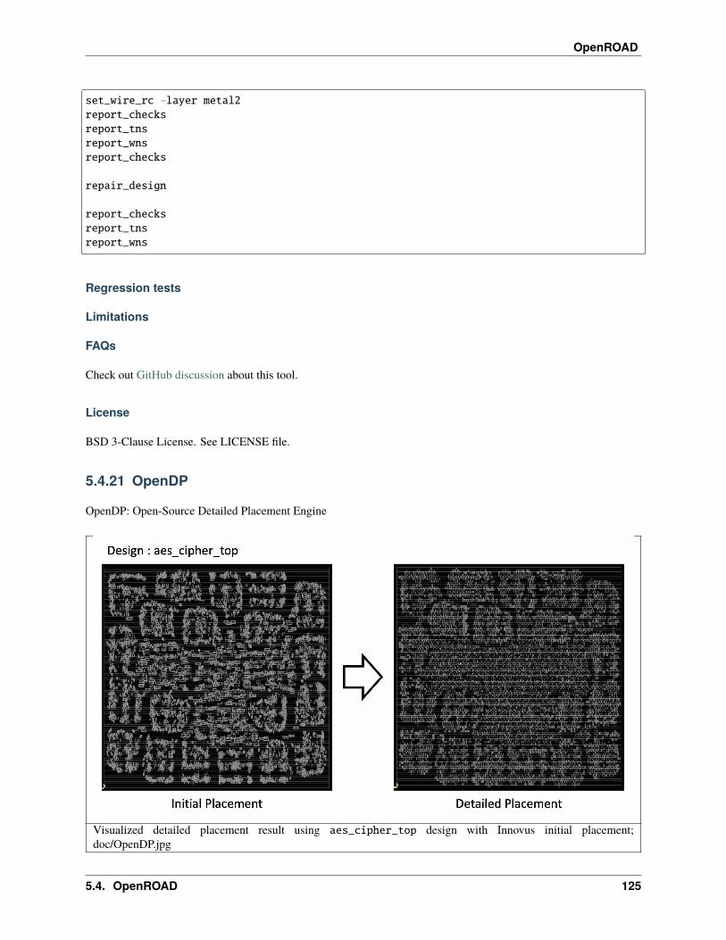
OpenROAD
set_wire_rc -layer metal2report_checksreport_tnsreport_wnsreport_checks
repair_design
report_checksreport_tnsreport_wns
Regression tests
Limitations
FAQs
Check out GitHub discussion about this tool.
License
BSD 3-Clause License. See LICENSE file.
5.4.21 OpenDP
OpenDP: Open-Source Detailed Placement Engine
Visualized detailed placement result using aes_cipher_top design with Innovus initial placement;doc/OpenDP.jpg
5.4. OpenROAD 125
OpenROAD
Features:
• Fence region and multi-height cells. (ICCAD 2017 Contest benchmarks)
• Fragmented ROWs.
• Macro blocks.
Commands
The detailed_placement command performs detailed placement of instances to legal locations after global place-ment.
set_placement_padding -global|-instances insts|-masters masters[-left pad_left] [-right pad_right]
detailed_placement [-max_displacement disp|{disp_x disp_y}]check_placement [-verbose]filler_placement [-prefix prefix] filler_mastersoptimize_mirroring
The set_placement_padding command sets left and right padding in multiples of the row site width. Use theset_placement_padding command before legalizing placement to leave room for routing. Use the -global flagfor padding that applies to all instances. Use -instances for instance-specific padding. The instances insts can bea list of instance names, or an instance object returned by the SDC get_cells command. To specify padding for allinstances of a common master, use the -filter “ref_name == ” option to get_cells.
The set_power_net command is used to set the power and ground special net names. The defaults are VDD and VSS.
The -max_displacement argument to detailed_placement specifies how far an instance can be moved when find-ing a site where it can be placed. The default values are {500 100} sites. The x/y displacement arguments are inmicrons.
The check_placement command checks the placement legality. It returns 0 if the placement is legal.
The filler_placement command fills gaps between detail-placed instances to connect the power and ground railsin the rows. filler_masters is a list of master/macro names to use for filling the gaps. Wildcard matching issupported, so FILL* will match, e.g., FILLCELL_X1 FILLCELL_X16 FILLCELL_X2 FILLCELL_X32 FILLCELL_X4FILLCELL_X8. To specify a different naming prefix from FILLER_ use -prefix <new prefix>.
The optimize_mirroring command mirrors instances about the Y axis in a weak attempt to reduce total wirelength(HPWL).
Example scripts
Regression tests
Limitations
FAQs
Check out GitHub discussion about this tool.
126 Chapter 5. Site Map
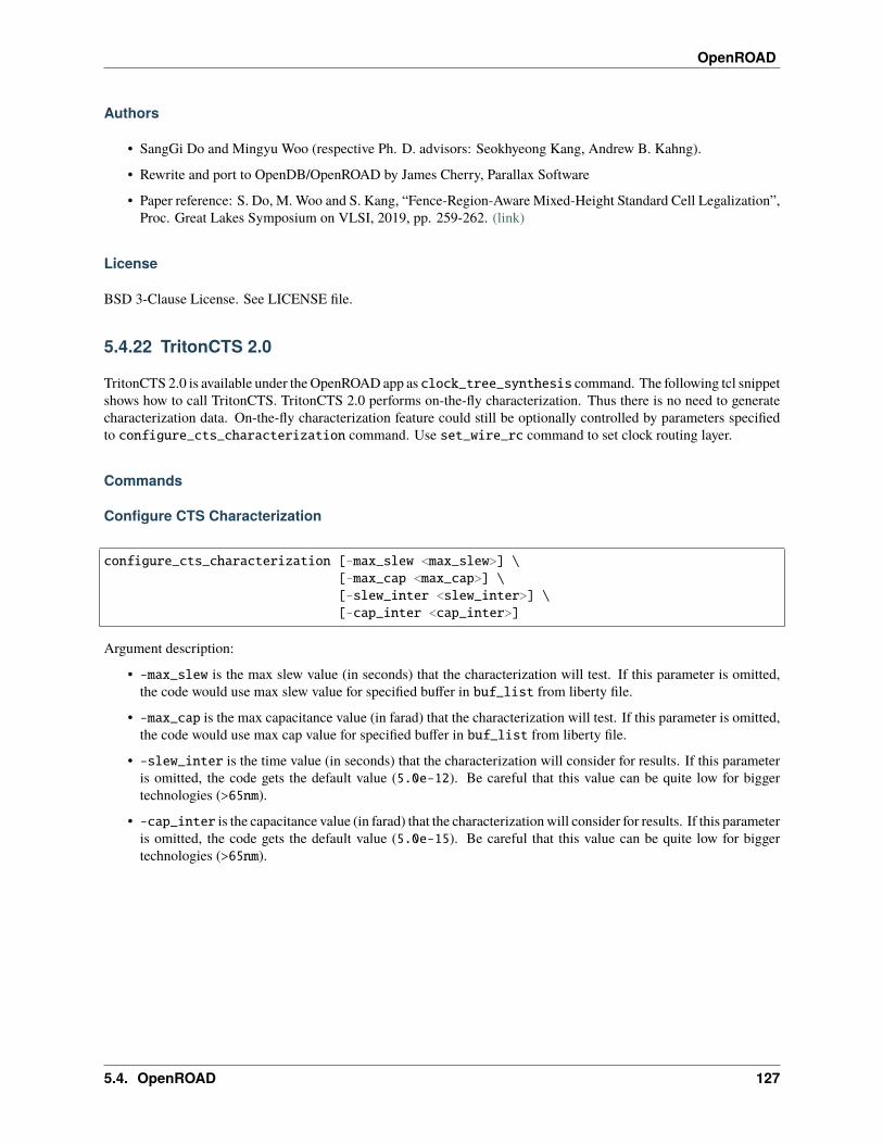
OpenROAD
Authors
• SangGi Do and Mingyu Woo (respective Ph. D. advisors: Seokhyeong Kang, Andrew B. Kahng).
• Rewrite and port to OpenDB/OpenROAD by James Cherry, Parallax Software
• Paper reference: S. Do, M. Woo and S. Kang, “Fence-Region-Aware Mixed-Height Standard Cell Legalization”,Proc. Great Lakes Symposium on VLSI, 2019, pp. 259-262. (link)
License
BSD 3-Clause License. See LICENSE file.
5.4.22 TritonCTS 2.0
TritonCTS 2.0 is available under the OpenROAD app as clock_tree_synthesis command. The following tcl snippetshows how to call TritonCTS. TritonCTS 2.0 performs on-the-fly characterization. Thus there is no need to generatecharacterization data. On-the-fly characterization feature could still be optionally controlled by parameters specifiedto configure_cts_characterization command. Use set_wire_rc command to set clock routing layer.
Commands
Configure CTS Characterization
configure_cts_characterization [-max_slew <max_slew>] \[-max_cap <max_cap>] \[-slew_inter <slew_inter>] \[-cap_inter <cap_inter>]
Argument description:
• -max_slew is the max slew value (in seconds) that the characterization will test. If this parameter is omitted,the code would use max slew value for specified buffer in buf_list from liberty file.
• -max_cap is the max capacitance value (in farad) that the characterization will test. If this parameter is omitted,the code would use max cap value for specified buffer in buf_list from liberty file.
• -slew_inter is the time value (in seconds) that the characterization will consider for results. If this parameteris omitted, the code gets the default value (5.0e-12). Be careful that this value can be quite low for biggertechnologies (>65nm).
• -cap_inter is the capacitance value (in farad) that the characterization will consider for results. If this parameteris omitted, the code gets the default value (5.0e-15). Be careful that this value can be quite low for biggertechnologies (>65nm).
5.4. OpenROAD 127
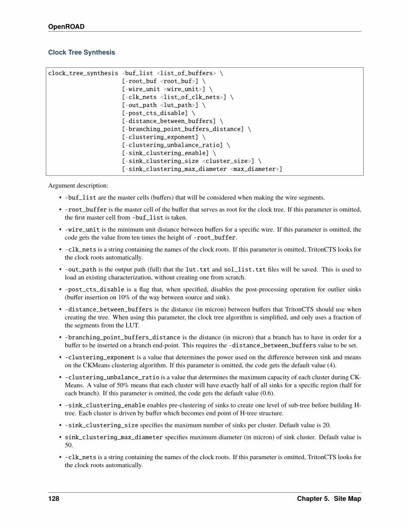
OpenROAD
Clock Tree Synthesis
clock_tree_synthesis -buf_list <list_of_buffers> \[-root_buf <root_buf>] \[-wire_unit <wire_unit>] \[-clk_nets <list_of_clk_nets>] \[-out_path <lut_path>] \[-post_cts_disable] \[-distance_between_buffers] \[-branching_point_buffers_distance] \[-clustering_exponent] \[-clustering_unbalance_ratio] \[-sink_clustering_enable] \[-sink_clustering_size <cluster_size>] \[-sink_clustering_max_diameter <max_diameter>]
Argument description:
• -buf_list are the master cells (buffers) that will be considered when making the wire segments.
• -root_buffer is the master cell of the buffer that serves as root for the clock tree. If this parameter is omitted,the first master cell from -buf_list is taken.
• -wire_unit is the minimum unit distance between buffers for a specific wire. If this parameter is omitted, thecode gets the value from ten times the height of -root_buffer.
• -clk_nets is a string containing the names of the clock roots. If this parameter is omitted, TritonCTS looks forthe clock roots automatically.
• -out_path is the output path (full) that the lut.txt and sol_list.txt files will be saved. This is used toload an existing characterization, without creating one from scratch.
• -post_cts_disable is a flag that, when specified, disables the post-processing operation for outlier sinks(buffer insertion on 10% of the way between source and sink).
• -distance_between_buffers is the distance (in micron) between buffers that TritonCTS should use whencreating the tree. When using this parameter, the clock tree algorithm is simplified, and only uses a fraction ofthe segments from the LUT.
• -branching_point_buffers_distance is the distance (in micron) that a branch has to have in order for abuffer to be inserted on a branch end-point. This requires the -distance_between_buffers value to be set.
• -clustering_exponent is a value that determines the power used on the difference between sink and meanson the CKMeans clustering algorithm. If this parameter is omitted, the code gets the default value (4).
• -clustering_unbalance_ratio is a value that determines the maximum capacity of each cluster during CK-Means. A value of 50% means that each cluster will have exactly half of all sinks for a specific region (half foreach branch). If this parameter is omitted, the code gets the default value (0.6).
• -sink_clustering_enable enables pre-clustering of sinks to create one level of sub-tree before building H-tree. Each cluster is driven by buffer which becomes end point of H-tree structure.
• -sink_clustering_size specifies the maximum number of sinks per cluster. Default value is 20.
• sink_clustering_max_diameter specifies maximum diameter (in micron) of sink cluster. Default value is50.
• -clk_nets is a string containing the names of the clock roots. If this parameter is omitted, TritonCTS looks forthe clock roots automatically.
128 Chapter 5. Site Map
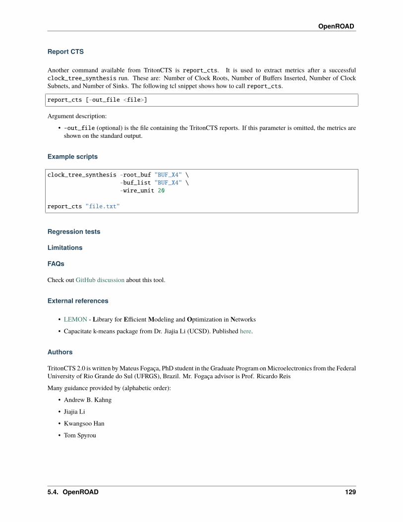
OpenROAD
Report CTS
Another command available from TritonCTS is report_cts. It is used to extract metrics after a successfulclock_tree_synthesis run. These are: Number of Clock Roots, Number of Buffers Inserted, Number of ClockSubnets, and Number of Sinks. The following tcl snippet shows how to call report_cts.
report_cts [-out_file <file>]
Argument description:
• -out_file (optional) is the file containing the TritonCTS reports. If this parameter is omitted, the metrics areshown on the standard output.
Example scripts
clock_tree_synthesis -root_buf "BUF_X4" \-buf_list "BUF_X4" \-wire_unit 20
report_cts "file.txt"
Regression tests
Limitations
FAQs
Check out GitHub discussion about this tool.
External references
• LEMON - Library for Efficient Modeling and Optimization in Networks
• Capacitate k-means package from Dr. Jiajia Li (UCSD). Published here.
Authors
TritonCTS 2.0 is written by Mateus Fogaça, PhD student in the Graduate Program on Microelectronics from the FederalUniversity of Rio Grande do Sul (UFRGS), Brazil. Mr. Fogaça advisor is Prof. Ricardo Reis
Many guidance provided by (alphabetic order):
• Andrew B. Kahng
• Jiajia Li
• Kwangsoo Han
• Tom Spyrou
5.4. OpenROAD 129
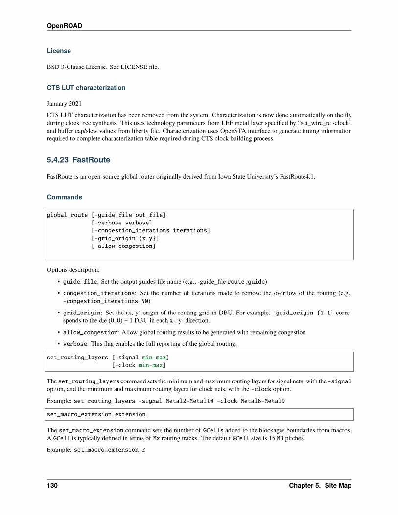
OpenROAD
License
BSD 3-Clause License. See LICENSE file.
CTS LUT characterization
January 2021
CTS LUT characterization has been removed from the system. Characterization is now done automatically on the flyduring clock tree synthesis. This uses technology parameters from LEF metal layer specified by “set_wire_rc -clock”and buffer cap/slew values from liberty file. Characterization uses OpenSTA interface to generate timing informationrequired to complete characterization table required during CTS clock building process.
5.4.23 FastRoute
FastRoute is an open-source global router originally derived from Iowa State University’s FastRoute4.1.
Commands
global_route [-guide_file out_file][-verbose verbose][-congestion_iterations iterations][-grid_origin {x y}][-allow_congestion]
Options description:
• guide_file: Set the output guides file name (e.g., -guide_file route.guide)
• congestion_iterations: Set the number of iterations made to remove the overflow of the routing (e.g.,-congestion_iterations 50)
• grid_origin: Set the (x, y) origin of the routing grid in DBU. For example, -grid_origin {1 1} corre-sponds to the die (0, 0) + 1 DBU in each x-, y- direction.
• allow_congestion: Allow global routing results to be generated with remaining congestion
• verbose: This flag enables the full reporting of the global routing.
set_routing_layers [-signal min-max][-clock min-max]
The set_routing_layers command sets the minimum and maximum routing layers for signal nets, with the -signaloption, and the minimum and maximum routing layers for clock nets, with the -clock option.
Example: set_routing_layers -signal Metal2-Metal10 -clock Metal6-Metal9
set_macro_extension extension
The set_macro_extension command sets the number of GCells added to the blockages boundaries from macros.A GCell is typically defined in terms of Mx routing tracks. The default GCell size is 15 M3 pitches.
Example: set_macro_extension 2
130 Chapter 5. Site Map
OpenROAD
set_global_routing_layer_adjustment layer adjustment
The set_global_routing_layer_adjustment command sets routing resource adjustments in the routing layers ofthe design. Such adjustments reduce the number of routing tracks that the global router assumes to exist. This promotesthe spreading of routing and reduces peak congestion, to reduce challenges for detailed routing.
You can set adjustment for a specific layer, e.g., set_global_routing_layer_adjustment Metal4 0.5 reducesthe routing resources of routing layer Metal4 by 50%. You can also set adjustment for all layers at once using*, e.g., set_global_routing_layer_adjustment * 0.3 reduces the routing resources of all routing layers by30%. And, you can also set resource adjustment for a layer range, e.g.: set_global_routing_layer_adjustmentMetal4-Metal8 0.3 reduces the routing resources of routing layers Metal4, Metal5, Metal6, Metal7 and Metal8by 30%.
set_routing_alpha [-net net_name] alpha
By default the global router uses heuristic rectilinear Steiner minimum trees (RSMTs) as an initial basis to constructroute guides. An RSMT tries to minimize the total wirelength needed to connect a given set of pins. The Prim-Dijkstraheuristic is an alternative net topology algorithm that supports a trade-off between total wirelength and maximum pathdepth from the net driver to its loads. The set_routing_alpha command enables the Prim/Dijkstra algorithm andsets the alpha parameter used to trade-off wirelength and path depth. Alpha is between 0.0 and 1.0. When alpha is 0.0the net topology minimizes total wirelength (i.e. capacitance). When alpha is 1.0 it minimizes longest path betweenthe driver and loads (i.e., maximum resistance). Typical values are 0.4-0.8. For more information about PDRev, checkthe paper [here](in https://vlsicad.ucsd.edu/Publications/Journals/j18.pdf). You can call it multiple times for differentnets.
Example: set_routing_alpha -net clk 0.3 sets the alpha value of 0.3 for net clk.
set_global_routing_region_adjustment {lower_left_x lower_left_y upper_right_x upper_→˓right_y}
-layer layer -adjustment adjustment
The set_global_routing_region_adjustment command sets routing resource adjustments in a specific region ofthe design. The region is defined as a rectangle in a routing layer.
Example: set_global_routing_region_adjustment {1.5 2 20 30.5} -layer Metal4 -adjustment 0.7
set_global_routing_random [-seed seed][-capacities_perturbation_percentage percent][-perturbation_amount value]
The set_global_routing_random command enables randomization of global routing results. The random-ized global routing shuffles the order of the nets and randomly subtracts or adds to the capacities of a randomset of edges. The -seed option sets the random seed and is required to enable the randomization mode. The-capacities_perturbation_percentage option sets the percentage of edges whose capacities are perturbed.By default, the edge capacities are perturbed by adding or subtracting 1 (track) from the original capacity. The-perturbation_amount option sets the perturbation value of the edge capacities. This option will only have meaningand effect when -capacities_perturbation_percentage is used. The random seed must be different from 0 toenable randomization of the global routing.
Example: set_global_routing_random -seed 42 -capacities_perturbation_percentage 50-perturbation_amount 2
repair_antennas diodeCellName/diodePinName [-iterations iterations]
5.4. OpenROAD 131

OpenROAD
The repair_antenna command evaluates the global routing results to find antenna violations, and repairs the violationsby inserting diodes. The input for this command is the diode cell and its pin names, and a prescribed number ofiterations. By default, the command runs only one iteration to repair antennas. It uses the antennachecker tool toidentify any nets with antenna violations and, for each such net, the exact number of diodes necessary to fix the antennaviolation.
Example: repair_antenna sky130_fd_sc_hs__diode_2/DIODE
write_guides file_name
The write_guides generates the guide file from the routing results.
Example: write_guides route.guide.
To estimate RC parasitics based on global route results, use the -global_routing option of theestimate_parasitics command.
estimate_parasitics -global_routing
draw_route_guides net_names [-show_pin_locations]
The draw_route_guides command plots the route guides for a set of nets. To erase the route guides from the GUI,pass an empty list to this command: draw_route_guides {}. The show_pin_locations flag draw circles for thepin positions on the routing grid.
Report wire length
report_wire_length [-net net_list][-file file][-global_route][-detailed_route][-verbose]
Options description:
• net: A list of nets. Use * to report the wire length for all nets of the design.
• file: The name of the file for the wire length report.
• global_route: This flag is used to report the wire length of the global routing.
• detailed_route: This flag is used to report the wire length of the detailed routing.
• verbose: This flag enables the full reporting of the wire length information.
The report_wire_length command reports the wire length of the nets. Use the -global_route and the-detailed_route flags to report the wire length from global and detailed routing, respectively. If none of theseflags are used, the tool will identify the state of the design and report the wire length accordingly.
Example: report_wire_length -net {clk net60} -global_route -detailed_route -verbose -fileout.csv
132 Chapter 5. Site Map

OpenROAD
Debug Mode
global_route_debug [-st][-rst][-tree2D][-tree3D][-net net_name]
Options description:
• st: Show the Steiner Tree generated by stt.
• rst: Show the Rectilinear Steiner Tree generated by FastRoute.
• tree2D: Show the Rectilinear Steiner Tree generated by FastRoute after the overflow iterations.
• tree3D: Show the 3D Rectilinear Steiner Tree post-layer assignment.
• net: Set the name of the net name to be displayed.
The global_route_debug command allows you to start a debug mode to view the status of the Steiner Trees. Thismust be used before calling the global_route command. Set the name of the net and the trees that you want tovisualize.
Example scripts
Regression tests
Limitations
FAQs
Check out GitHub discussion about this tool.
External references
• The algorithm base is from FastRoute4.1, and the database comes from OpenDB
• FastRoute 4.1 documentation. The FastRoute4.1 version was received from [email protected] on June 15, 2019,with the BSD-3 open source license as given in the FastRoute website.
• Min Pan, Yue Xu, Yanheng Zhang and Chris Chu. “FastRoute: An Efficient and High-Quality Global Router.VLSI Design, Article ID 608362, 2012.” Available here.
• P-D paper is C. J. Alpert, T. C. Hu, J. H. Huang, A. B. Kahng and D. Karger, “Prim-Dijkstra Tradeoffs forImproved Performance-Driven Global Routing”, IEEE Transactions on Computer-Aided Design of IntegratedCircuits and Systems 14(7) (1995), pp. 890-896. Available here.
5.4. OpenROAD 133
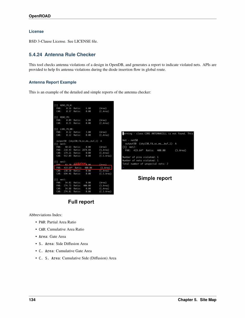
OpenROAD
License
BSD 3-Clause License. See LICENSE file.
5.4.24 Antenna Rule Checker
This tool checks antenna violations of a design in OpenDB, and generates a report to indicate violated nets. APIs areprovided to help fix antenna violations during the diode insertion flow in global route.
Antenna Report Example
This is an example of the detailed and simple reports of the antenna checker:
Abbreviations Index:
• PAR: Partial Area Ratio
• CAR: Cumulative Area Ratio
• Area: Gate Area
• S. Area: Side Diffusion Area
• C. Area: Cumulative Gate Area
• C. S. Area: Cumulative Side (Diffusion) Area
134 Chapter 5. Site Map

OpenROAD
Antenna Checker Algorithm: WireGraphExample
Step 1: (a) Start from the root node (ITerm) using upper Via tofind a node for a new wire. (b) Save the ITerm area for cumulativegate/diffusion area.
Step 2: From the node of the wire, findall the nodes in the wire through segmentwires and find the “root” node of this wire.
Step 3: (a) From the “root” node of the wire, along the outgoing seg-ment edge that goes to other nodes belonging to this wire, calculatethe area of this wire. (b) Then, find all the ITerms below these nodes,except for the root node (directly use an ITerm or lower Vias to findITerms for lower metals). © Sum up the areas of all the ITerms foundwith the cumulative areas and calculate the PAR of this wire. (d) Addthe PAR value and the wire info (layer, Index) into the PAR table. Addthe new area to the cumulative areas.
Step 4: Find all the upper Vias on this wire(for all the nodes on this wire), and go tothe higher-level metal.
Step 5: Repeat Steps 2 and 3 for new-found upper-level wires.
Step 6: Repeat Steps 4 and 5 until we reacha wire that cannot have upper Vias for itsnodes (highest-level metal).
Step 7: Pick up another ITerm as a root node and repeat Steps 1 to6, skipping the wires already in the PAR table. Repeat this for all theITerms to get a whole PAR table.
Step 8: (a) Pick up a gate ITerm and a nodeof a wire (e.g., M4,1). Find possible pathsthat connect them, look up the PAR valueof the wires along these paths, and addthem up to get the CAR of the (gate, wire)pair. (b) Compare to the AntennaRule tosee if the CAR violates the rules. © Checkthis for all (gate, wire) pairs.
5.4. OpenROAD 135
OpenROAD
Commands
check_antennas
Check antenna violations on all nets and generate a report.
check_antennas [-report_filename <FILE>] [-report_violating_nets]
• -report_filename: specifies the filename path where the antenna violation report is to be saved.
• -report_violating_nets: provides a summary of the violated nets.
Limitations
FAQs
Check out GitHub discussion about this tool.
License
BSD 3-Clause License. See LICENSE file.
5.4.25 TritonRoute
TritonRoute is an open-source detailed router for modern industrial designs. The router consists of several main buildingblocks, including pin access analysis, track assignment, initial detailed routing, search and repair, and a DRC engine.The initial development of the router is inspired by the ISPD-2018 initial detailed routing contest. However, the currentframework differs and is built from scratch, aiming for an industrial-oriented scalable and flexible flow.
TritonRoute provides industry-standard LEF/DEF interface with support of ISPD-2018 and ISPD-2019 contest-compatible route guide format.
Commands
Report wire length
Check the global router README file for the full description of the report_wire_length command.
Example scripts
Regression tests
Limitations
FAQs
Check out GitHub discussion about this tool.
136 Chapter 5. Site Map
OpenROAD
References
Please cite the following paper(s) for publication:
• A. B. Kahng, L. Wang and B. Xu, “TritonRoute: The Open Source Detailed Router”, IEEE Transactions onComputer-Aided Design of Integrated Circuits and Systems (2020), doi:10.1109/TCAD.2020.3003234.
• A. B. Kahng, L. Wang and B. Xu, “The Tao of PAO: Anatomy of a Pin Access Oracle for Detailed Routing”,Proc. ACM/IEEE Design Automation Conf., 2020, pp. 1-6.
Authors
TritonRoute was developed by graduate students Lutong Wang and Bangqi Xu from UC San Diego, and serves as thedetailed router in the OpenROAD project.
License
BSD 3-Clause License. See LICENSE file.
5.4.26 Metal fill
This module inserts floating metal fill shapes to meet metal density design rules while obeying DRC constraints. It isdriven by a json configuration file.
Commands
% density_fill -rules <json_file> [-area <list of lx ly ux uy>]
If -area is not specified, the core area will be used.
Example scripts
The rules json file controls fill and you can see an example here.
The schema for the json is:
{"layers": {"<group_name>": {"layers": "<list of integer gds layers>","names": "<list of name strings>","opc": {"datatype": "<list of integer gds datatypes>","width": "<list of widths in microns>","height": "<list of heightsin microns>","space_to_fill": "<real: spacing between fills in microns>","space_to_non_fill": "<real: spacing to non-fill shapes in microns>","space_line_end": "<real: spacing to end of line in microns>"
},"non-opc": {"datatype": "<list of integer gds datatypes>",
(continues on next page)
5.4. OpenROAD 137
OpenROAD
(continued from previous page)
"width": "<list of widths in microns>","height": "<list of heightsin microns>","space_to_fill": "<real: spacing between fills in microns>","space_to_non_fill": "<real: spacing to non-fill shapes in microns>"
}}, ...
}}
The opc section is optional depending on your process.
The width/height lists are effectively parallel arrays of shapes to try in left to right order (generally larger to smaller).
The layer grouping is for convenience. For example in some technologies many layers have similar rules so it isconvenient to have a Mx, Cx group.
This all started out in klayout so there are some obsolete fields that the parser accepts but ignores (e.g.,space_to_outline).
Regression tests
Limitations
FAQs
Check out GitHub discussion about this tool.
License
BSD 3-Clause License. See LICENSE file.
5.4.27 Flute3
Flute3 is an open-source rectilinear Steiner minimum tree heuristic with improvements made by UFRGS students andJames Cherry. The version in this repository uses CMake and C++ namespace, and has dynamic memory allocation.Flute3 can handle nets with any degree.
External references (Optional)
The algorithm base is Flute3.1, extracted from the FastRoute4.1 version that was received from [email protected] onJune 15, 2019, with the BSD-3 open source license as given in the FastRoute website.
138 Chapter 5. Site Map

OpenROAD
License
See LICENSE file.
5.4.28 UCSD Prim-Dijkstra Revisited
Usage: ./pd_rev -h------------------------------------------------------UCSD Prim-Dijkstra Revisitedcoded by Kwangsoo Han and Sriram Venkatesh
-------------------------------------------------------v verbose mode (1 - 4)-a1 alpha for PD (default: 0.3)-a2 alpha for PD-II (default: 0.45)-bu enable PD-II (default: off)-m1 Upperbound of max pathlength degradation in DAS wirelength minimization
(default: 1.1 --> allow 10% max PL degradation for WL optimization)-f input file with pointset-hv enable HoVW Steinerization and Detour-Aware Steinerization (default off)
Sample input file: test.in
Net FE_OFN298734_n20421 10 (Net NetName NumOfTerminals)0 10672450 199765 (Index x_loc y_loc, index 0 is root)1 10769055 4254152 10861105 4252703 10734350 3089904 10762195 3400955 10741025 3742956 10844360 4254157 10862030 4150108 10724765 2544159 10745900 326235
Example runs:
1. run Prim-Dijkstra with alpha = 0.3
./pd_rev -f ./test.in -a1 0.3
2. run Prim-Dijkstra with alpha = 0.3 and PD-II with alpha = 0.45
./pd_rev -f ./test.in -a1 0.3 -bu 1 -a2 0.45
3. run Prim-Dijkstra with alpha = 0.3 and PD-II with alpha = 0.45 and HVW Steinerization and DAS
./pd_rev -f ./test.in -a1 0.3 -bu 1 -a2 0.45 -hv 1
5.4. OpenROAD 139

OpenROAD
External references
• C. J. Alpert, W.-K. Chow, K. Han, A. B. Kahng, Z. Li, D. Liu and S. Venkatesh, “Prim-Dijkstra Revisited:Achieving Superior Timing-driven Routing Trees”, Proc. ACM/IEEE Intl. Symp. on Physical Design, 2018, pp.10-17.
Authors
• Kwangsoo Han
• Andrew B. Kahng
• Sriram Venkatesh
Contact: [email protected], [email protected], [email protected]
Affiliation: Computer Science and Engineering Department, UC San Diego, La Jolla, CA 92093-0404, USA
License
BSD 3-Clause License. See LICENSE file.
5.4.29 PartitionMgr
PartitionMgr is a tool that performs partitioning/clustering on a specific netlist. It provides a wrapper of three well-known permissively open-sourced tools: Chaco, GPMetis and MLPart.
Commands
PartitionMgr offers six commands: partition_netlist, evaluate_partitioning, write_partitioning_to_db, cluster_netlist,write_clustering_to_db and report_netlist_partitions.
partition_netlist
Divides the netlist into N partitions and returns the id (partition_id) of the partitioning solution. The command may becalled many times with different parameters. Each time, the command will generate a new solution.
The following Tcl snippet shows how to call partition_netlist:
partition_netlist -tool <name>-num_partitions <value>[-graph_model <name>][-clique_threshold <value>][-weight_model <name>][-max_edge_weight <value>][-max_vertex_weight range][-num_starts <value>][-random_seed <value>][-seeds <value>][-balance_constraint <value>][-coarsening_ratio <value>][-coarsening_vertices <value>]
(continues on next page)
140 Chapter 5. Site Map

OpenROAD
(continued from previous page)
[-enable_term_prop <value>][-cut_hop_ratio <value>][-architecture <value>][-refinement <value>][-partition_id <value>]
Argument description:
• tool (Mandatory) defines the partitioning tool. Can be “chaco”, “gpmetis” or “mlpart”.
• num_partitions (Mandatory) defines the final number of partitions. Can be any integer greater than 1.
• graph_model is the hypergraph to graph decomposition approach. Can be “clique”, “star” or “hybrid”.
• clique_threshold is the maximum degree of a net decomposed with the clique net model. If using the cliquenet model, nets with degree higher than the threshold are ignored. In the hybrid net model, nets with degreehigher than the threshold are decomposed using the star model.
• weight_model is the edge weight scheme for the graph model of the netlist. Can be any integer from 1 to 7.
• max_edge_weight defines the maximum weight of an edge.
• max_vertex_weight defines the maximum weight of a vertex.
• num_starts is the number of solutions generated with different random seeds.
• random_seed is the seed used when generating new random set seeds.
• seeds is the number of solutions generated with set seeds.
• balance_constraint is the maximum vertex area percentage difference between two partitions. E.g., a 50%difference means that neither partition in a 2-way partitioning can contain less than 25% or more than 75% ofthe total vertex area in the netlist.
• coarsening_ratio defines the minimal acceptable reduction in the number of vertices in the coarsening step.
• coarsening_vertices defines the maximum number of vertices that the algorithm aims to have in its most-coarsened graph or hypergraph.
• enable_term_prop enables terminal propagation (Dunlop and Kernighan, 1985), which aims to improve datalocality. This adds constraints to the Kernighan-Lin (KL) algorithm. Improves the number of edge cuts andterminals, at the cost of additional runtime.
• cut_hop_ratio controls the relative importance of generating a new cut edge versus increasing the interpro-cessor distance associated with an existing cut edge (tradeoff of data locality versus cut edges). This is largelyspecific to Chaco.
• architecture defines the topology (for parallel processors) to be used in the partitioning. These can be 2D or3D topologies, and they define the total number of partitions. This is largely specific to Chaco.
• refinement specifies how many times a KL refinement is run. Incurs a modest runtime hit, but can generatebetter partitioning results.
• partition_id is the partition_id (output from partition_netlist) from a previous computation. This is used togenerate better results based on past results or to run further partitioning.
5.4. OpenROAD 141
OpenROAD
evaluate_partitioning
Evaluates the partitioning solution(s) based on a specific objective function. This function is run for each partition-ing solution that is supplied in the partition_ids parameter (return value from partition_netlist) and returns the bestpartitioning solution according to the specified objective (i.e., metric).
evaluate_partitioning -partition_ids <id> -evaluation_function <function>
Argument description:
• -partition_ids (mandatory) are the partitioning solution id’s. These are the return values from the parti-tion_netlist command. They can be a list of values or only one id.
• -evaluation_function (mandatory) is the objective function that is evaluated for each partitioning solution.It can be terminals, hyperedges, size, area, runtime, or hops.
The following Tcl snippet shows how to call evaluate_partitioning:
set id [ partition_netlist -tool chaco -num_partitions 4 -num_starts 5 ]
evaluate_partitioning -partition_ids $id -evaluation_function function
write_partitioning_to_db
Writes the partition id of each instance (i.e., the cluster that contains the instance) to the DB as a property calledpartitioning_id.
The following Tcl snippet shows how to call write_partitioning_to_db:
write_partitioning_to_db -partitioning_id <id> [-dump_to_file <file>]
Argument description:
• -partitioning_id (Mandatory) is the partitioning solution id. These are the return values from the parti-tion_netlist command.
• -dump_to_file is the file where the vertex assignment results will be saved. The assignment results consist oflines that each contain a vertex name (e.g. an instance) and the partition it is part of.
Another Tcl snippet showing the use of write_partitioning_to_db is:
set id [partition_netlist -tool chaco -num_partitions 4 -num_starts 5]evaluate_partitioning -partition_ids $id -evaluation_function "hyperedges"write_partitioning_to_db -partitioning_id $id -dump_to_file "file.txt"
write_partition_verilog
Writes the partitioned network to a Verilog file containing modules for each partition.
write_partition_verilog -partitioning_id <id>[-port_prefix <prefix>][-module_suffix <suffix>]<file.v>
Argument description:
142 Chapter 5. Site Map
OpenROAD
• partitioning_id (Mandatory) is the partitioning solution id. These are the return values from the parti-tion_netlist command.
• filename (Mandatory) is the path to the Verilog file.
• port_prefix is the prefix to add to the internal ports created during partitioning; default is partition_.
• module_suffix is the suffix to add to the submodules; default is _partition.
The following Tcl snippet shows how to call write_partition_verilog:
set id [partition_netlist -tool chaco -num_partitions 4 -num_starts 5 ]evaluate_partitioning -partition_ids $id -evaluation_function "hyperedges"write_partition_verilog -partitioning_id $id -port_prefix prefix -module_suffix suffix␣→˓filename.v
cluster_netlist
Divides the netlist into N clusters and returns the id (cluster_id) of the clustering solution. The command may becalled many times with different parameters. Each time, the command will generate a new solution. (Note that whenwe partition a netlist, we typically seek N = O(1) partitions. On the other hand, when we cluster a netlist, we typicallyseek N = Theta(|V|) clusters.)
cluster_netlist -tool name[-coarsening_ratio value][-coarsening_vertices value][-level value]
Argument description:
• tool (Mandatory) defines the multilevel partitioning tool whose recursive coarsening is used to induce a clus-tering. Can be “chaco”, “gpmetis”, or “mlpart”.
• coarsening_ratio defines the minimal acceptable reduction in the number of vertices in the coarsening step.
• coarsening_vertices defines the maximum number of vertices that the algorithm aims to coarsen a graph to.
• level defines which is the level of clustering to return.
write_clustering_to_db
Writes the cluster id of each instance (i.e., the cluster that contains the instance) to the DB as a property calledcluster_id.
write_clustering_to_db -clustering_id <id> [-dump_to_file <name>]
Argument description:
• clustering_id (Mandatory) is the clustering solution id. These are the return values from the cluster_netlistcommand.
• dump_to_file is the file where the vertex assignment results will be saved. The assignment results consist oflines that each contain a vertex name (e.g. an instance) and the cluster it is part of.
The following Tcl snippet shows how to call write_clustering_to_db:
5.4. OpenROAD 143
OpenROAD
set id [cluster_netlist -tool chaco -level 2 ]write_clustering_to_db -clustering_id $id -dump_to_file name
report_netlist_partitions
Reports the number of partitions for a specific partition_id and the number of vertices present in each one.
report_netlist_partitions -partitioning_id <id>
Argument description:
• partitioning_id (Mandatory) is the partitioning solution id. These are the return values from the parti-tion_netlist command.
The following Tcl snippet shows how to call report_netlist_partitions:
set id [partition_netlist -tool chaco -num_partitions 4 -num_starts 5 ]evaluate_partitioning -partition_ids $id -evaluation_function "hyperedges"report_netlist_partitions -partitioning_id $id
Regression tests
Limitations
FAQs
Check out GitHub discussion about this tool.
External references
• Chaco.
• GPMetis.
• MLPart.
Authors
PartitionMgr is written by Mateus Fogaça and Isadora Oliveira from the Federal University of Rio Grande do Sul(UFRGS), Brazil, and Marcelo Danigno from the Federal University of Rio Grande (FURG), Brazil.
Mateus’s and Isadora’s advisor is Prof. Ricardo Reis; Marcelo’s advisor is Prof. Paulo Butzen.
Many guidance provided by:
• Andrew B. Kahng
• Tom Spyrou
144 Chapter 5. Site Map
OpenROAD
License
BSD 3-Clause License. See LICENSE file.
5.5 Getting Started with OpenROAD Flow
OpenROAD Flow is a full RTL-to-GDS flow built entirely on open-source tools. The project aims for automated,no-human-in-the-loop digital circuit design with 24-hour turnaround time.
5.5.1 Setup
System Requirements
To build the binaries and run gcd through the flow:
• Minimum: 1 CPU core and 4GB RAM.
• Recommend: 4 CPU cores and 16GB of RAM.
NOTE
gcd is a small design, and thus requires less computational power. Larger designs may require better hardware.
Building and Installing the Software
WARNING
On CentOS 7 you need to manually make sure the PATH variable includes at least one of the new version of GCC/Clang.To enable GCC-8 or Clang-7 you need to run:
# to enable gcc-8source /opt/rh/devtoolset-8/enable# or to enable clang-7source /opt/rh/llvm-toolset-7.0/enable
There are currently two options to set up the OpenROAD Flow:
• Build from sources using Docker, instructions here.
• Build from sources locally, instructions here.
5.5. Getting Started with OpenROAD Flow 145
OpenROAD
5.5.2 Running a Design
Sample design configurations are available in the designs directory. You can select a design using either of thefollowing methods:
1. The flow Makefile contains a list of sample design configurations at the top of the file. Uncomment the respectiveline to select the design.
2. Specify the design using the shell environment. For example:
make DESIGN_CONFIG=./designs/nangate45/swerv/config.mk# orexport DESIGN_CONFIG=./designs/nangate45/swerv/config.mkmake
By default, the gcd design is selected using the nangate45 platform. The resulting GDS will be available at flow/results/nangate45/gcd/6_final.gds. The flow should take only a few minutes to produce a GDS for this design.We recommend implementing this design first to validate your flow and tool setup.
Adding a New Design
To add a new design, we recommend looking at the included designs for examples of how to set one up.
5.5.3 Platforms
OpenROAD-flow-scripts supports Verilog to GDS for the following open platforms:
• ASAP7
• Nangate45 / FreePDK45
• SKY130
These platforms have a permissive license which allows us to redistribute the PDK and OpenROAD platform-specificfiles. The platform files and license(s) are located in platforms/{platform}.
OpenROAD-flow-scripts also supports the following commercial platforms:
• GF12
• TSMC65LP
The PDKs and platform-specific files for these kits cannot be provided due to NDA restrictions. However, if you areable to access these platforms, you can create the necessary platform-specific files yourself.
Once the platform is set up, you can create a new design configuration with information about the design. See sampleconfigurations in the design directory. Refer to the Flow variables document for details on how to use environmentvariables in OpenROAD-flow-scripts to configure platform and design specific parameters.
146 Chapter 5. Site Map

OpenROAD
Adding a New Platform
Refer to the platform bring up documentation to set up a new platform for OpenROAD-flow-scripts.
5.5.4 Implement the Design
Run make to perform Verilog to GDS. The final output will be located at flow/results/{platform}/{design_name}/6_final.gds
5.5.5 Miscellaneous
smoke-test harness for top-level Verilog designs
1. Drop your Verilog files into designs/src/harness
2. Start the workflow:
TIP!
Start with a very small submodule in your design that has only a few pins.
make DESIGN_NAME=TopLevelName DESIGN_CONFIG=$(pwd)/designs/harness.mk
AutoTuner: Automatic parameter tuning framework
Automatic parameter tuning framework for commercial and academic RTL-to-GDS flows. AutoTuner provides twomain functionalities as follows.
• Automatic hyperparameter tuning framework for OpenROAD-flow-scripts
• Parametric sweeping experiments for OpenROAD-flow-scripts
Refer to the detailed instructions here for AutoTuner.
5.5.6 Build from sources using Docker
Prerequisites
For this method you only need to install Docker on your machine.
WARNING
The build_openroad.sh will use the host number of CPUs to compile openroad.
Please check your Docker daemon setup to make sure all host CPUs are available. If you are not sure, you can checkwith the command below. If the output number is different from the number of CPUs from your machine, then isrecommended that you restrict the number of CPUs used by the scripts (see instructions below).
5.5. Getting Started with OpenROAD Flow 147
OpenROAD
docker run <IMAGE> nproc# <IMAGE> can be any commonly used OS, e.g., 'centos:centos7'docker run centos:centos7 nproc
You can restrict the number of CPUs with the -t|--threads N argument:
./build_openroad.sh --threads N
Clone and Build
git clone --recursive https://github.com/The-OpenROAD-Project/OpenROAD-flow-scriptscd OpenROAD-flow-scripts./build_openroad.sh
Verify Installation
The binaries are only available from inside the Docker container, thus to start one use:
docker run -it -u $(id -u ${USER}):$(id -g ${USER}) -v $(pwd)/flow/platforms:/OpenROAD-→˓flow-scripts/flow/platforms:ro openroad/flow-scripts
Then, inside docker:
source ./setup_env.shyosys -helpopenroad -helpcd flowmakeexit
5.5.7 Build from sources locally
Prerequisites
OpenROAD
Dependencies for OpenROAD app are documented in the script below. During initial setup or if you have a newmachine, run this script:
# either run as root or use sudo./etc/DependencyInstaller.sh -dev
148 Chapter 5. Site Map
OpenROAD
KLayout
OpenROAD Flow requires KLayout v0.27.1.
Packages
• libffi-devel
• tcl
• time
• pandas Python library
– Available from pip (e.g., python3-pip) to install pandas: pip3 install --user pandas
Clone and Build
git clone --recursive https://github.com/The-OpenROAD-Project/OpenROAD-flow-scriptscd OpenROAD-flow-scripts./build_openroad.sh --local
Verify Installation
The binaries should be available on your $PATH after setting up the environment.
source ./setup_env.shyosys -helpopenroad -helpexit
5.5.8 User Guide
The OpenROAD Project uses three tools to perform automated RTL-to-GDS layout generation:
1. yosys: Logic Synthesis
2. OpenROAD App: Floorplanning through Detailed Routing
3. KLayout: GDS merge, DRC and LVS (public PDKs)
To automate RTL-to-GDS we provide OpenROAD Flow, which contains scripts that integrate the three tools.
5.5. Getting Started with OpenROAD Flow 149
OpenROAD
Code Organization
The OpenROAD Flow repository serves as an example RTL-to-GDS flow using the OpenROAD tools. The scriptbuild_openroad.sh in the repository will automatically build the OpenROAD toolchain.
The two main directories are:
1. tools/: contains the source code for the entire yosys and OpenROAD App (both via submodules) as well asother tools required for the flow.
2. flow/: contains reference recipes and scripts to run designs through the flow. It also contains public platformsand test designs.
Setup
See Getting Started guide.
Using the OpenROAD Flow
See the documentation here for details about the flow and how to run designs through the flow.
Using the OpenROAD App
See the documentation here for details about the app and the available features and commands.
5.5.9 Environment Variables for the OpenROAD Flow Scripts
Environment variables are used in the OpenROAD flow to define various platform, design and tool specific variablesto allow finer control and user overrides at various flow stages. These are defined in the config.mk file located in theplatform and design specific directories.
Platform
These variables must be defined in the platform specific config file located in the OpenROAD-flow-scripts directory of./flow/platforms/<PLATFORM>/config.mk
Note: The variable PLATFORM_DIR is set by default based on the PLATFORM variable. For OpenROAD Flow Scriptswe have the following public platforms:
• sky130hd
• sky130hs
• nangate45
• asap7
150 Chapter 5. Site Map

OpenROAD
Platform Specific Environment Variables
The table below lists the complete set of variables used in each of the public platforms supported by the OpenROADflow.
Note:
• = indicates default definition assigned by the tool
• ?= indicates that the variable value may be reassigned with design config.mk
• N/A indicates that the variable/files is not supported currently.
Configuration Variable sky130hd sky130hs nangate45 asap7Library SetupPROCESS = = = =TECH_LEF = = = =SC_LEF = = = =LIB_FILES = = = =GDS_FILES = = = =DONT_USE_CELLS = = = =SynthesisLATCH_MAP_FILE = = = =CLKGATE_MAP_FILE = = = =ADDER_MAP_FILE ?= ?= ?= ?=TIEHI_CELL_AND_PORT = = = =TIELO_CELL_AND_PORT = = = =MIN_BUF_CELL_AND_PORTS = = = =ABC_CLOCK_PERIOD_IN_PS ?= ?= ?= ?=ABC_DRIVER_CELL = = = =ABC_LOAD_IN_FF = = = =FloorplanPLACE_SITE = = = =MAKE_TRACKS = = = =TAPCELL_TCL = = = =MACRO_PLACE_HALO ?= ?= ?= ?=MACRO_PLACE_CHANNEL ?= ?= ?= ?=PDN_CFG ?= ?= ?= ?=IO_PLACER_H = = = =IO_PLACER_V = = = =PlacementCELL_PAD_IN_SITES_GLOBAL_PLACEMENT ?= ?= ?= ?=CELL_PAD_IN_SITES_DETAIL_PLACEMENT ?= ?= ?= ?=PLACE_DENSITY ?= ?= ?= ?=WIRE_RC_LAYER = = = =Clock Tree SynthesisCTS_BUF_CELL = = = =FILL_CELLS = = = =CTS_BUF_DISTANCE N/A N/A N/A =RoutingMIN_ROUTING_LAYER = = = =MAX_ROUTING_LAYER = = = =FASTROUTE_TCL ?= ?= ?= N/A
continues on next page
5.5. Getting Started with OpenROAD Flow 151
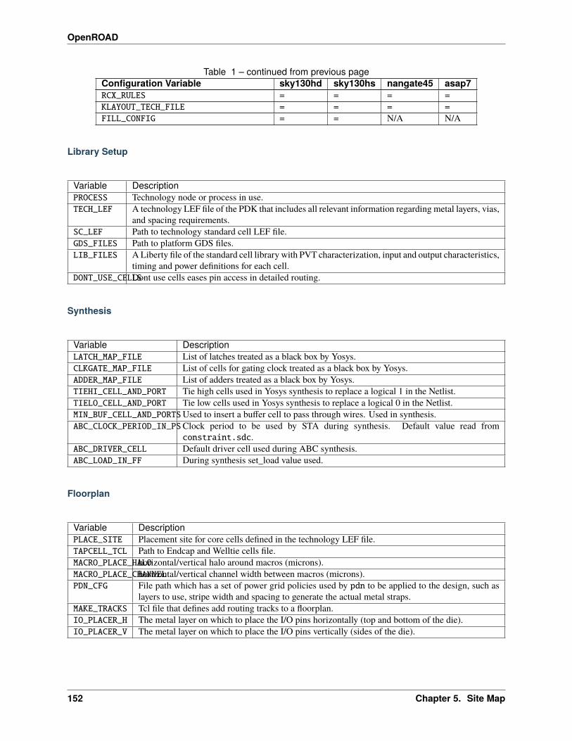
OpenROAD
Table 1 – continued from previous pageConfiguration Variable sky130hd sky130hs nangate45 asap7RCX_RULES = = = =KLAYOUT_TECH_FILE = = = =FILL_CONFIG = = N/A N/A
Library Setup
Variable DescriptionPROCESS Technology node or process in use.TECH_LEF A technology LEF file of the PDK that includes all relevant information regarding metal layers, vias,
and spacing requirements.SC_LEF Path to technology standard cell LEF file.GDS_FILES Path to platform GDS files.LIB_FILES A Liberty file of the standard cell library with PVT characterization, input and output characteristics,
timing and power definitions for each cell.DONT_USE_CELLSDont use cells eases pin access in detailed routing.
Synthesis
Variable DescriptionLATCH_MAP_FILE List of latches treated as a black box by Yosys.CLKGATE_MAP_FILE List of cells for gating clock treated as a black box by Yosys.ADDER_MAP_FILE List of adders treated as a black box by Yosys.TIEHI_CELL_AND_PORT Tie high cells used in Yosys synthesis to replace a logical 1 in the Netlist.TIELO_CELL_AND_PORT Tie low cells used in Yosys synthesis to replace a logical 0 in the Netlist.MIN_BUF_CELL_AND_PORTSUsed to insert a buffer cell to pass through wires. Used in synthesis.ABC_CLOCK_PERIOD_IN_PSClock period to be used by STA during synthesis. Default value read from
constraint.sdc.ABC_DRIVER_CELL Default driver cell used during ABC synthesis.ABC_LOAD_IN_FF During synthesis set_load value used.
Floorplan
Variable DescriptionPLACE_SITE Placement site for core cells defined in the technology LEF file.TAPCELL_TCL Path to Endcap and Welltie cells file.MACRO_PLACE_HALOhorizontal/vertical halo around macros (microns).MACRO_PLACE_CHANNELhorizontal/vertical channel width between macros (microns).PDN_CFG File path which has a set of power grid policies used by pdn to be applied to the design, such as
layers to use, stripe width and spacing to generate the actual metal straps.MAKE_TRACKS Tcl file that defines add routing tracks to a floorplan.IO_PLACER_H The metal layer on which to place the I/O pins horizontally (top and bottom of the die).IO_PLACER_V The metal layer on which to place the I/O pins vertically (sides of the die).
152 Chapter 5. Site Map
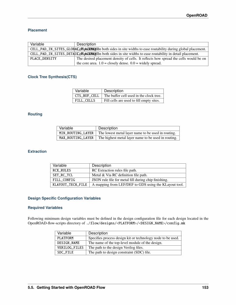
OpenROAD
Placement
Variable DescriptionCELL_PAD_IN_SITES_GLOBAL_PLACEMENTCell padding on both sides in site widths to ease routability during global placement.CELL_PAD_IN_SITES_DETAIL_PLACEMENTCell padding on both sides in site widths to ease routability in detail placement.PLACE_DENSITY The desired placement density of cells. It reflects how spread the cells would be on
the core area. 1.0 = closely dense. 0.0 = widely spread.
Clock Tree Synthesis(CTS)
Variable DescriptionCTS_BUF_CELL The buffer cell used in the clock tree.FILL_CELLS Fill cells are used to fill empty sites.
Routing
Variable DescriptionMIN_ROUTING_LAYER The lowest metal layer name to be used in routing.MAX_ROUTING_LAYER The highest metal layer name to be used in routing.
Extraction
Variable DescriptionRCX_RULES RC Extraction rules file path.SET_RC_TCL Metal & Via RC definition file path.FILL_CONFIG JSON rule file for metal fill during chip finishing.KLAYOUT_TECH_FILE A mapping from LEF/DEF to GDS using the KLayout tool.
Design Specific Configuration Variables
Required Variables
Following minimum design variables must be defined in the design configuration file for each design located in theOpenROAD-flow-scripts directory of ./flow/designs/<PLATFORM>/<DESIGN_NAME>/config.mk
Variable DescriptionPLATFORM Specifies process design kit or technology node to be used.DESIGN_NAME The name of the top-level module of the design.VERILOG_FILES The path to the design Verilog files.SDC_FILE The path to design constraint (SDC) file.
5.5. Getting Started with OpenROAD Flow 153
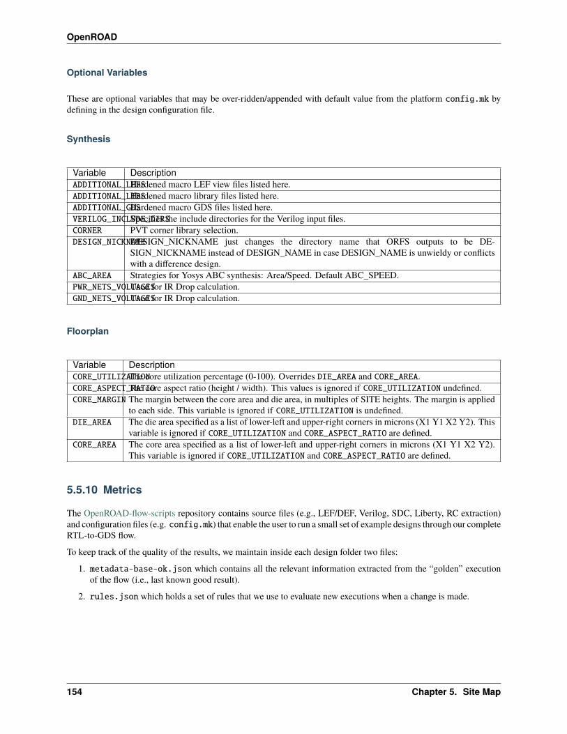
OpenROAD
Optional Variables
These are optional variables that may be over-ridden/appended with default value from the platform config.mk bydefining in the design configuration file.
Synthesis
Variable DescriptionADDITIONAL_LEFSHardened macro LEF view files listed here.ADDITIONAL_LIBSHardened macro library files listed here.ADDITIONAL_GDSHardened macro GDS files listed here.VERILOG_INCLUDE_DIRSSpecifies the include directories for the Verilog input files.CORNER PVT corner library selection.DESIGN_NICKNAMEDESIGN_NICKNAME just changes the directory name that ORFS outputs to be DE-
SIGN_NICKNAME instead of DESIGN_NAME in case DESIGN_NAME is unwieldy or conflictswith a difference design.
ABC_AREA Strategies for Yosys ABC synthesis: Area/Speed. Default ABC_SPEED.PWR_NETS_VOLTAGESUsed for IR Drop calculation.GND_NETS_VOLTAGESUsed for IR Drop calculation.
Floorplan
Variable DescriptionCORE_UTILIZATIONThe core utilization percentage (0-100). Overrides DIE_AREA and CORE_AREA.CORE_ASPECT_RATIOThe core aspect ratio (height / width). This values is ignored if CORE_UTILIZATION undefined.CORE_MARGIN The margin between the core area and die area, in multiples of SITE heights. The margin is applied
to each side. This variable is ignored if CORE_UTILIZATION is undefined.DIE_AREA The die area specified as a list of lower-left and upper-right corners in microns (X1 Y1 X2 Y2). This
variable is ignored if CORE_UTILIZATION and CORE_ASPECT_RATIO are defined.CORE_AREA The core area specified as a list of lower-left and upper-right corners in microns (X1 Y1 X2 Y2).
This variable is ignored if CORE_UTILIZATION and CORE_ASPECT_RATIO are defined.
5.5.10 Metrics
The OpenROAD-flow-scripts repository contains source files (e.g., LEF/DEF, Verilog, SDC, Liberty, RC extraction)and configuration files (e.g. config.mk) that enable the user to run a small set of example designs through our completeRTL-to-GDS flow.
To keep track of the quality of the results, we maintain inside each design folder two files:
1. metadata-base-ok.json which contains all the relevant information extracted from the “golden” executionof the flow (i.e., last known good result).
2. rules.json which holds a set of rules that we use to evaluate new executions when a change is made.
154 Chapter 5. Site Map
OpenROAD
Checking against golden
The evaluation checks for key metrics (e.g., worst slack, number of DRCs) to ensure that changes do not degrade toomuch with respect to the “golden” values.
After you make a significant change, e.g., fixing a bug in a piece of code, or changing some configuration variable(PLACE_DENSITY), you should review the results and compare them with the “golden”. To perform the check, you willneed to run the following command:
cd OpenROAD-flow-scripts/flow# the clean_metadata is only required if you need to re-runmake [clean_metadata] metadata
If the command above yields any error message, please review to make sure the change in metrics is expected andjustifiable. If so, proceed to the next section to update the “golden” reference.
Update process
Update of the reference files is mandatory if any metrics became worse than the values limited by the rules.json(see previous section on how to perform the check). Also, it is a good idea to update the “golden” files if your changeshave improved a metric, to ensure that the improvement will not be lost in the future.
To update all the reference files:
cd OpenROAD-flow-scripts/flowmake update_ok
In case you have a special reason to only update one of the files, you can do so with the following commands:
# update metadata-base-ok.json file for the designmake update_metadata
# update rules.json file for the design# this will use the current (+ a padding) metadata-base-ok.json# the padding ensures that small changes do not break the flowmake update_rules
5.5.11 Instructions for AutoTuner with Ray
AutoTuner is a “no-human-in-loop” parameter tuning framework for commercial and academic RTL-to-GDS flows.AutoTuner provides a generic interface where users can define parameter configuration as JSON objects. This enablesAutoTuner to easily support various tools and flows. AutoTuner also utilizes METRICS2.1 to capture PPA of individualsearch trials. With the abundant features of METRICS2.1, users can explore various reward functions that steer theflow autotuning to different PPA goals.
AutoTuner provides two main functionalities as follows.
• Automatic hyperparameter tuning framework for OpenROAD-flow-script (ORFS)
• Parametric sweeping experiments for ORFS
AutoTuner contains top-level Python script for ORFS, each of which implements a different search algorithm. Currentsupported search algorithms are as follows.
• Random/Grid Search
5.5. Getting Started with OpenROAD Flow 155
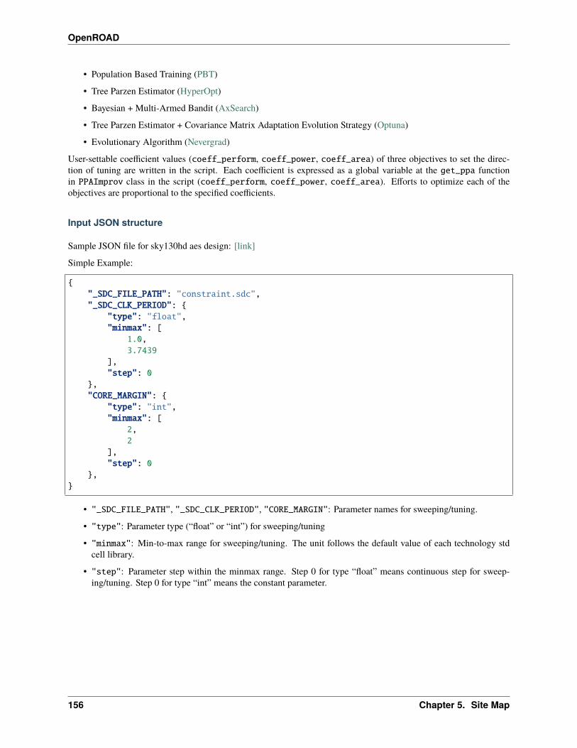
OpenROAD
• Population Based Training (PBT)
• Tree Parzen Estimator (HyperOpt)
• Bayesian + Multi-Armed Bandit (AxSearch)
• Tree Parzen Estimator + Covariance Matrix Adaptation Evolution Strategy (Optuna)
• Evolutionary Algorithm (Nevergrad)
User-settable coefficient values (coeff_perform, coeff_power, coeff_area) of three objectives to set the direc-tion of tuning are written in the script. Each coefficient is expressed as a global variable at the get_ppa functionin PPAImprov class in the script (coeff_perform, coeff_power, coeff_area). Efforts to optimize each of theobjectives are proportional to the specified coefficients.
Input JSON structure
Sample JSON file for sky130hd aes design: [link]
Simple Example:
{"_SDC_FILE_PATH": "constraint.sdc","_SDC_CLK_PERIOD": {
"type": "float","minmax": [
1.0,3.7439
],"step": 0
},"CORE_MARGIN": {
"type": "int","minmax": [
2,2
],"step": 0
},}
• "_SDC_FILE_PATH", "_SDC_CLK_PERIOD", "CORE_MARGIN": Parameter names for sweeping/tuning.
• "type": Parameter type (“float” or “int”) for sweeping/tuning
• "minmax": Min-to-max range for sweeping/tuning. The unit follows the default value of each technology stdcell library.
• "step": Parameter step within the minmax range. Step 0 for type “float” means continuous step for sweep-ing/tuning. Step 0 for type “int” means the constant parameter.
156 Chapter 5. Site Map
OpenROAD
Tunable / sweepable parameters
Tables of parameters that can be swept/tuned in technology platforms supported by ORFS. Any variable that can be setfrom the command line can be used for tune or sweep.
For SDC you can use:
• _SDC_FILE_PATH
– Path relative to the current JSON file to the SDC file.
• _SDC_CLK_PERIOD
– Design clock period. This will create a copy of _SDC_FILE_PATH and modify the clock period.
• _SDC_UNCERTAINTY
– Clock uncertainty. This will create a copy of _SDC_FILE_PATH and modify the clock uncertainty.
• _SDC_IO_DELAY
– I/O delay. This will create a copy of _SDC_FILE_PATH and modify the I/O delay.
For FastRoute you can use:
• _FR_FILE_PATH
– Path relative to the current JSON file to the fastroute.tcl file.
• _FR_LAYER_ADJUST
– Layer adjustment. This will create a copy of _FR_FILE_PATH and modify the layer adjustment for allroutable layers, i.e., from $MIN_ROUTING_LAYER to $MAX_ROUTING_LAYER.
• _FR_LAYER_ADJUST_NAME
– Layer adjustment for layer NAME. This will create a copy of _FR_FILE_PATH and modify the layer ad-justment only for the layer NAME.
• _FR_GR_SEED
– Global route random seed. This will create a copy of _FR_FILE_PATH and modify the global route randomseed.
How to use
General Information
distributed.py scripts handles sweeping and tuning of ORFS parameters.
For both sweep and tune modes :
python3 distributed.py -h
Note: the order of the parameters matter. Arguments --design, --platform and --config are always required andshould precede .
• AutoTuner: python3 distributed.py tune -h
Example:
5.5. Getting Started with OpenROAD Flow 157
OpenROAD
python3 distributed.py --design gcd --platform sky130hd \--config ../designs/sky130hd/gcd/autotuner.json \tune
• Parameter sweeping: python3 distributed.py sweep -h
Example:
python3 distributed.py --design gcd --platform sky130hd \--config distributed-sweep-example.json \sweep
Google Cloud Platform (GCP) distribution with Ray.
GCP Setup Tutorial coming soon.
List of input arguments
• Target design
– –design
∗ Name of the design for autotuning
– –platform
∗ Name of the platform for autotuning
• Experiment setup
– –config
∗ Configuration file that sets which knobs to use for autotuning
– –experiment
∗ Experiment name. This parameter is used to prefix the FLOW_VARIANT and to set the Ray log destina-tion
– –resume
∗ Resume previous run
• Git setup
– –git-clean
∗ Clean binaries and build files
– –git-clone
∗ Force new git clone
– –git-clone-args
∗ Additional git clone arguments
– –git-latest
∗ Use the latest version of OR app
– –git-or-branch
158 Chapter 5. Site Map
OpenROAD
∗ OR app branch to use
– –git-orfs-branch
∗ ORFS branch to use
– –git-url
∗ ORFS repo URL to use
– –build-args
∗ Additional arguments given to ./build_openroad.sh
• For AutoTuner
– –algorithm
∗ Search algorithm to use for autotuning
– –eval
∗ Evaluate function to use with search algorithm
– –samples
∗ Number of samples for autotuning
– –iterations
∗ Number of iterations for autotuning
– –reference
∗ Reference file for use with “PPAImprov” evaluation function
– –perturbation
∗ Perturbation interval for PopulationBasedTraining
– –seed
∗ Random seed for parameter selection during autotuning
• Workload
– –jobs
∗ Max number of concurrent jobs
– –openroad-threads
∗ Max number of threads OR app can use
– –server
∗ The address of Ray server to connect
– –port
∗ The port of Ray server to connect
– -v, –verbose
∗ Verbosity level
· 0: only print Ray status
· 1: also print training stderr
· 2: also print training stdout
5.5. Getting Started with OpenROAD Flow 159
OpenROAD
GUI
Basically, progress is displayed at the terminal where you run, and when all runs are finished, the results are displayed.You could find the “Best config found” on the screen.
To use TensorBoard GUI, run tensorboard --logdir=./<logpath>. While TensorBoard is running, you can openthe webpage http://localhost:6006/ to see the GUI.
Citation
Please cite the following paper.
• J. Jung, A. B. Kahng, S. Kim and R. Varadarajan, “METRICS2.1 and Flow Tuning in the IEEE CEDA RobustDesign Flow and OpenROAD”, (.pdf), (.pptx), (.mp4), Proc. ACM/IEEE International Conference on Computer-Aided Design, 2021.
Acknowledgments
AutoTuner has been developed by UCSD with the OpenROAD Project.
5.6 FAQs
If you cannot find your question/answer here, please file a GitHub issue to the appropriate repository or start a discus-sion.
• Issues and bugs:
– OpenROAD: https://github.com/The-OpenROAD-Project/OpenROAD/issues
– OpenROAD Flow: https://github.com/The-OpenROAD-Project/OpenROAD-flow-scripts/issues
• Discussions:
– OpenROAD: https://github.com/The-OpenROAD-Project/OpenROAD/discussions
– OpenROAD Flow: https://github.com/The-OpenROAD-Project/OpenROAD-flow-scripts/discussions
5.6.1 How can I contribute?
Thank you for your willingness to contribute. Please see the Getting Involved guide.
5.6.2 How do I update the design reference files?
See how to update the Metrics here.
160 Chapter 5. Site Map
OpenROAD
5.7 OpenROAD Flow Scripts Tutorial
5.7.1 Table of Contents
• Table of Contents
• Introduction
• User Guide
• Getting Started
– Setting Up The Environment
∗ Building OpenROAD Locally
• Configuring The Design
– Platform Configuration
– Design Configuration
– Timing Constraints
– Design Input Verilog
• Running The Automated RTL-to-GDS Flow
– Design Goals
– Viewing ORFS Directory Structure And Results
• Viewing Results And Logs
– Area
– Timing
– Power
• OpenROAD GUI
– Viewing Layout Results
– Visualizing Design Objects And Connectivity
– Tracing The Clock Tree
– Using Heat Maps
– Viewing Timing Report
– Using Rulers
– DRC Viewer
– Tcl Command Interface
– Customizing The GUI
• Manual Usage Of The OpenROAD Flow For Better User Control And Results
– Synthesis Explorations
∗ Area And Timing Optimization
– Floorplanning And Placement
∗ Floorplan Initialization Based On Core And Die Area
5.7. OpenROAD Flow Scripts Tutorial 161
OpenROAD
∗ Floorplan Based On Core Utilization
∗ Defining Placement Density
– Chip Level IO Pad Placement
– Power Planning And Analysis
– Placement Area or Timing Optimizations
∗ Macro Placement
· Macro Placement With Halo Spacing
· Macro placement With Channel Spacing
∗ Timing Optimization Using repair_design
∗ Timing Optimization Using repair_timing
∗ Timing Optimization Based On Multiple Corners
∗ Fixing Setup Violations
∗ Fixing Hold Violations
– Clock Tree Synthesis
∗ Reporting Clock Skews
∗ Reporting CTS Metrics
5.7.2 Introduction
This document describes a tutorial to run the complete OpenROAD based flow from RTL-to-GDS using OpenROADFlow Scripts. This tutorial also includes examples of useful design explorations and manual usage in key flow stagesto help users gain a good understanding of the OpenROAD application flow, data organization, GUI and commands.
This is intended for:
• Beginners or new users with some understanding of basic VLSI design flow. Users will learn the basics ofinstallation to use OpenROAD-flow-scripts for the complete RTL-to-GDS flow.
• Users already familiar with the OpenROAD application and flow but would like to learn more about specificfeatures and commands.
5.7.3 User Guide
• This tutorial requires a specific directory structure built by OpenROAD-flow-scripts (ORFS). Do not modify thisstructure or underlying files since this will cause problems in the flow execution.
• User can run the full RTL-to-GDS flow and learn specific flow sections independently. This allows users to learnthe flow and tool capabilities at their own pace, time and preference.
• Results shown, such as images or outputs of reports and logs, could vary based on release updates. However, themain flow and command structure should generally apply.
Note: Please submit any problem found under Issues in the GitHub repository here.
162 Chapter 5. Site Map
OpenROAD
5.7.4 Getting Started
This section describes the environment setup to build ORFS and get ready to execute the RTL-to-GDS flow of theopen-source design ibex using the sky130hd technology.
ibex is a 32 bit RISC-V CPU core (RV32IMC/EMC) with a two-stage pipeline.
Setting Up The Environment
Use the bash shell to run commands and scripts.
Install OpenROAD Flow Scripts. Refer to the Getting Started with OpenROAD Flow documentation.
If ORFS is already installed but needs updating, run the following commands:
cd OpenROAD-flow-scriptsgit checkout mastergit pullgit submodule update
Building OpenROAD Locally
Only the --local build option is used in the tutorial. For further details refer to the Build Locally documentation.
Alternatively, the user may build using the docker installation by referring to Build With Docker documentation.
./build_openroad.sh --localsource setup_env.sh
You will see the following message:
OPENROAD: <path>/OpenROAD-flow-scripts/tools/OpenROAD
ORFS installation is complete.
5.7.5 Configuring The Design
This section shows how to set up the necessary platform and design configuration files to run the complete RTL-to-GDSflow using OpenROAD-flow-scripts.
cd flow
Platform Configuration
View the platform configuration file setup for default variables for sky130hd.
less ./platforms/sky130hd/config.mk
The config.mk file has all the required variables for the sky130 platform and hence it is not recommended to changeany variable definition here. You can view the sky130hd platform configuration here.
Refer to the Flow variables document for details on how to use platform and design specific environment variables inOpenROAD-flow-scripts to customize and configure your design flow.
5.7. OpenROAD Flow Scripts Tutorial 163
OpenROAD
Design Configuration
View the default design configuration of ibex design:
less ./designs/sky130hd/ibex/config.mk
You can view ibex design config.mk here.
Note: The following design-specific configuration variables are required to specify main design inputs such as platform,top-level design name and constraints. We will use default configuration variables for this tutorial.
VariableName
Description
PLATFORM Specifies Process design kit.DESIGN_NAME The name of the top-level module of the designVERILOG_FILES The path to the design Verilog filesSDC_FILE The path to design .sdc fileCORE_UTILIZATIONThe core utilization percentage.PLACE_DENSITY The desired placement density of cells. It reflects how spread the cells would be on the core area.
1 = closely dense. 0 = widely spread
Timing Constraints
View timing constraints specified in the .sdc file here.
less ./designs/sky130hd/ibex/constraint.sdc
For ibex design, we simply use the clock definition as follows as a minimum required timing constraint.
create_clock -name core_clock -period 17.4 [get_ports {clk_i}]
Design Input Verilog
The Verilog input files are located in ./designs/src/ibex/
The design is defined in ibex_core.v available here.
Refer to the ibex design README.md here.
5.7.6 Running The Automated RTL-to-GDS Flow
This section describes the complete execution of the design flow from RTL-to-GDS. The OpenROAD applicationexecutes the entire autonomous flow using Tcl scripts that invoke open-sourced tools, from synthesis to the final .gdsfile creation, without requiring human intervention. However, in this tutorial, the user will learn both the automatedand a few interactive ways to run Tcl commands for important flow stages.
From the OpenROAD-flow-scripts directory, users can access individual flow stages, respective tools and the corre-sponding README.md for tool commands, configuration examples using the Tcl interface and other such details.
• Synthesis - Yosys.
• Floorplanning - Initialize Floorplan.
• Global Placement - RePlAce.
164 Chapter 5. Site Map
OpenROAD
• Clock Tree Synthesis - TrintonCTS 2.0.
• Detailed Placement - OpenDP.
• Global Route - Fast Route.
• Antenna Rule Checker - Antenna Rule Checker.
• Timing Optimization using Resizer - Gate Resizer.
• Detail Routing - TritonRoute.
• Layout Generation - KLayout (Requires v0.27.1).
Design Goals
Run the ibex design in ORFS automated flow from RTL-to-GDS using sky130hd for the given design goals below:
• Area
Minimum Required Die size: 0 0 798 800 (in micron)Core size: 2 2 796 798 (in micron)
• Timing
Clock period to meet timing: 17.4 (in ns)
ibex takes approximately 8 minutes on a machine with 8-cores and 16GB RAM. The runtime will vary based on yourconfiguration.
Change your current directory to the flow directory.
cd OpenROAD-flow-scripts/flow
Run the complete flow with:
make DESIGN_CONFIG=./designs/sky130hd/ibex/config.mk
As the flow executes, check out the ORFS directory contents and their significance.
Viewing ORFS Directory Structure And Results
Open a new tab in the terminal and explore the directory structure in OpenROAD-flow-scripts/flow by typing lscommand to view its contents:
designs logs Makefile objects platforms reports results scripts test util
Navigate through each of the sub-directories above to understand how underlying files are organized.
• designs/sky130hd/ibex Files include: designs make file and SDC file for the sky130hd platform and otherfiles for autotuner and metrics.
autotuner.json config.mk constraint_doe.sdc constraint.sdc metadata-base-ok.json rules.→˓json
• platforms Includes public PDKs supported by OpenROAD flow
5.7. OpenROAD Flow Scripts Tutorial 165
OpenROAD
asap7 nangate45 sky130hd sky130hs sky130io sky130ram
• objects/sky130hd/ibex/base Includes ABC constraints and all the temporary library files used for the com-pletion flow
abc.constr klayout.lyt klayout_tech.lef lib
• logs/sky130hd/ibex/base Logs directory, which contains log files for each flow stage.
logs
1_1_yosys.log 3_1_place_gp.log 5_2_TritonRoute.log2_1_floorplan.log 3_2_place_iop.log 6_1_merge.log2_2_floorplan_io.log 3_3_resizer.log 6_report.log2_3_tdms_place.log 3_4_opendp.log
2_4_mplace.log 4_1_cts.log
2_5_tapcell.log 4_2_cts_fillcell.log
2_6_pdn.log 5_1_fastroute.log
• results/sky130hd/ibex/base Results directory which contains .v/.sdc/.def/.spef files
results
1_1_yosys.v 3_1_place_gp.def 5_route.sdc1_synth.sdc 3_2_place_iop.def 6_1_fill.def1_synth.v 3_3_place_resized.def 6_1_fill.sdc2_1_floorplan.def 3_4_place_dp.def 6_1_merged.gds2_2_floorplan_io.def 3_place.def 6_final.def2_3_floorplan_tdms.def 3_place.sdc 6_final.gds2_4_floorplan_macro.def 4_1_cts.def 6_final.sdc2_5_floorplan_tapcell.def 4_2_cts_fillcell.def 6_final.spef2_6_floorplan_pdn.def 4_cts.def 6_final.v2_floorplan.def 4_cts.sdc output_guide.mod2_floorplan.sdc 4_cts.v route.guide2_floorplan.v 5_route.def updated_clks.sdc
• reports/sky130hd/ibex/base Reports directory, which contains DRC report, design statistics and antennalog for reference.
reports
5_route_drc.rpt final_clocks.webp final_placement.webpantenna.log final_clocks.webp final.webpsynth_stat.txt synth_check.txt final_resizer.webp
The table below briefly describes the reports directory files.
166 Chapter 5. Site Map

OpenROAD
File Name Description5_route_drc.rpt DRC violations if occurredfinal_clocks.webp OR extracted image reference after clock tree synthesis.final_resizer.webp OR extracted image reference after resizer.synth_check.txt Synthesis warning/error messagesantenna.log Antenna check log reportfinal_placement.webp Extracted image after final placementfinal.webp Extracted image after routing.synth_stat.txt Post synthesis design statistics log saved here.
The flow completes with the message below by creating a merged final GDS file.
[INFO] Writing out GDS/OAS'results/sky130hd/ibex/base/6_1_merged.gds'cp results/sky130hd/ibex/base/6_1_merged.gdsresults/sky130hd/ibex/base/6_final.gds
5.7.7 Viewing Results And Logs
ORFS prepends a prefix to each flow stage, as shown below, to indicate the position in the RTL-GDS flow. This makesit easier to understand and debug each flow stage in case of failure.
View ibex design logs:
ls logs/sky130hd/ibex/base/
The log structure is as follows:
logs
1_1_yosys.log 3_1_place_gp.log 5_2_TritonRoute.log2_1_floorplan.log 3_2_place_iop.log 6_1_merge.log2_2_floorplan_io.log 3_3_resizer.log 6_report.log2_3_tdms_place.log 3_4_opendp.log
2_4_mplace.log 4_1_cts.log
2_5_tapcell.log 4_2_cts_fillcell.log
2_6_pdn.log 5_1_fastroute.log
5.7. OpenROAD Flow Scripts Tutorial 167
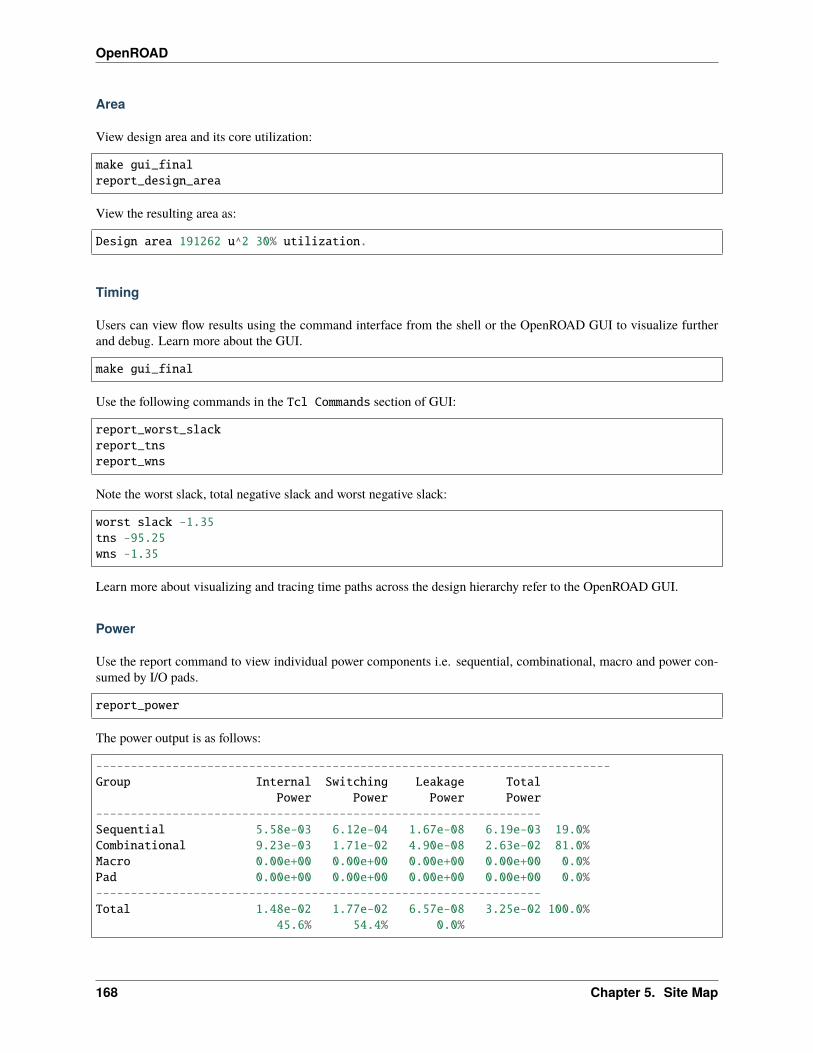
OpenROAD
Area
View design area and its core utilization:
make gui_finalreport_design_area
View the resulting area as:
Design area 191262 u^2 30% utilization.
Timing
Users can view flow results using the command interface from the shell or the OpenROAD GUI to visualize furtherand debug. Learn more about the GUI.
make gui_final
Use the following commands in the Tcl Commands section of GUI:
report_worst_slackreport_tnsreport_wns
Note the worst slack, total negative slack and worst negative slack:
worst slack -1.35tns -95.25wns -1.35
Learn more about visualizing and tracing time paths across the design hierarchy refer to the OpenROAD GUI.
Power
Use the report command to view individual power components i.e. sequential, combinational, macro and power con-sumed by I/O pads.
report_power
The power output is as follows:
--------------------------------------------------------------------------Group Internal Switching Leakage Total
Power Power Power Power----------------------------------------------------------------Sequential 5.58e-03 6.12e-04 1.67e-08 6.19e-03 19.0%Combinational 9.23e-03 1.71e-02 4.90e-08 2.63e-02 81.0%Macro 0.00e+00 0.00e+00 0.00e+00 0.00e+00 0.0%Pad 0.00e+00 0.00e+00 0.00e+00 0.00e+00 0.0%----------------------------------------------------------------Total 1.48e-02 1.77e-02 6.57e-08 3.25e-02 100.0%
45.6% 54.4% 0.0%
168 Chapter 5. Site Map
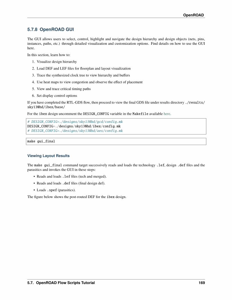
OpenROAD
5.7.8 OpenROAD GUI
The GUI allows users to select, control, highlight and navigate the design hierarchy and design objects (nets, pins,instances, paths, etc.) through detailed visualization and customization options. Find details on how to use the GUIhere.
In this section, learn how to:
1. Visualize design hierarchy
2. Load DEF and LEF files for floorplan and layout visualization
3. Trace the synthesized clock tree to view hierarchy and buffers
4. Use heat maps to view congestion and observe the effect of placement
5. View and trace critical timing paths
6. Set display control options
If you have completed the RTL-GDS flow, then proceed to view the final GDS file under results directory ./results/sky130hd/ibex/base/
For the ibex design uncomment the DESIGN_CONFIG variable in the Makefile available here.
# DESIGN_CONFIG=./designs/sky130hd/gcd/config.mkDESIGN_CONFIG=./designs/sky130hd/ibex/config.mk# DESIGN_CONFIG=./designs/sky130hd/aes/config.mk
make gui_final
Viewing Layout Results
The make gui_final command target successively reads and loads the technology .lef, design .def files and theparasitics and invokes the GUI in these steps:
• Reads and loads .lef files (tech and merged).
• Reads and loads .def files (final design def).
• Loads .spef (parasitics).
The figure below shows the post-routed DEF for the ibex design.
5.7. OpenROAD Flow Scripts Tutorial 169

OpenROAD
Visualizing Design Objects And Connectivity
Note the Display Control window on the LHS that shows buttons for color, visibility and selection options forvarious design objects: Layers, Nets, Instances, Blockages, Heatmaps, etc.
The Inspector window on the RHS allows users to inspect details of selected design objects and the timing report.
Try selectively displaying (show/hide) various design objects through the display control window and observing theirimpact on the display.
Tracing The Clock Tree
View the synthesized clock tree for ibex design:
• From the top Toolbar Click View -> Find
• In the Dialog Box Find Object search the clock net using a keyword as follows:
170 Chapter 5. Site Map

OpenROAD
Click Ok to view the synthesized clock tree of your design.
View clock tree structure below, the user needs to disable the metal Layers section on LHS as shown below.
From the top Toolbar, click on the Windows menu to select/hide different view options of Scripting, Display control,etc.
5.7. OpenROAD Flow Scripts Tutorial 171
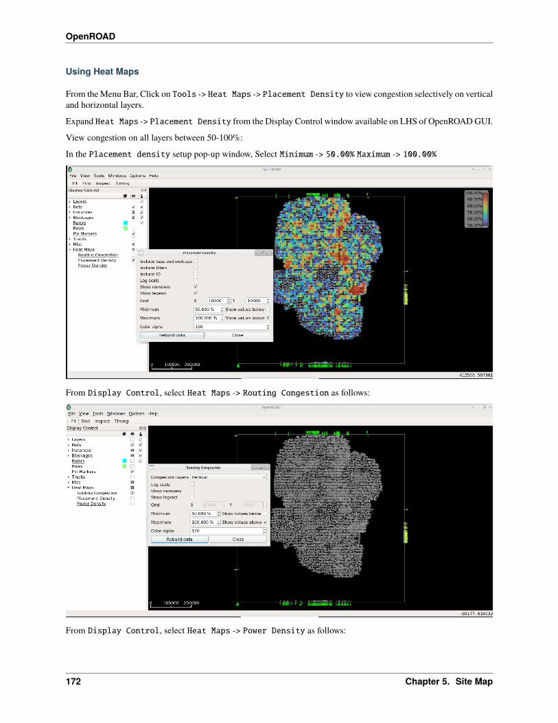
OpenROAD
Using Heat Maps
From the Menu Bar, Click on Tools -> Heat Maps -> Placement Density to view congestion selectively on verticaland horizontal layers.
Expand Heat Maps -> Placement Density from the Display Control window available on LHS of OpenROAD GUI.
View congestion on all layers between 50-100%:
In the Placement density setup pop-up window, Select Minimum -> 50.00% Maximum -> 100.00%
From Display Control, select Heat Maps -> Routing Congestion as follows:
From Display Control, select Heat Maps -> Power Density as follows:
172 Chapter 5. Site Map

OpenROAD
Viewing Timing Report
Click Timing -> Options to view and traverse specific timing paths. From Toolbar, click on the Timing icon, ViewTiming Report window added at the right side (RHS) of GUI as shown below.
In Timing Report Select Paths -> Update, Paths should be integer numbers. The number of timing paths shouldbe displayed in the current window as follows:
5.7. OpenROAD Flow Scripts Tutorial 173
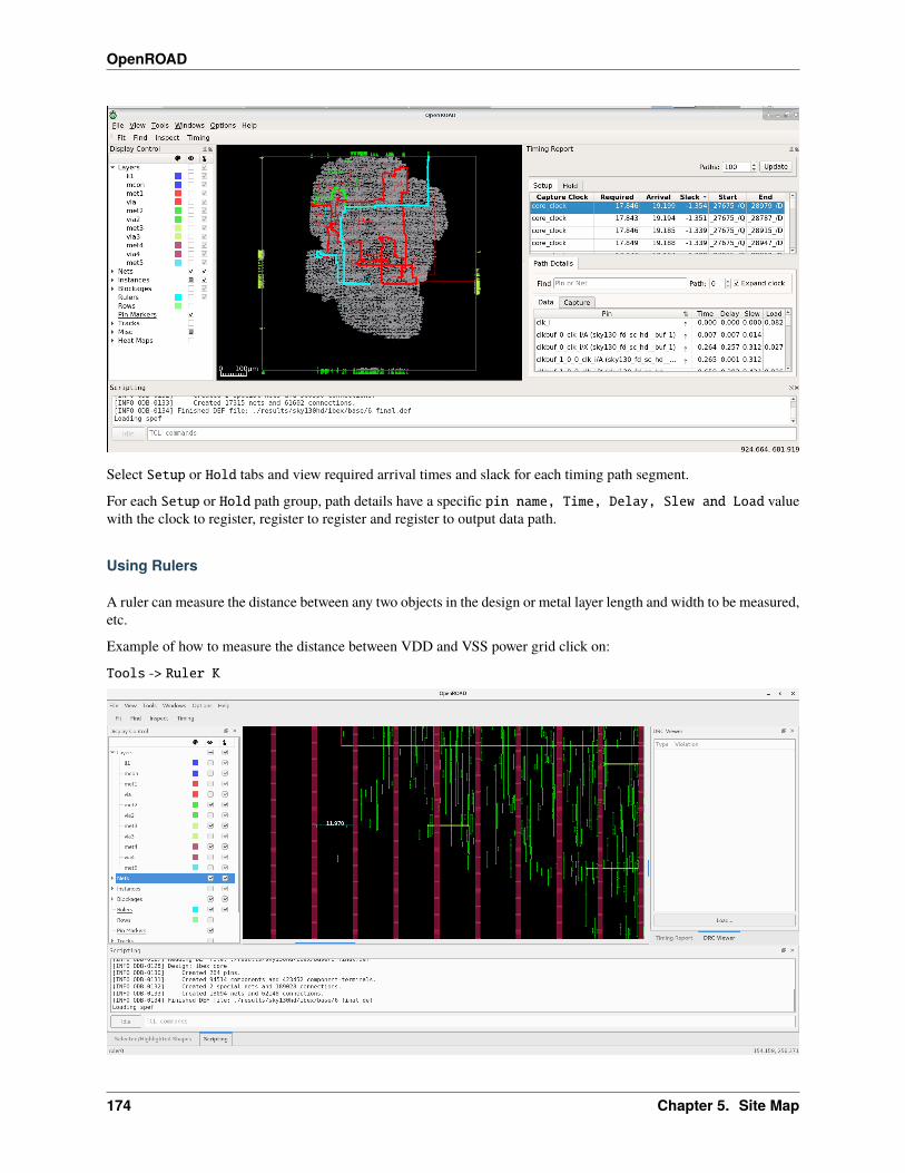
OpenROAD
Select Setup or Hold tabs and view required arrival times and slack for each timing path segment.
For each Setup or Hold path group, path details have a specific pin name, Time, Delay, Slew and Load valuewith the clock to register, register to register and register to output data path.
Using Rulers
A ruler can measure the distance between any two objects in the design or metal layer length and width to be measured,etc.
Example of how to measure the distance between VDD and VSS power grid click on:
Tools -> Ruler K
174 Chapter 5. Site Map

OpenROAD
Distance between VDD and VSS layer is 11.970
DRC Viewer
You can use the GUI to trace DRC violations and fix them.
View DRC violations post routing:
less ./reports/sky130hd/ibex/base/5_route_drc.rpt
Any DRC violations are logged in the 5_route_drc.rpt file, which is empty otherwise.
From OpenROAD GUI, Enable the menu options Windows -> DRC Viewer. A DRC viewer window is added on theright side (RHS) of the GUI. From DRC Viewer -> Load navigate to 5_route_drc.rpt
By selecting DRC violation details, designers can analyze and fix them. Here user will learn how a DRC violation canbe traced with the gcd design. Refer to the following openroad test case for more details.
cd ./flow/tutorials/scripts/drt/openroad -gui
In the Tcl Commands section of GUI:
source drc_issue.tcl
Post detail routing in the log, you can find the number of violations left in the design:
[INFO DRT-0199] Number of violations = 7.
Based on DRC Viewer steps load results/5_route_drc.rpt. GUI as follows
5.7. OpenROAD Flow Scripts Tutorial 175
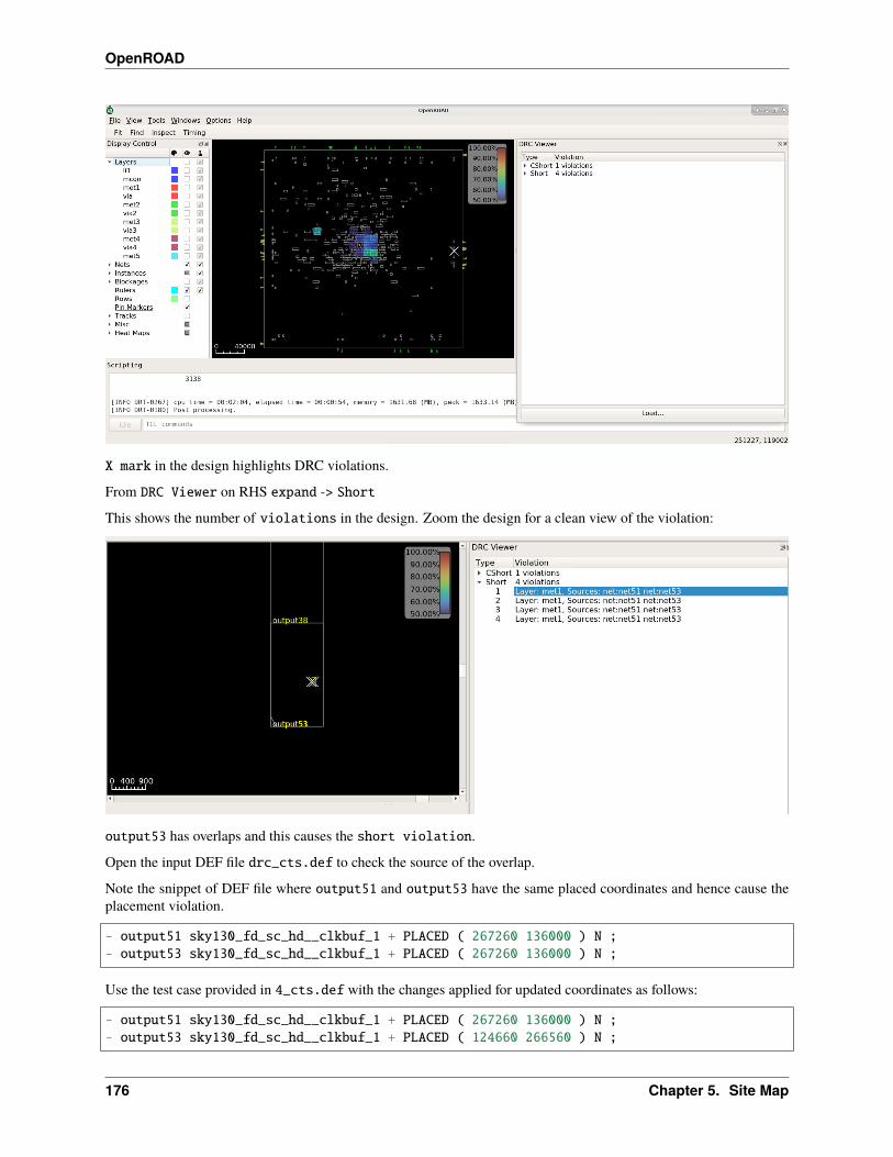
OpenROAD
X mark in the design highlights DRC violations.
From DRC Viewer on RHS expand -> Short
This shows the number of violations in the design. Zoom the design for a clean view of the violation:
output53 has overlaps and this causes the short violation.
Open the input DEF file drc_cts.def to check the source of the overlap.
Note the snippet of DEF file where output51 and output53 have the same placed coordinates and hence cause theplacement violation.
- output51 sky130_fd_sc_hd__clkbuf_1 + PLACED ( 267260 136000 ) N ;- output53 sky130_fd_sc_hd__clkbuf_1 + PLACED ( 267260 136000 ) N ;
Use the test case provided in 4_cts.def with the changes applied for updated coordinates as follows:
- output51 sky130_fd_sc_hd__clkbuf_1 + PLACED ( 267260 136000 ) N ;- output53 sky130_fd_sc_hd__clkbuf_1 + PLACED ( 124660 266560 ) N ;
176 Chapter 5. Site Map
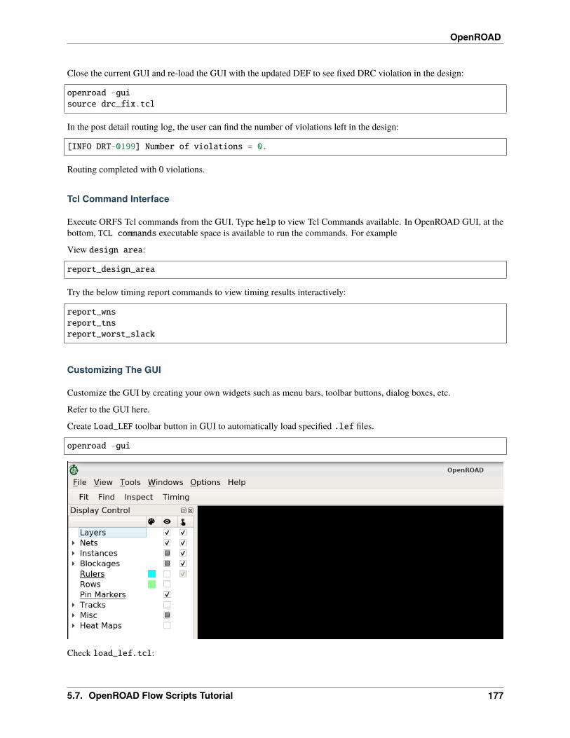
OpenROAD
Close the current GUI and re-load the GUI with the updated DEF to see fixed DRC violation in the design:
openroad -guisource drc_fix.tcl
In the post detail routing log, the user can find the number of violations left in the design:
[INFO DRT-0199] Number of violations = 0.
Routing completed with 0 violations.
Tcl Command Interface
Execute ORFS Tcl commands from the GUI. Type help to view Tcl Commands available. In OpenROAD GUI, at thebottom, TCL commands executable space is available to run the commands. For example
View design area:
report_design_area
Try the below timing report commands to view timing results interactively:
report_wnsreport_tnsreport_worst_slack
Customizing The GUI
Customize the GUI by creating your own widgets such as menu bars, toolbar buttons, dialog boxes, etc.
Refer to the GUI here.
Create Load_LEF toolbar button in GUI to automatically load specified .lef files.
openroad -gui
Check load_lef.tcl:
5.7. OpenROAD Flow Scripts Tutorial 177
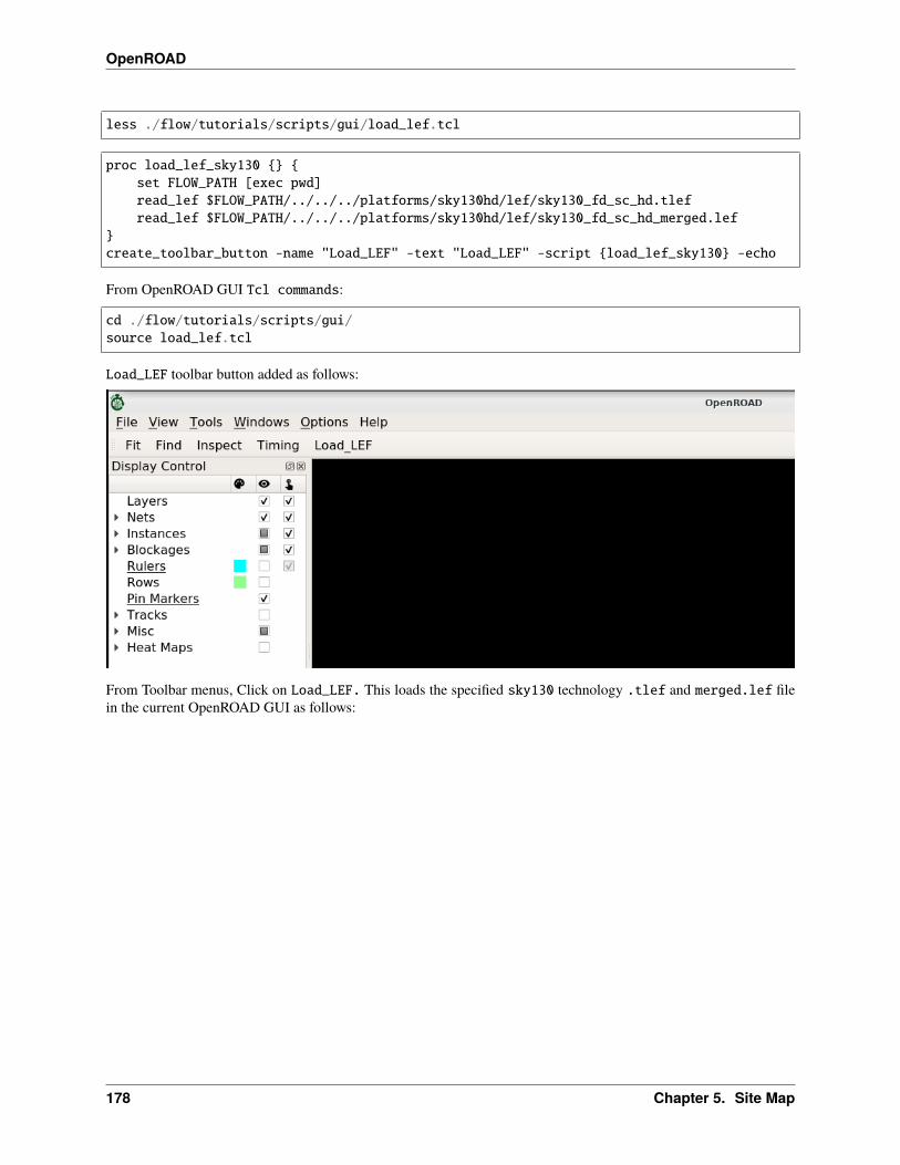
OpenROAD
less ./flow/tutorials/scripts/gui/load_lef.tcl
proc load_lef_sky130 {} {set FLOW_PATH [exec pwd]read_lef $FLOW_PATH/../../../platforms/sky130hd/lef/sky130_fd_sc_hd.tlefread_lef $FLOW_PATH/../../../platforms/sky130hd/lef/sky130_fd_sc_hd_merged.lef
}create_toolbar_button -name "Load_LEF" -text "Load_LEF" -script {load_lef_sky130} -echo
From OpenROAD GUI Tcl commands:
cd ./flow/tutorials/scripts/gui/source load_lef.tcl
Load_LEF toolbar button added as follows:
From Toolbar menus, Click on Load_LEF. This loads the specified sky130 technology .tlef and merged.lef filein the current OpenROAD GUI as follows:
178 Chapter 5. Site Map
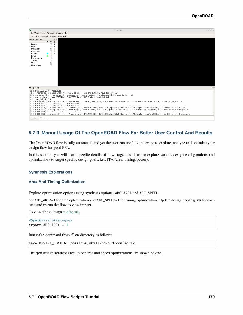
OpenROAD
5.7.9 Manual Usage Of The OpenROAD Flow For Better User Control And Results
The OpenROAD flow is fully automated and yet the user can usefully intervene to explore, analyze and optimize yourdesign flow for good PPA.
In this section, you will learn specific details of flow stages and learn to explore various design configurations andoptimizations to target specific design goals, i.e., PPA (area, timing, power).
Synthesis Explorations
Area And Timing Optimization
Explore optimization options using synthesis options: ABC_AREA and ABC_SPEED.
Set ABC_AREA=1 for area optimization and ABC_SPEED=1 for timing optimization. Update design config.mk for eachcase and re-run the flow to view impact.
To view ibex design config.mk.
#Synthesis strategiesexport ABC_AREA = 1
Run make command from flow directory as follows:
make DESIGN_CONFIG=./designs/sky130hd/gcd/config.mk
The gcd design synthesis results for area and speed optimizations are shown below:
5.7. OpenROAD Flow Scripts Tutorial 179
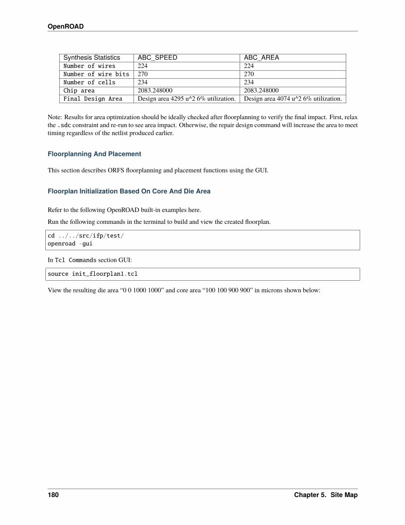
OpenROAD
Synthesis Statistics ABC_SPEED ABC_AREANumber of wires 224 224Number of wire bits 270 270Number of cells 234 234Chip area 2083.248000 2083.248000Final Design Area Design area 4295 u^2 6% utilization. Design area 4074 u^2 6% utilization.
Note: Results for area optimization should be ideally checked after floorplanning to verify the final impact. First, relaxthe .sdc constraint and re-run to see area impact. Otherwise, the repair design command will increase the area to meettiming regardless of the netlist produced earlier.
Floorplanning And Placement
This section describes ORFS floorplanning and placement functions using the GUI.
Floorplan Initialization Based On Core And Die Area
Refer to the following OpenROAD built-in examples here.
Run the following commands in the terminal to build and view the created floorplan.
cd ../../src/ifp/test/openroad -gui
In Tcl Commands section GUI:
source init_floorplan1.tcl
View the resulting die area “0 0 1000 1000” and core area “100 100 900 900” in microns shown below:
180 Chapter 5. Site Map
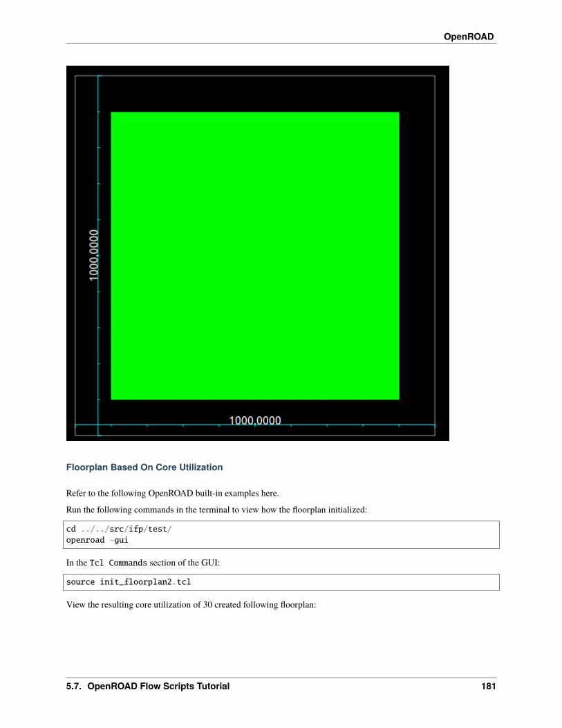
OpenROAD
Floorplan Based On Core Utilization
Refer to the following OpenROAD built-in examples here.
Run the following commands in the terminal to view how the floorplan initialized:
cd ../../src/ifp/test/openroad -gui
In the Tcl Commands section of the GUI:
source init_floorplan2.tcl
View the resulting core utilization of 30 created following floorplan:
5.7. OpenROAD Flow Scripts Tutorial 181
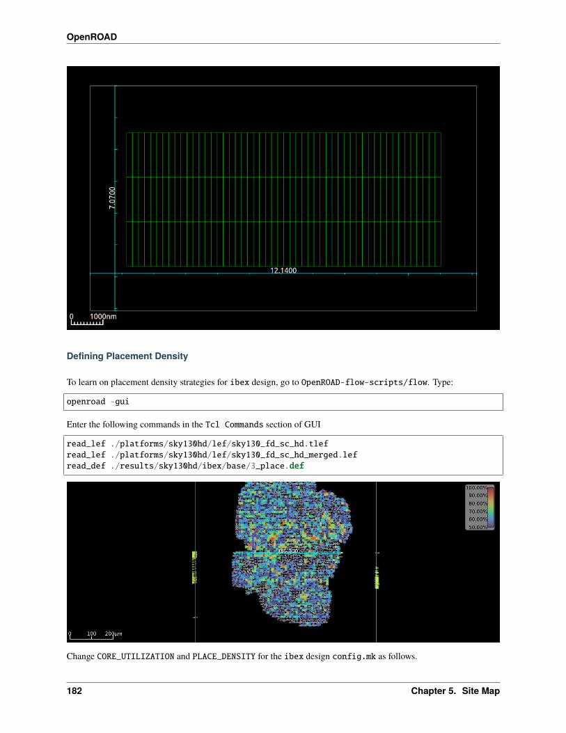
OpenROAD
Defining Placement Density
To learn on placement density strategies for ibex design, go to OpenROAD-flow-scripts/flow. Type:
openroad -gui
Enter the following commands in the Tcl Commands section of GUI
read_lef ./platforms/sky130hd/lef/sky130_fd_sc_hd.tlefread_lef ./platforms/sky130hd/lef/sky130_fd_sc_hd_merged.lefread_def ./results/sky130hd/ibex/base/3_place.def
Change CORE_UTILIZATION and PLACE_DENSITY for the ibex design config.mk as follows.
182 Chapter 5. Site Map

OpenROAD
View ibex design config.mk here.
export CORE_UTILIZATION = 40export CORE_ASPECT_RATIO = 1export CORE_MARGIN = 2export PLACE_DENSITY = 0.50
Re-run the ibex design with the below command:
make DESIGN_CONFIG=./designs/sky130hd/ibex/config.mk
View the ibex design placement density heat map as shown below:
So from above, GUI understood that change in CORE_UTILIZATION from 20 to 40 and placement density default 0.60to 0.50 changes standard cell placement became widely spread.
Chip Level IO Pad Placement
In this section, you will generate an I/O pad ring for the coyote design using a Tcl script.
ICeWall is a utility to place IO cells around the periphery of a design, and associate the IO cells with those present inthe netlist of the design.
For I/O pad placement using ICeWall refer to the readme file here.
Refer to the built-in examples here.
Launch openroad GUI:
cd ../../src/pad/test/openroad -gui
Run coyote_tc_sky130.tcl to view ICeWall based IO pad placement.
From the GUI Tcl commands section:
source coyote_tc_sky130.tcl
View the resulting IO pad ring in GUI:
5.7. OpenROAD Flow Scripts Tutorial 183
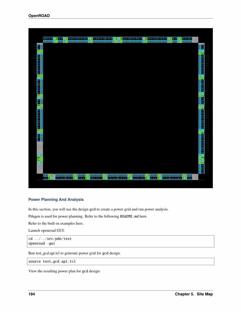
OpenROAD
Power Planning And Analysis
In this section, you will use the design gcd to create a power grid and run power analysis.
Pdngen is used for power planning. Refer to the following README.md here.
Refer to the built-in examples here.
Launch openroad GUI:
cd ../../src/pdn/testopenroad -gui
Run test_gcd.api.tcl to generate power grid for gcd design.
source test_gcd.api.tcl
View the resulting power plan for gcd design:
184 Chapter 5. Site Map
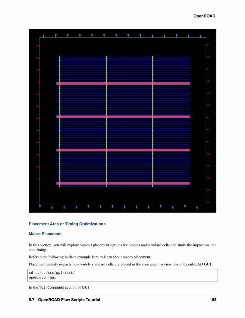
OpenROAD
Placement Area or Timing Optimizations
Macro Placement
In this section, you will explore various placement options for macros and standard cells and study the impact on areaand timing.
Refer to the following built-in example here to learn about macro placement.
Placement density impacts how widely standard cells are placed in the core area. To view this in OpenROAD GUI:
cd ../../src/gpl/test/openroad -gui
In the Tcl Commands section of GUI
5.7. OpenROAD Flow Scripts Tutorial 185
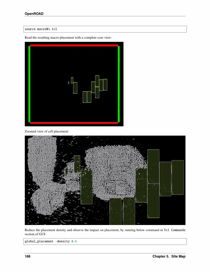
OpenROAD
source macro01.tcl
Read the resulting macro placement with a complete core view:
Zoomed view of cell placement:
Reduce the placement density and observe the impact on placement, by running below command in Tcl Commandssection of GUI:
global_placement -density 0.6
186 Chapter 5. Site Map
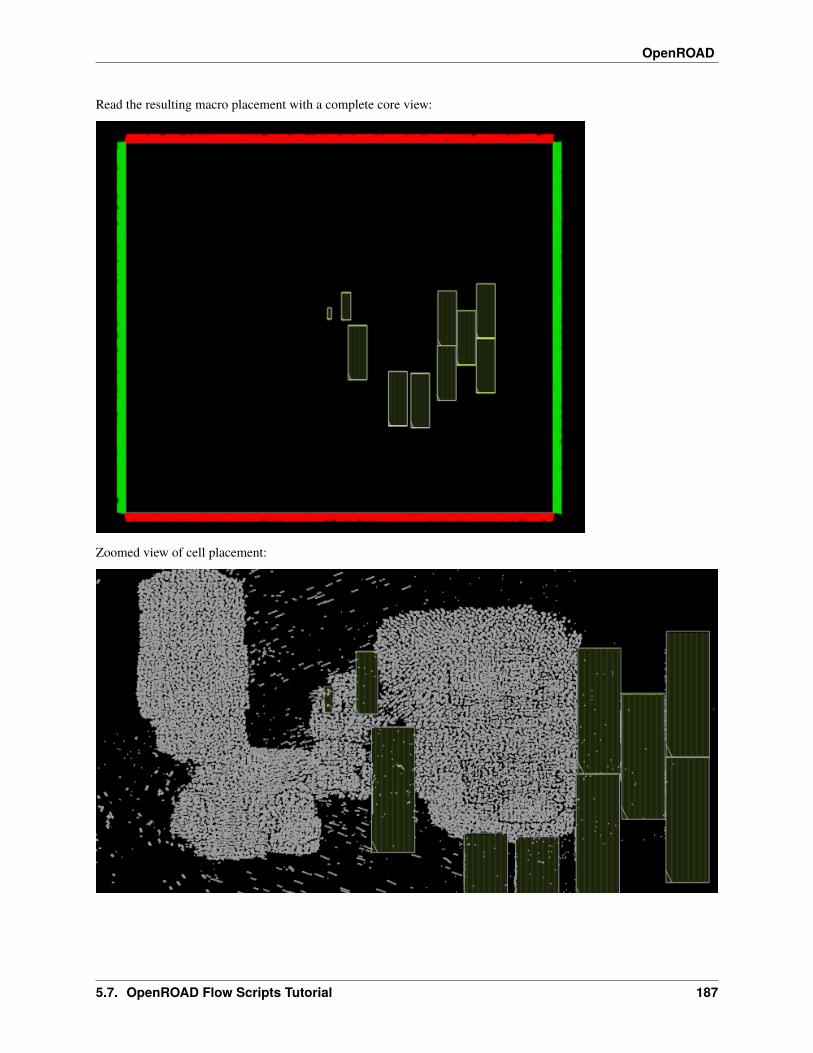
OpenROAD
Read the resulting macro placement with a complete core view:
Zoomed view of cell placement:
5.7. OpenROAD Flow Scripts Tutorial 187

OpenROAD
Macro Placement With Halo Spacing
Explore macro placement with halo spacing, refer to the example here.
Launch GUI:
cd ../../src/mpl/testopenroad -gui
In the Tcl Commands section of GUI:
source helpers.tclread_liberty Nangate45/Nangate45_typ.libread_liberty Nangate45/fakeram45_64x7.libread_lef Nangate45/Nangate45.lefread_lef Nangate45/fakeram45_64x7.lefread_def gcd_mem1.defread_sdc gcd.sdc
DEF file without halo spacing
Now increase the halo width for better routing resources.
In the Tcl Commands section of GUI:
macro_placement -halo {2.0 2.0}
DEF file with macro moved 2.0 micron from the left side of the core edge.
188 Chapter 5. Site Map
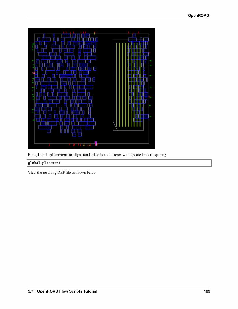
OpenROAD
Run global_placement to align standard cells and macros with updated macro spacing.
global_placement
View the resulting DEF file as shown below
5.7. OpenROAD Flow Scripts Tutorial 189
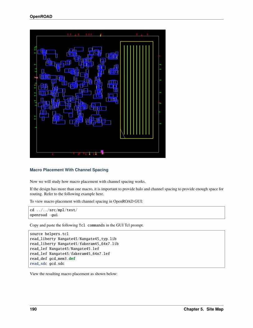
OpenROAD
Macro Placement With Channel Spacing
Now we will study how macro placement with channel spacing works.
If the design has more than one macro, it is important to provide halo and channel spacing to provide enough space forrouting. Refer to the following example here.
To view macro placement with channel spacing in OpenROAD GUI:
cd ../../src/mpl/test/openroad -gui
Copy and paste the following Tcl commands in the GUI Tcl prompt.
source helpers.tclread_liberty Nangate45/Nangate45_typ.libread_liberty Nangate45/fakeram45_64x7.libread_lef Nangate45/Nangate45.lefread_lef Nangate45/fakeram45_64x7.lefread_def gcd_mem3.defread_sdc gcd.sdc
View the resulting macro placement as shown below:
190 Chapter 5. Site Map
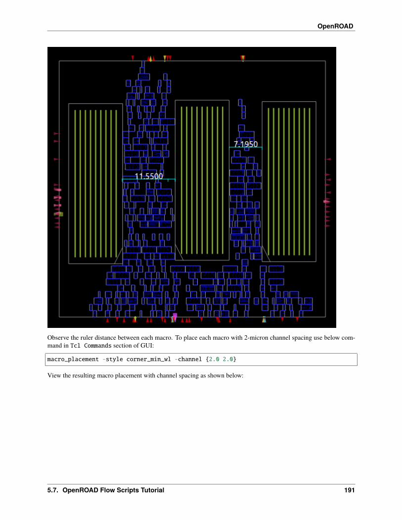
OpenROAD
Observe the ruler distance between each macro. To place each macro with 2-micron channel spacing use below com-mand in Tcl Commands section of GUI:
macro_placement -style corner_min_wl -channel {2.0 2.0}
View the resulting macro placement with channel spacing as shown below:
5.7. OpenROAD Flow Scripts Tutorial 191
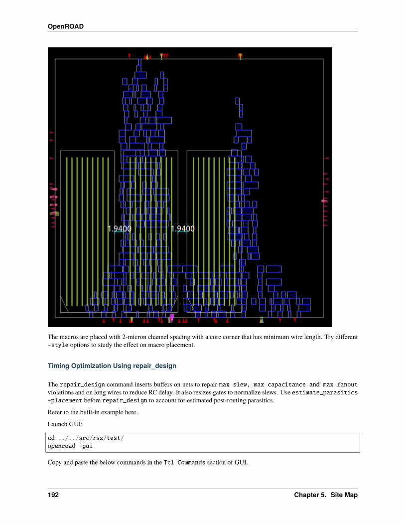
OpenROAD
The macros are placed with 2-micron channel spacing with a core corner that has minimum wire length. Try different-style options to study the effect on macro placement.
Timing Optimization Using repair_design
The repair_design command inserts buffers on nets to repair max slew, max capacitance and max fanoutviolations and on long wires to reduce RC delay. It also resizes gates to normalize slews. Use estimate_parasitics-placement before repair_design to account for estimated post-routing parasitics.
Refer to the built-in example here.
Launch GUI:
cd ../../src/rsz/test/openroad -gui
Copy and paste the below commands in the Tcl Commands section of GUI.
192 Chapter 5. Site Map
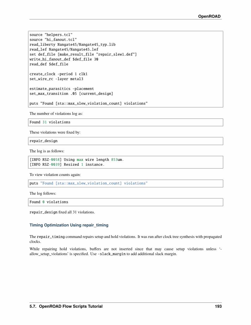
OpenROAD
source "helpers.tcl"source "hi_fanout.tcl"read_liberty Nangate45/Nangate45_typ.libread_lef Nangate45/Nangate45.lefset def_file [make_result_file "repair_slew1.def"]write_hi_fanout_def $def_file 30read_def $def_file
create_clock -period 1 clk1set_wire_rc -layer metal3
estimate_parasitics -placementset_max_transition .05 [current_design]
puts "Found [sta::max_slew_violation_count] violations"
The number of violations log as:
Found 31 violations
These violations were fixed by:
repair_design
The log is as follows:
[INFO RSZ-0058] Using max wire length 853um.[INFO RSZ-0039] Resized 1 instance.
To view violation counts again:
puts "Found [sta::max_slew_violation_count] violations"
The log follows:
Found 0 violations
repair_design fixed all 31 violations.
Timing Optimization Using repair_timing
The repair_timing command repairs setup and hold violations. It was run after clock tree synthesis with propagatedclocks.
While repairing hold violations, buffers are not inserted since that may cause setup violations unless ‘-allow_setup_violations’ is specified. Use -slack_margin to add additional slack margin.
5.7. OpenROAD Flow Scripts Tutorial 193

OpenROAD
Timing Optimization Based On Multiple Corners
OpenROAD supports multiple corner analysis to calculate worst-case setup and hold violations.
Setup time optimization is based on the slow corner or the best case when the launch clock arrives later than the dataclock. Hold time optimization is based on the fast corner or the best case when the launch clock arrives earlier than thecapture clock.
Refer to the following gcd design on repair_timing with fast and slow corners.
Refer to the built-in example here.
Run the following commands in the terminal:
cd ../../test/openroadsource gcd_sky130hd_fast_slow.tcl
The resulting worst slack, TNS:
report_worst_slack -min -digits 3worst slack 0.321report_worst_slack -max -digits 3worst slack -16.005report_tns -digits 3tns -529.496
Fixing Setup Violations
To fix setup timing path violations, use repair_timing -setup.
Refer to the following built-in example to learn more about fixing setup timing violations.
Refer to the built-in example here.
Launch OpenROAD in an interactive mode:
cd ../../src/rsz/test/openroad
Copy and paste the following Tcl commands.
define_corners fast slowread_liberty -corner slow Nangate45/Nangate45_slow.libread_liberty -corner fast Nangate45/Nangate45_fast.libread_lef Nangate45/Nangate45.lefread_def repair_setup1.defcreate_clock -period 0.3 clkset_wire_rc -layer metal3estimate_parasitics -placementreport_checks -fields input -digits 3
View the generated timing report with the slack violation.
194 Chapter 5. Site Map
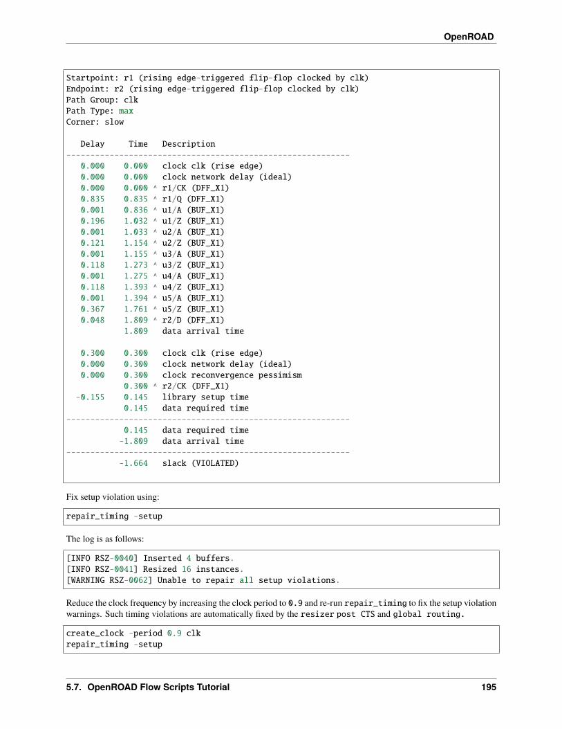
OpenROAD
Startpoint: r1 (rising edge-triggered flip-flop clocked by clk)Endpoint: r2 (rising edge-triggered flip-flop clocked by clk)Path Group: clkPath Type: maxCorner: slow
Delay Time Description-----------------------------------------------------------
0.000 0.000 clock clk (rise edge)0.000 0.000 clock network delay (ideal)0.000 0.000 ^ r1/CK (DFF_X1)0.835 0.835 ^ r1/Q (DFF_X1)0.001 0.836 ^ u1/A (BUF_X1)0.196 1.032 ^ u1/Z (BUF_X1)0.001 1.033 ^ u2/A (BUF_X1)0.121 1.154 ^ u2/Z (BUF_X1)0.001 1.155 ^ u3/A (BUF_X1)0.118 1.273 ^ u3/Z (BUF_X1)0.001 1.275 ^ u4/A (BUF_X1)0.118 1.393 ^ u4/Z (BUF_X1)0.001 1.394 ^ u5/A (BUF_X1)0.367 1.761 ^ u5/Z (BUF_X1)0.048 1.809 ^ r2/D (DFF_X1)
1.809 data arrival time
0.300 0.300 clock clk (rise edge)0.000 0.300 clock network delay (ideal)0.000 0.300 clock reconvergence pessimism
0.300 ^ r2/CK (DFF_X1)-0.155 0.145 library setup time
0.145 data required time-----------------------------------------------------------
0.145 data required time-1.809 data arrival time
------------------------------------------------------------1.664 slack (VIOLATED)
Fix setup violation using:
repair_timing -setup
The log is as follows:
[INFO RSZ-0040] Inserted 4 buffers.[INFO RSZ-0041] Resized 16 instances.[WARNING RSZ-0062] Unable to repair all setup violations.
Reduce the clock frequency by increasing the clock period to 0.9 and re-run repair_timing to fix the setup violationwarnings. Such timing violations are automatically fixed by the resizer post CTS and global routing.
create_clock -period 0.9 clkrepair_timing -setup
5.7. OpenROAD Flow Scripts Tutorial 195
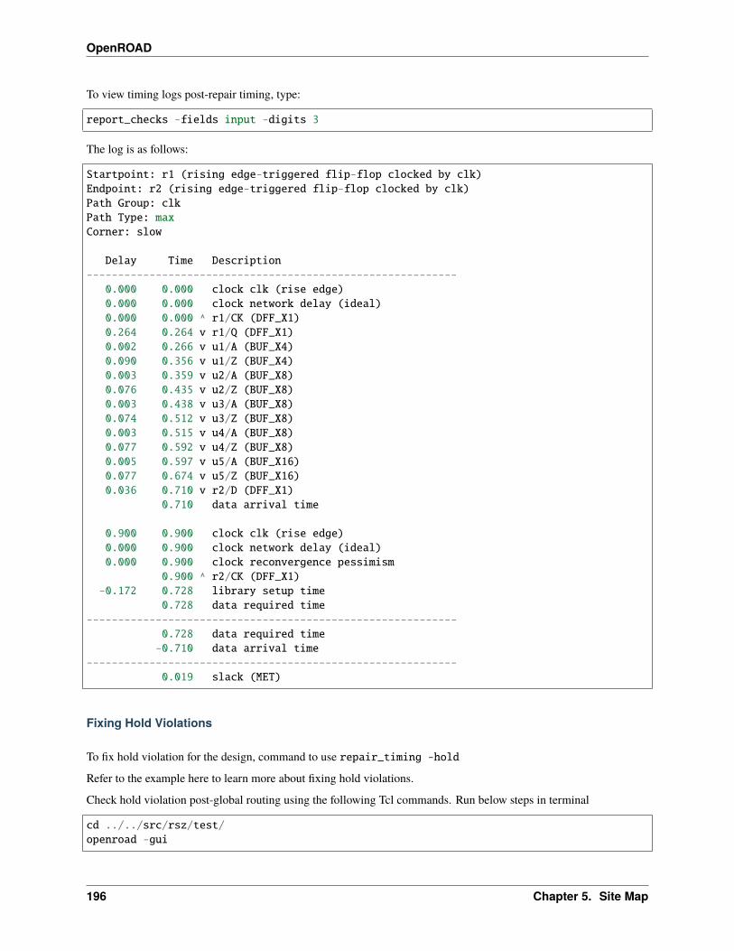
OpenROAD
To view timing logs post-repair timing, type:
report_checks -fields input -digits 3
The log is as follows:
Startpoint: r1 (rising edge-triggered flip-flop clocked by clk)Endpoint: r2 (rising edge-triggered flip-flop clocked by clk)Path Group: clkPath Type: maxCorner: slow
Delay Time Description-----------------------------------------------------------
0.000 0.000 clock clk (rise edge)0.000 0.000 clock network delay (ideal)0.000 0.000 ^ r1/CK (DFF_X1)0.264 0.264 v r1/Q (DFF_X1)0.002 0.266 v u1/A (BUF_X4)0.090 0.356 v u1/Z (BUF_X4)0.003 0.359 v u2/A (BUF_X8)0.076 0.435 v u2/Z (BUF_X8)0.003 0.438 v u3/A (BUF_X8)0.074 0.512 v u3/Z (BUF_X8)0.003 0.515 v u4/A (BUF_X8)0.077 0.592 v u4/Z (BUF_X8)0.005 0.597 v u5/A (BUF_X16)0.077 0.674 v u5/Z (BUF_X16)0.036 0.710 v r2/D (DFF_X1)
0.710 data arrival time
0.900 0.900 clock clk (rise edge)0.000 0.900 clock network delay (ideal)0.000 0.900 clock reconvergence pessimism
0.900 ^ r2/CK (DFF_X1)-0.172 0.728 library setup time
0.728 data required time-----------------------------------------------------------
0.728 data required time-0.710 data arrival time
-----------------------------------------------------------0.019 slack (MET)
Fixing Hold Violations
To fix hold violation for the design, command to use repair_timing -hold
Refer to the example here to learn more about fixing hold violations.
Check hold violation post-global routing using the following Tcl commands. Run below steps in terminal
cd ../../src/rsz/test/openroad -gui
196 Chapter 5. Site Map

OpenROAD
Copy and paste the below commands in the Tcl Commands section of GUI.
source helpers.tclread_liberty sky130hd/sky130hd_tt.libread_lef sky130hd/sky130hd.tlefread_lef sky130hd/sky130hd_std_cell.lefread_def repair_hold10.defcreate_clock -period 2 clkset_propagated_clock clkset_wire_rc -resistance 0.0001 -capacitance 0.00001set_routing_layers -signal met1-met5global_routeestimate_parasitics -global_routingreport_worst_slack -min
Read the resulting worst slack as:
worst slack -1.95
The above worst slack was fixed with:
repair_timing -hold
The log is as follows:
[INFO RSZ-0046] Found 2 endpoints with hold violations.[INFO RSZ-0032] Inserted 5 hold buffers.
Re-check the slack value after repair_timing. Type:
report_worst_slack -min
The result worst slack value is as follows:
worst slack 0.16
Note that the worst slack is now met and the hold violation was fixed by the resizer.
Clock Tree Synthesis
TritonCTS 2.0 is available under the OpenROAD app to perform clock tree synthesis as the clock_tree_synthesisflow command. The ORFS automatically generates a well-balanced clock tree post-placement. In this section, you willlearn details about the building and visualize the clock tree.
Refer to the built-in example here.
Launch OpenROAD GUI:
cd ../../src/cts/test/openroad -gui
To build the clock tree, run the following commands in Tcl Commands of GUI:
read_lef Nangate45/Nangate45.lefread_liberty Nangate45/Nangate45_typ.lib
(continues on next page)
5.7. OpenROAD Flow Scripts Tutorial 197

OpenROAD
(continued from previous page)
read_def "16sinks.def"create_clock -period 5 clkset_wire_rc -clock -layer metal3clock_tree_synthesis -root_buf CLKBUF_X3 \
-buf_list CLKBUF_X3 \-wire_unit 20
Layout view before CTS as follows:
Layout view after CTS can be viewed via Find -> Find Object.
198 Chapter 5. Site Map

OpenROAD
Here we explore how clock tree buffers are inserted to balance the clock tree structure.
Refer to the built-in example here.
Generate a clock- tree that is unbalanced first, then explore the creation of a well-balanced clock tree.
Launch OpenROAD GUI:
cd ../../src/cts/test/openroad -gui
Use the following commands in the TCL commands section of GUI:
source balance_levels.tcl
The clock tree structure is as follows with unbalanced mode.
5.7. OpenROAD Flow Scripts Tutorial 199
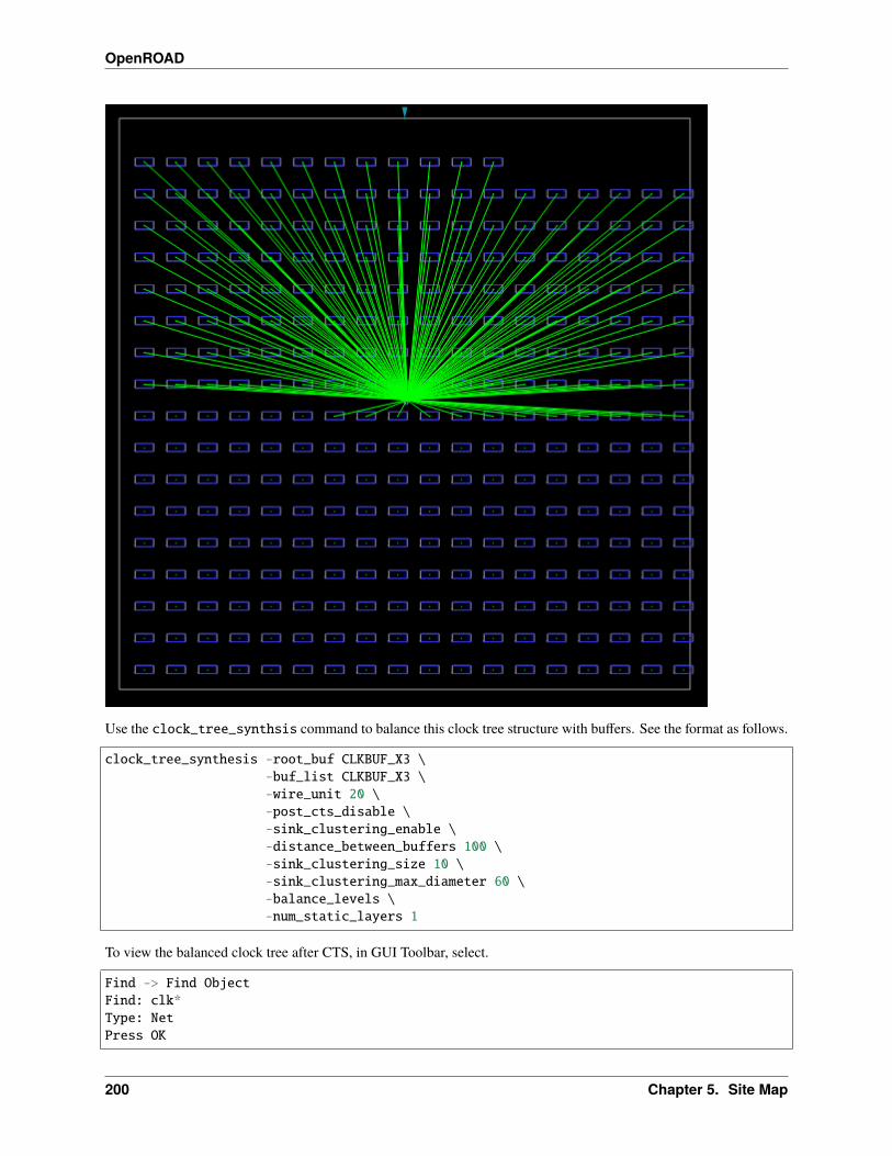
OpenROAD
Use the clock_tree_synthsis command to balance this clock tree structure with buffers. See the format as follows.
clock_tree_synthesis -root_buf CLKBUF_X3 \-buf_list CLKBUF_X3 \-wire_unit 20 \-post_cts_disable \-sink_clustering_enable \-distance_between_buffers 100 \-sink_clustering_size 10 \-sink_clustering_max_diameter 60 \-balance_levels \-num_static_layers 1
To view the balanced clock tree after CTS, in GUI Toolbar, select.
Find -> Find ObjectFind: clk*Type: NetPress OK
200 Chapter 5. Site Map
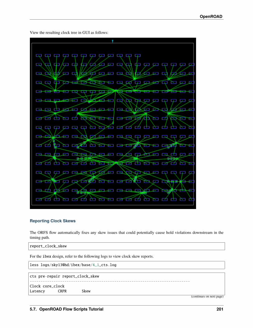
OpenROAD
View the resulting clock tree in GUI as follows:
Reporting Clock Skews
The ORFS flow automatically fixes any skew issues that could potentially cause hold violations downstream in thetiming path.
report_clock_skew
For the ibex design, refer to the following logs to view clock skew reports.
less logs/sky130hd/ibex/base/4_1_cts.log
cts pre-repair report_clock_skew--------------------------------------------------------------------------Clock core_clockLatency CRPR Skew
(continues on next page)
5.7. OpenROAD Flow Scripts Tutorial 201
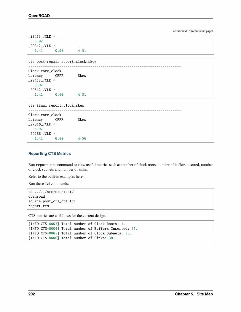
OpenROAD
(continued from previous page)
_28453_/CLK ^5.92
_29312_/CLK ^1.41 0.00 4.51
cts post-repair report_clock_skew--------------------------------------------------------------------------Clock core_clockLatency CRPR Skew_28453_/CLK ^
5.92_29312_/CLK ^
1.41 0.00 4.51
cts final report_clock_skew--------------------------------------------------------------------------Clock core_clockLatency CRPR Skew_27810_/CLK ^
5.97_29266_/CLK ^
1.41 0.00 4.56
Reporting CTS Metrics
Run report_cts command to view useful metrics such as number of clock roots, number of buffers inserted, numberof clock subnets and number of sinks.
Refer to the built-in examples here.
Run these Tcl commands:
cd ../../src/cts/test/openroadsource post_cts_opt.tclreport_cts
CTS metrics are as follows for the current design.
[INFO CTS-0003] Total number of Clock Roots: 1.[INFO CTS-0004] Total number of Buffers Inserted: 35.[INFO CTS-0005] Total number of Clock Subnets: 35.[INFO CTS-0006] Total number of Sinks: 301.
202 Chapter 5. Site Map