
Documentation EJ2128
109
Documentation EJ2128 8-Channel Digital Output Module 5 V DC / 3.3 V DC 1.0 2019-05-21 Version: Date:
-
Upload
khangminh22 -
Category
Documents
-
view
2 -
download
0
Transcript of Documentation EJ2128
Documentation
EJ2128
8-Channel Digital Output Module 5 V DC / 3.3 V DC
1.02019-05-21
Version:Date:

Table of contents
EJ2128 3Version: 1.0
Table of contents1 Foreword .................................................................................................................................................... 5
1.1 Notes on the documentation.............................................................................................................. 51.2 Safety instructions ............................................................................................................................. 61.3 Documentation issue status .............................................................................................................. 71.4 Version identification of EtherCAT devices ....................................................................................... 7
2 System overview ..................................................................................................................................... 11
3 Product overview..................................................................................................................................... 123.1 EJ2128 - Introduction ...................................................................................................................... 123.2 EJ2128 - Technical data.................................................................................................................. 133.3 EJ2128 - Connection ....................................................................................................................... 143.4 EJ2128 - LEDs ................................................................................................................................ 15
4 Basics communication ........................................................................................................................... 164.1 EtherCAT basics.............................................................................................................................. 164.2 EtherCAT devices - cabling - wired ................................................................................................. 164.3 General notes for setting the watchdog........................................................................................... 164.4 EtherCAT State Machine................................................................................................................. 184.5 CoE - Interface: notes...................................................................................................................... 204.6 Distributed Clock ............................................................................................................................. 21
5 Installation of EJ modules ...................................................................................................................... 225.1 Power supply for the EtherCAT plug-in modules............................................................................. 225.2 EJxxxx - dimensions........................................................................................................................ 245.3 Installation positions and minimum distances ................................................................................. 25
5.3.1 Minimum distances for ensuring installability................................................................... 255.3.2 Installation positions ........................................................................................................ 26
5.4 Codings ........................................................................................................................................... 285.4.1 Color coding..................................................................................................................... 285.4.2 Mechanical position coding.............................................................................................. 29
5.5 Installation on the signal distribution board ..................................................................................... 305.6 Extension options ............................................................................................................................ 31
5.6.1 Using placeholder modules for unused slots ................................................................... 315.6.2 Linking with EtherCAT Terminals and EtherCAT Box modules via an Ethernet/EtherCAT
connection ....................................................................................................................... 325.7 IPC integration................................................................................................................................. 335.8 Disassembly of the signal distribution board ................................................................................... 35
6 Commissioning........................................................................................................................................ 366.1 TwinCAT Quick Start ....................................................................................................................... 36
6.1.1 TwinCAT 2 ....................................................................................................................... 396.1.2 TwinCAT 3 ....................................................................................................................... 49
6.2 TwinCAT Development Environment .............................................................................................. 616.2.1 Installation of the TwinCAT real-time driver..................................................................... 616.2.2 Notes regarding ESI device description........................................................................... 676.2.3 TwinCAT ESI Updater ..................................................................................................... 716.2.4 Distinction between Online and Offline............................................................................ 71
Table of contents
EJ21284 Version: 1.0
6.2.5 OFFLINE configuration creation ...................................................................................... 726.2.6 ONLINE configuration creation ........................................................................................ 776.2.7 EtherCAT subscriber configuration.................................................................................. 85
6.3 General notes for commissioning of the EtherCAT slave................................................................ 946.4 EJ2128 - Switching behavior ......................................................................................................... 103
7 Appendix ................................................................................................................................................ 1047.1 EtherCAT AL Status Codes........................................................................................................... 1047.2 EJ2128 - Firmware compatibility ................................................................................................... 1047.3 Support and Service ...................................................................................................................... 105

Foreword
EJ2128 5Version: 1.0
1 Foreword
1.1 Notes on the documentation
Intended audience
This description is only intended for the use of trained specialists in control and automation engineering whoare familiar with the applicable national standards.It is essential that the documentation and the following notes and explanations are followed when installingand commissioning these components.It is the duty of the technical personnel to use the documentation published at the respective time of eachinstallation and commissioning.
The responsible staff must ensure that the application or use of the products described satisfy all therequirements for safety, including all the relevant laws, regulations, guidelines and standards.
Disclaimer
The documentation has been prepared with care. The products described are, however, constantly underdevelopment.
We reserve the right to revise and change the documentation at any time and without prior announcement.
No claims for the modification of products that have already been supplied may be made on the basis of thedata, diagrams and descriptions in this documentation.
Trademarks
Beckhoff®, TwinCAT®, EtherCAT®, EtherCAT P®, Safety over EtherCAT®, TwinSAFE®, XFC® and XTS® areregistered trademarks of and licensed by Beckhoff Automation GmbH.Other designations used in this publication may be trademarks whose use by third parties for their ownpurposes could violate the rights of the owners.
Patent Pending
The EtherCAT Technology is covered, including but not limited to the following patent applications andpatents: EP1590927, EP1789857, DE102004044764, DE102007017835 with corresponding applications orregistrations in various other countries.
The TwinCAT Technology is covered, including but not limited to the following patent applications andpatents: EP0851348, US6167425 with corresponding applications or registrations in various other countries.
EtherCAT® is registered trademark and patented technology, licensed by Beckhoff Automation GmbH,Germany.
Copyright
© Beckhoff Automation GmbH & Co. KG, Germany.The reproduction, distribution and utilization of this document as well as the communication of its contents toothers without express authorization are prohibited.Offenders will be held liable for the payment of damages. All rights reserved in the event of the grant of apatent, utility model or design.
Foreword
EJ21286 Version: 1.0
1.2 Safety instructions
Safety regulations
Please note the following safety instructions and explanations!Product-specific safety instructions can be found on following pages or in the areas mounting, wiring,commissioning etc.
Exclusion of liability
All the components are supplied in particular hardware and software configurations appropriate for theapplication. Modifications to hardware or software configurations other than those described in thedocumentation are not permitted, and nullify the liability of Beckhoff Automation GmbH & Co. KG.
Personnel qualification
This description is only intended for trained specialists in control, automation and drive engineering who arefamiliar with the applicable national standards.
Description of instructions
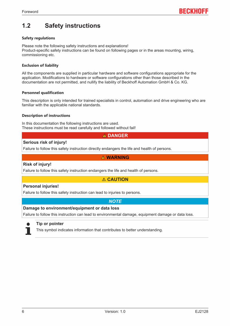
In this documentation the following instructions are used. These instructions must be read carefully and followed without fail!
DANGERSerious risk of injury!Failure to follow this safety instruction directly endangers the life and health of persons.
WARNINGRisk of injury!Failure to follow this safety instruction endangers the life and health of persons.
CAUTIONPersonal injuries!Failure to follow this safety instruction can lead to injuries to persons.
NOTEDamage to environment/equipment or data lossFailure to follow this instruction can lead to environmental damage, equipment damage or data loss.
Tip or pointerThis symbol indicates information that contributes to better understanding.
Foreword
EJ2128 7Version: 1.0
1.3 Documentation issue statusVersion Comment1.0 • 1st publication EJ2128
1.4 Version identification of EtherCAT devices
Designation
A Beckhoff EtherCAT device has a 14-digit designation, made up of
• family key• type• version• revision
Example Family Type Version RevisionEL3314-0000-0016 EL terminal
(12 mm, non-pluggable connectionlevel)
3314 (4-channel thermocoupleterminal)
0000 (basic type) 0016
ES3602-0010-0017 ES terminal(12 mm, pluggableconnection level)
3602 (2-channel voltagemeasurement)
0010 (high-precision version)
0017
CU2008-0000-0000 CU device 2008 (8-port fast ethernet switch) 0000 (basic type) 0000
Notes• The elements mentioned above result in the technical designation. EL3314-0000-0016 is used in the
example below.• EL3314-0000 is the order identifier, in the case of “-0000” usually abbreviated to EL3314. “-0016” is the
EtherCAT revision.• The order identifier is made up of
- family key (EL, EP, CU, ES, KL, CX, etc.)- type (3314)- version (-0000)
• The revision -0016 shows the technical progress, such as the extension of features with regard to theEtherCAT communication, and is managed by Beckhoff.In principle, a device with a higher revision can replace a device with a lower revision, unless specifiedotherwise, e.g. in the documentation.Associated and synonymous with each revision there is usually a description (ESI, EtherCAT SlaveInformation) in the form of an XML file, which is available for download from the Beckhoff web site. From 2014/01 the revision is shown on the outside of the IP20 terminals, see Fig. “EL5021 EL terminal,standard IP20 IO device with batch number and revision ID (since 2014/01)”.
• The type, version and revision are read as decimal numbers, even if they are technically saved inhexadecimal.
Identification number
Beckhoff EtherCAT devices from the different lines have different kinds of identification numbers:
Production lot/batch number/serial number/date code/D number
The serial number for Beckhoff IO devices is usually the 8-digit number printed on the device or on a sticker.The serial number indicates the configuration in delivery state and therefore refers to a whole productionbatch, without distinguishing the individual modules of a batch.
Foreword
EJ21288 Version: 1.0
Structure of the serial number: KK YY FF HH
KK - week of production (CW, calendar week)YY - year of productionFF - firmware versionHH - hardware version
Example with Ser. no.: 12063A02: 12 - production week 12 06 - production year 2006 3A - firmware version 3A 02 -hardware version 02
Exceptions can occur in the IP67 area, where the following syntax can be used (see respective devicedocumentation):
Syntax: D ww yy x y z u
D - prefix designationww - calendar weekyy - yearx - firmware version of the bus PCBy - hardware version of the bus PCBz - firmware version of the I/O PCBu - hardware version of the I/O PCB
Example: D.22081501 calendar week 22 of the year 2008 firmware version of bus PCB: 1 hardware versionof bus PCB: 5 firmware version of I/O PCB: 0 (no firmware necessary for this PCB) hardware version of I/OPCB: 1
Unique serial number/ID, ID number
In addition, in some series each individual module has its own unique serial number.
See also the further documentation in the area
• IP67: EtherCAT Box
• Safety: TwinSafe• Terminals with factory calibration certificate and other measuring terminals
Examples of markings
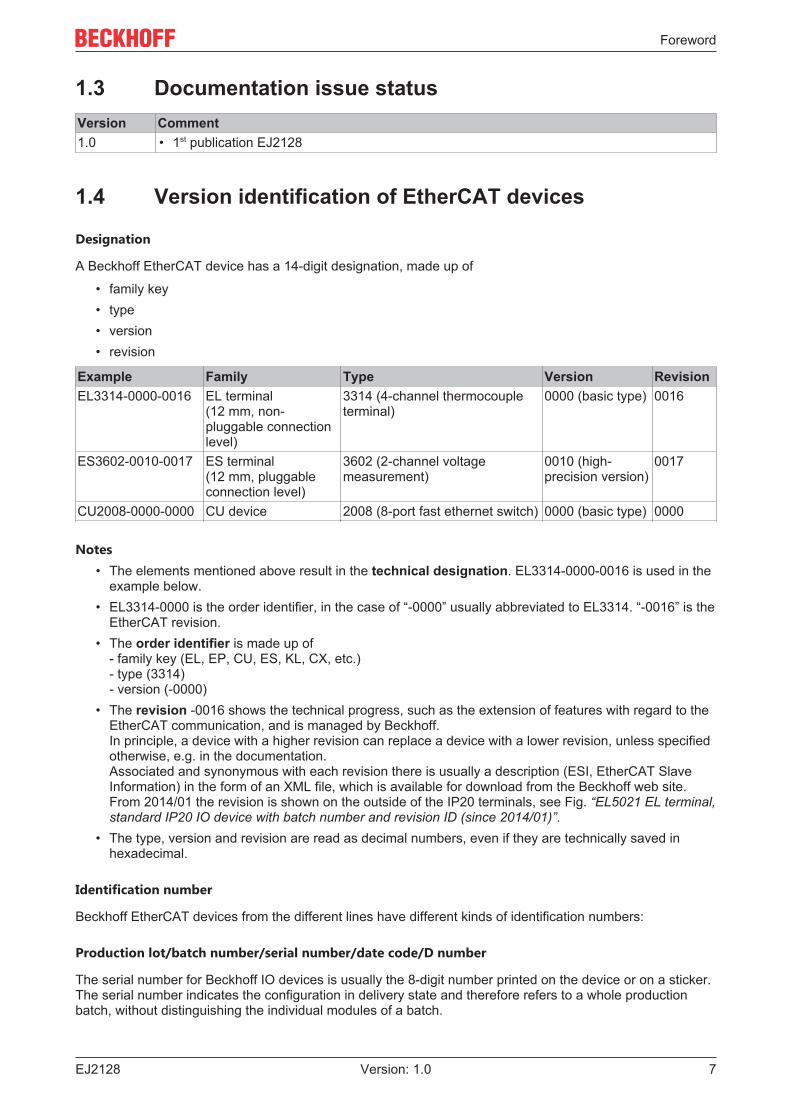
Fig. 1: EL5021 EL terminal, standard IP20 IO device with serial/ batch number and revision ID (since2014/01)
Foreword
EJ2128 9Version: 1.0
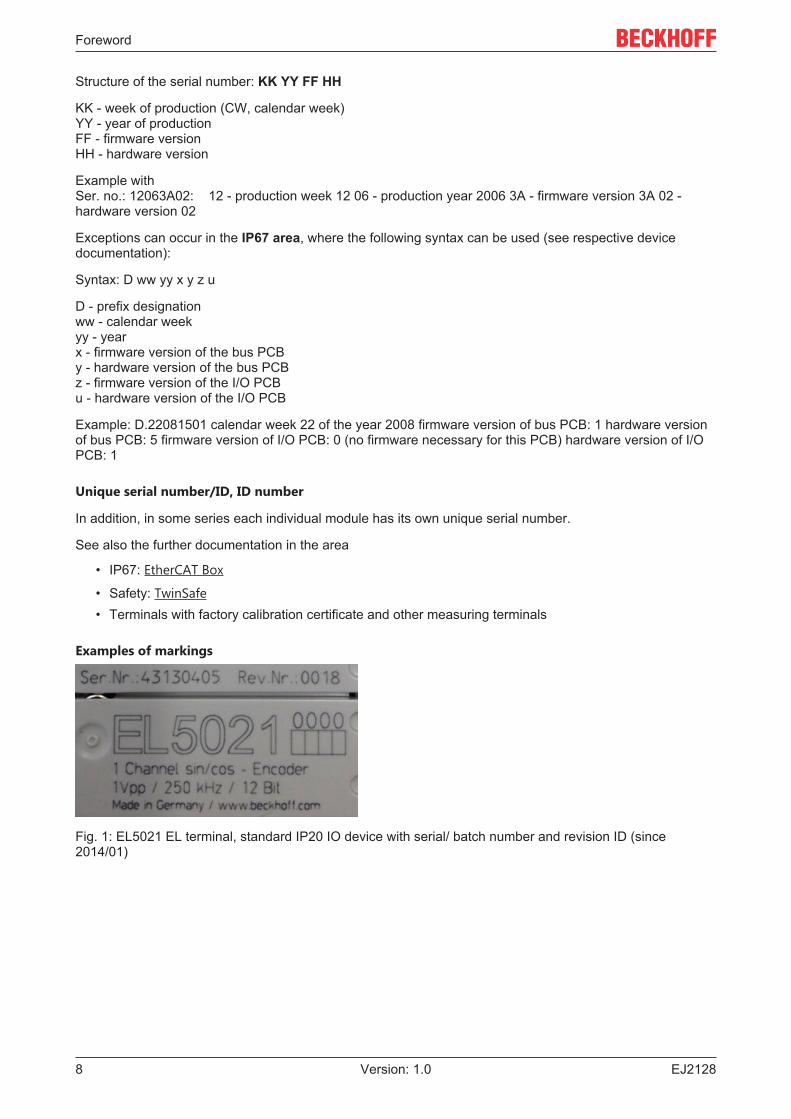
Fig. 2: EK1100 EtherCAT coupler, standard IP20 IO device with serial/ batch number
Fig. 3: CU2016 switch with serial/ batch number
Fig. 4: EL3202-0020 with serial/ batch number 26131006 and unique ID-number 204418
Foreword
EJ212810 Version: 1.0
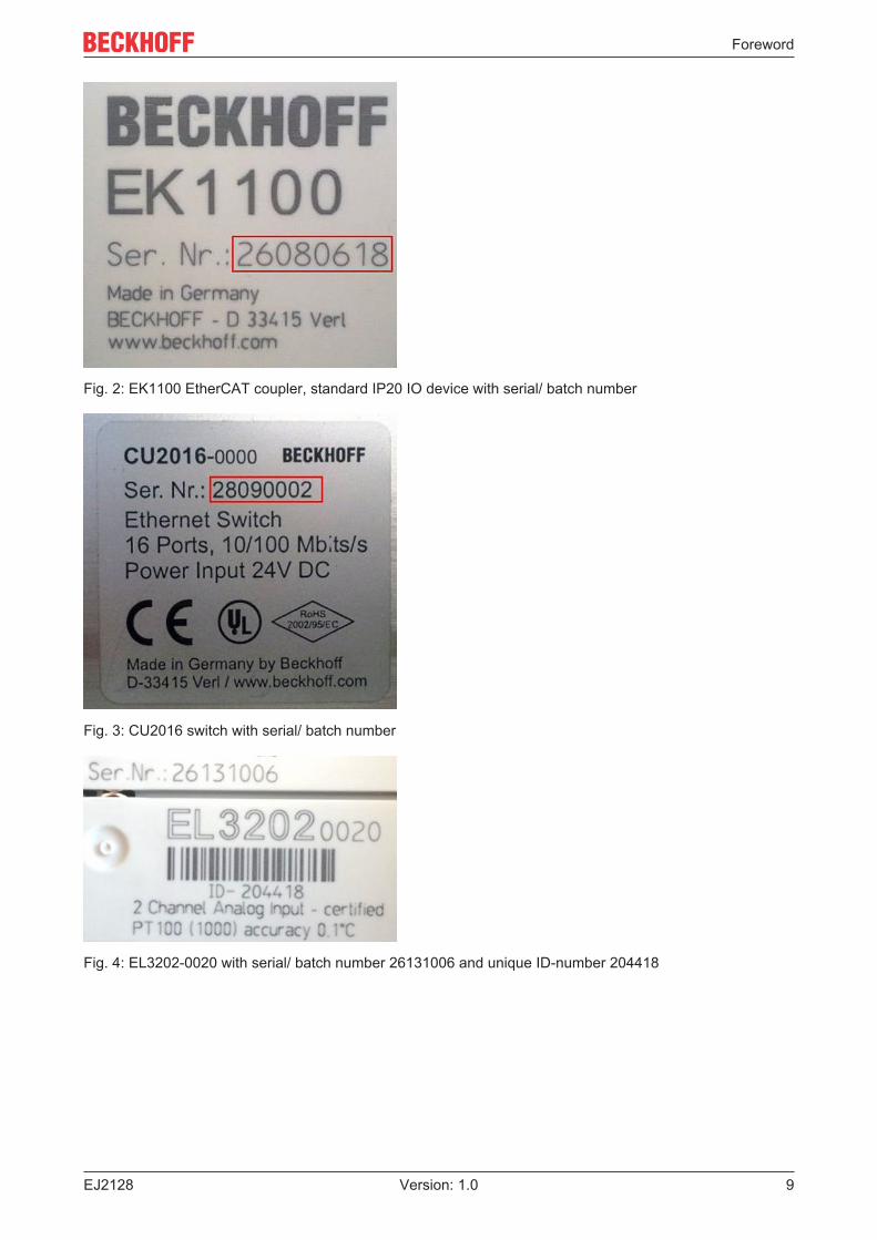
Fig. 5: EP1258-00001 IP67 EtherCAT Box with batch number/ date code 22090101 and unique serialnumber 158102
Fig. 6: EP1908-0002 IP67 EtherCAT Safety Box with batch number/ date code 071201FF and unique serialnumber 00346070
Fig. 7: EL2904 IP20 safety terminal with batch number/ date code 50110302 and unique serial number00331701
Fig. 8: ELM3604-0002 terminal with unique ID number (QR code) 100001051 and serial/ batch number44160201
System overview
EJ2128 11Version: 1.0
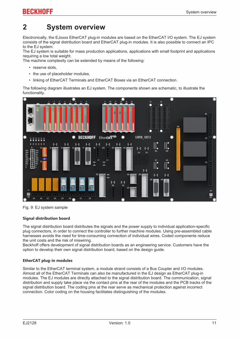
2 System overviewElectronically, the EJxxxx EtherCAT plug-in modules are based on the EtherCAT I/O system. The EJ systemconsists of the signal distribution board and EtherCAT plug-in modules. It is also possible to connect an IPCto the EJ system.The EJ system is suitable for mass production applications, applications with small footprint and applicationsrequiring a low total weight.The machine complexity can be extended by means of the following:
• reserve slots,• the use of placeholder modules,• linking of EtherCAT Terminals and EtherCAT Boxes via an EtherCAT connection.
The following diagram illustrates an EJ system. The components shown are schematic, to illustrate thefunctionality.
Fig. 9: EJ system sample
Signal distribution board
The signal distribution board distributes the signals and the power supply to individual application-specificplug connectors, in order to connect the controller to further machine modules. Using pre-assembled cableharnesses avoids the need for time-consuming connection of individual wires. Coded components reducethe unit costs and the risk of miswiring.Beckhoff offers development of signal distribution boards as an engineering service. Customers have theoption to develop their own signal distribution board, based on the design guide.
EtherCAT plug-in modules
Similar to the EtherCAT terminal system, a module strand consists of a Bus Coupler and I/O modules.Almost all of the EtherCAT Terminals can also be manufactured in the EJ design as EtherCAT plug-inmodules. The EJ modules are directly attached to the signal distribution board. The communication, signaldistribution and supply take place via the contact pins at the rear of the modules and the PCB tracks of thesignal distribution board. The coding pins at the rear serve as mechanical protection against incorrectconnection. Color coding on the housing facilitates distinguishing of the modules.

Product overview
EJ212812 Version: 1.0
3 Product overview
3.1 EJ2128 - Introduction
Fig. 10: EJ2128
8-channel digital output module 5 VDC / 3.3 VDC
The EJ2128 EtherCAT plug-in module relays the binary control signals of the automation device separatelyto the actuators at the process level and generates load currents with outputs that are protected againstoverload and short-circuit.
The EtherCAT plug-in module contains eight channels, optionally with a rated load voltage of 5 VDC or3.3 VDC.
The 5 VDC supply required for the module can be provided using the EJ9505 power supply module.
LEDs indicate the signal states of the channels.
Product overview
EJ2128 13Version: 1.0
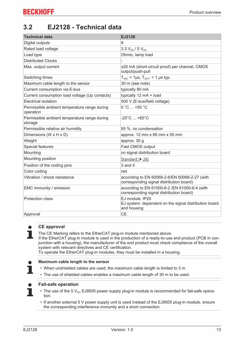
3.2 EJ2128 - Technical dataTechnical data EJ2128Digital outputs 8Rated load voltage 3.3 VDC / 5 VDC
Load type Ohmic, lamp loadDistributed Clocks -Max. output current ±20 mA (short-circuit proof) per channel, CMOS
output/push-pullSwitching times TON: < 1µs, TOFF: < 1 µs typ.Maximum cable length to the sensor 30 m (see note)Current consumption via E-bus typically 80 mACurrent consumption load voltage (Up contacts) typically 12 mA + loadElectrical isolation 500 V (E-bus/field voltage)Permissible ambient temperature range duringoperation
0 °C ... +55 °C
Permissible ambient temperature range duringstorage
-25°C ... +85°C
Permissible relative air humidity 95 %, no condensationDimensions (W x H x D) approx. 12 mm x 66 mm x 55 mmWeight approx. 30 gSpecial features Fast CMOS outputMounting on signal distribution boardMounting position Standard [} 26]Position of the coding pins 3 and 4Color coding redVibration / shock resistance according to EN 60068-2-6/EN 60068-2-27 (with
corresponding signal distribution board)EMC immunity / emission according to EN 61000-6-2 /EN 61000-6-4 (with
corresponding signal distribution board)Protection class EJ module: IP20
EJ system: dependent on the signal distribution boardand housing
Approval CE
CE approvalThe CE Marking refers to the EtherCAT plug-in module mentioned above.If the EtherCAT plug-in module is used in the production of a ready-to-use end product (PCB in con-junction with a housing), the manufacturer of the end product must check compliance of the overallsystem with relevant directives and CE certification.To operate the EtherCAT plug-in modules, they must be installed in a housing.
Maximum cable length to the sensor• When unshielded cables are used, the maximum cable length is limited to 3 m.• The use of shielded cables enables a maximum cable length of 30 m to be used.
Fail-safe operation• The use of the 5 VDC EJ9505 power supply plug-in module is recommended for fail-safe opera-
tion.• If another external 5 V power supply unit is used instead of the EJ9505 plug-in module, ensure
the corresponding interference immunity and a short connection.
Product overview
EJ212814 Version: 1.0
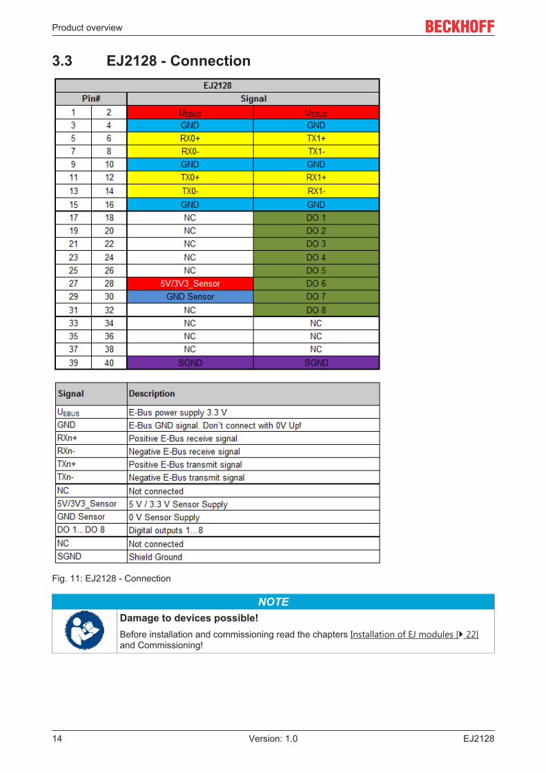
3.3 EJ2128 - Connection
Fig. 11: EJ2128 - Connection
NOTEDamage to devices possible!Before installation and commissioning read the chapters Installation of EJ modules [} 22]and Commissioning!
Product overview
EJ2128 15Version: 1.0
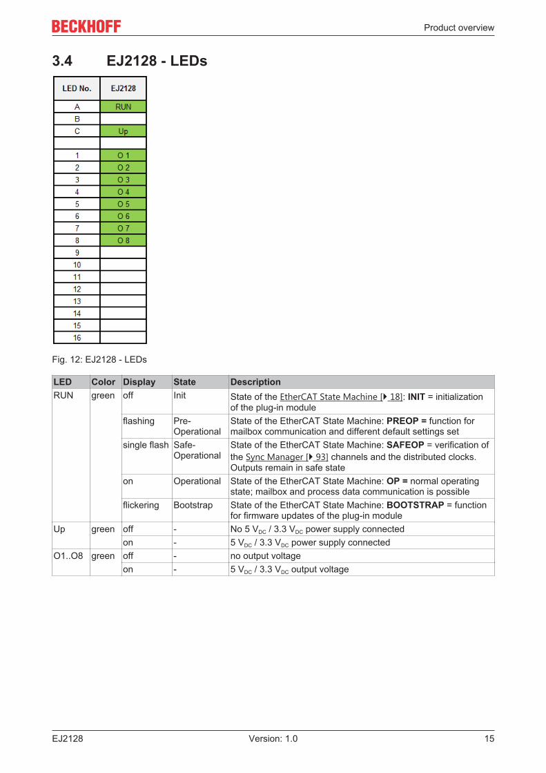
3.4 EJ2128 - LEDs
Fig. 12: EJ2128 - LEDs
LED Color Display State DescriptionRUN green off Init State of the EtherCAT State Machine [} 18]: INIT = initialization
of the plug-in moduleflashing Pre-
OperationalState of the EtherCAT State Machine: PREOP = function formailbox communication and different default settings set
single flash Safe-Operational
State of the EtherCAT State Machine: SAFEOP = verification ofthe Sync Manager [} 93] channels and the distributed clocks.Outputs remain in safe state
on Operational State of the EtherCAT State Machine: OP = normal operatingstate; mailbox and process data communication is possible
flickering Bootstrap State of the EtherCAT State Machine: BOOTSTRAP = functionfor firmware updates of the plug-in module
Up green off - No 5 VDC / 3.3 VDC power supply connectedon - 5 VDC / 3.3 VDC power supply connected
O1..O8 green off - no output voltageon - 5 VDC / 3.3 VDC output voltage
Basics communication
EJ212816 Version: 1.0
4 Basics communication
4.1 EtherCAT basicsPlease refer to the EtherCAT System Documentation for the EtherCAT fieldbus basics.
4.2 EtherCAT devices - cabling - wiredThe cable length between two EtherCAT devices must not exceed 100 m. This results from the FastEthernettechnology, which, above all for reasons of signal attenuation over the length of the cable, allows a maximumlink length of 5 + 90 + 5 m if cables with appropriate properties are used. See also the Designrecommendations for the infrastructure for EtherCAT/Ethernet.
Cables and connectors
For connecting EtherCAT devices only Ethernet connections (cables + plugs) that meet the requirements ofat least category 5 (CAt5) according to EN 50173 or ISO/IEC 11801 should be used. EtherCAT uses 4 wiresfor signal transfer.
EtherCAT uses RJ45 plug connectors, for example. The pin assignment is compatible with the Ethernetstandard (ISO/IEC 8802-3).
Pin Color of conductor Signal Description1 yellow TD + Transmission Data +2 orange TD - Transmission Data -3 white RD + Receiver Data +6 blue RD - Receiver Data -
Due to automatic cable detection (auto-crossing) symmetric (1:1) or cross-over cables can be used betweenEtherCAT devices from Beckhoff.
Recommended cablesSuitable cables for the connection of EtherCAT devices can be found on the Beckhoff website!
4.3 General notes for setting the watchdogELxxxx terminals are equipped with a safety feature (watchdog) that switches off the outputs after aspecifiable time e.g. in the event of an interruption of the process data traffic, depending on the device andsettings, e.g. in OFF state.
The EtherCAT slave controller (ESC) in the EL2xxx terminals features 2 watchdogs:
• SM watchdog (default: 100 ms)• PDI watchdog (default: 100 ms)
SM watchdog (SyncManager Watchdog)
The SyncManager watchdog is reset after each successful EtherCAT process data communication with theterminal. If no EtherCAT process data communication takes place with the terminal for longer than the setand activated SM watchdog time, e.g. in the event of a line interruption, the watchdog is triggered and theoutputs are set to FALSE. The OP state of the terminal is unaffected. The watchdog is only reset after asuccessful EtherCAT process data access. Set the monitoring time as described below.
The SyncManager watchdog monitors correct and timely process data communication with the ESC from theEtherCAT side.

Basics communication
EJ2128 17Version: 1.0
PDI watchdog (Process Data Watchdog)
If no PDI communication with the EtherCAT slave controller (ESC) takes place for longer than the set andactivated PDI watchdog time, this watchdog is triggered.PDI (Process Data Interface) is the internal interface between the ESC and local processors in the EtherCATslave, for example. The PDI watchdog can be used to monitor this communication for failure.
The PDI watchdog monitors correct and timely process data communication with the ESC from theapplication side.
The settings of the SM- and PDI-watchdog must be done for each slave separately in the TwinCAT SystemManager.
Fig. 13: EtherCAT tab -> Advanced Settings -> Behavior -> Watchdog
Notes:
• the multiplier is valid for both watchdogs.• each watchdog has its own timer setting, the outcome of this in summary with the multiplier is a
resulting time.• Important: the multiplier/timer setting is only loaded into the slave at the start up, if the checkbox is
activated.If the checkbox is not activated, nothing is downloaded and the ESC settings remain unchanged.
Multiplier
Multiplier
Both watchdogs receive their pulses from the local terminal cycle, divided by the watchdog multiplier:
Basics communication
EJ212818 Version: 1.0
1/25 MHz * (watchdog multiplier + 2) = 100 µs (for default setting of 2498 for the multiplier)
The standard setting of 1000 for the SM watchdog corresponds to a release time of 100 ms.
The value in multiplier + 2 corresponds to the number of basic 40 ns ticks representing a watchdog tick.The multiplier can be modified in order to adjust the watchdog time over a larger range.
Example "Set SM watchdog"
This checkbox enables manual setting of the watchdog times. If the outputs are set and the EtherCATcommunication is interrupted, the SM watchdog is triggered after the set time and the outputs are erased.This setting can be used for adapting a terminal to a slower EtherCAT master or long cycle times. Thedefault SM watchdog setting is 100 ms. The setting range is 0..65535. Together with a multiplier with a rangeof 1..65535 this covers a watchdog period between 0..~170 seconds.
Calculation
Multiplier = 2498 → watchdog base time = 1 / 25 MHz * (2498 + 2) = 0.0001 seconds = 100 µsSM watchdog = 10000 → 10000 * 100 µs = 1 second watchdog monitoring time
CAUTIONUndefined state possible!The function for switching off of the SM watchdog via SM watchdog = 0 is only implemented in terminalsfrom version -0016. In previous versions this operating mode should not be used.
CAUTIONDamage of devices and undefined state possible!If the SM watchdog is activated and a value of 0 is entered the watchdog switches off completely. This isthe deactivation of the watchdog! Set outputs are NOT set in a safe state, if the communication is inter-rupted.
4.4 EtherCAT State MachineThe state of the EtherCAT slave is controlled via the EtherCAT State Machine (ESM). Depending upon thestate, different functions are accessible or executable in the EtherCAT slave. Specific commands must besent by the EtherCAT master to the device in each state, particularly during the bootup of the slave.
A distinction is made between the following states:
• Init• Pre-Operational• Safe-Operational and• Operational• Boot
The regular state of each EtherCAT slave after bootup is the OP state.
Basics communication
EJ2128 19Version: 1.0
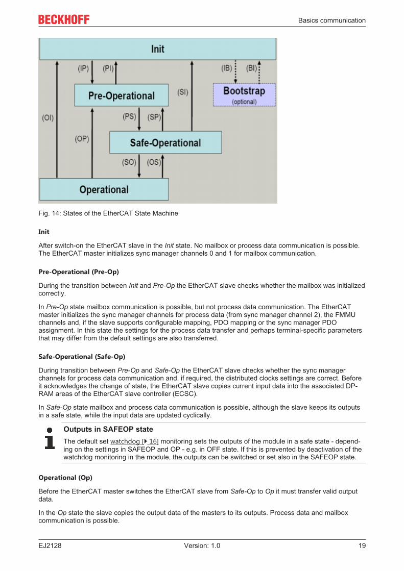
Fig. 14: States of the EtherCAT State Machine
Init
After switch-on the EtherCAT slave in the Init state. No mailbox or process data communication is possible.The EtherCAT master initializes sync manager channels 0 and 1 for mailbox communication.
Pre-Operational (Pre-Op)
During the transition between Init and Pre-Op the EtherCAT slave checks whether the mailbox was initializedcorrectly.
In Pre-Op state mailbox communication is possible, but not process data communication. The EtherCATmaster initializes the sync manager channels for process data (from sync manager channel 2), the FMMUchannels and, if the slave supports configurable mapping, PDO mapping or the sync manager PDOassignment. In this state the settings for the process data transfer and perhaps terminal-specific parametersthat may differ from the default settings are also transferred.
Safe-Operational (Safe-Op)
During transition between Pre-Op and Safe-Op the EtherCAT slave checks whether the sync managerchannels for process data communication and, if required, the distributed clocks settings are correct. Beforeit acknowledges the change of state, the EtherCAT slave copies current input data into the associated DP-RAM areas of the EtherCAT slave controller (ECSC).
In Safe-Op state mailbox and process data communication is possible, although the slave keeps its outputsin a safe state, while the input data are updated cyclically.
Outputs in SAFEOP stateThe default set watchdog [} 16] monitoring sets the outputs of the module in a safe state - depend-ing on the settings in SAFEOP and OP - e.g. in OFF state. If this is prevented by deactivation of thewatchdog monitoring in the module, the outputs can be switched or set also in the SAFEOP state.
Operational (Op)
Before the EtherCAT master switches the EtherCAT slave from Safe-Op to Op it must transfer valid outputdata.
In the Op state the slave copies the output data of the masters to its outputs. Process data and mailboxcommunication is possible.
Basics communication
EJ212820 Version: 1.0
Boot
In the Boot state the slave firmware can be updated. The Boot state can only be reached via the Init state.
In the Boot state mailbox communication via the file access over EtherCAT (FoE) protocol is possible, but noother mailbox communication and no process data communication.
4.5 CoE - Interface: notesThis device has no CoE.
Detailed information on the CoE interface can be found in the EtherCAT system documentation on theBeckhoff website.

Basics communication
EJ2128 21Version: 1.0
4.6 Distributed ClockThe distributed clock represents a local clock in the EtherCAT slave controller (ESC) with the followingcharacteristics:
• Unit 1 ns• Zero point 1.1.2000 00:00• Size 64 bit (sufficient for the next 584 years; however, some EtherCAT slaves only offer 32-bit support,
i.e. the variable overflows after approx. 4.2 seconds)• The EtherCAT master automatically synchronizes the local clock with the master clock in the EtherCAT
bus with a precision of < 100 ns.
For detailed information please refer to the EtherCAT system description.
Installation of EJ modules
EJ212822 Version: 1.0
5 Installation of EJ modules
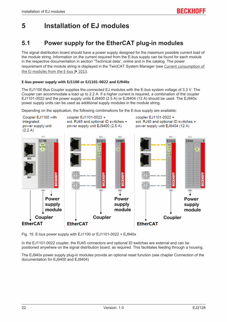
5.1 Power supply for the EtherCAT plug-in modulesThe signal distribution board should have a power supply designed for the maximum possible current load ofthe module string. Information on the current required from the E-bus supply can be found for each modulein the respective documentation in section “Technical data“, online and in the catalog. The powerrequirement of the module string is displayed in the TwinCAT System Manager (see Current consumption ofthe EJ modules from the E-bus [} 101]).
E-bus power supply with EJ1100 or EJ1101-0022 and EJ940x
The EJ1100 Bus Coupler supplies the connected EJ modules with the E-bus system voltage of 3.3 V. TheCoupler can accommodate a load up to 2.2 A. If a higher current is required, a combination of the couplerEJ1101-0022 and the power supply units EJ9400 (2.5 A) or EJ9404 (12 A) should be used. The EJ940xpower supply units can be used as additional supply modules in the module string.
Depending on the application, the following combinations for the E-bus supply are available:
Fig. 15: E-bus power supply with EJ1100 or EJ1101-0022 + EJ940x
In the EJ1101-0022 coupler, the RJ45 connectors and optional ID switches are external and can bepositioned anywhere on the signal distribution board, as required. This facilitates feeding through a housing.
The EJ940x power supply plug-in modules provide an optional reset function (see chapter Connection of thedocumentation for EJ9400 and EJ9404)
Installation of EJ modules
EJ2128 23Version: 1.0
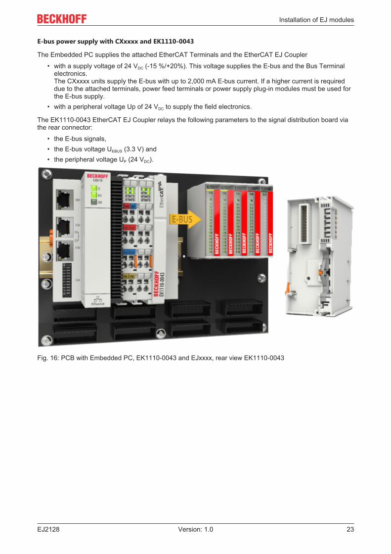
E-bus power supply with CXxxxx and EK1110-0043
The Embedded PC supplies the attached EtherCAT Terminals and the EtherCAT EJ Coupler
• with a supply voltage of 24 VDC (-15 %/+20%). This voltage supplies the E-bus and the Bus Terminalelectronics. The CXxxxx units supply the E-bus with up to 2,000 mA E-bus current. If a higher current is requireddue to the attached terminals, power feed terminals or power supply plug-in modules must be used forthe E-bus supply.
• with a peripheral voltage Up of 24 VDC to supply the field electronics.
The EK1110-0043 EtherCAT EJ Coupler relays the following parameters to the signal distribution board viathe rear connector:
• the E-bus signals,• the E-bus voltage UEBUS (3.3 V) and• the peripheral voltage UP (24 VDC).
Fig. 16: PCB with Embedded PC, EK1110-0043 and EJxxxx, rear view EK1110-0043
Installation of EJ modules
EJ212824 Version: 1.0
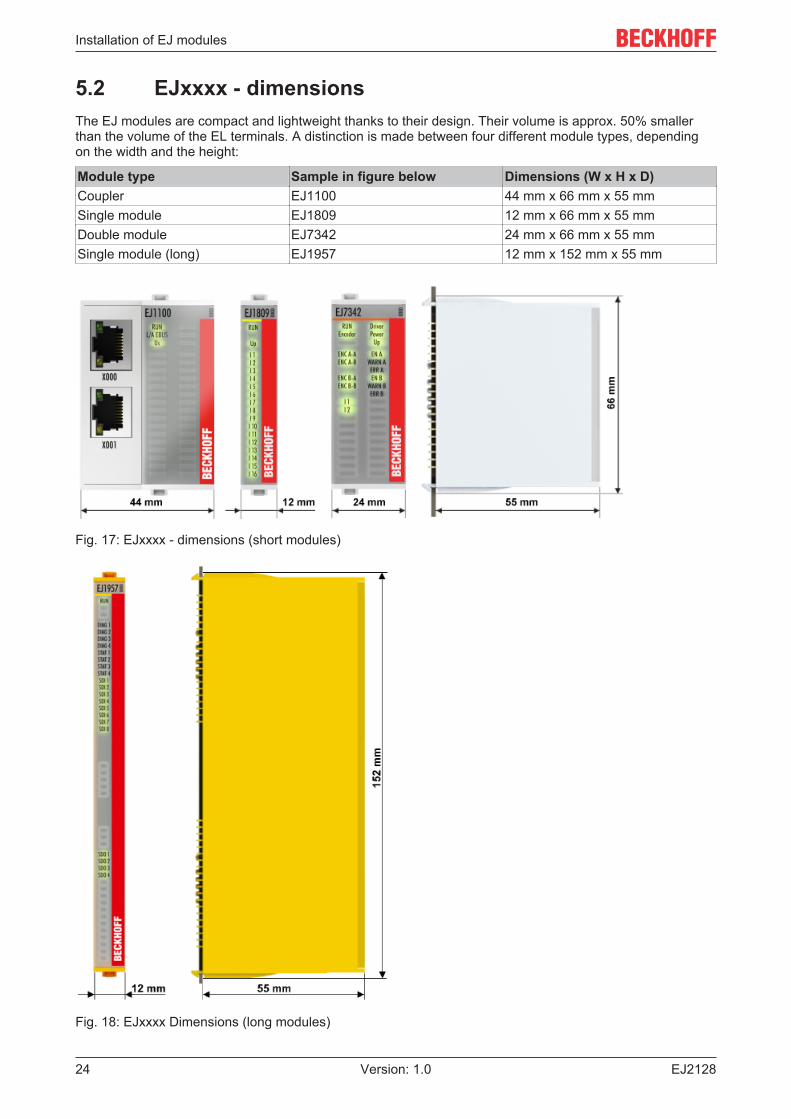
5.2 EJxxxx - dimensionsThe EJ modules are compact and lightweight thanks to their design. Their volume is approx. 50% smallerthan the volume of the EL terminals. A distinction is made between four different module types, dependingon the width and the height:
Module type Sample in figure below Dimensions (W x H x D)Coupler EJ1100 44 mm x 66 mm x 55 mmSingle module EJ1809 12 mm x 66 mm x 55 mmDouble module EJ7342 24 mm x 66 mm x 55 mmSingle module (long) EJ1957 12 mm x 152 mm x 55 mm
Fig. 17: EJxxxx - dimensions (short modules)
Fig. 18: EJxxxx Dimensions (long modules)
Installation of EJ modules
EJ2128 25Version: 1.0
5.3 Installation positions and minimum distances
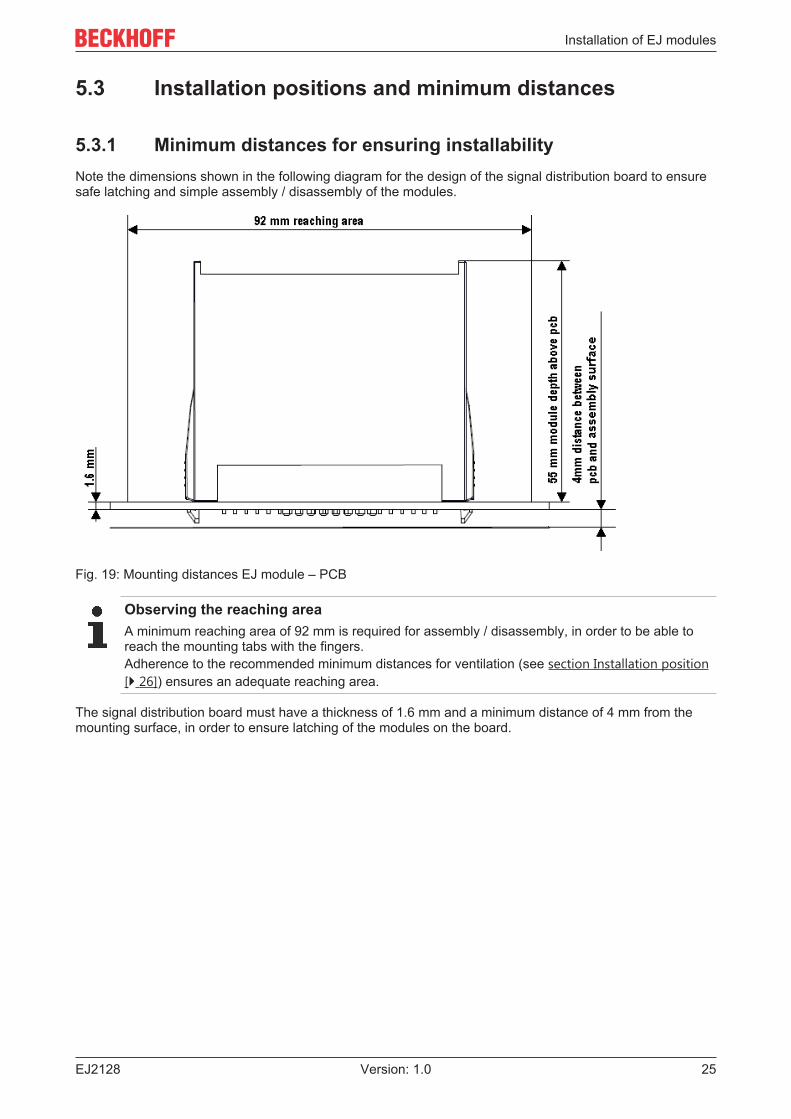
5.3.1 Minimum distances for ensuring installabilityNote the dimensions shown in the following diagram for the design of the signal distribution board to ensuresafe latching and simple assembly / disassembly of the modules.
Fig. 19: Mounting distances EJ module – PCB
Observing the reaching areaA minimum reaching area of 92 mm is required for assembly / disassembly, in order to be able toreach the mounting tabs with the fingers.Adherence to the recommended minimum distances for ventilation (see section Installation position[} 26]) ensures an adequate reaching area.
The signal distribution board must have a thickness of 1.6 mm and a minimum distance of 4 mm from themounting surface, in order to ensure latching of the modules on the board.
Installation of EJ modules
EJ212826 Version: 1.0
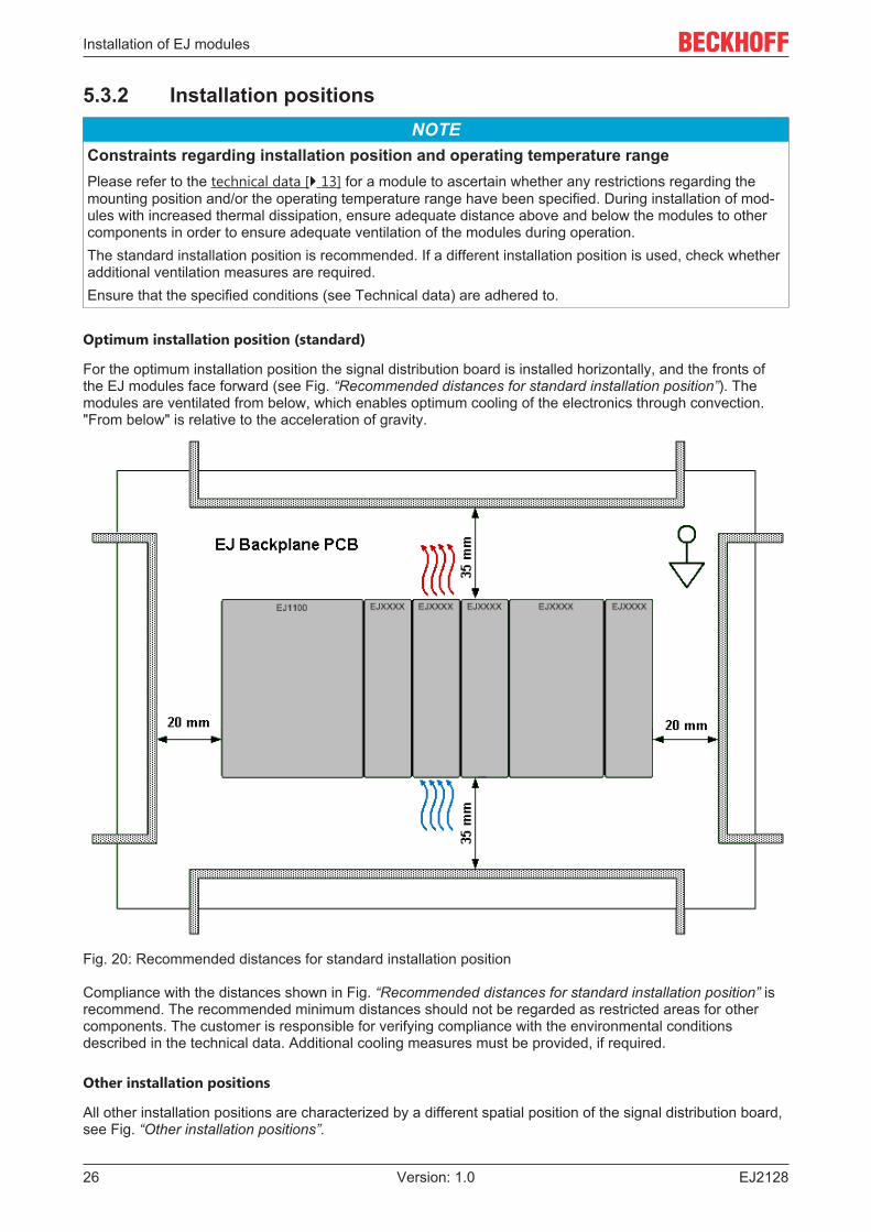
5.3.2 Installation positionsNOTE
Constraints regarding installation position and operating temperature rangePlease refer to the technical data [} 13] for a module to ascertain whether any restrictions regarding themounting position and/or the operating temperature range have been specified. During installation of mod-ules with increased thermal dissipation, ensure adequate distance above and below the modules to othercomponents in order to ensure adequate ventilation of the modules during operation.The standard installation position is recommended. If a different installation position is used, check whetheradditional ventilation measures are required.Ensure that the specified conditions (see Technical data) are adhered to.
Optimum installation position (standard)
For the optimum installation position the signal distribution board is installed horizontally, and the fronts ofthe EJ modules face forward (see Fig. “Recommended distances for standard installation position”). Themodules are ventilated from below, which enables optimum cooling of the electronics through convection."From below" is relative to the acceleration of gravity.
Fig. 20: Recommended distances for standard installation position
Compliance with the distances shown in Fig. “Recommended distances for standard installation position” isrecommend. The recommended minimum distances should not be regarded as restricted areas for othercomponents. The customer is responsible for verifying compliance with the environmental conditionsdescribed in the technical data. Additional cooling measures must be provided, if required.
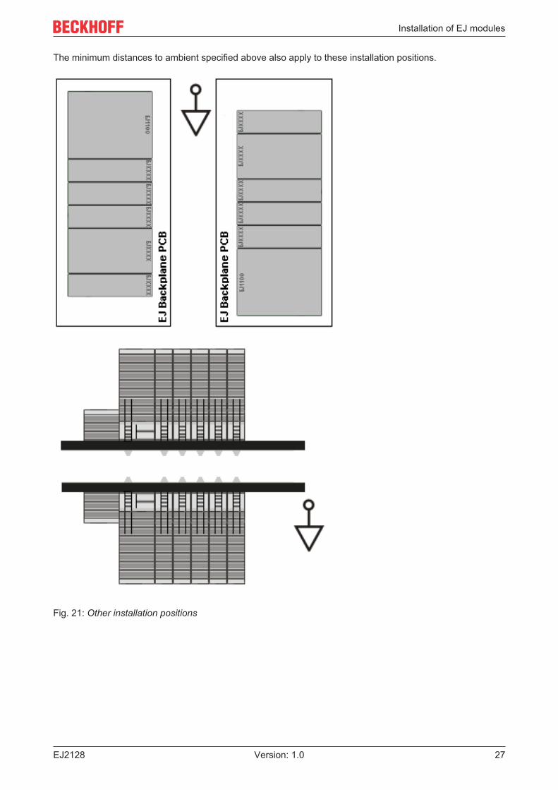
Other installation positions
All other installation positions are characterized by a different spatial position of the signal distribution board,see Fig. “Other installation positions”.
Installation of EJ modules
EJ2128 27Version: 1.0
The minimum distances to ambient specified above also apply to these installation positions.
Fig. 21: Other installation positions
Installation of EJ modules
EJ212828 Version: 1.0
5.4 Codings
5.4.1 Color coding
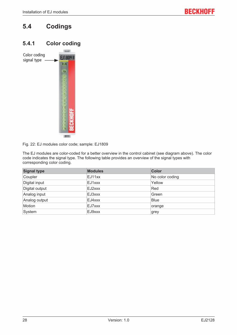
Fig. 22: EJ modules color code; sample: EJ1809
The EJ modules are color-coded for a better overview in the control cabinet (see diagram above). The colorcode indicates the signal type. The following table provides an overview of the signal types withcorresponding color coding.
Signal type Modules ColorCoupler EJ11xx No color codingDigital input EJ1xxx YellowDigital output EJ2xxx RedAnalog input EJ3xxx GreenAnalog output EJ4xxx BlueMotion EJ7xxx orangeSystem EJ9xxx grey
Installation of EJ modules
EJ2128 29Version: 1.0
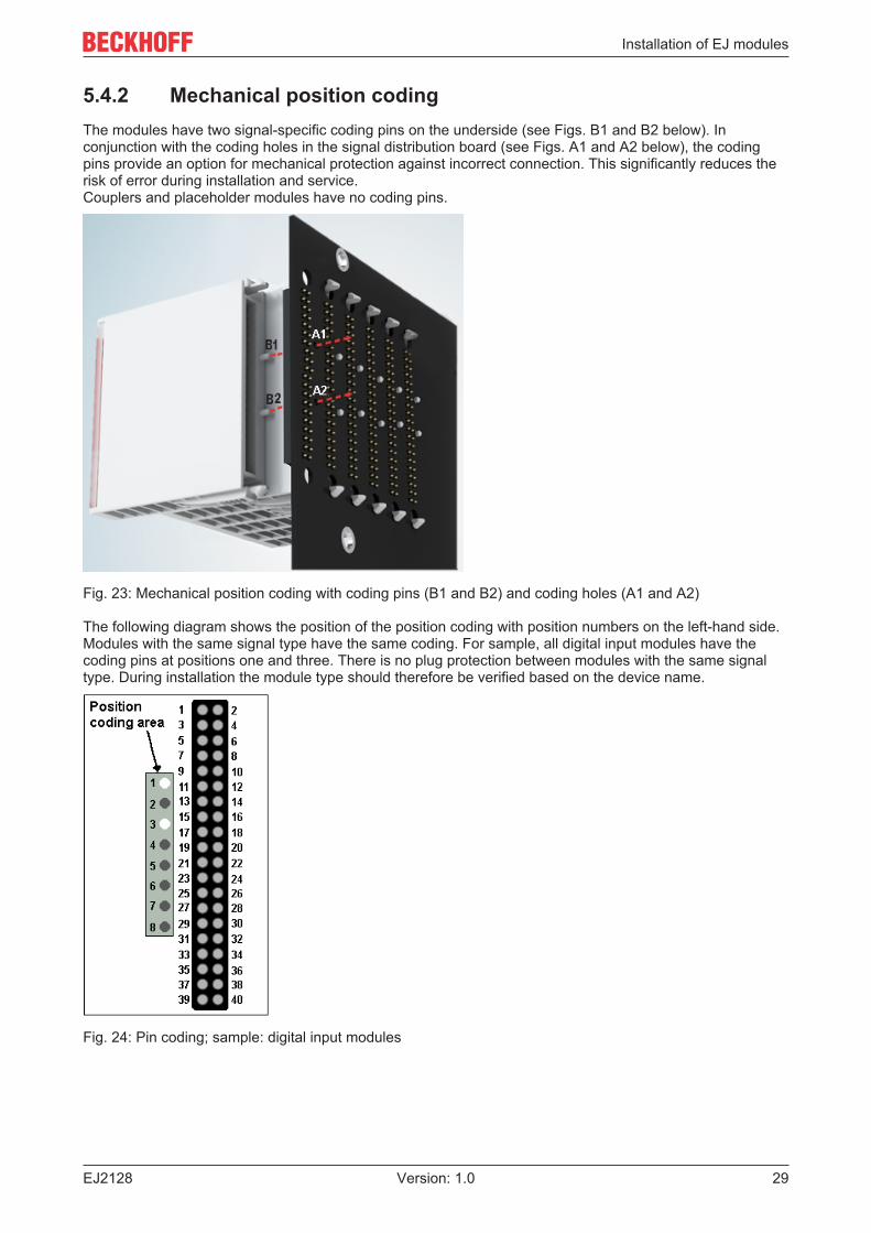
5.4.2 Mechanical position codingThe modules have two signal-specific coding pins on the underside (see Figs. B1 and B2 below). Inconjunction with the coding holes in the signal distribution board (see Figs. A1 and A2 below), the codingpins provide an option for mechanical protection against incorrect connection. This significantly reduces therisk of error during installation and service.Couplers and placeholder modules have no coding pins.
Fig. 23: Mechanical position coding with coding pins (B1 and B2) and coding holes (A1 and A2)
The following diagram shows the position of the position coding with position numbers on the left-hand side.Modules with the same signal type have the same coding. For sample, all digital input modules have thecoding pins at positions one and three. There is no plug protection between modules with the same signaltype. During installation the module type should therefore be verified based on the device name.
Fig. 24: Pin coding; sample: digital input modules
Installation of EJ modules
EJ212830 Version: 1.0
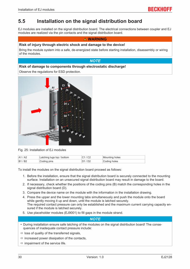
5.5 Installation on the signal distribution boardEJ modules are installed on the signal distribution board. The electrical connections between coupler and EJmodules are realized via the pin contacts and the signal distribution board.
WARNINGRisk of injury through electric shock and damage to the device!Bring the module system into a safe, de-energized state before starting installation, disassembly or wiringof the modules.
NOTERisk of damage to components through electrostatic discharge!Observe the regulations for ESD protection.
Fig. 25: Installation of EJ modules
A1 / A2 Latching lugs top / bottom C1 / C2 Mounting holesB1 / B2 Coding pins D1 / D2 Coding holes
To install the modules on the signal distribution board proceed as follows:
1. Before the installation, ensure that the signal distribution board is securely connected to the mountingsurface. Installation on an unsecured signal distribution board may result in damage to the board.
2. If necessary, check whether the positions of the coding pins (B) match the corresponding holes in thesignal distribution board (D).
3. Compare the device name on the module with the information in the installation drawing.4. Press the upper and the lower mounting tabs simultaneously and push the module onto the board
while gently moving it up and down, until the module is latched securely.The required contact pressure can only be established and the maximum current carrying capacity en-sured if the module is latched securely.
5. Use placeholder modules (EJ9001) to fill gaps in the module strand.
NOTE• During installation ensure safe latching of the modules on the signal distribution board! The conse-
quences of inadequate contact pressure include:ð loss of quality of the transferred signals,ð increased power dissipation of the contacts,ð impairment of the service life.
Installation of EJ modules
EJ2128 31Version: 1.0
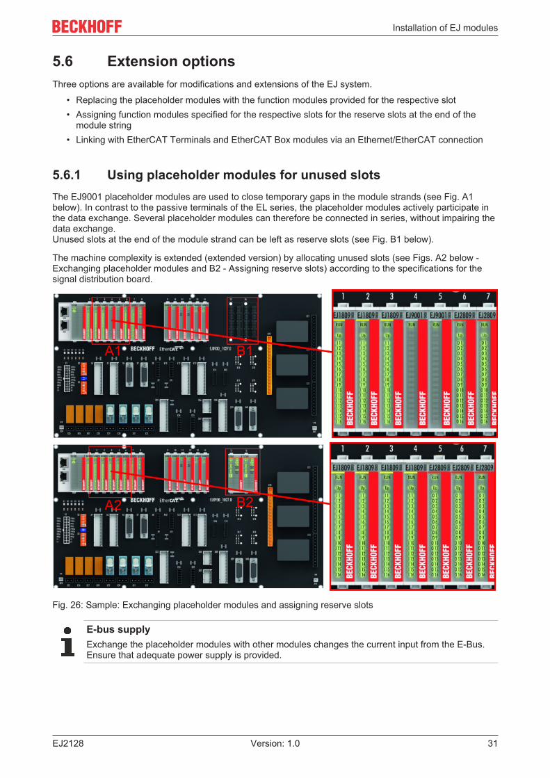
5.6 Extension optionsThree options are available for modifications and extensions of the EJ system.
• Replacing the placeholder modules with the function modules provided for the respective slot• Assigning function modules specified for the respective slots for the reserve slots at the end of the
module string• Linking with EtherCAT Terminals and EtherCAT Box modules via an Ethernet/EtherCAT connection
5.6.1 Using placeholder modules for unused slotsThe EJ9001 placeholder modules are used to close temporary gaps in the module strands (see Fig. A1below). In contrast to the passive terminals of the EL series, the placeholder modules actively participate inthe data exchange. Several placeholder modules can therefore be connected in series, without impairing thedata exchange.Unused slots at the end of the module strand can be left as reserve slots (see Fig. B1 below).
The machine complexity is extended (extended version) by allocating unused slots (see Figs. A2 below -Exchanging placeholder modules and B2 - Assigning reserve slots) according to the specifications for thesignal distribution board.
Fig. 26: Sample: Exchanging placeholder modules and assigning reserve slots
E-bus supplyExchange the placeholder modules with other modules changes the current input from the E-Bus.Ensure that adequate power supply is provided.
Installation of EJ modules
EJ212832 Version: 1.0
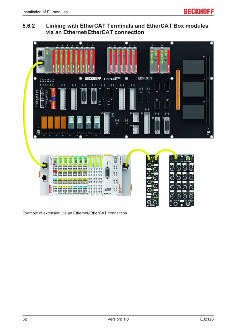
5.6.2 Linking with EtherCAT Terminals and EtherCAT Box modulesvia an Ethernet/EtherCAT connection
Example of extension via an Ethernet/EtherCAT connection
Installation of EJ modules
EJ2128 33Version: 1.0
5.7 IPC integration
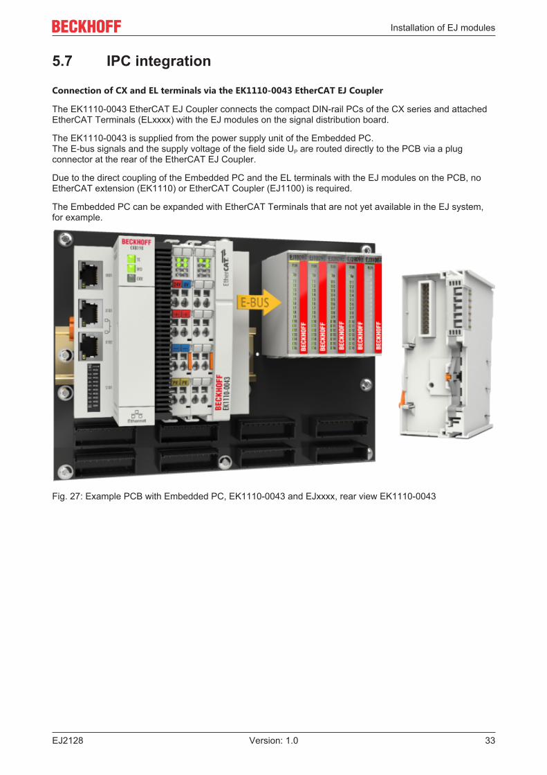
Connection of CX and EL terminals via the EK1110-0043 EtherCAT EJ Coupler
The EK1110-0043 EtherCAT EJ Coupler connects the compact DIN-rail PCs of the CX series and attachedEtherCAT Terminals (ELxxxx) with the EJ modules on the signal distribution board.
The EK1110-0043 is supplied from the power supply unit of the Embedded PC.The E-bus signals and the supply voltage of the field side UP are routed directly to the PCB via a plugconnector at the rear of the EtherCAT EJ Coupler.
Due to the direct coupling of the Embedded PC and the EL terminals with the EJ modules on the PCB, noEtherCAT extension (EK1110) or EtherCAT Coupler (EJ1100) is required.
The Embedded PC can be expanded with EtherCAT Terminals that are not yet available in the EJ system,for example.
Fig. 27: Example PCB with Embedded PC, EK1110-0043 and EJxxxx, rear view EK1110-0043
Installation of EJ modules
EJ212834 Version: 1.0
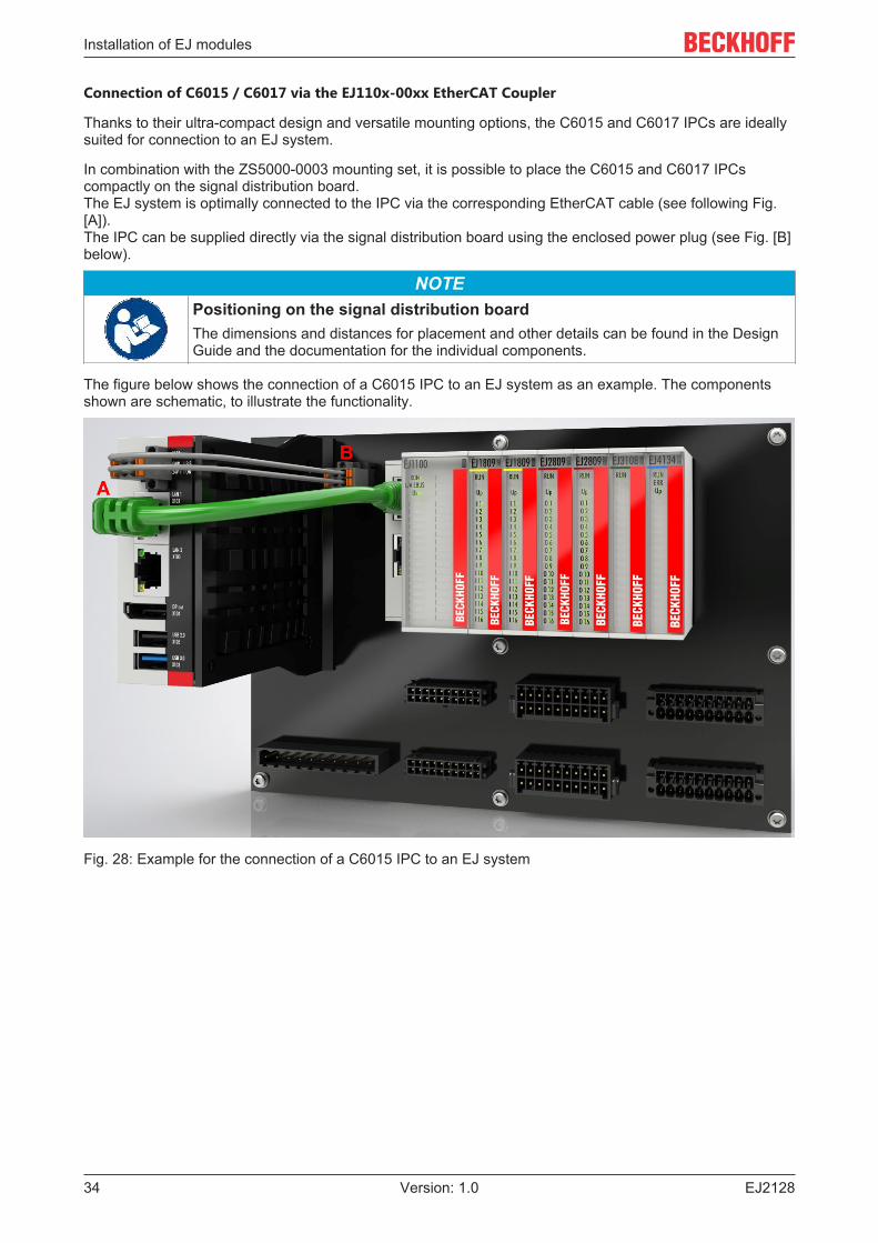
Connection of C6015 / C6017 via the EJ110x-00xx EtherCAT Coupler
Thanks to their ultra-compact design and versatile mounting options, the C6015 and C6017 IPCs are ideallysuited for connection to an EJ system.
In combination with the ZS5000-0003 mounting set, it is possible to place the C6015 and C6017 IPCscompactly on the signal distribution board.The EJ system is optimally connected to the IPC via the corresponding EtherCAT cable (see following Fig.[A]).The IPC can be supplied directly via the signal distribution board using the enclosed power plug (see Fig. [B]below).
NOTEPositioning on the signal distribution boardThe dimensions and distances for placement and other details can be found in the DesignGuide and the documentation for the individual components.
The figure below shows the connection of a C6015 IPC to an EJ system as an example. The componentsshown are schematic, to illustrate the functionality.
Fig. 28: Example for the connection of a C6015 IPC to an EJ system
Installation of EJ modules
EJ2128 35Version: 1.0
5.8 Disassembly of the signal distribution board WARNING
Risk of injury through electric shock and damage to the device!Bring the module system into a safe, de-energized state before starting installation, disassembly or wiringof the modules.
NOTERisk of damage to components through electrostatic discharge!Observe the regulations for ESD protection.
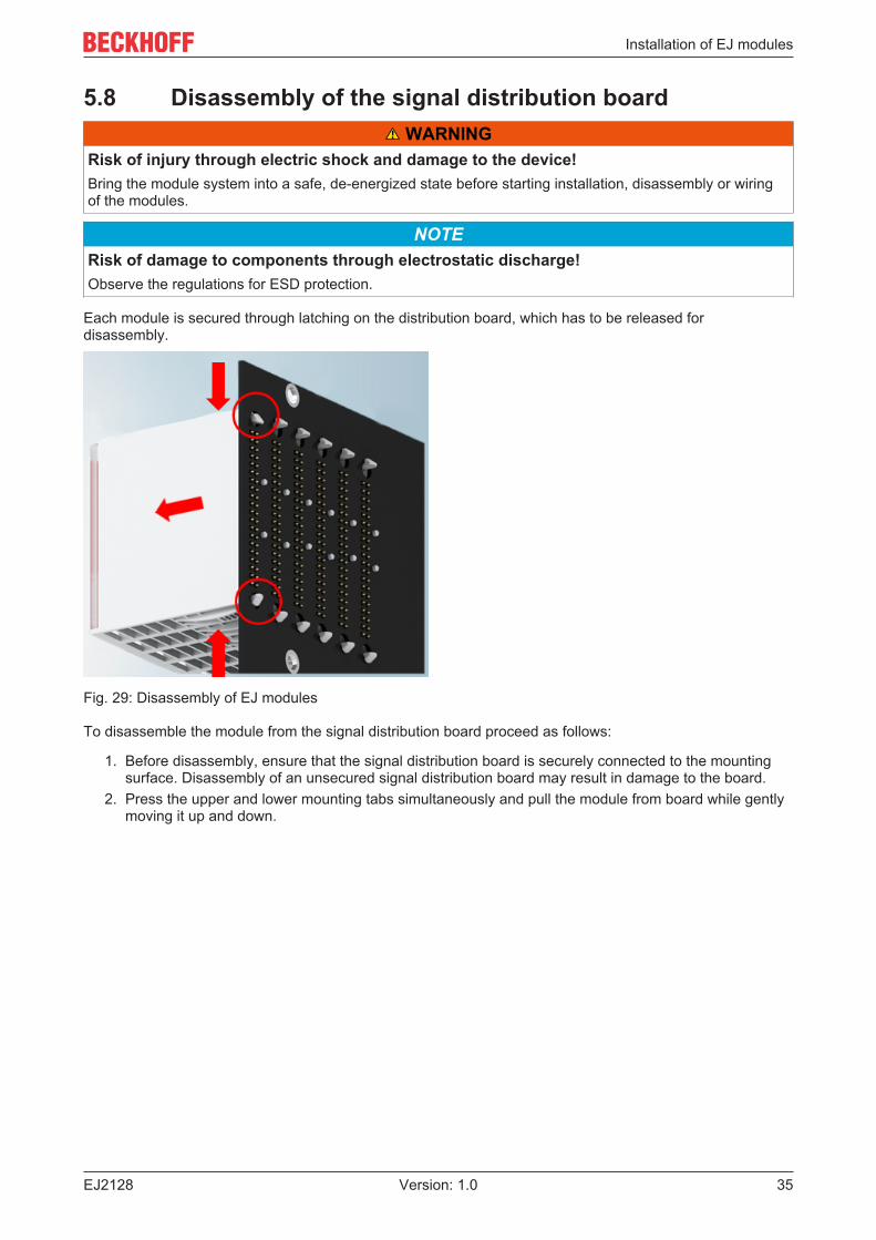
Each module is secured through latching on the distribution board, which has to be released fordisassembly.
Fig. 29: Disassembly of EJ modules
To disassemble the module from the signal distribution board proceed as follows:
1. Before disassembly, ensure that the signal distribution board is securely connected to the mountingsurface. Disassembly of an unsecured signal distribution board may result in damage to the board.
2. Press the upper and lower mounting tabs simultaneously and pull the module from board while gentlymoving it up and down.
Commissioning
EJ212836 Version: 1.0
6 Commissioning
6.1 TwinCAT Quick StartTwinCAT is a development environment for real-time control including multi-PLC system, NC axis control,programming and operation. The whole system is mapped through this environment and enables access to aprogramming environment (including compilation) for the controller. Individual digital or analog inputs oroutputs can also be read or written directly, in order to verify their functionality, for example.
For further information please refer to http://infosys.beckhoff.com:
• EtherCAT Systemmanual:Fieldbus Components → EtherCAT Terminals → EtherCAT System Documentation → Setup in theTwinCAT System Manager
• TwinCAT 2 → TwinCAT System Manager → I/O - Configuration• In particular, TwinCAT driver installation:
Fieldbus components → Fieldbus Cards and Switches → FC900x – PCI Cards for Ethernet →Installation
Devices contain the terminals for the actual configuration. All configuration data can be entered directly viaeditor functions (offline) or via the "Scan" function (online):
• "offline": The configuration can be customized by adding and positioning individual components.These can be selected from a directory and configured.
◦ The procedure for offline mode can be found under http://infosys.beckhoff.com:TwinCAT 2 → TwinCAT System Manager → IO - Configuration → Adding an I/O Device
• "online": The existing hardware configuration is read
◦ See also http://infosys.beckhoff.com:Fieldbus components → Fieldbus cards and switches → FC900x – PCI Cards for Ethernet →Installation → Searching for devices
The following relationship is envisaged from user PC to the individual control elements:
Commissioning
EJ2128 37Version: 1.0
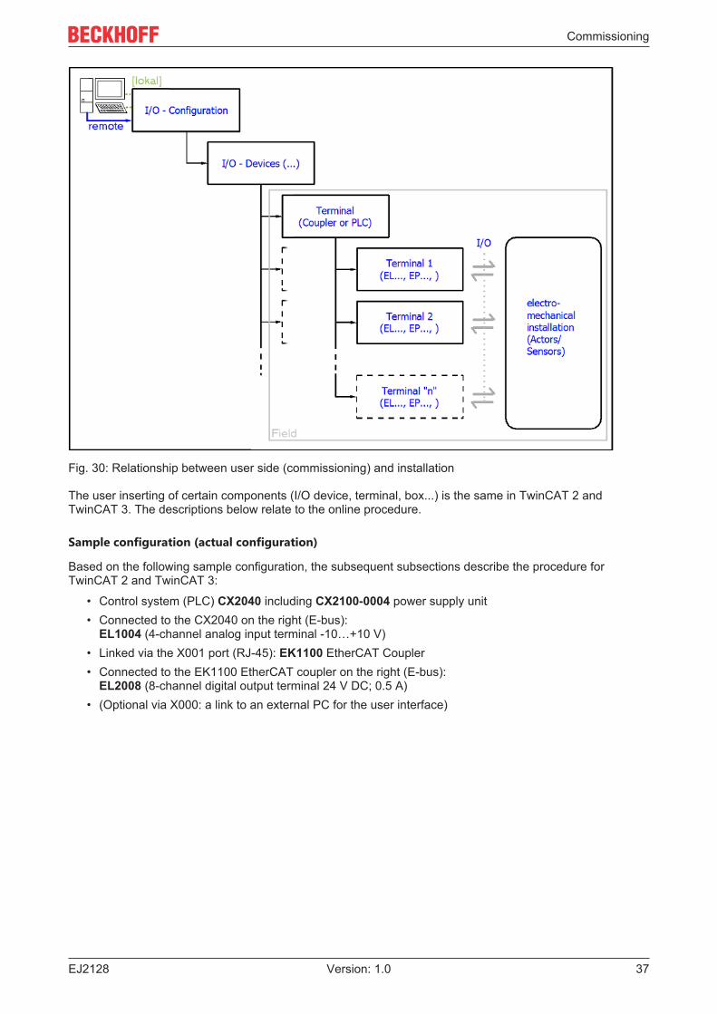
Fig. 30: Relationship between user side (commissioning) and installation
The user inserting of certain components (I/O device, terminal, box...) is the same in TwinCAT 2 andTwinCAT 3. The descriptions below relate to the online procedure.
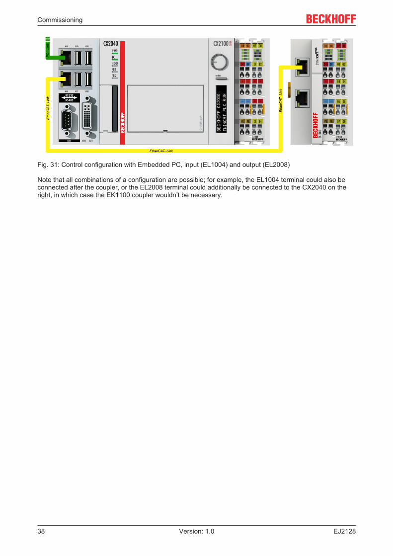
Sample configuration (actual configuration)
Based on the following sample configuration, the subsequent subsections describe the procedure forTwinCAT 2 and TwinCAT 3:
• Control system (PLC) CX2040 including CX2100-0004 power supply unit• Connected to the CX2040 on the right (E-bus):
EL1004 (4-channel analog input terminal -10…+10 V)• Linked via the X001 port (RJ-45): EK1100 EtherCAT Coupler• Connected to the EK1100 EtherCAT coupler on the right (E-bus):
EL2008 (8-channel digital output terminal 24 V DC; 0.5 A)• (Optional via X000: a link to an external PC for the user interface)
Commissioning
EJ212838 Version: 1.0
Fig. 31: Control configuration with Embedded PC, input (EL1004) and output (EL2008)
Note that all combinations of a configuration are possible; for example, the EL1004 terminal could also beconnected after the coupler, or the EL2008 terminal could additionally be connected to the CX2040 on theright, in which case the EK1100 coupler wouldn’t be necessary.
Commissioning
EJ2128 39Version: 1.0
6.1.1 TwinCAT 2
Startup
TwinCAT basically uses two user interfaces: the TwinCAT System Manager for communication with theelectromechanical components and TwinCAT PLC Control for the development and compilation of acontroller. The starting point is the TwinCAT System Manager.
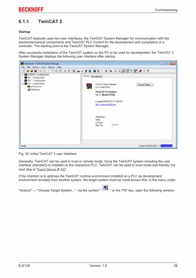
After successful installation of the TwinCAT system on the PC to be used for development, the TwinCAT 2System Manager displays the following user interface after startup:
Fig. 32: Initial TwinCAT 2 user interface
Generally, TwinCAT can be used in local or remote mode. Once the TwinCAT system including the userinterface (standard) is installed on the respective PLC, TwinCAT can be used in local mode and thereby thenext step is "Insert Device [} 41]".
If the intention is to address the TwinCAT runtime environment installed on a PLC as developmentenvironment remotely from another system, the target system must be made known first. In the menu under
"Actions" → "Choose Target System...", via the symbol " " or the "F8" key, open the following window:
Commissioning
EJ212840 Version: 1.0
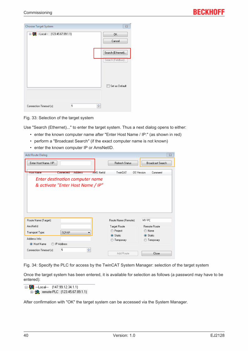
Fig. 33: Selection of the target system
Use "Search (Ethernet)..." to enter the target system. Thus a next dialog opens to either:
• enter the known computer name after "Enter Host Name / IP:" (as shown in red)• perform a "Broadcast Search" (if the exact computer name is not known)• enter the known computer IP or AmsNetID.
Fig. 34: Specify the PLC for access by the TwinCAT System Manager: selection of the target system
Once the target system has been entered, it is available for selection as follows (a password may have to beentered):
After confirmation with "OK" the target system can be accessed via the System Manager.
Commissioning
EJ2128 41Version: 1.0
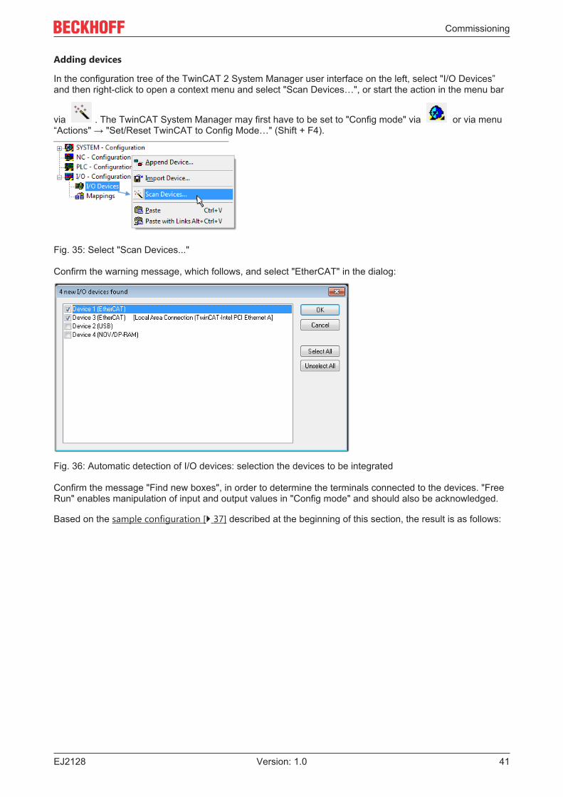
Adding devices
In the configuration tree of the TwinCAT 2 System Manager user interface on the left, select "I/O Devices”and then right-click to open a context menu and select "Scan Devices…", or start the action in the menu bar
via . The TwinCAT System Manager may first have to be set to "Config mode" via or via menu“Actions" → "Set/Reset TwinCAT to Config Mode…" (Shift + F4).
Fig. 35: Select "Scan Devices..."
Confirm the warning message, which follows, and select "EtherCAT" in the dialog:
Fig. 36: Automatic detection of I/O devices: selection the devices to be integrated
Confirm the message "Find new boxes", in order to determine the terminals connected to the devices. "FreeRun" enables manipulation of input and output values in "Config mode" and should also be acknowledged.
Based on the sample configuration [} 37] described at the beginning of this section, the result is as follows:
Commissioning
EJ212842 Version: 1.0
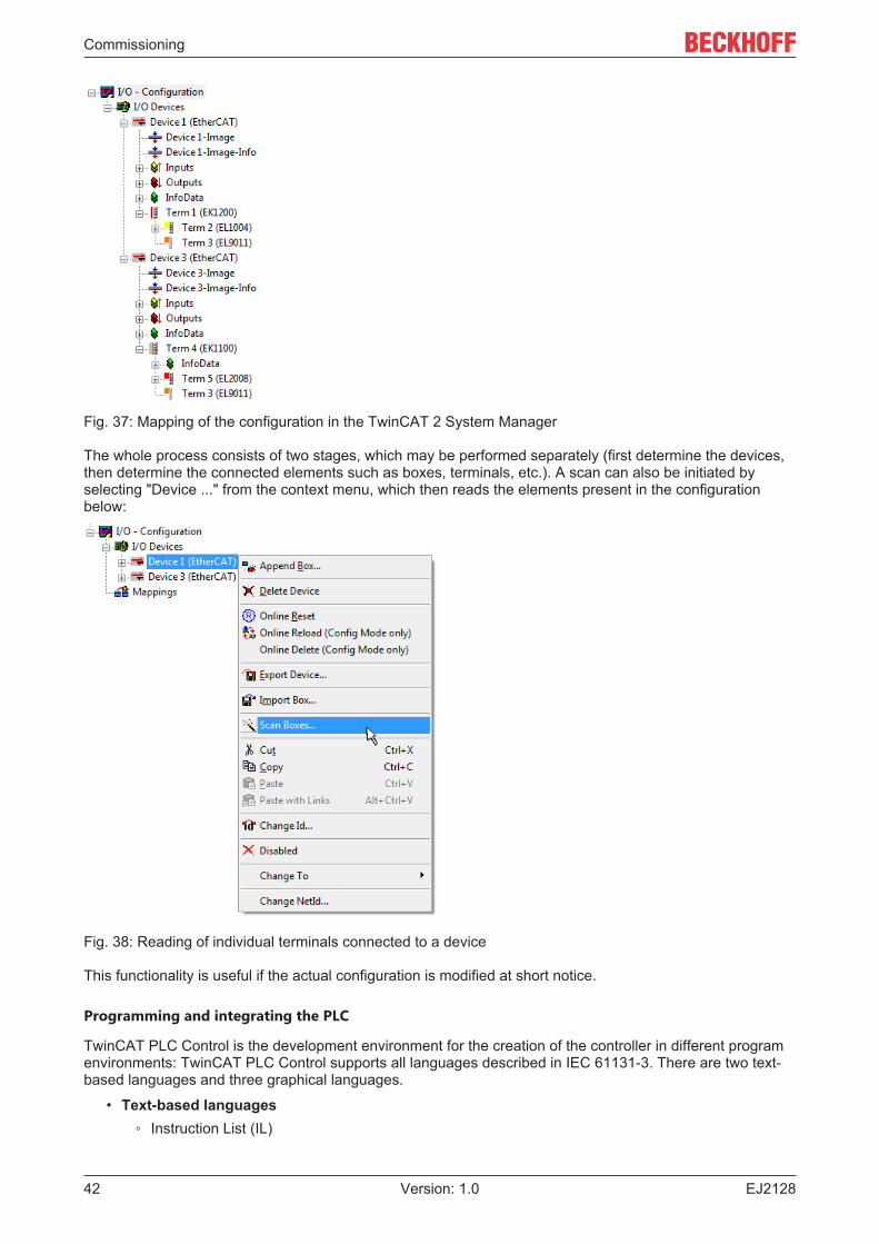
Fig. 37: Mapping of the configuration in the TwinCAT 2 System Manager
The whole process consists of two stages, which may be performed separately (first determine the devices,then determine the connected elements such as boxes, terminals, etc.). A scan can also be initiated byselecting "Device ..." from the context menu, which then reads the elements present in the configurationbelow:
Fig. 38: Reading of individual terminals connected to a device
This functionality is useful if the actual configuration is modified at short notice.
Programming and integrating the PLC
TwinCAT PLC Control is the development environment for the creation of the controller in different programenvironments: TwinCAT PLC Control supports all languages described in IEC 61131-3. There are two text-based languages and three graphical languages.
• Text-based languages◦ Instruction List (IL)
Commissioning
EJ2128 43Version: 1.0
◦ Structured Text (ST)• Graphical languages
◦ Function Block Diagram (FBD)◦ Ladder Diagram (LD)◦ The Continuous Function Chart Editor (CFC)◦ Sequential Function Chart (SFC)
The following section refers to Structured Text (ST).
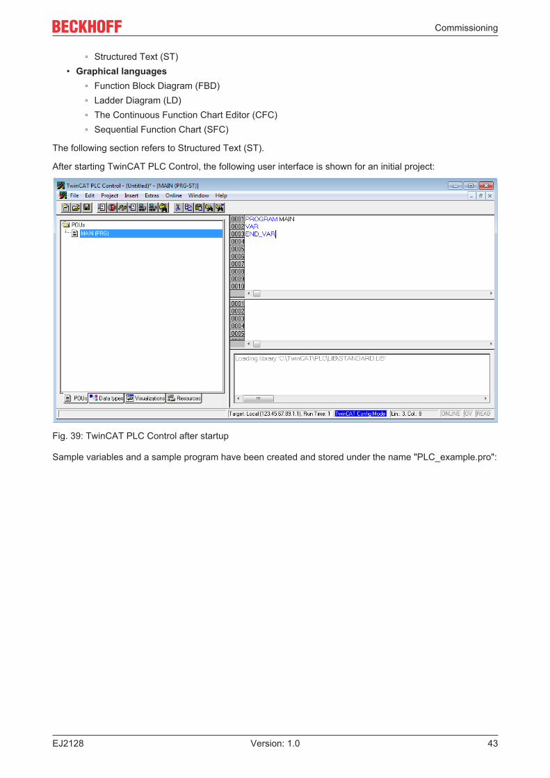
After starting TwinCAT PLC Control, the following user interface is shown for an initial project:
Fig. 39: TwinCAT PLC Control after startup
Sample variables and a sample program have been created and stored under the name "PLC_example.pro":
Commissioning
EJ212844 Version: 1.0
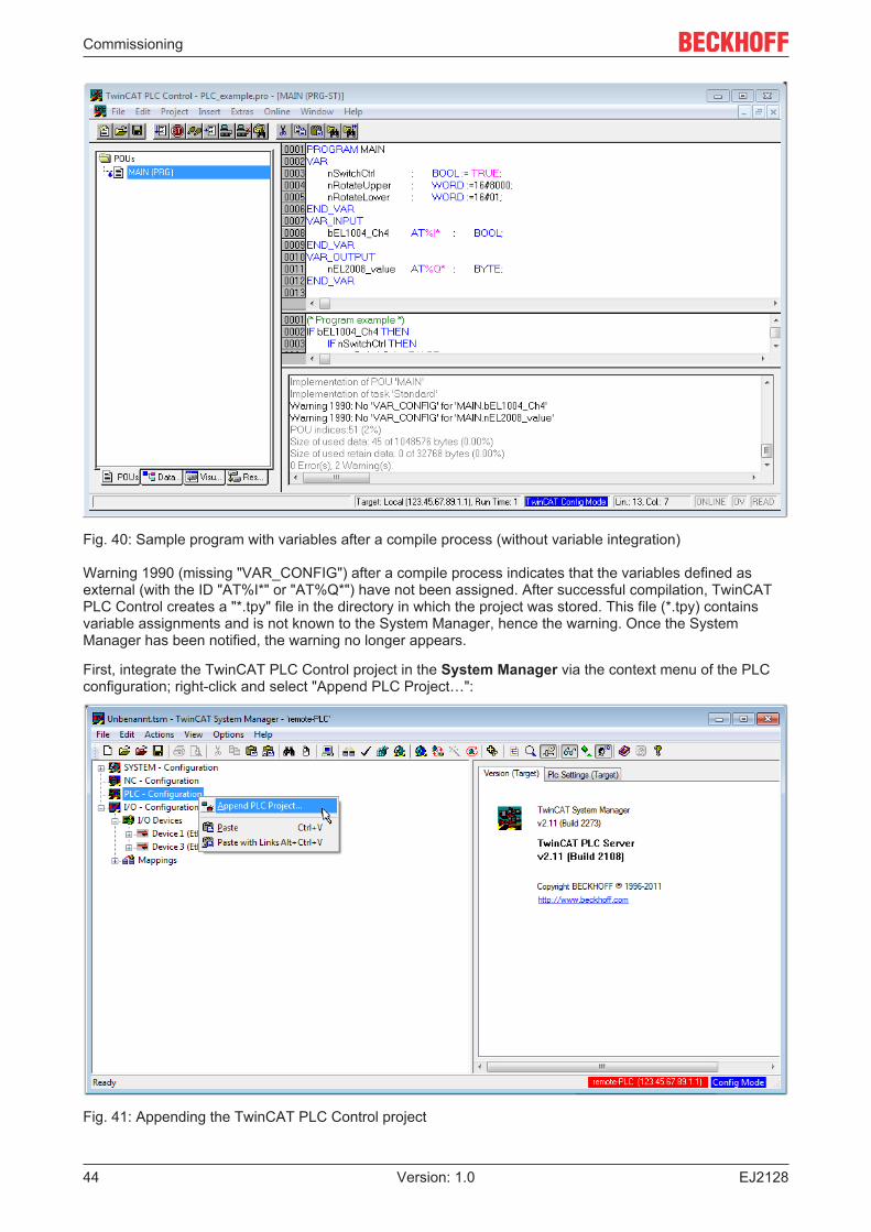
Fig. 40: Sample program with variables after a compile process (without variable integration)
Warning 1990 (missing "VAR_CONFIG") after a compile process indicates that the variables defined asexternal (with the ID "AT%I*" or "AT%Q*") have not been assigned. After successful compilation, TwinCATPLC Control creates a "*.tpy" file in the directory in which the project was stored. This file (*.tpy) containsvariable assignments and is not known to the System Manager, hence the warning. Once the SystemManager has been notified, the warning no longer appears.
First, integrate the TwinCAT PLC Control project in the System Manager via the context menu of the PLCconfiguration; right-click and select "Append PLC Project…":
Fig. 41: Appending the TwinCAT PLC Control project
Commissioning
EJ2128 45Version: 1.0
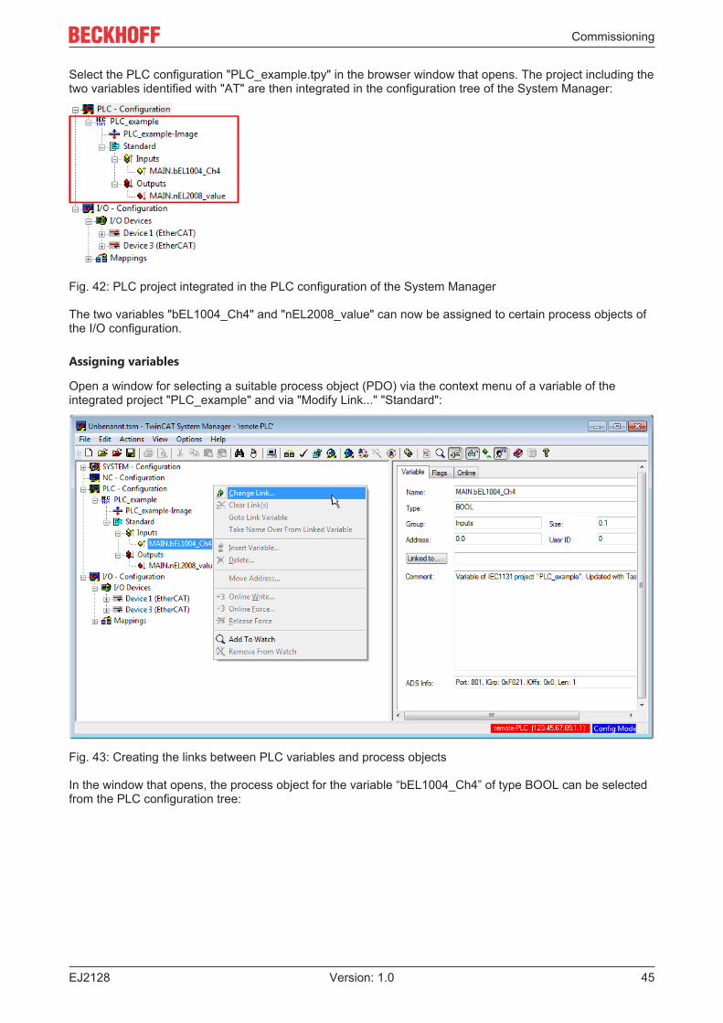
Select the PLC configuration "PLC_example.tpy" in the browser window that opens. The project including thetwo variables identified with "AT" are then integrated in the configuration tree of the System Manager:
Fig. 42: PLC project integrated in the PLC configuration of the System Manager
The two variables "bEL1004_Ch4" and "nEL2008_value" can now be assigned to certain process objects ofthe I/O configuration.
Assigning variables
Open a window for selecting a suitable process object (PDO) via the context menu of a variable of theintegrated project "PLC_example" and via "Modify Link..." "Standard":
Fig. 43: Creating the links between PLC variables and process objects
In the window that opens, the process object for the variable “bEL1004_Ch4” of type BOOL can be selectedfrom the PLC configuration tree:
Commissioning
EJ212846 Version: 1.0
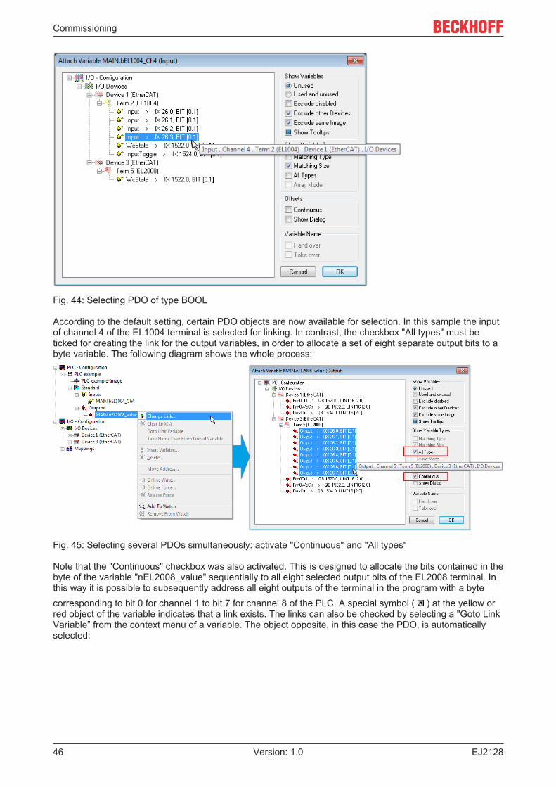
Fig. 44: Selecting PDO of type BOOL
According to the default setting, certain PDO objects are now available for selection. In this sample the inputof channel 4 of the EL1004 terminal is selected for linking. In contrast, the checkbox "All types" must beticked for creating the link for the output variables, in order to allocate a set of eight separate output bits to abyte variable. The following diagram shows the whole process:
Fig. 45: Selecting several PDOs simultaneously: activate "Continuous" and "All types"
Note that the "Continuous" checkbox was also activated. This is designed to allocate the bits contained in thebyte of the variable "nEL2008_value" sequentially to all eight selected output bits of the EL2008 terminal. Inthis way it is possible to subsequently address all eight outputs of the terminal in the program with a bytecorresponding to bit 0 for channel 1 to bit 7 for channel 8 of the PLC. A special symbol ( ) at the yellow orred object of the variable indicates that a link exists. The links can also be checked by selecting a "Goto LinkVariable” from the context menu of a variable. The object opposite, in this case the PDO, is automaticallyselected:
Commissioning
EJ2128 47Version: 1.0
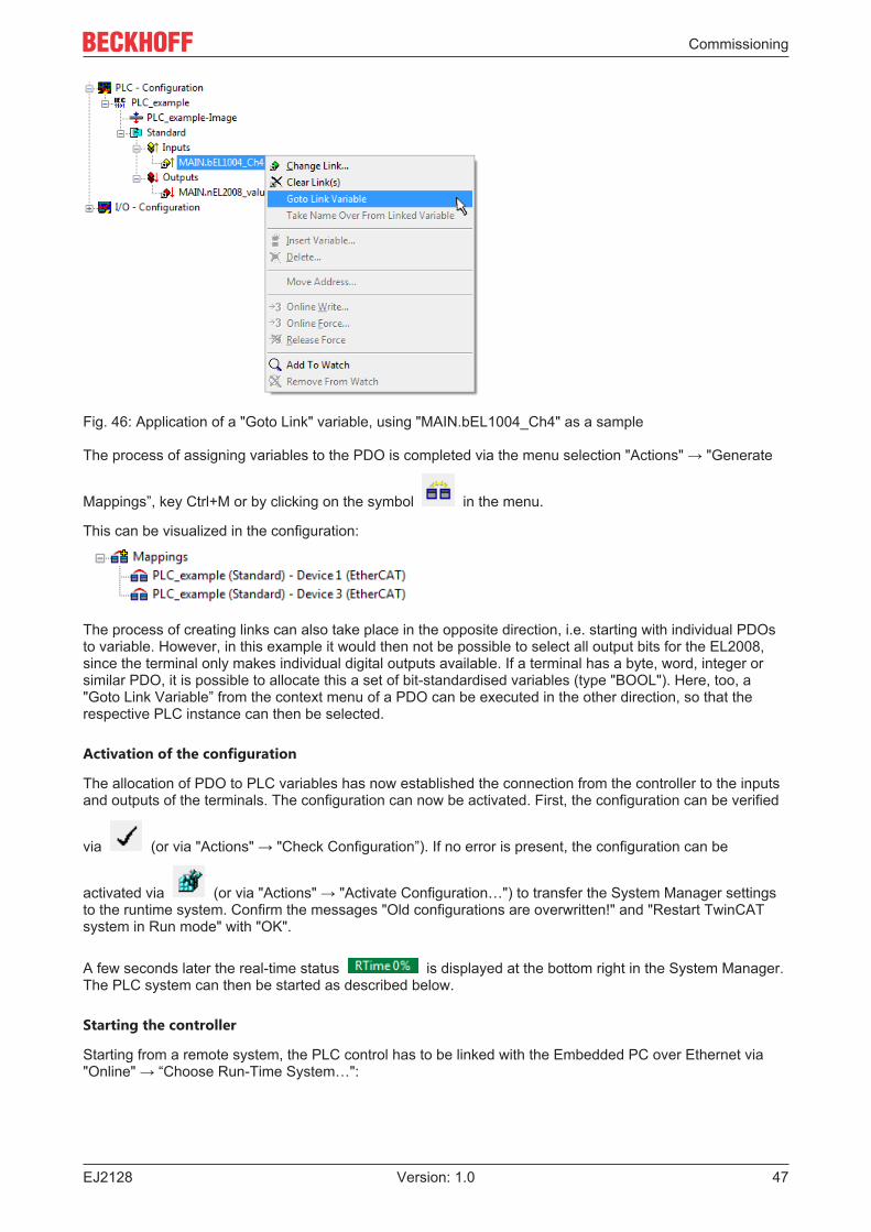
Fig. 46: Application of a "Goto Link" variable, using "MAIN.bEL1004_Ch4" as a sample
The process of assigning variables to the PDO is completed via the menu selection "Actions" → "Generate
Mappings”, key Ctrl+M or by clicking on the symbol in the menu.
This can be visualized in the configuration:
The process of creating links can also take place in the opposite direction, i.e. starting with individual PDOsto variable. However, in this example it would then not be possible to select all output bits for the EL2008,since the terminal only makes individual digital outputs available. If a terminal has a byte, word, integer orsimilar PDO, it is possible to allocate this a set of bit-standardised variables (type "BOOL"). Here, too, a"Goto Link Variable” from the context menu of a PDO can be executed in the other direction, so that therespective PLC instance can then be selected.
Activation of the configuration
The allocation of PDO to PLC variables has now established the connection from the controller to the inputsand outputs of the terminals. The configuration can now be activated. First, the configuration can be verified
via (or via "Actions" → "Check Configuration”). If no error is present, the configuration can be
activated via (or via "Actions" → "Activate Configuration…") to transfer the System Manager settingsto the runtime system. Confirm the messages "Old configurations are overwritten!" and "Restart TwinCATsystem in Run mode" with "OK".
A few seconds later the real-time status is displayed at the bottom right in the System Manager.The PLC system can then be started as described below.
Starting the controller
Starting from a remote system, the PLC control has to be linked with the Embedded PC over Ethernet via"Online" → “Choose Run-Time System…":
Commissioning
EJ212848 Version: 1.0
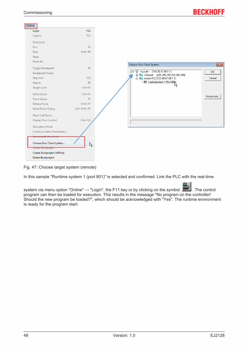
Fig. 47: Choose target system (remote)
In this sample "Runtime system 1 (port 801)" is selected and confirmed. Link the PLC with the real-time
system via menu option "Online" → "Login", the F11 key or by clicking on the symbol . The controlprogram can then be loaded for execution. This results in the message "No program on the controller!Should the new program be loaded?", which should be acknowledged with "Yes". The runtime environmentis ready for the program start:
Commissioning
EJ2128 49Version: 1.0
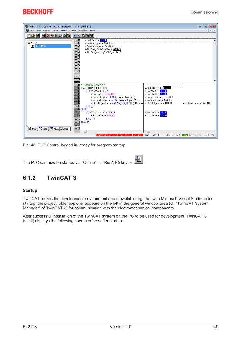
Fig. 48: PLC Control logged in, ready for program startup
The PLC can now be started via "Online" → "Run", F5 key or .
6.1.2 TwinCAT 3
Startup
TwinCAT makes the development environment areas available together with Microsoft Visual Studio: afterstartup, the project folder explorer appears on the left in the general window area (cf. "TwinCAT SystemManager" of TwinCAT 2) for communication with the electromechanical components.
After successful installation of the TwinCAT system on the PC to be used for development, TwinCAT 3(shell) displays the following user interface after startup:
Commissioning
EJ212850 Version: 1.0
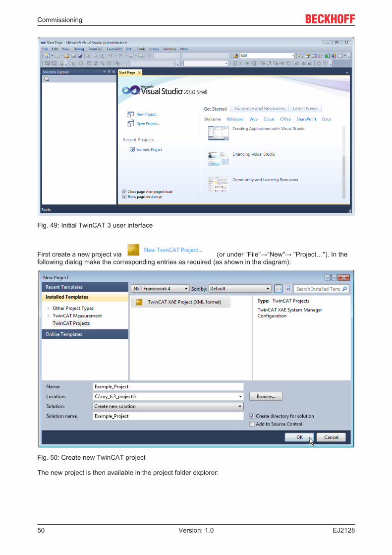
Fig. 49: Initial TwinCAT 3 user interface
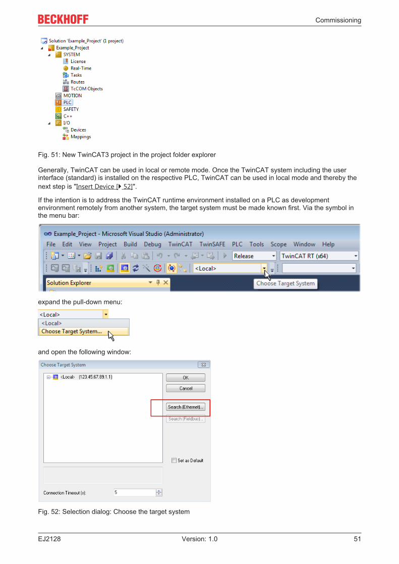
First create a new project via (or under "File"→“New"→ "Project…"). In thefollowing dialog make the corresponding entries as required (as shown in the diagram):
Fig. 50: Create new TwinCAT project
The new project is then available in the project folder explorer:
Commissioning
EJ2128 51Version: 1.0
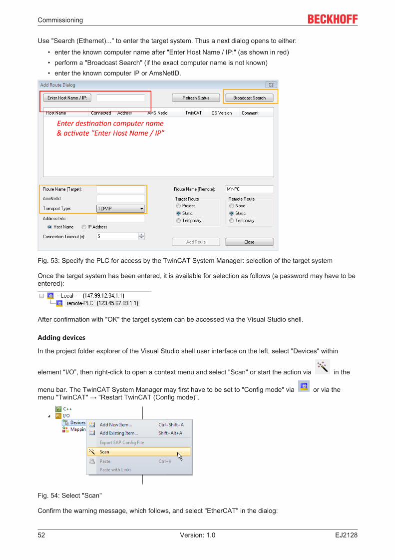
Fig. 51: New TwinCAT3 project in the project folder explorer
Generally, TwinCAT can be used in local or remote mode. Once the TwinCAT system including the userinterface (standard) is installed on the respective PLC, TwinCAT can be used in local mode and thereby thenext step is "Insert Device [} 52]".
If the intention is to address the TwinCAT runtime environment installed on a PLC as developmentenvironment remotely from another system, the target system must be made known first. Via the symbol inthe menu bar:
expand the pull-down menu:
and open the following window:
Fig. 52: Selection dialog: Choose the target system
Commissioning
EJ212852 Version: 1.0
Use "Search (Ethernet)..." to enter the target system. Thus a next dialog opens to either:
• enter the known computer name after "Enter Host Name / IP:" (as shown in red)• perform a "Broadcast Search" (if the exact computer name is not known)• enter the known computer IP or AmsNetID.
Fig. 53: Specify the PLC for access by the TwinCAT System Manager: selection of the target system
Once the target system has been entered, it is available for selection as follows (a password may have to beentered):
After confirmation with "OK" the target system can be accessed via the Visual Studio shell.
Adding devices
In the project folder explorer of the Visual Studio shell user interface on the left, select "Devices" within
element “I/O”, then right-click to open a context menu and select "Scan" or start the action via in the
menu bar. The TwinCAT System Manager may first have to be set to "Config mode" via or via themenu "TwinCAT" → "Restart TwinCAT (Config mode)".
Fig. 54: Select "Scan"
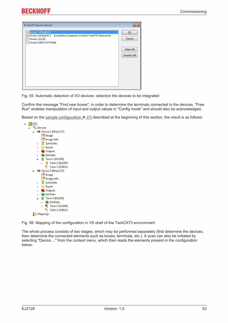
Confirm the warning message, which follows, and select "EtherCAT" in the dialog:
Commissioning
EJ2128 53Version: 1.0
Fig. 55: Automatic detection of I/O devices: selection the devices to be integrated
Confirm the message "Find new boxes", in order to determine the terminals connected to the devices. "FreeRun" enables manipulation of input and output values in "Config mode" and should also be acknowledged.
Based on the sample configuration [} 37] described at the beginning of this section, the result is as follows:
Fig. 56: Mapping of the configuration in VS shell of the TwinCAT3 environment
The whole process consists of two stages, which may be performed separately (first determine the devices,then determine the connected elements such as boxes, terminals, etc.). A scan can also be initiated byselecting "Device ..." from the context menu, which then reads the elements present in the configurationbelow:
Commissioning
EJ212854 Version: 1.0
Fig. 57: Reading of individual terminals connected to a device
This functionality is useful if the actual configuration is modified at short notice.
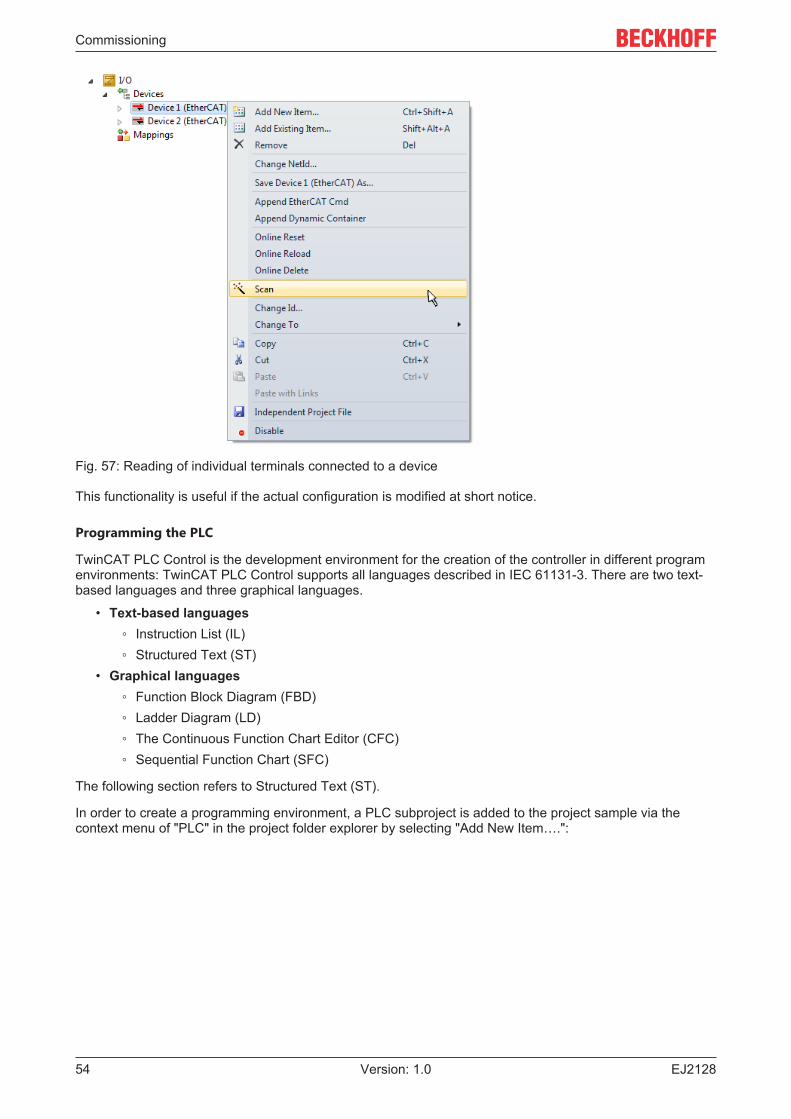
Programming the PLC
TwinCAT PLC Control is the development environment for the creation of the controller in different programenvironments: TwinCAT PLC Control supports all languages described in IEC 61131-3. There are two text-based languages and three graphical languages.
• Text-based languages◦ Instruction List (IL)◦ Structured Text (ST)
• Graphical languages◦ Function Block Diagram (FBD)◦ Ladder Diagram (LD)◦ The Continuous Function Chart Editor (CFC)◦ Sequential Function Chart (SFC)
The following section refers to Structured Text (ST).
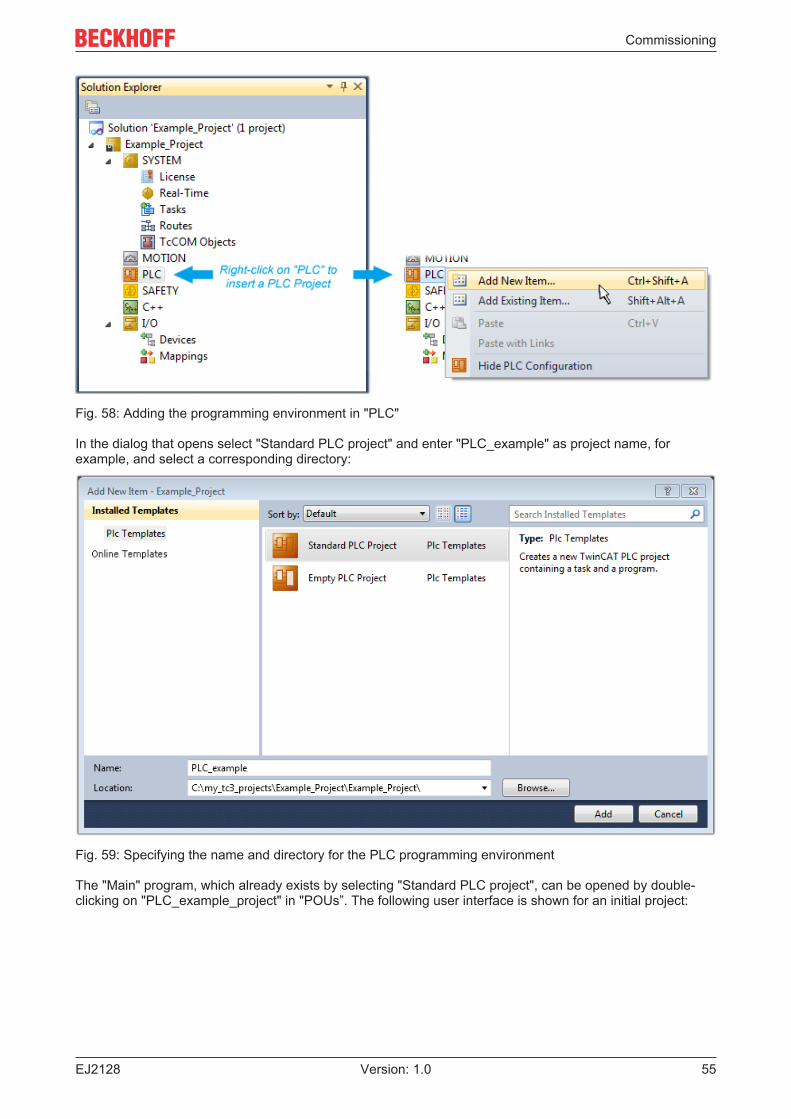
In order to create a programming environment, a PLC subproject is added to the project sample via thecontext menu of "PLC" in the project folder explorer by selecting "Add New Item….":
Commissioning
EJ2128 55Version: 1.0
Fig. 58: Adding the programming environment in "PLC"
In the dialog that opens select "Standard PLC project" and enter "PLC_example" as project name, forexample, and select a corresponding directory:
Fig. 59: Specifying the name and directory for the PLC programming environment
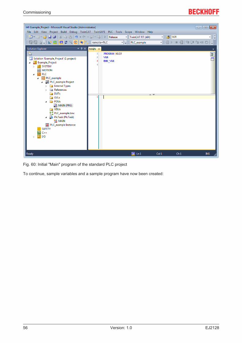
The "Main" program, which already exists by selecting "Standard PLC project", can be opened by double-clicking on "PLC_example_project" in "POUs”. The following user interface is shown for an initial project:
Commissioning
EJ212856 Version: 1.0
Fig. 60: Initial "Main" program of the standard PLC project
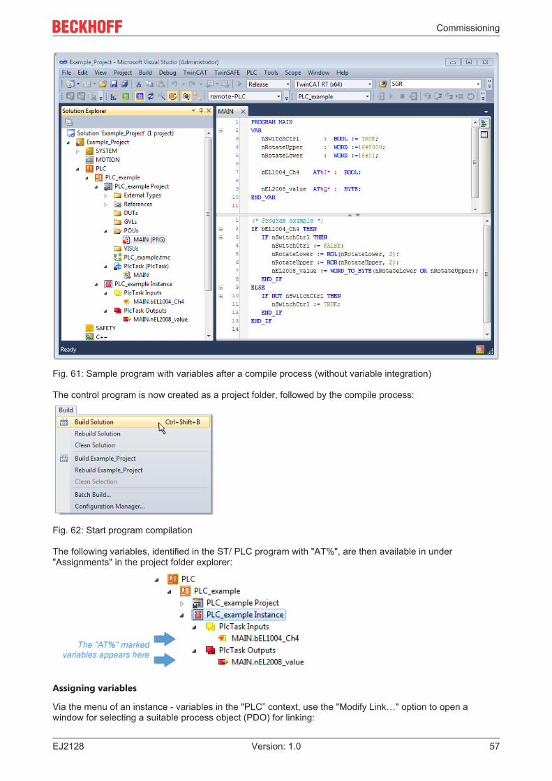
To continue, sample variables and a sample program have now been created:
Commissioning
EJ2128 57Version: 1.0
Fig. 61: Sample program with variables after a compile process (without variable integration)
The control program is now created as a project folder, followed by the compile process:
Fig. 62: Start program compilation
The following variables, identified in the ST/ PLC program with "AT%", are then available in under"Assignments" in the project folder explorer:
Assigning variables
Via the menu of an instance - variables in the "PLC” context, use the "Modify Link…" option to open awindow for selecting a suitable process object (PDO) for linking:
Commissioning
EJ212858 Version: 1.0
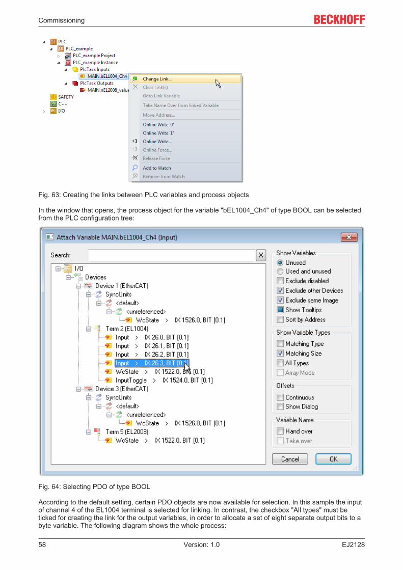
Fig. 63: Creating the links between PLC variables and process objects
In the window that opens, the process object for the variable "bEL1004_Ch4" of type BOOL can be selectedfrom the PLC configuration tree:
Fig. 64: Selecting PDO of type BOOL
According to the default setting, certain PDO objects are now available for selection. In this sample the inputof channel 4 of the EL1004 terminal is selected for linking. In contrast, the checkbox "All types" must beticked for creating the link for the output variables, in order to allocate a set of eight separate output bits to abyte variable. The following diagram shows the whole process:
Commissioning
EJ2128 59Version: 1.0
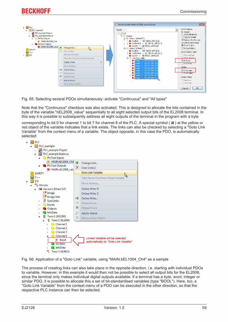
Fig. 65: Selecting several PDOs simultaneously: activate "Continuous" and "All types"
Note that the "Continuous" checkbox was also activated. This is designed to allocate the bits contained in thebyte of the variable "nEL2008_value" sequentially to all eight selected output bits of the EL2008 terminal. Inthis way it is possible to subsequently address all eight outputs of the terminal in the program with a bytecorresponding to bit 0 for channel 1 to bit 7 for channel 8 of the PLC. A special symbol ( ) at the yellow orred object of the variable indicates that a link exists. The links can also be checked by selecting a "Goto LinkVariable” from the context menu of a variable. The object opposite, in this case the PDO, is automaticallyselected:
Fig. 66: Application of a "Goto Link" variable, using "MAIN.bEL1004_Ch4" as a sample
The process of creating links can also take place in the opposite direction, i.e. starting with individual PDOsto variable. However, in this example it would then not be possible to select all output bits for the EL2008,since the terminal only makes individual digital outputs available. If a terminal has a byte, word, integer orsimilar PDO, it is possible to allocate this a set of bit-standardised variables (type "BOOL"). Here, too, a"Goto Link Variable” from the context menu of a PDO can be executed in the other direction, so that therespective PLC instance can then be selected.
Commissioning
EJ212860 Version: 1.0
Activation of the configuration
The allocation of PDO to PLC variables has now established the connection from the controller to the inputs
and outputs of the terminals. The configuration can now be activated with or via the menu under"TwinCAT" in order to transfer settings of the development environment to the runtime system. Confirm themessages "Old configurations are overwritten!" and "Restart TwinCAT system in Run mode" with "OK". Thecorresponding assignments can be seen in the project folder explorer:
A few seconds later the corresponding status of the Run mode is displayed in the form of a rotating symbol
at the bottom right of the VS shell development environment. The PLC system can then be started asdescribed below.
Starting the controller
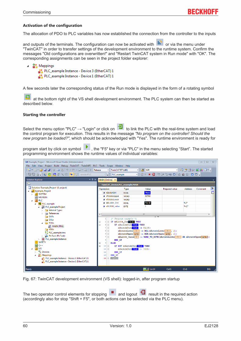
Select the menu option "PLC" → "Login" or click on to link the PLC with the real-time system and loadthe control program for execution. This results in the message "No program on the controller! Should thenew program be loaded?", which should be acknowledged with "Yes". The runtime environment is ready for
program start by click on symbol , the "F5" key or via "PLC" in the menu selecting “Start”. The startedprogramming environment shows the runtime values of individual variables:
Fig. 67: TwinCAT development environment (VS shell): logged-in, after program startup
The two operator control elements for stopping and logout result in the required action(accordingly also for stop "Shift + F5", or both actions can be selected via the PLC menu).
Commissioning
EJ2128 61Version: 1.0
6.2 TwinCAT Development EnvironmentThe Software for automation TwinCAT (The Windows Control and Automation Technology) will bedistinguished into:
• TwinCAT 2: System Manager (Configuration) & PLC Control (Programming)• TwinCAT 3: Enhancement of TwinCAT 2 (Programming and Configuration takes place via a common
Development Environment)
Details:• TwinCAT 2:
◦ Connects I/O devices to tasks in a variable-oriented manner◦ Connects tasks to tasks in a variable-oriented manner◦ Supports units at the bit level◦ Supports synchronous or asynchronous relationships◦ Exchange of consistent data areas and process images◦ Datalink on NT - Programs by open Microsoft Standards (OLE, OCX, ActiveX, DCOM+, etc.)◦ Integration of IEC 61131-3-Software-SPS, Software- NC and Software-CNC within Windows
NT/2000/XP/Vista, Windows 7, NT/XP Embedded, CE◦ Interconnection to all common fieldbusses
◦ More…
Additional features:• TwinCAT 3 (eXtended Automation):
◦ Visual-Studio®-Integration◦ Choice of the programming language◦ Supports object orientated extension of IEC 61131-3◦ Usage of C/C++ as programming language for real time applications◦ Connection to MATLAB®/Simulink®◦ Open interface for expandability◦ Flexible run-time environment◦ Active support of Multi-Core- und 64-Bit-Operatingsystem◦ Automatic code generation and project creation with the TwinCAT Automation Interface
◦ More…
Within the following sections commissioning of the TwinCAT Development Environment on a PC System forthe control and also the basically functions of unique control elements will be explained.
Please see further information to TwinCAT 2 and TwinCAT 3 at http://infosys.beckhoff.com.
6.2.1 Installation of the TwinCAT real-time driverIn order to assign real-time capability to a standard Ethernet port of an IPC controller, the Beckhoff real-timedriver has to be installed on this port under Windows.
This can be done in several ways. One option is described here.
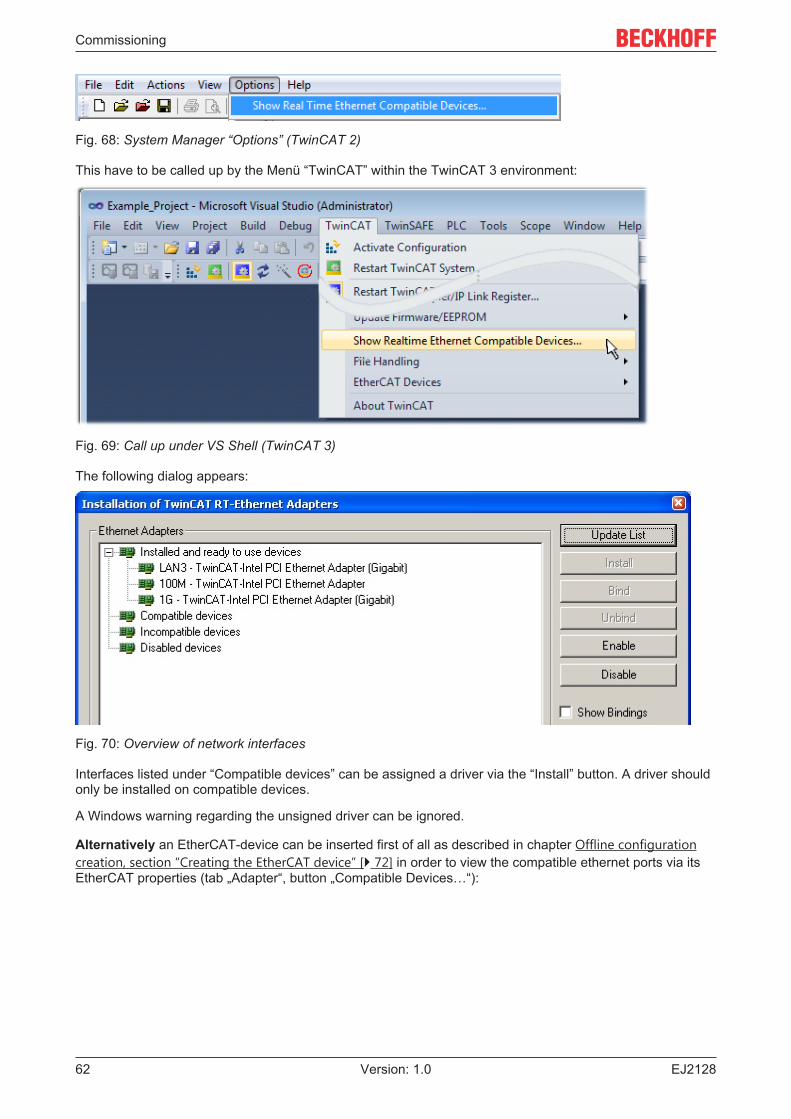
In the System Manager call up the TwinCAT overview of the local network interfaces via Options → ShowReal Time Ethernet Compatible Devices.
Commissioning
EJ212862 Version: 1.0
Fig. 68: System Manager “Options” (TwinCAT 2)
This have to be called up by the Menü “TwinCAT” within the TwinCAT 3 environment:
Fig. 69: Call up under VS Shell (TwinCAT 3)
The following dialog appears:
Fig. 70: Overview of network interfaces
Interfaces listed under “Compatible devices” can be assigned a driver via the “Install” button. A driver shouldonly be installed on compatible devices.
A Windows warning regarding the unsigned driver can be ignored.
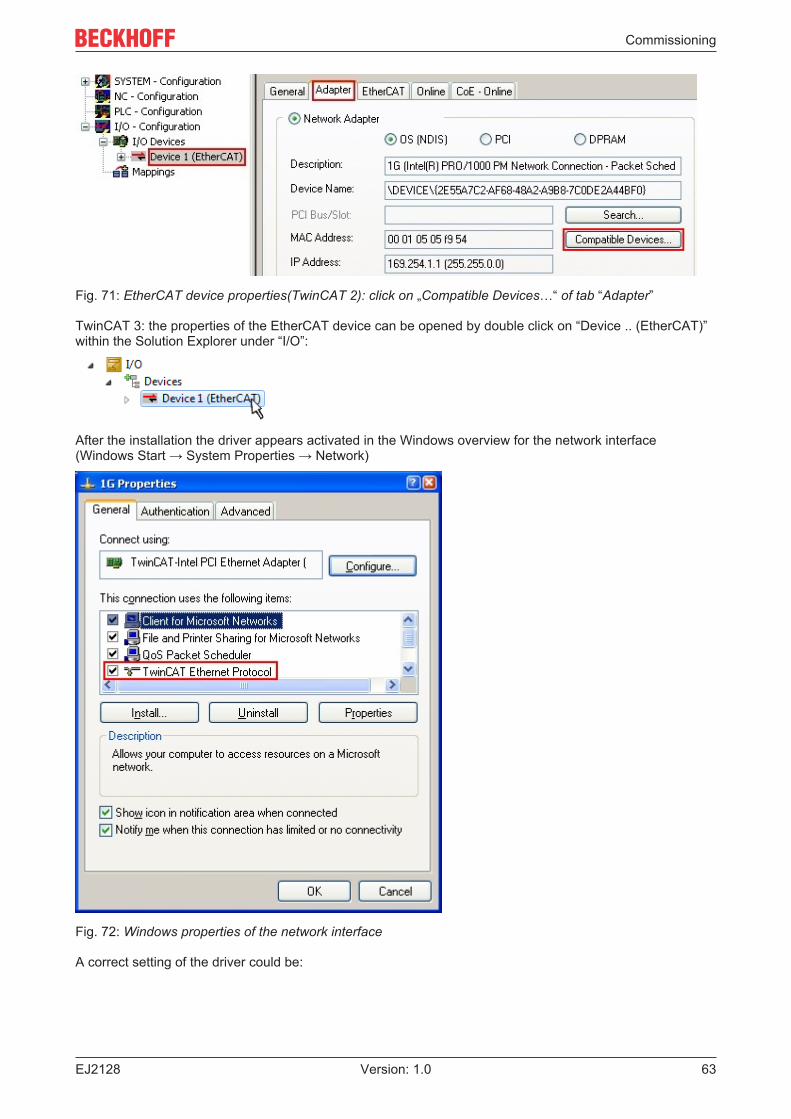
Alternatively an EtherCAT-device can be inserted first of all as described in chapter Offline configurationcreation, section “Creating the EtherCAT device” [} 72] in order to view the compatible ethernet ports via itsEtherCAT properties (tab „Adapter“, button „Compatible Devices…“):
Commissioning
EJ2128 63Version: 1.0
Fig. 71: EtherCAT device properties(TwinCAT 2): click on „Compatible Devices…“ of tab “Adapter”
TwinCAT 3: the properties of the EtherCAT device can be opened by double click on “Device .. (EtherCAT)”within the Solution Explorer under “I/O”:
After the installation the driver appears activated in the Windows overview for the network interface(Windows Start → System Properties → Network)
Fig. 72: Windows properties of the network interface
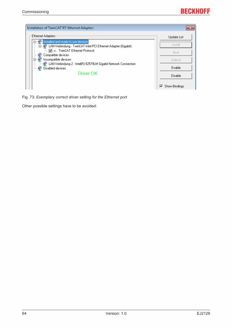
A correct setting of the driver could be:
Commissioning
EJ212864 Version: 1.0
Fig. 73: Exemplary correct driver setting for the Ethernet port
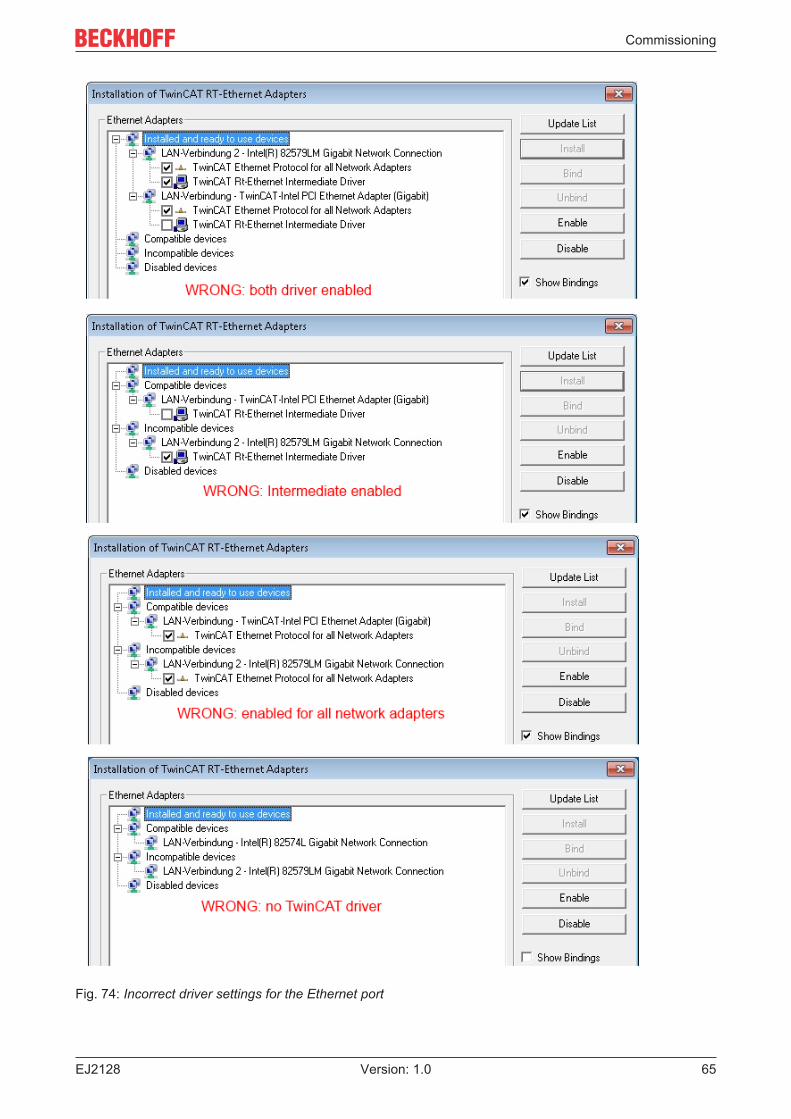
Other possible settings have to be avoided:
Commissioning
EJ2128 65Version: 1.0
Fig. 74: Incorrect driver settings for the Ethernet port
Commissioning
EJ212866 Version: 1.0
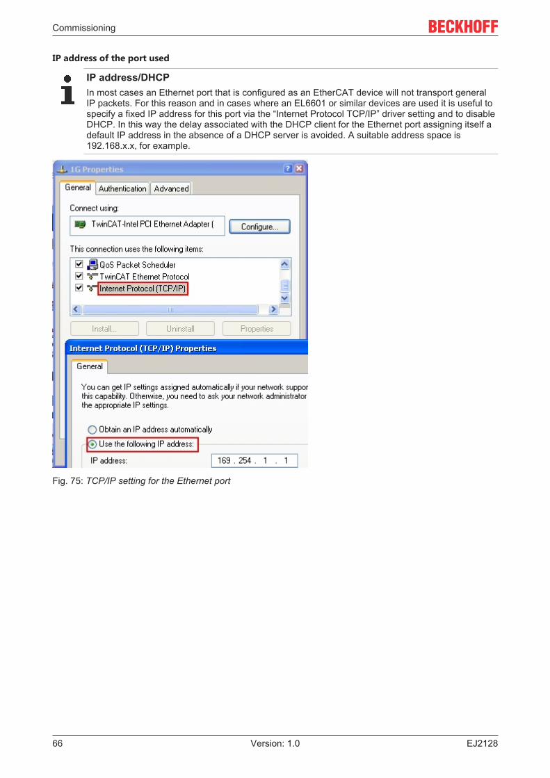
IP address of the port used
IP address/DHCPIn most cases an Ethernet port that is configured as an EtherCAT device will not transport generalIP packets. For this reason and in cases where an EL6601 or similar devices are used it is useful tospecify a fixed IP address for this port via the “Internet Protocol TCP/IP” driver setting and to disableDHCP. In this way the delay associated with the DHCP client for the Ethernet port assigning itself adefault IP address in the absence of a DHCP server is avoided. A suitable address space is192.168.x.x, for example.
Fig. 75: TCP/IP setting for the Ethernet port
Commissioning
EJ2128 67Version: 1.0
6.2.2 Notes regarding ESI device description
Installation of the latest ESI device description
The TwinCAT EtherCAT master/System Manager needs the device description files for the devices to beused in order to generate the configuration in online or offline mode. The device descriptions are containedin the so-called ESI files (EtherCAT Slave Information) in XML format. These files can be requested from therespective manufacturer and are made available for download. An *.xml file may contain several devicedescriptions.
The ESI files for Beckhoff EtherCAT devices are available on the Beckhoff website.
The ESI files should be stored in the TwinCAT installation directory.
Default settings:
• TwinCAT 2: C:\TwinCAT\IO\EtherCAT• TwinCAT 3: C:\TwinCAT\3.1\Config\Io\EtherCAT
The files are read (once) when a new System Manager window is opened, if they have changed since thelast time the System Manager window was opened.
A TwinCAT installation includes the set of Beckhoff ESI files that was current at the time when the TwinCATbuild was created.
For TwinCAT 2.11/TwinCAT 3 and higher, the ESI directory can be updated from the System Manager, if theprogramming PC is connected to the Internet; by
• TwinCAT 2: Option → “Update EtherCAT Device Descriptions”• TwinCAT 3: TwinCAT → EtherCAT Devices → “Update Device Descriptions (via ETG Website)…”
The TwinCAT ESI Updater [} 71] is available for this purpose.
ESIThe *.xml files are associated with *.xsd files, which describe the structure of the ESI XML files. Toupdate the ESI device descriptions, both file types should therefore be updated.
Device differentiation
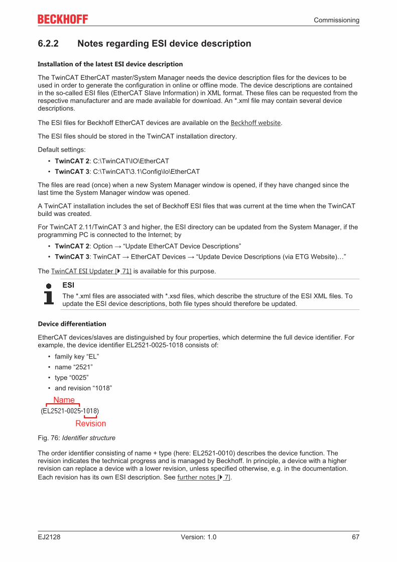
EtherCAT devices/slaves are distinguished by four properties, which determine the full device identifier. Forexample, the device identifier EL2521-0025-1018 consists of:
• family key “EL”• name “2521”• type “0025”• and revision “1018”
Fig. 76: Identifier structure
The order identifier consisting of name + type (here: EL2521-0010) describes the device function. Therevision indicates the technical progress and is managed by Beckhoff. In principle, a device with a higherrevision can replace a device with a lower revision, unless specified otherwise, e.g. in the documentation.Each revision has its own ESI description. See further notes [} 7].
Commissioning
EJ212868 Version: 1.0
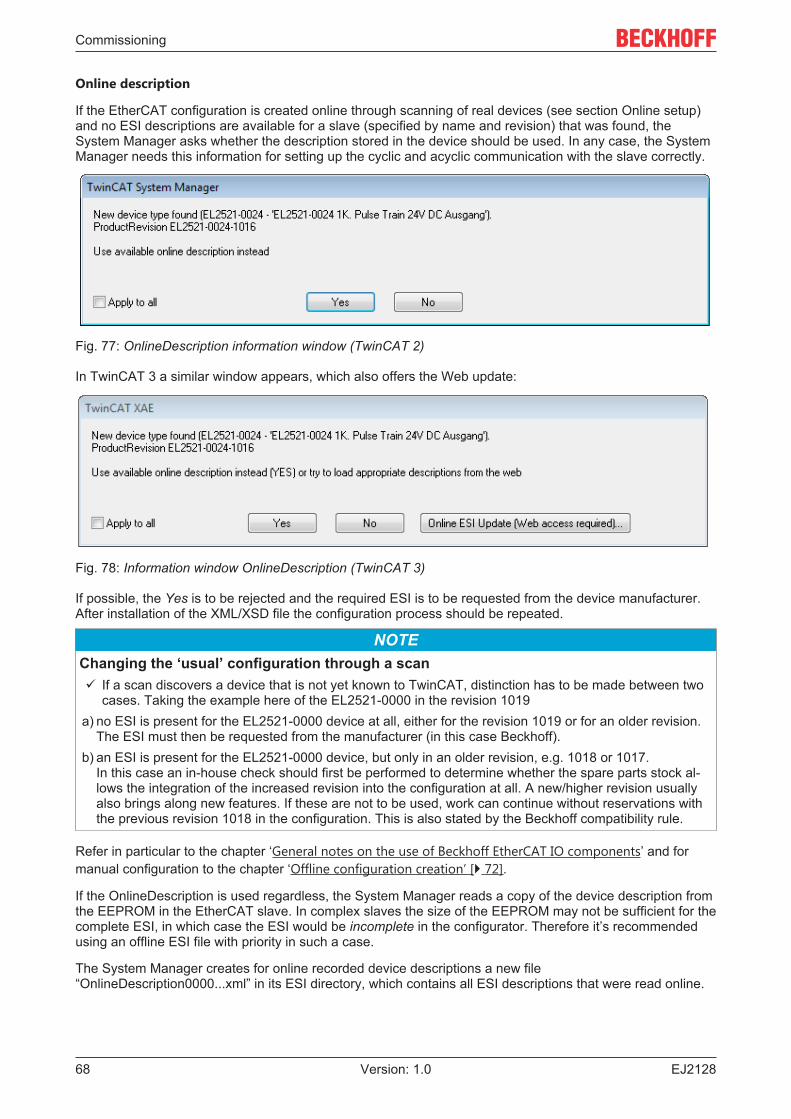
Online description
If the EtherCAT configuration is created online through scanning of real devices (see section Online setup)and no ESI descriptions are available for a slave (specified by name and revision) that was found, theSystem Manager asks whether the description stored in the device should be used. In any case, the SystemManager needs this information for setting up the cyclic and acyclic communication with the slave correctly.
Fig. 77: OnlineDescription information window (TwinCAT 2)
In TwinCAT 3 a similar window appears, which also offers the Web update:
Fig. 78: Information window OnlineDescription (TwinCAT 3)
If possible, the Yes is to be rejected and the required ESI is to be requested from the device manufacturer.After installation of the XML/XSD file the configuration process should be repeated.
NOTEChanging the ‘usual’ configuration through a scanü If a scan discovers a device that is not yet known to TwinCAT, distinction has to be made between two
cases. Taking the example here of the EL2521-0000 in the revision 1019a) no ESI is present for the EL2521-0000 device at all, either for the revision 1019 or for an older revision.
The ESI must then be requested from the manufacturer (in this case Beckhoff).b) an ESI is present for the EL2521-0000 device, but only in an older revision, e.g. 1018 or 1017.
In this case an in-house check should first be performed to determine whether the spare parts stock al-lows the integration of the increased revision into the configuration at all. A new/higher revision usuallyalso brings along new features. If these are not to be used, work can continue without reservations withthe previous revision 1018 in the configuration. This is also stated by the Beckhoff compatibility rule.
Refer in particular to the chapter ‘General notes on the use of Beckhoff EtherCAT IO components’ and formanual configuration to the chapter ‘Offline configuration creation’ [} 72].
If the OnlineDescription is used regardless, the System Manager reads a copy of the device description fromthe EEPROM in the EtherCAT slave. In complex slaves the size of the EEPROM may not be sufficient for thecomplete ESI, in which case the ESI would be incomplete in the configurator. Therefore it’s recommendedusing an offline ESI file with priority in such a case.
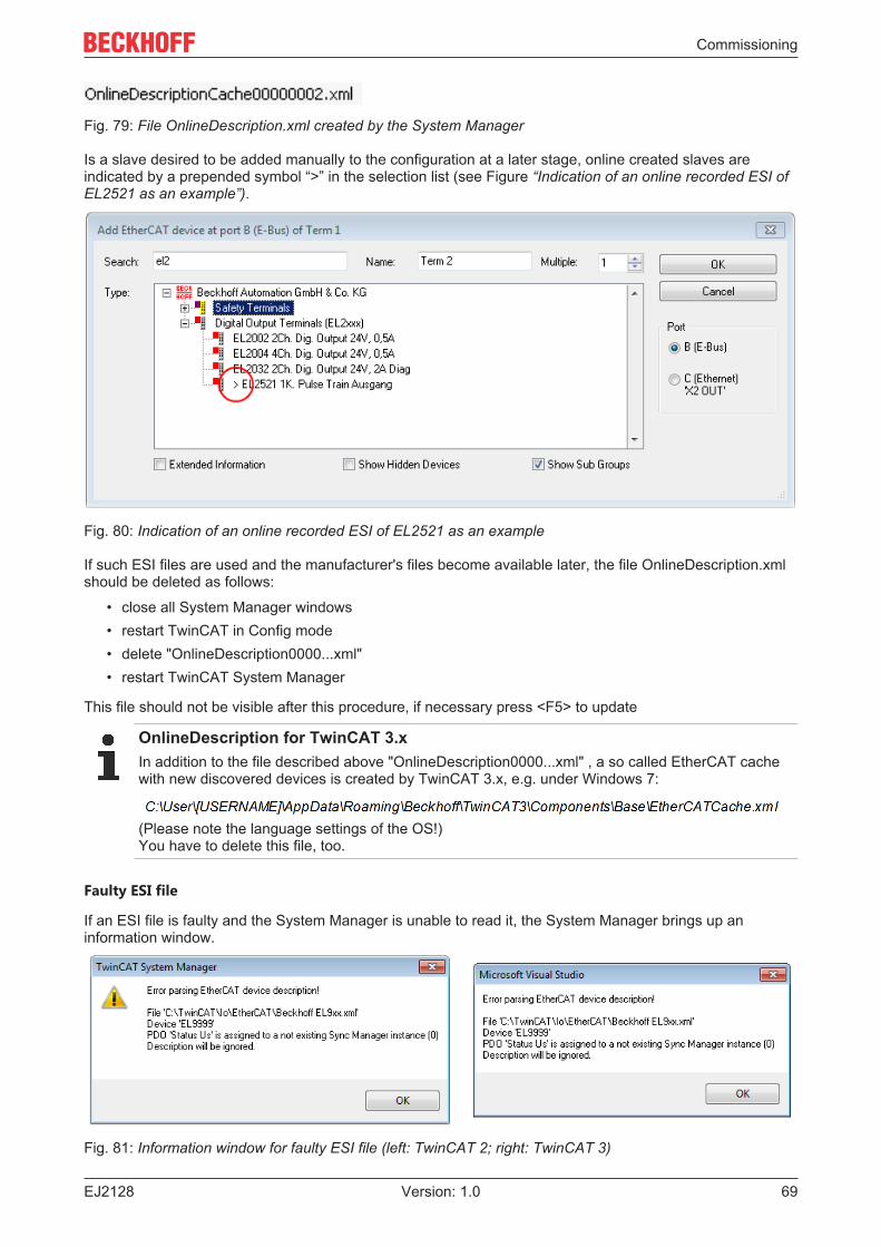
The System Manager creates for online recorded device descriptions a new file“OnlineDescription0000...xml” in its ESI directory, which contains all ESI descriptions that were read online.
Commissioning
EJ2128 69Version: 1.0
Fig. 79: File OnlineDescription.xml created by the System Manager
Is a slave desired to be added manually to the configuration at a later stage, online created slaves areindicated by a prepended symbol “>” in the selection list (see Figure “Indication of an online recorded ESI ofEL2521 as an example”).
Fig. 80: Indication of an online recorded ESI of EL2521 as an example
If such ESI files are used and the manufacturer's files become available later, the file OnlineDescription.xmlshould be deleted as follows:
• close all System Manager windows• restart TwinCAT in Config mode• delete "OnlineDescription0000...xml"• restart TwinCAT System Manager
This file should not be visible after this procedure, if necessary press <F5> to update
OnlineDescription for TwinCAT 3.xIn addition to the file described above "OnlineDescription0000...xml" , a so called EtherCAT cachewith new discovered devices is created by TwinCAT 3.x, e.g. under Windows 7:
(Please note the language settings of the OS!)You have to delete this file, too.
Faulty ESI file
If an ESI file is faulty and the System Manager is unable to read it, the System Manager brings up aninformation window.
Fig. 81: Information window for faulty ESI file (left: TwinCAT 2; right: TwinCAT 3)

Commissioning
EJ212870 Version: 1.0
Reasons may include:
• Structure of the *.xml does not correspond to the associated *.xsd file → check your schematics• Contents cannot be translated into a device description → contact the file manufacturer
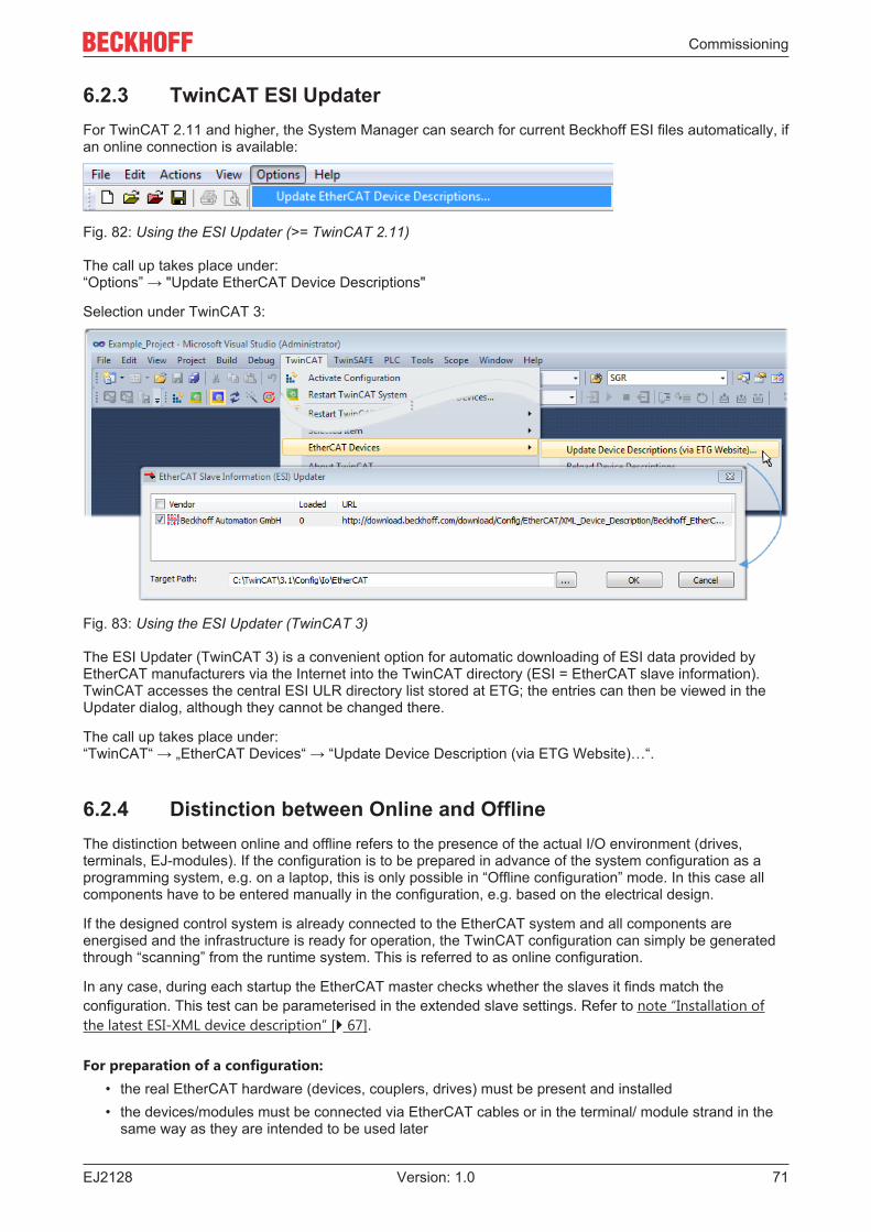
Commissioning
EJ2128 71Version: 1.0
6.2.3 TwinCAT ESI UpdaterFor TwinCAT 2.11 and higher, the System Manager can search for current Beckhoff ESI files automatically, ifan online connection is available:
Fig. 82: Using the ESI Updater (>= TwinCAT 2.11)
The call up takes place under:“Options” → "Update EtherCAT Device Descriptions"
Selection under TwinCAT 3:
Fig. 83: Using the ESI Updater (TwinCAT 3)
The ESI Updater (TwinCAT 3) is a convenient option for automatic downloading of ESI data provided byEtherCAT manufacturers via the Internet into the TwinCAT directory (ESI = EtherCAT slave information).TwinCAT accesses the central ESI ULR directory list stored at ETG; the entries can then be viewed in theUpdater dialog, although they cannot be changed there.
The call up takes place under:“TwinCAT“ → „EtherCAT Devices“ → “Update Device Description (via ETG Website)…“.
6.2.4 Distinction between Online and OfflineThe distinction between online and offline refers to the presence of the actual I/O environment (drives,terminals, EJ-modules). If the configuration is to be prepared in advance of the system configuration as aprogramming system, e.g. on a laptop, this is only possible in “Offline configuration” mode. In this case allcomponents have to be entered manually in the configuration, e.g. based on the electrical design.
If the designed control system is already connected to the EtherCAT system and all components areenergised and the infrastructure is ready for operation, the TwinCAT configuration can simply be generatedthrough “scanning” from the runtime system. This is referred to as online configuration.
In any case, during each startup the EtherCAT master checks whether the slaves it finds match theconfiguration. This test can be parameterised in the extended slave settings. Refer to note “Installation ofthe latest ESI-XML device description” [} 67].
For preparation of a configuration:• the real EtherCAT hardware (devices, couplers, drives) must be present and installed• the devices/modules must be connected via EtherCAT cables or in the terminal/ module strand in the
same way as they are intended to be used later
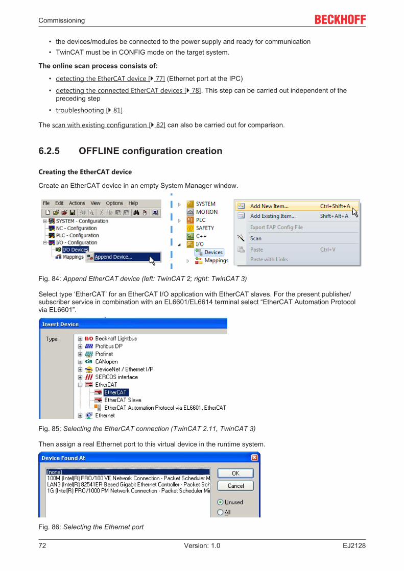
Commissioning
EJ212872 Version: 1.0
• the devices/modules be connected to the power supply and ready for communication• TwinCAT must be in CONFIG mode on the target system.
The online scan process consists of:
• detecting the EtherCAT device [} 77] (Ethernet port at the IPC)
• detecting the connected EtherCAT devices [} 78]. This step can be carried out independent of thepreceding step
• troubleshooting [} 81]
The scan with existing configuration [} 82] can also be carried out for comparison.
6.2.5 OFFLINE configuration creation
Creating the EtherCAT device
Create an EtherCAT device in an empty System Manager window.
Fig. 84: Append EtherCAT device (left: TwinCAT 2; right: TwinCAT 3)
Select type ‘EtherCAT’ for an EtherCAT I/O application with EtherCAT slaves. For the present publisher/subscriber service in combination with an EL6601/EL6614 terminal select “EtherCAT Automation Protocolvia EL6601”.
Fig. 85: Selecting the EtherCAT connection (TwinCAT 2.11, TwinCAT 3)
Then assign a real Ethernet port to this virtual device in the runtime system.
Fig. 86: Selecting the Ethernet port
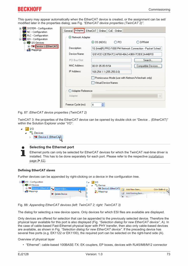
Commissioning
EJ2128 73Version: 1.0
This query may appear automatically when the EtherCAT device is created, or the assignment can be set/modified later in the properties dialog; see Fig. “EtherCAT device properties (TwinCAT 2)”.
Fig. 87: EtherCAT device properties (TwinCAT 2)
TwinCAT 3: the properties of the EtherCAT device can be opened by double click on “Device .. (EtherCAT)”within the Solution Explorer under “I/O”:
Selecting the Ethernet portEthernet ports can only be selected for EtherCAT devices for which the TwinCAT real-time driver isinstalled. This has to be done separately for each port. Please refer to the respective installationpage [} 61].
Defining EtherCAT slaves
Further devices can be appended by right-clicking on a device in the configuration tree.
Fig. 88: Appending EtherCAT devices (left: TwinCAT 2; right: TwinCAT 3)
The dialog for selecting a new device opens. Only devices for which ESI files are available are displayed.
Only devices are offered for selection that can be appended to the previously selected device. Therefore thephysical layer available for this port is also displayed (Fig. “Selection dialog for new EtherCAT device”, A). Inthe case of cable-based Fast-Ethernet physical layer with PHY transfer, then also only cable-based devicesare available, as shown in Fig. “Selection dialog for new EtherCAT device”. If the preceding device hasseveral free ports (e.g. EK1122 or EK1100), the required port can be selected on the right-hand side (A).
Overview of physical layer
• “Ethernet”: cable-based 100BASE-TX: EK couplers, EP boxes, devices with RJ45/M8/M12 connector
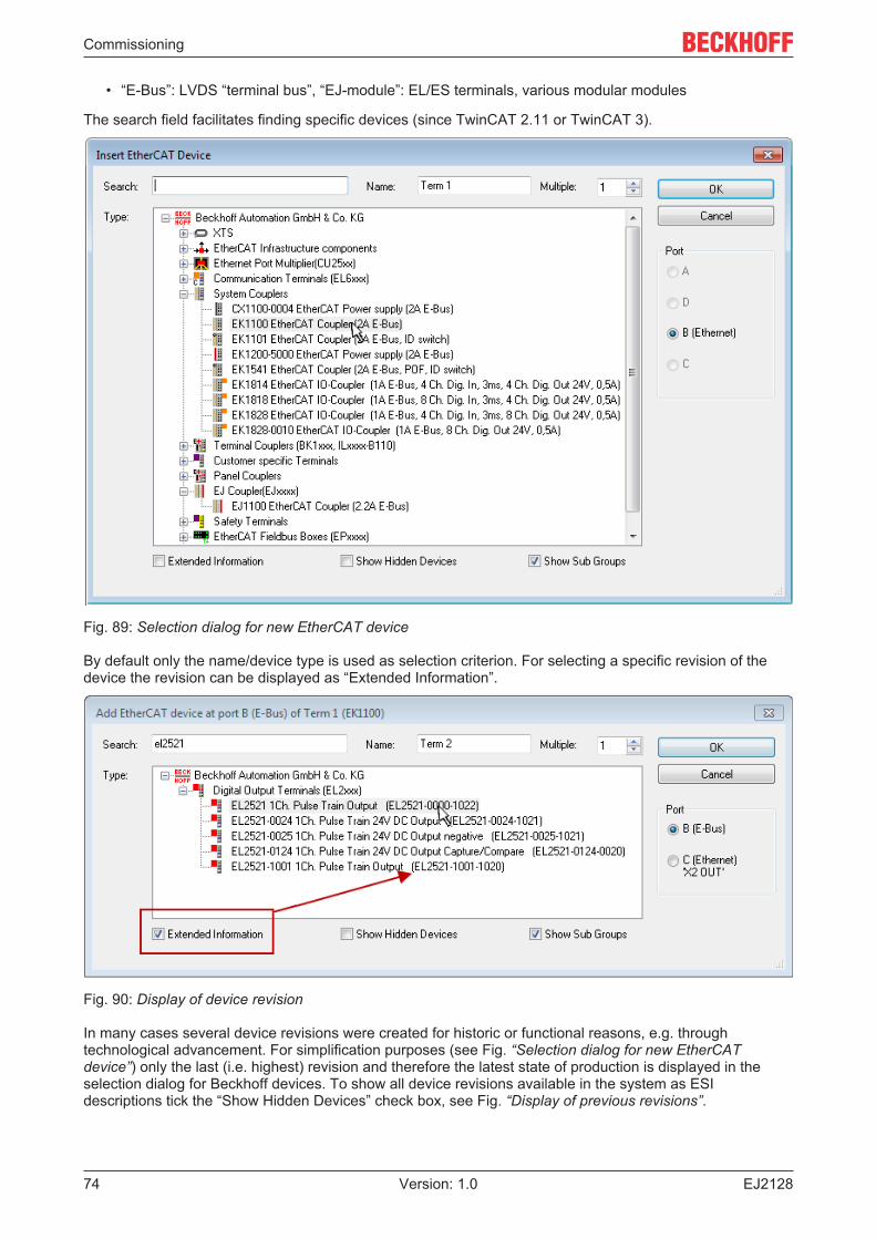
Commissioning
EJ212874 Version: 1.0
• “E-Bus”: LVDS “terminal bus”, “EJ-module”: EL/ES terminals, various modular modules
The search field facilitates finding specific devices (since TwinCAT 2.11 or TwinCAT 3).
Fig. 89: Selection dialog for new EtherCAT device
By default only the name/device type is used as selection criterion. For selecting a specific revision of thedevice the revision can be displayed as “Extended Information”.
Fig. 90: Display of device revision
In many cases several device revisions were created for historic or functional reasons, e.g. throughtechnological advancement. For simplification purposes (see Fig. “Selection dialog for new EtherCATdevice”) only the last (i.e. highest) revision and therefore the latest state of production is displayed in theselection dialog for Beckhoff devices. To show all device revisions available in the system as ESIdescriptions tick the “Show Hidden Devices” check box, see Fig. “Display of previous revisions”.
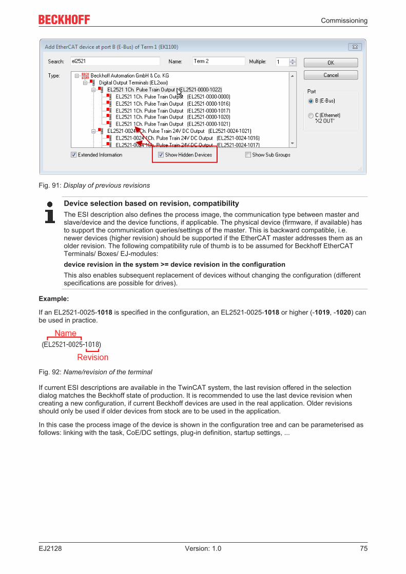
Commissioning
EJ2128 75Version: 1.0
Fig. 91: Display of previous revisions
Device selection based on revision, compatibilityThe ESI description also defines the process image, the communication type between master andslave/device and the device functions, if applicable. The physical device (firmware, if available) hasto support the communication queries/settings of the master. This is backward compatible, i.e.newer devices (higher revision) should be supported if the EtherCAT master addresses them as anolder revision. The following compatibility rule of thumb is to be assumed for Beckhoff EtherCATTerminals/ Boxes/ EJ-modules:device revision in the system >= device revision in the configurationThis also enables subsequent replacement of devices without changing the configuration (differentspecifications are possible for drives).
Example:
If an EL2521-0025-1018 is specified in the configuration, an EL2521-0025-1018 or higher (-1019, -1020) canbe used in practice.
Fig. 92: Name/revision of the terminal
If current ESI descriptions are available in the TwinCAT system, the last revision offered in the selectiondialog matches the Beckhoff state of production. It is recommended to use the last device revision whencreating a new configuration, if current Beckhoff devices are used in the real application. Older revisionsshould only be used if older devices from stock are to be used in the application.
In this case the process image of the device is shown in the configuration tree and can be parameterised asfollows: linking with the task, CoE/DC settings, plug-in definition, startup settings, ...
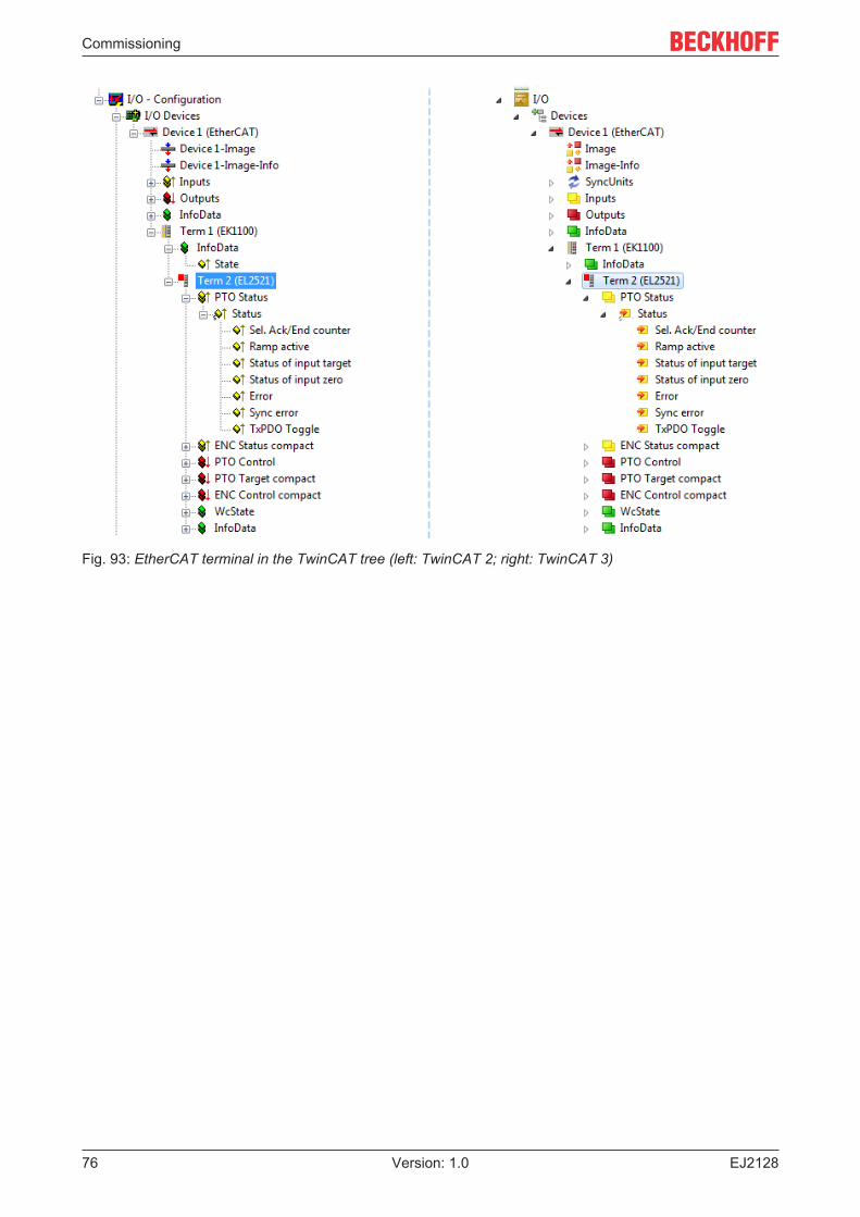
Commissioning
EJ212876 Version: 1.0
Fig. 93: EtherCAT terminal in the TwinCAT tree (left: TwinCAT 2; right: TwinCAT 3)
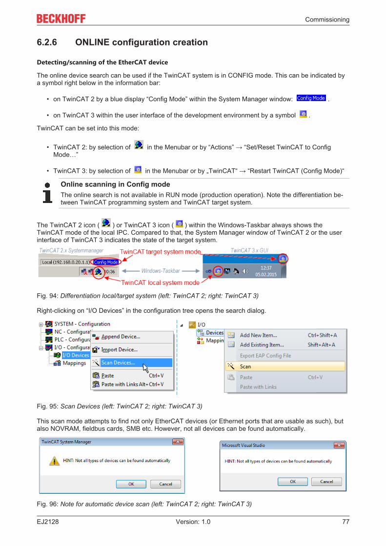
Commissioning
EJ2128 77Version: 1.0
6.2.6 ONLINE configuration creation
Detecting/scanning of the EtherCAT device
The online device search can be used if the TwinCAT system is in CONFIG mode. This can be indicated bya symbol right below in the information bar:
• on TwinCAT 2 by a blue display “Config Mode” within the System Manager window: .
• on TwinCAT 3 within the user interface of the development environment by a symbol .
TwinCAT can be set into this mode:
• TwinCAT 2: by selection of in the Menubar or by “Actions” → “Set/Reset TwinCAT to ConfigMode…”
• TwinCAT 3: by selection of in the Menubar or by „TwinCAT“ → “Restart TwinCAT (Config Mode)“
Online scanning in Config modeThe online search is not available in RUN mode (production operation). Note the differentiation be-tween TwinCAT programming system and TwinCAT target system.
The TwinCAT 2 icon ( ) or TwinCAT 3 icon ( ) within the Windows-Taskbar always shows theTwinCAT mode of the local IPC. Compared to that, the System Manager window of TwinCAT 2 or the userinterface of TwinCAT 3 indicates the state of the target system.
Fig. 94: Differentiation local/target system (left: TwinCAT 2; right: TwinCAT 3)
Right-clicking on “I/O Devices” in the configuration tree opens the search dialog.
Fig. 95: Scan Devices (left: TwinCAT 2; right: TwinCAT 3)
This scan mode attempts to find not only EtherCAT devices (or Ethernet ports that are usable as such), butalso NOVRAM, fieldbus cards, SMB etc. However, not all devices can be found automatically.
Fig. 96: Note for automatic device scan (left: TwinCAT 2; right: TwinCAT 3)
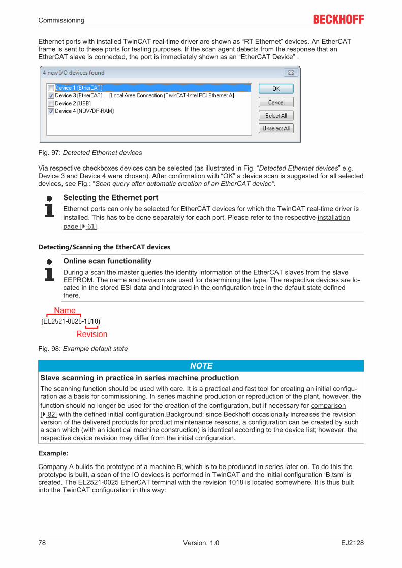
Commissioning
EJ212878 Version: 1.0
Ethernet ports with installed TwinCAT real-time driver are shown as “RT Ethernet” devices. An EtherCATframe is sent to these ports for testing purposes. If the scan agent detects from the response that anEtherCAT slave is connected, the port is immediately shown as an “EtherCAT Device” .
Fig. 97: Detected Ethernet devices
Via respective checkboxes devices can be selected (as illustrated in Fig. “Detected Ethernet devices” e.g.Device 3 and Device 4 were chosen). After confirmation with “OK” a device scan is suggested for all selecteddevices, see Fig.: “Scan query after automatic creation of an EtherCAT device”.
Selecting the Ethernet portEthernet ports can only be selected for EtherCAT devices for which the TwinCAT real-time driver isinstalled. This has to be done separately for each port. Please refer to the respective installationpage [} 61].
Detecting/Scanning the EtherCAT devices
Online scan functionalityDuring a scan the master queries the identity information of the EtherCAT slaves from the slaveEEPROM. The name and revision are used for determining the type. The respective devices are lo-cated in the stored ESI data and integrated in the configuration tree in the default state definedthere.
Fig. 98: Example default state
NOTESlave scanning in practice in series machine productionThe scanning function should be used with care. It is a practical and fast tool for creating an initial configu-ration as a basis for commissioning. In series machine production or reproduction of the plant, however, thefunction should no longer be used for the creation of the configuration, but if necessary for comparison[} 82] with the defined initial configuration.Background: since Beckhoff occasionally increases the revisionversion of the delivered products for product maintenance reasons, a configuration can be created by sucha scan which (with an identical machine construction) is identical according to the device list; however, therespective device revision may differ from the initial configuration.
Example:
Company A builds the prototype of a machine B, which is to be produced in series later on. To do this theprototype is built, a scan of the IO devices is performed in TwinCAT and the initial configuration ‘B.tsm’ iscreated. The EL2521-0025 EtherCAT terminal with the revision 1018 is located somewhere. It is thus builtinto the TwinCAT configuration in this way:
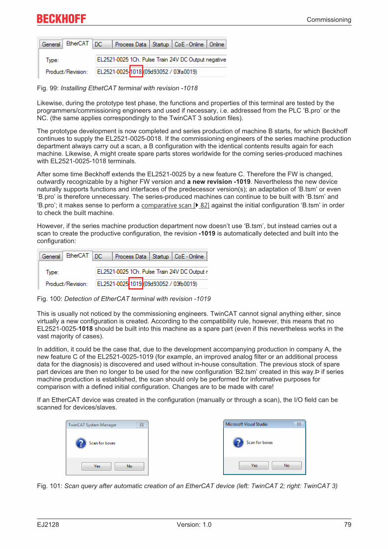
Commissioning
EJ2128 79Version: 1.0
Fig. 99: Installing EthetCAT terminal with revision -1018
Likewise, during the prototype test phase, the functions and properties of this terminal are tested by theprogrammers/commissioning engineers and used if necessary, i.e. addressed from the PLC ‘B.pro’ or theNC. (the same applies correspondingly to the TwinCAT 3 solution files).
The prototype development is now completed and series production of machine B starts, for which Beckhoffcontinues to supply the EL2521-0025-0018. If the commissioning engineers of the series machine productiondepartment always carry out a scan, a B configuration with the identical contents results again for eachmachine. Likewise, A might create spare parts stores worldwide for the coming series-produced machineswith EL2521-0025-1018 terminals.
After some time Beckhoff extends the EL2521-0025 by a new feature C. Therefore the FW is changed,outwardly recognizable by a higher FW version and a new revision -1019. Nevertheless the new devicenaturally supports functions and interfaces of the predecessor version(s); an adaptation of ‘B.tsm’ or even‘B.pro’ is therefore unnecessary. The series-produced machines can continue to be built with ‘B.tsm’ and‘B.pro’; it makes sense to perform a comparative scan [} 82] against the initial configuration ‘B.tsm’ in orderto check the built machine.
However, if the series machine production department now doesn’t use ‘B.tsm’, but instead carries out ascan to create the productive configuration, the revision -1019 is automatically detected and built into theconfiguration:
Fig. 100: Detection of EtherCAT terminal with revision -1019
This is usually not noticed by the commissioning engineers. TwinCAT cannot signal anything either, sincevirtually a new configuration is created. According to the compatibility rule, however, this means that noEL2521-0025-1018 should be built into this machine as a spare part (even if this nevertheless works in thevast majority of cases).
In addition, it could be the case that, due to the development accompanying production in company A, thenew feature C of the EL2521-0025-1019 (for example, an improved analog filter or an additional processdata for the diagnosis) is discovered and used without in-house consultation. The previous stock of sparepart devices are then no longer to be used for the new configuration ‘B2.tsm’ created in this way.Þ if seriesmachine production is established, the scan should only be performed for informative purposes forcomparison with a defined initial configuration. Changes are to be made with care!
If an EtherCAT device was created in the configuration (manually or through a scan), the I/O field can bescanned for devices/slaves.
Fig. 101: Scan query after automatic creation of an EtherCAT device (left: TwinCAT 2; right: TwinCAT 3)
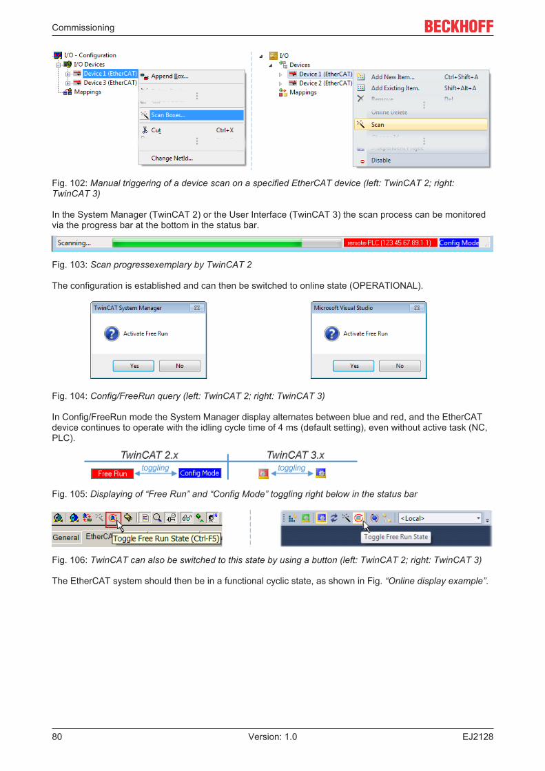
Commissioning
EJ212880 Version: 1.0
Fig. 102: Manual triggering of a device scan on a specified EtherCAT device (left: TwinCAT 2; right:TwinCAT 3)
In the System Manager (TwinCAT 2) or the User Interface (TwinCAT 3) the scan process can be monitoredvia the progress bar at the bottom in the status bar.
Fig. 103: Scan progressexemplary by TwinCAT 2
The configuration is established and can then be switched to online state (OPERATIONAL).
Fig. 104: Config/FreeRun query (left: TwinCAT 2; right: TwinCAT 3)
In Config/FreeRun mode the System Manager display alternates between blue and red, and the EtherCATdevice continues to operate with the idling cycle time of 4 ms (default setting), even without active task (NC,PLC).
Fig. 105: Displaying of “Free Run” and “Config Mode” toggling right below in the status bar
Fig. 106: TwinCAT can also be switched to this state by using a button (left: TwinCAT 2; right: TwinCAT 3)
The EtherCAT system should then be in a functional cyclic state, as shown in Fig. “Online display example”.
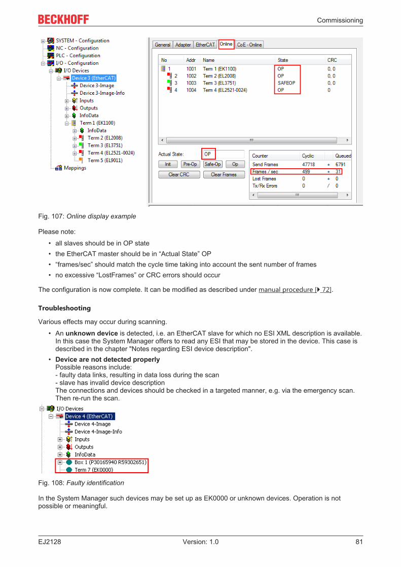
Commissioning
EJ2128 81Version: 1.0
Fig. 107: Online display example
Please note:
• all slaves should be in OP state• the EtherCAT master should be in “Actual State” OP• “frames/sec” should match the cycle time taking into account the sent number of frames• no excessive “LostFrames” or CRC errors should occur
The configuration is now complete. It can be modified as described under manual procedure [} 72].
Troubleshooting
Various effects may occur during scanning.
• An unknown device is detected, i.e. an EtherCAT slave for which no ESI XML description is available.In this case the System Manager offers to read any ESI that may be stored in the device. This case isdescribed in the chapter "Notes regarding ESI device description".
• Device are not detected properlyPossible reasons include:- faulty data links, resulting in data loss during the scan- slave has invalid device descriptionThe connections and devices should be checked in a targeted manner, e.g. via the emergency scan.Then re-run the scan.
Fig. 108: Faulty identification
In the System Manager such devices may be set up as EK0000 or unknown devices. Operation is notpossible or meaningful.
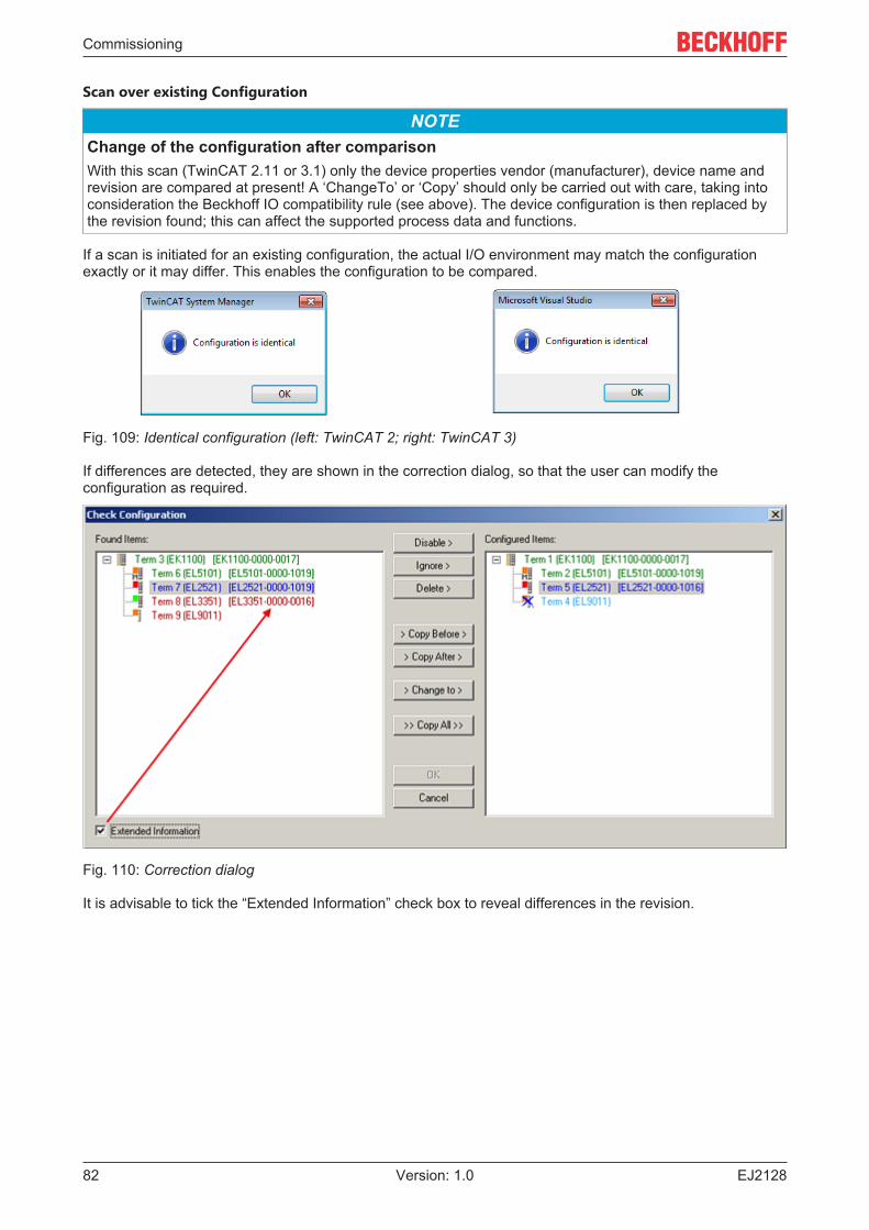
Commissioning
EJ212882 Version: 1.0
Scan over existing Configuration
NOTEChange of the configuration after comparisonWith this scan (TwinCAT 2.11 or 3.1) only the device properties vendor (manufacturer), device name andrevision are compared at present! A ‘ChangeTo’ or ‘Copy’ should only be carried out with care, taking intoconsideration the Beckhoff IO compatibility rule (see above). The device configuration is then replaced bythe revision found; this can affect the supported process data and functions.
If a scan is initiated for an existing configuration, the actual I/O environment may match the configurationexactly or it may differ. This enables the configuration to be compared.
Fig. 109: Identical configuration (left: TwinCAT 2; right: TwinCAT 3)
If differences are detected, they are shown in the correction dialog, so that the user can modify theconfiguration as required.
Fig. 110: Correction dialog
It is advisable to tick the “Extended Information” check box to reveal differences in the revision.
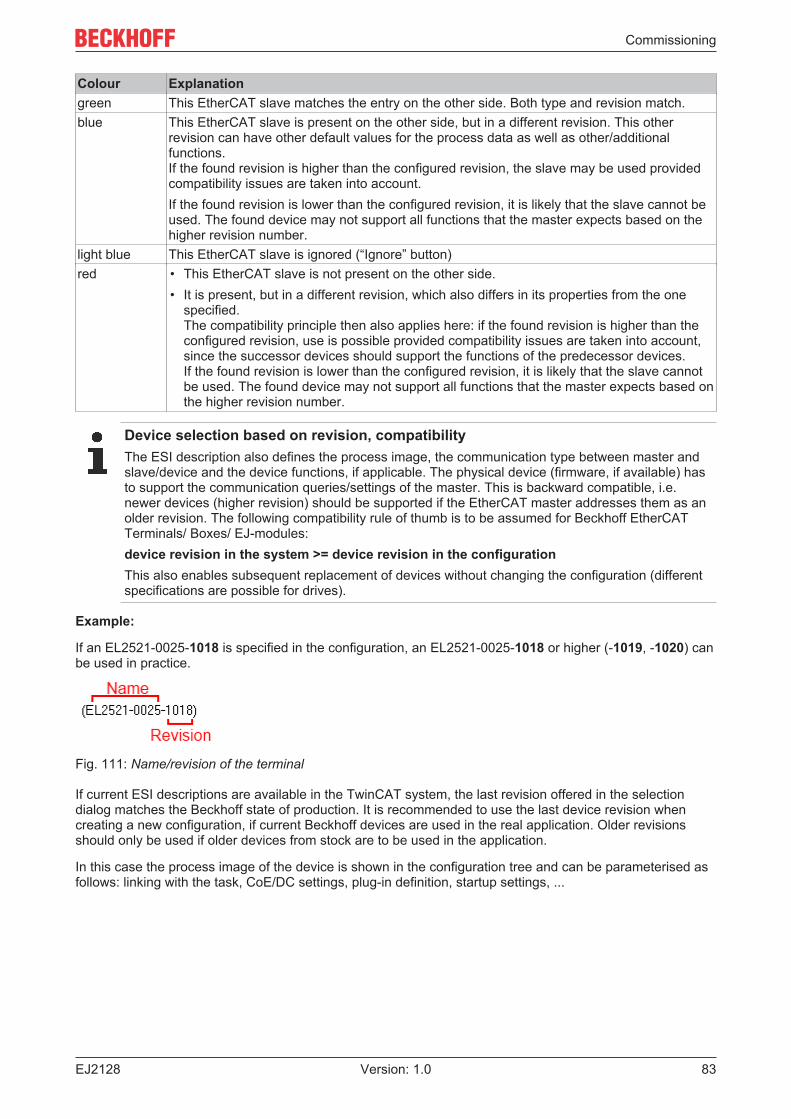
Commissioning
EJ2128 83Version: 1.0
Colour Explanationgreen This EtherCAT slave matches the entry on the other side. Both type and revision match.blue This EtherCAT slave is present on the other side, but in a different revision. This other
revision can have other default values for the process data as well as other/additionalfunctions.If the found revision is higher than the configured revision, the slave may be used providedcompatibility issues are taken into account.If the found revision is lower than the configured revision, it is likely that the slave cannot beused. The found device may not support all functions that the master expects based on thehigher revision number.
light blue This EtherCAT slave is ignored (“Ignore” button)red • This EtherCAT slave is not present on the other side.
• It is present, but in a different revision, which also differs in its properties from the onespecified.The compatibility principle then also applies here: if the found revision is higher than theconfigured revision, use is possible provided compatibility issues are taken into account,since the successor devices should support the functions of the predecessor devices. If the found revision is lower than the configured revision, it is likely that the slave cannotbe used. The found device may not support all functions that the master expects based onthe higher revision number.
Device selection based on revision, compatibilityThe ESI description also defines the process image, the communication type between master andslave/device and the device functions, if applicable. The physical device (firmware, if available) hasto support the communication queries/settings of the master. This is backward compatible, i.e.newer devices (higher revision) should be supported if the EtherCAT master addresses them as anolder revision. The following compatibility rule of thumb is to be assumed for Beckhoff EtherCATTerminals/ Boxes/ EJ-modules:device revision in the system >= device revision in the configurationThis also enables subsequent replacement of devices without changing the configuration (differentspecifications are possible for drives).
Example:
If an EL2521-0025-1018 is specified in the configuration, an EL2521-0025-1018 or higher (-1019, -1020) canbe used in practice.
Fig. 111: Name/revision of the terminal
If current ESI descriptions are available in the TwinCAT system, the last revision offered in the selectiondialog matches the Beckhoff state of production. It is recommended to use the last device revision whencreating a new configuration, if current Beckhoff devices are used in the real application. Older revisionsshould only be used if older devices from stock are to be used in the application.
In this case the process image of the device is shown in the configuration tree and can be parameterised asfollows: linking with the task, CoE/DC settings, plug-in definition, startup settings, ...
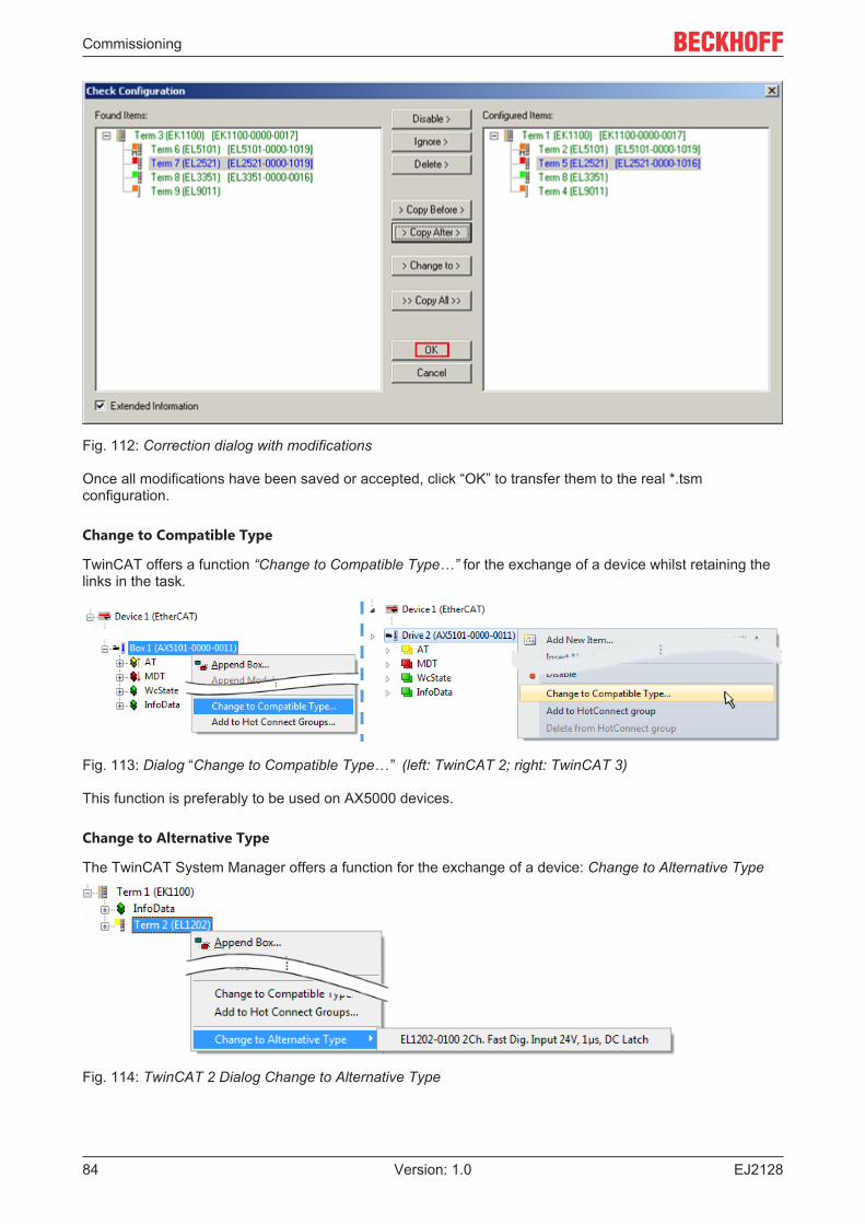
Commissioning
EJ212884 Version: 1.0
Fig. 112: Correction dialog with modifications
Once all modifications have been saved or accepted, click “OK” to transfer them to the real *.tsmconfiguration.
Change to Compatible Type
TwinCAT offers a function “Change to Compatible Type…” for the exchange of a device whilst retaining thelinks in the task.
Fig. 113: Dialog “Change to Compatible Type…” (left: TwinCAT 2; right: TwinCAT 3)
This function is preferably to be used on AX5000 devices.
Change to Alternative Type
The TwinCAT System Manager offers a function for the exchange of a device: Change to Alternative Type
Fig. 114: TwinCAT 2 Dialog Change to Alternative Type
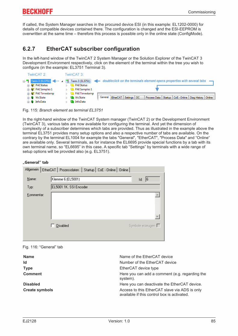
Commissioning
EJ2128 85Version: 1.0
If called, the System Manager searches in the procured device ESI (in this example: EL1202-0000) fordetails of compatible devices contained there. The configuration is changed and the ESI-EEPROM isoverwritten at the same time – therefore this process is possible only in the online state (ConfigMode).
6.2.7 EtherCAT subscriber configurationIn the left-hand window of the TwinCAT 2 System Manager or the Solution Explorer of the TwinCAT 3Development Environment respectively, click on the element of the terminal within the tree you wish toconfigure (in the example: EL3751 Terminal 3).
Fig. 115: Branch element as terminal EL3751
In the right-hand window of the TwinCAT System manager (TwinCAT 2) or the Development Environment(TwinCAT 3), various tabs are now available for configuring the terminal. And yet the dimension ofcomplexity of a subscriber determines which tabs are provided. Thus as illustrated in the example above theterminal EL3751 provides many setup options and also a respective number of tabs are available. On thecontrary by the terminal EL1004 for example the tabs "General", "EtherCAT", "Process Data" and “Online“are available only. Several terminals, as for instance the EL6695 provide special functions by a tab with itsown terminal name, so “EL6695” in this case. A specific tab “Settings” by terminals with a wide range ofsetup options will be provided also (e.g. EL3751).
„General“ tab
Fig. 116: “General” tab
Name Name of the EtherCAT deviceId Number of the EtherCAT deviceType EtherCAT device typeComment Here you can add a comment (e.g. regarding the
system).Disabled Here you can deactivate the EtherCAT device.Create symbols Access to this EtherCAT slave via ADS is only
available if this control box is activated.
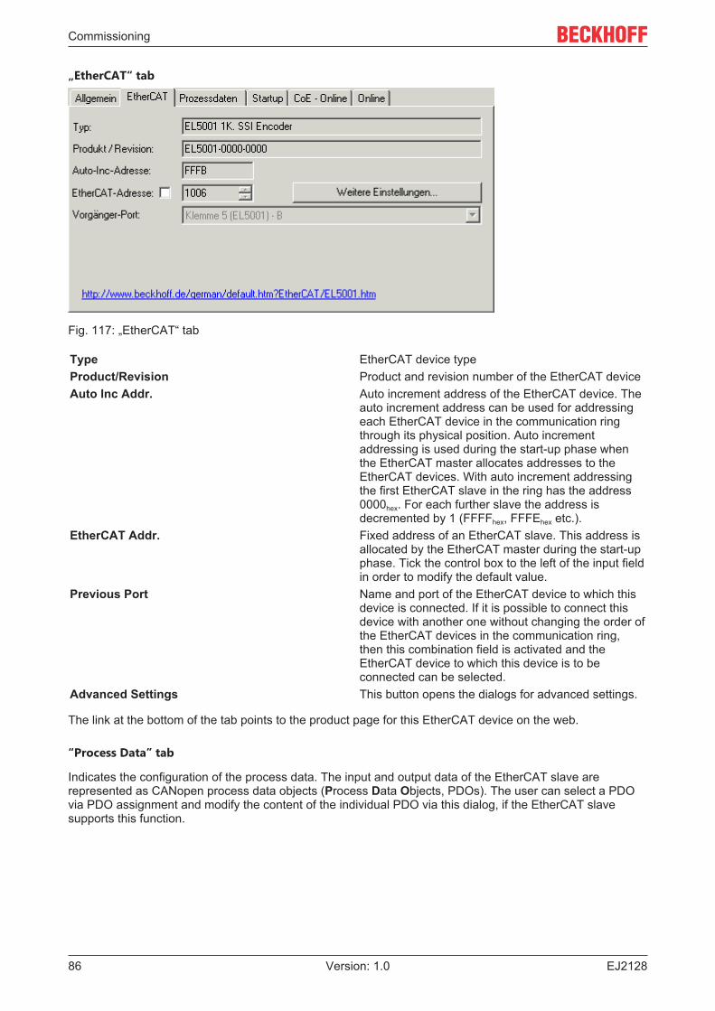
Commissioning
EJ212886 Version: 1.0
„EtherCAT“ tab
Fig. 117: „EtherCAT“ tab
Type EtherCAT device typeProduct/Revision Product and revision number of the EtherCAT deviceAuto Inc Addr. Auto increment address of the EtherCAT device. The
auto increment address can be used for addressingeach EtherCAT device in the communication ringthrough its physical position. Auto incrementaddressing is used during the start-up phase whenthe EtherCAT master allocates addresses to theEtherCAT devices. With auto increment addressingthe first EtherCAT slave in the ring has the address0000hex. For each further slave the address isdecremented by 1 (FFFFhex, FFFEhex etc.).
EtherCAT Addr. Fixed address of an EtherCAT slave. This address isallocated by the EtherCAT master during the start-upphase. Tick the control box to the left of the input fieldin order to modify the default value.
Previous Port Name and port of the EtherCAT device to which thisdevice is connected. If it is possible to connect thisdevice with another one without changing the order ofthe EtherCAT devices in the communication ring,then this combination field is activated and theEtherCAT device to which this device is to beconnected can be selected.
Advanced Settings This button opens the dialogs for advanced settings.
The link at the bottom of the tab points to the product page for this EtherCAT device on the web.
“Process Data” tab
Indicates the configuration of the process data. The input and output data of the EtherCAT slave arerepresented as CANopen process data objects (Process Data Objects, PDOs). The user can select a PDOvia PDO assignment and modify the content of the individual PDO via this dialog, if the EtherCAT slavesupports this function.
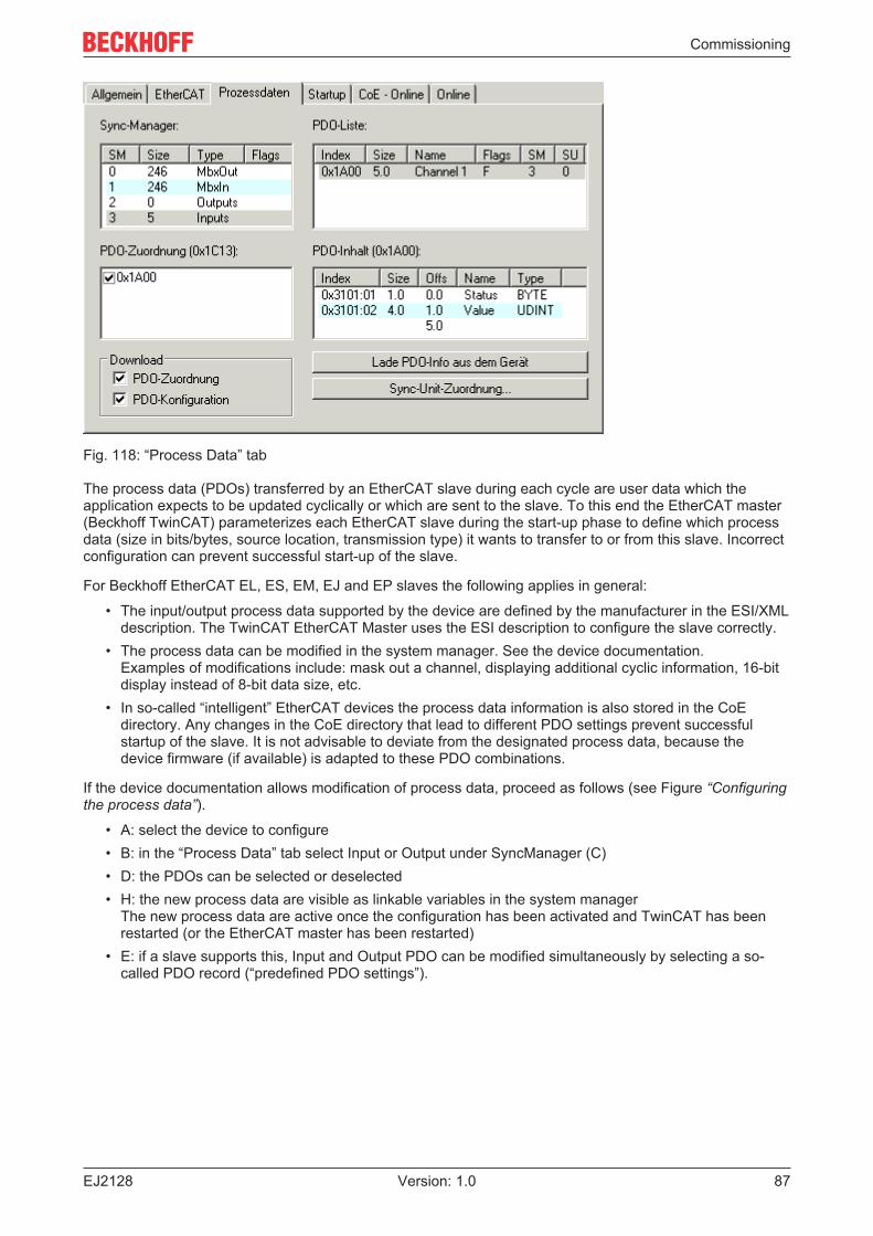
Commissioning
EJ2128 87Version: 1.0
Fig. 118: “Process Data” tab
The process data (PDOs) transferred by an EtherCAT slave during each cycle are user data which theapplication expects to be updated cyclically or which are sent to the slave. To this end the EtherCAT master(Beckhoff TwinCAT) parameterizes each EtherCAT slave during the start-up phase to define which processdata (size in bits/bytes, source location, transmission type) it wants to transfer to or from this slave. Incorrectconfiguration can prevent successful start-up of the slave.
For Beckhoff EtherCAT EL, ES, EM, EJ and EP slaves the following applies in general:
• The input/output process data supported by the device are defined by the manufacturer in the ESI/XMLdescription. The TwinCAT EtherCAT Master uses the ESI description to configure the slave correctly.
• The process data can be modified in the system manager. See the device documentation.Examples of modifications include: mask out a channel, displaying additional cyclic information, 16-bitdisplay instead of 8-bit data size, etc.
• In so-called “intelligent” EtherCAT devices the process data information is also stored in the CoEdirectory. Any changes in the CoE directory that lead to different PDO settings prevent successfulstartup of the slave. It is not advisable to deviate from the designated process data, because thedevice firmware (if available) is adapted to these PDO combinations.
If the device documentation allows modification of process data, proceed as follows (see Figure “Configuringthe process data”).
• A: select the device to configure• B: in the “Process Data” tab select Input or Output under SyncManager (C)• D: the PDOs can be selected or deselected• H: the new process data are visible as linkable variables in the system manager
The new process data are active once the configuration has been activated and TwinCAT has beenrestarted (or the EtherCAT master has been restarted)
• E: if a slave supports this, Input and Output PDO can be modified simultaneously by selecting a so-called PDO record (“predefined PDO settings”).
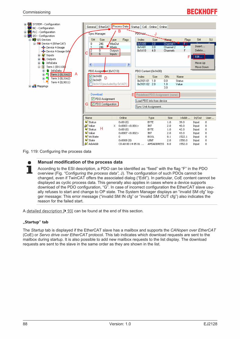
Commissioning
EJ212888 Version: 1.0
Fig. 119: Configuring the process data
Manual modification of the process dataAccording to the ESI description, a PDO can be identified as “fixed” with the flag “F” in the PDOoverview (Fig. “Configuring the process data”, J). The configuration of such PDOs cannot bechanged, even if TwinCAT offers the associated dialog (“Edit”). In particular, CoE content cannot bedisplayed as cyclic process data. This generally also applies in cases where a device supportsdownload of the PDO configuration, “G”. In case of incorrect configuration the EtherCAT slave usu-ally refuses to start and change to OP state. The System Manager displays an “invalid SM cfg” log-ger message: This error message (“invalid SM IN cfg” or “invalid SM OUT cfg”) also indicates thereason for the failed start.
A detailed description [} 93] can be found at the end of this section.
„Startup“ tab
The Startup tab is displayed if the EtherCAT slave has a mailbox and supports the CANopen over EtherCAT(CoE) or Servo drive over EtherCAT protocol. This tab indicates which download requests are sent to themailbox during startup. It is also possible to add new mailbox requests to the list display. The downloadrequests are sent to the slave in the same order as they are shown in the list.
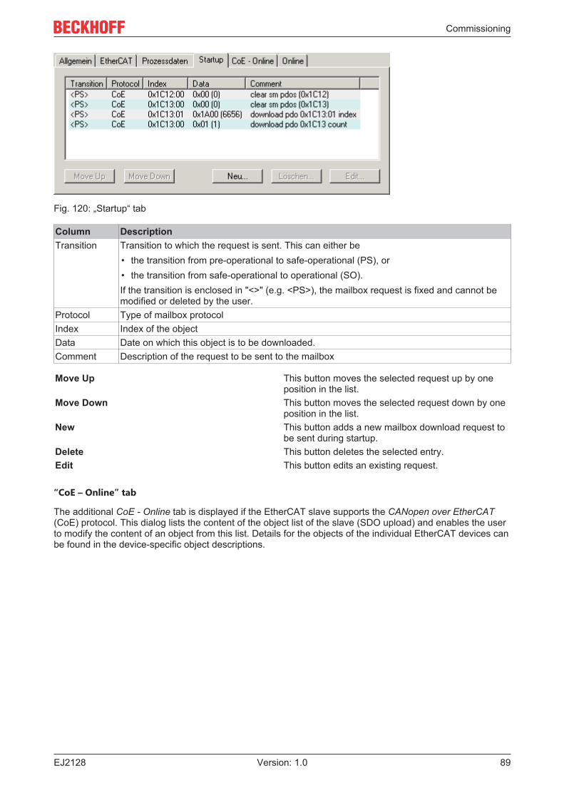
Commissioning
EJ2128 89Version: 1.0
Fig. 120: „Startup“ tab
Column DescriptionTransition Transition to which the request is sent. This can either be
• the transition from pre-operational to safe-operational (PS), or• the transition from safe-operational to operational (SO).If the transition is enclosed in "<>" (e.g. <PS>), the mailbox request is fixed and cannot bemodified or deleted by the user.
Protocol Type of mailbox protocolIndex Index of the objectData Date on which this object is to be downloaded.Comment Description of the request to be sent to the mailbox
Move Up This button moves the selected request up by oneposition in the list.
Move Down This button moves the selected request down by oneposition in the list.
New This button adds a new mailbox download request tobe sent during startup.
Delete This button deletes the selected entry.Edit This button edits an existing request.
“CoE – Online” tab
The additional CoE - Online tab is displayed if the EtherCAT slave supports the CANopen over EtherCAT(CoE) protocol. This dialog lists the content of the object list of the slave (SDO upload) and enables the userto modify the content of an object from this list. Details for the objects of the individual EtherCAT devices canbe found in the device-specific object descriptions.
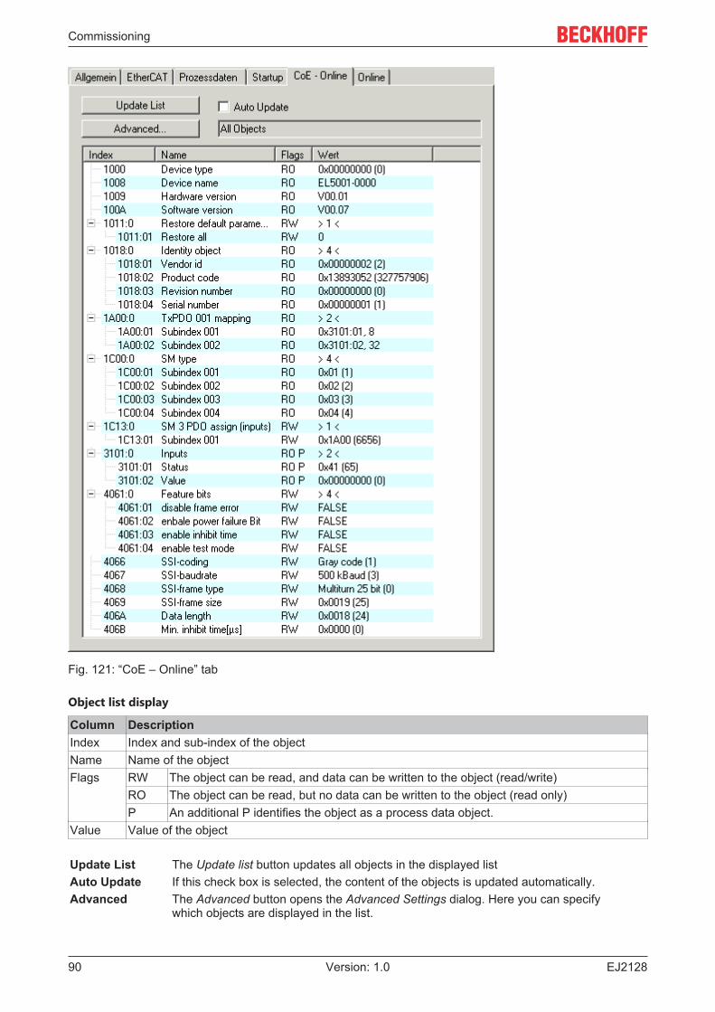
Commissioning
EJ212890 Version: 1.0
Fig. 121: “CoE – Online” tab
Object list display
Column DescriptionIndex Index and sub-index of the objectName Name of the objectFlags RW The object can be read, and data can be written to the object (read/write)
RO The object can be read, but no data can be written to the object (read only)P An additional P identifies the object as a process data object.
Value Value of the object
Update List The Update list button updates all objects in the displayed listAuto Update If this check box is selected, the content of the objects is updated automatically.Advanced The Advanced button opens the Advanced Settings dialog. Here you can specify
which objects are displayed in the list.
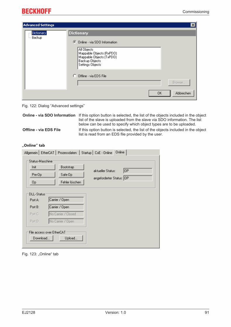
Commissioning
EJ2128 91Version: 1.0
Fig. 122: Dialog “Advanced settings”
Online - via SDO Information If this option button is selected, the list of the objects included in the objectlist of the slave is uploaded from the slave via SDO information. The listbelow can be used to specify which object types are to be uploaded.
Offline - via EDS File If this option button is selected, the list of the objects included in the objectlist is read from an EDS file provided by the user.
„Online“ tab
Fig. 123: „Online“ tab
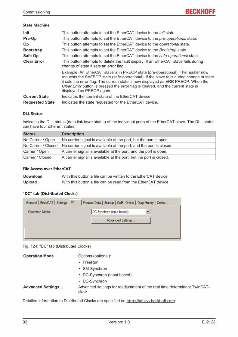
Commissioning
EJ212892 Version: 1.0
State Machine
Init This button attempts to set the EtherCAT device to the Init state.Pre-Op This button attempts to set the EtherCAT device to the pre-operational state.Op This button attempts to set the EtherCAT device to the operational state.Bootstrap This button attempts to set the EtherCAT device to the Bootstrap state.Safe-Op This button attempts to set the EtherCAT device to the safe-operational state.Clear Error This button attempts to delete the fault display. If an EtherCAT slave fails during
change of state it sets an error flag.Example: An EtherCAT slave is in PREOP state (pre-operational). The master nowrequests the SAFEOP state (safe-operational). If the slave fails during change of stateit sets the error flag. The current state is now displayed as ERR PREOP. When theClear Error button is pressed the error flag is cleared, and the current state isdisplayed as PREOP again.
Current State Indicates the current state of the EtherCAT device.Requested State Indicates the state requested for the EtherCAT device.
DLL Status
Indicates the DLL status (data link layer status) of the individual ports of the EtherCAT slave. The DLL statuscan have four different states:
Status DescriptionNo Carrier / Open No carrier signal is available at the port, but the port is open.No Carrier / Closed No carrier signal is available at the port, and the port is closed.Carrier / Open A carrier signal is available at the port, and the port is open.Carrier / Closed A carrier signal is available at the port, but the port is closed.
File Access over EtherCAT
Download With this button a file can be written to the EtherCAT device.Upload With this button a file can be read from the EtherCAT device.
"DC" tab (Distributed Clocks)
Fig. 124: "DC" tab (Distributed Clocks)
Operation Mode Options (optional):• FreeRun• SM-Synchron• DC-Synchron (Input based)• DC-Synchron
Advanced Settings… Advanced settings for readjustment of the real time determinant TwinCAT-clock
Detailed information to Distributed Clocks are specified on http://infosys.beckhoff.com:
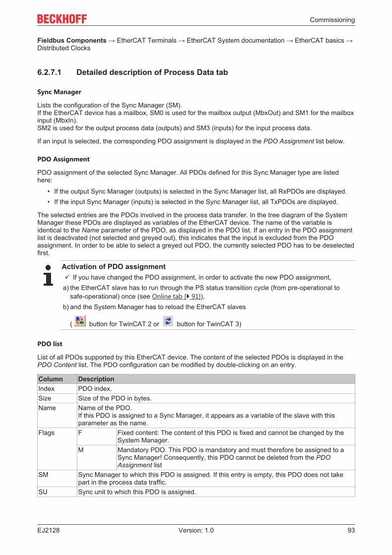
Commissioning
EJ2128 93Version: 1.0
Fieldbus Components → EtherCAT Terminals → EtherCAT System documentation → EtherCAT basics →Distributed Clocks
6.2.7.1 Detailed description of Process Data tab
Sync Manager
Lists the configuration of the Sync Manager (SM).If the EtherCAT device has a mailbox, SM0 is used for the mailbox output (MbxOut) and SM1 for the mailboxinput (MbxIn).SM2 is used for the output process data (outputs) and SM3 (inputs) for the input process data.
If an input is selected, the corresponding PDO assignment is displayed in the PDO Assignment list below.
PDO Assignment
PDO assignment of the selected Sync Manager. All PDOs defined for this Sync Manager type are listedhere:
• If the output Sync Manager (outputs) is selected in the Sync Manager list, all RxPDOs are displayed.• If the input Sync Manager (inputs) is selected in the Sync Manager list, all TxPDOs are displayed.
The selected entries are the PDOs involved in the process data transfer. In the tree diagram of the SystemManager these PDOs are displayed as variables of the EtherCAT device. The name of the variable isidentical to the Name parameter of the PDO, as displayed in the PDO list. If an entry in the PDO assignmentlist is deactivated (not selected and greyed out), this indicates that the input is excluded from the PDOassignment. In order to be able to select a greyed out PDO, the currently selected PDO has to be deselectedfirst.
Activation of PDO assignmentü If you have changed the PDO assignment, in order to activate the new PDO assignment,a) the EtherCAT slave has to run through the PS status transition cycle (from pre-operational to
safe-operational) once (see Online tab [} 91]),b) and the System Manager has to reload the EtherCAT slaves
( button for TwinCAT 2 or button for TwinCAT 3)
PDO list
List of all PDOs supported by this EtherCAT device. The content of the selected PDOs is displayed in thePDO Content list. The PDO configuration can be modified by double-clicking on an entry.
Column DescriptionIndex PDO index.Size Size of the PDO in bytes.Name Name of the PDO.
If this PDO is assigned to a Sync Manager, it appears as a variable of the slave with thisparameter as the name.
Flags F Fixed content: The content of this PDO is fixed and cannot be changed by theSystem Manager.
M Mandatory PDO. This PDO is mandatory and must therefore be assigned to aSync Manager! Consequently, this PDO cannot be deleted from the PDOAssignment list
SM Sync Manager to which this PDO is assigned. If this entry is empty, this PDO does not takepart in the process data traffic.
SU Sync unit to which this PDO is assigned.
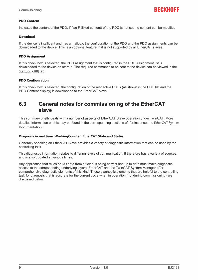
Commissioning
EJ212894 Version: 1.0
PDO Content
Indicates the content of the PDO. If flag F (fixed content) of the PDO is not set the content can be modified.
Download
If the device is intelligent and has a mailbox, the configuration of the PDO and the PDO assignments can bedownloaded to the device. This is an optional feature that is not supported by all EtherCAT slaves.
PDO Assignment
If this check box is selected, the PDO assignment that is configured in the PDO Assignment list isdownloaded to the device on startup. The required commands to be sent to the device can be viewed in theStartup [} 88] tab.
PDO Configuration
If this check box is selected, the configuration of the respective PDOs (as shown in the PDO list and thePDO Content display) is downloaded to the EtherCAT slave.
6.3 General notes for commissioning of the EtherCATslave
This summary briefly deals with a number of aspects of EtherCAT Slave operation under TwinCAT. Moredetailed information on this may be found in the corresponding sections of, for instance, the EtherCAT SystemDocumentation.
Diagnosis in real time: WorkingCounter, EtherCAT State and Status
Generally speaking an EtherCAT Slave provides a variety of diagnostic information that can be used by thecontrolling task.
This diagnostic information relates to differing levels of communication. It therefore has a variety of sources,and is also updated at various times.
Any application that relies on I/O data from a fieldbus being correct and up to date must make diagnosticaccess to the corresponding underlying layers. EtherCAT and the TwinCAT System Manager offercomprehensive diagnostic elements of this kind. Those diagnostic elements that are helpful to the controllingtask for diagnosis that is accurate for the current cycle when in operation (not during commissioning) arediscussed below.
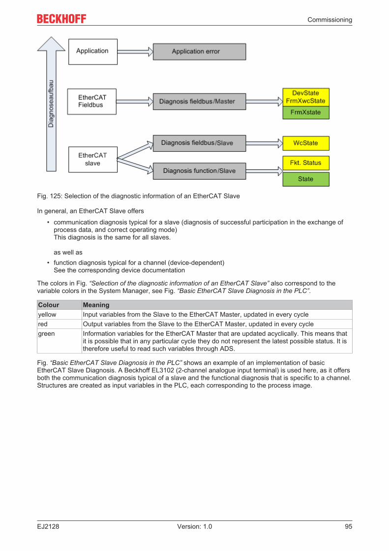
Commissioning
EJ2128 95Version: 1.0
Fig. 125: Selection of the diagnostic information of an EtherCAT Slave
In general, an EtherCAT Slave offers
• communication diagnosis typical for a slave (diagnosis of successful participation in the exchange ofprocess data, and correct operating mode)This diagnosis is the same for all slaves.
as well as• function diagnosis typical for a channel (device-dependent)
See the corresponding device documentation
The colors in Fig. “Selection of the diagnostic information of an EtherCAT Slave” also correspond to thevariable colors in the System Manager, see Fig. “Basic EtherCAT Slave Diagnosis in the PLC”.
Colour Meaningyellow Input variables from the Slave to the EtherCAT Master, updated in every cyclered Output variables from the Slave to the EtherCAT Master, updated in every cyclegreen Information variables for the EtherCAT Master that are updated acyclically. This means that
it is possible that in any particular cycle they do not represent the latest possible status. It istherefore useful to read such variables through ADS.
Fig. “Basic EtherCAT Slave Diagnosis in the PLC” shows an example of an implementation of basicEtherCAT Slave Diagnosis. A Beckhoff EL3102 (2-channel analogue input terminal) is used here, as it offersboth the communication diagnosis typical of a slave and the functional diagnosis that is specific to a channel.Structures are created as input variables in the PLC, each corresponding to the process image.
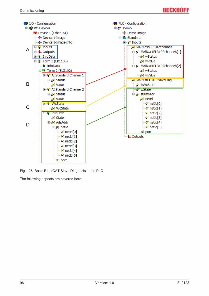
Commissioning
EJ212896 Version: 1.0
Fig. 126: Basic EtherCAT Slave Diagnosis in the PLC
The following aspects are covered here:
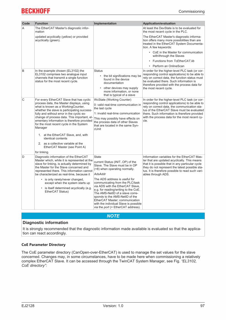
Commissioning
EJ2128 97Version: 1.0
Code Function Implementation Application/evaluationA The EtherCAT Master's diagnostic infor-
mation
updated acyclically (yellow) or providedacyclically (green).
At least the DevState is to be evaluated forthe most recent cycle in the PLC.
The EtherCAT Master's diagnostic informa-tion offers many more possibilities than aretreated in the EtherCAT System Documenta-tion. A few keywords:
• CoE in the Master for communicationwith/through the Slaves
• Functions from TcEtherCAT.lib
• Perform an OnlineScanB In the example chosen (EL3102) the
EL3102 comprises two analogue inputchannels that transmit a single functionstatus for the most recent cycle.
Status
• the bit significations may befound in the devicedocumentation
• other devices may supplymore information, or nonethat is typical of a slave
In order for the higher-level PLC task (or cor-responding control applications) to be able torely on correct data, the function status mustbe evaluated there. Such information istherefore provided with the process data forthe most recent cycle.
C For every EtherCAT Slave that has cyclicprocess data, the Master displays, usingwhat is known as a WorkingCounter,whether the slave is participating success-fully and without error in the cyclic ex-change of process data. This important, el-ementary information is therefore providedfor the most recent cycle in the SystemManager
1. at the EtherCAT Slave, and, withidentical contents
2. as a collective variable at theEtherCAT Master (see Point A)
for linking.
WcState (Working Counter)
0: valid real-time communication inthe last cycle
1: invalid real-time communication
This may possibly have effects onthe process data of other Slavesthat are located in the same Syn-cUnit
In order for the higher-level PLC task (or cor-responding control applications) to be able torely on correct data, the communication sta-tus of the EtherCAT Slave must be evaluatedthere. Such information is therefore providedwith the process data for the most recent cy-cle.
D Diagnostic information of the EtherCATMaster which, while it is represented at theslave for linking, is actually determined bythe Master for the Slave concerned andrepresented there. This information cannotbe characterized as real-time, because it
• is only rarely/never changed,except when the system starts up
• is itself determined acyclically (e.g.EtherCAT Status)
State
current Status (INIT..OP) of theSlave. The Slave must be in OP(=8) when operating normally.
AdsAddr
The ADS address is useful forcommunicating from the PLC/taskvia ADS with the EtherCAT Slave,e.g. for reading/writing to the CoE.The AMS-NetID of a slave corre-sponds to the AMS-NetID of theEtherCAT Master; communicationwith the individual Slave is possiblevia the port (= EtherCAT address).
Information variables for the EtherCAT Mas-ter that are updated acyclically. This meansthat it is possible that in any particular cyclethey do not represent the latest possible sta-tus. It is therefore possible to read such vari-ables through ADS.
NOTEDiagnostic informationIt is strongly recommended that the diagnostic information made available is evaluated so that the applica-tion can react accordingly.
CoE Parameter Directory
The CoE parameter directory (CanOpen-over-EtherCAT) is used to manage the set values for the slaveconcerned. Changes may, in some circumstances, have to be made here when commissioning a relativelycomplex EtherCAT Slave. It can be accessed through the TwinCAT System Manager, see Fig. “EL3102,CoE directory”:
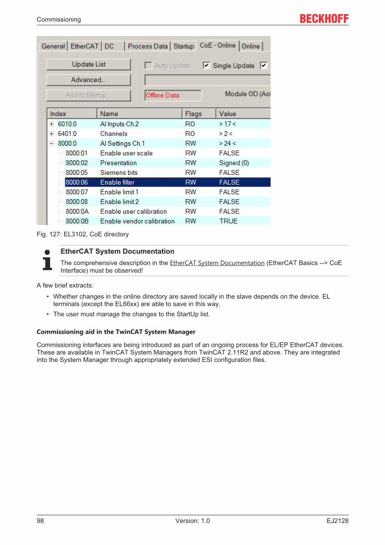
Commissioning
EJ212898 Version: 1.0
Fig. 127: EL3102, CoE directory
EtherCAT System DocumentationThe comprehensive description in the EtherCAT System Documentation (EtherCAT Basics --> CoEInterface) must be observed!
A few brief extracts:
• Whether changes in the online directory are saved locally in the slave depends on the device. ELterminals (except the EL66xx) are able to save in this way.
• The user must manage the changes to the StartUp list.
Commissioning aid in the TwinCAT System Manager
Commissioning interfaces are being introduced as part of an ongoing process for EL/EP EtherCAT devices.These are available in TwinCAT System Managers from TwinCAT 2.11R2 and above. They are integratedinto the System Manager through appropriately extended ESI configuration files.
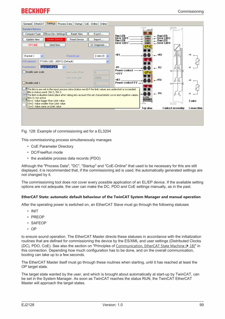
Commissioning
EJ2128 99Version: 1.0
Fig. 128: Example of commissioning aid for a EL3204
This commissioning process simultaneously manages
• CoE Parameter Directory• DC/FreeRun mode• the available process data records (PDO)
Although the "Process Data", "DC", "Startup" and "CoE-Online" that used to be necessary for this are stilldisplayed, it is recommended that, if the commissioning aid is used, the automatically generated settings arenot changed by it.
The commissioning tool does not cover every possible application of an EL/EP device. If the available settingoptions are not adequate, the user can make the DC, PDO and CoE settings manually, as in the past.
EtherCAT State: automatic default behaviour of the TwinCAT System Manager and manual operation
After the operating power is switched on, an EtherCAT Slave must go through the following statuses
• INIT• PREOP• SAFEOP• OP
to ensure sound operation. The EtherCAT Master directs these statuses in accordance with the initializationroutines that are defined for commissioning the device by the ES/XML and user settings (Distributed Clocks(DC), PDO, CoE). See also the section on "Principles of Communication, EtherCAT State Machine [} 18]" inthis connection. Depending how much configuration has to be done, and on the overall communication,booting can take up to a few seconds.
The EtherCAT Master itself must go through these routines when starting, until it has reached at least theOP target state.
The target state wanted by the user, and which is brought about automatically at start-up by TwinCAT, canbe set in the System Manager. As soon as TwinCAT reaches the status RUN, the TwinCAT EtherCATMaster will approach the target states.
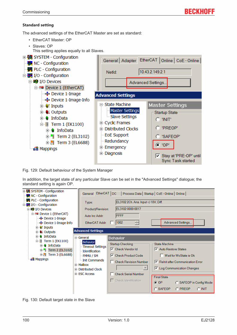
Commissioning
EJ2128100 Version: 1.0
Standard setting
The advanced settings of the EtherCAT Master are set as standard:
• EtherCAT Master: OP• Slaves: OP
This setting applies equally to all Slaves.
Fig. 129: Default behaviour of the System Manager
In addition, the target state of any particular Slave can be set in the "Advanced Settings" dialogue; thestandard setting is again OP.
Fig. 130: Default target state in the Slave
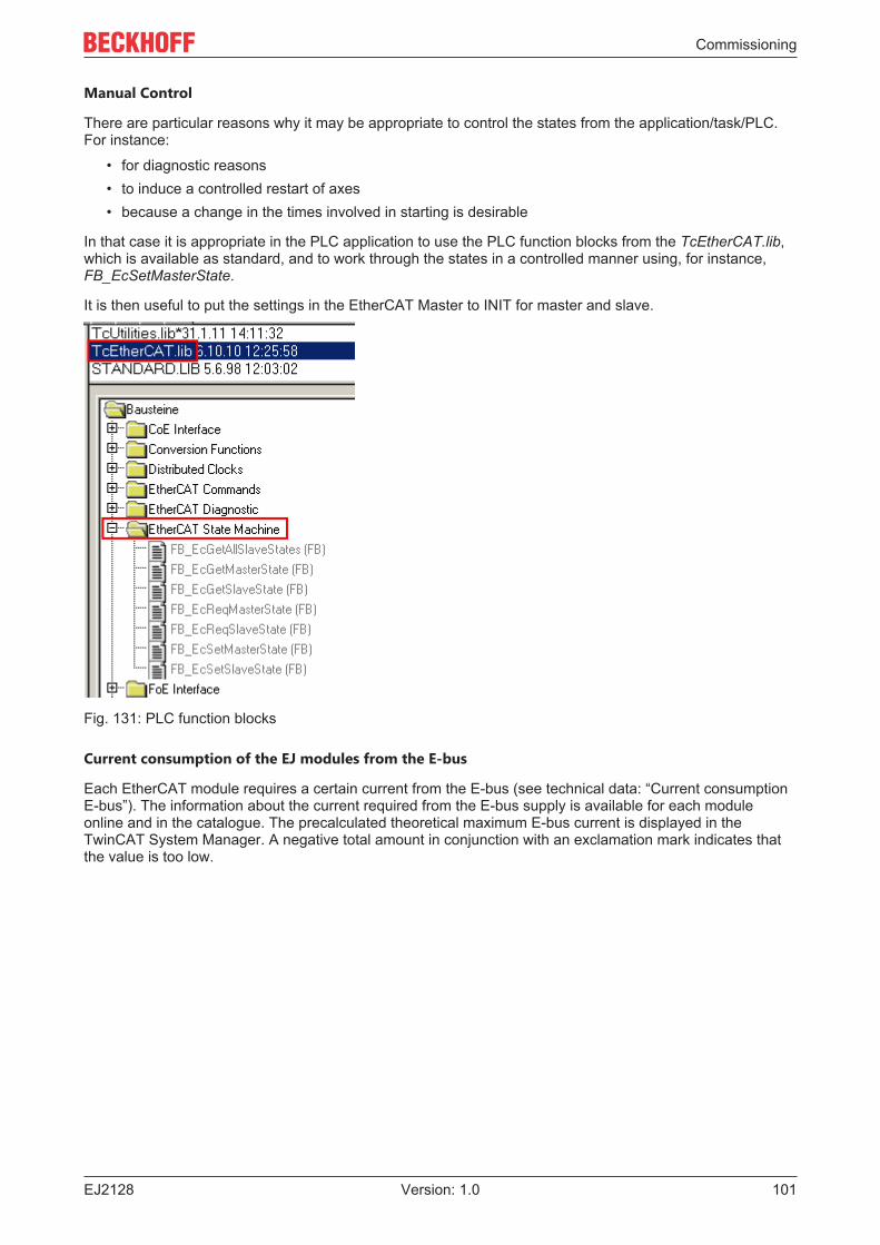
Commissioning
EJ2128 101Version: 1.0
Manual Control
There are particular reasons why it may be appropriate to control the states from the application/task/PLC.For instance:
• for diagnostic reasons• to induce a controlled restart of axes• because a change in the times involved in starting is desirable
In that case it is appropriate in the PLC application to use the PLC function blocks from the TcEtherCAT.lib,which is available as standard, and to work through the states in a controlled manner using, for instance,FB_EcSetMasterState.
It is then useful to put the settings in the EtherCAT Master to INIT for master and slave.
Fig. 131: PLC function blocks
Current consumption of the EJ modules from the E-bus
Each EtherCAT module requires a certain current from the E-bus (see technical data: “Current consumptionE-bus”). The information about the current required from the E-bus supply is available for each moduleonline and in the catalogue. The precalculated theoretical maximum E-bus current is displayed in theTwinCAT System Manager. A negative total amount in conjunction with an exclamation mark indicates thatthe value is too low.
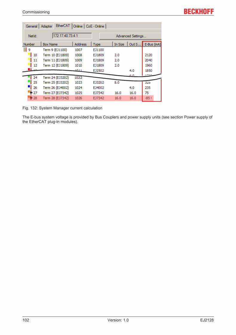
Commissioning
EJ2128102 Version: 1.0
Fig. 132: System Manager current calculation
The E-bus system voltage is provided by Bus Couplers and power supply units (see section Power supply ofthe EtherCAT plug-in modules).
Commissioning
EJ2128 103Version: 1.0
6.4 EJ2128 - Switching behaviorThe output circuit of the EJ2128 EtherCAT plug-in module is optimized for fast signal output. The EJ2128module has a push/pull output stage that actively switches to 5 V/3.3 V and 0 V for this purpose.
The push stage is overcurrent- and short circuit-protected, the pull stage (switching to 0 V) is not. This mayhave to be taken into account when inductive loads are switched off.
The length of time required for a signal change as a rising/falling edge from the central control unit (ESC,EtherCAT slave controller) to the connection point at the rear of the module is specified for an EtherCATplug-in module as TON/TOFF < 1 µs, both for a rising edge (TON) and for a falling edge (TOFF). Due to this shortabsolute signal cycle time the temperature drift during the cycle time is also very low.
The edge steepness of the output drivers is < 1 µs/5 V or < 1 µs/3.3V.
The EJ module and the actuator should always be supplied from a power supply unit. Furthermore,appropriate potential equalization must be ensured.
Measurement of time delayAlthough the time delay between the physical real edge at the ESC output and the edge at the con-nection point at the rear of the module is optimized by the electronics to < 1 µs, it cannot be shorterthan a certain minimum time. If the user has a particular need for precision, calibration must be car-ried out, and the precise time delay measured in accordance with the environmental conditions.
Appendix
EJ2128104 Version: 1.0
7 Appendix
7.1 EtherCAT AL Status CodesFor detailed information please refer to the EtherCAT system description.
7.2 EJ2128 - Firmware compatibilityThe EJ2128 EtherCAT plug-in module has no firmware.

Appendix
EJ2128 105Version: 1.0
7.3 Support and ServiceBeckhoff and their partners around the world offer comprehensive support and service, making available fastand competent assistance with all questions related to Beckhoff products and system solutions.
Beckhoff's branch offices and representatives
Please contact your Beckhoff branch office or representative for local support and service on Beckhoffproducts!
The addresses of Beckhoff's branch offices and representatives round the world can be found on her internetpages:http://www.beckhoff.com
You will also find further documentation for Beckhoff components there.
Beckhoff Headquarters
Beckhoff Automation GmbH & Co. KG
Huelshorstweg 2033415 VerlGermany
Phone: +49(0)5246/963-0Fax: +49(0)5246/963-198e-mail: [email protected]
Beckhoff Support
Support offers you comprehensive technical assistance, helping you not only with the application ofindividual Beckhoff products, but also with other, wide-ranging services:
• support• design, programming and commissioning of complex automation systems• and extensive training program for Beckhoff system components
Hotline: +49(0)5246/963-157Fax: +49(0)5246/963-9157e-mail: [email protected]
Beckhoff Service
The Beckhoff Service Center supports you in all matters of after-sales service:
• on-site service• repair service• spare parts service• hotline service
Hotline: +49(0)5246/963-460Fax: +49(0)5246/963-479e-mail: [email protected]
List of illustrations
EJ2128106 Version: 1.0
List of illustrationsFig. 1 EL5021 EL terminal, standard IP20 IO device with serial/ batch number and revision ID (since
2014/01)....................................................................................................................................... 8Fig. 2 EK1100 EtherCAT coupler, standard IP20 IO device with serial/ batch number......................... 9Fig. 3 CU2016 switch with serial/ batch number.................................................................................... 9Fig. 4 EL3202-0020 with serial/ batch number 26131006 and unique ID-number 204418 ................... 9Fig. 5 EP1258-00001 IP67 EtherCAT Box with batch number/ date code 22090101 and unique se-
rial number 158102...................................................................................................................... 10Fig. 6 EP1908-0002 IP67 EtherCAT Safety Box with batch number/ date code 071201FF and
unique serial number 00346070 .................................................................................................. 10Fig. 7 EL2904 IP20 safety terminal with batch number/ date code 50110302 and unique serial num-
ber 00331701............................................................................................................................... 10Fig. 8 ELM3604-0002 terminal with unique ID number (QR code) 100001051 and serial/ batch num-
ber 44160201............................................................................................................................... 10Fig. 9 EJ system sample........................................................................................................................ 11Fig. 10 EJ2128......................................................................................................................................... 12Fig. 11 EJ2128 - Connection ................................................................................................................... 14Fig. 12 EJ2128 - LEDs............................................................................................................................. 15Fig. 13 EtherCAT tab -> Advanced Settings -> Behavior -> Watchdog .................................................. 17Fig. 14 States of the EtherCAT State Machine........................................................................................ 19Fig. 15 E-bus power supply with EJ1100 or EJ1101-0022 + EJ940x...................................................... 22Fig. 16 PCB with Embedded PC, EK1110-0043 and EJxxxx, rear view EK1110-0043........................... 23Fig. 17 EJxxxx - dimensions (short modules) .......................................................................................... 24Fig. 18 EJxxxx Dimensions (long modules)............................................................................................. 24Fig. 19 Mounting distances EJ module – PCB ........................................................................................ 25Fig. 20 Recommended distances for standard installation position......................................................... 26Fig. 21 Other installation positions .......................................................................................................... 27Fig. 22 EJ modules color code; sample: EJ1809..................................................................................... 28Fig. 23 Mechanical position coding with coding pins (B1 and B2) and coding holes (A1 and A2) .......... 29Fig. 24 Pin coding; sample: digital input modules.................................................................................... 29Fig. 25 Installation of EJ modules............................................................................................................ 30Fig. 26 Sample: Exchanging placeholder modules and assigning reserve slots ..................................... 31Fig. 27 Example PCB with Embedded PC, EK1110-0043 and EJxxxx, rear view EK1110-0043............ 33Fig. 28 Example for the connection of a C6015 IPC to an EJ system..................................................... 34Fig. 29 Disassembly of EJ modules......................................................................................................... 35Fig. 30 Relationship between user side (commissioning) and installation............................................... 37Fig. 31 Control configuration with Embedded PC, input (EL1004) and output (EL2008) ........................ 38Fig. 32 Initial TwinCAT 2 user interface................................................................................................... 39Fig. 33 Selection of the target system ..................................................................................................... 40Fig. 34 Specify the PLC for access by the TwinCAT System Manager: selection of the target system.. 40Fig. 35 Select "Scan Devices..." .............................................................................................................. 41Fig. 36 Automatic detection of I/O devices: selection the devices to be integrated................................. 41Fig. 37 Mapping of the configuration in the TwinCAT 2 System Manager............................................... 42Fig. 38 Reading of individual terminals connected to a device................................................................ 42Fig. 39 TwinCAT PLC Control after startup ............................................................................................. 43Fig. 40 Sample program with variables after a compile process (without variable integration) ............... 44Fig. 41 Appending the TwinCAT PLC Control project ............................................................................. 44
List of illustrations
EJ2128 107Version: 1.0
Fig. 42 PLC project integrated in the PLC configuration of the System Manager ................................... 45Fig. 43 Creating the links between PLC variables and process objects .................................................. 45Fig. 44 Selecting PDO of type BOOL ...................................................................................................... 46Fig. 45 Selecting several PDOs simultaneously: activate "Continuous" and "All types".......................... 46Fig. 46 Application of a "Goto Link" variable, using "MAIN.bEL1004_Ch4" as a sample ........................ 47Fig. 47 Choose target system (remote) ................................................................................................... 48Fig. 48 PLC Control logged in, ready for program startup ....................................................................... 49Fig. 49 Initial TwinCAT 3 user interface................................................................................................... 50Fig. 50 Create new TwinCAT project....................................................................................................... 50Fig. 51 New TwinCAT3 project in the project folder explorer .................................................................. 51Fig. 52 Selection dialog: Choose the target system ................................................................................ 51Fig. 53 Specify the PLC for access by the TwinCAT System Manager: selection of the target system.. 52Fig. 54 Select "Scan" ............................................................................................................................... 52Fig. 55 Automatic detection of I/O devices: selection the devices to be integrated................................. 53Fig. 56 Mapping of the configuration in VS shell of the TwinCAT3 environment..................................... 53Fig. 57 Reading of individual terminals connected to a device................................................................ 54Fig. 58 Adding the programming environment in "PLC" .......................................................................... 55Fig. 59 Specifying the name and directory for the PLC programming environment ................................ 55Fig. 60 Initial "Main" program of the standard PLC project...................................................................... 56Fig. 61 Sample program with variables after a compile process (without variable integration) ............... 57Fig. 62 Start program compilation............................................................................................................ 57Fig. 63 Creating the links between PLC variables and process objects .................................................. 58Fig. 64 Selecting PDO of type BOOL ...................................................................................................... 58Fig. 65 Selecting several PDOs simultaneously: activate "Continuous" and "All types".......................... 59Fig. 66 Application of a "Goto Link" variable, using "MAIN.bEL1004_Ch4" as a sample ........................ 59Fig. 67 TwinCAT development environment (VS shell): logged-in, after program startup....................... 60Fig. 68 System Manager “Options” (TwinCAT 2)..................................................................................... 62Fig. 69 Call up under VS Shell (TwinCAT 3) ........................................................................................... 62Fig. 70 Overview of network interfaces ................................................................................................... 62Fig. 71 EtherCAT device properties(TwinCAT 2): click on „Compatible Devices…“ of tab “Adapter” ..... 63Fig. 72 Windows properties of the network interface............................................................................... 63Fig. 73 Exemplary correct driver setting for the Ethernet port ................................................................. 64Fig. 74 Incorrect driver settings for the Ethernet port ............................................................................. 65Fig. 75 TCP/IP setting for the Ethernet port ............................................................................................ 66Fig. 76 Identifier structure ....................................................................................................................... 67Fig. 77 OnlineDescription information window (TwinCAT 2) ................................................................... 68Fig. 78 Information window OnlineDescription (TwinCAT 3) ................................................................... 68Fig. 79 File OnlineDescription.xml created by the System Manager ...................................................... 69Fig. 80 Indication of an online recorded ESI of EL2521 as an example .................................................. 69Fig. 81 Information window for faulty ESI file (left: TwinCAT 2; right: TwinCAT 3).................................. 69Fig. 82 Using the ESI Updater (>= TwinCAT 2.11).................................................................................. 71Fig. 83 Using the ESI Updater (TwinCAT 3)............................................................................................ 71Fig. 84 Append EtherCAT device (left: TwinCAT 2; right: TwinCAT 3) ................................................... 72Fig. 85 Selecting the EtherCAT connection (TwinCAT 2.11, TwinCAT 3)............................................... 72Fig. 86 Selecting the Ethernet port ......................................................................................................... 72Fig. 87 EtherCAT device properties (TwinCAT 2) ................................................................................... 73
List of illustrations
EJ2128108 Version: 1.0
Fig. 88 Appending EtherCAT devices (left: TwinCAT 2; right: TwinCAT 3)............................................. 73Fig. 89 Selection dialog for new EtherCAT device ................................................................................. 74Fig. 90 Display of device revision ........................................................................................................... 74Fig. 91 Display of previous revisions ...................................................................................................... 75Fig. 92 Name/revision of the terminal ...................................................................................................... 75Fig. 93 EtherCAT terminal in the TwinCAT tree (left: TwinCAT 2; right: TwinCAT 3).............................. 76Fig. 94 Differentiation local/target system (left: TwinCAT 2; right: TwinCAT 3)....................................... 77Fig. 95 Scan Devices (left: TwinCAT 2; right: TwinCAT 3) ...................................................................... 77Fig. 96 Note for automatic device scan (left: TwinCAT 2; right: TwinCAT 3)........................................... 77Fig. 97 Detected Ethernet devices .......................................................................................................... 78Fig. 98 Example default state .................................................................................................................. 78Fig. 99 Installing EthetCAT terminal with revision -1018 ......................................................................... 79Fig. 100 Detection of EtherCAT terminal with revision -1019 .................................................................... 79Fig. 101 Scan query after automatic creation of an EtherCAT device (left: TwinCAT 2; right: Twin-
CAT 3) ......................................................................................................................................... 79Fig. 102 Manual triggering of a device scan on a specified EtherCAT device (left: TwinCAT 2; right:
TwinCAT 3).................................................................................................................................. 80Fig. 103 Scan progressexemplary by TwinCAT 2 ..................................................................................... 80Fig. 104 Config/FreeRun query (left: TwinCAT 2; right: TwinCAT 3)......................................................... 80Fig. 105 Displaying of “Free Run” and “Config Mode” toggling right below in the status bar .................... 80Fig. 106 TwinCAT can also be switched to this state by using a button (left: TwinCAT 2; right: Twin-
CAT 3) ......................................................................................................................................... 80Fig. 107 Online display example ............................................................................................................... 81Fig. 108 Faulty identification ...................................................................................................................... 81Fig. 109 Identical configuration (left: TwinCAT 2; right: TwinCAT 3) ......................................................... 82Fig. 110 Correction dialog ......................................................................................................................... 82Fig. 111 Name/revision of the terminal ...................................................................................................... 83Fig. 112 Correction dialog with modifications ........................................................................................... 84Fig. 113 Dialog “Change to Compatible Type…” (left: TwinCAT 2; right: TwinCAT 3) .............................. 84Fig. 114 TwinCAT 2 Dialog Change to Alternative Type ........................................................................... 84Fig. 115 Branch element as terminal EL3751............................................................................................ 85Fig. 116 “General” tab................................................................................................................................ 85Fig. 117 „EtherCAT“ tab............................................................................................................................. 86Fig. 118 “Process Data” tab....................................................................................................................... 87Fig. 119 Configuring the process data....................................................................................................... 88Fig. 120 „Startup“ tab................................................................................................................................. 89Fig. 121 “CoE – Online” tab ....................................................................................................................... 90Fig. 122 Dialog “Advanced settings”.......................................................................................................... 91Fig. 123 „Online“ tab .................................................................................................................................. 91Fig. 124 "DC" tab (Distributed Clocks)....................................................................................................... 92Fig. 125 Selection of the diagnostic information of an EtherCAT Slave ................................................... 95Fig. 126 Basic EtherCAT Slave Diagnosis in the PLC............................................................................... 96Fig. 127 EL3102, CoE directory ................................................................................................................ 98Fig. 128 Example of commissioning aid for a EL3204 .............................................................................. 99Fig. 129 Default behaviour of the System Manager .................................................................................. 100Fig. 130 Default target state in the Slave .................................................................................................. 100Fig. 131 PLC function blocks .................................................................................................................... 101

List of illustrations
EJ2128 109Version: 1.0
Fig. 132 System Manager current calculation ........................................................................................... 102