i2 Analyze documentation
522
i2 Analyze | 1 i2 Analyze Welcome to the i2 ® Analyze documentation, where you can learn how to install, deploy, configure, and upgrade i2 Analyze. i2 Analyze is an integrated set of secure services and stores that provide search, analysis, and storage of intelligence data to authorized users. It presents these functions through the web and desktop applications that connect to it. Support The i2 Analyze support page contains links to the release notes and support articles. i2 Analyze support Understanding i2 Analyze i2 ® Analyze is an integrated set of secure services and stores that provide search, analysis, and storage of intelligence data to authorized users. It presents these functions through the web and desktop applications that connect to it. When deployed with all components active, i2 Analyze provides key features to its users: • A structured store for intelligence data with services that enable bulk and targeted create, retrieve, update, and delete operations. • An extensible framework for connecting to and retrieving intelligence data from sources external to the platform. • A searchable store for Analyst's Notebook charts that analysts can use for remote storage, and for sharing work with their peers. • A pervasive data model that is optimized for exploring and visualizing the relationships between records. • A security model and architecture that together ensure the security of data in motion and at rest. i2 Analyze enables these features through a range of technologies: • The i2 Analyze services are deployed in an application on a WebSphere Liberty application server. • Searching and returning results from intelligence data uses the Apache Solr search index platform. • The stores for intelligence data and Analyst's Notebook charts are created in a database management system. The precise feature set of a particular deployment of i2 Analyze depends on the components that you decide to include, which depends in turn on the i2 software that you use it with. The different components of i2 Analyze are subject to licensing agreements. Understanding i2 Analyze: Data model on page 5 The i2 Analyze data model governs the structure of the data that i2 Analyze processes. That structure, consisting of entities and links and the properties they contain, is fundamental to the analytical and presentational functionality provided by other offerings that i2 Analyze is part of, for example i2 Analyst's Notebook Premium and i2 Enterprise Insight Analysis. i2 Analyze: Security model on page 18 © N. Harris Computer Corporation (2022)
-
Upload
khangminh22 -
Category
Documents
-
view
1 -
download
0
Transcript of i2 Analyze documentation
i2 Analyze | 1
i2 AnalyzeWelcome to the i2® Analyze documentation, where you can learn how to install, deploy, configure, andupgrade i2 Analyze.
i2 Analyze is an integrated set of secure services and stores that provide search, analysis, and storageof intelligence data to authorized users. It presents these functions through the web and desktopapplications that connect to it.
SupportThe i2 Analyze support page contains links to the release notes and support articles.
i2 Analyze support
Understanding i2 Analyzei2® Analyze is an integrated set of secure services and stores that provide search, analysis, and storageof intelligence data to authorized users. It presents these functions through the web and desktopapplications that connect to it.
When deployed with all components active, i2 Analyze provides key features to its users:
• A structured store for intelligence data with services that enable bulk and targeted create, retrieve,update, and delete operations.
• An extensible framework for connecting to and retrieving intelligence data from sources external tothe platform.
• A searchable store for Analyst's Notebook charts that analysts can use for remote storage, and forsharing work with their peers.
• A pervasive data model that is optimized for exploring and visualizing the relationships betweenrecords.
• A security model and architecture that together ensure the security of data in motion and at rest.
i2 Analyze enables these features through a range of technologies:
• The i2 Analyze services are deployed in an application on a WebSphere Liberty application server.
• Searching and returning results from intelligence data uses the Apache Solr search index platform.
• The stores for intelligence data and Analyst's Notebook charts are created in a databasemanagement system.
The precise feature set of a particular deployment of i2 Analyze depends on the components thatyou decide to include, which depends in turn on the i2 software that you use it with. The differentcomponents of i2 Analyze are subject to licensing agreements.
Understandingi2 Analyze: Data model on page 5The i2 Analyze data model governs the structure of the data that i2 Analyze processes. That structure,consisting of entities and links and the properties they contain, is fundamental to the analytical andpresentational functionality provided by other offerings that i2 Analyze is part of, for example i2 Analyst'sNotebook Premium and i2 Enterprise Insight Analysis.
i2 Analyze: Security model on page 18
© N. Harris Computer Corporation (2022)

Understanding i2 Analyze | 2
All data in i2 Analyze can be secured so that only the users who are supposed to interact with it are ableto do so. Using the i2 Analyze security model, you can decide what access users have to records andfeatures, based on their membership of user groups.
i2 Analyze: Logging and auditing on page 25i2 Analyze provides mechanisms for logging two types of information that the system generates duringnormal execution. You can control what information is sent to the system logs, and audit the commandsthat users invoke.
Configuration tasksConfiguring i2 Analyze on page 103During implementation of a production deployment, you need to modify the original base deployment tomatch the needs of your organization. When the i2 Analyze deployment is in use, you can make furtherconfiguration changes to adjust to changing needs, and to administer the system.
Troubleshooting and supporti2 Analyze support page
i2 Support
ComponentsThe data and security models that i2 Analyze provides are a constant in all deployments. Its otherfeatures are due to components that you can choose to deploy according to your requirements and theterms of your license.
i2 Group provides i2 Analyze as a part of other offerings. For example, i2 Analyst's Notebook Premiumand i2 Enterprise Insight Analysis. These offerings entitle you to deploy different components of i2Analyze.
i2 Enterprise Insight Analysis
i2 Analyst's Notebook Premium
i2 Analyze components
Chart Storei2 Connect gateway
Information Store
i2 Notebook
• For any of the offerings, you can deploy i2 Analyze with the Chart Store, so that users can store andshare their charts securely.
© N. Harris Computer Corporation (2022)
Understanding i2 Analyze | 3
• You can also deploy i2 Analyze with the i2 Connect gateway, which allows you to develop anddeploy connectors to data sources outside your organization.
• For Enterprise Insight Analysis only, you can also deploy the Information Store, in which users canretain, process, and analyze intelligence data.
Chart StoreThe Chart Store has two purposes in a deployment of i2 Analyze. First, it provides Analyst's NotebookPremium users with server-based, secure storage for their charts. Second, in a deployment that doesnot also include the Information Store, it supports the operation of the i2 Notebook web client.
Users of Analyst's Notebook Premium can upload charts to a Chart Store as easily as they can savethem to their workstations. When they do so, they can choose to share charts with their colleagues, ortake advantage of i2 Analyze's features for organizing, indexing, and securing charts:
• i2 Analyze authenticates users at login and then uses authorization to control access to all storedcharts
• Charts in the Chart Store are subject to the i2 Analyze security model, enabling per-team or per-useraccess
• i2 Analyze indexes both the contents and the metadata of uploaded Analyst's Notebook charts, sothat users can search and filter large numbers of charts quickly and easily
Note: For each chart in the store, the generated index contains information from i2 Analyze recordsand Analyst's Notebook chart items. i2 Analyze does not index the contents of any documents thatare embedded in a chart.
• The chart metadata itself is configurable, so that the options for categorizing and searching chartsreflect the users' domain.
Users of the i2 Notebook web client can search for and visualize data from an Information Store andany external sources that are connected through the i2 Connect gateway. However, not all deploymentsof i2 Analyze include both of those components. In a deployment that does not have an InformationStore, the i2 Notebook web client requires the Chart Store, which provides short-term storage for theweb charts that users create.
For information on deploying i2 Analyze with the Chart Store, see the deployment documentation.
i2 Connect gatewayWhen you deploy i2 Analyze with the i2 Connect gateway, you gain the option to develop or purchaseconnectors that can acquire intelligence data from external sources. When a user of Analyst's NotebookPremium or the i2 Notebook web client makes a request to an external data source, the connectorconverts results from their original format into the entities, links, and properties of i2 Analyze records.
When i2 Analyze accesses data through a connector, the source is not modified. After the data is vettedand verified, and provided that the new or modified entities and links have compatible types, Analyst'sNotebook Premium users can upload the records to an Information Store.
For each external data source, an organization can choose between setting up a connector to accessthe data in the external location, and ingesting the data into an Information Store. The choice dependson a number of factors, including the following considerations:
Availability
A connector is typically useful where a data source is constantly available. If a data source isnot always available, ingestion to the Information Store provides users with constant access to asnapshot of the data.
© N. Harris Computer Corporation (2022)
Understanding i2 Analyze | 4
Currency
If an external data source is updated very frequently, and it is desirable to have the most currentdata returned at each request, a connector can be used to achieve this. If regular refreshes areappropriate for the data, but moment-to-moment currency is not required, the data source couldinstead be ingested to the Information Store on a regular schedule.
Quantity
The Information Store is designed for high-volume data. However, an organization might not wantto create a duplicate copy of a very large external data source that can be made available using aconnector.
Terms of use
For reasons of security, privacy, or commercial interest, a third-party provider of data might notpermit the organization to store a copy of the data source in their own environment. In this situation,a connector must be used to access the external data source.
For more information about how the i2 Connect gateway and connectors provide access to externaldata, see Connecting to external data sources. For examples of creating and deploying connectors, seethe open-source project at https://github.com/i2group/Analyze-Connect.
Information StoreThe Information Store is a secure, structured store for intelligence data that analysts and other userscan search and visualize. i2 Analyze provides services that enable bulk and targeted create, retrieve,update, and delete operations on Information Store data. In deployments that include it, the InformationStore also fulfills the functions of the Chart Store on page 3.
Records in the Information Store can be loaded automatically from data sources external to i2 Analyze,or they can be imported or created by individual Analyst's Notebook Premium users. To cope with thedifferent requirements of bulk and targeted operations, the store distinguishes between system- andanalyst-governed data:
• System-governed data is loaded into the Information Store in bulk. i2 Analyze includes a toolkit thataccelerates the process of extracting and transforming data from external sources and loading itinto the Information Store. You can arrange for correlation to take place during this process, and forsubsequent loads from the same source to update or delete data that the Information Store has seenbefore.
• Analyst-governed data is added to the Information Store through Analyst's Notebook Premium,when users upload records that they've imported or created directly on their charts. To optimize thatprocess, i2 Analyze provides matching functionality, so that users are alerted when records that theycreate match records that are already in the Information Store.
Subject to authorization, Analyst's Notebook Premium users can modify analyst-governed records in theInformation Store, but system-governed records are read-only. Apart from that distinction, all records inthe Information Store can searched for, compared, and analyzed in exactly the same way, regardless ofgovernance.
Users of the i2 Investigate and i2 Notebook web clients cannot modify any records in the InformationStore, but they can search for and visualize records from the store using the tools that thoseapplications provide.
To understand the structure of data in the Information Store, see The i2 Analyze data model. To learnhow to deploy i2 Analyze with the Information Store, see Creating an example with an Information Storeand Creating a production deployment. For more information about using the ETL toolkit to populate theInformation Store with system-governed data, see Ingesting data into the Information Store.
© N. Harris Computer Corporation (2022)

Understanding i2 Analyze | 5
Data modelThe i2 Analyze data model governs the structure of the data that i2 Analyze processes. That structure,consisting of entities and links and the properties they contain, is fundamental to the analytical andpresentational functionality provided by other offerings that i2 Analyze is part of, for example i2 Analyst'sNotebook Premium and i2 Enterprise Insight Analysis.
The i2 Analyze data modelThe i2 Analyze data model is the foundation on which the abilities of the platform to manage, process,and visualize data are based. On the server and in the user interface, i2 software models data in termsof entities, links, and properties (ELP).
• An entity represents a real-world object, such as a person or a car.
• A link associates two entities with each other. For example, a Person entity might be associated witha Car entity through an Owns link.
• A property stores a value that characterizes an entity or a link. For example, a Person entity mighthave properties that store their given name, their surname, their date of birth, and their hair color.
Every deployment of i2 Analyze contains descriptions of the kinds of entities and links that can appear inthe data for that deployment. These descriptions also state exactly what properties the entities and linkscan have, and define the relationships that can exist between entities and links of different kinds.
In i2 Analyze, schemas provide these deployment-specific descriptions of the data model:
• If your deployment includes an Information Store, a schema determines both its structure and theshape that data must have in order for the Information Store to process it.
• If your deployment includes the i2 Connect gateway, each connector can have a schema thatdescribes the shape of the data that it provides. Additionally, the gateway can have one or moreschemas that describe the data for several related connectors.
To create a schema for an i2 Analyze deployment, you must examine the data that is likely to beavailable for analysis, and understand how that data is used during an investigation. Understanding theaims of your investigations is key to helping you to organize data effectively.
ELP relationships in i2 Analyze
Depending on the nature of the data that you want to process in your deployment of i2 Analyze, youmight need to shape it to the ELP (entity, link, property) format. Putting data into ELP format enablesmany of the analytical functions that i2 Analyze provides.
The simplest ELP relationship involves two entities that are connected with a single link. These kindsof relationships are the building blocks for networks that contain groups and chains of entities with anynumber of links between them.
In i2 Analyze, a simple relationship that involves two entities, a link, and their properties can bevisualized like this example:
© N. Harris Computer Corporation (2022)

Understanding i2 Analyze | 6
Note: Because of the way that these relationships appear in visualizations, the structure is sometimescalled a dumbbell.
Some of the information that users see in a relationship like this one comes from the data itself:
• For the entity on the left, the data includes the property values "Anna", "Harvey", and "5/5/74".
• Similarly, for the entity on the right, the property values include "Ford", "Mondeo", and "2007".
• The data for the link includes a way of identifying the two entities that it connects.
The remainder of the information in the example comes from definitions in an i2 Analyze schema:
• The default icons for the entities, and the names ("First Name", "Manufacturer") and logical types oftheir properties, are all defined in an i2 Analyze schema.
• The default label for the link ("Owns") is also defined in an i2 Analyze schema.
In practice, it can be best to make links lightweight and use intermediate entities to model the detailsof complex associations. Among other things, this approach allows improved modeling of multi-wayassociations, such as a conference call that has multiple participants. The following diagram shows thedifference:
To align your data with an i2 Analyze schema, you must resolve it into the component parts of ELPrelationships. If your source is a relational database, it is possible that your tables each correspond toparticular kinds of entities, while foreign key relationships form the basis for particular kinds of links. Ifyour source is a delimited text file, it is possible that rows in the file contain the data for one or moreentities and links.
© N. Harris Computer Corporation (2022)

Understanding i2 Analyze | 7
Entity types, link types, and property types
In the i2 Analyze data model, entity types and link types that determine what entities and links canappear in the data to which the schema applies. The property types of those entity and link typesdetermine what properties the entities and links can have.
Entity types and link types
In an i2 Analyze schema, entity types and link types have similar definitions. Among several commonfeatures, entity types and link types both have:
• Identifiers, so that types can refer to each other in rules about their relationships
• Names that users see when they interact with entities and links of particular types
• Definitions of the properties that entities and links of particular types can contain
Link type
Identifier
Property types
Display name
'From' type identifiers
'To' type identifiers
Entity type
Identifier
Property types
Display name
Icon
Entity type
Identifier
Property types
Display name
Icon
As well as the common features, each entity type contains the icon that represents entities with that typein visualizations. Link types do not contain icons, but they do contain lists of 'from' and 'to' entity typeidentifiers. For a link that has a particular link type, these lists determine what entity types the entitiesat each of the link can have. For example, a link of type Calls might be valid in both directions betweentwo entities of type Person. An Owns link might be valid between a Person and a Car, but would not beallowed in the opposite direction.
For an i2 Analyze schema to be valid, any identifiers that appear in the 'from' and 'to' lists of link typesmust also appear as the identifiers of entity types.
Property types
In an i2 Analyze schema, entity types and link types both contain property types. For an entity or linkrecord that has a particular type, the property types specify the names and the logical types of theproperties that the entity or link can have.
© N. Harris Computer Corporation (2022)

Understanding i2 Analyze | 8
Property type
Data type
Display name
Identifier
Note: This representation is simplified. A property type can also specify a list of possible values forproperties of that type. Furthermore, it can declare whether a property of that type is mandatory for anentity or a link that has the containing type.
i2 Analyze schemas
An i2 Analyze schema is a statement about the categories of data that a deployment can work with,and about the relationships that can exist between data in different categories. As a result, i2 Analyzeschemas are responsible for what data looks like when it is visualized; for the types of analysis that canusers can perform; and for the structures in which data is stored for retrieval.
Kinds of schema
All deployments of i2 Analyze must contain at least one schema. Some deployments can containseveral schemas. All schemas perform the same role, but which kinds of schema you need dependspartly on how you want your deployment to behave, and partly on which components of i2 Analyze ituses.
© N. Harris Computer Corporation (2022)
Understanding i2 Analyze | 9
i2 Analyze deployment
Web server
Information Store
i2 Analyze application
i2 Connect gateway
Connector Connector
Gateway schema
Information Store schema
SchemaSchema
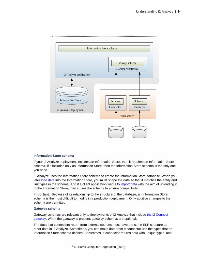
Information Store schema
If your i2 Analyze deployment includes an Information Store, then it requires an Information Storeschema. If it includes only an Information Store, then the Information Store schema is the only oneyou need.
i2 Analyze uses the Information Store schema to create the Information Store database. When youlater load data into the Information Store, you must shape the data so that it matches the entity andlink types in the schema. And if a client application wants to import data with the aim of uploading itto the Information Store, then it uses the schema to ensure compatibility.
Important: Because of its relationship to the structure of the database, an Information Storeschema is the most difficult to modify in a production deployment. Only additive changes to theschema are permitted.
Gateway schema
Gateway schemas are relevant only to deployments of i2 Analyze that include the i2 Connectgateway. When the gateway is present, gateway schemas are optional.
The data that connectors return from external sources must have the same ELP structure asother data in i2 Analyze. Sometimes, you can make data from a connector use the types that anInformation Store schema defines. Sometimes, a connector returns data with unique types, and
© N. Harris Computer Corporation (2022)

Understanding i2 Analyze | 10
defines a schema of its own. But sometimes, you might have several connectors whose data sharesa set of common types. In this situation, you can create a gateway schema and arrange for all theconnectors to use the types that the gateway schema defines.
Note: Because gateway schemas are not tied to the structure of data storage, they are relativelyeasy to modify and redeploy. Developing and testing a gateway schema can be a convenient way tocreate a schema that you plan eventually to use for the Information Store.
Connector schema
All data in an i2 Analyze deployment must use entity and link types from a schema. If a connectordoes not or cannot use types from an Information Store schema or a gateway schema, then it mustprovide its own definitions of the types that it uses.
A connector schema can be appropriate when you are prototyping a connector to a new datasource, or when you know that data from a particular source is subject to frequent changes.Alternatively, you might be using or creating a connector that is designed for use in multiple i2Analyze deployments. In that case, it can be helpful for the connector to come with definitions of itsown types.
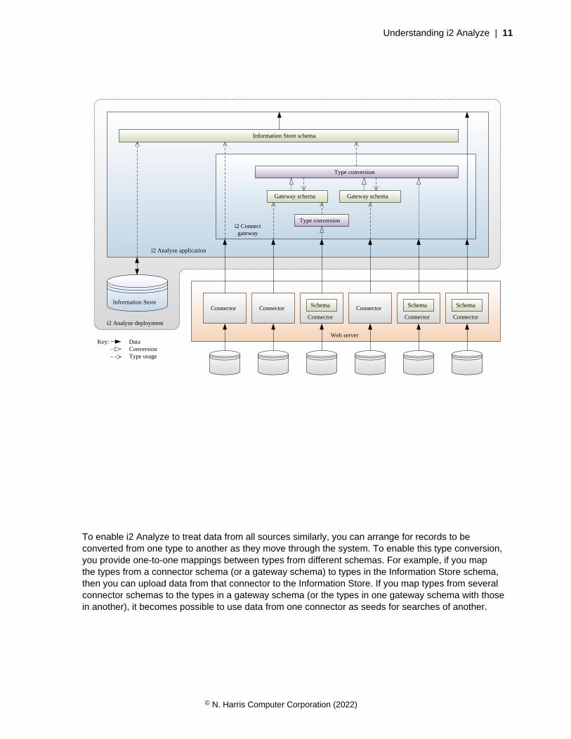
Schema type conversion
An i2 Analyze deployment that includes the i2 Connect gateway and connectors to external datasources is likely to involve several schemas. Client software can visualize data that uses types fromany schema, display its property values, and subject it to structural analysis. However, data can beuploaded to an Information Store only if it uses types from that store's schema. And users can performcomparative analysis only between data that uses the same types.
© N. Harris Computer Corporation (2022)
Understanding i2 Analyze | 11
i2 Analyze deployment
Web server
Information Store
i2 Analyze application
ConnectorConnector
Gateway schema
Information Store schema
Schema Schema
Type conversion
Type conversion
ConnectorConnector
Key: Data Conversion Type usage
Connector
SchemaConnector
Gateway schema
i2 Connectgateway
To enable i2 Analyze to treat data from all sources similarly, you can arrange for records to beconverted from one type to another as they move through the system. To enable this type conversion,you provide one-to-one mappings between types from different schemas. For example, if you mapthe types from a connector schema (or a gateway schema) to types in the Information Store schema,then you can upload data from that connector to the Information Store. If you map types from severalconnector schemas to the types in a gateway schema (or the types in one gateway schema with thosein another), it becomes possible to use data from one connector as seeds for searches of another.
© N. Harris Computer Corporation (2022)
Understanding i2 Analyze | 12
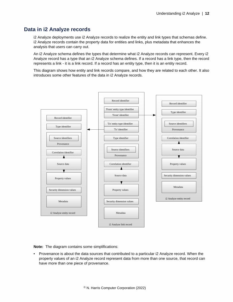
Data in i2 Analyze recordsi2 Analyze deployments use i2 Analyze records to realize the entity and link types that schemas define.i2 Analyze records contain the property data for entities and links, plus metadata that enhances theanalysis that users can carry out.
An i2 Analyze schema defines the types that determine what i2 Analyze records can represent. Every i2Analyze record has a type that an i2 Analyze schema defines. If a record has a link type, then the recordrepresents a link - it is a link record. If a record has an entity type, then it is an entity record.
This diagram shows how entity and link records compare, and how they are related to each other. It alsointroduces some other features of the data in i2 Analyze records.
i2 Analyze link record
Type identifier
'From' identifier
'To' identifier
i2 Analyze entity record
'From' entity type identifier
'To' entity type identifier
Metadata
Property values
Type identifier
Property values
Security dimension values
Security dimension values
Metadata
Provenance
Source identifiers
Correlation identifier
Correlation identifier
i2 Analyze entity record
Metadata
Type identifier
Property values
Security dimension values
Correlation identifier
Provenance
Source identifiers
Provenance
Source identifiers
Source data
Source data
Source data
Record identifierRecord identifier
Record identifier
Note: The diagram contains some simplifications:
• Provenance is about the data sources that contributed to a particular i2 Analyze record. When theproperty values of an i2 Analyze record represent data from more than one source, that record canhave more than one piece of provenance.
© N. Harris Computer Corporation (2022)
Understanding i2 Analyze | 13
• When an i2 Analyze record has more than one piece of provenance, it can contain all the data fromall the contributing sources. In that case, the property values that the record presents are derivedfrom the source data.
• Metadata includes the following information:
• Timestamps, which reflect when data in an i2 Analyze record was created or modified
• Source references, which describe the sources that the data in a record came from
• Notes, which users can write to add free-form text commentary to a record
For link records, the metadata also includes information about the strength and direction of the link.
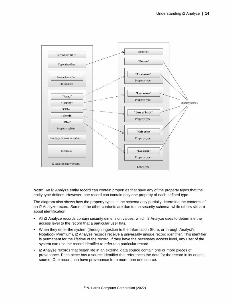
As an example of how to represent a simple entity that contains data from a single source, consider thefollowing information about a person:
Full name Anna Harvey
Date of birth 5/5/74
Hair color Blonde
Eye color Blue
The following diagram shows one way to represent this information as an i2 Analyze record:
© N. Harris Computer Corporation (2022)
Understanding i2 Analyze | 14
Entity type
Identifier
Property type
Property type
Property type
Property type
Property type
"First name"
"Last name"
"Date of birth"
"Hair color"
"Eye color"
"Person"
i2 Analyze entity record
Metadata
Type identifier
Property values
Security dimension values
Provenance
Source identifier
"Anna"
"Harvey"
5/5/74
"Blonde"
"Blue"
Record identifier
Display names
Note: An i2 Analyze entity record can contain properties that have any of the property types that theentity type defines. However, one record can contain only one property of each defined type.
The diagram also shows how the property types in the schema only partially determine the contents ofan i2 Analyze record. Some of the other contents are due to the security schema, while others still areabout identification:
• All i2 Analyze records contain security dimension values, which i2 Analyze uses to determine theaccess level to the record that a particular user has.
• When they enter the system (through ingestion to the Information Store, or through Analyst'sNotebook Premium), i2 Analyze records receive a universally unique record identifier. This identifieris permanent for the lifetime of the record. If they have the necessary access level, any user of thesystem can use the record identifier to refer to a particular record.
• i2 Analyze records that began life in an external data source contain one or more pieces ofprovenance. Each piece has a source identifier that references the data for the record in its originalsource. One record can have provenance from more than one source.
© N. Harris Computer Corporation (2022)

Understanding i2 Analyze | 15
Note: For records in an Information Store that were loaded through ingestion, source identifiershave the additional feature of being unique within the store. These source identifiers are known asorigin identifiers.
• All i2 Analyze records can contain timestamps in their metadata that specify when source data forthe record was created or edited.
• i2 Analyze link records contain an indication of their direction. i2 Analyze considers links to go 'from'one entity 'to' another. The direction of a link can be with or against that flow, or it can run in bothdirections or none.
When i2 Analyze records are stored in an Information Store, they contain a few extra pieces of data:
• All i2 Analyze records retain timestamps in their metadata for when they were first created oruploaded to the Information Store, for when they were most recently uploaded, and for when theywere last updated.
• All i2 Analyze records can contain a correlation identifier. If two records have the same correlationidentifier, the platform considers that they represent the same the real-world object and might mergethem together.
Your data sources are likely to contain some, but not all, of the data that i2 Analyze records require. Toenable an Information Store to ingest your data, or to develop a connector for the i2 Connect gateway,or to write an import specification, you must provide the extra information to i2 Analyze.
Identifiers in i2 Analyze records
i2 Analyze records make extensive use of identifiers. Records use identifiers to refer to their type in ani2 Analyze schema, to their original source data, and to other records in ELP relationships. Preparingdata for compatibility with i2 Analyze often involves creating or providing the identifiers that form thebasis for the reference mechanisms.
Type identifiers
Every i2 Analyze record contains a type identifier, which is a reference to one of the entity types or linktypes that a schema defines. When you create an ingestion mapping file, an import specification, or aconnector, you must arrange for each incoming record to receive the identifier of a type definition.
Every i2 Analyze link record contains two further type identifiers, which are references to the entitytypes of the records at the ends of the link. You must arrange for incoming link records to receive theseidentifiers as well.
This strong typing of records in i2 Analyze is key to the analytical functions that the platform provides.It allows users to consider not only the existence of relationships between records, but also the natureof those relationships. Schemas define exactly what relationships to allow between record types, and i2Analyze enforces those rules during record creation.
Record identifiers
i2 Analyze records are created when you ingest data into the Information Store, or when a user createsan item that contains an i2 Analyze record on the chart surface by:
• Importing data through an import specification
• Adding the results of an operation against an external source
• Using an i2 Analyze palette in Analyst's Notebook Premium
© N. Harris Computer Corporation (2022)
Understanding i2 Analyze | 16
At creation, every i2 Analyze record automatically receives a universally unique record identifier thatis permanent for the lifetime of that record. Users and administrators of an i2 Analyze deployment canuse the record identifier as a convenient way to refer to a record in features such as text search and theInvestigate Add-On.
Source identifiers
The role of a source identifier is to refer to the data for a record reproducibly in its original source. If arecord represents data from several sources, then it contains several source identifiers. The nature of asource identifier depends on the source and the record creation method, and sometimes on whether therecord is a link or an entity.
When you write ingestion mappings or develop connectors for the i2 Connect gateway, you areresponsible for providing the identifying information. For example, if the original source is a relationaldatabase, then entity data is likely to have ready-made source identifiers: table names and primarykeys. Link data can also have ready-made source identifiers, but it might not, especially if therelationship that the link represents exists only as a foreign key.
If the source of a record is a text file, then the file name might form part of the source identifier, alongwith some reference to the data within the file.
Note: Source identifiers are not displayed to end users, but they are a part of the data that recordscontain. Avoid including sensitive information such as passwords, or configuration detail such as IPaddresses. Assume that any information you use as part of a source identifier might be read by users ofthe system.
Origin identifiers
In general, source identifiers are not certain to be unique within a deployment of i2 Analyze. Severalusers might independently retrieve the same data from an external source, resulting in several recordswith the same source identifier. However, when you ingest data into the Information Store, i2 Analyzecompares the incoming source identifier with existing records. If it finds a match, i2 Analyze updates arecord instead of creating one.
The source identifiers that records receive during ingestion therefore are unique within i2 Analyze, andthey have a special name in this context. They are called origin identifiers.
Correlation identifiers
The purpose of a correlation identifier is to indicate that the data in an i2 Analyze record pertains toa particular real-world object. As a result, correlation identifiers are usually related to property valuesrather than other identifiers. (For example, two Person records from different sources that contain thesame social security number are likely to contain data about the same real person.) When two recordshave the same correlation identifier, they represent the same real-world object, and are candidates to bemerged.
When you ingest data into the Information Store, you can provide a correlation identifier for eachincoming record. For more information about correlation identifiers and how to create them, seeCorrelation identifiers.
© N. Harris Computer Corporation (2022)
Understanding i2 Analyze | 17
Security of i2 Analyze records
i2 Analyze records are subject to the i2 Analyze security rules. The security schema defines the securitymodel for your i2 Analyze deployment, and every i2 Analyze record must have at least one value fromeach security dimension in the schema.
When a user runs a query, i2 Analyze looks up which groups the user belongs to, and determines theirsecurity permissions. Then, it compares their security permissions to the security dimension values ofthe records in the query results. In this way, i2 Analyze calculates which records the user has access to.
If your deployment of i2 Analyze includes an Information Store that you populate through ingestion, thenyou must add security information to the data during that process. Each time the process runs, you canspecify which security dimension values the incoming records receive:
• If you decide that all the data from a given external source must have the same security settings, youcan specify the same dimension values for records of all types.
• Alternatively, you can dictate that all the records of a particular entity type or link type receive thesame security dimension values.
• You can also configure the process so that individual records receive security dimension values thatyou specify or determine programmatically.
Note: In this version of i2 Analyze, you can change the security dimension values of an ingested recordonly by ingesting it again with a different set of values.
All other i2 Analyze records receive dimension values when users create them in Analyst's NotebookPremium by importing them, or searching an external source, or by using an i2 Analyze palette. Theserecords start with default values that users can edit in the same way that they can edit property values.
Storing charts in i2 AnalyzeIn addition to storing records in the Information Store, i2 Analyze can provide a shared Chart Store forAnalyst's Notebook charts. Users of Analyst's Notebook Premium can search for, download, edit, andupload charts in the i2 Analyze Chart Store.
To store charts, i2 Analyze uses a similar model to the one that it uses for storing records in theInformation Store. Charts in the Chart Store benefit from features such as timestamps, notes, andsource references. They also use the same security model as the rest of the system, so user access tocharts is controlled in the same way as user access to records.
Extensions to the record model mean that the Chart Store indexes the contents of a chart for searching,in addition to its notes and properties. It also keeps an image of the chart's appearance when it wasuploaded. Furthermore, the Chart Store retains a version history and performs basic version controloperations for its contents.
Note: At this version of i2 Analyze, the Chart Store treats charts as stand-alone entities and does notmodel connections between them.
To learn more about the information in the Chart Store and what tasks an administrator of i2 Analyzecan use it for, see Retrieving chart metadata.
© N. Harris Computer Corporation (2022)

Understanding i2 Analyze | 18
Security modelAll data in i2 Analyze can be secured so that only the users who are supposed to interact with it are ableto do so. Using the i2 Analyze security model, you can decide what access users have to records andfeatures, based on their membership of user groups.
In i2 Analyze, all users are members of one or more groups. For example, there might be a groupof "administrator" users. There might be separate groups of users for each operational team inyour organization. There might be a group of users with higher security clearance than others. Theassignment of users to groups is handled at login.
Just as users of i2 Analyze are categorized, so too are records, according to a range of deployment-specific criteria. For example, records might be categorized according to the nature of the informationthey contain, or how sensitive that information is.
To make sure that users see only the records that they are allowed to see, every deployment of i2Analyze has a security schema. The security schema defines the categories into which records must beplaced, and the relationships that determine what access the users in a particular group get to recordsin a particular category.
In other words, the i2 Analyze security schema allows you to create rules that say things like, "Userswith low security clearance cannot see sensitive records," or "Users in Team A can see only recordswhose source was signals intelligence." i2 Analyze then combines such rules predictably, on a per-record and per-user basis.
Important: Orthogonal to this security model, i2 Analyze supports blanket controls over the visibilityof records with particular types. You can specify that only certain groups of users can see records ofa specific type, and that all records of that type are invisible to all other users, regardless of securityschema categories. For more information about this functionality, see Item type security.
i2 Analyze security dimensionsIn the i2 Analyze security model, a security dimension is a way to categorize a record, with the aim ofusing its category to determine whether particular users are allowed to view or modify it. The availablesecurity dimensions in a deployment of i2 Analyze are specific to that deployment, and they are definedin its security schema.
A deployment of i2 Analyze might need several different ways to categorize records:
• Records might be categorized by their security classifications
• Records might be categorized by the type of intelligence that produced them
• Records might be categorized by the operational teams who are allowed to access them
As a result, the deployment requires several security dimensions. Each dimension contains a set ofvalues that records can have in order to classify them within that dimension.
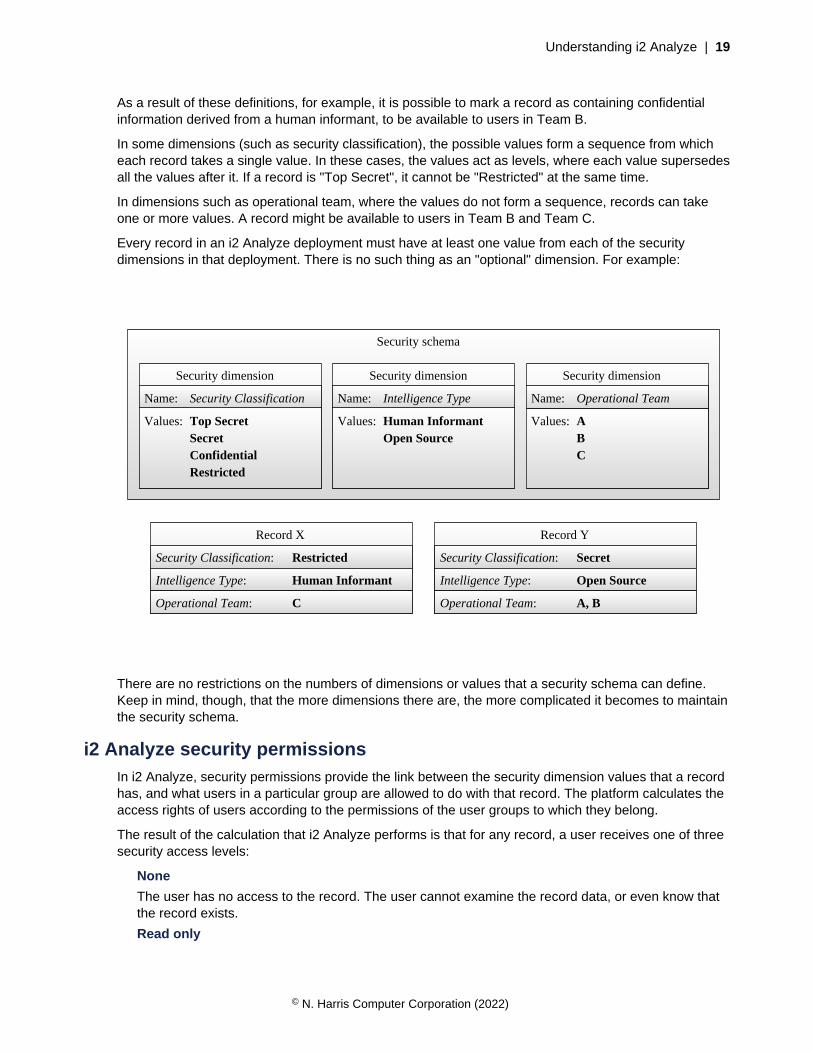
To continue the example, the three dimensions might contain values as follows:
Security classification
Top Secret, Secret, Confidential, Restricted
Intelligence type
Human Informant, Open Source
Operational team
A, B, C
© N. Harris Computer Corporation (2022)
Understanding i2 Analyze | 19
As a result of these definitions, for example, it is possible to mark a record as containing confidentialinformation derived from a human informant, to be available to users in Team B.
In some dimensions (such as security classification), the possible values form a sequence from whicheach record takes a single value. In these cases, the values act as levels, where each value supersedesall the values after it. If a record is "Top Secret", it cannot be "Restricted" at the same time.
In dimensions such as operational team, where the values do not form a sequence, records can takeone or more values. A record might be available to users in Team B and Team C.
Every record in an i2 Analyze deployment must have at least one value from each of the securitydimensions in that deployment. There is no such thing as an "optional" dimension. For example:
Security schema
Security dimension Security dimension Security dimension
Record X Record Y
Name: Security Classification
Values: Top SecretSecretConfidentialRestricted
Values: Human InformantOpen Source
Values: ABC
Security Classification:
Name: Intelligence Type Name: Operational Team
Intelligence Type:
Operational Team:
Restricted
Human Informant
C
Security Classification:
Intelligence Type:
Operational Team:
Secret
Open Source
A, B
There are no restrictions on the numbers of dimensions or values that a security schema can define.Keep in mind, though, that the more dimensions there are, the more complicated it becomes to maintainthe security schema.
i2 Analyze security permissionsIn i2 Analyze, security permissions provide the link between the security dimension values that a recordhas, and what users in a particular group are allowed to do with that record. The platform calculates theaccess rights of users according to the permissions of the user groups to which they belong.
The result of the calculation that i2 Analyze performs is that for any record, a user receives one of threesecurity access levels:
None
The user has no access to the record. The user cannot examine the record data, or even know thatthe record exists.
Read only
© N. Harris Computer Corporation (2022)

Understanding i2 Analyze | 20
The user has read-only access to the record and its data.
Update
The user can read, modify, and delete the record and its data.
In an i2 Analyze security schema, the set of security permissions for a user group defines mappingsfrom dimension values to access levels. Users receive the security access levels that their user groupindicates for the dimension values of a record.
For example, a dimension value might mark a record as containing open source information, and asecurity permission might state that members of a certain user group have the "Update" access level onrecords with that dimension value. In that case, a user in that group receives the "Update" access levelon that record.
In practice, when a user is a member of several user groups, or a record has multiple dimension values,it is possible for a user to receive several security access levels from different security permissions. Inthese circumstances, i2 Analyze computes a single security access level from all the contributors.
Security schema
Permissions for members of User Group 1
Security dimension Value Security access level
Security Classification
Operational Team
Confidential
A
Read only
Update
Permissions for members of User Group 2
Security dimension Value Security access level
Security Classification
Operational Team
Operational Team
Secret
A
B
Read only
Read only
Update
Intelligence Type OS Read only
Intelligence Type OS Read only
Intelligence Type HUMINT Read only
Operational Team B Read only
© N. Harris Computer Corporation (2022)

Understanding i2 Analyze | 21
It is not compulsory for a set of permissions for a user group to provide a security access level for everyvalue of every dimension. Any dimension value that does not appear in a set of permissions receives adefault security access level, according to a set of rules:
• For an unordered dimension, a dimension value that does not appear in the permissions receives the"None" level.
• For an ordered dimension:
• If the unspecified value comes after a dimension value that does appear, then the unspecifiedvalue receives the same level as the specified value.
• If the unspecified value comes before a dimension value that does appear, then the unspecifiedvalue receives the "None" level.
For example, if a particular set of permissions associates the "Read only" access level with"Restricted" records (and makes no other setting), then the default access level for "Confidential"records is "None". However, if the permissions associate the "Read only" access level with"Confidential" records instead, then users in the same group receive that access level for"Restricted" records as well.
An i2 Analyze system administrator must arrange the security schema so that all users can receive asecurity access level that is not "None" for at least one value in every dimension.
Security model exampleAt any moment, a user has one security access level for each record in i2 Analyze. The platformcalculates this level according to a consistent set of rules.
The process for determining a security access level involves examining security permissions within andacross dimensions. The platform does the job in three steps:
1. Bring together the permissions for all the user groups of which the user is a member.
2. Use the permissions to determine all the security access levels that the user receives for eachdimension value that the record has. Take the least restrictive level in each case.
3. Examine all of these "least restrictive" dimension-specific security access levels, and take the mostrestrictive.
For example, consider the following record, which has one value for each of two security dimensions,and two values for a third.
Record Y
Security Classification:
Intelligence Type:
Operational Team:
Secret
Open Source
A, B
Then, consider a user in a group that has the following security permissions. (It does not matter whetherthe permissions are due to one user group or several.)
© N. Harris Computer Corporation (2022)
Understanding i2 Analyze | 22
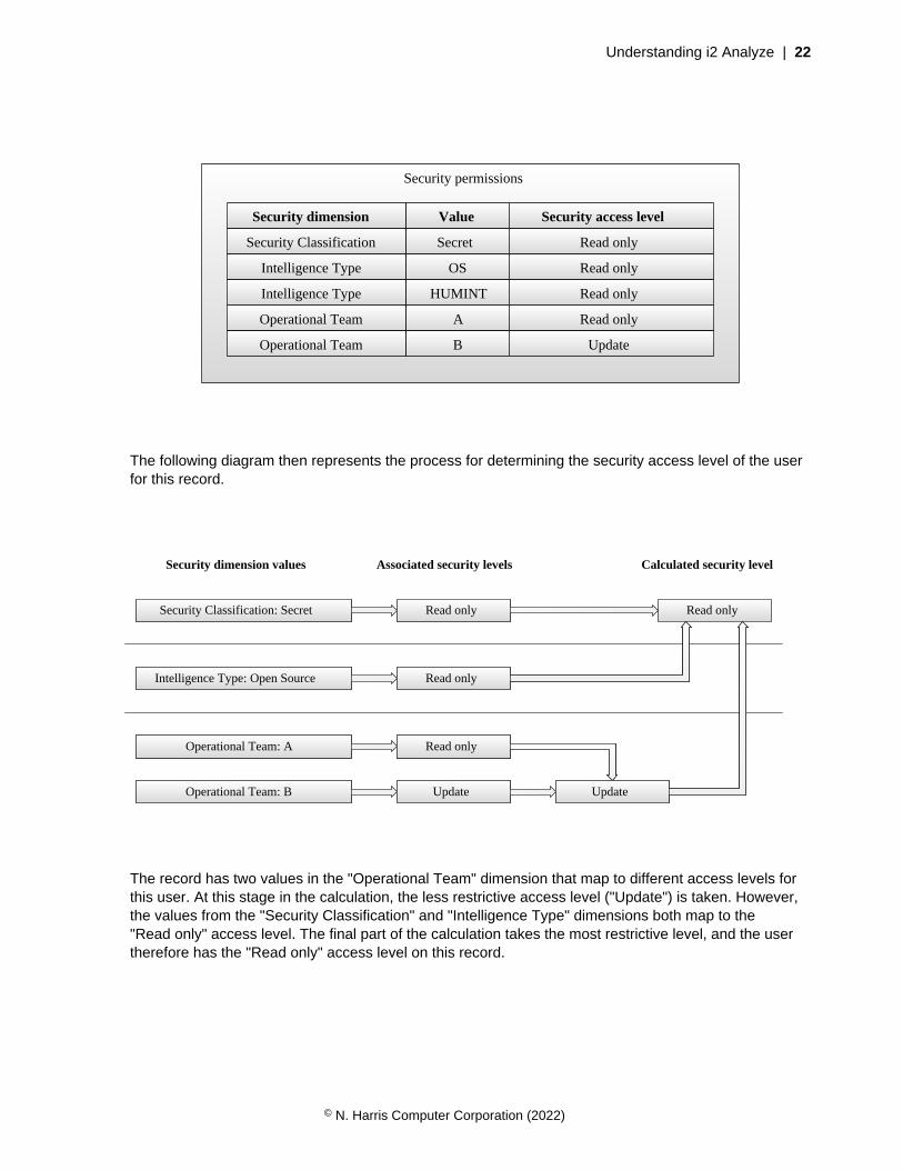
Security permissions
Security dimension Value Security access level
Security Classification
Operational Team
Operational Team
Secret
A
B
Read only
Read only
Update
Intelligence Type OS Read only
Intelligence Type HUMINT Read only
The following diagram then represents the process for determining the security access level of the userfor this record.
Read only
Security dimension values Associated security levels Calculated security level
Security Classification: Secret
Operational Team: A
Operational Team: B
Read only
Update
Read only
Update
Intelligence Type: Open Source Read only
The record has two values in the "Operational Team" dimension that map to different access levels forthis user. At this stage in the calculation, the less restrictive access level ("Update") is taken. However,the values from the "Security Classification" and "Intelligence Type" dimensions both map to the"Read only" access level. The final part of the calculation takes the most restrictive level, and the usertherefore has the "Read only" access level on this record.
© N. Harris Computer Corporation (2022)

Understanding i2 Analyze | 23
Security architectureThe i2 Analyze security architecture supports the behavior that the i2 Analyze security model requires.Any part of the i2 Analyze application can interact with the security architecture to determine what rightsthe current user has for the operation that they want to perform.
i2 Analyze authenticates users through a choice of technologies, and determines their access levelfor every record that it manages. The i2 Analyze security model bases its behavior on the interactionbetween the security dimension values that records have, and the security permissions that user groupsconvey.
• Records in i2 Analyze are categorized by receiving values from security dimensions. The values thata record has from different security dimensions affect whether users can view or edit that record.
• Security permissions apply to groups of users. On a per-group basis, they associate security accesslevels with particular dimension values. User group membership is often decided by the teammembership or the security clearance of the users that they contain.
The components of an i2 Analyze deployment interact with the security architecture in the followingways:
• At login, WebSphere Liberty requires clients to authenticate before they can interact with i2 Analyze.On successful authentication, the client receives a Lightweight Third-Party Authentication (LTPA)token in a cookie.
• During normal operation, the client passes the cookie back to the i2 Analyze application, whichenforces data access rights.
The following diagram shows how security works in a typical i2 Analyze deployment:
© N. Harris Computer Corporation (2022)

Understanding i2 Analyze | 24
Write-side Server
WebSphere Application Server
Web Browser
Client
loginCLIENT
SERVER
Default
HTTP Server
TrustAssociation Interceptor
Servlet Container
IntelligenceAnalysis Platform Write Application
WebSphereUser
Registry
PrincipalProvider
authentication
LDAP
authorization
normal operation
In a standard i2 Analyze deployment, authentication and authorization take place as follows:
• Authentication between a client and Liberty uses standard HTTP authentication methods such asbasic authentication or form-based authentication.
• Liberty uses its user registry to verify the credentials that the user supplies through the client. Theuser registry is a service that provides access to user and group information. It can be held in anXML file, one or more LDAP registries, or in any similar store that Liberty can use.
• To authorize users of a client to access records, the i2 Analyze application communicates withthe Liberty user registry to retrieve information about the current user's membership of groups. A
© N. Harris Computer Corporation (2022)
Understanding i2 Analyze | 25
principal provider then maps the retrieved information to group permissions that are defined in thesecurity permissions section of the i2 Analyze security schema. This mapping is deployment-specificbecause the security schema is deployment-specific.
• Code in the i2 Analyze application compares the permissions of the current user with the securitydimension values of records, to determine what access levels the user receives for each record.
The technologies in the diagram are not fixed. For example, it is possible to use any supported store forthe user registry. The requirements are as follows:
• The i2 Analyze application must be able to derive information about a user from the credentials theypresent.
• A (potentially) deployment-specific module must map user information onto membership of thegroups that are named in the security permissions section of the i2 Analyze security schema.
If an implementation of the security architecture fulfills these requirements, then it is suitable for use inan i2 Analyze deployment.
Supplied security implementationOne of the requirements for a deployment of i2 Analyze is a principal provider, which is the mechanismthrough which the users in an organization are mapped to the user groups in the security schema.When a deployment environment uses WebSphere Liberty for user authentication, the i2 Analyzedeployment toolkit contains a production-quality class that might be an appropriate solution.
The WebSphereDynamicAccessRoleBasedPrincipalProvider class from the deployment toolkitperforms a direct mapping from the names of user groups in Liberty to the names of user groups inthe security schema. When the user is a member of a Liberty group, they receive access levels inaccordance with the contents of corresponding <GroupPermissions> elements in the i2 Analyzesecurity schema.
The i2 Analyze deployment toolkit can provide an example security schema and Liberty user registrythat contain correlating group names and dimension values. These files are suitable for use indevelopment environments, but not in production.
Logging and auditingi2 Analyze provides mechanisms for logging two types of information that the system generates duringnormal execution. You can control what information is sent to the system logs, and audit the commandsthat users invoke.
System logging
The components that make up the i2 Analyze server all contain instrumentation that sends informationabout the health of the system to log files or the console. You can control the locations of the log files,and the volume of information that the system sends, by editing the log4j.properties files in thedeployment toolkit.
The information that i2 Analyze can log through this mechanism includes detail about warningsand errors that users see in their client software, and incremental status reports about long-runningprocesses such as ingestion.
For more information about system logging, see the deployment and configuration guides for i2 Analyze,or the Apache Log4j website.
© N. Harris Computer Corporation (2022)
Deploying i2 Analyze | 26
User activity logging
When a user runs an authenticated command against any of its services, i2 Analyze can recordinformation about the user who ran the command, and full details of the command that they ran.For example, you might use this functionality to audit the frequency with which different users makerequests for the data that i2 Analyze manages, or to track searches with particular patterns. i2 Analyzehandles user activity logging for the i2 Connect gateway separately from the Information Store and theChart Store.
Note: Depending on the volume of data, enabling user activity logging might affect the performance ofi2 Analyze.
Information Store and Chart Store
i2 Analyze supports user activity logging for all of the main analysis operations against theInformation Store and (where relevant) the Chart Store. For example, you can configure separatelogging (or no logging at all) for search, expand, and find path operations. You can also arrange forlogging to occur when records and charts are created or modified.
To audit user activity, including activity due to Analyst's Notebook Premium and the InvestigateAdd-On, you write a class that implements the IAuditLogger interface and specify it in theApolloServerSettingsMandatory.properties file in the deployment toolkit.
At startup, i2 Analyze calls IAuditLogger to discover what activities to log information about.Later, it calls again with information such as the time of the activity, the name and security clearanceof the user, and the parameters that they supplied.
For more information and an example of how to implement IAuditLogger, see i2 AnalyzeDeveloper Essentials.
i2 Connect gateway
To log operations against external sources through the i2 Connect gateway, i2 Analyze uses thesame IAuditLogger interface that it uses for the Information Store and chart store. However, allsuch operations are logged through a single method on the IAuditLogger interface.
Deploying i2 AnalyzeAll deployments of i2 Analyze are different in terms of the functionality they support and the componentsthey employ. They are also different in terms of how you intend them to be used. The process by whichyou deploy i2 Analyze changes significantly, depending on whether your target is an example or aproduction environment.Deployment informationDeployment types on page 27Before you start a deployment of i2 Analyze, choose the type of deployment that you want to create.Use the following information to ensure that you choose the correct type of deployment for yourrequirements.
Deployment tasksCreating an example deployment on page 27To understand what i2 Analyze is, and to demonstrate the features of the system, you can create anexample deployment.
Creating a production deployment on page 37
© N. Harris Computer Corporation (2022)

Deploying i2 Analyze | 27
The process of creating a production deployment is separated into a number of different activities, whichyou complete in an iterative process. The suggested process involves the creation and retention ofseveral environments, each one focused on different aspects of a production deployment of i2 Analyze.
Troubleshooting and supporti2 Analyze support page
i2 Support
Deployment typesBefore you start a deployment of i2 Analyze, choose the type of deployment that you want to create.Use the following information to ensure that you choose the correct type of deployment for yourrequirements.
Example deployment
You can use an example deployment to learn about i2 Analyze, demonstrate the features of thesystem, and ensure that any software prerequisites are installed correctly on a single server.
When you create an example deployment, the deployment toolkit populates all of the mandatoryconfiguration settings with default values and deploys the system. The deployment uses an examplei2 Analyze schema, security schema, and data. Some configuration settings that are not mandatoryfor deployment are also populated to demonstrate extra features of the system.
For more information about example deployments, see Creating an example deployment on page27.
Production deployment
A production deployment is available to analysts to complete mission critical analysis on real-worlddata. When you decide to create a production deployment of i2 Analyze, you must start from a cleaninstallation of i2 Analyze.
The process for creating a production deployment involves a number of different deployment andconfiguration activities. As part of the process, you must develop an i2 Analyze schema and securityschema for your data.
For more information about production deployments, see Creating a production deployment on page37.
Creating an example deploymentTo understand what i2 Analyze is, and to demonstrate the features of the system, you can create anexample deployment.
An example deployment uses default values that are provided by the deployment toolkit, and containsa configuration that demonstrates the features provided by i2 Analyze. You can also use an exampledeployment to verify that any prerequisites are installed correctly.
© N. Harris Computer Corporation (2022)

Deploying i2 Analyze | 28
Creating an example with the Chart StoreAn installation of i2 Analyze includes example settings for deploying the server with the Chart Store.This topic describes how to use those settings in an example deployment.
Install i2 Analyze and any software prerequisites. For more information, see Installing i2 Analyze. Todeploy the Chart Store, you need either IBM® Db2® or Microsoft™ SQL Server 2019. You do not needIBM HTTP Server.
If you are using SQL Server, download the Microsoft™ JDBC Driver 7.4 for SQL Server archivefrom https://www.microsoft.com/en-us/download/details.aspx?id=58505. Extract the contents of thedownload, and locate the sqljdbc_7.4\enu\mssql-jdbc-7.4.1.jre11.jar file.
Important: For a deployment of Analyst's Notebook Premium to a small workgroup, an exampledeployment of i2 Analyze with the Chart Store and custom security settings might offer sufficientperformance for use in a production environment. For a larger workgroup, or for a group with a largenumber of charts, a production deployment is appropriate.
The following procedure describes how to create an example deployment of i2 Analyze with theChart Store. The i2® Analyze toolkit contains an example configuration for the deployment. ThedeployExample task generates the default values for the mandatory settings and deploys the platform.
The example deployment demonstrates a working i2 Analyze system with an example user so that youcan log in.
In the example deployment, i2 Analyze runs with an example security schema and matching Libertysecurity groups and users. The example user has the following credentials:
• The user name is Jenny
• The password is Jenny
The example deployment uses the chart-storage-schema.xml schema file, with the associatedchart-storage-schema-charting-schemes.xml file as the charting scheme.
1. Create the configuration directory:
a) Navigate to the \toolkit\examples\configurations\chart-storage directory.
This directory contains the preconfigured files that you need to deploy a system that uses theChart Store to store Analyst's Notebook charts.
b) Copy the configuration directory to the root of the toolkit.For example, C:\i2\i2analyze\toolkit\configuration.
If you are using SQL Server as your database management system, you must complete extraconfiguration actions to deploy the example.
2. Copy the example topology.xml file for SQL Server from the toolkit\configuration\examples\topology\sqlserver to the toolkit\configuration\environment directory.Overwrite the existing topology.xml file in the destination directory.
3. Copy the mssql-jdbc-7.4.1.jre11.jar file that you downloaded to the toolkit\configuration\environment\common\jdbc-drivers directory.
Regardless of your database management system, you must complete the following steps after youcreate the configuration directory.
4. Specify the credentials to use for the deployment.
a) Using a text editor, open the toolkit\configuration\environment\credentials.properties file.
b) Enter the user name and password to use with the database.
© N. Harris Computer Corporation (2022)

Deploying i2 Analyze | 29
c) Enter a user name and password to use for Solr.
d) Enter a password to use to encrypt LTPA tokens.
e) Save and close the credentials.properties file.
5. If you are using IBM Db2 11.5.6 Fix Pack 0 or later, you might need to update the port number that isused in the topology.xml file.
By default, i2 Analyze is deployed to connect to Db2 using port 50000. In version 11.5.6 Fix Pack 0and later, the default port that Db2 uses is changed to 25000. For more information about the portsthat Db2 uses, see Db2 server TCP/IP port numbers.
a) Using an XML editor, open the toolkit\configuration\environment\topology.xml file.
b) In the <database> element, set the value of the port-number attribute to 25000.
c) Save and close the topology.xml file.
6. Run the setup script to create the example deployment.
a) Open a command prompt and navigate to the toolkit\scripts directory.
b) To deploy the example, run the following command:
setup -t deployExample
c) To start the Liberty server, run the following command:
setup -t start
When you start i2® Analyze, the URI that you can use to connect to the deployment is displayed in theconsole. For example:
Web application available (default_host): http://host_name:9082/opal.
Install Analyst's Notebook Premium and connect to your deployment. For more information, seeConnecting clients on page 96.
Creating an example with the Information StoreAn installation of i2 Analyze includes example settings for deploying the server with the InformationStore. This topic describes how to use those settings in an example deployment.
Install i2 Analyze and any software prerequisites. For more information, see Installing i2 Analyze. Todeploy the preconfigured examples for the Information Store, you need either IBM® Db2® or Microsoft™
SQL Server 2019. You do not need IBM HTTP Server.
If you are using SQL Server, download the Microsoft™ JDBC Driver 7.4 for SQL Server archivefrom https://www.microsoft.com/en-us/download/details.aspx?id=58505. Extract the contents of thedownload, and locate the sqljdbc_7.4\enu\mssql-jdbc-7.4.1.jre11.jar file.
The following procedure describes how to create an example deployment of i2 Analyze with theInformation Store, which also fulfills the functions of the Chart Store. The i2® Analyze toolkit contains anexample configuration for the deployment. The deployExample task generates the default values forthe mandatory settings and deploys the platform.
The example deployment demonstrates a working i2 Analyze system with an example user so that youcan log in.
In the example deployment, i2 Analyze runs with an example security schema and matching Libertysecurity groups and users. The example user has the following credentials:
© N. Harris Computer Corporation (2022)
Deploying i2 Analyze | 30
• The user name is Jenny
• The password is Jenny
The example deployment uses the law-enforcement-schema.xml schema as the i2 Analyzeschema with the associated law-enforcement-schema-charting-schemes.xml as the chartingscheme.
1. Create the configuration directory:
a) Navigate to the \toolkit\examples\configurations\information-store-opaldirectory.
This directory contains the preconfigured files that you need to deploy a system that uses theInformation Store to store data and Analyst's Notebook charts, and to support the i2 Notebookweb client.
b) Copy the configuration directory to the root of the toolkit.For example, C:\i2\i2analyze\toolkit\configuration.
If you are using SQL Server as your database management system, you must complete extraconfiguration actions to deploy the example.
2. Copy the example topology.xml file for SQL Server from the toolkit\configuration\examples\topology\sqlserver to the toolkit\configuration\environment directory.Overwrite the existing topology.xml file in the destination directory.
3. Copy the mssql-jdbc-7.4.1.jre11.jar file that you downloaded to the toolkit\configuration\environment\common\jdbc-drivers directory.
Regardless of your database management system, you must complete the following steps after youcreate the configuration directory.
4. Specify the credentials to use for the deployment.
a) Using a text editor, open the toolkit\configuration\environment\credentials.properties file.
b) Enter the user name and password to use with the database.
c) Enter a user name and password to use for Solr.
d) Enter a password to use to encrypt LTPA tokens.
e) Save and close the credentials.properties file.
5. If you are using IBM Db2 11.5.6 Fix Pack 0 or later, you might need to update the port number that isused in the topology.xml file.
By default, i2 Analyze is deployed to connect to Db2 using port 50000. In version 11.5.6 Fix Pack 0and later, the default port that Db2 uses is changed to 25000. For more information about the portsthat Db2 uses, see Db2 server TCP/IP port numbers.
a) Using an XML editor, open the toolkit\configuration\environment\topology.xml file.
b) In the <database> element, set the value of the port-number attribute to 25000.
c) Save and close the topology.xml file.
6. Run the setup script to create the example deployment.
a) Open a command prompt and navigate to the toolkit\scripts directory.
b) To deploy the example, run the following command:
setup -t deployExample
© N. Harris Computer Corporation (2022)

Deploying i2 Analyze | 31
c) To start the Liberty server, run the following command:
setup -t start
7. Optional: To populate your Information Store with the provided example data for the law-enforcement-schema.xml schema, run the following command:
setup -t ingestExampleData
When you start i2® Analyze, the URI that you can use to connect to the deployment is displayed in theconsole. For example:
Web application available (default_host): http://host_name:9082/opal.
Install Analyst's Notebook Premium or open a web browser and connect to your deployment. For moreinformation, see Connecting clients on page 96.
Creating an example with the i2 Connect gatewayAn installation of i2 Analyze includes example settings for deploying the server with support for thei2 Connect gateway only. With these settings, the i2 Connect gateway enables Analyst's NotebookPremium users to search for and retrieve data from external data sources, and then to analyze theresults on charts.
Install i2 Analyze and any software prerequisites. For more information, see Installing i2 Analyze. Youdo not need IBM HTTP Server.
Before you create the example deployment, you must download and install Node.js to host the exampleconnector. Download Node.js for your operating system from https://nodejs.org/en/download/. You caninstall Node.js with the default settings.
To use any deployment of i2 Analyze with the i2 Connect gateway, you must obtain or create aconnector to the external data source that you want to search. The i2 Analyze toolkit contains anexample configuration for the deployment, and an example connector with example data.
The example deployment demonstrates a working i2 Analyze system that can query and retrieve datafrom an external data source. You can log in with an example user. In the example deployment, i2Analyze runs with the example security schema and matching Liberty security groups and users. Theexample user has the following credentials:
• The user name is Jenny
• The password is Jenny
Note: This example does not support the i2 Notebook web client. To give users the option of using theweb client, you must Create an example with the Chart Store.
1. Create the configuration directory:
a) Navigate to the \toolkit\examples\configurations\daod-opal directory.
This directory contains the preconfigured files that you need to deploy a system that uses the i2Connect gateway to connect to an external data source.
b) Copy the configuration directory to the root of the toolkit.For example, C:\i2\i2analyze\toolkit\configuration.
2. Specify the credentials to use for the deployment.
a) Using a text editor, open the toolkit\configuration\environment\credentials.properties file.
© N. Harris Computer Corporation (2022)
Deploying i2 Analyze | 32
b) Enter the user name and password to use for Solr.
c) Enter the password to use to encrypt LTPA tokens.
d) Save and close the credentials.properties file.
3. Run the setup script to create the example deployment.
a) Open a command prompt and navigate to the toolkit\scripts directory.
b) To deploy the example, run the following command:
setup -t deployExample
4. Install any dependencies and start the server that hosts the example connector.
Note: The example connector uses port number 3700. Ensure that no other processes are usingthis port number before you start the connector.
a) In a command prompt, navigate to the toolkit\examples\connectors\example-connector directory.
b) To install the dependencies that are required for the example connector, run the followingcommand:
npm install
Note: You must be connected to the internet to install the dependencies.
c) To start the Node.js server, run the following command:
npm start
5. Start i2 Analyze.
a) Open a command prompt and navigate to the toolkit\scripts directory.
b) To start i2 Analyze, run the following command:
setup -t start
When you start i2 Analyze, the URI that you can use to connect to it from Analyst's Notebook Premiumis displayed in the console. For example:Web application available (default_host):http://host_name:9082/opaldaod.
Install Analyst's Notebook Premium and connect to your deployment. For more information, seeConnecting clients on page 96.
Production deployments of i2 Analyze use client-authenticated SSL communication between i2 Analyzeand any connectors. The example deployment does not use it, and so Analyst's Notebook Premiumdisplays a warning to that effect when you open the external searches window. For more informationabout configuring client-authenticated SSL, see Client-authenticated Secure Sockets Layer with the i2Connect gateway.
You can create your own connectors to use with the deployment of i2 Analyze. For more information,see i2 Analyze and the i2 Connect gateway.
Creating an example with the Chart Store and the i2 Connect gatewayAn installation of i2 Analyze includes example settings for deploying the server with the Chart Store andsupport for the i2 Connect gateway. With these settings, Analyst's Notebook Premium users can upload
© N. Harris Computer Corporation (2022)
Deploying i2 Analyze | 33
charts to the Chart Store, while both they and i2 Notebook web client users can search for and retrievedata from an example external data source through the i2 Connect gateway.
Install i2 Analyze and any software prerequisites. For more information, see Installing i2 Analyze. Todeploy the Chart Store, you need either IBM® Db2® or Microsoft™ SQL Server 2019. You do not needIBM HTTP Server.
If you are using SQL Server, download the Microsoft™ JDBC Driver 7.4 for SQL Server archivefrom https://www.microsoft.com/en-us/download/details.aspx?id=58505. Extract the contents of thedownload, and locate the sqljdbc_7.4\enu\mssql-jdbc-7.4.1.jre11.jar file.
Before you create the example deployment, you must download and install Node.js to host the exampleconnector. Download Node.js for your operating system from: https://nodejs.org/en/download/. You caninstall Node.js with the default settings.
The following procedure describes how to create an example deployment of i2 Analyze with the ChartStore and the i2 Connect gateway. To use any deployment of i2 Analyze with the i2 Connect gateway,you must obtain or create a connector to the external data source that you want to search. The i2Analyze toolkit contains an example configuration for the deployment, and an example connector withexample data. The deployExample task generates the default values for the mandatory settings anddeploys the platform.
The example deployment demonstrates a working i2 Analyze system with an example user so that youcan log in.
In the example deployment, i2 Analyze runs with the example security schema and matching Libertysecurity groups and users. The example user has the following credentials:
• The user name is Jenny
• The password is Jenny
The example deployment uses the chart-storage-schema.xml schema file, with the associatedchart-storage-schema-charting-schemes.xml file as the charting scheme.
1. Create the configuration directory:
a) Navigate to the \toolkit\examples\configurations\chart-storage-daod directory.
This directory contains the preconfigured files that you need to deploy a system that uses the i2Connect gateway to connect to an external data source, and the Chart Store to store Analyst'sNotebook charts and support the i2 Notebook web client.
b) Copy the configuration directory to the root of the toolkit.For example, C:\i2\i2analyze\toolkit\configuration.
If you are using SQL Server as your database management system, you must complete extraconfiguration actions to deploy the example.
2. Copy the example topology.xml file for SQL Server from the toolkit\configuration\examples\topology\sqlserver to the toolkit\configuration\environment directory.Overwrite the existing topology.xml file in the destination directory.
3. Copy the mssql-jdbc-7.4.1.jre11.jar file that you downloaded to the toolkit\configuration\environment\common\jdbc-drivers directory.
Regardless of your database management system, you must complete the following steps after youcreate the configuration directory.
4. Specify the credentials to use for the deployment.
a) Using a text editor, open the toolkit\configuration\environment\credentials.properties file.
© N. Harris Computer Corporation (2022)
Deploying i2 Analyze | 34
b) Enter the user name and password to use with the database.
c) Enter a user name and password to use for Solr.
d) Enter a password to use to encrypt LTPA tokens.
e) Save and close the credentials.properties file.
5. If you are using IBM Db2 11.5.6 Fix Pack 0 or later, you might need to update the port number that isused in the topology.xml file.
By default, i2 Analyze is deployed to connect to Db2 using port 50000. In version 11.5.6 Fix Pack 0and later, the default port that Db2 uses is changed to 25000. For more information about the portsthat Db2 uses, see Db2 server TCP/IP port numbers.
a) Using an XML editor, open the toolkit\configuration\environment\topology.xml file.
b) In the <database> element, set the value of the port-number attribute to 25000.
c) Save and close the topology.xml file.
6. Run the setup script to create the example deployment.
a) Open a command prompt and navigate to the toolkit\scripts directory.
b) To deploy the example, run the following command:
setup -t deployExample
7. Install any dependencies and start the server that hosts the example connector.
Note: The example connector uses port number 3700. Ensure that no other processes are usingthis port number before you start the connector.
a) In a command prompt, navigate to the toolkit\examples\connectors\example-connector directory.
b) To install the dependencies that are required for the example connector, run the followingcommand:
npm install
Note: You must be connected to the internet to install the dependencies.
c) To start the Node.js server, run the following command:
npm start
8. Start i2 Analyze.
a) Open a command prompt and navigate to the toolkit\scripts directory.
b) To start i2 Analyze, run the following command:
setup -t start
When you start i2 Analyze, the URI that you can use to connect to the deployment is displayed in theconsole. For example:
Web application available (default_host): http://host_name:9082/opal.
Install Analyst's Notebook Premium or open a web browser and connect to your deployment. For moreinformation, see Connecting clients on page 96.
© N. Harris Computer Corporation (2022)

Deploying i2 Analyze | 35
Production deployments of i2 Analyze use client-authenticated SSL communication between i2 Analyzeand any connectors. The example deployment does not use it, and so Analyst's Notebook Premiumdisplays a warning to that effect when you open the external searches window. For more informationabout configuring client-authenticated SSL, see Client-authenticated Secure Sockets Layer with the i2Connect gateway.
You can create your own connectors to use with the deployment of i2 Analyze. For more information,see i2 Analyze and the i2 Connect gateway.
Creating an example with the Information Store and the i2 Connectgateway
An installation of i2 Analyze includes example settings for deploying the server with the InformationStore and support for the i2 Connect gateway. Users can access data in the Information Store in theusual manner, and the i2 Connect gateway enables analysts to search for and retrieve data from anexample external data source.
Install i2 Analyze and any software prerequisites. For more information, see Installing i2 Analyze. Todeploy the preconfigured examples for the Information Store, you need either IBM® Db2® or Microsoft™
SQL Server 2019. You do not need IBM HTTP Server.
If you are using SQL Server, download the Microsoft™ JDBC Driver 7.4 for SQL Server archivefrom https://www.microsoft.com/en-us/download/details.aspx?id=58505. Extract the contents of thedownload, and locate the sqljdbc_7.4\enu\mssql-jdbc-7.4.1.jre11.jar file.
Before you create the example deployment, you must download and install Node.js to host the exampleconnector. Download Node.js for your operating system from https://nodejs.org/en/download/. You caninstall Node.js with the default settings.
The following procedure describes how to create an example deployment of i2 Analyze with theInformation Store, which also fulfills the functions of the Chart Store, and the i2 Connect gateway. Touse any deployment of i2 Analyze with the i2 Connect gateway, you must obtain or create a connectorto the external data source that you want to search. The i2 Analyze toolkit contains an exampleconfiguration for the deployment, and an example connector with example data. The deployExampletask generates the default values for the mandatory settings and deploys the platform.
The example deployment demonstrates a working i2 Analyze system with an example user so thatyou can log in. You can ingest example data into the Information Store and then perform searches andanalysis, and use the example connector to query and retrieve data from an external data source.
In the example deployment, i2 Analyze runs with the example security schema and matching Libertysecurity groups and users. The example user has the following credentials:
• The user name is Jenny
• The password is Jenny
The example deployment uses the law-enforcement-schema.xml schema as the i2 Analyzeschema with the associated law-enforcement-schema-charting-schemes.xml as the chartingscheme.
1. Create the configuration directory:
a) Navigate to the \toolkit\examples\configurations\information-store-daod-opaldirectory.
This directory contains the preconfigured files that you need to deploy a system that uses the i2Connect gateway to connect to an external data source, and the Information Store to store dataand Analyst's Notebook charts, and to support the i2 Notebook web client.
© N. Harris Computer Corporation (2022)
Deploying i2 Analyze | 36
b) Copy the configuration directory to the root of the toolkit.For example, C:\i2\i2analyze\toolkit\configuration.
If you are using SQL Server as your database management system, you must complete extraconfiguration actions to deploy the example.
2. Copy the example topology.xml file for SQL Server from the toolkit\configuration\examples\topology\sqlserver to the toolkit\configuration\environment directory.Overwrite the existing topology.xml file in the destination directory.
3. Copy the mssql-jdbc-7.4.1.jre11.jar file that you downloaded to the toolkit\configuration\environment\common\jdbc-drivers directory.
Regardless of your database management system, you must complete the following steps after youcreate the configuration directory.
4. Specify the credentials to use for the deployment.
a) Using a text editor, open the toolkit\configuration\environment\credentials.properties file.
b) Enter the user name and password to use with the database.
c) Enter a user name and password to use for Solr.
d) Enter a password to use to encrypt LTPA tokens.
e) Save and close the credentials.properties file.
5. If you are using IBM Db2 11.5.6 Fix Pack 0 or later, you might need to update the port number that isused in the topology.xml file.
By default, i2 Analyze is deployed to connect to Db2 using port 50000. In version 11.5.6 Fix Pack 0and later, the default port that Db2 uses is changed to 25000. For more information about the portsthat Db2 uses, see Db2 server TCP/IP port numbers.
a) Using an XML editor, open the toolkit\configuration\environment\topology.xml file.
b) In the <database> element, set the value of the port-number attribute to 25000.
c) Save and close the topology.xml file.
6. Run the setup script to create the example deployment.
a) Open a command prompt and navigate to the toolkit\scripts directory.
b) To deploy the example, run the following command:
setup -t deployExample
7. Install any dependencies and start the server that hosts the example connector.
Note: The example connector uses port number 3700. Ensure that no other processes are usingthis port number before you start the connector.
a) In a command prompt, navigate to the toolkit\examples\connectors\example-connector directory.
b) To install the dependencies that are required for the example connector, run the followingcommand:
npm install
Note: You must be connected to the internet to install the dependencies.
© N. Harris Computer Corporation (2022)
Deploying i2 Analyze | 37
c) To start the Node.js server, run the following command:
npm start
8. Start i2 Analyze.
a) Open a command prompt and navigate to the toolkit\scripts directory.
b) To start i2 Analyze, run the following command:
setup -t start
9. Optional: To populate your Information Store with the provided example data for the law-enforcement-schema.xml schema, run the following command:
setup -t ingestExampleData
When you start i2 Analyze, the URI that you can use to connect to the deployment is displayed in theconsole. For example:
Web application available (default_host): http://host_name:9082/opal.
Install Analyst's Notebook Premium or open a web browser and connect to your deployment. For moreinformation, see Connecting clients on page 96.
Production deployments of i2 Analyze use client-authenticated SSL communication between i2 Analyzeand any connectors. The example deployment does not use it, and so Analyst's Notebook Premiumdisplays a warning to that effect when you open the external searches window. For more informationabout configuring client-authenticated SSL, see Client-authenticated Secure Sockets Layer with the i2Connect gateway.
You can create your own connectors to use with the deployment of i2 Analyze. For more information,see i2 Analyze and the i2 Connect gateway.
Creating a production deploymentThe process of creating a production deployment is separated into a number of different activities, whichyou complete in an iterative process. The suggested process involves the creation and retention ofseveral environments, each one focused on different aspects of a production deployment of i2 Analyze.
Planning for production
Before you can start to install and deploy i2 Analyze, you must first understand how i2 Analyze fits intoyour organization:
• Understand what i2 Analyze is.
• Understand the requirements of the deployment, and align these to a deployment pattern.
• Understand the data and security models of the environment that i2 Analyze is deployed in.
For more information, see the Understanding section.
Deploying
After you identify the requirements of the deployment, you can start to create the productiondeployment. The process of deploying i2 Analyze is completed in three phases that are explained inDeployment phases and environments on page 38.
© N. Harris Computer Corporation (2022)
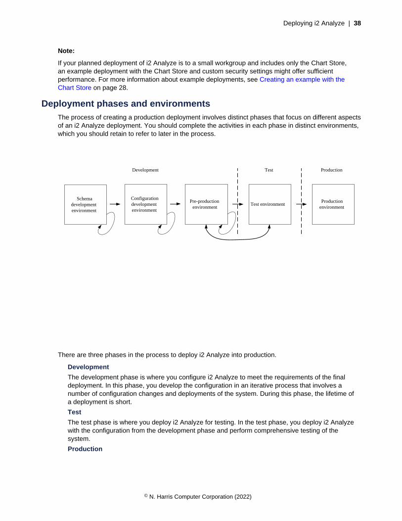
Deploying i2 Analyze | 38
Note:
If your planned deployment of i2 Analyze is to a small workgroup and includes only the Chart Store,an example deployment with the Chart Store and custom security settings might offer sufficientperformance. For more information about example deployments, see Creating an example with theChart Store on page 28.
Deployment phases and environmentsThe process of creating a production deployment involves distinct phases that focus on different aspectsof an i2 Analyze deployment. You should complete the activities in each phase in distinct environments,which you should retain to refer to later in the process.
Pre-production environment
Test environmentProduction
environment
Schema development environment
Development ProductionTest
Configuration development environment
There are three phases in the process to deploy i2 Analyze into production.
Development
The development phase is where you configure i2 Analyze to meet the requirements of the finaldeployment. In this phase, you develop the configuration in an iterative process that involves anumber of configuration changes and deployments of the system. During this phase, the lifetime ofa deployment is short.
Test
The test phase is where you deploy i2 Analyze for testing. In the test phase, you deploy i2 Analyzewith the configuration from the development phase and perform comprehensive testing of thesystem.
Production
© N. Harris Computer Corporation (2022)

Deploying i2 Analyze | 39
The production phase is where you deploy i2 Analyze into production. i2 Analyze is deployed withthe configuration that you tested in the test phase. In production, the deployment is fully operationaland used by analysts to complete mission critical work.
To start creating your production deployment, complete the instructions in Schema developmentenvironment on page 39.
Schema development environmentThe first task in the development phase is often to develop the schema and the security schema forthe deployment. You can use a schema development environment, which features a single-serverdeployment of i2 Analyze with the i2 Connect gateway to develop the schemas.
Pre-production environment
Test environmentProduction
environment
ProductionTest
Schema development environment
Development
Configuration development environment
In an environment that includes a database, significant changes to the schema or the security schemacan be time-consuming. Destructive changes to either schema require you to rebuild the database.The purpose of the schema development environment is to enable rapid iteration. When you apply theschemas that you create here to the Information Store in the configuration development environment,they are less likely to need significant changes.
Creating the schema development environment
In the schema development environment, you first populate the values of some of the mandatorysettings for deploying i2 Analyze. After you deploy i2 Analyze for the first time, you can then develop theschemas to meet your requirements.
Depending on the terms of your license and the needs of your organization, a deployment of i2 Analyzemight include the Chart Store alone, or the Information Store alone, or the i2 Connect gateway. The
© N. Harris Computer Corporation (2022)

Deploying i2 Analyze | 40
i2 Connect gateway can itself appear alone, or in combination with the Chart Store or the InformationStore.
• If your target deployment includes only the Chart Store, then you do not need to create aschema development environment. Instead, you can go directly to the configuration developmentenvironment.
• If your target deployment does not include the Information Store but does include the i2 Connectgateway, then the schema development environment is a convenient place to develop a gatewayschema. If you do not intend to use a gateway schema, the environment still provides support forprototyping a security schema.
• If your target deployment includes the Information Store, then you must complete the steps in thisand subsequent topics to develop the schema that will become your Information Store schema.
The schema development environment features an instance of i2 Analyze with the i2 Connect gateway;there is no Information Store or Chart Store. By using a deployment without a database, you can quicklyprototype changes to the schema and the security schema, and then visualize the changes in Analyst'sNotebook Premium.
1. Install any prerequisite software to prepare your server for the schema development environment.
• For the schema development environment, prepare your server for the i2 Connect deploymenttopology.
• Install Analyst's Notebook Premium to connect to your deployment and i2 Analyze SchemaDesigner to edit your schema files. For more information, see Installing i2® Analyst's NotebookPremium.
2. In the deployment toolkit that you installed, copy the toolkit\examples\configurations\daod-opal\configuration directory to the toolkit directory.
3. Enter a user name and password to use with the Solr index and a password to encrypt the LTPAtokens in the configuration\environment\credentials.properties file.
For more information about credentials in i2 Analyze, see Specifying the deployment credentials onpage 68.
4. In a command prompt, navigate to the toolkit\scripts directory, and run the followingcommand to populate some mandatory settings with default values:
setup -t generateDefaults
The environment.properties and topology.xml are modified by this toolkit task. For moreinformation about the default values that are provided, see Configuration files reference.
5. In i2 Analyze Schema Designer, either create a new schema or open one of the examples to modify.
For information about creating or modifying schema files, see Creating schemas and Chartingschemes.
Example schema files are located in subdirectories of the configuration\examples\ directory.For more information, see Example schemas on page 60.
Note:
If your planned deployment does not include the Information Store and you do not intend to usea gateway schema, your choice of example here is not important. You just need to set up a validdevelopment environment.
a) Save the initial version of your schema in the configuration\fragments\common\WEB-INF\classes directory.
© N. Harris Computer Corporation (2022)
Deploying i2 Analyze | 41
A charting scheme file is saved in the same location when you save the schema.
b) Keep the schema file open in Schema Designer so that you can make more modifications afteryou deploy i2 Analyze.
6. Copy the example security schema to the configuration\fragments\common\WEB-INF\classes directory.
The example security schema file is located in the configuration\examples\security-schema directory. For more information, see Example schemas on page 60.
7. In the configuration\fragments\common\WEB-INF\classes\ApolloServerSettingsMandatory.properties file, set the values of the following settings tothe file names of your schema, charting scheme, and security schema:
• Gateway.External.SchemaResource
• Gateway.External.ChartingSchemesResource
• DynamicSecuritySchemaResource
For example, Gateway.External.SchemaResource=custom-schema.xml
8. Deploy i2 Analyze:
setup -t deploy
9. Create an example user that you can use to log in:
setup -t ensureExampleUserRegistry
The user has the user name 'Jenny' and the password 'Jenny'.
10.Start i2 Analyze:
setup -t startLiberty
When you start i2 Analyze, the URI that you can use to connect to it from Analyst's NotebookPremium is displayed in the console. For example:Web application available(default_host): http://host_name:9082/opaldaod.
11.Connect to your deployment by using Analyst's Notebook Premium. Log in with the example 'Jenny'user.
For more information, see Connecting i2 Analyst's Notebook Premium to i2 Analyze.
12.In Analyst's Notebook Premium, create items on the chart to visualize the i2 Analyze schema byusing the Gateway palette.
After you deploy i2 Analyze with the initial schema files, you can develop them for your own datarequirements:
• Updating the schema and the charting scheme on page 42
• Updating the security schema on page 42
After you develop your schema files, you move to the configuration development environment. In theconfiguration development environment, you deploy i2 Analyze with the schemas that you developed inyour schema development environment.
You can choose whether to retain your schema development environment. If you need to make smallchanges to your schemas later, you can do this in your configuration development environment. If youneed to make more substantial changes, you might create another schema development environment.
© N. Harris Computer Corporation (2022)
Deploying i2 Analyze | 42
When you have finalized your schemas, you can move to the next environment. For more information,see Configuration development environment on page 44.
Updating the schema and the charting scheme
In the schema development environment, you can quickly deploy your changes to the schema and thecharting scheme. Use this environment to develop the schema and charting scheme for your productiondeployment.
Develop a schema and an associated charting scheme to meet your data requirements. Then updateyour schema development environment with the modified schema and charting scheme.
1. In i2 Analyze Schema Designer, modify the schema that is deployed in your schema developmentenvironment.
For information about creating or modifying your schema files, see Creating schemas and Chartingschemes.
After you modify your schema, update the deployment with your changes.
2. Update and redeploy the system:
setup -t updateConnectorsConfiguration
3. Start i2 Analyze:
setup -t restartLiberty
4. Test the changes to the schema and charting scheme by connecting to your deployment in Analyst'sNotebook Premium and modeling representative data on the chart by using the Gateway palette.
Repeat this process until the schema and the charting scheme meet your requirements. When yourschema development is complete, store your schema and charting scheme files in a version controlsystem.
This is not the final chance to modify the schema, but it should now contain all the entity and link typesthat you require, and most of the property types.
When you are satisfied with the schema, develop the security schema for the deployment. For moreinformation, see Updating the security schema on page 42.
Updating the security schema
In the schema development environment, you can quickly make and deploy changes to the i2 Analyzesecurity schema. Use this environment to develop the security schema for your production deployment.
Develop a security schema to meet your security requirements. Then update your schema developmentenvironment with the modified security schema.
1. In an XML editor, either create a new security schema or open the one that is deployed in theschema development environment.
For information about creating or modifying a security schema file for i2 Analyze, see The i2 AnalyzeSecurity schema.
a) Save your security schema in the toolkit\configuration\fragments\common\WEB-INF\classes directory.
b) Ensure that your security schema file is specified in configuration\fragments\common\WEB-INF\classes\ApolloServerSettingsMandatory.properties.
After you modify your security schema, update the deployment with your changes.
© N. Harris Computer Corporation (2022)

Deploying i2 Analyze | 43
2. Update and redeploy the system:
setup -t updateSecuritySchema
setup -t deployLiberty
3. Start i2 Analyze:
setup -t restartLiberty
4. If you changed the names of the user groups in the security schema, update the basic user registryto match the new names.
For more information, see Configuring the Liberty user registry.
5. Test the changes to the security schema by connecting to the deployment in Analyst's NotebookPremium as different users and changing the security permissions on records that you create.
Repeat this process until your security schema meets your requirements. When your security schemadevelopment is complete, store your security schema and Liberty user registry files in a version controlsystem.
This is not the final time that you can modify the security schema, but you should aim to have most ofthe security dimensions and dimension values defined.
After you finish developing your schema files, you can move to the next environment. For moreinformation, see Configuration development environment on page 44.
© N. Harris Computer Corporation (2022)

Deploying i2 Analyze | 44
Configuration development environmentIn the configuration development environment, you configure i2 Analyze to meet your requirements. Theaspects of i2 Analyze that you might configure include how your data is added to the system and howanalysts interact with that data.
Pre-production environment
Test environmentProduction
environment
ProductionTest
Schema development environment
Development
Configuration development environment
After you create your schemas, you can use a configuration development environment to configure i2Analyze in a single server environment. In the configuration development environment, you deploy i2Analyze with the same data store as your intended production system.
In this deployment of i2 Analyze, you use any schema files that you previously created. If your intendedproduction system includes the Information Store and you have not created your schema files, completethe instructions in Schema development environment on page 39.
Creating the configuration development environment
When you create the configuration development deployment, you deploy i2 Analyze on a single serverin the same deployment pattern as your intended production system.
If you intend your production deployment to contain only the i2 Connect gateway, and to be accessedonly through Analyst's Notebook Premium, you can use your schema development environment asyour configuration development environment. In this scenario, you can move to develop the i2 Analyzeconfiguration.
If your intended production deployment contains the Information Store, ensure that you have accessto the following files from the schema development environment so that you can copy them to theconfiguration development environment:
• The Information Store schema
© N. Harris Computer Corporation (2022)

Deploying i2 Analyze | 45
• The associated charting scheme
• The security schema
• The user registry, user-registry.xml
If you did not create a schema development environment because you intend your productionenvironment to contain the Chart Store, you must retrieve equivalent files from the deployment toolkit:
• The Chart Store schema, chart-storage-schema.xml
• The associated charting scheme, chart-storage-schema-charting-schemes.xml
• The example security schema, example-dynamic-security-schema.xml
For deployments that include the Chart Store, the following procedure explains how to create anexample user registry when it becomes necessary to do so.
1. Install any prerequisite software to prepare your server for the configuration developmentenvironment.
• For the configuration development environment, prepare your server for the Single serverdeployment topology with the same components and database management system as in yourintended production system.
2. Create the configuration directory in the i2 Analyze deployment toolkit.
a) Navigate to the toolkit\examples\configurations directory where you installed i2Analyze.
b) Copy the configuration directory from your chosen base configuration to the root of thetoolkit.For example, copy the toolkit\examples\configurations\information-store-opal\configuration directory to the toolkit directory.
For more information about the different base configurations, see The base configurations onpage 58.
3. If you are using SQL Server as your database management system, copy the exampletopology.xml file from configuration\examples\topology\sqlserver to theconfiguration\environment directory. Overwrite the existing topology.xml file in thedestination directory.
4. If you are using IBM HTTP Server, in the topology.xml file set the value of the http-server-host attribute to true.
To allow the deployment toolkit to create and modify components of i2 Analyze, you provide user namesand passwords for each of the components in your configuration.
5. Specify the user names and passwords to use for the deployment in the toolkit\configuration\environment\credentials.properties file.
For more information about credentials in i2 Analyze, see Specifying the deployment credentials onpage 68.
6. Copy the JDBC driver to use with the deployment to the configuration\environment\common\jdbc-drivers directory.
For more information, see Specifying the JDBC driver.
You do not need to provide a JDBC driver for deployment that contains only the i2 Connect gateway.
7. Use the deployment toolkit to populate some of the mandatory settings with default values:
setup -t generateDefaults
© N. Harris Computer Corporation (2022)

Deploying i2 Analyze | 46
The environment.properties and topology.xml are modified by this toolkit task. For moreinformation about the default values that are provided, see Configuration files reference.
8. Specify the i2 Analyze schema, charting scheme, and security schema that you previously prepared.
a) Copy your i2 Analyze schema, charting scheme, and security schema files to theconfiguration\fragments\common\WEB-INF\classes directory.
b) In the configuration\fragments\common\WEB-INF\classes\ApolloServerSettingsMandatory.properties file, set the file names of the schema,charting scheme, and security schema.
• If your deployment includes the Information Store or the Chart Store, set SchemaResourceand ChartingSchemesResource.
• If your deployment includes the i2 Connect gateway and you have developeda gateway schema, set Gateway.External.SchemaResource andGateway.External.ChartingSchemesResource
• In both cases, set DynamicSecuritySchemaResource
9. Deploy i2 Analyze:
setup -t deploy
10.If you created a schema development environment, copy the user registry file from that environmentto the deploy\wlp\usr\shared\config directory in the new environment.
If you did not create a schema development environment, execute the following command to createan example user that you can use to log in:
setup -t ensureExampleUserRegistry
The user has the user name 'Jenny' and the password 'Jenny'.
11.Start i2 Analyze:
setup -t start
The URI that users must specify is displayed in the console. For example:
Web application available (default_host): http://host_name:9082/opal/
After you deploy i2 Analyze, you can begin Developing the i2 Analyze configuration on page 46.
Developing the i2 Analyze configuration
At this stage of the production deployment process, you can use the configuration developmentenvironment to define how the i2 Analyze application behaves specifically for your organization.
Developing the configuration is separated into two parts: enabling i2 Analyze to work with your data, anddefining how analysts interact with your data.
The i2 Analyze deployment in the configuration development environment is not your final deployment.When you are configuring the deployment, use small amounts of data with a few users to ensure thatthe processes are functional.
Depending on the composition of your deployment, there are three methods that you can use to getyour data into i2 Analyze for analysis.
© N. Harris Computer Corporation (2022)

Deploying i2 Analyze | 47
1. To develop the process for ingesting data into the Information Store, refer to Ingesting data into theInformation Store.
2. To develop connections to external data sources, refer to Connecting to external data sources.
3. Ensure that analysts can import and create representative records in Analyst's Notebook Premium.Then, if required, upload records to the Information Store. For more information, see Import data andCreate i2 Analyze chart items.
When you develop the process to get your data into i2 Analyze, you might realize that your schemaor security schema are not correct for your data. You can update the deployed schemas to betterrepresent your data and security model. Some changes require you to remove and recreate theunderlying database.
4. To update your deployed Information Store or Chart Store schema, refer to Changing the schema.
5. To update your deployed security schema, refer to Configuring the security schema.
After you develop the mechanisms for making data available to analysts, you can configure howanalysts interact with the data when they use the system. The list of things that you can configureincludes:
6. To configure which features or types of commands analysts can access, refer to Controlling accessto features.
7. To configure how analysts search for information, and the options that are available to them, refer toConfiguring search.
8. To configure how analysts can identify matching records, refer to Configuring matching.
9. To configure user security, refer to Configure user authentication and authorization.
For more information about the configuration changes that you can make, see Configuring i2Analyze.
After you configure your deployment sufficiently in the single-server environment, you can move toanother environment that is more representative of the production deployment. Keep your configurationdevelopment environment in place so that you can access the configuration directory in laterphases of the production process, and return to it to make further configuration changes.
Next, create the Pre-production environment on page 48.
© N. Harris Computer Corporation (2022)
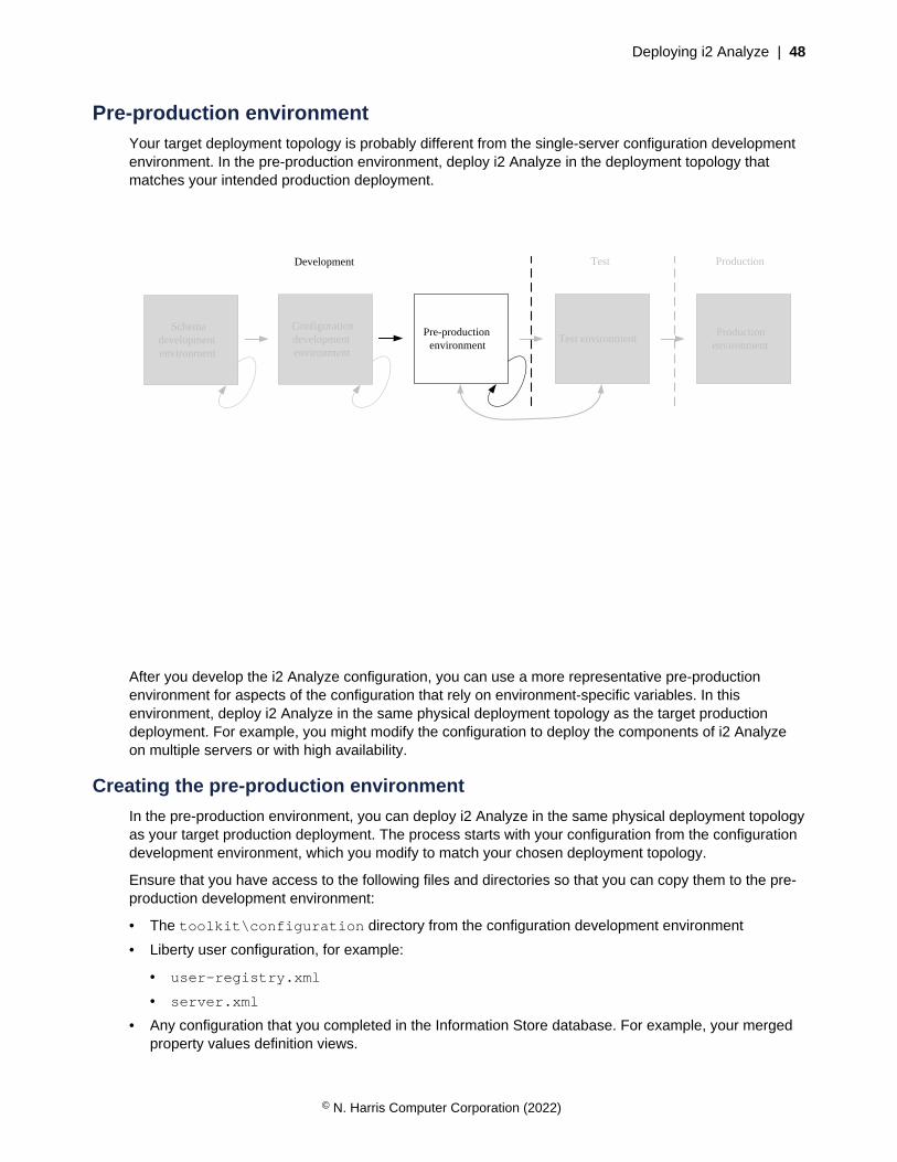
Deploying i2 Analyze | 48
Pre-production environmentYour target deployment topology is probably different from the single-server configuration developmentenvironment. In the pre-production environment, deploy i2 Analyze in the deployment topology thatmatches your intended production deployment.
Pre-production environment
Test environmentProduction
environment
ProductionTest
Schema development environment
Development
Configuration development environment
After you develop the i2 Analyze configuration, you can use a more representative pre-productionenvironment for aspects of the configuration that rely on environment-specific variables. In thisenvironment, deploy i2 Analyze in the same physical deployment topology as the target productiondeployment. For example, you might modify the configuration to deploy the components of i2 Analyzeon multiple servers or with high availability.
Creating the pre-production environment
In the pre-production environment, you can deploy i2 Analyze in the same physical deployment topologyas your target production deployment. The process starts with your configuration from the configurationdevelopment environment, which you modify to match your chosen deployment topology.
Ensure that you have access to the following files and directories so that you can copy them to the pre-production development environment:
• The toolkit\configuration directory from the configuration development environment
• Liberty user configuration, for example:
• user-registry.xml
• server.xml
• Any configuration that you completed in the Information Store database. For example, your mergedproperty values definition views.
© N. Harris Computer Corporation (2022)
Deploying i2 Analyze | 49
• Any certificates and certificate stores that are required
If you are planning to deploy in production with high availability, you should configure and deploy highavailability in the pre-production environment to develop the configuration. To create a pre-productionenvironment configured for high availability, complete the instructions in i2 Analyze with high availabilityon page 77 rather than the steps on this page.
Create your pre-production environment, and update your configuration to match the physicaldeployment topology of the pre-production environment.
1. Install any prerequisite software to prepare your servers for the pre-production environment.
For the pre-production environment, use the same deployment topology as your intended productionenvironment. For more information, see Deployment topologies on page 54.
2. Copy the toolkit\configuration directory from the configuration development environment,to the toolkit directory at the root of the deployment toolkit on the Liberty server in the pre-production environment.
3. Update the values for any configuration settings that are specific to the environment.
a) If you are creating a deployment with a database that is remote from the Liberty server,follow the instructions in Specifying remote database storage on page 70 to update theenvironment.properties and topology.xml files for this deployment topology.
b) If you are creating a deployment with multiple Solr and ZooKeeper servers, follow the instructionsin Specifying remote Solr and ZooKeeper servers on page 73 to update the topology.xmlfile for these deployment topologies.
The environment.properties, http-server.properties, and topology.xml containhost name and file path settings that you might need to update for the servers in your pre-productionenvironment. For more information, see Configuration files reference.
4. If your deployment uses a proxy server or load balancer to route requests from clients, ensure that itis configured for use with i2 Analyze. Specify the URI that clients use to connect to i2 Analyze.
For more information, see Deploying a proxy server for use with i2 Analyze on page 75.
5. Deploy and start i2 Analyze:
• In a single-server topology, or with a remote database only, see Deploying i2 Analyze on page89.
• In a multiple-server topology, see Deploying i2 Analyze on multiple servers on page 90.
After you deploy i2 Analyze, you can replicate any configuration changes that are not stored in theconfiguration of i2 Analyze.
6. Configure Liberty security for your environment. To do this, repeat any changes that you made to theLiberty configuration in the previous environment.
This might involve copying the user registry file, or updating the server.xml file.
7. Complete any configuration changes in the Information Store database.
a) If you created any rules or schedules to delete records by rule, replicate the rules and schedulesthat you created in the previous environment.
b) If you created any merged property values definition views for your ingestion process, replicatethe view definition that you created in the previous environment.
After you deploy i2 Analyze in the pre-production development environment, you might want toconfigure aspects of the deployment that are topology specific. For example, in a multiple-serverenvironment you can secure the connections between servers by using SSL.
To configure i2 Analyze in pre-production, see Configuring i2 Analyze in pre-production on page 50.
© N. Harris Computer Corporation (2022)
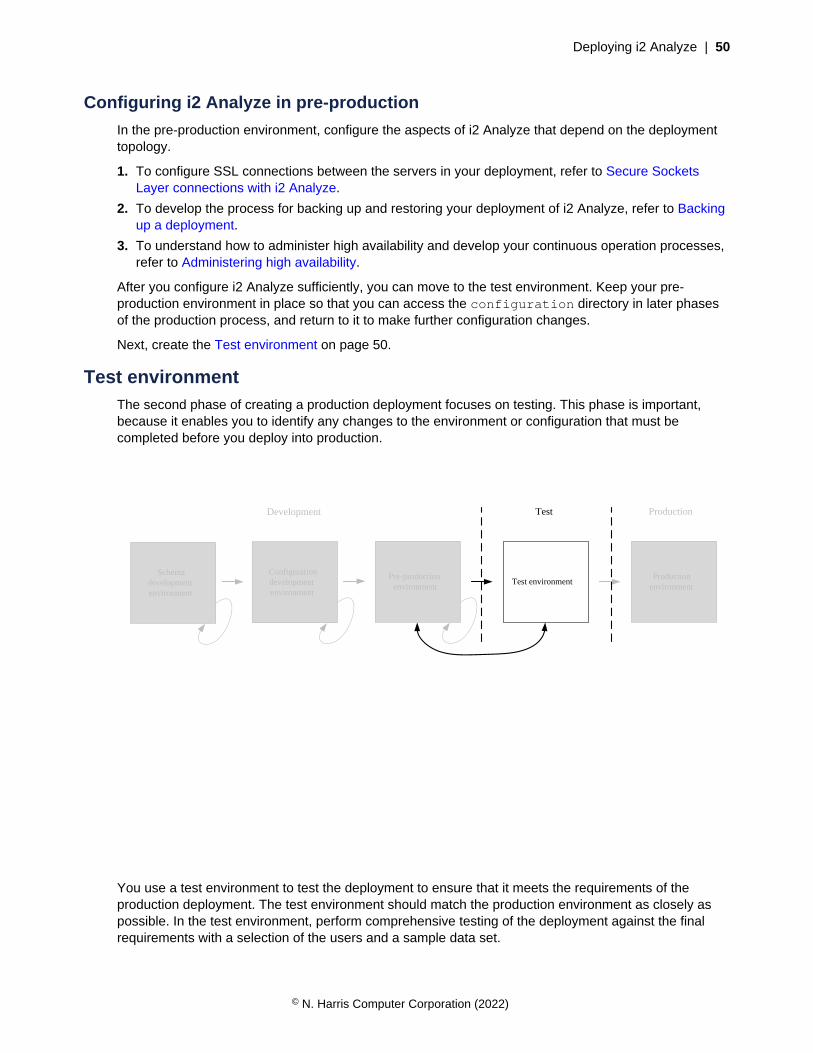
Deploying i2 Analyze | 50
Configuring i2 Analyze in pre-production
In the pre-production environment, configure the aspects of i2 Analyze that depend on the deploymenttopology.
1. To configure SSL connections between the servers in your deployment, refer to Secure SocketsLayer connections with i2 Analyze.
2. To develop the process for backing up and restoring your deployment of i2 Analyze, refer to Backingup a deployment.
3. To understand how to administer high availability and develop your continuous operation processes,refer to Administering high availability.
After you configure i2 Analyze sufficiently, you can move to the test environment. Keep your pre-production environment in place so that you can access the configuration directory in later phasesof the production process, and return to it to make further configuration changes.
Next, create the Test environment on page 50.
Test environmentThe second phase of creating a production deployment focuses on testing. This phase is important,because it enables you to identify any changes to the environment or configuration that must becompleted before you deploy into production.
Pre-production environment
Test environmentProduction
environment
ProductionTest
Schema development environment
Development
Configuration development environment
You use a test environment to test the deployment to ensure that it meets the requirements of theproduction deployment. The test environment should match the production environment as closely aspossible. In the test environment, perform comprehensive testing of the deployment against the finalrequirements with a selection of the users and a sample data set.
© N. Harris Computer Corporation (2022)
Deploying i2 Analyze | 51
Creating the test environment
In the test environment, you deploy i2 Analyze with the configuration that you developed previously.With i2 Analyze deployed in the test environment, you can perform comprehensive testing of thedeployment to confirm that it meets your production requirements.
Ensure that you have access to the following files and directories so that you can copy them to the testenvironment:
• The toolkit\configuration directory from the pre-production environment
• Liberty user configuration, for example the server.xml file
• Any configuration that you completed in the Information Store database. For example, your mergedproperty values definition views.
• Any certificates and certificate stores that are required
If you are planning to deploy in production with high availability, complete the instructions in i2 Analyzewith high availability on page 77 rather than the steps on this page.
1. Install any prerequisite software to prepare your servers for the test environment.
For the test environment, use the same deployment topology as in your pre-production environment.For more information, see Deployment topologies on page 54.
2. Copy the toolkit\configuration directory from the pre-production environment to thetoolkit directory at the root of the deployment toolkit on the Liberty server in the test environment.
3. Update the values for any configuration settings that are specific to the environment.
environment.properties, http-server.properties, and topology.xml contain settingsthat you might need to update. For more information, see Configuration files reference.
4. If your deployment uses a proxy server or load balancer to route requests from clients, ensure that itis configured for use with i2 Analyze. Specify the URI that clients use to connect to i2 Analyze.
For more information, see Deploying a proxy server for use with i2 Analyze on page 75.
5. Deploy and start i2 Analyze:
• In a single-server topology, or with a remote database only, see Deploying i2 Analyze on page89.
• In a multiple-server topology, see Deploying i2 Analyze on multiple servers on page 90.
After you deploy, you can replicate any configuration changes that are not stored in the configuration ofi2 Analyze.
6. Configure Liberty security for your environment. To do this, repeat any changes that you made to theLiberty configuration in the previous environment.
This might involve copying the user registry file, or updating the server.xml file.
7. Complete any configuration changes in the Information Store database.
a) If you created any rules or schedules to delete records by rule, replicate the rules and schedulesin the current environment.
b) If you created any merged property values definition views for your ingestion process, replicatethe view definitions in the current environment.
After you deploy i2 Analyze in the test environment, you can test your deployment to ensure that itmeets the requirements of your organization.
For information about testing i2 Analyze, see Testing your deployment on page 52.
© N. Harris Computer Corporation (2022)

Deploying i2 Analyze | 52
Testing your deployment
In your test environment, complete the comprehensive testing of the system that is required to provethat the deployment is ready for production.
Create a test charter that contains a list of tests that you can use to verify that your deployment is readyfor production.
In your test environment, you should use real data at a representative volume.
1. Create the test charter.
Focus your test charter in the following areas that are applicable to your deployment:
• Data ingestion into the Information Store
• Data deletion from the Information Store
• Data acquisition from external sources
• Searching and analyzing data
• Storing and retrieving charts in the Chart Store
• Performance of the system
• Backup and recovery of the system
• High availability and continuous operations after server failure
After you create a test charter for your deployment, you can start your testing.
2. Complete each test in your charter, and record if the deployment passed or failed each test.
3. If any of the tests fail, return to your development or pre-production environment and change theconfiguration. Then, deploy the same change to the test environment and repeat the testing.
After you test i2 Analyze sufficiently, you can move to the production phase. Keep your test environmentin place, so that you can access the configuration directory in later phases of the productionprocess and continue to test any changes to your configuration.
Next, complete the instructions in Production environment on page 53.
© N. Harris Computer Corporation (2022)

Deploying i2 Analyze | 53
Production environmentThe third phase of the deployment process focuses on deploying into production. In this phase youmake your deployment of i2 Analyze available to users.
Pre-production environment
Test environmentProduction
environment
ProductionTest
Schema development environment
Development
Configuration development environment
You use a production environment to host the deployment in production. When you have a configurationof i2 Analyze that passed your test phase, you can deploy i2 Analyze with that configuration into yourproduction environment.
In the production environment, run the tests again to confirm that the deployment is workingsuccessfully. If these tests are successful, you can make the deployment available to users. If the testsare not successful, you must return to your test or development environment to make any necessarychanges. Then, complete the test phase once more.
Creating the production environment
To deploy i2 Analyze in production, you use the i2 Analyze configuration that you developed previously.Before you deploy i2 Analyze, update the configuration to reflect any environment changes.
Ensure that you have access to the following files and directories so that you can copy them to theproduction environment:
• The toolkit\configuration directory from the test environment
• Liberty user configuration, for example the server.xml file
• Any configuration that you completed in the Information Store database. For example, your mergedproperty values definition views.
• Any certificates and certificate stores that are required
© N. Harris Computer Corporation (2022)

Deploying i2 Analyze | 54
If you are planning to deploy with high availability, complete the instructions in i2 Analyze with highavailability on page 77 rather than the steps on this page.
1. Install any prerequisite software to prepare your servers for the production environment.
For the production environment, use the same deployment topology as in your test environment. Formore information, see Deployment topologies on page 54.
2. Copy the toolkit\configuration directory from the test environment to the toolkit directoryat the root of the deployment toolkit on the Liberty server in the production environment.
3. Update the values for any configuration settings that are specific to the environment.
environment.properties, http-server.properties, and topology.xml contain settingsthat you might need to update. For more information, see Configuration files reference.
4. If your deployment uses a proxy server or load balancer to route requests from clients, ensure that itis configured for use with i2 Analyze. Specify the URI that clients use to connect to i2 Analyze.
For more information, see Deploying a proxy server for use with i2 Analyze on page 75.
5. Deploy and start i2 Analyze:
• In a single-server topology, or with a remote database only, see Deploying i2 Analyze on page89.
• In a multiple-server topology, see Deploying i2 Analyze on multiple servers on page 90.
After you deploy i2 Analyze, you can replicate any configuration changes that are not stored in theconfiguration of i2 Analyze.
6. Configure Liberty security for your environment. To do this, repeat any changes that you made to theLiberty configuration in the previous environment.
This might involve copying the user registry file, or updating the server.xml file.
7. Complete any configuration changes in the Information Store database.
a) If you created any rules or schedules to delete records by rule, replicate the rules and schedulesin the current environment.
b) If you created any merged property values definition views for your ingestion process, replicatethe view definitions in the current environment.
Complete testing of the deployment to ensure that it is working in the production environment before youmake i2 Analyze available to users.
Deployment resourcesThe deployment resources section contains information that is referenced elsewhere in the deploymentsection. The information is used in a many places throughout the deployment process.
Deployment topologiesYou can use the deployment toolkit to deploy i2 Analyze in a number of different physical topologies.Throughout the process of creating a production deployment, you might use several of them dependingon your purpose at the time.
The following diagrams show the servers that are used in each deployment topology, the prerequisitesthat are required on each server, and the components of i2 Analyze that are deployed.
You can deploy i2 Analyze in the following physical deployment topologies:
• i2 Connect gateway only (single server) on page 55
© N. Harris Computer Corporation (2022)

Deploying i2 Analyze | 55
• Single server on page 55
• Multiple servers on page 56
i2 Connect gateway only (single server)
In the i2 Connect gateway only deployment, all of the components of i2 Analyze are on the same server.No database management system is required.
i2 Connect only topology
i2 Analyze server
i2 Analyze toolkit
Configuration
Prerequisites Deployed components
Liberty
i2 Analyze
Solr client
Solr nodes
ZooKeeper
ZooKeeper host
On the i2 Analyze server, install the prerequisites by following these instructions:
• Installing i2 Analyze
Single server
In the single-server topology, all of the components of i2 Analyze are on the same server.
© N. Harris Computer Corporation (2022)
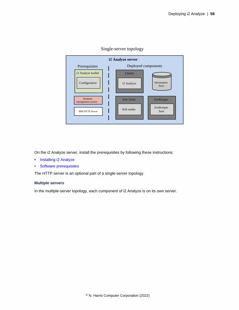
Deploying i2 Analyze | 56
Single-server topology
i2 Analyze server
Database management system
i2 Analyze toolkit
Configuration
Prerequisites Deployed components
Liberty
i2 Analyze
Solr client
Solr nodes
ZooKeeper
ZooKeeper host
Information Store
IBM HTTP Server
On the i2 Analyze server, install the prerequisites by following these instructions:
• Installing i2 Analyze
• Software prerequisites
The HTTP server is an optional part of a single-server topology.
Multiple servers
In the multiple-server topology, each component of i2 Analyze is on its own server.
© N. Harris Computer Corporation (2022)
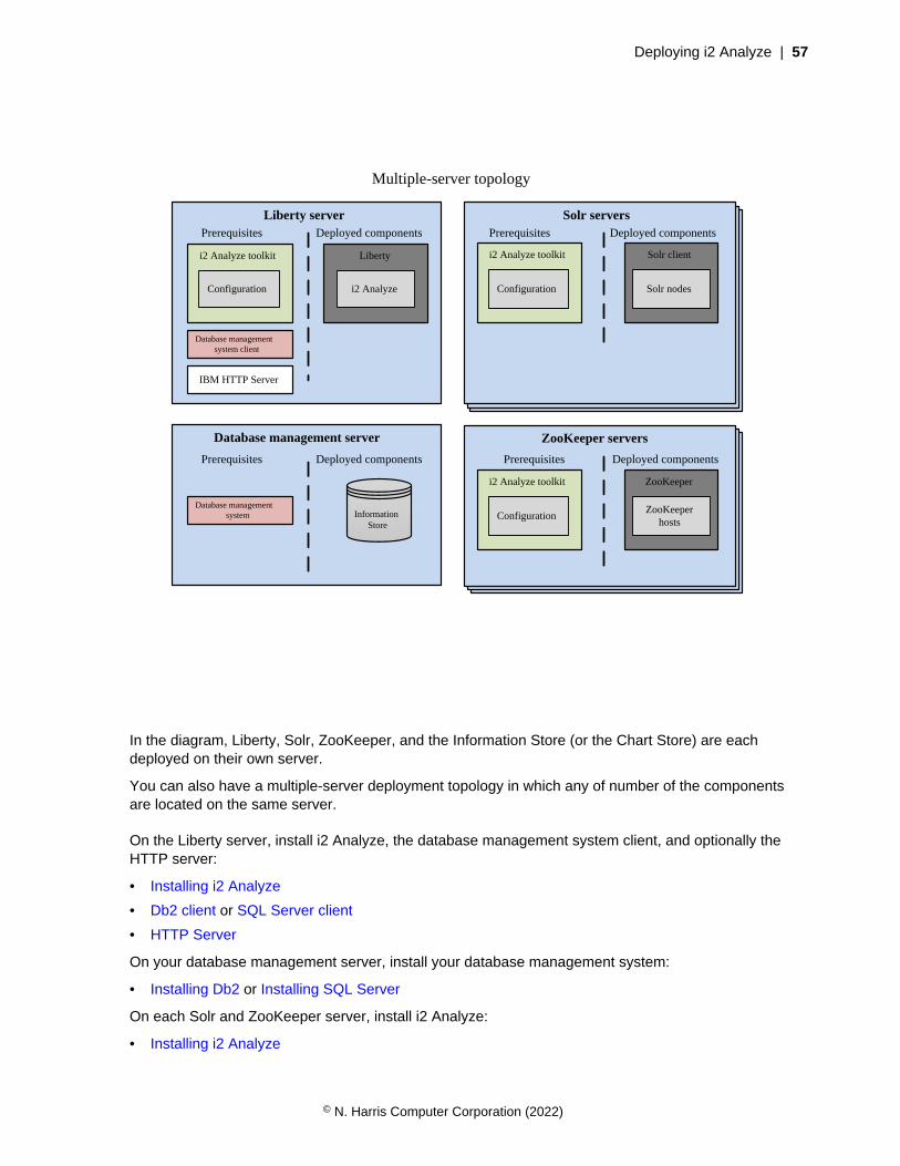
Deploying i2 Analyze | 57
Multiple-server topology
Database management server
Prerequisites Deployed components
Liberty server
Database management system client
Prerequisites Deployed components
ZooKeeper server(s)
ZooKeeper
ZooKeeper host(s)
i2 Analyze toolkit
Configuration
ZooKeeper server(s)
ZooKeeper
ZooKeeper host(s)
i2 Analyze toolkit
Configuration
ZooKeeper servers
Prerequisites Deployed components
Database management system
IBM HTTP Server
Solr server(s)
Solr client
Solr node(s)
i2 Analyze toolkit
Configuration
Prerequisites ResultSolr server(s)
Solr client
Solr node(s)
i2 Analyze toolkit
Configuration
Prerequisites Result
Solr serversPrerequisites Deployed components
i2 Analyze toolkit
Configuration
i2 Analyze toolkit
Configuration
Solr client
Solr nodes
i2 Analyze toolkit
Configuration
ZooKeeper
ZooKeeper hosts
Liberty
i2 Analyze
Information Store
In the diagram, Liberty, Solr, ZooKeeper, and the Information Store (or the Chart Store) are eachdeployed on their own server.
You can also have a multiple-server deployment topology in which any of number of the componentsare located on the same server.
On the Liberty server, install i2 Analyze, the database management system client, and optionally theHTTP server:
• Installing i2 Analyze
• Db2 client or SQL Server client
• HTTP Server
On your database management server, install your database management system:
• Installing Db2 or Installing SQL Server
On each Solr and ZooKeeper server, install i2 Analyze:
• Installing i2 Analyze
© N. Harris Computer Corporation (2022)

Deploying i2 Analyze | 58
The i2 Analyze deployment toolkitThe deployment toolkit contains scripts and components that you need to deploy and maintain i2Analyze. Configuring components within the toolkit allows you to deploy consistently to the samelocations with the same settings.
Directories
The deployment toolkit contains files in several directories. On most occasions, you need to interact withonly three of the directories:
• The examples directory includes the base configurations that you can use to create exampledeployments, example data, and an example i2 Connect connector.
• The configuration directory contains files that you must update with information specific to yourdeployment.
Note: When the deployment toolkit is first installed, this directory does not exist. At the start ofdeployment, you use one of the base configurations to create this directory.
• The scripts directory contains the setup script that you use to deploy and configure i2 Analyze.
The setup script
The setup script completes tasks that apply configuration and other changes to deployments of i2Analyze. For a list of available tasks and other information, refer to Deployment toolkit tasks on page60.
Alternatively, on the i2 Analyze server, open a command prompt and navigate to toolkit\scriptsand run one of the following commands:
setup -h
The -h argument displays the usage, common tasks, and examples of use for the setup script.
setup -a
The -a argument displays the same content as when you use -h, and a list of additional tasks.
Note: On Linux, whenever you run the setup script you must prefix its name with './'. For example,./setup -t deploy.
The base configurations
In the i2 Analyze deployment toolkit, several base configurations are available. To reduce the amountof configuration that you need to complete, you can start from the configuration that is closest to therequirements of your final deployment pattern.
The i2 Analyze deployment toolkit includes the following base configurations:
chart-storage
The chart-storage base configuration contains settings for a deployment of i2 Analyze thatincludes:
• A Chart Store only
Users can connect to the deployment with the following client:
• Analyst's Notebook Premium
information-store-opal
© N. Harris Computer Corporation (2022)

Deploying i2 Analyze | 59
The information-store-opal base configuration contains settings for a deployment of i2Analyze that includes:
• An Information Store (and a Chart Store)
Users can connect to the deployment with the following clients:
• Analyst's Notebook Premium
• i2 Notebook web client
• i2 Investigate web client
daod-opal
The daod-opal base configuration contains settings for a deployment of i2 Analyze that includes:
• The i2 Connect gateway only, which can provide access to other data stores through connectorsthat you create
Users can connect to the deployment with the following client:
• Analyst's Notebook Premium
chart-storage-daod
The chart-storage-daod base configuration contains settings for a deployment of i2 Analyzethat includes:
• A Chart Store
• The i2 Connect gateway, which can provide access to other data stores through connectors thatyou create
Users can connect to the deployment with the following clients:
• Analyst's Notebook Premium
• i2 Notebook web client
information-store-daod-opal
The information-store-daod-opal base configuration contains settings for a deployment of i2Analyze that includes:
• An Information Store (and a Chart Store)
• The i2 Connect gateway, which can provide access to other data stores through connectors thatyou create
Users can connect to the deployment with the following clients:
• Analyst's Notebook Premium
• i2 Notebook web client
• i2 Investigate web client
It is possible to extend your deployment after you select and deploy a base configuration by adding theappropriate components and configuration files.
For more information about the components that are included in a deployment of i2 Analyze, seeUnderstanding components.
© N. Harris Computer Corporation (2022)

Deploying i2 Analyze | 60
Example schemas
The i2 Analyze deployment toolkit includes example schema files that you can use as a starting point foryour own schemas.
Example i2 Analyze schemas
The deployment toolkit includes five pairs of example i2 Analyze schemas and associated chartingschemes in the toolkit\examples\schemas directory:
Law Enforcement
The law enforcement schema deals with criminal activity. It contains entity and link types that aredesigned to track connections within criminal networks.
Commercial Insurance
The commercial insurance schema deals with fraud in a commercial setting. It contains entityand link types that are designed to track financial transactions such as credit card payments andinsurance claims.
Military
The military schema helps with military intelligence tracking. It contains entity and link types thattarget military operations.
Signals Intelligence
The signals intelligence schema focuses particularly on the cellphones and cell towers that areinvolved in mobile telecommunications, and on the calls that take place between them.
Chart Storage
The chart storage schema is not an example of a particular domain, but rather the starting point forany deployment of i2 Analyze that includes only the Chart Store.
Example security schema
The example security schema files specify a number of security dimensions and dimension values, andsecurity groups for users.
After you create the toolkit\configuration directory by copying it from the base configurationof your choice, you can find an appropriate example security schema file in the toolkit\configuration\examples\security-schema directory.
Deployment toolkit tasks
The following toolkit options and tasks are available to use with the setup script in the deploymenttoolkit.
usage: setup [-h] [-a] [-s SERVER] [-w WAR | -id IDENTIFIERS | -hn HOST | --all] [--force] -t TASK[--option-name...]
Argument name Argument Description
-h, --help Shows this help message, and exits
-a, --additional Shows additional arguments and tasks, and exits
-t, --task <task> Specifies the task to perform
-s, --server <server> Specifies the server profile to manage
© N. Harris Computer Corporation (2022)
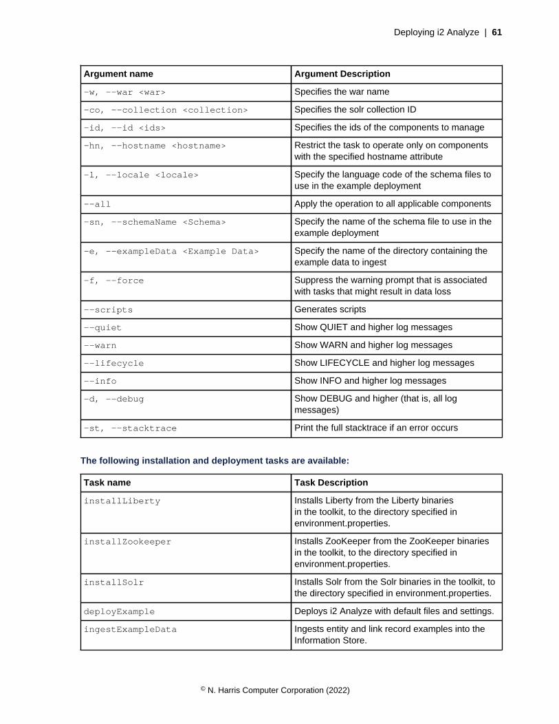
Deploying i2 Analyze | 61
Argument name Argument Description
-w, --war <war> Specifies the war name
-co, --collection <collection> Specifies the solr collection ID
-id, --id <ids> Specifies the ids of the components to manage
-hn, --hostname <hostname> Restrict the task to operate only on componentswith the specified hostname attribute
-l, --locale <locale> Specify the language code of the schema files touse in the example deployment
--all Apply the operation to all applicable components
-sn, --schemaName <Schema> Specify the name of the schema file to use in theexample deployment
-e, --exampleData <Example Data> Specify the name of the directory containing theexample data to ingest
-f, --force Suppress the warning prompt that is associatedwith tasks that might result in data loss
--scripts Generates scripts
--quiet Show QUIET and higher log messages
--warn Show WARN and higher log messages
--lifecycle Show LIFECYCLE and higher log messages
--info Show INFO and higher log messages
-d, --debug Show DEBUG and higher (that is, all logmessages)
-st, --stacktrace Print the full stacktrace if an error occurs
The following installation and deployment tasks are available:
Task name Task Description
installLiberty Installs Liberty from the Liberty binariesin the toolkit, to the directory specified inenvironment.properties.
installZookeeper Installs ZooKeeper from the ZooKeeper binariesin the toolkit, to the directory specified inenvironment.properties.
installSolr Installs Solr from the Solr binaries in the toolkit, tothe directory specified in environment.properties.
deployExample Deploys i2 Analyze with default files and settings.
ingestExampleData Ingests entity and link record examples into theInformation Store.
© N. Harris Computer Corporation (2022)
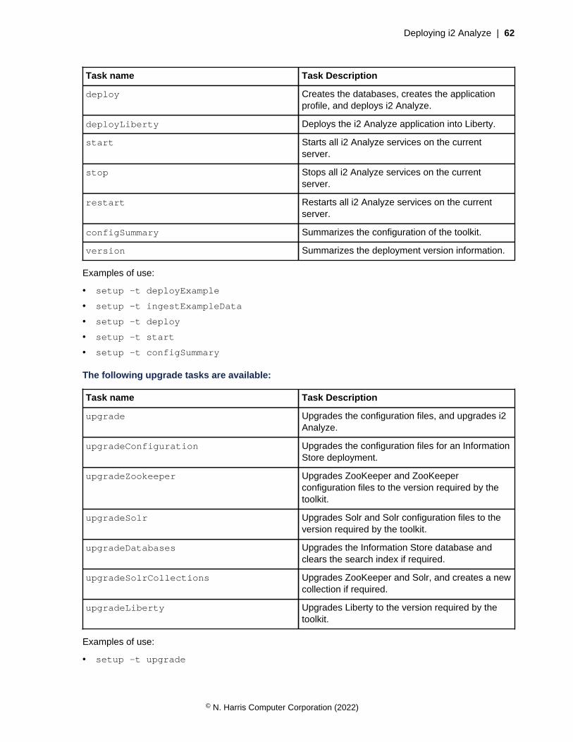
Deploying i2 Analyze | 62
Task name Task Description
deploy Creates the databases, creates the applicationprofile, and deploys i2 Analyze.
deployLiberty Deploys the i2 Analyze application into Liberty.
start Starts all i2 Analyze services on the currentserver.
stop Stops all i2 Analyze services on the currentserver.
restart Restarts all i2 Analyze services on the currentserver.
configSummary Summarizes the configuration of the toolkit.
version Summarizes the deployment version information.
Examples of use:
• setup -t deployExample
• setup -t ingestExampleData
• setup -t deploy
• setup -t start
• setup -t configSummary
The following upgrade tasks are available:
Task name Task Description
upgrade Upgrades the configuration files, and upgrades i2Analyze.
upgradeConfiguration Upgrades the configuration files for an InformationStore deployment.
upgradeZookeeper Upgrades ZooKeeper and ZooKeeperconfiguration files to the version required by thetoolkit.
upgradeSolr Upgrades Solr and Solr configuration files to theversion required by the toolkit.
upgradeDatabases Upgrades the Information Store database andclears the search index if required.
upgradeSolrCollections Upgrades ZooKeeper and Solr, and creates a newcollection if required.
upgradeLiberty Upgrades Liberty to the version required by thetoolkit.
Examples of use:
• setup -t upgrade
© N. Harris Computer Corporation (2022)
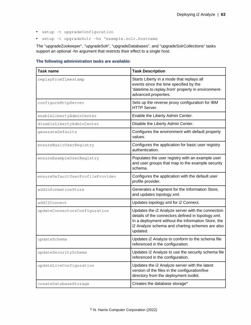
Deploying i2 Analyze | 63
• setup -t upgradeConfiguration
• setup -t upgradeSolr -hn "example.solr.hostname
The "upgradeZookeeper", "upgradeSolr", "upgradeDatabases", and "upgradeSolrCollections" taskssupport an optional -hn argument that restricts their effect to a single host.
The following administration tasks are available:
Task name Task Description
replayFromTimestamp Starts Liberty in a mode that replays allevents since the time specified by the'datetime.to.replay.from' property in environment-advanced.properties.
configureHttpServer Sets up the reverse proxy configuration for IBMHTTP Server.
enableLibertyAdminCenter Enable the Liberty Admin Center.
disableLibertyAdminCenter Disable the Liberty Admin Center.
generateDefaults Configures the environment with default propertyvalues.
ensureBasicUserRegistry Configures the application for basic user registryauthentication.
ensureExampleUserRegistry Populates the user registry with an example userand user groups that map to the example securityschema.
ensureDefaultUserProfileProvider Configures the application with the default userprofile provider.
addInformationStore Generates a fragment for the Information Store,and updates topology.xml.
addI2Connect Updates topology.xml for i2 Connect.
updateConnectorsConfiguration Updates the i2 Analyze server with the connectiondetails of the connectors defined in topology.xml.In a deployment without the Information Store, thei2 Analyze schema and charting schemes are alsoupdated.
updateSchema Updates i2 Analyze to conform to the schema filereferenced in the configuration.
updateSecuritySchema Updates i2 Analyze to use the security schema filereferenced in the configuration.
updateLiveConfiguration Updates the i2 Analyze server with the latestversion of the files in the configuration/livedirectory from the deployment toolkit.
createDatabaseStorage Creates the database storage*
© N. Harris Computer Corporation (2022)

Deploying i2 Analyze | 64
Task name Task Description
createDatabases Creates the database storage and tables*
modifyInformationStoreDatabase Runs the informationStoreModifications.sql scripton the Information Store database.
dropTables Drops all of the tables from the database butleaves the database intact*
dropDatabases Drops the entire database and de-allocatesstorage*
emptyInformationStore Empties the Information Store of data, apart frommetadata.
addInformationStoreIngestionSource Adds or replaces information about an ingestionsource to the Information Store.
createInformationStoreStagingTable Creates an Information Store staging table for aspecific entity or link type.
ingestInformationStoreRecords Ingests records into the Information Store.
deleteProvenance Deletes (entity/link) provenance from theInformation Store.
previewDeleteProvenance Previews deleting (entity/link) provenance fromthe Information Store.
syncInformationStoreCorrelation Synchronizes data in the Information Store after acorrelation operation failed during ingestion.
enableMergedPropertyValues Creates the database views used to define theproperty values of merged i2 Analyze records.
disableMergedPropertyValues Removes the database views used to define theproperty values of merged i2 Analyze records.
duplicateProvenanceCheck Checks the Information Store for duplicated originidentifiers. Any provenance that has a duplicatedorigin identifier is added to a staging table.
duplicateProvenanceDelete Deletes (entity/link) provenance from theInformation Store that has duplicated originidentifiers. The provenance to delete isidentified in the staging tables created by theduplicateProvenanceCheck task.
deleteOrphanedDatabaseObjects Deletes (entity/link) database objects that are notassociated with an i2 Analyze record from theInformation Store.
createEtlToolkit Creates a DataStage ETL toolkit that contains thefiles DataStage requires to run pipeline jobs.
generateInformationStoreIndexCreationScriptsGenerates InfoStore 'create indexes' DDL scriptsfor the specified item type
© N. Harris Computer Corporation (2022)
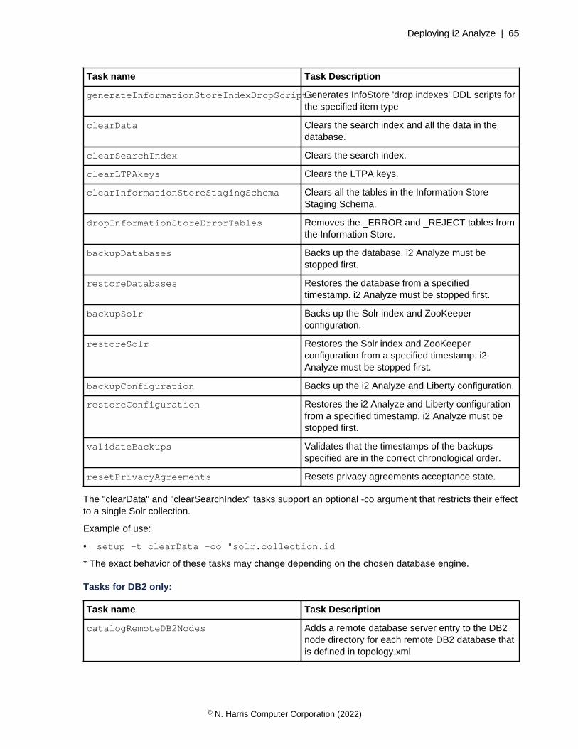
Deploying i2 Analyze | 65
Task name Task Description
generateInformationStoreIndexDropScriptsGenerates InfoStore 'drop indexes' DDL scripts forthe specified item type
clearData Clears the search index and all the data in thedatabase.
clearSearchIndex Clears the search index.
clearLTPAkeys Clears the LTPA keys.
clearInformationStoreStagingSchema Clears all the tables in the Information StoreStaging Schema.
dropInformationStoreErrorTables Removes the _ERROR and _REJECT tables fromthe Information Store.
backupDatabases Backs up the database. i2 Analyze must bestopped first.
restoreDatabases Restores the database from a specifiedtimestamp. i2 Analyze must be stopped first.
backupSolr Backs up the Solr index and ZooKeeperconfiguration.
restoreSolr Restores the Solr index and ZooKeeperconfiguration from a specified timestamp. i2Analyze must be stopped first.
backupConfiguration Backs up the i2 Analyze and Liberty configuration.
restoreConfiguration Restores the i2 Analyze and Liberty configurationfrom a specified timestamp. i2 Analyze must bestopped first.
validateBackups Validates that the timestamps of the backupsspecified are in the correct chronological order.
resetPrivacyAgreements Resets privacy agreements acceptance state.
The "clearData" and "clearSearchIndex" tasks support an optional -co argument that restricts their effectto a single Solr collection.
Example of use:
• setup -t clearData -co "solr.collection.id
* The exact behavior of these tasks may change depending on the chosen database engine.
Tasks for DB2 only:
Task name Task Description
catalogRemoteDB2Nodes Adds a remote database server entry to the DB2node directory for each remote DB2 database thatis defined in topology.xml
© N. Harris Computer Corporation (2022)

Deploying i2 Analyze | 66
Task name Task Description
uncatalogRemoteDB2Nodes Removes the remote database server entry inthe DB2 node directory for each remote DB2database that is defined in topology.xml.
recatalogRemoteDB2Nodes Removes, then re-adds the remote database entryin the DB2 node directory for each remote DB2database that is defined in topology.xml.
listDB2NodeDirectory Lists the contents of the DB2 node directory.
catalogDB2Databases Adds an entry to the system database directoryfor each DB2 database that is defined intopology.xml. If the database is remote from the i2Analyze server, the database is cataloged at thenode specified for that database in topology.xml.
uncatalogDB2Databases Removes the entry in the system databasedirectory for each DB2 database that is defined intopology.xml.
recatalogDB2Databases Removes, then re-adds the entry in the systemdatabase directory for each DB2 database that isdefined in topology.xml.
listDB2SystemDatabaseDirectory Lists the contents of the local DB2 systemdatabase directory.
Examples of use:
• setup -t configureHttpServer
• setup -t replayFromTimestamp
In addition to the start, stop and restart tasks, the following tasks are available:
Task name Task Description
startLiberty Starts Liberty.
stopLiberty Stops Liberty.
restartLiberty Restarts Liberty.
startSolrAndZk Starts the Solr nodes and ZooKeeper hosts.
stopSolrAndZk Stops the Solr nodes and ZooKeeper hosts.
restartSolrAndZk Restarts the Solr nodes and ZooKeeper hosts.
startSolrNodes Starts the Solr nodes.
stopSolrNodes Stops the Solr nodes.
restartSolrNodes Restarts the Solr nodes.
startZkHosts Starts ZooKeeper hosts.
stopZkHosts Stops ZooKeeper hosts.
© N. Harris Computer Corporation (2022)

Deploying i2 Analyze | 67
Task name Task Description
restartZkHosts Restarts ZooKeeper hosts.
Examples of use:
• setup -t startSolrAndZk
• setup -t stopZkHosts -id "1,3"
• setup -t restartSolrNodes -id node1
• setup -t startSolrNodes -hn "example.solr.hostname"
The "SolrNodes" and "ZkHosts" tasks support an optional -id argument.
The comma-separated list of identifiers that you specify restricts the task to the nodes and hosts withmatching identifiers in the topology.
The "SolrNodes" and "ZkHosts" tasks support an optional -hn argument that restricts their effect to asingle host.
The following Solr and ZooKeeper tasks are available:
Task name Task Description
createSolrNodes Creates the Solr nodes that are defined intopology.xml. If the nodes already exist, theirconfiguration is updated.
createZkHosts Creates the ZooKeeper hosts that are definedin topology.xml. If the hosts already exist, theirconfiguration is updated.
getZkStatus Reports the status of the ZooKeeper hosts thatare defined in topology.xml
createAndUploadSolrConfig Creates and uploads the Solr configuration to theZooKeeper hosts.
createSolrCollections Creates the Solr collections that are defined intopology.xml.
deleteSolrCollections Deletes the Solr collections that are defined intopology.xml.
setSolrAutoscalingClusterPolicy Updates the Solr autoscaling cluster policy withthe contents of solr.autoscaling.policy.json.
Examples of use:
• setup -t createSolrNodes -hn "example.solr.hostname"
• setup -t createSolrCollections -co "solr.collection.id"
These tasks support an optional -hn argument that restricts their effect to a single host.
The "createAndUploadSolrConfig", "createSolrCollections", and "deleteSolrCollections" tasks support anoptional -co argument that restricts their effect to a single Solr collection.
© N. Harris Computer Corporation (2022)

Deploying i2 Analyze | 68
The following tasks manage main indexes and match indexes. ZooKeeper and the applicationserver must be running for these commands to succeed:
Task name Task Description
switchStandbyMatchIndexToLive Sets the standby match index to live if it isREADY, and sets the previous live match index tostandby.
clearStandbyMatchIndex Deletes the contents of the standby match indexand sets its state to DISABLED.
updateMatchRules Uploads the system match rules and appliesthem to the standby match index, which startsBUILDING again.
switchStandbyMainIndexToLive Sets the standby main index to live if it is READY,and sets the previous live main index to standby.
clearStandbyMainIndex Deletes the contents of the standby main indexand sets its state to DISABLED.
rebuildStandbyMainIndex Instructs the standby main index to startBUILDING again, if it exists.
switchStandbyChartIndexToLive Sets the standby chart index to live if it is READY,and sets the previous live chart index to standby.
clearStandbyChartIndex Deletes the contents of the standby chart indexand sets its state to DISABLED.
rebuildStandbyChartIndex Instructs the standby chart index to startBUILDING again, if it exists.
pauseIndexPopulation Pauses index population for a specified index orall indexes. Population is paused until the Libertyserver restarts.
resumeIndexPopulation Resumes index population for a specified index orall indexes where population is currently paused.
i2 Analyze deployment settingsSome settings in the deployment toolkit require values that are specific to the environment that you aredeploying in. Although these settings can sometimes use the default values, at different times duringthe production process you might need to specify values that meet your environment and deploymentrequirements.
Specifying the deployment credentials
To allow the deployment toolkit to update the database, Lightweight Third-Party Authentication (LTPA)keys, and Solr search platform components, you must provide user names and passwords. The usernames and passwords that you provide allow the system to set up and administer components of i2Analyze, and are not used to access i2 Analyze.
Database
© N. Harris Computer Corporation (2022)
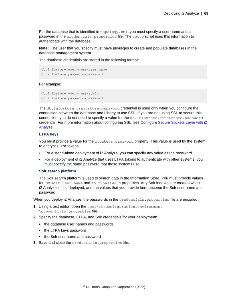
Deploying i2 Analyze | 69
For the database that is identified in topology.xml, you must specify a user name and apassword in the credentials.properties file. The setup script uses this information toauthenticate with the database.
Note: The user that you specify must have privileges to create and populate databases in thedatabase management system.
The database credentials are stored in the following format:
db.infostore.user-name=user name
db.infostore.password=password
For example:
db.infostore.user-name=admin
db.infostore.password=password
The db.infostore.truststore.password credential is used only when you configure theconnection between the database and Liberty to use SSL. If you are not using SSL to secure thisconnection, you do not need to specify a value for the db.infostore.truststore.passwordcredential. For more information about configuring SSL, see Configure Secure Sockets Layer with i2Analyze.
LTPA keys
You must provide a value for the ltpakeys.password property. This value is used by the systemto encrypt LTPA tokens.
• For a stand-alone deployment of i2 Analyze, you can specify any value as the password.
• For a deployment of i2 Analyze that uses LTPA tokens to authenticate with other systems, youmust specify the same password that those systems use.
Solr search platform
The Solr search platform is used to search data in the Information Store. You must provide valuesfor the solr.user-name and solr.password properties. Any Solr indexes are created wheni2 Analyze is first deployed, and the values that you provide here become the Solr user name andpassword.
When you deploy i2 Analyze, the passwords in the credentials.properties file are encoded.
1. Using a text editor, open the toolkit\configuration\environment\credentials.properties file.
2. Specify the database, LTPA, and Solr credentials for your deployment:
• the database user names and passwords
• the LTPA keys password
• the Solr user name and password
3. Save and close the credentials.properties file.
© N. Harris Computer Corporation (2022)

Deploying i2 Analyze | 70
Specifying the JDBC driver
The application server requires a JDBC driver to enable communication with the database. The JDBCdriver that you provide to the deployment toolkit depends on the database management system to usewith the deployment.
1. Locate the JDBC driver for your database management system.
• If you are using Db2®, locate the IBM\SQLLIB\java\db2jcc4.jar file.
• If you are using SQL Server, download the Microsoft™ JDBC Driver 7.4 for SQL Server archivefrom https://www.microsoft.com/en-us/download/details.aspx?id=58505. Extract the contents ofthe download, and locate the sqljdbc_7.4\enu\mssql-jdbc-7.4.1.jre11.jar file.
2. Copy the relevant driver file for your database management system to the toolkit\configuration\environment\common\jdbc-drivers directory.
Note: Ensure that the user you use to run the deployment commands has write permissions for theJDBC jar file.
Specifying remote database storage
You can deploy i2 Analyze with storage that is remote from the i2 Analyze server. You can choose toconfigure either IBM Db2 or SQL Server database storage.
Configuring remote IBM Db2 database storage
You can deploy i2 Analyze with Db2 database storage that is remote from the i2 Analyze server. Wheni2 Analyze is configured to deploy with a remote instance of Db2, the database is created and updatedremotely without the i2 Analyze deployment toolkit present on the server that hosts the Db2 instance.
To deploy an i2 Analyze server that uses remote Db2 database storage, you must install Db2 on yourdatabase server, and Db2 or IBM Data Server Client on the application server. Both instances of Db2must be installed according to the specifications defined in the i2 Analyze software prerequisites. Formore information about installing the prerequisites, see Software prerequisites.
To deploy with remote storage, the i2 Analyze configuration must contain certain information about yourDb2 instances. After you update the configuration, the specified databases can be created and updatedby the deployment toolkit on the remote server.
1. Edit the configuration\environment\topology.xml file to specify your remote Db2databases:
a) Update the host-name and port-number attribute values of the <database> element tomatch the values of your remote Db2 instance.
b) Add the node-name and os-type attributes to the <database> element of the database to behosted remotely.For example:
<database database-type="InfoStore" dialect="db2" instance-name="DB2"
database-name="ISTORE" xa="false" id="infostore"
host-name="hostname" port-number="50000"
node-name="node1" os-type="WIN" />
The value for node-name is the name of the node to create in the Db2 node directory. The valueof the node-name attribute must start with a letter, and have fewer than nine characters. Formore information about naming in Db2, see Naming conventions.
© N. Harris Computer Corporation (2022)

Deploying i2 Analyze | 71
The value for os-type is the operating system of the remote Db2 server. The value of the os-type attribute must be one of the following values: AIX, UNIX, or WIN.
Note: The value of the instance-name attribute must match the instance name of the remote Db2instance.
You can use the db2level command to get the name of your remote instance. For moreinformation, see db2level - Show Db2 service level command.
2. Edit the configuration\environment\opal-server\environment.properties file, tospecify the details of your remote and local instance of Db2.
a) Ensure that the value of the db.installation.dir property is set for the local instance of Db2or Data Server Client on the Liberty server.
If you are using a non-root installation, set the value for this property to the sqllib directory inthe installation user's home directory. For example, /home/db2admin/sqllib.
b) Set the value of the db.database.location.dir property for the remote instance of Db2 onthe database server.
3. Ensure that the users that are specified for your databases in the configuration\environment\credentials.properties file are valid for your remote instance of Db2 on the database server.
4. Catalog the remote node:
setup -t catalogRemoteDB2Nodes
You can complete the steps that are performed by the catalogRemoteDB2Nodes task manually.For example, if you are deploying a system that uses Transport Layer Security (TLS).
To catalog the remote nodes manually, you can run the CATALOG TCPIP NODE instead of using thesetup -t catalogRemoteDB2Nodes command. For more information about the command, seeCATALOG TCPIP/TCPIP4/TCPIP6 NODE command.
The following table shows how the CATALOG command parameters map to the values in thetopology.xml file:
CATALOG TCPIP NODE command parameters <database> element attributes
TCPIP NODE nodename node-name
REMOTE hostname host-name
SERVER port number port-number
REMOTE_INSTANCE instance-name instance-name
When i2 Analyze is deployed, the Information Store database is created or updated on the remotedatabase management system. A remote node is created with the name that is specified for the node-name attribute, and the database is cataloged against that node.
To check that the remote nodes and databases are cataloged, you can use thelistDB2NodeDirectory and listDB2SystemDatabaseDirectory tasks after you deploy i2Analyze:
• The listDB2NodeDirectory task lists the contents of the Db2 node directory.
• The listDB2SystemDatabaseDirectory task lists the contents of the local Db2 systemdatabase directory.
© N. Harris Computer Corporation (2022)

Deploying i2 Analyze | 72
Configuring remote SQL Server database storage
You can deploy i2® Analyze with SQL Server database storage that is remote from the i2® Analyzeserver. When i2® Analyze is configured to deploy to a remote instance of SQL Server, the InformationStore database can be created and updated remotely without the i2® Analyze deployment toolkit presenton the server that hosts the SQL Server instance.
To deploy an i2® Analyze server that uses remote SQL Server database storage for the InformationStore, you must install SQL Server on your database server, and the SQL Server client toolson your application server. SQL Server and the client tools must be installed according to thespecifications defined in the i2® Analyze software prerequisites. For more information about installingthe prerequisites, see Software prerequisites.
To deploy with remote storage, the deployment toolkit must contain certain information about yourSQL Server installation. After you update the configuration, the specified database can be created andupdated on the remote server by the deployment toolkit.
1. Edit the configuration\environment\topology.xml file to specify the details of your remotedatabase:
a) Update the host-name, and either the port-number or instance-name, attribute values ofthe <database> element for the Information Store to match the values for SQL Server on yourdatabase server.
If you are using SQL Server on Linux, you must use the port-number attribute.
b) Add the os-type attribute to the <database> element for the Information Store database. Thevalue of the os-type is used to support the search functions for the Information Store.For example:
<database database-type="InfoStore" dialect="sqlserver"
instance-name="remote.instance.name"
database-name="ISTORE" xa="false" id="infostore"
host-name="remote.hostname" os-type="WIN" />
Where the value for os-type is the operating system of the remote database server. The valueof the os-type attribute must be one of the following values: UNIX or WIN.
For more information about the <database> element attributes, see Databases on page 302.
2. Edit the configuration\environment\opal-server\environment.properties file tospecify the details of your remote and local installations of SQL Server:
a) Ensure that the value of the db.installation.dir property is set for the local installation ofSQL Server or the Microsoft™ Command Line Utilities for SQL Server on the Liberty server.
b) Set the value of the db.database.location.dir property for the remote installation of SQLServer on the database server.
3. Ensure that the user that is specified for your database in the configuration\environment\credentials.properties file is valid for your remote installation of SQL Server on thedatabase server.
When i2 Analyze is deployed, the Information Store database is created or updated on the remotedatabase management system.
If the connection details for the remote database management system change, you can update thetopology.xml file and redeploy the system.
© N. Harris Computer Corporation (2022)
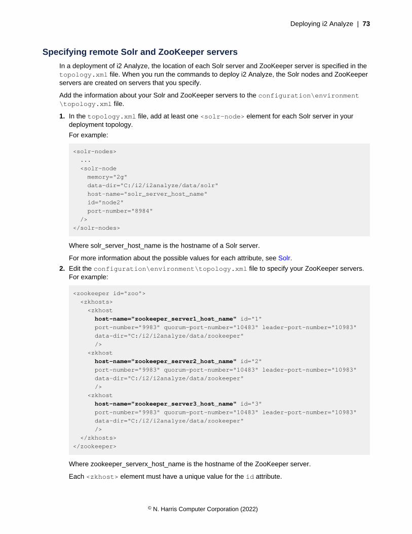
Deploying i2 Analyze | 73
Specifying remote Solr and ZooKeeper servers
In a deployment of i2 Analyze, the location of each Solr server and ZooKeeper server is specified in thetopology.xml file. When you run the commands to deploy i2 Analyze, the Solr nodes and ZooKeeperservers are created on servers that you specify.
Add the information about your Solr and ZooKeeper servers to the configuration\environment\topology.xml file.
1. In the topology.xml file, add at least one <solr-node> element for each Solr server in yourdeployment topology.
For example:
<solr-nodes>
...
<solr-node
memory="2g"
data-dir="C:/i2/i2analyze/data/solr"
host-name="solr_server_host_name"
id="node2"
port-number="8984"
/>
</solr-nodes>
Where solr_server_host_name is the hostname of a Solr server.
For more information about the possible values for each attribute, see Solr.
2. Edit the configuration\environment\topology.xml file to specify your ZooKeeper servers.For example:
<zookeeper id="zoo">
<zkhosts>
<zkhost
host-name="zookeeper_server1_host_name" id="1"
port-number="9983" quorum-port-number="10483" leader-port-number="10983"
data-dir="C:/i2/i2analyze/data/zookeeper"
/>
<zkhost
host-name="zookeeper_server2_host_name" id="2"
port-number="9983" quorum-port-number="10483" leader-port-number="10983"
data-dir="C:/i2/i2analyze/data/zookeeper"
/>
<zkhost
host-name="zookeeper_server3_host_name" id="3"
port-number="9983" quorum-port-number="10483" leader-port-number="10983"
data-dir="C:/i2/i2analyze/data/zookeeper"
/>
</zkhosts>
</zookeeper>
Where zookeeper_serverx_host_name is the hostname of the ZooKeeper server.
Each <zkhost> element must have a unique value for the id attribute.
© N. Harris Computer Corporation (2022)
Deploying i2 Analyze | 74
For more information about the possible values for each attribute, see ZooKeeper.
Specifying the Java™ distribution
i2® Analyze comes pre-packaged with the Adopt OpenJDK 11 HotSpot distribution of Java™. You canchange the distribution of Java™ that is used, and also you can specify different distributions for differentcomponents of i2® Analyze.
Any Java™ distribution that you specify for use with i2® Analyze and its components must be Java™
version 11.
Note: If you decide to use a different distribution, you assume responsibility for updating thatdistribution for security patches or if the version required by the i2® Analyze changes.
To change the Java™ distribution to use, you modify the setup.in script in the configuration\environment directory to contain the path where it is installed. If you are using the Linux® distributionof the i2® Analyze toolkit, this is the setup.in file. On Windows™ it is setup.in.bat.
The setup.in file contains the following variables:
I2A_TOOLKIT_SCRIPTS_JAVA_HOME
The path to a Java™ installation that is used to run the toolkit tasks.
The path can be absolute or a relative path from the root of the toolkit.
By default, it is \tools\java on Windows™ and tools/java on Linux®.
Note: When you deploy i2® Analyze, Adopt OpenJDK 11 HotSpot is installed in the default location.If you change the path, you must ensure that an installation of Java™ 11 exists in the specifiedlocation.
I2A_COMPONENTS_JAVA_HOME
An absolute path to a Java™ installation that is used by the Solr, ZooKeeper, and Libertycomponents of i2® Analyze. By default, it is C:\i2\i2analyze\deploy\java on Windows™ and/opt/i2/i2analyze/deploy/java on Linux®.
Note: When you deploy i2® Analyze, Adopt OpenJDK 11 HotSpot is installed in the specifiedlocation if it does not contain an installation of Java.
The following variables are commented out in the file, but can be used to specify different Java™
installations for the components of i2® Analyze. If the file contains these variables, their values overridethe value of I2A_COMPONENTS_JAVA_HOME for each component.
SOLR_JAVA_HOME
An absolute path to a Java™ installation that is used by Solr.
Apache recommends to use Adopt OpenJDK 11 HotSpot with Solr.
ZK_JAVA_HOME
An absolute path to a Java™ installation that is used by ZooKeeper.
Apache recommends to use Adopt OpenJDK 11 HotSpot with ZooKeeper.
LIBERTY_JAVA_HOME
An absolute path to a Java™ installation that is used by Liberty.
i2 recommends to use Adopt OpenJDK 11 OpenJ9 with Liberty.
ETL_TOOLKIT_JAVA_HOME
© N. Harris Computer Corporation (2022)
Deploying i2 Analyze | 75
The path to a Java™ installation that is used by the ingestion commands in the ETL toolkit. The pathcan be absolute or a relative path from the root of the ETL toolkit.
Note: When you create the ETL toolkit, Adopt OpenJDK 11 HotSpot is included as part of theETL toolkit. If you change the path, you must ensure that an installation of Java™ 11 exists in thespecified location.
The setup.in is part of the configuration, and is copied to each deployment toolkit in yourenvironment. It is recommended that you install Java™ in the same location on each server wherea particular component is located. This means that this file remains the same on each copy of theconfiguration.
1. In a text editor, open the setup.in script file for your operating system.
2. Uncomment and update the paths to specify the Java™ 11 installations that you want to use.
3. Save and close the file.
After you update the file, continue with the rest of the deployment process.
Deploying a proxy server for use with i2 Analyze
When you deploy i2 Analyze, the application is bound to the local server on port 9082. Clients can usethe hostname, IP address of the server, or localhost to connect to the deployment. To work with yourexisting network, or for load-balancing purposes, you can deploy a proxy server or load balancer for usewith i2 Analyze.
When you deploy a proxy server or load balancer for i2 Analyze, there are two mechanisms that youcan use to determine how users connect to the application:
• Populate the X-Forwarded-Host and X-Forwarded-Proto headers on requests
• Specify a single connection string for the FrontEndURI setting in the i2 Analyze configuration
To use a proxy server or load balancer with i2 Analyze, it must meet the following requirements:
• Handle WebSocket requests and keep the WebSocket connection alive for longer than 180 seconds.
• Pass through any security configurations (for example client certificate authentication) to the i2Analyze server. You must enable this according to the documentation for your proxy server.
• If you want to use the X-Forwarded headers, the proxy server or load balancer must be able topopulate them. For more information about the headers, see X-Forwarded-Host and X-Forwarded-Proto.
• If you are planning to deploy i2 Analyze with high availability, your load balancer must also provideserver persistence. For more information, see Deploying a load balancer on page 87.
To allow users to connect by using the URI of the proxy server or load balancer, you can populateX-Forwarded-Host and X-Forwarded-Proto headers or specify the URI in the i2 Analyzeconfiguration. If you configure the connection URI for your deployment, users that connect to i2 Analyzemust use the URI that you specify.
If your application has the http-server-host attribute set to true in the topology.xml, your proxyserver is not required to route requests to the port number the application is listening on.
The following image shows the URIs that you might use in this example:
© N. Harris Computer Corporation (2022)
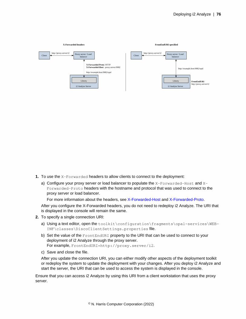
Deploying i2 Analyze | 76
FrontEndURI: http://proxy.server/i2
X-Forwarded headers
ClientProxy server / Load
balancer
i2 Analyze Server
Liberty
http://proxy.server/i2
X-Forwarded-Proto: HTTPX-Forwarded-Host: proxy.server:9082
http://example.host:9082/opal
FrontEndURI specified
ClientProxy server / Load
balancer
i2 Analyze Server
Liberty
http://proxy.server/i2
http://example.host:9082/opal
1. To use the X-Forwarded headers to allow clients to connect to the deployment:
a) Configure your proxy server or load balancer to populate the X-Forwarded-Host and X-Forwarded-Proto headers with the hostname and protocol that was used to connect to theproxy server or load balancer.
For more information about the headers, see X-Forwarded-Host and X-Forwarded-Proto.
After you configure the X-Forwarded headers, you do not need to redeploy i2 Analyze. The URI thatis displayed in the console will remain the same.
2. To specify a single connection URI:
a) Using a text editor, open the toolkit\configuration\fragments\opal-services\WEB-INF\classes\DiscoClientSettings.properties file.
b) Set the value of the FrontEndURI property to the URI that can be used to connect to yourdeployment of i2 Analyze through the proxy server.For example, FrontEndURI=http://proxy.server/i2.
c) Save and close the file.
After you update the connection URI, you can either modify other aspects of the deployment toolkitor redeploy the system to update the deployment with your changes. After you deploy i2 Analyze andstart the server, the URI that can be used to access the system is displayed in the console.
Ensure that you can access i2 Analyze by using this URI from a client workstation that uses the proxyserver.
© N. Harris Computer Corporation (2022)
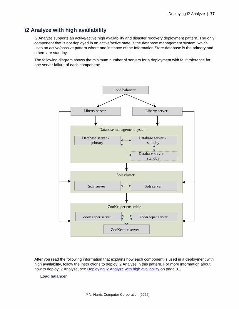
Deploying i2 Analyze | 77
i2 Analyze with high availabilityi2 Analyze supports an active/active high availability and disaster recovery deployment pattern. The onlycomponent that is not deployed in an active/active state is the database management system, whichuses an active/passive pattern where one instance of the Information Store database is the primary andothers are standby.
The following diagram shows the minimum number of servers for a deployment with fault tolerance forone server failure of each component:
Load balancer
Liberty serverLiberty server
Database management system
Database server - primary
Database server - standby
Solr cluster
Solr server Solr server
ZooKeeper ensemble
ZooKeeper server
ZooKeeper server
ZooKeeper server
Database server - standby
After you read the following information that explains how each component is used in a deployment withhigh availability, follow the instructions to deploy i2 Analyze in this pattern. For more information abouthow to deploy i2 Analyze, see Deploying i2 Analyze with high availability on page 81.
Load balancer
© N. Harris Computer Corporation (2022)
Deploying i2 Analyze | 78
A load balancer is required to route requests from clients to the Liberty servers that host the i2Analyze application. Additionally, the load balancer is used to monitor the status of the Libertyservers in a deployment. The load balancer must route requests only to servers that report theirstatus as "live".
After you deploy i2 Analyze with a load balancer, you can make requests to i2 Analyze through theload balancer only.
You can also use the load balancer to distribute requests from clients across the servers in yourdeployment. The load balancer must provide server persistence for users.
Liberty
To provide high availability of Liberty, and the i2 Analyze application, you can deploy i2 Analyzeon multiple Liberty servers. Each Liberty server can process requests from clients to connect to i2Analyze.
In a deployment with multiple Liberty servers, one is elected the leader. The leader can processrequests that require exclusive access to the database. The actions that are required to becompleted on the leader Liberty are described in Liberty leadership configuration.
At a minimum, two Liberty servers are required.
Database management system
To provide high availability of the Information Store database, use the functions provided by yourdatabase management system to replicate the primary database to at least one standby instance.i2 Analyze connects to the primary instance at one time, with the contents of the Information Storedatabase replicated to the standby instances.
If the primary instance fails, one of the standby instances becomes the primary. When a standbybecomes the primary, it must be configured to be read and writable. This means that i2 Analyze cancontinue to function when the initial primary server fails.
• For more information about high availability in Db2, see High availability.
• For more information about high availability in SQL Server:
• For Enterprise edition, see What is an Always On availability group?
• For Standard edition, see Basic availability groups
• If you are deploying with SQL Server on Linux, see Always On availability groups on Linux
For Db2, at a minimum one primary server and one standby server is required.
For SQL Server, at a minimum one primary server and two standby servers are required. If you areusing basic availability groups, this is one standby server and one failover quorum witness.
Solr
i2 Analyze uses SolrCloud to deploy Solr with fault tolerance and high availability capabilities. Toprovide fault tolerance and high availability of the Solr cluster, deploy the cluster across at least twoSolr nodes with each node on a separate server.
At a minimum, two Solr servers are required.
For more information about SolrCloud, see How SolrCloud Works.
ZooKeeper
To deploy ZooKeeper for high availability, deploy multiple ZooKeeper servers in a cluster knownas an ensemble. For a highly available solution, Apache ZooKeeper recommend that you usean odd number of ZooKeeper servers in your ensemble. The ZooKeeper ensemble continues to
© N. Harris Computer Corporation (2022)
Deploying i2 Analyze | 79
function while there are more than 50% of the members online. This means, that if you have threeZooKeeper servers, you can continue operations when a single ZooKeeper server fails.
At a minimum, three ZooKeeper servers are required.
For more information about a multiple server ZooKeeper setup, see Clustered (Multi-Server) Setup.
Deploy for disaster recovery
The deployment topology to provide availability in the event of an availability zone failure is similar to thehigh availability topology. An active/active pattern is still used for Liberty, Solr, and ZooKeeper, howeverthe servers that you deploy are in separate availability zones.
The components behave in the same way as in the high availability deployment topology, except theyare deployed in availability zones. You can think of an availability zone as a data center. By deployingacross a number of availability zones, the deployment continues to function if one of the zones fails.
© N. Harris Computer Corporation (2022)
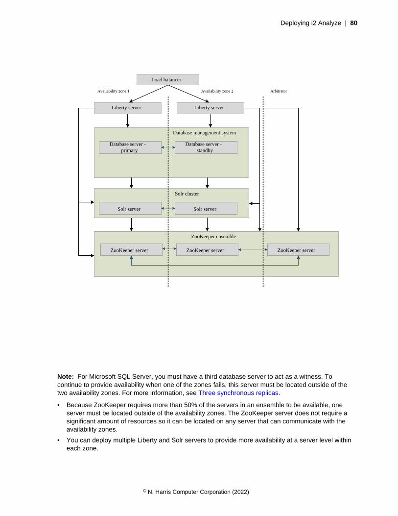
Deploying i2 Analyze | 80
Load balancer
Liberty serverLiberty server
Database management system
Database server - primary
Database server - standby
Solr cluster
Solr server Solr server
ZooKeeper ensemble
ZooKeeper server ZooKeeper serverZooKeeper server
Availability zone 1 Availability zone 2 Arbitrator
Note: For Microsoft SQL Server, you must have a third database server to act as a witness. Tocontinue to provide availability when one of the zones fails, this server must be located outside of thetwo availability zones. For more information, see Three synchronous replicas.
• Because ZooKeeper requires more than 50% of the servers in an ensemble to be available, oneserver must be located outside of the availability zones. The ZooKeeper server does not require asignificant amount of resources so it can be located on any server that can communicate with theavailability zones.
• You can deploy multiple Liberty and Solr servers to provide more availability at a server level withineach zone.
© N. Harris Computer Corporation (2022)
Deploying i2 Analyze | 81
• For the components that use an active/active pattern, servers in each availability zone are used toprocess requests. To maintain the performance of the system, ensure that the network that is usedbetween availability zones is stable and provides enough bandwidth for system operation.
Deploying i2 Analyze with high availability
When you deploy i2 Analyze with high availability, there are a number of steps that you must complete.
To configure i2 Analyze for high availability, there are a number of extra configuration and deploymentsteps that you must complete in addition to a normal multiple server deployment. When you aredeploying i2 Analyze into production with a high availability configuration, complete the following stepswhen you are in your pre-production, test, and production environments. After you create the highavailability configuration, you can copy it between environments as usual.
1. Install any prerequisite software to prepare your servers for the pre-production environment.
• For a deployment with high availability, use the multiple servers deployment topology with atleast the minimum number of servers required for high availability of each component. For moreinformation, see Deployment topologies on page 54.
• To deploy with high availability, you must configure your database management system after youinstall it:
• Preparing Db2 for HADR on page 82
• Preparing SQL Server for HADR on page 83
2. Copy the toolkit\configuration directory from the configuration development environment, tothe toolkit directory at the root of the deployment toolkit on one of the Liberty servers.
3. Update the configuration to specify your remote database, follow the instructions in Specifyingremote database storage on page 70 to update the environment.properties andtopology.xml files.
a) If you are using Db2, you can specify any alternative database location information in thetopology.xml.
• If you are using an automated cluster-controller such as IBM Tivoli System Automation forMultiplatforms (TSAMP), then specify the hostname and port number of the cluster.
• If you are not using an automated cluster-controller, in the <database> element for yourInformation Store, provide the hostname and port number of any standby databases in thealternate-hosts attribute.
The host and port number must be separated by a colon (:), and each database server mustbe separated by a (,).
For example, alternate-hosts="hostname:port_number,hostname:port_number".
b) If you are using SQL Server, specify the hostname and port number of the availability grouplistener.
4. Update the configuration to configure each component for high availability:
a) Configuring ZooKeeper for HADR on page 84
b) Configuring Solr for HADR on page 85
c) Deploying a load balancer on page 87
The environment.properties, http-server.properties, and topology.xml containhostname and file path settings that you might need to update for the servers in your pre-productionenvironment. For more information, see Configuration files reference.
© N. Harris Computer Corporation (2022)

Deploying i2 Analyze | 82
5. Deploy and start i2 Analyze with one Liberty server by following the instructions in Deploying i2Analyze on multiple servers on page 90.
6. After you deploy with one Liberty server, update the configuration on any other Liberty servers.
a) Copy the configuration directory from the deployed Liberty server to the toolkit directoryon any other Liberty servers in your environment.
b) On each Liberty server, in the topology.xml file update the host-name and port-numberattributes of the <application> element.
7. Deploy and start the i2 Analyze application on each of the other Liberty servers:
setup -t installLiberty
setup -t deployLiberty
setup -t startLiberty
After you deploy i2 Analyze, you can replicate any configuration changes that are not stored in theconfiguration of i2 Analyze on each Liberty server.
The security configuration must be the same on each server.
8. Configure Liberty security for your environment. To do this, repeat any changes that you made to theLiberty configuration in the previous environment.
This might involve copying the user registry file, or updating the server.xml file.
9. After you deploy i2 Analyze, configure your database management system to replicate theInformation Store database to your standby servers.
a) If you are using Db2, configure high availability for the Information Store database and replicate itto any standby database instances.
For more information, see Replicate the Information Store in Db2 on page 88.
b) If you are using SQL Server, add the Information Store to your availability group.
For more information, see Replicate the Information Store in SQL Server on page 89.
10.Complete any configuration changes in the Information Store database on the primary server.
a) If you created any rules or schedules to delete records by rule, replicate the rules and schedulesthat you created in the previous environment.
On SQL Server, you must update the automated job creation schedule on every databaseinstance. For more information see, Changing the automated job creation schedule.
b) If you created any merged property values definition views for your ingestion process, replicatethe view definition that you created in the previous environment.
After you deploy i2 Analyze with high availability, return to perform the rest of the instructions forcreating a deployment in your current environment:
• Creating the pre-production environment on page 48
• Creating the test environment on page 51
• Creating the production environment on page 53
Preparing Db2 for HADR
When you deploy i2 Analyze with multiple database servers, there must be a mechanism in place toroute requests to the new primary server if the current primary server fails.
In Db2, you configure the Information Store database for HADR after you create it. However, there aresome decisions that you must make before you create the i2 Analyze configuration.
© N. Harris Computer Corporation (2022)
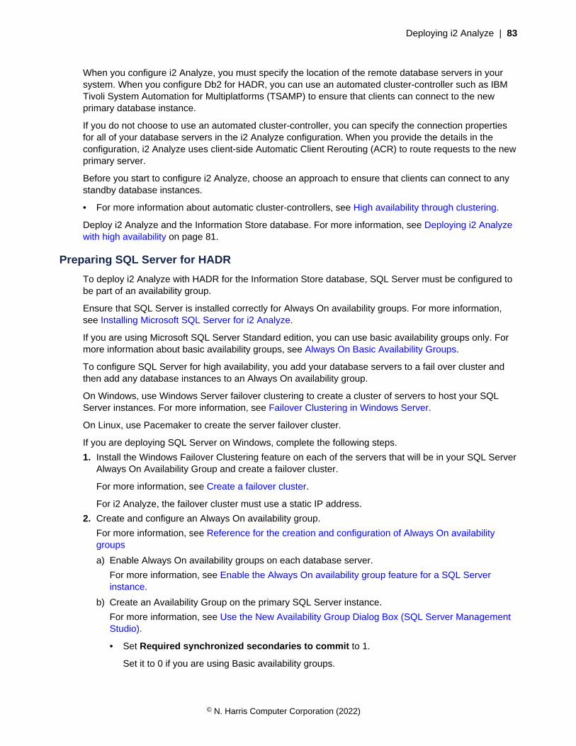
Deploying i2 Analyze | 83
When you configure i2 Analyze, you must specify the location of the remote database servers in yoursystem. When you configure Db2 for HADR, you can use an automated cluster-controller such as IBMTivoli System Automation for Multiplatforms (TSAMP) to ensure that clients can connect to the newprimary database instance.
If you do not choose to use an automated cluster-controller, you can specify the connection propertiesfor all of your database servers in the i2 Analyze configuration. When you provide the details in theconfiguration, i2 Analyze uses client-side Automatic Client Rerouting (ACR) to route requests to the newprimary server.
Before you start to configure i2 Analyze, choose an approach to ensure that clients can connect to anystandby database instances.
• For more information about automatic cluster-controllers, see High availability through clustering.
Deploy i2 Analyze and the Information Store database. For more information, see Deploying i2 Analyzewith high availability on page 81.
Preparing SQL Server for HADR
To deploy i2 Analyze with HADR for the Information Store database, SQL Server must be configured tobe part of an availability group.
Ensure that SQL Server is installed correctly for Always On availability groups. For more information,see Installing Microsoft SQL Server for i2 Analyze.
If you are using Microsoft SQL Server Standard edition, you can use basic availability groups only. Formore information about basic availability groups, see Always On Basic Availability Groups.
To configure SQL Server for high availability, you add your database servers to a fail over cluster andthen add any database instances to an Always On availability group.
On Windows, use Windows Server failover clustering to create a cluster of servers to host your SQLServer instances. For more information, see Failover Clustering in Windows Server.
On Linux, use Pacemaker to create the server failover cluster.
If you are deploying SQL Server on Windows, complete the following steps.
1. Install the Windows Failover Clustering feature on each of the servers that will be in your SQL ServerAlways On Availability Group and create a failover cluster.
For more information, see Create a failover cluster.
For i2 Analyze, the failover cluster must use a static IP address.
2. Create and configure an Always On availability group.
For more information, see Reference for the creation and configuration of Always On availabilitygroups
a) Enable Always On availability groups on each database server.
For more information, see Enable the Always On availability group feature for a SQL Serverinstance.
b) Create an Availability Group on the primary SQL Server instance.
For more information, see Use the New Availability Group Dialog Box (SQL Server ManagementStudio).
• Set Required synchronized secondaries to commit to 1.
Set it to 0 if you are using Basic availability groups.
© N. Harris Computer Corporation (2022)
Deploying i2 Analyze | 84
• Select Database level health detection.
• Do not specify any Availability Databases now because the Information Store database doesnot exist.
c) Create an availability group listener for the availability group.
For more information, see Configure a listener for an Always On availability group.
Use a static IP address for the availability group listener. When you configure i2 Analyze toconnect to a remote Information Store database, you specify the hostname and port number ofthe Availability Group Listener.
If you are deploying SQL Server on Linux, complete the following steps.
3. Deploy a Pacemaker cluster.
For more information, see Deploy a Pacemaker cluster for SQL Server on Linux.
4. Create and configure an Always on availability group and the Pacemaker cluster.
For more information, see Create and configure an availability group for SQL Server on Linux.
• Set cluster type to EXTERNAL
• In Select Databases, do not select any databases because the Information Store database doesnot exist.
• In Specify Replicas, create an Availability Group Listener. When you create the availabilitygroup listener, use a static IP address. When you configure i2 Analyze to connect to a remoteInformation Store database, you specify the hostname and port number of the Availability GroupListener.
• When you create the IP address resource for the availability group, use the same IP address asthe Availability Group Listener.
Deploy i2 Analyze and the Information Store database. For more information, see Deploying i2 Analyzewith high availability on page 81.
Configuring ZooKeeper for HADR
The i2 Analyze configuration specifies the structure of your ZooKeeper ensemble. To provide highavailability, configure a ZooKeeper ensemble with an odd number of severs.
In the i2 Analyze configuration, provide the details about the ZooKeeper servers in your environment.
Edit the configuration\environment\topology.xml file to specify your ZooKeeper servers.
© N. Harris Computer Corporation (2022)
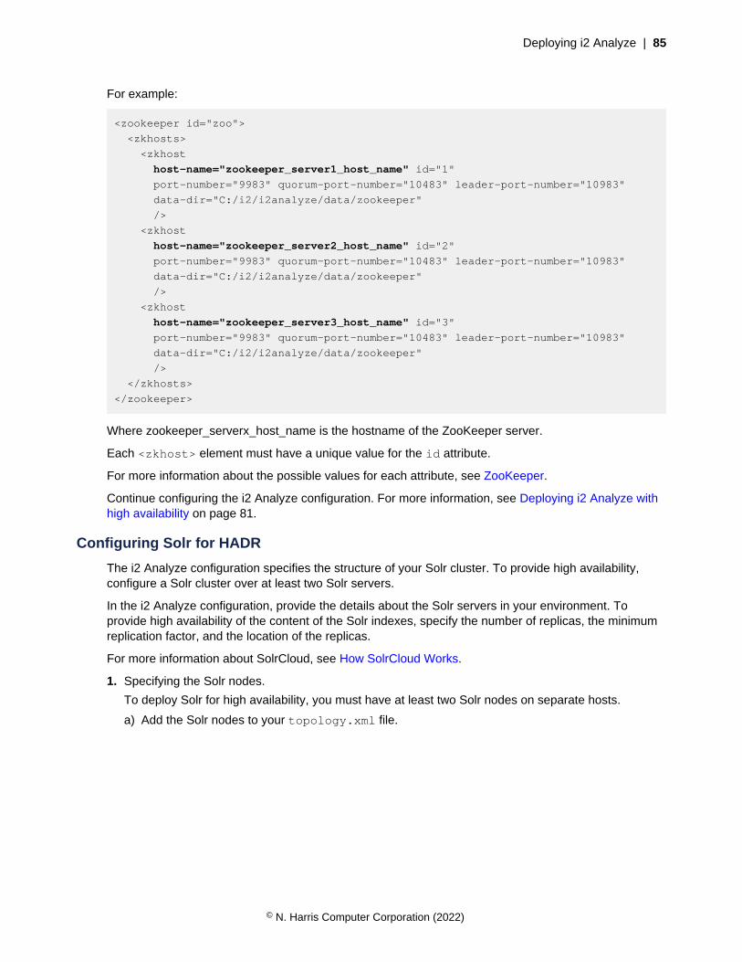
Deploying i2 Analyze | 85
For example:
<zookeeper id="zoo">
<zkhosts>
<zkhost
host-name="zookeeper_server1_host_name" id="1"
port-number="9983" quorum-port-number="10483" leader-port-number="10983"
data-dir="C:/i2/i2analyze/data/zookeeper"
/>
<zkhost
host-name="zookeeper_server2_host_name" id="2"
port-number="9983" quorum-port-number="10483" leader-port-number="10983"
data-dir="C:/i2/i2analyze/data/zookeeper"
/>
<zkhost
host-name="zookeeper_server3_host_name" id="3"
port-number="9983" quorum-port-number="10483" leader-port-number="10983"
data-dir="C:/i2/i2analyze/data/zookeeper"
/>
</zkhosts>
</zookeeper>
Where zookeeper_serverx_host_name is the hostname of the ZooKeeper server.
Each <zkhost> element must have a unique value for the id attribute.
For more information about the possible values for each attribute, see ZooKeeper.
Continue configuring the i2 Analyze configuration. For more information, see Deploying i2 Analyze withhigh availability on page 81.
Configuring Solr for HADR
The i2 Analyze configuration specifies the structure of your Solr cluster. To provide high availability,configure a Solr cluster over at least two Solr servers.
In the i2 Analyze configuration, provide the details about the Solr servers in your environment. Toprovide high availability of the content of the Solr indexes, specify the number of replicas, the minimumreplication factor, and the location of the replicas.
For more information about SolrCloud, see How SolrCloud Works.
1. Specifying the Solr nodes.
To deploy Solr for high availability, you must have at least two Solr nodes on separate hosts.
a) Add the Solr nodes to your topology.xml file.
© N. Harris Computer Corporation (2022)
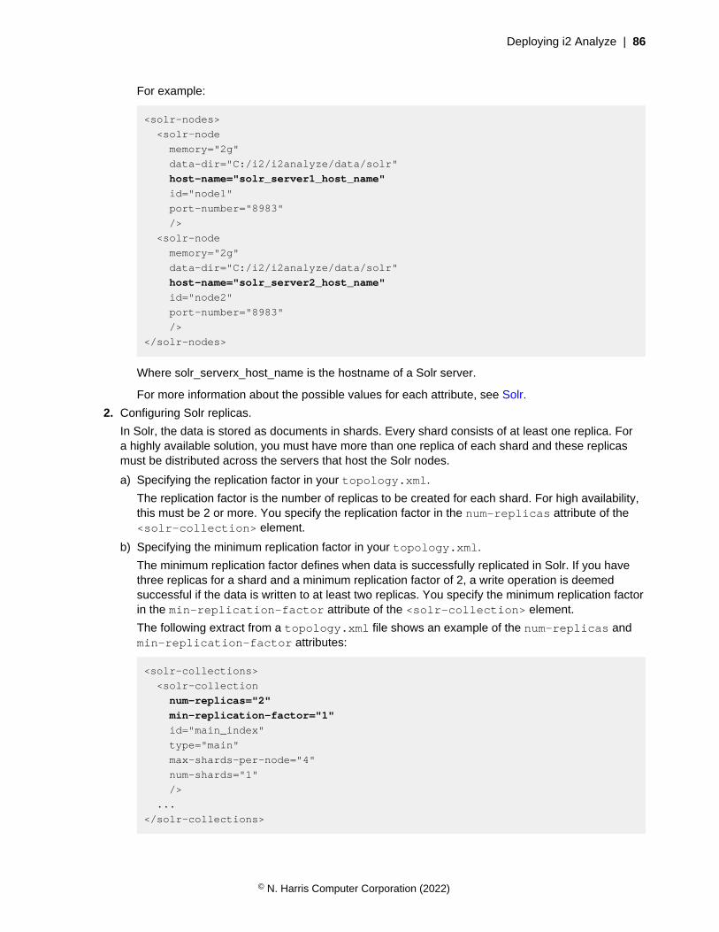
Deploying i2 Analyze | 86
For example:
<solr-nodes>
<solr-node
memory="2g"
data-dir="C:/i2/i2analyze/data/solr"
host-name="solr_server1_host_name"
id="node1"
port-number="8983"
/>
<solr-node
memory="2g"
data-dir="C:/i2/i2analyze/data/solr"
host-name="solr_server2_host_name"
id="node2"
port-number="8983"
/>
</solr-nodes>
Where solr_serverx_host_name is the hostname of a Solr server.
For more information about the possible values for each attribute, see Solr.
2. Configuring Solr replicas.
In Solr, the data is stored as documents in shards. Every shard consists of at least one replica. Fora highly available solution, you must have more than one replica of each shard and these replicasmust be distributed across the servers that host the Solr nodes.
a) Specifying the replication factor in your topology.xml.
The replication factor is the number of replicas to be created for each shard. For high availability,this must be 2 or more. You specify the replication factor in the num-replicas attribute of the<solr-collection> element.
b) Specifying the minimum replication factor in your topology.xml.
The minimum replication factor defines when data is successfully replicated in Solr. If you havethree replicas for a shard and a minimum replication factor of 2, a write operation is deemedsuccessful if the data is written to at least two replicas. You specify the minimum replication factorin the min-replication-factor attribute of the <solr-collection> element.
The following extract from a topology.xml file shows an example of the num-replicas andmin-replication-factor attributes:
<solr-collections>
<solr-collection
num-replicas="2"
min-replication-factor="1"
id="main_index"
type="main"
max-shards-per-node="4"
num-shards="1"
/>
...
</solr-collections>
© N. Harris Computer Corporation (2022)

Deploying i2 Analyze | 87
c) Specify the Solr autoscaling policies.
To ensure that your system can still operate if a Solr server or node fails, you must ensure thatthere is at least on replica of each shard still available. To do this, you can create a replicaplacement policy to specify that each replica of a shard must be placed on a distinct host.
• Create the configuration\environment\opal-server\solr.autoscaling.policy.json file.
• In the file, provide your Solr autoscaling policies. For more information about the policies, seeAutoscaling Policy and Preferences.
• To create a cluster policy that creates each replica of a shard on a distinct host, add thefollowing lines to the file:
{
"set-cluster-policy":[
{
"replica":"<2",
"shard":"#EACH",
"host":"#EACH"
}
]
}
• The cluster policy is set when you create the Solr cluster as part of thedeployment steps. Additionally, you can update the cluster policy by running thesetSolrAutoscalingClusterPolicy toolkit task.
Continue configuring the i2 Analyze configuration. For more information, see Deploying i2 Analyze withhigh availability on page 81.
Deploying a load balancer
In a deployment with HADR, there are multiple Liberty servers that host the i2 Analyze application. Toenable analysts to connect to the deployment by using a single URI, you must use a load balancer toroute requests to each Liberty server in your deployment.
For a load balancer to work successfully with i2 Analyze, it must be configured to:
• Handle WebSocket requests.
• Route requests to the i2 Analyze application on active Liberty servers only.
• Use a cookie issued by the load balancer to achieve server persistence for a user. The serverpersistence should last as long as possible or until the server is not active.
If the connection from the clients is secured by using SSL, you might need to implement SSLtermination in the load balancer to achieve server persistence.
You can also configure your load balancer to balance requests across the Liberty servers in yourdeployment. The mechanism that you choose must allow for server persistence to be maintained.
For more information about load balancers and application layer server persistence, see LoadBalancing, Affinity, Persistence, Sticky Sessions: What You Need to Know.
1. Install your load balancer on a separate server from any other component in the deployment.
2. Configure your load balancer to identify the active Liberty servers by using the api/v1/health/live REST endpoint.
© N. Harris Computer Corporation (2022)
Deploying i2 Analyze | 88
The live endpoint returns 200 when the server is live and processing requests. For moreinformation about the endpoint, see The health/live endpoint.
Call the live endpoint on each Liberty server in your deployment. The endpoint returns the status ofa single Liberty server, and not the others in the deployment.
3. Configure your load balancer to use cookie-based server persistence.
When a user connects, if there is no cookie from the load balancer that indicates it has alreadyconnected to one of the active Liberty servers, provide it with one. When this user connects again,the cookie it received ensures that any requests are routed to the same Liberty server.
If the server that a user has persistence with is offline, the load balancer must route the request to alive Liberty server. The user's cookie must be updated to achieve persistence with the live server thatit connected to.
4. Before you can connect to i2 Analyze via the load balancer, you might need to specify theconnection URI that clients can use to connect to i2 Analyze.
a) In the configuration\fragments\opal-services\WEB-INF\classes\DiscoClientSettings.properties file, set the value of the FrontEndURI setting to theURI that can be used to connect to your deployment of i2 Analyze.
For more information, see Specifying the connection URI.
Some load balancers modify the HTTP origin header, the value that you specify for theFrontEndURI must match the value of the HTTP origin header after it is modified by the loadbalancer.
Continue configuring the i2 Analyze configuration. For more information, see Deploying i2 Analyze withhigh availability on page 81.
Replicate the Information Store in Db2
After you create the Information Store database on the primary database server, initialize HADR andreplicate the Information Store database to your standby servers.
To initialize HADR for the Information Store, follow the instructions described in Initializing highavailability disaster recovery (HADR).
When you configure the synchronize mode, it is recommended that you use the SYNC synchronizemode. For more information about the synchronization modes, see High availability disaster recovery(HADR) synchronization mode.
At a high level, the steps are:
• Update the Information Store database configuration for HADR
• Create a backup of the Information Store database on the primary server
• Restore the backup on the standby servers
• Update the Information Store database configuration on the standby servers
• Start HADR as standby on the standby servers
• Start HADR as primary on the primary server
Continue the deployment process. For more information, see Deploying i2 Analyze with high availabilityon page 81.
© N. Harris Computer Corporation (2022)

Deploying i2 Analyze | 89
Replicate the Information Store in SQL Server
After you create the Information Store database on the primary database server, add the database toyour availability group and replicate the Information Store database to your standby servers.
1. Before you can add the Information Store database to your availability group, you must create a fullbackup.
For more information, see Create a Full Database Backup.
2. Add the Information Store database to your availability group.
For more information, see Add a Database to an Always On availability group.
3. Add any replicas to the availability group.
For more information, see Add a secondary replica to an Always On Availability Group.
When you add the replicas to the availability group, configure the replicas as follows:
• Set Failover Mode to Automatic
• Set Availability Mode to Synchronous commit
• Set Readable Secondary to Yes
If you are using Basic availability groups, set it to No.
Continue the deployment process. For more information, see Deploying i2 Analyze with high availabilityon page 81.
i2 Analyze deployment commandsThe scripts that deploy i2 Analyze depend on the values in the i2 Analyze configuration. The scripts andcommands that you run depend on the topology of the deployment that you want to create.
Deploying i2 Analyze
To deploy i2 Analyze in a single-server deployment topology, you can run a script. After i2 Analyze issuccessfully deployed, you can start the system.
You must have an i2 Analyze configuration that is set up for a single-server, remote database only, or i2Connect gateway only deployment topology. For more information about creating a valid configuration,see Creating the pre-production environment on page 48.
Run any toolkit commands from the toolkit\scripts directory in the deployment toolkit.
1. Deploy i2 Analyze:
setup -t deploy
2. Start i2 Analyze:
setup -t start
If an error message is displayed, refer to Troubleshooting the deployment process on page 92.
After you deploy and start i2 Analyze, return to perform the rest of the instructions for creating adeployment in your current environment:
• Creating the pre-production environment on page 48
• Creating the test environment on page 51
• Creating the production environment on page 53
© N. Harris Computer Corporation (2022)
Deploying i2 Analyze | 90
• Deploying i2 Analyze with high availability on page 81
Deploying i2 Analyze on multiple servers
To deploy i2 Analyze in a multiple-server deployment topology, you must run the commands to install,deploy, and start the components of i2 Analyze on each server.
You must have an i2 Analyze configuration that is set up for a multiple-server physical deploymenttopology or a deployment with high availability:
• For more information about creating a valid multiple-server configuration, see Creating the pre-production environment on page 48.
• For more information about creating a valid high availability configuration, see Deploying i2 Analyzewith high availability on page 81.
To deploy i2 Analyze in a multiple server deployment topology, you must provide the configuration toeach deployment toolkit. Then, you can run the commands to deploy the components of i2 Analyzeon each server. It is important to pay attention to which server you must run each command on, andwhether you need to specify the hostname of that server.
Run any toolkit commands from the toolkit\scripts directory in the deployment toolkit on thespecified server in your environment.
Copying the i2 Analyze configuration
The i2 Analyze configuration is required by all servers that host components of i2 Analyze. You do nothave to copy the configuration to the database server, if it contains only the Information Store databaseand no other components.
Copy the toolkit\configuration from the server where you created and populated your i2Analyze configuration, to the toolkit directory of the deployment toolkit on each server in yourenvironment.
Installing components
Install the components of i2 Analyze on the servers that you have identified.
1. On the Liberty server, run the following commands:
setup -t installLiberty
2. On each ZooKeeper server, run the following command:
setup -t installZookeeper
3. On each Solr server, run the following command:
setup -t installSolr
© N. Harris Computer Corporation (2022)

Deploying i2 Analyze | 91
Deploying and starting components
Deploy and start the components of i2 Analyze on the specified servers.
1. On each ZooKeeper server, encode the credentials and create and start any ZooKeeper hosts:
setup -t ensureCredentialsEncoded
setup -t createZkHosts --hostname zookeeper.hostname
setup -t startZkHosts --hostname zookeeper.hostname
Where zookeeper.hostname is the hostname of the ZooKeeper server where you are runningthe command, and matches the value for the host-name attribute of a <zkhost> element in thetopology.xml file.
2. On the Liberty server, run the command to upload the Solr configuration to ZooKeeper:
setup -t createAndUploadSolrConfig --hostname liberty.hostname
Where liberty.hostname is the hostname of the Liberty server where you are running thecommand, and matches the value for the host-name attribute of the <application> element inthe topology.xml file.
3. On each Solr server, encode the credentials and create and start any Solr nodes:
setup -t ensureCredentialsEncoded
setup -t createSolrNodes --hostname solr.hostname
setup -t startSolrNodes --hostname solr.hostname
Where solr.hostname is the hostname of the Solr server where you are running thecommand, and matches the value for the host-name attribute of a <solr-node> element in thetopology.xml file.
On the Liberty server, run the commands to deploy and start a number of the components.
4. Create the Solr collections:
setup -t createSolrCollections --hostname liberty.hostname
To test that the Solr Collection is created correctly, click Cloud in the Solr Web UI, or you can goto http://solr.hostname:port-number/solr/#/~cloud. Log in with the user name andpassword for Solr in the credentials.properties file.
A horizontal tree with the collection as the root is displayed. Here you can see the breakdown of theshards, nodes, and replicas in any collections.
5. Create the Information Store database:
setup -t createDatabases
To check that the database is created correctly, connect to the database by using a databasemanagement tool.
6. Deploy the i2 Analyze application:
setup -t deployLiberty
© N. Harris Computer Corporation (2022)

Deploying i2 Analyze | 92
7. If you are using IBM HTTP Server, configure the HTTP Server:
setup -t configureHttpServer
8. Start the Liberty server:
setup -t startLiberty
After you deploy and start i2 Analyze, return to perform the rest of the instructions for creating adeployment in your current environment:
• Creating the pre-production environment on page 48
• Creating the test environment on page 51
• Creating the production environment on page 53
• Deploying i2 Analyze with high availability on page 81
Troubleshooting the deployment processi2 Analyze provides mechanisms that assist with deployment before, while, and after you do it.
Deployment toolkit validation messages
The i2 Analyze deployment toolkit validates some of the configuration files that are required for adeployment. By reading the validation messages, you can be certain that required properties havevalues, that property values have the correct format, and that required files are in the correct locations.
Validation takes place when you run a number of the deployment toolkit tasks. Validation can completein the following ways:
Success
On success, the validation process displays a brief configuration summary, and the maindeployment process continues. For example:
============== Configuration Summary (brief) ==============
+ configuration/fragments/common/WEB-INF/classes/ApolloServerSettings
Mandatory.properties:
- ChartingSchemesResource='law-enforcement-schema-charting-schemes.xml'
- SchemaResource='law-enforcement-schema.xml'
- DynamicSecuritySchemaResource='security-schema.xml'
===========================================================
Warning
When there is a warning, the validation process displays a brief configuration summary and aWARNINGS section. The WARNINGS section identifies settings that might not be configured correctly,but the deployment process continues. For example:
====================== WARNINGS (1) =======================
+ configuration/fragments/common/WEB-INF/classes/ApolloServerSettings
Mandatory.properties:
- The <SchemaResource> property has not been set.
===========================================================
© N. Harris Computer Corporation (2022)
Deploying i2 Analyze | 93
Here, the schema is not set, and so the default law enforcement schema is used.
Error
If an error occurs, the validation process displays a longer configuration summary, and an ERRORSsection. The ERRORS section identifies missing values that must be present. The deploymentprocess stops, and you must correct the errors before you attempt to deploy again. For example:
======================= ERRORS (1) ========================
+ configuration/environment/opal-server/environment.properties:
- "db.database.location.dir" has not been set
===========================================================
Here, the database location directory is not set, so the database cannot be configured.
Deployment progress messages
During the deployment process, i2 Analyze displays detailed messages that provide information aboutthe state and configuration of the system.
The output from the deployment process describes each task that the setup command performs duringdeployment. If a task runs successfully, then only its name appears. For example:
:buildApplication
There are two reasons why a task might not run, but deployment can still proceed.
UP-TO-DATE
The task was performed earlier, or its output is already present. For example:
:installJDBCDrivers UP-TO-DATE
SKIPPED
The task is not required for this deployment. For example:
:importLTPAKey SKIPPED
If an error occurs, deployment stops in a controlled manner. i2 Analyze displays a stack trace thatcontains the name of the task that failed, and information about the location of the error. For example:
:createDatabasesIfNecessary FAILED
FAILURE: Build failed with an exception.
* Where:
Script 'C:\i2\i2analyze\toolkit\scripts\gradle\database.gradle' line: 173
* What went wrong:
Execution failed for task ':createDatabasesIfNecessary'.
The messages are displayed on screen and sent to the log files that are stored in the toolkit\configuration\logs directory.
© N. Harris Computer Corporation (2022)
Deploying i2 Analyze | 94
Deployment log files
i2 Analyze produces logging information about deployment tasks and the transactions that take placewhen the system is operational. After deployment, you can check these logs to help diagnose potentialissues.
The following types of logged information are available for you to review:
Deployment logs
Each time that you run the setup command, a log file is created in the deployment toolkit.The messages in these logs describe which tasks were called, whether the tasks completedsuccessfully, and the details of any issues that occurred.
These log files contain the same information as the console output. You can find them in thetoolkit\configuration\logs directory.
Liberty logs
In addition to the information in the deployment logs, extra information that relates to the applicationserver is also logged in deploy\wlp\usr\servers\opal-server\logs.
The directory contains the following log files that you might use to help troubleshoot any issues:
console.log
The console.log file contains basic server status and operation messages, which are alsodisplayed on the console.
\messages\messages.log
The messages.log file contains messages from Liberty.
\messages\ffdc\ffdc.log
The ffdc.log file contains Fist Failure Data Capture (FFDC) output from Liberty components (forexample the database drivers that typically include selective memory dumps of diagnostic data).
\opal-services\i2_Alert_Scheduler.log
The i2_Alert_Scheduler.log contains messages that record when the scheduled operationsfor saved Visual Queries run.
\opal-services\i2_Analysis_Repository.log
The i2_Analysis_Repository.log file contains messages that are intercepted by log4j fromthe i2 Analyze application.
\opal-services\i2_General.log
The i2_General.log file contains any messages that are intercepted by log4j, but not from the i2Analyze application.
\opal-services\i2_Component_Availability.log
The i2_Solr_Cluster_Status.log file contains entries for changes to the state of the Solrclusters in your deployment.
\opal-services\i2_Connect_Async_Query.log
The i2_Connect_Async_Query.log file contains messages for failures or issues related toasynchronous queries from i2 Connect connectors.
\opal-services\i2_Update_Live_Configuration.log
The i2_Update_Live_Configuration.log file contains messages that are displayed in theconsole when you run the updateLiveConfiguration toolkit task or use the admin/reloadendpoint.
\opal-services\i2_Solr.log
© N. Harris Computer Corporation (2022)
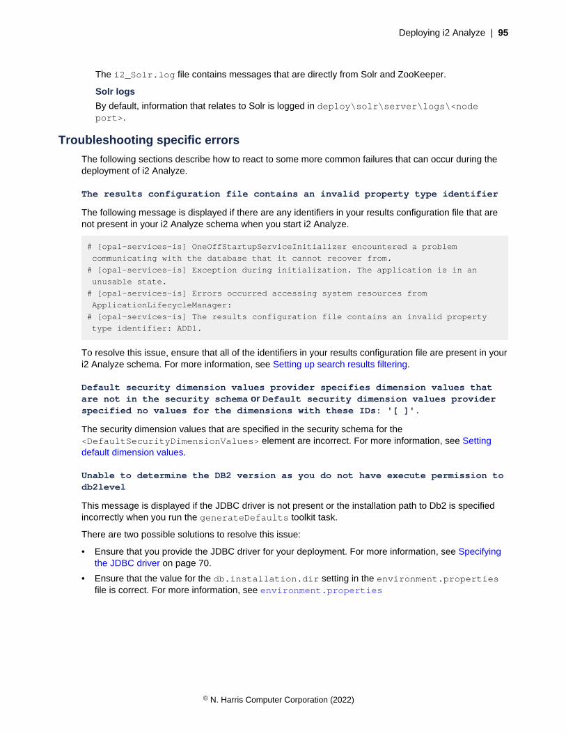
Deploying i2 Analyze | 95
The i2_Solr.log file contains messages that are directly from Solr and ZooKeeper.
Solr logs
By default, information that relates to Solr is logged in deploy\solr\server\logs\<nodeport>.
Troubleshooting specific errors
The following sections describe how to react to some more common failures that can occur during thedeployment of i2 Analyze.
The results configuration file contains an invalid property type identifier
The following message is displayed if there are any identifiers in your results configuration file that arenot present in your i2 Analyze schema when you start i2 Analyze.
# [opal-services-is] OneOffStartupServiceInitializer encountered a problem
communicating with the database that it cannot recover from.
# [opal-services-is] Exception during initialization. The application is in an
unusable state.
# [opal-services-is] Errors occurred accessing system resources from
ApplicationLifecycleManager:
# [opal-services-is] The results configuration file contains an invalid property
type identifier: ADD1.
To resolve this issue, ensure that all of the identifiers in your results configuration file are present in youri2 Analyze schema. For more information, see Setting up search results filtering.
Default security dimension values provider specifies dimension values thatare not in the security schema or Default security dimension values providerspecified no values for the dimensions with these IDs: '[ ]'.
The security dimension values that are specified in the security schema for the<DefaultSecurityDimensionValues> element are incorrect. For more information, see Settingdefault dimension values.
Unable to determine the DB2 version as you do not have execute permission todb2level
This message is displayed if the JDBC driver is not present or the installation path to Db2 is specifiedincorrectly when you run the generateDefaults toolkit task.
There are two possible solutions to resolve this issue:
• Ensure that you provide the JDBC driver for your deployment. For more information, see Specifyingthe JDBC driver on page 70.
• Ensure that the value for the db.installation.dir setting in the environment.propertiesfile is correct. For more information, see environment.properties
© N. Harris Computer Corporation (2022)
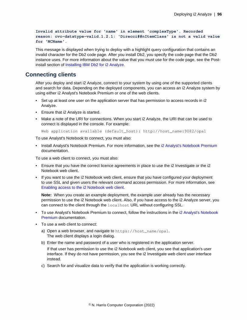
Deploying i2 Analyze | 96
Invalid attribute value for 'name' in element 'complexType'. Recordedreason: cvc-datatype-valid.1.2.1: 'Direcci##nItemClass' is not a valid valuefor 'NCName'.
This message is displayed when trying to deploy with a highlight query configuration that contains aninvalid character for the Db2 code page. After you install Db2, you specify the code page that the Db2instance uses. For more information about the value that you must use for the code page, see the Post-install section of Installing IBM Db2 for i2 Analyze.
Connecting clientsAfter you deploy and start i2 Analyze, connect to your system by using one of the supported clientsand search for data. Depending on the deployed components, you can access an i2 Analyze system byusing either i2 Analyst's Notebook Premium or one of the web clients.
• Set up at least one user on the application server that has permission to access records in i2Analyze.
• Ensure that i2 Analyze is started.
• Make a note of the URI for connections. When you start i2 Analyze, the URI that can be used toconnect is displayed in the console. For example:
Web application available (default_host): http://host_name:9082/opal
To use Analyst's Notebook to connect, you must also:
• Install Analyst's Notebook Premium. For more information, see the i2 Analyst's Notebook Premiumdocumentation.
To use a web client to connect, you must also:
• Ensure that you have the correct licence agreements in place to use the i2 Investigate or the i2Notebook web client.
• If you want to use the i2 Notebook web client, ensure that you have configured your deploymentto use SSL and given users the relevant command access permission. For more information, seeEnabling access to the i2 Notebook web client.
Note: When you create an example deployment, the example user already has the necessarypermission to use the i2 Notebook web client. Also, if you have access to the i2 Analyze server, youcan connect to the client through the localhost URL without configuring SSL.
• To use Analyst's Notebook Premium to connect, follow the instructions in the i2 Analyst's NotebookPremium documentation.
• To use a web client to connect:
a) Open a web browser, and navigate to https://host_name/opal.The web client displays a login dialog.
b) Enter the name and password of a user who is registered in the application server.
If that user has permission to use the i2 Notebook web client, you see that application's userinterface. If they do not have permission, you see the i2 Investigate web client user interfaceinstead.
c) Search for and visualize data to verify that the application is working correctly.
© N. Harris Computer Corporation (2022)

Deploying i2 Analyze | 97
Removing a deployment of i2 AnalyzeYou might need to reset a deployment of i2 Analyze to its just-installed state. For example, you mightcomplete an example deployment and then want to start creating a production deployment on the samesystem.
Important: This procedure completely removes all the data and deployed components of i2 Analyze.If you want to retain any data from the system, back up your data first. For more information aboutbacking up your data, see Backing up a deployment.
To remove a deployment of i2 Analyze, you must remove the database from the system and then thedeployment and data files from disk.
1. Stop the deployment of i2 Analyze:
• In a single-server or remote database topology, run setup -t stop.
• In a multiple-server topology, see Stopping and starting i2 Analyze.
2. If your deployment contains a data store, drop the database from the system:
setup -t dropDatabases
A message is displayed when you run the toolkit task to confirm that you want to complete theaction. Enter Y to continue.
To ensure that the database is removed correctly, use a database management tool to try andconnect to the database.
3. Move or delete the deployment and data directories in every i2 Analyze deployment toolkit in yourenvironment.
By default, the directories are: i2\i2analyze\deploy and i2\i2analyze\data:
• The deployment directories for the components of i2 Analyze, and the data directory fori2 Analyze is specified in the environment.properties file. For more information seeenvironment.properties.
• The data directories for the components of i2 Analyze are specified in the topology.xml file.For more information about this file, see topology.xml.
4. Move or delete the toolkit\configuration directory in every i2 Analyze deployment toolkit inyour environment.
The i2 Analyze deployment is returned to its just-installed state.
Best practicesWhen you create or manage a production deployment of i2 Analyze, there are a number of bestpractices that you might follow.
Server host names
When you have multiple environments with i2 Analyze deployed, it can be useful to use hostnames for the servers and application that identify their purpose. For example, in your developmentenvironment you might set the host names of servers as follows: i2analyze.development.server.
Configuration management
When you create and maintain a deployment of i2 Analyze, it is an iterative process. Because of theiterative nature, it is important to keep a record of changes to the i2 Analyze configuration. By usinga source control system, you can maintain a history of changes to the configuration.
© N. Harris Computer Corporation (2022)
Deploying i2 Analyze | 98
After you populate the configuration directory in the pre-production environment, make a copy of thedirectory in a location that is managed by a source control system.
Permanent environments
You can maintain your final development and test environments so that you can return to previousdeployment phases or use the environments to test any future upgrades of the system.
Production changes
Make any configuration changes in the lowest available deployment, then promote up to production.
Installing i2 AnalyzeYou can install i2 Analyze by extracting an archive file.
You must ensure that the system that you are planning to install i2 Analyze onto is compatible with thesystem requirements. For details of the system requirements, see the Release notes available on the i2Analyze support page.
To install i2 Analyze, you must have the i2 Analyze version 4.4.0 distribution. Choose one of thefollowing distributions to install i2 Analyze from:
• i2 Analyze V4.4.0 (Archive install) for Windows
• i2 Analyze V4.4.0 (Archive install) for Linux
i2 Analyze is provided in a .zip archive file for Windows, and a .tar.gz archive file for Linux. Toinstall i2 Analyze, extract the archive file and then accept the license agreement.
1. Download the i2 Analyze distribution file for your operating system, and extract the contents into oneof the following directories:
• On Windows, C:\i2\i2analyze
• On Linux, /opt/i2/i2analyze
Before you can use i2 Analyze, you must read and accept the license agreement and copyright notices.
2. In a text editor, open the notices file and the license file for your language from the i2analyze\license directory.For example, the English license is in the LA_en file.
3. Accept the license and copyright notices.
a) Open the i2\i2analyze\license_acknowledgment.txt file.
b) To accept the license and copyright notices, change the value of LIC_AGREEMENT to ACCEPT.For example:
LIC_AGREEMENT = ACCEPT
c) Save and close the file.
Software prerequisitesThe software prerequisites that you require depend on the deployment pattern and deployment topologyof i2® Analyze that you want to deploy.
The software prerequisites that you might require are:
• A supported database management system.
© N. Harris Computer Corporation (2022)
Deploying i2 Analyze | 99
• IBM® Db2® Enterprise Server, Advanced Enterprise Server, Workgroup Server, or AdvancedWorkgroup Server editions at version 11.1 Fix Pack 3 or later, or Advanced and Standard editionsat version 11.5.
IBM® Db2® Standard Edition - VPC Option - version 11.5 is included with i2 Analyze.
For more information about how to install Db2, see Installing IBM Db2 for i2 Analyze on page99.
• Microsoft™ SQL Server Standard or Enterprise editions at version 14.0 (2017) or 15.0 (2019).
For more information about how to install SQL Server, see Installing Microsoft SQL Server for i2Analyze on page 101.
• An HTTP server that supports a reverse proxy.
If you decide to use an HTTP server, it must be configured to handle WebSocket requests.
The deployment toolkit can automatically configure an IBM® HTTP Server instance on the serverwhere the i2 Analyze application is deployed to act as a reverse proxy. To support this approach,you must install IBM® HTTP Server 9.0.0.7.
For more information about how to install IBM HTTP Server, see Installing IBM HTTP Server for i2Analyze on page 102.
For more information about the system requirements and prerequisites, see Release Material.
Installing IBM Db2 for i2 Analyze
Location
If you are creating a production deployment, you can install Db2® in any location. When you install Db2®,record the location of the installation directory because you must specify this location in the deploymenttoolkit before you can deploy i2® Analyze.
If you are creating an example deployment, install Db2® in the following location:
• For Windows™: C:\Program Files\IBM\SQLLIB
• For Linux®: /opt/ibm/db2/Db2_version
Features and language
In all deployments, you must ensure that the following features are installed:
• Spatial Extender server support
• Spatial Extender client
When you deploy i2® Analyze with the Information Store, you must install Db2® with the productinterface language set to English only. Additionally, if you install Db2® on Red Hat® Enterprise Linux®,you must use an English version of Red Hat® Enterprise Linux®. For more information, see Changingthe Db2® interface language (Linux® and UNIX®) and Changing the Db2® product interface language(Windows™).
For Linux® deployments, if you are deploying with a schema that contains non-English characters,ensure that the operating system's LANG environment variable is set to the locale of the non-Englishcharacters.
You can only deploy i2® Analyze with a Db2® instance where the DB2_WORKLOAD environmentvariable is not set and the database is row-organized. If you have an existing Db2® instance where
© N. Harris Computer Corporation (2022)
Deploying i2 Analyze | 100
DB2_WORKLOAD is set or the database is column-organized, you must create a Db2® instance with thesupported configuration and deploy i2® Analyze with it. For more information about the DB2_WORKLOADenvironment variable, see System environment. For more information about column-organizeddatabases, see Setting the default table organization.
Users
On Windows™, Db2® creates a Windows™ user account (db2admin), and two Windows™ groups(DB2ADMNS, DB2USERS). To work successfully with Db2®, ensure that your Windows™ user account is amember of the DB2ADMNS Windows™ group.
On Linux®, Db2® creates an Administration Server user (dasusr1) and group (dasadm1), aninstance-owning user (db2inst1) and group (db2iadm1), and a fenced user (db2fenc1) and group(db2fadm1). To work successfully with Db2®, ensure that the user that runs the deployment script is amember of the dasadm1 and db2iadm1 groups.
Make a note of any user names and passwords that are specified during the installation process.
Note: In all scenarios, the user that you use to run the deployment scripts must have permission tocreate and modify the database. For more information, see CREATE DATABASE command.
Post-install
After you install Db2® for the Information Store, you must enable the administrative task scheduler andset the code page on the Db2® installation:
1. On the command line, navigate to the SQLLIB\bin directory of your Db2® installation. On Linux®,navigate to the db2inst1/sqllib/bin directory.
2. To enable the administrative task scheduler, run the following command:
db2set DB2_ATS_ENABLE=YES
3. To set the code page for UTF-8 encoding, run the following command:
db2set DB2CODEPAGE=1208
For more information about installing Db2®, see Installing Db2® database servers.
If you installed IBM Db2 on Linux, ensure that the operating system user process resource limits(ulimits) meet the Db2 recommended values. For more information about the recommended ulimits, seeOperating system user limit requirements (Linux and UNIX).
Remote Db2® database storage
If you plan to deploy i2® Analyze with remote database storage, you must install Db2® on your databaseserver, and Db2® or IBM® Data Server Client on the application server. Install Db2® according to theprevious instructions; if you are using IBM® Data Server Client, also ensure that Spatial Extender clientsupport is installed. For more information about IBM® Data Server Client, see Installing IBM® DataServer drivers and clients.
The instance of Db2® or IBM® Data Server Client on the application server must be the same versionlevel as the instance of Db2® on the database server. For example, if the instance of Db2® on yourdatabase server is version 11.1, the instance of Db2® or IBM® Data Server Client on the applicationserver must also be version 11.1.
© N. Harris Computer Corporation (2022)
Deploying i2 Analyze | 101
High availability
When you install Db2 in a deployment that uses HADR, the following must be true:
• The version of Db2 installed on the primary and standby servers must be the same.
• Install Db2 on all servers according to the previous information
• Db2 must be installed with the same bit size (32 or 64 bit) for both the primary and standby servers.
• The primary and standby databases must have the same database name.
• The primary and standby databases must be in difference instances.
• The amount of space allocated for log files must be the same on both the primary and standbydatabases.
For more information about the Db2 requirements, see High availability disaster recovery (HADR)support. For more information about the Db2 HADR feature, see High availability disaster recovery(HADR).
Installing Microsoft SQL Server for i2 Analyze
Location
If you are creating a production deployment, you can install SQL Server in any location. When youinstall SQL Server, record the location of the installation directory because you must specify this locationin the deployment toolkit before you can deploy i2® Analyze.
If you are creating an example deployment, install SQL Server in the default location:
• For Windows™: C:\Program Files\Microsoft SQL Server
• For Linux®: /opt/mssql. Install the SQL Server tools in the default path: /opt/mssql-tools
Features
In all deployments, you must ensure that the following features are installed or enabled:
• Database Engine Services
• SQL Server Authentication
• TCP/IP protocol
In all deployments, you must install the ODBC Driver for SQL Server and sqlcmd utility on yourdatabase server.
On Windows™:
• Microsoft™ ODBC Driver 17 for SQL Server, Microsoft™ ODBC Driver 17 for SQL Server.
• The sqlcmd utility https://docs.microsoft.com/en-us/sql/tools/sqlcmd-utility?view=sql-server-2017#download-the-latest-version-of-sqlcmd-utility.
On Linux®:
• Microsoft™ ODBC Driver 17 for SQL Server, Microsoft™ ODBC Driver 17 for SQL Server.
• The SQL Server command-line tools, https://docs.microsoft.com/en-us/sql/linux/sql-server-linux-setup-tools?view=sql-server-2017
You can also install Microsoft™ SQL Server Management Studio to administer your SQL Serverinstallation. If you are using SQL Server on Linux®, you can install SQL Server Management Studio on aWindows™ machine and connect to your SQL Server installation.
© N. Harris Computer Corporation (2022)

Deploying i2 Analyze | 102
To create an example deployment on Windows™, the instance name that you use must beMSSQLSERVER. Regardless of your operating system, the port number must be 1433.
Users
You must have an SQL Server Authentication Login that has the following permissions:
• Server Roles:
• dbcreator
• bulkadmin, to ingest the example data. The bulkadmin role is not supported on Linux®.
• User mappings for the msdb database:
• SQLAgentUserRole
• db_datareader
Note: In all scenarios, the user that you use to run the deployment scripts must have permission tocreate and modify the database.
Post-install
• Ensure that the SQL Server Agent service is running.
• On Windows™, if you want to use the instance name to connect to SQL Server ensure that the SQLServer Browser service is running.
Remote SQL Server database storage
If you plan to deploy i2® Analyze with remote database storage, you must install SQL Server on thedatabase server, and SQL Server or Microsoft™ Command Line Utilities 17 for SQL Server on theapplication server. You can install SQL Server and the Command Line Utilities according to the previousinstructions.
High availability
When you install SQL Server for HADR, you must ensure that the following statements are true:
• All database servers are in the same IP address range.
• All database servers are members of the same domain for SQL Server Always On AvailabilityGroups DNS name resolution.
• Two static TCP/IP addresses, one for the Windows Failover Cluster and one for the SQL ServerAlways On Availability Group. The IP addresses must be in the same range.
• The same version of Windows Server is installed.
For information about installing SQL Server with SQL Server Always On Availability Groups, seePrerequisites, Restrictions, and Recommendations for Always On availability groups.
Installing IBM HTTP Server for i2 Analyze
An i2 Analyze deployment might require a reverse proxy server that routes client requests to theappropriate destination.
The deployment toolkit can automatically configure an IBM® HTTP Server instance to act as a reverseproxy. To support this approach, install IBM® HTTP Server as follows:
Location
© N. Harris Computer Corporation (2022)
Configuring i2 Analyze | 103
Install IBM® HTTP Server from an archive file in the following location:
• For Windows™: C:\IBM\HTTPServer
• For Linux®: /opt/IBM/HTTPServer
For more information about installing, see Installing IBM® HTTP Server.
The Web Server Plug-ins for WebSphere® Application Server are included in the archive installer.
Post-install
• The bin/ikeyman file and the bin/gskcmd file use the Java™ in your provided $JAVA_HOMEenvironment variable. After you deploy i2® Analyze, you can set your $JAVA_HOME environmentvariable to the directory where the deployment toolkit installs Java™.
• Ensure that Microsoft™ Internet Information Server is either inactive or not present on the i2Analyze server.
• On Linux®, the user that you use to run the deployment scripts must have write permissions onthe /opt/IBM/HTTPServer/conf/httpd.conf file.
Configuring i2 AnalyzeDuring implementation of a production deployment, you need to modify the original base deployment tomatch the needs of your organization. When the i2 Analyze deployment is in use, you can make furtherconfiguration changes to adjust to changing needs, and to administer the system.Configuration sectionsConfiguring the i2 Analyze application on page 104To configure i2 Analyze for your organization's requirements, you complete various activities that modifyits behavior. These activities can affect aspects of the system such as authenticating and authorizingusers, controlling access to features, and providing appropriate search options.
Ingesting data into the Information Store on page 408System administrators can add data to the Information Store in bulk by following an ETL (extract,transform, load) process. To update data that was added to the Information Store earlier, they can usethe same process to add it again.
Connecting to external data sources on page 323Subject to your licensing terms, a deployment of i2® Analyze can use the i2® Connect gateway to queryand retrieve data from external data sources. By connecting to an external data source, you enable adeployment of i2® Analyze to create and display records that represent the data in that source.
i2 Analyze Schema Designer on page 383Welcome to the i2 Analyze Schema Designer documentation, where you can find information about howto use i2 Analyze Schema Designer.
Common tasksModifying a deployed i2 Analyze schema on page 106i2 Analyze supports a limited set of small changes to the Information Store schema in a productiondeployment. In general, if your changes only add to the existing schema, you can apply them withoutthe disruption that more significant changes can cause.
Configuring user security on page 129In a deployment of i2 Analyze, you can configure how users are authenticated and authorized with thesystem.
Connecting to external data sources on page 323
© N. Harris Computer Corporation (2022)

Configuring i2 Analyze | 104
Subject to your licensing terms, a deployment of i2® Analyze can use the i2® Connect gateway to queryand retrieve data from external data sources. By connecting to an external data source, you enable adeployment of i2® Analyze to create and display records that represent the data in that source.
Configuring Find Matching Records on page 219Analysts use Find Matching Records to identify when multiple records on an Analyst's NotebookPremium chart might represent the same real-world object or relationship.
Troubleshooting and supporti2 Enterprise Insight Analysis support page
i2 Support
Configuring the i2 Analyze applicationTo configure i2 Analyze for your organization's requirements, you complete various activities that modifyits behavior. These activities can affect aspects of the system such as authenticating and authorizingusers, controlling access to features, and providing appropriate search options.
If you want to modify the configuration of an i2 Analyze system that is already in production, i2recommends that you make your changes first in the environment that is furthest away from production.For example, start by changing the configuration development environment, and then promote thosechanges through pre-production, test, and finally into production.
For more information about creating deployment environments, see Deployment phases andenvironments.
Configuring i2 Analyze schemasAn important part of developing an i2 Analyze deployment is creating the schemas for it to use. Betweenthem, the Information Store, gateway, and connector schemas model the data that you want to analyzein the deployment.
When you deploy a schema, you also deploy one or more charting schemes to accompany it. Theseseparate files specify how entities and links and their properties appear when they are visualized oncharts. To provide users with more flexibility in their investigations, you can visualize data in differentways by creating multiple charting schemes.
Any schemas that you create for the i2 Connect gateway or for individual connectors are relativelyflexible, and you can modify them after deployment as you see fit. However, after an Information Storeschema enters production, the changes that you can make to it are strictly limited. Therefore, it isimportant to ensure early in the development process that if your deployment includes an InformationStore, its schema meets the requirements of the organization.
Note: In some deployments of i2 Analyze, the Chart Store replaces the Information Store. The schemaand the charting scheme for the Chart Store are much smaller than their equivalents for the InformationStore, but changing them in a production deployment is subject to the same limitations.
You can view, edit, and create schemas with Schema Designer. For instructions on creating and editinga schema, see the i2 Analyze Schema Designer documentation.
Schema settings
When a deployment of i2 Analyze includes the i2 Connect gateway and connectors that define theirown schemas, the gateway interrogates the connectors for the locations of those schemas. For
© N. Harris Computer Corporation (2022)
Configuring i2 Analyze | 105
schemas that are hosted on the server, the i2 Analyze application retrieves their locations from theApolloServerSettingsMandatory.properties file.
For a deployment of i2 Analyze that includes the Chart Store or the Information Store,ApolloServerSettingsMandatory.properties must contain populated SchemaResource andChartingSchemesResource settings that provide the locations of the schema and charting schemefiles:
SchemaResource=
ChartingSchemesResource=
Note: A single deployment of i2 Analyze cannot include both the Chart Store and the Information Store.When necessary, the Information Store subsumes the Chart Store, and the Information Store schemaincludes the elements that describe stored Analyst's Notebook charts.
The ApolloServerSettingsMandatory.properties files in the exampleconfigurations that include the i2 Connect gateway contain extra settings that are namedGateway.External.SchemaResource and Gateway.External.ChartingSchemesResource.However, these names are not mandatory, and they are not the only settings for gateway schemas thatcan appear in the file.
In general, a deployment of i2 Analyze that includes the i2 Connect gateway can have any numberof gateway schemas. Every pair of schema and charting scheme files must be identified in theApolloServerSettingsMandatory.properties file, using the following syntax:
Gateway.ShortName.SchemaResource=
Gateway.ShortName.ChartingSchemesResource=
You are free to specify the ShortName of each pair of settings as you wish. The short name that youprovide is displayed to Analyst's Notebook Premium users in the names of item types from the schema.It is also displayed to system administrators in the user interface for creating type conversion mappings.And i2 Analyze uses the short name to differentiate between any item types that have the same name inseparate gateway schemas.
Modifying a deployed Chart Store schema
A deployment of i2 Analyze that includes the Chart Store (with or without the i2 Connect gateway)supports a limited set of changes to the supplied example schema. By adding property types to the"Analyst's Notebook Chart" entity type, you can enhance users' ability to categorize and retrieve thecharts that they store.
The example Chart Store schema in the deployment toolkit contains a single "Analyst's Notebook Chart"entity type. That entity type contains two property types that represent the name and description of anychart that is stored in the Chart Store. In a live deployment, i2 Analyze permits additive changes to theChart Store schema. By adding property types to the "Analyst's Notebook Chart" entity type, you canenable users to search for charts more effectively, and to filter search results by the values of the newproperties.
Note: In a deployment of i2 Analyze that includes the Information Store, the schema includes theChart Store's "Analyst's Notebook Chart" entity type alongside all the Information Store item types. Theinstructions here apply to modifications to that entity type in Chart Store and Information Store schemas.
If you follow this procedure in a deployment that provides high availability, you must complete each stepand run each command on every Liberty server in your environment before you move to the next step orcommand.
© N. Harris Computer Corporation (2022)
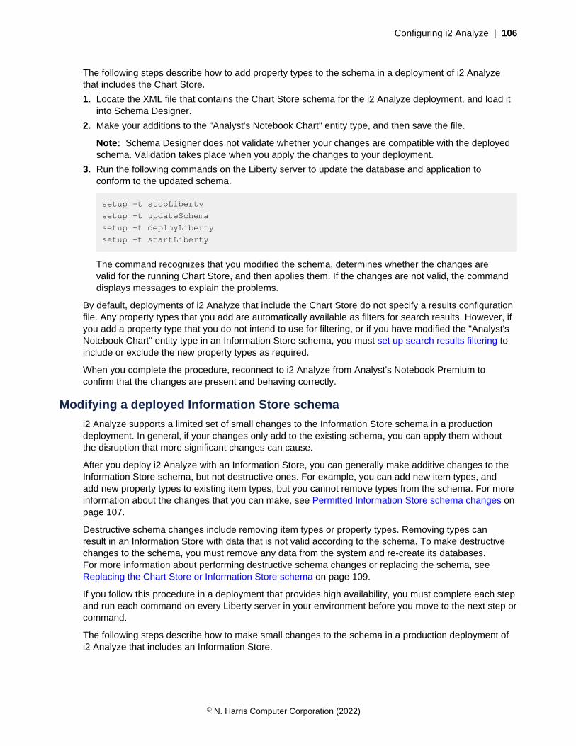
Configuring i2 Analyze | 106
The following steps describe how to add property types to the schema in a deployment of i2 Analyzethat includes the Chart Store.
1. Locate the XML file that contains the Chart Store schema for the i2 Analyze deployment, and load itinto Schema Designer.
2. Make your additions to the "Analyst's Notebook Chart" entity type, and then save the file.
Note: Schema Designer does not validate whether your changes are compatible with the deployedschema. Validation takes place when you apply the changes to your deployment.
3. Run the following commands on the Liberty server to update the database and application toconform to the updated schema.
setup -t stopLiberty
setup -t updateSchema
setup -t deployLiberty
setup -t startLiberty
The command recognizes that you modified the schema, determines whether the changes arevalid for the running Chart Store, and then applies them. If the changes are not valid, the commanddisplays messages to explain the problems.
By default, deployments of i2 Analyze that include the Chart Store do not specify a results configurationfile. Any property types that you add are automatically available as filters for search results. However, ifyou add a property type that you do not intend to use for filtering, or if you have modified the "Analyst'sNotebook Chart" entity type in an Information Store schema, you must set up search results filtering toinclude or exclude the new property types as required.
When you complete the procedure, reconnect to i2 Analyze from Analyst's Notebook Premium toconfirm that the changes are present and behaving correctly.
Modifying a deployed Information Store schema
i2 Analyze supports a limited set of small changes to the Information Store schema in a productiondeployment. In general, if your changes only add to the existing schema, you can apply them withoutthe disruption that more significant changes can cause.
After you deploy i2 Analyze with an Information Store, you can generally make additive changes to theInformation Store schema, but not destructive ones. For example, you can add new item types, andadd new property types to existing item types, but you cannot remove types from the schema. For moreinformation about the changes that you can make, see Permitted Information Store schema changes onpage 107.
Destructive schema changes include removing item types or property types. Removing types canresult in an Information Store with data that is not valid according to the schema. To make destructivechanges to the schema, you must remove any data from the system and re-create its databases.For more information about performing destructive schema changes or replacing the schema, seeReplacing the Chart Store or Information Store schema on page 109.
If you follow this procedure in a deployment that provides high availability, you must complete each stepand run each command on every Liberty server in your environment before you move to the next step orcommand.
The following steps describe how to make small changes to the schema in a production deployment ofi2 Analyze that includes an Information Store.
© N. Harris Computer Corporation (2022)

Configuring i2 Analyze | 107
1. Locate the XML file that contains the Information Store schema for the i2 Analyze deployment, andload it into Schema Designer.
2. Make your changes to the schema and its associated charting schemes, and then save the file.
Note: Schema Designer does not validate whether your changes are compatible with the deployedschema. Validation takes place when you apply the changes to your deployment.
3. Run the following commands on the Liberty server to update the database and application toconform to the updated schema.
setup -t stopLiberty
setup -t updateSchema
setup -t deployLiberty
setup -t startLiberty
The command recognizes that you modified the schema, determines whether the changes are validfor the running Information Store, and then applies them. If the changes are not valid, the commanddisplays messages to explain the problems.
Note: If you customized the Information Store creation process by specifyingcreatedatabase="false" in the topology file and running the scripts yourself, this commandworks in the same way. Execution stops so that you can customize the changes to the InformationStore. After you apply the changes, you can run the task again to complete the process.
Because you can make only additive changes to an Information Store schema that you modify throughthis procedure, it is not mandatory to change other parts of your deployment. However, to take fulladvantage of your additions, consider the following complementary changes.
• To enable the Information Store to ingest data for the new item types and property types, modifyyour ingestion artifacts. See Information Store data ingestion.
• If your deployment includes definitions of the property values of merged i2 Analyze records, youmust update your merged property values definition views. See Define how property values ofmerged records are calculated.
• If you want users to see the new types in quick search filters, edit the configuration file that controlsthem. See Setting up search results filtering.
• If your deployment includes highlight queries, you can update them for the new item and propertytypes. For more information, see Deploying highlight queries on page 194.
Permitted Information Store schema changes
After you create an Information Store schema and use it in a deployment, i2 Analyze restrictssubsequent changes to that schema to ensure that data in the system remains accessible. In general,you can add content to a published Information Store schema, but you cannot take content away.
To be specific, i2 Analyze prevents changes to a schema that might invalidate data that is alreadystored. For example, if you remove an item type from the Information Store schema, then the storemight contain data for which i2 Analyze no longer has a definition. However, you can make additivechanges to the schema. You can also disable or hide item or property types in some parts of thesystem, if you are certain that they are no longer required.
Permitted changes
You can make the following changes to the Information Store schema of a live deployment:
• Add an item type.
© N. Harris Computer Corporation (2022)
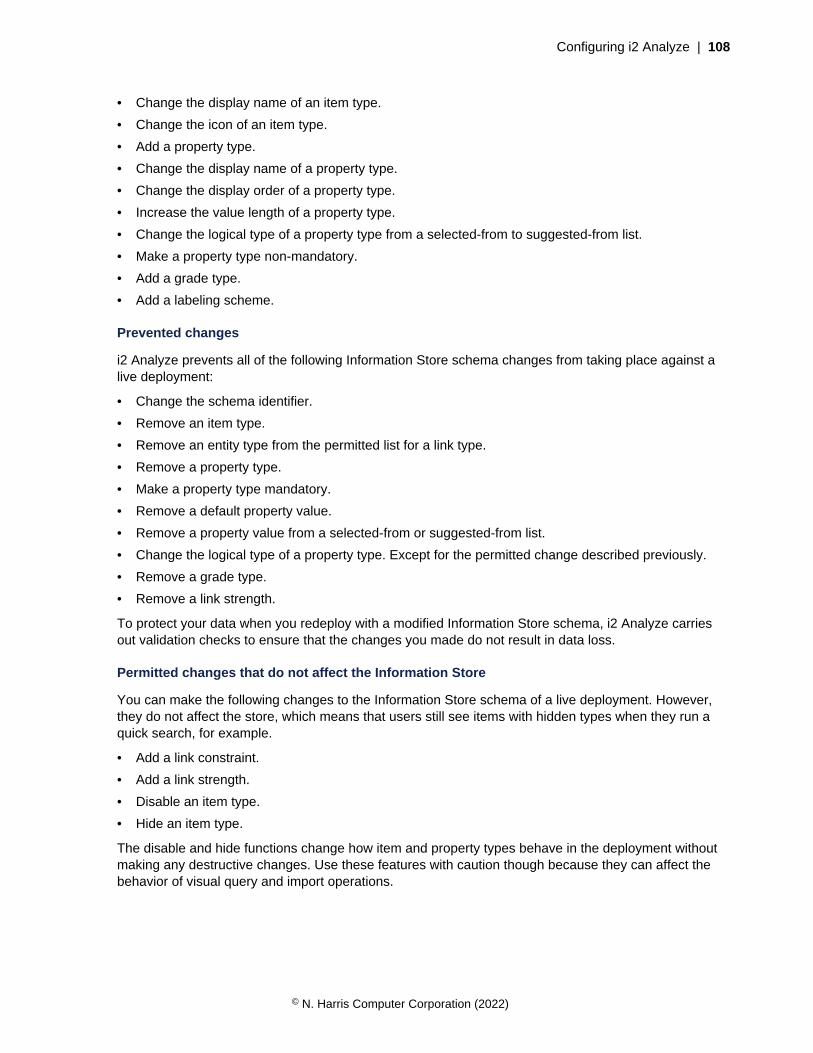
Configuring i2 Analyze | 108
• Change the display name of an item type.
• Change the icon of an item type.
• Add a property type.
• Change the display name of a property type.
• Change the display order of a property type.
• Increase the value length of a property type.
• Change the logical type of a property type from a selected-from to suggested-from list.
• Make a property type non-mandatory.
• Add a grade type.
• Add a labeling scheme.
Prevented changes
i2 Analyze prevents all of the following Information Store schema changes from taking place against alive deployment:
• Change the schema identifier.
• Remove an item type.
• Remove an entity type from the permitted list for a link type.
• Remove a property type.
• Make a property type mandatory.
• Remove a default property value.
• Remove a property value from a selected-from or suggested-from list.
• Change the logical type of a property type. Except for the permitted change described previously.
• Remove a grade type.
• Remove a link strength.
To protect your data when you redeploy with a modified Information Store schema, i2 Analyze carriesout validation checks to ensure that the changes you made do not result in data loss.
Permitted changes that do not affect the Information Store
You can make the following changes to the Information Store schema of a live deployment. However,they do not affect the store, which means that users still see items with hidden types when they run aquick search, for example.
• Add a link constraint.
• Add a link strength.
• Disable an item type.
• Hide an item type.
The disable and hide functions change how item and property types behave in the deployment withoutmaking any destructive changes. Use these features with caution though because they can affect thebehavior of visual query and import operations.
© N. Harris Computer Corporation (2022)
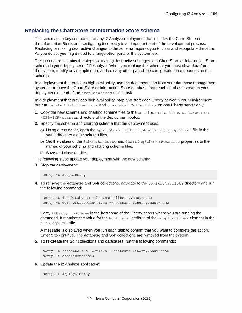
Configuring i2 Analyze | 109
Replacing the Chart Store or Information Store schema
The schema is a key component of any i2 Analyze deployment that includes the Chart Store orthe Information Store, and configuring it correctly is an important part of the development process.Replacing or making destructive changes to the schema requires you to clear and repopulate the store.As you do so, you might need to change other parts of the system too.
This procedure contains the steps for making destructive changes to a Chart Store or Information Storeschema in your deployment of i2 Analyze. When you replace the schema, you must clear data fromthe system, modify any sample data, and edit any other part of the configuration that depends on theschema.
In a deployment that provides high availability, use the documentation from your database managementsystem to remove the Chart Store or Information Store database from each database server in yourdeployment instead of the dropDatabases toolkit task.
In a deployment that provides high availability, stop and start each Liberty server in your environmentbut run deleteSolrCollections and createSolrCollections on one Liberty server only.
1. Copy the new schema and charting scheme files to the configuration\fragments\common\WEB-INF\classes directory of the deployment toolkit.
2. Specify the schema and charting scheme that the deployment uses.
a) Using a text editor, open the ApolloServerSettingsMandatory.properties file in thesame directory as the schema files.
b) Set the values of the SchemaResource and ChartingSchemesResource properties to thenames of your schema and charting scheme files.
c) Save and close the file.
The following steps update your deployment with the new schema.
3. Stop the deployment:
setup -t stopLiberty
4. To remove the database and Solr collections, navigate to the toolkit\scripts directory and runthe following command:
setup -t dropDatabases --hostname liberty.host-name
setup -t deleteSolrCollections --hostname liberty.host-name
Here, liberty.hostname is the hostname of the Liberty server where you are running thecommand. It matches the value for the host-name attribute of the <application> element in thetopology.xml file.
A message is displayed when you run each task to confirm that you want to complete the action.Enter Y to continue. The database and Solr collections are removed from the system.
5. To re-create the Solr collections and databases, run the following commands:
setup -t createSolrCollections --hostname liberty.host-name
setup -t createDatabases
6. Update the i2 Analyze application:
setup -t deployLiberty
© N. Harris Computer Corporation (2022)

Configuring i2 Analyze | 110
7. Update the schema:
setup -t updateSchema
8. Start Liberty:
setup -t startLiberty
If you are using a results configuration file, configure the facets to match the item and property typesthat you added or changed in the Information Store schema. See Setting up search results filtering onpage 209.
If you are defining the property values of merged i2 Analyze records, you must update your mergedproperty values definition views. See Define how property values of merged records are calculated.
Adding, removing, modifying gateway schemas
A single deployment of i2 Analyze that includes the i2 Connect gateway can containseveral gateway schemas. When you add or remove gateway schemas, you must edit theApolloServerSettingsMandatory.properties file. It is likely that you must edit some of theother configuration files and settings too.
When several connectors query the same data source, it can make sense for them to share a gatewayschema instead of defining schemas of their own. If you buy or develop more than one set of suchconnectors, then it is possible for your deployment of i2 Analyze to use several gateway schemas. Thesection of the settings file then looks like this:
Gateway.SourceOne.SchemaResource=
Gateway.SourceOne.ChartingSchemesResource=
Gateway.SourceTwo.SchemaResource=
Gateway.SourceTwo.ChartingSchemesResource=
For each gateway schema that you add to a deployment, you must add two entries to this list with a newname in place of SourceOne or SourceTwo. If you remove a gateway schema, make sure to removeboth entries that were associated with that schema.
If you follow this procedure in a deployment that provides high availability, you must complete each stepand run each command on every Liberty server in your environment before you move to the next step orcommand.
After you add or remove the settings for a particular gateway schema fromApolloServerSettingsMandatory.properties, check other aspects of your systemconfiguration.
1. Before you reload the i2 Analyze server to reflect your changes, make sure that the resultsconfiguration file matches your new set of gateway schemas.
a) Open the file indicated by the ResultsConfigurationResource property inDiscoServerSettingsCommon.properties and follow the instructions in Setting up searchresults filtering on page 209 to remove references to item types from removed gatewayschemas.
b) Add or edit elements in the file to enable result filtering on item and property types in any newgateway schemas.
2. Follow the instructions in Modifying and testing a connector to reload the server and update itsinformation about the gateway schemas.
© N. Harris Computer Corporation (2022)

Configuring i2 Analyze | 111
3. Follow the instructions in Configuring matching on page 214 to make any changes to the systemor Find Matching Records match rules files that are required as a result of your changes to theconfigured schemas.
4. If your deployment uses them, update the set of type conversion mappings.
a) Open a web browser and navigate to the i2 Analyze server admin console, as described inModifying and testing a connector.
b) In the i2 Analyze type conversion app, add, edit, or remove type conversion mappings to reflectthe new set of gateway schemas.
c) Export the modified conversion mappings. Copy the resulting mapping-configuration.jsonfile to the deployment toolkit's configuration\fragments\common\WEB-INF\classesdirectory.
d) Redeploy Liberty to update the type conversion mappings on the server.
On completion of the above steps, your i2 Analyze deployment is fully updated in response to thechanges that you introduced by adding, removing, or modifying a gateway schema.
Configuring the security schemaAfter you deploy an i2 Analyze security schema, there are restrictions on the changes that you canmake to the security schema. The actions that you perform to update a deployed security schemadepend on the changes that you make.
You are relatively free to create security groups and permissions, add security dimension values toexisting security dimensions, and change any display names. For more information about performingthese types of change, see Modifying security permissions on page 113 and Modifying securitydimensions on page 111.
If you want to replace the security schema, make destructive changes, and add security dimensions,you must remove and re-create the underlying database in the system. For more information aboutperforming these types of change, see Replacing a security schema on page 116.
Important: To change the schema in the way that this documentation describes, your deploymentmust use the supplied WebSphereDynamicAccessRoleBasedPrincipalProvider securityimplementation.
Modifying security dimensions
You can add dimension values to security dimensions, and you can make cosmetic changes todimensions and values without clearing your data from the system.
The following table shows the changes that you can make to the security dimensions in a deployedsecurity schema without clearing data from the system. It also states whether a reindex is required if thechange takes place:
Change XML elements orattributes
Allowed Reindexrequired
Add a security dimension <Dimension> No N/A
Modify an existing security dimension DisplayName,Description
Yes No
Remove an existing security dimension <Dimension> No N/A
© N. Harris Computer Corporation (2022)
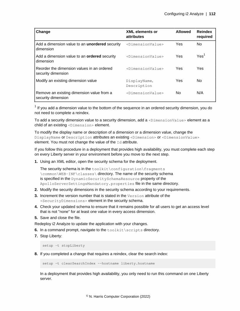
Configuring i2 Analyze | 112
Change XML elements orattributes
Allowed Reindexrequired
Add a dimension value to an unordered securitydimension
<DimensionValue> Yes No
Add a dimension value to an ordered securitydimension
<DimensionValue> Yes Yes1
Reorder the dimension values in an orderedsecurity dimension
<DimensionValue> Yes Yes
Modify an existing dimension value DisplayName,Description
Yes No
Remove an existing dimension value from asecurity dimension
<DimensionValue> No N/A
1 If you add a dimension value to the bottom of the sequence in an ordered security dimension, you donot need to complete a reindex.
To add a security dimension value to a security dimension, add a <DimensionValue> element as achild of an existing <Dimension> element.
To modify the display name or description of a dimension or a dimension value, change theDisplayName or Description attributes an existing <Dimension> or <DimensionValue>element. You must not change the value of the Id attribute.
If you follow this procedure in a deployment that provides high availability, you must complete each stepon every Liberty server in your environment before you move to the next step.
1. Using an XML editor, open the security schema for the deployment.
The security schema is in the toolkit\configuration\fragments\common\WEB-INF\classes\ directory. The name of the security schemais specified in the DynamicSecuritySchemaResource property of theApolloServerSettingsMandatory.properties file in the same directory.
2. Modify the security dimensions in the security schema according to your requirements.
3. Increment the version number that is stated in the Version attribute of the<SecurityDimensions> element in the security schema.
4. Check your updated schema to ensure that it remains possible for all users to get an access levelthat is not "none" for at least one value in every access dimension.
5. Save and close the file.
Redeploy i2 Analyze to update the application with your changes.
6. In a command prompt, navigate to the toolkit\scripts directory.
7. Stop Liberty:
setup -t stopLiberty
8. If you completed a change that requires a reindex, clear the search index:
setup -t clearSearchIndex --hostname liberty.hostname
In a deployment that provides high availability, you only need to run this command on one Libertyserver.
© N. Harris Computer Corporation (2022)

Configuring i2 Analyze | 113
9. Update and redeploy the system:
setup -t updateSecuritySchema
setup -t deployLiberty
10.Start Liberty:
setup -t startLiberty
Modifying security permissions
It is possible to change the mapping between user groups and the security permissions that the securityschema defines without reimporting or reindexing your data. You must take care to ensure that all i2Analyze users retain the ability to access your deployment.
The following table shows the changes that you can make to the security permissions in a deployedsecurity schema without clearing data from the system:
Change XML elements orattributes
Allowed Reindexrequired
Add a security group <GroupPermissions> Yes No
Modify an existing security group UserGroup Yes No
Remove an existing security group <GroupPermissions> Yes No
Add security dimensions to a security group <Permissions> Yes No
Remove security dimension from a security group <Permissions> Yes No
Add security permissions from a securitydimension for a security group
<Permission> Yes No
Modify existing security level from a securitydimension permission for a security group
DimensionValue, Level Yes No
Remove existing security permissions from asecurity dimension permissions element for asecurity group
<Permission> Yes No
If the requirements for security groups change, you can modify the <GroupPermissions> elementand its children.
• To add a group, insert a complete <GroupPermissions> element. To use the new group, youmust ensure that the user repository contains a group that matches the value of the UserGroupattribute.
• To modify the name that is associated with a group, change the value of the UserGroup attribute.
• To remove a group, remove the <GroupPermissions> element for that group.
If the requirements for the permissions of a security group change, you can add or remove<Permissions> elements, and add, modify, and remove child <Permission> elements.
• To change the dimensions that a group has permissions for, you can add or remove<Permissions> elements as follows:
• To add a dimension that the group has permissions for, insert a <Permissions> element wherethe value of the Id attribute matches the value of the Id attribute of the dimension.
© N. Harris Computer Corporation (2022)
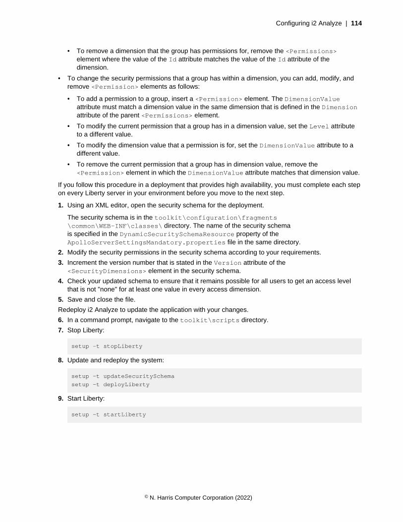
Configuring i2 Analyze | 114
• To remove a dimension that the group has permissions for, remove the <Permissions>element where the value of the Id attribute matches the value of the Id attribute of thedimension.
• To change the security permissions that a group has within a dimension, you can add, modify, andremove <Permission> elements as follows:
• To add a permission to a group, insert a <Permission> element. The DimensionValueattribute must match a dimension value in the same dimension that is defined in the Dimensionattribute of the parent <Permissions> element.
• To modify the current permission that a group has in a dimension value, set the Level attributeto a different value.
• To modify the dimension value that a permission is for, set the DimensionValue attribute to adifferent value.
• To remove the current permission that a group has in dimension value, remove the<Permission> element in which the DimensionValue attribute matches that dimension value.
If you follow this procedure in a deployment that provides high availability, you must complete each stepon every Liberty server in your environment before you move to the next step.
1. Using an XML editor, open the security schema for the deployment.
The security schema is in the toolkit\configuration\fragments\common\WEB-INF\classes\ directory. The name of the security schemais specified in the DynamicSecuritySchemaResource property of theApolloServerSettingsMandatory.properties file in the same directory.
2. Modify the security permissions in the security schema according to your requirements.
3. Increment the version number that is stated in the Version attribute of the<SecurityDimensions> element in the security schema.
4. Check your updated schema to ensure that it remains possible for all users to get an access levelthat is not "none" for at least one value in every access dimension.
5. Save and close the file.
Redeploy i2 Analyze to update the application with your changes.
6. In a command prompt, navigate to the toolkit\scripts directory.
7. Stop Liberty:
setup -t stopLiberty
8. Update and redeploy the system:
setup -t updateSecuritySchema
setup -t deployLiberty
9. Start Liberty:
setup -t startLiberty
© N. Harris Computer Corporation (2022)

Configuring i2 Analyze | 115
Setting default dimension values
When users create i2 Analyze records in Analyst's Notebook Premium, i2 Analyze applies a defaultset of dimension values to the record. Similarly, when the Information Store ingests data, the createdrecords receive dimension values during the process.
You might change the default security dimension values that are applied to records for different reasons:
• If you change the dimensions or dimension values in your security schema.
• If the security requirements of your deployment change.
Regardless of your reason for changing the default security dimension values, or when the values areapplied, each record must have at least one dimension value from each security dimension.
If you follow this procedure in a deployment that provides high availability, you must complete each stepon every Liberty server in your environment before you move to the next step.
1. Using an XML editor, open the security schema for the deployment.
The security schema is in the toolkit\configuration\fragments\common\WEB-INF\classes\ directory. The name of the security schemais specified in the DynamicSecuritySchemaResource property of theApolloServerSettingsMandatory.properties file in the same directory.
2. Update the value of the <DefaultSecurityDimensionValues> element with a commaseparated list of identifiers of security dimension values that you want to be applied by default.
For example, <DefaultSecurityDimensionValues>CON,OSI,HI</DefaultSecurityDimensionValues>.
In a standard deployment of i2 Analyze, a supplied implementation of theDefaultSecurityDimensionValuesProvider that applies dimension values fromthe <DefaultSecurityDimensionValues> element is used. You can create your ownimplementation that does not use these values by using i2 Analyze Developer Essentials.
3. When data is ingested into the Information Store, the records that it contains receive their securitydimension values during the ingestion process.
To change the behavior of the ingestion process, update the contents of the<securityDimensionValues> element in the mapping file with the identifiers of securitydimension values that you want to be applied by default. For more information about updating thedefault security dimension values that are applied during ingestion, see Information Store dataingestion.
4. In a command prompt, navigate to the toolkit\scripts directory.
5. Stop Liberty:
setup -t stopLiberty
6. Update the i2 Analyze application:
setup -t updateSecuritySchema
setup -t deployLiberty
7. Start Liberty:
setup -t startLiberty
© N. Harris Computer Corporation (2022)

Configuring i2 Analyze | 116
Replacing a security schema
The security schema is a key component of an i2 Analyze deployment, and configuring it correctly isan important part of the development process. Replacing or making destructive changes to the securityschema requires you to clear and repopulate the data stores in your deployment.
In a deployment that provides high availability, use the documentation from your database managementsystem to remove the Information Store database from each database server in your deploymentinstead of the dropDatabases toolkit task.
In a deployment that provides high availability, stop and start each Liberty server in your environmentbut run deleteSolrCollections and createSolrCollections on one Liberty server only.
1. Modify or create the security schema that you want to update your deployment with.
For more information about creating the security schema, see Creating a security schema on page117.
2. Update the configuration with your security schema.
a) Ensure that the security schema file is in the configuration\fragments\common\WEB-INF\classes directory.
b) Ensure that your security schema file is specified in configuration\fragments\common\WEB-INF\classes\ApolloServerSettingsMandatory.properties.
c) Ensure that the identifiers of the security dimension values that records receive by default arevalid in the <DefaultSecurityDimensionValues> element in your security schema.
For more information, see Setting default dimension values on page 115.
The following steps update your deployment with the new security schema.
3. Stop the deployment:
setup -t stopLiberty
4. To remove the database and Solr collections, navigate to the toolkit\scripts directory and runthe following command:
setup -t dropDatabases --hostname liberty.host-name
setup -t deleteSolrCollections --hostname liberty.host-name
Here, liberty.hostname is the hostname of the Liberty server where you are running thecommand. It matches the value for the host-name attribute of the <application> element in thetopology.xml file.
A message is displayed when you run each task to confirm that you want to complete the action.Enter Y to continue. The database and Solr collections are removed from the system.
5. To re-create the Solr collections and databases, run the following commands:
setup -t createSolrCollections --hostname liberty.host-name
setup -t createDatabases
6. Update and redeploy the system:
setup -t updateSecuritySchema
setup -t deployLiberty
© N. Harris Computer Corporation (2022)
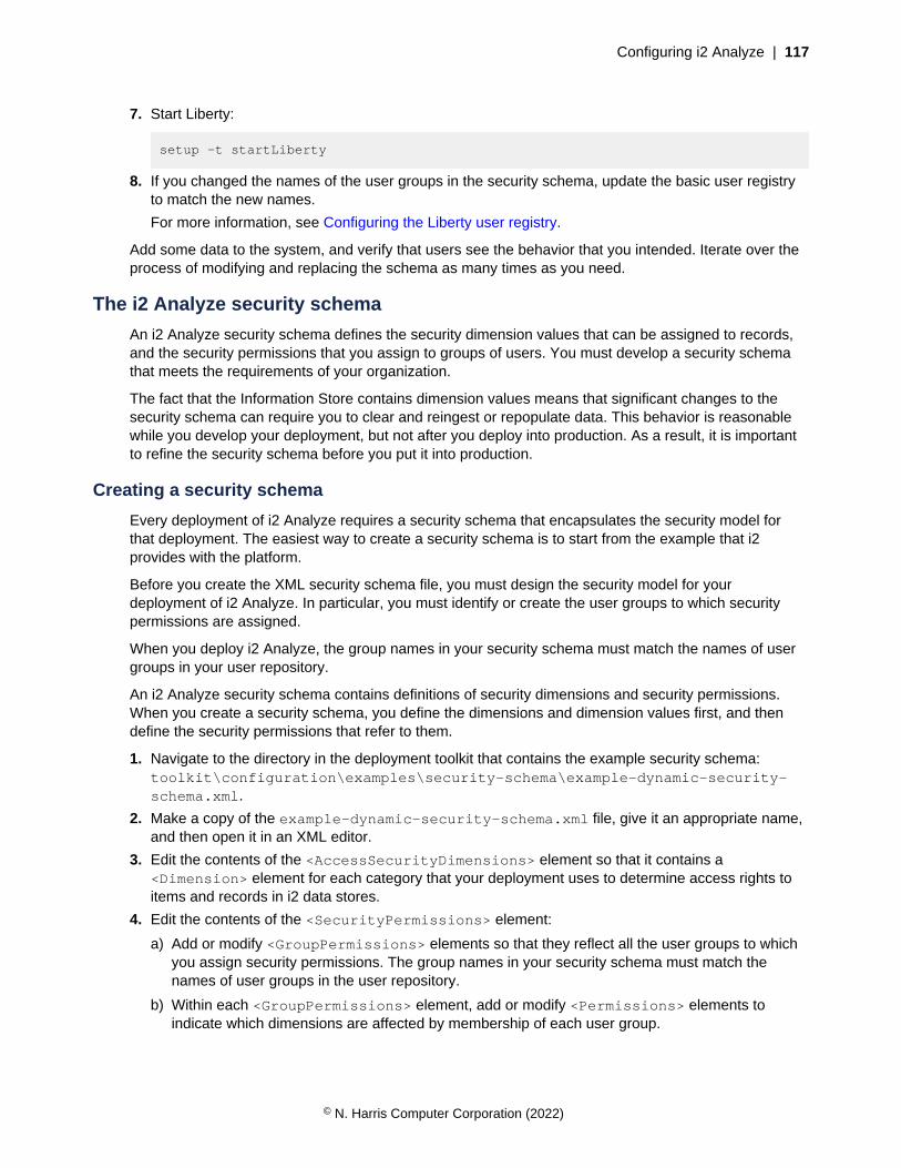
Configuring i2 Analyze | 117
7. Start Liberty:
setup -t startLiberty
8. If you changed the names of the user groups in the security schema, update the basic user registryto match the new names.
For more information, see Configuring the Liberty user registry.
Add some data to the system, and verify that users see the behavior that you intended. Iterate over theprocess of modifying and replacing the schema as many times as you need.
The i2 Analyze security schema
An i2 Analyze security schema defines the security dimension values that can be assigned to records,and the security permissions that you assign to groups of users. You must develop a security schemathat meets the requirements of your organization.
The fact that the Information Store contains dimension values means that significant changes to thesecurity schema can require you to clear and reingest or repopulate data. This behavior is reasonablewhile you develop your deployment, but not after you deploy into production. As a result, it is importantto refine the security schema before you put it into production.
Creating a security schema
Every deployment of i2 Analyze requires a security schema that encapsulates the security model forthat deployment. The easiest way to create a security schema is to start from the example that i2provides with the platform.
Before you create the XML security schema file, you must design the security model for yourdeployment of i2 Analyze. In particular, you must identify or create the user groups to which securitypermissions are assigned.
When you deploy i2 Analyze, the group names in your security schema must match the names of usergroups in your user repository.
An i2 Analyze security schema contains definitions of security dimensions and security permissions.When you create a security schema, you define the dimensions and dimension values first, and thendefine the security permissions that refer to them.
1. Navigate to the directory in the deployment toolkit that contains the example security schema:toolkit\configuration\examples\security-schema\example-dynamic-security-schema.xml.
2. Make a copy of the example-dynamic-security-schema.xml file, give it an appropriate name,and then open it in an XML editor.
3. Edit the contents of the <AccessSecurityDimensions> element so that it contains a<Dimension> element for each category that your deployment uses to determine access rights toitems and records in i2 data stores.
4. Edit the contents of the <SecurityPermissions> element:
a) Add or modify <GroupPermissions> elements so that they reflect all the user groups to whichyou assign security permissions. The group names in your security schema must match thenames of user groups in the user repository.
b) Within each <GroupPermissions> element, add or modify <Permissions> elements toindicate which dimensions are affected by membership of each user group.
© N. Harris Computer Corporation (2022)

Configuring i2 Analyze | 118
c) Within each <Permissions> element, add or modify <Permission> elements to assignsecurity levels to items and records that have particular dimension values.
There are three permitted values for the Level attribute of the <Permission> element:
• NONE
• READ_ONLY
• UPDATE
5. Edit the contents of the <DefaultSecurityDimensionValues> element to define the defaultsecurity dimension values that i2 Analyze provides to records that users create in Analyst's NotebookPremium.
Update the value of the <DefaultSecurityDimensionValues> element with a commaseparated list of identifiers of security dimension values that you want to be appliedby default. For example, <DefaultSecurityDimensionValues>CON,OSI,HI</DefaultSecurityDimensionValues>.
6. Save the completed security schema to the configuration\fragments\common\WEB-INF\classes directory in the deployment toolkit.
Security schemas
An i2 Analyze security schema defines the security dimensions that exist in a deployment, and thedimension values that can be assigned to items and records. A security schema also defines thepermissions that i2 Analyze users can receive.
Every deployment of i2 Analyze has a security schema whose contents reflect local requirements. It isthe responsibility of the deployer to ensure that the security schema is appropriate for the environmentwhere it is used. Often, the security dimensions map to security classifications that exist in theorganization.
Before you create a security schema, it is important to understand the relationship between the securitymodel and the security schema. For more information, see i2 Analyze security model .
Security dimensions
A security schema defines access security dimensions that contain dimensions and dimension values.
Security permissions
A security schema defines security permissions by user group, and then by dimension. For a particularuser group, the schema identifies one or more dimensions for which membership of that group affectsaccess rights. For each identified dimension, the schema contains a list of security permissions.
It is not necessary for the security schema to define permissions for every user group in theorganization. Similarly, it is not necessary for the permissions within any particular dimension or groupto set a security level for every possible dimension value. The completeness of the schema is judged atrun time when the security level of a particular user for a particular item or record is calculated.
© N. Harris Computer Corporation (2022)
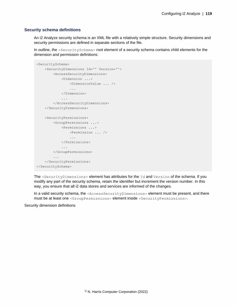
Configuring i2 Analyze | 119
Security schema definitions
An i2 Analyze security schema is an XML file with a relatively simple structure. Security dimensions andsecurity permissions are defined in separate sections of the file.
In outline, the <SecuritySchema> root element of a security schema contains child elements for thedimension and permission definitions:
<SecuritySchema>
<SecurityDimensions Id="" Version="">
<AccessSecurityDimensions>
<Dimension ...>
<DimensionValue ... />
...
</Dimension>
...
</AccessSecurityDimensions>
</SecurityDimensions>
<SecurityPermissions>
<GroupPermissions ...>
<Permissions ...>
<Permission ... />
...
</Permissions>
...
</GroupPermissions>
...
</SecurityPermissions>
</SecuritySchema>
The <SecurityDimensions> element has attributes for the Id and Version of the schema. If youmodify any part of the security schema, retain the identifier but increment the version number. In thisway, you ensure that all i2 data stores and services are informed of the changes.
In a valid security schema, the <AccessSecurityDimensions> element must be present, and theremust be at least one <GroupPermissions> element inside <SecurityPermissions>.
Security dimension definitions
© N. Harris Computer Corporation (2022)
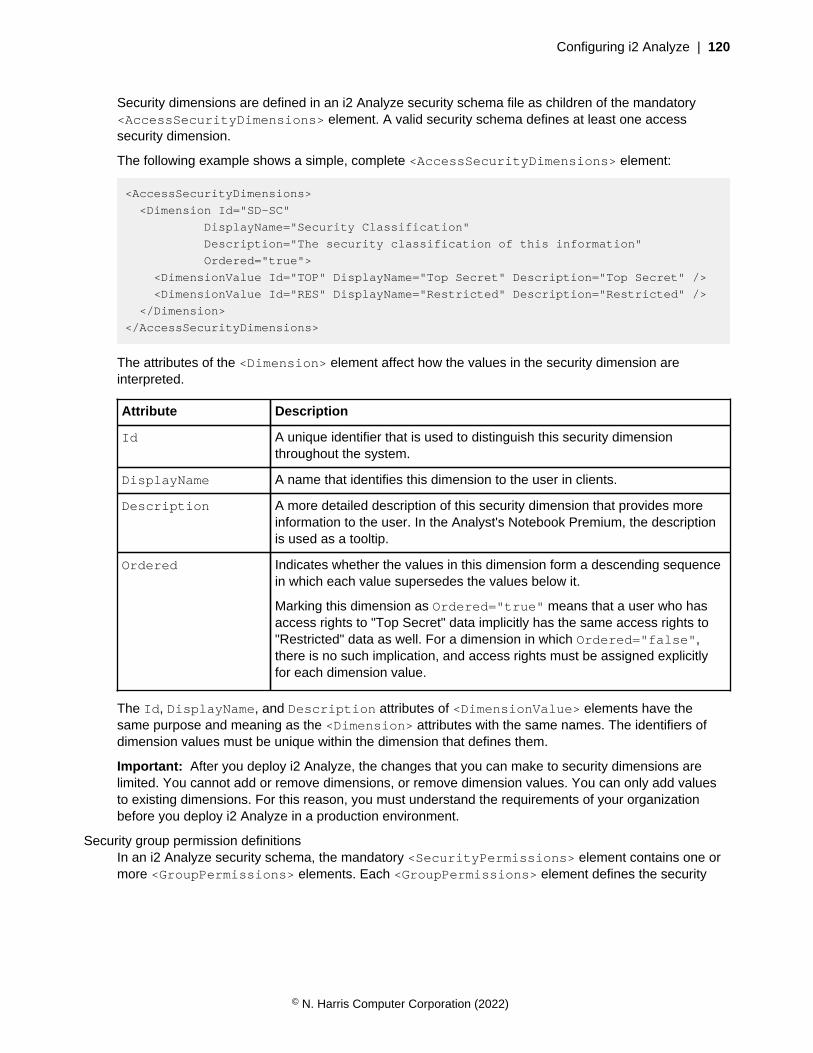
Configuring i2 Analyze | 120
Security dimensions are defined in an i2 Analyze security schema file as children of the mandatory<AccessSecurityDimensions> element. A valid security schema defines at least one accesssecurity dimension.
The following example shows a simple, complete <AccessSecurityDimensions> element:
<AccessSecurityDimensions>
<Dimension Id="SD-SC"
DisplayName="Security Classification"
Description="The security classification of this information"
Ordered="true">
<DimensionValue Id="TOP" DisplayName="Top Secret" Description="Top Secret" />
<DimensionValue Id="RES" DisplayName="Restricted" Description="Restricted" />
</Dimension>
</AccessSecurityDimensions>
The attributes of the <Dimension> element affect how the values in the security dimension areinterpreted.
Attribute Description
Id A unique identifier that is used to distinguish this security dimensionthroughout the system.
DisplayName A name that identifies this dimension to the user in clients.
Description A more detailed description of this security dimension that provides moreinformation to the user. In the Analyst's Notebook Premium, the descriptionis used as a tooltip.
Ordered Indicates whether the values in this dimension form a descending sequencein which each value supersedes the values below it.
Marking this dimension as Ordered="true" means that a user who hasaccess rights to "Top Secret" data implicitly has the same access rights to"Restricted" data as well. For a dimension in which Ordered="false",there is no such implication, and access rights must be assigned explicitlyfor each dimension value.
The Id, DisplayName, and Description attributes of <DimensionValue> elements have thesame purpose and meaning as the <Dimension> attributes with the same names. The identifiers ofdimension values must be unique within the dimension that defines them.
Important: After you deploy i2 Analyze, the changes that you can make to security dimensions arelimited. You cannot add or remove dimensions, or remove dimension values. You can only add valuesto existing dimensions. For this reason, you must understand the requirements of your organizationbefore you deploy i2 Analyze in a production environment.
Security group permission definitionsIn an i2 Analyze security schema, the mandatory <SecurityPermissions> element contains one ormore <GroupPermissions> elements. Each <GroupPermissions> element defines the security
© N. Harris Computer Corporation (2022)
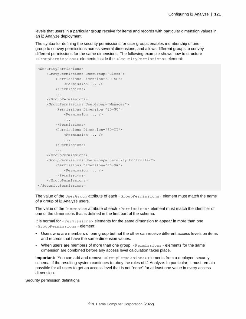
Configuring i2 Analyze | 121
levels that users in a particular group receive for items and records with particular dimension values inan i2 Analyze deployment.
The syntax for defining the security permissions for user groups enables membership of onegroup to convey permissions across several dimensions, and allows different groups to conveydifferent permissions for the same dimensions. The following example shows how to structure<GroupPermissions> elements inside the <SecurityPermissions> element:
<SecurityPermissions>
<GroupPermissions UserGroup="Clerk">
<Permissions Dimension="SD-SC">
<Permission ... />
</Permissions>
...
</GroupPermissions>
<GroupPermissions UserGroup="Manager">
<Permissions Dimension="SD-SC">
<Permission ... />
...
</Permissions>
<Permissions Dimension="SD-IT">
<Permission ... />
...
</Permissions>
...
</GroupPermissions>
<GroupPermissions UserGroup="Security Controller">
<Permissions Dimension="SD-GA">
<Permission ... />
</Permissions>
</GroupPermissions>
</SecurityPermissions>
The value of the UserGroup attribute of each <GroupPermissions> element must match the nameof a group of i2 Analyze users.
The value of the Dimension attribute of each <Permissions> element must match the identifier ofone of the dimensions that is defined in the first part of the schema.
It is normal for <Permissions> elements for the same dimension to appear in more than one<GroupPermissions> element:
• Users who are members of one group but not the other can receive different access levels on itemsand records that have the same dimension values.
• When users are members of more than one group, <Permissions> elements for the samedimension are combined before any access level calculation takes place.
Important: You can add and remove <GroupPermissions> elements from a deployed securityschema, if the resulting system continues to obey the rules of i2 Analyze. In particular, it must remainpossible for all users to get an access level that is not "none" for at least one value in every accessdimension.
Security permission definitions
© N. Harris Computer Corporation (2022)
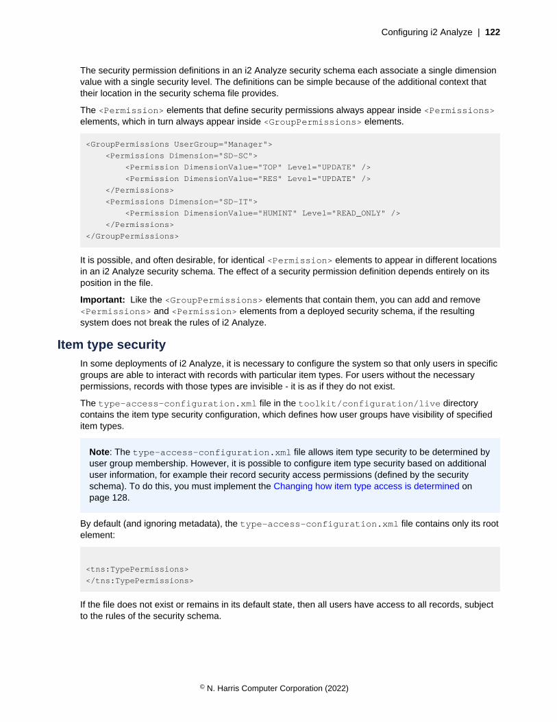
Configuring i2 Analyze | 122
The security permission definitions in an i2 Analyze security schema each associate a single dimensionvalue with a single security level. The definitions can be simple because of the additional context thattheir location in the security schema file provides.
The <Permission> elements that define security permissions always appear inside <Permissions>elements, which in turn always appear inside <GroupPermissions> elements.
<GroupPermissions UserGroup="Manager">
<Permissions Dimension="SD-SC">
<Permission DimensionValue="TOP" Level="UPDATE" />
<Permission DimensionValue="RES" Level="UPDATE" />
</Permissions>
<Permissions Dimension="SD-IT">
<Permission DimensionValue="HUMINT" Level="READ_ONLY" />
</Permissions>
</GroupPermissions>
It is possible, and often desirable, for identical <Permission> elements to appear in different locationsin an i2 Analyze security schema. The effect of a security permission definition depends entirely on itsposition in the file.
Important: Like the <GroupPermissions> elements that contain them, you can add and remove<Permissions> and <Permission> elements from a deployed security schema, if the resultingsystem does not break the rules of i2 Analyze.
Item type securityIn some deployments of i2 Analyze, it is necessary to configure the system so that only users in specificgroups are able to interact with records with particular item types. For users without the necessarypermissions, records with those types are invisible - it is as if they do not exist.
The type-access-configuration.xml file in the toolkit/configuration/live directorycontains the item type security configuration, which defines how user groups have visibility of specifieditem types.
Note: The type-access-configuration.xml file allows item type security to be determined byuser group membership. However, it is possible to configure item type security based on additionaluser information, for example their record security access permissions (defined by the securityschema). To do this, you must implement the Changing how item type access is determined onpage 128.
By default (and ignoring metadata), the type-access-configuration.xml file contains only its rootelement:
<tns:TypePermissions>
</tns:TypePermissions>
If the file does not exist or remains in its default state, then all users have access to all records, subjectto the rules of the security schema.
© N. Harris Computer Corporation (2022)
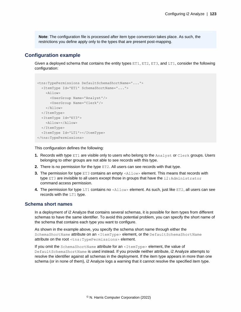
Configuring i2 Analyze | 123
Note: The configuration file is processed after item type conversion takes place. As such, therestrictions you define apply only to the types that are present post-mapping.
Configuration example
Given a deployed schema that contains the entity types ET1, ET2, ET3, and LT1, consider the followingconfiguration:
<tns:TypePermissions DefaultSchemaShortName="...">
<ItemType Id="ET1" SchemaShortName="...">
<Allow>
<UserGroup Name="Analyst"/>
<UserGroup Name="Clerk"/>
</Allow>
</ItemType>
<ItemType Id="ET3">
<Allow></Allow>
</ItemType>
<ItemType Id="LT1"></ItemType>
</tns:TypePermissions>
This configuration defines the following:
1. Records with type ET1 are visible only to users who belong to the Analyst or Clerk groups. Usersbelonging to other groups are not able to see records with this type.
2. There is no permission for the type ET2. All users can see records with that type.
3. The permission for type ET3 contains an empty <Allow> element. This means that records withtype ET3 are invisible to all users except those in groups that have the i2:Administratorcommand access permission.
4. The permission for type LT1 contains no <Allow> element. As such, just like ET2, all users can seerecords with the LT1 type.
Schema short names
In a deployment of i2 Analyze that contains several schemas, it is possible for item types from differentschemas to have the same identifier. To avoid this potential problem, you can specify the short name ofthe schema that contains each type you want to configure.
As shown in the example above, you specify the schema short name through either theSchemaShortName attribute on an <ItemType> element, or the DefaultSchemaShortNameattribute on the root <tns:TypePermissions> element.
If you omit the SchemaShortName attribute for an <ItemType> element, the value ofDefaultSchemaShortName is used instead. If you provide neither attribute, i2 Analyze attempts toresolve the identifier against all schemas in the deployment. If the item type appears in more than oneschema (or in none of them), i2 Analyze logs a warning that it cannot resolve the specified item type.
© N. Harris Computer Corporation (2022)
Configuring i2 Analyze | 124
Note: It is not possible to specify more than one <ItemType> element with the same Id andSchemaShortName attributes.
Other considerations
Take note of the following considerations when you configure item type security in your deployment of i2Analyze.
Command access control
Users in groups with the i2:Administrator command access permission are never affected by itemtype permissions.
Connectors & services
A connector service is hidden from the list of services on the client if all the possible item types of resultrecords, as defined by resultItemTypeIds in the service configuration, are invisible to the user. If allof a connector's services are hidden for this reason, the connector itself is hidden.
Entities & links
Item type security restrictions on one entity type have no implications for other entity types. Similarly,restrictions on one link type have no implications for other link types, or for entity types. However,restrictions on the visibility of entity records can also affect the visibility of link records.
Taking the example configuration above, the deployed schema might specify that the entity type ET1is the only permitted type for records at one end of links with type LT1. In other words, ET1 is the onlyentity type identifier in the fromTypeIds or toTypeIds attribute for the link type, like this:
<LinkType Id="LT1" FromTypeIds="ET1" ToTypeIds="ET2" ...>
In this situation, users who cannot see records of type ET1 also cannot see records of type LT1.
On the other hand, if the definition of LT1 specifies other valid link end types that are not restricted forthe same users, as in this case, then records of type LT1 remain visible:
<LinkType Id="LT1" FromTypeIds="ET1 ET2" ToTypeIds="ET2" ...>
Seeds
Item type security restrictions can affect the behavior of seeded search services. The following rulesapply to services configured with seedConstraints:
• If the service accepts seeds of a restricted type, and does not specify that it must have at least oneseed of that type (that is, it is possible to use the service without a seed of the restricted type), thenthat constraint is removed from the user's view.
• If the service accepts seeds of a restricted type, and it must have at least one seed of that type, thenthe service is removed from the user's view.
Item type conversion
As previously mentioned, item type restrictions apply only after item type conversion has taken place.
© N. Harris Computer Corporation (2022)

Configuring i2 Analyze | 125
Asynchronous queries
Asynchronous queries are validated when they are launched, to ensure that the seeds are visible to theuser.
If a user's permissions change after initiating the asynchronous query on the connector, the query runsto completion, but any results no longer visible to the user are filtered out of the result set (which mightbe empty as a result).
Changing item type permissions
By default, deployments of i2 Analyze do not define item type permissions. All users can see recordsof all types, provided that per-record security does not prevent them from doing so. To define orsubsequently modify item type permissions, you must edit and redeploy the type access configuration.
Before you begin
The type access configuration is one of a group of configuration files that you can modify and send tothe i2 Analyze server without the need for system downtime. These files are stored in the toolkit/configuration/live directory.
To enable updating the server without the need to restart it, ensure that you have access to acommand-line tool such as postman or curl.
Procedure
Edit the configuration file:
1. If you do not already have one, obtain and configure an XML editor.
2. In the XML editor, open the toolkit/configuration/live/type-access-configuration.xml file.
3. Using the The item type security configuration file on page 126 and Item type security on page122 information, modify the file to define the type access permissions that you need.
Update the deployment with your changes.
The following method deploys your changes without stopping the server, through a POST request to aREST endpoint.
To redeploy your changes using only the deployment toolkit, see Redeploying Liberty.
You must use the deployment toolkit if you are in a deployment with high availability, or if you aredeploying to your production environment.
1. At the command line, navigate to the toolkit/scripts directory.
2. Update the server with your configuration file:
setup -t updateLiveConfiguration
© N. Harris Computer Corporation (2022)

Configuring i2 Analyze | 126
3. Update the running application by using the reload endpoint. Make sure that you provide thecredentials of a user with administration rights:
curl -i --cookie-jar cookie.txt -d j_username=<user_name>
-d j_password=<password>
http://<host_name>/<context_root>/
j_security_check
curl -i --cookie cookie.txt -X
POST http://<host_name>/<context_root>/api/v1/admin/config/reload
Warning: reload updates the configuration without requiring a server restart, but any logged-inusers are logged out from i2 Analyze when you run it.
The server validates the item type configuration as it loads, and returns any errors in its response.
Test the new and updated item type permissions.
1. A good way to verify that your item type security configuration is loaded correctly is to call connectoror gateway schema endpoints and search the response body for an item type that the current usershould not be able to see.
The item type security configuration file
The type-access-configuration.xml file controls which users get access to each of the itemtypes declared in the schema. The set of permitted XML elements in an item type security configurationfile is relatively small.
Root element
<TypePermissions>
<TypePermissions> is the root element of the item type security configuration file. In the file thatdeployments of i2 Analyze receive by default, the element is empty and its name is prefixed with thetns namespace:
<tns:TypePermissions DefaultSchemaShortName="...">
...
</tns:TypePermissions>
The <TypePermissions> element has a single, optional attribute namedDefaultSchemaShortName. If the item types that you want to constrain are all or mostly defined in aparticular schema, then it is efficient to provide the short name of that schema here.
When the <TypePermissions> element is empty, there are no item type constraints on the recordsthat users can see.
© N. Harris Computer Corporation (2022)
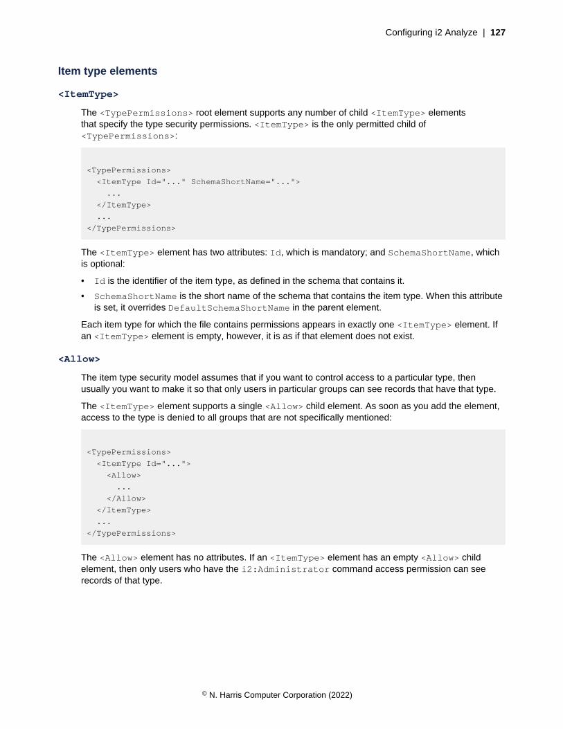
Configuring i2 Analyze | 127
Item type elements
<ItemType>
The <TypePermissions> root element supports any number of child <ItemType> elementsthat specify the type security permissions. <ItemType> is the only permitted child of<TypePermissions>:
<TypePermissions>
<ItemType Id="..." SchemaShortName="...">
...
</ItemType>
...
</TypePermissions>
The <ItemType> element has two attributes: Id, which is mandatory; and SchemaShortName, whichis optional:
• Id is the identifier of the item type, as defined in the schema that contains it.
• SchemaShortName is the short name of the schema that contains the item type. When this attributeis set, it overrides DefaultSchemaShortName in the parent element.
Each item type for which the file contains permissions appears in exactly one <ItemType> element. Ifan <ItemType> element is empty, however, it is as if that element does not exist.
<Allow>
The item type security model assumes that if you want to control access to a particular type, thenusually you want to make it so that only users in particular groups can see records that have that type.
The <ItemType> element supports a single <Allow> child element. As soon as you add the element,access to the type is denied to all groups that are not specifically mentioned:
<TypePermissions>
<ItemType Id="...">
<Allow>
...
</Allow>
</ItemType>
...
</TypePermissions>
The <Allow> element has no attributes. If an <ItemType> element has an empty <Allow> childelement, then only users who have the i2:Administrator command access permission can seerecords of that type.
© N. Harris Computer Corporation (2022)

Configuring i2 Analyze | 128
<UserGroup>
The <Allow> element supports any number of child <UserGroup> elements. Members of eachuser group that you specify (as well as users who have the i2:Administrator command accesspermission) are allowed to see records that have the parent item type:
<TypePermissions>
<ItemType Id="...">
<Allow>
<UserGroup Name="..."/>
...
</Allow>
</ItemType>
...
</TypePermissions>
The <UserGroup> element has a single, mandatory Name attribute. For each user group thatshould have permission to see records of the specified type, the <Allow> element must contain a<UserGroup> element whose Name attribute is set to the name of the user group.
Changing how item type access is determined
In some deployments of i2 Analyze, it is necessary to configure the system so that users are onlyable to access and interact with records with particular item types. By default, i2 Analyze determineswhich item types a user can access by their user group membership using the type-access-configuration.xml file. If this suits your needs, see Item type security on page 122 to learn howto configure users' access to item types in this way. To determine which item types a user can accessbased on other user information, you must implement the item type security SPI.
By implementing the item type security SPI, user item type access can be determined by anycombination of:
• User principal name
• User group membership
• User security dimension access permissions (defined by the i2 Analyze security schema)
The SPI is a set of Java interfaces that you can implement with your own Java classes. Then, you canconfigure i2 Analyze to use your implementation instead of the default one.
Implementing the SPI
See the com.i2group.disco.security.spi package in the i2 Analyze Security SPI documentationfor details, but the two interfaces that you need to implement are:
• IUserItemTypeAccessResolver. This interface is used to get the access levels assigned to aspecific user for each item type.
• IUserItemTypeAccessResolverProvider. This is the interface that i2 Analyze uses to obtainIUserItemTypeAccessResolver instances for specific users. It also exposes a method thatallows you to validate and reload the item type security configuration on server startup and reload.
You must package your SPI implementation into a single JAR file.
© N. Harris Computer Corporation (2022)

Configuring i2 Analyze | 129
Configuring i2 Analyze to use your implementation
Note: Customizing item type access resolution should take place during the development phase of yourdeployment, in the configuration development environment. See Deployment phases and environments
for more information.
For i2 Analyze to use your item type security implementation, you must:
1. Copy the JAR file containing your implementation into the toolkit/configuration/fragments/opal-services/WEB-INF/lib i2 Analyze toolkit directory where it will be deployedinto the application.
2. Instruct i2 Analyze to use your implementation by setting theIUserItemTypeAccessResolverProvider property in the toolkit/configuration/fragments/opal-services/WEB-INF/classes/DiscoServerSettingsCommon.properties file to the fully qualified class name of yourIUserItemTypeAccessResolverProvider implementation. For example:
IUserItemTypeAccessResolverProvider=com.example.ImplementationClassName
3. Redeploy and restart liberty. From the toolkit/scripts directory, run:
setup -t stopLiberty
setup -t deployLiberty
setup -t startLiberty
High availability deployments
For high availability and disaster recovery deployment topologies, performing the above procedurein the configuration development environment ensures that your SPI implementation is copied toeach Liberty server when you configure the pre-production environment. To make changes to the SPIimplementation in a pre-production or test environment that has multiple Liberty servers, you mustensure that the updated JAR file is copied to the toolkit of each Liberty server.
Configuring user securityIn a deployment of i2 Analyze, you can configure how users are authenticated and authorized with thesystem.
Configuring the Liberty user registry
The access levels that each user receives within i2 Analyze are determined by their membership ofgroups. The names of these groups must match the group permissions elements values that are definedin your security schema.
In the production deployment process, you must configure the Liberty user registry when you modify thegroups in the security schema in the schema development or configuration development environments.
The following rules apply:
1. You must create groups in the Liberty user registry whose names exactly match the UserGroupattribute of the group permissions elements in the security schema.
2. You must ensure that every user is a member of enough groups such that they are assigned adimension value and level from each access security dimension. A user does not require a mappingto a grant security dimension.
© N. Harris Computer Corporation (2022)
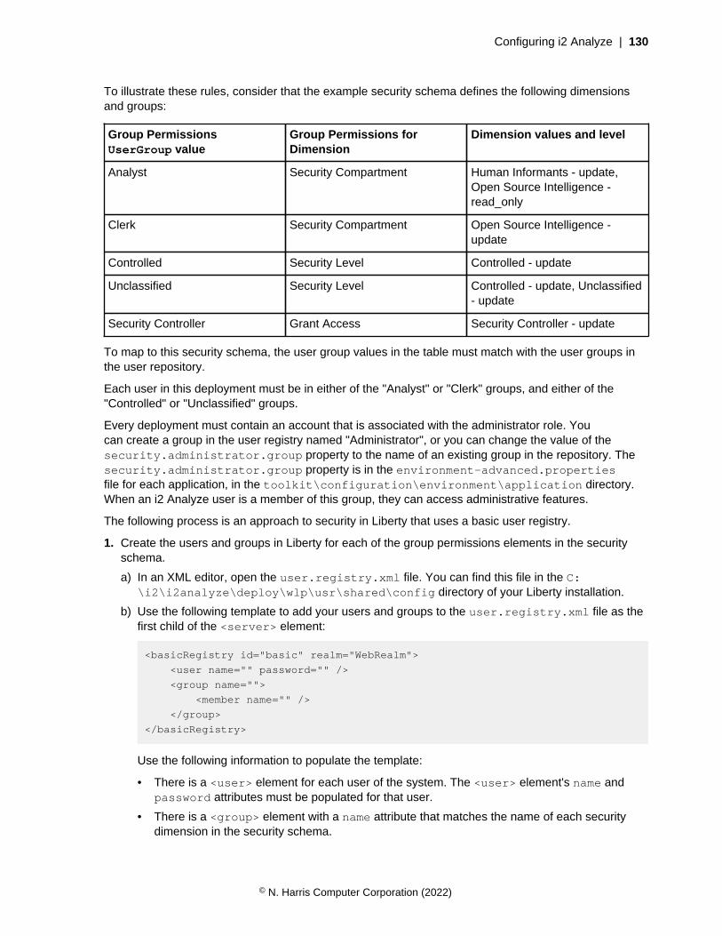
Configuring i2 Analyze | 130
To illustrate these rules, consider that the example security schema defines the following dimensionsand groups:
Group PermissionsUserGroup value
Group Permissions forDimension
Dimension values and level
Analyst Security Compartment Human Informants - update,Open Source Intelligence -read_only
Clerk Security Compartment Open Source Intelligence -update
Controlled Security Level Controlled - update
Unclassified Security Level Controlled - update, Unclassified- update
Security Controller Grant Access Security Controller - update
To map to this security schema, the user group values in the table must match with the user groups inthe user repository.
Each user in this deployment must be in either of the "Analyst" or "Clerk" groups, and either of the"Controlled" or "Unclassified" groups.
Every deployment must contain an account that is associated with the administrator role. Youcan create a group in the user registry named "Administrator", or you can change the value of thesecurity.administrator.group property to the name of an existing group in the repository. Thesecurity.administrator.group property is in the environment-advanced.propertiesfile for each application, in the toolkit\configuration\environment\application directory.When an i2 Analyze user is a member of this group, they can access administrative features.
The following process is an approach to security in Liberty that uses a basic user registry.
1. Create the users and groups in Liberty for each of the group permissions elements in the securityschema.
a) In an XML editor, open the user.registry.xml file. You can find this file in the C:\i2\i2analyze\deploy\wlp\usr\shared\config directory of your Liberty installation.
b) Use the following template to add your users and groups to the user.registry.xml file as thefirst child of the <server> element:
<basicRegistry id="basic" realm="WebRealm">
<user name="" password="" />
<group name="">
<member name="" />
</group>
</basicRegistry>
Use the following information to populate the template:
• There is a <user> element for each user of the system. The <user> element's name andpassword attributes must be populated for that user.
• There is a <group> element with a name attribute that matches the name of each securitydimension in the security schema.
© N. Harris Computer Corporation (2022)

Configuring i2 Analyze | 131
• The <group> elements are populated by <member> elements. For a user to be a member ofa group, a <member> element's name attribute must match that user's name attribute.
If you are using the example deployment, the user Jenny is a member of each group.
In the following example user.registry.xml, the users Analyst1, and Clerk1 have beenadded into a subset of the groups. If you use the following example, log in as these users to seethe different permission levels of each group:
<basicRegistry id="basic" realm="WebRealm">
<user name="Jenny" password="{xor}FToxMSY="/>
<user name="Analyst1" password="{xor}FToxMSY=" />
<user name="Clerk1" password="{xor}FToxMSY=" />
<group name="Analyst">
<member name="Jenny"/>
<member name="Analyst1"/>
</group>
<group name="Clerk">
<member name="Jenny"/>
<member name="Clerk1"/>
</group>
<group name="Controlled">
<member name="Jenny"/>
<member name="Analyst1"/>
</group>
<group name="Unclassified">
<member name="Jenny"/>
<member name="Clerk1"/>
</group>
<group name="Security Controller">
<member name="Jenny"/>
</group>
<group name="Administrator">
<member name="Jenny"/>
</group>
</basicRegistry>
The passwords can be encoded by the Liberty security utility.
2. Use the Liberty securityUtility command to encode the password for each user.
a) Navigate to the bin directory of your WebSphere® Application Server Liberty profiledeployment that is configured by the deployment toolkit. By default Liberty is deployed in the C:\i2\i2analyze\deploy\wlp directory.
b) In a command prompt, run the following command:
securityUtility encode password
The encoded password is displayed in the command line. Record the encoded password,including the {xor} prefix, and use the encoded password as the password in theuser.registry.xml file.
For more information about using the security utility, see securityUtility command.
3. Save and close the file.
© N. Harris Computer Corporation (2022)
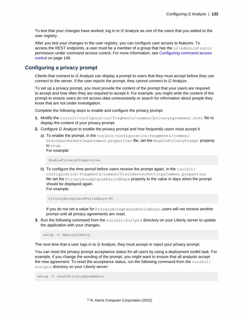
Configuring i2 Analyze | 132
To test that your changes have worked, log in to i2 Analyze as one of the users that you added to theuser registry.
After you test your changes to the user registry, you can configure user access to features. Toaccess the REST endpoints, a user must be a member of a group that has the i2:Administratorpermission under command access control. For more information, see Configuring command accesscontrol on page 149.
Configuring a privacy prompt
Clients that connect to i2 Analyze can display a prompt to users that they must accept before they canconnect to the server. If the user rejects the prompt, they cannot connect to i2 Analyze.
To set up a privacy prompt, you must provide the content of the prompt that your users are requiredto accept and how often they are required to accept it. For example, you might write the content of theprompt to ensure users do not access data unnecessarily or search for information about people theyknow that are not under investigation.
Complete the following steps to enable and configure the privacy prompt:
1. Modify the toolkit/configuration/fragments/common/privacyagreement.html file todisplay the content of your privacy prompt.
2. Configure i2 Analyze to enable the privacy prompt and how frequently users must accept it.
a) To enable the prompt, in the toolkit/configuration/fragments/common/DiscoServerSettingsCommon.properties file, set the EnablePrivacyPrompt propertyto true.For example:
EnablePrivacyPrompt=true
b) To configure the time period before users receive the prompt again, in the toolkit/configuration/fragments/common/DiscoServerSettingsCommon.propertiesfile set the PrivacyAcceptancePeriodDays property to the value in days when the promptshould be displayed again.For example:
PrivacyAcceptancePeriodDays=90
If you do not set a value for PrivacyAcceptancePeriodDays, users will not receive anotherprompt until all privacy agreements are reset.
3. Run the following command from the toolkit/scripts directory on your Liberty server to updatethe application with your changes.
setup -t deployLiberty
The next time that a user logs in to i2 Analyze, they must accept or reject your privacy prompt.
You can reset the privacy prompt acceptance status for all users by using a deployment toolkit task. Forexample, if you change the wording of the prompt, you might want to ensure that all analysts acceptthe new agreement. To reset the acceptance status, run the following command from the toolkit/scripts directory on your Liberty server:
setup -t resetPrivacyAgreements
© N. Harris Computer Corporation (2022)

Configuring i2 Analyze | 133
You can also complete these actions on a running server by using the associated admin endpoints.Configuration changes completed by the admin endpoints do not persist after a server redeployment.For more information about the admin endpoints, see Using the admin endpoints on page 322.
Configuring SPNEGO single sign-on for i2 Analyze
The following section describes how to configure i2 Analyze with Simple and Protected GSS-APINegotiation Mechanism (SPNEGO) single sign-on. The instructions detail how to configure SPNEGOsingle sign-on with an existing deployment of i2 Analyze.
Intended audience
In the production deployment process, you might first configure SPNEGO single sign-on in theconfiguration or pre-production environments. As you move to a production deployment, you mustreplicate any configuration changes in any new deployments.
This section is intended for readers who are familiar with configuring and managing domain controllers,Microsoft™ Active Directory, and have an understanding of SPNEGO single sign-on.
There are many different single sign-on technologies. This section defines a SPNEGO single sign-onsetup with workstations that are members of the same Microsoft Active Directory domain. i2 Analyzeuses the users and groups in Active Directory to determine the authorization of users.
The instructions assume that the following prerequisites are installed and accessible:
• A Microsoft Windows® Server running an Active Directory Domain Controller and associatedKerberos Key Distribution Center (KDC).
• A Microsoft Windows® domain member (client) with a web browser that supports the SPNEGOauthentication mechanism.
• A working deployment of i2 Analyze that can be accessed by users in Active Directory.
For information on the prerequisites that are required, see the Before you begin section of ConfiguringSPNEGO authentication in Liberty .
Attention: i2 takes reasonable steps to verify the suitability of i2® Analyze for internetdeployment. However, it does not address lower-level issues such as guarding networks againstpenetration, securing accounts, protecting against brute force attacks, configuring firewalls toavoid DoS or DDoS attacks, and the like. For your deployment of i2® Analyze, follow industry-standard practices and recommendations for protection of your systems. i2 accepts no liabilityfor the consequences of such attacks on your systems. This information is not intended toprovide instructions for managing key databases or certificates.
i2 Analyze with SPNEGO single sign-on
In the production deployment process, i2 Analyze is configured to use user names and passwords thatare stored in a file-based registry. By configuring the deployment to use SPNEGO single sign-on, a useris logged in through the domain client workstation that they are logged in to.
After a user logs in to a single sign-on environment, they are authenticated with any systems that theyhave access to. i2 Analyze can be configured to allow authentication through SPNEGO single sign-on,with authorization through Active Directory.
SPNEGO single sign-on enables users to log in to a Microsoft domain controller, and be authenticatedwithin the single sign-on environment. In SPNEGO single sign-on, to change the user that is logged in toi2 Analyze, the user must log out of the workstation, and a new user must log in to the workstation.
© N. Harris Computer Corporation (2022)
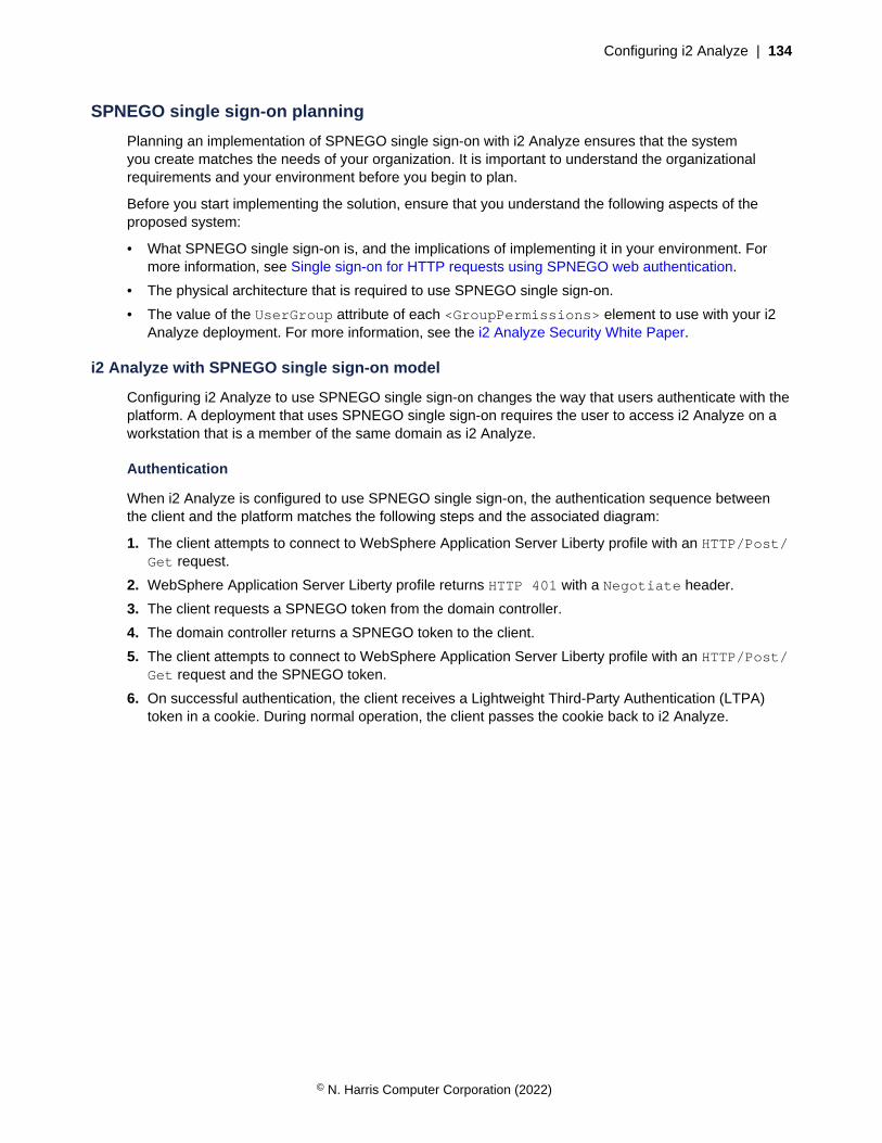
Configuring i2 Analyze | 134
SPNEGO single sign-on planning
Planning an implementation of SPNEGO single sign-on with i2 Analyze ensures that the systemyou create matches the needs of your organization. It is important to understand the organizationalrequirements and your environment before you begin to plan.
Before you start implementing the solution, ensure that you understand the following aspects of theproposed system:
• What SPNEGO single sign-on is, and the implications of implementing it in your environment. Formore information, see Single sign-on for HTTP requests using SPNEGO web authentication.
• The physical architecture that is required to use SPNEGO single sign-on.
• The value of the UserGroup attribute of each <GroupPermissions> element to use with your i2Analyze deployment. For more information, see the i2 Analyze Security White Paper.
i2 Analyze with SPNEGO single sign-on model
Configuring i2 Analyze to use SPNEGO single sign-on changes the way that users authenticate with theplatform. A deployment that uses SPNEGO single sign-on requires the user to access i2 Analyze on aworkstation that is a member of the same domain as i2 Analyze.
Authentication
When i2 Analyze is configured to use SPNEGO single sign-on, the authentication sequence betweenthe client and the platform matches the following steps and the associated diagram:
1. The client attempts to connect to WebSphere Application Server Liberty profile with an HTTP/Post/Get request.
2. WebSphere Application Server Liberty profile returns HTTP 401 with a Negotiate header.
3. The client requests a SPNEGO token from the domain controller.
4. The domain controller returns a SPNEGO token to the client.
5. The client attempts to connect to WebSphere Application Server Liberty profile with an HTTP/Post/Get request and the SPNEGO token.
6. On successful authentication, the client receives a Lightweight Third-Party Authentication (LTPA)token in a cookie. During normal operation, the client passes the cookie back to i2 Analyze.
© N. Harris Computer Corporation (2022)

Configuring i2 Analyze | 135
Authorization
After the user is authenticated, they are logged in to i2 Analyze. To define the data that the user hasaccess to, the user must be authorized by i2 Analyze.
For authorization, the i2 Analyze application communicates with Active Directory, through theWebSphere Application Server Liberty profile user registry APIs to retrieve information about the currentuser. The principal provider then maps the retrieved information to security dimension values in the i2Analyze security schema.
The following diagram shows how authorization works in i2 Analyze:
© N. Harris Computer Corporation (2022)
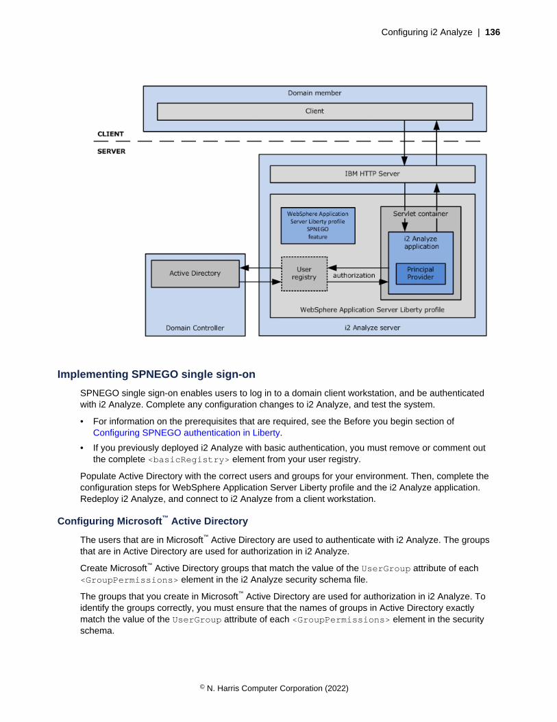
Configuring i2 Analyze | 136
Implementing SPNEGO single sign-on
SPNEGO single sign-on enables users to log in to a domain client workstation, and be authenticatedwith i2 Analyze. Complete any configuration changes to i2 Analyze, and test the system.
• For information on the prerequisites that are required, see the Before you begin section ofConfiguring SPNEGO authentication in Liberty.
• If you previously deployed i2 Analyze with basic authentication, you must remove or comment outthe complete <basicRegistry> element from your user registry.
Populate Active Directory with the correct users and groups for your environment. Then, complete theconfiguration steps for WebSphere Application Server Liberty profile and the i2 Analyze application.Redeploy i2 Analyze, and connect to i2 Analyze from a client workstation.
Configuring Microsoft™ Active Directory
The users that are in Microsoft™ Active Directory are used to authenticate with i2 Analyze. The groupsthat are in Active Directory are used for authorization in i2 Analyze.
Create Microsoft™ Active Directory groups that match the value of the UserGroup attribute of each<GroupPermissions> element in the i2 Analyze security schema file.
The groups that you create in Microsoft™ Active Directory are used for authorization in i2 Analyze. Toidentify the groups correctly, you must ensure that the names of groups in Active Directory exactlymatch the value of the UserGroup attribute of each <GroupPermissions> element in the securityschema.
© N. Harris Computer Corporation (2022)

Configuring i2 Analyze | 137
Note: The security schema that the deployment uses is defined in theApolloServerSettingsMandatory.properties file. The security schema, and properties files arein the toolkit\configuration\fragments\common\WEB-INF\classes directory.
In a single sign-on setup, the following users must be present in Active Directory:
• A user for the server that hosts the i2 Analyze application, that is mapped to a Kerberos ServicePrincipal Name (SPN).
• The users that are used to log in to i2 Analyze.
To authorize users, the following groups must be present in Active Directory:
• A group for each of the group permission elements in the i2 Analyze security schema.
• A group for administrators.
1. Create the Microsoft™ Active Directory groups.
For more information, see How to Create a Group in Active Directory.
a) Open the Microsoft™ Active Directory groups controller.
b) Create groups whose names exactly match the value of the UserGroup attribute of each<GroupPermissions> element in the i2 Analyze security schema file.
2. Create any Microsoft™ Active Directory users.
Create user accounts that can be used to log in to i2 Analyze.
For more information, see How to Create a Domain Account in Active Directory.
3. Make each user a member of the correct groups for your environment.
The groups that the user is a member of in Active Directory are used for authorization in i2 Analyze.
For more information, see Adding Users to an Active Directory Group.
The users that can access i2 Analyze are created, and are members of the groups that define theiraccess levels.
Configuring WebSphere Application Server Liberty profile
Create the Kerberos service principal name (SPN) and keytab file for the server that hosts WebSphereApplication Server Liberty profile that runs the i2 Analyze application. Edit the WebSphere ApplicationServer Liberty profile configuration to use SPNEGO single sign-on and the Active Directory registry.
To use SPNEGO single sign-on with the Liberty server that is deployed by i2 Analyze and otherWebSphere Application Server servers, each server must use the same LTPA keys file. For moreinformation about LTPA, see Authentication - LTPA.
The value that is set for the ltpakeys.password property in the credentials.properties filemust match the password that is required to import the keys from the LTPA keys file. If you changethe password in the credentials.properties file, you must redeploy i2 Analyze for the passwordchange to take effect.
If you follow this procedure for a deployment that provides high availability, you must complete eachstep on every Liberty server in your environment before you move to the next step.
1. Configure WebSphere Application Server Liberty profile to use SPNEGO single sign-on by using thefirst two steps in Configuring SPNEGO authentication in Liberty as a reference.
a) Create the Kerberos SPN and keytab files on the domain controller.
© N. Harris Computer Corporation (2022)
Configuring i2 Analyze | 138
Note: Ensure that the host file on the Active Directory server uses the full host name, includingthe domain name, for the i2 Analyze server. Remove any entries that use only the short name forthe i2 Analyze server. The value in the host file must match the value that is used for the SPN.
b) Configure the server that hosts WebSphere Application Server Liberty profile, and WebSphereApplication Server Liberty profile.
2. Configure WebSphere Application Server Liberty profile to use the Microsoft™ Active Directoryregistry by using the instructions in Configuring LDAP user registries with Liberty as a reference.
a) Complete step 1 to add the features to the i2analyze\deploy\wlp\usr\servers\opal-server\server.xml file.
b) Complete step 4 by using the Microsoft Active Directory Server example to populate the<ldapRegistry> element.
Note: This information does not cover the configuration of Secure Sockets Layer (SSL) betweenWebSphere Application Server Liberty profile and Active Directory. Do not include the <ssl> and<keyStore> elements from the example, in your server.xml.
c) Ensure that the mapping between Active Directory and the i2 Analyze security schema is correct.Add the following code after the <ldapRegistry> element in the server.xml file:
<federatedRepository>
<primaryRealm name="">
<participatingBaseEntry name=""/>
<groupSecurityNameMapping inputProperty="cn" outputProperty="cn"/>
</primaryRealm>
</federatedRepository>
Populate the empty name attribute values by using the following information:
• The <primaryRealm> element's name attribute has the same value as the realm attribute ofthe <ldapRegistry> element.
• The <participatingBaseEntry> element's name attribute has the same value as thebaseDN attribute as the <ldapRegistry> element.
By default, all requests to access protected resources use SPNEGO authentication. If you previouslydeployed i2 Analyze with basic authentication, you must ensure that the basic registry is not present inthe user.registry.xml file.
3. Using an XML editor, either remove or comment out the complete <basicRegistry> element inthe i2analyze\deploy\wlp\usr\shared\config\user.registry.xml file.
Configuring the i2 Analyze application
Set the security administrator group to the value used in Microsoft Active Directory.
If you follow this procedure for a deployment that provides high availability, you must complete eachstep on every Liberty server in your environment before you move to the next step.
Using a text editor, open toolkit\configuration\environment\opal-server\environment-advanced.properties. Edit the value of the security.administrator.group property to thename of the group in Active Directory to use for administrators. For example, i2Admins.
The mapping to the administrator group must be in terms of the Common Name that is definedin the <participatingBaseEntry> element of the <federatedRepository> element inthe server.xml file. For more information about the <federatedRepository> element, seeConfiguring WebSphere Application Server Liberty profile on page 137.
© N. Harris Computer Corporation (2022)
Configuring i2 Analyze | 139
Redeploying i2 Analyze
Redeploy i2 Analyze to update the application with your configuration changes.
If you follow this procedure for a deployment that provides high availability, you must complete eachstep on every Liberty server in your environment before you move to the next step.
1. In a command prompt, navigate to the toolkit\scripts directory.
2. Stop Liberty:
setup -t stopLiberty
3. Update the i2 Analyze application:
setup -t deployLiberty
4. Start Liberty:
setup -t startLiberty
5. If you are using the IBM HTTP Server, start, or restart, it.
Testing i2 Analyze with SPNEGO single sign-on on the client workstation
To test the SPNEGO single sign-on setup, connect to i2 Analyze from a domain client workstation. Theuser that is logged in to the domain client is logged in to i2 Analyze.
• Your web browser must be configured according to step 3 in Configuring SPNEGO authentication inLiberty.
• You must be logged in to the client workstation as one of the users in the domain controller, who is inat least one group per security dimension in the i2 Analyze security schema.
Log in to the client workstation as users with different access levels. For each user, complete thefollowing steps to demonstrate that authorization is working correctly when you are using SPNEGOsingle sign-on.
1. Open your web browser, and navigate to http://host_name/opal (where host_name is the fullyqualified domain name or IP address of the server that hosts the i2 Analyze application).
2. Create, browse, and search for data, to ensure that your are authenticated and authorized with theplatform correctly.
Note: When you create items, ensure that the permissions are set up so that you have access toview them.
After you test your changes, you can configure user access to features. To access the REST endpoints,a user must be a member of a group that has the i2:Administrator permission under commandaccess control. For more information, see Configuring command access control on page 149.
Resources for system protection
In order to protect your system from external forces, you must implement system controls thatprevent or mitigate the effect of attacks. Although i2 Group does not manage login configuration,and the responsibility for protection of your network from external attack remains yours, the followingcommunities provide a starting point for your investigation into preventative methods.
The Open Web Application Security Project
© N. Harris Computer Corporation (2022)

Configuring i2 Analyze | 140
The Open Web Application Security Project Foundation is a not-for-profit organizationthat is dedicated to enabling organizations to conceive, develop, operate, and maintainapplications that can be trusted. In particular, see https://owasp.org/www-community/controls/Blocking_Brute_Force_Attacks and https://cheatsheetseries.owasp.org/cheatsheets/Authentication_Cheat_Sheet.html.
SANS Institute
The System-Admin, Audit, Network, and Security Institute is the largest source for informationsecurity training and security certification in the world. It also develops, maintains, and makesavailable at no cost, the largest collection of research documents about various aspects ofinformation security, and it operates the internet's early warning system - the Internet StormCenter. In particular, see https://www.sans.org/security-resources/policies/general/pdf/password-construction-guidelines
Common Weakness Enumeration
CWE™ is a community-developed list of common software security weaknesses. It serves as acommon language, a measuring stick for software security tools, and as a baseline for weaknessidentification, mitigation, and prevention efforts.
In particular, see http://cwe.mitre.org/top25/index.html#CWE-307.
Configuring X.509 client certificate authentication with i2 Analyze
You can enable your deployment to use X.509 client certificate authentication. After successfulconfiguration, users can log in to i2 Analyze with client certificates instead of user names andpasswords.
After you configure client certificate authentication, a user does not need to enter a user name andpassword separately. Each certificate is associated with a single user in the user registry to enableauthentication. Anyone that has access to a client certificate can log in to i2 Analyze as the userassociated with that certificate without entering a password.
To enable a user to log in using a client certificate, the client certificate must be installed in the user'spersonal certificate store on the workstation they are using to access i2 Analyze. After the clientcertificate is installed in the personal certificate store, the user can use the certificate to log in to i2Analyze through Analyst's Notebook Premium.
When a user connects using Analyst's Notebook Premium, the user chooses the certificate to use to login when they open a connection to the Information Store.
Intended audience
In the production deployment process, you might first configure client certificate authentication in theconfiguration or pre-production environments. As you move to a production deployment, you mustreplicate any configuration changes in any new deployments.
This information is intended for readers who are familiar with managing key databases and certificates,user authentication mechanisms, and the i2 Analyze toolkit.
Prerequisites
The starting point for configuring client certificate authentication is a deployment of i2 Analyze that isconfigured to use Secure Sockets Layer on connections to the HTTP Server, and between the HTTPServer and Liberty. For more information about configuring Secure Sockets Layer on connections to theHTTP Server, see Configuring Secure Sockets Layer with i2 Analyze.
© N. Harris Computer Corporation (2022)

Configuring i2 Analyze | 141
Attention: i2 takes reasonable steps to verify the suitability of i2® Analyze for internetdeployment. However, it does not address lower-level issues such as guarding networks againstpenetration, securing accounts, protecting against brute force attacks, configuring firewalls toavoid DoS or DDoS attacks, and the like. For your deployment of i2® Analyze, follow industry-standard practices and recommendations for protection of your systems. i2 accepts no liabilityfor the consequences of such attacks on your systems. This information is not intended toprovide instructions for managing key databases or certificates.
Client certificates
The client certificates that are used to authenticate users must be signed by a certificate authority that istrusted by the i2 Analyze server.
The common name in a client certificate must match a user name in the i2 Analyze user registry. A userthat selects such a certificate logs in to i2 Analyze as the corresponding i2 Analyze user.
You can have as many client certificates as you require. Each certificate is associated with a single userin the user registry. Each certificate can be installed on any number of workstations. Each workstationcan have any number of certificates installed.
To demonstrate a working configuration, you can use a self-signed client certificate. For moreinformation, see Creating a self-signed client certificate on page 141. However, in a productiondeployment you must use certificates that are signed by a certificate authority that is trusted by the i2Analyze server.
There are many methods for obtaining an X.509 certificate that is signed by a certificate authority.When you receive a signed certificate, you also receive signer certificates so that you can trust theclient certificates that are signed by that certificate authority. If the certificate authority that signed yourcertificates is not already trusted within the key database, you must add any signer certificates to thekey database so that the certificate authority is trusted.
For information about managing key databases, certificates, and trusted certificate authorities using theIBM Key Management utility, see Managing keys with the IKEYMAN graphical interface.
Creating a self-signed client certificate
The client certificate is used to log in and authenticate a user with i2 Analyze. Use the IBM KeyManagement utility to create a self-signed certificate.
Create a self-signed certificate to use as a client certificate to demonstrate a working configuration. Ifyou are using client certificates that are signed by a certificate authority, you do not need to completethe following instructions.
1. Start the IBM Key Management utility.
For more information, see Starting the Key Management utility user interface.
Note: The IBM® Key Management utility uses a GUI or Window Manager. If you do not have aGUI or Window Manager on your system, you can use the command line interface to complete thesame actions. For more information about the command line interface, see Key Management utilitycommand-line interface (gskcmd) syntax.
2. Open the key database that is used for Secure Sockets Layer (SSL) connections. If you followedthe instructions to set up the SSL example, the key database file is i2\i2analyze\i2-http-keystore.kdb.
For more information about opening a key database, see Working with key databases.
3. Create a self-signed certificate.
© N. Harris Computer Corporation (2022)
Configuring i2 Analyze | 142
For more information, see Creating a self-signed certificate.
a) Set the Key Label to a value that enables you to identify the user.For example, Jenny.
b) Ensure that the value of Common Name matches the name of a user in the user registry for i2Analyze.
If you are using the example user registry, set the value of Common Name to Jenny.
Note: The user name cannot contain a comma (,).
For this example, you can use the default values for the remaining properties.
4. Export the certificate and private key from the key database.
a) Click Export/Import.
b) Ensure that Export Key is selected.
c) From the Key file type list, select PKCS12.
d) Set the File name to a value that enables you to identify the user.For example, Jenny.p12.
e) Ensure that Location is set to the same directory as the key database.
f) Click OK.
g) When you are prompted, provide a password that is used to access the keys.
5. Extract the certificate from the key database.
a) Click Extract Certificate.
b) From the Data type list, select Binary DER data.
c) Set the Certificate file name to a value that enables you to identify the user.For example, Jenny.der.
d) Ensure that Location is set to the same directory as the key database.
e) Click OK.
Configuring the key databases
To enable the i2 Analyze server to trust the client certificates, you must ensure that the signer of yourclient certificates is trusted within the i2 Analyze key database. You must also create a copy of thekeystore as a truststore that WebSphere Application Server Liberty uses.
If you are using client certificates that are signed by a certificate authority, ensure that the certificateauthority that signed the certificates is trusted within the i2 Analyze key database.
You can list the certificate authorities that are trusted within a key database in the IBM Key Managementutility. For more information, see Listing certificate authorities.
After you add the certificate to the key database, create a truststore that WebSphere Application ServerLiberty uses. The truststore is a copy of the i2 Analyze key database.
1. Start the IBM Key Management utility.
For more information, see Starting the Key Management utility user interface.
Note: The IBM® Key Management utility uses a GUI or Window Manager. If you do not have aGUI or Window Manager on your system, you can use the command line interface to complete thesame actions. For more information about the command line interface, see Key Management utilitycommand-line interface (gskcmd) syntax.
© N. Harris Computer Corporation (2022)
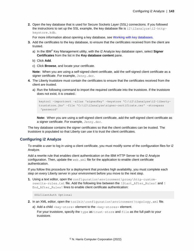
Configuring i2 Analyze | 143
2. Open the key database that is used for Secure Sockets Layer (SSL) connections. If you followedthe instructions to set up the SSL example, the key database file is i2\i2analyze\i2-http-keystore.kdb.
For more information about opening a key database, see Working with key databases.
3. Add the certificates to the key database, to ensure that the certificates received from the client aretrusted.
a) In the IBM® Key Management utility, with the i2 Analyze key database open, select SignerCertificates from the list in the Key database content pane.
b) Click Add.
c) Click Browse, and locate your certificate.
Note: When you are using a self-signed client certificate, add the self-signed client certificate as asigner certificate. For example, Jenny.der.
4. The Liberty truststore must contain the certificates to ensure that the certificates received from theclient are trusted.
a) Run the following command to import the required certificate into the truststore. If the truststoredoes not exist, it is created.:
keytool -importcert -alias "signerKey" -keystore "C:\i2\i2analyze\i2-liberty-
truststore.jks" -file "C:\i2\i2analyze\signer-certificate.cer" -storepass
"password"
Note: When you are using a self-signed client certificate, add the self-signed client certificate asa signer certificate. For example, Jenny.der.
The key database contains the signer certificates so that the client certificates can be trusted. Thetruststore is populated so that Liberty can use it to trust the client certificates.
Configuring i2 Analyze
To enable a user to log in using a client certificate, you must modify some of the configuration files for i2Analyze.
Add a rewrite rule that enables client authentication on the IBM HTTP Server to the i2 Analyzeconfiguration. Then, update the web.xml file for the application to enable client certificateauthentication.
If you follow this procedure for a deployment that provides high availability, you must complete eachstep on every Liberty server in your environment before you move to the next step.
1. Using a text editor, open the configuration\environment\proxy\http-custom-rewrite-rules.txt file. Add the following line between the !Start_After_Rules! and !End_After_Rules! lines to enable client certificate authentication:
SSLClientAuth Optional
2. In an XML editor, open the toolkit\configuration\environment\topology.xml file.
a) Add a child <key-store> element to the <key-stores> element.
For your truststore, specify the type as trust-store and file as the full path to yourtruststore.
© N. Harris Computer Corporation (2022)
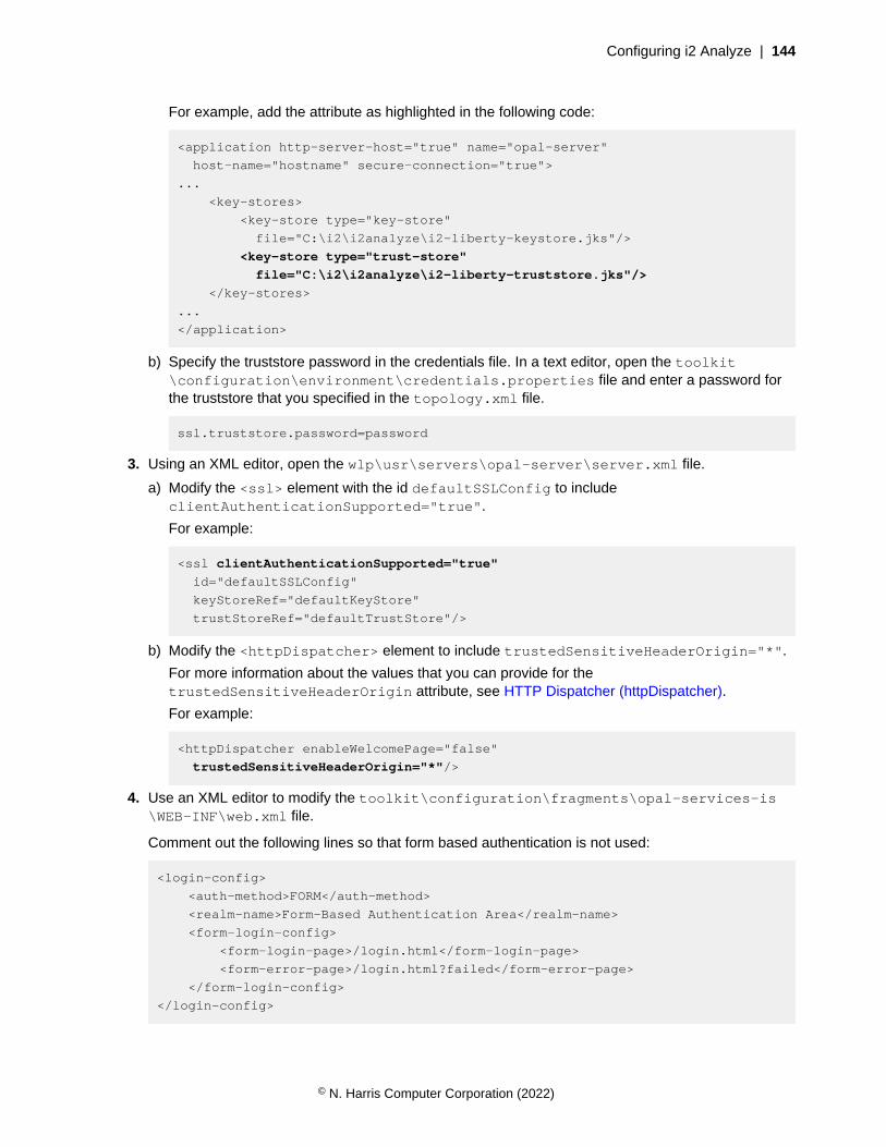
Configuring i2 Analyze | 144
For example, add the attribute as highlighted in the following code:
<application http-server-host="true" name="opal-server"
host-name="hostname" secure-connection="true">
...
<key-stores>
<key-store type="key-store"
file="C:\i2\i2analyze\i2-liberty-keystore.jks"/>
<key-store type="trust-store"
file="C:\i2\i2analyze\i2-liberty-truststore.jks"/>
</key-stores>
...
</application>
b) Specify the truststore password in the credentials file. In a text editor, open the toolkit\configuration\environment\credentials.properties file and enter a password forthe truststore that you specified in the topology.xml file.
ssl.truststore.password=password
3. Using an XML editor, open the wlp\usr\servers\opal-server\server.xml file.
a) Modify the <ssl> element with the id defaultSSLConfig to includeclientAuthenticationSupported="true".
For example:
<ssl clientAuthenticationSupported="true"
id="defaultSSLConfig"
keyStoreRef="defaultKeyStore"
trustStoreRef="defaultTrustStore"/>
b) Modify the <httpDispatcher> element to include trustedSensitiveHeaderOrigin="*".
For more information about the values that you can provide for thetrustedSensitiveHeaderOrigin attribute, see HTTP Dispatcher (httpDispatcher).
For example:
<httpDispatcher enableWelcomePage="false"
trustedSensitiveHeaderOrigin="*"/>
4. Use an XML editor to modify the toolkit\configuration\fragments\opal-services-is\WEB-INF\web.xml file.
Comment out the following lines so that form based authentication is not used:
<login-config>
<auth-method>FORM</auth-method>
<realm-name>Form-Based Authentication Area</realm-name>
<form-login-config>
<form-login-page>/login.html</form-login-page>
<form-error-page>/login.html?failed</form-error-page>
</form-login-config>
</login-config>
© N. Harris Computer Corporation (2022)
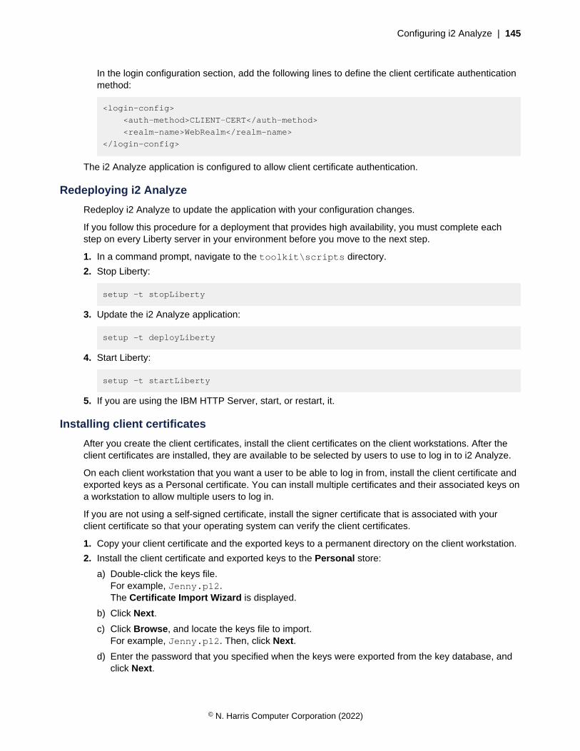
Configuring i2 Analyze | 145
In the login configuration section, add the following lines to define the client certificate authenticationmethod:
<login-config>
<auth-method>CLIENT-CERT</auth-method>
<realm-name>WebRealm</realm-name>
</login-config>
The i2 Analyze application is configured to allow client certificate authentication.
Redeploying i2 Analyze
Redeploy i2 Analyze to update the application with your configuration changes.
If you follow this procedure for a deployment that provides high availability, you must complete eachstep on every Liberty server in your environment before you move to the next step.
1. In a command prompt, navigate to the toolkit\scripts directory.
2. Stop Liberty:
setup -t stopLiberty
3. Update the i2 Analyze application:
setup -t deployLiberty
4. Start Liberty:
setup -t startLiberty
5. If you are using the IBM HTTP Server, start, or restart, it.
Installing client certificates
After you create the client certificates, install the client certificates on the client workstations. After theclient certificates are installed, they are available to be selected by users to use to log in to i2 Analyze.
On each client workstation that you want a user to be able to log in from, install the client certificate andexported keys as a Personal certificate. You can install multiple certificates and their associated keys ona workstation to allow multiple users to log in.
If you are not using a self-signed certificate, install the signer certificate that is associated with yourclient certificate so that your operating system can verify the client certificates.
1. Copy your client certificate and the exported keys to a permanent directory on the client workstation.
2. Install the client certificate and exported keys to the Personal store:
a) Double-click the keys file.For example, Jenny.p12.The Certificate Import Wizard is displayed.
b) Click Next.
c) Click Browse, and locate the keys file to import.For example, Jenny.p12. Then, click Next.
d) Enter the password that you specified when the keys were exported from the key database, andclick Next.
© N. Harris Computer Corporation (2022)
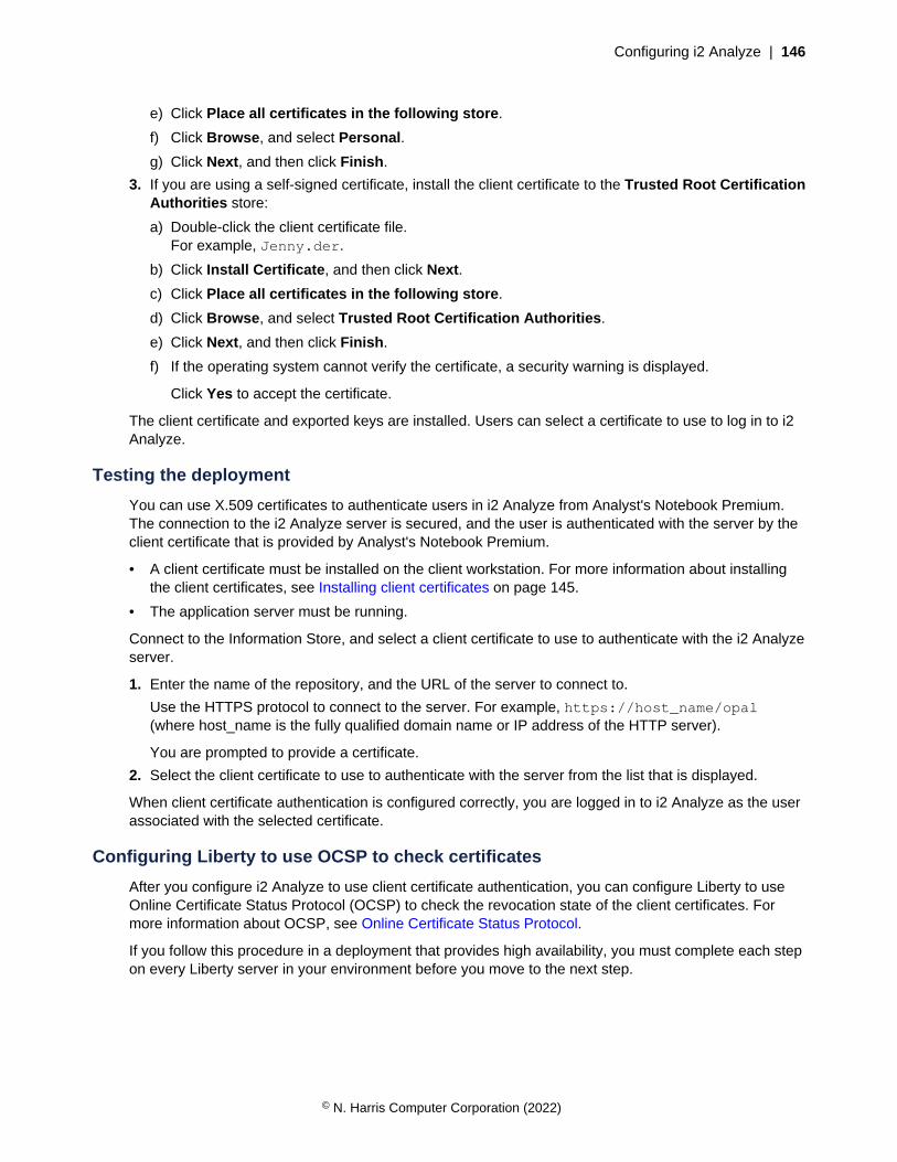
Configuring i2 Analyze | 146
e) Click Place all certificates in the following store.
f) Click Browse, and select Personal.
g) Click Next, and then click Finish.
3. If you are using a self-signed certificate, install the client certificate to the Trusted Root CertificationAuthorities store:
a) Double-click the client certificate file.For example, Jenny.der.
b) Click Install Certificate, and then click Next.
c) Click Place all certificates in the following store.
d) Click Browse, and select Trusted Root Certification Authorities.
e) Click Next, and then click Finish.
f) If the operating system cannot verify the certificate, a security warning is displayed.
Click Yes to accept the certificate.
The client certificate and exported keys are installed. Users can select a certificate to use to log in to i2Analyze.
Testing the deployment
You can use X.509 certificates to authenticate users in i2 Analyze from Analyst's Notebook Premium.The connection to the i2 Analyze server is secured, and the user is authenticated with the server by theclient certificate that is provided by Analyst's Notebook Premium.
• A client certificate must be installed on the client workstation. For more information about installingthe client certificates, see Installing client certificates on page 145.
• The application server must be running.
Connect to the Information Store, and select a client certificate to use to authenticate with the i2 Analyzeserver.
1. Enter the name of the repository, and the URL of the server to connect to.
Use the HTTPS protocol to connect to the server. For example, https://host_name/opal(where host_name is the fully qualified domain name or IP address of the HTTP server).
You are prompted to provide a certificate.
2. Select the client certificate to use to authenticate with the server from the list that is displayed.
When client certificate authentication is configured correctly, you are logged in to i2 Analyze as the userassociated with the selected certificate.
Configuring Liberty to use OCSP to check certificates
After you configure i2 Analyze to use client certificate authentication, you can configure Liberty to useOnline Certificate Status Protocol (OCSP) to check the revocation state of the client certificates. Formore information about OCSP, see Online Certificate Status Protocol.
If you follow this procedure in a deployment that provides high availability, you must complete each stepon every Liberty server in your environment before you move to the next step.
© N. Harris Computer Corporation (2022)

Configuring i2 Analyze | 147
1. In a text editor, open the i2analyze\deploy\wlp\usr\servers\opal-server\jvm.optionsfile and add the following lines:
-Dcom.sun.net.ssl.checkRevocation=true
-Djava.security.properties=C:/i2/i2analyze/deploy/wlp/usr/servers/opal-server/
java-security-ocsp.properties
Where:
• checkRevocation is set to true to instruct Liberty to check whether certificates have beenrevoked.
• java.security.properties is the path to a properties file that contains the settings toconfigure OCSP.
2. In a text editor, create the i2analyze\deploy\wlp\usr\servers\opal-server\java-security-ocsp.properties file and add the following lines:
ocsp.enable=true
ocsp.responderURL=
Where:
• ocsp.enable is set to true to enable OCSP.
• ocsp.responderURL is the URL of the OCSP service that is used to check the status of acertificate. When this value is specified, it overrides the value in the Authority Information Accessextension on the certificate.
3. Restart Liberty:
setup -t restartLiberty
Log in to your deployment to test that revoked certificates are identified successfully.
If a user attempts to log in with a revoked certificate, a message is displayed in the Liberty logs. Forexample:
java.security.cert.CertPathValidatorException: Certificate has been revoked, reason: UNSPECIFIED, revocation date: Wed Jan 20 17:13:35 UTC 2021, authority: CN=ocsp, OU=i2, O=IBM, ST=England, C=GB, extension OIDs: []
If your OCSP service is unavailable, a message is displayed in the Liberty logs. For example:
The extended error message from the SSL handshake exception is: PKIX path validation failed: java.security.cert.CertPathValidatorException: Unable to determine revocation status due to network error
Resources for system protection
In order to protect your system from external forces, you must implement system controls thatprevent or mitigate the effect of attacks. Although i2 Group does not manage login configuration,and the responsibility for protection of your network from external attack remains yours, the followingcommunities provide a starting point for your investigation into preventative methods.
The Open Web Application Security Project
The Open Web Application Security Project Foundation is a not-for-profit organizationthat is dedicated to enabling organizations to conceive, develop, operate, and maintain
© N. Harris Computer Corporation (2022)
Configuring i2 Analyze | 148
applications that can be trusted. In particular, see https://owasp.org/www-community/controls/Blocking_Brute_Force_Attacks and https://cheatsheetseries.owasp.org/cheatsheets/Authentication_Cheat_Sheet.html.
SANS Institute
The System-Admin, Audit, Network, and Security Institute is the largest source for informationsecurity training and security certification in the world. It also develops, maintains, and makesavailable at no cost, the largest collection of research documents about various aspects ofinformation security, and it operates the internet's early warning system - the Internet StormCenter. In particular, see https://www.sans.org/security-resources/policies/general/pdf/password-construction-guidelines
Common Weakness Enumeration
CWE™ is a community-developed list of common software security weaknesses. It serves as acommon language, a measuring stick for software security tools, and as a baseline for weaknessidentification, mitigation, and prevention efforts.
In particular, see http://cwe.mitre.org/top25/index.html#CWE-307.
Controlling access to featuresYou can control access to the features and types of command that are available to i2 Analyze users. Torestrict (and in some cases, to allow) access to features, you need to specify a command access controlfile.
Note: In the production deployment process, you first configure access to features in the configurationdevelopment environment.
You can use a command access control file to specify which permissions to assign to the user groupsin the user repository for your deployment. The command access control file contains permissions thatapply to i2 Analyze and, where applicable, to clients and client services.
When you create an example deployment, i2 Analyze is configured with the command access controlfile that the example contains. However, when no file is specified in the configuration, access control isnot enabled. All authenticated users can access all features except:
• Exporting search results to a CSV file
• Using the i2 Notebook web client
• Uploading i2 Analyst's Notebook charts to the Chart Store in bulk
• Creating alerts through the REST API
• The administrator permission
After you specify a command access control file, access to all features is controlled by that file. Beforethey can use a feature, you must give the appropriate permission to a group of users.
When you upgrade a system that has access to specific features enabled, ensure that you check fornew features that require new permissions. Without updating your file to add permissions, access tothe features are denied to all users. For information about any new permissions, see Configuration anddatabase changes.
© N. Harris Computer Corporation (2022)

Configuring i2 Analyze | 149
Configuring command access control
You can use command access control to determine which commands and features users can access.You can create a command access control file to match the specific needs of your deployment.
In any command access control file that you create, the group names in the file must match the namesof user groups in the user registry.
If you follow this procedure in a deployment that provides high availability, you must complete each stepon every Liberty server in your environment before you move to the next step.
1. Create a command access control file.
a) Navigate to the directory in the deployment toolkit that contains the example security schema:toolkit\configuration\examples\security-schema.
b) Copy the example-command-access-control.xml file to the configuration\fragments\opal-services\WEB-INF\classes directory, and rename it to command-access-control.xml.
2. Modify the command access control file.
a) Open the command-access-control.xml file in your XSD-aware XML editor. For moreinformation, see Setting up your XSD aware XML editor on page 321.
The associated XSD file is: toolkit\scripts\xsd\CommandAccessControl.xsd.
b) Use the reference information to specify the access control that your system requires.
c) Save the completed file.
3. To set the command access control file to be used in the deployment:
a) Using a text editor, open the toolkit\configuration\fragments\opal-services\WEB-INF\classes\DiscoServerSettingsCommon.properties file.
b) Specify your command access control file as the value for theCommandAccessControlResource property.For example:
CommandAccessControlResource=command-access-control.xml
c) Save the file.
Redeploy i2 Analyze to update the application with your changes.
4. In a command prompt, navigate to the toolkit\scripts directory.
5. Stop Liberty:
setup -t stopLiberty
6. Update the i2 Analyze application:
setup -t deployLiberty
7. Start Liberty:
setup -t startLiberty
Connect to your deployment and test that members of each user group have the correct access tofeatures. Continue to change the configuration until you are satisfied with the access of each usergroup.
© N. Harris Computer Corporation (2022)
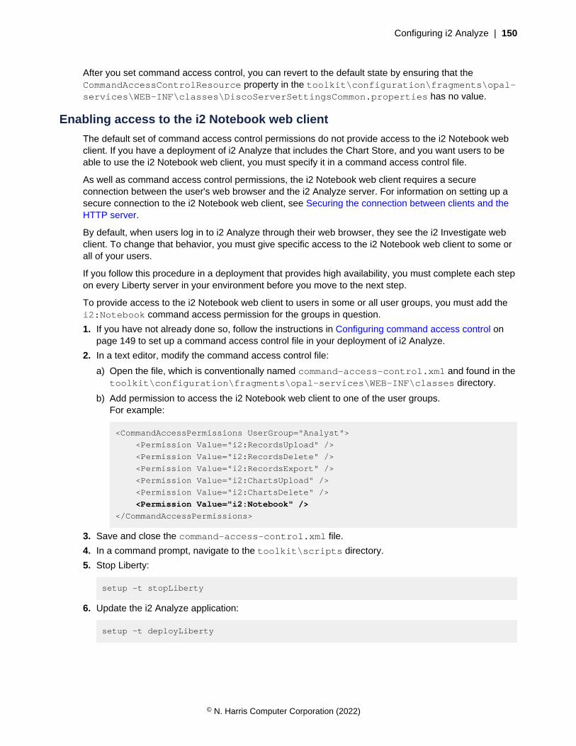
Configuring i2 Analyze | 150
After you set command access control, you can revert to the default state by ensuring that theCommandAccessControlResource property in the toolkit\configuration\fragments\opal-services\WEB-INF\classes\DiscoServerSettingsCommon.properties has no value.
Enabling access to the i2 Notebook web client
The default set of command access control permissions do not provide access to the i2 Notebook webclient. If you have a deployment of i2 Analyze that includes the Chart Store, and you want users to beable to use the i2 Notebook web client, you must specify it in a command access control file.
As well as command access control permissions, the i2 Notebook web client requires a secureconnection between the user's web browser and the i2 Analyze server. For information on setting up asecure connection to the i2 Notebook web client, see Securing the connection between clients and theHTTP server.
By default, when users log in to i2 Analyze through their web browser, they see the i2 Investigate webclient. To change that behavior, you must give specific access to the i2 Notebook web client to some orall of your users.
If you follow this procedure in a deployment that provides high availability, you must complete each stepon every Liberty server in your environment before you move to the next step.
To provide access to the i2 Notebook web client to users in some or all user groups, you must add thei2:Notebook command access permission for the groups in question.
1. If you have not already done so, follow the instructions in Configuring command access control onpage 149 to set up a command access control file in your deployment of i2 Analyze.
2. In a text editor, modify the command access control file:
a) Open the file, which is conventionally named command-access-control.xml and found in thetoolkit\configuration\fragments\opal-services\WEB-INF\classes directory.
b) Add permission to access the i2 Notebook web client to one of the user groups.For example:
<CommandAccessPermissions UserGroup="Analyst">
<Permission Value="i2:RecordsUpload" />
<Permission Value="i2:RecordsDelete" />
<Permission Value="i2:RecordsExport" />
<Permission Value="i2:ChartsUpload" />
<Permission Value="i2:ChartsDelete" />
<Permission Value="i2:Notebook" />
</CommandAccessPermissions>
3. Save and close the command-access-control.xml file.
4. In a command prompt, navigate to the toolkit\scripts directory.
5. Stop Liberty:
setup -t stopLiberty
6. Update the i2 Analyze application:
setup -t deployLiberty
© N. Harris Computer Corporation (2022)
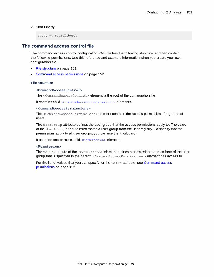
Configuring i2 Analyze | 151
7. Start Liberty:
setup -t startLiberty
The command access control file
The command access control configuration XML file has the following structure, and can containthe following permissions. Use this reference and example information when you create your ownconfiguration file.
• File structure on page 151
• Command access permissions on page 152
File structure
<CommandAccessControl>
The <CommandAccessControl> element is the root of the configuration file.
It contains child <CommandAccessPermissions> elements.
<CommandAccessPermissions>
The <CommandAccessPermissions> element contains the access permissions for groups ofusers.
The UserGroup attribute defines the user group that the access permissions apply to. The valueof the UserGroup attribute must match a user group from the user registry. To specify that thepermissions apply to all user groups, you can use the * wildcard.
It contains one or more child <Permission> elements.
<Permission>
The Value attribute of the <Permission> element defines a permission that members of the usergroup that is specified in the parent <CommandAccessPermissions> element has access to.
For the list of values that you can specify for the Value attribute, see Command accesspermissions on page 152.
© N. Harris Computer Corporation (2022)
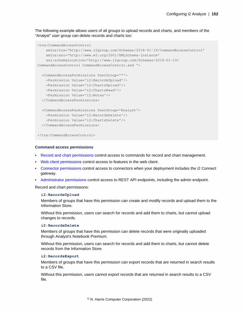
Configuring i2 Analyze | 152
The following example allows users of all groups to upload records and charts, and members of the"Analyst" user group can delete records and charts too:
<tns:CommandAccessControl
xmlns:tns="http://www.i2group.com/Schemas/2018-01-19/CommandAccessControl"
xmlns:xsi="http://www.w3.org/2001/XMLSchema-instance"
xsi:schemaLocation="http://www.i2group.com/Schemas/2018-01-19/
CommandAccessControl CommandAccessControl.xsd ">
<CommandAccessPermissions UserGroup="*">
<Permission Value="i2:RecordsUpload"/>
<Permission Value="i2:ChartsUpload"/>
<Permission Value="i2:ChartsRead"/>
<Permission Value="i2:Notes"/>
</CommandAccessPermissions>
<CommandAccessPermissions UserGroup="Analyst">
<Permission Value="i2:RecordsDelete"/>
<Permission Value="i2:ChartsDelete"/>
</CommandAccessPermissions>
</tns:CommandAccessControl>
Command access permissions
• Record and chart permissions control access to commands for record and chart management.
• Web client permissions control access to features in the web client.
• Connector permissions control access to connectors when your deployment includes the i2 Connectgateway.
• Administrator permissions control access to REST API endpoints, including the admin endpoint.
Record and chart permissions:
i2:RecordsUpload
Members of groups that have this permission can create and modify records and upload them to theInformation Store.
Without this permission, users can search for records and add them to charts, but cannot uploadchanges to records.
i2:RecordsDelete
Members of groups that have this permission can delete records that were originally uploadedthrough Analyst's Notebook Premium.
Without this permission, users can search for records and add them to charts, but cannot deleterecords from the Information Store.
i2:RecordsExport
Members of groups that have this permission can export records that are returned in search resultsto a CSV file.
Without this permission, users cannot export records that are returned in search results to a CSVfile.
© N. Harris Computer Corporation (2022)
Configuring i2 Analyze | 153
i2:ChartsUpload
Members of groups that have this permission can create and modify Analyst's Notebook chartsand upload them to the Chart Store. Modifying a chart includes deleting versions of a chart, but notdeleting the chart itself.
Without this permission, users can save Analyst's Notebook charts locally, but cannot upload newcharts and modifications to existing charts.
i2:ChartsBulkUpload
Members of groups that have this permission receive access to the Upload from Folder feature ini2 Analyst's Notebook Premium that enables users to upload charts from disk to the Chart Store inbulk.
Note: This permission automatically includes the i2:ChartsUpload permission. You do not needto give both permissions to the same user groups.
i2:ChartsDelete
Members of groups that have this permission can delete charts that were originally uploadedthrough Analyst's Notebook Premium.
Without this permission, users cannot delete charts from the Chart Store.
i2:ChartsRead
Members of groups that have this permission can search for and retrieve charts from the ChartStore.
Without this permission, users cannot search for or retrieve charts.
i2:Notes
Members of groups that have this permission can create and access notes on records and charts.
Without this permission, notes are not displayed in the Notes tab, and the contents of any notes arenot searchable.
Web client permission:
i2:Notebook
Members of groups that have this permission can access the i2 Notebook web client. Members ofgroups without this permission see the i2 Investigate web client instead.
For more information, see Enabling access to the i2 Notebook web client on page 150.
Connector permissions:
i2:Connectors
If you are using the i2 Connect gateway, members of groups that have this permission can view alli2 Connect connectors.
Without this permission, i2 Connect connectors are not visible unless individual connectors arespecified by using the i2:Connectors:connector-id permission.
i2:Connectors:connector-id
If you are using the i2 Connect gateway, members of groups that have this permission can view thei2 Connect connector with the matching connector-id. For example, i2:Connectors:example-connector.
Without this permission, the specified i2 Connect connector is not visible.
Administrator permissions:
© N. Harris Computer Corporation (2022)
Configuring i2 Analyze | 154
i2:AlertsCreate
Members of groups that have this permission can access the REST API alerts endpoint to createand send alerts to i2 Analyze users. For more information, see Managing i2 Analyze on page 408.
i2:Administrator
Members of groups that have this permission can access the REST API admin endpoints. For moreinformation, see Using the admin endpoints on page 322.
Configuring server monitoringYou can monitor and report on your deployment of i2 Analyze by using Prometheus and Grafana.
The monitoring of i2 Analyze licences is completed via a REST API. By using a REST API, i2 Analyzecan be monitored by well-used industry standard tools.
The i2 Analyze toolkit includes template configuration files for Prometheus and Grafana. Theinstructions here describe how you can install and configure Prometheus and Grafana to monitor yourdeployment of i2 Analyze.
Running Prometheus and Grafana
i2 Analyze and its components provide a number of metrics through REST endpoints. You can usePrometheus to monitor your deployment, and Grafana to visualize the captured data.
To monitor your deployment of i2 Analyze, complete the following actions:
• Update the i2 Analyze configuration to enable metrics reporting
• Configure and run Prometheus and Grafana
• View the monitoring reports in Grafana using the provided dashboards
To configure your Prometheus and Grafana instances, use your configuration developmentenvironment. When the tools are configured to meet your requirements, you can update them to matchthe security requirements of your production system.
Complete the following steps to enable metrics on i2 Analyze, and configure and install the monitoringtools.
1. Configure i2 Analyze.
a) Uncomment the monitoring features and non-SSL elements in the Libertyserver.extensions.xml file. The file is located in the toolkit/configuration/libertydirectory.For example:
<server>
<featureManager>
<feature>mpMetrics-1.1</feature>
<feature>monitor-1.0</feature>
</featureManager>
<mpMetrics authentication="false"/>
</server>
b) To enable i2 Analyze metrics, in the toolkit/configuration/fragments/opal-services/WEB-INF/classes/DiscoServerSettingsCommon.properties file, set theEnableMetrics property to true.
© N. Harris Computer Corporation (2022)

Configuring i2 Analyze | 155
For example:
EnableMetrics=true
c) Run the following command on your Liberty server to update the application with your changes.
setup -t deployLiberty
2. Configure and run Prometheus.
When you start Prometheus, you must reference a configuration file. The i2 Analyze deploymenttoolkit includes a template Prometheus configuration file that contains configuration to enablemonitoring of Prometheus, Liberty, and i2 Analyze. The prometheus.yml file is in the toolkit/examples/prometheus directory.
In the prometheus.yml file, update the values to match your environment:
a) Replace <liberty_domain>:<port> with the fully qualified domain name and port of yourLiberty server.For example, `i2analyze.eia:9082`
If you are using the opal-daod deployment pattern, update the metrics_path to '/opaldaod/api/v1/metrics'.
b) Replace <prometheus_domain>:<port> with the host name and port of your Prometheusserver.For example, `127.0.0.1:9090`
c) Replace the <username> and <password> entries for each job.
For the i2 Analyze and Liberty jobs, the user must be able to authenticate with your deployment ofi2 Analyze.
After you complete the configuration file, install and run Prometheus with your configuration. In thisexample we install and run Prometheus using Docker, but you can install it in a number of ways. Formore information about installing Prometheus, see Prometheus installation.
a) If you have Docker installed, run the following command to run Prometheus with yourconfiguration on Docker:
docker run -d -p 9090:9090 -v
"/<path_to>/prometheus.yml:/etc/prometheus/prometheus.yml"
prom/prometheus
Where <path_to> is the path with your updated prometheus.yml file. For example,toolkit/examples/prometheus.
3. Configure and run Grafana.
The i2 Analyze deployment toolkit includes a template Grafana data source configuration file anddashboards. The prometheus-datasource.yml file is in the toolkit/examples/grafana/provisioning/datasources directory.
a) In the prometheus-datasource.yml, replace <prometheus_domain>:<port> with thehost name and port of your Prometheus server.
The quickest way to install Grafana is by using Docker, but you can install it in a number of otherways. For more information about installing Grafana, see Install Grafana.
© N. Harris Computer Corporation (2022)

Configuring i2 Analyze | 156
a) If you have Docker installed, run the following command to run Grafana on Docker:
docker run -d
--name "grafana"
-p "3000:3000"
-v "<grafana_data>:/var/lib/grafana"
-v "<grafana_provisioning_dashboards>:/etc/grafana/provisioning/
dashboards"
-v "<grafana_provisioning_datasources>:/etc/grafana/provisioning/
datasources"
-v "<grafana_dashboards>:/etc/grafana/dashboards"
"grafana/grafana-oss"
Where:
• <grafana_data> is a path to store Grafana data.
• <grafana_provisioning_dashboards> is the path to your dashboard provisioning files.For example toolkit/examples/grafana/provisioning/dashboards.
For more information, see Provisioning dashboards.
• <grafana_provisioning_datasources> is the path to your data source configurationfiles. For example toolkit/examples/grafana/provisioning/datasources.
For more information, see Provisioning data sources.
• <grafana_dashboards> is the path to your dashboard files. For example toolkit/examples/grafana/dashboards.
Connect to the Grafana UI to review the dashboards. In a browser, navigate to your Grafana instance.For example, http://localhost:3000/dashboards.
By default, Grafana includes an admin user that you can use to log in. The user name is "admin" andthe password is "admin".
The toolkit includes the following example dashboards:
• The "i2 Analyze License Reporting" dashboard reports on the usage of your system by analysts. Forexample: User Activity, Privacy Agreement Count, and License Consumption.
For example:
© N. Harris Computer Corporation (2022)
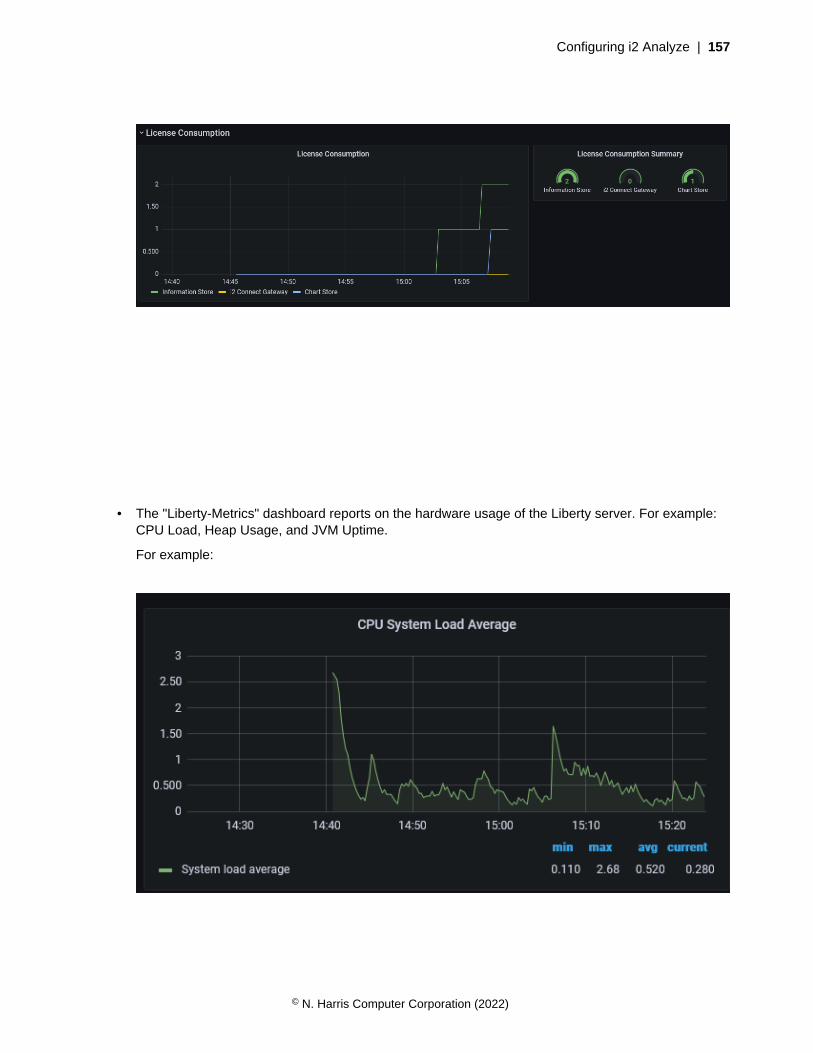
Configuring i2 Analyze | 157
• The "Liberty-Metrics" dashboard reports on the hardware usage of the Liberty server. For example:CPU Load, Heap Usage, and JVM Uptime.
For example:
© N. Harris Computer Corporation (2022)
Configuring i2 Analyze | 158
You can extend the example configuration to meet your requirements.
To run Prometheus and Grafana in production, you might want to configure authentication,authorization, and other features. You can use the Prometheus and Grafana documentation todetermine how to configure these features.
• When you move into pre-prod and production deployment, you might be deploying with TLS. Youcan configure Prometheus to communicate with Liberty by using TLS:
• Securing Prometheus API and UI endpoints using TLS encryption
• To communicate with Liberty using TLS, you must uncomment the <quickStartSecurity>element in the server.extensions.xml file and provide a user name and password toauthenticate with.
• You can configure user authentication:
• Grafana: Configure authentication
• Prometheus: HTTPS and authentication
For the complete documentation, see:
• Prometheus
• Grafana
Configuring system limits and variablesThe i2 Analyze deployment toolkit contains settings that specify system limits and variables. If youmodify these settings in a deployed system, redeploy i2 Analyze to update your deployment with anychanges.
Modifying the database configuration
You can configure the Information Store database that is deployed as part of i2 Analyze. The types ofconfiguration that you can modify include certain properties of the database and the indexes that arecreated.
Information Store database properties
The Information Store database properties files specify the names and details of database objects thatare using in the Information Store. There is a separate file for IBM® Db2® and Microsoft™ SQL Server.
The InfoStoreNamesDb2.properties and InfoStoreNamesSQLServer.properties files arein the toolkit\configuration\fragments\opal-services-is\WEB-INF\classes directory.
The settings in these files control the following database objects:
• The names of the database schemas
• The name of the deletion by rule role
• The collation sequence
• For Db2®, the page size
• For Db2®, the names of the buffer pools
• For SQL Server, the logical names and locations of the filegroup files
Note: If you change the values for any of the settings after the Information Store is created, you musteither manually change the names of the database objects in your database management system or re-create the database.
© N. Harris Computer Corporation (2022)

Configuring i2 Analyze | 159
Settings for Db2 and SQL Server
The InfoStoreNamesDb2.properties and InfoStoreNamesSQLServer.properties filescontain the following settings:
MetadataSchema
The metadata schema contains objects that relate to the definitions of data structures in theInformation Store.
By default, the value is IS_Meta
DataSchema
The data schema contains objects that store all the data that is available for analysis.
By default, the value is IS_Data
WebChartSchema
The web chart schema contains temporary objects used during manipulation of the web chart.
By default, the value is IS_WC
VisualQuerySchema
The visual query schema contains temporary objects used during visual query processing.
By default, the value is IS_Vq
FindPathSchema
The find path schema contains objects that support find path results.
By default, the value is IS_FP
StagingSchema
The staging schema contains temporary objects that support the ingestion process.
By default, the value is IS_Staging
PublicSchema
The public schema contains objects that represent a public API for the Information Store. It alsocontains procedures, tables, and views related to the deletion by rule feature.
By default, the value is IS_Public
DeletionByRuleRoleName
The deletion-by-rule role name.
By default, the value is Deletion_By_Rule
Collation
The collation sequence used for the Information Store. You can only change this settingbefore you create the Information Store database. Defaults to CLDR181_LEN_S1 for Db2 andLatin1_General_100_CI_AI_SC for SQL Server.
Settings for Db2
The InfoStoreNamesDb2.properties file contains the following settings that are specific todeployments that use IBM® Db2® to host the Information Store database:
© N. Harris Computer Corporation (2022)

Configuring i2 Analyze | 160
SystemTempTableSpace
The system temporary table space.
By default, the value is IS_TEMP_TS
UserTemp16KTableSpace
The user temporary 16K table space to hold global temporary objects.
By default, the value is IS_16K_TS
BigTableSpace
The partitioned table spaces to hold data objects and indexes.
By default, the value is IS_BIG_TS
BigIndexTableSpace
By default, the value is IS_BIG_INDEX_TS
SmallTableSpace
The non-partitioned table spaces to hold data objects and indexes.
By default, the value is IS_SMALL_TS
SmallIndexTableSpace
By default, the value is IS_SMALL_INDEX_TS
LobTableSpace
The table spaces to hold LOB data objects and indexes.
By default, the value is IS_LOB_TS
LobIndexTableSpace
By default, the value is IS_LOB_INDEX_TS
IngestionTempTableSpace
The temporary table space to hold global temporary objects during ingestion.
By default, the value is IS_16K_TS
PageSize
The page size.
By default, the value is 16K
BufferPool16K
The 16K buffer pool.
By default, the value is IS_16K_BP
Settings for SQL Server
The InfoStoreNamesSQLServer.properties file contains the following settings that are specific todeployments that use Microsoft™ SQL Server to host the Information Store database.
© N. Harris Computer Corporation (2022)

Configuring i2 Analyze | 161
For the Filename settings, you must specify a file name or absolute path. If you specify a file name,it is located relative to the value that is specified in the environment.properties file for thedb.database.location.dir property. If you specify a file path, it is considered an absolute path.
ISSchema
The Information Store schema contains internal configuration information about the InformationStore database.
By default, the value is IS_Core
PrimaryName
The SQL Server database primary data file contains the startup and configuration information for theInformation Store database. The logical name of the primary data file.
By default, the value is IStore_System_Data
PrimaryFilename
The filename or absolute path for the primary data file.
By default, the value is IStore-p1.mdf
UserTableName
The user table filegroup contains all the tables and data for the Information Store database. Thelogical name of the user table in the user table filegroup.
By default, the value is User_Table_Data
UserTableFilename
The filename or absolute path for the user table file.
By default, the value is IStore-ut1.ndf
IndexName
The index filegroup contains the indexes for the Information Store database. The logical name ofthe index file.
By default, the value is IStore_Indexes
IndexFilename
The filename or absolute path for the index file.
By default, the value is IStore-i1.ndf
LobName
The LOB filegroup contains the tables that Store LOB data. The logical name of the lob file.
By default, the value is IStore_Lobs
LobFilename
The filename or absolute path for the index file.
By default, the value is IStore-b1.ndf
MemoryOptimizedName
The memory-optimized filegroup holds one or more containers that contain data files, delta files, orboth for memory-optimized tables. The logical name of the memory-optimized file.
© N. Harris Computer Corporation (2022)

Configuring i2 Analyze | 162
By default, the value is IStore_Memory_Optimized
MemoryOptimizedFilename
The filename or absolute path for the memory-optimized file.
By default, the value is IStore-mo1.ndf
SqlLogName1
The transaction log files used for the Information Store. The logical name of the first SQL log.
By default, the value is IStore_Logs_1
SqlLogFilename1
The filename or absolute path for the first SQL log file.
By default, the value is IStore-log1.ldf
SqlLogName2
The logical name of the second SQL log.
By default, the value is IStore_Logs_2
SqlLogFilename2
The filename or absolute path for the second SQL log file.
By default, the value is IStore-log2.ldf
DDLBatchSize
The number of DDL statements in each batch.
By default, the value is 5
DMLBatchSize
The number of DML statements in each batch.
By default, the value is 1000
After you update the database properties, you can either modify other aspects of the deployment toolkitor deploy the system to update the deployment with any changes.
The InfoStoreNamesDb2.properties file
The following properties are in the InfoStoreNamesDb2.properties file:
MetadataSchema
The metadata schema contains objects that relate to the definitions of data structures in theInformation Store.
By default, the value is IS_Meta
DataSchema
The data schema contains objects that store all the data that is available for analysis.
By default, the value is IS_Data
WebChartSchema
The web chart schema contains temporary objects used during manipulation of the web chart.
© N. Harris Computer Corporation (2022)

Configuring i2 Analyze | 163
By default, the value is IS_WC
VisualQuerySchema
The visual query schema contains temporary objects used during visual query processing.
By default, the value is IS_Vq
FindPathSchema
The find path schema contains objects that support find path results.
By default, the value is IS_FP
StagingSchema
The staging schema contains temporary objects that support the ingestion process.
By default, the value is IS_Staging
PublicSchema
The public schema contains objects that represent a public API for the Information Store. It alsocontains procedures, tables, and views related to the deletion by rule feature.
By default, the value is IS_Public
SystemTempTableSpace
The system temporary table space.
By default, the value is IS_TEMP_TS
UserTemp16KTableSpace
The user temporary 16K table space to hold global temporary objects.
By default, the value is IS_16K_TS
BigTableSpace
The partitioned table spaces to hold data objects and indexes.
By default, the value is IS_BIG_TS
BigIndexTableSpace
By default, the value is IS_BIG_INDEX_TS
SmallTableSpace
The non-partitioned table spaces to hold data objects and indexes.
By default, the value is IS_SMALL_TS
SmallIndexTableSpace
By default, the value is IS_SMALL_INDEX_TS
LobTableSpace
The table spaces to hold LOB data objects and indexes.
By default, the value is IS_LOB_TS
LobIndexTableSpace
By default, the value is IS_LOB_INDEX_TS
© N. Harris Computer Corporation (2022)

Configuring i2 Analyze | 164
IngestionTempTableSpace
The temporary table space to hold global temporary objects during ingestion.
By default, the value is IS_16K_TS
InternalStagingTableSpace
The table space to hold internal staging data objects created during ingestion Note: these tableshave data inserted using NOT LOGGED INITIALLY
By default, the value is IS_INTSTG_TS
PageSize
The page size.
By default, the value is 16K
BufferPool16K
The 16K buffer pool.
By default, the value is IS_16K_BP
DeletionByRuleRoleName
The deletion-by-rule role name.
By default, the value is Deletion_By_Rule
Collation
The collation sequence used for the Information Store in Db2. You can only change this settingbefore you create the Information Store database. Defaults to "CLDR181_LEN_S1".
By default, the value is CLDR181_LEN_S1
LoggerSchema
The following options are not used for new Information Store deployments, but might be used duringupgrade from earlier versions. You must not modify these settings.
By default, the value is LOGGER
LoggerDataSchema
By default, the value is LOGDATA
LoggerModuleSchema
By default, the value is LOGGER_1B
LoggerTableSpace
By default, the value is LOG_DATA_SPACE
LoggerMetadataTableSpace
By default, the value is LOGGER_SPACE
ReportsSchema
By default, the value is IS_Rpt
© N. Harris Computer Corporation (2022)

Configuring i2 Analyze | 165
The InfoStoreNamesSQLServer.properties file
The following properties are in the InfoStoreNamesSQLServer.properties file:
ISSchema
The Information Store schema contains internal configuration information about the InformationStore database.
By default, the value is IS_Core
MetadataSchema
The metadata schema contains objects that relate to the definitions of data structures in theInformation Store.
By default, the value is IS_Meta
DataSchema
The data schema contains objects that store all the data that is available for analysis.
By default, the value is IS_Data
WebChartSchema
The web chart schema contains temporary objects used during manipulation of the web chart.
By default, the value is IS_WC
VisualQuerySchema
The visual query schema contains temporary objects used during visual query processing.
By default, the value is IS_Vq
FindPathSchema
The find path schema contains objects that support find path results.
By default, the value is IS_FP
StagingSchema
The staging schema contains temporary objects that support the ingestion process.
By default, the value is IS_Staging
PublicSchema
The public schema contains objects that represent a public API for the Information Store. It alsocontains procedures, tables, and views related to the deletion by rule feature.
By default, the value is IS_Public
DeletionByRuleRoleName
The deletion-by-rule role name.
By default, the value is Deletion_By_Rule
Collation
The collation sequence used for the Information Store in SQL Server. You can onlychange this setting before you create the Information Store database. Defaults toLatin1_General_100_CI_AI_SC.
© N. Harris Computer Corporation (2022)
Configuring i2 Analyze | 166
By default, the value is Latin1_General_100_CI_AI_SC
PrimaryName
The SQL Server database primary data file contains the startup and configuration information for theInformation Store database. The logical name of the primary data file.
By default, the value is IStore_System_Data
PrimaryFilename
The filename or absolute path for the primary data file.
By default, the value is IStore-p1.mdf
UserTableName
The user table filegroup contains all the tables and data for the Information Store database. Thelogical name of the user table in the user table filegroup.
By default, the value is User_Table_Data
UserTableFilename
The filename or absolute path for the user table file.
By default, the value is IStore-ut1.ndf
IndexName
The index filegroup contains the indexes for the Information Store database. The logical name ofthe index file.
By default, the value is IStore_Indexes
IndexFilename
The filename or absolute path for the index file.
By default, the value is IStore-i1.ndf
LobName
The LOB filegroup contains the tables that Store LOB data. The logical name of the lob file.
By default, the value is IStore_Lobs
LobFilename
The filename or absolute path for the index file.
By default, the value is IStore-b1.ndf
MemoryOptimizedName
The memory-optimized filegroup holds one or more containers that contain data files, delta files, orboth for memory-optimized tables. The logical name of the memory-optimized file.
By default, the value is IStore_Memory_Optimized
MemoryOptimizedFilename
The filename or absolute path for the memory-optimized file.
By default, the value is IStore-mo1.ndf
SqlLogName1
© N. Harris Computer Corporation (2022)

Configuring i2 Analyze | 167
The transaction log files used for the Information Store. The logical name of the first SQL log.
By default, the value is IStore_Logs_1
SqlLogFilename1
The filename or absolute path for the first SQL log file.
By default, the value is IStore-log1.ldf
SqlLogName2
The logical name of the second SQL log.
By default, the value is IStore_Logs_2
SqlLogFilename2
The filename or absolute path for the second SQL log file.
By default, the value is IStore-log2.ldf
ReportsSchema
The following options are not used for new Information Store deployments, but might be used duringupgrade from earlier versions. You must not modify these settings.
By default, the value is IS_Rpt
Creating indexes in the Information Store database
In the Information Store, you can add indexes to the item type tables, and to the property type columnsof those tables.
Indexes can improve the performance of Visual Query searches. Indexes can also improve theperformance of the merged property values definition views if you are using them.
To create an index, you must use the informationStoreModifications.sql file. Thisscript is run every time the Information Store database is created. You can also use themodifyInformationStoreDatabase toolkit task to run the script at any time.
The file must be in the configuration\environment\opal-server\databases\infostoredirectory. infostore is the value of the id attribute of the database element for your Information Storedatabase in the topology.xml file.
In the Information Store database, the IS_DATA schema contains the tables for each item type. Entityitem type tables are prefixed with E_ and link item type tables with L_. In these tables, property columnsare prefixed with P_.
For example, your i2 Analyze schema might contain a Person entity with a First Given Name property. Ifyou know that this property is used a lot by analysts in Visual Query searches, you might want to createan index on that table and column. To create a simple index for the First Given Name property, add thefollowing statement to the informationStoreModifications.sql file:
CREATE INDEX IS_DATA.E_PERSON_FN_IX ON IS_DATA.E_PERSON (P_FIRST_GIVEN_NAME);
IS_DATA.E_PERSON_FN_IX is the name of the index to create, IS_DATA.E_PERSON is the table forthe Person entity type, and P_FIRST_GIVEN_NAME is the column for the first given name property type.
To determine the syntax of the SQL statement that you must use to create the index, use thedocumentation for your database management system. For more information about creating indexes in
© N. Harris Computer Corporation (2022)

Configuring i2 Analyze | 168
a Db2 database, see CREATE INDEX statement and for SQL Server, see CREATE INDEX (Transact-SQL).
1. Identify the item types, and any of their property types, that you want to add indexes for.
2. Create the directory for the informationStoreModifications.sql file.
a) In the configuration\environment\opal-server directory, create the databasesdirectory.
b) In the databases directory that you created, create the infostore directory.
You can find the value to use for infostore in your topology.xml file. The value to use in yourdeployment is the value of the id attribute of the <database> element for your Information Storedatabase.
For example, configuration\environment\opal-server\databases\infostore.
3. Using a text editor, create a file that is named informationStoreModifications.sql in theconfiguration\environment\opal-server\databases\infostore directory.
4. Develop a script to create the indexes on the tables and columns that you identified in step 1 in theinformationStoreModifications.sql file.
5. Save and close the file.
6. If the Information Store database exists, run the modifyInformationStoreDatabase toolkit taskto run the script that you saved in step 4.
a) Open a command prompt and navigate to the toolkit\scripts directory.
b) Run the following command to run the informationStoreModifications.sql file:
setup -t modifyInformationStoreDatabase
Ensure that the indexes you expect are in the Information Store database. You can use IBM Data Studioor SQL Server Management Studio to see the indexes in the Information Store database.
Modifying the remote Db2 database configuration
You can change the configuration attributes of your remote Db2 databases in the i2 Analyze deploymenttoolkit. To modify the remote database configuration, you must recatalog the remote nodes.
When you recatalog a remote node, the existing node is removed from the Db2 node directory and isthen cataloged again with the updated configuration values.
If you need to configure security settings on the connection, you can recatalog the remote nodesmanually, instead of using the tasks that are in the deployment toolkit. To recatalog the remote nodesmanually, you can use the Db2 UNCATALOG NODE and CATALOG TCPIP/TCPIP4/TCPIP6 NODEcommands.
You run the UNCATALOG NODE and CATALOG NODE commands manually instead of using therecatalogRemoteDB2Nodes task. For more information about the commands, see UNCATALOGNODE command and CATALOG TCPIP/TCPIP4/TCPIP6 NODE command.
Note: The catalogRemoteDB2Nodes and recatalogRemoteDB2Nodes tasks use the Db2CATALOG TCPIP NODE command. The following table shows how the CATALOG command parametersmap to the values in the topology.xml file:
CATALOG TCPIP NODE command parameters <database> element attributes
TCPIP NODE nodename node-name
© N. Harris Computer Corporation (2022)
https://docs.microsoft.com/en-us/sql/t-sql/statements/create-index-transact-sql?view=sql-server-2017

Configuring i2 Analyze | 169
CATALOG TCPIP NODE command parameters <database> element attributes
REMOTE hostname host-name
SERVER port number port-number
REMOTE_INSTANCE instance-name instance-name
1. Change the host name, port, and operating system type attributes of the remote database:
a) Using an XML editor, open toolkit\configuration\environment\topology.xml.
b) Update the host-name and port-number attribute values of the <database> element for thedatabase.
c) Run the following command to recatalog the remote node:
setup -t recatalogRemoteDB2Nodes
2. Change the node name attribute of the remote database:
a) Run the following command to uncatalog the remote node:
setup -t uncatalogRemoteDB2Nodes
b) Using an XML editor, open toolkit\configuration\environment\topology.xml.
c) Update the node-name attribute values of the <database> element for the database.
d) Run the following command to catalog the remote node:
setup -t catalogRemoteDB2Nodes
The next time that you deploy i2 Analyze, or recreate the database, the database is created using thenew values that you provided in the topology.xml.
Modifying the maximum number of notes in a record
In a deployment of i2 Analyze, analysts can add notes that contain information that is not categorizedby the type of entity or link to Information Store records. The number of notes that a record contains canimpact the performance of searching for and uploading that record.
You can configure the maximum number of notes that a record can contain to a number that bettermatches system requirements. By default, the maximum number of notes that a record can contain is50.
If a record already contains more notes than the maximum that you set, analysts can continue to editand delete the existing notes. However, analysts can only create notes in the record by deleting existingnotes until the number of notes is less than the new maximum.
If you follow this procedure in a deployment that provides high availability, you must complete each stepon every Liberty server in your environment before you move to the next step.
1. Using a text editor, open the DiscoServerSettingsCommon.properties file. You can find thisfile in the following location: toolkit\configuration\fragments\opal-services\WEB-INF\classes.
2. Change the value of the RecordMaxNotes property.For example, RecordMaxNotes=25.
3. Save your changes.
© N. Harris Computer Corporation (2022)

Configuring i2 Analyze | 170
After you modify the maximum number of notes a record can contain, redeploy the i2 Analyzeapplication for the changes to take effect. For more information about redeploying your system, seeRedeploying Liberty on page 321.
After you redeploy i2 Analyze, test that the system continues to meet your requirements.
Configuring searchDepending on the requirements of the environment that you are deploying into, a number ofconfigurable options are available for searching and indexing. You can configure the behavior of searchfeatures to match your requirements.
Configuring Quick Search
Analysts can use Quick Search to find records in the Information Store by specifying terms that recordsmight contain. You can configure the behavior of Quick Search to meet the language and structure ofyour data and the requirements of your analysts.
Configuring the Solr index
By default, the Solr index assumes that text data in i2 Analyze follows the conventions of WesternEuropean languages, and uses a list of synonyms that contains US English terms. It also treats letterslike o, ó, and ö as equivalent for the purposes of filtering search results. You can change these settingsso that the index meets the language requirements of your data.
To configure the Solr index, modify the schema-template-definition.xml file. In the templatedefinition, you can control the following aspects of Solr:
• How Solr returns data based on the language of the data in the index
• The Solr synonyms file
• Whether to preserve diacritics in search result filters. For example to treat a, å, and ä as equivalentor not.
By default, the Solr search index is configured for Western European languages, and uses synonymlists that contain US English terms. The template definition configuration file includes template optionsfor ar_EG (Arabic) and he_IL(Hebrew) languages.
Each language template has a default synonyms file that is associated with the template language. Youcan change the default synonyms file to use a customized synonyms file. For more information, seeCreating a synonyms file on page 174.
By default, diacritics are not preserved in filters. This means that "Amélie" and "Amelie" both contributeto the "amelie" filter To ensure that "Amélie" and "Amelie" create separate filters, you can preserve thediacritics.
Note: Changing the diacritic behavior for filters does not impact the behavior when searching.
If you need to configure the behavior of the Solr index, do this in your configuration developmentenvironment. If your system contains data, you must reindex after changing the Solr configuration.
1. To modify the Solr index configuration, open the configuration\solr\schema-template-definition.xml file in an XML editor.
2. Specify the language template and synonyms file for the index.
a) To specify the language template and default synonyms file, uncomment the section of thetemplate file for the language you want to use.
© N. Harris Computer Corporation (2022)
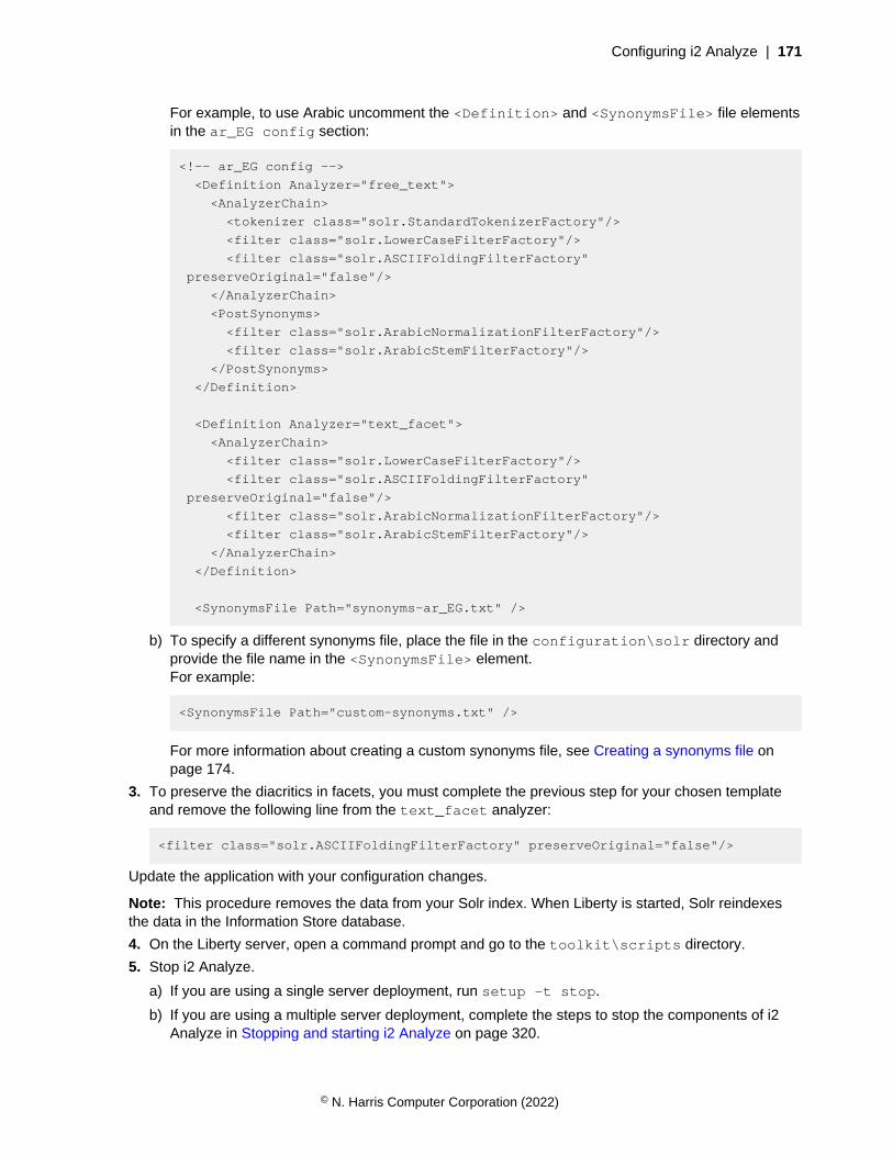
Configuring i2 Analyze | 171
For example, to use Arabic uncomment the <Definition> and <SynonymsFile> file elementsin the ar_EG config section:
<!-- ar_EG config -->
<Definition Analyzer="free_text">
<AnalyzerChain>
<tokenizer class="solr.StandardTokenizerFactory"/>
<filter class="solr.LowerCaseFilterFactory"/>
<filter class="solr.ASCIIFoldingFilterFactory"
preserveOriginal="false"/>
</AnalyzerChain>
<PostSynonyms>
<filter class="solr.ArabicNormalizationFilterFactory"/>
<filter class="solr.ArabicStemFilterFactory"/>
</PostSynonyms>
</Definition>
<Definition Analyzer="text_facet">
<AnalyzerChain>
<filter class="solr.LowerCaseFilterFactory"/>
<filter class="solr.ASCIIFoldingFilterFactory"
preserveOriginal="false"/>
<filter class="solr.ArabicNormalizationFilterFactory"/>
<filter class="solr.ArabicStemFilterFactory"/>
</AnalyzerChain>
</Definition>
<SynonymsFile Path="synonyms-ar_EG.txt" />
b) To specify a different synonyms file, place the file in the configuration\solr directory andprovide the file name in the <SynonymsFile> element.For example:
<SynonymsFile Path="custom-synonyms.txt" />
For more information about creating a custom synonyms file, see Creating a synonyms file onpage 174.
3. To preserve the diacritics in facets, you must complete the previous step for your chosen templateand remove the following line from the text_facet analyzer:
<filter class="solr.ASCIIFoldingFilterFactory" preserveOriginal="false"/>
Update the application with your configuration changes.
Note: This procedure removes the data from your Solr index. When Liberty is started, Solr reindexesthe data in the Information Store database.
4. On the Liberty server, open a command prompt and go to the toolkit\scripts directory.
5. Stop i2 Analyze.
a) If you are using a single server deployment, run setup -t stop.
b) If you are using a multiple server deployment, complete the steps to stop the components of i2Analyze in Stopping and starting i2 Analyze on page 320.
© N. Harris Computer Corporation (2022)
Configuring i2 Analyze | 172
6. Redeploy i2 Analyze:
setup -t deployLiberty
7. Create and upload the Solr configuration to ZooKeeper:
setup -t createAndUploadSolrConfig --hostname 'liberty.host-name'
Here, liberty.hostname is the hostname of the Liberty server where you are running thecommand. It matches the value for the host-name attribute of the <application> element in thetopology.xml file.
8. Clear the search index:
setup -t clearSearchIndex --hostname 'liberty.host-name'
Here, liberty.hostname is the hostname of the Liberty server where you are running thecommand. It matches the value for the host-name attribute of the <application> element in thetopology.xml file.
9. Start i2 Analyze
a) If you are using a single server deployment, run setup -t start.
b) If you are using a multiple server deployment, complete the steps to start the components of i2Analyze in Stopping and starting i2 Analyze on page 320.
Run a selection of queries against your deployment server to test the configuration.
The Solr template configuration file
The Solr template configuration file that is provided in the i2 Analyze deployment toolkit containscommented-out templates for a number of languages.
Root element
• <SolrSchemaTemplate>
i2 Analyze elements
• <Definition>
• <AnalyzerChain>
• <PostSynonyms>
• <SynonymsFile>
Solr elements
• <tokenizer> and <filter>
Root element
<SolrSchemaTemplate>
© N. Harris Computer Corporation (2022)

Configuring i2 Analyze | 173
<SolrSchemaTemplate> is the root element of the Solr template configuration file. It referencesthe SolrSchemaTemplate.xsd file and version number. Do not change the value for theVersion attribute.
<SolrSchemaTemplate
xmlns:tns="http://www.i2group.com/Schemas/2021-02-12/SolrSchemaTemplate"
xmlns:xsi="http://www.w3.org/2001/XMLSchema-instance"
xsi:schemaLocation="http://www.i2group.com/Schemas/2021-02-12/
SolrSchemaTemplate SolrSchemaTemplate.xsd "
Version="1">
</SolrSchemaTemplate>
i2 Analyze elements
<Definition>
In the Solr index, analyzers are used to examine the text that is stored in the index. Two of theanalyzers that i2 Analyze uses are the free_text and text_facet analyzers. In the templatefile, the analyzer is specified in the Analyzer attribute of the <Definition> element.
<Definition Analyzer="free_text">
...
</Definition>
<Definition Analyzer="text_facet">
...
</Definition>
<AnalyzerChain>
The <AnalyzerChain> element is a container for the Solr elements on page 174 in the analyzerchain. The <AnalyzerChain> element is a child of the <Definition> element.
<Definition Analyzer="free_text">
<AnalyzerChain>
...
</AnalyzerChain>
</Definition>
<PostSynonyms>
The <PostSynonyms> element is a container for the Solr elements on page 174 in the analyzerchain that are applied after the synonym filter. The <PostSynonyms> element is a child of the<Definition> element, specified after the <AnalyzerChain> element.
<Definition Analyzer="free_text">
<AnalyzerChain> ... </AnalyzerChain>
<PostSynonyms>
...
</PostSynonyms>
</Definition>
© N. Harris Computer Corporation (2022)
Configuring i2 Analyze | 174
<SynonymsFile>
The Path attribute of the <SynonymsFile> element contains the file name of the synonyms file touse. The <SynonymsFile> element is at the same level as the <Definition> element.
<SynonymsFile Path="synonyms-ar_EG.txt" />
Solr elements
The <tokenizer> and <filter> are directly converted to Solr. For more information about theelements, see Understanding Analyzers, Tokenizers, and Filters.
In the Solr template configuration, the <tokenizer> and <filter> elements can be child elements ofthe <AnalyzerChain> and <PostSynonyms> elements.
Note: The <tokenizer> element can be specified as a child of the <Definition> element whereAnalyzer="free_text".
Creating a synonyms file
Solr provides the facility to configure the synonyms that are used for querying textual data. In i2Analyze, you can use this option to apply a customized list of synonyms at query time. Synonyms, if notaccounted for, can cause a reduction in the relevance of a search result when you search for keywordsthat are present in alternative forms in your index.
The synonyms file is the part of the Solr configuration that accounts for the presence of synonyms inyour data. For example, your data might contain the words, “bag, handbag, pocketbook, purse” for theconcept “bag”. When someone searches they are likely to search for one, but expect results for all four.To meet that expectation, you might want to create a customized synonyms file to accommodate similarvariations that are specific to your data. The exact words in a synonyms list that are most useful in yourdeployment depend on the content of your data. You can also use a mix of languages, which might beuseful in some contexts, for example names: 'George, ########, Jorge'.
The default synonyms file and synonyms list are in US English. The synonyms files that are associatedby default with each supported language are supplied in the directory, toolkit\configuration\solr.
To customize the alternative terms that are used in search operations for your data, you can create filesthat contain different terms from those terms that are contained in the supplied synonyms files.
The customized file must adhere to the following guidelines:
• The file must be UTF-8 encoded.
• The terms in the file must match the terms that are produced by the analyzer chain that is used inSolr prior to the synonym filter being applied.
• If multiple forms of a word exist, all the forms must be specified in order for synonym matching towork on each form.
• Words from Latin script languages, for example French or Italian, must be specified withoutdiacritics. For example, use the following substitution:
• a instead of á
• c instead of ç
• Arabic and Hebrew words must be specified exactly as they are written.
1. Create a text file that defines synonyms in the required Solr format.
© N. Harris Computer Corporation (2022)
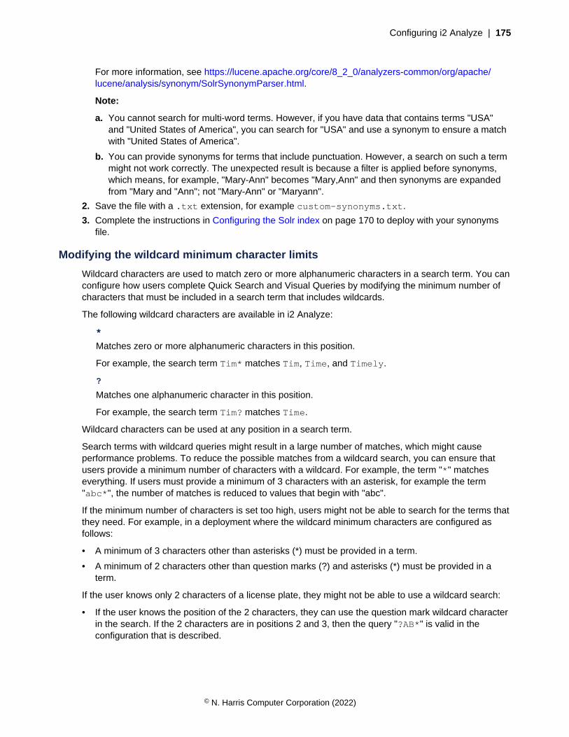
Configuring i2 Analyze | 175
For more information, see https://lucene.apache.org/core/8_2_0/analyzers-common/org/apache/lucene/analysis/synonym/SolrSynonymParser.html.
Note:
a. You cannot search for multi-word terms. However, if you have data that contains terms "USA"and "United States of America", you can search for "USA" and use a synonym to ensure a matchwith "United States of America".
b. You can provide synonyms for terms that include punctuation. However, a search on such a termmight not work correctly. The unexpected result is because a filter is applied before synonyms,which means, for example, "Mary-Ann" becomes "Mary,Ann" and then synonyms are expandedfrom "Mary and "Ann"; not "Mary-Ann" or "Maryann".
2. Save the file with a .txt extension, for example custom-synonyms.txt.
3. Complete the instructions in Configuring the Solr index on page 170 to deploy with your synonymsfile.
Modifying the wildcard minimum character limits
Wildcard characters are used to match zero or more alphanumeric characters in a search term. You canconfigure how users complete Quick Search and Visual Queries by modifying the minimum number ofcharacters that must be included in a search term that includes wildcards.
The following wildcard characters are available in i2 Analyze:
*
Matches zero or more alphanumeric characters in this position.
For example, the search term Tim* matches Tim, Time, and Timely.
?
Matches one alphanumeric character in this position.
For example, the search term Tim? matches Time.
Wildcard characters can be used at any position in a search term.
Search terms with wildcard queries might result in a large number of matches, which might causeperformance problems. To reduce the possible matches from a wildcard search, you can ensure thatusers provide a minimum number of characters with a wildcard. For example, the term "*" matcheseverything. If users must provide a minimum of 3 characters with an asterisk, for example the term"abc*", the number of matches is reduced to values that begin with "abc".
If the minimum number of characters is set too high, users might not be able to search for the terms thatthey need. For example, in a deployment where the wildcard minimum characters are configured asfollows:
• A minimum of 3 characters other than asterisks (*) must be provided in a term.
• A minimum of 2 characters other than question marks (?) and asterisks (*) must be provided in aterm.
If the user knows only 2 characters of a license plate, they might not be able to use a wildcard search:
• If the user knows the position of the 2 characters, they can use the question mark wildcard characterin the search. If the 2 characters are in positions 2 and 3, then the query "?AB*" is valid in theconfiguration that is described.
© N. Harris Computer Corporation (2022)
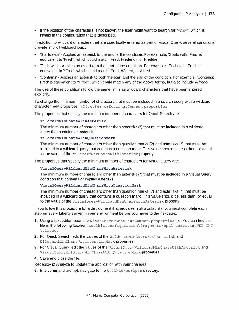
Configuring i2 Analyze | 176
• If the position of the characters is not known, the user might want to search for "*AB*", which isinvalid in the configuration that is described.
In addition to wildcard characters that are specifically entered as part of Visual Query, several conditionsprovide implicit wildcard logic:
• 'Starts with' - Applies an asterisk to the end of the condition. For example, 'Starts with: Fred' isequivalent to 'Fred*', which could match; Fred, Frederick, or Freddie.
• 'Ends with' - Applies an asterisk to the start of the condition. For example, 'Ends with: Fred' isequivalent to '*Fred', which could match; Fred, Wilfred, or Alfred.
• 'Contains' - Applies an asterisk to both the start and the end of the condition. For example, 'Contains:Fred' is equivalent to '*Fred*', which could match any of the above terms, but also include Alfredo.
The use of these conditions follow the same limits as wildcard characters that have been enteredexplicitly.
To change the minimum number of characters that must be included in a search query with a wildcardcharacter, edit properties in DiscoServerSettingsCommon.properties.
The properties that specify the minimum number of characters for Quick Search are:
WildcardMinCharsWithAsterisk
The minimum number of characters other than asterisks (*) that must be included in a wildcardquery that contains an asterisk.
WildcardMinCharsWithQuestionMark
The minimum number of characters other than question marks (?) and asterisks (*) that must beincluded in a wildcard query that contains a question mark. This value should be less than, or equalto the value of the WildcardMinCharsWithAsterisk property.
The properties that specify the minimum number of characters for Visual Query are:
VisualQueryWildcardMinCharsWithAsterisk
The minimum number of characters other than asterisks (*) that must be included in a Visual Querycondition that contains or implies asterisks.
VisualQueryWildcardMinCharsWithQuestionMark
The minimum number of characters other than question marks (?) and asterisks (*) that must beincluded in a wildcard query that contains a question mark. This value should be less than, or equalto the value of the VisualQueryWildcardMinCharsWithAsterisk property.
If you follow this procedure for a deployment that provides high availability, you must complete eachstep on every Liberty server in your environment before you move to the next step.
1. Using a text editor, open the DiscoServerSettingsCommon.properties file. You can find thisfile in the following location: toolkit\configuration\fragments\opal-services\WEB-INF\classes.
2. For Quick Search, edit the values of the WildcardMinCharsWithAsterisk andWildcardMinCharsWithQuestionMark properties.
3. For Visual Query, edit the values of the VisualQueryWildcardMinCharsWithAsterisk andVisualQueryWildcardMinCharsWithQuestionMark properties.
4. Save and close the file.
Redeploy i2 Analyze to update the application with your changes.
5. In a command prompt, navigate to the toolkit\scripts directory.
© N. Harris Computer Corporation (2022)

Configuring i2 Analyze | 177
6. Stop Liberty:
setup -t stopLiberty
7. Update the i2 Analyze application:
setup -t deployLiberty
8. Start Liberty:
setup -t startLiberty
Run a selection of Quick Search and Visual Queries that use conditions including wildcard characters.Continue to change the configuration until you are satisfied with the wildcard behavior.
Configuring Visual Query
Analysts can use Visual Query to search for records in the Information Store based on the values ofspecific properties and on their relationship to other records. You can configure a number of aspects ofVisual Query, including the conditions that are available to analysts and how regularly saved queries arerun.
You can configure how users complete Visual Queries by modifying the minimum number of charactersthat must be included in a search term that includes wildcards. For more information, see Modifying thewildcard minimum character limits on page 175.
Visual Query condition restrictions
In order to create a configuration file that helps you to manage your Visual Query performanceeffectively, it is important to understand the available restrictions. Having a proper understanding of theimplications of the rules that can be created, allows you to reduce the number of iterations required.
The visual-query-configuration.xml file in configuration/fragments/opal-services/WEB-INF/classes includes commented out examples of rules applicable to the law enforcementschema. Using these examples as guidance, you can create rules that apply to your system.
Important: The rules that are added in visual-query-configuration.xml are applied to the i2Analyze server and not the Analyst's Notebook Premium client. As such, users are still able to constructqueries that include restricted conditions, but the server will prevent the query from being run.
Depending on your circumstances, there are two main approaches that can be used to create yourrules:
Invalidating a particular type of query
If you are aware of query types that are an issue, you can deny the specific conditions that lead tothe issue, allowing all other Visual Query behavior to remain unchanged.
Enabling specific queries
If you are uncertain about the type of queries that might produce an issue, or want to restrict thetypes of searches that can be carried out, you can deny all conditions, and selectively allow thetypes of query that you require.
As you build up your Visual Query configuration file, it is worth bearing in mind the following keyconcepts:
Rule components
Each rule consists of the following components:
© N. Harris Computer Corporation (2022)
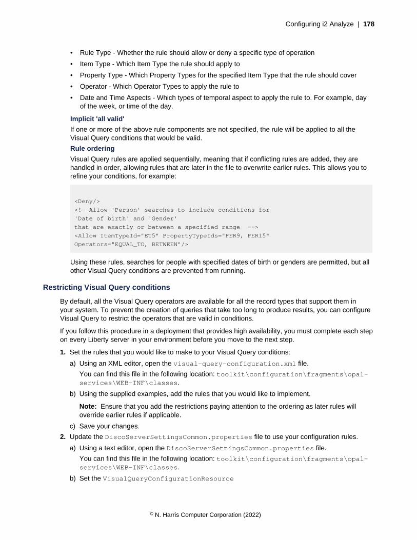
Configuring i2 Analyze | 178
• Rule Type - Whether the rule should allow or deny a specific type of operation
• Item Type - Which Item Type the rule should apply to
• Property Type - Which Property Types for the specified Item Type that the rule should cover
• Operator - Which Operator Types to apply the rule to
• Date and Time Aspects - Which types of temporal aspect to apply the rule to. For example, dayof the week, or time of the day.
Implicit 'all valid'
If one or more of the above rule components are not specified, the rule will be applied to all theVisual Query conditions that would be valid.
Rule ordering
Visual Query rules are applied sequentially, meaning that if conflicting rules are added, they arehandled in order, allowing rules that are later in the file to overwrite earlier rules. This allows you torefine your conditions, for example:
<Deny/>
<!--Allow 'Person' searches to include conditions for
'Date of birth' and 'Gender'
that are exactly or between a specified range -->
<Allow ItemTypeId="ET5" PropertyTypeIds="PER9, PER15"
Operators="EQUAL_TO, BETWEEN"/>
Using these rules, searches for people with specified dates of birth or genders are permitted, but allother Visual Query conditions are prevented from running.
Restricting Visual Query conditions
By default, all the Visual Query operators are available for all the record types that support them inyour system. To prevent the creation of queries that take too long to produce results, you can configureVisual Query to restrict the operators that are valid in conditions.
If you follow this procedure in a deployment that provides high availability, you must complete each stepon every Liberty server in your environment before you move to the next step.
1. Set the rules that you would like to make to your Visual Query conditions:
a) Using an XML editor, open the visual-query-configuration.xml file.
You can find this file in the following location: toolkit\configuration\fragments\opal-services\WEB-INF\classes.
b) Using the supplied examples, add the rules that you would like to implement.
Note: Ensure that you add the restrictions paying attention to the ordering as later rules willoverride earlier rules if applicable.
c) Save your changes.
2. Update the DiscoServerSettingsCommon.properties file to use your configuration rules.
a) Using a text editor, open the DiscoServerSettingsCommon.properties file.
You can find this file in the following location: toolkit\configuration\fragments\opal-services\WEB-INF\classes.
b) Set the VisualQueryConfigurationResource
© N. Harris Computer Corporation (2022)
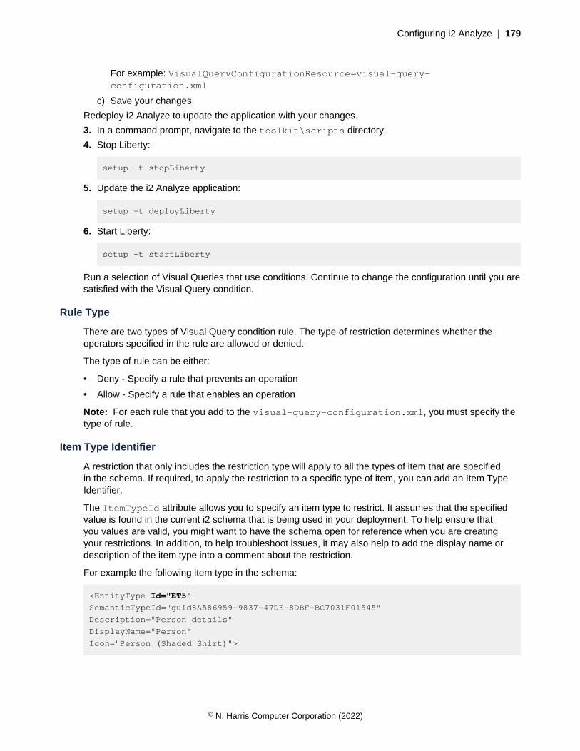
Configuring i2 Analyze | 179
For example: VisualQueryConfigurationResource=visual-query-configuration.xml
c) Save your changes.
Redeploy i2 Analyze to update the application with your changes.
3. In a command prompt, navigate to the toolkit\scripts directory.
4. Stop Liberty:
setup -t stopLiberty
5. Update the i2 Analyze application:
setup -t deployLiberty
6. Start Liberty:
setup -t startLiberty
Run a selection of Visual Queries that use conditions. Continue to change the configuration until you aresatisfied with the Visual Query condition.
Rule Type
There are two types of Visual Query condition rule. The type of restriction determines whether theoperators specified in the rule are allowed or denied.
The type of rule can be either:
• Deny - Specify a rule that prevents an operation
• Allow - Specify a rule that enables an operation
Note: For each rule that you add to the visual-query-configuration.xml, you must specify thetype of rule.
Item Type Identifier
A restriction that only includes the restriction type will apply to all the types of item that are specifiedin the schema. If required, to apply the restriction to a specific type of item, you can add an Item TypeIdentifier.
The ItemTypeId attribute allows you to specify an item type to restrict. It assumes that the specifiedvalue is found in the current i2 schema that is being used in your deployment. To help ensure thatyou values are valid, you might want to have the schema open for reference when you are creatingyour restrictions. In addition, to help troubleshoot issues, it may also help to add the display name ordescription of the item type into a comment about the restriction.
For example the following item type in the schema:
<EntityType Id="ET5"
SemanticTypeId="guid8A586959-9837-47DE-8DBF-BC7031F01545"
Description="Person details"
DisplayName="Person"
Icon="Person (Shaded Shirt)">
© N. Harris Computer Corporation (2022)
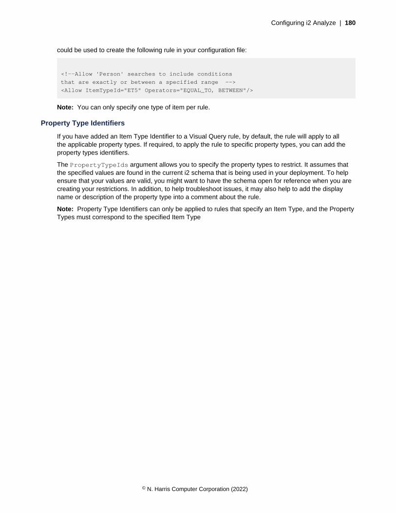
Configuring i2 Analyze | 180
could be used to create the following rule in your configuration file:
<!--Allow 'Person' searches to include conditions
that are exactly or between a specified range -->
<Allow ItemTypeId="ET5" Operators="EQUAL_TO, BETWEEN"/>
Note: You can only specify one type of item per rule.
Property Type Identifiers
If you have added an Item Type Identifier to a Visual Query rule, by default, the rule will apply to allthe applicable property types. If required, to apply the rule to specific property types, you can add theproperty types identifiers.
The PropertyTypeIds argument allows you to specify the property types to restrict. It assumes thatthe specified values are found in the current i2 schema that is being used in your deployment. To helpensure that your values are valid, you might want to have the schema open for reference when you arecreating your restrictions. In addition, to help troubleshoot issues, it may also help to add the displayname or description of the property type into a comment about the rule.
Note: Property Type Identifiers can only be applied to rules that specify an Item Type, and the PropertyTypes must correspond to the specified Item Type
© N. Harris Computer Corporation (2022)

Configuring i2 Analyze | 181
For example the following property types in the law enforcement schema:
<EntityType Id="ET5"
SemanticTypeId="guid8A586959-9837-47DE-8DBF-BC7031F01545"
Description="Person details"
DisplayName="Person"
Icon="Person (Shaded Shirt)">
...
<PropertyType Position="2"
Mandatory="false"
SemanticTypeId="guidFE45F1C4-B198-4111-8123-F42D2CD6419D"
DisplayName="Date of Birth"
Description=""
LogicalType="DATE"
Id="PER9">
<PossibleValues />
</PropertyType>
<PropertyType Position="3"
Mandatory="false"
SemanticTypeId="guid7548369B-BA9A-4C4B-AEAD-0CB442EAFA27"
DisplayName="Gender"
Description=""
LogicalType="SUGGESTED_FROM"
Id="PER15">
<PossibleValues>
<PossibleValue Description="" Value="<Unknown>"/>
<PossibleValue Description="Male" Value="Male"/>
<PossibleValue Description="Female" Value="Female"/>
</PossibleValues>
...
</EntityType>
could be used to create the following rule:
<!--Allow 'Person' searches to include conditions for
'Date of birth' and 'Gender'
that match on an exact value or a range of values -->
<Allow ItemTypeId="ET5" PropertyTypeIds="PER9, PER15"
Operators="EQUAL_TO, BETWEEN"/>
Note: This example restriction allows conditions to be run that search for 'equal to' exact values. Inaddition it includes allowing conditions that search between specified values. As a range of valuescannot be determined for a 'suggested from' property type, conditions that are between a specifiedrange will only be enabled for dates of birth.
Date and Time Aspects
When a rule specifies property types with the DATE or DATE_TIME data type, there are a number ofoptions for querying that data. Rules can be applied to specific aspects of temporal information.
DATE_AND_TIME
© N. Harris Computer Corporation (2022)

Configuring i2 Analyze | 182
Apply the rule to conditions that include both a date and time. For example: Searches for peoplespotted in a specific location at specific time.
DATE
Apply the rule to conditions that focus on a date. For example: Searches for people born on aparticular day.
TIME
Apply the rule to conditions that focus on a time. For example: Searches for financial transactionsthat regularly occur at a set time.
DAY_OF_MONTH
Apply the rule to conditions that focus on the day of the month. For example: Searches for peoplepaid on a specific day of the month.
MONTH
Apply the rule to conditions that focus on the month. For example: Searches for people born within aspecific month.
QUARTER
Apply the rule to conditions that focus on the quarter of the year. For example: Searches forfinancial results.
YEAR
Apply the rule to conditions that focus on a specific year. For example: Searches for people bornwithin a specific year.
DAY_OF_WEEK
Apply the rule to conditions that focus on a specific day of the week. For example: Searches forevents that always occur on a Tuesday.
WEEK_OF_YEAR
Apply the rule to conditions that focus on the week of the year as calculated using the ISO weekdate system. For example weekly sales results.
Operators
You can use operators to specify the types of visual query condition to restrict. If you do not specify anoperator, the restriction applies to all valid operations.
STARTS_WITH
Applies an implicit asterisk to the end of the condition. For example, Starts with: Fred isequivalent to 'Fred*', which might match; Fred, Frederick, or Freddie.
Supported logical types:
• SINGLE_LINE_STRING
• SUGGESTED_FROM
• SELECTED_FROM
Note: The server places a limit on the length of the strings that this operator considers. By default,the limit is 256 characters.
© N. Harris Computer Corporation (2022)
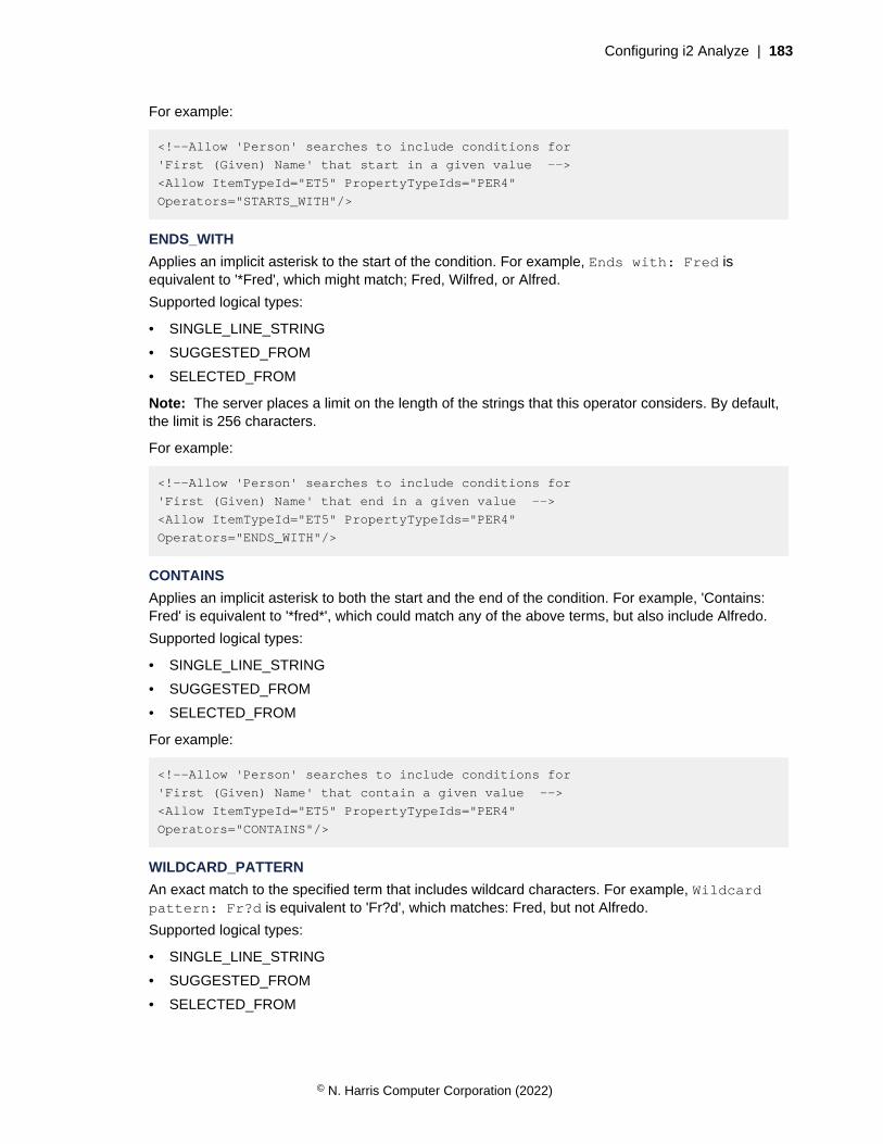
Configuring i2 Analyze | 183
For example:
<!--Allow 'Person' searches to include conditions for
'First (Given) Name' that start in a given value -->
<Allow ItemTypeId="ET5" PropertyTypeIds="PER4"
Operators="STARTS_WITH"/>
ENDS_WITH
Applies an implicit asterisk to the start of the condition. For example, Ends with: Fred isequivalent to '*Fred', which might match; Fred, Wilfred, or Alfred.
Supported logical types:
• SINGLE_LINE_STRING
• SUGGESTED_FROM
• SELECTED_FROM
Note: The server places a limit on the length of the strings that this operator considers. By default,the limit is 256 characters.
For example:
<!--Allow 'Person' searches to include conditions for
'First (Given) Name' that end in a given value -->
<Allow ItemTypeId="ET5" PropertyTypeIds="PER4"
Operators="ENDS_WITH"/>
CONTAINS
Applies an implicit asterisk to both the start and the end of the condition. For example, 'Contains:Fred' is equivalent to '*fred*', which could match any of the above terms, but also include Alfredo.
Supported logical types:
• SINGLE_LINE_STRING
• SUGGESTED_FROM
• SELECTED_FROM
For example:
<!--Allow 'Person' searches to include conditions for
'First (Given) Name' that contain a given value -->
<Allow ItemTypeId="ET5" PropertyTypeIds="PER4"
Operators="CONTAINS"/>
WILDCARD_PATTERN
An exact match to the specified term that includes wildcard characters. For example, Wildcardpattern: Fr?d is equivalent to 'Fr?d', which matches: Fred, but not Alfredo.
Supported logical types:
• SINGLE_LINE_STRING
• SUGGESTED_FROM
• SELECTED_FROM
© N. Harris Computer Corporation (2022)
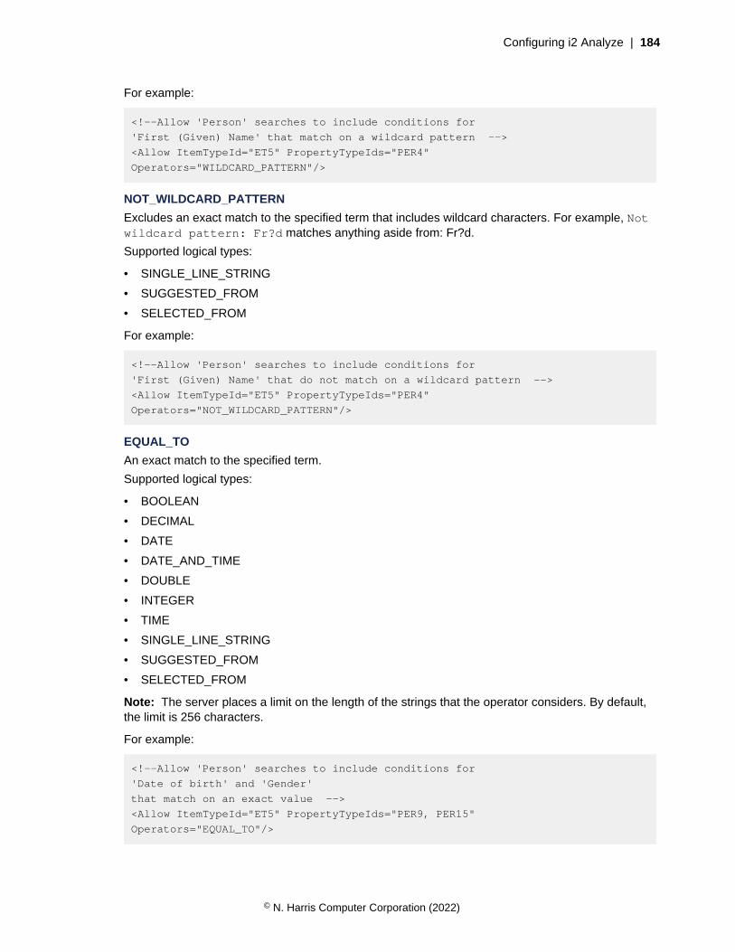
Configuring i2 Analyze | 184
For example:
<!--Allow 'Person' searches to include conditions for
'First (Given) Name' that match on a wildcard pattern -->
<Allow ItemTypeId="ET5" PropertyTypeIds="PER4"
Operators="WILDCARD_PATTERN"/>
NOT_WILDCARD_PATTERN
Excludes an exact match to the specified term that includes wildcard characters. For example, Notwildcard pattern: Fr?d matches anything aside from: Fr?d.
Supported logical types:
• SINGLE_LINE_STRING
• SUGGESTED_FROM
• SELECTED_FROM
For example:
<!--Allow 'Person' searches to include conditions for
'First (Given) Name' that do not match on a wildcard pattern -->
<Allow ItemTypeId="ET5" PropertyTypeIds="PER4"
Operators="NOT_WILDCARD_PATTERN"/>
EQUAL_TO
An exact match to the specified term.
Supported logical types:
• BOOLEAN
• DECIMAL
• DATE
• DATE_AND_TIME
• DOUBLE
• INTEGER
• TIME
• SINGLE_LINE_STRING
• SUGGESTED_FROM
• SELECTED_FROM
Note: The server places a limit on the length of the strings that the operator considers. By default,the limit is 256 characters.
For example:
<!--Allow 'Person' searches to include conditions for
'Date of birth' and 'Gender'
that match on an exact value -->
<Allow ItemTypeId="ET5" PropertyTypeIds="PER9, PER15"
Operators="EQUAL_TO"/>
© N. Harris Computer Corporation (2022)
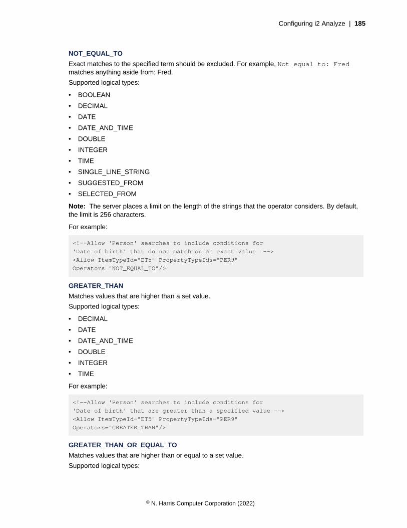
Configuring i2 Analyze | 185
NOT_EQUAL_TO
Exact matches to the specified term should be excluded. For example, Not equal to: Fredmatches anything aside from: Fred.
Supported logical types:
• BOOLEAN
• DECIMAL
• DATE
• DATE_AND_TIME
• DOUBLE
• INTEGER
• TIME
• SINGLE_LINE_STRING
• SUGGESTED_FROM
• SELECTED_FROM
Note: The server places a limit on the length of the strings that the operator considers. By default,the limit is 256 characters.
For example:
<!--Allow 'Person' searches to include conditions for
'Date of birth' that do not match on an exact value -->
<Allow ItemTypeId="ET5" PropertyTypeIds="PER9"
Operators="NOT_EQUAL_TO"/>
GREATER_THAN
Matches values that are higher than a set value.
Supported logical types:
• DECIMAL
• DATE
• DATE_AND_TIME
• DOUBLE
• INTEGER
• TIME
For example:
<!--Allow 'Person' searches to include conditions for
'Date of birth' that are greater than a specified value -->
<Allow ItemTypeId="ET5" PropertyTypeIds="PER9"
Operators="GREATER_THAN"/>
GREATER_THAN_OR_EQUAL_TO
Matches values that are higher than or equal to a set value.
Supported logical types:
© N. Harris Computer Corporation (2022)

Configuring i2 Analyze | 186
• DECIMAL
• DATE
• DATE_AND_TIME
• DOUBLE
• INTEGER
• TIME
For example:
<!--Allow 'Person' searches to include conditions for
'Date of birth' that are greater than or equal to a specified value -->
<Allow ItemTypeId="ET5" PropertyTypeIds="PER9"
Operators="GREATER_THAN_OR_EQUAL_TO"/>
LESS_THAN
Matches values that are less than a set value.
Supported logical types:
• DECIMAL
• DATE
• DATE_AND_TIME
• DOUBLE
• INTEGER
• TIME
For example:
<!--Allow 'Person' searches to include conditions for
'Date of birth' that are lower than to a specified value -->
<Allow ItemTypeId="ET5" PropertyTypeIds="PER9, PER15"
Operators="LESS_THAN"/>
LESS_THAN_OR_EQUAL_TO
Matches values that are less than or equal to a set value.
Supported logical types:
• DECIMAL
• DATE
• DATE_AND_TIME
• DOUBLE
• INTEGER
• TIME
© N. Harris Computer Corporation (2022)

Configuring i2 Analyze | 187
For example:
<!--Allow 'Person' searches to include conditions for
'Date of birth' that are lower than or equal to a specified value -->
<Allow ItemTypeId="ET5" PropertyTypeIds="PER9"
Operators="LESS_THAN_OR_EQUAL_TO"/>
BETWEEN
Matches values that are within a set range.
Supported logical types:
• DECIMAL
• DATE
• DATE_AND_TIME
• DOUBLE
• INTEGER
• TIME
For example:
<!--Allow 'Person' searches to include conditions for
'Date of birth' that match on a range of values -->
<Allow ItemTypeId="ET5" PropertyTypeIds="PER9"
Operators="BETWEEN"/>
IS_SET
Matches properties with any populated value.
Supported logical types:
• BOOLEAN
• DECIMAL
• DATE
• DATE_AND_TIME
• DOUBLE
• INTEGER
• TIME
• SINGLE_LINE_STRING
• SUGGESTED_FROM
• SELECTED_FROM
For example:
<!--Allow 'Person' searches to include searches for 'Date of birth' values
that have been entered -->
<Allow ItemTypeId="ET5" PropertyTypeIds="PER9"
Operators="IS_SET"/>
IS_NOT_SET
© N. Harris Computer Corporation (2022)
Configuring i2 Analyze | 188
Matches properties without a value entered.
Supported logical types:
• BOOLEAN
• DECIMAL
• DATE
• DATE_AND_TIME
• DOUBLE
• INTEGER
• TIME
• SINGLE_LINE_STRING
• SUGGESTED_FROM
• SELECTED_FROM
For example:
<!--Allow 'Person' searches to include searches for 'Date of birth' values
that have not been entered -->
<Allow ItemTypeId="ET5" PropertyTypeIds="PER9"
Operators="IS_NOT_SET"/>
Improving Visual Query performance for multi-line string property types
To improve the performance of Visual Query searches for multi-line string property types when usingIBM Db2, you can update the Information Store database. After you update the Information Store, thedatatype that is used to store multi-line string property values is changed from a CLOB to a VARCHAR.
Before you begin
• The allowed size of a CLOB column is slightly larger than the size of a VARCHAR column. If a CLOBcolumn contains more than 32,672 bytes (or octets), then it cannot be converted and no other CLOBcolumns in that table will be converted. Before you attempt to convert the CLOB columns, ensurethat all data is less than 32,672 bytes in size.
• You can use a toolkit task to update the multi-line string columns automatically, or you can generatethe SQL scripts that update the Information Store database and run those scripts manually.
• If i2 Analyze is deployed with high availability or disaster recovery, the process for updating theInformation Store is different. For more information, see HADR.
If you want to update the Information Store using the SQL scripts, see Updating the Information Storemanually.
Procedure
1. Open a command prompt on the server, and navigate to the toolkit\scripts directory of the i2Analyze toolkit.
2. Run the following command:
setup -t convertClobsToVarchars
© N. Harris Computer Corporation (2022)
Configuring i2 Analyze | 189
3. Restart i2 Analyze:
setup -t restartLiberty
When Liberty starts, the process of updating the multi-line string columns is started. This process worksin the same way as the processing that occurs to the Information Store after an upgrade. For moreinformation about this processing, and how to monitor its progress, see: Information Store processing.
While the process is running, data cannot be ingested or uploaded into the Information Store.
Updating the Information Store manually
To generate the database scripts that update the columns so that you can run them manually, run theconvertClobsToVarchars task with the --scripts argument. For example:
setup -t convertClobsToVarchars --scripts
Note: As part of the script generation process, each table that contains a CLOB column is checked toensure the data in that CLOB column will fit inside a VARCHAR(32672) column. This process alonemight take several hours depending on the number of rows in each table and the number of CLOBcolumns. If you know that there are no CLOB columns that contain data that is too large, you can usethe -p skipSizeCheck parameter to skip this process.
When you run the command, the SQL scripts are generated in the toolkit\scripts\database\db2\InfoStore\generated\convert-clobs-to-varchars directory. There is a script for eachitem type, for example 0200-0300-clob-to-varchar_ET1.sql. The item type scripts can be run inparallel.
Use the Db2 command line processor to run the generated SQL scripts.
Data size
When running the convertClobsToVarchars toolkit task, the following message is displayed if thedata in a CLOB column is more than 32,672 bytes (or octets):
The <table name> table contains a CLOB column that is too long to fit into a
VARCHAR column. Conversion of this table has been abandoned.
To remedy the issue, truncate the data in the specified CLOB columns, re-run theconvertClobsToVarchars toolkit task, and restart the server.
When running the SQL scripts, the following messages are displayed in the toolkit log file if the data in aCLOB column is more than 32,672 bytes (or octets):
Column <column name> in table <table name> has a defined length of <n> which is
greater than the maximum permitted size of <n>. (Skipping table conversion).
Found: <n> values with length greater than 32,672 in table: <table name>, column:
<column name>. (Skipping table conversion).
To remedy the issue, truncate the data in the specified CLOB columns, re-run theconvertClobsToVarchars --scripts toolkit task, and run the scripts again.
© N. Harris Computer Corporation (2022)
Configuring i2 Analyze | 190
Error handling
The process to convert columns from CLOB to VARCHAR is designed to be re-run in the event of afailure.
When you start the Liberty server, monitor the console.log to ensure that the process completessuccessfully. If an error does occur, the process will continue when you restart the server after youresolve the cause of the error.
If you are running the scripts manually, errors are reported in the Db2 command line processor. You canrerun the same script after you resolve the cause of the error.
The most common error is that the Db2 server runs out of disk space while populating the replica tablesthat are used to retain data while the data type is updated.
HADR
If the i2 Analyze deployment is in HADR mode, you must update the database by using the followingprocedure:
1. Backup the primary database
2. Generate the update scripts and run the scripts on the primary database
3. Backup the primary database
4. Disable HADR
5. Restore the primary database onto the secondary server
6. Re-enable HADR
Restricting the length of Visual Query lists
When a Visual Query is constructed by a user, certain conditions allow the values to be specified as alist of values. The length of these lists can be restricted to reduce the size of messages from the client.
By default, the number of items that can be used in a list condition for a visual query condition is set to10000. If you reduce this value, the number of values that can be applied to conditions of this type isreduced.
If you follow this procedure in a deployment that provides high availability, you must complete each stepon every Liberty server in your environment before you move to the next step.
To modify the list length:
1. Using a text editor, open the DiscoServerSettingsCommon.properties file. You can find thisfile in the following location: toolkit\configuration\fragments\opal-services\WEB-INF\classes.
2. Edit the value of VisualQueryMaxValuesInList.
3. Save and close the file.
Redeploy i2 Analyze to update the application with your changes.
4. In a command prompt, navigate to the toolkit\scripts directory.
5. Stop Liberty:
setup -t stopLiberty
© N. Harris Computer Corporation (2022)
Configuring i2 Analyze | 191
6. Update the i2 Analyze application:
setup -t deployLiberty
7. Start Liberty:
setup -t startLiberty
Run a selection of Visual Queries that use conditions including lists. Continue to change theconfiguration until you are satisfied with the lists in your Visual Queries that use conditions.
Visual Query schedule
When the user enables alerting on a saved Visual Query, the query is run automatically on schedule.The default schedule can be changed to suit your performance requirements and the number of VisualQueries that are saved with alerting enabled.
By default, the Visual Queries that are saved with alerting enabled are run once every 24 hours, at00:00 according to the server time. If the result of a query is different from the last time that the queryran, the user receives an alert with this information.
You can change or override the default schedule, as follows.
• Change the time of day that the saved Visual Queries run. For more information, see Changing thedaily schedule for Visual Queries on page 191.
• Create a custom schedule to specify when the saved Visual Queries run. For more information, seeCreating a custom schedule for Visual Queries on page 192.
Note: Running Visual Queries on schedule might impact performance for users of the system. Thefollowing factors are examples of the characteristics of Visual Queries that can affect performance.
• Number of queries
• Complexity of the queries
• Volume of data searched by the queries
In this situation, consider setting the daily schedule for a quiet period, such as overnight, or setting thecustom schedule for a low frequency.
Changing the daily schedule for Visual Queries
You can change the time of day that i2 Analyze runs Visual Queries that are saved with alertingenabled. By default, these queries are run once every 24 hours at 00:00 according to the server time.
If you follow this procedure in a deployment that provides high availability, you must complete each stepon every Liberty server in your environment before you move to the next step.
1. Using a text editor, open the DiscoServerSettingsCommon.properties file. You can find thisfile in the following location: toolkit\configuration\fragments\opal-services\WEB-INF\classes.
2. Edit the value of AlertScheduleTimeOfDay.
The default value is 00:00. The required format is HH:mm. HH is the hour of the day in a 24-hourtime format, 00 - 23, and mm is the number of minutes past the hour, 00 - 59.
3. To ensure that the daily schedule value is implemented, check that theAlertScheduleExpression property is not enabled.
For more information, see Creating a custom schedule for Visual Queries on page 192.
© N. Harris Computer Corporation (2022)

Configuring i2 Analyze | 192
4. Save and close the file.
Redeploy i2 Analyze to update the application with your changes.
5. In a command prompt, navigate to the toolkit\scripts directory.
6. Stop Liberty:
setup -t stopLiberty
7. Update the i2 Analyze application:
setup -t deployLiberty
8. Start Liberty:
setup -t startLiberty
After you redeploy i2 Analyze, the Visual Queries that are saved with alerting enabled are run accordingto the updated daily schedule.
Creating a custom schedule for Visual Queries
To create a custom schedule to run the Visual Queries that are saved with alerting enabled, use a UNIXC cron expression. The default schedule to run these Visual Queries is once every 24 hours, at 00:00hours according to the server time.
You can create a custom schedule in the AlertScheduleExpression property. TheAlertScheduleExpression property requires a value in UNIX C cron expression format.
With the property AlertScheduleExpression, you can override the default daily schedule. Bydefault, this property is not enabled. If the property is enabled, whenever the value of the expressionmatches the current date and time, i2 Analyze runs the Visual Queries that are saved with alertingenabled. For more information, see UNIX cron format.
When you enable the property AlertScheduleExpression, its value overrides thevalue of the default property, AlertScheduleTimeOfDay. For more information aboutAlertScheduleTimeOfDay, see Changing the daily schedule for Visual Queries on page 191.
If you follow this procedure in a deployment that provides high availability, you must complete each stepon every Liberty server in your environment before you move to the next step.
1. Using a text editor, open the DiscoServerSettingsCommon.properties file. You can find thisfile in the following location: toolkit\configuration\fragments\opal-services\WEB-INF\classes.
2. Uncomment AlertScheduleExpression.
When you uncomment the AlertScheduleExpression property, the value for this property isused instead of the value for the AlertScheduleTimeOfDay property.
3. Edit the value of AlertScheduleExpression.For example, the value 0,4,16,20 * * * schedules the Visual Queries that are saved with alertingenabled to run every 4 hours. A short way of expressing this schedule option is 0 */4 * * *.
4. Save and close the file.
Redeploy i2 Analyze to update the application with your changes.
5. In a command prompt, navigate to the toolkit\scripts directory.
© N. Harris Computer Corporation (2022)

Configuring i2 Analyze | 193
6. Stop Liberty:
setup -t stopLiberty
7. Update the i2 Analyze application:
setup -t deployLiberty
8. Start Liberty:
setup -t startLiberty
After you deploy i2 Analyze, the updated schedule is applied to run Visual Queries that are saved withalerting enabled.
Highlight queries
In the i2 Enterprise Insight Analysis Investigate Add On, users can search for records in the InformationStore, flag records of interest, and find paths in the data between flagged records. However, the webapplication does not support charting and expanding the records that users find. Instead, when usersselect a record, they see its information together with lists of other records that are related to it. Theappearance and contents of these lists are driven by highlight queries.
The role of highlight queries is to navigate the data in the Information Store on the behalf of users, andto present them with answers to questions that they ask most frequently. For example:
• If the subject record is a car, then your users might be interested in its recent owners or its recentsightings.
• If the subject is a cellphone, users might want to know which other phones it calls most often - orwho owns the phones that it calls most often.
• If the subject is a person, the key information might be their bank accounts; or the bank accountsthat the person's accounts transact with; or the owners of those transacting accounts.
Highlight queries run whenever the user opens or refreshes the page that contains the details of aparticular record. The first five results from each highlight query appear in highlight panes on the samepage as the subject record. Each highlight pane also contains a button that the user can click to showmore information and more results.
Technical background
Functionally, a highlight query is a predefined, type-specific, multi-level, conditional expand operation.Using the subject entity record as a seed, a highlight query searches the Information Store for entityrecords of a particular type that are connected to the seed by links of a particular type. After that, it canuse those records as the seeds for another, similar search, and so on. The results that users see arethe entity records found by the final search that the highlight query performs - which might be the first, orthe second, or the sixth.
Because highlight queries are type-specific, they are tightly bound to the Information Store schema.Each entity type in the schema can have its own group of highlight queries that run when the user viewsa record of that type in the Investigate Add On. Since highlight queries are targeted at finding specificrelationships in your data, they are not typically portable between different entity types or different i2Analyze deployments.
© N. Harris Computer Corporation (2022)

Configuring i2 Analyze | 194
Automatically generated highlight queries
When a deployment of i2 Analyze starts up for the first time, the server automatically generates a setof highlight queries from the Information Store schema. This set contains one highlight query for eachentity type in the schema that appears in at least one list of valid link end types. Each highlight querysearches for entity-link-entity structures in which the types of the target link and entity are the first validtypes for such structures.
For example, imagine a simple schema that defines four entity types (Address, Car, Cellphone, andPerson) and four link types (Calls, Owns, Related, and Resides). According to the link type definitions:
• Cars can be linked to addresses, through Resides links
• Cellphones can be linked to other cellphones, through Calls links
• People can be linked to addresses (through Resides links), to cars and cellphones (through Ownslinks), and to other people (through Related links)
In this scenario, with the automatically generated highlight queries in place, a user who selects acellphone record sees a highlight pane containing a list of cellphones that the first cellphone has called.(Calls is the only valid link type for cellphones, and Cellphone is the only valid end type.)
If the user selects a person record, they see a highlight pane containing a list of the cars that the personowns. (Owns is the first valid link type for people, and Car is the first valid end type for such links.)
Custom highlight queries
The automatic mechanism for generating highlight queries is designed only to be a starting point.When you write your own highlight queries, you can make them search for more complex relationshipsbetween the subject record and others in the Information Store.
For example, for data that matches the same schema as before, you might enable users to select aperson record and see a list of people who reside at the same address (person-address-person), or towhom the subject makes cellphone calls (person-cellphone-cellphone-person).
To create a set of custom highlight queries for your data and your users, you write an XML configurationfile that is valid according to an XSD file that is derived from the Information Store schema. Subsequenttopics describe how to start, edit, and publish a highlight queries configuration for your deployment of i2Analyze.
Deploying highlight queries
New, production deployments of i2 Analyze have a set of automatically generated highlight queries thatretrieve records with simple relationships to a subject record. To replace this set with custom queriesthat reflect the structure of your data and the needs of your users, you must write your own highlightqueries configuration file.
The highlight queries configuration is one of a group of configuration files that you can modify and sendto the i2 Analyze server without the need for system downtime. These files are stored in the toolkit\configuration\live directory. The default highlight-queries-configuration.xml fileinstructs the server to generate the automatic highlight query set.
To enable updating the server without the need to restart it, ensure that you have a command-line toolsuch as postman or curl.
The procedure for writing a new highlight queries configuration file starts with a download of two filesfrom the server. Through a pair of REST endpoints, you can retrieve an XML file that defines the sameset of highlight queries that the server generated automatically, and an XSD file that validates it. With
© N. Harris Computer Corporation (2022)

Configuring i2 Analyze | 195
these files as a guide, you can develop your own highlight queries, replace the default file, and upload itto the i2 Analyze server.
Highlight queries are closely aligned with the Information Store schema. You create and edit thehighlight queries configuration file in your configuration development environment, alongside VisualQueries and search results filters.
Note: As described in Example highlight queries on page 206, example deployments of i2 Analyzereceive an example set of highlight queries instead of the automatically generated set. To replacethe example set with an automatically generated set, replace the highlight queries configuration file intoolkit\configuration\live with its equivalent from a configuration\live directory underthe toolkit\examples directory. Then, pick up the procedure below after Step 8.
The first part of the process is to fetch the XSD file that corresponds to the Information Store schemafrom the server.
1. Open a web browser and connect to the i2 Analyze server at http://host_name/opal/doc toview the REST API documentation.
If you are not logged in to the server, you are prompted to do so. The user must be a member of agroup that has the i2:Administrator permission under command access control.
Note: This requirement is in addition to the other requirements on i2 Analyze users, all of whommust be members of groups that confer an access level for at least one dimension value in eachsecurity dimension.
2. Open the section for the GET v1/admin/highlightqueryconfig/xsd method, and click Try itout! to request the XSD file from the server.The file is displayed in the Response Body field.
3. Save the contents of the field to a file named highlight-queries-configuration.xsd in thetoolkit\configuration\live directory.
Next, you need a highlight queries configuration file to edit. To start from scratch, you can use thehighlight-queries-configuration.xml file from the live directory. Alternatively, you candownload the file that defines the automatically generated highlight queries.
4. Open the section for the GET v1/admin/highlightqueryconfig/automatic method, andclick Try it out! to request the XML file from the server.The file is displayed in the Response Body field.
5. Save the contents of the field to a file named highlight-queries-configuration.xml in thetoolkit\configuration\live directory, replacing the existing file.
Edit the configuration file.
6. If you do not already have one, obtain and configure an XSD-aware XML editor, as described inSetting up your XSD aware XML editor on page 321.
7. In the XML editor, open the toolkit\configuration\live\highlight-queries-configuration.xml file.
8. Using the reference and example information, modify the file to define the highlight queries that youranalysts require.
Update the deployment with your changes.
The following method deploys your changes without stopping the server by using a POST request to aREST endpoint.
To redeploy your changes by using the deployment toolkit only, see Redeploying Liberty on page 321.You must deploy your changes by using the deployment toolkit if you are in a deployment with highavailability or you are deploying in your production environment.
© N. Harris Computer Corporation (2022)

Configuring i2 Analyze | 196
9. At the command line, navigate to the toolkit\scripts directory.
10.Update the server with your configuration file:
setup -t updateLiveConfiguration
11.Update the running application by using the reload endpoint:
curl -i --cookie-jar cookie.txt -d j_username=user_name
-d j_password=password
http://host_name/context_root/j_security_check
curl -i --cookie cookie.txt -X
POST http://host_name/context_root/api/v1/admin/config/reload
Warning: The reload method updates the configuration without requiring a server restart,but any logged-in users are logged out from i2 Analyze when you run it.
The server validates your highlight queries as it loads them and returns any errors in its response.
12.If the configuration is invalid, modify the highlight-queries-configuration.xml file, andthen repeat the process to update the deployment.
Test the new and updated highlight queries.
13.In your web browser, view the highlight panes for a record with a number of connections that testyour highlight queries.
Structure of highlight queries
The aim of highlight queries is to provide users with relevant information about the records that areassociated with the current subject of their investigation. The structure of the queries that you createreflects the idea of starting from the subject and finding records that are one, two, or more links away.
When a user examines records of the same type in the i2 Enterprise Insight Analysis Investigate AddOn, they expect to be able to compare them in a consistent way. Highlight queries are grouped bytype in the configuration file, and records of a particular type are always displayed with the same set ofhighlight panes.
Highlight queries themselves use the idea of a path to describe how the results of the query are relatedto the subject. The path is made up of segments that take the results one step further from the subject,like this:
© N. Harris Computer Corporation (2022)
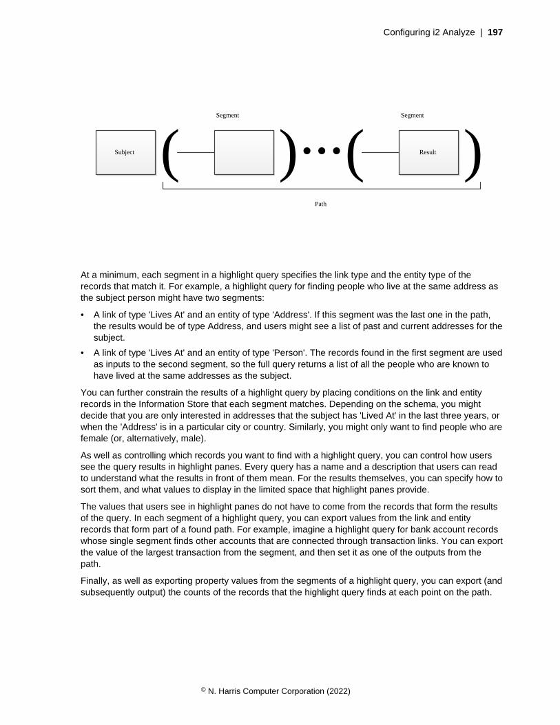
Configuring i2 Analyze | 197
Subject Result( ) ( )...Segment Segment
Path
At a minimum, each segment in a highlight query specifies the link type and the entity type of therecords that match it. For example, a highlight query for finding people who live at the same address asthe subject person might have two segments:
• A link of type 'Lives At' and an entity of type 'Address'. If this segment was the last one in the path,the results would be of type Address, and users might see a list of past and current addresses for thesubject.
• A link of type 'Lives At' and an entity of type 'Person'. The records found in the first segment are usedas inputs to the second segment, so the full query returns a list of all the people who are known tohave lived at the same addresses as the subject.
You can further constrain the results of a highlight query by placing conditions on the link and entityrecords in the Information Store that each segment matches. Depending on the schema, you mightdecide that you are only interested in addresses that the subject has 'Lived At' in the last three years, orwhen the 'Address' is in a particular city or country. Similarly, you might only want to find people who arefemale (or, alternatively, male).
As well as controlling which records you want to find with a highlight query, you can control how userssee the query results in highlight panes. Every query has a name and a description that users can readto understand what the results in front of them mean. For the results themselves, you can specify how tosort them, and what values to display in the limited space that highlight panes provide.
The values that users see in highlight panes do not have to come from the records that form the resultsof the query. In each segment of a highlight query, you can export values from the link and entityrecords that form part of a found path. For example, imagine a highlight query for bank account recordswhose single segment finds other accounts that are connected through transaction links. You can exportthe value of the largest transaction from the segment, and then set it as one of the outputs from thepath.
Finally, as well as exporting property values from the segments of a highlight query, you can export (andsubsequently output) the counts of the records that the highlight query finds at each point on the path.
© N. Harris Computer Corporation (2022)

Configuring i2 Analyze | 198
A B C
Count A: 3
Count A: 1
Count A: 2
Count B: 2Count C: 2
Count B: 1Count C: 1
Count B: 2Count C: 3
Count A: 1Count B: 1Count C: 1
Count A: 1Count B: 1Count C: 1
In the diagram, the five records on the right are results of a highlight query whose subject was thesingle record on the left. When you present the results to users, you can output or sort by the counts ofrecords along their paths. The meanings of the counts, and whether they are useful, vary according tothe specifics of the highlight query.
The highlight queries configuration file
The permitted XML elements in a highlight queries configuration file include some that are commonto all such files, and others that depend upon the Information Store schema. The structure of the filereflects the structure of the highlight queries themselves.
Root element
• <highlightQueryConfiguration>
Top-level elements
• <settings>
• <highlightQueryGroups>
Highlight query elements
• <highlightQueryGroup>
• <highlightQuery>
• <description>
• <path>
• <sortBy>
© N. Harris Computer Corporation (2022)

Configuring i2 Analyze | 199
Path elements
• <segments>
• <EntityType>/<LinkType>
• <direction>
• <conditions>
• <exportFields>
• <outputs>
Condition elements
• <PropertyType>
Root element
<highlightQueryConfiguration>
<highlightQueryConfiguration> is the root element of the highlight query configuration file.In the examples, and in the automatically generated file, it references the highlight-queries-configuration.xsd file:
<highlightQueryConfiguration xmlns:xsi="http://www.w3.org/2001/XMLSchema-
instance"
xsi:noNamespaceSchemaLocation="highlight-queries-configuration.xsd">
...
</highlightQueryConfiguration>
Top-level elements
<settings>
As well as the highlight queries themselves, the configuration file enables control of some aspectsof highlight query behavior that can affect the performance of the i2 Analyze server. The optional<settings> element supports the following child elements:
• <maxLinkResultsPerSegment> - The maximum number of link records that a single segmentcan match in the Information Store, which defaults to 50000.
• <maxSeedsPerSegment> - The maximum number of entity records that any segment exceptthe last can match in the Information Store, which defaults to 1000.
• <maxResultsPerQuery> - The maximum number of entity records that the last segment canmatch in the Information Store, which defaults to 1000.
• <expireResultsInMinutes> - The length of time for which the server caches the results of ahighlight query, which defaults to 30 minutes.
<highlightQueryConfiguration ...>
<settings>
<maxLinkResultsPerSegment>50000</maxLinkResultsPerSegment>
...
</settings>
...
</highlightQueryConfiguration>
© N. Harris Computer Corporation (2022)

Configuring i2 Analyze | 200
If any of the "max" limits is breached, the query in question returns no results and the user sees anerror message. Other queries that do not breach the limits continue to run normally.
<highlightQueryGroups>
The only other element permitted as a direct child of <highlightQueryConfiguration> is<highlightQueryGroups>, which contains all the highlight queries for the deployment, groupedby the entity types of the subject records to which they apply.
<highlightQueryConfiguration ...>
<settings>...</settings>
<highlightQueryGroups>
...
</highlightQueryGroups>
</highlightQueryConfiguration>
Highlight query elements
<highlightQueryGroup>
Each highlight query group contains the highlight queries for subject records of a particular type.The itemType attribute of the <highlightQueryGroup> element indicates which type the groupis for. The valid values for the itemType attribute are defined in the XSD file; they are based on thedisplay names of entity types in the Information Store schema.
<highlightQueryGroups>
<highlightQueryGroup itemType="Vehicle-I">
...
</highlightQueryGroup>
...
</highlightQueryGroups>
<highlightQuery>
A <highlightQueryGroup> element can have multiple child <highlightQuery> elements.Each <highlightQuery> element defines a query to run against the Information Store, andcontrols some aspects of the highlight pane that displays the query results in the user interface.
The <highlightQuery> element supports the title attribute whose value is displayed as thetitle of the highlight pane. It also supports the automatic attribute that determines whether thequery runs as soon as a user views the subject record. You can specify that users must run a time-consuming query manually (by clicking a button) by setting the value of this optional attribute tofalse.
<description>
In the <description> child of a <highlightQuery> element, you can explain the behaviorof the query to users. The contents of this element are displayed to users when they click theinformation icon ( i ) in a highlight pane heading. At a minimum, i2 recommends that you describethe relationship of the results to the subject record, and the order that you chose to present them in.
<path>
The <path> child of a <highlightQuery> element contains <segments> and <outputs>elements that together provide the logic for the query. Segments are responsible for the querystructure, while outputs determine how users see the query results in highlight panes.
© N. Harris Computer Corporation (2022)

Configuring i2 Analyze | 201
<sortBy>
The last permitted child of a <highlightQuery> element is <sortBy>. This optional (butimportant) element specifies how values that were discovered during execution of the querycan change the results that users see. For example, depending on your investigation, you mightsort a list of people who are associated with a vehicle by their family names or by their dates ofassociation.
The <field> children of <sortBy> are processed in order of appearance. In each one, the idattribute contains the identifier of a field that was exported from the path. The order attributedetermines whether results appear in ascending (ASC) or descending (DESC) order of the values ofthe identified field.
<highlightQueryGroup itemType="Vehicle-I">
<highlightQuery title="People with access" automatic="true">
<description>People who have access to this vehicle,
sorted by family name.</description>
<path>...</path>
<sortBy>
<field id="familyName" order="ASC"/>
</sortBy>
</highlightQuery>
...
</highlightQueryGroup>
Path elements
<segments>
<path> elements always have exactly two children: <segments> and <outputs>. <segments>always contains at least one <segment> element that defines a part of the query structure.
<path>
<segments>
<segment>
...
</segment>
...
</segments>
<outputs>
...
</outputs>
</path>
<segment>
Each <segment> element also has exactly two children that specify the link and entity types thatrecords must have in order to match this part of the query. Like the legal values for the itemTypeattribute of the <highlightQueryGroup> element, the names of these elements are not fixed butdepend upon the Information Store schema for the deployment. Furthermore, the link type must be
© N. Harris Computer Corporation (2022)

Configuring i2 Analyze | 202
valid for the entity type that you specified in <highlightQueryGroup>, and the entity type mustbe valid for that link type. For example, a segment for people who have access to vehicles:
<highlightQuery title="People with access">
<path>
<segments>
<segment>
<Access_To-I/>
<Person-I/>
</segment>
...
It is valid to use <AnyLinkType/> in place of a specific link type from the schema. It is also validto use <AnyEntityType/> in place of a specific entity type, in any segment except the last one inthe path.
<EntityType>/<LinkType>
The previous example contains a functionally complete segment definition. In a highlight query, thesegment finds all the people in the Information Store that are connected to the inputs by 'Access To'links. If the segment is the first in the path, its single input is the subject record. Otherwise, its inputsare the records that the previous segment found.
The "entity type" and "link type" elements that make up a segment support three child elements, allof which are optional. To place further constraints on the records that the segment matches, youcan add a <direction> or a <conditions> element. If you want to use some values from therecords that you find at this stage of the query to provide context for the final results, you can addan <exportFields> element.
<direction>
For link type elements only, you can constrain matching records according to whether their directionis towards or away from the entity record that forms the input to the segment. The <direction>child of a link type element always contains a single <value> child element whose text content iseither INCOMING or OUTGOING.
A constraint of this type is often useful in scenarios such as telephone call analysis or financialinvestigations, where the direction of a link is key to determining its relevance.
<conditions>
The <conditions> child of an entity type or link type element can contain any number of childelements that correspond to property types of the entity type or link type in question. For eachproperty type, you can place a requirement on the values that matching records must have.
Note: At this version of i2 Analyze, highlight queries do not support conditions on property typeswith geospatial or multi-line string logical types.
<exportFields>
You might want to export values from a segment of a highlight query for two reasons. First, todisplay those values to users alongside the results in the highlight pane for the query. Second, touse the values as criteria by which to sort the results of the query.
For a particular highlight query result, the values that you can export are the values of propertiesfrom the segments that contributed to that result. For example, imagine a query that finds bankaccount records that are connected through transaction links. You want to display the transactiondates from those links alongside the found accounts. In this example, every account is connected to
© N. Harris Computer Corporation (2022)
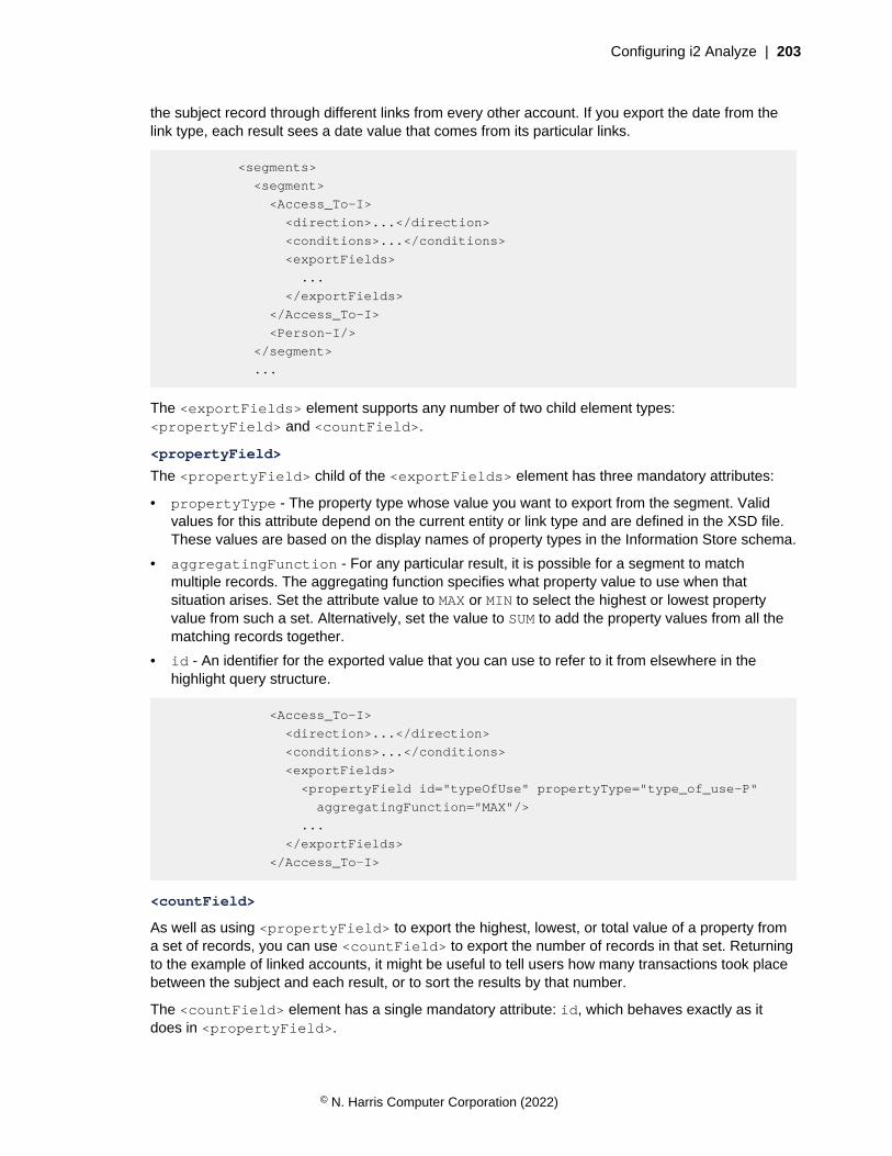
Configuring i2 Analyze | 203
the subject record through different links from every other account. If you export the date from thelink type, each result sees a date value that comes from its particular links.
<segments>
<segment>
<Access_To-I>
<direction>...</direction>
<conditions>...</conditions>
<exportFields>
...
</exportFields>
</Access_To-I>
<Person-I/>
</segment>
...
The <exportFields> element supports any number of two child element types:<propertyField> and <countField>.
<propertyField>
The <propertyField> child of the <exportFields> element has three mandatory attributes:
• propertyType - The property type whose value you want to export from the segment. Validvalues for this attribute depend on the current entity or link type and are defined in the XSD file.These values are based on the display names of property types in the Information Store schema.
• aggregatingFunction - For any particular result, it is possible for a segment to matchmultiple records. The aggregating function specifies what property value to use when thatsituation arises. Set the attribute value to MAX or MIN to select the highest or lowest propertyvalue from such a set. Alternatively, set the value to SUM to add the property values from all thematching records together.
• id - An identifier for the exported value that you can use to refer to it from elsewhere in thehighlight query structure.
<Access_To-I>
<direction>...</direction>
<conditions>...</conditions>
<exportFields>
<propertyField id="typeOfUse" propertyType="type_of_use-P"
aggregatingFunction="MAX"/>
...
</exportFields>
</Access_To-I>
<countField>
As well as using <propertyField> to export the highest, lowest, or total value of a property froma set of records, you can use <countField> to export the number of records in that set. Returningto the example of linked accounts, it might be useful to tell users how many transactions took placebetween the subject and each result, or to sort the results by that number.
The <countField> element has a single mandatory attribute: id, which behaves exactly as itdoes in <propertyField>.
© N. Harris Computer Corporation (2022)

Configuring i2 Analyze | 204
<outputs>
After the <segments> in the path are the <outputs>, which control the values that users seewith the query results in a highlight pane. The <outputs> element supports any number of child<field> elements, which have two attributes:
• id - The identifier of an export field, as previously specified in a <propertyField> or<countField> element.
• label - A value that the user interface uses as a column header for the field.
<path>
<segments>
<segment>
...
</segment>
...
</segments>
<outputs>
<field id="typeOfUse" label="Type of use" />
...
</outputs>
</path>
Each highlight pane has space for up to two output fields. If you specify more than two <field>elements, users see them only when they click Show more in the highlight pane to display moreresult information.
Condition elements
<PropertyType>
Inside an <EntityType> or <LinkType> element, the <conditions> element can contain anynumber of child elements whose names are based on property types from the Information Storeschema. The child elements restrict the records in the Information Store that match the currentsegment. The permitted contents of the condition depend on the logical type of the property type.
<Access_To-I>
<conditions>
<type_of_use-P>
...
</type_of_use-P>
...
</conditions>
...
</Access_To-I>
Some logical types - geospatial values, multiple-line strings, documents, pictures, and XML data -are not supported in highlight query conditions. According to the generated XSD file, property typeswith unsupported logical types are not valid children of <conditions> elements. For propertytypes with supported logical types, this version of i2 Analyze supports conditions with four kinds ofoperators:
© N. Harris Computer Corporation (2022)

Configuring i2 Analyze | 205
• For all valid property types, you can use <isSet> and <isNotSet> elements to specify thatmatching records must (or explicitly must not) have a value for the property with that type.
<conditions>
<type_of_use-P>
<isSet/>
</type_of_use-P>
...
</conditions>
• For property types whose properties have string values, you can use <equalTo> and<notEqualTo> elements to specify that matching records must have a value for the propertythat exactly matches (or explicitly does not match) values that you provide.
<conditions>
<type_of_use-P>
<notEqualTo>
<value>Passenger</value>
...
</notEqualTo>
</type_of_use-P>
...
</conditions>
• For property types whose properties have numeric values, you can use <greaterThan>,<lessThan>, <greaterThanOrEqualTo>, and <lessThanOrEqualTo> elements to specifythat matching records must have a property value with the specified relationship to a value thatyou provide.
<conditions>
...
<transaction_value-P>
<greaterThan>
<value>50000</value>
</greaterThan>
</transaction_value-P>
...
</conditions>
© N. Harris Computer Corporation (2022)
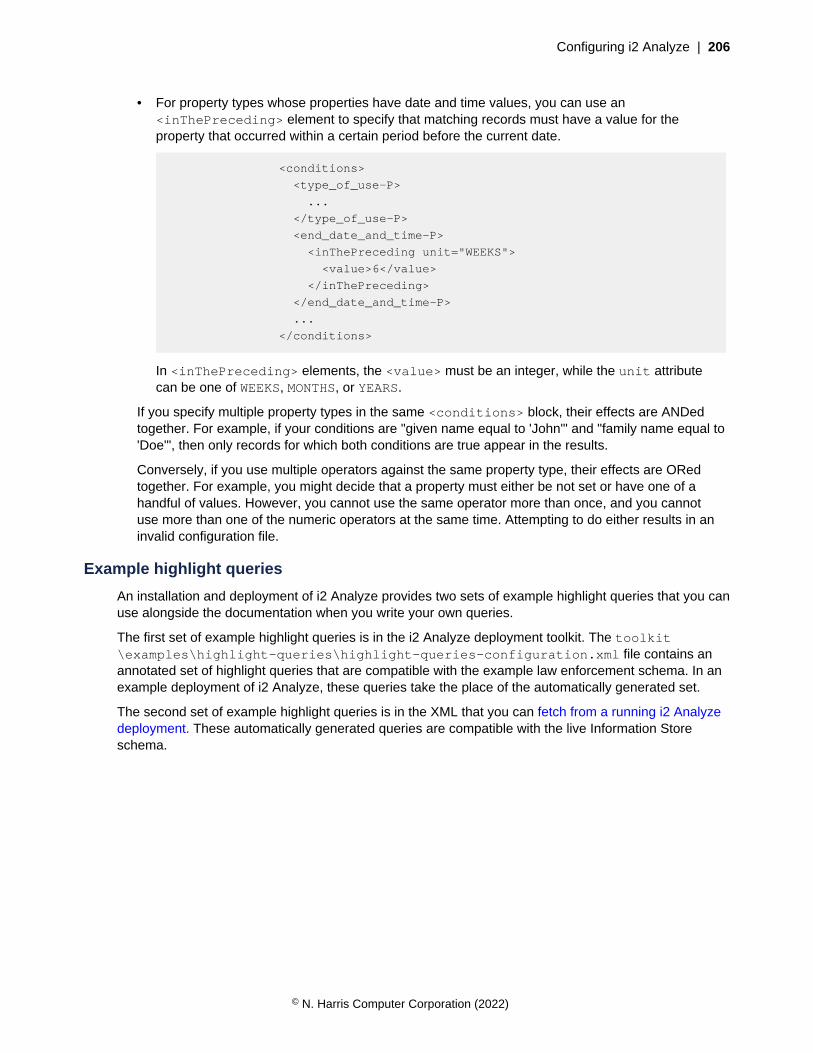
Configuring i2 Analyze | 206
• For property types whose properties have date and time values, you can use an<inThePreceding> element to specify that matching records must have a value for theproperty that occurred within a certain period before the current date.
<conditions>
<type_of_use-P>
...
</type_of_use-P>
<end_date_and_time-P>
<inThePreceding unit="WEEKS">
<value>6</value>
</inThePreceding>
</end_date_and_time-P>
...
</conditions>
In <inThePreceding> elements, the <value> must be an integer, while the unit attributecan be one of WEEKS, MONTHS, or YEARS.
If you specify multiple property types in the same <conditions> block, their effects are ANDedtogether. For example, if your conditions are "given name equal to 'John'" and "family name equal to'Doe'", then only records for which both conditions are true appear in the results.
Conversely, if you use multiple operators against the same property type, their effects are ORedtogether. For example, you might decide that a property must either be not set or have one of ahandful of values. However, you cannot use the same operator more than once, and you cannotuse more than one of the numeric operators at the same time. Attempting to do either results in aninvalid configuration file.
Example highlight queries
An installation and deployment of i2 Analyze provides two sets of example highlight queries that you canuse alongside the documentation when you write your own queries.
The first set of example highlight queries is in the i2 Analyze deployment toolkit. The toolkit\examples\highlight-queries\highlight-queries-configuration.xml file contains anannotated set of highlight queries that are compatible with the example law enforcement schema. In anexample deployment of i2 Analyze, these queries take the place of the automatically generated set.
The second set of example highlight queries is in the XML that you can fetch from a running i2 Analyzedeployment. These automatically generated queries are compatible with the live Information Storeschema.
© N. Harris Computer Corporation (2022)
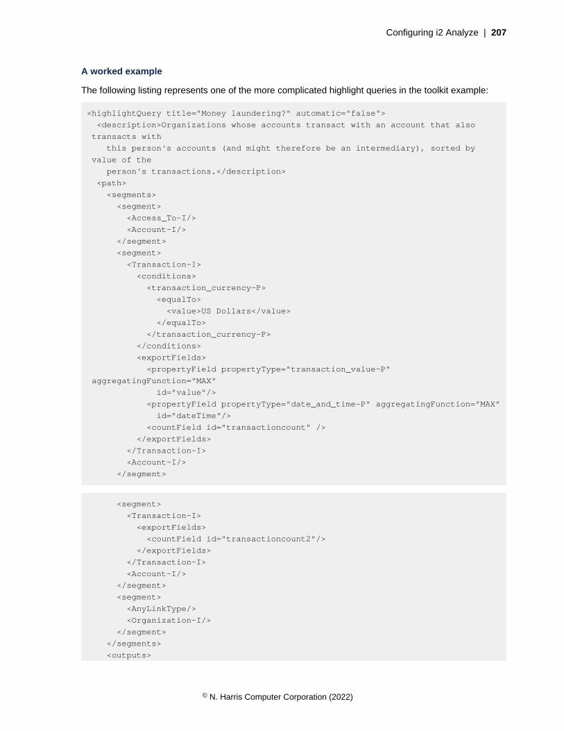
Configuring i2 Analyze | 207
A worked example
The following listing represents one of the more complicated highlight queries in the toolkit example:
<highlightQuery title="Money laundering?" automatic="false">
<description>Organizations whose accounts transact with an account that also
transacts with
this person's accounts (and might therefore be an intermediary), sorted by
value of the
person's transactions.</description>
<path>
<segments>
<segment>
<Access_To-I/>
<Account-I/>
</segment>
<segment>
<Transaction-I>
<conditions>
<transaction_currency-P>
<equalTo>
<value>US Dollars</value>
</equalTo>
</transaction_currency-P>
</conditions>
<exportFields>
<propertyField propertyType="transaction_value-P"
aggregatingFunction="MAX"
id="value"/>
<propertyField propertyType="date_and_time-P" aggregatingFunction="MAX"
id="dateTime"/>
<countField id="transactioncount" />
</exportFields>
</Transaction-I>
<Account-I/>
</segment>
<segment>
<Transaction-I>
<exportFields>
<countField id="transactioncount2"/>
</exportFields>
</Transaction-I>
<Account-I/>
</segment>
<segment>
<AnyLinkType/>
<Organization-I/>
</segment>
</segments>
<outputs>
© N. Harris Computer Corporation (2022)
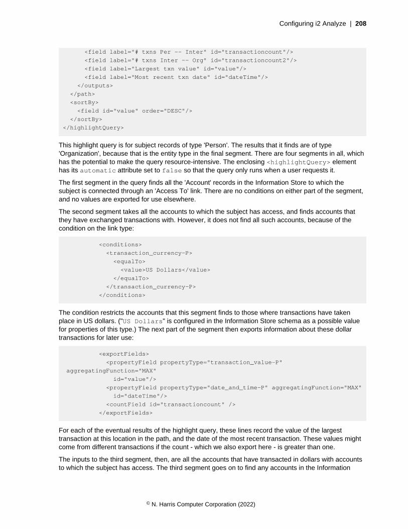
Configuring i2 Analyze | 208
<field label="# txns Per -- Inter" id="transactioncount"/>
<field label="# txns Inter -- Org" id="transactioncount2"/>
<field label="Largest txn value" id="value"/>
<field label="Most recent txn date" id="dateTime"/>
</outputs>
</path>
<sortBy>
<field id="value" order="DESC"/>
</sortBy>
</highlightQuery>
This highlight query is for subject records of type 'Person'. The results that it finds are of type'Organization', because that is the entity type in the final segment. There are four segments in all, whichhas the potential to make the query resource-intensive. The enclosing <highlightQuery> elementhas its automatic attribute set to false so that the query only runs when a user requests it.
The first segment in the query finds all the 'Account' records in the Information Store to which thesubject is connected through an 'Access To' link. There are no conditions on either part of the segment,and no values are exported for use elsewhere.
The second segment takes all the accounts to which the subject has access, and finds accounts thatthey have exchanged transactions with. However, it does not find all such accounts, because of thecondition on the link type:
<conditions>
<transaction_currency-P>
<equalTo>
<value>US Dollars</value>
</equalTo>
</transaction_currency-P>
</conditions>
The condition restricts the accounts that this segment finds to those where transactions have takenplace in US dollars. ("US Dollars" is configured in the Information Store schema as a possible valuefor properties of this type.) The next part of the segment then exports information about these dollartransactions for later use:
<exportFields>
<propertyField propertyType="transaction_value-P"
aggregatingFunction="MAX"
id="value"/>
<propertyField propertyType="date_and_time-P" aggregatingFunction="MAX"
id="dateTime"/>
<countField id="transactioncount" />
</exportFields>
For each of the eventual results of the highlight query, these lines record the value of the largesttransaction at this location in the path, and the date of the most recent transaction. These values mightcome from different transactions if the count - which we also export here - is greater than one.
The inputs to the third segment, then, are all the accounts that have transacted in dollars with accountsto which the subject has access. The third segment goes on to find any accounts in the Information
© N. Harris Computer Corporation (2022)

Configuring i2 Analyze | 209
Store that have exchanged transactions with the inputs. It also exports the count of transactions at thislocation in the path:
<exportFields>
<countField id="transactioncount2"/>
</exportFields>
The final segment takes these accounts that are twice-removed from accounts to which the subject hasaccess, and finds organizations in the Information Store that are connected to them in any way. To doso, it makes use of an <AnyLinkType> element:
<segment>
<AnyLinkType/>
<Organization-I/>
</segment>
It is worth recounting what this means from an investigative point of view. For an organization to befound by this query, it must be linked to an account that has transacted with an account that has alsoexchanged dollar transactions with an account to which the subject has access. In simpler terms, itmight be that accounts belonging to the person and the found organizations are exchanging moneythrough third accounts. The query certainly is not conclusive, but the results might become targets forfurther investigation.
When the results of the query are presented to users, they include the values that were exported fromthe second and third segments:
<outputs>
<field label="# txns Per -- Inter" id="transactioncount"/>
<field label="# txns Inter -- Org" id="transactioncount2"/>
<field label="Largest txn value" id="value"/>
<field label="Most recent txn date" id="dateTime"/>
</outputs>
These lines show the challenges of displaying useful information in the relatively confined space of ahighlight pane. In fact, only the first two fields appear in the pane; the others are displayed when theuser clicks Show more to display more results (and more property values from those results). Ideally,the labels work in harmony with the <description> of the query that you write to explain the results toyour users.
The final part of the highlight query specifies how the application should sort the results. In general, youcan request multiple sorts here that are applied in sequence. In this instance, the single criterion is thehighest transaction value from the second segment. Setting the order to DESC means that numbersrun from high to low, which is the more common requirement. The opposite is true when you sort on textvalues, and setting order to ASC places the results in alphabetical sequence.
Setting up search results filtering
In the clients of an i2 Analyze server, users can filter search results. You can configure the propertytypes and metadata criteria that appear in the filter list by creating and configuring facets for each typeof entity and link record that can appear in search results.
Selecting which property types to use for filtering search results can improve both system performanceand the user experience. For example, if the values of properties of a particular type are always unique
© N. Harris Computer Corporation (2022)
Configuring i2 Analyze | 210
(license plates, social security numbers), then by default the user sees a separate, one-record facet forevery value in the search results. If you configure that property type not to appear, then the system hasfewer facets to calculate, and it can display more useful facets from different property types instead.
For records of each entity and link type, the results configuration file defines which property types andmetadata criteria to use for filtering in Quick Search, external search, and Visual Query results views. Allthese views display the same set of facets.
The deployment toolkit contains a results configuration file for each of the example schemas inthe examples\schemas directory, apart from the Chart Store schema. Their names all end in -results.configuration.xml. If your system uses a modified version of one of the exampleschemas, you can modify the appropriate results configuration file.
If you decide to write your own file, the entity and link types that appear must correspond to entity andlink types from the deployed schemas. Examine the schemas and the data in your system, and decidewhich property types to display with facets in the results view. You can also decide which metadatacriteria to use for the same purpose.
If you do not specify a results configuration file, all of the property types and metadata criteria that canbe displayed with facets, for records of all entity and link types, are displayed in the results view inschema order.
If you follow this procedure in a deployment that provides high availability, you must complete each stepon every Liberty server in your environment before you move to the next step.
For more information about the results configuration file and the changes that you can make, seeUnderstanding the results configuration file on page 211.
1. Using an XML editor, open the results configuration file that you want to modify.
2. Add, modify, or remove any <ItemTypeFacet> elements and appropriate child<PropertyTypeFacet> and <MetadataFacet> elements for your deployment.
Note: Property types that have the following logical types cannot be used to filter search results:
• GEOSPATIAL
• MULTIPLE_LINE_STRING
3. Save and close the file.
Note: Ensure that your modified file is stored in the toolkit\configuration\fragments\common\WEB-INF\classes directory.
4. If you have created the file or changed its name, you must update the name of the file that thedeployment uses.
a) Using a text editor, open the DiscoServerSettingsCommon.properties file in the toolkit\configuration\fragments\opal-services\WEB-INF\classes directory.
b) Ensure that the value of the ResultsConfigurationResource property is set to the name ofyour results configuration file, and then save and close the file.
Tip: If you do not want to configure search result filtering, clear the value of theResultsConfigurationResource property.
Redeploy i2 Analyze to update the application with your changes.
5. In a command prompt, navigate to the toolkit\scripts directory.
6. Stop Liberty:
setup -t stopLiberty
© N. Harris Computer Corporation (2022)

Configuring i2 Analyze | 211
7. Update the i2 Analyze application:
setup -t deployLiberty
8. Start Liberty:
setup -t startLiberty
Run a selection of queries against an i2 Analyze server. Continue to change the configuration until youare satisfied with the types of filter that are available.
Understanding the results configuration file
In the results configuration file, you specify the schema item types, and their associated property typesand metadata criteria, by which users can filter search results. By defining the filtering behavior fordifferent entity and link types, you can refine the filtering to make it as valuable as possible for yourusers.
The results configuration file has the following basic shape:
<!-- Results configuration for Law_Enforcement_Schema.xml -->
<tns:ResultsConfiguration ...>
<Facets InlineLimit="5" ViewAllLimit="100">
<!-- Address -->
<ItemTypeFacet TypeId="ET1" Subfacets="ExcludeSpecific">
<!-- Unique Reference -->
<PropertyTypeFacet TypeId="ADD1" />
...
<MetadataFacet Criterion="NotesCreatedBy" />
...
</ItemTypeFacet>
...
</Facets>
</tns:ResultsConfiguration>
Here, the <ItemTypeFacet> element is used to declare which item type you are defining propertytypes and metadata criteria for. The value of the TypeId attribute specifies the item type. This valuecorresponds to the Id value of an <EntityType> or <LinkType> in the schema.
Important: For item types that are defined in gateway or connector schemas, you must augment theitem type identifier with the short name of its schema. If the type in the previous example was defined ina gateway schema with the short name External, then the <ItemTypeFacet> element changes:
<ItemTypeFacet TypeId="ET1-external" Subfacets="ExcludeSpecific">
...
</ItemTypeFacet>
In these augmented identifiers, the short name is always in lower-case letters, and any whitespace ornon-alphanumeric characters are converted to single hyphens. Furthermore, the short name is alwaysseparated from the original identifier with a hyphen.
Property types are specified in child <PropertyTypeFacet> elements. The value of the TypeIdattribute specifies the property type. This value corresponds to the Id value of a <PropertyType> inthe i2 Analyze schema.
© N. Harris Computer Corporation (2022)
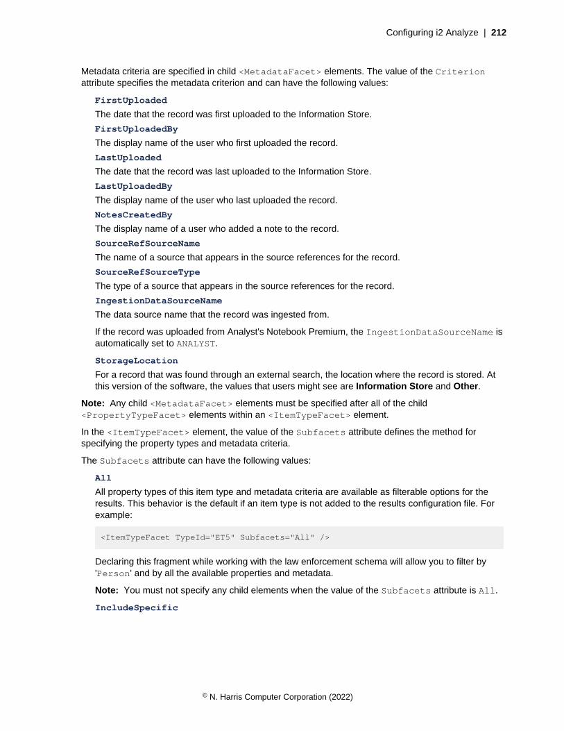
Configuring i2 Analyze | 212
Metadata criteria are specified in child <MetadataFacet> elements. The value of the Criterionattribute specifies the metadata criterion and can have the following values:
FirstUploaded
The date that the record was first uploaded to the Information Store.
FirstUploadedBy
The display name of the user who first uploaded the record.
LastUploaded
The date that the record was last uploaded to the Information Store.
LastUploadedBy
The display name of the user who last uploaded the record.
NotesCreatedBy
The display name of a user who added a note to the record.
SourceRefSourceName
The name of a source that appears in the source references for the record.
SourceRefSourceType
The type of a source that appears in the source references for the record.
IngestionDataSourceName
The data source name that the record was ingested from.
If the record was uploaded from Analyst's Notebook Premium, the IngestionDataSourceName isautomatically set to ANALYST.
StorageLocation
For a record that was found through an external search, the location where the record is stored. Atthis version of the software, the values that users might see are Information Store and Other.
Note: Any child <MetadataFacet> elements must be specified after all of the child<PropertyTypeFacet> elements within an <ItemTypeFacet> element.
In the <ItemTypeFacet> element, the value of the Subfacets attribute defines the method forspecifying the property types and metadata criteria.
The Subfacets attribute can have the following values:
All
All property types of this item type and metadata criteria are available as filterable options for theresults. This behavior is the default if an item type is not added to the results configuration file. Forexample:
<ItemTypeFacet TypeId="ET5" Subfacets="All" />
Declaring this fragment while working with the law enforcement schema will allow you to filter by'Person' and by all the available properties and metadata.
Note: You must not specify any child elements when the value of the Subfacets attribute is All.
IncludeSpecific
© N. Harris Computer Corporation (2022)
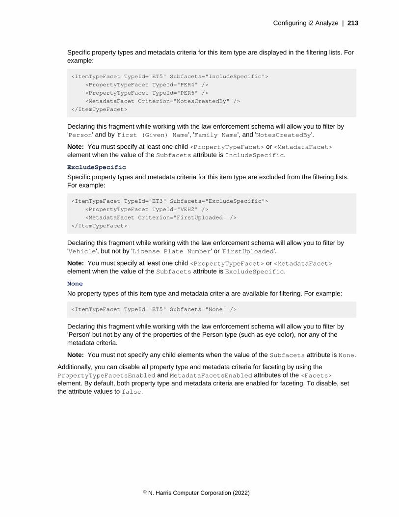
Configuring i2 Analyze | 213
Specific property types and metadata criteria for this item type are displayed in the filtering lists. Forexample:
<ItemTypeFacet TypeId="ET5" Subfacets="IncludeSpecific">
<PropertyTypeFacet TypeId="PER4" />
<PropertyTypeFacet TypeId="PER6" />
<MetadataFacet Criterion="NotesCreatedBy" />
</ItemTypeFacet>
Declaring this fragment while working with the law enforcement schema will allow you to filter by'Person' and by 'First (Given) Name', 'Family Name', and 'NotesCreatedBy'.
Note: You must specify at least one child <PropertyTypeFacet> or <MetadataFacet>element when the value of the Subfacets attribute is IncludeSpecific.
ExcludeSpecific
Specific property types and metadata criteria for this item type are excluded from the filtering lists.For example:
<ItemTypeFacet TypeId="ET3" Subfacets="ExcludeSpecific">
<PropertyTypeFacet TypeId="VEH2" />
<MetadataFacet Criterion="FirstUploaded" />
</ItemTypeFacet>
Declaring this fragment while working with the law enforcement schema will allow you to filter by'Vehicle', but not by 'License Plate Number' or 'FirstUploaded'.
Note: You must specify at least one child <PropertyTypeFacet> or <MetadataFacet>element when the value of the Subfacets attribute is ExcludeSpecific.
None
No property types of this item type and metadata criteria are available for filtering. For example:
<ItemTypeFacet TypeId="ET5" Subfacets="None" />
Declaring this fragment while working with the law enforcement schema will allow you to filter by'Person' but not by any of the properties of the Person type (such as eye color), nor any of themetadata criteria.
Note: You must not specify any child elements when the value of the Subfacets attribute is None.
Additionally, you can disable all property type and metadata criteria for faceting by using thePropertyTypeFacetsEnabled and MetadataFacetsEnabled attributes of the <Facets>element. By default, both property type and metadata criteria are enabled for faceting. To disable, setthe attribute values to false.
© N. Harris Computer Corporation (2022)
Configuring i2 Analyze | 214
Allowing users to cancel Expand operations
Some Expand operations against the Information Store can find many i2 Analyze records. Returning allof these records to the user might make the chart too crowded or affect system performance. You canconfigure i2 Analyze to warn users of large result sets and allow them to cancel the operation.
To specify the number of records that an Expand operation can find before a warning is displayedto analysts, you can provide a value for the ExpandMaxResultsSoftLimit setting in theDiscoServerSettingsCommon.properties file.
If the number of results exceeds this value, Analyst's Notebook Premium displays a message to informthe user. The user can choose to continue or cancel the operation.
By default this setting has a value of 0, which means that no warning is displayed.
If you follow this procedure in a deployment that provides high availability, you must complete each stepon every Liberty server in your environment before you move to the next step.
1. Open the DiscoServerSettingsCommon.properties file, and provide a value for theExpandMaxResultsSoftLimit setting.For example, to display a warning if the number of records exceeds 100:
ExpandMaxResultsSoftLimit=100
2. Save and close the file.
Redeploy i2 Analyze to update the application with your changes.
3. In a command prompt, navigate to the toolkit\scripts directory.
4. Stop Liberty:
setup -t stopLiberty
5. Update the i2 Analyze application:
setup -t deployLiberty
6. Start Liberty:
setup -t startLiberty
After you redeploy i2 Analyze, run a selection of Expand queries to test the behavior of the deployment.
Configuring matchingIn a deployment of i2 Analyze that contains data that originates from multiple sources, the likelihoodof multiple records that represent the same real-world object or relationship increases. To enableanalysts to identify and reduce the number of matching records, you can activate the matching featuresin Analyst's Notebook Premium by creating custom match rules.
i2 Analyze can be presented with data from multiple sources, through multiple routes. The mechanismsthat identify matching records depend on how the data is presented to i2 Analyze:
• For records that are on a chart, system matching can compare them with records in the InformationStore, and Find Matching Records can compare records on the chart with each other.
• When data is presented through Analyst's Notebook Premium import, or retrieved by connectors, orcreated by analysts, system matching can compare incoming records with records on the chart andin the Information Store.
© N. Harris Computer Corporation (2022)
Configuring i2 Analyze | 215
• During the ingestion process, the incoming records are compared with the records in the InformationStore. For more information about identifying matches in this way, see Information Store datacorrelation.
Important:
The scope of match rules is not the same for link records as it is for entity records. Rules for matchingentity records apply universally, but rules for matching link records apply only to links between the samepair of ends. Link records that do not connect the same ends are never a match for each other.
This behavior also means that rules for matching link records behave differently in system matching andFind Matching Records:
• In system matching, link records can match only when they are between the same pair of entityrecords.
• In Find Matching Records, link records can match when they are between any two records in a pairof entity items on the chart surface.
If the pair of entity items on the chart contain a large number of united records, some combinationsof those records are not searched for matching links. By default, the number of link end recordcombinations that are searched is 100. You can change this value, but the link matching process mighttake longer if more combinations are searched. For more information about changing the maximumnumber of combinations that are searched, see The DiscoServerSettingsCommon.propertiesfile.
Configuring system matching
System matching uses system match rules to identify matching records. To configure system matching,you define and deploy your system match rules on the i2 Analyze server.
The mechanism that you use to deploy system match rules depends on your deployment pattern:
• In a deployment that contains the Information Store, your system match rules are used to create amatch index that determines whether a record matches one that exists in the Information Store. Thematch index is employed by the Get Matches feature in Analyst's Notebook Premium, and whenrecords are presented through import, connectors, or created by analysts. To create the match indexfrom your match rules, see Deploying system match rules on page 216.
• In a deployment that contains only the i2 Connect gateway, a match index is not necessary becausethe system match rules act only on records in search results and on the chart surface. To deployyour system match rules in this deployment pattern, see Deploying system match rules for the i2Connect gateway only on page 217.
Analysts can choose whether to use system matching at all, but they cannot choose the match rulesthat are used or approve matches on a record-by-record basis. To ensure that your system match rulesdo not cause false-positive matches, focus on using known strong identifiers in your data.
If system matching acts on data that involves a large number of seed or matching records (in the tensof thousands), the matching process can take a long time to complete. In this scenario, the followingactions might accelerate the process:
• Investigate your match rules to ensure that you are not matching too many records by accident.
• Investigate that the data in your Information Store is being ingested correctly, so that your strongidentifiers are not accidentally present on too many records.
• Advise your analysts to use system matching on smaller sets of data.
© N. Harris Computer Corporation (2022)
Configuring i2 Analyze | 216
Deploying system match rules
The system match rules that you deploy are used to create a match index of your data in the InformationStore. The match index identifies matches between records that enter the system (or records on a chart)and records in the Information Store.
Ensure that i2 Analyze is started, and that you can connect to the deployment by using Analyst'sNotebook Premium.
In your configuration development environment, use Analyst's Notebook Premium to create your matchrules, which are saved to an XML file that you can move to the i2 Analyze server. (The match rules filesthat Analyst's Notebook Premium creates are compatible with both Find Matching Records and systemmatching, but i2 recommends that you configure the features separately.)
After you create your match rules file, you create a match index of the data in the Information Store fromthose rules. In fact, every deployment of i2 Analyze has two match indexes, generated from differentversions of the match rules file. One of the indexes is live, and the application uses it to process systemmatch requests. The other index is the standby, which is generated when you modify or write newsystem match rules.
When the standby index is ready, you switch the standby index to live so that the application uses thematch index that reflects your new rules.
Note: If your deployment uses only the i2 Connect gateway, follow the instructions in Deploying systemmatch rules for the i2 Connect gateway only on page 217.
1. Connect to your server in Analyst's Notebook Premium to load the i2 Analyze schema, and thencreate your match rules.
For more information about how to create match rules, see Find matching records in the Analyst'sNotebook documentation.
After you create your rules, Analyst's Notebook Premium saves a file named local-fmr-match-rules.xml to the %localappdata%\i2\Enterprise Insight Analysis\Match Rules\<data_source_id> directory on the local workstation. The file is saved in the directory that wasmodified most recently.
Next, you must place the match rules file on the i2 Analyze server and update the deployment with yourchanges.
2. Move the local-fmr-match-rules.xml file to the toolkit\configuration\environmentdirectory in the i2 Analyze deployment toolkit.
3. Rename local-fmr-match-rules.xml to system-match-rules.xml.
4. In a command prompt, navigate to the toolkit\scripts directory.
5. Update the system match rules on the server and start the population of the standby match index:
setup -t updateMatchRules
6. Monitor the i2analyze\deploy\wlp\usr\servers\opal-server\logs directory for aStandbyMatchIndexReady file. The file is created when the standby match index completesindexing the data in the Information Store with your new system match rules.
7. Update the application to use the standby match index:
setup -t switchStandbyMatchIndexToLive
This toolkit task switches the standby match index for your new rules to the live index. The matchindex that was live is now the standby match index.
© N. Harris Computer Corporation (2022)

Configuring i2 Analyze | 217
Connect to the deployment again and test your system rules with representative data to ensure that theymeet your requirements. In Analyst's Notebook Premium, you must log out and log in again to see yourchanges.
If you want to modify the system rules again without using Analyst's Notebook Premium, you can modifythe file in an XML editor. For more information about the structure of the match rules file, see Matchrules syntax on page 221.
Deploying system match rules for the i2 Connect gateway only
In a deployment of i2 Analyze that includes only the i2 Connect gateway, the system match rulesidentify matches between records from external sources and those that are already on a chart. There isno match index, and as a consequence the procedure for deploying system match rules is different fromsystems with an Information Store.
Ensure that i2 Analyze is started, and that you can connect to the deployment by using Analyst'sNotebook Premium.
Also, to reload the server through the reload endpoint, ensure that you have a command-line toolsuch as postman or curl, and a user that has the i2:Administrator command access controlpermission.
Note: For more information about using the admin endpoints, see Using the admin endpoints on page322.
In your configuration development environment, use Analyst's Notebook Premium to create your matchrules, which are saved to an XML file that you can move to the i2 Analyze server. (The match rules filesthat Analyst's Notebook Premium creates are compatible with both Find Matching Records and systemmatching, but i2 recommends that you configure the features separately.)
1. Connect to your server in Analyst's Notebook Premium to load the i2 Analyze schema, and thencreate your match rules.
For more information about how to create match rules, see Find matching records in the Analyst'sNotebook documentation.
After you create your rules, Analyst's Notebook Premium saves a file named local-fmr-match-rules.xml to the %localappdata%\i2\Enterprise Insight Analysis\Match Rules\<data_source_id> directory on the local workstation. The file is saved in the directory that wasmodified most recently.
Next, you must place the match rules file on the i2 Analyze server and update the deployment with yourchanges.
2. Move the local-fmr-match-rules.xml file to the toolkit\configuration\live directoryin the i2 Analyze deployment toolkit.
3. Delete the system-match-rules.xml file from the toolkit\configuration\live directory.
4. Rename local-fmr-match-rules.xml to system-match-rules.xml.
Update the deployment with your changes.
The following method deploys your changes without stopping the server by using a POST request to aREST endpoint.
To redeploy your changes by using the deployment toolkit only, see Redeploying Liberty on page 321.You must deploy your changes by using the deployment toolkit if you are in a deployment with highavailability or you are deploying in your production environment.
5. In a command prompt, navigate to the toolkit\scripts directory.
© N. Harris Computer Corporation (2022)

Configuring i2 Analyze | 218
6. Update the configuration on the server:
setup -t updateLiveConfiguration
The updateLiveConfiguration toolkit task updates server with every file in the toolkit\configuration\live directory.
7. Update the running application by using the reload endpoint:
curl -i --cookie-jar cookie.txt -d j_username=user_name
-d j_password=password
http://host_name/context_root/j_security_check
curl -i --cookie cookie.txt -X POST http://host_name/context_root/api/v1/admin/
config/reload
To reload the server like this, ensure that you can use the admin endpoints. For more information,see Using the admin endpoints on page 322.
Warning: The reload method updates the configuration without requiring a server restart,but any logged-in users are logged out from i2 Analyze when you run it.
Connect to the deployment again and test your system rules with representative data to ensure that theymeet your requirements. In Analyst's Notebook Premium, you must log out and log in again to see yourchanges.
If you want to modify the system rules again without using Analyst's Notebook Premium, you can modifythe file in an XML editor. For more information about the structure of the match rules file, see Matchrules syntax on page 221.
Handling matches in i2 Connect result sets
By default, i2 Analyze returns records from the i2 Connect gateway to clients without reacting tomatches among those records. You can edit the I2ConnectRecordMatchAction property so thatrecords in the results that match each other arrive on the chart as merged or united records.
You can set I2ConnectRecordMatchAction to one of three possible values:
• IGNORE
i2 Analyze ignores any matches between records in the results of an i2 Connect query. This is thedefault setting.
• UNITE
Records in the results of an i2 Connect query that match each other are added to the chart as entityand link items that contain sets of matching records.
• MERGE
Records in the results of an i2 Connect query that match each other are merged into single recordsbefore they reach the chart.
For all three values, and depending on your other settings, the records from the i2 Connect gatewaymight still match with others when they reach the chart surface.
To change how i2 Analyze handles matching records in i2 Connect result sets:
© N. Harris Computer Corporation (2022)
Configuring i2 Analyze | 219
1. In a text editor, open the DiscoServerSettingsCommon.properties file from the toolkit\configuration\fragments\opal-services\WEB-INF\classes directory.
2. Find or add the I2ConnectRecordMatchAction property and set its value to your preferredsetting. For example:
I2ConnectRecordMatchAction=UNITE
3. Save and close the file.
4. In a command prompt, navigate to the toolkit\scripts directory and run the followingcommands to update and restart the Liberty server:
setup -t stopLiberty
setup -t deployLiberty
setup -t startLiberty
With the changes in place, you can reconnect to i2 Analyze from i2 Analyst's Notebook Premium andverify that the platform handles matching records in the way that you specified.
Configuring Find Matching Records
Analysts use Find Matching Records to identify when multiple records on an Analyst's NotebookPremium chart might represent the same real-world object or relationship.
Analysts can write their own match rules for Find Matching Records, but you can also configure i2Analyze to provide a common set of rules to all analysts when they connect. Analysts can choosewhether to use all, none, or a selection of the match rules that the server provides. For more informationabout how analysts might use Find Matching Records, see Creating rules for record matching.
For information about how to create and deploy server-side match rules for Find Matching Records, seeDeploying Find Matching Records match rules on page 219.
Both server and local match rules for Find Matching Records are tied to a particular server. If adestructive schema change in i2 Analyze takes place, all match rules, whether they are deployed on theserver or the client, are invalidated.
Deploying Find Matching Records match rules
In a deployment of i2 Analyze, you can deploy match rules on the server for all Analyst's NotebookPremium users to use in Find Matching Records. The match rules are provided to analysts when theyconnect to the server.
Ensure that i2 Analyze is started, and that you can connect to the deployment by using Analyst'sNotebook Premium.
Also, to reload the server through the reload endpoint, ensure that you have a command-line toolsuch as postman or curl, and a user that has the i2:Administrator command access controlpermission.
Note: For more information about using the admin endpoints, see Using the admin endpoints on page322.
In your configuration development environment, use Analyst's Notebook Premium to create your matchrules, which are saved to an XML file that you can move to the i2 Analyze server. (The match rules filesthat Analyst's Notebook Premium creates are compatible with both Find Matching Records and systemmatching, but you should configure the features separately.)
© N. Harris Computer Corporation (2022)
Configuring i2 Analyze | 220
Alternatively, you can create the server rules by editing the match rules XML file manually. If you createthe match rules this way, you must still complete the following steps that describe how to configure anddeploy the file on the i2 Analyze server.
1. Connect to your server in Analyst's Notebook Premium to load the i2 Analyze schema, and thencreate your match rules. As you do so, test them with representative data on the chart.
For more information about how to create match rules, see Find matching records in the Analyst'sNotebook documentation.
After you create your rules, Analyst's Notebook Premium saves a file named local-fmr-match-rules.xml to the %localappdata%\i2\Enterprise Insight Analysis\Match Rules\<data_source_id> directory on the local workstation. The file is saved in the directory that wasmodified most recently.
Next, you must place the match rules file on the i2 Analyze server and update the deployment with yourchanges.
2. Move the local-fmr-match-rules.xml file to the toolkit\configuration\live directoryin the i2 Analyze deployment toolkit.
3. Delete the fmr-match-rules.xml file from the toolkit\configuration\live directory.
4. Rename local-fmr-match-rules.xml to fmr-match-rules.xml.
Update the deployment with your changes.
The following method deploys your changes without stopping the server by using a POST request to aREST endpoint.
To redeploy your changes by using the deployment toolkit only, see Redeploying Liberty on page 321.You must deploy your changes by using the deployment toolkit if you are in a deployment with highavailability or you are deploying in your production environment.
5. In a command prompt, navigate to the toolkit\scripts directory.
6. Update the configuration on the server:
setup -t updateLiveConfiguration
The updateLiveConfiguration toolkit task updates server with every file in the toolkit\configuration\live directory.
7. Update the running application by using the reload endpoint:
curl -i --cookie-jar cookie.txt -d j_username=user_name
-d j_password=password
http://host_name/context_root/j_security_check
curl -i --cookie cookie.txt -X POST http://host_name/context_root/api/v1/admin/
config/reload
To reload the server like this, ensure that you can use the admin endpoints. For more information,see Using the admin endpoints on page 322.
Warning: The reload method updates the configuration without requiring a server restart,but any logged-in users are logged out from i2 Analyze when you run it.
Connect to the deployment again and test that your server rules are visible in the Find MatchingRecords feature. In Analyst's Notebook Premium, you must log out and log in again to see yourchanges.
© N. Harris Computer Corporation (2022)

Configuring i2 Analyze | 221
Note: If you copied the local-fmr-match-rules.xml file instead of moving it, each rule isduplicated in Analyst's Notebook Premium because the local and server rules are the same.
If you continue to develop your server rules by using this process, the cached-fmr-match-rules.xml file in the Match Rules directory contains the rules that are currently deployed on theserver. Every time that Analyst's Notebook Premium connects, the cached rules file is overwritten withthe latest version from the server.
If you want to modify the server rules again without using Analyst's Notebook Premium, you can modifythe file in an XML editor. Any changes that you make are validated when you start i2 Analyze. For moreinformation about the structure of the match rules file, see Match rules syntax on page 221.
Match rules syntax
A match rules file is an XML document whose structure is validated when i2 Analyze starts. The matchrules syntax is the same for both system match and Find Matching Records match rules files.
Root element: matchRules
The root element of a match rules file is a <matchRules> element from the defined namespace. Forexample:
<tns:matchRules
xmlns:tns="http://www.i2group.com/Schemas/2019-05-14/MatchRules"
xmlns:xsi="http://www.w3.org/2001/XMLSchema-instance"
xmlns:xsd="http://www.w3.org/2001/XMLSchema"
xsi:schemaLocation=
"http://www.i2group.com/Schemas/2019-05-14/MatchRules MatchRules.xsd"
version="2"
enableSourceIdentifierMatching="true">
...
</tns:matchRules>
The <matchRules> element has the following customizable attributes:
Attribute Description
enableSourceIdentifierMatching For a deployment that contains the Information Store and thei2 Connect gateway, controls whether system matching usessource identifiers to determine whether records match each other,regardless of whether they have property matches.
When this attribute is false or absent, different users can causeduplication by retrieving the same records from external sources,editing them, and uploading them to the Information Store. When itis true, such records are detected by system matching.
version The version of the match rules file, which must be 2 at this release.
matchRule
Inside the root element, each <matchRule> element defines a match rule for records of a particularentity or link type. The <matchRule> element has the following attributes:
© N. Harris Computer Corporation (2022)
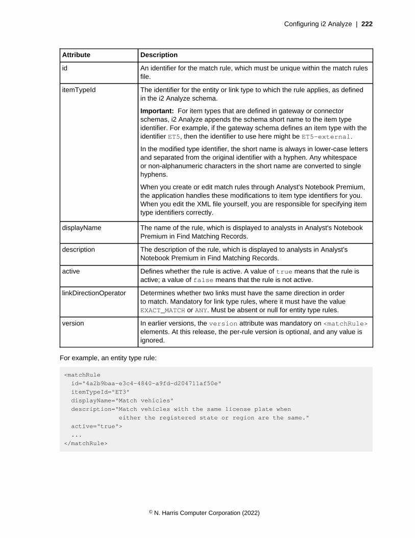
Configuring i2 Analyze | 222
Attribute Description
id An identifier for the match rule, which must be unique within the match rulesfile.
itemTypeId The identifier for the entity or link type to which the rule applies, as definedin the i2 Analyze schema.
Important: For item types that are defined in gateway or connectorschemas, i2 Analyze appends the schema short name to the item typeidentifier. For example, if the gateway schema defines an item type with theidentifier ET5, then the identifier to use here might be ET5-external.
In the modified type identifier, the short name is always in lower-case lettersand separated from the original identifier with a hyphen. Any whitespaceor non-alphanumeric characters in the short name are converted to singlehyphens.
When you create or edit match rules through Analyst's Notebook Premium,the application handles these modifications to item type identifiers for you.When you edit the XML file yourself, you are responsible for specifying itemtype identifiers correctly.
displayName The name of the rule, which is displayed to analysts in Analyst's NotebookPremium in Find Matching Records.
description The description of the rule, which is displayed to analysts in Analyst'sNotebook Premium in Find Matching Records.
active Defines whether the rule is active. A value of true means that the rule isactive; a value of false means that the rule is not active.
linkDirectionOperator Determines whether two links must have the same direction in orderto match. Mandatory for link type rules, where it must have the valueEXACT_MATCH or ANY. Must be absent or null for entity type rules.
version In earlier versions, the version attribute was mandatory on <matchRule>elements. At this release, the per-rule version is optional, and any value isignored.
For example, an entity type rule:
<matchRule
id="4a2b9baa-e3c4-4840-a9fd-d204711af50e"
itemTypeId="ET3"
displayName="Match vehicles"
description="Match vehicles with the same license plate when
either the registered state or region are the same."
active="true">
...
</matchRule>
© N. Harris Computer Corporation (2022)

Configuring i2 Analyze | 223
And a link type rule:
<matchRule
id="8aa5f6f4-a1a8-41de-b5c5-8701e44bcde7"
itemTypeId="LAS1"
displayName="Match duplicate links"
description="Match link records between the same pair of entity
records when the links are in the same direction."
active="true"
linkDirectionOperator="EXACT_MATCH">
...
</matchRule>
matchAll and matchAny
To specify the behavior of a match rule, you can use the following children of the <matchRule>element:
matchAll
The <matchAll> element specifies that all of the conditions within it must be met.
matchAny
The <matchAny> element specifies that at least one of the conditions within it must be met.
A <matchRule> element must have both the <matchAll> and <matchAny> elements. For example:
<matchRule ... >
<matchAll>
...
</matchAll>
<matchAny />
</matchRule>
condition
All match rules must contain the <matchAll> and <matchAny> elements, although both can be emptyfor link type rules. It is valid to create a rule that makes all link records of the same type between thesame pair of entity records match each other, regardless of any other considerations.
All entity type rules must contain at least one condition. Many link type rules contain conditions too.Each condition defines a comparison that takes place between values in different records, and specifieswhen those values are considered to match. Conditions can be refined by using operators, values, andnormalizations.
To specify the conditions of a match rule, you use the <condition> element that can be a childof the <matchAll> and <matchAny> elements. Each <condition> element has a mandatorypropertyTypeId attribute, which is the identifier for the property type to which the condition applies,as defined in the i2 Analyze schema.
For example:
<condition propertyTypeId="VEH2">
...
</condition>
© N. Harris Computer Corporation (2022)
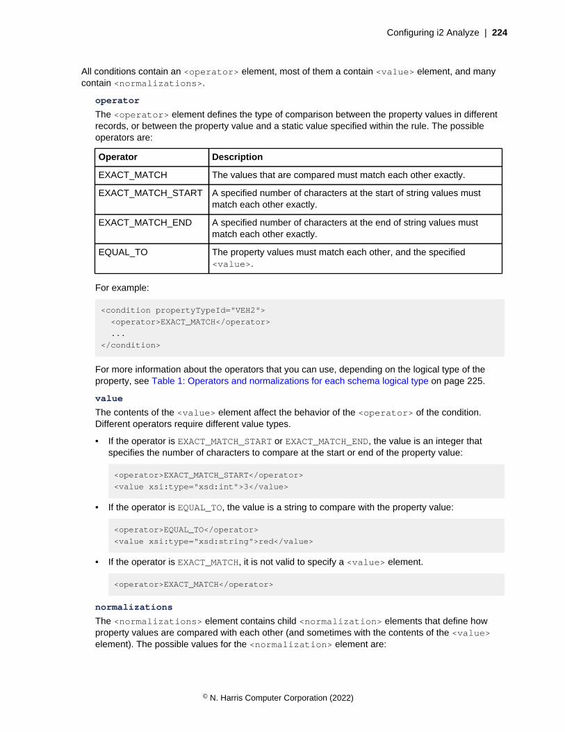
Configuring i2 Analyze | 224
All conditions contain an <operator> element, most of them a contain <value> element, and manycontain <normalizations>.
operator
The <operator> element defines the type of comparison between the property values in differentrecords, or between the property value and a static value specified within the rule. The possibleoperators are:
Operator Description
EXACT_MATCH The values that are compared must match each other exactly.
EXACT_MATCH_START A specified number of characters at the start of string values mustmatch each other exactly.
EXACT_MATCH_END A specified number of characters at the end of string values mustmatch each other exactly.
EQUAL_TO The property values must match each other, and the specified<value>.
For example:
<condition propertyTypeId="VEH2">
<operator>EXACT_MATCH</operator>
...
</condition>
For more information about the operators that you can use, depending on the logical type of theproperty, see Table 1: Operators and normalizations for each schema logical type on page 225.
value
The contents of the <value> element affect the behavior of the <operator> of the condition.Different operators require different value types.
• If the operator is EXACT_MATCH_START or EXACT_MATCH_END, the value is an integer thatspecifies the number of characters to compare at the start or end of the property value:
<operator>EXACT_MATCH_START</operator>
<value xsi:type="xsd:int">3</value>
• If the operator is EQUAL_TO, the value is a string to compare with the property value:
<operator>EQUAL_TO</operator>
<value xsi:type="xsd:string">red</value>
• If the operator is EXACT_MATCH, it is not valid to specify a <value> element.
<operator>EXACT_MATCH</operator>
normalizations
The <normalizations> element contains child <normalization> elements that define howproperty values are compared with each other (and sometimes with the contents of the <value>element). The possible values for the <normalization> element are:
© N. Harris Computer Corporation (2022)
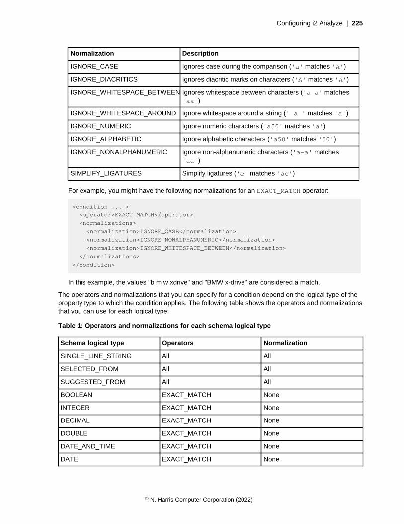
Configuring i2 Analyze | 225
Normalization Description
IGNORE_CASE Ignores case during the comparison ('a' matches 'A')
IGNORE_DIACRITICS Ignores diacritic marks on characters ('Ã' matches 'A')
IGNORE_WHITESPACE_BETWEEN Ignores whitespace between characters ('a a' matches'aa')
IGNORE_WHITESPACE_AROUND Ignore whitespace around a string (' a ' matches 'a')
IGNORE_NUMERIC Ignore numeric characters ('a50' matches 'a')
IGNORE_ALPHABETIC Ignore alphabetic characters ('a50' matches '50')
IGNORE_NONALPHANUMERIC Ignore non-alphanumeric characters ('a-a' matches'aa')
SIMPLIFY_LIGATURES Simplify ligatures ('æ' matches 'ae')
For example, you might have the following normalizations for an EXACT_MATCH operator:
<condition ... >
<operator>EXACT_MATCH</operator>
<normalizations>
<normalization>IGNORE_CASE</normalization>
<normalization>IGNORE_NONALPHANUMERIC</normalization>
<normalization>IGNORE_WHITESPACE_BETWEEN</normalization>
</normalizations>
</condition>
In this example, the values "b m w xdrive" and "BMW x-drive" are considered a match.
The operators and normalizations that you can specify for a condition depend on the logical type of theproperty type to which the condition applies. The following table shows the operators and normalizationsthat you can use for each logical type:
Table 1: Operators and normalizations for each schema logical type
Schema logical type Operators Normalization
SINGLE_LINE_STRING All All
SELECTED_FROM All All
SUGGESTED_FROM All All
BOOLEAN EXACT_MATCH None
INTEGER EXACT_MATCH None
DECIMAL EXACT_MATCH None
DOUBLE EXACT_MATCH None
DATE_AND_TIME EXACT_MATCH None
DATE EXACT_MATCH None
© N. Harris Computer Corporation (2022)
Configuring i2 Analyze | 226
Schema logical type Operators Normalization
TIME EXACT_MATCH None
Property types that have the following logical types cannot be used in match rules:
• GEOSPATIAL
• MULTIPLE_LINE_STRING
The following XML is an example of a match rules file that contains a single entity match rule. The rulematches vehicle records that have the same values for the license plate property, and the same valuesfor either the state or region properties.
© N. Harris Computer Corporation (2022)
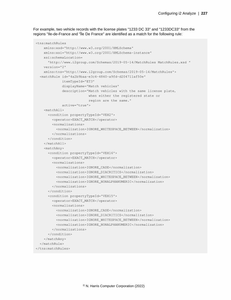
Configuring i2 Analyze | 227
For example, two vehicle records with the license plates "1233 DC 33" and "1233DC33" from theregions "Ile-de-France and "Île De France" are identified as a match for the following rule:
<tns:matchRules
xmlns:xsd="http://www.w3.org/2001/XMLSchema"
xmlns:xsi="http://www.w3.org/2001/XMLSchema-instance"
xsi:schemaLocation=
"http://www.i2group.com/Schemas/2019-05-14/MatchRules MatchRules.xsd "
version="2"
xmlns:tns="http://www.i2group.com/Schemas/2019-05-14/MatchRules">
<matchRule id="4a2b9baa-e3c4-4840-a9fd-d204711af50e"
itemTypeId="ET3"
displayName="Match vehicles"
description="Match vehicles with the same license plate,
when either the registered state or
region are the same."
active="true">
<matchAll>
<condition propertyTypeId="VEH2">
<operator>EXACT_MATCH</operator>
<normalizations>
<normalization>IGNORE_WHITESPACE_BETWEEN</normalization>
</normalizations>
</condition>
</matchAll>
<matchAny>
<condition propertyTypeId="VEH16">
<operator>EXACT_MATCH</operator>
<normalizations>
<normalization>IGNORE_CASE</normalization>
<normalization>IGNORE_DIACRITICS</normalization>
<normalization>IGNORE_WHITESPACE_BETWEEN</normalization>
<normalization>IGNORE_NONALPHANUMERIC</normalization>
</normalizations>
</condition>
<condition propertyTypeId="VEH15">
<operator>EXACT_MATCH</operator>
<normalizations>
<normalization>IGNORE_CASE</normalization>
<normalization>IGNORE_DIACRITICS</normalization>
<normalization>IGNORE_WHITESPACE_BETWEEN</normalization>
<normalization>IGNORE_NONALPHANUMERIC</normalization>
</normalizations>
</condition>
</matchAny>
</matchRule>
</tns:matchRules>
© N. Harris Computer Corporation (2022)
Configuring i2 Analyze | 228
Configuring geospatial mappingAnalyst's Notebook supports several different mechanisms for mapping chart items, but only onethat supports geographic data that is stored in i2 Analyze records. You must define the maps andgeographic reference systems to use before the mapping features that can be used with i2 Analyzerecords can be enabled.
When records contain geographic information, Analysts can view their location on supplied maps. Inaddition, Analysts can use visual queries to search for information in specific locations.
The mapping configuration file contains the following main types of information:
Mapping tiles
The mapping configuration file contains information that identifies the map tiles that are available toAnalysts. The following details are needed for each map:
• A displayName for the mapping tile to display to the Analyst.
• The URL that hosts the mapping tile.
• Any information about the origins of the mapping tile, such as the source and any copyrightdetails.
Base Maps
Base maps form the background on which other GIS items are overlaid. Depending on the typeof investigation, and the location, different types of base map might be suitable. For example, youmight want to use graphical representations or satellite imagery. In addition to the details that areneeded for all mapping tiles, you can specify which base map is opened by default.
Overlays
Layers that sit over the base map and contain detailed information that might be relevant to specifictypes of investigation. For example, cell tower locations, buildings of interest, borders, or roadsystems. By adding such information to layers that are overlaid over a base map, you can select therelevant information without displaying information that isn't needed. Unlike base maps, as differentoverlays can contain different information, multiple overlay tiles can be added to the mappingview. As overlay-mapping tiles are added over other maps, you can set the opacity level to seeinformation on lower mapping tiles.
Coordinate Systems
The 2D coordinate reference systems that can be used to translate coordinates to map locations.The following details are needed for each coordinate system:
• A displayName for the coordinate system to display to the Analyst.
• The projection string that defines the coordinate system. This string must be a valid PROJ4coordinate reference system string.
• The type of editor to use to input the values.
In addition, you can define the bounds to use with the coordinates to constrain the area beingmapped.
© N. Harris Computer Corporation (2022)

Configuring i2 Analyze | 229
Defining the mapping solution
In a deployment of i2® Analyze, you can define the mapping tiles that can be accessed, and thecoordinate systems that are used to plot locations on them. By default, analysts can select from a list ofpublicly available maps and common coordinate systems.
Analyst's can access mapping features to help investigate geographic information. You might needto update the mapping tiles that are provided, or the coordinate reference systems that are used tocalculate locations. The contents of the example files that are included in the deployment toolkit.
1. Modify the geospatial-configuration.json file:
a) In your JSON editor, open the toolkit\configuration\live\geospatial-configuration.json file.
b) Using the reference and example information, modify the file to define the mapping tiles andcoordinate reference systems your analysts can use.
Update the deployment with your changes.
The following method deploys your changes without stopping the server by using a POST request to aREST endpoint.
To redeploy your changes by using the deployment toolkit only, see Redeploying Liberty on page 321.You must deploy your changes by using the deployment toolkit if you are in a deployment with highavailability or you are deploying in your production environment.
2. Update the configuration on the server:
setup -t updateLiveConfiguration
3. Update the running application by using the admin endpoint:
curl -i --cookie-jar cookie.txt -d j_username=user_name -d j_password=password
http://host_name/conext_root/j_security_check
curl -i --cookie cookie.txt -X POST http://host_name/conext_root/api/v1/admin/
config/reload
To reload the server by using the reload endpoint, ensure that you can use the admin endpoints. Formore information about using the admin endpoints, see Using the admin endpoints on page 322.
Warning: The reload method updates the configuration without requiring a server restart,but any logged-in users are logged out from i2 Analyze when you run it.
Your configuration is validated, and any errors are reported in the REST response and in the wlp\usr\servers\opal-server\logs\deployed_war\i2_Update_Live_Configuration.log.
Where deployed_war can be:
• opal-services-is
• opal-services-daod
• opal-services-is-daod
Depending on the type of spatial data that you are ingesting into your Information Store, to increasethe performance of Visual Query operations, you might need to set up spatial database indexes onIS_DATA tables that contain geographical data. For more information on creating indexes manuallyin the Information Store, see Creating indexes in the Information Store database on page 167. Inaddition, for database specific information about the use of spatial indexes:
© N. Harris Computer Corporation (2022)

Configuring i2 Analyze | 230
• For Db2 databases, see the IBM Integrated Analytics System documentation: Using indexes andviews to access spatial data.
• For SQL Server databases, see the Microsoft SQL Server Spatial Indexing documentation: https://docs.microsoft.com/en-us/sql/relational-databases/spatial/spatial-indexes-overview?view=sql-server-ver15.
The example mapping configuration file
The toolkit information-store-opal and information-store-daod-opal exampleconfigurations contain an example geospatial-configuration.json file in the configuration/live folder. This example defines publicly available mapping tiles, and common coordinate referencesystems.
The geospatial-configuration.json file that is included in the deployment toolkit contains:
Base Map - Esri World Street Map
A link to the publicly available Esri World Street Map tile that presents highway-level data for theworld and street-level data for specific regions such as North America, Europe, and Africa. Formore information about the Esri World Street Map, see https://www.arcgis.com/home/item.html?id=3b93337983e9436f8db950e38a8629af.
Coordinate Systems
The following coordinate systems are included:
OSGB36 National Grid
Used in Great Britain.
NAD83 / UTM zone 10N
Used in North America - between 126°W and 120°W - onshore and offshore. Canada - BritishColumbia; Northwest Territories; Yukon. United States (USA) - California; Oregon; Washington.
NAD83 / BC Albers
Used in Canada - British Columbia.
WGS 84 / UPS North (N,E)
Used in the northern hemisphere - North of 60°N onshore and off shore, including Arctic.
WGS 84 / UPS South (N,E)
Southern hemisphere - south of 60°S onshore and offshore - Antarctica.
WGS 84 / Pseudo-Mercator
Used in World between 85.06°S and 85.06°N.
You might need to update this file for a number of reasons, for example:
• Network access - If you are within a network that is not connected to the internet, you need to hostmapping tiles on an internal server, and provide details of your internally hosted mapping tiles. In thisscenario, as the example maps are not accessible, the original maps should also be removed.
• Additional Maps - You can add references to additional mapping tiles that are either publiclyavailable or hosted locally. This allows you to add different base map tiles to include featuressuch as satellite imagery, and different overlay layers to include items of interest such as keytransportation routes or buildings of a particular type.
• Handling alternative coordinate systems - If you are aware that coordinates in your system use aparticular coordinate reference system, you can update the list to include a different coordinatesystem that covers a specific area such as the Alberta 3-TM transformation. Alternatively, you canremove coordinate reference systems that are unlikely to be used in your deployment.
© N. Harris Computer Corporation (2022)
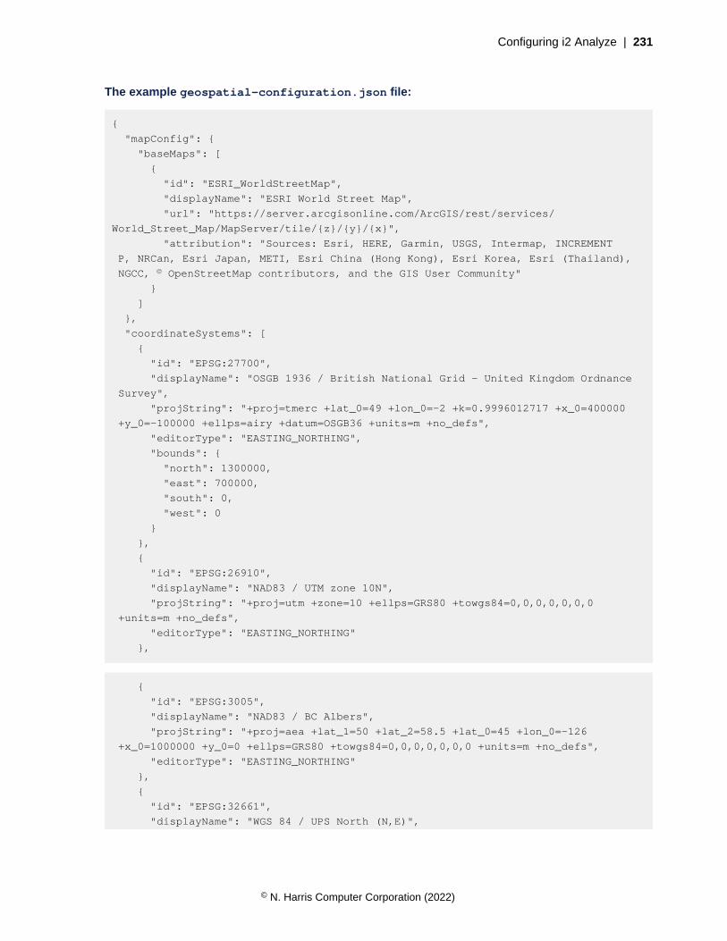
Configuring i2 Analyze | 231
The example geospatial-configuration.json file:
{
"mapConfig": {
"baseMaps": [
{
"id": "ESRI_WorldStreetMap",
"displayName": "ESRI World Street Map",
"url": "https://server.arcgisonline.com/ArcGIS/rest/services/
World_Street_Map/MapServer/tile/{z}/{y}/{x}",
"attribution": "Sources: Esri, HERE, Garmin, USGS, Intermap, INCREMENT
P, NRCan, Esri Japan, METI, Esri China (Hong Kong), Esri Korea, Esri (Thailand),
NGCC, © OpenStreetMap contributors, and the GIS User Community"
}
]
},
"coordinateSystems": [
{
"id": "EPSG:27700",
"displayName": "OSGB 1936 / British National Grid - United Kingdom Ordnance
Survey",
"projString": "+proj=tmerc +lat_0=49 +lon_0=-2 +k=0.9996012717 +x_0=400000
+y_0=-100000 +ellps=airy +datum=OSGB36 +units=m +no_defs",
"editorType": "EASTING_NORTHING",
"bounds": {
"north": 1300000,
"east": 700000,
"south": 0,
"west": 0
}
},
{
"id": "EPSG:26910",
"displayName": "NAD83 / UTM zone 10N",
"projString": "+proj=utm +zone=10 +ellps=GRS80 +towgs84=0,0,0,0,0,0,0
+units=m +no_defs",
"editorType": "EASTING_NORTHING"
},
{
"id": "EPSG:3005",
"displayName": "NAD83 / BC Albers",
"projString": "+proj=aea +lat_1=50 +lat_2=58.5 +lat_0=45 +lon_0=-126
+x_0=1000000 +y_0=0 +ellps=GRS80 +towgs84=0,0,0,0,0,0,0 +units=m +no_defs",
"editorType": "EASTING_NORTHING"
},
{
"id": "EPSG:32661",
"displayName": "WGS 84 / UPS North (N,E)",
© N. Harris Computer Corporation (2022)

Configuring i2 Analyze | 232
"projString": "proj4.defs(\"EPSG:32661\",\"+proj=stere +lat_0=90 +lat_ts=90
+lon_0=0 +k=0.994 +x_0=2000000 +y_0=2000000 +datum=WGS84 +units=m +no_defs\");",
"editorType": "EASTING_NORTHING"
},
{
"id": "EPSG:32761",
"displayName": "WGS 84 / UPS South (N,E)",
"projString": "+proj=stere +lat_0=-90 +lat_ts=-90 +lon_0=0 +k=0.994
+x_0=2000000 +y_0=2000000 +datum=WGS84 +units=m +no_defs",
"editorType": "EASTING_NORTHING"
},
{
"id": "EPSG:3857",
"displayName": "WGS 84 / Pseudo-Mercator -- Spherical Mercator, Google Maps,
OpenStreetMap, Bing, ArcGIS, ESRI",
"projString": "+proj=merc +a=6378137 +b=6378137 +lat_ts=0.0 +lon_0=0.0
+x_0=0.0 +y_0=0 +k=1.0 +units=m +nadgrids=@null +wktext +no_defs",
"editorType": "EASTING_NORTHING"
}
]
}
The geospatial-configuration.json file
The geospatial-configuration.json file contains definitions of the mapping tiles and coordinatereference systems to use in your deployment. You can use this reference and example informationwhen you create your own mapping configuration file.
Whether you choose to update the example provided, or create your own file, the geospatial-configuration.json contains the following key elements:
• mapConfig
• baseMaps
• overlays
• coordinateSystems
mapConfig
The mapConfig object defines the mapping tiles that are available.
The mapConfig object can contain a single instance of each of the following objects that are usedto define the mapping view and to provide defaults for all mapping layers that are defined in the file:
Option Description Type Default
center The geographic center of the map when it is firstopened.
The lat and lng fields are used to specify the centerpoint.
Lat/Long
Undefined
zoom The map zoom level when it is first opened. Number Undefined
© N. Harris Computer Corporation (2022)
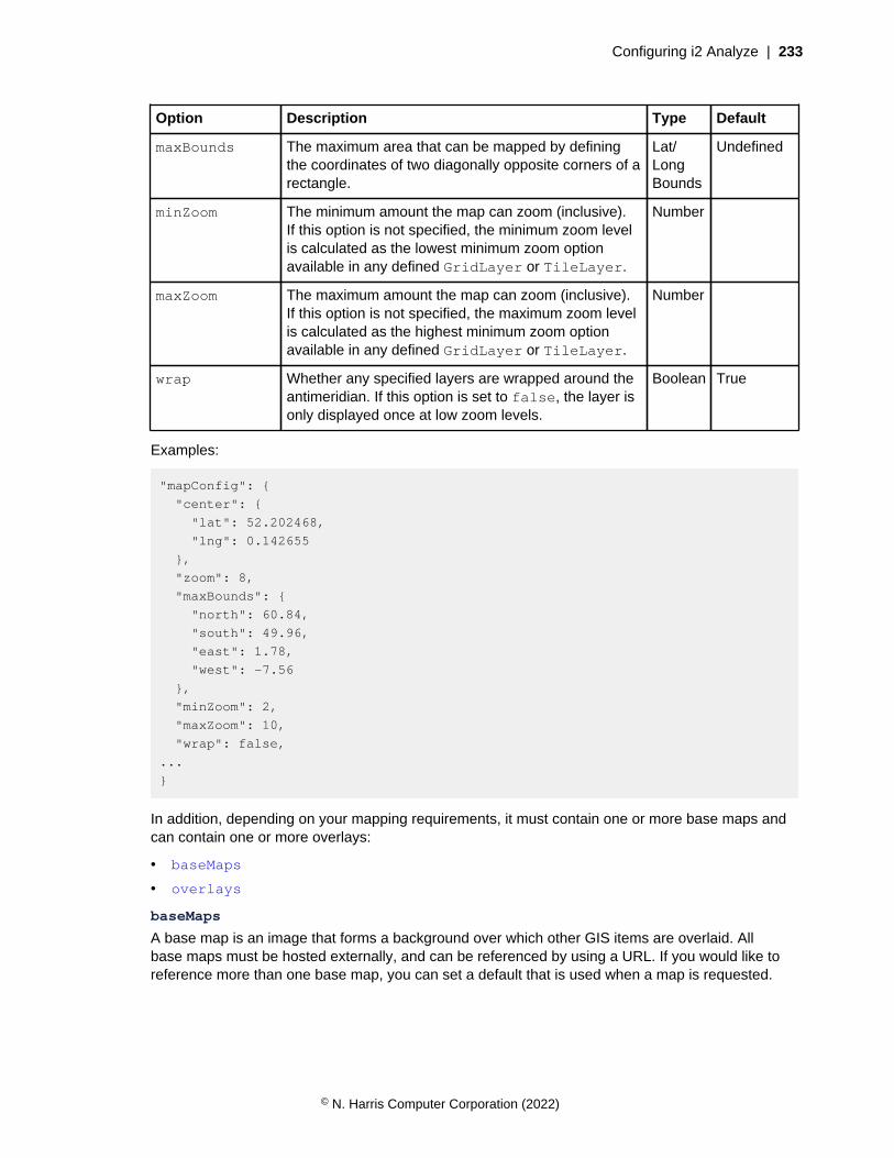
Configuring i2 Analyze | 233
Option Description Type Default
maxBounds The maximum area that can be mapped by definingthe coordinates of two diagonally opposite corners of arectangle.
Lat/LongBounds
Undefined
minZoom The minimum amount the map can zoom (inclusive).If this option is not specified, the minimum zoom levelis calculated as the lowest minimum zoom optionavailable in any defined GridLayer or TileLayer.
Number
maxZoom The maximum amount the map can zoom (inclusive).If this option is not specified, the maximum zoom levelis calculated as the highest minimum zoom optionavailable in any defined GridLayer or TileLayer.
Number
wrap Whether any specified layers are wrapped around theantimeridian. If this option is set to false, the layer isonly displayed once at low zoom levels.
Boolean True
Examples:
"mapConfig": {
"center": {
"lat": 52.202468,
"lng": 0.142655
},
"zoom": 8,
"maxBounds": {
"north": 60.84,
"south": 49.96,
"east": 1.78,
"west": -7.56
},
"minZoom": 2,
"maxZoom": 10,
"wrap": false,
...
}
In addition, depending on your mapping requirements, it must contain one or more base maps andcan contain one or more overlays:
• baseMaps
• overlays
baseMaps
A base map is an image that forms a background over which other GIS items are overlaid. Allbase maps must be hosted externally, and can be referenced by using a URL. If you would like toreference more than one base map, you can set a default that is used when a map is requested.
© N. Harris Computer Corporation (2022)
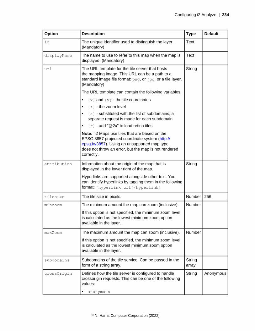
Configuring i2 Analyze | 234
Option Description Type Default
id The unique identifier used to distinguish the layer.(Mandatory)
Text
displayName The name to use to refer to this map when the map isdisplayed. (Mandatory)
Text
url The URL template for the tile server that hoststhe mapping image. This URL can be a path to astandard image file format: png, or jpg, or a tile layer.(Mandatory)
The URL template can contain the following variables:
• {x} and {y} - the tile coordinates
• {z} - the zoom level
• {s} - substituted with the list of subdomains, aseparate request is made for each subdomain
• {r} - add "@2x" to load retina tiles
Note: i2 Maps use tiles that are based on theEPSG:3857 projected coordinate system (http://epsg.io/3857). Using an unsupported map typedoes not throw an error, but the map is not renderedcorrectly.
String
attribution Information about the origin of the map that isdisplayed in the lower right of the map.
Hyperlinks are supported alongside other text. Youcan identify hyperlinks by tagging them in the followingformat: [hyperlink]url[/hyperlink]
String
tilesize The tile size in pixels. Number 256
minZoom The minimum amount the map can zoom (inclusive).
If this option is not specified, the minimum zoom levelis calculated as the lowest minimum zoom optionavailable in the layer.
Number
maxZoom The maximum amount the map can zoom (inclusive).
If this option is not specified, the minimum zoom levelis calculated as the lowest minimum zoom optionavailable in the layer.
Number
subdomains Subdomains of the tile service. Can be passed in theform of a string array.
Stringarray
crossOrigin Defines how the tile server is configured to handlecrossorigin requests. This can be one of the followingvalues:
• anonymous
String Anonymous
© N. Harris Computer Corporation (2022)
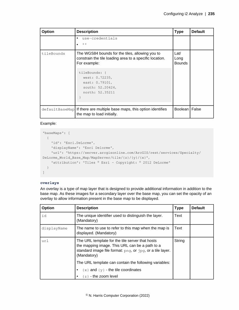
Configuring i2 Analyze | 235
Option Description Type Default
• use-credentials
• ""
tileBounds The WGS84 bounds for the tiles, allowing you toconstrain the tile loading area to a specific location.For example:
tileBounds: {
west: 0.72235,
east: 0.79101,
south: 52.20424,
north: 52.35211
}
Lat/LongBounds
defaultBaseMap If there are multiple base maps, this option identifiesthe map to load initially.
Boolean False
Example:
"baseMaps": [
{
"id": "Esri.DeLorme",
"displayName": "Esri Delorme",
"url": "https://server.arcgisonline.com/ArcGIS/rest/services/Specialty/
DeLorme_World_Base_Map/MapServer/tile/{z}/{y}/{x}",
"attribution": "Tiles © Esri — Copyright: © 2012 DeLorme"
}
]
overlays
An overlay is a type of map layer that is designed to provide additional information in addition to thebase map. As these images for a secondary layer over the base map, you can set the opacity of anoverlay to allow information present in the base map to be displayed.
Option Description Type Default
id The unique identifier used to distinguish the layer.(Mandatory)
Text
displayName The name to use to refer to this map when the map isdisplayed. (Mandatory)
Text
url The URL template for the tile server that hoststhe mapping image. This URL can be a path to astandard image file format: png, or jpg, or a tile layer.(Mandatory)
The URL template can contain the following variables:
• {x} and {y} - the tile coordinates
• {z} - the zoom level
String
© N. Harris Computer Corporation (2022)

Configuring i2 Analyze | 236
Option Description Type Default
• {s} - substituted with the list of subdomains, aseparate request is made for each subdomain
• {r} - add "@2x" to load retina tiles
Note: i2 Maps use tiles that are based on theEPSG:3857 projected coordinate system (http://epsg.io/3857). Using an unsupported map typedoes not throw an error, but the map is not renderedcorrectly.
attribution Information about the origin of the map that isdisplayed in the lower right of the map.
Hyperlinks are supported alongside other text. Youcan identify hyperlinks by tagging them in the followingformat: [hyperlink]url[/hyperlink]
String
tilesize The tile size in pixels. Number 256
minZoom The minimum amount the map can zoom (inclusive).
If this option is not specified, the minimum zoom levelis calculated as the lowest minimum zoom optionavailable in the layer.
Number
maxZoom The maximum amount the map can zoom (inclusive).
If this option is not specified, the minimum zoom levelis calculated as the lowest minimum zoom optionavailable in the layer.
Number
subdomains Subdomains of the tile service. Can be passed in theform of a string array.
Stringarray
crossOrigin Defines how the tile server is configured to handlecrossorigin requests. This can be one of the followingvalues:
• anonymous
• use-credentials
• ""
String Anonymous
tileBounds The WGS84 bounds for the tiles, allowing you toconstrain the tile loading area to a specific location.For example:
tileBounds: {
west: 0.72235,
east: 0.79101,
south: 52.20424,
north: 52.35211
}
Lat/LongBounds
© N. Harris Computer Corporation (2022)
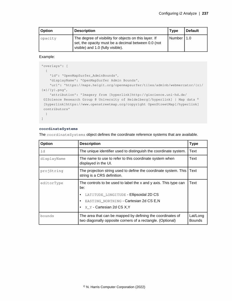
Configuring i2 Analyze | 237
Option Description Type Default
opacity The degree of visibility for objects on this layer. Ifset, the opacity must be a decimal between 0.0 (notvisible) and 1.0 (fully visible).
Number 1.0
Example:
"overlays": [
{
"id": "OpenMapSurfer_AdminBounds",
"displayName": "OpenMapSurfer Admin Bounds",
"url": "https://maps.heigit.org/openmapsurfer/tiles/adminb/webmercator/{z}/
{x}/{y}.png",
"attribution": "Imagery from [hyperlink]http://giscience.uni-hd.de/
GIScience Research Group @ University of Heidelberg[/hyperlink] | Map data ©
[hyperlink]https://www.openstreetmap.org/copyright OpenStreetMap[/hyperlink]
contributors"
}
]
coordinateSystems
The coordinateSystems object defines the coordinate reference systems that are available.
Option Description Type
id The unique identifier used to distinguish the coordinate system. Text
displayName The name to use to refer to this coordinate system whendisplayed in the UI.
Text
projString The projection string used to define the coordinate system. Thisstring is a CRS definition.
Text
editorType The controls to be used to label the x and y axis. This type canbe:
• LATITUDE_LONGITUDE - Ellipsoidal 2D CS
• EASTING_NORTHING - Cartesian 2d CS E,N
• X_Y - Cartesian 2d CS X,Y
Text
bounds The area that can be mapped by defining the coordinates oftwo diagonally opposite corners of a rectangle. (Optional)
Lat/LongBounds
© N. Harris Computer Corporation (2022)
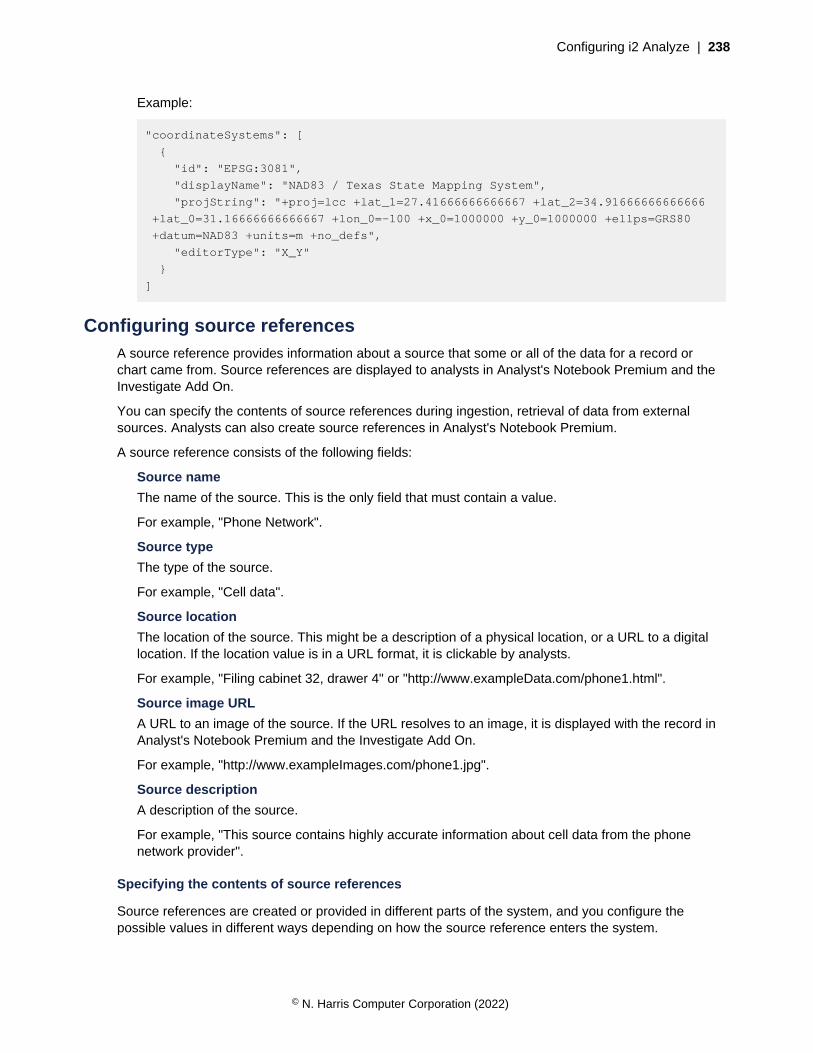
Configuring i2 Analyze | 238
Example:
"coordinateSystems": [
{
"id": "EPSG:3081",
"displayName": "NAD83 / Texas State Mapping System",
"projString": "+proj=lcc +lat_1=27.41666666666667 +lat_2=34.91666666666666
+lat_0=31.16666666666667 +lon_0=-100 +x_0=1000000 +y_0=1000000 +ellps=GRS80
+datum=NAD83 +units=m +no_defs",
"editorType": "X_Y"
}
]
Configuring source referencesA source reference provides information about a source that some or all of the data for a record orchart came from. Source references are displayed to analysts in Analyst's Notebook Premium and theInvestigate Add On.
You can specify the contents of source references during ingestion, retrieval of data from externalsources. Analysts can also create source references in Analyst's Notebook Premium.
A source reference consists of the following fields:
Source name
The name of the source. This is the only field that must contain a value.
For example, "Phone Network".
Source type
The type of the source.
For example, "Cell data".
Source location
The location of the source. This might be a description of a physical location, or a URL to a digitallocation. If the location value is in a URL format, it is clickable by analysts.
For example, "Filing cabinet 32, drawer 4" or "http://www.exampleData.com/phone1.html".
Source image URL
A URL to an image of the source. If the URL resolves to an image, it is displayed with the record inAnalyst's Notebook Premium and the Investigate Add On.
For example, "http://www.exampleImages.com/phone1.jpg".
Source description
A description of the source.
For example, "This source contains highly accurate information about cell data from the phonenetwork provider".
Specifying the contents of source references
Source references are created or provided in different parts of the system, and you configure thepossible values in different ways depending on how the source reference enters the system.
© N. Harris Computer Corporation (2022)

Configuring i2 Analyze | 239
Ingestion source references
The values for source reference name and description are taken from the ingestion source nameand description that is specified in the mapping file that is used when you ingest the data.
Records acquire a source reference during the ingestion process. You can provide values for thesource reference type, location, and image URL fields for each row in the staging table when youingest data into the Information Store.
For more information about providing values for this type of source reference, see Information Storestaging tables.
Analyst-created source references
Analysts can add source references to records and charts by using Analyst's Notebook Premium.You can constrain the values that analysts can use for the source reference name and type fields.
For more information about configuring these values, see Configuring analyst-created sourcereferences on page 239.
Connector source references
When records are retrieved from an external data source via the i2 Connect gateway, the connectorimplementation can provide a source reference.
For more information about implementing source references into your connectors, see Returningsource references.
Configuring analyst-created source references
Analysts can create source references on i2 Analyze records and charts by using the Record Inspectoror Chart Inspector in Analyst's Notebook Premium. By default, analysts can use any values for thesource reference name and type, but you can restrict the values that are available for them to use.
It is recommended that you configure analyst-created source references in your configurationdevelopment environment before you implement them in your production environment.
You can restrict the values that analysts can specify for the source name and source type for each itemtype and for charts. Analysts can provide single-line string values, or you can define selected-from orsuggested-from lists that they can choose from. You might choose to restrict the values that analystscan specify to improve the quality of the source references in a system. By enforcing selected-from lists,you can ensure consistent names within your system.
If you follow this procedure in a deployment that provides high availability, you must complete each stepon every Liberty server in your environment before you move to the next step.
1. Enable the use of the source reference schema.
a) Create your source-reference-schema.xml file XML schema file in the configuration\fragments\opal-services\WEB-INF\classes directory.
b) Specify your source reference schema file name as the value for theSourceReferenceSchemaResource property in the configuration\fragments\opal-services\WEB-INF\classes\DiscoServerSettingsCommon.properties file.For example:
SourceReferenceSchemaResource=source-reference-schema.xml
2. Modify the source reference schema configuration file.
© N. Harris Computer Corporation (2022)

Configuring i2 Analyze | 240
a) Open your XSD aware XML editor. For more information see Setting up your XSD aware XMLeditor on page 321.
The associated XSD file is: toolkit\scripts\xsd\SourceReferenceSchema.xsd.
b) In your XML editor, open your source-reference-schema.xml file.
c) Using the reference and example information, modify the file to define the values that analystscan use.
3. Update the deployment with your changes. On the Liberty server, in a command prompt navigate tothe toolkit\scripts directory:
setup -t deployLiberty
setup -t startLiberty
4. Test the source reference schema that you created.
a) In Analyst's Notebook Premium, use the Record Inspector or Chart Inspector to create sourcereferences on records and charts.
In Analyst's Notebook Premium, you must log out and log in again to see your changes.
b) Ensure that the values that analysts can use meet your requirements.
Complete this process as many times as necessary until the source reference schema meets yourrequirements.
The source-reference-schema.xml file
The source reference schema XML file has the following structure. You can use this reference andexample information when you create your own source reference schema file.
• <sourceReferenceSchema>
• <sourceReferenceSchemaFragments><sourceReferenceSchemaFragment>
• <sourceName>
• <sourceType>
• <possibleValues><possibleValue>
<sourceReferenceSchema>
The <sourceReferenceSchema> element is the root of the configuration file.
<sourceReferenceSchemaFragments><sourceReferenceSchemaFragment>
The <sourceReferenceSchemaFragments> element can contain one or more<sourceReferenceSchemaFragment> child elements.
The <sourceReferenceSchemaFragment> defines the values that analysts can use for thesource name and source type for a particular set of item types.
The itemTypeIds attribute specifies the item types within a set. You must use the item type IDsthat come from the i2 Analyze schema for the itemTypeIds attribute. You can specify multipleitem type IDs as a comma-separated list. If you do not specify any item type IDs, the restrictionsapply to all item types that are not referenced elsewhere in the source reference schema.
© N. Harris Computer Corporation (2022)

Configuring i2 Analyze | 241
For example, to make a set for the source references associated with charts and the item type withID "ET5":
<sourceReferenceSchemaFragments>
<sourceReferenceSchemaFragment itemTypeIds="CHART,ET5">
...
</sourceReferenceSchemaFragments>
The <sourceReferenceSchemaFragment> can contain one child <sourceName> element andone child <sourceType> element.
<sourceName>
The <sourceName> element contains the possible values that analysts can use as a source name.
The logicalType attribute defines whether analysts must choose a value or can provide their ownvalues. The values for the logicalType attribute are:
• SELECTED_FROM - You provide a list of source names that analysts can use.
• SUGGESTED_FROM - You provide a list of source names that analysts can use and they cancreate their own.
• SINGLE_LINE_STRING - Analysts create their own source names.
If you specify the SELECTED_FROM or SUGGESTED_FROM logical types, use the child<possibleValues> element to specify the values that analysts can use.
<sourceType>
The <sourceType> element contains the possible values that analysts can use as a source type.
The logicalType attribute defines whether analysts must choose a value or can provide their ownvalues. The values for the logicalType attribute are:
• SELECTED_FROM - You provide a list of source types that analysts can use.
• SUGGESTED_FROM - You provide a list of source types that analysts can use and they can createtheir own.
• SINGLE_LINE_STRING - Analysts create their own source types.
The mandatory attribute defines whether analysts must specify a value for the source type whenthey create a source reference. The possible values are true and false.
If you specify the SELECTED_FROM or SUGGESTED_FROM logical types, use the child<possibleValues> element to specify the values that analysts can use.
<possibleValues><possibleValue>
The <possibleValues> element contains child <possibleValue> elements. You canspecify the <possibleValues> element when its parent element specifies SELECTED_FROM orSUGGESTED_FROM for the logicalType attribute.
The value attribute of the <possibleValue> element contains the value that is displayed toanalysts to select.
Example
In this example, analysts can create source references for charts with the source name "Local PoliceDepartment" or "Analyst Team 1" to describe the source of the chart.
© N. Harris Computer Corporation (2022)
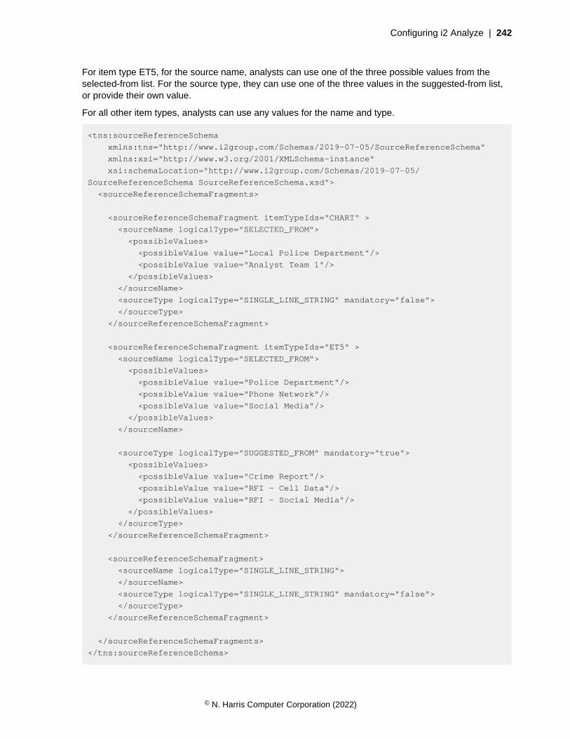
Configuring i2 Analyze | 242
For item type ET5, for the source name, analysts can use one of the three possible values from theselected-from list. For the source type, they can use one of the three values in the suggested-from list,or provide their own value.
For all other item types, analysts can use any values for the name and type.
<tns:sourceReferenceSchema
xmlns:tns="http://www.i2group.com/Schemas/2019-07-05/SourceReferenceSchema"
xmlns:xsi="http://www.w3.org/2001/XMLSchema-instance"
xsi:schemaLocation="http://www.i2group.com/Schemas/2019-07-05/
SourceReferenceSchema SourceReferenceSchema.xsd">
<sourceReferenceSchemaFragments>
<sourceReferenceSchemaFragment itemTypeIds="CHART" >
<sourceName logicalType="SELECTED_FROM">
<possibleValues>
<possibleValue value="Local Police Department"/>
<possibleValue value="Analyst Team 1"/>
</possibleValues>
</sourceName>
<sourceType logicalType="SINGLE_LINE_STRING" mandatory="false">
</sourceType>
</sourceReferenceSchemaFragment>
<sourceReferenceSchemaFragment itemTypeIds="ET5" >
<sourceName logicalType="SELECTED_FROM">
<possibleValues>
<possibleValue value="Police Department"/>
<possibleValue value="Phone Network"/>
<possibleValue value="Social Media"/>
</possibleValues>
</sourceName>
<sourceType logicalType="SUGGESTED_FROM" mandatory="true">
<possibleValues>
<possibleValue value="Crime Report"/>
<possibleValue value="RFI - Cell Data"/>
<possibleValue value="RFI - Social Media"/>
</possibleValues>
</sourceType>
</sourceReferenceSchemaFragment>
<sourceReferenceSchemaFragment>
<sourceName logicalType="SINGLE_LINE_STRING">
</sourceName>
<sourceType logicalType="SINGLE_LINE_STRING" mandatory="false">
</sourceType>
</sourceReferenceSchemaFragment>
</sourceReferenceSchemaFragments>
</tns:sourceReferenceSchema>
© N. Harris Computer Corporation (2022)

Configuring i2 Analyze | 243
Securing i2 AnalyzeDepending on the requirements of the deployment, you can configure your deployment to use additionalsecurity mechanisms.
Secure Sockets Layer connections with i2® Analyze
Secure Sockets Layer (SSL) technology can be used to establish an encrypted connection between aclient and server. You can use SSL to ensure that communication between i2 Analyze components isencrypted.
Depending on your topology and requirements, you can configure SSL for the following connections:
• The client and the HTTP server
• The HTTP server and Liberty
• Liberty, ZooKeeper, and Solr
• Liberty and the database management system
For information about securing the connection between Liberty and any i2 Connectors, see clientauthenticated Secure Sockets Layer with the i2 Connect gateway.
The version of the TLS protocol that is supported by i2 Analyze is TLS V1.2.
The instructions are intended for readers who are familiar with configuring i2® Analyze, securing networkconnections, and managing SSL key authentication certificates. Refer also to the documentation for theindividual components: IBM HTTP Server, Liberty, Solr, ZooKeeper, Db2, or Microsoft SQL Server.
The instructions are based on a sample scenario for a single-server deployment. The instructionsuse self-signed certificates to demonstrate working SSL configurations. During the process ofcreating a production deployment, you can configure SSL in the pre-production environment. In aproduction deployment, you must use certificates that are signed by a trusted certificate authority. Formore information about implementing SSL in a deployment on multiple servers, see the distributeddeployment example on GitHub.
Important: At this release, if you configure Solr to use SSL after it is deployed without it, you must re-create your Solr collections. Aim to configure Solr to use SSL before you ingest a large amount of datainto your system.
Attention: i2 takes reasonable steps to verify the suitability of i2® Analyze for internetdeployment. However, it does not address lower-level issues such as guarding networks againstpenetration, securing accounts, protecting against brute force attacks, configuring firewalls toavoid DoS or DDoS attacks, and the like. For your deployment of i2® Analyze, follow industry-standard practices and recommendations for protection of your systems. i2 accepts no liabilityfor the consequences of such attacks on your systems. This information is not intended toprovide instructions for managing key databases or certificates.
Connections between components of i2 Analyze
Depending on your deployment pattern, i2 Analyze connections can involve the client, the HTTPserver, Liberty, the database management system, Solr, and ZooKeeper. You can choose to secureconnections by using SSL.
The physical architecture and the network topology of an i2 Analyze deployment determine howappropriate it is to use SSL to secure its connections. For example, if two parts of the deployment areon a single server that you physically control, then the need for SSL to secure the connection between
© N. Harris Computer Corporation (2022)

Configuring i2 Analyze | 244
them might be reduced. If your deployment contains a firewall, then you might need to weigh thebenefits of inspecting traffic against the benefits of encrypting it.
Note: To enable access to i2 Analyze through the i2 Notebook web client, you must use SSL to securethe connection between the browser and the HTTP server. i2 Notebook requires the HTTPS protocol.
The following diagram shows the connections in a deployment that you can use SSL to secure:
IBM HTTP Server
Liberty
Clients
Server
i2 Analyze application
Analyst's Notebook Premium
Investigate Add-on
Database management system
Information Store
1.
3.
2.
ZooKeeper
3.
Solr
4.
The numbered connections in the diagram are as follows:
1. The connections between the clients and the HTTP server.
2. The connection between the HTTP server and Liberty.
3. The connections between Liberty, ZooKeeper, and Solr.
4. The connection between Liberty and the database management system.
To secure connection 2, you must first secure connection 1. To secure connections 3 and 4, you mustfirst secure connections 1 and 2.
© N. Harris Computer Corporation (2022)
Configuring i2 Analyze | 245
SSL certificates for i2 Analyze
SSL communication relies on encryption, keys, and certificates to initiate a secure connection. Thecertificates are stored in keystore files on the client and the server.
Certificates are exchanged to establish trust during the handshake process that initiates a secureconnection. When a certificate is granted through a certificate authority, that certificate can be trusted bythe clients or applications that trust certificates that are signed by that authority. A public key certificatethat authenticates a server is stored in a keystore file on the server. Trusted certificate authoritycertificates are stored in the client's truststore file.
As part of the SSL handshake process, certificates are exchanged that are signed by a trustedcertificate authority to verify that a certificate is authentic. The environment where you are deploying i2Analyze might already have a well-defined certificate process that you can use to obtain certificates andpopulate the required key and truststores.
The examples in the following procedures use self-signed certificates to demonstrate working SSLconfigurations. In a production deployment, you must use certificates that are signed by a trustedcertificate authority.
If all of the public key certificates are signed by the same certificate authority, then you can add thecertificate authority's certificate to each of your truststores. If you have a number of certificates toauthenticate trust, you might have to add multiple certificates to your truststores.
In the examples, the self-signed certificate is created in a keystore, exported, and imported to therelevant truststore. When you configure SSL communication between components of i2 Analyze, youmust have the required certificates in the correct keystores. In the following procedures, examplescommands are provided for creating, exporting, and importing self-signed certificates.
SSL keystores for i2 Analyze
To use SSL to secure a connection between components, i2 Analyze requires Java KeyStore (JKS)or Certificate Management System (CMS) key database files depending on the components. Thekeystore contains the certificate that acts as the identity of the server and the truststore contains a list ofcertificates that are trusted by a server.
A JKS file is a repository of security certificates that is used in SSL encryption. In WebSphere® Libertyand Solr, a file with extension .jks serves as a keystore.
IBM Global Security Kit (GSKit) is a common component that is used by IBM HTTP Server and Db2for its cryptographic and SSL capabilities. CMS is the native GSKit key database (keystore) thatcontains certificates. GSKit stores public and private keys and certificates in a key database. A keydatabase consists of a file with a .kdb extension and up to three other files with .sth, .rdb, and .crlextensions. You must save the key database password to a stash file on your computer.
The following diagram shows where these files are used in the components of i2 Analyze and theconnections between them.
© N. Harris Computer Corporation (2022)

Configuring i2 Analyze | 246
IBM HTTP Server
Liberty
Clients
Server
i2 Analyze application
Analyst's Notebook Premium
Investigate Add-on
Database management system
Information Store
ZooKeeper
Solr
Truststore
KeystoreTruststore
Keystore Truststore
Keystore
Keystore Truststore
Keystore Truststore
The environment in which you are deploying i2 Analyze might already contain files that are candidatesfor use as keystores or truststores. If not, you must create the required files. The files that are requiredin the sample scenario that is described in the instructions are summarized by component, in thefollowing list.
IBM HTTP Server
To enable SSL connections, the HTTP server requires a CMS key database (*.kdb). Thepassword for this key database must be saved to a stash file. A certificate in the key databaseidentifies the HTTP server and is used when clients connect to i2 Analyze so that they canauthenticate the HTTP server. This key database is also used as a truststore to authenticate thecertificate that it receives from Liberty.
The i2 Analyze client's truststore, usually located in the operating system or web browser, is used toauthenticate the certificate that it receives from the HTTP server.
WebSphere® Application Server Liberty
The Liberty server requires a keystore file (*.jks) and a truststore file (*.jks).
A certificate in the keystore identifies the Liberty server and is used to connect to the HTTP server.The HTTP server key database authenticates this certificate that it receives from Liberty.
© N. Harris Computer Corporation (2022)
Configuring i2 Analyze | 247
The certificate in the Liberty truststore is used to authenticate certificates that are received from thedatabase management system keystore and the Solr keystore.
Solr
Each Solr server requires a keystore file (*.jks) and a truststore file (*.jks). Solr requires thatall Solr certificates are available in the Solr truststores and the Liberty truststore, so that individualnodes can trust one another, and Liberty can trust the Solr nodes. When you enable ZooKeeper touse SSL, the Solr certificate must also be trusted by the ZooKeeper truststore.
The certificate in the Solr keystore identifies the Solr server and is used to connect to Liberty, andZooKeeper if it is configured for SSL.
The certificate in the Solr keystore also identifies each Solr node and is used to authenticate secureconnection within Solr itself, using the Solr truststore. The certificate in the Solr truststore is used toauthenticate the certificate that it received from the Solr keystore.
ZooKeeper
Each ZooKeeper server requires a keystore file (*.jks) and a truststore file (*.jks). ZooKeeperrequires that all ZooKeeper certificates are available in the ZooKeeper truststores and the Libertytruststore. This enables the individual servers to trust one another, and Liberty can trust theZooKeeper servers. Additionally, the Solr certificate must be in the ZooKeeper truststore so thatZooKeeper can trust Solr.
The certificate in the ZooKeeper keystore identifies the ZooKeeper server and is used to connect toLiberty.
The certificate in the ZooKeeper keystore also identifies each ZooKeeper server and is used toauthenticate secure connections between the servers in the ZooKeeper quorum, by using theZooKeeper truststore. The certificate in the ZooKeeper truststore is used to authenticate thecertificate that is received from the ZooKeeper keystore.
Database management system
To enable SSL connections, the database management system requires a keystore to connectto Liberty. The type of keystore depends on the type of database management system. For moreinformation about SSL in your database management system, see Configuring SSL for a Db2instance on page 256 or Configuring SSL for Microsoft SQL Server on page 258.
The certificate in the database management system keystore identifies the database managementsystem server and is used to connect to Liberty.
In the following procedures, example commands are provided for creating the keystores, certificates,and truststores to use with each component of i2 Analyze. The instructions contain details that arebased on a single-server deployment example.
Securing the connection between clients and the HTTP server
i2 Analyze supports the use of SSL to secure the connections between the clients and the HTTP server.After you configure the connections between the clients and the HTTP server, you can opt to configurethe connection between the HTTP server and WebSphere Liberty.
Note: To enable access to i2 Analyze through the i2 Notebook web client, you must use SSL to securethe connection between the browser and the HTTP server. i2 Notebook requires the HTTPS protocol.
To connect to i2 Analyze by using SSL, the client workstation must first trust the HTTP server becausethe client connects to i2 Analyze through the HTTP server. Trust is established through a certificate thatis associated with the HTTP server and trusted by the client workstation.
© N. Harris Computer Corporation (2022)
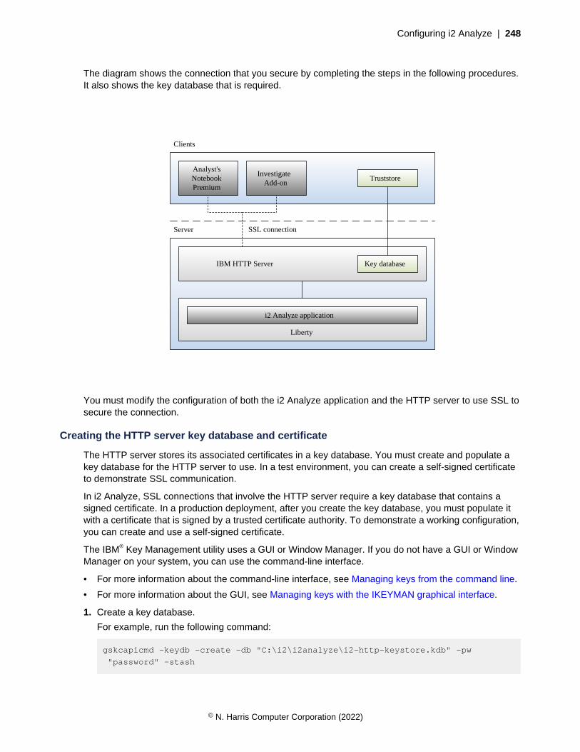
Configuring i2 Analyze | 248
The diagram shows the connection that you secure by completing the steps in the following procedures.It also shows the key database that is required.
IBM HTTP Server
Liberty
Clients
Server
i2 Analyze application
Analyst's Notebook Premium
Investigate Add-on
Truststore
Key database
SSL connection
You must modify the configuration of both the i2 Analyze application and the HTTP server to use SSL tosecure the connection.
Creating the HTTP server key database and certificate
The HTTP server stores its associated certificates in a key database. You must create and populate akey database for the HTTP server to use. In a test environment, you can create a self-signed certificateto demonstrate SSL communication.
In i2 Analyze, SSL connections that involve the HTTP server require a key database that contains asigned certificate. In a production deployment, after you create the key database, you must populate itwith a certificate that is signed by a trusted certificate authority. To demonstrate a working configuration,you can create and use a self-signed certificate.
The IBM® Key Management utility uses a GUI or Window Manager. If you do not have a GUI or WindowManager on your system, you can use the command-line interface.
• For more information about the command-line interface, see Managing keys from the command line.
• For more information about the GUI, see Managing keys with the IKEYMAN graphical interface.
1. Create a key database.
For example, run the following command:
gskcapicmd -keydb -create -db "C:\i2\i2analyze\i2-http-keystore.kdb" -pw
"password" -stash
© N. Harris Computer Corporation (2022)
Configuring i2 Analyze | 249
• Save a password for the key database to a stash file by using the -stash attribute.
• Set -db location to the directory that contains the toolkit directory in your deployment.
2. Create a self-signed certificate.
For example, run the following command:
gskcapicmd -cert -create -db "C:\i2\i2analyze\i2-http-keystore.kdb" -label
"httpKey" -dn "CN=hostname" -san_dnsname "hostname" -pw "password" -sigalg
sha256 -size 2048
Important: Set the value of CN and san_dnsname to the fully qualified domain name for host nameof the server that hosts the HTTP server. The URL that you use to connect to i2 Analyze must usethe same value for the host name as the value of the CN. The password is the one that you saved tothe stash file in step 1.
3. Extract the certificate from the key database.
For example, run the following command:
gskcapicmd -cert -extract -db "C:\i2\i2analyze\i2-http-keystore.kdb" -label
"httpKey" -target "C:\i2\i2analyze\i2-http-certificate.cer" -pw "password"
Set the location of the certificate to the same directory as the key database.
To enable SSL connections to i2® Analyze, the certificate that you added to, or created in, the keydatabase must be installed to be trusted on each client workstation.
Installing the certificate on client workstations
To enable SSL connections to i2® Analyze, the certificate in the key database must be trusted on eachclient workstation.
The following steps describe how to install and trust the self-signed certificate on a Windows client. Toinstall the certificate on Linux workstations, see the documentation for your operating system.
1. Copy the certificate to any folder on the client workstation.
2. To install the certificate, complete the following steps:
a) Double-click the certificate file.
b) Click Install Certificate, and then click Next.
c) Click Place all certificates in the following store.
d) Click Browse, select Trusted Root Certification Authorities, and click OK.
e) Click Next, and then click Finish.
Note: If the certificate is self-signed, Windows displays a security warning because it cannotverify the self-signed certificate. Click Yes to accept the certificate.
Configuring the HTTP server for SSL
In a default deployment of i2® Analyze, SSL is unavailable. To enable clients to connect through SSL,you must modify the configuration of both the i2 Analyze application and the HTTP server.
Ensure that the following attributes of the <application> element in the topology.xml are setcorrectly:
© N. Harris Computer Corporation (2022)

Configuring i2 Analyze | 250
• The http-server-host attribute is set to true
• Ensure that the host-name attribute is set to the name of the server that you are running Liberty on.
For more information about modifying the topology file, see Modifying the topology.
1. Stop the HTTP server.
Run the command to stop the HTTP server, C:\IBM\HTTPserver\bin\httpd -k stop.
2. Edit the http-server.properties file.
a) Navigate to the toolkit\configuration\environment directory, and open the http-server.properties file in a text editor.
b) Set the http.server.ssl.enabled property to true.
c) Set the http.server.keystore.file property to the location of the key database file of yourHTTP server.For example, C:/i2/i2analyze/i2-http-keystore.kdb.
d) Set the http.server.keystore.certificate.label property to the label of the HTTPserver certificate that is in the key database file. For example, httpKey.
3. Open a command prompt and navigate to the toolkit\scripts directory.
4. To deploy i2® Analyze with the edited http-server.properties file, and to install the SSLconfiguration on the HTTP server, run the following commands.
setup -t deployLiberty
setup -t configureHttpServer
The httpd.conf and plugin-cfg.xml files are updated to use the SSL configuration.
5. Start Liberty.
To start Liberty, run the following command on each Liberty server:
setup -t startLiberty
6. Restart the HTTP server.
Run the command to start the HTTP server, C:\IBM\HTTPserver\bin\httpd -k start.
If you modified the FrontEndURI property in your deployment, you must update it to use the HTTPSprotocol. For more information about changing the FrontEndURI property, see Deploying a proxyserver for use with i2 Analyze on page 75.
To test that the connection is using SSL in your deployment, see Testing SSL in an i2 Analyzedeployment on page 250.
Testing SSL in an i2 Analyze deployment
To ensure that a deployment allows only connections that use SSL, you can access it from a clientworkstation.
• The certificate that the client receives from the HTTP server must be trusted on the clientworkstation. For more information, see Installing the certificate on client workstations on page 249.
• The Liberty application server must be running.
To connect to i2 Analyze from Analyst's Notebook Premium, you must install the Opal Connector. Formore information about installing the Analyst's Notebook Premium, see Installing i2 Analyst's NotebookPremium.
© N. Harris Computer Corporation (2022)
Configuring i2 Analyze | 251
Open Analyst's Notebook Premium and connect to i2 Analyze at the URL https://host_name/opal.
host_name is the fully qualified domain name or IP address of the HTTP server, and matches theCommon Name value of the certificate.
Note: You cannot connect by using the HTTP protocol http://host_name/opal.
When you connect to i2 Analyze, the connection is secure.
Securing connections with Liberty
You can use SSL to secure the connection between WebSphere® Liberty and the HTTP server, thedatabase management system, and Solr. To secure connections in i2 Analyze, the HTTP server musttrust the certificate that it receives from Liberty and Liberty must trust the certificates that it receives fromthe database management system and Solr.
i2 Analyze uses a Java keystore to contain the certificate that is required to identify the i2 Analyzeserver when it connects with the HTTP server.
i2 Analyze uses a Java truststore to verify the certificates that are received from the databasemanagement system, and Solr.
For more information, see SSL keystores for i2 Analyze on page 245.
Creating the Liberty keystore and certificate
WebSphere® Liberty stores certificates in Java keystore files (.jks). Follow the procedure to create aJava keystore and export the appropriate certificates.
The following steps use a self-signed certificate. In a production environment, use or request a signedcertificate for Liberty from a certificate authority. Place this certificate in the Liberty keystore.
Create a keystore and self-signed certificate for Liberty by using the Java keytool utility.
For more information, see keytool - Key and Certificate Management Tool.
a) Open a command prompt and navigate to the i2analyze\deploy\java\bin directory.
b) Create a keystore and certificate.
For example, run the following command:
keytool -genkeypair -alias "libertyKey" -keystore "C:\i2\i2analyze\i2-liberty-
keystore.jks" -dname "CN=hostname" -keyalg RSA -storepass "password" -ext
san=dns:hostname
Important: Ensure that you provide values as follows:
• Enter a unique alias.
• Set the location of the keystore to the directory that contains the toolkit.
• Set the value of CN and san=dns to the hostname of the server that hosts Liberty.
• Assign a secure password.
c) Export the certificate from the Liberty keystore.
For example, run the following command:
keytool -exportcert -alias "libertyKey" -keystore "C:\i2\i2analyze\i2-liberty-
keystore.jks" -file "C:\i2\i2analyze\i2-liberty-certificate.cer" -storepass
"password"
© N. Harris Computer Corporation (2022)

Configuring i2 Analyze | 252
If you are using self-signed certificates, add the certificate that you exported from your Liberty keystoreto the HTTP server key database. For more information, see Adding the Liberty certificate to the HTTPkey database on page 253.
Configuring Liberty for SSL
To secure the connection between WebSphere® Liberty and other components in i2 Analyze, you mustconfigure Liberty for SSL. Update the configuration with the location of a keystore and truststore to use,and the passwords that are used to access the certificates that are contained within them.
Create a keystore and truststore for Liberty that contain the required certificates. For more information,see Creating the Liberty keystore and certificate on page 251.
Modify the i2 Analyze topology.xml file to specify that a secure connection must be used with theapplication server. Then, update the credentials.properties file to specify the password for theLiberty keystore and truststore files.
When the procedure is complete, it is only possible to connect to Liberty by the HTTPS protocol thatuses the secure port that is defined in the port definition properties file. The non-secure port cannot beused.
1. In an XML editor, open the toolkit\configuration\environment\topology.xml file.
a) In the <application> element for the application server to secure, add the secure-connection attribute with the value of true.For example, add the attribute as highlighted in the following code:
<application http-server-host="true" name="opal-server"
host-name="hostname" secure-connection="true">
Note: The host-name attribute value must match the common name that is associated with thecertificate for the application server.
b) Add the <key-stores> element as a child of the <application> element. Then, add a child<key-store> element.
For your keystore, specify the type as key-store and file as the full path to your keystore.
For example, add the attribute as highlighted in the following code:
<application http-server-host="true" name="opal-server"
host-name="hostname" secure-connection="true">
...
<key-stores>
<key-store type="key-store"
file="C:/i2/i2analyze/i2-liberty-keystore.jks"/>
</key-stores>
...
</application>
2. Specify the keystore passwords in the credentials file.
a) In a text editor, open the toolkit\configuration\environment\credentials.properties file.
b) Enter the password for the keystore that you specified in the topology.xml file.
ssl.keystore.password=password
© N. Harris Computer Corporation (2022)

Configuring i2 Analyze | 253
3. Update the application with your configuration changes. For more information, see RedeployingLiberty on page 321.
You must secure the connection between the HTTP Server and Liberty. For more information, seeSecuring the connection between the HTTP server and Liberty on page 253.
Securing the connection between the HTTP server and Liberty
Use SSL to secure the connection between the HTTP server and WebSphere® Liberty. The HTTPserver key database and the Liberty truststore must contain the required certificates.
• Secure the connection between clients and the HTTP server. For more information, see Securing theconnection between clients and the HTTP server on page 247.
• Configure Liberty for SSL. For more information, see Configuring Liberty for SSL on page 252.
The diagram shows the connection that you secure by completing the following instructions. It alsoshows the key database and keystore that are required.
IBM HTTP Server
Liberty
Clients
Server
i2 Analyze application
Analyst's Notebook Premium
Investigate Add-on
Truststore
Key database
SSL connection
Existing SSL connection
Truststore
Keystore
Adding the Liberty certificate to the HTTP key databaseTo secure the connection between the HTTP server and Liberty, you must add to the key database thecertificate that is required to enable trust with Liberty.
If you are using self-signed certificates, add to the HTTP server key database the certificate that youexported from your Liberty keystore.
© N. Harris Computer Corporation (2022)
Configuring i2 Analyze | 254
In a production environment, import certificates into the HTTP key database to ensure that thecertificates that are received from Liberty are trusted.
Add the certificate that you exported from the Liberty keystore into the HTTP server key database.
For more information about exporting the certificate from the Liberty keystore, see Creating the Libertykeystore and certificate on page 251.
For example, run the following command:
gskcapicmd -cert -add -db "C:\i2\i2analyze\i2-http-keystore.kdb" -label
"libertyKey" -file "C:\i2\i2analyze\i2-liberty-certificate.cer" -pw "password"
Configuring IBM® HTTP ServerTo secure the connection between the i2 Analyze application server and the HTTP server, you mustarrange for the plugin-cfg.xml file to contain some necessary information.
1. Stop the HTTP server.
2. Navigate to the toolkit\configuration\environment directory, and open the http-server.properties file in a text editor.
3. Set the value of the http.server.ssl.require.secure.backend property to true, and thensave and close the file.
4. Open a command prompt, and navigate to the toolkit\scripts directory.
5. To deploy i2® Analyze with the edited http-server.properties file, run the followingcommands:
setup -t configureHttpServer
setup -t deployLiberty
The plugin-cfg.xml file is updated to enforce that a secure connection is available between theHTTP server and Liberty.
6. Navigate to the IBM\HTTPServer\plugins\iap\config directory, and open the plugin-cfg.xml file in an XML editor.
7. In each <ServerCluster> element, there is a child <Server> element. Ensure that each of these<Server> elements has a child <Transport> element that uses the https protocol.
Update the <ServerCluster> element with the value "opal-server_cluster".
a) Add the following element to any of the child <Server> elements that do not have a child<Transport> element that uses the HTTPS protocol.
<Transport Hostname="hostname" Port="portnumber" Protocol="https">
</Transport>
hostname is the same as for the <Transport> element that uses the HTTP protocol, andportnumber matches the value in the port definition properties for the application that youare securing. You can find this value in C:\i2\i2analyze\toolkit\configuration\environment\opal-server.
b) Add the following <Property> elements as children of each <Transport> element that usesthe HTTPS protocol:
<Property Name="Keyring" Value="C:/i2/i2analyze/i2-http-keystore.kdb"/>
<Property Name="Stashfile" Value="C:/i2/i2analyze/i2-http-keystore.sth"/>
© N. Harris Computer Corporation (2022)

Configuring i2 Analyze | 255
Where the Value attributes contain the absolute paths to the keystore for the HTTP server andthe associated password stash file.
c) Save and close the plugin-cfg.xml file.
8. Restart the HTTP server.
To ensure that the configuration is correct, look in the IBM\HTTPServer\plugins\iap\logs\plugin-cfg.log file.
If the <Property> elements for the keyring and stashfile are not present on each <Transport>element in your plugin-cfg.xml, the following error message is displayed:
ERROR: ws_transport:
transportInitializeSecurity: Keyring was not set.
ERROR: ws_transport:
transportInitializeSecurity: No stashfile or keyring password given.
To resolve this issue, ensure that the <Property> elements for the keyring and stashfile arepresent on each <Transport> element in your plugin-cfg.xml.
Securing the connection between Liberty and the database
In an i2 Analyze deployment, Liberty connects to the database management system. You can securethe connection between Liberty and the database management system by using SSL.
Configure Liberty for SSL. For more information, see Configuring Liberty for SSL on page 252.
Setting up an SSL connection to the database is a two-part process. First, you must configure yourdatabase instance to use SSL. Then, regardless of which database management system you use, youmust update the i2 Analyze configuration with the location of the truststore and the truststore password.
This diagram shows the connection that you secure by completing the steps in the following procedures.It also shows the keystore and truststore that are required.
© N. Harris Computer Corporation (2022)
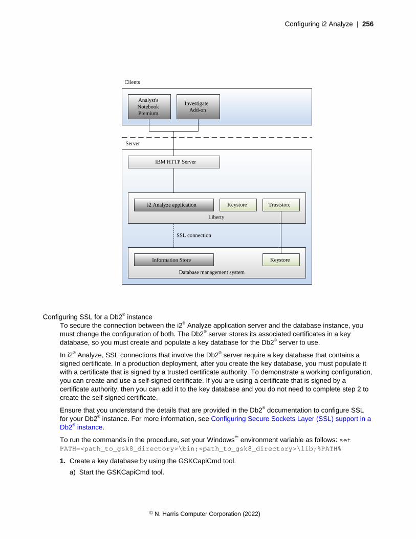
Configuring i2 Analyze | 256
IBM HTTP Server
Liberty
Clients
Server
i2 Analyze application
Analyst's Notebook Premium
Investigate Add-on
Database management system
Information Store
Keystore Truststore
Keystore
SSL connection
Configuring SSL for a Db2® instanceTo secure the connection between the i2® Analyze application server and the database instance, youmust change the configuration of both. The Db2® server stores its associated certificates in a keydatabase, so you must create and populate a key database for the Db2® server to use.
In i2® Analyze, SSL connections that involve the Db2® server require a key database that contains asigned certificate. In a production deployment, after you create the key database, you must populate itwith a certificate that is signed by a trusted certificate authority. To demonstrate a working configuration,you can create and use a self-signed certificate. If you are using a certificate that is signed by acertificate authority, then you can add it to the key database and you do not need to complete step 2 tocreate the self-signed certificate.
Ensure that you understand the details that are provided in the Db2® documentation to configure SSLfor your Db2® instance. For more information, see Configuring Secure Sockets Layer (SSL) support in aDb2® instance.
To run the commands in the procedure, set your Windows™ environment variable as follows: setPATH=<path_to_gsk8_directory>\bin;<path_to_gsk8_directory>\lib;%PATH%
1. Create a key database by using the GSKCapiCmd tool.
a) Start the GSKCapiCmd tool.
© N. Harris Computer Corporation (2022)
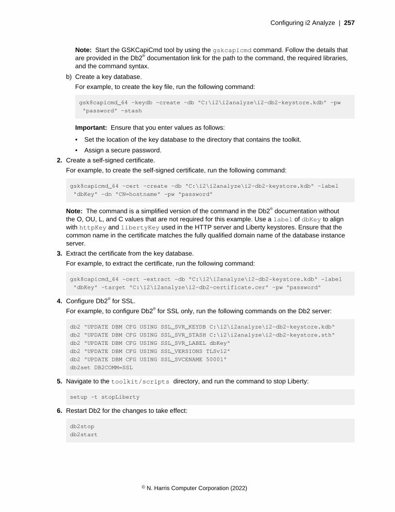
Configuring i2 Analyze | 257
Note: Start the GSKCapiCmd tool by using the gskcapicmd command. Follow the details thatare provided in the Db2® documentation link for the path to the command, the required libraries,and the command syntax.
b) Create a key database.
For example, to create the key file, run the following command:
gsk8capicmd_64 -keydb -create -db "C:\i2\i2analyze\i2-db2-keystore.kdb" -pw
"password" -stash
Important: Ensure that you enter values as follows:
• Set the location of the key database to the directory that contains the toolkit.
• Assign a secure password.
2. Create a self-signed certificate.
For example, to create the self-signed certificate, run the following command:
gsk8capicmd_64 -cert -create -db "C:\i2\i2analyze\i2-db2-keystore.kdb" -label
"dbKey" -dn "CN=hostname" -pw "password"
Note: The command is a simplified version of the command in the Db2® documentation withoutthe O, OU, L, and C values that are not required for this example. Use a label of dbKey to alignwith httpKey and libertyKey used in the HTTP server and Liberty keystores. Ensure that thecommon name in the certificate matches the fully qualified domain name of the database instanceserver.
3. Extract the certificate from the key database.
For example, to extract the certificate, run the following command:
gsk8capicmd_64 -cert -extract -db "C:\i2\i2analyze\i2-db2-keystore.kdb" -label
"dbKey" -target "C:\i2\i2analyze\i2-db2-certificate.cer" -pw "password"
4. Configure Db2® for SSL.
For example, to configure Db2® for SSL only, run the following commands on the Db2 server:
db2 "UPDATE DBM CFG USING SSL_SVR_KEYDB C:\i2\i2analyze\i2-db2-keystore.kdb"
db2 "UPDATE DBM CFG USING SSL_SVR_STASH C:\i2\i2analyze\i2-db2-keystore.sth"
db2 "UPDATE DBM CFG USING SSL_SVR_LABEL dbKey"
db2 "UPDATE DBM CFG USING SSL_VERSIONS TLSv12"
db2 "UPDATE DBM CFG USING SSL_SVCENAME 50001"
db2set DB2COMM=SSL
5. Navigate to the toolkit/scripts directory, and run the command to stop Liberty:
setup -t stopLiberty
6. Restart Db2 for the changes to take effect:
db2stop
db2start
© N. Harris Computer Corporation (2022)

Configuring i2 Analyze | 258
After you configure Db2®, you can check the db2diag.log file to ensure that there are no errors withyour SSL configuration.
Note: If you are using a remote Db2 database, then you must configure the Db2 client on the Libertyserver to communicate by using SSL. Run the following commands to configure the Db2 client to usethe keystore and stash file:
db2 "UPDATE DBM CFG USING SSL_CLNT_KEYDB C:\i2\i2analyze\i2-db2-keystore.kdb"
db2 "UPDATE DBM CFG USING SSL_CLNT_STASH C:\i2\i2analyze\i2-db2-keystore.sth"
Configuring SSL for Microsoft™ SQL ServerTo secure the connection between the i2® Analyze application server and the database instance, youmust change the configuration of both. Microsoft™ SQL Server stores its associated certificates and youmust create or obtain certificates for the Microsoft™ SQL Server to use.
In i2® Analyze, SSL connections that involve SQL Server require i2® Analyze to trust the certificate thatit receives from SQL Server. SQL Server stores certificates in the operating system's certificate stores.In a production deployment, you must use a certificate that is signed by a trusted certificate authority. Todemonstrate a working configuration, you can create and use a self-signed certificate.
Ensure that you understand the details that are provided in the SQL Server documentation to configureSSL for your SQL Server. For more information, on Windows™ see Enable Encrypted Connections tothe Database Engine or Linux® see Server Initiated Encryption.
Create a self-signed certificate for SQL Server.
1. For example, on Windows™ you can use the New-SelfSignedCertificate command inPowerShell. For information, see New-SelfSignedCertificate.Run the following command to create a certificate:
New-SelfSignedCertificate -Subject "CN=hostname" -KeyAlgorithm
RSA -KeyLength 2048 -CertStoreLocation "cert:\LocalMachine\My" -
TextExtension @("2.5.29.37={text}1.3.6.1.5.5.7.3.1") -Hash 'SHA256' -Type
SSLServerAuthentication -Provider 'Microsoft RSA SChannel Crytographic
Provider'
Important: Ensure that you set the value of CN to the hostname of the server where SQL Server islocated.
2. For example, on Linux® you can run the following commands by using OpenSSL:
openssl req -x509 -nodes -newkey rsa:2048 -subj '/CN=hostname' -keyout sql-
server-key.key -out sql-server-certificate.pem -days 365
sudo chown mssql:mssql sql-server-certificate.pem sql-server-key.key
sudo chmod 600 sql-server-certificate.pem sql-server-key.key
sudo mv sql-server-certificate.pem /etc/ssl/certs/
sudo mv sql-server-key.key /etc/ssl/private/
Important: Ensure that you set the value of CN to the hostname of the server where SQL Server islocated.
Export the self-signed certificate.
3. On Windows™:
a) Use the Certificates snap-in in the Microsoft™ Management Console to export the certificate fromthe Local Computer user's certificates.
© N. Harris Computer Corporation (2022)
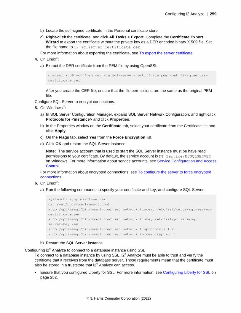
Configuring i2 Analyze | 259
b) Locate the self-signed certificate in the Personal certificate store.
c) Right-click the certificate, and click All Tasks > Export. Complete the Certificate ExportWizard to export the certificate without the private key as a DER encoded binary X.509 file. Setthe file name to i2-sqlserver-certificate.cer.
For more information about exporting the certificate, see To export the server certificate.
4. On Linux®:
a) Extract the DER certificate from the PEM file by using OpenSSL:
openssl x509 -outform der -in sql-server-certificate.pem -out i2-sqlserver-
certificate.cer
After you create the CER file, ensure that the file permissions are the same as the original PEMfile.
Configure SQL Server to encrypt connections.
5. On Windows™:
a) In SQL Server Configuration Manager, expand SQL Server Network Configuration, and right-clickProtocols for <instance> and click Properties.
b) In the Properties window on the Certificate tab, select your certificate from the Certificate list andclick Apply.
c) On the Flags tab, select Yes from the Force Encryption list.
d) Click OK and restart the SQL Server instance.
Note: The service account that is used to start the SQL Server instance must be have readpermissions to your certificate. By default, the service account is NT Service/MSSQLSERVERon Windows. For more information about service accounts, see Service Configuration and AccessControl.
For more information about encrypted connections, see To configure the server to force encryptedconnections.
6. On Linux®:
a) Run the following commands to specify your certificate and key, and configure SQL Server:
systemctl stop mssql-server
cat /var/opt/mssql/mssql.conf
sudo /opt/mssql/bin/mssql-conf set network.tlscert /etc/ssl/certs/sql-server-
certificate.pem
sudo /opt/mssql/bin/mssql-conf set network.tlskey /etc/ssl/private/sql-
server-key.key
sudo /opt/mssql/bin/mssql-conf set network.tlsprotocols 1.2
sudo /opt/mssql/bin/mssql-conf set network.forceencryption 1
b) Restart the SQL Server instance.
Configuring i2® Analyze to connect to a database instance using SSLTo connect to a database instance by using SSL, i2® Analyze must be able to trust and verify thecertificate that it receives from the database server. Those requirements mean that the certificate mustalso be stored in a truststore that i2® Analyze can access.
• Ensure that you configured Liberty for SSL. For more information, see Configuring Liberty for SSL onpage 252.
© N. Harris Computer Corporation (2022)
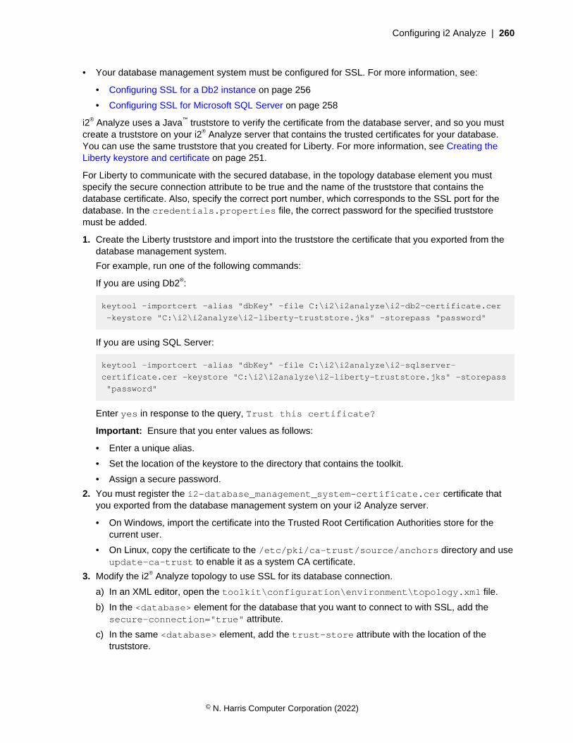
Configuring i2 Analyze | 260
• Your database management system must be configured for SSL. For more information, see:
• Configuring SSL for a Db2 instance on page 256
• Configuring SSL for Microsoft SQL Server on page 258
i2® Analyze uses a Java™ truststore to verify the certificate from the database server, and so you mustcreate a truststore on your i2® Analyze server that contains the trusted certificates for your database.You can use the same truststore that you created for Liberty. For more information, see Creating theLiberty keystore and certificate on page 251.
For Liberty to communicate with the secured database, in the topology database element you mustspecify the secure connection attribute to be true and the name of the truststore that contains thedatabase certificate. Also, specify the correct port number, which corresponds to the SSL port for thedatabase. In the credentials.properties file, the correct password for the specified truststoremust be added.
1. Create the Liberty truststore and import into the truststore the certificate that you exported from thedatabase management system.
For example, run one of the following commands:
If you are using Db2®:
keytool -importcert -alias "dbKey" -file C:\i2\i2analyze\i2-db2-certificate.cer
-keystore "C:\i2\i2analyze\i2-liberty-truststore.jks" -storepass "password"
If you are using SQL Server:
keytool -importcert -alias "dbKey" -file C:\i2\i2analyze\i2-sqlserver-
certificate.cer -keystore "C:\i2\i2analyze\i2-liberty-truststore.jks" -storepass
"password"
Enter yes in response to the query, Trust this certificate?
Important: Ensure that you enter values as follows:
• Enter a unique alias.
• Set the location of the keystore to the directory that contains the toolkit.
• Assign a secure password.
2. You must register the i2-database_management_system-certificate.cer certificate thatyou exported from the database management system on your i2 Analyze server.
• On Windows, import the certificate into the Trusted Root Certification Authorities store for thecurrent user.
• On Linux, copy the certificate to the /etc/pki/ca-trust/source/anchors directory and useupdate-ca-trust to enable it as a system CA certificate.
3. Modify the i2® Analyze topology to use SSL for its database connection.
a) In an XML editor, open the toolkit\configuration\environment\topology.xml file.
b) In the <database> element for the database that you want to connect to with SSL, add thesecure-connection="true" attribute.
c) In the same <database> element, add the trust-store attribute with the location of thetruststore.
© N. Harris Computer Corporation (2022)
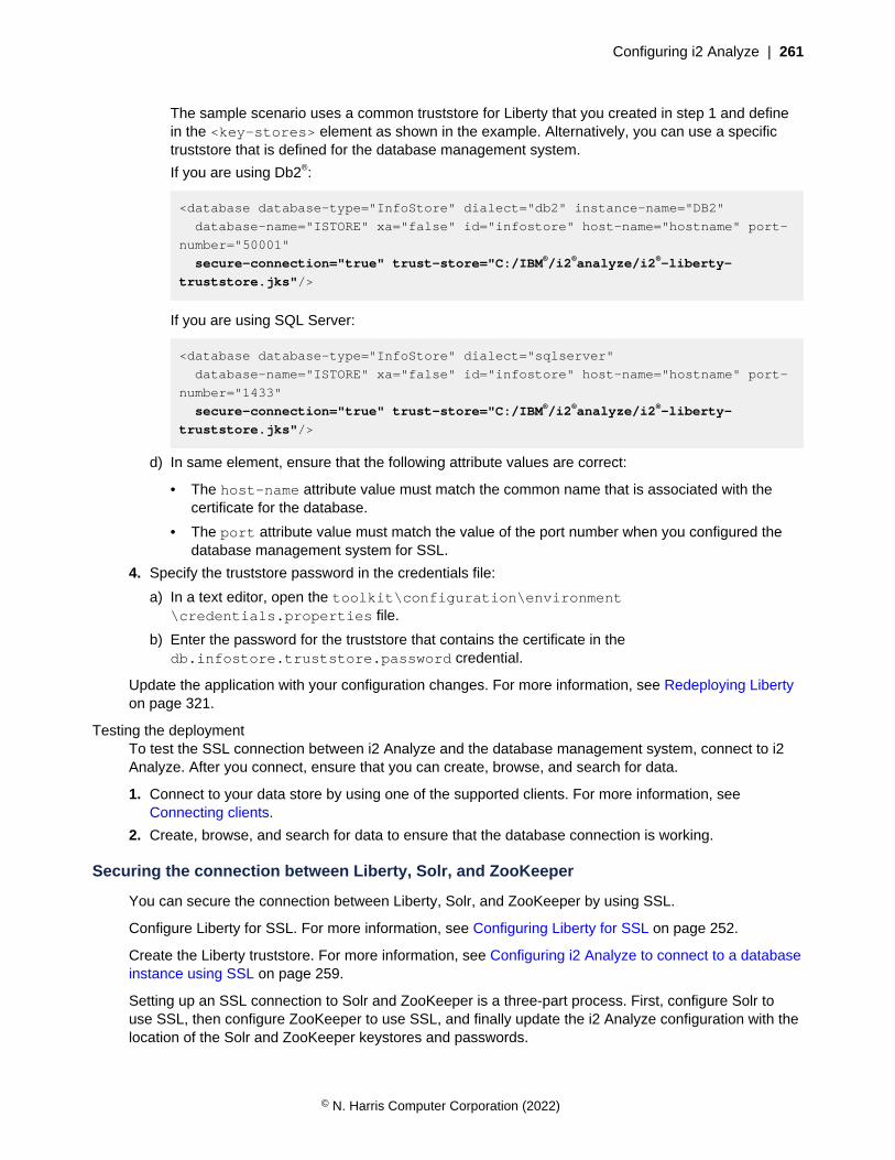
Configuring i2 Analyze | 261
The sample scenario uses a common truststore for Liberty that you created in step 1 and definein the <key-stores> element as shown in the example. Alternatively, you can use a specifictruststore that is defined for the database management system.
If you are using Db2®:
<database database-type="InfoStore" dialect="db2" instance-name="DB2"
database-name="ISTORE" xa="false" id="infostore" host-name="hostname" port-
number="50001"
secure-connection="true" trust-store="C:/IBM®/i2®analyze/i2®-liberty-
truststore.jks"/>
If you are using SQL Server:
<database database-type="InfoStore" dialect="sqlserver"
database-name="ISTORE" xa="false" id="infostore" host-name="hostname" port-
number="1433"
secure-connection="true" trust-store="C:/IBM®/i2®analyze/i2®-liberty-
truststore.jks"/>
d) In same element, ensure that the following attribute values are correct:
• The host-name attribute value must match the common name that is associated with thecertificate for the database.
• The port attribute value must match the value of the port number when you configured thedatabase management system for SSL.
4. Specify the truststore password in the credentials file:
a) In a text editor, open the toolkit\configuration\environment\credentials.properties file.
b) Enter the password for the truststore that contains the certificate in thedb.infostore.truststore.password credential.
Update the application with your configuration changes. For more information, see Redeploying Libertyon page 321.
Testing the deploymentTo test the SSL connection between i2 Analyze and the database management system, connect to i2Analyze. After you connect, ensure that you can create, browse, and search for data.
1. Connect to your data store by using one of the supported clients. For more information, seeConnecting clients.
2. Create, browse, and search for data to ensure that the database connection is working.
Securing the connection between Liberty, Solr, and ZooKeeper
You can secure the connection between Liberty, Solr, and ZooKeeper by using SSL.
Configure Liberty for SSL. For more information, see Configuring Liberty for SSL on page 252.
Create the Liberty truststore. For more information, see Configuring i2 Analyze to connect to a databaseinstance using SSL on page 259.
Setting up an SSL connection to Solr and ZooKeeper is a three-part process. First, configure Solr touse SSL, then configure ZooKeeper to use SSL, and finally update the i2 Analyze configuration with thelocation of the Solr and ZooKeeper keystores and passwords.
© N. Harris Computer Corporation (2022)

Configuring i2 Analyze | 262
The certificate in the Solr keystore is used to identify the Solr server. The certificate in the Libertytruststore is used to authenticate certificates that are received from the Solr keystore.
The certificate in the Solr keystore is also used for authentication within Solr itself, using the Solrtruststore. The certificate in the Solr truststore is used to authenticate the certificate that it received fromthe Solr keystore.
The certificate in the ZooKeeper keystore is used to identify the ZooKeeper server. The certificate in theLiberty truststore is used to authenticate certificates that are received from the ZooKeeper keystore.
The certificate in the ZooKeeper keystore is also used for authentication within a ZooKeeper quorum, byusing the ZooKeeper truststore. The certificate in the ZooKeeper truststore is used to authenticate thecertificate that it received from the ZooKeeper keystore.
The certificate in the ZooKeeper truststore is used to authenticate certificates that are received from theSolr keystore.
The diagram shows the connection that you can secure by completing the following instructions. It alsoincludes the keystores and truststores that are required for a single server.
IBM HTTP Server
Liberty
Clients
Server
i2 Analyze application
Analyst's Notebook Premium
Investigate Add-on
ZooKeeper
Solr
Keystore Truststore Keystore Truststore
Keystore Truststore
Existing SSL connection
Existing SSL connection
SSL connections
SSL connection
Creating Solr keystores and certificates
© N. Harris Computer Corporation (2022)
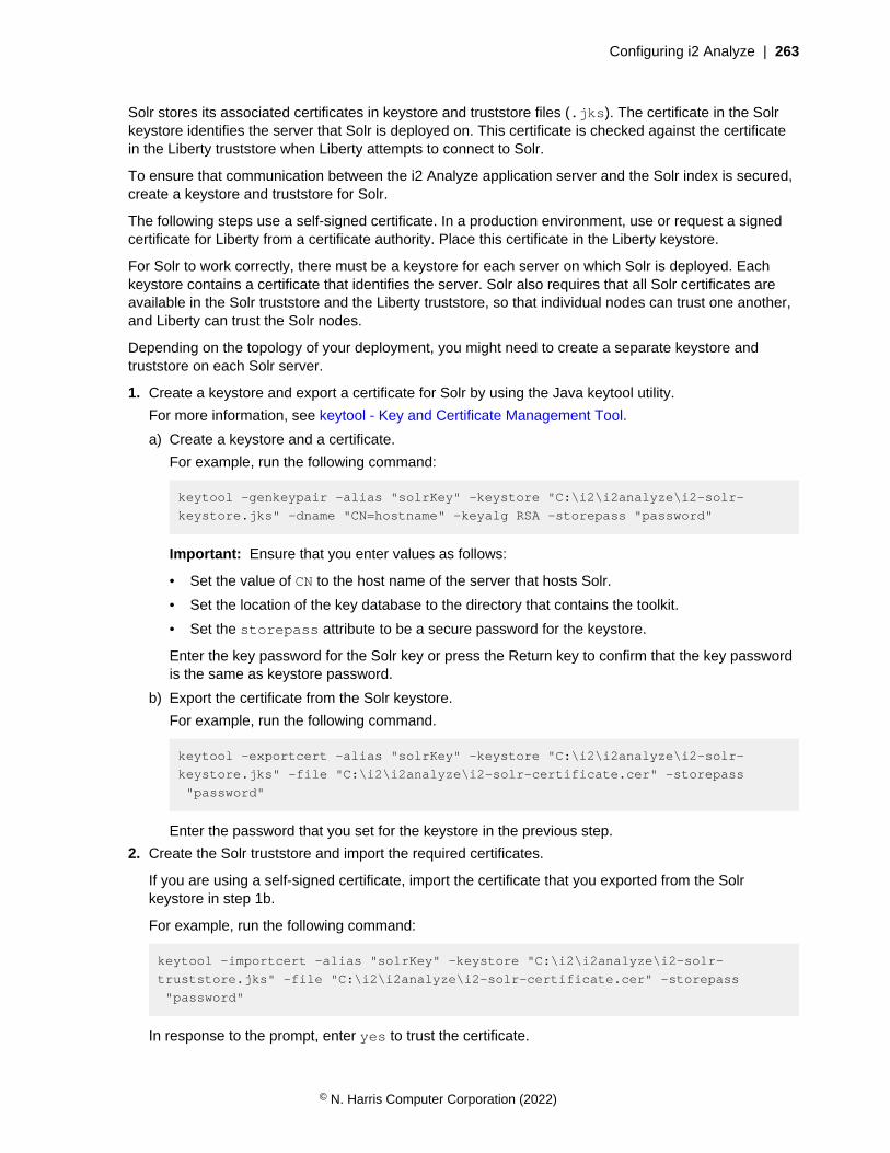
Configuring i2 Analyze | 263
Solr stores its associated certificates in keystore and truststore files (.jks). The certificate in the Solrkeystore identifies the server that Solr is deployed on. This certificate is checked against the certificatein the Liberty truststore when Liberty attempts to connect to Solr.
To ensure that communication between the i2 Analyze application server and the Solr index is secured,create a keystore and truststore for Solr.
The following steps use a self-signed certificate. In a production environment, use or request a signedcertificate for Liberty from a certificate authority. Place this certificate in the Liberty keystore.
For Solr to work correctly, there must be a keystore for each server on which Solr is deployed. Eachkeystore contains a certificate that identifies the server. Solr also requires that all Solr certificates areavailable in the Solr truststore and the Liberty truststore, so that individual nodes can trust one another,and Liberty can trust the Solr nodes.
Depending on the topology of your deployment, you might need to create a separate keystore andtruststore on each Solr server.
1. Create a keystore and export a certificate for Solr by using the Java keytool utility.
For more information, see keytool - Key and Certificate Management Tool.
a) Create a keystore and a certificate.
For example, run the following command:
keytool -genkeypair -alias "solrKey" -keystore "C:\i2\i2analyze\i2-solr-
keystore.jks" -dname "CN=hostname" -keyalg RSA -storepass "password"
Important: Ensure that you enter values as follows:
• Set the value of CN to the host name of the server that hosts Solr.
• Set the location of the key database to the directory that contains the toolkit.
• Set the storepass attribute to be a secure password for the keystore.
Enter the key password for the Solr key or press the Return key to confirm that the key passwordis the same as keystore password.
b) Export the certificate from the Solr keystore.
For example, run the following command.
keytool -exportcert -alias "solrKey" -keystore "C:\i2\i2analyze\i2-solr-
keystore.jks" -file "C:\i2\i2analyze\i2-solr-certificate.cer" -storepass
"password"
Enter the password that you set for the keystore in the previous step.
2. Create the Solr truststore and import the required certificates.
If you are using a self-signed certificate, import the certificate that you exported from the Solrkeystore in step 1b.
For example, run the following command:
keytool -importcert -alias "solrKey" -keystore "C:\i2\i2analyze\i2-solr-
truststore.jks" -file "C:\i2\i2analyze\i2-solr-certificate.cer" -storepass
"password"
In response to the prompt, enter yes to trust the certificate.
© N. Harris Computer Corporation (2022)
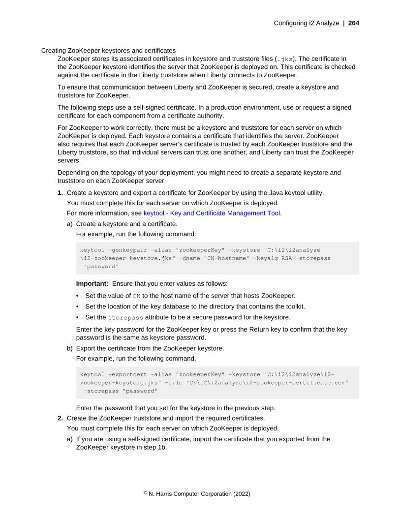
Configuring i2 Analyze | 264
Creating ZooKeeper keystores and certificatesZooKeeper stores its associated certificates in keystore and truststore files (.jks). The certificate inthe ZooKeeper keystore identifies the server that ZooKeeper is deployed on. This certificate is checkedagainst the certificate in the Liberty truststore when Liberty connects to ZooKeeper.
To ensure that communication between Liberty and ZooKeeper is secured, create a keystore andtruststore for ZooKeeper.
The following steps use a self-signed certificate. In a production environment, use or request a signedcertificate for each component from a certificate authority.
For ZooKeeper to work correctly, there must be a keystore and truststore for each server on whichZooKeeper is deployed. Each keystore contains a certificate that identifies the server. ZooKeeperalso requires that each ZooKeeper server's certificate is trusted by each ZooKeeper truststore and theLiberty truststore, so that individual servers can trust one another, and Liberty can trust the ZooKeeperservers.
Depending on the topology of your deployment, you might need to create a separate keystore andtruststore on each ZooKeeper server.
1. Create a keystore and export a certificate for ZooKeeper by using the Java keytool utility.
You must complete this for each server on which ZooKeeper is deployed.
For more information, see keytool - Key and Certificate Management Tool.
a) Create a keystore and a certificate.
For example, run the following command:
keytool -genkeypair -alias "zookeeperKey" -keystore "C:\i2\i2analyze
\i2-zookeeper-keystore.jks" -dname "CN=hostname" -keyalg RSA -storepass
"password"
Important: Ensure that you enter values as follows:
• Set the value of CN to the host name of the server that hosts ZooKeeper.
• Set the location of the key database to the directory that contains the toolkit.
• Set the storepass attribute to be a secure password for the keystore.
Enter the key password for the ZooKeeper key or press the Return key to confirm that the keypassword is the same as keystore password.
b) Export the certificate from the ZooKeeper keystore.
For example, run the following command.
keytool -exportcert -alias "zookeeperKey" -keystore "C:\i2\i2analyze\i2-
zookeeper-keystore.jks" -file "C:\i2\i2analyze\i2-zookeeper-certificate.cer"
-storepass "password"
Enter the password that you set for the keystore in the previous step.
2. Create the ZooKeeper truststore and import the required certificates.
You must complete this for each server on which ZooKeeper is deployed.
a) If you are using a self-signed certificate, import the certificate that you exported from theZooKeeper keystore in step 1b.
© N. Harris Computer Corporation (2022)

Configuring i2 Analyze | 265
For example, run the following command:
keytool -importcert -alias "zookeeperKey" -keystore "C:\i2\i2analyze
\i2-zookeeper-truststore.jks" -file "C:\i2\i2analyze\i2-zookeeper-
certificate.cer" -storepass "password"
In response to the prompt, enter yes to trust the certificate.
b) Import the certificate that authenticates the certificates that are received from Solr. In thisexample, import the self-signed Solr i2-solr-certificate.cer certificate that you exportedin Creating Solr keystores and certificates on page 262.For example, run the following command:
keytool -importcert -alias "solrKey" -keystore "C:\i2\i2analyze\i2-zookeeper-
truststore.jks" -file "C:\i2\i2analyze\i2-solr-certificate.cer" -storepass
"password"
In response to the prompt, enter yes to trust the certificate.
c) Import the certificate that authenticates the certificates that are received from Liberty. In thisexample, import the self-signed Liberty i2-liberty-certificate.cer certificate that youexported in Creating the Liberty keystore and certificate on page 251.
For example, run the following command:
keytool -importcert -alias "libertyKey" -keystore "C:\i2\i2analyze\i2-
zookeeper-truststore.jks" -file "C:\i2\i2analyze\i2-liberty-certificate.cer"
-storepass "password"
In response to the prompt, enter yes to trust the certificate.
Configuring the SSL connectionsTo secure the connection between the i2 Analyze application server, Solr, and ZooKeeper, you mustchange the configuration of all three components. The i2 Analyze configuration must define the keystoreand truststore for Solr and ZooKeeper.
• Ensure that you configured Liberty for SSL. For more information, see Configuring Liberty for SSL onpage 252.
• You must have the appropriate keystore set up for your Solr deployment. For more information, seeCreating Solr keystores and certificates on page 262.
• You must have the appropriate keystore set up for your ZooKeeper deployment. For moreinformation, see Creating ZooKeeper keystores and certificates on page 264.
Liberty uses a Java truststore to verify the certificate from the Solr and ZooKeeper servers, and so youmust create or reuse a truststore on your i2 Analyze server to contain the trusted certificates for yourSolr and ZooKeeper servers. You can use the same truststore that you created for Liberty to hold thecertificate from the database management system. For more information, see Configuring i2 Analyze toconnect to a database instance using SSL on page 259.
At this release, you delete and re-create the Solr collections during the configuration process. Afteryou delete and re-create the Solr collections, the system must reindex all of your data. You shouldaim to configure Solr to use SSL before you ingest a large amount of data into your system. If you areconfiguring SSL in a production system with a large amount of data, contact i2 Support before youdelete your Solr collections.
© N. Harris Computer Corporation (2022)
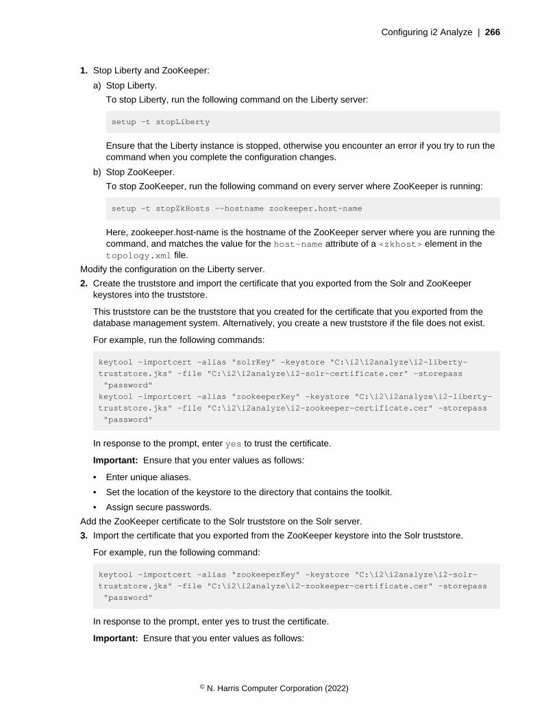
Configuring i2 Analyze | 266
1. Stop Liberty and ZooKeeper:
a) Stop Liberty.
To stop Liberty, run the following command on the Liberty server:
setup -t stopLiberty
Ensure that the Liberty instance is stopped, otherwise you encounter an error if you try to run thecommand when you complete the configuration changes.
b) Stop ZooKeeper.
To stop ZooKeeper, run the following command on every server where ZooKeeper is running:
setup -t stopZkHosts --hostname zookeeper.host-name
Here, zookeeper.host-name is the hostname of the ZooKeeper server where you are running thecommand, and matches the value for the host-name attribute of a <zkhost> element in thetopology.xml file.
Modify the configuration on the Liberty server.
2. Create the truststore and import the certificate that you exported from the Solr and ZooKeeperkeystores into the truststore.
This truststore can be the truststore that you created for the certificate that you exported from thedatabase management system. Alternatively, you create a new truststore if the file does not exist.
For example, run the following commands:
keytool -importcert -alias "solrKey" -keystore "C:\i2\i2analyze\i2-liberty-
truststore.jks" -file "C:\i2\i2analyze\i2-solr-certificate.cer" -storepass
"password"
keytool -importcert -alias "zookeeperKey" -keystore "C:\i2\i2analyze\i2-liberty-
truststore.jks" -file "C:\i2\i2analyze\i2-zookeeper-certificate.cer" -storepass
"password"
In response to the prompt, enter yes to trust the certificate.
Important: Ensure that you enter values as follows:
• Enter unique aliases.
• Set the location of the keystore to the directory that contains the toolkit.
• Assign secure passwords.
Add the ZooKeeper certificate to the Solr truststore on the Solr server.
3. Import the certificate that you exported from the ZooKeeper keystore into the Solr truststore.
For example, run the following command:
keytool -importcert -alias "zookeeperKey" -keystore "C:\i2\i2analyze\i2-solr-
truststore.jks" -file "C:\i2\i2analyze\i2-zookeeper-certificate.cer" -storepass
"password"
In response to the prompt, enter yes to trust the certificate.
Important: Ensure that you enter values as follows:
© N. Harris Computer Corporation (2022)
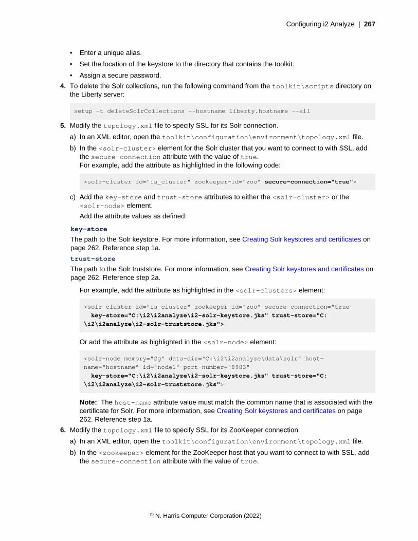
Configuring i2 Analyze | 267
• Enter a unique alias.
• Set the location of the keystore to the directory that contains the toolkit.
• Assign a secure password.
4. To delete the Solr collections, run the following command from the toolkit\scripts directory onthe Liberty server:
setup -t deleteSolrCollections --hostname liberty.hostname --all
5. Modify the topology.xml file to specify SSL for its Solr connection.
a) In an XML editor, open the toolkit\configuration\environment\topology.xml file.
b) In the <solr-cluster> element for the Solr cluster that you want to connect to with SSL, addthe secure-connection attribute with the value of true.For example, add the attribute as highlighted in the following code:
<solr-cluster id="is_cluster" zookeeper-id="zoo" secure-connection="true">
c) Add the key-store and trust-store attributes to either the <solr-cluster> or the<solr-node> element.
Add the attribute values as defined:
key-store
The path to the Solr keystore. For more information, see Creating Solr keystores and certificates onpage 262. Reference step 1a.
trust-store
The path to the Solr truststore. For more information, see Creating Solr keystores and certificates onpage 262. Reference step 2a.
For example, add the attribute as highlighted in the <solr-clusters> element:
<solr-cluster id="is_cluster" zookeeper-id="zoo" secure-connection="true"
key-store="C:\i2\i2analyze\i2-solr-keystore.jks" trust-store="C:
\i2\i2analyze\i2-solr-truststore.jks">
Or add the attribute as highlighted in the <solr-node> element:
<solr-node memory="2g" data-dir="C:\i2\i2analyze\data\solr" host-
name="hostname" id="node1" port-number="8983"
key-store="C:\i2\i2analyze\i2-solr-keystore.jks" trust-store="C:
\i2\i2analyze\i2-solr-truststore.jks">
Note: The host-name attribute value must match the common name that is associated with thecertificate for Solr. For more information, see Creating Solr keystores and certificates on page262. Reference step 1a.
6. Modify the topology.xml file to specify SSL for its ZooKeeper connection.
a) In an XML editor, open the toolkit\configuration\environment\topology.xml file.
b) In the <zookeeper> element for the ZooKeeper host that you want to connect to with SSL, addthe secure-connection attribute with the value of true.
© N. Harris Computer Corporation (2022)

Configuring i2 Analyze | 268
For example, add the attribute as highlighted in the following code:
<zookeeper id="zoo" secure-connection="true">
c) Add the key-store and trust-store attributes to either the <zookeeper> or to the<zkhost> element.
Add the attribute values as defined:
key-store
The path to the ZooKeeper keystore. For more information, see Creating ZooKeeper keystores andcertificates on page 264. Reference step 1a.
trust-store
The path to the ZooKeeper truststore. For more information, see Creating ZooKeeper keystores andcertificates on page 264. Reference step 2a.
• For example, add the attribute as highlighted in the <zookeeper> element:
<zookeeper id="zoo" secure-connection="true" key-store="C:\i2\i2analyze
\i2-zookeeper-keystore.jks" trust-store="C:\i2\i2analyze\i2-zookeeper-
truststore.jks">
• For example, add the attribute as highlighted in the <zkhost> element:
<zkhost quorum-port-number="10483" leader-port-number="10983" data-dir="C:
\i2\i2analyze\data\zookeeper" host-name="hostname" id="1" port-number="
9983" key-store="C:\i2\i2analyze\i2-zookeeper-keystore.jks" trust-
store="C:\i2\i2analyze\i2-zookeeper-truststore.jks">
Note: The host-name attribute value must match the common name that is associated withthe certificate for ZooKeeper. For more information, see Creating ZooKeeper keystores andcertificates on page 264. Reference step 1a.
7. Modify the topology.xml file to add the Liberty truststore.
Add a child <key-store> element. For your keystore, specify the type as trust-store andfile as the full path to your truststore.
For example, add the element as highlighted in the following code:
<application http-server-host="true" name="opal-server"
host-name="hostname" secure-connection="true">
...
<key-stores>
<key-store type="key-store"
file="C:\i2\i2analyze\i2-liberty-keystore.jks"/>
<key-store type="trust-store"
file="C:\i2\i2analyze\i2-liberty-truststore.jks"/>
</key-stores>
...
</application>
8. Specify the truststore and keystore passwords in the credentials file.
a) In a text editor, open the toolkit\configuration\environment\credentials.properties file.
© N. Harris Computer Corporation (2022)

Configuring i2 Analyze | 269
b) Enter the passwords for the Solr keystore and truststore that you specified in the topology file.
solr.truststore.password=password
solr.keystore.password=password
c) Enter the passwords for the ZooKeeper keystore and truststore that you specified in the topologyfile.
zookeeper.truststore.password=password
zookeeper.keystore.password=password
d) Enter the password for the Liberty truststore that you specified in the topology file.
ssl.truststore.password=password
9. Copy the toolkit\configuration from the Liberty server, to the toolkit directory of thedeployment toolkit on each server in your environment.
Update the application with your configuration changes. Run the following commands from thetoolkit\scripts directory on the Liberty server.
10.Redeploy Liberty to update the application:
setup -t deployLiberty
11.Recreate the ZooKeeper host on each server where your ZooKeeper hosts are located:
setup -t createZkHosts --hostname zookeeper.host-name
Where zookeeper.host-name is the hostname of the ZooKeeper server where you are runningthe command, and matches the value for the host-name attribute of a <zkhost> element in thetopology.xml file.
12.Start ZooKeeper.
To start ZooKeeper, run the following command on every server where your ZooKeeper hosts arelocated:
setup -t startZkHosts --hostname zookeeper.host-name
Where zookeeper.host-name is the hostname of the ZooKeeper server where you are runningthe command, and matches the value for the host-name attribute of a <zkhost> element in thetopology.xml file.
13.Upload the new Solr configuration to ZooKeeper:
setup -t createAndUploadSolrConfig --hostname liberty.hostname
Where liberty.hostname is the hostname of the Liberty server where you are running thecommand, and matches the value for the host-name attribute of the <application> element inthe topology.xml file.
14.Restart the Solr nodes.
To restart the Solr nodes, run the following command on every server where Solr is running:
setup -t restartSolrNodes --hostname solr.host-name
© N. Harris Computer Corporation (2022)

Configuring i2 Analyze | 270
Where solr.host-name is the host name of the Solr server where you are running the command, andmatches the value for the host-name attribute of a <solr-node> element in the topology.xmlfile.
15.Create the Solr collections.
Run the following command from the Liberty server:
setup -t createSolrCollections --hostname liberty.hostname --all
16.Start Liberty.
To start Liberty, run the following command on each Liberty server:
setup -t startLiberty
Connect to your Information Store. For more information, see Connecting i2 Analyst's NotebookPremium to i2 Analyze.
Search for data to ensure that the Solr connection is working.
Resources for system protection
In order to protect your system from external forces, you must implement system controls thatprevent or mitigate the effect of attacks. Although i2 Group does not manage login configuration,and the responsibility for protection of your network from external attack remains yours, the followingcommunities provide a starting point for your investigation into preventative methods.
The Open Web Application Security Project
The Open Web Application Security Project Foundation is a not-for-profit organizationthat is dedicated to enabling organizations to conceive, develop, operate, and maintainapplications that can be trusted. In particular, see https://owasp.org/www-community/controls/Blocking_Brute_Force_Attacks and https://cheatsheetseries.owasp.org/cheatsheets/Authentication_Cheat_Sheet.html.
SANS Institute
The System-Admin, Audit, Network, and Security Institute is the largest source for informationsecurity training and security certification in the world. It also develops, maintains, and makesavailable at no cost, the largest collection of research documents about various aspects ofinformation security, and it operates the internet's early warning system - the Internet StormCenter. In particular, see https://www.sans.org/security-resources/policies/general/pdf/password-construction-guidelines
Common Weakness Enumeration
CWE™ is a community-developed list of common software security weaknesses. It serves as acommon language, a measuring stick for software security tools, and as a baseline for weaknessidentification, mitigation, and prevention efforts.
In particular, see http://cwe.mitre.org/top25/index.html#CWE-307.
© N. Harris Computer Corporation (2022)

Configuring i2 Analyze | 271
Client authenticated Secure Sockets Layer with the i2 Connect gateway
To secure the connection between Liberty and any connectors for the i2 Connect gateway, you mustconfigure Liberty and your connectors to use SSL. If you are using SSL, i2 Analyze enforces client-authenticated communication with a connector.
In a production deployment you should configure i2 Analyze to connect to your connector using client-authenticated SSL communication. To do so, your connector and i2 Analyze must trust the certificatesthat they receive during the SSL handshake process. In a production environment, the certificates mustbe signed by a trusted certificate authority. For more information about client authenticated SSL, seeClient-authenticated TLS handshake.
The following diagram shows the keystores and truststores that are required for Liberty and theconnector.
IBM HTTP Server
Liberty
Clients
Server
i2 Analyze application
Analyst's Notebook Premium
Keystore Truststore
Connector
KeystoreTruststore
The Liberty server requires a keystore file and a truststore file. Your connector can use anyimplementation for its keystore and truststore. The certificates in each truststore must trust thecertificates received from the corresponding keystore.
The certificates that are required are as follows, where certificate authority (CA) X issues the certificatesto the connector (the server) and Liberty (the client):
© N. Harris Computer Corporation (2022)

Configuring i2 Analyze | 272
The connector requires:
• In its keystore:
• The personal certificate issued to the connector by CA X
• The connector's private key
• In the truststore:
• The CA certificate for CA X
Liberty requires:
• In its keystore:
• The personal certificate issued to Liberty by CA X
• Liberty's private key
• In its truststore:
• The CA certificate for CA X
After you have created and populated the keystores and truststores for the connector and Liberty, youmust configure Liberty to use SSL to communicate with any connectors.
The following steps explain the process of updating the i2 Analyze configuration with the location ofa keystore and truststore to use, and the passwords that are used to access the certificates that arecontained within them.
To configure the example-connector to use client-authenticated SSL, and for examples of how tocreate keystores, truststores, and certificates for Liberty, follow the instructions in Securing the exampleconnector on page 273.
1. In an XML editor, open the toolkit\configuration\environment\topology.xml file.
a) Add the <key-stores> element as a child of the <application> element. Then, add child<key-store> elements.
For your keystore, specify the type as key-store, and file as the full path to your keystore.For your truststore, specify the type as trust-store, and file as the full path to yourtruststore.
For example, add the attribute as highlighted in the following code:
<application http-server-host="true"
name="opal-server" host-name="hostname">
...
<key-stores>
<key-store type="key-store"
file="C:/i2/i2analyze/i2-liberty-keystore.jks"/>
<key-store type="trust-store"
file="C:/i2/i2analyze/i2-liberty-truststore.jks"/>
</key-stores>
...
</application>
b) Update the base-url attribute of any connectors using SSL to use the HTTPS protocol.
© N. Harris Computer Corporation (2022)

Configuring i2 Analyze | 273
For example:
<connectors>
<connector id="example-connector" name="Example"
base-url="https://localhost:3700/" />
</connector>
Note: Ensure that the hostname that is used in the base URL matches the common name on thecertificate of the connector.
2. Specify the keystore and truststore passwords in the credentials file.
a) In a text editor, open the toolkit\configuration\environment\credentials.properties file.
b) Enter the password for the keystore and truststore that you specified in the topology.xml file.
ssl.keystore.password=password
ssl.truststore.password=password
Redeploy i2 Analyze to update the application with your changes.
3. In a command prompt, navigate to the toolkit\scripts directory.
4. Stop Liberty:
setup -t stopLiberty
5. Update the i2 Analyze application:
setup -t deployLiberty
6. Start Liberty:
setup -t startLiberty
You can create your own connectors to use with the deployment of i2 Analyze, when you create yourown connector you can implement security that conforms to the security required by the i2 Connectgateway. For more information about creating your own connectors, see i2 Analyze and i2 Connect.
When you use a connector configured for SSL communication, you should not see any warningsdisplayed in Analyst's Notebook Premium.
Securing the example connector
In a production deployment, you must configure your connectors with client-authenticated SSLcommunication. You can configure the example connector to communicate with i2 Analyze by usingclient-authenticated SSL communication.
You must configure your connectors to use client-authenticated SSL communication with i2 Analyze.For more information about configuring security between connectors and i2 Analyze, see Clientauthenticated Secure Sockets Layer with the i2 Connect gateway on page 271.
Configure secure communication between Liberty and the example connector that is provided with i2Analyze. The following steps demonstrate how to create the keystores, truststores, and certificates, thenconfigure i2 Analyze and the example connector to use them.
When you create your own connector, you can implement the security implementation in the same wayas used in the example connector, or a different method depending on your requirements.
© N. Harris Computer Corporation (2022)

Configuring i2 Analyze | 274
In a production deployment, you must use a certificate that has been signed by a trusted certificateauthority, which the connector can verify. The following steps use a self-signed certificate todemonstrate the functionality.
Create a keystore for Liberty that contains a signed certificate that is used to authenticate with theconnector.
1. Create a keystore and a self-signed certificate for Liberty by using the Java keytool utility.
For more information about the Java keytool utility, see keytool - Key and Certificate ManagementTool.
a) Open a command prompt and navigate to the i2analyze\deploy\java\bin directory.
b) Create the keystore and certificate by running the following command:
keytool -genkeypair -alias "libertyKey"
-keystore "C:\i2\i2analyze\i2-liberty-keystore.jks"
-dname "CN=hostname" -keyalg RSA -storepass "libertyKeyStorePassword"
Important: Ensure that you enter values as follows:
• Set the location of the keystore to the directory that contains the toolkit.
• Set the value of CN to the hostname of the server that hosts Liberty, as defined in thetopology.xml file.
The password that is specified is used to access the keystore.
c) The example connector implementation requires the Liberty certificate in a base64 encodedformat. Export the certificate in base64 encoding by running the following command:
keytool -exportcert -alias "libertyKey"
-keystore "C:\i2\i2analyze\i2-liberty-keystore.jks"
-file "C:\i2\i2analyze\i2-liberty-certificate.cer"
-rfc -storepass "libertyKeyStorePassword"
Create a keystore for the connector that contains a signed certificate that is used to authenticate withLiberty.
2. Create a keystore and certificate for the connector by using the IBM Key Management Utilitycommand-line interface.
For more information about the IBM Key Management Utility, see Key Management Utility command-line interface (gskcmd) syntax.
a) In a command prompt, navigate to the bin directory of your IBM HTTP Server installation. Forexample: IBM\HTTPServer\bin or IBM\HTTPServer\IHS\bin.
b) Create a keystore in PKCS12 format. To create the keystore, run the following command:
gskcapicmd -keydb -create -type pkcs12
-db "C:\i2\i2analyze\toolkit\examples\connectors\example-connector\example-
connector-keystore.p12"
-pw "connectorKeyStorePassword"
The password that is specified is used to access the keystore.
© N. Harris Computer Corporation (2022)

Configuring i2 Analyze | 275
c) Create a self-signed certificate by running the following command:
gskcapicmd -cert -create
-db "C:\i2\i2analyze\toolkit\examples\connectors\example-connector\example-
connector-keystore.p12"
-label "connectorKey" -dn "CN=hostname" -pw "connectorKeyStorePassword"
Important: Set the value of CN to the hostname of the server that hosts the connector, asdefined in the topology.xml file. By default in the daod-opal example configuration, the valueis localhost.
3. The example connector implementation requires the private key in the PEM format, and thecertificate for the connector.
a) Export the personal certificate and private key into a PKCS12 file by running the followingcommand:
gskcapicmd -cert -export
-db "C:\i2\i2analyze\toolkit\examples\connectors\example-connector\example-
connector-keystore.p12"
-pw "connectorKeyStorePassword" -label "connectorKey" -type pkcs12
-target "C:\i2\i2analyze\toolkit\examples\connectors\example-connector
\example-connector-key.p12"
-target_pw "connectorKeyPassword" -target_type pkcs12
b) Convert the private key from the PKCS12 format to the PEM format. You can use OpenSSL to dothis. For more information about OpenSSL see https://www.openssl.org/source/. If you are usingOpenSSL, you can run the following command:
openssl pkcs12 -in C:\i2\i2analyze\toolkit\examples\connectors\example-
connector\example-connector-key.p12
-out C:\i2\i2analyze\toolkit\examples\connectors\example-connector\example-
connector-key.pem
-nocerts -nodes
When you are prompted for a password, provide the password that you specified whenyou created the example-connector-key.p12 PKCS12 file. In this example, enterconnectorKeyPassword.
c) Extract the certificate for the connector by running the following command:
gskcapicmd -cert -extract
-db "C:\i2\i2analyze\toolkit\examples\connectors\example-connector\example-
connector-keystore.p12"
-label "connectorKey"
-target "C:\i2\i2analyze\toolkit\examples\connectors\example-connector
\example-connector-certificate.cer"
-pw "connectorKeyStorePassword"
Create a truststore for Liberty that contains the certificate that is used to trust the certificate that itreceives from the connector.
© N. Harris Computer Corporation (2022)

Configuring i2 Analyze | 276
4. Create the Liberty truststore and populate it with the connector's certificate by using the Java keytoolby running the following command:
keytool -importcert -alias "exampleconnector"
-keystore "C:\i2\i2analyze\i2-liberty-truststore.jks"
-file "C:\i2\i2analyze\toolkit\examples\connectors\example-connector\example-
connector-certificate.cer"
-storepass "libertyTrustStorePassword"
In response to the prompt, enter yes to trust the certificate.
5. Populate the connector keystore with Liberty's certificate by using the IBM Key Management Utilityby running the following command:
gskcapicmd -cert -add -type pkcs12
-db "C:\i2\i2analyze\toolkit\examples\connectors\example-connector\example-
connector-keystore.p12"
-pw "connectorKeyStorePassword" -label "libertyKey" -trust enable
-file "C:\i2\i2analyze\i2-liberty-certificate.cer"
6. The example connector implementation requires the certificate that is used to trust Liberty toalso be present in the example-connector directory. Copy the C:\i2\i2analyze\i2-liberty-certificate.cer file to the C:\i2\i2analyze\toolkit\examples\connectors\example-connector directory.
7. If you are using the IBM HTTP Server, start or restart it.
The certificates are now in place to enable client authentication SSL between Liberty and the connector.
8. Configure the example connector to reference the certificates that you created, and the hostname ofthe gateway. Using a text editor, modify the security-config.json file with the following values.
https
Set to true to use the HTTPS protocol to connect to the connector.
keyFileName
The file name for the private key of the connector in PEM format. For this example, example-connector-key.pem.
keyPassphrase
The password that is required to access the key file specified in keyFileName. For this example,connectorKeyPassword.
certificateFileName
The file name for the certificate of the connector. For this example, example-connector-certificate.cer.
certificateAuthorityFileName
The file name of the certificate that enables trust of the certificate that is received from Liberty. Forthis example, i2-liberty-certificate.cer.
gatewayCN
The common name of the gateway. This must be the value of the common name in the certificatethe connector receives from Liberty. You specified the value of the CN in the certificate in step 1.
Configure Liberty to use the keystore and truststore that you created.
9. In an XML editor, open the toolkit\configuration\environment\topology.xml file.
© N. Harris Computer Corporation (2022)
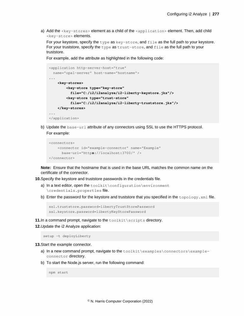
Configuring i2 Analyze | 277
a) Add the <key-stores> element as a child of the <application> element. Then, add child<key-store> elements.
For your keystore, specify the type as key-store, and file as the full path to your keystore.For your truststore, specify the type as trust-store, and file as the full path to yourtruststore.
For example, add the attribute as highlighted in the following code:
<application http-server-host="true"
name="opal-server" host-name="hostname">
...
<key-stores>
<key-store type="key-store"
file="C:/i2/i2analyze/i2-liberty-keystore.jks"/>
<key-store type="trust-store"
file="C:/i2/i2analyze/i2-liberty-truststore.jks"/>
</key-stores>
...
</application>
b) Update the base-url attribute of any connectors using SSL to use the HTTPS protocol.
For example:
<connectors>
<connector id="example-connector" name="Example"
base-url="https://localhost:3700/" />
</connector>
Note: Ensure that the hostname that is used in the base URL matches the common name on thecertificate of the connector.
10.Specify the keystore and truststore passwords in the credentials file.
a) In a text editor, open the toolkit\configuration\environment\credentials.properties file.
b) Enter the password for the keystore and truststore that you specified in the topology.xml file.
ssl.truststore.password=libertyTrustStorePassword
ssl.keystore.password=libertyKeyStorePassword
11.In a command prompt, navigate to the toolkit\scripts directory.
12.Update the i2 Analyze application:
setup -t deployLiberty
13.Start the example connector.
a) In a new command prompt, navigate to the toolkit\examples\connectors\example-connector directory.
b) To start the Node.js server, run the following command:
npm start
© N. Harris Computer Corporation (2022)

Configuring i2 Analyze | 278
Note: The example connector uses port number 3700. Ensure that no other processes are usingthis port number before you start the connector.
14.Start Liberty:
setup -t startLiberty
15.If you are using the IBM HTTP Server, start or restart it.
Use Analyst's Notebook Premium to connect to your deployment. For more information, see Connectingi2 Analyst's Notebook Premium to i2 Analyze.
Now that the example connector is configured for SSL, no warnings are displayed in Analyst's NotebookPremium.
Adding more data sourcesYou can extend your system to use different sources of data by adding the i2 Connect gateway, andconfiguring your deployment to identify the data source and searching to use. You can add the i2Connect gateway to an existing deployment of i2 Analyze.
You must have a deployment of i2 Analyze. When you add the i2 Connect gateway to your deployment,the configuration for an example connector is included. To use the example connector, you mustdownload and install Node.js to host the example connector. Download Node.js for your operatingsystem from: https://nodejs.org/en/download/. You can install Node.js with the default settings.
To use a custom connector that is tailored to your deployment, you either need the details of aconnector that is provided to you, or to create a connector. For more information about how to create acustom connector, see Connecting to external data sources.
The i2 Connect gateway enables analysts to search for and retrieve data from external data sources,and then analyze the results on a chart in Analyst's Notebook Premium. To use the i2 Connect gateway,you must obtain or create a custom connector to the external data source that you want to search. Thei2 Analyze toolkit contains an example configuration for the deployment, and an example connector.
1. Run the addI2Connect task to add the i2 Connect gateway to your deployment. In a commandprompt, navigate to the toolkit\scripts directory and run the following command:
setup -t addI2Connect
2. Decide which connector you would like to add to your deployment:
• If you want to use the example connector, complete the step to start the example connector inDeploying i2 Analyze with the Information Store and the i2 Connect gateway.
• If you would like to add a custom connector, replace the following elements from theconfiguration\environment\topology.xml file with elements specific to the connectoryou want to use:
• The <connector> element with the ID example-connector
• The connector-id element with the value example-connector
Note: For more information about making connector-specific changes to the topology file, seeAdding a connector to the topology.
3. Redeploy i2 Analyze.
setup -t deploy
© N. Harris Computer Corporation (2022)
Configuring i2 Analyze | 279
4. Start i2 Analyze.
setup -t start
5. Start, or restart, the HTTP server that hosts the reverse proxy.
When you start i2 Analyze, the URI that users must specify in Analyst's Notebook Premium isdisplayed in the console. For example, This application is configured for access onhttp://host_name/opal.
Install Analyst's Notebook Premium and connect to your deployment. For more information, seeInstalling i2 Analyst's Notebook Premium and Connecting i2 Analyst's Notebook Premium to i2 Analyze.
Note: The example connector does not use client authenticated SSL communication between i2Analyze and any connectors, so a warning is displayed in Analyst's Notebook Premium. For moreinformation about configuring client-authenticated SSL, see Client authenticated Secure Sockets Layerwith the i2 Connect gateway.
Back up and restoreAn effective backup strategy considers the key components in your deployment and assess the impactof creating replica versions versus the cost of replacing those components if the system fails. Allproduction deployments of i2 Analyze should have a backup and restore strategy in place.
The following components of an i2 Analyze deployment should be backed up to provide acomprehensive backup strategy:
• The configuration
• The Solr search index and ZooKeeper configuration (If you have an Information Store or Chart Store)
• The database (If you have an Information Store or Chart Store)
When you create a backup strategy, consider the following items:
• The amount of time, if any, that is acceptable for a system to be offline to create backups.
• The amount of time that is acceptable for a system to be offline while recovery is in progress.
• The amount of time between backups, for each component.
In a deployment of i2 Analyze that contains a database, the database is the source of truth about thedata contained in a deployment.
This means that the Solr search index must be backed up before the database is and that the databasemust be restored before the Solr search index. If any data in the Information Store was modified afterthe Solr search index was backed up, the changes are updated in the index after the restoring.
The i2 Analyze deployment toolkit contains toolkit tasks that you can use to back up and restore eachcomponent of i2 Analyze. You can choose to use the toolkit tasks to back up all components, or you canuse the toolkit tasks to back up a subset and use the native back up and restore procedure providedby other components. For example, if your organization has existing processes for backing up andrestoring databases but not a Solr search index, you can use the existing process to back up thedatabase in a deployment and the provided toolkit task to back up the Solr search index.
Backing up a deployment
In a production deployment of i2 Analyze, use a tested backup and restore procedure to ensure thatyou can recover from failures. The various components of i2 Analyze must be backed up for completebackup coverage.
© N. Harris Computer Corporation (2022)
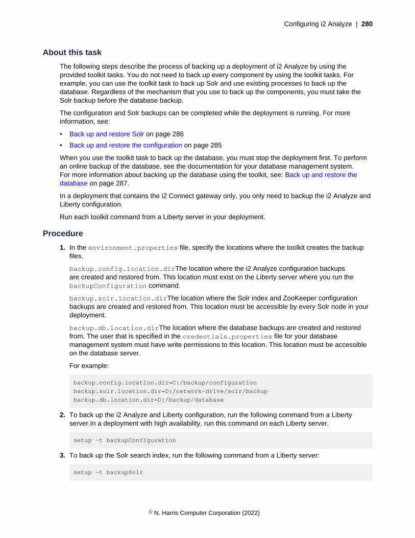
Configuring i2 Analyze | 280
About this task
The following steps describe the process of backing up a deployment of i2 Analyze by using theprovided toolkit tasks. You do not need to back up every component by using the toolkit tasks. Forexample, you can use the toolkit task to back up Solr and use existing processes to back up thedatabase. Regardless of the mechanism that you use to back up the components, you must take theSolr backup before the database backup.
The configuration and Solr backups can be completed while the deployment is running. For moreinformation, see:
• Back up and restore Solr on page 286
• Back up and restore the configuration on page 285
When you use the toolkit task to back up the database, you must stop the deployment first. To performan online backup of the database, see the documentation for your database management system.For more information about backing up the database using the toolkit, see: Back up and restore thedatabase on page 287.
In a deployment that contains the i2 Connect gateway only, you only need to backup the i2 Analyze andLiberty configuration.
Run each toolkit command from a Liberty server in your deployment.
Procedure
1. In the environment.properties file, specify the locations where the toolkit creates the backupfiles.
backup.config.location.dirThe location where the i2 Analyze configuration backupsare created and restored from. This location must exist on the Liberty server where you run thebackupConfiguration command.
backup.solr.location.dirThe location where the Solr index and ZooKeeper configurationbackups are created and restored from. This location must be accessible by every Solr node in yourdeployment.
backup.db.location.dirThe location where the database backups are created and restoredfrom. The user that is specified in the credentials.properties file for your databasemanagement system must have write permissions to this location. This location must be accessibleon the database server.
For example:
backup.config.location.dir=C:/backup/configuration
backup.solr.location.dir=D:/network-drive/solr/backup
backup.db.location.dir=D:/backup/database
2. To back up the i2 Analyze and Liberty configuration, run the following command from a Libertyserver.In a deployment with high availability, run this command on each Liberty server.
setup -t backupConfiguration
3. To back up the Solr search index, run the following command from a Liberty server:
setup -t backupSolr
© N. Harris Computer Corporation (2022)
Configuring i2 Analyze | 281
4. To back up the database in your deployment by using the toolkit task, you must stop the applicationfirst, and ensure that there are no other connections to the database, then run the backup command.In a deployment that contains multiple Liberty servers, you must run the stopLiberty command onevery Liberty server.
setup -t stopLiberty
setup -t backupDatabases
setup -t startLiberty
Restoring a deployment to a point in time
Use the backups of the components of i2 Analyze to restore the system to a previous point in time. In aproduction deployment of i2 Analyze, use a tested backup and restore procedure to ensure that you canrecover from failures.
About this task
The following steps describe the process of restoring a deployment of i2 Analyze by using the providedtoolkit tasks. You do not need to restore every component by using the toolkit tasks. For example, youcan use existing processes to restore the database and use the toolkit task to restore Solr. Regardlessof the mechanism that you use to restore the components, you must restore the database before yourestore the Solr index.
To deploy to a previous point in time, your deployment must be functional. The procedure assumes thatSolr, ZooKeeper, and the database management system are running. As part of the process, you muststop the Liberty servers in the deployment. To recover a deployment after a disaster, see Recoveringfrom a disaster on page 282.
In a deployment that contains the i2 Connect gateway only, you only need to restore the i2 Analyze andLiberty configuration.
For more information about the restore toolkit tasks, see:
• Back up and restore the database on page 287
• Back up and restore Solr on page 286
• Back up and restore the configuration on page 285
Run each toolkit command from a Liberty server in your deployment.
Procedure
1. Use the validateBackups to ensure that the timestamps of the backups you are restoring arecompatible.This task compares the timestamps of the backups created by the toolkit to ensure thatthe configuration backup is the earliest, and that the Solr backup precedes the database backup.
setup -t validateBackups -p configTimestamp=<timestamp> -p
solrTimestamp=<timestamp> -p dbTimestamp=<timestamp>
Where configTimestamp is the timestamp of a configuration backup, solrTimestamp is thetimestamp of a Solr backup, and dbTimestamp is the timestamp of a database backup. You do nothave to provide all of the timestamps to run the toolkit task.
If the backups are compatible, continue with the restore process.
© N. Harris Computer Corporation (2022)

Configuring i2 Analyze | 282
2. Before you restore the deployment, stop Liberty. In a deployment that contains multiple Libertyservers, you must run the stopLiberty command on every Liberty server.
setup -t stopLiberty
3. To restore the database in your deployment, run the following command from a Liberty server:
setup -t restoreDatabases -p timestamp=<timestamp>
The database backup is identified in the location from the backup.db.location.dir setting byusing the timestamp that was specified in the command. The timestamp value in the command mustmatch the timestamp of a backup in the location.
For example: setup -t restoreDatabases -p timestamp=20210420145332.
4. To restore the Solr search index, run the following command from a Liberty server:
setup -t restoreSolr -p timestamp=<timestamp> --hostname <liberty.hostname>
Where liberty.hostname is the hostname of the Liberty server where you are running thecommand, and matches the value for the host-name attribute of the <application> element in thetopology.xml file.
The Solr backup is identified in the location from the backup.solr.location.dir setting byusing the timestamp that was specified in the command. The timestamp value in the command mustmatch the timestamp of a backup directory in the location.
For example: setup -t restoreSolr -p timestamp=20210420145332 --hostname<liberty.hostname>.
5. To restore the i2 Analyze and Liberty configuration, run the following command from a Liberty server:
setup -t restoreConfiguration -p timestamp=<timestamp>
The configuration backup is identified in the location from the backup.config.location.dirsetting by using the timestamp that was specified in the command.The timestamp value in thecommand must match the timestamp of a backup directory in the location.In a deployment with highavailability, run this command on each Liberty server.
For example: setup -t restoreConfiguration -p timestamp=20210420145332.
6. Start Liberty.In a deployment that contains multiple Liberty servers, you must run thestartLiberty command on every Liberty server.
setup -t startLiberty
Result
Your deployment of i2 Analyze is restored to the point in time of the backups that you specified.
Recovering from a disaster
You can use the backups of the components of i2 Analyze to restore the system, or parts of a thesystem, after a disaster. In a production deployment of i2 Analyze, use a tested backup and restoreprocedure to ensure that you can recover from failures.
© N. Harris Computer Corporation (2022)
Configuring i2 Analyze | 283
About this task
The following steps describe the process of restoring a deployment of i2 Analyze by using the providedtoolkit tasks. You do not need to restore every component by using the toolkit tasks. For example, youcan use existing processes to restore the database and use the toolkit task to restore Solr. Regardlessof the mechanism that you use to restore the components, you must restore the components in thesame order as the following steps.
For more information about the restore toolkit tasks, see:
• Back up and restore the database on page 287
• Back up and restore Solr on page 286
• Back up and restore the configuration on page 285
In a deployment that contains the i2 Connect gateway only, you only need to restore the i2 Analyze andLiberty configuration.
To recover from a disaster, you might need to reinstall the i2 Analyze deployment toolkit and install thecomponents of i2 Analyze on the failed servers. The following process assumes that you are recreatingthe servers for each component in your deployment.
Procedure
1. Create the environment to restore your deployment in to. If your servers were lost due to a disaster,you might need to recreate them with the required prerequisites. For more information about theservers that are used in a deployment of i2 Analyze, see Deployment topologies.
2. Use the validateBackups to ensure that the timestamps of the backups you are restoring arecompatible.This task compares the timestamps of the backups created by the toolkit to ensure thatthe configuration backup is the earliest, and that the Solr backup precedes the database backup.
setup -t validateBackups -p configTimestamp=<timestamp> -p
solrTimestamp=<timestamp> -p dbTimestamp=<timestamp>
Where configTimestamp is the timestamp of a configuration backup, solrTimestamp is thetimestamp of a Solr backup, and dbTimestamp is the timestamp of a database backup. You do nothave to provide all of the timestamps to run the toolkit task.
If the backups are compatible, continue with the restore process.
3. Restoring to new Liberty servers.
a. Copy the i2a-config-<timestamp>\toolkit-config directory from your backup tothe toolkit\configuration directory of the deployment toolkit on each server in yourenvironment.
You might have a different configuration backup for each Liberty server in your deployment,ensure that you copy the correct backup for each Liberty server.
4. Create a new deployment to restore into. To create a new deployment, follow the instructions toinstall, deploy, and start the components in Deploying i2 Analyze on multiple servers.
By starting the components, you ensure that your environment is deployed successfully. You cannow restore your environment from your backups.
© N. Harris Computer Corporation (2022)

Configuring i2 Analyze | 284
5. Before you restore the deployment, stop Liberty. In a deployment that contains multiple Libertyservers, you must run the stopLiberty command on every Liberty server.
setup -t stopLiberty
6. To restore the database in your deployment, run the following command from a Liberty server:
setup -t restoreDatabases -p timestamp=<timestamp>
The database backup is identified in the location from the backup.db.location.dir setting byusing the timestamp that was specified in the command. The timestamp value in the command mustmatch the timestamp of a backup in the location.
For example: setup -t restoreDatabases -p timestamp=20210420145332.
7. To restore the Solr search index, run the following command from a Liberty server:
setup -t restoreSolr -p timestamp=<timestamp> --hostname <liberty.hostname>
Where liberty.hostname is the hostname of the Liberty server where you are running thecommand, and matches the value for the host-name attribute of the <application> element in thetopology.xml file.
The Solr backup is identified in the location from the backup.solr.location.dir setting byusing the timestamp that was specified in the command. The timestamp value in the command mustmatch the timestamp of a backup directory in the location.
For example: setup -t restoreSolr -p timestamp=20210420145332 --hostname<liberty.hostname> .
8. Deploying to new Liberty servers.
a. To restore the i2 Analyze and Liberty configuration, run the following command from a Libertyserver:
setup -t restoreConfiguration -p timestamp=<timestamp>
• The configuration backup is identified in the location from thebackup.config.location.dir setting by using the timestamp that was specified in thecommand.
• The timestamp value in the command must match the timestamp of a backup directory in thelocation.
• In a deployment that contains multiple Liberty servers, run the restoreConfigurationcommand on each Liberty server.
For example: setup -t restoreConfiguration -p timestamp=20210420145332.
b. Start Liberty.In a deployment that contains multiple Liberty servers, you must run thestartLiberty command on each Liberty server.
setup -t startLiberty
Result
Your deployment of i2 Analyze is restored to new servers after a disaster.
© N. Harris Computer Corporation (2022)
Configuring i2 Analyze | 285
Back up and restore the configuration
The i2 Analyze and Liberty configuration contains the files that define the functionality of thedeployment, and how users connect to the deployment. To restore the deployment after a failure, createa backup of the configuration.
Intro
• The configuration directory and some files from the Liberty deployment are backed up. Thesefiles enable you to recreate a deployment from the backup files in the same configuration.
• The system can be running when you back up the configuration. The system must be stopped whenyou restore the configuration.
• In a distributed deployment of i2 Analyze, the configuration directory should be identical on eachserver. Therefore, you only need to back up the configuration from the Liberty server.
Backup location
In the environment.properties file, the backup.config.location.dir setting is the locationwhere the configuration backups are created and restored from when you use the toolkit tasks. Thislocation must exist on the Liberty server where you run the toolkit tasks.
Toolkit tasks
• backupConfiguration
• The backupConfiguration toolkit task backs up the i2 Analyze and Liberty configuration to thebackup.config.location.dir location.For example:
setup -t backupConfiguration
• restoreConfiguration
• The restoreConfiguration toolkit task restores the i2 Analyze and Liberty configurationfrom a backup. The restoreConfiguration also deploys Liberty. You must passthe timestamp parameter to the toolkit task with a timestamp for a backup in thebackup.config.location.dir location.For example:
setup -t restoreConfiguration -p timestamp=<timestamp>
If you are recovering from a disaster scenario where you must create new Liberty servers, you mustcopy the i2 Analyze deployment toolkit configuration from the backup to your new Liberty serversbefore you run the restoreConfiguration task.
Backup files
When the backupConfiguration task is run, a directory is created named i2a-config-<timestamp> where <timestamp> is the timestamp of when the toolkit task was run. The directory
© N. Harris Computer Corporation (2022)
Configuring i2 Analyze | 286
contains the files of the i2 Analyze and Liberty configuration and a file that shows the version of i2Analyze. For example:
- i2a-config-20210420145332
- version.txt
- liberty-app-config
- liberty-shared-config
- toolkit-config
The following directories are included in the backup:
• toolkit\configuration
• wlp\usr\shared\configs
• wlp\usr\servers\opal-server
Back up and restore Solr
When you use the backupSolr and restoreSolr toolkit tasks to back up and restore the Solr indexand ZooKeeper configuration, a call to the Solr REST API is made. The toolkit tasks create and restorea full backup of the non-transient Solr collections.
Intro
• The non-transient Solr collections are backed up and restored by using the provided toolkit tasks.The following collection types are non-transient:
• main_index
• match_index
• chart_index
• You must take the Solr backup before a database backup, and you must restore Solr after yourestore the database.
Backup location
In the environment.properties file, the backup.solr.location.dir setting is the locationwhere the Solr index and ZooKeeper configuration backups are created and restored from. This locationmust be accessible by every Solr node in your deployment.
Toolkit tasks
• backupSolrThe backupSolr toolkit task backs up the Solr index and ZooKeeper configuration tothe backup.solr.location.dir location.For example:
setup -t backupSolr
• restoreSolrThe restoreSolr toolkit task restores the Solr index and ZooKeeper configurationfrom a backup. You must pass the timestamp parameter to the toolkit task with a value for abackup in the backup.solr.location.dir location.You must also specify the hostnameparameter, with the hostname of the Liberty server where you are running the command, and that
© N. Harris Computer Corporation (2022)

Configuring i2 Analyze | 287
matches the value for the host-name attribute of the <application> element in the topology.xmlfile. For example:
setup -t restoreSolr -p timestamp=<timestamp> --hostname <liberty.hostname>
Backup files
When the backupSolr task is run, a directory is created named i2a-solr-<collection_name>-<timestamp> where <timestamp> is the timestamp of when the toolkit task was run and<collection_name> the name of the Solr collection backed up. A directory is created for each non-transient Solr collection, with each collection containing a back up. For example:
- i2a-solr-chart_index-20210420145332
- backup.properties
- snapshot.shard1
- snapshot.shard2
- zk_backup
- i2a-solr-main_index-20210420145332
- backup.properties
- snapshot.shard1
- snapshot.shard2
- zk_backup
- i2a-solr-match_index1-20210420145332
- backup.properties
- snapshot.shard1
- snapshot.shard2
- zk_backup
- i2a-solr-match_index2-20210420145332
- backup.properties
- snapshot.shard1
- snapshot.shard2
- zk_backup
Back up and restore the database
When you use the backupDatabases and restoreDatabases toolkit tasks to back up and restorethe database in your deployment, a call to the database management system is made. The toolkit taskscreate and restore a full backup of the database.
Intro
• The backupDatabases toolkit task completes a full backup of the database. The application mustbe stopped before you can back up the database and there must be no active connections to thedatabase.
• Refer to your database management system documentation to learn how to ensure that there areno connections to your database before you create the backup.
• The toolkit task is aimed for smaller deployments where the system can be offline while the databasebackup is completed. If you have a larger deployment or don't want the system to be offline at all,you can back up the database manually. To back up and restore the database manually refer to thedocumentation for your database management system:
© N. Harris Computer Corporation (2022)

Configuring i2 Analyze | 288
• For Db2, see Developing a backup and recovery strategy
• For SQL Server, see Backup Overview
• If you back up the database manually, you can still use the toolkit tasks to back up the i2 Analyzeconfiguration and the Solr index.
• When you back up a deployment of i2 Analyze, the database must be backed up after the Solr index.When you restore the database, you must restore the database before the Solr index.
Backup location
In the environment.properties file, the backup.db.location.dir setting is the locationwhere the database backup are created and restored from. This location must be accessible from thedatabase server. The user that is specified in the credentials.properties file for your databasemanagement system must have write permissions to this location.
Toolkit tasks
• backupDatabasesThe backupDatabases toolkit task backs up the database to thebackup.db.location.dir location.For example:
setup -t backupDatabases
• restoreDatabasesThe restoreDatabases toolkit task restores the database from a backup.You must pass the timestamp parameter to the toolkit task with a value for a backup in thebackup.db.location.dir location.For example:
setup -t restoreDatabases -p timestamp=<timestamp>
Backup files
A backup file is created in the location specified in backup.db.location.dir. The file nameincludes a timestamp of when the backup is created. For example:
• On Db2: ISTORE.0.db2inst1.DBPART000.20210604144506.001
• On SQL Server: ISTORE.20210604152638.bak
You can verify the backup file was correctly created by running the following commands on yourdatabase server:
• On Db2: db2ckbkp <backup file>
• On SQL Server:
RESTORE VERIFYONLY FROM DISK = "<backup file>";
GO
Administering high availabilityWhen your system is deployed in an environment that is designed for high availability or disasterrecovery, you must develop, configure, and test your continuous operation procedures. Continuous
© N. Harris Computer Corporation (2022)

Configuring i2 Analyze | 289
operation includes, but is not limited to, components of the application continuing to function after asubset of their resources is taken offline.
In summary, when a server, or number of servers, fail in your environment you need to ensure that thesystem continues to function. To do so, the process involves:
• Detecting server failure
• Ensuring that only the functional servers are used to process requests
• Recovering the failed servers
• Configuring the environment to use the recovered servers again
The implementation of this process is different for each component of i2 Analyze, the softwareprerequisites that are used, and the operating system that the component is deployed on. For somecomponents of i2 Analyze, the process is automatic but you should understand the process and whatstate the environment is in.
The following information outlines the process for each component in a deployment of i2 Analyze.
Liberty
In a deployment that provides high availability, multiple Liberty servers are used to provide active/activeavailability. The active/active pattern allows multiple Liberty servers to allow connections from clientsand continue to function when some of the Liberty servers fail.
Detecting server failure
To detect if a Liberty server has failed, you can use logs in your load balancer. In the load balancer,monitor the response where you use the health/live endpoint to determine which Liberty servers toroute clients to. If the response from the health/live endpoint for a particular Liberty server is 503,that Liberty server may have failed.
For more information about the endpoint and its responses, see The health/live endpoint on page 291.
The Liberty server can return a 503 if it is not started, in the startup process, or there is a temporaryloss of connection to another component. Liberty can restart as a non-leader if it temporarily loses theconnection to a component and loses leadership. If this is the reason for the 503, the following messageis displayed in the i2_Component_Availability.log file:
INFO ApplicationStateHandler - I2ANALYZE_STATUS:0066 - Application is
entering non-leader mode to serve requests
For more information about the log file, see Monitor the system availability on page 295.
Automatic failover
If a Liberty server fails, the other Liberty servers continue to function as usual. If a client was connectedto the failed Liberty server, the analyst might have to log out from the client and log in again for the loadbalancer to route the request to one of the live Liberty servers.
If it was the leader Liberty server that failed, one of the remaining Liberty servers is elected leader. Formore information about the leadership process, see Liberty leadership configuration on page 290.
© N. Harris Computer Corporation (2022)

Configuring i2 Analyze | 290
Recovering failed servers
There are a number of reasons why a server might fail. Use the logs from the failed server to diagnoseand solve the issue. For example, you might need to restart the server, increase the hardwarespecification, or replace hardware components.
• The Liberty logs are in the deploy\wlp\usr\servers\opal-server\logs directory.
• The deployment toolkit logs are in the toolkit\configuration\logs directory.
For more information about the different log files and their contents, see Deployment log files.
Reinstating high availability
On the recovered Liberty server, run setup -t startLiberty to restart the server and i2 Analyzeapplication.
You can use the load balancer logs to ensure that the Liberty server is now returning 200 from thehealth/live endpoint.
Liberty leadership configuration
In a deployment with multiple Liberty servers, one server is determined to be the leader.
Liberty leadership behavior
The leader Liberty can complete actions that require exclusive access to the Information Storedatabase. These actions include;
• Initiating Solr indexing
• Initiating online upgrade tasks
• Initiating alerts for saved Visual Queries
• Initiating deletion-by-rule jobs
Leadership state
ZooKeeper is used to determine and manage the leadership state of the Liberty servers in adeployment. Each Liberty server polls ZooKeeper for the current leadership state. If there is no leader,the Liberty attempts to become the leader. One Liberty will successfully become the leader.
Leadership poll
To become a leader, and to maintain leadership, Liberty must be able to connect to ZooKeeper, Solr,and the database management system. The connection to each component is checked whenever theleadership state is polled. If any of the components cannot be connected to, the Liberty either releasesits leadership or cannot run for leader if there is not currently a leader.
The leadership poll schedule is independent on each Liberty server. If the current leader releases itsleadership, there is no leader until the leadership poll runs on another Liberty that can then assumeleadership status.
The leadership poll is completed on a configurable schedule. By default, theleadership state is checked every five minutes. To change the interval, updatethe value for the ServerLeadershipReconnectIntervalMinutes setting inDiscoServerSettingsCommon.properties.
© N. Harris Computer Corporation (2022)
Configuring i2 Analyze | 291
For example:
ServerLeadershipReconnectIntervalMinutes=5
Error thresholds
The leadership state can change if a certain number of errors are encountered during indexingoperations within a specified time span. These types of operations are run only on the leader Liberty.The maximum number of errors that can occur, and the time span in which they can occur, areconfigurable.
The MaxPermittedErrorsBeforeLeadershipRelease setting definesthe maximum number of errors that can occur in the time specified by theTimeSpanForMaxPermittedErrorsBeforeLeadershipReleaseInSeconds setting. By default,up to five errors can occur within 30 seconds before the Liberty relinquishes its leadership.
For example:
MaxPermittedErrorsBeforeLeadershipRelease=5
TimeSpanForMaxPermittedErrorsBeforeLeadershipReleaseInSeconds=30
Restarting limits
If the leader Liberty releases leadership, it attempts to restart in non-leader mode. If Liberty cannotconnect to each component, it fails to start. By default, it tries to start three times before failing. Tostart Liberty on this server again, resolve the issue that is stopping Liberty connecting to all of thecomponents and run setup -t startLiberty.
You can change the maximum number of times that Liberty attempts to start before it fails. To changethe number of attempts, update the value of the ServerLeadershipMaxFailedStarts setting inDiscoServerSettingsCommon.properties.
ServerLeadershipMaxFailedStarts=3
The health/live endpoint
The api/v1/health/live REST endpoint returns the status of the i2 Analyze application running ona Liberty server.
The api/v1/health/live endpoint can return one of two possible responses:
• 200 The application is UP and handling requests.
• 503 The application is DOWN and not handling requests.
When the endpoint is called, the application checks whether it can connect to ZooKeeper, Solr, and thedatabase management system if your deployment uses one. If it can connect to all of the components,the endpoint returns 200. This means that you can route client requests to this Liberty server.
If the application fails to connect to a component, the endpoint returns 503. The Liberty server cannotprocess client requests.
The endpoint also returns 503 until the application completes the start process.
When you configure a load balancer for use in a high availability deployment, it should use the api/v1/health/live endpoint to determine which servers to send requests to. For more information, seeDeploying a load balancer.
© N. Harris Computer Corporation (2022)

Configuring i2 Analyze | 292
Database management system
In a deployment that provides high availability, the Information Store database is deployed in an active/passive pattern. In the active/passive pattern, there is a primary database instance and a number ofstandbys.
Detecting server failure
There are a number of different ways to detect if there has been a database failure.
• The i2_Component_Availability.log contains messages that report the connection status forthe Information Store database. For more information about the messages that are specific to thedatabase, see Database management system messages on page 297.
There are also a number of different tools that are specific to your database management system.
• Db2:
• Db2 fault monitor on Linux
• Heartbeat monitoring in clustered environments
• Monitoring Db2 High Availability Disaster Recovery (HADR) databases
For more information about detecting failures for Db2, see Detecting an unplanned outage.
• SQL Server
• To understand when SQL Server initiates failover, see How Automatic Failover Works.
Manual and automatic failover
When the primary server fails, the system must fail over and use the remaining servers to completeoperations.
• Db2
• If you are using an automated-cluster controller, failover to a standby instance is automatic. Formore information, see .
• If you are using client-side automatic client rerouting, then you must manually force a standbyinstance to become the new primary. For more information about initiating a takeover, seePerforming an HADR failover operation.
• SQL Server
• When SQL Server is configured for high availability in an availability group with three servers,failover is automatic. For more information about failover, see Automatic Failover.
Recovering failed servers
There are a number of reasons why a server might fail. You can use the logs from the database serverto diagnose and solve the issue. For example, you might need to restart the server, increase thehardware specification, or replace hardware components that caused the issue.
When the server is back online and functional, you can recover it to become the primary server again.Alternatively, you can recover it to become the standby for the new primary that you failed over to.
This might include recovering a back up of the Information Store database from before the server failed.
© N. Harris Computer Corporation (2022)
Configuring i2 Analyze | 293
Reinstating high availability
• Db2
• Some toolkit tasks only work on the original primary database server when you are not usingan automated-cluster controller such as TSAMP. To use those toolkit tasks, you must revert tousing the original primary database server after a failure or redeploy your system to use the newprimary database server.
• For more information about the process to make the recovered database the primary again,see Reintegrating a database after a takeover operation.
• To redeploy with the new primary, update the topology.xml on each Liberty to referencethe new server in the host-name and port-number and redeploy each Liberty.
• SQL Server
• On SQL Server it is not required to return to the previous primary, however you might chooseto do so. You can initiate a planned manual failover to return the initial primary server. For moreinformation, see Planned Manual Failover (Without Data Loss).
Solr
In a deployment that provides high availability, i2 Analyze uses SolrCloud to deploy Solr with faulttolerance and high availability capabilities. Solr uses an active/active pattern that allows all Solr serversto respond to requests.
Detecting server failure
To detect if there has been a Solr failure, you can use the following mechanisms:
• The i2_Component_Availability.log contains messages that report the status of the Solrcluster. For more information about the messages that are specific to Solr, see Solr messages onpage 295.
• The Solr Web UI displays the status of any collections in a Solr cluster. Navigate to the followingURL in a web browser to access the UI: http://localhost:8983/solr/#/~cloud?view=graph. Where localhost and 8983 are replaced with the hostname and port number of one ofyour Solr nodes.
Automatic failover
Solr continues to update the index and provide search results while there is at least one replicaavailable for each shard.
Recovering failed servers
There are a number of reasons why a server might fail. Use the logs from the server to diagnose andsolve the issue.
Solr logs:
• The Solr logs are located in the i2analyze\deploy\solr\server\logs\8983 directory oneach Solr server. Where 8983 is the port number of the Solr node on the server.
• The application logs are in the deploy\wlp\usr\servers\opal-server\logs directory,specifically the i2_Solr.log file.
For more information about the different log files and their contents, see Deployment log files.
© N. Harris Computer Corporation (2022)

Configuring i2 Analyze | 294
To recover the failed server you might need to restart the server, increase the hardware specification, orreplace hardware components.
Reinstating high availability
On the recovered Solr server, run setup -t startSolrNodes -hn solr.hostname to start theSolr nodes on the server.
You can us the i2_Component_Availability.log and Solr Web UI to ensure that the nodes startcorrectly and that the cluster returns to its previous state.
ZooKeeper
In a deployment that provides high availability, ZooKeeper is used to manage the Solr cluster andmaintain Liberty leadership information. ZooKeeper uses an active/active pattern that allows allZooKeeper servers to respond to requests.
Detecting server failure
To detect ZooKeeper server failures:
• The i2_Component_Availability.log contains messages that report the status of theZooKeeper quorum. For more information, see ZooKeeper status messages on page 297.
• The Solr Web UI contains the status of the ZooKeeper quorum: http://localhost:8983/solr/#/~cloud?view=zkstatus. Where localhost and 8983 are replaced with the host name and portnumber of one of your Solr nodes.
Manual and automatic fail over
The ZooKeeper quorum continues to function while more than half of the total number of ZooKeeperhosts in the quorum are available. For example, if you have three ZooKeeper servers, your system cansustain one ZooKeeper server failure.
Recovering failed servers
There are a number of reasons why a server might fail. Use the logs from the server to diagnose andsolve the issue.
ZooKeeper logs:
• The ZooKeeper logs are located in the i2analyze\data\zookeeper\8\ensembles\zoo\zkhosts\1\logs directory on the failed ZooKeeper server. Where 1 is the identifier of theZooKeeper host on the server.
• The application logs are in the deploy\wlp\usr\servers\opal-server\logs directory.
For more information about the different log files and their contents, see Deployment log files.
To recover the failed server you might need to restart the server, increase the hardware specification, orreplace hardware components.
Reinstating high availability
On the recovered ZooKeeper server, run setup -t startZkHosts -hn zookeeper.hostname tostart the ZooKeeper host on the server.
You can use the i2_Component_Availability.log and Solr Web UI ZooKeeper status view toensure that the system returns to its previous state.
© N. Harris Computer Corporation (2022)

Configuring i2 Analyze | 295
Monitor the system availability
i2 Analyze reports on the availability of each component in the environment so that the state can bemonitored. The availability is logged on each Liberty server in the environment.
To monitor the status of your deployment, use the i2_Component_Availability.log file. Thislog file is located in the wlp/servers/opal-server/opal-services/logs directory on eachLiberty server in your deployment. Therefore, you must monitor the log file on each Liberty server inyour deployment.
The log contains messages about the Liberty leadership status, Solr cluster status, and the availabilityof each component.
Liberty leadership messages
If the Liberty starting the election process, the following message is displayed:
•INFO ServerLeadershipMonitor - We are running for Liberty leader
If the Liberty is elected leader, the following messages are displayed:
•INFO ServerLeadershipMonitor - We are the Liberty leader
•INFO ApplicationStateHandler - I2ANALYZE_STATUS:0065 - Application is
entering leader mode
If the Liberty is not elected leader, the following messages are displayed:
•INFO ServerLeadershipMonitor - We are not the Liberty leader
•INFO ApplicationStateHandler - I2ANALYZE_STATUS:0063 - Application is
entering non-leader mode to serve requests
Component messages
If all of the components are available to the Liberty server, the following message is displayed:
•INFO ComponentAvailabilityCheck - All components are available
If at least one of the components in not available to the Liberty server, the following message isdisplayed:
•WARN ComponentAvailabilityCheck - Not all components are availale
When the Liberty server continues to check the availability of each component, the followingmessage is displayed:
•INFO ComponentAvailabilityCheck - I2ANALYZE_STATUS:0068 - The
application is waiting for all components to be available
Solr messages
© N. Harris Computer Corporation (2022)
Configuring i2 Analyze | 296
If the Liberty server cannot connect to the Solr cluster, the following message is displayed:
•WARN ComponentAvailabilityCheck - Unable to connect to Solr cluster
WARN ComponentAvailabilityCheck - The Solr cluster is unavailable
The following messages describe the state of the Solr cluster in the deployment:
• ALL_REPLICAS_ACTIVE - The named Solr collection is healthy. All replicas in the collection areactive.
For example:
INFO SolrHealthStatusLogger - 'main_index','ALL_REPLICAS_ACTIVE'
• DEGRADED - The named Solr collection is degraded. The minimum replication factor can beachieved, but at least one replica is down or failed to recover.
For example:
WARN SolrHealthStatusLogger - 'main_index','DEGRADED'
When the status is DEGRADED, data can still be written to the Solr index. When the status returnsto ALL_REPLICAS_ACTIVE, the data is synchronized in the Solr index as described in Datasynchronization in i2 Analyze on page 297.
They deployment can still be used with the collection in a degraded state, however thedeployment can now sustain fewer Solr server failures. If a degraded state is common, or lastsfor an extended time, you should investigate the Solr logs to improve the stability of the system.
• RECOVERING - The named Solr collection is recovering. The minimum replication factor cannotbe achieved, because too many replicas are currently in recovery mode.
For example:
INFO SolrHealthStatusLogger - 'main_index','RECOVERING'
If all of the replicas recover, the status changes to ALL_REPLICAS_ACTIVE. If the replicas fail torecover, the status changes to DEGRADED or DOWN.
• DOWN - The named Solr collection is down. The minimum replication factor cannot be achievedbecause too many replicas are down or have failed to recover.
For example:
WARN SolrHealthStatusLogger - 'main_index','DOWN'
When the status is DOWN, data cannot be written to the Solr index. You should attempt to resolvethe issue. For more information, see Solr on page 293.
• UNAVAILABLE - The named Solr collection is unavailable. The application cannot connect to thecollection.
For example:
WARN SolrHealthStatusLogger - 'main_index','UNAVAILABLE'
© N. Harris Computer Corporation (2022)
Configuring i2 Analyze | 297
When the status is UNAVAILABLE, data cannot be written to the Solr index. You should attemptto resolve the issue. For more information, see Solr on page 293.
ZooKeeper status messages
If the connection to ZooKeeper is lost, the following messages are displayed:
WARN ComponentAvailabilityCheck - Unable to connect to ZooKeeper
WARN ComponentAvailabilityCheck - The ZooKeeper quorum is unavailable
When the connection to the database is restored, the all components are active message isdisplayed.
Database management system messages
If the connection to the database is lost, the following messages are displayed:
WARN ComponentAvailabilityCheck - Information Store database appears to be
offline, retrying...
WARN ComponentAvailabilityCheck - Unable to connect to the Information
Store database.
java.sql.SQLException: The TCP/IP connection to the host has failed.
Error: "Socket operation on nonsocket: configureBlocking. Verify the connection
properties.
Make sure that an instance of SQL Server is running on the host and accepting
TCP/IP connections at the port.
Make sure that TCP connections to the port are not blocked by a firewall.".
DSRA0010E: SQL State = 08S01, Error Code = 0
WARN ComponentAvailabilityCheck - The Information Store database is
unavailable
When the connection to the database is restored, the all components are active message isdisplayed.
Data synchronization in i2 Analyze
In a deployment of i2 Analyze that contains an Information Store database, data is stored in both thedatabase and the Solr search index. In i2 Analyze, the database is considered the source of truth fordata in the deployment. When data is added, modified, or removed from the deployment, the datachange is applied to the database before those changes are reflected in the search index.
When data changes occur, the database and Solr retain watermarks that record if the operation wassuccessfully completed in the database and Solr index. i2 Analyze routinely checks these watermarksin the deployment. i2 Analyze can respond to the state of the deployment in a number of different ways,and can normally be resolved without manual intervention.
Note: There is no mechanism in i2 Analyze to ensure that data is written to any standby databaseinstances before the watermarks are updated.
Changes to the Solr collection health
If at least on replica for a shard is unavailable, the collection is marked as unhealthy. If there are datachanges in the database during this time, the Solr index is updated on the replicas that are availablewhile the minimum replication factor is achieved.
© N. Harris Computer Corporation (2022)

Configuring i2 Analyze | 298
When all of the replicas are available and the Solr collection is marked as healthy again, all of thedata changes that occurred when it was in the unhealthy state are reindexed. This means that all datachanges are indexed on every replica.
At i2 Analyze application start
When the i2 Analyze application starts, i2 Analyze checks the watermarks.
• If the deployment is in sync, then the deployment starts as usual.
• If there is data in the database that isn't in the Solr index, the indexing process indexes the data fromthe database that is not in the Solr index.
• If there is data in the Solr index that isn't in the database, i2 Analyze does not start and the followingmessage is displayed:
The 'main_index' index reports that it is ahead of the database
This situation can occur if you recover the database from a backup that was taken before the currentSolr index. In your back up and restore procedure, ensure that you restore the database from abackup that was taken after the Solr index backup.
Implementation details
The values that i2 Analyze uses to record the state of the deployment are called watermarks. Wheneverdata is changed in the database, the data change is then indexed in Solr. When Solr has completedindexing the changed data, the watermarks are updated. The watermarks are stored in the databaseand ZooKeeper. Two watermarks are maintained, a high watermark and a low watermark.
High watermark
The high watermark is updated in both locations when Solr achieves the minimum replicationfactor. That is, when the index is updated on a specified number of replicas for a shard. Whenyou configure Solr for high availability, you specify the minimum replication factor for each Solrcollection.
Low watermark
The low watermark is updated in both locations when Solr achieves the maximum replication factor.That is, when the index is updated on all of the replicas for a shard. The low watermark is onlyupdated after the high watermark, the low watermark cannot have a higher value than the highwatermark.
Configuration resourcesThe configuration resources section contains information that is referenced elsewhere in theconfiguration section. The section also includes the reference documentation for the configuration filesthat are in the i2 Analyze deployment toolkit.
Configuration files reference
In the deployment toolkit, you can identify and modify the core components of your deployment. Many ofthe settings in the configuration files must be set before you can deploy i2 Analyze.
Specifying the deployment credentials
To allow the deployment toolkit to update the database, Lightweight Third-Party Authentication (LTPA)keys, and Solr search platform components, you must provide user names and passwords. The user
© N. Harris Computer Corporation (2022)

Configuring i2 Analyze | 299
names and passwords that you provide allow the system to set up and administer components of i2Analyze, and are not used to access i2 Analyze.
Database
For the database that is identified in topology.xml, you must specify a user name and apassword in the credentials.properties file. The setup script uses this information toauthenticate with the database.
Note: The user that you specify must have privileges to create and populate databases in thedatabase management system.
The database credentials are stored in the following format:
db.infostore.user-name=user name
db.infostore.password=password
For example:
db.infostore.user-name=admin
db.infostore.password=password
The db.infostore.truststore.password credential is used only when you configure theconnection between the database and Liberty to use SSL. If you are not using SSL to secure thisconnection, you do not need to specify a value for the db.infostore.truststore.passwordcredential. For more information about configuring SSL, see Configure Secure Sockets Layer with i2Analyze.
LTPA keys
You must provide a value for the ltpakeys.password property. This value is used by the systemto encrypt LTPA tokens.
• For a stand-alone deployment of i2 Analyze, you can specify any value as the password.
• For a deployment of i2 Analyze that uses LTPA tokens to authenticate with other systems, youmust specify the same password that those systems use.
Solr search platform
The Solr search platform is used to search data in the Information Store. You must provide valuesfor the solr.user-name and solr.password properties. Any Solr indexes are created wheni2 Analyze is first deployed, and the values that you provide here become the Solr user name andpassword.
When you deploy i2 Analyze, the passwords in the credentials.properties file are encoded.
1. Using a text editor, open the toolkit\configuration\environment\credentials.properties file.
2. Specify the database, LTPA, and Solr credentials for your deployment:
• the database user names and passwords
• the LTPA keys password
• the Solr user name and password
3. Save and close the credentials.properties file.
© N. Harris Computer Corporation (2022)
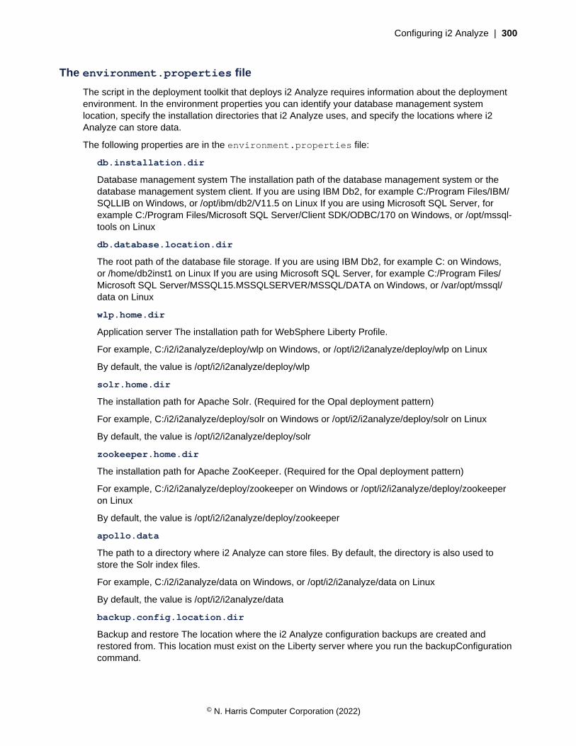
Configuring i2 Analyze | 300
The environment.properties file
The script in the deployment toolkit that deploys i2 Analyze requires information about the deploymentenvironment. In the environment properties you can identify your database management systemlocation, specify the installation directories that i2 Analyze uses, and specify the locations where i2Analyze can store data.
The following properties are in the environment.properties file:
db.installation.dir
Database management system The installation path of the database management system or thedatabase management system client. If you are using IBM Db2, for example C:/Program Files/IBM/SQLLIB on Windows, or /opt/ibm/db2/V11.5 on Linux If you are using Microsoft SQL Server, forexample C:/Program Files/Microsoft SQL Server/Client SDK/ODBC/170 on Windows, or /opt/mssql-tools on Linux
db.database.location.dir
The root path of the database file storage. If you are using IBM Db2, for example C: on Windows,or /home/db2inst1 on Linux If you are using Microsoft SQL Server, for example C:/Program Files/Microsoft SQL Server/MSSQL15.MSSQLSERVER/MSSQL/DATA on Windows, or /var/opt/mssql/data on Linux
wlp.home.dir
Application server The installation path for WebSphere Liberty Profile.
For example, C:/i2/i2analyze/deploy/wlp on Windows, or /opt/i2/i2analyze/deploy/wlp on Linux
By default, the value is /opt/i2/i2analyze/deploy/wlp
solr.home.dir
The installation path for Apache Solr. (Required for the Opal deployment pattern)
For example, C:/i2/i2analyze/deploy/solr on Windows or /opt/i2/i2analyze/deploy/solr on Linux
By default, the value is /opt/i2/i2analyze/deploy/solr
zookeeper.home.dir
The installation path for Apache ZooKeeper. (Required for the Opal deployment pattern)
For example, C:/i2/i2analyze/deploy/zookeeper on Windows or /opt/i2/i2analyze/deploy/zookeeperon Linux
By default, the value is /opt/i2/i2analyze/deploy/zookeeper
apollo.data
The path to a directory where i2 Analyze can store files. By default, the directory is also used tostore the Solr index files.
For example, C:/i2/i2analyze/data on Windows, or /opt/i2/i2analyze/data on Linux
By default, the value is /opt/i2/i2analyze/data
backup.config.location.dir
Backup and restore The location where the i2 Analyze configuration backups are created andrestored from. This location must exist on the Liberty server where you run the backupConfigurationcommand.
© N. Harris Computer Corporation (2022)
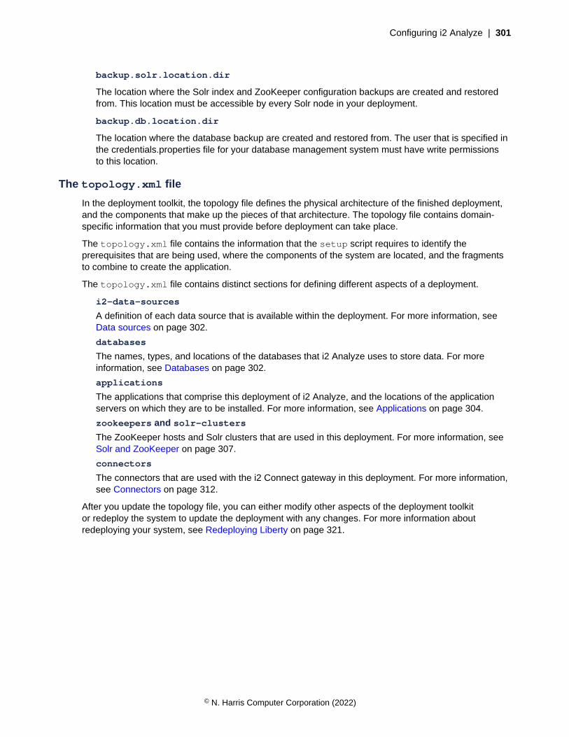
Configuring i2 Analyze | 301
backup.solr.location.dir
The location where the Solr index and ZooKeeper configuration backups are created and restoredfrom. This location must be accessible by every Solr node in your deployment.
backup.db.location.dir
The location where the database backup are created and restored from. The user that is specified inthe credentials.properties file for your database management system must have write permissionsto this location.
The topology.xml file
In the deployment toolkit, the topology file defines the physical architecture of the finished deployment,and the components that make up the pieces of that architecture. The topology file contains domain-specific information that you must provide before deployment can take place.
The topology.xml file contains the information that the setup script requires to identify theprerequisites that are being used, where the components of the system are located, and the fragmentsto combine to create the application.
The topology.xml file contains distinct sections for defining different aspects of a deployment.
i2-data-sources
A definition of each data source that is available within the deployment. For more information, seeData sources on page 302.
databases
The names, types, and locations of the databases that i2 Analyze uses to store data. For moreinformation, see Databases on page 302.
applications
The applications that comprise this deployment of i2 Analyze, and the locations of the applicationservers on which they are to be installed. For more information, see Applications on page 304.
zookeepers and solr-clusters
The ZooKeeper hosts and Solr clusters that are used in this deployment. For more information, seeSolr and ZooKeeper on page 307.
connectors
The connectors that are used with the i2 Connect gateway in this deployment. For more information,see Connectors on page 312.
After you update the topology file, you can either modify other aspects of the deployment toolkitor redeploy the system to update the deployment with any changes. For more information aboutredeploying your system, see Redeploying Liberty on page 321.
© N. Harris Computer Corporation (2022)
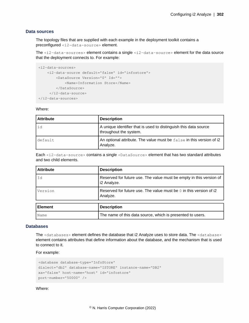
Configuring i2 Analyze | 302
Data sources
The topology files that are supplied with each example in the deployment toolkit contains apreconfigured <i2-data-source> element.
The <i2-data-sources> element contains a single <i2-data-source> element for the data sourcethat the deployment connects to. For example:
<i2-data-sources>
<i2-data-source default="false" id="infostore">
<DataSource Version="0" Id="">
<Name>Information Store</Name>
</DataSource>
</i2-data-source>
</i2-data-sources>
Where:
Attribute Description
id A unique identifier that is used to distinguish this data sourcethroughout the system.
default An optional attribute. The value must be false in this version of i2Analyze.
Each <i2-data-source> contains a single <DataSource> element that has two standard attributesand two child elements.
Attribute Description
Id Reserved for future use. The value must be empty in this version ofi2 Analyze.
Version Reserved for future use. The value must be 0 in this version of i2Analyze.
Element Description
Name The name of this data source, which is presented to users.
Databases
The <databases> element defines the database that i2 Analyze uses to store data. The <database>element contains attributes that define information about the database, and the mechanism that is usedto connect to it.
For example:
<database database-type="InfoStore"
dialect="db2" database-name="ISTORE" instance-name="DB2"
xa="false" host-name="host" id="infostore"
port-number="50000" />
Where:
© N. Harris Computer Corporation (2022)

Configuring i2 Analyze | 303
Attribute Description
database-type The value must be InfoStore in this version of i2 Analyze.
dialect Specifies the type of database engine. This attribute can be set to one of thefollowing values:
• db2
• sqlserver
database-name A name that identifies the database to the database engine.
instance-name The instance name that was specified during installation of your databaseengine.
If you are using SQL Server, you can either specify the port-number orinstance-name attribute. For SQL Server on Linux, you must use theport-number attribute.
xa Determines whether distributed transactions are enabled for this database.
host-name The hostname of the server where the database is located.
id A unique identifier that is used to distinguish this database throughout thesystem. The value must match the id in the <i2-data-source> element.
port-number The port on the database server to send requests to.
If you are using SQL Server, you can either specify the port-number orinstance-name attribute.
Remote database attributes
If your database is on a remote server from the i2 Analyze application, you must use the followingattributes in the topology.xml file:
Attribute Description
os-type Identifies the operating system of the server where the database is located.This can be one of the following values:
• WIN
• UNIX
If you are using Db2, you can also specify AIX.
node-name Identifies the node to create in the Db2 node directory.
The value of the node-name attribute must start with a letter, and havefewer than 8 characters. For more information about naming in Db2, seeNaming conventions.
© N. Harris Computer Corporation (2022)

Configuring i2 Analyze | 304
For example, if you are using IBM Db2:
<database database-type="InfoStore" dialect="db2" instance-name="DB2"
database-name="ISTORE" xa="false" id="infostore"
host-name="remote.hostname" port-number="50000"
node-name="node1" os-type="WIN" />
For example, if you are using Microsoft SQL Server:
<database database-type="InfoStore" dialect="sqlserver" instance-name="SQLSERVER"
database-name="ISTORE" xa="false" id="infostore"
host-name="remote.hostname" os-type="WIN" />
Applications
The <applications> and child <application> element within the topology file define the indexes,file stores, and WAR file for the application.
An <application> element has the following attributes:
Attribute Description
name The value must be opal-server in this version of i2 Analyze.
host-name The hostname of the server where the application is located.
http-server-host
Determines whether the HTTP Server is configured by the deployment toolkit.
Set to true to configure the HTTP Server, or false not to configure the HTTPServer.
The following sections explain how to define the indexes, file stores, and WAR file for an application.
File stores
The <application> element contains a child <file-stores> element that defines the file storesthat are used by the application. The location attribute specifies the file path to use for each file store.The other attributes must be left with their default values.
WAR files
The <application> element contains a child <wars> element. The <wars> element contains child<war> elements that define the contents of the i2 Analyze WAR files that are installed on the applicationserver.
Each <war> element has the following attributes:
Attribute Description
target The type of WAR file to create. The following types are available:
• opal-services-is
• opal-services-daod
• opal-services-is-daod
© N. Harris Computer Corporation (2022)
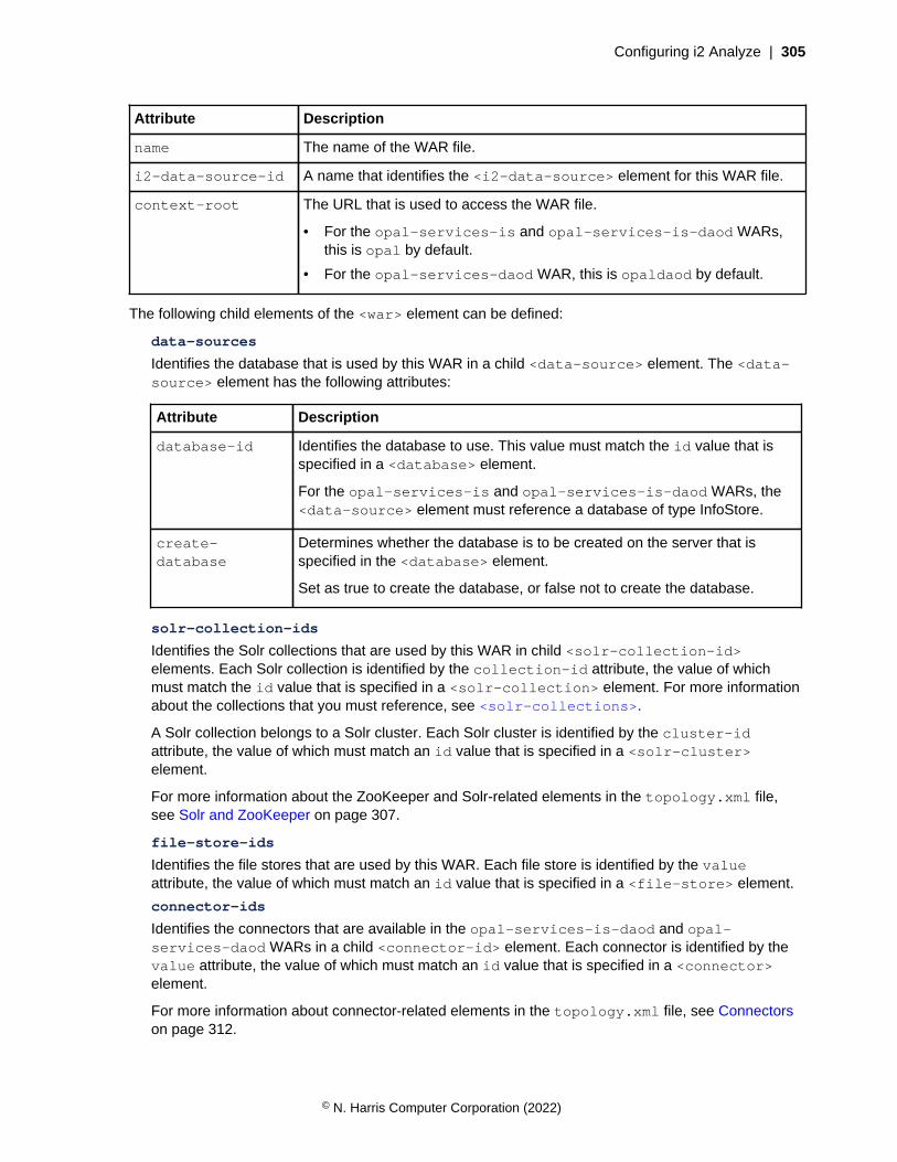
Configuring i2 Analyze | 305
Attribute Description
name The name of the WAR file.
i2-data-source-id A name that identifies the <i2-data-source> element for this WAR file.
context-root The URL that is used to access the WAR file.
• For the opal-services-is and opal-services-is-daod WARs,this is opal by default.
• For the opal-services-daod WAR, this is opaldaod by default.
The following child elements of the <war> element can be defined:
data-sources
Identifies the database that is used by this WAR in a child <data-source> element. The <data-source> element has the following attributes:
Attribute Description
database-id Identifies the database to use. This value must match the id value that isspecified in a <database> element.
For the opal-services-is and opal-services-is-daod WARs, the<data-source> element must reference a database of type InfoStore.
create-database
Determines whether the database is to be created on the server that isspecified in the <database> element.
Set as true to create the database, or false not to create the database.
solr-collection-ids
Identifies the Solr collections that are used by this WAR in child <solr-collection-id>elements. Each Solr collection is identified by the collection-id attribute, the value of whichmust match the id value that is specified in a <solr-collection> element. For more informationabout the collections that you must reference, see <solr-collections>.
A Solr collection belongs to a Solr cluster. Each Solr cluster is identified by the cluster-idattribute, the value of which must match an id value that is specified in a <solr-cluster>element.
For more information about the ZooKeeper and Solr-related elements in the topology.xml file,see Solr and ZooKeeper on page 307.
file-store-ids
Identifies the file stores that are used by this WAR. Each file store is identified by the valueattribute, the value of which must match an id value that is specified in a <file-store> element.
connector-ids
Identifies the connectors that are available in the opal-services-is-daod and opal-services-daod WARs in a child <connector-id> element. Each connector is identified by thevalue attribute, the value of which must match an id value that is specified in a <connector>element.
For more information about connector-related elements in the topology.xml file, see Connectorson page 312.
© N. Harris Computer Corporation (2022)
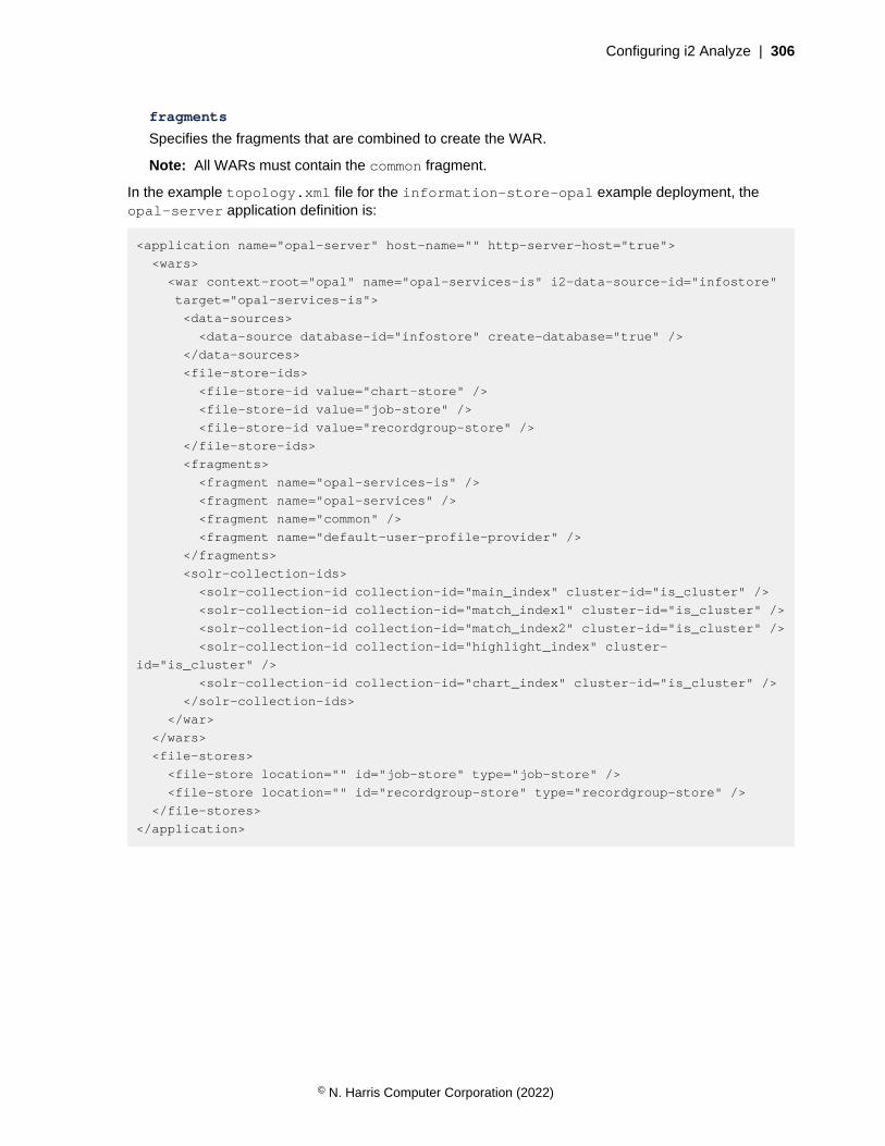
Configuring i2 Analyze | 306
fragments
Specifies the fragments that are combined to create the WAR.
Note: All WARs must contain the common fragment.
In the example topology.xml file for the information-store-opal example deployment, theopal-server application definition is:
<application name="opal-server" host-name="" http-server-host="true">
<wars>
<war context-root="opal" name="opal-services-is" i2-data-source-id="infostore"
target="opal-services-is">
<data-sources>
<data-source database-id="infostore" create-database="true" />
</data-sources>
<file-store-ids>
<file-store-id value="chart-store" />
<file-store-id value="job-store" />
<file-store-id value="recordgroup-store" />
</file-store-ids>
<fragments>
<fragment name="opal-services-is" />
<fragment name="opal-services" />
<fragment name="common" />
<fragment name="default-user-profile-provider" />
</fragments>
<solr-collection-ids>
<solr-collection-id collection-id="main_index" cluster-id="is_cluster" />
<solr-collection-id collection-id="match_index1" cluster-id="is_cluster" />
<solr-collection-id collection-id="match_index2" cluster-id="is_cluster" />
<solr-collection-id collection-id="highlight_index" cluster-
id="is_cluster" />
<solr-collection-id collection-id="chart_index" cluster-id="is_cluster" />
</solr-collection-ids>
</war>
</wars>
<file-stores>
<file-store location="" id="job-store" type="job-store" />
<file-store location="" id="recordgroup-store" type="recordgroup-store" />
</file-stores>
</application>
© N. Harris Computer Corporation (2022)
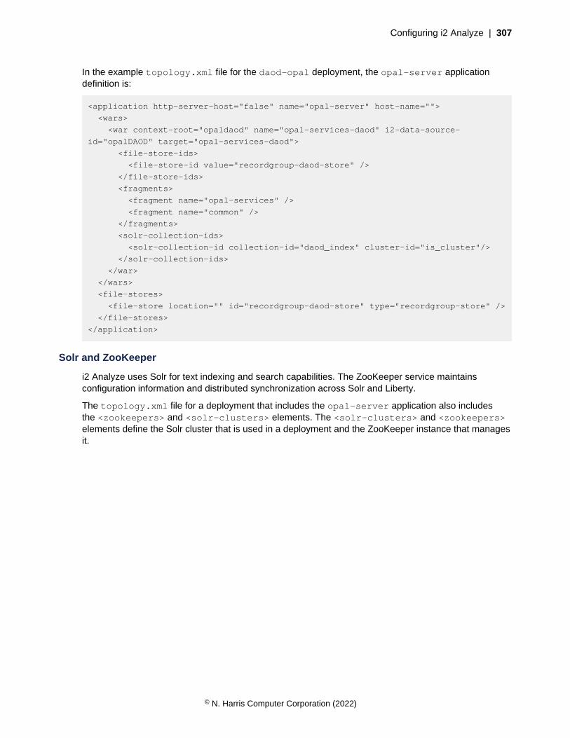
Configuring i2 Analyze | 307
In the example topology.xml file for the daod-opal deployment, the opal-server applicationdefinition is:
<application http-server-host="false" name="opal-server" host-name="">
<wars>
<war context-root="opaldaod" name="opal-services-daod" i2-data-source-
id="opalDAOD" target="opal-services-daod">
<file-store-ids>
<file-store-id value="recordgroup-daod-store" />
</file-store-ids>
<fragments>
<fragment name="opal-services" />
<fragment name="common" />
</fragments>
<solr-collection-ids>
<solr-collection-id collection-id="daod_index" cluster-id="is_cluster"/>
</solr-collection-ids>
</war>
</wars>
<file-stores>
<file-store location="" id="recordgroup-daod-store" type="recordgroup-store" />
</file-stores>
</application>
Solr and ZooKeeper
i2 Analyze uses Solr for text indexing and search capabilities. The ZooKeeper service maintainsconfiguration information and distributed synchronization across Solr and Liberty.
The topology.xml file for a deployment that includes the opal-server application also includesthe <zookeepers> and <solr-clusters> elements. The <solr-clusters> and <zookeepers>elements define the Solr cluster that is used in a deployment and the ZooKeeper instance that managesit.
© N. Harris Computer Corporation (2022)

Configuring i2 Analyze | 308
<solr-clusters>
In the supplied topology.xml file that includes the opal-server application with the opal-services-is WAR, the <solr-clusters> definition is:
<solr-clusters>
<solr-cluster id="is_cluster" zookeeper-id="zoo">
<solr-collections>
<solr-collection
id="main_index" type="main"
lucene-match-version=""
max-shards-per-node="4" num-shards="4" num-replicas="1"
/>
<solr-collection
id="match_index1" type="match"
lucene-match-version=""
max-shards-per-node="4" num-shards="4" num-replicas="1"
/>
<solr-collection
id="match_index2" type="match"
lucene-match-version=""
max-shards-per-node="4" num-shards="4" num-replicas="1"
/>
<solr-collection
id="highlight_index" type="highlight"
lucene-match-version=""
max-shards-per-node="4" num-shards="4" num-replicas="1"
/>
<solr-collection
id="chart_index" type="chart"
lucene-match-version=""
max-shards-per-node="4" num-shards="4" num-replicas="1"
/>
<solr-collection
id="vq_index" type="vq"
lucene-match-version=""
max-shards-per-node="4" num-shards="4" num-replicas="1"
/>
</solr-collections>
<solr-nodes>
<solr-node
memory="2g"
id="node1"
host-name=""
data-dir=""
port-number="8983"
/>
</solr-nodes>
</solr-cluster>
</solr-clusters>
© N. Harris Computer Corporation (2022)

Configuring i2 Analyze | 309
The <solr-clusters> element includes a child <solr-cluster> element. The id attribute of the<solr-cluster> element is a unique identifier for the Solr cluster. To associate the Solr cluster withthe ZooKeeper instance, the value of the zookeeper-id attribute must match the value of the idattribute of the <zookeeper> element.
<solr-collections>
The <solr-collections> element is a child of the <solr-cluster> element. The <solr-collections> element has child <solr-collection> elements.
Depending on the WARs that are included in the application, the number and type of required child<solr-collection> elements is different.
opal-services-is
In the opal-services-is WAR, you must have <solr-collection> elements with each of thefollowing values for the type attribute:
• main - you must have either one or two collections of type main
• match - you must have two collections of type match
• highlight - you must have one collection of type highlight
• chart - you must have one collection of type chart
• vq - you must have one collection of type vq
opal-services-daod
In the opal-services-daod WAR, you must have one <solr-collection> element with avalue of daod for the type attribute.
opal-services-is-daod
In the opal-services-is-daod WAR, you must have <solr-collection> elements witheach of the following values for the type attribute:
• main - you must have either one or two collections of type main
• daod - you must have one collection of type daod
• match - you must have two collections of type match
• highlight - you must have one collection of type highlight
• chart - you must have one collection of type chart
• vq - you must have one collection of type vq
The <solr-collection> element has the following attributes:
Attribute Description
id An identifier that is used to identify the Solr collection.
type The type of the collection. The possible values are:
• main
• daod
• match
• highlight
• chart
© N. Harris Computer Corporation (2022)
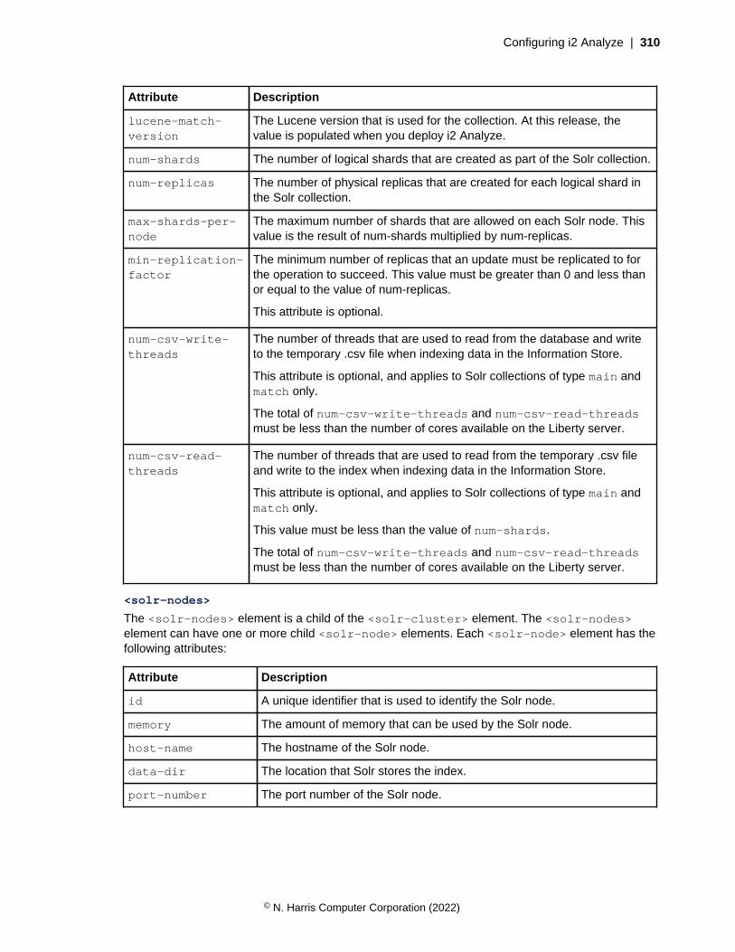
Configuring i2 Analyze | 310
Attribute Description
lucene-match-version
The Lucene version that is used for the collection. At this release, thevalue is populated when you deploy i2 Analyze.
num-shards The number of logical shards that are created as part of the Solr collection.
num-replicas The number of physical replicas that are created for each logical shard inthe Solr collection.
max-shards-per-node
The maximum number of shards that are allowed on each Solr node. Thisvalue is the result of num-shards multiplied by num-replicas.
min-replication-factor
The minimum number of replicas that an update must be replicated to forthe operation to succeed. This value must be greater than 0 and less thanor equal to the value of num-replicas.
This attribute is optional.
num-csv-write-threads
The number of threads that are used to read from the database and writeto the temporary .csv file when indexing data in the Information Store.
This attribute is optional, and applies to Solr collections of type main andmatch only.
The total of num-csv-write-threads and num-csv-read-threadsmust be less than the number of cores available on the Liberty server.
num-csv-read-threads
The number of threads that are used to read from the temporary .csv fileand write to the index when indexing data in the Information Store.
This attribute is optional, and applies to Solr collections of type main andmatch only.
This value must be less than the value of num-shards.
The total of num-csv-write-threads and num-csv-read-threadsmust be less than the number of cores available on the Liberty server.
<solr-nodes>
The <solr-nodes> element is a child of the <solr-cluster> element. The <solr-nodes>element can have one or more child <solr-node> elements. Each <solr-node> element has thefollowing attributes:
Attribute Description
id A unique identifier that is used to identify the Solr node.
memory The amount of memory that can be used by the Solr node.
host-name The hostname of the Solr node.
data-dir The location that Solr stores the index.
port-number The port number of the Solr node.
© N. Harris Computer Corporation (2022)

Configuring i2 Analyze | 311
<zookeepers>
In the supplied topology.xml file that includes the opal-server application, the <zookeepers>definition is:
<zookeepers>
<zookeeper id="zoo">
<zkhosts>
<zkhost
id="1"
host-name=""
data-dir=""
port-number="9983"
quorum-port-number=""
leader-port-number=""
/>
</zkhosts>
</zookeeper>
</zookeepers>
The <zookeepers> element includes a child <zookeeper> element. The id attribute of the<zookeeper> element is a unique identifier for the ZooKeeper instance. To associate the ZooKeeperinstance with the Solr cluster, the value of the id attribute must match the value of the zookeeper-idattribute of the <solr-cluster> element.
The <zkhosts> element is a child of the <zookeeper> element. The <zkhosts> element can haveone or more child <zkhost> elements. Each <zkhost> element has the following attributes:
Attribute Description
id A unique identifier that is used to identify the ZooKeeper host. This value must be aninteger in the range 1 - 255.
host-name The hostname of the ZooKeeper host.
data-dir The location that ZooKeeper uses to store data.
port-number
The port number of the ZooKeeper host.
quorum-port-number
The port number that is used for ZooKeeper quorum communication. By default, thevalue is 10483.
leader-port-number
This port number that is used by ZooKeeper for leader election communication. Bydefault, the value is 10983.
© N. Harris Computer Corporation (2022)
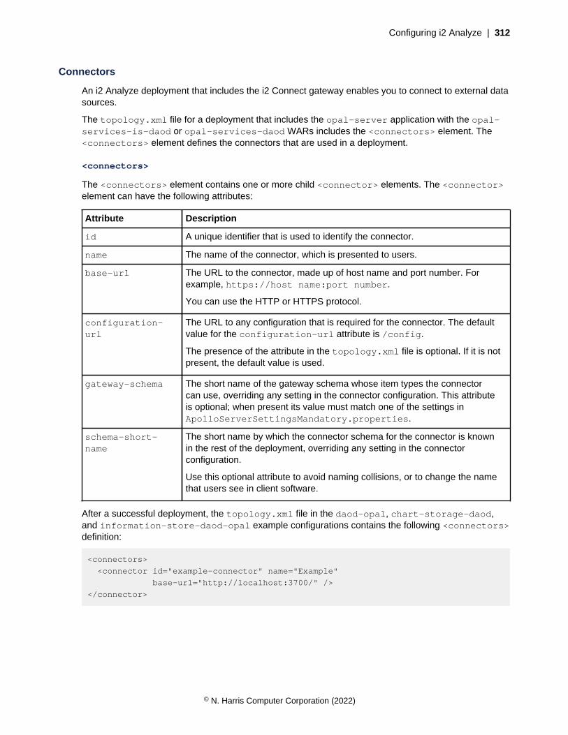
Configuring i2 Analyze | 312
Connectors
An i2 Analyze deployment that includes the i2 Connect gateway enables you to connect to external datasources.
The topology.xml file for a deployment that includes the opal-server application with the opal-services-is-daod or opal-services-daod WARs includes the <connectors> element. The<connectors> element defines the connectors that are used in a deployment.
<connectors>
The <connectors> element contains one or more child <connector> elements. The <connector>element can have the following attributes:
Attribute Description
id A unique identifier that is used to identify the connector.
name The name of the connector, which is presented to users.
base-url The URL to the connector, made up of host name and port number. Forexample, https://host name:port number.
You can use the HTTP or HTTPS protocol.
configuration-url
The URL to any configuration that is required for the connector. The defaultvalue for the configuration-url attribute is /config.
The presence of the attribute in the topology.xml file is optional. If it is notpresent, the default value is used.
gateway-schema The short name of the gateway schema whose item types the connectorcan use, overriding any setting in the connector configuration. This attributeis optional; when present its value must match one of the settings inApolloServerSettingsMandatory.properties.
schema-short-name
The short name by which the connector schema for the connector is knownin the rest of the deployment, overriding any setting in the connectorconfiguration.
Use this optional attribute to avoid naming collisions, or to change the namethat users see in client software.
After a successful deployment, the topology.xml file in the daod-opal, chart-storage-daod,and information-store-daod-opal example configurations contains the following <connectors>definition:
<connectors>
<connector id="example-connector" name="Example"
base-url="http://localhost:3700/" />
</connector>
© N. Harris Computer Corporation (2022)
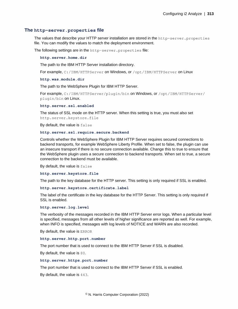
Configuring i2 Analyze | 313
The http-server.properties file
The values that describe your HTTP server installation are stored in the http-server.propertiesfile. You can modify the values to match the deployment environment.
The following settings are in the http-server.properties file:
http.server.home.dir
The path to the IBM HTTP Server installation directory.
For example, C:/IBM/HTTPServer on Windows, or /opt/IBM/HTTPServer on Linux
http.was.module.dir
The path to the WebSphere Plugin for IBM HTTP Server.
For example, C:/IBM/HTTPServer/plugin/bin on Windows, or /opt/IBM/HTTPServer/plugin/bin on Linux.
http.server.ssl.enabled
The status of SSL mode on the HTTP server. When this setting is true, you must also sethttp.server.keystore.file
By default, the value is false
http.server.ssl.require.secure.backend
Controls whether the WebSphere Plugin for IBM HTTP Server requires secured connections tobackend transports, for example WebSphere Liberty Profile. When set to false, the plugin can usean insecure transport if there is no secure connection available. Change this to true to ensure thatthe WebSphere plugin uses a secure connection to backend transports. When set to true, a secureconnection to the backend must be available.
By default, the value is false
http.server.keystore.file
The path to the key database for the HTTP server. This setting is only required if SSL is enabled.
http.server.keystore.certificate.label
The label of the certificate in the key database for the HTTP Server. This setting is only required ifSSL is enabled.
http.server.log.level
The verbosity of the messages recorded in the IBM HTTP Server error logs. When a particular levelis specified, messages from all other levels of higher significance are reported as well. For example,when INFO is specified, messages with log levels of NOTICE and WARN are also recorded.
By default, the value is ERROR
http.server.http.port.number
The port number that is used to connect to the IBM HTTP Server if SSL is disabled.
By default, the value is 80.
http.server.https.port.number
The port number that is used to connect to the IBM HTTP Server if SSL is enabled.
By default, the value is 443.
© N. Harris Computer Corporation (2022)

Configuring i2 Analyze | 314
The ApolloServerSettingsMandatory.properties file
The following properties are in the ApolloServerSettingsMandatory.properties file:
SchemaResource
The file that contains the schema for the Chart Store or the Information Store. This setting can beremoved if the deployment includes neither store. When specified, this XML file needs to be on theclasspath.
By default, the value is law-enforcement-schema.xml
ChartingSchemesResource
The file that contains charting schemes for the Chart Store or the Information Store. This setting canbe removed if the deployment includes neither store. When specified, this XML file needs to be onthe classpath.
By default, the value is law-enforcement-schema-charting-schemes.xml
Gateway.External.SchemaResource
A file that contains a gateway schema for this deployment of i2 Analyze. This setting can beremoved if the deployment does not require a gateway schema. When specified, this XML file needsto be on the classpath.
Gateway.External.ChartingSchemesResource
A file that contains gateway charting schemes for this deployment of i2 Analyze. This setting canbe removed if the deployment does not include a gateway schema. When specified, this XML fileneeds to be on the classpath.
UserGroupsProvider
The full class name of the user group provider. To retrieve user groups from the WebSphere userregistry, specify com.i2group.disco.user.WebSphereUserGroupsProvider
By default, the value is com.i2group.disco.user.WebSphereUserGroupsProvider
DynamicSecuritySchemaResource
The security schema file, which defines the security dimensions and values that are available in thesystem, and the mapping of user groups to dimension values. This (XML) file needs to be on theclasspath.
By default, the value is example-dynamic-security-schema.xml
AuditLogger
The full class name of the audit logger. If no auditing is required, specifycom.i2group.disco.audit.NoOpAuditLogger
By default, the value is com.i2group.disco.audit.NoOpAuditLogger
DefaultSecurityDimensionValuesProvider
The full class name of the default security dimension values provider. Usecom.i2group.disco.user.PropertyBasedDefaultSecurityDimensionValuesProvider to set the defaultsecurity dimension values on a record to the list from the DefaultSecurityDimensionValues elementin your security schema. This is only applicable to the Information Store with Opal Services.
By default, the value iscom.i2group.disco.user.PropertyBasedDefaultSecurityDimensionValuesProvider
© N. Harris Computer Corporation (2022)

Configuring i2 Analyze | 315
The DiscoServerSettingsCommon.propertiesfile
The following properties are in the DiscoServerSettingsCommon.properties file:
IdleLogoutMinutes
The idle time in minutes after which the end user is logged out.
By default, the value is 15
AlertBeforeIdleLogoutMinutes
The time in minutes the end user is alerted prior to being logged out due to inactivity.
By default, the value is 2
AlwaysAllowLogout
Forces logout to always be available for all authentication methods.
By default, the value is false
DeletedChartTimeoutSeconds
The time in seconds till a deleted chart is permanently removed.
By default, the value is 7200
ResultsConfigurationResource
The file that specifies what options are available to users when they view and filter results.
CommandAccessControlResource
The file that is used to specify specific group access to commands.
EnableSolrIndexScheduler
Turn on or off the scheduling of indexing Setting this option to false disables the scheduler andshould be used when ingesting large amounts of data.
By default, the value is true
SolrHealthCheckIntervalInSeconds
The interval time in seconds between the checks of the Solr cluster status.
By default, the value is 60
QueryTimeoutSeconds
The time in seconds after which the server can cancel a search, resulting in an error. This is not anabsolute limit. A search might continue to run for several seconds after the limit is reached, but itshould terminate within a reasonable time. A zero setting disables search timeout.
By default, the value is 60
WildcardMinCharsWithAsterisk
The minimum number of characters (not counting asterisks) that must be provided in a wildcard textsearch query that contains asterisks.
By default, the value is 0
WildcardMinCharsWithQuestionMark
© N. Harris Computer Corporation (2022)
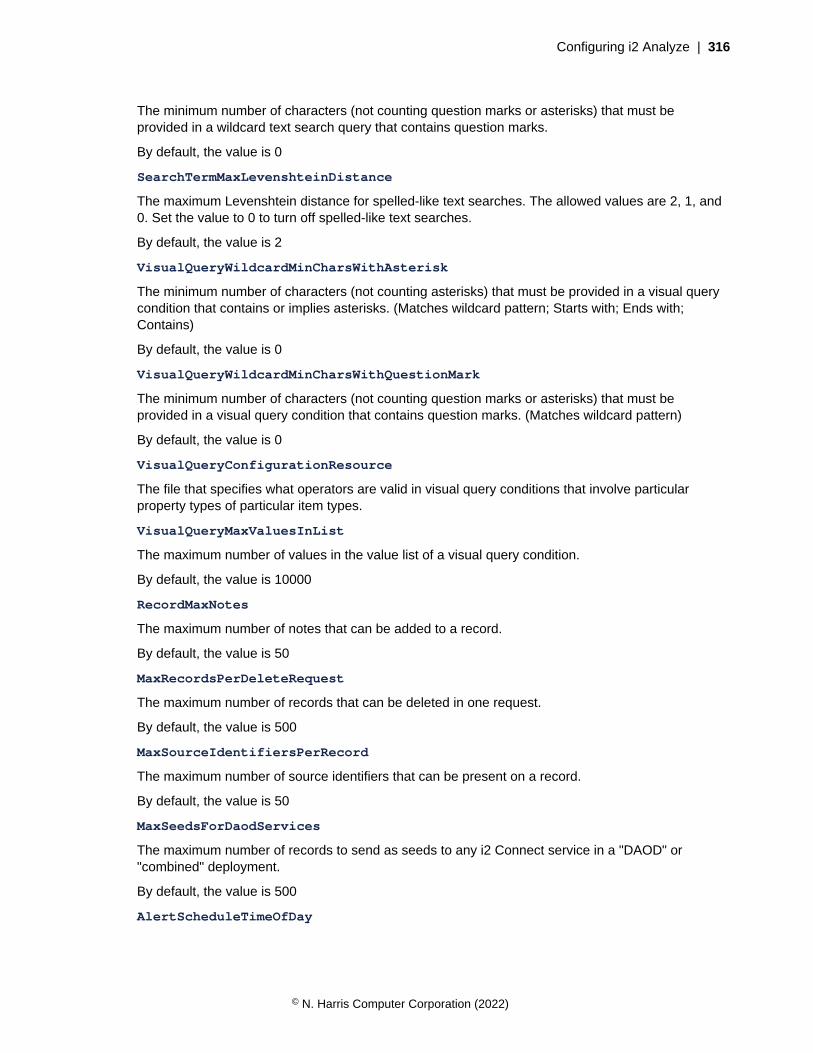
Configuring i2 Analyze | 316
The minimum number of characters (not counting question marks or asterisks) that must beprovided in a wildcard text search query that contains question marks.
By default, the value is 0
SearchTermMaxLevenshteinDistance
The maximum Levenshtein distance for spelled-like text searches. The allowed values are 2, 1, and0. Set the value to 0 to turn off spelled-like text searches.
By default, the value is 2
VisualQueryWildcardMinCharsWithAsterisk
The minimum number of characters (not counting asterisks) that must be provided in a visual querycondition that contains or implies asterisks. (Matches wildcard pattern; Starts with; Ends with;Contains)
By default, the value is 0
VisualQueryWildcardMinCharsWithQuestionMark
The minimum number of characters (not counting question marks or asterisks) that must beprovided in a visual query condition that contains question marks. (Matches wildcard pattern)
By default, the value is 0
VisualQueryConfigurationResource
The file that specifies what operators are valid in visual query conditions that involve particularproperty types of particular item types.
VisualQueryMaxValuesInList
The maximum number of values in the value list of a visual query condition.
By default, the value is 10000
RecordMaxNotes
The maximum number of notes that can be added to a record.
By default, the value is 50
MaxRecordsPerDeleteRequest
The maximum number of records that can be deleted in one request.
By default, the value is 500
MaxSourceIdentifiersPerRecord
The maximum number of source identifiers that can be present on a record.
By default, the value is 50
MaxSeedsForDaodServices
The maximum number of records to send as seeds to any i2 Connect service in a "DAOD" or"combined" deployment.
By default, the value is 500
AlertScheduleTimeOfDay
© N. Harris Computer Corporation (2022)
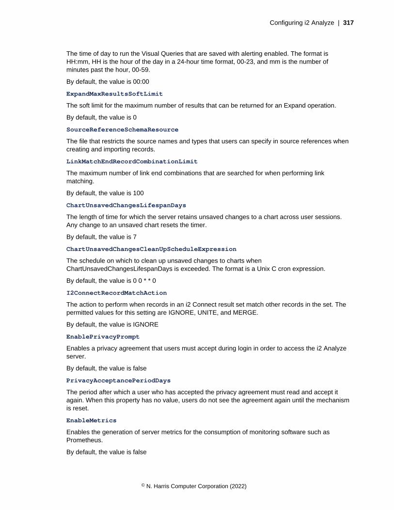
Configuring i2 Analyze | 317
The time of day to run the Visual Queries that are saved with alerting enabled. The format isHH:mm, HH is the hour of the day in a 24-hour time format, 00-23, and mm is the number ofminutes past the hour, 00-59.
By default, the value is 00:00
ExpandMaxResultsSoftLimit
The soft limit for the maximum number of results that can be returned for an Expand operation.
By default, the value is 0
SourceReferenceSchemaResource
The file that restricts the source names and types that users can specify in source references whencreating and importing records.
LinkMatchEndRecordCombinationLimit
The maximum number of link end combinations that are searched for when performing linkmatching.
By default, the value is 100
ChartUnsavedChangesLifespanDays
The length of time for which the server retains unsaved changes to a chart across user sessions.Any change to an unsaved chart resets the timer.
By default, the value is 7
ChartUnsavedChangesCleanUpScheduleExpression
The schedule on which to clean up unsaved changes to charts whenChartUnsavedChangesLifespanDays is exceeded. The format is a Unix C cron expression.
By default, the value is 0 0 * * 0
I2ConnectRecordMatchAction
The action to perform when records in an i2 Connect result set match other records in the set. Thepermitted values for this setting are IGNORE, UNITE, and MERGE.
By default, the value is IGNORE
EnablePrivacyPrompt
Enables a privacy agreement that users must accept during login in order to access the i2 Analyzeserver.
By default, the value is false
PrivacyAcceptancePeriodDays
The period after which a user who has accepted the privacy agreement must read and accept itagain. When this property has no value, users do not see the agreement again until the mechanismis reset.
EnableMetrics
Enables the generation of server metrics for the consumption of monitoring software such asPrometheus.
By default, the value is false
© N. Harris Computer Corporation (2022)

Configuring i2 Analyze | 318
Redeploying and resetting i2 Analyze
Most changes to the configuration of i2 Analyze require you to redeploy the system. Duringdevelopment, it is common to clear data from Information Store, or to remove the Information Store andre-create it.
Significant changes to the Information Store schema or the security schema of an i2 Analyzedeployment usually invalidate the information in the Information Store, or even the store itself. As youdevelop your schemas, you often need either to remove and re-ingest your test data, or to remove andre-create the store.
After any change to the toolkit configuration of a deployment of i2 Analyze, you must redeploy in orderto update to the running deployment.
Performing these actions in sequence is common before in your development environments, but rarein production. If you do run them in sequence, the combination effectively resets the system to its just-deployed state.
You might also need to reset a deployment of i2 Analyze to its just-installed state. For example, if youcompleted an example deployment and then want to start developing a production deployment on thesame hardware.
Clearing data from the system
The clearData task can remove data that is stored in both the search index and the Information Storedatabase. You can use this task to remove test data from a system.
In a multiple server deployment, run the clearData and clearSearchIndex tasks from the Libertyserver.
In a deployment that provides high availability, stop and start each Liberty server in your environmentbut run clearData and clearSearchIndex on the Liberty server that you used to create thedatabase only.
Important: These instructions are designed to remove data that is used for test purposes. Do not usethe task to clear data in a production system without backing up your data. For more information aboutbacking up your data, see Backing up a deployment.
1. On the Liberty server, in a command prompt navigate to the toolkit\scripts directory.
2. Stop the deployment:
setup -t stopLiberty
3. To clear data and the search index, run the following command:
setup -t clearData --hostname liberty.host-name
• Where liberty.hostname is the hostname of the Liberty server where you are running thecommand, and matches the value for the host-name attribute of the <application> elementin the topology.xml file.
• A message is displayed when you run the task to confirm that you want to complete the action.Enter Y to continue. The data and the search index are removed from the system.
If you run the clearData task with the --scripts argument, the scripts for clearing theInformation Store database are generated in the toolkit\scripts\database\<databasedialect>\InfoStore\generated\clearData directory, but not run. You can then inspect the
© N. Harris Computer Corporation (2022)

Configuring i2 Analyze | 319
scripts before they are run, or run the scripts yourself. To run the scripts yourself, run them in theirnumbered order to clear the data from your system.
To generate the scripts for the task, run:
setup -t clearData --scripts
After you run the scripts manually, clear the search index:
setup -t clearSearchIndex --hostname liberty.host-name
4. Start the deployment of i2 Analyze.
setup -t startLiberty
Resetting the system
The dropDatabases task can remove not only the data, but also the underlying structures such astables from your database management system. The deleteSolrCollections task can remove anySolr collections from the system.
To drop the databases, you must ensure that there are no active connections to them.
In a multiple-server environment, run all toolkit tasks from the Liberty server.
In a deployment that provides high availability, use the documentation from your database managementsystem to remove the Information Store database from each database server in your deploymentinstead of the dropDatabases toolkit task.
In a deployment that provides high availability, stop and start each Liberty server in your environmentbut run clearSearchIndex on the Liberty server that you used to create the database only.
Important: These instructions are designed to remove databases that are used for test purposes. Donot use the task to remove databases in a production system without backing up your data. For moreinformation about backing up your data, see Backing up a deployment.
1. In a command prompt, navigate to the toolkit\scripts directory.
2. Stop the deployment:
setup -t stopLiberty
3. To remove the database and Solr collections, navigate to the toolkit\scripts directory and runthe following command:
setup -t dropDatabases --hostname liberty.host-name
setup -t deleteSolrCollections --hostname liberty.host-name
Here, liberty.hostname is the hostname of the Liberty server where you are running thecommand. It matches the value for the host-name attribute of the <application> element in thetopology.xml file.
A message is displayed when you run each task to confirm that you want to complete the action.Enter Y to continue. The database and Solr collections are removed from the system.
© N. Harris Computer Corporation (2022)
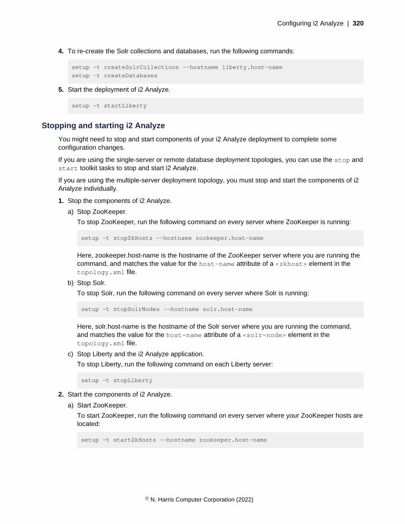
Configuring i2 Analyze | 320
4. To re-create the Solr collections and databases, run the following commands:
setup -t createSolrCollections --hostname liberty.host-name
setup -t createDatabases
5. Start the deployment of i2 Analyze.
setup -t startLiberty
Stopping and starting i2 Analyze
You might need to stop and start components of your i2 Analyze deployment to complete someconfiguration changes.
If you are using the single-server or remote database deployment topologies, you can use the stop andstart toolkit tasks to stop and start i2 Analyze.
If you are using the multiple-server deployment topology, you must stop and start the components of i2Analyze individually.
1. Stop the components of i2 Analyze.
a) Stop ZooKeeper.
To stop ZooKeeper, run the following command on every server where ZooKeeper is running:
setup -t stopZkHosts --hostname zookeeper.host-name
Here, zookeeper.host-name is the hostname of the ZooKeeper server where you are running thecommand, and matches the value for the host-name attribute of a <zkhost> element in thetopology.xml file.
b) Stop Solr.
To stop Solr, run the following command on every server where Solr is running:
setup -t stopSolrNodes --hostname solr.host-name
Here, solr.host-name is the hostname of the Solr server where you are running the command,and matches the value for the host-name attribute of a <solr-node> element in thetopology.xml file.
c) Stop Liberty and the i2 Analyze application.
To stop Liberty, run the following command on each Liberty server:
setup -t stopLiberty
2. Start the components of i2 Analyze.
a) Start ZooKeeper.
To start ZooKeeper, run the following command on every server where your ZooKeeper hosts arelocated:
setup -t startZkHosts --hostname zookeeper.host-name
© N. Harris Computer Corporation (2022)

Configuring i2 Analyze | 321
Here, zookeeper.host-name is the hostname of the ZooKeeper server where you are running thecommand, and matches the value for the host-name attribute of a <zkhost> element in thetopology.xml file.
b) Start Solr.
To start Solr, run the following command on every server where your Solr nodes are located:
setup -t startSolrNodes --hostname solr.host-name
Here, solr.host-name is the hostname of the Solr server where you are running the command,and matches the value for the host-name attribute of a <solr-node> element in thetopology.xml file.
c) Start Liberty and the i2 Analyze application.
To start Liberty, run the following command on each Liberty server:
setup -t startLiberty
Redeploying Liberty
Redeploy Liberty to update the i2 Analyze application with your configuration changes.
In a multiple-server environment, run all toolkit tasks from the Liberty server.
If you follow this procedure in a deployment that provides high availability, you must complete each stepon every Liberty server in your environment before you move to the next step.
1. In a command prompt, navigate to the toolkit\scripts directory.
2. Stop Liberty:
setup -t stopLiberty
3. Update the i2 Analyze application:
setup -t deployLiberty
4. Start Liberty:
setup -t startLiberty
5. If you are using the IBM HTTP Server, start or restart it.
Setting up your XSD aware XML editor
Some configuration files are provided with an associated XSD file. The XSD file provides client-sidevalidation, and makes it easier to develop your XML configuration files.
It is recommended that you use an XSD-aware XML editor with intelligent code completion.
The following instructions describe how to install Visual Studio Code and the XML Language Support byRed Hat extension.
1. Download and install Visual Studio Code, https://code.visualstudio.com/.
2. In Visual Studio Code, install the XML Language Support by Red Hat extension.
© N. Harris Computer Corporation (2022)

Configuring i2 Analyze | 322
For information about how to install extensions, see https://code.visualstudio.com/docs/editor/extension-gallery.
After you install and configure your editor, you should use this editor whenever the instructions tell youto use an XSD-aware XML editor.
If you are using Visual Studio Code, the associated XSD file must be in the same directory as the XMLfile that you are editing.
Using the admin endpoints
The reload endpoints support the POST method, which you must call through a command-line tool suchas postman or curl. The endpoint requires authentication, which means that you must log in to theserver as an administrator and retrieve a cookie before you can POST to reload.
To use the admin endpoints, you must log in as a user that has the administrator permission. To providea user with the i2:Administrator permission, use command access control to specify the usergroup to give access to the administrator role. For more information, see Configuring command accesscontrol on page 149.
The following steps demonstrate how to use curl to POST to the admin endpoints.
You can find the REST API reference documentation at the following URL on the i2 Analyze server:http://host_name/conext_root/doc. For example, http://localhost/opal/doc.
1. If the curl utility is not available on your server, download it from the project website at https://curl.haxx.se/download.html.
2. Open a command prompt and use curl to log in to the i2 Analyze server and retrieve anauthorization cookie:
curl -i --cookie-jar cookie.txt
-d j_username=user_name
-d j_password=password
http://host_name/conext_root/j_security_check
This command connects to the specified i2 Analyze server as the specified user, retrieves theauthentication cookie, and saves it to a local file named cookie.txt. The LTPA token in the cookieis valid for 2 hours.
When the command completes, the response from the request is displayed. If the retrieval issuccessful, the first line of the response is:
HTTP/1.1 302 Found
After you retrieve and save the cookie, you can POST to the admin endpoints. When you POST to theadmin endpoints, include the cookie file that you received when you logged in.
3. The following command is an example of a POST to the admin endpoint to reload the liveconfiguration:
curl -i --cookie cookie.txt
-X POST
http://host_name/conext_root/api/v1/admin/config/reload
© N. Harris Computer Corporation (2022)

Configuring i2 Analyze | 323
When the command completes, the response from the request is displayed. If the retrieval issuccessful, the first line of the response is:
HTTP/1.1 200 OK
If you see the HTTP/1.1 403 Forbidden response code, the user for which you retrieved thetoken does not have the command access control administrator permission, or the token hasexpired:
• If your token has expired, you can get a new one by running the command in step 2 again.
• If your user does not the command access control i2:Administrator permission, seeConfiguring command access control on page 149 to provide the user with the permission.
Warning: The reload method updates the configuration without requiring a server restart,but any logged-in users are logged out from i2 Analyze when you run it.
Connecting to external data sourcesSubject to your licensing terms, a deployment of i2® Analyze can use the i2® Connect gateway to queryand retrieve data from external data sources. By connecting to an external data source, you enable adeployment of i2® Analyze to create and display records that represent the data in that source.
If the deployment and their permissions support it, users who create records from external sources canupload them to the Information Store for storage, sharing, and subsequent analysis.
Solutions that use the i2® Connect gateway depend on connectors that make the bridge between i2®
Analyze and external data sources. Conventionally, you have one connector for each source that youconnect to. Each connector provides one or more services that present a querying interface to usersand perform the actual queries on the data source.
Note:
i2 provides two ways for software developers to create connectors between the i2 Connect gateway andexternal data sources:
• The i2 Connect gateway defines a REST SPI that developers can implement. When the gatewaycalls SPI methods in response to user requests, an implementation can retrieve data from anexternal source and return it to the gateway. For information about this approach, and exampleconnectors written in Java and Python, see the open-source project at https://i2group.github.io/analyze-connect
• The open-source i2 Connect SDK enables projects that include a connector server, which simplifiesthe connector development process by replacing the REST SPI and many configuration settings witha JavaScript/TypeScript API. In most situations, you should use the i2 Connect SDK.
i2® Analyze and the i2® Connect gatewayIn an i2 Analyze deployment, you can provide users with access to an Information Store, or enable themto query data in one or more external sources, or both. i2® Analyze deployments that are targeted atexternal data access include the i2® Connect gateway alongside or instead of the Information Store.
In a complete solution, the i2® Connect gateway provides i2® Analyze with information about whatconnectors and services are available and how clients are to use them. i2® Analyze passes clientrequests for data to the gateway, which receives and responds to the requests on behalf of thoseservices.
© N. Harris Computer Corporation (2022)

Configuring i2 Analyze | 324
Client i2 Analyze application
i2 Connect gateway
Connector
Service
Connector
Service
Service
Service
Data
Data
Each connector contains the code that interacts with an external data source, the definitions of theservices that it supports, and the descriptions of how clients might present its services to users. Forexample, clients need to know the following information:
• The name and description of each service a user has access to
• Whether a service requires users to authenticate before they can use it
• Whether a service supports parameters that users can specify when they run it
• The input controls to display, and the validation to perform, for each parameter
• Whether a service behaves differently as a result of the current chart selection (any selected recordsare then seeds for the operation that the service performs)
The examples that i2 provides in the open-source repositories at https://i2group.github.io/analyze-connect and https://i2group.github.io/analyze-connect-node-sdk demonstrate meeting several of theserequirements in fully functional connectors.
Note: For information about securing the communication between the i2 Connect gateway and itsconnectors, see Client authenticated Secure Sockets Layer and the i2 Connect gateway.
System security with the i2 Connect gatewayThree separate mechanisms govern different aspects of security in a deployment of i2 Analyze withthe i2 Connect gateway. You can secure the connection between the gateway and a connector; youcan restrict which i2 Analyze users can run the queries that connectors implement; and connectorsthemselves can require users to authenticate before they can run queries.
Secure the connection to a connector
You can use client-authenticated SSL communication to secure the connection between the i2Connect gateway and a connector. For more information, see Client-authenticated Secure SocketsLayer with i2 Connect.
Restrict access to a connector
© N. Harris Computer Corporation (2022)
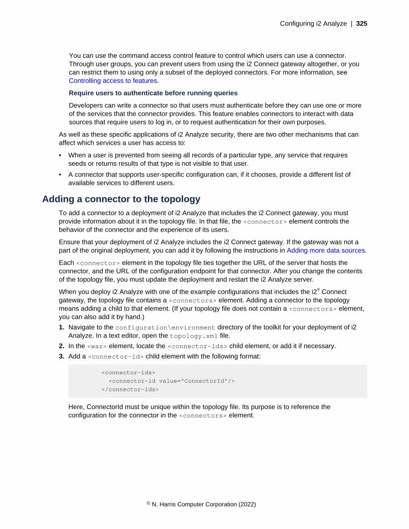
Configuring i2 Analyze | 325
You can use the command access control feature to control which users can use a connector.Through user groups, you can prevent users from using the i2 Connect gateway altogether, or youcan restrict them to using only a subset of the deployed connectors. For more information, seeControlling access to features.
Require users to authenticate before running queries
Developers can write a connector so that users must authenticate before they can use one or moreof the services that the connector provides. This feature enables connectors to interact with datasources that require users to log in, or to request authentication for their own purposes.
As well as these specific applications of i2 Analyze security, there are two other mechanisms that canaffect which services a user has access to:
• When a user is prevented from seeing all records of a particular type, any service that requiresseeds or returns results of that type is not visible to that user.
• A connector that supports user-specific configuration can, if it chooses, provide a different list ofavailable services to different users.
Adding a connector to the topologyTo add a connector to a deployment of i2 Analyze that includes the i2 Connect gateway, you mustprovide information about it in the topology file. In that file, the <connector> element controls thebehavior of the connector and the experience of its users.
Ensure that your deployment of i2 Analyze includes the i2 Connect gateway. If the gateway was not apart of the original deployment, you can add it by following the instructions in Adding more data sources.
Each <connector> element in the topology file ties together the URL of the server that hosts theconnector, and the URL of the configuration endpoint for that connector. After you change the contentsof the topology file, you must update the deployment and restart the i2 Analyze server.
When you deploy i2 Analyze with one of the example configurations that includes the i2® Connectgateway, the topology file contains a <connectors> element. Adding a connector to the topologymeans adding a child to that element. (If your topology file does not contain a <connectors> element,you can also add it by hand.)
1. Navigate to the configuration\environment directory of the toolkit for your deployment of i2Analyze. In a text editor, open the topology.xml file.
2. In the <war> element, locate the <connector-ids> child element, or add it if necessary.
3. Add a <connector-id> child element with the following format:
<connector-ids>
<connector-id value="ConnectorId"/>
</connector-ids>
Here, ConnectorId must be unique within the topology file. Its purpose is to reference theconfiguration for the connector in the <connectors> element.
© N. Harris Computer Corporation (2022)
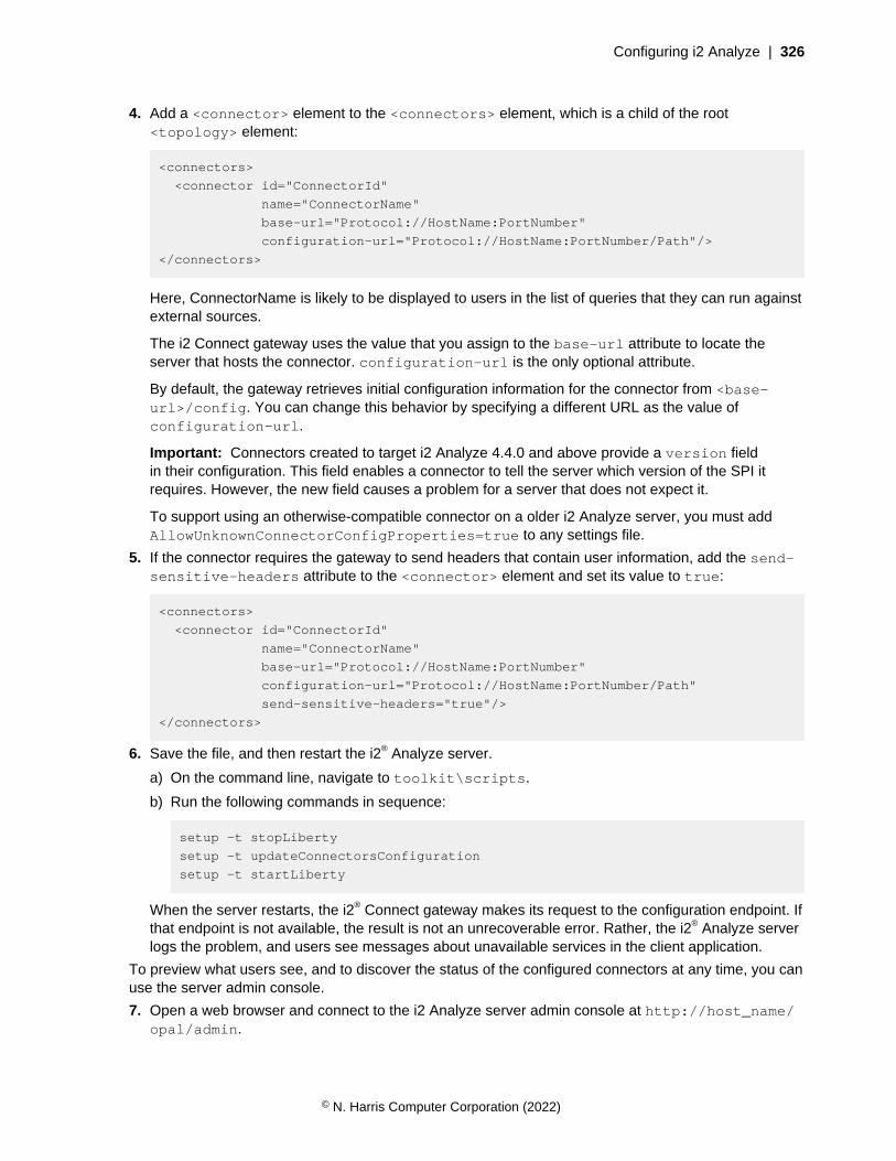
Configuring i2 Analyze | 326
4. Add a <connector> element to the <connectors> element, which is a child of the root<topology> element:
<connectors>
<connector id="ConnectorId"
name="ConnectorName"
base-url="Protocol://HostName:PortNumber"
configuration-url="Protocol://HostName:PortNumber/Path"/>
</connectors>
Here, ConnectorName is likely to be displayed to users in the list of queries that they can run againstexternal sources.
The i2 Connect gateway uses the value that you assign to the base-url attribute to locate theserver that hosts the connector. configuration-url is the only optional attribute.
By default, the gateway retrieves initial configuration information for the connector from <base-url>/config. You can change this behavior by specifying a different URL as the value ofconfiguration-url.
Important: Connectors created to target i2 Analyze 4.4.0 and above provide a version fieldin their configuration. This field enables a connector to tell the server which version of the SPI itrequires. However, the new field causes a problem for a server that does not expect it.
To support using an otherwise-compatible connector on a older i2 Analyze server, you must addAllowUnknownConnectorConfigProperties=true to any settings file.
5. If the connector requires the gateway to send headers that contain user information, add the send-sensitive-headers attribute to the <connector> element and set its value to true:
<connectors>
<connector id="ConnectorId"
name="ConnectorName"
base-url="Protocol://HostName:PortNumber"
configuration-url="Protocol://HostName:PortNumber/Path"
send-sensitive-headers="true"/>
</connectors>
6. Save the file, and then restart the i2® Analyze server.
a) On the command line, navigate to toolkit\scripts.
b) Run the following commands in sequence:
setup -t stopLiberty
setup -t updateConnectorsConfiguration
setup -t startLiberty
When the server restarts, the i2® Connect gateway makes its request to the configuration endpoint. Ifthat endpoint is not available, the result is not an unrecoverable error. Rather, the i2® Analyze serverlogs the problem, and users see messages about unavailable services in the client application.
To preview what users see, and to discover the status of the configured connectors at any time, you canuse the server admin console.
7. Open a web browser and connect to the i2 Analyze server admin console at http://host_name/opal/admin.
© N. Harris Computer Corporation (2022)
Configuring i2 Analyze | 327
The admin console displays a list of connectors with their statuses. To see what the logged-in userwould see in their client application, click Preview services.
Item type conversionA deployment of i2 Analyze that includes the i2 Connect gateway can have multiple connector andgateway schemas, as well as an Information Store schema. In such a deployment, and especially inone that features connector and gateway schemas from third parties, multiple item types can havesimilar names or purposes. For example, two connector or gateway schemas might independentlydefine "Person" item types, which might in turn be slightly different from a "Person" type defined in theInformation Store schema.
This kind of arrangement can have a number of consequences:
• The existence of several item types with the same or similar names can be confusing foradministrators and for users, who see records on their charts and item types in their palettes thatlook the same, but are not.
• By the same token, the analytical tools in i2 Analyze and i2 Analyst's Notebook Premium do notconsider records with similar-looking types to be equivalent for the purposes of comparison andother functions.
• Only records that have types from the Information Store schema can be uploaded to the InformationStore.
To address these problems, the i2 Connect gateway provides a dynamic type conversion service. Atstartup, the gateway builds a catalog of all the item types in all the schemas in the deployment. You canthen create mappings from one item type to another, in the following combinations:
• Connector schema type to Information Store schema type
• Connector schema type to gateway schema type
• Gateway schema type to Information Store schema type
• Gateway schema type to gateway schema type (in a different gateway schema)
© N. Harris Computer Corporation (2022)

Configuring i2 Analyze | 328
i2 Analyze deployment
Web server
Information Store
i2 Analyze application
ConnectorConnector
Gateway schema
Information Store schema
Schema Schema
Type conversion
Type conversion
ConnectorConnector
Key: Data Conversion Type usage
Connector
SchemaConnector
Gateway schema
i2 Connectgateway
Type conversion mappings describe how the property values of source records that have a particularitem type become the property values of target records that have a different item type.
For example, a gateway schema might define an entity type named "Person", with property typesincluding "Forename" and "Surname". In the same deployment, the Information Store might also definean entity type named "Person", with property types including "First Name" and "Family Name". Providedthat the property types in question have compatible logical types, you can create a mapping to changethe type of any record with the gateway type so that it becomes a record with the Information Store type.
The effect of this type conversion mapping is that any record that would otherwise appear in searchresults or on the chart surface with the gateway type instead appears with the Information Store type.As a result, it can be compared directly with existing records in the Information Store, and can itself beuploaded to the Information Store if the user requires it.
© N. Harris Computer Corporation (2022)

Configuring i2 Analyze | 329
Note: It is not mandatory to create mappings between item types. By default, records from connectorsare copied to users' charts with their assigned entity or link types, without modification.
Creating type conversion mappings
To create type conversion mappings, you use the i2 Analyze Server Admin Console.
In a web browser, navigate to the URI of a i2 Analyze development environment, but append /admin.For example: http://<host_name>:9082/opal/admin.
When you log in using credentials with the i2:Administrator command access control permission,the i2 Analyze Server Admin Console appears. For more information about ensuring you have thecorrect permissions, see i2 Analyze Server Admin Console on page 382.
The mapping configuration interface
By default, the admin console displays the status of the i2 Connect gateway. To display the mappingconfiguration interface, select the i2 Analyze Type Conversion app, which is highlighted in red:
The console now displays a list of all the item types across all gateway and connector schemas, withsome information about any item type mappings that have been defined. In this example, no mappingsare configured yet.
© N. Harris Computer Corporation (2022)

Configuring i2 Analyze | 330
Defining a mapping
Note: The following description is based on types from the NYPD-Complaints and KCPD-Crimeschemas that feature in examples in the analyze-connect repository.
The NYPD-Complaints and KCPD-Crime schemas both contain entity types named "Person". Bothtypes define the same property types: age, sex, and race. But a significant difference is that the NYPDPerson type models age in ranges, while the KCPD Person type holds specific values for ages.
© N. Harris Computer Corporation (2022)

Configuring i2 Analyze | 331
NYPD Person KCPD Person
1. Select the source type
In the list of item types, select the one to map from. For this example, the Person type from theNYPD-Complaints connector schema is selected. Then, click on either the arrow shown on the listitem, or Create mapping in the pane on the right.
2. Select the target type
The app now displays a dialog box that contains a list of item types to which your selected sourcetype can be mapped. Choose an appropriate item type. For this example, the Person type fromthe KCPD-Complaints gateway schema is selected. After you select the target type, click Createmapping.
© N. Harris Computer Corporation (2022)

Configuring i2 Analyze | 332
3. Define the property mappings
At this stage, define how the property values of the source type are mapped to property values of thetarget type.
© N. Harris Computer Corporation (2022)

Configuring i2 Analyze | 333
The properties shown in the dialog are the properties of the target type. For each target property, youcan do one of the following:
• Map a property from the source item type to the target property. When a record of the sourceitem type is converted to a record of the target item type, the target property is populated with thevalue of the source property. The logical type of the source property type must be compatible withthe logical type of the target property type.
• Map to a fixed value. When a record of the source item type is converted to a record of thetarget item type, the target property is populated with the fixed value provided in the mappingconfiguration.
• Leave the property unmapped. When a record of the source item type is converted to a recordof the target type, the target property is not populated. Target property types that are mandatorycannot be left unmapped.
Automatically mapped properties
A property type in the source item type is automatically mapped to a property type in the target itemtype if they have the same:
• Display name
• Logical type
© N. Harris Computer Corporation (2022)
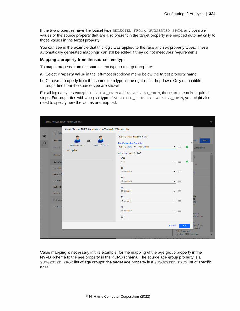
Configuring i2 Analyze | 334
If the two properties have the logical type SELECTED_FROM or SUGGESTED_FROM, any possiblevalues of the source property that are also present in the target property are mapped automatically tothose values in the target property.
You can see in the example that this logic was applied to the race and sex property types. Theseautomatically generated mappings can still be edited if they do not meet your requirements.
Mapping a property from the source item type
To map a property from the source item type to a target property:
a. Select Property value in the left-most dropdown menu below the target property name.
b. Choose a property from the source item type in the right-most dropdown. Only compatibleproperties from the source type are shown.
For all logical types except SELECTED_FROM and SUGGESTED_FROM, these are the only requiredsteps. For properties with a logical type of SELECTED_FROM or SUGGESTED_FROM, you might alsoneed to specify how the values are mapped.
Value mapping is necessary in this example, for the mapping of the age group property in theNYPD schema to the age property in the KCPD schema. The source age group property is aSUGGESTED_FROM list of age groups; the target age property is a SUGGESTED_FROM list of specificages.
© N. Harris Computer Corporation (2022)
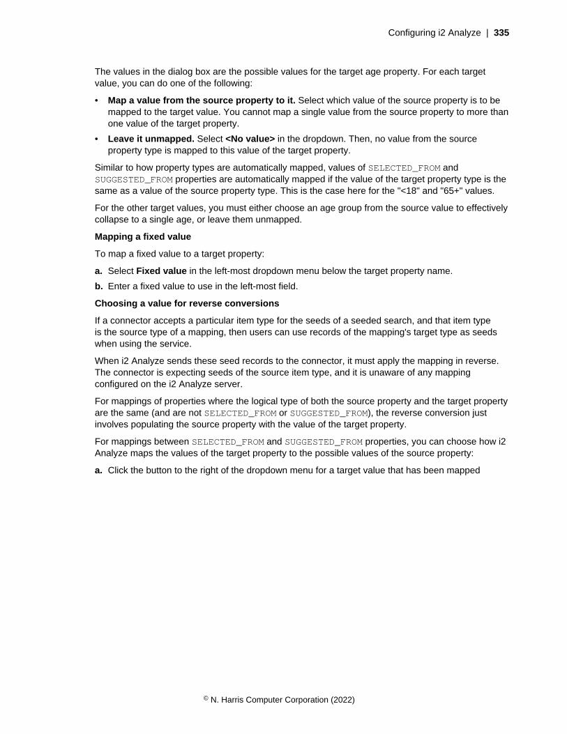
Configuring i2 Analyze | 335
The values in the dialog box are the possible values for the target age property. For each targetvalue, you can do one of the following:
• Map a value from the source property to it. Select which value of the source property is to bemapped to the target value. You cannot map a single value from the source property to more thanone value of the target property.
• Leave it unmapped. Select <No value> in the dropdown. Then, no value from the sourceproperty type is mapped to this value of the target property.
Similar to how property types are automatically mapped, values of SELECTED_FROM andSUGGESTED_FROM properties are automatically mapped if the value of the target property type is thesame as a value of the source property type. This is the case here for the "<18" and "65+" values.
For the other target values, you must either choose an age group from the source value to effectivelycollapse to a single age, or leave them unmapped.
Mapping a fixed value
To map a fixed value to a target property:
a. Select Fixed value in the left-most dropdown menu below the target property name.
b. Enter a fixed value to use in the left-most field.
Choosing a value for reverse conversions
If a connector accepts a particular item type for the seeds of a seeded search, and that item typeis the source type of a mapping, then users can use records of the mapping's target type as seedswhen using the service.
When i2 Analyze sends these seed records to the connector, it must apply the mapping in reverse.The connector is expecting seeds of the source item type, and it is unaware of any mappingconfigured on the i2 Analyze server.
For mappings of properties where the logical type of both the source property and the target propertyare the same (and are not SELECTED_FROM or SUGGESTED_FROM), the reverse conversion justinvolves populating the source property with the value of the target property.
For mappings between SELECTED_FROM and SUGGESTED_FROM properties, you can choose how i2Analyze maps the values of the target property to the possible values of the source property:
a. Click the button to the right of the dropdown menu for a target value that has been mapped
© N. Harris Computer Corporation (2022)
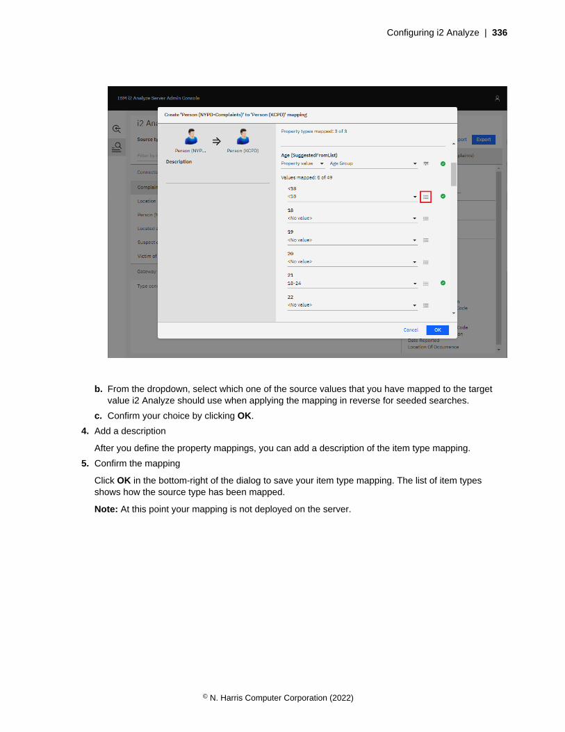
Configuring i2 Analyze | 336
b. From the dropdown, select which one of the source values that you have mapped to the targetvalue i2 Analyze should use when applying the mapping in reverse for seeded searches.
c. Confirm your choice by clicking OK.
4. Add a description
After you define the property mappings, you can add a description of the item type mapping.
5. Confirm the mapping
Click OK in the bottom-right of the dialog to save your item type mapping. The list of item typesshows how the source type has been mapped.
Note: At this point your mapping is not deployed on the server.
© N. Harris Computer Corporation (2022)

Configuring i2 Analyze | 337
You can edit the mapping by clicking Edit mapping in the right-hand pane, or delete it by clickingDelete mapping.
Applying the mappings for testing
After you define the item type mappings, you can test the i2 Connect services in your i2 Analyzedeployment to see how they would look if you were to apply the mappings you have configured. To dothis:
1. Click Apply. This applies the current mapping configuration for testing.
2. Click Preview services. This opens the External Searches dialog as it would appear in Analyst'sNotebook Premium. You can use the services and see the results as they would appear if themapping that has been applied for testing was deployed on the server.
© N. Harris Computer Corporation (2022)
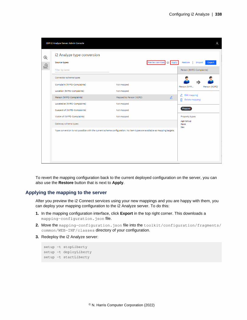
Configuring i2 Analyze | 338
To revert the mapping configuration back to the current deployed configuration on the server, you canalso use the Restore button that is next to Apply.
Applying the mapping to the server
After you preview the i2 Connect services using your new mappings and you are happy with them, youcan deploy your mapping configuration to the i2 Analyze server. To do this:
1. In the mapping configuration interface, click Export in the top right corner. This downloads amapping-configuration.json file.
2. Move the mapping-configuration.json file into the toolkit/configuration/fragments/common/WEB-INF/classes directory of your configuration.
3. Redeploy the i2 Analyze server:
setup -t stopLiberty
setup -t deployLiberty
setup -t startLiberty
© N. Harris Computer Corporation (2022)

Configuring i2 Analyze | 339
Adding a connector with a connector schema to an existing deployment
In this example scenario, we will add a new connector with its own connector schema to an i2 Analyzedeployment with an existing gateway schema. Item types in the connector schema will be mapped toitem types in the gateway schema where possible.
Note: These instructions can also apply to mapping item types from one gateway schema toanother gateway schema.
Setting up the scenario
To follow this example, start by deploying i2 Analyze with the example NYPD connector, as described inthe analyze-connect repository, with the connector configured to use a gateway schema.
With the example deployment in place, you can connect to the i2 Analyze server from Analyst'sNotebook Premium and use the services provided by the NYPD connector. For example, you might usethe "Get All" service and copy some of the results to a chart.
© N. Harris Computer Corporation (2022)

Configuring i2 Analyze | 340
Adding a second connector
Next, add the example KCPD connector to the deployment, ensuring that it is configured to use its ownconnector schema.
When the connector is deployed, you should be able to use the services that it provides and copy someresults to the chart.
The image uses highlighting and different icons to show how the gateway schema used by the NYPDconnector and the connector schema used by the KCPD connector use different item types to model thesame real-world objects.
Looking at all the available item types, you can see that both schemas have their own:
• 'Person' entity type
• 'Location' entity type
• 'Complaint'/'Report' entity type (different names, but modeling the same concept)
• 'Located At' link type
© N. Harris Computer Corporation (2022)

Configuring i2 Analyze | 341
• 'Suspect Of' link type
• 'Victim Of' link type
You can use type conversion mappings to resolve this duplication.
Configuring item type mappings
In a web browser, go to the the i2 Analyze Type Conversion app in the i2 Analyze Server AdminConsole on page 382 to see the list of item types that can be mapped. You should see a list of all itemtypes in the KCPD-Crime schema, and that none of them has been mapped.
Where appropriate, KCPD-Crime item types can be mapped to similar item types in the NYPD-Complaints gateway schema.
Report and Complaint
The Report entity type in the KCPD-Crime schema can be mapped to the Complaint entity type in theNYPD-Complaints schema.
1. Select the Report (KCPD-Crime) item type in the list, then click Create mapping in the right-handpane. This shows the list of item types to which the Report item type can be mapped.
2. Select the Complaint item type from the NYPD-Complaints schema, then click Create mapping.You will see all the property types of the Complaint type in the NYPD-Complaints schema, with
© N. Harris Computer Corporation (2022)
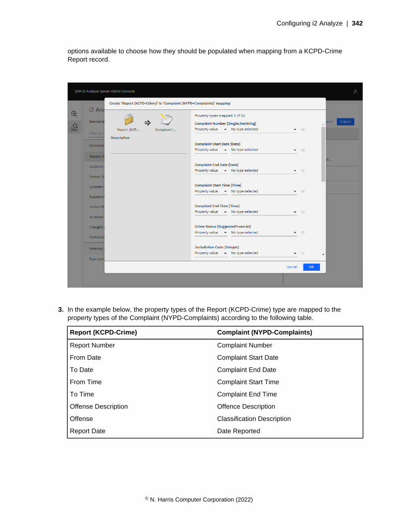
Configuring i2 Analyze | 342
options available to choose how they should be populated when mapping from a KCPD-CrimeReport record.
3. In the example below, the property types of the Report (KCPD-Crime) type are mapped to theproperty types of the Complaint (NYPD-Complaints) according to the following table.
Report (KCPD-Crime) Complaint (NYPD-Complaints)
Report Number Complaint Number
From Date Complaint Start Date
To Date Complaint End Date
From Time Complaint Start Time
To Time Complaint End Time
Offense Description Offence Description
Offense Classification Description
Report Date Date Reported
© N. Harris Computer Corporation (2022)
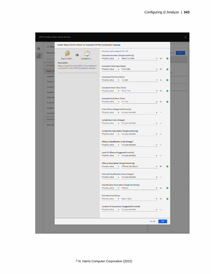
Configuring i2 Analyze | 343
© N. Harris Computer Corporation (2022)
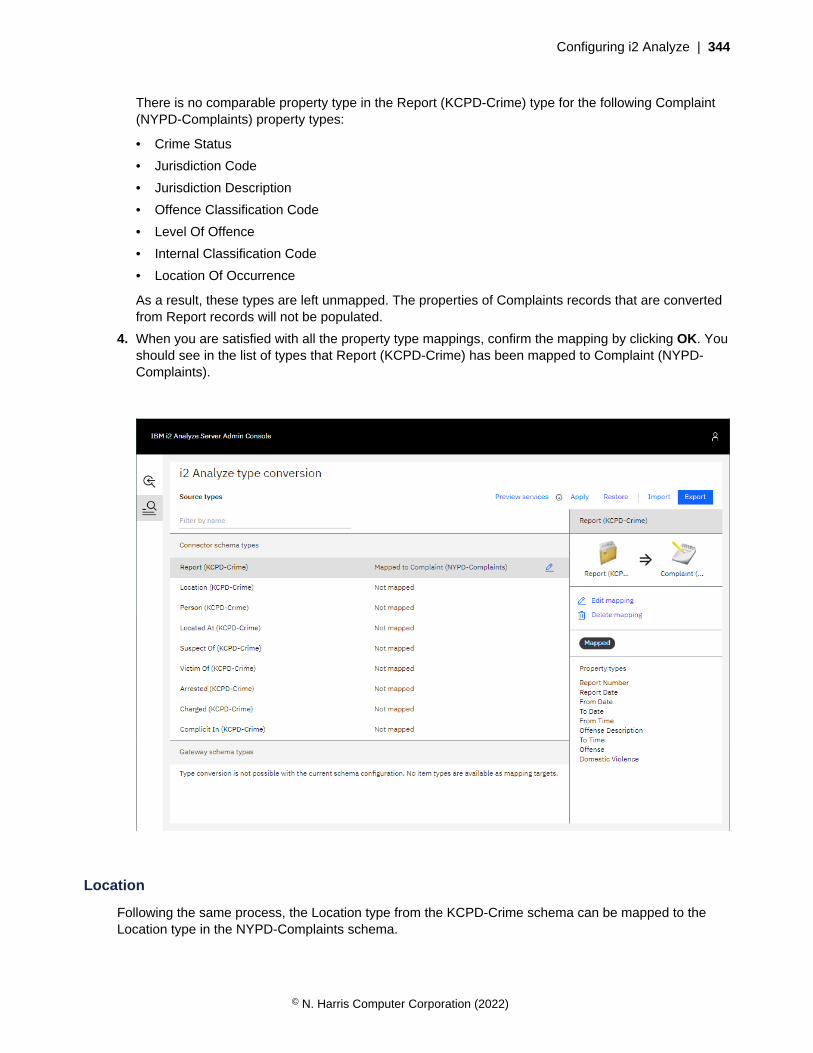
Configuring i2 Analyze | 344
There is no comparable property type in the Report (KCPD-Crime) type for the following Complaint(NYPD-Complaints) property types:
• Crime Status
• Jurisdiction Code
• Jurisdiction Description
• Offence Classification Code
• Level Of Offence
• Internal Classification Code
• Location Of Occurrence
As a result, these types are left unmapped. The properties of Complaints records that are convertedfrom Report records will not be populated.
4. When you are satisfied with all the property type mappings, confirm the mapping by clicking OK. Youshould see in the list of types that Report (KCPD-Crime) has been mapped to Complaint (NYPD-Complaints).
Location
Following the same process, the Location type from the KCPD-Crime schema can be mapped to theLocation type in the NYPD-Complaints schema.
© N. Harris Computer Corporation (2022)
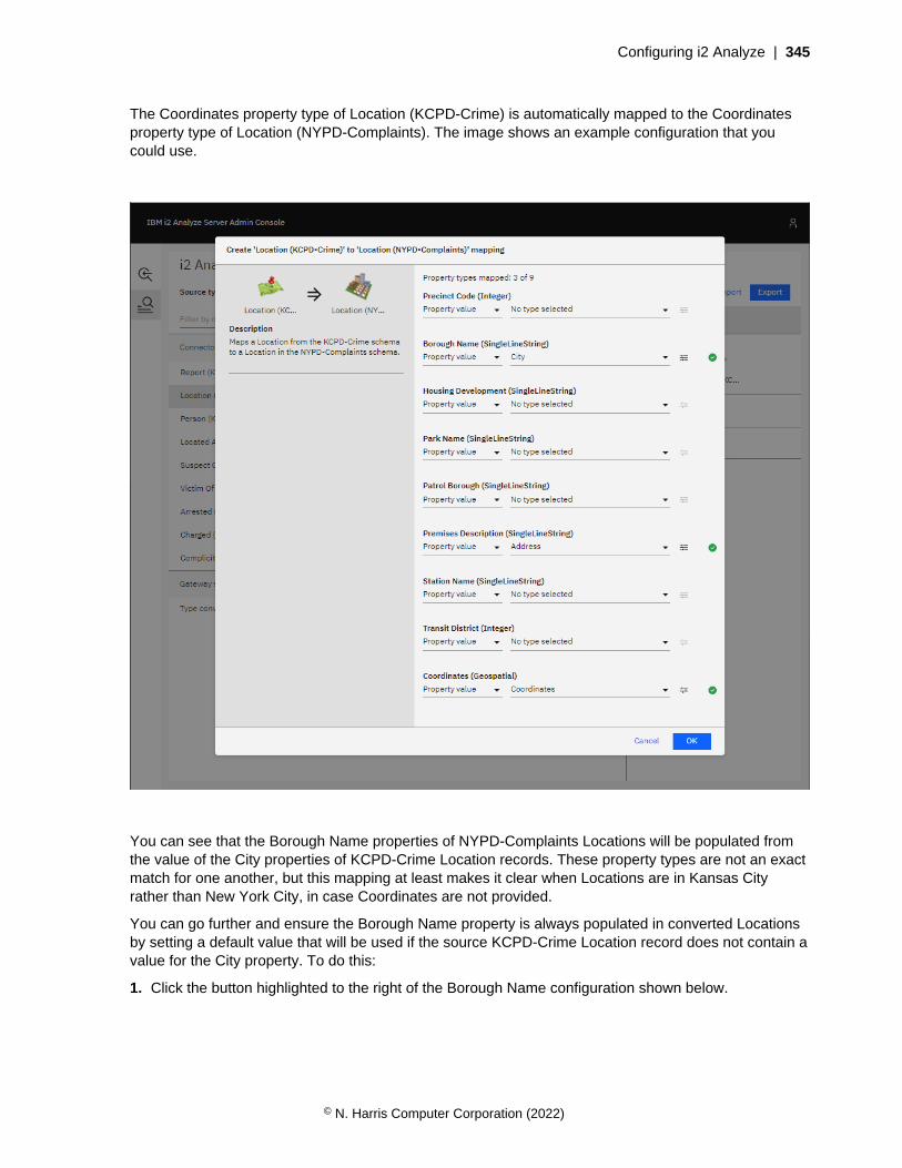
Configuring i2 Analyze | 345
The Coordinates property type of Location (KCPD-Crime) is automatically mapped to the Coordinatesproperty type of Location (NYPD-Complaints). The image shows an example configuration that youcould use.
You can see that the Borough Name properties of NYPD-Complaints Locations will be populated fromthe value of the City properties of KCPD-Crime Location records. These property types are not an exactmatch for one another, but this mapping at least makes it clear when Locations are in Kansas Cityrather than New York City, in case Coordinates are not provided.
You can go further and ensure the Borough Name property is always populated in converted Locationsby setting a default value that will be used if the source KCPD-Crime Location record does not contain avalue for the City property. To do this:
1. Click the button highlighted to the right of the Borough Name configuration shown below.
© N. Harris Computer Corporation (2022)
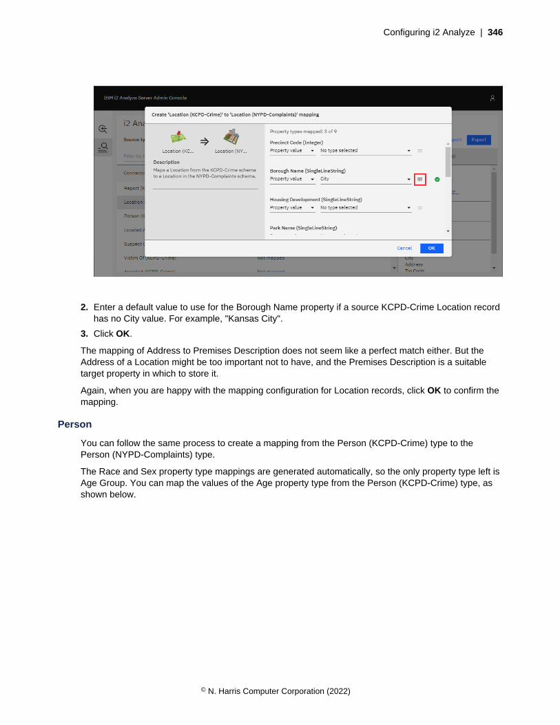
Configuring i2 Analyze | 346
2. Enter a default value to use for the Borough Name property if a source KCPD-Crime Location recordhas no City value. For example, "Kansas City".
3. Click OK.
The mapping of Address to Premises Description does not seem like a perfect match either. But theAddress of a Location might be too important not to have, and the Premises Description is a suitabletarget property in which to store it.
Again, when you are happy with the mapping configuration for Location records, click OK to confirm themapping.
Person
You can follow the same process to create a mapping from the Person (KCPD-Crime) type to thePerson (NYPD-Complaints) type.
The Race and Sex property type mappings are generated automatically, so the only property type left isAge Group. You can map the values of the Age property type from the Person (KCPD-Crime) type, asshown below.
© N. Harris Computer Corporation (2022)

Configuring i2 Analyze | 347
The Age property types of the source type and the target type are both SUGGESTED_FROM types, butthey have different suggested values. The source property type, from the KCPD-Crime schema, hassuggested values: <18, 19, 20, 21, ..., 64, and 65+; whereas the target property type, from the NYPD-Complaints schema, has suggested values: <18, 18-24, 25-44, 45-64, and 65+.
The <18 and 65+ values are automatically mapped to one another. For the remaining target values(18-24, 25-44, and 45-64), you must choose which source values should map to them.
You have the option to select a single value of the source property type from the dropdown, but thatwouldn't make much sense. The source property values 18, 19, 20, 21, 22, 23, and 24 should all mapto the 18-24 target value. To do this, click the button to the right of the dropdown menu beneath 18-24,highlighted below.
© N. Harris Computer Corporation (2022)
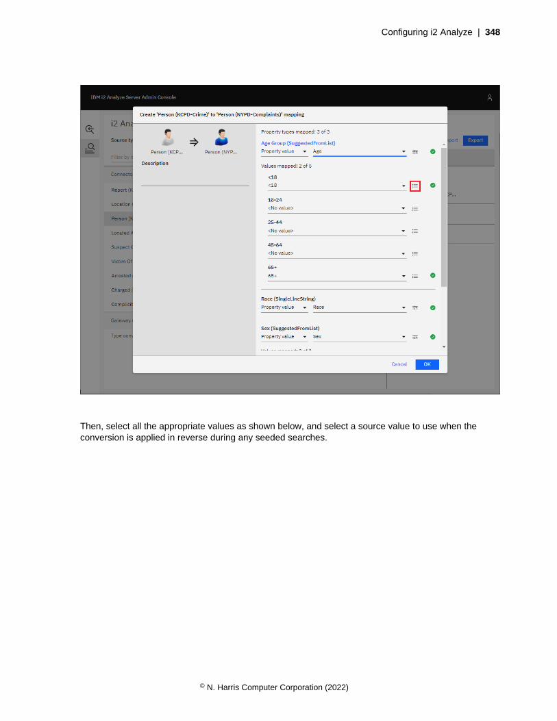
Configuring i2 Analyze | 348
Then, select all the appropriate values as shown below, and select a source value to use when theconversion is applied in reverse during any seeded searches.
© N. Harris Computer Corporation (2022)
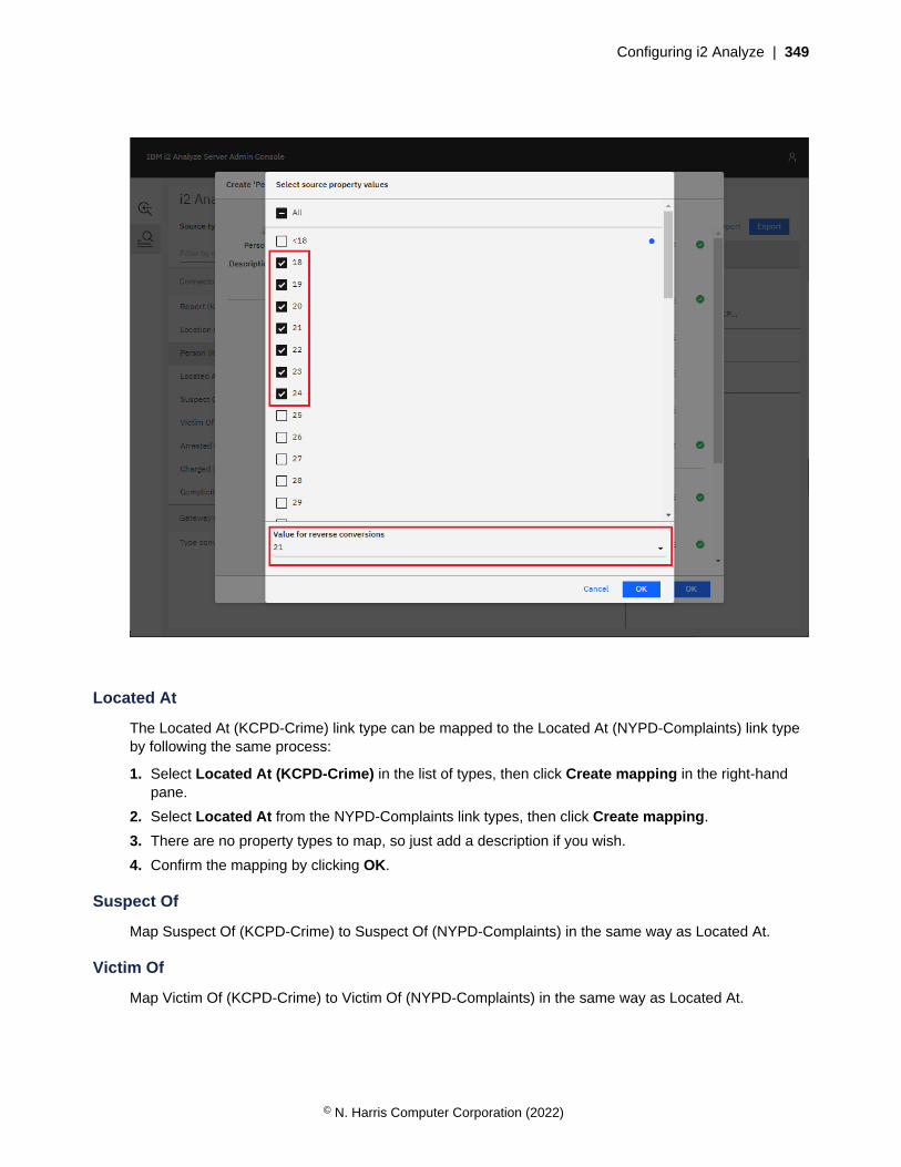
Configuring i2 Analyze | 349
Located At
The Located At (KCPD-Crime) link type can be mapped to the Located At (NYPD-Complaints) link typeby following the same process:
1. Select Located At (KCPD-Crime) in the list of types, then click Create mapping in the right-handpane.
2. Select Located At from the NYPD-Complaints link types, then click Create mapping.
3. There are no property types to map, so just add a description if you wish.
4. Confirm the mapping by clicking OK.
Suspect Of
Map Suspect Of (KCPD-Crime) to Suspect Of (NYPD-Complaints) in the same way as Located At.
Victim Of
Map Victim Of (KCPD-Crime) to Victim Of (NYPD-Complaints) in the same way as Located At.
© N. Harris Computer Corporation (2022)
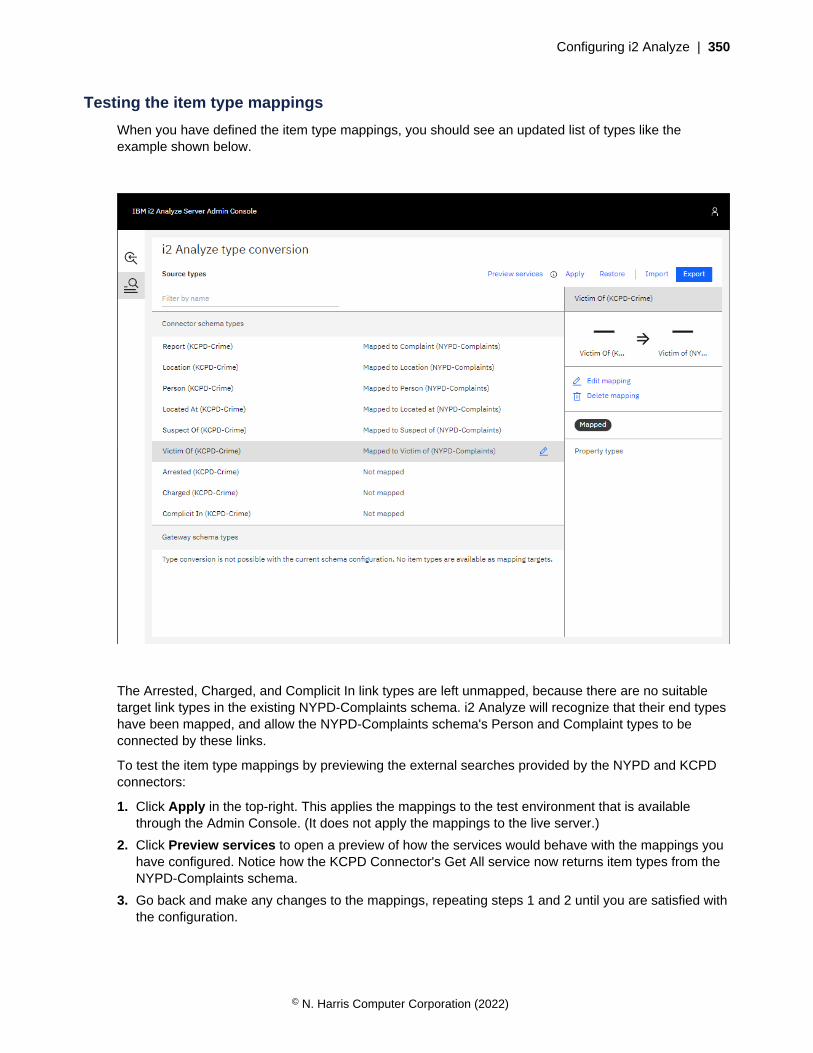
Configuring i2 Analyze | 350
Testing the item type mappings
When you have defined the item type mappings, you should see an updated list of types like theexample shown below.
The Arrested, Charged, and Complicit In link types are left unmapped, because there are no suitabletarget link types in the existing NYPD-Complaints schema. i2 Analyze will recognize that their end typeshave been mapped, and allow the NYPD-Complaints schema's Person and Complaint types to beconnected by these links.
To test the item type mappings by previewing the external searches provided by the NYPD and KCPDconnectors:
1. Click Apply in the top-right. This applies the mappings to the test environment that is availablethrough the Admin Console. (It does not apply the mappings to the live server.)
2. Click Preview services to open a preview of how the services would behave with the mappings youhave configured. Notice how the KCPD Connector's Get All service now returns item types from theNYPD-Complaints schema.
3. Go back and make any changes to the mappings, repeating steps 1 and 2 until you are satisfied withthe configuration.
© N. Harris Computer Corporation (2022)
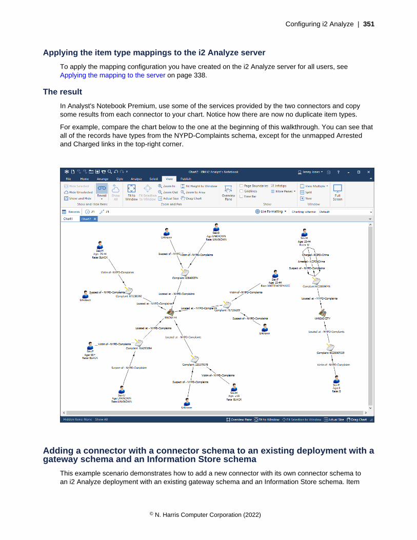
Configuring i2 Analyze | 351
Applying the item type mappings to the i2 Analyze server
To apply the mapping configuration you have created on the i2 Analyze server for all users, seeApplying the mapping to the server on page 338.
The result
In Analyst's Notebook Premium, use some of the services provided by the two connectors and copysome results from each connector to your chart. Notice how there are now no duplicate item types.
For example, compare the chart below to the one at the beginning of this walkthrough. You can see thatall of the records have types from the NYPD-Complaints schema, except for the unmapped Arrestedand Charged links in the top-right corner.
Adding a connector with a connector schema to an existing deployment with agateway schema and an Information Store schema
This example scenario demonstrates how to add a new connector with its own connector schema toan i2 Analyze deployment with an existing gateway schema and an Information Store schema. Item
© N. Harris Computer Corporation (2022)

Configuring i2 Analyze | 352
types in the connector schema are mapped to item types in the gateway schema, and item types in thegateway schema are mapped to item types in the Information Store schema.
The example also demonstrates how i2 Analyze resolves item type mappings that are chained together.That is, how mapping type A to type B and type B to type C results in an implicit mapping from type A totype C, so that all records of type A are converted to records of type C. It further shows how mapping toitem types in the Information Store schema allows converted records to be uploaded to the InformationStore.
Setting up the scenario
To follow this example:
1. Deploy i2 Analyze with the example NYPD connector, as described in the analyze-connectrepository, with the connector configured to use a gateway schema.
2. Add the example KCPD connector to the deployment, also configured to use a gateway schema.
With the example deployment in place, you can connect to the i2 Analyze server from Analyst'sNotebook Premium and use the services provided by the KCPD connector. For example, you might usethe "Get All" service and copy some of the results to a chart.
© N. Harris Computer Corporation (2022)
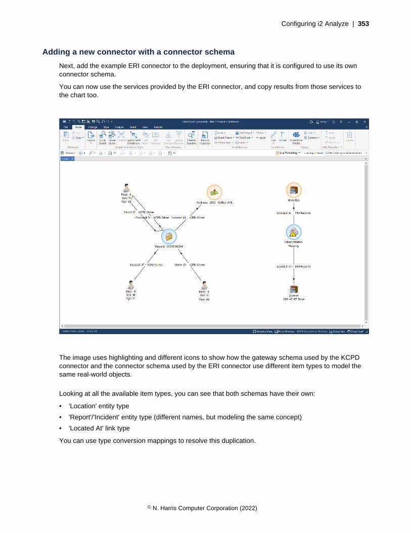
Configuring i2 Analyze | 353
Adding a new connector with a connector schema
Next, add the example ERI connector to the deployment, ensuring that it is configured to use its ownconnector schema.
You can now use the services provided by the ERI connector, and copy results from those services tothe chart too.
The image uses highlighting and different icons to show how the gateway schema used by the KCPDconnector and the connector schema used by the ERI connector use different item types to model thesame real-world objects.
Looking at all the available item types, you can see that both schemas have their own:
• 'Location' entity type
• 'Report'/'Incident' entity type (different names, but modeling the same concept)
• 'Located At' link type
You can use type conversion mappings to resolve this duplication.
© N. Harris Computer Corporation (2022)
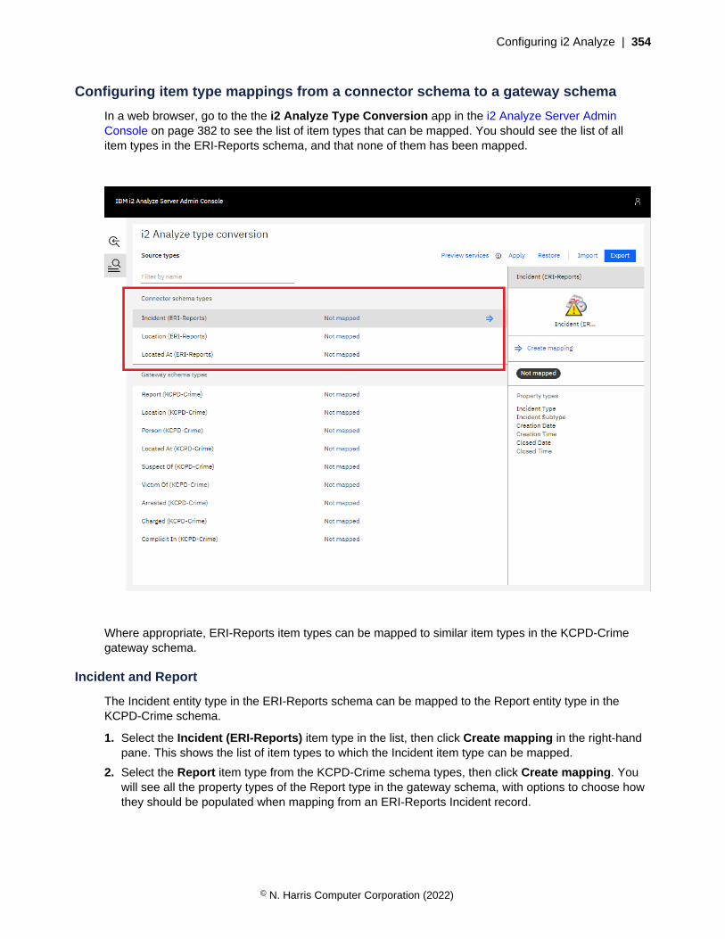
Configuring i2 Analyze | 354
Configuring item type mappings from a connector schema to a gateway schema
In a web browser, go to the the i2 Analyze Type Conversion app in the i2 Analyze Server AdminConsole on page 382 to see the list of item types that can be mapped. You should see the list of allitem types in the ERI-Reports schema, and that none of them has been mapped.
Where appropriate, ERI-Reports item types can be mapped to similar item types in the KCPD-Crimegateway schema.
Incident and Report
The Incident entity type in the ERI-Reports schema can be mapped to the Report entity type in theKCPD-Crime schema.
1. Select the Incident (ERI-Reports) item type in the list, then click Create mapping in the right-handpane. This shows the list of item types to which the Incident item type can be mapped.
2. Select the Report item type from the KCPD-Crime schema types, then click Create mapping. Youwill see all the property types of the Report type in the gateway schema, with options to choose howthey should be populated when mapping from an ERI-Reports Incident record.
© N. Harris Computer Corporation (2022)

Configuring i2 Analyze | 355
3. In the example below, the property types of the Incident (ERI-Reports) type are mapped to theproperty types of the Report (KCPD-Crime) according to the following table.
Incident (ERI-Reports) Report (KCPD-Crime)
Creation Date From Date
Closed Date To Date
Creation Time From Time
Closed Time To Time
Incident Subtype Offence Description
© N. Harris Computer Corporation (2022)
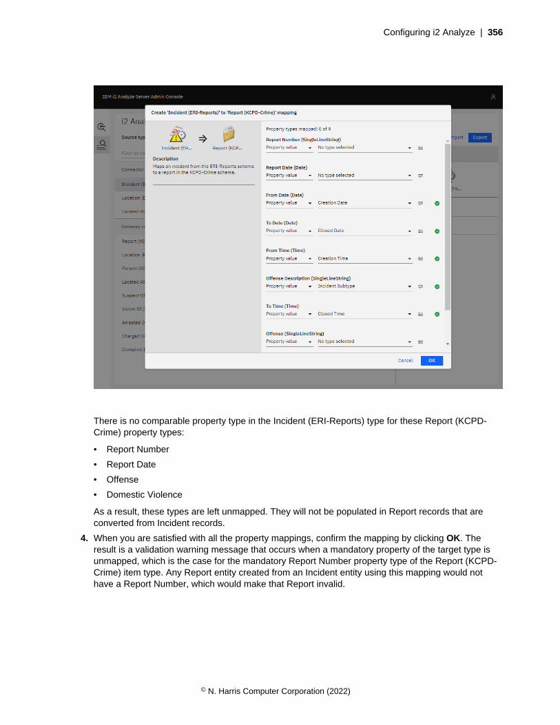
Configuring i2 Analyze | 356
There is no comparable property type in the Incident (ERI-Reports) type for these Report (KCPD-Crime) property types:
• Report Number
• Report Date
• Offense
• Domestic Violence
As a result, these types are left unmapped. They will not be populated in Report records that areconverted from Incident records.
4. When you are satisfied with all the property mappings, confirm the mapping by clicking OK. Theresult is a validation warning message that occurs when a mandatory property of the target type isunmapped, which is the case for the mandatory Report Number property type of the Report (KCPD-Crime) item type. Any Report entity created from an Incident entity using this mapping would nothave a Report Number, which would make that Report invalid.
© N. Harris Computer Corporation (2022)

Configuring i2 Analyze | 357
5. To provide a Report Number in all circumstances, select the Incident (ERI-Reports) item type in thelist, then click Edit mapping in the right-hand pane to update the mapping. In the mandatory ReportNumber (KCPD-Crime) property type, select the dropdown menu and change the type to Fixedvalue. Populate the field with a constant value.
6. After you update the property type mapping, confirm the item type mapping by clicking OK.
Location
Following the same process, you can map the Location type from the ERI-Reports schema to theLocation type in the KCPD-Crime schema.
The Address and Coordinates property types of Location (ERI-Reports) are automatically mapped to theAddress and Coordinates property types of Location (KCPD-Crime). Below is an example configurationyou could use.
© N. Harris Computer Corporation (2022)
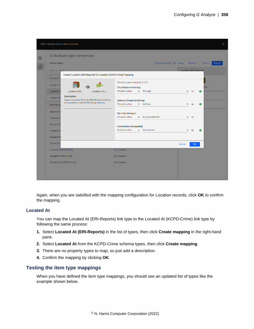
Configuring i2 Analyze | 358
Again, when you are satisfied with the mapping configuration for Location records, click OK to confirmthe mapping.
Located At
You can map the Located At (ERI-Reports) link type to the Located At (KCPD-Crime) link type byfollowing the same process:
1. Select Located At (ERI-Reports) in the list of types, then click Create mapping in the right-handpane.
2. Select Located At from the KCPD-Crime schema types, then click Create mapping.
3. There are no property types to map, so just add a description.
4. Confirm the mapping by clicking OK.
Testing the item type mappings
When you have defined the item type mappings, you should see an updated list of types like theexample shown below.
© N. Harris Computer Corporation (2022)
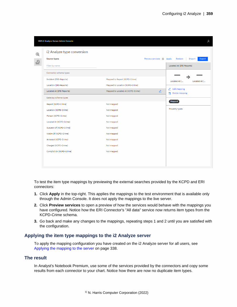
Configuring i2 Analyze | 359
To test the item type mappings by previewing the external searches provided by the KCPD and ERIconnectors:
1. Click Apply in the top-right. This applies the mappings to the test environment that is available onlythrough the Admin Console. It does not apply the mappings to the live server.
2. Click Preview services to open a preview of how the services would behave with the mappings youhave configured. Notice how the ERI Connector's "All data" service now returns item types from theKCPD-Crime schema.
3. Go back and make any changes to the mappings, repeating steps 1 and 2 until you are satisfied withthe configuration.
Applying the item type mappings to the i2 Analyze server
To apply the mapping configuration you have created on the i2 Analyze server for all users, seeApplying the mapping to the server on page 338.
The result
In Analyst's Notebook Premium, use some of the services provided by the connectors and copy someresults from each connector to your chart. Notice how there are now no duplicate item types.
© N. Harris Computer Corporation (2022)

Configuring i2 Analyze | 360
For example, compare the chart below to the one at the very beginning of this walkthrough. You cansee that all of the records have types from the KCPD-Crime schema, including the records from the ERIconnector. This is because of the mapping configuration that maps the item types in the ERI-Reportsschema to the item types in the KCPD-Crime schema.
Uploading converted records to the Information Store
Mapping connector types to gateway types does not result in records that can be uploaded to theInformation Store. The item types of the records are defined in the KCPD-Crime gateway schema,not the Information Store schema. Next, you can define mappings from the gateway schema to theInformation Store schema, and see that the records returned from both connectors can then beuploaded to the Information Store.
© N. Harris Computer Corporation (2022)
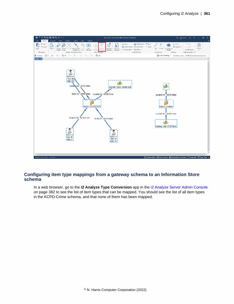
Configuring i2 Analyze | 361
Configuring item type mappings from a gateway schema to an Information Storeschema
In a web browser, go to the i2 Analyze Type Conversion app in the i2 Analyze Server Admin Consoleon page 382 to see the list of item types that can be mapped. You should see the list of all item typesin the KCPD-Crime schema, and that none of them has been mapped.
© N. Harris Computer Corporation (2022)

Configuring i2 Analyze | 362
Where appropriate, KCPD-Crime item types can be mapped to similar item types in the NYPD-Complaints Information Store schema.
Report and Complaint
The Report entity type in the KCPD-Crime schema can be mapped to the Complaint entity type in theInformation Store schema.
1. Select the Report (KCPD-Crime) item type in the list, then click Create mapping in the right-handpane. This shows the list of item types to which the Report item type can be mapped.
2. Select the Complaint item type from the Information Store schema, then click Create mapping. Youwill see all the property types of the Complaint type in the Information Store schema, with optionsavailable to choose how they should be populated when mapping from a KCPD-Crime Reportrecord.
3. In the example below, the property types of the Report (KCPD-Crime) type are mapped to theproperty types of the Complaint (InfoStore) according to the following table.
Report (KCPD-Crime) Complaint (InfoStore)
Report Number Complaint Number
© N. Harris Computer Corporation (2022)
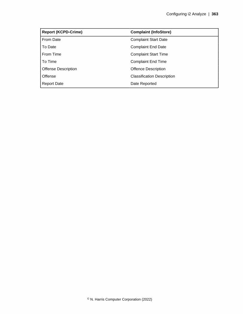
Configuring i2 Analyze | 363
Report (KCPD-Crime) Complaint (InfoStore)
From Date Complaint Start Date
To Date Complaint End Date
From Time Complaint Start Time
To Time Complaint End Time
Offense Description Offence Description
Offense Classification Description
Report Date Date Reported
© N. Harris Computer Corporation (2022)
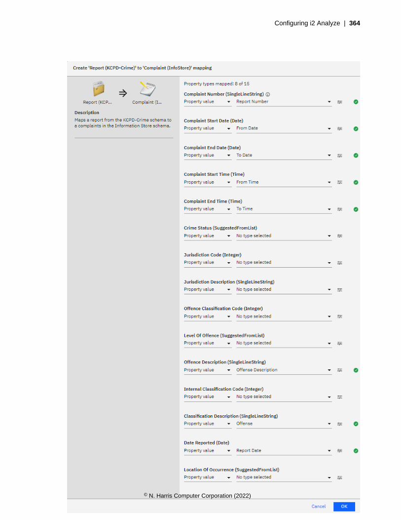
Configuring i2 Analyze | 364
© N. Harris Computer Corporation (2022)

Configuring i2 Analyze | 365
There is no comparable property type in the Report (KCPD-Crime) type for the Complaint (InfoStore)property types:
• Crime Status
• Jurisdiction Code
• Jurisdiction Description
• Offence Classification Code
• Level Of Offence
• Internal Classification Code
• Location Of Occurrence
As a result, these types are left unmapped. The properties of Complaints records that are convertedfrom Report records will not be populated.
4. When you are satisfied with all the property type mappings, confirm the mapping by clicking OK.
Location
Following the same process, the Location type from the KCPD-Crime schema can be mapped to theLocation type in the Information Store schema.
The Coordinates property type of Location (KCPD-Crime) is automatically mapped to the Coordinatesproperty type of Location (InfoStore). The image shows an example configuration that you could use.
© N. Harris Computer Corporation (2022)
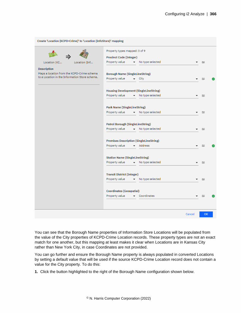
Configuring i2 Analyze | 366
You can see that the Borough Name properties of Information Store Locations will be populated fromthe value of the City properties of KCPD-Crime Location records. These property types are not an exactmatch for one another, but this mapping at least makes it clear when Locations are in Kansas Cityrather than New York City, in case Coordinates are not provided.
You can go further and ensure the Borough Name property is always populated in converted Locationsby setting a default value that will be used if the source KCPD-Crime Location record does not contain avalue for the City property. To do this:
1. Click the button highlighted to the right of the Borough Name configuration shown below.
© N. Harris Computer Corporation (2022)

Configuring i2 Analyze | 367
2. Enter a default value to use for the Borough Name property if a source KCPD-Crime Location recordhas no City value. For example, "Kansas City".
3. Click OK.
The mapping of Address to Premises Description does not seem like a perfect match either. But theAddress of a Location might be too important not to have, and the Premises Description is a suitabletarget property in which to store it.
Again, when you are satisfied with the mapping configuration for Location records, click OK to confirmthe mapping.
Person
You can follow the same process to create a mapping from the Person (KCPD-Crime) type to thePerson (InfoStore) type.
The Race and Sex property type mappings are generated automatically, so the only property type left isAge Group. You can map the values of the Age property type from the Person (KCPD-Crime) type, asshown below.
© N. Harris Computer Corporation (2022)
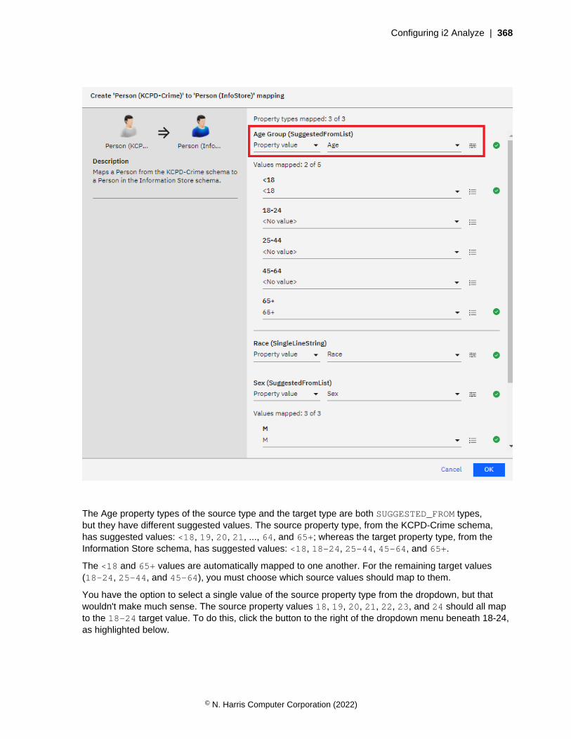
Configuring i2 Analyze | 368
The Age property types of the source type and the target type are both SUGGESTED_FROM types,but they have different suggested values. The source property type, from the KCPD-Crime schema,has suggested values: <18, 19, 20, 21, ..., 64, and 65+; whereas the target property type, from theInformation Store schema, has suggested values: <18, 18-24, 25-44, 45-64, and 65+.
The <18 and 65+ values are automatically mapped to one another. For the remaining target values(18-24, 25-44, and 45-64), you must choose which source values should map to them.
You have the option to select a single value of the source property type from the dropdown, but thatwouldn't make much sense. The source property values 18, 19, 20, 21, 22, 23, and 24 should all mapto the 18-24 target value. To do this, click the button to the right of the dropdown menu beneath 18-24,as highlighted below.
© N. Harris Computer Corporation (2022)

Configuring i2 Analyze | 369
Then, select all the appropriate values as shown below, and select a source value to use when theconversion is applied in reverse during any seeded searches.
© N. Harris Computer Corporation (2022)
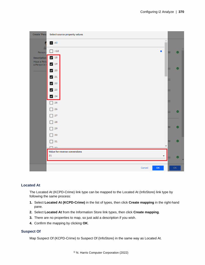
Configuring i2 Analyze | 370
Located At
The Located At (KCPD-Crime) link type can be mapped to the Located At (InfoStore) link type byfollowing the same process:
1. Select Located At (KCPD-Crime) in the list of types, then click Create mapping in the right-handpane.
2. Select Located At from the Information Store link types, then click Create mapping.
3. There are no properties to map, so just add a description if you wish.
4. Confirm the mapping by clicking OK.
Suspect Of
Map Suspect Of (KCPD-Crime) to Suspect Of (InfoStore) in the same way as Located At.
© N. Harris Computer Corporation (2022)
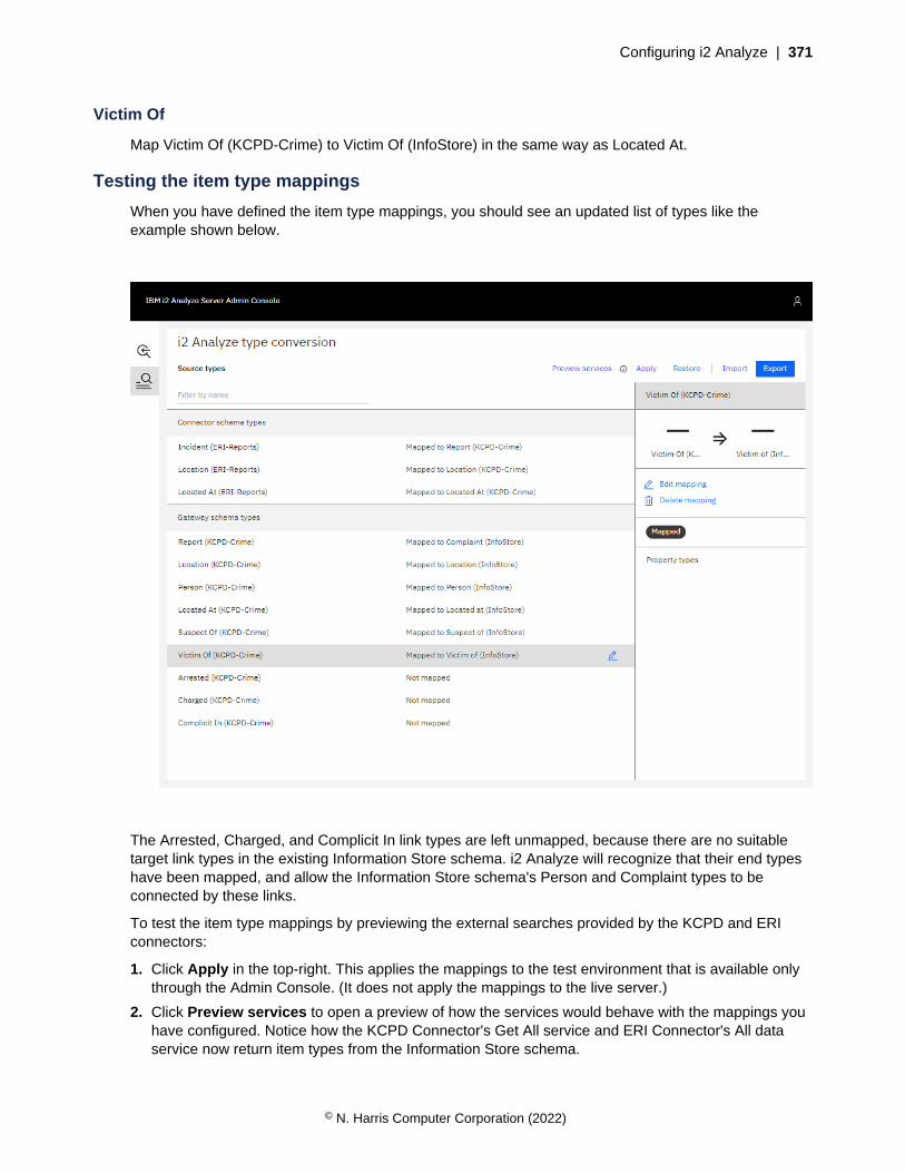
Configuring i2 Analyze | 371
Victim Of
Map Victim Of (KCPD-Crime) to Victim Of (InfoStore) in the same way as Located At.
Testing the item type mappings
When you have defined the item type mappings, you should see an updated list of types like theexample shown below.
The Arrested, Charged, and Complicit In link types are left unmapped, because there are no suitabletarget link types in the existing Information Store schema. i2 Analyze will recognize that their end typeshave been mapped, and allow the Information Store schema's Person and Complaint types to beconnected by these links.
To test the item type mappings by previewing the external searches provided by the KCPD and ERIconnectors:
1. Click Apply in the top-right. This applies the mappings to the test environment that is available onlythrough the Admin Console. (It does not apply the mappings to the live server.)
2. Click Preview services to open a preview of how the services would behave with the mappings youhave configured. Notice how the KCPD Connector's Get All service and ERI Connector's All dataservice now return item types from the Information Store schema.
© N. Harris Computer Corporation (2022)
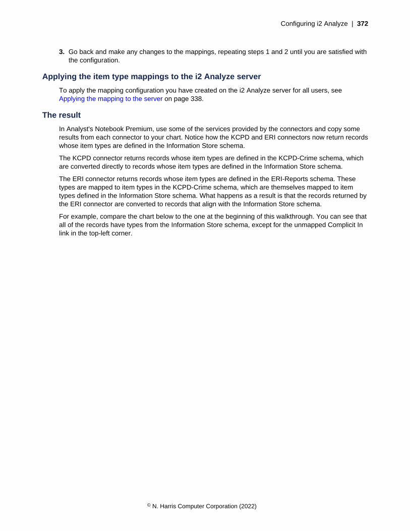
Configuring i2 Analyze | 372
3. Go back and make any changes to the mappings, repeating steps 1 and 2 until you are satisfied withthe configuration.
Applying the item type mappings to the i2 Analyze server
To apply the mapping configuration you have created on the i2 Analyze server for all users, seeApplying the mapping to the server on page 338.
The result
In Analyst's Notebook Premium, use some of the services provided by the connectors and copy someresults from each connector to your chart. Notice how the KCPD and ERI connectors now return recordswhose item types are defined in the Information Store schema.
The KCPD connector returns records whose item types are defined in the KCPD-Crime schema, whichare converted directly to records whose item types are defined in the Information Store schema.
The ERI connector returns records whose item types are defined in the ERI-Reports schema. Thesetypes are mapped to item types in the KCPD-Crime schema, which are themselves mapped to itemtypes defined in the Information Store schema. What happens as a result is that the records returned bythe ERI connector are converted to records that align with the Information Store schema.
For example, compare the chart below to the one at the beginning of this walkthrough. You can see thatall of the records have types from the Information Store schema, except for the unmapped Complicit Inlink in the top-left corner.
© N. Harris Computer Corporation (2022)
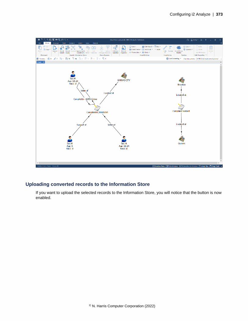
Configuring i2 Analyze | 373
Uploading converted records to the Information Store
If you want to upload the selected records to the Information Store, you will notice that the button is nowenabled.
© N. Harris Computer Corporation (2022)

Configuring i2 Analyze | 374
Click Upload Records. In the open window, you will see that one of the records - the unmappedComplicit In link in the top-left corner - cannot be uploaded because its item type is not from theInformation Store schema.
© N. Harris Computer Corporation (2022)

Configuring i2 Analyze | 375
If you want to upload this record, you must configure a mapping for its item type. Otherwise, you canclick Upload to upload the aligned records to the Information Store.
Merging two schemas
In this example of how to create type conversion mappings, two connectors - each with their owngateway schema - are being used in an i2 Analyze deployment. The two schemas contain similar itemtypes, so item type mappings will be used to remove duplicates.
It is not possible to define type conversion mappings in both directions between two schemas. That is,you cannot map item types from schema A to schema B, and also map item types from schema B toschema A. In a situation like this, you can create a third gateway schema that contains all the types youwant from the two original schemas, and then define mappings from the originals to the new schema.
Setting up the scenario
To follow this scenario, deploy i2 Analyze with the example NYPD connector and KCPD connector, bothconfigured to use gateway schemas.
© N. Harris Computer Corporation (2022)

Configuring i2 Analyze | 376
Reviewing the item types
Open the schema/nypd-complaint-data-schema.xml and schema/kcpd-crime-data-schema.xml schemas in Schema Designer to see the item types they define. Both schemas containentity types that represent:
• people
• complaints/reports
• locations
Both schemas also contain link types that represent:
• a complaint having occurred at a location
• a person being the victim of a complaint
• a person being the suspect of a complaint
The KCPD-Crime schema contains additional link types that represent:
• a person being complicit in a complaint
• a person having been arrested for a complaint
• a person having been charged for a complaint
There are obviously duplicate item types that can be resolved by defining item type mappings. Reviewthe item types and decide which of the duplicate types you prefer. For the purposes of this example, thepreferred item types are:
• Person (NYPD-Complaints)
• Report (KCPD-Crime)
• Location (KCPD-Crime)
• Located At (NYPD-Complaints)
• Suspect Of (NYPD-Complaints)
• Victim Of (NYPD-Complaints)
However, it is not possible to map the Person type in the KCPD-Crime schema to the Person type inthe NYPD-Complaints schema, and map the Complaint type in the NYPD-Complaints schema to theReport type in the KCPD-Crime schema. To resolve this, you can create a schema that contains thepreferred types from both schemas, configure it as a gateway schema, and then map types from theNYPD-Complaints schema and the KCPD-Crime schema to it.
Creating a schema
Use Schema Designer to create a schema that contains types identical to the preferred item types youchose from the NYPD-Complaints and KCPD-Crime schemas. An example containing the types listedabove is provided as schema/nypd-kcpd-merged-schema.xml in the analyze-connect repository.
Configure the new schema as a gateway schema in your deployment. Choose an appropriate shortname for this schema, such as "NYPD-KCPD-Merged".
Configuring item type mappings
Follow the process outlined in Creating type conversion mappings on page 329 to define mappingsof types from the NYPD-Complaints and KCPD-Crime schemas to types in the NYPD-KCPD-Mergedschema. Examples of specific mappings you might define are outlined below, but the general idea is to
© N. Harris Computer Corporation (2022)
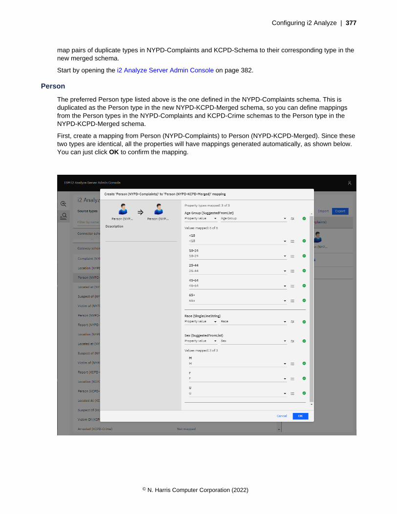
Configuring i2 Analyze | 377
map pairs of duplicate types in NYPD-Complaints and KCPD-Schema to their corresponding type in thenew merged schema.
Start by opening the i2 Analyze Server Admin Console on page 382.
Person
The preferred Person type listed above is the one defined in the NYPD-Complaints schema. This isduplicated as the Person type in the new NYPD-KCPD-Merged schema, so you can define mappingsfrom the Person types in the NYPD-Complaints and KCPD-Crime schemas to the Person type in theNYPD-KCPD-Merged schema.
First, create a mapping from Person (NYPD-Complaints) to Person (NYPD-KCPD-Merged). Since thesetwo types are identical, all the properties will have mappings generated automatically, as shown below.You can just click OK to confirm the mapping.
© N. Harris Computer Corporation (2022)

Configuring i2 Analyze | 378
Second, create a mapping from Person (KCPD-Crime) to Person (NYPD-KCPD-Merged) and map theproperties as if you were mapping to the NYPD-Complaints Person type. Example property mappingsyou might define are shown below.
Location
Similarly, the Location (NYPD-Complaints) and Location (KCPD-Crime) types can both be mapped toLocation (NYPD-KCPD-Merged).
The Location (NYPD-KCPD-Merged) type is identical to Location (KCPD-Crime), since that is thepreferred Location type. Start by mapping Location (KCPD-Crime) to Location (NYPD-KCPD-Merged),making use of the automatically-generated property mappings.
Then, map Location (NYPD-Complaints) to Location (NYPD-KCPD-Merged). Examples of propertymappings you might define are shown below.
© N. Harris Computer Corporation (2022)
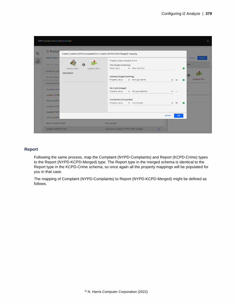
Configuring i2 Analyze | 379
Report
Following the same process, map the Complaint (NYPD-Complaints) and Report (KCPD-Crime) typesto the Report (NYPD-KCPD-Merged) type. The Report type in the merged schema is identical to theReport type in the KCPD-Crime schema, so once again all the property mappings will be populated foryou in that case.
The mapping of Complaint (NYPD-Complaints) to Report (NYPD-KCPD-Merged) might be defined asfollows.
© N. Harris Computer Corporation (2022)

Configuring i2 Analyze | 380
Links
The Located At, Suspect Of, and Victim Of link types in both the NYPD-Complaints and KCPD-Crimeschemas can be mapped to the corresponding link types in the NYPD-KCPD-Merged schema, whichare identical to the link types in NYPD-Complaints.
When all mappings are defined, you should see that all types - except the Complicit In, Arrested, andCharged links from the KCPD-Crime schema - have been mapped to the NYPD-KCPD-Merged schema.
© N. Harris Computer Corporation (2022)

Configuring i2 Analyze | 381
1. Click Apply in the top-right. This applies the mappings to the test environment that is available onlythrough the Admin Console. It does not apply the mappings to the live server.
2. Click Preview services to open a preview of how the services would behave with the mappings youhave configured.
3. Go back and make any changes to the mappings, repeating steps 1 and 2 until you are satisfied withthe configuration.
Applying the item type mappings to the i2 Analyze server
To apply the mapping configuration you have created on the i2 Analyze server for all users, seeApplying the mapping to the server on page 338.
The result
By creating a new gateway schema and defining item type mappings to it, you have mitigated theproblems caused by duplicate or similar item types in the NYPD-Complaints and KCPD-Crime schemas,without being limited to defining mappings in just one direction between them.
© N. Harris Computer Corporation (2022)
Configuring i2 Analyze | 382
i2 Analyze Server Admin ConsoleThe i2 Analyze Server Admin Console enables you to reload the gateway, preview configured serviceson the gateway, and configure type conversion mappings from a web browser.
To access the admin console, the user that you log in as must be a member of a user group that has thei2:Administrator command access control permission.
Verify that your user is an administrator
Check that your user has the i2:Administrator command access control permission when using theexample deployment:
1. Check that the Administrator user group in the example-command-access-control.xmlfile in toolkit\configuration\fragments\opal-services\WEB-INF\classes has thei2:Administrator permission:
<CommandAccessPermissions UserGroup="Administrator">
<Permission Value="i2:Administrator" />
</CommandAccessPermissions>
2. Check that your user belongs to the Administrator group in the user.registry.xml file ini2analyze\deploy\wlp\usr\shared\config.
For example, if the name of the user is "Jenny", you should have the following:
<group name="Administrator">
<member name="Jenny"/>
</group>
If this setting does not exist, add your user to the Administrator user group to reflect the snippetabove.
Deploy with changes
If you made changes to the example-command-access-control.xml file above, redeploy andrestart the Liberty server.
setup -t deployLiberty
setup -t startLiberty
Check access to the admin console
In a web browser, go to <i2-Analyze-URL>/admin and check that you can access the adminconsole using your login details. Here, <i2-Analyze-URL> is the URL used to access your i2 Analyzedeployment. For example, this might be http://localhost:9082/opaldaod/admin.
More information
For more information about command access control, see Controlling access to features.
© N. Harris Computer Corporation (2022)

Configuring i2 Analyze | 383
i2 Analyze Schema DesignerWelcome to the i2 Analyze Schema Designer documentation, where you can find information about howto use i2 Analyze Schema Designer.Getting startedSchemas on page 383A schema defines the structure of data that will be stored within your system. A schema must bedesigned in a way that effectively maps the data that you have, to the type of analysis that is going to becarried out.
Charting schemes on page 393Charting schemes determine the mapping between items in i2 Analyze and the same items whendisplayed on a chart in Analyst's Notebook Premium. You can transform data in different ways bycreating multiple charting schemes.
Common tasksCreating entity types on page 387Entity types define the structure for data that will be stored in i2 Analyze. By creating entity types, youcan classify your data.
Creating link types on page 389You can create link types to define the structure for describing the relationships between entities. Linktypes are similar to entity types in that they contain property types.
Changing the grading scheme on page 398You can grade your properties in i2 Analyze to indicate the level of confidence you have in propertyvalues. You can create and configure grade types within a grading scheme.
Troubleshooting and supporti2 Support
SchemasA schema defines the structure of data that will be stored within your system. A schema must bedesigned in a way that effectively maps the data that you have, to the type of analysis that is going to becarried out.
Structuring your data in a way that is easy to understand is important because correctly organizing dataincreases the likelihood of finding key information that relates to your investigation.
Data that will be stored within your system must be defined by using an entity, link, and property-basedmodel. Structuring your data in this format to fit the specifications of your investigation is called datamodeling.
You can use the Schema Designer to classify your data to resemble your data model. Dataclassification involves creating components within your schema for the data that will be stored in termsof entity and link types, with their property types.
Creating an effective schema involves several cycles of reviewing and testing before it is uploaded intoa production environment. This process reduces the need for changes during production that can affectthe data within your system.
Related tasksCreating schemas on page 386
© N. Harris Computer Corporation (2022)
Configuring i2 Analyze | 384
When the data that you want to analyze is modeled in terms of entities, links, and properties, you cancreate a schema with schema components. The example schemas that come with i2 Analyze can beedited if you do not want to start from a blank schema.
Data modeling
Before you create your schema, you must analyze the data that is likely to be available for analysis andunderstand how that data is used during an investigation. Based on your findings, you can create a datamodel that defines your data in terms of entities, links, and properties.
It is important to first establish the aim of your investigation when you are creating a data modelbecause it can help organize data effectively. You can analyze your data and consider how it fits thebasic concepts of data modeling.
The basic concepts of data modeling are formed by entities, links, and properties (ELP). Real worldobjects in your data can be expressed as entities, the association between those entities as links, andthe values that characterize the entities and links as properties. Both entities and links are types ofitems; items contain properties and property groups, and properties can be placed in items or propertygroups.
The Schema Designer can be used to create a schema that is based on the data model'sspecifications.
Important: If your deployment is using data connectors with other sources of data, the shape of thedata from those data connectors must also be modeled in your schema.
Schema structure
You can determine the structure of your schema by analyzing your data in terms of item and propertytypes. The schema structure is based on your data model.
Item types form the core of your schema and are created to classify the entities and links your identifiedin your data model. The following table describes the item types that you can create:
Table 2: Item types
Name Description
Entitytype
You can create entity types to classify your entities that represent your real world objects.For example, you might create a Person entity type to classify entities that representspecific people in an investigation. When you are adding information about these people,details about a specific person are added to a separate entity of type person within thesystem. You can assign a semantic type to an entity type to provide it with meaning byidentifying the nature of the data.
Link type You can create link types to classify the links you create between your entities. Forexample, a Car entity type and a Person entity type might be associated with an Owner linktype. When you are adding information about the relationship between a car and a person,it is added as a link of type owner within the system. A link type also dictates what typesof entities can be at the ends of links of that type. You can assign a semantic type to a linktype to provide it with meaning by identifying the nature of the data.
When you create item types, you can also create property and property group types that defineinformation about that item type. The following table describes how property and property group typesare used to classify property values for that are found in your data:
© N. Harris Computer Corporation (2022)
Configuring i2 Analyze | 385
Table 3: Property and property group types
Name Description
Property type You can create property types to identify features in entity and link types that might beuseful in analysis. Property types are important because they enable comparison ofdata more effectively by declaring whether they are the same. For example, you cancreate an Eye Color property type to classify properties in your data that representsdifferent eye colors. The logical type of a property type establishes what type of datacan be stored in that property type.
Propertygroup type
Property types can be grouped in property group types to organize your data in away that might help analysis. For example, if you had a Person entity type, you mightassign facial features such as Hair Color or Eye Color as property types, and thesetypes could be grouped in a Facial Features property group type.
In addition to creating item, property, and property group types, the following table describes how yourschema can define other behavior:
Table 4: Other behavior
Name Description
Labelingscheme
Labeling schemes define the property types that are used to identify items.
Grade types You can add grading information to indicate the level of confidence you have in yourproperty values for items. You can create a grading system with appropriate grade typesto match the rating system that your organization uses.
Linkstrengths
Link strengths that are set in the schema can be used on all link types. Only one linkstrength can be set as default. The default link strengths describe the links as beingeither confirmed, tentative, or unconfirmed, but you can configure the labels and theirappearance in the Schema Designer.
Schema development process
When you are creating a schema, you can go through a number of iterations to ensure that the schemasatisfies the requirements of your organization and functions correctly. By developing your schema intest environments, you ensure that it fits the format of your investigation.
Ensuring that you create and include only components that are necessary to your investigation isimportant. You cannot delete unnecessary components from your schema after you deploy it to theInformation Store.
After your schema is configured to the specifications of your data model, you can create one or morecharting schemes. A charting scheme determines how items that are stored in i2 Analyze are mapped toyour chart.
© N. Harris Computer Corporation (2022)
Configuring i2 Analyze | 386
Schema validationTo ensure the schema functions and is safe to use in your production environment, there are restrictionsyour schema must comply with when you create and develop it. The number and types of restrictionsthat are imposed on your schema vary depending on what stage of the development it is in.
Validation checks prevent you from implementing any changes that involve removing a unique ID fromyour schema. Your schema must retain these unique IDs because without them you cannot find thedata that they are assigned to.
Your schema must pass three types of validation checks before it can be uploaded:
System type validation
When you create a new schema, it contains system entity types. The system entity types mustexist for the schema to function. You can configure the Name and Description sections of thesesystem entity types as they do not change the function of the components. You can assign othercomponents to the system entity types such as property and property group types. You are unableto remove them from the schema.
Validation as you edit your schema
While you edit your schema, it must pass the Schema Designer validation checks. These checksdo not prevent you from editing your schema, but make you aware of any invalid changes that aremade. These validation checks ensure that your schema contains all the necessary components forit to function, such as link end constraints. Any issues that are found in the schema can be found atthe bottom of the Schema Designer window for you to fix.
Validation when you upload your schema
To protect your data, i2 Analyze checks ensure that any changes you might make do not result indata loss. Any changes that can cause data loss are called destructive changes. If you try to uploada destructively changed schema, the validation checks fail, and an error message is displayed.
Related tasksCreating link types on page 389You can create link types to define the structure for describing the relationships between entities. Linktypes are similar to entity types in that they contain property types.
Changing link strengths on page 399You can create link strengths to visually indicate how much confidence there is in the information that isrepresented by a particular link. Link strengths that you create in the schema can be applied to all linktypes.
Creating schemasWhen the data that you want to analyze is modeled in terms of entities, links, and properties, you cancreate a schema with schema components. The example schemas that come with i2 Analyze can beedited if you do not want to start from a blank schema.
When you create a schema, it contains default system entity types. These components hold necessaryinformation for the system and exist in order for it to work.
You can create schema components to classify and structure your data when it is stored in i2 Analyze.You can classify your data in terms of item types with their property types.
Related conceptsSchemas on page 383
© N. Harris Computer Corporation (2022)
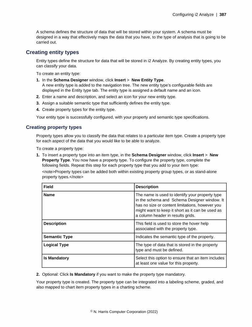
Configuring i2 Analyze | 387
A schema defines the structure of data that will be stored within your system. A schema must bedesigned in a way that effectively maps the data that you have, to the type of analysis that is going to becarried out.
Creating entity types
Entity types define the structure for data that will be stored in i2 Analyze. By creating entity types, youcan classify your data.
To create an entity type:
1. In the Schema Designer window, click Insert > New Entity Type.A new entity type is added to the navigation tree. The new entity type's configurable fields aredisplayed in the Entity type tab. The entity type is assigned a default name and an icon.
2. Enter a name and description, and select an icon for your new entity type.
3. Assign a suitable semantic type that sufficiently defines the entity type.
4. Create property types for the entity type.
Your entity type is successfully configured, with your property and semantic type specifications.
Creating property types
Property types allow you to classify the data that relates to a particular item type. Create a property typefor each aspect of the data that you would like to be able to analyze.
To create a property type:
1. To insert a property type into an item type, in the Schema Designer window, click Insert > NewProperty Type. You now have a property type. To configure the property type, complete thefollowing fields. Repeat this step for each property type that you add to your item type:
<note>Property types can be added both within existing property group types, or as stand-aloneproperty types.</note>
Field Description
Name The name is used to identify your property typein the schema and Schema Designer window. Ithas no size or content limitations, however youmight want to keep it short as it can be used asa column header in results grids.
Description This field is used to store the hover helpassociated with the property type.
Semantic Type Indicates the semantic type of the property.
Logical Type The type of data that is stored in the propertytype and must be defined.
Is Mandatory Select this option to ensure that an item includesat least one value for this property.
2. Optional: Click Is Mandatory if you want to make the property type mandatory.
Your property type is created. The property type can be integrated into a labeling scheme, graded, andalso mapped to chart item property types in a charting scheme.
© N. Harris Computer Corporation (2022)

Configuring i2 Analyze | 388
Creating property group types
Property groups are used to group related properties within the schema. You can create property grouptypes to group the property types that you consider to be similar.
When you group related properties as part of your schema design, it makes them easier to view andmanage for schema maintainers. Property groups are not available in Information Store or i2 Connectschemas.
To create a property group type:
1. To add a property group type to your selected item type, click Insert > New Property Group Type.You now have a property group type. To configure the property group type, complete the followingfields. Repeat this step for each property group type that you add to an item:
Field Description
Name The name is used to identify your property typein the schema and Schema Designer window. Ithas no size or content limitations, however youmight want to keep it short as it can be used asa column header in results grids.
Description This field is used to store a description of theproperty group type that might be useful toschema maintainers.
Is Mandatory Select this option to ensure that at least oneproperty within the property group is populatedfor an item.
2. Optional: Click Is Mandatory if you want to make the property group type mandatory.
Your property group type is created.
Specifying logical types
You must specify the logical type of a property type to inform your deployment about the type of datait is processing so it can enable and disable operators. By specifying the logical type, you can enter orimport data more accurately through validation checking.
The type of data that is stored in a property is determined by the logical type. It is important to selectthe correct logical type for the type of data that you would like to store and the type of analysis that isneeded. For more information about the logical types that you can choose, see Logical types on page389.
Note: When you are deciding whether to use a single-line or multi-line string type, it is important toconsider the intended use of the data and the performance of your system.
A property with the single-line string logical type is used to store text that can be used for faceting, andsupports operations such as 'Starts with' and 'Ends with'. A property with the multi-line string logicaltype can be used to store larger blocks of information, but the values cannot be used for faceting oroperations such as 'Start with' and 'Ends with'.
A property with the single-line string logical type can contain a maximum of 8000 characters in Db2databases, or 4000 characters in SQL Server databases.
To specify a logical type:
© N. Harris Computer Corporation (2022)
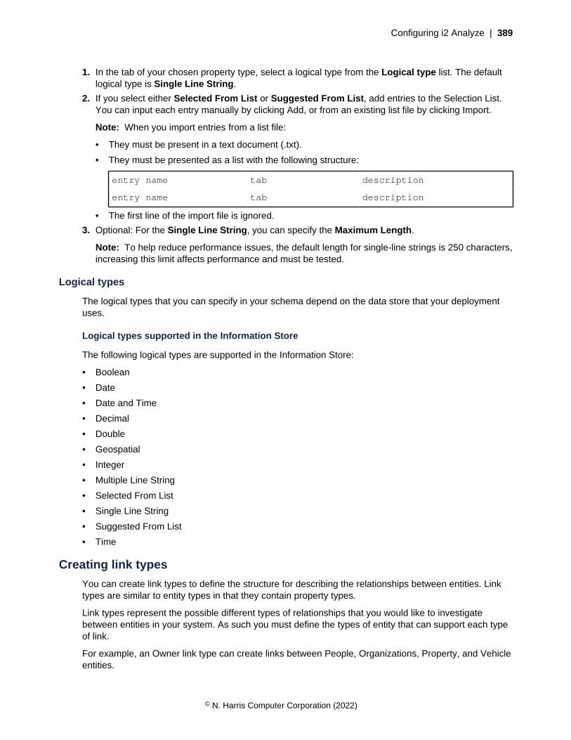
Configuring i2 Analyze | 389
1. In the tab of your chosen property type, select a logical type from the Logical type list. The defaultlogical type is Single Line String.
2. If you select either Selected From List or Suggested From List, add entries to the Selection List.You can input each entry manually by clicking Add, or from an existing list file by clicking Import.
Note: When you import entries from a list file:
• They must be present in a text document (.txt).
• They must be presented as a list with the following structure:
entry name tab description
entry name tab description
• The first line of the import file is ignored.
3. Optional: For the Single Line String, you can specify the Maximum Length.
Note: To help reduce performance issues, the default length for single-line strings is 250 characters,increasing this limit affects performance and must be tested.
Logical types
The logical types that you can specify in your schema depend on the data store that your deploymentuses.
Logical types supported in the Information Store
The following logical types are supported in the Information Store:
• Boolean
• Date
• Date and Time
• Decimal
• Double
• Geospatial
• Integer
• Multiple Line String
• Selected From List
• Single Line String
• Suggested From List
• Time
Creating link types
You can create link types to define the structure for describing the relationships between entities. Linktypes are similar to entity types in that they contain property types.
Link types represent the possible different types of relationships that you would like to investigatebetween entities in your system. As such you must define the types of entity that can support each typeof link.
For example, an Owner link type can create links between People, Organizations, Property, and Vehicleentities.
© N. Harris Computer Corporation (2022)

Configuring i2 Analyze | 390
To create a link type:
1. In the Schema Designer window, click Insert > New link Type.The link type has a default name, empty description field, and an ID that cannot be configured.
2. Enter a name and description for your link type.
3. Assign a suitable semantic type that sufficiently defines the link type.
4. Create property types for the link type.
5. Selecting link type end constraints is necessary to identify the possible entity types at the link's end.They are also used to create context for a search command.
a) Open the Link Ends tab for the selected link. All the entity types that are stored in the schemadisplay in both the From End Types and To End Types lists.
b) Select the entity types that apply to each end of the link.Your link end constraints are specified for your link type.
Your link type is successfully created with the specifications for its property types, semantic type, andlink end constraints.Related conceptsSchema validation on page 386To ensure the schema functions and is safe to use in your production environment, there are restrictionsyour schema must comply with when you create and develop it. The number and types of restrictionsthat are imposed on your schema vary depending on what stage of the development it is in.
Related tasksAssigning semantic types on page 391You can assign entity, link, and property types a semantic type to identify the real-world meaning ofthe data. Ensuring that your semantic types are assigned accurately is important because it affects theorganization and interpretation of your data.
Creating labeling schemes
To define how your data is labeled on screen, or as chart item type labels, you can create labelingschemes. The labeling scheme determines what information the user sees when items are listed orvisualized.
You can create item labels that determines how items are identified. For example, you create a labelingscheme for a Person entity type that has a Forename, Surname, and Date of Birth property type. Youcan use the Forename and Surname property types as the label.
Note: To maintain consistency, you can configure your charting schemes to use the labeling schemesto determine the chart item label.
To create a labeling scheme for your item type:
1. After you select Labeling Scheme in the navigation tree in the Schema Designer window, selectthe Item type list. The Properties list is updated with the property types created for your item type.
2. Select the properties to use in the label, and click the arrow to move them to the Label partscolumn.
3. Optional: Add any fixed values to the Label parts by entering them in the Free Text box and clickingthe corresponding arrow. Free text can be used to separate multiple properties when combined on alabel, but also provide a standard label for items that do not need a unique label
Note: For items that do not have property values to define their label, the system displays <Nolabel> by default. Adding any character other than spaces as free text changes this behavior,displaying the free text instead.
© N. Harris Computer Corporation (2022)

Configuring i2 Analyze | 391
If you want your labeling scheme to be used with your chart, you must map the labeling scheme inthe charting scheme editor.
4. Optional: Rearrange the Label Parts by clicking the up and down arrows as needed.
Your labeling scheme is created and applied to your item types based on your configuration. Yourlabeling scheme is composed of any property types you specified to be labeled.
Semantic types and charting schemesAnalyst's Notebook Premium can interpret and use any items that are defined in a schema. However,there is additional information that can be used by Analyst's Notebook Premium to interpret data.
Semantic type information and charting schemes are used to transform data into a format that Analyst'sNotebook Premium recognizes.
• Semantic types can be assigned to item, property, and property group types to identify the real lifemeaning in the data.
• Charting schemes determine the mapping between items in i2 Analyze and the same items whendisplayed on a chart in Analyst's Notebook Premium.
Assigning semantic types
You can assign entity, link, and property types a semantic type to identify the real-world meaning ofthe data. Ensuring that your semantic types are assigned accurately is important because it affects theorganization and interpretation of your data.
Item and property types are aligned and interpreted based on what semantic type is assigned to them.
For example, a Car entity type and a Plane entity type can be assigned the Vehicle semantic type.Analyst's Notebook Premium aligns item types that are assigned the Vehicle semantic type, andinterprets them as a type of vehicle.
You can assign semantic types to restrict the type of data that can be stored in a property type. Datatypes of property values must be consistent with the property's meaning.
Attention: If you are connected to multiple data sources, it is important to ensure that semantictypes are assigned correctly because data alignment depends on it. Having common propertysemantic types help searches to retrieve similar items from all of the data sources.
You must assign a semantic type to a property type, unless all three of the following conditions apply:
1. It is only used as a key, label, or description.
2. It is not displayed in a report, the search results grid, or the chart data record.
3. It has no search operators defined.
To assign a semantic type to your item or property type:
1. Select the item or property type you want to assign a semantic type to.
2. In the selected item or property type's tab, click Select next to the semantic type field.
The Select Semantic Type window opens. It is the i2® semantic type library that is used by Analyst'sNotebook Premium.
3. Browse the library to find and select the semantic type that defines your data to the depth yourequire.
4. When your semantic type is identified and selected, click Assign.
© N. Harris Computer Corporation (2022)

Configuring i2 Analyze | 392
Your item or property type is assigned a semantic type. You can remove this semantic type byclicking Remove.
Related tasksCreating link types on page 389You can create link types to define the structure for describing the relationships between entities. Linktypes are similar to entity types in that they contain property types.
Deriving custom semantic types
You can derive a custom semantic type when the semantic types that are stored in the standard librarydo not sufficiently classify the data that they are being assigned to. You can derive a custom semantictype from an appropriate generalized parent semantic type.
Ensuring that you choose the correct parent semantic type is important because the custom semantictype inherits characteristics and behavior from the parent. If you choose a parent semantic type that isnot fitting, Analyst's Notebook Premium might interpret the data incorrectly.
For example, it would be inappropriate for you to derive a custom semantic type for a sporting eventfrom the Document entity semantic type. A sporting event is not a specialization of a document. Theresult of this inappropriate specification would be that Analyst's Notebook Premium would expect tointerpret documentation as opposed to sporting event data.
You can edit the details for a custom semantic type at any time, but it is best to avoid changing themin a way that changes the original meaning. Different versions of the same custom semantic type alignregardless of the custom semantic type's name, description, or synonyms.
CAUTION: Defining a custom semantic type when the library already contains an appropriatesemantic type can cause problems with information retrieval. Information that is retrieved fromyour data source would be unaligned with information retrieved from other data sources thathave the correct semantic type assigned. Search carefully for an available semantic type beforeyou create your own custom semantic types.
To derive a custom semantic type:
1. After you select the item type you want to assign a semantic type to in Schema Designer, clickSelect to open the Select Semantic Type window.
2. Locate the available semantic type that is the most similar to the specialization that you require, bysearching for semantic types that have a generalized name.
3. Select the generalized type in the tree of semantic types, and then click Derive Custom Type. Anew semantic type is added as a child of the generalized semantic type.
Note: Custom semantic types are given a special red icon to differentiate them from the standard i2®
semantic types.
4. Change the name of the custom semantic type to a name that reflects your usage.
5. To improve search results when you try to locate this semantic type in the future, add synonymsfor this custom semantic type in the Synonyms text box. Separate each synonym with a comma.Phrases are allowed.
6. Describe the intended usage for this custom semantic type in the Description box. You can type aweb address to provide a hyperlink to a web page for more information.
7. After your new custom semantic types are configured to your specification, click Assign to assignthis new custom semantic type to your item type.
8. Optional: You can save the custom semantic type by clicking File > Custom Semantic Types >Save Library.
© N. Harris Computer Corporation (2022)
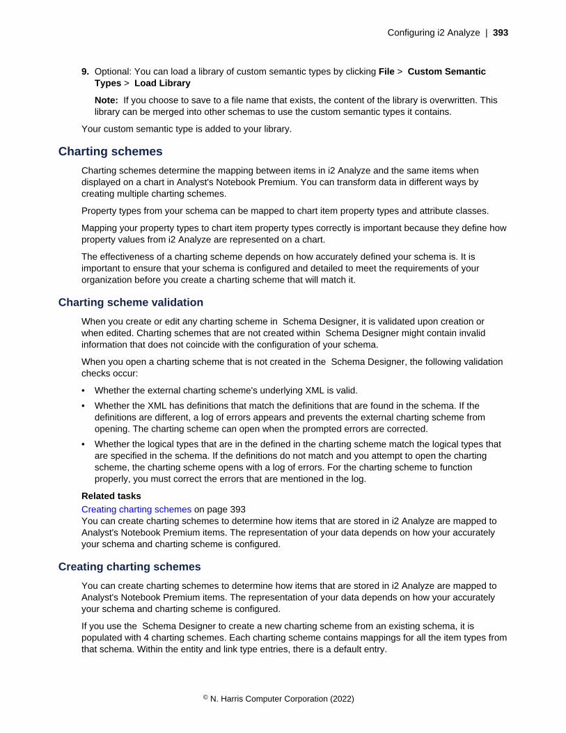
Configuring i2 Analyze | 393
9. Optional: You can load a library of custom semantic types by clicking File > Custom SemanticTypes > Load Library
Note: If you choose to save to a file name that exists, the content of the library is overwritten. Thislibrary can be merged into other schemas to use the custom semantic types it contains.
Your custom semantic type is added to your library.
Charting schemes
Charting schemes determine the mapping between items in i2 Analyze and the same items whendisplayed on a chart in Analyst's Notebook Premium. You can transform data in different ways bycreating multiple charting schemes.
Property types from your schema can be mapped to chart item property types and attribute classes.
Mapping your property types to chart item property types correctly is important because they define howproperty values from i2 Analyze are represented on a chart.
The effectiveness of a charting scheme depends on how accurately defined your schema is. It isimportant to ensure that your schema is configured and detailed to meet the requirements of yourorganization before you create a charting scheme that will match it.
Charting scheme validation
When you create or edit any charting scheme in Schema Designer, it is validated upon creation orwhen edited. Charting schemes that are not created within Schema Designer might contain invalidinformation that does not coincide with the configuration of your schema.
When you open a charting scheme that is not created in the Schema Designer, the following validationchecks occur:
• Whether the external charting scheme's underlying XML is valid.
• Whether the XML has definitions that match the definitions that are found in the schema. If thedefinitions are different, a log of errors appears and prevents the external charting scheme fromopening. The charting scheme can open when the prompted errors are corrected.
• Whether the logical types that are in the defined in the charting scheme match the logical types thatare specified in the schema. If the definitions do not match and you attempt to open the chartingscheme, the charting scheme opens with a log of errors. For the charting scheme to functionproperly, you must correct the errors that are mentioned in the log.
Related tasksCreating charting schemes on page 393You can create charting schemes to determine how items that are stored in i2 Analyze are mapped toAnalyst's Notebook Premium items. The representation of your data depends on how your accuratelyyour schema and charting scheme is configured.
Creating charting schemes
You can create charting schemes to determine how items that are stored in i2 Analyze are mapped toAnalyst's Notebook Premium items. The representation of your data depends on how your accuratelyyour schema and charting scheme is configured.
If you use the Schema Designer to create a new charting scheme from an existing schema, it ispopulated with 4 charting schemes. Each charting scheme contains mappings for all the item types fromthat schema. Within the entity and link type entries, there is a default entry.
© N. Harris Computer Corporation (2022)

Configuring i2 Analyze | 394
You can configure the default entry for entity and link types. To apply your default entry to the itemtypes in your schema, they all must have property types with the same name. The default configurationsare used unless a type-specific mapping exists. For example, if your Default entry is configured and aspecific Person type mapping is inserted, then your Account uses Default, and Person uses Person.
You can choose to create data records on the mapped chart items. The data records contain theinformation in the i2 Analyze item, regardless of whether it is mapped or not. You can also choose toinclude property gradings in the data record.
To create or edit a charting scheme:
1. In the Schema Designer window, click File > Edit Charting Schemes.
If your current schema has no associated charting schemes, a window opens with four defaultcharting schemes in a navigation tree. If your schema has charting schemes that are associated withit, a window opens with the charting schemes in the navigation tree.
In the Edit Charting Scheme window you can create, delete, and edit charting schemes.
2. When you are finished creating, deleting, or editing charting schemes, you can click OK to save yourchanges. Alternatively, you can click Cancel if you do not want to save any creations or changes.
Related conceptsCharting scheme validation on page 393When you create or edit any charting scheme in Schema Designer, it is validated upon creation orwhen edited. Charting schemes that are not created within Schema Designer might contain invalidinformation that does not coincide with the configuration of your schema.
Inserting chart item property types
You can map the property types in your schema to an Analyst's Notebook Premium chart by insertingchart item property types into a charting scheme. Chart item property types determine how the propertyvalues that are stored in i2 Analyze, are represented on the chart.
The Edit Charting Schemes window must be open. Select the item type that you want to create aproperty mapping for.
The following are chart item property types that are available for mapping to include descriptive piecesof information you might want visualized on the chart:
• Label
• Date
• Time
• Description of date & time
• Description
• Source reference
• Source type
In the chart item property type configuration screen, you can insert multiple property types to map tothe chart item property type. Multiple chart item properties can be mapped to by the same i2 Analyzeproperty.
You can configure whether the mapped property types have a prefix or suffix for their i2 Analyzeproperty values. You can also determine how you want the i2 Analyze properties to behave if they havemultiple values.
© N. Harris Computer Corporation (2022)

Configuring i2 Analyze | 395
Labeling schemes for chart item property types are created to label the data that is represented ona chart for analysis. To map from the label of an item in i2 Analyze, you must specify which labelingscheme you want to use.
To map a property type to a chart item property type:
1. Right-click on the Properties entry of the relevant property type, and select Insert Chart ItemProperty Type.The Add Chart Item Property Type window is shown.
2. From the Available chart item property type list, select a property and click OK. The Availablechart item property type list contains any chart item property type that is not mapped.The appropriate property type page is shown, for example Label.
3. Configure the property type's specifications to how you want them to be represented on the chart.The property type setup depends on the property type that is selected. You can define a label fromas many property types as you want, and include spaces or new lines.For example, given name followed by a space followed by surname.
Your property type is successfully mapped to a chart item property.Multiple value settings
It is possible for an item in i2 Analyze to contain properties with multiple values. Charting schemescontain configurable specifications that define how multiple property values are charted.
For example, an item might have several properties of type Middle name, all of which have differentvalues. Items on a chart do not support this notion, so you must create a charting scheme and configureit to accommodate the multiple property values.
You can configure the property value specifications when you insert property or attribute mappings.
The configuration options for determining the value that is charted depends on the underlying data typeof the property. For example, you can chart a Date & Time property value by using the earliest or themost recent value from the set of multiple values.
Note: The default configuration is set to Use any single value. For the default configurations, they holdno deterministic rules that specify which value in the set of values is charted.
When links are summarized - Single, Directed or Flow - each link item that is being summarized mighthave multiple values for a property. When you are creating link type property mappings, the followingextra options are available for populating the set of values from which the charted value is selected:
• All values from all links
• Primary property from each link
CAUTION: The Information Store and Analyst's Notebook Premium do not support the conceptthat a single property type can possess multiple property values. Data loss can occur if youcreate and upload a charting scheme that accommodates for multiple property values, and placeitems with selected property values onto a chart.
Related tasksConfiguring link summarizations on page 397If there are multiple links between the same two entities on an Analyst's Notebook Premium chart, youcan choose how to represent those links to compact information. Your links can summarize information
© N. Harris Computer Corporation (2022)

Configuring i2 Analyze | 396
such as transaction links with the Flow option selected, and can show the transactions between twobank accounts with all of the transaction amounts.
Inserting attribute instances
You can map property types to instances of attribute classes. You can define a new attribute class tomap to, or map your property type to an existing attribute class.
The Edit Charting Schemes window must be open. Select the item type that you want to map aninstance of an attribute class to.
To insert an instance of an attribute class mapping:
1. Right-click your property type and select Insert Attribute Instance.
2. In the Insert Attribute Class window, you can either select an attribute class that exists, or createone specifically for the property type.
3. If you want to map to an existing attribute class, click Select an existing attribute class and choosean attribute from the list.
4. If you want to create an attribute class specifically for the property type:
a) Click Select a repository property and enter a name for your new attribute class in the Specifythe new attribute class name.
b) Click Next and configure the attribute class.
5. When your attribute class is configured, click OK.
Your property type is mapped to an instance of an attribute class. If your attribute class was createdspecifically, it appears in your attribute classes section and your property type's attribute section.
Inserting attribute classesAttribute classes determine the type of data that is stored and displayed as attributes on an Analyst'sNotebook Premium chart. You can create attribute classes and map property types to them or storethem within an Analyst's Notebook Premium chart template.
Attribute classes contain configurable options that include naming the attribute class, selecting itssemantic type, and deciding how it is displayed on the chart. You can also configure how the attributeclass behaves with other items on the chart with regards to pasting and merging.
Attribute classes must have unique names. If an attribute class of the same name exists in the currentchart, the settings for the attribute class are retained over the settings in the charting scheme.
To create an attribute class for your Analyst's Notebook Premium chart template:
1. In the Edit Charting Schemes window, expand the tree structure for the charting scheme and right-click the Attribute Classes entry.
2. Select the appropriate menu item for the type of attribute class that you want to create: Text, Flag,Number, or Date & Time.A new attribute class is created in the tree view.
3. Configure the details to your specifications in your New Attribute Class' window. You can configureyour attribute class' name, appearance on the chart, semantic type, and behavior to use for attributevalues of this class when you merge or paste chart items.
4. When your attribute class is configured, click OK.
Your attribute class is successfully configured and inserted. If an attribute class that is specific to aproperty type is inserted, the configurations for that attribute class appear when that property type isused.
© N. Harris Computer Corporation (2022)

Configuring i2 Analyze | 397
Configuring link summarizations
If there are multiple links between the same two entities on an Analyst's Notebook Premium chart, youcan choose how to represent those links to compact information. Your links can summarize informationsuch as transaction links with the Flow option selected, and can show the transactions between twobank accounts with all of the transaction amounts.
To configure link summarization for a link type:
1. In the tree view of the Edit Charting Schemes window, expand the charting scheme that you wishto edit and click and expand Link Types.
2. Select the link type that you want to configure link summarization for.
3. In the Link Summarization area, select on of the following options.
Option Description
Single Link All the links of the selected link type betweenthe same two entities are combined into a singlelink. This option is useful if you are producing asummary chart and do not want to show all ofthe details.
Directed All the links of the selected link type in thesame direction between the same two entitiesare combined. This option is useful whencharting information such as telephone calls ortransactions.
Multiple Each link of the selected link type between thesame two entities is charted separately. Thisoption is useful if you want to show all of thedetail but if there are many links, it might makethe chart cluttered or unreadable.
Flow All the links of the selected link type arecombined into a single link. The direction (orflow) is determined from a property that youspecify. For example, if there are severalfinancial transactions between two bankaccounts, this option is useful to determinethe direction that the aggregate amount of themoney is flowing. Select a property from theProperty used to calculate flow list. Flow valueis calculated and is available for you to mapin an attribute instance or chart item propertymapping.
Note: The Flow option is available onlywhen the selected link type has numeric dataproperties.
4. When you combine multiple links between the same two entities, you can choose whether to retainthe strengths by keeping links of different strengths separate. Alternatively, you can choose to usethe strength of the weakest link. Select the appropriate options on the right side of the page.
© N. Harris Computer Corporation (2022)
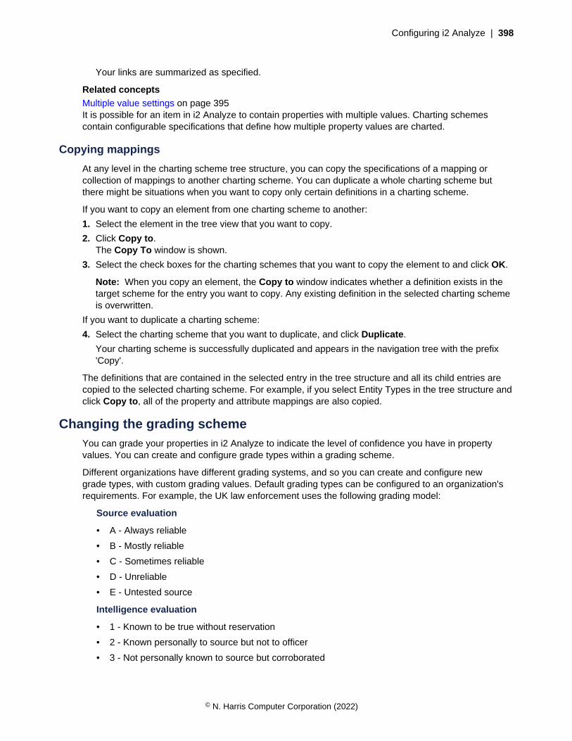
Configuring i2 Analyze | 398
Your links are summarized as specified.
Related conceptsMultiple value settings on page 395It is possible for an item in i2 Analyze to contain properties with multiple values. Charting schemescontain configurable specifications that define how multiple property values are charted.
Copying mappings
At any level in the charting scheme tree structure, you can copy the specifications of a mapping orcollection of mappings to another charting scheme. You can duplicate a whole charting scheme butthere might be situations when you want to copy only certain definitions in a charting scheme.
If you want to copy an element from one charting scheme to another:
1. Select the element in the tree view that you want to copy.
2. Click Copy to.The Copy To window is shown.
3. Select the check boxes for the charting schemes that you want to copy the element to and click OK.
Note: When you copy an element, the Copy to window indicates whether a definition exists in thetarget scheme for the entry you want to copy. Any existing definition in the selected charting schemeis overwritten.
If you want to duplicate a charting scheme:
4. Select the charting scheme that you want to duplicate, and click Duplicate.
Your charting scheme is successfully duplicated and appears in the navigation tree with the prefix'Copy'.
The definitions that are contained in the selected entry in the tree structure and all its child entries arecopied to the selected charting scheme. For example, if you select Entity Types in the tree structure andclick Copy to, all of the property and attribute mappings are also copied.
Changing the grading schemeYou can grade your properties in i2 Analyze to indicate the level of confidence you have in propertyvalues. You can create and configure grade types within a grading scheme.
Different organizations have different grading systems, and so you can create and configure newgrade types, with custom grading values. Default grading types can be configured to an organization'srequirements. For example, the UK law enforcement uses the following grading model:
Source evaluation
• A - Always reliable
• B - Mostly reliable
• C - Sometimes reliable
• D - Unreliable
• E - Untested source
Intelligence evaluation
• 1 - Known to be true without reservation
• 2 - Known personally to source but not to officer
• 3 - Not personally known to source but corroborated
© N. Harris Computer Corporation (2022)
Configuring i2 Analyze | 399
• 4 - Cannot be judged
• 5 - Suspected to be false or malicious
Handling code
• 1 - Can be disseminated to other law enforcement and prosecuting agencies, including lawenforcement agencies within the EEA, and EU compatible (no special conditions)
• 2 - Can be disseminated to UK non-prosecuting parties (authorization and records needed)
• 3 - Can be disseminated to non-EEA law enforcement agencies (special conditions apply)
• 4 - Can be disseminated within the originating agency only
• 5 - No further dissemination: refer to the originator. Special handling requirements that areimposed by the officer who authorized collection
To change the grading scheme:
1. After you select Grade Types in the navigation tree in the Schema Designer application window,click Insert > New Grade Type.
The new grade type is added to the Grade Types list on the left.
2. Enter a Name and a Description to identify the grade type.
3. For each grade value, enter a Grade Value and click Add.
4. Optional: Use the arrow buttons to change the order in which the grade values are displayed.
5. Optional: With a grade value selected, click Remove to delete the value.
6. Optional: Select the Mandatory check box to force users to select a value for this grade type whenyou enter data.
Your grading scheme is successfully modified.
Changing link strengthsYou can create link strengths to visually indicate how much confidence there is in the information that isrepresented by a particular link. Link strengths that you create in the schema can be applied to all linktypes.
To change the link strengths that are available:
1. In the Schema Designer window, click Insert > New Link Strength or open an existing linkstrength in the navigation tree.
2. Enter a Name for the link strength.
3. Select the Line style.
4. Optional: Select Set as default.
A new link strength is created and configured to your investigation's specification.Related conceptsSchema validation on page 386To ensure the schema functions and is safe to use in your production environment, there are restrictionsyour schema must comply with when you create and develop it. The number and types of restrictionsthat are imposed on your schema vary depending on what stage of the development it is in.
GlossaryThis glossary provides terms and definitions for the i2 Analyze software and products.
The following cross-references are used in this glossary:
© N. Harris Computer Corporation (2022)
Configuring i2 Analyze | 400
• See refers you from a nonpreferred term to the preferred term or from an abbreviation to the spelled-out form.
• See also refers you to a related or contrasting term.
A
abstract semantic type
A semantic type that only serves as the parent of other semantic types. Abstract semantic typescategorize their child semantic types, but are never associated with real data.
access level
A measure of the rights that a user has to view or edit an item. Access levels are calculatedseparately for every user and every item. See also grant level, security dimension.
administrator
A person responsible for administrative tasks such as access authorization and contentmanagement. Administrators can also grant levels of authority to users.
alert
A message or other indication that signals an event or an impending event that meets a set ofspecified criteria.
alert definition
The statement of criteria that trigger an alert.
aligned value
A value that is used to interpret equivalent native values from different data sources. For example,the value Male can be used to align the native values M or Ma.
analysis attribute
A characteristic or trait pertaining to a chart item. Analysis attributes are never displayed on charts.
association chart
A chart that highlights the relationships between entities, rather than a chronology of events, byarranging data in a manner that emphasizes particular associations.
attribute
A piece of information that is associated with a chart item, such as a date of birth or an accountnumber. An attribute is represented by a symbol, or a value, or both, that is displayed with the chartitem.
attribute class
A descriptor of the characteristics of an attribute, including the type of its values, how its values aredisplayed, and the treatment of its values when they are merged or pasted on a chart.
attribute entry
An attribute with a preset value that can be associated with a chart item.
attribute instance
A single use of an attribute on a chart item.
audit
To record information about database or instance activity by applications or individuals.
authority
A measure of how well-connected an entity is, based on its inbound links. Authority is one of twoeigenvector centrality measures used in social network analysis. See also centrality, eigenvector.
© N. Harris Computer Corporation (2022)

Configuring i2 Analyze | 401
automatic attribute
An attribute that is created automatically by the application and added to a chart item.
B
betweenness
A measure of how important an entity is, based on the number of paths that pass through it on anassociation chart. Betweenness is one of the centrality measures used in social network analysis.See also centrality, gatekeeper.
binding strength
A measure of the strength of a relationship between two entities that are directly or indirectly linked.See also common neighbor.
box
An entity representation that can indicate an organization or group on a chart. A box is often used toenclose other entities. See also circle, representation.
C
card
A record of information attached to an item. An item can have multiple cards.
centrality
The relative importance of one entity compared to other entities in social network analysis, asdetermined by its relationships. See also authority, betweenness, closeness, degree, eigenvector,hub, social network analysis.
chart
A visual representation of real-world objects, such as organizations, people, events, or locations,and the relationships between them.
chart fragment
A view of a chart that highlights particular items of interest.
charting scheme
A definition that describes how item data behaves when it is visualized on a chart. For example,how data is copied into chart item properties, the chart template and labeling scheme to use, andwhether to display attributes and pictures. See also chart template.
chart property
A characteristic of a chart, such as its summary description, time zone, grid size, background color,or merge and paste rules. Chart properties are saved with the chart. See also chart template.
chart template
An object that is used for chart creation that contains preconfigured chart properties, and lists ofpermitted entity types and link types. See also chart property, charting scheme.
child
In a generalization relationship, the specialization of another element, the parent. See also parent.
circle
An entity representation that can indicate an organization or a group on a chart. A circle is oftenused to enclose other entities. See also box, representation.
circular layout
A layout in which entities are arranged by type around the circumference of a circle. See also layout.
© N. Harris Computer Corporation (2022)

Configuring i2 Analyze | 402
cloaked item
An item whose existence is known to the user but whose information is hidden from the user. Seealso item, placeholder, signpost message.
closeness
A measure of how quickly an entity can use links to get access to other entities on an associationchart. Closeness is one of the centrality measures used in social network analysis. See alsocentrality.
cluster
A group of entities that have more connections to each other than to entities outside the group.
common neighbor
An entity that is directly connected to at least two other entities. For example, if C is connected to Aand B, then C is a common neighbor of A and B. See also binding strength, connection.
compact peacock layout
A layout in which complex groups of linked entities are arranged to highlight the structure ofassociations. It is most suitable for charts with many linked entities. See also layout.
condition
A specified property, a value, and an operator that defines a comparison relationship between them.One or more conditions can be used to create a query or a conditional formatting specification. Seealso parameterized query.
conditional formatting
The process of defining and applying rules to change the appearance of chart items automatically,based on their properties. See also conditional formatting specification.
conditional formatting specification
A collection of conditional formatting rules. See also conditional formatting.
connection
A direct relationship between a pair of entities on a chart, represented by one or more links. Seealso common neighbor, connection multiplicity, directed connection.
connection multiplicity
A setting that controls whether multiple links between the same items are displayed as a single line,as directed lines, or as multiple lines. See also connection.
controlling item
A chart item whose position on the chart is defined by its date and time, and whose position affectsthe positions of other timed items. See also free item, ordered item.
cover sheet
A page on which the user can view and edit the summary and custom properties of a chart.
D
degree
A measure of how many direct relationships an entity has with other entities on an association chart.Degree is one of the centrality measures used in social network analysis. See also centrality, rootentity.
directed connection
A connection between entities in which links that are in the same direction are represented as asingle link on a chart. See also connection.
© N. Harris Computer Corporation (2022)
Configuring i2 Analyze | 403
diverted theme line
A theme line that is attached to an event frame such that when the event frame is moved, the themeline maintains its vertical position with respect to the frame. See also event frame, theme line.
E
eigenvector
A measure of how well-connected an entity is, based on its inbound and outbound links.Eigenvector is one of the centrality measures used in social network analysis. See also authority,centrality, hub.
end
An entity that is attached to a link. See also end constraint.
end constraint
A constraint on the types of entities that can be the end of a particular link. See also end, valid endtype.
entity
A set of details that are held about a real-world object such as a person, location, or bank account.An entity is a kind of item.
entity semantic type
A semantic type that can be assigned only to an entity or an entity type. See also semantic type.
entity type
A descriptor of the characteristics of an entity, including the properties it can contain and itsappearance in visualizations.
event frame
An entity representation that emphasizes date and time information. An event frame is often used inconjunction with theme lines. See also diverted theme line, representation.
excluded word list
A list of words that are ignored when they are entered as search terms.
expansion
A process that searches for entities within a data source that are directly related to some selectedentities.
F
free item
A chart item that is not ordered. Free items can be moved anywhere on the chart. See alsocontrolling item, ordered item.
G
gatekeeper
An entity with a high measure of betweenness that may control the flow of information among otherentities on an association chart. See also betweenness.
grade
A rating that indicates the accuracy of a piece of information or the reliability of an intelligencesource.
grading system
© N. Harris Computer Corporation (2022)

Configuring i2 Analyze | 404
A rating scale that is used to classify information in a data store or on a chart. A grading system is ameasure of reliability and accuracy.
grant level
A measure of the rights that a user has to change the security permissions of an item. Grant levelsare calculated separately for every user and every item. See also access level, security dimension.
grouped layout
A layout in which entities are arranged to show groups of interconnected entities. See also layout.
H
heat map
A graphical representation of data values in a two-dimensional table format, in which higher valuesare represented by darker colors and lower values by lighter ones.
hierarchical layout
A layout in which entities are arranged to show organizational structures. See also layout.
histogram
A graphical display of the distribution of values for a numeric field, in the form of a vertical bar chartin which taller bars indicate higher values. See also histogram filter.
histogram filter
A filter that changes the appearance of a chart. When a histogram bar is selected, items thatmatch the conditions defined by that bar are selected, while items that do not are hidden. See alsohistogram.
hub
A measure of how well-connected an entity is, based on its outbound links. Hub is one of twoeigenvector centrality measures used in social network analysis. See also centrality, eigenvector.
I
icon
An entity representation that consists of a stylized image and an optional label. See alsorepresentation.
import design
A specification of how data from an external source will be transformed into chart items during animport procedure.
item
An entity or a link. Items are characterized by the values of their properties. See also cloaked item,merged item, ordered item.
L
labeling scheme
A specification for combining property values to be displayed on screen, or as chart item labels.
layout
The arrangement of items on a chart. See also circular layout, compact peacock layout, groupedlayout, hierarchical layout, minimize crossed links layout, peacock layout.
line strength
© N. Harris Computer Corporation (2022)
Configuring i2 Analyze | 405
An indication of confidence in the information underlying a particular link. Line strength isrepresented as a solid, dashed, or dotted line on a chart.
link
An association between two entities, such as an ownership relationship between a person and avehicle.
link direction
An indication that the meaning of a link is different for each of its ends. For example, the direction ofa telephone call makes one end the caller and the other the recipient. Link direction can influencethe centrality measures used in social network analysis.
link semantic type
A semantic type that can be assigned only to a link or a link type. See also semantic type.
link separation
The distance between adjacent links in a connection on a chart.
link type
A descriptor of the characteristics of a link, including the properties it can contain and itsappearance in visualizations.
M
match
The part of a result that met a condition during a search operation. A search can yield a perfectmatch or a partial match.
merged item
An item that is created by merging the information held in two or more items. See also item.
minimize crossed links layout
A layout in which entities are arranged in a configuration where the fewest number of links overlap.See also layout.
multiplicity
See connection multiplicity.
N
network chart
See association chart.
O
ordered item
A chart item whose position is maintained within a sequence. The movement of an ordered item isrestricted such that it cannot be dragged beyond neighboring ordered items. See also controllingitem, free item, item.
P
parameterized query
A query with conditions in which one or more parameters are defined. The parameter values are setby the user. See also condition.
© N. Harris Computer Corporation (2022)

Configuring i2 Analyze | 406
parent
In a hierarchy or auto-level hierarchy, a member that has one or more child members at the levelimmediately below.
path
A route on a chart between two entities. A path may include intermediate entities.
peacock layout
A layout where complex groups of linked entities are arranged to show the structure of associations.It is most suitable for charts with many linked entities. See also layout.
pick list
A data category that has a limited number of permissible values, which are often presented in adrop-down list in the user interface.
placeholder
A redacted version of an item that is displayed to the user in situations where displaying the full itemis not possible or not permitted. See also cloaked item, signpost message.
property
A container for a single piece of information about an item.
property group
A piece of information about an item that comprises related properties. For example, adistinguishing feature of a person comprises information about the type, appearance, and locationof the distinguishing feature.
property semantic type
A semantic type that can be assigned to a property type, a property in a data record, or an attributeclass. See also semantic type.
property type
A descriptor of the characteristics of a property, including the type of information it can contain.
proportional
Pertaining to an area of a chart in which the horizontal distances between items have a linearrelationship with the time differences between them.
R
representation
The form in which an entity is represented on a chart. See also box, circle, event frame, icon, themeline.
root entity
An entity in a grouped layout that has the highest degree centrality in its group. Depending on thedata, there can be more than one root entity. See also degree.
S
schema
A complete description of all the entity types, link types, and their associated property types that areavailable for items within a system.
security dimension
A collection of related values that can be used to label a user according to their role or securityclearance, with the aim of affecting their access to information. See also access level, grant level.
© N. Harris Computer Corporation (2022)
Configuring i2 Analyze | 407
semantic type
A category that defines the real-world meaning of data, and therefore how applications shouldinterpret that data. For example, Person is a semantic type that could be assigned to entity typessuch as Male, Victim, and Witness. See also entity semantic type, link semantic type, propertysemantic type.
signpost message
A piece of text that is stored and displayed with an item or a placeholder. The signpost messageexplains how to obtain more control over, or more information about, the item. See also cloakeditem, placeholder.
snapshot
A stored version of a chart that preserves its contents and layout at a particular stage of itsdevelopment.
social network analysis
A method of analyzing the structure of social relationships that uses mathematical metrics to makeclaims about social organization and social dynamics. See also centrality, weight.
source reference
An identifier that indicates the source of information, for example, a document reference number.
style segment
A section of a theme line between adjacent items to which color and strength can be applied.
T
theme line
An entity representation that shows the interactions of an entity over time. A theme line can be usedwith event frames. See also diverted theme line, representation.
theme line extent
The distance between the beginning and end of a theme line
theme line wiring
The manner in which a theme line diverts from a horizontal trajectory in order to pass through andtravel between event frames.
timeline chart
A chart or a portion of a chart that shows a chronology of events. For example, a series of meetingsthat occur over several days, or a set of transactions that occur over a period of time.
V
valid end type
An entity type that conforms to the end constraints of a particular link. See also end constraint.
W
weight
A value that is added to a link on an association chart, to represent its importance relative to otherlinks. Weight can influence the centrality measures used in social network analysis. See also socialnetwork analysis.
weightings file
A file that contains information that can apply weighting values to links on a chart.
© N. Harris Computer Corporation (2022)
Managing i2 Analyze | 408
wiring segment
The section of a theme line between adjacent diverting event frames.
Managing i2 AnalyzeAs the administrator of an i2 Analyze deployment, you have access to tools for ingesting and deletingdata from the Information Store; for alerting users when something in the system changes; and forscheduling tasks. You can also call the methods of the i2 Analyze REST API.
Ingesting data into the Information Store
System administrators can add data to the Information Store in bulk by following an ETL (extract,transform, load) process. To update data that was added to the Information Store earlier, they canuse the same process to add it again.
Information Store data deletion
i2 Analyze supports several different mechanisms for creating records in the Information Store. Italso supports different mechanisms for deleting them individually, selectively, or in bulk.
Retrieving chart metadata
i2 Analyze enables database administrators and third-party extensions to retrieve information aboutcharts that users upload to the Information Store or the Chart Store. Specifically, you can find outwhich users have uploaded a particular chart, and when that chart was last accessed.
Sending alerts to i2 Analyze users
i2 Analyze enables system administrators and third-party extensions to send alerts to users of thesystem. These alerts appear in the Analyst's Notebook Premium client alongside the alerts fromVisual Queries that users are familiar with.
Scheduling custom server tasks
i2 Analyze supports the development of custom 'tasks' that the server executes on a user-definedschedule. A task is simply a Java class that implements a specific interface and performs a customaction when invoked.
REST API documentation
i2 Analyze supports a REST API that provides the ability to run text and geospatial searches againstthe data in the Information Store; to download schemas and server settings; and to perform someserver administration functions.
Troubleshooting and supporti2 Enterprise Insight Analysis support page
i2 Support
Ingesting data into the Information StoreSystem administrators can add data to the Information Store in bulk by following an ETL (extract,transform, load) process. To update data that was added to the Information Store earlier, they can usethe same process to add it again.Ingesting dataInformation Store data ingestion on page 409To enable its analytical capabilities, i2® Analyze places requirements on the data records that itprocesses. i2® Analyze records must conform to the general data model and a deployment-specifici2® Analyze schema, and they need information that might not be present in external sources. Before
© N. Harris Computer Corporation (2022)
Managing i2 Analyze | 409
you can add data from your source to the Information Store, you must transform it to meet the samerequirements.
Information Store data correlation on page 458This documentation provides an overview of the correlation functions that are available during dataingestion into the Information Store in i2 Analyze. Later sections describe how to configure correlationwith an example use case.
Information Store data deletion on page 482
Information Store data ingestionTo enable its analytical capabilities, i2® Analyze places requirements on the data records that itprocesses. i2® Analyze records must conform to the general data model and a deployment-specifici2® Analyze schema, and they need information that might not be present in external sources. Beforeyou can add data from your source to the Information Store, you must transform it to meet the samerequirements.
i2® Analyze provides two mechanisms that make it easier to align your data with an i2® Analyze schemaand prepare it for ingestion:
• The i2® Analyze deployment toolkit includes a command for creating staging tables that match thestructure of the schema, in the same database as the Information Store. If you can load your datainto the staging tables successfully, the Information Store can ingest your data from those tables.
• During data ingestion, i2® Analyze uses ingestion mappings that describe how to create records inthe Information Store from the data in the staging tables. You can define these mappings in one ormore files.
There are two scenarios for ingesting data from an external source. The first time that you load dataof a particular item type from an external source, you perform an initial load. In an initial load, you arepresenting the data to the Information Store for the first time. After you perform the initial load, you mightwant to perform periodic loads that update the Information Store as data is added to the external sourceor the data is changed. The same staging tables and mapping files can be used in both scenarios.
The following diagram shows the types of data that can be included in each type of load that you mightperform. The data in blue is presented to the Information Store for the first time, and the data in redcontains updates to data that exists in the Information Store.
© N. Harris Computer Corporation (2022)
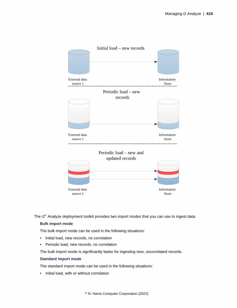
Managing i2 Analyze | 410
Initial load – new records
External data source 1
Information Store
Periodic load – new and updated records
External data source 1
Information Store
Periodic load – new records
External data source 1
Information Store
The i2® Analyze deployment toolkit provides two import modes that you can use to ingest data:
Bulk import mode
The bulk import mode can be used in the following situations:
• Initial load, new records, no correlation
• Periodic load, new records, no correlation
The bulk import mode is significantly faster for ingesting new, uncorrelated records.
Standard import mode
The standard import mode can be used in the following situations:
• Initial load, with or without correlation
© N. Harris Computer Corporation (2022)

Managing i2 Analyze | 411
• Periodic load, new and updated records, with or without correlation
Standard import mode trades some performance for increased data validation and additionaloperations during ingestion.
For more information about correlation, see Overview of correlation.
Because ingestion is completed on a per-item-type basis, you can use the bulk import mode for someitem types and use standard mode for others from the external source. You can also use the bulk importmode to complete an initial load, and then use the standard import mode to complete periodic loads toupdate the data.
About this guide
This documentation explains how to add data from external sources to the i2 Analyze Information Store,and how to keep the Information Store up-to-date as the contents of the external source changes. Therequirements are mostly the same in both scenarios, but there are some differences depending on thedata that you are updating the Information Store with.
Intended audience
This guide is intended for users who understand both the i2 Analyze data model and the i2 Analyzeschema that defines the data structure of their deployment. Populating the Information Store stagingtables also requires you to be familiar with your database management system.
Information Store ingestion and the production deployment process
Before you deploy i2 Analyze into production you develop your configuration in a number ofenvironments. The same is true for the ingestion process. You use the same environments to developthe Information Store ingestion process for each of your external data sources.
In the configuration development environment, ingest small amounts of test data that is representativeof the entity and link types in your existing data sources. By doing this, you can learn how to ingest yourdata into the Information Store database and ensure that your i2 Analyze schema and security schemaare correct for your data. If you discover that the schemas cannot represent your data, you can updateyour schema files.
You are likely to complete many test ingestions during this development phase. As you understand theprocess more, you might change how the data is loaded into the staging tables, the data that you use togenerate identifiers, or change the ingestion mappings. If you modify the i2 Analyze schema, you mustre-create your staging tables to match.
The ingestion mappings that you use are slightly different for each external data source that you ingestdata from. It is recommended that you keep any ingestion mapping files in a source control system totrack changes and so that you can use them in later development and production environments.
In your pre-production environment or test environment, use the process that you developed toingest larger quantities of data and note the time that is taken to ingest the data. You can completerepresentative initial and periodic loads from each of your external data sources. The time that eachingestion takes allows you to plan when to ingest data in your production environment more accurately.
In your production environment, complete your initial loads by using the developed and tested process.According to your schedule, perform your periodic loads on an ongoing basis.
Your deployment architecture can impact the ingestion process in general, and any logic or tools usedfor transformation of data. For more information, see Understanding the architecture on page 429.
© N. Harris Computer Corporation (2022)

Managing i2 Analyze | 412
The instructions that describe the ingestion process are separated into preparing for ingestion andadding data to the Information Store.
Preparing for ingestion
You must complete three tasks before the Information Store can ingest data from an external source.You must identify exactly which data to load, transform the data to align with the active i2 Analyzeschema, and augment the data with extra information that the Information Store requires.
The only way to add and modify large volumes of data in the i2 Analyze Information Store is to enableand then instruct the Information Store to ingest it. The enablement process involves creating andpopulating staging tables for the data, and then supplying the metadata that is crucial to the analyticalcapabilities of i2 Analyze.
You can plan and run the Information Store data ingestion process in a series of discrete steps. Thisdiagram illustrates the approach.
IBM DB2
Staging area
Ingestion mapping file
Information Store
Externaldata source
i2 Analyze schema
Create
Create
Data tablesData tables
Data tablesData tables
Data tablesData tables
Data tables
Staging tables
Ingestion mappings
Ingest
ETL tools(optional)
Populate
1
2
3
5
4
6
1. Decide which entity types and link types in the active i2 Analyze schema best represent the data thatyou want the Information Store to ingest.
2. Create staging tables in the database for the types that you identified. Create more than one stagingtable for some link types.
3. Use external tools, or any other appropriate technique, to transform your data and load the stagingtables with the data for ingestion.
4. Add information about your data source to the list of ingestion sources that the Information Storemaintains.
© N. Harris Computer Corporation (2022)
Managing i2 Analyze | 413
5. Write the ingestion mappings that govern the ingestion process and provide additional informationthat the Information Store requires.
6. Run the ingestion command separately for each of the ingestion mappings that you wrote.
The examples\data\law-enforcement-data-set-1 and \signal-intelligence-data-set-1 directories in the deployment toolkit contain files that i2 Analyze uses when you run the setup-t ingestExampleData command to populate the Information Store during deployment. These filesprovide demonstrations of many of the steps in the standard approach to ingestion. The following topicsdescribe those steps in more depth as they detail the Information Store ingestion process.
Identifying the data to be ingested
The detail of how you arrange for the Information Store to ingest your data varies according to how thatdata is stored in its source. However, the start of the process is always to consider what data you have,and work out how you can shape it to fit the i2 Analyze schema.
Usually, when you start thinking about adding data from an external source into the Information Store,an i2 Analyze deployment is already in place. That deployment necessarily has an i2 Analyze schemathat defines all of the entity types, link types, and property types that data in the system can have.Before you go any further, you must have a clear idea of how your data becomes i2 Analyze entityrecords and link records in the Information Store.
It is unlikely that the data in your external source has a one-to-one mapping with the entity types andlink types in the i2 Analyze schema:
• Probably, your source does not contain data for all the entity types in the schema. As a result, you donot usually need to create a staging table for every possible entity type.
• The schema can define link types that connect several different entity types. In that case, eachentity-link-entity type combination for which your source contains data requires a separate stagingtable.
For example, imagine an i2 Analyze schema that defines the entity types "Person", "Vehicle", and"Account", and the link type "Access to". In this situation, you might decide to create a staging table foreach of the entity types. However, the data requires two staging tables for "Access to" links: one forlinks between people and vehicles, and the other for links between people and accounts.
1. Open the schema for the i2 Analyze deployment in Schema Designer.
2. Go through the list of entity types, and determine which of them represent data in your source.
3. Make a note of the identifier of each entity type that represents your data.
4. Repeat steps 2 and 3 for the list of link types. Check the Link Ends tab, and make a note of all thecombinations for which your source contains data.
When you complete the steps, you have a list of all the i2 Analyze schema types that your datacontains. You also have a list of all the staging tables that you need to create.
Creating the staging tables
The Information Store does not ingest data directly from your data source. Instead, ingestion takesplace from staging tables that you create and populate. This abstraction makes it easier for you to alignyour data with the Information Store, and allows i2 Analyze to validate your data before ingestion.
The staging tables that you use to ingest data into the Information Store must conform to a specificstructure. For more information about the staging table structure, see Information Store staging tableson page 433.
© N. Harris Computer Corporation (2022)
Managing i2 Analyze | 414
The simplest approach to Information Store ingestion is to create a staging table for every entity type,and every entity-link-entity type combination, that you identified in your data. The i2 Analyze deploymenttoolkit and the ETL toolkit both have a command for creating one staging table at a time.
The deployment toolkit command looks like this:
setup -t createInformationStoreStagingTable
-p schemaTypeId=type_identifier
-p databaseSchemaName=staging_schema
-p tableName=staging_table_name
While the ETL toolkit command looks like this:
createInformationStoreStagingTable
-stid type_identifier
-sn staging_schema
-tn staging_table_name
In both cases, type_identifier is the identifier of one of the entity types or link types from the i2 Analyzeschema that is represented in your data source. staging_schema is the name of the database schemato contain the staging tables. (If you are using Db2, the command creates the database schema if itdoes not exist. If you are using SQL Server, the schema must exist.) staging_table_name is the name ofthe staging table itself, which must be unique, and must not exceed 21 characters in length.
Important: Many of the commands that are associated with the ingestion process modify the databasethat hosts the Information Store. By default, the commands use the database credentials that youspecified during deployment in the credentials.properties file.
To use different credentials in the deployment toolkit, add importName and importPasswordparameters to the list that you pass to the command. To use different credentials in the ETL toolkit,modify the DBUsername and DBPassword settings in the Connection.properties file.
1. If you are using the deployment toolkit, open a command prompt and navigate to the toolkit\scripts directory. If you are using the ETL toolkit, navigate to the etltoolkit directory.
2. For each entity type or link type that you identified for ingestion, run thecreateInformationStoreStagingTable command.For example:
setup -t createInformationStoreStagingTable
-p schemaTypeId=ET5 -p databaseSchemaName=IS_Staging
-p tableName=E_Person
By convention, you create all of the staging tables for the same source in the same databaseschema, which has the name IS_Staging in this example. It is also conventional to name thestaging table itself similarly to the display name of the entity type or link type to which the tablecorresponds. In this case, the staging table is for the Person entity type.
© N. Harris Computer Corporation (2022)
Managing i2 Analyze | 415
Note: When the i2 Analyze schema allows the same link type between several different entity types,create separate staging tables for each combination:
setup -t createInformationStoreStagingTable
-p schemaTypeId=LAC1 -p databaseSchemaName=IS_Staging
-p tableName=L_Access_To_Per_Acc
setup -t createInformationStoreStagingTable
-p schemaTypeId=LAC1 -p databaseSchemaName=IS_Staging
-p tableName=L_Access_To_Per_Veh
This example illustrates an Access To link type (with identifier LAC1) that can make connections fromPerson entities to Account entities, or from Person entities to Vehicle entities. The commands createstaging tables with different names based on the same link type.
At the end of this procedure, you have a set of staging tables that are ready to receive your data beforeingestion takes place. The next task is to make your data ready to populate the staging tables.
Preparing the external data
The staging tables that you create during the ingestion process have data structures that are similarto, but simpler than, the Information Store data tables. Whatever your source is, you must find a way toshape the data that it contains into a form that is compatible with the staging tables.
After you create the staging tables, you can view them in IBM Data Studio (or similar software) to seethe definitions of their columns. You must make your data matches these definitions before you can goon to populate the staging tables.
Because all data sources and many i2 Analyze schemas are different, there is no single procedurethat you can follow to prepare your data for ingestion. However, there are a number of commonconsiderations.
• Each staging table can contain data that maps to only one entity type or link type. If your source datahas rows or records that contain data for more than one of the types that you identified, then youmust separate them during preparation or population.
For data in a relational source, this preparation might mean creating views on the original tables. Ifthe data is in CSV files, then you might need to wait until you populate the staging tables to changeits shape in this way.
• The Information Store does not support storing properties with multiple values in the same i2Analyze record. The records that you create must contain values for a maximum of one property witheach permitted property type.
• If you are dealing with date and time data, that data must meet extra requirements before theInformation Store can ingest it. To retain information unambiguously, the staging tables use fourcolumns to represent date and time data.
Even if you know that your date and time data was recorded in Coordinated Universal Time,you must make that fact explicit in the data to be ingested. For example, if your source containsinformation about an event that started at 9 AM on October 6 2002, then the values you need toprepare are:
2002-10-06 09:00:00 (the data and time originally entered)UTC (the timezone)0 (Daylight Saving Time is not in effect)
© N. Harris Computer Corporation (2022)
Managing i2 Analyze | 416
2002-10-06 09:00:00 (the date and time in Coordinated Universal Time)
• The source_id, origin_id_type, origin_id_keys columns of the staging table are usedto store values that reference the data in its original source and can be used to make up the originidentifier of the resulting record.
Note: If the staging table definition was for a link type, it would also contain from_ and to_variations of each of the columns.
For more information about generating origin identifiers during ingestion, see Origin identifiers onpage 445.
• If your external source is a relational database, you might find that the only data for some links isthe presence of a foreign key relationship between two tables. In that case, you must synthesize areproducible reference for the link from the other data that you have available.
For example, you might be able to create a unique reference for a link by combining the identifiers ofthe entity records at its ends.
• All staging tables contain a source_last_updated column that you can use to store informationabout when the data to be ingested was modified in its source.
• All staging tables contain columns for each of the access dimensions that the security schemadefines. If your external source includes security information, then you can map that information tothe security schema of your target deployment, and populate the staging table columns accordingly.
Alternatively, you can leave the security columns blank, and provide security dimension values on amapping- or source-wide basis later in the ingestion process.
• All staging tables contain correlation_id_type and correlation_id_key columns. Tocorrelate data that is ingested into the Information Store, use these columns to store the values thatcomprise the correlation identifier for each row of data. If you do not want to use correlation, leavethe columns blank.
If you specify values for a correlation identifier, then also specify a value for thesource_last_updated column, which is used during the correlation process.
For more information about correlation, correlation identifiers, and the impact of thesource_last_updated value, see Overview of correlation.
• The columns named source_ref_source_type, source_ref_source_location, andsource_ref_source_image_url are used to populate the source reference that is generatedwhen the data is ingested.
For more information about implementing source references in your deployment, see Configuringsource references.
• The staging tables for link types contain a column for the direction of the link.
The Information Store considers links to go "from" one entity "to" another. The direction of a link canbe WITH or AGAINST that flow, or it can run in BOTH directions, or NONE.
• If your link data includes direction information, then you can add it to the staging table during thepopulation process, and then refer to it from the mapping file.
• If your link data does not include direction information, then you can specify a value in themapping file directly.
By default, if you have no direction information and you do nothing in the mapping file, theInformation Store sets the direction of an ingested link to NONE.
© N. Harris Computer Corporation (2022)
Managing i2 Analyze | 417
Important: The Information Store places limits on the ranges of values that properties with differentlogical types can contain. If you attempt to use values outside these ranges, failures can occur during orafter ingestion. For more information, see Information Store property value ranges on page 436.
The examples\data\law-enforcement-data-set-1 directory of the deployment toolkit contains aset of CSV files that were exported from a relational database.
In files like event.csv, you can see date and time data that meets the requirements of the stagingtables. You can also see multiple files for "Access to" links, and how some staged link rows contain littlemore than a set of identifiers.
Populating the staging tables
The i2 Analyze deployment toolkit and the ETL toolkit create the staging tables for data ingestion in thesame database as the Information Store data tables. After you prepare your data, but before you caninstruct the Information Store to ingest it, you must populate the staging tables.
The approach that you take to populate the staging tables depends on the database managementsystem that you are using, the form that your source data is in, and the tools that you have available.
Db2 provides the ingest, import, and load utilities:
• If your data is in comma-separated value (CSV) files, then you can use the IMPORT or INGESTcommands.
• If your data is in the tables or views of another database, then you can use the IMPORT, INGEST, orLOAD commands.
SQL Server provides the bulk insert and insert utilities:
• If your data is in comma-separated value (CSV) files, then you can use the BULK INSERTcommand.
Note: To use the BULK INSERT command, the user that you run the command as must be amember of the bulkadmin server role.
• If your data is in the tables or views of another database, then you can use the INSERT command.
• You can use SQL Server Integration Services as a tool to extract and transform data from varioussources, and then load it into the staging tables.
Alternatively, regardless of your database management system, you can use IBM InfoSphereDataStage as a tool for transforming your data and loading it into the staging tables. You can specify thedatabase schema that contains the staging tables as the target location for the ETL output.
The subdirectories of the examples\data directory in the deployment toolkit all contain a db2 and asqlserver directory.
If you are using Db2, inspect the LoadCSVDataCommands.db2 file in the db2 directory. In each case,this file is a Db2 script that populates the example staging tables from the prepared CSV files. The scriptcalls the IMPORT command repeatedly to do its work. In most instances, the command just takes datafrom columns in a CSV file and adds it to a staging table in a Db2 database schema.
If you are using SQL Server, inspect the LoadCSVDataCommands.sql file in the sqlserverdirectory. In each case, this file is an SQL script that populates the example tables from the preparedCSV files. The script calls the BULK INSERT command repeatedly to do its work. The BULK INSERTcommand uses .fmt format files, which are also in the sqlserver directory, to instruct SQL Serverhow to process the CSV files into the staging tables. For more information about format files, see Non-XML Format Files.
© N. Harris Computer Corporation (2022)
Managing i2 Analyze | 418
Defining an ingestion source
The Information Store keeps a list of all the sources from which it has ingested data. Before it can ingestdata, you must tell the Information Store about your source. In the ingestion mapping file, you thenspecify the data source name in the mapping definition for each entity type and link type.
The i2 Analyze deployment toolkit and the ETL toolkit both have a command for adding informationabout an ingestion source to the Information Store.
The deployment toolkit command looks like this:
setup -t addInformationStoreIngestionSource
-p ingestionSourceName=src_name
-p ingestionSourceDescription=src_display_name
While the ETL toolkit command looks like this:
addInformationStoreIngestionSource
-n src_name
-d src_display_name
In both cases, src_name is a unique name for the ingestion source, which also appears in the mappingfile. src_display_name is a friendlier name for the ingestion source that might appear in the userinterface of applications that display records from the Information Store.
Important: The value that you provide for src_name must be 30 characters or fewer in length. Also, donot use the word ANALYST as the name of your ingestion source. That name is reserved for records thatanalysts create in the Information Store through a user interface.
1. If you are using the deployment toolkit, open a command prompt and navigate to the toolkit\scripts directory. If you are using the ETL toolkit, navigate to the etltoolkit directory.
2. Run the addInformationStoreIngestionSource command, specifying the short and displaynames of your ingestion source.For example:
setup -t addInformationStoreIngestionSource
-p ingestionSourceName=EXAMPLE
-p ingestionSourceDescription="Example data source"
If the Information Store already contains information about an ingestion source with the nameEXAMPLE, this command has no effect.
After you complete this task, you have performed all the necessary actions, and gathered all thenecessary information, to be able to write ingestion mapping files. The next task is to create theingestion mapping file for your ingestion source.
Creating an ingestion mapping file
The mappings in an ingestion mapping file define how rows in staging tables become i2 Analyze recordsin the Information Store during the ingestion process. Each mapping that you write describes how toconstruct the origin identifiers for data of a particular type, and specifies the security dimension valuesthat apply to records.
Before you create your ingestion mappings, review the information about origin identifiers and securitydimension values in i2 Analyze.
© N. Harris Computer Corporation (2022)

Managing i2 Analyze | 419
The Information Store ingestion mechanism makes it possible for you to develop and extend youringestion mappings over time. You can test your approach to ingestion by writing and using a single(entity type) mapping, and then adding more entity type and link type mappings later. You can putall your mappings in one file, or put each mapping in a separate file, or anything between those twoextremes.
If you populated the staging tables successfully, then writing ingestion mappings can be straightforward.Eventually, you need a mapping for each staging table that you created, but you can approach theproblem one mapping at a time.
1. Choose a populated staging table for an entity type that has links to other entity records in the datamodel.
2. Create an ingestion mapping file that contains an ingestion mapping for the staging table that youchose in step 1.
If you prefer to start from an existing file, look at mapping.xml in the examples\data\law-enforcement-data-set-1 directory of the deployment toolkit.
3. Run the ingestion command to validate the mapping.
If you are unhappy with the outcome, edit the ingestion mapping and run the command again.
4. Repeat all of the preceding steps for all the other staging tables that you populated.
The examples\data\law-enforcement-data-set-1 directory of the deployment toolkit containsan ingestion mapping file named mapping.xml. This file contains ingestion mappings for all the stagingtables that the ingestion example creates. You can use mapping.xml as the basis for the ingestionmappings that you need for your data.
Validating the ingestion configuration
After you create and populate your staging tables and write your ingestion mappings, the final part of theprocess is to run the command to validate your work.
When you instruct the Information Store to ingest the data that you loaded into the staging tables, youdo it one ingestion mapping (and one staging table) at a time. The i2 Analyze deployment toolkit and theETL toolkit both have a command for validating your staging tables and a particular ingestion mappingin a particular mapping file.
The procedure for instructing the Information Store to ingest your data is similar to many others in thisprocess. You start with one type or one staging table, and build from there.
1. Choose an entity staging table that you populated with data and provided with an ingestion mapping.
2. Run the ingestInformationStoreRecords command in VALIDATE mode.For example:
setup -t ingestInformationStoreRecords -p importMappingsFile=mapping.xml
-p importMappingId=Person -p importMode=VALIDATE
When you specify importMode and set it to VALIDATE, the command checks the validity ofthe specified mapping, but no ingestion takes place. For more information about the running thecommand and any arguments, see The ingestInformationStoreRecords task on page 448.
The output to the console indicates whether the mapping you identified is valid, provides guidancewhen it is not valid, and gives a full list of column mappings. The command sends the sameinformation to a log file that you can find at toolkit\configuration\logs\importer\i2_Importer.log.
3. Complete this validation step for each staging table and ingestion mapping that you plan to use.
© N. Harris Computer Corporation (2022)
Managing i2 Analyze | 420
The ingestion process for links verifies that the entities at each end of the link are already ingested.If it fails to find them, the process fails. When you are developing your ingestion process, ingest asmall amount of entity data before you validate your links.
Correct any problems in the ingestion mappings file (or any ingestion properties file that you specified)before you proceed to Adding data to the Information Store on page 420.
Adding data to the Information Store
After you populate the staging tables and write ingestion mappings, you can use toolkit commandsto instruct the Information Store to ingest or update the records that represent external data. TheInformation Store keeps a log of all such instructions that you can review to determine the success orfailure of each one.
The commands in the i2 Analyze deployment and ETL toolkits make it possible for you to create,update, and delete records in the Information Store. All three operation types are controlled by the datain the staging tables and the mappings in the ingestion mapping files.
After any operation that uses toolkit commands to change the contents of the Information Store, you canexamine ingestion reports to determine how successful the operation was.
As described in Information Store data ingestion on page 409, there are 2 different import modesthat you can use to ingest your data. Before you run the ingestion commands, ensure that you use thecorrect import mode for the data that you want to ingest. Remember that this might differ depending onthe item type that you are ingesting or ingestion mapping that you are using.
Using bulk import mode
Bulk import mode can be used for improved ingestion performance when you are populating theInformation Store with new records as part of an initial or periodic load.
• Before you run the ingestion commands, ensure that you complete all of the tasks in Preparing foringestion on page 412.
• For Db2, the mechanism that bulk import mode uses to load the data from the staging tables to theInformation Store can require changes to the database configuration. Before you ingest data, ensurethat your database is configured correctly. For more information, see Database configuration for IBMDb2 on page 421.
• You can drop and re-create the database indexes during the ingestion process, which can reducethe total time that it takes to ingest data. For more information about when it is beneficial to drop andre-create the database indexes, see Database index management on page 422.
When you instruct the Information Store to ingest the data that you loaded into the staging tables, youdo it one ingestion mapping (and one staging table) at a time. The i2 Analyze deployment toolkit andthe ETL toolkit both have a command for ingesting the data that is associated with a particular ingestionmapping in a particular mapping file. For more information about the running the command and anyarguments, see The ingestInformationStoreRecords task on page 448.
When you use bulk import mode, take the following points into consideration:
• For best performance, ensure that there are no analysts using the system during the ingestionprocess.
• Do not include correlation identifiers in the data that you ingest by using bulk import mode. If anycorrelation identifiers are included, the ingestion fails.
• You cannot run concurrent ingestInformationStoreRecords commands when using bulkimport mode.
© N. Harris Computer Corporation (2022)
Managing i2 Analyze | 421
After you stage your data and create your configuration files, you can instruct the Information Store toingest your data by using bulk import mode. The procedure to ingest your data is similar to many othersin this process. You start with one type or one staging table, and build from there.
1. If you have decided to drop the database indexes, do so now.
2. Use the following command to ingest your data.
setup -t ingestInformationStoreRecords
-p importMappingsFile=ingestion_mapping_file
-p importMappingId=ingestion_mapping_id
-p importLabel=ingestion_label
-p importConfigFile=ingestion_settings_file
-p importMode=BULK
For more information about the running the command and any arguments, see TheingestInformationStoreRecords task on page 448.
3. If any errors occur, refer to Troubleshooting the ingestion process on page 454.
4. If you need to re-create the database indexes, do so now.
Database configuration for IBM Db2
When you use bulk or bulk delete import modes, the way that the data is inserted into or removed fromthe Information Store from the staging table requires more transaction log space and database locksavailable than the standard modes.
Transaction log size
For entity operations, allocate at least 1.5 GB of transaction log space.
For link operations, allocate at least 22 GB of transaction log space.
For more information about changing the Db2 log file size, see logfilsiz - Size of log files configurationparameter, logprimary - Number of primary log files configuration parameter, and logsecond - Number ofsecondary log files configuration parameter.
Lock list size
For entity operations, the formula for calculating the required lock list size is:
1200000 * (lock_record_size / 4000)
If the lock record size for your deployment is 256 bytes, you need a lock list size of 75,000.
For link operations, the formula for calculating the required lock list size is:
3600000 * (lock_record_size / 4000)
If the lock record size for your deployment is 256 bytes, you need a lock list size of 225,000. Linkingestion requires an increased lock list size because more tables in the Information Store are written to.
For information about lock lists, see locklist - Maximum storage for lock list configuration parameter.
© N. Harris Computer Corporation (2022)

Managing i2 Analyze | 422
Database index management
It can be beneficial for performance to drop and re-create indexes in the Information Store databaseduring bulk mode ingestion. The situations when dropping and creating the database indexes might helpchange over the lifetime of a deployment as your Information Store contains more data.
Decide when to drop and create indexes
The situations where you might want to drop and re-create the database indexes include:
• Completing an initial load for an item type or ingesting data into an empty Information Store
• When ingesting large amounts of data (For example, more than 20 million rows in the staging table)
The situation where you do not want to drop and re-create the database indexes include:
• When the Information Store contains a large amount of data for the item type you are ingesting,the time that it takes to re-create the indexes can make the total ingestion time longer. If you areingesting into an Information Store that already contains about 1 billion records, do not drop and re-create the database indexes.
• If you are ingesting links between entities of the same type and some of those entities might becorrelated, do not drop and re-create the database indexes.
By default, the indexes are kept in place and not dropped during data ingestion.
To help determine what is best for your data, you can test some ingestions that drop and re-createindexes and some that don't. When you complete the test ingestions, record the time that it takes tocomplete. You can use these times to inform you whether to manage the database indexes duringingestion or not. As the amount of data in the Information Store increases, the time it takes to create theindexes also increases.
Dropping and re-creating indexes during a bulk import ingestion process
If you decide to drop and re-create the database indexes during large ingestions that use multiplestaging tables across both entity and link types, the high-level process consists of the following steps:
1. Stop Liberty and Solr
2. Drop the database indexes for the entity types that you are ingesting data for
3. Ingest all entity data
4. Create the database indexes for the entity types that you ingested data for
5. Drop the database indexes for the link types that you are ingesting data for
6. Ingest all link data
7. Create the database indexes for the link types that you ingested data for
8. Start Liberty and Solr
You can use two methods to drop and create indexes:
• Use the i2 Analyze deployment toolkit to generate scripts that you run against the databasemanually.
• Use the import configuration properties file to specify whether the indexes must be dropped orcreated during a bulk import mode ingestion.
If you are ingesting data for multiple link types or you want to review the database scripts and run themmanually, it is best to use the generated scripts to drop and re-create the database indexes. If you
© N. Harris Computer Corporation (2022)

Managing i2 Analyze | 423
do not want to, or cannot, run scripts against the Information Store database, you can use the importconfiguration file and allow the ingestion process to drop and re-create the database indexes.
If you are completing an ingestion that spans multiple ingestion periods where the system is in usebetween ingestion periods, ensure that all of the indexes are created at the end of an ingestion periodand that you start Liberty and Solr before analysts use the system.
For information about creating the import configuration file, see References and system properties.
Using the generated scripts method
1. In your import configuration file, set both the dropIndexes and createIndexes settings toFALSE.
For example:
dropIndexes=FALSE
createIndexes=FALSE
2. Generate the create and drop index scripts for each item type that you are ingesting data for.
For example, to generate the scripts for the item type with identifier ET5, run the followingcommands:
setup -t generateInformationStoreIndexCreationScripts -p schemaTypeId=ET5
setup -t generateInformationStoreIndexDropScripts -p schemaTypeId=ET5
The scripts are output in the toolkit\scripts\database\db2\InfoStore\generateddirectory, in the createIndexes and dropIndexes directories.
3. Stop Liberty and Solr.
On the Liberty server, run:
setup -t stopLiberty
On each Solr server, run:
setup -t stopSolrNodes --hostname solr.host-name
Where solr.host-name is the host name of the Solr server where you are running the command, andmatches the value for the host-name attribute of a <solr-node> element in the topology.xmlfile.
4. Run the scripts that you generated in step 2 to drop the indexes for each entity type that you plan toingest data for. For example:
db2 -tvf ET5-drop-indexes.db2
Where ET5 is the item type identifier.
5. Complete the process to ingest the entity data using the bulk import mode. For more information, seeUsing bulk import mode on page 420.
© N. Harris Computer Corporation (2022)

Managing i2 Analyze | 424
6. Run the scripts that you generated in step 2 to create the indexes for each entity type that youingested. For example:
db2 -tvf ET5-create-indexes.db2
7. Run the scripts that you generated in step 2 to drop the indexes for each link type that you plan toingest data for. For example:
db2 -tvf LT1-drop-indexes.db2
Where LT1 is the item type identifier.
8. Complete the process to ingest the link data using the bulk import mode. For more information, seeUsing bulk import mode on page 420.
Only re-create the database indexes after you ingest the link data for every link type that you plan toingest.
9. Run the scripts that you generated in step 2 to create the indexes for each link type that youingested. For example:
db2 -tvf LT1-create-indexes.db2
10.Start Liberty and Solr.
On each Solr server, run:
setup -t startSolrNodes --hostname solr.host-name
Where solr.host-name is the host name of the Solr server where you are running the command, andmatches the value for the host-name attribute of a <solr-node> element in the topology.xmlfile.
On the Liberty server, run:
setup -t startLiberty
Using the import configuration properties file method
When you use the import configuration settings to drop and re-create the database indexes, the toolkitcreates and drops the indexes for you as part of the ingestion process instead of running scripts againstthe database manually. However, you must modify the import configuration file a number of timesthroughout the ingestion of multiple item types. You must still stop Liberty and Solr before you run theingestion command, and start them again after the indexes are created.
If all of the data for a single item type is ingested with a single ingestion command, in your importconfiguration file set the dropIndexes and createIndexes settings as follows:
dropIndexes=TRUE
createIndexes=TRUE
If the data for a single item type must be ingested by using multiple ingestion commands, you need tomodify the import configuration file before the first ingestion command, for the intermediate commands,and before the final command for each item type. For example, if your data for a single entity type is inmore than one staging table.
© N. Harris Computer Corporation (2022)
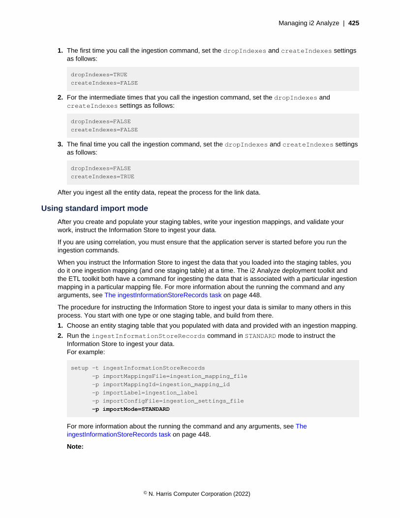
Managing i2 Analyze | 425
1. The first time you call the ingestion command, set the dropIndexes and createIndexes settingsas follows:
dropIndexes=TRUE
createIndexes=FALSE
2. For the intermediate times that you call the ingestion command, set the dropIndexes andcreateIndexes settings as follows:
dropIndexes=FALSE
createIndexes=FALSE
3. The final time you call the ingestion command, set the dropIndexes and createIndexes settingsas follows:
dropIndexes=FALSE
createIndexes=TRUE
After you ingest all the entity data, repeat the process for the link data.
Using standard import mode
After you create and populate your staging tables, write your ingestion mappings, and validate yourwork, instruct the Information Store to ingest your data.
If you are using correlation, you must ensure that the application server is started before you run theingestion commands.
When you instruct the Information Store to ingest the data that you loaded into the staging tables, youdo it one ingestion mapping (and one staging table) at a time. The i2 Analyze deployment toolkit andthe ETL toolkit both have a command for ingesting the data that is associated with a particular ingestionmapping in a particular mapping file. For more information about the running the command and anyarguments, see The ingestInformationStoreRecords task on page 448.
The procedure for instructing the Information Store to ingest your data is similar to many others in thisprocess. You start with one type or one staging table, and build from there.
1. Choose an entity staging table that you populated with data and provided with an ingestion mapping.
2. Run the ingestInformationStoreRecords command in STANDARD mode to instruct theInformation Store to ingest your data.For example:
setup -t ingestInformationStoreRecords
-p importMappingsFile=ingestion_mapping_file
-p importMappingId=ingestion_mapping_id
-p importLabel=ingestion_label
-p importConfigFile=ingestion_settings_file
-p importMode=STANDARD
For more information about the running the command and any arguments, see TheingestInformationStoreRecords task on page 448.
Note:
© N. Harris Computer Corporation (2022)

Managing i2 Analyze | 426
• You can improve the performance of entity ingestion by runningingestInformationStoreRecords for different entity types at the same time when you usethe standard import mode. It is recommended that you use the ETL toolkit to run concurrentingestInformationStoreRecords commands. Do not attempt to run the command for dataof the same type at the same time.
• Due to the increased number of operations and comparisons that are required, using correlationcan make the ingestion process take longer.
3. Repeat steps 1 and 2 for the other staging table and ingestion mapping combinations that youcreated. Take care to run the command for entity types before you run it for link types.
The ingestion process for links verifies that the entities at each end of the link are already ingested. Ifit fails to find them, the process fails.
At the end of this procedure, all the external data that you populated the staging tables with is in theInformation Store. To add or update records, you can repopulate the staging tables and rerun theingestInformationStoreRecords command.
Updating the Information Store for changed data
The data that the Information Store ingests is fixed at the moment of ingestion, and changes to thedata in its source do not automatically update the Information Store. However, you can update theInformation Store to reflect changes in an external source by running through the ingestion processagain.
For most changes to the data in an external source, it is likely that you can reuse the work that you didto enable initial ingestion. If the changes to an external source are not significant enough to affect yourmethod for generating reproducible origin identifiers, repeat ingestion follows the same process as initialingestion.
1. Examine the new or changed data in the external source, and your ingestion mappings. Confirm thatyour configuration still generates origin identifiers that the Information Store can compare with theirequivalents in existing ingested data.
2. Delete the contents of each staging table that you know to be affected by changes to the externaldata.
3. Populate the affected staging tables with the latest data from your external source.
4. Run the ingestion command specifying the standard import mode for each ingestion mapping thatrefers to an affected staging table, taking care to process entity data before link data, as usual.
The Information Store uses the origin identifier of each row that it attempts to ingest to determinewhether the data is new:
• If the origin identifier does not match the origin identifier of any data that is already in theInformation Store, then the data is new to the Information Store. It is ingested in the usual way.
• If the origin identifier does match the origin identifier of any data that is already in the InformationStore, then the staging table contains updated information. The Information Store clears itsexisting data and refills it with the new data.
Note: If the correlation identifier changed, additional merge and unmerge operations might occur.
After you follow this procedure, the Information Store contains new data that was added to an externalsource since the last ingestion. It also contains updated data that was changed in an external sourcesince the last ingestion.
© N. Harris Computer Corporation (2022)
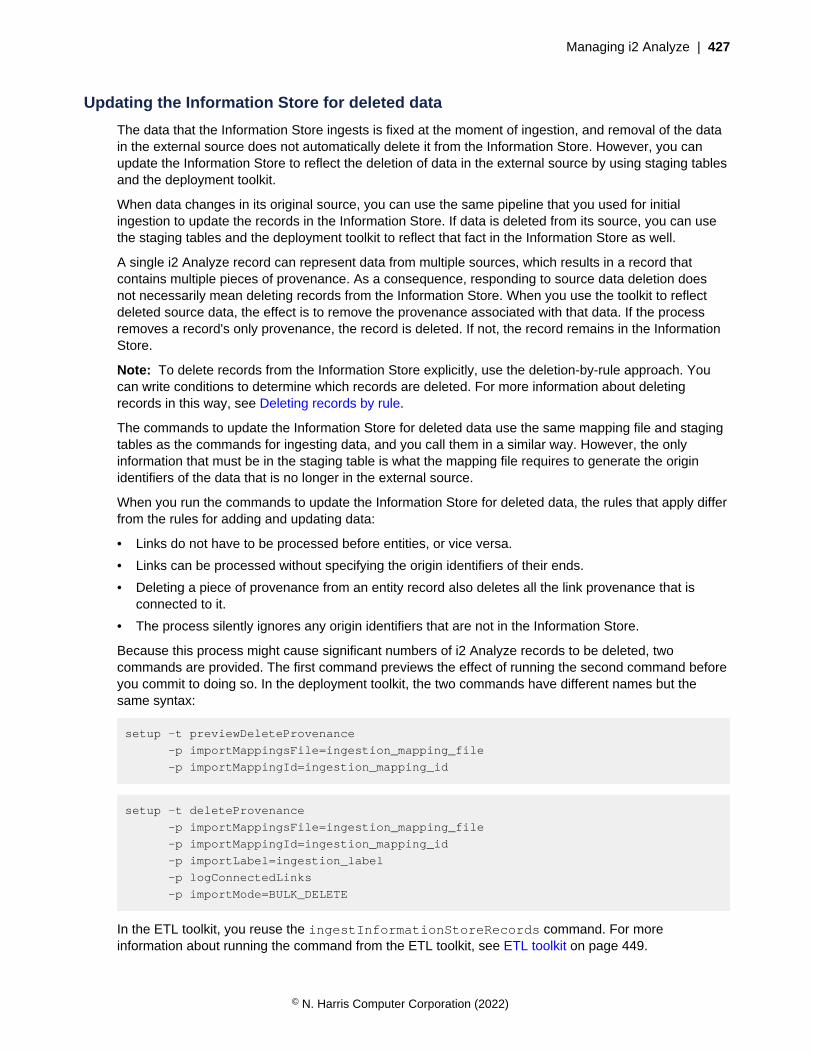
Managing i2 Analyze | 427
Updating the Information Store for deleted data
The data that the Information Store ingests is fixed at the moment of ingestion, and removal of the datain the external source does not automatically delete it from the Information Store. However, you canupdate the Information Store to reflect the deletion of data in the external source by using staging tablesand the deployment toolkit.
When data changes in its original source, you can use the same pipeline that you used for initialingestion to update the records in the Information Store. If data is deleted from its source, you can usethe staging tables and the deployment toolkit to reflect that fact in the Information Store as well.
A single i2 Analyze record can represent data from multiple sources, which results in a record thatcontains multiple pieces of provenance. As a consequence, responding to source data deletion doesnot necessarily mean deleting records from the Information Store. When you use the toolkit to reflectdeleted source data, the effect is to remove the provenance associated with that data. If the processremoves a record's only provenance, the record is deleted. If not, the record remains in the InformationStore.
Note: To delete records from the Information Store explicitly, use the deletion-by-rule approach. Youcan write conditions to determine which records are deleted. For more information about deletingrecords in this way, see Deleting records by rule.
The commands to update the Information Store for deleted data use the same mapping file and stagingtables as the commands for ingesting data, and you call them in a similar way. However, the onlyinformation that must be in the staging table is what the mapping file requires to generate the originidentifiers of the data that is no longer in the external source.
When you run the commands to update the Information Store for deleted data, the rules that apply differfrom the rules for adding and updating data:
• Links do not have to be processed before entities, or vice versa.
• Links can be processed without specifying the origin identifiers of their ends.
• Deleting a piece of provenance from an entity record also deletes all the link provenance that isconnected to it.
• The process silently ignores any origin identifiers that are not in the Information Store.
Because this process might cause significant numbers of i2 Analyze records to be deleted, twocommands are provided. The first command previews the effect of running the second command beforeyou commit to doing so. In the deployment toolkit, the two commands have different names but thesame syntax:
setup -t previewDeleteProvenance
-p importMappingsFile=ingestion_mapping_file
-p importMappingId=ingestion_mapping_id
setup -t deleteProvenance
-p importMappingsFile=ingestion_mapping_file
-p importMappingId=ingestion_mapping_id
-p importLabel=ingestion_label
-p logConnectedLinks
-p importMode=BULK_DELETE
In the ETL toolkit, you reuse the ingestInformationStoreRecords command. For moreinformation about running the command from the ETL toolkit, see ETL toolkit on page 449.
© N. Harris Computer Corporation (2022)
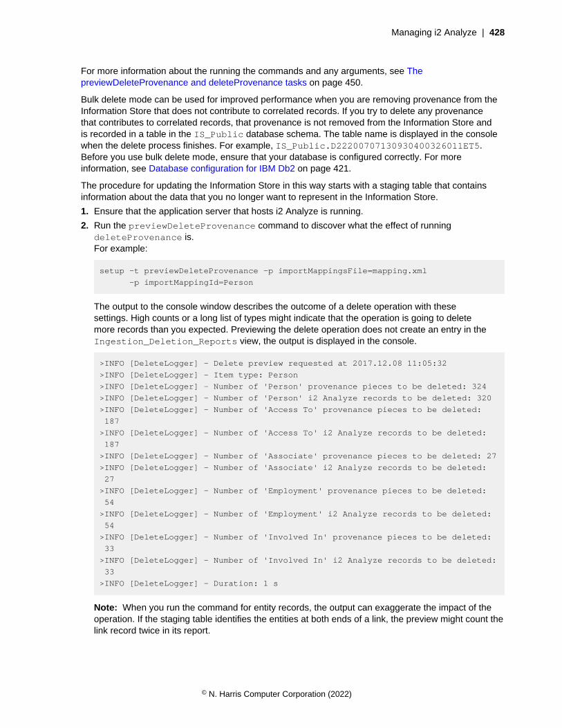
Managing i2 Analyze | 428
For more information about the running the commands and any arguments, see ThepreviewDeleteProvenance and deleteProvenance tasks on page 450.
Bulk delete mode can be used for improved performance when you are removing provenance from theInformation Store that does not contribute to correlated records. If you try to delete any provenancethat contributes to correlated records, that provenance is not removed from the Information Store andis recorded in a table in the IS_Public database schema. The table name is displayed in the consolewhen the delete process finishes. For example, IS_Public.D22200707130930400326011ET5.Before you use bulk delete mode, ensure that your database is configured correctly. For moreinformation, see Database configuration for IBM Db2 on page 421.
The procedure for updating the Information Store in this way starts with a staging table that containsinformation about the data that you no longer want to represent in the Information Store.
1. Ensure that the application server that hosts i2 Analyze is running.
2. Run the previewDeleteProvenance command to discover what the effect of runningdeleteProvenance is.For example:
setup -t previewDeleteProvenance -p importMappingsFile=mapping.xml
-p importMappingId=Person
The output to the console window describes the outcome of a delete operation with thesesettings. High counts or a long list of types might indicate that the operation is going to deletemore records than you expected. Previewing the delete operation does not create an entry in theIngestion_Deletion_Reports view, the output is displayed in the console.
>INFO [DeleteLogger] - Delete preview requested at 2017.12.08 11:05:32
>INFO [DeleteLogger] - Item type: Person
>INFO [DeleteLogger] - Number of 'Person' provenance pieces to be deleted: 324
>INFO [DeleteLogger] - Number of 'Person' i2 Analyze records to be deleted: 320
>INFO [DeleteLogger] - Number of 'Access To' provenance pieces to be deleted:
187
>INFO [DeleteLogger] - Number of 'Access To' i2 Analyze records to be deleted:
187
>INFO [DeleteLogger] - Number of 'Associate' provenance pieces to be deleted: 27
>INFO [DeleteLogger] - Number of 'Associate' i2 Analyze records to be deleted:
27
>INFO [DeleteLogger] - Number of 'Employment' provenance pieces to be deleted:
54
>INFO [DeleteLogger] - Number of 'Employment' i2 Analyze records to be deleted:
54
>INFO [DeleteLogger] - Number of 'Involved In' provenance pieces to be deleted:
33
>INFO [DeleteLogger] - Number of 'Involved In' i2 Analyze records to be deleted:
33
>INFO [DeleteLogger] - Duration: 1 s
Note: When you run the command for entity records, the output can exaggerate the impact of theoperation. If the staging table identifies the entities at both ends of a link, the preview might count thelink record twice in its report.
© N. Harris Computer Corporation (2022)
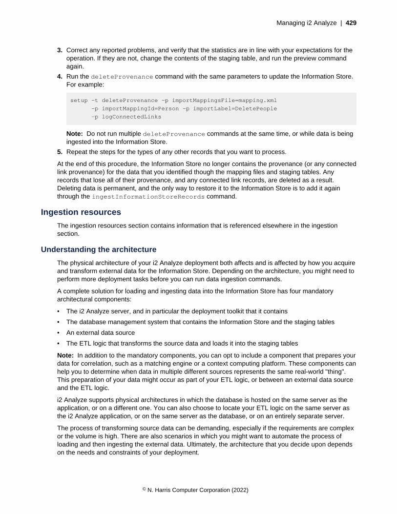
Managing i2 Analyze | 429
3. Correct any reported problems, and verify that the statistics are in line with your expectations for theoperation. If they are not, change the contents of the staging table, and run the preview commandagain.
4. Run the deleteProvenance command with the same parameters to update the Information Store.For example:
setup -t deleteProvenance -p importMappingsFile=mapping.xml
-p importMappingId=Person -p importLabel=DeletePeople
-p logConnectedLinks
Note: Do not run multiple deleteProvenance commands at the same time, or while data is beingingested into the Information Store.
5. Repeat the steps for the types of any other records that you want to process.
At the end of this procedure, the Information Store no longer contains the provenance (or any connectedlink provenance) for the data that you identified though the mapping files and staging tables. Anyrecords that lose all of their provenance, and any connected link records, are deleted as a result.Deleting data is permanent, and the only way to restore it to the Information Store is to add it againthrough the ingestInformationStoreRecords command.
Ingestion resources
The ingestion resources section contains information that is referenced elsewhere in the ingestionsection.
Understanding the architecture
The physical architecture of your i2 Analyze deployment both affects and is affected by how you acquireand transform external data for the Information Store. Depending on the architecture, you might need toperform more deployment tasks before you can run data ingestion commands.
A complete solution for loading and ingesting data into the Information Store has four mandatoryarchitectural components:
• The i2 Analyze server, and in particular the deployment toolkit that it contains
• The database management system that contains the Information Store and the staging tables
• An external data source
• The ETL logic that transforms the source data and loads it into the staging tables
Note: In addition to the mandatory components, you can opt to include a component that prepares yourdata for correlation, such as a matching engine or a context computing platform. These components canhelp you to determine when data in multiple different sources represents the same real-world "thing".This preparation of your data might occur as part of your ETL logic, or between an external data sourceand the ETL logic.
i2 Analyze supports physical architectures in which the database is hosted on the same server as theapplication, or on a different one. You can also choose to locate your ETL logic on the same server asthe i2 Analyze application, or on the same server as the database, or on an entirely separate server.
The process of transforming source data can be demanding, especially if the requirements are complexor the volume is high. There are also scenarios in which you might want to automate the process ofloading and then ingesting the external data. Ultimately, the architecture that you decide upon dependson the needs and constraints of your deployment.
© N. Harris Computer Corporation (2022)
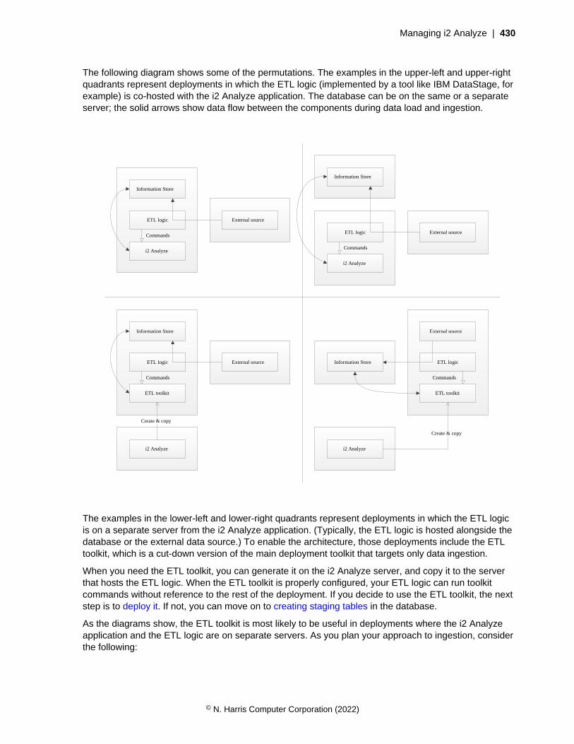
Managing i2 Analyze | 430
The following diagram shows some of the permutations. The examples in the upper-left and upper-rightquadrants represent deployments in which the ETL logic (implemented by a tool like IBM DataStage, forexample) is co-hosted with the i2 Analyze application. The database can be on the same or a separateserver; the solid arrows show data flow between the components during data load and ingestion.
Information Store
i2 Analyze
External sourceETL logic
i2 Analyze
External sourceETL logic
Information Store
i2 Analyze
External sourceETL logic
Information Store
ETL toolkit
i2 Analyze
External source
ETL logicInformation Store
ETL toolkit
Create & copy
Create & copy
Commands
Commands
Commands
Commands
The examples in the lower-left and lower-right quadrants represent deployments in which the ETL logicis on a separate server from the i2 Analyze application. (Typically, the ETL logic is hosted alongside thedatabase or the external data source.) To enable the architecture, those deployments include the ETLtoolkit, which is a cut-down version of the main deployment toolkit that targets only data ingestion.
When you need the ETL toolkit, you can generate it on the i2 Analyze server, and copy it to the serverthat hosts the ETL logic. When the ETL toolkit is properly configured, your ETL logic can run toolkitcommands without reference to the rest of the deployment. If you decide to use the ETL toolkit, the nextstep is to deploy it. If not, you can move on to creating staging tables in the database.
As the diagrams show, the ETL toolkit is most likely to be useful in deployments where the i2 Analyzeapplication and the ETL logic are on separate servers. As you plan your approach to ingestion, considerthe following:
© N. Harris Computer Corporation (2022)

Managing i2 Analyze | 431
• If the ETL logic is relatively simple and data volumes are low, there are benefits to colocating asmany components as you can, especially in a new deployment.
• If your deployment requires separate servers from the start, or as it evolves over time, determinewhere the bottlenecks are. Is it limited by server speed or network speed?
• If the ETL logic is taxing a server that hosts other components, consider moving the logic, but beaware of the increase in network traffic.
• If the volume of data is taxing the network, consider colocating components when you are able. (Youmight not have permission to deploy components to some servers, for example.)
By acting as a proxy for the i2 Analyze deployment toolkit, the ETL toolkit provides for more flexibility inyour choice of architecture. In some circumstances you can separate the database, the ETL logic, andthe i2 Analyze application without incurring a networking penalty.
Deploying the ETL toolkit
If your deployment includes logic that extracts, transforms, and loads data on a different server from thei2® Analyze application or the Information Store, consider deploying the ETL toolkit. The ETL logic canthen run ETL toolkit commands to automate loading and ingesting data into the Information Store.
In an i2® Analyze deployment that uses data from an external source, the ETL logic is the processingthat transforms source data for loading into the Information Store staging tables. In mature deployments,it is common for the ETL process to be automated so that loading and ingesting data happen insequence, on a schedule.
When your ETL logic is colocated with the standard i2® Analyze deployment toolkit, the logic can usethat toolkit to drive the ingestion process automatically. When those components are on separateservers, you can deploy the ETL toolkit to the server that hosts the ETL logic. The ETL toolkit providesthe ingestion functions of the deployment toolkit in a stand-alone package.
The ETL toolkit must be able to communicate with the Information Store with all the same credentials asthe deployment toolkit. To enable this behavior, you use the deployment toolkit to create the ETL toolkit,and then copy it to the ETL logic server.
1. On the server that has the deployment toolkit, open a command prompt and navigate to thetoolkit\scripts directory.
2. Run the createEtlToolkit command to generate the ETL toolkit:
setup -t createEtlToolkit -p outputPath=output_path
This command creates the ETL toolkit in a directory that is named etltoolkit in the output paththat you specify.
3. Copy the ETL toolkit to the server that hosts the ETL logic.
If the ETL logic and toolkit are on the same server as the database management system that hosts theInformation Store, you do not need to modify the connection configuration. If the database managementsystem is on a different server, then you must ensure that the ETL toolkit can communicate with theremote database.
4. Dependent on your database management system, install either Db2® client software or Microsoft™
Command Line Utilities for SQL Server on the server that hosts the ETL toolkit.
For more information, see Software Prerequisites.
5. Navigate to the classes directory of the ETL toolkit and open the Connection.properties filein a text editor.
© N. Harris Computer Corporation (2022)

Managing i2 Analyze | 432
6. Ensure that the value for the db.installation.dir setting is correct for the path to the Db2®
client or Microsoft™ Command Line Utilities for SQL Server on the server that hosts this ETL toolkit.For example:
db.installation.dir=C:/Program Files/IBM/SQLLIB
7. If you are using Db2® to host the Information Store, you must catalog the remote Db2® database.Run the following commands to enable the ETL toolkit to communicate with the Information Store:
db2 catalog tcpip node node-name host-name server port-number
db2 catalog database instance-name at node node-name
Here, host-name, port-number, and instance-name are the values that are specified in thetopology.xml file. node-name can be any value that you choose, but you must use the samevalue in both commands.
If the database management system that hosts the Information Store is not using SSL, then the processis complete.
If the database management system is configured to use SSL, you must also enable the ETL toolkit tocommunicate by using SSL.
8. Register the i2-database_management_system-certificate.cer certificate that youexported from the database management system when you configured SSL on the server that hoststhe ETL toolkit.
• On Windows, import the certificate into the Trusted Root Certification Authorities store for thecurrent user.
• On Linux, copy the certificate to the /etc/pki/ca-trust/source/anchors directory and useupdate-ca-trust to enable it as a system CA certificate.
9. Create a truststore and import into the truststore the certificate that you exported from the databasemanagement system when you configured SSL.For example, run the following command:
keytool -importcert -alias "dbKey"
-file C:\i2\etltoolkit\i2-database_management_system-certificate.cer
-keystore "C:\i2\etltoolkit\i2-etl-truststore.jks"
-storepass "password"
Enter yes in response to the query, Trust this certificate?
10.Navigate to the classes directory of the ETL toolkit and open the TrustStore.properties filein a text editor.
11.Populate the DBTrustStoreLocation and DBTrustStorePassword properties with the full pathto the truststore that you created, and the password that is required to access it.For example:
DBTrustStoreLocation=C:/i2/etltoolkit/i2-etl-truststore.jks
DBTrustStorePassword=password
12.You can use the Liberty profile securityUtility command to encode the password for thetruststore.
a) Navigate to the bin directory of the WebSphere® Application Server Liberty profile deploymentthat was configured by the deployment toolkit.
© N. Harris Computer Corporation (2022)
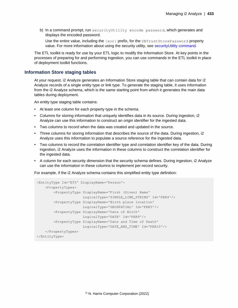
Managing i2 Analyze | 433
b) In a command prompt, run securityUtility encode password, which generates anddisplays the encoded password.
Use the entire value, including the {xor} prefix, for the DBTrustStorePassword propertyvalue. For more information about using the security utility, see securityUtility command.
The ETL toolkit is ready for use by your ETL logic to modify the Information Store. At key points in theprocesses of preparing for and performing ingestion, you can use commands in the ETL toolkit in placeof deployment toolkit functions.
Information Store staging tables
At your request, i2 Analyze generates an Information Store staging table that can contain data for i2Analyze records of a single entity type or link type. To generate the staging table, it uses informationfrom the i2 Analyze schema, which is the same starting point from which it generates the main datatables during deployment.
An entity type staging table contains:
• At least one column for each property type in the schema.
• Columns for storing information that uniquely identifies data in its source. During ingestion, i2Analyze can use this information to construct an origin identifier for the ingested data.
• Two columns to record when the data was created and updated in the source.
• Three columns for storing information that describes the source of the data. During ingestion, i2Analyze uses this information to populate a source reference for the ingested data.
• Two columns to record the correlation identifier type and correlation identifier key of the data. Duringingestion, i2 Analyze uses the information in these columns to construct the correlation identifier forthe ingested data.
• A column for each security dimension that the security schema defines. During ingestion, i2 Analyzecan use the information in these columns to implement per-record security.
For example, if the i2 Analyze schema contains this simplified entity type definition:
<EntityType Id="ET5" DisplayName="Person">
<PropertyTypes>
<PropertyType DisplayName="First (Given) Name"
LogicalType="SINGLE_LINE_STRING" Id="PER4"/>
<PropertyType DisplayName="Birth place location"
LogicalType="GEOSPATIAL" Id="PER5"/>
<PropertyType DisplayName="Date of Birth"
LogicalType="DATE" Id="PER9"/>
<PropertyType DisplayName="Date and Time of Death"
LogicalType="DATE_AND_TIME" Id="PER10"/>
</PropertyTypes>
</EntityType>
© N. Harris Computer Corporation (2022)

Managing i2 Analyze | 434
This SQL statement is then the definition of a corresponding staging table in Db2:
CREATE TABLE "IS_Staging"."E_Person" (
"source_id" VARCHAR(50),
"origin_id_type" VARCHAR(100),
"origin_id_keys" VARCHAR(1000),
"source_created" TIMESTAMP,
"source_last_updated" TIMESTAMP,
"correlation_id_type" VARCHAR(100),
"correlation_id_key" VARCHAR(1000),
"p_first_given_name" VARCHAR(250),
"p_birth_place_location" VARCHAR(250),
"p_date_of_birth" DATE,
"p0_date_and_time_of_deat" TIMESTAMP,
"p1_date_and_time_of_deat" VARCHAR(250),
"p2_date_and_time_of_deat" SMALLINT,
"p3_date_and_time_of_deat" TIMESTAMP,
"security_level" VARCHAR(50),
"security_compartment" VARCHAR(50),
"source_ref_source_type" VARGRAPHIC(200),
"source_ref_source_location" DBCLOB(2000),
"source_ref_source_image_url" DBCLOB(2000)
);
And this SQL statement is then the definition of a corresponding staging table in SQL Server:
CREATE TABLE IS_Staging.E_Person(
source_id nvarchar(50) NULL,
origin_id_type nvarchar(100),
origin_id_keys nvarchar(1000),
source_created datetime2(6) NULL,
source_last_updated datetime2(6) NULL,
correlation_id_type nvarchar(100) NULL,
correlation_id_key nvarchar(1000) NULL,
p_first_given_name varchar(250) NULL,
p_birth_place_location varchar(max) NULL,
p0_date_and_time_of_deat datetime2(4) NULL,
p1_date_and_time_of_deat nvarchar(250) NULL,
p2_date_and_time_of_deat smallint NULL,
p3_date_and_time_of_deat datetime2(6) NULL,
security_level nvarchar(50) NULL,
security_compartment nvarchar(50) NULL,
source_ref_source_type nvarchar(200) NULL,
source_ref_source_location nvarchar(2000) NULL,
source_ref_source_image_url nvarchar(2000) NULL
);
Note: Additionally, staging tables for link types contain a column for the direction of the link, and furthercolumns for the information that uniquely identifies the link end data in the source.
© N. Harris Computer Corporation (2022)
Managing i2 Analyze | 435
The statements create the staging table in a separate schema from the Information Store data tables.Many of the columns in the staging table have names that are derived from the display names of theproperty types in the i2 Analyze schema. In most cases, the relationship between the schema and thestaging table is obvious, but there are a number of extra columns and differences:
• The source_id, origin_id_type, origin_id_keys columns of the staging table can be usedto store values that reference the rest of the data in its original source and can be used to make upthe origin identifier of the resulting record.
Note: If the staging table definition was for a link type, it would also contain from_ and to_variations of each of the columns.
For more information about generating origin identifiers during ingestion, see Origin identifiers onpage 445.
• The next two columns of the staging table are source_created and source_last_updated.You can use these columns to store information about when the data to be ingested was created andmodified in its source.
• The next two columns of the staging table are correlation_id_type andcorrelation_id_key. If you want to correlate data during ingestion into the Information Store,you can use these columns to store values that i2 Analyze uses to generate correlation identifiers.For more information, see Overview of correlation.
Note: Although populating the correlation identifier columns is not mandatory, doing so acts like aswitch. The presence of correlation identifier values in any row of a staging table causes i2 Analyzeto perform correlation for all the rows in that table.
• Any property type in the i2 Analyze schema that has the logical type DATE_AND_TIME occupies fourcolumns in the staging table. These columns always appear in the same order:
• The "P0" column is for the local date and time as originally recorded, as a DATE_AND_TIME.
• The "P1" column is for the time zone of the local date and time, as listed in the IANA database.For example, Europe/London.
• The "P2" column is for an indicator of whether Daylight Saving Time is (1) or is not (0) in effect.
Note: i2 Analyze considers this value only when the time is ambiguous because it occurs duringthe hour that is "repeated" when Daylight Saving Time ends.
• The "P3" column is for the date and time as expressed in Coordinated Universal Time (UTC), asanother DATE_AND_TIME.
For more information about the permitted values for DATE_AND_TIME columns in your databasemanagement system, see Information Store property value ranges on page 436.
• The next columns derive from the security schema rather than the i2 Analyze schema. One columnexists for each security dimension that the security schema defines. You can use these columns ifyou want to give different dimension values to each i2 Analyze record that is created or updated as aresult of ingestion.
• In link tables, there is also a direction column to store the direction of links.
• The final three columns are named source_ref_source_type,source_ref_source_location, and source_ref_source_image_url. These columns areused to populate the source reference that is generated when the data is ingested.
For more information about implementing source references in your system, see Configuring sourcereferences.
© N. Harris Computer Corporation (2022)
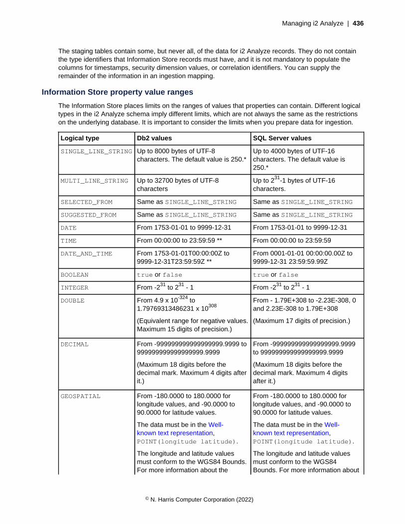
Managing i2 Analyze | 436
The staging tables contain some, but never all, of the data for i2 Analyze records. They do not containthe type identifiers that Information Store records must have, and it is not mandatory to populate thecolumns for timestamps, security dimension values, or correlation identifiers. You can supply theremainder of the information in an ingestion mapping.
Information Store property value ranges
The Information Store places limits on the ranges of values that properties can contain. Different logicaltypes in the i2 Analyze schema imply different limits, which are not always the same as the restrictionson the underlying database. It is important to consider the limits when you prepare data for ingestion.
Logical type Db2 values SQL Server values
SINGLE_LINE_STRING Up to 8000 bytes of UTF-8characters. The default value is 250.*
Up to 4000 bytes of UTF-16characters. The default value is250.*
MULTI_LINE_STRING Up to 32700 bytes of UTF-8characters
Up to 231-1 bytes of UTF-16characters.
SELECTED_FROM Same as SINGLE_LINE_STRING Same as SINGLE_LINE_STRING
SUGGESTED_FROM Same as SINGLE_LINE_STRING Same as SINGLE_LINE_STRING
DATE From 1753-01-01 to 9999-12-31 From 1753-01-01 to 9999-12-31
TIME From 00:00:00 to 23:59:59 ** From 00:00:00 to 23:59:59
DATE_AND_TIME From 1753-01-01T00:00:00Z to9999-12-31T23:59:59Z **
From 0001-01-01 00:00:00.00Z to9999-12-31 23:59:59.99Z
BOOLEAN true or false true or false
INTEGER From -231 to 231 - 1 From -231 to 231 - 1
DOUBLE From 4.9 x 10-324 to1.79769313486231 x 10308
(Equivalent range for negative values.Maximum 15 digits of precision.)
From - 1.79E+308 to -2.23E-308, 0and 2.23E-308 to 1.79E+308
(Maximum 17 digits of precision.)
DECIMAL From -999999999999999999.9999 to999999999999999999.9999
(Maximum 18 digits before thedecimal mark. Maximum 4 digits afterit.)
From -999999999999999999.9999to 999999999999999999.9999
(Maximum 18 digits before thedecimal mark. Maximum 4 digitsafter it.)
GEOSPATIAL From -180.0000 to 180.0000 forlongitude values, and -90.0000 to90.0000 for latitude values.
The data must be in the Well-known text representation,POINT(longitude latitude).
The longitude and latitude valuesmust conform to the WGS84 Bounds.For more information about the
From -180.0000 to 180.0000 forlongitude values, and -90.0000 to90.0000 for latitude values.
The data must be in the Well-known text representation,POINT(longitude latitude).
The longitude and latitude valuesmust conform to the WGS84Bounds. For more information about
© N. Harris Computer Corporation (2022)

Managing i2 Analyze | 437
Logical type Db2 values SQL Server values
values, see Spatial reference -WGS84.
the values, see Spatial reference -WGS84.
* The value for SINGLE_LINE_STRING depends on the value that is specified for each property withthat type in the i2 Analyze schema.
** If a Db2 database underlies the Information Store you can load time values that represent midnight as24:00:00. When it stores such values, the database converts them to fit the ranges in the table.
Data that includes non-printing or control characters might not be indexed and can cause errors.
In addition to the values in the table, you can set the value of any non-mandatory property to null. In thestaging table for an item type that has a DATE_AND_TIME property type, all four columns that the valueis spread across must be null in that case.
Ingestion mapping files
An ingestion mapping file is an XML document whose structure is validated during the ingestionprocess. Every time that you instruct the Information Store to ingest data, you specify both the mappingfile to use, and the ingestion mapping within it. You can choose to put all your ingestion mappings in onefile, or to spread them across several files.
Ingestion mappings have two complementary purposes. First, they make the association between anentity type or a link type in the i2 Analyze schema and a staging table in the database. Second, theyprovide any extra information that the Information Store requires but the staging tables do not contain.
For all record types, the extra information that an ingestion mapping can provide includes:
• The type identifier of the entity or link type that the mapping applies to
• The name of the data source that the data to be ingested comes from
• How to create an origin identifier for data of this type
• The security dimension values that all records of this type receive, if you do not use per-recordsecurity
Link type ingestion mappings provide further information that addresses the requirements of linkrecords:
• The Information Store must be able to test that it already contains the entity records at the ends ofan incoming link. The link type mapping must describe how to create the origin identifiers that areassociated with those records so that the Information Store can look them up.
• To make the look-up more efficient, the link type mapping also contains the type identifiers of theentity records that appear at the "from" and "to" ends of the incoming links. A link type that canconnect entities of several different types requires a separate mapping for each valid combination ofend types.
© N. Harris Computer Corporation (2022)

Managing i2 Analyze | 438
Ingestion mapping syntax
The root element of an ingestion mapping file is an <ingestionMappings> element from the definednamespace. For example:
<ns2:ingestionMappings
xmlns:ns2="http://www.i2group.com/Schemas/2016-08-12/IngestionMappings"
xmlns:xsi="http://www.w3.org/2001/XMLSchema-instance">
...
</ns2:ingestionMappings>
Within the ingestion mapping file, you use an <ingestionMapping> element to define a mapping fora particular entity type or link type. Each <ingestionMapping> element has a mandatory id attributethat must be unique within the mapping file. You use the value to identify the mapping when you startingestion. For example:
<ingestionMapping id="Person">
...
</ingestionMapping>
Note: For examples of complete ingestion mapping files, search for files with the name mapping.xmlin the i2 Analyze deployment toolkit. All of those files contain definitions that are similar to the definitionshere.
Entity type ingestion mappings
When the mapping is for an entity type, the <ingestionMapping> element has the following children:
stagingArea
The <stagingArea> element specifies where the mapping gets its staged data from. In thisversion of i2 Analyze, the staged data is always in a staging table, and <stagingArea> alwayshas a <tableName> child.
tableName
The value of <tableName> is the name of the staging table that contains the data to be ingested.
For example:
...
<stagingArea xsi:type="ns2:databaseIngestionSource">
<tableName>IS_Staging.E_Person</tableName>
</stagingArea>
...
itemTypeId
The value of the <itemTypeId> element is the identifier of the entity type (or the link type) to whichthe mapping applies, as defined in the i2 Analyze schema.
© N. Harris Computer Corporation (2022)

Managing i2 Analyze | 439
For example:
...
<itemTypeId>ET5</itemTypeId>
...
originId
The <originId> element contains a template for creating the origin identifier of each ingested row.<originId> has two mandatory child elements: <type> and <keys>.
For example:
...
<originId>
<type>$(origin_id_type)</type>
<keys>
<key>$(origin_id_keys)</key>
</keys>
</originId>
...
Here, $(origin_id_type) and $(origin_id_keys) are references to the columns namedorigin_id_type and origin_id_keys in the staging table to which this ingestion mappingapplies. When the Information Store ingests the data, the values from the staging table become theorigin identifier in the Information Store.
For more information about generating origin identifiers during ingestion, see Origin identifiers onpage 445.
dataSourceName
The value of the <dataSourceName> element identifies the data source from which the data inthe staging table came. It must match the name of an ingestion source that you provide to theInformation Store during the ingestion process.
For example:
...
<dataSourceName>EXAMPLE</dataSourceName>
...
createdSource and lastUpdatedSource
By default, the ingestion process automatically puts the values from the source_created andsource_last_updated columns of the staging tables into the Information Store. If you want touse the same values for all ingested data, you can override that behavior by including the non-mandatory <createdSource> and <lastUpdatedSource> elements and specifying values inthe date-time string format for your database management system.
© N. Harris Computer Corporation (2022)

Managing i2 Analyze | 440
For example:
...
<createdSource>2002-10-04 09:21:33</createdSource>
<lastUpdatedSource>2002-10-05 09:34:45</lastUpdatedSource>
...
securityDimensionValues
Every row that the Information Store ingests must have at least one security dimension value fromeach dimension in the security schema. The Information Store staging tables contain a column foreach access security dimension that the security schema defines.
In your ingestion process, you can use the staging table columns to store dimension values ona per-row basis. Alternatively, you can specify that all the data that the Information Store ingeststhrough the same mapping get the same security dimension values.
In the ingestion mapping file, the <securityDimensionValues> element has<securityDimensionValue> children. For per-row security, use the value of each<securityDimensionValue> element to reference a security dimension column.
For example:
...
<securityDimensionValues>
<securityDimensionValue>$(security_level)</securityDimensionValue>
<securityDimensionValue>$(security_compartment)</securityDimensionValue>
</securityDimensionValues>
...
In the staging table, the referenced columns can contain either a single dimension value, or acomma-separated list of dimension values.
For per-mapping security, set the value of each <securityDimensionValue> element to asecurity dimension value.
For example:
...
<securityDimensionValues>
<securityDimensionValue>HI</securityDimensionValue>
<securityDimensionValue>UC</securityDimensionValue>
<securityDimensionValue>OSI</securityDimensionValue>
</securityDimensionValues>
...
In either approach, the values that you specify must be present in the i2 Analyze security schema.
Link type ingestion mappings
When the ingestion mapping is for a link type, the <ingestionMapping> element has the samechildren that entity types require, plus the following ones:
fromItemTypeId
© N. Harris Computer Corporation (2022)
Managing i2 Analyze | 441
The value of the <fromItemTypeId> element is the type identifier of entity records that theschema permits at the "from" end of the link type to which this mapping applies.
For example:
...
<fromEntityTypeId>ET5</fromEntityTypeId>
...
fromOriginId
The <fromOriginId> element contains a template for creating the origin identifier of the entityrecord at the "from" end of each ingested link row. Its syntax is identical to the <originId>element.
The origin identifiers that result from <fromOriginId> must match the origin identifiers that resultfrom the <originId> element for the entity type in question. The ingestion process uses thisinformation to verify that the Information Store already ingested an entity record that has this originidentifier.
For example:
...
<fromOriginId>
<type>$(from_origin_id_type)</type>
<keys>
<key>$(from_origin_id_keys)</key>
</keys>
</fromOriginId>
...
For more information about generating origin identifiers during ingestion, see Origin identifiers onpage 445.
toItemTypeId
The value of the <toItemTypeId> element is the type identifier of entity records that the schemapermits at the "to" end of the link type to which this mapping applies.
For example:
...
<toEntityTypeId>ET10</toEntityTypeId>
...
toOriginId
The <toOriginId> element behaves identically to the <fromOriginId> element, except that itapplies to the entity record at the "to" end of each ingested link row.
© N. Harris Computer Corporation (2022)
Managing i2 Analyze | 442
For example:
...
<toOriginId>
<type>$(to_origin_id_type)</type>
<keys>
<key>$(to_origin_id_keys)</key>
</keys>
</toOriginId>
...
For more information about generating origin identifiers during ingestion, see Origin identifiers onpage 445.
linkDirection
The <linkDirection> element is a non-mandatory child of the <ingestionMapping> element.When you include a <linkDirection> element in an ingestion mapping, you can either providethe same value for all links, or refer to the direction column of the staging table. Legal values forthe element or the column are WITH, AGAINST, BOTH, and NONE.
For example, to use a fixed value:
...
<linkDirection>WITH</linkDirection>
...
Or, to use the value in the direction column:
...
<linkDirection>$(direction)</linkDirection>
...
If an ingestion mapping for a link type does not contain a <linkDirection> element, then anylinks that the Information Store ingests through the mapping have no direction.
References and system properties
In an ingestion mapping, you can use constants or references to specify values for i2 Analyze records.When you use a reference, the ingestion process retrieves a value from a staging table column or aproperty in a settings file. The settings file can also set system properties that control some aspects ofingestion into the Information Store.
By default, the settings file does not exist. You must create the settings file and specify the file when yourun the ingestion command.
For example, you might call your settings file ingestion_settings.properties and it mightcontain the following name-value pairs :
SEC_LEVEL_VALUE=UC
SEC_COMPARTMENT_VALUE=HI,OSI
IngestionFailureMode=MAPPING
© N. Harris Computer Corporation (2022)
Managing i2 Analyze | 443
When you run the ingestion command, you reference your settings file as follows:
setup -t ingestInformationStoreRecords
...
-p importConfigFile=ingestion_settings.properties
• System properties on page 443
• References on page 444
System properties
As well as providing values for ingestion mappings, you can use the settings file to configure thebehavior of the ingestion process. The file supports a handful of system properties that you can set inthe same way as you create and set custom properties.
IngestionFailureMode [ RECORD | MAPPING ]
When the Information Store encounters a problem with a record during ingestion, its defaultbehavior is to log the error and move on to the next record. Failure is record-based. Instead, youcan specify that a problem with one record causes the Information Store not to ingest any of therecords from that staging table. Failure then is mapping-based.
In the settings file, the possible values for the IngestionFailureMode setting are RECORD orMAPPING. The default value is RECORD.
For example, to change the failure mode to mapping, add the following line to your settings file:
IngestionFailureMode=MAPPING
RecordFailureThreshold
During the ingestion process, if the number of errors that occur is greater than the value forthe RecordFailureThreshold property the process stops and no data is ingested into theInformation Store. By default, the value for this property is 1000.
For example:
RecordFailureThreshold=500
IngestionRunstats [ TRUE | FALSE ]
If you are using Db2, during the ingestion process the RUNSTATS command updates statistics in thesystem catalog about the characteristics of a table, associated indexes, or statistical views.
In a table that contains many records, it can take the RUNSTATS command a long time to complete.If the number of records that you are ingesting is a small percentage of the total number of recordsin the table, it is recommended that you configure the ingestion process not to call the RUNSTATScommand. You can then manually run the RUNSTATS command after a significant number ofrecords are ingested.
To prevent the ingestion process from calling the RUNSTATS command, set the value ofIngestionRunstats to FALSE. For example:
IngestionRunstats=FALSE
© N. Harris Computer Corporation (2022)
Managing i2 Analyze | 444
The following command is the RUNSTATS command to run manually after an ingestion.The command generates query output, and saves the output to the file namedISStatisticsCollection.sql that you can run.
db2 connect to ISTORE user <user name> using <password>
db2 -x
"SELECT
'RUNSTATS ON TABLE ' || TRIM(TABSCHEMA) ||'.'|| TRIM(TABNAME) || '
WITH DISTRIBUTION ON ALL COLUMNS
AND INDEXES ALL
ALLOW WRITE ACCESS
TABLESAMPLE BERNOULLI(10)
INDEXSAMPLE BERNOULLI(10);'
FROM SYSCAT.TABLES
WHERE TYPE = 'T' AND TABSCHEMA = 'IS_DATA'"
> ISStatisticsCollection.SQL
ImportBatchSize
The ImportBatchSize controls the number of rows from a staging table that are ingested perbatch. By default, the ImportBatchSize is set to 100,000.
For example:
ImportBatchSize=100000
If you are ingesting data into the system while analysts are using the system, it is possible thatsome analysis operations are blocked from returning results while a batch of data is being ingested.During the ingestion process, up to 100,000 rows (or the value of your batch size) can be lockedin the database during each batch of the import. These locks cause a potential for the followinganalytical operations to stop returning results until the batch is complete: Find Path, Expand, andVisual Query.
To determine how long each batch takes to ingest, inspect the IS_Data.Ingestion_Batchestable. The time that the batch takes to complete is the time that analytical operations might beblocked from returning results. If the time is too long for your requirements, you can reduce thevalue for ImportBatchSize to reduce the batch size and the time that it takes to complete.
For SQL Server, a batch size greater than 1,700 can cause table locks during link ingestion.
References
Many of the pieces of information that you provide in an ingestion mapping are fixed for that mapping.Item types, end types, and some parts of the origin identifier do not change between the i2 Analyzerecords that one mapping is responsible for. The most appropriate way to specify this kind of informationis to use constant values on a per-mapping basis.
The two main reasons for preferring references to constant values lie at opposite ends of the spectrum:
• To give different values for the same field in records that are ingested through the same mapping,you can refer to a staging table column. This approach is appropriate for many non-property valuesthat change from one record to the next.
© N. Harris Computer Corporation (2022)
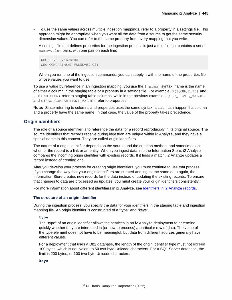
Managing i2 Analyze | 445
• To use the same values across multiple ingestion mappings, refer to a property in a settings file. Thisapproach might be appropriate when you want all the data from a source to get the same securitydimension values. You can refer to the same property from every mapping that you write.
A settings file that defines properties for the ingestion process is just a text file that contains a set ofname=value pairs, with one pair on each line:
SEC_LEVEL_VALUE=UC
SEC_COMPARTMENT_VALUE=HI,OSI
When you run one of the ingestion commands, you can supply it with the name of the properties filewhose values you want to use.
To use a value by reference in an ingestion mapping, you use the $(name) syntax. name is the nameof either a column in the staging table or a property in a settings file. For example, $(SOURCE_ID) and$(DIRECTION) refer to staging table columns, while in the previous example $(SEC_LEVEL_VALUE)and $(SEC_COMPARTMENT_VALUE) refer to properties.
Note: Since referring to columns and properties uses the same syntax, a clash can happen if a columnand a property have the same name. In that case, the value of the property takes precedence.
Origin identifiers
The role of a source identifier is to reference the data for a record reproducibly in its original source. Thesource identifiers that records receive during ingestion are unique within i2 Analyze, and they have aspecial name in this context. They are called origin identifiers.
The nature of a origin identifier depends on the source and the creation method, and sometimes onwhether the record is a link or an entity. When you ingest data into the Information Store, i2 Analyzecompares the incoming origin identifier with existing records. If it finds a match, i2 Analyze updates arecord instead of creating one.
After you develop your process for creating origin identifiers, you must continue to use that process.If you change the way that your origin identifiers are created and ingest the same data again, theInformation Store creates new records for the data instead of updating the existing records. To ensurethat changes to data are processed as updates, you must create your origin identifiers consistently.
For more information about different identifiers in i2 Analyze, see Identifiers in i2 Analyze records.
The structure of an origin identifier
During the ingestion process, you specify the data for your identifiers in the staging table and ingestionmapping file. An origin identifier is constructed of a "type" and "keys".
type
The "type" of an origin identifier allows the services in an i2 Analyze deployment to determinequickly whether they are interested in (or how to process) a particular row of data. The value ofthe type element does not have to be meaningful, but data from different sources generally havedifferent values.
For a deployment that uses a Db2 database, the length of the origin identifier type must not exceed100 bytes, which is equivalent to 50 two-byte Unicode characters. For a SQL Server database, thelimit is 200 bytes, or 100 two-byte Unicode characters.
keys
© N. Harris Computer Corporation (2022)

Managing i2 Analyze | 446
The "keys" of an origin identifier contain the information necessary to reference the data in itsoriginal source. The pieces of information that you use to make up the keys differs depending on thesource of the data. For data that originates in relational sources, you might use keys whose valuesinclude the source name, the table name, and the unique identifier of the data within that table.
The length of the origin identifier keys must not exceed the following sizes:
• On Db2: 1000 bytes. This is equivalent to 500 Unicode characters.
• On SQL Server: 692 bytes. This is equivalent to 346 Unicode characters.
• It is recommended that your origin identifiers are as short as possible in length, and that anycommon values are at the end of the key.
• Do not use non-printing or control characters in your origin identifiers because they might not beindexed correctly and cause your origin identifiers to be different from your intended values.
Creating origin identifiers for your data
There are two mechanisms for specifying the data for your origin identifiers. You can populatethe staging table with all the information required to create the origin identifiers, or you can use acombination of information in the staging table and the ingestion mapping.
When you can provide all the information in the staging tables, there is less processing of the dataduring ingestion, which can improve ingestion performance.
All information in the staging table
If you can populate the staging table with all the information for your origin identifiers, you can usethe origin_id_type and origin_id_keys columns to store this information. Populate theorigin_id_type column with the type of your origin identifier. Populate the origin_id_keyscolumn with a unique value that is already a composite of key values including the unique identifierfrom the source. When you use these columns, you must specify them in the ingestion mapping filethat you use.
To ingest links, you must specify the origin identifiers at the end of the link. You specify the "to" endof the link in the to_origin_id_type and to_origin_id_keys columns, and the "from" end infrom_origin_id_type and from_origin_id_keys.
When you specify all the information in the staging table, the origin identifier section of youringestion mapping is more simple. For example:
...
<originId>
<type>$(origin_id_type)</type>
<keys>
<key>$(origin_id_keys)</key>
</keys>
</originId>
...
© N. Harris Computer Corporation (2022)
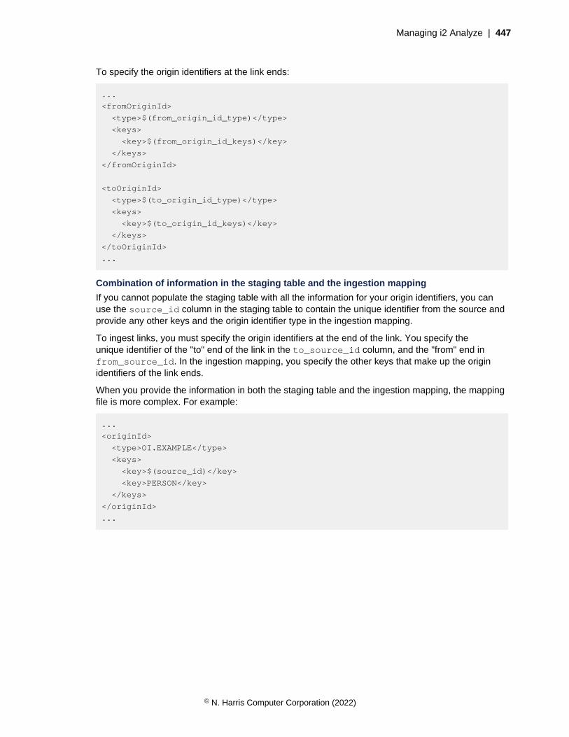
Managing i2 Analyze | 447
To specify the origin identifiers at the link ends:
...
<fromOriginId>
<type>$(from_origin_id_type)</type>
<keys>
<key>$(from_origin_id_keys)</key>
</keys>
</fromOriginId>
<toOriginId>
<type>$(to_origin_id_type)</type>
<keys>
<key>$(to_origin_id_keys)</key>
</keys>
</toOriginId>
...
Combination of information in the staging table and the ingestion mapping
If you cannot populate the staging table with all the information for your origin identifiers, you canuse the source_id column in the staging table to contain the unique identifier from the source andprovide any other keys and the origin identifier type in the ingestion mapping.
To ingest links, you must specify the origin identifiers at the end of the link. You specify theunique identifier of the "to" end of the link in the to_source_id column, and the "from" end infrom_source_id. In the ingestion mapping, you specify the other keys that make up the originidentifiers of the link ends.
When you provide the information in both the staging table and the ingestion mapping, the mappingfile is more complex. For example:
...
<originId>
<type>OI.EXAMPLE</type>
<keys>
<key>$(source_id)</key>
<key>PERSON</key>
</keys>
</originId>
...
© N. Harris Computer Corporation (2022)

Managing i2 Analyze | 448
To specify the origin identifiers at the link ends, if the to end is an "Account" entity type:
...
<fromOriginId>
<type>OI.EXAMPLE</type>
<keys>
<key>$(from_source_id)</key>
<key>PERSON</key>
</keys>
</fromOriginId>
<toOriginId>
<type>OI.EXAMPLE</type>
<keys>
<key>$(to_source_id)</key>
<key>ACCOUNT</key>
</keys>
</toOriginId>
...
The ingestInformationStoreRecords task
The parameters and usage of the ingestInformationStoreRecords depends on whether you areusing the i2 Analyze deployment toolkit or the ETL toolkit.
• i2 Analyze deployment toolkit
• ETL deployment toolkit
i2 Analyze deployment toolkit
The deployment toolkit command for ingesting records looks like this:
setup -t ingestInformationStoreRecords
-p importMappingsFile=ingestion_mapping_file
-p importMappingId=ingestion_mapping_id
-p importLabel=ingestion_label
-p importConfigFile=ingestion_settings_file
-p importMode=STANDARD|VALIDATE|BULK
Here, ingestion_mapping_file is the path to the XML file that contains the mapping that you want to use,and ingestion_mapping_id is the identifier of the mapping within that file. The latter is mandatory unlessthe file contains only one mapping.
The importLabel, importConfigFile, and importMode parameters are optional:
• When you specify importLabel, ingestion_label is a name that identifies a particular use of thecommand in the Information Store's IS_Public.Ingestion_Deletion_Reports view.
• When you specify importConfigFile, ingestion_settings_file is the path to a settings file thatcontains name=value pairs. You can refer to names in the settings file from references in theingestion mapping file to use their values when you run the ingestInformationStoreRecordscommand.
• When you specify importMode, you can set it to STANDARD, VALIDATE, or BULK.
© N. Harris Computer Corporation (2022)

Managing i2 Analyze | 449
• STANDARD mode can be used to ingest new and updated records, with or without correlation. Ifyou do not specify importMode, STANDARD mode is used.
• VALIDATE mode checks the validity of the specified mapping, but no ingestion takes place.
• BULK mode can be used to ingest new records without correlation.
ETL toolkit
The equivalent ETL toolkit command looks like this. The ETL toolkit command can also deleteprovenance from the Information Store.
ingestInformationStoreRecords
-imf ingestion_mapping_file
-imid ingestion_mapping_id
-il ingestion_label
-icf ingestion_settings_file
-lcl true|false
-im STANDARD|VALIDATE|BULK|DELETE_PREVIEW|DELETE|BULK_DELETE
Here, ingestion_mapping_file is the path to the XML file that contains the mapping that you want to use,and ingestion_mapping_id is the identifier of the mapping within that file. The latter is mandatory unlessthe file contains only one mapping.
The other parameters are optional:
• When you specify il, ingestion_label is a name that identifies a particular use of the command in theInformation Store's IS_Public.Ingestion_Deletion_Reports view.
• When you specify icf, ingestion_settings_file is the path to a settings file that containsname=value pairs. You can refer to names in the settings file from references in the ingestionmapping file to use their values when you run the ingestInformationStoreRecords command.
• When you specify lcl as true, any links that are removed as part of an entity delete operation arelogged in IS_Public.D<import identifier><entity type id>_<link type id>_Linkstables. For example, IS_Public.D20180803090624143563ET5_LAC1_Links.
You can specify lcl with the DELETE import mode only.
• When you specify im you can set it to one of the following modes:
• STANDARD mode can be used to ingest new and updated records, with or without correlation. Ifyou do not specify im, STANDARD mode is used.
• VALIDATE mode checks the validity of the specified mapping, but no ingestion takes place.
• BULK mode can be used to ingest new records without correlation.
• DELETE_PREVIEW mode can be used to preview the effect of running a delete.
• DELETE mode can be used to delete provenance from the Information Store.
• BULK_DELETE mode can be used to delete provenance that does not contribute to a correlatedrecord.
© N. Harris Computer Corporation (2022)
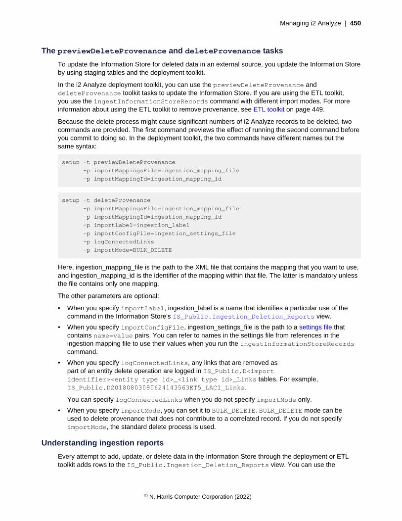
Managing i2 Analyze | 450
The previewDeleteProvenance and deleteProvenance tasks
To update the Information Store for deleted data in an external source, you update the Information Storeby using staging tables and the deployment toolkit.
In the i2 Analyze deployment toolkit, you can use the previewDeleteProvenance anddeleteProvenance toolkit tasks to update the Information Store. If you are using the ETL toolkit,you use the ingestInformationStoreRecords command with different import modes. For moreinformation about using the ETL toolkit to remove provenance, see ETL toolkit on page 449.
Because the delete process might cause significant numbers of i2 Analyze records to be deleted, twocommands are provided. The first command previews the effect of running the second command beforeyou commit to doing so. In the deployment toolkit, the two commands have different names but thesame syntax:
setup -t previewDeleteProvenance
-p importMappingsFile=ingestion_mapping_file
-p importMappingId=ingestion_mapping_id
setup -t deleteProvenance
-p importMappingsFile=ingestion_mapping_file
-p importMappingId=ingestion_mapping_id
-p importLabel=ingestion_label
-p importConfigFile=ingestion_settings_file
-p logConnectedLinks
-p importMode=BULK_DELETE
Here, ingestion_mapping_file is the path to the XML file that contains the mapping that you want to use,and ingestion_mapping_id is the identifier of the mapping within that file. The latter is mandatory unlessthe file contains only one mapping.
The other parameters are optional:
• When you specify importLabel, ingestion_label is a name that identifies a particular use of thecommand in the Information Store's IS_Public.Ingestion_Deletion_Reports view.
• When you specify importConfigFile, ingestion_settings_file is the path to a settings file thatcontains name=value pairs. You can refer to names in the settings file from references in theingestion mapping file to use their values when you run the ingestInformationStoreRecordscommand.
• When you specify logConnectedLinks, any links that are removed aspart of an entity delete operation are logged in IS_Public.D<importidentifier><entity type id>_<link type id>_Links tables. For example,IS_Public.D20180803090624143563ET5_LAC1_Links.
You can specify logConnectedLinks when you do not specify importMode only.
• When you specify importMode, you can set it to BULK_DELETE. BULK_DELETE mode can beused to delete provenance that does not contribute to a correlated record. If you do not specifyimportMode, the standard delete process is used.
Understanding ingestion reports
Every attempt to add, update, or delete data in the Information Store through the deployment or ETLtoolkit adds rows to the IS_Public.Ingestion_Deletion_Reports view. You can use the
© N. Harris Computer Corporation (2022)
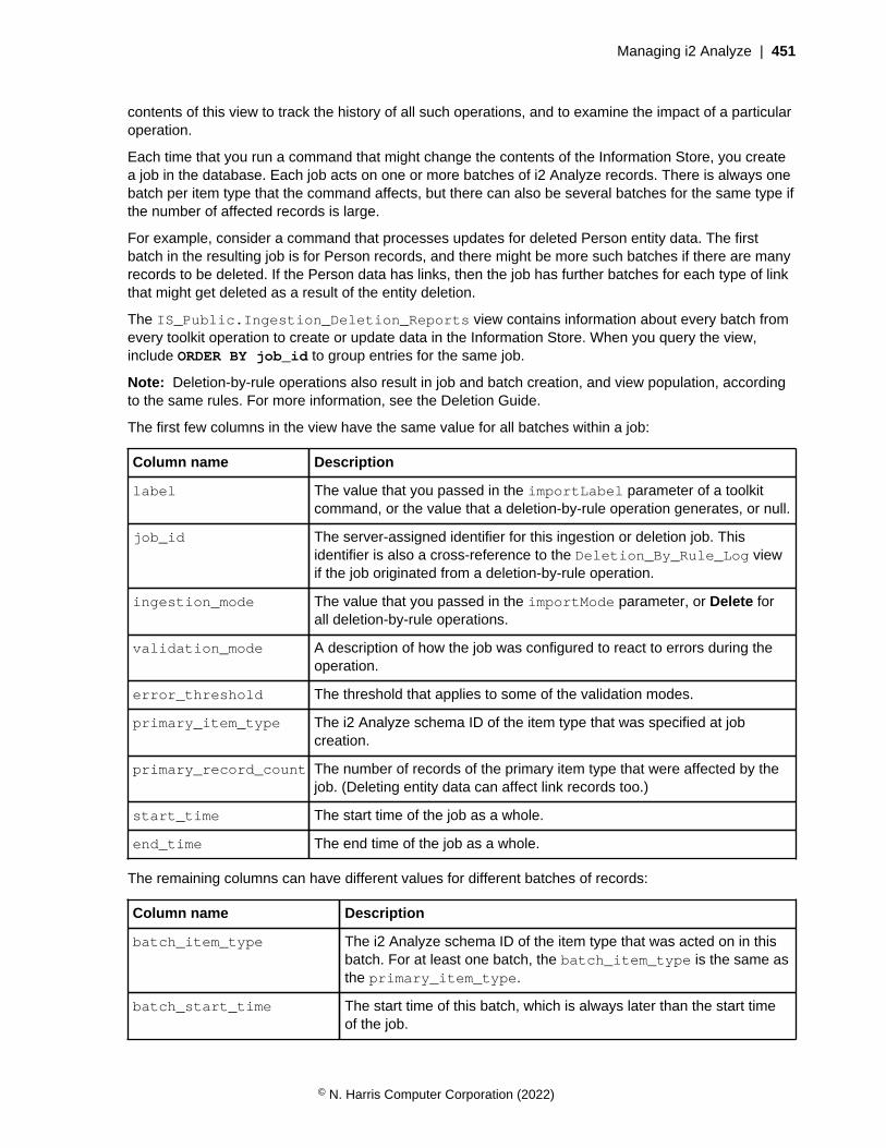
Managing i2 Analyze | 451
contents of this view to track the history of all such operations, and to examine the impact of a particularoperation.
Each time that you run a command that might change the contents of the Information Store, you createa job in the database. Each job acts on one or more batches of i2 Analyze records. There is always onebatch per item type that the command affects, but there can also be several batches for the same type ifthe number of affected records is large.
For example, consider a command that processes updates for deleted Person entity data. The firstbatch in the resulting job is for Person records, and there might be more such batches if there are manyrecords to be deleted. If the Person data has links, then the job has further batches for each type of linkthat might get deleted as a result of the entity deletion.
The IS_Public.Ingestion_Deletion_Reports view contains information about every batch fromevery toolkit operation to create or update data in the Information Store. When you query the view,include ORDER BY job_id to group entries for the same job.
Note: Deletion-by-rule operations also result in job and batch creation, and view population, accordingto the same rules. For more information, see the Deletion Guide.
The first few columns in the view have the same value for all batches within a job:
Column name Description
label The value that you passed in the importLabel parameter of a toolkitcommand, or the value that a deletion-by-rule operation generates, or null.
job_id The server-assigned identifier for this ingestion or deletion job. Thisidentifier is also a cross-reference to the Deletion_By_Rule_Log viewif the job originated from a deletion-by-rule operation.
ingestion_mode The value that you passed in the importMode parameter, or Delete forall deletion-by-rule operations.
validation_mode A description of how the job was configured to react to errors during theoperation.
error_threshold The threshold that applies to some of the validation modes.
primary_item_type The i2 Analyze schema ID of the item type that was specified at jobcreation.
primary_record_count The number of records of the primary item type that were affected by thejob. (Deleting entity data can affect link records too.)
start_time The start time of the job as a whole.
end_time The end time of the job as a whole.
The remaining columns can have different values for different batches of records:
Column name Description
batch_item_type The i2 Analyze schema ID of the item type that was acted on in thisbatch. For at least one batch, the batch_item_type is the same asthe primary_item_type.
batch_start_time The start time of this batch, which is always later than the start timeof the job.
© N. Harris Computer Corporation (2022)
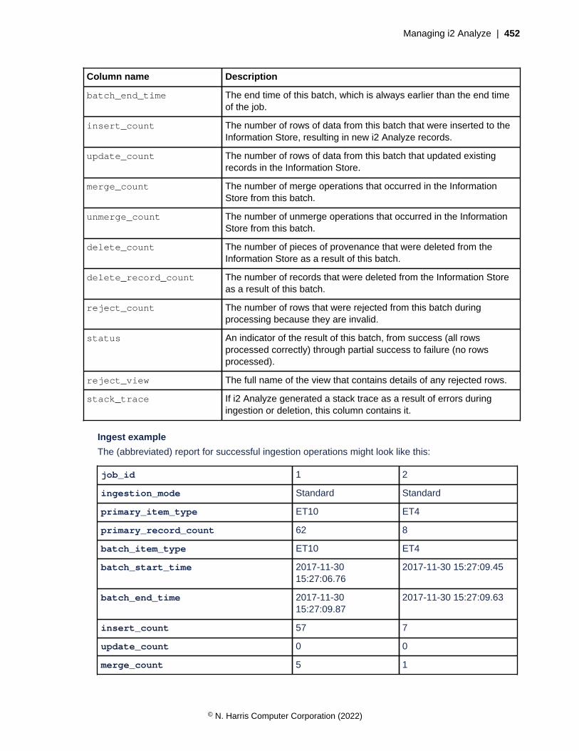
Managing i2 Analyze | 452
Column name Description
batch_end_time The end time of this batch, which is always earlier than the end timeof the job.
insert_count The number of rows of data from this batch that were inserted to theInformation Store, resulting in new i2 Analyze records.
update_count The number of rows of data from this batch that updated existingrecords in the Information Store.
merge_count The number of merge operations that occurred in the InformationStore from this batch.
unmerge_count The number of unmerge operations that occurred in the InformationStore from this batch.
delete_count The number of pieces of provenance that were deleted from theInformation Store as a result of this batch.
delete_record_count The number of records that were deleted from the Information Storeas a result of this batch.
reject_count The number of rows that were rejected from this batch duringprocessing because they are invalid.
status An indicator of the result of this batch, from success (all rowsprocessed correctly) through partial success to failure (no rowsprocessed).
reject_view The full name of the view that contains details of any rejected rows.
stack_trace If i2 Analyze generated a stack trace as a result of errors duringingestion or deletion, this column contains it.
Ingest example
The (abbreviated) report for successful ingestion operations might look like this:
job_id 1 2
ingestion_mode Standard Standard
primary_item_type ET10 ET4
primary_record_count 62 8
batch_item_type ET10 ET4
batch_start_time 2017-11-3015:27:06.76
2017-11-30 15:27:09.45
batch_end_time 2017-11-3015:27:09.87
2017-11-30 15:27:09.63
insert_count 57 7
update_count 0 0
merge_count 5 1
© N. Harris Computer Corporation (2022)

Managing i2 Analyze | 453
unmerge_count 0 6
delete_count 0 0
delete_record_count 0 0
reject_count 0 0
status Succeeded Succeeded
In this example, several commands to ingest entity records resulted in the creation of several jobs.Each job demonstrates different behavior that is possible during ingestion, including correlationoperations:
JOB_ID 1
This job demonstrates what the ingestion report can look like when data in the staging table causesmerge operations. In this example, five merge operations are completed on the incoming rows ofdata, as shown in the merge_count column. This results in 57 i2 Analyze records created from the62 rows of data, as shown in the insert_count and primary_record_count columns. Thisincludes merging five rows of data with existing i2 Analyze records in the Information Store.
JOB_ID 2
This job demonstrates what the ingestion report can look like when the data in the staging tablecauses unmerge and merge operations. In this example, six unmerge operations are completedon the incoming rows of data, as shown in the unmerge_count column. One merge operationis completed on the incoming rows, as shown in the merge_count column. This results in7 i2 Analyze records created, from eight rows of data as shown in the insert_count andprimary_record_count columns. The primary_record_count value does not include theunmerge_count.
Delete example
The (abbreviated) report for a successful delete operation might look like this:
job_id 26 26 26 26 26
ingestion_mode Delete Delete Delete Delete Delete
primary_item_type ET5 ET5 ET5 ET5 ET5
primary_record_count 324 324 324 324 324
batch_item_type ET5 LAC1 LAS1 LEM1 LIN1
batch_start_time 2017-11-3015:27:06.76
2017-11-3015:27:08.60
2017-11-3015:27:08.60
2017-11-3015:27:09.43
2017-11-3015:27:09.45
batch_end_time 2017-11-3015:27:09.87
2017-11-3015:27:09.30
2017-11-3015:27:09.29
2017-11-3015:27:09.62
2017-11-3015:27:09.63
insert_count 0 0 0 0 0
update_count 0 0 0 0 0
merge_count 0 0 0 0 0
unmerge_count 0 0 0 0 0
delete_count 324 187 27 54 33
© N. Harris Computer Corporation (2022)

Managing i2 Analyze | 454
delete_record_count 320 187 27 54 33
reject_count 0 0 0 0 0
status Succeeded Succeeded Succeeded Succeeded Succeeded
In this example, a command to update the Information Store for deleted entity data (withitem type ET5) resulted in the creation of a job with five batches. The first few columns of theIngestion_Deletion_Reports view contain the same values for all batches in the same job.Later columns reveal how deleting entity records results in the deletion of connected link records(with item types LAC1, LAS1, LEM1, LIN1).
In one case, the delete_record_count value is less than the delete_count value. This isbecause some of the provenance to be deleted was associated with an i2 Analyze record that hadmore than one piece of provenance. An i2 Analyze record is deleted only when the last associatedprovenance is deleted.
Troubleshooting the ingestion process
The commands that you run during the ingestion process send information about their progress to thecommand line and a log file. If any command encounters errors or does not run to completion, you canread the output to help you to diagnose the problem.
When an ingestion process runs to completion, the final output from the command is a report of whathappened to the Information Store. The reports appear on the command line and in the ingestion log attoolkit\configuration\logs\importer\i2_Importer.log. The three possible end states aresuccess, partial success, and failure.
Success
If the ingestion command processed all of the rows in the staging table without error, then theInformation Store reflects the contents of the staging table. The command reports success like thisexample:
> INFO [IImportLogger] - Total number of rows processed: 54
> INFO [IImportLogger] - Number of records inserted: 0
> INFO [IImportLogger] - Number of records updated: 54
> INFO [IImportLogger] - Number of merges: 0
> INFO [IImportLogger] - Number of unmerges: 0
> INFO [IImportLogger] - Number of rows rejected: 0
> INFO [IImportLogger] - Duration: 5 s
> INFO [IImportLogger] -
> INFO [IImportLogger] - Result: SUCCESS
Partial success
© N. Harris Computer Corporation (2022)
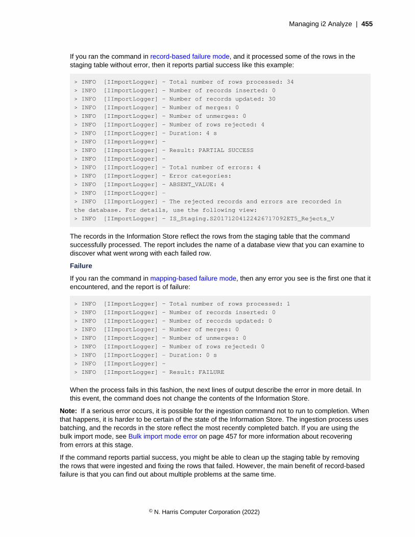
Managing i2 Analyze | 455
If you ran the command in record-based failure mode, and it processed some of the rows in thestaging table without error, then it reports partial success like this example:
> INFO [IImportLogger] - Total number of rows processed: 34
> INFO [IImportLogger] - Number of records inserted: 0
> INFO [IImportLogger] - Number of records updated: 30
> INFO [IImportLogger] - Number of merges: 0
> INFO [IImportLogger] - Number of unmerges: 0
> INFO [IImportLogger] - Number of rows rejected: 4
> INFO [IImportLogger] - Duration: 4 s
> INFO [IImportLogger] -
> INFO [IImportLogger] - Result: PARTIAL SUCCESS
> INFO [IImportLogger] -
> INFO [IImportLogger] - Total number of errors: 4
> INFO [IImportLogger] - Error categories:
> INFO [IImportLogger] - ABSENT_VALUE: 4
> INFO [IImportLogger] -
> INFO [IImportLogger] - The rejected records and errors are recorded in
the database. For details, use the following view:
> INFO [IImportLogger] - IS_Staging.S20171204122426717092ET5_Rejects_V
The records in the Information Store reflect the rows from the staging table that the commandsuccessfully processed. The report includes the name of a database view that you can examine todiscover what went wrong with each failed row.
Failure
If you ran the command in mapping-based failure mode, then any error you see is the first one that itencountered, and the report is of failure:
> INFO [IImportLogger] - Total number of rows processed: 1
> INFO [IImportLogger] - Number of records inserted: 0
> INFO [IImportLogger] - Number of records updated: 0
> INFO [IImportLogger] - Number of merges: 0
> INFO [IImportLogger] - Number of unmerges: 0
> INFO [IImportLogger] - Number of rows rejected: 0
> INFO [IImportLogger] - Duration: 0 s
> INFO [IImportLogger] -
> INFO [IImportLogger] - Result: FAILURE
When the process fails in this fashion, the next lines of output describe the error in more detail. Inthis event, the command does not change the contents of the Information Store.
Note: If a serious error occurs, it is possible for the ingestion command not to run to completion. Whenthat happens, it is harder to be certain of the state of the Information Store. The ingestion process usesbatching, and the records in the store reflect the most recently completed batch. If you are using thebulk import mode, see Bulk import mode error on page 457 for more information about recoveringfrom errors at this stage.
If the command reports partial success, you might be able to clean up the staging table by removingthe rows that were ingested and fixing the rows that failed. However, the main benefit of record-basedfailure is that you can find out about multiple problems at the same time.
© N. Harris Computer Corporation (2022)

Managing i2 Analyze | 456
The most consistent approach to addressing failures of all types is to fix up the problems in the stagingtable and run the ingestion command again. The following sections describe how to react to some of themore common failures.
Link rows in the staging table refer to missing entity records
When the Information Store ingests link data, you might see the following error message in the consoleoutput:
Link data in the staging table refers to missing entity records
This message is displayed if the entity record at either end of a link is not present in the InformationStore. To resolve the error:
• Examine the console output for your earlier operations to check that the Information Store ingestedall the entity records properly.
• Ensure that the link end origin identifiers are constructed correctly, and exist for each row in thestaging table.
• Ensure that the link type and the entity types at the end of the links are valid according to the i2Analyze schema.
Then, rerun the ingestion command.
Rows in the staging table have duplicate origin identifiers
During any ingestion procedure, but especially when a staging table is large, you might see the followingerror message in the console output:
Rows in the staging table have duplicate origin identifiers
This message is displayed when several rows in a staging table generate the same origin identifier. Forexample, more than one row might have the same value in the source_id column.
If more than one row in the staging table contains the same provenance information, you must resolvethe issue and repopulate the staging table. Alternatively, you can separate the rows so that they are notin the same staging table at the same time.
This problem is most likely to occur during an update to the Information Store that attempts to changethe same record (with the same provenance) twice in the same batch. It might be appropriate tocombine the changes, or to process only the last change. After you resolve the problem, repopulate thestaging table and rerun the ingestion command.
Geospatial data is in the incorrect format
During an ingestion procedure that contains geospatial data, you might see the following errormessages in the console output:
On Db2:
SQLERRMC=GSEGEOMFROMWKT;;GSE3052N Unknown type "FOO(33.3" in WKT.
On SQL Server:
System.FormatException: 24114: The label FOO(33.3 44.0) in the input well-known text (WKT) is not valid.
This message is displayed when data in a geospatial property column is not in the correct format.
Data in geospatial property columns must be in the POINT(longitude latitude) format. For moreinformation, see Information Store property value ranges on page 436.
© N. Harris Computer Corporation (2022)

Managing i2 Analyze | 457
Error occurred during a correlation operation
During an ingestion procedure with correlated data, you might see the following error message in theconsole output:
An error occurred during a correlation operation. There might be some data in an unusable state.
This message is displayed if the connection to the database or Solr is interrupted during a correlationoperation.
To resolve the problem, you must repair the connection that caused the error, and then run thesyncInformationStoreCorrelation toolkit task. This task synchronizes the data in theInformation Store with the data in the Solr index so that the data returns to a usable state.
After you run the syncInformationStoreCorrelation task, reingest the data that you wereingesting when the failure occurred. Any attempt to run an ingestion or a deletion command before yourun syncInformationStoreCorrelation will fail.
Ingestion with correlated data is still in progress
During an ingestion procedure, you might see the following error message in the console output:
You cannot ingest data because an ingestion with correlated data is still in progress,or because an error occurred during a correlation operation in a previous ingestion.
If another ingestion is still in progress, you must wait until it finishes. If a previous ingestion failed duringa correlation operation, you must run the syncInformationStoreCorrelation toolkit task.
For more information about running the syncInformationStoreCorrelation toolkit task, see Erroroccurred during a correlation operation on page 457.
Ingestion of the same item type is still in progress
During an ingestion procedure, you might see the following error message in the console output:
You cannot ingest data for item type <ET5> because an ingestion is still in progress. You must wait until the process is finished before you can start another ingestion for this item type.
If another ingestion of the same item type is still in progress, you must wait until it finishes.
If you are sure that the ingestion is complete or not in progress, you can remove the file that is blockingthe ingestion. To determine whether an ingestion is in progress, a file is created in the temporarydirectory on the server where the ingestion command was run. For example, AppData\Local\Temp.The file name is INGESTION_IN_PROGRESS_<item type ID>. After you remove the file, you canrun the ingestion command again.
Bulk import mode error
The symptoms of this type of failure are a stack trace and failure message in the console and importerlog. To recover from a failure at this time:
1. Identify the cause of the failure. You must use the SQL error codes to determine the cause of thefailure.
You might see error messages about the following issues:
© N. Harris Computer Corporation (2022)

Managing i2 Analyze | 458
• Log size or connectivity issues.
• Invalid data in the staging table.
2. Fix the problem that caused the failure. This might include ensuring connectivity to the database orincreasing the log size.
3. After you resolve the problem that caused the error, you can attempt the ingestion again. If any ofthe rows in the staging table were already ingested into the Information Store, you must removethem from the staging table before you can ingest in bulk mode.
• In the console or importer log, if the value for Number of rows accepted is 0 then run theingestion command again.
• In the console or importer log, if the value for Number of rows accepted is greater than 0,you must ensure that these records are not ingested again.
Before you run the ingestion command again, add the CheckExistingOriginIds=filtersetting to the import configuration file. When this value is set, the ingestion process calculateswhether the origin identifiers in the staging table already exist in the Information Store and doesnot attempt to ingest them again.
When this is set to filter, the ingestion might take longer to complete. After the ingestion thatfailed is complete, you can remove the CheckExistingOriginIds setting from your importconfiguration file for future ingestion operations.
For more information about creating an import configuration file, see References and systemproperties on page 442.
Information Store data correlationThis documentation provides an overview of the correlation functions that are available during dataingestion into the Information Store in i2 Analyze. Later sections describe how to configure correlationwith an example use case.
Intended audience
This documentation is intended for users who want to correlate data as it is being ingested into theInformation Store.
Users must understand how to ingest data into the Information Store. For more information, seeInformation Store data ingestion.
Users must understand the i2 Analyze data model, and i2 Analyze record structure. For moreinformation, see Data in i2 Analyze records.
Overview of correlation
Correlation is the process of associating multiple pieces of data with each other based on strongidentifiers. For the process of ingesting data into the Information Store, i2 Analyze can use correlationidentifiers that you provide to determine how to process and represent data in i2 Analyze records.
Correlation in i2 Analyze
During the ingestion process for the Information Store, correlation can be used to determine when datathat is ingested is associated with existing records, and must be represented by a single i2 Analyzerecord. Conversely, if data no longer represents the same object, the data can be represented bymultiple i2 Analyze records. In i2 Analyze, these operations are known as merge and unmerge.
© N. Harris Computer Corporation (2022)

Managing i2 Analyze | 459
During the correlation process, an identifier is used to determine how each row of data is associated.You present the identifier to the Information Store with the other staging data during ingestion.
You can limit the use of correlation to data from a specific source, of certain item types, or per row ofdata ingested into the Information Store. You do not have to provide a correlation identifier for all thedata that you ingest into the Information Store.
Correlation uses
You might want to use correlation when you are ingesting data that originates from disparate sources,which have common properties, or have the potential to represent the same real-world objects. Forexample, if you have two data sources that contain information about people.
Another scenario where you might use correlation, is when the data that you are ingesting is in the formof event driven models (crime or complaint reports) where the same actors (people, locations, phones,and vehicles) might be referred to frequently in the same source.
Correlation can be used in these scenarios to combine multiple source records into single i2 Analyzerecords for link analysis.
Correlation method
In i2 Analyze, correlation identifiers and implicit discriminators are used to determine how theInformation Store processes data during ingestion.
When you ingest data into the Information Store, you can provide a correlation identifier type and keyvalue that are used to construct the correlation identifier for each row of data in the staging table. Thetype and key values that you provide are used to process data that is determined to represent thesame real world object. Implicit discriminators are formed from parts of the i2 Analyze data model inthe Information Store. Even if correlation identifiers match, if values for elements of the i2 Analyze datamodel are not compatible, that data cannot be represented by the same i2 Analyze record. For moreinformation about correlation identifiers and implicit discriminators, see Correlation identifiers on page459.
During the ingestion process, i2 Analyze compares the correlation identifiers of the data to be ingestedand existing data in the Information Store. The value of the correlation identifiers determines theoperations that occur. For more information about the correlation operations that can occur, seeCorrelation operations on page 461.
The example data sets demonstrate the correlation behavior in this release of i2 Analyze. For moreinformation, see Ingesting example correlation data on page 481.
Correlation identifiers
The role of a correlation identifier is to indicate that data is about a specific real-world object. If multiplepieces of data are about the same specific real-world object, they have the same correlation identifier.At ingestion time, the correlation identifier of incoming data informs the Information Store how toprocess that data. Depending on the current state of the i2 Analyze record that is associated with theincoming data, a match with the correlation identifier on an inbound row of data determines the outcomeof the association.
You specify the values for the correlation identifier in the staging table that you are ingesting the datafrom. The correlation identifier is made up of two parts, the correlation identifier type and the correlationidentifier key.
type
© N. Harris Computer Corporation (2022)
Managing i2 Analyze | 460
The type of a correlation identifier specifies the type of correlation key that you are using as part ofthe correlation identifier. If you are generating correlation keys by using different methods, you mightwant to distinguish them by specifying the name of the method as the correlation identifier type. Ifyour correlation keys are consistent regardless of how they are created, you might want to use aconstant value for the correlation identifier type.
When you specify the identifier type, consider that this value might be seen by analysts.
The length of the value for the type must not exceed 100 bytes. This value is equivalent to 50Unicode characters.
key
The key of a correlation identifier contains the information necessary to identify whether multiplepieces of data represent the same real-world object. If multiple pieces of data represent the samereal-world object, they have the same correlation identifier key.
The length of the correlation identifier key must not exceed the following sizes:
• On Db2: 1000 bytes. This is equivalent to 500 Unicode characters.
• On SQL Server: 692 bytes. This is equivalent to 346 Unicode characters.
To prepare your data for correlation by i2 Analyze, you might choose to use a matching engine orcontext computing platform. Matching engines and context computing platforms can support theidentification of matches that enable you to identify when data that is stored in multiple sourcesrepresents a single entity. You can provide these values to the Information Store at ingestion time. Anexample of such a tool is IBM InfoSphere Identity Insight. InfoSphere Identity Insight provides resolvedentities with an entity identifier. If you are using such a platform, you can populate the correlationidentifier type to record this, for example identityInsight. You might populate the correlationidentifier key with the entity identifier, for example 1234. This generates a correlation identifier ofidentityInsight.1234. For more information about IBM InfoSphere Identity Insight, see Overviewof IBM InfoSphere Identity Insight.
Alternatively, as part of the data processing to add data to the staging tables, you might populatethe correlation identifier with values from property fields that distinguish entities. For example, todistinguish People entities you might combine the values for their date of birth and an identificationnumber, and you might specify the type as manual. This generates a correlation identifier ofmanual.1991-02-11123456.
The complete correlation identifier is used for comparison. Only data with correlation identifiers of thesame type is correlated.
For more information about specifying a correlation identifier during the ingestion process, seeInformation Store staging tables.
Implicit discriminators
In addition to the correlation identifier that is created from the type and key values that you provide,implicit discriminators are also used during the matching process. In addition to the correlation identifier,the following implicit discriminators are also compared. The implicit discriminators must be compatible toenable correlation to occur.
Item type
The item type of the data that you are ingesting must be the same as the item type of the existing i2Analyze record that is matched by the correlation identifier. If the item types are not the same, thenno correlation operations occur.
© N. Harris Computer Corporation (2022)

Managing i2 Analyze | 461
Security dimension values
The security dimension values of the data that you are ingesting must be the same as the data thatis matched by the correlation identifier. If the security dimension values are not the same, then nocorrelation operations occur.
Link direction and ends
For link data, the link direction and ends of the data that you are ingesting must be the same asthe data that is matched by the correlation identifier. If the link direction and ends are not the same,then no correlation operations occur.
The direction and ends of a link are inspected, and direction is respected. For example, a link fromA to B of direction 'WITH' matches with a link from B to A of direction 'AGAINST'. A link from A to Bof direction 'WITH' does not match with a link from A to B of direction 'AGAINST'.
Correlation operations
When the Information Store receives a correlation identifier, the way the system responds depends onthe value of the correlation identifier, and the state of any records that are associated with it.
The following section explains the merge and unmerge operations that the system can respond withwhen it receives a correlation identifier. This response is in addition to the insert and update operationsthat are part of the standard ingestion process.
Merge
When one or more pieces of data are determined to represent the same real-world object, the datais merged into a single i2 Analyze record. For the Information Store to merge data, the correlationidentifiers must match, the implicit discriminators must be compatible, and the origin identifiers must bedifferent.
During ingestion, a merge operation can occur in the following scenarios:
• New data in the staging table contains the same correlation identifier as an existing record in theInformation Store. The new data has an origin identifier that is not associated with the existingrecord.
• An update to an existing record with a single piece of provenance in the Information Store causesthe correlation identifier of that record to change. The new correlation identifier matches with anotherrecord in the Information Store.
• Multiple rows of data in the staging table contain the same correlation identifier. The InformationStore ingests the data as a new i2 Analyze record, or the record merges with an existing record inthe Information Store.
After a merge operation, the following statements are true for the merged record:
• The record has a piece of provenance for all of the source information that contributed to the mergedrecord.
• By default, the property values for the merged i2 Analyze record are taken from thesource information associated with the provenance that has the most recent value for thesource_last_updated column.
If only one piece of provenance for a record has a value for the source_last_updated column,the property values from the source information that is associated with that provenance areused. Otherwise, the property values to use are determined by the ascending order of the originidentifier keys that are associated with the record. The piece of provenance that is last in theorder is chosen. To ensure data consistency, update your existing records with a value for the
© N. Harris Computer Corporation (2022)
Managing i2 Analyze | 462
source_last_updated column before you start to use correlation, and continue to update thevalue.
If the default behavior does not match the requirements of your deployment, you can change themethod for defining property values for merged records. For more information, see Define howproperty values of merged records are calculated on page 470.
• If an existing record to be merged contained any notes, the notes are moved to the merged record.
• If an existing record to be merged was an entity record at the end of any links, the links are updatedto reference the merged record.
Note: Any links that were created through Analyst's Notebook Premium are also updated toreference the merged record.
During ingestion, the number of merge operations that occur is reported in the merge_count column ofthe ingestion report.
The following diagrams demonstrate the merge operation.
In the first example of a merge operation, data in the staging table is merged into an existing i2 Analyzeentity record because the correlation identifiers match and the origin identifiers are different.
© N. Harris Computer Corporation (2022)

Managing i2 Analyze | 463
Staging table data
Correlation identifier : IIS.1234
Property values
First name : Jon
Existing i2 Analyze record (a)
Merge
Origin identifier : OI.22
Provenance
Origin identifier : OI.12
Provenance
Origin identifier : OI.22
Correlation identifier : IIS.1234
Property values
First name : John
Provenance
Origin identifier : OI.12
Property values
First name : Jon
Compare:match
Merged i2 Analyze record (a)
Correlation identifier : IIS.1234
Figure 1: Incoming staging data merges with an existing i2 Analyze record.
In the diagram, the correlation identifiers of data in the staging table and the existing i2 Analyze record(a) match, which causes a merge operation. The existing i2 Analyze record (a) is not associated with theorigin identifier of the incoming data. In this example, it is assumed that the staging table data is morerecent than the existing data. As part of the merge, the property values from the data in the staging tablerow are used. This results in a change to the value for the first name property from "John" to "Jon". The
© N. Harris Computer Corporation (2022)

Managing i2 Analyze | 464
merged i2 Analyze record (a) now contains provenance for the origin identifier OI.12 and one for thenew data, OI.22.
In the second example of a merge operation, data in the staging table causes an update to an existingrecord (a) that changes the correlation identifier to match another record (b) in the Information Store,causing a merge.
© N. Harris Computer Corporation (2022)

Managing i2 Analyze | 465
Existing i2 Analyze record (a)
Provenance
Origin identifier : OI.12
Correlation identifier : IIS.1234
Correlation identifier : IIS.9012
Origin identifier : OI.12
Staging table data
Correlation identifier : IIS.9012
Provenance
Origin identifier : OI.32
Property values
First name : John
Existing i2 Analyze record (b)
Property values
First name : Jon
Property values
First name : John
Provenance
Origin identifier : OI.12
Correlation identifier : IIS.9012
Provenance
Origin identifier : OI.32
Property values
First name : Jon
Merge
Remove
Compare:change
Compare:match
Merged i2 Analyze record (b)
Figure 2: Incoming data updates an existing record, which causes the existing record to mergewith another existing record in the Information Store. One of the existing records now has noprovenance, and it is removed.
In the diagram, the data in the staging table has a different correlation identifier to the record (a) that itis currently associated with by its origin identifier, and the same correlation identifier as another existingrecord (b). This causes a merge operation. The first existing record (a) no longer has any provenanceassociated with it, and is removed. In this example, it is assumed that the staging table data is more
© N. Harris Computer Corporation (2022)

Managing i2 Analyze | 466
recent than the existing data. As part of the merge, the property values from the staging table row areused. This results in a change to the value for the first name property from "Jon" to "John". The mergedi2 Analyze record (b) contains multiple pieces of provenance, one for the origin identifier OI.32 and onefor the new data, OI.12.
Unmerge
If the data for a merged i2 Analyze record is determined to no longer represent the same real-worldobject, the i2 Analyze record can be unmerged into two i2 Analyze records. For the Information Storeto unmerge records, the correlation identifier or implicit discriminators of the data associated with thatrecord must be changed.
Assuming that the implicit discriminators are compatible, the unmerge operation occurs when thecorrelation identifier of a row in the staging table is different from the correlation identifier on the mergedrecord that it is currently associated with by its origin identifier.
After the unmerge operation, the following statements are true for the existing i2 Analyze record:
• The piece of provenance for the source information that caused the operation is unmerged from therecord.
• The property values for the record are taken from the source information associated with theprovenance that has the most recent value for source_last_updated.
If only one piece of provenance for a record has a value for the source_last_updated column,the property values from the source information that is associated with that provenance areused. Otherwise, the property values to use are determined by the ascending order of the originidentifier keys that are associated with the record. The piece of provenance that is last in theorder is chosen. To ensure data consistency, update your existing records with a value for thesource_last_updated column before you start to use correlation, and continue to update thevalue.
If the default behavior does not match the requirements of your deployment, you can change themethod for defining property values for merged records. For more information, see Define howproperty values of merged records are calculated on page 470.
• All notes remain on the record.
• The last updated time of the record is updated to the time that the unmerge operation occurred.
• If the existing record was an entity record at the end of any links, any links to the unmerged piece ofprovenance are updated to reference the record that now contains the provenance.
After the unmerge operation, depending on the change in correlation identifier that is presented tothe Information Store, either a new i2 Analyze record is inserted or a merge operation is completed.During ingestion, this process is reported in the unmerge_count, insert_count, and merge_countcolumns of the ingestion report.
The following diagrams demonstrate the unmerge operation. In each diagram, the data that is ingestedfrom the staging table contains a different correlation identifier to the one on the record that it isassociated with by its origin identifier. One unmerge operation results in a new record, and one resultsin a merge operation.
In the first example of an unmerge, the correlation identifier of the provenance that is unmerged froman existing record (a) does not match with another correlation identifier in the staging table or theInformation Store. A new i2 Analyze record (b) is created with the property values from the stagingtable.
© N. Harris Computer Corporation (2022)

Managing i2 Analyze | 467
Existing merged i2 Analyze record (a)
Staging table data
Provenance
Origin identifier : OI.22
Correlation identifier : IIS.1234
Provenance
Origin identifier : OI.12
Property values
First name : Jon
Correlation identifier : IIS.5678
Property values
First name : John
Origin identifier : OI.22
Correlation identifier : IIS.1234
Provenance
Origin identifier : OI.12
Property values
First name : Jon
Correlation identifier : IIS.5678
Provenance
Origin identifier : OI.22
Property values
First name : John
UnmergeInsert
Compare:change
Existing i2 Analyze record (a)
New i2 Analyze record (b)
Figure 3: Incoming staging table data causes an unmerge operation. After the unmerge, a newrecord is inserted.
In the diagram, the data in the staging table has a different correlation identifier to the record (a) thatit is currently associated with. This causes an unmerge operation. The provenance is unmerged fromthe existing record (a). The existing record (a) only contains the provenance for the origin identifierOI.12 and the property values from the source information that is associated with that provenance. The
© N. Harris Computer Corporation (2022)

Managing i2 Analyze | 468
correlation identifier of the staging table data does not match with any others in the Information Store, soa new record (b) is inserted.
In the second example of an unmerge, if the correlation identifier of the provenance that is unmergedfrom an existing record (a) now matches the correlation identifier of another record (b), a mergeoperation is performed.
© N. Harris Computer Corporation (2022)
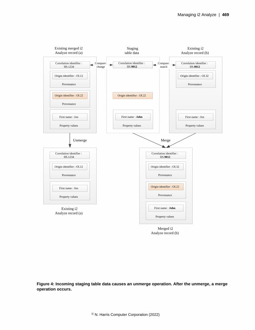
Managing i2 Analyze | 469
Existing i2 Analyze record (b)
Existing merged i2 Analyze record (a)
Staging table data
Correlation identifier : IIS.9012
Property values
First name : John
Origin identifier : OI.22
Unmerge Merge
Provenance
Origin identifier : OI.22
Correlation identifier : IIS.9012
Provenance
Origin identifier : OI.32
Property values
First name : John
Correlation identifier : IIS.9012
Provenance
Origin identifier : OI.32
Property values
First name : Jon
Compare:match
Provenance
Origin identifier : OI.22
Correlation identifier : IIS.1234
Provenance
Origin identifier : OI.12
Property values
First name : Jon
Compare:change
Correlation identifier : IIS.1234
Provenance
Origin identifier : OI.12
Property values
First name : Jon
Existing i2 Analyze record (a)
Merged i2 Analyze record (b)
Figure 4: Incoming staging table data causes an unmerge operation. After the unmerge, a mergeoperation occurs.
© N. Harris Computer Corporation (2022)
Managing i2 Analyze | 470
In the diagram, the data in the staging table that is ingested has a different correlation identifier to therecord (a) that it is currently associated with. This causes the unmerge operation. The origin identifierand provenance are unmerged from the existing record (a). The existing record (a) now only containsthe provenance for the origin identifier OI.12 and the property values from the source information thatis associated with that provenance.
The correlation identifier of the staging table data now matches with another record (b) in theInformation Store, so a merge operation occurs. In this example, it is assumed that the staging tabledata is more recent than the existing data. As part of the merge, the property values from the stagingtable row are used. This results in a change to the value for the first name property from "Jon" to "John".The merged i2 Analyze record (b) now contains two pieces of provenance, one for the origin identifierOI.32 and one for the new data, OI.22.
For more information about the behavior of a merge operation, see Merge on page 461.
Hidden circular links
As a result of a merge operation, circular links might occur in the Information Store. The InformationStore does not support circular links.
If data in the staging table causes existing records that are linked to each other in the Information Storeto merge, the link becomes circular. As part of this operation, the existing link record is hidden in theInformation Store. When a link record is hidden in the Information Store, analysts are unable to discoverthe link in search results and analysis.
A hidden link is revealed when the merged record at its ends is unmerged. After a hidden link isrevealed, analysts are able to discover the link in search results and analysis.
Define how property values of merged records are calculated
In the Information Store, each property of an i2 Analyze record can have only one value. When multiplepieces of source data contribute to an i2 Analyze record, the system must calculate a single value foreach property type.
Intended audience
The information about defining the property values of merged records is intended for users who aredatabase administrators and experienced in SQL. To define the property values, you must writecomplex SQL view definition statements.
Important: You must write and test the SQL view statements for defining the property values ofmerged records in a non-production deployment of i2 Analyze. If you create an incorrect view, you mighthave to clear all the data from the system. Before you implement your view definitions in a productionsystem, you must complete extensive testing in your development and test environments.
Why define the property values
When a record contains more than one piece of provenance, it is a merged record. The properties foran i2 Analyze record are calculated when a merge or unmerge operation occurs, or when provenance isremoved from a record.
By default, all of the property values for a record come from the source data that contributed to therecord with the most recent source-last-updated-time. If no source data has a source-last-updated-time,the property values to use are determined by the ascending order of the origin identifier keys that areassociated with the record. The source data that is last in the order is chosen.
© N. Harris Computer Corporation (2022)

Managing i2 Analyze | 471
If the default source-last-updated-time behavior does not match the requirements of your deployment,you can define how the property values are calculated for merged i2 Analyze records. You might defineyour own rules when multiple data sources contain values for different properties of an item type or onedata source is more reliable for a particular item or property type.
To demonstrate when it is useful to define how to calculate the property values for merged records,imagine that the following two pieces of source data contributed to an i2 Analyze record of type Person:
Origin identifier Correlationidentifier
Ingestion sourcename
Source lastupdated
First givenname
DVLA1234 II1 DVLA 12:20:22 09/10/2018 John
PNC5678 II1 PNC 14:10:43 09/10/2018 Jon
In the default behavior, the property values are used from the source data with the most recent valuefor the Source last updated column. The property values from the row with the ingestion source name ofPNC are used for the merged i2 Analyze record, and the record gets the value of Jon for the first givenname property.
If you know that data from the DVLA ingestion source is more reliable for this item type, you can definethat source data with the value of DVLA for the ingestion source name takes precedence. By using thisdefinition, the i2 Analyze record gets the value of John for the first given name property.
After you define this rule for the Person entity type, all future updates to the records of this item typetake the property values from the DVLA ingestion source if it is present in any of the source data thatcontributed to a merged i2 Analyze record.
For more information about how to enable this function, and create your own rules, see Defining theproperty values of merged i2 Analyze records on page 471.
Defining the property values of merged i2 Analyze records
By default, the mechanism for controlling the property values of merged records is not enabled in adeployment of i2 Analyze. To define which property values are used for merged records, you mustinform i2 Analyze that you intend to do this and then customize views in the Information Store database.
Important: You must write and test the SQL view statements for defining the property values ofmerged records in a non-production deployment of i2 Analyze. If you create an incorrect view, you mighthave to clear all the data from the system. Before you implement your view definitions in a productionsystem, you must complete extensive testing in your development and test environments.
To inform i2 Analyze that you intend to define the property values of merged records, you must run theenableMergedPropertyValues toolkit task. You can take control of the property values for recordsof specific item types, or all item types in the i2 Analyze schema.
When you run the toolkit task, two views are created for each item type that you specify. The views arecreated in the IS_Public schema, and are named with the display name of each item type. The twoviews provide the mechanism for viewing the data that contributes to the merged i2 Analyze records,and for creating rules to calculate a single value for each property:
• The view whose name is suffixed with _MCV contains all the data that contributed to each merged i2Analyze record of that item type. This is the merge contributors view. This view is designed for you toinspect the column names and property values from the data in the Information Store. You must notmodify the merge contributors view.
© N. Harris Computer Corporation (2022)
Managing i2 Analyze | 472
For more information about the merge contributors view, see The merge contributors view on page473.
• The view whose name is suffixed with _MPVDV is where you can define the rules for calculatingthe property values of merged records. This is the merged property values definition view. You canmodify this view to define how the merged property values are calculated from the data in the mergecontributors view.
When you generate the merged property values definition view, the default source-last-updated-timebehavior is implemented in the view.
For more information about modifying the definition, and some examples, see The merged propertyvalues definition view on page 475.
For example, the Person entity type from the example law enforcement schema produces theIS_Public.E_Person_MCV and IS_Public.E_Person_MPVDV views.
1. Identify the item types that you want to define the property values for.
For more information about why you might want to do this, see Define how property values ofmerged records are calculated on page 470.
2. Run the enableMergedPropertyValues toolkit task for each of the item types that you identifiedin step 1.
a) Open a command prompt and navigate to the toolkit/scripts directory.
b) Run the enableMergedPropertyValues toolkit task:For example, to create the views for the Person entity type from the example law enforcementschema, run the following command:
setup -t enableMergedPropertyValues -p schemaTypeId=ET5
You can run the toolkit task with schemaTypeId=ItemTypeId or without any arguments to createthe views for all item types in the i2 Analyze schema. You can run the task multiple times withdifferent item type identifiers.
3. Inspect the merge contributors view (_MCV) that is created in the IS_Public schema and identifyany rules to create for calculating the property values of merged records.
For more information about the merge contributors view, see The merge contributors view on page473.
4. Modify the SQL create statement for the merged property values definition view (_MPVDV) that iscreated in the IS_Public schema to create a view that implements the rules you identified in step3.
For more information about modifying the definition, and some examples, see The merged propertyvalues definition view on page 475.
After you ingest data that causes correlation operations, ensure that the property values for the mergedi2 Analyze records match your expectations by searching for them. If you can ingest data successfully,and the property values are correct in your testing, the merged property values definition view is correct.If the property values are not correct in all cases, you must continue to modify the merged propertyvalues definition view and test the results until your requirements are met.
It is recommended that you keep a backup of your complete merged property values definition view.
During the testing of your deployment, you might need to clear any test data from the system to ensurethat your view is behaving correctly. For more information, see Clearing data from the system.
© N. Harris Computer Corporation (2022)

Managing i2 Analyze | 473
You must maintain the merged property values definition view for the lifetime of your deployment. Ifyou change the i2 Analyze schema file, you must update the SQL statement for your view to matchany changes. For example, if you add a property type to an item type, the new property must be addedto the SQL statement for your merged property values definition view. You do not need to update themerge contributors view. The merge contributors view is updated when the schema is updated so thatyou can inspect the column name for the new property. For more information, see How to maintain yourmerged property values definition view on page 480.
After you test the view definition in your non-production database, you can implement the view on yourproduction database.
The merge contributors view
In the merge contributors view you can see the source data that contributes to merged i2 Analyzerecords. By inspecting the view, you can gain an understanding about the data in your system andidentify any rules to create that change the way that the property values are calculated.
To understand the merge contributors view, you must first understand the identifiers that the InformationStore and i2 Analyze records use. For more information about i2 Analyze identifiers, see Identifiers in i2Analyze records.
The merge contributors view contains the following details about each piece of source data:
item_id
Item identifiers are used to distinguish i2 Analyze records of a particular type uniquely within theInformation Store. Multiple rows in the merge contributors view can have the same item identifier.Each row that has the same item identifier represents one piece of source data that contributed tothe i2 Analyze record with that identifier.
In the merge contributors view, the item identifier is stored in the item_id column.
record_id
Record identifiers distinguish i2 Analyze records uniquely throughout the deployment. In the mergecontributors view, there is a one-to-one mapping between record identifiers and item identifiers.
In the merge contributors view, the record identifier is stored in the record_id column.
origin_id_type and origin_id_keys
The origin identifier is used to reference data in its original source. Each piece of source data has aunique origin identifier.
In the merge contributors view, the origin identifier is stored in the origin_id_type andorigin_id_keys columns.
source_last_updated
When data is ingested into the Information Store, you can provide values for when the data waslast updated in the data source from which it originated. The values in this column are used for thedefault source-last-updated-time behavior.
In the merge contributors view, the last updated time is stored in the source_last_updatedcolumn.
Property values
There is a column for each property type in the i2 Analyze schema. Each column is the displayname of the property type prefixed with p_.
© N. Harris Computer Corporation (2022)
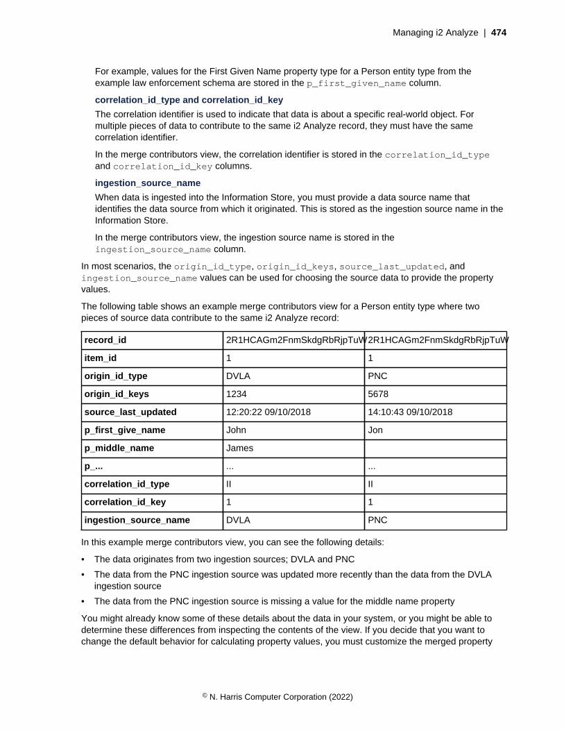
Managing i2 Analyze | 474
For example, values for the First Given Name property type for a Person entity type from theexample law enforcement schema are stored in the p_first_given_name column.
correlation_id_type and correlation_id_key
The correlation identifier is used to indicate that data is about a specific real-world object. Formultiple pieces of data to contribute to the same i2 Analyze record, they must have the samecorrelation identifier.
In the merge contributors view, the correlation identifier is stored in the correlation_id_typeand correlation_id_key columns.
ingestion_source_name
When data is ingested into the Information Store, you must provide a data source name thatidentifies the data source from which it originated. This is stored as the ingestion source name in theInformation Store.
In the merge contributors view, the ingestion source name is stored in theingestion_source_name column.
In most scenarios, the origin_id_type, origin_id_keys, source_last_updated, andingestion_source_name values can be used for choosing the source data to provide the propertyvalues.
The following table shows an example merge contributors view for a Person entity type where twopieces of source data contribute to the same i2 Analyze record:
record_id 2R1HCAGm2FnmSkdgRbRjpTuW2R1HCAGm2FnmSkdgRbRjpTuW
item_id 1 1
origin_id_type DVLA PNC
origin_id_keys 1234 5678
source_last_updated 12:20:22 09/10/2018 14:10:43 09/10/2018
p_first_give_name John Jon
p_middle_name James
p_... ... ...
correlation_id_type II II
correlation_id_key 1 1
ingestion_source_name DVLA PNC
In this example merge contributors view, you can see the following details:
• The data originates from two ingestion sources; DVLA and PNC
• The data from the PNC ingestion source was updated more recently than the data from the DVLAingestion source
• The data from the PNC ingestion source is missing a value for the middle name property
You might already know some of these details about the data in your system, or you might be able todetermine these differences from inspecting the contents of the view. If you decide that you want tochange the default behavior for calculating property values, you must customize the merged property
© N. Harris Computer Corporation (2022)

Managing i2 Analyze | 475
values definition view. For more information about how to customize the merged property valuesdefinition view, see The merged property values definition view on page 475.
The merged property values definition view
The merged property values definition view is used to calculate the property values of merged i2Analyze records. You can modify the view to define which property values records receive.
The merged property values definition view is used to calculate a single value for each property type foreach merged record.
After you inspect the merge contributors view and identify the rules that you want to define, you mustmodify the SQL statement to create a view that matches your requirements. For more information aboutthe merge contributors view, see The merge contributors view on page 473.
After you create a merged property values definition view, you must maintain the view through thelifetime of your deployment. For more information, see How to maintain your merged property valuesdefinition view on page 480.
Requirements of the view
The merged property values definition view is over the merge contributors view. To produce a singlevalue for each property type, the view must contain one row for each item_id and populate eachcolumn with a value. You can include NULL values for property types that have no value.
After you customize the merged property values definition view, it must conform to the followingrequirements:
• The view must have columns for the item identifier and every property type column in the mergecontributors view. The column names in both views must be the same.
The merged property values definition view must not contain the origin_id_type,origin_id_keys, source_last_updated, correlation_id_type, correlation_id_keys,or ingestion_source_name columns.
• Each item identifier must be unique.
Important: You cannot ingest data into the Information Store if the view contains multiple rows withthe same item identifier.
Default behavior
By default, the merged property values definition view uses the default source-last-updated-timebehavior to define which source data the property values come from. You can see the SQL statement
© N. Harris Computer Corporation (2022)

Managing i2 Analyze | 476
for the view in IBM Data Studio or SQL Server Management Studio. An example of the SQL statementfor the generated view for the Person entity from the example law enforcement schema is:
SELECT item_id, p_unique_reference, p_title,
... (all property type columns) ...
p2_issued_date_and_time, p3_issued_date_and_time
FROM
(
SELECT MCV.*,
ROW_NUMBER ( ) OVER (PARTITION BY MCV.item_id
ORDER BY source_last_updated DESC NULLS LAST,
origin_id_keys DESC,
origin_id_type DESC)
AS partition_row_number
FROM IS_Public.E_Person_MCV AS MCV
INNER JOIN IS_Public.E_Person_STP AS STP
ON MCV.item_id = STP.item_id
) AS P
WHERE partition_row_number = 1
The SQL statement for the default view works in the following way:
• To ensure that the view contains the correct columns, the first SELECT statement returns theitem_id and all property type columns. For example, p_title.
• To split the rows into groups that contain only the data that contributed to a single merged record,the OVER and PARTITION BY clauses are used on the item_id column.
• To define the value for each property, the ROW_NUMBER function and ORDER BY clauses areused. For the default behavior, the ORDER BY clause is used on the source_last_updated,origin_id_keys, and origin_id_type columns. Each column is in descending order. By usingNULLS LAST, you ensure that if the source_last_updated column does not contain a value, it islisted last.
The ROW_NUMBER function returns the number of each row in the partition. After the rows areordered, the first row is number 1. The initial SELECT statement uses a WHERE clause to select thevalues for each row with a value of 1 for partition_row_number. Because only one row has avalue of 1, the view contains only one row for each item identifier.
• When you enable merged property views by using the enableMergedPropertyViews toolkit task,a table alias for an internal staging table is also created. For example, IS_Public.E_Person_STPis the table alias for the staging table that is created during a Person item type ingestion.
During the ingestion process, the internal staging table contains the item identifiers of the records tobe inserted or updated as part of the current ingestion in the item_id column. When the propertyvalues for records are calculated by using the _MPVDV view, it uses the information in the _STPalias to restrict the number of rows that are processed. The following statement from the previousexample ensures that the _MPVDV view uses the alias for a specific item type:
INNER JOIN IS_Public.E_Person_STP AS STP
ON MCV.item_id = STP.item_id
© N. Harris Computer Corporation (2022)

Managing i2 Analyze | 477
Examples
You can modify the following example views to match the data in your i2 Analyze schema or to meetyour property value requirements:
Ingestion Source Name precedence
In this example, the data is ordered so that a specified ingestion source takes precedence. Forexample, the DVLA ingestion source takes precedence over the PNC one.
SELECT item_id, p_unique_reference, p_title,
... (all property type columns) ...
p2_issued_date_and_time, p3_issued_date_and_time
FROM (
SELECT MCV.*,
ROW_NUMBER ( ) OVER (PARTITION BY MCV.item_id
ORDER BY CASE ingestion_source_name
WHEN 'DVLA' THEN 1
WHEN 'PNC' THEN 2
ELSE 3
END
) AS partition_row_number
FROM IS_Public.E_Person_MCV AS MCV
INNER JOIN IS_Public.E_Person_STP AS STP
ON MCV.item_id = STP.item_id
) AS P
WHERE partition_row_number = 1
If an ingestion source name does not match DVLA or PNC, it is ordered last. If multiple contributingpieces of data have the same ingestion source name, the behavior is non-deterministic. In aproduction system, you must include another clause that provides deterministic ordering in allscenarios.
To order the ingestion sources, the ORDER BY CASE clause is used. The rows are ordered by thevalue that they are assigned in the CASE expression. For more information about the ORDER BYCASE statement, for Db2 see ORDER BY clause and CASE expression or for SQL Server see UsingCASE in an ORDER BY clause.
The ROW_NUMBER function and the OVER and PARTITION BY clauses are used in the same way asthe view for the default behavior.
Source last updated and non-NULL
In this example, the data is ordered by the source last updated time. However if there is a NULLvalue for a particular property type, the value is taken from the data that has the next most recenttime. This process is completed until a value for the property is found, or no data is left for thatrecord. The definitions are slightly different depending on the database management system thathosts the Information Store database.
© N. Harris Computer Corporation (2022)
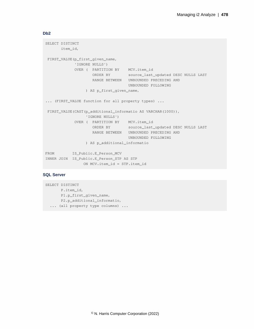
Managing i2 Analyze | 478
Db2
SELECT DISTINCT
item_id,
FIRST_VALUE(p_first_given_name,
'IGNORE NULLS')
OVER ( PARTITION BY MCV.item_id
ORDER BY source_last_updated DESC NULLS LAST
RANGE BETWEEN UNBOUNDED PRECEDING AND
UNBOUNDED FOLLOWING
) AS p_first_given_name,
... (FIRST_VALUE function for all property types) ...
FIRST_VALUE(CAST(p_additional_informatio AS VARCHAR(1000)),
'IGNORE NULLS')
OVER ( PARTITION BY MCV.item_id
ORDER BY source_last_updated DESC NULLS LAST
RANGE BETWEEN UNBOUNDED PRECEDING AND
UNBOUNDED FOLLOWING
) AS p_additional_informatio
FROM IS_Public.E_Person_MCV
INNER JOIN IS_Public.E_Person_STP AS STP
ON MCV.item_id = STP.item_id
SQL Server
SELECT DISTINCT
P.item_id,
P1.p_first_given_name,
P2.p_additional_informatio,
... (all property type columns) ...
© N. Harris Computer Corporation (2022)
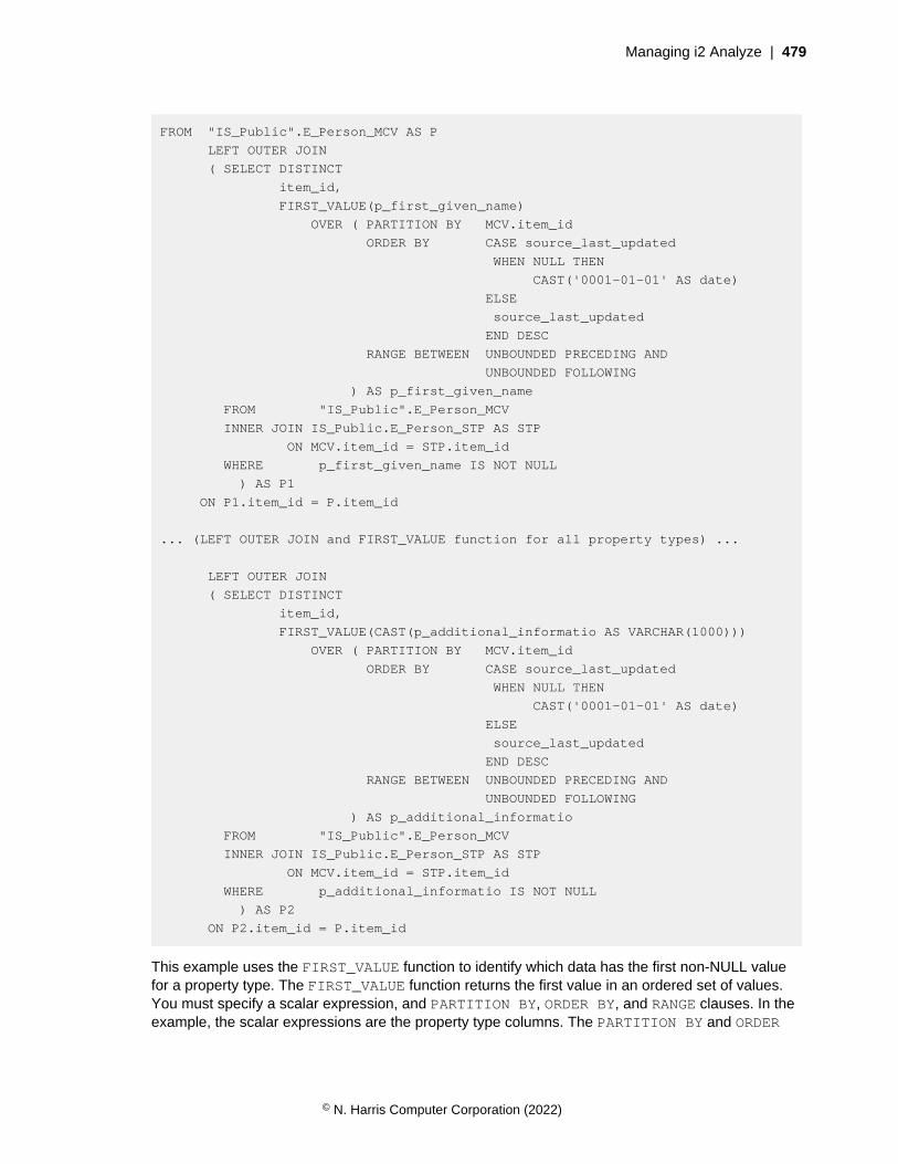
Managing i2 Analyze | 479
FROM "IS_Public".E_Person_MCV AS P
LEFT OUTER JOIN
( SELECT DISTINCT
item_id,
FIRST_VALUE(p_first_given_name)
OVER ( PARTITION BY MCV.item_id
ORDER BY CASE source_last_updated
WHEN NULL THEN
CAST('0001-01-01' AS date)
ELSE
source_last_updated
END DESC
RANGE BETWEEN UNBOUNDED PRECEDING AND
UNBOUNDED FOLLOWING
) AS p_first_given_name
FROM "IS_Public".E_Person_MCV
INNER JOIN IS_Public.E_Person_STP AS STP
ON MCV.item_id = STP.item_id
WHERE p_first_given_name IS NOT NULL
) AS P1
ON P1.item_id = P.item_id
... (LEFT OUTER JOIN and FIRST_VALUE function for all property types) ...
LEFT OUTER JOIN
( SELECT DISTINCT
item_id,
FIRST_VALUE(CAST(p_additional_informatio AS VARCHAR(1000)))
OVER ( PARTITION BY MCV.item_id
ORDER BY CASE source_last_updated
WHEN NULL THEN
CAST('0001-01-01' AS date)
ELSE
source_last_updated
END DESC
RANGE BETWEEN UNBOUNDED PRECEDING AND
UNBOUNDED FOLLOWING
) AS p_additional_informatio
FROM "IS_Public".E_Person_MCV
INNER JOIN IS_Public.E_Person_STP AS STP
ON MCV.item_id = STP.item_id
WHERE p_additional_informatio IS NOT NULL
) AS P2
ON P2.item_id = P.item_id
This example uses the FIRST_VALUE function to identify which data has the first non-NULL valuefor a property type. The FIRST_VALUE function returns the first value in an ordered set of values.You must specify a scalar expression, and PARTITION BY, ORDER BY, and RANGE clauses. In theexample, the scalar expressions are the property type columns. The PARTITION BY and ORDER
© N. Harris Computer Corporation (2022)

Managing i2 Analyze | 480
BY clauses are similar to the other examples, where they act on the item identifier and the sourcelast updated time.
In Db2, the FIRST_VALUE function allows you to ignore null values by specifying 'IGNORENULLS' in the expression. This functionality is not available in SQL Server. To achieve the sameresult, you must perform a series of LEFT OUTER JOINs for each FIRST_VALUE function. In theORDER BY CASE clause for each FIRST_VALUE function, when the value for the column in theFIRST_VALUE function is NULL you can set the source last updated time to 0001-01-01. Settingthe last updated time to this value and ordering the partition this way ensures that the row with avalue for the property and the most recent source last updated time is returned.
• For more information about the FIRST_VALUE function in Db2, see OLAP specification -FIRST_VALUE.
• For more information about the FIRST_VALUE function in SQL Server see FIRST_VALUE(Transact-SQL).
To use the FIRST_VALUE function, you must define a function for each property type separately.In the previous examples, there are two examples of the FIRST_VALUE function for two propertytypes:
• The first acts on the p_first_given_name column.
• The second acts on the p_additional_informatio column. The same process iscompleted, however in the merge contributors view the p_additional_informatio column isof data type CLOB(32M). This data type is not supported by the FIRST_VALUE function. To usethis column, you must cast it into a supported data type. For example, VARCHAR(1000). Youmust ensure that if a column is cast, that you do not lose any data.
How to maintain your merged property values definition view
The merged property values definition views include all of the property types for an item type as theywere when the view was created. If you change the i2 Analyze schema to add a property type to an itemtype, the merged property values definition view is now incorrect.
The merged property values definition view does not contain a column for the new property type, andtherefore cannot populate an i2 Analyze record with a value for that property. When you add propertytypes to the i2 Analyze schema for an item type, you must update any merged property values definitionview to include any new property types. i2 Analyze updates the merge contributors view when theschema is updated, you can use the updated merge contributors view to see the name of the newcolumn.
Note: If you do not update your merged property values definition view, you cannot ingest data into theInformation Store.
To stop controlling the property values of merged records for an item type, you can informi2 Analyze that you no longer intend to use this function. Inform i2 Analyze by running thedisableMergedPropertyValues toolkit task. You can specify schemaTypeId=ItemTypeIdto remove the views for one item type only, or without any arguments to remove the views for everyitem type in the i2 Analyze schema. After you run the toolkit task, the default source-last-updated-timebehavior is used.
You can modify the merged property values definition view or run thedisableMergedPropertyValues toolkit task at any time. The property values of i2 Analyze recordsthat are already in the Information Store are not updated. If you ingest any data that updates an existingi2 Analyze record, the property values for that record are recalculated with the new merged propertyvalues definition view.
© N. Harris Computer Corporation (2022)
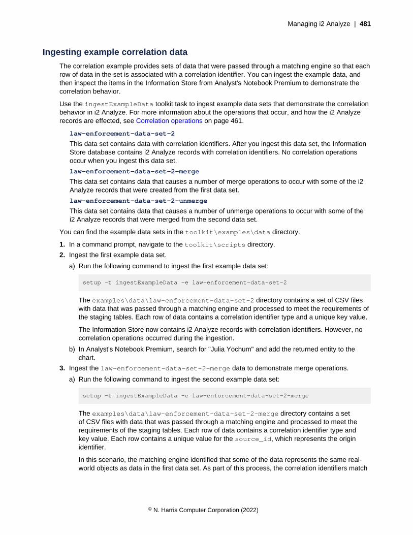
Managing i2 Analyze | 481
Ingesting example correlation data
The correlation example provides sets of data that were passed through a matching engine so that eachrow of data in the set is associated with a correlation identifier. You can ingest the example data, andthen inspect the items in the Information Store from Analyst's Notebook Premium to demonstrate thecorrelation behavior.
Use the ingestExampleData toolkit task to ingest example data sets that demonstrate the correlationbehavior in i2 Analyze. For more information about the operations that occur, and how the i2 Analyzerecords are effected, see Correlation operations on page 461.
law-enforcement-data-set-2
This data set contains data with correlation identifiers. After you ingest this data set, the InformationStore database contains i2 Analyze records with correlation identifiers. No correlation operationsoccur when you ingest this data set.
law-enforcement-data-set-2-merge
This data set contains data that causes a number of merge operations to occur with some of the i2Analyze records that were created from the first data set.
law-enforcement-data-set-2-unmerge
This data set contains data that causes a number of unmerge operations to occur with some of thei2 Analyze records that were merged from the second data set.
You can find the example data sets in the toolkit\examples\data directory.
1. In a command prompt, navigate to the toolkit\scripts directory.
2. Ingest the first example data set.
a) Run the following command to ingest the first example data set:
setup -t ingestExampleData -e law-enforcement-data-set-2
The examples\data\law-enforcement-data-set-2 directory contains a set of CSV fileswith data that was passed through a matching engine and processed to meet the requirements ofthe staging tables. Each row of data contains a correlation identifier type and a unique key value.
The Information Store now contains i2 Analyze records with correlation identifiers. However, nocorrelation operations occurred during the ingestion.
b) In Analyst's Notebook Premium, search for "Julia Yochum" and add the returned entity to thechart.
3. Ingest the law-enforcement-data-set-2-merge data to demonstrate merge operations.
a) Run the following command to ingest the second example data set:
setup -t ingestExampleData -e law-enforcement-data-set-2-merge
The examples\data\law-enforcement-data-set-2-merge directory contains a setof CSV files with data that was passed through a matching engine and processed to meet therequirements of the staging tables. Each row of data contains a correlation identifier type andkey value. Each row contains a unique value for the source_id, which represents the originidentifier.
In this scenario, the matching engine identified that some of the data represents the same real-world objects as data in the first data set. As part of this process, the correlation identifiers match
© N. Harris Computer Corporation (2022)
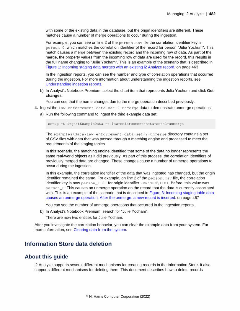
Managing i2 Analyze | 482
with some of the existing data in the database, but the origin identifiers are different. Thesematches cause a number of merge operations to occur during the ingestion.
For example, you can see on line 2 of the person.csv file the correlation identifier key isperson_0, which matches the correlation identifier of the record for person "Julia Yochum". Thismatch causes a merge between the existing record and the incoming row of data. As part of themerge, the property values from the incoming row of data are used for the record, this results inthe full name changing to "Julie Yocham". This is an example of the scenario that is described inFigure 1: Incoming staging data merges with an existing i2 Analyze record. on page 463
In the ingestion reports, you can see the number and type of correlation operations that occurredduring the ingestion. For more information about understanding the ingestion reports, seeUnderstanding ingestion reports.
b) In Analyst's Notebook Premium, select the chart item that represents Julia Yochum and click Getchanges.
You can see that the name changes due to the merge operation described previously.
4. Ingest the law-enforcement-data-set-2-unmerge data to demonstrate unmerge operations.
a) Run the following command to ingest the third example data set:
setup -t ingestExampleData -e law-enforcement-data-set-2-unmerge
The examples\data\law-enforcement-data-set-2-unmerge directory contains a setof CSV files with data that was passed through a matching engine and processed to meet therequirements of the staging tables.
In this scenario, the matching engine identified that some of the data no longer represents thesame real-world objects as it did previously. As part of this process, the correlation identifiers ofpreviously merged data are changed. These changes cause a number of unmerge operations tooccur during the ingestion.
In this example, the correlation identifier of the data that was ingested has changed, but the originidentifier remained the same. For example, on line 2 of the person.csv file, the correlationidentifier key is now person_1101 for origin identifier PER:GEN\1101. Before, this value wasperson_0. This causes an unmerge operation on the record that the data is currently associatedwith. This is an example of the scenario that is described in Figure 3: Incoming staging table datacauses an unmerge operation. After the unmerge, a new record is inserted. on page 467
You can see the number of unmerge operations that occurred in the ingestion reports.
b) In Analyst's Notebook Premium, search for "Julie Yocham".
There are now two entities for Julie Yocham.
After you investigate the correlation behavior, you can clear the example data from your system. Formore information, see Clearing data from the system.
Information Store data deletion
About this guidei2 Analyze supports several different mechanisms for creating records in the Information Store. It alsosupports different mechanisms for deleting them. This document describes how to delete records
© N. Harris Computer Corporation (2022)

Managing i2 Analyze | 483
individually, selectively, or in bulk; and it describes the circumstances in which each approach ispossible or desirable.
This guide is intended for system implementers and database administrators who want to delete datadirectly from the Information Store. It applies to data added by ingestion from one or more external datasources, and to data added by users who share information through i2 Analyst's Notebook Premium.
Note: For more information about adding data by ingestion, see Information Store data ingestion. Formore information about adding data through i2 Analyst's Notebook Premium, see Uploading records tothe Information Store.
The tasks that the following topics describe variously require familiarity with the i2 Analyze data model,your database management systems, SQL queries, and IBM Data Studio or SQL Server ManagementStudio. Some of the approaches also require specialized authorization with the Information Store.
OverviewTo comply with data protection regulations, storage restrictions, or other requirements, you mightneed to delete data from the Information Store. i2 Analyze provides mechanisms for doing so. Themechanism that you choose depends on how the records were created in the Information Store andyour reason for deleting them.
At version 4.4.0 of i2 Analyze, there are two ways to delete records from the Information Store:
• Some of the records in the Information Store are created and uploaded through Analyst's NotebookPremium. If a user deletes a record that they or a colleague uploaded, it becomes unreachable forall users, but remains in the Information Store. You can arrange to delete these soft-deleted recordspermanently, either automatically or on demand.
• For all records in the Information Store, you can write identifying rules that target them for deletionindividually or as a group. This approach deletes records no matter how they were originally createdor what their current state is.
It is common to all record deletion that deleting an entity record forces i2 Analyze to delete the linkrecords that are attached to that entity. A link must always have two ends. If one end is deleted, the linkis automatically deleted as well.
It is also common to both of these ways for deleting records from the Information Store that theprocedure is permanent. If you might need to recover the deleted data in future, ensure that you have abackup plan in place before you begin.
Note: The demands of synchronizing with the contents of an external source can also require youto delete data from the Information Store. In that situation, you can reflect deleted data in an externalsource by using the same ingestion pipeline that you use to reflect creation and modification.
For more information about updating the Information Store in this manner, see Updating the InformationStore for deleted data.
Deleting shared recordsAnalyst's Notebook Premium enables authorized users to create and delete records in the InformationStore. However, even authorized users can delete only records that they or their colleagues create, andthe operation is not immediately permanent. To delete records completely, you must interact with theInformation Store database.
When a user deletes a record in the Information Store through Analyst's Notebook Premium, the effectfor all users is instant. The record is no longer returned in the results of search or expand operations,and copies of the record on other Analyst's Notebook charts become orphaned.
© N. Harris Computer Corporation (2022)
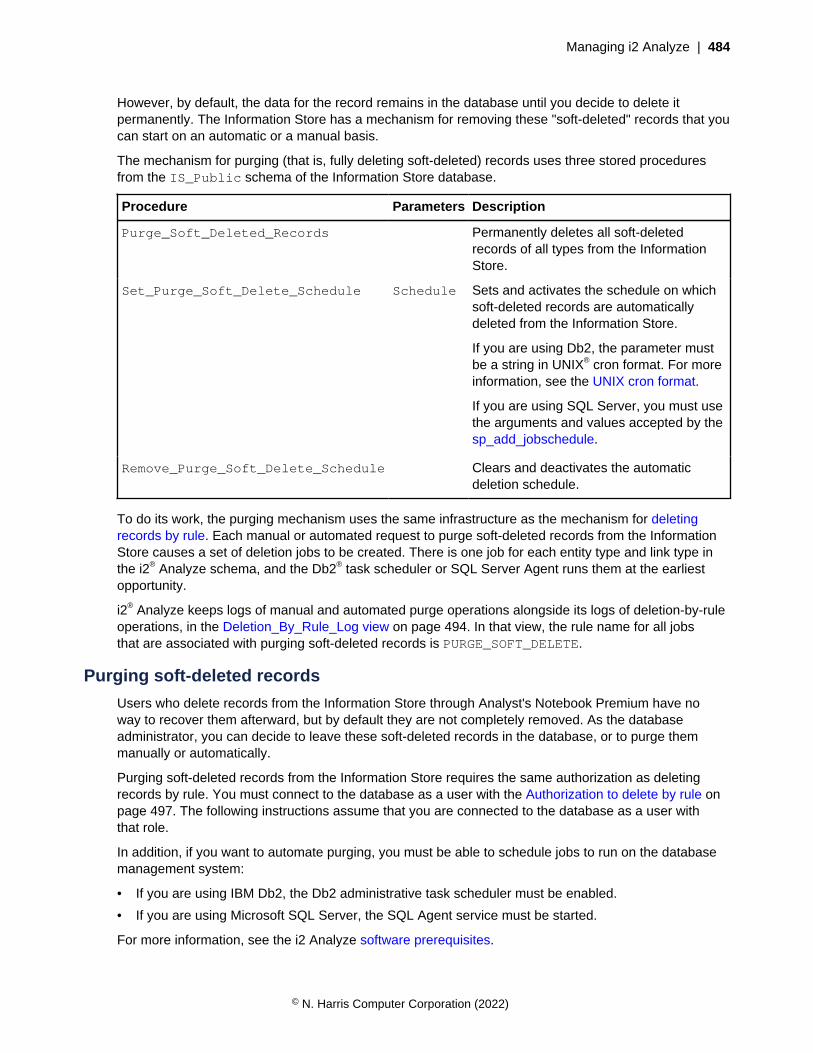
Managing i2 Analyze | 484
However, by default, the data for the record remains in the database until you decide to delete itpermanently. The Information Store has a mechanism for removing these "soft-deleted" records that youcan start on an automatic or a manual basis.
The mechanism for purging (that is, fully deleting soft-deleted) records uses three stored proceduresfrom the IS_Public schema of the Information Store database.
Procedure Parameters Description
Purge_Soft_Deleted_Records Permanently deletes all soft-deletedrecords of all types from the InformationStore.
Set_Purge_Soft_Delete_Schedule Schedule Sets and activates the schedule on whichsoft-deleted records are automaticallydeleted from the Information Store.
If you are using Db2, the parameter mustbe a string in UNIX® cron format. For moreinformation, see the UNIX cron format.
If you are using SQL Server, you must usethe arguments and values accepted by thesp_add_jobschedule.
Remove_Purge_Soft_Delete_Schedule Clears and deactivates the automaticdeletion schedule.
To do its work, the purging mechanism uses the same infrastructure as the mechanism for deletingrecords by rule. Each manual or automated request to purge soft-deleted records from the InformationStore causes a set of deletion jobs to be created. There is one job for each entity type and link type inthe i2® Analyze schema, and the Db2® task scheduler or SQL Server Agent runs them at the earliestopportunity.
i2® Analyze keeps logs of manual and automated purge operations alongside its logs of deletion-by-ruleoperations, in the Deletion_By_Rule_Log view on page 494. In that view, the rule name for all jobsthat are associated with purging soft-deleted records is PURGE_SOFT_DELETE.
Purging soft-deleted records
Users who delete records from the Information Store through Analyst's Notebook Premium have noway to recover them afterward, but by default they are not completely removed. As the databaseadministrator, you can decide to leave these soft-deleted records in the database, or to purge themmanually or automatically.
Purging soft-deleted records from the Information Store requires the same authorization as deletingrecords by rule. You must connect to the database as a user with the Authorization to delete by rule onpage 497. The following instructions assume that you are connected to the database as a user withthat role.
In addition, if you want to automate purging, you must be able to schedule jobs to run on the databasemanagement system:
• If you are using IBM Db2, the Db2 administrative task scheduler must be enabled.
• If you are using Microsoft SQL Server, the SQL Agent service must be started.
For more information, see the i2 Analyze software prerequisites.
© N. Harris Computer Corporation (2022)
Managing i2 Analyze | 485
When users delete records from the Information Store through Analyst's Notebook, the data remainsin the Information Store (but is inaccessible to users) unless you do something to change that. Thefollowing procedures describe how to purge soft-deleted records manually, how to automate thatprocess, and how to understand the effect of a purge operation.
To perform a one-off, manual purge of all soft-deleted records from the Information Store:
• Run the IS_Public.Purge_Soft_Deleted_Records stored procedure.
• For example, for Db2:
CALL IS_Public.Purge_Soft_Deleted_Records;
• For example, for SQL Server:
EXECUTE "IS_Public".Purge_Soft_Deleted_Records;
You can use this procedure regardless of whether you also configure automatic purging.
It immediately creates jobs for purging soft-deleted records of every type.
To set up the Information Store so that soft-deleted records are purged automatically, on a schedule:
• Run the IS_Public.Set_Purge_Soft_Delete_Schedule stored procedure with the schedulethat you want to use.
• For example, for Db2:
CALL IS_Public.Set_Purge_Soft_Delete_Schedule('0 0 * * *');
For more information about the format of the schedule, see UNIX cron format.
• For example, for SQL Server:
EXECUTE "IS_Public".Set_Purge_Soft_Delete_Schedule
@freq_type=4,@freq_interval=1,
@freq_subday_type=1,@active_start_time = 00000;
For more information about the arguments and values for the schedule, see sp_add_jobschedule.
Note: You must not specify values for the @job_id, @job_name, @name, @enabledarguments. i2 Analyze provides the values for these arguments.
In this example, the Information Store is configured to create the jobs that purge any soft-deletedrecords every day, at midnight.
To turn off automatic purging, call the IS_Public.Remove_Purge_Soft_Delete_Schedulestored procedure.
Regardless of whether a purge was started manually or automatically, the effect is always the same: aset of jobs is created to remove soft-deleted records from the Information Store. To inspect the statusand outcome of those jobs, you can use a view that the Information Store provides:
• In IBM Data Studio or SQL Server Management Studio, open theIS_Public.Deletion_By_Rule_Log view and look for blocks of jobs where the rule_name isPURGE_SOFT_DELETE.
For more information about the contents of the IS_Public.Deletion_By_Rule_Log view, seeDeletion_By_Rule_Log view on page 494.
© N. Harris Computer Corporation (2022)
Managing i2 Analyze | 486
Deleting records by ruleIf you need to delete records from the Information Store for policy reasons, rather than to reflect deleteoperations that happened elsewhere, you can use the deletion-by-rule mechanism. You can directlydelete any records that you select by specifying their property values and metadata.
Through deletion by rule, you can target records that match specific conditions and automate deletion tooccur regularly. Deletion can be applied consistently across all of the records in the Information Store,whether ingested from an external source or created in i2® Analyst's Notebook Premium. You can deleterecords by their source, their update time, or by any of their property values.
A deletion-by-rule operation has the following components:
• A condition specifies the particular records in the Information Store that you want to delete.
• A rule contains the condition in a form that you can store, together with a name and informationabout how you want a deletion job to be created.
• A job contains the rule and is placed in a queue to run deletion on the specified records.
For deleting records by rule, i2 Analyze provides the following procedures and views:
• Deletion views are based on the entities and links that are defined in the i2® Analyze schema. Theseviews are a simplified representation of the underlying data structures for composing conditions.
• Procedures are supplied for defining and managing deletion rules. If you want a job to be scheduledto run automatically, set the rule to be automated.
• Procedures are supplied for creating deletion jobs based on existing rules.
• Views provide a list of deletion rules, mappings between views and schema types, and a log ofdeletion jobs, status, and outcomes.
The procedures and views that are associated with deletion by rule are generated automatically whenyou deploy an Information Store or when you upgrade from an earlier version.
You can construct an SQL query that identifies the data that is to be deleted from the InformationStore. When you verify that the correct data is returned in response to the SQL query, you can use thatcondition to create a rule as a basis for a deletion job. You do not need to have a detailed understandingof the database structure. You do need a knowledge of the i2® Analyze schema. For more information,see the i2® Analyze data model documentation.
When you want to run a deletion job only once or irregularly, you can create it on a manual basis. Youmight also have deletion jobs that you want run regularly on automated basis. All automated jobs arecreated according to the same schedule and placed in a queue of jobs to run in order of their creationtime.
Running deletion-by-rule jobs on an automated basis requires the Db2® administrative task schedulerif you are using Db2®, or the SQL Server Agent to be running if you are using SQL Server. For moreinformation, see the i2® Analyze software prerequisites. You can configure the schedule for deletion-by-rule job creation according to your requirements.
Deleting data by rule
Use an SQL query to identify the data to be deleted, then create and store the deletion rule to identifythe corresponding data records for deletion. You can define the rule to specify deletion on an automatedschedule or a manual basis.
If you want to apply deletion by rule to a remote Information Store hosted on a Db2, you must catalogthe remote database by using the local IBM Db2 client. For more information, see the first note inConfiguring remote IBM Db2 database storage.
© N. Harris Computer Corporation (2022)

Managing i2 Analyze | 487
By default, deletion-by-rule privileges are granted to the Information Store database administration user.If necessary, the privileges can be granted to other users by giving them the Deletion_By_Rulerole. For more information, see Authorization to delete by rule. The privileges give you access to all thedeletion-by-rule views and procedures, as summarized in the following outline of the main tasks.
CAUTION: Grant the Deletion_By_Rule role only to users with sufficient knowledge andauthority. Use caution when you complete deletion-by-rule tasks as they constitute a powerfulmechanism for deletion of data that might be difficult to recover. Ensure that there is a reliablebackup in place before you delete by rule.
1. Identify the data to be deleted by composing and running an SQL query to select the data from thedeletion view.
You can use a different view to see details of the deletion views for your database.
2. Check the SQL results to confirm that the selected data is as you expected.
You can use the condition in subsequent steps to identify the particular records in the InformationStore that you want to be deleted.
3. Create a deletion rule based on the SQL query you verified at step 2 by using the supplied storedprocedure.
By default when a rule is created, automated job creation is switched off. You can use another viewto see a list of rules and their automation status.
4. Create a deletion job manually by using the supplied stored procedure.
The procedure creates a deletion job that contains the rule, which is queued to run.
5. Check the status of the job, and that deletion occurred as you expected, by consulting theIS_Public.Deletion_By_Rule_Log view.
For more information, see Verifying deletion by rule.
6. Optional: Automate deletion by rule by using the supplied stored procedure to include the rule inautomated job creation.
Identifying the data
How you compose a rule to delete data from the Information Store varies according to the structure andcontent of your database. The first step is to understand what you need to delete, and then create anSQL query that selects that data from the deletion views.
Use the deletion views as a basis to create and validate an SQL query that selects the data you want todelete. For more information, see Deletion views and columns on page 491.
You can complete this task in IBM Data Studio or Microsoft SQL Server Management Studio.
1. Connect to your database as a user with the Deletion_By_Rule role.
2. By using the data in a deletion view, identify the criteria that you can use to delete specific data.
3. Create your SQL query.For example, based on the deletion view IS_Public.E_Event_DV, create a query that returns allevent entities where the last update in the source data was more than three years ago:
• For Db2:
SELECT *
FROM IS_Public.E_Event_DV
WHERE source_last_updated < CURRENT_DATE -3 YEARS
© N. Harris Computer Corporation (2022)

Managing i2 Analyze | 488
• For SQL Server:
SELECT *
FROM "IS_Public".E_Event_DV
WHERE source_last_updated < DATE_ADD(yyyy, -3, GETDATE())
4. Verify that the data that is returned from your SQL query is the data that you want to delete.
Create a deletion rule based on your query. For more information, see Creating a deletion rule.
Creating a deletion rule
Use a valid SQL query as a basis for a deletion rule. Store the corresponding deletion rule for use in thedeletion process.
Verify the condition that you need for the deletion rule by creating an SQL query that returns theappropriate data. For more information, see Identifying the data.
1. Connect to your database as a user with the Deletion_By_Rule role.
2. Run the IS_Public.Create_Deletion_Rule stored procedure. You must specify the mandatoryparameter values for the stored procedure.
a) To give the rule a name by which it can be identified, enter a unique name in Rule_Name.
Rule names are not case-sensitive.
b) To identify the deletion view that the rule targets, enter the name in View_Name.
Enter the view name without the IS.Public schema name prefix.
c) Enter the WHERE clause conditions from your SQL query in Conditions.
Enter the code that follows the WHERE keyword in the SQL query.
For example, see the sample parameter values in the following table. Mandatory values are markedwith an asterisk.
Table 5: Sample parameter values for creating a rule
Name Type Value
Rule_Name* VARCHAR(50) OLD EVENTS
View_Name* VARCHAR(128) E_Event_DV
Conditions VARCHAR(1000) source_last_updated < CURRENT_DATE -3 YEARS
Running this procedure does not run the rule. However, the rule is validated to inform you of anyerrors. If the rule has no conditions, you receive a warning message to ensure that you are aware ofthe consequences when you do create a deletion job based on the rule
CAUTION: When a job is created from a rule that has no conditions, it deletes every recordin the view.
To review the rule, browse the data in the IS_Public.Deletion_Rules view. For example, see thefollowing rule details.
© N. Harris Computer Corporation (2022)

Managing i2 Analyze | 489
Table 6: Sample listing of a deletion rule
rule_name view_name conditions automated
OLD EVENTS E_Event_DV source_last_updated <CURRENT_DATE -3 YEARS
N
By default, the rule is set up so that you can use it to create jobs manually. For more information,see Creating a deletion job on page 489. You can also configure the rule so that jobs are createdautomatically, according to a schedule. For more information, see Automating deletion by rule.
You can update a stored rule by a procedure similar to rule creation, or use a procedure to delete a rule.For more information, see Stored procedures on page 493.
Creating a deletion job
Creating a rule stores it with a name that you can use to refer to it later. To delete records that matchthe rule, you must create a deletion job.
Create a deletion rule. For more information, see Creating a deletion rule.
When you create a job, the rule is placed in the job queue and initially has a status of Pending. At 10-second intervals, i2 Analyze checks for deletion jobs to run.
Note: Do not run a deletion job while data is being ingested into the Information Store.
1. Connect to your database as a user with the Deletion_By_Rule role.
2. To create the deletion job, run the IS_Public.Create_Deletion_Job stored procedure andenter the name of the rule.
You can check the status of the job in the IS_Public.Deletion_By_Rule_Log view. For moreinformation, see Verifying deletion by rule.
You can automate the rule for deletion on a schedule. For more information, see Automating deletion byrule on page 490.
Verifying deletion by rule
You can verify the outcome of each deletion-by-rule job by consulting theIS_Public.Deletion_By_Rule_Log view. The status indicates whether an instance of deletionbased on a rule is pending, succeeded, or failed.
1. Connect to your database as a user with the Deletion_By_Rule role.
2. To verify the status of deletion jobs, browse the data in the IS_Public.Deletion_By_Rule_Logview.
3. Find the rule and job that you are interested in. You can use the rule_name andjob_creation_time columns to do find the rule.
4. Verify the status or the outcome of the deletion process in the status column.
For more information about the contents of the log, see Deletion_By_Rule_Log view on page 494.
When the job status is Succeeded, you can browse the data in the deletion view for indications that theeffect of the job on the database is as expected. Alternatively, you can run the SQL statement and verifythat there are no matching records.
When the job fails, the job status indicates an error. For more information, see Troubleshooting on page490.
© N. Harris Computer Corporation (2022)
Managing i2 Analyze | 490
Automating deletion by rule
By default, new deletion rules are configured so that you can create deletion jobs manually. You canconfigure each rule so that deletion jobs are created automatically according to a schedule.
Running deletion-by-rule jobs on an automated basis requires the Db2® administrative task schedulerif you are using Db2®, or the SQL Server Agent to be running if you are using SQL Server. For moreinformation, see the i2® Analyze software prerequisites.
When you automate a deletion rule, it is included in a deletion job that is created by a scheduled task.i2 Analyze processes in sequence all the jobs that are in the queue whether created manually orautomatically.
To automate a rule, complete the following steps.
Note: Do not run a deletion job while data is being ingested into the Information Store. For moreinformation about the deletion-by-rule job schedule, see Changing the automated job creation scheduleon page 496.
1. Connect to your database as a user with the Deletion_By_Rule role.
2. Run the IS_Public.Automate_Deletion_Rule stored procedure and enter the name of therule.
The automated flag for the rule is changed from N to Y.
3. To view the rule details and confirm an automated setting, browse the data in theIS_Public.Deletion_Rules view.
At the time when automated deletion by rule is scheduled, a job is created for each rule that is set toautomated. Each job is queued and runs in sequence.
You can check the status of the job in the IS_Public.Deletion_By_Rule_Log view. For moreinformation, see Verifying deletion by rule on page 489.
You can configure the schedule for deletion-by-rule job creation according to your requirements. Formore information, see Changing the automated job creation schedule on page 496.
To disable automated deletion for a rule, run the procedure IS_Public.Disable_Deletion_Ruleand enter the rule name.
Troubleshooting
When a deletion by rule job is completed, information that indicates success or failure issent to the IS_Public.Deletion_By_Rule_Log view. More details are recorded in theIS_Public.Ingestion_Deletion_Reports view.
You can see the status of all deletion-by-rule jobs in the IS_Public.Deletion_By_Rule_Log view.For more information, see Verifying deletion by rule on page 489.
If the value of status is not Succeeded, the type of error that is recorded informs your diagnosis andtroubleshooting steps. The possible status values, explanations, and steps to take for each value aredescribed as follows.
Pending: status unchanged after a significant amount of time
1. Check other jobs in the IS_Public.Deletion_By_Rule_Log view to see whether there is abacklog due to the number and complexity of jobs; or jobs are not being processed as expected anda significant amount of time has elapsed since the most recent job was processed.
© N. Harris Computer Corporation (2022)

Managing i2 Analyze | 491
2. Check whether the server is running. You might need to restart the server. For more information, seeDeploying i2® Analyze.
3. Check whether the server is connected to the database. There might be a network issue. You canfind the Opal server logs here: i2\i2analyze\deploy\wlp\usr\servers\opal-server\logs
If you are applying deletion by rule to a remote Information Store on Db2, the remote database must becataloged by using the local Db2® client. If the configuration files are not already updated, complete theupdate by using the toolkit. For more information, see Configuring remote IBM® Db2® database storage.
If you are using IBM Db2 and none of the previous steps resolve the issue, there might be aproblem with the Administrative Task Scheduler or Db2. For more information, see Troubleshootingadministrative task scheduler.
Server error
1. To assess the extent of the problem, in the IS_Public.Deletion_By_Rule_Log view, check thereject_count value to see the number of items that are rejected.
2. Access the IS_Public.Ingestion_Deletion_Reports view for more information. A specificdeletion job can be identified by the job_id value, which is identical to the job_id value in theIS_Public.Deletion_By_Rule_Log view.
Note: Deletion-by-rule automatically populates the label column in theIS_Public.Ingestion_Deletion_Reports view with the value Deletion rule:<Deletion RuleName>.
Deletion views and columns
Deploying i2 Analyze automatically generates a set of deletion views in the IS_Public schema that ispart of the Information Store. Using the views, you can browse the record data and write SQL queriesthat select records for deletion.
Use the IS_Public.Deletion_View_Lookup view to determine the deletion view names in yourInformation Store. You can also use the view to understand how the deletion views relate to the schematype IDs. The following table contains some examples.
Table 7: Extract from a sample Deletion_View_Lookup view
Schema type identifier Display name Deletion view name
ET2 Event E_Event_DV
ET5 Person E_Person_DV
ET8 Communications device E_Communications_Device_DV
ET10 Account E_Account_DV
LCO1 Communication L_Communication_DV
LAS1 Associate L_Associate_DV
LAC1 Access To L_Access_To_DV
There is a deletion view for each record type. Each of these views has a suffix of _DV. Prefixes of E_and L_ are used for entities and links. In IBM Data Studio or SQL Server Management Studio, you canexpand a view to see its columns.
© N. Harris Computer Corporation (2022)

Managing i2 Analyze | 492
Any columns with a prefix of P_ contain values of properties that are defined in the i2 Analyze schema.The other columns contain metadata values that it might be useful to base rules on. Each view hascolumns for property values, which vary by item type, and columns for metadata values that arecommon to all records. The following table contains some examples of property columns.
Table 8: Sample extract of deletion views and properties from an IS_Public schema
Deletion view name Column name Sample value
E_Person_DV p_unique_referencep_date_of_birthp_gender...
P86539K1932-10-14Male...
L_Access_To_DV p_unique_referencep_type_of_use...
ADC153Account Holder...
Metadata columns can be useful for creating deletion rule conditions. All deletion views have a commonset of metadata columns as described in the following table.
Table 9: Metadata columns that are common across deletion views
Column name Description
record_id The record identifier that distinguishes the i2 Analyze record uniquelythroughout the deployment
item_id The item identifier that distinguishes i2 Analyze records of a particulartype within the Information Store
last_update_time The timestamp of the most recent i2 Analyze data ingestion
create_time The timestamp that i2 Analyze assigned at the point of creation of therecord
source_names The names of the sources of the data
source_created The timestamp from the external source for the creation of the data
source_last_updated The timestamp from the external source for the last update of the data
Note:
• In the Information Store, there is a one-to-one mapping between record identifiers and itemidentifiers. For more information about the identifiers that are used in i2 Analyze, see Identifiers in i2Analyze records.
• Records that are created through i2 Analyst's Notebook have a value of ANALYST in thesource_names column and null values for source_created and source_last_updated.
Views that represent link types have a few extra metadata columns as described in the following table.
© N. Harris Computer Corporation (2022)
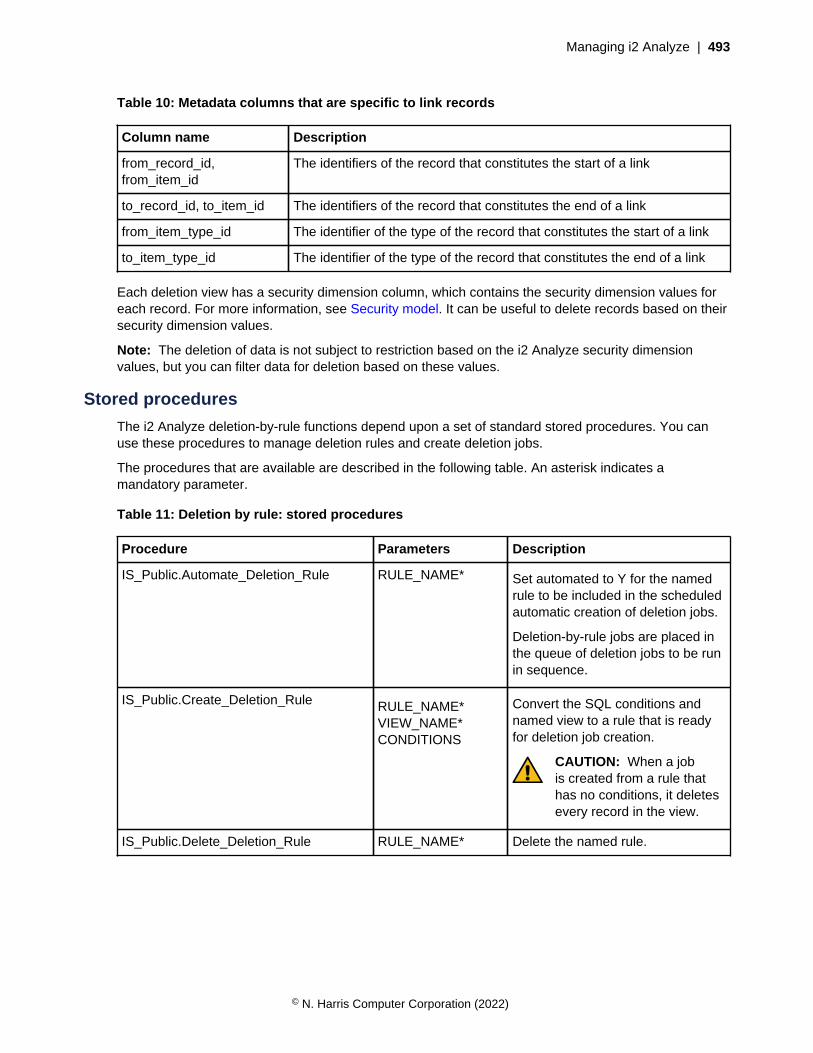
Managing i2 Analyze | 493
Table 10: Metadata columns that are specific to link records
Column name Description
from_record_id,from_item_id
The identifiers of the record that constitutes the start of a link
to_record_id, to_item_id The identifiers of the record that constitutes the end of a link
from_item_type_id The identifier of the type of the record that constitutes the start of a link
to_item_type_id The identifier of the type of the record that constitutes the end of a link
Each deletion view has a security dimension column, which contains the security dimension values foreach record. For more information, see Security model. It can be useful to delete records based on theirsecurity dimension values.
Note: The deletion of data is not subject to restriction based on the i2 Analyze security dimensionvalues, but you can filter data for deletion based on these values.
Stored procedures
The i2 Analyze deletion-by-rule functions depend upon a set of standard stored procedures. You canuse these procedures to manage deletion rules and create deletion jobs.
The procedures that are available are described in the following table. An asterisk indicates amandatory parameter.
Table 11: Deletion by rule: stored procedures
Procedure Parameters Description
IS_Public.Automate_Deletion_Rule RULE_NAME* Set automated to Y for the namedrule to be included in the scheduledautomatic creation of deletion jobs.
Deletion-by-rule jobs are placed inthe queue of deletion jobs to be runin sequence.
IS_Public.Create_Deletion_Rule RULE_NAME*VIEW_NAME*CONDITIONS
Convert the SQL conditions andnamed view to a rule that is readyfor deletion job creation.
CAUTION: When a jobis created from a rule thathas no conditions, it deletesevery record in the view.
IS_Public.Delete_Deletion_Rule RULE_NAME* Delete the named rule.
© N. Harris Computer Corporation (2022)
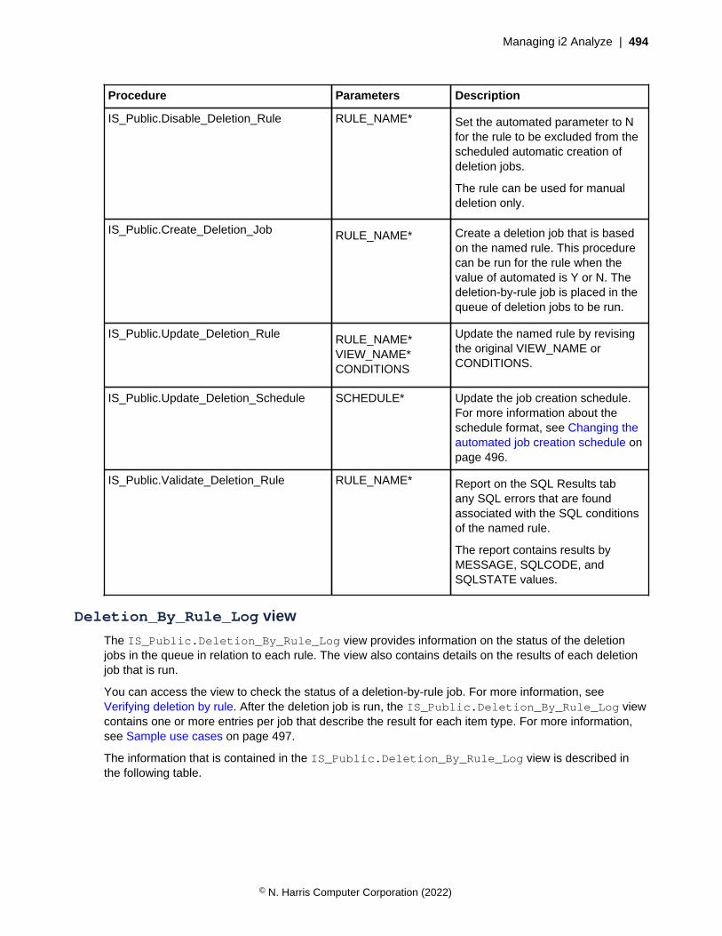
Managing i2 Analyze | 494
Procedure Parameters Description
IS_Public.Disable_Deletion_Rule RULE_NAME* Set the automated parameter to Nfor the rule to be excluded from thescheduled automatic creation ofdeletion jobs.
The rule can be used for manualdeletion only.
IS_Public.Create_Deletion_Job RULE_NAME* Create a deletion job that is basedon the named rule. This procedurecan be run for the rule when thevalue of automated is Y or N. Thedeletion-by-rule job is placed in thequeue of deletion jobs to be run.
IS_Public.Update_Deletion_Rule RULE_NAME*VIEW_NAME*CONDITIONS
Update the named rule by revisingthe original VIEW_NAME orCONDITIONS.
IS_Public.Update_Deletion_Schedule SCHEDULE* Update the job creation schedule.For more information about theschedule format, see Changing theautomated job creation schedule onpage 496.
IS_Public.Validate_Deletion_Rule RULE_NAME* Report on the SQL Results tabany SQL errors that are foundassociated with the SQL conditionsof the named rule.
The report contains results byMESSAGE, SQLCODE, andSQLSTATE values.
Deletion_By_Rule_Log view
The IS_Public.Deletion_By_Rule_Log view provides information on the status of the deletionjobs in the queue in relation to each rule. The view also contains details on the results of each deletionjob that is run.
You can access the view to check the status of a deletion-by-rule job. For more information, seeVerifying deletion by rule. After the deletion job is run, the IS_Public.Deletion_By_Rule_Log viewcontains one or more entries per job that describe the result for each item type. For more information,see Sample use cases on page 497.
The information that is contained in the IS_Public.Deletion_By_Rule_Log view is described inthe following table.
© N. Harris Computer Corporation (2022)

Managing i2 Analyze | 495
Table 12: IS_Public.Deletion_By_Rule_Log view columns
Column name Description
status Status of the deletion by rule job:
• Succeeded
• Pending
• Server error
• Validation error
rule_name Name of the deletion rule.
view_name Name of the view that the rule is targeting.
conditions Deletion conditions that are applied by the rule.
job_id Identifier for the job, which is also used to identify the job in thejob_id column of the Ingestion_Deletion_Reports view.
job_creation_time Time stamp that indicates when the deletion by rule job wascreated.
job_run_time Time stamp that indicates when the deletion by rule job was runand corresponds to the value in the start_time_stamp columnof the Ingestion_Deletion_Reports view. There is no valuein the job_run_time column while the job is pending.
item_type Item type of the records that were deleted. There can be morethan one entry in this view for the same job. For example, deletingentity records can also cause link records to be deleted.
delete_count The number of records that are deleted.
reject_count The number of records that are rejected.
Example of job results logged
See the following tables for an example of how the IS_Public.Deletion_By_Rule_Log view mightlook with completed job details.
Table 13: IS_Public.Deletion_By_Rule_Log job details (part 1)
status rule_name view_name conditions
Succeeded OLDACCOUNTS
E_Account_DV p_date_opened < CURRENT_DATE - 50 YEARS
Succeeded OLDACCOUNTS
E_Account_DV p_date_opened < CURRENT_DATE - 50 YEARS
© N. Harris Computer Corporation (2022)
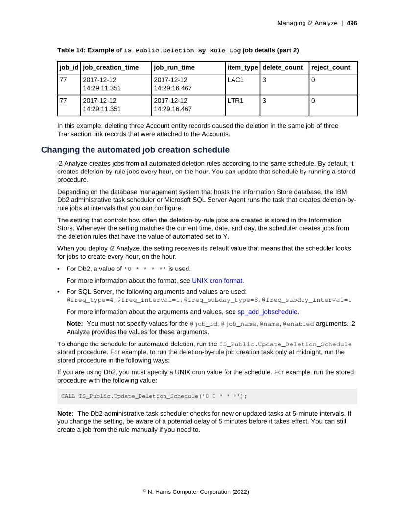
Managing i2 Analyze | 496
Table 14: Example of IS_Public.Deletion_By_Rule_Log job details (part 2)
job_id job_creation_time job_run_time item_type delete_count reject_count
77 2017-12-1214:29:11.351
2017-12-1214:29:16.467
LAC1 3 0
77 2017-12-1214:29:11.351
2017-12-1214:29:16.467
LTR1 3 0
In this example, deleting three Account entity records caused the deletion in the same job of threeTransaction link records that were attached to the Accounts.
Changing the automated job creation schedule
i2 Analyze creates jobs from all automated deletion rules according to the same schedule. By default, itcreates deletion-by-rule jobs every hour, on the hour. You can update that schedule by running a storedprocedure.
Depending on the database management system that hosts the Information Store database, the IBMDb2 administrative task scheduler or Microsoft SQL Server Agent runs the task that creates deletion-by-rule jobs at intervals that you can configure.
The setting that controls how often the deletion-by-rule jobs are created is stored in the InformationStore. Whenever the setting matches the current time, date, and day, the scheduler creates jobs fromthe deletion rules that have the value of automated set to Y.
When you deploy i2 Analyze, the setting receives its default value that means that the scheduler looksfor jobs to create every hour, on the hour.
• For Db2, a value of '0 * * * *' is used.
For more information about the format, see UNIX cron format.
• For SQL Server, the following arguments and values are used:@freq_type=4,@freq_interval=1,@freq_subday_type=8,@freq_subday_interval=1
For more information about the arguments and values, see sp_add_jobschedule.
Note: You must not specify values for the @job_id, @job_name, @name, @enabled arguments. i2Analyze provides the values for these arguments.
To change the schedule for automated deletion, run the IS_Public.Update_Deletion_Schedulestored procedure. For example, to run the deletion-by-rule job creation task only at midnight, run thestored procedure in the following ways:
If you are using Db2, you must specify a UNIX cron value for the schedule. For example, run the storedprocedure with the following value:
CALL IS_Public.Update_Deletion_Schedule('0 0 * * *');
Note: The Db2 administrative task scheduler checks for new or updated tasks at 5-minute intervals. Ifyou change the setting, be aware of a potential delay of 5 minutes before it takes effect. You can stillcreate a job from the rule manually if you need to.
© N. Harris Computer Corporation (2022)

Managing i2 Analyze | 497
If you are using SQL Server, you must specify arguments for the sp_add_jobschedule storedprocedure. For example, run the stored procedure with the following value:
EXECUTE "IS_Public".Update_Deletion_Schedule
@freq_type=4,@freq_interval=1,
@freq_subday_type=8,@freq_subday_interval=24;
Note: If you are using Db2 and you follow this procedure in a deployment that provides high availability,you must run the stored procedure on the primary and any standby database instances.
Authorization to delete by rule
The deletion-by-rule capability is enabled by the i2 Analyze Information Store deployment. By defaultthe database user who deploys the Information Store is authorized to delete by rule.
Authorization to delete by rule includes permission to access and run all of the views and procedures fordoing so in the IS_Public schema. For more information, see Deletion views and columns on page491 and Stored procedures on page 493. If you do not have this authorization, you can see but notaccess or run these views and procedures.
The authorization to delete by rule can be granted to other users. You can create a new database userand assign the Deletion_By_Rule role to that user, or you can assign the role to an existing user.
For example, you can run the following statement for Db2:
GRANT ROLE Deletion_By_Rule TO USER deletion_user
You can run the following statement for SQL Server:
ALTER SERVER ROLE Deletion_By_Rule ADD MEMBER deletion_user
CAUTION: Assign the Deletion_By_Rule role only to users with sufficient knowledgeand authority. Exercise caution when you create deletion rules as they constitute a powerfulmechanism for deletion of data that cannot be recovered afterward.
Sample use cases
Stored data might be monitored for compliance with international standards, corporate regulations, orstorage volume restrictions. Depending on the use case, different rules can be created to meet manydifferent kinds of requirement.
Reasons for data deletion often fall into one or more of the following categories:
• Data is out of date
• Data is obsolete or irrelevant in the context of the purpose of the database
• Data has data privacy or security issues
• Data reaches a storage volume threshold
The SQL statements in the following examples contain the kinds of conditions that are commonly usedas a basis for deletion.
Note: If you are using Db2, when you are creating SQL for time-based conditions you can use thefollowing documentation on date and time arithmetic support. For more information, see Datetimeoperations and durations.
© N. Harris Computer Corporation (2022)
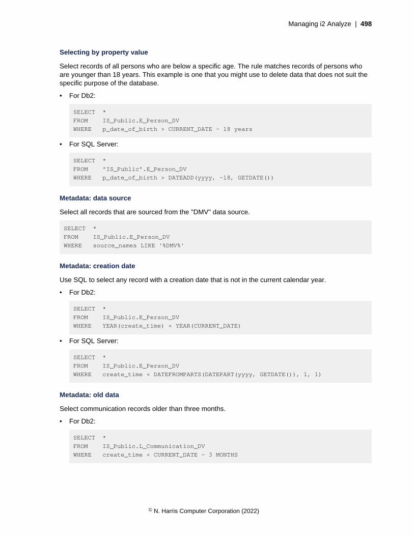
Managing i2 Analyze | 498
Selecting by property value
Select records of all persons who are below a specific age. The rule matches records of persons whoare younger than 18 years. This example is one that you might use to delete data that does not suit thespecific purpose of the database.
• For Db2:
SELECT *
FROM IS_Public.E_Person_DV
WHERE p_date_of_birth > CURRENT_DATE - 18 years
• For SQL Server:
SELECT *
FROM "IS_Public".E_Person_DV
WHERE p_date_of_birth > DATEADD(yyyy, -18, GETDATE())
Metadata: data source
Select all records that are sourced from the "DMV" data source.
SELECT *
FROM IS_Public.E_Person_DV
WHERE source_names LIKE '%DMV%'
Metadata: creation date
Use SQL to select any record with a creation date that is not in the current calendar year.
• For Db2:
SELECT *
FROM IS_Public.E_Person_DV
WHERE YEAR(create_time) < YEAR(CURRENT_DATE)
• For SQL Server:
SELECT *
FROM IS_Public.E_Person_DV
WHERE create_time < DATEFROMPARTS(DATEPART(yyyy, GETDATE()), 1, 1)
Metadata: old data
Select communication records older than three months.
• For Db2:
SELECT *
FROM IS_Public.L_Communication_DV
WHERE create_time < CURRENT_DATE - 3 MONTHS
© N. Harris Computer Corporation (2022)

Managing i2 Analyze | 499
• For SQL Server:
SELECT *
FROM IS_Public.L_Communication_DV
WHERE create_time < DATEADD(mm, -3, GETDATE())
Without the specified link
This case is an example where you require deletion of entities that are not linked to other entities. Youmight want this type of deletion as a general database cleanup, or to target links of a specific type, forexample those granting access to a building or an account. Select records of people who do not haveany access links.
The rule matches records of people when the item_id is not contained in a from_item_id column inthe link deletion view. When your rule joins to another deletion view, it is recommended that you identifyrecords by using the item_id columns.
SELECT *
FROM IS_Public.E_Person_DV
WHERE item_id NOT IN (
SELECT from_item_id
FROM IS_Public.L_Access_To_DV
)
With the specified links
Select records of any person who is associated with a person named 'Michael Wilson'.
When your rule joins to another deletion view, it is recommended that you identify records by using theitem_id columns.
SELECT *
FROM IS_Public.E_Person_DV
WHERE item_id IN (
SELECT A.from_item_id
FROM IS_Public.L_Associate_DV AS A
INNER JOIN IS_Public.E_Person_DV AS P
ON P.item_id = A.to_item_id
WHERE P.p_first_given_name = 'Michael' AND
P.p_family_name = 'Wilson'
)
Data source, property, and timeframe
This case is an example of the kind of deletion that might be used to clean up a database or reducestorage requirements. Select records from a specific source based on when the last update occurred.The rule matches records of people with the named data source and an update date that is older thanthree years from the current date.
© N. Harris Computer Corporation (2022)

Managing i2 Analyze | 500
• For Db2:
SELECT *
FROM IS_Public.E_Person_DV
WHERE source_names LIKE '%LawEnforcementDB%' AND
source_last_updated < CURRENT_DATE - 3 YEARS
• For SQL Server:
SELECT *
FROM IS_Public.E_Person_DV
WHERE source_names LIKE '%LawEnforcementDB%' AND
source_last_updated < DATEADD(yyyy, -3, GETDATE())
Retrieving chart metadatai2 Analyze enables database administrators and third-party extensions to retrieve information aboutcharts that users upload to the Information Store or the Chart Store. Specifically, you can find out whichusers have uploaded a particular chart, and when that chart was last accessed.
Note: In this context, "accessed" refers to when the chart was uploaded, downloaded, or had itsdetails (that is, its history) requested by a user.
With this knowledge, you might implement a policy such that charts that haven't been accessed for acertain period of time are automatically deleted - but only after you Sending alerts to i2 Analyze users onpage 501 to all the users who uploaded the chart to warn them.
Determining when a chart was last accessedTo determine when a chart was last accessed, you can query the chart deletion view, whosename has the following format: IS_Public.<ChartTableName>_DV. Provided that theitem type in the i2 Analyze schema that represents charts has not been modified, its name isIS_Public.E_Analyst_S_Notebook_Ch_DV.
This view has the same structure as other deletion views, but with two extra columns:
Column name Description
chart_type The type of the chart - that is, web or desktop
last_seen_time The (UTC) date and time when the chart was lastaccessed
For this purpose, the last_seen_time column is pertinent. To determine which charts have not beenaccessed for approximately 12 months, you might execute the following (Db2) SQL statement:
SELECT item_id
FROM IS_Public.E_Analyst_S_Notebook_Ch_DV
WHERE last_seen_time < NOW() - 12 MONTHS;
You can then use the list of identifiers that this statement returns to find out which users need to benotified.
© N. Harris Computer Corporation (2022)
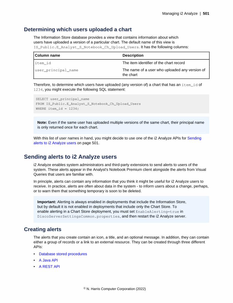
Managing i2 Analyze | 501
Determining which users uploaded a chartThe Information Store database provides a view that contains information about whichusers have uploaded a version of a particular chart. The default name of this view isIS_Public.E_Analyst_S_Notebook_Ch_Upload_Users. It has the following columns:
Column name Description
item_id The item identifier of the chart record
user_principal_name The name of a user who uploaded any version ofthe chart
Therefore, to determine which users have uploaded (any version of) a chart that has an item_id of1234, you might execute the following SQL statement:
SELECT user_principal_name
FROM IS_Public.E_Analyst_S_Notebook_Ch_Upload_Users
WHERE item_id = 1234;
Note: Even if the same user has uploaded multiple versions of the same chart, their principal nameis only returned once for each chart.
With this list of user names in hand, you might decide to use one of the i2 Analyze APIs for Sendingalerts to i2 Analyze users on page 501.
Sending alerts to i2 Analyze usersi2 Analyze enables system administrators and third-party extensions to send alerts to users of thesystem. These alerts appear in the Analyst's Notebook Premium client alongside the alerts from VisualQueries that users are familiar with.
In principle, alerts can contain any information that you think it might be useful for i2 Analyze users toreceive. In practice, alerts are often about data in the system - to inform users about a change, perhaps,or to warn them that something temporary is soon to be deleted.
Important: Alerting is always enabled in deployments that include the Information Store,but by default it is not enabled in deployments that include only the Chart Store. Toenable alerting in a Chart Store deployment, you must set EnableAlerting=true inDiscoServerSettingsCommon.properties, and then restart the i2 Analyze server.
Creating alertsThe alerts that you create contain an icon, a title, and an optional message. In addition, they can containeither a group of records or a link to an external resource. They can be created through three differentAPIs:
• Database stored procedures
• A Java API
• A REST API
© N. Harris Computer Corporation (2022)
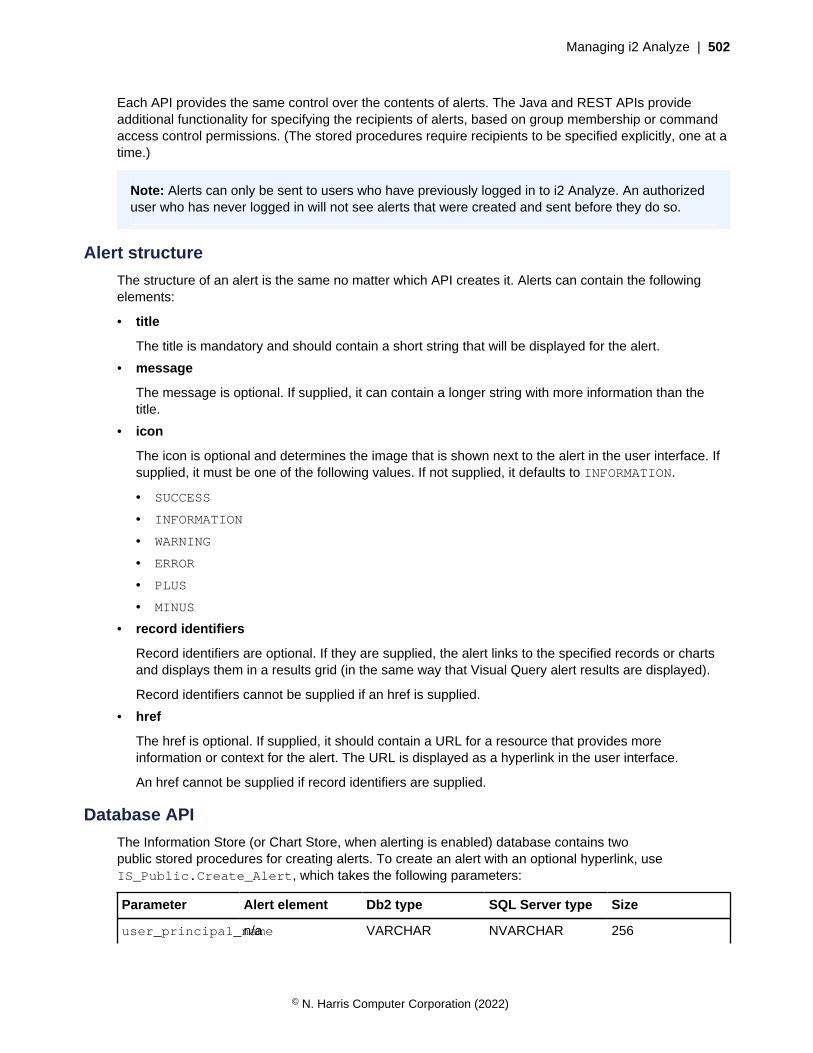
Managing i2 Analyze | 502
Each API provides the same control over the contents of alerts. The Java and REST APIs provideadditional functionality for specifying the recipients of alerts, based on group membership or commandaccess control permissions. (The stored procedures require recipients to be specified explicitly, one at atime.)
Note: Alerts can only be sent to users who have previously logged in to i2 Analyze. An authorizeduser who has never logged in will not see alerts that were created and sent before they do so.
Alert structure
The structure of an alert is the same no matter which API creates it. Alerts can contain the followingelements:
• title
The title is mandatory and should contain a short string that will be displayed for the alert.
• message
The message is optional. If supplied, it can contain a longer string with more information than thetitle.
• icon
The icon is optional and determines the image that is shown next to the alert in the user interface. Ifsupplied, it must be one of the following values. If not supplied, it defaults to INFORMATION.
• SUCCESS
• INFORMATION
• WARNING
• ERROR
• PLUS
• MINUS
• record identifiers
Record identifiers are optional. If they are supplied, the alert links to the specified records or chartsand displays them in a results grid (in the same way that Visual Query alert results are displayed).
Record identifiers cannot be supplied if an href is supplied.
• href
The href is optional. If supplied, it should contain a URL for a resource that provides moreinformation or context for the alert. The URL is displayed as a hyperlink in the user interface.
An href cannot be supplied if record identifiers are supplied.
Database API
The Information Store (or Chart Store, when alerting is enabled) database contains twopublic stored procedures for creating alerts. To create an alert with an optional hyperlink, useIS_Public.Create_Alert, which takes the following parameters:
Parameter Alert element Db2 type SQL Server type Size
user_principal_namen/a VARCHAR NVARCHAR 256
© N. Harris Computer Corporation (2022)
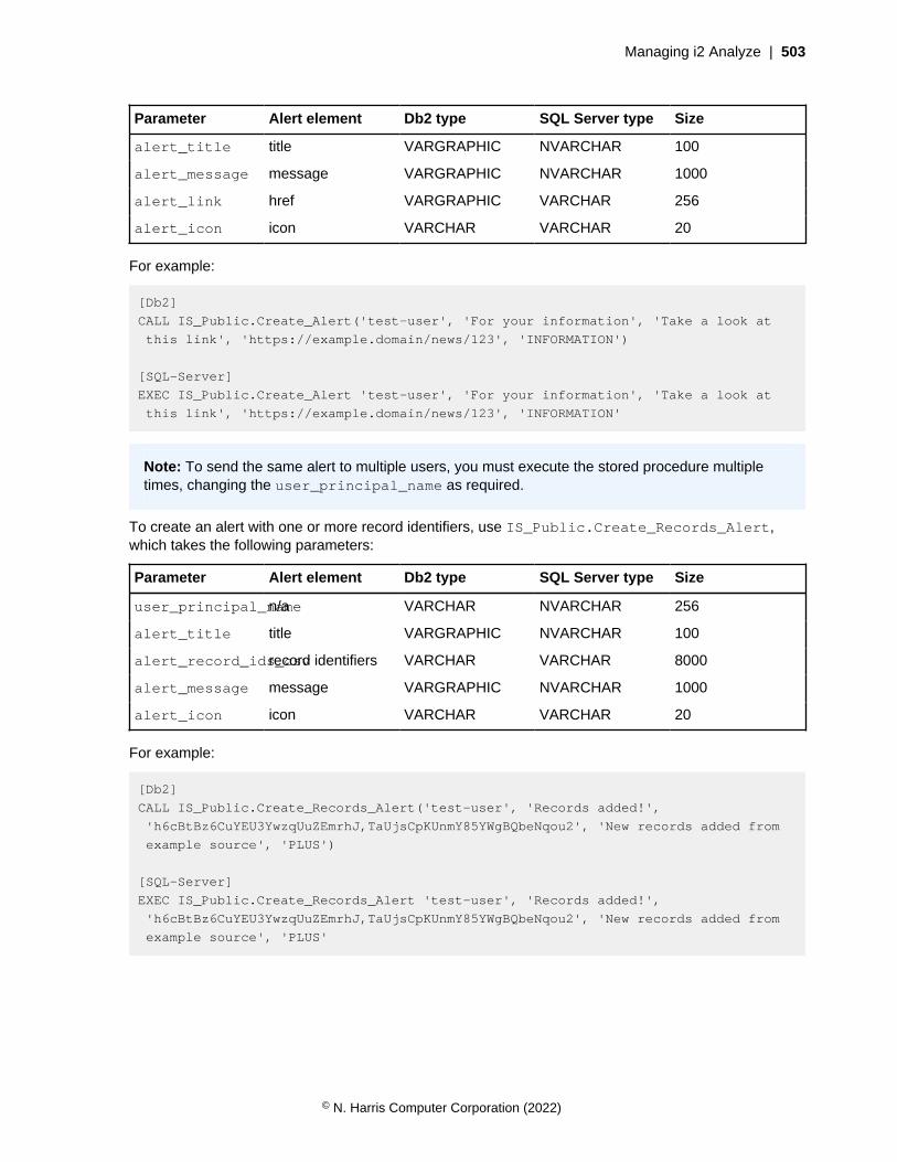
Managing i2 Analyze | 503
Parameter Alert element Db2 type SQL Server type Size
alert_title title VARGRAPHIC NVARCHAR 100
alert_message message VARGRAPHIC NVARCHAR 1000
alert_link href VARGRAPHIC VARCHAR 256
alert_icon icon VARCHAR VARCHAR 20
For example:
[Db2]
CALL IS_Public.Create_Alert('test-user', 'For your information', 'Take a look at
this link', 'https://example.domain/news/123', 'INFORMATION')
[SQL-Server]
EXEC IS_Public.Create_Alert 'test-user', 'For your information', 'Take a look at
this link', 'https://example.domain/news/123', 'INFORMATION'
Note: To send the same alert to multiple users, you must execute the stored procedure multipletimes, changing the user_principal_name as required.
To create an alert with one or more record identifiers, use IS_Public.Create_Records_Alert,which takes the following parameters:
Parameter Alert element Db2 type SQL Server type Size
user_principal_namen/a VARCHAR NVARCHAR 256
alert_title title VARGRAPHIC NVARCHAR 100
alert_record_ids_csvrecord identifiers VARCHAR VARCHAR 8000
alert_message message VARGRAPHIC NVARCHAR 1000
alert_icon icon VARCHAR VARCHAR 20
For example:
[Db2]
CALL IS_Public.Create_Records_Alert('test-user', 'Records added!',
'h6cBtBz6CuYEU3YwzqUuZEmrhJ,TaUjsCpKUnmY85YWgBQbeNqou2', 'New records added from
example source', 'PLUS')
[SQL-Server]
EXEC IS_Public.Create_Records_Alert 'test-user', 'Records added!',
'h6cBtBz6CuYEU3YwzqUuZEmrhJ,TaUjsCpKUnmY85YWgBQbeNqou2', 'New records added from
example source', 'PLUS'
© N. Harris Computer Corporation (2022)

Managing i2 Analyze | 504
Note: Alerts that you create through this stored procedure can contain at most 242 records,because of the sizes of record identifiers and the alert_record_ids_csv parameter. The Javaand REST APIs call the stored procedure, so they have the same limit.
Java API
The Java API for creating alerts is available through the API for creating Scheduling custom servertasks on page 507.
The API provides the ability to identify the recipients of an alert by specifying lists of users, groups, andcommand access control permissions. The criteria are ORed together inclusively, so only one criterionmust be met in order for a user to receive an alert. It is also possible to specify that an alert should besent to all system users.
Note: You can send an alert to all users that are in the Analyst group OR the Clerk group.But you cannot specify that an alert should be sent only to users that are members of both theAnalyst group AND the Clerk group.
© N. Harris Computer Corporation (2022)

Managing i2 Analyze | 505
For example:
package com.example.tasks;
import com.i2group.disco.alerts.AlertIcon;
import com.i2group.disco.alerts.IAlertManager;
import com.i2group.disco.alerts.ISendTo;
import com.i2group.disco.alerts.SendTo;
import com.i2group.disco.task.spi.CustomTaskFailedException;
import com.i2group.disco.task.spi.IScheduledTask;
import com.i2group.tracing.ITracer;
import java.sql.SQLException;
import java.util.List;
public class ExampleCustomTask implements IScheduledTask {
private IScheduledTaskObjects scheduledTaskObjects;
@Override
public void onStartup(IScheduledTaskObjects scheduledTaskObjects) {
this.scheduledTaskObjects = scheduledTaskObjects;
}
@Override
public void run() {
final IAlertManager alertManager = scheduledTaskObjects.getAlertManager();
try {
// Create an alert with a hyperlink
final ISendTo sendToTestUser = SendTo.createWithUsers("test-user");
alertManager.createAlert(
sendToTestUser, "For your information",
AlertIcon.INFORMATION, "Take a look at this link",
"https://example.domain/news/123");
// Create an alert that contains records
final ISendTo sendToAnalysts = SendTo.createWithGroups("Analyst");
alertManager.createRecordsAlert(
sendToAnalysts, "Records added!",
AlertIcon.PLUS, "New records added from example source",
List.of("h6cBtBz6CuYEU3YwzqUuZEmrhJ", "TaUjsCpKUnmY85YWgBQbeNqou2"));
} catch (SQLException ex) {
final ITracer tracer =
scheduledTaskObjects.getTracerFactory().getTracer(getClass());
tracer.warn("Could not create alert", ex);
throw CustomTaskFailedException.reschedule("Failed to create alerts. Will try
again later.");
}
}
}
© N. Harris Computer Corporation (2022)
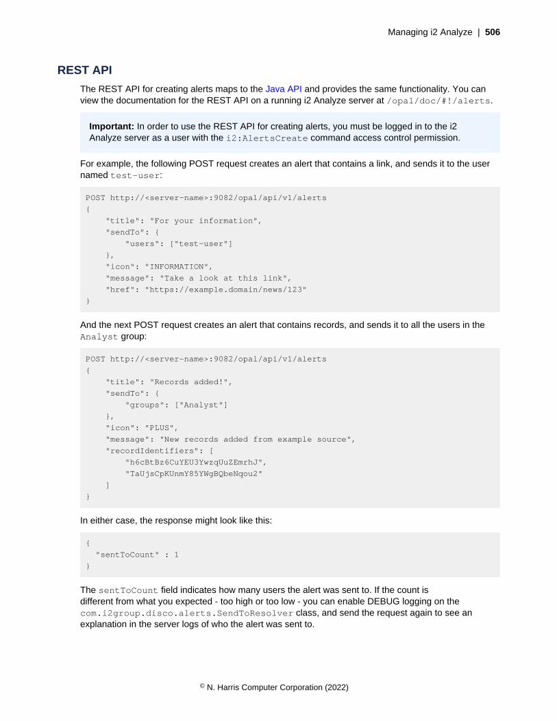
Managing i2 Analyze | 506
REST API
The REST API for creating alerts maps to the Java API and provides the same functionality. You canview the documentation for the REST API on a running i2 Analyze server at /opal/doc/#!/alerts.
Important: In order to use the REST API for creating alerts, you must be logged in to the i2Analyze server as a user with the i2:AlertsCreate command access control permission.
For example, the following POST request creates an alert that contains a link, and sends it to the usernamed test-user:
POST http://<server-name>:9082/opal/api/v1/alerts
{
"title": "For your information",
"sendTo": {
"users": ["test-user"]
},
"icon": "INFORMATION",
"message": "Take a look at this link",
"href": "https://example.domain/news/123"
}
And the next POST request creates an alert that contains records, and sends it to all the users in theAnalyst group:
POST http://<server-name>:9082/opal/api/v1/alerts
{
"title": "Records added!",
"sendTo": {
"groups": ["Analyst"]
},
"icon": "PLUS",
"message": "New records added from example source",
"recordIdentifiers": [
"h6cBtBz6CuYEU3YwzqUuZEmrhJ",
"TaUjsCpKUnmY85YWgBQbeNqou2"
]
}
In either case, the response might look like this:
{
"sentToCount" : 1
}
The sentToCount field indicates how many users the alert was sent to. If the count isdifferent from what you expected - too high or too low - you can enable DEBUG logging on thecom.i2group.disco.alerts.SendToResolver class, and send the request again to see anexplanation in the server logs of who the alert was sent to.
© N. Harris Computer Corporation (2022)
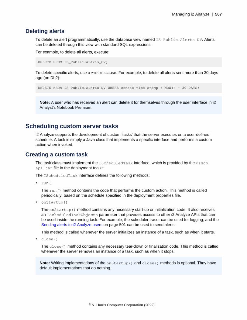
Managing i2 Analyze | 507
Deleting alertsTo delete an alert programmatically, use the database view named IS_Public.Alerts_DV. Alertscan be deleted through this view with standard SQL expressions.
For example, to delete all alerts, execute:
DELETE FROM IS_Public.Alerts_DV;
To delete specific alerts, use a WHERE clause. For example, to delete all alerts sent more than 30 daysago (on Db2):
DELETE FROM IS_Public.Alerts_DV WHERE create_time_stamp < NOW() - 30 DAYS;
Note: A user who has received an alert can delete it for themselves through the user interface in i2Analyst's Notebook Premium.
Scheduling custom server tasksi2 Analyze supports the development of custom 'tasks' that the server executes on a user-definedschedule. A task is simply a Java class that implements a specific interface and performs a customaction when invoked.
Creating a custom taskThe task class must implement the IScheduledTask interface, which is provided by the disco-api.jar file in the deployment toolkit.
The IScheduledTask interface defines the following methods:
• run()
The run() method contains the code that performs the custom action. This method is calledperiodically, based on the schedule specified in the deployment properties file.
• onStartup()
The onStartup() method contains any necessary start-up or initialization code. It also receivesan IScheduledTaskObjects parameter that provides access to other i2 Analyze APIs that canbe used inside the running task. For example, the scheduler tracer can be used for logging, and theSending alerts to i2 Analyze users on page 501 can be used to send alerts.
This method is called whenever the server initializes an instance of a task, such as when it starts.
• close()
The close() method contains any necessary tear-down or finalization code. This method is calledwhenever the server removes an instance of a task, such as when it stops.
Note: Writing implementations of the onStartup() and close() methods is optional. They havedefault implementations that do nothing.
© N. Harris Computer Corporation (2022)
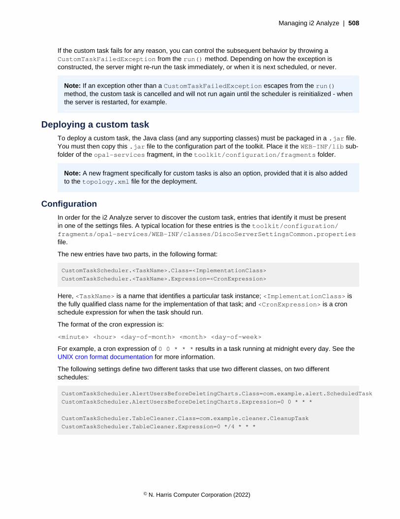
Managing i2 Analyze | 508
If the custom task fails for any reason, you can control the subsequent behavior by throwing aCustomTaskFailedException from the run() method. Depending on how the exception isconstructed, the server might re-run the task immediately, or when it is next scheduled, or never.
Note: If an exception other than a CustomTaskFailedException escapes from the run()method, the custom task is cancelled and will not run again until the scheduler is reinitialized - whenthe server is restarted, for example.
Deploying a custom taskTo deploy a custom task, the Java class (and any supporting classes) must be packaged in a .jar file.You must then copy this .jar file to the configuration part of the toolkit. Place it the WEB-INF/lib sub-folder of the opal-services fragment, in the toolkit/configuration/fragments folder.
Note: A new fragment specifically for custom tasks is also an option, provided that it is also addedto the topology.xml file for the deployment.
Configuration
In order for the i2 Analyze server to discover the custom task, entries that identify it must be presentin one of the settings files. A typical location for these entries is the toolkit/configuration/fragments/opal-services/WEB-INF/classes/DiscoServerSettingsCommon.propertiesfile.
The new entries have two parts, in the following format:
CustomTaskScheduler.<TaskName>.Class=<ImplementationClass>
CustomTaskScheduler.<TaskName>.Expression=<CronExpression>
Here, <TaskName> is a name that identifies a particular task instance; <ImplementationClass> isthe fully qualified class name for the implementation of that task; and <CronExpression> is a cronschedule expression for when the task should run.
The format of the cron expression is:
<minute> <hour> <day-of-month> <month> <day-of-week>
For example, a cron expression of 0 0 * * * results in a task running at midnight every day. See theUNIX cron format documentation for more information.
The following settings define two different tasks that use two different classes, on two differentschedules:
CustomTaskScheduler.AlertUsersBeforeDeletingCharts.Class=com.example.alert.ScheduledTask
CustomTaskScheduler.AlertUsersBeforeDeletingCharts.Expression=0 0 * * *
CustomTaskScheduler.TableCleaner.Class=com.example.cleaner.CleanupTask
CustomTaskScheduler.TableCleaner.Expression=0 */4 * * *
© N. Harris Computer Corporation (2022)

Upgrading i2 Analyze | 509
Deployment
When the .jar file is copied into the toolkit, and the DiscoServerSettingsCommon.propertiesfile is updated with the custom task class name and the cron schedule, the task is ready for deploymentto the i2 Analyze server.
To deploy the custom task to the i2 Analyze server, run setup -t deployLiberty to update theconfiguration with your changes. Then, to set up the task to run according to its defined schedule, runsetup -t startLiberty.
Monitoring a custom taskThe scheduler log stores information about the state of all configured tasks, including when a task waslast run, when it will next run, whether it has failed, and so on.
The scheduler log can be found in the i2_Scheduler.log file, inside the i2 Analyze server.
Note: If a custom task is configured to use the scheduler tracer(IScheduledTaskObjects.getSchedulerTracer()) in its onStartup() method, thenanything logged through that object is also written to the i2_Scheduler.log file.
Upgrading i2 AnalyzeDifferent deployments of i2 Analyze can contain different combinations of its component parts. Toupgrade a particular deployment of i2 Analyze, you must upgrade the deployment toolkit and thenconfigure and upgrade the deployment itself.
This information relates to the latest release of i2 Analyze.
Troubleshooting and supporti2 Support
Upgrade pathsTo upgrade a deployment of i2® Analyze, you must first upgrade the deployment toolkit that you areusing. You then use this upgraded toolkit to upgrade your deployment. The version of your currentdeployment determines exactly which path to follow.
• If you are upgrading i2® Analyze version 4.3.1 or later, complete the instructions in Upgrading to i2Analyze 4.4.0 on page 510.
• If you are upgrading from version 4.3.0 or earlier, part of the upgrade includes upgrading Solr toversion 8, which requires the Solr index to be recreated as part of the process. This procedure cantake a significant amount of time, during which your system is offline. To complete the upgrade witha period of downtime, complete the instructions in Upgrading to i2 Analyze 4.4.0 on page 510.
Note: To limit the time that your system is offline, you can upgrade to version 4.3.1 first using theonline process, and then upgrade to version 4.4.0. As i2 Analyze 4.3.1 is no longer supported, youmust contact i2 support for more information about this path.
Note: From i2® Analyze version 4.3.3, the Analysis Repository, Intelligence Portal, and Onyx servicesare no longer supported. Deployments that contain an Analysis Repository should migrate data intoanother repository.
© N. Harris Computer Corporation (2022)

Upgrading i2 Analyze | 510
Software prerequisites
If you are upgrading a deployment of i2 Analyze 4.3.0 or earlier that uses SQL Server for theInformation Store database, you must install a later version of the ODBC Driver SQL Server andsqlcmd utility. For more information, see Software prerequisites.
As part of the i2 Analyze upgrade process, WebSphere® Liberty, Solr, ZooKeeper, and Java™ areupdated. You do not need to download and update these prerequisites before you upgrade an existingdeployment.
Upgrading to i2® Analyze 4.4.0To upgrade a deployment of i2 Analyze, you must first install the latest version of the deployment toolkit.After you install the latest version, you can upgrade your deployment.
Before you upgrade your production deployment, use a pre-production or test environment to verifythat you can complete the upgrade process successfully and that you are familiar with the procedure.After you test the upgrade process for your deployment, complete the upgrade in your productionenvironment. If you do not have a pre-production or test environment, you can create one. For moreinformation, see Creating a production deployment.
• If you are upgrading a deployment of i2 Analyze 4.3.0 or earlier that uses SQL Server for theInformation Store database, you must install a later version of the ODBC Driver for SQL Server andsqlcmd utility. For more information, see Software prerequisites on page 98.
• Ensure that you back up your deployment before you complete an upgrade. For more informationabout backing up your deployment, see Backing up a deployment.
Depending on the scale and complexity of your data, changes of this nature can take time. You mightwant to plan your upgrade to take place in a period where there is usually no activity, and back up yoursystem before proceeding.
To upgrade the deployment toolkit to version 4.4.0:
1. Stop i2 Analyze:
• In a single-server topology, run setup -t stop.
• In a multiple-server topology, see Stopping and starting i2 Analyze.
2. On each server where the deployment toolkit is installed, make a backup of the i2 Analyze directory.For example, IBM\i2analyze.
3. Install the i2® Analyze deployment toolkit.
a) On each server where the toolkit is installed, remove the toolkit, license, and swidtagdirectories from the existing installation.
b) Install the i2 Analyze version 4.4.0 deployment toolkit over your existing i2 Analyze directory. Formore information, see Installing i2 Analyze on page 98.
4. For each deployment toolkit in your deployment, copy the configuration directory that youbacked up in step 2 to the i2analyze\toolkit directory of the upgraded deployment toolkit thatyou installed in step 3.
5. If it is not already present, create and populate the credentials.properties file. This file mustbe stored in the following location: toolkit\configuration\environment in each deploymenttoolkit.
For more information about the file, see The credentials.properties file.
© N. Harris Computer Corporation (2022)
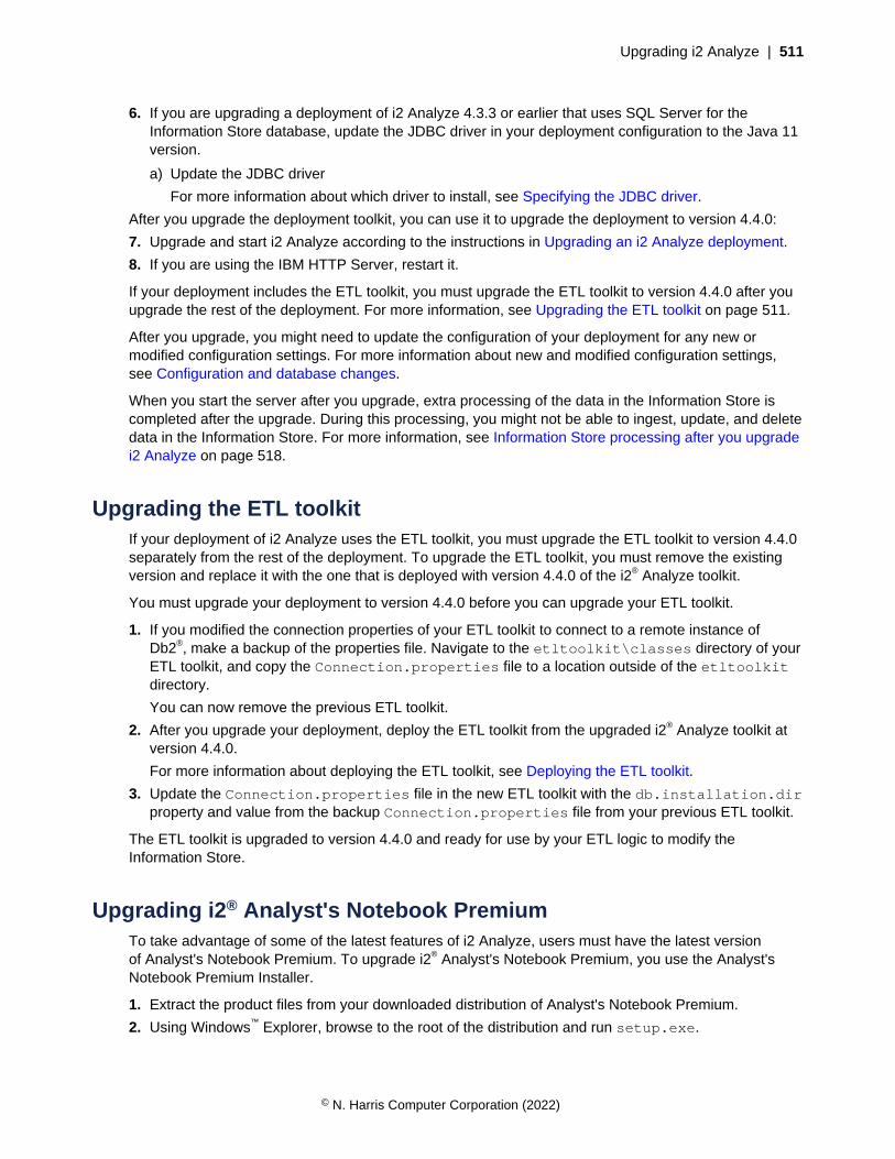
Upgrading i2 Analyze | 511
6. If you are upgrading a deployment of i2 Analyze 4.3.3 or earlier that uses SQL Server for theInformation Store database, update the JDBC driver in your deployment configuration to the Java 11version.
a) Update the JDBC driver
For more information about which driver to install, see Specifying the JDBC driver.
After you upgrade the deployment toolkit, you can use it to upgrade the deployment to version 4.4.0:
7. Upgrade and start i2 Analyze according to the instructions in Upgrading an i2 Analyze deployment.
8. If you are using the IBM HTTP Server, restart it.
If your deployment includes the ETL toolkit, you must upgrade the ETL toolkit to version 4.4.0 after youupgrade the rest of the deployment. For more information, see Upgrading the ETL toolkit on page 511.
After you upgrade, you might need to update the configuration of your deployment for any new ormodified configuration settings. For more information about new and modified configuration settings,see Configuration and database changes.
When you start the server after you upgrade, extra processing of the data in the Information Store iscompleted after the upgrade. During this processing, you might not be able to ingest, update, and deletedata in the Information Store. For more information, see Information Store processing after you upgradei2 Analyze on page 518.
Upgrading the ETL toolkitIf your deployment of i2 Analyze uses the ETL toolkit, you must upgrade the ETL toolkit to version 4.4.0separately from the rest of the deployment. To upgrade the ETL toolkit, you must remove the existingversion and replace it with the one that is deployed with version 4.4.0 of the i2® Analyze toolkit.
You must upgrade your deployment to version 4.4.0 before you can upgrade your ETL toolkit.
1. If you modified the connection properties of your ETL toolkit to connect to a remote instance ofDb2®, make a backup of the properties file. Navigate to the etltoolkit\classes directory of yourETL toolkit, and copy the Connection.properties file to a location outside of the etltoolkitdirectory.
You can now remove the previous ETL toolkit.
2. After you upgrade your deployment, deploy the ETL toolkit from the upgraded i2® Analyze toolkit atversion 4.4.0.
For more information about deploying the ETL toolkit, see Deploying the ETL toolkit.
3. Update the Connection.properties file in the new ETL toolkit with the db.installation.dirproperty and value from the backup Connection.properties file from your previous ETL toolkit.
The ETL toolkit is upgraded to version 4.4.0 and ready for use by your ETL logic to modify theInformation Store.
Upgrading i2® Analyst's Notebook PremiumTo take advantage of some of the latest features of i2 Analyze, users must have the latest versionof Analyst's Notebook Premium. To upgrade i2® Analyst's Notebook Premium, you use the Analyst'sNotebook Premium Installer.
1. Extract the product files from your downloaded distribution of Analyst's Notebook Premium.
2. Using Windows™ Explorer, browse to the root of the distribution and run setup.exe.
© N. Harris Computer Corporation (2022)
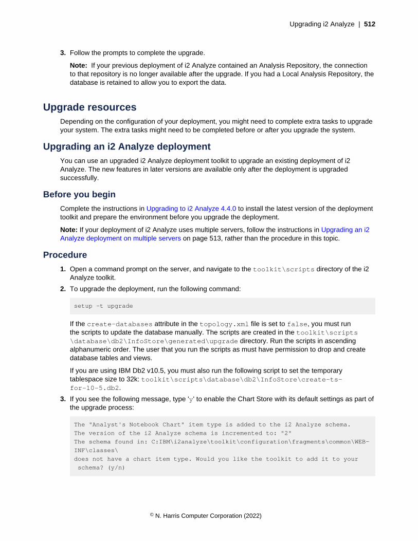
Upgrading i2 Analyze | 512
3. Follow the prompts to complete the upgrade.
Note: If your previous deployment of i2 Analyze contained an Analysis Repository, the connectionto that repository is no longer available after the upgrade. If you had a Local Analysis Repository, thedatabase is retained to allow you to export the data.
Upgrade resourcesDepending on the configuration of your deployment, you might need to complete extra tasks to upgradeyour system. The extra tasks might need to be completed before or after you upgrade the system.
Upgrading an i2 Analyze deploymentYou can use an upgraded i2 Analyze deployment toolkit to upgrade an existing deployment of i2Analyze. The new features in later versions are available only after the deployment is upgradedsuccessfully.
Before you begin
Complete the instructions in Upgrading to i2 Analyze 4.4.0 to install the latest version of the deploymenttoolkit and prepare the environment before you upgrade the deployment.
Note: If your deployment of i2 Analyze uses multiple servers, follow the instructions in Upgrading an i2Analyze deployment on multiple servers on page 513, rather than the procedure in this topic.
Procedure
1. Open a command prompt on the server, and navigate to the toolkit\scripts directory of the i2Analyze toolkit.
2. To upgrade the deployment, run the following command:
setup -t upgrade
If the create-databases attribute in the topology.xml file is set to false, you must runthe scripts to update the database manually. The scripts are created in the toolkit\scripts\database\db2\InfoStore\generated\upgrade directory. Run the scripts in ascendingalphanumeric order. The user that you run the scripts as must have permission to drop and createdatabase tables and views.
If you are using IBM Db2 v10.5, you must also run the following script to set the temporarytablespace size to 32k: toolkit\scripts\database\db2\InfoStore\create-ts-for-10-5.db2.
3. If you see the following message, type 'y' to enable the Chart Store with its default settings as part ofthe upgrade process:
The "Analyst's Notebook Chart" item type is added to the i2 Analyze schema.
The version of the i2 Analyze schema is incremented to: "2"
The schema found in: C:IBM\i2analyze\toolkit\configuration\fragments\common\WEB-
INF\classes\
does not have a chart item type. Would you like the toolkit to add it to your
schema? (y/n)
© N. Harris Computer Corporation (2022)
Upgrading i2 Analyze | 513
Alternatively, if you type 'n', the upgrade process exits without enabling the Chart Store. Insteadof accepting the default settings, you can open the Information Store schema in Schema Designerto add the "Analyst's Notebook Chart" item type. You can then customize the item type by addingproperty types before you complete the upgrade.
4. To complete this part of the upgrade and start the application, run the following command:
setup -t start
What to do next
After you upgrade and restart i2 Analyze, return to perform the rest of the instructions to finish upgradingthe system.
Upgrading an i2 Analyze deployment on multiple servers
To upgrade i2 Analyze in a multiple-server deployment topology, you must run the commands toupgrade and start the components of i2 Analyze on each server.
Before you begin
Complete the instructions in Upgrading to i2 Analyze 4.3.5 to install the latest version of the deploymenttoolkit on the Liberty, Solr, and ZooKeeper servers, and prepare the environment before you upgradethe deployment.
About this task
To upgrade i2 Analyze in a multiple server deployment topology, you must provide an upgradedconfiguration to each deployment toolkit. Then, you can run the commands to upgrade the componentsof i2 Analyze on each server.
As you follow the procedure, it is important to keep track of which server each command runs on, andwhether you need to specify the hostname of that server to the command.
Run all toolkit commands from the toolkit/scripts directory in the deployment toolkit on thespecified server in your environment.
Procedure
1. Upgrade and copy the i2 Analyze configuration.
a. Upgrade the i2 Analyze configuration:
setup -t upgradeConfiguration
b. If you see the following message, type 'y' to enable the Chart Store with its default settings aspart of the upgrade process:
The "Analyst's Notebook Chart" item type is added to the i2 Analyze schema.
The version of the i2 Analyze schema is incremented to: "2"
The schema found in: C:IBM\i2analyze\toolkit\configuration\fragments\common
\WEB-INF\classes\
does not have a chart item type. Would you like the toolkit to add it to your
schema? (y/n)
© N. Harris Computer Corporation (2022)

Upgrading i2 Analyze | 514
Alternatively, if you type 'n', the upgrade process exits without enabling the Chart Store. Insteadof accepting the default settings, you can open the Information Store schema in SchemaDesigner to add the "Analyst's Notebook Chart" item type. You can then customize the item typeby adding property types before you complete the upgrade.
c. Provided that all servers have the same configuration, copy the upgraded toolkit\configuration to the toolkit directory on each Solr and ZooKeeper server in yourenvironment. Accept any file overwrites.
2. Upgrade the ZooKeeper and Solr components of i2 Analyze.
a. On each ZooKeeper server, run the following command:
setup -t upgradeZookeeper --hostname zookeeper.hostname
Where zookeeper.hostname is the hostname of the ZooKeeper server where you are runningthe command, and matches the value for the host-name attribute of a <zkhost> element in thetopology.xml file.
b. On each Solr server, run the following command:
setup -t upgradeSolr --hostname solr.hostname
Where solr.hostname is the hostname of the Solr server where you are running thecommand, and matches the value for the host-name attribute of a <solr-node> element in thetopology.xml file.
3. Upgrade the Information Store database.
On the Liberty server, run the following command:
setup -t upgradeDatabases
If the create-databases attribute in the topology.xml file is set to false, you must runthe scripts to update the database manually. The scripts are created in the toolkit\scripts\database\db2\InfoStore\generated\upgrade directory. Run the scripts in ascendingalphanumeric order. The user that you run the scripts as must have permission to drop and createdatabase tables and views.
If you are using IBM Db2 v10.5, you must also run the following script to set the temporarytablespace size to 32k: toolkit\scripts\database\db2\InfoStore\create-ts-for-10-5.db2.
4. Start the ZooKeeper component of i2 Analyze.
On each ZooKeeper server, start the ZooKeeper hosts:
setup -t startZkHosts --hostname zookeeper.hostname
5. Upload the Solr configuration to ZooKeeper.
On the Liberty server, run:
setup -t createAndUploadSolrConfig --hostname liberty.hostname
6. Start the Solr component of i2 Analyze.
© N. Harris Computer Corporation (2022)
Upgrading i2 Analyze | 515
On each Solr server, start Solr:
setup -t startSolrNodes --hostname solr.hostname
7. Upgrade the Solr collections, and upgrade and start Liberty.
On the Liberty server, run the following commands:
setup -t upgradeSolrCollections --hostname liberty.hostname
setup -t upgradeLiberty
setup -t startLiberty
What to do next
After you upgrade and start i2 Analyze, return to perform the rest of the instructions to finish upgradingthe system.
Configuration and database changesAs a result of an upgrade, you might need to consider configuration or database changes that are newor different compared with previous versions of the software. Depending on the default behavior, youmight want to modify the configuration to meet your requirements after you upgrade the deployment.
Version 4.3.5
No changes are introduced at i2 Analyze version 4.3.5 that affect upgrade. However, if your deploymentincludes an Information Store that runs on IBM Db2, this version includes tooling to Improving VisualQuery performance for multi-line string property types on page 188 with properties that containmultiple-line strings.
Version 4.3.4
The following changes are introduced at i2 Analyze version 4.3.4:
Java install location setting moved
The java.home.dir setting in the environment.properties file is no longer used. The valuethat was specified for this setting is now used for the I2A_COMPONENTS_JAVA_HOME variable in thesetup.in file.
For more information about how the location of Java is specified, see Specifying the Java distribution.
Additional setting require for client certificate authentication
If your deployment uses client certificate authentication, you must update the server.xml in Libertywith a new mandatory attribute. For more information, see Configuring i2 Analyze for client certificateauthentication.
Temporary ingestion table space deprecated in Db2
The IngestionTempTableSpace setting in the InfoStoreNamesDb2.properties file issuperseded by the InternalStagingTableSpace setting.
© N. Harris Computer Corporation (2022)
Upgrading i2 Analyze | 516
Version 4.3.3
The following changes are introduced at i2 Analyze version 4.3.3:
Record matching
If your existing deployment of i2 Analyze included the i2 Connect gateway butnot the Information Store, then the upgrade process modifies the contents ofApolloServerSettingsMandatory.properties to reclassify your schema as a gateway schema.The effect of this change is to modify the identifiers of the item types in the schema.
If your deployment includes match rules files on the server, the upgrade process automatically updatesthose files to contain the correct item type identifiers. However, if your users have developed local rulesfiles for Find Matching Records, you must edit those files before they reconnect to the server after anupgrade.
On each workstation, follow the instructions to find the local-fmr-match-rules.xml file and usethe information in Match rules syntax to update the item type identifiers in the file.
Search results filtering
If your existing deployment of i2 Analyze included the i2 Connect gateway butnot the Information Store, then the upgrade process modifies the contents ofApolloServerSettingsMandatory.properties to reclassify your schema as a gateway schema.If your existing deployment also used a results configuration file, then you must update that file to reflectthe reclassification.
Follow the instructions in Setting up search results filtering and Understanding the results configurationfile to make the necessary changes to the item type identifiers in the file.
Command access control permissions
A new permission can be added to your command access control file. The new permission grantsaccess to the i2 Notebook web client for the Information Store. For more information, see Controllingaccess to features.
If you do not update your command access control configuration file to include the new permission, orif command access control is not configured in your deployment, access to the feature is denied to allusers.
Liberty log location
The Liberty log files from the i2 Analyze application are now located in the wlp\usr\servers\opal-server\logs\opal-services directory. Any logs generated from your previous release remain intheir current location. Any new log messages are created in the new files in the new location.
For more information about the log files, see Deployment log files.
New Information Store table space in Db2
The IS_INTSTG_TS table space is added to the Information Store database. This table spaceis used to store the internal staging tables that are created as part of the ingestion process. TheInfoStoreNamesDb2.properties file contains a new InternalStagingTableSpace setting.
Version 4.3.2
No changes are introduced at i2 Analyze version 4.3.2 that affect upgrade.
© N. Harris Computer Corporation (2022)
Upgrading i2 Analyze | 517
Version 4.3.1 Fix Pack 1
The following changes are introduced at i2 Analyze version 4.3.1.1:
Command access control permissions
New permissions can be added to your command access control file. The new permissions grantaccess to upload, delete, and read charts with the Information Store. For more information, seeControlling access to features.
If you do not update your command access control configuration file to include the new permissions,access to the features is denied to all users. If command access control is not configured in yourdeployment, all authenticated users have access to the new features.
Chart storage
For the Information Store database to store charts, the Information Store schema is updated to includethe chart item type. After you upgrade the Information Store database, the following tables are added forchart storage:
• E_ANALYST_S_NOTEBOOK_CH - the data table, includes the chart properties
• E_ANALYST_S_NOTEBOOK_CH_BIN - the binary data table, includes the binary representation of thechart
• E_ANALYST_S_NOTEBOOK_CH_TXT - the text data table, includes the text from the chart that can besearched for
Version 4.3.1
The following changes are introduced at i2 Analyze version 4.3.1:
OpenJDK - Java Development Kit
The JDK that is installed by the i2 Analyze toolkit is now the OpenJDK, instead of the Oracle JDK.
When you upgrade your deployment of i2 Analyze, the Oracle JDK is uninstalled and the OpenJDK isinstalled.
Deletion view column changes
To incorporate record identifiers, the deletion views are updated to include a new item_id column. Thecontent of the existing record_id column now contains the record identifier for a record. The item_idcolumn contains the item identifier.
If your existing deletion rules use the record_id column, you might need to update them to use theitem_id column. For more information, see Deleting records by rule.
Version 4.3.0
The following changes are introduced at i2 Analyze version 4.3.0:
Database transaction log size increase
The database management system now logs more tables during data movement, which causes anincrease to the size of the transaction log. This is more noticeable in deployments that contain largeamounts of data.
© N. Harris Computer Corporation (2022)
Upgrading i2 Analyze | 518
InfoStoreNames.properties file rename
The InfoStoreNames.properties file is renamed to InfoStoreNamesDb2.properties.
Version 4.2.1
The following changes are introduced at i2 Analyze version 4.2.1:
Configuration fragments
You can deploy the Information Store and i2 Connect in the same deployment of i2 Analyze. Toconfigure a deployment with this topology, some properties files and settings are in a different location:
• If your deployment contained the opal-services-daod fragment, it is renamed to opal-services. The settings in the OpalServerSettingsDaodManadatory.properties file arenow in the DiscoServerSettingsCommon.properties file.
• If your deployment contained the opal-services-is fragment, the opal-services fragment isadded and the following files are moved to the opal-services fragment:
• DiscoClientSettings.properties
• DiscoServerSettingsCommon.properties
• Results configuration file
• visual-query-configuration.xml
By default, all of the values for the settings in the files are unchanged.
Command access control permissions
New permissions can be added to your command access control file. The new permissions grantaccess to the export search results to a CSV file and i2 Connect features in Analyst's NotebookPremium. For more information, see Controlling access to features.
If you do not update your command access control configuration file to include the new permissions,access to the features is denied to all users. If command access control is not configured in yourdeployment, all authenticated users have access to the features except the export to CSV file feature.
Oracle Java Development Kit
The JDK that is installed by the i2 Analyze toolkit is now the Oracle JDK, instead of the IBM® JDK.
When you upgrade your deployment of i2 Analyze, the IBM JDK is uninstalled and the Oracle JDK isinstalled.
Information Store processing after you upgrade i2® AnalyzeAfter you upgrade a deployment of some versions of i2® Analyze with an Information Store, extraprocessing of the data in the Information Store takes place. Analysts can continue to use the systemduring while the data is processed.
Upgrade processes
There are a number of different processes that can occur after you upgrade i2 Analyze. The processesthat are started depend on the version that you are upgrading to or from. Each process places somerestrictions on the system before they are completed.
© N. Harris Computer Corporation (2022)
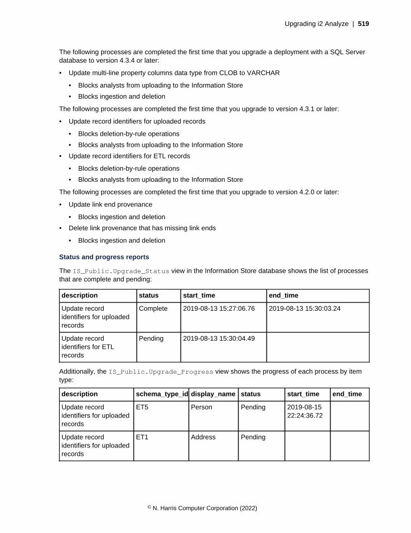
Upgrading i2 Analyze | 519
The following processes are completed the first time that you upgrade a deployment with a SQL Serverdatabase to version 4.3.4 or later:
• Update multi-line property columns data type from CLOB to VARCHAR
• Blocks analysts from uploading to the Information Store
• Blocks ingestion and deletion
The following processes are completed the first time that you upgrade to version 4.3.1 or later:
• Update record identifiers for uploaded records
• Blocks deletion-by-rule operations
• Blocks analysts from uploading to the Information Store
• Update record identifiers for ETL records
• Blocks deletion-by-rule operations
• Blocks analysts from uploading to the Information Store
The following processes are completed the first time that you upgrade to version 4.2.0 or later:
• Update link end provenance
• Blocks ingestion and deletion
• Delete link provenance that has missing link ends
• Blocks ingestion and deletion
Status and progress reports
The IS_Public.Upgrade_Status view in the Information Store database shows the list of processesthat are complete and pending:
description status start_time end_time
Update recordidentifiers for uploadedrecords
Complete 2019-08-13 15:27:06.76 2019-08-13 15:30:03.24
Update recordidentifiers for ETLrecords
Pending 2019-08-13 15:30:04.49
Additionally, the IS_Public.Upgrade_Progress view shows the progress of each process by itemtype:
description schema_type_id display_name status start_time end_time
Update recordidentifiers for uploadedrecords
ET5 Person Pending 2019-08-1522:24:36.72
Update recordidentifiers for uploadedrecords
ET1 Address Pending
© N. Harris Computer Corporation (2022)

Upgrading i2 Analyze | 520
description schema_type_id display_name status start_time end_time
Update recordidentifiers for ETLrecords
ET5 Person Pending
Update recordidentifiers for ETLrecords
ET1 Address Pending
You can use this view to check how many item types are completed and how many are pending. TheIS_Public.Upgrade_Progress view is populated with the item type status only when the process isin the Pending state in the IS_Public.Upgrade_Status view.
The possible values for the status columns are:
Pending
The process is either not started or started but not completed.
Complete
The process is completed.
Note: If you stop i2® Analyze before all the processes are complete, the next time that you start i2®
Analyze any pending processes continue.
Upgrading a customized Information StoreThe Information Store is designed to store large amounts of data, and the underlying database can becustomized to optimize performance at scale. If you have modified your database in this manner youmust also handle the database upgrade separately.
If you have customized your Information Store, having the deployment toolkit upgrade your databasestructure automatically is not desirable. However, to upgrade your system, you still need to modify theInformation Store to match the newer version.
Note: Depending on the scale and complexity of your data, making changes of this nature can taketime. Plan your upgrade to take place in a period of low activity, and back up your system beforeproceeding.
1. Open a command prompt on the server, and navigate to the toolkit\scripts directory of the i2Analyze 4.4.0 toolkit.
2. To generate the DDL scripts that can you can use to upgrade your Information Store, run thefollowing command:
setup -t generateInfoStoreUpgradeScripts
The upgrade scripts are placed in the following location: toolkit\scripts\database\db2\InfoStore\generated\upgrade
3. Evaluate the scripts provided and use them to update your database.
When you have modified your Information Store to match the latest structure, you must ensure thatyour applications are upgraded without the database upgrade. To do this, ensure that you have set thecreate-database attribute of the Information Store data-source to false in the topology.xmlbefore Upgrading an i2 Analyze deployment.
© N. Harris Computer Corporation (2022)

Download PDFs | 521
Download PDFsi2 Analyze documentation is also available in PDF documents.
• Full i2 Analyze documentation
© N. Harris Computer Corporation (2022)

| Index | 522
Index
G
glossary 399