Documentation EBHSCR - Elektrobit
27
Documentation EBHSCR Release 21.11.0 Nov 10, 2021
-
Upload
khangminh22 -
Category
Documents
-
view
1 -
download
0
Transcript of Documentation EBHSCR - Elektrobit
Documentation EBHSCRRelease 21.11.0
Nov 10, 2021

TABLE OF CONTENTS
1 EBHSCR 11.1 Version Information . . . . . . . . . . . . . . . . . . . . . . . . . . . . . . . . . . . . . . . . . . . 11.2 EBHSCR major description . . . . . . . . . . . . . . . . . . . . . . . . . . . . . . . . . . . . . . . 21.3 Ethernet . . . . . . . . . . . . . . . . . . . . . . . . . . . . . . . . . . . . . . . . . . . . . . . . . . 4
1.3.1 Header Fields . . . . . . . . . . . . . . . . . . . . . . . . . . . . . . . . . . . . . . . . . . 41.3.1.1 Major number . . . . . . . . . . . . . . . . . . . . . . . . . . . . . . . . . . . . . 41.3.1.2 Channel . . . . . . . . . . . . . . . . . . . . . . . . . . . . . . . . . . . . . . . . 41.3.1.3 Status** . . . . . . . . . . . . . . . . . . . . . . . . . . . . . . . . . . . . . . . . 51.3.1.4 Start timestamp . . . . . . . . . . . . . . . . . . . . . . . . . . . . . . . . . . . . 61.3.1.5 Stop timestamp . . . . . . . . . . . . . . . . . . . . . . . . . . . . . . . . . . . . 61.3.1.6 Major number specific header . . . . . . . . . . . . . . . . . . . . . . . . . . . . . 7
1.3.2 Payload . . . . . . . . . . . . . . . . . . . . . . . . . . . . . . . . . . . . . . . . . . . . . 91.3.2.1 Frame Discarded . . . . . . . . . . . . . . . . . . . . . . . . . . . . . . . . . . . . 91.3.2.2 Capture and Replay . . . . . . . . . . . . . . . . . . . . . . . . . . . . . . . . . . 9
1.4 NMEA . . . . . . . . . . . . . . . . . . . . . . . . . . . . . . . . . . . . . . . . . . . . . . . . . . 91.4.1 Header Fields . . . . . . . . . . . . . . . . . . . . . . . . . . . . . . . . . . . . . . . . . . 9
1.4.1.1 Major number . . . . . . . . . . . . . . . . . . . . . . . . . . . . . . . . . . . . . 91.4.1.2 Channel . . . . . . . . . . . . . . . . . . . . . . . . . . . . . . . . . . . . . . . . 91.4.1.3 Status . . . . . . . . . . . . . . . . . . . . . . . . . . . . . . . . . . . . . . . . . 91.4.1.4 Start timestamp . . . . . . . . . . . . . . . . . . . . . . . . . . . . . . . . . . . . 91.4.1.5 Stop timestamp . . . . . . . . . . . . . . . . . . . . . . . . . . . . . . . . . . . . 101.4.1.6 Major number specific header . . . . . . . . . . . . . . . . . . . . . . . . . . . . . 10
1.4.2 Payload . . . . . . . . . . . . . . . . . . . . . . . . . . . . . . . . . . . . . . . . . . . . . 101.5 TimeState . . . . . . . . . . . . . . . . . . . . . . . . . . . . . . . . . . . . . . . . . . . . . . . . . 10
1.5.1 Header Fields . . . . . . . . . . . . . . . . . . . . . . . . . . . . . . . . . . . . . . . . . . 101.5.1.1 Major number . . . . . . . . . . . . . . . . . . . . . . . . . . . . . . . . . . . . . 101.5.1.2 Slot . . . . . . . . . . . . . . . . . . . . . . . . . . . . . . . . . . . . . . . . . . . 101.5.1.3 Channel . . . . . . . . . . . . . . . . . . . . . . . . . . . . . . . . . . . . . . . . 101.5.1.4 Status . . . . . . . . . . . . . . . . . . . . . . . . . . . . . . . . . . . . . . . . . 101.5.1.5 Start timestamp . . . . . . . . . . . . . . . . . . . . . . . . . . . . . . . . . . . . 101.5.1.6 Start timestamp . . . . . . . . . . . . . . . . . . . . . . . . . . . . . . . . . . . . 111.5.1.7 Major number specific header . . . . . . . . . . . . . . . . . . . . . . . . . . . . . 11
1.5.2 Payload . . . . . . . . . . . . . . . . . . . . . . . . . . . . . . . . . . . . . . . . . . . . . 111.6 CAN . . . . . . . . . . . . . . . . . . . . . . . . . . . . . . . . . . . . . . . . . . . . . . . . . . . 12
1.6.1 Header Fields . . . . . . . . . . . . . . . . . . . . . . . . . . . . . . . . . . . . . . . . . . 121.6.1.1 Major number . . . . . . . . . . . . . . . . . . . . . . . . . . . . . . . . . . . . . 121.6.1.2 Channel . . . . . . . . . . . . . . . . . . . . . . . . . . . . . . . . . . . . . . . . 121.6.1.3 Status . . . . . . . . . . . . . . . . . . . . . . . . . . . . . . . . . . . . . . . . . 121.6.1.4 Start timestamp . . . . . . . . . . . . . . . . . . . . . . . . . . . . . . . . . . . . 121.6.1.5 Stop timestamp . . . . . . . . . . . . . . . . . . . . . . . . . . . . . . . . . . . . 12
i
1.6.1.6 Major number specific header . . . . . . . . . . . . . . . . . . . . . . . . . . . . . 121.6.2 Payload . . . . . . . . . . . . . . . . . . . . . . . . . . . . . . . . . . . . . . . . . . . . . 13
1.7 Digital IO . . . . . . . . . . . . . . . . . . . . . . . . . . . . . . . . . . . . . . . . . . . . . . . . . 151.7.1 Header Fields . . . . . . . . . . . . . . . . . . . . . . . . . . . . . . . . . . . . . . . . . . 15
1.7.1.1 Major number . . . . . . . . . . . . . . . . . . . . . . . . . . . . . . . . . . . . . 151.7.1.2 Channel . . . . . . . . . . . . . . . . . . . . . . . . . . . . . . . . . . . . . . . . 151.7.1.3 Status . . . . . . . . . . . . . . . . . . . . . . . . . . . . . . . . . . . . . . . . . 151.7.1.4 Start timestamp . . . . . . . . . . . . . . . . . . . . . . . . . . . . . . . . . . . . 151.7.1.5 Stop timestamp . . . . . . . . . . . . . . . . . . . . . . . . . . . . . . . . . . . . 151.7.1.6 Major number specific header . . . . . . . . . . . . . . . . . . . . . . . . . . . . . 15
1.8 Padding . . . . . . . . . . . . . . . . . . . . . . . . . . . . . . . . . . . . . . . . . . . . . . . . . . 151.9 LIN . . . . . . . . . . . . . . . . . . . . . . . . . . . . . . . . . . . . . . . . . . . . . . . . . . . . 161.10 FlexRay . . . . . . . . . . . . . . . . . . . . . . . . . . . . . . . . . . . . . . . . . . . . . . . . . . 18
1.10.1 Header Fields . . . . . . . . . . . . . . . . . . . . . . . . . . . . . . . . . . . . . . . . . . 181.10.1.1 Major number . . . . . . . . . . . . . . . . . . . . . . . . . . . . . . . . . . . . . 181.10.1.2 Channel . . . . . . . . . . . . . . . . . . . . . . . . . . . . . . . . . . . . . . . . 181.10.1.3 Status . . . . . . . . . . . . . . . . . . . . . . . . . . . . . . . . . . . . . . . . . 181.10.1.4 Start timestamp . . . . . . . . . . . . . . . . . . . . . . . . . . . . . . . . . . . . 181.10.1.5 Stop timestamp . . . . . . . . . . . . . . . . . . . . . . . . . . . . . . . . . . . . 191.10.1.6 Major number specific header . . . . . . . . . . . . . . . . . . . . . . . . . . . . . 19
1.10.2 Payload . . . . . . . . . . . . . . . . . . . . . . . . . . . . . . . . . . . . . . . . . . . . . 201.10.2.1 Frame Header (5 bytes) . . . . . . . . . . . . . . . . . . . . . . . . . . . . . . . . 21
Index 23
ii
CHAPTER
ONE
EBHSCR
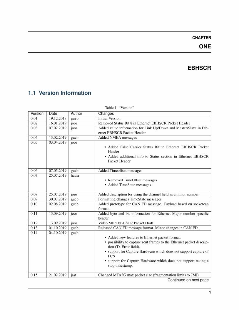
1.1 Version Information
Table 1: “Version”Version Date Author Changes0.01 19.12.2018 gueb Initial Version0.02 16.01.2019 joor Removed Status Bit 8 in Ethernet EBHSCR Packet Header0.03 07.02.2019 joor Added value information for Link Up/Down and Master/Slave in Eth-
ernet EBHSCR Packet Header0.04 13.02.2019 gueb Added NMEA messages0.05 03.04.2019 joor
• Added False Carrier Status Bit in Ethernet EBHSCR PacketHeader
• Added additional info to Status section in Ethernet EBHSCRPacket Header
0.06 07.05.2019 gueb Added Timeoffset messages0.07 25.07.2019 hawa
• Removed TimeOffset messages• Added TimeState messages
0.08 25.07.2019 jore Added description for using the channel field as a minor number0.09 30.07.2019 gueb Formatting changes TimeState messages0.10 02.08.2019 gueb Added prototype for CAN FD message. Payload based on socketcan
format.0.11 13.09.2019 joor Added byte and bit information for Ethernet Major number specific
header0.12 13.09.2019 joor Video MIPI EBHSCR Packet Draft0.13 01.10.2019 gueb Released CAN FD message format. Minor changes in CAN FD.0.14 04.10.2019 gueb
• Added new features to Ethernet packet format:• possibility to capture sent frames to the Ethernet packet descrip-
tion (Tx Error field).• support for Capture Hardware which does not support capture of
FCS• support for Capture Hardware which does not support taking a
stop timestamp.
0.15 21.02.2019 jast Changed MTA3G max packet size (fragmentation limit) to 7MBContinued on next page
1

Documentation EBHSCR, Release 21.11.0
Table 1 – continued from previous pageVersion Date Author Changes0.16 04.05.2020 gueb Added CAN Timesync source to EB time state packet0.17 04.05.2020 fllu Updated timesource values so that they correspond to the FPGA values0.18 04.09.2020 hawa Added Can Error Logging Counter (CEL) to CAN(-FD) protocol status
content0.19 16.09.2020 olma Added information about the start timestamp interpretation in the replay
case for Ethernet0.20 02.02.2020 fllu Added Digital IO messages0.21 08.11.2021 fllu Added FlexRay and Lin messages
1.2 EBHSCR major description
The Elektrobit High Speed Capture and Replay (EBHSCR) protocol is produced by Elektrobit hardware for interfacinghigh speed automotive interfaces.
Protocol-Layout:0 1 2 30 1 2 3 4 5 6 7 0 1 2 3 4 5 6 7 0 1 2 3 4 5 6 7 0 1 2 3 4 5 6 7+-+-+-+-+-+-+-+-+-+-+-+-+-+-+-+-+-+-+-+-+-+-+-+-+-+-+-+-+-+-+-+-+| Major number |Sl | Channel |SlG|Ver| Status |+-+-+-+-+-+-+-+-+-+-+-+-+-+-+-+-+-+-+-+-+-+-+-+-+-+-+-+-+-+-+-+-+| Off | Payload Length |+-+-+-+-+-+-+-+-+-+-+-+-+-+-+-+-+-+-+-+-+-+-+-+-+-+-+-+-+-+-+-+-+| |+ Start timestamp +| |+-+-+-+-+-+-+-+-+-+-+-+-+-+-+-+-+-+-+-+-+-+-+-+-+-+-+-+-+-+-+-+-+| |+ Stop timestamp +| |+-+-+-+-+-+-+-+-+-+-+-+-+-+-+-+-+-+-+-+-+-+-+-+-+-+-+-+-+-+-+-+-+| |+ Major number specific header +| |+-+-+-+-+-+-+-+-+-+-+-+-+-+-+-+-+-+-+-+-+-+-+-+-+-+-+-+-+-+-+-+-+
• All multi-byte fields in the frame header are big endian.
• After the header comes payload of Payload Length bytes. Its content depends on the Major number.
• Every field marked as reserved in the EBHSCR protocol shall be handled in the following way: Set to 0 whengenerating, ignore when processing. This handling enables adding future extensions to the protocol.
Table 2: EBHSCR major header descriptionHeader-Field DescriptionMajor number Type of the frameSlot (Sl) Slot 0-3
Continued on next page
2 Chapter 1. EBHSCR

Documentation EBHSCR, Release 21.11.0
Table 2 – continued from previous pageHeader-Field DescriptionChannel / Mi-nor number Each slot has channels: 0-63.
The Channel number shall be zero based and dense. The structure and semantics of datareceived / transmittedmay be different for each channel. Therefore it is also possible to use this field as a Minornumber,especially for protocols which don’t support dedicated channels. Depending on the majornumber, the slot fieldmay have its original semantics when using the channel as a minor number, or it may be used toextend therange of the minor number by two bits.
Slot group(SlG) Slot groups (0-3) may be used to further sub-group slots.
Version (Ver)Version of header format.
• 0: The packet format defined in this table is used. Currently only protocol Version 0 isdefined.
• <>0: Everything except these four bits and the length in bytes may change with a newformat. This
• ensures that unknown packets can be skipped if the new version is not yet supported.
StatusFlags used for status information and error reporting, specific for each Major number.
• Unused bits are reserved for future use (set to 0 when generating, ignore when processing).• Bit numbering: Bit 0 is least significant Bit in 4th byte of EBHSCR header, Bit 11 is most
significant bit of Status field in 3rd byte of EBHSCR header.
Payload Offset(Off) Defines an offset in bytes when the payload begins. If different from zero payload offset bytes
padding ofundefined content are prepended before the payload field. Needed in order to keep the requiredalignment.
PayloadLength Number of payload bytes received until the end of the frame or until an error occurred. Not
including headerlength. Please note that the maximum supported payload length an application should handle is8MB. See alsoPadding.
Start times-tamp • Containing the 64-bit timestamp value when received the start of the payload frame.
• The timestamp is a nanoseconds counter.• The exact timestamping point is defined depending on the Major number.
Continued on next page
1.2. EBHSCR major description 3
Documentation EBHSCR, Release 21.11.0
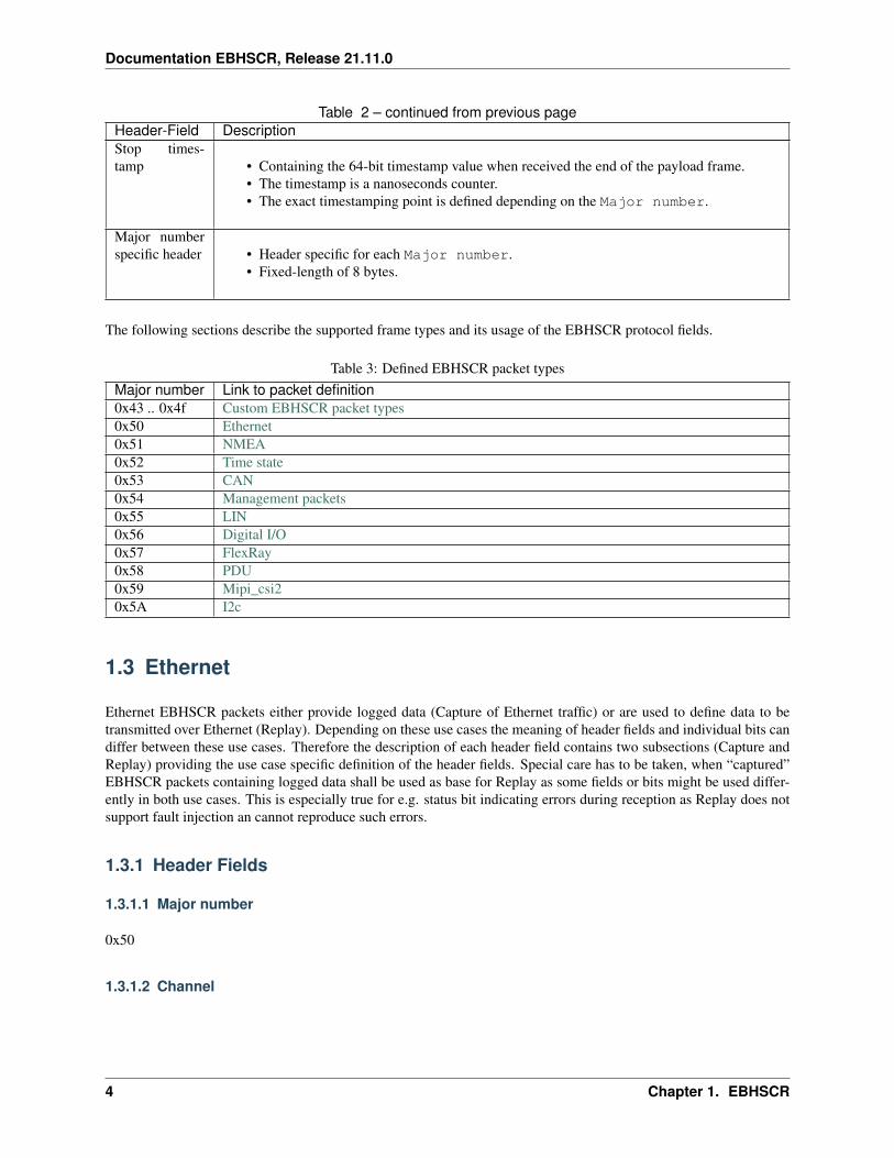
Table 2 – continued from previous pageHeader-Field DescriptionStop times-tamp • Containing the 64-bit timestamp value when received the end of the payload frame.
• The timestamp is a nanoseconds counter.• The exact timestamping point is defined depending on the Major number.
Major numberspecific header • Header specific for each Major number.
• Fixed-length of 8 bytes.
The following sections describe the supported frame types and its usage of the EBHSCR protocol fields.
Table 3: Defined EBHSCR packet typesMajor number Link to packet definition0x43 .. 0x4f Custom EBHSCR packet types0x50 Ethernet0x51 NMEA0x52 Time state0x53 CAN0x54 Management packets0x55 LIN0x56 Digital I/O0x57 FlexRay0x58 PDU0x59 Mipi_csi20x5A I2c
1.3 Ethernet
Ethernet EBHSCR packets either provide logged data (Capture of Ethernet traffic) or are used to define data to betransmitted over Ethernet (Replay). Depending on these use cases the meaning of header fields and individual bits candiffer between these use cases. Therefore the description of each header field contains two subsections (Capture andReplay) providing the use case specific definition of the header fields. Special care has to be taken, when “captured”EBHSCR packets containing logged data shall be used as base for Replay as some fields or bits might be used differ-ently in both use cases. This is especially true for e.g. status bit indicating errors during reception as Replay does notsupport fault injection an cannot reproduce such errors.
1.3.1 Header Fields
1.3.1.1 Major number
0x50
1.3.1.2 Channel
4 Chapter 1. EBHSCR
Documentation EBHSCR, Release 21.11.0
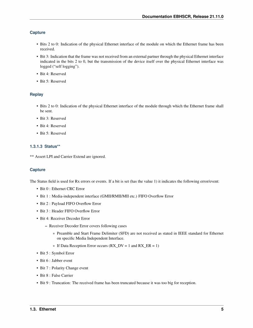
Capture
• Bits 2 to 0: Indication of the physical Ethernet interface of the module on which the Ethernet frame has beenreceived.
• Bit 3: Indication that the frame was not received from an external partner through the physical Ethernet interfaceindicated in the bits 2 to 0, but the transmission of the device itself over the physical Ethernet interface waslogged (“self logging”).
• Bit 4: Reserved
• Bit 5: Reserved
Replay
• Bits 2 to 0: Indication of the physical Ethernet interface of the module through which the Ethernet frame shallbe sent.
• Bit 3: Reserved
• Bit 4: Reserved
• Bit 5: Reserved
1.3.1.3 Status**
** Assert LPI and Carrier Extend are ignored.
Capture
The Status field is used for Rx errors or events. If a bit is set (has the value 1) it indicates the following error/event:
• Bit 0 : Ethernet CRC Error
• Bit 1 : Media-independent interface (GMII/RMII/MII etc.) FIFO Overflow Error
• Bit 2 : Payload FIFO Overflow Error
• Bit 3 : Header FIFO Overflow Error
• Bit 4: Receiver Decoder Error
– Receiver Decoder Error covers following cases
* Preamble and Start Frame Delimiter (SFD) are not received as stated in IEEE standard for Etherneton specific Media Independent Interface.
* If Data Reception Error occurs (RX_DV = 1 and RX_ER = 1)
• Bit 5 : Symbol Error
• Bit 6 : Jabber event
• Bit 7 : Polarity Change event
• Bit 8 : False Carrier
• Bit 9 : Truncation: The received frame has been truncated because it was too big for reception.
1.3. Ethernet 5
Documentation EBHSCR, Release 21.11.0
• Bit 10: Transmission Discarded Error: An Ethernet scheduled for transmission could not be sent within aconfigured time window. If this bit is set, then the EBHSCR packet contains no payload. This bit can only beset in conjunction with bit 3 of the Channel field. Otherwise: Reserved.
• Bit 11: Reserved
Replay
• Bits 9 to 0: Reserved
• Bit 10: START_FRAME_SEPARATION_BIT
• Bit 11: WAIT_FRAME_SEPARATION_BIT
1.3.1.4 Start timestamp
Capture
The timestamp is taken after the end of the SFD (Start of Frame Delimiter) detection, as specified in the IEEE 1588Specification Sep-2004 (IEC 61588 First Edition). The timestamp is taken on the Media-Independent Interface (MII)between DATA LINK and PHY Layer, inside of the FPGA. The timestamp definition is valid for all capture packets,including the logged transmission packets (“self logging”). Detailed information: The MII is a parallel/non-serial MII(e.g. GMII/RMII/MII) and the data on the interface is not encoded (e.g. 8b10b, 64b66b).
If bit 10 (Transmission Discarded Error) in the Status field of the EBHSCR header is set, the start timestamp containsthe time when the Ethernet frame was discarded.
Replay
The start timestamp describes the time when the transmission of first bit of the Destination MAC is on the Media-Independent Interface (MII) between DATA LINK and PHY Layer, inside of the FPGA. Detailed information: TheMII is a parallel/non-serial MII (e.g. GMII/RMII/MII) and the data on the interface is not encoded (e.g. 8b10b,64b66b).
The delay of the PHY Layer (e.g. PCS/PMA, Phy Device etc.) is not considered.
1.3.1.5 Stop timestamp
Capture
The stop timestamp is taken after the FCS of an Ethernet frame has been received.
If an implementation does not support taking a stop timestamp, then the stop timestamp will be set to the same valueas the start timestamp.
If bit 10 (Transmission Discarded Error) in the Status field of the EBHSCR header is set, the stop timestamp containsthe time when the Ethernet frame was discarded.
Replay
The stop timestamp is not considered during the replay of packets. The value written inside of the stop timestamp fieldcan be ignored.
6 Chapter 1. EBHSCR
Documentation EBHSCR, Release 21.11.0
1.3.1.6 Major number specific header
Capture
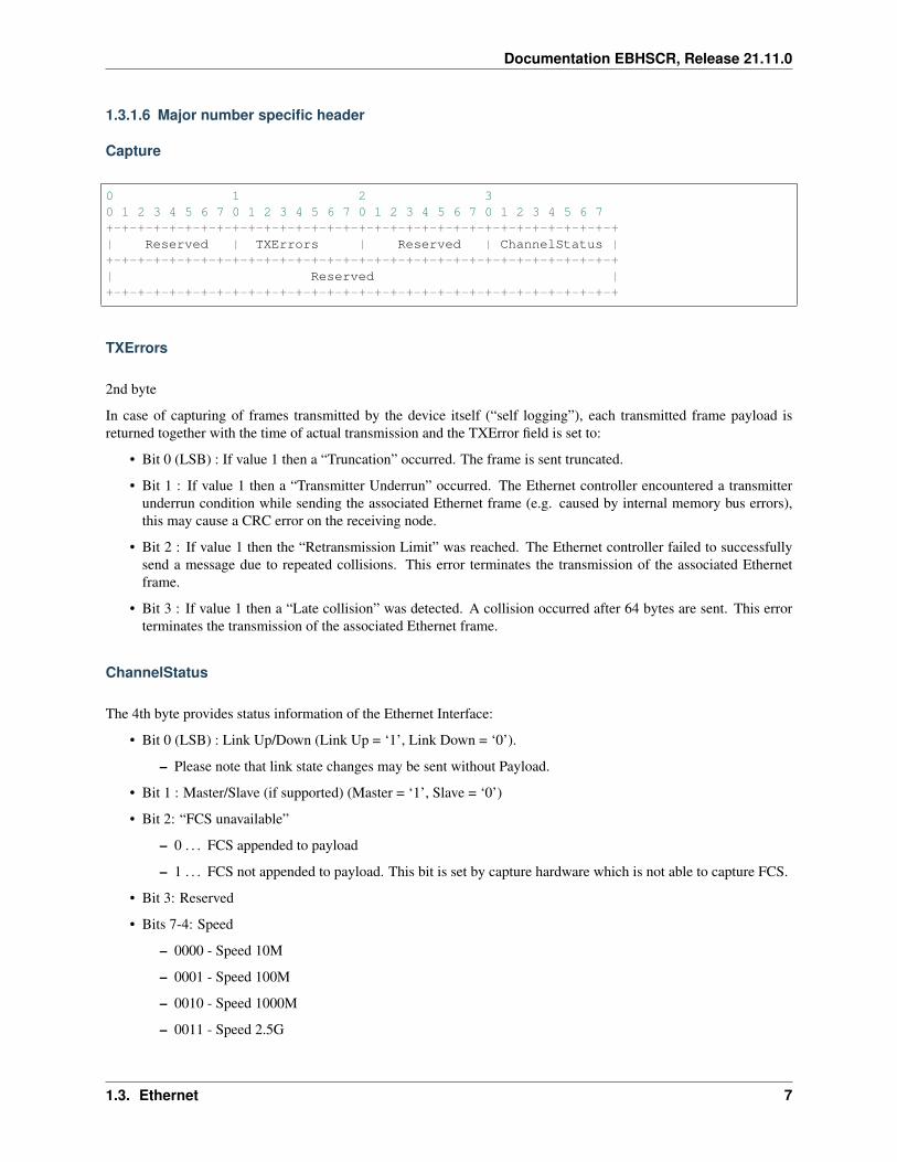
0 1 2 30 1 2 3 4 5 6 7 0 1 2 3 4 5 6 7 0 1 2 3 4 5 6 7 0 1 2 3 4 5 6 7+-+-+-+-+-+-+-+-+-+-+-+-+-+-+-+-+-+-+-+-+-+-+-+-+-+-+-+-+-+-+-+-+| Reserved | TXErrors | Reserved | ChannelStatus |+-+-+-+-+-+-+-+-+-+-+-+-+-+-+-+-+-+-+-+-+-+-+-+-+-+-+-+-+-+-+-+-+| Reserved |+-+-+-+-+-+-+-+-+-+-+-+-+-+-+-+-+-+-+-+-+-+-+-+-+-+-+-+-+-+-+-+-+
TXErrors
2nd byte
In case of capturing of frames transmitted by the device itself (“self logging”), each transmitted frame payload isreturned together with the time of actual transmission and the TXError field is set to:
• Bit 0 (LSB) : If value 1 then a “Truncation” occurred. The frame is sent truncated.
• Bit 1 : If value 1 then a “Transmitter Underrun” occurred. The Ethernet controller encountered a transmitterunderrun condition while sending the associated Ethernet frame (e.g. caused by internal memory bus errors),this may cause a CRC error on the receiving node.
• Bit 2 : If value 1 then the “Retransmission Limit” was reached. The Ethernet controller failed to successfullysend a message due to repeated collisions. This error terminates the transmission of the associated Ethernetframe.
• Bit 3 : If value 1 then a “Late collision” was detected. A collision occurred after 64 bytes are sent. This errorterminates the transmission of the associated Ethernet frame.
ChannelStatus
The 4th byte provides status information of the Ethernet Interface:
• Bit 0 (LSB) : Link Up/Down (Link Up = ‘1’, Link Down = ‘0’).
– Please note that link state changes may be sent without Payload.
• Bit 1 : Master/Slave (if supported) (Master = ‘1’, Slave = ‘0’)
• Bit 2: “FCS unavailable”
– 0 . . . FCS appended to payload
– 1 . . . FCS not appended to payload. This bit is set by capture hardware which is not able to capture FCS.
• Bit 3: Reserved
• Bits 7-4: Speed
– 0000 - Speed 10M
– 0001 - Speed 100M
– 0010 - Speed 1000M
– 0011 - Speed 2.5G
1.3. Ethernet 7
Documentation EBHSCR, Release 21.11.0
– 0100 - Speed 5G
– 0101 - Speed 10G
– 0110 - Speed 25G
– 0111 - Speed 40G
– 1000 - Speed 100G
– 1001 - 1110 - reserved
– 1111 - Speed unknown. This value can be used when the speed could not be detected (e.g. because ofethernet transceiver access errors)
All reserved bytes and bits are set to 0.
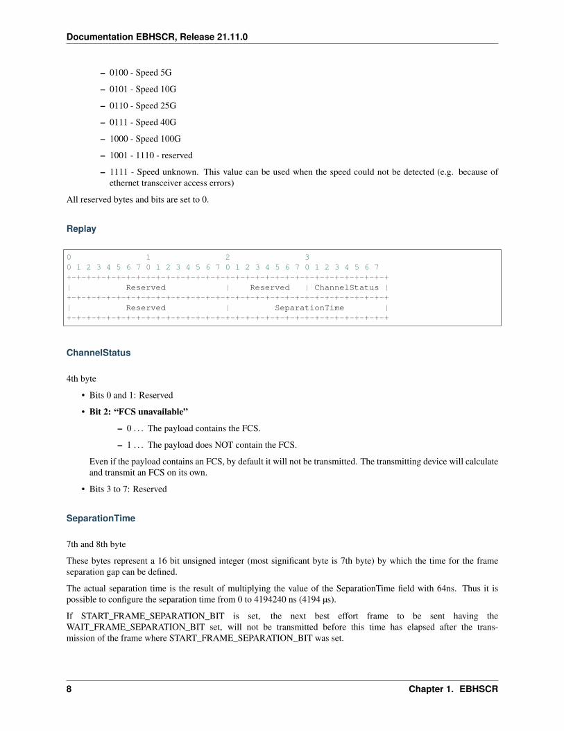
Replay
0 1 2 30 1 2 3 4 5 6 7 0 1 2 3 4 5 6 7 0 1 2 3 4 5 6 7 0 1 2 3 4 5 6 7+-+-+-+-+-+-+-+-+-+-+-+-+-+-+-+-+-+-+-+-+-+-+-+-+-+-+-+-+-+-+-+-+| Reserved | Reserved | ChannelStatus |+-+-+-+-+-+-+-+-+-+-+-+-+-+-+-+-+-+-+-+-+-+-+-+-+-+-+-+-+-+-+-+-+| Reserved | SeparationTime |+-+-+-+-+-+-+-+-+-+-+-+-+-+-+-+-+-+-+-+-+-+-+-+-+-+-+-+-+-+-+-+-+
ChannelStatus
4th byte
• Bits 0 and 1: Reserved
• Bit 2: “FCS unavailable”
– 0 . . . The payload contains the FCS.
– 1 . . . The payload does NOT contain the FCS.
Even if the payload contains an FCS, by default it will not be transmitted. The transmitting device will calculateand transmit an FCS on its own.
• Bits 3 to 7: Reserved
SeparationTime
7th and 8th byte
These bytes represent a 16 bit unsigned integer (most significant byte is 7th byte) by which the time for the frameseparation gap can be defined.
The actual separation time is the result of multiplying the value of the SeparationTime field with 64ns. Thus it ispossible to configure the separation time from 0 to 4194240 ns (4194 µs).
If START_FRAME_SEPARATION_BIT is set, the next best effort frame to be sent having theWAIT_FRAME_SEPARATION_BIT set, will not be transmitted before this time has elapsed after the trans-mission of the frame where START_FRAME_SEPARATION_BIT was set.
8 Chapter 1. EBHSCR
Documentation EBHSCR, Release 21.11.0
The minimum IFG defined in the Ethernet specification will always be considered and automatically be added to theframe separation time defined by the SeparationTime field.
Reserved
Reserved bytes/bits should be set to 0. Anyway these will be ignored for transmission.
1.3.2 Payload
1.3.2.1 Frame Discarded
If the Transmission Discarded Error bit is set in the Status field of the header, the EBHSCR packet does contain apayload of 8 bytes, only. The payload contains the original start timestamp (big endian - as in the EBHSCR headerfields) of the packet which contained the frame which was discarded, i.e. the point in time, when the frame shouldhave been sent.
1.3.2.2 Capture and Replay
802.3 Ethernet frame:
• The payload begins with the destination MAC and ends with the FCS of an Ethernet frame.
• The payload contains a FCS if “FCS unavailable” bit is cleared.
• The payload does not contain a FCS if “FCS unavailable” bit is set.
• The payload may be handed over to Wireshark or Tcpdump Ethernet dissectors unmodified.
1.4 NMEA
1.4.1 Header Fields
1.4.1.1 Major number
0x51
1.4.1.2 Channel
Controller id (zero based)
1.4.1.3 Status
Unused: 0
1.4.1.4 Start timestamp
• ZDA: Timestamp of 1PPS pulse
• all other: undefined
1.4. NMEA 9
Documentation EBHSCR, Release 21.11.0
1.4.1.5 Stop timestamp
Timestamp taken after the NMEA message was received from UART
1.4.1.6 Major number specific header
Unused: 0
1.4.2 Payload
ASCII NMEA data
1.5 TimeState
1.5.1 Header Fields
1.5.1.1 Major number
0x52
1.5.1.2 Slot
0
1.5.1.3 Channel
0
1.5.1.4 Status
Validity bitmask - a bitmask indicating which payload fields contain valid data.
• Bit 0: time offset valid (Payload Byte 0..7). This can be used for replay to set time offset manually.
• Bit 1: last offset change valid (Payload Byte 8..15). Ignored for replay.
• Bit 2: nano seconds last jump valid (Payload Byte 16..23). Ignored for replay.
• Bit 3: UTC leap seconds valid (Payload Byte 24..25). This can be used for replay to set the UTC leap secondsmanually.
• Bit 4: sync state valid (Payload Byte 26..27). Ignored for replay.
1.5.1.5 Start timestamp
Defines the point in time when the packet was created. Only valid for capture, ignored for replay.
10 Chapter 1. EBHSCR
Documentation EBHSCR, Release 21.11.0
1.5.1.6 Start timestamp
Set to same value as start timestamp.
1.5.1.7 Major number specific header
• Byte 7: Time source. One of the following values:
– 0x00: TimeSourceNone
– 0x01: TimeSourceEBTimesyncHard
– 0x02: TimeSourceXTSS
– 0x03: TimeSourcePTPHW
– 0x10: TimeSourcePTPSW
– 0x20: TimeSourceGPS
– 0x30: TimeSourceEBTimesyncSoft
– 0x40: TimeSourceCAN
– 0x50: TimeSourceEBVirt
Implementation note: The least significant 4 bits are time sources handled by FPGA. The most significant bits are timesource handled by CPU.
1.5.2 Payload
All multibyte payload fields are unsigned and big endian:
• Byte 0..7: EB time offset in nanoseconds.
– The offset is the difference of the zero-based start and stop timestamp in the EBHSCR header to TAI(1.1.1970 00:00:00, without leap seconds)
• Byte 8..15: last offset change in nanoseconds
– Point in time of last change of time offset. Can be used to track changes in time offset.
• Byte 16..23: nanoseconds last jump
– Point in time of last hard change/jump of time count after the jump. Hard changes in time count indicatean error - this only happens if smooth change is not possible.
• Byte 24..25: UTC leap-seconds
• Byte 26..27: sync state
– 0x0000: free running
– 0x0001: locked to master
1.5. TimeState 11
Documentation EBHSCR, Release 21.11.0
1.6 CAN
1.6.1 Header Fields
1.6.1.1 Major number
0x53
1.6.1.2 Channel
Controller id (zero based)
1.6.1.3 Status
• Bit 0: CAN FD flag.
– 0: Classical CAN
– 1: CAN FD data frame
• Bit 1: protocol status flag (only relevant for capture, ignored for replay)
– 0: protocol status not available
– 1: protocol status available
1.6.1.4 Start timestamp
Defines the point in time about 25ns after the Start-of-frame (SOF) of CAN message.
1.6.1.5 Stop timestamp
Defines the point in time about 25ns after the End-of-frame (EOF) of CAN message. Only relevant for capture, ignoredfor replay.
1.6.1.6 Major number specific header
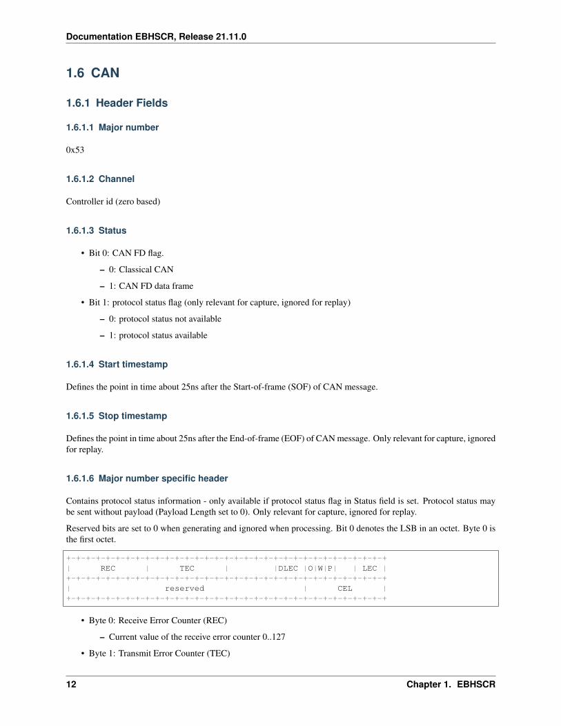
Contains protocol status information - only available if protocol status flag in Status field is set. Protocol status maybe sent without payload (Payload Length set to 0). Only relevant for capture, ignored for replay.
Reserved bits are set to 0 when generating and ignored when processing. Bit 0 denotes the LSB in an octet. Byte 0 isthe first octet.
+-+-+-+-+-+-+-+-+-+-+-+-+-+-+-+-+-+-+-+-+-+-+-+-+-+-+-+-+-+-+-+-+| REC | TEC | |DLEC |O|W|P| | LEC |+-+-+-+-+-+-+-+-+-+-+-+-+-+-+-+-+-+-+-+-+-+-+-+-+-+-+-+-+-+-+-+-+| reserved | CEL |+-+-+-+-+-+-+-+-+-+-+-+-+-+-+-+-+-+-+-+-+-+-+-+-+-+-+-+-+-+-+-+-+
• Byte 0: Receive Error Counter (REC)
– Current value of the receive error counter 0..127
• Byte 1: Transmit Error Counter (TEC)
12 Chapter 1. EBHSCR
Documentation EBHSCR, Release 21.11.0
– Current value of the transmit error counter 0..255
• Byte 2:
– Bit 0-2: data phase last error code (DLEC)
* Error code during data phase of CAN FD frame with BRS flag set.
* Coding is the same as LEC.
• Byte 3:
– Bit 0-2: last error code (LEC)
* 0: No Error. The last CAN message transfer was OK
* 1: Stuff Error. More than 5 equal bits in a sequence have occurred in a part of a received messagewhere this is not allowed.
* 2: Form Error. The fixed-format part of a frame has the wrong format.
* 3: Ack Error. The message transmitted was not acknowledged by another node.
* 4: Bit1 Error. During the transmission of a message (with the exception of the arbitration field),the device wanted to send a recessive level (bit of logical value 1), but the monitored bus value wasdominant.
* 5: Bit0 Error. During the transmission of a message (or acknowledge bit, or active error flag, oroverload flag), the device wanted to send a dominant level (data or identifier bit logical value 0),but the monitored bus value was recessive. During Bus_Off recovery this status is set each time asequence of 11 recessive bits has been monitored. This enables the CPU to monitor the proceeding ofthe Bus_Off recovery sequence (indicating the bus is not stuck at dominant or continuously disturbed).
* 6: CRC Error. The CRC checksum received for an incoming message does not match the CRC valuethat the controller calculated for the received data.
* 7: NoChange. No CAN bus event was detected since last read. This event is currently unused.
– Bit 5: ERRP (P)
* 0: error counters are below the error passive limit (128).
* 1: One of the error counters has reached the error passive limit (128).
– Bit 6: ERRW (W)
* 0: error counters are below the error warning limit (96).
* 1: One of the error counters has reached the error warning limit (96).
– Bit 7: BOFF (O)
* 0: Not in Bus Off state.
* 1: In Bus Off state.
• Byte 7: Can Error Logging Counter (CEL)
– Current value of the CAN error logging counter 0..255
1.6.2 Payload
Reserved bits are set to 0 when generating and ignored when processing. Bit 0 denotes the LSB in an octet. Byte 0 isthe first octet.
1.6. CAN 13

Documentation EBHSCR, Release 21.11.0
+-+-+-+-+-+-+-+-+-+-+-+-+-+-+-+-+-+-+-+-+-+-+-+-+-+-+-+-+-+-+-+-+| id |+-+-+-+-+-+-+-+-+-+-+-+-+-+-+-+-+-+-+-+-+-+-+-+-+-+-+-+-+-+-+-+-+| len | flags | reserved |+-+-+-+-+-+-+-+-+-+-+-+-+-+-+-+-+-+-+-+-+-+-+-+-+-+-+-+-+-+-+-+-+| |+ data 0 .. 64 bytes +| |+-+-+-+-+-+-+-+-+-+-+-+-+-+-+-+-+-+-+-+-+-+-+-+-+-+-+-+-+-+-+-+-+
• Byte 0-3: id in little endian format.
– Bit 31: extended frame format (EFF) flag
* 0: standard 11 bit can identifier
* 1: extended 29 bit can identifier
– Bit 30: remote transmission request (RTR) flag
* RTR frames are not supported by CAN FD.
* RTR frames have a length (len field) set, but do not carry data.
– Bit 29: reserved
– Bit 0-28: CAN identifier:
* standard: 11 bit (EFF flag 0)
* extended: 29 bit (EFF flag 1)
• Byte 4: len - Frame data length in byte.
– 0..8 for classic CAN (including RTR frames)
* RTR frames have a length set, but they do not carry payload!
– 0..8, 12, 16, 20, 24, 32, 48, 64 for CAN FD
– bit 7 (most significant bit): set to 0 when generating, ignore when processing
• Byte 5: flags - Used for CAN FD specific flags:
– bit 0: bit rate switch (BRS). If set the second bit rate for data is used in CAN FD frame
– bit 1: error state indicator (ESI). Set by the transmitting CAN FD controller to indicate errors
– bit 2-7: set to 0 when generating, ignore when processing
• Byte 8..: data - CAN frame payload:
– 0..8 for classic CAN data frames
– 0 for classic CAN RTR frames
– 0..8, 12, 16, 20, 24, 32, 48, 64 for CAN FD
Warning:
In case of RTR frames, or in case of errors on the CAN bus there may be less data bytesavailable than specified in the len field. Please make sure to never read out more data bytes thanavailable overall (as specified by the overall EBHSCR Header Payload Length field)!
14 Chapter 1. EBHSCR
Documentation EBHSCR, Release 21.11.0
1.7 Digital IO
1.7.1 Header Fields
1.7.1.1 Major number
0x56
1.7.1.2 Channel
• Digital IO line number (zero based)
• EB2200 / EB5200 provides 4 input lines for DETI. (Values: 0-3)
1.7.1.3 Status
• Bit 0: Set to 1 in case of an overflow in the monitoring unit. In this case all remaining fields are invalid. Onlyrelevant for capture, ignored for replay.
• Bit 10: Set to 1 if a time jump occured near the edge and thus the timestamp was estimated. Only relevant forcapture, ignored for replay.
1.7.1.4 Start timestamp
Defines the point in time about 25ns afer the edge specified in the Value type field.
1.7.1.5 Stop timestamp
Same value as start timestamp. Only relevant for capture, ignored for replay.
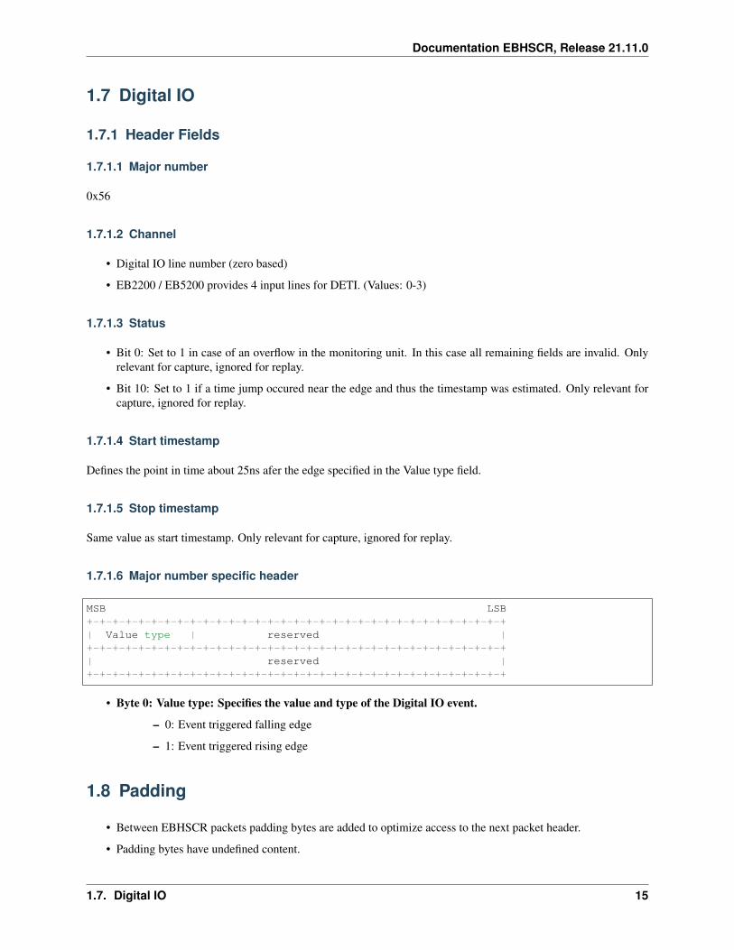
1.7.1.6 Major number specific header
MSB LSB+-+-+-+-+-+-+-+-+-+-+-+-+-+-+-+-+-+-+-+-+-+-+-+-+-+-+-+-+-+-+-+-+| Value type | reserved |+-+-+-+-+-+-+-+-+-+-+-+-+-+-+-+-+-+-+-+-+-+-+-+-+-+-+-+-+-+-+-+-+| reserved |+-+-+-+-+-+-+-+-+-+-+-+-+-+-+-+-+-+-+-+-+-+-+-+-+-+-+-+-+-+-+-+-+
• Byte 0: Value type: Specifies the value and type of the Digital IO event.
– 0: Event triggered falling edge
– 1: Event triggered rising edge
1.8 Padding
• Between EBHSCR packets padding bytes are added to optimize access to the next packet header.
• Padding bytes have undefined content.
1.7. Digital IO 15
Documentation EBHSCR, Release 21.11.0
• The padding bytes are not included in the Payload Length header field.
• The number of padding bytes added are depending on the implementation architecture of the FPGA design toreach the following alignment:
– EB7200 “Mi5 base Architecture”: 8 byte alignment
– EB7200 “LVDS3G Architecture”: 4 byte alignment
– EB8200: “LVDS3G Architecture”: 4 byte alignment (in UDP frames)
• Because the number of padding bytes is implementation dependent and the padding bytes have undefined contentthe user application shall not rely on it. E.g. it shall not use the padding bytes for application specific code.
1.9 LIN
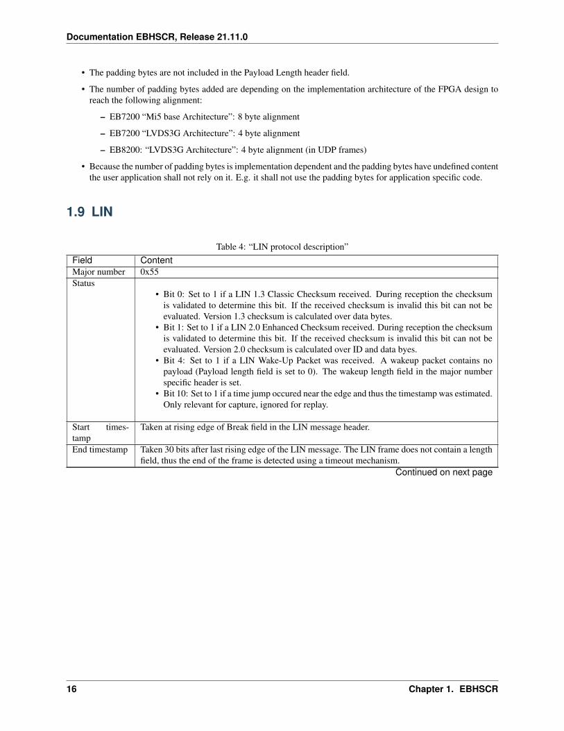
Table 4: “LIN protocol description”Field ContentMajor number 0x55Status
• Bit 0: Set to 1 if a LIN 1.3 Classic Checksum received. During reception the checksumis validated to determine this bit. If the received checksum is invalid this bit can not beevaluated. Version 1.3 checksum is calculated over data bytes.
• Bit 1: Set to 1 if a LIN 2.0 Enhanced Checksum received. During reception the checksumis validated to determine this bit. If the received checksum is invalid this bit can not beevaluated. Version 2.0 checksum is calculated over ID and data byes.
• Bit 4: Set to 1 if a LIN Wake-Up Packet was received. A wakeup packet contains nopayload (Payload length field is set to 0). The wakeup length field in the major numberspecific header is set.
• Bit 10: Set to 1 if a time jump occured near the edge and thus the timestamp was estimated.Only relevant for capture, ignored for replay.
Start times-tamp
Taken at rising edge of Break field in the LIN message header.
End timestamp Taken 30 bits after last rising edge of the LIN message. The LIN frame does not contain a lengthfield, thus the end of the frame is detected using a timeout mechanism.
Continued on next page
16 Chapter 1. EBHSCR
Documentation EBHSCR, Release 21.11.0
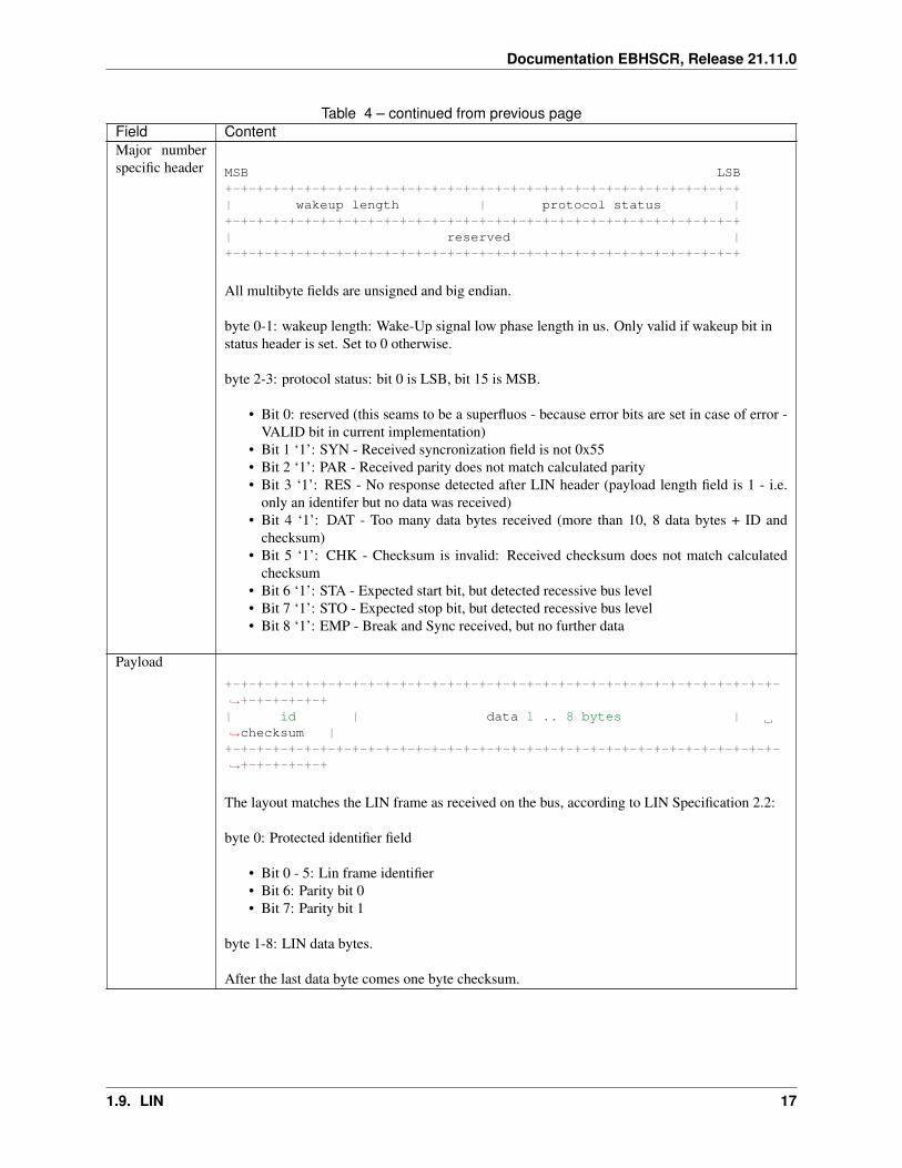
Table 4 – continued from previous pageField ContentMajor numberspecific header MSB LSB
+-+-+-+-+-+-+-+-+-+-+-+-+-+-+-+-+-+-+-+-+-+-+-+-+-+-+-+-+-+-+-+-+| wakeup length | protocol status |+-+-+-+-+-+-+-+-+-+-+-+-+-+-+-+-+-+-+-+-+-+-+-+-+-+-+-+-+-+-+-+-+| reserved |+-+-+-+-+-+-+-+-+-+-+-+-+-+-+-+-+-+-+-+-+-+-+-+-+-+-+-+-+-+-+-+-+
All multibyte fields are unsigned and big endian.
byte 0-1: wakeup length: Wake-Up signal low phase length in us. Only valid if wakeup bit instatus header is set. Set to 0 otherwise.
byte 2-3: protocol status: bit 0 is LSB, bit 15 is MSB.
• Bit 0: reserved (this seams to be a superfluos - because error bits are set in case of error -VALID bit in current implementation)
• Bit 1 ‘1’: SYN - Received syncronization field is not 0x55• Bit 2 ‘1’: PAR - Received parity does not match calculated parity• Bit 3 ‘1’: RES - No response detected after LIN header (payload length field is 1 - i.e.
only an identifer but no data was received)• Bit 4 ‘1’: DAT - Too many data bytes received (more than 10, 8 data bytes + ID and
checksum)• Bit 5 ‘1’: CHK - Checksum is invalid: Received checksum does not match calculated
checksum• Bit 6 ‘1’: STA - Expected start bit, but detected recessive bus level• Bit 7 ‘1’: STO - Expected stop bit, but detected recessive bus level• Bit 8 ‘1’: EMP - Break and Sync received, but no further data
Payload+-+-+-+-+-+-+-+-+-+-+-+-+-+-+-+-+-+-+-+-+-+-+-+-+-+-+-+-+-+-+-+-+-+-+-→˓+-+-+-+-+-+| id | data 1 .. 8 bytes |→˓checksum |+-+-+-+-+-+-+-+-+-+-+-+-+-+-+-+-+-+-+-+-+-+-+-+-+-+-+-+-+-+-+-+-+-+-+-→˓+-+-+-+-+-+
The layout matches the LIN frame as received on the bus, according to LIN Specification 2.2:
byte 0: Protected identifier field
• Bit 0 - 5: Lin frame identifier• Bit 6: Parity bit 0• Bit 7: Parity bit 1
byte 1-8: LIN data bytes.
After the last data byte comes one byte checksum.
1.9. LIN 17

Documentation EBHSCR, Release 21.11.0
1.10 FlexRay
1.10.1 Header Fields
1.10.1.1 Major number
0x57
1.10.1.2 Channel
• Bit 0: Channel A
• Bit 1: Channel B
• Bit 2..4: Controller id (zero based) big endian
1.10.1.3 Status
• Bit 0: Synchronous monitoring packet
– 0: packet was generated by asynchronous monitoring
– 1: packet was generated by FlexRay synchronous monitoring
• Bit 1: FlexRay cluster is in sync (only valid if bit 0 = 1)
• Bit 3..2: packet type (see ‘Major number specific header’ for details)
– 00: packet contains a FlexRay frame
* Bit 4: CODERR: Coding error. Indicates if a Frame Start Sequence Error (FSSERR) or a Byte StartSequence error (BSSERR) occurred.
* Bit 5: TSSVIOL: TSS violation
* Bit 6: HCRCERR: Header CRC error
* Bit 7: FCRCERR: Frame CRC error
* Bit 8: FESERR: Frame end sequence error
* Bit 9: FSSERR: Frame start sequence error
* Bit 10: BSSERR: Byte start sequence error
– 01: Packet contains a symbol
– 10: Packet contains the slot status (only if bit 1 = 1)
– 11: Packet contains the start-of-cycle (only if bit 1 = 1)
• Bit 11: Set to 1 if a time jump occured near the edge and thus the timestamp was estimated. Only relevant forcapture, ignored for replay.
1.10.1.4 Start timestamp
Defines the point in time about 80ns after the falling edge of the TSS of the FlexRay frame
18 Chapter 1. EBHSCR
Documentation EBHSCR, Release 21.11.0
Replay
• 0: do synchronous replay (use slot/cycle/supercycle information)
• otherwise: do asynchonous replay (not supported yet)
1.10.1.5 Stop timestamp
Defines the point in time about 25ns after the rising edge in between the frame end sequence bits
1.10.1.6 Major number specific header
Capture
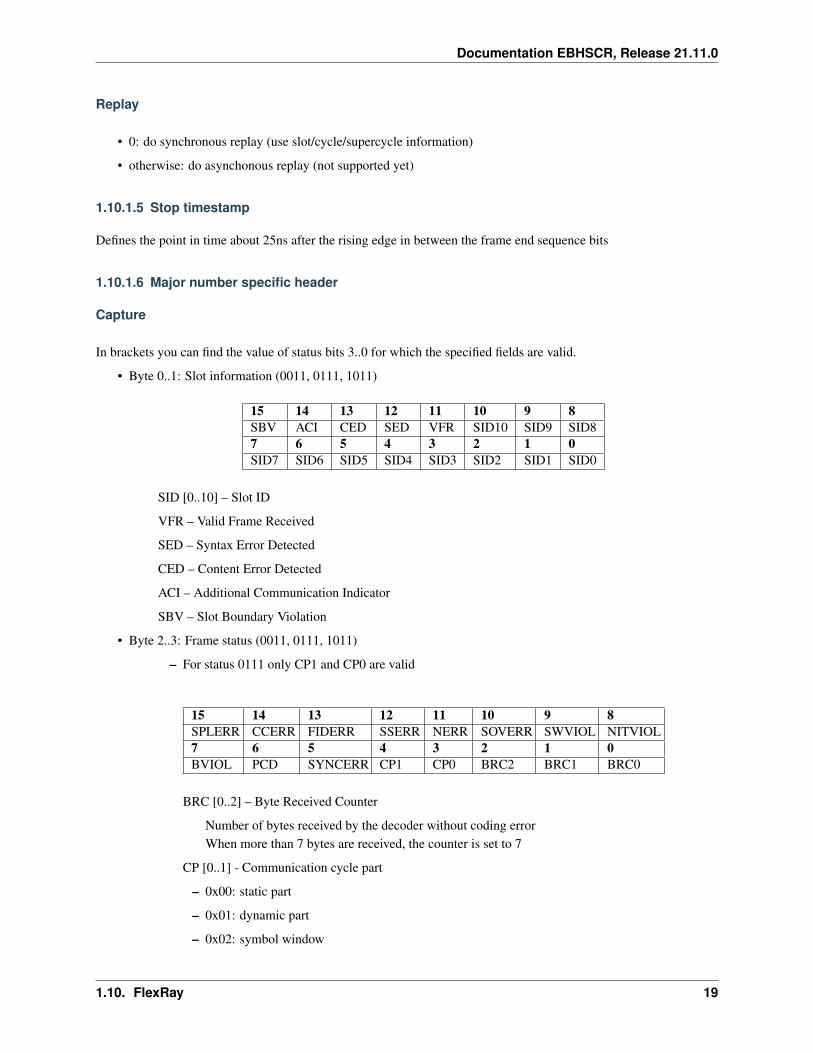
In brackets you can find the value of status bits 3..0 for which the specified fields are valid.
• Byte 0..1: Slot information (0011, 0111, 1011)
15 14 13 12 11 10 9 8SBV ACI CED SED VFR SID10 SID9 SID87 6 5 4 3 2 1 0SID7 SID6 SID5 SID4 SID3 SID2 SID1 SID0
SID [0..10] – Slot ID
VFR – Valid Frame Received
SED – Syntax Error Detected
CED – Content Error Detected
ACI – Additional Communication Indicator
SBV – Slot Boundary Violation
• Byte 2..3: Frame status (0011, 0111, 1011)
– For status 0111 only CP1 and CP0 are valid
15 14 13 12 11 10 9 8SPLERR CCERR FIDERR SSERR NERR SOVERR SWVIOL NITVIOL7 6 5 4 3 2 1 0BVIOL PCD SYNCERR CP1 CP0 BRC2 BRC1 BRC0
BRC [0..2] – Byte Received Counter
Number of bytes received by the decoder without coding errorWhen more than 7 bytes are received, the counter is set to 7
CP [0..1] - Communication cycle part
– 0x00: static part
– 0x01: dynamic part
– 0x02: symbol window
1.10. FlexRay 19

Documentation EBHSCR, Release 21.11.0
– 0x03: NIT
SYNCERR - Sync and/or startup bit wrongly set
PCD - Prolonged channel idle detection
FES to CHIRP took longer than 11 bit timesThis is always true for dynamic frames because of the DTS.
BVIOL – Boundary violation
NITVIOL – NIT violation
SWVIOL – Symbol Window violation
SOVERR – Slot overbooked error
NERR – Null frame error
SSERR – Sync or startup error
FIDERR – Frame ID error
CCERR – Cycle counter error
SPLERR – Static Payload length error
• Byte 4: Symbol length and status (01xx)
7 6 5 4 3 2 1 0SYERR SL6 SL5 SL4 SL3 SL2 SL1 SL0
SYERR - The low phase was too long
SL [0..6] - Symbol length in units of bit cells
• Byte 0: POC-State (1111)
• Byte 1: Cycle counter of following cycle (1111)
• Byte 4..7: Supercycle counter (00xx, 10xx, 11xx)
Replay
Currently only replay of frames in synchronous mode is supported.
• Byte 4..7: Supercycle counter (00xx, 10xx, 11xx) (big endian); if 0, use next available supercycle
1.10.2 Payload
Only packets of type ‘FlexRay frame’ contain payload. The payload consists of a 5-byte header followed by up to254 data bytes. The number of bytes may be calculated by multiplying the payload length information (PL) with2. However, the actual number of bytes in data may be smaller than the calculated value because of truncation (e.g.because of an error on the bus). No padding is added after the data bytes.
The Frame CRC is not appended. If the Frame CRC is wrong the error bit FCRCERR in Error Flags shall be set.
Bits 39 through 32 appear in the first octet, Bits 31 through 24 in the second octet., Bits 23 through 16 in the thirdoctet, and so on. In the octet bits with bits 39-32 bit 39 is the high order bit and bit 32 is the low order bit, all furtherbits use the same bit counting policy.
20 Chapter 1. EBHSCR

Documentation EBHSCR, Release 21.11.0
1.10.2.1 Frame Header (5 bytes)
39 38 37 36 35 34 33 32– PPI NFI SFI STFI FID10 FID9 FID831 30 29 28 27 26 25 24FID7 FID6 FID5 FID4 FID3 FID2 FID1 FID023 22 21 20 19 18 17 16PL6 PL5 PL4 PL3 PL2 PL1 PL0 HCRC1015 14 13 12 11 10 9 8HCRC9 HCRC8 HCRC7 HCRC6 HCRC5 HCRC4 HCRC3 HCRC27 6 5 4 3 2 1 0HCRC1 HCRC0 CC5 CC4 CC3 CC2 CC1 CC0
PPI - Payload preamble indicator
static segment: If this bit is set the first 0 to 12 bytes of the payload may optionally be used as a networkmanagement vector;dynamic segment: If this bit is set the first two bytes of the payload may optionally be used as a message IDfield.If the frame is a NULL frame, the PPI is always 0.
NFI - Null frame indicator
indicates whether or not the frame is a NULL frameNFI = “0” -> payload segment contains no valid dataNFI = “1” -> payload segment contains dataNote: This is in line with the FlexRay specification
SFI - Sync frame indicator
indicates whether or not the frame is a SYNC frameSFI = “0” -> no receiving node shall consider the frame for synchronizationSFI = “1” -> all receiving nodes shall use the frame for synchronizationSync frames are only sent in the static segment!Each node is only allowed to send one single frame as a sync frame!
STFI - Startup frame indicator
indicates whether or not a frame is a STARTUP frameSTFI = “0” -> frame is not a startup frameSTFI = “1” -> frame is a startup frameA startup frame must always be a sync frame!
FID [0..10] - Frame ID
Values between 1 and 2047FID10 is the most significant bit, FID0 is the least significant bit (big endian).Frame ID 0 is an invalid frame ID!
PL[0..6] - Payload length in words (2 bytes) Values between 0 and 127
HCRC[0..10] - Header CRC Values between 0 and 2047. HCRC10 is the most significant bit. HCRC0 is the leastsignificant bit (big endian).
CC[0..5] - Cycle count Values between 0 and 63
1.10. FlexRay 21

Documentation EBHSCR, Release 21.11.0
22 Chapter 1. EBHSCR
INDEX
CCAN, 12
DDigital IO, 15
EEBHSCR, 1, 2Ethernet, 4
FFlexRay, 18
Hheader, 2
LLIN, 16
Mmain, 2
NNMEA, 9
Ppadding, 15
TTimeState, 10
Vversion, 1
23