
GeoResources Journal Issue 2 – 2021
52
GeoResources Verlag ISSN | Online 2364-8430 • Print 2364-8422 www.georesources.net Journal for Resources, Mining, Tunnelling, Geotechnics and Equipment 2 | 2021 Journal Shortage of materials Biogredable materials Reinforcement with soil nails IT for special civil engineering Parking caverns Fresh air for tunnelling Tunnel-in-Tunnel Method Digitlisation/BIM Mechanical vs. drill and blast Tailings Storage Facilities (TSF) Exploration for ASM Bolivia/Israel/Ghana/global Special Topic: Safe, resource-saving and efficient construction methods, products, materials
-
Upload
khangminh22 -
Category
Documents
-
view
4 -
download
0
Transcript of GeoResources Journal Issue 2 – 2021

GeoResources Verlag ISSN | Online 2364-8430 • Print 2364-8422 www.georesources.net
Journal for Resources, Mining, Tunnelling, Geotechnics and Equipment 2 | 2021
Journal
Shortage of materialsBiogredable materialsReinforcement with soil nailsIT for special civil engineering
Parking cavernsFresh air for tunnellingTunnel-in-Tunnel MethodDigitlisation/BIM
Mechanical vs. drill and blast Tailings Storage Facilities (TSF)Exploration for ASMBolivia/Israel/Ghana/global
Special Topic: Safe, resource-saving and efficient construction methods, products, materials

Beak Consultants GmbH | Am St.-Niclas-Schacht 13 | 09599 Freiberg | Germany P +49 3731 781 350 | F +49 3731 781 352 | [email protected] | www.beak.de
Beak Consultants GmbH – your partner for applied geology, environmental services, customised software development and advanced e-government solutions.
Data Management Artifi cial
Intelligence
Geosciences
Software Products
advangeo® software solutions cover the entire of geo-scientifi c data life cycle: capture, storage, processing, benefi ciation, presentation:
Geodata management• Observations/ measurements• Maps, documents, literature• Cadastral data• Bore holes, samples, analytics• Mine sites…
Mobile data capture• Orientation/ navigation• Documentation• Mobile analytics
AI based predictive mapping• Mineral Exploration • Geohazard prevention • Infrastructure protection • From point data to aerial data • Raster data interpretation• 2D and 3D
Features• Scalable • Adjustable • Multilingual • Windows and web based
Secutex® GreenThe biodegradable nonwoven geotextile
RENEWABLE RAW MATERIALS
METABOLISABLE
BIODEGRADABLE
SUSTAINABLE
Secutex® GreenThe biodegradable nonwoven geotextile
Secutex® Green is available in the robustness classes GRK 2 (low) to GRK 5 (high). The biodegradability is certifi ed by TÜV Austria. Contact us for more information.
www.naue.com
Anzeige_Secutex_Green_DT_EN.indd 2 25.05.20 10:08
Manfred_Koenig_9
Notiz
Naue-Verknüpfung muss raus...

3
GeoResources Journal 2 | 2021 Content www.georesources.net
Specialist Foundation Construction 15GeoResources Team in an interview with Jochen MaurerThe GeoResources Team met with Jochen Maurer, the managing director of fielddata.io GmbH, to discuss efficiency improvements in the field of special foundation construction. His company provides construction firms with an IT platform for initiatives of this kind.Geotechnics • Special foundation construction • Digitisation • Data acquisition • Efficiency • Software
Geotechnics/tunnellinG
Challenging Design and Excavation of huge Parking Caverns in Jerusalem 18Roland HerrA technically challenging project is under construction. Two huge underground parking caverns are being built in Jerusalem close to the historic Temple Mount. A modern business hub is being developed.Geotechnics • Tunnelling • Caverns • Excavation • Parking facility • Israel
tunnellinG
Demand-oriented Ventilation in Tunnel Construction 21Matthias PapeschFresh air is essential when carrying out tunnelling work underground. The CFH Group offers innovative energy- and cost-efficient solutions for ventila-tion during tunnel construction – as adopted for the Kramer Tunnel in Bavaria.Tunnelling • Ventilation • Innovation • Energy efficiency • Cost efficiency • Case study
tunnellinG
Refurbishment of the German Kuckuckslay Tunnel with the ‘Tunnel-in-Tunnel Method’ 23Roland HerrThe Kuckuckslay Tunnel in Germany built in 1871 was refurbished using the tunnel-in-tunnel method. Rail operations were able to continue during the enlargement and rebuilding.Tunnelling • Refurbishment • Tunnel-in-tunnel method • Rail operation • Efficiency • Safety
Content
Ventilation on Demand
With the ‘Korfmann Air Guard’, the CFH Group offers an innovative system for real-time moni-toring and demand-oriented control of ventila-tion. Monitoring the entire system, particularly with regard to energy efficiency, helps to re-duce the energy consumption of the ventila-tion drastically. This not only protects the en-vironment, but also saves on operating costs. Read more about the system and its applica-tion in the construction of the Kramer Tunnel on pages 21 and 22.
https://cfh-group.info/en
GeoResources Verlag ISSN | Online 2364-8430 • Print 2364-8422 www.georesources.net
Journal for Resources, Mining, Tunnelling, Geotechnics and Equipment 2 | 2021
Journal
Shortage of materialsBiogredable materialsReinforcement with soil nailsIT for special civil engineering
Parking cavernsFresh air for tunnellingTunnel-in-Tunnel MethodDigitlisation/BIM
Mechanical vs. drill and blast Tailings Storage Facilities (TSF)Exploration for ASMBolivia/Israel/Ghana/global
Special Topic: Safe, resource-saving and efficient construction methods, products, materials
Special TopicSafe, resource-saving and efficient construction methods, products, materials
A Word on ...Shortage of Construction Materials – Scarcity unlocks Creativity 5GeoResources TeamFirst Corona, and now, to make things worse, a shortage of construction materials! In this context, the special topic of this edition of GeoResources Journal ‘Safe, resource-saving, efficient con-struction methods, products and materials’ could not be more timely.Construction materials • Shortage • Raw material security • Supply chains • Innovation • A Word on ...
Geotechnics
Biodegradable Nonwovens have proven their Worth 7Naue GmbH & Co. KGBiodegradable nonwovens are suitable for temporary uses and applications where the release of plastic fragments cannot be ruled out. Two successful applications of Secutex Green G1 in civil engineering are described.Geotechnics • Sustainability • Construction product • Nonwoven • Environment • Resource efficiency
Geotechnics
The Cable Car Network of La Paz in Bolivia – Reinforcement of Transportation Infrastructure 9Freddy Lopez and Racquel NottinghamThe metropolitan area of La Paz and El Alto in Bolivia has a population of around two million peo-ple. Because of its hilly topography and the limited area available for geographical expansion, the rapid growth of La Paz led to massive urban development on steep slopes nearby. A cable car net-work was successfully implemented to interconnect the different districts. The complex geological and geotechnical conditions lead to repreated landslide occurrences in the densely populated areas, resulting in damage, and to significant risk to life and infrastructure. This paper discusses a particular failure mechanism potentially affecting the stability of vital elements of the cable car network. Based on analysis, a reinforcement solution with self-drilling soil nails is proposed.Geotechnics • Landslide • Risk analysis • Reinforcement • Micropiles • Bolivia
Geotechnics/intervieW
Creating Potential for Workload Reduction – an IT Solution for

4
GeoResources Journal 2 | 2021 Contentwww.georesources.net
tunnellinG
BIM for the Maintenance and Operation of Road Tunnels – Project Aims, Modelling Work and underlying Requirements 25Hendrik Wahl, Götz Vollmann, Markus Thewes, Markus König, Marcel Stepien, Werner Riepe, Ferdinand Weißbrod and Anne LehanThe research project FE 15.0623/2016/RRB ‘BIM in Tunnelling’ is currently laying down the foundations for a BIM-based operating model for road tunnels. This includes a consideration of existing model-theory principles along with an additional survey of the requirements of builder-owners and operators with reference to the operational issues arising during the life cycle of the facility.Tunnelling • Tunnel operation • Digitisation • BIM • Modelling • Research
MininG/tunnellinG
Mechanical Rock Excavation versus Drilling and Blasting 32Karl-Heinz WennmohsThe choice between mechanical equipment and drilling and blasting for the rock excavation will depend to a large extent on the prevailing geological conditions, but will also be driven by a consideration of the benefits and drawbacks associated with each method. This article provides suggestions aimed at helping with the decision making process.Mining • Tunnelling • Roadheading • Processes • Development • Drill and blast
Geotechnics/MininG/rAW MAteriAls
Tailings and Mine Residues in the Extractive Industries – a global Challenge for Humanity and the Environment 37Peter von Hartlieb and Katrin BrummermannClimate and environment protection are vital for maintaining human life on this planet. The predicted and ongoing increase in population is just one of the factors that pose a challenge to the sufficiency of raw material supplies – and this despite the efforts being made towards an energy transition and the conservation of resources. The tailings and residues produced by the extractive industries require safer, more environmentally friendly and more economic solutions. This applies particularly in the case of muddy tailings and with regard to the effects of climate change. This article seeks to examine the tailings issue in all its complexity.Mining • Geotechnics • Raw materials • Tailings • Safety • Environmental protection
MininG
Exploration Targeting for small-scale Gold Mining Operations in the Dunkwa Area, Ghana 43Andreas Barth, Samuel Torkornoo, Kwame Boamah, Andreas Brosig, Delira Hanelli, Stefan Schäfer, Ekow Bartels and Daniel BoamahThe key objective of an investigation programme in Ghana was to develop new exploitation targets suitable for artisanal and small-scale mining. The method used can help drive similar activities in Ghana and in other countries. Mining • Exploration • Geology • Artisanal and small-scale mining (ASM) • Case study • Ghana
MininG/Geotechnics
Red Dog Mine Alaska: Ground Improvement in Permafrost 50Bauer GroupRed Dog Mine is located in a geological permafrost area in Alaska. Bauer Foundation Corp. was tasked with carrying out field tests using the jet grouting and Cutter Soil Mixing (CSM) methods for ground improvement.Mining • Geotechnics • USA • Alaska • Permafrost • Testing • CSM
Imprint GeoResources Zeitschrift GeoResources Journal7. Year. Journal for Mining, Tunnelling, Geotechnics and EquipmentDate of publication: 9 July 2021 ISSN | Online 2364-8430 • Print 2364-8422Publication: GeoResources appears 4 times per year in German (GeoResources Zeitschrift) and 4 times in English (GeoResources Journal). GeoResources is released as online issues on the GeoResources Portal (www.georesources.net). Additional GeoResources Jour-nals are available as printed copies.Purchase Price:Online issues are free of charge. Printed issues in one language for 100 €/a, the combined English and German package for 150 €/a. Student discount 50 %, incl. shipping costs, shipping envelope, VAT in Germany included. Contact: [email protected]
Publisher:GeoResources Portal Manfred KönigOleanderweg 12, 47228 Duisburg, Germanymobile: +49 172 244 1616 email: [email protected] Editors: Dr.-Ing. M.A. Katrin Brummermann mobile: +49 151 70 888 162 email: [email protected] Dipl.-Ing. Manfred Königmobile: +49 172 244 16 16 email: [email protected] and Advertising: email: [email protected]: +49 2841 60 789 67Production/Layout/DTP: Herbert Stimperemail: [email protected] Production: Kiess und Makossa Mediengruppe GmbH, Gelsen-kirchen, D
Copyright:All rights reserved ©GeoResources Portal, Duis-burg, Germanywww.georesources.net No part of this journal may be reproduced in any form by photostatic copy, microfilm or another pro-cess without the permission of the copyright owner or utilized in a form resulting from machines or data processing systems. Science and non-commercial instruction represent exceptions. Notification of use is appreciated. The contents of the submitted manuscripts remain the property of the authors (writers) providing they were submitted free of charge. The writer is responsible for the content of signed contributions and supplied photos and diagrams.
A Word on ... 5
GeoResources Journal 2 | 2021GeoResouces Team:Shortage of Construction Materials – Scarcity unlocks Creativity www.georesources.net
Spec
ial T
opic
First Corona, and now, to make things worse, a shortage of construction materials! In this con-text, the special topic of this edition of GeoRe-sources Journal ‘Safe, resource-saving, efficient construction methods, products and materials’ could not be more timely.
Construction materials • Shortage • Raw material security • Supply chains • Innovation • A Word on ...
Shortage of Construction Materials – Scarcity unlocks CreativityGeoResources Team
Last autumn, we chose the special topic for this second quarter of 2021 ‘Safe, resource-saving, efficient construction methods, products and
materials’. We had definite ideas and concepts as to which content and articles would be relevant for this topic. Since then, things have turned out as being rather different to the way we saw them then. Current devel-opments have changed or widened the way we now see this special topic. In the past year, which brought entire sectors of the economy to a standstill, the construction industry was able to continue working quite well, even if the daily work routine had to be adapted to the new distancing and hygiene rules.
New Developments in our Lives
In the recent past, we have experienced not only nega-tive but also quite positive developments. Digitalisation was given a boost. We have ventured into new media, and working from home office has turned out better than expected. Video conferencing has become rou-tine and helps avoid the hassle of strenuous travel. The economic stimulus programmes include, among other things, the construction and rehabilitation of infra-structure. Measures against climate change are also be-ing especially promoted. The construction industry will certainly benefit from this.
Construction Materials and Products in short Supply
And now we are being confronted by another particu-lar phenomenon. Construction materials and prod-ucts are becoming ever scarcer, and this shortage can be so severe that skilled workers who are actually in short supply are sent home. We are talking about very different construction materials and products, such
as wood, metal, plastics, sands, gravels, construction chemicals, electrical accessories, to name but a few. Building and civil engineering, and many different trades are affected. Our ‘land of milk and honey’ is no longer functioning as it used to. There are serious sup-ply bottlenecks. Manufacturers of construction ma-terials get the raw materials for their products at sig-nificantly higher prices, in smaller quantities, late, or sometimes not at all. Construction companies and cli-ents cannot reliably calculate prices and construction times. Everyday construction processes are coming to a standstill. Jobs cannot be executed as planned. The way we used to see things is no longer valid. Allocating blame is not easy.
Even if the pandemic is part of the cause of the prob-lems, there are also various other reasons that we have not yet adequately addressed and which, conversely, may even be part of the reasons for the pandemic, for example:
▶ New deposits being opened and developed too late ▶ A huge global demand for building materials for
new construction and infrastructure rehabilitation – also boosted by the almost simultaneous avail-ability of funds from current economic-stimulus programmes

6 A Word on ...
GeoResources Journal 2 | 2021 GeoResouces Team:Shortage of Construction Materials – Scarcity unlocks Creativitywww.georesources.net
Spec
ial T
opic
▶ Interventions affecting the environment and cli-mate change, for example with increased drought-induced forest fires or pest infestation, but also more frequent flood events
Creative Thinking, creative Solutions
In the context described, resource conservation with safer, more efficient construction methods, products, and materials assumes an importance that we can no longer ignore. This new, extreme situation or building material crisis can offer opportunities and trigger de-velopments which in time will be seen as positive. We cannot simply continue to carry on as before; we need to adjust to the new situation, change the direction in which we think, experience changes in our awareness, and experiment with different ways of living.
The current shortage can unlock creativity and help us treat our habitat Earth with more care; we can avoid senseless over-production and excesses – in food, in oth-er commodities, in our transport behaviour and in our infrastructure. Sometimes, as we all know, less is more. Freeing ourselves from ballast sometimes results in our feeling even better.
When the wind of change blows, some build protective walls while others build windmills. This nugget of Chi-nese wisdom does not fit just because it is about build-ing. Despite all the difficulties, let’s also use the current material shortage situation to build windmills. Let’s be inspired to develop safer, more resource-efficient con-struction methods and products. Changes like that will help in the preservation of our habitat Earth. Even if we cannot ‘save the whole world’, it is important that we take action with the means at our disposal, and with our expertise and skills. If in so doing we also engage with others and with their ideas and arguments, this will in-spire us to re-think and live differently.
As just one of many examples, the mining of the construction material gypsum in the Harz Mountains has different, even contradictory facets:
GeoResources EditorsContact: Dr.-Ing. M.A. Katrin Brummermann: [email protected]. Manfred König: [email protected]
Gypsum mining in the German Harz MountainsPhoto: CASEA GmbH, Ellrich, Germany
▶ Mining the rock means intervening in nature ▶ Gypsum is needed for the construction of urgently
needed housing in the cities. ▶ As a result of the coal phase-out, around 6 million
tonnes of FGD gypsum will be lost as a by-product from coal-fired power plants.
▶ After they are recultivated, opencast mines are often important and valuable nature reserves.
So it is a real challenge in individual cases to find a sensible solution, a good compromise with as many advantages and as few disadvantages as possible, or per-haps even completely new solutions. This will involve considering all aspects and allowing for new, creative thinking.
With regard to climate-protection targets, Olaf Lies, Lower Saxony’s Minister for the Environment, Energy, Building and Environmental Protection, re-cently said in his welcome address to the North Ger-man Geothermal Conference that it is not only tar-gets but solutions which are decisive, and that more facts rather than percentage targets are needed. This is a fitting appeal, worthy of attention for everyone involved in construction – and for the way we handle the shortage of building materials. And you will find some possible solutions and suggestions in this issue of GeoResources Journal.
Let us think anew in our fields of expertise and not be afraid to put good ideas into practice, to try out and develop the new and, if necessary, discard the old – fa-miliar old habits – for safety, for resource protection and efficiency, or for a future worth living.
Your GeoResources Team

Geotechnics 7
GeoResources Journal 2 | 2021NAUE GmbH & Co. KG:Biodegradable Nonwovens have proven their Worth www.georesources.net
Spec
ial T
opic
Biodegradable nonwovens are suitable for temporary uses and applica-tions where the release of plastic fragments cannot be ruled out. Two successful applications of Secutex Green G1 in civil engineering are de-scribed.
Geotechnics • Sustainability • Construction product • Nonwoven • Environment • Resource efficiency
Biodegradable Nonwovens have proven their WorthNaue GmbH & Co. KG, Espelkamp, Germany
In civil engineering, geotechnical materials are synony-mous with sustainable constructions. In addition to classical geosynthetics, Naue, a manufacturer of geo-technical construction materials, presented its first bio-degradable nonwoven, Secutex® Green G1 (Fig. 1), last year. This biodegradable nonwoven has already proven itself successfully in various applications – for example, in the dunes of Sylt (Fig. 2) and under construction roads in Lower Saxony and Baden-Wuerttemberg.
Sustainable construction in civil engineering is synonymous with ‘durable’, ‘long-lasting’, or ‘environ-mentally friendly’. Geotechnical construction materials made from highly developed polymer meet these criteria and ensure optimised construction in geotechnical engi-neering. Due to reduction in material transport, natural resources are conserved, transport cycles are omitted, and the infrastructure is relieved. Thus, geotechnical construction materials reduce CO2 emissions, improve resource utilisation, and cut costs. The polymer materials are mainly designed for a very long service life. However, applications exist in which an extremely long lifespan for the separation and filtration is not necessary. Further-more, in situations where a structure is only required for a short time and must then be removed, additional de-mands on environmental safety may be imposed. In such cases, the requirements for sustainability change and Se-cutex Green is an environmentally friendly alternative.
Properties of geotechnical Construction Materials made from biodegradable Materials
The best results for mechanical properties with simul-taneous biodegradability were achieved using industri-ally produced staple fibres (Fig. 3). These can be made from different natural resources. Further developments are currently in progress. The production of Secutex Green G1 takes place exclusively from organic, natural, renewable raw materials from certified sources. Envi-ronmental friendliness is also taken into account in production, for example in water consumption and the recyclability of production water. Industrial fibre pro-duction means that fibre quality is more consistent than for natural fibres such as flax, jute or coconut. Unlike polymeric fibres, fibres from natural sources are mostly UV stable, and so do not normally degrade in outdoor applications with exposure to sunlight.
As is the case with common polymeric nonwovens used in road construction, certain biodegradable non-wovens can also be assigned to geotextile robustness classes (GRK) with requirements for mass per unit area, thickness and static-puncture (CBR) values, and
Fig. 1: Biodegradable nonwoven
Fig. 3: Industrially produced organic staple fibres
Fig. 2: Beach path on the island of Sylt with Secutex Green

8 Geotechnics
GeoResources Journal 2 | 2021 NAUE GmbH & Co. KG:Biodegradable Nonwovens have proven their Worthwww.georesources.net
Spec
ial T
opic
and construction time, and thus costs. The biodegrad-able nonwoven was chosen because in the ecologically sensitive area, unintentional release of plastic into the environment from the temporarily exposed peripheral areas and during deconstruction was to be avoided. The biodegradable nonwoven can be composted after its temporary use for the construction road, and any small residues remaining in the area of the road are not critical because of the biodegradability.
Beach Path on the Island of Sylt
Secutex Green also proved to be an excellent problem solver in Kampen on the island of Sylt in Schleswig-Holstein. Using the biodegradable nonwoven, a beach path was constructed between the dunes to improve access through the dunes to the beautiful North Sea (Fig. 5). This path is a great relief for people with prams, rollators or wheelchairs. Combined with larch wood, the nonwoven becomes a rollable path that can be easily laid through the dunes. Biologically harmless, the new beach path makes it easier to cross the loose dune sand. Easy and sustainable with clear benefits for the general public, an ideal combination.
Conclusion and Outlook
When an extremely long service life is not important in gardening, landscaping and civil engineering, the use of biodegradable nonwovens can make sense. This ap-plies in particular to applications in which the nonwo-vens only have to fulfil their function temporarily, such as in construction roads, or where the release of plastic fragments in non-covered applications cannot be ruled out at the design stage. The project-dependent bound-ary conditions must be taken into account when mak-ing the selection. Further investigations are currently underway, for example with different raw materials, the results of which will lead to further development of the products.
References
[1] TÜV Austria: Registrierbescheid gem. Zertifizierungs-programm „Produkte aus kompostierbaren Werk-stoffen“ einschl. EN 13432 für Secutex® Green G1
Fig. 5: Beach path between the dunes with Secutex Green
Fig. 4: Construction road with Secutex Green in an ecologically sensitive area in Baden-Wuerttemberg
Dr.-Ing. Helge Hoymeis Product Manager Greenline at NAUE GmbH & Co. KG, Espelkamp, Germany.Contact: [email protected]
fulfilment of requirements in tenders for infrastructure measures can be verified.
Internationally, there is a wide range of certifications for different product properties. Biodegradability is now fairly well standardised. Different labels are mainly based on results of similar, comparable or identical tests. The biodegradability of the Secutex Green nonwoven was confirmed by TÜV Austria with the certification ‘OK-biodegradable’ for the five environments soil, freshwater, salt water, industrial compost, and domestic compost [1].
Construction Road in Baden-Wuerttemberg
One example is a construction road near Stuttgart in Germany. A retaining wall had to be rehabilitated and this required a construction road in an ecologically sensitive area (Fig. 4). The rehabilitation work was car-ried out from an ‘island’ between a river and a canal, and the construction site could only be reached by a private footpath. In coordination with the authorities, this path had to be widened into a temporary 3 to 4 m wide construction road suitable for use by heavy equip-ment such as trucks and excavators. As an alternative to the classical construction method with granular layers several decimetres thick, the biodegradable separation nonwoven Secutex Green G1 was installed on the exist-ing subsoil. The nonwoven prevented mixing of the bal-last and the fine subsoil, which is why considerably less material was needed. This also reduced transport cycles

Geotechnics 9
GeoResources Journal 2 | 2021Lopez and Nottingham:The Cable Car Network of La Paz in Bolivia – Reinforcement of Transportation Infrastructure www.georesources.net
Spec
ial T
opic
The metropolitan area of La Paz and El Alto in Bo-livia has a population of around two million peo-ple. Because of its hilly topography and the limited area available for geographical expansion, the rap-id growth of La Paz led to massive urban develop-ment on steep slopes nearby. A cable car network was successfully implemented to interconnect the different districts. The complex geological and geotechnical conditions lead to repreated land-slide occurrences in the densely populated areas, resulting in damage, and to significant risk to life and infrastructure. This paper discusses a particu-lar failure mechanism potentially affecting the sta-bility of vital elements of the cable car network. Based on analysis, a reinforcement solution with self-drilling soil nails is proposed.
Geotechnics • Landslide • Risk analysis • Reinforcement • Micropiles • Bolivia
The Cable Car Network of La Paz in Bolivia – Reinforcement of Transportation InfrastructureFreddy Lopez, M.Sc., and Racquel Nottingham, M.Sc.,Friedr. Ischebeck GmbH, Ennepetal, Germany
1 Introduction
La Paz is the seat of the government and the financial centre of the Plurinational State of Bolivia. The Metro-politan Area of the neighbouring cities of La Paz and El Alto has a population of approximately two million. The valley of La Paz has a very abrupt topography, with a longitudinal slope of around 5 % (1 km in 18.5 km) and a transverse slope of around 16 % (0.5 km in 3 km) (Fig. 1).
Because of the topography and the limited area available for La Paz to expand, the urban development of the past few decades has occurred in regions charac-terized by the presence of steep slopes. To connect these densely populated built-up areas, 2014 saw the start of the construction of a cable car network.
Operating at about 4,000 m above sea level and transporting 3,000 passengers/hour, the implementa-tion of the cable car network has had a major influence on the urban development, and has effected significant changes in the public transportation.
According to official information, as of June 2019, more than 200 million passengers have used the ca-ble transportation system [2]. The network currently has ten operative lines spanning approx. 30.5 km. The Golden Line (Línea Dorada) is in the final design stage (Fig. 2).
Fig. 1: Location and topography of La Paz, Bolivia [1]
Fig. 2: Metropolitan Cable Car Integration Network of La Paz and El Alto [2]
Table 1: Land area distribution [3]
Terrain Grade[%]
Area distribution[%]
Steep slopes > 50 35
Moderate slopes 10 to 49 28
Slight slopes / flat terrain < 10 37
2 Landslides in La Paz
The city of La Paz has an area of roughly 472 km2. Deep valleys and steep slopes characterize most of the urban area, which is prone to landslides. According to official information, the urban sprawl area is primarily covered by slopes (Table 1).
The combination of steep slopes, torrential rainfall (around 600 mm/year) and intense superficial erosion

10 Geotechnics
GeoResources Journal 2 | 2021 Lopez and Nottingham:The Cable Car Network of La Paz in Bolivia – Reinforcement of Transportation Infrastructurewww.georesources.net
Spec
ial T
opic
3 The Auquisamaña Landslide
At 16:00 hours (local time) on February 15 2017, a 40 m high, massive clayey cliff collapsed, destroying at least 8 houses in the quarter of Auquisamaña (District of Calacoto, Macrodistrict South) shown in Fig. 4.
3.1 Site Conditions
The geology of the area corresponds to the extended La Paz-Formation, which is characterized by the presence of over-consolidated, low to high plastic clays acc. to [3]. These clays have very good properties for the foun-dation of structures; however, they can be susceptible to instability in areas with intense erosion and abrupt topography, due to the possible development of joints and defined slip planes. The geotechnical properties of the La Paz-Formation scatter throughout its extension, as depicted in Table 3.
Fig. 4: Aerial views of the Auquisamaña-Landslide
Table 2: Major landslides recorded since 1996
Landslide Date Aftermath
Cotahuma 04/1996 60 collapsed houses 18 human casualties
Retamani II 02/2009 50 collapsed houses
Huano Huanuni 01/2010 61 collapsed houses
Sta Rosa de Callapa 02/2011 1,188 collapsed houses
Las Lomas 02/2012 11 collapsed houses
Hoyada 23 de Marzo 02/2012 10 collapsed houses 1 human casualty
Auquisamaña 02/2017 8 collapsed houses
Kantutani 02/2019 66 collapsed houses 2 human casualties
Table 3: Characterization of the La Paz-Formation [4]
Classification Friction Angle
[°]
Cohe-sion
[kPa]
Unit weight [kN/m3]
E- modulus
[MPa]
Over-consolidated, low plastic clays CL
18 to 23(20)
50 to 75(60)
17 to 19(17)
11 to 25(23)
( ) indicate the values for the district of Calacoto
Fig. 3: Risk map for the city of La Paz (modified according to [3])
contributes to potential instability problems and results in periodical occurrence of landslides, especially in the districts located in or near steep slopes, which have been identified as high-risk zones (red marked areas) by the official integral risk management report [3] as de-picted in Fig. 3.
In the past 25 years, at least eight catastrophic land-slides were recorded in the seven main districts of La Paz, as summarised in Table 2. As shown in the Table, the events took place between the months of January and April, which correlate with the typical rainy sea-son from December to March. This condition usually points to instability due to an accumulation of pore wa-ter pressures and superficial erosion, associated with heavy rainfall.
However, the records of one particular landslide: Auquisamaña (02/2017) show particularly abnormal dry conditions. This paper will discuss possible reasons for instability in this particular case, since it presents possible implications for the stability of the infrastruc-ture of the cable car network.

Geotechnics 11
GeoResources Journal 2 | 2021Lopez and Nottingham:The Cable Car Network of La Paz in Bolivia – Reinforcement of Transportation Infrastructure www.georesources.net
Spec
ial T
opic
3.2 Landslide Analysis
A digital model of the slope was developed using the available official planimetry and altimetry of La Paz [5] and the software GGU-Stability. Slope stability analyses were carried out to determine the factor of safety and the risk of sliding. For the analysis, the General Wedge Method acc. to DIN 4084 (1981) [6] was used, in com-bination with a Mohr-Coulomb constitutive model, using the values listed in Table 3. The General Wedge Method consists of the analysis of polygonal slip surfac-es of rigid slip bodies, which are bounded by ‘external’ and ‘internal’ slip planes defined by the borders to the neighbouring slip bodies (Fig. 5).
The analysis of polygonal slip planes is recommend-ed for slopes in over-consolidated soils and/or with pre-defined potential slip planes [7].
The analysis of the Auquisamaña-Landslide resulted in a global safety factor of η = 1.6 (Fig. 6), although the clayey cliff clearly collapsed. One clue was decisive in understanding the failure mechanism: one day after the landslide, the Risk Management Office (DEGIR) remarked that the landslide occurred under abnormally hot and dry weather conditions, and that the collapse was due to the ‘drying and contraction’ of the clays [8]. This condition suggests the occurrence of a ‘degradation process’ reducing the shear resistance of the constitutive materials.
A sensitivity analysis was conducted to evaluate potential factors that might have affected the cliff. The main focus was on evaluating the presence of possible joints or fissures, which can occur as a result of the re-peated exposition of the clays to humidity-dryness-cy-
Fig. 5: Failure mechanism with the General Wedge Method (modified, according to [7])
Fig. 8: Global safety factor vs. joint inclination
Fig. 7: Outcrop in Rosaspampa – evidence of joint in the La Paz-Formation [3]
Fig. 6: Critical slip body (No. 313) / Safety factor η = 1.6
Table 4: Definition of the adopted joint parameters
Friction angle [°]
Cohesion [kPa]
Hor. inclination [°]
Joints 20 0 30 to 90
cles over time, and the subsequent differential erosion along the joints. Evidence of this joint formation can be found at other locations (Fig. 7). Table 4 presents the joint parameters adopted for the analysis.
The results of the sensitivity analysis are pre-sented in Fig. 8. A global safety factor η < 1.0 was

12 Geotechnics
GeoResources Journal 2 | 2021 Lopez and Nottingham:The Cable Car Network of La Paz in Bolivia – Reinforcement of Transportation Infrastructurewww.georesources.net
Spec
ial T
opic
▶ On and/or near steep slopes ▶ Founded on the La Paz-Formation
Following the above-mentioned methodology, a slope stability analysis was conducted for Tower 24 of the Green Line, located on a 43 m high, steep clayey cliff (Figs. 11 and 12). The geotechnical parameters pre-sented in Table 3 were used for the calculations, since they were considered to be a good representation for the location. Fig. 13 presents the result of the calcula-tions, with a more than satisfactory global safety factor of η = 1.5. The results of the sensitivity analysis are pre-sented in Fig. 14.
Fig. 14: Global safety factor vs. joint inclinationFig. 13: Critical slip body (No. 55)
safety factor η = 1.5
Fig. 12: Lateral view of the Tower 24 (Green Line)Fig. 11: Plan view of the Tower 24 (Green Line)
Fig. 10: Some examples of towers for the Cable Car Net-work – Yellow Line (otl) and Purple Line (otr)
Fig. 9: Critical slip body (No. 495)joint inclination = 45° and corresponding safety factor η = 0.75
obtained for a joint inclination between 50 and 53° (measured from the horizontal). Under these condi-tions, it was possible to calibrate the model and de-termine the critical slip body, for which the failure was verified, showing a good agreement with the col-lapsed cliff (Fig. 9).
4 Implications for the Infrastructure of the Cable Car Network
Several of the towers (pylons) in the network are located in areas, characterized by the same conditions discussed in this paper (Fig. 10):

Geotechnics 13
GeoResources Journal 2 | 2021Lopez and Nottingham:The Cable Car Network of La Paz in Bolivia – Reinforcement of Transportation Infrastructure www.georesources.net
Spec
ial T
opic
The results of the study show that, as a general case, a global safety factor η > 1.0 could be obtained for every analysed joint inclination, verifying the overall stability of the clayey cliff. However, a significant reduction in the global safety factor was observed for joints with in-clinations between 45 and 60°, measured from the hori-zontal (i. e. Fig. 15).
5 Proposed Reinforcement
To increase the overall stability of the analysed slope, reinforcement with soil nails was evaluated. Soil nails allow tensile forces to be accommodated, tying the critical slip bodies back into the passive zone. The load is transferred to the surrounding soil via the bond resistance at the interface grout-soil (skin fric-tion). An ultimate skin friction value of qs = 150 kPa was adopted for the analysis. Several calculations were performed until a minimum factor of safety of 1.4 was achieved. Fig. 16 shows the slope reinforced with six (6) soil nails, set up with a centre-to-centre distance of 1 m in both horizontal and vertical di-rection. The details are presented in Table 5. Due to the abrupt topography on site, the reinforcement was placed only on the more accessible areas at the top of the slope.
The analysis was carried out considering the use of Ischebeck Titan self-drilling soil nails. Self-drilling soil nails consist of continuously threaded hollow bars, made out of seamless steel pipes, installed via rotary per-cussive drilling. During the drilling process, the soil nails are continuously grouted (dynamic injection), creating a rough interlocking surface at the interface grout-soil and thus increasing the skin friction [9], as presented in Figs. 17 and 18.
These soil nails fulfil the requirements of different execution guidelines and standards, such as the FHWA (2003) [11] and the EN 14490 (2010) [12]. The pro-posed reinforcement was chosen on account of the ad-vantages of the system:
▶ Suitable for use in areas where working space is lim-ited or challenging (Fig. 19)
Table 5: Soil nail detailsincluding length L, diameter of grouted body D, safe working load Radm and inclination αhor
N° Titan L[m]
D[mm]
Radm[kN]
αhor [°]
1 40/16 24 150 350 15
2 40/16 24 150 350 15
3 40/16 24 150 350 15
4 40/16 24 150 350 15
5 40/16 24 150 350 15
6 40/16 24 150 350 15
Radm = safe working load with a safety factor = 1.5
Fig. 16: Reinforcement with soil nailsCritical slip body (No. 155) – joint inclination = 45° and corresponding safety factor η = 1.4
Fig. 15: Critical slip body (No. 263)joint inclination = 45° and corresponding safety factor η = 1.03
Fig. 17: Rotary percussive drilling with flushing grout (w/c = 0.7 to 0.8) [10]
Fig. 18: Dynamic pressure grouting (w/c = 0.4 to 0.5) [10]

14 Geotechnics
GeoResources Journal 2 | 2021 Lopez and Nottingham:The Cable Car Network of La Paz in Bolivia – Reinforcement of Transportation Infrastructurewww.georesources.net
Spec
ial T
opic
[3] DEGIR-GAMLP (2011): Memoria Indicativa y Mapa de Riesgos de los Distritos Urbanos del Municipio de La Paz. Report. La Paz
[4] Sangueza, O.; Prudencio, M. (2016): Caracterización Geotécnica de la formación La Paz, Sectores Curva de Holguín y Alpacoma. Thesis for Civil Engineering De-gree, Catholic University of Bolivia, La Paz
[5] GAMLP (2012): Mapas del Municipio de La Paz. La Paz
[6] DIN 4084 (1981): Subsoil; Calculations of terrain rup-ture and slope rupture. German Standard, Berlin, Beuth Verlag
[7] Katzenbach, R. (2011): Böschungs- und Geländebruch. Studienunterlagen Geotechnik, Technische Universität Darmstadt: VII-1 to 47, Darmstadt
[8] Tierra Plus (2017): Press release. Online Newspaper: https://www.tierraplus.com.bo/Internacional/Social/Sequedad-y-calor-han-ocasionado-el-deslizamiento-en-Auquisamaa
[9] Lopez, F.; Severi, G. (2017): Micropiling in Urban Infra-structure: Advantages, experience and challenges. Pro-ceedings of the DFI-EFFC International Conference on Deep Foundations and Ground Improvement. Rome, June 5-8
[10] Friedr. Ischebeck GmbH (2019): Technical Documents. Ennepetal
[11] Federal Highway Administration FHWA (2003): Geo-technical Engineering Circular No. 7: Soil Nail Walls. Maryland
[12] EN 14490 (2010): Execution of special geotechnical works – Soil Nailing. European Standard
[13] Deutsches Institut für Bautechnik (DIBt) (2020): Na-tional Technical Approval: TITAN Micropiles. Berlin
Fig. 19: Execution self-drilling soil nails in areas with restricted space [10]
▶ Varying soil conditions do not pose a threat to this system and the soil nails can be adapted for every possible scenario.
▶ Permanent corrosion protection by means of grout cover is provided, in accordance with the National Technical Approval [13].
6 Conclusions
This paper discusses a particular failure mechanism that affected one area of the city of La Paz: the Auquisa-maña-Landslide.
The results of the analysis suggest that the collapse of the 40 m tall clayey cliff was triggered by a ‘degrada-tion process’ of the constitutive materials, as a result of the repeated exposition to humidity-dryness-cycles over time. This condition might have caused jointing of the over-consolidated clays, with a corresponding reduction of the shear strength.
Based on the results obtained, a study was conduct-ed to evaluate the possible implications of this degra-dation process on the stability of vital elements of the cable car network: the towers.
Several calculations were carried out to evaluate the stability of one tower along the Green Line (Tower 24), located on a 43m high, steep slope, with similar condi-tions to those present in the Auquisamaña-Landslide. It could be concluded that although the overall stability of the slope was verified, significant reductions in the global safety factor were to be expected. Based on those results, a reinforcement solution using Ischebeck Titan self-drilling soil nails was proposed in order to re-estab-lish the required safety level, providing the slope with additional resistance reserves. These preventative meas-ures can be implemented to limit or eliminate the risk to life and infrastructure.
7 References
[1] Lopez, F.; Saucedo, M.; Gonzalez, D. (2019): The Cable Car network in La Paz. Proceedings of the 14th Inter-national Workshop on Micropiles. Goldcoast, August 21-23
[2] Mi Teleférico (2019): Los números de Mi Teleférico. Re-port. La Paz
Raquel Nottingham, M.Sc.,Geotechnical Design Engineer , Friedr. Ische-beck GmbH, Ennepetal, Germany.
Contact: [email protected]
Freddy Lopez, M.Sc.Geotechnical Engineer, Friedr. Ischebeck GmbH, Ennepetal, Germany.
Contact: [email protected]

Geotechnics/intervieW 15
GeoResources Journal 2 | 2021GeoResources Team in an interview with Jochen Maurer:Creating Potential for Workload Reduction – an IT Solution for Specialist Foundation Construction www.georesources.net
Spec
ial T
opic
The GeoResources Team met with Jochen Mau-rer, the managing director of fielddata.io GmbH, to discuss efficiency improvements in the field of special foundation construction. His company provides construction firms with an IT platform for initiatives of this kind.
Geotechnics • Special foundation construction • Digitisation • Data acquisition • Efficiency • Software
Creating Potential for Workload Reduction – an IT Solution for Specialist Foundation ConstructionThe GeoResources Team in an interview with Jochen Maurer, the founder of fielddata.io GmbH
Why is a specific IT solution necessary for special foun-dation construction? Can it really make the job easier and does it have the potential for efficiency improve-ment? The GeoResources Team put these and other questions to Jochen Maurer, the managing director of the relatively new, Munich-based fielddata.io company.
GeoResources Team / Katrin Brummermann: Hello Mr Maurer (Fig. 1), and many thanks for taking the time out to inform our readers about what you can offer to help simplify data management processes for special foundation construction projects. How did your com-pany come to develop IT solutions for the civil engi-neering industry in the first place?
Jochen Maurer: We realised that there were real op-portunities in this sector given the increasing demands that clients were making on the data management side of things. And at the same time there were still no stand-ard solutions available on the market. For us this was the decisive factor in recognising a market opportunity for setting a new benchmark.
GeoResources: The first thing that strikes me when I see your logo and read your company name is the ‘.io’ bit. What is the actual message behind this?
Jochen Maurer: IO stands for ‘input/output’. The logo symbolises that we collect data (input) (Fig. 2), process it and release it again (output), for example in report form or directly as an interface with other systems.
GeoResources: So let us focus on your actual software system: you are offering a digital working platform for special foundation construction and companies that may be interested in it are being assured of greater pro-ject success. Other digital platforms are generally avail-able on the market and some are designed for engineer-ing companies, so what is the added value of a specific platform for this particular kind of underground con-struction?
Jochen Maurer: Special foundation construction brings its own unique challenges. It happens below ground, which means that, unlike superstructure engineering, the resulting structures only see the light of day in ex-ceptional cases and so cannot really be visually surveyed and assessed. You always have to rely on measurements taken as the different elements are being created and in
Fig. 1: Jochen Maurer, managing director of fielddata.io GmbH
Fig. 2: Data input on site

16 Geotechnics/intervieW
GeoResources Journal 2 | 2021 GeoResources Team in an interview with Jochen Maurer:Creating Potential for Workload Reduction – an IT Solution for Specialist Foundation Constructionwww.georesources.net
Spec
ial T
opic
needed for the mixed teams that are normally involved? Is this outlay worthwhile when set against the benefits obtained?
Jochen Maurer: All our applications are web-based, in other words apart from an internet access nothing else is actually needed. Our WORKLIST and ACTIVITY applications are designed for use on mobile devices such as tablets and smartphones. This means that it is quite possible to install a tablet in the driver’s cab so that the operator of a large drilling machine can call up and in-put data directly (Fig. 3).
We market our applications as ‘software-as-a-ser-vice’ (SaaS), in other words on a rental basis, with the number of workplaces in concurrent operation serving as the benchmark figure. As far as the cost-benefit re-lationship is concerned experience has shown that the software costs are almost negligible if you have issues at a construction site and the software helps to detect and eliminate the problem. Just consider what a non-productive hour can cost, with the outlay on equipment and manpower, and you are talking about a lot more money than the rental costs of our software.
GeoResources: Is it both possible and practical, for time and cost reasons, to procure and deploy the system module by module, in other words to start off with the basic components and then extend them gradually?
Jochen Maurer: We consider ourselves to be a modular platform, that is to say the separate components can be used individually. However we have learned from many of our customers that grouping the data together actu-ally generates the maximum benefit for our clients.
GeoResources: According to your experience where exactly can we see the greatest potential and opportuni-ties for using your system?
Jochen Maurer: There are two points to note here. The first involves the preparation of the documentation re-
Fig. 3: Data retrieval on site
this way these measured values allow assumptions to be made as regards the correct installation. This purely sen-sory recording process, together with a perspective that is very much based on the individual element, is not to be found in other digital platforms.
GeoResources: Is your platform also suitable for com-panies that do not operate exclusively in the special foundation construction sector? What is the situation with the emerging interfaces, for example?
Jochen Maurer: Interfaces – or to use the latest jar-gon ‘APIs’ – are absolutely essential for modern sys-tems. With digitisation it is increasingly all about the networking of systems, for no system can offer all the features that are required. We have concentrated quite deliberately on special foundation construction and can provide complete and well-proved interfaces that can link in to other systems, for example for accounting and invoicing or for BIM planning.
GeoResources: How long has your system been on the market? Have you already got client references and does your target group consist exclusively of contracting companies?
Jochen Maurer: We started work on the software devel-opment in 2019 and the first applications were placed on the market the following year. Our products are aimed at contracting companies and we are pleased to have already acquired a number of clients in the DACH region (Germany (D), Austria (A) and Switzerland (CH)). And we have also just won a contract from the UK, where a massive railway project is to be carried out in the coming years involving a great deal of special foundation construction work.
GeoResources: What kind of IT infrastructure is needed to use your software? And what level of invest-ment is generally required for the software itself, for the requisite infrastructure and for the adaptation training

Geotechnics/intervieW 17
GeoResources Journal 2 | 2021GeoResources Team in an interview with Jochen Maurer:Creating Potential for Workload Reduction – an IT Solution for Specialist Foundation Construction www.georesources.net
Spec
ial T
opic
quired for the contracting authority. Here there is huge potential for construction supervisors and project man-agers to save valuable time. According to a survey about 1.5 days a week are now being spent on preparing docu-mentation. Our experience shows that 50 % of this time can be saved. The second aspect involves the analysis of the construction process based on the documentation. And the results have proved to be very promising. Rela-tively little outlay is needed to accurately document the construction process and identify any procedural prob-lems. This can result in an improvement in the actual process or alternatively may lead to a discussion with accountable persons outside the actual company. The outcome will depend very much on the particular situ-ation as each construction site has its own specificities. However it will prove to be of enormous benefit for the contracting firm. And this may include arranging for contractual adjustments with the client.
GeoResources: Given the current situation involving contact restrictions and more decentralised working, with people setting up offices at home for example, is there now a growing demand for digital platforms of this kind? Have companies now got a greater need for such things and are they showing a greater interest in them than before? Has the new situation generated more of a readiness to invest in a digital platform?
Jochen Maurer: My experience shows that there is now a greater openness to digital solutions. People have come to realise that digital tools can help deal with all manner of common problems. Being able to involve the workplace directly when there are changes to the sched-ule or planning status, and not having to fall back on paper documentation and move it around, very often proves to be beneficial for the workflow.
GeoResources: Your digital platform has to be used by all kinds of employees working as a team within the cli-ent company. How do you generally address the chal-lenges arising due to language barriers, for example? Can your software only operate in German-speaking areas or can it also be used further afield?
Jochen Maurer: We have developed our software in such a way that every user can apply his or her own language. This is essential for employing the system in Germany as well as in the UK or USA, as not everyone involved in a project will speak the same language.
GeoResources: Could you give us a brief overview of the kind of developments we might expect in the fu-ture?
Jochen Maurer: Gladly. We see ourselves as an applica-tion for the full array of foundation engineering projects and for this reason we have also established ourselves as a multi-vendor supplier, in other words we enable data imports for machines from various manufacturers with
whom we have in the main also concluded cooperation agreements. And there are quite a lot of machine makers out there. Each new client therefore also means a fresh challenge as far as connecting into the machine pool is concerned, but of course this is something that we glad-ly accept. And the range of techniques used presents a further challenge. We started out with drilling and bor-ing (Kelly method, SOB/CFA/VDW processes) and we are now in the process of introducing soil mixing, after which we shall move on to vibrating and ramming and then applications for diaphragm walls. As you see, there is real complexity in all this detail.
GeoResources: Mr Maurer, we would like to thank you for this interesting discussion and we will certainly be keeping an eye on these ongoing developments so that our readers can stay fully updated. We also hope that your company enjoys the success that you are predicting for those who opt to use your digital platforms.
Jochen Maurer in an Interviewis founder and CEO of fielddata.io GmbH, Munich, Germany.Contact: [email protected]

18 Geotechnics/tunnellinG
GeoResources Journal 2 | 2021 Herr:Challenging Design and Excavation of huge Parking Caverns in Jerusalemwww.georesources.net
A technically challenging project is under con-struction. Two huge underground parking caverns are being built in Jerusalem close to the historic Temple Mount. A modern business hub is being developed.
Geotechnics • Tunnelling • Caverns • Excavation • Parking facility • Israel
Challenging Design and Excavation of huge Parking Caverns in JerusalemDipl.-Ing. Roland Herr, Wetzlar/Germany, Bangkok/Thailand
In Jerusalem a remarkable project is under construction to create the Shazar Caverns (Fig. 1), a parking facility with underground traffic access for a new quarter. Close to the historic Temple Mount and at the start of a rail connection to the International Tel Aviv Airport, this
Fig. 1: One of two 30 m high and 20 m wide caverns under construction
Fig. 2: Location of the Shazar Caverns in the Temple Mount area of Jerusalem
Fig. 3: Cross-section of the caverns near the new Hauma railway station
area will become a modern business hub called the ‘Je-rusalem Gateway’ (Fig. 2). In a presentation at the 2020 Geomechanics Colloquium in Salzburg Dr Roberto Schuerch from Pini Swiss Engineers gave an overview of progress on the project, its design, and on construction challenges.
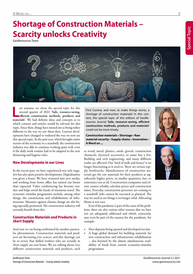
Two parallel caverns 20 m wide, 30 m high and 270 m long lie beneath Shazar Road in the Temple Mount area of Jerusalem with just 3 to 12 m overbur-den, passing within 4.5 m of the new Hauma train sta-tion and within 7 m of the planned K convention centre (Fig. 3). Each cavern has a three-lane road in the up-per part and about 700 parking places distributed over five floors beneath. The distance between the parallel caverns is 3.8 m at the top and 5 m in the lower area (Fig. 4).
Excavation of the parking and road caverns by the contractor Electra Group for owner Moriah Jerusalem Development started in April 2017 to designs pre-pared by Pini Swiss Engineers. Opening of the facility is planned for the end of 2022.
When operation begins, traffic will be connected by six cross passages between the caverns and there will be five vehicle exits and eight pedestrian connections to the Convention Center of Jerusalem, the Hauma Railway Station and other nearby structures. The caverns were excavated by drill and blast from both the east and west portal simultaneously through weak sedimentary rock. The size of the caverns, the restricted distance between them, the limited overburden, the difficult ground con-ditions, awareness of nearby structures, and the intense potential earthquake activity of the area, make the Shaz-ar project technically very challenging.

Geotechnics/tunnellinG 19
GeoResources Journal 2 | 2021Herr:Challenging Design and Excavation of huge Parking Caverns in Jerusalem www.georesources.net
The geology consists mainly of dolomite and dolo-mitic limestone of the Bina-Weradim formation. The upper portion of the rock mass is highly weathered with extensive karst features and a 3 m layer of fill above. The weathering of the 3 to 7 m layer had led to its being clas-sified as soft ground. Below 7 m, both intact and poorly jointed, fractured and crushed rock was encountered. Sound dolomitic limestone appeared at about 30 to 40 m below the ground surface. Major karst cavities, both empty and filled with clay, have been encountered with one of the largest having to be filled with more than 750 m3 of concrete.
Due to the limited overburden, the poor ground conditions and the large cavern span, large settlements and, in the worst case, crater formation at ground sur-face were identified as the major geotechnical hazards during excavation of the top heading. A pipe umbrella presupport system in combination with full face ex-cavation was applied over the majority of the 270 m length of the caverns (Fig. 5). Partial excavation of the top heading, with a central drift enlarged with two side drifts, was added and applied over the most critical areas (Fig. 6). The primary support of the top heading con-sisted of a combination of steel ribs and a 45 cm shot-crete lining.
The instability of the rock mass below the top head-ing was another significant hazard. To mitigate this risk, a 1 m2 longitudinal foundation beam reinforced with a longitudinal coupled reinforcement was installed at the base of the top heading span on both sides (Fig. 4). Each beam was interrupted only by the junctions of shafts and cross-passages. During the casting of the in-situ final lin-ing, the beams were used as the foundation for the gan-try crane. Prestressed rock bolts were installed beneath the top-heading foundation beams to reduce further the risk of vertical settlements of the top heading.
Due to the limited distance between the caverns and between the caverns and the new Hauma Station (Fig. 3), with a separation of about 4.5 m over a length of about 90 m, the instability of the rock pillar present-ed a major hazard during bench excavation. To mitigate this risk, the maximum height of benching was limited to 3 m. Four rock-bolting patterns were designed to cope with all possible geological scenarios. The patterns included cross-bolting between the caverns using Gewi bolts with a preload of 110 kN. Primary support of the walls consisted of 30 cm thick shotcrete reinforced with two layers of steel mesh. Additional strengthening was applied in the areas of the connection passages and exit shafts.
The final lining was designed without taking into account the favourable effect of the primary lining and support (Fig. 4). To address all hazards and load com-binations, the final lining is a 45 cm thick cast in place steel-reinforced concrete arch in the crown, a 90 cm thick concrete slab across the top heading invert, 30 cm cast concrete and installation of precast parking slabs designed to support the ground pressure under both static and dynamic conditions. A sheet membrane wa-
Fig. 4: Design details of the caverns
Fig. 5: Pipe umbrella presupport
Fig. 6: Partial top-heading excavation in a critical area
terproofing is placed behind the final lining, which was cast bottom-up after completion of cavern excavation.
The potential of earthquake activity was investi-gated thoroughly for both the construction and opera-tion phase of the caverns. During excavation the behav-iour of the caverns was monitored by installed optical prisms, total stations with prism arrays, load cells and
20 Geotechnics/tunnellinG
GeoResources Journal 2 | 2021 Herr:Challenging Design and Excavation of huge Parking Caverns in Jerusalemwww.georesources.net
extensometers, and by monitoring the force in the pre-stressed bolts. Systematic probe drilling was carried out to identify the presence of karst features in the pillar and beneath the benches. Detected voids were filled with cementitious grouting. The longitudinal foundation beams were designed to cope with the worst-case sce-nario of a badly filled karst cavity extending underneath the top heading foundation.
One of the most critical sections of the project was in the area adjacent to the new underground Hauma Railway Station where, over a length of 90 m, the north cavern runs within 4.5 m of the station (Fig. 7). The sta-tion was not part of the contract and was built before the cavern. The platform level of the station is lower than the bottom of the caverns (Fig. 3). It was excavated partly by drill and blast, starting from a circular shaft, and partly from the surface outside the Jerusalem hill. Previous analyses by others identified that the excava-tion of the caverns might create unacceptable stresses in and around the narrow rock pillar between the cavern and the station. These stress levels, combined with the fact that the station walls are unsupported over a height of 8.5 m on the vertical span, were judged unacceptable for the serviceability and ultimate state of the station, thus questioning the technical feasibility of the entire project.
The final design involved an intervention in the sta-tion, reinforcing the station wall using steel plates. This solution was combined with sequential excavation of the top-heading in this area and a risk management plan based on intensive monitoring of the wall behaviour during excavation. Deformations measured in Hauma Station during cavern excavation remained within the expected ranges and no cracks appeared in the station walls.
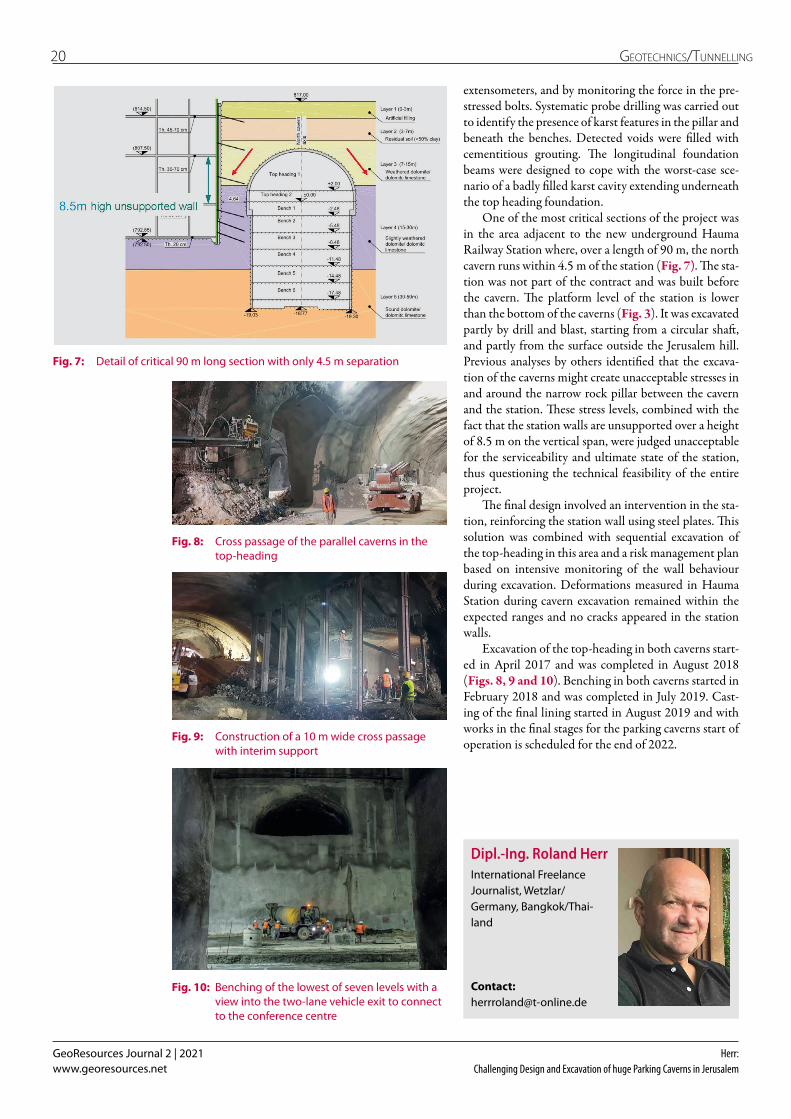
Excavation of the top-heading in both caverns start-ed in April 2017 and was completed in August 2018 (Figs. 8, 9 and 10). Benching in both caverns started in February 2018 and was completed in July 2019. Cast-ing of the final lining started in August 2019 and with works in the final stages for the parking caverns start of operation is scheduled for the end of 2022.
Fig. 7: Detail of critical 90 m long section with only 4.5 m separation
Fig. 8: Cross passage of the parallel caverns in the top-heading
Fig. 9: Construction of a 10 m wide cross passage with interim support
Fig. 10: Benching of the lowest of seven levels with a view into the two-lane vehicle exit to connect to the conference centre
Dipl.-Ing. Roland HerrInternational Freelance Journalist, Wetzlar/ Germany, Bangkok/Thai-land
Contact: [email protected]

tunnellinG 21
GeoResources Journal 2 | 2021Papesch:Demand-oriented Ventilation in Tunnel Construction www.georesources.net
Spec
ial T
opic
Fresh air is essential when carrying out tunnelling work underground. The CFH Group offers innova-tive energy- and cost-efficient solutions for venti-lation during tunnel construction – as adopted for the Kramer Tunnel in Bavaria.
Tunnelling • Ventilation • Innovation • Energy efficiency • Cost efficiency • Case study
Demand-oriented Ventilation in Tunnel ConstructionMatthias Papesch, M.Sc., CFT GmbH, Gladbeck, Germany
Potential for Energy Savings
In tunnel construction, supply of fresh air is necessary to be able to carry out the work underground and to achieve the goal of completing the tunnel. However, the enormous energy consumption for ventilation is often not sufficiently taken into account.
With the ‘Korfmann Air Guard’, patented through-out Europe, the CFH Group has developed a system for the more energy-efficient ventilation of duct-bound tun-nelling (Fig. 1). A combination of a PLC (programma-ble logic controller) and a computer program forms the core component. Using a frequency inverter, the PLC is able to control fans according to demand so that only the required amount of air is provided in the tunnel. How-ever, the software is the much greater advantage. The programme evaluates the installed ducting system in terms of its energy efficiency and highlights potential for improvement and energy savings. In addition, it can be seen at an early stage whether the existing fans are suf-ficient for the planned construction work or whether an increase is necessary. This can help to avoid unnecessary downtime and ensure that those working in the tunnel are constantly supplied with sufficient fresh air.
All measured and calculated values are logged dur-ing operation, and this allows for various analyses. One or more indicator lights also signal the effectiveness of the system on site. By integrating the computer into a higher-level network the current situation can be moni-tored, even from the office, and necessary changes can be effected.
Fig. 1: Sketch of ‘Korfmann Air Guard System’Source: Korfmann Lufttechnik GmbH
Depending on the power of the fans and the size of the construction site, the use of the ‘Korfmann Air Guard’ in tunnel construction can significantly reduce energy consumption during the construction phase, thus conserving resources, protecting the environment, and saving millions in energy costs.
Construction of the Kramer Tunnel in Bavaria
Layout of the new B 23 Bypass
The construction of a new B 23 bypass to the west of Garmisch-Partenkirchen is designed to reduce the im-pact of through traffic on the district of Garmisch. The bypass (B 23 new) follows the route of the existing B 23 north of Garmisch-Partenkirchen until shortly before the future northern tunnel portal. The north portal of the tunnel, which penetrates the Kramer massif, is locat-ed in a former quarry. The south portal is located near the local animal shelter where the route crosses the mu-nicipal road to Maximilianshöhe on a flyover structure.

22 tunnellinG
GeoResources Journal 2 | 2021 Papesch:Demand-oriented Ventilation in Tunnel Constructionwww.georesources.net
Spec
ial T
opic
For ventilation after the tunnel is complete, a fan cavern and a ventilation duct will be constructed. The fan cavern is located approximately one third of the way from the north portal and is positioned on the south-eastern side of the tunnel tube. The overburden depth above the cavern is around 99 m. From the ventilation cavern, a vertical shaft with a clear diameter of 4.50 m leads upwards and ends here in an above-ground ex-haust air structure. The exhaust shaft will have a height of around 118 m including the external structure.
Construction Method
The construction method for the underground struc-tures consists of a succession of excavation and prelimi-nary lining of the cavity. This ensures that a bond, capable of load transfer, is created between the lining elements and the surrounding rock, and that in the course of the stress redistribution the load-bearing capacity of the rock is maintained and utilised as far as possible. Due to the geology, the excavation is mainly carried out by blasting.
Ventilation during the Construction Phase
An AL18-6300 axial fan with a diameter of 1.8 m, comprehensive sound insulation, and a motor rating of 630 kW will be used for ventilation in the Kramer Tunnel during the construction phase. In addition to the fan, the CFH Group supplied a control container and the corre-sponding measurement devices for the demand-oriented fan control and the Air Guard. These include, among oth-er things, volume measurement at the fan and at the end of the duct as well as total pressure measurement at the fan. In addition, a CFT measurement kit is in use which continuously measures various workplace limit values at the workplace – e. g. carbon dioxide, nitrogen dioxide and nitrogen monoxide, etc. With the complete package, the client can provide its employees with sufficient fresh air at all times and thus protect their health.
Conclusion
In tunnel construction work, demand-based ventilation with a system designed for this purpose significantly re-duces energy requirements and thus contributes to both protecting the environment and saving costs.
Fig. 2: View of the construction site with ventilation equipment of the CFH GroupSource: CFT GmbH
Matthias Papesch, M.Sc.Project Manager, CFT GmbH, Gladbeck, Germany
Contact: +49 20302 / 1702 [email protected]
The rest of the route runs north of the US housing estate (Breitenau Family Housing) in a south-westerly direc-tion along the foot of the mountain range and joins the existing B 23 near Schmölz with two bridges over the River Loisach. The total length of the bypass is 5.56 km. For traffic coming from the direction of Munich, a loop ramp is under construction for the Garmisch/Burgrain junction to the north, and this will be connected by a roundabout to the Garmisch-Burgrain municipal road. For traffic coming from the direction of Garmisch, an additional direct ramp will be built.
Kramer Tunnel Construction Section
The section ‘New construction of the B 23 section with the Kramer Tunnel’ essentially comprises the traffic fa-cilities for the non-tunnel-section and the portal areas, the Kramer Tunnel (Fig. 2) including the associated ancillary structures, structure 0/2 ‘Burgrain junction flyover structure’, structure 0/3 ‘Burgrain groundwater basin’, and the Garmisch/Burgrain junction. The centre-piece is the Kramer Tunnel, which will be a single-tube tunnel with two-way traffic and a parallel rescue gallery and cross cuts. The main part of the tunnel structure will be driven underground (approx. 3,520 m). The cut-and-cover method will be used for around 75 m in the area of the south portal and about 10 m at the north portal of the tunnel. This section serves primarily as rockfall protection for the roadway in the vicinity of the adja-cent rock face. A total of six breakdown bays and 13 crosscuts to the accompanying emergency tunnel are ar-ranged at fixed intervals along the length of the tunnel.
A large part of the trafficable rescue tunnel was al-ready driven as an exploratory tunnel in 2011 and 2012. It runs to the west of the tunnel tube and will later have a total length of about 3,700 m. The centre-to-centre distance between the tubes varies. It lies between 21 m at the portals and 45 m in the middle section.

tunnellinG 23
GeoResources Journal 2 | 2021Herr:Refurbishment of the German Kuckuckslay Tunnel with the ‘Tunnel-in-Tunnel Method’ www.georesources.net
Spec
ial T
opic
The Kuckuckslay Tunnel in Germany built in 1871 was refurbished using the tunnel-in-tunnel meth-od. Rail operations were able to continue during the enlargement and rebuilding.
Tunnelling • Refurbishment • Tunnel-in-tunnel method • Rail operation • Efficiency • Safety
Refurbishment of the German Kuckuckslay Tunnel with the ‘Tunnel-in-Tunnel Method’Dipl.-Ing. Roland Herr, International Freelance Journalist, Wetzlar/Germany, Bangkok/Thailand
The 451 m Kuckuckslay tunnel in Germany is a single-tube double-track railway tunnel built in 1871 and lo-cated along the River Kyll between Trier and Cologne. The joint venture of Porr and Alfred Kunz (EKT JV, Er-neuerung Kuckuckslay Tunnel JV) was commissioned by the German rail operator Deutsche Bahn DB Netz in 2018 to refurbish the facility and replace the original lining of sandstone blocks backfilled with stones. Con-struction began in February 2019 and is planned to be completed in 2021 after a short full closure. The €19.15 million contract includes the preliminary work for the closure of one of the rail track while the other stays in service, the enlargement of the cross-section, and the finishing of the construction work.
The tunnel-in-tunnel rehabilitation method (TiT) is a process tried and tested by Deutsche Bahn. It uses a movable construction rig installed on its own set of rails to enclose the operating track and allow train traffic to continue as the work progresses (Figs. 1 +2). Outside the protective unit, the existing lining was demolished and at the same time the cross-section was expanded us-ing drill+blast. After the enlargement process was fin-ished, a special mobile formwork rig was installed. In a presentation for the 2020 Geomechanics Colloquium in Salzburg, Stefan Vetter of DB Netz, Mario Galli of EKT JV and Peter Steiner of Laabmayr Consulting, ex-plained the details of the construction.
After mechanical removal of the existing lining and drill+blast expansion of the cross section, a regime of rockbolts and shotcrete was installed for immediate support. Both steps are performed on the same working platform cyclically at a few metres apart.
At Kuckuckslay the EKT JV used a 36 m long tun-nel enlargement unit (TEU) with a weight of 160 t fabricated by GTA Maschinensysteme (Fig. 2). Similar in design as units used on previous projects, the unit consists of three sections – a shield, the main unit, and a backup gantry. The shield has hydraulically adjust-able support plates and always remains within the ex-isting rail envelope, preventing the existing lining from breaking ahead and falling onto the operating track. The main working unit is fitted with demolition hammers and drilling equipment to drill charge holes and holes for rock-support anchors and for spiling pre-support as
Fig. 1: Enlargement working platform unit and protective shield
Fig. 2: Operation continued during enlargement and rebuilding
required by geological conditions. The supply devices, such as hydraulic and power units, ventilation equip-ment and lay-down areas for supplies were mounted on the backup gantry. The steel structure and the equip-ment on the TEU was constructed for blast immission exposure. Excavators removed the demolished lining and excavated enlargement rock from the tunnel.
The portals of the Kuckuckslay tunnel are crossed by a service and cycling route, which was used as a con-struction road for the works. To enable the works to be set up, a temporary concrete canopy was constructed at each portal using the cut-and-cover method.
While the cut-and-cover canopy at the north por-tal was on a flat foundation, the 26.5 m-long canopy in poorer geological conditions at the south portal had

24 tunnellinG
GeoResources Journal 2 | 2021 Herr:Refurbishment of the German Kuckuckslay Tunnel with the ‘Tunnel-in-Tunnel Method’www.georesources.net
Spec
ial T
opic
exposure to air pollutants, particularly to diesel emis-sions from the continuing train operations and the dust generated during the lining demolition, blasting and shotcreting operations. In the planning phase, a suction ventilation system was provided for the working areas on the working unit, as well as a pressure ventilation system for the main cross-section (Fig. 3). The natural airflow was generally from north to south, with the ventilation situation affected also by the bi-directional train traffic.
Due to a requirement of the fire department that any haze, especially from smoke, had to be taken away from the main approach direction of the emergency services, the ventilation plan had to be designed from south to north. This was achieved by installing jet fans on the TEU which generated a vacuum in the main cross section into which dust was sucked from the TEU working areas.
The ventilation and air quality management system was supplemented by the use of water-spraying devices to suppress dust. The dust conveyed in the direction of tunnelling could also be suppressed with water spray.
With this plan, it was possible to meet the occupa-tional safety limits at all work stages and minimise the use of supplementary personal protective equipment including respirators.
Progress of the TEU, for removal of the existing lin-ing, expansion of the cross-section from 4.10 to 5.47 m inner radius and installation of primary support took a total of about 200 days, working two 12 hr shifts per day, 7 days a week (Figs. 4 and 5). An average progress of 2 m per day was achieved.
Dip.-Ing. Roland HerrInternational Freelance Journalist, Wetzlar/ Germany, Bangkok/ Thailand.
Contact: [email protected]. 5: Breakthrough at the North Portal of the Kuckuckslay tunnel in July
2020
Fig. 3: Ventilation system to protect workers in the operating railway environment
Fig. 4: Excavation is completed and casting of the inner concrete lining can start
to be supported on a foundation of bored piles either side of the operating rail tracks. Since these had been destroyed and partially restored during the Second World War, there were uncertainties regarding the static loadbearing capacity of the rebuilt sections. There were also logistical and programming considerations and for these reasons, instead of a roof foundation on solid bored piles, an alternative foundation of micropiles was proposed and implemented. A major advantage of the micropile foundation was that the drilling work could be carried out with a light-weight drilling equipment instead of heavier bored piling equipment.
Once the TEU working unit was launched, demoli-tion, excavation and primary support work progressed without any breaks. Excavation blasting took place dur-ing possession outages of the operating track and after close coordination between the construction supervi-sion managers, railway operators and the construction management. Track possessions depended on availabili-ty and were as short as possible. As many as 45 trains per day ran on the one operating track in both directions during the works. Depending on the geological condi-tions, blast rounds were 1 to 1.5 m with the enlargement unit running on rails mounted on temporary reinforced concrete foundations on either side of the rail tracks.
In the enclosed and limited working area, attention was paid to occupational health to protect workers from

tunnellinG 25
GeoResources Journal 2 | 2021Wahl, Vollmann, Thewes, König, Stepien, Riepe, Weißbrod and Lehan:BIM for the Maintenance and Operation of Road Tunnels – Project Aims, Modelling Work and underlying Requirements www.georesources.net
The research project FE 15.0623/2016/RRB ‘BIM in Tunnelling’ is currently laying down the founda-tions for a BIM-based operating model for road tunnels. This includes a consideration of existing model-theory principles along with an additional survey of the requirements of builder-owners and operators with reference to the operational issues arising during the life cycle of the facility.
Tunnelling • Tunnel operation • Digitisation • BIM • Modelling • Research
BIM for the Maintenance and Operation of Road Tunnels – Project Aims, Modelling Work and underlying RequirementsHendrik Wahl, M.Sc., Dr.-Ing Götz Vollmann and Prof. Dr.-Ing. Markus Thewes, Department of Tunnelling and Construction Operations, Ruhr University Bochum, GermanyProf. Dr.-Ing. Markus König and Marcel Stepien, M.Sc., Department of Informatics in Civil Engineering, Ruhr University Bochum, GermanyDipl.-Ing. Werner Riepe and Ferdinand Weißbrod, M.Eng., BUNG Ingenieure AG, Heidelberg, GermanyDipl.-Wirtsch.-Ing. Anne Lehan, Federal Highway Research Institute (BASt), Bergisch Gladbach, Germany
1 Introduction
For building operators and planning engineers Build-ing Information Modelling (BIM) is becoming an in-creasingly essential tool for adapting the planning and construction of transport infrastructure to meet mod-ern requirements in an age of every greater digitisation. Hitherto the main focus in this regard has primarily been placed on the early phases of the HOAI (German fee structure for architects and engineers) – combined with the aim of ensuring that the entire construction sequence is in future undertaken with BIM support. A great deal of effort is currently being directed towards this goal and to the provision of suitable framework conditions, which also includes research and develop-ment activities.
The operational aspect of the finished structure has hitherto tended to lead a somewhat marginalised exist-ence, even though this comprises the greater part of the life cycle, especially where tunnels are concerned. The-oretically speaking, the models that are developed for planning and construction purposes deliver the ideal set of conditions for establishing a BIM-supported mainte-nance management system – at least to the extent that the models developed and used in the initial construc-tion phases can be adapted to suit the needs of the op-erational phase.
The research project FE 15.0623/2016/RRB ‘BIM in Tunnelling’, which has been commissioned by the BASt (Federal Highway Research Institute), is currently engaged in developing theoretical and practical princi-ples for operating models for road tunnels. These are to be based on the requirements imposed during the oper-ating phase of the tunnel and on the tunnel modelling concepts that are now being established in Germany within the BIM environment. This project will also in-vestigate the applicability of internationally used data formats, e. g. the IFC (Industry Foundation Classes) standard, and will seek to develop proposals for imple-menting and extending these format fields.
This paper will present the initial results from the project, with a focus on the strategy adopted by the consortium to accurately formulate the required ap-plication scenarios based on a targeted interrogation of future users.
A second paper will then follow soon after to elu-cidate how ‘traditional’ tunnel operations differ from BIM-supported maintenance management and how classic approaches can be seen as widely in line with digital implementation.
2 Basic Principles of a BIM-supported Information Management System
2.1 BIM Reference Process
When applied to road tunnel constructions the term BIM describes a collaborative method of working based on digital models of a structure that allows information and data to be consistently recorded and applied over the entire life cycle. In Germany the aims and strategies behind an integrated and comprehensive application of BIM were first set out in the BMVI (Federal Ministry of Transport and Digital Infrastructure) ‘Multi-stage plan for digital construction and operation’, which stipu-lates that BIM should be used on all new projects being planned from 2020 onwards. [1]
The plan also includes specifications for an overarch-ing BIM reference process (Fig. 1) based on the HOAI (German fee structure for architects and engineers) per-formance phases. Tendering for a BIM project will oblige the client to specify Employer’s Information Require-ments (EIR) setting forth in precise detail what kind of data will be needed and when. The multi-stage plan also involves the preparation of a BIM Execution Plan (BEP), detailing the processes used for generating the required data and for assessing the existing BIM competencies on the part of the contractor. The yellow dots in Fig. 1 repre-

26 tunnellinG
GeoResources Journal 2 | 2021 Wahl, Vollmann, Thewes, König, Stepien, Riepe, Weißbrod and Lehan:BIM for the Maintenance and Operation of Road Tunnels – Project Aims, Modelling Work and underlying Requirementswww.georesources.net
produced on the basis of the requirements specified by all participating interest groups. These information requirements comprise three distinct types (Fig.2), in compliance with DIN EN ISO 19650-1 [3]:
▶ Organisational information requirements (OIR) based on the strategic aims laid down by the client, e. g. optimisation of operation and maintenance
▶ Project information requirements (PIR), i. e. the information that is needed to execute the building project, e. g. local conditions
▶ Asset information requirements (AIR), i. e. the in-formation that is required for operational purposes, e. g. object-specific information
This clearly shows that the project information require-ments in terms of the EIR (Employer’s information re-quirements), which constitute the client’s content and information requirements for project execution, play a central role in the implementation of the BIM.
3 Analysis of Requirements for Tunnel Operation
On the basis of this knowledge a concept was developed for the project in question that first provided for an analysis of the requirements for tunnel operation. This comprised, as a first step, an analysis of the organisation-al specifications along with the derivation of informa-tion requirements for specific application scenarios for a BIM information model.
This generally involved an analysis of the relevant rules, guidelines and recommendations connected with the regulatory framework for a BIM-based operating model that should serve as an example and information carrier for the requirements for tunnel operation. How-ever, experience in dealing with built facilities that form part of the federal trunk road network shows that the requirements have to go beyond the purely regulatory guidelines if they are to represent specific features of the on-site operations. Expert interviews were therefore conducted with representatives of the regional authori-ties as part of the analysis process, the aim here being to identify both the framework conditions and the specific need for a BIM-based operating concept.
3.1 Organisational Specifications
Investigating the organisational specifications that have to be taken into account for a BIM-based operating concept for road tunnels calls for an examination of the administrative, operational and regulatory factors (Fig. 3). These individual elements are presented in summary below.
3.1.1 Administrative Conditions
The strategic objective ultimately determines the orien-tation of an organisation. RABT 2006 [4], in conjunc-Fig. 2: Hierarchy of information requirements based on [3]
Fig. 1: BIM reference process through the HOAI performance phases [2]
sent the exact timings for the handover of the data to the client during the different performance phases.
The models prepared for the operational phase must also essentially comply with these requirements. This is especially important in order to ensure that the hand-over – in other words the transfer of the model from the construction phase to the operational phase – runs smoothly and without any loss of information. This calls for a uniform procedure to be maintained throughout all the performance phases.
2.2 Composition of the Information Requirements
Information models for the planning and execution phase and for the operational phase first have to be

tunnellinG 27
GeoResources Journal 2 | 2021Wahl, Vollmann, Thewes, König, Stepien, Riepe, Weißbrod and Lehan:BIM for the Maintenance and Operation of Road Tunnels – Project Aims, Modelling Work and underlying Requirements www.georesources.net
tion with EABT-80/100 [5], stipulates that assuring the safe operation of road tunnels is the priority goal.
This imposes requirements on the organisational structure that result from the conflicting priorities of ad-ministrative authorities, tunnel managers, investigating bodies, safety inspectors and tunnel control centres. Fig. 4 shows how the different organisational units interact with one another and also specifies their relevant functions.
When it comes to an integrated information man-agement process other parties also have to be taken into account, e. g. general services, as these are needed to sup-port the organisational units in carrying out structural repairs and technical maintenance work.
3.1.2 Operational Conditions
The activities of the organisational units stem from the three phases, comprising structural operation, mainte-nance and technical operations, these being allocated on the basis of the DAUB recommendations for determin-ing life-cycle costs [6]. These activities therefore consti-tute initiating events according to DIN EN ISO 19650-1 [3], on the basis of which the structural conditions of the building or of its equipment and facilities are likely to be altered, this in turn triggering an exchange of in-formation. Operational aspects resulting from these actions, such as maintenance cycles and corresponding
Fig. 3: Review of organisational requirements based on administrative, operational and regulatory conditions
Fig. 4: Organisational structure of tunnel operations showing selected interfaces with the support services and emergency services as specified in RABT 2006 [4] in conjunction with EABT 80-100 [5]
costs, can be coordinated using the digital information management process and optimised accordingly.
3.1.3 Regulatory Conditions
Regardless of the use of BIM methodology the relevant regulations, guidelines and recommendations, such as DIN 1076 [7] in conjunction with RI-EBW-Prüf [8], also specify requirements pertaining to documentation (engineering documentation, inventory records, etc.) and data logging and structuring (including status data and building data).
In order to avoid the need for copying and converting the information from the different systems, which may even entail an additional administrative cost and effort, a means for linking the different information sources was de-veloped as part of the INTERLINK research project [9]. This has created a decentralised data retention system and information from the ASB-ING [10] and data from the SIB-Bauwerke programming system can be incorporated into the model using this linking process. This new tool has to date mainly been used in bridge construction projects.
3.2 Identification of BIM Applications
Identification of BIM application scenarios is based on expert interviews, these being developed as a multi-

28 tunnellinG
GeoResources Journal 2 | 2021 Wahl, Vollmann, Thewes, König, Stepien, Riepe, Weißbrod and Lehan:BIM for the Maintenance and Operation of Road Tunnels – Project Aims, Modelling Work and underlying Requirementswww.georesources.net
to play here. Other activities that were analysed in this regard as part of the project exercise relate to tunnel monitoring and the operation of the supporting struc-ture, with a particular focus on structural monitoring and testing. Here the information requirements and as-sociated tests may vary in some areas, in direct compari-son to the maintenance process. However, in essence the processes under examination build on a uniform docu-ment base.
The information required for the processes forming part of the road tunnel operation is generated during the preceding project phases (planning and execution), though in some instances will only be available after the structure has been fitted out. To this effect, and as part of the application of BIM, the information required from the as-built model has to be transferred to an op-erating model and supplemented accordingly (Fig. 5 ac-cording to BIM4INFRA [11]).
Because of the increased outlay on the development and maintenance of the model the handover is therefore to be considered as a function or supply performance in its own right and so is treated as an individual applica-tion. Fig. 6 shows how the volume of information in-creases with each individual project phase. The project information requirements (PIR) increase linearly dur-ing the planning and execution stages. With the crea-tion of the operational model the project information is reduced to the relevant level and then augmented in line with the asset information requirements (AIR).
In the case of built facilities the information for the operating model is to be derived directly from the cor-responding engineering documentation. Supplementing this, the geometric modelling can be provided by photo-grammetry or laser scanning, this particular requirement being assessed beforehand on a project-specific basis.
4 Model-theory Concepts for the BIM-based operational and Maintenance Phase of Road Tunnel Projects
4.1 Derivation of Information Requirements
The implementation of a BIM-based operational phase for road tunnels calls for information requirements to be derived for individual application scenarios or rel-evant processes. Within the framework of the research project Information Delivery Manuals as specified in ISO standard 29841-1 [12] were produced for the indi-
Fig. 5: Derivation of an operating model based on BIM4INFRA [11]
Fig. 6: Handover between the project phase and the operational phase of a road tunnel in accordance with DIN EN ISO 19650-1 [3]
stage initiative involving representatives from the road tunnel operations sector. The first stage of this process sought to establish the general goals of the organisa-tion in question. These could be summarised from the overriding objectives of ensuring safe tunnel operations along with a high tunnel availability ratio.
The following is a summary of the BIM objectives as they apply to the maintenance process:
▶ Uniformly structured inventory documentation for more efficient administration of operational data
▶ Evaluation of operating data, e. g. by linking up with modules/tools
▶ Reduction in outlay on document management by introducing process digitisation, e. g. maintenance/servicing based on digital worksheets with links to the model
▶ Support for the invoicing of outsourced services ▶ Auditing of operational issues early on in the plan-
ning phase
Practical experience has shown that the opportunities that exist for the optimised planning of maintenance measures are still limited because of a lack of staff. Here a great deal of extra expenditure is also generated due to duplicate work, such as the compilation of lists and the examination and sorting of documents.
Taking maintenance procedures as an example it therefore appears, according to tunnelling-industry representatives and organisational units, that digitised information processing in particular has a central role

tunnellinG 29
GeoResources Journal 2 | 2021Wahl, Vollmann, Thewes, König, Stepien, Riepe, Weißbrod and Lehan:BIM for the Maintenance and Operation of Road Tunnels – Project Aims, Modelling Work and underlying Requirements www.georesources.net
vidual processes forming part of the tunnel operations. These manuals largely consisted of process diagrams and exchange requirements. The information requirements for each process were also drawn up in the form of a LOIN (Level of Information Need) framework, in ac-cordance with DIN EN 17412 [13].
The exchange of information between the different players in the context of BIM is based on information containers as specified in ISO 21597-1 [14]. Using this information container process enables a heterogeneous interchange to take place along with information stor-age and archiving. Using the linked data concept, and by application of RDF/OWL ontologies (Resource Description Framework and Web Ontology Language), the exchange of requirements can therefore be achieved using a BIM model in the IFC format along with XML documents (Extensible Markup Language).
Fig. 7 shows the structure of a container as based on the example of a maintenance routine, with the cor-responding exchange requirements that were identi-fied within the scope of the project. According to the ISO standard this container should comprise at least one file with meta-information (Index.rdf ), one folder with ontology-based schemata for generating document links and properties (ontology resources), the objects of the action, such as the model and worksheets (payload documents), and entities from the ontology schemata with concrete links between the documents and the model objects (payload triples). The relevant informa-tion exchange takes place at two points in time during the maintenance process:
1) After initiation of the maintenance work, as based on designated servicing intervals, with the provision of information by the managing authority to the maintenance contractor
2) After completion of the maintenance work with the handover of the (digitised) documentation
Fig. 7: Specimen contents of an ICDD container in the target process ‘Maintenance and inspection of technical equipment’
For a machine-readable analysis of the maintenance re-sults, for example, the worksheets are provided within the first exchange as an XSD schema file (XML Schema Definition) and can be filled out as an XML document by the executing personnel in the course of the main-tenance operation and then returned. These can be prepared with technical support (tools for XML-based document processing).
4.2 Extension of the IFC Data Format in Respect of Requirements for the opera-tional Phase
In this particular project the implementation of a BIM-based model for the road-tunnel operating phase was undertaken on the basis of the IFC standard that for several years has been supported at international level as an essential tool for the BIM-based and heterogene-ous exchange of data models in countless applications. While a comparatively broad standard has already been defined for the structural engineering industry, corre-sponding categories and methods are still being devel-oped for the infrastructure sector (including IFC Rail, IFC Road, IFC Bridge and IFC Tunnel).
IFC essentially differentiates between elements on the basis of spatial structures (site, building, facil-ity etc.) and physical objects (door, wall, rail etc.). A facility provides the basic model structure and identi-fies the content as a specific construction. In the tunnel construction sector a buildingSMART working group is currently developing enhanced IFC Tunnel Compo-nents, which also involves extensive structuring work for tunnel models. This comprises components for tun-nel equipment and facilities and for various tunnel con-struction methods.
As part of the project agenda these findings were integrated and coordinated for the modelling of both the tunnel structures and the operational equipment

30 tunnellinG
GeoResources Journal 2 | 2021 Wahl, Vollmann, Thewes, König, Stepien, Riepe, Weißbrod and Lehan:BIM for the Maintenance and Operation of Road Tunnels – Project Aims, Modelling Work and underlying Requirementswww.georesources.net
the tunnel structure and equipment for the operational phase and therefore forms the basis of a BIM-supported maintenance and operational management system.
In the next stage of the operation the results of the research project will be implemented at a suitable built facility as part of a demonstration exercise. This includes an operation to verify the features of the BIM model by means of an exemplary application of the scenarios that had been derived over the course of the project. A targeted workflow evaluation will also be carried out based on extended expert interviews in which further elaboration can be achieved by applying BIM-induced administrative requirements to the operating routines within the organisational units (see Section 3.1.1). On completion of the project the results and findings are to be published in a paper that will feature in a future edi-tion of this journal. This will also attempt to show how a BIM-supported operating and maintenance manage-ment concept differs from the ‘traditional’ system for operating road tunnels.
6 References
Wahl, H.; Vollmann, G.; Thewes, M.; König, M.; Stepi-en, M.; Riepe, W.; Weißbrod, F.; Lehan, A. (2021): BIM für die Erhaltung und den Betrieb von Straßentunneln – Zielstellung, Modellansätze und Anforderungen. GeoResources Zeitschrift (2-2021), S. 35–41. Online: https://www.georesources.net/download/GeoResourc-es-Zeitschrift-2-2021.pdf
[1] Bundesministerium für Verkehr und digitale Infrastruk-tur (BMVI): Stufenplan Digitales Planen und Bauen. Einführung moderner, IT-gestützter Prozesse und Tech-nologien bei Planung, Bau und Betrieb von Bauwerken, 2015.
[2] planen-bauen 4.0 GmbH. Aus: Arbeitsgemeinschaft des BMVI – BIM4INFRA2020: Handreichungen – Teil 1: Grundlagen und BIM-Gesamtprozess, April 2019.
[3] DIN EN ISO 19650-1:2019-08: Organisation und Digitalisierung von Informationen zu Bauwerken und Ingenieurleistungen, einschließlich Bauwerksinforma-tionsmodellierung (BIM) – Informationsmanagement mit BIM – Teil 1: Begriffe und Grundsätze. (English ti-tle: Organization and digitization of information about buildings and civil engineering works, including build-ing information modelling (BIM) - Information man-agement using building information modelling- Part 1: Concepts and principles (ISO 19650-1:2018); German version EN ISO 19650-1:2018)
[4] Forschungsgesellschaft für Straßen- und Verkehrswesen (FGSV): Richtlinien für die Ausstattung und den Be-trieb von Straßentunneln RABT. Köln 2006.
[5] Forschungsgesellschaft für Straßen- und Verkehrswesen (FGSV): Empfehlungen für die Ausstattung und den Betrieb von Straßentunneln mit einer Planungsge-schwindigkeit von 80 km/h oder 100 km/h. Köln 2019.
[6] Deutscher Ausschuss für unterirdisches Bauen e. V.: Empfehlungen für die Ermittlung von Lebenszykluskos-ten für Straßentunnel. Köln November 2018.Fig. 8: Allocation of IFC categories
with a view to creating a BIM-oriented data model. The example given in Fig. 8 depicts the structuring of a ventilation system forming part of the road-tunnel operating equipment, with related feature groups for semantic tagging. Increasing efforts are being made to cut down on the existing classification structure in or-der to respond to the challenges posed by the growing complexity associated with the description of structures and equipment elements. This has led to an extraction of the attributions from the categories and their absorp-tion into a set of characteristics.
Model objects are therefore semantically labelled and standardised based on the specification of their properties and characteristics. By linking a feature group for structural information, for example, a model object can be identified as maintenance-relevant. A cor-responding application then allows all maintenance-relevant objects to be identified on the basis of the fea-ture group. The result is a generalised category structure that is substantiated by the linking of the characteristics according to their information requirements. This con-cept forms the basis for describing the requirements for information exchange during the operational phase.
5 Summary and Outlook
Within the framework of a project to analyse the opera-tor requirements various application scenarios for the operation of road tunnels were identified on the basis of organisational targets and operational issues of a practi-cal nature. On this basis, and taking into account the different types of process involved, information require-ments in the form of Information Delivery Manuals were then compiled and the Level of Information Need for individual scenarios characterised in accordance with ISO specifications for the operationally relevant model objects of a road tunnel. One of the major chal-lenges arising involved the amalgamation of the differ-ent sets of requirements, this relating not only to the operators but also to the relevant regulatory provisions.
In parallel with this a complementary data model was developed on the basis of the IFC standard. This model constitutes an extension of the key elements of

tunnellinG 31
GeoResources Journal 2 | 2021Wahl, Vollmann, Thewes, König, Stepien, Riepe, Weißbrod and Lehan:BIM for the Maintenance and Operation of Road Tunnels – Project Aims, Modelling Work and underlying Requirements www.georesources.net
[7] DIN 1076:2011-11: Ingenieurbauwerke im Zuge von Straßen und Wegen – Überwachung und Prüfung.
[8] Bundesministerium für Verkehr und digitale Infrastruk-tur (BMVI): Richtlinie zur einheitlichen Erfassung, Bewertung, Aufzeichnung und Auswertung von Ergeb-nissen der Bauwerksprüfung nach DIN 1076 – RI-EBW-PRÜF. Februar 2017.
[9] INTERLINK: https://roadotl.eu/static/ireport/index.html, last downloaded 2020-07-15.
[10] Bundesministerium für Verkehr, Bau- und Stadtent-wicklung (BMVBS) – Abteilung Straßenbau: Anwei-sung Straßeninformationsbank Segment Bauwerksdaten – ASB-ING. Oktober 2013.
[11 ] BIM4INFRA: Umsetzung des Stufenplans „Digitales Planen und Bauen“ – Teil 1: Grundlagen und BIM-Ges-amtprozess. Source: https://bim4infra.de/wp-content/uplo-ads/2019/07/BIM4INFRA2020_AP4_Teil1.pdf, downloaded 2021-04-26.
[12 ] DIN EN ISO 29481-1:2018-01: Bauwerksinforma-tionsmodelle – Handbuch der Informationslieferungen. Teil 1: Methodik und Format. Beuth Verlag GmbH, Berlin. (English title: Building information models - In-formation delivery manual - Part 1: Methodology and format (ISO 29481-1:2016); German version EN ISO 29481-1:2017)
[13] DIN EN 17412-1:2021-06: Bauwerksinformationsmod-ellierung - Informationsbedarfstiefe - Teil 1: Konzepte und Grundsätze; Deutsche Fassung EN 17412-1:2020 (English title: Building Information Modelling - Level of Information Need - Part 1: Concepts and principles; German version EN 17412-1:2020)
[14] ISO 21597-1:2020-04: Informationscontainer zur Datenübergabe - Austausch-Spezifikation - Teil 1: Con-tainer (English title: Information container for linked document delivery - Exchange specification - Part 1: Container)
Hendrik Wahl, M. Sc. is a research associate at the Department of Tunnelling and Construction Operations, Ruhr University Bochum, Germany.
Contact: [email protected]
Dr.-Ing. Götz Vollmannis academic adviser at the Depart-ment of Tunnelling and Construc-tion Operations, Ruhr University Bochum, Germany.
Contact: [email protected]
Prof. Dr.-Ing. Markus Thewes is Head of the Department of Tunnelling and Construction Op-erations, Ruhr University Bochum, Germany.
Contact: [email protected]
Prof. Dr.-Ing. Markus Königis Head of the Department of Applied Informatics in Civil Engineering at the Ruhr University Bochum, Germany.
Contact: [email protected]
Marcel Stepien, M.Sc.is a research associate at the Department of Tunnelling and Construction Operations, Ruhr University Bochum, Germany.
Contact: [email protected]
Dipl.-Ing. Werner Riepe is Head of the Tunnel Construction Department at BUNG Ingenieure AG, Heidelberg, Germany.
Contact: [email protected]
Ferdinand Weißbrod, M.Eng.is responsible for BIM, 3D plan-ning, new technologies and IT at BUNG Ingenieure AG, Heidelberg, Germany.
Contact: [email protected]
Dipl.-Wirtsch.-Ing. Anne Lehan is on the scientific staff at the Federal Highway Research Insti-tute (BASt), Bergisch Gladbach, Germany.
Contact: [email protected]

32 MininG/tunnellinG
GeoResources Journal 2 | 2021 Wennmohs:Mechanical Rock Excavation versus Drilling and Blastingwww.georesources.net
Spec
ial T
opic
The choice between mechanical equipment and drilling and blasting for the rock excavation will depend to a large extent on the prevailing geo-logical conditions, but will also be driven by a consideration of the benefits and drawbacks as-sociated with each method. This article provides suggestions aimed at helping with the decision making process.
Mining • Tunnelling • Roadheading • Processes • Development • Drill and blast
Mechanical Rock Excavation versus Drilling and BlastingDipl.-Ing. Karl-Heinz Wennmohs, M & R Consulting, Witten, Germany
Background
When undertaking mining and tunnelling operations it is often difficult to decide whether a mechanical system or drilling and blasting is the better solution for rock excavation [1]. This article weighs up the pros and cons of the two different methods in an attempt to draw ap-propriate comparisons and reach decisions of relevance under project conditions. It commences with a look at the history of rock excavation down the years and goes on to discuss the advantages and drawbacks of both techniques in terms of the parameters that are relevant for mining and tunnelling projects. The results of the study are summarised and conclusions are drawn.
The History of Rock Excavation
From Muscle Power to Drilling and Blasting
Before the introduction of blasting with black powder muscle power and simple tools were for many years the only option available for creating underground cavi-ties, whether this was done in order to extract minerals and other natural resources or for some other purpose. For the miners working underground it was important to make the best possible use of the resources to hand, namely working time, personal strength and the qual-ity of the available tools (Fig. 1). Given these interact-ing factors the proverbial ability to ‘read’ the rock was also an important and perhaps also an essential condi-tion. As the rock became harder the rate of extraction per man and shift tended to decline. When excavating underground drifts, where working conditions were difficult and the rock could be extremely hard, it was common practice to opt initially for a minimum tunnel cross section, this subsequently being widened out if the planned application demanded it.
‘Fire setting’ was a traditional technique used to prepare harder rock formations for manual extraction by hammer and pick. However, it took the development
Fig. 1: Excavating rock by hammer and pick
of drilling and blasting technology to make tunnelling through hard rock both possible and effective. The des-ignation ‘hard rock’ relates to a strength limit for effi-cient cutting capacity in rock based on roadheader ma-chines operating in material above a certain compressive strength level. The transition from soft to hard rock is somewhat blurred and roughly equates to a compressive strength level of 100 MPa (UCS), though other factors also have to be taken into consideration. Manual drill-ing was a time consuming process until the introduction of mechanised drilling technology and the availability of drill bits with carbide.
Our ancestors realised that this kind of work could be made much easier if they could somehow get ‘behind the stone’, as the old saying goes. In other words: rock, ore, coal and so on could be detached from the solid much more readily if it were subjected to a tensile force rather than a compressive one.
Even with today’s tunnelling machines a high rock compressive strength in combination with an abrasive mineral content places extremely high demands on the operating life of the cutting tools and loading equip-ment. Any increase in the compressive strength and in the proportion of abrasive material present will cause the rate of tunnelling advance to fall quite noticeably as the tools (picks and disc cutter) will only achieve a shallow penetration depth and their service life will be much reduced as a result.
Full-face and Roadheader Tunnelling and Mining Machines
The mechanical excavation of rock all began with the hammer and pick. This task first involved channelling out grooves in the stone. Depending on the hardness and brittleness of the rock (mineral) these grooves were cut out, or rather milled out, in close proximity to one another (Fig. 2). This technique was then refined when tunnelling and production machines came along. When tunnelling, drifting machines (full-face and road-

MininG/tunnellinG 33
GeoResources Journal 2 | 2021Wennmohs:Mechanical Rock Excavation versus Drilling and Blasting www.georesources.net
Spec
ial T
opic
heading machines) are being used the gap between the milled grooves is referred-to as the ‘spacing’.
This basic technique is also employed for excavat-ing rock with selective-cut roadheading machines. In this case round-shank picks with carbide tips are used to score the rock face and create a series of tracks. Such a practice still has its limitations, this resulting from the material composition of the tools fitted to the machine and the amount of thrust pressure that can be applied to counteract the hardness of the in-situ rock. This type of rock extraction system is the subject of continuous test-ing aimed at determining its effectiveness in harder and more abrasive formations. However there have been few signs of a breakthrough in this area and little success has been achieved to date in extending the operating range of roadheading technology.
Nevertheless, because of the wide range of profile shapes and sizes that can be produced by boom-type roadheaders this type of rock excavation system is very much in demand by end users. It is therefore not surpris-ing that new technologies have been developed for this sector and for working in hard rock formations.
In recent years disc cutters have become the cutting tool of choice for roadheader systems (Fig. 3). This type of cutter is currently being tried out in roadway drivages and tunnel excavations, as well as in shaft sinking pro-jects. As the machines in question have to apply high contact forces to the roller bits they have to be equipped with suitably sized gripper systems.
All the aforementioned excavation techniques for full-face and selective-cut heading machines are designed to counteract the compressive strength of the in-situ rock. Under these extreme requirements, and with op-erations of this kind now being extended to include very hard rock formations, it is understandable that disc cut-ters have continually increased in size, with those being fitted to hard-rock tunnelling machines now measuring 19 to 20 inches in diameter. These disc cutters can weigh up to 200 kg and more and are designed to accept bear-ing loads and thrust forces of as much as 35 t (Fig. 4).
The requirements specified for raise-boring tools are even higher due to the nature of this kind of operation, as tool changes are not possible during the actual boring phase. These roller bits must therefore be fitted with car-bide studs and be suitably dimensioned for the job. The bits employed in operations of this type can therefore be as much as 17½ inches in diameter and have specified bearing loads of up to 70 t (Fig. 5).
The first trials with cutting head systems began in the 1960s, the aim being to ‘get behind the stone’. The term ‘undercutting’ was born. This technique recorded its first successes with the Swiss-manufactured Habeg-ger-Wohlmeyer system – a tunnelling machine that was labelled the ‘mini full-facer’ (Fig. 6).
In the 1990s undercutting came back into fashion with a series of disc cutter tests being carried out by the Wirth company. Several machines with movable booms designed for non-circular cross sections were built and tested at this time (Fig. 7).
Fig. 2: Traces of milling in ancient mine workings.Source: Von Markscheider, CC BY-SA 3.0 de
Fig. 3: Roadheader with disc cuttersSource: Epiroc
Fig. 5: Roller bits for raise boringSource: Sandvik Mining & Rock Technology
Fig. 4: Disc cutters for the tunnel boring machine (TBM)Source: Roxard Industries

34 MininG/tunnellinG
GeoResources Journal 2 | 2021 Wennmohs:Mechanical Rock Excavation versus Drilling and Blastingwww.georesources.net
Spec
ial T
opic
Comparison between mechanical Excavation and Drilling and Blasting
General
Many of the theoretical studies published over the years have attempted to assess and draw comparisons between mechanical rock excavation techniques and the drilling and blasting method. These comparative analyses con-tain many unknown factors. Some of the pros and cons that can be applied to each of the two methods – aspects
Fig. 6: Undercutting with the ‘mini full-facer’Source: Karl-Heinz Wennmohs
Fig. 7: Undercutting with disc cuttersSource: Wirth
Mechanical methods Drilling and blasting
for
▶ Very high rates of advance when geological conditions permit
▶ Continuous mode of operation ▶ High profile accuracy, no systemic overbreaks ▶ Unstable and water-bearing ground can also be tackled with the aid of EPB and mix shield support technology
▶ When using fully-enclosed machines (shield systems) the operating crew does not interact with the rock, which makes for greater safety
▶ Disc cutter change can be done from the safety of the rear head area (back loading cutter).
▶ By using tubbing segments the tunnel final support can be installed ready-made.
▶ No vibrations and noise generated by blasting
▶ Can adapt to the strata conditions, especially in formations subject to heavy rock pressure
▶ Low project-specific investment ▶ Machines (drill jumbos and spoil loading equipment) can be in-cluded in further project plans.
▶ Short start-up phase ▶ Excavation performance over the entire project lifetime with several attack points is comparable to that of mechanised systems.
▶ No limits imposed by way of rock hardness and abrasiveness
agai
nst
▶ Well trained personnel are needed for mechanised operations.
▶ Preparation, design, construction, transport and as-sembly are time consuming processes.
▶ Conventionally driven start tubes are often needed for the project preparation phase.
▶ High investment requirement for the overall roadheading package, including concrete tunnel segments production
▶ The quota of machine components that can be assigned to subsequent tunnel drivages is usually low – apart from the actual steelwork.
▶ Heading advance rate over the entire project lifetime is often in the same order of magnitude as that of drilling and shotfiring.
▶ Mechanical damage to machinery during the heading operation is time consuming and costly to repair.
▶ Work has to be carried out on the cutterhead between the front of the machine and the tunnel face (deposit welding etc.).
▶ If a TBM becomes stuck in place because of ground movement or rock burst the consequences can be extremely challenging, especially with shield-type machines, and such incidents can often result in long stoppages or even in the machine being lost.
▶ Handling and transporting explosives can potentially constitute a safety risk in some geographical areas.
▶ Blasting causes noise and vibration.
▶ Blasting creates overbreaks and underbreaks that can generate significant additional costs.
▶ Cyclical operations with the heading advance being inter-rupted during blasting
▶ Blasting can increase the accident risk due to rock falling from the heading face during charging.
▶ Qualified miners are required to undertake the drilling, blasting and excavation work.
Table 1: Mechanical excavation versus drilling and blasting: some arguments for and against
that have been the subject of much debate within the user group – are listed in Table 1.
Drilling and blasting is, by its very nature, a more dangerous method to use. Statements like this tend to suggest that industrial explosives, and even permitted explosives that have been tested and approved, present some kind of risk. And yet the number of accidents as-sociated with underground blasting operations is very low. This can be attributed to the effective training given to the personnel involved and to the high safety stand-ards that are applied to the exploders and explosive de-vices. After all, no one would attempt to fire a round of shots while standing within range of the blast.
Drilling and blasting can prove effective in extremely hard and abrasive geological formations provided that a denser drill hole pattern is used and consequently a larg-er quantity of explosives. This results in greater wear of the percussive drilling tools along with a low reduction in drilling rate. While this certainly makes things more expensive, such an operation will always be competi-tive when compared with mechanised excavation. The technical status of the face and production drilling op-erations enables high drilling rates to be achieved even in the hardest types of rock. This kind of performance, combined with today’s pumpable emulsion explosives, underscores the economic competitiveness of this exca-vation technique. Using such a method does not present any potential system-inherent risk.
Continuous Operation
The continuous operating mode that is often highlight-ed when discussing mechanical excavation methods in general, and tunnelling machines in particular, is a key factor in any assessment of excavation and tunnelling systems.
It is an accepted aspect of the process that in any drilling and blasting operation activities at the tunnel face, along with various outbye tasks, will be much cur-tailed when personnel are engaged in working with ex-plosives and that after the blasting cycle itself the tunnel advance will be interrupted by a standby time of about 30 minutes.
If we analyse the mechanical tunnelling system in terms of its apparent continuous mode of operation it will be seen that in actual practice we are left with something much less than the potential 100 % operat-ing time of the machine system (i. e. the actual cutting time). This remaining proportion can in fact turn out to be 50 % or even less of the theoretical cutting time. The intervening stoppages are often the result of high levels of wear suffered by the cutting tools and loading equip-ment. This wear is a particular problem when working through rock of increasing strength and when there is a high proportion of abrasive mineral material.
All these aspects serve to underline the fact that when it comes to seeking a continuous operating rou-tine there is little to choose between mechanised road-heading and drilling and blasting.

MininG/tunnellinG 35
GeoResources Journal 2 | 2021Wennmohs:Mechanical Rock Excavation versus Drilling and Blasting www.georesources.net
Spec
ial T
opic
comparisons are increasingly looking at the alternative idea of starting out from several points of attack.
Workplace Conditions
One of the main points of contention concerns the working conditions. In some countries it is becom-ing increasingly difficult to find people, and especially younger persons, who are prepared to undertake work of this kind. Of course working at a machine control cabin is an attractive proposition for those starting out on their career. And safety is also an important fac-tor, for in mechanised excavation systems with fully-enclosed TBMs that use shield-type systems it is nor-mally only a matter of managing the rock and debris as it moves away from the roadhead. When it comes to open tunnel boring machines and selective-cut road-headers there is in fact little difference between these operations and conventional tunnelling based on drill-ing and blasting.
If a mechanical malfunction occurs things become much more challenging and special demands are im-posed on those involved in the operation. This may also include having to free up a stuck TBM. In such an event the question that arises is: who will undertake this de-manding and perhaps dangerous work? Such situations call for an experienced team of miners (Fig. 8).
Tunnelling Performance
When trade journals report on mechanised tunnelling projects, especially those being carried out by tunnel bor-ing machines, they always mention the rates of advance, focussing particularly on the peak figures achieved per day, per week and per month. It is simply not possible to compare the two excavation systems directly as there will always be differences in geology to take account of. Nevertheless, it can be established that the average head-ing performance of each system only differs very slightly when viewed over the entire project period.
Cost
An objective cost comparison cannot be undertaken because the preconditions for using each system will always be different. It is accepted that significant invest-ment is needed for a tunnel boring machine and it is rarely possible to re-use a TBM for other projects with-out replacing a number of key components.
The equipment required for a conventional drivage operation only costs a fraction of the investment needed for a machanical excavation project. Moreover, all the machines deployed can be budgeted for subsequent tunnel excavation work. Where new projects are con-cerned assessments based on cost and performance
YOUR MACHINESOUR HYDRAULIC LIQUIDS
Fluid-Competence GmbHinfo@fl uid-competence.defl uid-competence.de
SYSTEM PROTECTIONENVIRONMENTAL PROTECTIONHEALTH PROTECTIONFIRE PROTECTION
APPLICATIONS: SURFACE AND UNDERGROUND MINING, STEEL MAKING, CHEMICAL INDUSTRY, PAPER INDUSTRY, WATER INDUSTRY, WASTE MANAGEMENT,
AGRICULTURE AND FORESTRY, CONSTRUCTION SECTOR, LOGISTICS

36 MininG/tunnellinG
GeoResources Journal 2 | 2021 Wennmohs:Mechanical Rock Excavation versus Drilling and Blastingwww.georesources.net
Spec
ial T
opic
Summary
While every kind of rock is mechanically ‘extractable’, it is important in this context to avoid using the term ‘cut-table’. Here the operating limits are set by the potential costs involved and/or by other requirements. Both ex-cavation methods discussed above have their strengths and weaknesses and users have to weigh these up before deciding in favour of one system or the other. As a ba-sic principle it can generally be established that when driving tunnels and mine roadways the advantages of the drilling and blasting method will become more ap-parent as rock strength levels increase. The conventional drilling and blasting excavation technique also wins out when it comes to working through rock that is subject to heavy rock pressure or when there is a risk of rock-bursts. The roadway and tunnel profiles that are created in this way are often seen as the system’s main cost fac-tor. This is certainly true when double-lining support systems are being applied. However, profile accuracy is not so relevant when single linings are being installed under hard rock conditions in conjunction with shot-crete and rockbolts. This is where the drilling and blast-ing system yields significant advantages.
Mechanised drivage methods are now very much in trend for operations involving variable geological conditions and unstable geological formations. Mecha-nised systems operating in conjunction with concrete
Fig. 9: Automation charging for blastingSource: Epiroc-Orica
Dipl.-Ing. Karl-Heinz WennmohsM & R Consulting, Witten, Germany
Contact: [email protected]
segments that are installed as the excavation advances have now become a key feature of this modern tunnel construction technique.
Over the years explosives manufacturers have tend-ed to pay too little attention to the growing market for mechanised techniques and excavation systems. New types of explosive, PR efforts and all manner of detailed information have not proved enough to keep pace with the competition.
One interesting development in this area has recent-ly been announced by the Epiroc and Orica companies. It is hoped that this innovative idea will stimulate some movement in a market that has been developmentally moribund for some time (Fig. 9).
The excavation of rock will always require a certain amount of energy, irrespective of the methods being used. This energy requirement will be greater as the rock hardness intensifies. In the case of mechanised excava-tion systems this situation has to be counterbalanced by increasing the installed power rating in kilowatts, while for blasting operations the number of boreholes, and hence the amount of explosive charge, will have to be increased. A direct comparison of efficiency levels based on the amount of energy expended and the excavation performance achieved can prove insightful and is gener-ally recommended.
There will still be a market for both excavation methods in the years ahead. There is more to mining than just driving tunnels and sinking shafts, for after all the real aim of the exercise is to extract rock and mineral ores and to do this as efficiently as possible.
References
Wennmohs, K.-H. (2021): Gesteinslösen mit mecha-nischen Verfahren versus Bohr - und Sprengtechnik. GeoResources Zeitschrift (2-2021), S. 51–55. Online: https://www.georesources.net/download/GeoResourc-es-Zeitschrift-2-2021.pdf
[1] Wennmohs, K.-H.: Mechanisches Verfahren zum Gesteinslösen versus Gesteinslösen mit Bohr und Sprengtechnik. Langefeld, O.; Tudeshki, H. (Hrsg.): Bohr- und Sprengtechnik, 22. Kolloquium, TU Clausthal, 3. und 4. Februar 2021, S. 39–47
Fig. 8: Control of the cutterheadSource: Robbins

Geotechnics/MininG/rAW MAteriAls 37
GeoResources Journal 2 | 2021von Hartlieb and Brummermann:Tailings and Mine Residues in the Extractive Industries – a global Challenge for Humanity and the Environment www.georesources.net
Spec
ial T
opic
Climate and environment protection are vital for maintaining human life on this planet. The pre-dicted and ongoing increase in population is just one of the factors that pose a challenge to the sufficiency of raw material supplies – and this de-spite the efforts being made towards an energy transition and the conservation of resources. The tailings and residues produced by the extractive industries require safer, more environmentally friendly and more economic solutions. This ap-plies particularly in the case of muddy tailings and with regard to the effects of climate change. This article seeks to examine the tailings issue in all its complexity.
Mining • Geotechnics • Raw materials • Tailings • Safety • Environmental protection
Tailings and Mine Residues in the Extractive Industries – a global Challenge for Humanity and the EnvironmentPeter von Hartlieb, EnergieAgentur.NRW, Dusseldorf, GermanyDr.-Ing. M. A. Katrin Brummermann, GeoResources, Hannover, Germany
1 Background
The Earth’s natural habitat is now seriously endangered and stands at an ecological tipping point. And tailing ponds, with their mining slurries and sludges, have con-tributed to this situation. Many thousands of tailing ponds of this kind in many countries around the world are the legacies of mining activities. Tailing dams are be-ing newly built, extended and filled all the time. These installations take up huge amounts of land and often pose a serious threat to local inhabitants, the natural en-vironment and the surrounding infrastructure.
The world’s population is expected to increase sig-nificantly in the coming decades. It is accepted that everyone has a right to decent living conditions and providing everyone with the raw materials that they need is and will remain a huge global challenge. Natural resources have to be extracted as efficiently as possible while at the same time providing employment, ensuring safe working conditions and protecting the climate and the environment.
The failure of a number of tailing dams over the years, resulting in a tragic loss of human life and massive environmental damage, has shown that these facilities still pose an enormous risk and that a multidisciplinary approach is needed to tackle the problem. A dam breach of this kind occurred at the tailings facility for the Mount Polley gold and copper mine in British Colom-bia on 4th August 2014. The failure led to the sudden release of some 8 million m3 of toxic slurry and other material, and about 17 million m3 of water, and caused
Fig. 1: Mount Polley in Canada – aerial photo taken on 24.07.2014 before the dam failed and again on 05.08.2014 after the breachSource: Jesse Allen, using Landsat data from the U.S. Geological Survey. Caption by Adam Voiland
a torrent of mud to flow out into the surrounding area [1, 2, 3]. This caused a huge environmental disaster that had serious consequences for the natural environment and the local residents (Fig. 1).
Starting out from an internationally-supported webinar organised by the mining network of the Energy Agency.NRW and supported among others by the Research Centre Post-Mining at the Technical University of Applied Sciences Georg Agricola (see information box) this article seeks to provide a general introduction to this topic and to promote a further ex-change of views and ideas that may contribute to finding a solution to these challenges. Further papers will follow

38 Geotechnics/MininG/rAW MAteriAls
GeoResources Journal 2 | 2021 von Hartlieb and Brummermann:Tailings and Mine Residues in the Extractive Industries – a global Challenge for Humanity and the Environmentwww.georesources.net
Spec
ial T
opic
national Council on Mining and Metals (ICMM), the United Nations Environment Program (UNEP) and Principles for Responsible Investment (PRI) (Fig. 2). The aim of the standard is to provide for the safe man-agement of tailings storage facilities (TSF). It seeks to ensure zero harm to people and the environment and zero tolerance for human fatality – and this is to apply over the entire life cycle of the installation, including during closure and post-closure operations. The stand-ard contains guidelines and principles relating to the following:
▶ Affected communities ▶ Integrated knowledge base ▶ Design, construction, operation and monitoring of
the tailings facility ▶ Management and governance ▶ Emergency response and long-term recovery ▶ Public disclosure and access to information
The guidelines proposed in the standard relate to the subject of tailings management in all its different facets. However they only provide for one framework and do not put forward specific proposals for solving the prob-lem but merely identify the challenges that need to be tackled. We have to ensure that real solutions and/or policies are developed that address the problems out-lined in the standard and are tailored to meet the indi-vidual circumstances.
Webinar on Mine Tailings organised by the EnergyAgency.NRW (EA): Let’s get out of this mess!
The EA’s latest webinar, which took ‘Innovation and the environment’ as its key theme, was held in April 2021 and was coordinated from Dusseldorf by the Network Mining Industry. The webinar, which followed on from previous events in July and October 2020, attracted some 100 on-line par-ticipants from 15 countries. Peter von Hartlieb, head of the EA’s Mining Industry section, and Profes-sor Dr Jürgen Kretschmann, President of the Technical University of Applied Sciences Georg Agricola (THGA) in Bochum, welcomed the on-line audience with introductory words. Professor Dr Tobias Rudolph, who in May 2019 was appointed Endowed Professor for Geomonitoring Post-Mining at the THGA Research Center of Post-Mining, then took over as moderator and set out the technical objectives of the 90-minute event.
The size of the audience who logged into such a specialised technical meeting shows that there is huge global interest at many levels not only in how we manage mine tailings, which remain a potential cause of human tragedies and environmental disasters, but also in the efforts being made towards ongoing research, systematic innovation and the development of this material as a sales segment that represents the end of the mineral processing chain. More than 30 % of those taking part came from universities, colleges and research institutes, with a further 45 % representing in-dustry, engineering companies and service providers.
A speaker from the University of Oulu in Finland then reported on the quantity of mine tailings currently held in storage worldwide. This indicated that there are at least 25,000 to 30,000 active tailing ponds and an unknown number of inactive facilities of this kind around the world. Dr Karsten Zimmermann of the DMT Group in Essen and Professor Frederic Cawood and Dr Iqra Atif from the University of the Witwatersrand in Johannesburg, RSA, then presented papers on integrated moni-toring and this was followed by Dipl.-Ing. Günter Becker, Head of the Mining Section at Munich Re, who gave his views on insurance issues and the new global standard.
The overall feedback from the webinar audience was very positive and the EA plans to organise further events on the tailings theme at some future date.
Fig. 2: Cover of the Global Industry Standard on Tailings Management [4]
covering a range of various sub-topics from the perspec-tive of different authors whose attempt to ‘see the big-ger picture’ may succeed in stimulating interdisciplinary collaboration.
The text below opens with a brief introduction to the newly drafted standard on mine tailings manage-ment [4]. It then goes on to describe typical tailing pond designs and provides details of some selected projects. This serves to illustrate the varied nature and relevant multidisciplinary aspects of these installations, along with the urgent need for action to mitigate or solve the current raft of problems that affect this area.
2 A global industrial Standard for Tailings Management
The joint ‘Global Industry Standard on Tailings Man-agement’ was launched in August 2020 by the Inter-

Geotechnics/MininG/rAW MAteriAls 39
GeoResources Journal 2 | 2021von Hartlieb and Brummermann:Tailings and Mine Residues in the Extractive Industries – a global Challenge for Humanity and the Environment www.georesources.net
Spec
ial T
opic
3 Typical tailing-pond Designs and selected Project Examples
3.1 Typical Designs
Three common types of sequential dam are used for the containment of tailing ponds (TSF) (Fig. 3). These re-taining dams, which are gradually increased in height throughout the life of the mine, have their inherent ad-vantages and drawbacks and so present different levels of risk. The layouts used differ according to the direc-tion in which the crest of the dam shifts in relation to the starter dam at the base of the structure:
▶ Upstream: the crest moves upstream towards the tailings
▶ Downstream: the crest moves away from the tail-ings pond
▶ Centreline: the crest does not shift its position
The following projects have been selected to illustrate the complex nature of these operations as well as to show the kind of positive effects that can be achieved for the benefit of local communities and the environment.
3.2 DRDGold: the largest Tailings Project in South Africa
The DRD mining company in South Africa has taken a pragmatic approach in setting up a commercial venture to recover residue metal in conjunction with the reha-bilitation of mining spoil dumps, an operation that will deliver sustainable social and ecological benefits [5]. In concrete terms this comprises:
▶ The removal and decontamination of existing tail-ing sediments that are currently sited on sensitive dolomitic groundwater aquifers, the aim being to eliminate or mitigate any future environmental im-pact and risk
▶ The establishment of a 1,350-hectare central pro-cessing facility to be set up on less permeable sub-strate away from the sensitive dolomite zone, a move that will also create new jobs for local workers
▶ A reduction in the health risks that potential dust emissions can pose for the surrounding communi-ties
▶ Removal of sulphides through a sulphuric acid plant to reduce acid mine drainage risk
▶ Re-use of currently impacted mine water for hy-draulic mining operations and treatment of excess water to potable drinking water standards
DRD has been engaged in the recovery of residue metal from dried tailings since 2018. Phase 1 of this operation involved the upgrading of the Driefontein 2 plant to process tailings from the Driefontein 5 dump at a rate of 400,000 to 600,000 t/month and the deposition of the residue on the Driefontein 4 tailings dam. Gold produc-
Fig. 3: Typical cross sections of sequential tailing dams – upstream, downstream and centrelineSource: GRID ARENDAL – López, 2017, Vicks 1983, 1990
Fig. 4: DRD operated gold processing plantSource: DRD Gold
tion commenced during the first quarter of 2019 and since then the output has amounted to around 120 kg (3,800 oz) per month (Fig. 4). Phase 2 comprises the development of a high-volume central processing facil-ity and a new deposition site that will create the capacity to handle at least 1 mt a month using a blend of material from different tailing sources. This phase will involve the reclamation of tailings from the Driefontein 3, Li-banon and Kloof 1 dumps, this to be followed by mate-rial from Ventersdorp North and South.
3.3 Pucobre builds a Photovoltacs Power Station in a former Tailings Pond in Chile
The Chilean mining company Pucobre has teamed up with the AES Gener electricity company to build a pho-

40 Geotechnics/MininG/rAW MAteriAls
GeoResources Journal 2 | 2021 von Hartlieb and Brummermann:Tailings and Mine Residues in the Extractive Industries – a global Challenge for Humanity and the Environmentwww.georesources.net
Spec
ial T
opic
tive sludge, and all this within a fairly densely populated area. The subsequent remediation programme compris-es the following phases:
▶ Decommissioning of the mines ▶ Flooding of the mine workings ▶ Water purification ▶ Dismantling and demolition of contaminated
buildings and installations ▶ Remediation of spoil dumps and slurry ponds
(Fig. 5) ▶ Environmental monitoring
The large-scale remediation scheme carried out by the state-owned Wismut company has proved, even by in-ternational standards, to be a unique and very success-ful mining and environmental project. By 2021 a large part of the affected land had been made useable again and the operation has clearly improved and restored the quality of life and the environment of the region. By working closely with Wismut the communities concerned have succeeded in creating a solid basis for the future. The municipality of Schlema, for example, which had been affected by the contamination, is now once again a spa resort, while the now restored slagheap landscape of the area was listed as a UNESCO World Heritage Site in 2019.
3.5 Research in the Harz Mountains – Recy-cling Materials of strategic Importance
The REWITA [8] scheme for the recovery of key raw materials from Rammelsberg tailings ponds at Goslar in the Harz mountains has been running since 2015 and is a centrepiece project of the REWIMET Recycling Cluster for Strategic Metals. Six companies have been engaged in this collaborative research effort, which also involves four institutes at Clausthal University of Technology and two of the departments at the Clausthal Institute of Environmental Technology (CUTEC). For Germany the project represents a major milestone in the recovery
Fig. 5: Culmitzsch tailings pond 1991 and 2016Source: Wirmut GmbH
tovoltaics power plant in the dried-up tailings pond of a copper mine that was closed in 2014. The installation is being developed at Tierra Amarilla in the Atacama region [6]. The plant will have an installed capacity of 3 MW and will provide an alternative source of self-supplied power for the copper concentrator at San José, which is located a few kilometres from Tierra Amarilla. It will also contribute to an effective reduction in the company’s carbon emissions. Pucobre has stated that the project has reaffirmed its commitment to sustainable mining and to a measurable reduction in its ecological footprint. For AES Gener the installation is also part of its decarbonisation plan for the Chilean energy sector. The commissioning of the new plant has meant that since January 2021 all the energy that the company needs for its copper production activities at all its installations and production sites is now 100 % renewables based.
3.4 Wismut Remediation Project in eastern Germany
The Wismut uranium-remediation project [7] has be-come an internationally significant reference point for future technologies linked to the remediation of radio-active waste dumps. The first signs of real progress in tackling the legacies of the mining industry appeared in the form of relatively simple remediation efforts, such as the demolition of buildings and the decontamina-tion of industrial sites. However these early years were mainly about developing strategies and concepts when it came to more complicated tasks, like the flooding of mine workings and the restoration of industrial settling ponds.
The Wismut region of Saxony and Thuringia has been severely affected by the intensive extraction and processing of uranium ore over a period of more than 40 years. These activities left a legacy of huge environ-mental damage, with people and nature afflicted in equal measure. When mining ceased the Wismut re-gion still contained 1,500 km of open mine workings, 311 million m³ of spoil and 160 million m³ of radioac-

Geotechnics/MininG/rAW MAteriAls 41
GeoResources Journal 2 | 2021von Hartlieb and Brummermann:Tailings and Mine Residues in the Extractive Industries – a global Challenge for Humanity and the Environment www.georesources.net
Spec
ial T
opic
and recycling of raw materials from mining residues. An analysis of core samples taken in the course of the inves-tigations revealed that the deposited residue material in-cludes 43 t of indium, 170 t of gallium, 1,200 t of cobalt and about 1.4 million t of baryte (Fig. 6). The cobalt content was much higher than expected, this element is being used for example in the production of lithium-ion batteries. Follow-up studies may well provide an answer as to the best solution for the tailing ponds.
4 A Problem with a multidisciplinary Reach
The above illustrates that finding effective solutions for the management of mining residues and tailings is a many-faceted issue that calls for a multidisciplinary ap-proach. The following list, which complements the main themes addressed in the international standard [4], gives some idea of the complex make-up of the problem:
▶ Society: The management of mine tailings is a global and multifaceted problem that has relevance for the affected regions and the individuals con-cerned.
▶ Political framework: Political decisions taken at international, national and regional level have an impact on resource security, climate and environ-mental protection, human rights, education and de-velopment, the retention and transfer of know-how, finance and economic interests. Practical solutions and workable compromises between conflicting in-terests therefore need to be found.
▶ Company profitability and social responsibility: The operators of companies that produce raw ma-terials have to find a balance between their vested economic interests and their social responsibilities. These two policy objectives can contain contradic-tions that will feed directly into the decision-mak-ing process.
▶ Technical know-how
The challenges that lie ahead will only be solved by cross-discipline expertise, target-oriented research and/or ongoing development, and these actions will have to be coordinated in a meaningful way. The list below provides an initial insight into the diverse nature of the relevant disciplines involved:
▶ Technical aspects: Mine developments over the entire project life cycle, comprising planning, op-erations and aftercare, geotechnics (structural integ-rity, sealing, new construction, remediation etc.), monitoring, plant engineering and process technol-ogy, logistics, IT and digitisation, recycling of mine tailings and the impact of climate change on tailing ponds (Fig. 7)
▶ Finance ▶ Risk management, liability etc.: viewed from dif-
ferent perspectives, incl. business undertakings,
Fig. 6: Test drilling for commercially valuable metals in the Harz tailings pondSource: Andre Bertram, CUTEC
society, environmentalists, insurance companies etc.
▶ Communication: a sense of responsibility and transparency in the actions of policymakers and authorities and in the conduct of operating compa-nies, the daily and trade press, service providers and suppliers
It will be a huge challenge to reconcile all these many different viewpoints and to combine the know-how of different institutions so that we can develop a common future strategy.
5 Conclusions on priority Actions and Future Prospects
Action is imperative if we are to press ahead with the management, construction, operation and, where nec-essary, remediation of tailing ponds, and if we are to
Fig. 7: Impact of climate change on tailings damsSource: GRID-Arendal

42 Geotechnics/MininG/rAW MAteriAls
GeoResources Journal 2 | 2021 von Hartlieb and Brummermann:Tailings and Mine Residues in the Extractive Industries – a global Challenge for Humanity and the Environmentwww.georesources.net
Spec
ial T
opic
America’s largest fjord lakes: Quesnel Lake, British Co-lumbia, Canada. Geophys. Res. Lett., 42, 3347–3355, doi:10.1002/2015GL063345
[4] ICMM International Council on Mining & Met-als, UN environment programme and PRI Principles for Responsible Investment (2020): Global Industrial Standard on Tailings Management. Online: https://globaltailingsreview.org/global-industry-standard/
[5] DRDGold: South Africa’s largest tailings project kicks into first gear. Mining Review Africa. Issue 10 2018. Online: https://www.miningreview.com/top-stories/drdgold-largest-tailings/
[6] Electricidad (2021): Energía solar: Pucobre desarrolla proyecto fotovoltaico sobre tranque de relave cerrado. Electricidad, La revista engegética de Chile, 23/04/2021. Online: https://www.revistaei.cl/2021/04/22/energia-solar-pucobre-desarrolla-proyecto-fotovoltaico-sobre-tranque-de-relave-cerrado/
[7] Wismut GmbH: Website zur Bergbausanierung in Sach-sen und Thüringen. Online: https://www.wismut.de
[8] Clausthaler Umwelttechnik Forschungszentrum (CUTEC): r4 Innovative Technologien für Ressourcen-effizienz – Rückgewinnung von Sekundärrohstoffen – REWITA. Online: https://www.r4-innovation.de//de/rewita.html
Peter von Hartliebis Senior Consultant at the EnergyAgency.NRW in Dus-seldorf, Germany.
Contact: [email protected]
Dr.-Ing. M.A. Katrin Brummermannis a civil engineer and technical editor of GeoRe-sources Journal, Hannover, Germany.
Contact: [email protected]
stop accumulating this material and instead develop ef-fective methods for tailings recycling. John F. Kennedy once said: “You’ll get a head start in life if you set to work while others just start off talking.” And this is also good advice for dealing with tailings and residues from the extractive industries. It certainly makes no sense to be intimidated into doing nothing because of the scale of the challenges facing us. “If you want something big you have to know how to limit yourself, but if you want eve-rything you really don’t want anything and you will get nowhere.” This quote from Georg Friedrich Wilhelm Hegel contains two pieces of advice for those who are involved with mine tailings, namely:
▶ Instead of keeping our eyes closed until a tragic ac-cident strikes let us set out now to find solutions to these challenges.
▶ Let us not dissipate our efforts but rather focus on constructive steps forward that fit in with the over-all framework and can be considered and assessed from different perspectives.
The EnergyAgency.NRW (a network representing the mining sector and mining technology whose motto is ‘Innovation and the environment’) and GeoResources Journal, which focuses on geotechnics, tunnelling, min-ing, energy and equipment and takes an interdiscipli-nary approach based on ‘Putting the underground in the foreground’, have therefore come together to use their combined potential to help tackle the aforemen-tioned challenges. This effort will include:
▶ Webinars ▶ This paper and future articles by various authors on
topics such as operator responsibility and monitoring ▶ An exchange of expertise and the promotion of net-
working and teambuilding that will help those in-volved to ‘see the bigger picture’
▶ New ideas and practical applications
6 References
Hartlieb, P. von; Brummermann, K. (2021): Tailings bzw. Rückstände aus der Rohstoffgewinnung – eine globale Herausforderung für die Menschheit und die Umwelt. GeoResources Zeitschrift (2-2021), S. 25–30. Online: https://www.georesources.net/download/GeoResources-Zeitschrift-2-2021.pdf
[1] Government of British Columbia: Mount Polley Tail-ing Dam Breach. Online: https://www2.gov.bc.ca/gov/content/environment/air-land-water/spills-envi-ronmental-emergencies/spill-incidents/past-spill-inci-dents/mt-polley
[2] Government of British Columbia (2015): Independ-ent Expert Engineering Investigation and Review Pan-el – Report on Mount Polley Tailings Storage Facility Breach
[3] Petticrew, E. L., et al. (2015), The impact of a catastroph-ic mine tailings impoundment spill into one of North

MininG 43
GeoResources Journal 2 | 2021Barth, Torkornoo, Boamah, Brosig, Hanelli, Schäfer, Bartels and Boamah:Exploration Targeting for small-scale Gold Mining Operations in the Dunkwa Area, Ghana www.georesources.net
The key objective of an investigation programme in Ghana was to develop new exploitation targets suitable for artisanal and small-scale mining. The method used can help drive similar activities in Ghana and in other countries.
Mining • Exploration • Geology • Artisanal and small-scale mining (ASM) • Case study • Ghana
Exploration targeting for small-scale Gold Mining Operations in the Dunkwa Area of GhanaDr. rer. nat. Andreas Barth, Beak Consultants GmbH, Freiberg, GermanySamuel Torkornoo, P. Geo., Torkornoo and Associates, Accra, GhanaKwame Boamah, Andreas Brosig, Delira Hanelli and Stefan Schäfer, Beak Consultants GmbH, Freiberg, GermanyEkow Bartels, Ministry of Lands and Natural Resources, Accra, GhanaDaniel Boamah, Ghana Geological Survey Authority, Accra, Ghana
1 Background
About 35 % of Ghana’s annual gold production of 142 t (2019, [1]) comes from artisanal and small-scale min-ing (ASM) operations. This contributes substantially to Ghana’s mining industry generated national income and is an important factor for poverty reduction and national development. Because of declining production figures, exhausting resources, and enormous ASM re-lated environmental damage the Government of Ghana has launched the World Bank financed programme ‘Ghana Artisanal and Small-Scale Mining Formalisa-tion Project (GASMFP)’, which is executed under the Management of the National Ministry of Lands and Natural Resources, and accompanied by the Ghana Geological Survey Authority. The generation of new exploitation targets suitable for ASM activities is one of the key tasks of this programme. The methodology and results presented here represent a case study and guideline for further similar activities throughout the country. They may also serve as a reference for similar activities in other countries.
Fig. 1: Gold Potential Map of SW Ghana [2] showing the survey area
Fig. 2: Regional geological setting of the survey area
2 Objectives and Survey Area Location
The objective of the current research is to identify new exploitation targets for small-scale mining activities in the Dunkwa mining area. Placer gold has been mined here, though the main valleys have now almost been completely mined out. New mining targets are being identified in small side valleys, in old river terraces and in basement rocks.
The survey area was initially identified using the ‘Gold Potential Map of SW-Ghana’ [2], as generated within the framework of a research project in 2013 by a consortium of the Geological Survey Department

44 MininG
GeoResources Journal 2 | 2021 Barth, Torkornoo, Boamah, Brosig, Hanelli, Schäfer, Bartels and Boamah:Exploration Targeting for small-scale Gold Mining Operations in the Dunkwa Area, Ghanawww.georesources.net
between 2132 and 2097 Ma [4]. Progressive tectonism evolved into a transgressional regime with thrusts de-veloping into transcurrent faults and syntectonic plu-tonism plus metamorphism affecting both the Birimian and Tarkwaian stratigraphy.
Most of the gold in Ghana was emplaced relatively late in the Eburnean Orogeny [3, 5, 6] and principally in deformation zones in Birimian metasediments and metavolcanics and as paleoplacer (Witwatersrand-like) deposits in Tarkwaian braided fluvial quartz pebble conglomerates. To a lesser extent gold was emplaced within pre- and syntectonic granitoid intrusive bodies pervading the greenstone belts and within basin sedi-ments along regional structures. Metallogenetically, the most important greenstone belt in Ghana is the Ashanti Belt.
The survey areas are located directly on the famous Ashanti Belt, between the cities of Kumasi in the North-east (NE) and Dunkwa in the Southwest (SW). Geo-logically, the surrounding rocks belong to the Birimian Supergroup of the Proterozoic age. The areas are crossed by the Ashanti and Kubi shear zones. Major hard rock gold deposits are located NE and SW of the survey area [3].
The local geology is marked mainly by NE-SW striking metavolcanics and metasediments of the Birim-ian Supergroup (Kumasi phyllites, Sefwi diabase and volcanoclastics) and cut by mafic dykes (Fig. 3). This map was compiled using data from [7], and our own air-borne geophysical data interpretation.
4 Legacy Data and Map of Minerals
Over the years many regional and local geological map-ping, prospecting and exploration activities were carried
Fig. 3: Local geological setting
Fig. 4: Examples of geophysical datasets [13]Th and U in ppm Equivalent, K in % Fig. 5: The Map of Minerals of the Survey Area
(Ghana), Beak Consultants GmbH (Freiberg, Germa-ny) and the Technical University Freiberg (Germany) (Fig. 1). This area is located in the centre of the famous Ashanti gold belt. The survey zone covers an area of 115 km2 and consists of two separate sections.
3 Geological Setting
The project area is located in south-western Ghana in the Man Shield (also referred to as Leo Shield) of the Precambrian West African Craton (Fig. 2). In Ghana, the Man Shield consists of seven mostly NE striking Paleoproterozoic greenstone belts of the Birimian Su-pergroup, emplaced from 2250 to 2170 Ma, separated by flyshoid basin sediments deposited during 2150 to 2100 Ma [3].
The Man Shield was affected by the Eburnean Orog-eny resulting from convergence between the West Afri-can Craton and the São Luis Craton of South America, occurring during 2130-1980 Ma [3]. The early stages of this collision event resulted in thrust tectonism and crustal thickening. Uplift developed foreland basins in several of the greenstone belts in Ghana, particularly in the Ashanti Belt, which were subsequently filled with molassic sediments of the Tarkwaian Group deposited

MininG 45
GeoResources Journal 2 | 2021Barth, Torkornoo, Boamah, Brosig, Hanelli, Schäfer, Bartels and Boamah:Exploration Targeting for small-scale Gold Mining Operations in the Dunkwa Area, Ghana www.georesources.net
out in and around the survey area [e. g. 8, 9, 19, 11, 12]. Unfortunately, the data obtained from these private exploration activities were not fully available for our project. The survey area is covered by geological maps of 1:100,000 scale and regional airborne geophysical data (magnetics and radiometry, [13], Fig. 4).
Using the publicly available remote sensing Sentinel data [14] and the available legacy data the Map of Min-erals (Fig. 5) was created as the main input data set (the training data) for the initial artificial neural networks (ANN) based exploration targeting. The initial hard rock gold potential map was produced in conjunction with the regional geological and geophysical data.
5 Multistep Artificial Neural Network (ANN) based Exploration Targeting
Artificial neural networks (ANN) are an excellent in-strument for the identification of exploration targets. The approach was implemented in Beak´s advangeo® prediction software [15, 16]. The respective data pro-cessing workflow is shown in Fig. 6. Using known min-eral occurrences as training features and pre-existing geoscientific data as controlling parameters exploration target maps have been compiled in an iterative process using the body of data as it grew during the project as follows:
▶ At the beginning: using the regional geophysical and geological data for general survey area identifi-cation
▶ After legacy data collection: for detailed planning of the field survey program
▶ At the end: consideration of all field data; for final exploration targeting and follow-up work program design
The interim target map was verified independently by the results of stream sediment sampling: the stream sediment Au anomalies match very well with the main ANN generated target areas. Results of ANN based exploration targeting, stream sediment, auger and soil sampling are mutually confirmative.
6 Field Work and Analytics
The field work was executed as a combination of stream sediment sampling, soil sampling, pitting, auger drill-ing, and hard rock sampling:
▶ The entire area was covered with a stream sediment survey (density 2 samples/km2). Stream sediment data were processed as shown in Fig. 7: the sam-pling points were identified using the local stream network, the analytical results have been logarith-mized, related to the respective catchment areas, and gridded to make them useable in the ANN based calculations.
▶ Multi-element analytics were performed at ALS laboratories. QAQC (QAQC: Quality Assurance/
Fig. 6: ANN-based exploration targeting workflow implemented in the advangeo® Prediction Software
Fig. 7: Scheme of stream sediment data processing

46 MininG
GeoResources Journal 2 | 2021 Barth, Torkornoo, Boamah, Brosig, Hanelli, Schäfer, Bartels and Boamah:Exploration Targeting for small-scale Gold Mining Operations in the Dunkwa Area, Ghanawww.georesources.net
Quality Control) was executed using blanks, dupli-cates and standard reference materials.
▶ Placer exploration pitting (63 pits, 1 x 1 m) was used for identification of placer resources (Fig. 8).
▶ Soil sampling was used to identify primary ore zones in stream sediment anomalies and ANN iden-tified target zones (Fig. 9).
▶ Auger drilling (110 bore holes) was used for the verification of primary mineralization targets (Fig. 10). Hard rock sampling was executed for the evaluation of primary mineralisation. 87 samples have been taken from active and abandoned hard rock mining sites (Figs. 11 and 12) and from bed rock recovered in placer exploration pits.
7 The final Target Maps
The final exploration target map combines the results of four independently generated datasets:
▶ The stream sediment gold anomaly map ▶ The ANN based target map created exclusively using
remote sensing data (radiometry and magnetics) ▶ The soil sampling results ▶ The hard rock sampling results
As Fig. 13 shows the results of the approaches match up very well. They have been used to identify priority fol-low-up areas and to design the respective programmes.
8 Results
8.1 Placer Gold
Modest gold placers are very common in the survey area. Native gold was found in almost all pits in differ-ent geomorphological positions:
▶ Recent valleys ▶ Old terraces ▶ Slope debris
Fig. 11: Abandoned ASM pit on Suhyenso Tema ridge
Fig. 12: Milky smoky quartz with 41 ppm gold from the Suhyenso Tema Ridge abandoned pit waste (see Fig. 11) waste
Fig. 8: Placer exploration pitting Fig. 9: Soil geochemistry lines at the Suhyenso Tema Ridge area and interpreted primary gold mineralisation zones
Fig. 10: Auger bore hole line for targeting potential hard rock mineralisation upslope of ASM slope debris mining

MininG 47
GeoResources Journal 2 | 2021Barth, Torkornoo, Boamah, Brosig, Hanelli, Schäfer, Bartels and Boamah:Exploration Targeting for small-scale Gold Mining Operations in the Dunkwa Area, Ghana www.georesources.net
Generally, the gold grades in the gravel do not exceed 0.2 g/m3 and in most cases are well below 0.1 g/m3. The average thickness of placers with a gold grade of > 0.04 g/m3 is 1 m, the average overburden is 0.9 m. These gold placers cover an area of 2.7 km2. The value of the contained gold is just 7.8 M USD, and consequently, the value of the gold related to 1 m2 of land is approx. 3 USD. The very low value of the contained gold pre-vents an acceptable rehabilitation of mined out areas. The placers are not recommended for mining because of the risk of significant environmental damage.
8.2 Hard Rock Gold
Hard rock gold is currently only mined by ASM opera-tions at a few locations in the survey area. The mined material usually consists of low thickness (a few cm to a few decimetres) quartz veins in carbonaceous phyllites. The Au grades in the quartz veins are high and range from 10 to 43 g/t. Based on soil sampling data a series of ore zones of up to 100 m thickness and 1.5 km lateral extension was identified in the Tema Ridge Mountains. Because of the 2 m interval channel sampling these vein-lets were not identified during earlier industrial explora-tion trenching programmes. Only sub-economic gold mineralisation of 0.1 – 2 g/t was identified in many trenches during the 1970s and 1980s. The high-grade quartz veins have been diluted down to uneconomic grades by low-grade host rocks. The ore zones identi-
Fig. 14: The proposed mining technology consists of traditional vein mining using a system of adits, drifts, overcuttings and steep stopes.
Table 1: Ranking matrix of target areas
Area Number 1 2 3 4 5 6 7 8
Area [km²] 15.8 6.3 8.4 3.1 6.7 0.9 9.9 2.6
Priority Status 1 1 2 2 3 4 4 4
Level of Au anomaly in stream sediments 3 2 2 2 3 4 4 4
Predictive Model #76 status 3 2 2 3 2 1 1 2
Large thrust fault in the area? 0 1 0 0 1 1 1 0
Hard rock gold ASM activities? 3 3 0 0 0 0 1 0
K anomaly? 3 3 3 3 2 2 1 2
Sum of parameters 12 11 7 8 6 5 5 5
Fig. 13: The final target map: a combination of two independent datasets: stream sediment Au anomalies and ANN based targeting by remote sensing data (radiometry and magnet-ics)
fied at that time were too small and/or too low grade for large-scale industrial opencast mining.
These mineralisations now have prospects for typi-cal vein mining by small to medium sized operations combining a system of tunnels, drifts and steep-gradient stopes (Fig. 14) with hand picking of the quartz material. High-grade quartz material can be processed by crush-ing, milling and grinding followed by gravity separation. The tailings and potentially low-grade host rock material can be leached using a simple cyanide-based process.
9 Next Steps
The potential target areas have been ranked (Fig. 15, Table 1), and follow-up work is recommended in two first and two second priority areas, including soil sam-pling on lines, trenching, and inclined drilling.
Exploration activities for identification of mineable resources will be combined with metallurgical investi-gations to identify simple and effective recovery tech-nologies for the respective ore type: native Au in almost mono-mineral quartz veins.
Exploratory adits can be used for both detailed explo-ration and recovery of material for metallurgical test-work.

48 MininG
GeoResources Journal 2 | 2021 Barth, Torkornoo, Boamah, Brosig, Hanelli, Schäfer, Bartels and Boamah:Exploration Targeting for small-scale Gold Mining Operations in the Dunkwa Area, Ghanawww.georesources.net
[2] Mineral Prospectivity Mapping in South-West Ghana. Joint Research Project of the Geological Survey Depart-ment, Ghana, Technical University Mining Academy Freiberg, and Beak Consultants GmbH. Freiberg, 2013. Online: https://www.beak.de/beak/sites/default/files/content/7_News/171_17_Sep_2013/Presentation_LOW.pdf
[3] Feybesse, J. L.; Billa, M.; Guerrot, C.; Duguey, E.; Les-cuyer, J. L.; Milesi, J. P.; Bouchot, V., 2006: The Paleo-proterozoic Ghanaian province: Geodynamic model and ore controls, including regional stress modelling: Precambrian Research 149 pp.149–196.
[4]: Oberthür, T.: Vetter, U.; Davis, D. W.; Amanor, J. A.; 1998: Age constraints on gold mineralisation and Paleo-proterozoic crustal evolution in the Ashanti belt of southern Ghana.
[5] Allibone, A. H.; McCuaig, T. C.,; Harris, D.; Etheridge, M. A.; Munroe, S.; Byrne, D.; Amanor, J.; Gyapong, W., 2002: Structural controls on gold mineralisation at the Ashanti gold deposit, Obuasi, Ghana: Society of Eco-nomic Geologists Special Publication 9, p. 65–93.
[6] Milesi, J. P.; Ledru, P.; Feybesse, J. L.; Dommanget, A.; Marcoux, E.; 1992: Early Proterozoic ore deposits and tectonics of the Birimian orogenic belt, West Africa: Precambrian Research 58, pp.305–344.
[7] Perrouty, S.; Aillères, L.; Jessell, M. W.; Baratoux, L.; Bourassa, Y.; Crawford, B.: Revised Eburnean geody-namic evolution of the gold-rich southern Ashanti Belt, Ghana, with new field and geophysical evidence of pre-Tarkwaian deformations. Precambrian Research 204– 205 (2012) 12– 39.
[8] Adansi Gold Company (GH) Ltd: Obotan Gold Pro-ject, Amansie District, Ghana. National Instrument 43-101 Technical Report. ENGINEERING SERVICES LIMITED ABN 12 121 542 738. 2012
[9] Asante Gold Corporation: Kubi Gold Project, Ashanti Region, West Ghana. National Instrument 43-101 Technical Report. SEMS Exploration. 2014
[10] Griffis, R. J.; Barning Kwasi; Francis, L.; Agezo; Fred K. AKOSAH: Gold deposits of Ghana, Minerals Commis-sion, Ghana, 2002
[11] Gyedu, John Nketia, Felix Sibsa: Gyimigya Concession, Ashanti Region. Terminal Report and Application for Renewal of Prospecting License. Adansi Gold Company Ltd., April, 2014.
[12] Williams, E. H.: Geology and Prospectivity of the Koto-pre Prospect, North Bekansi Concession. Ashanti Gold-fields Corporation. January 1996.
[13] Ghana Geological Survey Authority: Airborne magnetic and airborne radiometric data of the survey area. 2020.
[14] Copernicus: Copernicus Open Access Hub / Sentinel data. Online: https://scihub.copernicus.eu/
[15] Barth, A.; Knobloch, A.; Noack, S.; Schmidt, F. (2014): Neural Network-Based Spatial Modeling of Natural Phenomena and Events. In: Khosrow-Pour, M. (Ed.): Systems and Software Develop-ment, Modeling, and Analysis: New Perspectives and Methodologies. IGI Global. P. 186 - 211. ISBN13: 9781466660984
Fig. 15: Identification and ranking of potential target areas
The proposed type of small- to medium-scale under-ground mining requires a solid business and economic model, this to be executed by well-organised economic entities. Solid pre-financing is required to implement the necessary exploration and feasibility studies.
Economic operators could possibly form a co-operative venture involving existing large-scale mines with the new small- to medium-scale mining enter-prises.
10 Conclusions
Within just six months a multi-component programme has been set up to evaluate both the placer and the hard rock gold potential within the 115 km2 survey area. Placer occurrences have been evaluated as not econom-ic, while the hard rock gold potential was recommended for further detailed exploration. The prospective miner-alisation style was identified as low thickness and high-grade quartz veins hosted by phyllites.
Implementing the multistep ANN-based explora-tion targeting technology in combination with a stream-lined field work programme proved very successful. This strategy served to minimise exploration expenditure and speed-up the target identification process. The same methodology can be recommended for further applica-tion throughout the country.
11 References
[1] Ghana Chamber of Mines: 2019 annual report. On-line: https://ghanachamberofmines.org/wp-content/uploads/2020/05/2019-Annual-Report_Complete.pdf

MininG 49
GeoResources Journal 2 | 2021Barth, Torkornoo, Boamah, Brosig, Hanelli, Schäfer, Bartels and Boamah:Exploration Targeting for small-scale Gold Mining Operations in the Dunkwa Area, Ghana www.georesources.net
[16] Noack, S.; Barth, A.; Irkhin, A.; Bennewitz, E.; Schmidt, F.: Spatial Modelling of Natural Phenomena and Events with
Dr. rer. nat. Andreas BarthManaging Director of Beak Consultants GmbH, Freiberg, Germany.Contact: [email protected]
Stefan Schäfer, M. Sc. Economic Geology,former Project Manager at Beak Consultants GmbH, Freiberg, Germany, now Science Officer at the Bavar-ian State Office for the Environment, Hof, Germany.Contact: [email protected]
Samuel Torkornoo, P. Geo.President of Tokornoo and Associates, Accra, Ghana.Contact: [email protected]
Ekow BartelsMining Specialist (MS), Ghana ASM Formalization Project (GASMFP) Contact: [email protected]
Dr. rer. nat. Kwame BoamahConsulting Geologist, self-employed, GhanaContact: [email protected]
Andreas Brosig, M.Sc.Geologist, Project Manager, Expert for 3D Modelling and Mineral Predictive Mapping at Beak Consultants GmbH, Freiberg, GermanyContact: [email protected]
Delira Hanelli, M.Sc.Project Manager, Geographic Information System Expert, Remote Sensing Specialist at Beak Consult-ants GmbH, Freiberg, GermanyContact: [email protected]
Dr. Daniel BoamahAg. Director-General, Geological Survey Authority, Accra, GhanaContact: [email protected]
Artificial Neural Networks and GIS. International Journal of Applied Geospatial Research (IJAGR) 3(1), 2012.
Organization: Institute of Mining and Special Civil Engineering Univ.-Prof. Dr.-Ing. Helmut Mischo, Pr. Eng. Fuchsmühlenweg 9 09599 Freiberg
Contact: E-Mail: [email protected] Web: freibergbau.tu-freiberg.de Phone: +49 (0) 3731 39-3819
The 5th Symposium FreiBERGbau on October, 5th and 6th, 2021 will be dedicated to Dust and Dust Control:
• Regulations and legal requirements • Impact of dust on health • Explosive dusts • Dust measurement • Dust control in operational environments • Dust management by ventilation • Engineering controls for dust management • Personal protective equipment

50 MininG/Geotechnics
GeoResources Journal 2 | 2021 Bauer Group:Red Dog Mine Alaska: Ground Improvement in Permafrostwww.georesources.net
Red Dog Mine is located in a geological permafrost area in Alaska. Bauer Foundation Corp. was tasked with carrying out field tests using the jet grouting and Cutter Soil Mixing (CSM) methods for ground improvement.
Mining • Geotechnics • USA • Alaska • Permafrost • Testing • CSM
Red Dog Mine Alaska: Ground Improvement in PermafrostBauer Group, Schrobenhausen, Germany
Fig. 1: Around 170 km north of the Arctic Circle, Bauer Foundation Corp. carried out field tests using the jet grouting and Cutter Soil Mixing methods
Fig. 2: Amongst others, a multi-purpose Bauer BG 30 drilling rig with special Arctic equipment was used
Wiebke FoellmerBAUER Aktiengesellschaft, Schrobenhausen, GermanyContact: [email protected]
Manager with Bauer Foundation. “Trials were carried out from August to December of 2019, which ulti-mately identified the CSM method as the most suitable choice for the main scope of this project.” The CSM method combines features of the diaphragm wall tech-nique and the mixed-in-place ground improvement method (MIP). The soil is broken up using a cutter, then rearranged and mixed with an aggregate. The trials for the Red Dog Mine also determined the extent to which existing subsoil were to be replaced with suitable filler material to facilitate later mixing.
In 2020, during the period from July to November, 50 % of the pre-drilling was completed as well as 30 % of the CSM. In addition, Bauer Foundation Corp. was tasked with the construction of a secant pile wall as an extension to an existing slurry wall. To achieve this, the required pile wall was integrated into the existing slurry wall and the underlying rock using primary and second-ary piles. In all, 93 secant piles were constructed. A mul-ti-purpose Bauer BG 30 drilling rig with special Arctic equipment along with various drilling tool and mixer sets were used for the execution of all the works (Fig. 2).
One of the main challenges was the mobilization of equipment in the limited time provided by the sched-ule. However, the required special equipment was mobilized in record time. Some equipment was trans-ported by plane and then by ship from Seattle Harbor across the Bering Sea to a dock just over 80 km from the mine. Other equipment was transported via Her-cules aircraft from Anchorage airport to the airport on the mine site. This logistical success was made possible by close collaboration with various Bauer subsidiaries and Teck. “The remote and isolated location, the long deployment times and accommodation in camps pose additional challenges, as do the extreme Arctic climate conditions, precautionary measures associated with the corona pandemic and the specific safety requirements of the mining industry,” says Alejandro de la Rosa Knecht.
Despite all these challenges, the Bauer and client teams were able to successfully conclude trial work be-tween August and December 2019 and the first phase of production activities between July and November 2020. The final production phase which includes CSM and demobilization is due to be completed by June 2021.
Red Dog Mine, one of the world’s largest zinc mines, is located in the north-west of Alaska, around 170 km north of the Arctic Circle and nearly 1,000 km to the north-west of Anchorage. The mine has been operating since the late 1980s with around 10 % of the world’s zinc extracted here in open-cast mining.
Its location in the Arctic Circle region means that the entire mine is in a geological permafrost area that keeps the ground permanently and completely frozen below a certain depth. There is an active zone near the surface that thaws during the summer and refreezes dur-ing winter. Based on an evaluation of the permafrost and soil on the site, ground improvements were identified as a prudent measure to counteract the effects of poten-tial melting permafrost. To this end, Bauer Foundation Corp. was tasked by Teck with carrying out field tests using the jet grouting and Cutter Soil Mixing (CSM) methods (Fig. 1).
“The trials included detailed data capture and strict quality controls in close collaboration with Teck, the project owner, and other geotechnical consulting en-gineers,” explains Alejandro de la Rosa Knecht, Project

STUVA Conference 2021
International Forum for Tunnels and Infrastructure
24–26 November 2021 · Karlsruhe, Germany
STUVA – Research Association for Tunnels and Transportation FacilitiesMathias-Brueggen-Str. 41, D-50827 Köln/ColognePhone +49 (221) 5 97 95-0, Fax +49 (221) 5 97 95-50E-Mail: [email protected]
Separate Segment Tunnel
Operation/Planning!
More than 3,800 experts from over 20 countries
World’s leading industry meeting for underground construction and operation
Accompanying exhibition on 7,000 m² with more than 200 exhibitors from home and abroad
Thanks to the well-advanced vaccination campaign against the coronavirus, we are confident that this unique event for the tunnel industry will almost take place in the usual way. Of course, we will carefully monitor the development of the pandemic and follow the official regulations during the event.
Request the program booklet now – Online registration will be open as of August 2021.
Take the opportunity, to get targeted information at the „family get-together of the tunnelling industry“ about the latest developments and exchange views with colleagues from all over the world. Attend the STUVA Conference from 24–26 November 2021 at the Karlsruhe Trade Fair Centre!
www.stuva-conference.comwww.stuva-expo.com
STUVA21-Tagung_Anz_EN_A4_2021-07-20_bel.indd 1 20.07.21 09:32

agru Kunststofftechnik Gesellschaft m.b.H. | Ing.-Pesendorfer-Strasse 31 | 4540 Bad Hall, Austria | T +43 7258 7900 | [email protected]
Soil & groundwater protection
High chemical resistance
One stop shopping
Proven quality products
High supply capability
GEOMEMBRANES FOR ENVIRONMENTAL PROTECTION
L I N I N GS Y S T E M S
AGRU MICROSPIKE GEOMEMBRANE
LINER