
CCJ-Issue-69-Full.pdf - Combined Cycle Journal
100
User Group Conference Schedule Number 69 2022 www.ccj-online.com $15 INDEPENDENT VOICE OF THE GAS-TURBINE-BASED GENERATION SECTOR User Group Reports 501F Users Group.................................... 6 Long-time chairman, Russ Snyder, retires, replaced by Ivan Kush; preview of the 2022 in-person conference and vendor fair at the Hyatt Regency in New Orleans; review of the 2021 virtual meeting—including summaries of vendor presentations by ARNOLD Group, AGT Services, PSM, C C Jensen, Donald- son, NEC, Mitsubishi Power, SVI Dynamics, and EMW filtertechnik; 501F Best Practices Awards (p 22). Western Turbine Users Group............. 36 The 2022 conference, forced into a virtual format by the pandemic for a third year, will mirror the highly successful 2021 event summarized here day by day. Day One: Leadership team, acronyms you should know, breakout session profiles; Two: LM6000; Three: LMS100; Four: LM2500; Five and Six: GE sessions on LM6000 and LM2500; Seven: user-only discussions; Eight: Axford and Friends; Nine and Ten: special technical presentations by Noxco, ARNOLD Group, Liburdi, GasTOPS, Ethos Energy, EMW filternechnik. Aero Best Prac- tices Awards (p 49). ABHUG—Australasian Boiler and HRSG Users Group ............................... 56 A three-morning virtual conference with the following highlights: Long-term HRSG layup, IAPWS chemistry updates, management of corrosion fatigue, electrode boilers 101, mini- mal chemistry instrumentation, erosion of HP bypass valves, finite element analysis and creep-fatigue crack growth, inspecting for corrosion under insulation, FAC assessment. Best Practices Awards to plants powered by: n 501F engines: CPV Valley ... 22 South Point. ... 32 Klamath ................ 33 Rolling Hills ............................... 34 n LM6000 engines: Orange Cogen ............................ 48 Worthington ............................... 49 Lawrence County....................... 52 n 501D5 engines: Milford ........................................ 76 n 501G engines: Kings Mountain ......................... 81 New Covert ................................ 85 Athens. ....................................... 86 Middletown ................................ 88 Shepard ...................................... 91 Features Plant-network, data- link, communications issues revealed during commissioning .............. 66 Post-outage checklist for turbine owners ............. 68 Service provider tracks valve health, makes expert repairs, cuts maintenance cost ................................ 70 Ask the Chairman: What are the risks associated with forced cooling of your HRSG? ........72 Help a colleague by sharing your HRSG know-how, earn a reward .................................. 72 Isophase bus duct: Keep it dry, clean, cool............................. 74 Turbine Tip No. 16: A simple way to check gas-turbine performance ......................... 96 Miscellany Industry suffers consequences from cold-weather-ops design decisions. ..................................... 3 Sponsored content: Trinity Turbine Technology ..... 30 Polar Clean................................ 53 Professional services ..................... 97 2022 Virtual Conference April 18-21 and 26-28, plus May 3-5 Follow www.wtui.com for details Contact: [email protected] 2022 Virtual Conference March 22-23 and 29-30 www.filmformingsubstances.com Contact: [email protected] 2022 Virtual Conference May 17-19 www.europeanHRSGforum.com Contact: [email protected] 2022 Conference and Vendor Fair May 23-27, Dallas, Tex Fairmont Dallas Hotel Contact: [email protected]
-
Upload
khangminh22 -
Category
Documents
-
view
2 -
download
0
Transcript of CCJ-Issue-69-Full.pdf - Combined Cycle Journal

User Group Conference Schedule
Number 69 2022
www.ccj-online.com
$15
INDEPENDENT VOICE OF THE GAS-TURBINE-BASED GENERATION SECTOR
User Group Reports501F Users Group ....................................6Long-time chairman, Russ Snyder, retires, replaced by Ivan Kush; preview of the 2022 in-person conference and vendor fair at the Hyatt Regency in New Orleans; review of the 2021 virtual meeting—including summaries of vendor presentations by ARNOLD Group, AGT Services, PSM, C C Jensen, Donald-son, NEC, Mitsubishi Power, SVI Dynamics, and EMW filtertechnik; 501F Best Practices Awards (p 22). Western Turbine Users Group .............36The 2022 conference, forced into a virtual format by the pandemic for a third year, will mirror the highly successful 2021 event summarized here day by day. Day One: Leadership team, acronyms you should know, breakout session profiles; Two: LM6000; Three: LMS100; Four: LM2500; Five and Six: GE sessions on LM6000 and LM2500; Seven: user-only discussions; Eight: Axford and Friends; Nine and Ten: special technical presentations by Noxco, ARNOLD Group, Liburdi, GasTOPS, Ethos Energy, EMW filternechnik. Aero Best Prac-tices Awards (p 49). ABHUG—Australasian Boiler and HRSG Users Group ...............................56A three-morning virtual conference with the following highlights: Long-term HRSG layup, IAPWS chemistry updates, management of corrosion fatigue, electrode boilers 101, mini-mal chemistry instrumentation, erosion of HP bypass valves, finite element analysis and creep-fatigue crack growth, inspecting for corrosion under insulation, FAC assessment.
Best Practices Awardsto plants powered by:n 501F engines: CPV Valley ... 22 South Point. ...32 Klamath ................ 33 Rolling Hills ............................... 34n LM6000 engines: Orange Cogen ............................ 48 Worthington ............................... 49 Lawrence County .......................52n 501D5 engines:
Milford ........................................ 76n 501G engines:
Kings Mountain ......................... 81 New Covert ................................ 85 Athens. ....................................... 86 Middletown ................................ 88 Shepard ...................................... 91
FeaturesPlant-network, data- link, communications issues revealed during commissioning ..............66
Post-outage checklist for turbine owners .............68
Service provider tracks valve health, makes expert repairs, cuts maintenance
cost ................................70
Ask the Chairman: What are the risks associated with forced cooling of your HRSG? ....... .72
Help a colleague by sharing your HRSG know-how, earn a reward ..................................72
Isophase bus duct: Keep it dry, clean, cool .............................74
Turbine Tip No. 16: A simple way to check gas-turbine performance .........................96
MiscellanyIndustry suffers consequences from
cold-weather-ops design decisions. ..................................... 3
Sponsored content: Trinity Turbine Technology ..... 30 Polar Clean ................................ 53
Professional services ..................... 97
2022 Virtual ConferenceApril 18-21 and 26-28, plus May 3-5Follow www.wtui.com for detailsContact: [email protected]
2022 Virtual ConferenceMarch 22-23 and 29-30www.filmformingsubstances.comContact: [email protected]
2022 Virtual ConferenceMay 17-19www.europeanHRSGforum.comContact: [email protected]
2022 Conference and Vendor FairMay 23-27, Dallas, TexFairmont Dallas HotelContact: [email protected]


COMBINED CYCLE JOURNAL, Number 69 (2022) 3
Industry suffers consequences from cold-weather-ops design decisions
You can spend a lot of quality time pointing fingers towards whom or what was to blame for the cold-weather issues experienced in several electricity
markets—most notably Ercot—during February 2021. But no question, many gas-fired plants and their fuel suppliers were ill-prepared for the sustained cold weather. Lessons that may have been learned during previous cold-weather events over the last decade were either lost at some exist-ing plants or not adopted at new ones.
Several industry presentations over the last six months focused on cold-weather prep and ops, and for good reason, changes are afoot. NERC has adopted a new reliability stan-dard, EOP-011-2, which includes mandatory cold-weather prep plans, with specificity, and training to be provided to O&M staff. (See “Management of compliance risks focus of NAES meeting” in this issue.)
Some of the horror stories depicted during these presen-tations included a plant in Nevada designed for 15F heat trace which experienced sustained ambient temperatures of -7F. Once the plant tripped because of a frozen transmitter, the rest of the plant froze up; it took a week, reportedly, to restart. Other horror stories are the plant that spent $100,000 on more robust transmitters and another which spent and additional $4.5-million to run in cold weather.
Woodbridge Energy Center has won CCJ Best Prac-tices and Best of the Best Awards for the quality time staff invested in bolstering its heat tracing and cold-weather prep and ops (CCJ No. 53, 2017, p 22); the word “inadequate” is probably charitable for describing the original heat-trace systems and other equipment the owner/operator found lacking during pre-commissioning and early operation.
A manager at a plant CCJ visited in Kentucky said “cold weather is a pain in the ass.” Apparently, the design cold-weather points (wind, temperature) are for short duration. If they see 5F to 15F for multiple days, they have problems with insulation and heat tracing. Like Woodbridge, the plant had warranty issues with the EPC.
“We need a building!” the guy in Kentucky said. Wood-
bridge, in northern New Jersey and near the coast also was designed as an outdoor plant. A plant in Kansas, featured during a roundtable on cold-weather prep at the Combined Cycle Users Group’s 2021 conference (see “Grid meltdown focuses cold-weather prep to front burner” elsewhere in this issue), was described as “primarily an outdoor facil-ity.” Most of the plants in Texas affected by the 2021 freeze undoubtedly are of outdoor design as well.
The questions nobody asked or volunteered in their presentations at these meetings are: (1) Why are plants in these locations being designed as outdoor facilities in the first place; (2) why are the ambient design conditions selected of such short duration, or not reflecting possible ambient conditions of temperature, wind speed, direction, and duration; and (3) why are these critical heat-trace systems being installed by local electrical contractors with little or no experience in this area?
Surely, someone with some financial smarts can see that the risk of one or two penalties from the ISO for non-perfor-mance during cold weather would more than pay for more robust systems. And surely many of us can speculate that the cost of complying with new NERC standards, which in itself doesn’t necessarily guarantee better cold-weather ops, could have paid for some gold-plated design margins of the kind electric utilities used to apply routinely to avoid these crises.
Revenue lost during cold-induced downtime could prob-ably pay for a plant designed to run in Antarctica, regardless of what arguments the EPCs, banks, and project developers put up about additional capital expense, change orders, etc.
Granted, paying more for more robust design won’t solve all the cold-weather problems unrelated to fuel sup-ply. It’s still easy for operators to neglect proper inspection and care upstream of winter, or these days simply not have the bandwidth with so few people on site. But better design surely is the place to start.
Utilities used to design for reliability. Today, the industry is designing for resiliency. Someone expressed the difference this way: Reliability is avoiding a punch, resiliency is the ability to take a punch and bounce back. What happened in Ercot is neither. But maybe a few hun-dred deaths from a statewide grid failure will cause us as an industry to go back to avoiding a punch with better design principles and margins, rather than wrestling with NERC over the wording in standards, new forms to fill out, guidelines to follow, and penalties to pay.
Marketing ServicesHow to access customers and prospects through the CCJ Network:n Print advertising.n ONline advertisingn Custom sponsorshipsn Webinarsn Special promotionsn Buyers Guiden eMarketingTo learn more, please contact: Lisa Juncaj Advertising Sales Director914-774-1947, [email protected] CYCLE Journal is published by PSI Media Inc, a Pearl Street company. Editorial offices are at 7628 Belmondo Lane, Las Vegas, Nev 89128. Office manager: Robert G Schwieger Jr.To cancel or change your subscription, write [email protected]
Editorial StaffScott G SchwiegerGeneral ManagerPrint and Electronic Products702-612-9406, [email protected] KomodaCreative DirectorSteven C StultzConsulting EditorClark G SchwiegerSpecial Projects ManagerRobert G Schwieger SrEditor Emeritus702-869-4739, [email protected]
Editorial Advisory BoardJason Makansi, Chairman President, Pearl StreetRobert W Anderson Competitive Power ResourcesRobert D Threlkeld Principal, RT Power ConsultingSam Graham Plant Manager Tenaska Virginia Generating StationPeter So Director of Project Management & Development, CalpineGabriel Fleck Manager, Gas Plant Operations Associated Electric Cooperative IncDr Barry Dooley Structural Integrity Associates Inc

4 COMBINED CYCLE JOURNAL, Number 69 (2022)

COMBINED CYCLE JOURNAL, Number 69 (2022) 5

6 COMBINED CYCLE JOURNAL, Number 69 (2022)
The 501F Users Group returns to in-person conferencing in 2022 with a year of experi-ence in the virtual meeting
world under its belt. The organiza-tion’s 22nd annual conference con-venes in New Orleans at the Hyatt Regency on Sunday, February 20, and runs through noon on the 24th (Thursday).
Sunday is reserved for socializing. There’s a golf tournament at TPC Loui-siana starting at noon and a welcome reception from 7 to 9 in the evening.
Work begins in earnest Monday morning at 8:25 with the group’s inter-active safety roundtable—following breakfast, welcome, and introductions. Chairman Russ Snyder will be miss-ing from the podium for the first time in 11 years, replaced by Ivan Kush, Cogentrix Energy Power Management. Snyder retired from his day job as VP generation operations at Cleco Power LLC at the end of 2021. No longer employed by a 501F owner or operator, he had to resign his volunteer position at that time as well.
Vendorama begins after morning refreshments and runs until 3 p.m. with a break for lunch. It comprises 20 half-hour technical presentations by third-party services providers, selected by the steering committee (Sidebar 1) to bring attendees up-to-date on equipment and services of primary interest to the 501F community. The Vendorama program is arranged in four tracks, each having five concur-rent presentations. The vendor fair from 4 to 7:30 features exhibits from about 70 manufacturers and service firms (Sidebar 2).
Tuesday’s first hour is reserved for a user’s closed session, followed by a generator roundtable. Siemens’ presentations to users starts after the morning break and runs until lunch at noon. PSM presentations begin after
lunch and go until 5 p.m. A three-hour evening event, hosted by PSM, starts at 6:00.
The group gathers again Wednes-day at 8 a.m. Hour-long roundtables on inlet/exhaust and compressor are followed by rotor and HGP round-tables—also an hour each—complet-ing the morning program. Owner/operators of advanced F frames have a breakout option in place of the first two roundtables. Mitsubishi Power owns the afternoon, presenting from 1 to 5.
Three roundtables Thursday morn-ing—combustor, auxiliaries, and out-age—budgeted for 60 minutes each, complete the 2022 program by noon.
Several vendors committed to assuring attendees wouldn’t go hun-gry by sponsoring meals Tuesday and Wednesday. They are LPG Industries and AGT Services (breakfasts) and ARNOLD Group and Mitsubishi Power (luncheons).
2021 conference reviewThe 501F Users Group’s first virtual conference was conducted over seven 6-hr days, Feb 15-18 and 23-25, 2021. Owner/operators of 501G engines, and Siemens H and V frames, were invited to participate in selected ses-sions as well.
Day One featured the annual safety roundtable and 30-min Vendorama presentations by ARNOLD Group, Allied Power Group, Dürr Universal, AGT Services, and National Electric Coil. A big benefit of the virtual meet-ing is that it enables all attendees access to all presentations. Recall that at 501F in-person conferences the Vendorama program is comprised of several tracks, each with several presentations conducted in parallel.
Day Two began with a generator roundtable; presentations by Braden Filtration, Donaldson Company, Fren-zelit, Parker Hannifin, and C C Jensen followed.
A 90-min vendor fair was conducted at the end of both the Day One and Day Two programs, with only the Ven-dorama presenters for each of those days participating.
Day Three started with an inlet and exhaust roundtable; 501G and advanced-frame owner/operators had the option of participating in concur-rent breakouts for those machines.
1. 2022 Conference and Vendor Fair
February 20 – 24Hyatt RegencyNew Orleans, La
Officers and DirectorsChairman Ivan Kush, principal CT and con-
trols engineer, Cogentrix Energy Power Management
Vice ChairmanCarey Frost, program manager,
Duke EnergySecretary and Board MemberBrian Berkstresser, plant manager,
Liberty UtilitiesBoard Members:Blaine Gartner, principal engineer,
Xcel EnergyJohn Burke, O&M manager, Cottage
Grove Power Plant, NAES CorpDave Gundry, senior engineer, Xcel
EnergyGreg Dolezal, managing director,
Klamath Energy LLC (Avangrid Renewables)
Jaime Oliveira, O&M senior man-ager, Norte Fluminense, EdF

COMBINED CYCLE JOURNAL, Number 69 (2022) 7

8 COMBINED CYCLE JOURNAL, Number 69 (2022)
501F USERS GROUP
Next, National Electric Coil con-ducted a 60-min training session, Generator Rotor 101, with non-gen-erator SMEs (subject matter experts) in mind. A two-and-a-half hour PSM super session for F users closed out the day.
Day Four was much the same as Day Three except that the 501F com-pressor was the subject of the opening roundtable and NEC’s training session focused on the generator stator. Mit-subishi Power’s super session followed.
The programs for Days Five and Six (Week Two) were arranged like those on the first two days but with rotor and combustion roundtables the opening sessions on these agendas. Vendorama presentations by Voith Turbo, ORR Protection Systems, SVI Dynamics, Shell, Reliability 360, and Nord-Lock (four-way joint) were featured on Day Five; Nord-Lock (coupling bolts), EMW filtertechnik, ARNOLD Group, Doosan Turbomachinery Services, and GE presentations were conducted on Day Six. Both days ended with vendor fairs featuring the Vendorama presenters.
Day Seven, the final day of the 2021 conference, with no pressures
imposed by hotel checkouts, traffic, airline schedules, etc, began with two roundtables (HGP and auxiliaries) and concluded with Siemens’ super session.
Another benefit of virtual confer-ences is the ability to record their pro-ceedings. PowerPoint slide decks and recordings of all the presentations and roundtables from the 2021 meeting are accessible to registered 501F users at https://forum.501fusers.org (search the user-only forums for “2021 Conference Materials”). That is, all presentations except for those made by Siemens, which are available only through the company’s Customer Extranet Portal.
The next section of this report provides precises or thumbnails of all vendor presentations, enabling you to see what you might have missed—or don’t remember—and might want to follow up via a simple search on the user group’s website.
Finally, the last portion of the report features best practices sub-mitted by 501F users for CCJ’s 2021 awards program. The successful plants: CPV Valley Energy Center, South Point Energy Center, Klam-ath Energy LLC, and Rolling Hills
Generating LLC. Best practices from 501G-powered combined cycles are complied in a special section elsewhere in this issue.
Vendor presentationsTwo dozen of the leading third-party suppliers of products and services for the 501F fleet made nominal half-hour presentations at the user group’s 2021 virtual conference. They are available for viewing by owner/operators of 501F engines who are registered on the organization’s website at https://forum.501fusers.com. To access the presentations, look through the user-only forums for “2021 Conference Materials.” Precises of selected pre-sentations follow.
ARNOLD Group Advanced steam-turbine warming
systems to increase startup flexibilityPierre Ansmann opened his presen-
tation on “the most advanced turbine insulation combined with a high-per-formance heating system to improve startup flexibility,” by summarizing its value proposition thusly:n Increased in-market availability.n Lower startup costs.n Reduced thermal fatigue and lon-
ger mean time to repair for critical components.
n Increased operating flexibility.He reviewed alternative warming-
system arrangements, rejecting those integrating the heating circuits in insulation blankets, installing the heater on a thin mattress below the blanket, and using glass-fiber-insulat-ed heating cable. The optimal system for the upper casing, he said, is heater on metal mesh baffle, for the lower cas-ing, permanent mounting of heating cable below the split line.
The ARNOLD system features interlocking high-performance blan-kets which conform perfectly to the turbine surface. High-quality materi-als and manufacturing, and long-term high-temperature resistance, allow the company to guarantee reuse of its insulation system for 15 outages without a decrease in efficiency.
Dozens of thermocouples, strategi-cally located on the turbine, ensure proper heating. Each of the 18 or so heating zones has t/cs installed on the heating wires to double check if the zone is responding correctly and at the specified temperature. Below every heating zone, multiple t/cs are mounted on the casing to confirm even heating of the turbine.
Ansmann said a properly main-
2. Companies exhibiting at the vendor fair Advanced Turbine SupportAGT Services IncAllied Power GroupAlta Solutions IncAmerican Thermal SolutionsArnold GroupBBM-CPG Technology IncBearings PlusBraden Filtration LLCBrüel & Kjær VibroC C Jensen, Oil MaintenanceCatalytic Combustion CorpConax TechnologiesConval IncCrossby Systems IncCutsforth IncDonaldson CompanyDoosan Turbomachinery Services IncDürr Universal IncEagleBurgmannEMW filtertechnik GmbHEnvironex IncEnvironment One CorpFalcon Crest Aviation Supply IncFiltration GroupFrenzelit IncFreudenberg FiltrationGE Power Groome Industrial Service GroupHilco Filtration SystemsHRST IncHy-Pro FiltrationIndustrial Air Flow Dynamics IncIntertek AIMITH Engineering
JASCKoenig Engineering IncLPG Industries IncMacemore IncMee Industries IncMeggitt/Vibro-MeterMitsubishi PowerMoog IndustrialNational Electric CoilNederman PneumafilNord-Lock GroupNRG Energy ServicesORR Protection Systems IncParker Hannifin CorpPowerFlow Engineering IncPrecision Iceblast CorpPSMRochem Technical ServicesROMCO Manufacturing IncSchock ManufacturingSensatek Propulsion Technology IncShell Oil ProductsSiemens EnergySulzer Turbo Services Houston IncSVI Industrial (SVI Dynamics/
Bremco)Tetra Engineering Group IncTOPS Field ServicesTrinity Turbine TechnologyTRS Services LLCUmicore Catalyst USA LLCVeracity Technology SolutionsViking Turbine Services IncVoith TurboVoom


10 COMBINED CYCLE JOURNAL, Number 69 (2022)
501F USERS GROUP
tained ARNOLD insulation system can maintain your turbine in a hot-start condition for at least four or five days after shutdown. No preheating of the turbine is required prior to a start within this time period, reduc-ing startup fuel consumption and auxiliary power.
Combining high-quality insulation and warming systems enables tight control of casing-to-casing and rotor-to-casing expansion during shutdowns. A goal for operations personnel to aim for, Ansmann said, is a homogeneous cooldown to maintain the tempera-ture difference between the upper and lower casings to less than about 100 deg F.
A case study presented attested to the value of a warming system for a 4.5-day shutdown. Major con-cerns with the turbine analyzed were the following: casing-to-casing and rotor-to-casing expansion issues during startup; rotor fatigue attributed to differ-ential-expansion control mechanisms; and valve thermal fatigue caused by the turbine startup proce-dure to deal with thermal expansion.
The solution described in a series of charts included preventing casings and valves from going into cold conditions, plus reducing heat loss to maintain casing and rotor elongation.
AGT Services Inc Generator high-voltage
connection, bushing box, and bushing inspections
Jamie Clark’s well illustrated pre-sentation focused on these three areas:n High-voltage connection inspec-
tions, answering the questions most often asked by users: How/why do HV connections overheat? He covered flexible connections, the importance of tight surface contact, hardware (bolt/nut, washers, etc) selection, and connection restora-tion.
n HV bushings for pressurized gas-cooled generators: What to look for in bushing inspections and how to locate gas leaks.
n Main-bushing construction meth-ods—addressing porcelain insula-tors, flange designs, and conductor designs. Asked what type of bolts AGT
Services uses on HV bushing mount-ing flanges, Clark responded thusly: Typically carbon steel, but sometimes duronze. Stainless-steel bolts are avoided because they tend to gall on aluminum or stainless terminal plates
or nuts/hardware. He went on to say that tight con-
nections are critical for keeping HV bushings cool, recommending the blue-checking of electrical connections at disassembly and reassembly and verifying proper alignment.
When bushings must be replaced, Clark said pre-planning is key to a successful project. For example, be sure to arrange for access to both the inside and outside of the bushing box and be familiar with plant auxiliary equipment removal and lockout/tagout requirements, scaffolding needs, for-eign material exclusion, etc.
PSMOutage results, experience with first
501F FlameTOP7, hydrogen, future developments
PSM’s session, at two and a half hours, was about the same length as the other major players on the 2021 program: Siemens, Mitsubishi, and GE. President Alex Hoffs led off with an overview of the company’s activities and safety program.
Chris Johnston, director of prod-uct execution, followed with a review of PSM’s outage experiences in the US, Asia, and Mexico—positive out-comes despite Covid-19 challenges. Field service hours worked in 2020 established a new record for the firm. One of Johnston’s brief case histories involved emergency support to deal with a generator exciter failure.
Brian Micklos, senior manager, project management, directed the lon-gest presentation on the program—an in-depth review of the first 501F Fla-meTOP7 installation, at SRP’s Desert Basin Generating Station, a 2 × 1 501FD2-powered combined cycle. It should be of interest to most, if not all,
501F owner/operators given the detailed comments on the project by SRP’s Jess Bills and Moh Saleh, both long-term participants in the industry’s leading users groups.
Recall that FlameTOP7 essentially integrates the gas-turbine optimization aspects of GTOP7 with the output and efficiency improvements from the FlameSheet combus-tion system, with AutoTune thrown in for good measure. GTOP and FlameSheet are hardware upgrades, while AutoTune embodies advanced controls.
Highlights of the project provided by Bills and Saleh include the following:n C o m b u s t i o n c o n v e r s i o n t o
FlameSheet™.n Hot-gas-path upgrade to GTOP7—
ARNOLD Group. Combining high-quality insulation and warming systems enables tight control of casing-to-casing and rotor-to-casing expansion during shutdowns
AGT Services. Jamie Clark offered a primer on inspection and maintenance of generator high-voltage connections and bushings


NEXT GENERATION TURBINE WARMING
Contact: Pierre Ansmann [email protected]
Ÿ Seamless Turnkey Solution
Ÿ Increase Protability
Ÿ Maintain Hot-Start Conditions
Operational Advantages
Ÿ Mitigate Case Distortion
Ÿ Eliminate Cold Starts
Ÿ Enhanced Operator Safety Features
Maintenance Advantages
Economic Advantages
Ÿ Faster Starts
Ÿ Gain Competitive Market Advantage
Ÿ Reduced Fuel Consumption
Ÿ Advanced, Customizable Control
Ÿ Easy Access to Critical AreasŸ Quick & Easy Removal / Reinstall

14 COMBINED CYCLE JOURNAL, Number 69 (2022)
501F USERS GROUP
exchange of all capital components.n Installation of an upgraded exhaust
system—cylinder and manifold.n Installation of an inlet bleed heat
system.n Controls logic upgrade to include
AutoTune and Part Load Perfor-mance features.
n ARNOLD insulation upgrade for the gas turbine. Detailed planning of the project
work scope, critical for others consider-ing a FlameTOP7 upgrade, was part of the presentation. Project results and recommissioning highlights closed out this portion of the PSM session.
The company’s experience in the combustion of hydrogen and mixtures of it and natural gas followed. A look ahead at developments being pursued by the company’s engineers closed out the PSM program.
C C Jensen, Oil MaintenanceRemote monitoring of lube oil and
diesel conditioningOil conditioners/kidney-loop filters
are known for their ability to keep oil, and the machines relying on it, clean and healthy. In his presentation, Axel Wegner shows you how to keep lube, diesel, and transformer insulating oils
in top condition; plus, how to receive alerts as soon as anything oil-related drifts out of spec—such as cooling-water temperature, excessive wear of machine parts, ISO particle count, etc.
Wegner’s message is clear: The optimal condition-monitoring and fil-tration system for any machine and oil type allows you to identify problems remotely and to take action before they get out of control. This presentation is one you might want to consider shar-ing with your plant’s O&M staff during a lunch-and-learn session.
DonaldsonTechnology solutions providing
more power to youThe Donaldson presentation opened
with an overview of the company’s capabilities and moved quickly to a review of its “Three Pillars of Fil-tration” methodology for rating gas-turbine inlet air filters. HEPA filtra-tion and efficiency testing was next, followed by a look at the company’s quick-lock yoke technology which helps enable rapid filter changeout and its secure installation. A brief summary of Donaldson’s connected solutions to help users better manage their filtra-tion and reduce operating costs closed out the program.
First, a refresher on “Three Pil-lars.” Given the existence of several standards for the classification of gas-turbine inlet filters, which can cause confusion in the minds of at least some owner/operators, Donaldson has developed a user-friendly filter rating system with the goal of building a con-sensus to support adoption of its three-part rating system industry-wide.
The three performance factors most important to selection of the proper filter for your plant are efficiency, water-tightness, and, in pulse-clean-able applications, pulse recovery rate. Think of them as the key filtration “pil-lars” that support optimal gas-turbine operation. In most cases, all three performance factors are important, but their ranking may vary depending on the local environment and operating conditions.
The “Three Pillars” are described as follows:
Efficiency. The proportion of par-ticulates entrained in the inlet air and captured by the filter is the most widely recognized performance met-ric. Because higher-efficiency filters have associated costs, operators need to determine an efficiency rating that delivers the best return on investment (ROI).
GTOP6 + GTOP7 + FlameSheet = FlameTOP7 • Compressor upflow • Modular vane design• New R4 blade, ring segment • Additive manufacturing and coating technology • Upgraded turbine hardware • Redesign of R1 and R2 blades
= Flame TOP7
PSM. FlameTOP7 increases the simple-cycle output of a standard W501FD2 by 20 MW while reducing heat rate by 3.8% because of the improvements noted below the illustration. Unit turndown can extend below 40% of the full-load rating with FlameSheet™ and the inlet bleed heat installed. NOx emissions are less than 9 ppm across the load range
C C Jensen’s oil condition monitor displays historic data, produces con-tinuous data curves, triggers alerts via email or text, routes information the control room or M&D center
Donaldson. Dirty air can lead to fouled components, such as the inlet guide vanes at left after 1200 hours of running time with filters of medium-high capture efficiency. IGVs at right operated for 5000 hours with HEPA filtration

16 COMBINED CYCLE JOURNAL, Number 69 (2022)
501F USERS GROUP
Water-tightness. In humid or ocean-front locations, resistance to moisture becomes a high priority. Salts and other dissolved solids carried by water can be highly corrosive and oftentimes more detrimental than airborne con-taminants.
Pulse recovery rate. How readily filters regain peak performance after pulsing is a third key concern. High pulse recovery rises to top priority in desert or arctic environments, where there is either continual exposure to dust, snow, and ice buildup, or poten-tially sudden episodes of heavy loading.
Careful and objective evaluation is necessary on a case-by-case basis to determine the ranking of these fac-tors for a local situation and operating budget. Identifying priorities enables the most appropriate inlet design and filter combination to be incorporated into your gas turbine system.
Next topic was the success the company has had with its TurbO-Tek™ H2O+ HEPA-grade filters which feature very high capture efficiency, water tightness, high dust holding capacity, durability, and insensitiv-ity to humidity/moisture plus coastal and offshore environments. A couple of dozen slides attest to the high perfor-mance of this filter in several areas of the country as well as in Asia. The fil-ter is suitable for use in pulse systems.
National Electric CoilGenerator 101 rotor and statorW Howard Moudy, director of oper-
ations at National Electric Coil (NEC) presented two tutorials of lasting value at the 2021 501F conference, one on the basics of generator rotors and the other on stators. Plant managers, O&M managers, and other respon-sible parties might consider these
presentations among their assets for training staff.
The rotor tutorial first. Moudy began at the beginning—in this case with William Sturgeon’s finding in 1823 that current running through copper wire wound around a piece of iron produces a magnetic field. He reviewed the basic components of rotors and their purposes. For exam-ple, the shaft, retaining rings, and wedges are of forged steel, the winding of copper. Then there’s the insulation.
The photo nearby shows the slots machined in the rotor forging to hold the winding’s copper turns. Wedge grooves, “fir tree-” or “T-” shaped allow wedges to hold copper turns in place during rotation. He went on to describe the various types/designs of retaining rings and the material preferred for them for holding the windings in place.
Cooling was Moudy’s next topic. He covered conventional indirect cooled, inner-cooled conductors, inner-cooled coils and insulation, and GE’s diagonal cooled windings. Details on coil-to-coil and pole-to-pole connectors for a variety of machines (Aeropac, Westac, Siemens TLRI, Alstom) followed.
Remaining segments of the pre-sentation included end-turn blocking, rotor slot wedges, slip rings/collector rings, radial and axial connections, J-strap leads, rotor journals and bear-ings, and rotor fans/blowers.
The stator tutorial resembled a medical text showing all the body parts. The illustrations will benefit greatly O&M personnel who have never seen the machine apart. The sta-tor, Moudy said, consists of the frame, core iron, and coils, the first “holding everything together.” The core iron provides a magnetic path for the flux, while the coils carry the current gener-
ated by the induced voltage. Illustrations of proper core clamp-
ing and the types of core laminations (GE’s key-bar slot and the Westing-house building-bolt design) followed.
Spark erosion then was explained and described with photos showing the progression of a failure. Side ripple filler was touted as a cure for SE and that fact was verified at two plants.
Final topics in this portion of the program: stator slot wedges, stator coil bracing, coil design, endwind-ing stability, phase leads and phase rings, main/neutral lead transitions, and bushings.
Mitsubishi PowerBusiness and technical updatesMitsubishi’s primary goal was to
showcase its technologies critical to solving known fleet issues with tur-bine parts, exhaust section, compres-sor diaphragms, and the rotor torque tube. The company believes it offers the market’s lowest lifecycle cost for these items based on its successes in both the M501F and W501F fleets.
The first two segments of the Mit-subishi program provided overviews of business and outage-execution improvements, and field-service per-formance—including metrics, dealing with Covid-19 challenges, outage-improvement initiatives, and safety. Even if these areas are not a top priority for you, the slides are worth perusing, if only for the responsibilities and photos of key personnel that plant staff wouldn’t ordinarily see during an outage. Given the travel restrictions of the last two years, this material helps keep you “connected.”
Subject matter of greatest impor-tance to attendees with feet on the deck plates began with Matt McGough’s
Frame
CoreCoils
National Electric Coil. Rotor forging was machined from a single piece of NiCrMoV steel to withstand torsional, lateral bending, vibratory, and rotational stresses
National Electric Coil. Stator consists of the frame, core iron, and coils, with the first holding everything together. Core iron provides a magnetic pathway for the flux, the coils carry the current generated by the induced voltage

http://secc.umicore.com
Smarter catalysts: two in one
Better emissions compliance
http://secc.umicore.com
Clean air is our business. The GTC-802 (NOx/CO-VOC) “Dual Function” catalyst will
help your plant meet stricter emission standards while improving performance and
profitability. GTC-802 combines two catalysts in one, delivering both superior
NOx reduction and outstanding CO and VOC oxidation. Lowest pressure drop,
near zero SO2 oxidation and reduced ammonia slip add up to improved heat
rate, increased power output and fewer cold-end maintenance issues. GTC-802 is
positioned downstream of the ammonia injection grid in the same location as the
current SCR catalyst. As an added benefit, the catalyst allows direct injection of
liquid ammonia or urea in place of the traditional vaporized ammonia.
18 COMBINED CYCLE JOURNAL, Number 69 (2022)
501F USERS GROUP
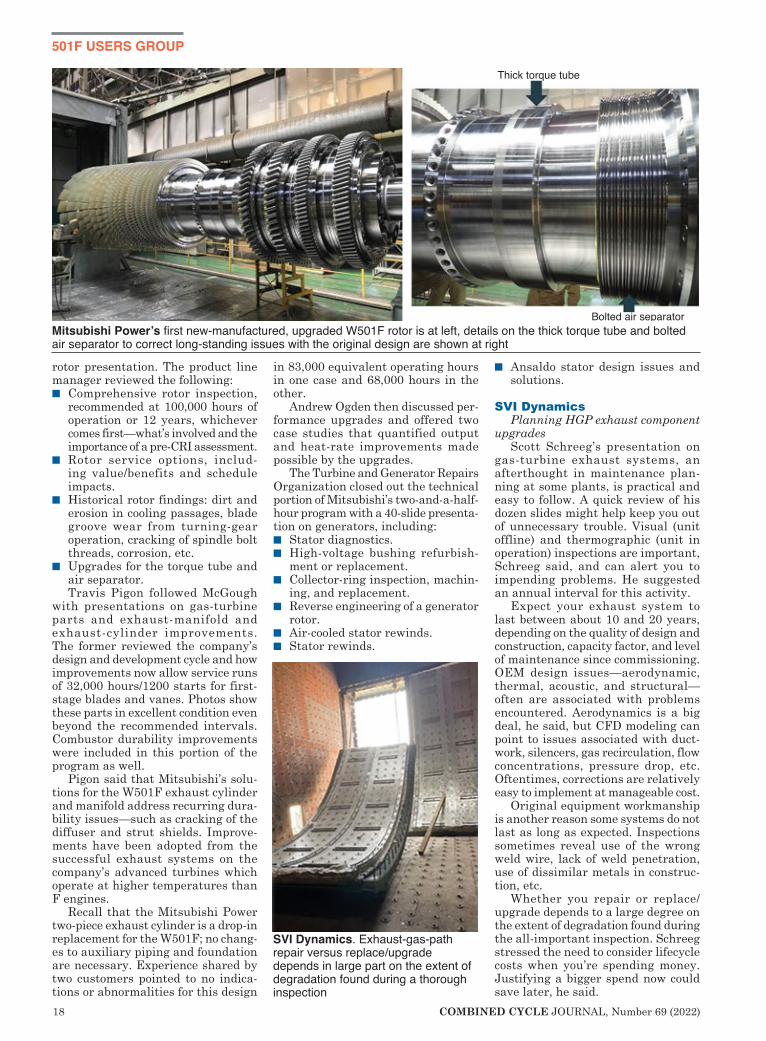
rotor presentation. The product line manager reviewed the following:n Comprehensive rotor inspection,
recommended at 100,000 hours of operation or 12 years, whichever comes first—what’s involved and the importance of a pre-CRI assessment.
n Rotor service options, includ-ing value/benefits and schedule impacts.
n Historical rotor findings: dirt and erosion in cooling passages, blade groove wear from turning-gear operation, cracking of spindle bolt threads, corrosion, etc.
n Upgrades for the torque tube and air separator. Travis Pigon followed McGough
with presentations on gas-turbine parts and exhaust-manifold and exhaust-cylinder improvements. The former reviewed the company’s design and development cycle and how improvements now allow service runs of 32,000 hours/1200 starts for first-stage blades and vanes. Photos show these parts in excellent condition even beyond the recommended intervals. Combustor durability improvements were included in this portion of the program as well.
Pigon said that Mitsubishi’s solu-tions for the W501F exhaust cylinder and manifold address recurring dura-bility issues—such as cracking of the diffuser and strut shields. Improve-ments have been adopted from the successful exhaust systems on the company’s advanced turbines which operate at higher temperatures than F engines.
Recall that the Mitsubishi Power two-piece exhaust cylinder is a drop-in replacement for the W501F; no chang-es to auxiliary piping and foundation are necessary. Experience shared by two customers pointed to no indica-tions or abnormalities for this design
in 83,000 equivalent operating hours in one case and 68,000 hours in the other.
Andrew Ogden then discussed per-formance upgrades and offered two case studies that quantified output and heat-rate improvements made possible by the upgrades.
The Turbine and Generator Repairs Organization closed out the technical portion of Mitsubishi’s two-and-a-half-hour program with a 40-slide presenta-tion on generators, including:n Stator diagnostics.n High-voltage bushing refurbish-
ment or replacement.n Collector-ring inspection, machin-
ing, and replacement. n Reverse engineering of a generator
rotor. n Air-cooled stator rewinds. n Stator rewinds.
n Ansaldo stator design issues and solutions.
SVI DynamicsPlanning HGP exhaust component
upgradesScott Schreeg’s presentation on
gas-turbine exhaust systems, an afterthought in maintenance plan-ning at some plants, is practical and easy to follow. A quick review of his dozen slides might help keep you out of unnecessary trouble. Visual (unit offline) and thermographic (unit in operation) inspections are important, Schreeg said, and can alert you to impending problems. He suggested an annual interval for this activity.
Expect your exhaust system to last between about 10 and 20 years, depending on the quality of design and construction, capacity factor, and level of maintenance since commissioning. OEM design issues—aerodynamic, thermal, acoustic, and structural—often are associated with problems encountered. Aerodynamics is a big deal, he said, but CFD modeling can point to issues associated with duct-work, silencers, gas recirculation, flow concentrations, pressure drop, etc. Oftentimes, corrections are relatively easy to implement at manageable cost.
Original equipment workmanship is another reason some systems do not last as long as expected. Inspections sometimes reveal use of the wrong weld wire, lack of weld penetration, use of dissimilar metals in construc-tion, etc.
Whether you repair or replace/upgrade depends to a large degree on the extent of degradation found during the all-important inspection. Schreeg stressed the need to consider lifecycle costs when you’re spending money. Justifying a bigger spend now could save later, he said.
Thick torque tube
Bolted air separatorMitsubishi Power’s first new-manufactured, upgraded W501F rotor is at left, details on the thick torque tube and bolted air separator to correct long-standing issues with the original design are shown at right
SVI Dynamics. Exhaust-gas-path repair versus replace/upgrade depends in large part on the extent of degradation found during a thorough inspection


20 COMBINED CYCLE JOURNAL, Number 69 (2022)
501F USERS GROUP
EMW filtertechnikDifferent GT filters, different com-
pressor efficiency results Florian Winkler’s presentation
provides users a methodology for selecting the optimal filter for their gas turbines. It does this by way of a series of performance charts that are easy to understand.
He begins by answering the ques-tion: Who is EMW filtertechnik? Then briefly describes his company’s products and identifies some of its customers—a few likely more familiar to you by name than EMW.
One reason filter selection can be challenging is because five filter test standards may be involved—EN779, ISO 16890, Ashrae 52.2. EN 1822, and ISO 26463—and there are many filter classes (different ones for each standard as the handy table included in the presentation attests).
Add to this the product names used by the more than a dozen filter manu-facturers serving gas-turbine owner/operators, and you can understand why plant personnel are often left scratching their heads when it comes to choosing the “best” inlet filters for their machines. After all, this is not their only responsibility and decisions on filter purchases typically are years apart.
For those not quite sure how much difference there is between one filter rating and another, there’s a slide with comparison photos of compressor air-foils “protected” by F8, F9, E10, E11, and E12 final filters after 5000 hours of operation in a Siemens H-class gas turbine. It’s an eye-opener. A bar chart confirms the differences.
A series of slides comparing the impact on performance of E10, E11, and E12 final filters installed in a Siemens SGT6-5000F are worth seri-ous review. Winkler’s conclusion from the data plots: E10 filters designed to the EN 1822 standard should not be considered as the final filter for a high-performance gas turbine. Better filtration pays for itself, he said, add-ing that in the near and long term an E12’s efficiency is what users demand-ing maximum performance from their engines should select.
Other presentations of interestAPG, Extending the life and capability of a M501F3 R1 turbine blade through repair modifications. Reviews field experience of R1 turbine blades from several suppliers, design/repair related issues, repair process, coatings.
Dürr Universal, Field evaluation of combustion turbine exhaust and inlet systems. Inspection basics supported by excellent photos of key components and their associated issues.
National Electric Coil, Key generator considerations for 501F applications. The five key considerations addressed in the presentation: spark erosion, speed cycling (starts/stops), endwind-ing support system, partial discharge, and global VPI.
Braden Filtration, To pulse or not to pulse. “Functionalization of cartridge filter technologies.” Asks: How do you judge performance? What are you try-
ing to address—pressure drop, turbine protection, filter life? Explains how pulse filters work and what makes a good pulse filter. Identifies new surface treatments and composites. Highly informative, fast-moving presentation.
Frenzelit, Expansion joint upgrade for legacy 501FD units. Photos describe the steps in removing the existing exhaust manifold, surface preparation of mating surfaces, welding of a new scalloped TEM flange, installation of insulation and new expansion joint.
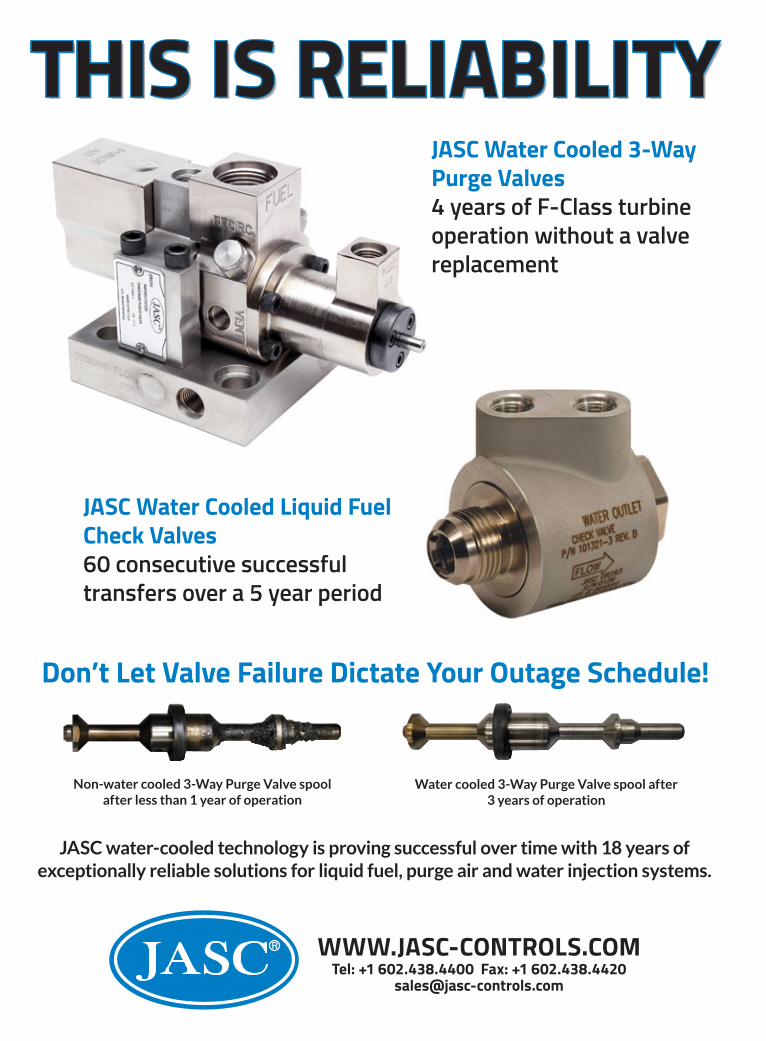
Parker Hannifin, Challenges and solu-tions for gas-turbine fluid systems. Covers the development of custom gas-turbine check and ball valves used to control fuel, water, and purge air in challenging turbine-compartment environments.
Voith Turbo, Options for legacy 501F starting systems. Reliability improve-ment is the focus of the presentation.
ORR Protection, Improving the life safety of CO2 fire extinguishing system water mist technology. Checklist of CO2 system safety features and introduc-tion to water mist systems—including the hybrid water mist system which uses nitrogen to atomize the water to a sub-10-micron level.
Shell, Interpreting oil analysis. Thumbnail descriptions of laboratory tests—including color/clarity, viscos-ity, trace metals, water content, total acid number, infrared analysis, and particle count.
Reliability 360, Oil condition moni-toring digital solution. Fluid (lube oil, diesel oil, and other liquid fuels) condition monitoring using optical technology focuses on reducing down-time and operating expenses of critical equipment.
Nord-Lock Group, 501F 4-way joint solution. Describes the company’s Boltight™ and Superbolt technologies for mitigating leakage at the four-way joint—typically in three shifts during an HGP or major inspection.
Solutions for turbine coupling bolt issues. Discusses through- and fitted-bolt issues and how the company’s EzFit expansion bolts can eliminate them.
Doosan Turbomachinery Services, Turbine blade-ring assembly funda-mentals. Blade-ring disassembly and inspection details covers special fixtur-ing and procedures believed necessary to assure proper repairs. A checklist of things to be aware of during shop work is included.
EMW filtertechnik says its work in (H)EPA filter development shows washing is no substitute for good filtration


22 COMBINED CYCLE JOURNAL, Number 69 (2022)
2021 501F BEST PRACTICES AWARDS
Challenge. CPV Valley Energy Cen-ter’s procedure for depressurization and purge of its fuel-gas system for inspection and maintenance required multiple movements of equipment (nitrogen trailers and hook-ups). Plant’s goal was having a procedure that didn’t require the movement of equipment and one conducive to faster purging.
Solution involved adding new valves to permit isolation of each section of the gas train (Fig 1) and a detailed
procedure for depressurization and purge that stressed safety. The gas-line regulator manufacturer provided comprehensive instructions (more than a hundred steps) to achieve the plant’s goals.
The added isolation valves allowed depressurization and purging of sec-tions of the gas line versus purging the entire line to both generating units each time repairs were needed. The regulator manufacturer provided instructions for staff to hold open the regulator, allowing the nitrogen purge
to flow through the regulator at low pressure.
The procedure developed allowed one location for the nitrogen trailer to accommodate either a sectional or complete purge.
Results. The improvements made allow staff to depressurize and then purge the gas line in sections, or end-to-end, without moving equipment.
Other benefits: n Reduced the time needed to achieve safe working conditions for gas-line work.n Reduced the amount of fuel vented when working on iso-
lated parts of the line.n Ability to isolate one gas turbine
at a time, potentially allowing the other unit to remain in service.
Project participants:John Anderson, operations technicianEd Peters, maintenance managerDave Engelman, operations managerJosh Zimmer, plant engineerBen Stanley, plant manager
How Valley reduced the costs of plant makeup, dischargesChallenge. While air-cooled condensers (ACC) contribute to a significant reduc-tion in overall water use at combined-cycle facilities, CPV Valley was strug-gling with high usage and discharge rates. This created issues with overall water-management expenses—includ-ing higher gray-water intake and dis-charge costs, higher chemical usage, heat losses in the HRSGs (contribut-ing to higher heat rates), and the need for increased operator involvement in maintaining plant chemistry and tank levels.
Solution. Through a collaborative
CPV Valley CPV Valley Energy CenterOwned by CPV/Diamond Generating CorpManaged by Competitive Power VenturesOperated by DGC Operations LLC 680 MW, gas-fired 2 × 1 SGT6-5000-powered combined cycle located in Middletown, NY Plant manager: Ben Stanley
New purge procedure allows faster start of gas-line maintenance
1. One of the new isolation valves added for each generating unit

Turnkey solutions for:
Independent Power Operators | Regulated Industries
Power Plant Management Teams | Investors
We’re removing the burden and responsibility of protecting & managing complex emission systems for power plants. We’re delivering performance, predictability,
cash flow, and 100% risk mitigation through a turnkey solution.
844-GO-NOXCO 844-466-6926 www.gonoxco.com
NOXCO raises the bar with the very first LTSA for
emissions compliance.
Contact us today to learn more.

24 COMBINED CYCLE JOURNAL, Number 69 (2022)
effort, the CPV Valley team developed the following key action items:n Conduct a comprehensive review
of chemistry logs with third-party consultant HDR Engineering. Out-come: The cycle-chemistry control strategy (intermittent and continu-ous blowdown rates) was adjusted to optimize system performance while dramatically reducing blow-down and quench-water costs.
n Initiate monthly chemistry review meetings with the O&M staff and HDR Engineering.
n Update the plant’s Cycle Chemistry Manual; train the O&M team on the changes.
n Conduct a plant-wide thermo-
graphic survey to find leaking drain valves. Outcome: More than 100 valves in the steam cycle dam-aged or worn out during commis-sioning required replacement or repair.
n Review and optimize water-treat-ment-system self-cleaning and backwash rates to reduce waste.
n Update operator process screens to show daily intake and discharge rates to raise awareness of their impacts on the plant budget (Fig 2).
n Perform a recapture pilot to collect valuable process and chemistry data for possible capital system upgrades in the future.
Key results of implementing the solu-tions above included the following:n Reductions of from 30% to 50%
in monthly water use, discharge rates, and chemical use.
n Overall net heat-rate improve-ment.
n Reduced wear and tear on water-treatment-system components (less operation, cleanings, and filter replacements).
Project participants:Dave Engelman, operations managerEd Peters, maintenance managerJosh Zimmer, plant engineerBen Stanley, plant managerDonald G Atwood, asset managerDan Sampson, principal technical
consultant, HDR Engineering
Safely managing, preventing gearbox failuresChallenge. CPV Valley’s “In-Air” air-cooled condensers (ACC) are US serial numbers 1 and 2 (Fig 3). Though there are many benefits to the induced-draft 2. New screen shows impact of operating variables on budget

COMBINED CYCLE JOURNAL, Number 69 (2022) 25
design, there also are many mainte-nance challenges.
Example: Traditional ACCs are designed for ease of maintenance, typically having an access platform/rail trolley system which allows equip-ment to be rigged and lowered out the bottom of a cell. Design of the In-Air system allowed for maintenance by
use of a davit assembly in each cell—roughly 35 ft in the air above the cell platform. There are several factors to consider when using this method for maintenance—including safety, manpower, downtime, accessibility, and logistics.
While the system as designed is feasible, it presents many chal-
lenges. Among them: Setting up of scaffolding in the fan cell, erecting a davit (with multiple pieces) on the fan deck, and disassembling the fan one blade at a time and lower-ing down the components before the equipment requiring mainte-nance can be accessed. The fan hub, blades, and gearbox must be manipulated to fit through the ACC floor, requiring adjustment of the suspended load. This process cre-ates significant safety risk, is labor intensive, and requires significant downtime. Plus, it is logistically difficult.
The rigging challenge became obvious when several gearboxes experienced output-shaft seal leaks. To replace a seal with OEM parts requires full disassembly as described above.
Solution. Plant personnel recognized the challenges and took a comprehen-sive approach towards maintenance activities and scenarios. Solutions for each problem are presented below.
Output-shaft seal failures. Know-ing the challenges and time associated with disassembly and reassembly of the fan blades and hub assembly to change out a seal, the maintenance department pursued development 3. In-Air induced-draft ACC was the first such unit installed in the US
TURBınE ınSULATıOn AT ıTS FınEST

26 COMBINED CYCLE JOURNAL, Number 69 (2022)
of a seal design that would require minimal disassembly. The team worked to understand the failure mechanism and engaged Corrosion Products & Equipment to collaborate on a solution. A flange-mounted split seal design was chosen. The Inpro/Seal solution continues to be leak-free and reliable after more than a year’s operation (Fig 4).
Major equipment changeout ser-vice. Staff recognized quickly that a plan was needed to change out a fan motor and/or gearbox. Several sce-narios were evaluated and the pros/cons weighed for feasibility. The team worked with IPE Rigging Corp to develop an engineered plan and offer solutions to the problem.
The first solution proposed was to use a “davit arm” concept (Fig 5), which involved rigging equipment up to the fan deck. This would allow the fan to be jacked up and locked in place above the gearbox. The gearbox then could be lifted, slid out on a rail and beam-trolley system attached to the fan jacks, and then lowered to the ground.
During the design phase of the davit/jacking system, one of the ACC gearboxes failed. This created an opportunity for the team to prove that concept. However, it quickly became evident that the approach was logis-tically infeasible, created numerous
safety issues, and would have taken seven full days to complete. Working from the top seemed to be the better approach.
The affected gearbox happened to be in the second row from the out-side, which made it easily accessible by crane. A 175-ton crane with a jib could access the fan at a radius of 105 ft, approximately 95 ft above ground level. The process involved remov-ing the entire 36-ft-diam fan-blade assembly from the gearbox, placing it on the ground, and then removing the gearbox (Fig 6).
The first gearbox change was com-
pleted successfully—including setup, demob, and final alignments—in four days. With many lessons learned, the team was confident that if it planned properly, the work could be done safely in three days.
A design review found a crane could reach all 36 fans on the ACC. There are many details and obstacles that still must be reviewed—including terrain, setup area, underground utili-ties, crane size, and cost—before this can be confirmed. But this approach would give CPV Valley a viable solution for having any fan up and running in a three-day window, as opposed to seven days or longer using the davit assembly.
Results: n A safer approach to equipment
maintenance on the ACC.n The split seal bearing design played
a key role in equipment reliability and reduced downtime.
n A comprehensive study and plan involving major equipment remov-al and maintenance was developed for the site.
Project participants:Tom Viertel, lead maintenance
mechanicCharlie McDonough, maintenance
mechanic
4. Lead Maintenance Mechanic Tom Viertel (right) explains to I&C Techni-cian Trevor Badu how the proposed output-shaft split seal is installed
COMBINED CYCLE JOURNAL, Number 69 (2022) 27
Corrosion Products & EquipmentIPE Rigging Corp
Benefits of an equipment maintenance review processChallenge. Establishing a compre-hensive maintenance program takes
critical focus by the O&M staff on a continual basis. When getting the initial work-management process set up, not all items for each piece of equipment, skid assembly, or system always are captured.
Solution. Team Valley developed and refined an Equipment Maintenance Review Process that takes a com-prehensive approach to equipment maintenance. Key elements of the program:n System/equip-
ment identi-fication. The
original list of systems/equip-ment from the EPC contractor was reviewed and updated to ensure accuracy.
n System review checklist. A stan-dard list was developed to assure questions are asked about each system and piece of equipment—including inventory, critical spares, lubrication, calibration requirements, etc. All information was reviewed and updated in the
5. This “davit-arm” design was the first idea for removing a fan and/or gearbox from the CPV Valley ACC. It was rejected
6. A crane was used to pick the fan (left) and gearbox (right) at Valley
© 2014 Optimus Industries, LLC.
Who’s Behind Your HRSG
Pressure Parts?
Headers • Harps • Bundles • In-House Finning Replacement Pressure Parts from the Source
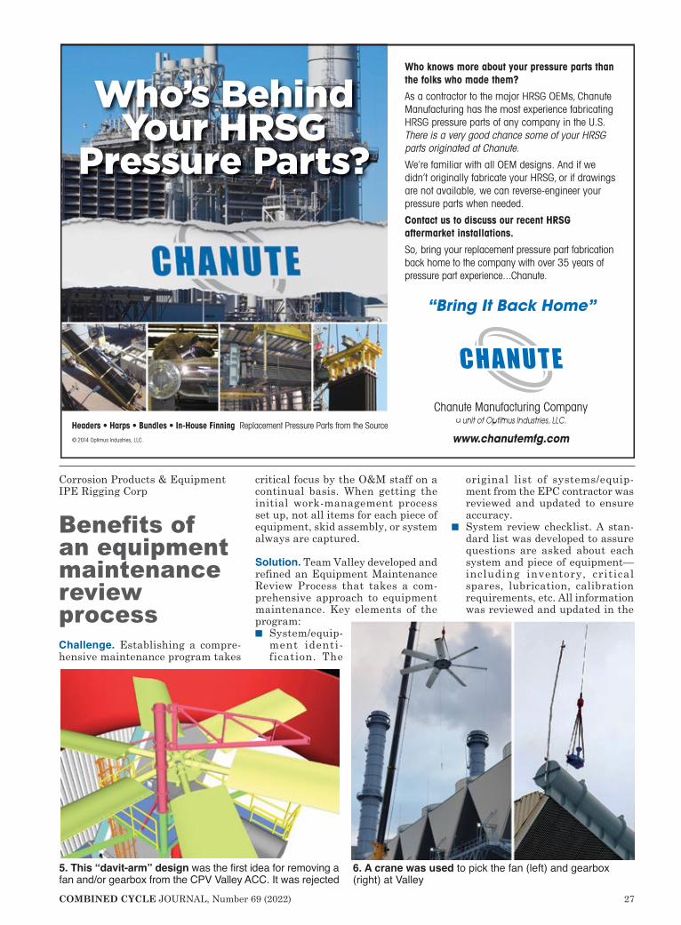
Who knows more about your pressure parts than the folks who made them?
As a contractor to the major HRSG OEMs, Chanute Manufacturing has the most experience fabricating HRSG pressure parts of any company in the U.S. There is a very good chance some of your HRSG parts originated at Chanute.
We’re familiar with all OEM designs. And if we didn’t originally fabricate your HRSG, or if drawings are not available, we can reverse-engineer your pressure parts when needed.
Contact us to discuss our recent HRSG aftermarket installations.
So, bring your replacement pressure part fabrication back home to the company with over 35 years of pressure part experience...Chanute.
Chanute Manufacturing Company a unit of Optimus Industries, LLC.
www.chanutemfg.com
“Bring It Back Home”

28 COMBINED CYCLE JOURNAL, Number 69 (2022)
CMMS (computerized maintenance management system).
n Periodic meetings are conducted with key O&M stakeholders to review the checklist, O&M manu-als, service bulletins, etc.
n Operator rounds and surveillance checks are reviewed and updated based on any findings from the review.
n Engineering and EHS personnel review any potential regulatory or compliance requirements.
n Team members are assigned action items for completion and follow up prior to the next meeting. Exam-ples of action items: Creation of PMs, modification of existing PMs, obtaining quotes, and submission of new inventory forms.
n CMMS is updated with any new items related to preventive mainte-nance, spare parts, and inventory.
n Status of the program/action items is distributed weekly and posted in common areas so all can see and monitor program process.
Results: n Developed a more comprehensive
preventive-maintenance and work-management program for plant systems and equipment.
n O&M team members increased their knowledge of systems and equipment through the more-focused reviews of individual com-
ponents.n Less corrective/reactive mainte-
nance is required.
Project participants:Ed Peters, maintenance managerBen Stanley, plant manager
A collaborative, comprehensive approach to safetyChallenge. Sustaining a best-in-class approach to safety requires continu-ous effort by plant employees. The best way to maintain the program is to make sure that safety issues are addressed in a timely manner and results are reported back to all hands so they know action will be taken when they bring up safety issues.
Solution. There are several key ele-ments to a plant safety program—such as proper training, proactive safety discussions during daily meet-ings, employee-led safety commit-tees, safety recognition, job hazard analysis, near-miss reporting, lessons learned, etc. This entry focuses on a few key safety program elements at CPV Valley Energy Center, as
described below: Safety work management. While
there still is a use for the dusty safety suggestion box, a better way to track safety concerns is through the plant’s work management system. Team Valley implemented the following features in their CMMS:n Safety work orders are classified
as “Safety” (immediate concern) or “Safety suggestion” (a safety improvement).
n If a Safety work order is submitted, an email to the entire plant staff is generated making all personnel aware of the issue.
n Plant management reviews the Safety work order immediately and ensures that preliminary mitiga-tion measures have been taken.
n If the issue can be resolved quickly, it is addressed and the work order closed. If a long-term fix is required then mitigation measures are put in place. The work-order status is changed to “Safety Mitigated” until it can be addressed permanently through proper planning and bud-geting.
n When the work order is closed out, another email informs all employ-ees that the issue was resolved.
n The entire list of safety work orders, safety suggestions, and safety mitigation work orders is reviewed during the plant’s peri-odic work-management meetings

COMBINED CYCLE JOURNAL, Number 69 (2022) 29
and by the plant employee-led safety committee. Some of the best items/actions may be selected for recognition, with contributing staff members receiving a recogni-tion notice along with a gift card thanking them for their attention to safety. Housekeeping is an important
safety program item. CPV Val-ley staff took an area ownership approach. Teams were developed (based on shifts) and physical areas designated on a facility map. Clean-ing stations were set up for easy access to cleaning equipment and trash cans. Periodically, site man-agement chooses a new area to inspect to ensure the crews are keeping their areas clean and have the resources to do so. Management also has an assigned area and meets periodically to roll up their sleeves and maintain their areas of respon-sibility.
Visitor management and orienta-tion–pandemic and beyond. With the onset of the pandemic, the tracking and admitting of visitors without exposing anyone became more of a challenge. Several key processes were developed, including these:n Contractor orientation. Contrac-
tors are contacted before they
arrive at the site to review the plant’s orientation video online. They still are required to complete the exams associated with the video and report back to the site’s EHS coordinator, who validates attendance and ensures all site documentation requirements are met.
n Job hazard analysis. Blank forms are sent to contractors for comple-tion ahead of time; the contractor returns the forms prior to arriving at the plant. This gives the sponsor the opportunity to review and make changes, if necessary. The JHA still is reviewed and signed in person, but the initial time taken to com-plete the forms is done remotely, minimizing exposure time between employees and contractors.
n Sign-in/sign-out process. Site personnel came up with a better way to track visitors and contrac-tors onsite using LobbyTrack, software that allows for contact-less registration through use of a Quick Response code that can be scanned by any smartphone. The visitor enters his or her contact information into the system and is automatically registered in the plant’s visitor log.The system also has features such
as host notification, whereby the host can pre-register visitors and will be notified when the check-in process is completed. The system can be used to notify visitors and contractors via text message when evacuation orders are initiated. Lastly, the visitor log can be viewed from anywhere using a computer, smartphone, or tablet.
Results:n A safety program that values
employee input.n Quick resolution of safety issues.n Clear communication on safety
items and progress.n Constant input and improvement
to safety programs. n Streamlined contractor orientation
and check-in along with minimal social interaction and touchless registration options.
Project participants:CPV Valley O&M teamEd Peters, maintenance managerDave Engelman, operations managerJames Longhenry, EHS coordinatorElizabeth Judge, plant administra-
tive assistantJohn Anderson, operations tech
and chairman of the Safety Com-mittee

30 COMBINED CYCLE JOURNAL, Number 69 (2022)
Sponsored content
Most O&M personnel at gas-turbine-powered simple- and combined-cycle generating
plants are aware that Trinity Turbine Technology, the family-owned busi-ness in Rosharon, Tex, repairs frame GT components. But how much do you know about the company’s cur-rent capabilities? If you’ve been out of contact with brothers Phillip and Sonny Scott and their team of experts since the start of the pandemic, it’s time for a refresher: The Trinity you knew is not the Trinity of today. It is no longer “just another repair shop.”
And, in the unlikely event the Trinity name is not familiar to you, this is a good time to get acquainted.
The facility. Trinity has grown incre-mentally since opening the doors to its
5000-ft² “starter” shop 20 years ago. Most recently it moved into an 85,000-ft² purpose-built facility on 13 acres in the Houston area (Fig 1). The company will be celebrating its two decades of ser-vice to the industry during the first half of 2022. Tune into www.trinityturbine.com for details as they become available. In the meantime, users can schedule a visit the facility at any time.
Capabilities/equipment. As Trinity added shop space its capabilities and equipment grew to include the following:n ISO 9001: 2001 certification.n Turnkey hot-section, combustion,
and compressor repairs and coat-ings (Fig 2) made possible by the shop’s 50 welding stations (Fig 3) and three HVOF coating booths. Plus, “cold” coatings for compres-
sor blades and vanes. n In-house gas and liquid fuel system
flow testing; combustion-system design improvements.
n Turnkey turbine overhaul/repair in the shop or field (Figs 4 and 5).
n Turnkey compressor, pump, genera-tor, and gearbox overhaul/repair in the field or shop.
n In-field maintenance support for all rotating equipment—nested, sup-plemental, short/long term.
n Alternative LTSA/MSA programs.n Large inventory and network to sup-
ply new, used, and reconditioned turbine parts, as well as complete rotors or units. Leadership team assembled by
Phillip and Sonny is focused on the legacy their father, Jessie, began over
Trinity Turbine Technology emerging from the pandemic a far more capable repair shop
1. Trinity Turbine’s new 85,000-ft² shop

COMBINED CYCLE JOURNAL, Number 69 (2022) 31
30 years ago. Their collective goal is to give the customer a high-quality product/service that is fair in price and unmatched in service no matter how big the project. n Joe Drury, president, Trinity Coat-
ings.n Chris Green, president, Trinity Tur-
bine Services.n Greg Gaul, director of engineering
and quality.n Iain McLean, director of combustion
systems. n Roger Ford, VP of business devel-
opment. Consider Trinity Turbine Technol-
ogy when you require field or shop support for your rotating equipment. Call 346-328-1580 or write [email protected] for assistance 24/7.
Trinity Turbine Technology emerging from the pandemic a far more capable repair shop
1. Trinity Turbine’s new 85,000-ft² shop
5. Field installation of turbine section
2. Recoated combustion covers
3. In-shop weld repair
4. Turbine wheel awaiting reassembly

32 COMBINED CYCLE JOURNAL, Number 69 (2022)
2021 501F BEST PRACTICES AWARDS
Challenge. The need for proper control of boiler chemistry is well known. An important part of any operator’s shift involves monitoring of boiler chemis-try parameters and taking action to ensure they are maintained within posted specifications. The actions in real time help assure long-term integ-rity of boiler systems and, by exten-sion, plant reliability.
There are time limits on how long chemistry parameters can be out of spec. For exam-ple, EPRI’s “Action Levels” establishes the time limits based on the severity of the out-of-spec parameter.
When logs were main-tained on paper, tracking the time boilers operated in these levels was cumbersome—if done at all. The challenge to South Point staff: Find a more efficient way to track chemistry action levels to allow better decisions on boiler chemistry control.
Solution. Chemistry logs at South Point now are maintained in an electronic software format. The logs include the date and time of the analysis and the readings for the chemistry parameter.
If an out-of-spec read-ing is found while taking chemistry readings, the operations team responds
immediately, taking appropriate steps to return chemistry to the proper con-trol band.
The application used allows down-loading of the data to an Excel format. The spreadsheet has the capability to flag when parameters are out of spec. The date and time stamp allows cal-culation of how long the out-of-spec condition lasted. Then the out-of-spec time periods can be added to deter-
mine the time in each action level. Posting the results on a monthly basis gives staff and management insight into the efficacy of the chemistry control plan.
Results. By monitoring the plant’s adherence to chemis-try action levels, the efficacy of the plant’s chemistry con-trol plan can be measured and acted upon. Tracking magnitude and time of out-of-spec chemistry param-eters can offer insight into potential future maintenance issues.
Sharing of this informa-tion with the operations staff can foster ownership of the chemistry control program. Trending improvements attributed to the chemistry control program over time could become part of an incen-tive plan.
Project participants: Kurt Fetters, plant managerDarren Otero, operations managerStan Avallone, Calpine chemistry program mgr Vincent Powers, plant engi- neer
South Point Energy CenterCalpine Corp580-MW, gas-fired, 2 × 1 combined cycle powered by 501FD2 gas tur-bines, located in Mohave Valley, ArizPlant manager: Kurt Fetters
South Point
Screen shot shows key ele-ments of South Point’s elec-tronic logs and data trending and analysis capabilities to maintain boiler chemistry within designated parameters
Electronic log enables tighter control of boiler chemistry

COMBINED CYCLE JOURNAL, Number 69 (2022) 33
2021 501F BEST PRACTICES AWARDS
Background. Klamath Cogen’s mechan-ical-draft counterflow cooling tower was built by Balcke-Dürr in 2000 without vibration probes installed on its gear-boxes. The CT is of fiberglass-reinforced polyester (FRP) construction with eight cells, each 48 ft wide × 48 ft long. The tower’s fans are driven by 200-hp, two-speed motors. A single-piece, full-floating composite horizontal drive shaft transmits drive-motor torque to Flender right-angle gearboxes.
Challenge. Direct vibration readings of the gearboxes were cumbersome at best, a process involving the follow-ing steps:1. Operations to approve the cell being
removed from service. Decision-making required consideration of generation load and weather condi-tions.
2. A LOTO and confined-space permit were required for cell entry.
3. Remove the fan cowling access panel.
4. Install scaffolding and/or person-nel safety systems for cells with no provision for gearbox access.
5. Enter cell and install two vibration probes—one on the input shaft, one on the output shaft.
6. Route wires from the probes to the cell exterior by zip-typing the wires to supports/piping/railing, and attach the wires to the monitoring device.
7. Reinstall the cell cowling.8. Remove the LOTO to make the cell
available for testing.9. Start and monitor the motor and
gearbox vibrations at both high and low speeds.
10. Secure the cell from vibration analysis.
11. Reapply the LOTO. 12. Remove the fan cowling access
panel.
13. Enter the cell and remove the vibration probes, wiring, and zip ties.
14. Remove scaffolding and/or person-nel safety systems.
15. Reinstall the cell cowling.16. Remove the LOTO and make the
cell available for normal operation.
Bear in mind that staff had to repeat the process seven more times to analyze vibrations in all cells. This typically took three days (approxi-mately three hours per
cell) and involved two mechanics. Total cost of the analyses: $4200.
Mechanics also attempted to get reliable indications of gearbox vibra-tions by recording readings from the motor mount and support tube to the gearbox. But analysis of vibra-tions analysis using this method was unreliable.
Solution. Install a permanent vibra-tion monitoring system. All compo-nents were installed, wired-up, and commissioned with a crew of three in two days during the spring outage (photos). Hardware and installation costs totaled $12,000 ($8500 for parts, $3500 for labor). Vibration analyses are conducted semiannually, so payback was approximately a year and a half.
Results. Today, the checking of gear-box vibrations is a simple one-person task done this way:1. Operations confirms that a cell can
be manipulated from high- to low-speed and then returned to normal service.
2. Analysis of vibrations is next, a process that takes about 25 minutes per cell. The positive effects of permanent
probe installations for analysis of vibrations are the following:n Only one person is required for data
acquisition.n No LOTO and/or confined-space
permits are required.n An analysis easily can be repeated
at any time if further investigation is required.
n The cost today for analyzing vibra-tions in all cells is only $300.
Project participant: Doug Hudson, maintenance supervisor
Klamath Klamath Energy LLCAvangrid Renewables536-MW, gas-fired, 2 × 1 combined-cycle cogeneration plant powered by 501FD3/6 gas turbines, located in Klamath Falls, OrePlant manager: Greg Dolezal
Permanent monitoring system cuts time, cost of vibration analysis
Output-shaft vibration probe
Input-shaft vibration probe
Vibration-probe cabling and tie wraps Gearbox vibration-
probe connectors
Vibration probes are mounted permanently on gearboxes (left) and motor drivers (right)

34 COMBINED CYCLE JOURNAL, Number 69 (2022)
2021 501F BEST PRACTICES AWARDS
Challenge. Rolling Hills recently updated its run profile from a 30-min start window to five minutes. Like many other plants with a 5-min win-dow, a remote start program was implemented.
The challenge that Rolling Hills faced was to simplify the old startup sequence so an operator could bring units online successfully while work-ing remotely from a secure device, and then drive to the plant.
Before project implementation, the starting procedure required the operator to open the main fuel-gas valve, start the demineralized-water pump, start the fuel-gas heater, and put the unit on turning gear. The first three already were integrated into the control system, but the turning gear was not. It was controlled by a hand switch located in the electrical package for each unit.
Lastly, Rolling Hills faced the challenge of fuel surging and popping relief valves from opening the main fuel-gas valve without first equalizing the plant pressure. This was done via a hand-operated valve, also opened by the operator before each start.
Solution. Logic changes were required to implement a simple remote start/stop routine. The plan: Create a single remote-start page that had only five buttons, one for each of the plant’s five gas turbines (Fig 1). With the main fuel-gas valve, fuel-gas heater, and demin-water pump already integrated into the DCS, focus of the plan was to electrically control the turning gear and the fuel-gas equalizing valve.
The turning-gear hand switch was located inside each units’ electrical package, where the PLC also was
housed. A wire was run from an output card directly to the “auto” side of the hand switch, then mapped to the DCS for programming.
The last piece of the puzzle was how to ensure the pressure differen-tial between the plant side and supply side of the fuel-gas system would not be so great as to impede safe opera-tion. Bear in mind that the main fuel-gas valve is an instantaneous open/close valve to protect the plant in case of an emergency. Opening this valve when there is a high pressure differential would open relief valves throughout the plant, causing a high pressure drop.
Thus, the replacement for the hand valve had to be one that could be con-trolled by a 4-20-mA signal to regu-late the equalization pressure. Plant employees installed the valve (Fig 2), ran the power and control wires, and mapped the valve back to the DCS for
programming.Lastly, the logic was created to auto-
matically equalize Rolling Hills’ fuel-gas pressure, open the main fuel-gas valve, start the fuel-gas heater, reset any trips on the unit, place the turbine on turning gear, and then, after a set time, start the unit. Staff mapped the new logic to pictograms and placed it all on a special, designated remote-start page, reducing the start and stop sequences to a single-button permis-sive per unit.
Result. All employees were trained on the new start procedure. The simplified
Rolling Hills Generating LLCOwned by Eastern Generation LLCOperated by Consolidated Asset Management Services LLC850-MW, gas-fired, simple-cycle generating facility powered by five 501F engines, located in Wilkesville, OhioPlant manager: Corey Lyons
Rolling Hills
Single-permissive remote start, automated fuel equalizing
1. Rolling Hills starts and stops are controlled by these five buttons (above)2. Main fuel-gas valve is of the instan-taneous open/close type to protect the plant in case of an emergency (right)

COMBINED CYCLE JOURNAL, Number 69 (2022) 35
process helps prevent operators from missing any steps and has allowed them to start units remotely with ease. Success: Every technician has started units remotely and Rolling Hills has not missed a dispatch within the 5-min window.
Logic was reversed to make the unit stop sequence as easy as the start. By simply sending an “off” permissive using the same single remote-start button, the unit virtually runs the logic backwards and shuts down everything automatically—all while remaining smart enough to know when another unit is running and not to stop the fuel and water system. Plus, also placing itself back on turning gear for unit cooldown.
Project participants:All Rolling Hills OMTs
Covid-19 initiatives protect plant, contractor personnelChallenge. The questions Covid-19 presented to Rolling Hills and other plants included the following:n How do we keep our employees safe?n How do we keep up ongoing main-
tenance with reduced staffing?n How do we keep our contractors and
employees working safely during scheduled outages?At plants with a relatively small
workforce, like Rolling Hills, outage work had to be broken down methodi-cally into step-by-step procedures to analyze the potential contamination of tools, equipment, and staff. Industry standard procedures were rewritten to adapt to the “new normal.” With only a handful of employees at this simple-cycle facility, the need to limit staff exposure to sickness was particularly important. One of the first things that had to be addressed was the need to get contractors into the plant and ready for work while limiting staff exposure.
Solution. First step was to improve the plant’s safety orientation plan. Contractor orientation and visitor registration procedures were rewrit-ten, paying close attention to detail to limit Covid exposure from outside sources.
Prior to being admitted onsite, contractors were emailed an infor-mation packet that included instruc-
tions on where to park and report to for a wellness screening conducted by contracted health professionals (Fig 3). Good health verified, contractors were directed to the plant warehouse, which was converted to a breakroom for safety orientation—complete with DVD player, procedures, and required paperwork.
Rolling Hills staff was on hand (at a safe distance) to answer any ques-tions contractor personnel might have had during their self-guided orienta-tion using strategically placed plant radios.
Contractors were given the option to watch the safety video and complete their testing prior to arrival onsite. To accomplish this, a YouTube channel was created and the safety orientation was uploaded to it. Contractors were emailed the link along with the test quiz and plant evacuation drill, to be completed before arrival, thereby eas-ing the amount of onsite paperwork. Contractors waited in their cars until plant staff reviewed all the paperwork, hung LOTOs, and then met with them outside to walk down the LOTOs without needing to ender the admin building. The last limited the risk of employee infection.
Result. By streamlining the orien-tation and visitor log-in remotely, plant was able to limit staff exposure to Covid and keep the spring outage progressing without costly unforeseen future outages caused by delayed maintenance intervals and plant per-formance degradation.
Project participant: Dan Newsome, plant superintendent
3. Wellness screening was con-ducted by health professionals in this temporary facility

36 COMBINED CYCLE JOURNAL, Number 69 (2022)
Western Turbine Users Inc, the world’s largest inde-pendent organization of gas-turbine owner/opera-
tors, had to cancel its third consecutive in-person annual conference in 2022 because of the pandemic. A virtual meeting will be conducted in its place, from April 18 to May 5. Follow www.wtui.com for details as they become available, and to register; a formal agenda is not available at this time.
The organization of meeting content will be close to that pre-sented in 2021, which is summa-rized below. To dig deeper into topics of interest, know that recordings of the presentations are available at https://wtui.com/forums. However, you must email Wayne Feragen ([email protected]) for access.
The 2021 virtual conference was conducted over a three-week period (June 7-24)—Monday through Thursday the first week and Tuesday through Thursday in Weeks Two and Three. Ten days in total, from 9 a.m. to about noon (US West Coast time). Interestingly, more than half of the registrants had never attended an in-person WTUI meeting.
The technical program was robust, mirroring WTUI’s in-person confer-ences in the following ways:n Presentations by the OEM and
the authorized service providers (Canada’s TCT, Germany’s MTU, and Japan’s IHI), focusing on shop findings and solutions. You’ll find the acronyms sidebar on p 42 of help here. This group of users, perhaps more so than any other, tends to speak in technical shorthand.
n Experience with upgrades to boost output, availability, and/or reliabil-ity, and to reduce emissions.
n Technical presentations by con-sultants and third-party solutions providers invited by the organiza-tion’s Leadership Team (p 38).
n Open discussions in user-only ses-sions that provide insights you’ll find valuable for improving the performance of your engines.
n Access to the industry’s top techni-cal talent at a virtual vendor fair and in special breakout rooms. The material presented by owner/
operators, the OEM and its authorized service providers, and independent third-party providers of products and services is important and conducive to
your success. Participation in this and future WTUI meetings will help you manage your plant in a manner that maximizes revenue, efficiency, and availability/reliability—all while main-taining the highest degree of safety.
The only things missing from a tra-ditional live conference are the golf and bowling tournaments and other group functions important to the comradery that benefits interaction among users and suppliers. Next year!
LM6000, industry workhorse. Judging from breakout-session atten-dance numbers from the 2021 confer-ence, the engine of greatest interest to WTUI attendees is the LM6000. The global installed fleet numbers more than 1100 engines, according to Tony Brough of Dora Partners & Co. About two-thirds of these machines have single annular combustors (SAC), the remainder dry, low emissions (DLE) combustion systems.
The LM6000 is one of the most suc-cessful fleets in the industry’s history. The first unit, an LM6000PA, SAC-equipped, went into service in 1991, the year following WTUI’s incorpo-ration. COD for the fleet’s first DLE machine was in 1994.
In their 31 years of service, LM6000s have aggregated nearly 50-million operating hours while com-piling enviable simple-cycle-plant and package availabilities in recent years of 93% and 96%, respectively—accord-ing to data compiled by Strategic Power Systems Inc. Of note is that the SAC-fleet leader was north of 200,000 operating hours last year, the DLE leader above 185,000.
Week One was particularly busy. Day One included introduc-tions of the engine chairs, the Engine Refresher Workshop, a presentation on
the value of the WTUI web-site, ORAP overview, and thumbnails of the authorized service providers (ASPs) and the GE aero team. Days Two through Four focused on technical aspects of the LM6000, LMS100, and LM2500 engines, respectively.
Calpine’s Andrew Gundershaug brings new energy and a wealth of experience to the Engine Refresher Workshop, so important for familiariz-ing attendees with the details required
to maximize their takeaway from the upcoming engine-spe-cific technical sessions. Recall that Gundershaug chaired
the LM5000 and LM6000 breakout sessions for years prior to accepting this assignment. Plus, his day job involves managing several LM6000-equipped sites, which keeps him cur-rent on the technical challenges that attendees face.
Gundershaug is a patient instruc-tor who knows what newcomers to the LM fleet need to be aware of to assure their units operate at high reliability and safely. In keeping with his knowledge-sharing persona (“if you don’t understand, please ask”), this very-well-illustrated presenta-tion should be on the top shelf of your plant’s training library.
Next, attendees were introduced to the session chairs:
LM2500. Garry Grimwade is responsible for operating and main-taining four LM6000s, four GE10s, and an LM2500-powered combined cycle at Riverside (Calif) Public Utili-ties. Before his involvement with land-based aero engines, he spent a decade working with “big iron,” including a 700-MW merchant facility and two GE “H” frames. Grimwade, who hails from the UK, served in the US Navy as an aviation machinist’s mate before investing five years at the Pacific Gas Turbine Center overhauling aero engines.
LM5000. Wellhead Electric Co’s Perry Leslie is a technician at the Yuba City Cogeneration Plant, with respon-sibilities including I&C, mechanical maintenance, and operations. He has served that facility since 2004 while also managing the now-shuttered Binghamton Cogeneration Plant for a brief period. Before Yuba City, Les-lie spent six years as a field service technician for GE in the Bakersfield area working on LM1600, LM2500,
2022 Virtual ConferenceApril 18-May 5

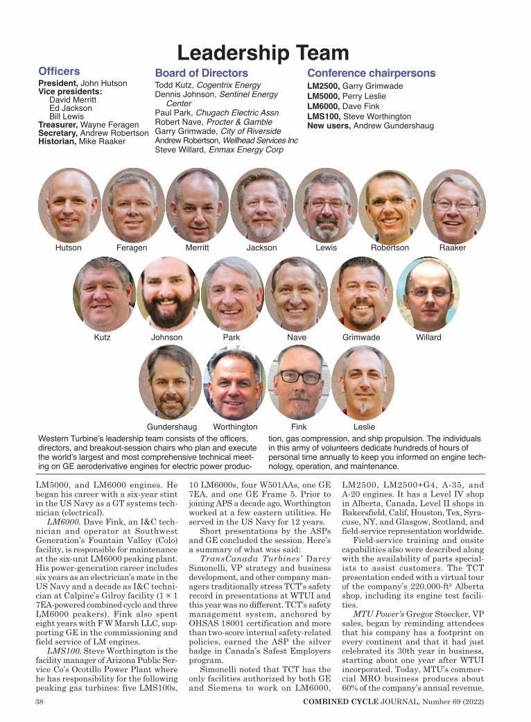
38 COMBINED CYCLE JOURNAL, Number 69 (2022)
LM5000, and LM6000 engines. He began his career with a six-year stint in the US Navy as a GT systems tech-nician (electrical).
LM6000. Dave Fink, an I&C tech-nician and operator at Southwest Generation’s Fountain Valley (Colo) facility, is responsible for maintenance at the six-unit LM6000 peaking plant. His power-generation career includes six years as an electrician’s mate in the US Navy and a decade as I&C techni-cian at Calpine’s Gilroy facility (1 × 1 7EA-powered combined cycle and three LM6000 peakers). Fink also spent eight years with F W Marsh LLC, sup-porting GE in the commissioning and field service of LM engines.
LMS100. Steve Worthington is the facility manager of Arizona Public Ser-vice Co’s Ocotillo Power Plant where he has responsibility for the following peaking gas turbines: five LMS100s,
10 LM6000s, four W501AAs, one GE 7EA, and one GE Frame 5. Prior to joining APS a decade ago, Worthington worked at a few eastern utilities. He served in the US Navy for 12 years.
Short presentations by the ASPs and GE concluded the session. Here’s a summary of what was said:
TransCanada Turbines’ Darcy Simonelli, VP strategy and business development, and other company man-agers traditionally stress TCT’s safety record in presentations at WTUI and this year was no different. TCT’s safety management system, anchored by OHSAS 18001 certification and more than two-score internal safety-related policies, earned the ASP the silver badge in Canada’s Safest Employers program.
Simonelli noted that TCT has the only facilities authorized by both GE and Siemens to work on LM6000,
LM2500, LM2500+G4, A-35, and A-20 engines. It has a Level IV shop in Alberta, Canada, Level II shops in Bakersfield, Calif, Houston, Tex, Syra-cuse, NY, and Glasgow, Scotland, and field-service representation worldwide.
Field-service training and onsite capabilities also were described along with the availability of parts special-ists to assist customers. The TCT presentation ended with a virtual tour of the company’s 220,000-ft² Alberta shop, including its engine test facili-ties.
MTU Power’s Gregor Stoecker, VP sales, began by reminding attendees that his company has a footprint on every continent and that it had just celebrated its 30th year in business, starting about one year after WTUI incorporated. Today, MTU’s commer-cial MRO business produces about 60% of the company’s annual revenue,
Hutson Feragen Merritt Jackson Lewis Robertson Raaker
Kutz Johnson Park Nave Grimwade Willard
Gundershaug Worthington Fink Leslie
OfficersPresident, John HutsonVice presidents:
David MerrittEd JacksonBill Lewis
Treasurer, Wayne FeragenSecretary, Andrew RobertsonHistorian, Mike Raaker
Western Turbine’s leadership team consists of the officers, directors, and breakout-session chairs who plan and execute the world’s largest and most comprehensive technical meet-ing on GE aeroderivative engines for electric power produc-
tion, gas compression, and ship propulsion. The individuals in this army of volunteers dedicate hundreds of hours of personal time annually to keep you informed on engine tech-nology, operation, and maintenance.
Leadership TeamBoard of DirectorsTodd Kutz, Cogentrix Energy Dennis Johnson, Sentinel Energy
CenterPaul Park, Chugach Electric AssnRobert Nave, Procter & GambleGarry Grimwade, City of Riverside Andrew Robertson, Wellhead Services IncSteve Willard, Enmax Energy Corp
Conference chairpersonsLM2500, Garry GrimwadeLM5000, Perry LeslieLM6000, Dave FinkLMS100, Steve WorthingtonNew users, Andrew Gundershaug


40 COMBINED CYCLE JOURNAL, Number 69 (2022)
commercial engines about one-quarter, and military engines the remainder.
Highlights of what’s new at MTU include the following:n Commissioning of a liquid-fuel test
system for the LM2500 (2019).n Ongoing effort in the development
of LM2500+G4 and LM6000PF+ test capabilities; load banks were in preparation during the 2021 meeting. Note that MTU is not permitted to supply energy to the grid during engine tests, making huge load banks necessary.
n MTU Coating Services GmbH was founded in February 2020 next door to the company’s Berlin-Branden-burg Level IV repair shop. This is a certified repair station focusing on surface treatment. Services include hard-chrome, cadmium, and nickel plating, hard-chromic and sulfuric anodizing, plasma thermal spray coating, all types of painting (including dry film lubrica-tion), FPI and MPI nondestructive testing, and shot-peening/blasting, grinding. The company’s commitment to
health and safety was another talk-ing point, as well as its significant lease and rotable pool assets. Stoecker closed with an overview of MTU’s leakage detection tool, which uses an array of ultrasonic microphones that can locate sounds created by the flow of any gas created during a leakage. This capability is said to improve the quality of overhaul services, minimize commissioning time, and increasing safety.
Air New Zealand Gas Turbines’ short video offered a glimpse of the company’s Level IV shop for LM2500 and LM5000 engines in its facilities at Auckland International Airport, which is accessible from anywhere in the world. A full range of support services—including plasma spray, welding, machining, and NDT are available onsite. The company has two 24/7 teams of field-service techni-cians—one in Auckland, the other in Bakersfield, Calif—equipped to per-form engine inspections, hot-section change-outs, top-case removals, and trim balancing.
IHI Power Systems’ Yuya Ishikawa, sales manager, and Roy Burchfield, GM for IGT business development, Cheyenne Service Center, collaborated on a short presentation covering both the parent company’s broad range of product and services offerings and the capabilities of the Level II facilities in Wyoming.
Ishikawa’s slide, entitled “Full Life-cycle Solution,” was perhaps of great-est interest to attendees. It described the GE/IHI program for LM6000 com-
WESTERN TURBINE USERS INCOFFICERS AND MEMBERS OF THE BOARD OF DIRECTORS
1990-2021
WESTERN TURBINE USERS INCOFFICERS AND MEMBERS OF THE BOARD OF DIRECTORS
1990-2021
Steve JohnsonWayne Kawamoto
Jon KimbleMarc Kodis
Thomas KoehlerTodd Kutz
Charles LawlessJoel Lepoutre
Bill LewisJames McArthurBob McCaffreyRonnie McCrayRick McPherson
David MerrittRob Nave
Bob NelsonBrent NewtonFrank Oldread
Paul ParkMike RaakerRich Recor
Andrew RobertsonHarry Scarborough
Tony SkonhovdRichard SmithErnie Soczka
Don StahlJohn TunksAl Vanhart
Steve WillardJermaine Woodall
Jimmie Wooten
Jim AmarelDan Arellano
Bryan AtkissonJohn Baker
Leon BallardJim Bloomquist
Alvin BoydMark Breen
Charles ByromBill CaldwellChuck Casey
Devin ChapinJack Dow
Don DriskillNorm Duperon
Todd EmeryWayne Feragen
Bob FieldsKen Gestel
Garry GrimwadeAndrew Gundershaug
Don HainesBrad Hans
Dave HermansonJim Hinrichs
Howard HoffmannCharlie Hoock
Mike HornBrian HulseJohn HutsonEd Jackson
Dennis Johnson


42 COMBINED CYCLE JOURNAL, Number 69 (2022)
pressor rear-frame manufacture for the PC, PD, PF, and PH models; IHI’s original design package and controls for the LM6000; the company’s full
EPC solution for the LM6000; and its maintenance capabilities in the shop and in the field.
Burchfield explained the layout of
the Cheyenne Service Center, which is equipped with three bays, two for gas-turbine work and one for tooling and rotable exchange component storage.
Acronyms
AGB—Accessory gearbox (also called the transfer gearbox)
AVR—Automatic voltage regulatorCCM—Condition maintenance manualCCR—Customized customer repairCDP—Compressor discharge portCFF—Compressor front frameCOD—Commercial operating dateCPLM—Critical-parts life managementCRF—Compressor rear frameCWC—Customer web center (GE)DEL—Deleted partDLE—Dry, low emissions combustorDOD—Domestic object damageEM—Engine manualFFA—Front frame assemblyFOD—Foreign object damageFPI—Fluorescent penetrant inspectionFSNL—Full speed, no loadGG—Gas generator (consists of the com-
pressor and hot sections only)GT—Gas turbine (consists of the gas gen-
erator pieces with the power turbine attached)
GTA—Gas-turbine assemblyHCF—High-cycle fatigueHGP—Hot gas path
HPC—High-pressure compressorHPCR—High-pressure compressor rotorHPCS—High-pressure compressor statorHPT—High-pressure turbineHPTN—High-pressure turbine nozzleHPTR—High-pressure turbine rotorIGB—Inlet gearbox IGV—Inlet guide vaneIPT—Intermediate-pressure turbine
(LMS100)IRM—Industrial repair manualLM—Land and marineLCF—Low-cycle fatigueLO—Lube oilLPC—Low-pressure compressor (not on
LM2500; just LM5000 and LM6000)LPCR—Low-pressure compressor rotorLPCS—Low-pressure compressor statorLPT—Low-pressure turbineLPTR—Low-pressure turbine rotorLPTS—Low-pressure turbine statorMCD—Magnetic chip detectorMOH—Major overhaulNGV—Nozzle guide vaneOEM—Original equipment manufacturerPN—Part numberPT—Power turbine (turns a generator,
pump, compressor, propeller, etc)PtAl—Platinum aluminide RCA—Root cause analysisRDS—Radial drive shaftRFQ—Request for quoteRPL—Replaced partSAC—Single annular combustorSB—Service bulletinSL—Service letterSUP—Superseded partSTIG—Steam-injected gas turbineTA—Technical advisorTAT—Turnaround timeTAN—Total acid number (lube oil)TBC—Thermal barrier coatingTGB—Transfer gearbox (also called the
accessory gearbox)TMF—Turbine mid frame and thermal
mechanical fatigueTRF—Turbine rear frameVBV—Variable bleed valve (not on
LM2500; just LM5000 and LM6000)VBVD—Variable bypass valve doorsVIGV—Variable inlet guide vanesVSV—Variable stator vaneVSVA—Variable stator-vane actuator
Keep this list of acronyms nearby during WTUI’s 2022 virtual conference. You’ll find that most speakers talk in “shorthand,” using acronyms freely. If you’re not up
to snuff on your aero lingo you can get lost in a hurry and possibly miss key points. The “cheat sheet” that follows can help you remain focused.

COMBINED CYCLE JOURNAL, Number 69 (2022) 43
GE’s aero product line CEO Clive Nickolay concluded the day’s presen-tations with a look at GE Gas Power’s strategic focus and recent investments in the installed base and in new tech-nologies. He stressed the OEM’s com-mitment to “deliver world-class tech-nology built on a foundation of quality, performance, reliability, execution, and trust.”
On the product front, Nickolay pointed to the following recent devel-opments:n LM2500 G5, the latest improvement
in a 50-year journey for that engine.n LM2500XPRESS, a new package
and design for faster installation. One utility transitioning from coal-fired assets to gas has purchased six of these units. None were opera-tional at the time of the meeting.
n LM6000 PF+ is the next evolution for this engine which has a 45% higher output than the first-gen-eration machine.
n LMS100 focus is growing out the model’s rotable and lease engines pool.
n Thermal hybrids designed for flex-ible operation in light of growing renewables penetration. The CEO addressed customer con-
cerns thusly:n Managed care to improve asset
operations.
n Lean transformation to eliminate waste and enhance execution. One improvement here was a 50% reduc-tion in footprint of the Houston rotor shop. Another: Single-piece flow to reduce work in progress and manufacturing time. One outcome: Work of higher quality.
n Resolution of fleet issues to improve product quality and reliability. Finally, in a discussion of the com-
pany’s pathway to low or near-zero carbon power, Nickolay noted that today’s gas-fired LM engines produce about half the carbon emissions of coal-fired plants. Improvement to a 60% reduction was possible for both an LMS100 burning a 30/70 mixture of hydrogen and natural gas and an LM6000 operating on 35% hydrogen. A 71% reduction in carbon emissions (compared to coal) was possible for an LM2500 with a 75/25 mixture of hydrogen and methane.
Day Two began with Strategic Power Systems’ Tom Christiansen presenting an ORAP analysis of LM6000 fleet performance and the Top Ten causes of forced outages. Ralph Reichert followed with MTU’s LM6000 field/shop updates—includ-ing LPT failure (solutions and experi-ences), post-overhaul vibrations dur-ing a test run, and nitride bearings. Robert Smans then spoke to TCT’s
recent shop experiences with LPT S1 nozzle distress, LPT B/P premature seal distress, HPT S2 nozzle spoolies and nozzle distress, LPC corrosion, primary/secondary swirler (SAC) dis-tress, and a DOD event.
Hiroshi Aoki shared IHI’s field/shop experiences including these: leaf seal found around LPT S1 nozzle, difficulty removing LPT module and resulting damage, jacking-oil hose found disconnected inside generator, fuel-nozzle seal-ring failure, clean-ing of HPC rotor blades and vanes to address silica deposition, VIGV case corrosion, LPC and HPC damage, oil leak attributed to RDS housing in the incorrect position, cracks in the aft flange of the combustor outer liner (not repairable).
Day Three opened with Christian-sen’s analysis of the Top Ten causes of forced outages in the LMS100 fleet. GE followed with its field/shop updates and solutions. Recall that the ASPs are not certified to provide after-market services for these engines. Among the topics covered: parts and shop fixes, critical bulletins, Mark VIe counters, spare parts on hand and forecasting methodology, intercooler seals, and RAM programs for FOD screen, HPC VSV and blades, IPT S2N, IPT frame hardware, PT S5B.
Day Four saw Strategic Power Sys-

44 COMBINED CYCLE JOURNAL, Number 69 (2022)
tems’ Bob Steel analyze LM2500 fleet performance and identify the Top Ten causes of forced outages. MTU’s Oliver Eckert then discussed the company’s first experiences with nitrided main bearings, early rub-coat exposure on HPC stator S15 and S16, TMF damage attributed to exhaust t/c failure, new leakage detection system, CRF/B-sump oil leakage when engine idling, CFF cracking at welds with resultant air leakage, HTP S2 nozzle-support air tube misalignment.
TCT’s Ian Andrew updated the group on IGB horizontal duplex bear-ing events, HPC stator corrosion and VSV bushings, HPC stator S15 and S16 blades, TMF No. 5 bearing event, SL2500-IND-21-001 and SBs 284 and 285 with regard to the liquid fuel mani-fold, hexavalent chromium update on identification process.
Chris Martin closed out the day with ANZGT’s field/shop experiences: IGB horizontal duplex bearing events, HPC stator corrosion and VSV bush-ings, HPC stator S15 and S16 blades, TMF No. 5 bearing event, SL2500-IND-21-001 and SBs 284 and 285 with regard to the liquid-fuel manifold, hex chrome update on identification process.
Week Two was dominated by GE’s field/shop updates and solutions—for
the LM6000 on Day Five and the LM2500 on Day Six. Day Seven was reserved for user-only discussions in concurrent breakout sessions for the LM2500, LM5000, LM6000, and LMS100, each with the respective engine chairman at the podium.
Presentation topics for the LM6000 on Day Five were these: HPC S1 blades, HPC S3-S5 blades plus HPC S3-S9 spool, 4B bearing nitride, 5R bearing nitride, HPC S1/S2 inner shroud (Metco), LPT vibrations after overhaul, improved material for LP Sprint nozzle, enhancement for end of VBV rod, LPT PCC flex joint, S11 legacy and PF+ check valves, T48 tip liberation, VSV bushing durability, ejector-nozzle thrust balance, PG HTP S2N in PC, Rad-Rad, SBs 345 and 346 related to HPT S1 and S2 disks.
Topics for the LM2500 session on Day Six: IGB spline wear, VSV turn-buckle wear, debonding of HPC air-duct wear strip, tip losses on HPC S12-S14, platform corner loss on HPC S15 and S16, bearing events caused by hard-particle contamination, HP recoup algorithm V4.2 for LM2500+G4, field limits for HPT S1B, IGB duplex bearing events, gas-manifold distress (DLE).
Reviews of active programs includ-ed gas-manifold distress (SAC), trail-ing-edge oxidation on HPT S1 blades,
high-vane-count HPC, HPC corrosion, HPT rubs and unnecessary engine trips, axial shift of TMF liner, bracket wear on VSV actuator.
Week Three began on Day Eight with a session billed as Axford and Friends. Mark Axford, the Houston-based turbine consultant, is a crowd favorite at this meeting, having shared his considerable market and techni-cal knowledge with the group for the last 15 years or so. Old friend Tony Brough, PE, president, Dora Partners & Co, presented his respected annual analysis of gas turbine-orders.
New Friends Jason Miller, PE, and Erik Youngquist, VP, of GridSME, updated the group on the “State of the Combustion Turbine: A Grid Compli-ance Perspective,” which focused on the California market so important to the majority of attendees. They covered opportunities and challenges for gas generation, generator test-ing requirements (including a case study), notes on the August 2020 “heat storm,” system mix changes, etc. Their discussion-style presentation (similar to a radio show on current issues) is interspersed with meaningful Q&A and audience commentary.
Axford opened with the positive thought that the Covid shock to the global gas-turbine order book was

COMBINED CYCLE JOURNAL, Number 69 (2022) 45
not as bad as had been anticipated (Brough said about 40 GW were ordered in both 2019 and 2020, more than in 2017 and 2018) but the long-term trend is still on a downward trajectory. Primary reasons he gave for the decline in orders: regulations, mandates, and subsidies.
Recent impacts of the market decline included the following:n Siemens’ spin-off of its turbine
group a year ago as Siemens Ener-gy.
n GE Oil & Gas is gone, now part of Baker Hughes.
n Pending sale of PSM by Ansaldo Energia, completed after the meet-ing to Hanwha Group.Axford brought the group up to date
on renewables, H-class gas turbines, impacts of the Texas storm in Febru-ary 2021, electric vehicles, battery storage, the outlook for hydrogen, carbon capture, and what life might be like in the post-Covid world. Way too much for a short summary; listen to the nominal 40-min presentation yourself as time allows.
He closed with three turbine lessons learned over the last couple of years:n Be prepared for delays or cancel-
lations of gas-turbine projects—caused, in part, by longer lead times for everything.
n Rethink your parts inventory; focus less on “just in time.”
n Rethink your supply chain: verify vendor inventories, consider the impacts of politics and transport for equipment sourced internationally, think about manufacturing in your home country even if it costs more. A four-hour vendor fair with break-
out rooms for each solutions provider began immediately after the Axford and Friends session. The participat-ing companies: Advanced Filtra-tion Concepts, Aero Land & Marine,
AGTSI, AP+M, Catalytic Combustion, Cormetech, Donaldson Company, ECT, Gastops, GTC Control Solutions, GustoGen, HPI Energy Services, Nord-Lock Group, ORR Protection Systems, Parker Hannifin, Relevant Solutions/Switch Filtration, SSS Clutch Com-pany, Strategic Power Systems, Suez Water Technologies & Solutions, and ProEnergy.
Days Nine and Ten were dedicated to special technical presentations. They are summarized in the follow-ing section.
Vendor presentationsNoxco
Guaranteed emissions compliance for your aging plant
CEO Jeff Bause opened his presen-tation by explaining to turbine users how Noxco is raising an industry bar with the first LTSA (long-term service agreement) for emissions compliance. He said that by removing the burden and responsibility for protecting and managing complex systems from owner/operators, Noxco delivers per-formance, predictability, cash flow, and 100% risk mitigation through a turnkey solution.
Bause is well-known to many CCJ readers for his deep knowledge of cata-
Noxco. Comparing the traditional after-market catalyst spend to the annual cost of Noxco’s guaranteed emissions com-pliance program for aging gas turbines

46 COMBINED CYCLE JOURNAL, Number 69 (2022)
WESTERN TURBINE USERS
ARNOLD GroupOptimized insulation for gas tur-
binesPierre Ansmann opened his pre-
sentation pointing to problems with insulation systems avoided by use of
his company’s 3D-shaped blankets that fit perfectly to the shape of exhaust-system components—including the following:Interlocking steps between blankets,
use of stainless-steel foil, and super-tight wire mesh virtually eliminate vibration damage.
Blanket damage requiring repair/replacement every outage.
Surface hot spots conducive to insula-
tion damage.Overheated noise enclosure.Loose fibers and dust that cause health
and safety issues.A series of photos provides details.
LiburdiMaximize component repair yields
to reduce LM 2500 gas-turbine over-haul costs
In their introductory comments, Bob Tollett and Scott Hastie explained to attendees how Liburdi resets the materials clock on gas-turbine alloys by way of its proprietary repair pro-cesses and coatings, thereby lessening the possibility for creep, cracking, and other life-limiting issues commonly associated with aging materials. Plus, the company recovers dimensional wall thickness and throat areas with advanced patented alloys that last longer at high operating temperatures.
This gives Liburdi a big advantage over competitors, they said, by improv-ing engine reliability and reducing the scrap rate in subsequent overhauls.
The technologies that enable
ARNOLD Group insulation systems for LM2500 and LM6000 engines are designed for a perfect fit to the gas turbine thereby maximizing the lifetime of the thermal shield
Liburdi. Full-solution rejuvenation of turbine blades maximizes component repair yields, extends the lives of parts, and reduces engine overhaul costs
GasTOPS. Bearings and gears are damaged in service because of stress con-centrations that arise from misalignment, mishandling, misassembly, corrosion, and contaminants in lube oil
lyst system maintenance, gained over the years as CEO of Groome Indus-trial Service Group. He is a frequent speaker at industry events on SCR and CO catalyst cleaning, repacking, and replacement, plus the cleaning of ammonia vaporizers and injection grids, as well as of HRSG tubes.
Noxco’s turnkey solution, Bause says, increases the operational flex-ibility and performance of the SCR, CO catalyst, and ammonia injection system (AIG) to deliver sustained peak performance at the lowest life-cycle cost. LTSA benefits include all system maintenance, inspections, tuning, optimization, catalyst test-ing and cleaning, catalyst replace-ment with the optimal product for your site and operating conditions, spent catalyst disposal, AIG design optimization and tuning, and per-formance upgrades.

COMBINED CYCLE JOURNAL, Number 69 (2022) 47
WESTERN TURBINE USERS
Liburdi to deliver on its promises, the speakers said, are blade alloy reju-venation (FSR®) which returns turbine blades back to “zero-hour” life and Liburdi power metallurgy (LPM) which offers higher strength than welding and allows reconstruction of wall thickness.
GasTOPSAn easy upgrade to
peaker bearing condition monitoring
Debris monitoring of scavenge oil alerts on the onset and progression of bearing/gear damage by detecting both ferrous and non-ferrous particles. This helps owners and operators decide how much longer they can operate an engine without incurring a forced out-age. Oil debris monitoring (ODM) is said to provide the earliest warning of damage. Thus, it is proac-tive, not reactive like chip detectors, vibration moni-tors, and spectrometric oil analysis.
Sensors, which fit inline on the scavenge discharge, are said to be reliable and not produce false positives. Installation typically can be done in a day; the ROI usually is a year or less.
EthosEnergySolutions that maximize value and
extend the life of your equipment Owner/operators of gas turbines are
forever looking for ways to improve the value of their generating plants by producing more power, improv-ing operational flexibility, reducing emissions, etc. A series of case studies offered by EthosEnergy’s Tom Watson, Rikki Blair, and Nelson Rouette pro-vide some guidance.
The challenge for one owner was the need to perform multiple offline (on crank) water washes to deal with flagging compressor efficiency on an LM2500. The solution was a high-pressure water wash system to clean the compressor online without the need for detergent. The results: availability increased by 2%, performance by from 1% to 4%, plus less fuel is burned, less water is consumed, and detergent use was cut by one-half.
Turbine and BOP controls retrofits at two LM6000 facilities corrected UPS, power-distribution, and wiring issues with these benefits: higher starting reliability, increased output,
and faster synchronization with the grid.
More case studies are included in the presentation. You can access all at www.wtui.com.
EMW filtertechnikBetter filtration pays for itself—
H(EPA) filters and GT performanceFlorian Winkler’s presentation at
WTUI was a condensed version of one made to the 501F users, a precis of which is provided in that report. Please turn to p 20 for the details.
Other presentations of interestBraden Filtration, The evolution of LM gas-turbine inlet cartridge filters. Information and options that can help you make better decisions regarding your inlet-filtration needs. Likely different than other filtration presen-
tations you’ve listened to. It begins with the types of filter media—drylaid, airlaid, wet-laid (most common), spunlaid, meltblown, and spinning—and provides such information as how filters are made, capture efficiency, addition of nanofi-bers for enhancing filter per-formance, etc.
Emerson, Maintaining and upgrading LM-series gas turbines to reliably meet the demands of today’s grid.
Focuses on the company’s field-proven LM6000 controls retrofit solutions for Wood-ward Netcon, Micronet, and GE Speedtronic™ Mark VI and VIe systems. Highlights include Ovation’s enhanced
control features for aeros and a case history describing the replacement of Woodward Netcon 5000, Rockwell AB-
PLC5/SLC, and Wonderware HMI systems on four LM6000s with a single Ovation system.
US Cleanblast, Ice-blast field results: HPC efficiency improvements and life exten-sion. Details on the dry-ice cleaning of an LM6000 and before and after performance analyses conducted by the engine OEM that determined there was an overall improve-ment in compressor efficien-cy, increased mass flow (air), increased power production,
and greater stall margin.
Woodward. Grid stability and fre-quency-response testing. Covers grid fluctuations, speed/MW droop, MW setpoint and AGC control, primary frequency control, and MOD 27 testing.
VBR Turbine Partners. LM pre-dictive maintenance put into practice with Decide. Company’s mission is to optimize the reliability, availability, and maintainability of LM gas-turbine operations. Its decision support tool, Decide, provides predictive insight into an engine’s expected health to prevent forced outages, boost profitability.
Brush. Avoiding forced outag-es through site-specific preventive maintenance of generators based on operating conditions and environ-ment. Title says it all. Presentation highlights: condition assessments of lube-oil system components, slot liner movement, blocking and brac-ing damage, coil movement, partial discharge, phase-gap clearance, dirt and contamination.
EthosEnergy offers solutions (such as water wash systems and controls upgrades) to maximize value and extend the life of your equipment
EMW filtertechnik. Compressor blades are in pristine condition after operating 5000 hours with E12 final filters

48 COMBINED CYCLE JOURNAL, Number 69 (2022)
2021 AERO BEST PRACTICES AWARDS
Challenge. Orange Cogeneration has an in-line surface condenser (Fig 1) of a design that makes inspection for tube leaks very time-consuming. The plant traditionally had outsourced this task or used two employees to pres-sure-check each of the 4475 tubes—a job that could easily take a week to complete.
Solution. This is no longer necessary. Orange Cogen recently purchased a digital ultrasound inspection tool for preventive maintenance on pumps and motors. Staff found the same instru-ment could be used to inspect the condenser tubesheet for leaking tubes.
Here’s how: During a planned out-age, the waterbox manways are opened and the hotwell is drained (Fig 2). A venturi-style air blower is placed in the hotwell manway door with the dis-charge end facing outward. Next, the manway opening around the blower is semi-sealed, to help create a small vacuum in the hotwell and contain the noise generated by the blower.
The UE Systems Ultraprobe (Fig 3) then is used to scan and listen to the 4475 tubes. If the decibel reading spikes for a particular tube, that tube is identified with a rubber plug. When the tubesheet scan is complete, the marked tubes are pressure-checked for leak verification.
Results. The results of this evolution were impressive. Plant personnel were able to scan the entire condenser within an hour. First use revealed 21 suspect tubes. Of those, 18 were veri-fied to have leaks. The time saved to perform the checks was approximately
64 hours. Conductivity of the con-densate dropped from 8 to 1 µmho. Ultraprobe also has been used to find condenser air leaks.
Project participant: Jason Leverette, operations manager
Orange Cogen Orange CogenerationOwned by Northern Star Genera-tionOperated by Consolidated Asset Management Services LLC104 MW, gas-fired 2 × 1 com-bined-cycle cogeneration plant powered by DLN-equipped LM6000 engines, located in Bar-tow, Fla. Condensing extraction steam turbine is rated 25 MW. Steam is sold to producers of orange juice and ethanolPlant manager: Allen Czerkie-wicz
Ultrasound inspection tool finds leaking condenser tubes
Steam-turbine exhaust
Surface condenser
1. Arrangement of surface condenser and steam-turbine exhaust
Manway
2. Manway cover is removed and an air blower inserted with its discharge end facing outward (above)3. Ultrasound inspection tool is effective for finding leaks in condensers (right)

COMBINED CYCLE JOURNAL, Number 69 (2022) 49
2021 AERO BEST PRACTICES AWARDS
Challenge. Worthington Genera-tion’s LM6000 packages each had two turbine and two generator ven-tilation fans located above their respective engine compartments, requiring use of a manlift to conduct maintenance and inspections. The fan locations were difficult, danger-
ous, and expensive to reach. Goals included the following:n Create a working surface around
the package fans.n Eliminate the need for fall protec-
tion. n Reduce the cost of accessing the
fans. Solution. The plant’s safety commit-tee worked with local contractors to develop plans allowing safe access to package fans. Eliminating the manlift and fall protection were priorities, along with creating a safe working surface.
What was done to achieve project goals:n Fabricated a 1.25-in. bar-grate
platform around the turbine fans—including ladder, cage, swing gate, and handrails (Fig 1).
n Fabricated two 1.25-in. bar-grate side platforms that would attach to the existing generator compart-ment roof—including ladder, cage, swing gate, and handrails around both platforms (Fig 2).
Results. Worthington and its contrac-tors fabricated and installed the pack-age-fan platforms described above, thereby eliminating the need for aerial lifts and fall protection. The solution also eliminated the cost to rent the lifts. Something staff did not anticipate was the inspection reliabil-ity this improvement actually made. Maintenance inspections became more detailed and more frequent with atten-dant benefits.
Project participants: Matthew O’Hara, lead O&M techJason Robertson, O&M/IC&E techWilliam Hooker, O&M tech
1. Turbine package fans before (left) and after (right) installation of platform to facilitate access and make the work location safer
2. The need for a platform to access generator fans is in evidence here. Photo at left was taken before platform installation, at right after
Worthington
Platforms added to facilitate access to package fans
Worthington Generation LLCOwned by Hoosier Energy Rural Electric Co-op IncOperated by NAES Corp174 MW, four simple-cycle LM6000 natural-gas-fired peaking units, located in Greene County, Ind, and connected to Hoosier’s 138-kV transmission linePlant manager: Robert VanDen-burgh


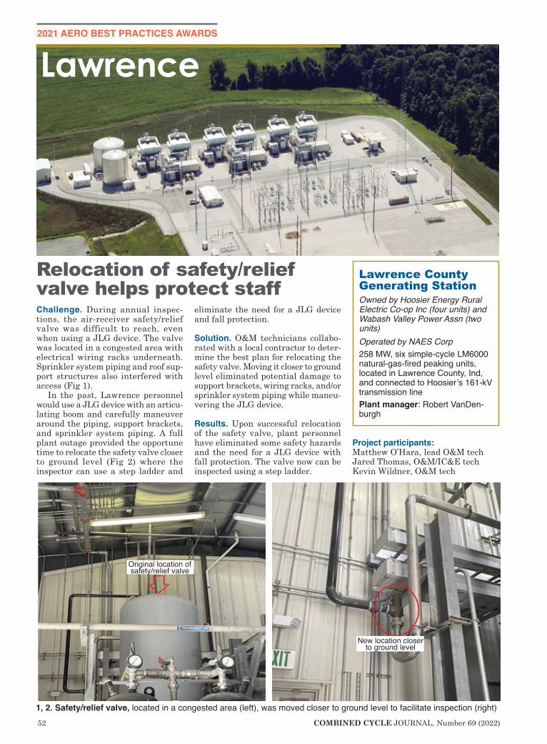
52 COMBINED CYCLE JOURNAL, Number 69 (2022)
2021 AERO BEST PRACTICES AWARDS
Challenge. During annual inspec-tions, the air-receiver safety/relief valve was difficult to reach, even when using a JLG device. The valve was located in a congested area with electrical wiring racks underneath. Sprinkler system piping and roof sup-port structures also interfered with access (Fig 1).
In the past, Lawrence personnel would use a JLG device with an articu-lating boom and carefully maneuver around the piping, support brackets, and sprinkler system piping. A full plant outage provided the opportune time to relocate the safety valve closer to ground level (Fig 2) where the inspector can use a step ladder and
eliminate the need for a JLG device and fall protection.
Solution. O&M technicians collabo-rated with a local contractor to deter-mine the best plan for relocating the safety valve. Moving it closer to ground level eliminated potential damage to support brackets, wiring racks, and/or sprinkler system piping while maneu-vering the JLG device.
Results. Upon successful relocation of the safety valve, plant personnel have eliminated some safety hazards and the need for a JLG device with fall protection. The valve now can be inspected using a step ladder.
Project participants: Matthew O’Hara, lead O&M techJared Thomas, O&M/IC&E techKevin Wildner, O&M tech
Lawrence
Lawrence County Generating StationOwned by Hoosier Energy Rural Electric Co-op Inc (four units) and Wabash Valley Power Assn (two units) Operated by NAES Corp258 MW, six simple-cycle LM6000 natural-gas-fired peaking units, located in Lawrence County, Ind, and connected to Hoosier’s 161-kV transmission linePlant manager: Robert VanDen-burgh
Relocation of safety/relief valve helps protect staff
1, 2. Safety/relief valve, located in a congested area (left), was moved closer to ground level to facilitate inspection (right)
Original location of safety/relief valve
New location closerto ground level

COMBINED CYCLE JOURNAL, Number 69 (2022) 53
Sponsored content
Consider dry ice for cleaning delicate, hard-to-reach electrical components
Joseph P Sergio, PhD, founder, Polar Clean LLC (https://polarclean.com)
There are no small cleaning jobs in a powerplant, only small spaces—where the combination
of dust, grime, and delicate electri-cal equipment has a way of creating oversize challenges. And while every piece of equipment in a generating station poses its own unique clean-ing problems, those associated with small, delicate, and hard-to-reach components typically are the last to be addressed.
The use of CO2 cleaning for gas turbines, generators, and HRSGs has been well documented in CCJ over the years (Fig 1). But when it comes to delicate circuit boards and other electrical equipment, relatively little has been reported.
When the only alternative is clean-ing by hand—a tedious and time-con-suming process that tends to produce spotty results—it’s easy to understand why so much grime collects in tight spaces with sensitive equipment.
Operators in otherwise well-main-tained facilities put off, or overlook, the cleaning of breakers, switchgear, motor windings, overhead ductwork, etc, fearing the damage that can be done by use of the wrong cleaning method. However, this thinking cre-ates its own risks, as accumulated dirt and debris can lead to equip-ment damage, shorts, outages, and even fire.
Dry-ice cleaning works by using one of a series of specialized nozzles, depending on the application, to deliver a non-abrasive, non-flamma-ble, and non-conducive spray of CO2 pellets that range in size and shape from rice-sized pellets to nuggets and shaved block ice. Unlike alternative blasting media, dry ice leaves no secondary waste and uses no water or chemicals.
CO2 cleaning is an enormously adaptable process—as effective for blasting encrusted bird waste from exposed substation surfaces as it is for delivering a feather dusting that leaves delicate circuit boards pristine and undamaged. Because the mate-rial dissipates instantly, there is little post-cleaning debris and containment is a relatively simple process. Results that require days of downtime with abrasive or water-blasting methods can be accomplished in hours with dry-ice cleaning.
Other advantages of CO2 for pow-erplant cleaning jobs include the fol-lowing:n The ability to access crevices,
heights, and interiors otherwise inaccessible to all but the most painstaking hand-cleaning meth-ods.
n Improved megohm readings.n Increased polarization indices. n Chemical-free, water-free, environ-
mentally safe.n Elimination of wear and tear.n Reduced cleaning time and produc-
tion-line disruption.n Safe to use around electrical equip-
ment.
Dry-ice cleaning is a solution with an increasing number of applications as environmental concerns take pre-cedence, says Sean Simpson, director of operations for Polar Clean, based in South Bend, Ind. Plus, the use of CO2 is aligned with initiatives to reduce water and chemical use in many facili-ties.
Joseph P Sergio, PhD, is a member of the Dry Ice Standards Committee of the Association for Materials Protection and Performance. He is the author of numerous articles on industrial clean-ing applications, safety, and disaster mitigation—among other topics.
1. Dry-ice cleaning of a generator core (before at left; after at right) facilitates inspection and repairs
2. Electrical control panel before cleaning is at left, after at right. Because humid-ity was a concern, the room was dehumidified prior to a gentle CO2 dusting. Latter was followed by a HEPA-filtered vacuuming


56 COMBINED CYCLE JOURNAL, Number 69 (2022)
ABHUG 2021 was a virtual event, conducted on three consecutive mornings from Brisbane, Australia, and
elsewhere, joined by more than 110 participants worldwide. Now in its 12th year, ABHUG (formerly AHUG) has added conventional fossil plant technology and issues closely related to those in HRSGs.
The event included 14 technical presentations with a blend of cycle chemistry, mechanical, and control experiences and issues across com-bined-cycle/HRSG plants and conven-tional boilers.
ABHUG organization and content are tied closely to its supporting orga-nizations, which include the European HRSG Forum and various national groups of the International Association for the Properties of Water and Steam (IAPWS). Also closely aligned is the annual US-based HRSG Forum, mak-ing this part of a worldwide HRSG/combined-cycle information exchange.
Bob Anderson (Competitive Power Resources) and Barry Dooley (Struc-tural Integrity Associates and IAPWS) were the moderators for ABHUG 2021.
Selected highlights are given below. For reference, the full agenda items and a listing of sponsor and vendor presentations also are provided.
Day One“Nothing’s for free”CleanCo, Queensland’s publicly owned clean-energy generator, discussed the changes that have taken place at its Swanbank E Power Station (first com-missioned by Stanwell in 2002) over the years. The facility’s transforma-tion from baseload to a market-driven profile required continuous effort, long-term commitment, and careful attention to system impacts.
The 380-MW Swanbank E 1 × 1 combined cycle, based on GT26 gas turbine technology, has always been one of Australia’s most efficient ther-mal plants. The Alstom machine was the largest gas turbine in Australia at its time of commissioning and set a world record of 254.8 days of continu-ous operation in 2011 before shutting down for maintenance. Swanbank efficiency has reached 58% burning
coal-seam gas with 98% methane.The original design profile was daily
operation with high output as needed, and low-load operation in the evenings (Figs 1 and 2).
But in 2014, the plant was put into cold storage, primarily to benefit from the increasing world-market value of its gas entitlements. Return-to-service dates then experienced delays, and long-term preservation techniques became a major new challenge.
As the owner’s representative stat-ed at the 2016 AHUG conference, “Long-term storage has a number of unknowns. It is good to come to these user group meetings to share our experiences and learn from others.” For some trial-and-error layup details discussed at the earlier conference, see
the accompanying sidebar. CleanCo Queensland Ltd reopened
Swanbank E in 2021 with a revised retirement date of 2036. Swanbank would no longer be a baseload unit, but would support CleanCo’s fleet of hydro-electric, pumped-storage, and planned wind assets, helping Queensland tran-sition to renewables.
As CleanCo’s Matt Sands explained:
2021Virtual Conference By Steven C Stultz, Consulting Editor
Step-up transformer
Air inlet HRSG
CondenserHP and IP/LP steam turbines Generator Gas turbine
1. Swanbank E Power Station, Queensland, Australia, recently transitioned to a market-driven operating profile
2. Alstom GT 26 powers the Swanbank E 380-MW, 1 × 1 combined cycle

HRSGMaintenanceServices
SCR Catalyst Cleaning & Repacking
CO Catalyst Cleaning & Repacking
Ammonia Injection Grid Cleaning
Ammonia Vaporizer Cleaning
SCR & CO Catalyst Replacement
HRSG Tube Cleaning
Inlet Filter House & DuctRefurbishment
| (800) 505-6100

58 COMBINED CYCLE JOURNAL, Number 69 (2022)
“With these operational changes, we’ve had to understand the unit a lot bet-ter. We’ve had to start pushing the
boundaries and finding ways to meet the new market-driven demand curve.
“We’re having to re-learn the
impacts of starting every day: ther-mal fatigue in the HRSG, drain and blowdown operations, and total system
Planning and executing a long-term layup program (a/k/a cold storage)Swanbank E Power Station was removed from service in December 2014 and not expected back until 2017. A comprehensive cold-storage and preservation program for all sys-tems began; site labor was reduced to a caretaker team. Ongoing lessons learned, covered in detail by the own-er’s representative at the 2016 AHUG Conference, could be helpful to other owners and operators.
To prepare for storage, a full baseline inspection documented component and system conditions. Major storage risks predicted are outlined below.1. Pitting and general corrosion:n Steam/water side—HRSG, steam
turbine, piping.n Gas side—gas turbine and HRSG
hot gas path.n Under-insulation corrosion—
steam, gas, and feedwater lines.2. Corrosion fatigue:n Steam/water side—HRSG and
steam turbine.3. Acid dewpoint corrosion: n HRSG gas side.
This storage process began with Australia’s AS3788, “Pressure Equipment: In-service Inspection” and Clause 4.6, preservation-plan requirements and return-to-service procedures. The speaker outlined specific steps taken and lessons learned for both inspecting and preparing the HRSG and its associ-ated steam/water and gas path, gas turbine, steam turbine, and genera-tor. Balance-of-plant discussions included gas yard, plant air, control systems, and pumps.
Relative-humidity monitoring details also were given, showing equipment and locations (with ongo-ing lessons-learned updates). Cold-storage monitoring trends then were presented for all major equipment. Vigilance to every detail was stressed, such as valve tagging to identify those modified for air circulation. Areas eas-ily overlooked received attention, such as draining of the flash box on the side of the condenser.
Perhaps most beneficial were the cold-storage lessons learned:
1. New equipment is needed (dehu-midifiers, for example). This should include critical spares.
2. Plant staff must understand the impact of every change (for example, valve position) made during layup.
3. The entire process (including changes) must be clearly record-ed and traceable.
4. “Don’t just set and forget.” Staff should always look for improve-ments. This means reviewing all ongoing strategies, not just the original plan.
5. Ongoing strategy reviews should include all site personnel.During comments/discussions,
Barry Dooley, Structural Integrity Associates and co-chairman of the AHUG conference committee, stressed the LP turbine as a critical risk location for any layup beyond three days. He cited continuing work by the International Association for the Properties of Water and Steam (IAPWS) on film-forming amines for protection during layup.

COMBINED CYCLE JOURNAL, Number 69 (2022) 59
impacts, to maximize the life of the HRSG, turbines, and plant.
“And to do this, you have to under-stand that nothing’s for free. When you are starting and stopping the unit, it is going to cost you somewhere.” Operation has shifted to daily starts to support renewables, generally 3 to 11 p.m., Monday through Friday.
Sands listed examples such as offline-induced corrosion, thermal recycling, equivalent operating hours on the machines, and boiler/system chemistry. “Nothing’s for free, and we need to know all of the pinch points,” he repeated.
Stanwell E’s original design ramp rate was 11.5 MW per minute. To meet the new market demands, tri-als were set at 30 MW/min. The plant achieved that rate and currently oper-ates at 17.5.
The latest effort is the Stanwell Fast Start Project, where there have been more teething issues. Intent is to reach minimum load in half their normal time of 4.5 hours. “If we get there sooner, we save a lot of fuel,” Sands stressed. But again, nothing is free. So he discussed some notable impacts on the steam/water cycle and steam-turbine temperature control.
He talked about improved tem-perature probes, and a new econo-mizer bypass to increase range, to help
condition water, and achieve higher temperatures. He also offered details about drum level control.
During these startups, the gas turbine’s Bearing 2 experienced high vibration (nothing is for free), an issue now being monitored. “And we seem to be pushing some valves to their limits,” he added.
He then discussed low-load opera-tion. “We are still testing, and look-ing at the impacts on the gas turbine, steam turbine, HRSG, and system water chemistry.”
Future projects will look at amines for wet storage, header crack moni-toring, steam-turbine control-valve throttling, and flow issues with attem-perator spray and OTC control valves.
Other Day One highlightsn Presentation by AGL Energy (Aus-
tralia) on the “Management of Cor-rosion Fatigue at Liddell Power Station.” The four-unit, 2000-MW, coal-fired station commissioned in the early 1970s with tangentially fired boilers had plenty of experi-ence to share.
n “Introduction to Electrode Boilers,” David Addison, Thermal Chemistry Ltd (New Zealand) and member of the ABHUG conference committee.
A summary of Addison’s presen-tation appears at the end of this report.
n “IAPWS/Chemistry Updates Includ-ing Film Forming Substances,” Barry Dooley, Structural Integrity Associates (UK) and co-chairman of the ABHUG conference committee. Presentation provides international updates on HRSG and fossil-plant cycle chemistry, instrumentation, and flow-accelerated corrosion (FAC)—including reviews of tech-nical guidance documents (TGD) recently issued by IAPWS in these areas:
● Application of film-forming sub-stances (FFS) in industrial steam generators, TGD11-19.
● Chemistry management in gen-erator cooling water during opera-tion and shutdown, TGD10-19.
● Air in-leakage in steam/water cycles, TGD9-18.
● Corrosion-product sampling and analysis for fossil and combined-cycle plants, TGD6-13 (2014).These IAPWS technical guidance
documents represent the accumu-lated experience of the 21 member countries represented in the orga-nization’s Power Cycle Chemistry Working Group. The TGDs can be downloaded from www.iapws.org at no cost.

60 COMBINED CYCLE JOURNAL, Number 69 (2022)
AUSTRALASIAN BOILER AND HRSG USERS GROUP
Day TwoMinimal chemistry instrumentationThis is a recurring conference topic because of its importance and less-than-optimum global observance. It focuses on instrumentation require-ments for proper system water-chem-istry control and monitoring. Chemis-try-influenced failures and potential personnel safety issues are increas-ingly common with today’s changing operating profiles.
Kirk Buecher, Mettler-Toledo (US), offered a well-organized, informative review of all important measurements, instrumentation, and rationale—including important optional measure-ments and equipment.
He first tied to and emphasized a topic from earlier in the agenda, Dooley’s “Repeat Cycle Chemistry Situations” (RCCS):n Corrosion products.n Fossil waterwall/HRSG evaporator
deposition.n Non-optimum chemical cleaning.n Contaminant ingress.n Drum carryover.n High level of air in-leakage.n Lack of shutdown protection.n Inadequate online alarmed instru-
mentation.n No action plans for repeat situa-
tions.Get the details on RCCS by re-read-
ing the HRSG Forum special report, “Trends in HRSG reliability, a 10-year review,” in CCJ No. 61 (2019), p 44.
“Too many plants are under-instrument-ed today,” Buecher told attendees. “So, let’s look at the minimums o f bo th equ ipment level and redundancy.” Some redundancy, he explained, can offer good cross-checks of other equipment.
“This is a non-commercial presenta-tion, and we’ll look at the options,” he said. He went on to list the principal drivers of his information including the IAPWS Power Cycle Chemistry Working Group as well as EPRI, VGB, ASME, ASTM, and other reli-able sources. OEMs and academia are heavily involved.
So, he provided the following over-view:1. Every plant should have at least a
minimum level of instrumentation (MLI) which can uniquely identify (pinpoint) the key parameters and drivers to each and every failure/damage mechanism that can occur.
2. Redundancy: The MLI does not only analyze specific chemistry locally; it needs to provide sensitivity analysis for the cycle (holistic view) in the event of a defective or out-of-service instrument. Thus, an instrument within the minimum key level is backed by other instrumentation or verification technologies. In a serious contamination event, the operator does not need to take time to validate the reading of an indi-vidual instrument.
3. Equally important, the MLI should all be audibly alarmed in the control
room or on the distributed control system.An interesting direct quote here:
“Pre-Covid, I visited somewhere between 40 and 50 plants a year all over the world and I’m still surprised by how many sensors, transmitters, and analyzers are just standalone. They’re not connected to anything. So, if you’re not right next to the transmitter or the analyzer when the alarm goes off, hours could pass before anybody notices the problem,” he explained.
Buecher followed with a detail-rich presentation on specific and direct conductivity, cation (acid) conductiv-ity, pH, dissolved oxygen, sodium, phosphate, and oxidation/reduction potential. He included some equipment new to the market. He then added common reasons for monitoring and measuring degassed cation conductiv-ity, silica, and TOC.
Catch problems early. Buecher went on to stress the proper mea-surement locations, and tying some
optional measurements based on plant history. He focused on makeup water, condensate, feedwater, drum/evaporator moni-toring, and steam-turbine protection.
One of the examples presented is illustrated in Fig 3. For condensate, measurement at the con-densate pump discharge gives first warning of con-denser leaks, regenera-tion chemicals from the makeup plant, or contami-nated condensate from the storage system. It is critical for detecting air in-leakage.
At this same location, measuring cation con-ductivity gives a rapid alert to the ingress of corrosive anions. For sea-water-cooled plants with-out condensate polishing, measuring for sodium is
Cation conductivity
Dissolved oxygen
Sodium
Condensatepump
From HP superheater
Flow
Flow
14 in.
To cold reheat
12 in.
Temperature
Temp element (maybe)
Temp
To blowdown 1.5 in.
16 in.
Common
main
stea
m
Steam turbine
2 in.
2 in.Tempelement
To blowdown
3. Condensate-pump discharge instrumentation is arranged to warn of a condenser leak and other problems
4. Typical HP pressure-control-valve erosion
5. Anderson’s pre-sentation explained how to achieve warm-ing steam flow for cold lag starts, perhaps by enlarging/install-ing a warmup drain upstream of the HP isolation valve


62 COMBINED CYCLE JOURNAL, Number 69 (2022)
critical. Measuring pH and conductiv-ity are optional, but also helpful for confirming other information. Mea-suring degassed cation conductivity can clearly indicate whether or not an increase in cation conductivity is from CO2.
He completed this section with makeup water, feedwater with and without polisher, HRSG evaporator water (running AVT, caustic treat-ment, phosphate), and main and reheat steam.
Update on erosion of HP bypass valvesAn important and recurring problem at many HRSG/combined-cycle plants is erosion of seating surfaces in HP bypass pressure-control valves (PCV), attributed to ingestion of wet steam and water (Fig 4).
Seat/plug damage results in leak-ing steam that overheats downstream carbon steel pipe. Operators must then open the valve to minimum to enable safe attemperator operation to cool the pipe. Manual desuperheater operation will cause even more liner and pipe damage.
Anderson explained how water can end up in the valves, including that from condensate which forms while warming the HP steam pipework.
Common solutions are ensuring the HPSH is drained during startup (before steam flow), ensuring inter-stage and final attemperators do not leak, reviewing DCS data to make sure superheat is available when the PCV is opened (may require additional surface-mounted thermocouples), and avoiding HP bypass operation during layup.
As noted during AHUG 2018, a change in PCV materials or design will not solve the erosion problem (CCJ No. 59, 4Q/2018, p 62, “Workshop 1: Steam-turbine bypass”). A change in operating practice can perhaps reduce the problem, but installation of new or larger pipe-warming drains may be needed.
Anderson’s presentation explained how to achieve warming steam flow for cold lag startups in 2 × 1, 3 × 1, and 4 × 1 systems, perhaps by enlarging/installing a warmup drain upstream of the HP isolation valve (Fig 5).
Other Day Two highlightsn “Icthys LNG’s Combined Cycle
Power Plant,” INPEX Australia. n “Mechanism and Root Cause of
Boiler Overload Failure,” ALS Global (Australia).
n “Callide B Furnace Screen Tube Failure,” ALS Industrial and CS Energy (Australia). This failure occurred in a 350-MW, coal-fired
Tube ligament crack modeling
Secondary IIsuperheater outlet header
Tertiary SH outlet header
Second-stage RHoutlet header
Platen SH outlet header
6. FEA and remaining-life studies included components shown in figure
SCHOCK Retrofit SystemsGas Turbine Owners’ Preferred Choice for Retrofit Upgrades
Intake & Filter Systems Exhaust Silencer Upgrades Exhaust Systems Exhaust Plenum
Schedule a free site inspection/scope review: www.schock-mfg.com
From filterhouse to exhaust outlet, Schock inspects,
designs, and manufactures innovative and economical
GT auxiliary solutions. Experience on 1200+ GT
exhaust systems, 1100+ exhaust diffusers,
and 2000+ intake and filter systems.

COMBINED CYCLE JOURNAL, Number 69 (2022) 63
Babcock Hitachi KK Carolina-style, natural-circulation reheat unit with a split back pass.
n “Effect of Gas Turbine Upgrades on HRSG Performance, Operation, and Reliability,” HRST (US).
Day ThreeDeep dive into FEA, remaining lifeFor those who tuned in for a deep dive into finite element analysis and creep-fatigue crack growth, that came from Daniel Blanks, senior structural integrity engineer at Quest Integrity.
Blanks did not stop with what is involved in analysis, he showed attendees how to undertake assess-ments with step-by-step narratives and graphics. His background state-ment: “The shift away from baseload to flexible operation can result in an increase in damage to plant com-ponents, in particular thick-walled boiler components.”
The basic scope of his studies:n Remaining life of an initial tube
ligament crack is used to compare the effects of the various flexible operation modes on header com-ponents.
n Creep-fatigue crack growth is com-
puted under baseload, two-shift, and low-load modes of operation. He covered risk to headers and
was very clear about his technical approach. Participants saw heat-transfer thermal models, stress analy-ses, and the details of creep-fatigue crack growth. This led to computation of remaining-life assessment for the various modes of operation.
For crack growth and remaining-life examples, Blanks selected an ini-tial crack depth of 3 mm as a conserva-tive initial sizing based on inspection capabilities of a conventional UT scan.
Visuals clearly showed results for each operating mode, for a platen superheater outlet header, tertiary superheater outlet header, and the other components illustrated in Fig 6.
His observations: n For all headers considered during
flexible operations studies, two-shift operation resulted in the fastest creep-fatigue crack growth, resulting in the shortest remaining lifetimes for those components.
n For cases where remaining lives were shortest (less than 20 years), the dominant crack growth mecha-nism was fatigue; creep crack growth contributed very little.
n Low-load modes of operation gener-ally promoted faster creep-fatigue crack growth than baseload opera-
tion; however, it was generally slow enough to remain acceptable over the future service life of the component (30 years).
n Across all headers, baseload opera-tion is very benign, with limited creep-fatigue crack growth.And his conclusions:
n Using a combined FEA and creep-fatigue crack growth approach can provide an understanding of the effects flexible operations may have on header components, by compar-ing the remaining life of an initial crack.
n For some components, two-shifting can be very damaging, resulting in rapid creep-fatigue crack growth.
n If considering transition to flexible operation, wide-ranging thermo-couple coverage and adequate test-ing of transient modes are essential to constructing a valid model for assessing remaining life.
Other Day Three highlightsn “Collie Power Station Flexibility
Improvements,” Synergy (Austra-lia). Focus of the presentation on this 340-MW coal-fired plant was on low-load operation, reduction in startup time and fuel-oil consump-tion, and enhancement of network

64 COMBINED CYCLE JOURNAL, Number 69 (2022)
support capabilities—all consider-ing equipment design safety limits and remaining life and market demands.
n “Boiler Feedwater Contamination Incident at Rio Tinto Yarwun.” Causes and immediate impact of the caustic contamination incident were covered in the presentation, along with post-incident inspection and findings.
n “Selecting Which (Corrosion-Under-Insulation) Inspection Tech-nology Should be Used,” IRISNDT (Australia). NDT methods for CUI covered were the following: visual inspection/ultrasonic thickness testing, infrared, neutron back-scatter, real-time radiography, guided-wave inspection, 3D laser profile, pulsed eddy current, and profile radiography using digital detector array (DDA).
n “FAC Assessment at AGL Bayswa-ter,” ALG (Australia). Inspection of the four-unit, 2680-MW coal-fired station revealed dramatic wall loss at desuperheater-attemperator spray control valves.
Electrode boilersAddison of Thermal Chemistry con-tinued his tradition of bringing some-thing new to the annual conference. In
2021, he introduced electrode boilers to the group. His subtitle: “New tech-nology, new gremlins, new solutions.” Addison focused on steam/water chemistry, corrosion, and control. But first he explained the technology.
Although electrode boilers are operating in Europe and Australasia, there is very little industry guid-ance, insufficient understanding, and therefore limited technical-standard material. IAPWS (in particular, New Zealand and Scandinavia) continues to monitor experience, with the goal of producing a global IAPWS Technical Guidance Document.
Principal issues with this class
of boilers include corrosion, steam contamination, and high energy use.
In New Zealand, electrode boilers are replacing some old industrial units for process heating (dairy, wool, etc), with the government offering incen-tives to move away from coal and gas.
Of the three common types of units (immersion element, immersion electrode, and jet electrode), the one covered in detail was the high-voltage immersion electrode type for either steam or hot water.
Water becomes an electrolyte and part of the electrical circuit as well as a heat-transfer medium for the pro-cess—very different from conventional boilers (Figs 7 and 8).
Addison then looked at the posi-tives and negatives of this growing fleet of boilers.
Advantages:n Fast response and startup.n Smaller thermal mass, lower ther-
mal stress. n Small plant footprint.n No fuel or waste-handling systems.n Considered Green, provided elec-
tricity is supplied from renewables.n Highly automated, low staffing
levels.n No boiler tube failures, but cor-
rosion and deposition cautions remain.Disadvantages:
ElectrodesBucket
7. Basic design of a high-voltage electrode boiler

COMBINED CYCLE JOURNAL, Number 69 (2022) 65
n High fuel cost (electricity).n Potential safety issues with
required high-voltage electric-ity.
n High-purity makeup water needed.
n New learning curve.n Water chemistry control more
complex, needing to balance heat-transfer medium, cor-rosion and deposition control, and electrolyte chemistry.
n Limited chemical vendor understanding of water chem-istry complexities.
n Lack of international stan-dards and published case studies/examples.
n Smaller water volumes make chemical dosing control more challenging; need to use dilute chemicals and correctly sized pumps.
n Risk of electrical arcing in service, leading to electrode and material damage, efficiency loss.
SupportersABHUG is supported by the Interna-tional Association for the Properties of Water and Steam together with the IAPWS national committees in Aus-tralia and New Zealand. It is held in
association with the European HRSG Forum (https://europeanhrsgforum.com) and the US-based HRSG Forum (https://hrsgforum.com).
There were 10 sponsors for the 2021 meeting. Each provided a 10-min virtual exhibit during the discussion periods. The sponsors were: n Anodamine, manufacturer and sup-
plier of exclusive water-treatment programs.
n Duff and Macintosh/Sentry offers equipment to safeguard people,
processes, components. n Ecolab provides solutions for
monitoring and predicting component operation.
n Energy Plant Solutions sup-plies industrial and biomass boilers and services.
n hrl: provides expert and advi-sory consulting services.
n HRST presented on services and products to improve HRSG performance and safety.
n Mettler Toledo specializes in analytical instrumentation.
n RTR GmbH is an indepen-dent supplier of premium steel for powerplant applica-tions.
n Swan Australia offers analyti-cal instruments and analytics.
n Water Treatment Services dis-cussed its water modeling capabili-ties and specialty chemicals. Finally, ABHUG 2021 was orga-
nized by Mecca Concepts; CCJ man-aged the virtual event.
Looking ahead to 2022. The next ABHUG conference is planned for fall 2022, but no details are available yet. Contact Barry Dooley ([email protected]) and/or Bob Anderson ([email protected]) for further information and your sug-gestions for presentations at that meeting. ccj
8. A 13-MW electrode boiler serves New Zealand’s Open Country Dairy
DESIGN/BUILD & REPLACEMENT OF INTAKE HOODS
303 East Brooks Road, Memphis, TN 38109 www.filter-doc.com
New Yoke AssembliesGrit Blasting & CoatingsMedia Change-Outs
Combustion Turbine Inlet Services
█ Cartridge filters█ Panel filters█ New 4-point mounting hardware█ New pre-filter mounting frames█ Evaporative media█ CELdek® and DRIFdek® █ New metering and setups
Contact: Robert Murphree, Pres m: 901.734.5954 o: 901.396.3625 [email protected] Greg Murphree, VP, Sales m: 901.412.1195 o: 901.396.3625 [email protected]

66 COMBINED CYCLE JOURNAL, Number 69 (2022)
SOFTWARE/HARDWARE
While the industry makes progress towards the fully connected, largely auto-mated powerplant with
a meta-organization of onsite staff, remote monitoring and diagnostics (M&D) assistance, and market delivery setpoints, there are some serious and costly gaps that are overlooked in data links and industrial communications. According to Jeff Downen, business owner, Black Start LLC, these gaps are often revealed and corrected dur-ing commissioning.
Some root causes of the gaps include the following:n Scope irregularities between the
automation platform’s OEM and the plant’s EPC, often based on technology design and concepts a decade or two out of date.
n Insuff ic ient communication between vendors while designing communication links and network paths, usually reflected in the I&C drawings and configurations.
n Quantum leaps in data points being captured, transmitted, and moni-tored in sophisticated graphics with data speeds at the gigabit level.
n EPCs using electrical engineers to do the design, rather than I&C/DCS engineers with IT networking experience.
n Engineering and procurement documents often don’t address communications protocols, network speeds, connection types, and media conversion.As Downen said in an interview,
“All of these software packages and hardware procured from different vendors are designed so they can com-municate, but someone still has to troubleshoot and integrate the systems so they will.”
Here are some of the most common issues Downen and his team encounter during commissioning while working directly for the EPC:
Improperly matched commu-nications speeds. One example is multiple issues with incorrect baud rates on the serial links and 100/1000
base connections for fiber and Eth-ernet (Fig 1). An example: SEL (Schweitzer Engineering Labs) 2730 small form-factor pluggable (SFP) ports designed as 1000 base fiber, and designed to connect with Emerson-provided EtherWAN media converters that were 100 base, are incompatible.
Media and cabling. Single- and multi-mode fiber issues crop up from the engineering and procurement
phases. Example: A generator step-up (GSU) annunciator panel’s initial design called for an SEL serial device for a Modbus remote terminal unit (RTU). However, the network path
Plant-network, data-link, communications issues revealed during commissioning
1. Media conversion device (black box, center of photograph) had to be inserted during com-missioning for testing purposes. The SEL network on one side of the communications link needed to be at the gigabit speed in order to properly communicate with the DCS network which was procured at 100-megabit speed (above)2. Mini network connects mul-tiple TCP/IP network devices to the Modbus gateway (port 502) and then converts the signals from Ethernet to the fiber going back to the DCS (right)

COMBINED CYCLE JOURNAL, Number 69 (2022) 67
only allowed a Modbus TCP/IP via the routers over port 502 and also needed a null-modem serial cable.
This was corrected by adding a mini-network for media and protocol conversion shown in Fig 2. Port 502 is the Modbus protocol widely used for TCP/IP communications, allowing Modbus data links and traffic to pass through an IP network.
Another example involved the SEL discrete programmable automa-tion controller (DPAC). The real-time automation controllers (RTAC) in the switchyard were using SEL 273A cables and communicating over a dis-tributed network protocol (DNP). The serial nature of the protocol prohibits the cable from allowing traffic between the devices because the request-to-send (RTS) and clear-to-send (CTS) pinouts on the selected cable were incompatible. For non-IT types, RTS and CTS are data flow control mecha-nisms which are part of the RS232 standard connector.
This issue was corrected by chang-ing over to the SEL protocol but would never have been an issue if SEL 272 cables were selected in the first place; it has the correct pinout.
IP addressing and subnets. Devices on the same network often are not configured properly, along with incorrect gateway assignments, port configuration issues, and the same subnets being used on the adjacent sides of a field router. An example that Downen found was an Ovation DCS with Ethernet link controller cards on the same subnet with identical IP addresses as some of the relays on an opposing network (each side of a router). This can be corrected by changing either side of the router’s respective devices. An example: RTACs and relay network settings to be changed out by recon-figuring the router files and the DCS programming. Both are costly and time-consuming tasks.
Some ports, especially 80 (HTTP), 502 (Modbus), and 23 (Telnet) are not properly understood during design and end up being used incorrectly on a majority of devices for serial tun-neling, web interfaces, and Modbus communications.
Spares and equipped spaces with blank equipment for a plant’s future use typically have a default IP address but are still connected to the same net-work in use by the plant, causing net-work collisions, or loss of information and errors while communicating. This event can be witnessed when a master or client device is confused because an identical subnet is on the other side of the field router with similar device IP addresses. ccj
Call Us Today! 614-488-1151x105 or 724-787-4967Email Us at [email protected]
See www.national-electric-coil.com for more about NEC and its services and products.
RotorsInspections & TestingNew or Refurbished Windings• Copper or Aluminum• Any Cooling Design• Any Profile: C, E or otherFFull-Service Balance Pit• Overspeed Testing• Running Electrical Tests• Thermal Sensitivity Testing• Vibration Analysis
Generator Engineering Design• OEM TILs• Up• Uprates• Upgrades
StatorsInspections & TestingWinding ManufacturingRewinds & OverhaulsCore RestacksRewedgesRRepairs
National Electric Coil’s Generator ServicesGroup will be at your site day or night,helping you get your generator back onlineas quickly as possible.
Our team of generator engineers, projectmanagers, logistics expeditors and experiencedsite technicians are ready site technicians are ready to helpyou determine the best short-and long-term options forreturning your unitto service.
ISO 9001Certified Quality
ManagementSystems
EMERGENCY OR PLANNED OUTAGE?

68 COMBINED CYCLE JOURNAL, Number 69 (2022)
GAS AND STEAM TURBINE/GENERATORS
Greg McAuley, CTO of TRS Services and lead consultant at sister company GMW Consulting, shared his
decades of industry experi-ence on outage contingency planning in the last issue (CCJ No. 68, p 67). Here he presents the post-outage checklist he developed for owner/operators of gas and steam turbine/generators.
Post-outage reviews and records are particularly impor-tant because you already paid for the knowledge gained and don’t want to repeat any errors in judgement that might have been made.
Priority No. 1 after cel-ebrating your outage success is to ensure all vendors—in
particular, those service providers participating in the inspection, repair, upgrade, etc, of HRSGs, high-energy piping systems, and gas and steam tur-
bine/generators—have completed and submitted their outage reports while memories are still fresh. McAuley sug-gests you have the reports within a month or two after work is completed.
Reports received, the next step is obvious: Read the reports thoroughly, jotting down questions for follow-up with vendors, noting where clarifica-tions are necessary. Next, load perti-nent data into your CMMS and other systems/databases. Review recom-mendations made by service provid-ers, factoring pertinent comments into the plan for your next outage.
In parallel with your outage review, ensure all components removed from plant equipment are accounted for and their locations are known. Aim for completing the post-outage inventory in less than six months.
The timeline may sound generous but it really is not, because the follow-ing work is involved:n Repair versus scrap assessment.
Segregate from the repairable spares, parts damaged beyond repair and those that have reached their retirement dates based on service hours or starts.
n Schedule repairs. Decide what parts to repair, and when. McAuley suggests that if you do not have a risk-based inventory management plan, this would be a good time to develop one. Keep an open mind on schedule: Depending on inven-tory and power demand, you may want to delay or accelerate repairs of critical spares (photos).
n Develop the necessary RFQs.n Evaluate the quotes received and
award inspections. McAuley notes that peer and/or consultant review can help here because no two repair vendors think or act alike.
n Follow the repair effort closely, paying particular attention to assure specifications and dimen-sions are met and verified by inter-nal or external experts.
n Return repaired parts to inventory.n Don’t forget the consumables. A list
of consumable hardware requiring replenishment should be provided by the maintenance contractor or warehouse supervisor. This can be done to the same time schedule as capital parts.
Post-outage checklist for turbine owner/operators
Deciding what parts to repair and when is a major post-out-age responsibility

COMBINED CYCLE JOURNAL, Number 69 (2022) 69
Safety. Goal for incorporating safety lessons learned into the plant’s procedures should be three months or less.
Pay particular attention to the fol-lowing:n LOTO issues.n Performance of dedicated safety
personnel.n Rigging and lifting assessments;
factor findings into future lift plans.
n Results of safety audits.n Results of toolbox meeting audits.n Communicate audit results and
resulting procedural changes to staff.Outage performance. Review
how everyone performed during the outage and how plant contractor per-sonnel can improve going forward. Budget up to three months for this effort.n Review and discuss the outage
scorecard.n Reassess outage manpower
requirements.n Identify bottlenecks encountered.n How did safety impact schedule?
Outage financial analysis. Four to six months typically is adequate for this segment of the outage evaluation.n Quantify and qualify extra work:
Should it have been part of the original work scope?
n Manpower loading and tooling: Could the work have been done with fewer people? Would more personnel have been better?
n Quantify surprises: How could sur-prises have been avoided by spending less than the extra impact of them?Post-outage data analysis. Find-
ings can impact several of the other analyses being conducted, so this should have a high priority. Aim to have this effort finished within a month after outage completion.n Tuning.n Vibration.n Performance.n Remaining or new equipment
issues—for example, oil or air leaks. Planning the next outage. Begin
this task immediately and never stop.n Base work scope on the type of out-
age.n Identify additional scope from the
results of the outage just complet-ed.
n Incorporate safety and other lessons learned in RFQ documentation.
n Develop RFQs while experiences are fresh in everyone’s mind. Wait-ing contributes to forgetting and missing opportunities.
n Modify your plans as new informa-tion/data is uncovered or produced. ccj
Oklahoma’s Only University of APPLIED Technology
Empowering the Next Generation of Power Plant Operators
OSUIT students engage in a two-year degree plan that includes a paid internship & significant progress towards an initial Plant Operator qualification.
Visit osuit.edu/powerplant for the top ten reasons to pursue your degree at OSUIT.

70 COMBINED CYCLE JOURNAL, Number 69 (2022)
Combined-cycle O&M per-sonnel typically focus their attention on major equip-ment—gas and steam tur-
bine/generators and HRSGs. Today’s manpower-constrained staffs often do not have the time available to provide the same level of attentiveness to valves and auxiliaries. Adding to the challenge is the general lack of on-staff expertise concerning the maintenance of balance-of-plant (BOP) equipment. Discussions at user-group meetings remind that poorly maintained valves can negatively impact plant perfor-mance—in the extreme, cause or con-tribute to a forced outage.
The O&M manager for a 3 × 1 501G-powered combined cycle present-ing at the 2021 virtual conference of the Combined Cycle Users Group offered his colleagues a solution: Partner with a qualified third-party services firm hav-ing the capability to inspect, monitor, and repair valves as part of an ongoing maintenance program.
This plant’s formal valve inspection and maintenance program was a long time coming. The facility ran for years following COD in 2003 without an “official” valve maintenance tracking sheet. The only records were a group of reports from different vendors. MP2, an enterprise asset manage-ment software application familiar to many readers, was used to generate work orders for valve inspections and maintenance.
Thus, the historical information available for decision-making was inadequate, consisting only of work-order records and comments operators and I&C technicians included with them when the valves had visible issues, noise, leaks, etc. Plant manage-ment spent years trying to establish a valve maintenance program with manufacturers but that goal proved elusive.
The lack of a formal maintenance plan was costly, resulting in unplanned maintenance and, at times, outages. Millennium Power Services (MPS), which had done some valve work at the plant over the years and had signifi-
cantly expanded its capabilities in the last decade, was selected as the site’s preferred service provider for valves. A couple of small suppliers also are involved in the plant’s valve activities.
MPS worked closely with plant personnel to track and prioritize valve maintenance, thereby bringing
the facility up to industry standards. Millennium maintains the records of more than 200 major valves and has identified maintenance requirements for each through 2030, according to a chart shared with users. The result is an experience-based, proactive approach to valve maintenance with
1. Individual TrimKit suitcases, supplied by Millennium Power Services, con-tain all the parts necessary for the repair of specific valves (left); multiple kits arrive onsite by pallet for outage work (right)
Service provider tracks valve health, makes expert repairs, cuts maintenance cost
2. Outage complete, trim kits and reusable parts are returned to the Millennium shop for restocking and repair

COMBINED CYCLE JOURNAL, Number 69 (2022) 71
the capability to review, prioritize, and coordinate inspections and repairs with the service provider based on plant needs, budget, and experience.
Millennium adheres to industry valve standards in its repairs, keeps the plant informed of ongoing work, transmits photos of damage found in timely fashion, and issues reports within 30 days of an outage. Reports then are reviewed/discussed by MPS and plant personnel during a sit-down.
Among the program features dis-cussed by the plant’s O&M manager at the CCUG meeting is Millennium’s TrimKit program, designed to reduce costs and labor by having all new parts for specific valves arrive in dedicated “suitcases” (Fig 1). Only the parts needed are removed from the kits, which are returned to MPS after the outage for restocking. Used parts also are returned—for refurbishment or replacement (Fig 2).
Note that TrimKits are provided only for valves with parts difficult to replace on a timely basis during an outage. For example, drain valves are not included in the program. Neither are turbine valves, which are procured from the OEM.
Excerpts from the presentation and follow-on discussion included the following:n Safety and relief valves undergo
annual testing. Those results deter-mine what maintenance, if any, must be performed.
n Most valves in an advanced-class combined cycle are inspected over a five-year period, sometimes more often.
n Valve work, typically scheduled over a three-week period during both the spring and fall outages, requires five or six MPS mechanics onsite until work is complete (Fig 3).
n Millennium encourages customers to share their budgets with it to
facilitate planning and prioritize work. The company says it now serves about a dozen plants with the same type of agreement described in this article; plus another two to three dozen customers with less robust requirements.
n MPS typically plans its work by plant area, thereby keeping tools and people in the same vicinity to improve efficiency.
n Millennium says manufacturing of its reverse-engineered valve parts typically takes about a week on a rush basis (Fig 4). The company’s research shows its spare parts for critical valves are about one-third to one-half the cost of new parts from their respective manufactur-ers. Normal time interval from order submittal to delivery is about one-quarter to one-third of the time required by valve OEMs.
n Attemperator spray and block valves are overhauled or replaced annually. ccj
4. 3D scanner is a vital component in the MPS reverse engineering program
3. Final machining of a large valve cage is done by lathe

72 COMBINED CYCLE JOURNAL, Number 69 (2022)
A virtual discussion on the Power Users Group’s HRSG forum (www.powerusers.org), facili-
tated by Bob Anderson, elicited the following response from MMK, a highly experienced F-class combined-cycle manager, on the use of forced cooling to reduce the time required for HRSG entry:
When forcing cooling, you should control the cooldown as an inverse of the startup/heat-up curve provided by the OEM. If you are cooling down and have bypasses available, depressurize through the bypasses until the time you can open the sky vents. Cool until the HRSG temperature is low enough for entry. Be cautious of a temperature rebound: Cool below the temperature you desire because it will rebound some after you stop forced cooling.
Anderson, a former plant manager and today a well-respected HRSG con-sultant in the US and abroad, joined the discussion. Over the years, he has reviewed the operating data from many plants during periods of expedited cool-ing and offered the comments below based on his reviews.
He began with this caution: Use of startup HP-drum pressure-ramp limits during depressurization may not be safe. During startup, he said, pressure stress is subtracted from ther-mal stress to give total stress. During depressurization (online and offline) pressure stress is added to thermal stress to give total stress. Thus, at high pressures the safe pressure-decrease ramp rate may be much less than the safe pressure-increase ramp rate.
Because of the interaction between pressure and thermal stress, he contin-ued, pressure-increase limits are lower at low pressures and increase at high pressures. Pressure-decrease limits are more restrictive at high pressures and less so as pressure decreases.
In some cases, he said, designers of early HRSGs did not provide pressure-decrease ramp-rate limits. For those in this situation, he recommended hir-ing a competent engineer calculate a unit-specific set of HP-drum pressure-ramp limits in both directions. It’s not expensive.
At the same time, you might have
the engineer help you determine if the plant’s forced-cooling procedure is causing damaging thermal transients in main-steam and/or hot-reheat piping and/or erosion of the steam-turbine-bypass pressure control valve (PVC). This, too, is not expensive, or difficult. It requires plotting the following data during forced cooling and looking for rapid down-shocks in excess of 50 deg F; they can cause accelerated fatigue damage. Also, examine the data to assure steam is not entering the PVC with less than 30 deg F of superheat to help protect against erosion.
Here are the data you should record:n High-pressure superheater (HPSH)
attemperator inlet and outlet tem-peratures.
n HPSH outlet steam temperature.n If depressurizing with the bypass
system, record HP/hot reheat (HRH) steam temperatures between the HPSH/RH outlet and the HP/HRH bypass branch tee (and HP/HRH PVC inlet—if possible).
n If depressurizing with HP pipe drains and/or vents, record HP steam temperatures along the HP steam pipe.
n HP/HRH saturation temperature, which generally requires calcula-tion.Another user participating in the
forum discussion suggested intermit-tently draining and filling the HP drum to aid forced cooling. Anderson noted that intermittent feeding of a hot economizer/preheater can cause accelerated fatigue damage and offered the following guidance: Evaluation of economizer/preheater quench is rela-tively simple and something the engi-neer you engaged can handle. Plot the following data and look for feedwater temperatures 50 deg F, or more, lower than the gas-path temperature at the economizer/preheater inlet section:n Feedwater inlet temperature.n Gas-path temperatures (top, middle,
bottom, and both sides) at the econo-mizer/preheater water inlet.
n Feedwater flow. Having explained why he didn’t
agree with the logic of using the reverse of the startup/heat-up curve for cooldown, Anderson offered several more observations related to rapid
cooling and its effects gained from his work over the years.
He began by saying it’s not possible to give specific advice on how damag-ing various forced-cooling procedures may, or may not be, to a particular HRSG and its BOP equipment (that is, steam pipes, valves, etc) without detailed unit-specific information and operating data.
Some of the variables that influence how much damage occurs, Anderson continued, include these: HP drum design, preheater/economizer design, heat-retention/migration within the gas path after shutdown, plus HPSH/RH harp design, and drain, steam-pipe, and bypass steam pipe and PCV arrangements.
Close examination of industry data indicates some units force-cooling by way of gas-turbine high-speed crank-ing, and using HP/HRH bypasses to depressurize the HP system, have
Ask the Chairman
Submit your HRSG questions to Bob Anderson, [email protected]
What are the risks associated with forced cooling of your HRSG?
Help a colleague by sharing your HRSG know-howUsers with an HRSG experience, best practice, or lesson learned to share with colleagues could be rewarded with a complimentary registration for the upcoming annual meeting of the HRSG Forum in June (date, venue, and other details to be announced on HRSGforum.com as they become available).
Bob Anderson, the forum chair-man, encourages owner/operators to email abstracts of their entries, with photo and/or drawing (if perti-nent), to his attention at [email protected], by March 31.
The top five entries, as voted by the organization’s steering commit-tee, will be announced by the end of April. The successful entrants can make a short presentation (up to 10 minutes) at HRSG Forum 2022. Alternatively, Chairman Anderson can make the presenta-tion for you. Plus, he’ll publish your entry on the Forum.Submit your entry today!

COMBINED CYCLE JOURNAL, Number 69 (2022) 73
experienced thermal down-shocks of hundreds of degrees in HP and/or HRH pipework. This is caused by con-densate, generated in the HPSH and/or RH, being swept into the HP and/or HRH steam lines.
The condensate also can be ingested by the PVCs, leading to risk of erosion damage to internal parts and prema-ture leak-by.
Data also have shown that some units with different design/arrange-ment details experienced no such thermal down-shocks while perform-ing similar procedures. The devil is in the details.
Anderson continued: While HP/HRH bypass systems are excellent at precisely controlling HP-drum pres-sure reduction at a safe rate, any HPSH/RH tubes exposed to gas-path temperatures below Tsat in the tubes will produce condensate.
If the gas turbine is performing a high-speed crank at the same time, air flow over the tubes will produce a large amount of condensate. If steam is flowing through the HPSH/RH via the bypass systems or sky vents, this condensate likely will be swept past the drains—even if they are open—and end up in the HP/HRH
pipework and bypass valves. Unit details matter!
Intermittently introducing feed-water to the drum when the unit is hot, but not firing, is viewed as an undesirable action that risks thermal-fatigue damage to the econo-mizer/preheater inlet because of repeated quenching.
In general, crossflow economizer/preheater harps, harps with mul-tiple downflow or upflow tubes per header, or harps with tube bends at the inlet header connections are at higher risk of damage from econo-mizer quench. ccj

74 COMBINED CYCLE JOURNAL, Number 69 (2022)
Think of the electrical bus con-necting the generator to the step-up transformer as your plant’s link to the outside
world—that is, to the grid, the market, your customers. RMS Energy wants to remind you that it’s a critical facil-ity asset that can take out the plant when it fails. And what a costly out-age it can be, eight weeks in one case study you’ll hear about if you stay to the end of the webinar “Isophase Bus Duct Maintenance,” conducted by Brian O’Neill, VP Operations (www.ccj-online.com/isophase-bus-system-maintenance-in-action/).
O’Neill opened his presentation with a five-word admonition: Keep it dry, clean, cool. Then he reviewed some basics, including the different types of bus systems (cable, non-segregated, segregated) and critical components, before diving into main-tenance aspects.
Moisture ingress from the outside, and condensation on the inside of bus duct, are the most common causes of maintenance issues and failures. Moisture settles at low points, and dust and debris “hold it like a sponge.” This leads to accumulation in the firestop barriers and seal-off bushings, crack-ing of expansion bellows and insulator supports, and degrading of rubber bel-lows and bolted connections.
Other common issues include:n Cracked laminations in the termi-
nation assemblies caused by vibra-tion or air flow.
n Damaged flex braids.n Improperly greased and/or over-
torqued bolted connections.n Dry rot in gaskets.n Spatter from poor-quality welding.n Inaccessible areas—such as firestop
barriers.n Phase-to-ground faults.
Aux systems may include drains
and heaters to dry out moisture-prone areas, forced air cooling to increase the electrical load in a smaller volume, and air pressurization to keep inter-nal surfaces hotter than external and prevent condensation.
Planning for maintenance ahead of an outage includes checking for inac-cessible areas (possibly adding covers), scaffolding and man-lift needs, avail-ability of qualified welders, accommo-dation of other contractors in the area, electrical testing plans aligned with testing of the generator and trans-former, and ordering of materials, as some components have lead times of six to eight weeks these days.
Pre- and post-maintenance testing includes electromagnetic signature analysis (EMSA), ac/dc hipot, and digital low resistance ohm (DRLO).
Internals can be cryogenically cleaned to remove dust and debris, including carbon, after faults, and sil-
Isophase bus duct: Keep it dry, clean, cool

COMBINED CYCLE JOURNAL, Number 69 (2022) 75
ver plating of certain components can be conducted onsite, says O’Neill. The bus duct system also can be outfitted for continuous online monitoring with fiberoptic temperature and humidity sensors, especially at critical termina-tions, heating circuit electrical sensors, partial discharge monitors, and strate-gically located infrared cameras. RMS
Energy offers its own Watchkeeper service for trending and alarming 24/7.
The plant in the case study expe-rienced phase-to-ground faults in the firestop barrier. The photos in the recording tell the story. The firestop material and the entire starter cabinet had to be replaced at significant cost over eight weeks.
O’Neill’s second case study involved a site that neglected maintenance and repair in any timely way. The bus duct suffered prolonged moisture exposure, leading to regular phase-to-ground fault trips, and inability to pass a hipot test. Repairs proved not cost-effective and the entire system had to be replaced. ccj
Proper assembly (left) and installa-tion (right) of bus duct are necessary to prevent moisture ingress

76 COMBINED CYCLE JOURNAL, Number 69 (2022)
Challenge. Upon completion of Mil-ford Power’s uprate and improvement project in 2019 (CCJ No. 64, 2020, p 42), the plant’s new air-permit limits were reduced as follows: NOx from 9 to
2 ppm, CO from 50 to 2 ppm, and NH3 slip from 10 to 2 ppm. Emissions test-ing after completion of the uprate proj-ect revealed that only CO emissions would be in compliance. NOx was mea-
sured at 3 ppm, ammo-nia slip 5 ppm. Note that the original continuous emissions monitoring (CEMS) equipment and companion data acquisi-tion system were reused, but reprogrammed to address the new lower emissions limits and air-permit obligations.
With provisions in the new operating air permit that allowed time to make the nec-essary corrections, staff began investigating unit deficiencies.
First steps. Operation-ally, the steam-to-fuel ratio of the gas turbine’s NOx steam injection system was increased from 1.4 to 1.6/1.7 to reduce the amount of NOx going to the
Upgrading emissions controls to meet today’s more stringent requirements
Milford Power LLCOwned by Starwood Energy Group and JERA CoOperated by NAES Corp 204 MW, gas-fired 1 × 1 W501D5-powered combined cycle located in Milford, Mass Plant manager: William Vogel
Milford Power2021 501D5 BEST PRACTICES AWARDS

COMBINED CYCLE JOURNAL, Number 69 (2022) 77
HRSG. This provided some improve-ment, but the plant still was not able to meet its mandated NOx limit. Because the existing ammonia deliv-ery system and injection grid were reused, plant management decided to test overall system performance. The grid manifold and piping were vacuum cleaned, and the nozzle open-ings cleared of any blockages. The unit had five sky-climber ports, and they were used as test ports across the top surface of the HRSG down at the SCR catalyst inlet and outlet.
Performance testing. Manual traverse testing was performed prior to and after the project. For testing, five ports across the width of the unit allowed a probe to measure at 10 different elevations from top to bottom giving a total of 50 different test points. For more detail on sampling, please see “Repairs to gas baffles between HRSG tube panels restore SCR performance,” elsewhere in this issue.
All information collected was used to determine the NOx, CO, NH3, and O2 distributions at the SCR catalyst inlet and outlet using a Teledyne-API T200H analyzer containing chemilu-minescent and paramagnetic technolo-gies to measure both NOx and O2 con-centrations. In addition to collecting test data for performance evaluation,
staff used the results to better bal-ance the ammonia flow in the AIG by adjusting the exterior control valves for each header.
The as-found results of the test showed a variation in flow through the AIG holes, with a higher flow in the lances directly across from the header inlet. This is consistent with a header that is either not large enough, or has too many lances, or a combination of both. Within each lance, the flow is lower through the holes on the inlet side near the header, and higher on the end side. Downstream of the AIG and ahead of the catalyst, personnel saw high and low concentrations across the catalyst face—probably caused by inadequate mixing.
On the outlet side to the catalyst, an excessive amount of ammonia flow (slip) was found on the side walls of the HRSG, where the catalyst sup-port structure is fastened, and along the top seal where the structure meets the inner liner.
Using drawings available from the HRSG manufacturer, and actual measurements taken during previous inspections, a model geometry was produced that encompassed the entire exhaust-gas flow path downstream of the turbine exit through the outlet of the SCR catalyst.
To create the flow model, design-flow
condition information was input to a computational fluid dynamics (CFD) modeling program. Additionally, data collected from the traverse test was used to confirm field measurements of ammonia distribution, validate the identity of the problems found, and redesign the system to improve per-formance.
To sum up, the baseline CFD model of the HRSG indicated poor ammonia distribution at the SCR catalyst, and modifications to the AIG distribution system were recommended.
Solution. The AIG as-designed con-sisted of 75 one-piece horizontal lances divided into five bundles, each with 15 lances. Each lance was welded to the inlet header and capped, and supported on the opposite end. At the HRSG casing, there were five supply pipes located on one side of the unit. Inside the casing were the five large headers, each connected to 15 AIG lances. Each lance had eighty-one 5/32-in.-diam holes spaced 4 in. apart in a staggered pattern.
Inspection of the AIG and sur-rounding areas found high ammonia concentrations along the vertical support channels which would block ammonia flow. Some holes in the lances were directly behind these channels; injecting ammonia into

78 COMBINED CYCLE JOURNAL, Number 69 (2022)
2021 501D5 BEST PRACTICES AWARDS
these dead-flow regions created the high concentrations.
Based on CFD results, the AIG system was redesigned with two sections of ammonia injection grids—entering from both sides of the HRSG instead of the one side in the original layout. The vertical supply pipe on the outside of the HRSG has eight penetrations for supply to the AIG’s inside headers, for a total of 16 con-trol zones. Each supply line from the outside header has an isolation valve, flow orifice, manometer, and pressure gage (Fig 1).
On the inside, each header supplies eight lances with mixing baffles (Fig 2) to produce turbulence for optimal mix-ing of ammonia with flue gas. The new lances only extend halfway across the HRSG, so a new center support tower was installed to minimize flow block-age and support the ends of the lances (Fig 3). The entire AIG assembly also was moved upstream and closer to the evaporator tube bundle. The increased distance between the grid and catalyst provides better mixing of ammonia in the gas stream.
The original catalyst support struc-ture was made of angle-iron sections designed to hold catalyst modules in place by use of jack bolts on the outlet side and a seal on the inlet side. This structure was fastened to the sidewalls in four locations and fixed on the bot-tom. A sliding plate provided the top support and allowed for HRSG growth during operation.
With the catalyst less than a year old, staff didn’t expect to find any issues with the catalyst blocks them-selves. The OEM inspected catalyst condition prior to the project to assure there were no anomalies that would affect performance. Findings included some shifted elements and ugly glued joints, but nothing out of the ordinary for hand-manufactured elements.
The angle-iron support structure was buckled at the jacking retaining-screw locations, indicating these were not supportive enough for the jacking forces used to hold and seal the cata-lyst in position. The side angles were found in disrepair, allowing gas to pass along the structure and HRSG sidewall liners.
To address support-structure defi-ciencies and enable effective use of the new catalyst, it was necessary to remove the catalyst blocks and install a newly designed structure (Fig 4). The new connections to the casing allowed for vertical movement of the structure while maintaining the rigid-ity needed for catalyst module support and sealing. Square box-steel sections were used instead of angle iron to prevent any
distortion. The box steel also provided a more robust jack-screw platform on the downstream side of the catalyst to assure the front sealing face and gasket stay tight.
Project highlights:n An access opening was cut into the
side of the HRSG to allow for instal-lation of modular assemblies.
n A tent arrangement was set up to protect the removed catalyst from the weather; it provided easier access for loading and unloading of the modules.
n The ammonia vaporizer skid was reused because the blowers could provide sufficient supply pressure for the newly designed AIG.
n All testing was done without duct burners in operation. When the project was completed a final emis-sions performance test was per-formed for the state DEP. There was no increase in emissions with the duct burners in service.
Results:n Air operating-permit limits of less
than 2 ppm NOx, CO, and NH3 slip were achieved for all specified load ranges with and without duct burn-ers in service.
n There were no OSHA recordable
injuries, no lost-time accidents, no environmental events.
n This project was done at the begin-ning of the Covid-19 pandemic and was completed without incident to any of the contractors and plant personnel.
n Removal and replacement of the catalyst was accomplished without any physical or moisture damage.
Project participants:William Vogel, plant managerChris TetaKris BuckmanKevin Collins
1. Ammonia is supplied to the injection grid via the vertical pipe in the cen-ter of the left-hand photo. Each supply line from the outside header (right-hand photo) has an isolation valve, flow orifice, manometer, and pressure gage
2. New lances are equipped with baf-fles to promote mixing of the ammonia and exhaust gas
3. New AIG with center support and inside header shown here enabled Mil-ford Power to meet its new operating-permit limits
4. New sidewall structure with verti-cal slide affixed to the casing provides the necessary rigidity for catalyst mod-ule support and sealing


80 COMBINED CYCLE JOURNAL, Number 69 (2022)
2021 Best Practices AwardsWere earned by owner/operators of
501G gas turbines at the following plants:
n Kings Mountain Energy Centern New Covert Generating Con Athens Generating Plantn Middletown Energy Centern Shepard Energy Centre

COMBINED CYCLE JOURNAL, Number 69 (2022) 81
2021 501G BEST PRACTICES AWARDS
Challenges. Staff was constantly chasing chemistry control in the HRSG feedwater and drums; simi-larly, regarding circulating-water (CW) anti-scalant injection. The systems were designed to auto-inject amine and anti-scalant but were not achieving the desired results, thus requiring operator intervention and constant adjustments to achieve the proper chemistry.
However, the plant’s water-treat-ment systems were functioning and personnel saw the opportunity for improvement in the reverse-osmosis and mix-bed-demineralization sys-tems.
Solutions: n Amine injection was adjusted to be
controlled off of conductivity rather than pH, thereby allowing for more precise control of water quality in the LP drum.
n O2 scavenger injection was modified to control dissolved oxygen (DO) in the boiler-feed-pump discharge instead of the condensate-pump discharge.
n Added HP and IP phosphate-pump auto start/stop capability to help control pH.
n Modified CW anti-scalant injection to control based on CW makeup flow rather than blowdown flow to help get around the evaporation vari-able. The CW pH and ORP alarms were changed to be based off of a control set point.
n Modified wastewater pH to alarm only when pumps are running, to help combat false readings.
n Calculations were added for RO percent recovery and mixed-bed total flow so staff would know when to clean the membranes and how to optimize use of the
mixed beds. Calculation for RO permeate salt-rejection percent was added to guide membrane servicing.
n Graphics were updated to accom-modate all of the changes listed above.
The results in feedwater and drum chemistry control have been outstand-ing and require very little intervention to maintain proper levels. Chemistry control also has had positive results from the changes made. Water-treat-ment control changes have improved operations and reduced the costs of mixed-bed regeneration and RO opera-tion and cleaning.
Project participants. The KMEC O&M team developed and implemented this and the plant’s best practices that follow.
Upgrading of automatic generation control benefits dispatchChallenge. Kings Mountain Energy Center (KMEC) has multiple custom-ers with variable daily loads. This means plant output must constantly update to meet requirements.
Some customers receive hydro-energy allocations throughout the day, requiring control-room operators (CROs) to adjust generator output constantly to avoid generation imbal-ances (over/under generation). There
also are numerous individual meter communications
that can be interrupted and “block” sales must be input manually to cover this when it occurs.
All of these constantly changing inputs required
an operator to focus solely on matching plant output requirements, thereby requiring a second operator to monitor and operate the plant.
Solution. The original Automatic Gen-eration Control (AGC) system took in meter signals and controlled output, but it had no way to deal with the many other variables. A logic input sheet was created to add a line-loss factor to all city loads, add block sales, and add hydro energy values for every hour in the Day Ahead schedule. The ability to force individual city-meter values to zero also was added for when communications with meters were lost.
Also, megawatt-hour totals for all city loads for the previous hour were added, along with previous-hour, -day, -week, -month, and -year MWh totals for “Plant Net MW,” plus the same information for heat rate. Finally, “MW Trim” logic was created to add or subtract from the AGC set point to reduce imbalance in each hour.
Finally, graphics were modified to accommodate the changes described above.
Results. Today the CRO receives a Day Ahead schedule before midnight and uploads the hydro energy, line-loss values, etc, into the logic sheet. The AGC system digests this information and trims the output, as necessary, for each hour automatically. Thus, the CRO is free to monitor and operate the plant as needed. This also reduces the generator imbalances the project incurs, which is important: A 30% reduction in generation imbalances can save the project approximately $10,000 to $15,000 per operating year.
The updated DCS graphics provide a quick reference on plant operation; the added logic helps make the plant more user friendly and efficient.
Kings Mountain
Chemical-feed, water-treatment changes, improvements
Kings Mountain Energy CenterOwned by Carolina Power PartnersManaged by CAMSOperated by NAES Corp 475 MW, gas-fired 1 × 1 M501GAC-powered combined cycle located in Kings Mountain, NCPlant manager: Sean Spain
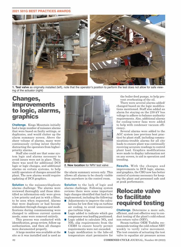
82 COMBINED CYCLE JOURNAL, Number 69 (2022)
2021 501G BEST PRACTICES AWARDS
Changes, improvements to logic, alarms, graphicsChallenge. Kings Mountain initially had a large number of nuisance alarms that were based on faulty settings, or duplicates, and would clutter up the alarm summary screen. Above the sheer volume of alarms, many were continuously cycling in/out thereby distracting the operators from higher-priority alarms.
Staff also could see that some sys-tem logic and alarms necessary to avoid issues were not in place. Thus, there was need for additional DCS logic or logic changes, and additional alarms on certain systems, to help notify operators of changes around the plant. The new alarms would require updating of DCS graphics.
Solution to the nuisance/duplicate alarms challenge: The alarms were reviewed thoroughly and those iden-tified as information-only were given a low priority and put in with a filter, to be seen when requested. Alarms that were duplicate or had become redundant through changes and modi-fications during commissioning were changed to address current system needs; some were removed entirely.
This process was conducted with identification, group review, follow-up authorization, and then all changes were documented properly.
A large monitor was available at the site so it was installed and is used as
the alarm summary screen only. This allows all alarms to be clearly visible from anywhere in the control room.
Solution to the lack of logic and alarms challenge. Following system reviews there were some important logic changes identified that had to be implemented, including the following:n Adjustments to improve the calcu-
lations for low-flow trip on turbine air cooling, to avoid unnecessary gas-turbine trips.
n Logic added to indicate which gas compressor was lead/lag positioned.
n Logic added to calculate NOx and NH3 slip requirements from the CEMS to ensure hourly permit requirements were not exceeded.
n Logic modification to the lube-oil temperature start permissive for
the boiler-feed pumps, to help pre-vent overheating of the oil. There were several alarms added/
changed based on the logic modifica-tions mentioned. Staff also added an alarm for staying on the 230-kV bus voltage to adhere to balance-authority requirements. Also, additional alarms for cooling-tower fans were added to help with condenser vacuum effi-ciency.
Several alarms were added to the AGC system (see previous best prac-tice) by plant staff, including commu-nications-trouble alarms for all city loads to ensure plant was continually receiving accurate readings to control plant load. Graphics modifications were made to display information not on any screen, to aid in operation and trending.
Results. With the changes and improvements to DCS logic, alarms, and graphics, the CRO now has better control of systems necessary for keep-ing the plant and personnel safe and at peak performance.
Relocate valve to facilitate required testingChallenge. Determine a more safe, efficient, and cost-effective way to con-duct testing of the plant’s cold-reheat non-return valve (NRV),
Steam-turbine OEM Toshiba rec-ommends testing the cold-reheat NRV weekly to verify valve movement. The test consists of actuating the test valve to equalize air pressure across
1. Test valve as originally installed (left), note that the operator’s position to perform the test does not allow for safe view-ing of the actuator (right)
2. New location for NRV test valve

COMBINED CYCLE JOURNAL, Number 69 (2022) 83
2021 501G BEST PRACTICES AWARDS
the piston, thereby causing the NRV to move away from its full-open position. Movement must be observed to verify that the valve is not stuck in the full-open position.
The test actuator was installed overhead and adjacent to the NRV (Fig 1). This required the operator to use a step ladder in a walkway to reach the actuator and to maneuver around adjacent conduit, wiring, and hot piping (or engage a second operator) to see the valve while manipulating the test lever.
Solution. It was determined through the plant’s Management of Change process to relocate the test actuator to where it could be both oper-ated and seen safely from ground level by one person. The test actuator was relocated to a nearby stanchion (Fig 2) using stainless-steel tubing and an appropriate mounting material.
Results. The test is now performed from ground level and away from steam piping, thereby providing a safe, ergonomic, and convenient location without the use of a step ladder.
Calorimeter vent extensions promote safetyChallenge. Identify a more safe and efficient way to vent the purge and sample gas that continuously flows through the calorimeter required for proper operation of the gas turbine’s combustion/emissions control sys-tem. The meter is located adjacent to the fuel-gas regulating and control yard. Considering the prevailing winds, the calorimeter was located downstream of the yard. The system vented and purged natural gas in a location that made it difficult to
determine if the “gas smell” was com-ing from the calorimeter or from a gas leak. The constant ordor had the possibility of causing complacency regarding fuel-gas leaks.
The solution team decided that by raising the existing calorimeter vents (Fig 3), it would alleviate the possibil-ity of the normally vented gas from interfering with the leak-detection inspections of the gas yard and adja-cent equipment.
Results. The vents are now located approximately 8 ft higher than they were originally (right photo) and direct gas away from other equipment in the yard. This eliminated the constant small of odorized natural gas and allows personnel to exercise greater situational awareness when working or performing daily inspections.
Platform facilitates strainer removal, promotes safetyChallenge. Condensate strainers are big and require pneumatic tooling
and/or large wrenches to remove and replace their covers. The extremely heavy covers must be swung out of the way for access to the strainers, a function per-formed often during commission-ing and periodically afterwards. Doing this off a ladder is unsafe, while setting up temporary scaf-folding is conducive to inadvertent equipment damage (insulation, transmitters, and gages).
Solution. An ergonomically designed platform was installed to access condensate-pump strainers safely when clean-ing is required. The strainers
are located between the condensate pumps and the condenser, so the platform includes a short ladder to a walkway and then opens up to allow access to both strainers (Fig 4).
Results. Adding the platform around the condensate strainers increases personnel safety by eliminating the use of a ladder, and reduces cost by eliminating the need for scaffolding. The platform provides access for two workers, making the maneuvering of the strainer cover safe and manage-able.
Simplifying the understanding of Management of Change projectsChallenge. Communicate a simple summary of the plant’s Management of Change (MOC) projects. Most MOC initiatives have extensive paperwork, filings, and drawing changes that take time and sometimes a deep understanding of the systems and/
3. Vents as installed are at left, at right after extensions were added
4. New platform facilitates the safe removal of condensate strainers

84 COMBINED CYCLE JOURNAL, Number 69 (2022)
or equipment involved to appreciate the change and the benefits from that change.
Long files and lengthy explana-tions of changes can bog down reviews and slow knowledge transfer with personnel and stakeholders. While all of the information is necessary and should be saved, communicating it for everyone’s understanding can be difficult.
Solution. A short summary of each MOC project is completed in a format that allows for quick understanding of the issue the MOC is resolving and the final product of the MOC. A visual indication of the equipment or system changed also is provided on the logic screen. This then is grouped by year in a reference binder that allows for a quick and simple summary pre-sented to employees, stakeholders, and auditors.
An example of an MOC communica-tion was provided in the presentation for water-treatment chemical-injection controls and RO system updates. A written explanation follows for the auto control and alarms required; however, screen shots illustrating this effort were not of a quality high enough for use in CCJ’s print format. n Modified amine injection to control
conductivity rather than pH.
n Modified O2 scavenger injection to control dissolved oxygen in BFP dis-charge rather than in condensate-pump discharge.
n Modified cooling-water anti-scalant injection to control based in CW makeup flow rather than blowdown flow.
n Modified CW pH and ORP alarms.n Added calculation for water-treat-
ment RO percent recovery and mixed-bed total flow.
n Added calculation for water-treat-ment RO permeate salt-rejection percent.
n Added alarms for RO in-service and mixed-bed change-out.
n Modified wastewater pH to alarm only when pumps are running.
n Modified demin-tank permissives for service-water pump start and trip.
n Added HP and IP phosphate-pump auto start/stop and pH control.
n Modified graphics to accommodate the changes listed above.
Results. Changes now can be under-stood by everyone, even if they were not directly involved in the change. This also makes for quicker sum-maries for auditors or non-technical reviewers, with the ability to choose the change they would like to review more closely.
TURBınE ınSULATıOn AT ıTS FınEST
Monitoring,Inspection,
Maintenance
Online training on-demandat NO COSTAccess the complete course on generator monitoring, inspection, and maintenance, conducted by Clyde Maughan, president, Maughan Generator Consultants LLC, at www.ccj-online.com/onscreen. The program is divided into the following manageable one-hour segments:■ Impact of design on reliability■ Problems relating to operation■ Failure modes and root causes■ Monitoring capability and limita-
tions■ Inspection basic principles■ Test options and risks■ Maintenance basic approaches
www.ccj-online.com/onscreen

COMBINED CYCLE JOURNAL, Number 69 (2022) 85
2021 501G BEST PRACTICES AWARDS
Challenge. New Covert’s auxiliary boiler provides steam during plant startup to the air ejectors, gas-turbine cooling system, and steam-turbine seals. Plus, it is required to remain warm and in a ready-to-run condition.
Boiler firing is controlled by moni-toring steam flow and sending a 4-20-mA signal to a controller mechanical-ly linked to a jackshaft that positions the main fuel valve and the damper for the forced-draft fan. The original controller was located on top of the boiler (Fig 1), by the steam drum, in a relatively warm environment. Over time, the actuator would not operate at full travel. Result: The boiler could not achieve full expected output.
I&C technicians had adjusted the actuator and tested it numerous times, only to have it fail to reach full poten-
tial in actual required operations. When the boiler was tuned in 2018, the technician could only get the actuator to function at 80% of rated operation. Several times during a plant startup operators had to be stationed at the boiler to manually operate the jack-shaft. They were in direct communi-cation with the control room to coor-dinate jackshaft movement between the open and closed positions to satisfy system demand.
Solution. For years, operators sus-pected the actuator’s poor perfor-mance was caused by the warm environment on top of the boiler and lack of use. A proposal was provided by the boiler tuning company for the purchase of an upgraded pneu-matic actuator and its installation
in a cooler environment. A K-Tork range actuator was purchased in summer 2019 and installed in front of the auxiliary boiler, away from the heat (Fig 2).
The improved actuator was designed to operate in high-temperature areas and to provide precise modulation of quarter-turn control valves with an accuracy of 0.25% or better.
Result. The boiler is now able to achieve rated capacity. The increase in output enables the boiler to warm up faster, provide usable steam sooner, and respond quickly to changing load conditions. Today, boiler operation is reliable and steam output predictable. Finally, the new controller has elimi-nated the need for having an operator at the auxiliary boiler during startup, making that person available for more productive work.
Project participants: Chris HeadKent RetterbushGeorge (Bucky) RayJeff Calkins
New Covert New Covert Generating CoOwned by Eastern Gen-eration LLCOperated by Consolidat-ed Asset Management Services LLC1200-MW, gas-fired combined cycle with three 1 × 1 Mitsubishi 501G-powered units, located in Covert, MichPlant manager: Ken Tomaski
Aux boiler regains design output with new controller
1. Original controller was located on top of the boiler, by the steam drum
2. New controller (above) is locat-ed in front of the boiler (right)

86 COMBINED CYCLE JOURNAL, Number 69 (2022)
2021 501G BEST PRACTICES AWARDS
Challenge. Plant and OEM person-nel occasionally require access to the combustor shells of Athens’ gas tur-bines for inspection and maintenance. Combustor shells are permit-required
confined spaces given the nature of the hazardous energy that could be pres-ent in the area. Thus, a confined-space rescue plan is required before anyone can enter a shell.
Originally, the confined-space res-cue plan involved use of a harness and lanyard mounted to the roof beam above the combustor. However, during outages the roof beam also may be removed, to facilitate work on/in the combustor. In these situations, Athens would use a crane, supported over the combustor shell, to mount the lanyard and harness. This was not ideal as it would remove a crane from service. Plus, each time someone needed to get into the combustor shell, the overhead crane would have to be LOTOed out.
Solution. Athens Generating worked with a vendor to design and construct a removable rescue device for use in the event an individual must be recovered from inside the combustor shell. It uses a ladder and beam overhanging the combustor shell port on which fall protection and rescue devices can be mounted. The ladder provides grab points for personnel to hold when the enter and exit the shell. The rescue device is portable and is bolted onto the shell when in use (Fig 1).
Result. The combustor-shell rescue device has been well received by plant and OEM personnel. While no one has yet been rescued using the device, it was in place during recent outages.
Project participants:Chris Mitchell, O&M managerSteve Cole, O&M manager
Electronic database, tablets, mobile rounds focus of plant modernizationChallenge. Since commissioning, Ath-ens Generating had used hard copies of procedures and technical drawings retained in the plant library. While there were procedures and drawings on the plant’s shared drive, they were disorganized and it was difficult to know how to access the most recent revision of a document. Operators
Athens Athens Generating PlantManaged by Kelson EnergyOperated by NAES Corp1080-MW, gas-fired combined cycle with three 1 × 1 Siemens 501G-pow-ered units, located in Athens, NYPlant manager: Hank Tripp
Rescue device helps extract persons in distress from combustor shell
1. The combustor-shell rescue device has been well received by plant and OEM personnel

COMBINED CYCLE JOURNAL, Number 69 (2022) 87
2021 501G BEST PRACTICES AWARDS
spent a lot of time searching for pro-cedures and oftentimes where a cer-tain procedure was located was tribal knowledge.
Also, Athens used traditional pen and paper when making rounds. It was difficult to review completed rounds as the reviewer would have to read through a mountain of paperwork.
Solution. In 2020, the plant initiated a modernization effort to improve the accessibility of plant procedures and technical drawings out in the field. Athens worked with a vendor to develop a digital database that could be accessed on any device with an internet connection. The total number of documents in the database: around 25,000 drawings, 300 procedures, and 200 job hazard analyses.
The new platform enables users to mark-up drawings and procedures to make corrections or changes. Changes are approved or rejected via sev-eral document control steps, and if approved, they are reflected on the revised document. Media files, such as images and videos, also are sup-ported by the platform. They can be standalone procedures or embedded into other documents.
The database is fully searchable based on document number, title, and category—even text contained within each document. The documents are fully printable and/or downloadable.
Coupled with the electronic data-base, Athens Generating implement-ed the use of mobile tablets during rounds, replacing pen and paper. Staff worked with a vendor to design and implement the plant’s mobile platform. Electronic rounds are easily searchable and reviewable.
Additionally, the plant has been working on a project to implement Wi-Fi across the site. Once this ser-vice is available, operators will have the ability to pull up any procedure or drawing in the database from any-where in the plant using their mobile tablets.
Results. Tablets and mobile rounds have been well received by plant operators. The new platform allows for searchability of completed rounds and also allows users to trend values entered in past rounds.
Project participants:Chris Mitchell, O&M managerTod Wolford, E/I&C technicianKyle Kubler, E/I&C technician
Covid-19 response plan gets high marksChallenge. Athens Generating was dealing with a forced outage on one unit in the midst of the Covid-19 pan-demic and had almost 80 contractors from multiple companies onsite. There was a significant need for implementa-tion of Covid-19 precautions to ensure the safety of everyone.
Solution. Athens took several precau-tions to prevent the spread of Covid-19. For example, access to the Plant Ser-vices Building (a/k/a Administration Building) was restricted to plant per-sonnel. All others were directed to the contractor shed and climate-controlled trailers that were brought onsite. On
days when Athens was expecting a large number of visitors, a screening tent was set up near the plant entrance (Fig 2) to take contractor temperatures before they were allowed onsite. The safety video, which all contrac-tors must watch before starting work, was put on a YouTube channel and
2. Covid-19 screening tent was set up near the plant entrance
3. UV-light ultrafiltration system improved air quality in the admin building and control room
4. Covid-19 screening was moved from the tent to a well-equipped conex
5. Automatic temperature scanner reads skin temperature, alerts when not normal

88 COMBINED CYCLE JOURNAL, Number 69 (2022)
2021 501G BEST PRACTICES AWARDS
each person was sent a quiz on the video to bring with them.
Restricting access to the Plant Ser-vices Building meant that contractors could no longer come into the control room to fill out safe-work permits or LOTOs. Athens installed a tent with a remote desktop and signature pad just outside the control room for this purpose. A doorbell was wired up from the tent to the control room to notify the CRO that someone was outside waiting for a safe-work/LOTO.
Athens personnel who were able to perform their jobs from home did so. The plant transitioned to having daily meetings midmorning to keep updated on what each person was working on and to adjust workflows as necessary.
These meetings originally were conference calls, but were moved to Microsoft Teams, which offered the ability to see others on the call talking and sharing their screens. Morning meetings, which previously took place in the control room, were moved to the warehouse to meet social-distance requirements.
Professional cleaners disinfected common surfaces in the Plant Services Building (PSB) several times a week. Athens also worked with a contractor to implement a UV-light air disinfec-tion system in the PSB and control room HVAC unit (Fig 3). The S-Series ultrafiltration system improved PSB air quality by disinfecting all air com-ing into the HVAC system.
Later in the year, Athens com-pleted the outage and winter arrived, making a Covid-19 screening tent and manual temperature reading unfeasible. Another Conex trailer was brought in and set up to be the new Covid screening area (Fig 4 left). In the Covid screening conex, space was provided for contractors to watch the safety video, complete the Covid ques-tionnaire, and sign into and out of the plant (Fig 4 right).
An automatic temperature scanner also was installed to eliminate the need for manual temperature-taking. This instrument reads skin temperature and send an email notification to plant personnel if an elevated temperature is detected (Fig 5).
Results. As of February 2021, no Ath-ens employee had tested positive for Covid-19 and there had been no known transmissions among the contractors. Control-room operators expressed their preference for the remote desk-top over the old process for safe-work/LOTO sign-in.
Project participants:Chris Mitchell, O&M managerSteve Cole, O&M manager
System mods, filtration cart extend life of cooling-tower gearbox oilChallenge. Middletown’s cooling-tower (CT) gearboxes are not easily service-able (Fig 1), but they are critical to plant operation—especially during the summer when seven cells are required to operate at full load.
Gearbox oil typically is changed every six months based on manufac-turer recommendation. Oil changes require that each cell be removed from service and temporary scaffolding be installed for safe access and work.
Changing the oil in one cell typically takes two maintenance technicians four hours. Thus, servicing of all the gearboxes normally would require three and a half days.
Solution. Maintenance Technician Scott Ashely proposed installing oil suction and return lines outside the CT shroud to allow fluid maintenance without need to enter the cell (Fig 2). Bear in mind that each cell is a
Middletown
Middletown Energy CenterOwned by NTE Ohio LLCOperated by NAES Corp 475-MW, gas-fired 1 × 1 combined cycle powered by an M501GAC gas turbine, located in Middletown, OhioPlant manager: Dino Padilha
Vent line Return line
Supply line
1. Service lines serving one of Mid-dletown’s gearboxes
2. Service lines terminate outside the shroud, facilitating hook-up to the filtration cart

COMBINED CYCLE JOURNAL, Number 69 (2022) 89
2021 501G BEST PRACTICES AWARDS
Challenge. Many combined-cycle plants are lean-staffed and during startups operators have a long list of preparatory activities that must be completed to get the unit online safely. One task Middletown Energy Center personnel viewed as an area for improvement was how the operators had to fill the gland seal system’s “U” seals before starting the steam turbine.
The original design of the plant called for operators to run hoses from the condensate system and fill the “U” seals manually. This was a time-consuming job and posed unnecessary risk for injury as it required climbing around pipe and under platforms while pulling a hose.
Solution. One of the plant’s mainte-nance techs proposed that condensate be permanently piped to the seals from a manifold station so operators could fill all the seals safely from one location. Staff concurred with that idea. The mani-
fold station system installed allowed operators to easily fill all six “U” seals from one location.
Result. During plant startups the “U” seals often were overlooked or inade-quately filled, creating a lack of proper sealing. With the manifold system in place, operators are able to successfully throttle condensate flow to the seals and save critical time during plant startups, all while improving safety. Once a seal is established, operators can just isolate the flow and continue with their startup duties.
The new system also makes under-standing and completing the seal-filling tasks more straightforward—especially for new operators. The “U”
seal fill points often are difficult to find; with the manifold system, the exact locations of the seals do not have to be known.
Project participants: Scott Ashley, maintenance technicianDan Truax, O&M managerDino Padilha, plant manager
How to reduce the risk of exposure during a pandemicChallenge. Keeping employees healthy is critical to reliable plant operation. A spread of Covid-19 at Middletown Energy Center would quickly impact the availability of personnel to operate the plant. Outages must also be taken to continue reliable operation, so special measures were implemented to protect employees while having contractors onsite to perform maintenance.
Solution. Middletown employees came up with multiple special measures to reduce the risk of exposure, including the following:n When contractors arrive onsite for
an outage, they normally would sign in with the assigned plant employee coordinator and watch a safety video in the shop area. To reduce contact with contractors, a sign-in board was installed in the storage tent for each company (Fig 5).
n To view the safety video, a TV was mounted in the storage tent (Fig 6). This is larger than the shop area used in normal times, allowing adequate space between contractor personnel. Also, because the tent was not heated or cooled, the doors were left open for better ventilation.
n After contractors had signed in for the day, they proceeded into the facility to complete their assign-ments. On the main road into the plant there is a guard station to control traffic and perform dermal temperature scans, the latter to ensure each individual was not showing signs of Covid-19 (Fig 7).
n Once in the plant, contractors would meet with their plant-employee coordinator to get safe-work permits and sign on to any LOTOs required. Before the pandemic, contractors would enter the control room to do this. To protect operations per-sonnel, unnecessary people in the control room had to be eliminated.
confined space requiring substantial paperwork and safety measures to ensure each entrant is safeguarded
adequately. Without the need to enter the space, those safety efforts can be placed elsewhere, increasing overall plant safety and efficiency.
Result. With service lines installed outside the shroud, oil is filtered using a mobile filtration cart (Fig 3). It is equipped with 10-micron and water-removal filters, and a particle monitor. This filtration arrangement extends oil life from six months up to three years based on oil analysis, thereby providing additional cost and time savings.
Use of the filtration cart has short-ened the maintenance time to one to two hours per cell. Other benefits: Oil maintenance can be performed while the CT cell is in service using a cart small enough for one technician to perform the activities required.
Project participants:Scott Ashley, maintenance technicianDan Truax, O&M managerDino Padilha, plant manager
3. Filtration cart is small enough for one technician to perform the tasks required
Manifold simplifies filling of ‘U’ seals prior to ST startup
4. Manifold station for filling “U” seals simpli-fies what had been a time-consuming job with safety risks

90 COMBINED CYCLE JOURNAL, Number 69 (2022)
2021 501G BEST PRACTICES AWARDS
Staff erected a tent and used the control-room windows as a walk-up area where contractors could request the required paperwork (Fig 8). This allowed operators to maintain social distance while pre-venting crowds waiting for a permit.
n Staff also realized the risks of allow-ing contractors to use plant sanitary facilities. To reduce exposure risk, all plant facilities were marked as “restricted.” In various places, mul-tiple portable restrooms and hand-washing stations were acquired for contractor use. Middletown also arranged for proper sanitation of these facilities every four hours.
n Contractors were permitted to work without masks while they were with their groups. Anytime a plant employee had to interact with them, masks were required.
n To provide contractors a safe place to eat and take breaks, tables and microwaves were set up in the open-air tent at the front of the plant.
Result. With the aforementioned mea-sures in place, Middletown Energy Center did not experience any Covid-19 cases directly related to the outage.
Project participants: Allen Snowbarger, maintenance tech-
nicianTonya Harris, administrative assistantPete Kelly, EHS managerDan Truax, O&M managerDino Padilha, plant manager
5. Contractor sign-in board is the first stop for contract personnel
6. Safety video is aired in storage tent with adequate room for social distancing
7. Temperature check point is maintained by a security guard
8. Small tent in walk-up area allows contractors access to operations personnel without entering the control room

COMBINED CYCLE JOURNAL, Number 69 (2022) 91
2021 501G BEST PRACTICES AWARDS
Challenge. Under certain ambient winter conditions at Shepard, rime ice would form on the leading edges of gas-turbine inlet-air heating coils and continue to build, drastically reducing air flow into the machine. As the pres-
sure differential increased across the inlet filter house, team members would manually scrape ice off the coil fins to prevent a unit runback or plant derate.
Why the ice forms: Occasionally, wind direction would blow cooling-tower plume towards the gas turbines and a portion of that plume would be drawn into the air intakes. When coupled with freezing temperatures, ice would form on the coil fins and it was extremely difficult to scrape off.
The scraping process presented a significant risk to personnel safety and impacted Shepard’s production capabil-ity. The total surface area that required scraping was over 260 m² for each GT. At times, continuous scraping was nec-essary. Plant employees occasionally were exposed to extremely cold tem-peratures—perhaps as low as -50C with wind chill. Since commercial operation of Shepard began in March 2015, scraping was required on more than 100 occa-sions, resulting in a total of 6.3 GWh of related plant-capacity derating.
Additional staff was brought onsite for scraping duty during off-shifts when necessary. If weather condi-tions were extreme, unit load would be decreased to less than 70% of baseload output, thereby allowing the gas tur-bine’s compressor discharge air valve
to open and thaw the coils.
Solution. For better heat-transfer effi-ciency, the existing heating coils were of the reverse-flow type. To see if parallel flow would eliminate the problem, tem-
porary spools were installed and glycol flow was reversed during icing conditions. This did not reduce rime-ice forma-tion; a new heating-coil design was necessary.
A detailed engineering study revealed that an improved design, one using materials of higher thermal conductivity, was needed to cope with high-humidity air in cold conditions. The original Type 304 stainless steel tube and fin coils were replaced with ones made of copper tubes and alumi-num fins. Fin spacing was increased from eight fins per inch to seven, and glycol flow as changed to parallel.
Result. These combined changes were incorporated into the design of the replacement coils for both units, increasing their duty by about 16% and eliminating the need for staff to manually scrape away ice.
Project participants:Shepard management, engineering,
and O&M staff
Mods improve RO system reliabilityChallenge. By design, Shepard uses reclaimed wastewater for all its power generation needs—a first in Alberta. This design feature saves having to draw nearly 6 million m³ of fresh water annually from the Bow River. Most of the intake water is used for cooling-tower makeup, the remainder is treated onsite for boiler makeup. Using reclaimed water helps reduce Shepard’s impact on the environment and eliminates the need to return water used at the plant back to the watershed.
The use of reclaimed water in a reverse osmosis (RO) system presents many challenges. From a chemistry perspective, reclaimed water is far more variable than fresh water and
Shepard Shepard Energy CentreENMAX Energy and Capital Power868-MW, gas-fired 2 × 1 combined cycle powered by Mitsubishi 501G1 gas turbines, located in Calgary, Alta, CanadaPlant manager: Terence Dumonceau
Replacement GT inlet heating coil eliminates manual ice scraping
1. Rime buildup on coils despite use of anti-icing
2. New coils are lifted into position 3. Ice be gone with new coils in place

92 COMBINED CYCLE JOURNAL, Number 69 (2022)
2021 501G BEST PRACTICES AWARDS
contains a large proportion of inorganic and organic compounds. These must be carefully monitored and managed. Some substances can cause premature plugging of membranes and the need for frequent cleaning.
Others must be kept within strict concentration limits for health and environmental reasons. In some cases, the analytical test methods them-selves were found to be influenced by the unique water chemistry, and new sample preservation methods had to be developed.
On average, first-pass RO mem-branes at Shepard used to require replacement about every 18 months. A review of the RO process and of managing water quality was initiated to improve reliability and efficiency.
Solution. The following equipment and performance activities were under-taken in 2020 to address the impact of using reclaimed water in the RO process.n Replacing hoses used for clean-in-
place lines with hard pipe as an added safety measure.
n Installing a skid that injects biocide for 25 seconds during the train flush prior to stopping on low demand.
n Relocating sodium bisulfite injec-tion downstream of RO inlet pre-filters (versus upstream).
n Doubling the feed-storage-tank free-chlorine residual to 2 ppm.
n Installing a drain line at the bottom of the inlet prefilters. The drain is left cracked open to prevent stag-nation when the RO systems are offline.
n Increasing the first-pass reject flow.n Upgrading the second-pass pumps
with variable-frequency drives to better control first-pass permeate pressure and fix pressure swings, resulting in a much more stable operation. A consistent pH sample pressure provided a more accurate pH indication, allowing automated caustic addition.
n Installing pressure transmitters on rejects from first-pass stages 1 and 2. This information was needed to imple-ment RO performance monitoring.
Result. RO system operation is now stable and does not trip from high-differential scenarios. System cleaning time also has decreased, and mixed-bed replace time tripled because of stable pH control. In addition, the use of RO performance software has helped with predictive cleaning to extend the life of the RO system.
Project participants:Shepard management, engineering,
and O&M staff
Cooling-tower foam controlChallenge. Reclaimed water contains a high level of total dissolved solids and organic material which cause foam to develop on the surface of the water while in use (Fig 4). Excess foam at the top of the cooling tower became an issue at Shepard. The foam would float down to parking areas below and overflow from the tower basin onto walkways, presenting a safety and environmental issue that had to be addressed.
Solution:n Three 50% cloth disc filters were
installed on the reclaimed-water makeup line to help reduce the quantity of suspended solids enter-ing the cooling-tower basin.
n Multiple anti-foam products were tested to determine which was the most effective. A temporary injection system to the basin was simultaneously set up to use.
n A permanent anti-foam skid (Fig 5) was installed with an injection point to the condenser cooling-water outlet pipe.
Result. The cooling-tower anti-foam skid is regulating foam build-up successfully. Foam no longer spills from the basin and foam at the top of the cooling tower is minimal. This innovation has resulted a significant saving in staff time by eliminating foam monitoring, abatement, and cleanup.
Project participants:Shepard management, engineering,
and O&M staff
Increasing cycles dramatically reduces cooling-tower water consumptionChallenge. Shepard’s stainless-steel-tubed steam-turbine condenser was subject to stress corrosion cracking, attributable to tensile stress and cooling-water chemistry. The most common environmental exposure con-dition responsible for SCC is chlorides, so their limits are key to condenser longevity. At Shepard the limit speci-fied for its condenser was 500 ppm. The cooling tower operated at about 3.2 cycles of concentration to stay within this limit (Fig 6).
The cooling tower uses munici-pal reclaimed water, which contains a high level of dissolved organic
5. Anti-foam pump skid has dealt successfully with Shepard’s cooling-tower foaming issue
4. High levels of total dissolved solids and organic material cause foaming in the cooling tower

COMBINED CYCLE JOURNAL, Number 69 (2022) 93
compounds. Sodium hypo-chlorite disinfectant reacts with these compounds to form byproducts that include trihalomethanes (THMs, speci f ical ly chloroform <0.05 ppm)—another fac-tor impacting total cycles of concentration.
Shepard’s challenge was to improve water conser-vation efforts at the plant by increasing cooling-tower cycles of concentration while staying within condenser metallurgical tolerances, as well as within the city
of Calgary’s requirements for plant water discharge.
Solution:n Completed a detailed engineer-
ing study to determine limits of chlorides, sulphates, hardness, scale inhibitor capacity, as well as chloroform formation. The findings allowed an increase in chloride limits to 1000 ppm with no stress corrosion cracking.
n Established a scaling model to understand the corrosion potential and mitigate it with cooling-water pH control.
n Made small , gradual increases to cycles of con-centration with two weeks of monitoring between every increase.
n Increased frequency of onsite water quality moni-toring with bench tests as well as third-party lab tests.
n Installed a slip-stream blowdown line on the cool side of auxiliary cooling-water exchanger supply. This flow was incorpo-rated into the plant’s total blowdown flow control. Flow was optimized to keep chloroform formation at a minimum.
6. Shepard’s cooling tower now operates at 5.2 cycles of concentration, up from 3.2
Makeup from condensate system
+ Cycle Chemistry Audits+ New Project Specifications
+ FAC Management+ Chemistry Investigations+ Cycle Chemistry Training
+64 21 843 [email protected]
NEW ZEALAND
CCGT / HRSG Chemistry Experts
www.thermalchemistry.com
7. New line from the condensate system provides make-up to the auxiliary boiler, eliminating the need to start and stop the BFP to top off the unit when on standby

94 COMBINED CYCLE JOURNAL, Number 69 (2022)
n Provided automated controls to adjust cycles of concentration based on ambient temperature and the results of water-quality monitoring.
Result. Cycles of concentration were increased from 3.2 to 5.2 with water chemistry comfortably within all required parameters. Raw water use has been reduced by about 800,000 m³ annually and discharge water by about 400,000 m³ annually. Total water-cost saving as a result of this innovation is at least $1.5-million per year.
Recall that in the cooling-water cycle, every pass through the towers increases the concentration of dis-solved substances. After three years of meticulous research, observation, and lab testing, the Shepard team was able to pinpoint the optimal operating efficiency of the cooling towers while still maintaining all cooling-water chemistry parameters within their required concentration limits. Now, into the third year of the optimization initiative, the process continues to improve. Shepard saved $2.14 million in 2020 while concurrently increasing power output.
Project participants:Shepard management, engineering,
and O&M staff
Aux-boiler makeup line reduces BFP wear and tearChallenge. Shepard’s gas turbines are steam-cooled and rely on an aux-iliary boiler to provide cooling steam during plant startups. The boiler’s mud drum is equipped with a heating coil to keep the unit warm for quick starting. Drains are left cracked open when the boiler is offline, to ensure the steam line to the main power block also remains hot.
Thus, the water level in the boiler slowly drops and must be topped off once per shift using the boiler feed-water pump (BFP). The number of pump starts and stops was causing an unfavorably high rate of wear and tear on the pump, its motor driver, and mechanical seals.
Solution. The design and installation of a permanent makeup line from the plant’s condensate system into a modified drain line downstream of the boiler level control valve solved the problem (Fig 7).
Result. Excessive starts and stops have been eliminated, leading to a reduction in wear and tear. No pump repairs have been required since the makeup line was added. Total cost savings from this innovation are about $100,000 annu-ally. Condensate is already chemically treated for boiler use, an added benefit of using condensate versus deaerator water. To eliminate constant tem-perature swings on the boiler drum, the use of condensate also reduces the dissolved oxygen levels in the auxiliary boiler system.
Project participants:Shepard management, engineering, and O&M staff


96 COMBINED CYCLE JOURNAL, Number 69 (2022)
Turbine Tip No. 16 from the PAL solu-tions library applies to all models of legacy GE gas turbines.
GE gas turbines installed in electric generating plants from the mid-1960s to the late 1980s operate infrequently today—typically confined to peaking and emergency service—given the availability of more-efficient machines for mid-range and baseload duty. How-ever, when your legacy engines do run it is good to know if they are operating “up to snuff.”
There’s an easy way to do this knowing compressor discharge pres-sure and exhaust temperature, calcu-lating the pressure ratio, and plotting this information on the OEM’s perfor-mance graph provided in the plant’s Control Specifications.
Below are the steps involved, using the MS5001L gas turbine to illus-trate the process. These so-called 5L turbines were designed with NEMA (National Electrical Manufacturers Assn) ratings of approximately 15,000 kW for a compressor inlet temperature of 80F and site elevation of 1000 ft (14.17 psia).
First, access the following infor-mation from the control system dis-play (Fig 1) at full speed/no load (FSNL):n Turbine exhaust temperature
(TXA).n Compressor discharge pressure
(PCD).n Fuel-pump stroke reference
(VCO). The data are repeated in the
caption to facilitate readability. Given the compressor inlet pres-sure is 14.39 psia from site data (if not available, use the standard 14.7 as its impact will be minimal, especially for legacy turbines), the pressure ratio (CPR) can be calcu-lated as follows: CPR = [76.1 (PCD) + 14.39] ÷ 14.39 = 6.29.
Since speed is constant at FSNL, in preparation for the generator to supply power to the grid, consider that a new operating “plateau” has been reached: synchronous speed. Thereafter, the data of interest increase in direct rela-tion to fuel flow to the combustors (Fig 2). For greater insight, refer back to
Turbine Tip No. 7, “Benefits accrue from observing startup, operational, and shutdown sequences,” CCJ No. 64 (2020), p 114.
Again, the data are repeated in the caption to facilitate readability. As for the previous calculation, the compres-sor inlet pressure is 14.39 from site data and the pressure ratio at baseload is the following:CPR = [90 (PCD) + 14.39] ÷ 14.39 = 7.25.
Next, go to Fig 3 and plot the aver-age exhaust temperature at full load
(851F, Fig 2) against the compressor pressure ratio of 7.25 at baseload. That point occurs well below the base temperature control line, as the arrow indicates. Important to note that GE engines are designed to run on the lower control line. When operating below this line, the unit is under-firing—that is, performing below the design rating. Fig 4 illustrates this with a power output of 12 MW, lower than expected with 3.5 MVAr of reac-tive power.
Of course, you might choose to operate slightly below the engine’s design rating to main-tain its reliability and minimize wear and tear, given the unit’s age. You can do this by adjust-ing the fuel regulator to reduce exhaust temperature. This and other options available to you are described in Turbine Tip No. 1, “Limit output to maintain reli-ability of legacy engines,” CCJ No. 58 (Third Quarter 2018), p 29.
Performance analysis
For the Frame 5L example, power production increases from 0 MW at FSNL to 12 MW, because fuel flow to the compressor increases dur-ing the ramp up in output. During this transition, compressor discharge pres-sure goes from 76.1 to 90 psig—a rise of only 13.9 psi, which is considered low and indicative of something being
TURBINE TIPS, No. 16 in a series
By Dave Lucier, PAL Turbine Services LLC www.pondlucier.com
1040
1020
1000
980
960
940
920
900
Turb
ine
exha
ust t
empe
ratu
re, F
7.0 7.5 8.0 8.5 9.0Compressor pressure ratio
Peak-load control line
Base-temperature control line
1. Data displayed when operating at full speed/no load (FSNL) are the following: Turbine speed, 5191 rpm; turbine exhaust temperature (average of all working exhaust thermocouples), 467F; compressor discharge pres-sure, 76.1 psig; fuel-pump stroke, 85 psig
2. Data displayed after the engine is synchronized to the grid (so-called base temperature control) are the following: Turbine speed, 5191 rpm; turbine exhaust temperature (average of all working exhaust thermocouples), 851F; compressor discharge pressure, 90.0 psig; fuel-pump stroke, 168 psig
3. GE engines are designed to run on the lower control line. The arrow points to the current operating point well below that, as defined by the intersec-tion of the horizontal line for 851F turbine exhaust temperature with the vertical line for a compressor pressure ratio of 7.25
A simple way to check gas-turbine performance

COMBINED CYCLE JOURNAL, Number 69 (2022) 97
Aeroderivative Gas Turbine Support, Inc.phone: (561) 994-0000fax: (561) 994-3600email: [email protected]
1141 S. Rogers Circle, Suite 11 Boca Raton, FL 33487
LM2500LM5000LM6000LMS100GG4/FT4
Visit our newly redesigned website www.agtsi.com
Generating Timely Repair Solutions•Generator Testing Services
•Generator Repair Services • Stator – Rewinds, Rewedges, Core Repairs, etc..
• Rotor – Rewinds, Retaining Ring Removal/Replacement, etc…
• High Voltage Bushing Manufacturing & Refurbishment
518.843.1112
www.agtservices.com
AGT Services specializes in providing generator test, inspection, and repair
solutions, coupled with expert restorations and expedited delivery of components to
repair or rewind any Steam, Gas, or Nuclear turbine generator.
PROFESSIONAL SERVICES
COMBINED CYCLE Journal CCJ No. 69 (2022)
Index to advertisers7EA Users Group ............................557F Users Group ...............................997HA Users Group ............................94Advanced Filtration Concepts .........43Advanced Turbine Support LLC ........9AGT Services Inc ......................24, 97AGTSI ........................................37, 97Arnold Group ..... 12-13, 25, 59, 75, 84C C Jensen ....................................21CCJ Generator Training ..................84Chanute Manufacturing ...................27Combined Cycle Users Group ........54Crown Electric .................................19Cust-O-Fab Specialty Services .......63Cutsforth Inc ...............................50-51Donaldson Company Inc .................26Doosan Turbomachinery Services ..11EMW Filtertechnik ...........................29Frame 5 Users Group .....................55Frame 6 Users Group .....................55Filter-Doc Corp ................................65
Generator Users Group ...................54Groome Industrial Service Group ....57 HRSG Forum ..................................73HRST Inc ...................................35, 97Hydro Inc ........................................4-5IAPWS .............................................73IC Spares ........................................97IHI ....................................................39Indeck Power Equipment ................67International Generator Technical Community ......................................80IPG Srl .............................................71JASC ...............................................15KinetiClean (Groome) ....................100Liburdi Turbine Services ..................42Maximum Turbine Support ..............41MD&A ...............................................2Mettler Toledo ..................................61Millennium Power ............................58Mobile Excitation Services ..............44National Breaker Services ...............19National Electric Coil .......................67
Noxco ..............................................23OSU Institute of Technology ............69Ovation Users Group.......................98Power Plant Controls Users Group .54Power Users, Forums ......................95Power Users, Legacy Conference ..55Power Users, Umbrella Organization .................................79RMS Energy ....................................74Schock Manufacturing .....................62Shaft Current Solutions ...................93Sohre Turbomachinery ....................93Steam Turbine Users Group ...........54SVI Industrial ...................................28Taylor’s Industrial Coatings .............64TesTex .............................................69Thermal Chemistry .........................93Trinity Turbine Technology...............77TTS Energy Services ........................7Umicore Catalyst USA Inc ...............17ValvTechnologies .............................76Zokman Products Inc ......................45

98 COMBINED CYCLE JOURNAL, Number 69 (2022)
wrong. Here’s what to check:n Fouled compressor, typically
caused by poor-quality ambient air. Examples: Soot deposits are common in gas turbines down-stream from a refinery or chemi-cal processing plant, salt deposits in units located within five miles or so of an ocean or other body of saltwater.
Action to consider: At FSNL, inject Carbo Blast or equivalent for dynamic cleaning of compressor blades. Veterans may recall walnut shells being used for this purpose back in the 1960s and 1970s.
n Partially opened compressor bleed valves. During startup, CBVs should be fully closed at about 75% of rated speed and never leak. Action to consider if your CBVs leak: Disassemble, inspect,
clean, and lap sealing surfaces as required.
n Leakage at the compressor dis-charge—such as missing transi-tion-piece side seals or at another unwanted opening causing a pres-sure loss. Action to consider: Bring in a qualified borescope inspection team to look for passages for leak-age.
n Cracking or erosion of one or more first-stage nozzles. If the trailing edges of nozzle partitions are worn or eroded, the backpres-sure on turbine buckets will drop, reducing power output. Action to consider: Conduct a borescope inspection of first-stage trailing-edge partitions.Finally, consider the case where
power output increases from FSNL to the 15 MW designers intended for
the Frame 5L. For these conditions, the expected average turbine exhaust temperature would be approximately 950F. Also, compressor discharge pressure should increase by nearly 20 psi—from 76.1 psig (refer back to Fig 1) to the 95 psig expected based on the NEMA rating for this machine with a clean compressor. The com-pressor pressure ratio for the Frame 5L at NEMA conditions and using the same calculation presented earlier, would be 7.72.
Final step: Plot the 950F exhaust temperature and 7.72 pressure ratio on the Fig 3 chart (X marks the spot), noting that it is above the control line. This means the unit is over-firing and the exhaust temperature should be reduced by 20 deg F or so to mini-mize the wear and tear on first-stage nozzles. ccj
4. Power output (left) and reactive power output (right) for the Frame 5L described in the article
5. FSNL and baseload data (left and right, respectively) presented for a unit with a clean compressor show improvement over that recorded for the base-case gas turbine


| (800) 505-6100
KinetiClean is safer and fasterwith the deepest cleaning effect
of any method currently used to clean HRSG fin tubes.
BeforeAfter
TThhee mmoosstt eeffffeeccttiivvee wwaayy ttoo cclleeaann aa HHRRSSGG
Groome’s patented technology uses a proven
Kinetic Shockwave cleaning method to remove
unwanted foulant. An innovative and automated
air system then distributes high-pressure,
high-volume air to liberate remaining debris.
• No manual tube movement
• Minimal-to-no scaffolding
• Other projects can continue in tandem
• No additional moisture
• Highly-trained and fully-licensedprofessionals manage explosive process