— PME120-AI / PME120-AN (Contrac) Electrical rotary actuator
Research ArticleForward and Reverse Movements of a Linear Positioning StageBased on the Parasitic Motion Principle
Hu Huang and Hongwei Zhao
College of Mechanical Science & Engineering, Jilin University, Renmin Street 5988, Changchun, Jilin 130025, China
Correspondence should be addressed to Hongwei Zhao; [email protected]
Received 27 May 2014; Accepted 20 July 2014; Published 20 August 2014
Academic Editor: Yong Chen
Copyright © 2014 H. Huang and H. Zhao. This is an open access article distributed under the Creative Commons AttributionLicense, which permits unrestricted use, distribution, and reproduction in any medium, provided the original work is properlycited.
A compact linear positioning stage using one microgripper and one piezoelectric stack is presented based on the parasitic motionprinciple. Characteristics of the linear positioning stage along the positive y-axis and the negative y-axis aremeasured and comparedwith each other. Experimental results indicate that the linear positioning stage has features of the large motion range, variousmovement velocities and stepping displacement, and forward and reverse movements. Meanwhile, the positioning stage has goodresolution and enough load capacity. Possible reasons leading to nonlinearity and velocity difference between forward and reversemovements are discussed. Research results in this paper will make applications of the parasitic motion principle more flexible.
1. Introduction
Precision positioning stages are widely required in scientificresearch and industrial applications. Precision positioningstages based on piezoelectric stacks and flexure hinge-based compliant mechanisms are playing more and moreimportant roles in scanning systems [1], precision andultraprecision machining [2, 3], micromanipulators [4, 5],micro/nanomechanical testing [6, 7], and so on. For differentapplication requirements, kinds of driving principles havebeen proposed, such as the piezoelectric stack direct drivingprinciple [8], the inchworm driving principle [9], the impactdriving principle [10], and the stick-slip driving principle [11].
Up to now, improving positioning accuracy and increas-ing the motion range are two important research topics forpiezodriven positioning stages [12, 13]. But they are usuallyconflicting. As a modified stick-slip driving principle, theparasitic motion principle (PMP) which has the potentialto solve both of these two issues was presented in [14].Based on the parasitic motion principle, the microgripperis used to modulate the output of the piezoelectric stackinstead of directly piezodriven form stick-slip style. Withthe symmetrical structure, the PMP linear actuator in [14]mainly consisting of twomicrogrippers and two piezoelectric
stacks realizes the large motion range, various velocities, andforward and reverse movements. However, the symmetricalstructure also increases dimensions of the PMP linear actu-ator, and its size reaches 130mm × 50mm × 26mm, whichlowers the flexibility of its applications. For example, thedimension along 𝑦-axis of the in situ scratch testing device in[6] is strongly dependent on dimensions of the PMP linearactuator. If dimensions of the PMP linear actuator can bereduced but its functions still maintained, applications ofthe PMP linear actuator will be more flexible. Based on thisconsideration, we will try to use only one microgripper andone piezoelectric stack to realize similar functions of the PMPlinear actuator [14] in this paper.
2. Structure
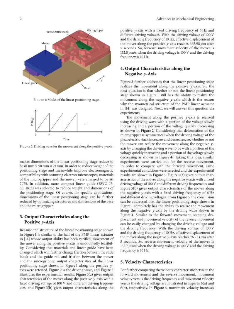
Figure 1 is the model of the linear positioning stage based onthe parasitic motion principle. In order to reduce repeateddesign, the microgripper of this linear positioning stageis the same to that of the PMP linear actuator in [14].Compared with the structure of the PMP linear actuatorin [14], the biggest difference in Figure 1 is that only onemicrogripper and one piezoelectric stack are used, which
Hindawi Publishing CorporationAdvances in Mechanical EngineeringVolume 2014, Article ID 452560, 7 pageshttp://dx.doi.org/10.1155/2014/452560
2 Advances in Mechanical Engineering
Base
y
Microgripper
Linear guide
Mover
Piezoelectric stack
Figure 1: Model of the linear positioning stage.
TimeT
Volta
ge
0
· · ·
Figure 2: Driving wave for the movement along the positive 𝑦-axis.
makes dimensions of the linear positioning stage reduce tobe 81mm × 50mm × 21mm. In order to reduce weight of thepositioning stage and meanwhile improve electromagneticcompatibility with scanning electron microscopes, materialsof the microgripper and the mover were changed to be Al7075. In addition, more compact linear guide (BWU 17-30, IKO) was selected to reduce weight and dimensions ofthe positioning stage. Of course, for specific applications,dimensions of the linear positioning stage can be furtherreduced by optimizing structures and dimensions of the baseand the microgripper.
3. Output Characteristics along thePositive 𝑦-Axis
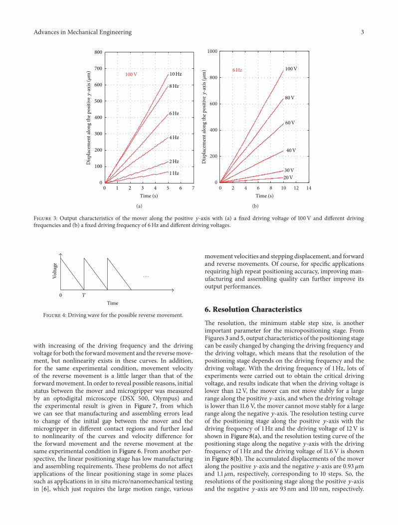
Because the structure of the linear positioning stage shownin Figure 1 is similar to the half of the PMP linear actuatorin [14] whose output ability has been verified, movement ofthe mover along the positive 𝑦-axis is undoubtedly feasibil-ity. Considering that materials and linear guide have beenchanged which will further change friction between the slideblock and the guide rail and friction between the moverand the microgripper, output characteristics of the linearpositioning stage shown in Figure 1 along the positive 𝑦-axis were retested. Figure 2 is the driving wave, and Figure 3illustrates the experimental results. Figure 3(a) gives outputcharacteristics of the mover along the positive 𝑦-axis with afixed driving voltage of 100V and different driving frequen-cies, and Figure 3(b) gives output characteristics along the
positive 𝑦-axis with a fixed driving frequency of 6Hz anddifferent driving voltages. With the driving voltage of 100Vand the driving frequency of 10Hz, effective displacement ofthe mover along the positive 𝑦-axis reaches 663.98 𝜇m after5 seconds. So, forward movement velocity of the mover is132.8 𝜇m/s when the driving voltage is 100V and the drivingfrequency is 10Hz.
4. Output Characteristics along theNegative 𝑦-Axis
Figure 3 further addresses that the linear positioning stagerealizes the movement along the positive 𝑦-axis. So, thenext question is that whether or not the linear positioningstage shown in Figure 1 still has the ability to realize themovement along the negative 𝑦-axis which is the reasonwhy the symmetrical structure of the PMP linear actuatorin [14] was designed. Next, we will answer this question viaexperiments.
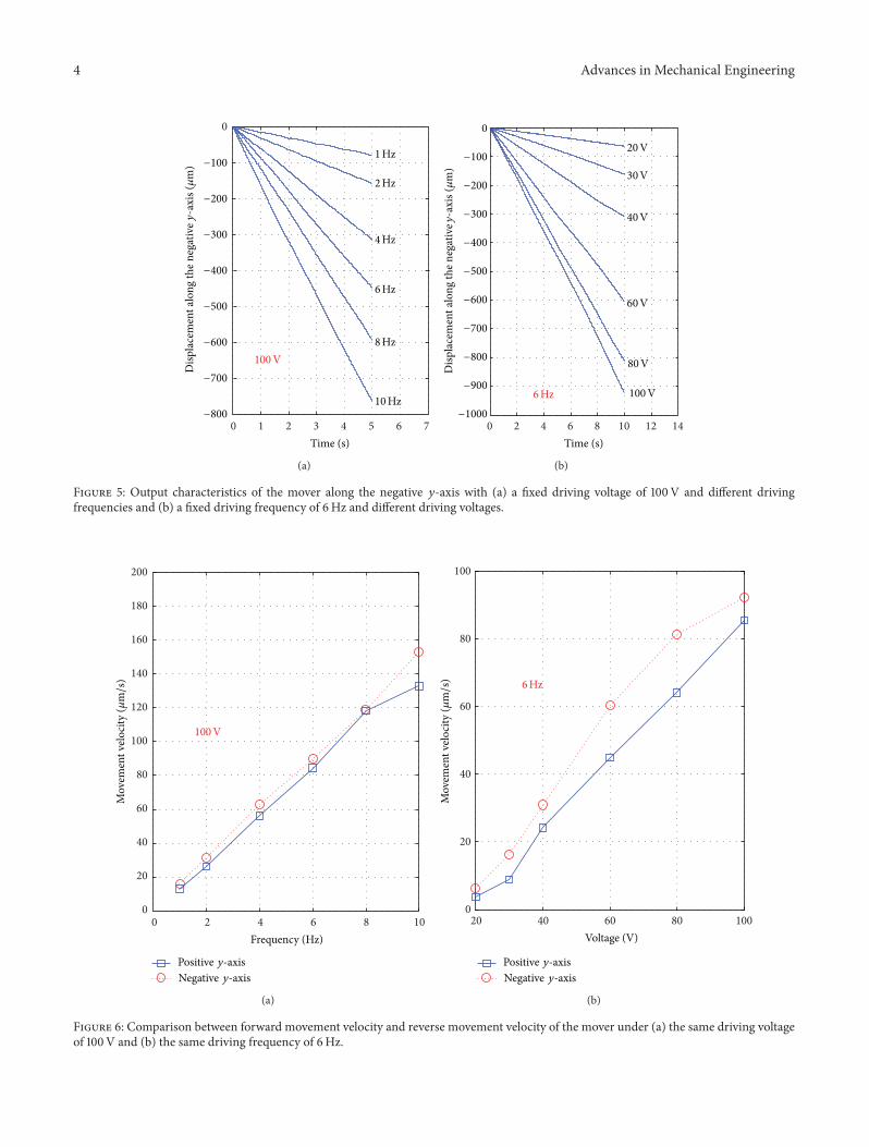
The movement along the positive 𝑦-axis is realizedusing the driving wave with a portion of the voltage slowlyincreasing and a portion of the voltage quickly decreasingas shown in Figure 2. Considering that deformation of themicrogripper is symmetrical when the driving voltage of thepiezoelectric stack increases and decreases, so, whether or notthe mover can realize the movement along the negative 𝑦-axis by changing the driving wave to be with a portion of thevoltage quickly increasing and a portion of the voltage slowlydecreasing as shown in Figure 4? Taking this idea, similarexperiments were carried out for the reverse movement.In order to compare with the forward movement, sameexperimental conditions were selected and the experimentalresults are shown in Figure 5. Figure 5(a) gives output char-acteristics of the mover along the negative 𝑦-axis with a fixeddriving voltage of 100V and different driving frequencies, andFigure 5(b) gives output characteristics of the mover alongthe negative 𝑦-axis with a fixed driving frequency of 6Hzand different driving voltages. From Figure 5, the conclusioncan be addressed that the linear positioning stage shown inFigure 1 completely has the ability to realize the movementalong the negative 𝑦-axis by the driving wave shown inFigure 4. Similar to the forward movement, stepping dis-placement and movement velocity of the reverse movementcan be easily changed by changing the driving voltage andthe driving frequency. With the driving voltage of 100Vand the driving frequency of 10Hz, effective displacement ofthe mover along the negative 𝑦-axis reaches 763.53 𝜇m after5 seconds. So, reverse movement velocity of the mover is152.7 𝜇m/s when the driving voltage is 100V and the drivingfrequency is 10Hz.
5. Velocity Characteristics
For further comparing the velocity characteristic between theforward movement and the reverse movement, movementvelocity versus the driving frequency and movement velocityversus the driving voltage are illustrated in Figures 6(a) and6(b), respectively. In Figure 6, movement velocity increases
Advances in Mechanical Engineering 3
800
700
600
500
300
100
400
200
00 1 2 3 4 5 6 7
Time (s)
100V 10Hz
6Hz
8Hz
4Hz
2Hz
1Hz
Disp
lace
men
t alo
ng th
e pos
itive
y-a
xis (𝜇
m)
(a)
0 2 4 6 8 10 12 140
200
400
600
800
1000
Time (s)D
ispla
cem
ent a
long
the p
ositi
vey-a
xis (𝜇
m) 6Hz 100V
80V
60V
40V
30V20V
(b)
Figure 3: Output characteristics of the mover along the positive 𝑦-axis with (a) a fixed driving voltage of 100V and different drivingfrequencies and (b) a fixed driving frequency of 6Hz and different driving voltages.
TimeT
Volta
ge
0
· · ·
Figure 4: Driving wave for the possible reverse movement.
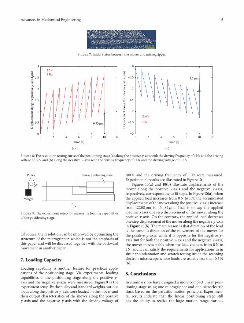
with increasing of the driving frequency and the drivingvoltage for both the forwardmovement and the reversemove-ment, but nonlinearity exists in these curves. In addition,for the same experimental condition, movement velocityof the reverse movement is a little larger than that of theforwardmovement. In order to reveal possible reasons, initialstatus between the mover and microgripper was measuredby an optodigital microscope (DSX 500, Olympus) andthe experimental result is given in Figure 7, from whichwe can see that manufacturing and assembling errors leadto change of the initial gap between the mover and themicrogripper in different contact regions and further leadto nonlinearity of the curves and velocity difference forthe forward movement and the reverse movement at thesame experimental condition in Figure 6. From another per-spective, the linear positioning stage has low manufacturingand assembling requirements. These problems do not affectapplications of the linear positioning stage in some placessuch as applications in in situ micro/nanomechanical testingin [6], which just requires the large motion range, various
movement velocities and stepping displacement, and forwardand reverse movements. Of course, for specific applicationsrequiring high repeat positioning accuracy, improving man-ufacturing and assembling quality can further improve itsoutput performances.
6. Resolution Characteristics
The resolution, the minimum stable step size, is anotherimportant parameter for the micropositioning stage. FromFigures 3 and 5, output characteristics of the positioning stagecan be easily changed by changing the driving frequency andthe driving voltage, which means that the resolution of thepositioning stage depends on the driving frequency and thedriving voltage. With the driving frequency of 1Hz, lots ofexperiments were carried out to obtain the critical drivingvoltage, and results indicate that when the driving voltage islower than 12V, the mover can not move stably for a largerange along the positive 𝑦-axis, and when the driving voltageis lower than 11.6 V, the mover cannot move stably for a largerange along the negative 𝑦-axis. The resolution testing curveof the positioning stage along the positive 𝑦-axis with thedriving frequency of 1Hz and the driving voltage of 12 V isshown in Figure 8(a), and the resolution testing curve of thepositioning stage along the negative 𝑦-axis with the drivingfrequency of 1Hz and the driving voltage of 11.6 V is shownin Figure 8(b). The accumulated displacements of the moveralong the positive 𝑦-axis and the negative 𝑦-axis are 0.93 𝜇mand 1.1 𝜇m, respectively, corresponding to 10 steps. So, theresolutions of the positioning stage along the positive 𝑦-axisand the negative 𝑦-axis are 93 nm and 110 nm, respectively.
4 Advances in Mechanical Engineering
0
Disp
lace
men
t alo
ng th
e neg
ativ
ey-a
xis (𝜇
m)
−800
−700
−600
−500
−400
−300
−200
−100
0 1 2 3 4 5 6 7Time (s)
100V
10Hz
6Hz
8Hz
4Hz
2Hz
1Hz
(a)
0 2 4 6 8 10 12 14Time (s)
Disp
lace
men
t alo
ng th
e neg
ativ
ey-a
xis (𝜇
m)
6Hz 100V
80V
60V
40V
30V
20V
−1000
−900
−800
−700
−600
−500
−400
−300
−200
−100
0
(b)
Figure 5: Output characteristics of the mover along the negative 𝑦-axis with (a) a fixed driving voltage of 100V and different drivingfrequencies and (b) a fixed driving frequency of 6Hz and different driving voltages.
0 2 4 6 8 100
20
40
60
80
100
120
140
160
180
200
Frequency (Hz)
Mov
emen
t velo
city
(𝜇m/s
)
Positive y-axisNegative y-axis
100V
(a)
20 40 60 80 1000
20
40
60
80
100
6Hz
Mov
emen
t velo
city
(𝜇m/s
)
Positive y-axisNegative y-axis
Voltage (V)
(b)
Figure 6: Comparison between forward movement velocity and reverse movement velocity of the mover under (a) the same driving voltageof 100V and (b) the same driving frequency of 6Hz.
Advances in Mechanical Engineering 5
1mm
Figure 7: Initial status between the mover and microgripper.
3
2.5
2
1.5
1
0.5
00 2 4 6 8 10 12
Time (s)
12V1Hz
Disp
lace
men
t alo
ng th
e pos
itive
y-a
xis (𝜇
m)
0.93𝜇m
(a)
0 2 4 6 8 10 12
1.1 𝜇m
−3
−2.5
−2
−1.5
−1
−0.5
0
Time (s)
Disp
lace
men
t alo
ng th
e neg
ativ
ey-a
xis (𝜇
m)
11.6V
1Hz
(b)
Figure 8:The resolution testing curve of the positioning stage (a) along the positive 𝑦-axis with the driving frequency of 1Hz and the drivingvoltage of 12V and (b) along the negative 𝑦-axis with the driving frequency of 1Hz and the driving voltage of 11.6 V.
Linear positioning stagePulley
Weight
y
Figure 9: The experiment setup for measuring loading capabilitiesof the positioning stage.
Of course, the resolution can be improved by optimizing thestructure of the microgripper, which is not the emphasis ofthis paper and will be discussed together with the backwardmovement in another paper.
7. Loading Capacity
Loading capability is another feature for practical appli-cations of the positioning stage. Via experiments, loadingcapabilities of the positioning stage along the positive 𝑦-axis and the negative 𝑦-axis were measured. Figure 9 is theexperiment setup. By the pulley and standardweights, variousloads along the positive 𝑦-axis were loaded on themover, andthen output characteristics of the mover along the positive𝑦-axis and the negative 𝑦-axis with the driving voltage of
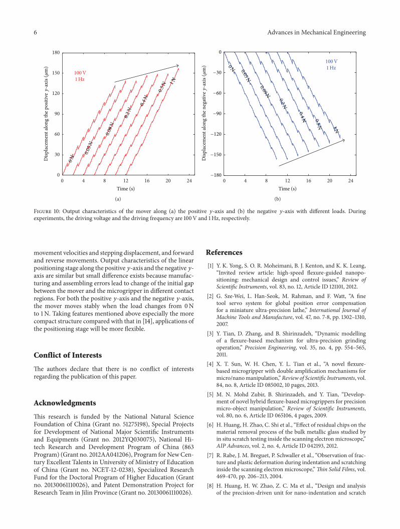
100V and the driving frequency of 1Hz were measured.Experimental results are illustrated in Figure 10.
Figures 10(a) and 10(b) illustrate displacements of themover along the positive 𝑦-axis and the negative 𝑦-axis,respectively, corresponding to 10 steps. In Figure 10(a), whenthe applied load increases from 0N to 1N, the accumulateddisplacements of themover along the positive 𝑦-axis increasefrom 127.08 𝜇m to 154.82 𝜇m. That is to say, the appliedload increases one step displacement of the mover along thepositive 𝑦-axis. On the contrary, the applied load decreasesone step displacement of the mover along the negative 𝑦-axisin Figure 10(b). The main reason is that direction of the loadis the same to direction of the movement of the mover forthe positive 𝑦-axis, while it is opposite for the negative 𝑦-axis. But for both the positive 𝑦-axis and the negative 𝑦-axis,the mover moves stably when the load changes from 0N to1N, and it can satisfy the requirements for applications in insitu nanoindentation and scratch testing inside the scanningelectron microscope whose loads are usually less than 0.5N[6].
8. Conclusions
In summary, we have designed a more compact linear posi-tioning stage using one microgripper and one piezoelectricstack based on the parasitic motion principle. Experimen-tal results indicate that the linear positioning stage stillhas the ability to realize the large motion range, various
6 Advances in Mechanical Engineering
0 4 8 12 16 20 240
30
60
90
120
150
180D
ispla
cem
ent a
long
the p
ositi
vey
-axi
s (𝜇
m)
Time (s)
100V1 Hz
0N
0.05
N
0.09
N
0.2
N
0.4
N
0.5
N 1N
(a)
0 4 8 12 16 20 24
Disp
lace
men
t alo
ng th
e neg
ativ
ey-a
xis (𝜇
m)
Time (s)
100V1 Hz0N 0.05N
0.09N
0.2N
0.4N 0.5N 1N
−180
−150
−120
−90
−60
−30
0
(b)
Figure 10: Output characteristics of the mover along (a) the positive 𝑦-axis and (b) the negative 𝑦-axis with different loads. Duringexperiments, the driving voltage and the driving frequency are 100V and 1Hz, respectively.
movement velocities and stepping displacement, and forwardand reverse movements. Output characteristics of the linearpositioning stage along the positive𝑦-axis and the negative𝑦-axis are similar but small difference exists because manufac-turing and assembling errors lead to change of the initial gapbetween the mover and the microgripper in different contactregions. For both the positive 𝑦-axis and the negative 𝑦-axis,the mover moves stably when the load changes from 0Nto 1N. Taking features mentioned above especially the morecompact structure compared with that in [14], applications ofthe positioning stage will be more flexible.
Conflict of Interests
The authors declare that there is no conflict of interestsregarding the publication of this paper.
Acknowledgments
This research is funded by the National Natural ScienceFoundation of China (Grant no. 51275198), Special Projectsfor Development of National Major Scientific Instrumentsand Equipments (Grant no. 2012YQ030075), National Hi-tech Research and Development Program of China (863Program) (Grant no. 2012AA041206), Program for NewCen-tury Excellent Talents in University of Ministry of Educationof China (Grant no. NCET-12-0238), Specialized ResearchFund for the Doctoral Program of Higher Education (Grantno. 20130061110026), and Patent Demonstration Project forResearch Team in Jilin Province (Grant no. 20130061110026).
References
[1] Y. K. Yong, S. O. R. Moheimani, B. J. Kenton, and K. K. Leang,“Invited review article: high-speed flexure-guided nanopo-sitioning: mechanical design and control issues,” Review ofScientific Instruments, vol. 83, no. 12, Article ID 121101, 2012.
[2] G. Sze-Wei, L. Han-Seok, M. Rahman, and F. Watt, “A finetool servo system for global position error compensationfor a miniature ultra-precision lathe,” International Journal ofMachine Tools and Manufacture, vol. 47, no. 7-8, pp. 1302–1310,2007.
[3] Y. Tian, D. Zhang, and B. Shirinzadeh, “Dynamic modellingof a flexure-based mechanism for ultra-precision grindingoperation,” Precision Engineering, vol. 35, no. 4, pp. 554–565,2011.
[4] X. T. Sun, W. H. Chen, Y. L. Tian et al., “A novel flexure-based microgripper with double amplification mechanisms formicro/nanomanipulation,”Review of Scientific Instruments, vol.84, no. 8, Article ID 085002, 10 pages, 2013.
[5] M. N. Mohd Zubir, B. Shirinzadeh, and Y. Tian, “Develop-ment of novel hybrid flexure-based microgrippers for precisionmicro-object manipulation,” Review of Scientific Instruments,vol. 80, no. 6, Article ID 065106, 4 pages, 2009.
[6] H. Huang, H. Zhao, C. Shi et al., “Effect of residual chips on thematerial removal process of the bulk metallic glass studied byin situ scratch testing inside the scanning electron microscope,”AIP Advances, vol. 2, no. 4, Article ID 042193, 2012.
[7] R. Rabe, J. M. Breguet, P. Schwaller et al., “Observation of frac-ture and plastic deformation during indentation and scratchinginside the scanning electron microscope,”Thin Solid Films, vol.469-470, pp. 206–213, 2004.
[8] H. Huang, H. W. Zhao, Z. C. Ma et al., “Design and analysisof the precision-driven unit for nano-indentation and scratch
Advances in Mechanical Engineering 7
test,” Journal of Manufacturing Systems, vol. 31, no. 1, pp. 76–81,2012.
[9] J. Li, R. Sedaghati, J. Dargahi, and D. Waechter, “Designand development of a new piezoelectric linear Inchworm,”Mechatronics, vol. 15, no. 6, pp. 651–681, 2005.
[10] C. F. Yang, S. L. Jeng, and W. H. Chieng, “Motion behavior oftriangular waveform excitation input in an operating impactdrive mechanism,” Sensors and Actuators, A: Physical, vol. 166,no. 1, pp. 66–77, 2011.
[11] J. W. Li, G. S. Yang, W. J. Zhang, S. D. Tu, and X. B. Chen,“Thermal effect on piezoelectric stick-slip actuator systems,”Review of Scientific Instruments, vol. 79, no. 4, Article ID 046108,3 pages, 2008.
[12] Y. Qin, Y. Tian, D. Zhang, B. Shirinzadeh, and S. Fatikow, “Anovel direct inverse modeling approach for hysteresis compen-sation of piezoelectric actuator in feedforward applications,”IEEE/ASMETransactions onMechatronics, vol. 18, no. 3, pp. 981–989, 2013.
[13] Y. Qin, B. Shirinzadeh, Y. Tian, D. Zhang, U. Bhagat, and L.Clark, “Design and Computational Optimization of a Decou-pled 2-DOFMonolithic Mechanism,” IEEE/ASME Transactionson Mechatronics, vol. 19, no. 3, pp. 872–881, 2013.
[14] H. Huang, H. Zhao, Z. Yang et al., “A novel driving principleby means of the parasitic motion of the microgripper and itspreliminary application in the design of the linear actuator,”Review of Scientific Instruments, vol. 83, no. 5, Article ID 055002,6 pages, 2012.

Submit your manuscripts athttp://www.hindawi.com
VLSI Design
Hindawi Publishing Corporationhttp://www.hindawi.com Volume 2014
International Journal of
RotatingMachinery
Hindawi Publishing Corporationhttp://www.hindawi.com Volume 2014
Hindawi Publishing Corporation http://www.hindawi.com
Journal ofEngineeringVolume 2014
Hindawi Publishing Corporationhttp://www.hindawi.com Volume 2014
Shock and Vibration
Hindawi Publishing Corporationhttp://www.hindawi.com Volume 2014
Mechanical Engineering
Advances in
Hindawi Publishing Corporationhttp://www.hindawi.com Volume 2014
Civil EngineeringAdvances in
Acoustics and VibrationAdvances in
Hindawi Publishing Corporationhttp://www.hindawi.com Volume 2014
Hindawi Publishing Corporationhttp://www.hindawi.com Volume 2014
Electrical and Computer Engineering
Journal of
Hindawi Publishing Corporationhttp://www.hindawi.com Volume 2014
Distributed Sensor Networks
International Journal of
The Scientific World JournalHindawi Publishing Corporation http://www.hindawi.com Volume 2014
SensorsJournal of
Hindawi Publishing Corporationhttp://www.hindawi.com Volume 2014
Modelling & Simulation in EngineeringHindawi Publishing Corporation http://www.hindawi.com Volume 2014
Hindawi Publishing Corporationhttp://www.hindawi.com Volume 2014
Active and Passive Electronic Components
Hindawi Publishing Corporationhttp://www.hindawi.com Volume 2014
Chemical EngineeringInternational Journal of
Control Scienceand Engineering
Journal of
Hindawi Publishing Corporationhttp://www.hindawi.com Volume 2014
Antennas andPropagation
International Journal of
Hindawi Publishing Corporationhttp://www.hindawi.com Volume 2014
Hindawi Publishing Corporationhttp://www.hindawi.com Volume 2014
Navigation and Observation
International Journal of
Advances inOptoElectronics
Hindawi Publishing Corporation http://www.hindawi.com
Volume 2014
RoboticsJournal of
Hindawi Publishing Corporationhttp://www.hindawi.com Volume 2014
Copyright © 2022 FDOKUMEN