Towards the development of a SMA-actuated MRI-compatible tendon-driven neurosurgical robot
Upload
independentCategory
view
3download
0
THE INTERNATIONAL JOURNAL OF MEDICAL ROBOTICS AND COMPUTER ASSISTED SURGERYInt J Med Robotics Comput Assist Surg 2009; 5: 66–76. ORIGINAL ARTICLEPublished online 28 January 2009 in Wiley InterScience (www.interscience.wiley.com). DOI: 10.1002/rcs.236
Development of a piezo-actuatedmicro-teleoperation system for cell manipulation
M. Zareinejad1*S. M. Rezaei2
A. Abdullah2
S. Shiry Ghidary3
1Department of MechanicalEngineering, Amirkabir University,Tehran, Iran2Department of MechanicalEngineering and New TechnologyResearch Centre, AmirkabirUniversity, Tehran, Iran3Department of ComputerEngineering, Amirkabir University,Tehran, Iran
*Correspondence to: M. Zareinejad,Department of MechanicalEngineering, Amirkabir University,Tehran, Iran.E-mail: [email protected]
Accepted: 12 December 2008
Abstract
Background Intracytoplasmic sperm injection (ICSI) requires long trainingand has low success rates, primarily due to poor control over the injectionforce. Making force feedback available to the operator will improve thesuccess rate of the injection task. A macro–micro-teleoperation systembridges the gap between the task performed at the micro-level and themacroscopic movements of the operator. The teleoperation slave manipulatorshould accurately position a needle to precisely penetrate a cell membrane.Piezoelectric actuators are widely used in micromanipulation applications;however, hysteresis non-linearity limits the accuracy of these actuators.
Method This paper presents a novel approach for utilizing a piezo-electric nano-stage as slave manipulator of a teleoperation system. ThePrandtl–Ishlinskii (PI) model is used to model actuator hysteresis in a feed-forward scheme to cancel out this non-linearity. To deal with the influenceof parametric uncertainties, unmodelled dynamics and PI identification error,a perturbation term is added to the slave model and applies a slidingmode-based impedance control with perturbation estimation.
Results The stability of entire system is guaranteed by Llewellyn’sabsolute stability criterion. The performance of the proposed controller wasinvestigated through experiments for cell membrane penetration.
Conclusion The experimental results verified the accurate position trackingin free motion and simultaneous position and force tracking in contact witha low stiffness environment. Copyright 2009 John Wiley & Sons, Ltd.
Keywords micro-teleoperation; piezo-electric actuator; cell manipulation
Introduction
Telemanipulation defines the idea of a user interacting with and manip-ulating a remote environment and has led to applications ranging fromspace-based robotics to telesurgery (1). Beside several applications of tele-operation systems there is a new application area called macro–microteleoperation. Humans are restricted in sensing or manipulating micro-objects directly; macro–micro teleoperation can enable them to manip-ulate tasks in the micro-world. Manual intracytoplasmic sperm injec-tion (ICSI) requires long training and has low success rates, primar-ily due to poor control over the injection force. Consequently, there
Copyright 2009 John Wiley & Sons, Ltd.

Piezo-actuated micro-teleoperation system for cell manipulation 67
is a need for quantification of forces during biologicalcell injection and for an automated cell injection system.Providing force feedback to the operator will improvethe success rate of the injection task (2). Teleoperationtechnology has also been investigated for the developmentof emerging microsurgery systems (3,4).
Micro-assembly is another example of macro–micro-teleoperated systems. Assembly of micro- and millimeter-sized parts requires fine position resolution, below themicron range. As with macro-assembly, force reflection isessential. Teleoperated micro-assembly systems provide asolution to manual micro-assembly through overcomingscaling restriction and achieving high accuracies, whileoffering flexibility and an intuitive human-controlledworking environment (5–7).
It has been recognized that the presence of time delayis one of the most important barriers in teleoperationsystems. This problem is mainly due to the distanceseparating the master from the slave site. It may alsobe due to the lag effect of filters and motor drivers. Toovercome this problem, many concepts, such as networktheory, passivity and scattering theory have been used.The idea is to analyse mechanisms responsible for the lossof stability and derive a time delay compensation schemeto guarantee stability (19–22).
The two-port network representation of teleoperationsystems has been used in several studies (23,24).Llewellyn stability criterion for two-port networks is lessconservative and applicable to linear systems. Cho andPark (20) proposed a sliding mode-based impedancecontrol (SMBIC) for a linear system with uncertainparameters. The proposed robust impedance controllerwas designed based on a desired impedance model andthe sliding-mode controller, which has robustness tosystem uncertainty.
In the present study, a piezoelectric-actuated stagewas used as the slave manipulator of a macro–microteleoperation system. A piezoelectric actuator is anexcellent choice as a micropositioning actuator becauseof its high resolution, fast response and capability ofproducing high forces.
The hysteresis effect of piezoelectric actuators, whichis revealed in their response to an applied electric field,is the main setback in precise position open-loop control.The maximum error due to hysteresis can be as much as10–15% of the path covered if the actuators are run inan open-loop fashion (8). Moreover, unknown hysteresischaracteristics cause difficulties in closed-loop controldesign. The dynamic hysteresis relationship between theapplied voltage and the actuator displacement originatesfrom a cascaded combination of a static hysteresisbetween the applied voltage and the induced charge intothe actuator. There is a linear electromechanical couplingbetween the induced charge and the excitation force.A linear dynamic relationship between the excitationforce and the actuator displacement is also present (9).Although the effect of hysteresis could be bypassed withcontrol of the induced charge, costly instrumentation isrequired for the measurement and amplification of the
induced charge (10,11). Voltage drive strategies are thuspreferred, despite their limiting hysteresis non-linearity.
Many methods have been proposed to compensatehysteresis on the actuation of piezoelectric actuators.Preisach (8,12) and Maxwell (13,14) are well-knownhysteresis models; however, their approximation accuracyis limited and they suffer from complicated identificationprocedures.
Kuhenen proposed a modified Prandtl–Ishlinskii (PI)model for hysteresis non-linearity (15). This model hasbeen extended for rate-dependent and load-dependenthysteresis (16). The PI model is less complex and itsinverse can be computed analytically. In this study, amodified PI model is applied and its inverse is usedto cancel out the hysteresis effect. Accurate tracking ofpiezoelectric actuators with voltage steering strategy wascarried out extensively in both feedforward and feedbackcontrol operations. Most feedforward controllers cascadean inverse hysteresis model in series with a piezoelectricactuator to cancel out the effect of non-linearity andachieve a relatively linear response (17,18).
In the present study the non-linear piezoelectricactuator was linearized using feedforward inversehysteresis. The linearized uncertain model was thenused to design the controller. The sliding mode-basedimpedance control with perturbation estimation schemewas used. By applying impedance control for the mastermanipulator, the desired dynamic behaviour between thehuman operator and the master device could be realized.Stability of the teleoperation system against time delaywas achieved using the Llewellyn criterion and propercontroller gains were adjusted to achieve stability andperformance simultaneously.
Teleoperator modelling
Figure 1 shows the master–slave system for a micro-telemanipulation set-up. To design an efficient controllerfor this system, the dynamics equations of motion of theteleoperation system were first derived.
Dynamic modelling for the masterrobot
In this research, the master manipulator had one degreeof freedom (DOF) and utilized a DC servo-motor. A loadcell was installed on the shaft of the motor to measurethe force exerted on the master. A dynamic model of themotor can be considered as follows:
jmθm(t) + bmθm + kmθm = um(t) + LmFh(t) (1)
where θm is the rotation angle and jm, bm and km are themoments of inertia of the rotating system, damping andstiffness, respectively, Fh is the force exerted by humanoperator, Lm is the effective length between the force andmotor shaft, and um is the control signal that is applied tothe master robot.
Copyright 2009 John Wiley & Sons, Ltd. Int J Med Robotics Comput Assist Surg 2009; 5: 66–76.DOI: 10.1002/rcs

68 M. Zareinejad et al.
Figure 1. Macro–micro telemanipulation set-up
Dynamic modelling for the slave robot
The slave manipulator consists of a one-DOF stageactuated by a piezo stack actuator. The hysteresis effect ofpiezoelectric actuators, which is revealed in their responseto an applied electric field, is the main drawback in precisepositioning. Therefore, the development of a dynamicmodel that describes the hysteresis behaviour is veryimportant for improvement of the control performance ofthe piezo-positioning mechanism. In many investigations,second-order linear dynamics have been utilized fordescribing the system dynamics. As shown in Figure 2,this model combines the mass-spring-damper ratio witha non-linear hysteresis function appearing in the inputexcitation to the system.
The following equation defines the model:
msxs(t) + bsxs(t) + ksxs(t) = HF(v(t)) (2)
where xs(t) is the slave position and ms, bs and ksare mass, viscous coefficient and stiffness, respectively.HF(v(t)) denotes the hysteretic relation between inputvoltage and excitation force.
Piezoelectric actuators have very high stiffness andconsequently possess very high natural frequency. In low-frequency operations, the effects of actuator damping andinertia could safely be neglected. Hence, the governingequation of motion is reduced to the following statichysteresis relationship between the input voltage andactuator displacement:
x(t) = 1ks
HF(v(t)) = Hx(v(t))
{msxs(t) � bsxs(t) � ksxs(t)} (3)
Figure 2. Piezoelectric actuator equivalent dynamic model
Equation (3) facilitates the identification of the hysteresisfunction HF(v(t)) between the input voltage and theexcitation force. This is performed by first identifyingthe hysteresis map between the input voltage and theactuator displacement, Hx(v(t)). It is then scaled up to ksto obtain HF(v(t)):
msxs(t) + bsxs(t) + ksxs(t) = ksHx(v(t) (4)
To consider the influence of parametric uncertainties,unmodelled dynamics, and identification error, a pertur-bation term, P(t), is added to the slave model. Thus, theslave model (equation 2) can be rewritten as follows:
msxs(t) + bsxs(t) + ksxs(t)
= HF(v(t)) + P(t) = ksHx(v(t)) + P(t) (5)
To consider interaction with the environment, the forceFe(t) exerted by the environment is included to the model.Therefore, a dynamic model of the slave manipulator canbe written as follows:
msxs(t) + bsxs(t) + ksxs(t) = HF(v(t)) + P(t) − Fe(t) (6)
Hysteresis modelling
In this section, hysteresis modelling using the Prandtl–Ishlinskii (PI) model is described. This model canapproximate the hysteresis loop accurately and its inversecan be obtained analytically, therefore it facilitates inversefeedforward control design (15).
The structure of inverse feedforward hysteresis com-pensation is shown in Figure 3. The key idea of an inversefeedforward controller is to cascade the inverse hysteresisoperator H−1
x with the actual hysteresis, which is repre-sented by the hysteresis operator Hx, to obtain an identitymapping between the desired actuator output xd(t) andthe actuator response x(t). The inverse PI operator H−1
xuses xd(t) as input and transforms it into a control inputvH−1
x(t), which produces x(t) in the hysteretic system that
closely tracks xd(t).
Copyright 2009 John Wiley & Sons, Ltd. Int J Med Robotics Comput Assist Surg 2009; 5: 66–76.DOI: 10.1002/rcs

Piezo-actuated micro-teleoperation system for cell manipulation 69
Figure 3. The feedforward inverse control
Delayed signals and scaling factors
When teleoperation is performed over a long distance, atime delay is incurred in the transmission of informationfrom one side to the other side (Figure 4). Another sourceof delay is the filtering effect of amplifiers and drivers thatcontribute a small amount of pure delay to the system. Toconsider the time delay in the communication channel,the transmitted signals between master and slave can berepresented as:
θdm(t) = θm(t − T1) θd
m = θm(t − T1).
Fdh = Fd
h(t − T1) Fde = Fd
e (t − T2) (7)
Fdde = Fe(t − T2 − T1)
where θdm(t), θm(t) and Fd
h(t) represent position, velocityand the force applied to the master by the operator. Thesignals transmitted from master to the slave face delay T1.On the other hand, the slave sends the environment forceFe to the master with delay T2. Thus, the master receivesit as Fd
e = Fe(t − T2). If the master sends force signal Fde (t)
back to the slave, the arrival of the signal at the slave sidewill be delayed again by T1, represented as:
Fdde = Fe(t − T2 − T1)
These delayed signals are then scaled up or down byfactors depending on the teleoperation tasks, therefore:
xs(t) = kpθdm(t), xs(t) = kpθ
dm(t), Fh = kf Fd
e (t) (8)
where kp and kf are scaling factors for position/velocityand force, respectively.
Materials and methods
Impedance control for the master robot
The main objective of impedance control is maintaininga desired dynamic relationship between robot position
Figure 4. Block diagram of the teleoperator
and contact force. This approach provides unique controlarchitecture for both compliant and non-compliantmotions.
An impedance controller is used for the mastermanipulator. The desired impedance for the mastermanipulator can be shown as:
jmθm(t) + bmθm(t) + kmθm(t) = Lm(Fh(t) − kf Fe(t)) (9)
where jm, bm and km are the desired inertia, viscousdamping coefficient and stiffness, respectively. The rightside of this equation reflects the scaled contact forcebetween the environment and the slave manipulator. Thisforce is exerted to the operator by the desired impedanceof the master manipulator. It is possible to replace thedynamics of the master manipulator (equation 1) withthe desired dynamics (equation 9) using the followingcontrol law:
um(t) = (bm − jmjm
bm)θm(t) + (jmjm
− 1)Fh(t)
− jmjm
(kf Fde (t) + kmθm(t)) (10)
Impedance control for the slave withsliding mode-based perturbationestimation
The desired dynamic for the slave manipulator isconsidered as follows:
ms ¨x(t) + bs ˙x(t) + ksx(t) = −Fe(t) (11)
where ms, bs and ks are the desired mass, viscous dampingcoefficient and stiffness of the slave, respectively, andx(t) = xs(t) − kpθ
dm is the position error.
The control law of the slave controller is obtained bycombining equations (11) and(5):
us(t) = H−1F
{−ms
ms[bs ˙x(t) + ksx(t) + Fe(t)]
+ Fe(t) − bsxs(t) + mskpθdm − Pest
}(12)
To deal with parametric uncertainties, unmodelleddynamics and identification error, estimation of theperturbation term Pest is added to the slave model. Inthe next section the procedure for estimation of Pest isrepresented.
Copyright 2009 John Wiley & Sons, Ltd. Int J Med Robotics Comput Assist Surg 2009; 5: 66–76.DOI: 10.1002/rcs

70 M. Zareinejad et al.
Perturbation estimation
Elmali and Olgac have proposed a perturbation estimationscheme which is embedded in the traditional sliding modecontrol (SMC) design (24,25). The main advantage ofthis methodology is that a priori knowledge of the upperbounds of perturbation is not required. The general classof non-linear dynamics is considered as:
x(n) = f (x) + �f (x) + [B(x) + �B(x)]u + d(t) (13)
where Xi =[xi, xi, . . . , x(n−1)
i
]T ∈ Rn, i = 1, 2, . . . , n is thestate subvector and xi, i = 1, 2, . . . , m are m-independentcoordinates. �f (x) is the perturbation of f , �B(t) is theperturbation of the control gain u and d(t) is the systemdisturbance vector. Perturbations and disturbance aregathered into a variable named the perturbation vector:
�(X, t)actual = �f (x) + �B(t)u + d(t) = x(n) − f − Bu(14)
If all the components in the dynamics show slowervariations with respect to the loop closure (or sampling)speed, �(X, t) can be estimated as:
�(X, t)estimated = x(n)
calculated − f − Bu(t − δ) (15)
where δ is the control interval or sampling time inthe digital controller. In practice, sampling frequencyis selected high enough to ensure that u(t) = u(t − δ).
The error in this estimation is inevitable. However, it isimportant to note that our objective is not to reduce theestimation error to zero. No matter how large the actualperturbations are, the smaller the perturbation error, thebetter the performance.
A modified version of system equation (5) could bewritten as:
msxs(t) + bsxs(t) + ksxs(t) = HF(v(t)) + Pest(t) − P(t)(16)
where P(t) = Pest(t) − P(t) is the error signal between thesystem perturbation and its estimation.
Based on the perturbation estimation technique,an estimation of the perturbation function given inequation (5) is obtained as:
Pest(t) = msxs(t) + bsxs(t) + ksxs(t) − HF(v(t − δ)) (17)
Substituting HF(v(t)) by ksHx(v(t)) using eqaution(4),one can obtain:
Pest(t) = msxs(t) + bsxs(t) + ksxs(t) − ksHx(v(t − δ))
(18)
Sliding mode-based impedance controlfor slave robot using perturbationestimation
Sliding surface can be defined as follows:
S(t) := 1ms
∫ t
0Ie(t)dt (19)
where Ie(t) is the impedance error, i.e.:
Ie := ms ¨x(t) + bs ˙x(t) + ksx(t) − (−Fe(t)) (20)
TheoremFor the system described by equation (6), if the controllaw is given by:
v(t) = us(t)
= H−1F
−msms
[bs ˙x(t) + ksx(t) + Fe(t)] + Fe(t)
+bsxs(t) + mskpθdm − γ sgn(S)
−λS − Pest
(21)
where sgn(S) represents the signum function and γ andλ are the positive scalars, then asymptotic tracking of thesystem is guaranteed:
ProofFor analysing the stability of the proposed control scheme,a Lyapunov function candidate is defined as:
V = S2
2(22)
The derivative of V with respect to time can be obtainedas:
V = SS (23)
By substituting equation (20) in equation (19), one canobtain:
V = SS = S
[¨x(t) + bs
ms
˙x(t) + 1ms
(ksx(t) + Fe(t))
](24)
Utilizing equation (16) for substituting ¨x(t) = xs(t) −kpθ
dm(t) in equation (24) yields:
V = S
[−kpθ
dm + bs
ms
˙x(t) + 1ms
(ksx(t) + Fe(t))
]
+ 1ms
[−bsxs − ksxs + HF(v(t))+Pest − Fe − P(t)
](25)
Substituting v(t) from equation (21) in equation (25)yields:
V = S
[−kpθ
dm + bs
ms
˙x(t) + 1ms
(ksx(t) + Fe(t))
]
+ 1ms
[−bsxs − ksxs + Pest − Fe − P(t)] + 1ms
× HF
H−1
F
−msms
[bs ˙x(t) + ksx(t) + Fe(t)]
+Fe(t) + bsxs + mskpθdm−
γ sgn(S) − λS − Pest(t)
(26)
Copyright 2009 John Wiley & Sons, Ltd. Int J Med Robotics Comput Assist Surg 2009; 5: 66–76.DOI: 10.1002/rcs

Piezo-actuated micro-teleoperation system for cell manipulation 71
Equation (26) can be rewritten as follows:
V = SS = S
[− λ
msS − 1
msγ sgn(S) − P(t)
ms
]
= − λ
msS2 − 1
msγ |S| − P(t)
ms(27)
If the gain γ is selected such that condition γ > |P(t)| issatisfied, equation (27) leads to:
V ≤ − λ
msS2 ≤ 0 (28)
Equation (28) depicts that the time derivative of thepositive definite Lyapunov function V is definitelynegative. Thus, the stability of the system is guaranteed.Essentially, equation (28) states that the squared distanceto the sliding surface, as measured by S2, decreases alongall system trajectories.
The chattering phenomenon is the main problemof sliding mode control and must be eliminated forthe controller to perform properly. For this purpose,controller discontinuity can be smoothed out by usinga saturation function, sat(S
/ϕ), instead of sgn(S), where
ϕ is the boundary layer thickness. Therefore, control law,equation (21), can be rewritten as follows:
us(t)
= H−1F
−msms
[bs ˙x(t) + ksx(t) + Fe(t)] + Fe(t)
+bsxs(t) + mskpθdm − γ sat(S
/ϕ)
−λS − Pest
(29)
The acceleration term θdm is replaced with lower-order
using the delayed master, so equation (29) leads to:
us(t)
= H−1F
−msms
[bs ˙x(t) + ksx(t) + Fe(t)]
+Fe(t) + bsxs(t) − γ sat(S/
ϕ)
−λS − Pest + kpmsjm
[−bmθm
−kmθm + Lm(Fdh − kf Fdd
e )]
(30)
Stability of the entire system
Stability and transparency are two major issues inteleoperation systems. They are defined as follows (26):
• Stability. Maintain stability of the closed-loop systemirrespective of the behaviour of the operator or theenvironment
• Telepresence. Provide the human operator with a senseof telepresence, with the latter regarded as transparencyof the system between the environment and theoperator.
There is a trade-off between the above two objectives.Several control architectures try to improve transparencyfor a stable teleoperation system.
Bilateral teleoperation is usually modelled as a two-port network, as electrical network analysis tools havealready been developed for two-port networks. In thiscase, force and velocity of teleoperation system will bereplaced with voltage and current, respectively, in theelectrical two-port network.
DefinitionA linear two-port system is said to be absolutely stableif there exists no set of passive terminating one-portimpedance for which the system is unstable. Fh (contactforce between master and operator) and xs (velocity ofslave side) are inputs. Fe (contact force between slave andenvironment) and θm (velocity of master side) are outputs.The linear relationship between inputs and outputs canbe represented in hybrid matrix configuration. Using theLaplace notation, the hybrid matrix configuration is givenas follows: [
Fhxs
]=
[h11 h12
h21 h22
] [θm−Fe
](31)
It is clear that, in order to analyse the stability of thewhole teleoperation system, the teleoperator should beconsidered together with the environment and the humanoperator. If the human operator and the environment areassumed to be passive, the stability of the teleoperatorcan be analysed independently.
Llewellyn’s criterion conditions
For the two-port network represented by hybrid configu-ration matrix (31), the necessary and sufficient Llewellyn’sconditions for absolute stability in terms of the h parame-ters (25) are:
1. h11(s) and h22(s) have no poles in the right half plane.2. Any poles of h11(s) and h22(s) on the imaginary axis
are simple with real and positive residues.3. for all real values the inequalities (32) and (33) hold.
Re[h11] ≥ 0, Re[h22] ≥ 0 (32)
η(ω) = −Re[h12h21]|h12h21| + 2Re[h11]Re[h22]
|h12h21| ≥ 1 (33)
These conditions represent Llewellyn’s criterion forabsolute stability. If any of the conditions is not satisfied,the network is potentially unstable. The condition inequation (33) can also be rewritten (27) as:
η(ω) = −Cos( � h12h21) + 2Re[h11]Re[h22]|h12h21| ≥ 1 (34)
Parameter η is called the network stability parameter.From equation (34), the value of the network stabilityparameter for a perfect transparent teleoperator canbe calculated as η = 1, which means that the perfect
Copyright 2009 John Wiley & Sons, Ltd. Int J Med Robotics Comput Assist Surg 2009; 5: 66–76.DOI: 10.1002/rcs

72 M. Zareinejad et al.
transparent teleoperator is marginally absolutely stable.Absolute stability is applicable for linear systems (27).
Values for hi,j; i, j = 1, 2 are obtained from thefollowing definitions and desired impedance models ofmaster and slave robots according to the impedancemodels:
h11 = Fh(s)θm(s)
= jm(s) + bm + km
s(35)
h12 = Fh(s)Fe(s)
= −kf e−T2s (36)
h21 = xs(s)θm(s)
= −kpe−T1s (37)
h22 = xs(s)Fe(s)
= s
mss2 + bss + ks(38)
The Llewellyn’s criterion conditions 1 and 2, togetherwith the first part of 3, are satisfied with positiveimpedance parameters. The second part of condition 3,which is represented by equation (34), can be rewrittenas:
kpkf [Cos(T1 + T2)ω − 1] + 2bmbsω2
(ks − msω2)2 + (bsω)2
≥ 0
(39)
since kpkf [Cos(T1 + T2)ω − 1] ≤ −1kpkf . Therefore, equa-tion (39) is satisfied if:
2bmbsω2
(ks − msω2)2 + (bsω)2
≥ kpkf (40)
Equation (40) can be rewritten as follows:
Aω4 + Bω2 + C ≤ 0 (41)
where:
A = kpkf m2s (42)
B = kpkf (b2s − 2ksms) − 2bmbs (43)
C = k2s (44)
In order to satisfy the inequality in equation (41), twoconditions should be met:
(i) B < 0 (45)
(ii) B2 − 4AC > 0 (46)
In the next section, impedance parameters are designedsuch that these conditions are satisfied.
Control parameters
Parameters of controllers should be designed to main-tain stability in all conditions while achieving a desiredtransparency. To meet the conditions given by equa-tions (45) and (46) and to achieve transparency, thedesired impedance parameters for the master and slaverobots are chosen, as shown in Table 1. kp and kf scalingfactors are selected according to the position range of mas-ter and slave robots. Position scaling factor kp is designedsuch that with master rotation of 180◦ the piezo-stagemoves 100 µm.
Gains ϕ and γ are selected experimentally to assurethe robustness of the system against the ever-presentunmodelled dynamics and to moderate the chattering
Figure 5. The experimental set-up for injecting the egg cell
Copyright 2009 John Wiley & Sons, Ltd. Int J Med Robotics Comput Assist Surg 2009; 5: 66–76.DOI: 10.1002/rcs
Piezo-actuated micro-teleoperation system for cell manipulation 73
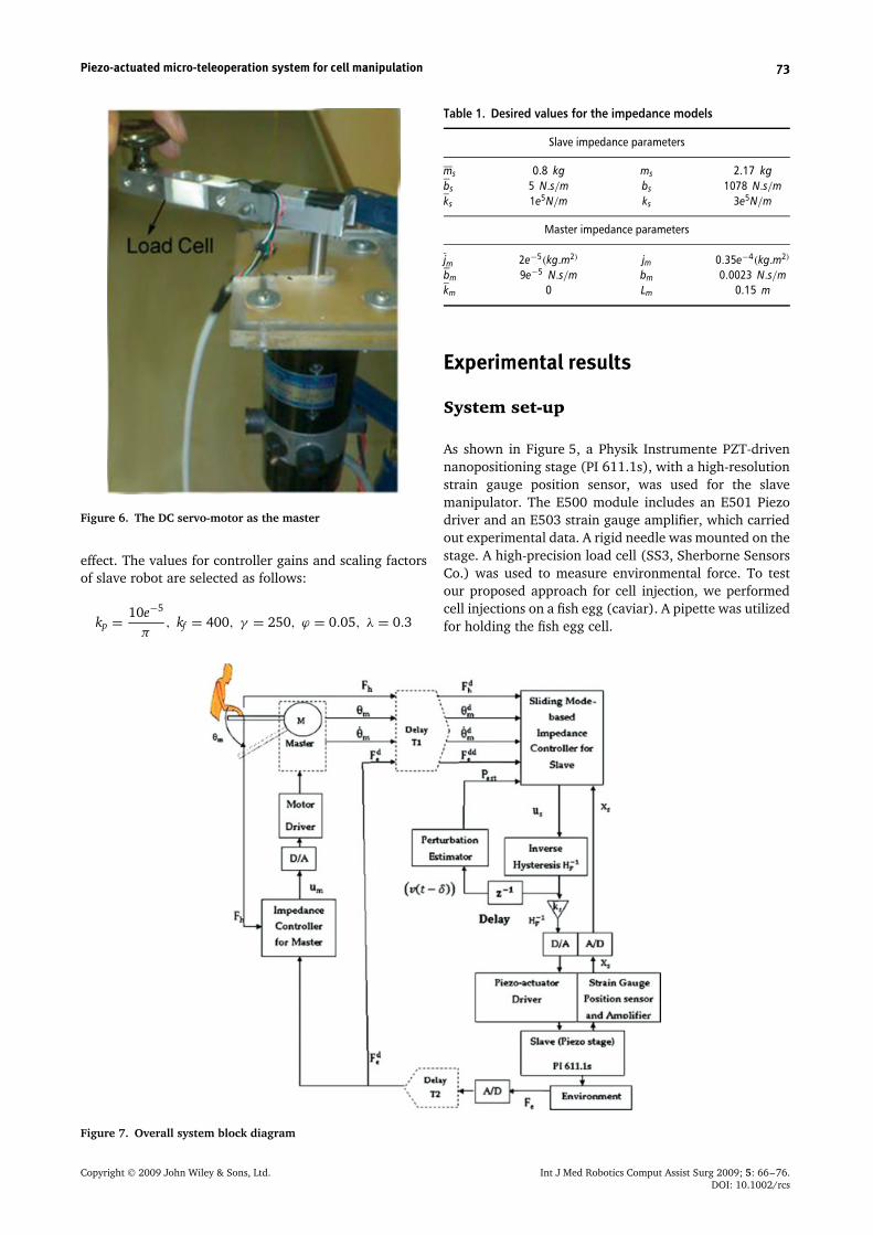
Figure 6. The DC servo-motor as the master
effect. The values for controller gains and scaling factorsof slave robot are selected as follows:
kp = 10e−5
π, kf = 400, γ = 250, ϕ = 0.05, λ = 0.3
Table 1. Desired values for the impedance models
Slave impedance parameters
ms 0.8 kg ms 2.17 kgbs 5 N.s/m bs 1078 N.s/mks 1e5N/m ks 3e5N/m
Master impedance parameters
jm 2e−5(kg.m2) jm 0.35e−4(kg.m2)
bm 9e−5 N.s/m bm 0.0023 N.s/mkm 0 Lm 0.15 m
Experimental results
System set-up
As shown in Figure 5, a Physik Instrumente PZT-drivennanopositioning stage (PI 611.1s), with a high-resolutionstrain gauge position sensor, was used for the slavemanipulator. The E500 module includes an E501 Piezodriver and an E503 strain gauge amplifier, which carriedout experimental data. A rigid needle was mounted on thestage. A high-precision load cell (SS3, Sherborne SensorsCo.) was used to measure environmental force. To testour proposed approach for cell injection, we performedcell injections on a fish egg (caviar). A pipette was utilizedfor holding the fish egg cell.
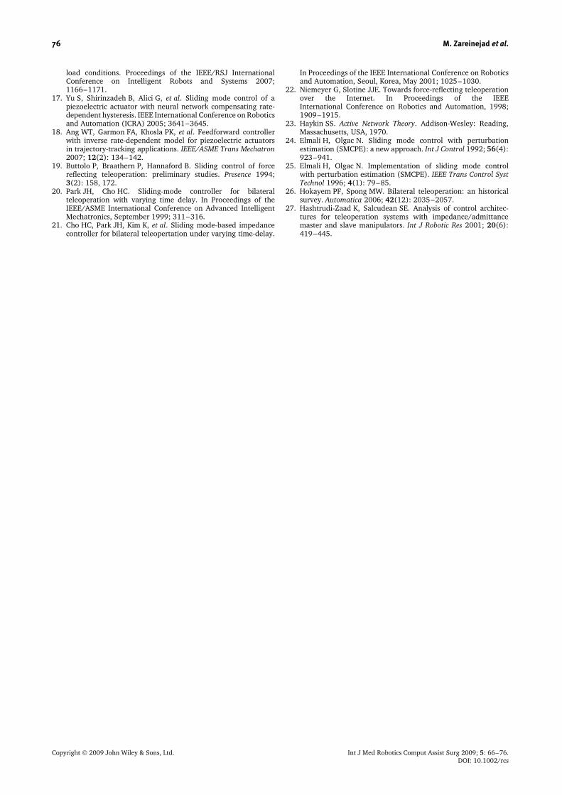
Figure 7. Overall system block diagram
Copyright 2009 John Wiley & Sons, Ltd. Int J Med Robotics Comput Assist Surg 2009; 5: 66–76.DOI: 10.1002/rcs

74 M. Zareinejad et al.
A data acquisition board controller board was usedas an interface element between the MATLAB Real-time Workshop and the equipment. The controllers weredeveloped in Simulink and implemented in real time,using MATLAB Real-time Workshop, and through controldesk software. To effectively implement the controller,the sampling frequency was set to 10 kHz. The masterrobot consisted of a DC servo-motor which was equippedwith a high-resolution encoder. A load cell was installedon the motor shaft to measure the force exerted on themaster (Figure 6). A digital motor controller was used todrive the DC servomotor. Two load cell amplifiers wereused to convert the low voltage of load cells output to the0–10 V range. A stereo loop microscope equipped witha CCD camera was utilized to provide visual feedback.For verification of the proposed controllers, the humanoperator manipulated the master end-effector to generatea desired position trajectory.
The motion of the slave contains two stages, as follows:
1. Free motion, when the needle is not in contact withthe egg and after the needle has penetrated the cellmembrane.
Figure 8. Master–slave position tracking without delay
2. Interaction stage, when the needle exerts force on theegg. At this stage, the needle exerts an interactionforce on the fish egg and also moves forward until itpenetrates the egg.
Two experiments were performed, the first with-out time delay and the second with a time delay(T1 + T2 = 0.4 s). An overall block diagram of this sys-tem, including master, slave and proposed controllers, isshown in Figure 7.
Figures 8 and 9 show the experimental results forposition and force tracking without time delay. Theproposed scheme can achieve good tracking performance.In spite of the contact with environment, the slave side canstill track the master’s desired position (Figure 8) whilethe force reflected back to the master side is increasing(Figure 9). Figure 9 shows the variation of slave scaledforce with time during membrane penetration of a fishegg cell. As shown in Figure 8, there is a gradual increasein the force before penetration of the membrane. Themaximum force is observed when the cell membrane ispunctured. The controllers are capable of achieving bothposition and force tracking.
The experimental results for position/force trackingunder communication time delay are depicted inFigures 10 and 11. T1 and T2 were implemented usingsimulink time delay and were considered as T1 = 0.3 sand T2 = 0.1 s, respectively. The filtering effect of theamplifiers contributes a small amount of pure delay tothe system. A second source of delay in the system isthe finite time required to execute the digital controlloop. Therefore, real delay would be larger than T1, T2.As shown in Figures 10 and 11, the proposed controlachieved a good tracking performance.
• Remark 1. The amplitude of force in Figures 9 and 11is not equal. This is due to the fact that, in eachexperiment, the initial positions of the needle and fishegg cell were different.
Figure 9. Master–slave force tracking without delay
Copyright 2009 John Wiley & Sons, Ltd. Int J Med Robotics Comput Assist Surg 2009; 5: 66–76.DOI: 10.1002/rcs

Piezo-actuated micro-teleoperation system for cell manipulation 75
Figure 10. Master–slave position tracking with delay(T1 + T2 = 0.4 s)
Figure 11. Master–slave force tracking with delay(T1 + T2 = 0.4 s)
• Remark 2. In order to acquire more complete forceinformation about the environment, the bandwidth ofthe filter for force signals is higher than that of theposition filter.
Conclusion and discussion
In this study, macro–micro teleoperation was imple-mented using a piezoelectric actuator as the slave robotfor cell membrane-puncturing tasks.
A non-linear dynamic model for piezoelectric actuatorswas considered, which combines a modified PI hysteresisoperator with a second-order linear dynamic. An inversemodel-based feedforward controller was then proposedand implemented to compensate for hysteresis. To copewith remained non-linearity and uncertainty of model anovel impedance control with sliding mode perturbationestimation was utilized.
An impedance controller for the master was imple-mented to achieve suitable force tracking. The proposedcontrollers make teleoperation robustly stable againstuncertainties and bounded constant time delays. The
non-linear term of the teleoperator was compensatedthrough the feedforward inverse control. Thus, the stabil-ity of the linearized system was guaranteed by Llewellyn’sabsolute stability criterion, which is applicable only forlinear systems. Control parameters were tuned to satisfystability conditions and good performance. The exper-imental results verified the accurate position trackingin free motion and simultaneous position and forcetracking in contact with the low-stiffness environment.Experiments were performed on caviar egg cells todemonstrate success in measuring forces in the mNrange. The experimental results verified force trackingin the cell-penetrating task. Future work on the topic ofthis paper will address the extension of the proposedschemes to a multi-degree-of-freedom macro–micro-telemanipulation system. The measurement noises causeundesired vibrations on master and slave, which maydamage the cell. To improve the cell survival rate,reducing the vibration is another approach of futurework.
References
1. Sheridan TB. Telerobotics, Automation, and Human SupervisoryControl. MIT Press: Cambridge, MA, 1992.
2. Pillarisetti A, Pekarev M, Brooks D, Desai JP. Evaluating theeffect of force feedback in cell injection. IEEE Trans AutomSci Eng 2007; 4(3): 322–331.
3. Gersem DG. Kinaesthetic feedback and enhanced sensitivity inrobotic endoscopic telesurgery. PhD Dissertation, KatholiekeUniversiteit Leuven, Belgium, 2005.
4. Preusche C, Ortmaier T, Hirzinger G. Teleoperation conceptsin minimal invasive surgery. Control Eng Pract 2002; 10(11):1245–1250.
5. Sitti M, Hashimoto H. Macro to nano telemanipulation towardsnanoelectromechanical systems. J Robotics Mechatron 2000;12(3): 209–217.
6. Sitti M, Hashimoto H. Tele-nanorobotics using atomic forcemicroscope as a robot and sensor. Adv Robotics J 1999; 13(4):417–436.
7. Onal CD, Pawashe C, Sitti M. A scaled bilateral controlsystem for experimental 1-D teleoperated nanomanipulationapplications. In Proceedings of the IEEE/RSJ InternationalConference on Intelligent Robots and Systems, 2007; 483–488.
8. Ge P, Jouaneh M. Modeling hysteresis in piezoceramic actuators.Precision Eng 1995; 17(3): 211–221.
9. Bashash S, Jalili N. Robust multiple frequency trajectory track-ing control of piezoelectrically driven micro/nanopositioningsystems. IEEE Trans Control Syst Technol 2007; 15(5): 867–878.
10. Newcomb C, Filnn I. Improving linearity of piezoelectric ceramicactuators. Electron Lett 1982; 18: 442–444.
11. Furutani K, Urushibata M, Mohri N. Displacement controlof piezoelectric element by feedback of induced charge.Nanotechnology 1998; 9: 93–98.
12. Leang KK, Devasia S. Design of hysteresis-compensatingiterative learning control for piezo-positioners: application toatomic force microscopes. Mechatronics 2006; 16: 141–158.
13. Hu H, Georgiou HMS, Ben Mrad R. Enhancement of trackingability in piezoceramic actuators. IEEE/ASME Trans Mechatron2005; 10(2): 230–239.
14. Goldfarb M, Celanovic N. Modeling piezoelectric stack actuatorsfor control of micromanipulation. IEEE Control Syst Mag 1999;17(3): 69–79.
15. Kuhnen K, Janocha H. Complex hysteresis modeling of a broadclass of hysteretic nonlinearities. Proceedings of the 8thInternational Conference on New Actuators, Bremen, June 2002;688–691.
16. Habibollahi H, Rezaei SM, Shiry Ghidari S, et al. Hysteresiscompensation of piezoelectric actuator under dynamic
Copyright 2009 John Wiley & Sons, Ltd. Int J Med Robotics Comput Assist Surg 2009; 5: 66–76.DOI: 10.1002/rcs
76 M. Zareinejad et al.
load conditions. Proceedings of the IEEE/RSJ InternationalConference on Intelligent Robots and Systems 2007;1166–1171.
17. Yu S, Shirinzadeh B, Alici G, et al. Sliding mode control of apiezoelectric actuator with neural network compensating rate-dependent hysteresis. IEEE International Conference on Roboticsand Automation (ICRA) 2005; 3641–3645.
18. Ang WT, Garmon FA, Khosla PK, et al. Feedforward controllerwith inverse rate-dependent model for piezoelectric actuatorsin trajectory-tracking applications. IEEE/ASME Trans Mechatron2007; 12(2): 134–142.
19. Buttolo P, Braathern P, Hannaford B. Sliding control of forcereflecting teleoperation: preliminary studies. Presence 1994;3(2): 158, 172.
20. Park JH, Cho HC. Sliding-mode controller for bilateralteleoperation with varying time delay. In Proceedings of theIEEE/ASME International Conference on Advanced IntelligentMechatronics, September 1999; 311–316.
21. Cho HC, Park JH, Kim K, et al. Sliding mode-based impedancecontroller for bilateral teleopertation under varying time-delay.
In Proceedings of the IEEE International Conference on Roboticsand Automation, Seoul, Korea, May 2001; 1025–1030.
22. Niemeyer G, Slotine JJE. Towards force-reflecting teleoperationover the Internet. In Proceedings of the IEEEInternational Conference on Robotics and Automation, 1998;1909–1915.
23. Haykin SS. Active Network Theory. Addison-Wesley: Reading,Massachusetts, USA, 1970.
24. Elmali H, Olgac N. Sliding mode control with perturbationestimation (SMCPE): a new approach. Int J Control 1992; 56(4):923–941.
25. Elmali H, Olgac N. Implementation of sliding mode controlwith perturbation estimation (SMCPE). IEEE Trans Control SystTechnol 1996; 4(1): 79–85.
26. Hokayem PF, Spong MW. Bilateral teleoperation: an historicalsurvey. Automatica 2006; 42(12): 2035–2057.
27. Hashtrudi-Zaad K, Salcudean SE. Analysis of control architec-tures for teleoperation systems with impedance/admittancemaster and slave manipulators. Int J Robotic Res 2001; 20(6):419–445.
Copyright 2009 John Wiley & Sons, Ltd. Int J Med Robotics Comput Assist Surg 2009; 5: 66–76.DOI: 10.1002/rcs
Copyright © 2022 FDOKUMEN