Swarm-based structure-specified controller design for bilateral transparent teleoperation systems...
26
IMA Journal of Mathematical Control and Information (2013) Page 1 of 26 doi:10.1093/imamci/dnt005 Swarm-based structure-specified controller design for bilateral transparent teleoperation systems via μ synthesis Alireza Alfi ∗ Faculty of Electrical and Robotic Engineering, Shahrood University of Technology, Shahrood 36199-95161, Iran ∗ Corresponding author. Email: a_alfi@shahroodut.ac.ir and Alireza Khosravi and Ali Lari Department of Electrical and Computer Engineering, Babol University of Technology, Bobol 47135-484, Iran [Received on 7 June 2012; revised on 23 December 2012; accepted on 2 February 2013] This paper proposes a novel robust controller design for bilateral teleoperation systems using μ synthe- sis based on an inspired algorithm namely particle swarm optimization with time-varying acceleration coefficients. In the proposed structure, the μ synthesis problem is considered as a constraint optimiza- tion problem. Indeed, this technique proposes a novel alternative solution for solving the μ synthesis problem to design simple structure controllers satisfying robust stability and performance. The goal of the proposed structure is to achieve complete transparency and robust stability for bilateral teleoperation systems with uncertainty in time delay and task environment. To this reason, two local controllers are designed. One local controller is responsible for tracking the master commands and the other local con- troller is in charge of force tracking as well as guaranteeing the stability of a closed-loop system. The comparative results demonstrate the effectiveness of the proposed controller compared with the results obtained from D-K iteration controller. Keywords: teleoperation; heuristic algorithm; model reduction; μ synthesis; D-K iteration method. 1. Introduction Teleoperation systems are tools that indicate the capability of a human being to carry out operations in a remote environment. By means of these systems, a human operator can interact with remote and unknown environments, which can be hazardous or inaccessible, such as mining, sub-sea exploration and, more recently, in health care. In a teleoperation system, master and slave systems, communication channel, human operator and task environment are the key components (Fig. 1). Without requiring direct physical contact between human operator and task environment, a human operator is able to move a slave manipulator located in the remote environment by moving a master manipulator located in the local environment. Stability and performance are two key issues of bilateral teleoperation systems. If the slave accu- rately reproduces the master’s commands and the master correctly feels the slave forces, then the human operator experiences the same interaction as the slave would. This is the major criterion for performance of teleoperation systems, called as transparency (Lawrence, 1993). c The authors 2013. Published by Oxford University Press on behalf of the Institute of Mathematics and its Applications. All rights reserved. IMA Journal of Mathematical Control and Information Advance Access published April 18, 2013 by guest on April 19, 2013 http://imamci.oxfordjournals.org/ Downloaded from
-
Upload
independent -
Category
Documents
-
view
2 -
download
0
Transcript of Swarm-based structure-specified controller design for bilateral transparent teleoperation systems...

IMA Journal of Mathematical Control and Information (2013) Page 1 of 26doi:10.1093/imamci/dnt005
Swarm-based structure-specified controller design for bilateral transparentteleoperation systems via μ synthesis
Alireza Alfi∗
Faculty of Electrical and Robotic Engineering, Shahrood University of Technology,Shahrood 36199-95161, Iran
∗Corresponding author. Email: [email protected]
and
Alireza Khosravi and Ali Lari
Department of Electrical and Computer Engineering, Babol University of Technology,Bobol 47135-484, Iran
[Received on 7 June 2012; revised on 23 December 2012; accepted on 2 February 2013]
This paper proposes a novel robust controller design for bilateral teleoperation systems using μ synthe-sis based on an inspired algorithm namely particle swarm optimization with time-varying accelerationcoefficients. In the proposed structure, the μ synthesis problem is considered as a constraint optimiza-tion problem. Indeed, this technique proposes a novel alternative solution for solving the μ synthesisproblem to design simple structure controllers satisfying robust stability and performance. The goal ofthe proposed structure is to achieve complete transparency and robust stability for bilateral teleoperationsystems with uncertainty in time delay and task environment. To this reason, two local controllers aredesigned. One local controller is responsible for tracking the master commands and the other local con-troller is in charge of force tracking as well as guaranteeing the stability of a closed-loop system. Thecomparative results demonstrate the effectiveness of the proposed controller compared with the resultsobtained from D-K iteration controller.
Keywords: teleoperation; heuristic algorithm; model reduction; μ synthesis; D-K iteration method.
1. Introduction
Teleoperation systems are tools that indicate the capability of a human being to carry out operationsin a remote environment. By means of these systems, a human operator can interact with remote andunknown environments, which can be hazardous or inaccessible, such as mining, sub-sea explorationand, more recently, in health care. In a teleoperation system, master and slave systems, communicationchannel, human operator and task environment are the key components (Fig. 1). Without requiringdirect physical contact between human operator and task environment, a human operator is able tomove a slave manipulator located in the remote environment by moving a master manipulator locatedin the local environment.
Stability and performance are two key issues of bilateral teleoperation systems. If the slave accu-rately reproduces the master’s commands and the master correctly feels the slave forces, then the humanoperator experiences the same interaction as the slave would. This is the major criterion for performanceof teleoperation systems, called as transparency (Lawrence, 1993).
c© The authors 2013. Published by Oxford University Press on behalf of the Institute of Mathematics and its Applications. All rights reserved.
IMA Journal of Mathematical Control and Information Advance Access published April 18, 2013 by guest on A
pril 19, 2013http://im
amci.oxfordjournals.org/
Dow
nloaded from

2 of 26 A. ALFI ET AL.
Human
Operator
Master
System
Time delay
Time delay
Slave
System
Task
Environment
Fig. 1. The general structure of a bilateral teleoperation system.
The time delay and task environment uncertainties make transparency and stability significantlycompromised. According to these issues, different control approaches have been proposed in literaturefor teleoperation systems. Passivity theory (Hou & Luecke, 2005), non-linear control (Le et al., 2011),compliance control (Munir & Book, 2002), adaptive control (Hosseini-Suny et al., 2010) and optimalcontrol (Ganjefarar et al., 2011) are some of these approaches. Due to the uncertainty in the task envi-ronment and the time delay in communication channel, robust control theory is one of the significantapproaches to control bilateral teleoperation systems (Sha Sadeghi et al., 2008). Among the robust con-trol methods, μ synthesis, one of the most powerful robust techniques, has been employed to design arobust controller for teleoperation systems (Leung et al., 1995). In spite of high efficiency, high-orderμ synthesis controllers may not be feasible for real-time implementation because of hardware and com-putational limitations.
To handle this problem, this paper proposes a structure-specified approach for designing a robustcontroller in bilateral teleoperation systems with uncertainties in the task environment and the commu-nication time delay. This idea has been employed to design simple structure controllers in other robustcontrol problems such as loop shaping (Nimpitiwan & Kaitwanidvilai, 2012), H∞ problem (Zaminiet al., 2009) and mixed H2/H∞ (Ho et al., 2005).
Structure singular value, denoted by μ, is utilized as a tool for the assessment of controller quality(Zhou & Doyle, 1998). In this point of view, μ synthesis problem is considered as a constraint optimiza-tion problem. In the constraint optimization problem, robust stability measured via μ stability analysisis assumed as a constraint whereas robust performance measured via μ performance analysis is consid-ered as an objective function which must be minimized. Particle swarm optimization (PSO) algorithm,a powerful inspired algorithm, is employed to solve this optimization problem. This algorithm triesto find the coefficients of structure-specified controllers, and satisfies the robust conditions. Recently,heuristic algorithms especially with stochastic search techniques seem to be a more hopeful approachand provide a powerful means to solve real-world optimization problems (Modares et al., 2010a,b; Alfi& Fateh, 2011a,b; Alfi & Modares, 2011; Wang et al., 2012). They can be a promising alternative totraditional techniques. The key features of heuristic algorithms such as genetic algorithm (GA) and PSOare: (i) the objective function’s gradient is not required; (ii) they are not sensitive to starting point and(iii) they usually do not get stuck into so-called local optima.
PSO as a population-based algorithm can solve a variety of difficulties associated with optimizationproblems. Compared with GA, PSO takes less time for each function evaluation as it does not use manyGA operators such as mutation, crossover and selection operator (Alfi & Fateh, 2011b). Due to thesimple concept, easy implementation and quick convergence, nowadays PSO has gained much attentionand wide applications in different fields (Modares et al., 2010a,b; Alfi & Fateh, 2011b). According ourknowledge, this is the first research to apply PSO for teleoperation systems via μ synthesis.
Motivated by the aforementioned, in this paper, a novel PSO-based robust controller design is intro-duced for bilateral transparent teleoperation systems in the presence of uncertainties including timedelay in communication channel and task environment. To this end, we use a modified PSO algorithmnamely PSO with time-varying acceleration coefficients (PSO-TVAC). The key contribution of the
by guest on April 19, 2013
http://imam
ci.oxfordjournals.org/D
ownloaded from

SWARM-BASED STRUCTURE-SPECIFIED CONTROLLER DESIGN FOR TELEOPERATION SYSTEMS 3 of 26
proposed controller structure is: (i) the closed-loop control system is robust stable and the μ condi-tions including robust stability and performance are satisfied, (ii) the teleoperation system is completetransparent, (iii) it is simple and easy to implement with simple and low-order structure controllers.The preference of the proposed control method has been shown by comparison with those obtained theconventional technique namely D-K iteration for solving μ synthesis problem.
This paper is organized as follows. Section 2 discusses the basic μ synthesis problem. In Section 3,problem formulation is illustrated. Section 4 introduces the proposed approach. In this section, robustcontrol design based on the proposed method for teleoperation systems is studied. Simulation result ispresented in Section 5. Finally, conclusions are drawn in Section 6.
2. Preliminary
In this section, we describe a brief introduction to the μ synthesis problem.
2.1 μ synthesis problem
The structure singular value denoted by μ depends on the underlying block structure of perturbationswhich is defined as follows: perturbation matrix Δ ⊂ C
n×n is considered as
Δ = {diag[δ1Ir1, . . . , δSIrS , Δ1, . . . , ΔF] : δi ∈ C, Δj ∈ Cmj×mj}, (1)
whereS∑
i=1
ri +F∑
j=1
mj = n. (2)
The block diagonal matrix Δ includes two types of blocks: repeated scalar block (δi and full block (Δj).In Equation (1), n is the dimension of the block Δ and the parameters δi of the repeated scalar blockscan be real numbers only, if further information of the uncertainties is available. The Structure singularvalue μΔ(M ) of a matrix M ∈ C
n×n with respect to a block structure Δ ∈ Δ is defined as
μΔ(M ) = 1
min{σ̄ (Δ) : Δ ∈ Δ, det(I − MΔ) = 0} . (3)
If there is no Δ ∈ Δ such that det(I − MΔ) = 0, then μΔ(M ) = 0.Unfortunately, Equation (3) is not suitable for computing μ since the optimization problem may
have multiple local minima (Doyle & Packard, 1987). However, the upper and the lower bounds for μ
may be effectively computed as
maxU∈U
ρ(MU) � μΔ(M ) � infD∈D
σ̄ (DMD−1), (4)
where U and D are given in Equations (5) and (6), respectively.
U = {U ∈ Δ : UU∗ = In}, (5)
D ={
diag[D1, . . . , DS , d1Im1 , . . . , dF−1ImF−1 , ImF ] :Di ∈ C
ri×ri , Di = D∗i > 0, dj ∈ R, dj > 0
}. (6)
by guest on April 19, 2013
http://imam
ci.oxfordjournals.org/D
ownloaded from

4 of 26 A. ALFI ET AL.
d v
zw
uP
K
Fig. 2. General framework.
w zM
d
Fig. 3. Analysis framework.
2.2 Robust stability and performance based on μ analysis
To fit the general framework, an interconnected system can be rearranged as shown in Fig. 2. In thisfigure, K is the controller, P the nominal plant and Δ is the uncertainty set (perturbation matrix). More-over, w denotes the exogenous input vector typically including command signals, disturbances, noisesetc.; z the error output usually consisting of regulator output, tracking errors, filtered actuator signals etc;v and d are the input and output signals of dynamic uncertainties. Finally, u and y are the control inputand the measurement signal, respectively. The general framework shown in Fig. 2 can be represented asFig. 3. In Fig. 2, M (P, K) = Fl(P, K) and Fl(P, K) are the lower linear fractional transformation (lowerLFT) of P and K.
Let M be partitioned accordingly as shown in Equation (7). In this partitioning, M11 and M areutilized for robust stability and robust performance analysis, respectively.[
vz
]=
[M11 M12
M21 M22
]︸ ︷︷ ︸
M
[dw
]. (7)
The structure used for robust stability analysis based on μ is shown in Fig. 4. When M11 is aninterconnected transfer function formed with respect to the uncertainty set Δ, the structure singularvalue of M11(s) indicates the robust stability of the perturbed system. Without loss of generality, assumethat the uncertainties have been normalized. The standard configuration shown in Fig. 4 is robust stableif M11(s) is stable and μΔ(M11(s)) < 1 (or ‖M11‖μ < 1). Figure 5 is also the standard configuration
by guest on April 19, 2013
http://imam
ci.oxfordjournals.org/D
ownloaded from

SWARM-BASED STRUCTURE-SPECIFIED CONTROLLER DESIGN FOR TELEOPERATION SYSTEMS 5 of 26
11M
d v
Fig. 4. Structure for robust stability analysis.
w
v
z
M
d
P
Fig. 5. Structure for robust performance analysis.
for robust performance analysis. The system performance specification can usually be interpreted asa reduction of z with respect to w. The robust performance problem based on Fig. 5 is equivalent torobust stability problem shown in Fig. 4, if the uncertainty set Δ replace with Δ̃ in Equation (8). Withnormalized uncertainties, the structure shown in Fig. 5 is robustly stable in the presence of uncertaintyset Δ̃ (robust performance in the presence of uncertainty set Δ) if μΔ̃(M (s)) < 1 (or ‖M‖μ < 1).
Δ̃ ∈ Δ̃ := {diag{Δ, ΔP} : Δ ∈ BΔ, ‖ΔP‖∞ � 1},BΔ = {Δ ∈ Δ : σ̄ (Δ) � 1}.
(8)
Based on aforementioned conditions, designing of such a controller is so-called μ synthesis problem.D-K iteration is the most common technique to solve this problem. Upper limit of μ is consideredinstead of its value in this technique.
The D-K iteration method, for a fixed K(s), is a convex optimization problem at each frequencyω as
infK(s)
supω∈R
infD∈D
σ̄ [DFl(P, K)D−1(jω)], (9)
where matrix D is defined in Equation (6). In fact, Equation (9) is a different approach to solve mainproblem given in Equation (10).
infK(s)
supω∈R
μΔ̃[Fl(P, K)(jω)]. (10)
by guest on April 19, 2013
http://imam
ci.oxfordjournals.org/D
ownloaded from

6 of 26 A. ALFI ET AL.
ys
ym Cm(s) Pm(s)
Master
e-sTms
e-sTsm
Kp
Kf
Fh
Fr noise
noise
Ze
Ps(s) Cs(s) Fs
Fe
Slave
ym
Fig. 6. The control scheme for a bilateral teleoperation system.
After the minimization over a range of frequency of interest, the resultant diagonal constant matricesD’s can be approximated, via curve fitting, by a stable, minimum phase, rational transfer function matrixD(s), which will be used in the next iteration for K(s). The D-K iterative μ-synthesis algorithm can besummarized as follows:
Step 1: Start with an initial guess for D, usually set D = I.Step 2: Fix D and solve the H∞-optimization for K,
K = arg infK
‖Fl(P, K)‖∞.
Step 3: Fix K and solve the following convex optimization problem for D at each frequency over aselected frequency range,
D(jω) = arg infD∈D
σ̄ [DFl(P, K)D−1(jω)].
Step 4: Curve fit D(jω) to get a stable, minimum-phase D(s); go to Step 2 and repeat, until a stopcriterion is achieved.
Although successful applications of the D-K iteration method have been reported, there exists someshortcoming. The main disadvantage of D-K iteration is that the algorithm may not converge in somecases, which lead to non-optimality of the resulting controller (Stein & Doyle, 1991). To overcome ofthis shortcoming, this paper introduces a different solution for solving μ synthesis problem.
3. Problem description
In this study, a control structure shown in Fig. 6 is used (Alfi & Farrokhi, 2008a,b). In this figure,P, C and y denote the transfer function of the local systems, the local controllers and the outputs,respectively, where the subscripts m and s designate the master and the slave, respectively. Tms and Tsm
denote the forward and the backward time delays, respectively. Fe is the force exerted on the slave byits environment, Ze is the environment impedance, Fh is the force applied to the master by the human
by guest on April 19, 2013
http://imam
ci.oxfordjournals.org/D
ownloaded from

SWARM-BASED STRUCTURE-SPECIFIED CONTROLLER DESIGN FOR TELEOPERATION SYSTEMS 7 of 26
Cs
Ws1
Ze
Ps
Ws2
Ws3
z1 z2
e
Fsym ys
noise
Fig. 7. Control scheme for the slave side.
noise
z3 z4
ym ym Fe Fh
Slave
SidePm Cm
Wm3
Wm2Wm1
e-sTms
e-sTsm
Fig. 8. Control scheme for the master site.
operator, Kp and Kf are the position and force scaling factors, respectively, Fs is the input force appliedto the slave and Fr is the reflected force.
The performance system objectives are reflected by choosing appropriate weighting functions. Thecontrol scheme for the master and the salve sites are shown in Figs 7 and 8, respectively. In thesefigures, W1 and W2 are the weighting functions chosen to represent the desired tracking performanceand control signal, respectively, and W3 is used to reflect the frequency characteristics of the sensornoise. The following assumptions have to be stated first:
Assumption 1 The slave system acts in a non-free task environment.
Assumption 2 The position and force scaling factors Kp and Kf are equal to 1.
Assumption 3 The task environment is passive.
The main goal of the proposed control scheme is to achieve stability and transparency. That is, thefollowing conditions must be guaranteed:
(1) The closed loop of the overall system is stable.
by guest on April 19, 2013
http://imam
ci.oxfordjournals.org/D
ownloaded from

8 of 26 A. ALFI ET AL.
(2) Position/velocity tracking is guaranteed. The position/velocity tracking means that the slaveoutput ys has to follow the master output ym with an acceptable accuracy. Note that the masterand the slave outputs can be considered position or velocity.
(3) Force tracking is guaranteed. It means that reflecting force Fr has to follow the human operatorforce Fh.
These goals are achieved by designing two local controllers; one in the remote site Cs guarantees theposition/velocity tracking and the other one in the local site Cm guarantees the force tracking as well asstability of the overall system. It is necessary to recall that, based on the designed slave controller in thefirst step, the master controller is designed in the next step.
4. The proposed approach
In this section, the proposed approach is described for solving the μ synthesis problem. To this end, firstwe briefly explain PSO algorithm.
4.1 PSO-TVAC algorithm
PSO is originally attributed to Kennedy & Eberhart (1995), based on the social behaviour of collectionof animals such as birds flocking. In PSO algorithm, each individual of the swarm, called particle,remembers the best solution found by itself and by the whole swarm along the search trajectory. Theparticles move along the search space and exchange information with other particles according to thefollowing equations:
Vid = wVid + c1r1(Pid − Xid) + c2r2(Pgd − Xid), (11)
Xid = Xid + Vid , d = 1, 2, . . . , N , i = 1, 2, . . . , S, (12)
where Xid represents the current position of particle, Pid is the best individual particle position, Pgd thebest swarm position, the parameters c1 and c2 are cognitive and social parameters, respectively; theparameters r1 and r2 are random numbers between 0 and 1. Finally, w is the inertia weight to balancethe global and local search abilities. A large inertia weight facilitates global search while a small inertiaweight facilitates local search. In an empirical study on PSO, Shi & Eberhart (1999) claimed that alinearly decreasing inertia weight could improve local search towards the end of a run, rather than usinga constant value throughout. So the inertia weight is adapted non-linearly as follows:
w = (itermax − itercur)
(winitial − wfinal
itermax
)+ wfinal, (13)
where winitial and wfinal represent the initial and final inertia weights at the start of a given run, respec-tively; itermax is the maximum number of allowable iterations and itercur denotes the current iterationnumber at the present iteration. However, due to the utilization of a linearly decreasing inertia weight,the global search ability at the end of the run may be inadequate. The PSO may fail to find the requiredoptimal in cases when the problem is too complicated. But, to some extent, this can be overcome byemploying a self-adapting strategy for adjusting the acceleration coefficients.
Suganthan (1999) observed that the fixed acceleration coefficients (c1 and c2) at 2 generate bettersolutions. However, through empirical studies, he suggested that the acceleration coefficients should notbe equal to 2 all the time. Ratnaweera et al. (2004) improve the convergence of particles to the global
by guest on April 19, 2013
http://imam
ci.oxfordjournals.org/D
ownloaded from
SWARM-BASED STRUCTURE-SPECIFIED CONTROLLER DESIGN FOR TELEOPERATION SYSTEMS 9 of 26
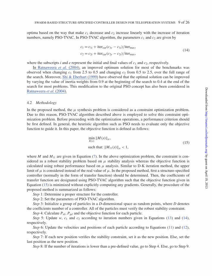
optima based on the way that make c1 decrease and c2 increase linearly with the increase of iterationnumbers, namely PSO-TVAC. In PSO-TVAC algorithm, the parameters c1 and c2 are given by
c1 = c1i + itercur(c1e − c1i)/itermax,
c2 = c2i + itercur(c2e − c2i)/itermax,(14)
where the subscripts i and e represent the initial and final values of c1 and c2, respectively.In Ratnaweera et al. (2004), an improved optimum solution for most of the benchmarks was
observed when changing c1 from 2.5 to 0.5 and changing c2 from 0.5 to 2.5, over the full range ofthe search. Moreover, Shi & Eberhart (1999) have observed that the optimal solution can be improvedby varying the value of inertia weights from 0.9 at the beginning of the search to 0.4 at the end of thesearch for most problems. This modification to the original PSO concept has also been considered inRatnaweera et al. (2004).
4.2 Methodology
In the proposed method, the μ synthesis problem is considered as a constraint optimization problem.Due to this reason, PSO-TVAC algorithm described above is employed to solve this constraint opti-mization problem. Before proceeding with the optimization operations, a performance criterion shouldbe first defined. In general, the heuristic algorithm such as PSO needs to evaluate only the objectivefunction to guide it. In this paper, the objective function is defined as follows:
minK(s)
‖M (s)‖μ,
such that: ‖M11(s)‖μ < 1,(15)
where M and M11 are given in Equation (7). In the above optimization problem, the constraint is con-sidered as a robust stability problem based on μ stability analysis whereas the objective function iscalculated using robust performance based on μ analysis. Similar to D-K iteration method, the upperlimit of μ is considered instead of the real value of μ. In the proposed method, first a structure-specifiedcontroller (normally in the form of transfer function) should be determined. Then, the coefficients oftransfer function are designated using PSO-TVAC algorithm such that the objective function given inEquation (15) is minimized without explicitly computing any gradients. Generally, the procedure of theproposed method is summarized as follows:
Step 1: Determine a proper structure for the controller.Step 2: Set the parameters of PSO-TVAC algorithm.Step 3: Initialize a group of particles in a D-dimensional space as random points, where D denotes
the coefficients number of a controller. All of the particles must verify the robust stability constraint.Step 4: Calculate Pid , Pgd and the objective function for each particle.Step 5: Update w, c1 and c2 according to iteration numbers given in Equations (13) and (14),
respectively.Step 6: Update the velocities and positions of each particle according to Equations (11) and (12),
respectively.Step 7: If each new position verifies the stability constraint, set it as the new position. Else, set the
last position as the new position.Step 8: If the number of iterations is lower than a pre-defined value, go to Step 4. Else, go to Step 9.
by guest on April 19, 2013
http://imam
ci.oxfordjournals.org/D
ownloaded from

10 of 26 A. ALFI ET AL.
Step 9: Consider Pgd as the coefficient of desired controller. If the obtained controller is not efficientenough, the order of a structure-specified controller can be incremented.
5. Simulation results and discussion
In many literatures, a linear model of master–slave system has been utilized (Hokayayaem & Spong,2006; Valdovinos et al., 2007). In order to evaluate the effectiveness of the proposed control structure,it is applied to the following simplified model, which has been utilized (Alfi & Farrokhi, 2008b).
(Jms2 + Bms + MmgLm)θm = um, (Jss2 + Bss + MsgLs)θs = us, (16)
where J , M and L are the moment of inertia, the mass and the length of the manipulators links, respec-tively; B the viscous friction coefficient, θ the rotational angle, g the gravity acceleration and u the input;indices m and s are for the master and the slave, respectively. The considered parameters of the masterand the slave are, respectively,
Jm = 2 kg m2, Bm = 3Nm
rad/s, Lm = 0.2 m, Mm = 0.6 kg;
Js = 1 kg m2, Bs = 5Nm
rad/s, Ls = 0.3 m, Ms = 2 kg.
By using the first-order Pade’ approximation, the modelling of time delay in the forward and in thebackward path can be written as follows:
e−Ts ≈ 1 − (T/2)s
1 + (T/2)s. (17)
The nominal values of Tms and Tsm are set to Tms = Tsm = 1.5. The maximum values of time delay areequal to 3 s. Moreover, to consider the interaction between the slave and the remote environment, thefollowing model for impedance of task environment is given by
Ze = Bes + Ke, 2 < Be < 4 and 4 < Ke < 8, (18)
where the nominal values of viscous friction Be and the stiffness Ke are chosen to be 3 and 6, respec-tively.
A structure-specified controller for master and slave is selected as a proportional integral derivative(PID) controller with first-order derivative filter. The controller structure is expressed in Equation (19).This controller is proposed in Kaitwanidvilai & Parnichkun (2008) for designing a robust controller.
K(s) = Kp + Ki
s+ Kds
τds + 1, (19)
where τd denotes the filter’s time constant and Kp, Ki and Kd represent the proportional gain, the integraltime and the derivative time, respectively. All these parameters are supposed to be positive.
In the problem in hand, the parameters Kp, Ki, Kd and τd must be obtained using PSO-TVAC. Theparameters of PSO-TVAC algorithm as well as the bound of search space for each coefficient of masterand slave controllers are listed in Tables 1 and 2, respectively. The weighting functions of the structuresgiven in Figs 7 and 8 are also listed in Table 3.
by guest on April 19, 2013
http://imam
ci.oxfordjournals.org/D
ownloaded from

SWARM-BASED STRUCTURE-SPECIFIED CONTROLLER DESIGN FOR TELEOPERATION SYSTEMS 11 of 26
Table 1 Parameters values in PSO-TVAC algorithm
Parameter Value Parameter Value
c1e 0.5 Number of particles Master = 20, Slave = 25c1s 1.5 Number of iterations Master = 80, Slave = 100c2e 1.5 winitial 0.9c2s 0.5 wfinal 0.4
Table 2 Search space of the proposed controller parameters inPSO-TVAC algorithm
Master controller Range Slave controller Range
Kpm [0 1] Kps [0 100]Kim [0 1] Kis [0 100]Kdm [0 1] Kds [0 100]τdm [0 5] τds [0 100]
Table 3 Weighting functions
Master Slave
Wm1 = 0.3s2 + 15s + 2.4
s2 + 18s + 0.001Ws1 = 0.9
s2 + 8s + 25
s2 + 10s + .01Wm2 = 0.02 Ws2 = 0.02
Wm3 = 10−4 s
0.001s + 1Ws3 = 10−4 s
0.001s + 1
The control performance is evaluated by applying two different inputs exerted by a human oper-ator: step input and pulse input. In addition, simulation results are performed in two general parts. Inthe first part, the feasibility of the proposed control structure method against parameter uncertaintiesincluding the task environment and time delay in communication channel is represented. In the secondpart, the performance of the proposed method is compared with those obtained D-K iteration, which isthe conventional method to solve the μ synthesis problem. In all the simulations, a Gaussian noise withmean zero and variance 0.005 is also considered as a measurement noise of sensor. Based on these, theproposed slave and master controllers are obtained as follows:
Cs(s) = 17.3 + 33.4
s+ 29.4s
45.4s + 1, (20)
Cm(s) = 10−3
(40 + 22
s+ 285s
3.43s + 1
). (21)
5.1 Performance analysis in presence of uncertainties
5.1.1 Uncertainty in time delay. In this part, the performance of the proposed algorithm isinvestigated in different values of time delay including constant time delay and perturbed time delay,
by guest on April 19, 2013
http://imam
ci.oxfordjournals.org/D
ownloaded from

12 of 26 A. ALFI ET AL.
0 10 20 30 40 50 60 70 80 90 1000
0.2
0.4
0.6
0.8
1
1.2
Time (sec)
Fo
rce
Tra
ckin
g (
N.m
)
Tms=Tsm=0.5 sec
Tms=Tsm=3 sec
Fig. 9. Step response of force tracking for constant time delays.
whereas the nominal values for other parameters are used. First, two different values for constant timedelay in communication channel are utilized: (i) Constant time delay equals 0.5 s. (ii) Constant timedelay equals 3 s. The transparency response including force tracking and position tracking are demon-strated in Figs 9–12. Referring to these figures, a teleoperation system can preserve the transparencyin the presence of time delay. Secondly, a perturbed time delay shown in Figs 13 and 16 is consideredfor step and pulse inputs, respectively. Figures 14, 15, 17 and 18 show the transparency response. Fromthese figures, we can verify that the teleoperation system is also able to track the human command inspite of the perturbed time delay.
5.1.2 Uncertainty in the task environment. To cover wide operating conditions, three different casesshown in Table 4 are opted as the uncertainty of environment impedance. In these cases, a nominaltime delay is considered. The results are illustrated in Figs 19–26 for step and pulse inputs, respectively.From these figures, the proposed control structure can cope up very well in the presence of environmentimpedance uncertainty.
5.2 Comparison
This section assigns the comprehensive comparison between the proposed controller structure andthe D-K iteration controller. Using the D-K iteration method, the obtained order of slave and mastercontrollers are 8 and 18, respectively. As the orders of these controllers are high for real-time control,to reduce order, we employ the optimal Hankel norm approximation. The reduced order controllers areas follows:
Cs_reduced(s) = 1.808 × 10⁴s3 + 5.659 × 10⁵s2 + 4.155 × 10⁶s + 5.706 × 10⁶
s4 + 1012s3 + 2.531 × 10⁴s2 + 1.741 × 10⁵s + 174.1, (22)
Cm_reduced(s) = −90.61s3 − 115.3s2 + 6.281s + 25.05
s4 + 25.51s3 + 344.4s2 + 1797s + 0.09982. (23)
by guest on April 19, 2013
http://imam
ci.oxfordjournals.org/D
ownloaded from

SWARM-BASED STRUCTURE-SPECIFIED CONTROLLER DESIGN FOR TELEOPERATION SYSTEMS 13 of 26
0 10 20 30 40 50 60 70 80 90 1000
0. 05
0. 1
0. 15
0. 2
Time (sec)
Po
siti
on
Tra
ckin
g (
rad
)
Slave
Master
0 10 20 30 40 50 60 70 80 90 1000
0. 05
0. 1
0. 15
0. 2
Po
siti
on
Tra
ckin
g (
rad
)
Slave
Master
Time (sec)
(a)
(b)
Fig. 10. Step response of position tracking: (a) time delay equal to 0.5 and (b) time delay equal to 3 s.
0 50 100 150 200 250 300
0
0. 5
1
1. 5
Fo
rce
Tra
ckin
g (
N.m
)
Tms=Tsm=0.5 sec
Tms=Tsm=3 sec
Time (sec)
Fig. 11. Pulse response of force tracking for constant time delays.
by guest on April 19, 2013
http://imam
ci.oxfordjournals.org/D
ownloaded from

14 of 26 A. ALFI ET AL.
0 50 100 150 200 250 300
0
0.05
0. 1
0.15
0. 2
Po
siti
on
Tra
ckin
g (
rad
)Slave
Master
0 50 100 150 200 250 300-0.05
0
0.05
0.1
0.15
0.2
Po
siti
on
Tra
ckin
g (
rad
)
Slave
Master
Time (sec)
Time (sec)
(a)
(b)
Fig. 12. Pulse response of position tracking: (a) time delay equal to 0.5 and (b) time delay equal to 3 s.
0 10 20 30 40 50 60 70 80 90 1000.8
1
1.2
1.4
1.6
1.8
2
2.2
Del
ay in
Co
mm
un
icat
ion
Lin
e (s
ec)
Time (sec)
Fig. 13. Perturbed time delay in the forward and the backward paths for step input.
by guest on April 19, 2013
http://imam
ci.oxfordjournals.org/D
ownloaded from

SWARM-BASED STRUCTURE-SPECIFIED CONTROLLER DESIGN FOR TELEOPERATION SYSTEMS 15 of 26
0 10 20 30 40 50 60 70 80 90 1000
0.2
0.4
0.6
0.8
1
Fo
rce
Tra
ckin
g (
N.m
)
Time (sec)
Fig. 14. Force tracking for perturbed time delay shown in Fig. 13.
0 10 20 30 40 50 60 70 80 90 1000
0.05
0.1
0.15
0.2
Fo
rce
Tra
ckin
g (
N.m
)
Slave
Master
Time (sec)
Fig. 15. Position tracking for perturbed time delay shown in Fig. 13.
These controllers are relatively complex in comparing with the simple structure-specified controllersgiven in Equations (20) and (21). It is noticeable that the main issue in controller order reduction isto preserve the stability and performance of the closed-loop system. The basic idea of order reduc-tion is to minimize the difference between high-order and reduced-order closed-loop transfer function.To analyse the effect of reduction, the behaviour of the reduced-order controllers compared with theoriginal controllers is acceptable (Figs 27 and 28). In these figures, because of high similarity in thefeatures of robust stability, the robust performance features are compared. Figures 29–32 demonstratethe comparison of slave and master controllers obtained by the proposed structure-specified methodand D-K iteration based on μ stability and performance analysis, respectively. Figure 29 shows thatthe slave controllers have the same condition in robust stability. The peak value of μ plot for the D-Kiteration controller is 0.151, whereas for the structure-specified controller it is 0.162. It means that bothof controllers have well enough stability margins. According to Fig. 30, the robust performance of slave
by guest on April 19, 2013
http://imam
ci.oxfordjournals.org/D
ownloaded from

16 of 26 A. ALFI ET AL.
0 50 100 150 200 250 3000.8
1
1.2
1.4
1.6
1.8
2
2.2
Del
ay in
Co
mm
un
icat
ion
Lin
e (s
ec)
Time (sec)
Fig. 16. Perturbed time delay in the forward and the backward paths for pulse input.
0 50 100 150 200 250 300
0
0.2
0.4
0.6
0.8
1
Fo
rce
Tra
ckin
g (
N.m
)
Time (sec)
Fig. 17. Force tracking for perturbed time delay shown in Fig. 16.
controllers is very similar to others in entire frequency ranges. In Fig. 30, peak values of μ plot equals0.975 and 0.970 for the D-K iteration controller and the structure-specified controller, respectively. Forthe master controller, Fig. 31 illustrates that the peak values of μ plot for the D-K iteration and thestructure-specified controller are 0.447 and 0.399, respectively. It concludes that both controllers havethe appropriate robust stability conditions and the structure-specified controller has a slightly better sta-bility margin. Referring to Fig. 32, the structure-specified controller has a much better stability perfor-mance condition with respect to the D-K iteration controller. In Fig. 32, the peak value of μ plot for theD-K iteration controller and the structure-specified controller equals to 0.990 and 0.714, respectively.
To evaluate the performance analysis of the closed-loop system, Figs 33–35 depict the timeresponses of a system by considering the nominal model. As these figures show, due to the existence ofundershoot in the step response related to the D-K iteration controller, the proposed structure-specifiedcontroller exhibits the better performance in transparency response. Indeed, because of existence the
by guest on April 19, 2013
http://imam
ci.oxfordjournals.org/D
ownloaded from

SWARM-BASED STRUCTURE-SPECIFIED CONTROLLER DESIGN FOR TELEOPERATION SYSTEMS 17 of 26
0 50 100 150 200 250 300
0
0.05
0.1
0.15
0.2
Po
siti
on
Tra
ckin
g (
rad
)Slave
Master
Time (sec)
Fig. 18. Position tracking for perturbed time delay shown in Fig. 13.
Table 4 Three different cases for envi-ronment impedance uncertainty
Case Be Ke Ze
1 4 8 Ze = 4 s + 82 3 6 Ze = 3 s + 63 2 4 Ze = 2 s + 4
0 10 20 30 40 50 60 70 80 90 1000
0.2
0.4
0.6
0.8
1
Fo
rce
Tra
ckin
g (
N.m
)
Case 1
Case 2
Case 3
Time (sec)
Fig. 19. Step response of force tracking for environment impedance uncertainty.
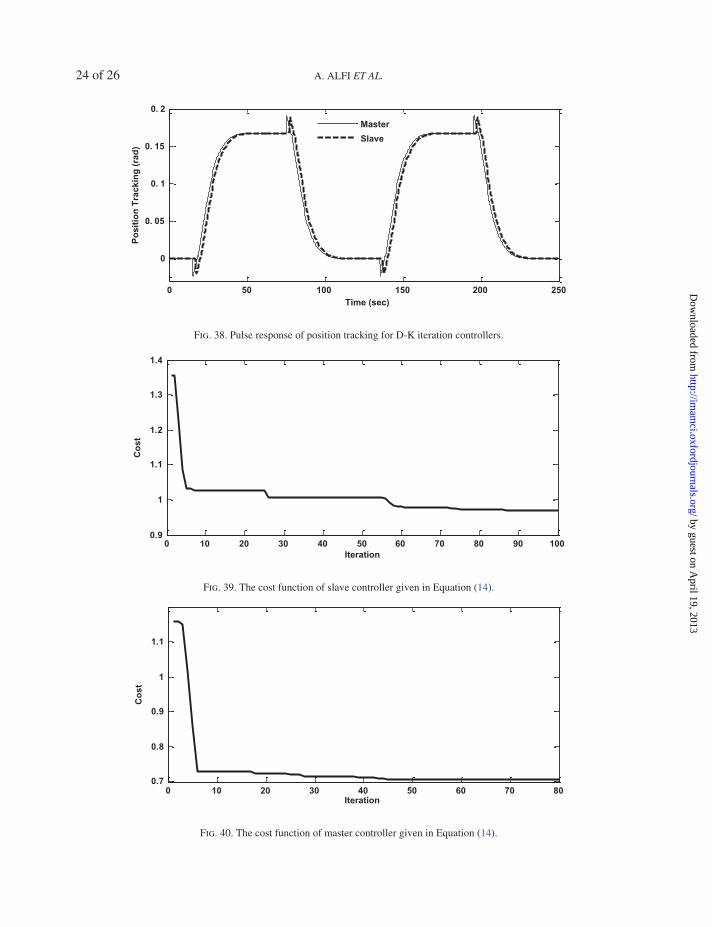
right zero in the D-K iteration controller given in Equation (23), the transient response is slower. Thisfact can be seen in Figs 33, 35, 36 and 38. In addition, the objective functions of both slave and masterfor the structure-specified controllers are depicted in Figs 39 and 40, respectively.
by guest on April 19, 2013
http://imam
ci.oxfordjournals.org/D
ownloaded from

18 of 26 A. ALFI ET AL.
0 10 20 30 40 50 60 70 80 90 1000
0. 05
0. 1
Po
siti
on
Tra
ckin
g (
rad
)
Master
Slave
Time (sec)
Fig. 20. Step response of position tracking for environment impedance uncertainty (Case 1).
0 10 20 30 40 50 60 70 80 90 1000
0. 05
0. 1
0. 15
0. 2
Po
siti
on
Tra
ckin
g (
rad
)
Master
Slave
Time (sec)
Fig. 21. Step response of position tracking for environment impedance uncertainty (Case 2).
0 10 20 30 40 50 60 70 80 90 1000
0. 05
0. 1
0. 15
0. 2
0. 25
Time (sec)
Po
siti
on
Tra
ckin
g (
rad
) Master
Slave
Fig. 22. Step response of position tracking for environment impedance uncertainty (Case 3).
by guest on April 19, 2013
http://imam
ci.oxfordjournals.org/D
ownloaded from

SWARM-BASED STRUCTURE-SPECIFIED CONTROLLER DESIGN FOR TELEOPERATION SYSTEMS 19 of 26
0 50 100 150 200 250 300-0.2
0
0.2
0.4
0.6
0.8
1
1.2
Fo
rce
Tra
ckin
g (
N.m
)
Case 1
Case 2
Case 3
Time (sec)
Fig. 23. Pulse response of force tracking for environment impedance uncertainty.
0 50 100 150 200 250 300
0
0. 05
0. 1
Po
siti
on
Tra
ckin
g (
rad
)
Master
Slave
Time (sec)
Fig. 24. Pulse response of position tracking for environment impedance uncertainty (Case 1).
0 50 100 150 200 250 300
0
0. 05
0. 1
0. 15
Po
siti
on
Tra
ckin
g (
rad
)
Master
Slave
Time (sec)
Fig. 25. Pulse response of position tracking for environment impedance uncertainty (Case 2).
by guest on April 19, 2013
http://imam
ci.oxfordjournals.org/D
ownloaded from

20 of 26 A. ALFI ET AL.
0 50 100 150 200 250 300
0
0.05
0.1
0.15
0.2
0.25P
osi
tio
n T
rack
ing
(ra
d)
Master
Slave
Time (sec)
Fig. 26. Pulse response of position tracking for environment impedance uncertainty (Case 3).
10-2 100 102 104 1060.86
0.88
0.9
0.92
0.94
0.96
0.98
Mu
up
per
bo
un
d
Reduced D-K
D-K
Frequency (rad/sec)
Fig. 27. Robust performance of D-K iteration controller and its reduced order designed for the slave site.
10-4 10-2 100 102 104 1060.2
0.3
0.4
0.5
0.6
0.7
0.8
0.9
1
Mu
up
per
bo
un
d
Reduced D-K
D-K
Frequency (rad/sec)
Fig. 28. Robust performance of D-K iteration controller and its reduced order designed for the master site.
by guest on April 19, 2013
http://imam
ci.oxfordjournals.org/D
ownloaded from

SWARM-BASED STRUCTURE-SPECIFIED CONTROLLER DESIGN FOR TELEOPERATION SYSTEMS 21 of 26
10 -2 10 0 10 2 10 4 10 60
0.05
0.1
0.15
0.2
Mu
up
per
bo
un
dD-K Iteration
Structure-Specified
Frequency (rad/sec)
Fig. 29. Comparison between the slave controllers based on μ stability analysis.
10 -2 10 0 10 2 10 4 10 60.86
0.88
0.9
0.92
0.94
0.96
0.98
Mu
up
per
bo
un
d
Structure-Specified
D-K Iteration
Frequency (rad/sec)
Fig. 30. Comparison between the slave controllers based on μ performance analysis.
10 -4 10 -2 10 0 10 2 10 4 10 60
0.1
0.2
0.3
0.4
0.5
Mu
up
per
bo
un
d
Structure-Specified
D-K Iteration
Frequency (rad/sec)
Fig. 31. Comparison between the master controllers based on μ stability analysis.
by guest on April 19, 2013
http://imam
ci.oxfordjournals.org/D
ownloaded from

22 of 26 A. ALFI ET AL.
10 -4 10 -2 10 0 10 2 10 4 10 60.2
0.3
0.4
0.5
0.6
0.7
0.8
0.9
1
Mu
up
per
bo
un
dD-K Iteration
Structure-Specified
Frequency (rad/sec)
Fig. 32. Comparison between the master controllers based on μ performance analysis.
0 10 20 30 40 50 60 70 80 90 100-0.2
0
0.2
0.4
0.6
0.8
1
Fo
rce
Tra
ckin
g (
N.m
) Structure-Specified
D-K Iteration
Time (sec)
Fig. 33. Step response of force tracking of D-K iteration and structure-specified controllers.
0 10 20 30 40 50 60 70 80 90 1000
0.05
0.1
0.15
0.2
Po
siti
on
Tra
ckin
g (
rad
)
Master
Slave
Time (sec)
Fig. 34. Step response of position tracking of the structure-specified controllers.
by guest on April 19, 2013
http://imam
ci.oxfordjournals.org/D
ownloaded from

SWARM-BASED STRUCTURE-SPECIFIED CONTROLLER DESIGN FOR TELEOPERATION SYSTEMS 23 of 26
0 10 20 30 40 50 60 70 80 90 100
0
0.05
0.1
0.15
0.2
Po
siti
on
Tra
ckin
g (
rad
)
Master
Slave
Time (sec)
Fig. 35. Step response of position tracking for D-K iteration controllers.
0 50 100 150 200 250-0.2
0
0.2
0.4
0.6
0.8
1
1.2
Fo
rce
Tra
ckin
g (
N.m
)
Structure-Specified
D-K Iteration
Time (sec)
Fig. 36. Pulse response of force tracking for D-K iteration and structure-specified controllers.
0 50 100 150 200 250
0
0.05
0.1
0.15
0.2
Po
siti
on
Tra
ckin
g (
rad
)
Master
Slave
Time (sec)
Fig. 37. Pulse response of position tracking for the structure-specified controllers.
by guest on April 19, 2013
http://imam
ci.oxfordjournals.org/D
ownloaded from
24 of 26 A. ALFI ET AL.
0 50 100 150 200 250
0
0. 05
0. 1
0. 15
0. 2
Po
siti
on
Tra
ckin
g (
rad
)Master
Slave
Time (sec)
Fig. 38. Pulse response of position tracking for D-K iteration controllers.
0 10 20 30 40 50 60 70 80 90 1000.9
1
1.1
1.2
1.3
1.4
Co
st
Iteration
Fig. 39. The cost function of slave controller given in Equation (14).
0 10 20 30 40 50 60 70 800.7
0.8
0.9
1
1.1
Co
st
Iteration
Fig. 40. The cost function of master controller given in Equation (14).
by guest on April 19, 2013
http://imam
ci.oxfordjournals.org/D
ownloaded from

SWARM-BASED STRUCTURE-SPECIFIED CONTROLLER DESIGN FOR TELEOPERATION SYSTEMS 25 of 26
6. Conclusions
This paper introduced a novel robust control design for the bilateral teleoperation system in presence ofuncertainties including time delay and task environment. The robust controllers are designed based onμ stability and performance analysis via an inspired algorithm namely PSO-TVAC. This approach canbe considered as an alternative solution to the μ synthesis problem. The performance of teleoperationsystem was investigated in terms of transparency and robust stability. To this end, two local controllerswere designed. The first controller is responsible for tracking the master commands, whereas the secondcontroller is in charge of force tracking as well as guaranteeing the stability of the overall closed-loopsystem. Simulation results confirmed the efficiency of the proposed control structure in comparison withthe D-K iteration method.
References
Alfi, A. & Farrokhi, M. (2008a) A simple structure for bilateral transparent teleoperation under communicationtime delay. ASME J. Dyn. Syst. Meas. Control, 130(4), 044502, doi:10.1115/1.2936854.
Alfi, A. & Farrokhi, M. (2008b) Force reflecting bilateral control of master-slave systems in teleoperation.J. Intell. Robot. Syst., 52, 209–232.
Alfi, A. & Fateh, M. M. (2011a) Intelligent identification and control using improved fuzzy particle swarmoptimization. Expert Syst. Appl., 38, 12312–12317.
Alfi, A. & Fateh, M. M. (2011b) Identification of nonlinear systems using modified particle swarm optimization:A hydraulic suspension system. J. Veh. Syst. Dyn., 46, 871–887.
Alfi, A. & Modares, H. (2011) System identification and control using adaptive particle swarm optimization.J. Appl. Math. Model., 35, 1210–1221.
Doyle, J. C. & Packard, A. (1987) Uncertain multivariable systems from a state space perspective. IEEE Pro-ceedings of American Control Conference. Minneapolis, MN, pp. 2147–2152.
Ganjefarar, S., Najibia, S. & Momeni, H. R. (2011) A novel structure for the optimal control of bilateral teleop-eration systems with variable time delay. J. Franklin Inst., 348, 1537–1555.
Ho, S. J., Ho, S. Y., Hung, M. H., Shu, L. S. & Huang, H. L. (2005) Designing structure-specified mixedH28̋ optimal controllers using an intelligent genetic algorithm IGA. IEEE Trans. Control Syst. Technol., 13,874–876.
Hokayayaem, P. F. & Spong, M. W. (2006) Bilateral teleoperation: an historical survey. Automatica, 42,2035–2055.
Hosseini-Suny, K., Momeni, H. & Janabi-Sharifi, F. (2010) A modified adaptive controller design for teleoper-ation systems. Robot. Auton. Syst., 58, 676–683.
Hou, Y. & Luecke, G. R. (2005) Time delayed teleoperation system control: a passivity-based method. 12th IEEEConference on Advanced Robotics. Washington, DC, USA, pp. 796–802.
Kaitwanidvilai, S. & Parnichkun, M. (2008) Design of structured controller satisfying H infinite loop shapingusing evolutionary optimization: application to a pneumatic robot arm. Eng. Lett., 16, 193–201.
Kennedy, J. & Eberhart, R. (1995) Particle swarm optimization. IEEE International Conference on NeuralNetworks. Washington, DC, USA, pp. 1942–1948.
Lawrence, D. A. (1993) Stability and transparency in bilateral teleoperation. IEEE Trans. Robot. Automat., 9,625–637.
Le, M. Q., Pham, M. T., Tavakoli, M. & Moreau, R. (2011) Sliding mode control of a pneumatic haptic teleoper-ation system with on/off solenoid valves. IEEE International Conference on Robotics and Automation. Lyon,France, pp. 874–879.
Leung, G. M. H., Francis, B. A. & Apkaarian, J. (1995) Bilateral controller for teleoperators with time delay viaμ synthesis. IEEE Trans. Robot. Autom., 11, 105–116.
Modares, H., Alfi, A. & Fateh, M. M. (2010b) Parameter identification of chaotic dynamic systems through animproved particle swarm optimization. Expert Syst. Appl., 37, 3714–3720.
by guest on April 19, 2013
http://imam
ci.oxfordjournals.org/D
ownloaded from

26 of 26 A. ALFI ET AL.
Modares, H., Alfi, A. & Naghibi Sistani, M. B. (2010b) Parameter estimation of bilinear systems based on anadaptive particle swarm optimization. J. Eng. Appl. Artif. Intell., 23, 1105–1111.
Munir, S. & Book, W. J. (2002) Internet-based teleoperation using wave variable with prediction. IEEE/ASMETrans. Mechateronics, 7, 124–133.
Nimpitiwan, N. & Kaitwanidvilai, S. (2012) Static output feedback robust loop shaping control for grid con-nected inverter using genetic algorithms. Int. J. Innov. Comput. Inf. Control, 8, 6081–6095.
Ratnaweera, A., Halgamuge, S. K. & Watson, H. C. (2004) Self-organizing hierarchical particle swarm opti-mizer with time varying acceleration coefficients. IEEE Trans. Evol. Comput., 8, 240–255.
Sha Sadeghi, M., Momeni, H. R. & Amirifar, R. (2008) H∞ and L1 control of a teleoperation system via LMIs.Appl. Math. Comput., 206, 669–677.
Shi, Y. & Eberhart, R. C. (1999) Empirical study of particle swarm optimization. Proceedings of the IEEECongress on Evolutionary Computation. Indiana, USA, vol. 3, pp. 101–106.
Stein, G. & Doyle, J. (1991) Beyond singular values and loop-shapes. AIAA J. Guid. Control., 14, 5–16.Suganthan, P. N. (1999) Particle swarm optimizer with neighborhood operator. IEEE International Conference
on Evolutionary Computation. Washington, DC: IEEE Press, pp. 1958–1962.Valdovinos, L. G., Parra-Vega, V. & Arteaga, M. A. (2007) Observer-Based sliding mode impedance control
of bilateral teleoperation under constant unknown time delay. Robot. Auton. Syst., 55, 609–617.Wang, B., Li, Y. & Watada, J. (2012) A distance-based PSO approach to solve fuzzy MOPSM with distinct risk
measurements. Int. J. Innov. Comput. Inf. Control, 8, 6191–6205.Zamini, M., Sadati, N. & Karimi Ghartemai, M. (2009) Design of an H∞ PID controller using particle swarm
optimization. Int. J. Control Autom. Syst., 7, 273–280.Zhou, K. & Doyle, J. C. (1998) Essentials of Robust Control. Englewood Cliffs, NJ: Prentice-Hall.
by guest on April 19, 2013
http://imam
ci.oxfordjournals.org/D
ownloaded from