Electrically conductive carbon nanopipe-graphite nanosheet/polyaniline composites

UNCORRECTEDPROOF
Graphical Abstract
Polymer 2010, -, ---Formation of nanostructured composites with environmentally-dependentelectrical properties based on poly(vinylidene fluoride)epolyaniline coreeshelllatex system
Gururaj M. Neelgund a, Valery N. Bliznyuk a,*, Alexander A. Pud b, Kateryna Yu. Fatyeyeva b,Erika Hrehorova a, Margaret Joyce a
aDepartment of Paper Engineering, Chemical Engineering and Imaging, Western Michigan University,Kalamazoo, MI 49008, USAb Institute of Bioorganic Chemistry and Petrochemistry of National Academy of Science of Ukraine, 50,Kharkivske Schose, 02160 Kyiv, Ukraine
Contents lists available at ScienceDirect
Polymer
journal homepage: www.elsevier .com/locate/polymer
ARTICLE IN PRESS
Polymer xxx (2010) 1
JPOL13806_grabs ■ 6 March 2010 ■ 1/1
Please cite this article in press as: Neelgund GM, et al., Polymer (2010), doi:10.1016/j.polymer.2010.02.038
123456789
10111213141516171819202122232425262728293031
323334353637383940414243444546474849505152535455
56575859606162

Q2
Q1
lable at ScienceDirect
ARTICLE IN PRESS
Polymer xxx (2010) 1e7
JPOL13806_proof ■ 6 March 2010 ■ 1/7
123456789
10111213141516171819202122232425262728293031323334353637383940414243444546474849505152535455
Contents lists avai
Polymer
journal homepage: www.elsevier .com/locate/polymer
56575859606162636465666768
OOF
Formation of nanostructured composites with environmentally-dependentelectrical properties based on poly(vinylidene fluoride)epolyaniline coreeshelllatex system
Gururaj M. Neelgund a, Valery N. Bliznyuk a,*, Alexander A. Pud b, Kateryna Yu. Fatyeyeva b,Erika Hrehorova a, Margaret Joyce a
aDepartment of Paper Engineering, Chemical Engineering and Imaging, Western Michigan University, Kalamazoo, MI 49008, USAb Institute of Bioorganic Chemistry and Petrochemistry of National Academy of Science of Ukraine, 50, Kharkivske Schose, 02160 Kyiv, Ukraine
697071727374757677787980
a r t i c l e i n f o
Article history:Received 21 December 2009Received in revised form16 February 2010Accepted 21 February 2010Available online xxx
Keywords:LatexPoly(vinylidene fluoride)Polyaniline
* Corresponding author. Tel.: þ1 269 2763213.E-mail address: [email protected] (V.N.
0032-3861/$ e see front matter � 2010 Published bydoi:10.1016/j.polymer.2010.02.038
Please cite this article in press as: Neelgund
81828384
CTEDPRa b s t r a c t
Submicron poly(vinylidene fluoride) (PVDF)/polyaniline (PANI) coreeshell latex particles are synthesizedand examined as an active component in a simple conductometric chemical sensor. The structure andphysical properties of these particles and nanostructured composite PVDFePANI polymer films built ofthem are characterized with transmission electron and atomic force microscopy techniques, differentialscanning calorimetry, and conductivity measurements. The nanostructured composite films withconductivity of about 4 � 10�4 S/cm suitable for sensor applications are prepared by casting from thecoreeshell particles dispersions on glass substrates patterned with silver electrodes followed byannealing at 180 �C, i.e. above Tm of the PVDF component. Sensor properties of these films are tested bymeasuring currentevoltage (IeV) characteristics in response to varying concentration of NH3 or HClvapors. The developed thin film sensor heterostructures with electrically conductive percolation networkof PANI as an active component and employing the conductometric detection scheme show highsensitivity to both analytes. However, the polymer material is especially efficient for application to NH3
sensing with the detection limit as low as 100 ppb, and good reproducible recovery behavior uponrepeated exposure to NH3 at ambient conditions.
� 2010 Published by Elsevier Ltd.
8586 E87
888990919293949596979899100101102103104105
UNCORR
1. Introduction
Intrinsically conducting polymers (ICPs) can be used as chemicalsensor materials due to the fact that their conductivity and opticalproperties are very sensitive to their doping level, which in turn canbe easily effected by different external chemical agents. [1,2] In factconductivity of ICPs such as polyacetylene, polyparaphenylenevinylene, polypyrroles, polythiophenes etc. can be changed in a verybroad range from semiconducting or even insulating properties(10�6e10�10 S/cm) to highly conductive “quasi-metallic” state withthe conductivity approaching that of copper (w104 S/cm). Thismakes ICPs attractive materials for usage as active components ofsensors to identify different chemical substances and, in some cases,even some physical factors [3,4]. In turn these changes are the basisof simple mechanisms of transduction of events, which includespecific chemical and/or physical interactions of these polymerswith effecting factors, into electric or optical signals [5].
Bliznyuk).
Elsevier Ltd.
GM, et al., Polymer (2010), d
106107108
Among ICPs polyaniline (PANI) matches the best combination ofsensor properties, stability, conductivity, cost, etc. [6]. The signifi-cant distinction of PANI from other ICPs is its ability to react,dependently on degree of doping, reversibly with basic or acidicenvironment. The difference is that this response to the environ-ment is not due to a variation of the redox-state, but originates froma variation of the degree of protonation of the polymer chains thatresults both in color (spectral) and conductivity changes of thematerial [3,7,8]. This mechanism is based on the simple reversibleinteraction of emeraldine salt or base forms of PANI withcompounds having base or acid functions correspondingly. Suchchanges can be easily registered and processed by proper devicesespecially in case of nanostructured PANI materials, which showenhanced magnitude and response rate of these signals due toa high specific surface area and enhanced accessibility of theirsensitive centers [9e11]. Naturally, the sensing response essentiallydepends also on the PANI material morphology [12], and on thedegree of doping [13].
The above considerations put two mutually exclusive require-ments to design of advanced functional materials (both PANI and
oi:10.1016/j.polymer.2010.02.038
109110

E
G.M. Neelgund et al. / Polymer xxx (2010) 1e72
ARTICLE IN PRESS JPOL13806_proof ■ 6 March 2010 ■ 2/7
111112113114115116117118119120121122123124125126127128129130131132133134135136137138139140141142143144145146147148149150151152153154155156157158159160161162163164165166167168169170171172173174175
176177178179180181182183184185186187188189190191192193194195196197198199200201202203204205206207208209210211212213214215216217218219220221222223224225226227228229230231232233234235236237238239240
UNCORRECT
other ICP based ones) for sensor applications of: 1) enhancementof the proportion of functional groups located on the surface of thematerial and therefore readily available for specific interactionwith an analyte; 2) the easiness of integration of a new materialinto existing microelectronics fabrication protocols. The firstrequirement can be satisfied in materials based on nanoparticles(like PANI nanotubes or nanofibers). However such materials havea drawback of more complex fabrication protocols and do notpossess sufficient mechanical stability [14,15]. As an alternative,more robust and mechanically stable highly porous bulkymaterials can be used [16,17]. The latter are perfectly compatiblewith the existing traditional deposition and processing techno-logies but have generally longer sensor response time, reducedsensitivity and poorer reproducibility in comparison to thenanoparticles analogs. We have demonstrated in our paper howthe above dilemma in application of the nanoparticles or highlyporous bulky materials can be resolved in the framework of theapproach using a system of submicron coreeshell polymerparticles. In the latter case the PANI functional sensing shell can bestructured at the nanoscale through application of specialpolymerization approaches [18e20], while more bulky and heavycore insures mechanical stability of the material as the whole.Moreover the core itself might play an important special functionin the system. For instance, it can introduce desirable physicalproperties like macroscopic polarization, optical transparency,mechanical toughness and thermal processability. This approachsimultaneously dramatically reduces human health and environ-mental risks associated with formation of aero-sols in existingnanofabrication protocols [21,22].
In this connection, we directed our efforts on the investigation ofpossibility for creation of nanostructured electrically conductivecomposites based on recently developed poly(vinylidene fluoride)ePANI, dopedwith dodecylbenzenesulfonic acid, (PVDFePANIeDBSA)submicron coreeshell particles [23] PVDF as a core polymer materialpossesses simultaneously convenient range of melting transitiontemperature, good processability, chemical inertness against manyorganic solvents, acids and bases, and thermal stability of properties[24]. As an additional advantage, PVDF latex particles have higherdensity (r ¼ 1.78 g/cm3) in comparison to other common polymerlatex materials (e.g. 1.05 g/cm3 for polystyrene and 1.19 g/cm3 forpoly(methyl methacrylate)). The higher density of PVDF helps tominimize problems associated with the nanoparticle dust formationand possible risks of its inhalation during processing operations. Inour research, we intended to study the morphology, electricalproperties and their variation for the PVDFePANI coreeshellpolymer system depending on the preparation conditions. We alsowanted to make assessment of such nanostructured compositematerial as an active component for possible sensor applications. Forthis, NH3 and HCl vapors as typical and practically importantanalytes, strongly affecting the electrical conductivity of PANI,were applied.
2. Experimental
2.1. Preparation of PVDF/PANIeDBSA coreeshell particles
The coreeshell particles were prepared through a proceduredescribed elsewhere [23]. Specifically, aniline (Merck) was poly-merized under the action of oxidant potassium persulfate(K2S2O8) in a medium of PVDF 1000 Kynar latex (Arkema) in thepresence of DBSA (Acros) at 10 �C for 5 h under stirring. The latexcontains PVDF submicron particles with average diameterw200 nm. DBSA functioned in this system as a surface activesubstance, a plasticizing agent and a dopant for the PANIcomponent. The molar ratio of aniline: DBSA and aniline:K2S2O8
Please cite this article in press as: Neelgund GM, et al., Polymer (2010), d
DPROOF
were 1:1.5 and 1:1.25, respectively. The concentrations of thereagents allowed 4.8 wt.% PANIeDBSA loading in the hybridparticles. After the polymerization was completed, the dispersephase of PVDF/PANIeDBSA was rinsed with an excess ofwater, and finally dried under vacuum at 70 �C to a constantweight. The final PVDF/PANIeDBSA composite powder was usedin further tests.
2.2. Deposition of the PVDFePANI films
Nanostructured PVDFePANI films were prepared via casting ofthe PVDFePANI dispersions on glass slides with thermallyevaporated silver electrode pattern. For this, a 4 wt.% dispersionof PVDF or PVDFePANI latexes were prepared in chloroform(Aldrich) and then cast onto the glass surface. The solvent wasallowed to evaporate at room temperature. After proper drying,the films were additionally annealed at temperature 180 �C forvarious periods of time (0e30 min) in a laboratory oven. The filmthickness was measured from AFM as an elevation of the filmsurface over the glass substrate at places of artificially producedscratches. These measurements showed relatively uniformfilm thickness with a standard deviation of less than 15% of themean value.
2.3. Electrical and sensor measurements
The electrical measurements were carried out with a Keithley2400 multimeter in accordance to a procedure described else-where [24]. The prepared amperometric devices (i.e., glass slideswith patterned silver electrodes and active polymer latex filmsdeposited on top) were exposed to NH3 and HCl vapors of variableconcentrations in air and their electrical properties in terms ofIeV characteristics were monitored in the voltage range �1 V toþ1 V at room temperature in a specially designed test chamber of1 L volume. During the sensing measurement, gas concentrationsof the NH3 or HCl analytes were altered by injecting the samplegas into the airtight testing chamber using a sample injector(syringe). The variation of current was simultaneously measureddepending on the applied voltage and the analyte concentration.The variation of the current at a constant voltage was alsomonitored for several cases as a function of time and dependingon the concentration of the NH3 or HCl analyte to measure therate and reproducibility of the sensing response. Raw currentmeasurements were used for estimation of electrical conductivityfor several samples using the equation: s ¼ Il/U$A ¼ Il/U$(W$T);where s is electrical conductivity, I is experimentally measuredcurrent under applied voltage U, l is the gap between planarelectrodes, and A is the cross-sectional area of the sample (can beestimated as a product of the electrodes' width, W, and the filmthickness, T) [24]. The electrodes for these measurements werefabricated by thermal evaporation of silver on cleaned glass slidesin vacuum 10�5 torr. Typically they had the width W in the rangeof 5e15 mm and the gap l ¼ 200 mm.
2.4. Structure and physical properties characterization
The size of the PVDF particles and uniformity of PANI coating onPVDF particles were investigated utilizing JEOL JEM-100CXIItransmission electron microscope (TEM). The thermal behavior ofthe PVDFePANI particles was characterized using PerkineElmerPyris 1 DSC system in air with the heating rate of 20 �C/min. Themorphological characterization of the films was conducted usingan Autoprobe CP AFM equipment (ThermoMicroscopes Inc.),operated in a tapping mode with silicon nitride tips and ORION�helium ion microscope (HIM) (Carl Zeiss SMT, Inc., Peabody, MA).
oi:10.1016/j.polymer.2010.02.038

E
OF
Fig. 1. TEM images of (a) PVDF latex particles and (b) PVDFePANI coreeshell latex particles.
G.M. Neelgund et al. / Polymer xxx (2010) 1e7 3
ARTICLE IN PRESS JPOL13806_proof ■ 6 March 2010 ■ 3/7
241242243244245246247248249250251252253254255256257258259260261262263264265266267268269270271272273274275276277278279280281282283284285286287288289290291292293294295296297298299300301302303304305
306307308309310311312313314315316317318319320321322323324325326327328329330331332333334335336337338339340341342343344345346
ECT
3. Results and discussion
Fig. 1 provides the transmission electron microscopy (TEM)images of PVDF latex particles before and after modification withPANI. Unmodified PVDF particles were found to possess an averagesize of 200 nm and a uniform size distribution (Fig. 1(a)). Modifiedlatex particles (PVDFePANI coreeshell system) have largerdiameter (about 220 nm) as can be seen from their TEM image(Fig. 1(b)). Presence of the PANI shell is displayed here as a semi-transparent quite uniform layer, which surrounds more dense andsmooth PVDF particles. It should be mentioned here that formationof PANI shells at the surface of various particles due to anilinepolymerization in water dispersions is the well known signature ofthe PANI polymerization process [25,26].
The thermal behavior of the unmodified and PANI modifiedPVDF particles was addressed with differential scanning calorim-etry (DSC) and the resulting thermograms are presented in Fig. 2(a)and (b). The melting transition temperature (Tm) of PVDF latexparticles can be seen as a sharp endothermic peak in the heatingportion of the thermograms accompanied with well-pronouncedreversed peaks of crystallization in the cooling portions of the
UNCORR
Fig. 2. DSC thermograms of (a) PVDF latex particles
Please cite this article in press as: Neelgund GM, et al., Polymer (2010), d
DPROcurves. Similar behavior has been observed for PVDF/PANIeDBSA
coreeshell particles. One can see that the polymerization of anilineand creation of the PANI shell on top of the PVDF core has almost noeffect on the crystalline properties of the latter. Specifically,PANIeDBSA modified PVDF coreeshell particles possess Tm whichis just 0.8� lower than that of pristine PVDF particles (Fig. 2(a) and(b)). The effect can be probably due to a plasticizing effect of a smallquantity of DBSA. PVDF and PVDF/PANIeDBSA latex systems arehowever significantly different in sense of their crystallizationtemperatures when cooled from the melt state. The latter effect canbe ascribed to the presence of the PANIeDBSA shells acting asseeding centers for heterogeneous nucleation and promotinghigher crystallization temperature in the case of PVDFePANIeDBSAsystem in comparison to pure PVDF. Several minor peaks seen inthe DSC curves belong to impurities, have not been reproduciblefrom scan to scan and therefore are not interpreted.
With the known geometrical parameters of the film (i.e., filmthickness, width of the silver electrodes and the gap between them)it was possible to estimate the electrical conductivity fromregistered current-voltage characteristics (IeV curves) [24]. Thefilm thickness was in the range of 300e800 nm (as measured from
and (b) PVDFePANI coreeshell latex particles.
oi:10.1016/j.polymer.2010.02.038
347348349350351352353354355356357358359360361362363364365366367368369370
E
G.M. Neelgund et al. / Polymer xxx (2010) 1e74
ARTICLE IN PRESS JPOL13806_proof ■ 6 March 2010 ■ 4/7
371372373374375376377378379380381382383384385386387388389390391392393394395396397398399400401402403404405406407408409410411412413414415416417418419420421422423424425426427428429430431432433434435
436437438439440441442443444445446447448449450451452453454455456457458459460461462463464465466467468469470471472473474475476477478479480481
RRECT
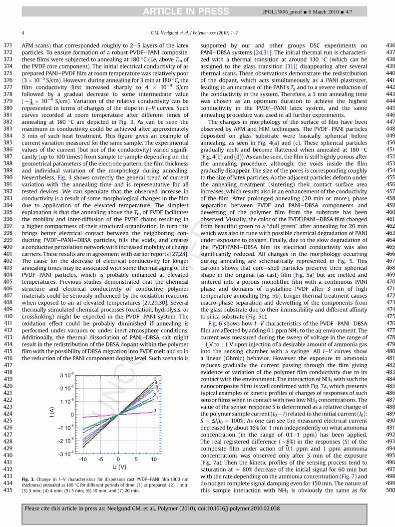
AFM scans) that corresponded roughly to 2e5 layers of the latexparticles. To ensure formation of a robust PVDFePANI composite,these films were subjected to annealing at 180 �C (i.e. above Tm ofthe PVDF core component). The initial electrical conductivity of asprepared PANIePVDF film at room temperature was relatively poor(3� 10�5 S/cm). However, during annealing for 3 min at 180 �C, thefilm conductivity first increased sharply to 4 � 10�4 S/cmfollowed by a gradual decrease to some intermediate value(w3 � 10�4 S/cm). Variation of the relative conductivity can berepresented in terms of changes of the slope in IeV curves. Suchcurves recorded at room temperature after different times ofannealing at 180 �C are depicted in Fig. 3. As can be seen themaximum in conductivity could be achieved after approximately3 min of such heat treatment. This figure gives an example ofcurrent variation measured for the same sample. The experimentalvalues of the current (but not of the conductivity) varied signifi-cantly (up to 100 times) from sample to sample depending on thegeometrical parameters of the electrode pattern, the film thicknessand individual variation of the morphology during annealing.Nevertheless, Fig. 3 shows correctly the general trend of currentvariation with the annealing time and is representative for alltested devices. We can speculate that the observed increase inconductivity is a result of some morphological changes in the filmdue to application of the elevated temperature. The simplestexplanation is that the annealing above the Tm of PVDF facilitatesthe mobility and inter-diffusion of the PVDF chains resulting ina higher compactness of their structural organization. In turn thisbrings better electrical contact between the neighboring con-ducting PVDFePANIeDBSA particles, fills the voids, and createsa conductive percolation networkwith increasedmobility of chargecarriers. These results are in agreement with earlier reports [27,28].The cause for the decrease of electrical conductivity for longerannealing times may be associated with some thermal aging of thePVDFePANI particles, which is probably enhanced at elevatedtemperatures. Previous studies demonstrated that the chemicalstructure and electrical conductivity of conductive polymermaterials could be seriously influenced by the oxidation reactionswhen exposed to air at elevated temperatures [27,29,30]. Severalthermally stimulated chemical processes (oxidation, hydrolysis, orcrosslinking) might be expected in the PVDFePANI system. Theoxidation effect could be probably diminished if annealing isperformed under vacuum or under inert atmosphere conditions.Additionally, the thermal dissociation of PANIeDBSA salt mightresult in the redistribution of the DBSA dopant within the polymerfilmwith the possibility of DBSAmigration into PVDFmelt and so inthe reduction of the PANI component doping level. Such scenario is
UNCO
-3 10-6
-2 10-6
-1 10-6
0
1 10-6
2 10-6
3 10-6
-10 -5 0 5 10U (V)
1
2
3456
7
I (A)
Fig. 3. Change in IeV characteristics for dispersion cast PVDFePANI film (300 nmthickness) annealed at 180 �C for different periods of time: (1) as prepared; (2) 1 min;(3) 3 min; (4) 4 min; (5) 5 min; (6) 10 min; and (7) 20 min.
Please cite this article in press as: Neelgund GM, et al., Polymer (2010), d
482483484485486487488489490491492493494495496497498499500
DPROOF
supported by our and other groups DSC experiments onPANIeDBSA systems [24,31]. The initial thermal run is characteri-zed with a thermal transition at around 130 �C (which can beassigned to the glass transition [31]) disappearing after severalthermal scans. These observations demonstrate the redistributionof the dopant, which acts simultaneously as a PANI plastisizer,leading to an increase of the PANI's Tg and to a severe reduction ofthe conductivity in the system. Therefore, a 3 min annealing timewas chosen as an optimum duration to achieve the highestconductivity in the PVDFePANI latex system, and the sameannealing procedure was used in all further experiments.
The changes in morphology of the surface of film have beenobserved by AFM and HIM techniques. The PVDFePANI particlesdeposited on glass substrate were basically spherical beforeannealing, as seen in Fig. 4(a) and (c). These spherical particlesgradually melt and become flattened when annealed at 180 �C(Fig. 4(b) and (d)). As can be seen, the film is still highly porous afterthe annealing procedure, although, the voids inside the filmgradually disappear. The size of the pores is corresponding roughlyto the size of latex particles. As the adjacent particles deform underthe annealing treatment (sintering) their contact surface areaincreases, which results also in an enhancement of the conductivityof the film. After prolonged annealing (20 min or more), phaseseparation between PVDF and PANIeDBSA components anddewetting of the polymer film from the substrate has beenobserved. Visually, the color of the PVDF/PANIeDBSA film changedfrom beautiful green to a “dull green” after annealing for 20 minwhich was also in tune with possible chemical degradation of PANIunder exposure to oxygen. Finally, due to the slow degradation ofthe PVDF/PANIeDBSA film its electrical conductivity was alsosignificantly reduced. All changes in the morphology occurringduring annealing are schematically represented in Fig. 5. Thiscartoon shows that coreeshell particles preserve their sphericalshape in the original (as cast) film (Fig. 5a) but are melted andsintered into a porous monolithic film with a continuous PANIphase and domains of crystalline PVDF after 3 min of hightemperature annealing (Fig. 5b). Longer thermal treatment causesmacro-phase separation and dewetting of the components fromthe glass substrate due to their immiscibility and different affinityto silica substrate (Fig. 5c).
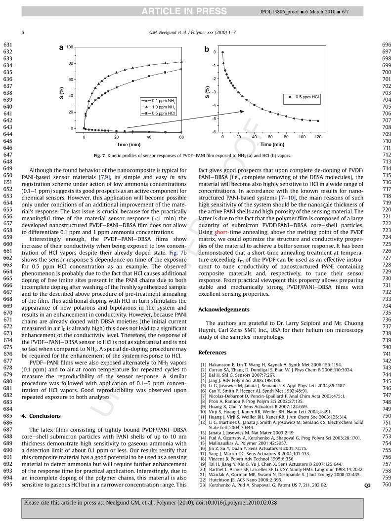
Fig. 6 shows how IeV characteristics of the PVDFePANIeDBSAfilm are affected by adding 0.1 ppmNH3 to the air environment. Thecurrent was measured during the sweep of voltage in the range of�1 V to þ1 V upon injection of a desirable amount of ammonia gasinto the sensing chamber with a syringe. All IeV curves showa linear (Ohmic) behavior. However the exposure to ammoniareduces gradually the current passing through the film givingevidence of variation of the polymer film conductivity due to itscontact with the environment. The interaction of NH3with such thenanocomposite films is well confirmed with Fig. 7a, which presentstypical examples of kinetic profiles of changes of responses of suchsensor films when in contact with two lowNH3 concentrations. Thevalue of the sensor response S is determined as a relative change ofthe polymer sample current (I0� I) related to the initial current (I0):S ¼ DI/I0 � 100%. As one can see the measured electrical currentdecreased by about 16% for 1 min independently onwhat ammoniaconcentration (in the range of 0.1e1 ppm) has been applied.The real registered difference (w8%) in the responses (S) of thecomposite film under action of 0.1 ppm and 1 ppm ammoniaconcentrations was observed only after 3 min of the exposure(Fig. 7a). Then the kinetic profiles of the sensing process tend tosaturation at w 80% decrease of the initial signal for 60 min butwith the rate depending on the ammonia concentration (Fig. 7) anddo not get complete signal damping even for 150min. The nature ofthis sample interaction with NH3 is obviously the same as for
oi:10.1016/j.polymer.2010.02.038

TEDPROOF
Fig. 4. AFM tappingmode (a, b) and ORION� helium ionmicroscopy (c, d) images of as prepared PVDFePANI film (a and c), and PVDFePANI film annealed at 180 �C for 3 min (b and d).
G.M. Neelgund et al. / Polymer xxx (2010) 1e7 5
ARTICLE IN PRESS JPOL13806_proof ■ 6 March 2010 ■ 5/7
501502503504505506507508509510511512513514515516517518519520521522523524525526527528529530531532533534535536537538539540541542543544545546547548549550551552553554555556557558559560561562563564565
566567568569570571572573574575576577578579580581582583584585586587588589590591592593594595596597598599600601602603604605606607608
RECdoped PANI [7]. Specifically, when NH3 vapors interact with
PVDF/PANIeDBSA film, the NH3 molecules compete with PANI forthe acid dopant (DBSA). In a solid phase they pull aside protons Hþ
from the doped PANI due to their stronger basicity. The process canbe understood as just a simple competition between PANIeDBSAsalt including weak base (PANI) and a stronger base (NH3). Asa result, the quantity of positive charges at PANI molecules
UNCOR
Fig. 5. Schematic representation of morphological changes which happen on thesurface of PVDFePANI films at different stages of the annealing (see more explanationsin text).
Please cite this article in press as: Neelgund GM, et al., Polymer (2010), d
decreases leading to a significant drop of the electrical conductivityin the system. However, in the nanocomposite case the rate of thisprocess should obviously depend not only on NH3 concentrationbut also on accessibility of PANI sensing sites, which in its turnis determined by the polymer film's porosity and the thickness ofthe PANI shell.
-3 10-5
-2 10-5
-1 10-5
0
1 10-5
2 10-5
3 10-5
-1 -0.5 0 0.5 1U (V)
1
16I (A)
Fig. 6. IeV characteristics for PVDFePANI film depending on the ammonia exposure:(1) a pristine film cast from chloroform dispersion and then thermally annealed at180 �C for 3 min (film thickness 600 nm). The same film after different time of theexposure to 0.1 ppm NH3: (2) 1 min; (3) 3 min; (4) 5 min; (5) 7 min; (6) 9 min; (7)11 min; (8) 13 min; (9) 15 min; (10) 20 min; (11) 30 min; (12) 40 min; (13) 50 min; (14)60 min; (15) 90 min; and (16) 120 min.
oi:10.1016/j.polymer.2010.02.038
609610611612613614615616617618619620621622623624625626627628629630
E
OF0 20 40 60
0
20
40
60
80
100
)%
(S
Time (min)
0.1 ppm NH 1.0 ppm NH 0.5 ppm HCl
0 20 40 60 80 100 120-6
-5
-4
-3
-2
-1
0
)%
(S
Time (min)
0.5 ppm HCl
a b
Fig. 7. Kinetic profiles of sensor responses of PVDFePANI film exposed to NH3 (a) and HCl (b) vapors.
G.M. Neelgund et al. / Polymer xxx (2010) 1e76
ARTICLE IN PRESS JPOL13806_proof ■ 6 March 2010 ■ 6/7
631632633634635636637638639640641642643644645646647648649650651652653654655656657658659660661662663664665666667668669670671672673674675676677678679680681682683684685686687688689690691692693694695
696697698699700701702703704705706707708709710711712713714715716717718719720721722723724725726727728729730731732733734735736737738739740741742743744745746747
NCORRECT
Although the found behavior of the nanocomposite is typical forPANI-based sensor materials [7,9], its simple and easy in situregistration scheme under action of low ammonia concentrations(0.1e1 ppm) suggests its good prospects as an active component forchemical sensors. However, this application will become possibleonly under conditions of an additional improvement of the mate-rial's response. The last issue is crucial because for the practicallymeaningful time of the material sensor response (<1 min) thedeveloped nanostructured PVDFePANIeDBSA film does not allowto differentiate 0.1 ppm and 1 ppm ammonia concentrations.
Interestingly enough, the PVDFePANIeDBSA films showincrease of their conductivity when being exposed to low concen-tration of HCl vapors despite their already doped state. Fig. 7bshows the sensor response S dependence on time of the exposurefor 0.5 ppm HCl concentration as an example. The observedphenomenon is probably due to the fact that HCl causes additionaldoping of free imine sites present in the PANI chains due to bothincomplete doping after washing of the freshly synthesized sampleand to the described above procedure of pre-treatment annealingof the film. This additional doping with HCl in turn stimulates theappearance of new polarons and bipolarons in the system andresults in an enhancement in conductivity. However, because PANIchains are already doped with DBSA moieties (the initial currentmeasured in air I0 is already high) this does not lead to a significantenhancement of the conductivity level. Therefore, the response ofthe PVDFePANIeDBSA sensor to HCl is not as substantial and is notso fast when compared to NH3. A special de-doping procedure maybe required for the enhancement of the system response to HCl.
PVDFePANI films were also exposed alternately to NH3 vapors(0.1 ppm) and to air at room temperature for repeated cycles tomeasure the reproducibility of the sensor response. A similarprocedure was followed with application of 0.1e5 ppm concen-tration of HCl vapors. Good reproducibility was observed uponrepeated exposure to both analytes.
3
748749750751752753754755756757758759760
U4. Conclusions
The latex films consisting of tightly bound PVDF/PANIeDBSAcoreeshell submicron particles with PANI shells of up to 10 nmthickness demonstrate high sensitivity to gaseous ammonia witha detection limit of about 0.1 ppm or less. Our results testify thatthis composite material has a good potential to be used as a sensingmaterial to detect ammonia but will require further enhancementof the response time for practical application. Interestingly, due toan incomplete doping of the polymer chains, this material is alsosensitive to gaseous HCl but in a narrower concentration range. This
Please cite this article in press as: Neelgund GM, et al., Polymer (2010), d
DPROfact gives good prospects that upon complete de-doping of PVDF/
PANIeDBSA (i.e., complete removing of the DBSA molecules), thematerial will become also highly sensitive to HCl in a wide range ofconcentrations. In accordance with the known results for nano-structured PANI-based systems [7e10], the main reasons of suchhigh sensitivity of the system should be the nanoscale thickness ofthe active PANI shells and high porosity of the sensingmaterial. Thelatter is due to the fact that the polymer film is composed of a largequantity of submicron PVDF/PANIeDBSA coreeshell particles.Using short-time annealing, above the melting point of the PVDFmatrix, we could optimize the structure and conductivity proper-ties of the material to achieve a better sensor response. It has beendemonstrated that a short-time annealing treatment at tempera-ture exceeding Tm of the PVDF can be used as an effective instru-ment to tune conductivity of nanostructured PANI containingcomposite materials and, respectively, to tune their sensorresponse. From practical viewpoint this property allows preparingstable and mechanically strong PVDF/PANIeDBSA films withexcellent sensing properties.
Acknowledgements
The authors are grateful to Dr. Larry Scipioni and Mr. ChuongHuynh, Carl Zeiss SMT, Inc., USA for their helium ion microscopystudy of the samples' morphology.
References
[1] Hakansson E, Lin T, Wang H, Kaynak A. Synth Met 2006;156:1194.[2] Curran SA, Zhang D, Dundigal S, Blau W. J Phys Chem B 2006;110:3924.[3] Bai H, Shi G. Sensors 2007;7:267.[4] Jang J. Adv Polym Sci 2006;199:189.[5] Li G, Josowicz M, Janata J, Semancik S. Appl Phys Lett 2004;85:1187.[6] Cao Y, Smith P, Heeger AJ. Synth Met 1992;48:91.[7] Nicolas-Debarnot D, Poncin-Epaillard F. Anal Chim Acta 2003;475:1.[8] Pron A, Rannou P. Prog Polym Sci 2002;27:135.[9] Huang X, Choi Y. Sens Actuators B 2007;122:659.
[10] Virji S, Huang J, Kaner RB, Weiller BH. Nano Lett 2004;4:491.[11] Huang J, Virji S, Weiller BH, Kaner RB. J Am Chem Soc 2003;125:314.[12] Li G, Martinez C, Janata J, Smith A, Josowicz M, Semancik S. Electrochem Solid
State Lett 2004;7:H44.[13] Janata J, Josowicz M. Nat Mater 2003;2:19.[14] Pud A, Ogurtsov A, Korzhenko A, Shapoval G. Prog Polym Sci 2003;28:1701.[15] Malinauskas A. Polymer 2001;42:3957.[16] Jin Z, Su Y, Duan Y. Sens Actuators B 2001;72:75.[17] Yang J, Martin DC. Sens Actuators B 2004;101:133.[18] Vincent B. Polym Adv Technol 1995;6:356.[19] Tai H, Jiang Y, Xie G, Yu J, Chen X. Sens Actuators B 2007;125:644.[20] Barthet C, Armes SP, Lascelles SF, Luk SY, Stanly HME. Langmuir 1998;14:2032.[21] Wardak A, Gorman ME, Swami N, Deshpande S. J Ind Ecology 2008;12:435.[22] Hutchison JE. ACS Nano 2008;2:395.[23] Korzhenko A, Pud A, Shapoval, G. Patent US 7, 211, 202 B2. Q
oi:10.1016/j.polymer.2010.02.038

Q4
G.M. Neelgund et al. / Polymer xxx (2010) 1e7 7
ARTICLE IN PRESS JPOL13806_proof ■ 6 March 2010 ■ 7/7
761762763764765
766767768769770
[24] Bliznyuk VN, Baig A, Singamaneni S, Pud AA, Fatyeyeva KY, Shapoval GS.Polymer 2005;46:11728.
[25] Pud AA, Noskov Yu V, Kassiba A, Fatyeyeva KYu, Ogurtsov NA, Makowska-Janusik M, et al. J Phys Chem B 2007;111:2174.
[26] Stejskal J, Quadrat O, Sapurina I, Zemek J, Drelinkiewicz A, Hasik M, et al. EurPolym J 2002;38:631.
UNCORRECTE
Please cite this article in press as: Neelgund GM, et al., Polymer (2010), d
[27] Liau W, Sun Y, Yang L, Wang L, Chiu W, Hsieh K, et al. J Appl Polym Sci2006;102:5406.
[28] Huijs FM, Vercauteren FF, Hadziioannou G. Synth Met 2002;125:395.[29] Stejskal J, OmastovaM, Fedorova S, Proke�s J, TrchovaM. Polymer 2003;44:1353.[30] Proke�s J, Trchova M, Hlavata D, Stejskal J. Polym Degrad Stab 2002;78:393.[31] Hoa ND, Quy NV, Cho Y, Kim D. Sens Actuators B 2007;127:447.
DPROOF
oi:10.1016/j.polymer.2010.02.038
Copyright © 2022 FDOKUMEN