Revisiting the Redox Transitions of Polyaniline. Semiquantitative ...
11
Revisiting the redox transitions of Polyaniline. Semiquantitative interpretation of electrochemically induced IR bands F. Huerta a , C. Quijada a , F. Montilla b,⇑ , E. Morallón b a Departamento de Ingenieria Textil y Papelera, Universitat Politecnica de Valencia, Plaza Ferrandiz y Carbonell, 1, Alcoy E-03801, Spain b Departamento de Química Física e Instituto Universitario de Materiales de Alicante. Universidad de Alicante. Crtra. San Vicente s/n, Alicante E-03690, Spain ARTICLE INFO ABSTRACT The redox transitions of PANI in acidic medium have been monitored by a combination of cyclic voltammetry, in situ conductance and in situ FTIR spectroscopy. The results of the semiquantitative analysis strongly suggest that the classical tetrameric model of PANI does not satisfactorily describe the actual structures of the polymer at different redox states. An octameric model is revisited, with the inclusion of essential resonant structures, to provide an appropriate prediction of the relative IR intensity changes of the aromatic CAC stretching (at around 1520 cm -1 ) and the quinoid C@C stretching (at around 1590 cm -1 ) vibrations observed by FTIR, which are difficult to interpret by considering only 4 aniline rings. Particularly, it is found that the emeraldine state is better described as a resonance hybrid of the classical bipolaronic and semiquinoid (polaron lattice) structures, while most of the charge transferred at the onset of the second voltammetric peak comes from the additional oxidation of this hybrid, which becomes unstable in the electrochemical environment producing mineralization to CO 2 and release of soluble quinones. 1. Introduction Polymers containing non-localized electrons in their backbones are often referred to as conducting polymers. A great deal of both scientific and technological interest has been devoted to the fundamental elec- trochemistry of these systems owing to their dual character. On the one hand, they show semiconducting properties in the native (un- doped) state that allow its use as replacement of inorganic semicon- ductors in, essentially, all the existing electronic devices: transistors, diodes, solar cells, etc. giving rise to a new scientific-technological field called organic (or plastic) electronics [1]. On the other hand, the progressive oxidation (or reduction) of the polymer backbone (doping process) increases the conductivity of the material by several orders of magnitude. This behavior, and additional physicochemical properties, supported their applicability to non-linear optics, electro- catalysis, electrochemomechanical devices or charge storage systems, among other research fields [2]. The electrochemical oxidation of resonant aromatic molecules such as pyrrole, thiophene, aniline and their derivatives has become one of the main methods used to prepare conjugated, electronically conduct- ing polymers [3,4]. Polyaniline (PANI) and its derivatives are probably the most studied conducting polymers synthesized by electrochemical methods [5–8]. Even before the advent of macromolecular chemistry, the existence of polyaniline (known initially as aniline-black) was rec- ognized although the concept of polymer itself did not exist [9]. The first studies on aniline-black come from the 19th century [10] but it was in the early 20th century that the works of Willstatter, Moore, Green and Woodhead defined the different oxidation states of an eight-unit molecule (the so-called eight-nucleal structure, since the term oligomer was not defined yet) considered precursors of aniline- black [11,12]. Already at that time the complex redox structure of ani- line-black was recognized and the terminology related to the different oxidation states of the octamer was assigned, the so-called leu- coemeraldine, protoemeraldine, emeraldine, nigraniline and perni- graniline. These states correspond to 0, 25, 50, 75 and 100% of oxidized rings, respectively [12]. Once the polymeric character of PANI was identified after the first quarter of the 20th century, this compound went quite unnoticed until its rediscovery as a conducting polymer in the mid-1980s. In this sense, MacDiarmid’s seminal papers led to establishing that PANI presents a conductivity influenced by the pH of the synthesis medium and demonstrated that the conductive forms of PANI only appear at pH lower than 4 [13]. The redox species that provides electric conductivity to this poly- mer is the protonated emeraldine, which suffers an internal redox reaction giving rise to a semiquinone or separate polaron radical- cation [14–16], Scheme 1. From an electrochemical point-of-view, https://doi.org/10.1016/j.jelechem.2021.115593 Received 12 April 2021; Received in revised form 2 August 2021; Accepted 6 August 2021 Available online 12 August 2021 1572-6657/© 2021 The Author(s). Published by Elsevier B.V. This is an open access article under the CC BY license (http://creativecommons.org/licenses/by/4.0/). ⇑ Corresponding author. E-mail address: [email protected] (F. Montilla). Journal of Electroanalytical Chemistry 897 (2021) 115593 Contents lists available at ScienceDirect Journal of Electroanalytical Chemistry journal homepage: www.elsevier.com/locate/jelechem
-
Upload
khangminh22 -
Category
Documents
-
view
0 -
download
0
Transcript of Revisiting the Redox Transitions of Polyaniline. Semiquantitative ...

Journal of Electroanalytical Chemistry 897 (2021) 115593
Contents lists available at ScienceDirect
Journal of Electroanalytical Chemistry
journal homepage: www.elsevier .com/locate / je lechem
Revisiting the redox transitions of Polyaniline. Semiquantitativeinterpretation of electrochemically induced IR bands
https://doi.org/10.1016/j.jelechem.2021.115593Received 12 April 2021; Received in revised form 2 August 2021; Accepted 6 August 2021Available online 12 August 20211572-6657/© 2021 The Author(s). Published by Elsevier B.V.This is an open access article under the CC BY license (http://creativecommons.org/licenses/by/4.0/).
⇑ Corresponding author.E-mail address: [email protected] (F. Montilla).
F. Huerta a, C. Quijada a, F. Montilla b,⇑, E. Morallón b
aDepartamento de Ingenieria Textil y Papelera, Universitat Politecnica de Valencia, Plaza Ferrandiz y Carbonell, 1, Alcoy E-03801, SpainbDepartamento de Química Física e Instituto Universitario de Materiales de Alicante. Universidad de Alicante. Crtra. San Vicente s/n, Alicante E-03690, Spain
A R T I C L E I N F O
A B S T R A C TThe redox transitions of PANI in acidic medium have been monitored by a combination of cyclic voltammetry,in situ conductance and in situ FTIR spectroscopy. The results of the semiquantitative analysis strongly suggestthat the classical tetrameric model of PANI does not satisfactorily describe the actual structures of the polymerat different redox states. An octameric model is revisited, with the inclusion of essential resonant structures, toprovide an appropriate prediction of the relative IR intensity changes of the aromatic CAC stretching (ataround 1520 cm−1) and the quinoid C@C stretching (at around 1590 cm−1) vibrations observed by FTIR,which are difficult to interpret by considering only 4 aniline rings. Particularly, it is found that the emeraldinestate is better described as a resonance hybrid of the classical bipolaronic and semiquinoid (polaron lattice)structures, while most of the charge transferred at the onset of the second voltammetric peak comes fromthe additional oxidation of this hybrid, which becomes unstable in the electrochemical environment producingmineralization to CO2 and release of soluble quinones.
1. Introduction
Polymers containing non-localized electrons in their backbones areoften referred to as conducting polymers. A great deal of both scientificand technological interest has been devoted to the fundamental elec-trochemistry of these systems owing to their dual character. On theone hand, they show semiconducting properties in the native (un-doped) state that allow its use as replacement of inorganic semicon-ductors in, essentially, all the existing electronic devices: transistors,diodes, solar cells, etc. giving rise to a new scientific-technologicalfield called organic (or plastic) electronics [1]. On the other hand,the progressive oxidation (or reduction) of the polymer backbone(doping process) increases the conductivity of the material by severalorders of magnitude. This behavior, and additional physicochemicalproperties, supported their applicability to non-linear optics, electro-catalysis, electrochemomechanical devices or charge storage systems,among other research fields [2].
The electrochemical oxidation of resonant aromatic molecules suchas pyrrole, thiophene, aniline and their derivatives has become one ofthe main methods used to prepare conjugated, electronically conduct-ing polymers [3,4]. Polyaniline (PANI) and its derivatives are probablythe most studied conducting polymers synthesized by electrochemicalmethods [5–8]. Even before the advent of macromolecular chemistry,
the existence of polyaniline (known initially as aniline-black) was rec-ognized although the concept of polymer itself did not exist [9]. Thefirst studies on aniline-black come from the 19th century [10] but itwas in the early 20th century that the works of Willstatter, Moore,Green and Woodhead defined the different oxidation states of aneight-unit molecule (the so-called eight-nucleal structure, since theterm oligomer was not defined yet) considered precursors of aniline-black [11,12]. Already at that time the complex redox structure of ani-line-black was recognized and the terminology related to the differentoxidation states of the octamer was assigned, the so-called leu-coemeraldine, protoemeraldine, emeraldine, nigraniline and perni-graniline. These states correspond to 0, 25, 50, 75 and 100% ofoxidized rings, respectively [12]. Once the polymeric character ofPANI was identified after the first quarter of the 20th century, thiscompound went quite unnoticed until its rediscovery as a conductingpolymer in the mid-1980s. In this sense, MacDiarmid’s seminal papersled to establishing that PANI presents a conductivity influenced by thepH of the synthesis medium and demonstrated that the conductiveforms of PANI only appear at pH lower than 4 [13].
The redox species that provides electric conductivity to this poly-mer is the protonated emeraldine, which suffers an internal redoxreaction giving rise to a semiquinone or separate polaron radical-cation [14–16], Scheme 1. From an electrochemical point-of-view,

F. Huerta et al. Journal of Electroanalytical Chemistry 897 (2021) 115593
PANI adopts its fully reduced state (leucoemeraldine) at cathodicpotentials and, as the applied potential is made more positive, thepolymer backbone gradually oxidizes to emeraldine (the intermediateoxidation state) and, subsequently, to pernigraniline (the fully oxi-dized state). The electrochemical oxidation of the reduced form ofPANI results in anion inclusion to maintain the electro-neutrality[5,7].
The three oxidation states referred above may be protonated or not,although the fully reduced form may not contain significant amountsof protonated units, even at very low pH. Some studies showed coun-ter-anions being expelled out of the film during the electrochemicalreduction of PANI [17–19]. The emeraldine state presents two isoelec-tronic resonant configurations with polaronic and bipolaronic struc-tures [20]. This oxidation state is the unique electron-conductingform of PANI and the charge transport occurs via a hopping mecha-nism, where the electronic states remain localized [21]. It is generallyaccepted that conduction implies the interchange of reduced (ben-zenoid) and oxidized (quinoid) domains via a tautomeric protonmigration between nitrogen atoms [22]. The fully oxidized polymer(pernigraniline) seems to release counter-anions and hence to beunprotonated, which results in a substantial decrease in electronic con-ductivity [23,24]
A variety of experimental techniques have been applied tradition-ally to characterize PANI, including elemental analysis, electrochemi-cal methods, microscopy techniques and ex-situ spectroscopies such asFTIR, Raman or XPS that are powerful tools to characterize the poly-mer at a molecular level. In contrast to the ex-situ, the use of in situtechniques ensures the integrity of the film during the analysis and,besides, allows the inspection of the film under potential control. Inthis way, one can obtain direct information on the film condition atevery potential and follow the molecular changes related to variationson the redox state of the polymer. Some in situ techniques applied tothe characterization of PANI were Raman spectroscopy [25], UV–visi-ble spectroscopy [26–28] or conductimetry studies [29–33], amongothers [34,35]. Particularly, in situ FTIR spectroscopy is recognizedas a key tool to follow the polymerization process of PANI [36], deter-mine its molecular structure as a function of the potential [19,37,38]and confirm degradation pathways [39]. However, to the best of ourknowledge, none of the above techniques have been used to providea deep quantitative characterization of the various chemical struc-tures/species that prevail at the different oxidation states/dopinglevels. The present contribution aims to provide a novel semiquantita-tive model based on a combination of in situ FTIR and conductancemeasurements. The overoxidation process will be also investigated.Semi-quantitative information will be extracted from the integration
Scheme 1. Current tetrameric structure describing PANI transitions. The initial l
2
of IR absorption bands, which will be correlated with the doping levelof the polymer. The approach will provide deeper knowledge on thetrue nature of the species involved in the redox transformations ofpolyaniline.
2. Experimental
2.1. Reactants
Aniline (reagent grade) and H2SO4 (suprapure) were supplied byMerck. Aniline was distilled before use. The ultrapure water (18.2MΩ cm) was obtained from a Millipore-MilliQ system. D2O (99.9%-D) was supplied by Aldrich.
2.2. Cyclic voltammetry
The working electrode was a platinum polycrystalline electrode(0.1 cm2) and the counter electrode was a platinum wire. All potentialswere measured against the reversible hydrogen electrode (RHE)immersed in the working solution through a Luggin capillary. Theelectrochemical measurements were performed by using a bipoten-tiostat-galvanostat (Pine instrument AFCBP1 model) equipped withan EDAQ e-corder 410.
2.3. Electropolymerization of aniline
The working electrode was thermally cleaned and subsequentlyprotected from the laboratory atmosphere by a droplet of ultrapure(or deuterated) water. Then, it was transferred to the working solution(previously deaerated by bubbling N2) where it was immersed at con-trolled potential (0.1 V). The electropolymerization of aniline was car-ried out in 0.1 M aniline + 0.5 M H2SO4 solution.
PANI nucleation was performed by a single first cycle up to 1.15 V.Then, 7 cycles were performed to an upper limit set at 1.05 V to avoidthe degradation of the polymer during the growth (see fig. S1 in thesupporting information).
2.4. In situ FTIR measurements
A mirror-polished working electrode (1 cm2) was used in this case.The electrode was coated with a PANI deposit as thin as 100 nm tominimize the effect of light dispersion. After the electrochemical syn-thesis, the electrode was rinsed repeatedly with either ultrapure ordeuterated water and transferred to a Nicolet Magna 850 spectrometerfor the in situ FTIR experiments. The spectroelectrochemical cell was
eucoemeraldine structure is presented in the base form for visual simplicity.
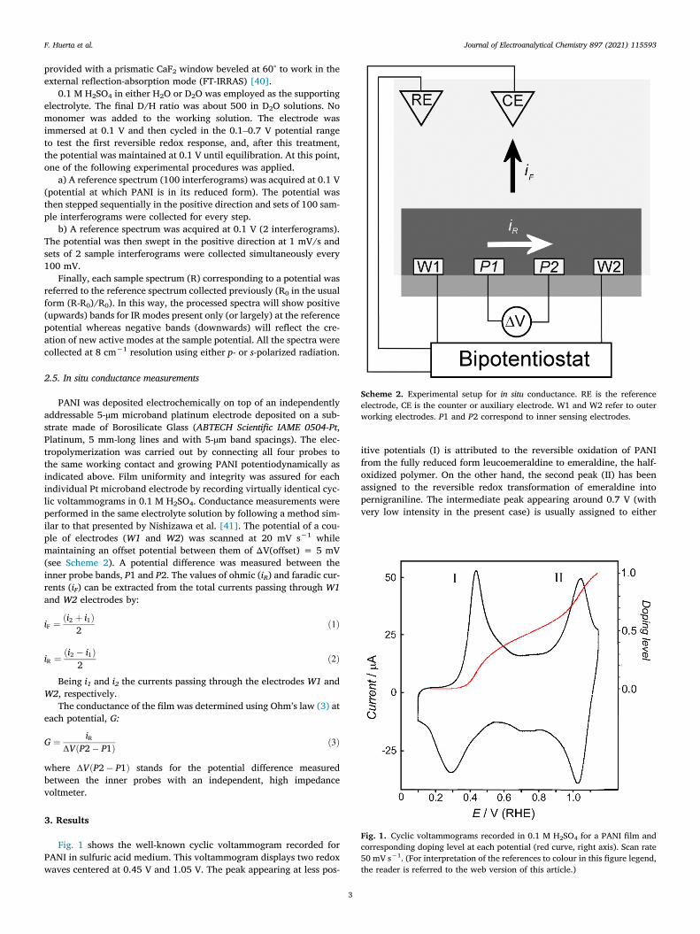
Scheme 2. Experimental setup for in situ conductance. RE is the referenceelectrode, CE is the counter or auxiliary electrode. W1 and W2 refer to outerworking electrodes. P1 and P2 correspond to inner sensing electrodes.
Fig. 1. Cyclic voltammograms recorded in 0.1 M H2SO4 for a PANI film andcorresponding doping level at each potential (red curve, right axis). Scan rate50 mV s−1. (For interpretation of the references to colour in this figure legend,the reader is referred to the web version of this article.)
F. Huerta et al. Journal of Electroanalytical Chemistry 897 (2021) 115593
provided with a prismatic CaF2 window beveled at 60° to work in theexternal reflection-absorption mode (FT-IRRAS) [40].
0.1 M H2SO4 in either H2O or D2O was employed as the supportingelectrolyte. The final D/H ratio was about 500 in D2O solutions. Nomonomer was added to the working solution. The electrode wasimmersed at 0.1 V and then cycled in the 0.1–0.7 V potential rangeto test the first reversible redox response, and, after this treatment,the potential was maintained at 0.1 V until equilibration. At this point,one of the following experimental procedures was applied.
a) A reference spectrum (100 interferograms) was acquired at 0.1 V(potential at which PANI is in its reduced form). The potential wasthen stepped sequentially in the positive direction and sets of 100 sam-ple interferograms were collected for every step.
b) A reference spectrum was acquired at 0.1 V (2 interferograms).The potential was then swept in the positive direction at 1 mV/s andsets of 2 sample interferograms were collected simultaneously every100 mV.
Finally, each sample spectrum (R) corresponding to a potential wasreferred to the reference spectrum collected previously (R0 in the usualform (R-R0)/R0). In this way, the processed spectra will show positive(upwards) bands for IR modes present only (or largely) at the referencepotential whereas negative bands (downwards) will reflect the cre-ation of new active modes at the sample potential. All the spectra werecollected at 8 cm−1 resolution using either p- or s-polarized radiation.
2.5. In situ conductance measurements
PANI was deposited electrochemically on top of an independentlyaddressable 5-µm microband platinum electrode deposited on a sub-strate made of Borosilicate Glass (ABTECH Scientific IAME 0504-Pt,Platinum, 5 mm-long lines and with 5-µm band spacings). The elec-tropolymerization was carried out by connecting all four probes tothe same working contact and growing PANI potentiodynamically asindicated above. Film uniformity and integrity was assured for eachindividual Pt microband electrode by recording virtually identical cyc-lic voltammograms in 0.1 M H2SO4. Conductance measurements wereperformed in the same electrolyte solution by following a method sim-ilar to that presented by Nishizawa et al. [41]. The potential of a cou-ple of electrodes (W1 and W2) was scanned at 20 mV s−1 whilemaintaining an offset potential between them of ΔV(offset) = 5 mV(see Scheme 2). A potential difference was measured between theinner probe bands, P1 and P2. The values of ohmic (iR) and faradic cur-rents (iF) can be extracted from the total currents passing through W1and W2 electrodes by:
iF ¼ ði2 þ i1Þ2
ð1Þ
iR ¼ ði2 � i1Þ2
ð2Þ
Being i1 and i2 the currents passing through the electrodes W1 andW2, respectively.
The conductance of the film was determined using Ohm’s law (3) ateach potential, G:
G ¼ iRΔVðP2� P1Þ ð3Þ
where ΔVðP2� P1Þ stands for the potential difference measuredbetween the inner probes with an independent, high impedancevoltmeter.
3. Results
Fig. 1 shows the well-known cyclic voltammogram recorded forPANI in sulfuric acid medium. This voltammogram displays two redoxwaves centered at 0.45 V and 1.05 V. The peak appearing at less pos-
3
itive potentials (I) is attributed to the reversible oxidation of PANIfrom the fully reduced form leucoemeraldine to emeraldine, the half-oxidized polymer. On the other hand, the second peak (II) has beenassigned to the reversible redox transformation of emeraldine intopernigraniline. The intermediate peak appearing around 0.7 V (withvery low intensity in the present case) is usually assigned to either

Fig. 2. Conductance measured in situ for a PANI thin film against (a) appliedpotential and (b) doping level.
F. Huerta et al. Journal of Electroanalytical Chemistry 897 (2021) 115593
cross-linking between polymer chains [42] or to the appearance ofdiverse hydrolysis products [43,44].
The amount of charge injected into the polymer can be quantifiedby integration of the voltammetric curve in Fig. 1. A value of + 0.76 V(+0.56 V over the oxidation onset) was ascribed to a doping level of0.5, under the assumption that the emeraldine state is attained at apotential corresponding to a charge averaging that passed up to thefirst and that passed up to the second transition peak. Similarly, thepernigraniline state (doping level 1) is reached at twice this value,which corresponds to a potential of + 1.12 V. Details on the calcula-tion of the doping level can be found in the supporting information.The scale for doping level (i.e., electronic charge injected per mono-mer unit) derived from the integration of the voltammetric charge isincluded as the right axis in Fig. 1. The red curve represents the pro-gress of doping level at increasing potential.
We have considered that the current involved after the doping peakcorresponds to surface-confined faradic process in the polymer (pseu-docapacitive current). Although voltammetric currents after the dop-ing process (current plateau) occasionally present capacitivecharacter, it seems more appropriate to take into consideration themolecularity of the system [45]. In this sense the oligomer approach,extensively discussed by Heinze, provides a comprehensive modelfor the electrochemical behaviour of conducting polymers [46]. There-fore, the plateau appearing in the voltammogram between 0.6 and0.8 V in Fig. 1 is mainly due to the overlapped faradaic redox processesof chains with different conjugation lengths. The fact that the polymeris polydisperse favours this effect. In other words, the electrochemicalcharging process of conducting polymers is described by a sequence ofdiscrete but overlapping redox faradic steps.
The doping process of PANI is linked to the formation of conductivespecies, free polarons, which are chemically described as radical enti-ties bearing unpaired electrons. Free polarons can be detected by elec-tron spin resonance (ESR) spectroscopy and visualized as semiquinonerings, as depicted in Scheme 3.
The formation of such species, representing a free charge carrier,stimulates sharp changes in conductivity upon electrochemical oxida-tion [47,48]. Fig. 2 shows in situ conductance measured during theelectrochemical doping of PANI. Below 0.2 V the polymer is still inits reduced (leucoemeraldine) state and, accordingly, presents verylow conductance. Interestingly, at potentials beyond the oxidationonset of the polymer, conductivity fluctuates according to four differ-ent regimes. At the early doping stages, (represented as segment I inFig. 2b) conductance remains low, in the order of 10−6 S at 0.3 V (dop-ing level 0.007), which means that free polaronic species can beneglected in this regime. Conductance increases then exponentiallybetween 0.3 V and 0.4 V (doping level 0.007 to 0.07) with an observedslope close to 29 mV decade−1, as seen in the supporting information,Fig. S3. This number is in the order of magnitude found for other elec-trochemically prepared conducting polymers, such as polypyrroles orpolythiophenes [49,50].
From 0.4 V to 0.65 V (segment III, doping level 0.07 to 0.45) PANIconductance still progresses at increasing doping levels, but at a lowerrate. The highest value recorded, 0.01 S, is almost four orders of mag-nitude larger than the initial value and is reached at 0.62 V (dopinglevel 0.41). From this point, a small charge injection causes conduc-tance to drop softly until the emeraldine redox state is completelyreached (0.77 V, doping level 0.5). Finally, a sharp decrease isrecorded in the potential region corresponding to the transition from
Scheme 3. Initial stage of leucoemeraldine oxidation.
4
emeraldine to pernigraniline state (segment IV). Conductance reacheseventually a value similar to that of the leucoemeraldine initial state.
It is widely accepted that electrochemical oxidation beyond theemeraldine redox state stimulates deprotonation of polymer chains,which is responsible for the lack of conductivity of the polymer whenpernigraniline is formed. In this context, in situ FTIR spectroscopy canbe used to monitor the effect of changing the potential on the chemicalstructure of the polymer. Fig. 3 shows in situ FTIR spectra collected in0.1 M H2SO4/H2O at 0.5 V, 1.0 V and 1.2 V sample potentials for a thinPANI film in the absence of aniline monomer. The reference spectrumwas acquired firstly at 0.1 V, so it contains the vibrational informationcorresponding to the fully reduced form of the polymer. By referringeach of the sample spectra to the single reference collected previously,the group of processed FTIR spectra was obtained.
As shown in Fig. 2, the onset of polymer doping occurs at around0.3 V. The number of chemical changes involved at so low doping levelshould be very scarce. However, in situ FTIR reveals positive (upwards)and negative (downwards) features in the spectra collected at samplepotentials higher than 0.2 V (see Fig. S4 in the Supporting Informa-tion). The intensity of such bands increases at higher potentials andthey can be observed in Fig. 3 at 0.5 V (doping level 0.25), just abovethe first anodic maximum (peak I) on the cyclic voltammogram ofFig. l. The absorption at 1520 cm−1 is usually ascribed to the aromaticCAC ring-stretching vibration of benzenoid rings whereas the feature

Fig. 3. In situ FTIR spectra collected during the oxidation of an electrochem-ically synthesized PANI film in 0.1 M H2SO4/H2O test solution. Referencepotential 0.1 V. Sample potential labeled for each spectrum. 100 interfero-grams at each potential. p-polarized radiation.
F. Huerta et al. Journal of Electroanalytical Chemistry 897 (2021) 115593
at 1290 cm−1 is related to the aromatic ring deformation [25]. Theirpositive character reflects a decrease in the population of benzenoidstructures due to PANI oxidation. In the same way, the positive-goingband at 1220 cm−1 is ascribed to the disappearance of amine stretch-ing modes of leucoemeraldine to yield imine-type bonds [18,25]. Anadditional negative-going broad band can be observed at1592 cm−1, which partially overlaps the uncompensated, strongabsorption coming from H2O bending in the same spectral region. Thisfeature is connected with the C@C stretching of quinoid rings that aregenerated during oxidation [25,51]. Finally, this spectrum shows twonegative-going bands of 1172 and 1350 cm−1. The former is mostlyattributed to in-plane CAH bending in quinoid structures [52] andthe latter to a CAN stretching in semiquinoid units, although the mar-ginal presence of this vibrational mode coming from phenazine-typerings cannot be ruled out [53,54]. At this point, it is worth noting thatthe semiquinoid CAN feature appears at a higher potential than theC@C stretching of quinoid rings (Fig. S4, Supporting Information).
The shape of the spectrum collected at 1.0 V (doping level 0.75)does not differ significantly from that recorded at 0.5 V. The intensifi-cation of the 1520 cm−1 band suggests further oxidation of reducedrings compared to 0.5 V. What seems significant in this spectrum isa very weak band at 2344 cm−1 that reveals the onset of carbon diox-
5
ide formation. This result points to the occurrence of degradation atpotentials lower than those corresponding to peak II on the cyclicvoltammogram, probably through the hydrolysis and mineralizationof terminal defects, as quinone or quinone-imine, in some polymerchains [43]. The CO2 absorption can be better perceived in the spec-trum collected at 1.2 V (doping level >1), a potential at which PANIoveroxidation is significant because is beyond the second oxidationmaximum. It is also noticeable that this latter spectrum shows a strongalteration in the 1100–1500 cm−1 frequency which may revealchanges in the polymer structure due to overoxidation. For instance,the positive-going band peaking at 1609 cm−1 has been attributedin some studies to a disorder-induced CAC aromatic ring stretchingmode [18].
The question that arises at this point is whether or not soluble prod-ucts (apart from CO2) are released from PANI by overoxidation atpotentials around the second oxidation peak. Again, in situ FTIR spec-troscopy can help in carrying out this task thanks to the use of s-polar-ized radiation. Usually, the polarization of the incident IR beam in aplane parallel to the electrode surface (s-polarized) provides a wayto discriminate vibrational modes coming from species present inthe bulk solution, a phenomenon known as the surface selection rulefor electrochemical interfaces [40]. However, owing to the actualthree-dimensional characteristics of a PANI deposit, s-polarized radia-tion is expected not to be fully insensitive to vibrational modes next tothe electrode surface. To focus the study on soluble species, the com-bined use of s-polarized radiation and deuterated water as the solventis preferable because spectral interferences coming from water bend-ing in the surroundings of 1600 cm−1 are avoided. According to thispremise, a set of spectra were collected for the PANI deposit at samplepotentials around peak II in D2O/H2SO4 and the results are shown inFig. 4. The presence of a positive-going band at 1516 cm−1 revealsthe vanishing of aromatic CAC vibrations at 1.0 V in PANI (the refer-ence spectrum was acquired previously at 0.1 V). The activation of thisvibrational mode under s-polarized radiation is associated, as men-tioned above, with the three-dimensional character of the sample.Interestingly, the spectrum obtained at 1.1 V (at around the maximumof the voltammetric peak II) shows an additional clear-cut band cen-tered at 1657 cm−1 whose frequency is characteristic of C@O stretch-ing in soluble quinones [19,39]. The intensity of this feature increasessignificantly at 1.2 V, thus showing an enhanced degradation of PANIchains induced by the potential.
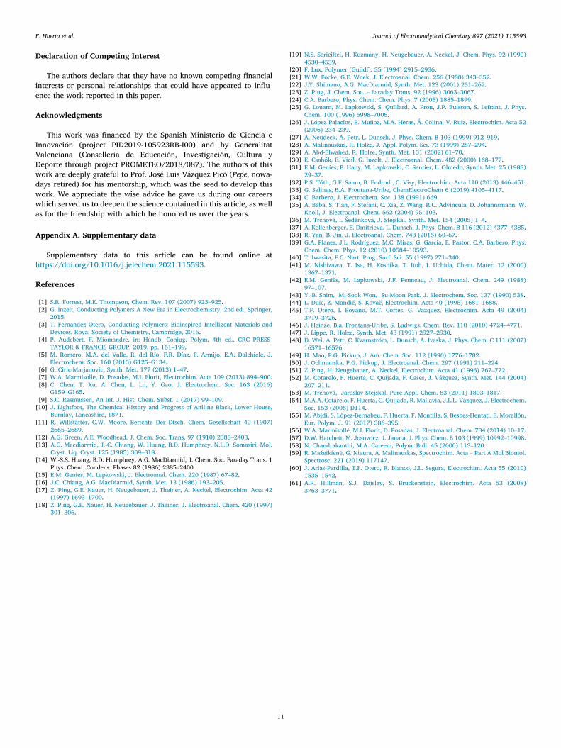
To facilitate a correlation between FTIR spectra and the CV profileduring the gradual oxidation process undergone by PANI from its fullyreduced state, the potential of a thin polymer film in contact with a sul-furic acid electrolyte in deuterated water as the solvent was sweptfrom 0.1 up to 1.2 V, while sample spectra were collected simultane-ously (see the experimental section for details). The results of thisexperiment are shown in Fig. 5, where the intense positive-going bandat 1519 cm−1 (aromatic CAC stretching) reveals the disappearance ofbenzenoid rings and the less intense band at 1594 cm−1 is assigned tothe formation of C@C as a result of polymer oxidation. In addition tothese two main absorptions, the spectra in Fig. 5 show also an overlap-ping band at 1620 cm−1, undetected in Fig. 3 because of H2O absorp-tion. Its position and negative character are both compatible with thepresence of C@N vibrational modes in quinone-imine structures[18,55], but it may also include a contribution from C@C stretchingvibration in phenazine-like segments [53].
Band intensities coming from CAC and C@C vibrations are inte-grated as a function of the applied potential in Fig. 6. The integrationof the latter was carried out between 1573 cm−1 and 1598 cm−1 tominimize interference from the overlapped C@N stretching.
The vanishing of the aromatic CAC stretching mode (red squares)rises sharply at low oxidation potentials and starts leveling off at apotential close to 0.6 V, which corresponds to a doping level of 0.4in Fig. 1. Above 0.6 V the loss of benzenoid rings is negligible (lessthan 6%) when compared to the drop that occurred between 0.3 V
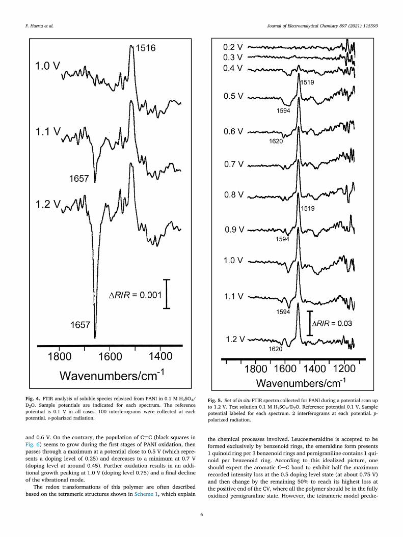
Fig. 4. FTIR analysis of soluble species released from PANI in 0.1 M H2SO4/D2O. Sample potentials are indicated for each spectrum. The referencepotential is 0.1 V in all cases. 100 interferograms were collected at eachpotential. s-polarized radiation.
Fig. 5. Set of in situ FTIR spectra collected for PANI during a potential scan upto 1.2 V. Test solution 0.1 M H2SO4/D2O. Reference potential 0.1 V. Samplepotential labeled for each spectrum. 2 interferograms at each potential. p-polarized radiation.
F. Huerta et al. Journal of Electroanalytical Chemistry 897 (2021) 115593
and 0.6 V. On the contrary, the population of C@C (black squares inFig. 6) seems to grow during the first stages of PANI oxidation, thenpasses through a maximum at a potential close to 0.5 V (which repre-sents a doping level of 0.25) and decreases to a minimum at 0.7 V(doping level at around 0.45). Further oxidation results in an addi-tional growth peaking at 1.0 V (doping level 0.75) and a final declineof the vibrational mode.
The redox transformations of this polymer are often describedbased on the tetrameric structures shown in Scheme 1, which explain
6
the chemical processes involved. Leucoemeraldine is accepted to beformed exclusively by benzenoid rings, the emeraldine form presents1 quinoid ring per 3 benzenoid rings and pernigraniline contains 1 qui-noid per benzenoid ring. According to this idealized picture, oneshould expect the aromatic CAC band to exhibit half the maximumrecorded intensity loss at the 0.5 doping level state (at about 0.75 V)and then change by the remaining 50% to reach its highest loss atthe positive end of the CV, where all the polymer should be in the fullyoxidized pernigraniline state. However, the tetrameric model predic-

Fig. 6. Potential dependence of the normalized integrated band intensity fromPANI aromatic CAC stretching (■) and quinoid C@C stretching (■). Dataobtained from Fig. 5. The doping level of the polymer at selected potentials isalso included.
F. Huerta et al. Journal of Electroanalytical Chemistry 897 (2021) 115593
tions do not match the experimental findings reported in this work.Our results suggest that the voltammetric charge recorded between0.7 V and the maximum of the anodic peak (II) is not consumed inthe transformation of a significant number of benzenoid rings, but itis certainly related to an increase in the population of quinoid rings.Above peak (II), where pernigraniline is the expected redox state,the amount of quinoid structures diminishes whereas the populationof benzenoid rings keeps nearly constant. It can be then concluded thatthe semi-quantitative results obtained by FTIR are difficult to fit withinthe current PANI tetrameric model.
4. Discussion
To make a proper quantification of the in situ FTIR signals appear-ing during the redox transitions of the polymer, 4 different speciesshould be considered according to the intensity of the correspondingabsorption. First, a benzenoid ring in its unoxidized state, which isbonded to secondary nitrogen. For this species, the nitrogen atomshows sp3 hybridization and, consequently, bears a non-bonding orbi-tal with paired electrons. This type of ring presents a strong IR signalascribed to the aromatic CAC stretching mode. The conversion of ben-zenoid into semiquinone species obliges nitrogen to adopt sp2
hybridization and, consequently, to leave a half-filled pz orbital. Thislatter orbital can easily interact with π electrons of the adjacent aro-matic ring disturbing aromaticity, as shown in Scheme 4, and thereforethe IR signal coming from the aromatic CAC stretching mode in semi-quinones is very weak.
Deeper oxidation of the ring yields a quinoid species bonded toimine nitrogen that can be either protonated (as in emeraldine) orunprotonated (as in pernigraniline). In this case, the term protonationrefers to changes in the protonation level of the rings involved in theredox transition (not to the absolute protonation of the material).For example, leucoemeraldine is presented in base form (for visualclarity) but it is worth noting that part of the amine nitrogens in thismaterial should be protonated [56,57].
As detected by in situ FTIR, the absorption intensity of the quinoidC@C stretching mode seems strongly influenced by its chemical envi-ronment. This effect was already reported [58] and ascribed to therelease of a proton upon oxidation, which probably increases the sym-
7
metry of the absorbing center thus affecting absorptivity. Similarbehavior was described in [23], where a noticeable intensity loss ofthe vibrational modes associated with oxidized units was observedupon deprotonation of emeraldine salt. As a result, the IR signal forthe unprotonated quinoid ring weakens. In Table 1, the four-ring struc-tures that can be present in PANI at different oxidation states arerepresented.
As discussed in Fig. 2, the presence of free polaron species (semi-quinone in Table 1) was not detected below 0.3 V by conductivitymeasurements. This result agrees with the in situ FTIR spectrum shownin Fig. 2S (SI), for which the band assigned to protonated quinoid spe-cies (~1580 cm−1) appears at potentials lower than those correspond-ing to the CAN stretching in semiquinoid units (~1330 cm−1). Thesefindings do not necessarily preclude the formation of radical cationspecies at doping levels below 0.004 e/monomer. They may occur as“isolated polarons” (in connection with the increase of the 430-nmoptical absorption [28]) at too low a concentration to be discernedby our FTIR measurements. Interestingly, recent differential Ramanspectra of polyaniline films subjected to low anodic potentials in acidicmedia showed no bands lying within 1320–1340 cm−1 (polaron CANvibrations), even at laser excitation wavelengths giving rise to reso-nant enhancement of spectral features related to the oxidized formsof the polymer [59]. However, our experimental evidence suggest thatthe formation of protonated quinone-imine is favoured at dopinglevels below 0.004. In any case, neither protonated quinone-iminenor isolated radical cations provide significant conductivity to thepolymer at this stage. According to this interpretation, the main redoxtransition occurring at the early stages of doping is represented inScheme 5.
Within the 0.3–0.4 V potential window, which corresponds to dop-ing values ranging between 0.004 and 0.1, there is a significant vanish-ing of aromatic vibrational modes and a concomitant growth of nearly4 orders of magnitude in conductance. FTIR band intensity quantifica-tion suggests that each protoemeraldine octamer, the prevalent redoxstate at 0.5 V (doping level ~0.25), contains one protonated quinone-imine moiety (colored in orange), two protonated amine rings (blue)and five unprotonated aromatic rings (white). Such an arrangementis in essence similar to the bottom structure in Scheme 5. The sharpconductivity growth throughout this doping regime, together withthe development of the CAN stretching in semiquinoid units, revealthe progressive formation of a resonant, electron-conducting protoe-meraldine structure containing semiquinone rings.
In Fig. 6, the FTIR features of the protoemeraldine-emeraldine con-version between 0.5 and 0.7 V reveal an additional vanishing of ben-zenoid (white) rings in parallel to a decrease in the population ofquinoneimines (orange). This result along with the measured increasein conductance, which reaches its maximum value at 0.6 V (dopinglevel 0.4), strongly suggests the formation of two emeraldine resonantforms for which semiquinone (blue) rings are prevalent, as depicted inScheme 6. In terms of the current tetrameric structure (Scheme 1) theresonance hybrid would be interpreted as having a proportion of 25%in bipolaronic and 75% in semiquinone moieties at different polymerchains.
The upper structure in Scheme 6 was already proposed by Lux tomodel the conductivity of solid-state PANI [20] and implies the coexis-tence of bipolaronic and polaronic centers in the same chain. From thein situ FTIR standpoint, since only 3 or 4white rings remain, bipolaronicand semiquinoid structures could both explain a maximum intensitydecay of the aromatic CAC absorption at 0.8 V. However, the decreaseof the quinoid band intensity to, roughly, half of its maximum value ataround this potential (see Fig. 6) implies that the resonance hybrid isthe most suitable description of the emeraldine redox state.
According to Fig. 6, as the oxidation proceeds above 0.8 V, thenumber of unprotonated aromatic rings remains constant but quinoidstructures are progressively recovered. As a result, the conjugationlength is shortened and hence conductance deteriorates during the

Scheme 4. First oxidation step of polyaniline.
Table 1Ring structures present in PANI and observed intensity of the IR absorption.
Scheme 5. Redox transition of PANI at doping level <0.25. The leucomeraldine structure is represented in the base form for the sake of visual simplicity.
Scheme 6. Resonant forms of the emeraldine state at 0.76 V (doping level 0.50).
F. Huerta et al. Journal of Electroanalytical Chemistry 897 (2021) 115593
8

Scheme 7. Emeraldine to nigraniline (E >0.7 V) and nigraniline to pernigraniline redox transition (E >1.0 V).
F. Huerta et al. Journal of Electroanalytical Chemistry 897 (2021) 115593
emeraldine-nigraniline transformation (see Fig. 2). The polymerfinally reaches the nigraniline redox state at a doping level of 0.75,which occurs in the surroundings of 1.0 V. This process is illustratedin the first step of Scheme 7, where no separate polarons are repre-sented for nigraniline because the high concentration of charges favorsthe formation of unprotonated bipolaronic species (red rings) which,as deduced from Fig. 6, show weak infrared adsorption. Further oxida-tion beyond 1.0 V leads to the formation of the unprotonated, insulat-ing form of PANI, pernigraniline [24]. As deduced from the spectra inFig. 3, this redox transition is accompanied by the rupture of somepolymer chains yielding soluble quinones and carbon dioxide.
Fig. 7. Comprehensive model proposed for the redox transformations of PANI. Thisdifferent doping levels.
9
As mentioned above, the overall redox response of PANI is cur-rently described based on a tetrameric model. However, a better cor-relation between CAC vibrational modes and ring structures atdifferent redox states can be found from the octameric model proposedin Schemes 5-7. This correlation, which relies on the quality of themolecular structure of synthesized PANI, will be more representativefor long, linear polymeric chains and is not appropriate for describingthe redox behavior of this material in crosslinking or overoxidizedregions, among other chemical defects. The complete representationof PANI redox transitions can be found in Fig. 7, which also includesscales for doping level and applied potential.
model summarizes the predominant chemical structures of a PANI octamer at

F. Huerta et al. Journal of Electroanalytical Chemistry 897 (2021) 115593
Based on that figure and according to the usual form of represent-ing PANI redox states, the contribution of each particular ring struc-ture to the corresponding redox state has been summarized inTable 2. Fractional numbers account for the partial contribution of res-onance hybrids to each redox state.
The octameric model succeeds also in describing the relative inten-sity changes of IR absorptions during the potential excursion from theleucoemeraldine undoped state to the pernigraniline form. In Table 3,the experimental IR band intensities obtained from Fig. 6 for aromaticCAC and quinoid C@C stretching vibrations are collected. If a compar-ison is made with the intensity predicted from the octameric model, agood correlation is found, with the only discrepancy occurring for thenigraniline to pernigraniline transition.
Although the prediction qualitatively agrees with the observeddecrease in both purely aromatic and protonated quinone-imine bandintensities, the number of aromatic rings detected is lower thanexpected (a drop from 1 to 0.96 instead of 0.80) while the amountof protonated quinone-imine rings is higher than that suggested bythe model (0.63). The sharp conductivity loss caused by deprotonationof emeraldine to yield pernigraniline (segment IV in Fig. 2) seems to beat the origin of these divergences. During this process, small, conduct-ing domains of the polymer may become electrically isolated bybroader insulating areas that most likely prevent them from reachingfull oxidation to the pernigraniline state. The fast undoping processcauses similar effects to other conducting polymers, giving rise toion trapping phenomena, [60,61], where associated dopant anions/protons remain surrounded by an insulating matrix and are electricallyretained within the polymer instead of being released. In the presentcase, the survival of small conducting domains embedded in a depro-tonated pernigraniline dielectric structure would give rise to a recov-ery of purely aromatic structures lower than expected during thenigraniline to pernigraniline transition. The same argument appliesto explain the unexpected prevalence of protonated quinone-imineunits in the pernigraniline state. Furthermore, another effect thatmay cause a deviation from model predictions arises from the poten-tial-induced degradation suffered by the polymer above 1.0 V (Figs. 3and 4) which probably disturbs the accurate quantification of speciesby FTIR at so high potential.
5. Conclusions
Cyclic voltammetry, in situ conductance and in situ FTIR spectroscopymeasurements were combined to gain deeper insight on the redox tran-
Table 2Chemical speciation of PANI rings according to the octameric model.
Strong IR absorption
Purely aromatic Protonated quinone-
Leucoemeraldine 8 0Protoemeraldine 5 1Emeraldine 3.5 0.5Nigraniline 3 1Pernigraniline 4 0
Table 3Relative IR band intensity predicted by the octameric model and experimental value
Purely aromatic (white)
Predicted Experim
Leucoemeraldine 0 0Protoemeraldine 0.60 0.58Emeraldine 0.90 0.94Nigraniline 1.00 1.00Pernigraniline 0.80 0.96
10
sitions of PANI in acidicmedium. A return from the current 4-ring struc-ture of PANI to the classical octameric model has been proposed torationalize the results of the semiquantitative spectroscopic analysis.
In situ FTIR spectra of PANI are dominated by the aromatic CACstretching (at around 1520 cm−1) and the quinoid C@C stretching(1590 cm−1) vibrations, whose intensity is found to be strongly influ-enced by the protonation level of the adjacent nitrogen atoms. In thisway, PANI redox transitions stimulate changes in both CAC absorp-tions as they are associated with deep changes in the acidity ofamine/imine bonds. It is suggested that the intensity of the aromaticCAC stretching located at radical cations weakens as a consequenceof the change in nitrogen hybridization from sp3 to sp2. According tothe semiquantitative redox model proposed, the population of aro-matic rings reaches a minimum at the onset of emeraldine state andtherefore these species are no longer (quantitatively) involved in sub-sequent redox transitions.
The emeraldine state is better described as a resonance hybrid ofthe classical bipolaronic and the semiquinoid (polaron lattice) struc-tures. The observation that the population of protonated quinone-imine rings fluctuates at increasing potentials is interpreted in termsof the compromise reached between injected charge and resonantstructures. Understanding these processes seems essential to make asuitable correlation between IR spectra, conductance, chemical struc-ture and applied potential.
Finally, it is confirmed that most of the charge transferred at theonset of the second voltammetric peak comes from the additional oxi-dation of the resonance hybrid, which becomes unstable in the electro-chemical environment producing mineralization to CO2 and release ofsoluble quinones. According to this, pernigraniline should contain asignificant amount of broken polymer chains with lower conjugationlength, a picture that is supported by in situ conductance measure-ments. The most conducting form of PANI is obtained at a doping levelclose to 0.4, slightly below the actual emeraldine redox state.
CRediT authorship contribution statement
F. Huerta: Conceptualization, Investigation, Methodology, Formalanalysis, Visualization, Writing - original draft, Writing - review & edit-ing. C. Quijada: Validation, Formal analysis, Visualization, Writing -review & editing. F. Montilla: Methodology, Investigation, Formalanalysis, Visualization, Writing - original draft, Writing - review & edit-ing. E. Morallón: Funding acquisition, Supervision, Visualization,Writing - review & editing.
Weak IR absorption
imine Semiquinone Unprotonated quinone-imine
0 02 04 02 20 4
s.
Protonated quinone-imine (orange)
ental Predicted Experimental
0 01.00 0.800.50 0.431.00 1.000 0.63
F. Huerta et al. Journal of Electroanalytical Chemistry 897 (2021) 115593
Declaration of Competing Interest
The authors declare that they have no known competing financialinterests or personal relationships that could have appeared to influ-ence the work reported in this paper.
Acknowledgments
This work was financed by the Spanish Ministerio de Ciencia eInnovación (project PID2019-105923RB-I00) and by GeneralitatValenciana (Conselleria de Educación, Investigación, Cultura yDeporte through project PROMETEO/2018/087). The authors of thiswork are deeply grateful to Prof. José Luis Vázquez Picó (Pepe, nowa-days retired) for his mentorship, which was the seed to develop thiswork. We appreciate the wise advice he gave us during our careerswhich served us to deepen the science contained in this article, as wellas for the friendship with which he honored us over the years.
Appendix A. Supplementary data
Supplementary data to this article can be found online athttps://doi.org/10.1016/j.jelechem.2021.115593.
References
[1] S.R. Forrest, M.E. Thompson, Chem. Rev. 107 (2007) 923–925.[2] G. Inzelt, Conducting Polymers A New Era in Electrochemistry, 2nd ed., Springer,
2015.[3] T. Fernandez Otero, Conducting Polymers: Bioinspired Intelligent Materials and
Devices, Royal Society of Chemistry, Cambridge, 2015.[4] P. Audebert, F. Miomandre, in: Handb. Conjug. Polym, 4th ed., CRC PRESS-
TAYLOR & FRANCIS GROUP, 2019, pp. 161–199.[5] M. Romero, M.A. del Valle, R. del Río, F.R. Díaz, F. Armijo, E.A. Dalchiele, J.
Electrochem. Soc. 160 (2013) G125–G134.[6] G. Ciric-Marjanovic, Synth. Met. 177 (2013) 1–47.[7] W.A. Marmisolle, D. Posadas, M.I. Florit, Electrochim. Acta 109 (2013) 894–900.[8] C. Chen, T. Xu, A. Chen, L. Lu, Y. Gao, J. Electrochem. Soc. 163 (2016)
G159–G165.[9] S.C. Rasmussen, An Int. J. Hist. Chem. Subst. 1 (2017) 99–109.[10] J. Lightfoot, The Chemical History and Progress of Aniline Black, Lower House,
Burnlay, Lancashire, 1871.[11] R. Willstätter, C.W. Moore, Berichte Der Dtsch. Chem. Gesellschaft 40 (1907)
2665–2689.[12] A.G. Green, A.E. Woodhead, J. Chem. Soc. Trans. 97 (1910) 2388–2403.[13] A.G. Macdiarmid, J.-C. Chiang, W. Huang, B.D. Humphrey, N.L.D. Somasiri, Mol.
Cryst. Liq. Cryst. 125 (1985) 309–318.[14] W.-S.S. Huang, B.D. Humphrey, A.G. MacDiarmid, J. Chem. Soc. Faraday Trans. 1
Phys. Chem. Condens. Phases 82 (1986) 2385–2400.[15] E.M. Genies, M. Lapkowski, J. Electroanal. Chem. 220 (1987) 67–82.[16] J.C. Chiang, A.G. MacDiarmid, Synth. Met. 13 (1986) 193–205.[17] Z. Ping, G.E. Nauer, H. Neugebauer, J. Theiner, A. Neckel, Electrochim. Acta 42
(1997) 1693–1700.[18] Z. Ping, G.E. Nauer, H. Neugebauer, J. Theiner, J. Electroanal. Chem. 420 (1997)
301–306.
11
[19] N.S. Sariciftci, H. Kuzmany, H. Neugebauer, A. Neckel, J. Chem. Phys. 92 (1990)4530–4539.
[20] F. Lux, Polymer (Guildf). 35 (1994) 2915–2936.[21] W.W. Focke, G.E. Wnek, J. Electroanal. Chem. 256 (1988) 343–352.[22] J.Y. Shimano, A.G. MacDiarmid, Synth. Met. 123 (2001) 251–262.[23] Z. Ping, J. Chem. Soc. – Faraday Trans. 92 (1996) 3063–3067.[24] C.A. Barbero, Phys. Chem. Chem. Phys. 7 (2005) 1885–1899.[25] G. Louarn, M. Lapkowski, S. Quillard, A. Pron, J.P. Buisson, S. Lefrant, J. Phys.
Chem. 100 (1996) 6998–7006.[26] J. López-Palacios, E. Muñoz, M.A. Heras, Á. Colina, V. Ruiz, Electrochim. Acta 52
(2006) 234–239.[27] A. Neudeck, A. Petr, L. Dunsch, J. Phys. Chem. B 103 (1999) 912–919.[28] A. Malinauskas, R. Holze, J. Appl. Polym. Sci. 73 (1999) 287–294.[29] A. Abd-Elwahed, R. Holze, Synth. Met. 131 (2002) 61–70.[30] E. Csahók, E. Vieil, G. Inzelt, J. Electroanal. Chem. 482 (2000) 168–177.[31] E.M. Genies, P. Hany, M. Lapkowski, C. Santier, L. Olmedo, Synth. Met. 25 (1988)
29–37.[32] P.S. Tóth, G.F. Samu, B. Endrodi, C. Visy, Electrochim. Acta 110 (2013) 446–451.[33] G. Salinas, B.A. Frontana-Uribe, ChemElectroChem 6 (2019) 4105–4117.[34] C. Barbero, J. Electrochem. Soc. 138 (1991) 669.[35] A. Baba, S. Tian, F. Stefani, C. Xia, Z. Wang, R.C. Advincula, D. Johannsmann, W.
Knoll, J. Electroanal. Chem. 562 (2004) 95–103.[36] M. Trchová, I. Šeděnková, J. Stejskal, Synth. Met. 154 (2005) 1–4.[37] A. Kellenberger, E. Dmitrieva, L. Dunsch, J. Phys. Chem. B 116 (2012) 4377–4385.[38] R. Yan, B. Jin, J. Electroanal. Chem. 743 (2015) 60–67.[39] G.A. Planes, J.L. Rodríguez, M.C. Miras, G. García, E. Pastor, C.A. Barbero, Phys.
Chem. Chem. Phys. 12 (2010) 10584–10593.[40] T. Iwasita, F.C. Nart, Prog. Surf. Sci. 55 (1997) 271–340.[41] M. Nishizawa, T. Ise, H. Koshika, T. Itoh, I. Uchida, Chem. Mater. 12 (2000)
1367–1371.[42] E.M. Geniès, M. Lapkowski, J.F. Penneau, J. Electroanal. Chem. 249 (1988)
97–107.[43] Y.-B. Shim, Mi-Sook Won, Su-Moon Park, J. Electrochem. Soc. 137 (1990) 538.[44] L. Duić, Z. Mandić, S. Kovač, Electrochim. Acta 40 (1995) 1681–1688.[45] T.F. Otero, I. Boyano, M.T. Cortes, G. Vazquez, Electrochim. Acta 49 (2004)
3719–3726.[46] J. Heinze, B.a. Frontana-Uribe, S. Ludwigs, Chem. Rev. 110 (2010) 4724–4771.[47] J. Lippe, R. Holze, Synth. Met. 43 (1991) 2927–2930.[48] D. Wei, A. Petr, C. Kvarnström, L. Dunsch, A. Ivaska, J. Phys. Chem. C 111 (2007)
16571–16576.[49] H. Mao, P.G. Pickup, J. Am. Chem. Soc. 112 (1990) 1776–1782.[50] J. Ochmanska, P.G. Pickup, J. Electroanal. Chem. 297 (1991) 211–224.[51] Z. Ping, H. Neugebauer, A. Neckel, Electrochim. Acta 41 (1996) 767–772.[52] M. Cotarelo, F. Huerta, C. Quijada, F. Cases, J. Vázquez, Synth. Met. 144 (2004)
207–211.[53] M. Trchová, Jaroslav Stejskal, Pure Appl. Chem. 83 (2011) 1803–1817.[54] M.A.A. Cotarelo, F. Huerta, C. Quijada, R. Mallavia, J.L.L. Vázquez, J. Electrochem.
Soc. 153 (2006) D114.[55] M. Abidi, S. López-Bernabeu, F. Huerta, F. Montilla, S. Besbes-Hentati, E. Morallón,
Eur. Polym. J. 91 (2017) 386–395.[56] W.A. Marmisollé, M.I. Florit, D. Posadas, J. Electroanal. Chem. 734 (2014) 10–17.[57] D.W. Hatchett, M. Josowicz, J. Janata, J. Phys. Chem. B 103 (1999) 10992–10998.[58] N. Chandrakanthi, M.A. Careem, Polym. Bull. 45 (2000) 113–120.[59] R. Mažeikienė, G. Niaura, A. Malinauskas, Spectrochim. Acta – Part A Mol Biomol.
Spectrosc. 221 (2019) 117147.[60] J. Arias-Pardilla, T.F. Otero, R. Blanco, J.L. Segura, Electrochim. Acta 55 (2010)
1535–1542.[61] A.R. Hillman, S.J. Daisley, S. Bruckenstein, Electrochim. Acta 53 (2008)
3763–3771.