Deposition of polyaniline on RVC electrodes: effect of substrate thickness
10
ORIGINAL PAPER Deposition of polyaniline on RVC electrodes: effect of substrate thickness Carla Dalmolin & Sonia R. Biaggio & Romeu C. Rocha-Filho & Nerilso Bocchi Received: 15 April 2006 / Revised: 28 June 2006 / Accepted: 11 July 2006 / Published online: 23 September 2006 # Springer-Verlag 2006 Abstract Polyaniline films, obtained by either chemical or electrochemical deposition on reticulated vitreous carbon (RVC), were investigated as a function of the substrate thickness. The electrochemical properties of these RVC/Pani electrodes were assessed by cyclic voltammetry and electro- chemical impedance spectroscopy (EIS), whereas the mor- phology of the Pani films on RVC was analyzed by scanning electron microscopy (SEM). The cyclic voltammetric results revealed that the oxidation/reduction charges for electro- deposited polyaniline decrease as the RVC thickness is increased. Conversely, the charge densities for the chemi- cally deposited films do not present a significant dependence on the substrate thickness. Two time constants, appearing in all the EIS spectra, indicate that an ohmic drop effect within the RVC substrate affects the polymer electrodeposition and the electrochemical behavior of the obtained electrodes. Therefore, an electric equivalent circuit considering the different electrochemical environments at the outer and inner RVC surfaces was proposed to analyze the EIS data. Keywords Polyaniline electrodeposition . Reticulated vitreous carbon . Impedance spectroscopy . Tridimensional electrodes . RVC thickness Introduction Wang [1] originally introduced reticulated vitreous carbon (RVC) as a promising material for electrochemical applica- tions. RVC (also referred to as carbon foam) is described as an open-pore material having a honeycomb or foamy structure, composed of non-porous vitreous carbon. This tridimensional (3-D) porous structure leads to a high macroscopic surface area and a low density. The RVC surface is easily modified by various materials, including conducting polymers [2]. In the last decades, RVC was used for many electrochemical purposes, especially as modified electrodes for batteries and electroanalysis [2–6]. Recently, Friedrich et al. [7] presented an illustrated review of RVC as an electrode material, encompassing applications such as electroanalytical studies and sensors, metal ion removal, synthesis of organics and Fenton’ s reagent, H 2 O 2 production and batteries/fuel cells. They also analyzed the physical structure of RVC by using scanning electron microscopy. In spite of all the advantages presented by RVC electrodes, it was only in this decade that this material was employed as a substrate for conducting polymer deposition, especially in applications where a high surface area is intended. The effect of the electrodeposition conditions of polypyrrole (PPy) and polyaniline (Pani) films onto RVC substrates on the remedi- ation of Cr(VI) by its reduction in aqueous media was analyzed by Rodriguez et al. [8] and by Ruotolo et al. [9, 10]. RVC/PPy composites were prepared either to recover Cu(II) from diluted acidic solutions [11] or to separate and recover gold and other metal ions with a high degree of efficiency and selectivity [12]. RVC electrodes were also employed as host substrates for the electrochemical deposition of heparin- doped polypyrrole, resulting in a new method for purifica- tion of thrombin [13]. Tsutsumi et al. [14] developed an electrode for lithium ion batteries using chemically prepared polyaniline deposited onto reticulated vitreous carbon. This electrode showed good performance during the first cycles, although a capacity fade was observed due to peeling of the polymer from the substrate. Furthermore, RVC–polyaniline– Pd electrodes were investigated for hydrogen sorption [15]. J Solid State Electrochem (2007) 11:609–618 DOI 10.1007/s10008-006-0206-z C. Dalmolin : S. R. Biaggio (*) : R. C. Rocha-Filho : N. Bocchi Departamento de Química, Universidade Federal de São Carlos, C.P. 676, 13560-970 São Carlos-SP, Brazil e-mail: [email protected]
Transcript of Deposition of polyaniline on RVC electrodes: effect of substrate thickness

ORIGINAL PAPER
Deposition of polyaniline on RVC electrodes: effectof substrate thickness
Carla Dalmolin & Sonia R. Biaggio &
Romeu C. Rocha-Filho & Nerilso Bocchi
Received: 15 April 2006 / Revised: 28 June 2006 /Accepted: 11 July 2006 / Published online: 23 September 2006# Springer-Verlag 2006
Abstract Polyaniline films, obtained by either chemical orelectrochemical deposition on reticulated vitreous carbon(RVC), were investigated as a function of the substratethickness. The electrochemical properties of these RVC/Panielectrodes were assessed by cyclic voltammetry and electro-chemical impedance spectroscopy (EIS), whereas the mor-phology of the Pani films on RVC was analyzed by scanningelectron microscopy (SEM). The cyclic voltammetric resultsrevealed that the oxidation/reduction charges for electro-deposited polyaniline decrease as the RVC thickness isincreased. Conversely, the charge densities for the chemi-cally deposited films do not present a significant dependenceon the substrate thickness. Two time constants, appearing inall the EIS spectra, indicate that an ohmic drop effect withinthe RVC substrate affects the polymer electrodeposition andthe electrochemical behavior of the obtained electrodes.Therefore, an electric equivalent circuit considering thedifferent electrochemical environments at the outer and innerRVC surfaces was proposed to analyze the EIS data.
Keywords Polyaniline electrodeposition .
Reticulated vitreous carbon . Impedance spectroscopy .
Tridimensional electrodes . RVC thickness
Introduction
Wang [1] originally introduced reticulated vitreous carbon(RVC) as a promising material for electrochemical applica-tions. RVC (also referred to as carbon foam) is described as
an open-pore material having a honeycomb or foamystructure, composed of non-porous vitreous carbon. Thistridimensional (3-D) porous structure leads to a highmacroscopic surface area and a low density. The RVCsurface is easily modified by various materials, includingconducting polymers [2]. In the last decades, RVC was usedfor many electrochemical purposes, especially as modifiedelectrodes for batteries and electroanalysis [2–6]. Recently,Friedrich et al. [7] presented an illustrated review of RVC asan electrode material, encompassing applications such aselectroanalytical studies and sensors, metal ion removal,synthesis of organics and Fenton’s reagent, H2O2 productionand batteries/fuel cells. They also analyzed the physicalstructure of RVC by using scanning electron microscopy.
In spite of all the advantages presented by RVC electrodes,it was only in this decade that this material was employed as asubstrate for conducting polymer deposition, especially inapplications where a high surface area is intended. The effectof the electrodeposition conditions of polypyrrole (PPy) andpolyaniline (Pani) films onto RVC substrates on the remedi-ation of Cr(VI) by its reduction in aqueous media wasanalyzed by Rodriguez et al. [8] and by Ruotolo et al. [9, 10].RVC/PPy composites were prepared either to recover Cu(II)from diluted acidic solutions [11] or to separate and recovergold and other metal ions with a high degree of efficiencyand selectivity [12]. RVC electrodes were also employed ashost substrates for the electrochemical deposition of heparin-doped polypyrrole, resulting in a new method for purifica-tion of thrombin [13]. Tsutsumi et al. [14] developed anelectrode for lithium ion batteries using chemically preparedpolyaniline deposited onto reticulated vitreous carbon. Thiselectrode showed good performance during the first cycles,although a capacity fade was observed due to peeling of thepolymer from the substrate. Furthermore, RVC–polyaniline–Pd electrodes were investigated for hydrogen sorption [15].
J Solid State Electrochem (2007) 11:609–618DOI 10.1007/s10008-006-0206-z
C. Dalmolin : S. R. Biaggio (*) : R. C. Rocha-Filho :N. BocchiDepartamento de Química, Universidade Federal de São Carlos,C.P. 676, 13560-970 São Carlos-SP, Brazile-mail: [email protected]

Polyaniline itself has received much attention for a widerange of technological applications, such as sensors,electrochromic displays, supercapacitors and batteries [16,17], where its high surface area is an important advantage.Dinh and Birss [18] investigated the effect of the substrate(glassy carbon, Au and Pt) on the properties of electro-chemically deposited Pani films and found that the film’sgrowth rate, electrochemical properties and morphologicalcharacteristics are significantly affected by the substrate.Moreover, since RVC electrodes are tridimensional, theirproperties are critically dependent on the potential distri-bution generated within their structure [19, 20].
Although various studies using RVC as substrate forelectropolymerization were reported, not many concern thedependence of the final electrode properties on the substrate3-D features. Recently, we have reported some differencesbetween the Pani electropolymerization process ontocarbon fiber (CF), a 2-D substrate, and onto RVC [21].The electrochemical properties of CF/Pani and RVC/Panielectrodes were investigated by cyclic voltammetry andelectrochemical impedance spectroscopy (EIS); the differ-ences between the two electrodes were analyzed based onthe substrates’ geometry, since for a 3-D electrode apotential gradient across its thickness should be considered.In this context, Lassia [22] reported some EIS analyses ofporous electrodes, based on de Levie’s models for bidimen-sional and microporous electrodes [23], where a concentra-tion gradient of the electroactive species inside the pores isalways considered. However, this assumption does not holdfor the macroporous 3-D RVC electrodes, since thehomogeneous macropores do not hinder the influx of theelectroactive species; nevertheless, a limited current pene-tration depth is always observed [19] and a new approach tothe EIS analysis should be envisaged.
Thus, taking into account that RVC can be considered asa substrate to prepare high surface area Pani electrodesand that a more detailed analysis of the previously reportedresults [21] was intended, in this work polyanilinedeposition is carried out as a function of the RVCthickness, aiming at understanding and minimizing theohmic drop effect in the RVC/Pani electrodes. Theelectrochemical and morphological properties of Pani filmsproduced via electropolymerization or chemical synthesisare analyzed by means of cyclic voltammetry, electro-chemical impedance spectroscopy and scanning electronmicroscopy.
Materials and methods
The substrate (80-ppi RVC from ERG, USA) was cut intopieces ∼1.0-cm high, ∼0.5-cm wide (or ∼1.5-cm wide forthe two thicker electrodes), of various thicknesses: 1/16 in.
(0.19 cm), 1/8 in. (0.38 cm), 1/4 in. (0.76 cm) and 3/8 in.(1.14 cm). The corresponding specific surface areas foreach RVC electrode were calculated based on the ratiosurface area/volume reported by Friedrich et al. [7] for 80-ppi RVC, that is, 50 cm−1. Before any electrochemicalmeasurement, the RVC pieces were left in contact with theworking electrolyte for at least 24 h to ensure theircomplete wetting. The Pani electrosynthesis were carriedout potentiodynamically for 300 voltammetric cycles in a0.5 M H2SO4/0.1 M aniline solution, according to apreviously reported procedure [21, 24]. The initial 3 cycleswere imposed at a slower sweep rate over a wider potentialrange, to activate a higher number of anilinium radicalcations necessary to initiate the polymerization.
To analyze Pani films whose substrate thicknesses wouldnot affect the polymer deposition, chemical depositionswere also performed. Thus, the emeraldine salt of polyani-line was chemically synthesized by oxidative polymeriza-tion of aniline in aqueous 1 M H2SO4 containingammonium persulfate at −2.0 °C, based on a procedurecarried out by a group of laboratories [25] using excess HCl(instead of H2SO4). The obtained green powder was treatedwith 1 M NH4OH and the resulting emeraldine base wasthen dissolved in N-methylpyrrolidinone (NMP). The RVCsubstrates were immersed in the Pani/NMP solution forabout 5 min; after, the obtained RVC/Pani electrodes werekept at 80 °C under vacuum for 48 h so the NMPevaporated.
The electrochemical experiments were carried out in aconventional three-electrode Pyrex-glass cell containingRVC/Pani as working electrode, a Pt cylindric grid as counterelectrode and a saturated calomel electrode (SCE) asreference, which were connected to an ECOCHEMIEPGSTAT 20 general purpose electrochemical system andfrequency response analyzer. Both the voltammetric and theEIS measurements were made in a 0.5 M H2SO4 solutionkept at room temperature (ca. 25 °C). In the voltammetrictests, the electrode potential was scanned for up to 200 cyclesbetween −0.3 V and 0.69 V (SCE) at 100 mV s−1 and thecorresponding electrical charges were measured. The imped-ance spectra were obtained potentiostatically, from −0.20 Vto 0.60 V (SCE) in steps of 0.10 V. The frequency of the acsignal with an amplitude of 10 mV (rms) was varied in the10 mHz to 10 kHz frequency range. An equilibration time of600 s was set at each dc potential before the EIS measure-ments were started. A non-linear least square (NLLS)method was used to fit an electrical equivalent circuit tothe obtained data [26].
The morphological characteristics of the RVC/Panielectrodes were investigated using a 960 DSM Zeissscanning electron microscope. The inner surface of theRVC substrates was accessed by a sectional cut along thecenter of the electrode.
610 J Solid State Electrochem (2007) 11:609–618

Results and discussion
Voltammetric profiles and morphology
Voltammetric profiles for the chemically prepared polyanilinedeposited onto RVC with different thicknesses are shown inFig. 1. The electrochemical behavior is quite similar for allthicknesses, although the current intensities increase with thesubstrate thickness due to the increase of the substrate realarea. A faradaic process is observed in the anodic scan,corresponding to the oxidation process of the insulating formof polyaniline (leucoemeraldine) to its conducting form(emeraldine). On the reverse scan, a cathodic faradaic processindicates the reduction of emeraldine. The subsequenttransition (emeraldine to pernigranile) is not evident due tothe low positive potential limit, as required for better filmproperties to be used as electrodes in batteries [24]. The Panideposited films showed good stability and adherence to theRVC substrate, since the electrical charge associated to therespective voltammograms did not change significantly evenafter 200 cycles. For thicker substrates the potential separa-tion between the anodic and cathodic peaks is larger. Thisfeature is usually found for thick polyaniline films, sinceelectrolyte access to the polymer is hindered and therefore theredox processes are slowed down [24]. However, this shouldnot be the case for the films presently analyzed. In thechemical depositions where electrodes are immersed in thepolymer solution, the thickness of the Pani films should bedependent only on the polymer concentration and theimmersion time, regardless of the substrate thickness.Scanning electron micrographs of chemically synthesizedpolyaniline films deposited on 1/8 in.-thick RVC (see Fig. 2)reveal the formation of a uniform, compact film. These film
micrographs along with the voltammetric responses (seebelow) indicate that the amount of chemically depositedpolyaniline is very low, thus leading to the formation of verythin films. Hence, the larger potential peak separation thatoccurs as the substrate thickness is increased cannot beattributed to the film thickness. The same morphologicalfeatures were found for Pani deposited on the substrates ofother thicknesses. Therefore, it is believed that the RVCthickness is, in some way, unsettling the polyanilineelectrochemical processes during cyclic voltammetry.
The cyclic voltammograms (200th cycle) for polyanilineelectrosynthesized onto RVC of different thicknesses are
Fig. 1 Voltammetric profiles for the 200th cycle between −0.3 V and0.69 V, at 100 mV s−1, in a 0.5 M H2SO4 aqueous solution for theRVC/Pani electrodes prepared by casting on RVC substrates ofvarious thicknesses (indicated in the figure)
Fig. 2 SEM micrographs of the inner region of chemically preparedRVC/Pani deposited on the 1/8 in.-thick substrate. Magnification: (a)1,000× and (b) 5,000×
J Solid State Electrochem (2007) 11:609–618 611
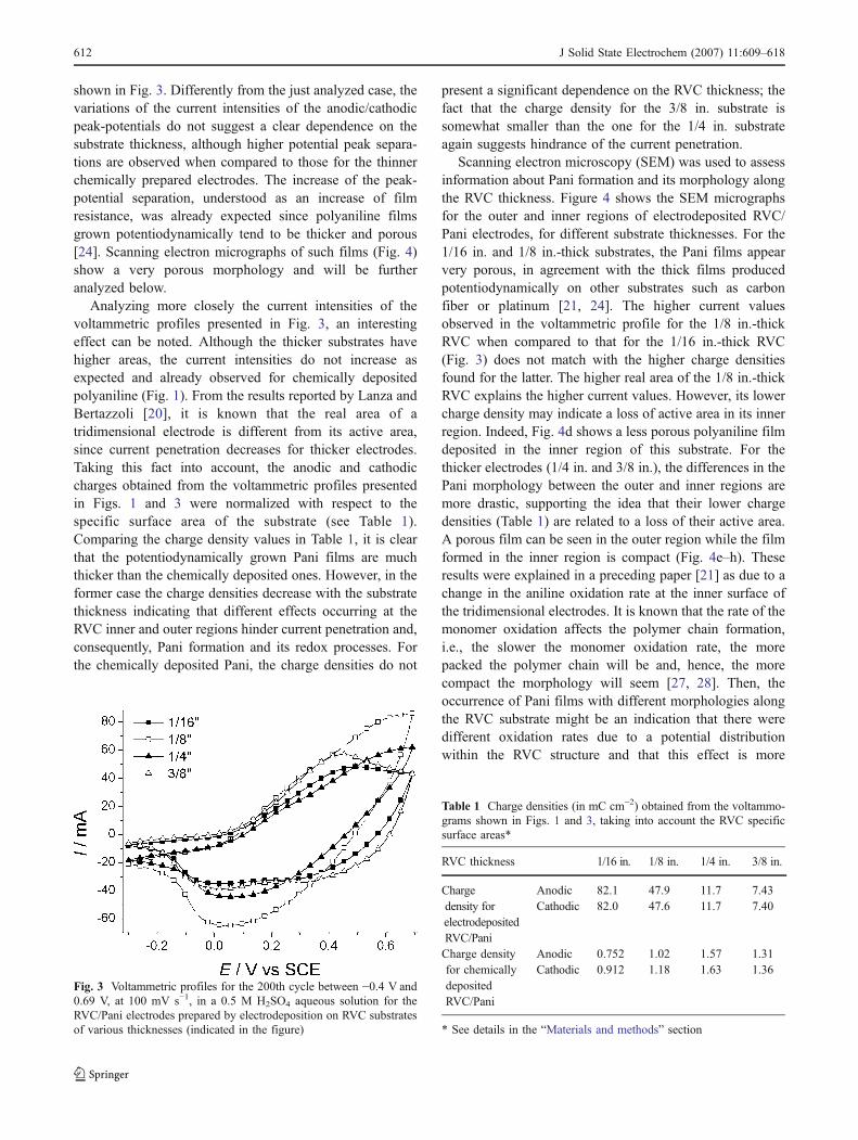
shown in Fig. 3. Differently from the just analyzed case, thevariations of the current intensities of the anodic/cathodicpeak-potentials do not suggest a clear dependence on thesubstrate thickness, although higher potential peak separa-tions are observed when compared to those for the thinnerchemically prepared electrodes. The increase of the peak-potential separation, understood as an increase of filmresistance, was already expected since polyaniline filmsgrown potentiodynamically tend to be thicker and porous[24]. Scanning electron micrographs of such films (Fig. 4)show a very porous morphology and will be furtheranalyzed below.
Analyzing more closely the current intensities of thevoltammetric profiles presented in Fig. 3, an interestingeffect can be noted. Although the thicker substrates havehigher areas, the current intensities do not increase asexpected and already observed for chemically depositedpolyaniline (Fig. 1). From the results reported by Lanza andBertazzoli [20], it is known that the real area of atridimensional electrode is different from its active area,since current penetration decreases for thicker electrodes.Taking this fact into account, the anodic and cathodiccharges obtained from the voltammetric profiles presentedin Figs. 1 and 3 were normalized with respect to thespecific surface area of the substrate (see Table 1).Comparing the charge density values in Table 1, it is clearthat the potentiodynamically grown Pani films are muchthicker than the chemically deposited ones. However, in theformer case the charge densities decrease with the substratethickness indicating that different effects occurring at theRVC inner and outer regions hinder current penetration and,consequently, Pani formation and its redox processes. Forthe chemically deposited Pani, the charge densities do not
present a significant dependence on the RVC thickness; thefact that the charge density for the 3/8 in. substrate issomewhat smaller than the one for the 1/4 in. substrateagain suggests hindrance of the current penetration.
Scanning electron microscopy (SEM) was used to assessinformation about Pani formation and its morphology alongthe RVC thickness. Figure 4 shows the SEM micrographsfor the outer and inner regions of electrodeposited RVC/Pani electrodes, for different substrate thicknesses. For the1/16 in. and 1/8 in.-thick substrates, the Pani films appearvery porous, in agreement with the thick films producedpotentiodynamically on other substrates such as carbonfiber or platinum [21, 24]. The higher current valuesobserved in the voltammetric profile for the 1/8 in.-thickRVC when compared to that for the 1/16 in.-thick RVC(Fig. 3) does not match with the higher charge densitiesfound for the latter. The higher real area of the 1/8 in.-thickRVC explains the higher current values. However, its lowercharge density may indicate a loss of active area in its innerregion. Indeed, Fig. 4d shows a less porous polyaniline filmdeposited in the inner region of this substrate. For thethicker electrodes (1/4 in. and 3/8 in.), the differences in thePani morphology between the outer and inner regions aremore drastic, supporting the idea that their lower chargedensities (Table 1) are related to a loss of their active area.A porous film can be seen in the outer region while the filmformed in the inner region is compact (Fig. 4e–h). Theseresults were explained in a preceding paper [21] as due to achange in the aniline oxidation rate at the inner surface ofthe tridimensional electrodes. It is known that the rate of themonomer oxidation affects the polymer chain formation,i.e., the slower the monomer oxidation rate, the morepacked the polymer chain will be and, hence, the morecompact the morphology will seem [27, 28]. Then, theoccurrence of Pani films with different morphologies alongthe RVC substrate might be an indication that there weredifferent oxidation rates due to a potential distributionwithin the RVC structure and that this effect is more
Fig. 3 Voltammetric profiles for the 200th cycle between −0.4 V and0.69 V, at 100 mV s−1, in a 0.5 M H2SO4 aqueous solution for theRVC/Pani electrodes prepared by electrodeposition on RVC substratesof various thicknesses (indicated in the figure)
Table 1 Charge densities (in mC cm−2) obtained from the voltammo-grams shown in Figs. 1 and 3, taking into account the RVC specificsurface areas*
RVC thickness 1/16 in. 1/8 in. 1/4 in. 3/8 in.
Chargedensity forelectrodepositedRVC/Pani
Anodic 82.1 47.9 11.7 7.43Cathodic 82.0 47.6 11.7 7.40
Charge densityfor chemicallydepositedRVC/Pani
Anodic 0.752 1.02 1.57 1.31Cathodic 0.912 1.18 1.63 1.36
* See details in the “Materials and methods” section
612 J Solid State Electrochem (2007) 11:609–618
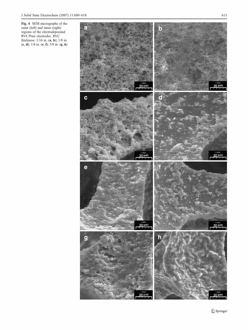
Fig. 4 SEM micrographs of theouter (left) and inner (right)regions of the electrodepositedRVC/Pani electrodes. RVCthickness: 1/16 in. (a, b); 1/8 in.(c, d); 1/4 in. (e, f); 3/8 in. (g, h)
J Solid State Electrochem (2007) 11:609–618 613
pronounced for thicker electrodes. The lower current valuesand charge densities as the RVC thickness increased alsoindicate a loss in the active area of the tridimensionalsubstrate. Consequently, when more homogenous andporous films are intended, whose electrochemical propertieswill not be influenced by the potential distribution insidethe substrate structure, undoubtedly the polyaniline electro-deposition should be carried out on the thinner RVCsubstrate. For applications where thicker substrates areneeded, chemically synthesized polyaniline seems to bemore suitable, though its electrochemical activity will bestill compromised by lower current penetration in thetridimensional electrodes.
Electrochemical impedance spectroscopy
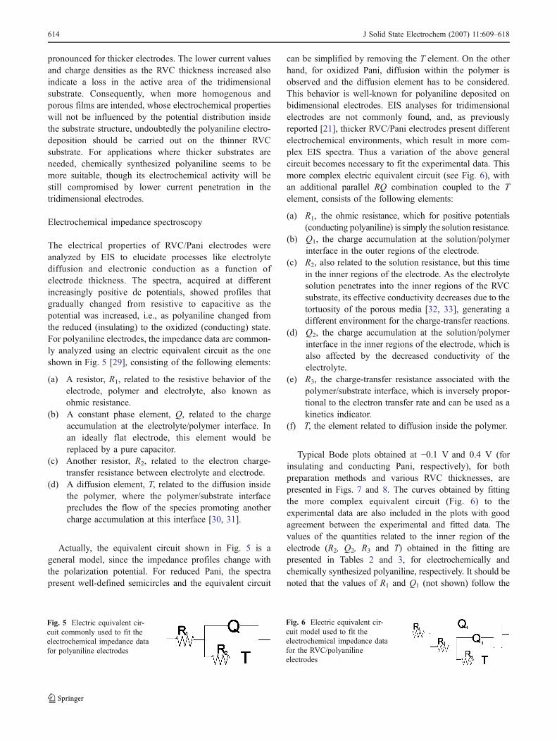
The electrical properties of RVC/Pani electrodes wereanalyzed by EIS to elucidate processes like electrolytediffusion and electronic conduction as a function ofelectrode thickness. The spectra, acquired at differentincreasingly positive dc potentials, showed profiles thatgradually changed from resistive to capacitive as thepotential was increased, i.e., as polyaniline changed fromthe reduced (insulating) to the oxidized (conducting) state.For polyaniline electrodes, the impedance data are common-ly analyzed using an electric equivalent circuit as the oneshown in Fig. 5 [29], consisting of the following elements:
(a) A resistor, R1, related to the resistive behavior of theelectrode, polymer and electrolyte, also known asohmic resistance.
(b) A constant phase element, Q, related to the chargeaccumulation at the electrolyte/polymer interface. Inan ideally flat electrode, this element would bereplaced by a pure capacitor.
(c) Another resistor, R2, related to the electron charge-transfer resistance between electrolyte and electrode.
(d) A diffusion element, T, related to the diffusion insidethe polymer, where the polymer/substrate interfaceprecludes the flow of the species promoting anothercharge accumulation at this interface [30, 31].
Actually, the equivalent circuit shown in Fig. 5 is ageneral model, since the impedance profiles change withthe polarization potential. For reduced Pani, the spectrapresent well-defined semicircles and the equivalent circuit
can be simplified by removing the T element. On the otherhand, for oxidized Pani, diffusion within the polymer isobserved and the diffusion element has to be considered.This behavior is well-known for polyaniline deposited onbidimensional electrodes. EIS analyses for tridimensionalelectrodes are not commonly found, and, as previouslyreported [21], thicker RVC/Pani electrodes present differentelectrochemical environments, which result in more com-plex EIS spectra. Thus a variation of the above generalcircuit becomes necessary to fit the experimental data. Thismore complex electric equivalent circuit (see Fig. 6), withan additional parallel RQ combination coupled to the Telement, consists of the following elements:
(a) R1, the ohmic resistance, which for positive potentials(conducting polyaniline) is simply the solution resistance.
(b) Q1, the charge accumulation at the solution/polymerinterface in the outer regions of the electrode.
(c) R2, also related to the solution resistance, but this timein the inner regions of the electrode. As the electrolytesolution penetrates into the inner regions of the RVCsubstrate, its effective conductivity decreases due to thetortuosity of the porous media [32, 33], generating adifferent environment for the charge-transfer reactions.
(d) Q2, the charge accumulation at the solution/polymerinterface in the inner regions of the electrode, which isalso affected by the decreased conductivity of theelectrolyte.
(e) R3, the charge-transfer resistance associated with thepolymer/substrate interface, which is inversely propor-tional to the electron transfer rate and can be used as akinetics indicator.
(f) T, the element related to diffusion inside the polymer.
Typical Bode plots obtained at −0.1 V and 0.4 V (forinsulating and conducting Pani, respectively), for bothpreparation methods and various RVC thicknesses, arepresented in Figs. 7 and 8. The curves obtained by fittingthe more complex equivalent circuit (Fig. 6) to theexperimental data are also included in the plots with goodagreement between the experimental and fitted data. Thevalues of the quantities related to the inner region of theelectrode (R2, Q2, R3 and T) obtained in the fitting arepresented in Tables 2 and 3, for electrochemically andchemically synthesized polyaniline, respectively. It should benoted that the values of R1 and Q1 (not shown) follow the
Fig. 5 Electric equivalent cir-cuit commonly used to fit theelectrochemical impedance datafor polyaniline electrodes
Fig. 6 Electric equivalent cir-cuit model used to fit theelectrochemical impedance datafor the RVC/polyanilineelectrodes
614 J Solid State Electrochem (2007) 11:609–618

same trend as those of R2 and Q2, respectively. However, thevalues of R2 are higher than those of R1, indicating thatelectrolyte conductivity is indeed affected by the porousmedium. This means that an environment in the inner RVCsurfaces differs from that at the outer RVC surfaces.
The values of R3 obtained for electrodes polarized at−0.1 V refer to the charge-transfer resistance of theinsulating Pani film. The higher R3 values for chemicallyprepared polyaniline can be due to its more compactmorphology, which hinders the mobility of the counter-ions across the film for charge compensation. As it can beseen in Tables 2 and 3, the fitting of the EIS data yieldedvalues for the diffusion element T even at potentials wherepolyaniline is insulating. As stated earlier, the diffusionelement T is related to finite diffusion in a medium wereone interface precludes diffusion, creating saturation zones,
as it may occur, for example, at the polymer/substrateinterface. Thus, its impedance is related to a hyperbolictangent function, defined as [34]:
Z Tð Þ ¼tanh B jwð Þ1=2
h i
Y0 jwð Þ1=2
where
B ¼ffiffiffiffiffiffiL2
D
r
L being the film thickness and D a combination of thediffusion coefficients of the ionic species (Di) and theelectrons (De) [34]. Then, the high values obtained for Bindicate a low diffusion coefficient, as expected for Paniinsulating films. For chemically prepared polyaniline,
Fig. 7 Bode plots for the electrochemically synthesized RVC/polyaniline electrodes in a 0.5 M H2SO4 aqueous solution. Experimental data(points) and fitted curves for different RVC thicknesses: (a) 1/16 in., b) 1/8 in., c) 1/4 in. and d) 3/8 in.
J Solid State Electrochem (2007) 11:609–618 615

deposited on the thinner 1/16 in. or the 1/8 in. RVC, thefitting of the data did not yield a diffusion element. Thissuggests that for these RVC thicknesses, the Pani film ismuch more compact, something that is confirmed bycomparing the SEM micrographs for the chemically(Fig. 2) and electrochemically prepared (Fig. 4a and d)Pani films on the 1/8 in. RVC.
Differences in the EIS spectra are more pronouncedwhen polyaniline is conducting. For chemically preparedpolyaniline (Fig. 8), two time constants are always seen,independent of the RVC thickness. This can be explainedby the deposition of a compact, thin and homogeneous Panifilm both on the outer and the inner RVC surfaces.However, two electrochemical environments are presentdue to the ohmic loss at the inner region of the electrodesand, therefore, the circuit presented in Fig. 6 had to be usedfor the fitting of the data. On the other hand, for theelectrosynthesized polyaniline, R1 and Q1 were not defined
for the 1/16 in. or the 1/8 in. RVC, indicating that for thesethinner electrodes the effect of the ohmic drop inside thesubstrate is minimized due to the highly porous Pani filmon the RVC macroporous structure (see Fig. 4a–d). In thesecases, the RVC/Pani behaves as if it was a bidimensionalelectrode and no differences between the outer and theinner regions are observed. When the RVC thicknessincreases, different Pani morphologies within the electrode(see again Fig. 4) yield different electrochemical environ-ments, leading to different impedance behaviors.
Values calculated for R3 and T for chemically preparedPani (Table 3) confirm the above analysis. When thepolymer is conducting, De≫Di and Di is the rate determin-ing factor for the charge-carrier diffusion [34]. The decreasein the value of B as the potential is increased indicates thatthe diffusion coefficients of the moving counter-ions arebecoming larger. However, for electrosynthesized films(Table 2), the values of B increase with the electrode
Fig. 8 Bode plots for the chemically synthesized RVC/polyaniline electrodes in a 0.5 M H2SO4 aqueous solution. Experimental data (points) andfitted curves for different RVC thicknesses: (a) 1/16 in., b) 1/8 in., c) 1/4 in. and d) 3/8 in.
616 J Solid State Electrochem (2007) 11:609–618

thickness, indicating that the diffusion coefficient isbecoming smaller. For the chemically prepared electrodes,the values of B are not affected by the RVC thickness.Therefore, the differences observed in the T element for theelectrosynthesized Pani may be related to the polymermorphology, which is affected by the substrate thickness.
The data in Tables 2 and 3 also suggest that the charge-transfer resistance (R3) is affected by the RVC thickness,especially in the case of the electrosynthesized polyaniline.High R3 values are observed at −0.1 V, decreasing as theelectrode area increases, i.e., RVC thickness increases. Forconducting Pani, an opposite effect is observed as theelectrode area increases, showing again that its redoxreactions are negatively affected. However, this behavioris not observed for the chemically prepared RVC/Panielectrodes, thus indicating that its cause is not the RVCthickness itself, but the different film morphologiesobtained during the electrochemical polymerization ofpolyaniline onto the thicker RVC substrates.
Conclusions
Electrochemical and morphological aspects of RVC/Panielectrodes produced by both chemical and electrochemicalmethods were investigated as a function of the RVCthickness. Although high surface area electrodes are obtainedwhen tridimensional electrodes are used as the substrate forthe polyaniline electropolymerization, its redox reactions areaffected by the substrate thickness. For chemically preparedelectrodes, whose deposition is not affected by the substratethickness, the voltammetric results show only a slightdependence of the Pani electrochemical behavior upon theRVC thickness. Thicker substrates still present high activeareas, although with higher peak-potential separations,indicating slower electrochemical reaction rates, somethingnot observed for the thinner substrates. Indeed, EIS measure-ments showed that the electrolyte conductivity decreases atthe inner surfaces and this could be an explanation for thosehigher peak-potential separations.
Table 2 Values of different parameters obtained by fitting the response of the equivalent circuit shown in Fig. 6 to the impedance data for theelectrodeposited RVC/Pani electrodes, as a function of the applied potential and substrate thickness
E/V vs SCE RVC thickness/in. R2/Ω R3/Ω Q2/Ω−1 sn nQ2 Y0/Ω
−1 s0.5 B/s0.5
−0.1 1/16 14.8 3893 4.52×10⁻⁵ 0.820 1.16×10⁻³ 9.071/8 8,48 1309 2.39×10⁻⁵ 0.780 2.99×10⁻³ 9.251/4 4.75 237 3.36×10⁻⁵ 0.876 2.72×10⁻³ 10.23/8 2.95 154 3.26×10⁻⁵ 0.741 4.63×10⁻³ 15.2
0.2 1/16 1.87 0.330 1.79×10⁻² 0.700 2.40×10⁻¹ 0.7901/8 1.34 0.433 2.20×10⁻² 0.758 3.14×10⁻¹ 0.8731/4 1.14 11.0 4.11×10⁻² 0.753 4.31×10⁻¹ 1.673/8 0.927 11.5 1.15×10⁻¹ 0.719 2.39×10⁻¹ 2.60
0.4 1/16 1.59 0.160 9.54×10⁻³ 0.790 2.70×10⁻¹ 0.5901/8 1.87 0.332 1.60×10⁻³ 0.730 2.93×10⁻¹ 0.7761/4 1.09 5.52 2.83×10⁻² 0.766 4.51×10⁻¹ 1.523/8 0.884 8.52 1.13×10⁻¹ 0.692 3.42×10⁻¹ 2.38
Table 3 Values of different parameters obtained by fitting the response of the equivalent circuit shown in Fig. 6 to the impedance data forchemically prepared RVC/Pani electrodes, as a function of applied potential and substrate thickness
E/V vs SCE RVC thickness/in. R2/Ω R3/Ω Q2/Ω−1 sn nQ2 Y0/Ω
−1 s0.5 B/s0.5
−0.1 1/16 8.17 9620 1.08×10⁻⁴ 0.889 – –1/8 11.5 5473 4.54×10⁻⁴ 0.725 – –1/4 14.3 247 3.09×10⁻³ 0.774 1.41×10⁻² 9.583/8 3.98 126 8.67×10⁻³ 0.801 2.67×10⁻² 10.1
0.2 1/16 12.4 2993 1.58×10⁻³ 0.677 2.07×10⁻⁴ 4.671/8 2.20 19.0 3.29×10⁻³ 0.684 2.66×10⁻² 1.481/4 14.0 5.90 3.51×10⁻² 0.605 1.24×10⁻² 1.963/8 2.98 0.548 6.24×10⁻² 0.605 9.58×10⁻³ 2.05
0.4 1/16 13.8 82.1 2.15×10⁻³ 0.662 3.12×10⁻⁴ 1.871/8 2.14 10.0 2.23×10⁻³ 0.633 3.16×10⁻³ 1.231/4 14.6 5.90 4.02×10⁻² 0.726 1.43×10⁻² 0.9343/8 3.71 4.86 6.11×10⁻² 0.651 2.09×10⁻² 1.32
J Solid State Electrochem (2007) 11:609–618 617

Conversely, the electrodeposition of Pani is stronglydependent upon the substrate thickness, as showed by theSEM micrographs. Thus, high peak-potential separations inthe voltammetric profiles were already expected due to thepolymer porous morphology, although a direct relationshipbetween substrate thickness (specific surface area) andactive area could not be obtained.
An equivalent electric circuit model was proposed for theanalysis of the EIS data, taking into account the differentelectrochemical environments at the outer and inner RVCsurfaces. The values obtained for the different parametersindicate that electrochemically prepared electrodes are moresusceptible to an ohmic drop across the RVC structure sincethe morphologies of the obtained Pani are different. Finally,when more homogenous and porous polyaniline films arerequired, the obtained results indicate that electropolymeri-zation onto thinner substrates might be the best choice. Onthe other hand, for applications where a high tridimensionalsurface area is intended (thicker substrates), chemicaldeposition seems to be the best choice.
Acknowledgements The authors are grateful to FAPESP, CAPESand CNPq for the scholarships and grants that made this workpossible. C.D. is grateful to FAPESP for her doctoral scholarship.
References
1. Wang J (1980) Electrochim Acta 26:17212. Czerwinski A, Dmochowska M, Grden M, Kopczyk M, Wojcik G,
Mlynarek G, Kolata J, Skowronski JM (1999) J Power Sources 77:283. Czerwinski A, Zelazowska M (1997) J Power Sources 64:294. Gyenge E, Jung J, Mahato B (2003) J Power Sources 113:3885. Alvarez-Gallegos A, Pletcher D (1998) Electrochim Acta 44:8536. Tang X, Xie B, Larsson P, Danielsson B, Khayyami M, Johansson
G (1998) Anal Chim Acta 374:185
7. Friedrich JM, Ponce-de-Léon C, Reade GW, Walsh FC (2004)J Electroanal Chem 561:203
8. Rodriguez FJ, Gutiérrez S, Ibañez JG, Bravo JL, Batina N (2000)Environ Sci Technol 34:2018
9. Ruotolo LAM, Liao AA, Gubulin JC, J Appl Electrochem34:1259
10. Ruotolo LAM, Gubulin JC (2005) React Funct Polym 62:14111. Piatnicki CMS, Azambuja DS, Hasse EES, Castagno KRL,
Guterres SB (2002) Sep Sci Technol 37:245912. Price WE, Ralph SF, Wallace GG (2001) Aust J Chem 54:61513. Yang X, Too CO, Sparrow L, Ramshaw J, Wallace GG (2002)
React Funct Polym 53:5314. Tsutsumi H, Yamashita S, Oishi T (1997) Synth Met 85:136115. Frydrychewicz A, Vassiliev SY, Tsirlina GA, Jackowska K (2005)
Electrochim Acta 50:188516. Bhattacharya A, De A (1996) Prog Solid State Chem 24:14117. Gospodinova N, Terlemezyan L (1998) Prog Polym Sci 23:144318. Dinh HN, Birss VI (2000) J Electrochem Soc 147:377519. Doherty T, Sunderland JG, Roberts EPL, Pickett DJ (1996)
Electrochim Acta 41:51920. Lanza MRV, Bertazzoli R (2000) J Appl Electrochem 30:6121. Dalmolin C, Canobre SC, Biaggio SR, Rocha-Filho RC, Bocchi N
(2005) J Electroanal Chem 578:922. Lasia A (1995) J Electroanal Chem 397:2723. de Levie R (1963) Electrochim Acta 8:75124. Andrade GT, Aguirre MJ, Biaggio SR (1998) Electrochim Acta
44:63325. Stejskal J, Gilbert RG (2002) Pure Appl Chem 74:85726. Boukamp BA (1995) Software EQUIVCRT, Version 4.5127. Nunziante P, Pistoia G (1989) Electrochim Acta 34:22328. Tang H, Kitani A, Shiotami M (1996) Electrochim Acta 41:156129. Gazotti WA Jr, Matencio T, De Paoli M-A (1998) Electrochim
Acta 43:45730. Boukamp BA (1986) Solid State Ion 20:3131. Skinner NG, Hall EAH (1994) Synth Met 63:13332. Ruotolo LAM, Gubulin JC (2002) Proceedings of 30th ENEMP:
Congresso Brasileiro de Sistemas Particulados, São Carlos, SP.(http://www.ufscar.br/~enemp2002/pi32.pdf)
33. Gonzalez-Garcia J, Bonete P, Exposito E, Montiel V, Aldaz A,Torregrosa-Macia R (1999) J Mater Chem 9:419
34. Vorotynsev MA, Daikhin LI, Levi MD (1994) J Electroanal Chem364:37
618 J Solid State Electrochem (2007) 11:609–618