Finite-Element Simulations of a Thermoelectric Generator and ...
10
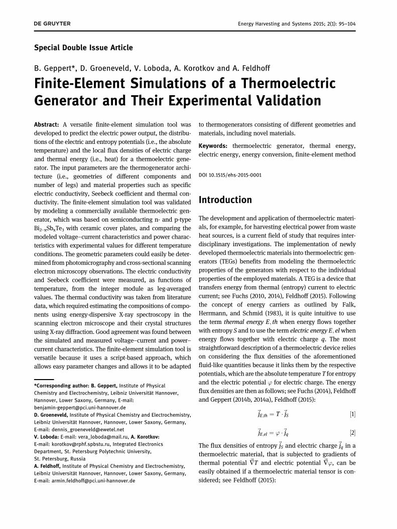
Special Double Issue Article B. Geppert*, D. Groeneveld, V. Loboda, A. Korotkov and A. Feldhoff Finite-Element Simulations of a Thermoelectric Generator and Their Experimental Validation Abstract: A versatile finite-element simulation tool was developed to predict the electric power output, the distribu- tions of the electric and entropy potentials (i.e., the absolute temperature) and the local flux densities of electric charge and thermal energy (i.e., heat) for a thermoelectric gene- rator. The input parameters are the thermogenerator archi- tecture (i.e., geometries of different components and number of legs) and material properties such as specific electric conductivity, Seebeck coefficient and thermal con- ductivity. The finite-element simulation tool was validated by modeling a commercially available thermoelectric gen- erator, which was based on semiconducting n- and p-type Bi 2–x Sb x Te 3 with ceramic cover plates, and comparing the modeled voltage–current characteristics and power charac- teristics with experimental values for different temperature conditions. The geometric parameters could easily be deter- mined from photomicrography and cross-sectional scanning electron microscopy observations. The electric conductivity and Seebeck coefficient were measured, as functions of temperature, from the integer module as leg-averaged values. The thermal conductivity was taken from literature data, which required estimating the compositions of compo- nents using energy-dispersive X-ray spectroscopy in the scanning electron microscope and their crystal structures using X-ray diffraction. Good agreement was found between the simulated and measured voltage–current and power– current characteristics. The finite-element simulation tool is versatile because it uses a script-based approach, which allows easy parameter changes and allows it to be adapted to thermogenerators consisting of different geometries and materials, including novel materials. Keywords: thermoelectric generator, thermal energy, electric energy, energy conversion, finite-element method DOI 10.1515/ehs-2015-0001 Introduction The development and application of thermoelectric materi- als, for example, for harvesting electrical power from waste heat sources, is a current field of study that requires inter- disciplinary investigations. The implementation of newly developed thermoelectric materials into thermoelectric gen- erators (TEGs) benefits from modeling the thermoelectric properties of the generators with respect to the individual properties of the employed materials. A TEG is a device that transfers energy from thermal (entropy) current to electric current; see Fuchs (2010, 2014), Feldhoff (2015). Following the concept of energy carriers as outlined by Falk, Herrmann, and Schmid (1983), it is quite intuitive to use the term thermal energy E; th when energy flows together with entropy S and to use the term electric energy E; el when energy flows together with electric charge q. The most straightforward description of a thermoelectric device relies on considering the flux densities of the aforementioned fluid-like quantities because it links them by the respective potentials, which are the absolute temperature T for entropy and the electric potential ’ for electric charge. The energy flux densities are then as follows; see Fuchs (2014), Feldhoff and Geppert (2014b, 2014a), Feldhoff (2015): ~ j E;th ¼ T ~ j S ½1 ~ j E;el ¼ ’ ~ j q ½2 The flux densities of entropy ~ j S and electric charge ~ j q in a thermoelectric material, that is subjected to gradients of thermal potential ~ ÑT and electric potential ~ Ñ’, can be easily obtained if a thermoelectric material tensor is con- sidered; see Feldhoff (2015): *Corresponding author: B. Geppert, Institute of Physical Chemistry and Electrochemistry, Leibniz Universität Hannover, Hannover, Lower Saxony, Germany, E-mail: [email protected] D. Groeneveld, Institute of Physical Chemistry and Electrochemistry, Leibniz Universität Hannover, Hannover, Lower Saxony, Germany, E-mail: [email protected] V. Loboda: E-mail: [email protected], A. Korotkov: E-mail: [email protected], Integrated Electronics Department, St. Petersburg Polytechnic University, St. Petersburg, Russia A. Feldhoff, Institute of Physical Chemistry and Electrochemistry, Leibniz Universität Hannover, Hannover, Lower Saxony, Germany, E-mail: [email protected] Energy Harvesting and Systems 2015; 2(1): 95–104
-
Upload
khangminh22 -
Category
Documents
-
view
0 -
download
0
Transcript of Finite-Element Simulations of a Thermoelectric Generator and ...
Special Double Issue Article
B. Geppert*, D. Groeneveld, V. Loboda, A. Korotkov and A. Feldhoff
Finite-Element Simulations of a ThermoelectricGenerator and Their Experimental Validation
Abstract: A versatile finite-element simulation tool wasdeveloped to predict the electric power output, the distribu-tions of the electric and entropy potentials (i.e., the absolutetemperature) and the local flux densities of electric chargeand thermal energy (i.e., heat) for a thermoelectric gene-rator. The input parameters are the thermogenerator archi-tecture (i.e., geometries of different components andnumber of legs) and material properties such as specificelectric conductivity, Seebeck coefficient and thermal con-ductivity. The finite-element simulation tool was validatedby modeling a commercially available thermoelectric gen-erator, which was based on semiconducting n- and p-typeBi2–xSbxTe3 with ceramic cover plates, and comparing themodeled voltage–current characteristics and power charac-teristics with experimental values for different temperatureconditions. The geometric parameters could easily be deter-mined fromphotomicrography and cross-sectional scanningelectron microscopy observations. The electric conductivityand Seebeck coefficient were measured, as functions oftemperature, from the integer module as leg-averagedvalues. The thermal conductivity was taken from literaturedata, which required estimating the compositions of compo-nents using energy-dispersive X-ray spectroscopy in thescanning electron microscope and their crystal structuresusing X-ray diffraction. Good agreement was found betweenthe simulated and measured voltage–current and power–current characteristics. The finite-element simulation tool isversatile because it uses a script-based approach, whichallows easy parameter changes and allows it to be adapted
to thermogenerators consisting of different geometries andmaterials, including novel materials.
Keywords: thermoelectric generator, thermal energy,electric energy, energy conversion, finite-element method
DOI 10.1515/ehs-2015-0001
Introduction
The development and application of thermoelectric materi-als, for example, for harvesting electrical power from wasteheat sources, is a current field of study that requires inter-disciplinary investigations. The implementation of newlydeveloped thermoelectric materials into thermoelectric gen-erators (TEGs) benefits from modeling the thermoelectricproperties of the generators with respect to the individualproperties of the employed materials. A TEG is a device thattransfers energy from thermal (entropy) current to electriccurrent; see Fuchs (2010, 2014), Feldhoff (2015). Followingthe concept of energy carriers as outlined by Falk,Herrmann, and Schmid (1983), it is quite intuitive to usethe term thermal energy E; th when energy flows togetherwith entropy S and to use the term electric energy E; elwhenenergy flows together with electric charge q. The moststraightforward description of a thermoelectric device relieson considering the flux densities of the aforementionedfluid-like quantities because it links them by the respectivepotentials, which are the absolute temperature T for entropyand the electric potential ’ for electric charge. The energyflux densities are then as follows; see Fuchs (2014), Feldhoffand Geppert (2014b, 2014a), Feldhoff (2015):
~jE;th ¼ T �~jS ½1�
~jE;el ¼ ’ �~jq ½2�The flux densities of entropy~jS and electric charge~jq in athermoelectric material, that is subjected to gradients ofthermal potential ~�T and electric potential ~�’, can beeasily obtained if a thermoelectric material tensor is con-sidered; see Feldhoff (2015):
*Corresponding author: B. Geppert, Institute of PhysicalChemistry and Electrochemistry, Leibniz Universität Hannover,Hannover, Lower Saxony, Germany, E-mail:[email protected]. Groeneveld, Institute of Physical Chemistry and Electrochemistry,Leibniz Universität Hannover, Hannover, Lower Saxony, Germany,E-mail: [email protected]. Loboda: E-mail: [email protected], A. Korotkov:E-mail: [email protected], Integrated ElectronicsDepartment, St. Petersburg Polytechnic University,St. Petersburg, RussiaA. Feldhoff, Institute of Physical Chemistry and Electrochemistry,Leibniz Universität Hannover, Hannover, Lower Saxony, Germany,E-mail: [email protected]
Energy Harvesting and Systems 2015; 2(1): 95–104

~jS~jq
!¼ � σ � α2 þ Λ σ � α
σ � α σ
� �� ~�T
~�’
� �½3�
The thermoelectric tensor consists of three tensorial quanti-ties; however, these quantities are treated as scalars. Theseare the specific electric conductivity σ under isothermalconditions (i.e., ~�T ¼ 0, vanishing thermal potential gradi-ent), the specific entropy conductivityΛ under electric open-circuited conditions (i.e.,~jq¼0, vanishing electric current),and the so-called Seebeck coefficient α, which is defined asentropy flow per flow of unit charge; see Fuchs (2014),Feldhoff and Geppert (2014b, 2014a), Feldhoff (2015).
In principle, electric charge is bound to some particlewith chemical potential μ, and in the concept of com-bined potentials, see Fuchs (2014), the electrochemicalpotential ~μ ¼ μþ q � ’ is the more accurate quantity.However, because gradients are relevant, when the che-mical potential μ has a weak temperature dependence,the electric potential ’ can be used as a good approxima-tion rather than the electrochemical potential ~μ as in eqs[2] and [3]; see Feldhoff (2015).
To construct the basic unit of a thermoelectric gen-erator, two materials with different algebraic signs for theSeebeck coefficient α (entropy flow per flow of unit charge)must be thermally connected in parallel and electricallyconnected in series. For α >0, the motions of thermal andelectrical fluxes are directed in the same way. In contrast,for α<0, the thermal and electrical fluxes are directed inopposite directions; see Feldhoff and Geppert (2014b),Feldhoff (2015). By additively connecting several ofthese basic units thermally in parallel and electrically inseries, the electric potential ’ can be increased over thedevice to provide an important electric energy flux den-sity at device output according to eq. [2]; see Feldhoff(2015) for illustration. The choice of the thermoelectricmaterials that comprise the TEG depends on the condi-tions in which the energy conversion is to be performed.
Among the various thermoelectric materials, semicon-ductors exhibit the best thermoelectric performancebecause of their moderate charge carrier concentration,and they provide a good balance between specific electri-cal conductivity σ and the Seebeck coefficient α; see Ioffe(1957). Consequently, semiconductors provide a high valueof the so-called power factor σ � α2, which is the charge-coupled entropy conductivity and occurs as part of thethermoelectric tensor in eq. [3]. To obtain a good TEGperformance, the combination of n- and p-type semicon-ductors and a low-resistance electrical connection betweenthem realized by metals or alloys is preferred. In commer-cially available generators, Bi2�xSbxTe3-based materialsare primarily used; see Kuznetsov et al. (2002), Poudel et
al. (2008). Additionally, the geometric properties of thematerials that are combined to form the complete devicehave to be optimized for every system. Finite-elementmethod (FEM) simulations are useful for calculating thethermoelectric performance in terms of the used materialsand their geometric properties without constructing a realTEG. The thermoelectric properties can be measured overeach individual material. Afterwards, the materials can becombined in a simulated TEG system with a specific geo-metry. Because the device does not have to be constructed,FEM simulations provide results ecologically, flexibly andrapidly. The objective of the present study is to demon-strate that FEM simulations are useful for predicting thethermoelectric properties of a TEG.
Experimental
Thermoelectric Measurement Setup
To estimate the thermoelectric characteristics of the TEG, itwas placed between a heat source (heated copper plate)and a heat sink (water-cooled copper plate). The devicewas fixed with a clamping force of 0.6 kN, as indicated bya dynamometer. A schematic illustration of the measure-ment setup is shown in Figure 1. To provide good thermalsurface contact, thermal grease with a specific thermalenergy conductivity of λ> 1:46WðmKÞ�1 in the temperaturerange of ca. 300–550 K was used as the interface material.The temperature was monitored using thermocouples. Thevoltage U ¼ Δ’ was measured as the drop of the electricpotential on the external load Rload. Due to the low internalresistance Rmodule of the thermoelectric generator (seeTable 4), the electric current I was estimated indirectly:
I ¼ URload
½4�
Figure 1: Schematic illustration of the measurement setup for deter-mining the thermoelectric characteristics of the TEG with thermalgrease as the interface material, after Hejtmanek et al. (2014).
96 B. Geppert et al.: Finite-Element Simulations of a Thermoelectric Generator

The electric output power Pel was estimated according to:
Pel ¼ U2
Rload½5�
Estimation of the Geometric andThermoelectric Properties of theThermoelectric Generator
A commercially available thermoelectric generator waspurchased from Conrad Electronics SE (item number193593–62, model number 1–7105). To construct the TEGin the model system, the geometry of the device, includ-ing the thermoelectric legs, the electric copper connectorsand the alumina cover plates, were determined usingthe graphical tool ImageJ, which was applied to photo-micrographs; see Schneider, Rasband, and Eliceiri (2012).
Figure 2 presents photographs of the TEG and of thedevice modeled based on the estimated geometry foreach individual component.
The TEG includes 122 � 2 ¼ 142 legs. The spacebetween each pair of legs is 1 mm. Table 1 lists thegeometric properties of the TEG without considering thetin solder. The geometric properties were estimated byanalyzing the photographs shown in Figure 2. The rele-vant parameters are the length L of each material parallelto the entropy flux and its cross-sectional area A. Thefilling factor of the module, i.e., the ratio of thermoelec-tric active to inactive areas, is equal to 32%. For thecopper connectors and alumina cover plates, the valuesfor the specific resistivity ρ and specific thermal energy(heat) conductivity λ were taken from the literature; seeLide (2008). For the thermoelectric Bi2�xSbxTe3 materials,the specific thermal energy (heat) conductivity λ was alsotaken from the literature; see Kim et al. (2012). The
Figure 2: Photographs of the TEG for estimating the geometrical parameters and display of the modeled device; (a) inner top view of theTEG, (b) side view of the TEG, (c) modeled device with n- and p-type thermoelectric material and electric copper connectors, (d) modeleddevice with Al2O3 cover plates.
Table 1: Measured geometric properties of the TEG.
Component Material L/mm A=mm2 ρ=Ωm λ=WðmKÞ�1 Λ=Wm�1K�2
TE leg(n,p) Bi2�xSbxTe3 . . see Table . ·−
Electric connector Cu . . .·− .Cover plates Al2O3 . · . .·−
Notes: Length L of material and cross-sectional area A. The specific thermal energy resistivity ρ and specific thermal energy (heat) conductivity λ weretaken from the literature as indicated in the text. The specific entropy conductivity λ was estimated according to eq. [6]. All data refer to a medialtemperature of 350 K.
B. Geppert et al.: Finite-Element Simulations of a Thermoelectric Generator 97

temperature-averaged values for the specific entropy con-ductivity Λ in Table 1 were calculated for a medial tem-perature of 350 K according to:
λ ¼ T � Λ ½6�The specific electrical resistivity ρ ¼ 1
σ of the thermoelec-tric material is the reciprocal of the specific electricalconductivity σ, and it was estimated under the tempera-ture drops listed in Table 4. The systematic error, whichresults from the deviation from isothermal conditions (i.e.�T ¼ 0) according to requirements of eq. [3], however, isassumed to be small.
The Seebeck coefficient α was experimentally deter-mined under electric open-circuited conditions (i.e.~jq¼0),for which eq. [3] provides:
α ¼ �~�’~�T
� �Δ’L
� �ΔTL
� � ¼ �Δ’ΔT
½7�
As expressed by eq. [7], for balanced gradients of potentialsreferring to a sample of length L, the gradients � can besubstituted by the drops Δ of potentials along this length.
Microstructure Analysis
A basic unit was cut from the thermoelectric generator andpolished using diamond-lapping films (Allied High TechMultiprep) for field-emission scanning electron microscopy(FE-SEM) investigations using a JEOL JSM-6700F, whichwas equipped with an Oxford Instruments INCA 300energy-dispersive X-ray spectrometer (EDXS) for elementalanalysis. The phase composition of the bulk n- and p-typeBi2�xSbxTe3-legs was analyzed by X-ray diffraction (XRD)using a Bruker D8 Advance with Cu-Kα radiation. The legswere isolated from the TEG and prepared for XRD measure-ments by pressing the ductile material onto the sampleholder to increase the detectable area of the samples. Thispreparation approach caused an orientation in the crystalstructure, which was considered in the analysis of the dif-fraction data. The XRD measurement results were analyzedusing the Rietveldmethod as implemented in Topas 4.2. Thereference data for the structure analysis were taken from theInorganic Crystal Structure Database (ICSD).
Finite-Element Simulations
Using a script-based input process referring to theAnalysis System (ANSYS), changes in thermoelectricproperties as a result of changing material parameters,such as the composition and geometry of the considered
materials, and the number of legs can be rematched veryeasily. The used ANSYS version is 15.0 academic. Thescript-based input tool uses the ANSYS ParametricDesign Language (APDL). The simulation process can beseparated into three basic steps: preprocessing, solvingand postprocessing. During the preprocessing step, thegeometric properties are created, the material’s propertiesare set, the model is meshed and additional conditionsare defined. Meshing determines the number of elementsof the model and their nodes. The accuracy is given bythe network’s density. After the preprocessing is com-plete, solving of the grid points is executed. During thepostprocessing step, the results are exported as plots,tables or figures. In this work, as mentioned in Section“Estimation of the Geometric and ThermoelectricProperties of the Thermoelectric Generator”, a commer-cially available TEG was measured to estimate the aver-age data for the thermoelectric properties and to evaluatea model system created using the FEM simulation tool.The modeled device consists of 72048 elements. Eachthermoelectric leg is build up by 36 elements (total num-ber of elements for the thermoelectric legs is 5,112) whileeach electric copper connector contains 220 elements(total number of elements for the electric copper connec-tors is 31,460). Each alumina cover plate consists of17,138 (total number of elements for the alumina coverplates is 35,476). The non-linear solution converged afterequilibrium iteration 2.
Results and Discussion
Microstructure of Materials
To estimate the elemental composition of the thermoelec-tric materials using the EDXS method in the FE-SEM, atwo-leg fragment was cut from the TEG and polished. TheSEM micrograph in Figure 3(a) shows the thermoelectric n-and p-type Bi2�xSbxTe3, the electric copper connectors andthe alumina cover plates. The geometrical parameters arethe same as those obtained from the photomicrograph ofFigure 2(a), (b). Figure 3(b)–(f) shows the EDXS elementaldistribution in the device by bright contrast.
Figure 4 presents the EDX spectra of the n- andp-type material (areas of analysis are marked inFigure 3(a)). The EDXS analysis does not detect anyamount of antimony inside the n-type thermoelectricsemiconductor. However, Kouhkarenko et al. (2001)reported that doping with a certain amount of antimony,approximately 25 at.% in the bismuth telluride structure,
98 B. Geppert et al.: Finite-Element Simulations of a Thermoelectric Generator

leads to an improvement in the Seebeck coefficient α ofthe n-type thermoelectric material. The thermoelectricproperties of Bi2�xSbxTe3 are also influenced by theratio of (Bi,Sb) and Te; see Fleurial et al. (1988). Theideal ratio for a stoichiometric composition ðBi; SbÞ2Te3is ðBi;SbÞ
Te ¼ 23¼ 0:667. Within the accuracy of quantitative
EDXS, both materials (n-type and p-type) match thisvalue, which supports the assumption that the materialshave been made according to the strategy described byKouhkarenko et al. (2001).
The composition of the analyzed materials of the TEGis as expected. As indicated by the XRD pattern inFigure 5, the structure is preferentially orientated withthe c-axis perpendicular to the sample holder, which isconfirmed by the appearance of lattice reflections from
the (0 0 l) planes with l ¼ 9, 12, 15 (main reflection), 18,and 21. Furthermore, reflections from the (1 0 l) planeswith l ¼ 10, 13, 25, 28 are present, which, however,indicates only a slight tilt away from the c-axis. Forrefinement of the crystal structure, the preferred orienta-tion resulting from the preparation (pressing of ductilematerial onto the sample holder) has to be considered.Because of the considerable amount of the Sb in thep-type material, the lattice parameters for this composi-tion are smaller than those for the n-type material. Theradii for structure-building elements can be extractedfrom Shannon (1976). With a medial coordination numberof 6, it is 76 pm for Sb3þ, 103 pm for Bi3þ, and 221 pm forTe2�. For the n-type material, which contains only Bi onthe cationic site, the diffraction data were fitted to the
Figure 3: Side view of basic unit of the TEG exhibiting p- and n-type thermoelectric legs; (a) secondary electron micrograph, (b) Bi-M,(c) Sb-L, (d) Te-L, (e) Al-K, (f) Cu-K. Rectangularly marked areas in (a) refer to EDX spectra shown in Figure 4.
B. Geppert et al.: Finite-Element Simulations of a Thermoelectric Generator 99

reference structure of Bi2Te3. For the p-type material,which contains a large amount of Sb on the cationicsite, the diffraction data were fitted to the referencestructure of Sb2Te3. The lattice parameters that werecalculated by fitting the diffraction data to the aforemen-tioned reference structures are listed in Table 2.
The results for the atomic positions considering thegoodness of the Rietveld fit are listed in Table 3. Thecoordinates x ¼ 0 and y ¼ 0 are fixed. The goodnessof fit (GOF) is expressed by the R-weighted pattern Rwp
and R-expected Rexp. For the fit criteria used in Topas 4.2see Young (1993).
Thermoelectric Investigations
To estimate the thermoelectric properties of the TEG, themeasurement data were analyzed and the average valuesfor the specific electrical conductivity σ (T), the Seebeckcoefficient α (T) from the thermovoltage U(T) and the
0.0
C-K
O-K
Inte
nsity
/ ar
b. u
nits
Al-K Bi-MzSb-Ln
Bi-My
Bi-Mβ
n-type Bi2Te3
p-type Sb2-xBixTe3
Bi-Mα1
Te-Lα1
Te-Lβ1
Te-Lβ2
Te-Ly1
0.5 1.0 1.5 2.0 2.5 3.0 3.5 4.0 4.5 5.0 5.5 6.0E/ keV
Figure 4: EDX spectra of n- and p-type thermoelectric legs according to the rectangular areas marked in Figure 3(a).
Figure 5: Scanned (black curve) and refined (red curve) X-ray diffraction data with difference curve (light gray); (a) n-type Bi2Te3, (b) p-typeSb2�xBixTe3.
100 B. Geppert et al.: Finite-Element Simulations of a Thermoelectric Generator

temperature difference ΔT for the thermoelectric materi-als were calculated. The electronic and thermal quantitiesfor copper and alumina were taken from Lide (2008) andare presented in Table 1. A summary of the electronic,thermal and thermoelectric parameters of the thermoelec-tric materials is given in Table 4. The specific resistivitiesρleg of the legs were estimated from the absolute resistiv-ity of the complete device Rmodule by considering thenumber of thermoelectric legs and their geometry. TheSeebeck coefficient αleg was estimated from the open-circuit voltage UOC according to eq. [7]. Because the coef-ficient was averaged over all integrated legs, the sameabsolute values for n- and p-type legs are obtained, andthe Seebeck coefficient becomes �αleg. The maximumelectric current ISC under electric short-circuited condi-tions (i.e. U ¼ Δ’ ¼ 0) and the maximum electric outputpower Pmax are listed. All quantities are related to theestablished temperature drops ΔT and the medial tem-perature of the device Tmedial.
To determine the thermoelectric parameters of thedevice, five temperature differences ΔT were established,which are indicated in Table 4 and Figures 6 and 7.Figure 6 shows U–I curves with good agreement betweenthe FEM simulation (solid line) and measurement (datapoints) for all temperature conditions. Note, that theslope of the lines refers to the internal resistanceRmodule, as indicated in Table 4. The electric outputpower Pel was estimated in terms of different load resis-tivities Rload. Figure 7 shows good agreement between theexperimental Pel � I curve (data points) and the FEMsimulation (solid line).
The results of the thermoelectric behavior can beshown in a vectorial plot that refers to the density oftransported quantities, the thermal energy flux density~jE;th and the electric flux density~jq. Figure 8 shows theresults of the FEM simulation of the properties of theTEG’s components at the maximum electric power outputfor a chosen temperature difference of 58 K. The colors of
Table 2: Lattice parameters and unit cell volumes obtained from the Rietveld refinement and comparison toreferences. The space group, No. 166, is represented in hexagonal axes.
Stoichiometry Description Space group a=Å c=Å Vcell=Å3
Bi2Te3�y Measured (n-type) R9�3mH . . .Bi2Te3 ICSD: R9�3mH . . .Sb2�xBixTe3�y Measured (p-type) R9�3mH . . .Sb2Te3 ICSD: R9�3mH . . .
Table 3: Atomic positions and goodness of fit for the Rietveld refinement of the X-ray diffraction data presentedin Figure 5. The coordinates x ¼ 0 and y ¼ 0 are fixed.
Description Atom Site z coordinate ICSD z coordinate Rietveld Rwp Rexp GOF
n-type Bi c . . . . .Te a . .Te c . .
p-type Sb c . . . . .Te c . .Te a . .
Table 4: Determined thermoelectric parameters of the TEG (complete device) and single legs for differenttemperature conditions.
Thot=K ΔT=K Tmedial=K Rmodule=Ω ρleg=μΩ �m αleg=μV � K�1 Pmax=mW UOC=mV ISC=mA
. . � 142.18 . . . . � 158.53 . . . . � 144.05 . . . . � 131.55 . . . . � 107.80 . .
B. Geppert et al.: Finite-Element Simulations of a Thermoelectric Generator 101

the vectors refer to the local value of the density of thetransported quantity, which is in indicated in the legend.The flux densities of thermal energy ~jE;th and electriccharge~jq depend on the material of the TEG’s componentsand on the local potential gradients according to the poten-tial distributions of Figure 9. The Al2O3 cover plates are notdisplayed but the flux densities at their location are. FromFigure 8(a), it is clear that the thermal power density~jE;th isdistinctly smaller in the region of the Al2O3 cover plates(4W=m2) than in the copper connectors (2� 4 � 104W=m2)or the thermoelectric Bi2�xSbxTe3 legs (4� 5 � 104W=m2).Due to the extremely high electric resistivity of the Al2O3
cover plates (see Table 1), the electric current density ~jqvanishes at their location. In the copper connectors, itamounts to ~jq ¼ 1 � 10�17 � 2 � 105A=m2 with strong localvariation, and it is highest in the thermoelectric legs
(2 � 105A=m2). Note that fluxes of thermal energy and elec-tric charge are co-aligned in the case of p-type legs andcounter-aligned in the case of n-type legs.
Figure 9(a) shows the distribution of the entropypotential T, obtained from the FEM simulation and across-section of the TEG at maximum electric power out-put for a potential drop of ΔT ¼ 58K. Figure 9(b) showsthe respective distribution of the electric potentialU ¼ Δ’ along the electric serial connection of theassembled thermoelectric legs and copper connectorsinside the module. When the potential at the electricinput is at ground (i.e. ’ ¼ 0), it continuously increasesalong the chain to be ’ ¼ 571mV at the electric output.Note that this value is identical to the voltage at theelectric power maximum (from Figure 7) in Figure 6 forthe same temperature drop. The modeling of TEGs using
1200
1000
800
600
U/m
V
400
200
00 50 100 150 200 250 300 350 450400 500
ΔT = 58 KΔT = 43 KΔT = 33 KΔT = 25 KΔT = 13 K
I/mA
Figure 6: Comparison of measured (dots) and simulated (lines)decrease in voltage over electrical current in terms of load resis-tance RL and temperature difference ΔT .
160 18
16
14
12
10
8
4
Ele
ctric
al p
ower
den
sity
/ m
W c
m−
2
2
0
6
ΔT = 58 KΔT = 43 KΔT = 33 KΔT = 25 KΔT = 13 K
140
120
100
80
PeI
/ m
W
60
40
20
00 50 100 150 200 250
I/mA300 350 400 450
Figure 7: Comparison of measured (dots) power characteristics andsimulated (lines) parameters in terms of load resistance RL andtemperature difference ΔT .
Figure 8: Flux densities of transported quantities with an establishedtemperature difference of 58 K for conditions of maximum electricpower output. (a) thermal energy flux density ~jE;th, (b) electric fluxdensity~jq.
102 B. Geppert et al.: Finite-Element Simulations of a Thermoelectric Generator

the FEM method has the advantage of providing deepinsight into the distribution of all relevant quantitiesthroughout the entire module.
The results from the finite-element simulation illus-trate the relation between the entropy potential T andelectric potential ’, which is given algebraically ineq. [3] by the respective gradients, and the obtainedflux densities~jE;th (see eq. [1]) and~jq.
Conclusions
The model thermoelectric system created from the finite-element simulation provides results with acceptableaccuracy. The latter is estimated from the good agree-ment between simulation and experimental data in thecase of voltage–electric current (U � I) curves and elec-tric power–electric current (Pel � I) curves for differenttemperature situations. Deep insights into the local varia-tions of the relevant thermoelectric parameters can beobtained from this type of modeling. Overall, the devel-oped model system can predict the thermoelectric proper-ties of a certain TEG quite well if the proper parametersfor feeding the simulation tool are selected. Work onthermoelectric materials and systems benefits from theuse of FEM simulations to check the properties beforeconstructing a device. The properties of the regarded
systems can be varied very easily, thus making FEMtools a very flexible possibility for predicting the powercharacteristics of a thermoelectric device in terms of therequirements for its application.
References
Falk, G., F. Herrmann, and G. Schmid. 1983. “Energy Forms or EnergyCarriers?” American Journal of Physics 51: 1074–77.
Feldhoff, A. 2015. “Thermoelectric material tensor derived from theOnsager – de Groot – Callen model.” Energy Harvesting andSystems 2 (1): 5–13.
Feldhoff, A., and B. Geppert. 2014a. “Erratum to EHS 1 (1–2),69–78 (2014): A High-Temperature Thermoelectric GeneratorBased on Oxides.” Energy Harvesting and Systems1 (3–4): 251.
Feldhoff, A., and B. Geppert. 2014b. “A High-TemperatureThermoelectric Generator Based on Oxides.” Energy Harvestingand Systems 1 (1–2): 69–78.
Fleurial, J., L. Gailliard, R. Triboulet, H. Scherrer, and S. Scherrer.1988. “Thermal Properties of High Quality Single Crystals ofBismuth Telluride – Part I: Experimental Characterization.”Journal of Physics and Chemistry of Solids 49: 1237–47.
Fuchs, H. 2010. The Dynamics of Heat – A Unified Aproach toThermodynamics and Heat Transfer. 2nd edition. GraduateTexts in Physics. New York, NY: Springer.
Fuchs, H. 2014. “A Direct Entropic Approach to Uniform and SpatiallyContinuous Dynamical Models of Thermoelectric Devices.”Energy Harvesting and Systems 2: 1–13.
Figure 9: Potential distributions in the TEG at the electric power maximum and referring to the temperature difference of 58 K as obtainedfrom the finite-element simulation: (a) temperature distribution referring to the local entropy potential, (b) established electric potential.
B. Geppert et al.: Finite-Element Simulations of a Thermoelectric Generator 103

Hejtmanek, J., K. Knizek, V. Svejda, P. Horna, and M. Sikora. 2014.“Test System for Thermoelectric Modules and Materials.”Journal of Electronic Materials 43: 3726–32.
Ioffe, A. 1957. Semiconductor Thermoelements and ThermoelectricCooling. 1st edition. London: Infosearch Ltd.
Kim, C., D. H. Kim, H. Kim, and J. S. Chung. 2012. “SignificantEnhancement in the Thermoelectric Performance of BismuthTelluride Nanocompound Through Brief FabricationProcedures.” ASC Applied Materials and Interfaces 4: 2949–54.
Kouhkarenko, E., N. Frety, V. G. Shepelevich, and J. C. Tedenac.2001. “Electrical Properties of Bi2−xSbxTe3 Materials Obtainedby Ultrarapid Quenching.” Journal of Alloys and Compounds327: 1–4.
Kuznetsov, V. L., L. A. Kuznetsova, A. E. Kaliazin, and D. M. Rowe.2002. “High Performance Functionally Graded and Segmented
Bi2Te3-Based Materials for Thermoelectric Power Generation.”Journal of Materials Science 37: 2893–97.
Lide, D. 2008. CRC Handbook of Chemistry and Physics. 89th edi-tion. Internet Version 2009. Boca Raton, FL: CRC Press.
Poudel, B., Q. Hao, Y. Ma, Y. Lan, A. Minnich, B. Yu, X. Yan, D. Wang,A. Muto, D. Vashaee, et al. 2008. “High-ThermoelectricPerformance of Nanostructured Bismuth Antimony TellurideBulk Alloys.” Science 320: 634–38.
Schneider, C., A. Rasband, and K. Eliceiri. 2012. “NIH to ImageJ: 25Years of Image Analysis.” Nature Methods 9: 671–75.
Shannon, R. 1976. “Revised Effective Ionic Radii and SystematicStudies of Interatomic Distances in Halides andChalcogenides.” Acta Crystallographica A 32: 751–67.
Young, R. 1993. Introduction to the Rietveld Method. IUCr Bookseries. Oxford: Oxford University Press.
104 B. Geppert et al.: Finite-Element Simulations of a Thermoelectric Generator