Final Report - AHRI
446
Final Report ARTI Report No. 06030-01 NOVEL MATERIALS FOR HEAT EXCHANGERS Phase I Final Report March 2008 Anthony M. Jacobi (PI) Xiaohong Han Young-Gil Park Andrew Sommers Christophe T’Joen Qin Wang AIR CONDITIONING AND REFRIGERATION CENTER MECHANICAL SCIENCE AND ENGINEERING UNIVERSITY OF ILLINOIS 1206 West Green Street Urbana, IL 61801 [email protected] ph. 217/333-4108 Prepared for AIR-CONDITIONING AND REFRIGERATION TECHNOLOGY INSTITUTE, INC 4100 N. Fairfax Drive, Suite 200, Arlington, Virginia 22203-1678
-
Upload
khangminh22 -
Category
Documents
-
view
0 -
download
0
Transcript of Final Report - AHRI

Final Report
ARTI Report No. 06030-01 NOVEL MATERIALS FOR HEAT EXCHANGERS Phase I Final Report March 2008
Anthony M. Jacobi (PI) Xiaohong Han
Young-Gil Park Andrew Sommers Christophe T’Joen
Qin Wang
AIR CONDITIONING AND REFRIGERATION CENTER MECHANICAL SCIENCE AND ENGINEERING
UNIVERSITY OF ILLINOIS 1206 West Green Street
Urbana, IL 61801
[email protected] ph. 217/333-4108
Prepared for
AIR-CONDITIONING AND REFRIGERATION TECHNOLOGY INSTITUTE, INC 4100 N. Fairfax Drive, Suite 200, Arlington, Virginia 22203-1678

DISCLAIMER This report was prepared as an account of work sponsored by the Air-Conditioning and Refrigeration Technology Institute, Inc. (ARTI). Neither ARTI, its research program financial supporters, or any agency thereof, nor any of their employees, contractors, subcontractors or employees thereof - makes any warranty, expressed or implied; assumes any legal liability or responsibility for the accuracy, completeness, any third party’s use of, or the results of such use of any information, apparatus, product, or process disclosed in this report; or represents that its use would not infringe privately owned rights. Reference herein to any specific commercial product, process, or service by trade name, trademark, manufacturer, or otherwise, does not necessarily constitute nor imply its endorsement, recommendation, or favoring by ARTI, its sponsors, or any agency thereof or their contractors or subcontractors. The views and opinions of authors expressed herein do not necessarily state or reflect those of ARTI, its program sponsors, or any agency thereof. Funding for this project was provided by (listed alphabetically): - Air-Conditioning & Refrigeration Institute (ARI) - Copper Development Association (CDA) - Heating, Refrigeration and Air Conditioning Institute of Canada (HRAI) - New York State Energy Research and Development Authority (NYSERDA)

iii
EXECUTIVE SUMMARY
Heat exchangers are important to the overall efficiency, cost, and compactness of air-conditioning, refrigeration, and energy-recovery systems. Current heat exchanger designs rely heavily upon copper and aluminum constructions of fin-and-tube or plate heat exchangers. However, recent advances in polymers, metal and carbon foams, lattice structures and other materials open opportunities for novel heat exchanger designs, exploiting the properties of these new materials. Although some research has been reported on using these materials for heat exchangers in other applications, there has not been a comprehensive study of the use of these emerging materials in conventional HVAC&R systems. The overarching objective of this study is to identify new materials that hold promise for use in heat exchangers and to assess their potential benefits and feasibility for application in HVAC&R systems. Supporting this objective are six specific research tasks: (A) a literature review to identify promising new materials for heat exchangers in HVAC&R systems; (B) a critical evaluation of the potential benefits of using these material; (C) a study of the best ways to exploit the properties of these new materials; (D) an assessment of the feasibility of implementing these materials in heat exchangers; (E) a study of cost and performance benefits of using new materials; and (F) recommendations for further research on this topic. In order to identify novel materials that are most promising for heat exchangers in HVAC&R applications, a comprehensive literature review is conducted. Ideas are collected from a wide span of industry and applications in the technical literature including journal papers, conference proceedings, reports, patents, and online documents. Over 500 technical articles are collected, organized, categorized, and the germane work is reviewed in detail. We explore the use of polymers, metals, carbonaceous materials, and ceramics, and all of these materials in composite forms. The thermal and mechanical properties of individual materials are collected in tabular form; however, thermal-hydraulic performance data are found to be limited. Heat exchanger designs are explored, considering the replacement of materials in existing designs and use of new material with dramatic changes in heat exchanger configuration. Practical issues related to implementing the designs, including manufacturing issues, are considered. Component simulations are used to compare to the performance of conventional metallic heat exchangers to new designs. The simulations show that in some applications polymeric heat exchangers can surpass metallic counterparts in weight, with the potential for attendant cost savings. Likewise, for some applications high porosity metal foams are also shown to hold excellent promise for use as air-side surfaces. The recommendations identify directions unlikely to be useful as well as research directions with promise. The focus of the recommendations is on the development and testing of prototype heat exchangers similar to the designs analyzed in this study.

iv
TABLE OF CONTENTS
Page
EXECUTIVE SUMMARY ...................................................................................................... iii
TABLE OF CONTENTS ......................................................................................................... iv
LIST OF FIGURES ................................................................................................................. vii
LIST OF TABLES ....................................................................................................................xv
ABBREVIATIONS ................................................................................................................ xvii
CHAPTER 1 INTRODUCTION ...............................................................................................1
1.1 Background.........................................................................................................................1 1.2 Objectives ...........................................................................................................................1
CHAPTER 2 LITERATURE REVIEW ...................................................................................3
2.1 Types of materials used in heat exchangers........................................................................3 2.2 Potential of polymers and polymer matrix composites (PMCs).........................................5
2.2.1 Material properties .......................................................................................................5 2.2.1.1 Monolithic polymers.............................................................................................5 2.2.1.2 Polymer matrix composite materials (PMCs).....................................................10 2.2.1.3 Modeling of composite material properties ........................................................22
2.2.2 Liquid-to-liquid heat exchangers ...............................................................................25 2.2.3 Liquid-to-gas heat exchangers ...................................................................................32 2.2.4 Gas-to-gas heat exchangers........................................................................................37 2.2.5 Heat sinks...................................................................................................................38 2.2.6 Polymer matrix composite (PMC) heat exchangers ..................................................40
2.3 Potential of metals and metal matrix composites (MMCs) ..............................................41 2.3.1 Material properties .....................................................................................................41 2.3.2 Liquid-to-liquid heat exchangers ...............................................................................53 2.3.3 Liquid-to-gas heat exchangers ...................................................................................54 2.3.4 Gas-to-gas heat exchangers........................................................................................56 2.3.5 Heat sinks...................................................................................................................57
2.4 Potential of carbonaceous materials and carbon matrix composites (CAMCs) ...............61 2.4.1 Material properties .....................................................................................................61
2.4.1.1 Monolithic carbonaceous materials ....................................................................61 2.4.1.2 Carbon matrix composites (CAMCs) .................................................................65
2.4.2 Liquid-to-liquid heat exchangers ...............................................................................73 2.4.3 Liquid-to-gas heat exchangers ...................................................................................75 2.4.4 Gas-to-gas heat exchangers........................................................................................78 2.4.5 Heat sinks...................................................................................................................83
2.5 Potential of ceramics and ceramic matrix composites (CMCs)........................................89 2.5.1 Material properties .....................................................................................................90 2.5.2 Liquid-to-liquid heat exchangers ...............................................................................94 2.5.3 Liquid-to-gas heat exchangers ...................................................................................96 2.5.4 Gas-to-gas heat exchangers........................................................................................98

v
2.5.5 Heat sinks.................................................................................................................101
CHAPTER 3 EXPLOITATION OF POTENTIAL NOVEL MATERIALS ....................103
3.1 Introduction.....................................................................................................................103 3.2 Replacement of parts for existing heat exchangers.........................................................107
3.2.1 Liquid-liquid heat exchangers..................................................................................111 3.2.2 Liquid-gas heat exchangers......................................................................................114 3.2.3 Gas-gas heat exchangers ..........................................................................................116 3.2.4 Heat sinks.................................................................................................................116
3.3 Change of heat exchanger configurations.......................................................................124 3.3.1 Small capacity LiBr/H2O absorption chiller (L-L heat exchangers) .......................125
3.3.1.1 Generators and recuperators .............................................................................127 3.3.1.2 Absorber, evaporator and condenser.................................................................129 3.3.1.3 Summary ...........................................................................................................131
3.3.2 Polymer radiator (L-G heat exchangers)..................................................................132 3.3.3 Counter-flow polymer-film heat exchanger without fins ........................................136 3.3.4 Porous-fin heat exchanger (L-G heat exchanger) ....................................................138
CHAPTER 4 FEASIBILITY OF IMPLEMENTATION ASSESSMENT ........................142
4.1 Background.....................................................................................................................142 4.2 Manufacturing methods and limitations .........................................................................142
4.2.1 Polymers and polymer matrix composites (PMCs) .................................................142 4.2.2 Metals and metal matrix composites (MMCs).........................................................149 4.2.3 Carbonaceous materials and carbon matrix composites (CAMCs) .........................161 4.2.4 Ceramics and ceramic matrix materials (CMCs).....................................................164
CHAPTER 5 PERFORMANCE COMPARISON...............................................................168
5.1 Application one: gas-gas plate heat exchanger for fresh air heat recovery ....................168 5.1.1 Simulated results for material replacement..............................................................169 5.1.2 Finless corrugated plate geometry ...........................................................................174
5.2 Application two: liquid-gas polymer tube heat exchanger .............................................175 5.2.1 Reference case: fin-and-tube heat exchanger ..........................................................175 5.2.2 Performance comparisons........................................................................................176
5.3 Application three: porous fin heat exchanger .................................................................185 5.3.1 Baseline (louver) and porous (metal foam) fin configurations................................185 5.3.2 Air-side performance comparison............................................................................188
5.4 Application four: recuperators in LiBr-H2O absorption chillers for air conditioning applications .....................................................................................................................194
5.4.1 Operation conditions and dimension data for the recuperators ...............................194 5.4.2 Simulation results.....................................................................................................195
CHAPTER 6 CONCLUSIONS AND RECOMMENDATIONS ........................................202
6.1 Introduction.....................................................................................................................202 6.2 Summary of results .........................................................................................................202
6.2.1 Identification of applicable materials.......................................................................202 6.2.2 Compilation of property data and assessment of potential ......................................202 6.2.3 Exploration of possible designs with novel materials..............................................203
vi
6.2.4 Assessment of feasibility for implementation..........................................................204 6.2.5 Performance modeling .............................................................................................204
6.3 Recommendations for future work .................................................................................204
LIST OF REFERENCES .......................................................................................................206
APPENDIX A – ANNOTATED BIBLIOGRAPHY............................................................219
A.1 Polymers and PMCs.....................................................................................................219 A.2 Metals and MMCs........................................................................................................312 A.3 Carbon and CAMCs ....................................................................................................345 A.4 Ceramics and CMCs ....................................................................................................394
APPENDIX B – EES SIMULATION CODES.....................................................................420
B.1 Application one: gas-gas plate heat exchanger..........................................................420 B.2 Application two: liquid-gas polymer tube heat exchanger.......................................423 B.3 Application three: porous fin heat exchanger ...........................................................426
APPENDIX C – BRAINSTORMING LOG .........................................................................429

vii
LIST OF FIGURES
Page Figure 2.1 Composite materials with different forms of constituents (from [1]) ...........................4
Figure 2.2 Predicted ratio of the thermal conductivity of the composite to the thermal conductivity of the matrix material for various volume fractions of the fillers computed using Nielsen model as a function of the ratio of the thermal conductivity of the filler material to the thermal conductivity of the matrix (from [15]). .................................................................................................................13
Figure 2.3 Measured thermal conductivity of a polyamid matrix with various types of copper filler [18]. ........................................................................................................15
Figure 2.4 Schematic illustrations of nanocomposites: A-conventional, B-intercalated, C-ordered exfoliated, and D-disordered exfoliated polymer–clay nanocomposite [40]..............................................................................................................................20
Figure 2.5 Comparison of the tensile strength and Young’s modulus for nylon-6, a 4 wt% clay composite and a 48 wt% glass fiber reinforced composite [41] .........................21
Figure 2.6 Comparison of Young’s modulus for nylon-6 clay composite and a glass fiber reinforced composite at low filler loadings [41] ........................................................22
Figure 2.7 Measured thermal conductivity ratio of the PMC to the polymer matrix material for various volume fractions compared to the ‘series’ model (full line) and the ‘parallel’ model (dashed line) [42] ................................................................23
Figure 2.8 Measured thermal conductivity ratio of the PMC to the polymer matrix material for various volume fractions compared to the Nielsen model (full line) and the Hatta-Taya model (dashed line) (from [42]) .........................................24
Figure 2.9 Typical representation of the electrical conductivity of a PMC using metal particles vs. the filler volume content displaying percolation behavior (from [17]) ............................................................................................................................25
Figure 2.10 PVC shell and tube heat exchanger studied by Morcos et al. [44]............................26
Figure 2.11 Turbulator introduced within the heat exchanger tube by Morcos et al. [44]...........27
Figure 2.12 Polymer shell and tube heat exchanger studied by Liu et al. [49] ............................28
Figure 2.13 Immersed heat exchanger studied by Liu et al. [49] .................................................29
Figure 2.14 Different tube shapes studied by Li et al. [50]: (a) lenticular, (b) teardrop, and (c) oval........................................................................................................................30
Figure 2.15 Concept of a hollow fiber heat exchanger as proposed by Zakardas et al. [51]........31
Figure 2.16 Desalination unit studied by Bourouni et al. [58]. ....................................................33
Figure 2.17 Corrugated PE tubes as used in a shell and tube heat exchanger – Rousse et al. [59]..............................................................................................................................33

viii
Figure 2.18 Polysulfone economizer [6].......................................................................................34
Figure 2.19 Corrugated PEEK films used for heat exchanger [5] ................................................35
Figure 2.20 Heat exchanger geometry studied by Cheng et al. [62] ............................................35
Figure 2.21 Nylon inserts as used by Van der Geld et al. [63].....................................................36
Figure 2.22 PMMA micro cross flow heat exchanger, Harris et al. [64] .....................................37
Figure 2.23 Flue gas heat recovery unit, Jia et al. [65].................................................................37
Figure 2.24 Plate heat exchanger for dehumidification and cooling studied by Alizadeh et al. [67] ........................................................................................................................38
Figure 2.25 Two typical bonded fin graphite/epoxy heat sinks: (a) Direct impingement type, (b) cross flow type .............................................................................................39
Figure 2.26 Comparison of hybrid and laminated graphite/epoxy heat sinks ..............................40
Figure 2.27 Structure of metal foam and dodecahedron having 12 pentagon-shaped facets [77]..............................................................................................................................43
Figure 2.28 A schematic illustration of open- and close-celled periodic structures [95] .............45
Figure 2.29 Aluminum foams 8% dense: (a) 10 ppi, (b) 20 ppi, (c) 30 ppi [77]..........................47
Figure 2.30 Compressed metal foam: 30ppi foam uniaxially compressed to 35% density (a) in plane and (b) out of plane (middle), and (c) 30-ppi biaxially compressed to 35% density [77].....................................................................................................48
Figure 2.31 30-ppi foam uniaxially compressed to 20% density (a) in plane and (b) out of plane [77]....................................................................................................................48
Figure 2.32 A 30-ppi, 8% dense Cu foam was biaxially compressed to 35% density [77]..........49
Figure 2.33 SEM images of reticulated metal foam structure (FeCrAlY): interconnected tortuous pathways enhances flow mixing in through-flowing fluids [81] .................49
Figure 2.34 Drawing of a cross section of the sandwich plate structure. The heat exchanger consists of two plates with a wire mesh brazed on the contact points to the plates [100] .......................................................................................................53
Figure 2.35 (a) Sandwich plate-cross section of the sandwich plate + metal foam, (b) detail of the heat transfer channel, and (c) brazed plates assembled [100] ................53
Figure 2.36 Flow direction of metal foam heat exchanger [104] .................................................54
Figure 2.37 Metal foam heat exchanger: (a) manufacturing demo sample, (b) integrated heat exchanger [104] ..................................................................................................55
Figure 2.38 The structure of heat-pipe wicks (Metafoam®) [105]................................................55
Figure 2.39 Some of the complex geometries used for heat pipe wicks [106]............................56
Figure 2.40 Metal-foam filled tubes using co-sintering technique. [107] ....................................57

ix
Figure 2.41 (a) Aluminum-foam samples, from Duocel; (b) foams bonded to aluminum substrate [113] ............................................................................................................58
Figure 2.42 (a) An aluminum-foam heat sink (AFHS), (b) a parallel-plate heat sink (PPHS) [112] ..............................................................................................................59
Figure 2.43 Schematic of a stochastic cellular metal heat sink used to cool computer chips ......60
Figure 2.44 (a) Typical RVC foam produced by ERG [121], (b) Mesophase pitch-based carbon foam produced at ORNL [117].......................................................................62
Figure 2.45 A shell-and-tube type heat exchanger with a removable graphite tube bundle [146]............................................................................................................................73
Figure 2.46 A side view of the graphite tube, condensing heat exchanger [147].........................73
Figure 2.47 Port distribution in the synthetic graphite experimental blocks [149] ......................74
Figure 2.48 Schematic representation of heat exchanger with cooling air forced through the pores in the foam [129, 151].................................................................................75
Figure 2.49 (a) A prototype of an air radiator made from carbon-foam finned tubes, (b) test set-up for thermal performance measurements [129, 153] ..................................77
Figure 2.50 Warm gas plenum radiator design using C-C panel and C-Foam with embedded tube [155] ..................................................................................................78
Figure 2.51 Conceptual heat exchanger design [156]...................................................................78
Figure 2.52 Flow passage configuration for a recuperator made from carbon foam [128] ..........79
Figure 2.53 (a) Typical plate fin heat exchanger core components, (b) A single layer C-C composite plate-fin heat exchanger unit.....................................................................80
Figure 2.54 (a) Conventional heat exchanger assembly, (b) Integral heat exchanger assembly [143]............................................................................................................80
Figure 2.55 Closed Brayton cycle T-s diagram [161-163] ...........................................................82
Figure 2.56 Infrared thermographs of the PDP screen for high and low conductance heat spreaders [165] ...........................................................................................................83
Figure 2.57 Heat dissipating component using high conducting inserts [166].............................84
Figure 2.58 Heat pipe remote heat exchanger (RHE) with graphite block [167] .........................84
Figure 2.59 Schematic of test rig [168] ........................................................................................86
Figure 2.60 (a) Two-dimensional array of nanotube fins, and (b) Porous structure of preferable nanotube layer [136, 170, 171]..................................................................87
Figure 2.61 Morphology and structure of laser-patterned CNT films: (a) Microstructure of three cooler blocks laser etched next to each other in the CNT film, (b) Grooves and a pyramidal fin obelisk of aligned nanotubes, (c) Close-up image of the aligned nanotubes [172] ...................................................................................88

x
Figure 2.62 (a) Portrait conductive cooled Module, (b) conduction cooled landscape module installed in a liquid cooled avionics rack [145, 173].....................................89
Figure 2.63 Thermal Spreader Results [140, 177]........................................................................89
Figure 2.64 Ceramic micro heat exchanger construction and cross-flow arrangement [183] ......95
Figure 2.65 (a) Pressure drop and (b) heat transfer coefficient data for various water mass flow rates (1-cold stream, 2-warm stream) [183] .......................................................95
Figure 2.66 Schematic of ceramic heat exchanger for use in a high-pressure, high-temperature H2SO4 vaporizer unit [186] ....................................................................96
Figure 2.67 Ceramic pipe heat exchanger utilizing both heat and mass transfer [187]................97
Figure 2.68 (a) Polymer “lost mold” and (b) fully-dense silicon nitride sintered part [188] .......98
Figure 2.69 (a) Schematic of the heat exchanger body showing the flow directions and (b) a sintered SiC process gas plate [179]. .......................................................................99
Figure 2.70 Schematic of a ceramic heat pipe recuperator [189] ...............................................100
Figure 2.71 Gas turbine power plant with ceramic heat exchanger [190] ..................................101
Figure 2.72 Photographs and schematic of representative SiC heat sink samples [191]............102
Figure 2.73 (a) The thermal resistance of water-cooled heat sinks is significantly lower that air-cooled sinks for modest flow rates, and (b) the Nusselt number based on base area was observed to increase as the number of rows increased [191] .......102
Figure 3.1 Schematic diagram of the double-effect absorption heat pump [196] ......................126
Figure 3.2 Schematic diagram of the absorption chiller configuration [197].............................127
Figure 3.3 PEEK shell and tube recuperator [193] .....................................................................128
Figure 3.4 PEEK shell and tube recuperator (Cross sections) [193] ..........................................129
Figure 3.5 Thin-film plastic heat exchanger element with serpentine passage [194].................130
Figure 3.6 Polymer-tube-bundle liquid-to-gas heat exchanger; (a) Single-module cross-flow configuration, (b) Two-module counter-cross-flow configuration ..................134
Figure 3.7 Design parameters of the polymer-tube-bundle heat exchanger; (a) tube bundle, (b) header..................................................................................................................134
Figure 3.8 Shortened tube configurations with the same frontal area as that of Figure 3.6(a); (a) long header design, (b) branched header design......................................135
Figure 3.9 Polymer-tube-bundle heat exchanger with tube supporting plate .............................135
Figure 3.10 Plate-fin heat exchanger [75]...................................................................................136
Figure 3.11 Cross-flow polymer heat exchanger [193] ..............................................................137

xi
Figure 3.12 Polymer film gas to gas heat exchanger by Fieschel et al. [199]; (a) counter flow configuration, (b) alternating flow passages implemented by thin plastic membranes................................................................................................................137
Figure 3.13 Polymer film gas to gas heat exchanger by Perry et al. [200]; (a) and (b) show possible channel configurations................................................................................138
Figure 3.14 Finless polymer film gas to gas heat exchanger: (a) overall counter flow heat exchanger configuration, (b) cross-sectional view of flow configuration at the middle section (A-A) and the entrance/exit section (B-B) .......................................138
Figure 3.15 Thermal hydraulic performance of porous metal structure [95] .............................139
Figure 3.16 Porous-fin heat exchanger: (a) Overall fin and tube configuration, (b) gas flow through porous fin—local flow follows shortest path through porous layer............140
Figure 3.17 Porous-fin polymer-tube bundle heat exchanger: (a) unit cell, (b) folded cell bundle, (c) folded porous-fin heat exchanger configuration ....................................141
Figure 4.1 Schematic representation of the test facility used to study the propagation behavior of adhesives in capillary joint gaps [202]..................................................144
Figure 4.2 Propagation of the Epo-tek 302-3M adhesive after two hours in a 7 µm high joint between two PMMA platelets [202] ................................................................145
Figure 4.3 Cross-sectional view of a Kapton® recuperator [52]. The drawing is to scale, and the length of the recuperator is 26 cm................................................................146
Figure 4.4 The arrangement of alternate layers of Kapton® film within the recuperator to form a counterflow heat exchanger [52]. The opposing flows through the recuperator are delineated by solid lines and dashed lines. ......................................147
Figure 4.5 Corrugated PEEK sheets used in the PFCHE [61]....................................................147
Figure 4.6 Gold on graphite X-ray mask [203]...........................................................................148
Figure 4.7 Fabrication process for PMMA micro cross-flow heat exchanger [203]: (a) a SEM micrograph of nickel mold insert, (b) one side of embossed heat exchanger, (c) urethane coated side of heat exchanger, (d) assembled plastic heat exchanger (coolant channels)............................................................................149
Figure 4.8 Extruded maraging steel LCA reduced from oxide powders [115]: (a) an 8×8 square cell array, (b) side view of extruded section .................................................150
Figure 4.9 Schematic of the cross-section of a monolith inserted into a tube, which is surrounded by a heat transfer medium [204]. On the right a typical radial temperature profile is shown. ...................................................................................150
Figure 4.10 Porous metal fin heat exchanger [111]: (a) overall heat exchanger configuration, (b) simplified model..........................................................................151
Figure 4.11 Copper foam brazed with Au/In brazed alloy (left) and after bond strength test (right) [205] ..............................................................................................................151
xii
Figure 4.12 Sandwich construction with textile technology [95]: (a) a transient liquid phase joins the wire-mesh screen laminated at all points of contact; (b) facesheets are added to the textile core. ...................................................................152
Figure 4.13 Expanded honeycomb manufacturing process used to make low relative density honeycombs [206]........................................................................................153
Figure 4.14 Corrugation-manufacturing process used to make high relative density honeycombs [206] ....................................................................................................153
Figure 4.15 A strip slotting method for making [206]: (a) square honeycomb and (b) triangular honeycombs. The strips can be bonded by brazing. ................................154
Figure 4.16 Investment casting method [206]: a wax or acrylonitrile butadiene styrene (ABS) polymer pattern with gates, runners and vents attached. The pattern is coated with a ceramic casting slurry and filled with a metallic alloy.......................155
Figure 4.17 A perforated metal sheet can be bent and bonded to create a tetrahedral lattice truss structure [206]. .................................................................................................156
Figure 4.18 Example of a multilayer tetrahedral structure constructed from folded perforated aluminum sheet with open cell faces [206]. The cell size is approximately 10 mm...............................................................................................156
Figure 4.19 A pyramidal lattice truss structure can be made by periodically slitting a metal sheet and then stretching (expanding) it [206]. Alternate bending rows of nodes converts the expanded metal sheet into a pyramidal lattice truss structure. ...................................................................................................................157
Figure 4.20 Copper textile core sandwich panels [206]: (a) 08/908 wire (square) orientation. (b) C458/K458 wire (diamond) orientation. .........................................157
Figure 4.21 Hollow pyramidal lattice truss panel fabricated from tubes and precision drilled compound face sheets [206]..........................................................................158
Figure 4.22 Overview of the various ‘‘families’’ of production methods for cellular metallic materials [207]. ...........................................................................................159
Figure 4.23 Pore structure of a ‘‘gasar’’. Surface normal to direction of pores is shown [207]..........................................................................................................................159
Figure 4.24 Production of cellular metals by investment casting [207]. ....................................160
Figure 4.25 Electro-deposition technique for making metal foam [207]....................................160
Figure 4.26 Metalized (plated) foam heat sink [132] .................................................................162
Figure 4.27 Schematic of manufacturing process for extruding carbon foam [210] ..................162
Figure 4.28 Carbon foam radiator [155]: (a) FEM model shows serpentine tubes embedded in carbon foam, (b) full-scale prototype heat exchanger.........................163
Figure 4.29 Manufacturing process described by Schmitt et al. [212] for the construction of a ceramic plate heat exchanger from green tape ..................................................165

xiii
Figure 4.30 The so-called doctor blade process described by Schmitt et al. [212] for the production of green tape ...........................................................................................166
Figure 4.31 Rapid prototyping process outlined by Alm et al. [183] for the manufacture of ceramic heat exchangers...........................................................................................167
Figure 4.32 Channel plate assembly and cross-section showing the glass solder joining technique used by Alm et al. [183]...........................................................................167
Figure 5.1 Schematic of conventional air-to-air heat exchanger ................................................169
Figure 5.2 Conductive wall heat transfer resistance divided by total thermal resistance and heat transfer rate for various air side velocities and different material conductivities............................................................................................................170
Figure 5.3 Conductive wall heat transfer resistance contribution and heat transfer rate for different material conductivities and two different thermal boundary conditions (velocity = 2 m/s). ...................................................................................171
Figure 5.4 Conductive wall heat transfer resistance contribution and heat transfer rate for various air side channel aspect ratios and different material conductivities (velocity 2 m/s). ........................................................................................................171
Figure 5.5 Air side pressure drop vs. channel aspect ratio .........................................................172
Figure 5.6 Conductive wall heat transfer resistance divided by total thermal resistance and heat transfer rate for various wall thermal conductivities against the fresh air velocity; constant room air velocity (2 m/s).............................................................173
Figure 5.7 Comparison of heat transfer rate for conventional finned plate heat exchanger and finless plate heat exchanger ...............................................................................175
Figure 5.8 Schematic of conventional louvered fin-and-tube heat exchanger [214] ..................175
Figure 5.9 Heat transfer rate for the baseline, metal finned-tube heat exchanger as a function of air-side face velocity. .............................................................................177
Figure 5.10 Water and air side heat transfer resistance contribution for varying air and water velocities in the baseline, metal finned-tube heat exchanger. ........................178
Figure 5.11 Air side pressure drop for the baseline, metal finned-tube heat exchanger.............178
Figure 5.12 Water side pressure drop for the baseline, metal finned-tube heat exchanger ........179
Figure 5.13 Heat transfer rate for various levels of wall thermal conductivity (water velocity is fixed at 0.25 m/s) with the baseline, fin-and-tube geometry ..................180
Figure 5.14 Wall conduction heat transfer resistance contribution for various levels of wall thermal conductivity (water velocity is fixed at 0.25 m/s) ...............................180
Figure 5.15 Convective air-side heat transfer resistance contribution various levels of wall thermal conductivity (water velocity is fixed at 0.25 m/s) .......................................181
Figure 5.16 Heat transfer rate and air side pressure drop for varying tube layout (heat exchanger geometry and operating conditions are described in Table 5.4...............183

xiv
Figure 5.17 Schematic illustrations of air-side fin geometry: (a) serpentine louver fin [216] and (b) metal foam [111] ................................................................................185
Figure 5.18 Volume goodness comparison of louver-fin and porous-fin heat exchangers ........190
Figure 5.19 Fin efficiency of louver-fin and porous-fin heat exchangers ..................................190
Figure 5.20 Maximum core air-flow velocities for louver-fin and porous-fin heat exchangers at given power consumption rate per volume........................................191
Figure 5.21 Air-side overall pressure drop for louver-fin and porous-fin heat exchangers at the same fan power consumption rate per volume ...................................................191
Figure 5.22 Area goodness comparison of louver-fin and porous-fin heat exchangers .............192
Figure 5.23 Maximum core air-flow velocities of louver-fin and porous-fin heat exchangers at given fan power consumption rate per unit surface area ...................192
Figure 5.24 Required surface area ratio for louver-fin and porous-fin heat exchangers under the same heat transfer load and fan power expenditure .................................193
Figure 5.25 Required volume ratio for louver-fin and porous-fin heat exchangers under the same heat transfer load and fan power expenditure............................................193
Figure 5.26 Effectiveness versus conductivity of parting sheets (Vstrong = 0.01m/s)..................196
Figure 5.27 Effectiveness versus conductivity of parting sheets (Vstrong = 0.05m/s)..................197
Figure 5.28 Effectiveness versus conductivity of parting sheets (Vstrong = 0.09m/s)..................198
Figure 5.29 Effectiveness versus conductivity of parting sheets (Vstrong = 0.01m/s)..................199
Figure 5.30 Effectiveness versus conductivity of parting sheets (Vstrong = 0.05m/s)..................200
Figure 5.31 Effectivenesses versus conductivities of parting sheets (Vstrong = 0.09m/s)............201

xv
LIST OF TABLES
Page Table 2.1 Brief property features of monolithic materials..............................................................4
Table 2.2 List of common thermoplastics and thermosets .............................................................6
Table 2.3 Thermal and mechanical properties of commonly cited polymers.................................9
Table 2.4 Properties of monolithic polymers and PMCs..............................................................18
Table 2.5 Properties of fiber reinforced PMCs.............................................................................19
Table 2.6 Heat transfer surface areas for tube-in-shell HX at 5.7L/min [49] ...............................28
Table 2.7 Heat transfer surface areas for immersed heat exchanger [49].....................................29
Table 2.8 Figures of merit for various configurations as presented by Harris et al. ....................37
Table 2.9 Properties of monolithic metals ....................................................................................42
Table 2.10 Aluminum foam samples [77] ....................................................................................46
Table 2.11 Properties of MMCs....................................................................................................52
Table 2.12 Parameters of the aluminum-foam heat sinks [112] ...................................................59
Table 2.13 Properties of monolithic carbonaceous materials and CAMCs ..................................68
Table 2.14 Properties of natural graphites and resin matrix composites ......................................69
Table 2.15 Properties of different kinds of carbon foams ...........................................................70
Table 2.16 Properties of various carbon reinforcements ..............................................................71
Table 2.17 Comparison of properties of carbon-carbon composites ............................................72
Table 2.18 Comparison of heat transfer coefficients obtained for heat exchangers with different configurations ..............................................................................................76
Table 2.19 Comparison of the heat transfer coefficients obtained for graphite foam and aluminum foam heat sinks [117, 121] ........................................................................85
Table 2.20 Properties of various ceramic materials......................................................................92
Table 2.21 Properties of various ceramic matrix composites (CMCs).........................................93
Table 3.1 Types of heat exchangers in HVAC&R systems........................................................104
Table 3.2 Typical applications of heat exchangers in HVAC&R systems (Liquid-Liquid).......105
Table 3.3 Typical applications of heat exchangers in HVAC&R systems (Liquid-Gas) ...........106
Table 3.4 Typical applications of heat exchangers in HVAC&R systems (Gas-Gas)................106
Table 3.5 Typical applications of heat exchangers in HVAC&R systems (Heat sinks).............107
Table 3.6 Definitions of rating grades for properties of the candidate materials .......................107

xvi
Table 3.7 Rating grades for properties of the candidate materials .............................................109
Table 3.8 Target applications of heat exchangers in HVAC&R systems...................................110
Table 3.9 Definitions of weight scores for criteria in each target applications ..........................111
Table 3.10 Weights of criterions for components of heat exchangers in target applications .....118
Table 3.11 Selection of potential component materials for target applications..........................121
Table 3.12 Comparison of different designs of small gas-fired LiBr/H2O absorption chillers ......................................................................................................................132
Table 4.1 A Comparison of the Most Commonly Used Composite Molding Processes [201]..........................................................................................................................143
Table 5.1 Required flow length for various inlet velocities to balance the air side pressure drop (polymer heat exchanger design). ....................................................................174
Table 5.2 Heat exchanger width, total number of channels and resulting heat exchanger volume for an inlet velocity of 0.5 m/s and a required heat transfer rate of 5.8 kW. ...........................................................................................................................174
Table 5.3 Reference configuration as studied by Wang et al. [214]...........................................176
Table 5.4 Compact polymer heat exchanger designs matching metal design. ...........................183
Table 5.5 Modified polymer heat exchanger designs matching metal design. ...........................184
Table 5.6 Geometrical description of selected flat-tube louver-fin heat exchanger ...................186
Table 5.7 Geometrical data and physical properties of aluminum metal foam ..........................186
Table 5.8 Operation conditions of the recuperators used in LiBr-H2O absorption chillers.......194
Table 5.9 Dimension data of the recuperators used in LiBr-H2O absorption chillers ...............194

xvii
ABBREVIATIONS APG annealed pyrolytic graphite
CAMC carbon-matrix composite
C-C carbon-carbon
CCC carbon-carbon composite
CMC ceramic-matrix composite
CNT carbon nano-tube
CNTC carbon nano-tube composite
CTE coefficient of thermal expansion
CVD chemical vapor deposition
FEM finite element method
HOPG highly oriented pyrolytic graphite
LCA linear cellular alloy
LCP liquid crystal polymer
LIGA lithography, electroplating, and molding (German: lithographie, galvanoformung, und abformung)
μ-HX micro heat exchanger
MMC metal-matrix composite
PFCHE polymer-film compact heat exchanger
PMC polymer-matrix composite
RVC reticulated vitreous carbon
SMA shape memory alloy
* For particular material names, refer to sections 2.2.1 (polymer), 2.3.1 (metal), 2.4.1 (carbon), and 2.5.1 (ceramic)

1
CHAPTER 1 INTRODUCTION
1.1 Background In air-conditioning, refrigeration, and energy-recovery applications, heat exchangers are very important to the overall efficiency, cost, and size of the system. Current heat exchanger designs rely heavily on fin-and-tube or plate heat exchanger designs, often constructed using copper and aluminum. Recent developments in material science—in particular, advances in polymers, metal and carbon foams, lattice structures and other materials—open opportunities for new heat exchanger designs. Some research directed toward using these materials for heat exchangers in other applications has been reported; however, there has not been a comprehensive study of the use of these emerging materials in conventional HVAC&R systems. We firmly believe that this study and its outcome could be extremely important to the HVAC&R industries in terms of guiding material selection, design, and manufacturing innovation.
1.2 Objectives The overarching objective of this study was the identification of new materials that hold promise for use in heat exchangers, and the assessment of their potential benefits and feasibility for application in HVAC&R systems. Supporting this objective were six specific research tasks denoted hereafter as Task 1.A through Task 1.F in order to form a one-to-one correspondence with the scope of work and the tasks of the work statement. Each of these research tasks is described in detail below, and the outcomes of these tasks are discussed in the rest of the report. Tasks 1.A and 1.B are discussed in Chapter 2. Task 1.C is described in Chapter 3, and Task 1.D is contained within Chapter 4. Tasks 1.E and 1.F are discussed in Chapters 5 and 6, respectively. Chapter 2 (Task 1.A): Identify applicable materials. One of the major goals of this project was to identify the most promising concepts of heat exchanger design with novel materials based on the available information from industry, patents, and the technical literature. In doing so, we also identified other industries or applications where these materials are currently used. The types of heat exchangers that were considered included evaporators, condensers, heat pump systems, gas coolers, tube banks and matrix surfaces. The target HVAC&R application areas of interest can be classified into comfort cooling (residential and commercial air-conditioning), refrigeration, heating, heat wheels and air-to-air energy recovery systems. For the feasibility study, the relevant standard operating conditions for each application area corresponding to different type of heat exchangers were obtained in consultation with the ARTI PMS. The ultimate outcome of this task was the identification of materials with promise for heat exchanger application in the systems, and under the conditions, relevant to the HVAC&R industries. Chapter 2 (Task 1.B): Compile property data and assess potential. A critical evaluation of the potential benefits from the new materials identified in the preceding task requires a complete

2
understanding of their advantages and disadvantages in various heat exchanger applications. For this goal, we first conducted a thorough search for the performance data, physical/chemical properties, and other characteristics of the materials. The compiled property data were then quantitatively converted to a figure of merit that was used in a comparison between the novel and the conventional technology. Next, we reviewed the available performance evaluation criteria in the literature for their suitability in each targeted heat exchanger application. The ultimate outcome of this task was the evaluation of the relative merits of new materials to conventional materials in each HVAC&R heat exchanger application. This task was extremely important as a thermal-hydraulic performance evaluation of the component performance. Chapter 3 (Task 1.C): Determine where and how to exploit properties. Key features of the novel materials were then investigated in order to target specific usages in heat exchangers. This task guided the development of a list of most feasible design alternatives to conventional technologies. The effort behind this task can be divided into three main aspects: replacement of construction materials for existing geometries, major change of configurations by adopting new geometrical concepts, and utilization of advanced fabrication technologies to maximize the benefit from new materials. A combination of these efforts can yield improvements and may offer potential breakthroughs in heat exchanger technology.
Chapter 4 (Task 1.D): Assess feasibility of implementation. For the promising materials and configurations identified through the above tasks, we evaluated the feasibility of implementation. Our evaluation addressed manufacturing issues, such as bonding, the need for a controlled environment during assembly, manifold construction, and mechanical/structural stability. We also included an assessment of any unusual shipping, installation, operation, or disposal issues. Unusual manufacturing or implementation techniques were identified and assessed. Chapter 5 (Task 1.E): Cost and performance comparison. Assessing the cost and performance of the most promising technologies to the nearest conventional heat exchanger required a study of target systems. Where possible, we performed application-specific system simulations utilizing heat exchanger performance data acquired through the other tasks and modeling to determine the heat exchanger geometry necessary to achieve a specified capacity and system COP (that corresponding to the baseline conventional-material heat exchanger). However, due to the number of assumptions involved in system modeling, our primary focus was highly detailed and accurate component simulations. For these simulations, the inputs to the heat exchanger were air-side and tube-side operating conditions and desired capacity, and the output was the heat exchanger core volume, and therefore cost. Chapter 6 (Task 1.F): Recommendations for further research. Based on the findings from the above tasks and our experience in developing and evaluating heat exchanger technologies, we recommend a Phase II experimental project for further evaluation of promising novel materials and designs.

3
CHAPTER 2 LITERATURE REVIEW
2.1 Types of materials used in heat exchangers Solid materials holding promise for use in heat exchangers can be divided into four categories— polymers, metals, ceramics and carbonaceous materials. In many heat exchanger applications, these materials perform satisfactorily in their unmodified or non-reinforced form. However, in many applications advanced structural materials are needed to be stronger, stiffer, lighter in weight, and more resistant to hostile environments. Composite materials offer engineers an ability to create a limitless number of new material systems having unique properties that cannot be obtained using a single monolithic material. This approach to construction holds tremendous promise for future heat exchanger designs—rather than selecting a single material, multiple materials may be selected and then tailored to meet the specific requirements of an application. Table 2.1 gives a very brief overview of the typical properties of the above four categories of monolithic materials
Composite materials are constructed of two or more materials, commonly referred to as constituents, and have characteristics derived from the individual constituents. The constituent that is continuous and which is often, but not always, present in the greater quantity in the composite is termed the matrix. The second constituent is referred to as the reinforcing phase, or reinforcement, as it enhances or reinforces the properties of the matrix [1]. The reinforcements and matrix materials naturally fall into one of the four material categories described above. As a result, composite materials can be classified into four main categories according to the kind of matrix material used— polymer matrix composites (PMCs), metal matrix composites (MMCs), ceramic matrix composites (CMCs) and carbon matrix composites (CAMCs). The last category, CAMCs, includes CCCs which consist of carbon matrices reinforced with carbon fibers.
The major reinforcements used in structuring composites are particles, fibers, flakes and laminas. Fiber-reinforced composites are usually strongly anisotropic. Particle-reinforced composites tend to be isotropic. An important characteristic of fiber-reinforced composites is that their properties often can be tailored greatly, controlled by the chosen fiber, matrix, or processing options. The properties of the composites depend on the manner in which the constituents are put together. The resulting composite materials may have the combined characteristics of the constituents or have substantially different properties from the individual constituents. Figure 2.1 shows the different possible forms of composite materials [1]. The technologies used in the fabrication of matrices and useful structures with strong fiber reinforcement were commercialized in the two decades following 1970 [2]. Along with new fibers, new matrices were developed, and new commercial fabrication techniques were

4
introduced. For example, thermally conductive carbon fibers are now used in the production of commercially available PMCs, MMCs, CAMCs and CMCs which has given rise to new types of composites with unique physical properties.
Figure 2.1 Composite materials with different forms of constituents (from [1])
Table 2.1 Brief property features of monolithic materials
Polymers Metals Carbonaceous
materials Ceramics
Density Low to moderate Moderate to high Low to moderate Moderate to high
Thermal conductivity Low Moderate to high Moderate to very high Low to high
Temperature Low (< 500°C) Moderate (500-1000°C)
Very high (< 2600°C)
High (< 1650°C)
Chemical resistance Moderate to good Poor to moderate Good Excellent
Mechanical properties Poor Good Poor to moderate Good
Shape and join Easy Moderate Difficult Difficult
Cost Relatively Inexpensive Moderate to High Moderate to High Moderate to High
Main weaknesses Lack of strength Low corrosion and fouling resistance
Low compressive strengths and friability Inherent brittleness
By combining matrices of polymers, metals, carbon and ceramics with thermally conductive reinforcements such as special carbon fibers, SiC particles and diamond particles, it is possible to create new materials with high thermal conductivities and a wide range of CTEs (Coefficients of

5
Thermal Expansion). The greatest potential for composites is probably discontinuous fibers in PMCs and MMCs because these reinforcements are much cheaper than continuous fibers. In addition, they can be used with low-cost processes such as injection molding and infiltration casting. With respect to composites, CCCs are fairly expensive so PMCs are more likely to be the dominant materials followed by MMCs. Any significant use of CCCs will depend on major manufacturing cost reductions. [3] More detailed information about the properties of monolithic materials and their composites will be discussed in the following sections. The use of these materials in heat exchanger design will also be discussed according to the intended application of the heat exchanger (i.e. liquid-liquid, liquid-gas, gas-gas, etc.).
2.2 Potential of polymers and polymer matrix composites (PMCs)
Traditionally, heat exchangers have been manufactured using metal components with copper, aluminum, and steel being the most common materials. A large amount of information can be found in the open literature on attempts to enhance the heat transfer performance of these standard designs. However, the use of alternate materials might open the door for new and more efficient heat-transfer-surface designs. One of these materials is polymers. Much of the initial interest in the development of polymer heat exchangers was stimulated by their ability to handle liquids and gases (i.e. single and two-phase duties), their resistance to fouling and corrosion, and their possible use in both humidification and dehumidification systems. Perhaps most importantly, the use of polymers offers substantial weight, volume, space and cost savings which can provide a competitive edge over heat exchangers manufactured from metallic alloys. The goal of this research project is to identify new designs that hold promise for use in heat exchangers and to assess their potential benefits and feasibility for application in HVAC&R systems. The use of polymers and polymer matrix composites to manufacture the heat exchanger opens possibilities for many new and novel designs. In the following section, a survey of the literature will be presented describing previous studies that have been performed as well as the current state of the art on the use of polymers and PMCs in heat exchanger design. To assist in the evaluation of these new designs, material property data are first presented and compared to other materials.
2.2.1 Material properties
2.2.1.1 Monolithic polymers Polymers are large organic molecules consisting of a series of repeating units, called monomers, connected to each other. A polymer is primarily made out of hydrogen and carbon atoms, arranged in long chains. Naturally occurring polymers include wood, rubber, and cotton.

6
However, a large number of synthetic polymers also exist. These can be categorized in several different ways. One classic distinction considers the behavior of the polymer when it is heated and cooled down. Thermoplastics are polymers that soften when heated and become firm again when cooled. Heating and cooling may be repeated. Thermosets are plastics that soften when heated and can be molded, but harden permanently. They will decompose when reheated. When considering new heat exchanger designs, both the thermal and mechanical properties are important. Standards and codes (ASTM, ASHRAE, ARI, etc.) impose minimal mechanical requirements for materials used in HVAC applications. Therefore, these aspects must be considered when data are available. The most important property data include the thermal conductivity, heat capacity, maximum operating temperature, coefficient of thermal expansion, ultimate tensile strength, tensile modulus, and density. A classification of many common polymers is given in Table 2.2. The data were compiled using both manufacturer data [4] and technical publications. In the following paragraphs, brief material descriptions are presented taken from technical papers [5], [6], [7], and [8]. Table 2.2 List of common thermoplastics and thermosets
Thermoplastics Thermosets
Fluoroplastics (PTFE, ETFE…) Ionomers Liquid Crystal Polymer (LCP) Polyamide (PA or Nylon) Polyethylene Terephthalate (PET) Polycarbonate (PC) Polyethylene (PE) Polyetheretherketone (PEEK) Polypropylene (PP) Polystyrene (PS) Polysulfone (PSU) Polyvinyl chloride (PVC) Polyvinylidene difluoride (PVDF)
Epoxy Phenolic resins Polyester resins
Fluoropolymers are corrosion resistant to most chemicals due to their chemical structure. Polytetrafluoroethylene (PTFE) and fluorinated ethylene-propylene (FEP) are fully fluorinated polymers—that is, each branch terminates with a fluorine atom. Polyvinylidene difluoride (PVDF), ethylene tetrafluorethylene (ETFE) and ethylene-chlorotrifluoroethylene (ECTFE) are only partially fluorinated (i.e. some branches do not end with a fluorine atom). A fully fluorinated structure provides a polymer that is both chemically inert and thermodynamically stable even at high temperatures. Partially fluorinated polymers sacrifice some of this chemical and thermal resistance to enhance their mechanical properties at room temperature—the result being a higher ambient temperature tensile strength and modulus. However, the upper operating limits of the PVDF, ETFE, and ECTFE are severely restricted. This is important in heating

7
applications where thermal margins of safety can be extremely important. Wharry [7] presented data on the chemical resistance of fluoropolymers. PVDF swells in ketones, dissolves in polar solvents, and is not generally recommended for applications where there is contact with bases. It is suitable, however, for heat recovery processes involving acids, processes aimed at reducing pollution emissions, and flue gas cleaning purposes. Its service temperature range is -1.6 to 154 °C. Teflon® (PTFE, trademark of DuPont) is resistant to everything except molten alkali metals and fluorine. Teflon® can withstand temperatures up to 204 °C. It is widely used in bromine recovery systems, metal pickling, plating solutions and deionized water heating. Teflon® is also well known for its non-stick properties. Liquid crystal polymers (LCP) combine the material properties of both polymers and liquid crystals. Reay [6] believed that these materials might be useful at temperatures in excess of 300 °C. The molecules of LCPs are rigid, unlike those of conventional polymers, which provides self-reinforcing characteristics and give properties similar to those of fiber-reinforced conventional thermoplastics including a good resistance to creep. Deronzier et al. [8] presented pure LCP property data showing a good chemical resistance to organic solvents, acids and bases, very high tensile strength and modulus, and a very low coefficient of thermal expansion–characteristics that are attractive for heat exchanger manufacturing. By using fillers (glass fibers and silica powder), the mechanical properties can be further enhanced. Polypropylene (PP) is rigidly constructed and is only prone to attack by oxidizing agents on the tertiary hydrogen. It is non-toxic, non-staining, and exhibits excellent corrosion resistance. It has a significant application in mechanical vapor compression desalination units. Polyethylene (PE) has a comparatively low density arising from the presence of a small amount of branching on the carbon chain. Approximately 2% of the carbon atoms are branched which results in a more open structure. PE is sufficiently robust to be virtually unbreakable, and at the same time, it is quite flexible. Chemically, PE is inert at room temperature although it is slowly attacked by strong oxidizing agents, and some solvents will cause softening or swelling. It may be used at temperatures up to 95 °C for short periods and at 80 °C continuously. Polycarbonate (PC) has good chemical resistance to acids but poor resistance to alkalis and solvents. It is resistant to mineral acids, organic acids, greases and oils and dissolves in nitrile, polyamide and hot melt. It has a service temperature range of -4 to 135 °C. Polyphenylene sulphide (PPS) is noted for its exceptional resistance to acid attack. Results of tests in 85% sulphuric acid at 120 °C for up to 5000 h, suggested that PPS is the best performer in acidic conditions compared to Teflon® and PVDF. Furthermore, PPS has been found to be very resistant to fouling and easy to clean.

8
Polyphenylene oxide (PPO) is similar in chemical composition to polyphenylene ether (PPE), and they are generally treated as equivalents. It has good heat resistance but poor chemical resistance. Nevertheless, the strength, stability and the acceptance of flame-retardants of PPO makes it desirable for machine and appliance housings. The lack of chemical resistance and color stability means that the latter often have to be painted in these applications. Low water absorption leads to the use of PPO in various water-handling products. Moreover, PPO can also be electroplated. PEEK has an estimated continuous working temperature of 250°C, with excellent retention of mechanical properties at over 300°C. In addition to its high resistance to chemical attack, it can be used at high temperatures (>250°C) in steam or high pressure water environments without significant property degradation. The only common materials that attack PEEK are supposedly concentrated nitric and sulphuric acids. The material is fully resistant to 50% H2SO4 and 50% NaOH at room temperature according to published data. PSU is an amorphous thermoplastic with a maximum continuous use temperature of 190°C. It has a high creep resistance and thermal stability. It is resistant to most solvents, oils, acids and alkalis. If one compares the property data of the polymers in Table 2.3 to those of the commonly used metals, large differences can be found. Considering typical HVAC&R applications, the most striking difference is the thermal conductivity. PVDF has a thermal conductivity of 0.19 W/m-K, which is 100–1000 times lower than that of steels and other metals. At first glance, their low thermal conductivity might make it appear futile to pursue polymers for heat transfer applications. However, Zaheed et al. [5] compared a Ni-Cr-Mo alloy (8 W/m-K) tubular heat exchanger to a PVDF version of the same unit, and when considering the difference in density and in material cost, it was found that despite being 6 times larger the PVDF heat exchanger costs 2.5 times less than the metal version. Moreover, by using thin wall structures, the increased heat transfer resistance of the tube walls compared to metal tubes can be reduced. Ma et al. [9] reported on PTFE film processing conditions aimed at promoting drop-wise condensation on tubes. In many phase-change heat transfer applications, drop-wise condensation is preferred over film-wise condensation, because it manifests generally higher heat transfer. Condensation experiments on a single tube coated with a PTFE film showed an increase of the heat transfer rate ranging from 0.3 to 4.6 times as compared to a brass tube. Drop-wise condensation was found to occur for more than 22,000 hours. Similar experiments on a PVDF film showed the same condensation behavior and long lifetime. Brouwers et al. [10] found drop-wise condensation occurred within a pure PVDF plate heat exchanger. This indicates that polymer films could be used to increase the heat transfer rate in condensing applications sustaining drop-wise condensation over an extended period of time.

9
Prop
ertie
s
Den
sity
, g/c
c
Wat
er A
bsor
ptio
n, %
Moi
stur
e A
bsor
ptio
n at
Equ
ilibr
ium
, %
Tens
ile S
treng
th, U
ltim
ate,
MPa
Tens
ile S
treng
th, Y
ield
, MPa
Elon
gatio
n at
Bre
ak, %
Tens
ile M
odul
us, G
Pa
Flex
ural
Mod
ulus
, GPa
Flex
ural
Yie
ld S
treng
th, M
Pa
CTE
, lin
ear 2
0°C
, µm
/m-°
C
CTE
, lin
ear 1
00°C
, µm
/m-°
C
Ther
mal
Con
duct
ivity
, W/m
-K
Mel
ting
Poin
t, °C
Gla
ss T
empe
ratu
re, °
C
Spec
ific
Hea
t Cap
acity
, J/g
-°C
Iono
mer
0.95
5
0.01
0.01
1
27.1
14.3
440
0.3
0.25
150
0.24
85.1
2.4
LD
PE
0.92
3
0.06
7
0.01
11
10.8
190
0.21
0.27
210
0.3
110
2.2
Nyl
on 6
.6
1.12
2.3 2 73.1
63.6
82.8
2.1
2.4
88.4
100
100
0.26
250
2.2
PC
1.2
0.17
0.27
64
62
98
2.3
2.3
91.8
70.2
65
0.2
150
1.2
PEE
K
1.33
0.21
0.46
110
98.8
36.7
4.5
4.8
170
44.1
39.2
0.25
340
140
2
PPS
1.43
0.03
1
0.03
86.7
68.9
4.1
3.6
4.9
140
39.2
170
0.3
280
88
PPSU
1.29
0.37
0.85
76
72
60
7.2
2.4
130
55.8
55
0.35
220
PP
0.93
7
0.07
9
0.1
36.8
30.7
120
1.9
1.4
36.2
120
0.11
160
2
PS
1.05
0.08
8
0.08
9
44.9
43.9
6.9
3 2.8
84.2
79.8
0.14
90.4
2.1
PSU
1.24
0.41
0.32
72
74.9
56.8
2.5
2.8
100
60.1
60
0.22
190
1.2
PTFE
2.17
0.00
42
33.6
11.6
400
0.61
0.52
100
140
0.27
330
1.4
Tabl
e 2.
3 Th
erm
al a
nd m
echa
nica
l pro
perti
es o
f com
mon
ly c
ited
poly
mer
s
PVD
F
1.78
0.03
2
0.01
8
42.8
44
64.6
1.8
1.7
44.2
140
145
0.19
160
-37.
6
1.5

10
2.2.1.2 Polymer matrix composite materials (PMCs) Despite having a much lower thermal conductivity as compared to metals, polymers do offer some clear benefits for HVAC&R applications. By modifying existing designs (e.g. using thinner polymer walls), the increased conduction resistance can be mitigated significantly. However, when manufacturing a heat exchanger, the mechanical properties are often as important as the thermal transport properties of the materials. National codes and standards enforce minimal requirements for mechanical properties such as tensile strength or creep behavior over time to ensure the system has a minimum life expectancy, e.g. at least 10 years [11]. In some cases, such data are not readily available, indicating a need for more research. It is well known that the mechanical and thermal properties of a base polymer can be enhanced by using fillers, resulting in a polymer matrix composite (PMC). Popular fillers include glass or carbon fibers, metal spheres or flakes, graphite particles, and minerals such as clays, etc. A large number of papers can be found in open literature presenting mechanical and or thermal property data on specific polymer matrix composites. However, due to the vast number of different material combinations that are possible and future technological innovations that allow new composites to be manufactured, it is clear that this is in many ways an emerging area where many advances can be expected. Moreover, the main focus of most authors is to present the material property data; very few papers were found in which actual systems such as heat exchangers were manufactured with these materials and tested. The following literature survey will thus primarily present an overview of papers concerning the material properties of PMCs and models developed to predict these properties. This section of the literature review focuses purely on polymer matrix composites. Among polymer matrix composites, a distinction is often made between particulate and fibrous composites. In the case of particulate composites, the particles can either be randomly dispersed within the second phase or have a preferred orientation such as flakes laid parallel to each other. For fibrous composites, a clear distinction is made between using short fibers (length smaller than 100 times the diameter) and long fibers for reinforcement. Similar to particulate composites, the short fibers can either be randomly dispersed or have a preferred orientation. For long fibers, the fibers are dispersed in either a unidirectional or bi-directional (woven) way. A laminate composite consists of several layers each having a different fiber orientation. Because of the directionality of these long and short fibers, these composites have material properties that are highly anisotropic. The most common fibrous, polymer composites use either glass, carbon or aramid fibers as shown in Table 2.4. Other interesting fiber materials are boron and basalt. Carbon nanotubes are another very promising fiber technology. a. Glass Fiber Reinforced Polymers (GFRPs) Glass fiber reinforced polymers (GFRPs), also known as fiberglass have a high specific strength and elastic modulus, good corrosion resistance, and excellent insulating properties. Glass is an inexpensive material with a high tensile strength (up to 4.1 GPa). Different glass types are used for polymers: E-glass results in very low electrical conductivity and is the cheapest and most

11
common version. C-glass imparts good chemical and corrosion resistance and is suitable for storage tanks, pipes, etc. S-glass is stronger than E-glass and is commonly used in aerospace applications. Fiberglass materials usually have a laminate structure with different fibers orientations in the reinforcing glass layers. The concentration of glass fibers in fiberglass is normally between 40% and 70%. The most popular matrix materials for manufacturing fiberglass are thermosets such as unsaturated polyesters, epoxies and thermoplastics such as nylon, polycarbonate, polystyrene and polyvinylchloride. b. Carbon Fiber Reinforced Polymers (CFRP) Carbon fiber reinforced polymers (CFRPs) have a very high specific elastic modulus and strength, as well as excellent corrosion and fatigue resistance properties. The carbon fibers result in an electrically conductive material. Carbon fibers are significantly more expensive than glass fibers; however, the low density results in very high specific material properties which partially offsets this incremental cost. CFRP also have a very low coefficient of thermal expansion. Carbon fibers are very brittle resulting in low impact resistance. There are different types of carbon fibers:
• HT (high tensile, low modulus)—tensile strength is smaller than 3 GPa, and the modulus of elasticity is smaller than 100 GPa.
• IM (intermediate modulus)—modulus of elasticity is in the range of 200-350 GPa. • HM (high modulus)—modulus of elasticity is in the range of 350-450 GPa. • UHM (ultra high modulus)—modulus of elasticity is greater than 450GPa.
The thermal properties of these different types of carbon fibers will be discussed later in Section 2.4.1. The most popular matrix materials for manufacturing CFRPs are epoxy, polyester and nylon (polyamide).
c. Aramid Fiber Reinforced Polymers (KFRPs)∗ Aramid fibers have a very high tensile strength (i.e. five times stronger per unit weight than steel) and a high modulus of elasticity, a very low coefficient of thermal expansion, and very low elongation up to failure as well as excellent corrosion and flame resistance. The very low compressive strength and ability to absorb moisture, together with difficulties in cutting are its main disadvantages. These fibers are excellent for absorbing impact. Different grades of KFRPs exist, developed for various applications ranging from bullet-proof vests to airplane components. The most popular matrix materials for manufacturing KFRPs are epoxies, vinylester and phenolics.
∗ KFRPs have the DuPont tradename Kevlar®

12
d. Carbon Nanotube Reinforced Polymers (CNTRPs) A new and very promising type of fiber used in the manufacture of polymer matrix composites is carbon nanotube (CNT). These fibers are one atom thick sheets of graphite rolled into a seamless cylinder with diameters on the order of a nanometer. Breuer et al. [12] and Thostenon et al. [13] each presented reviews of the basic material properties of pure CNTs as well as the first PMCs made with these fibers. Perhaps most importantly, compared to regular carbon fiber reinforcement, the properties of carbon nanotubes reinforcement is of a different order since the fibers that are introduced are on the order of nanometers in size. Pure carbon nanotubes have very interesting material properties—a tensile strength ranging from 100-600 GPa (two orders higher than regular carbon fibers) and a density of 1.3 g/cm³. Carbon nanotubes combine high stiffness with flexibility and strength—a significant advantage compared to ordinary brittle graphite fibers. The thermal conductivity is highly anisotropic ranging from higher than diamond in the direction of the tube to highly insulating perpendicular to it. In their reviews, Breuer et al. [12] and Thostenon et al. [13] also describe the various common ways of producing these materials. It is clear that while the mass production of carbon nanotubes is feasible using techniques such as chemical vapor deposition, such mass production is unlikely to be underway soon. Currently, only short nanotubes can be manufactured, but some authors have begun describing spun nanotubes fibers which may result in a new type of carbon fiber with exceptional flexibility, stiffness and strength. Initial tests of carbon nanotube composites (CNTC) with a polymer matrix revealed the importance as well as the difficulty of achieving a good dispersion of the fibers and interfacial contact between the matrix and the fibers. Injection molded CNTC showed a significant reduction of the coefficient of thermal expansion in the flow direction. Because carbon nanotubes are highly conductive, CNTC exhibit an interesting percolation behavior (to be described later) in their electrical conductivity. An epoxy CNTC showed a 120% increase in thermal conductivity for a 1 wt% addition of nanotubes. Xu et al. [14] reported the thermal properties (diffusivity, specific heat, etc.) of a PVDF CNTC and found that increasing the wt% of nanotubes decreased the coefficient of thermal expansion. For 49 wt% addition of nanotubes, the thermal conductivity was increased to 0.8 W/m-K; however, this value fell far short of model predictions. This result, which might be due to the large thermal resistance at the interface between the matrix and the nanotube, indicates the need for more research focused on understanding the nanoscale behavior of these materials. The matrix material used by PMCs can be any polymer; both thermosetting polymers (i.e. epoxy, vinylester, polyester, etc.) and thermoplastics (i.e. nylon, PP, etc.) are used. The matrix material should have good resistance to environmental degradation, good toughness properties (to ensure that the composite is not too brittle), and an ability to deform at least as much as the reinforcing polymer fiber in order to realize the full mechanical potential. As stated previously, good adhesion between the filler and the matrix material is essential for achieving this composite behavior.

13
The thermal conductivities of polymers traditionally have been enhanced by addition of conductive metal and ceramic particles like silver, copper, aluminum, alumina, aluminum nitride and boron nitride. These reinforcements result in composite materials with thermal conductivities that are generally less than 4 W/m-K, although somewhat higher values have been reported. The thermal conductivities of these materials are still low in comparison to metals and might be too low for many commercial applications. [3] Bigg [15] presented a review of particulate composite materials composed of either metallic (i.e. gold, copper, and aluminum) or glass spheres. The data were compared to existing models, and it was found that the Nielsen model (described later) was accurate in predicting the thermal conductivity of these composites. At a volume fraction of 0.6 for metallic particles, the ratio of thermal conductivity of the composite to the thermal conductivity of the matrix material was found to be 7, indicating an excellent enhancement. For fillers with a low thermal conductivity such as glass, the thermal conductivity of the composite was almost twice that of the matrix material for a volume fraction of 0.3. Using Nielsen’s model, Bigg [15] showed that there is only a minimal effect on the thermal conductivity of the PMC if the ratio of the thermal conductivity of the filler to the thermal conductivity of the base polymer material is larger than 100 (as shown in Figure 2.2). This finding means that inorganic fillers such as CaO or Al2O3 are just as effective in increasing the thermal conductivity as metals. Practically, it also means that thermally conductive PMCs can be manufactured that are electrically insulating. This is a requirement for some applications such as circuit boards.
Figure 2.2 Predicted ratio of the thermal conductivity of the composite to the thermal conductivity of the matrix material for various volume fractions of the fillers computed using Nielsen model as a function of the ratio of the thermal conductivity of the filler material to the thermal conductivity of the matrix (from [15]).

14
A very large number of papers on polymer matrix composites reporting material properties are available in open literature. A few examples will be presented below indicating the potential of these materials. Boudenne et al. [16] provided data on the density, thermal conductivity, specific heat capacity, crystallinity and thermal diffusivity of polypropylene-aluminum particulate composites. Two different types of aluminum spherical particles were used having different average sizes: 8 µm and 44 µm. It was found that for 58.7 vol% aluminum the thermal conductivity increased to 2.7 W/m-K for the small particles and 4.2 W/m-K for the large particles. Compared to the thermal conductivity of the matrix material (i.e. 0.239 W/m-K), this represented a substantial increase. However, these results differed from previous studies since it was found that the larger particles resulted in a larger thermal conductivity. Boudenne et al. [16] attributed this result to the thin oxide layer surrounding the aluminum. For larger particles, there is a higher proportion of aluminum to alumina, and aluminum has a much higher thermal conductivity. The oxidation also results in the composite being electrically insulating. Mamunya et al. [17] provided data on the thermal and electrical conductivity of epoxy/PVC copper or nickel powder-filled composites. The nickel particles were spherical and had a diameter of 10 µm, while the copper particles were irregular and had an average size of 100 µm. The thermal conductivity increased from 0.45 W/m-K to 1.64 W/m-K for a filler volume fraction of 0.4 Cu in a PVC matrix and from 0.52 W/m-K to 1.6 W/m-K for a filler volume fraction of 0.25 Cu in an epoxy matrix. Over the range of studied filler content, the thermal conductivity of the epoxy composites was larger than that of the PVC composites, indicating the importance of the matrix conductivity since the polymer layers between the metal particles restrict the heat flow rate. Serkan Tekce et al. [18] studied the impact of various types of copper fillers in a polyamid matrix—spheres, flakes and short fibers. The results are presented in Figure 2.3. A sizeable increase in thermal conductivity was observed from 0.21 W/m-K to 11.57 W/m-K at a 60% copper flake concentration. At low concentrations (i.e. lower than 10%), the behavior is linear, indicating no inter-particle interactions; however as the concentration rises, particles begin interacting with each other to produce a shaper increase in the thermal conductivity. Due to their shape, copper fibers result in a faster rise in thermal conductivity than flakes or spheres.

15
Figure 2.3 Measured thermal conductivity of a polyamid matrix with various types of copper filler [18]. Krupa et al. [19] studied HDPE and LDPE composites filled with graphite particles. The electrical conductivity showed percolation behavior (discussed in more detail later in the report) at a volume content of 0.11. Thermal conductivity rose from 0.35 W/m-K to 2.4 W/m-K for a filler content of 0.38. Mechanical properties were reported, including the strain at failure (decreasing two orders for LDPE and three orders for HDPE), the stress at failure, and Young’s modulus (5.5 times larger for HDPE and 7.5 times larger for LDPE) all for a volume content of 0.38 of graphite. This work shows how a common and synthetically created inorganic material such as graphite can have a strong impact on the thermal and mechanical properties of PMCs. In a previous paper, Krupa et al. [20] also presented experimental data on a PS matrix with two types of graphite particle filler. The graphite fillers had a distinct difference in the particle size distribution. The thermal conductivity showed a distinct difference between the two filler types especially at high filler rates. This behavior is most likely due to the ease of forming conductive paths between the larger particles at higher filling rates. The thermal conductivity rose from 0.2 to 1.3 W/m-K for a filler volume content of 0.33. A major breakthrough was the development of injection molding compounds which use thermally conductive discontinuous carbon fibers and have reported thermal conductivities as high as 100 W/m-K as shown in Table 2.4. These materials open up several new commercial applications. Weber et al. performed compounding runs followed by injection molding and thermal conductivity testing of carbon-filled nylon 6,6 and polycarbonate based resins (see Table

16
2.5) [21]. The three carbon fillers investigated included an electrically conductive carbon black, synthetic graphite particles, and a milled pitch-based carbon fiber. The results showed that the largest increase of the in-plane thermal conductivity was from 0.3 W/m-K to 16.6 W/m-K for nylon composites with 40 wt % carbon fiber, and from 0.23 W/m-K to 20.1 W/m-K for polycarbonate composites formed from different combinations of 5 wt %, 30 wt % and 20 wt % for carbon black, synthetic graphite and carbon fiber, respectively. With respect to the through-thickness thermal conductivity, it was determined that for both the nylon 6,6 and polycarbonate-based resins, synthetic graphite particles caused the largest increase in composite thermal conductivity followed by the carbon fibers. The combination of synthetic graphite particles and carbon fiber produced the third largest increase in composite thermal conductivity. Nysten and Issi [22] developed and measured twelve different unidirectional composites based on commercially available pitch-derived continuous carbon fibers (P-55, P-75, P-100, P-120) (see Table 2.5). Two commercial matrices were used: a thermoset polystyrene and a polyester-based resin. The best polyester composite possessed a thermal conductivity value as high as 245 W/m-K and contained 45% of P-120 fibers which had a density of 1.66 kg/cm3. Chen and Ting [23] fabricated epoxy composites based on vapor grown carbon fiber (VGCF) and analyzed the room temperature thermo-physical properties of these VGCF/epoxy composites. An unusually high thermal conductivity of 695 W/m-K for a 1-D polymer matrix composite was obtained for a 56% volume fraction of VGCF (see Table 2.5). The densities of all the composites were lower than 1.5 g/cm3. In addition, the coefficient of thermal expansion (CTE) for the polymer material was significantly reduced by the incorporation of VGCF. Later, Ting et al. [24] developed other polymer composites using three different high thermal conductivity vapor grown carbon fibers (short stable VGCF, mat VGCF and hybrid VGCF) as reinforcement. The mat VGCF/epoxy and short stable VGCF/cyanate ester resin showed the best room temperature thermal conductivities of the 1-D and 2-D composites, respectively (see Table 2.5)). The experimental results also showed an apparent linear relationship between the volume fraction of vapor deposited carbon in the composite and the measured thermal conductivity. Schou et al. [25] investigated the effect of orientation, manufacturing process, and impregnation content on the thermal conductivity. The thermal conductivity values for six different grades of manufactured graphite were obtained. The thermal conductivity of non-impregnated, extruded graphite showed significant and uniform anisotropy, ranging from 140 to 100 W/m-K parallel and perpendicular to the direction of extrusion, respectively. Impregnation of extruded graphite with pitch increased the thermal conductivity at all angles by approximately 20 W/m-K, while still maintaining its uniform anisotropy. Both vibration-molded and isostatically pressed graphite exhibited little anisotropy. The thermal conductivity of vibration-molded graphite with and without a synthetic resin impregnant was determined to be approximately 97 and 103 W/m-K, respectively. For isostatically pressed graphite, the thermal conductivity was significantly less—

17
approximately 56 and 63 W/m-K for the non-impregnated and resin-impregnated cases, respectively. In 2002, a new natural graphite-epoxy composite material was developed by Norley et al. [26-33]. The material is lightweight, has a density of only 1.9 g/cm3, and possesses an in-plane thermal conductivity of 370 W/m-K, which is close to that of copper (see Table 2.14). This material is being used today as a fin material in combination with an aluminum or copper base to make hybrid heat sinks. Bunning et al. [34] investigated the thermal and mechanical properties of polyurethane (PU)-infiltrated MER carbon foam of three different densities. The higher density foams showed the greatest heat transfer in a set of experiments that used a heat source and a heat sink. As a result of PU infiltration, the mechanical properties of the carbon-filled foams were substantially improved (see Table 2.15). Both the tensile strength and the modulus increased by an order of magnitude for the composite foam as compared to the unfilled foam, while the compressive and shear strengths and modulus of the composite foams approached values typical of pure polyurethane. Resin-infiltrated carbon-foam matrix composites (i.e. infiltrated CFOAM), which represent a significant improvement over conventional carbon foams, were first developed at Touchstone Research Laboratory, Inc. [37]. The infiltrated CFOAMs are cost competitive because of the inexpensive process, equipment and precursor needed for producing them. For geometrically complex parts,, the CFOAM can be easily pre-machined to the shape of the finished part before resin infiltration to avoid complicated machining. This pre-machining may also lower the final cost since less resin and infiltration time are needed. While full resin infiltration enables the infiltrated CFOAM to be more isotropic, partial infiltration can also be used for selective reinforcement.
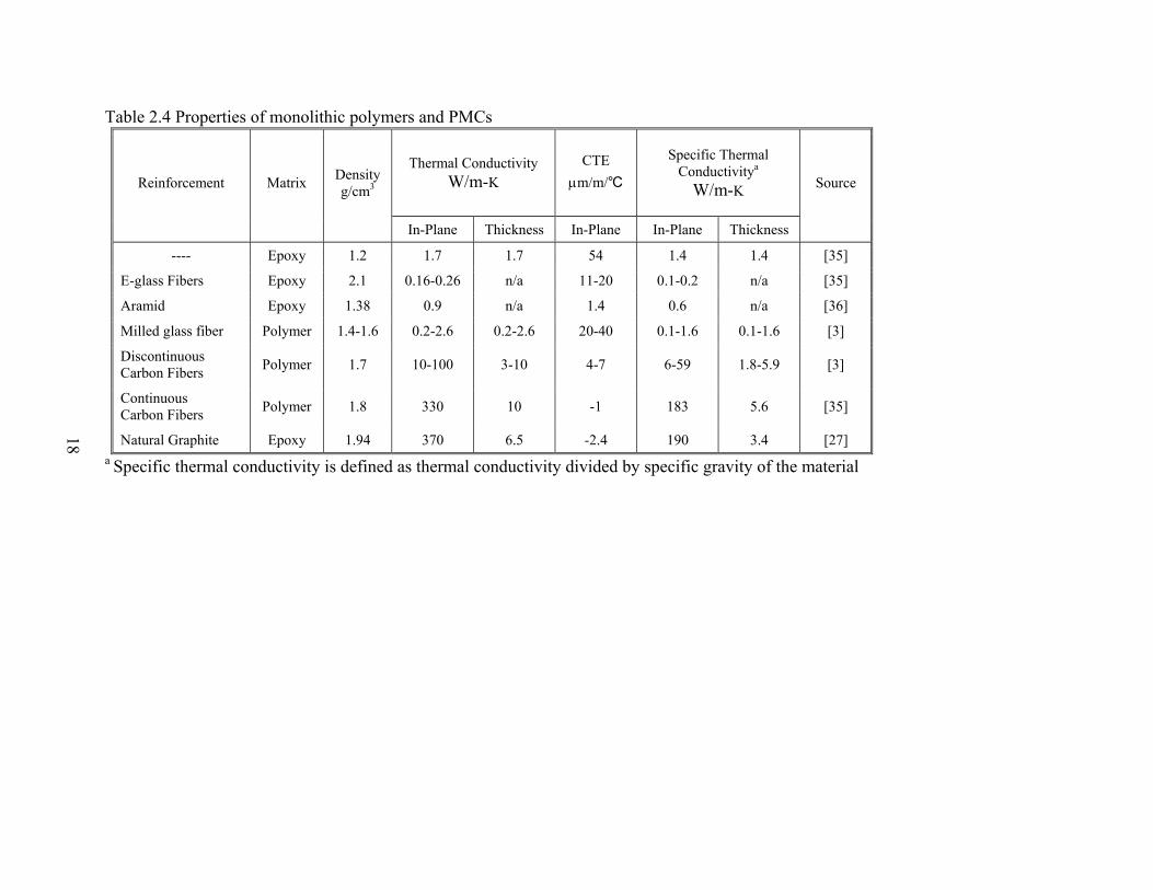
18
Table 2.4 Properties of monolithic polymers and PMCs
Thermal Conductivity W/m-K
CTE μm/m/℃
Specific Thermal Conductivitya
W/m-K Reinforcement Matrix Density g/cm3
In-Plane Thickness In-Plane In-Plane Thickness
Source
---- Epoxy 1.2 1.7 1.7 54 1.4 1.4 [35]
E-glass Fibers Epoxy 2.1 0.16-0.26 n/a 11-20 0.1-0.2 n/a [35]
Aramid Epoxy 1.38 0.9 n/a 1.4 0.6 n/a [36]
Milled glass fiber Polymer 1.4-1.6 0.2-2.6 0.2-2.6 20-40 0.1-1.6 0.1-1.6 [3]
Discontinuous Carbon Fibers Polymer 1.7 10-100 3-10 4-7 6-59 1.8-5.9 [3]
Continuous Carbon Fibers Polymer 1.8 330 10 -1 183 5.6 [35]
Natural Graphite Epoxy 1.94 370 6.5 -2.4 190 3.4 [27] a Specific thermal conductivity is defined as thermal conductivity divided by specific gravity of the material

19
Table 2.5 Properties of fiber reinforced PMCs
Reinforcement Formulation Matrix Density Thermal Conductivity CTE Source
W/m-K 10-6 m/m/°C % (wt or Vf)
g/cm3 x y z x y
CFa 40 wt Nylon 6,6 n/a 16.6 16.6 0.95 n/a n/a [21]
CFa 40 wt Polycarbonate n/a 12.2 12.2 0.74 n/a n/a [21]
CB/SGa/CFa 5/30/20 Polycarbonate n/a 20.1 20.1 1.99 n/a n/a [21]
1D P-75 35 wt Polystyrene 1.34 59.8 n/a n/a n/a n/a [22]
1D P-75 30 wt Polystyrene 1.34 95.4 n/a n/a n/a n/a [22]
1D P-75 45 wt Polyester 1.58 64.5 n/a n/a n/a n/a [22]
1D P-100 45 wt Polyester 1.64 104.4 n/a n/a n/a n/a [22]
1D P-120 45 wt Polyester 1.66 245.0 n/a n/a n/a n/a [22]
1D short staple VGCF
54 Vf Cyanate ester
resin 1.68 466 142 3 -1.5 18 [23]
2D short staple VGCF 54 Vf
Cyanate ester resin 1.69 303 284 4 2.0 6.3 [23]
1D mat VGCF 75 Vf Epoxy 1.87 661 37 9 n/a n/a [23]
2D mat VGCF 64 Vf Epoxy 1.84 300 268 8 n/a n/a [23]
1D VGCF 38 Vf Epoxy 1.48 695 36 n/a -0.11 n/a [24]
2D VGCF 56 Vf Epoxy 1.37 292 285 n/a n/a n/a [24]
NOTE: a - CB signifies Kejenblack EC-600 JD, SG signifies Thermocarb™ specialty graphite, and CF signifies Thermal Graph DKD X.

20
Similar to fiber reinforced polymer matrix composites, there is a growing interest in enhancing the properties of particulate polymer matrix composites at the nanoscale. Jordan et al. [38] presented a review on this topic indicating some interesting first tests as well as the trends found within the different papers. To qualify as a “nanocomposite,” at least one dimension of the particles must be in the range of 1-100 nm. From the review, it is clear that there is a large range of different manufacturing techniques to create nanocomposites. Due to the different results that were obtained and the different polymer nanocomposite systems that were examined, Jordan et al. [38] found no universal trend that can be modeled and explained. It is clear, however, that the behavior of nanocomposites differs from composites with larger scale inclusions. The particle size, the polymer, and particle morphology play very important roles. In addition, the nature of dispersion and the aggregation of particles can affect the properties of composites significantly. Filler–matrix interaction is another factor that influences the properties. For nanoparticles, any configuration changes in the matrix will have a significant effect when the characteristic radius of polymer chains is of the same order as the inclusions. Although these materials show promise (like carbon nanotube fiber PMCs), these materials are still in the research phase with much of their behavior still unexplored and unexplained. Inorganic clays have also attracted considerable attraction as filler material for polymer nanocomposites. Lebaron et al. [39] and Ahmadi et al. [40] presented a review on these materials. It was shown that in order for clay-composite materials to have strong improved mechanical properties, the particles should be well dispersed within the matrix—the so called ‘exfoliated’ design (see Figure 2.4). Achieving this dispersion often requires pretreatment of the clays.
Figure 2.4 Schematic illustrations of nanocomposites: A-conventional, B-intercalated, C-ordered exfoliated, and D-disordered exfoliated polymer–clay nanocomposite [40].

21
Gao [41] presented a short review on the history of clay-polymer nanocomposites and then compared those materials to conventional glass-fiber reinforced polymers. In theory, the reinforcement of polymers at the nanometer scale has significant advantages over traditional fiber reinforced composites. The main weakness of fiber-reinforced composites is the inability to fully utilize inherent properties of the constituent materials. For example, carbon fibers are used in composite materials because of the strong covalent bonds that are present within the aromatic sheets of the graphite structure. However, current carbon fibers only achieve 3-4% of the theoretical strength of the aromatic sheets. This is not a problem in layered-filler reinforced polymer nanocomposites. Once the layers are exfoliated in the polymer matrix, they are interconnected by the polymer so that the inherent properties of the individual layers can be fully utilized within the nanocomposite. In reality, the mechanical properties of the best clay/polymer nanocomposites (i.e. clay/nylon-6 nanocomposites with ~4 wt% clay loading) are much lower than conventional fiber reinforced composites with a high fiber volume fraction. It can be seen in Figure 2.5 that clay/nylon-6 nanocomposites with ~4 wt% clay loading cannot match nylon-6 fiber reinforced polymers with 48 wt% chopped glass fibers. The main reason for this difference is that obtaining the exfoliated layout for the clay particles at higher loadings has proved to be extremely difficult. By using large amounts of solvents, some advances have been made but at a substantial increase in cost. It is important to note, however, that when clay and fiber composites are compared in the low filler range, the clay composites exhibit superior properties as seen in Figure 2.6.
Figure 2.5 Comparison of the tensile strength and Young’s modulus for nylon-6, a 4 wt% clay composite and a 48 wt% glass fiber reinforced composite [41]
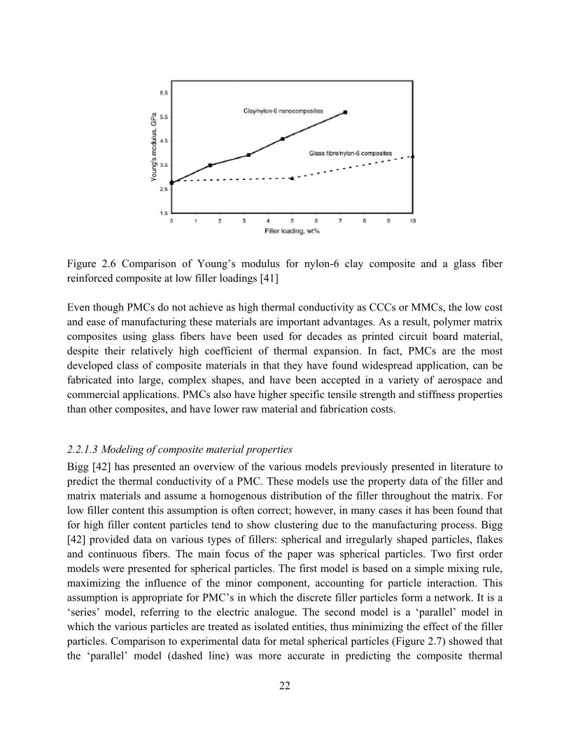
22
Figure 2.6 Comparison of Young’s modulus for nylon-6 clay composite and a glass fiber reinforced composite at low filler loadings [41] Even though PMCs do not achieve as high thermal conductivity as CCCs or MMCs, the low cost and ease of manufacturing these materials are important advantages. As a result, polymer matrix composites using glass fibers have been used for decades as printed circuit board material, despite their relatively high coefficient of thermal expansion. In fact, PMCs are the most developed class of composite materials in that they have found widespread application, can be fabricated into large, complex shapes, and have been accepted in a variety of aerospace and commercial applications. PMCs also have higher specific tensile strength and stiffness properties than other composites, and have lower raw material and fabrication costs.
2.2.1.3 Modeling of composite material properties Bigg [42] has presented an overview of the various models previously presented in literature to predict the thermal conductivity of a PMC. These models use the property data of the filler and matrix materials and assume a homogenous distribution of the filler throughout the matrix. For low filler content this assumption is often correct; however, in many cases it has been found that for high filler content particles tend to show clustering due to the manufacturing process. Bigg [42] provided data on various types of fillers: spherical and irregularly shaped particles, flakes and continuous fibers. The main focus of the paper was spherical particles. Two first order models were presented for spherical particles. The first model is based on a simple mixing rule, maximizing the influence of the minor component, accounting for particle interaction. This assumption is appropriate for PMC’s in which the discrete filler particles form a network. It is a ‘series’ model, referring to the electric analogue. The second model is a ‘parallel’ model in which the various particles are treated as isolated entities, thus minimizing the effect of the filler particles. Comparison to experimental data for metal spherical particles (Figure 2.7) showed that the ‘parallel’ model (dashed line) was more accurate in predicting the composite thermal

23
conductivity. Higher order models for the thermal conductivity are based on series expansions based on localized thermal conductivity. These models however require more information about the microstructure of the PMC. In many cases, such data are not readily available.
Figure 2.7 Measured thermal conductivity ratio of the PMC to the polymer matrix material for various volume fractions compared to the ‘series’ model (full line) and the ‘parallel’ model (dashed line) [42] As described by Bigg [42], Nielsen developed a model for the thermal conductivity based on the Kerner equation for the modulus of a composite material. This model included the effect of the maximum packing fraction of the particles and introduced a coefficient dependant on the shape and orientation of the particle, greatly extending the application of the model. When comparing the second order models and Nielsen’s model to experimental data for metal spheres (Figure 2.8), it is clear these models are far more accurate than the first order models. It seems that for high filler concentrations Nielsen’s model has a tendency to overpredict the increase in thermal conductivity. From Figure 2.8, it is clear that there is no significant particle interaction up to a volume loading of 0.3. Above this level it seems there is a level partial interaction, as indicated by the spread in the data points. To quantify this effect however in high order models, as stated, more information is required on the microstructure of the material.

24
Figure 2.8 Measured thermal conductivity ratio of the PMC to the polymer matrix material for various volume fractions compared to the Nielsen model (full line) and the Hatta-Taya model (dashed line) (from [42]) Bigg [42] also described the models of Agari and Hatta-Taya for irregular shaped particles, flakes and short fibers. It was found that the Hatta-Taya model was very good for predicting the thermal conductivity of isotropic short fiber reinforced polymer matrix composites, whereas the Nielsen model overpredicted due to giving more weight to the dispersed phase. The data, however, consisted of in-plane thermal conductivity measurements. Very few data are available to validate these models for through-thickness thermal conductivity. A comparison with limited data indicated that the Hatta-Taya model is fairly accurate, but more validation is required. The Nielsen model is not suited for long fibers as it is unable to account for the various distributions of the fibers. However, it is found that a simple mixture model can be used to determine the thermal conductivity of the composite. In a previous review paper, Bigg [15] listed all data points used in his studies, carefully identifying matrix and filler material, reference, type of filler and composite properties. In both review papers, Bigg [15, 42] presented a description of both steady state and transient techniques used to measure the thermal conductivity. Ahmed et al. [43] presented an overview of previously published theoretical models to predict the tensile modulus and strength of particulate polymer composites. It was found these properties of a particulate composite material are affected by many parameters, including the material properties of the matrix and particles, volume fraction of the particles, the state of the interface between matrix and particle, particle size distribution (some authors report smaller particles result in an increased modulus), particle shape (sharp edges can result in stress concentration promoting cracking) and the microstructure of the composite (aggregates of particles can result in an increased modulus). To date, there appears to be no successful general theory satisfactorily

25
predicting the modulus or tensile strength of a particulate composite material. It is clear much more systematic research is required in this area. Mamunya et al. [17] provide a description of percolation theory for conduction (electrical and thermal) in particle filled polymer matrix composites. Percolation is the behavior in which a material property shows a characteristic sudden rise as the volume fraction of the filler is increased, as can be seen in Figure 2.9. For conduction, this is due to the formation of a particle aggregates resulting in an ‘infinite conducting unit.’ This behavior is always found for metal powder filled composites, but not for the thermal conductivity. This behavior is because in order to achieve percolation-like behavior the relative difference between the two conductivities of the matrix and filler material must be at least of the order 100. It is found that the maximum packing factor F of the particles is a key parameter for describing percolation behavior, taking into account the phase topology and particle shape.
Figure 2.9 Typical representation of the electrical conductivity of a PMC using metal particles vs. the filler volume content displaying percolation behavior (from [17])
2.2.2 Liquid-to-liquid heat exchangers In their reviews, Zaheed et al. [5] and Reay [6] present an overview of existing polymer heat exchangers, but they mainly provide manufacturers’ unproven claims found on websites. Most presented applications deal with corrosive applications, such as immersion coils for electroplating, cooling and heating of acids, and heat recovery from a solvent-laden air stream. Some applications are of interest to the current project. An automotive radiator made of glass fiber reinforced Nylon is described (manufactured by Dupont). The unit consists of thin-walled tubing, 0.2 mm thickness, 3.66 mm outer diameter. The number of tubes was selected to keep the cross-sectional flow area of the shell identical to that of a commercial metal heat exchanger. With 86 tubes, the heat transfer area is 0.42 m², 50% larger than the metal heat exchanger and the

26
heat transfer rate is 40% higher than its metal counterpart. These units are suited for HVAC and many other industrial uses. Apparently, commercial production for comfort heating and cooling applications started in 2001. A ‘monoblock’ plate heat exchanger made of extruded PP sheets is also presented (manufactured by AB Segerfrojd). The working temperature range is stated to range from -40 °C to 90 °C, with an overall pressure drop ranging from 10 to 400 Pa. Seamless connections between the different sheets result in an airtight unit. Aside from these two review articles (and the articles they cited) some additional technical papers on polymer heat exchangers were found. The most relevant papers will be briefly summarized below, divided by type of heat exchanger considered. Morcos et al. [44] presented heat transfer and pressure drop data for a PVC shell and tube heat exchanger for varying tube and shell side Reynolds numbers. The unit (Figure 2.10) consisted of 1.3 m long circular tubes with an outer diameter of 34 mm and a wall thickness of 5 mm. Five baffles were placed within the shell. The wall thickness was found to limit the overall heat transfer coefficient to a maximum of 90 W/m²-K; reducing the thickness would result in a higher maximum value. In order to enhance the heat transfer rate double conical PVC turbulators (Figure 2.11) were introduced in the tubes. These were held in place using wires. Heat transfer enhancement factors of up to 3.5 were reported without a pressure drop penalty. This finding might be due to high pressure drops associated with the manifolds.
Figure 2.10 PVC shell and tube heat exchanger studied by Morcos et al. [44]

27
Figure 2.11 Turbulator introduced within the heat exchanger tube by Morcos et al. [44] The solar energy research group at the University of Minnesota has worked extensively towards creating a low-cost solar water heater. They conducted a review on the use of polymers in liquid to liquid heat transfer [45]. In order to determine which polymers were suitable for the application a three level screening was performed. First, the NSF standards were checked to determine which polymers meet potable water requirements. These polymers were then assessed for their mechanical properties. For most polymers, no mechanical data were available for hot water or hot propylene glycol interaction; data from hot-air measurements were used. Using criteria based on the glazing temperature, the thermal index and the heat distortion temperature at 1.8 MPa, the set of suitable polymers was reduced. In a final screening, the remaining polymers were ranked according to strength, stiffness, cost and thermal conductivity. The aim of this screening was to study the polymer’s response to mechanical and thermal static or cyclic loads. The material properties were all combined into a single figure of merit: the ratio of the thermal conductance to the cost of the per unit area. For the thin-wall tubes, high-temperature nylon (HTN), cross-linked polyethylene (PEX) and PP were found to be the best candidates. For the headers, glass-fiber reinforced polymers were preferred, HTN, PP and PPS being the recommended types. More details on this screening can be found in Raman et al. [11]. This first phase of their study indicated a lack of data on the long term mechanical behavior of polymer tubing in hot water environments. To fill this gap, an experimental program was set up to resulting in data on the creep compliance, tensile strength and strain at failure for PSU, PB and Nylon 6,6 at 82 °C and in hot chlorinated water (Freeman et al. [46] and Wu et al. [47]). Scaling in these polymer tubes was studied by Wang et al. [48]. It was found that Nylon 6,6 had a more pronounced scaling rate compared to HTN, PB, PP and Cu. Having analyzed the material properties and having selected polymers of choice for the solar heater, Liu et al. [49] numerically studied the feasibility of both a shell and tube heat exchanger and an immersed unit. The arrangement and number of tubes, shell dimensions, flow rate of the liquids and the required heat rate in an external tube-in-shell heat exchanger were fixed, and the length of the tube required was calculated. Figure 2.12 and Figure 2.13 show the dimensions and layout of the polymer shell and tube heat exchanger and the immersed heat exchanger, respectively. Two kinds of polymer tubes were analyzed: PEX and nylon. The thermal

28
conductivities for PEX and nylon were similar, with PEX being slightly more conductive (~0.38 W/m-K) as compared to nylon (~0.31 W/m-K). The PEX heat exchanger used a standard PEX tube with outer diameter 9.53 mm and a wall thickness of 1.78 mm, while the nylon heat exchanger used smaller tubes of outer diameter 3.81 mm and only 0.2-mm-thick walls, as can be seen in Figure 2.12 The analysis highlighted the fact that the thermal resistance of the wall was a dominant limitation of the PEX heat exchanger, but that was not the case for the nylon unit. Liu and co-workers noted that at a typical flow rate of 5.7 l/min, the contributions of inside, outside and wall conduction to the total thermal resistance were 24%, 34% and 42%, respectively for the PEX heat exchanger, and 49%, 26% and 25%, respectively for the nylon counterpart. Additionally, the required lengths of the tube for the nylon heat exchanger were ~75% less than the PEX heat exchanger. This is mostly due to decreased thermal resistance because of thinner walls in nylon heat exchanger. Further, the analysis of a copper heat exchanger, with tubes of outer diameter 6.35 mm and wall thickness 0.5 mm, showed that its wall thermal resistance was negligible and its performance was limited only by the flow inside the tubes, the percents of inside, outside and wall thermal resistances, at typical flow rate of 5.7 L/min, being 76%, 24% and 0.04%, respectively. A comparison of the polymer heat exchanger with the copper one is given in Table 2.6. It is interesting to note that the thin-walled nylon heat exchanger has a performance very similar to that of the copper heat exchanger.
Figure 2.12 Polymer shell and tube heat exchanger studied by Liu et al. [49]
Table 2.6 Heat transfer surface areas for tube-in-shell HX at 5.7L/min [49] Heat transfer capacity PEX Nylon Copper
3000 W @ 5.7L/min 1.78 m² 0.50 m² 0.50 m² 6000 W @ 5.7L/min 7.78 m² 2.16 m² 2.19 m²

29
The immersed heat exchanger (Figure 2.13) has a bundle of horizontal tubes placed in a water tank; liquid flows through the tubes and natural convection prevails in the tank. The outer diameters and wall thicknesses of the tubes for PEX and nylon immersed tube-bank configuration were the same as those for the tube-in-shell configuration. The results of the analysis were very similar to the tube-in-shell configuration and have been summarized in Table 2.7. In this case, the copper immersed heat exchanger was modeled as a single 15.88 mm outside diameter tube.
Figure 2.13 Immersed heat exchanger studied by Liu et al. [49] Table 2.7 Heat transfer surface areas for immersed heat exchanger [49] Heat transfer capacity PEX Nylon Copper
3000 W @ 5.7L/min 4.21 m² 1.89 m² 1.10 m² 6000 W @ 5.7L/min 11.4 m² 8.42 m² 2.03 m²

30
Again, it is clear from the results that heat transfer areas for the nylon and copper heat exchangers were significantly lower than that required for the PEX heat exchanger. Thus in liquid-to-liquid heat exchangers, thin walls in polymer designs can achieve thermal performance levels comparable to their metallic counterparts. The results presented by Liu et al. indicated that using Nylon or PEX as heat exchanger material is a viable option for solar water heating. However, modifying the design by using smaller tubes with thin walls the advantages of the polymer materials can be further exploited. In order to reduce exterior pressure drop, Li et al. [50] undertook a numerical study of different extruded shaped tubes: lenticular, teardrop and oval (Figure 2.14). The inner flow passage is circular. The analysis showed that adding material to the base tube to form these shaped tubes reduces the heat transfer rate, due to the low thermal conductivity of the material. The analysis introduced “shaped tube efficiency,” comparing the added material to a longitudinal fin. Increasing the thermal conductivity of the polymer to 1 W/m-K will make the use of these shaped tubes even more interesting. Surprisingly, no data were presented on the reduction in shell-side side pressure drop.
(a) (b) (c)
Figure 2.14 Different tube shapes studied by Li et al. [50]: (a) lenticular, (b) teardrop, and (c) oval Zakardas et al. [51] presented a novel design of polymer heat exchanger for liquid to liquid or condensing fluid to liquid heat transfer. The design was hollow-fiber heat exchangers. The heat exchanger consists of thin fibers connected between two headers (Figure 2.15). It is basically a shell and tube heat exchanger without baffles, but on a different length scale. The shell-side flow can be cross flow or parallel/counter flow. In the constructed heat exchangers, thin PP (425/575 µm ID/OD) and PEEK hollow fibers (150/360 µm ID/OD) were used. Three different designs were tested. These units showed a very high compactness, achieving 1500 m² of exterior surface area in a shell that was 11.8 cm long with a diameter of 2.3 cm. Overall heat transfer coefficients up to 1360 W/m²-K were reported. The design (designated 41939) transfered up to 5.3 kW using a volume less than 250 times smaller than a conventional design. Two figures of merit were defined: the overall conductance per unit volume and the pressure drop per NTU. Comparing their design to a conventional shell-and-tube design and a plate heat exchanger, it was found that

31
even for fouled conditions the unit achieved similar performance, while having a lower overall pressure drop. This type of heat exchanger appears to be highly competitive as a replacement for the conventional metal designs.
Figure 2.15 Concept of a hollow fiber heat exchanger as proposed by Zakardas et al. [51] Patel et al. [52] studied a polymer Kapton®* heat exchanger for cryogenic applications. The heat exchanger was made using thin 127 µm polymer films with a serpentine flow path. The aim was to exchange heat between a superfluid for a Stirling cycle and a He3-He4 dilution. Polymer materials clearly offer some advantages for very-low-temperature applications because the conductive resistance becomes small compared to the Kapitza limit. Several other applications have been described of dilution heat exchangers for Stirling cycles; however, these applications lie outside the scope of this project. Leigh et al. [53] conducted a research program at Brookhaven National Laboratory (BNL) which addressed the possibility of dramatically lowering the first cost of absorption chillers through lowered material intensity and the use of lower-cost materials, primarily in the heat exchangers which make up the bulk of the operating components of these systems [1-chapter3]. They identified and tested a set of polymeric and metallic materials appropriate to particular components to meet the cost goals. They also developed conceptual designs and a simulation model which indicated this design will operate with a COP of 1.0 for a directly fired, double-effect unit. They determined that the second-effect generator and one or both recuperators were viable candidates to be manufactured from PEEK, but that the permeability of all polymers rendered them unsuitable for the evaporator, absorber, or condenser, since they would allow oxygen into the chiller from the circulating water. The additional load on the chiller’s purge system would be unacceptable, and the chiller’s performance would be significantly degraded [53]. A novel design for a plastic thin-film heat exchanger was developed and tested by Lowenstein et al. [54, 55]. This investigation proved the feasibility of designing and producing evaporators and
* Kapton® is a trademark of DuPont

32
absorbers from thin plastic films. A laminated film composed of Mylar®†/PVDC/adhesive/ polyethylene-EVA demonstrated excellent seal strength in bursts tests of single tubes. Based on tests of the long-term creep characteristics of a HDPE film, the projected life of this heat exchanger made from HDPE and operating at 25 psi/100°F would be 20 years.
2.2.3 Liquid-to-gas heat exchangers Bigg et al. [56] studied the use of polymeric tubes and coatings covering metal tubes for a condensing heat exchanger placed in the flue gas flow of a gas-fired boiler. The aim of the study was to assess the lifetime of the polymer tubes and coatings. Commercial 1.27 cm diameter tubes of PTFE, PP and PPS and 1.9 cm diameter tubes of PSU, PEI were tested. Aluminum tubes of 1.9 cm diameter were covered with an epoxy or vinyl ester coating of 0.1 mm thickness or a thicker coating of 0.5 mm of FEP. After 100 days of exposure, none of the full polymer tubes showed any degradation (as indicated by local hardness measurement and infrared scans); however, the epoxy and vinyl ester coating had failed. Due to the difference in thermal expansion between the metal and the coating, small cracks had appeared, allowing the corrosive gas to attack the base metal. A coating mixed with aluminum flakes (to increase the thermal conductivity) showed degradation where the flakes made contact with the surface. Previous studies had shown that thin coatings can fail due to pinhole effects, indicating the need for thicker extruded coverings. El-Dessouky et al. [57] presented a numerical model for PTFE plate preheaters and a shell and tube evaporator for a single-stage mechanical vapor compression unit. This is a typical desalination application, where the hot brine is very corrosive to metals. In the model, thin-walled polymer tubes and plates were studied (40-150 µm), indicating a need for spacers to prevent the structure from collapsing and for very fine filtering, should this unit ever be constructed. The results were compared to metal heat exchangers made of titanium, high alloy steel and Cu-Ni alloys. The specific heat transfer area of the PTFE preheaters and evaporator was 2 to 4 times larger than that of the metal heat exchangers with varying top brine temperature. However, economic evaluations found that the polymer heat exchanger had the lowest cost. Bourouni et al. [58] presented experimental data on a falling film evaporator and condenser made of 2.5 cm diameter circular PP tubes (wall thickness = 5 mm) used in an ‘aero-evapo-condensation process’ for desalination. The studied test rig is shown in Figure 2.16. The results were compared to a model showing good agreement on the impact of water mass flow rate and inlet temperature. An economic analysis indicated that the unit would only be viable if cheap heat was available, such as from a geothermal power source, or process waste heat. Rousse et al. [59] presented an experimental study of a PE shell and tube heat recovery unit for greenhouses. This trial unit was not very compact (i.e. only 27 m²/m³) and was solely aimed at
† Mylar® is a trademark of DuPont

33
demonstrating the proof of concept to greenhouse owners. Five corrugated PE tubes (shown in Figure 2.17) with a wall thickness of 1 mm were placed within a single shell. Experimental data agreed well with the proposed model. The designed unit met the design requirements: low cost (three year pay back period); ease of assembly, repair, maintenance and operation; corrosion resistance and satisfactory performance under frosting conditions. In operation, efficiencies up to 84% were measured, with latent heat contributing about 40% of the total heat transferred in some cases.
Figure 2.16 Desalination unit studied by Bourouni et al. [58].
Figure 2.17 Corrugated PE tubes as used in a shell and tube heat exchanger – Rousse et al. [59]. Tather et al. [60] presented a numerical study on using PTFE tubes in adsorption heat pumps to increase the COP. A previously validated model was used to show that if thin walled (< 1 mm) PTFE tubes are used the total power of the cycle was the same as for stainless steel tubes. However, the COP of the system increased 1.5 to 2.5 times. This work considered the presence

34
of thin zeolite coatings (<100 µm) on the polymer and stainless steel surfaces, however it still needs to be shown this type of coating can be applied to polymer tubes. Zaheed et al. [5] and Reay [6] both presented some examples of polymer plate heat exchangers intended to be used for liquid-to-gas heat transfer. An interesting design presented by Reay [6] was an economizer made of thin (reinforced) PSU plates, having 1.5 mm diameter circular channels inside which formed the secondary-fluid heat transfer surface (Figure 2.18).
Figure 2.18 Polysulfone economizer [6] Burns et al. [61] presented a compact plate heat exchanger made of thin (100 µm) PEEK films. The straight films were formed into wavy corrugated films with a mean thickness of 53 µm and amplitude of 1 mm. Seven sheets, 13.5 cm wide by 13.5 cm long, were stacked each rotated 90° to one another to provide a cross-corrugated layers for fluid flow, as can be seen in Figure 2.19. PEEK was selected for its high chemical and fatigue resistance, high working temperature (up to 220 °C) and thermal stability. The hydrophobic and very smooth surface, combined with the thermal expansion properties should also strongly reducing fouling. The constructed unit showed remarkable mechanical stability resisting pressures up to 10 bar at atmospheric conditions. The typical heat duty of these units ranged from 10 to 400 W. Experimentally measured pressure drops on the liquid side were below 400 Pa for a flow rate up to 500 ml/min and on the gas side below 4.3 kPa for a flow rate up to 10 m³/h. Overall heat transfer coefficients ranged from 60 to 370 W/m²-K with drop-wise condensation on the gas side. It was found that a significant volume of liquid condensate remained within the gas layer which decreases as the gas flow rate was increased.
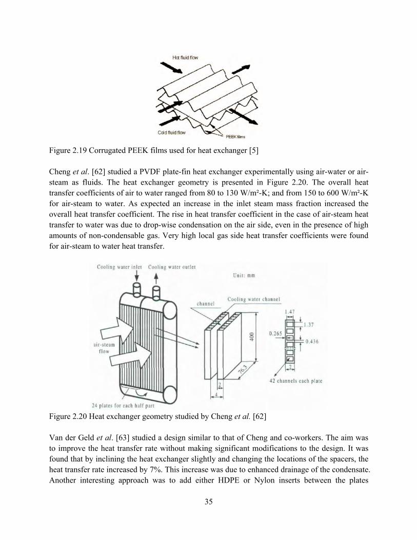
35
Figure 2.19 Corrugated PEEK films used for heat exchanger [5] Cheng et al. [62] studied a PVDF plate-fin heat exchanger experimentally using air-water or air-steam as fluids. The heat exchanger geometry is presented in Figure 2.20. The overall heat transfer coefficients of air to water ranged from 80 to 130 W/m²-K; and from 150 to 600 W/m²-K for air-steam to water. As expected an increase in the inlet steam mass fraction increased the overall heat transfer coefficient. The rise in heat transfer coefficient in the case of air-steam heat transfer to water was due to drop-wise condensation on the air side, even in the presence of high amounts of non-condensable gas. Very high local gas side heat transfer coefficients were found for air-steam to water heat transfer.
Figure 2.20 Heat exchanger geometry studied by Cheng et al. [62] Van der Geld et al. [63] studied a design similar to that of Cheng and co-workers. The aim was to improve the heat transfer rate without making significant modifications to the design. It was found that by inclining the heat exchanger slightly and changing the locations of the spacers, the heat transfer rate increased by 7%. This increase was due to enhanced drainage of the condensate. Another interesting approach was to add either HDPE or Nylon inserts between the plates

36
(Figure 2.21). These random fiber-like structures resulted in a considerable increase in the heat transfer rate. The increased heat transfer was due to a limited fin effect (low thermal conductivity), a large increase of the exterior surface area (159% increase for the HDPE inserts) and an increase in the velocity between the plates. This explanation is consistent with the data, indicating the main effect of the inserts was to increase the convective part of the heat transfer.
Figure 2.21 Nylon inserts as used by Van der Geld et al. [63] Harris et al. [64] studied a micro cross flow plate heat exchanger made of nickel and PMMA (Figure 2.22). The overall dimensions of the polymer heat exchanger were 5 mm by 5 mm by 1.8 mm. The nickel heat exchanger was manufactured using a sacrificial PMMA mandrel. An analytical model was derived for the micro cross flow heat exchanger combined with finite element simulations to predict the performance. Good agreement was found between the predictions and the measured results. The results are presented in Table 2.8. The first two lines show the experimental data for the PMMA and nickel heat exchanger. Three figures of merit were introduced: the heat transfer rate Q was divided by the temperature difference between the fluids entering the heat exchanger ΔT and then divided by either the frontal surface A, the volume V, or the mass m. The performance of the fabricated nickel heat exchanger was significantly better than for the fabricated PMMA heat exchanger, in terms of heat transfer/frontal area. However, the PMMA heat exchanger out performed the nickel heat exchanger on heat transfer/mass basis, due to the low density of the polymer. The final row of Table 2.8 contains data on a conventional-scale radiator, showing good performance on the basis of heat transfer/frontal area and performance slightly below that of the micro-heat exchangers on a heat transfer/mass basis. The model was then used to study the effect of using more conductive materials (aluminum, ceramic). An optimal design was first determined, limiting the channel size to 200 µm. This design is indicated by (opt) in Table 2.8. It can be seen that the polymer heat exchanger has similar performance to that of the aluminum version when comparing on a heat transfer/mass basis, but significantly lower performance on a heat transfer/frontal surface or volume basis.
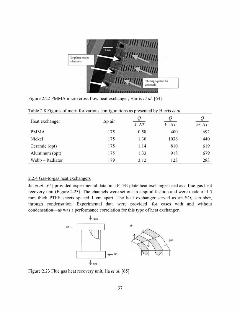
37
Figure 2.22 PMMA micro cross flow heat exchanger, Harris et al. [64] Table 2.8 Figures of merit for various configurations as presented by Harris et al.
Heat exchanger Δp airTA
QΔ⋅ TV
QΔ⋅
Tm
QΔ⋅
PMMA 175 0.58 400 692Nickel 175 1.30 1036 440Ceramic (opt) 175 1.14 810 619Aluminum (opt) 175 1.33 918 679Webb – Radiator 179 3.12 123 283
2.2.4 Gas-to-gas heat exchangers Jia et al. [65] provided experimental data on a PTFE plate heat exchanger used as a flue-gas heat recovery unit (Figure 2.23). The channels were set out in a spiral fashion and were made of 1.5 mm thick PTFE sheets spaced 1 cm apart. The heat exchanger served as an SO2 scrubber, through condensation. Experimental data were provided—for cases with and without condensation—as was a performance correlation for this type of heat exchanger.
Figure 2.23 Flue gas heat recovery unit, Jia et al. [65]

38
An interesting idea was proposed by Dobbs [66]. It consists of using ionomer membranes, such as sulfonated or carboxylated polymer membranes. This heat exchanger is intended to be used as an ‘energy recovery unit’ in HVAC, recovering not only heat but also moisture, which can pass through the membranes. Of course such a design feature is not possible with metallic heat recovery units. No experimental data were presented. Saman and Alizadeh [67, 68] presented a numerical and experimental study of a polymer plate heat exchanger aimed at dehumidification and cooling (Figure 2.24). A liquid desiccant was injected into one air stream in order to dehumidify, while water was injected into the secondary stream to provide evaporative cooling. Thin PE sheets (0.2 mm) separated both streams. The numerical results were compared to measured data and good agreement was found. Various parameters were studied: the injection angle, air mass flow rate, temperature and humidity. However, the unit was not able to achieve desired summer comfort level conditions in Brisbane, Australia and instead required additional HVAC systems.
Figure 2.24 Plate heat exchanger for dehumidification and cooling studied by Alizadeh et al. [67]
2.2.5 Heat sinks Heat sinks are a possible interesting application for polymer materials. Their low weight and electrically insulating properties make them an interesting and safe option for portable applications such as laptops. Miller [69] stated that the ‘Apple Powerbook’ used polymer components made of polymer composites with a high thermal conductivity. It has been argued that a minimal thermal conductivity of 1 W/m-K is required to create an economically viable heat sink; thus conventional polymers might not be suitable for this application. However, polymer composite materials are a suitable option, as shown by Bahadur et al. [70]. In their work, a natural-convection pin-fin heat sink made of fiber-filled PPS (20 W/m-K) had a performance similar to that of an aluminum design for small fin heights. The thermal performance of the graphite-epoxy composite is significantly better than that of aluminum (and even approaches that of copper), but at only 70% and 21% of the weight of

39
aluminum and copper, respectively. The result is a heat sink that performs like copper but at a fraction of the weight. Norley et al. [26-33, 71]developed a novel approach for an improved heat sink by using a new natural graphite-based/epoxy composite material with an in-plane thermal conductivity value of ~370 W/m-K and a through-thickness thermal conductivity of 7 W/m-K. Because this material is naturally graphitized, anisotropic heat-spreaders with high thermal conductivity can be manufactured without using traditional carbon fiber-based additives. The design and manufacturing of heat sinks from a material that has high thermal conductivity in only two directions is a great challenge, especially for the heat sink base. Norley and Chen [29] studied the influence of different high thermal conductivity orientations in the base of a heat sink by means of computational analysis. The results showed that the worst orientation for the base plate was when the lowest thermal conductivity was in the through-thickness orientation. This finding is perhaps intuitive since heat cannot be effectively conducted through the base thickness to the fins when it is in this orientation. Marotta et al. [28] developed a bonded-fin graphite/epoxy heat sink for high performance servers using this natural graphite-based/epoxy material. Two typical bonded fin graphite/epoxy heat sinks are shown in Figure 2.25. The heat sinks were manufactured in both cases using pre-molded graphite-epoxy fins and spacers bonded together. Because these materials are relatively soft, some form of mechanical protection is often required. One solution is to use aluminum end plates to provide edge protection to the heat sink, with metal stiffeners inserted into the base to enhance the structural integrity. A variety of mechanical attachment methods were evaluated for joining the graphite to the copper heat spreader. A bonded-fin graphite/epoxy heat sink has been built and has demonstrated thermal performance comparable to a copper heat sink of similar geometry but at only 21-25% of the mass.
(a) (b)
Figure 2.25 Two typical bonded fin graphite/epoxy heat sinks: (a) Direct impingement type, (b) cross flow type
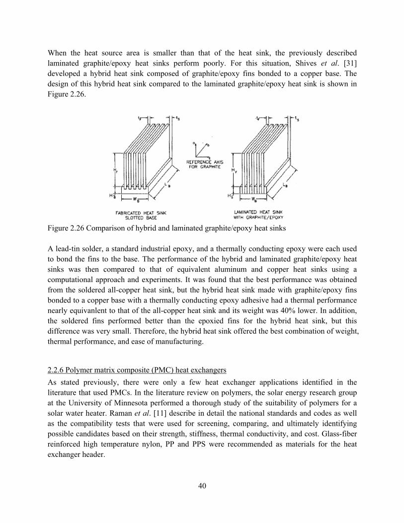
40
When the heat source area is smaller than that of the heat sink, the previously described laminated graphite/epoxy heat sinks perform poorly. For this situation, Shives et al. [31] developed a hybrid heat sink composed of graphite/epoxy fins bonded to a copper base. The design of this hybrid heat sink compared to the laminated graphite/epoxy heat sink is shown in Figure 2.26.
Figure 2.26 Comparison of hybrid and laminated graphite/epoxy heat sinks
A lead-tin solder, a standard industrial epoxy, and a thermally conducting epoxy were each used to bond the fins to the base. The performance of the hybrid and laminated graphite/epoxy heat sinks was then compared to that of equivalent aluminum and copper heat sinks using a computational approach and experiments. It was found that the best performance was obtained from the soldered all-copper heat sink, but the hybrid heat sink made with graphite/epoxy fins bonded to a copper base with a thermally conducting epoxy adhesive had a thermal performance nearly equivanlent to that of the all-copper heat sink and its weight was 40% lower. In addition, the soldered fins performed better than the epoxied fins for the hybrid heat sink, but this difference was very small. Therefore, the hybrid heat sink offered the best combination of weight, thermal performance, and ease of manufacturing.
2.2.6 Polymer matrix composite (PMC) heat exchangers As stated previously, there were only a few heat exchanger applications identified in the literature that used PMCs. In the literature review on polymers, the solar energy research group at the University of Minnesota performed a thorough study of the suitability of polymers for a solar water heater. Raman et al. [11] describe in detail the national standards and codes as well as the compatibility tests that were used for screening, comparing, and ultimately identifying possible candidates based on their strength, stiffness, thermal conductivity, and cost. Glass-fiber reinforced high temperature nylon, PP and PPS were recommended as materials for the heat exchanger header.

41
Fontana et al. [72] describe various ‘polymer concretes’ designed to replace steels in highly corrosive environments such as geothermal heat systems. A polymer concrete is a concrete in which the aggregate is bound together by a dense matrix with a polymer binder. The studied monomer system consisted of 60 wt% styrene – 40 wt% trimetholpropanetrimethacrylate (TMPTMA). Adding metal powders or fibers to the substrate was found to have only a small impact on the thermal conductivity, resulting in thermal conductivity of 1.7 W/m-K for 30 wt% copper powder. A thermally conductive polymer concrete was finally developed using a silicon carbide aggregate with a thermal conductivity of 6.2 W/m-K. Tubes were cast with a wall thicknesses ranging from 2.5 mm to 6.4 mm and were found to resist internal hydrostatic pressures from 1.1 MPa to 2.9 MPa at 150°C. These tubes are promising for use in a supercritical Rankine cycle with a working fluid of a 90/10 mixture of isobutane and isopentane and a geothermal brine as the heat source. Bahadur et al. [70] performed a numerical optimization study of a fiber-filled PPS matrix pin fin heat sink. The material properties were taken directly from the manufacturer, including a specified thermal conductivity of 20 W/m-K. In comparison with other work, this value for the thermal conductivity seems high. The results indicated that for short fins (shorter than 5 cm) the same thermal performance could be reached as for an aluminum fin heat exchanger, but with a mass-based heat transfer coefficient that is 50% higher.
Historically, the interest in polymer materials for heat exchanger applications has been driven by their high chemical stability and corrosion resistance. It was shown that through the use of a polymer coating or polymer tubing, heat recovery from solvent-laden streams is possible. A careful study of the existing standards and the mechanical material properties revealed that several polymer materials were suitable for a solar hot water heating application. However, because of the low thermal conductivity of polymers, using standard design configurations will likely result in a dominating heat transfer resistance by the polymer walls. By using very thin polymer structures, both plate and tubular heat exchangers have been successfully designed, constructed, and tested with their performances being comparable to conventional units. From this review, it is clear that through careful material selection and design modification polymer materials can compete with conventional metallic constructions in some HVAC&R applications.
2.3 Potential of metals and metal matrix composites (MMCs)
2.3.1 Material properties Metal is the most common material from which heat exchangers are built. Generally, metals are good thermal conductors, with good mechanical properties. The best conductors are the "noble metals" which include gold, silver, and platinum. However, noble metals are very expensive. For most applications, with notable exceptions in the aerospace industry, the noble metals are too expensive for heat exchangers in HVAC&R systems. Even the non-noble metals are relatively
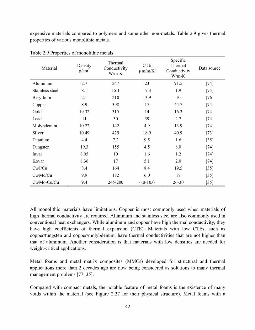
42
expensive materials compared to polymers and some other non-metals. Table 2.9 gives thermal properties of various monolithic metals.
Table 2.9 Properties of monolithic metals
Material Density g/cm3
Thermal Conductivity
W/m-K
CTE μm/m/K
Specific Thermal
Conductivity W/m-K
Data source
Aluminum 2.7 247 23 91.5 [74] Stainless steel 8.1 15.1 17.3 1.9 [75] Beryllium 2.1 210 13.9 10 [76] Copper 8.9 398 17 44.7 [74] Gold 19.32 315 14 16.3 [74] Lead 11 30 39 2.7 [74] Molybdenum 10.22 142 4.9 13.9 [74] Silver 10.49 429 18.9 40.9 [73] Titanium 4.4 7.2 9.5 1.6 [35] Tungsten 19.3 155 4.5 8.0 [74] Invar 8.05 10 1.6 1.2 [74] Kovar 8.36 17 5.1 2.0 [74] Cu/I/Cu 8.4 164 8.4 19.5 [35] Cu/Mo/Cu 9.9 182 6.0 18 [35] Cu/Mo-Cu/Cu 9.4 245-280 6.0-10.0 26-30 [35]
All monolithic materials have limitations. Copper is most commonly used when materials of high thermal conductivity are required. Aluminum and stainless steel are also commonly used in conventional heat exchangers. While aluminum and copper have high thermal conductivity, they have high coefficients of thermal expansion (CTE). Materials with low CTEs, such as copper/tungsten and copper/molybdenum, have thermal conductivities that are not higher than that of aluminum. Another consideration is that materials with low densities are needed for weight-critical applications. Metal foams and metal matrix composites (MMCs) developed for structural and thermal applications more than 2 decades ago are now being considered as solutions to many thermal management problems [77, 35]. Compared with compact metals, the notable feature of metal foams is the existence of many voids within the material (see Figure 2.27 for their physical structure). Metal foams with a
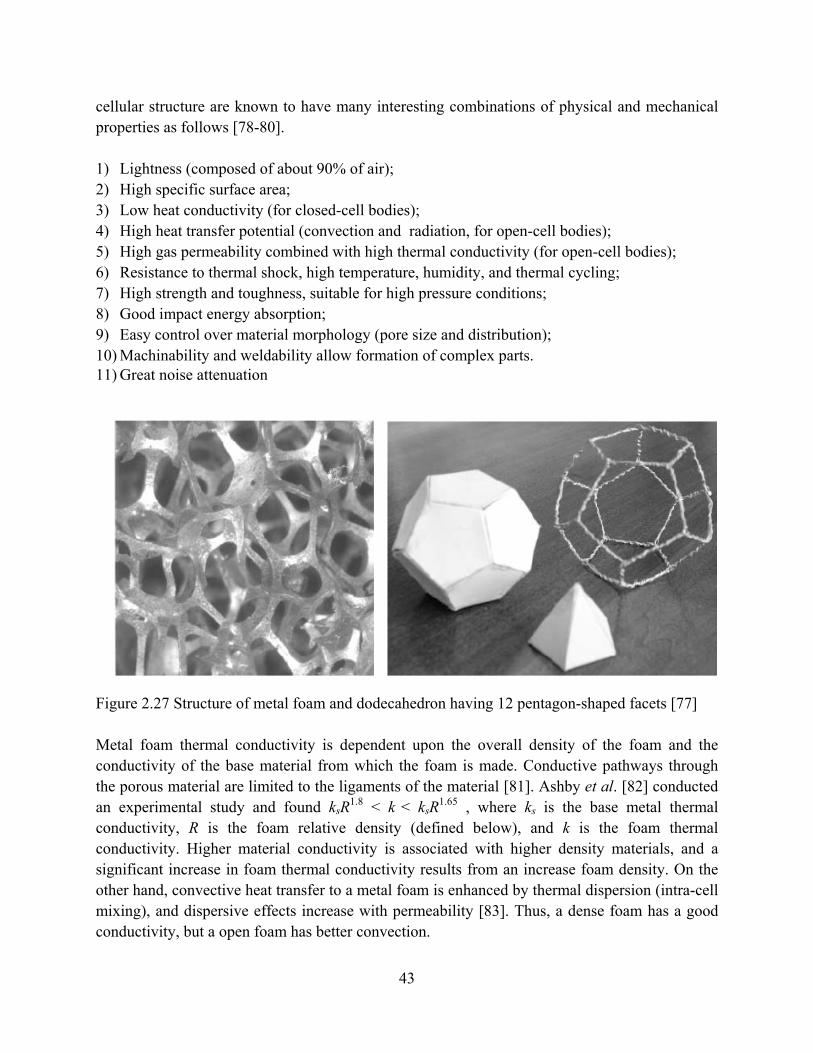
43
cellular structure are known to have many interesting combinations of physical and mechanical properties as follows [78-80]. 1) Lightness (composed of about 90% of air); 2) High specific surface area; 3) Low heat conductivity (for closed-cell bodies); 4) High heat transfer potential (convection and radiation, for open-cell bodies); 5) High gas permeability combined with high thermal conductivity (for open-cell bodies); 6) Resistance to thermal shock, high temperature, humidity, and thermal cycling; 7) High strength and toughness, suitable for high pressure conditions; 8) Good impact energy absorption; 9) Easy control over material morphology (pore size and distribution); 10) Machinability and weldability allow formation of complex parts. 11) Great noise attenuation
Figure 2.27 Structure of metal foam and dodecahedron having 12 pentagon-shaped facets [77] Metal foam thermal conductivity is dependent upon the overall density of the foam and the conductivity of the base material from which the foam is made. Conductive pathways through the porous material are limited to the ligaments of the material [81]. Ashby et al. [82] conducted an experimental study and found ksR1.8 < k < ksR1.65 , where ks is the base metal thermal conductivity, R is the foam relative density (defined below), and k is the foam thermal conductivity. Higher material conductivity is associated with higher density materials, and a significant increase in foam thermal conductivity results from an increase foam density. On the other hand, convective heat transfer to a metal foam is enhanced by thermal dispersion (intra-cell mixing), and dispersive effects increase with permeability [83]. Thus, a dense foam has a good conductivity, but a open foam has better convection.

44
Because of their interesting properties, many new applications have been suggested for metal foams, such as structural elements for aerospace, automotive, and building systems, thermal management systems, filters and catalyst carriers, and others [84]. Indeed, metal foams have been used to produce filters, catalyst supporters, porous electrodes, energy absorbers, silencers, shock-absorbing buffers, electromagnetic shielding or compatible elements, heat exchangers, flame arresters and so on. Furthermore, they can be used to produce many composite materials or to serve as gaskets. Metal foams are a versatile engineering material [85]. Cellular metals are composed of cells that can be categorized as (i) either open or closed foams and (ii) either stochastic or ordered/periodic. Regardless of the classification, cellular metals have a relative density given by R=ρ/ρs [86], where ρ is the density of the cellular metal and ρs is the density of the solid material. Various cellular material properties such as elastic stiffness, effective thermal conductivity, and effective yield strength can be directly related to the properties of the solid comprising the cell walls through the relative density [87]. High porosity, ultra-lightweight, cellular metal structures with open topologies have emerged in the past decade as attractive heat exchange media for a wide range of high-heat-flux applications [82, 88]. These cellular metal structures can be classified into two broad classes, one with a stochastic topology (i.e. metal foams [89]) and the other with a periodic structure [90-95]. A schematic illustration of several open- and one closed-celled periodic structures are shown in Figure 2.28. Examples of the periodic structure include materials made from stacked metal textiles and microtruss concepts, with tetrahedral, pyramidal, and other types of topographies [92]. A wide variety of process-routes have been developed to manufacture cellular metals with relative densities from 0.01 to 0.20, and cell sizes from 100 μm to several centimeters. The open cell systems shown in Figure 2.28(a-e) compare favorably to closed cell honeycombs when used for the cores of sandwich panels. They are therefore attracting considerable attention as multi-functional structures [95].

45
Figure 2.28 A schematic illustration of open- and close-celled periodic structures [95]
Due to the high surface-area density and strong mixing capability for the fluid, open-cell metal foams are currently regarded as a highly promising material for the manufacture of efficient compact heat exchangers. The structure of open-cell metal foams can lead to a wide variety of possible applications, such as light-weight structural applications, mechanical energy absorbers, filters, pneumatic silencers, containment matrices and burn rate enhancers for solid propellants, flow straighteners, catalytic reactors, and more recently heat exchangers. Open-cell metal foams have desirable properties for heat exchanger usage, e.g. a high specific surface area (500 to over 10,000 m2/m3), high thermal conductivity, and a tortuous flow path to promote mixing. In some applications, such as cryogenic refrigeration/ liquefaction systems, heat exchangers are critical components. Unlike in most other chemical process industries, heat exchangers must be highly effective in low-temperature refrigeration systems. The performance of cryogenic refrigerators, liquefiers and separation units is strongly dependent on the effectiveness of the heat exchangers--if the effectiveness of the heat exchanger is below a certain critical value, most cryogenic processes cease to function. In addition, the low values of attainable coefficient of performance and the resulting high cost of refrigeration make it economically sensible to use more effective, albeit more expensive, heat transfer equipment [96]. Currently, most metal foams are produced and used with a range of pore distributions, pores per inch (ppi), from 5 to 60 and a relative density from 3 to 15%. Table 2.10 gives some properties of aluminum foam samples, and Figure 2.29 to Figure 2.32 show metal foams with different pore distributions [77].

46
Table 2.10 Aluminum foam samples [77]
Sample Bulk density (g/mL)
Density (%)
Porosity Permeability (×107) (m2)
Inertial coefficient*
Effective conductivity (W/m-K)
Specific surface (m2/m3)
5ppi 0.899 2.28 0.075 7.32
5ppi 0.93 2.40 0.084 5.33
10 ppi 0.217 8.1 0.9085 1.62 0.078 6.71 899
10 ppi 0.9386 1.54 0.085 4.78
20 ppi 0.165 6.1 0.92 1.11 0.081 5.97 1266
20ppi 0.9353 1.14 0.085 4.99
30 ppi 0.145 5.4 1477
40ppi 0.9091 0.51 0.078 6.67
40ppi 0.9586 0.54 0.086 3.48
* See Eq. (5.4) in section 5.3.1.
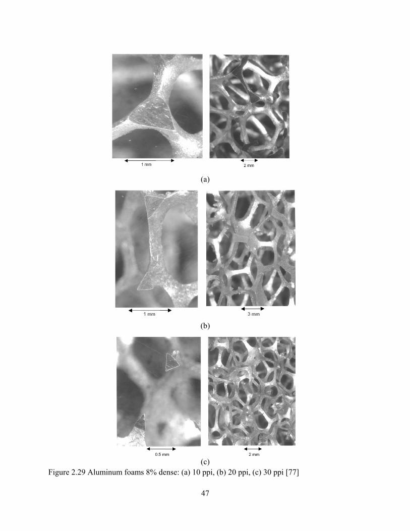
47
(a)
(b)
(c)
Figure 2.29 Aluminum foams 8% dense: (a) 10 ppi, (b) 20 ppi, (c) 30 ppi [77]

48
(a) (b) (c)
Figure 2.30 Compressed metal foam: 30ppi foam uniaxially compressed to 35% density (a) in plane and (b) out of plane (middle), and (c) 30-ppi biaxially compressed to 35% density [77]
(a) (b)
Figure 2.31 30-ppi foam uniaxially compressed to 20% density (a) in plane and (b) out of plane [77]

49
Figure 2.32 A 30-ppi, 8% dense Cu foam was biaxially compressed to 35% density [77] The use of cellular materials for heat exchanger applications is restricted to open cell metal foams as the flow of a liquid through the material is a prerequisite. An open cell metal-foam structure, as shown in Figure 2.33 [81], consists of ligaments forming a network of inter-connected dodecahedral-like cells. The cells are randomly oriented and mostly homogenous in size and shape (Figure 2.33a), as a result of the manufacturing method used to create the metal foam precursor material). The triangular-shaped edges of each cell are hollow (Figure 2.33b) caused by the manufacturing technique. Pore size may be varied from approximately 0.4 to 3mm, and the net density‡ from 3% to 15% of a solid of the same material. Alloys and single-element materials are available for the ligaments. Common materials include copper, aluminum, stainless steel, and high temperature iron-based alloys (FeCrAlY).
Figure 2.33 SEM images of reticulated metal foam structure (FeCrAlY): interconnected tortuous pathways enhances flow mixing in through-flowing fluids [81]
‡ Density means volume fraction by the solid material; porosity is volume fraction of the void

50
As is obvious from Table 2.10, a major limitation arises for metal foams due to the fact that they are porous structures of their parent material. While metal foams have effective thermal conductivities that are larger then those of polymers, their conductivities are up to an order of magnitude lower than those of their dense parent material. Also apparent from the table and the photographs, foams have a high surface-area-to-volume ratio and highly tortuous flow paths; these characteristics motivate their use in high-heat-flux applications [97]. In sections that follow, applications as heat exchangers will be discussed. Metal matrix composites (MMCs) are metallic matrices reinforced with ceramic particles or fibers for higher strength and stiffness, lower thermal expansion, improved high temperature properties, and wear resistance. Long-fiber reinforcement materials show the most significant property gains, but they are the most expensive to produce. MMCs with discontinuous fillers (commonly particles) are attractive for their processability into various shapes. Layered composites in the form of a matrix-filler-matrix sandwich are useful for planar components. Discontinuous fillers are most commonly ceramic particles. The filler sheets are often low CTE metal alloy sheets. Aluminum and copper are common metal matrices due to their high conductivity. In reviews on packaging materials for electronic equipment, Zweben focused on the advances that have been made in composite materials with high thermal conductivity, low weight, and low coefficient of thermal expansion [3, 35, 36, 98, 99]. These composites have a very high thermal through-plane thermal conductivity (comparable to or even higher than copper), but in some cases a relatively low through-thickness thermal conductivity. In his reviews, Zweben described various composite materials used in packaging technology. Properties of some MMCs are listed in Table 2.11. Chung also reviewed materials with high thermal conductivity and thermal interface materials for thermal conduction [74]. Aluminum is the most dominant matrix for MMCs for both structural and electronic applications. The thermal conductivity of aluminum matrix composites depends on the filler and its volume fraction, the alloy matrix heat treatment condition, as well as the filler-matrix interface. Silicon carbide particle-reinforced aluminum (Al/SiC) is an MMC first used in microelectronic and optoelectronic packaging by GE the early 1980s [99]. In order to increase the thermal conductivity of Al/SiC, a diamond film can be deposited on the composite. Both carbon and SiC suffer from forming a galvanic couple with aluminum, which is the anode—the component of the composite that is corroded. Because copper is heavy, the filler does not have to be lightweight. Thus, low CTE but heavy metals such as tungsten, molybdenum and Invar are often used as fillers. These metals (except Invar) have the advantage that they are quite conductive thermally and are available in particle and sheet forms, so that they are suitable for particulate as well as layered composites. Another

51
advantage of the metallic fillers is the better wettability of the molten matrix metal with metal fillers than ceramic fillers, in case the composite is fabricated by a method involving liquid phase. An advantage of copper over aluminum is its nonreactivity with carbon, so carbon is highly suitable as a filler for copper. Carbon is lightweight, and carbon fibers are available in a continuous form. As carbon fillers that are sufficiently graphitic are even more thermal conductive than copper, the thermal conductivity of a copper matrix composite can exceed that of copper. Less common fillers for copper are ceramics and diamond powder. MMCs have a higher temperature resistance than do PMCs but in general are heavier. They are not as widely used as are PMCs, but they are finding increasing application in many areas. Further development of manufacturing and processing techniques are essential to bringing down product costs and accelerating the use of MMCs. Also, the advantages of metals as matrices, compared to polymer matrices, are their high tensile strength and shear modulus, high melting point, small coefficient of expansion, resistance to moisture, dimensional stability, ease of joining, high ductility, and toughness.

52
Table 2.11 Properties of MMCs
Thermal Conductivity W/mK
CTE 10-6m/m/℃
Specific Thermal Conductivity
W/mK Reinforcement Matrix Density g/cm
In-Plane Thro-Plane In-Plane In-Plane Thro-Plane
Source
Copper Tungsten 15-17 157-190 157-190 5.7-8.3 9-13 9-13 [35]
Copper Molybdenum 9.9-10.0 184-197 184-197 7.0-7.1 18-20 18-20 [35]
Discontinuous Carbon Fibers Copper 6.8 300 200 6.5-9.5 44 29 [35]
SiC Particles Copper 6.6 320 320 7.0-10.9 48 48 [35]
Carbon Foam Copper 5.7 350 350 7.4 61 61 [35]
Continuous Carbon Fibers Copper 5.3-8.2 400-420 200 0.5-16.0 49-79 25-38 [35]
Diamond Particles Copper 5.9 600-1200 600-1200 5.8 102-203 102-203 [35]
Diamond Particles Cobalt 4.12 >600 >600 3.0 >145 >145 [35]
Diamond Particles Silver 5.8 400-600 400-600 5.8 69-103 69-103 [35]
Diamond Particles Magnesium N/A 550 550 8 N/A N/A [35]
Beryllia Particles Beryllium 2.6 240 N/A 6.1 92 N/A [36]
Invar Silver 8.8 153 N/A 6.5 17 N/A [36]
Beryllium Aluminum 2.1 210 N/A 13.9 100 N/A [36]
Silicon Aluminum 2.5-2.6 126-160 N/A 6.5-17.0 49-63 N/A [36]
Discontinuous Carbon Fibers Aluminum 2.5 190-230 120-150 3.0-9.5 76-92 48-60 [3]
Continuous Carbon Fibers Aluminum 2.5 200-290 120-150 0-16 80-116 48-60 [3]
Graphite Flake Aluminum 2.3 400-600 80-110 4.5-5.0 174-260 35-48 [35]
Diamond Particles Aluminum 3.1 550-600 550-600 7.0-7.5 177-194 177-194 [35]

53
2.3.2 Liquid-to-liquid heat exchangers Smeding et al. [100] studied the sandwich plate structure with metal foam in small-scale ammonia-water/LiBr-H2O absorption chillers for residential and small commercial applications. The sandwich structure consists of two thin flat plates with a wire mesh between (see Figure 2.34). The junctions of the wire mesh are vacuum brazed to both plates. The construction can resist a high-pressure difference from inside to outside due to the proportional distribution of the junctions. The heat transfer medium flows through the open space of the wire mesh and transfers the heat to the area of the wire mesh and the wall. Especially for laminar flow conditions, a good heat transfer is achieved through the continuous mixing up of the flow and forced disturbance of boundary layers. The secondary side (outside) of the heat exchanger surface is intended to be in close contact with the H2O/salt. Surface enlarging structures, such as a wire mesh, metal foam can be applied to further increase the heat transfer at the secondary side. The detailed structure is shown in Figure 2.35. In Figure 2.35, metal foam is brazed on the outside surface to enhance the effective conduction of heat to the H2O/salt.
Figure 2.34 Drawing of a cross section of the sandwich plate structure. The heat exchanger consists of two plates with a wire mesh brazed on the contact points to the plates [100]
Figure 2.35 (a) Sandwich plate-cross section of the sandwich plate + metal foam, (b) detail of the heat transfer channel, and (c) brazed plates assembled [100] Tadrist et al. [101] made a liquid-liquid cross-flow heat exchanger, in which U-shaped aluminum plates were piled. Each of these plates was equipped with a 40-ppi aluminum foam, this pile was then brazed. The fluids circulated in rectangular cross-section channels. All the channels had the same geometrical characteristics for a given heat exchanger. A schematic diagram of the heat exchanger was not reported.

54
Porous metals with high thermal conductivity are also used in the fabrication of heat exchangers with concentrated heat exchange (discrete type) in dilution refrigerators for obtaining super-low temperatures [102]. A maximally extended surface of a heat exchanger with a porous structure makes it possible to decrease the limiting thermal Kapitsa resistance, which gives rise to a temperature jump at the liquid-solid interface through which heat is transmitted. Such a heat exchanger consists of a block, containing two chambers, filled with a permeable material with high thermal conductivity and high specific surface area [103]. Usually, both the porous matrix and the block are made of copper.
2.3.3 Liquid-to-gas heat exchangers Klein and Whiteside studied cross-flow glycol water-air fin tube type exchangers (the fins were metal foam), as shown in Figure 2.36 and Figure 2.37 (Figure 2.36 illustrates two configurations of flow direction; Figure 2.37 shows photographs of the samples) [104]. The liquid circulated through flat tubes and the air passed through the aluminum foam, which was brazed between the tubes. Three types of aluminum foam (10, 20, and 40 PPI) were used in these exchanger prototypes. The tubes were also spaced at two different distances in order to study the efficiency of the exchange surfaces.
Figure 2.36 Flow direction of metal foam heat exchanger [104]
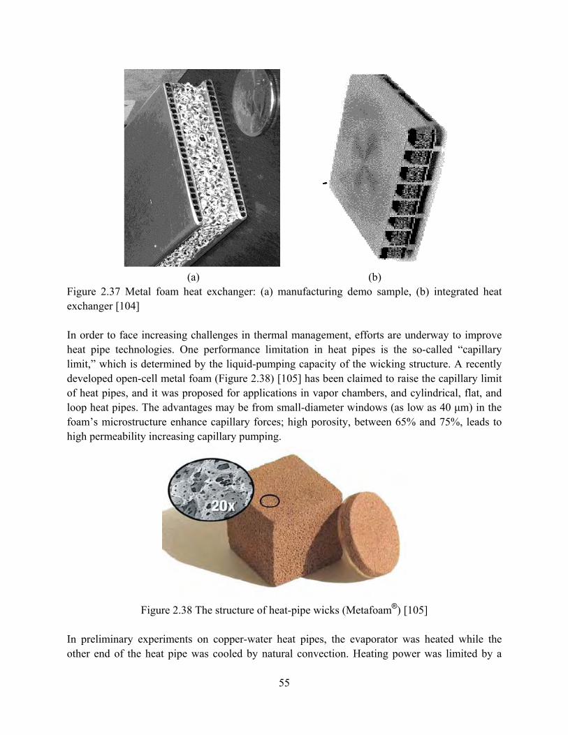
55
(a) (b)
Figure 2.37 Metal foam heat exchanger: (a) manufacturing demo sample, (b) integrated heat exchanger [104] In order to face increasing challenges in thermal management, efforts are underway to improve heat pipe technologies. One performance limitation in heat pipes is the so-called “capillary limit,” which is determined by the liquid-pumping capacity of the wicking structure. A recently developed open-cell metal foam (Figure 2.38) [105] has been claimed to raise the capillary limit of heat pipes, and it was proposed for applications in vapor chambers, and cylindrical, flat, and loop heat pipes. The advantages may be from small-diameter windows (as low as 40 μm) in the foam’s microstructure enhance capillary forces; high porosity, between 65% and 75%, leads to high permeability increasing capillary pumping.
Figure 2.38 The structure of heat-pipe wicks (Metafoam®) [105]
In preliminary experiments on copper-water heat pipes, the evaporator was heated while the other end of the heat pipe was cooled by natural convection. Heating power was limited by a

56
maximum evaporator temperature of 100ºC. The prototype using Metafoam transferred 11 W while a particular commercial screen mesh heat pipe transferred 6 W [105]. These results are preliminary. Thermacore has developed porous metal structures for use as wicks in heat pipes. Using sintered powder metal, porous structures can be fabricated in complex shapes with precisely controlled porosity. Figure 2.39 shows some of the complex geometries used for heat pipe wicks. In order to understand the structure of powder metal wick structures, imagine a container containing nearly uniform spheres. Sintering provides structural strength and good thermal conduction paths. The space between the spehres forms an interconnected pore structure or flow path, with the geometry determined by the size and uniformity of the powder metal grains. Bi-modal pore structures can control boiling within the wick. The resulting structure can also provide large capillary pumping forces. Aluminum foam, capper foam, nickel foam and stainless steel foams can be produced [106].
Figure 2.39 Some of the complex geometries used for heat pipe wicks [106]
2.3.4 Gas-to-gas heat exchangers Zhao [107] analyzed the heat transfer performance of metal-foam-filled tube-in-tube heat exchangers, such those as shown in Figure 2.40. The heat exchangers are made of copper, and air is used as the working fluid on both sides. Results show the use of metal foams can significantly improve the heat transfer performance due to enlarged surface area and excellent mixing of fluid flow in metal foams. For the same area density, the heat transfer performance of the foam filled annular tube is approximately three times higher than that of a longitudinally finned tube. Using spiral instead of longitudinal fins improves the performance of the conventional heat exchanger

57
but the heat transfer is still much than that achieved with the metal-foam filled annular channel [107].
Figure 2.40 Metal-foam filled tubes using co-sintering technique. [107]
2.3.5 Heat sinks The development of improved microchips having greater power density is essential to continued improvements in computing speed. Greater power densities, however, generate more waste heat and require more effective thermal management systems. Heat rejection is a limiting factor in increasing computer speed and reliability. Heat sinks are used to reject heat generated in the electronics and maintain the system within allowable operating temperatures. Using small and light heat exchangers is important for portable high-speed computers. Although the latest commercial heat sinks use attached fans (active heat sinks), or increases heat sink size to provide better heat rejection, these approaches increase the cost of the heat sink Recently, metal-foam heat sinks have received considerable attention [108-112]. Aluminum foam is now available to be used in thermal management applications. The foam structure enables this material to possess not only the desirable property of the bulk metal such as corrosion resistance, acceptance of coatings, and more importantly, electrical and thermal conductivity, but also properties such as low density, high strength-to-weight ratio, high porosity, and extremely large surface-area-to-volume ratio. The high surface-area-to-volume ratio increases the heat transfer by convection. Mahdi developed all-aluminum heat sinks with brazed joints to provide continuous, high-conductivity heat paths, and with a porosity of over 90% the pressure drops were relatively small (see Figure 2.41) [113].

58
(a) (b)
Figure 2.41 (a) Aluminum-foam samples, from Duocel; (b) foams bonded to aluminum substrate [113] Three aluminum foams (pore densities: 10, 20, 40 ppi) were used by Mahdi. The thermal resistance was inversely proportional to the pore density. That is, the foam with a pore density of 10 ppi had a higher thermal resistance than did the foam with a pore density of 40 ppi. In addition, the results showed that aluminum foams have similarity in the slope of thermal resistance, regardless of the pore density. The foam characteristics also provided for a smaller pressure drop through the ‘fins’ which, in turn, improved the heat rejection by forced convection.. Kim et al. [111, 112] investigated the thermal performance of aluminum-foam heat sinks for forced air-cooling of electronics. Test specimens of aluminum-foam heat sink (AFHS) were made of an aluminum foam block brazed to a base plate, as illustrated in Figure 2.42(a). A thin base plate was adopted to reduce the influence of conduction thermal resistance through the base plate on the overall thermal resistance. For comparison of thermal performance, conventional heat sinks in Figure 2.42(b) referred to as a parallel-plate heat sink (PPHS) were fabricated to have the same thickness of base plate. The heat sink was mounted on the grooved surface fabricated at the bottom wall of the test channel protruding from the heated base plate. The aluminum-foam heat sinks (AFHS) and the conventional parallel-plate heat sinks (PPHS) were made of aluminum-alloy 6101 and 6063, respectively. Their density and thermal conductivity were almost identical, in spite of the slight difference in material composition [112]. The parameters of the aluminum-foam heat sinks are given in Table 2.12.

59
(a) (b) Figure 2.42 (a) An aluminum-foam heat sink (AFHS), (b) a parallel-plate heat sink (PPHS) [112] Table 2.12 Parameters of the aluminum-foam heat sinks [112]
Experiments were carried out to investigate the thermal performance of aluminum-foam heat sinks for electronics cooling. The thermal performance of aluminum-foam heat sinks was evaluated in terms of the Nusselt number and the convective thermal resistance. Thermal performance of the aluminum-foam heat sinks was strongly affected by the pore density of aluminum foam material [112]. As the pore density decreased, the thermal performance substantially increased, due to a higher flow rate through the heat sinks. The aluminum-foam heat sink with a pore density of 10 ppi showed about 16–27% higher Nusselt number than that with 40 ppi. The thermal resistance of aluminum-foam heat sinks displayed more than 28% reduction compared to the conventional parallel-plate heat sinks. Furthermore, the mass of the aluminum-foam heat sink was only about 25% of the conventional parallel-plate heat sinks. Therefore, the aluminum-foam heat sink might be very useful for satisfying the needs for compact cooling system [112]. Using a stochastic open-cell metal foam as heat sink, shown in Figure 2.43, Dempsey [114] conducted an experimental study for heat transfer performance, and compared the results to a Linear Cellular Alloy (LCA) heat sink. The external dimensions of the stochastic cellular metal

60
heat sink were 20 mm in height, 25 mm in length, and 25 mm in width. The inlet velocity was 4 m/s. The LCA heat sink had the same external dimensions and inlet velocity, and the temperature boundary conditions with top and bottom walls were fixed at 373K. The result showed that the LCA provided comparable heat removal at half the pressure drop. The ability of the square cell LCA to provide relatively high steady state heat transfer rates at relatively low pressure drop via laminar flow is attractive in electronic package cooling applications. Because they are extruded with closed exterior faces, LCA heat sinks can be designed with internal bypass (selectively larger interior cells), offer low noise characteristics, and can be operated with other higher conductivity working fluids such as water at higher Biot numbers [115] to achieve enhanced heat transfer. It would be interesting to consider comparisons of relative performance of LCA heat sinks operated at higher air flow rates in the turbulent flow regime with that of stochastic metal foam heat sinks.
Figure 2.43 Schematic of a stochastic cellular metal heat sink used to cool computer chips
New applications for highly effective and multi-functional heat exchange devices are driving the development of components from metal foam materials. Metal foam materials have the potential to increase heat transfer rates from solid surfaces by conducting heat to the material struts and inducing a favorable interaction between the struts and a through-flowing fluid. New manufacturing techniques based upon powder metallurgy lend itself to effective, low-cost, high volume manufacturing, and new assembly techniques are being developed to manufacture complex assemblies of foam added to solid metals to form heat exchange devices.

61
2.4 Potential of carbonaceous materials and carbon matrix composites (CAMCs)
2.4.1 Material properties
2.4.1.1 Monolithic carbonaceous materials
Carbonaceous materials exist in a wide variety of forms including, carbon, graphite, diamond, highly oriented pyrolytic graphite (HOPG), ThermalGraph, carbon foam, and carbon nanotubes. The properties of monolithic carbonaceous materials are listed in Table 2.13.
Carbon is relatively inexpensive and has a higher thermal conductivity than most resins, but carbon has a lower thermal conductivity than most metals. Because carbon is too brittle and susceptible to chipping, it is not a useful material to build heat exchangers. Graphite is a crystalline and a refined form of elemental carbon. Graphite has the advantage of being readily and cheaply available in a variety of shapes and sizes. Graphite has a higher thermal conductivity but costs more than ordinary carbon. Natural graphite is generally found or obtained in the form of small, soft flakes or powder. Synthetic graphite is produced by the pyrolysis or thermal decomposition of a carbonaceous gas. Natural graphites possess a very high degree of structural anisotropy. Typically, the thermal conductivity of manufactured graphite is about ten times that of pure carbon. Carbon and graphite are inert throughout their entire structure. They are stable over a wide temperature range and are chemically resistant to most corrosive materials.
Coupling these characteristics with its competitive price, compared to materials with similar corrosion resistance, makes graphite an excellent material for the construction of heat transfer equipment. Natural graphite has been used as a thermal interface material for many years. The first block-type graphite heat-exchanger appeared on the market early in 1938 [120]. The thermal conductivity of these early graphite materials was relative low—about 150 W/m-K in plane (see Table 2.14). A new kind of natural graphite, available both as a laminate and a compression-molded product, was then developed for thermal management applications by Norley et al. [26, 27]. In-plane thermal conductivity values of approximately 370 W/m-K were demonstrated, similar to aluminum materials at about half the weight [29] (See Table 2.14). Some interesting composite derivatives of this material can also be produced by laminating graphite with metals. Until the discovery of carbon nanotubes, diamond had the highest measured thermal conductivity of any known material. Diamond films, which are made by chemical vapor deposition (CVD), have been used in production applications for several years (See Table 2.13) [36].
HOPG has been around for many years. However, recently has it been applied in electronics packaging. HOPG is produced by annealing pyrolytic graphite at 3500 °C for short periods. It is a highly anisotropic, rather brittle, and weak material with a reported in-plane thermal

62
conductivity as high as 1700 W/m-K, and through-thickness conductivity of 10-25 W/m-K. This in-plane thermal conductivity represents more than a 400% enhancement over 2-D C-C composite materials. (See Table 2.13) HOPG can be encapsulated with other materials having a variety of CTEs to provide additional strength and stiffness. Encapsulated HOPG is currently being used in ground-based radars and aerospace printed circuit board thermal planes (also called thermal cores, heat sinks and cold plates). It is also under consideration for many other applications [36]. Carbon foams were first developed in the late 1960s by Walter Ford [121, 122]. These initial carbon foams were made by the pyrolysis of a thermosetting polymer foam to obtain a carbonaceous skeleton or reticulated vitreous carbon (RVC) foam (see Figure 2.44). In the decades following this initial discovery, many different aerospace and industry applications of RVC foams have been explored including thermal insulation, impact absorption, catalyst support, and metal and gas filtration. RVC foams are thermally stable, low in weight and density, and chemically pure. They also have low thermal expansion, resist thermal stress and thermal shock, and are relatively inexpensive.
(a) (b)
Figure 2.44 (a) Typical RVC foam produced by ERG [121], (b) Mesophase pitch-based carbon foam produced at ORNL [117]
In the early 1990’s, researchers at the Wright Patterson Air Force Base pioneered mesophase pitch derived graphitic foams, specifically for replacing expensive 3-D woven fiber preforms in polymer composites and as replacements for honeycomb materials [117, 123, 124]. This material was one of the first high-thermal-conductivity carbon foams to be produced.
A research group at West Virginia University developed a method to use coal as a precursor for high-strength foams with excellent thermal insulation properties and high strength [121]. Although coal-based carbon foams have a lower bulk thermal conductivity relative to pitch-

63
based carbon foams, their higher strengths allow for greater flexibility in heat exchanger fin and tube design.
In 1997, James Klett at the Oak Ridge National Laboratory (ORNL) reported the first graphitic foams with bulk thermal conductivities greater than 40 W/m-K (tradename POCO) [117]. Later POCO HTC graphitic foam was developed, with an even higher thermal conductivity and density. Properties for these various kinds of carbon foams are listed in Table 2.15. The high-conductivity carbon foam developed at ORNL is an open-cell structure with highly aligned graphitic ligaments (see Figure 2.44). Studies have shown that the typical interlayer spacing is 0.34 nm which is very close to that of perfect graphite. Thermal conductivities along the ligament were calculated to be approximately 1700 W/m-K. Perhaps more importantly, the material exhibits low density (i.e. 0.25-0.60 g/cm3). The specific thermal conductivity of the foam (i.e. 220~270 W/m-K) is significantly larger than that of most available materials (in-plane and out-of-plane). The open, interconnected void structure of the foam enables fluid infiltration so that large increases in the total heat transfer surface area are possible (5,000 to 50,000 m2/m3) [128]. The foam is very versatile—it can be made in large samples, is easily machined, laminated with face sheets, or net shape formed. The manufacturing process can be altered to control the density and pore size of the graphite foam with little to no change in the thermal conductivity [129, 130]. Although the high-conductivity graphitic foams may display some level of anisotropy related to the foaming growth directions, they are far more isotropic and homogeneous than typical fiber-based composites [131].
It is clear that for weight sensitive thermal management applications or applications experiencing unsteady effects, the graphitic foam can be superior to other available materials with respect to its thermal properties. The advantage lies in its isotropic thermal and mechanical properties combined with its open cell structure which should allow for novel designs that are more flexible and more efficient [131]. Because the process for fabricating pitch-based graphitic foams is less time consuming, this new foam should be less expensive and easier to fabricate than traditional foams. Therefore, it should lead to a significant reduction in the cost of carbon-based structural materials for thermal management. Carbon foam is generally recognized as having great potential for replacing metal fins in thermal management systems such as heat exchangers, space radiators, and thermal protection systems. An initial barrier to its implementation, however, is the inherent weakness and friability of carbon foams. However, these carbon foam fins can be made more rigid by several techniques such as carbon CVI, polymer coating, and metallization by vapor plating techniques [132]. For example, Ceramic Composites Inc. has demonstrated the ability to increase the compressive strength by 2½ times through the treatment of the carbon foam ligaments with a uniform silicon
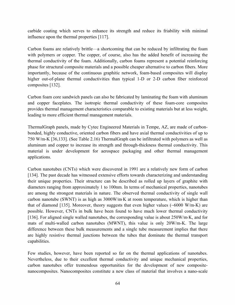
64
carbide coating which serves to enhance its strength and reduce its friability with minimal influence upon the thermal properties [117]. Carbon foams are relatively brittle—a shortcoming that can be reduced by infiltrating the foam with polymers or copper. The copper, of course, also has the added benefit of increasing the thermal conductivity of the foam. Additionally, carbon foams represent a potential reinforcing phase for structural composite materials and a possible cheaper alternative to carbon fibers. More importantly, because of the continuous graphitic network, foam-based composites will display higher out-of-plane thermal conductivities than typical 1-D or 2-D carbon fiber reinforced composites [132]. Carbon foam core sandwich panels can also be fabricated by laminating the foam with aluminum and copper faceplates. The isotropic thermal conductivity of these foam-core composites provides thermal management characteristics comparable to existing materials but at less weight, leading to more efficient thermal management materials. ThermalGraph panels, made by Cytec Engineered Materials in Tempe, AZ, are made of carbon-bonded, highly conductive, oriented carbon fibers and have axial thermal conductivities of up to 750 W/m-K [36,133]. (See Table 2.16) ThermalGraph can be infiltrated with polymers as well as aluminum and copper to increase its strength and through-thickness thermal conductivity. This material is under development for aerospace packaging and other thermal management applications. Carbon nanotubes (CNTs) which were discovered in 1991 are a relatively new form of carbon [134]. The past decade has witnessed extensive efforts towards characterizing and understanding their unique properties. Their structure can be described as rolled up layers of graphite with diameters ranging from approximately 1 to 100nm. In terms of mechanical properties, nanotubes are among the strongest materials in nature. The observed thermal conductivity of single wall carbon nanotube (SWNT) is as high as 3000W/m⋅K at room temperature, which is higher than that of diamond [135]. Moreover, theory suggests that even higher values (~6000 W/m-K) are possible. However, CNTs in bulk have been found to have much lower thermal conductivity [136]. For aligned single walled nanotubes, the corresponding value is about 250W/m⋅K, and for mats of multi-walled carbon nanotubes (MWNT), this value is only 20W/m-K. The large difference between these bulk measurements and a single tube measurement implies that there are highly resistive thermal junctions between the tubes that dominate the thermal transport capabilities. Few studies, however, have been reported so far on the thermal applications of nanotubes. Nevertheless, due to their excellent thermal conductivity and unique mechanical properties, carbon nanotubes offer tremendous opportunities for the development of new composite-nanocomposites. Nanocomposites constitute a new class of material that involves a nano-scale

65
dispersion within the matrix. Nanocomposites have at least one ultrafine phase dimension, typically in the range of 1–100 nm and exhibit improved properties when compared to micro- and macro-composites. Strong interfacial interactions between the dispersed clay layers and the polymer matrix lead to enhanced mechanical, thermal, and barrier properties of the base polymer material.
2.4.1.2 Carbon matrix composites (CAMCs)
Carbon fibers are the workhorse reinforcements in high performance aerospace and commercial PMCs and some CMCs. Table 2.16 provides thermal properties for a few carbon fibers and carbonaceous reinforcements found in the literature. Carbon fiber was first used about 100 years ago as filaments in electric lamps [2]. These early fibers were relatively weak and of little use as reinforcements.
In the early 1960s the Union Carbide Corporation (UCC) used rayon as precursor to produce the first commercial carbon fiber [3]. Another technical and commercial breakthrough for high performance carbon fibers occurred in the mid 1960s the development of carbon fibers produced from polyacrylonitrile (PAN) precursor fibers. They have relatively low thermal conductivities. In the mid 1980s, high quality pitch-based carbon fibers with very high stiffness and thermal conductivity were commercially produced by the then called Union Carbide (presently Amoco fibers) in the US and various companies in Japan. These fibers initiated another era in carbon/carbon technology [137]. Vapor grown carbon fiber (VGCF) is produced through the pyrolysis of hydrocarbon gas in the presence of a metal catalyst. VGCF exhibits the highest thermal conductivity among all the carbon fibers. VGCF has been found to have values of thermal conductivity along the fiber axis approaching that of natural diamond. This material has been under development for approximately the past twenty years in both Japan and the United States [138]. The development of pitch-based carbon fibers, vapor grown carbon fibers, and carbon nanotubes having high thermal conductivities offers new potential. Continuous and discontinuous thermally conductive carbon fibers are now being used in commercially available processes to produce polymer matrix composites (PMCs), metal matrix composites (MMCs) and carbon-carbon composites (CCCs) which have given rise to several new types of composites with unique physical properties. Just as carbon fibers are the most common reinforcement in carbon-carbon composites, CCCs are the most common kind of CAMCs. Table 2.17 provides property information for a few carbon matrix composites found in the literature. The main drawback of CCCs is their high cost of fabrication which has promoted considerable competition between CCCs and MMCs for the same applications.

66
Beginning in the mid 1980s, carbon-carbon composites were considered for applications requiring a structural material with very thin walls [141]. This lead to a detailed investigation of the other properties of carbon-carbon composites including its use for thermal management, which resulted in several new applications such as electronic thermal planes, spacecraft thermal doublers and radiators, launch vehicle thermal shields, and aircraft heat exchangers. Carbon-carbon composites (CCCs) have historically been used for high temperature, ablative, and/or high friction applications. However, carbon has many other unique properties such as high thermal conductivity, tailorable mechanical stiffness and strength, chemical inertness, low thermal expansion, and low density [141]. Its advantages over metal heat exchangers include its lower weight, higher performance, and a similar coefficient of thermal expansion (CTE) as other materials in the core. CTE matching for all carbon compact plate/fin and core plate/fin is excellent compared to mixed metal plates, fins, and brazing materials [142]. CCCs are also inherently corrosion resistant, which may provide a significant benefit over metallic heat exchanger materials in terms of reduced maintenance.
Thus the derived benefits of using carbon-carbon heat exchangers in aircraft applications include reduced weight, increased cooling capacity, increased range and/or increased post-flight operations time and possibly reduced maintenance as well as improved safety, serviceability and readiness [143]. CCCs offer in-plane properties that are equivalent or better than organic composites, while at the same time exhibiting much higher through-thickness thermal conductivities, typically 40 W/m-K (see Table 2.17). They also appear to be more attractive than metals or organic composites for heat dissipation components. A family of high thermal conductive 2-D and 3-D C-C composites were developed at BFGoodrich [139]. Amoco’s P120 and K1100, Mitsubishi’s K321 and BFGoodrich’s proprietary pitch-based carbon fibers were all used. Good mechanical and thermal properties were measured for these lower cost C-C composites (see Table 2.17). In related work, Ting and Lake studied the production and thermal properties of VGCF composites. A 1-D VGCF/carbon composite was made, and a room temperature thermal conductivity of 910 W/m-K was achieved (see Table 2.17) [119]. In a similar manner, carbon foams can be made denser with copper, aluminum, carbon, epoxy, and thermoplastic resins [125, 144]. The foam is used as the reinforcement in a composite structure where high thermal conductivity is required but at a lower cost than traditional high conductivity carbon fibers. Klett et al. [126] produced a denser Pocofoam with naphthalene which was subsequently converted to graphitic carbon to form a foam-reinforced carbon-carbon composite using a novel process developed and licensed by the U.S. Air Force. The results showed that the new denser PocoFoam increased the thermal conductivity dramatically (Table 2.17). With 11 separate density-increasing steps as well as an intermediate graphitization step, the PocoFoam’s thermal conductivity in the thickness direction was increased from 149 to more

67
than 285 W/m-K. The density-increasing process also had a significant impact on the compressive strength of the foam increasing it from approximately 2 MPa to over 7 MPa for an increase in density of 110 - 130%. Weight sensitive applications, however, can also use cores made from highly graphitized CCCs, PMCs, and graphitic foam. The challenge behind these types of composites is the need to improve the out-of-plane thermal conductivity. Emerging applications, however, may begin using nano-fiber/carbon materials [145]. Applications of the monolithic carbonaceous materials and carbon matrix composites for heat exchangers will be reviewed in the following sections.

68
Spec
ific
Th
erm
al
Con
duct
ivity
Th
ickn
ess
W/m
-K
4.4
87-1
17
3.4
4.3-
10.9
310-
510
570 --
--
--
Spec
ific
Th
erm
al
Con
duct
ivity
In
-Pla
ne
W/m
-K
4.4
220-
270
175
565-
740
310-
510
570
316-
479
108-
189
97-1
25
Ther
mal
C
ondu
ctiv
ity
Thic
knes
s W
/m-K
6.3
70-7
8
4.5
10-2
5
1100
-180
0
2000
--
--
--
Ther
mal
C
ondu
ctiv
ity
In
-Pla
ne
W/m
-K
6.3
135-
245
233
1300
-170
0
1100
-180
0
2000
600-
910
200-
350
175-
225
CTE
, In
-Pla
ne
μm/m
-°C
2.6
-1.0
-0.7
7
-1.0
1.0-
2.0
0.9
-1.5
-1.2
0.5
Den
sity
g
/cm
3
1.42
0.6-
0.9
1.33
2.3
3.52
3.51
1.9
1.85
1.8
Ref
No.
[ ]
[116
]
[36,
117
]
[118
]
[35]
[35]
[74]
[76,
119
]
[76]
[76]
Mat
rix
Vitr
eous
car
bon
Car
bon
Foam
Nat
ural
Gra
phite
HO
PG
CV
D D
iam
ond
Dia
mon
d
Car
bon
Car
bon
Car
bon
Tabl
e 2.
13 P
rope
rties
of m
onol
ithic
car
bona
ceou
s mat
eria
ls a
nd C
AM
Cs
Rei
nfor
cem
ent
--
--
--
--
--
--
1-D
Car
bon
Fibe
rs
2-D
Car
bon
Fibe
rs
3-D
Car
bon
Fibe
rs
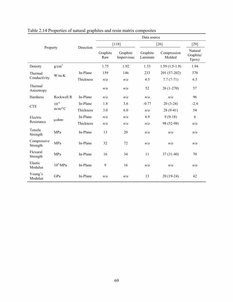
69
Table 2.14 Properties of natural graphites and resin matrix composites Data source
[118] [26] [29] Property Direction
Graphite Raw
Graphite Impervious
Graphite Laminate
Compression Molded
Natural Graphite/
Epoxy
Density g/cm3 1.75 1.92 1.33 1.59 (1.5-1.9) 1.94
In-Plane 159 146 233 201 (57-202) 370 Thermal Conductivity W/m-K
Thickness n/a n/a 4.5 7.7 (7-71) 6.5
Thermal Anisotropy n/a n/a 52 26 (1-270) 57
Hardness Rockwell R In-Plane n/a n/a n/a n/a 96
In-Plane 1.8 3.6 -0.77 20 (3-24) -2.4 CTE 10-6
m/m/°C Thickness 3.0 6.0 n/a 28 (9-41) 54
In-Plane n/a n/a 4.9 9 (9-18) 6 Electric Resistance μohm·
Thickness n/a n/a n/a 98 (52-98) n/a
Tensile Strength MPa In-Plane 13 20 n/a n/a n/a
Compressive Strength MPa In-Plane 32 72 n/a n/a n/a
Flexural Strength MPa In-Plane 16 34 11 37 (31-40) 70
Elastic Modulus 104 MPa In-Plane 9 16 n/a n/a n/a
Young’s Modulus GPa In-Plane n/a n/a 13 20 (19-24) 42

70
[34]
MER
Fo
am
1.21
--
--
--
--
41
82
550 --
29.0
[126
]
POC
O
Foam
1.12
113
285 --
--
> 7 --
--
--
--
Touc
hsto
ne
Foam
7.37
4
111 --
14.4
--
--
--
900
0.37
6
5.48
POC
O
HTC
5.70
6
342 --
7.43
--
--
--
300
1.38
9
14.5
5
[125
]
POC
O
Std
7.16
6
350 --
18.4
--
--
--
300
1.20
9
6.81
Touc
hsto
ne
Foam
0.27
-0.4
0
0.25
-70
--
5.0-
8.0
[127
] --
4.8-
15
82-8
8
--
--
100
MER
Fo
am
0.19
-0.8
0
0.05
-210
--
--
--
0.25
-7.0
64-9
9
30-1
270
--
100
POC
O
HTC
0.90
245
70
--
--
5.9 61
350 --
100
[117
]
POC
O
Std
0.56
135
78
--
--
2.1 70
350 --
100
Dir
ectio
n
In-P
lane
Th
ickn
ess
In-P
lane
Th
ickn
ess
In-P
lane
Uni
ts
g/cm
3
W/m
-K
μm/m
-°C
MPa
%
μm
cm2 /s
ec
%
Tabl
e 2.
15 P
rope
rties
of d
iffer
ent k
inds
of c
arbo
n fo
ams
Prop
erty
Den
sity
Ther
mal
C
ondu
ctiv
ity
CTE
Com
pres
sive
St
reng
th
Tota
l Por
osity
Avg
. Por
e D
iam
eter
Ther
mal
D
iffus
ivity
Wt.
%
Gra
phite

71
Table 2.16 Properties of various carbon reinforcements
Material Type Maximum Nominal
Thermal Conductivity W/m-K
Ref. No. [ ]
PAN-Based Carbon Fiber Continuous Fiber 160 [3]
Pitch-Based Carbon Fiber Continuous Fiber 1100 [3]
Pitch-Based Carbon Fiber Discontinuous Fiber 800 [3]
VGCF Carbon Fiber Semi-continuous Fiber 1950 [3]
ThermalGraph Panel 750 [36]
CVD Diamond Plate/Film 1800 [3]
Diamond-Type IIA Particle 2000-2100 [3]
Synthetic Graphite Flake 600 [3]
Single Wall Carbon Nanotube Nanotube 2000-6600 [3]
Graphite Nanoplatelet Flake 2000 [3]

72
[133
]
Ther
mal
G
raph
1.81
770
30
30
n/a
n/a
n/a
101.
4
146.
9
[119
]
1D V
GC
F
1.88
910
n/a
n/a
n/a
n/a
n/a
n/a
n/a
[126
]
OR
NL
Poco
Foam
1.12
113
113
285
n/a
n/a
n/a
n/a
> 7
[140
]
2D P
-30X
4k
1.9
350
350
40
-0.5
4 240
n/a
n/a
[139
]
BF
Goo
dric
h 3D
n/a
203
203
203
n/a
n/a
n/a
31.7
81.3
[139
]
Mits
ubis
hi
2D K
321
n/a
201
200
32
n/a
n/a
n/a
317
131
[139
]
Am
oco
2D
K11
00
1.85
360
358
52
n/a
n/a
n/a
241
96
[139
]
Am
oco
2D
P120
1.85
250
250
45
n/a
n/a
n/a
207
n/a
Dir
ectio
n
In-P
lane
(x)
In-P
lane
(y)
Thic
knes
s
In-P
lane
(x)
Thic
knes
s
In-P
lane
(x)
In-P
lane
(x)
In-P
lane
(x)
Uni
ts
g/cm
3
W/m
-K
μm/m
-°C
GPa
MPa
MPa
Tabl
e 2.
17 C
ompa
rison
of p
rope
rties
of c
arbo
n-ca
rbon
com
posi
tes
Prop
erty
Den
sity
Ther
mal
C
ondu
ctiv
ity
CTE
You
ng’s
M
odul
us
Tens
ile
Stre
ngth
Com
pres
sive
St
reng
th
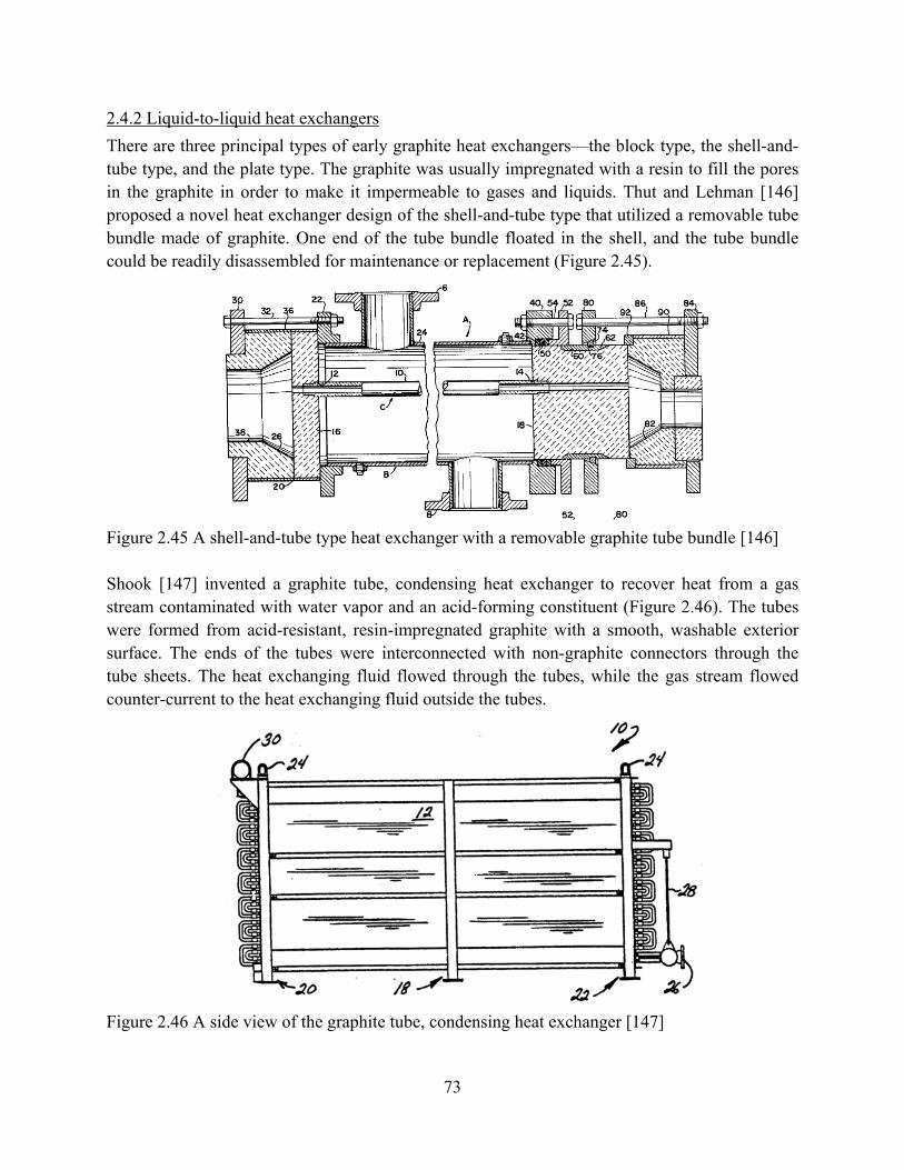
73
2.4.2 Liquid-to-liquid heat exchangers There are three principal types of early graphite heat exchangers—the block type, the shell-and-tube type, and the plate type. The graphite was usually impregnated with a resin to fill the pores in the graphite in order to make it impermeable to gases and liquids. Thut and Lehman [146] proposed a novel heat exchanger design of the shell-and-tube type that utilized a removable tube bundle made of graphite. One end of the tube bundle floated in the shell, and the tube bundle could be readily disassembled for maintenance or replacement (Figure 2.45).
Figure 2.45 A shell-and-tube type heat exchanger with a removable graphite tube bundle [146]
Shook [147] invented a graphite tube, condensing heat exchanger to recover heat from a gas stream contaminated with water vapor and an acid-forming constituent (Figure 2.46). The tubes were formed from acid-resistant, resin-impregnated graphite with a smooth, washable exterior surface. The ends of the tubes were interconnected with non-graphite connectors through the tube sheets. The heat exchanging fluid flowed through the tubes, while the gas stream flowed counter-current to the heat exchanging fluid outside the tubes.
Figure 2.46 A side view of the graphite tube, condensing heat exchanger [147]

74
Gillham [148] reported a fluoroplastic-bonded graphite (i.e. Diabon F 100) that could be used to make a plate heat exchanger by serving as a substitute for metallic materials such as corrosion resistant stainless steel, titanium, nickel, etc. Although the graphite plate wall thickness (1.5mm) was greater than that of metal plates, the high thermal conductivity (20 W/m-K) provided overall thermal transfer coefficients comparable to those of metal. Successful applications of this material were achieved with mid-range strength sulfuric acid at 120°C, concentrated hydrochloric acid above 100°C, phosphoric acid, and nitric acid at up to 50% strength at its boiling point.
Rabah and El-Dighidy [149] studied the effect of some polymeric and metallic impregnants on the performance of a cubic graphite heat exchanger at the laboratory scale, which simulated an actual heat exchanger installed in a superphosphate plant for cooling oleum (i.e. pyrosulfuric acid) in dilution with water. Figure 2.47 shows the distribution of the ports in the experimental blocks that were examined. The experimental results showed that non-impregnated synthetic graphite has a higher thermal conductivity than natural graphite. All the impregnated samples displayed higher heat transfer coefficients than the non-impregnated ones. In both cases, the effectiveness of the heat exchangers was raised by 5.5, 6.0, 6.5 and 7.2% by impregnation with a 16% uptake of PTFE, lead, carbon and copper, respectively.
Figure 2.47 Port distribution in the synthetic graphite experimental blocks [149]
Schou et al. [25, 150] investigated the thermodynamic and hydraulic performance of a cylindrical graphite block heat exchanger consisting of three graphite blocks and a steel shell.. Mathematical models of flow leakage and pressure drop were developed. Using the thermal conductivity data, a three-dimensional finite-element model was then set up to determine the wall resistance of a particular graphite block. The effect of the anisotropy of the extruded graphite on the wall resistance was investigated. It was found that, for typical operating film

75
coefficients with water on both sides, the overall heat transfer coefficient would increase by more than 50% if the resin layer were removed.
2.4.3 Liquid-to-gas heat exchangers The high thermal conductivity carbon foam developed at Oak Ridge National Laboratory (ORNL) was successfully applied to an air-to-water radiator [129, 151]. In order to demonstrate the heat transfer performance of the foam, three different carbon foam heat exchanger designs were tested in early experimental studies. The first design was simply a block of foam as shown in Figure 2.48 and Table 2.18 [131, 152]. In this design, aluminum 6061 tubes were press-fit through the foam. The second design consisted of a foam block with through holes machined into the foam to allow for the passage of cooling air as shown in Table 2.18. The through holes in this design only contributed a very small resistance to the overall air flow and thus served to significantly decrease the pressure drop. In the last design, both the fins and the through holes were machined out of the foam.
Figure 2.48 Schematic representation of heat exchanger with cooling air forced through the pores in the foam [129, 151]

76
Table 2.18 Comparison of heat transfer coefficients obtained for heat exchangers with different configurations
Foam Geometry Heat transfer
coefficient W/m2-K
ΔP/L psi/in
Dimension cm×cm×cm
Total surface area cm3
Solid foam
11000 2 10.2×10.2×2.54 208
Through- holes
943 0.1 20.3×20.3×2.54 948
Finned
977 0.05 22.9×17.8×15.3 7561
Current radiator
30-200 <0.05 68.6×48.3×7.6 N/A
Table 2.18 compares the heat transfer coefficients and pressure drops obtained for heat exchangers with different configurations. The overall heat transfer coefficient is very high compared to that of a standard automobile radiator.
Klett [151] developed a radiator for a passenger automobile which was significantly smaller in size using ORNL's graphic foam. Measured heat transfer coefficients of up to 3500 W/m2-K were reported for the prototype. The reduction in weight was another reported benefit which could improve the aerodynamic efficiency of the automobile. In the experiments, unexpectedly, a significant impact of air humidity on thermal performance was observed.
Klett et al. [129, 153] also developed a radiator for a natural gas, engine-driven heat pump (Figure 2.49). The fins and curvature needed to match the oval tubing were machined in the graphite foam and then brazed onto the aluminum tubing. The finned-tube configuration was a simple straight fin with a uniform cross-section attached to a flattened liner tube. The overall heat transfer coefficient measured in these experiments was found to be more than two orders of magnitude greater than the baseline case.

77
(a) (b)
Figure 2.49 (a) A prototype of an air radiator made from carbon-foam finned tubes, (b) test set-up for thermal performance measurements [129, 153] A C-C composite-based radiator panel with an aluminum honeycomb core was successfully used on the Earth Orbiter-1 (EO-1) spacecraft for an ambient condition of ~300K. Vaughn [154] presented the results from the design of the radiator, the thermal/mechanical tests of the face sheet materials, and the subcomponent test results on the C-C/Al honeycomb sandwich material. This radiator was constructed of two approximately 0.020-inch thick C-C face sheets bonded to both sides of an aluminum honeycomb core for a total panel thickness of 1 inch. The time from fabrication to test flight was about 10 months but could be optimized to 6 months using current production technology. The analysis of the radiator design showed that the radiator was able to meet, or exceed, all thermal and mechanical requirements. Rawal et al. [155] designed and fabricated a warm gas plenum radiator with YSH50/C-C face sheets and high thermal conductivity C-foam (Pocofoam™) core embedded with serpentine configuration on inconel tubing to satisfy the operational performance of an innovative altitude control subsystem (ACS) system (Figure 2.50). The radiator was designed to remove as much heat as possible from the gas to minimize the exit temperature of the gas based on an entrance temperature of 500°C to 750 °C. The heat was rejected to the space environment with radiation sink temperatures as low as -200°C. The thermal performance data indicated that the effective thermal conductance of the core assembly around the inconel tubing was about 200 W/m2-K; whereas, in the inter-tube region, the thermal conductance was approximately 690 W/m2-K.

78
Figure 2.50 Warm gas plenum radiator design using C-C panel and C-Foam with embedded tube [155] Filburn [156] investigated the efficiency of various fin designs applied to an oil cooler designed to remove the heat generated in the shaft bearing of a gas turbine engine with bypass air. Figure 2.51 shows one conceptual heat exchanger design. The final results of this project showed that the aluminum design had a total core weight of 25.4 lb while the carbon-carbon final design had a total core weight of 12.8 lb.
Figure 2.51 Conceptual heat exchanger design [156]
2.4.4 Gas-to-gas heat exchangers Very few studies are available on the use of natural graphite and carbon foam materials in gas-gas heat exchangers. Yu et al. [128] explored the potential of porous carbon foam in compact gas-to-gas recuperators for microturbine applications. Based on recent work applied to air-water heat exchangers, they developed a unit-cube geometric model for carbon foam, a heat transfer model and well-established convective correlations that were extended to account for effects of carbon foam (see Figure 2.52).

79
Figure 2.52 Flow passage configuration for a recuperator made from carbon foam [128] The performances have been calculated and compared with two cases: where the finned structure in reference [129], and when the finned structure was simply replaced by a block of porous foam, while maintaining the frontal area of the heat exchanger. The results showed that the volume occupied by the foam-block heat exchanger was more than 20 times smaller than the foam-finned case when the heat loads remained the same, while the pressure drop was approximately 1.4 times higher than the finned case. The results implied that very compact heat transfer devices could be designed using porous carbon foam, but the flow passages must be designed to give a more practical balance between the thermal and hydrodynamic resistances. Few studies are available on the use of composite materials in a compact heat exchanger. The Air Force Research Laboratory (AFRL) directed an ongoing effort to develop a high temperature, compact, C-C composite heat exchanger which could operate up to temperatures of 1200°F (650°C) for the aerospace industry because of the potential 40% weight savings and increased performance [143, 157-160]. Figure 2.53 gives a design configuration of a C-C corrugated plate/fin, cross-flow core using metallic air manifolds. Ram air cooled the hot compressor bleed air. The technical challenges for the C-C composite heat exchanger included material selection, thin plate fabrication, oxidation protection, and affordability.

80
(a) (b)
Figure 2.53 (a) Typical plate fin heat exchanger core components, (b) A single layer C-C composite plate-fin heat exchanger unit A number of different designs were considered and evaluated during the design development stage of the program. The best is the so-called “Integral Plate Fin” design. Figure 2.54 compares the integral design and conventional design of the heat exchanger assemblies. The conventional design was similar to the design of the metal heat exchanger. The integral design took advantages of composite processing to decrease assembly steps, so there was only one braze joint between parting sheets.
(a) (b)
Figure 2.54 (a) Conventional heat exchanger assembly, (b) Integral heat exchanger assembly [143]
The parting sheets and fins were both C-C composites. The parting sheet material selection was the polyacrylonitrile (PAN) fiber T-300 with a phenolic matrix. The fin material selected was the pitch-based fiber XN-50 with a phenolic matrix. The parting sheets served primarily a structural function and were the principal leakage boundary between the hot and cold airflow streams. For the parting sheets, through-thickness conductivity is important and sheets should be as thin as possible while meeting thermal, structural, and permeability requirements. A thickness of 0.15mm was selected for the parting sheets.

81
The corrugated plate-fins served both thermal and structural functions. In-plane thermal conductivity was much more important than transverse conductivity in the fins. Manufacturing capabilities limited C-C to the plain plate-fin design. There were 24 fins per inch in a core which was 0.15 m wide and 0.15 m long. The fin height within the core was 9 mm. The thickness of the fin was 0.127 mm. Channel edge closures served a structural function by acting as load carrying members and leakage boundaries. An aluminum plate-fin compact heat exchanger with a similar geometry was used to compare the performance of the C-C composite single layer heat exchanger. Experiment results showed that the C-C heat exchanger had lower Colburn heat transfer factor, but had high surface temperature effectiveness. The friction factor of the C-C heat exchanger was slightly lower than the metal plate-fin heat exchanger. However, if strip fins could be used in C-C construction, the C-C heat exchanger will have better performance. The development of C-C manifolds and external mounts and attachments was beyond the current scope of the program was restricted by the funding limitations. How to integrate the current metallic manifolds and the C-C heat exchanger core was left as a topic for further research. Kennel and Deutchman [160] described a technique that used an ion beam to deposit a metallic interface material into the surface of each material to be bonded. With the surfaces treated, they could be joined together using a metal-to-metal bonding technique. The method used liquid infiltration and liquid phase sintering of a powder based perform to produce wide gap joints able to accommodate expansion mismatch. These joining technologies were unproven in long-term, high-temperature service, and further research must be conducted. Because of its reliable operation and high efficiency, the direct gas Brayton (GB) system is one of the promising systems for a space nuclear power plant (SNPP). The GB system incorporates a recuperator that is nearly half the weight of the SNPP. Many efforts have been made to develop the carbon-carbon recuperators since their lighter and could provide better performance than current heat exchangers (Figure 2.55) [161-163]. Barrett [163] forecasted the performance expectations of closed-Brayton-cycle heat exchangers used in a 100-kWe SNPP. Preliminary design results indicated that component mass and pressure-loss targets were difficult to achieve using conventional metallic exchanger technology. Carbon-carbon sheeting or foam showed an attractive option to improve the overall performance.

82
Figure 2.55 Closed Brayton cycle T-s diagram [161-163]
Barrett et al. [162] further assessed the feasibility of using carbon-carbon recuperators in conceptual closed-Brayton-cycle space power conversion systems. The mass and volume characteristics of eight heat exchanger designs were compared, including six metal designs with different plate-fin geometries and two C-C designs with the same plate-fin geometry, but different fiber-based materials. Mass savings of 40 to 55 percent were projected for C-C recuperators with an effectiveness greater than 0.9 and thermal loads from 25 to 1400 kW. The smaller thermal loads corresponded with lower mass savings; however, at least 50 percent savings were forecast for all loads above 300 kW. Wolf [161] discussed several issues such as material compatibility with other structural materials in the system, permeability, corrosion, joining, and fabrication, in order to achieve a design to insure GB system operating for 15 to 20 years: (1) For the conceptual recuperator design, the side- and end-walls are expected to be metallic to
meet the critical permeability requirements. The composite core and metallic pressure boundary must be compatible and conform to the ASME boiler and pressure-vessel code.
(2) Incorporating a C-C composite into the system would add yet another potential source of contaminants.
(3) At high-temperatures, a key concern with carbon or graphite is its reactivity with oxidizing species.
(4) The CTE mismatch at C/C to metal interfaces may create excessive thermal stresses causing failure at the joint and catastrophic gas leakage when a carbon-carbon composite is integrated into an otherwise all-metallic energy conversion system.

83
(5) A plain plate-fin design has been considered instead of a more efficient strip-fin design for reducing cost and ease of fabrication.
2.4.5 Heat sinks
There have been many studies conducted on the use of monolithic carbonaceous materials and CCCs in heat sinks. Smalc et al. [164] developed a natural graphite heat spreader to cool a hard drive in a typical laptop, so as to reduce the touch temperature in a laptop computer. Experimental results showed that this spreader reduced the overall temperature gradient within the laptop and on the outer case. An estimated 16 watts of heat generated from the hard drive was transferred to other areas of the laptop and the temperature rise of the hard drive reduced from 27.8°C above ambient to 21.9°C.
Shooshtari et al. [165] developed natural graphite heat spreaders to reduce the peak temperatures and onscreen temperature variations of a 42-inch Samsung HP-P4261 PDP television, which are applied to the rear of the back panel with varying conductance. The natural graphite materials used in these tests were eGRAF® SPREADERSHIELD™† heat spreaders provided by GrafTech International Ltd. (GrafTech Int. Ltd.-Parma, OH).
From Figure 2.56, the beneficial effect of the in-plane conductance increase on the maximum screen temperature can be clearly seen for the 10 percent and 20 percent screen loadings. However, for the fully loaded screen the heat spreader conductance does not significantly affect the screen temperature map.
Figure 2.56 Infrared thermographs of the PDP screen for high and low conductance heat spreaders [165] Chen et al. invented a novel heat spreader using natural graphite combined with a high thermal conductivity insert to dissipate the heat from high power electronic components (Figure 2.57) [166].

84
Figure 2.57 Heat dissipating component using high conducting inserts [166]
The high conductivity insert was mounted in the cavity which was formed through the thickness of the graphite member having high thermal conductivity along the plane of the member and having a relatively low thermal conductivity through the thickness of the member. The insert may be an isotropic high thermal conductivity material such as copper or an anisotropic material such as graphite oriented to have high conductivity in the direction of the thickness of the planar element. Pokharna [167] proposed a cooling system that includes heat pipes and a remote heat exchanger. The heat pipes are coupled to an attach block which can be made from a graphite material such as annealed pyrolytic graphite (APG) (Figure 2.58).
Figure 2.58 Heat pipe remote heat exchanger (RHE) with graphite block [167]
Because graphite has higher conductivity than copper, it can spread the heat evenly around the heat pipe circumference, thus reducing the evaporator resistance.

85
The high thermal conductivity carbon foam developed at Oak Ridge National Laboratory (ORNL) has demonstrated the overall heat transfer coefficients of carbon foam-based heat sinks to be up to two orders of magnitude greater than those of conventional heat sinks [117, 121, 131, 152, 168]. Table 2.19 gives the experimental results of heat transfer coefficients obtained for graphite foam and aluminum foam with water and air as coolants. The schematic of test rig is shown in Figure 2.59. The overall heat transfer coefficient (h) was calculated from Equation (4.1) where
△TLM is the log mean temperature difference, A is the area of foam attached to the aluminum
plate, and q is the heat dissipated to the cooling fluid.
h = q / (A·△TLM) (4.1)
Table 2.19 Comparison of the heat transfer coefficients obtained for graphite foam and aluminum foam heat sinks [117, 121]
Heat transfer coefficientW/m2-K
ΔP/L psi/in
Thermal Resistance °C/W
Foam Geometry Al-Air
Foam-air
Foam-Water
Al-Air
Foam-air
Foam-Water Al-
Air Foam-
air Foam-Water
Solid foam
250 2600 23000 <0.05 2 2 1.3 0.13 0.02
finned
70 1000 2100 <0.05 <0.05 0.5 1-5 0.38 0.19
Pin-fin
550 1500 2500 <0.05 0.05 0.5 0.7 0.26 0.15
Blind-holes (pin fin
negative)
N/A 2000 4600 N/A 1 0.5 N/A 0.19 0.09
Blind-holes (parallel to air
flow)
N/A 3100 4500 N/A 0.35 0.5 N/A 0.13 0.09
corrugated
N/A 4100 9500 N/A 0.1 0.033 N/A N/A N/A
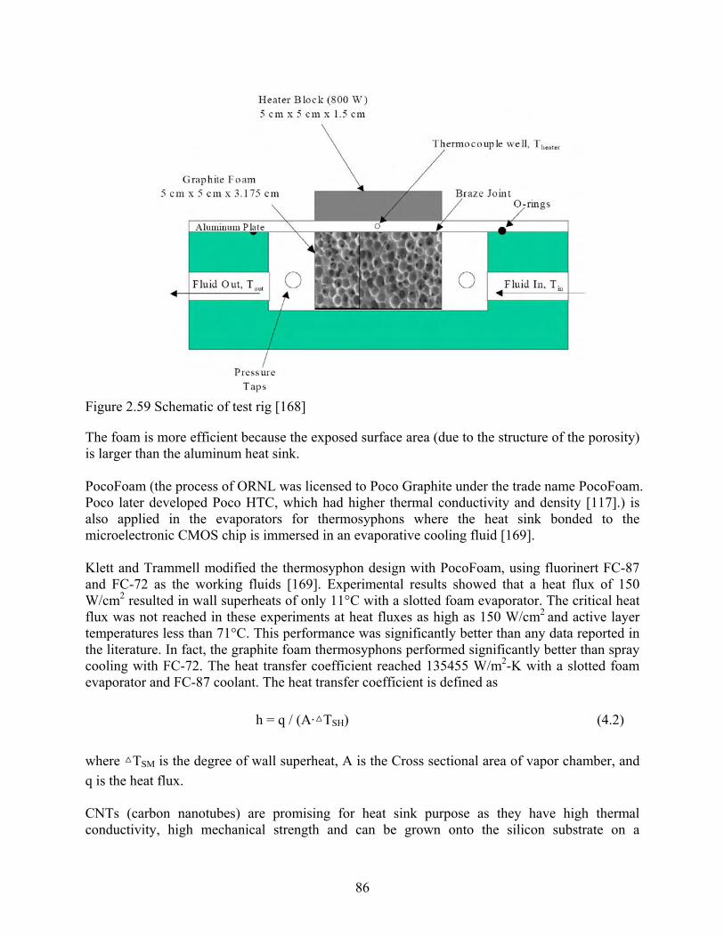
86
Figure 2.59 Schematic of test rig [168]
The foam is more efficient because the exposed surface area (due to the structure of the porosity) is larger than the aluminum heat sink. PocoFoam (the process of ORNL was licensed to Poco Graphite under the trade name PocoFoam. Poco later developed Poco HTC, which had higher thermal conductivity and density [117].) is also applied in the evaporators for thermosyphons where the heat sink bonded to the microelectronic CMOS chip is immersed in an evaporative cooling fluid [169]. Klett and Trammell modified the thermosyphon design with PocoFoam, using fluorinert FC-87 and FC-72 as the working fluids [169]. Experimental results showed that a heat flux of 150 W/cm2 resulted in wall superheats of only 11°C with a slotted foam evaporator. The critical heat flux was not reached in these experiments at heat fluxes as high as 150 W/cm2 and active layer temperatures less than 71°C. This performance was significantly better than any data reported in the literature. In fact, the graphite foam thermosyphons performed significantly better than spray cooling with FC-72. The heat transfer coefficient reached 135455 W/m2-K with a slotted foam evaporator and FC-87 coolant. The heat transfer coefficient is defined as
h = q / (A·△TSH) (4.2)
where △TSM is the degree of wall superheat, A is the Cross sectional area of vapor chamber, and q is the heat flux. CNTs (carbon nanotubes) are promising for heat sink purpose as they have high thermal conductivity, high mechanical strength and can be grown onto the silicon substrate on a

87
predefined pattern with a very high accuracy. But according to open literatures, few studies on the thermal applications of nanotubes have been reported so far. Mo et al. [136, 170, 171] proposed and investigated two methods to integrate high thermal conductive nanotubes with existing microchannel coolers for enhancement in cooling capability. The first one is to replace the silicon fins with nanotube fins. Microcoolers with two-dimensional nanotube fins were manufactured, by using lithography techniques, chemical vapor deposition and adhesive bonding (Figure 2.60). In a cooling area of 10 mm x 4 mm, 400 nanotube fins have been grown. Each fin is about 400 μm high and has a cross section of 50 μm x 50 μm.
(a) (b)
Figure 2.60 (a) Two-dimensional array of nanotube fins, and (b) Porous structure of preferable nanotube layer [136, 170, 171]
Experiments demonstrated that, with 23% higher input power (8.9 W vs. 7.2 W), the nanotube cooler could keep the transistor temperature 6°C lower than the reference cooler without fins. No significant abrasion was observed, indicating the good adhesion of the nanotube fins to the silicon substrate. However, a direct comparison with the conventional silicon microchannel cooler is not available. Experiments indicated some promising potential for this new cooler. The second method is to grow aligned nanotubes on the whole thermal exchange surface of the groove where the coolant flows (Figure 2.60). The preferable nanotube layer has a porous structure. Each nanotube stands separately and perpendicularly to the substrate surface. Each nanotube serves as a tiny fin, which increases dramatically the thermal exchange area. But the robust adhesion of the nanotube layer becomes most critical from the reliability point of view. This method was unnecessary to use lithography to pattern the catalyst layer, therefore, it extended the heat transfer surface for further enhancement of the cooling capability in a low-cost way. Kordas et al. [172] developed a more efficient cooling method for chip thermal management using laser patterned CNT fins transferred and mounted on the back side of the chips (Figure 2.61).

88
Figure 2.61 Morphology and structure of laser-patterned CNT films: (a) Microstructure of three cooler blocks laser etched next to each other in the CNT film, (b) Grooves and a pyramidal fin obelisk of aligned nanotubes, (c) Close-up image of the aligned nanotubes [172]
The diameters of nanotubes in the films show a broad distribution of 10-90 nm. Experiments demonstrated that, for a 1 mm2 surface area test chip, the applied power can be ~1W larger when a carbon nanotube cooler is applied—compared to the case of the bare chip—to reach the same temperature. And the nanotube fin structure would allow the dissipation of ~30 and ~100 W cm−2 more power at 100 °C from a hot chip for the cases of natural and forced convections, respectively. The nanotube fins are mechanically superior compared to metallic materials, being ten times lighter, flexible, and stiff at the same time. These properties accompanied with the relative simplicity of the fabrication makes the nanotube structures strong candidates for future on-chip thermal management applications. The high thermal conductivity allows the carbon-carbon thermal plane to keep the electronic apparatus from over-heating. Carbon-carbon has a low expansion, reducing the thermal fatigue of the chip soldering. Carbon-carbon also has a high stiffness which reduces deflections during vibrational loading. Combined with its low density and these properties, the carbon-carbon composites are an ideal material for electronic thermal planes. Many carbon-carbon heat spreaders made from carbon-carbon composite materials in different types could be seen in patents [145,173, 174-176]. The Air Force Research Laboratory/ Structural Materials Branch of the Nonmetallic Materials Division (AFRL/MLBC) designed, fabricated, and tested high thermal conductivity composite heat sinks for various advanced fighter and helicopter avionics applications [145, 173]. A module packaging system has been developed with the flexibility to be adapted for use in avionics systems with either air or liquid (Figure 2.62). The module core material selected for high power modules was composite encapsulated annealed pyrolytic graphite (APG) material with aluminum skins. For applications that are more weight sensitive, cores can made from an alternative of low density graphite composite material ThermalGraphTM (TG). The relative heat

89
sink system effective thermal conductivity of APG and TG were 3.1 and 4.4 times larger than that of aluminum. But the challenge was to reduce the cost of aircraft composite thermal planes.
(a) (b)
Figure 2.62 (a) Portrait conductive cooled Module, (b) conduction cooled landscape module installed in a liquid cooled avionics rack [145, 173] The very high cost (up to $10,000/kg) of C-C composites combined with their lengthy (up to 9 month) processing time has hindered their wide-spread commercialization. Kowbel et al. [140, 177] developed low cost, high thermal conductivity 2D C-C and 2-D C-SiC composites for Si-based and GaAs-based electronics. The thermal conductivities of 2D C-C are listed in Table 2.17. Both 2-D C-C and 2-D C-SIC greatly outperformed state-of-the-art Cu-W, AIN and BeO heat spreaders (Figure 2.63). The relatively low through-thickness thermal conductivity of C-C and C-Sic composites does not negatively affect their thermal performance up to 44 W/cm2. Chips were attached to both C-C and C-SiC via epoxy bonds. Up to 500 thermal cycles were performed satisfactorily. The price of C-C composites has greatly reduced to less than $100/lb. This allowed the fabrication of C-C and C-Sic heat spreaders at a cost comparable to Cu-W ($2/in2).
Figure 2.63 Thermal Spreader Results [140, 177]
2.5 Potential of ceramics and ceramic matrix composites (CMCs) The impetus behind the use of ceramics in the manufacturing and design of heat exchangers arises from their excellent corrosive properties, their ability to withstand extremely high operating temperatures (i.e. 1400°C), and the economics of their use in heat recovery systems, radiant heating applications, and micro-reactors. The major obstacles facing the incorporation and use of ceramics in these systems is ceramic-metallic mechanical sealing, manufacturing costs and methods, and their brittleness in tension. In the following sections, the properties of the

90
most promising ceramic materials will be presented along with identified industrial applications and recently improved manufacturing methods.
2.5.1 Material properties The word ceramic, derived from the Greek word keramikos, refers to inorganic, non-metallic materials formed due to the action of heat. The American Society for Testing and Materials (ASTM) defines a ceramic material as “an article [whose] body is produced from essentially inorganic, non-metallic substances and either is formed from a molten mass which solidifies on cooling, or is formed and simultaneously or subsequently matured by the action of the heat.” Most ceramic materials are hard, porous and brittle so the use of ceramics in application often requires methods for mitigating the problems associated with these characteristics. Ceramic materials are usually ionic or covalently bonded and may be crystalline or amorphous in structure. Because of this type of electronic bonding, ceramics tend to fracture before undergoing plastic deformation often resulting in fairly low tensile strength and generally poor material toughness. Moreover, because these materials tend to be porous, the microscopic pores can act as stress concentrators further decreasing the toughness and strength of ceramics. These factors can combine, leading to a catastrophic failure of the material instead of the normally more gentle modes of failure associated with metals. Although often neglected, ceramics do exhibit plastic deformation. In crystalline materials, this deformation process occurs very slowly due to the rigid structure of the ceramic and the lack of slip systems for dislocations to move. For non-crystalline ceramic materials, viscous flow is the dominant source of plastic deformation and is also very slow. The two main advantages for using ceramic materials in heat exchanger construction over more traditional metallic materials are their temperature resistance and corrosion resistance. First, ceramic materials can withstand operating temperatures that far exceed those of conventional metallic alloys. For example, the bulk material temperature of a heat exchanger made of carbon steel should not exceed 425°C. Similarly, the bulk material temperature of a heat exchanger manufactured from stainless steel typically should not exceed 650°C [178]. As a result, the heat exchanger must be protected in some applications. Thermal protection can be accomplished by means of an environmental barrier coating that overlays the metal which has the effect of adding a thermal resistance to the transfer of heat thereby reducing the overall performance of the unit. In other cases, the unit is operated in the parallel flow mode rather than the counterflow mode to maintain a lower overall material temperature. This mode of operation has the effect of increasing the lifetime of the heat exchanger at the expense of lowering the overall thermal efficiency of the unit. Another commonly employed technique is air dilution, where ambient air is added to the hot upstream exhaust gases upstream of the heat exchanger. This technique also has the effect of lowering the overall efficiency of the heat exchange. The second major advantage of ceramic-based heat exchangers is their resistance to corrosion and chemical erosion. Corrosion which occurs under normal conditions is exacerbated by elevated operating temperatures. Moreover, corrosion can occur in many different forms in an exhaust gas stream. For example, an exhaust stream rich in oxygen can actually attack a metallic surface. In this case, the diffusion of oxygen into the material causes scaling. Although this scaling initially forms a protective layer, the intermittent use of the heat exchanger and the

91
resulting thermal cycling can cause the scale to flake off, exposing the underlying material to further attack. Other possible gaseous constituents include sulfur and carbon which can also diffuse into the grain boundaries. The migration of sulfur into the grain boundaries forms eutectics that melt at temperatures significantly lower than the material melting temperature. The diffusion of carbon into the metallic surface results in the formation of carbides which can cause residual stresses and embrittlement to occur [178]. The merits and shortcomings of the following ceramic materials will now be discussed: silicon carbide, silicon nitride, alumina, zirconia, aluminum titanate, aluminum nitride, and ceramic matrix composites (CMCs). The thermal-mechanical properties of these materials are shown in Table 2.20 and Table 2.21. Perhaps the most promising ceramic material, silicon carbide (SiC) has a high temperature of decomposition (approx. 2500°C). It also displays good thermal shock resistance and maintains its flexural strength at elevated temperatures. Moreover, it is chemically inert and possesses high thermal conductivity (about four times that of steel). Silicon carbide manufactured using silicon powder also maintains its strength well as does reaction bonded Si-SiC. Both, however, are limited to operating temperatures below the melting point of silicon (~1425°C) [181]. Silicon nitride (Si3N4) exhibits excellent strength and creep resistance at elevated operating temperatures but may be limited by its vulnerability to oxidation at temperatures exceeding 1000°C [181]. Alumina (Al2O3) is very stable and highly resistant to chemical attack under both oxidizing and reducing conditions. Alumina also possesses the advantage of being fairly inexpensive to manufacture. However, alumina suffers from lower thermal shock resistance as compared to silicon carbide and silicon nitride [181]. Zirconia (ZeO2) cannot withstand large thermal gradients and therefore is susceptible to thermal shock failure. Aluminum titanate (Al2TiO5) possesses very low thermal conductivity and therefore is ideally used an insulatory material. Aluminum nitride (AlN) has good oxidation resistance and thermal stability up to 1300°C. At higher temperatures, however, it is susceptible to attack by oxidation as the Al2O3 scale begins to crack exposing the unprotected, underlying AlN [181].

92
Spec
ific
Hea
t Cap
, J/
g-°C
2.54
Mel
t Po
int,
°C
2837
1900
2050
Max
W
ork
Tem
p,
°C
1600
1700
1900
1700
1500
Ther
mal
C
ondu
ctiv
ity
1000°C
, W
/m-K
42
40 6
Ther
mal
C
ondu
ctiv
ity,
100°
C,
W/m
-K
12.6
- 20
0 †
7- 4
3 †
27.0
13.8
- 43
.2 †
0.9
- 2.0
†
Ther
mal
C
ondu
ctiv
ity,
20°C
, W
/m-K
125 30 29
CTE
, lin
ear
20°C
, μm
/m-K
4.8
4.6 --
4.6
2.8-
4.2
†
3.5
1.5-
3.6
†
7.5
7.1
4.5-
8.0
†
7 –
9 †
Flex
ural
Y
ield
St
reng
th,
MPa
400
379
300
Rup
ture
M
odul
us,
MPa
110
690
450
You
ng’s
M
odul
us,
GPa
427
410
410
340
Tens
ile
Stre
ngth
, Y
ield
, M
Pa
186 55
Den
sity
, g/
cc
3.21
--
3.10
3.10
2.2-
3.2
†
3.20
1.9-
3.0
†
--
--
3.90
3.45
-3.
99 †
3.5-
5.9
†
Ref
No.
[ ]
[178
]
[179
]
[180
]
[181
]
[182
]
[181
]
[182
]
[183
]
[179
]
[181
]
[182
]
[182
]
Tabl
e 2.
20 P
rope
rties
of v
ario
us c
eram
ic m
ater
ials
Prop
ertie
s
SiC
SiC
SiC
SiC
SiC
Si3N
4
Si3N
4
Al 2O
3
Al 2O
3
Al 2O
3
Al 2O
3
Zir
coni
a
† tem
pera
ture
rang
e no
t spe
cifie
d

93
SiC
lo
adin
g vo
l %
25%
70%
--
--
--
48%
25%
30%
--
0 - 4
5%
S O
pen
poro
sity
%
< 5%
< 1%
< 2%
--
--
< 3%
< 6%
< 3%
< 5%
< 1.
0%
Spec
ific
H
eat C
ap,
J/g-
°C
1.25
@
1000°C
0.80
-1.2
0 @
20
-120
0°C
0.80
–1.4
0
1.20
0.60
-2.2
0 @
20
-120
0°C
1.30
@
1200°C
--
--
--
--
T Th
erm
al
Con
duct
ivity
, ⎜⎜
orie
nt
W/m
-K
25
--
30
--
27
--
30
26.3
--
--
Ther
mal
C
ondu
ctiv
ity,
⊥ o
rient
W
/m-K
14
40
24
20
7
25-3
0
20
15.3
18.9
--
CTE
, ⎜⎜
orie
nt
μm/m
-K
--
1.8-
3.0
2.4-
2.7
--
0.5
0.5-
3.5
--
0.4-
2.6
1.1-
2.5
7 @
14
00°C
CTE
, ⊥
orie
nt
μm/m
-K
--
--
4.0-
4.7
4 6.5
1.0-
4.0
--
--
--
7 @
14
00°C
Flex
ural
Y
ield
St
reng
th,
MPa
65
80
67
--
320-
370
90-1
40
130
>160
80
346
You
ng’s
M
odul
us,
GPa
25
30
30-3
5
--
75
50-7
0
55
63
41
341
Den
sity
, g/
cc
2.0
2.4
2.25
2.25
1.6-
1.9
2.0-
2.1
1.95
1.8-
1.9
2.1-
2.3
3.40
Ref
N
o. [
]
[184
]
[184
]
[184
]
[184
]
[184
]
[184
]
[184
]
[184
]
[184
]
[185
]
Tabl
e 2.
21 P
rope
rties
of v
ario
us c
eram
ic m
atrix
com
posi
tes (
CM
Cs)
Prop
ertie
s
Schu
nk
FU29
52 †
SGL
car
bon
sigr
asic
†
Chr
ysle
r
C
-bra
ke †
Bre
mbo
C
CM
†
MS
prod
. si
com
†
DL
R
si
lca
SF †
Schu
nk
CF2
26/2
P77
‡
DL
R
silic
a X
S ‡
DL
R
si
lica
XG
‡
SiC
p/Al 2O
3
† C/C
– S
iC c
ompo
site
(sho
rt fi
ber)
‡
C/C
– S
iC c
ompo
site
(2-D
rein
forc
emen
t)

94
Table 2.21 Properties of various ceramic matrix composites (continued)
Reinforcement Matrix Densityg/cm3
Thermal Conductivity
W/m-K
CTE 10-6
m/m/°C
Specific Thermal Conductivity
W/m-⋅K Source
In-Plane Thickness In-
Plane In-Plane Thickness
---- Beryllium oxide 3 260 6 [74]
---- Aluminum nitride 3.3 320 4.5 [74]
---- Silicon carbide 3.3 270 3.7 [74]
Continuous Carbon Fibers SiC 2.2 370 38 2.5 170 [35]
Diamond Particles Silicon --- 525 525 4.5 --- [35]
Diamond Particles SiC 3.3 600 600 1.8 182 [35]
Silicon Carbide Particles Al/SiC 3.0 170-
220 170-220 6.2-16.2 57-73 [3]
2.5.2 Liquid-to-liquid heat exchangers
Alm et al. [183] studied the thermal performance of an alumina micro ceramic heat exchanger comprised of 26.2 mm x 26.2 mm plates containing channels 250 μm wide and 500 μm tall and 12.25 mm in length (See Figure 2.64). The micro-components were fabricated using a rapid prototyping assembly approach. First, a polymer master model was made of the original using stereolithography, and then a silicon mold was made. Next, “green bodies” were produced from an alumina/binder (MR52) dispersion through a low-pressure, injection molding process. Finally, the green bodies underwent a debinding step at 500°C and a sintering step at 1700°C. The joining of ceramic components was performed two ways—(1) by the hot joining of green bodies followed by group debindering/sintering, or (2) the joining of already sintered micro-components by glass solder. It was found that the hot joining of green bodies was less reproducible at higher pressures. Therefore, joining by glass solder was preferred but sometimes resulted in partially blocked (or completely blocked) channel passages. The thermal conductivity of the Al2O3 MR52 ceramic was 30.9 W/m-K at 28°C, 27.0 W/m-K at 100°C, and 9.1 W/m-K at 750°C. It should be noted that modular Al2O3 HXs may be limited to operating temperatures below 1000°C.
For the experiments performed on these ceramic heat exchangers, the mass flow rates ranged from 12.4 kg/h to 80.6 kg/h. For the first test conducted at 12.4 kg/h, the hot water stream entered at 93.7°C and exited at 75.8°C, whereas the cold water stream entered at 11°C and exited at 26.7°C at a flow rate of 12.6 kg/h. The system operating pressure for these tests was 8 bars. FLUENT was used to guide the initial heat exchanger design parameters although very little discussion of these simulations was provided; moreover, a flow distribution model was used in

95
these simulations to estimate the mass flow through these channels. Reduction of the experimental data was performed using a simple, 1-D planar thermal resistance model. The experimental overall heat transfer coefficient (U) ranged from 7-15 kW/m2-K. The associated pressure drop penalty (shown in Figure 2.65) ranged from 0.15 bar at 12.4 kg/h to more than 6 bar at 80 kg/h (attributed to problems w/ the glass soldering technique for joining the plates).
Figure 2.64 Ceramic micro heat exchanger construction and cross-flow arrangement [183]
(a) (b)
Figure 2.65 (a) Pressure drop and (b) heat transfer coefficient data for various water mass flow rates (1-cold stream, 2-warm stream) [183]
In a patent by Ishiyama and Maruyama, the construction of a ceramic heat exchanger for use in a thermo-chemical plant to produce large quantities of hydrogen and oxygen from feed water using nuclear heat at 950°C is described [186]. More specifically, the feed water supplied to the Bunsen reactor is decomposed under high-temperature, high-pressure conditions in the presence of concentrated sulfuric acid (H2SO4) and hydrogen iodide (HI). After reaction, the liquid mixture of H2SO4 and HI is fed to the acid separator where it is separated into two layers of

96
H2SO4 and HI. The HI solution is then supplied to distillation column; the resulting HI vapor is then decomposed and H2 is recovered from the condenser. The distillate residue and condensate are finally returned to the reactor. The H2SO4 solution is fed to a vaporizer, and the resulting vapor is fed into the H2SO4 decomposer where SO2, H20, and O2 are formed. These species are then fed to a condenser before being returned to the reactor (see Figure 2.66). It appears that because high-pressure ceramic tubes are difficult to manufacture, Ishiyama and Maruyama chose a block core design to allow for easier joining and vacuum sealing (see Figure 2.66). This application of ceramics to a heat exchanger is not especially novel, but it represents an important use of ceramics in a corrosive environment.
Figure 2.66 Schematic of ceramic heat exchanger for use in a high-pressure, high-temperature H2SO4 vaporizer unit [186]
2.5.3 Liquid-to-gas heat exchangers Gómez et al. [187] describe a ceramic tube bank consisting of 7 columns and 7 rows in a staggered arrangement used to recover heat and precondition the supply air to a room. The tubes were a porous ceramic material primarily composed of Al2O3. The density of these tubes was approx. 2.5 g/cm3. The porosity was 22-25%, and their absorption of water was 9-10%. This “semi-indirect evaporative cooler” shown in Figure 2.67 utilized heat and mass transfer in the return air stream, heat transport through the porous wall, and evaporation (or condensation) in the supply air stream to deliver the air to the occupied space at comfort conditions (22°C, 50% RH). This design was tested for tropical climates as well as continental summer and winter conditions. The intended application is for cooling in subtropical to tropical climates where the

97
temperature and humidity are both high. However, it may also be used in winter conditions to humidify the supply air. The ceramic pipes had an external diameter of 25 mm, thickness of 5 mm, and length of 600 mm. Tested air flow rates were 140-380 m3/h, and the average water flow rate was 100 L/h. Evaporative recuperators take advantage of the hydrothermal conditions of the indoor air to cool the water in the porous ceramic tubes to a lower temperature than would ordinarily be achieved using the outdoor air, especially when the outdoor air is humid. Gómez et al. [187] point out that these porous tubes prevent the exchange of harmful agents such as those causing Legionnaire’s disease (the tubes serve as a filter). However, because water can wick through the structure, these recuperators are labeled ‘semi-indirect.” Gómez et al. also point to a related work where this recuperator was compared to an indirect system using an aluminum flat-plate HX in cross-flow with everything held the same. The thermal efficiency and overall cooling capacity was found to be higher for the ceramic recuperator. The authors suggest that a similar device could be made from the ceramic materials used in building construction to make the recuperator cheaper. This type of recuperator is limited to non-pressurized applications and probably best suited for warmer, more humid environments limiting its realizable benefit.
Figure 2.67 Ceramic pipe heat exchanger utilizing both heat and mass transfer [187] Kelly et al. [188] describe potential applications for cross-flow, micro heat exchangers manufactured using a variation of the LIGA process where the liquid stream would be contained within the plane of the heat exchanger and the gas stream would pass through it. Materials being used to make these heat exchangers include PMMA (polymer), nickel (metal), Si3N4 (ceramic), and alumina (ceramic). Preliminary heat transfer and pressure drop data were provided and compared against model predictions but only for the case of the polymer and nickel cross-flow μ-HXs. Possible applications for these simple cross-flow μ-HXs include the surface cooling of gas turbine components and mechanical seals/journal bearings as well as catalytic converters. To fabricate a silicon nitride μ-HX, a derivative of the LIGA process is used where a PMMA part is bonded to another PMMA part to produce an enclosed PMMA “lost mold.” This mold is

98
then injected with silicon nitride precursor which is solidified at relatively low temperatures. The polymer is then dissolved, and the remaining solid is sintered to form a dense ceramic part (see Figure 2.68). This unique method of fabrication has also been used to produce complex metal μ-HXs on non-planar surfaces through an electroplating process. The heat transfer per unit mass (or heat transfer/volume) of μ-HXs has been shown to be superior to conventional cross flow HXs since the exit temperature of a gas flowing through this type of HX is constant for a given value of L/Dh
2 at fixed velocity and constant fluid/material properties. This means that a reduction in the hydraulic diameter allows for a significant reduction in the required flow depth [188]. The paper elaborates nicely on the manufacturing methods used in making μ-HXs and the theory behind their expected merits, but it provides very little supporting heat transfer data and none for the ceramic μ-HX.
(a) (b)
Figure 2.68 (a) Polymer “lost mold” and (b) fully-dense silicon nitride sintered part [188]
2.5.4 Gas-to-gas heat exchangers A sintered silicon carbide (SSC) offset strip fin (OSF-) heat exchanger coated with a 100 μm cordierite environmental barrier coating (EBC) wass described by Schulte-Fischedick et al. [179] with a focus on the design of the heat exchanger and the thermal-mechanical stresses induced during normal operation and sudden thermo-mechanical loading. The construction consists of 127 flue gas plates and 128 process plates sintered together to produce a counterflow heat exchanger block 2 m x 2 m x 0.5 m in size with a fin spacing of 11 mm (see Figure 2.69). The following operating conditions were used: a duty of 10.1 MW, inlet/outlet process gas temperatures of 700/1015°C, inlet/outlet flue gas temperatures of 1215/900°C, process/flue pressures of 14/1 bar, and process/flue gas pressure drops of 0.7/0.4 bar. Thermal design of the recuperator was performed using empirical correlations. Stress analysis was performed using FEM. Al2O3 was disallowed due to its high CTE and low thermal conductivity, which can create high thermal stresses. A prototype of an actual ceramic SSC HX was designed and constructed. Comparisons with other data were not provided. The HX was designed for a single application under a specific set of operating conditions, thus lacking generality of application. Nonetheless, this HX design might be beneficial for air-to-air heat

99
recovery systems. This construction approach has a distinct advantage, in that all the joints are sintered, so no pressure-tight seals are necessary. The modularity of this approach, however, is limited since damaged plates cannot be isolated for removal from a stack after joint sintering.
(a) (b)
Figure 2.69 (a) Schematic of the heat exchanger body showing the flow directions and (b) a sintered SiC process gas plate [179]. A high-temperature heat pipe recuperator, used to preheat combustion air with furnace exhaust gas was described by Strumpf et al. [189] (see Figure 2.70). The heat pipes are made from sintered silicon carbide (SiC) and are internally coated with CVD tungsten which serves as a protective layer and a heat pipe wicking material. The working fluid is liquid metal (sodium), and each of the three recuperator designs presented in this paper was based on a flue gas temperature of 2500°F, and an air preheat temperature of 2000°F. Pressure drops of 20-inch water and 8-inch water were permitted on the air-side and gas-side, respectively. Feasibility of construction was demonstrated in a laboratory environment. The paper presents an engineering economic analysis of ceramic heat pipe recuperators, but it does not provide an evaluation of their thermal performance. The simple payback period for these heat pipe recuperators was calculated to be 0.8 to 1.8 years. Because each heat pipe is essentially an independent heat exchanger, they are easy to replace and individually have a low impact on the overall performance of the recuperator should one fail.
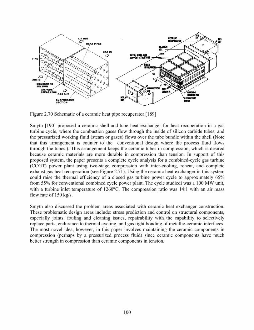
100
Figure 2.70 Schematic of a ceramic heat pipe recuperator [189] Smyth [190] proposed a ceramic shell-and-tube heat exchanger for heat recuperation in a gas turbine cycle, where the combustion gases flow through the inside of silicon carbide tubes, and the pressurized working fluid (steam or gases) flows over the tube bundle within the shell (Note that this arrangement is counter to the conventional design where the process fluid flows through the tubes.). This arrangement keeps the ceramic tubes in compression, which is desired because ceramic materials are more durable in compression than tension. In support of this proposed system, the paper presents a complete cycle analysis for a combined-cycle gas turbine (CCGT) power plant using two-stage compression with inter-cooling, reheat, and complete exhaust gas heat recuperation (see Figure 2.71). Using the ceramic heat exchanger in this system could raise the thermal efficiency of a closed gas turbine power cycle to approximately 65% from 55% for conventional combined cycle power plant. The cycle studiedi was a 100 MW unit, with a turbine inlet temperature of 1260°C. The compression ratio was 14:1 with an air mass flow rate of 150 kg/s. Smyth also discussed the problem areas associated with ceramic heat exchanger construction. These problematic design areas include: stress prediction and control on structural components, especially joints, fouling and cleaning issues, repairability with the capability to selectively replace parts, endurance to thermal cycling, and gas tight bonding of metallic-ceramic interfaces. The most novel idea, however, in this paper involves maintaining the ceramic components in compression (perhaps by a pressurized process fluid) since ceramic components have much better strength in compression than ceramic components in tension.

101
Figure 2.71 Gas turbine power plant with ceramic heat exchanger [190]
2.5.5 Heat sinks Bower et al. [191] described six different SiC heat sinks, 3.2 cm x 2.2 cm in platform area of varying thickness, channel diameter, number of channel rows, and number of channels per row (See Figure 2.72). These heat sinks were fabricated by co-extruding multiple layers of SiC filaments filled with a water-soluble polymer core (later removed during thermal processing). Water was passed through these heat sinks at 500 mL/min, and the thermal performance was measured using type-K thermocouples and pressure taps and compared to laminar flow theory. The bulk thermal conductivity of SiC (in this study) was only 15 W/m⋅°C, but because the CTE closely matches silicon, SiC is an ideal candidate for integration into microelectronic applications. Despite the low thermal conductivity value, these SiC heat sinks provided a thermal performance similar to a copper baseline heat sink at the same flow rate. The thermal resistance and Nusselt number data (shown in Figure 2.73) suggest that multiple-row SiC heat sinks perform better than single-row designs. However, Bower and co-workers conjecture that an optimum number of rows exists. The authors also assert that air-cooled heat sinks are limited to 100W/cm2 heat rejection, but water-cooled, microchannel heat sinks can achieve up to 790 W/cm2. Friction factor data compare favorably to the Shah and London correlation, and the Nusselt number data compare favorably to the solution by Hausen for thermally developing, hydrodynamically developed flow. These experiments were performed with great attention to detail. However, physical irregularities in the channels (size and shape distribution) were observed due to the fabrication method.

102
Figure 2.72 Photographs and schematic of representative SiC heat sink samples [191]
(a) (b) Figure 2.73 (a) The thermal resistance of water-cooled heat sinks is significantly lower that air-cooled sinks for modest flow rates, and (b) the Nusselt number based on base area was observed to increase as the number of rows increased [191]

103
CHAPTER 3 EXPLOITATION OF POTENTIAL NOVEL MATERIALS
3.1 Introduction In this chapter, key features of the novel materials will be investigated to identify specific uses in heat exchangers. A list of feasible material alternatives to the conventional technology will be developed. Our efforts can be divided into three main areas: (1) replacement of construction materials for existing geometries, (2) major configurational changes resulting from the adoption of new geometrical concepts, and (3) utilization of advanced fabrication technologies to maximize the benefit from new materials. The target HVAC&R application areas of interest can be classified into comfort cooling and heating (air-conditioning and heat pumping), refrigeration, and energy recovery (heat wheels and air-to-air energy recovery systems). Based on the application areas, we can divide the heat exchangers used in HVAC&R systems into eight catagories, see Table 3.1. In order to simplify the discussion, in the following sections, we can also divide the heat exchangers in HVAC&R systems into four types based on the heat transfer mechanisms: (1) liquid-to-liquid heat exchangers; (2) liquid-to-gas heat exchangers; (3) gas-to-gas heat exchangers; and (4) heat sinks. Here, the word “liquid” is taken to include single-phase liquid convection heat transfer or two-phase (liquid-vapor) convection heat transfer in the heat exchangers. The word “gas” represents single-phase gas convection heat transfer in the heat exchangers. Table 3.2 – Table 3.5 give a brief summary of typical applications of heat exchangers in HVAC&R systems base on the heat transfer mechanisms. In the following sections, we will study the possibilities of improving conventional heat exchangers by using the alternative, promising materials in two directions: (1) replacing parts of heat exchangers (e.g. fins or tubes) with new parts with minor geometrical modifications and (2) major design changes to take advantage of new characteristics. Good performance evaluation criteria are needed to facilitate an even-handed comparison between the most competitive conventional materials and the most promising alternatives and to help identify suitable geometric ranges and operating conditions. Because the merits of materials may rely on multiple factors, including enhanced convective heat transfer, higher thermal conductivity, low flow friction and size reduction, suitable comparison methods will be divided into several target applications differentiating the types of HVAC&R systems and the fluids involved.

104
Table 3.1 Types of heat exchangers in HVAC&R systems Categories Kind Features Applications
Double pipe Packaged water-cooled units Open vertical shell and tube Ammonia systems
Horizontal shell and tube
Liquid chillers Fishing vessels
Shell and coil Heat pump water heater
Water-cooled condensers
Plate Liquid chillers Evaporative condensers
Cascade condenser Cascade systems Intercooler Multi-stage systems
Tube Refrigerators
Condensers
Air-cooled condensers Tube-fin Air-source heat pump
Display cases Flooded Liquid chillers Liquid-cooling
evaporators Dry Liquid chillers Air-cooling evaporators Fin and tube Car air conditioner Evaporators
Plate evaporators Ice maker Food freezer
Heat wheel Furnace heat recover Heat pipe Fresh air heat recover Plate Aircraft air conditioning Shell and tube Fresh air heat recover
Recuperators
Suction-to-liquid HEs Double pipe Absorption chiller Refrigerator
Generators Absorption liquid chiller Absorbers Absorption refrigerator
Radiators Car air conditioner Fan coil units Distributed cooling Air handlers Central station system Ice maker HEs Ice storage
Terminals (Second HEs)
Gas-fired furnace HE Primary heat exchangers
Furnace heating Absorption liquid chiller
Gas coolers Aircraft air conditioning CO2 system
Ground HEs Ground-source heat pump Ice maker Evaporators Ice makers
Evaporator Coils Ice storage systems for air conditioning
Plate freezer Refrigeration systems for food storage
Hot end and cold end Thermal-electronic cooler
Heat sinks
Circuit board Electronic cooling

105
Table 3.2 Typical applications of heat exchangers in HVAC&R systems (Liquid-Liquid) Name Structure Fluids Typical Applications
Halocarbon-Water
Liquid chillers for resident comfort air conditioning Packaged water-cooled units Heat pump water heaters
Water-cooled condensers (Static)
Ammonia-Water Ammonia refrigeration systems for food storage CO2-CO2 Solidification of CO2 cascade refrigeration systems Cascade
condensers (Static) Ammonia-CO2
Ammonia-CO2 refrigeration systems for food storage
Halocarbon-Water Liquid chillers for resident comfort air conditioning
1
Liquid-cooling evaporators (Static)
Plate/Plate-fin
Halocarbon-Glycol Ice storage systems for air conditioning
Halocarbon-Water
Packaged water-cooled units used in freshwater ships Heat pump water heaters used in freshwater ships
Water-cooled condensers (Transportation)
Ammonia-Water Ammonia refrigeration systems used in freshwater fish ships
Cascade condenser (Transportation) Ammonia-CO2
Cascade systems used in freshwater fish ships for food storage
Halocarbon-Water
Packaged water-cooled units used in freshwater ships
2
Liquid-cooling evaporators (Transportation)
Plate/Plate-fin
Halocarbon-Glycol Ice storage systems for air conditioning
Halocarbon-Brine
Packaged sea water-cooled units used in sea ships Heat pump water heaters used in sea ships
Sea water-cooled condensers (Transportation)
Ammonia-Brine Ammonia systems used in sea fish ships for food storage
Halocarbon-Brine
3
Liquid-cooling evaporators (Transportation)
Plate/Plate-fin
Ammonia-Brine Refrigeration systems for food storage
Evaporators Water-Water Evaporative coolers for air conditioning
4 Evaporative condensers
Tube/Tube-fin Ammonia-Water Ammonia refrigeration systems for food storage
Halocarbon-Halocarbon 5 Intercoolers Tube/Tube-
fin Ammonia-Ammonia
Two-stage refrigeration systems for food storage
6 Recuperators Plate/Plate-fin
LiBr/H2O-LiBr/H2O LiBr/H2O absorption chillers for air conditioning
7 Generators Tube/Tube-fin Water-LiBr/H2O Steam-fired LiBr/H2O absorption chillers for air
conditioning
8 Absorbers Tube/Tube-fin LiBr/H2O-Water LiBr/H2O absorption chillers for air conditioning
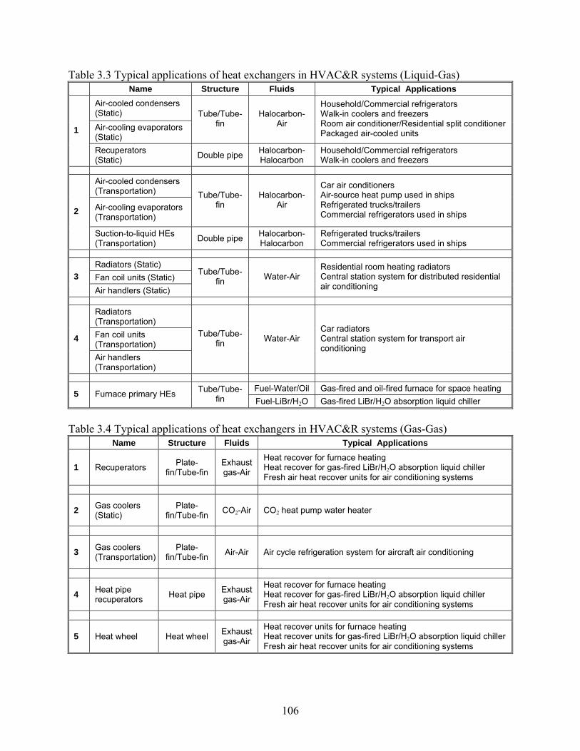
106
Table 3.3 Typical applications of heat exchangers in HVAC&R systems (Liquid-Gas) Name Structure Fluids Typical Applications
Air-cooled condensers (Static) Air-cooling evaporators (Static)
Tube/Tube-fin
Halocarbon-Air
Household/Commercial refrigerators Walk-in coolers and freezers Room air conditioner/Residential split conditioner Packaged air-cooled units 1
Recuperators (Static) Double pipe Halocarbon-
Halocarbon Household/Commercial refrigerators Walk-in coolers and freezers
Air-cooled condensers (Transportation)
Air-cooling evaporators (Transportation)
Tube/Tube-fin
Halocarbon-Air
Car air conditioners Air-source heat pump used in ships Refrigerated trucks/trailers Commercial refrigerators used in ships 2
Suction-to-liquid HEs (Transportation) Double pipe Halocarbon-
Halocarbon Refrigerated trucks/trailers Commercial refrigerators used in ships
Radiators (Static) Fan coil units (Static) 3 Air handlers (Static)
Tube/Tube-fin Water-Air
Residential room heating radiators Central station system for distributed residential air conditioning
Radiators (Transportation) Fan coil units (Transportation)
4
Air handlers (Transportation)
Tube/Tube-fin Water-Air
Car radiators Central station system for transport air conditioning
Fuel-Water/Oil Gas-fired and oil-fired furnace for space heating 5 Furnace primary HEs Tube/Tube-fin Fuel-LiBr/H2O Gas-fired LiBr/H2O absorption liquid chiller
Table 3.4 Typical applications of heat exchangers in HVAC&R systems (Gas-Gas)
Name Structure Fluids Typical Applications
1 Recuperators Plate-fin/Tube-fin
Exhaust gas-Air
Heat recover for furnace heating Heat recover for gas-fired LiBr/H2O absorption liquid chiller Fresh air heat recover units for air conditioning systems
2 Gas coolers (Static)
Plate-fin/Tube-fin CO2-Air CO2 heat pump water heater
3 Gas coolers (Transportation)
Plate-fin/Tube-fin Air-Air Air cycle refrigeration system for aircraft air conditioning
4 Heat pipe recuperators Heat pipe Exhaust
gas-Air
Heat recover for furnace heating Heat recover for gas-fired LiBr/H2O absorption liquid chiller Fresh air heat recover units for air conditioning systems
5 Heat wheel Heat wheel Exhaust gas-Air
Heat recover units for furnace heating Heat recover units for gas-fired LiBr/H2O absorption liquid chiller Fresh air heat recover units for air conditioning systems

107
Table 3.5 Typical applications of heat exchangers in HVAC&R systems (Heat sinks) Name Structure Fluids Typical Applications
1 Ground heat exchangers Tube/Tube-fin Coolant-soil Ground-source heat pump
2 Hot ends/cold ends Plate/Plate-fin PNP-Air
Circuit board-Air
Thermal-electronic cooler Electronic cooling
3 Plate freezers Plate Brine-Food Refrigeration systems with second refrigerant cycle for food storage
4 Ice maker evaporators Plate/Plate-fin Halocarbon-ice Ice makers
5 Evaporator coils Tube/Tube-fin Glycol-ice Ice storage systems for air conditioning
3.2 Replacement of parts for existing heat exchangers In order to find alternative materials for a part of a heat exchanger with a specific configuration, it is necessary to consider the desirable characteristics of the candidate changes. For example, air-side fins for some compact heat exchangers may benefit more from high thermal conductivity than from high structural strength. On the other hand, structural strength may be more important when considering a refrigerant tube. While some of these characteristics are directly linked to the figures of merit mentioned in chapter two, other factors, especially those related to reliability or application compatibility, may not be easily converted to a single figure of merit. An applicable performance evaluation method, which combines the thermal-hydraulic performance and qualitative properties, will be developed by employing a Pugh Matrix for each target application. First, we selected ten performance evaluation criteria that represent various material characteristics. For each of these criteria, Table 3.6 presents the material grading scheme. Then, based on the property features and data reviewed in chapter two, we selected seventeen most promising candidate materials for further evaluation; fifteen of them are considered as novel materials and two conventional materials (aluminum and copper) were included for comparison. Table 3.7 gives the grades of all candidate materials rated by using the criteria in Table 3.6. Table 3.6 Definitions of rating grades for properties of the candidate materials
Criteria 1 2 3 4 5 Shaping (Machining) Very difficult Difficult Moderate Easy Very easy Material cost Very high High Moderate Low Very low Thermal conductivity (W/mK) 0.1~10 10~100 100~250 250~400 >400 Temperature limit (°C) <300 300~500 500~1000 1000~1650 >1650 Material strength Very low Low Moderate High Very high Compatibility with 3 fluids Very poor Poor Moderate Good Excellent Fouling resistance Very poor Poor Moderate Good Excellent Material density (g/cm3) >8 5~8 3~4 1~2 <1

108
The shaping criterion denotes the current capability to machine complex geometries for each kind of material. It reflects the cost of the materials to be manufactured. The cost associated with fitting different parts (i.e. joining or bonding) is not included because it depends on the part materials to be fitted. Therefore, to make the evaluation fairly straightforward, we excluded the “fitting evaluation” from the above ten performance criteria for each application. As a general guideline, polymers and discontinuous composites are easily shaped into complex geometries by the mold-casting method. The machining cost of C-Cs, however, is often higher than other materials due to their hardness and the increased difficulty of manufacture. The material cost criterion denotes the cost of the material itself. It depends to large extent on the quality and method of manufacturing the material. C-Cs and MMCs are always in the highest range of the material cost in present, while most of the polymers are in the cheapest range. Thermal conductivities and densities of these materials can be found in the previous chapter. Temperature limits of these materials usually can be ranked in the following ascending sequence of polymers, PMCs, metals, MMCs, ceramics, CMCs, carbons and CAMCs. The material strength criterion denotes the mechanical properties of these materials. It is a complex issue, and many factors are involved. We separated the criterion of compatibility with working fluids into three catagories: with halocarbon and ammonia refrigerants, with LiBr-H2O and ammonia-water systems, and with secondary coolants. It will be more convenient to evaluate different applications. This criterion includes the corrosion resistance and permeability of the materials. Fouling resistance is another criterion which will influence the performance of heat exchangers over time. Usually, the ceramics and polymers possess the excellent fouling resistance. After carefully studying the criteria in Table 3.7 and typical applications in Table 3.2 to Table 3.5, we found that we could focus on a smaller list of heat transfer applications. These target applications are listed in the Table 3.8. In the following sections, we will evaluate the potential replacement of main components of heat exchangers with candidate novel materials by multiplying the assigned grades with the assigned weights for each criterion and then summing up the scores for each target application. It should be noted that each of the twenty target applications may be extended for a range of similar applications. For example, application 9 (condenser for residential food storage system) can be applied to evaporators with a similar configuration (i.e. plate fin-and-tube heat exchanger). Here, requirements for condensers are generally more restrictive than for evaporators, especially with temperature and pressure limits. On the other hand, condensate retention or frosting behavior of airside surfaces becomes important for an evaporator while irrelevant for a condenser. Likewise, application 10 (condenser for car air-conditioner) can be extended to automotive evaporators, which typically have a flat-tube serpentine louver-fin configuration similar to automotive condensers. Similar considerations of the differences can be made as with application 9.

109
Table 3.7 Rating grades for properties of the candidate materials Polymer PMC1 PMC2 PMC3 PMC4 Metal Metal Metal
Criterion Polymer
ConcreteGraphite /Epoxy
Discontinuous PMC
Continuous PMC Copper Aluminum Stainless
steel
Shaping (Machining) 5 5 5 5 3 5 5 5
Material cost 5 4 4 3 3 2 4 3
Thermal conductivity 1 1 4 2 4 4 3 2
Temperature limit 1 1 1 1 1 3 3 3
Material strength 2 2 2 3 3 5 5 5
Compatibility with halocarbon 1 3 3 2 3 5 5 5
Compatibility with LiBr-H2O 5 5 5 5 5 3 3 3
Compatibility with coolant 3 3 4 3 4 2 2 4
Fouling resistance 5 5 5 5 5 3 3 3
Material density 4 4 4 4 4 1 4 1
Metal Metal MMC1 MMC2 Carbon CAMC CAMC Ceramic CMC Criterion Copper
foam Aluminum
foam
Carbon Foam
/copper
Silicon /Aluminum
Carbon foam 2D C-C 3D C-C SiC SiC/SiC
Shaping (Machining) 4 4 3 5 3 2 2 2 2
Material cost 4 4 2 2 4 1 1 4 3
Thermal conductivity 2 2 4 3 3 4 3 3 4
Temperature limit 3 3 3 3 5 5 5 4 4
Material strength 1 1 1 4 1 5 5 2 3
Compatibility with halocarbon 5 5 5 5 5 5 5 5 5
Compatibility with LiBr-H2O 3 3 4 5 5 5 5 5 5
Compatibility with coolant 1 1 3 3 5 5 5 5 5
Fouling resistance 2 2 2 4 2 4 4 5 5
Material density 3 5 2 4 5 4 4 3 3

110
Table 3.8 Target applications of heat exchangers in HVAC&R systems Application Structure Fluids Typical Applications
1 Plate/Plate-fin Halocarbon-Water
Water-cooled condensers in liquid chillers for residential comfort air conditioning
2 Plate/Plate-fin Halocarbon/NH3-Water
Water-cooled condensers in packaged water-cooled units used in freshwater ships
3 Plate/Plate-fin Halocarbon/NH3-Water
Water-cooled condensers in packaged water-cooled units used in sea ships
4 Tube/Tube-fin Water-Water Evaporators in evaporative cooling systems for air conditioning
5 Tube/Tube-fin Halocarbon/NH3-Halocarbon Intercoolers in two-stage refrigeration systems for food storage
6 Plate/Plate-fin LiBr/H2O-LiBr/H2O Recuperators in LiBr/H2O absorption chillers for air conditioning
7 Plate/Plate-fin Water-LiBr/H2O Generators in steam generated LiBr/H2O absorption chillers for air conditioning
Liqu
id-L
iqui
d
8 Tube/Tube-fin Water-LiBr/H2O Absorbers in LiBr/H2O absorption chillers for air conditioning 9 Tube/Tube-fin Halocarbon-Air Air-cooled condensers in refrigerators for residential food storage
10 Tube/Tube-fin Halocarbon-Air Air-cooled condensers in car air conditioners 11 Tube/Tube-fin Water-Air Air handlers in central systems for distributed residential air conditioning 12 Tube/Tube-fin Water-Air Car radiators
Liqu
id-G
as
13 Tube/Tube-fin Exhaust gas-Water Primary heat exchangers in gas-fired furnaces for space heating
14 Plate/Plate-fin Air-Air Fresh air heat recovery units for air conditioning systems
Gas
-G
as
15 Plate/Plate-fin Air-Air Air- coolers in air-cycle systems for aircraft air conditioning 16 Tube/Tube-fin Coolant-soil Ground-source heat pumps 17 Plate/Plate-fin P/N-Air Hot end/cold end heat sinks in thermo-electric coolers 18 Plate/Plate-fin Brine-Food Plate freezers in refrigeration systems for food storage 19 Plate/Plate-fin Halo/NH3-Ice Evaporators in ice makers Hea
t sin
ks
20 Tube/Tube-fin Glycol-ice Evaporator coils in ice storage systems for air conditioning

111
3.2.1 Liquid-liquid heat exchangers
Eight different kinds of liquid-liquid heat exchangers will be discussed in this section.
Application 1: Water-cooled condensers in liquid chillers for resident comfort air conditioning An important application of liquid-liquid heat exchangers is residential comfort air conditioning. As a result, the plate (or plate-fin) condenser will be discussed here. In these applications, the heat exchanger fluids are usually halocarbon and water. In this kind of plate or plate-fin condenser, the components considered for replacement are the parting sheets, fins, and headers. The weight scores associated with the various criteria for the different parts of the heat exchanger in this application are shown in Table 3.10. The definitions of weight scores for criteria in each target applications are listed in Table 3.9. Table 3.9 Definitions of weight scores for criteria in each target applications
Criteria Unrelated Un- important
Much less important
Less important Important Very
important
Shaping (Machining) 0 1~2 3~4 5~6 7~8 9~10
Material cost 0 1~2 3~4 5~6 7~8 9~10
Thermal conductivity 0 1~2 3~4 5~6 7~8 9~10
Temperature limit 0 1~2 3~4 5~6 7~8 9~10
Structure strength 0 1~2 3~4 5~6 7~8 9~10
Compatibility with 3 fluids 0 1~2 3~4 5~6 7~8 9~10
Fouling resistance 0 1~2 3~4 5~6 7~8 9~10
Component weight 0 1~2 3~4 5~6 7~8 9~10
The criteria in Table 3.9 are similar to the criteria in Table 3.6, except the values assigned to some of them changed. Because Table 3.9 is connected more closely with the target applications discussed, the criteria are more closely linked with the parts of the heat exchangers. The definitions in Table 3.9 are also used in the following applications will be discussed.
• In this application, shaping cost of parting sheets, fins and headers are important, as well
as material cost of these parts. Usually no fin or few fins are used. • Usually, thermal conductivities of parting sheets and fins are important in liquid-liquid
heat exchangers, more important for fins, except for headers in the countercurrent configurations.
• Temperature limits for the parts in this application are unimportant, because the temperature in the condenser is usually below 150°C.
• Structural strength of parting sheets and headers are very important, because they need to endure the high pressure of the refrigerant systems. But the structural strength of fins is unimportant, since there is usually no fin or few fins in water-cooled condensers.
• Compatibility with halocarbons is very important for the parting sheets and headers but not for the fin, because the fins are on the water side.

112
• Compatibility with coolant is not very important because water is not a very corrosive coolant and no permeation will occur from the water side.
• Fouling resistance is less important because it is relatively easier to clean for the liquid-liquid heat exchanger applications.
• Component weight is also unimportant because this application is residential. • It is irrelevant to compatibility with LiBr-H2O in this application.
By multiplying the weight scores of each criterion in Table 3.10 for each part and the rating grades of the corresponding criterion in Table 3.7 for each material, we obtain the sum of multiplied scores for the specified part and material. The results are listed in the Table 3.11. From the Table 3.11, we can compare the scores of all the candidate materials for each part of the heat exchanger. The larger the scores is, the more promising the material is for this part. We highlight the three most promising candidate materials for each of the parts (using the scoring system of Table 3.11) and group them together to show the most promising candidate combinations (designs) for each application. For each design we can calculate the total of the scores from scores for each parts, as also shown in Table 3.11. All the promising designs can be ranked according to the sum of scores for each design in a tabular form. For example, from the best three materials for each of fin, tube, and header materials, a ranking of a total of 27 possible material combinations to constitute the heat exchanger for the target application can be obtained. The final selection should be made after accessing the feasibility of implementation, especially joining of materials, as further discussed in chapter four. For the rest of the 20 applications, the same procedure can be used to assess merits and obtain ranks, as summarized in the tables.
Application 2: Water-cooled condensers in packaged water-cooled units used in freshwater ships The only big difference between this application and application 1 is the water-cooled condensers are used in transportation. Therefore, the weight of the heat exchanger is a very important factor in heat exchanger design. A plate or plate-fin type condenser is discussed here. The heat exchanger fluids are halocarbon/NH3 and fresh water.
Application 3: Water-cooled condensers in packaged water-cooled units used in sea ships The main difference between this application and application 1 is the water-cooled condensers are used in transportation and sea water was used as coolant. Therefore, the weight of the heat exchanger and the compatibility with coolant are very important. The plate or plate-fin type condenser are discussed here. The heat exchanger fluids are halocarbon/NH3 and sea water.
Application 4: Evaporators in evaporative cooling systems for air conditioning In the direct evaporative cooling systems, cooling water in the air conditioning systems is cooled inside the tubes of the evaporators. An air flow is forced across the outside of the evaporators with a series nozzles spraying water directly over the tubes. Water lost through evaporation is replaced by make-up water. Such evaporators have some features of both air-cooled and water-cooled condensers. But they are very sensitive to fouling, because impurities remain behind when water is evaporated. The tube or tube-fin heat exchanger is discussed here.

113
Compared to application 1, five weight scores for this application have been changed, thermal conductivity, structural strength, compatibility with coolant and fouling resistance. Usually, thermal conductivities of tubes, fins and headers are important in tube or tube-fin type liquid-liquid heat exchangers, more important for fins. Structural strength of tubes, fins and headers in this kind of evaporators is much less important than other systems, because the pressure inside the tubes usually no more than one atmosphere high than the ambient air pressure. Compatibility with coolant becomes less important because the outside wet surface of tubes exposed in the air is prone to be corroded. Compatibility with halocarbon/NH3 and LiBr-H2O is irrelevant in this application. The other weight scores of criteria for this application are the same as application 1. Application 5: Intercoolers in two-stage refrigeration systems for food storage Tube or tube-fin intercoolers are discussed here. The heat exchanger fluids are halocarbon/NH3 on both side of the tubes. The main parts considered for replacement are tubes, fins and headers. Compared to application 1, three weight scores for this application have been changed, conductivity, compatibility with coolant and fouling resistance. The weight score of thermal conductivity is the same as application 4. It is irrelevant to compatibility with coolant in this application since the fluids in the intercoolers are both halocarbon/NH3. Fouling resistance is unimportant because the fluids in the intercoolers do not cause fouling in this application.
Application 6: Recuperators in LiBr/H2O absorption chillers for air conditioning LiBr/H2O absorption chillers are widely used where electricity is expensive but inexpensive heat is available. The main disadvantage of LiBr/H2O absorption chillers is the corrosive nature of LiBr/H2O to most metal materials. The performance of LiBr/H2O absorption chillers can be improved by using recuporators in solution cycle. Plate or plate-fin type recuporators are discussed in this application. The heat exchanger fluids are both LiBr/H2O solutions. The main parts considered for replacement are parting sheets, fins and headers. Compared to application 1, six weight scores for this application have been changed, material cost, structure strength, compatibility with halocarbon/NH3, LiBr/H2O and coolant, and fouling resistance. Another disadvantage of LiBr/H2O absorption chillers is their high first-cost, as the chiller consists mainly of heat exchangers. Therefore, the cost criterion is very important in this application. Structural strength of parting sheets and headers is less important than halocarbon/NH3 systems because they only need to endure the vacuum pressure which is less than one atmosphere. The structure strength of fins is unimportant, since there is usually no fin or few fins in these recuporators. Compatibility with LiBr/H2O is very important for the parting sheets, fins and headers in this application. Fouling resistance is unimportant because the fluids in the recuporator were both LiBr/H2O. The weight scores of shaping, thermal conductivity, temperature limit, and component weight are the same as application 1. Compatibility with halocarbon/NH3 and coolant in this application is irrelevant since the fluids in the recuporator are both LiBr/H2O solutions.

114
Application 7: Generators in steam generated LiBr/H2O absorption chillers for air conditioning The steam generated plate or plate-fin type generators are discussed in this application. The heat exchanger fluids are LiBr/H2O solution on one side and steam on other side. The main parts considered for replacement are parting sheets, fins and headers. Compared to application 6, three weight scores for this application have been changed, temperature limit, compatibility with coolant and fouling resistance. The weight score of compatibility with coolant becomes higher than application 1 even though the water coolant is the same. That is because the LiBr/H2O is at low pressure, and non-condensable gases--primarily oxygen and nitrogen-- dissolved in the steam might permeate into the system. The weight score of fouling resistance for this application is the same as application 1. The weight scores of other criteria for this application are the same as application 6. Application 8: Absorbers in LiBr/H2O absorption chillers for air conditioning Tube or tube-fin type absorbers are discussed in this application. The heat exchanger fluids are LiBr/H2O solution on one side and cooling water in other side. The main parts considered for replacement are tubes, fins and headers. Compared with application 7, only the weight score of temperature limit for this application has been changed. The temperature limit is similar to application 6, because the absorbing temperature will be less than 100°C. The weight scores of criterions for parts of heat exchangers in this application are listed in Table 3.10. In the same way, we can get the sum of multiplied scores for the specified part and material listed in the Table 3.11.
3.2.2 Liquid-gas heat exchangers
Five kinds of liquid-gas heat exchangers in application 9~13 will be discussed in this section.
Application 9: Air-cooled condensers in refrigerators for residential food storage Tube or tube-fin type condensers are discussed in this application. The heat exchanger fluids are halocarbon and air. The main parts considered for replacement are tubes, fins and headers. Compared to application 1, five weight scores for this application have been changed, material cost, thermal conductivity, structural strength, compatibility with coolant and fouling resistance. For small refrigerators, first-cost is very important. Therefore, the cost criterion is very important in this application. Usually, thermal conductivities of parting sheets and fins are important in liquid-gas heat exchangers, even though a little less important than for liquid-liquid heat exchangers. Structural strength of the parting sheets and headers are as important as application 1. Though the structural strength of fins is less important than for the tubes and headers, it is relatively important since there are usually a large number of fins on the air side for liquid-gas condensers. Compatibility with coolant is unimportant for air used as the coolant. Fouling resistance is important because these heat exchangers are prone to accumulated dust and are not easily (or ever) cleaned.

115
Application 10: Air-cooled condensers in car air conditioners Tube or tube-fin type condensers are discussed in this application. The heat exchanger fluids are halocarbon (or other common refrigerants) and air. The main parts considered for replacement are tubes, fins and headers. Compared to application 9, four weight scores have been changed, shaping, material cost, thermal conductivity and component weight. The big difference between this application and application 1 is that these condensers are used in transportation. Therefore, the weight and volume of the condenser are very important factors. Good shaping capacity of the material can allow the car condenser to take configurations matching the space available for the condensers. The power saving due to the weight saving can exceed the first-cost after a long operating period. Thus, the first-cost is not as important as in application 1.
Application 11: Air handlers in central systems for distributed air conditioning Tube or tube-fin type heat exchangers are discussed in this application. The heat exchanger fluids are usually water and air. The main parts considered for replacement are tubes, fins and headers. Compared to application 9, three weight scores for this application have been changed, structural strength, compatibility with halocarbon and coolant. Structural strength of the tubes, fins and headers in these kinds of heat exchangers is much less important than with halocarbon systems, similar to application 4, because the pressure inside the tubes is usually close to one atmosphere. The weight score of compatibility with coolant is the same as application 1, because the coolants both are water in these two applications. Compatibility with halocarbon and LiBr-H2O is irrelevant in this application.
Application 12: Car radiators Tube or tube-fin type car radiators are discussed in this application. The heat exchanger fluids are water and air. The main parts considered for replacement are tubes, fins and headers. Compared to application 10, two weight scores for this application have been changed, structural strength, and compatibility with halocarbons. The weight scores of structural strength are the same as application 11, because the pressure inside the tubes is close to one atmosphere. Compatibility with halocarbons and LiBr-H2O is irrelevant in this application.
Application 13: Primary heat exchangers in gas-fired furnaces for space heating Tube or tube-fin type heat exchangers are discussed in this application. The heat exchanger fluids are exhaust gas and water. The main parts considered for replacement are tubes, fins and headers. Compared with application 11, three weight scores for this application have been changed, conductivity, temperature limit and compatibility with coolant.

116
The conductivity is less important, because the temperature difference between exhaust gas and coolant is usually very large; often there is no fin or few fins on the gas side. The exhuast gas temperature is usually higher than 500°C. Thus, the temperature limits of the heat exchanger materials are very important in this application. The compatibility with coolant becomes very important since the parts of heat exchangers are exposed to a (potentially) corrosive gas in a high temperature environment.
3.2.3 Gas-gas heat exchangers
Two kinds of gas-gas heat exchangers in application 14~15 will be discussed in this section. Application 14: Fresh air heat recovery units for air conditioning systems Plate or plate-fin type heat recovery units are discussed in this application. The heat exchanger fluids sre usually both air. The main parts considered for replacement are parting sheets, fins and headers. Compared to application 11, five weight scores for this application have been changed, thermal conductivity, structural strength, compatibility with coolant, and fouling resistance. Usually, thermal conductivities of fins are important in gas-gas heat exchangers, but thermal conductivities of parting sheets are less important and those of headers are unimportant in plate or plate-fin type heat exchangers. Structural strength of parting sheets, fins and headers in these kinds of heat recovery units are unimportant, because the pressures on both sides of the parting sheets sre near ambient air pressure. The weight scores of compatibility with coolant are the same as application 9, because the coolants are both air in these two applications. The weight scores of fouling resistance are important because these units are prone to fouling and are not easily cleaned.
Application 15: Air coolers in air-cycle systems for aircraft air conditioning The air cycle consists of three processes: compression, cooling and expansion. Plate or plate-fin type heat exchangers are discussed in this application. The heat exchanger fluids are usually both air. The main parts considered for replacement are parting sheets, fins and headers. Compared to application 11, five weight scores for this application have been changed, shaping, material cost, structural strength, fouling resistance and component weight. In this application, structural strength of parting sheets and headers is very important (similar to application 9) but structural strength of fins is more important than application 9. The material cost is relatively unimportant and scores for shaping for parting sheets and fins are less than for application 14. The weight scores for fouling resistance are the same as in application 9, because the environment is relatively clean. The weight scores of component weight are the same as for application 12.
3.2.4 Heat sinks
Five kinds of heat sinks in application 16~20 will be discussed in this section.

117
Application 16: Ground-source heat pumps Here we will adopt the view that the in-gound heat exchangers act as heat sinks (or heat sources). Tube or tube-fin type heat exchangers are discussed in this application. The heat exchanger fluid is a liquid coolant. The main parts considered fro replacement are tubes, fins and headers. Compared to application 9, two weight scores for this application have been changed, thermal conductivity and structural strength. The in-ground heat exchangers are usually large and sensitive to first-cost; therefore, the cost criterion is very important in this application. Thermal conductivity is less important, because the conductivity of the soil is relatively low and the thermal resistance of soil is the controlling factor in the heat transfer process. The weight scores for structural strength of components are as important as in application 4. Fouling resistance is important, because it is inconvenient to clean the heat exchanger.
Application 17: Hot end/cold end heat sinks in thermo-electric coolers Plate or plate-fin type heat sinks are discussed in this application. The heat exchanger fluid is air. The main parts considered for replacement are plates, fins and headers. Compared to application 14, two weight scores for this application have been changed, thermal conductivity and fouling resistance. Usually, thermal conductivities in this application are very important because high heat fluxes are present at the hot end and cold end of thermo-electric coolers, and the performance of thermo-electric coolers is greatly influenced. Fouling resistance is less important, because there is only one side with fins and the environment is relatively clean. Application 18: Plate freezers in refrigeration systems for food storage The major use for plate freezers is to cool and freeze a solid product by conduction; often, fish are processed in this way. Brine is usually the coolant. The solid product and the plate function as a kind of heat sink. Plate or plate-fin type heat sinks are discussed in this application. The main parts considered for replacement are plates, fins and headers. Compared to application 1, three weight scores for this application have been changed: structural strength, compatibility with halocarbon/NH3, and compatibility with coolant. Usually, the thermal conductivities of plates and fins in this application are very important, because high heat fluxes are needed for fast freezing. Structural strength of the parting sheets and headers is important, because they are subjected to high pressures when pressed against the product. However, the structural strength of fins is unimportant, since there is usually no fin or few fins. Compatibility with halocarbons is irrelevant in this application. The weight scores of compatibility with coolant are the same as for application 3 because the brine is used as coolant in both cases.
Application 19: Evaporators in ice makers

118
In ice makers, the evaporators function as a heat sink. Plate or plate-fin type evaporators are discussed here. The heat exchanger fluids are halocarbon/NH3. The main parts considered for replacement are plates, fins and headers. Compared to application 1, only weight scores for thermal conductivity are different. Similar to application 16, thermal conductivities of plates and headers are less important, because the conductivity of the ice is relatively low and the thermal resistance of ice is the controlling factor in the heat transfer process. Tthe thermal conductivity of fins is still very important.
Application 20: Evaporator coils in ice storage systems for air conditioning Tube or tube-fin type evaporator coils are discussed here. The heat exchanger fluid is glycol. The main parts considered for replacement are tubes, fins and headers. Compared to application 19, only weight scores of structural strength are different. The weight scores of structural strength are the same as in application 4, because the pressure of the coolant circuit is similar. Table 3.10 Weights of criterions for components of heat exchangers in target applications Applications 1 2 3 4
Criteria Plate Fin Header Plate Fin Header Plate Fin Header Tube Fin Header
Shaping (Machining) 8 8 8 8 8 8 8 8 8 8 8 8
Material cost 8 8 8 8 8 8 8 8 8 8 8 8
Thermal conductivity 8 10 2 8 10 2 8 10 2 8 10 8
Temperature limit 1 1 1 1 1 1 1 1 1 1 1 1
Structural strength 10 2 10 10 2 10 10 2 10 4 2 4
Compatibility with halocarbon/NH3
10 2 10 10 2 10 10 2 10 0 0 0
Compatibility with LiBr-H2O 0 0 0 0 0 0 0 0 0 0 0 0
Compatibility with coolant 2 1 2 2 1 2 10 10 10 8 8 8
Fouling resistance 5 6 5 5 6 5 5 6 5 10 10 10
Component weight 1 1 1 10 10 10 10 10 10 1 1 1
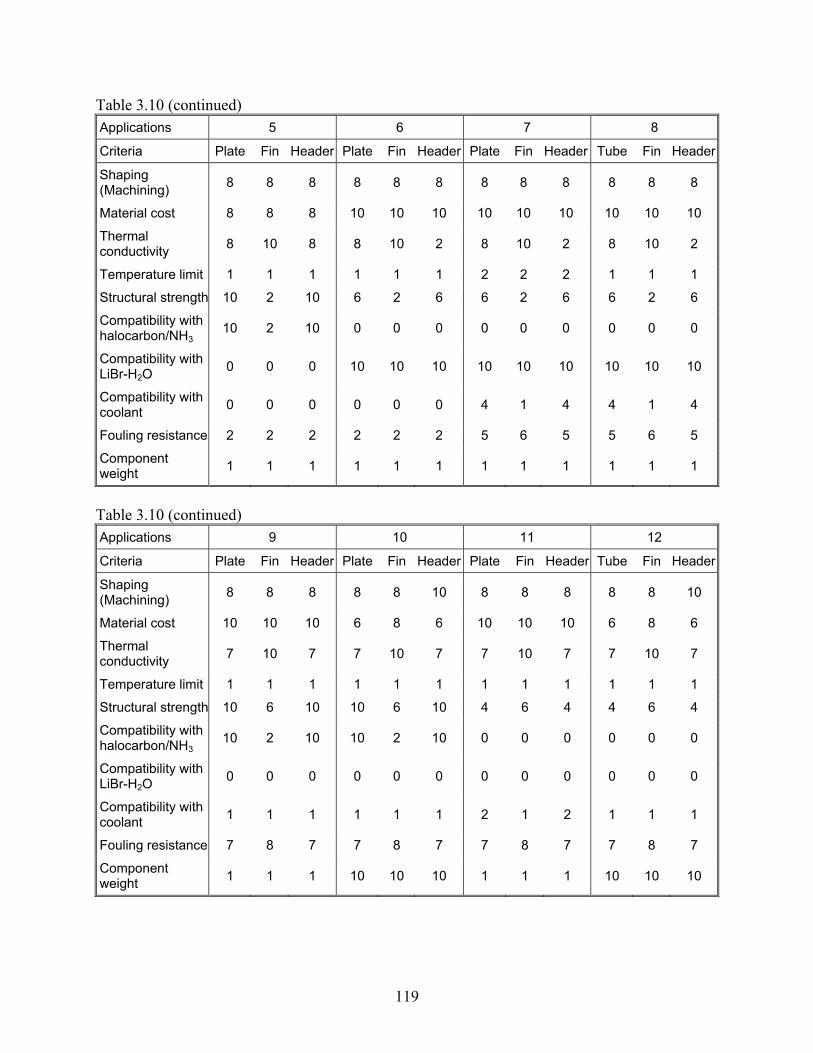
119
Table 3.10 (continued) Applications 5 6 7 8
Criteria Plate Fin Header Plate Fin Header Plate Fin Header Tube Fin Header
Shaping (Machining) 8 8 8 8 8 8 8 8 8 8 8 8
Material cost 8 8 8 10 10 10 10 10 10 10 10 10
Thermal conductivity 8 10 8 8 10 2 8 10 2 8 10 2
Temperature limit 1 1 1 1 1 1 2 2 2 1 1 1
Structural strength 10 2 10 6 2 6 6 2 6 6 2 6
Compatibility with halocarbon/NH3
10 2 10 0 0 0 0 0 0 0 0 0
Compatibility with LiBr-H2O 0 0 0 10 10 10 10 10 10 10 10 10
Compatibility with coolant 0 0 0 0 0 0 4 1 4 4 1 4
Fouling resistance 2 2 2 2 2 2 5 6 5 5 6 5
Component weight 1 1 1 1 1 1 1 1 1 1 1 1
Table 3.10 (continued) Applications 9 10 11 12
Criteria Plate Fin Header Plate Fin Header Plate Fin Header Tube Fin Header
Shaping (Machining) 8 8 8 8 8 10 8 8 8 8 8 10
Material cost 10 10 10 6 8 6 10 10 10 6 8 6
Thermal conductivity 7 10 7 7 10 7 7 10 7 7 10 7
Temperature limit 1 1 1 1 1 1 1 1 1 1 1 1
Structural strength 10 6 10 10 6 10 4 6 4 4 6 4
Compatibility with halocarbon/NH3
10 2 10 10 2 10 0 0 0 0 0 0
Compatibility with LiBr-H2O 0 0 0 0 0 0 0 0 0 0 0 0
Compatibility with coolant 1 1 1 1 1 1 2 1 2 1 1 1
Fouling resistance 7 8 7 7 8 7 7 8 7 7 8 7
Component weight 1 1 1 10 10 10 1 1 1 10 10 10

120
Table 3.10 (continued) Applications 13 14 15 16
Criteria Plate Fin Header Plate Fin Header Plate Fin Header Tube Fin Header
Shaping (Machining) 8 8 8 8 8 8 6 6 8 8 8 8
Material cost 10 10 10 10 10 10 2 2 2 10 10 10
Thermal conductivity 2 6 2 6 10 2 6 10 2 6 6 6
Temperature limit 10 10 10 1 1 1 1 1 1 1 1 1
Structural strength 4 6 4 2 6 2 10 8 10 4 2 4
Compatibility with halocarbon/NH3
0 0 0 0 0 0 0 0 0 0 0 0
Compatibility with LiBr-H2O 0 0 0 0 0 0 0 0 0 0 0 0
Compatibility with coolant 10 10 10 1 1 1 1 1 1 2 1 2
Fouling resistance 7 8 7 9 10 9 7 8 7 7 8 7
Component weight 1 1 1 1 1 1 10 10 10 1 1 1
Table 3.10 (continued) Applications 17 18 19 20
Criteria Plate Fin Header Plate Fin Header Plate Fin Header Tube Fin Header
Shaping (Machining) 8 8 8 8 8 8 8 8 8 8 8 8
Material cost 10 10 10 8 8 8 8 8 8 8 8 8
Thermal conductivity 10 10 10 8 10 2 4 10 4 4 10 4
Temperature limit 1 1 1 1 1 1 1 1 1 1 1 1
Structural strength 2 6 2 8 2 8 10 2 10 4 2 4
Compatibility with halocarbon/NH3
0 0 0 0 0 0 10 2 10 0 0 0
Compatibility with LiBr-H2O 0 0 0 0 0 0 0 0 0 0 0 0
Compatibility with coolant 1 1 1 10 10 10 2 1 2 2 1 2
Fouling resistance 7 10 7 5 6 5 5 6 5 5 6 5
Component weight 1 1 1 1 1 1 1 1 1 1 1 1

121
Table 3.11 Selection of potential component materials for target applications
Applications
1 Water-cooled condensers in
liquid chillers for resident comfort air conditioning
2 Water-cooled condensers in packaged water-cooled units
used in freshwater ships
3 Water-cooled condensers in packaged water-cooled units
used in sea ships Materials Plate Fin Header Total Plate Fin Header Total Plate Fin Header TotalPolymer 154 134 148 436 190 170 184 544 214 197 208 619 Polymer concrete 166 130 160 456 202 166 196 564 226 193 220 639 Graphite /epoxy 192 161 168 521 228 197 204 629 260 233 236 729 Discontinuous PMC 166 132 154 452 202 168 190 560 226 195 214 635 Continuous PMC 178 139 154 471 214 175 190 579 246 211 222 679 Copper 211 140 187 538 220 149 196 565 236 167 212 615 Aluminum 222 149 204 575 258 185 240 683 274 203 256 733 Stainless steel 207 130 195 532 216 139 204 559 248 175 236 659 Copper foam 158 115 146 419 185 142 173 500 193 151 181 525 Aluminum foam 160 117 148 425 205 162 193 560 213 171 201 585 Carbon foam /copper 153 112 129 394 171 130 147 448 195 157 171 523 Silicon /aluminum 203 138 185 526 239 174 221 634 263 201 245 709 Carbon foam 170 125 152 447 215 170 197 582 255 215 237 707 2D C-C 195 122 171 488 231 158 207 596 271 203 247 721 3D C-C 187 112 169 468 223 148 205 576 263 193 245 701 SiC 184 134 166 484 211 161 193 565 251 206 233 690 SiC/SiC 194 138 170 502 221 165 197 583 261 210 237 708
Table 3.11 (continued)
Applications
4 Evaporators in evaporative
cooling systems for air conditioning
5 Intercoolers in two-stage
refrigeration systems for food storage
6 Recuperators in LiBr/H2O absorption chillers for air
conditioning Materials Plate Fin Header Total Plate Fin Header Total Plate Fin Header TotalPolymer 175 173 175 523 133 111 133 377 175 169 169 513 Polymer concrete 167 165 167 499 145 107 145 397 165 159 159 483 Graphite /epoxy 199 203 199 601 169 137 169 475 189 189 165 543 Discontinuous PMC 171 169 171 511 145 109 145 399 169 161 157 487 Continuous PMC 179 181 179 539 155 115 155 425 169 165 145 479 Copper 158 156 158 472 198 126 198 522 162 150 138 450 Aluminum 169 165 169 503 209 135 209 553 177 163 159 499 Stainless steel 166 160 166 492 190 114 190 494 156 140 144 440 Copper foam 118 120 118 356 150 106 150 406 134 134 122 390 Aluminum foam 120 122 120 362 152 108 152 412 136 136 124 396 Carbon foam /copper 125 131 125 381 141 101 141 383 131 135 107 373 Silicon /aluminum 167 165 167 499 185 119 185 489 173 163 155 491 Carbon foam 154 158 154 466 154 112 154 420 158 160 140 458 2D C-C 165 163 165 493 173 101 173 447 155 143 131 429 3D C-C 157 153 157 467 165 91 165 421 147 133 129 409 SiC 177 179 177 533 159 109 159 427 159 157 141 457 SiC/SiC 181 183 181 545 169 113 169 451 163 159 139 461
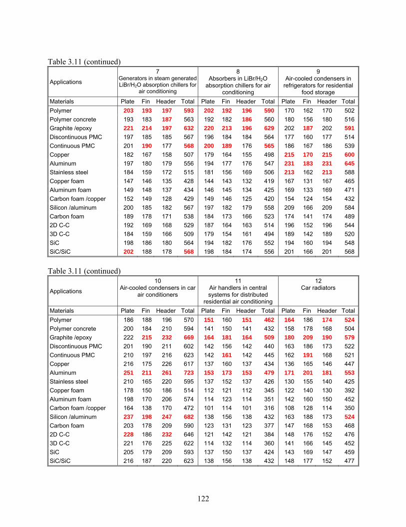
122
Table 3.11 (continued)
Applications
7 Generators in steam generatedLiBr/H2O absorption chillers for
air conditioning
8 Absorbers in LiBr/H2O
absorption chillers for air conditioning
9 Air-cooled condensers in
refrigerators for residential food storage
Materials Plate Fin Header Total Plate Fin Header Total Plate Fin Header TotalPolymer 203 193 197 593 202 192 196 590 170 162 170 502 Polymer concrete 193 183 187 563 192 182 186 560 180 156 180 516 Graphite /epoxy 221 214 197 632 220 213 196 629 202 187 202 591 Discontinuous PMC 197 185 185 567 196 184 184 564 177 160 177 514 Continuous PMC 201 190 177 568 200 189 176 565 186 167 186 539 Copper 182 167 158 507 179 164 155 498 215 170 215 600 Aluminum 197 180 179 556 194 177 176 547 231 183 231 645 Stainless steel 184 159 172 515 181 156 169 506 213 162 213 588 Copper foam 147 146 135 428 144 143 132 419 167 131 167 465 Aluminum foam 149 148 137 434 146 145 134 425 169 133 169 471 Carbon foam /copper 152 149 128 429 149 146 125 420 154 124 154 432 Silicon /aluminum 200 185 182 567 197 182 179 558 209 166 209 584 Carbon foam 189 178 171 538 184 173 166 523 174 141 174 489 2D C-C 192 169 168 529 187 164 163 514 196 152 196 544 3D C-C 184 159 166 509 179 154 161 494 189 142 189 520 SiC 198 186 180 564 194 182 176 552 194 160 194 548 SiC/SiC 202 188 178 568 198 184 174 556 201 166 201 568
Table 3.11 (continued)
Applications
10 Air-cooled condensers in car
air conditioners
11 Air handlers in central systems for distributed
residential air conditioning
12 Car radiators
Materials Plate Fin Header Total Plate Fin Header Total Plate Fin Header TotalPolymer 186 188 196 570 151 160 151 462 164 186 174 524 Polymer concrete 200 184 210 594 141 150 141 432 158 178 168 504 Graphite /epoxy 222 215 232 669 164 181 164 509 180 209 190 579 Discontinuous PMC 201 190 211 602 142 156 142 440 163 186 173 522 Continuous PMC 210 197 216 623 142 161 142 445 162 191 168 521 Copper 216 175 226 617 137 160 137 434 136 165 146 447 Aluminum 251 211 261 723 153 173 153 479 171 201 181 553 Stainless steel 210 165 220 595 137 152 137 426 130 155 140 425 Copper foam 178 150 186 514 112 121 112 345 122 140 130 392 Aluminum foam 198 170 206 574 114 123 114 351 142 160 150 452 Carbon foam /copper 164 138 170 472 101 114 101 316 108 128 114 350 Silicon /aluminum 237 198 247 682 138 156 138 432 163 188 173 524 Carbon foam 203 178 209 590 123 131 123 377 147 168 153 468 2D C-C 228 186 232 646 121 142 121 384 148 176 152 476 3D C-C 221 176 225 622 114 132 114 360 141 166 145 452 SiC 205 179 209 593 137 150 137 424 143 169 147 459 SiC/SiC 216 187 220 623 138 156 138 432 148 177 152 477

123
Table 3.11 (continued)
Applications
13 Primary heat exchangers in gas-fired furnaces for space
heating
14 Fresh air heat recovery units for air conditioning systems
15 Air-coolers in air-cycle systems for aircraft air
conditioning Materials Plate Fin Header Total Plate Fin Header Total Plate Fin Header TotalPolymer 179 192 179 550 153 170 149 472 145 150 151 446 Polymer concrete 169 182 169 520 143 160 139 442 143 148 149 440 Graphite /epoxy 185 210 185 580 162 191 146 499 162 179 156 497 Discontinuous PMC 165 184 165 514 141 166 133 440 157 164 159 480 Continuous PMC 163 190 163 516 138 171 122 431 158 173 148 479 Copper 160 189 160 509 127 166 111 404 144 153 138 435 Aluminum 181 206 181 568 144 179 132 455 172 177 170 519 Stainless steel 186 207 186 579 127 158 119 404 136 137 138 411 Copper foam 137 149 137 423 111 125 103 339 102 110 102 314 Aluminum foam 139 151 139 429 113 127 105 345 122 130 122 374 Carbon foam /copper 132 152 132 416 96 118 80 294 96 112 86 294 Silicon /aluminum 174 198 174 546 132 164 120 416 166 174 164 504 Carbon foam 193 209 193 595 117 135 105 357 128 140 122 390 2D C-C 186 216 186 588 110 150 94 354 166 176 154 496 3D C-C 184 210 184 578 104 140 92 336 160 166 152 478 SiC 198 219 198 615 135 160 123 418 132 145 124 401 SiC/SiC 194 221 194 609 133 166 117 416 146 161 134 441
Table 3.11 (continued)
Applications 16
Ground-source heat pumps 17
Hot end/cold end heat sinks in thermo-electric coolers
18 Plate freezers in refrigeration
systems for food storage Materials Plate Fin Header Total Plate Fin Header Total Plate Fin Header TotalPolymer 150 148 150 448 147 170 147 464 164 159 158 481 Polymer concrete 140 138 140 418 137 160 137 434 156 151 150 457 Graphite /epoxy 160 157 160 477 168 191 168 527 190 191 166 547 Discontinuous PMC 140 136 140 416 139 166 139 444 164 155 152 471 Continuous PMC 138 133 138 409 144 171 144 459 174 169 150 493 Copper 133 124 133 390 137 166 137 440 167 148 143 458 Aluminum 150 141 150 441 150 179 150 479 178 157 160 495 Stainless steel 135 124 135 394 129 158 129 416 179 156 167 502 Copper foam 110 109 110 329 115 125 115 355 114 114 102 330 Aluminum foam 112 111 112 335 117 127 117 361 116 116 104 336 Carbon foam /copper 97 94 97 288 108 118 108 334 125 129 101 355 Silicon /aluminum 135 128 135 398 136 164 136 436 169 155 151 475 Carbon foam 120 115 120 355 125 135 125 385 158 160 140 458 2D C-C 117 106 117 340 118 150 118 386 175 157 151 483 3D C-C 111 100 111 322 108 140 108 356 167 147 149 463 SiC 134 130 134 398 137 160 137 434 170 169 152 491 SiC/SiC 134 128 134 396 139 166 139 444 178 173 154 505

124
Table 3.11 (continued)
Applications
19 Evaporators in ice makers
20 Evaporator coils in ice storage systems for air
conditioning Materials Plate Fin Header Total Plate Fin Header Total Polymer 150 134 150 434 128 132 128 388 Polymer concrete 162 130 162 454 120 124 120 364 Graphite /epoxy 176 161 176 513 134 155 134 423 Discontinuous PMC 158 132 158 448 120 128 120 368 Continuous PMC 162 139 162 463 114 133 114 361 Copper 195 140 195 530 115 130 115 360 Aluminum 210 149 210 569 130 139 130 399 Stainless steel 199 130 199 528 119 120 119 358 Copper foam 150 115 150 415 94 105 94 293 Aluminum foam 152 117 152 421 96 107 96 299 Carbon foam /copper 137 112 137 386 81 102 81 264 Silicon /aluminum 191 138 191 520 117 128 117 362 Carbon foam 158 125 158 441 102 115 102 319 2D C-C 179 122 179 480 99 112 99 310 3D C-C 175 112 175 462 95 102 95 292 SiC 172 134 172 478 110 124 110 344 SiC/SiC 178 138 178 494 110 128 110 348
While we intend for the twenty applications we selected for evaluation to be thorough, we also want to point out that considering every heat exchanger application in the HVAC&R industry is probably not feasible for a single report. Moreover, we realize that the judgments we have made regarding the weighting factors may be open for argument. The most important part of this exercise may well be the comprehensive approach itself, as opposed to a simple PEC. We believe this approach can be applied in a straightforward manner to any HVAC&R application. Finally, it is important to note that the evaluation given in this section is aimed only at material-replacement options, and the ultimate promise of new materials might be realized through significant changes in heat exchanger configuration—such possibilities are explored next.
3.3 Change of heat exchanger configurations This task requires innovative ideas and insights into heat exchanger applications. In search of possible new heat exchanger configurations, we will strategically identify unique properties of alternative materials as well as conceptual barriers imposed by presuming conventional materials and manufacturing processes. For example, instead of the conventional geometrical configuration of a specific heat exchanger type (e.g. flat-tube louver-fin radiator material), an alternative configuration—more efficient and likely more complex—can be developed based concepts drawn from Constructal Theory [192]. Since the establishment of this theory, a number of investigations have been reported by researchers as an effort to optimize the configurations of various geometries for convective heat transfer. We have conducted a survey of such reports and documented the most promising geometries for heat exchangers. Furthermore, as numerous fabrication methods have been introduced by engineers from a wide range of related fields, we
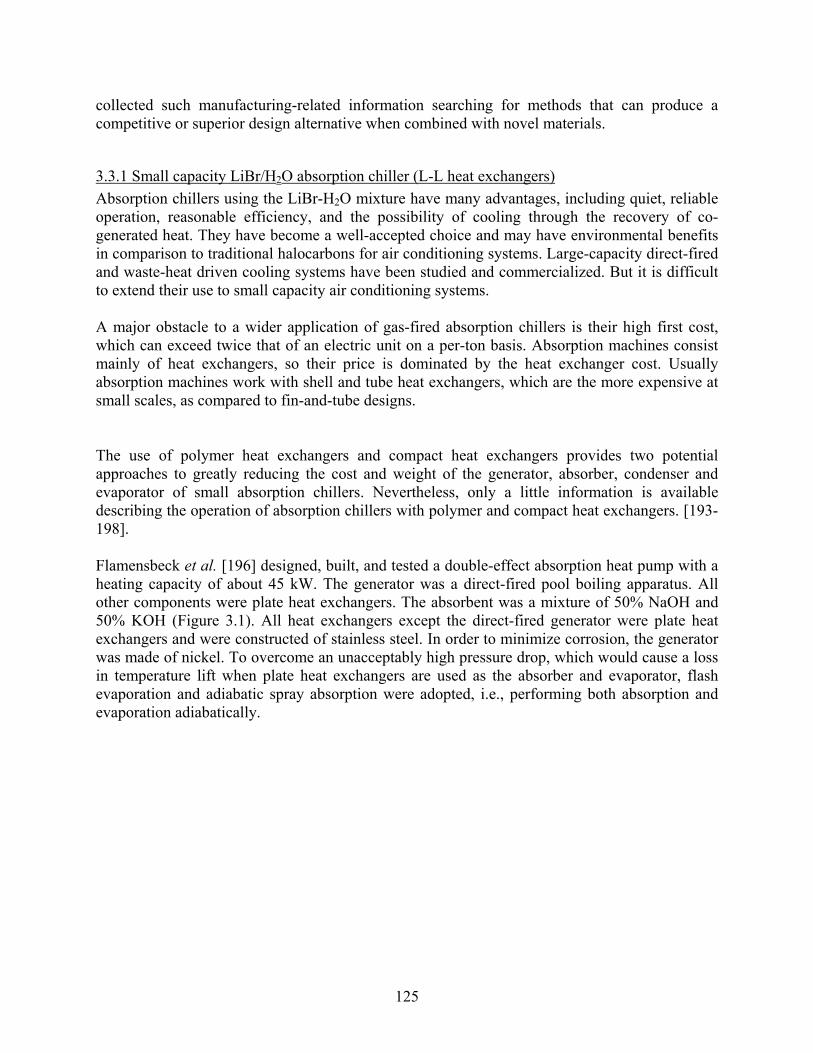
125
collected such manufacturing-related information searching for methods that can produce a competitive or superior design alternative when combined with novel materials.
3.3.1 Small capacity LiBr/H2O absorption chiller (L-L heat exchangers) Absorption chillers using the LiBr-H2O mixture have many advantages, including quiet, reliable operation, reasonable efficiency, and the possibility of cooling through the recovery of co-generated heat. They have become a well-accepted choice and may have environmental benefits in comparison to traditional halocarbons for air conditioning systems. Large-capacity direct-fired and waste-heat driven cooling systems have been studied and commercialized. But it is difficult to extend their use to small capacity air conditioning systems. A major obstacle to a wider application of gas-fired absorption chillers is their high first cost, which can exceed twice that of an electric unit on a per-ton basis. Absorption machines consist mainly of heat exchangers, so their price is dominated by the heat exchanger cost. Usually absorption machines work with shell and tube heat exchangers, which are the more expensive at small scales, as compared to fin-and-tube designs. The use of polymer heat exchangers and compact heat exchangers provides two potential approaches to greatly reducing the cost and weight of the generator, absorber, condenser and evaporator of small absorption chillers. Nevertheless, only a little information is available describing the operation of absorption chillers with polymer and compact heat exchangers. [193-198]. Flamensbeck et al. [196] designed, built, and tested a double-effect absorption heat pump with a heating capacity of about 45 kW. The generator was a direct-fired pool boiling apparatus. All other components were plate heat exchangers. The absorbent was a mixture of 50% NaOH and 50% KOH (Figure 3.1). All heat exchangers except the direct-fired generator were plate heat exchangers and were constructed of stainless steel. In order to minimize corrosion, the generator was made of nickel. To overcome an unacceptably high pressure drop, which would cause a loss in temperature lift when plate heat exchangers are used as the absorber and evaporator, flash evaporation and adiabatic spray absorption were adopted, i.e., performing both absorption and evaporation adiabatically.
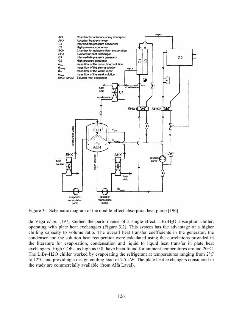
126
Figure 3.1 Schematic diagram of the double-effect absorption heat pump [196] de Vega et al. [197] studied the performance of a single-effect LiBr-H2O absorption chiller, operating with plate heat exchangers (Figure 3.2). This system has the advantage of a higher chilling capacity to volume ratio. The overall heat transfer coefficients in the generator, the condenser and the solution heat recuperator were calculated using the correlations provided in the literature for evaporation, condensation and liquid to liquid heat transfer in plate heat exchangers. High COPs, as high as 0.8, have been found for ambient temperatures around 20°C. The LiBr–H2O chiller worked by evaporating the refrigerant at temperatures ranging from 2°C to 12°C and providing a design cooling load of 7.5 kW. The plate heat exchangers considered in the study are commercially available (from Alfa Laval).

127
Figure 3.2 Schematic diagram of the absorption chiller configuration [197]
3.3.1.1 Generators and recuperators An earlier study performed by Brookhaven National Laboratory (BNL) and co-funded by GRI identified heat exchangers made from polymer and coated-metal films as a promising approach for reducing the cost of absorption systems [193]. They screened a large number of polymer films, which are a prime candidate because they offer great resistance to corrosion, and tested more than two dozen of the most promising for short-term hydrostatic tensile strength at room temperature and at 200°C. They identified the polymers with the highest tensile strength and thermal conductivity. They also measured the creep under stress and the durability of about six of the most promising of these for one year in 220°C lithium bromide (LiBr) brines. The most promising polymer was polyether-ether-ketone (PEEK). Leigh et al. [53] proposed to make the second-effect generator from PEEK for a gas-fired double-effect unit. They performed a simple experiment using a PEEK bag filled with oil and a resistance heater to determine whether the polymer heat exchanger would perform well in boiling heat transfer, and in particular address whether its smooth, low surface energy interface might inhibit nucleation. The results were encouraging. Many nucleation sites were involved in boiling, with their number increasing dramatically with heat transfer rate. The temperature drop due to the thermal resistance of the PEEK itself was about 2°C and, since the thermal resistance from the oil was considerably larger than would occur in condensation, the observed temperature differences across the interface were consistent with efficient second-effect generator operation at the somewhat higher heat transfer rate. Based on the above results and the results of other research [196, 197], we propose to use the polymer film compact heat exchanger (PFCHE) developed by Zaheed and Jachuck [5] to make the second-effect generator which uses 0.1 mm thick polymer films to overcome the low thermal conductivity in polymer heat exchangers. The use of polymer films of approximately 0.1 mm

128
thick will improve thermal performance and the presence of corrugations on the films also aids towards heat transfer enhancement, as it encourages more mixing of the fluid flow. Moreover, it exhibited good thermal stability and had a working temperature of about 220°C. Additionally the matrix can withstand a differential pressure of about 10 bar at ambient temperatures. Because the operation temperature of first-effect generator is usually too high to use polymer materials, we suggest the first-effect generator can be made from CMCs, such as SiC/SiC, based on the analysis of chapter two. Leigh et al. [53] constructed a small (3.3 ft2) shell-and-tube recuperator from PEEK, as hown in Figure 3.3 and Figure 3.4, and they tested its performance in (an approximately) counterflow heat exchange. The heat exchanger tubes were formed by welding together flat sheets. The thickness of PEEK films used in BNL’s film shell and tube recuperator was 1-2 mm. Unfortunately, the performance was poor due to the small size of the device, but it was sufficient to indicate that there were no big surprises and that polymer recuperators will act in accordance with standard engineering predictions for metallic heat exchangers despite the inherent flexibility and low surface energy of the material. They concluded that the best approach to fabrication, especially manifolding, would be blow molding from a pre-welded flat intermediate structure. We believe the heat transfer in high or low temperature recuperators in absorption chillers will be enhanced greatly if the PEEK film compact heat exchangers developed by Zaheed and Jachuck [5] are used. Of course, other PMCs with higher conductivity could be used if the material cost is not so high, such as graphite/epoxy, etc.
Figure 3.3 PEEK shell and tube recuperator [193]

129
Figure 3.4 PEEK shell and tube recuperator (Cross sections) [193]
3.3.1.2 Absorber, evaporator and condenser BNL concluded that plastic films were not suitable for either the absorber or evaporator of an absorption chiller, because the films would permit non-condensable gases--primarily oxygen and nitrogen--that are dissolved in the cooling water flowing within the heat exchanger to enter the chiller’s vacuum vessel [193]. Lowenstein et al. [194, 195] also tested the permeation of a 4 mil high-density polyethylene (HDPE) heat exchanger. The results showed that a fully aerated flow of cooling water provides essentially the same driving potential for air permeation across the plastic films as air at one atmosphere. Thin films made from common plastics such as polyethylene, PET or nylon will leak non-condensable gases into the vacuum vessel at a rate that was more than an order of magnitude greater than the purge rates now used in absorption chillers. Lowenstein and co-workers proposed co-extruded or laminated composite plastic films for service in an absorption chiller. These films, which were produced primarily for the food packaging industry, were designed to be effective barriers to oxygen and nitrogen. They overcame some of the poor physical characteristics of plastics that were excellent gas barriers by combining them with layers of other plastics. Thus a barrier film might have a polyester film—which has an exceptionally high tensile strength—as one outer layer, and polyethylene—which is easily thermally sealed—as the other. Between these films might be one or more layers of EVA and/or Saran—both of which are excellent gas barriers. Lowenstein and co-workers report a more promising composite, referred to as PM300S; this film is a laminate with the following structure: Mylar®/PVDC/adhesive/polyethylene-EVA. The film thickness was 0.0025 in, and its oxygen permeability was 0.49 cm3/100 in2-days-atm. The layer of Mylar® gave the film much greater strength than the Saranex films. Although the film’s thermal conductivity was expected to be low (no value is reported), its strength would permit it to be used in thin gauges, which would reduce it thermal resistance. This film gave a combined

130
oxygen/nitrogen permeation rate that was a factor of 340 times smaller than that previously calculated for HDPE, well within the capacity of a conventional purge system. Single tubes were made from this material and pressure tested. The burst pressure for a 3/8″ tube was 60 psi. Although it will not be possible to reinforce the turn region of a heat exchanger made from PM300S because the film is a laminate, the estimated burst pressure of 26 psi for a complete unit was still relatively high. Unfortunately, Lowenstein and co-workers did not make and test a complete heat exchanger.
A plastic thin-film heat exchanger element shown in Figure 3.5 was developed and tested. It was formed from two sheets of plastic material, and having a plurality of seams between two or more liquid-tight passages through the heat exchanger apparatus, with one or more turning regions. At least one substantially continuous, non-branching liquid conduit is through the heat exchanger. It can be used as the absorber, evaporator and condenser in an absorption chiller. Water passed through for transferring heat from the liquid LiBr/H2O mixture surroundings of the heat exchanger.
Figure 3.5 Thin-film plastic heat exchanger element with serpentine passage [194] A model made from 0.004″ HDPE, with 3/8″ diameter tubes, demonstrated that it could operate at internal pressures of 20 psi above that of the vacuum vessel. A well-designed plastic thin-film heat exchanger that was maintained under sufficient pressure to fully expand the passages will

131
have pressure drop characteristics that are almost identical to a rigid-wall heat exchanger. For a heat exchanger made of a pliable plastic, such as LDPE or a HDPE/LDPE blend, the working pressure within the heat exchanger is sufficient to keep the passages clear of folds and creases that might form in the region of the 180o turns. Lowenstein et al. [194, 195] suggested that the target system should be identified that imposes no more than 30 to 40 psi across the heat exchanger tubes and this target system should have the potential for a relatively high sales volume (e.g., 10 to 25 ton roof-top chillers). Leigh et al. [53] believed that an enhancement of heat transfer could be achieved during condensation due to the hydrophobic nature of many polymers. Substantial benefits from the use of PEEK or other polymers would occur wherever condensation occurred, since that condensation will be drop-wise over a far wider range of conditions than for metals. This change in condensation will result in specific (although as yet unmeasured) enhancement of the performance of a second-effect generator, perhaps more than overcoming the decrease due to the lower thermal conductivity of the polymer, for which they predicted a temperature drop of 3.5F for a 1.9 mil thick film in the second-effect generator [193]. Based on the above results and results of other research [196, 197], we propose to use the polymer film compact heat exchanger (PFCHE) developed by Zaheed and Jachuck [5] to make the absorber, evaporator and condenser which use 100 mm thick polymer films to overcome the low thermal conductivity in polymer heat exchangers and make the unit much more compact.
3.3.1.3 Summary Table 3.12 gives a summary of different designs for a small gas-fired LiBr/H2O absorption chiller from literatures and as recommended in this report. In addition to a high tensile strength, high thermal conductivity, and low oxygen and nitrogen permeability, the polymer film should not be attacked by concentrated lithium bromide solutions, should not be permeable to lithium or bromide ions. Therefore, tests should be performed to determine the above two characteristics of the polymer candidates in future research.
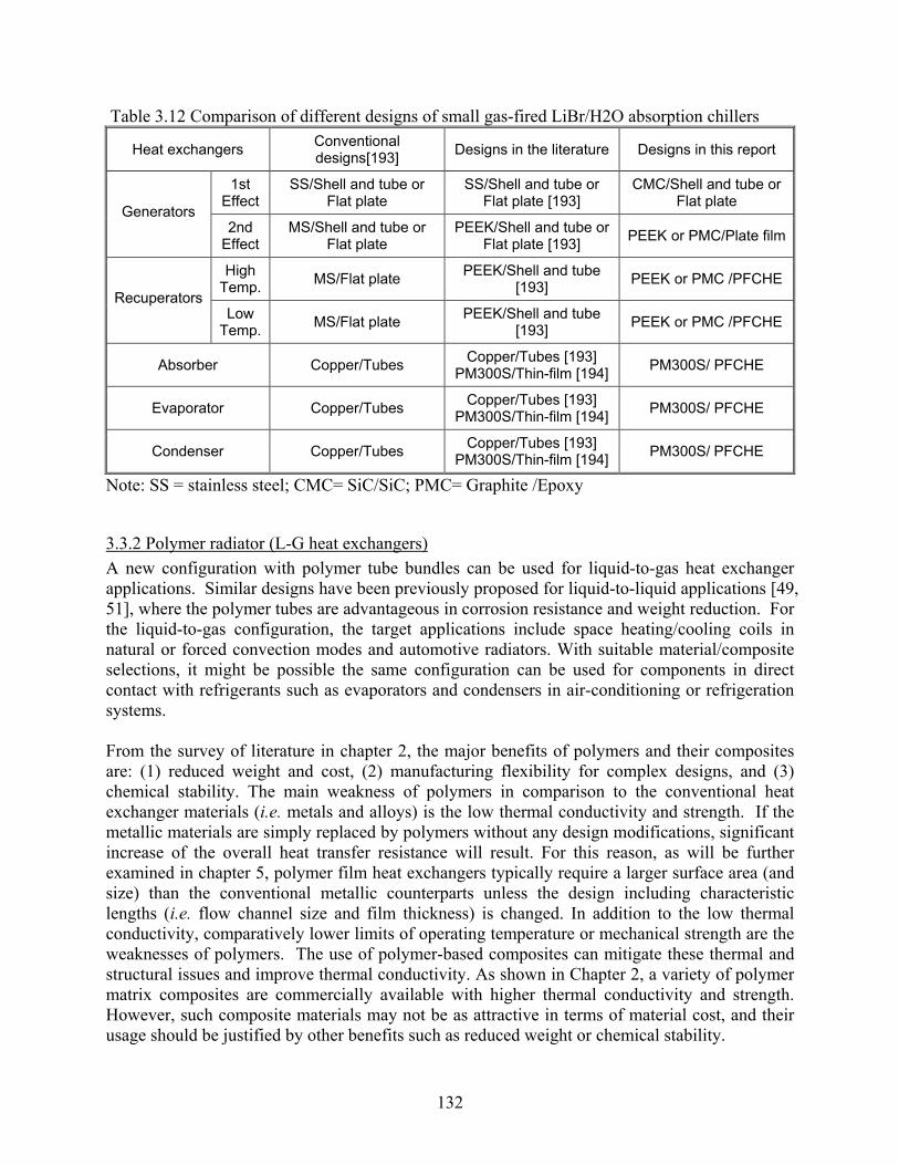
132
Table 3.12 Comparison of different designs of small gas-fired LiBr/H2O absorption chillers
Heat exchangers Conventional designs[193] Designs in the literature Designs in this report
1st Effect
SS/Shell and tube or Flat plate
SS/Shell and tube or Flat plate [193]
CMC/Shell and tube or Flat plate
Generators 2nd
Effect MS/Shell and tube or
Flat plate PEEK/Shell and tube or
Flat plate [193] PEEK or PMC/Plate film
High Temp. MS/Flat plate PEEK/Shell and tube
[193] PEEK or PMC /PFCHE Recuperators
Low Temp. MS/Flat plate PEEK/Shell and tube
[193] PEEK or PMC /PFCHE
Absorber Copper/Tubes Copper/Tubes [193] PM300S/Thin-film [194] PM300S/ PFCHE
Evaporator Copper/Tubes Copper/Tubes [193] PM300S/Thin-film [194] PM300S/ PFCHE
Condenser Copper/Tubes Copper/Tubes [193] PM300S/Thin-film [194] PM300S/ PFCHE
Note: SS = stainless steel; CMC= SiC/SiC; PMC= Graphite /Epoxy
3.3.2 Polymer radiator (L-G heat exchangers) A new configuration with polymer tube bundles can be used for liquid-to-gas heat exchanger applications. Similar designs have been previously proposed for liquid-to-liquid applications [49, 51], where the polymer tubes are advantageous in corrosion resistance and weight reduction. For the liquid-to-gas configuration, the target applications include space heating/cooling coils in natural or forced convection modes and automotive radiators. With suitable material/composite selections, it might be possible the same configuration can be used for components in direct contact with refrigerants such as evaporators and condensers in air-conditioning or refrigeration systems. From the survey of literature in chapter 2, the major benefits of polymers and their composites are: (1) reduced weight and cost, (2) manufacturing flexibility for complex designs, and (3) chemical stability. The main weakness of polymers in comparison to the conventional heat exchanger materials (i.e. metals and alloys) is the low thermal conductivity and strength. If the metallic materials are simply replaced by polymers without any design modifications, significant increase of the overall heat transfer resistance will result. For this reason, as will be further examined in chapter 5, polymer film heat exchangers typically require a larger surface area (and size) than the conventional metallic counterparts unless the design including characteristic lengths (i.e. flow channel size and film thickness) is changed. In addition to the low thermal conductivity, comparatively lower limits of operating temperature or mechanical strength are the weaknesses of polymers. The use of polymer-based composites can mitigate these thermal and structural issues and improve thermal conductivity. As shown in Chapter 2, a variety of polymer matrix composites are commercially available with higher thermal conductivity and strength. However, such composite materials may not be as attractive in terms of material cost, and their usage should be justified by other benefits such as reduced weight or chemical stability.

133
The low thermal conductivity has two practical implications for polymeric heat exchanger designs: (1) the use polymers as primary heat transfer path should be minimized, i.e. walls for heat conduction (e.g. tube or plate) should be made thin, and (2) long-distance heat conduction (e.g. fins) through polymers should be avoided. Thus, instead of relying on conduction through extended surfaces, a polymer heat exchanger design should increase the primary (i.e. base) heat transfer surface area. Meanwhile, the needs for reduced conduction resistance and higher mechanical strength apparently conflict with each other. The limitations in mechanical strength can be resolved by adopting small length scales, i.e. instead of using large-scale flow channels with thick bulk materials which degrade thermal performance, the flow can be divided into multiple smaller channels with thinner walls. The manufacturing flexibility of polymers provides an opportunity for producing a highly compact, multi-mini-channel heat exchanger design. On the basis of the above discussion, the proposed liquid-to-air heat exchanger uses a polymer tube bundle without fins. In order to reduce tube wall conduction resistance, the tubes should be made sufficiently thin while maintaining the structural integrity under normal operating conditions generating mechanical and thermal stresses. As typical heat exchangers operate with pressurized liquid inside the tubes, the pressure and the operating temperature becomes the limiting factor for the polymer tubes. Raman et al. [11] conducted a careful examination a number of polymeric materials for use in solar collectors. They selected several candidate materials by screening with national codes and standards for plumbing applications. Combining the thermal and mechanical limits of individual materials, they calculated the minimum tube thickness for a given nominal tube diameter. In summary, they proposed using large number of thin, small-diameter polymer tubes for solar collectors. They suggested using extruded polymer tubes and fiber-reinforced polymer composite headers. In their study, however, no prototype solar collector design was described and the aspect of thermal-hydraulic performance was not addressed. We take a similar approach in adopting large number of small and thin tubes made of polymers as a liquid-to-gas heat exchanger. Considering a nominal pressure of 10-20 bars, the tubes should be less than a few millimeters in diameter in order to achieve sufficient mechanical strength and reasonably low wall conduction resistance. A primary design of the polymer-tube-bundle heat exchanger is illustrated in Figure 3.6, where the heat exchanger is essentially a cross-flow type. When multiple cross-flow “modules” are stacked in the gas-flow direction, a counter-cross or parallel-cross configuration can be obtained as shown in Figure 3.6(b). The tube bundle has a few gas-side design parameters: tube diameter, transverse and longitudinal tube pitches, inline or staggered tube arrangement, and number of tube rows (see Figure 3.7). It is expected that these parameters need to be optimized for different applications, e.g. forced vs. natural convection.

134
(a) (b)
Figure 3.6 Polymer-tube-bundle liquid-to-gas heat exchanger; (a) Single-module cross-flow configuration, (b) Two-module counter-cross-flow configuration
(a) (b)
Figure 3.7 Design parameters of the polymer-tube-bundle heat exchanger; (a) tube bundle, (b) header There are a few concerns regarding this design, in contrast to the conventional fin-and-tube metallic heat exchangers. First, at first glance, the gas-side heat transfer surface area may be insufficient due to the elimination of fins. In fact, this is a matter of design optimization, and it can be overcome by using many small tubes if the overall dimension permits. Second, the small-diameter tubes can cause a noticeable increase the liquid pressure drop. A possible solution is reducing the liquid velocity as already implied by a large number of tubes in the bundle. On the other hand, this can result in reduced heat exchanger effectiveness due to an increased temperature change from a low liquid velocity, if the thermal capacity of gas flow is smaller than the liquid side. The change of liquid temperature can be reduced by shortening the polymer tubes. Short tubes also reduce the liquid pressure drop, which is approximately proportional to the tube length, assuming that header pressure drop is minor. Shortened tube length may be viewed as a design restriction that can affect the overall heat exchanger dimension. However, by using a more creative flow configuration, this problem can be overcome. For example, secondary headers that divide the liquid flow into multiple parallel passages can be added, and then the

135
polymer tube bundles can be attached between the upstream and downstream secondary headers. Perhaps, this is where the design freedom of polymers becomes especially advantageous. A simple long-header design and a branched header design are illustrated in Figure 3.8(a) and (b), respectively.
(a) (b) Figure 3.8 Shortened tube configurations with the same frontal area as that of Figure 3.6(a); (a) long header design, (b) branched header design Another concern is the need for bulk structural supports because a bundle of thin and long polymer tubes by itself is likely to be flimsy. Typical metallic heat exchangers have sufficient overall rigidity without any added structure due to the fairly large tube diameter and the rigidity of metallic tubes. However, the polymer tube bundle will require additional structure that will maintain the overall shape, e.g. a rigid frame on which both inlet and outlet headers are fixed. For relatively long tube bundles, further support can be installed such as a rigid plate oriented perpendicular to the tube axis between the headers that can help maintain individual tube spaces (see Figure 3.9). In Chapter 5, the thermal-hydraulic performance of the proposed polymer tube bundle heat exchanger will be modeled and compared to a conventional metallic fin-and-tube heat exchanger. Details for determining the initial design parameters will be discussed as well.
Figure 3.9 Polymer-tube-bundle heat exchanger with tube supporting plate

136
3.3.3 Counter-flow polymer-film heat exchanger without fins Heat exchangers for gas-to-gas heat recovery applications typically require a large surface area. In Figure 3.10, a simple gas-to-gas heat exchanger with corrugated plates in a cross-flow configuration is illustrated. The corrugated plate structure not only provides structural rigidity but also serves as an additional heat transfer area with fins. This type of heat exchanger is commonly implemented with conventional metallic construction materials. However, if the same heat exchanger configuration is built with a polymer with lower thermal conductivity, the benefit of additional surface area by the corrugated plates is substantially reduced due to low fin efficiency. A commercial product (Monoblock™ by Segerfrojd) is shown in Figure 3.11, in which welded polypropylene sheets are stacked in a cross-flow configuration. Apparently, the thin partitions between the rectangular channels serve primarily as structural reinforcements but not so much as thermal performance improvements. For a counter-flow configuration, which can be achieved through a modified inlet/outlet manifold design, it is possible to overcome the problem of low fin efficiency by eliminating the need for in-plane heat conduction through the corrugated plates. Thus, a counter-flow configuration may be more suitable for polymers. Besides, the manufacturing advantages of polymers for complex designs can be exploited in the necessary design modifications. Fischel et al. [199] have proposed polymer film gas-to-gas heat exchanger as shown in Figure 3.12. This design utilized unique inlet and outlet manifold design with corrugated mid-section plates to achieve alternating flow passages in both directions without fins as shown in Figure 3.12(b). Note that most conventional metallic gas-to-gas heat exchangers have rectangular channels where fin-like partitions exist. Such a design, however, is not ideal for a polymer film heat exchanger due to the apparently low fin efficiency from the low thermal conductivity of polymers.
Figure 3.10 Plate-fin heat exchanger [75]

137
(a) (b) Figure 3.11 Cross-flow polymer heat exchanger [193] Another similar counter-flow heat exchanger configuration was proposed by Perry et al. [200] as shown in Figure 3.13. This design eliminates the parting sheets while obtaining the fin-less alternating flow channels. The intended applications are liquid-liquid heat exchanger or evaporator for desalination. The commercially available polymer film heat exchanger with fins shown in Figure 3.11 can be further improved adopting the finless design. By eliminating the fins while incurring no additional hydrodynamic restrictions, a plate fin heat exchanger without the disadvantage of low fin efficiency can be attained. In chapter 5, the finless polymer-film heat exchanger performance will be compared with the conventional finned design, where the low thermal conductivity of polymers can result in a significantly reduced heat transfer. Figures 3.12 to 3.14 illustrate finless flow arrangement that is very similar to the conventional design. In Figure 3.14, the flow arrangement in section A-A is identical to that of the conventional finned heat exchanger. It can be noticed that section A-A is stretched considerably longer in comparison to section B-B. For this design, polymer plates can be an ideal candidate for the manufacturing although a metallic plate can be used as well. Also, tight sealing may not be necessary between diagonally adjacent channels because these channels represent parallel flow.
(a) (b)
Figure 3.12 Polymer film gas to gas heat exchanger by Fieschel et al. [199]; (a) counter flow configuration, (b) alternating flow passages implemented by thin plastic membranes

138
(a) (b)
Figure 3.13 Polymer film gas to gas heat exchanger by Perry et al. [200]; (a) and (b) show possible channel configurations
(a) (b)
Figure 3.14 Finless polymer film gas to gas heat exchanger: (a) overall counter flow heat exchanger configuration, (b) cross-sectional view of flow configuration at the middle section (A-A) and the entrance/exit section (B-B)
3.3.4 Porous-fin heat exchanger (L-G heat exchanger) Porous materials such as stochastic foams or periodically structured metal frames provide an opportunity for highly compact heat exchangers, due to the large surface area for a given volume. As shown in Figure 3.15, the increased Nusselt number, however, is accompanied by very large friction factor for porous materials. In order to maximize the heat transfer while limiting the pressure drop, it is desirable to have a short flow depth into the porous material while increasing the cross-sectional area. However, in practical applications, it is often difficult to adopt a heat exchanger design with very large frontal area and short flow depth. The novel folded-fin design in Figure 3.16, can effectively achieve a similar effect of large cross-sectional area with short flow depth. The corrugation of the fin has a length scale much larger that that of the porous fin,

139
and therefore the gas flow through the porous fin can be expected to be normal to the local face plane on the fin. Figure 3.17 shows a porous-fin heat exchanger design with more complex liquid flow configuration. This design can allow a wider space between the vertical tubes as it allows for a closer access of liquid to the fin by using secondary polymer tubes. The actual implementation of this configuration can be divided into two steps: manufacturing of individual fin-tube units and assembling of the unit cells into a whole heat exchanger. Polymeric materials can be especially useful for complex tube arrangement and fin-tube bonding. Furthermore, the assembled heat exchanger can be considered as another unit cell that can be arranged in a similarly folded manner. Such a design can be further optimized. In Chapter 5, the porous fin heat exchanger in Figure 3.16 will be modeled with available heat transfer and pressure drop data. The thermal-hydraulic performance of the porous fin heat exchanger will be compared to a conventional compact louver fin heat exchanger.
Figure 3.15 Thermal hydraulic performance of porous metal structure [95]

140
(a) (b) Figure 3.16 Porous-fin heat exchanger: (a) Overall fin and tube configuration, (b) gas flow through porous fin—local flow follows shortest path through porous layer
Metal or polymer tube
Corrugated porous sheet
Alternative porous block with blind holes

141
(a)
(b) (c)
Figure 3.17 Porous-fin polymer-tube bundle heat exchanger: (a) unit cell, (b) folded cell bundle, (c) folded porous-fin heat exchanger configuration
OD~1-2 mm Polymer tube
Air flow
Liquid flow

142
CHAPTER 4 FEASIBILITY OF IMPLEMENTATION ASSESSMENT
4.1 Background In the previous chapters, it was noted that, when novel materials are used for heat exchangers, either by replacing the materials of existing designs or by implementing new configurations, it is necessary to consider special needs during manufacturing, handling, and operation processes. In this chapter, we further examine the essential aspects of implementing of novel materials in heat exchangers. As the conventional metallic materials are replaced by novel materials, the compatibility of these materials with the operating environments must be evaluated. Not only in chemical process industry but also for HVAC&R applications, heat exchanger materials need to be selected based on their resistance to the specific chemical envirionments. For example, the compatibility with single-phase liquids for secondary loops, or synthetic and natural refrigerants becomes important for tube materials. It is believed that case-based studies of chemical compatibility exist in private industrial sectors. However, in the open literature, compatibility of novel materials with different types heat transfer fluids used in heat exchangers in HVAC&R systems has not been well established. Our understanding of material compatibility is further limited when operating temperatures or mechanical strength are added into consideration. For example, the coefficient of thermal expansion varies widely depending on the type of materials, as shown in Chapter 2. When dissimilar materials are interfaced, differential thermal expansion or contraction can have a pathological impact on the long-term durability of the heat exchangers. In the following sections, various manufacturing methods available for using non-conventional materials to construct heat exchangers are reviewed. Detailed fabrication procedures include forming primary components from raw materials, subsequent machining, joining, bonding, and assembling. While some of the techniques are currently being used for commercial products, further developments of manufacturing methods are needed for a wider use of novel materials in heat exchangers in HVAC&R applications. We believe that the benefits of novel material heat exchangers could drive the development of novel manufacturing methods as well as the assessment of material compatibility and long-term durability.
4.2 Manufacturing methods and limitations
4.2.1 Polymers and polymer matrix composites (PMCs) For polymeric materials, a great variety of manufacturing methods are available. The versatility of polymers to be shaped into complex geometries gives a unique design freedom when used as heat exchanger materials. Major categories of manufacturing methods to produce monolithic (vs. composite, further discussion later) polymer parts include extrusion and molding. In an extrusion process, the material is forced through a die with a prescribed cross-sectional profile, resulting in a long product, such as a bar or a tube. In a molding process, a hollow block that confines a volume of desired geometry (i.e. mold) is filled with the raw material under a heated and/or pressurized environment. Extruded plates or sheets can be pressed to further complex geometries. Other machining processes commonly used for metals can also be applied to polymer

143
components. As the manufacturing methods for basic polymer materials are well established, further details will be omitted. For polymer matrix composites, a number of manufacturing methods were reviewed in a report by Das [201]. Although the focus was on polymer composite automotive components, the same manufacturing techniques can be applied to heat exchanger fabrication. In Table 4.1, various fabrication processes for reinforced polymer composites are compared. For production economy, it is important to take process cycle time into consideration. Typical cycle times are shown in the table. Table 4.1 A Comparison of the Most Commonly Used Composite Molding Processes [201]
The use of prepregs, which are reinforced with carbon or glass in fiber and fabric forms coated with epoxy resins, may be suitable for only limited applications because of lower productivity. Some of the approaches that are used for making preforms are specially knit fabric designed to drape properly for a given component; braided reinforcement over molded foam cores; multiple

144
ply vacuum preforming; and robotically applied chopped fibers. The use of prepregs or preforms as a preliminary step is optional. Actual molding processes for polymer composites include sheet molding composite (SMC), bulk molding composite (BMC), reinforced reaction injection molding (RRIM), and liquid composite molding processes such as structural reaction injection molding (SRIM) and resin transfer molding (RTM). In the automotive industry, SMC and RRIM are most widely used. Das suggested that RTM and SRIM composite molding processes provide the best economic balance for the automotive structural products, because of favorable cycle times with large parts and good surface quality. The contribution of assembly cost to the overall part fabrication cost was found to be lower for polymer composites (18%), in comparison to metallic counterparts (28%). We have earlier noted that using short heat conduction paths (e.g. thin tubes or plates) is a most feasible solution to the low thermal conductivity of polymers. Based on this idea, it is naturally expected that polymer heat exchangers should have smaller geometrical features than metallic heat exchangers in order to retain reasonable structural integrity while reducing conduction resistance. Therefore, it is of particular interest to examine small-length-scale fabrication methods developed and used for polymeric components. Gerlach et al. [202] presented an experimental study of capillary adhesive bonding method for joining microcomponents, e.g. microfluidic flow channels. In a capillary adhesive bonding, the joining parts are aligned, fixed, and then the adhesive is introduced to the joint gap (see Figure 4.1). Capillary forces cause the adhesive to creep into the gap forming a tight seal. A proper geometrical design and implementation of the bonding process is required to ensure complete wetting in the gap while preventing the appearance of excess adhesive in functional areas. Adhesive propagation is determined mainly by the height of the joint gap, the wettability of adherents, and the viscosity of the adhesive. Figure 4.2 shows the result of capillary adhesive bonding process in a test apparatus.
Figure 4.1 Schematic representation of the test facility used to study the propagation behavior of adhesives in capillary joint gaps [202]

145
Figure 4.2 Propagation of the Epo-tek 302-3M adhesive after two hours in a 7 µm high joint between two PMMA platelets [202] Patel and Brisson [52] described a detailed fabrication process for a superfluid Stirling recuperator (SSR) primarily made of Kapton®. The Kapton® recuperator, shown in Figure 4.3, consists of metal headers, a Kapton®/Epoxy frame, and a multilayer recuperative portion. Due to the cryogenic operating environments, it is critical that the recuperator should withstand thermal stresses, especially at the transition from the metal header piece to the plastic portion of the heat exchanger. Acknowledging the higher coefficient of thermal expansion of polymers than metals, the stainless steel tube was inserted into Kapton®/Epoxy tube and bonded by Epoxy so that a tighter seal around the outer circumference of the metal tube is achieved at low temperatures. Also, the stainless steel tube was made thin and it conformed to the expansion and contraction of the polymer tube. The recuperative portion was built upon a base plate with had the same multilayered construction as the active channel layers such that failures due to differential thermal contraction were avoided. As shown in Figure 4.4, the active channel layer was made of alternating Kapton® film layers. Each layer was attached consecutively by applying a thin film of Epoxy using an ink brayer and squeezing out air bubbles which were visible through the thin Kapton® layers. The selection of Epoxy was based on its bonding performance at low temperatures and the capability to stay clear of the flow passages.

146
Figure 4.3 Cross-sectional view of a Kapton® recuperator [52]. The drawing is to scale, and the length of the recuperator is 26 cm.
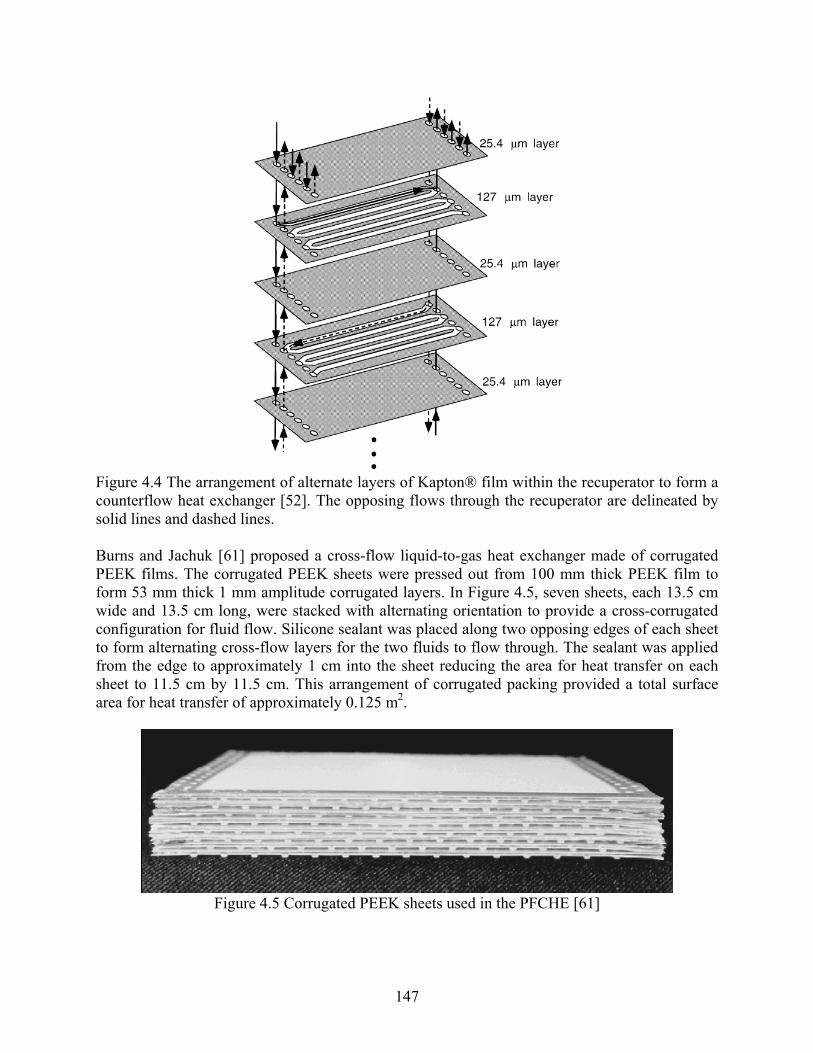
147
Figure 4.4 The arrangement of alternate layers of Kapton® film within the recuperator to form a counterflow heat exchanger [52]. The opposing flows through the recuperator are delineated by solid lines and dashed lines. Burns and Jachuk [61] proposed a cross-flow liquid-to-gas heat exchanger made of corrugated PEEK films. The corrugated PEEK sheets were pressed out from 100 mm thick PEEK film to form 53 mm thick 1 mm amplitude corrugated layers. In Figure 4.5, seven sheets, each 13.5 cm wide and 13.5 cm long, were stacked with alternating orientation to provide a cross-corrugated configuration for fluid flow. Silicone sealant was placed along two opposing edges of each sheet to form alternating cross-flow layers for the two fluids to flow through. The sealant was applied from the edge to approximately 1 cm into the sheet reducing the area for heat transfer on each sheet to 11.5 cm by 11.5 cm. This arrangement of corrugated packing provided a total surface area for heat transfer of approximately 0.125 m2.
Figure 4.5 Corrugated PEEK sheets used in the PFCHE [61]

148
Harris et al [203] reported detailed the fabrication process of a PMMA micro cross-flow heat exchanger. The prototype heat exchanger module was made using a LIGA process that combines lithography, electroplating, and molding. Initially, an optical mask with 5.1-by-5.1 cm cross-flow micro heat exchanger pattern was created comprised of gold absorber on graphite membrane X-ray mask, as shown in Figure 4.6. A 1-mm-thick sheet of PMMA bonded to a titanium substrate was exposed to the X-ray mask. After the PMMA was developed, the resulting void pattern was filled by nickel electroplating in a nickel sulfamate bath until an overplating thickness of 3 mm. The nickel was then removed from the titanium and the surface was machined followed by dissolving the PMMA away. Since the air channels are through-holes and the coolant channels need to be enclosed on the front and back faces of the heat exchanger, the nickel structures on the mold insert that correspond to the coolant channels were milled down 300 µm to obtain the final mold insert as shown in Figure 4.7(a). Using the nicked mold insert, a half piece of the heat exchanger was embossed in PMMA as shown in Figure 4.7(b). Several adhesive techniques were examined in terms of bond strength, uniformity, work life, ease of use, clogging of the channels, deformation of plastic due to glue, transparency, and high-temperature resistance. They found a urethane adhesive most suitable for bonding the two-piece PMMA micro heat exchanger. After a thorough surface cleaning, one side of the heat exchanger was pressed into a thin film of the urethane adhesive (see Figure 4.7(c)). The two pieces were aligned and pressed together for a cure time of 24 hours to obtain the final product shown in Figure 4.7(d).
Figure 4.6 Gold on graphite X-ray mask [203]

149
(a) (b)
(c) (d)
Figure 4.7 Fabrication process for PMMA micro cross-flow heat exchanger [203]: (a) a SEM micrograph of nickel mold insert, (b) one side of embossed heat exchanger, (c) urethane coated side of heat exchanger, (d) assembled plastic heat exchanger (coolant channels)
4.2.2 Metals and metal matrix composites (MMCs) Similar to polymers, manufacturing processes to produce and machine simple monolithic metals are well established in industry. Apparently, these common manufacturing methods are widely used to construct conventional metallic heat exchangers. Therefore, our attention is focused on the methods specifically relevant to the novel forms of metals. In the following paragraphs, a detailed review of manufacturing feasibility is presented for periodic cellular structures, stochastic foams, and metal composites. Hayes et al. [115] studied the mechanical properties of linear cellular alloys (LCAs) as heat exchanger materials (see Figure 4.8). They pointed out that LCAs have promises because of high-conductivity walls and high surface-area-to-volume ratio, and the ability to tailor cell size and shape to optimize the performance. LCAs are formed by two steps: extrusion of metal oxide powders followed by chemical reaction/sintering process to form near fully dense walls. They argued that, for practical applications, the optimal topography of cell structure (i.e. cross-sectional geometry) is non-uniform, because of the conflicting functional requirements—there exists a trade-off between high structural rigidity and high thermal-hydraulic performance. Based on their suggestion, an ideal configuration of LCA should have graded cell structures that accommodate stiffness and heat transfer depending on the relative importance of either

150
functional requirement. For example, triangular cells can be used at the locations where structural integrity is critical, whereas hexagonal cells can be used where hydraulic performance is important.
(a) (b)
Figure 4.8 Extruded maraging steel LCA reduced from oxide powders [115]: (a) an 8×8 square cell array, (b) side view of extruded section Boger and Heibel [204] describe monolithic metal structures packaged with copper tubes as a catalyst support in a gas reactor tube, as illustrated in Figure 4.9. They found that the thermal performance is improved by employing a smaller gap clearance between the monoliths and the tubes—this indicates the impact of thermal contact resistance. In order to obtain a good contact between the monolith and the copper tube, the monolith was first machined to a diameter slightly larger than the copper tube and then was pressed into the tubes. However, due to the increased difficulty in loading (assembling) the monoliths into the tubes, there is a practical limit in the minimum clearance that can be used in this method.
Figure 4.9 Schematic of the cross-section of a monolith inserted into a tube, which is surrounded by a heat transfer medium [204]. On the right a typical radial temperature profile is shown. Kim et al. [111, 112] reported an experimental study of heat exchangers with open-cell porous metal foam fins. For an experimental model, in which aluminum alloy foam was interfaced with

151
metal plates as shown in Figure 4.10, it was found that increasing the compressive load on the metal plates reduces thermal contact resistance.
(a) (b)
Figure 4.10 Porous metal fin heat exchanger [111]: (a) overall heat exchanger configuration, (b) simplified model It appears that, although mechanical contact may be “good enough” in some applications, further improvement of thermal contact may be necessary, especially for porous metal foams. Howard and Korinko [205] examined various vacuum furnace brazing methods to bond a reticulated open-cell copper form to a stainless-steel tube (see Figure 4.11). By forming a metallurgical bond between the foam and the tube, thermal interfacial resistance can be minimized. They found that a high-temperature brazing (980°C) with Au-Cu braze alloy resulted in an excessive creep damage to the copper foam. Using a copper-tin braze alloy caused excessive braze erosion and it was difficult to control the brazing process. Silver solid state diffusion bonding did not provide sufficient strength. The best result was obtained by using a Au-In braze alloy at a moderate temperatures (500-650°C); thermal creep or expansion damage was minimized, a good wetting of the braze alloy on both copper and SS was achieved, and no excessive braze erosion was observed.
Figure 4.11 Copper foam brazed with Au/In brazed alloy (left) and after bond strength test (right) [205]

152
Tian [95] describes detailed procedures to produce a textile heat sink as shown in Figure 4.12. Prototype sandwich heat sinks with laminated textile cores of plain woven copper cloth were fabricated using transient liquid phase (TLP) bonding and brazing. For TLP bonding, laminae were first lightly sprayed with a mix of polymer-based cement and Ni-25Cr-10P braze alloy powder. The collated laminae were then heated within flowing argon to volatilize the polymer cement. Then the core was brazed by placing in an evacuated environment which was heated to 1000°C. During the brazing process the braze alloy power melted, coated the wires, and was drawn to contact points by capillary effect. To construct a sandwich structure (see Figure 4.12(b)), face sheets, made of the same material as the wires, were sprayed with the TLP bonding mixture. Under a small compressive force on the face sheets, the sandwich structure went through a similar volatilization/brazing process as the textile core.
(a) (b)
Figure 4.12 Sandwich construction with textile technology [95]: (a) a transient liquid phase joins the wire-mesh screen laminated at all points of contact; (b) facesheets are added to the textile core. Wadley [206] described a variety of manufacturing techniques for multifunctional cellular periodic metals in a mass production scale. Figure 4.13 shows a typical process used to fabricate hexagonal honeycombs. In this process, a thin metal sheet is first cut into panels, bent, and strip bonded. This HOBE (honeycomb before expansion) block can then be cut and stretched perpendicular to the strip bonds to create a hexagonal structure. Figure 4.14 shows an alternative process in which the metal plates are first corrugated and then stacked. Figure 4.15 shows examples of slotted metal strip approach for square and triangular honeycombs. Since no metal bending is required, the slotted sheet process can be used to less ductile materials

153
Figure 4.13 Expanded honeycomb manufacturing process used to make low relative density honeycombs [206].
Figure 4.14 Corrugation-manufacturing process used to make high relative density honeycombs [206]

154
Figure 4.15 A strip slotting method for making [206]: (a) square honeycomb and (b) triangular honeycombs. The strips can be bonded by brazing. Wadley [206] also describes several processes to produce lattice truss structures. In an investment casing method, illustrated by Figure 4.16, first a wax or polymer pattern is created by injection molding or by a rapid prototyping methods for complex geometries. Then a negative model is obtained by a casting method, and liquid metal is filled into the empty pattern to obtain the final product. This approach can be used to fabricate complex, non-planar structures. However, due to limitation in filling liquid metals, investment casting method is not suitable for complex thin patterns or highly porous structures.

155
Figure 4.16 Investment casting method [206]: a wax or acrylonitrile butadiene styrene (ABS) polymer pattern with gates, runners and vents attached. The pattern is coated with a ceramic casting slurry and filled with a metallic alloy. Lattice truss structures can be made more commonly by folding of perforated or expanded metal sheets as shown in Figure 4.17 and Figure 4.18. Because there is a considerable waste of material during the perforation of the sheets, and therefore the cost increases significantly, a modified fabrication process has been developed that eliminates material waste as illustrated in Figure 4.19.

156
Figure 4.17 A perforated metal sheet can be bent and bonded to create a tetrahedral lattice truss structure [206].
Figure 4.18 Example of a multilayer tetrahedral structure constructed from folded perforated aluminum sheet with open cell faces [206]. The cell size is approximately 10 mm.

157
Figure 4.19 A pyramidal lattice truss structure can be made by periodically slitting a metal sheet and then stretching (expanding) it [206]. Alternate bending rows of nodes converts the expanded metal sheet into a pyramidal lattice truss structure. According to Wadley [206], the weaving and braiding of metallic wires provides a simple, inexpensive means for controlling the placement of metal trusses. Cellular structures are made from woven metal textiles by stacking and bonding layers of the fabric. For bonding, transient liquid phase bonding or node fusion welding method is typically used. Sandwich panels with metal textile cores are shown in Figure 4.20.
Figure 4.20 Copper textile core sandwich panels [206]: (a) 08/908 wire (square) orientation. (b) C458/K458 wire (diamond) orientation.

158
Using hollow tubes instead of solid wires for lattice truss structures has advantages of very low core density and increased buckling strength from a higher moment of inertia of the tubes. However, a more sophisticated fabrication technique is required, such as a precision drilling method used to fabricate hollow pyramidal lattices shown in Figure 4.21.
Figure 4.21 Hollow pyramidal lattice truss panel fabricated from tubes and precision drilled compound face sheets [206]. For stochastic cellular metals and metal foams, Banhart [207] summarized the manufacturing processes into 4 categories by producing the porous structure: (1) from liquid metal, (2) from solid metal in powdered form, (3) from metal vapor or gaseous metallic compounds, and (4) from a metal ion solution. As shown in Figure 4.22, various manufacturing methods for cellular metals are available. Depending on the processes, the porous metal foam attains an open-cell or a closed-cell structure. For example, metal foams produced by a direct foaming method by gas or a blowing agent usually result in a closed-cell structure. Also, the solid-gas eutectic solidification method (known as “gasars”) produces a unique, heterogeneous, directional, closed-cell porous structure as shown in Figure 4.23. Manufacturing methods that produce open-cell porous structures include investment casting and electro-deposition technique, as illustrated in Figure 4.24 and Figure 4.25, respectively.

159
Figure 4.22 Overview of the various ‘‘families’’ of production methods for cellular metallic materials [207].
Figure 4.23 Pore structure of a ‘‘gasar’’. Surface normal to direction of pores is shown [207].

160
Figure 4.24 Production of cellular metals by investment casting [207].
Figure 4.25 Electro-deposition technique for making metal foam [207]. Degischer [208] classified metal matrix composites into two types: discontinuously reinforced matrix and continuous fiber reinforced metals. Discontinuously reinforced MMCs are produced by embedding particulates, platelets, or short fibers of high aspect ratios within metal alloys, and conventional shaping methods like casting, forging, and extrusion can be applied. For continuous fiber reinforced MMCs, individual (monofilaments) or bundled (multifilaments) are embedded within the matrix. These composites should be manufactured by a net shape technique to preserve the continuous fibers. Such methods must properly address two processing problems: wetting of fiber reinforcements by molten metals, and preventing property degradation by chemical reactions between the matrix and the reinforcing phase. Ibrahim et al. [209] conducted a review of particulate reinforced metal matrix composites. They identified three categories processing methods for MMCs: liquid phase processes, solid state processes, and two phase (solid-liquid) processes. In a liquid phase process, ceramic particulates can be mixed with molten metals and cast into MMCs. This method can present difficulties from particle dispersion: agglomeration, settling, and segregation. Alternatively, a melt infiltration method can be used in which a molten alloy is forced into a porous ceramic preform. Due to the

161
nature of the process, this method can yield an undesirable structural non-uniformity and is limited to coarse grain sizes. In melt oxidation processes, a ceramic preform, formed into the final product shape by pressing, injection molding, or slip casting, is continuously infiltrated by a molten alloy. During this process, the metal alloy is oxidized by the surrounding air, and metal oxides appear at the ceramic-metal interfaces of the final product. In solid phase processes, solidified metal powders are rapidly mixed with the particulate reinforcements. The mixture is then pressed and degassed. The final consolidated product can be obtained by extrusion, forging, rolling, or other hot working methods. Two-phase processes for MMCs include Osprey decomposion and rheocasting. In an Osprey process, the reinforcement particulates are mixed with the stream of molten alloy which is subsequently atomized by jets of inert gas. The sprayed mixture is then collected on a substrate in the form of a reinforced metal matrix billet. In rheocasting, ceramic particulates are added into a metallic alloy matrix at a temperature within the solid-liquid range of the alloy, followed by a vigorous agitation to form a low-viscosity slurry. This method prevents particulate agglomeration and settling, and thus helps produce a homogeneous composite.
4.2.3 Carbonaceous materials and carbon matrix composites (CAMCs) Carbonaceous materials have comparatively low coefficients of thermal expansion. Therefore, heat exchangers made of carbon materials require a careful design consideration of thermal stress when interfaced with other materials with higher CTEs. Furthermore, most unreinforded carbonaceous materials (e.g. graphite or carbon foam) are brittle, and the applicable machining options are very limited. Nonetheless, carbonaceous materials can be suitable for various heat exchanger applications as discussed earlier in Chapter 2. In this section, some of the fabrication methods that can be used to make heat exchangers with carbonaceous materials are reviewed in more detail. In a report in 2001, Klett [132] presented the machinability of a pitch-based graphite foam for heat sink applications. This graphite foam, originally developed by ORNL, was brittle, and the geometrical detail of counterpart metallic heat sinks were not achievable by conventional machining process. For the graphite heat sink, the base thickness was increased to 4 mm in comparison to 2 mm for metallic heat sink. To improve mechanical strength and surface hardness, a few surface treatment methods were examined. A standard isothermal CVI (chemical vapor infiltration) rigidization resulted in a 5% addition of weight. The furnace condition was at 1160°C, with a 0.8 slpm (standard liters per minute) methane flow, and 12 torr absolute pressure and a 24-hour cycle period. The rigidized foam did not rub off when touched by finger, and appeared to be stiffer than the raw foam. Alternatively, a polymer coating rigidization method was used during which a dilute solution (5 or 10%) of phenolic resin in ethanol was initially applied to the foam. The foam was dried and cured at 150°C to solidify the phenolic resin. The procedure was found to add 6% to the total weight of the foam. As a result, the foam was successfully protected from flaking and incidental damages during handling. As another alternative, a metallization (metal plating) method was used (see Figure 4.26). The detailed plated process was not described, but the metallized foam showed a similar improvement of mechanical properties as those treated by the other methods.

162
Figure 4.26 Metalized (plated) foam heat sink [132] Carbon foams can be extruded or cast, and thus the post-machining process can be reduced or eliminated. In a patent [210], a method to extrude a pitch-based carbon foam was described. As shown in Figure 4.27, a viscous pitch foam is formed in a chamber. Then the viscous foam (precursor) is passed through an extrusion tube. The extrusion tube provides an environment that subjects the precursor to a temperature gradient which varies along the length of the extrusion tube to form extruded carbon foam.
Figure 4.27 Schematic of manufacturing process for extruding carbon foam [210] In another patent [211], a method to cast pitch-based carbon foam is described. The viscous pitch-based foam, derived from a mesophase or isotropic pitch was transferred into a mold before the coking process (i.e. baking at high temperature to remove volatile contents). The viscous pitch foam can be formed by placing pitch powder, granules, or pellets in a container. These pitch materials can be solvated if desired. The sample was heated to 50-100°C in an oxygen-free environment, preferably under vacuum or alternatively in an inert gas. Then the pressure was increased up to 400-1000 psi and the temperature was increased to cause pyrolysis gases to appear and produce the viscous pitch foam. At a preferred temperature of 450°C, the foam behaves like fluid and can be transferred into a mold with desired shape. The viscous foam

163
in the mold is heated in a furnace to a temperature of 500 to 1000°C at a heating rate of 2°C/min. The heating rate should be varied depending on the size and the shape to minimize thermal shock damage. The furnace temperature is held constant for approximately 15 minutes to let the foam be formed in the mold. The foam is then cooled and depressurized gradually before removing from the mold. The cast pitch foam can be post-heat-treated at 2000°C for a conversion into graphite foam which has a higher thermal conductivity. Recently, Rawal et al. [155] has reported the development of a spacecraft radiator using carbon foam. The heat exchanger was required to sustain high thermal loads and extreme operating temperatures (-100°C to 850°C), in addition to being lightweight and structurally stable. To meet the requirements, a carbon-carbon was developed with an inconel tube and conductive carbon foam core. As shown in Figure 4.28, the serpentine metal tube was embedded in the carbon foam. During the fabrication, an interface coating was applied on the tube surface to minimize potential reactions between the tubes and the adjacent carbon foam at high operating temperatures. Due to the mismatch of thermal expansion of carbon foam core and the face sheets, micro-cracks were observed, and therefore a different type of carbon-carbon composite material with the elastic modulus and the thermal expansion coefficient lower than the core carbon foam was used for attachment points. The full-scale radiator showed adequate thermal performance and was able to withstand mechanical vibrations and thermal shocks.
(a)
(b)
Figure 4.28 Carbon foam radiator [155]: (a) FEM model shows serpentine tubes embedded in carbon foam, (b) full-scale prototype heat exchanger

164
4.2.4 Ceramics and ceramic matrix materials (CMCs) The methods used for manufacturing ceramic heat exchangers may be classified as either monolithic assembly or non-monolithic assembly, depending on whether the heat exchanger components are permanently joined or not. Ceramic materials can be further classified depending on their composition and structure. Crystalline ceramic materials, which are more commonly used in the construction of a heat exchanger, are not amenable to a great range of processing options. Typically, the ceramic is made into the desired shape in one of two ways: (a) by reaction in situ, or (b) by "forming" the desired object using powders and then sintering it to form a solid body. Ceramic forming techniques include throwing, slip casting, tape casting, injection molding, dry pressing, and various hybrid approaches. Non-crystalline ceramics tend to be formed from melts. The glass is shaped by casting when fully molten or by blowing when highly viscous. If heat-treatments result in a partially crystalline structure, the resulting material is typically referred to as a glass-ceramic. In most cases, however, the method of manufacture is fairly complex involving semi-discontinuous assembly and frequently, a large expenditure of time. However, new manufacturing methods are making these limitations less and less of a concern. In fact, in some cases, the method of manufacture may even become the selling point. The choice of monolithic versus non-monolithic assembly frequently depends on the chosen configuration of the heat exchanger. In monolithic assembly, the individual heat exchange components are bonded together using slip and then re-fired to create an integral piece. This type of assembly may or may not include the plenum and ductwork; nevertheless, if the core of the heat exchanger is produced in this manner, it is referred to as being monolithic. This method of assembly is desirable for one major reason. There are no internal joints and therefore no attendant problems with sealing. The major drawback of this method is tied up in the advantage—the entire heat exchanger must be replaced after failure. Individual parts and components cannot be swapped and exchanged. Also, the monolithic assembly method can cause stress concentrations under extreme operating conditions that may shorten the life of the heat exchanger resulting in more frequent servicing and/or replacement.
In non-monolithic assembly, the heat exchanger is constructed from individual components and therefore can be disassembled and repaired. This is its major advantage. Accompanying this choice of assembly, however, is the need for mechanical joints and seals—historically, a problem area for ceramics due to their brittleness and the difficulties of forming a resilient metal-ceramic or ceramic-ceramic joint. The joining of two dissimilar materials poses a problem because stresses can arise at the interface due to differences in the coefficient for thermal expansion (CTE) of the two materials. To prevent leakage through the seal, advanced surface machining techniques are often necessary. In order to work around these difficulties, a compliant material is often used in ceramic-ceramic joints that allows for the release of these stresses while still providing good sealing. This material can be: (1) a cement, (2) a packing, or (3) a glass. Cements have the advantage of conforming to the surfaces being bonded; however, its strength must be tailored in such a way that permits it to yield at lower stresses than the surrounding ceramic materials. Packing is more commonly used because of its high fiber density which makes it a highly compliant, amorphous sealing material. However, at very high operating temperatures, this type of sealing becomes crystalline and loses some of its resilience. This type of seal is also not well-suited for high pressure applications. The glass joint design similar to the cement joint design also requires a careful tailoring of the material properties. In particular, the viscosity must be tailored to ensure that the glass does not flow out of the joint at high temperature.

165
A few different monolithic manufacturing methods will now be discussed in greater detail. Schmitt et al. [212] describes the construction of a catalytic, ceramic micro-structured plate micro-reactor. The manufacturing process begins with the casting of the ceramic “green” tape from a slip made from a particular form of α-alumina. The raw α-alumina tape is then cut into sheets using a laser, stacked into the desired arrangement, and laminated before being sintered together. This porous ceramic structure is then externally and internally sealed, and finally the reaction chamber is coated with catalyst. This process is illustrated below in Figure 4.29. The actual tape casting was performed using the so-called “doctor blade process” illustrated in Figure 4.30 where a casting substrate of polyethylene film is drawn at constant speed under a slip reservoir. The slip is then formed using two doctor blades whose height is adjusted to provide a uniform film on the casting substrate. Tape thicknesses between 0.1 and 1.2 mm were manufactured using this method. The connections to external equipment were accomplished using perfluorinated rubber O-rings which can withstand temperatures up to approx. 320°C. This, of course, places a significant limitation on the maximum operating temperature of the heat exchanger. Complete sealing of the internal porous partition plates which separate the reaction and cooling chambers was also difficult to obtain. However, using chemical vapor deposition (CVD) reductions in permeability from 29,500 nano-Perm to 270 nano-Perm after 40 hours of reaction time were achieved.
Figure 4.29 Manufacturing process described by Schmitt et al. [212] for the construction of a ceramic plate heat exchanger from green tape

166
Figure 4.30 The so-called doctor blade process described by Schmitt et al. [212] for the production of green tape
In a paper by Alm et al. [183], the thermal performance of an alumina micro ceramic heat exchanger comprised of 26.25 mm x 26.25 mm plates containing channels 250 μm wide and 500 μm tall and 12.25mm in length is described. The micro-components were fabricated using the rapid prototyping assembly approach shown in Figure 4.31. First, a polymer master model was made of the original using stereolithography, and then a silicon mold was made. Next, “green bodies” were produced from an alumina/binder (MR52) dispersion through a low-pressure, injection molding process. Finally, the green bodies undergo a debinding step at 500°C and a sintering step at 1700°C. The joining of ceramic components was performed two ways—(1) by the hot joining of green bodies followed by group debinding/sintering, or (2) by the joining of already sintered micro-components by glass solder. It was found that the hot joining of green bodies was less reproducible at higher pressures. Therefore, joining by glass solder was preferred but sometimes resulted in partially blocked (or completely blocked) channel passages. (See Figure 4.32) The thermal performance of this modular micro heat exchanger was also tested. Mass flow rates between 12.4 kg/h and 80.6 kg/h were examined. For tests conducted at 12.4 kg/h, the hot water stream entered at 93.7°C and exited at 75.8°C, and the cold water stream entered at 11°C and exited at 26.7°C at a flow rate of 12.6 kg/h. The system operating pressure for these tests was 8 bar. For this range of mass flow rates, overall heat transfer coefficients of 7-15 kW/m2K were measured, and the associated pressure drop ranged from 0.15 bar at 12.4 kg/h to more than 6 bar at 80 kg/h (attributed to problems with the glass soldering technique for joining the plates).
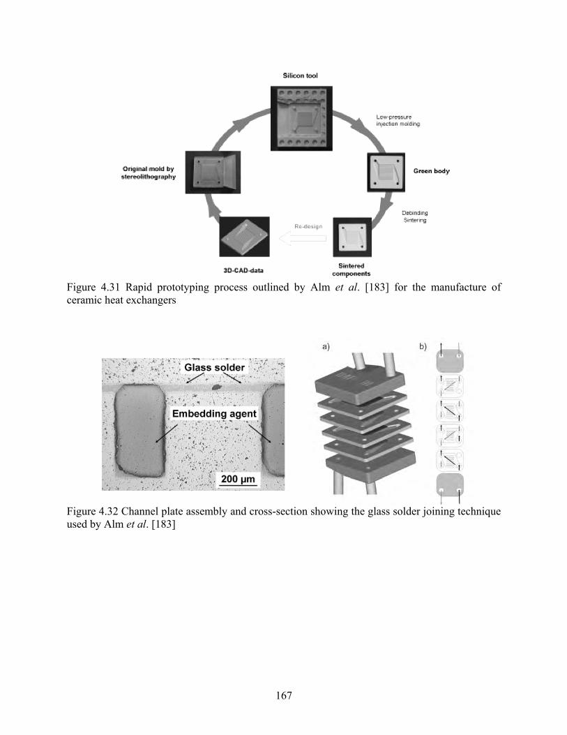
167
Figure 4.31 Rapid prototyping process outlined by Alm et al. [183] for the manufacture of ceramic heat exchangers
Figure 4.32 Channel plate assembly and cross-section showing the glass solder joining technique used by Alm et al. [183]

168
CHAPTER 5 PERFORMANCE COMPARISON
Assessing the cost and performance of the most promising technologies relative to conventional heat exchangers requires a thorough study of target systems. However, due to the number of assumptions involved in system modeling, our primary focus was highly detailed and accurate component simulations. We present four component simulations in this chapter for liquid-to-liquid, liquid-to-gas and gas-to-gas heat exchangers in the four target applications discussed in the preceding chapters, respectively. The inputs to the model were the geometry and size of the heat exchanger, the operating conditions for the heat exchange fluids, and the desired capacity, while the outputs were the cost and performance of the heat exchanger.
We used simulation models available from the Air Conditioning and Refrigeration Center (ACRC). These models utilize Engineering Equation Solver (EES) and a combination of simultaneous and successive calculations to simulate complex heat exchanger geometries with fewer initial guesses than a strictly Newton-Raphson-based method. It should be emphasized that each of the aforementioned simulation models has been well-tested and has been used as part of ongoing research within the ACRC for optimizing components and systems. In fact, a recent parametric study was completed at the ACRC using some of these simulation techniques to examine the feasibility of polymer heat exchangers for air-conditioning applications [213]. The veracity and value of our approach has been clearly established. The primary purpose of this task is not to be one of complete design optimization and computational heroics but rather an assessment of feasibility and technological promise. Also, the materials used for the applications in this chapter (i.e. polymer, metal foam) were not selected because they were the best performers as the materials themselves. The selected materials served well for the purpose of thermal-hydraulic performance modeling; they had some advantages for the targeted applications, and the relevant properties and performance data were readily available. Given sufficient data, other materials identified as good performers such as graphite/epoxy composite can be modeled, and performance superiority even greater than what was demonstrated in this chapter may be achieved.
5.1 Application one: gas-gas plate heat exchanger for fresh air heat recovery In this application, heat transfer resistance from conduction and convection are modeled with appropriate material properties and performance data. To determine the fluid side convective heat transfer coefficients, several correlations were used. For laminar flow, three boundary conditions are commonly used to determine the Nusselt number:
• T: Constant temperature - suited for evaporators, condensers and liquid to gas heat
exchangers with a high liquid flow rate. • H1: Constant axial wall heat flux with constant peripheral wall temperature – suited for
counterflow heat exchangers with Cr ≈ 1 (ratio of pcm& between both fluids), manufactured from highly conductive materials (such as aluminum, copper…)

169
• H2: Constant axial wall heat flux with constant peripheral heat flux – suited for counterflow heat exchanger with Cr ≈ 1, manufactured from poorly conductive materials (such as polymers…)
For turbulent flow, the Gnielinski correlation was used. A preliminary examination of the Reynolds numbers occurring in the studied case indicated that for the high velocities (5 m/s), transitional flow would occur. The linear asymptotic method proposed by Taborek was used for Reynolds number between 2000 and 8000. For rectangular channels, it is known that reducing the aspect ratio increases both the heat transfer rate and the pressure drop; however, the increase in the pressure drop is larger than the increase in the heat transfer rate. Therefore, perfectly (or near perfectly) square channels are often preferred. When considering the size of the channels and the velocity range, it was found that the flow would be ‘developing’, resulting in a higher Nusselt number compared to fully developed flow. Using a graph of the ratio of the ratio of the Nusselt number for developing flow to the Nusselt number for fully developed flow, a multiplier was defined. The curves on the graph are approximated using a polynomial expression. Different curves were obtained for various channel shapes.
5.1.1 Simulated results for material replacement Based on an existing metal (aluminum) heat exchanger, the following configuration was initially simulated for air to air heat recovery (see Figure 5.1).
Length: 0.54m Width: 0.54 m Channel height: 6 mm Fin/parting sheet thickness: 0.08 mm Fin spacing: 6.3 mm Number of layers: 90 Counterflow Temperature room air inlet: 25 °C Temperature fresh air inlet: 5°C Velocity range: 2-5 m/s
Figure 5.1 Schematic of conventional air-to-air heat exchanger
Figure 5.2 shows the ratio of the conductive wall heat transfer resistance to the total heat transfer resistance for 4 different velocities against different conductivity of the wall material. The thermal conductivity increases from 0.1 W/m⋅K to 370 W/m⋅K, spanning polymers to metals. This simulation considers simply replacing the metal with other materials, without altering the configuration. As can be seen, the conductive resistance only starts to be significant for a thermal conductivity below 1 W/m⋅K. Note that the velocity has very little impact on the relative contribution of wall conduction resistance. On the right axis in Figure 5.2, the heat transfer rate

170
is indicated for 4 different velocities. The highest achieved Reynolds number was 2350. As expected, the heat transfer rate increases with increasing air velocity. Note that the fluid velocity is the same in both air streams (room air and fresh air). Figure 5.2 clearly shows that for conductive materials such as metals the air side heat transfer resistance is dominant, while for polymers (0.1-1 W/m⋅K) the wall thermal resistance can have a profound impact. The boundary condition can have a strong impact on the results. For the considered cases Cr ≈ 1, so for the materials with a low thermal conductivity the H2 boundary condition is appropriate while for the high conductivity values the H1 boundary condition is appropriate. Considering that in general NuH1 ≥ NuT ≈ NuH2 the differences in the conductive heat transfer contribution and heat transfer rate for NuH1 and NuT are shown in Figure 5.3. Figure 5.4 shows the impact of the shape of the channel. Increasing the fin density results in reducing the aspect ratio of the channels. Fin spacing was set to 6.3 mm, 3.2 mm, 1.6 mm, and 1 mm. This results in a reduced Reynolds number (laminar flow). Reducing the channel aspect ratio increases the heat transfer rate, thus also increasing the conductive heat transfer resistance contribution. At the same time the pressure drop increases sharply, as can be seen in Figure 5.5.
0.01 0.1 1 10 100 10000
0.1
0.2
0.3
0.4
0.5
0.6
0.7
0.8
0
1000
2000
3000
4000
5000
6000
7000
8000
λfin [W/m-K]
Rw
all
NuT
Q [
W]
Rwall (2 m/s)Rwall (2 m/s)Rwall (3 m/s)Rwall (3 m/s)Rwall (4 m/s)Rwall (4 m/s)Rwall (5m/s)Rwall (5m/s)
Q (2m/s)Q (2m/s)
Q (3 m/s)Q (3 m/s)
Q (4 m/s)Q (4 m/s)
Q (5m/s)Q (5m/s)
Figure 5.2 Conductive wall heat transfer resistance divided by total thermal resistance and heat transfer rate for various air side velocities and different material conductivities.

171
0.1 1 10 100 10000
0.1
0.2
0.3
0.4
0.5
0.6
0.7
0
500
1000
1500
2000
2500
3000
3500
4000
4500
λfin [W/m-K]
Rw
all
Q [
W]
Rwall - NuH1Rwall - NuH1
Q - NuH1Q - NuH1
Rwall - NuTRwall - NuT
Q - NuTQ - NuT
Figure 5.3 Conductive wall heat transfer resistance contribution and heat transfer rate for different material conductivities and two different thermal boundary conditions (velocity = 2 m/s).
0.1 1 10 100 10000
0.1
0.2
0.3
0.4
0.5
0.6
0.7
0.8
0
2000
4000
6000
8000
10000
λfin [W/m-K]
Rw
all
Q [
W]
Rwall - α: 0.25Rwall - α: 0.25
Q - α: 0.25Q - α: 0.25
Rwall - α: 0.5Rwall - α: 0.5
Q - α: 0.5Q - α: 0.5
Rwall - α: 1Rwall - α: 1
Q - α: 1Q - α: 1
Rwall - α: 0.1667Rwall - α: 0.1667
Q - α: 0.1667Q - α: 0.1667
Figure 5.4 Conductive wall heat transfer resistance contribution and heat transfer rate for various air side channel aspect ratios and different material conductivities (velocity 2 m/s).

172
0 0.1 0.2 0.3 0.4 0.5 0.6 0.7 0.8 0.9 10
50
100
150
200
250
300
350
αchannel
δPfre
sh [
Pa]
Figure 5.5 Air side pressure drop vs. channel aspect ratio
Figure 5.6 shows both the heat transfer rate and the conductive wall heat transfer resistance contribution for varying fresh air speed. The original heat exchanger design (as described above) was simulated. The room air speed was kept constant at 2 m/s. Various wall thermal conductivities are considered. Only a gradual increase of the conductive wall heat transfer resistance contribution is noted for a velocity lower than 4 m/s. This behavior is due to the occurrence of laminar flow, resulting in a constant air-side Nusselt number. The gradual change is solely due to changing fluid properties as the average temperatures on both sides change slightly. At 5 m/s the Reynolds number in the channel is 2300, and the first impact of turbulent flow is clear in the stronger increase of both the heat transfer rate and the conductive wall heat transfer resistance contribution. At velocities lower than 5 m/s the increase in the heat transfer rate is solely driven by the increase in mass flow rate of the fresh air side.

173
1 1.5 2 2.5 3 3.5 4 4.5 50
0.1
0.2
0.3
0.4
0.5
0.6
0.7
0.8
0.9
0
500
1000
1500
2000
2500
3000
3500
4000
4500
5000
5500
Vairfresh [m/s]
Rw
all
Q [
W]
Rwall - λ: 10 W/mKRwall - λ: 10 W/mK
Rwall - λ: 1 W/mKRwall - λ: 1 W/mK
Rwall - λ: 0,1 W/mKRwall - λ: 0,1 W/mK
Q - λ: 0,1 W/mKQ - λ: 0,1 W/mK
Q - λ: 1 W/mKQ - λ: 1 W/mK
Q - λ: 10 W/mKQ - λ: 10 W/mK
Q - λ: 370 W/mKQ - λ: 370 W/mK
Figure 5.6 Conductive wall heat transfer resistance divided by total thermal resistance and heat transfer rate for various wall thermal conductivities against the fresh air velocity; constant room air velocity (2 m/s). Because polymers have a low thermal conductivity, the fin efficiency will be a lot lower when compared to materials with a high thermal conductivity. It is therefore advantageous to use an alternative design with smaller fins, reducing the passage size, and increasing the surface compactness. In a design described by Burns and Jachuck [61], thin PEEK films of 50 µm (0.23 W/m⋅K) and a channel height of 1 mm with an aspect ratio of 0.5 were used. In the following section, this design will be simulated and compared to a metal plate heat exchanger. Consider a metal plate heat exchanger as simulated above (H1 boundary condition) with an average inlet velocity of 3.5 m/s for both air streams. The resulting heat transfer rate was 5.8 kW, and the average air side pressure drop was 28 Pa. Now consider a polymer alternative, maintaining the plate size (0.54m by 0.54m) and inlet velocity (3.5 m/s) results in a smaller heat exchanger (342 mm height when compared to 540 mm height) for the same heat transfer rate (5.8 kW). The pressure drop is over 20 times higher: 630 Pa. In order to reduce the pressure drop the heat exchanger shape can be modified (smaller length) and the velocity can be reduced. Table 5.1 shows the various velocities considered and the required length to obtain a pressure drop of 28 Pa.

174
Table 5.1 Required flow length for various inlet velocities to balance the air side pressure drop (polymer heat exchanger design).
Velocity [m/s] Flow length [m] 3.5 0.024 2 0.042 1 0.085 0.5 0.172 0.25 0.34
As the inlet velocity decreases, the flow length increases, resulting in more feasible heat exchanger sizes. The design manufactured by Burns and Jachuck [61] consisted of PEEK sheets measuring 0.135 m by 0.135 m. Considering a velocity level of 0.5 m/s the final shape of heat exchanger is determined by the required heat transfer rate (5.8 kW). Two parameters can be varied: the total number of channels and the plate width. Table 5.2 shows that by using a very long heat exchanger, an excessive number of channels can be avoided. The resulting heat exchanger volume is reported as well. This can be compared to the metal heat exchanger volume of 0.1574 m³ (0.54 m x 0.54 m x 0.54 m). The first two configurations in Table 5.2 have a volume that is respectively 38% and 78% larger than the metal plate heat exchanger. Compared to the mass of the metal heat exchanger (11.1 kg) the polymer units are considerably heavier, due to the increased surface area. It is expected however that the material cost of this type of heat exchanger will be considerably lower than that of a metal heat exchanger. Table 5.2 Heat exchanger width, total number of channels and resulting heat exchanger volume for an inlet velocity of 0.5 m/s and a required heat transfer rate of 5.8 kW.
Heat exchanger width [m] Number of channels Volume [m³] Mass [kg] 2 600 0.2167 19.76 1 1550 0.2799 25.51 0.5 7500 0.6772 61.71
5.1.2 Finless corrugated plate geometry In Figure 5.7, heat transfer rates are compared for the baseline geometry (finned plate heat exchanger) and the finless corrugated plate geometry proposed in section 3.3.3 (see Figure 3.14). The geometrical and operational parameters are the same as those for Figure 5.6. As shown in the figure, significantly increased heat transfer can be achieved with the new design for a thermal conductivity range below 1 W/mK, which is typically to polymers. On the contrary, for fin materials with a thermal conductivity above 10 W/mK (e.g. metals and alloys), an insignificant improvement of heat transfer is produced by adopting the finless configuration. Therefore, it can be concluded that the finless corrugated plate design is especially beneficial for materials with a low thermal conductivity. For practical implementation of the finless design, more complex designs of inlet and exit headers may be needed. However, with an assumption that the channel flow length is sufficiently long and therefore constitutes dominant pressure drop, the entry and exit effects pertaining to the finless channel designs may be negligible.

175
0 1 2 3 4 5 61500
2000
2500
3000
3500
4000
4500
5000
5500
Vair,fresh [m/s]
Q [W
]Q - λ: 0,1 W/mKQ - λ: 0,1 W/mKQ - λ: 1 W/mKQ - λ: 1 W/mKQ - λ: 10 W/mKQ - λ: 10 W/mKQ - λ: 370 W/mKQ - λ: 370 W/mK
ηfin=1 ηfin<1
Figure 5.7 Comparison of heat transfer rate for conventional finned plate heat exchanger and finless plate heat exchanger.
5.2 Application two: liquid-gas polymer tube heat exchanger
5.2.1 Reference case: fin-and-tube heat exchanger In order to study the impact of changing the thermal conductivity of the tube material a reference case was selected: a metal fin-and-tube heat exchanger, studied by Wang et al. [214]; part of the data series used to form the correlation for louvered fins (Reference case # 10). The specific geometry of that configuration is described in Table 5.3. This cross-flow heat exchanger (as shown in Figure 5.8) is made up out of copper tubes and louvered aluminum fins.
Figure 5.8 Schematic of conventional louvered fin-and-tube heat exchanger [214]

176
Table 5.3 Reference configuration as studied by Wang et al. [214] Collar diameter 10.42 mm Transverse tube pitch 25.04 mm Fin pitch 2.08 mm Longitudinal tube pitch 19.05 mm Louver pitch 2.4 mm Number of tube rows 4 Louver height 1.4 mm Fin thickness 0.15 mm
The actual size of the heat exchangers is not reported in the study by Wang et al. [214], it is simply stated that actual heat exchangers are used in the study. In order to perform the simulations some more information was assumed: a tube length of 0.5 m, 8 tubes per row, a tube wall thickness of 0.9 mm. In the present performance modeling, heat rejection from liquid water from the tube to the ambient air is considered. The tube side heat transfer is calculated using the Gnielinski correlation for fully turbulent flow, a constant Nusselt number is assumed for laminar flow (4.364). To ensure a smooth transition between the two regimes the proposed linear asymptotic method of Taborek between the Reynolds number of 2000 and 8000 was used. The air inlet temperature was set to 25 °C and the water inlet temperature to 75 °C. The air side heat transfer and pressure drop were calculated using the proposed correlations by Wang et al. [214]. As tube-side fluid hot water was used, this case study is aimed at a (space) heating application.
5.2.2 Performance comparisons Figure 5.9 shows the overall heat transfer rate for varying air velocity and different levels of the water velocity for the baseline, metal finned-tube heat exchanger. As expected, increasing the air velocity for a given water velocity results in an increased heat transfer rate. There is a strong increase in heat transfer rate when varying the water velocity from 0.1 m/s to 0.25 m/s. This is due to the transition from laminar flow to turbulent flow. For a velocity of 0.1 m/s the Reynolds number of the flow is around 2000, near the onset of turbulent flow. As the onset of turbulent flow results in a strong increase in the tube side heat transfer coefficient, the overall heat transfer coefficient is a lot larger for turbulent flow on the water side.

177
1 1.5 2 2.5 3 3.5 4 4.5 5
0
2500
5000
7500
10000
12500
15000
17500
20000
Vair [m/s]
Q [
W]
Vwater: 0.1 m/sVwater: 0.1 m/s
Vwater: 0.25 m/sVwater: 0.25 m/s
Vwater: 0.5 m/sVwater: 0.5 m/s
Vwater: 1 m/sVwater: 1 m/s
Figure 5.9 Heat transfer rate for the baseline, metal finned-tube heat exchanger as a function of air-side face velocity. Figure 5.10 shows the breakdown of the overall heat transfer coefficient into the air and water side convective heat transfer resistance. It is clear from the data that the conductive wall heat transfer resistance is negligible (due to the high thermal conductivity of the tube and fin material), as the sum of the air and water side heat transfer resistance contribution is nearly one. Increasing the air side velocity for a given water velocity results in a decreasing heat transfer resistance on the air side, thus moderately shifting the various contributions to the total heat transfer resistance. Increasing the water velocity results in large drop of the water side heat transfer resistance contribution as the flow becomes turbulent.

178
1 1.5 2 2.5 3 3.5 4 4.5 5
0
0.1
0.2
0.3
0.4
0.5
0.6
0.7
0.8
0.9
1
0
0.1
0.2
0.3
0.4
0.5
0.6
0.7
0.8
0.9
1
Vair [m/s]
Rai
r
Rair - Vwater: 0.1 m/s
Rair - Vwater: 0.25 m/sRair - Vwater: 0.25 m/s
Rair - Vair: 0.5 m/sRair - Vair: 0.5 m/s
Rair - Vwater: 1 m/sRair - Vwater: 1 m/s
Rwater - Vwater: 0.1 m/sRwater - Vwater: 0.1 m/s
Rwater - Vwater: 0.25 m/sRwater - Vwater: 0.25 m/s
Rwater - Vwater: 0.5 m/sRwater - Vwater: 0.5 m/s
Rwater - Vwater: 1 m/sRwater - Vwater: 1 m/s
Figure 5.10 Water and air side heat transfer resistance contribution for varying air and water velocities in the baseline, metal finned-tube heat exchanger. Increasing the air and water velocity results in a considerable rise of the pressure drop, as can be seen in Figure 5.11 and Figure 5.12. The air side pressure drop increases twelve fold, while the increase in the water side pressure drop increases as much as 5000% in the considered range.
1 1.5 2 2.5 3 3.5 4 4.5 50
50
100
150
200
250
300
Vair [m/s]
δPai
r [P
a]
Figure 5.11 Air side pressure drop for the baseline, metal finned-tube heat exchanger

179
0.1 0.2 0.3 0.4 0.5 0.6 0.7 0.8 0.9 10
100
200
300
400
500
600
700
800
Vwater [m/s]
δPw
ater
[Pa
]
Figure 5.12 Water side pressure drop for the baseline, metal finned-tube heat exchanger Replacing the existing metal fin-and-tube heat exchanger with materials with a lower thermal conductivity will result in a reduced heat transfer rate, as can be seen in Figure 5.13. In this figure the heat transfer rate is shown as a function of the air velocity for 5 different levels of thermal conductivity. The water velocity is fixed at 0.25 m/s, resulting in turbulent flow on the tube side. It can be seen that as the thermal conductivity drops below 10 W/mK the heat transfer rate is reduced dramatically. It must be emphasized that the exact same geometry was simulated as the fin-and-tube heat exchanger, not considering any manufacturing issues. Decreasing the wall thermal conductivity increases the contribution of the heat transfer resistance to the total heat transfer resistance. For a thermal conductivity of 0.1 W/mK, the conductive wall heat transfer resistance contribution reaches up to 60% of the total heat transfer resistance, as can be seen in Figure 5.14. Figure 5.15 shows the contribution of the air-side convective heat transfer resistance, indicating that for lower wall conductivities the air side heat transfer resistance contribution is the second largest resistance term. In fact for the lowest wall thermal conductivity considered the water side heat transfer resistance contribution is 3%. Materials with a low thermal conductivity will have very low fin efficiency, and therefore should not be used as fin materials. In the considered case the fin efficiency dropped from 0.8 to less than 0.02 for a conductivity changing from 370 W/mK to 0.1 W/mK which is equal to substituting copper with most known polymers. Different designs should therefore be considered when using materials such as polymers.

180
1 2 3 4 50
2000
4000
6000
8000
10000
12000
14000
16000
Vair [m/s]
Q [
W]
λ: 370 W/mKλ: 370 W/mKλ: 200 W/mKλ: 200 W/mKλ: 10 W/mKλ: 10 W/mKλ: 1 W/mKλ: 1 W/mKλ: 0.1 W/mKλ: 0.1 W/mK
Figure 5.13 Heat transfer rate for various levels of wall thermal conductivity (water velocity is fixed at 0.25 m/s) with the baseline, fin-and-tube geometry
1 1.5 2 2.5 3 3.5 4 4.5 5
0
0.1
0.2
0.3
0.4
0.5
0.6
0.7
0.8
0.9
1
Vair [m/s]
Rw
all
λ: 370 W/mKλ: 370 W/mKλ: 200 W/mKλ: 200 W/mKλ: 10 W/mKλ: 10 W/mKλ: 1 W/mKλ: 1 W/mKλ: 0.1 W/mKλ: 0.1 W/mK
Figure 5.14 Wall conduction heat transfer resistance contribution for various levels of wall thermal conductivity (water velocity is fixed at 0.25 m/s)

181
1 1.5 2 2.5 3 3.5 4 4.5 5
0
0.1
0.2
0.3
0.4
0.5
0.6
0.7
0.8
0.9
1
Vair [m/s]
Rai
r
λ: 370 W/mKλ: 370 W/mK
λ: 200 W/mKλ: 200 W/mK
λ: 10 W/mKλ: 10 W/mK
λ: 1 W/mKλ: 1 W/mK
λ: 0.1 W/mKλ: 0.1 W/mK
Figure 5.15 Convective air-side heat transfer resistance contribution various levels of wall thermal conductivity (water velocity is fixed at 0.25 m/s) Liu et al. [49] analyzed two polymer heat exchanger designs (immersed tube bundle and a shell and tube heat exchanger without baffles) considering two materials (high-temperature nylon and cross linked PE) which had emerged from a previous study (Raman et al. [11]) as suitable candidates for the considered application of solar heating. Their results indicated that polymer heat exchangers can provide thermal output equivalent to conventional copper heat exchanger at lower cost. When using tubes with a low thermal conductivity it is important to use small wall thickness or a high ‘SDR’, standard diameter ratio (ratio of the exterior tube diameter to tube wall thickness). The permissible SDR for a thin walled tube with high pressure fluid (coolant) on the inside depends on the long term strength of the materials and the maximum material strength. In the study by Liu et al. [49] high temperature nylon tubes (exterior diameter of 0.381 cm and SDR of 19) and cross linked PE tubes (exterior diameter of 0.953 cm and SDR of 5.4) were considered. Both of these types of tubes are commercially available. The thermal conductivity of HTN is 0.31 W/mK and 0.38 W/mK for cross linked PE. In order to assess the feasibility of using polymers heat exchangers, the reference case metal fin-and-tube heat exchanger (as described above) will be replaced by a polymer design consisting of an unfinned tube bundle between two headers. As operating conditions, the air velocity was set to 2 m/s and the water velocity to 0.25 m/s. This resulted in a heat transfer rate of 8.8 kW. The air side pressure drop was 66 Pa and the tube side pressure drop was 68 Pa. The air side pressure drop and heat transfer of the tube bundle was computed using the correlations presented by Martin, as suggested by Shah and Sekulic [215]. Correlations for both inline and staggered tube layouts are presented. It is well known that the heat transfer rate of staggered tube bundles is larger than that of inline tube bundles due to smaller impact of the tube wake zones. A staggered tube layout is thus preferred for the current setup. The proposed

182
correlation is valid for 325.1 * ≤≤ tX , 36.0 * ≤≤ lX and *25.1 dX≤ . In order to obtain a heat exchanger as compact as possible the lower boundaries will be selected, but ensuring that the correlation is valid. For a first case the tube length was kept constant: 0.5 m. *
tX (the ratio of the transversal tube pitch Xt to the tube exterior diameter) was set to 1.25, and *
lX (the ratio of the longitudinal tube pitch Xl to the tube exterior diameter) was set to 0.65. Both tubes considered by Liu et al. were used in the simulations. The water velocity was modified in order to maintain the same tube side pressure drop. The number of tube rows was modified on the air side to match the air side pressure drop. By modifying the number of tubes per row the heat transfer rate could be matched closely. The results are presented in Table 5.4. If the HTN tubes are considered, the resulting heat exchanger is 18% smaller in volume and weighs only 29% of the metal heat exchanger. This is a sizeable difference, indicating clear promise of this design. The heat exchanger made of the PEX tubes is considerably larger due to the larger tube size. From these simulations it is clear that using a large number of thin walled small diameter polymer tubes is a viable alternative compared to modern metal fin-and-tube heat exchangers. In the subsequent part only the HTN tubes are considered. By altering the tube layout, the geometry of the heat exchanger can be modified resulting in a different overall shape of the heat exchanger. The resulting heat transfer rate and air side pressure drop for varying longitudinal and transversal tube pitch are presented in Figure 5.16. These simulations were conducted for the geometry described in Table 5.4. Increasing the transverse tube pitch (constant longitudinal tube pitch) results in a decrease in the heat transfer rate. This can be clearly seen when comparing the heat transfer rate for *
lX = 1.1, 1.5 and 2. As the tubes are spaced farther apart the contraction ratio decreases, resulting in a decreased air velocity between the tubes. As this velocity is the driving force for the convective heat transfer, reducted heat transfer was expected. Simultaneously an increase in the transversal tube pitch results in a decreased air side pressure drop, again due to the lower air side velocity between the tubes. The large increase in heat transfer rate and pressure drop between *
lX = 0.65 and *lX = 1.1 is due to a shift of the minimal free flow area. For *
lX = 0.65 this area occurs in the diagonal planes between two tube rows, while for the other cases the minimal free flow area occurs between the tubes in a single row.
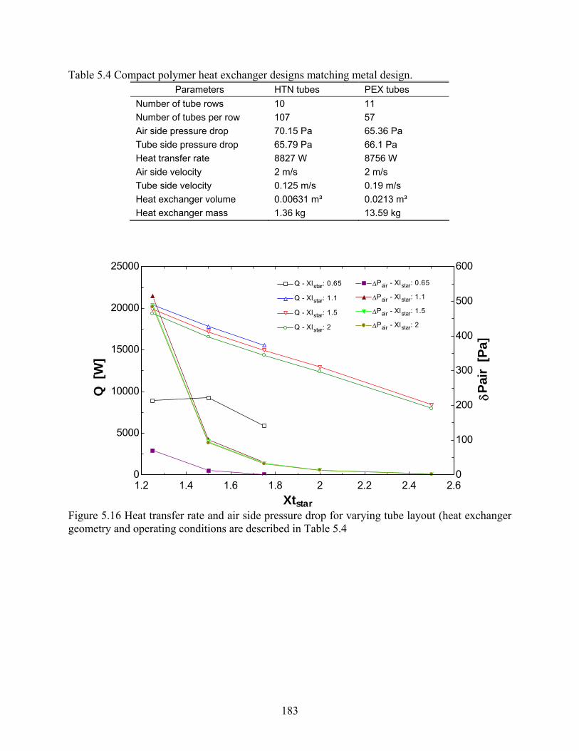
183
Table 5.4 Compact polymer heat exchanger designs matching metal design. Parameters HTN tubes PEX tubes
Number of tube rows 10 11 Number of tubes per row 107 57 Air side pressure drop 70.15 Pa 65.36 Pa Tube side pressure drop 65.79 Pa 66.1 Pa Heat transfer rate 8827 W 8756 W Air side velocity 2 m/s 2 m/s Tube side velocity 0.125 m/s 0.19 m/s Heat exchanger volume 0.00631 m³ 0.0213 m³ Heat exchanger mass 1.36 kg 13.59 kg
1.2 1.4 1.6 1.8 2 2.2 2.4 2.60
5000
10000
15000
20000
25000
0
100
200
300
400
500
600
Xtstar
Q [
W]
δPai
r [P
a]
Q - Xlstar: 0.65Q - Xlstar: 0.65
Q - Xlstar: 1.1Q - Xlstar: 1.1
Q - Xlstar: 1.5Q - Xlstar: 1.5
Q - Xlstar: 2Q - Xlstar: 2
ΔPair - Xlstar: 0.65ΔPair - Xlstar: 0.65
ΔPair - Xlstar: 1.1ΔPair - Xlstar: 1.1
ΔPair - Xlstar: 1.5ΔPair - Xlstar: 1.5
ΔPair - Xlstar: 2ΔPair - Xlstar: 2
Figure 5.16 Heat transfer rate and air side pressure drop for varying tube layout (heat exchanger geometry and operating conditions are described in Table 5.4

184
In Table 5.5 the resulting geometry of the heat exchanger is described for various tube layouts. From Figure 5.16 it is clear that using a higher *
lX compared to the first design (Table 5.4) can provide a considerable increase in the heat transfer rate, the pressure drop also rises significantly. During the simulation of ‘design 2’ (as described in Table 5.5) it was found that in order to match the air side pressure drop the air velocity had to be reduced below 2 m/s in order to maintain the ‘bundle characteristic,’ meaning having more than one row of tubes. Design 2 is clearly an extremely rectangular design measuring 0.8 cm by 84.8 cm. In design 3 *
lX is increased. This reduces the air side pressure drop allowing for a velocity of 2 m/s again and results in a more square shape of 2.5 cm by 44.6 cm. A further increase of *
lX to 2 combined with an increase of *
tX to 1.5 (this was required to result in a solvable series of equations) again results in a large drop in pressure drop. Two options then exist: either increase the air side velocity and have a low number of tube rows (design 4) or keep the air side velocity at 2 m/s and have a high number of tube rows (design 5). Design 4 measures 5.7 cm by 36.8 cm while design 5 measures 24.6 cm by 20.6 cm. The designs 2-5 indicate how the shape of the heat exchanger can be change significantly (from a very narrow rectangle to nearly square) while maintaining air side and tube side pressure drop and overall heat transfer rate. It should be noted, however, that altering the heat exchanger shape results in an increase in the number of tubes: from 356 for design 2 to 1161 for design 5. This will have a strong impact on the header design and cost. Increasing the number of tubes also increases the total weight of the unit, but all designs remain considerably lighter than the metal heat exchanger which weighs 4.75 kg. When considering the various factors described above, the design 4 appears to be the best choice out of the designs listed in Table 5.5 offering an acceptable heat exchanger shape and considerable weight reduction compared to the metal heat exchanger. Table 5.5 Modified polymer heat exchanger designs matching metal design.
Parameter Design 2 Design 3 Design 4 Design 5 *tX 1.1 1.1 1.5 1.5
*lX 1.25 1.5 2 2
Number of tube rows 2 6 10 43 Number of tubes per row 178 78 48 27 Air side pressure drop [Pa] 65.46 61.08 68.13 64.83 Heat transfer rate [W] 8836 8842 8898 9038 Air side velocity [m/s] 1.55 2 3 2 Heat exchanger volume [m³] 0.003553 0.005677 0.01045 0.02528 Heat exchanger mass [kg] 0.4522 0.6021 0.6097 1.475
From the previous simulations it is clear that polymer tube bundle heat exchangers without fins can offer a very competitive alternative compared to the common metal fin-and-tube heat exchanger. The most important aspect of these bundles is the use of thin walled small diameter tubes.

185
5.3 Application three: porous fin heat exchanger Compact heat exchangers are required for heat transfer applications where weight and space constraints prevail. For example, radiators or air conditioning evaporators in automotive systems are often configured with flat tubes and serpentine louver fins made of aluminum as shown in Figure 5.17(a). While this design provides adequate performance for typical automotive applications, even higher heat transfer performance is desired in other contexts such as aerospace or high intensity heat dissipation applications. Earlier in Chapter 3, we have proposed porous materials such as metal or carbon foams as an alternative to the conventional fin materials. A possible design is shown in Figure 5.17(b), where the serpentine louver fin is simply replaced with a porous fin made of metal foam. For such designs with porous materials, significantly higher pressure drop is expected as reported in previous studies (e.g. [95]), and we have examined possible designs to lower the airside pressure drop in section 3.3.
(a) (b)
Figure 5.17 Schematic illustrations of air-side fin geometry: (a) serpentine louver fin [216] and (b) metal foam [111] In this section, metal foam fin is compared to the conventional louver fin as a potential replacement for the existing flat-tube heat exchangers by simple performance modeling. Since the change of configuration is mainly associated with the air-side surface, the comparison is focused on the airside performance. The air-side thermal-hydraulic performances of louver-fin and metal foam are predicted using empirical correlations and experimental data found in the literature.
5.3.1 Baseline (louver) and porous (metal foam) fin configurations A flat-tube serpentine louver-fin heat exchanger sample was arbitrarily selected from the literature [216]. The configuration is similar to that shown in Figure 5.17(a), and the geometrical details are given in Table 5.6. The sample was chosen among typical heat exchangers of this type, and thus common geometrical parameters are represented by the design. For the porous fin configuration, a cuboid shape of a 40-ppi (pores per inch) aluminum foam was selected from the work by Bhattacharya et al. [217]. The properties and geometrical descriptions for the metal foam are shown in Table 5.7. While more compact metal foams (e.g. 60 ppi) have been reported in the literature, the current 40-ppi sample was selected because sufficient performance data were

186
available for this specific sample. Contrary to the expectation that a higher surface area to volume ratio would be obtained with the porous fin, the air-side surface-area-to-volume ratio (β) is 1100 m-1 for the louver fin and 580 m-1 for the porous fin. While this means that the airside geometry of the louver fin is more compact than the porous fin in the current comparison, the predicted performance indicates that the porous fin requires smaller air-side area and volume than the louver fin as shown later. Another noticeable factor as a potential disadvantage to the porous fin is the relatively low value of the effective bulk thermal conductivity (ke). This raises concern, especially for a long fin length (i.e. tube spacing), which can result in a low fin efficiency. Because the selected louver fin geometry in Table 5.6 uses a relatively long fin length, a comparison that imposes the same fin length favors the louver geometry over the porous fin geometry and thus serves as a more conservative assessment of the viability of the porous fin. Table 5.6 Geometrical description of selected flat-tube louver-fin heat exchanger
Source pL
(mm)
pF
(mm)
lF
(mm)
lL
(mm)
α
(deg)
dF
(mm)
pT
(mm)
fδ
(mm)
LBN
( – )
Chang and Wang [216] #5 1.42 2 19 17.18 28 22 24 0.16 2
Table 5.7 Geometrical data and physical properties of aluminum metal foam
Source Porosity
(ϕ) PPI fd (mm) pd (mm) f K (m2)
ek
(W/mK)
Bhattacharya et al. [217] #10 0.9272 40 0.25 2.02 0.089 6.1(10-8) 5.48
The heat transfer and pressure drop performances of the louver fin geometry were predicted using the Colburn-j and f factor correlations by Wang and Chang [218] and Chang et al. [219] as shown below:
05.028.068.023.029.014.027.049.0
90Re
−−−−−
−
⎟⎟⎠
⎞⎜⎜⎝
⎛⎟⎟⎠
⎞⎜⎜⎝
⎛⎟⎟⎠
⎞⎜⎜⎝
⎛⎟⎟⎠
⎞⎜⎜⎝
⎛⎟⎟⎠
⎞⎜⎜⎝
⎛⎟⎟⎠
⎞⎜⎜⎝
⎛⎟⎠⎞
⎜⎝⎛=
p
f
p
p
p
l
p
d
p
l
p
pLp LL
TLL
LT
LF
LF
jδθ (5.1)
3*2*1 ffff = (5.2)
where, if 150Re <Lp , 04.3
805.0
0.1lnRe39.141⎟⎟
⎠
⎞
⎜⎜
⎝
⎛
⎟⎟⎠
⎞⎜⎜⎝
⎛⎟⎟⎠
⎞⎜⎜⎝
⎛+=
⎟⎟⎠
⎞⎜⎜⎝
⎛−
p
pFF
Lp LF
f l
p
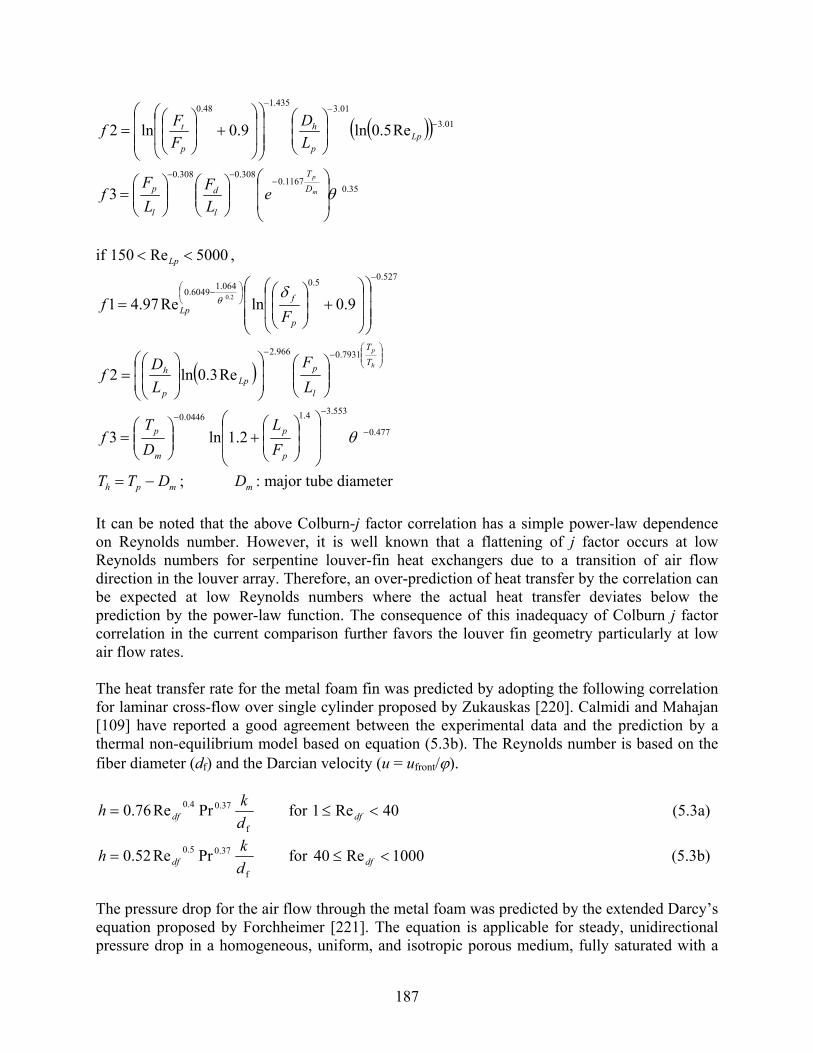
187
( )( ) 01.3
01.3435.148.0
Re5.0ln9.0ln2 −
−−
⎟⎟⎠
⎞⎜⎜⎝
⎛
⎟⎟⎟
⎠
⎞
⎜⎜⎜
⎝
⎛
⎟⎟
⎠
⎞
⎜⎜
⎝
⎛+⎟
⎟⎠
⎞⎜⎜⎝
⎛= Lp
p
h
p
t
LD
FFf
35.01167.0
308.0308.0
3 θ⎟⎟
⎠
⎞
⎜⎜
⎝
⎛⎟⎟⎠
⎞⎜⎜⎝
⎛⎟⎟⎠
⎞⎜⎜⎝
⎛=
−−−
m
p
DT
l
d
l
p eLF
LF
f
if 5000Re150 << Lp ,
527.05.0064.16049.09.0lnRe97.41 2.0
−
⎟⎠⎞
⎜⎝⎛ −
⎟⎟⎟
⎠
⎞
⎜⎜⎜
⎝
⎛
⎟⎟
⎠
⎞
⎜⎜
⎝
⎛+⎟
⎟⎠
⎞⎜⎜⎝
⎛=
p
fLp F
fδ
θ
( )⎟⎟⎠
⎞⎜⎜⎝
⎛−−
⎟⎟⎠
⎞⎜⎜⎝
⎛⎟⎟⎠
⎞⎜⎜⎝
⎛⎟⎟⎠
⎞⎜⎜⎝
⎛=
h
p
TT
l
pLp
p
h
LF
LD
f7931.0966.2
Re3.0ln2
477.0
553.34.10446.0
2.1ln3 −
−−
⎟⎟
⎠
⎞
⎜⎜
⎝
⎛
⎟⎟⎠
⎞⎜⎜⎝
⎛+⎟⎟
⎠
⎞⎜⎜⎝
⎛= θ
p
p
m
p
FL
DT
f
mph DTT −= ; mD : major tube diameter It can be noted that the above Colburn-j factor correlation has a simple power-law dependence on Reynolds number. However, it is well known that a flattening of j factor occurs at low Reynolds numbers for serpentine louver-fin heat exchangers due to a transition of air flow direction in the louver array. Therefore, an over-prediction of heat transfer by the correlation can be expected at low Reynolds numbers where the actual heat transfer deviates below the prediction by the power-law function. The consequence of this inadequacy of Colburn j factor correlation in the current comparison further favors the louver fin geometry particularly at low air flow rates. The heat transfer rate for the metal foam fin was predicted by adopting the following correlation for laminar cross-flow over single cylinder proposed by Zukauskas [220]. Calmidi and Mahajan [109] have reported a good agreement between the experimental data and the prediction by a thermal non-equilibrium model based on equation (5.3b). The Reynolds number is based on the fiber diameter (df) and the Darcian velocity (u = ufront/ϕ).
f
37.04.0 PrRe76.0dkh df= for 40Re1 <≤ df (5.3a)
f
37.05.0 PrRe52.0dkh df= for 1000Re40 <≤ df (5.3b)
The pressure drop for the air flow through the metal foam was predicted by the extended Darcy’s equation proposed by Forchheimer [221]. The equation is applicable for steady, unidirectional pressure drop in a homogeneous, uniform, and isotropic porous medium, fully saturated with a

188
Newtonian incompressible fluid [217]. The permeability (K) and the inertial coefficient (f) for the selected 40-ppi metal foam were reported by Bhattacharya et al. [217] as given in Table 5.7.
2
dd u
Kf
Ku
xP ρμ
+=− (5.4)
For the louver fin and the porous fin, the use of separate correlations for different Reynolds number ranges in equations (5.2) and (5.3) caused slight discontinuities in the predicted results. However, the overall comparison was not affected by the discontinuities.
5.3.2 Air-side performance comparison In Figure 5.18, the so-called “volume goodness” comparison of the louver and metal foam fin is presented, where the horizontal axis corresponds to fan power per unit air-side volume and the vertical axis corresponds to heat transfer rate per unit volume per unit temperature difference. The variable Eest is the fan power per unit surface area (W/m2). If the same fin length of 19 mm is used in the porous fin, a higher heat transfer performance is obtained by the porous fin for low fan power conditions and the trend is reversed for high fan power conditions. The reversed trend at high fan power range is due to the low bulk thermal conductivity of porous fin. In Figure 5.19, the long fin length results in a much lower fin efficiency for the porous fin than that of the louver fin. When the fin length of the porous fin is reduced by 50%, the fin efficiencies of both fins become similar. As shown in Figure 5.18, the shorter fin length significantly increases the heat transfer rate of the porous fin especially for the high fan power ranges. As a result, the porous fin gives higher heat transfer per volume for the entire range of comparison. It is important to notice that the porous fin, which has approximately half the surface area density (β) of the louver fin, actually can sustain the same amount of heat transfer with a smaller volume and less fan power consumption. Figure 5.20 shows that the maximum velocity at the fin core corresponding to the fan power per volume. For the selected louver and porous fins, the same core velocity condition corresponds to a similar face velocity condition, because the porosity of the louver fin (~0.92) is similar to that of porous fin (0.93). The figure shows that a higher fan power is required for the porous fin at the same maximum core velocity for the same volume. In other words, the same fan power for the same volume occurs at a lower core velocity for the porous fin than for the louver fin. In Figure 5.20, a fan power of 1000 W/m3 for the louver fin occurs at the core velocity of approximately 2 m/s, which is practically the upper limit of the typical operating condition with this type of heat exchangers. Because the reversed trend occurs above the fan power of 1000 W/m3 in Figure 5.18, it can be concluded that, for typical operating conditions of the selected flat-tube louver-fin heat exchanger, the porous fin even with the same fin length is always superior to the louver fin in the thermal-hydraulic performance even when configured with the longer fin length. Furthermore, as mentioned earlier, the possible over-estimation of heat transfer by louver fin for low Reynolds numbers suggests that the advantage of porous fin at low velocity ranges may be more pronounced. Figure 5.21 indicates that the overall pressure drop is greater with the porous fin at any given fan power per volume if the air flow depth is the same as that of the louver fin. With decreasing air

189
flow depth of porous fin, the pressure drop is reduced to a similar or even a lower value than the louver fin. It should be noted that a reduced flow depth requires an increased cross-sectional area for air flow in order to maintain the same volume and airside surface area. If the folded fin design in section 3.3 is adopted, the overall facial area can be reduced to a reasonable size while maintaining a lower pressure drop. In spite of the reduced core pressure drop by shorter flow depths, it should be noted that the fan power per volume for the porous fin is not affected in the present model, because the volumetric air flow rate is increased due to a larger cross-sectional area. If the average heat transfer coefficient is independent of flow depth as given by equation (5.3), the core air velocity is unchanged for a fixed heat transfer per volume with changing flow depth. Similarly, if the core pressure drop can be assumed to be linearly proportional to the flow depth, i.e. permeability (K) and inertial coefficient (f) are constant, then the fan power per volume is only a function of core velocity and independent of the air flow depth. In Figure 5.22, the thermal-hydraulic performances of louver fin and porous fin are compared on the basis of same surface area. The horizontal axis represents fan power per unit surface area and the vertical axis is heat transfer rate per unit surface area per unit temperature difference. Because the surface-area-to-volume ratio (β) is larger for the louver fin, the superiority of porous fin is even more pronounced in the figure. Similar to the trend in Figure 5.20, fan power per unit area is greater for the porous fin at the same core velocity as shown in Figure 5.23. Figure 5.24 present the ratio of required surface area at the same heat transfer load and fan power expenditure for the two fin geometries. Similarly, Figure 5.25 shows the required fin core volume for given heat transfer load and fan power consumption. Clearly, the porous fin can meet the same performance with significantly less surface area and core volume than the louver fin. The performance comparison in this section has demonstrated that reconfiguring the conventional compact flat-tube louver-fin heat exchangers with porous fins can achieve significant performance improvement leading to marked size reduction and potential cost saving. However, this simple comparison should be further augmented by considering other important aspects. For example, depending on specific heat exchanger applications, surface fouling or liquid retention on fin surfaces can raise reliability concerns. While both louver fins and porous foam fins have compact geometrical features, their performance and long-term behavior subject to various environmental conditions may differ. Other aspects include issues related to mechanical properties and manufacturing. We believe the development of novel heat exchangers with unconventional materials is a semi-heuristic process where analytical modeling and parametric optimization must be followed by prototype development and experimental studies.

190
100 101 102 103 104 105104
105
106
Estd β (W/m3)
η o h
β (W
/m3 K
)
Louver Fl=19 mmLouver Fl=19 mmPorous Fl=19 mmPorous Fl=19 mmPorous Fl=9.5 mmPorous Fl=9.5 mm
Figure 5.18 Volume goodness comparison of louver-fin and porous-fin heat exchangers
100 101 102 103 104 1050
0.2
0.4
0.6
0.8
1
Estd β (W/m3)
ηfin
Louver Fl=19 mmLouver Fl=19 mmPorous Fl=19 mmPorous Fl=19 mmPorous Fl=9.5 mmPorous Fl=9.5 mm
Figure 5.19 Fin efficiency of louver-fin and porous-fin heat exchangers

191
100 101 102 103 104 1050.01
0.1
1
10
100
Estd β (W/m3)
Vm
ax (m
/s)
LouverLouverPorousPorous
Figure 5.20 Maximum core air-flow velocities for louver-fin and porous-fin heat exchangers at given power consumption rate per volume
0 50 100 150 200 250 3000
50
100
150
200
250
300
ΔPlouver (Pa)
ΔPpo
rous
(Pa)
Porous Fd=22 mmPorous Fd=22 mmPorous Fd=16 mmPorous Fd=16 mmPorous Fd=11 mmPorous Fd=11 mm
Louver Fd=22 mm
Figure 5.21 Air-side overall pressure drop for louver-fin and porous-fin heat exchangers at the same fan power consumption rate per volume

192
10-3 10-2 10-1 100 101 102 103101
102
103103
Estd (W/m2)
ηo
h (W
/m2 K
)
Louver Fl=19 mmLouver Fl=19 mmPorous Fl=19 mmPorous Fl=19 mmPorous Fl=9.5 mmPorous Fl=9.5 mm
Figure 5.22 Area goodness comparison of louver-fin and porous-fin heat exchangers
10-3 10-2 10-1 100 101 102 1030.01
0.1
1
10
100
Estd (W/m2)
Vm
ax (m
/s)
LouverLouverPorousPorous
Figure 5.23 Maximum core air-flow velocities of louver-fin and porous-fin heat exchangers at given fan power consumption rate per unit surface area

193
10-3 10-2 10-1 100 101 1020
0.2
0.4
0.6
0.8
1
Estd,louver (W/m2)
Apo
rous
/Alo
uver
Pporous = Plouver
Porous Fl=9.5 mmPorous Fl=9.5 mm
Qporous = Qlouver
Porous Fl=19 mmPorous Fl=19 mm
Louver Fl=19 mm
Figure 5.24 Required surface area ratio for louver-fin and porous-fin heat exchangers under the same heat transfer load and fan power expenditure
100 101 102 103 104 1050.2
0.4
0.6
0.8
1
1.2
1.4
Estd,louverβ (W/m3)
Vpo
rous
/Vlo
uver
Pporous = Plouver
Porous Fl=9.5 mmPorous Fl=9.5 mm
Qporous = Qlouver
Porous Fl=19 mmPorous Fl=19 mm
Louver Fl=19 mm
Figure 5.25 Required volume ratio for louver-fin and porous-fin heat exchangers under the same heat transfer load and fan power expenditure

194
5.4 Application four: recuperators in LiBr-H2O absorption chillers for air conditioning applications
In Chapter 3 and 4, we discussed the replacement of conventional metal materials with polymer materials in LiBr-H2O absorption chillers. To further examine this possibility, we conducted a component simulation of the recuperators used in LiBr-H2O chiller systems. The results will be presented in this section.
5.4.1 Operation conditions and dimension data for the recuperators The configuration of the recuperator is the conventional plate-fin type heat exchanger similar to the one discussed in Section 3.3.1. The operating conditions and dimensional data are given in Table 5.8 and 5.9. Table 5.8 Operation conditions of the recuperators used in LiBr-H2O absorption chillers
Operation conditions Temperature or velocity Concentration (%) Spacing
Strong solution at inlet 100℃ 65% None
Weak solution at inlet 50℃ 60% None
Strong solution at outlet 65% Weak solution at outlet 60% Velocity of strong solution 0.01~0.09 m/s 0.004 m/s Velocity of weak solution 0.01~0.09 m/s 0.004 m/s
Table 5.9 Dimension data of the recuperators used in LiBr-H2O absorption chillers Variables Sizes Spacing
External dimensions Layer Width 300 mm Flow Length 300 mm Number of Layers 30
Fin Thickness 0.1-0.3 mm 0.2 mm Height 6 mm Spacing 1 mm Parting Sheet Thickness 0.1-0.9 mm 0.4 mm Height 300 mm Width 300 mm
The recuperator is used to recover the heat from the high-temperature, strong solution to the weak solution in an absorption chiller. The strong solution comes from the generator with high temperature. The weak solution comes from absorber at a low temperature and takes heat in the recuperator from the strong solution. The performance of the recuperator can be described in terms of the effectiveness of the recuperator, because the effectiveness is defined as the ratio of the actual heat transfer rate for the recuperator to the maximum possible heat transfer rate. Usually the specific heat capacity and the mass flow rate of weak solution are larger than those of the strong solution, thus the effectiveness directly indicates the degree to which the outlet

195
temperature of the strong solution approaches to the inlet temperature of the weak solution. In the performance simulation, we specified the inlet temperatures and concentrations of strong and weak solutions, along with the external dimensions of the recuporator, height and spacing of the fins, height and width of parting sheet. The factors which will influence the effectiveness are the velocities of strong and weak solutions, thicknesses and conductivities of fins and parting sheets. Their influences on effectiveness will be simulated and discussed in the following sections.
5.4.2 Simulation results Figure 5.26(a)-(f) show the trends in effectiveness with the changes of thicknesses and conductivities of fins and parting sheets at a velocity of 0.01 m/s for strong solution. Figure 5.26(a), (c), and (e) are effectiveness versus conductivity of fin at the conditions that fin thickness is 0.1 mm but sheet thickness are 0.1, 0.5, and 0.9 mm respectively. Similarly, Figure 5.26(b), (d), and (f) provide effectiveness versus conductivity of the fin at the conditions that fin thickness is 0.3 mm but sheet thickness are 0.1, 0.5, and 0.9 mm respectively. From the figures, it can be noted that the conduction resistance of sheet material becomes increasingly detrimental to the overall effectiveness for lower thermal conductivity of sheet. Transition to reduced effectiveness occurs at higher sheet conductivity when the sheets are thicker. For extremely low thermal conductivity of sheets, the effectiveness becomes nearly zero even if the thermal conductivity of fins is very high. Thus, the thermal conductivity of sheet materials is a limiting factor for this heat exchanger constituting primary surfaces. From Figure 5.27 and Figure 5.28, which correspond to solution velocities of 0.05 and 0.09 m/s, it can be seen that the overall effectiveness of the heat exchanger decreases unanimously with increasing velocity regardless of the thickness or the thermal conductivity of fins and sheets. This trend results, because reasing the strong-solution mass flow rate decreases the number of transfer units. The effect of fin thermal conductivity on heat exchanger effectiveness is explored for different values of fin thickness, sheet thickness, and sheet thermal conductivity in Figure 5.29, Figure 5.30, and Figure 5.31. It can be seen that the effect of fin thermal conductivity on effectiveness is more pronounced for higher sheet thermal conductivities and thinner sheets. Also, in contrary to sheet thermal conductivity, an extremely low thermal conductivity of fins does not result in a vanishing effectiveness. This is because the fin conduction resistance is only a partially limiting factor because fins are secondary heat transfer surfaces, i.e. either extreme value of fin conductivity yields a finite non-zero total surface efficiency. We have compared the performance of a polymer recuperator with a conventional metal recuperator. While the polymer gas-to-gas heat exchanger showed advantages over the metallic design in section 5.1, such promise was realized in the LiBr-H2O recuperator application. Due to the higher convective heat transfer coefficients with liquids, the heat transfer penalty associated with the higher conduction resistance was more pronounced with polymers plates in this application. Consequently, we were not able to find an advantage in the use of polymer recuperator over the conventional metallic counter part. However, further design optimization may identify a competitive polymer design.

196
0.1 1 10 100 10000.0
0.2
0.4
0.6
0.8
1.0
Vstrong= 0.01 m/s
λfin= 1000 W/mK λfin= 100 W/mK λfin= 10 W/mK λfin= 1 W/mK λfin= 0.1 W/mK
ε
λsheet(W/mK)
0.1 1 10 100 10000.0
0.2
0.4
0.6
0.8
1.0
Vstrong= 0.01 m/s
λfin= 1000 W/mK λfin= 100 W/mK λfin= 10 W/mK λfin= 1 W/mK λfin= 0.1 W/mK
ε
λsheet(W/mK) (a) δfin =0.1 mm, δsheet =0.1 mm (b) δfin =0.3 mm, δsheet =0.1 mm
0.1 1 10 100 10000.0
0.2
0.4
0.6
0.8
1.0Vstrong= 0.01 m/s
λfin= 1000 W/mK λfin= 100 W/mK λfin= 10 W/mK λfin= 1 W/mK λfin= 0.1 W/mK
ε
λsheet(W/mK)
0.1 1 10 100 10000.0
0.2
0.4
0.6
0.8
1.0Vstrong= 0.01 m/s
λfin= 1000 W/mK λfin= 100 W/mK λfin= 10 W/mK λfin= 1 W/mK λfin= 0.1 W/mK
ε
λsheet(W/mK) (c) δfin =0.1 mm, δsheet =0.5 mm (d) δfin =0.3 mm, δsheet =0.5 mm
0.1 1 10 100 10000.0
0.2
0.4
0.6
0.8
1.0Vstrong= 0.01 m/s
λfin= 1000 W/mK λfin= 100 W/mK λfin= 10 W/mK λfin= 1 W/mK λfin= 0.1 W/mK
ε
λsheet(W/mK)0.1 1 10 100 1000
0.0
0.2
0.4
0.6
0.8
1.0Vstrong= 0.01 m/s
λfin= 1000 W/mK λfin= 100 W/mK λfin= 10 W/mK λfin= 1 W/mK λfin= 0.1 W/mK
ε
λsheet(W/mK) (e) δfin =0.1 mm, δsheet =0.9 mm (f) δfin =0.3 mm, δsheet =0.9 mm
Figure 5.26 Effectiveness versus conductivity of parting sheets (Vstrong = 0.01m/s)

197
0.1 1 10 100 10000.0
0.2
0.4
0.6
0.8
1.0Vstrong= 0.05 m/s
λfin= 1000 W/mK λfin= 100 W/mK λfin= 10 W/mK λfin= 1 W/mK λfin= 0.1 W/mK
ε
λsheet(W/mK)0.1 1 10 100 1000
0.0
0.2
0.4
0.6
0.8
1.0Vstrong= 0.05 m/s
λfin= 1000 W/mK λfin= 100 W/mK λfin= 10 W/mK λfin= 1 W/mK λfin= 0.1 W/mK
ε
λsheet(W/mK) (a) δfin =0.1 mm, δsheet =0.1 mm (b) δfin =0.3 mm, δsheet =0.1 mm
0.1 1 10 100 10000.0
0.2
0.4
0.6
0.8
1.0Vstrong= 0.05 m/s
λfin= 1000 W/mK λfin= 100 W/mK λfin= 10 W/mK λfin= 1 W/mK λfin= 0.1 W/mK
ε
λsheet(W/mK)0.1 1 10 100 1000
0.0
0.2
0.4
0.6
0.8
1.0Vstrong= 0.05 m/s
λfin= 1000 W/mK λfin= 100 W/mK λfin= 10 W/mK λfin= 1 W/mK λfin= 0.1 W/mK
ε
λsheet(W/mK) (c) δfin =0.1 mm, δsheet =0.5 mm (d) δfin =0.3 mm, δsheet =0.5 mm
0.1 1 10 100 10000.0
0.2
0.4
0.6
0.8
1.0Vstrong= 0.05 m/s
λfin= 1000 W/mK λfin= 100 W/mK λfin= 10 W/mK λfin= 1 W/mK λfin= 0.1 W/mK
ε
λsheet(W/mK)0.1 1 10 100 1000
0.0
0.2
0.4
0.6
0.8
1.0Vstrong= 0.05 m/s
λfin= 1000 W/mK λfin= 100 W/mK λfin= 10 W/mK λfin= 1 W/mK λfin= 0.1 W/mK
ε
λsheet(W/mK) (e) δfin =0.1 mm, δsheet =0.9 mm (f) δfin =0.3 mm, δsheet =0.9 mm
Figure 5.27 Effectiveness versus conductivity of parting sheets (Vstrong = 0.05m/s)

198
0.1 1 10 100 10000.0
0.2
0.4
0.6
0.8
1.0Vstrong= 0.09 m/s
λfin= 1000 W/mK λfin= 100 W/mK λfin= 10 W/mK λfin= 1 W/mK λfin= 0.1 W/mK
ε
λsheet(W/mK)0.1 1 10 100 1000
0.0
0.2
0.4
0.6
0.8
1.0Vstrong= 0.09 m/s
λfin= 1000 W/mK λfin= 100 W/mK λfin= 10 W/mK λfin= 1 W/mK λfin= 0.1 W/mK
ε
λsheet(W/mK) (a) δfin =0.1 mm, δsheet =0.1 mm (b) δfin =0.3 mm, δsheet =0.1 mm
0.1 1 10 100 10000.0
0.2
0.4
0.6
0.8
1.0Vstrong= 0.09 m/s
λfin= 1000 W/mK λfin= 100 W/mK λfin= 10 W/mK λfin= 1 W/mK λfin= 0.1 W/mK
ε
λsheet(W/mK)0.1 1 10 100 1000
0.0
0.2
0.4
0.6
0.8
1.0Vstrong= 0.09 m/s
λfin= 1000 W/mK λfin= 100 W/mK λfin= 10 W/mK λfin= 1 W/mK λfin= 0.1 W/mK
ε
λsheet(W/mK) (c) δfin =0.1 mm, δsheet =0.5 mm (d) δfin =0.3 mm, δsheet =0.5 mm
0.1 1 10 100 10000.0
0.2
0.4
0.6
0.8
1.0Vstrong= 0.09 m/s
λfin= 1000 W/mK λfin= 100 W/mK λfin= 10 W/mK λfin= 1 W/mK λfin= 0.1 W/mK
ε
λsheet(W/mK)0.1 1 10 100 1000
0.0
0.2
0.4
0.6
0.8
1.0Vstrong= 0.09 m/s
λfin= 1000 W/mK λfin= 100 W/mK λfin= 10 W/mK λfin= 1 W/mK λfin= 0.1 W/mK
ε
λsheet(W/mK) (e) δfin =0.1 mm, δsheet =0.9 mm (f) δfin =0.3 mm, δsheet =0.9 mm
Figure 5.28 Effectiveness versus conductivity of parting sheets (Vstrong = 0.09m/s)

199
0.1 1 10 100 10000.0
0.2
0.4
0.6
0.8
1.0
Vstrong= 0.01 m/s
λsheet= 1000 W/mK λsheet= 100 W/mK λsheet= 10 W/mK λsheet= 1 W/mK λsheet= 0.1 W/mK
ε
λfin(W/mK)
0.1 1 10 100 10000.0
0.2
0.4
0.6
0.8
1.0Vstrong= 0.01 m/s
λsheet= 1000 W/mK λsheet= 100 W/mK λsheet= 10 W/mK λsheet= 1 W/mK λsheet= 0.1 W/mK
ε
λfin(W/mK) (a) δfin =0.1 mm, δsheet =0.1 mm (b) δfin =0.3 mm, δsheet =0.1 mm
0.1 1 10 100 10000.0
0.2
0.4
0.6
0.8
1.0Vstrong= 0.01 m/s
λsheet= 1000 W/mK
λsheet= 100 W/mK λsheet= 10 W/mK λsheet= 1 W/mK λsheet= 0.1 W/mK
ε
λfin(W/mK)
0.1 1 10 100 10000.0
0.2
0.4
0.6
0.8
1.0Vstrong= 0.01 m/s
λsheet= 1000 W/mK λsheet= 100 W/mK λsheet= 10 W/mK λsheet= 1 W/mK λsheet= 0.1 W/mK
ε
λfin(W/mK) (c) δfin =0.1 mm, δsheet =0.5 mm (d) δfin =0.3 mm, δsheet =0.5 mm
0.1 1 10 100 10000.0
0.2
0.4
0.6
0.8
1.0Vstrong= 0.01 m/s
λsheet= 1000 W/mK λsheet= 100 W/mK λsheet= 10 W/mK λsheet= 1 W/mK λsheet= 0.1 W/mK
ε
λfin(W/mK)
0.1 1 10 100 10000.0
0.2
0.4
0.6
0.8
1.0Vstrong= 0.01 m/s
λsheet= 1000 W/mK λsheet= 100 W/mK λsheet= 10 W/mK λsheet= 1 W/mK λsheet= 0.1 W/mK
ε
λfin(W/mK) (e) δfin =0.1 mm, δsheet =0.9 mm (f) δfin =0.3 mm, δsheet =0.9 mm
Figure 5.29 Effectiveness versus conductivity of parting sheets (Vstrong = 0.01m/s)

200
0.1 1 10 100 10000.0
0.2
0.4
0.6
0.8
1.0Vstrong= 0.05 m/s
λsheet= 1000 W/mK λsheet= 100 W/mK λsheet= 10 W/mK λsheet= 1 W/mK λsheet= 0.1 W/mK
ε
λfin(W/mK)0.1 1 10 100 1000
0.0
0.2
0.4
0.6
0.8
1.0
Vstrong= 0.05 m/s
λsheet= 1000 W/mK λsheet= 100 W/mK λsheet= 10 W/mK λsheet= 1 W/mK λsheet= 0.1 W/mK
ε
λfin(W/mK) (a) δfin =0.1 mm, δsheet =0.1 mm (b) δfin =0.3 mm, δsheet =0.1 mm
0.1 1 10 100 10000.0
0.2
0.4
0.6
0.8
1.0
Vstrong= 0.05 m/s
λsheet= 1000 W/mK λsheet= 100 W/mK λsheet= 10 W/mK λsheet= 1 W/mK λsheet= 0.1 W/mK
ε
λfin(W/mK)0.1 1 10 100 1000
0.0
0.2
0.4
0.6
0.8
1.0
Vstrong= 0.05 m/s
λsheet= 1000 W/mK λsheet= 100 W/mK λsheet= 10 W/mK λsheet= 1 W/mK λsheet= 0.1 W/mK
ε
λfin(W/mK) (c) δfin =0.1 mm, δsheet =0.5 mm (d) δfin =0.3 mm, δsheet =0.5 mm
0.1 1 10 100 10000.0
0.2
0.4
0.6
0.8
1.0Vstrong= 0.05 m/s
λsheet= 1000 W/mK λsheet= 100 W/mK λsheet= 10 W/mK λsheet= 1 W/mK λsheet= 0.1 W/mK
ε
λfin(W/mK)0.1 1 10 100 1000
0.0
0.2
0.4
0.6
0.8
1.0
Vstrong= 0.05 m/s
λsheet= 1000 W/mK λsheet= 100 W/mK λsheet= 10 W/mK λsheet= 1 W/mK λsheet= 0.1 W/mK
ε
λfin(W/mK) (e) δfin =0.1 mm, δsheet =0.9 mm (f) δfin =0.3 mm, δsheet =0.9 mm
Figure 5.30 Effectiveness versus conductivity of parting sheets (Vstrong = 0.05m/s)

201
0.1 1 10 100 10000.0
0.2
0.4
0.6
0.8
1.0
Vstrong= 0.09 m/s
λsheet= 1000 W/mK λsheet= 100 W/mK λsheet= 10 W/mK λsheet= 1 W/mK λsheet= 0.1 W/mK
ε
λfin(W/mK)0.1 1 10 100 1000
0.0
0.2
0.4
0.6
0.8
1.0Vstrong= 0.09 m/s
λsheet= 1000 W/mK λsheet= 100 W/mK λsheet= 10 W/mK λsheet= 1 W/mK λsheet= 0.1 W/mK
ε
λfin(W/mK) (a) δfin =0.1 mm, δsheet =0.1 mm (b) δfin =0.3 mm, δsheet =0.1 mm
0.1 1 10 100 10000.0
0.2
0.4
0.6
0.8
1.0
Vstrong= 0.09 m/s
λsheet= 1000 W/mK λsheet= 100 W/mK λsheet= 10 W/mK λsheet= 1 W/mK λsheet= 0.1 W/mK
ε
λfin(W/mK)0.1 1 10 100 1000
0.0
0.2
0.4
0.6
0.8
1.0
Vstrong= 0.09 m/s
λsheet= 1000 W/mK λsheet= 100 W/mK λsheet= 10 W/mK λsheet= 1 W/mK λsheet= 0.1 W/mK
ε
λfin(W/mK) (c) δfin =0.1 mm, δsheet =0.5 mm (d) δfin =0.3 mm, δsheet =0.5 mm
0.1 1 10 100 10000.0
0.2
0.4
0.6
0.8
1.0Vstrong= 0.09 m/s
λsheet= 1000 W/mK λsheet= 100 W/mK λsheet= 10 W/mK λsheet= 1 W/mK λsheet= 0.1 W/mK
ε
λfin(W/mK)0.1 1 10 100 1000
0.0
0.2
0.4
0.6
0.8
1.0
Vstrong= 0.09 m/s
λsheet= 1000 W/mK λsheet= 100 W/mK λsheet= 10 W/mK λsheet= 1 W/mK λsheet= 0.1 W/mK
ε
λfin(W/mK) (e) δfin =0.1 mm, δsheet =0.9 mm (f) δfin =0.3 mm, δsheet =0.9 mm
Figure 5.31 Effectivenesses versus conductivities of parting sheets (Vstrong = 0.09m/s)

202
CHAPTER 6 CONCLUSIONS AND RECOMMENDATIONS
6.1 Introduction In chapters 2-5, we identified eight kinds of new materials that hold promise for use in heat exchangers. We have assessed the potential benefits and feasibility of using these novel materials in HVAC&R systems. Our task was first to identify and then to utilize characteristics of these materials which appear to hold particular promise for future heat exchanger design. We used information available from industry, patents, and the technical literature as well as industries or applications where these materials are already currently used. A critical evaluation of the potential benefits of these new materials has been conducted and has produced a thorough compilation of performance data, physical/chemical properties, and other characteristics. Key features of seventeen of the most promising materials have been investigated to identify specific usages in heat exchangers based on a rating system comprised of ten performance evaluation criteria. A list of feasible material alternatives to twenty conventional applications was then generated by employing the Pugh matrix method. In order to take advantage of the characteristics of the novel materials, we have also proposed new heat exchanger configurations for four target applications. Based on the promising materials and configurations identified through the above tasks, we completed a study of the feasibility of new designs using novel materials. Four detailed component simulations were performed utilizing heat exchanger performance data acquired through the other tasks to determine the heat exchanger geometry necessary for achieving a specified capacity and to assess the cost and performance of the most promising technologies relative to conventional heat exchangers.
6.2 Summary of results
6.2.1 Identification of applicable materials In order to identify novel materials that are most promising for heat exchangers in HVAC&R applications, a comprehensive literature review has been conducted. Ideas have been collected from a wide span of industry and applications in the technical literature including journal papers, conference proceedings, reports, patents, and online documents. The identified types of materials for heat exchangers are polymers, metals, carbonaceous materials, and ceramics. All of these materials are available in composite forms with various kinds of fillers. Over 500 technical articles were found, organized, and categorized. After a careful initial screening, most relevant articles were critically reviewed and the results have been compiled into APPENDIX A in the form of an annotated bibliography with key findings.
6.2.2 Compilation of property data and assessment of potential The largest amount of technical literature was related to polymers and polymer composites with dominant applications in the chemical processing industry. Due to the characteristics of polymers that complement the properties of metallic heat exchangers, a number of polymer heat

203
exchangers are found in commercial applications. In addition to polymers, porous materials such as carbon or metal foam have received considerable attention in the literature due to the superior thermal performance at reduced sizes in comparison to conventional metallic finned-tube heat exchangers. Carbonaceous materials and ceramics have unique properties that limit them from entering broadly into HVAC&R applications. Most composite materials have good thermal performance as well as improved mechanical/thermal/chemical properties. However, high-performance composites appear to be limited from being adopted by a wide range of HVAC&R applications due to the higher material and manufacturing cost. The detailed thermal and mechanical properties of individual materials have been collected in tabular form. Contrary to widely available thermo-physical property data, thermal-hydraulic performance data were very limited for heat exchangers made of novel materials. Detailed characteristics of the four types of materials are compared in terms of the most essential aspects: thermal performance, thermal/mechanical/ environmental constraints, and manufacturing and installation issues. Due to the limited availability of performance data, component-based comparison methods were deemed most appropriate.
6.2.3 Exploration of possible designs with novel materials After the completion of extensive literature search and review, the benefits of novel materials were assessed and compared to the existing conventional heat exchanger technology. In order to explore heat exchanger designs utilizing the identified advantages of novel materials, two approaches were taken: (1) replacement of materials for existing heat exchangers and (2) potentially dramatic changes in heat exchanger configuration. The first approach was implemented such that the multiple merit aspects of heat exchanger materials were combined to produce a quantitative measure for comparison. Key features of seventeen of the most promising materials were rated based on a rating system comprised of ten performance evaluation criteria relevant to usages in heat exchangers. Then, major heat exchanger applications were reviewed for extensive analysis, and a list of feasible material alternatives to twenty conventional applications was generated. By employing a weighted Pugh matrix method, the most beneficial material combinations for fin/tube/header construction were obtained for each application. This approach strictly ranked material combinations in terms of material properties; however, further consideration in terms of the manufacturing compatibility is also important. The second approach required creative designs in order to maximize the specific strengths of the novel materials. During this stage, two facilitated brainstorming sessions were held at UIUC. The summary of ideas is given in APPENDIX C. Through a careful evaluation of the proposed ideas, several possible designs were screened for further assessment. The final list of new heat exchanger configurations was achieved after extensively evaluating the potential benefits based on material properties and performance data from the literature.

204
6.2.4 Assessment of feasibility for implementation Practical issues related to implementing the novel materials on heat exchangers in HVAC&R industry require in-depth knowledge and experience in manufacturing processes. This task was conducted through technical literature review and external consultation. Major challenges in using novel materials were identified for a set of heat exchanger applications. For specific aspects addressing the new heat exchanger configurations, a semi-heuristic approach, i.e. a combination of theoretical modeling and prototype development, and design iteration may be necessary.
6.2.5 Performance modeling A list of four applications was developed from the previous task of evaluating the potential benefits through material replacement or change of configuration. We utilized material property and performance data from the literature to conduct component simulations for selected heat exchanger applications. The results were compared to the performance of conventional metallic heat exchangers. Performance data in the literature are not sufficient for full-scale system simulations. However, by matching the system constraints, i.e. heat transfer and pressure drop, the benefits at the component level can be projected to the benefits in the system performance. The effectiveness of using novel materials in heat exchanger applications was assessed through performance simulations and guidelines for prototype designs were reached. For polymers, the simulations have demonstrated that the low thermal conductivity can be overcome by using thin walled plates and tubes and eliminating dependence on fins. Polymeric heat exchangers can surpass metallic counterparts in weight, with the potential for attendant cost savings. We found that high porosity metal foams typically incur higher pressure drop, but through judicious design it is possible to properly manage the pressure drop, and these foams hold excellent promise for use as air-side fins. A comparison of the air-side performance has demonstrated that metal foam fins can remarkably surpass the heat transfer performance of conventional louver fins with far less material and size requirement. The simulation program codes written in EES (Engineering Equation Solver) are given in APPENDIX B. Although the designs were not optimized in the present modeling, further optimization can be undertaken by modifying the simulation—we expect that this will be most useful when implemented during the process of prototype development.
6.3 Recommendations for future work Through this literature survey, we have uncovered a number of approaches to the use of novel materials in heat exchangers that hold substantial relevance and potential merit, but have not been suffiently studied to allow a complete assessment of cost and benefit. We have also noted some approaches for which there is not enough information to make rough assessments of promise. The following issues may be important in further exploring the use of novel materials for heat exchangers:
a. Our review did not focus on paper, wood, glass and some other materials. In most cases,

205
the lack of coverage reflects a dearth of information. However, the lack of information is probably due to lack of promise. We do not believe further exploration of such materials will be fruitful.
b. Likewise, our review did not uncover significant work on Shape Memory Alloys (SMA), another class of novel substances. SMAs are unique for their ability to change between pre-defined shapes when they are at prescribed temperatures, and they have found wide applications in diverse areas (refer to Wu and Schetky [222] and Song et al. [223]). SMAs might have promise as a heat exchanger material, for example in controlling frost. However, there has not been enough work reported in the open literature to make a fully informed decision about their use in HVAC&R systems. More work in this area might be useful.
c. Some thermal-hydraulic performance modeling (heat transfer and pressure-drop predictions) of these novel materials is over simplified, and there is very little experimental data available in the literature, especially for emerging porous materials (carbon foam, metal foam, etc.). More work in this area is needed before validated thermal-hydraulic performance predictions are possible.
d. Component modeling of heat exchangers relies on accurate thermal-hydraulic performance data, as do optimization studies. At this point we can identify with come confidence promising designs, but in order to make firm recommendations with respect to material changes further work is needed.
e. Likewise, system simulations will be reasonable only after the accuracy of component modeling is validated, and that modeling suffers from the lack of experimental data.
On the basis of the literature review, and our experience in developing and evaluating heat exchanger technologies, we believe a Phase II project for further evaluation of promising novel materials should focus on obtaining performance data with prototype heat exchangers. In this work we have identified several designs that hold promise. The scope of the new project should be focused on prototype construction and thermal-hydraulic performance testing. If a particular system benefit emerges, recommendations to include system testing for experimental evaluation can follow.
We have already confirmed opportunities for possible industrial participation for obtaining test samples and developing prototype heat exchangers. Thus, clearly, the recommended research is feasible.

206
LIST OF REFERENCES [1] Gurdal, Z., Haftka, R.T., and Hajela, P., Design and optimization of laminated composite
materials, Wiley, New York, 1999. [2] Schwartz, M.M., Composite materials, Prentice Hall PTR, Upper Saddle River, NJ, 1997. [3] Zweben, C., Emerging high-volume applications for advanced thermally conductive
materials, International SAMPE Symposium and Exhibition (Proceedings) 49, SAMPE 2004 Conference Proceedings - Materials and Processing Technology - 60 Years of SAMPE Progress (2004) 4046-4057.
[4] Matweb, http://www.matweb.com [5] Zaheed, L. and Jachuck, R.J.J., Review of polymer compact heat exchangers, with special
emphasis on a polymer film unit, Applied Thermal Engineering 24 (2004) 2323-2358. [6] Reay, D., The use of polymers in heat exchangers, Heat Recovery Systems & CHP 9 (3)
(1989) 209-216. [7] Wharry, Jr. S.R., Fluoropolymer heat exchangers, Metal Finishing, 100 (1) (2002) 752-
762. [8] Deronzier, J.C. and Bertolini, G., Plate heat exchanger in liquid crystal polymer, App.
Thermal Engineering 17(8-10) (1997) 799-808. [9] Ma, X., Chen, J., Xu, D., Lin, J., Ren, C., and Long Z., Influence of processing
conditions of polymer film on dropwise condensation heat transfer, Int. J. Heat and Mass Transfer, 45 (2002) 3405-3411.
[10] Brouwers, H. and Van Der Geld, C., Heat transfer, condensation and fog formation in crossflow plastic heat exchangers, Int. J. Heat Mass Transfer 39 (2) (1996) 391-405.
[11] Raman, R., Mantell, S., Davidson, J., Wu, C., and Jorgensen, G., A review of polymer materials for solar water heating systems, J. Solar Energy Engineering 122 (2000) 92-100.
[12] Breuer, O. and Sundararaj, U., Big returns from small fibers: A review of polymer carbon nanotube composites, Polymer Composites 25 (6) (2004) 630-645.
[13] Thostenson, E., Ren, Z., and Chou, T., Advances in the science and technology of carbon nanotubes and their composites: a review, Composites science and technology 61 (2001) 1899-1912.
[14] Xu, Y., Ray, G., and Abdel-Magid, B.H., Thermal behavior of single-walled carbon nanotube polymer–matrix composites, Composites: Part A 37 (2006) 114-121.
[15] Bigg, D., Thermally conductive Polymer compositions, Polymer Composites 7 (3) (1986) 125-140.
[16] Boudenne, A., Ibos, L., Fois, M., Gehin, E., and Majeste, J.C., Thermophysical properties of polypropylene-aluminum composites, J. Polymer Science: part B 42 (2004) 722-732.
[17] Mamunya, Y., Davydenko, V., Pissis, P., and Lebedev E., Electrical and thermal conductivity of polymers filled with metal powders, European Polymer Journal 38 (2002) 1887-1897.
[18] Serkan Tekce, H., Kumlutas, D., and Tavman, I., Effect of particle shape on thermal conductivity of copper reinforced polymer composites, J. Reinforced Plastics and Composites 26 (1) (2007) 113-121.
[19] Krupa, I., Novak, I., and Chodak, I., Electrically and thermally conductive polyethylene/graphite composites and their mechanical properties, Synthetic metals 145 (2004) 245-252.

207
[20] Krupa, I. and Chodák, I., Physical properties of thermoplastic/graphite composites, European Polymer Journal 37 (2001) 2159-2168.
[21] Weber, E.H., Clingerman, M.L., and King, J.A., Thermally conductive nylon 6,6 and polycarbonate based resins. I. ynergistic effects of carbon fillers, Journal of Applied Polymer Science 88 (1) (2003) 112-122.
[22] Nysten, B. and Issi, J.-P., Composites based on thermally hyperconductive carbon fibres, Composites 21 (4) (1990) 339-343.
[23] Chen, Y.-M. and Ting, J.-M., Ultra high thermal conductivity polymer composites, Carbon 40 (3) (2002) 359-362.
[24] Ting, J.-M., Guth, J.R.and Lake, M.L., Light weight, highly thermally conductive composites for space radiators, Ceramic Engineering and Science Proceedings 16 (4) (1995) 279-288.
[25] Schou, G. , Chen, X.D., Deans, J., Kunzel, J., and Muller-Steinhagen, H. , Wall resistance in graphite-block heat exchangers, Heat Transfer Engineering 18 (3) (1997) 39-50.
[26] Norley, J. , Tzeng, J.J.-W., Getz, G., Klug, J., and Fedor, B., The development of a natural graphite heat-spreader, Seventeenth Annual IEEE Semiconductor Thermal Measurement and Management Symposium (Cat. No.01CH37189) (2001) 107-110.
[27] Tzeng, J.W., Getz, G., Fedor, B.S. and Krassowski, D.W., Anisotropic Graphite Heat Spreaders for Electronics Thermal Management, Graftech, Inc., June 2000.
[28] Marotta, E.E. , Ellsworth Jr., M.J., Norley, J., and Getz, G., The development of a bonded fin graphite/epoxy heat sink for high performance”, Advances in Electronic Packaging 2, Advances in Electronic Packaging 2 (2003) 139-146.
[29] Norley, J. and Chen, G.G., High performance, lightweight graphite heat sinks/spreaders, PCIM 2002, Nuremberg, May 14-16, 2002
[30] Null, M.R., Lozier, W.W., and Moore, A. W., Thermal diffusivity and thermal conductivity of pyrolytic graphite from 300 to 2700 K, Carbon 11 (2) (1973) 81-87.
[31] Shives, G., Norley, J., Smalc, M., Chen, G., and Capp, J., Comparative thermal performance evaluation of graphite/epoxy fin heat sinks, Thermomechanical Phenomena in Electronic Systems -Proceedings of the Intersociety Conference 1 (2004) 410-417.
[32] Chen, G.G., Norley, J., Capp, J., Getz, G., and Flaherty, D., Optimum design of heat sinks using non-isotropic graphite composites, ASME Summer Heat Transfer Conference, Las Vegas, 2003.
[33] Norley, J., Graphite heatsinks: Like copper without the weight, Power Electronics Technology 31 (5) (2005) 76
[34] Bunning, T.J. , Jeon, H.G., Roy, A.K., Kearns, K.M., Farmer, B.L., and Adamst, W.W., Polyurethane-infiltrated carbon foams: a coupling of thermal and mechanical properties, Journal of Applied Polymer Science 87 (14) (2003) 2348-2355.
[35] Zweben, C., Thermal materials solve power electronics challenges, Power Electronics Technology 32 (2) (2006) 40-47.
[36] Zweben, C.H., New material options for high-power diode laser packaging, Proceedings of the SPIE - The International Society for Optical Engineering 5336 (1) (2004) 166-175.
[37] Chang, S.C. and Lucas, R.D., Resin infiltrated multi-functional carbon foam, International SAMPE Symposium and Exhibition (Proceedings) 50, SAMPE 05: New Horizons for Materials and Processing Technologies - Conference Proceedings (2005) 2397-2407.

208
[38] Jordan, J., Jacob, K., Tannenbaum, R., Sharaf, M., and Jasiuk, I., Experimental trends in nanocomposites – a review, Material Science and Engineering A 393 (2005) 1-11.
[39] LeBaron, P., Wang, Z., and Pinnavaia, T., Polymer-layered silicate nanocomposites - an overview, Applied clay science 15 (1999) 11-29.
[40] Ahmadi, S., Huang, Y., and Li, W., Synthetic routes, properties and future applications of polymer-layered silicate nanocomposites, J. Material Science 39 (2004) 1919-1925.
[41] Gao, F., Clay polymer composites: the story, Materials Today (2004) 50-55. [42] Bigg, D., Thermal conductivity of heterophase polymer compositions, Advances in
Polymer Science 119 (1995) 1-30. [43] Ahmed, S. and Jones, F., A review of particulate reinforcement theories for polymer
composites, J. Material Science 25 (1990) 4922-4942. [44] Morcos, V. and Shafey, H., Performance analysis of a plastic shell and tube heat
exchanger, Journal of Elastomers and Plastics 27 (1995) 200-213. [45] Davidson, J., Mantell, S., Liu, W., and Raman, R., Use of polymers in liquid to liquid
heat exchangers: applied to low cost solar water heating systems, Phase I, Task III report, University of Minnesota, Minneapolis, MN, 1998.
[46] Freeman, A., Mantell, S., and Davidson, J., Mechanical performance of polysulfone, polybutylene and polyamide 6/6 in hot chlorinated water, J. Solar Energy 79 (2005) 624-637.
[47] Wu, C., Mantell, S., and Davidson, J., Polymers for solar domestic hot water: long term performance of PB and Nylon 6,6 Tubing in hot water, J. Solar Energy Eng. 126 (2004) 581-586.
[48] Wang, Y., Davidson, J., and Francis, L., Scaling in polymer tubes and interpretation for use in solar water heating systems, J. Solar Energy Engineering127 (2005) 3-14.
[49] Liu W., Davidson, J., and Mantell, S., Thermal analysis of polymer heat exchangers for solar water heating: a case study, J. Solar Energy Eng. 122 (2000) 84-91.
[50] Li, Z., Davidson, J., and Mantell, S., Heat transfer enhancement using shaped polymer tubes: fin analysis, J. Heat Transfer. 126 (2004) 211-218.
[51] Zakardas, D., Li, B., and Sirkar K., Polymeric hollow fiber heat exchanger (PHFHEs): a new type of compact heat exchanger for low temperature applications, Proc. of the 2005 ASME Heat Transfer Conf, HT2005-72590, 2005.
[52] Patel, A.B. and Brisson, J.G., Design, construction and performance of plastic heat exchangers for sub-Kelvin use, Cryogenics 40 (2000) 91-98.
[53] Leigh, R.W., lsaacs, H.S., Kirley, J., and Ravve, A., Capital Cost Reductions in Absorption Chillers, ASHRAE transctons 95 (1) (1989) 939-952.
[54] Lowenstein, A. and Sibilia, M., A Low-cost thin-film absorber/evaporator for an absorption chiller, Final Report, Gas Research Inst., Chicago, IL, 1993, 44p.
[55] Lowenstein, A.I. and Sibilia, M.J., Thin plastic-film heat exchanger for absorption chillers, US patent 5992508, 1999.
[56] Bigg, D., Stickford, G., and Talbert, S., Applications of polymeric materials for condensing heat exchangers, Polymeric Eng. and Science 29 (16) (1989) 1111-1116.
[57] El-Dessouky, H. and Ettouney, H., Plastic compact heat exchangers for single effect desalination systems, Desalination 122 (1999) 271-289.
[58] Bourouni, K., Martin, R., Tadrist, L., and Tadrist, H., Experimental investigation of evaporation performance of a desalination prototype using aero-evapo-condensation process, Desalination 114 (1997) 111-128.

209
[59] Rousse, D., Martin, D., Thériault, R., Léveillée, F., and Boily, R., Heat recovery in greenhouses: a practical solution, App. Thermal. Eng. 20 (2000) 687-706.
[60] Tather, M. and Erdem-Senatalar, A., Polymeric heat exchangers to increase the COP values of adsorption heat pumps utilizing zeolite coatings, App. Therm. Eng. 24 (2004) 69-78.
[61] Burns, J. and Jachuck, R., Condensation studies using cross-corrugated polymer film compact heat exchangers, App. Thermal Eng. 21 (2001) 495-510.
[62] Cheng, L. and Van Der Geld, C., Experimental study of heat transfer and pressure drop characteristics of air/water and air-steam/water heat exchange in a polymer compact heat exchanger, Heat Transfer Eng. 26 (2) (2005) 18-27.
[63] Van Der Geld, C., Ganzevles, F., Simons, C., and Weitz, F., Geometry adaptations to improve the performance of compact polymer heat exchangers, Trans. IChemE 79 Part A (2001) 357-362.
[64] Harris, C., Kelly, K., Wang, T., McCandless, A., and Motakef, S., Fabrication, modeling and testing of micro-cross flow heat exchangers, J. Microelectromechanical Systems 11 (2) (2002) 726-735.
[65] Jia, J., Peng, X., Sun, J. and Chen, T., An experimental study on vapor condensation of wet flue gas in a plastic heat exchanger, Heat Transfer – Asian Research 30 (7) (2001) 571-580.
[66] Dobbs, G. and Freihaut, J., Plastic oil cooler, US patent 7152670 B2, 2006. [67] Saman, W. and Alizadeh, S., Modeling and performance analysis of a cross-flow type
plate heat exchanger for dehumidification/cooling, Solar Energy 70 (4) (2001) 361-372. [68] Saman, W. and Alizadeh, S., An experimental study of a cross flow type plate heat
exchanger for dehumidification/cooling, official journal of AIRAH, Sept. 2002. [69] Miller, J., Thermally conductive thermoplastics, Advanced Materials and Processes 161
(10) (2003) 34-35. [70] Bahadur, R. and Cohen, A., Thermal design and optimization of staggered polymer pin
fin natural convection heat sinks, Inter Soc. Conf. Thermal Phenomena (2004) 268-275. [71] Norley, J., Tzeng, J-W., and Klug, J., Graphite-based heat sink, US Patent 6503626, 2003. [72] Fontana, J.J., Reams, W., and Cheng, H.C., Potential polymer concrete heat exchanger
tubes for corrosive environments, Department of Energy, Washington, DC, BNL-38945; CONF-870946-2, 1986,
[73] Wikipedia, http://en.wikipedia.org [74] Chung, D.D.L., Materials for thermal conduction, Applied Thermal Engineering 21 (16)
(2001) 1593-1605. [75] Incropera, F.P. and DeWit, D.P., Fundamentals of heat and mass transfer, 6th edition,
John Wiley & Sons, Inc., 2007. [76] Koch, R.A., Watts, R., Benson-Tolle, T., and Strong, K., Challenges and opportunities
for thermal management materials, International SAMPE Symposium and Exhibition (Proceedings) 48 I (2003) 84-89.
[77] Ozmat, B., Leyda, B., and Benson, B., Thermal applications of open-cell metal foams, Materials and Manufacturing Processes 19 (5) (2004) 839-862.
[78] Liu P.S. and Liang, K.M., Review Functional materials of porous metals made by P/M, electroplating and some other techniques, Journal of Materials Science 36 (2001) 5059-5072.

210
[79] Tang, H., Liao, J, and Zhu, J., Porous metals of northwest institute for non-ferrous metal research, Materials Science Forum 534-536 (2007) 1281-1284.
[80] Tuchinskiy, L., Novel fabrication technology for metal foam, Journal of Advanced Materials 37 (3) (2005) 60-65.
[81] Haack, D.P., Butcher, K.R., Kim, T., and Lu, T.J., Novel lightweight metal foam heat exchanger, Proceedings of 2001 ASME International Mechanical Engineering Congress and Exposition, November 11-16, 2001, New york, NY PID-vol.6.
[82] Ashby, M.F., Evans, A., Fleck, N.A., Gibson, L.J., Hutchinson, J.W., Wadley, H.N.G., Metal foams: a design guide, Butterworth-Heinemann, Boston, 2000.
[83] Hunt, M.L. and Tien, C.L., Effect of thermal dispersion on forced convection in fibrous media, Int. J. Heat Mass Transfer 31 (1988) 301-309.
[84] Banhart, J., Baumeister, J., and Weber, M., Metal foams near commercialization, Metal Powder Report (UK) 52 (4) (1997) 38-41.
[85] Liu, P., Yu B., and Hu A., Development in applications of porous metals, Trans. Nonferrous Met. Soc. China 11 (5) 630-638.
[86] Bastawros, A.F. and Evans, A.G., Characterization of open cell aluminum alloy foams as heat sinks for high power electronic devices, in: D. Agonafer et al. (Eds.), CAE/CAD and Thermal Management Issues in Electronic Systems, ASME Conf. Proc. EEP-23/HTD-356, vol. 1, Dallas, TX, 1997, pp. 1–6.
[87] Ashby, M.F., Evans, A.G., Fleck, N.A., Gibson, L.J., Hutchinson, J.W., and Wadley, H.N.G., Cellular metals: a design guide, Butterworth-Heinemann, Boston, Massachusetts, 2000.
[88] M. Kaviany, Principles of Heat Transfer in Porous Media, Springer, New York, 1995 [89] Ruiz, E.C., Modelling of heat transfer in open cell metal foams, MS thesis, University of
Puerto Rico, 2004. [90] Sypeck, D.J. and Wadley, H.N.G., Multifunctional microtruss laminates: textile synthesis
and properties, J. Mater. Res. (2001) 890–897. [91] Tian, J., Kim, T., Lu, T.J., Hodson, H.P., Sypeck, D.J., and Wadley, H.N.G., The effects
of topology upon fluid-flow and heat-transfer within cellular copper structures, in: Proceedings of 8th UK National Heat Transfer Conference, Oxford, 9–10 September 2003.
[92] Wadley, H.N.G., Cellular metals manufacturing, Adv. Eng.Mater. 4 (2002) 726–733. [93] Lu, T.J., Stone, H.A., and Ashby, M.F., Heat transfer in opencell metal foams, Acta
Mater. 46 (1998) 3619–3635. [94] Evans, A.G., Hutchinson, J.W., Fleck, N.A., Ashby, M.F., and Wadley, H.N.G., The
topological design of multifunctional cellular metals, Prog. Mater. Sci. 46 (2001) 309–327.
[95] Tian, J., Kim, T., Lu, T.J., Hodson, H.P., Queheillalt, D.T., Sypeck, D.J., and Wadley, H.N.G., The effects of topology upon fluid-flow and heat-transfer within cellular copper structures, Int J Heat Mass Transfer 47 (2004) 3171–3186.
[96] Boomsma, K., Poulikakos, D., and Zwick, F., Metal foams as compact high performance heat exchangers, Mechanics of Materials 35 (2003) 1161–1176.
[97] Zhao, C.Y., Kim, T., Lu, T.J., and Hodson, H.P., Thermal transport in high porosity cellular metal foams, Journal of Thermophysics and Heat Transfer 18 (3) (2004) 358-363.

211
[98] Zweben, C., Overview of compsite materials for optomechanical, data storage and thermal management systems, Proceedings of SPIE – The International Society for Optical Engineering 3786 (1999) 148-161.
[99] Zweben, C., High-performance thermal management materials, Advanced Packaging 15 (2) (2006) 20-22.
[100] Smeding, S.F., Bakker, N., de Boer, R., Design, simulation and experiments on a new flat plate sandwich heat exchanger, ECN-M-06-096, 13th International Heat Transfer Conference, Sydney, Australia, 2006.
[101] Tadrist, L., Miscevic, M., Rahli, O., Topin, F., About the use of fibrous materials in compact heat exchangers, Experimental Thermal and Fluid Science 28 (2004) 193–199.
[102] Wheatley, J.C., Vieches, O.E., and Abel, W.R., Principles and methods of dilution refrigeration, Physics, 4(1) (1968:1-64)
[103] Severijins, A.D., Heat exchanger and method of manufacturing the same, US Patent 3794110, 1974.
[104] Klein, J., and Whiteside, J., Application of foam metal technology to aircraft systes-direction and status, Northrop Grumman Corp Melbourne FL Integrated Systems Sector, Report A628004, 2001.
[105] http://www.metafoam.com [106] Rosenfeld, J.H., Anderson, W.G., Horner-Richardson, K., John R. Hartenstine, Keller,
R.F., and Beals, J.T., Space power thermal management materials and fabrication technologies for commercial use, AIP Conf. Proc. 324 (1995) 893-902.
[107] Zhao, C.Y., Lu, W., Tassou, S.A., Thermal analysis on metal-foam filled heat exchangers, Part II: Tube heat exchangers, International Journal of Heat and Mass Transfer 49 (15-16) (2006) 2762-2770.
[108] Anthohe, B.V., Lage, J.L., and Price, D.C., Numerical characterization of micro heat exchangers using experimentally tested porous aluminum layers, International Journal of Heat and Fluid Flow 16 (6) (1996) 594–603.
[109] Calmidi, V.V. and Mahajan, R.L., Forced convection in high porosity metal foams. Journal of Heat Transfer 122 (2000) 557–565.
[110] Hsieh, W.H., Wu, J.Y., Shih, W.H., and Chiu, W.C., Experimental investigation of heat-transfer characteristics of aluminum foam heat sinks, International Journal of Heat and Mass Transfer 47 (2004) 5149–5157.
[111] Kim, Y., Paek, J.W., and Kang, B.H., Thermal performance of aluminum-foam heat sinks by forced air cooling, IEEE Transactions on Components and Packaging Technologies 26 (1) (2003) 262–267.
[112] Kang, B.H., Kim, S.Y., Lee, D.Y., Kim, J.H., and Ryu, H.S., Plate tube type heat exchanger having porous fins, US Patent 6142222, 2000.
[113] Mahdi, H., Lopez, P. Jr, Fuentes, A., and Jones, R., Thermal performance of aluminum-foam CPU heat exchangers, Int. J. Energy Res. 30 (11) (2006) 851–860.
[114] Dempsey, B.M., Eisele, S., and McDowell, D.L., Heat sink applications of extruded metal honeycombs, International Journal of Heat and Mass Transfer 48 (2005) 527–535.
[115] Hayes, A.M., Wang, A.-J., Dempsey, B.M., McDowell, D.L., Mechanics of linear cellular alloys, Mech. Mater. 36 (8) (2004) 691–671.
[116] Hugh O.P., Handbook of carbon, graphite, diamonds and fullerenes: properties, processing and applications, Noyes Publications, Park Ridge, N.J., 1993.

212
[117] Duston, C., Watts, R., Seghi, S., and Carney, B., Strength enhancement and application development of carbon foam for thermal management, Ceramic Composites Inc., Millersville, MD, 2004.
[118] Madner, P.J., Graphite heat exchangers in the process industries, First U.K. National Conference on Heat Transfer 2 (1984) 1263-1274.
[119] Lake, M.L. and Ting, J.-M., VGCF/carbon composites for plasma-facing materials, Proceedings of SPIE - The International Society for Optical Engineering, v 1997 (1993) 196-205.
[120] Rabah, M.A. and El-Dighidy, S.M., Effect of impregnants on the performance of graphite-block heat-exchangers, Journal of the Institute of Energy, 63 (455) (1990) 79-84.
[121] Gallego, N.C. and Klett, J.W., Carbon foams for thermal management, Carbon 41 (7) (2003) 1461-1466.
[122] Ford, W.D., Method of making cellular refractory thermal insulating material, US patent 3121050, 1964.
[123] Klett, J., High thermal conductivity mesophase pitch-derived carbon foam, J Composites in Mfg., 15 (4) (1999) 1-7.
[124] Hager, J.W. and Anderson , D.P., Idealized ligament formation and geometry in open-celled foams, in: Proceedings of 21st Biennial Conference on Carbon, American Carbon Society, Buffalo, New York, 1993, pp. 102-103.
[125] McCoy, J.W. and Vrable, D.L., Metal-matrix composites from graphitic foams and copper”, SAMPE Journal 40 (1) (2004) 7-15.
[126] Klett, J., Jones, S., Klett, L., and Walls, C., High thermal conductivity graphitic foam reinforced carbon-carbon composites, International SAMPE Symposium and Exhibition (Proceedings), v 48 I, 2003, p 38-52.
[127] Lucas, R.D., Emerging materials and processes: CFOAM - Out of the lab and into the real world of composite tooling, International SAMPE Symposium and Exhibition (Proceedings), v 49, SAMPE 2004 Conference Proceedings - Materials and Processing Technology - 60 Years of SAMPE Progress, 2004, pp. 1035-1046
[128] Yu, Q., Thompson, B.E., and Straatman, A.G., Carbon foam - New generation of enhanced surface compact recuperators for gas turbines, Proceedings of the ASME Turbo Expo, v 1, Proceedings of the ASME Turbo Expo 2005, pp. 1023-1028.
[129] Ott, R.D. , Zaltash, A., and Klett, J.W., Utilization of a graphite foam radiator on a natural gas engine-driven heat pump, American Society of Mechanical Engineers, Advanced Energy Systems Division (Publication) AES 42 (2002) 463-467.
[130] Klett, L. and Klett, J., Foam core sandwich panels made from high thermal conductivity mesophase pitch-based carbon foam, Proceedings of the 24th Bienial Conference on Carbon, July 11-16, Charleston, SC, 1999, p. 310.
[131] Klett, J. and Conway, B., Thermal management solutions utilizing high thermal conductivity graphite foams, International SAMPE Symposium and Exhibition (Proceedings), v 45 (II), 2000, pp. 1933-1943.
[132] Klett, J., Characterization of ORNL's high thermal conductivity graphite foam, CRADA Final Report C/ORNL-99-0563, Department of Energy, Washington, DC., 2001, 12 p.
[133] Ward, G.W., Self-reinforced graphite based on high thermal conductivity pitch-based fiber, International SAMPE Symposium and Exhibition (Proceedings) 42 (2), Evolving Technologies for the Competitive Edge, 1997, pp, 989-995.
[134] Lijima, S., Helical microtubules of graphitic carbon, Nature 354 (6348) (1991) 56-58.

213
[135] Kim, P., Shi, L., Majumdar, A., and McEuen, P.L., Thermal transport measurements of individual multiwalled nanotubes, Physical Review Letters 87 (21) (2001) 215502/1-4.
[136] Ekstrand, L., Mo, Z., Zhang, Y., and Liu, J., Modelling of carbon nanotubes as heat sink fins in microchannels for microelectronics cooling, Polytronic 2005: 5th International Conference on Polymers and Adhesives in Microelectronics and Photonics - Proceedings, v 2005, Polytronic 2005: 5th International Conference on Polymers and Adhesives in Microelectronics and Photonics - Proceedings, pp. 185-187.
[137] Fitzer, E. and Manocha. L.M., Carbon reinforcements and carbon /carbon composites, Berlin, New York, Springer-Verlag, 1998.
[138] Ting, J.-M. and Lake, M.L., Vapor-grown carbon-fiber reinforced carbon composites, Carbon, 33 (5) (1995) 663-667.
[139] Shih, W.T., Carbon-carbon (C-C) composites for thermal plane applications, Proc. 7th Int. SAMPE Electronics Conference, Parsippany, NJ, 1994, pp. 1-20.
[140] Kowbel, W., Champion, W., Withers, J.C., and Shih, W., Low cost, high thermal conductivity composite heat spreaders for power electronics, Sixteenth Annual IEEE Semiconductor Thermal Measurement and Management Symposium (Cat. No.00CH37068), 2000, pp. 195-200.
[141] Kearns, K.M., Recent developments in carbon-carbon composites, 43rd International SAMPE Symposium and Exhibition. Materials and Process Affordability. Keys to the Future, pt. 2, 1998, pp. 1362-1369.
[142] Watts, R., Advancement in compact lightweight carbon aircraft heat exchangers, International SAMPE Symposium and Exhibition (Proceedings), v 50, SAMPE 05: New Horizons for Materials and Processing Technologies - Conference Proceedings, 2005, pp. 2497-2505.
[143] Watts, R.J., Vrable, D.L., Kearns, K.M., Stevenson, D.L., and Anderson, D.P., Design of a high temperature compact carbon-carbon heat exchanger, ASME Paper #99-IMECE/PID-4, presented at ASME International Mechanical Engineering Congress & Exposition, Nashville, TN, 1999, ASME, New York, NY.
[144] Vrable, D.L. and Gottschlich, J.M., Graphite foam/copper composite substrate for electronic cooling, Collection of Technical Papers - 4th International Energy Conversion Engineering Conference, v 1, Collection of Technical Papers - 4th International Energy Conversion Engineering Conference, 2006, pp. 593-602.
[145] Watts, R., Kistner, M., and Colleary, A., Materials opportunity to electronic composite enclosures for aerospace and spacecraft thermal management, AIP Conference Proceedings, n 813, 2006, pp. 19-26.
[146] Thut , B.H. and Lehman, D.T., Heat exchanger, US Patent 4244423, 1981. [147] Shook, J.R., Graphite tube condensing heat exchanger and method of operating same, US
Patent 5036903, 1991. [148] Gillham, M.W.H., New composite material for plate heat exchangers, Materials &
Design 9 (4) (1988) 192-194. [149] Rabah, M.A. and El-Dighidy, S.M., Effect of impregnants on the performance of
graphite-block heat-exchangers, Journal of the Institute of Energy 63 (455) (1990) 79-84. [150] Schou, G., Deans, J., Kunzel, J., and Muller-Steinhagen, H., Thermal and hydraulic
performance of a graphite block heat exchanger, Chemical Engineering and Processing 36 (5) (1997) 371-384.

214
[151] Klett, J., Racing radiators utilizing ORNL's graphic foam, Department of Energy, Washington, DC., Report: C/ORNL98-0551, 2000.
[152] Klett, J., Ott, R., and McMillan, A., Heat exchangers for heavy vehicles utilizing high thermal conductivity graphite foams, Department of Energy, Washington, DC. , Report: SAE-TP-2001-01-2207, 2000.
[153] Yu, Q., Straatman, A.G., and Thompson, B.E., Carbon-foam finned tubes in air-water heat exchangers, Applied Thermal Engineering 26 (2-3) (2006) 131-143.
[154] Vaughn, W., Shinn, E., Rawal, S., and Wright, J., Carbon-carbon composite radiator development for the EO-1 spacecraft, Thirteenth Technical Conference of the American Society for Composites, Baltimore, MD,1998.
[155] Rawal, S.P., Johnson, K.S., and Makowski, K., Multifunctional carbon-carbon foam-core space radiator development, AIP Conference Proceedings, n 746, 2006, pp. 3-9.
[156] Filburn, T., Kloter, A., and Cloud, D., 2006, Design of a carbon-carbon finned surface heat exchanger for a high-bypass ratio, high speed gas turbine engine, Proceedings of the ASME Turbo Expo, v 3 PART A, Proceedings of the ASME Turbo Expo 2006 - Power for Land, Sea, and Air, 2006, pp. 483-490
[157] Stevenson, R.D., Vrable, D.L., and Watts, R.J., Development of an intermediate temperature carbon-carbon heat exchanger for aircraft applications, International SAMPE Symposium and Exhibition (Proceedings), v 44, n pt 2, 1999, pp. 1888-1897.
[158] Alam, M.K., Watts, R.J., and Price, J., Compact carbon-carbon composite heat exchanger, American Society of Mechanical Engineers, Heat Transfer Division, (Publication) HTD 372 (4) 2002, Heat Transfer Equipment Aerospace Heat Transfer, Heat Transfer in Multiphase Systems, Gas Turbine Heat Transfer, pp. 31-38.
[159] Kearns, K.M., Anderson, D.P., and Watts, R., Brazing of carbon-carbon for an aircraft heat exchanger, International SAMPE Symposium and Exhibition (Proceedings), v 44, n pt 2, 1999, pp. 1898-1908.
[160] Kennel, E.B. and Deutchman, A.H., Joining carbon composite fins to metal heat pipes using ion beam techniques, Proceedings of the 27th Intersociety Energy Conversion Engineering Conference (IEEE Cat. No.92CH3164-1) vol. 2, 1992, pp. 2.323-2.328.
[161] Wolf, R.A., Carbon-carbon composites as recuperator materials for direct gas brayton systems, Department of Energy, Washington, DC., 2006.
[162] Barrett, M.J. and Johnson, P.K., Carbon-carbon recuperators in closed-brayton-cycle space power systems, Collection of Technical Papers - 2nd International Energy Conversion Engineering Conference, v 2, 2004, pp. 1107-1113.
[163] Barrett, M., Performance expectations of closed-Brayton-cycle heat exchangers in 100-kWe nuclear space power systems, 1st International Energy Conversion Engineering Conference, Portsmouth, VA, 2003.
[164] Smalc, M., Chen, G., Shives, G., Guggari, S., Norley, J., and Reynolds, A.R., Thermal performance of natural graphite heat spreader, Proceedings of the ASME/Pacific Rim Technical Conference and Exhibition on Integration and Packaging of MEMS, NEMS, and Electronic Systems: Advances in Electronic Packaging 2005, v PART A, San Francisco, CA, pp. 79-90.
[165] Shooshtari, A. , Kahn, J., Bar-Cohen, A., Dessiatoun, S., Ohadi, M., Getz, M., and Norley, J., The impact of a thermal spreader on the temperature distribution in a plasma display panel, Tenth Intersociety Conference on Thermal and Thermomechanical Phenomena and Emerging Technologies in Electronic Systems, ITherm 2006, pp. 395-401.

215
[166] Chen, G.G. and Krassowski, D.W., Heat dissipating component using high conducting inserts, US Patent 6758263, 2004.
[167] Pokharna, H., Heat pipe remote heat exchanger (RHE) with graphite block, US Patent Application 20060113064, 2006.
[168] Klett, J., Tee, C.C., Stinton, D., and Yu, N.A., Heat exchangers based on high thermal conductivity graphite foam, Proceedings of the 1st World Conference on Carbon, July 9-15, 2000, Berlin, Germany, pp. 244.
[169] Klett, J.W. and Trammell, M., Parametric investigation of a graphite foam evaporator in a thermosyphon with fluorinert and a silicon CMOS chip, IEEE Transactions on Device and Materials Reliability 4 (4) (2004) 626-637.
[170] Zhimin, M., Anderson, J., and Liu, J., Integrating nano carbontubes with microchannel cooler, Proceedings of the Sixth IEEE CPMT Conference on High Density Microsystem Design and Packaging and Component Failure Analysis (HDP '04) (IEEE Cat. No.04EX905), 2004, pp. 373-376.
[171] Mo, Z., Morjan, R., Anderson, J., Campbell, E.E.B., and Liu, J., Integrated nanotube microcooler for microelectronics applications, Proceedings – 55th Electronic Components and Technology Conference, v 1, 2005, pp. 51-54.
[172] Kordas, K., Toth, G., Moilanen, P., Kumpumaki, M., Vahakangas, J., Uusimaki, A., Vajtai, R., and Ajayan, P.M., Chip cooling with integrated carbon nanotube microfin architectures, Applied Physics Letters 90 (12) (2007) 123105/1-3.
[173] Newland, S. and Watts, R., Applications for high thermal conductivity graphite heat sinks for fighter avionics, International Conference on Environmental Systems (ICES) Paper # 04ICES-263, Presented by SAE Aerospace, an SAE International Group, War, Colorado Springs, CO, 2004.
[174] Bhatti, P.K. and Eckblad, M Z., Heat spreader, electronic package including the heat spreader, and methods of manufacturing the heat spreader, US Patent 6407922, 2002.
[175] Dilley, R.L. and Kiser, C.E., Carbon/carbon heat spreader, US Patent 6052280, 2000. [176] Houle, S.J., Koning, P.A., and Chrysler, G.M., Carbon-carbon and/or metal-carbon fiber
composite heat spreaders, US Patent 7195951, 2007. [177] Kowbel, W., Webb, J., and Withers, J.C., Low-cost pitch and phenolic-based C-C
composites for passive thermal managemen”, International SAMPE Symposium and Exhibition (Proceedings), v 44, n pt 2, 1999, pp. 1878-1887.
[178] Richlen, S., A survey of ceramic heat exchanger opportunities, In: Advances in Ceramics: Ceramics in Heat Exchangers, B.D. Foster, J.B. Patton, Eds., vol. 14., 1985, pp. 3-14.
[179] Schulte-Fischedick, J., Dreißigacker, V., and Tamme, R., An innovative ceramic high temperature plate-fin heat exchanger for EFCC processes, Appl. Thermal Engr. 27 (2007) 1285-1294.
[180] Steen, M. and Ranzani, L., Potential of SiC as a heat exchanger material in a combined cycle plant, Ceramics International 26 (2000) 849-854.
[181] Smyth, R., The use of high temperature heat exchangers to increase power plant thermal efficiency, Energy Conversion Engineering Conference, Article No. 97089 (1997) 1690-1695.
[182] Liu, H.-C., Tsuru, H., Cooper, A.G., and Prinz, F.B., Rapid prototyping methods of silicon carbide micro heat exchangers, Proc. IMechE Vol. 219 Part B: J. Engineering Manufacture (2005) 525-538.

216
[183] Alm, B., Knitter, R., and Haußelt, J., Development of a ceramic micro heat exchanger design, construction, and testing, Chem. Eng. Technol. 28 (2005) 1554-1560.
[184] Krenkel, W. and Berndt, F., C/C-SiC composites for space applications and advanced friction systems, Materials Science and Engr. A 412 (2005) 177-181.
[185] Luzzatto, C., Morgana, A., Chaudourne, S., O’Doherty, T., and Sorbie, G., A new concept composite heat exchanger to be applied in high-temperature industrial processes, App. Thermal Engr. 17 (1997) 789-797.
[186] Ishiyama, S. and Maruyama, S., Compact heat exchanger made of ceramics having corrosion resistance at high temperature, U.S. Patent No. 7,168,481 B2, 2007
[187] Velasco Gómez, E., Rey Martínez, F.J., Varela Diez, F., Molina Leyva, M.J., and Herrero Martín, R., Description and experimental results of a semi-indirect ceramic evaporative cooler, Int. J. Refrig. 28 (2005) 654-662.
[188] Kelly, K.W., Harris, C., Stephens, L.S., Marques, C., and Foley, D., Industrial applications for LIGA-fabricated micro heat exchangers, MEMS Components and Applications for Industry, Automobiles, Aerospace, and Communication, H. Helvajian, S.W. Janson, F. Lärmer, eds. Proc. of SPIE 4559 (2001) 73-84.
[189] Strumpf, H.J., Stillwagon, T.L., Kotchick, D.M., and Coombs, M.G., Advanced industrial ceramic heat pipe recuperators, Heat Recovery Systems & CHP 8 (1988) 235-246.
[190] R. Smyth, A proposal for the use of a very high temperature ceramic heat exchanger in gas turbine power production, Energy Conversion Engineering Conference, Article No. 97088 (1997) 1696-1701.
[191] Bower, C., Ortega, A., Skandakumaran, P., Vaidyanathan, R., and Phillips, T., Heat transfer in water-cooled silicon carbide milli-channel heat sinks for high power electronic applications, J. Heat Transfer 127 (2005) 59-65.
[192] Bejan, A., Advanced Engineering Thermodynamics, Wiley-Interscience, 2nd edition, 1997.
[193] AB SEGERFRÖJD, http://www.segerfrojd.com/ [194] Lowenstein, A. and Sibilia, M., A low-cost thin-film absorber/evaporator for an
absorption chiller, Final Report, AIL Research, Inc., Princeton, NJ, Sponsor: Gas Research Inst., Chicago, IL., Apr 1993, 44 p.
[195] Lowenstein, A.I. and Sibilia, M.J., Thin plastic-film heat exchanger for absorption chillers, US Patent 718037, 1999.
[196] Flamensbeck, M., Summerer, F., Riesch, P., Ziegler, F., and Alefeld, G., A cost effective absorption chiller with plate heat exchangers using water and hydroxides, Applied Thermal Engineering 18 (6) (1998) 413-425.
[197] de Vega M., Almendros-Ibañez, J.A., and Ruiz, G., Performance of a LiBr-water absorption chiller operating with plate heat exchangers, Energy Conversion and Management 47 (18-19) (2006) 3393-3407.
[198] Fontana, J.J., Reams, W., and Cheng, H.C., Potential polymer concrete heat exchanger tubes for corrosive environments, Brookhaven National Lab., Upton, NY, Sponsor: Department of Energy, Washington, DC, Report: BNL-38945, CONF-870946-2, 1986, 11 p.
[199] Fischel, H. and Dichiro, A., Property exchange system for fluids, US Patent 3847211, 1974.
[200] Perry, C.R., Dietz, L.H., and Shannon. R.L., Heat exchange apparatus having thin film flexible sheets, US Patent 4411310, 1983.
217
[201] Das, S., The cost of automotive polymer composites: a review and assessment of DOE’s lightweight materials composites research, ORNL/TM-2000/283, Energy Division, Oak Ridge National Laboratory, 2001.
[202] Gerlach, A., Lambach, H., and Seidel, D., Propagation of adhesives in joints during capillary adhesive bonding of microcomponents, Microsystem Technologies 6 (1) (1999) 1432-1858.
[203] Harris, C., Despa, M., and Kelly, K., Design and fabrication of a cross flow micro heat exchanger, Journal of Microelectromechanical Systems 9 (4) (2000) 502-508.
[204] Boger, T., and Heibel, A.K., Heat transfer in conductive monolith structures, Chemical Engineering Science 60 (2005) 1823-1835.
[205] Howard, S.R. and Korinko, P.S., Vacuum furnace brazing open cell reticulated foam to stainless steel tubing, WSRC-MS-2002-00424, 2nd International Brazing and Soldering Conference, San Diego, CA, 2003.
[206] Wadley, H.N.G., Multifunctional periodic cellular metals, Philosophical Transactions of the Royal Society A 364 (2006) 31–68.
[207] Banhart, J., Manufacture, characterisation and application of cellular metals and metal foams, Progress in Materials Science 46 (2001) 559–632.
[208] Degischer, H.P., Innovative light metals: metal matrix composites and foamed aluminium, Materials & Design 18 (4) (1997) 221-226.
[209] Ibrahim, I.A., Mohamed, F.A., and Lavernia, E.J., Particulate reinforced metal matrix composites - a review, Journal of Materials Science 26 (1991) 1137-1156.
[210] Klett, J.W., Method for extruding pitch based foam, US Patent 6344159 B1, 2002. [211] Klett, J.W., Method of casting pitch based foam, US Patent 6398994 B1, 2002. [212] Schmitt, C., Agar, D.W., Platte, F., Buijssen, S., Pawlowski, B., and Duisberg, M.,
Ceramic plate heat exchanger for heterogeneous gas-phase reactions, Chem. Eng. Technol. 28 (2005) 337-343.
[213] Malik, T. and Bullard, C.W., Suitability of polymer heat exchangers for air conditioning applications, ACRC-TR-237, University of Illinois, Urbana, IL, 2005, 22 p.
[214] Wang, C.C., Lee, C.J., Chang, C.T. and Lin S.P., Heat transfer and friction correlation for compact louvered fin-and-tube heat exchanger, Int. J. Heat Mass Transfer 42 (1998) 1945-1956.
[215] Shah, R.K. and Sekulic, D.P., Fundamentals of heat exchanger design, John Wiley, New York, 2003.
[216] Chang, Y.J. and Wang, C.C., Air side performance of brazed aluminum heat exchangers, Journal of Enhanced Heat Transfer 3 (1) (1996) 15-28.
[217] Bhattacharya, A., Calmidi, V.V., and Mahajan, R.L., Thermophysical properties of high porosity metal foam, Int. J. Heat Mass Transfer 45 (2002) 1017-1031.
[218] Chang, Y.J. and Wang, C.C., A generalized heat transfer correlation for louver fin geometry, Int. J. Heat and Mass Transfer 40 (3) (1997) 533-544.
[219] Chang, Y.J., Hsu, K.C., Lin, Y.T., and Wang, C.C., A generalized friction correlation for louver fin geometry, International Journal of Heat and Mass Transfer 43 (12) (2000) 2237-2243.
[220] Zukauskas, A.A., Convective Heat Transfer in Cross-Flow,’’ Handbook of Single-Phase Heat Transfer, Kakac, S., et al., eds. Wiley, New York, 1987.
[221] Forchheimer, P., Wasserbewegung durch boden, VDI Z. 45 (1901) 1782-1788.

218
[222] Wu, M.H. and Schetky, L.M.D., “Industrial applications for shape memory alloys”, Proceedings of the International Conference on Shape Memory and Superelastic Technologies, Pacific Grove, California (2000) 171-182.
[223] Song, G., Kelly, B. and Agrawal, B. N., “Active position control of a shape memory alloy wire actuated composite beam,” Smart Mater. Struct. 9 (2000) 711–716.

219
APPENDIX A – ANNOTATED BIBLIOGRAPHY A.1 Polymers and PMCs R. Raman, S. Mantell, J. Davidson, C. Wu, G. Jorgensen, A review of polymer materials for solar water heating systems, J. Solar Energy Engineering 122 (2000) 92-100. Importance: 5 4 3 2 1 (5-high, 1-low) * Check below all that apply; Write specific features as necessary in the blank space
Article Type Material Configuration Application ( X ) Review paper ( X ) Polymer ( X ) Liquid-Gas ( ) Absorption system ( ) Experimental data ( X ) PMC ( X ) Liquid-Liquid ( ) Radiator ( ) Numerical data ( ) Carbon ( ) Gas-Gas ( ) Ice storage ( ) Correlation ( ) CAMC ( X ) Tubes ( ) Refrigerant system ( X ) HX modeling ( ) Metal ( ) Fins ( ) Thermo-electric sys. ( ) System modeling ( ) MMC ( ) Plates ( ) Direction-control HX ( X ) Material property ( ) Ceramic/CMC ( ) Heat sink (Liquid) ( ) Cryogenic system ( ) ( ) ( ) Heat sink (Gas) ( ) Heat pipe ( ) ( ) ( ) ( X ) Solar collector system ( ) ( ) ( ) ( ) PMC (Polymer Matrix Composite), CAMC (Carbon Matrix Composite), MMC (Metal Matrix Composite), CMC (Ceramic Matrix Composite)
The feasibility of polymer materials in solar water heating application is studied; meeting the requirements for solar collector glazing materials and those for heat exchanger materials
Requirements for polymeric glazing materials High transmittance across solar spectrum Long-term durability under UV and high temperature (55-90 degC) Mechanical strength (impact, wear, …)
Candidate glazing materials Durability exposure testing (standard outdoor test and accelerated lab exposure test) Survey of candidates – PET, PEN, fluoropolymer, acrylic, PC, PEA, PE, PVC, … Lab and outdoor exposure tests: long-term hemispherical transmittance is best for • Korad UV screen (brittle) + APEC 5393 (heat & UV stabilized PC, by GE)
Selection of polymers for heat exchangers in solar collector systems Compatibility with pressurized, hot potable water (US plumbing codes) Compatibility with antifreeze (propylene glycol) Non-hydroscopic, dimensionally stable in water at 82 degC for 10 years No swelling, softening, or hydrolyzation in long term NSF certification for potable water (NSF standard 14, 61) Water absorption (less than 1% wt), mechanical property retention Strength, stiffness, thermal conductivity, processability, cost Thermal index: maximum service temperature at which the tensile strength of the
polymer degrades to 50% of original value in 50000 hours Glass transition temperature, heat distortion temperature (ASTM D648) Recommended plastics for HX

220
• Propylene Glycol & water: FEP, HTN, PEEK, PEX, PFA, PLS, PP, PPA, PPS, PTFE
• Water only: PPO, PVDF Materials properties and merits are compared
Un-reinforced plastics (extruded tubes): thickness determined by strength • (HTR)/{(deltaT)(materal$perVolume)} = [W/K-$]
Fiber-reinforced plastics (header materials): same volume • (LongTermStrength)/(materal$perVolume) = [N-m/$]
Creep data has been collected (incomplete) Many thin walled tubes are required in order to meet system heat transfer requirements
Review opinion This paper is well written with good quality data and analysis Polymer selection method has exceptional strength in • Using national agency codes and standards • Establishment of basis of material comparison

221
Wharry Jr., S.R., Fluoropolymer heat exchangers, Metal Finishing, 100 (1) (2002) 752-762. Importance: 5 4 3 2 1 (5-high, 1-low) * Check below all that apply; Write specific features as necessary in the blank space
Article Type Material Configuration Application ( X) Review paper ( X ) Polymer ( X ) Liquid-Gas ( ) Absorption system ( ) Experimental data ( ) PMC ( X ) Liquid-Liquid ( ) Radiator ( ) Numerical data ( ) Carbon ( ) Gas-Gas ( ) Ice storage ( ) Correlation ( ) CAMC ( X ) Tubes ( ) Refrigerant system ( X ) HX modeling ( ) Metal ( ) Fins ( ) Thermo-electric sys. ( ) System modeling ( ) MMC ( ) Plates ( ) Direction-control HX ( X ) Material property ( ) Ceramic/CMC ( ) Heat sink (Liquid) ( ) Cryogenic system ( ) ( ) ( ) Heat sink (Gas) ( ) Heat pipe ( ) ( ) ( ) ( X ) Metal plating bath ( ) ( ) ( ) ( ) PMC (Polymer Matrix Composite), CAMC (Carbon Matrix Composite), MMC (Metal Matrix Composite), CMC (Ceramic Matrix Composite)
Advantages of fluoropolymers as heat exchangers in chemical industry (metal finishing) Chemical and thermal properties
Fully-fluorinated polymers (PTFE, PFA, FEP) are both chemically inert and thermally stable to high temperatures
Partially-fluorinated polymers (PVDF, ETFE, ECTFE) are somewhat limited in chemical and thermal characteristics (however, improved mechanical properties at room temperature)
Physical properties (thermal, mechanical) – PTFE, FEP, PFA, PVDF, ETFE, ECTFE Chemical compatibility table – PTFE, FEP, PFA, PVDF against various chemicals
Some design issues Practically, for fluoropolymer heat exchangers, tube OD < 0.5 in Typically, for fluoropolymer hx tubes, wall thickness ~= 10% of tube OD HXs for metal finishing baths (single/multi-tube immersion coils, shell-and-tube
coils) Advantage highlights (fluoropolymer vs. metal)
Corrosion resistance Electrically nonconductive Heat/cooling with same coil; safer than direct heating Resistant to fouling or plate-out; less waste production Easy installation/maintenance
Review opinion Handles practical design issues from manufacturer’s point of view
Useful property data Sales tone
Possible sections of final report to be mentioned in • Lit. review > material characteristics > polymer (fluoropolymer) • Lit. review > liquid-to-liquid > polymer

222
L. Zaheed, R.J.J. Jachuck, Review of polymer compact heat exchangers, with special emphasis on a polymer film unit, Applied Thermal Engineering 24 (2004) 2323-2358. Importance: 5 4 3 2 1 (5-high, 1-low) * Check below all that apply; Write specific features as necessary in the blank space
Article Type Material Configuration Application ( X ) Review paper ( X ) Polymer ( X ) Liquid-Gas ( X ) Absorption system ( ) Experimental data ( X ) PMC ( X ) Liquid-Liquid ( X ) Radiator ( ) Numerical data ( ) Carbon ( X ) Gas-Gas ( ) Ice storage ( ) Correlation ( ) CAMC ( X ) Tubes ( ) Refrigerant system ( X ) HX modeling ( ) Metal ( ) Fins ( ) Thermo-electric sys. ( ) System modeling ( ) MMC ( X ) Plates ( ) Direction-control HX ( ) Material property ( ) Ceramic/CMC ( X ) Heat sink (Liquid) ( X ) Cryogenic system ( ) ( ) ( ) Heat sink (Gas) ( X ) Heat pipe ( ) ( ) ( ) ( ) ( ) ( ) ( ) ( ) PMC (Polymer Matrix Composite), CAMC (Carbon Matrix Composite), MMC (Metal Matrix Composite), CMC (Ceramic Matrix Composite)
A review of polymer heat exchangers found in commercial products and patents (few research articles included)
Brief description of polymer materials for heat exchangers Types of polymers and their properties
Simple comparison: PVDF (k=.17 W/m-K) vs. Ni-Cr-Mo alloy (k=8) Heat conduction through walls of same thickness (1mm) • Convection on both sides (h=4000 W/m-K) • (ratio of required area for polymer/metal) = 6 • (ratio of density for polymer/metal) = 1/5 • (ratio of material unit cost for polymer/metal) = 1/3 • (ratio of total material cost for polymer/metal) = 1/2.5
Selected alloy has too low k to be a fair comparison! Categories of polymeric heat exchangers commercialized
Plate heat exchangers • Self-cleaning condensing process unit • Air-handling polymer plate HX with unique airfoil surface pattern • Ionomer membrane (sulphonated or carboxylated polymer membrane) – moisture
transfer • Air-to-air HX with complex, compact design • Regenerative HX for low-T, chemically harsh gas flow • Structured-surface PP tubes • Radiators, acid-cooling system, gas cleaning tower, heat recovery in ventilation
system, high-pressure (60 bar) plastic HX, Immersion coils • Popular in chemical processing industry – due to advantages of chemical
resistance and cleanness of polymers • Automotive intercoolers – easy manufacturing of complex shapes

223
Shell-and-tube HX Polymer film compact heat exchanger (PFCHE)
Stacked corrugated PEEK film (0.1 mm thick) in alternating directions was proposed Corrugation provides mixing enhancement and structural support
Rough comparison of two channel configurations for laminar (small channel) and turbulent (large channel) flows For the selected conditions, respectively for each configs, laminar flow gives higher
ratio of (U*deltaT)/(tau*v), (heat transfer rate)/(pumping power) The above ratio increases quadratically with v (or Re); the result depends on selection
of operating condition. (Also, the laminar-flow configuration requires a larger surface area than the turbulent-flow configuration. Hence, the comparison doesn’t have any common ground.)
List of PFCHE concepts in patents Desalination (USPat 4411310), heat recovery (USPat4744414), process evaporator
(USPat5112538) Film condensation/evaporation HX for thermo-compressor (USPat5671804) Absorption chiller (USPat5992508), biocidal compound for HX in food industry
(Reay, 1999) Secondary-fluid cooling (Wagner & Frossati, 1990), heat recovery in ventilation
(Rousse etal, 2000), automotive heater/radiator (USPat 4955435, 5050671, 5499676) Solar collector plates (Metwally etal, 1997), recuperators in cryogenics(Gush, 1991) Catalytic combustors at low temperatures (USPat6062210) Plastic heat pipe for electronics cooling (USPat6026888) Moisture-transferring polymer-coated porous membrane (USPat 6145588) Chemical reactor, anti-corrosive polymer coating (USPat 6200632) Water-vapor permitting porous polymer membrane (USPat 6484525) Power electronic module packaging (USPat 6377461) Anisotropic polymer-graphite composite (USPat 6465561) Polymer-film enthalpy wheel (USPat 6565999)
requires that exhaust air is saturated (nonsense!) Review opinion
Credibility of sources have not been verified Manufacturers’ unproven claims in sales documents on websites Patents without supporting scientific data Alternative explanations
Includes novel ideas to use polymer in heat exchangers Possible sections of final report to be mentioned in • Lit. review > material characteristics > polymer vs. metal comparison • Lit. review > all configurations > polymer

224
Bigg, D., Stickford, G. and Talbert, S., Applications of polymeric materials for condensing heat exchangers, Polymeric Eng. and Science, Vol. 29, No. 16, pp. 1111-1116, 1989. Importance: 5 4 3 2 1 (5-high, 1-low) * Check below all that apply
Article Type Material Configuration Application (X) Review paper (X) Polymer (X) Tubular (L-L), (L-G) ( ) Absorption system (X) Experimental data (X) PMC ( ) Plate (L-L), (L-G) ( ) Radiator ( ) Numerical data ( ) Carbon ( ) Film (G-G) ( ) Ice storage ( ) Correlation ( ) CAMC ( ) Tube-fin (L-G), (G-G) ( ) Refrigerant system ( ) HX modeling ( ) Metal ( ) Plate-fin (L-G), (G-G) ( ) Thermo-electric sys. ( ) System modeling ( ) MMC ( ) Spreader (heat sink) ( ) Direction-control HX (X) Material property ( ) Ceramic/CMC ( ) ( ) Cryogenic system ( ) ( ) ( ) ( ) ( ) ( ) ( ) ( ) PMC (Polymer Matrix Composite), CAMC (Carbon Matrix Composite), MMC (Metal Matrix Composite), CMC (Ceramic Matrix Composite)
Overall contribution of the article (to help us identify what it is; not same as title) Introduction on the use of polymers in heat exchangers to prevent corrosion. It is
found that for many properties such as e.g. acid resistance, only qualitative data is available, indicating a need for more research.
Previous studies in gas fired boilers indicated that the presence of H2SO4 generated strong corrosion on metals. Attempts to use polymer coatings on metals have not always proven to be successful due to ‘pinhole’ effects. Using a thicker covering of plastic was found to be an effective protection. It was also found that fluorinated polymers promote dropwise condensation resulting in increased heat transfer.
Literature study on previous works concerning polymers heat exchangers and corrosive environments.
Numerical study of tube bundle heat transfer showed that if the thermal conductivity of the tube wall material is ten times that of a conventional polymer, the heat exchanger reaches 95% of the heat transferred by a stainless steel HE.
Focus of the study: determine if certain polymers are suitable for long lifetime use in HE subjected to corrosive environments: three coatings and 5 full polymer tube HE.
The heat exchangers were placed in a flue gas channel and exposed for 10.000 cycles. Both the vinyl ester and epoxy coating had failed with corrosion of the base metal as a result. The shrunk ethylene propylene coating showed no signs of degradation, as did any of the tubes used.
Review opinion Research showed that through good selection of coatings/tube material a condenser
can operate to very low temperatures in flue gas. Possible sections of final report to be mentioned in • Lit. review > polymer > tubular HE.
225
D. Reay, The use of polymers in heat exchangers, Heat Recovery Systems & CHP, Vol. 9, No. 3, pp. 209-216-1989 Importance: 5 4 3 2 1 (5-high, 1-low) * Check below all that apply
Article Type Material Configuration Application ( ) Review paper ( X ) Polymer ( ) Tubular (L-L), (L-G) ( ) Absorption system ( ) Experimental data ( ) PMC ( X ) Plate (L-L), (L-G) ( ) Radiator ( ) Numerical data ( ) Carbon ( ) Film (G-G) ( ) Ice storage ( ) Correlation ( ) CAMC ( ) Tube-fin (L-G), (G-G) ( ) Refrigerant system ( ) HX modeling ( ) Metal ( ) Plate-fin (L-G), (G-G) ( ) Thermo-electric sys. ( ) System modeling ( ) MMC ( ) Spreader (heat sink) ( ) Direction-control HX ( X ) Material property ( ) Ceramic/CMC ( ) ( ) Cryogenic system ( ) ( ) ( ) ( ) ( ) ( ) ( ) ( ) PMC (Polymer Matrix Composite), CAMC (Carbon Matrix Composite), MMC (Metal Matrix Composite), CMC (Ceramic Matrix Composite)
Overall contribution of the article (to help us identify what it is; not same as title) Property data for PE, PP, PTFE, PS, PVC, PMMA: Nature, density, Young’s
Modulus, tensile strength, fracture toughness, softening temperature, specific heat, thermal conductivity and thermal expansion coefficient
Maximum operating temperature for various polymers, data on PES, PEEK and PEK Corrosion test on metal coated with thermoplastics: PPS best performer Liquid crystal polymer: high temperature resistance for the future? Examples of gas-gas HE: tubular, plate, regenerator; gas-liquid HE: tubular, plate,
evaporator (non HVAC), liquid-liquid HE: shell-and-tube, plate Review opinion
The paper provides an interesting amount of property data for various polymers For gas-gas, gas-liquid and liquid-liquid HE some manufactured products are listed,
with little information though, these patents could be interesting to examine. Possible sections of final report to be mentioned in • Lit. review > material characteristics > polymer • Lit. review > gas-to-liquid, gas-to-gas, liquid-to-liquid > polymer (if patents are
further explored)
226
Wharry, Jr. S.R., Fluoropolymer heat exchangers, Metal Finishing, Vol. 93, No. 1, 1995 Importance: 5 4 3 2 1 (5-high, 1-low) * Check below all that apply
Article Type Material Configuration Application ( ) Review paper ( X) Polymer (X) Tubular (L-L), (L-G) ( ) Absorption system (X) Experimental data ( ) PMC ( ) Plate (L-L), (L-G) ( ) Radiator ( ) Numerical data ( ) Carbon ( ) Film (G-G) ( ) Ice storage ( ) Correlation ( ) CAMC ( ) Tube-fin (L-G), (G-G) ( ) Refrigerant system ( ) HX modeling ( ) Metal ( ) Plate-fin (L-G), (G-G) ( ) Thermo-electric sys. ( ) System modeling ( ) MMC ( ) Spreader (heat sink) ( ) Direction-control HX (X) Material property ( ) Ceramic/CMC ( ) ( ) Cryogenic system ( ) ( ) ( ) ( ) ( ) ( ) ( ) ( ) PMC (Polymer Matrix Composite), CAMC (Carbon Matrix Composite), MMC (Metal Matrix Composite), CMC (Ceramic Matrix Composite)
Overall contribution of the article (to help us identify what it is; not same as title) An introduction is given concerning the very stable fluoro polymers such as PTFE
and FPA, and the partially fluorinated polymers PVDF, ETFE… Partially fluorinated polymers sacrifice a part of their mechanical and chemical properties for additional mechanical properties at room temperature.
Mechanical and thermal properties of PTFE, FEP, PFA, PVDF, ETFE and ECTFE are listed, as well as indications for chemical resistance to specific solvents.
Through a model of a heat exchanger the relative importance of the polymer thickness and conductivity is presented, as well as the impact of a possible fouling layer on e.g. a metal and a polymer heat exchanger: analysis of the dominant term.
For tubular HE wall conduction coefficients are presented for regular FEP tubes and ‘Q’ type tubes with an increased thermal conductivity.
The proposed heat exchangers are used for plating, applying a coating, thus to keep a bath warm or cold. Different configurations are considered: minicoils, supercoils and slimline designs. Tubes sizes vary from ¼ inch to 1/10 inch, single tubes or tube bundles formed through a honeycombing process.
Review opinion Data on fluoropolymers are presented as well as examples as heat exchangers for
plating baths. Possible sections of final report to be mentioned in • Lit. review > polymer > tubular HE.

227
A.G. Davidson, R.J. Jachuck, M.T. Tham and C. Ramshaw, On the dynamics and the control of a polymer film compact heat exchanger, Heat Recovery Systems & CHP, Vol. 15, No. 7, pp. 609-617, 1995 Importance: 5 4 3 2 1 (5-high, 1-low) * Check below all that apply
Article Type Material Configuration Application ( ) Review paper ( X ) Polymer ( ) Tubular (L-L), (L-G) ( ) Absorption system (X) Experimental data ( ) PMC (X) Plate (L-L), (L-G) ( ) Radiator ( ) Numerical data ( ) Carbon ( ) Film (G-G) ( ) Ice storage ( ) Correlation ( ) CAMC ( ) Tube-fin (L-G), (G-G) ( ) Refrigerant system (X) HX modeling ( ) Metal ( ) Plate-fin (L-G), (G-G) ( ) Thermo-electric sys. ( ) System modeling ( ) MMC ( ) Spreader (heat sink) ( ) Direction-control HX ( ) Material property ( ) Ceramic/CMC ( ) ( ) Cryogenic system ( ) ( ) ( ) ( ) ( ) ( ) ( ) ( ) PMC (Polymer Matrix Composite), CAMC (Carbon Matrix Composite), MMC (Metal Matrix Composite), CMC (Ceramic Matrix Composite)
Overall contribution of the article (to help us identify what it is; not same as title) Dynamic model of a Polymer Film Compact Heat Exchanger based on measurements. Description of the heat exchanger – test rig not present: [8]-[9] – no clear description
of the actual model: actual equations, only a modeling approach is stated. Series of control simulations using PID controllers indicated a PI control was
sufficient, thus showing promise for simple control strategies. Review opinion
The paper indicates that this type of HE is able to react fast to temperature changes in process flows and is able to be successfully controlled using a PI system. However much more research is required to validate this, as the findings are merely qualitative
Possible sections of final report to be mentioned in • Lit. review > polymer > thin film heat exchanger
228
Morcos, V. and Shafey, H., Performance analysis of a plastic shell and tube heat exchanger, Journal of Elastomers and Plastics, Vol. 27, pp. 200-213, 1995. Importance: 5 4 3 2 1 (5-high, 1-low) * Check below all that apply
Article Type Material Configuration Application ( ) Review paper (X) Polymer (X ) Tubular (L-L), (L-G) ( ) Absorption system (X) Experimental data ( ) PMC ( ) Plate (L-L), (L-G) ( ) Radiator ( ) Numerical data ( ) Carbon ( ) Film (G-G) ( ) Ice storage ( ) Correlation ( ) CAMC ( ) Tube-fin (L-G), (G-G) ( ) Refrigerant system ( ) HX modeling ( ) Metal ( ) Plate-fin (L-G), (G-G) ( ) Thermo-electric sys. ( ) System modeling ( ) MMC ( ) Spreader (heat sink) ( ) Direction-control HX ( ) Material property ( ) Ceramic/CMC ( ) ( ) Cryogenic system ( ) ( ) ( ) ( ) ( ) ( ) ( ) ( ) PMC (Polymer Matrix Composite), CAMC (Carbon Matrix Composite), MMC (Metal Matrix Composite), CMC (Ceramic Matrix Composite)
Overall contribution of the article (to help us identify what it is; not same as title) Experimental study on a PVC shell and tube heat exchanger with and without double
conical turbulators inserted into the tubes. Heat transfer and pressure drop data reported for various shell and tube side Reynolds
numbers and with and without turbulators. Analysis showed that the thick polymer walls (0.5 mm) limited the heat transfer for high tube side Reynolds numbers to a limit of 90 W/m²K, tube wall thickness reduction can boost this value. Heat transfer enhancement factors of up to 3.5 were recorded without pressure drop penalty. This is probably due to high dominating pressure drops at the inlet of the HE.
Exergy destruction used as a performance evaluation criterion. It was found that as pressure drop was low, the main exergy destruction was due to the heat transfer over a finite temperature difference, however with increasing mass flow rates this can shift.
Various samples tested against chemicals to determine solubility… Review opinion
Heat transfer and pressure drop data on a polymer shell and tube heat exchanger. Possible sections of final report to be mentioned in • Lit. review > polymer > tubular HE.
229
H. Brouwers and C. Van Der Geld, Heat transfer, condensation and fog formation in crossflow plastic heat exchangers, Int. J. Heat Mass Transfer, Vol. 39, No. 2, pp. 391-405, 1996 Importance: 5 4 3 2 1 (5-high, 1-low) * Check below all that apply
Article Type Material Configuration Application ( ) Review paper ( X ) Polymer ( ) Tubular (L-L), (L-G) ( ) Absorption system ( ) Experimental data ( ) PMC ( X ) Plate (L-L), (L-G) ( ) Radiator ( ) Numerical data ( ) Carbon ( ) Film (G-G) ( ) Ice storage ( ) Correlation ( ) CAMC ( ) Tube-fin (L-G), (G-G) ( ) Refrigerant system (X) HX modeling ( ) Metal ( ) Plate-fin (L-G), (G-G) ( ) Thermo-electric sys. ( ) System modeling ( ) MMC ( ) Spreader (heat sink) ( ) Direction-control HX ( ) Material property ( ) Ceramic/CMC ( ) ( ) Cryogenic system ( ) ( ) ( ) ( ) ( ) ( ) ( ) ( ) PMC (Polymer Matrix Composite), CAMC (Carbon Matrix Composite), MMC (Metal Matrix Composite), CMC (Ceramic Matrix Composite)
Overall contribution of the article (to help us identify what it is; not same as title) The paper describes a model developed for a PP – PVDF plate liquid-gas HE. The
model is aimed at predicting heat transfer with and without condensation and in the case of fog flow (comparing two models).
The simulated results are compared to measurements and show good accuracy. Review opinion
The considered HE is described briefly as are the operating conditions. Possible sections of final report to be mentioned in • Lit. review > polymer > plate HE (L-G)
230
Bourouni, K., Martin, R., Tadrist, L. and Tadrist, H., Experimental investigation of evaporation performance of a desalination prototype using aero-evapo-condensation process, Desalination, Vol. 114, pp. 111-128, 1997. Importance: 5 4 3 2 1 (5-high, 1-low) * Check below all that apply
Article Type Material Configuration Application ( ) Review paper (X) Polymer (X ) Tubular (L-L), (L-G) ( ) Absorption system (X) Experimental data ( ) PMC ( ) Plate (L-L), (L-G) ( ) Radiator ( ) Numerical data ( ) Carbon ( ) Film (G-G) ( ) Ice storage ( ) Correlation ( ) CAMC ( ) Tube-fin (L-G), (G-G) ( ) Refrigerant system (X) HX modeling ( ) Metal ( ) Plate-fin (L-G), (G-G) ( ) Thermo-electric sys. ( ) System modeling ( ) MMC ( ) Spreader (heat sink) ( ) Direction-control HX ( ) Material property ( ) Ceramic/CMC ( ) ( ) Cryogenic system ( ) ( ) ( ) ( ) ( ) ( ) ( ) ( ) PMC (Polymer Matrix Composite), CAMC (Carbon Matrix Composite), MMC (Metal Matrix Composite), CMC (Ceramic Matrix Composite)
Overall contribution of the article (to help us identify what it is; not same as title) Experimental study of a falling film condenser and evaporator made of PP tubes
aimed at desalination. The HE’s are made of 2.5 inch circular tubes in a cylindrical envelope. Total surface area 2000 m² for evaporator – 3000 m² for condenser.
Clear description of the test rig and testing conditions. It was found that the amount of evaporation rises linearly with the hot water inlet
temperature. This can be verified through a heat balance model. Experimental data was compared to model predictions to study the impact of the temperature gaps on the performance of the unit with varying hot water inlet temperature and how water Reynolds number. Higher inlet temperature and lower Reynolds number improve performance.
Modeling and validation for the evaporation rate vs. the mass flow rate of the film: falling film mode vs. droplet mode: a critical flow rate is found above which the evaporating mass flow rate decreases.
Modeling and validation for the evaporation rate vs. the mass flow rate and inlet temperature of the air: lower velocity and increased temperature result in higher evaporated amounts.
Reference to lifetime tests on PP and PE at 80 °C. An economical analysis was performed for the evaporation of a cubic meter of water:
experimental data from the test rig was used as input with a set of assumptions. The installation was compared to alternatives. It was found that this system, the aero evapo-condensation process can make sense economically if cheap heat is available, e.g. geothermal power source.
Review opinion Possible sections of final report to be mentioned in • Lit. review > Polymer > tubular HE.

231
M. Metwally, H. Abou-Ziyan and A. El-Leathy, Performance of advanced corrugated-duct solar air colletor compared with five conventional designs, Renewable Energy, Vol. 10, pp. 519-537, 1997 Importance: 5 4 3 2 1 (5-high, 1-low) * Check below all that apply
Article Type Material Configuration Application ( ) Review paper ( X ) Polymer ( ) Tubular (L-L), (L-G) ( ) Absorption system (X) Experimental data ( ) PMC ( ) Plate (L-L), (L-G) ( ) Radiator ( ) Numerical data ( ) Carbon ( ) Film (G-G) ( ) Ice storage ( ) Correlation ( ) CAMC ( ) Tube-fin (L-G), (G-G) ( ) Refrigerant system ( ) HX modeling ( ) Metal ( ) Plate-fin (L-G), (G-G) ( ) Thermo-electric sys. ( ) System modeling ( ) MMC ( ) Spreader (heat sink) ( ) Direction-control HX ( ) Material property ( ) Ceramic/CMC (X) Solar collector (S-G) ( ) Cryogenic system ( ) ( ) ( ) ( ) ( ) ( ) ( ) ( ) PMC (Polymer Matrix Composite), CAMC (Carbon Matrix Composite), MMC (Metal Matrix Composite), CMC (Ceramic Matrix Composite)
Overall contribution of the article (to help us identify what it is; not same as title) Experimental comparison of six solar collector configurations: corrugated design
offers best thermal performance: high air temperature out, stable plate temperature, increased pressure drop, no PEC is used to take this into consideration.
PE flat plates are spaced above the collector to reduce convection losses: small spacing results in reduced heat losses and thus better performance.
Review opinion Experimental study on solar collectors: corrugated plate design – PE slats offer
enhancements. Possible sections of final report to be mentioned in • Lit. review > polymer > solar collector

232
J.C. Deronzier and G. Bertolini, Plate heat exchanger in liquid crystal polymer, App. Thermal Engineering, Vol. 17, No. 8-10, pp. 799-808, 1997 Importance: 5 4 3 2 1 (5-high, 1-low) * Check below all that apply
Article Type Material Configuration Application ( ) Review paper ( X ) Polymer ( ) Tubular (L-L), (L-G) ( ) Absorption system (X) Experimental data ( ) PMC (X) Plate (L-L), (L-G) ( ) Radiator ( ) Numerical data ( ) Carbon ( ) Film (G-G) ( ) Ice storage ( ) Correlation ( ) CAMC ( ) Tube-fin (L-G), (G-G) ( ) Refrigerant system ( ) HX modeling ( ) Metal ( ) Plate-fin (L-G), (G-G) ( ) Thermo-electric sys. ( ) System modeling ( ) MMC ( ) Spreader (heat sink) ( ) Direction-control HX (X) Material property ( ) Ceramic/CMC ( ) ( ) Cryogenic system ( ) ( ) ( ) ( ) ( ) ( ) ( ) ( ) PMC (Polymer Matrix Composite), CAMC (Carbon Matrix Composite), MMC (Metal Matrix Composite), CMC (Ceramic Matrix Composite)
Overall contribution of the article (to help us identify what it is; not same as title) Property data on Liquid Crystal polymers. Comparison of various LCP for chemical resistance and mechanical properties:
selection of a polymer used for HE construction Design – construction of a plate HE in a tubular casing – test rig: measured heat
transfer coefficients vs. model. Review opinion
This paper provides a study on LCP focusing on enhancing them for HE-usage: chemical resistance – mechanical properties. A HE is built and tested. Findings indicate that the high costs of the specific material may make it unsuitable for use in very aggressive media.
Possible sections of final report to be mentioned in • Lit. review > polymer > Plate HE – property data LCP

233
M. Bojic, G. Papadakis and S. KyritsisH, Energy from a two-pipe, earth-to-air heat exchanger, Energy, Vol. 24, pp. 519-523, 1999 Importance: 5 4 3 2 1 (5-high, 1-low) * Check below all that apply
Article Type Material Configuration Application ( ) Review paper ( X ) Polymer (X) Tubular (L-L), (L-G) ( ) Absorption system ( ) Experimental data ( ) PMC ( ) Plate (L-L), (L-G) ( ) Radiator ( ) Numerical data ( ) Carbon ( ) Film (G-G) ( ) Ice storage ( ) Correlation ( ) CAMC ( ) Tube-fin (L-G), (G-G) ( ) Refrigerant system (X) HX modeling ( ) Metal ( ) Plate-fin (L-G), (G-G) ( ) Thermo-electric sys. ( ) System modeling ( ) MMC ( ) Spreader (heat sink) ( ) Direction-control HX ( ) Material property ( ) Ceramic/CMC ( ) ( ) Cryogenic system ( ) ( ) ( ) ( ) ( ) ( ) ( ) ( ) PMC (Polymer Matrix Composite), CAMC (Carbon Matrix Composite), MMC (Metal Matrix Composite), CMC (Ceramic Matrix Composite)
Overall contribution of the article (to help us identify what it is; not same as title) Mathematical model of an earth to air heat exchanger consisting of two parallel tubes
one in PVC, the other in steel. Simulations of the heat transfer ratio between tubes, impact of tube distance for a
summer and winter day. Review opinion
No validation of the simulations. Possible sections of final report to be mentioned in • Lit. review > polymer > tubular HE (earth air)

234
Bourouni, K., Martin, R., Tadrist, L. and Tadrist H., Experimentation and modeling of an innovative geothermal desalination unit, Desalination, Vol. 125, pp. 147-153, 1999. Importance: 5 4 3 2 1 (5-high, 1-low) * Check below all that apply
Article Type Material Configuration Application ( ) Review paper (X) Polymer (X ) Tubular (L-L), (L-G) ( ) Absorption system (X) Experimental data ( ) PMC ( ) Plate (L-L), (L-G) ( ) Radiator ( ) Numerical data ( ) Carbon ( ) Film (G-G) ( ) Ice storage ( ) Correlation ( ) CAMC ( ) Tube-fin (L-G), (G-G) ( ) Refrigerant system ( ) HX modeling ( ) Metal ( ) Plate-fin (L-G), (G-G) ( ) Thermo-electric sys. ( ) System modeling ( ) MMC ( ) Spreader (heat sink) ( ) Direction-control HX ( ) Material property ( ) Ceramic/CMC ( ) ( ) Cryogenic system ( ) ( ) ( ) ( ) ( ) ( ) ( ) ( ) PMC (Polymer Matrix Composite), CAMC (Carbon Matrix Composite), MMC (Metal Matrix Composite), CMC (Ceramic Matrix Composite)
Overall contribution of the article (to help us identify what it is; not same as title) Experimental study of a falling film condenser and evaporator made of PP tubes
aimed at desalination. Two different units were built and tested, one in France, one in Tunisia, data from both installations is compared. Parameter impact previously studied is further studied. Some modifications had a clear impact, e.g. better water distribution system in case of a falling film evaporator (perforated plate).
Review opinion Possible sections of final report to be mentioned in • Lit. review > Polymer > tubular HE.

235
H. El-Dessouky and H. Ettouney, Plastic compact heat exchangers for single effect desalination systems, Desalination, Vol. 122, pp. 271-289, 1999 Importance: 5 4 3 2 1 (5-high, 1-low) * Check below all that apply
Article Type Material Configuration Application ( ) Review paper ( X ) Polymer (X) Tubular (L-L), (L-G) ( ) Absorption system ( ) Experimental data ( ) PMC (X) Plate (L-L), (L-G) ( ) Radiator ( ) Numerical data ( ) Carbon ( ) Film (G-G) ( ) Ice storage ( ) Correlation ( ) CAMC ( ) Tube-fin (L-G), (G-G) ( ) Refrigerant system (X) HX modeling ( ) Metal ( ) Plate-fin (L-G), (G-G) ( ) Thermo-electric sys. ( ) System modeling ( ) MMC ( ) Spreader (heat sink) ( ) Direction-control HX ( ) Material property ( ) Ceramic/CMC ( ) ( ) Cryogenic system ( ) ( ) ( ) ( ) ( ) ( ) ( ) ( ) PMC (Polymer Matrix Composite), CAMC (Carbon Matrix Composite), MMC (Metal Matrix Composite), CMC (Ceramic Matrix Composite)
Overall contribution of the article (to help us identify what it is; not same as title) Numerical comparison of various materials used in a Mechanical Vapor Compression
system for desalination: Ti, Cu-Ni, SS and PTFE. Model included evaporator – preheater and condenser: PTFE system requires a 2 to 4 times larger area (lower conductivity) compared to metals. Different working conditions used per cycle!
Overview of (dis)advantages of polymers vs. metals for desalination. PTFE HE: thin walled plate HE: 40-150 µm, tube diameter 3.2 mm: so support
structure is required to ensure stability + fine filters to prevent blockage of passages. Review opinion
Numerical review on the potential of PTFE thin walled HE for desalination: PTFE can be used due to economic benefit, despite increased area requirements.
Possible interesting reference: [5]. Possible sections of final report to be mentioned in • Lit. review > polymer > tubular HE – Plate HE.

236
Patel, A.B. and Brisson, J.G., Design, construction and performance of plastic heat exchangers for sub-Kelvin use, Cryogenics, Vol. 40, pp. 91-98, 2000. Importance: 5 4 3 2 1 (5-high, 1-low) * Check below all that apply
Article Type Material Configuration Application ( ) Review paper ( X ) Polymer ( ) Tubular (L-L), (L-G) ( ) Absorption system (X) Experimental data ( ) PMC (X) Plate (L-L), (L-G) ( ) Radiator ( ) Numerical data ( ) Carbon ( ) Film (G-G) ( ) Ice storage ( ) Correlation ( ) CAMC ( ) Tube-fin (L-G), (G-G) ( ) Refrigerant system ( ) HX modeling ( ) Metal ( ) Plate-fin (L-G), (G-G) ( ) Thermo-electric sys. ( ) System modeling ( ) MMC ( ) Spreader (heat sink) ( ) Direction-control HX ( ) Material property ( ) Ceramic/CMC ( ) ( ) Cryogenic system ( ) ( ) ( ) ( ) ( ) ( ) ( ) ( ) PMC (Polymer Matrix Composite), CAMC (Carbon Matrix Composite), MMC (Metal Matrix Composite), CMC (Ceramic Matrix Composite)
Overall contribution of the article (to help us identify what it is; not same as title) Description of a Kapton® polymer counter flow plate heat exchanger designed to
exchange heat between the superfluid of a stirling refrigerator and a He3-He4 dilution. Aim of this work is for near 0 K temperatures, approaching the Kapitza limit of
materials. Alternative solutions to improve the heat transfer including using sintered metals to boost the heat transfer surface. However, polymers with a low natural Kapitza boundary resistance can be very interesting.
The heat exchanger is made from a series of thin films with a serpentine pathway etched into it. The manufacturing process is described.
The heat exchanger behavior is modeled in order to get an estimate. Review opinion
Near 0K operating heat exchanger. Possible sections of final report to be mentioned in • Lit. review > polymer > plate HE.

237
D. Rousse, D. Martin, R. Thériault, F. Léveillée and R. Boily, Heat recovery in greenhouses: a practical solution, App. Thermal. Eng., Vol. 20, pp. 687-706, 2000 Importance: 5 4 3 2 1 (5-high, 1-low) * Check below all that apply
Article Type Material Configuration Application ( ) Review paper ( X ) Polymer (X) Tubular (L-L), (L-G) ( ) Absorption system (X) Experimental data ( ) PMC ( ) Plate (L-L), (L-G) ( ) Radiator ( ) Numerical data ( ) Carbon ( ) Film (G-G) ( ) Ice storage ( ) Correlation ( ) CAMC ( ) Tube-fin (L-G), (G-G) ( ) Refrigerant system (X) HX modeling ( ) Metal ( ) Plate-fin (L-G), (G-G) ( ) Thermo-electric sys. ( ) System modeling ( ) MMC ( ) Spreader (heat sink) ( ) Direction-control HX ( ) Material property ( ) Ceramic/CMC ( ) ( ) Cryogenic system ( ) ( ) ( ) ( ) ( ) ( ) ( ) ( ) PMC (Polymer Matrix Composite), CAMC (Carbon Matrix Composite), MMC (Metal Matrix Composite), CMC (Ceramic Matrix Composite)
Overall contribution of the article (to help us identify what it is; not same as title) A shell and tube polymer HE aimed at reducing heating costs in greenhouses is
designed through a modified model, built and tested. The saving is accomplished through heat recovery using counter flow.
Corrugated thermoplastic tubes were used. Condensation occurred within the HE, as did ice formation.
Review opinion Description of a simple HE model taking possible condensation into consideration. Clear economical benefit for low investment costs. Possible sections of final report to be mentioned in • Lit. review > polymer > tubular HE.

238
W. Liu, J. Davidson and S. Mantell, Thermal analysis of polymer heat exchangers for solar water heating: a case study, J. Solar Energy Eng., Vol. 122, pp. 84-91, 2000 Importance: 5 4 3 2 1 (5-high, 1-low) * Check below all that apply
Article Type Material Configuration Application ( ) Review paper ( X ) Polymer (X) Tubular (L-L), (L-G) ( ) Absorption system ( ) Experimental data ( ) PMC ( ) Plate (L-L), (L-G) ( ) Radiator (X) Numerical data ( ) Carbon ( ) Film (G-G) ( ) Ice storage ( ) Correlation ( ) CAMC ( ) Tube-fin (L-G), (G-G) ( ) Refrigerant system (X) HX modeling ( ) Metal ( ) Plate-fin (L-G), (G-G) ( ) Thermo-electric sys. ( ) System modeling ( ) MMC ( ) Spreader (heat sink) ( ) Direction-control HX (X) Material property ( ) Ceramic/CMC ( ) ( ) Cryogenic system ( ) ( ) ( ) ( ) ( ) ( ) ( ) ( ) PMC (Polymer Matrix Composite), CAMC (Carbon Matrix Composite), MMC (Metal Matrix Composite), CMC (Ceramic Matrix Composite)
Overall contribution of the article (to help us identify what it is; not same as title) Numerical study on the feasibility of using high temperature Nylon and cross linked
PE as HE material for a solar collector heater. Shell and Tube or Immersed configuration considered. The nylon required less surface area.
Material properties HTN and PEX. Trade off: mechanical strength – lifetime vs. heat transfer: thickness of tube wall:
dominant heat transfer resistance in some design cases. For the considered application the polymer HE is able to provide the same heat
transfer as a copper HE with less manufacturing costs. Review opinion
Clear description of the considered HE designs, construction issues… Clearly described model of calculation.
Interesting references [10]-[11]. Possible sections of final report to be mentioned in • Lit. review > polymer > tubular HE.
239
J. Lia, X. Peng, J. Sun and T. Chen, An experimental study on vapor condensation of wet flue gas in a plastic heat exchanger, Heat Transfer – Asian Research, Vol. 30, No. 7, pp. 571-580, 2000 Importance: 5 4 3 2 1 (5-high, 1-low) * Check below all that apply
Article Type Material Configuration Application ( ) Review paper ( X ) Polymer ( ) Tubular (L-L), (L-G) ( ) Absorption system (X) Experimental data ( ) PMC ( ) Plate (L-L), (L-G) ( ) Radiator ( ) Numerical data ( ) Carbon (X) Film (G-G) ( ) Ice storage ( ) Correlation ( ) CAMC ( ) Tube-fin (L-G), (G-G) ( ) Refrigerant system ( ) HX modeling ( ) Metal ( ) Plate-fin (L-G), (G-G) ( ) Thermo-electric sys. ( ) System modeling ( ) MMC ( ) Spreader (heat sink) ( ) Direction-control HX ( ) Material property ( ) Ceramic/CMC ( ) ( ) Cryogenic system ( ) ( ) ( ) ( ) ( ) ( ) ( ) ( ) PMC (Polymer Matrix Composite), CAMC (Carbon Matrix Composite), MMC (Metal Matrix Composite), CMC (Ceramic Matrix Composite)
Overall contribution of the article (to help us identify what it is; not same as title) Experimental study of a PTFE ‘spiral’ HE for flue gas scrubbing of SO2. Not an
actual spiral design, but alternating channels in counter flow spaced around in a spiral. Material properties HTN and PEX.
Review opinion PTFE HE is able to recuperate latent heat from a flue gas containing SO2, resisting to
corrosion. SO2 scrubbing is equally possible. Possible sections of final report to be mentioned in • Lit. review > polymer > Film HE.

240
D. Pahud and B. Matthey, Comparison of the thermal performance of double U-pipe borehole heat exchangers measured in situ, Energy and Buildings, Vol. 33, pp. 503-507, 2001 Importance: 5 4 3 2 1 (5-high, 1-low) * Check below all that apply
Article Type Material Configuration Application ( ) Review paper ( X ) Polymer (X) Tubular (L-L), (L-G) ( ) Absorption system (X) Experimental data ( ) PMC ( ) Plate (L-L), (L-G) ( ) Radiator ( ) Numerical data ( ) Carbon ( ) Film (G-G) ( ) Ice storage ( ) Correlation ( ) CAMC ( ) Tube-fin (L-G), (G-G) ( ) Refrigerant system ( ) HX modeling ( ) Metal ( ) Plate-fin (L-G), (G-G) ( ) Thermo-electric sys. ( ) System modeling ( ) MMC ( ) Spreader (heat sink) ( ) Direction-control HX ( ) Material property ( ) Ceramic/CMC ( ) ( ) Cryogenic system ( ) ( ) ( ) ( ) ( ) ( ) ( ) ( ) PMC (Polymer Matrix Composite), CAMC (Carbon Matrix Composite), MMC (Metal Matrix Composite), CMC (Ceramic Matrix Composite)
Overall contribution of the article (to help us identify what it is; not same as title) Testing method and test rig to study the performance of a U-tube borehole. Transient
heat load testing to evaluate the heat transfer resistance. Review opinion
This paper describes U-tube borehole for ground heat storage – heat pump systems using PE tubes and shows a very slim amount of test data on these systems by means of a transient test.
Possible sections of final report to be mentioned in Lit. review > polymer > Film HE.

241
J. Burns and R. Jachuck, Condensation studies using cross-corrugated polymer film compact heat exchangers, App. Thermal Eng., Vol. 21, pp. 495-510, 2001 Importance: 5 4 3 2 1 (5-high, 1-low) * Check below all that apply
Article Type Material Configuration Application ( ) Review paper ( X ) Polymer ( ) Tubular (L-L), (L-G) ( ) Absorption system (X) Experimental data ( ) PMC (X) Plate (L-L), (L-G) ( ) Radiator ( ) Numerical data ( ) Carbon ( ) Film (G-G) ( ) Ice storage ( ) Correlation ( ) CAMC ( ) Tube-fin (L-G), (G-G) ( ) Refrigerant system (X) HX modeling ( ) Metal ( ) Plate-fin (L-G), (G-G) ( ) Thermo-electric sys. ( ) System modeling ( ) MMC ( ) Spreader (heat sink) ( ) Direction-control HX ( ) Material property ( ) Ceramic/CMC ( ) ( ) Cryogenic system ( ) ( ) ( ) ( ) ( ) ( ) ( ) ( ) PMC (Polymer Matrix Composite), CAMC (Carbon Matrix Composite), MMC (Metal Matrix Composite), CMC (Ceramic Matrix Composite)
Overall contribution of the article (to help us identify what it is; not same as title) Experimental work on a thin film (53 µm) corrugated PEEK HE focusing on
condensation heat transfer from moist air to water. Clear description of the heat exchanger and testing procedures. Heat transfer model to determine heat transfer coefficients shows some
inconsistencies with results: strong impact fluid flow suggests model is not accurate. Visualization of drop wise condensation between the plates – model for predicting the
volume fraction of the condensate: decreases with increasing Re. Review opinion
Clear description of the considered HE design, test method and results. Interesting references [1]: polymers aimed for use in CHE for condensation. Possible sections of final report to be mentioned in • Lit. review > polymer > Plate HE.

242
C. Van Der Geld, F. Ganzevles, C. Simons and F. Weitz, Geometry adaptations to improve the performance of compact polymer heat exchangers, Trans. IChemE, Vol. 79, Part A, pp. 357-362, 2001 Importance: 5 4 3 2 1 (5-high, 1-low) * Check below all that apply
Article Type Material Configuration Application ( ) Review paper ( X ) Polymer ( ) Tubular (L-L), (L-G) ( ) Absorption system (X) Experimental data ( ) PMC (X) Plate (L-L), (L-G) ( ) Radiator ( ) Numerical data ( ) Carbon ( ) Film (G-G) ( ) Ice storage ( ) Correlation ( ) CAMC ( ) Tube-fin (L-G), (G-G) ( ) Refrigerant system ( ) HX modeling ( ) Metal ( ) Plate-fin (L-G), (G-G) ( ) Thermo-electric sys. ( ) System modeling ( ) MMC ( ) Spreader (heat sink) ( ) Direction-control HX ( ) Material property ( ) Ceramic/CMC ( ) ( ) Cryogenic system ( ) ( ) ( ) ( ) ( ) ( ) ( ) ( ) PMC (Polymer Matrix Composite), CAMC (Carbon Matrix Composite), MMC (Metal Matrix Composite), CMC (Ceramic Matrix Composite)
Overall contribution of the article (to help us identify what it is; not same as title) Experimental work on a thin plate PVDF HE focusing on boosting the condensation
rate of moist air through geometric adaptations: inclining the HE to enlarge the droplet path, using spacers at the sides only to reduce drop transfer resistance and use of polymer inserts (Polyamid and high density PE) between the plates.
Clear arguments of the philosophy behind these modifications: droplet growth, droplet shedding.
Inclination resulted in a 7% rise of the heat transfer coefficient, mainly due to increased condensation, while inserts increased mainly the convective heat transfer rate due to improved mixing and surface enlargement.
Review opinion Polymer inserts used in a Polymer plate HE as a condenser result in increased
convective heat transfer. Possible sections of final report to be mentioned in • Lit. review > polymer > Plate HE.
243
W. Saman and S. Alizadeh, Modeling and performance analysis of a cross-flow type plate heat exchanger for dehumidification/cooling, Solar Energy, Vol. 70, No. 4, pp. 361-372, 2001 Importance: 5 4 3 2 1 (5-high, 1-low) * Check below all that apply
Article Type Material Configuration Application ( ) Review paper ( X ) Polymer ( ) Tubular (L-L), (L-G) ( ) Absorption system ( ) Experimental data ( ) PMC (X) Plate (L-L), (L-G) ( ) Radiator (X) Numerical data ( ) Carbon ( ) Film (G-G) ( ) Ice storage ( ) Correlation ( ) CAMC ( ) Tube-fin (L-G), (G-G) ( ) Refrigerant system (X) HX modeling ( ) Metal ( ) Plate-fin (L-G), (G-G) ( ) Thermo-electric sys. ( ) System modeling ( ) MMC ( ) Spreader (heat sink) ( ) Direction-control HX ( ) Material property ( ) Ceramic/CMC ( ) ( ) Cryogenic system ( ) ( ) ( ) ( ) ( ) ( ) ( ) ( ) PMC (Polymer Matrix Composite), CAMC (Carbon Matrix Composite), MMC (Metal Matrix Composite), CMC (Ceramic Matrix Composite)
Overall contribution of the article (to help us identify what it is; not same as title) Numerical study of a PE plate heat exchanger (0.2 mm thick plates) used for
dehumidification – evaporative cooling. Both channels contain moist air. In the primary channel liquid dessicant is injected, in the secondary stream water.
NTU on both sides, solution concentration and the ratio of the primary air mass flow rate to the secondary had the strongest impact on the absorber performance.
No difference in performance between cross flow and parallel flow, parallel flow resulted in reduced pressure drop.
The HE is unable to provide sufficient cooling – dehumidification for the Brisbane climate
Review opinion Numerical study of a Polymer PE plate HE. Experimental data previously reported
might be of greater importance. Possible sections of final report to be mentioned in • Lit. review > polymer > Plate HE.

244
C. Harris, K. Kelly, T. Wang, A. McCandless and S. Motakef, Fabrication, modeling and testing of micro-cross flow heat exchangers, J. Microelectromechanical Systems. Vol. 11, No. 2, pp. 726-735, 2002 Importance: 5 4 3 2 1 (5-high, 1-low) * Check below all that apply
Article Type Material Configuration Application ( ) Review paper ( X ) Polymer ( ) Tubular (L-L), (L-G) ( ) Absorption system (X) Experimental data ( ) PMC (X) Plate (L-L), (L-G) ( ) Radiator (X) Numerical data ( ) Carbon ( ) Film (G-G) ( ) Ice storage ( ) Correlation ( ) CAMC ( ) Tube-fin (L-G), (G-G) ( ) Refrigerant system (X) HX modeling ( ) Metal ( ) Plate-fin (L-G), (G-G) ( ) Thermo-electric sys. ( ) System modeling ( ) MMC ( ) Spreader (heat sink) ( ) Direction-control HX ( ) Material property ( ) Ceramic/CMC ( ) ( ) Cryogenic system ( ) ( ) ( ) ( ) ( ) ( ) ( ) ( ) PMC (Polymer Matrix Composite), CAMC (Carbon Matrix Composite), MMC (Metal Matrix Composite), CMC (Ceramic Matrix Composite)
Overall contribution of the article (to help us identify what it is; not same as title) Experimental pressure drop and heat transfer data on a micro channel PMMA and a
nickel micro channel heat exchanger. Validated model (using FEM) to predict thermo hydraulic behavior of micro channel
cross flow heat exchangers used to study alternative designs: composite, aluminum and ‘aggressive’ polymer and nickel. Aggressive indicates channel limits of 50 µm and heat exchanger height of 4 mm. Performance comparison based on heat transfer vs. frontal area, mass and volume. Compared to standard radiators, the studied design offer improvements on all factors.
Scaling of heat exchangers studied using L/dh². Review opinion
Measured data on PMMA micro channel heat exchangers – analytical model used to study alternative materials and desings.
Possible use as micro-boilers or micro-reactors: research further work by the authors? Possible sections of final report to be mentioned in • Lit. review > polymer > Plate HE.

245
Ma, X., Chen, J., Xu, D., Lin, J., Ren, C. and Long Z., Influence of processing conditions of polymer film on dropwise condensation heat transfer, Int. J. Heat and Mass Transfer, Vol. 45, pp. 3405-3411, 2002. Importance: 5 4 3 2 1 (5-high, 1-low) * Check below all that apply
Article Type Material Configuration Application ( ) Review paper (X) Polymer (X) Tubular (L-L), (L-G) ( ) Absorption system ( ) Experimental data ( ) PMC ( ) Plate (L-L), (L-G) ( ) Radiator ( ) Numerical data ( ) Carbon ( ) Film (G-G) ( ) Ice storage ( ) Correlation ( ) CAMC ( ) Tube-fin (L-G), (G-G) ( ) Refrigerant system ( ) HX modeling ( ) Metal ( ) Plate-fin (L-G), (G-G) ( ) Thermo-electric sys. ( ) System modeling ( ) MMC ( ) Spreader (heat sink) ( ) Direction-control HX (X) Material property ( ) Ceramic/CMC ( ) ( ) Cryogenic system ( ) ( ) ( ) ( ) ( ) ( ) ( ) ( ) PMC (Polymer Matrix Composite), CAMC (Carbon Matrix Composite), MMC (Metal Matrix Composite), CMC (Ceramic Matrix Composite)
Overall contribution of the article (to help us identify what it is; not same as title) Promoting drop wise condensation could be very interesting for process applications.
Previous studies have indicated that organic coatings, e.g. PVDC can result into heat transfer coefficients 20 times higher than film condensation, and have a long lifespan, up to 22000h.
A thin PTFE film was imposed on a series of base materials using an ion-beam implantation technique at various settings to study the optimum way of applying these materials.
A single tube was set up as a condenser. Basic heat transfer measurements were performed to determine the overall heat transfer coefficient/wall superheat. Wilson plot method assuming a correlation on the tube side.
The contact angle and surface energy was measured. The condensation heat transfer rate ranges from 0.3 to 4.6 times that of a regular brass
tube. It was found that the substrate material greatly affects the heat transfer rate: copper –
brass – stainless steel. So a different optimum can be found for each material. A clear need for further study of the adhesion of the polymer film on the metal base
material was found, searching for an optimal thickness. Review opinion
Research on PTFE coatings to generate drop wise condensation on tubes. Possible sections of final report to be mentioned in • Lit. review > Polymer > coatings.

246
A. Kudish, G. Evseev, G. Walter and T. Leukefeld, Simulation study of a solar collector with a selectively coated polymeric double wall absorber plate, Energy Conversion and Management, Vol. 43, pp. 651-671, 2002 Importance: 5 4 3 2 1 (5-high, 1-low) * Check below all that apply
Article Type Material Configuration Application ( ) Review paper ( X ) Polymer ( ) Tubular (L-L), (L-G) ( ) Absorption system (X) Experimental data ( ) PMC ( ) Plate (L-L), (L-G) ( ) Radiator (X) Numerical data ( ) Carbon ( ) Film (G-G) ( ) Ice storage ( ) Correlation ( ) CAMC ( ) Tube-fin (L-G), (G-G) ( ) Refrigerant system (X) HX modeling ( ) Metal ( ) Plate-fin (L-G), (G-G) ( ) Thermo-electric sys. ( ) System modeling ( ) MMC ( ) Spreader (heat sink) ( ) Direction-control HX ( ) Material property ( ) Ceramic/CMC (X) Solar Collector ( ) Cryogenic system ( ) ( ) ( ) ( ) ( ) ( ) ( ) ( ) PMC (Polymer Matrix Composite), CAMC (Carbon Matrix Composite), MMC (Metal Matrix Composite), CMC (Ceramic Matrix Composite)
Overall contribution of the article (to help us identify what it is; not same as title) Experimental validation of a solar collector simulation using a complex radiation
model. The solar collector consists of double wall absorber using glass, Tedlar or PC sheets.
The validated model is used to study the impact of the air gap, channel height, fluid mass flow rate and material properties. Glass is the material of choice, however the large weight is a considerable downside, making PC an interesting option.
Review opinion Possible sections of final report to be mentioned in • Lit. review > polymer > Solar Collectors.

247
Z.Li, J. Davidson and S. Mantell, Heat transfer enhancement using shaped polymer tubes: fin analysis, J. Heat Transfer., Vol. 126, pp. 211-218, 2004 Importance: 5 4 3 2 1 (5-high, 1-low) * Check below all that apply
Article Type Material Configuration Application ( ) Review paper ( X ) Polymer (X) Tubular (L-L), (L-G) ( ) Absorption system ( ) Experimental data ( ) PMC ( ) Plate (L-L), (L-G) (X) Radiator (X ) Numerical data ( ) Carbon ( ) Film (G-G) ( ) Ice storage ( ) Correlation ( ) CAMC ( ) Tube-fin (L-G), (G-G) ( ) Refrigerant system ( ) HX modeling ( ) Metal ( ) Plate-fin (L-G), (G-G) ( ) Thermo-electric sys. ( ) System modeling ( ) MMC ( ) Spreader (heat sink) ( ) Direction-control HX ( ) Material property ( ) Ceramic/CMC ( ) ( ) Cryogenic system ( ) ( ) ( ) ( ) ( ) ( ) ( ) ( ) PMC (Polymer Matrix Composite), CAMC (Carbon Matrix Composite), MMC (Metal Matrix Composite), CMC (Ceramic Matrix Composite)
Overall contribution of the article (to help us identify what it is; not same as title) Introduction on polymers: boosting conductivity through addition of e.g. metal
particles often results in anisotropy, boosting heat transfer e.g. longitudinally in tubes so focus on using polymer in tubes is thin walled tubing.
Use of tubes with non uniform thickness, but circular center for pressure resistance. Three studied shapes: oval, lenticular and teardrop: aim: reduced pressure drop.
Numerical study using ‘shaped tube efficiency’ ~ fin efficiency – vs. Bi (up to 5). For polymer tubes Bi ~ 0.3 – 1. Simple 1-D model validated through 2-D simulation.
For standard polymers the enhanced shapes provide no heat transfer boost, however overall system evaluation should be positive. Enhanced polymers might boost heat transfer performance as well.
Review opinion Numerical study of heat transfer behavior of alternative tube shapes: lenticular,
teardrop and oval. Aim: reduce air side pressure drop. Central tube opening circular: resisting forces, analysis of stresses reported in different paper.
References to high conductivity polymers: polymer matrix, metal fiber composite [1] – [3].
No overall performance evaluation noted for alternative tube design: air side pressure drop reduction not reported, some references, no data on teardrop shape.
Possible sections of final report to be mentioned in • Lit. review > polymer > HE design

248
C. Wu, S. Mantell and J. Davidson, Polymers for solar domestic hot water: long term performance of PB and Nylon 6,6 Tubing in hot water, J. Solar Energy Eng., Vol. 126, pp. 581-586, 2004 Importance: 5 4 3 2 1 (5-high, 1-low) * Check below all that apply
Article Type Material Configuration Application ( ) Review paper ( X ) Polymer (X) Tubular (L-L), (L-G) ( ) Absorption system (X ) Experimental data ( ) PMC ( ) Plate (L-L), (L-G) (X) Radiator ( ) Numerical data ( ) Carbon ( ) Film (G-G) ( ) Ice storage ( ) Correlation ( ) CAMC ( ) Tube-fin (L-G), (G-G) ( ) Refrigerant system ( ) HX modeling ( ) Metal ( ) Plate-fin (L-G), (G-G) ( ) Thermo-electric sys. ( ) System modeling ( ) MMC ( ) Spreader (heat sink) ( ) Direction-control HX (X) Material property ( ) Ceramic/CMC ( ) ( ) Cryogenic system ( ) ( ) ( ) ( ) ( ) ( ) ( ) ( ) PMC (Polymer Matrix Composite), CAMC (Carbon Matrix Composite), MMC (Metal Matrix Composite), CMC (Ceramic Matrix Composite)
Overall contribution of the article (to help us identify what it is; not same as title) Experimental data on creep compliance of PB and Nylon 6,6 for a domestic solar hot
water application: 82 °C, 0.55 MPa, 10 year life limit. Description of creep compliance testing for (non)-visco-elastic materials: temperature
and stress compensation. PB unaffected by moisture, Nylon 6,6 shows significant loss of stiffness due to
moisture absorption. Modes of failure considered: burst failure – excessive strain. Tube sizing suggestions
listed for both modes of failure. Review opinion
Lifetime modeling of a polymer HE for solar heating: modes of failure – tube shape design.
Interesting reference [3]: review of materials for polymer HE for solar app. Possible sections of final report to be mentioned in • Lit. review > polymer > material properties/ HE design

249
M. Tather and A. Erdem-Senatalar, Polymeric heat exchangers to increase the COP values of adsorption heat pumps utilizing zeolite coatings, App. Therm. Eng., Vol. 24, pp. 69-78, 2004 Importance: 5 4 3 2 1 (5-high, 1-low) * Check below all that apply
Article Type Material Configuration Application ( ) Review paper ( X ) Polymer (X) Tubular (L-L), (L-G) (X) Absorption system ( ) Experimental data ( ) PMC ( ) Plate (L-L), (L-G) ( ) Radiator (X ) Numerical data ( ) Carbon ( ) Film (G-G) ( ) Ice storage ( ) Correlation ( ) CAMC ( ) Tube-fin (L-G), (G-G) ( ) Refrigerant system ( ) HX modeling ( ) Metal ( ) Plate-fin (L-G), (G-G) ( ) Thermo-electric sys. (X) System modeling ( ) MMC ( ) Spreader (heat sink) ( ) Direction-control HX ( ) Material property ( ) Ceramic/CMC ( ) ( ) Cryogenic system ( ) ( ) ( ) ( ) ( ) ( ) ( ) ( ) PMC (Polymer Matrix Composite), CAMC (Carbon Matrix Composite), MMC (Metal Matrix Composite), CMC (Ceramic Matrix Composite)
Overall contribution of the article (to help us identify what it is; not same as title) Numerical study on PTFE HE for adsorption heat pumps using zeolite coated tubes. Earlier validated model for steel tubes used: small tube thickness < 1 mm results in no
difference between stainless steel and PTFE for cycle times (= system power). Using PTFE tubes resulted in a higher COP due to reduced tube mass for same tube
thickness compared to SS. Coating thickness impact: thicker coatings greatly increase cycle times: mass transfer
restrictions, but boost COP. Review opinion
If zeolite coatings can be grown on PTFE tubing (more research needed) the COP of an adsorption heat pump can be increased by 1.5-2.5 for the system considered using
Lit. review > polymer > application: adsorption cycle

250
H. Lee, Y. Jeong, J. Shin, J. Baek, M. Kang and K. Chun, Package embedded heat exchanger for stacked multi-chip module, Sensors and Actuators, Vol. 114, pp. 204-211, 2004 Importance: 5 4 3 2 1 (5-high, 1-low) * Check below all that apply
Article Type Material Configuration Application ( ) Review paper ( X ) Polymer ( ) Tubular (L-L), (L-G) ( ) Absorption system (X) Experimental data ( ) PMC ( ) Plate (L-L), (L-G) ( ) Radiator ( ) Numerical data ( ) Carbon ( ) Film (G-G) ( ) Ice storage ( ) Correlation ( ) CAMC ( ) Tube-fin (L-G), (G-G) ( ) Refrigerant system ( ) HX modeling ( ) Metal ( ) Plate-fin (L-G), (G-G) ( ) Thermo-electric sys. ( ) System modeling ( ) MMC (X) Spreader (heat sink) ( ) Direction-control HX ( ) Material property ( ) Ceramic/CMC ( ) ( ) Cryogenic system ( ) ( ) ( ) ( ) ( ) ( ) ( ) ( ) PMC (Polymer Matrix Composite), CAMC (Carbon Matrix Composite), MMC (Metal Matrix Composite), CMC (Ceramic Matrix Composite)
Overall contribution of the article (to help us identify what it is; not same as title) Design – construction and testing of a micro channel PDMS heat exchanger for a
multi stack chip. Polymer HE selected for ease of manufacturing and assembly, cost… Numerical simulation using Fluent – experimental data: impact channel spacing and
channel number Trade off: less channels: less pressure drop but less support for top chip
Review opinion An example of a possible application or polymer micro channel HE for chip cooling:
fast and low cost manufacture possible Possible sections of final report to be mentioned in • Lit. review > polymer > heat sink

251
D. Zakardas and K. Sirkar, Polymer hollow fiber heat exchangers: an alternative for lower temperature applications, Ind. Eng. Chem. Res., Vol. 43, pp. 8093-8106, 2004. Importance: 5 4 3 2 1 (5-high, 1-low) * Check below all that apply
Article Type Material Configuration Application ( ) Review paper (X) Polymer (X) Tubular (L-L), (L-G) ( ) Absorption system (X) Experimental data ( ) PMC ( ) Plate (L-L), (L-G) ( ) Radiator (X) Numerical data ( ) Carbon ( ) Film (G-G) ( ) Ice storage ( ) Correlation ( ) CAMC ( ) Tube-fin (L-G), (G-G) ( ) Refrigerant system ( ) HX modeling ( ) Metal ( ) Plate-fin (L-G), (G-G) ( ) Thermo-electric sys. ( ) System modeling ( ) MMC ( ) Spreader (heat sink) ( ) Direction-control HX (X) Material property ( ) Ceramic/CMC ( ) ( ) Cryogenic system ( ) ( ) ( ) ( ) ( ) ( ) ( ) ( ) PMC (Polymer Matrix Composite), CAMC (Carbon Matrix Composite), MMC (Metal Matrix Composite), CMC (Ceramic Matrix Composite)
Overall contribution of the article (to help us identify what it is; not same as title) New design of heat exchanger presented: polymeric hollow fibers of PP. A co flow
setup is used for water-water and water-ethanol heat transfer. A literature survey was performed on previous designs of polymer HE. Main focus of
the study was to determine previously reported configurations and heat transfer rates. It was found that the new design is able to generate higher heat transfer coefficients compared to previous studies, and should therefore be further studied. Data is presented from heat recovery applications, desalination, condensers…
A heat transfer model is derived for heat exchangers with two convective heat transfer boundaries and a non negligible wall heat transfer resistance.
Figures of merit for heat transfer rate based on the total volume of the heat exchanger: the overall heat transfer coefficient times the total surface/total volume and the volume goodness factor.
Description of the test rig – data is presented for three different configurations. Heat exchanger effectiveness, NTU, HTU is presented for varying mass flow rates, inlet temperatures…NTU values up to 4 are found for low flow rates. No fouling data was incorporated, as no such data exists for polymers. Using metal based fouling data is not adequate as polymers have different fouling characteristics.
The experimental data is compared to the model: prediction of the outlet temperature and good agreement is found.
Overall heat transfer coefficients for the studied cases are presented divided into the various parts, showing that often shell side heat transfer resistance was dominant. As stated the flow was co flow and by pass can affect the behavior, as previously found in membrane contractors (similar design). This conclusion was supported by the data showing more scattering at higher Re.
A correlation for the friction factor and the colburn factor were derived. The models deviated slightly from what could be expected. But differences could be attributed to surface roughness effects on the small diameter tubes

252
Based on literature data, data by manufacturers and the measured data a comparison was made between the overall conductance per volume unit for a PHFHE, shell and tube, plate HE, HTN shell and tube…for both clean and fouled cases.
A transient response test was performed to study the dynamic behavior of the HE. The volume goodness factors show that this type of HE holds great promise. The pressure drop results indicate very low pressure drop overall compared to
metallic heat exchangers. Review opinion
Heat transfer results and pressure drop for a novel type of heat exchanger: HFPHE. Clearly described setup, model and aim of the experiments.
Possible sections of final report to be mentioned in • Lit. review > polymer > Tubular HE.
253
R. Bahadur and A. Cohen, Thermal design and optimization of staggered polymer pin fin natural convection heat sinks, Inter Soc. Conf. Thermal Phenomena, pp. 268-275, 2004 Importance: 5 4 3 2 1 (5-high, 1-low) * Check below all that apply
Article Type Material Configuration Application ( ) Review paper ( X ) Polymer ( ) Tubular (L-L), (L-G) ( ) Absorption system (X ) Experimental data ( ) PMC ( ) Plate (L-L), (L-G) ( ) Radiator (X) Numerical data ( ) Carbon ( ) Film (G-G) ( ) Ice storage ( ) Correlation ( ) CAMC ( ) Tube-fin (L-G), (G-G) ( ) Refrigerant system ( ) HX modeling ( ) Metal ( ) Plate-fin (L-G), (G-G) ( ) Thermo-electric sys. ( ) System modeling ( ) MMC (X) Spreader (heat sink) ( ) Direction-control HX ( ) Material property ( ) Ceramic/CMC ( ) ( ) Cryogenic system ( ) ( ) ( ) ( ) ( ) ( ) ( ) ( ) PMC (Polymer Matrix Composite), CAMC (Carbon Matrix Composite), MMC (Metal Matrix Composite), CMC (Ceramic Matrix Composite)
Overall contribution of the article (to help us identify what it is; not same as title) Numerical modeling of PPS and aluminum staggered pin fin heat sink behavior for
different configurations: varying pin fin diameter and spacing Optimization for overall heat transfer coefficient, spatial claim heat transfer
coefficient and mass based heat transfer coefficient using published correlation, yet dataset does not cover full range studied.
Total coefficient of performance: includes energy required for transport and manufacturing: PPS > Al – linked to mass based heat transfer coefficient
Experimental test on three commercial heat sinks – combined with CFD model: radiation impact substantial
Comparable performance to aluminum heat sink for fins < 5 cm height. Review opinion
Numerical optimization of a PPS heat sink: pin fin shape – density. Various coefficients of performance – total COP including energy for manufacture. Possible sections of final report to be mentioned in • Lit. review > polymer > Heat Sink
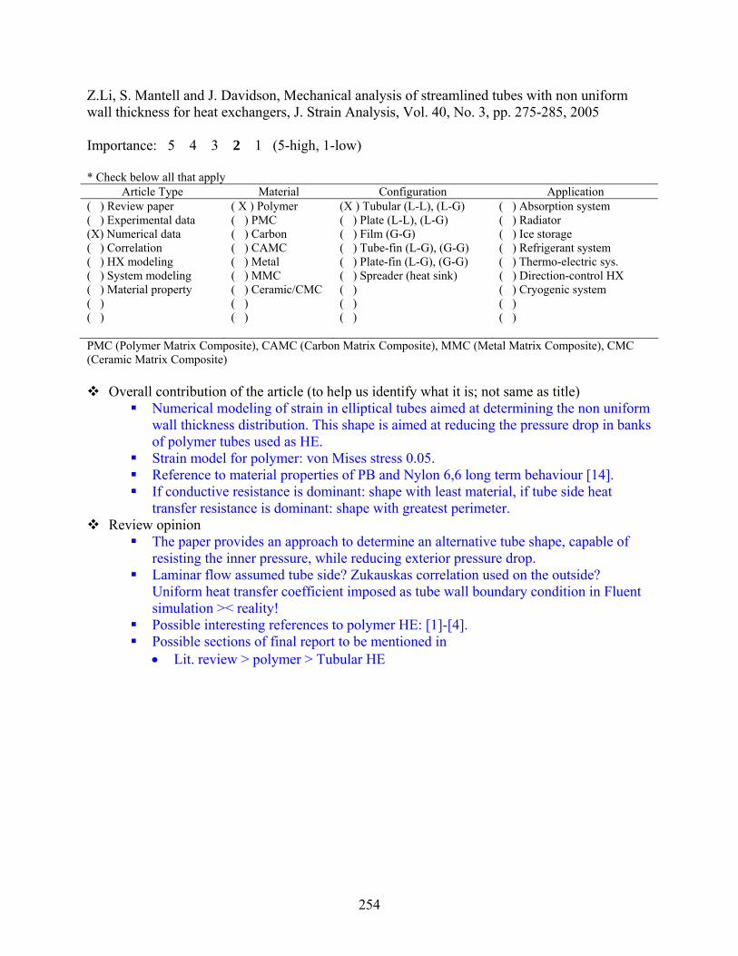
254
Z.Li, S. Mantell and J. Davidson, Mechanical analysis of streamlined tubes with non uniform wall thickness for heat exchangers, J. Strain Analysis, Vol. 40, No. 3, pp. 275-285, 2005 Importance: 5 4 3 2 1 (5-high, 1-low) * Check below all that apply
Article Type Material Configuration Application ( ) Review paper ( X ) Polymer (X ) Tubular (L-L), (L-G) ( ) Absorption system ( ) Experimental data ( ) PMC ( ) Plate (L-L), (L-G) ( ) Radiator (X) Numerical data ( ) Carbon ( ) Film (G-G) ( ) Ice storage ( ) Correlation ( ) CAMC ( ) Tube-fin (L-G), (G-G) ( ) Refrigerant system ( ) HX modeling ( ) Metal ( ) Plate-fin (L-G), (G-G) ( ) Thermo-electric sys. ( ) System modeling ( ) MMC ( ) Spreader (heat sink) ( ) Direction-control HX ( ) Material property ( ) Ceramic/CMC ( ) ( ) Cryogenic system ( ) ( ) ( ) ( ) ( ) ( ) ( ) ( ) PMC (Polymer Matrix Composite), CAMC (Carbon Matrix Composite), MMC (Metal Matrix Composite), CMC (Ceramic Matrix Composite)
Overall contribution of the article (to help us identify what it is; not same as title) Numerical modeling of strain in elliptical tubes aimed at determining the non uniform
wall thickness distribution. This shape is aimed at reducing the pressure drop in banks of polymer tubes used as HE.
Strain model for polymer: von Mises stress 0.05. Reference to material properties of PB and Nylon 6,6 long term behaviour [14]. If conductive resistance is dominant: shape with least material, if tube side heat
transfer resistance is dominant: shape with greatest perimeter. Review opinion
The paper provides an approach to determine an alternative tube shape, capable of resisting the inner pressure, while reducing exterior pressure drop.
Laminar flow assumed tube side? Zukauskas correlation used on the outside? Uniform heat transfer coefficient imposed as tube wall boundary condition in Fluent simulation >< reality!
Possible interesting references to polymer HE: [1]-[4]. Possible sections of final report to be mentioned in • Lit. review > polymer > Tubular HE

255
A. Freeman, S. Mantell and J. Davidson, Mechanical performance of polysulfone, polybutylene and polyamide 6/6 in hot chlorinated water, J. Solar Energy, Vol. 79, pp. 624-637, 2005 Importance: 5 4 3 2 1 (5-high, 1-low) * Check below all that apply
Article Type Material Configuration Application ( ) Review paper ( X ) Polymer (X ) Tubular (L-L), (L-G) ( ) Absorption system ( ) Experimental data ( ) PMC ( ) Plate (L-L), (L-G) ( ) Radiator ( ) Numerical data ( ) Carbon ( ) Film (G-G) ( ) Ice storage ( ) Correlation ( ) CAMC ( ) Tube-fin (L-G), (G-G) ( ) Refrigerant system ( ) HX modeling ( ) Metal ( ) Plate-fin (L-G), (G-G) ( ) Thermo-electric sys. ( ) System modeling ( ) MMC ( ) Spreader (heat sink) ( ) Direction-control HX ( X ) Material property ( ) Ceramic/CMC ( ) ( ) Cryogenic system ( ) ( ) ( ) (X) Int. collector storage ( ) ( ) ( ) ( ) PMC (Polymer Matrix Composite), CAMC (Carbon Matrix Composite), MMC (Metal Matrix Composite), CMC (Ceramic Matrix Composite)
Overall contribution of the article (to help us identify what it is; not same as title) Experimental creep data, tensile strength and strain at failure for PSU, PB and PA 6/6
in hot chlorinated water, characterized using ORP (oxidative reduction potential). PSU – PB are unaffected but PA 6/6 lost up to half its tensile strength primarily due
to water absorption. References to previous studies on tensile strength of polymers under chlorine
exposure. Material properties for PSU, PB and PA 6/6 and degradation mechanism.
Review opinion The paper provides creep data, tensile strength and strain at failure for PSU, PB and
PA 6/6 in hot chlorinated water. Possible interesting references to immersed polymer HE (Liu). Possible sections of final report to be mentioned in • Lit. review > polymer – mechanical properties

256
D. Zakardas, B. Li and K. Sirkar, Polymeric hollow fiber heat exchanger (PHFHEs): a new type of compact heat exchanger for low temperature applications, Proc. of the 2005 ASME Heat Transfer Conf, HT2005-72590, 2005. Importance: 5 4 3 2 1 (5-high, 1-low) * Check below all that apply
Article Type Material Configuration Application ( ) Review paper ( X ) Polymer (X) Tubular (L-L), (L-G) ( ) Absorption system (X) Experimental data ( ) PMC ( ) Plate (L-L), (L-G) ( ) Radiator ( ) Numerical data ( ) Carbon ( ) Film (G-G) ( ) Ice storage ( ) Correlation ( ) CAMC ( ) Tube-fin (L-G), (G-G) ( ) Refrigerant system ( ) HX modeling ( ) Metal ( ) Plate-fin (L-G), (G-G) ( ) Thermo-electric sys. ( ) System modeling ( ) MMC ( ) Spreader (heat sink) ( ) Direction-control HX ( ) Material property ( ) Ceramic/CMC ( ) ( ) Cryogenic system ( ) ( ) ( ) ( ) ( ) ( ) ( ) ( ) PMC (Polymer Matrix Composite), CAMC (Carbon Matrix Composite), MMC (Metal Matrix Composite), CMC (Ceramic Matrix Composite)
Overall contribution of the article (to help us identify what it is; not same as title) Literature survey on the use of polymers for heat exchangers, focusing on previous
reported heat transfer data, aimed at showing how polymers do make a viable alternative for metals in heat exchangers.
A summary of previous literature papers is presented showing the materials used, overall heat transfer coefficient, the application and the heat exchanger type. The overall heat transfer coefficients range from 55 W/m²K to 7000 W/m²K
A novel type of polymer heat exchanger is presented, consisting of thin hollow non porous fibers of PP and PEEK connected between two headers in a shell. The design is similar to a hollow fiber membrane contractor. This results in a high surface compactness.
A model is presented to analyze the heat transfer rate in case of condensation with subcooling. Experiments are performed using steam. Two figures of merit are presented: pressure drop per NTU and surface area to volume ratio considering the entire volume times the overall heat transfer coefficient.
In the test rig hot brine was cooled down using water. Results presented include NTU, epsilon, HTU (L/NTU), Q and U for three different configurations and various Re. U varied from 400 to 1360 W/m²K. PEEK tubes were found to have a lower U value due to larger wall thickness.
Previous studies showed that increasing the frontal surface for the same packing ratio or increasing the packing ratio improves throughput and the effectiveness.
For both steam condensing and fluid-fluid heat transfer the HFPF HE showed a similar figure of merit for heat transfer compared to plate heat exchanger for clean and fouled units.
Pressure drop results indicate that two designs had a reduced pressure compared to an acceptable value of 30 kPa for metal heat exchangers.
Review opinion Very interesting new heat exchanger design consisting of hollow polymer fibers.

257
Interesting references: [6]-[10]-[11] Possible sections of final report to be mentioned in • Lit. review > polymer > tubular HE.
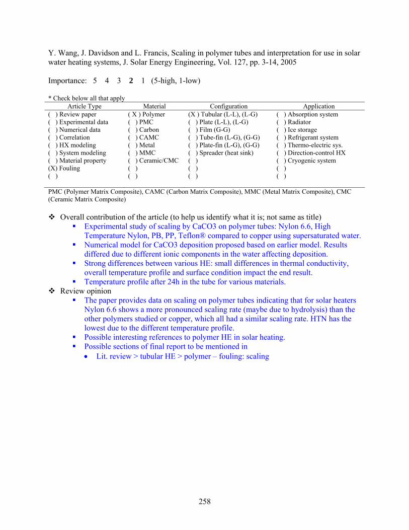
258
Y. Wang, J. Davidson and L. Francis, Scaling in polymer tubes and interpretation for use in solar water heating systems, J. Solar Energy Engineering, Vol. 127, pp. 3-14, 2005 Importance: 5 4 3 2 1 (5-high, 1-low) * Check below all that apply
Article Type Material Configuration Application ( ) Review paper ( X ) Polymer (X ) Tubular (L-L), (L-G) ( ) Absorption system ( ) Experimental data ( ) PMC ( ) Plate (L-L), (L-G) ( ) Radiator ( ) Numerical data ( ) Carbon ( ) Film (G-G) ( ) Ice storage ( ) Correlation ( ) CAMC ( ) Tube-fin (L-G), (G-G) ( ) Refrigerant system ( ) HX modeling ( ) Metal ( ) Plate-fin (L-G), (G-G) ( ) Thermo-electric sys. ( ) System modeling ( ) MMC ( ) Spreader (heat sink) ( ) Direction-control HX ( ) Material property ( ) Ceramic/CMC ( ) ( ) Cryogenic system (X) Fouling ( ) ( ) ( ) ( ) ( ) ( ) ( ) PMC (Polymer Matrix Composite), CAMC (Carbon Matrix Composite), MMC (Metal Matrix Composite), CMC (Ceramic Matrix Composite)
Overall contribution of the article (to help us identify what it is; not same as title) Experimental study of scaling by CaCO3 on polymer tubes: Nylon 6.6, High
Temperature Nylon, PB, PP, Teflon® compared to copper using supersaturated water. Numerical model for CaCO3 deposition proposed based on earlier model. Results
differed due to different ionic components in the water affecting deposition. Strong differences between various HE: small differences in thermal conductivity,
overall temperature profile and surface condition impact the end result. Temperature profile after 24h in the tube for various materials.
Review opinion The paper provides data on scaling on polymer tubes indicating that for solar heaters
Nylon 6.6 shows a more pronounced scaling rate (maybe due to hydrolysis) than the other polymers studied or copper, which all had a similar scaling rate. HTN has the lowest due to the different temperature profile.
Possible interesting references to polymer HE in solar heating. Possible sections of final report to be mentioned in • Lit. review > tubular HE > polymer – fouling: scaling

259
T. Mallik and C. Bullard, Suitability of polymer heat exchangers for air conditioning application, ACRC TR 237, 2005 Importance: 5 4 3 2 1 (5-high, 1-low) * Check below all that apply
Article Type Material Configuration Application ( ) Review paper ( X ) Polymer (X) Tubular (L-L), (L-G) ( ) Absorption system ( ) Experimental data ( ) PMC ( ) Plate (L-L), (L-G) ( ) Radiator (X) Numerical data ( ) Carbon ( ) Film (G-G) ( ) Ice storage ( ) Correlation ( ) CAMC ( ) Tube-fin (L-G), (G-G) ( ) Refrigerant system (X) HX modeling ( ) Metal ( ) Plate-fin (L-G), (G-G) ( ) Thermo-electric sys. ( ) System modeling ( ) MMC ( ) Spreader (heat sink) ( ) Direction-control HX ( ) Material property ( ) Ceramic/CMC ( ) ( ) Cryogenic system ( ) ( ) ( ) ( ) ( ) ( ) ( ) ( ) PMC (Polymer Matrix Composite), CAMC (Carbon Matrix Composite), MMC (Metal Matrix Composite), CMC (Ceramic Matrix Composite)
Overall contribution of the article (to help us identify what it is; not same as title) Numerical study of a heating and cooling coil fit into a standard air conditioning
cycle. A heat exchanger model was designed based on a series of assumptions and common practice. Optimal configurations were determined for both cases. It was found that the air side thermal resistance was dominant, thus replacing polymer with a material with a higher thermal conductivity has little impact. However due to low thermal conductivity, no extended surfaces are possible using polymer. This makes the polymer HE coils much less compact than their metallic counterparts. A comparison with a standard micro channel showed that the polymer HE would be 6 times heavier filled.
The final configuration of polymer HE coil consisted of 3000 tubes, thus manufacturing issues are clearly an issue as well.
Polymers that offer improved conductivity perpendicular to the wall could provide large improvements, however current types only offer this feature parallel to the wall and thus are not worth the added cost and manufacturing issues.
Review opinion Interesting references [1]-[3] Possible sections of final report to be mentioned in • Lit. review > polymer > tubular HE - HVAC.

260
M. Tago, K. Morita and M. Sugawara, Heat extraction characteristics of a single U-tube downhole heat exchanger with square cross section, Heat Mass Transfer, Vol. 42, pp. 608-616, 2006 Importance: 5 4 3 2 1 (5-high, 1-low) * Check below all that apply
Article Type Material Configuration Application ( ) Review paper ( X ) Polymer (X ) Tubular (L-L), (L-G) ( ) Absorption system ( ) Experimental data ( ) PMC ( ) Plate (L-L), (L-G) ( ) Radiator (X) Numerical data ( ) Carbon ( ) Film (G-G) ( ) Ice storage ( ) Correlation ( ) CAMC ( ) Tube-fin (L-G), (G-G) ( ) Refrigerant system ( ) HX modeling ( ) Metal ( ) Plate-fin (L-G), (G-G) ( ) Thermo-electric sys. ( ) System modeling ( ) MMC ( ) Spreader (heat sink) ( ) Direction-control HX ( ) Material property ( ) Ceramic/CMC ( ) ( ) Cryogenic system ( ) ( ) ( ) (X) Geothermal heat transfer ( ) ( ) ( ) ( ) PMC (Polymer Matrix Composite), CAMC (Carbon Matrix Composite), MMC (Metal Matrix Composite), CMC (Ceramic Matrix Composite)
Overall contribution of the article (to help us identify what it is; not same as title) Numerical simulation tool for a U-tube downhole heat exchanger in the stratum:
unsteady solution of the conduction equation. Model validated through comparison with a previous experimental survey. Outlet temperature and heat extraction rate vs. time for varying flow rate and tube
material: copper, SS, PVC and PE. Temperature profile after 24h in the tube for various materials. Using materials with a lower conductivity results in a reduced heat extraction rate,
however resins are a feasible alternative for cheap production. Review opinion
The paper provides a numerical simulation of a heat exchanger in the stratum comparing various tube wall materials. However no in depth analysis is performed on the design: e.g. modifying thickness to reduce impact of lower conductivity…
Possible sections of final report to be mentioned in • Lit. review > tubular HE > polymer (as an alternative application)

261
Wagner, R. and Frossati, G., A small plastic dilution heat exchanger, Physica B, Vol. 165-166, pp. 43-44, 1990 Importance: 5 4 3 2 1 (5-high, 1-low) * Check below all that apply
Article Type Material Configuration Application ( ) Review paper (X) Polymer ( ) Tubular (L-L), (L-G) ( ) Absorption system ( ) Experimental data ( ) PMC ( ) Plate (L-L), (L-G) ( ) Radiator ( ) Numerical data ( ) Carbon ( ) Film (G-G) ( ) Ice storage ( ) Correlation ( ) CAMC ( ) Tube-fin (L-G), (G-G) ( ) Refrigerant system ( ) HX modeling ( ) Metal ( ) Plate-fin (L-G), (G-G) ( ) Thermo-electric sys. ( ) System modeling ( ) MMC ( ) Spreader (heat sink) ( ) Direction-control HX ( ) Material property ( ) Ceramic/CMC ( ) ( ) Cryogenic system ( ) ( ) ( ) ( ) ( ) ( ) ( ) ( ) PMC (Polymer Matrix Composite), CAMC (Carbon Matrix Composite), MMC (Metal Matrix Composite), CMC (Ceramic Matrix Composite)
Overall contribution of the article (to help us identify what it is; not same as title) Description of a small dilution heat exchanger made of polymer aimed for high
intensity magnets. Field tests have shown a temperature of 10 mK was possible. A spiral heat exchanger path in araldite surrounded by a Kapton® cylinder and filled
with a Teflon® capillary tube followed by a plate heat exchanger from Kapton® foils. Review opinion
Possible sections of final report to be mentioned in
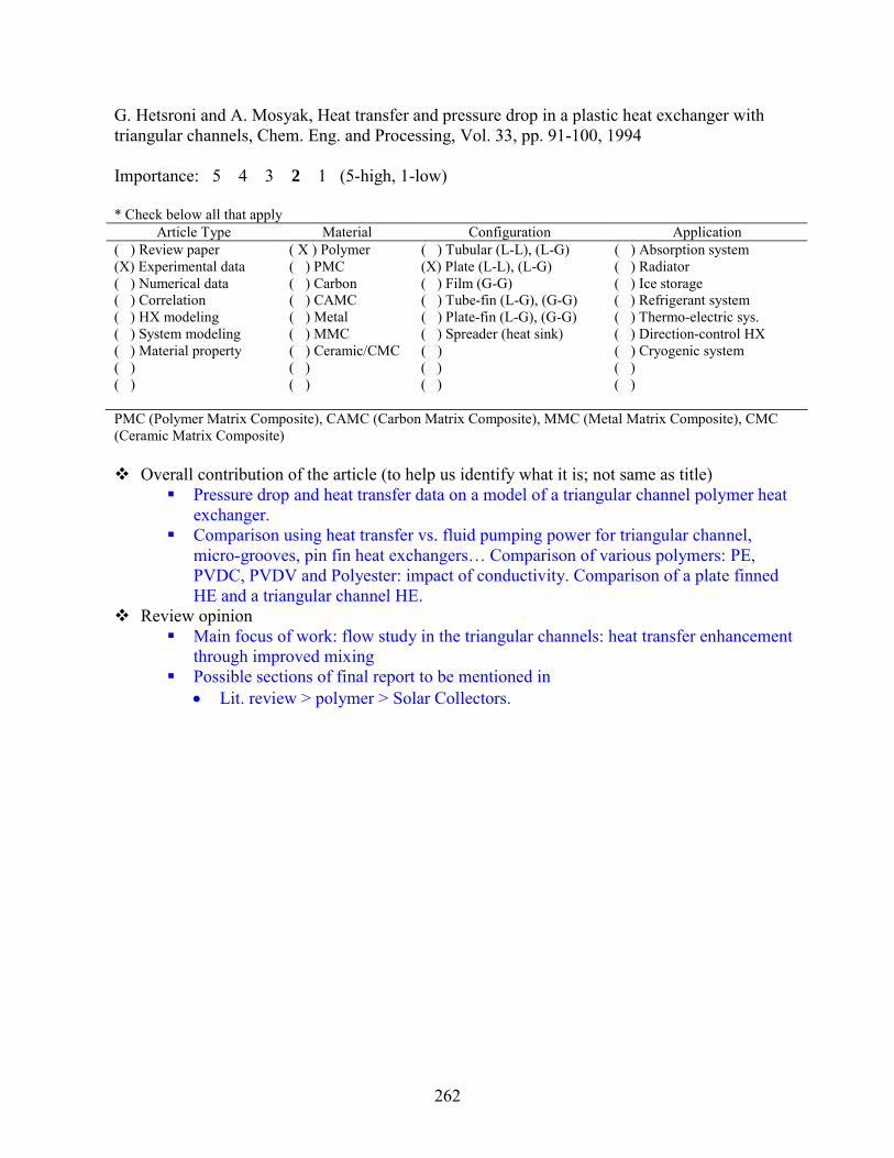
262
G. Hetsroni and A. Mosyak, Heat transfer and pressure drop in a plastic heat exchanger with triangular channels, Chem. Eng. and Processing, Vol. 33, pp. 91-100, 1994 Importance: 5 4 3 2 1 (5-high, 1-low) * Check below all that apply
Article Type Material Configuration Application ( ) Review paper ( X ) Polymer ( ) Tubular (L-L), (L-G) ( ) Absorption system (X) Experimental data ( ) PMC (X) Plate (L-L), (L-G) ( ) Radiator ( ) Numerical data ( ) Carbon ( ) Film (G-G) ( ) Ice storage ( ) Correlation ( ) CAMC ( ) Tube-fin (L-G), (G-G) ( ) Refrigerant system ( ) HX modeling ( ) Metal ( ) Plate-fin (L-G), (G-G) ( ) Thermo-electric sys. ( ) System modeling ( ) MMC ( ) Spreader (heat sink) ( ) Direction-control HX ( ) Material property ( ) Ceramic/CMC ( ) ( ) Cryogenic system ( ) ( ) ( ) ( ) ( ) ( ) ( ) ( ) PMC (Polymer Matrix Composite), CAMC (Carbon Matrix Composite), MMC (Metal Matrix Composite), CMC (Ceramic Matrix Composite)
Overall contribution of the article (to help us identify what it is; not same as title) Pressure drop and heat transfer data on a model of a triangular channel polymer heat
exchanger. Comparison using heat transfer vs. fluid pumping power for triangular channel,
micro-grooves, pin fin heat exchangers… Comparison of various polymers: PE, PVDC, PVDV and Polyester: impact of conductivity. Comparison of a plate finned HE and a triangular channel HE.
Review opinion Main focus of work: flow study in the triangular channels: heat transfer enhancement
through improved mixing Possible sections of final report to be mentioned in • Lit. review > polymer > Solar Collectors.

263
Ter Haar, E., Wagner, R., van Woerkens, C., Steel, S, Frossati, G., Skrbek, L., Meisel, M., Bindilatti, V., Rodrigues, A., Valls Martin, R., Oliveira Jr. N., Plastic dilution refrigerators, J. Low Temperature Physics, Vol. 99, pp. 151-166, 1995 Importance: 5 4 3 2 1 (5-high, 1-low) * Check below all that apply
Article Type Material Configuration Application ( ) Review paper (X) Polymer (X) Tubular (L-L), (L-G) ( ) Absorption system (X) Experimental data ( ) PMC (X) Plate (L-L), (L-G) ( ) Radiator ( ) Numerical data ( ) Carbon ( ) Film (G-G) ( ) Ice storage ( ) Correlation ( ) CAMC ( ) Tube-fin (L-G), (G-G) ( ) Refrigerant system ( ) HX modeling ( ) Metal ( ) Plate-fin (L-G), (G-G) ( ) Thermo-electric sys. ( ) System modeling ( ) MMC ( ) Spreader (heat sink) ( ) Direction-control HX ( ) Material property ( ) Ceramic/CMC ( ) ( ) Cryogenic system ( ) ( ) ( ) ( ) ( ) ( ) ( ) ( ) PMC (Polymer Matrix Composite), CAMC (Carbon Matrix Composite), MMC (Metal Matrix Composite), CMC (Ceramic Matrix Composite)
Overall contribution of the article (to help us identify what it is; not same as title) Description of a small dilution heat exchanger made of polymer aimed for high
intensity magnets and dipstick configurations. A clear description of the various parts is listed. The design consists of a still, a tubular heat exchanger followed by a Kapton® bellows heat exchanger. Several designs were made and tested for their performance: lowest temperature reached, flow rate, with and without the Kapton® heat exchanger, bellow shaped or alternative design…
A spiral heat exchanger path in araldite surrounded by a Kapton® cylinder and filled with a Teflon® capillary tube followed by a plate heat exchanger from Kapton® foils.
The cooling power, cool down time, residual heat leak and the base temperature were studied experimentally.
Review opinion Possible sections of final report to be mentioned in • Low temperature applications

264
Jaakola, H., cost effective evaporators for desalination, Desalination, Vol. 108, 1996. Importance: 5 4 3 2 1 (5-high, 1-low) * Check below all that apply
Article Type Material Configuration Application ( ) Review paper ( X ) Polymer ( ) Tubular (L-L), (L-G) ( ) Absorption system (X) Experimental data ( ) PMC (X) Plate (L-L), (L-G) ( ) Radiator ( ) Numerical data ( ) Carbon ( ) Film (G-G) ( ) Ice storage ( ) Correlation ( ) CAMC ( ) Tube-fin (L-G), (G-G) ( ) Refrigerant system ( ) HX modeling ( ) Metal ( ) Plate-fin (L-G), (G-G) ( ) Thermo-electric sys. ( ) System modeling ( ) MMC ( ) Spreader (heat sink) ( ) Direction-control HX ( ) Material property ( ) Ceramic/CMC ( ) ( ) Cryogenic system ( ) ( ) ( ) ( ) ( ) ( ) ( ) ( ) PMC (Polymer Matrix Composite), CAMC (Carbon Matrix Composite), MMC (Metal Matrix Composite), CMC (Ceramic Matrix Composite)
Overall contribution of the article (to help us identify what it is; not same as title) Description of a polymer evaporator aimed at mechanical vapor compression cycles
for desalination. Thin polymer films are connected to form bags in which steam condenses to evaporate the brine falling film.
The evaporators operate at lower temperature and smaller temperature differences to improve the efficiency. Lower temperature result in less scale formation, corrosion or degradation.
Review opinion Experimental data on a polymer plate heat exchanger. Possible sections of final report to be mentioned in • Lit. review > polymer > plate HE.
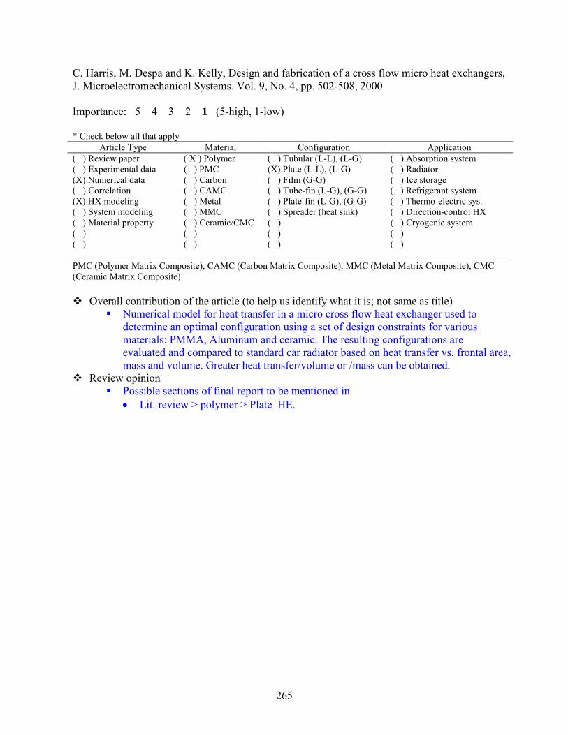
265
C. Harris, M. Despa and K. Kelly, Design and fabrication of a cross flow micro heat exchangers, J. Microelectromechanical Systems. Vol. 9, No. 4, pp. 502-508, 2000 Importance: 5 4 3 2 1 (5-high, 1-low) * Check below all that apply
Article Type Material Configuration Application ( ) Review paper ( X ) Polymer ( ) Tubular (L-L), (L-G) ( ) Absorption system ( ) Experimental data ( ) PMC (X) Plate (L-L), (L-G) ( ) Radiator (X) Numerical data ( ) Carbon ( ) Film (G-G) ( ) Ice storage ( ) Correlation ( ) CAMC ( ) Tube-fin (L-G), (G-G) ( ) Refrigerant system (X) HX modeling ( ) Metal ( ) Plate-fin (L-G), (G-G) ( ) Thermo-electric sys. ( ) System modeling ( ) MMC ( ) Spreader (heat sink) ( ) Direction-control HX ( ) Material property ( ) Ceramic/CMC ( ) ( ) Cryogenic system ( ) ( ) ( ) ( ) ( ) ( ) ( ) ( ) PMC (Polymer Matrix Composite), CAMC (Carbon Matrix Composite), MMC (Metal Matrix Composite), CMC (Ceramic Matrix Composite)
Overall contribution of the article (to help us identify what it is; not same as title) Numerical model for heat transfer in a micro cross flow heat exchanger used to
determine an optimal configuration using a set of design constraints for various materials: PMMA, Aluminum and ceramic. The resulting configurations are evaluated and compared to standard car radiator based on heat transfer vs. frontal area, mass and volume. Greater heat transfer/volume or /mass can be obtained.
Review opinion Possible sections of final report to be mentioned in • Lit. review > polymer > Plate HE.

266
C. Wu, S. Mantell and J. Davidson, A method for measuring the creep behavior of pressurized polymer tubing, Experimental Mechanics, Vol. 41, No. 4, pp. 368-374, 2001 Importance: 5 4 3 2 1 (5-high, 1-low) * Check below all that apply
Article Type Material Configuration Application ( ) Review paper ( X ) Polymer (X) Tubular (L-L), (L-G) ( ) Absorption system (X) Experimental data ( ) PMC ( ) Plate (L-L), (L-G) ( ) Radiator ( ) Numerical data ( ) Carbon ( ) Film (G-G) ( ) Ice storage ( ) Correlation ( ) CAMC ( ) Tube-fin (L-G), (G-G) ( ) Refrigerant system ( ) HX modeling ( ) Metal ( ) Plate-fin (L-G), (G-G) ( ) Thermo-electric sys. ( ) System modeling ( ) MMC ( ) Spreader (heat sink) ( ) Direction-control HX ( ) Material property ( ) Ceramic/CMC ( ) ( ) Cryogenic system ( ) ( ) ( ) ( ) ( ) ( ) ( ) ( ) PMC (Polymer Matrix Composite), CAMC (Carbon Matrix Composite), MMC (Metal Matrix Composite), CMC (Ceramic Matrix Composite)
Overall contribution of the article (to help us identify what it is; not same as title) Development of a sensor to measure the creep behavior of a polymer tube intended
for solar hot water system. Review opinion
Development of a strain gage sensor. Used on PP and PE tubes. More relevant data presented in a later paper.

267
W. Saman and S. Alizadeh, An experimental study of a cross flow type plate heat exchanger for dehumidification / cooling, official journal of AIRAH, Sept., 2002. Importance: 5 4 3 2 1 (5-high, 1-low) * Check below all that apply
Article Type Material Configuration Application ( ) Review paper ( X ) Polymer ( ) Tubular (L-L), (L-G) ( ) Absorption system (X) Experimental data ( ) PMC (X) Plate (L-L), (L-G) ( ) Radiator ( ) Numerical data ( ) Carbon ( ) Film (G-G) ( ) Ice storage ( ) Correlation ( ) CAMC ( ) Tube-fin (L-G), (G-G) ( ) Refrigerant system ( ) HX modeling ( ) Metal ( ) Plate-fin (L-G), (G-G) ( ) Thermo-electric sys. ( ) System modeling ( ) MMC ( ) Spreader (heat sink) ( ) Direction-control HX ( ) Material property ( ) Ceramic/CMC ( ) ( ) Cryogenic system ( ) ( ) ( ) ( ) ( ) ( ) ( ) ( ) PMC (Polymer Matrix Composite), CAMC (Carbon Matrix Composite), MMC (Metal Matrix Composite), CMC (Ceramic Matrix Composite)
Overall contribution of the article (to help us identify what it is; not same as title) Experimental study on a plate heat exchanger aimed at evaporative cooling and
dehumidification using a dessicant in the two channels. Three series of experiments: dessicant only, evaporative cooling only and combination.
Heat exchanger effectiveness and dehumidification effectiveness is presented for the various cases for various air flow rates and various injection angles of the dessicant/water.
The measured values are compared to a model for the heat transfer behavior, presented in a different paper. Considerable agreement is found.
Review opinion Experimental data on a polymer plate heat exchanger . Interesting references: [6]-[10]-[11] Possible sections of final report to be mentioned in • Lit. review > polymer > tubular HE.
268
F. Ganzevles and C. Van Der Geld, Temperatures and condensate heat resistance in drop wise condensation of multi component mixtures with inert gasses, Int. J. Heat Mass Transfer, Vol. 45, pp. 3233-3243, 2002 Importance: 5 4 3 2 1 (5-high, 1-low) * Check below all that apply
Article Type Material Configuration Application ( ) Review paper ( X ) Polymer ( ) Tubular (L-L), (L-G) ( ) Absorption system (X) Experimental data ( ) PMC (X) Plate (L-L), (L-G) ( ) Radiator ( ) Numerical data ( ) Carbon ( ) Film (G-G) ( ) Ice storage ( ) Correlation ( ) CAMC ( ) Tube-fin (L-G), (G-G) ( ) Refrigerant system ( ) HX modeling ( ) Metal ( ) Plate-fin (L-G), (G-G) ( ) Thermo-electric sys. ( ) System modeling ( ) MMC ( ) Spreader (heat sink) ( ) Direction-control HX ( ) Material property ( ) Ceramic/CMC ( ) ( ) Cryogenic system ( ) ( ) ( ) ( ) ( ) ( ) ( ) ( ) PMC (Polymer Matrix Composite), CAMC (Carbon Matrix Composite), MMC (Metal Matrix Composite), CMC (Ceramic Matrix Composite)
Overall contribution of the article (to help us identify what it is; not same as title) IR visualization of surface temperature of the plate – gas/water interface at droplet on
the plate. Review opinion
No relevant information except HE dimensions also stated in other papers by author..

269
S. Park and D. Lee, Investigations of heat transfer and pressure drop between parallel channels with pseudoplasic and dilatant fluids, J. Polymer Science, Vol. 89, pp. 3601-3608, 2003 Importance: 5 4 3 2 1 (5-high, 1-low) * Check below all that apply
Article Type Material Configuration Application ( ) Review paper ( ) Polymer ( ) Tubular (L-L), (L-G) ( ) Absorption system ( ) Experimental data ( ) PMC (X) Plate (L-L), (L-G) ( ) Radiator (X) Numerical data ( ) Carbon ( ) Film (G-G) ( ) Ice storage ( ) Correlation ( ) CAMC ( ) Tube-fin (L-G), (G-G) ( ) Refrigerant system ( ) HX modeling ( ) Metal ( ) Plate-fin (L-G), (G-G) ( ) Thermo-electric sys. ( ) System modeling ( ) MMC ( ) Spreader (heat sink) ( ) Direction-control HX ( ) Material property ( ) Ceramic/CMC ( ) ( ) Cryogenic system ( ) ( ) ( ) ( ) ( ) ( ) ( ) ( ) PMC (Polymer Matrix Composite), CAMC (Carbon Matrix Composite), MMC (Metal Matrix Composite), CMC (Ceramic Matrix Composite)
Overall contribution of the article (to help us identify what it is; not same as title) Numerical study on pressure drop and heat transfer for fully developed laminar flow
of non Newtonian fluids in infinitely long parallel channels with a constant temperature or constant heat flux boundary condition.
Review opinion Expansion of standard correlations for laminar flow in channels. Not relevant for this
research.

270
V. Golub, Y. Kobzar, Calculation of the long term strength of thin-walled polymeric tubes under biaxial loading, Mechanics of Composite Materials, Vol. 40, No. 6, pp. 533-541, 2004 Importance: 5 4 3 2 1 (5-high, 1-low) * Check below all that apply
Article Type Material Configuration Application ( ) Review paper (X) Polymer (X) Tubular (L-L), (L-G) ( ) Absorption system (X) Experimental data ( ) PMC ( ) Plate (L-L), (L-G) ( ) Radiator (X) Numerical data ( ) Carbon ( ) Film (G-G) ( ) Ice storage ( ) Correlation ( ) CAMC ( ) Tube-fin (L-G), (G-G) ( ) Refrigerant system ( ) HX modeling ( ) Metal ( ) Plate-fin (L-G), (G-G) ( ) Thermo-electric sys. ( ) System modeling ( ) MMC ( ) Spreader (heat sink) ( ) Direction-control HX ( ) Material property ( ) Ceramic/CMC ( ) ( ) Cryogenic system ( ) ( ) ( ) ( ) ( ) ( ) ( ) ( ) PMC (Polymer Matrix Composite), CAMC (Carbon Matrix Composite), MMC (Metal Matrix Composite), CMC (Ceramic Matrix Composite)
Overall contribution of the article (to help us identify what it is; not same as title) Numerical modeling of failure mechanisms of polymer tubes: HDPE, PVDC and
OChK Viniplast to determine life expectancy in a hot water application: 70 °C. Dual loads: e.g. pure torsion and torsion with tension. Models show good agreement with measurements
Review opinion Failure data on several polymers. Can be added to previously found papers
concerning the mechanical behavior of these materials.

271
L. Cheng and C. Van Der Geld, Experimental study of heat transfer and pressure drop characteristics of air/water and air-steam/water heat exchange in a polymer compact heat exchanger, Heat Transfer Eng., Vol. 26, No. 2, pp. 18-27, 2005 Importance: 5 4 3 2 1 (5-high, 1-low) * Check below all that apply
Article Type Material Configuration Application ( ) Review paper (X) Polymer ( ) Tubular (L-L), (L-G) ( ) Absorption system (X) Experimental data ( ) PMC (X) Plate (L-L), (L-G) ( ) Radiator ( ) Numerical data ( ) Carbon ( ) Film (G-G) ( ) Ice storage ( ) Correlation ( ) CAMC ( ) Tube-fin (L-G), (G-G) ( ) Refrigerant system ( ) HX modeling ( ) Metal ( ) Plate-fin (L-G), (G-G) ( ) Thermo-electric sys. ( ) System modeling ( ) MMC ( ) Spreader (heat sink) ( ) Direction-control HX ( ) Material property ( ) Ceramic/CMC ( ) ( ) Cryogenic system ( ) ( ) ( ) ( ) ( ) ( ) ( ) ( ) PMC (Polymer Matrix Composite), CAMC (Carbon Matrix Composite), MMC (Metal Matrix Composite), CMC (Ceramic Matrix Composite)
Overall contribution of the article (to help us identify what it is; not same as title) Experimental study of a PVDF compact heat exchanger focusing on drop wise
condensation. Overall pressure drop and heat transfer coefficients are reported with and without condensation, 80-130 W/m²K (without steam) to 150-600 W/m²K (with steam).
Impact of non condensable gas reduced compared to standard applications? Due to smaller channels?
Polymers: advantage for assuring drop wise condensation: PTFE-PVDF, due to low surface energy.
Review opinion Interesting paper on drop wise condensation in PVDF HE. Interesting reference: [5]. Possible sections of final report to be mentioned in • Lit. review > polymer > Plate HE.

272
Z. Li, J. Davidson and S. Mantell, Numerical simulation of the flow field and heat transfer of streamlined cylinders in cross flow, Proc. of HT2005, 2005. Importance: 5 4 3 2 1 (5-high, 1-low) * Check below all that apply
Article Type Material Configuration Application ( ) Review paper (X) Polymer (X) Tubular (L-L), (L-G) ( ) Absorption system ( ) Experimental data ( ) PMC ( ) Plate (L-L), (L-G) (X) Radiator (X) Numerical data ( ) Carbon ( ) Film (G-G) ( ) Ice storage ( ) Correlation ( ) CAMC ( ) Tube-fin (L-G), (G-G) ( ) Refrigerant system ( ) HX modeling ( ) Metal ( ) Plate-fin (L-G), (G-G) ( ) Thermo-electric sys. ( ) System modeling ( ) MMC ( ) Spreader (heat sink) ( ) Direction-control HX ( ) Material property ( ) Ceramic/CMC ( ) ( ) Cryogenic system ( ) ( ) ( ) ( ) ( ) ( ) ( ) ( ) PMC (Polymer Matrix Composite), CAMC (Carbon Matrix Composite), MMC (Metal Matrix Composite), CMC (Ceramic Matrix Composite)
Overall contribution of the article (to help us identify what it is; not same as title) Numerical study of lenticular and elliptical cylinders in cross flow, focused on the
overall heat transfers and drags coefficients. Uniform wall temperature – Fluent – partial laminar, partial turbulent domain for improved accuracy. Simulations for a round tube and elliptical one compared to measured data.
Example of application: automotive radiator. Study of possible benefit of polymer HE design. It is found that compared to round tubes the lenticular tubes only offer advantages at very low Reynolds numbers. However, if the pumping power is taken into consideration, nylon tubes can offer an enhancement when compared to the standard round tube. Applying the same idea to aluminum tubes resulted in much greater enhancement factors. The main issue remains the low thermal conductivity.
Review opinion Thoroughly validated numerical study. The subsequent case study is interesting for
the ARTI project, highlighting options that have been explored. Possible sections of final report to be mentioned in • Lit. review > polymer > Tubular HE - radiator.
273
W. Nunes dos Santos, P. Mummery and A. Wallwork, Thermal diffusivity of polymers by the laser flash technique, Polymer Testing, Vol. 24, pp. 628-634, 2004. Importance: 5 4 3 2 1 (5-high, 1-low) * Check below all that apply
Article Type Material Configuration Application ( ) Review paper (X) Polymer ( ) Tubular (L-L), (L-G) ( ) Absorption system (X) Experimental data ( ) PMC ( ) Plate (L-L), (L-G) ( ) Radiator ( ) Numerical data ( ) Carbon ( ) Film (G-G) ( ) Ice storage ( ) Correlation ( ) CAMC ( ) Tube-fin (L-G), (G-G) ( ) Refrigerant system ( ) HX modeling ( ) Metal ( ) Plate-fin (L-G), (G-G) ( ) Thermo-electric sys. ( ) System modeling ( ) MMC ( ) Spreader (heat sink) ( ) Direction-control HX (X) Material property ( ) Ceramic/CMC ( ) ( ) Cryogenic system ( ) ( ) ( ) ( ) ( ) ( ) ( ) ( ) PMC (Polymer Matrix Composite), CAMC (Carbon Matrix Composite), MMC (Metal Matrix Composite), CMC (Ceramic Matrix Composite)
Overall contribution of the article (to help us identify what it is; not same as title) Description of the laser flash technique to compare thermal diffusivity of polymers.
Using this value and provided the density and specific heat of the polymer are known, the thermal conductivity can be determined. Measured results compared to data obtained through other techniques
Property data for PVC, Nylon, LDPE, PP, PMMA, High Impact PS: glass transition temperature, melting point temperature, maximum service temperature, crystallinity and density from a reference. Recorded thermal diffusivity ranging from 25 °C to 100 °C.
Review opinion Possible sections of final report to be mentioned in • Lit. review > polymer > Material properties.

274
D. Zakardas and K. Sirkar, Polymer hollow fiber heat exchangers: an alternative for lower temperature applications, Ind. Eng. Chem. Res., Vol. 43, pp. 8093-8106, 2004. Importance: 5 4 3 2 1 (5-high, 1-low) * Check below all that apply
Article Type Material Configuration Application ( ) Review paper (X) Polymer (X) Tubular (L-L), (L-G) ( ) Absorption system (X) Experimental data ( ) PMC ( ) Plate (L-L), (L-G) ( ) Radiator (X) Numerical data ( ) Carbon ( ) Film (G-G) ( ) Ice storage ( ) Correlation ( ) CAMC ( ) Tube-fin (L-G), (G-G) ( ) Refrigerant system ( ) HX modeling ( ) Metal ( ) Plate-fin (L-G), (G-G) ( ) Thermo-electric sys. ( ) System modeling ( ) MMC ( ) Spreader (heat sink) ( ) Direction-control HX (X) Material property ( ) Ceramic/CMC ( ) ( ) Cryogenic system ( ) ( ) ( ) ( ) ( ) ( ) ( ) ( ) PMC (Polymer Matrix Composite), CAMC (Carbon Matrix Composite), MMC (Metal Matrix Composite), CMC (Ceramic Matrix Composite)
Overall contribution of the article (to help us identify what it is; not same as title) New design of heat exchanger presented: polymeric hollow fibers of PP. A co flow
setup is used for water-water and water-ethanol heat transfer. A literature survey was performed on previous designs of polymer HE. Main focus of
the study was to determine previously reported configurations and heat transfer rates. It was found that the new design is able to generate higher heat transfer coefficients compared to previous studies, and should therefore be further studied. Data is presented from heat recovery applications, desalination, condensers…
A heat transfer model is derived for heat exchangers with two convective heat transfer boundaries and a non negligible wall heat transfer resistance.
Figures of merit for heat transfer rate based on the total volume of the heat exchanger: the overall heat transfer coefficient times the total surface/total volume and the volume goodness factor.
Description of the test rig – data is presented for three different configurations. Heat exchanger effectiveness, NTU, HTU is presented for varying mass flow rates, inlet temperatures…NTU values up to 4 are found for low flow rates. No fouling data was incorporated, as no such data exists for polymers. Using metal based fouling data is not adequate as polymers have different fouling characteristics.
The experimental data is compared to the model: prediction of the outlet temperature and good agreement is found.
Overall heat transfer coefficients for the studied cases are presented divided into the various parts, showing that often shell side heat transfer resistance was dominant. As stated the flow was co flow and by pass can affect the behavior, as previously found in membrane contractors (similar design). This conclusion was supported by the data showing more scattering at higher Re.
A correlation for the friction factor and the colburn factor were derived. The models deviated slightly from what could be expected. But differences could be attributed to surface roughness effects on the small diameter tubes

275
Boudenne, A., Ibos, L., Fois, M., Gehin, E. and Majeste, J.C., Thermophysical properties of polypropylene-aluminum composites, J. Polymer Science: part B, Vol. 42, pp. 722-732 Importance: 5 4 3 2 1 (5-high, 1-low) * Check below all that apply
Article Type Material Configuration Application ( ) Review paper ( ) Polymer ( ) Tubular (L-L), (L-G) ( ) Absorption system ( ) Experimental data (X) PMC ( ) Plate (L-L), (L-G) ( ) Radiator ( ) Numerical data ( ) Carbon ( ) Film (G-G) ( ) Ice storage ( ) Correlation ( ) CAMC ( ) Tube-fin (L-G), (G-G) ( ) Refrigerant system ( ) HX modeling ( ) Metal ( ) Plate-fin (L-G), (G-G) ( ) Thermo-electric sys. ( ) System modeling ( ) MMC ( ) Spreader (heat sink) ( ) Direction-control HX (X) Material property ( ) Ceramic/CMC ( ) ( ) Cryogenic system ( ) ( ) ( ) ( ) ( ) ( ) ( ) ( ) PMC (Polymer Matrix Composite), CAMC (Carbon Matrix Composite), MMC (Metal Matrix Composite), CMC (Ceramic Matrix Composite)
Overall contribution of the article (to help us identify what it is; not same as title) Experimental study of the thermal conductivity and diffusivity of PP matrix polymers
filled with two types of aluminum spherical particles (difference in size, average 8 µm and 44 µm). Clear description of the manufacturing process.
Strong increase in thermal conductivity: from 0.239 to 2.67 for filler A and to 4.22 for filler B both at 58.7 vol%. The larger particles have the larger conductivity. This is in contradiction with earlier results by other authors. Possible explanation is the oxide layer around the particles: larger particles have a larger amount of non oxidized aluminum compared to small particles
Data reported on the thermal diffusivity, the density and the specific heat. It is found that the specific heat can be well predicted through a simple mixture rule.
Review opinion PP-aluminum composites: thermal properties Possible sections of final report to be mentioned in • Lit. review > PMC > material properties.

276
S. Ahmadi, Y. Huang and W. Li, Synthetic routes, properties and future applications of polymer-layered silicate nanocomposites, J. Material Science, Vol. 39, pp. 1919-1925, 2004. Importance: 5 4 3 2 1 (5-high, 1-low) * Check below all that apply
Article Type Material Configuration Application ( ) Review paper ( ) Polymer ( ) Tubular (L-L), (L-G) ( ) Absorption system ( ) Experimental data (X) PMC ( ) Plate (L-L), (L-G) ( ) Radiator ( ) Numerical data ( ) Carbon ( ) Film (G-G) ( ) Ice storage ( ) Correlation ( ) CAMC ( ) Tube-fin (L-G), (G-G) ( ) Refrigerant system ( ) HX modeling ( ) Metal ( ) Plate-fin (L-G), (G-G) ( ) Thermo-electric sys. ( ) System modeling ( ) MMC ( ) Spreader (heat sink) ( ) Direction-control HX (X) Material property ( ) Ceramic/CMC ( ) ( ) Cryogenic system ( ) ( ) ( ) ( ) ( ) ( ) ( ) ( ) PMC (Polymer Matrix Composite), CAMC (Carbon Matrix Composite), MMC (Metal Matrix Composite), CMC (Ceramic Matrix Composite)
Overall contribution of the article (to help us identify what it is; not same as title) Review and description of various polymer nano-composites: production processes
and advantages: enhanced mechanical and thermal properties, thermal stability, flame retardant, transparency, barrier…
Review opinion Brief overview of these materials and their enhanced properties, better reference
material is required for further assessment. Possibly interesting references: [2]-[5]-[49] Possible sections of final report to be mentioned in • Lit. review > polymer > Material properties, heat sinks.
277
Stappers, L., Yuan, Y. and Fransaer, J., H., Novel Composite Coatings for Heat Sink Applications, Journal of Electrochemical Soc., Vol. 152, No.7, pp. 457-461, 2005. Importance: 5 4 3 2 1 (5-high, 1-low) * Check below all that apply
Article Type Material Configuration Application ( ) Review paper ( ) Polymer ( ) Tubular (L-L), (L-G) ( ) Absorption system ( ) Experimental data (X) PMC ( ) Plate (L-L), (L-G) ( ) Radiator ( ) Numerical data ( ) Carbon ( ) Film (G-G) ( ) Ice storage ( ) Correlation ( ) CAMC ( ) Tube-fin (L-G), (G-G) ( ) Refrigerant system ( ) HX modeling ( ) Metal ( ) Plate-fin (L-G), (G-G) ( ) Thermo-electric sys. ( ) System modeling ( ) MMC (X) Spreader (heat sink) ( ) Direction-control HX (X) Material property ( ) Ceramic/CMC ( ) ( ) Cryogenic system ( ) ( ) ( ) ( ) ( ) ( ) ( ) ( ) PMC (Polymer Matrix Composite), CAMC (Carbon Matrix Composite), MMC (Metal Matrix Composite), CMC (Ceramic Matrix Composite)
Overall contribution of the article (to help us identify what it is; not same as title) Description of a new concept: metal based coatings containing small enclosed
capsules of phase changing material for heat sink applications. As the PCM melts at a set temperature and has a great heat transfer capacity compared to metals this type of coating could result in increased performance and longer lifespan of electronic components. A simple example showed that large reduction in temperature increase is possible.
Some of the phase change materials must be coated with a polymer, e.g. urethane before they can be introduced into the coating, this has an effect on the behavior as the urethane layer adds another heat transfer resistance and has a low thermal capacity.
Direct scanning calorimetry was used to determine the heat transfer capacity of various manufactured coatings.
Review opinion Possible sections of final report to be mentioned in • Lit. review > PCM > heat sink.

278
R. Bahadur and A. Cohen, Thermal design and optimization of staggered polymer pin fin natural convection heat sinks, IEEE Trans. on components and packaging technologies, Vol. 28, No. 2, pp. 238-246, 2005 Importance: 5 4 3 2 1 (5-high, 1-low) * Check below all that apply
Article Type Material Configuration Application ( ) Review paper ( ) Polymer ( ) Tubular (L-L), (L-G) ( ) Absorption system (X) Experimental data (X) PMC ( ) Plate (L-L), (L-G) ( ) Radiator (X) Numerical data ( ) Carbon ( ) Film (G-G) ( ) Ice storage ( ) Correlation ( ) CAMC ( ) Tube-fin (L-G), (G-G) ( ) Refrigerant system ( ) HX modeling ( ) Metal ( ) Plate-fin (L-G), (G-G) ( ) Thermo-electric sys. ( ) System modeling ( ) MMC (X) Spreader (heat sink) ( ) Direction-control HX ( ) Material property ( ) Ceramic/CMC ( ) ( ) Cryogenic system ( ) ( ) ( ) ( ) ( ) ( ) ( ) ( ) PMC (Polymer Matrix Composite), CAMC (Carbon Matrix Composite), MMC (Metal Matrix Composite), CMC (Ceramic Matrix Composite)
Overall contribution of the article (to help us identify what it is; not same as title) Numerical modeling of PPS and aluminum staggered pin fin heat sink behavior for
different configurations: varying pin fin diameter and spacing Optimization for overall heat transfer coefficient, spatial claim heat transfer
coefficient and mass based heat transfer coefficient using published correlation, yet dataset does not cover full range studied.
Total coefficient of performance: includes energy required for transport and manufacturing: PPS > Al – linked to mass based heat transfer coefficient
Experimental test on three commercial heat sinks – combined with CFD model: radiation impact substantial
Comparable performance to aluminum heat sink for fins < 5 cm height. Review opinion
Numerical optimization of a PPS heat sink: pin fin shape – density. Various coefficients of performance – total COP including energy for manufacture. Possible sections of final report to be mentioned in • Lit. review > PPS > Heat Sink

279
U. Arena, M. Mastellone, G. Camino and E. Boccaleri, An innovative process for mass production of multi-wall carbon nanotubes by means of low cost pyrolysis of polyolefins, Polymer degradation and stability, Vol. 91, pp. 763-768, 2006. Importance: 5 4 3 2 1 (5-high, 1-low) * Check below all that apply
Article Type Material Configuration Application ( ) Review paper ( ) Polymer ( ) Tubular (L-L), (L-G) ( ) Absorption system ( ) Experimental data ( ) PMC ( ) Plate (L-L), (L-G) ( ) Radiator ( ) Numerical data ( ) Carbon ( ) Film (G-G) ( ) Ice storage ( ) Correlation ( ) CAMC ( ) Tube-fin (L-G), (G-G) ( ) Refrigerant system ( ) HX modeling ( ) Metal ( ) Plate-fin (L-G), (G-G) ( ) Thermo-electric sys. ( ) System modeling ( ) MMC ( ) Spreader (heat sink) ( ) Direction-control HX ( ) Material property ( ) Ceramic/CMC ( ) ( ) Cryogenic system ( ) ( ) ( ) ( ) ( ) ( ) ( ) ( ) PMC (Polymer Matrix Composite), CAMC (Carbon Matrix Composite), MMC (Metal Matrix Composite), CMC (Ceramic Matrix Composite)
Overall contribution of the article (to help us identify what it is; not same as title) Description of a process to produce low cost carbon nanotubes. Description of the
experimental setup and the obtained results. Review opinion
No relevant information to the ARTI project.

280
R. Bahadur and A. Bar-Cohen, Analysis and design of a least material orthotropic pin fin heat sinks, IEEE, pp. 305-313, 2006. Importance: 5 4 3 2 1 (5-high, 1-low) * Check below all that apply
Article Type Material Configuration Application ( ) Review paper (X) Polymer ( ) Tubular (L-L), (L-G) ( ) Absorption system ( ) Experimental data ( ) PMC ( ) Plate (L-L), (L-G) ( ) Radiator (X) Numerical data ( ) Carbon ( ) Film (G-G) ( ) Ice storage ( ) Correlation ( ) CAMC ( ) Tube-fin (L-G), (G-G) ( ) Refrigerant system ( ) HX modeling ( ) Metal ( ) Plate-fin (L-G), (G-G) ( ) Thermo-electric sys. ( ) System modeling ( ) MMC (X) Spreader (heat sink) ( ) Direction-control HX ( ) Material property ( ) Ceramic/CMC ( ) ( ) Cryogenic system ( ) ( ) ( ) ( ) ( ) ( ) ( ) ( ) PMC (Polymer Matrix Composite), CAMC (Carbon Matrix Composite), MMC (Metal Matrix Composite), CMC (Ceramic Matrix Composite)
Overall contribution of the article (to help us identify what it is; not same as title) Numerical study of the effect of non isotropic thermal conductivity on pin fin heat
sink behavior. It was found that for air side heat transfer, fin orthotropy does not materially affect the behavior. The performance of a PPS heat sink in air natural convection is found to be very similar to that of an aluminum one. A least material analysis of a PPS heat sink is performed for various fin heights.
Review opinion Possible sections of final report to be mentioned in • Lit. review > polymer > heat sinks.
281
Luyt, A., Molefi, J. and Krump, H., Thermal, mechanical and electrical properties of copper powder filled low low-density and linear low-density polyethylene composites, Polymer degradation and stability, Vol. 91, PP. 1629-1636, 2006. Importance: 5 4 3 2 1 (5-high, 1-low) * Check below all that apply
Article Type Material Configuration Application ( ) Review paper ( ) Polymer ( ) Tubular (L-L), (L-G) ( ) Absorption system ( ) Experimental data (X) PMC ( ) Plate (L-L), (L-G) ( ) Radiator ( ) Numerical data ( ) Carbon ( ) Film (G-G) ( ) Ice storage ( ) Correlation ( ) CAMC ( ) Tube-fin (L-G), (G-G) ( ) Refrigerant system ( ) HX modeling ( ) Metal ( ) Plate-fin (L-G), (G-G) ( ) Thermo-electric sys. ( ) System modeling ( ) MMC ( ) Spreader (heat sink) ( ) Direction-control HX (X) Material property ( ) Ceramic/CMC ( ) ( ) Cryogenic system ( ) ( ) ( ) ( ) ( ) ( ) ( ) ( ) PMC (Polymer Matrix Composite), CAMC (Carbon Matrix Composite), MMC (Metal Matrix Composite), CMC (Ceramic Matrix Composite)
Overall contribution of the article (to help us identify what it is; not same as title) Thermal and mechanical properties for PMC made of LPDE and linear low density
PE: thermal conductivity, DSC, TGA, Youngs modulus, strain and elongation at break for increasing copper weight%. Percolation data for electrical conductivity is reported. Thermal conductivity reported up to 0.76 W/mK for 24 weight% copper.
Review opinion Possible sections of final report to be mentioned in • Lit. review > PMC > material properties.

282
Xu, Y., Ray, G. and Abdel-Magid, B., H., Thermal behavior of single-walled carbon nanotube polymer–matrix composites, Composites: Part A, Vol. 37, pp. 114-121, 2006. Importance: 5 4 3 2 1 (5-high, 1-low) * Check below all that apply
Article Type Material Configuration Application ( ) Review paper ( ) Polymer ( ) Tubular (L-L), (L-G) ( ) Absorption system ( ) Experimental data (X) PMC ( ) Plate (L-L), (L-G) ( ) Radiator ( ) Numerical data ( ) Carbon ( ) Film (G-G) ( ) Ice storage ( ) Correlation ( ) CAMC ( ) Tube-fin (L-G), (G-G) ( ) Refrigerant system ( ) HX modeling ( ) Metal ( ) Plate-fin (L-G), (G-G) ( ) Thermo-electric sys. ( ) System modeling ( ) MMC ( ) Spreader (heat sink) ( ) Direction-control HX (X) Material property ( ) Ceramic/CMC ( ) ( ) Cryogenic system ( ) ( ) ( ) ( ) ( ) ( ) ( ) ( ) PMC (Polymer Matrix Composite), CAMC (Carbon Matrix Composite), MMC (Metal Matrix Composite), CMC (Ceramic Matrix Composite)
Overall contribution of the article (to help us identify what it is; not same as title) Experimental study on the thermal conductivity of PVDF PMC with carbon
nanotubes. The thermal conductivity increased with the volume% of nanotubes, however was
limited to 0.54 W/mK, below the 1 W/mK threshold for heat sink applications. The thermal coefficient of expansion decreased with increasing amount of nanotubes.
The thermal capacity increased with rising temperature and was studied for varying amounts of nanotubes
Previous models were found to be unable to predict the heat transfer behavior, probably due to the number of junctions occurring within the nanotubes and the very low thermal conductance at the interface.
Review opinion Possible sections of final report to be mentioned in • Lit. review > PMC > material properties.

283
Serkan Tekce, H., Kumlutas, D. and Tavman, I., Effect of particle shape on thermal conductivity of copper reinforced polymer composites, J. Reinforced Plastics and Composites, Vol. 26, No. 1, pp. 113-121, 2007 Importance: 5 4 3 2 1 (5-high, 1-low) * Check below all that apply
Article Type Material Configuration Application ( ) Review paper ( ) Polymer ( ) Tubular (L-L), (L-G) ( ) Absorption system ( ) Experimental data (X) PMC ( ) Plate (L-L), (L-G) ( ) Radiator ( ) Numerical data ( ) Carbon ( ) Film (G-G) ( ) Ice storage ( ) Correlation ( ) CAMC ( ) Tube-fin (L-G), (G-G) ( ) Refrigerant system ( ) HX modeling ( ) Metal ( ) Plate-fin (L-G), (G-G) ( ) Thermo-electric sys. ( ) System modeling ( ) MMC ( ) Spreader (heat sink) ( ) Direction-control HX (X) Material property ( ) Ceramic/CMC ( ) ( ) Cryogenic system ( ) ( ) ( ) ( ) ( ) ( ) ( ) ( ) PMC (Polymer Matrix Composite), CAMC (Carbon Matrix Composite), MMC (Metal Matrix Composite), CMC (Ceramic Matrix Composite)
Overall contribution of the article (to help us identify what it is; not same as title) Experimental data on the thermal conductivity of copper powder filled polyamide
with three different types of filler: spheres, fibers and plates for different volume concentrations. The conductivity increases from 0.21 W/mK (0%) to 11.6 W/mK (60 vol% - plates), a sizeable increase.
The different particle shapes result in a same increase at low vol% however as the % rises the fibers are more prone to make thermal conductive pathways resulting in the strongest increase.
The thermal conductivity is measured using the ‘hot disk’ technique: a thin hot disk of nickel is placed between two insulating spheres (Kapton® or Mica, depending on the temperature range). This unit is then placed between two plates of the material to be tested and while heating the temperature profile is recorded. Assuming contact with an infinite medium the conductivity can be determined from the response.
Review opinion Possible sections of final report to be mentioned in • Lit. review > PMC > material properties

284
Pal, R., New Models for Thermal Conductivity of Particulate Composites, J. Reinforced Plastics and Composites, Vol. 26, No. 7, pp. 643-651, 2007 Importance: 5 4 3 2 1 (5-high, 1-low) * Check below all that apply
Article Type Material Configuration Application (X) Review paper ( ) Polymer ( ) Tubular (L-L), (L-G) ( ) Absorption system ( ) Experimental data (X) PMC ( ) Plate (L-L), (L-G) ( ) Radiator ( ) Numerical data ( ) Carbon ( ) Film (G-G) ( ) Ice storage ( ) Correlation ( ) CAMC ( ) Tube-fin (L-G), (G-G) ( ) Refrigerant system ( ) HX modeling ( ) Metal ( ) Plate-fin (L-G), (G-G) ( ) Thermo-electric sys. ( ) System modeling ( ) MMC ( ) Spreader (heat sink) ( ) Direction-control HX ( ) Material property ( ) Ceramic/CMC ( ) ( ) Cryogenic system ( ) ( ) ( ) ( ) ( ) ( ) ( ) ( ) PMC (Polymer Matrix Composite), CAMC (Carbon Matrix Composite), MMC (Metal Matrix Composite), CMC (Ceramic Matrix Composite)
Overall contribution of the article (to help us identify what it is; not same as title) Review on previous published models to predict the thermal conductivity of
composites made using particulates. Three different models are presented, which predict the relative thermal conductivity in function of the volume fraction and the thermal conductivity ratio of the matrix and the particles. The models are evaluated against 12 datasets, and reasonable agreement is found.
Review opinion Possible sections of final report to be mentioned in • Lit. review > PMC > material properties

285
R. Bahadur and A. Bar-Cohen, Orthotropic thermal conductivity effect on cylindrical pin fin heat transfer, Int. J. Heat Mass Transfer, Vol. 50, pp. 1155-1162, 2007. Importance: 5 4 3 2 1 (5-high, 1-low) * Check below all that apply
Article Type Material Configuration Application ( ) Review paper (X) Polymer ( ) Tubular (L-L), (L-G) ( ) Absorption system ( ) Experimental data ( ) PMC ( ) Plate (L-L), (L-G) ( ) Radiator (X) Numerical data ( ) Carbon ( ) Film (G-G) ( ) Ice storage ( ) Correlation ( ) CAMC ( ) Tube-fin (L-G), (G-G) ( ) Refrigerant system ( ) HX modeling ( ) Metal ( ) Plate-fin (L-G), (G-G) ( ) Thermo-electric sys. ( ) System modeling ( ) MMC (X) Spreader (heat sink) ( ) Direction-control HX (X) Material property ( ) Ceramic/CMC ( ) ( ) Cryogenic system ( ) ( ) ( ) ( ) ( ) ( ) ( ) ( ) PMC (Polymer Matrix Composite), CAMC (Carbon Matrix Composite), MMC (Metal Matrix Composite), CMC (Ceramic Matrix Composite)
Overall contribution of the article (to help us identify what it is; not same as title) Numerical study of the effect of non isotropic thermal conductivity on pin fin heat
transfer. It was found that for air side heat transfer, fin orthotropy does not materially affect the behavior.
Carbon fiber and graphite fillers can result in polymers with an axial conductivity of up to 300 W/mK, however radial conductivity of only 3 W/mK.
Relations are presented for various ranges of Biot numbers to compute the heat transfer of a given pin fin design.
Review opinion Interesting references: [2] Possible sections of final report to be mentioned in • Lit. review > polymer > Material properties, heat sinks.
286
Glasscock, D., Atolino, W., Kozielski, G. and Martens, M., High Performance Polyamides Fulfill Demanding Requirements for Automotive Thermal Management Components, Dupont. Importance: 5 4 3 2 1 (5-high, 1-low) * Check below all that apply
Article Type Material Configuration Application ( ) Review paper ( ) Polymer ( ) Tubular (L-L), (L-G) ( ) Absorption system ( ) Experimental data (X) PMC ( ) Plate (L-L), (L-G) ( ) Radiator ( ) Numerical data ( ) Carbon ( ) Film (G-G) ( ) Ice storage ( ) Correlation ( ) CAMC ( ) Tube-fin (L-G), (G-G) ( ) Refrigerant system ( ) HX modeling ( ) Metal ( ) Plate-fin (L-G), (G-G) ( ) Thermo-electric sys. ( ) System modeling ( ) MMC ( ) Spreader (heat sink) ( ) Direction-control HX (X) Material property ( ) Ceramic/CMC ( ) ( ) Cryogenic system ( ) ( ) ( ) ( ) ( ) ( ) ( ) ( ) PMC (Polymer Matrix Composite), CAMC (Carbon Matrix Composite), MMC (Metal Matrix Composite), CMC (Ceramic Matrix Composite)
Overall contribution of the article (to help us identify what it is; not same as title) Description of polymer chemistry more specifically nylon glass fiber reinforced
composites. Nylon has an important advantage: resistance to coolants. The retention of mechanical properties is studied for 5000h in a 50/50 coolant water mixture for pure Nylon, and two composite materials. Data is shown for the stress at break and the tensile modulus.
Some examples of applications are presented: water pump impeller, water outlet valve, water jacket spacer…
Review opinion Material properties of nylon and two glass fiber nylon composites exposed to coolants
for 5000h. Possible sections of final report to be mentioned in • Lit. review > PMC > material properties.

287
Fontana, J., Reams, W. and Cheng, H., Potential polymer concrete heat exchanger tubes for corrosive environments, BNL38945, 1986 Importance: 5 4 3 2 1 (5-high, 1-low) * Check below all that apply
Article Type Material Configuration Application ( ) Review paper ( ) Polymer (X) Tubular (L-L), (L-G) ( ) Absorption system (X) Experimental data (X) PMC ( ) Plate (L-L), (L-G) ( ) Radiator ( ) Numerical data ( ) Carbon ( ) Film (G-G) ( ) Ice storage ( ) Correlation ( ) CAMC ( ) Tube-fin (L-G), (G-G) ( ) Refrigerant system ( ) HX modeling ( ) Metal ( ) Plate-fin (L-G), (G-G) ( ) Thermo-electric sys. ( ) System modeling ( ) MMC ( ) Spreader (heat sink) ( ) Direction-control HX (X) Material property ( ) Ceramic/CMC ( ) ( ) Cryogenic system ( ) ( ) ( ) ( ) ( ) ( ) ( ) ( ) PMC (Polymer Matrix Composite), CAMC (Carbon Matrix Composite), MMC (Metal Matrix Composite), CMC (Ceramic Matrix Composite)
Overall contribution of the article (to help us identify what it is; not same as title) Aim of the research is to develop polymer matrix concrete tubes for geothermal
applications. These tubes should be more resistant to the very corrosive environment compared to standard steel tubes. Data on corrosion rates of regular steel tubes is presented.
The presented tubes (25 mm diameter) can resist 150 °C and pressures of up to 4.1 MPa. The material consisted of a silicon carbide aggregate and a 60 wt% Styrene – 40 wt% TPTMA monomer. This monomer has a conductivity of 7 W/mK. Data on the overall conductivity of the composite is presented for various wt% of the monomer and various added compounds in varying wt%: powder of aluminum, copper, iron and graphite fibers.
To manufacture the tubes it was found that casting under vacuum was required to ensure they are leak tight. Pressure tests were performed on a set of manufactured tubes.
Review opinion Description of polymer concrete tubing for geothermal applications, focus is on
manufacturing the material and experimenting with different compositions to obtain a higher thermal conductivity.
Possible sections of final report to be mentioned in • Lit. review > PMC > tubular HE – material properties.

288
Bigg, D., Thermally conductive Polymer compositions, Polymer Composites, Vol. 7, No. 3, 1986. Importance: 5 4 3 2 1 (5-high, 1-low) * Check below all that apply
Article Type Material Configuration Application (X) Review paper ( ) Polymer ( ) Tubular (L-L), (L-G) ( ) Absorption system ( ) Experimental data (X) PMC ( ) Plate (L-L), (L-G) ( ) Radiator ( ) Numerical data ( ) Carbon ( ) Film (G-G) ( ) Ice storage ( ) Correlation ( ) CAMC ( ) Tube-fin (L-G), (G-G) ( ) Refrigerant system ( ) HX modeling ( ) Metal ( ) Plate-fin (L-G), (G-G) ( ) Thermo-electric sys. ( ) System modeling ( ) MMC ( ) Spreader (heat sink) ( ) Direction-control HX (X) Material property ( ) Ceramic/CMC ( ) ( ) Cryogenic system ( ) ( ) ( ) ( ) ( ) ( ) ( ) ( ) PMC (Polymer Matrix Composite), CAMC (Carbon Matrix Composite), MMC (Metal Matrix Composite), CMC (Ceramic Matrix Composite)
Overall contribution of the article (to help us identify what it is; not same as title) Literature survey on polymer composites aimed at improved thermal conductivity. Thermal transport through phonons described: increased transport rate following the
crystalline axes, while scattering in the other sense. Carbon fibers show a strong dependence of thermal conductivity in the fiber direction with the tensile modulus. It is stated that thermal conductivity measurements are tedious and difficult, which could explain the large discrepancy between various published values for the same material in open literature.
Various models previously described in literature to predict the overall composite conductivity were compared and the model of Nielsen was found to be the best.
Description of measurement techniques: steady state: guarded hot plate (impact interface: varying thickness samples – thermal conductive paste can resolve issues); unsteady: transient hot wire and thermal comparator method.
Data on the relative increase of the thermal conductivity of the composite vs. the base polymer material when using metal – glass spheres and irregularly shaped non metallic – metallic particles for varying concentration. If the ratio of the thermal conductivity of the filler to the thermal conductivity of base polymer is greater than 100, further increasing this value has little effect. Model of Nielsen was found accurate up to high loadings, small difference attributed due to the difficulty of creating homogenous mixtures at high loads.
The effect of particle aspect ratio and maximum packing fraction for small aspect ratio fibers is presented validating the model of Nielsen
Model of Nielsen is used to study the composite thermal conductivity for fibers with aspect ratio of 35 common for glass, carbon… milled fibers, carbon black fibers and uniaxially oriented fiber composites. Though having a low conductivity carbon black particles have a tendency to form pathways.
Review opinion
Literature survey on PMC materials: clear overview of available data compared to a standard model.
Possible sections of final report to be mentioned in • Lit. review > PMC > material properties.
289
Ahmed, S. and Jones, F., A review of particulate reinforcement theories for polymer composites, J. Material Science, Vol. 25, pp. 4922-4942, 1990 Importance: 5 4 3 2 1 (5-high, 1-low) * Check below all that apply
Article Type Material Configuration Application (X) Review paper ( ) Polymer ( ) Tubular (L-L), (L-G) ( ) Absorption system ( ) Experimental data (X) PMC ( ) Plate (L-L), (L-G) ( ) Radiator ( ) Numerical data ( ) Carbon ( ) Film (G-G) ( ) Ice storage ( ) Correlation ( ) CAMC ( ) Tube-fin (L-G), (G-G) ( ) Refrigerant system ( ) HX modeling ( ) Metal ( ) Plate-fin (L-G), (G-G) ( ) Thermo-electric sys. ( ) System modeling ( ) MMC ( ) Spreader (heat sink) ( ) Direction-control HX ( ) Material property ( ) Ceramic/CMC ( ) ( ) Cryogenic system ( ) ( ) ( ) ( ) ( ) ( ) ( ) ( ) PMC (Polymer Matrix Composite), CAMC (Carbon Matrix Composite), MMC (Metal Matrix Composite), CMC (Ceramic Matrix Composite)
Overall contribution of the article (to help us identify what it is; not same as title) Review on previous published models to predict the modulus and strain of particulate
polymer composites. Main influencing parameters are the state of the interface, the size, shape and distribution of the inclusions. The existing correlations are compared to experimental data and reasonable agreement is found for some models.
Review opinion Possible sections of final report to be mentioned in • Lit. review > PMC > material properties: mechanical.

290
Nysten, B. and Issi, J.-P., Composites based on thermally hyperconductive carbon fibres, Composites, Vol. 21, No. 4, pp. 339-343, 1990. Importance: 5 4 3 2 1 (5-high, 1-low) * Check below all that apply
Article Type Material Configuration Application ( ) Review paper ( ) Polymer ( ) Tubular (L-L), (L-G) ( ) Absorption system ( ) Experimental data (X) PMC ( ) Plate (L-L), (L-G) ( ) Radiator ( ) Numerical data ( ) Carbon ( ) Film (G-G) ( ) Ice storage ( ) Correlation ( ) CAMC ( ) Tube-fin (L-G), (G-G) ( ) Refrigerant system ( ) HX modeling ( ) Metal ( ) Plate-fin (L-G), (G-G) ( ) Thermo-electric sys. ( ) System modeling ( ) MMC ( ) Spreader (heat sink) ( ) Direction-control HX (X) Material property ( ) Ceramic/CMC ( ) ( ) Cryogenic system ( ) ( ) ( ) ( ) ( ) ( ) ( ) ( ) PMC (Polymer Matrix Composite), CAMC (Carbon Matrix Composite), MMC (Metal Matrix Composite), CMC (Ceramic Matrix Composite)
Overall contribution of the article (to help us identify what it is; not same as title) Experimental study of the thermal conductivity of carbon fibers and carbon fiber
composites based on a thermosetting PS resin and a polyester resin. Three types of carbon fiber considered: expolyacrylonitrile fibers, pitch-derived fibers and benzene-derived fibers.
The thermal conductivity of various composites is reported, varying the volumetric concentration of the fibers. It is found that the conductivity increases linearly with the fiber concentration. The conductivity is only reported parallel to the fibers, no perpendicular data is shown. Comparison of specific thermal conductivity to e.g. copper and aluminum show the advantage of the low density matrix material. Conductivities up to 245 W/mK are reported.
Carbon fibers are electrically conductive so if insulating properties are required, materials such as PE fibers should be used instead.
Review opinion Experimental data on longitudinal thermal conductivity of carbon fibers and two
carbon fiber composites, perpendicular data should be provided. It shows promise for PMC materials.
Possible sections of final report to be mentioned in • Lit. review > PMC > material properties.

291
Engelland, W. and Kose, V., Glass low power closed cycle cryo refrigeratior for long termp operation, Cryogenics, Vol. 30, pp. 1074-1078 Importance: 5 4 3 2 1 (5-high, 1-low) * Check below all that apply
Article Type Material Configuration Application ( ) Review paper (X) Polymer ( ) Tubular (L-L), (L-G) ( ) Absorption system ( ) Experimental data ( ) PMC ( ) Plate (L-L), (L-G) ( ) Radiator ( ) Numerical data ( ) Carbon ( ) Film (G-G) ( ) Ice storage ( ) Correlation ( ) CAMC ( ) Tube-fin (L-G), (G-G) ( ) Refrigerant system ( ) HX modeling ( ) Metal ( ) Plate-fin (L-G), (G-G) ( ) Thermo-electric sys. ( ) System modeling ( ) MMC ( ) Spreader (heat sink) ( ) Direction-control HX ( ) Material property ( ) Ceramic/CMC ( ) ( ) Cryogenic system ( ) ( ) ( ) ( ) ( ) ( ) ( ) ( ) PMC (Polymer Matrix Composite), CAMC (Carbon Matrix Composite), MMC (Metal Matrix Composite), CMC (Ceramic Matrix Composite)
Overall contribution of the article (to help us identify what it is; not same as title) Cryogenic refrigerator to be coupled to a Stirling system. Standard components are
made from polymers due to low thermal conductivity, however due to high outgassing is a downside. An alternative design using a glass cone is described and tested over a long period (77 days) to verify long term behavior. Needs for long term behavior are: low total leakage rate, minimal outgassing and minimal gas permeation.
A model is described for the degradation of performance due to growing condensate layer.
Review opinion Possible sections of final report to be mentioned in

292
Patel, A. and Brisson, J., Experimental performance of a single stage superfluid Stirling refrigerator using a small plastic recuperator, J. Low Temperature Physics, Vol. 111, pp. 201-212, 1998 Importance: 5 4 3 2 1 (5-high, 1-low) * Check below all that apply
Article Type Material Configuration Application ( ) Review paper (X) Polymer ( ) Tubular (L-L), (L-G) ( ) Absorption system (X) Experimental data ( ) PMC (X) Plate (L-L), (L-G) ( ) Radiator ( ) Numerical data ( ) Carbon ( ) Film (G-G) ( ) Ice storage ( ) Correlation ( ) CAMC ( ) Tube-fin (L-G), (G-G) ( ) Refrigerant system ( ) HX modeling ( ) Metal ( ) Plate-fin (L-G), (G-G) ( ) Thermo-electric sys. ( ) System modeling ( ) MMC ( ) Spreader (heat sink) ( ) Direction-control HX ( ) Material property ( ) Ceramic/CMC ( ) ( ) Cryogenic system ( ) ( ) ( ) ( ) ( ) ( ) ( ) ( ) PMC (Polymer Matrix Composite), CAMC (Carbon Matrix Composite), MMC (Metal Matrix Composite), CMC (Ceramic Matrix Composite)
Overall contribution of the article (to help us identify what it is; not same as title) Description of a Kapton® plate heat exchanger for a superfluid stirling refrigerator.
Due to the low kapitza limit of polymers in combination with He, lower than conventional metals, this polymer HE design offers a similar performance at reduced cost.
Review opinion Possible sections of final report to be mentioned in • Low temperature applications

293
LeBaron, P., Wang, Z. and Pinnavaia, T., Polymer-layered silicate nanocomposites - an overview, Applied clay science, Vol. 15, PP. 11-29, 1999. Importance: 5 4 3 2 1 (5-high, 1-low) * Check below all that apply
Article Type Material Configuration Application ( ) Review paper ( ) Polymer ( ) Tubular (L-L), (L-G) ( ) Absorption system ( ) Experimental data (X) PMC ( ) Plate (L-L), (L-G) ( ) Radiator ( ) Numerical data ( ) Carbon ( ) Film (G-G) ( ) Ice storage ( ) Correlation ( ) CAMC ( ) Tube-fin (L-G), (G-G) ( ) Refrigerant system ( ) HX modeling ( ) Metal ( ) Plate-fin (L-G), (G-G) ( ) Thermo-electric sys. ( ) System modeling ( ) MMC ( ) Spreader (heat sink) ( ) Direction-control HX (X) Material property ( ) Ceramic/CMC ( ) ( ) Cryogenic system ( ) ( ) ( ) ( ) ( ) ( ) ( ) ( ) PMC (Polymer Matrix Composite), CAMC (Carbon Matrix Composite), MMC (Metal Matrix Composite), CMC (Ceramic Matrix Composite)
Overall contribution of the article (to help us identify what it is; not same as title) Overview of polymer-clay composite materials, focused on smectite used in various
matrices. The nanocomposites have improved properties ranging from tensile properties, barrier properties, and increased thermal stability - flame retardant.
Different composite structures: intercalated, ordered exfoliated and exfoliated. Conventional polymers were found to have increased rigidity but less elongation, strength and toughness. Exfoliated composites were found to have overall increased properties.
Manufacturing of various nano composites described: epoxy, PP, polyimide, polyurethane, polystyrene, rubber, caprolactam, polysiloxane, organo clay, liquid crystal.
Review opinion On the whole these clay nano composites are a very interesting new type of material,
however much more research is required to further enhance specific properties to make these materials attractive for use in installations.
Possible sections of final report to be mentioned in • Lit. review > PMC > material properties.

294
Das, S., The cost of automotive polymer composites: a review and assessment of DOE’s lightweight materials composite research, 2001 Importance: 5 4 3 2 1 (5-high, 1-low) * Check below all that apply
Article Type Material Configuration Application (X) Review paper ( ) Polymer ( ) Tubular (L-L), (L-G) ( ) Absorption system ( ) Experimental data (X) PMC ( ) Plate (L-L), (L-G) ( ) Radiator ( ) Numerical data ( ) Carbon ( ) Film (G-G) ( ) Ice storage ( ) Correlation ( ) CAMC ( ) Tube-fin (L-G), (G-G) ( ) Refrigerant system ( ) HX modeling ( ) Metal ( ) Plate-fin (L-G), (G-G) ( ) Thermo-electric sys. ( ) System modeling ( ) MMC ( ) Spreader (heat sink) ( ) Direction-control HX ( ) Material property ( ) Ceramic/CMC ( ) ( ) Cryogenic system ( ) ( ) ( ) ( ) ( ) ( ) ( ) ( ) PMC (Polymer Matrix Composite), CAMC (Carbon Matrix Composite), MMC (Metal Matrix Composite), CMC (Ceramic Matrix Composite)
Overall contribution of the article (to help us identify what it is; not same as title) Review of the DOE’s research program on lightweight composite materials for
automotive applications. Glass fiber-reinforced thermosetting polymers are used for mostly non-structural parts. Especially carbon fiberreinforced thermosets show great potential: twice the weight reduction potential of glass fiber-reinforced thermoset polymers.
High costs are the major barrier for increased use. On a $/lb basis, the cost of polymer composites is about 2-3 times higher than steel. To be cost competitive, cycle time and material utilization must be improved. The material cost plays a key role. The cost of carbon fiber needs to drop by 50%. of polymer composite, requiring low-cost, high-reliability materials, new high-speed processing techniques and new structural design approaches that are tailored for fiber-reinforced polymer materials.
The main focus of the program is on cost reduction methods but the other tasks: design data/test methodologies, joining and inspection, and recycling and repair, are also important for the overall economic viability of composites. The recyclability of thermoplastics shows a great promise, but DOE must continue the development of cost-effective means of recycling, including the separation of fibers from the resin matrix material. Without major breakthroughs composite’s application will continue to be seen in low-volume, niche market vehicles.
Review opinion Overview of DOE research program on lightweight composite materials for
automotive applications. It is found that carbon fiber composites show great promise but substantial work is needed to reduce the production and manufacturing cost in order to make the material an economically viable alternative to steel.
Possible sections of final report to be mentioned in • Lit. review > PMC > material properties.

295
Thostenson, E., Ren, Z. and Chou, T., Advances in the science and technology of carbon nanotubes and their composites: a review, Composites science and technology, Vol. 61, pp. 1899-1912, 2001 Importance: 5 4 3 2 1 (5-high, 1-low) * Check below all that apply
Article Type Material Configuration Application ( ) Review paper ( ) Polymer ( ) Tubular (L-L), (L-G) ( ) Absorption system ( ) Experimental data (X) PMC ( ) Plate (L-L), (L-G) ( ) Radiator ( ) Numerical data ( ) Carbon ( ) Film (G-G) ( ) Ice storage ( ) Correlation ( ) CAMC ( ) Tube-fin (L-G), (G-G) ( ) Refrigerant system ( ) HX modeling ( ) Metal ( ) Plate-fin (L-G), (G-G) ( ) Thermo-electric sys. ( ) System modeling ( ) MMC ( ) Spreader (heat sink) ( ) Direction-control HX (X) Material property ( ) Ceramic/CMC ( ) ( ) Cryogenic system ( ) ( ) ( ) ( ) ( ) ( ) ( ) ( ) PMC (Polymer Matrix Composite), CAMC (Carbon Matrix Composite), MMC (Metal Matrix Composite), CMC (Ceramic Matrix Composite)
Overall contribution of the article (to help us identify what it is; not same as title) Introduction and brief description of carbon nanotubes and their material properties:
atomic structure and morphology. Description of various manufacturing techniques to create carbon nanotubes:
chemical vapor deposition and laser ablation. More research is required to allow for commercial large scale production. The authors consider gas phase techniques such as chemical vapor deposition the prime candidate for increased production.
Description of the experiments used to characterize single or bundled carbon nanotubes studying nanotube deformation.
Overview of previous studies and models for the mechanics of carbon nanotubes, both single and multi walled tubes, for elastic and plastic behavior.
Some data on nanotube composite materials made of polymers but also of ceramics and metals. Carbon nanotubes could reduce the brittleness of ceramics such as SiC.
It is found that even very small amounts of nanotubes can have a profound effect on mechanical properties of polymers. However difficulties in manufacturing include ensuring a good dispersion and adhesion. An aligned composite is mentioned as is a spun carbon fiber.
Review opinion Review on carbon nanotube composites Possible sections of final report to be mentioned in • Lit. review > PMC > material properties.

296
Krupa, I. and Chodák, I., Physical properties of thermoplastic/graphite composites, European Polymer Journal, Vol. 37, pp. 2159-2168, 2001. Importance: 5 4 3 2 1 (5-high, 1-low) * Check below all that apply
Article Type Material Configuration Application ( ) Review paper ( ) Polymer ( ) Tubular (L-L), (L-G) ( ) Absorption system ( ) Experimental data (X) PMC ( ) Plate (L-L), (L-G) ( ) Radiator ( ) Numerical data ( ) Carbon ( ) Film (G-G) ( ) Ice storage ( ) Correlation ( ) CAMC ( ) Tube-fin (L-G), (G-G) ( ) Refrigerant system ( ) HX modeling ( ) Metal ( ) Plate-fin (L-G), (G-G) ( ) Thermo-electric sys. ( ) System modeling ( ) MMC ( ) Spreader (heat sink) ( ) Direction-control HX (X) Material property ( ) Ceramic/CMC ( ) ( ) Cryogenic system ( ) ( ) ( ) ( ) ( ) ( ) ( ) ( ) PMC (Polymer Matrix Composite), CAMC (Carbon Matrix Composite), MMC (Metal Matrix Composite), CMC (Ceramic Matrix Composite)
Overall contribution of the article (to help us identify what it is; not same as title) Composite polymers made of HDPE – PS and two types of carbon were studied. The
two types of filler differed in the size of the particles and their specific surface. Electrical conductivity was studied finding a percolation concentration. For the semi-
crystalline material a different percolation point was found for the two types of carbon. This is due to the concentration of the carbon flakes in limited zones, increasing the number of conductive paths.
Thermal conductivity is reported for HDPE: rising from 0.4 to 1.8 W/mK for a volume filler content of 0.33; for PS from 0.2 to 1.3 W/mK. A modified model for the behavior was presented.
Data on the thermal diffusivity of HDPE, Young’s Modulus, the elongation and strain at break are reported for HDPE for various filler content.
Review opinion Possible sections of final report to be mentioned in • Lit. review > PMC > material properties.

297
R. Kotsilkova, V. Petkova and Y. Pelovski, Thermal analysis of polymer silicate nano-composites, J. Thermal Analysis and Calorimetry, Vol. 64, pp. 591-598, 2001. Importance: 5 4 3 2 1 (5-high, 1-low) * Check below all that apply
Article Type Material Configuration Application ( ) Review paper ( ) Polymer ( ) Tubular (L-L), (L-G) ( ) Absorption system ( ) Experimental data (X) PMC ( ) Plate (L-L), (L-G) ( ) Radiator ( ) Numerical data ( ) Carbon ( ) Film (G-G) ( ) Ice storage ( ) Correlation ( ) CAMC ( ) Tube-fin (L-G), (G-G) ( ) Refrigerant system ( ) HX modeling ( ) Metal ( ) Plate-fin (L-G), (G-G) ( ) Thermo-electric sys. ( ) System modeling ( ) MMC ( ) Spreader (heat sink) ( ) Direction-control HX (X) Material property ( ) Ceramic/CMC ( ) ( ) Cryogenic system ( ) ( ) ( ) ( ) ( ) ( ) ( ) ( ) PMC (Polymer Matrix Composite), CAMC (Carbon Matrix Composite), MMC (Metal Matrix Composite), CMC (Ceramic Matrix Composite)
Overall contribution of the article (to help us identify what it is; not same as title) Experimental study on the thermal stability of various epoxy-smectite nano-
composites. In general the thermal stability increases by 50K-130K compared to the resin. The exfoliate polymer-silicate nanostructure acts as a heat insulator and mass transport barrier
Review opinion Temperature stability of epoxy-smectite nano-composites could be important for high
temperature applications (160 °C +) Possible sections of final report to be mentioned in • Lit. review > polymer > Material properties.

298
Mamunya, Y., Davydenko, V., Pissis, P. and Lebedev E., Electrical and thermal conductivity of polymers filled with metal powders, European Polymer Journal, Vol. 38, pp. 1887-1897, 2002. Importance: 5 4 3 2 1 (5-high, 1-low) * Check below all that apply
Article Type Material Configuration Application ( ) Review paper ( ) Polymer ( ) Tubular (L-L), (L-G) ( ) Absorption system ( ) Experimental data (X) PMC ( ) Plate (L-L), (L-G) ( ) Radiator ( ) Numerical data ( ) Carbon ( ) Film (G-G) ( ) Ice storage ( ) Correlation ( ) CAMC ( ) Tube-fin (L-G), (G-G) ( ) Refrigerant system ( ) HX modeling ( ) Metal ( ) Plate-fin (L-G), (G-G) ( ) Thermo-electric sys. ( ) System modeling ( ) MMC ( ) Spreader (heat sink) ( ) Direction-control HX (X) Material property ( ) Ceramic/CMC ( ) ( ) Cryogenic system ( ) ( ) ( ) ( ) ( ) ( ) ( ) ( ) PMC (Polymer Matrix Composite), CAMC (Carbon Matrix Composite), MMC (Metal Matrix Composite), CMC (Ceramic Matrix Composite)
Overall contribution of the article (to help us identify what it is; not same as title) Description of percolation theory for conduction (electrical and thermal) in particle
filled polymer matrix composites. Percolation is the behavior in which a material property shows a characteristic sudden rise as the volume fraction of the filler is increased. For conduction this is due to the formation of a particle aggregates resulting in an ‘infinite conducting unit’. This behavior is always found for metal powder filled composites, never for the thermal conductivity. This is because in order to achieve percolation like behavior the relative difference between the two conductivities of the matrix and filler material must be at least of the order 105. It is found that the maximum packing factor F of the particles is a key parameter for describing percolation behavior, taking into account the phase topology and particle shape.
Nickel and copper particles are used to create PMC with epoxy and PVC matrices. Both the thermal and electrical conductivity are measured and compared to the model showing good agreement.
Review opinion PP-aluminum composites: thermal properties Possible sections of final report to be mentioned in • Lit. review > PMC > material properties.
299
Hill, R. and Supancic, P., Thermal conductivity of platelet filled composites, J. Am. Ceram. Soc., Vol. 85, No. 4, pp. 851-857, 2002. Importance: 5 4 3 2 1 (5-high, 1-low) * Check below all that apply
Article Type Material Configuration Application ( ) Review paper ( ) Polymer ( ) Tubular (L-L), (L-G) ( ) Absorption system ( ) Experimental data (X) PMC ( ) Plate (L-L), (L-G) ( ) Radiator ( ) Numerical data ( ) Carbon ( ) Film (G-G) ( ) Ice storage ( ) Correlation ( ) CAMC ( ) Tube-fin (L-G), (G-G) ( ) Refrigerant system ( ) HX modeling ( ) Metal ( ) Plate-fin (L-G), (G-G) ( ) Thermo-electric sys. ( ) System modeling ( ) MMC ( ) Spreader (heat sink) ( ) Direction-control HX (X) Material property ( ) Ceramic/CMC ( ) ( ) Cryogenic system ( ) ( ) ( ) ( ) ( ) ( ) ( ) ( ) PMC (Polymer Matrix Composite), CAMC (Carbon Matrix Composite), MMC (Metal Matrix Composite), CMC (Ceramic Matrix Composite)
Overall contribution of the article (to help us identify what it is; not same as title) Experimental study of the thermal conductivity of epoxy polymer (0.2 W/mK) filled
with different types of platelets: Al2O3, TiB2, SiC and BN. It was found that the thermal conductivity of the filler when ranging from 30 to 300 W/mK had little or no impact on the overall result.
Platelets were studied: average diameter, surface, conductivity, density… It was found that one of the platelets had a much higher compacting behavior and
springback due to the deforming of the platelets as BN is softer than the other used types.
Using the hard fillers a conductivity up to 3.9 W/mK were reached and for the softer BN filler 13.5 W/mK was reached, a ratio of 65 of Kc/Kp. This is again due to the stronger deformation under pressure resulting in increased contact. The platelets show anisotropic behavior.
The data is compared to various existing models. Review opinion
Possible sections of final report to be mentioned in • Lit. review > PMC > material properties.

300
S. Ray and M. Okamoto, Biodegradable polylactide and its nanocomposites: opening a new dimension for plastics and composites, Macromol. Rapid Commun., Vol. 24, No. 14, PP. 815-840, 2003. Importance: 5 4 3 2 1 (5-high, 1-low) * Check below all that apply
Article Type Material Configuration Application ( ) Review paper ( ) Polymer ( ) Tubular (L-L), (L-G) ( ) Absorption system ( ) Experimental data (X) PMC ( ) Plate (L-L), (L-G) ( ) Radiator ( ) Numerical data ( ) Carbon ( ) Film (G-G) ( ) Ice storage ( ) Correlation ( ) CAMC ( ) Tube-fin (L-G), (G-G) ( ) Refrigerant system ( ) HX modeling ( ) Metal ( ) Plate-fin (L-G), (G-G) ( ) Thermo-electric sys. ( ) System modeling ( ) MMC ( ) Spreader (heat sink) ( ) Direction-control HX (X) Material property ( ) Ceramic/CMC ( ) ( ) Cryogenic system ( ) ( ) ( ) ( ) ( ) ( ) ( ) ( ) PMC (Polymer Matrix Composite), CAMC (Carbon Matrix Composite), MMC (Metal Matrix Composite), CMC (Ceramic Matrix Composite)
Overall contribution of the article (to help us identify what it is; not same as title) Experimental study on various properties of PLA (biodegradable!) and various nano-
composites: nano composite structure, thermal properties (crystallization and heat distortion temperature), O2 gas permeability, bio degradability, mechanical properties…
Production processes to manufacture PLA nano composites were tested – foam processing properties assessed.
Review opinion Biodegradable polymer – nano composites can provide important low environment
impact polymers in the future. Possible sections of final report to be mentioned in • Lit. review > polymer > Material properties.

301
F. Danes, B. Garnier and T. Dupuis, Predicting, measuring and tailoring the transverse thermal conductivity of composites from polymer matrix and metal filler. Importance: 5 4 3 2 1 (5-high, 1-low) * Check below all that apply
Article Type Material Configuration Application ( ) Review paper ( ) Polymer ( ) Tubular (L-L), (L-G) ( ) Absorption system ( ) Experimental data (X) PMC ( ) Plate (L-L), (L-G) ( ) Radiator ( ) Numerical data ( ) Carbon ( ) Film (G-G) ( ) Ice storage ( ) Correlation ( ) CAMC ( ) Tube-fin (L-G), (G-G) ( ) Refrigerant system ( ) HX modeling ( ) Metal ( ) Plate-fin (L-G), (G-G) ( ) Thermo-electric sys. ( ) System modeling ( ) MMC ( ) Spreader (heat sink) ( ) Direction-control HX (X) Material property ( ) Ceramic/CMC ( ) ( ) Cryogenic system ( ) ( ) ( ) ( ) ( ) ( ) ( ) ( ) PMC (Polymer Matrix Composite), CAMC (Carbon Matrix Composite), MMC (Metal Matrix Composite), CMC (Ceramic Matrix Composite)
Overall contribution of the article (to help us identify what it is; not same as title) Discussion on models to predict the thermal conductivity of filled composite
polymers. Different types of models: ‘ab initio’ using data of the bulk materials making up the composite and assuming distributions of the different phases – physical models using bulk data are either empirical or semi empirical.
A filled polymer composite is studied experimentally. Various degrees of filling are considered. Goal of the study is to investigate the capabilities of the existing models to predict the thermal conductivity.
A novel measurement technique was derived for small samples of the materials. The technique is based on the guarded hot plate method.
Ceramic fillers were found to create too much hardening of the matrix, except for boron nitride which is too expensive to result in a competitive product. Metal fillers resulted in an increased conductivity, where fibers provided a larger increase than powders.
The resulting thermal conductivity was found to be non uniform over the surface. To further boost conductivity more filler can be added (modifying the setup), an
additional component can be added to improve the dispersion in the matrix. Review opinion
Research on the thermal conductivity of polybutylene terephtalate and composites using e.g. aluminum fibers. The thermal conductivity was found to increase ten times for the highest filler rate.
Possible sections of final report to be mentioned in • Lit. review > PMC > material properties.

302
LeBaron, P., Wang, Z. and Pinnavaia, T., Polymer-layered silicate nanocomposites - an overview, Applied clay science, Vol. 15, PP. 11-29, 1999. Importance: 5 4 3 2 1 (5-high, 1-low) * Check below all that apply
Article Type Material Configuration Application (X) Review paper ( ) Polymer ( ) Tubular (L-L), (L-G) ( ) Absorption system ( ) Experimental data (X) PMC ( ) Plate (L-L), (L-G) ( ) Radiator ( ) Numerical data ( ) Carbon ( ) Film (G-G) ( ) Ice storage ( ) Correlation ( ) CAMC ( ) Tube-fin (L-G), (G-G) ( ) Refrigerant system ( ) HX modeling ( ) Metal ( ) Plate-fin (L-G), (G-G) ( ) Thermo-electric sys. ( ) System modeling ( ) MMC ( ) Spreader (heat sink) ( ) Direction-control HX ( ) Material property ( ) Ceramic/CMC ( ) ( ) Cryogenic system ( ) ( ) ( ) ( ) ( ) ( ) ( ) ( ) PMC (Polymer Matrix Composite), CAMC (Carbon Matrix Composite), MMC (Metal Matrix Composite), CMC (Ceramic Matrix Composite)
Overall contribution of the article (to help us identify what it is; not same as title) Review paper on polymer layered silicate composites. Previous research has found
these composites can present improved mechanical properties, moduli, strength, decreased permeability and flammability, biodegradability…
Different composite structures: intercalated, flocculated and exfoliated. The structure has a profound impact on the properties.
Various techniques to characterize these materials as well as preparation techniques, e.g. in situ polymerization are presented.
Some property data: mechanical, tensile, permeability, flammability, gas barrier… Review opinion
Possible sections of final report to be mentioned in • Lit. review > PMC > material properties.

303
Weber, E., Clingerman, M. and King, J., H., Thermally Conductive Nylon 6,6 and Polycarbonate Based Resins. I. Synergistic Effects of Carbon Fillers, Journal of Applied Polymer Science, Vol. 88, pp. 112-122, 2003 Importance: 5 4 3 2 1 (5-high, 1-low) * Check below all that apply
Article Type Material Configuration Application ( ) Review paper ( ) Polymer ( ) Tubular (L-L), (L-G) ( ) Absorption system ( ) Experimental data (X) PMC ( ) Plate (L-L), (L-G) ( ) Radiator ( ) Numerical data ( ) Carbon ( ) Film (G-G) ( ) Ice storage ( ) Correlation ( ) CAMC ( ) Tube-fin (L-G), (G-G) ( ) Refrigerant system ( ) HX modeling ( ) Metal ( ) Plate-fin (L-G), (G-G) ( ) Thermo-electric sys. ( ) System modeling ( ) MMC ( ) Spreader (heat sink) ( ) Direction-control HX (X) Material property ( ) Ceramic/CMC ( ) ( ) Cryogenic system ( ) ( ) ( ) ( ) ( ) ( ) ( ) ( ) PMC (Polymer Matrix Composite), CAMC (Carbon Matrix Composite), MMC (Metal Matrix Composite), CMC (Ceramic Matrix Composite)
Overall contribution of the article (to help us identify what it is; not same as title) Experimental study on the thermal conductivity of polycarbonate and nylon 6.6 resin,
with added carbon black, synthetic graphite particles and carbon fibers. A full factorial designed experiment was performed out using the various mixing agents. Using statistical analysis the significant impact factors were found to be graphite particles and the graphite fibers, followed by the mix of both.
Both the in plane and through plane conductivity were studied and the generated matrices were analyzed to determine the orientation of the fibers when compared to the heat transfer direction. It was found the fibers mainly aligned with the molding flow resulting in much higher values for the in plane conduction (up to 8 W/mK) compared to the through plane conduction (up to 1.1 W/mK)
The two levels of filler were selected as 0% and a % depending on the percolation for electrical conductivity.
Base conductivity of nylon 6.6 > polycarbonate. Review opinion
Thermal properties of various PMC’s based on nylon 6.6 and polycarbonate. Possible sections of final report to be mentioned in • Lit. review > PMC > material properties

304
J. Finan, Thermally conductive thermoplastics, Plastic Engineering, May, pp. 51-53, 2000. Importance: 5 4 3 2 1 (5-high, 1-low) * Check below all that apply
Article Type Material Configuration Application ( ) Review paper ( ) Polymer ( ) Tubular (L-L), (L-G) ( ) Absorption system ( ) Experimental data (X) PMC ( ) Plate (L-L), (L-G) ( ) Radiator ( ) Numerical data ( ) Carbon ( ) Film (G-G) ( ) Ice storage ( ) Correlation ( ) CAMC ( ) Tube-fin (L-G), (G-G) ( ) Refrigerant system ( ) HX modeling ( ) Metal ( ) Plate-fin (L-G), (G-G) ( ) Thermo-electric sys. ( ) System modeling ( ) MMC ( ) Spreader (heat sink) ( ) Direction-control HX (X) Material property ( ) Ceramic/CMC ( ) ( ) Cryogenic system ( ) ( ) ( ) ( ) ( ) ( ) ( ) ( ) PMC (Polymer Matrix Composite), CAMC (Carbon Matrix Composite), MMC (Metal Matrix Composite), CMC (Ceramic Matrix Composite)
Overall contribution of the article (to help us identify what it is; not same as title) Material properties of various PMC: PPS-composites, Nylon-6 and PP + filler. Short
description of various filler options and their resulting impact: e.g. electrically conductive or not, mechanical properties, isotropy…
Review opinion Possible sections of final report to be mentioned in • Lit. review > polymer > Material properties.

305
J. Miller, Thermally conductive thermoplastics, Advanced Materials and Processes, October, pp. 34-35, 2003. Importance: 5 4 3 2 1 (5-high, 1-low) * Check below all that apply
Article Type Material Configuration Application ( ) Review paper ( ) Polymer ( ) Tubular (L-L), (L-G) ( ) Absorption system ( ) Experimental data (X) PMC ( ) Plate (L-L), (L-G) ( ) Radiator ( ) Numerical data ( ) Carbon ( ) Film (G-G) ( ) Ice storage ( ) Correlation ( ) CAMC ( ) Tube-fin (L-G), (G-G) ( ) Refrigerant system ( ) HX modeling ( ) Metal ( ) Plate-fin (L-G), (G-G) ( ) Thermo-electric sys. ( ) System modeling ( ) MMC ( ) Spreader (heat sink) ( ) Direction-control HX (X) Material property ( ) Ceramic/CMC ( ) ( ) Cryogenic system ( ) ( ) ( ) ( ) ( ) ( ) ( ) ( ) PMC (Polymer Matrix Composite), CAMC (Carbon Matrix Composite), MMC (Metal Matrix Composite), CMC (Ceramic Matrix Composite)
Overall contribution of the article (to help us identify what it is; not same as title) Some examples are listed of applications made by Coolpoly using thermoplastics
with a high thermal conductivity. More information on the material properties can be found on the website of coolpolymers.
Review opinion Possible sections of final report to be mentioned in • Lit. review > polymer > Material properties.

306
Singh, P., Cushman, J. and Maier D., Three scale thermomechanical theory for swelling biopolymeric systems, Chem. Eng. Sc., Vol. 58, pp. 4017-4035, 2003. Importance: 5 4 3 2 1 (5-high, 1-low) * Check below all that apply
Article Type Material Configuration Application ( ) Review paper ( ) Polymer ( ) Tubular (L-L), (L-G) ( ) Absorption system ( ) Experimental data (X) PMC ( ) Plate (L-L), (L-G) ( ) Radiator ( ) Numerical data ( ) Carbon ( ) Film (G-G) ( ) Ice storage ( ) Correlation ( ) CAMC ( ) Tube-fin (L-G), (G-G) ( ) Refrigerant system ( ) HX modeling ( ) Metal ( ) Plate-fin (L-G), (G-G) ( ) Thermo-electric sys. ( ) System modeling ( ) MMC ( ) Spreader (heat sink) ( ) Direction-control HX (X) Material property ( ) Ceramic/CMC ( ) ( ) Cryogenic system ( ) ( ) ( ) ( ) ( ) ( ) ( ) ( ) PMC (Polymer Matrix Composite), CAMC (Carbon Matrix Composite), MMC (Metal Matrix Composite), CMC (Ceramic Matrix Composite)
Overall contribution of the article (to help us identify what it is; not same as title) A three scale model (micro – meso – macro) is developed for swelling biopolymeric
systems based on scaling the properties at the micro level up to the macro level. Review opinion
Possible sections of final report to be mentioned in • none

307
Heat and Moisture exchange device – 2003/0106680 Importance: 5 4 3 2 1 (5-high, 1-low) * Check below all that apply
Article Type Material Configuration Application ( ) Review paper ( ) Polymer ( ) Tubular (L-L), (L-G) ( ) Absorption system ( ) Experimental data (X) PMC ( ) Plate (L-L), (L-G) ( ) Radiator ( ) Numerical data ( ) Carbon ( ) Film (G-G) ( ) Ice storage ( ) Correlation ( ) CAMC ( ) Tube-fin (L-G), (G-G) ( ) Refrigerant system ( ) HX modeling ( ) Metal ( ) Plate-fin (L-G), (G-G) ( ) Thermo-electric sys. ( ) System modeling ( ) MMC ( ) Spreader (heat sink) ( ) Direction-control HX ( ) Material property ( ) Ceramic/CMC ( ) ( ) Cryogenic system (X) Patent ( ) ( ) ( ) ( ) ( ) ( ) ( ) PMC (Polymer Matrix Composite), CAMC (Carbon Matrix Composite), MMC (Metal Matrix Composite), CMC (Ceramic Matrix Composite)
Overall contribution of the article (to help us identify what it is; not same as title) Patent describes an energy recovery system aimed at the combined recovery of heat
and moisture (water or another polar fluid) from an exhaust stream. The moisture transport should occur through thin polymer membranes consisting of an at least partially sulfonated humidity conducting polymer and a reinforcing substrate (mesh).
Review opinion Possible sections of final report to be mentioned in • PMC > applications

308
Breuer O. and Sundararaj, U., Big returns from small fibers: A review of polymer carbon nanotube composites, Polymer Composites, Vol. 25, No. 6, pp. 630-645, 2004 Importance: 5 4 3 2 1 (5-high, 1-low) * Check below all that apply
Article Type Material Configuration Application ( ) Review paper ( ) Polymer ( ) Tubular (L-L), (L-G) ( ) Absorption system ( ) Experimental data (X) PMC ( ) Plate (L-L), (L-G) ( ) Radiator ( ) Numerical data ( ) Carbon ( ) Film (G-G) ( ) Ice storage ( ) Correlation ( ) CAMC ( ) Tube-fin (L-G), (G-G) ( ) Refrigerant system ( ) HX modeling ( ) Metal ( ) Plate-fin (L-G), (G-G) ( ) Thermo-electric sys. ( ) System modeling ( ) MMC ( ) Spreader (heat sink) ( ) Direction-control HX (X) Material property ( ) Ceramic/CMC ( ) ( ) Cryogenic system ( ) ( ) ( ) ( ) ( ) ( ) ( ) ( ) PMC (Polymer Matrix Composite), CAMC (Carbon Matrix Composite), MMC (Metal Matrix Composite), CMC (Ceramic Matrix Composite)
Overall contribution of the article (to help us identify what it is; not same as title) Introduction and brief description of carbon nanotubes and their material properties.
Two orders of magnitude higher tensile strength (100-600 GPa) and a lower density (1.3 g/cm³) than regular carbon fibers. Combination of high stiffness and flexibility and strength. Graphite fibers are brittle and lack stiffness. The thermal conductivity is highly anisotropic ranging from diamond like in the sense of the tube to insulating perpendicular to it.
Description of various manufacturing techniques to create carbon nanotubes. More research is required to allow for commercial large scale production. Description of manufacturing techniques to create carbon nanotube composites: melt mixing and preprocessing, in situ polymerization, and solution processing.
Description of first results with nanotubes materials. It is important that the filler is well dispersed and that there is a good interfacial contact between the two phases. A 1 wt% composite of PS was found to have a 25% higher tensile strength. An epoxy composite was found to have a 120% increase in thermal conductivity for a 1 wt% addition of nanotubes. Clear percolation behavior was found for the electrical conductivity.
Possible applications are stated including heat sinks. Future tasks are stated: tailoring, characterization, understanding the mechanisms..
Review opinion Review on carbon nanotube composites Possible sections of final report to be mentioned in • Lit. review > PMC > material properties.
309
D. Zakardas, B. Li and K. Sirkar, Polymeric hollow fiber heat exchanger (PHFHEs): a new type of compact heat exchanger for low temperature applications, Proc. of the 2005 ASME Heat Transfer Conf, HT2005-72590, 2005. Importance: 5 4 3 2 1 (5-high, 1-low) * Check below all that apply
Article Type Material Configuration Application ( ) Review paper ( ) Polymer ( ) Tubular (L-L), (L-G) ( ) Absorption system ( ) Experimental data (X) PMC ( ) Plate (L-L), (L-G) ( ) Radiator ( ) Numerical data ( ) Carbon ( ) Film (G-G) ( ) Ice storage ( ) Correlation ( ) CAMC ( ) Tube-fin (L-G), (G-G) ( ) Refrigerant system ( ) HX modeling ( ) Metal ( ) Plate-fin (L-G), (G-G) ( ) Thermo-electric sys. ( ) System modeling ( ) MMC ( ) Spreader (heat sink) ( ) Direction-control HX (X) Material property ( ) Ceramic/CMC ( ) ( ) Cryogenic system ( ) ( ) ( ) ( ) ( ) ( ) ( ) ( ) PMC (Polymer Matrix Composite), CAMC (Carbon Matrix Composite), MMC (Metal Matrix Composite), CMC (Ceramic Matrix Composite)
Overall contribution of the article (to help us identify what it is; not same as title) Electrical and thermal conductivity, Youngs modulus, elongation and stress at break
are reported for low and high density PE with different wt% of graphite filler. The electrical conductivity showed a percolation effect: large rise from a certain value
indicating the filler particles formed a path throughout the matrix. The thermal conductivity rose to 2.5 W/mK for 40 % filler. The crystallinity of the samples had no effect on the electrical conductivity but it did on the thermal conductivity. An additive rule was found to be sufficient to explain the behavior.
Review opinion Material properties on LD and HD PE with various amounts of graphite filler. Possible sections of final report to be mentioned in • Lit. review > PMC > material properties

310
Jordan, J., Jacob, K., Tannenbaum, R., Sharaf, M. and Jasiuk, I, Experimental trends in nanocomposites – a review, Material Science and Engineering A, Vol. 393, pp. 1-11, 2005. Importance: 5 4 3 2 1 (5-high, 1-low) * Check below all that apply
Article Type Material Configuration Application ( ) Review paper ( ) Polymer ( ) Tubular (L-L), (L-G) ( ) Absorption system ( ) Experimental data (X) PMC ( ) Plate (L-L), (L-G) ( ) Radiator ( ) Numerical data ( ) Carbon ( ) Film (G-G) ( ) Ice storage ( ) Correlation ( ) CAMC ( ) Tube-fin (L-G), (G-G) ( ) Refrigerant system ( ) HX modeling ( ) Metal ( ) Plate-fin (L-G), (G-G) ( ) Thermo-electric sys. ( ) System modeling ( ) MMC ( ) Spreader (heat sink) ( ) Direction-control HX (X) Material property ( ) Ceramic/CMC ( ) ( ) Cryogenic system ( ) ( ) ( ) ( ) ( ) ( ) ( ) ( ) PMC (Polymer Matrix Composite), CAMC (Carbon Matrix Composite), MMC (Metal Matrix Composite), CMC (Ceramic Matrix Composite)
Overall contribution of the article (to help us identify what it is; not same as title) Review on interesting first tests as well as the trends found within the different papers on
nanocomposites: at least one dimension of the particles must be in the range of 1-100 nm. Large range of different manufacturing techniques to create nanocomposites, most authors try
different techniques to achieve good distribution of the particles Some examples: the addition of CaCO3 nanoparticles to a PP matrix produced an increase in the
elastic modulus compared to the pure matrix. The increase in modulus coincided with an increase in nanoparticle volume fraction. The reverse effect was found for the yield stress and the tensile strength of the composites; both of these quantities were highest for the pure polypropylene and decreased as the volume fraction of CaCO3 increased. The strain-to-failure did not change much between the various systems. A series of tests on PMMA–alumina nanocomposites (40 nm) showed that as filler content increased, there was a sharp initial drop in Young’s modulus followed by a steady increase. Even at the highest filler content, however, the effective elastic modulus was lower than the pure system. In addition, the yield stress and tensile strength of the pure matrix was higher than for the composite. These results are very different from the other systems that have been examined. In addition, the strain-to-failure increased by around 800% over that for the pure system. Some data provided on organic clay composites as well.
Due to the different results obtained and the different nature of the various polymer nanocomposite systems, no universal trend can be found that can be modeled and explained. It is clear, however, that the behavior of nanocomposites differs from composites with larger scale inclusions. The particle size, the polymer and particle morphology tend to play a very important role. In addition, the nature of dispersion and aggregation of particles can affect the properties of composites significantly. Filler–matrix interaction is another factor that influences the properties. For nanoparticles, any configuration changes in the matrix will have a significant effect when the characteristic radius of polymer chains is of the same order as the inclusions. Although these materials show promise, just as carbon nanotube fiber PMCs these materials are still in the research phase with much of the behavior still unexplained.
Review opinion Review on polymer nanocomposites using organic clays, metals, glass, silica, alumina, CaCO3…
Emerging new technology, no thorough understanding of the mechanics of the enhancement indicating a strong need for further research. No data on thermal properties presented.
Possible sections of final report to be mentioned in • Lit. review > PMC > material properties.
311
L. Sherman, Plastics that conduct heat, J. Plastic Technology, pp. 52-57, 2001. Importance: 5 4 3 2 1 (5-high, 1-low) * Check below all that apply
Article Type Material Configuration Application ( ) Review paper ( ) Polymer ( ) Tubular (L-L), (L-G) ( ) Absorption system ( ) Experimental data (X) PMC ( ) Plate (L-L), (L-G) ( ) Radiator ( ) Numerical data ( ) Carbon ( ) Film (G-G) ( ) Ice storage ( ) Correlation ( ) CAMC ( ) Tube-fin (L-G), (G-G) ( ) Refrigerant system ( ) HX modeling ( ) Metal ( ) Plate-fin (L-G), (G-G) ( ) Thermo-electric sys. ( ) System modeling ( ) MMC ( ) Spreader (heat sink) ( ) Direction-control HX (X) Material property ( ) Ceramic/CMC ( ) ( ) Cryogenic system ( ) ( ) ( ) ( ) ( ) ( ) ( ) ( ) PMC (Polymer Matrix Composite), CAMC (Carbon Matrix Composite), MMC (Metal Matrix Composite), CMC (Ceramic Matrix Composite)
Overall contribution of the article (to help us identify what it is; not same as title) Polymer material advances aimed at increased thermal conductivity. Use of active
ingredients: graphite fibers (500-1000 W/mK), ceramics (aluminum nitride and boron nitride).
Electric shielding through boron nitride, electric conductivity using aluminum nitride. Companies: Cool Polymers, Dupont, GE Plastics, LNP… Possible applications: improved response of a temperature sensor using thermally
conductive casing, small motor casings and radiant floor heating… Indications of high initial costs being an obstacle against overall acceptance. Impact
of manufacturing cost must be taking into consideration: for small sizes manufacturing cost is dominant, larger pieces material cost.
Review opinion Reference to various manufacturers and their product range: high thermal conductive
polymers, most likely orthotropic (fibers) Possible sections of final report to be mentioned in • Lit. review > polymer > Material properties.

312
A.2 Metals and MMCs Ibrahim, I.A., Mohamed, F.A., and Lavernia, E.J., Particulate reinforced metal matrix composites - a review, Journal of Materials Science 26 (1991) 1137-1156. Importance: 5 4 3 2 1 (5-high, 1-low) * Check below all that apply; Write specific features as necessary in the blank space
Article Type Material Configuration Application ( X ) Review paper ( ) Polymer ( ) Liquid-Gas ( ) Absorption system ( ) Experimental data ( ) PMC ( ) Liquid-Liquid ( ) Radiator ( ) Numerical data ( ) Carbon ( ) Gas-Gas ( ) Ice storage ( ) Correlation ( ) CAMC ( ) Tubes ( ) Refrigerant system ( ) HX modeling ( ) Metal ( ) Fins ( ) Thermo-electric sys. ( ) System modeling ( X ) MMC ( ) Plates ( ) Direction-control HX ( X ) Material property ( ) Ceramic/CMC ( ) Heat sink (Liquid) ( ) Cryogenic system ( X ) Manufacturing ( ) ( ) Heat sink (Gas) ( ) Heat pipe ( ) ( ) ( ) ( ) ( ) ( ) ( ) ( ) PMC (Polymer Matrix Composite), CAMC (Carbon Matrix Composite), MMC (Metal Matrix Composite), CMC (Ceramic Matrix Composite)
Literature review of particulate reinforced metal matrix composites Ceramic particulate reinforcements imparts to MMCs:
Greater shear and compressive strengths Higher temperature limits
Manufacturing method categories Liquid phase processes Solid state processes Two-phase processes (solid-liquid)
Liquid phase process Ceramic particulates can be mixed with molten metals and cast into MMCs • Difficulties from particle dispersion (agglomeration, settling, and segregation)
Melt infiltration: molten alloy is forced into a porous ceramic perform • Results in structural non-uniformity • Limited to coarse grain sizes
Melt oxidation process • Ceramic perform is formed into the final product shape by pressing, injection
molding, or slip casting • Shaped perform is continuously infiltrated by a molten alloy
Solid phase process Rapidly solidified metal powders are mixed with the particulate reinforcements The mixture is then pressed and degassed Consolidation by extrusion, forging, rolling hot working methods
Two-phase process Osprey decomposition • Reinforcement particulates are mixed with the stream of molten alloy

313
• Mixture is atomized by jets of inert gas and solid billets are collected Rheocasting • Ceramic particulates are added into a metallic alloy matrix at a temperature within
the solid-liquid range of the alloy • Vigorous agitation to form a low viscosity slurry • Improved homogeneity
Review opinion Contains material property data for various MMCs with particulate reinforcements Relevance
Lit. review > material characteristics > MMC Manufacturing > MMC

314
Degischer, H.P., Innovative light metals: metal matrix composites and foamed aluminium, Materials & Design 18 (4) (1997) 221-226. Importance: 5 4 3 2 1 (5-high, 1-low) * Check below all that apply; Write specific features as necessary in the blank space
Article Type Material Configuration Application ( X ) Review paper ( ) Polymer ( ) Liquid-Gas ( ) Absorption system ( ) Experimental data ( ) PMC ( ) Liquid-Liquid ( ) Radiator ( ) Numerical data ( ) Carbon ( ) Gas-Gas ( ) Ice storage ( ) Correlation ( ) CAMC ( ) Tubes ( ) Refrigerant system ( ) HX modeling ( ) Metal ( ) Fins ( ) Thermo-electric sys. ( ) System modeling ( X ) MMC ( ) Plates ( ) Direction-control HX ( X ) Material property ( ) Ceramic/CMC ( ) Heat sink (Liquid) ( ) Cryogenic system ( ) ( ) ( ) Heat sink (Gas) ( ) Heat pipe ( ) ( ) ( ) ( ) ( ) ( ) ( ) ( ) PMC (Polymer Matrix Composite), CAMC (Carbon Matrix Composite), MMC (Metal Matrix Composite), CMC (Ceramic Matrix Composite)
Improving properties of light metals by reducing weight and increasing stiffness Metal matrix composites
Discontinuously reinforced matrix • Particulates, platelets of SiC, Al2O3, B4C • Short fibers of high aspect ratio particles • Conventional means of shaping: casting, forging, and extrusion
Continuous fiber reinforced metals • Mono- or multi-filaments of fibers, e.g. SiC, Al2O3, and carbon
Manufacturing challenges • Melt of light metals may not fully wet reinforcing materials • Light metals in a liquid state may react with reinforcements and degrade • Loss of ductility and particle segregation
Processes to produce particulate reinforced light metals • Mix ceramic powder with metal powder; consolidate through extrusion, forging,
or hipping • Stir casting technique: mix ceramic powder into molten matrix • Reinforcement in situ • Pressure or chemically assisted infiltration method to produce high volume
fraction composites Processes to produce continuous fiber reinforced light metals • Coat fibers with matrix material; then consolidate pack bundle by diffusion
bonding to produce flat or tubular shapes • Gas pressure infiltration of wound or braided performs to produce more complex
geometries Foamed aluminum
Extremely light bulk geometries with closed-cell aluminum foam (density 0.3-1g/cm3)
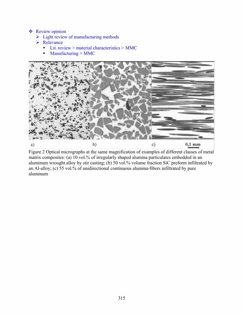
315
Review opinion Light review of manufacturing methods Relevance
Lit. review > material characteristics > MMC Manufacturing > MMC
Figure 2 Optical micrographs at the same magnification of examples of different classes of metal matrix composites: (a) 10 vol.% of irregularly shaped alumina particulates embedded in an aluminum wrought alloy by stir casting; (b) 50 vol.% volume fraction SiC preform infiltrated by an Al-alloy; (c) 55 vol.% of unidirectional continuous alumina-fibers infiltrated by pure aluminum

316
Kim, S.Y., Paek, J.W., and Kang, B.H., Flow and heat transfer correlations for porous fin in a plate-fin heat exchanger, J. Heat Transfer 122 (2000) 572-578. Importance: 5 4 3 2 1 (5-high, 1-low) * Check below all that apply; Write specific features as necessary in the blank space
Article Type Material Configuration Application ( ) Review paper ( ) Polymer ( X ) Liquid-Gas ( ) Absorption system ( X ) Experimental data ( ) PMC ( ) Liquid-Liquid ( X ) Radiator ( ) Numerical data ( ) Carbon ( ) Gas-Gas ( ) Ice storage ( X ) Correlation ( ) CAMC ( ) Tubes ( X ) Refrigerant system ( ) HX modeling ( ) Metal ( X ) Fins ( ) Thermo-electric sys. ( ) System modeling ( ) MMC ( ) Plates ( ) Direction-control HX ( ) Material property ( ) Ceramic/CMC ( ) Heat sink (Liquid) ( ) Cryogenic system ( ) ( X ) Metal Foam ( ) Heat sink (Gas) ( ) Heat pipe ( ) ( ) ( ) ( ) PMC (Polymer Matrix Composite), CAMC (Carbon Matrix Composite), MMC (Metal Matrix Composite), CMC (Ceramic Matrix Composite)
Heat transfer and pressure drop performance of flat-tube heat exchangers with open-cell aluminum foam fin
Experiments with simplified models using metal foam block between heated plates Aluminum foam samples PPI = 10, 20, 40; porosity = .89-.96 Louver-fin (baseline): Lp=1.0 mm, Fp=1.9 mm, Fl = 9mm, Fd=26 mm, β=1320 m-1
Friction and heat transfer rate are significantly affected by permeability and porosity Friction factor is lower for low permeable porous fins Modified j-factors (uses ηh instead of h) of the porous fins decrease as the pore
density increases or as the porosity decreases For present samples, thermal performance of porous fin is similar to that of conventional
louvered fin, but louvered fin shows slightly better pressure drop performance Porous fins show much higher friction factors than the louvered fin at high Re
Friction and heat transfer correlations were proposed for the porous fins Using Darcy number and geometrical parameters Metal foam fins with low permeability and low porosity are preferable
Review opinion
Heat transfer and friction data of porous metal foams as airside fins for heat exchangers Fin efficiency was not separated Parameter space for correlations is limited to 6 geometrical variants Comparison with other studies with metal foam is very light, esp. with their
correlations Category
Lit. review > material characteristics > metal foam

317
Lit. review > air-to-liquid > metal foam Performance modeling > air-to-liquid > metal foam
Fig. 1 Schematic configuration of the problem
Fig. 10 Effect of pore density on the air-side performance (porosity=0.92)
Fig. 11 Effect of porosity on the air-side performance (pore density=20 PPI)

318
Banhart, J., Manufacture, characterisation and application of cellular metals and metal foams, Progress in Materials Science 46 (2001) 559–632 Importance: 5 4 3 2 1 (5-high, 1-low) * Check below all that apply; Write specific features as necessary in the blank space
Article Type Material Configuration Application ( X ) Review paper ( ) Polymer ( ) Liquid-Gas ( ) Absorption system ( ) Experimental data ( ) PMC ( ) Liquid-Liquid ( ) Radiator ( ) Numerical data ( ) Carbon ( ) Gas-Gas ( ) Ice storage ( ) Correlation ( ) CAMC ( ) Tubes ( ) Refrigerant system ( ) HX modeling ( ) Metal ( ) Fins ( ) Thermo-electric sys. ( ) System modeling ( ) MMC ( ) Plates ( ) Direction-control HX ( ) Material property ( ) Ceramic/CMC ( ) Heat sink (Liquid) ( ) Cryogenic system ( X ) Manufacturing ( X ) Metal foam ( ) Heat sink (Gas) ( ) Heat pipe PMC (Polymer Matrix Composite), CAMC (Carbon Matrix Composite), MMC (Metal Matrix Composite), CMC (Ceramic Matrix Composite)
Extensive review of literature regarding cellular metals and metal foams Stochastic cellular metallic materials manufacturing process: 4 categories
From liquid metal From solid metal in powdered foam From metal vapour or gaseous metallic compounds, From a metal ion solution Geometry and materials details
Review opinion Various manufacturing processes are given for open-cell and closed-cell metal foams
Not all process may be useful for heat exchanger fabrication Relevance
Lit. review > material characteristics > metal foam Manufacturing > metal foam
Fig. 2. Overview of the various ‘‘families’’ of production methods for cellular metallic materials.

319
Solid–gas eutectic solidification (‘‘gasars’’)

320
Fig. 24. Manufacture of metal foam by spray forming

321
Fig. 28. Space holder technique for making porous metallic structures from metal powders

322
323
Howard, S.R. and Korinko, P.S., Vacuum furnace brazing open cell reticulated foam to stainless steel tubing, WSRC-MS-2002-00424, 2nd International Brazing and Soldering Conference, San Diego, CA, 2003. Importance: 5 4 3 2 1 (5-high, 1-low) * Check below all that apply; Write specific features as necessary in the blank space
Article Type Material Configuration Application ( ) Review paper ( ) Polymer ( ) Liquid-Gas ( ) Absorption system ( X ) Experimental data ( ) PMC ( ) Liquid-Liquid ( ) Radiator ( ) Numerical data ( ) Carbon ( ) Gas-Gas ( ) Ice storage ( ) Correlation ( ) CAMC ( X ) Tubes ( ) Refrigerant system ( ) HX modeling ( X ) Metal ( X ) Fins ( ) Thermo-electric sys. ( ) System modeling ( ) MMC ( ) Plates ( ) Direction-control HX ( X ) Material property ( ) Ceramic/CMC ( ) Heat sink (Liquid) ( ) Cryogenic system ( X ) Manufacturing ( ) ( ) Heat sink (Gas) ( ) Heat pipe ( ) ( ) ( ) ( X ) Thermal cycle absorption ( ) ( ) ( ) ( ) PMC (Polymer Matrix Composite), CAMC (Carbon Matrix Composite), MMC (Metal Matrix Composite), CMC (Ceramic Matrix Composite)
Experimental study of braze alloy and process for establishing a metallurgical bonding between stainless steel tube and copper foam
High temperature brazing resulted in extensive creep damage to the copper foam Also changed the interference fit between the outer tube and the inner tube due to
differential thermal expansion Copper-tin braze alloys caused excessive braze erosion and the brazing process was
difficult to control Silver solid state diffusion bonding does not provide suitable strength for the application A Au-18In alloy forms metallurgical bond between copper and stainless steel at a
moderate temperature Minimizes the damage due to creep and thermal expansion Braze alloy wets both copper and stainless steel but does not appear to cause
excessive braze erosion
Review opinion Evaluation of braze results was mostly qualitative (need to be further substantiated) Relevance
Lit. review > material characteristics > metal foam Manufacturing > metal foam

324
Hwang, J.J., Hwang, G.J., Yeh, R.H., and Chao, C.H., Measurement of interstitial convective heat transfer and friction drag for flow across metal foams, J. Heat Transfer 124 (2002) 120-129. Importance: 5 4 3 2 1 (5-high, 1-low) * Check below all that apply; Write specific features as necessary in the blank space
Article Type Material Configuration Application ( ) Review paper ( ) Polymer ( ) Liquid-Gas ( ) Absorption system ( X ) Experimental data ( ) PMC ( ) Liquid-Liquid ( ) Radiator ( X ) Numerical data ( ) Carbon ( ) Gas-Gas ( ) Ice storage ( X ) Correlation ( ) CAMC ( ) Tubes ( ) Refrigerant system ( ) HX modeling ( X ) Metal ( ) Fins ( ) Thermo-electric sys. ( ) System modeling ( ) MMC ( ) Plates ( ) Direction-control HX ( ) Material property ( ) Ceramic/CMC ( ) Heat sink (Liquid) ( ) Cryogenic system ( ) ( ) ( X ) Heat sink (Gas) ( ) Heat pipe ( ) ( ) ( ) ( ) ( ) ( ) ( ) ( ) PMC (Polymer Matrix Composite), CAMC (Carbon Matrix Composite), MMC (Metal Matrix Composite), CMC (Ceramic Matrix Composite)
Experimental study of heat transfer and friction drag in aluminum foams Heat transfer and flow experiments
Test samples • Identical ligament diameter • Different porosities (ε = 0.7, 0.8, 0.95)
Friction factor and volumetric heat transfer coefficient increase with decreasing the foam porosity at a fixed Reynolds number
Smoke-wire flow visualization • Large amount of eddies is downstream of the ε=0.7 foam whereas less agitation is
observed for ε=0.95 foam Volume-goodness comparison (volumetric heat transfer vs volumetric pumping power)
Porosity 0.8 gives best among the tested samples Power-law based curve fits for friction factor and Nusselt number
Function of porosity and Reynolds number Review opinion
Empirical data can be used for references in future studies Relevance
Lit. review > material characteristics > metal foam Lit. review > heat sink (air) > metal foam Performance modeling > porous media

325
Fig. 2 Schematic drawing of the test section
Fig. 11 Volumetric heat transfer coefficient as a function of the nondimensional pumping power

326
Bhattacharya, A., Calmidi, V.V., and Mahajan, R.L., Thermophysical properties of high porosity metal foam, Int. J. Heat Mass Transfer 45 (2002) 1017-1031 Importance: 5 4 3 2 1 (5-high, 1-low) * Check below all that apply; Write specific features as necessary in the blank space
Article Type Material Configuration Application ( ) Review paper ( ) Polymer ( ) Liquid-Gas ( ) Absorption system ( X ) Experimental data ( ) PMC ( ) Liquid-Liquid ( ) Radiator ( ) Numerical data ( ) Carbon ( ) Gas-Gas ( ) Ice storage ( ) Correlation ( ) CAMC ( ) Tubes ( ) Refrigerant system ( ) HX modeling ( ) Metal ( ) Fins ( ) Thermo-electric sys. ( ) System modeling ( ) MMC ( ) Plates ( ) Direction-control HX ( X ) Material property ( ) Ceramic/CMC ( ) Heat sink (Liquid) ( ) Cryogenic system ( ) ( X ) Metal foam ( ) Heat sink (Gas) ( ) Heat pipe ( ) ( ) ( ) ( ) ( ) ( ) ( ) ( ) PMC (Polymer Matrix Composite), CAMC (Carbon Matrix Composite), MMC (Metal Matrix Composite), CMC (Ceramic Matrix Composite)
Experimental and analytical evaluation of the properties of open-cell metal foams Effective thermal conductivity (ke)
Theoretical modeling from representing the structure by a two-dimensional array of hexagonal cells
Analysis suggests that effective thermal conductivity has a strong dependence on porosity and the ratio of cross-sections of the fiber and the intersection, but no systematic dependence on pore density
Experimental validation with aluminum and reticulated vitreous carbon (RVC) foams Empirical correlation for effective thermal conductivity
A = 0.35
Permeability (K) and inertial coefficient (f)
Modified Darcy’s equation (Forchheimer, 1901)
Experimental study in wind-tunnel • Permeability increases with pore diameter and porosity • Inertial constant depends only on porosity
Models for inertial coefficient and permeability model were proposed • Parameters: pore diameter, porosity, and tortuosity

327
Review opinion
Useful property data are reported with predictive models Relevance
Lit. review > material characteristics > metal foam Performance modeling > convection from porous media
Fig. 1. Commercially available high-porosity metal foam consisting of interconnected metal fibers and irregular lumps at metal intersections

328

329
Hayes, A.M., Wang, A., Dempsey, B.M., and McDowell, D.L., Mechanics of linear cellular alloys, Mechanics of Materials 36 (2004) 691–713. Importance: 5 4 3 2 1 (5-high, 1-low) * Check below all that apply; Write specific features as necessary in the blank space
Article Type Material Configuration Application ( ) Review paper ( ) Polymer ( ) Liquid-Gas ( ) Absorption system ( X ) Experimental data ( ) PMC ( ) Liquid-Liquid ( ) Radiator ( X ) Numerical data ( ) Carbon ( ) Gas-Gas ( ) Ice storage ( ) Correlation ( ) CAMC ( ) Tubes ( ) Refrigerant system ( ) HX modeling ( X ) Metal ( ) Fins ( ) Thermo-electric sys. ( ) System modeling ( ) MMC ( ) Plates ( ) Direction-control HX ( X ) Material property ( ) Ceramic/CMC ( X ) Heat sink (Liquid) ( ) Cryogenic system ( ) ( ) ( X ) Heat sink (Gas) ( ) Heat pipe ( ) ( ) ( ) ( ) ( ) ( ) ( ) ( ) PMC (Polymer Matrix Composite), CAMC (Carbon Matrix Composite), MMC (Metal Matrix Composite), CMC (Ceramic Matrix Composite)
Assessment of Linear Cellular Alloys (LCAs) as heat exchanger materials Stochastic metal foams (open or closed cell) have limited ability to withstand mechanical
loads, and the form drag (flow stagnation) causes a high pressure drop for open cell stochastic foams Linear cellular alloys (like honeycombs) can be superior in these regards
Use of LCAs as heat exchangers is promising because of the high conductivity walls, the high surface area to volume ratio, and the capability to tailor cell size and shape to optimize the tradeoff of pressure drop and heat transfer coefficient.
Manufacturing process of linear cellular alloys (LCA) enables more complex in-plane cell morphologies for desired functionality (Cochran et al 2000) Extrusion of metal oxide powders Chemical reaction/sintering process to form near fully dense walls (ceramic particles
are reduced in hydrogen atmosphere) Wall thickness as thin as 50 μm is possible
For most practical applications, the optimal topology of cell structure would not be uniform. Graded cell structures that combine attributes of high stiffness with high heat transfer
capability are desirable (e.g. triangular cells are structurally superior to hexagonal cells, but hexagonal cells provide better thermal-hydraulic performance
Detailed evaluation of mechanical strength of various LCA materials and geometries are presented (experiments and theoretical modeling)
Preliminary heat transfer performance modeling and tests were conducted Rectangular LCA used as a heat sink (e.g. electronics cooling)
Review opinion Article puts an emphasis on mechanical properties in consideration of materials and
structures Relevance & category
Lit. review > material characteristics > metals (metal foam, periodic)

330
Lit. review > heat sink > metal Manufacturing cost appears to be a most critical factor
LCAs may be prohibitively expensive for large scale conventional applications
Fig. 1. Extruded maraging steel LCA reduced from oxide powders and reduced to achieve an 8 · 8 square cell array (left); side view of extruded section (right).
Fig. 4. Honeycombs with different cell shapes, including: (a) square, (b) triangles arranged as hexagonal supercells, (c) simple hexagonal, (d) mixed triangular and square (triangles arranged as square supercell), (e) kagome, and (f) rectangular.

331
Tian, J., Kim, T., Lu, T.J., Hodson, H.P., Queheillalt, D.T., Sypeck, D.J., and Wadley, H.N.G., The effects of topology upon fluid-flow and heat-transfer within cellular copper structures, Int. J. Heat Mass Transfer 47 (2004) 3171–3186. Importance: 5 4 3 2 1 (5-high, 1-low) * Check below all that apply; Write specific features as necessary in the blank space
Article Type Material Configuration Application ( ) Review paper ( ) Polymer ( ) Liquid-Gas ( ) Absorption system ( X ) Experimental data ( ) PMC ( ) Liquid-Liquid ( ) Radiator ( ) Numerical data ( ) Carbon ( ) Gas-Gas ( ) Ice storage ( ) Correlation ( ) CAMC ( ) Tubes ( ) Refrigerant system ( ) HX modeling ( ) Metal ( ) Fins ( ) Thermo-electric sys. ( ) System modeling ( ) MMC ( ) Plates ( ) Direction-control HX ( ) Material property ( ) Ceramic/CMC ( ) Heat sink (Liquid) ( ) Cryogenic system ( ) ( X ) Metal foam ( X ) Heat sink (Gas) ( ) Heat pipe ( ) ( ) ( ) ( ) ( ) ( ) ( ) ( ) PMC (Polymer Matrix Composite), CAMC (Carbon Matrix Composite), MMC (Metal Matrix Composite), CMC (Ceramic Matrix Composite)
Heat transfer and friction performance of woven-mesh cellular copper structure Experiments under steady-state forced air convection with constant wall heat flux
For the range of Reynolds numbers considered, fluid flow in all textile meshes is form dominated: the friction factor in all cases is independent of the coolant velocity
Geometrical parameters (wire diameter, topology, and porosity) and orientation Porosity affects both friction and heat transfer • Increased open area ratio reduces friction
Orientation has strong effect on friction but weak effect on heat transfer Optimal porosity exists for heat transfer, given a fixed surface area density • At given porosity, heat dissipation rate increases as surface area density increases • With increasing porosity, conduction decreases while convection increases
Overall thermal efficiency index of the copper textiles-based media is approximately three times larger than that of stochastic copper foams Because of the lower pressure drop through the periodic wire-screen structure
Fabrication of TLP bonded and brazed textile heat sink Prototype sandwich heat sinks with laminated textile cores of plain woven copper
cloth were fabricated using two similar methods: transient liquid phase (TLP) bonding and brazing
TLP bonding • Laminae were first lightly sprayed with a mix of polymer-based cement and Ni-
25Cr-10P braze alloy powder • Collated laminae were heated within flowing argon to volatilize polymer cement • Core was brazed in an environment which was evacuated and heated to 1000°C
Sandwich structure • Face sheets, made of the same material as the wires, were sprayed with the TLP
bonding mixture

332
• Under a small compressive force on the face sheets, the sandwich structure went through a similar volatilization/brazing process as the textile core
Review opinion Thermal-hydraulic performance data can be useful as future design references Remarks on importance (relevance) to our project
Lit. review > material characteristics > metal foam Lit. review > heat sink > metal foam
Fig. 1. Topological comparison of periodic structures.

333
Fig. 2. Sandwich construction with textile technology: (a) a transient liquid phase joins the wire-mesh screen laminated at all points of contact; (b) facesheets are added to the textile core.
Fig. 3. Textile laminate heat exchangers: (a) images of orientation A with square-shaped pores; (b) images of orientation B with square-shaped pores; (c) images of diamond-shaped pores.
Fig. 5. Friction factor plotted as a function of Reynolds number based on channel height for brazed textiles.
Fig. 7. Nusselt number plotted as a function of Reynolds number based on channel height for woven textiles.
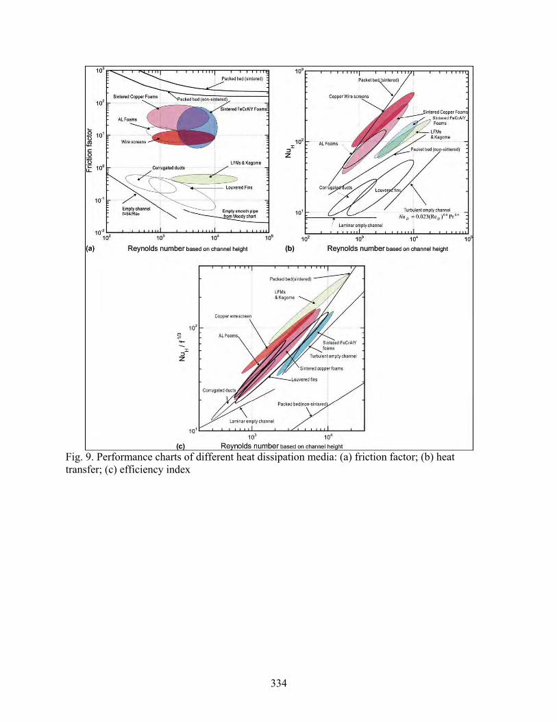
334
Fig. 9. Performance charts of different heat dissipation media: (a) friction factor; (b) heat transfer; (c) efficiency index

335
Ozmat, B., Leyda, B., and Benson, B., Thermal applications of open-cell metal foams, Materials and Manufacturing Processes 19 (5) (2004) 839-862. Importance: 5 4 3 2 1 (5-high, 1-low) * Check below all that apply; Write specific features as necessary in the blank space
Article Type Material Configuration Application ( X ) Review paper ( ) Polymer ( ) Liquid-Gas ( ) Absorption system ( X ) Experimental data ( ) PMC ( ) Liquid-Liquid ( ) Radiator ( ) Numerical data ( ) Carbon ( ) Gas-Gas ( ) Ice storage ( ) Correlation ( ) CAMC ( ) Tubes ( ) Refrigerant system ( ) HX modeling ( ) Metal ( ) Fins ( ) Thermo-electric sys. ( ) System modeling ( ) MMC ( ) Plates ( ) Direction-control HX ( X ) Material property ( ) Ceramic/CMC ( X ) Heat sink (Liquid) ( ) Cryogenic system ( ) ( X ) Metal foam ( X ) Heat sink (Gas) ( ) Heat pipe ( ) ( ) ( ) ( ) ( ) ( ) ( ) ( ) PMC (Polymer Matrix Composite), CAMC (Carbon Matrix Composite), MMC (Metal Matrix Composite), CMC (Ceramic Matrix Composite)
Structural and thermo-physical properties of reticulated metal foams (RMF) Commercially available metal foams
Pore density of 5, 10, 20, and 30 pore per inch (ppi) and a wide range of porosity Available metals include aluminum 6101 and 1100 alloys, copper C10100, inconel,
nickel, silver, and zinc RMF-based heat sinks can benefit high power heat dissipation devices by
Eliminating thermal interfaces between heat source and heat sink Enhancing convective heat transfer coefficient, and increasing surface area Accomplishing improvements in volume, weight, performance, and life cycle cost RMF also offers structural compatibility with semiconductor devices by direct
attachment Heat exchangers made of reticulated foam
Typically use high thermal conductivity material such as Al, Cu, Ag, SiC, or graphite RMF can be metallurgically bonded by soldering or brazing techniques to high-
performance electronic, optoelectronic devices Assessment of thermo-physical properties
Theoretical prediction of RMF ligament dimensions Surface area density experimentally measured by BET technique Thermal conductivity estimation based on electrical conductivity measurement • Neglects lattice vibration mode (valid for pure metals, invalid for alloys)
Experimental and finite element analysis of test module Compare thermal base plate, power device, RMF heat exchanger, and off-the-shelf
external cold plate RMF-based heat exchangers offer significant advantages
Large specific surface area Superior and scalable thermal performance Low weight and volume Compatibility with a large range of coolants

336
High structural compliance and specific stiffness Hard bondability to low expansion substrates
Review opinion Focused on high-power heat sink applications Limited details of experimental and numerical approaches Relevance
Lit. review > material characteristics > metal foam Lit. review > heat sink > metal foam
Figure 1. Structure of metal foam and dodecahedron having 12 pentagon-shaped facets.

337
Boger, T. and Heibel, A.K., Heat transfer in conductive monolith structures, Chemical Engineering Science 60 (2005) 1823-1835 Importance: 5 4 3 2 1 (5-high, 1-low) * Check below all that apply; Write specific features as necessary in the blank space
Article Type Material Configuration Application ( ) Review paper ( ) Polymer ( X ) Liquid-Gas ( ) Absorption system ( X ) Experimental data ( ) PMC ( ) Liquid-Liquid ( ) Radiator ( ) Numerical data ( ) Carbon ( ) Gas-Gas ( ) Ice storage ( ) Correlation ( ) CAMC ( X ) Tubes ( ) Refrigerant system ( X ) HX modeling ( X ) Metal ( ) Fins ( ) Thermo-electric sys. ( ) System modeling ( ) MMC ( ) Plates ( ) Direction-control HX ( ) Material property ( ) Ceramic/CMC ( ) Heat sink (Liquid) ( ) Cryogenic system ( ) ( ) ( ) Heat sink (Gas) ( ) Heat pipe ( ) ( ) ( ) ( ) ( ) ( ) ( ) ( ) PMC (Polymer Matrix Composite), CAMC (Carbon Matrix Composite), MMC (Metal Matrix Composite), CMC (Ceramic Matrix Composite)
Heat transfer performance of conductive monolith structures packaged into heat exchanger tubes
Copper monolithic catalyst support for immersed-tube gas reactor heat exchanger Extruded monolithic structure relieves the bottleneck in heat conduction through the
catalyst structure Higher heat transfer, and improved temperature control (i.e. local hot spots) and
process safety Analytical modeling and experimental measurements
Monolith material structure and properties Packaging tolerance Overall heat transfer coefficient: ~1000 W/m2K Consideration of thermal expansion of monolith and tube
Good contact between the monolith and the copper tube was established by first core drilling the monoliths to a diameter slightly larger than the copper tube and then pressing them into the tubes.
Conductive monoliths with a dense skin without additional tube Heat transfer coefficients up to 1500W/m2K Simplified assembly
Review opinion More emphasis was placed on chemical process, but possibly useful in HVAC&R
applications with high performance requirements Relevance
Lit. review > material characteristics > porous metal alloy Lit. review > gas-to-liquid > metal

338
Fig. 1. Photo ofcopper based monolithic catalyst support with high thermal conductivity.
Fig. 2. Schematic of the cross-section of a monolith inserted into a tube, which is surrounded by a heat transfer medium.

339
Zhao, C.Y., Lu, W., and Tassou, S.A., Thermal analysis on metal-foam filled heat exchangers, Part II: Tube heat exchangers, International Journal of Heat and Mass Transfer 49 (15-16) (2006) 2762-2770. Importance: 5 4 3 2 1 (5-high, 1-low) * Check below all that apply; Write specific features as necessary in the blank space
Article Type Material Configuration Application ( ) Review paper ( ) Polymer ( X ) Liquid-Gas ( ) Absorption system ( ) Experimental data ( ) PMC ( X ) Liquid-Liquid ( ) Radiator ( X ) Numerical data ( ) Carbon ( X ) Gas-Gas ( ) Ice storage ( ) Correlation ( ) CAMC ( X ) Tubes ( ) Refrigerant system ( X ) HX modeling ( ) Metal ( ) Fins ( ) Thermo-electric sys. ( ) System modeling ( ) MMC ( ) Plates ( ) Direction-control HX ( ) Material property ( ) Ceramic/CMC ( ) Heat sink (Liquid) ( ) Cryogenic system ( ) ( X ) Metal foam ( ) Heat sink (Gas) ( ) Heat pipe ( ) ( ) ( ) ( ) ( ) ( ) ( ) ( ) PMC (Polymer Matrix Composite), CAMC (Carbon Matrix Composite), MMC (Metal Matrix Composite), CMC (Ceramic Matrix Composite)
Analytical study of concentric-tube heat exchanger filled with open-cell metal foams Forced convection heat transfer characteristics in counter-flow tube-in-tube configuration
Brinkman-extended Darcy momentum model and two-equation heat transfer model for porous media for numerical study
Fully-developed, one-dimensional, steady-state Analytical solutions of the velocity and temperature distributions (both fluid and solid
phases) were obtained and overall Nusselt number was calculated Parametric study
Increasing the pore density improves the velocity distribution and reduces the temperature difference between the solid and fluid
Decreasing either the porosity or pore size leads to an increase in the heat transfer performance
Optimum inner tube diameter or flow cross-sectional area ratio varies with the relative pore densities of the metal foams filled on both sides of heat exchanger
Claimed that: metal foams can greatly enhance the heat transfer, and metal foams have significant potential in the manufacture of compact heat exchangers
Review opinion
Incremental contribution by using previously reported modeling methods Very high pressure drop accompanied by porous materials was not included when
comparing with conventional finned-tube geometry Remarks on importance (relevance) to our project
Lit. review > air-to-liquid > metal foam Performance modeling > open-cell metal foam heat exchanger

340
Fig. 1. A schematic diagram of a tube-in-tube heat exchanger filled with metal foam.
Fig. 12. Geometry of conventional finned tube heat exchanger (R = 6 mm, R1 = 6.5 mm, R2 = 10 mm). (a) The heat exchanger with inner grooved tube (spiral grooves: s = 0.1 mm, H = 1 mm) and fins (longitudinal fins: 20 fins, H = 2.5 mm, t = 0.075 mm), (b) metal-foam filled heat exchanger.

341
Smeding, S.F., Bakker, N., de Boer, R., Design, simulation and experiments on a new flat plate sandwich heat exchanger, ECN-M-06-096, 13th International Heat Transfer Conference, Sydney, Australia, 2006 Importance: 5 4 3 2 1 (5-high, 1-low) * Check below all that apply; Write specific features as necessary in the blank space
Article Type Material Configuration Application ( ) Review paper ( ) Polymer ( ) Liquid-Gas ( ) Absorption system ( X ) Experimental data ( ) PMC ( X) Liquid-Liquid ( ) Radiator ( ) Numerical data ( ) Carbon ( ) Gas-Gas ( ) Ice storage ( ) Correlation ( ) CAMC ( ) Tubes ( ) Refrigerant system ( ) HX modeling ( X ) Metal ( ) Fins ( ) Thermo-electric sys. ( ) System modeling ( ) MMC ( ) Plates ( ) Direction-control HX ( X ) Material property ( ) Ceramic/CMC ( ) Heat sink (Liquid) ( ) Cryogenic system ( ) ( ) ( ) Heat sink (Gas) ( ) Heat pipe ( ) ( ) ( ) ( X ) Solid sorption heat pump ( ) ( ) ( ) ( ) PMC (Polymer Matrix Composite), CAMC (Carbon Matrix Composite), MMC (Metal Matrix Composite), CMC (Ceramic Matrix Composite)
Sandwich plate heat exchanger for high temperature solid sorption heat pump Metal wire mesh brazed between two metal sheets
Superior heat transfer by enhanced flow mixing Durable for cyclic pressure variations
Experimental and numerical study of flow distribution and heat transfer coefficient Evaluation of mechanical properties
Cycle tensile strength for various operating temperatures FEM stress analysis
Semi-empirical heat transfer modeling gives good agreement with experimental data
Review opinion Example of porous media application Relevance
Lit. review > material characteristics > metal Lit. review > sorption system > metal foam

342

343
Wadley, H.N.G., Multifunctional periodic cellular metals, Philosophical Transactions of the Royal Society A 364 (2006) 31–68 Importance: 5 4 3 2 1 (5-high, 1-low) * Check below all that apply; Write specific features as necessary in the blank space
Article Type Material Configuration Application ( X ) Review paper ( ) Polymer ( ) Liquid-Gas ( ) Absorption system ( ) Experimental data ( ) PMC ( ) Liquid-Liquid ( ) Radiator ( ) Numerical data ( ) Carbon ( ) Gas-Gas ( ) Ice storage ( ) Correlation ( ) CAMC ( ) Tubes ( ) Refrigerant system ( ) HX modeling ( X ) Metal ( X ) Fins ( ) Thermo-electric sys. ( ) System modeling ( ) MMC ( X ) Plates ( ) Direction-control HX ( ) Material property ( ) Ceramic/CMC ( ) Heat sink (Liquid) ( ) Cryogenic system ( X ) Manufacturing ( ) ( ) Heat sink (Gas) ( ) Heat pipe ( ) ( ) ( ) ( ) PMC (Polymer Matrix Composite), CAMC (Carbon Matrix Composite), MMC (Metal Matrix Composite), CMC (Ceramic Matrix Composite)
Manufacturing methods to fabricate periodic cellular metals (literature review) Major categories of periodic cellular metals
Honeycombs • Closed-cell pores • Suitable for thermal protection and load support
Corrugated core structures • Less efficient and highly anisotropic load support • Allow cross-flow heat exchanger configuration because the pores are continuous
in one direction Lattice truss structures with open cell configurations
Extensive details of various manufacturing techniques Hexagonal honeycombs • Conventional: stacking, bonding, stretching • Alternative: corrugating, bonding
Square or triangular honeycombs • Strip slotting method: slotting, brazing
Lattice truss structures • Investment casting • Folded perforated metal sheets • Expanded metal sheet • Hollow pyramidal lattice truss
Predictions and measurements of mechanical properties Bulk strength, modulus
Review opinion Comprehensive summary of cellular metallic structures and their manufacturing methods Category
Lit. review > heat sink > metals Manufacturing methods > metals

344
Figure 1. Examples of the three forms of honeycomb shown as core structures in sandwich panels: (a) hexagonal honeycomb, (b) square honeycomb and (c) triangular honeycomb.
Figure 2. Prismatic (corrugation) topology structures. (a) Triangular corrugation, (b) a diamond topology (equivalent to a square corrugation rotated by 458) and (c) a steeper web truss corrugation with a flat top that is widely used in buildings and for marine applications where it is called Navtruss.
Figure 3. Examples of lattice truss topologies configured as the cores of sandwich panel structures. (a) Tetrahedral lattice, (b) pyramidal lattice, (c) three-dimensional Kagome lattice, (d ) diamond textile, (e) diamond collinear lattice and ( f ) square collinear lattice. Many can be made with solid or hollow trusses. The truss cross sections can also be shaped (e.g. square as opposed to circular).
345
A.3 Carbon and CAMCs Graphite heat exchangers in the process industries, Madner, P.J. (Robert Jenkins Syst. Ltd., Rotherham, UK) Source: First U.K. National Conference on Heat Transfer, 1984, p 1263-74, vol.2 Source: Institution of Chemical Engineers Symposium Series, n 86, 1984, p 1263-1274 * Check below all that apply; Write specific features as necessary in the blank space
Article Type Material Configuration Importance (× )Review paper ( ) Polymer (× ) Liquid-Gas (× ) 5 ( ) Experimental data ( ) PMC (× ) Liquid-Liquid ( ) 4
( ) Numerical data (× ) Carbon (× ) Gas-Gas ( ) 3
( ) Correlation (×) CAMC (×) Tubes ( ) 2
( ) HX modeling ( ) Metal (× ) Fins ( ) 1
( ) System modeling ( ) MMC ( ) Plates ( ) ( ) Material property ( ) ceramic/CMC ( ) Heat sink (Liquid) ( ) ( ) ( ) ( ) Heat sink (Gas) ( ) Specific features: Application: PMC (Polymer Matrix Composite), CAMC (Carbon Matrix Composite), MMC (Metal Matrix Composite), CMC (Ceramic Matrix Composite)
Overall contribution of the article (to help us identify what it is; not same as title) an introduction to graphite heat exchangers and discuss their specification and the factors that influence their specification
Description of key information from the article such as A good review of graphite heat spreader used in UK � Including design considerations See the hard copy: fig1~fig 3
Important findings and results A summary of status in UK before 1984 Give a three type division of graphite: Cubic block, Cylindrical block, Shell and tube. In order to use graphite as a construction material in heat transfer equipment, it is
necessary to seal the pores; this process is usually achieved by resin impregnation of the raw graphite.
Application limits of tem, pressure of the heat exchanger Review opinion
Critical evaluation of the paper by the reviewer Questionable items: Based on this, what development will happen? Alternative explanations: Norley natural graphite and resin matrix composite, then C-
C and other CAMC. Remarks on importance (relevance) to our project
Possible sections of final report to be mentioned in • Lit. review > Carbon > L-L, L-G, G-G heat exchangers • Exploitation > Carbon > L-L, L-G, G-G heat exchangers • Performance modeling > L-L, L-G, G-G heat exchangers
Something to remember If someone other than the reviewer reads this document, he/she should not
miss anything important in the article: Details of the experimental
346
Thermal and hydraulic performance of a graphite block heat exchanger Schou, G. (Univ of Auckland); Deans, J.; Kunzel, J.; Muller-Steinhagen, H. Source: Chemical Engineering and Processing, v 36, n 5, Sep, 1997, p 371-384 * Check below all that apply; Write specific features as necessary in the blank space
Article Type Material Configuration Importance ( )Review paper ( ) Polymer ( ) Liquid-Gas ( ) 5 (× ) Experimental data ( ) PMC (× ) Liquid-Liquid (× ) 4 (× ) Numerical data (× ) Carbon ( ) Gas-Gas ( ) 3 ( ) Correlation ( ) CAMC (× ) Tubes ( ) 2 ( ) HX modeling ( ) Metal (× ) Fins ( ) 1 ( ) System modeling ( ) MMC ( ) Plates ( ) ( ) Material property ( ) ceramic/CMC ( ) Heat sink (Liquid) ( ) ( ) ( ) ( ) Heat sink (Gas) ( ) ( ) ( ) ( ) ( ) ( ) ( ) ( ) ( ) Specific features: Application: chemical process equipment PMC (Polymer Matrix Composite), CAMC (Carbon Matrix Composite), MMC (Metal Matrix Composite), CMC (Ceramic Matrix Composite)
Overall contribution of the article (to help us identify what it is; not same as title) A test rig has been assembled to investigate the thermodynamic and hydraulic performance of a cylindrical graphite block heat exchanger consisting of three graphite blocks and a steel shell.
Description of key information from the article such as investigate the thermodynamic and hydraulic performance of a cylindrical graphite block heat
exchanger
Important findings and results Comparing with carbon and graphite blocks are usually impregnated with a phenol formaldehyde resin to fill the pores in the
graphite and make them impermeable to gases and liquids. Comparison with other data
None Review opinion
Critical evaluation of the paper by the reviewer Questionable items: How about the anisotropic thermal conductivity of this material? Alternative explanations: Leave unmentioned, the second discussed but no full text.
Remarks on importance (relevance) to our project Possible sections of final report to be mentioned in • Lit. review > Carbon > L-L, heat exchangers • Exploitation > Carbon > L-L, heat exchangers • Performance modeling > L-L, heat exchangers
Something to remember If someone other than the reviewer reads this document, he/she should not miss
anything important in the article: Details of the experimental, leakage flow

347
Tzeng, J. W. et al., “Anisotropic Graphite Heat Spreaders for Electronics Thermal Management”, PCIM 2000. * Check below all that apply; Write specific features as necessary in the blank space
Article Type Material Configuration Importance ( )Review paper ( ) Polymer ( ) Liquid-Gas ( ) 5 (× ) Experimental data ( ) PMC ( ) Liquid-Liquid (× ) 4 ( ) Numerical data () Carbon ( ) Gas-Gas ( ) 3 ( ) Correlation (× ) CAMC ( ) Tubes ( ) 2 ( ) HX modeling ( ) Metal ( ) Fins ( ) 1 ( ) System modeling ( ) MMC ( ) Plates ( ) ( ) Material property ( ) ceramic/CMC ( ) Heat sink (Liquid) ( ) ( ) ( ) (× ) Heat sink (Gas) ( ) ( ) ( ) ( ) ( ) ( ) ( ) ( ) ( ) Specific features: Application: PMC (Polymer Matrix Composite), CAMC (Carbon Matrix Composite), MMC (Metal Matrix Composite), CMC (Ceramic Matrix Composite)
Overall contribution of the article (to help us identify what it is; not same as title) This paper highlights the anisotropic nature of flexible graphite in comparison to isotropic materials such as metals and polymeric compounds commonly used in the electronics industry .
Description of key information from the article such as a good concise review of eGraf
Important findings and results Thermal conductivity of graphite crystal is as high as 1600-2000 W/m�C in the plane and 4-9
W/m�C. anisotropic materials exhibit a unique thermal conduction behavior that can be applied
for .directing. heat flows and .maneuvering. temperature profiles.. Comparison with other data
With metals and polymeric compounds Review opinion
Critical evaluation of the paper by the reviewer Questionable items: Figures 1a, 1b and 2 clearly demonstrate that fundamentally there are
a number of benefits and advantages to incorporating the concept of thermal anisotropy into the design considerations for advanced thermal systems. ?
Alternative explanations: walk and see Remarks on importance (relevance) to our project
Possible sections of final report to be mentioned in • Lit. review > CAMC > Heat sink • Exploitation > CAMC> Heat sink • Performance modeling > Heat sink
Something to remember If someone other than the reviewer reads this document, he/she should not miss
anything important in the article: Computer simulation

348
Norley, J. Tzeng, J.J.-W. Getz, G. Klug, J. Fedor, B., The development of a natural graphite heat-spreader, IEEE Semiconductor Thermal Measurement and Management Symposium,2001, 107-110 Importance: 5 4 3 2 1 (5-high, 1-low) * Check below all that apply; Write specific features as necessary in the blank space
Article Type Material Configuration Application (× )Review paper ( ) Polymer ( ) Liquid-Gas ( ) Absorption system (× ) Experimental data ( ) PMC ( ) Liquid-Liquid ( ) Radiator ( ) Numerical data (× ) Carbon ( ) Gas-Gas ( ) Ice storage ( ) Correlation (× ) CAMC ( ) Tubes ( ) Refrigerant system ( ) HX modeling ( ) Metal ( ) Fins ( ) Thermo-electric sys. ( ) System modeling ( ) MMC ( ) Plates ( ) Direction-control HX (× ) Material property ( ) ceramic/CMC ( ) Heat sink (Liquid) ( ) Cryogenic system ( ) ( ) (× ) Heat sink (Gas) ( ) Heat pipe ( ) ( ) ( ) (× ) electronic cooling ( ) ( ) ( ) ( ) PMC (Polymer Matrix Composite), CAMC (Carbon Matrix Composite), MMC (Metal Matrix Composite), CMC (Ceramic Matrix Composite)
Overall contribution of the article (to help us identify what it is; not same as title) New natural graphite-based heat-spreader materials have been developed, being available in the form of both laminates and compression-molded products.
Description of key information from the article such as Material properties and data Relationship between carbon, natural graphite and resin matrix graphite composite Manufacture process of the new material
Important findings and results New natural graphite-based heat-spreader materials have been developed, being
available in the form of both laminates and compression-molded products. Carbon and graphitebased materials are attracting interest as anisotropic heatspreaders,
with an additional advantage being their low density and cheap Comparison with other data
Aluminum 6061 and pure copper Review opinion
Critical evaluation of the paper by the reviewer Questionable items: How to take the advantage of anisotropic property? Alternative explanations: To decrease the axial heat transfer of a plate heat excahnger
Remarks on importance (relevance) to our project Possible sections of final report to be mentioned in • Lit. review > material characteristics > Carbon and CAMC • Lit. review > Carbon and CAMC > Heat sink • Exploitation > Carbon and CAMC > Heat sink • Performance modeling > Heat sink
Something to remember If someone other than the reviewer reads this document, he/she should not
miss anything important in the article

349
2006_The impact of a thermal spreader on the temperature distribution in a plasma display panel Shooshtari, Amir (Department of Mechanical Engineering, University of Maryland); Kahn, Jeffry; Bar-Cohen, Avram; Dessiatoun, Serguei; Ohadi, Michael; Getz, Matt; Norley, Julian Source: Thermomechanical Phenomena in Electronic Systems -Proceedings of the Intersociety Conference, v 2006, Tenth Intersociety Conference on Thermal and Thermomechanical Phenomena and Emerging Technologies in Electronic Systems, ITherm 2006, 2006, p 395-401 * Check below all that apply; Write specific features as necessary in the blank space
Article Type Material Configuration Importance ( )Review paper ( ) Polymer ( ) Liquid-Gas ( ) 5 (× ) Experimental data ( ) PMC ( ) Liquid-Liquid (× ) 4 (× ) Numerical data (× ) Carbon ( ) Gas-Gas ( ) 3 ( ) Correlation ( ) CAMC ( ) Tubes ( ) 2 ( ) HX modeling ( ) Metal ( ) Fins ( ) 1 ( ) System modeling ( ) MMC ( ) Plates ( ) ( ) Material property ( ) ceramic/CMC ( ) Heat sink (Liquid) ( ) ( ) ( ) (× ) Heat sink (Gas) ( ) ( ) ( ) ( ) ( ) ( ) ( ) ( ) ( ) Specific features: Application: PMC (Polymer Matrix Composite), CAMC (Carbon Matrix Composite), MMC (Metal Matrix Composite), CMC (Ceramic Matrix Composite)
Overall contribution of the article (to help us identify what it is; not same as title) reducing the peak temperatures and onscreen temperature variations through the use of naturalgraphite heat spreaders
Description of key information from the article such as problems inherent in PDP technology the beneficial effect of the in-plane conductance
Important findings and results the beneficial effect of the in-plane conductance increase on the maximum screen
temperature can be clearly seen for the 10 percent and 20 percent screen loadings. The higher conductance values lead to significantly cooler screen hot spots as well as smaller
onscreen temperature variations. xperimental and numerical results showed that the beneficial effect of in-plane conductance
decays asymptotically, offering only marginal improvement for values greater than 0.25 W/K. Comparison with other data
With aluminum/silicone spreader Review opinion
Critical evaluation of the paper by the reviewer Questionable items: How to match the CTEs between metal and graphite? Alternative explanations: There is an air gap.
Remarks on importance (relevance) to our project Possible sections of final report to be mentioned in • Lit. review > Carbon > Heat sink • Exploitation > Carbon > Heat sink • Performance modeling > Heat sink
Something to remember If someone other than the reviewer reads this document, he/she should not miss
anything important in the article: Details of the experimental

350
The Development of a Bonded Fin Graphite/Epoxy Heat Sink for High Performance Servers (hard copy) Marotta, E.E. (Thermal Technologies Group, Product Packaging, Power and Cooling, IBM Corporation); Ellsworth Jr., M.J.; Norley, J.; Getz, G. Source: Advances in Electronic Packaging, v 2, Advances in Electronic Packaging 2003: Volume 2, 2003, p 139-146 * Check below all that apply; Write specific features as necessary in the blank space
Article Type Material Configuration Importance ( )Review paper ( ) Polymer ( ) Liquid-Gas ( ) 5 (× ) Experimental data ( ) PMC ( ) Liquid-Liquid (× ) 4 (× ) Numerical data ( ) Carbon ( ) Gas-Gas ( ) 3 ( ) Correlation (× ) CAMC ( ) Tubes ( ) 2 ( ) HX modeling ( ) Metal ( ) Fins ( ) 1 ( ) System modeling ( ) MMC ( ) Plates ( ) ( ) Material property ( ) ceramic/CMC ( ) Heat sink (Liquid) ( ) ( ) ( ) (× ) Heat sink (Gas) ( ) ( ) ( ) ( ) ( ) ( ) ( ) ( ) ( ) Specific features: Application: PMC (Polymer Matrix Composite), CAMC (Carbon Matrix Composite), MMC (Metal Matrix Composite), CMC (Ceramic Matrix Composite)
Overall contribution of the article (to help us identify what it is; not same as title) A new case: examines the properties of natural graphite heat spreaders and the application of these spreaders to thermal management problems in laptop computers
Description of key information from the article such as High conductivity has got A good concise review of heat spreader and some good references � See the hard copy: table1~table 13
Important findings and results The thermal and mechanical properties of natural graphite heat spreaders are presented.. reduce the touch temperature in a laptop computer is presented.
Comparison with other data None
Review opinion Critical evaluation of the paper by the reviewer
Questionable items: How to match the CTEs between metal and graphite? Alternative explanations: be the subject of further research.
Remarks on importance (relevance) to our project Possible sections of final report to be mentioned in • Lit. review > Carbon > Heat sink • Exploitation > Carbon > Heat sink • Performance modeling > Heat sink
Something to remember If someone other than the reviewer reads this document, he/she should not miss
anything important in the article: Details of the experimental

351
Klett J, Klett L, Burchell T, and Walls C. Graphitic Foam Thermal Management Materials for Electronic Packaging. Socitey of Automotive Engineers Technical Paper Series 2000; (00FCC-117) * Check below all that apply; Write specific features as necessary in the blank space
Article Type Material Configuration Importance ( )Review paper ( ) Polymer ( ) Liquid-Gas ( ) 5 (× ) Experimental data ( ) PMC ( ) Liquid-Liquid (× ) 4 ( ) Numerical data (× ) Carbon ( ) Gas-Gas ( ) 3 ( ) Correlation ( ) CAMC ( ) Tubes ( ) 2 ( ) HX modeling ( ) Metal (× ) Fins ( ) 1 ( ) System modeling ( ) MMC (× ) Plates ( ) ( ) Material property ( ) ceramic/CMC ( ) Heat sink (Liquid) ( ) ( ) ( ) (× ) Heat sink (Gas) ( ) ( ) HX design ( ) ( ) ( ) ( ) ( ) ( ) ( ) Specific features: A once-through-foam core/aluminum-plated heat exchanger Application:. foam core sandwich panel replace honeycomb in applications that require high thermal conductivity and low weight. PMC (Polymer Matrix Composite), CAMC (Carbon Matrix Composite), MMC (Metal Matrix Composite), CMC (Ceramic Matrix Composite)
Overall contribution of the article (to help us identify what it is; not same as title) A once-through-foam core/aluminum-plated heat exchanger has been fabricated for testing inelectronic modules for power inverters...
Description of key information from the article such as Mitsubishi ARA24 naphthalene-based synthetic pitch with a melting point of 237°C (henceforth
called ARA24 Mesophase), and a proprietary mesophase pitch from Conoco Corporation... Important findings and results
Since the foam is open cellular, it is a prime candidate for use as a porous media heat exchanger for a power electronic substrate..
the effective heat transfer coefficient can be raised from ~ 250 W/m2·K for current designs to over 10,000 W/m2·K for flow through a porous graphite foam..
it was determined that slower heating rates during carbonization and graphization would result in a dramatic improvement in thermal conductivity, nearly 75% better than the initial values..
Comparison with other data None
Something to remember If someone other than the reviewer reads this document, he/she should not miss
anything important in the article: samples were examined using a scanning electron microscope..
Review opinion Critical evaluation of the paper by the reviewer
Questionable items:? Alternative explanations:.
Remarks on importance (relevance) to our project Possible sections of final report to be mentioned in • Lit. review > Carbon > Carbon foam> Heat Sink • Exploitation > Carbon > Carbon foam> Heat Sink • Performance modeling > Carbon > Carbon foam> Heat Sink

352
James Klett, C. C. Tee, Dave Stinton, N. A. Yu, "Heat Exchangers based on High Thermal Conductivity Graphite Foam," Proceedings of the 1st World Conference on Carbon, July 9-15, Berlin, Germany, (2000) p. 244. * Check below all that apply; Write specific features as necessary in the blank space
Article Type Material Configuration Importance ( )Review paper ( ) Polymer ( ) Liquid-Gas ( ) 5 (× ) Experimental data ( ) PMC ( ) Liquid-Liquid (× ) 4 ( ) Numerical data (× ) Carbon ( ) Gas-Gas ( ) 3 ( ) Correlation ( ) CAMC ( ) Tubes ( ) 2 ( ) HX modeling ( ) Metal (× ) Fins ( ) 1 ( ) System modeling ( ) MMC (× ) Plates ( ) ( ) Material property ( ) ceramic/CMC ( ) Heat sink (Liquid) ( ) ( ) ( ) (× ) Heat sink (Gas) ( ) ( ) HX design ( ) ( ) ( ) ( ) ( ) ( ) ( ) Specific features: A once-through-foam core/aluminum-plated heat exchanger Application:. foam core sandwich panel replace honeycomb in applications that require high thermal conductivity and low weight. PMC (Polymer Matrix Composite), CAMC (Carbon Matrix Composite), MMC (Metal Matrix Composite), CMC (Ceramic Matrix Composite)
Overall contribution of the article (to help us identify what it is; not same as title) A once-through-foam core/aluminum-plated heat exchanger has been fabricated for testing inelectronic modules for power inverters...
Description of key information from the article such as The overall heat transfer coefficient (Uo) is calculated from Equation (1) where DTLM is the log mean
temperature difference, A is the area of foam attached to the aluminum plate, and q is the heat dissipated to the cooling fluid..
The overall heat transfer coefficient is very high compared to that of a standard automobile radiator (2500 vs. 30 W/m2· K). Since the pressure drop was significant (Figure 5) and not acceptable in certain situations,
a second experiment was performed in which 20 vertical fins running parallel to the airflow were machined into the foam block.
Important findings and results In this case, the pressure drop was eliminated, but the heat transfer coefficient was reduced by 50 percent is
possible to eliminate cooling water and utilize air as the primary cooling fluid... In a parallel effort, radiators designed with the carbon foam exhibit a 10-fold increase in heat transfer coefficients.
Comparison with other data a standard automobile radiator
Something to remember If someone other than the reviewer reads this document, he/she should not miss anything important in the article:
None Review opinion
Critical evaluation of the paper by the reviewer Questionable items:? Alternative explanations:.
Remarks on importance (relevance) to our project Possible sections of final report to be mentioned in
• Lit. review > Carbon > Carbon foam> Heat Sink • Exploitation > Carbon > Carbon foam> Heat Sink • Performance modeling > Carbon > Carbon foam> Heat Sink

353
Heat Exchangers for Heavy Vehicles Utilizing High Thermal Conductivity Graphite Foams Klett, J.; Ott, R.; McMillan, A. (SAE International, Warrendale, PA.;Oak Ridge National Lab., TN.) Sponsor: Department of Energy, Washington, DC. Report: SAE-TP-2001-01-2207, Jun 2000, 6p * Check below all that apply; Write specific features as necessary in the blank space
Article Type Material Configuration Importance ( )Review paper ( ) Polymer ( ) Liquid-Gas ( ) 5 (× ) Experimental data ( ) PMC ( ) Liquid-Liquid (× ) 4 ( ) Numerical data (× ) Carbon (× ) Gas-Gas ( ) 3 ( ) Correlation ( ) CAMC ( ) Tubes ( ) 2 ( ) HX modeling ( ) Metal (× ) Fins ( ) 1 ( ) System modeling ( ) MMC (× ) Plates ( ) ( ) Material property ( ) ceramic/CMC ( ) Heat sink (Liquid) ( ) ( ) ( ) (× ) Heat sink (Gas) ( ) ( ) HX design ( ) ( ) ( ) ( ) ( ) ( ) ( ) Specific features: a heat sink and a G-G Application:. Heavy Vehicles. PMC (Polymer Matrix Composite), CAMC (Carbon Matrix Composite), MMC (Metal Matrix Composite), CMC (Ceramic Matrix Composite)
Overall contribution of the article (to help us identify what it is; not same as title) Two devices are currently used for thermal management: heat exchangers, which transfer heat energy from one area of a device to another, and heat sinks, which absorb heat.
Description of key information from the article such as In the first experiment a solid block of foam (5 cm x 5 cm x 3.175 cm) at a density of 0.47 g/cm3
was brazed to the aluminum using SuperBraze® low temperature braze. Important findings and results
Mesophase pitch-derived graphitic foam, on the other hand, can be considered as an interconnected network of graphitic ligaments and, thus, should exhibit isotropic material properties. More importantly, such a foam will exhibit extremely high thermal conductivities along the ligaments of the foam (up to 5 times better than copper) and, therefore, will exhibit high bulk thermal conductivities.
Metallic foams, on the other hand, are also being explored as a potential thermal management material. However, the thermal conductivities are still low, 5 - 50 W/m·K (1).,
This presents a unique problem in that if a crack or leak forms, then the water would short the circuitry and destroy the units.
The overall heat transfer coefficient was calculated to be between 6,000 and 11,000 W/m2·K and was dependent upon humidity. Most air/water heat exchangers, like a radiator on a car, exhibit a overall heat transfer coefficient of about 30-45 W/m2·K.
Because the pressure drop was significant a design similar to a current radiator was constructed as shown schematically in Figure 3 to reduce pressure drop. The overall heat transfer coefficient was calculated to be 977 W/m2·K and since the desired inlet coolant temperature was achieved, this was deemed a successful test.
The overall heat transfer coefficient is very high compared to that of a standard automobile radiator (2500 vs. 30 W/m2·K).
Such a reduced size will reduce overall weight, cost, and volume of the system, thereby improving fuel efficiency.
Comparison with other data a standard automobile radiator
Something to remember

354
Something to remember If someone other than the reviewer reads this document, he/she should not
miss anything important in the article: Description of experiment Review opinion
Critical evaluation of the paper by the reviewer Questionable items:? Alternative explanations:.
Remarks on importance (relevance) to our project Possible sections of final report to be mentioned in • Lit. review > Carbon > Carbon foam> Heat Sink and G-G • Exploitation > Carbon > Carbon foam> Heat Sink and G-G • Performance modeling > Carbon > Carbon foam> Heat Sink and G-G

355
Thermal management solutions utilizing high thermal conductivity graphite foams Klett, James (Oak Ridge Natl Lab); Conway, Bret Source: International SAMPE Symposium and Exhibition (Proceedings), v 45 (II), 2000, p 1933-1943 Database: Compendex * Check below all that apply; Write specific features as necessary in the blank space
Article Type Material Configuration Importance (× )Review paper ( ) Polymer (× ) Liquid-Gas ( × ) 5 ( ) Experimental data ( ) PMC ( ) Liquid-Liquid ( ) 4 ( ) Numerical data (×) Carbon ( ) Gas-Gas ( ) 3
( ) Correlation ( ) CAMC ( ) Tubes ( ) 2 ( ) HX modeling ( ) Metal ( ) Fins ( ) 1 ( ) System modeling ( ) MMC ( ) Plates ( ) ( ) Material property ( ) ceramic/CMC ( ) Heat sink (Liquid) ( ) ( ) ( ) (×) Heat sink (Gas) ( )
( ) ( ) ( ) ( ) ( ) ( ) ( ) ( ) Specific features: Application: an automobile or airplane PMC (Polymer Matrix Composite), CAMC (Carbon Matrix Composite), MMC (Metal Matrix Composite), CMC (Ceramic Matrix Composite)
Overall contribution of the article (to help us identify what it is; not same as title) To further demonstrate this phenomenon, a heat exchanger (radiator) for a passenger automobile has been developed that is significantly smaller in size, and testing has demonstrated feasibility to improve the automobiles aerodynamic efficiency and reduce weight.
Description of key information from the article such as A Good summary of carbon foam application.
Important findings and results Potentially, the process will lead to a significant reduction in the cost of carbon-based
thermal management an structural materials (i.e. foam-reinforced composites and foam core sandwich structures).
Although several of the other thermal management materials have higher in-plane thermal conductivities, their densities are much greater than that of the foam. Hence, the specific thermal conductivity (thermal conductivity divided by specific gravity) of the foam (>300 W/m·K) is significantly greater than most of the available thermal management panels (in-plane and out-of-plane). In fact, the specific thermal conductivity is more than six times greater than copper and five times greater than aluminum, the preferred materials for heat sinks.
It is clear that for weight sensitive thermal management applications or applications where transient conditions often occur, the graphitic foam can be superior in thermal properties to other available materials. The advantage of isotropic thermal and mechanical properties combined with open celled structure should allow for novel designs that are more flexible and more efficient.
The foam is very versatile: it can be made in large samples, is easily machined, laminated with facesheets, or net shape formed.
Also, successful densification with aluminum, carbon, epoxy, and thermoplastic resins has been accomplished, demonstrating the use of foam as the reinforcement in a composite structure where high thermal conductivity is required, but at a lower cost than traditional high conductivity carbon fibers.
The foam is more efficient because the exposed surface area (due to the structure of the porosity) is larger than the aluminum heat sink. With this in mind, the fins were machined

356
off the finned foam heat sink and the test repeated. Remarkably, the temperature of the aluminum plate equilibrated at 39°C.
Figure 7. The overall heat transfer coefficient was calculated to be between 6,000 and 11,000 W/m2·K and was dependent upon humidity. the pressure drop through the foam was approximately 5.4 KPa/cm. This is not unreasonable for land-based systems where developing a pressure head is feasible. However, in an automobile or airplane where weight and power is a significant concern,
unlike the previous test, through holes were machined as shown in Figure 8 so as to allow the passage of the cooling air through the holes and reduce the pressure drop. While the specific size of the holes and number are proprietary, the total surface area of the holes was 948 cm2.
Therefore, in a final test, a heat exchanger (radiator) for a NASCAR racing car was designed and constructed as shown schematically in Figure 9. This new design accounted for the need for very high surface area of the external fins of foam. The specific design cannot be shown due to its proprietary nature; however, the total external fin surface area was 7561 cm2. The through holes in this system yielded a very small resistance to air flow and, remarkably, a 0.03 KPa/cm pressure drop through the system was achieved. The overall heat transfer coefficient was calculated to be 977 W/m2·K and since the desired inlet coolant temperature was achieved, this was deemed a successful test.
Comparison with other data None
Review opinion Critical evaluation of the paper by the reviewer
Questionable items: The foam is the fins. Alternative explanations:.
Remarks on importance (relevance) to our project Possible sections of final report to be mentioned in • Lit. review > Carbon > Carbon foam> Heat sink and L-G • Exploitation > Carbon > Carbon foam> Heat sink and L-G • Performance modeling > Carbon > Carbon foam> Heat sink and L-G
Something to remember If someone other than the reviewer reads this document, he/she should not
miss anything important in the article: foams produced from a synthetic mesophase pitch from Mitsubishi Gas Chemical Co. labeled ARA24.

357

358
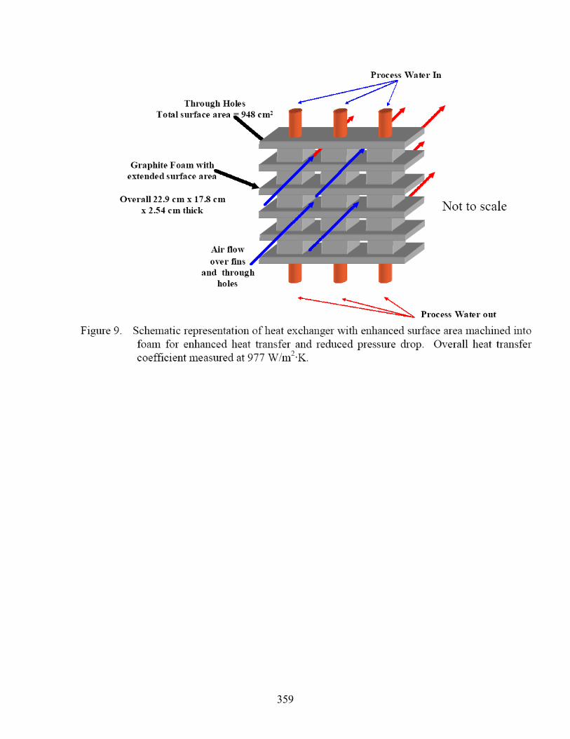
359

360
2002_Thermal Performance of a Graphite Foam Material with Water Flow for Cooling Power Electronics. Klett, J. * Check below all that apply; Write specific features as necessary in the blank space
Article Type Material Configuration Importance ( )Review paper ( ) Polymer ( ) Liquid-Gas ( ) 5 (×) Experimental data ( ) PMC ( ) Liquid-Liquid (× ) 4 ( ) Numerical data (× ) Carbon ( ) Gas-Gas ( ) 3
( ) Correlation ( ) CAMC ( ) Tubes ( ) 2 ( ) HX modeling ( ) Metal (×) Fins ( ) 1
( ) System modeling ( ) MMC (×) Plates ( )
( ) Material property ( ) ceramic/CMC (× ) Heat sink (Liquid) ( )
( ) ( ) ( ) Heat sink (Gas) ( ) ( ) HX design ( ) ( ) ( ) ( ) ( ) ( ) ( ) Specific features: water is used as the cooling fluid r Application:. electric aircraft recovery system (EARS). PMC (Polymer Matrix Composite), CAMC (Carbon Matrix Composite), MMC (Metal Matrix Composite), CMC (Ceramic Matrix Composite)
Overall contribution of the article (to help us identify what it is; not same as title) This section will provide a brief description of the graphite foam, the test facilities, the experimental procedures and the three different configurations tested...
Description of key information from the article such as The thermal performance for three configurations of the foam was tested using cooling
water and the results compared. water is used as the cooling fluid. A study is ongoing to quantify and determine alternative methods to maintain thermal
equilibrium for an advance linear motor (ALM) for use in an electric aircraft recovery system (EARS)...
A majority of published work by ORNL regarding this material is for forced-air thermal management systems.
most Navy applications are very volume and weight sensitive. The first sample, Foam #17, is made of high-density graphite foam with vertical blind
holes drilled perpendicular to the flow. The second sample, Foam #18, is solid, low-density graphite foam. The final sample, Foam #20, is high-density graphite foam with horizontal blind holes drilled parallel to the flow.
Important findings and results The graphite foam CTE is much closer matched to the silicon chip (2.6 ppm/°C)3 and the
CTE of typical baseplate ceramics, such as Aluminum Nitride (CTE of 3.3 ppm/°C)3. This may help reduce thermal stresses attributed to high mismatches in CTE values and thereby, improving reliability..
Table 2 provides a comparison between air-cooled data published in reference 6 and the water-cooled data presented in this paper. This table shows that water-cooling has over a tenfold enhancement in heat transfer at much lower fluid volumetric flow rates.
Comparison with other data None
Something to remember If someone other than the reviewer reads this document, he/she should not
miss anything important in the article: Test Facility.

361
Review opinion Critical evaluation of the paper by the reviewer
Questionable items: Liquid Heat sink possess an attractive Overall Heat Transfer Coefficient
Alternative explanations:. Remarks on importance (relevance) to our project
Possible sections of final report to be mentioned in • Lit. review > Carbon > Carbon foam> Heat Sink • Exploitation > Carbon > Carbon foam> Heat Sink • Performance modeling > Carbon > Carbon foam> Heat Sink
One test compared a standard aluminum finned heat sink used in a Pentium 133 microprocessor to a similar geometry device machined from a graphite foam sample. The graphite foam heat sink out performed the aluminum heat sink, which had a mass 5.5 times larger. In follow-on testing, the fins were machined off the graphite foam heat sink and a similar experiment was conducted. The graphite foam showed slightly less thermal performance, but its mass was eleven times smaller. For an additional test, an identical finned heat sink was machined from the graphite foam material and installed in an operational Pentium 133 computer. This computer has operated with the original cooling fan, without problems, for over a year.

362
Utilization of a graphite foam radiator on a natural gas engine-driven heat pump (hard copy) Ott, R.D. (Oak Ridge National Laboratory, Metals Division); Zaltash, A.; Klett, J.W. Source: American Society of Mechanical Engineers, Advanced Energy Systems Division (Publication) AES, v 42, 2002, p 463-467 Database: Compendex * Check below all that apply; Write specific features as necessary in the blank space
Article Type Material Configuration Importance ( )Review paper ( ) Polymer (×) Liquid-Gas ( ) 5
(×) Experimental data ( ) PMC ( ) Liquid-Liquid (× ) 4 ( ) Numerical data (× ) Carbon ( ) Gas-Gas ( ) 3
( ) Correlation ( ) CAMC (× ) Tubes ( ) 2
( ) HX modeling ( ) Metal (×) Fins ( ) 1
( ) System modeling ( ) MMC ( ) Plates ( ) ( ) Material property ( ) ceramic/CMC ( ) Heat sink (Liquid) ( ) ( ) ( ) ( ) Heat sink (Gas) ( ) (× ) HX design ( ) ( ) ( )
( ) ( ) ( ) ( ) Specific features: a heat exchanger (radiator) , propylence glycol and water Application:. A natural gas engine-driven heat pump PMC (Polymer Matrix Composite), CAMC (Carbon Matrix Composite), MMC (Metal Matrix Composite), CMC (Ceramic Matrix Composite)
Overall contribution of the article (to help us identify what it is; not same as title) A natural gas engine-driven heat pump was outfitted with a graphite foam radiator to demonstrate its thermal efficiency and compare it with that of a conventional radiator.
Description of key information from the article such as A sequence of tests was performed with the graphite foam radiator operating in series
with the standard aluminum radiator.. Most aluminum air-to-water radiators exhibit an overall heat transfer coefficient up to 100
W/(m2•K). Laboratory experiments have demonstrated that a graphite foam radiator can achieve an overall heat transfer coefficient up to an order of magnitude larger
The mesophase pitch derived graphite foam is a material that offers excellent thermal management capability. The foam has an accessible surface area of 4 m2/g and an open cell structure with graphitic ligaments aligned parallel to the cell walls, giving it an overall bulk thermal conductivity of up to 175 W/(m•K). The bulk thermal conductivity of aluminum is 180 W/(m•K). The density of the graphite foam is a fifth of that of aluminum and its thermal diffusivity is three times greater than aluminum
See hard copy Important findings and results
These properties allow the graphite foam to be utilized in radiator, or any other heat exchanger, designs that are more efficient than conventional radiators.
A graphite foam radiator designed to reject a given amount of heat will be smaller in size, weigh less, require less cooling air, and be quicker at removing heat than a conventional aluminum radiatorCarbon foam core radiator heat transfer coefficients more than two orders of magnitude greater than traditional radiators were measured..
Figure 3 Table 3:over all heat transfer coefficient is 5.7 times greater than that of the standard one
Comparison with other data
363
Standard radiator.. Something to remember
If someone other than the reviewer reads this document, he/she should not miss anything important in the article: None.
Review opinion Critical evaluation of the paper by the reviewer
Questionable items: The absolute value of U is small? 182 Alternative explanations: low water flow 7.5 lpm
Remarks on importance (relevance) to our project Possible sections of final report to be mentioned in • Lit. review > Carbon > Carbon foam> L-G • Exploitation > Carbon > Carbon foam> L-G • Performance modeling > Carbon > Carbon foam> L-G

364
Addendum: Modular heat sinks for desktop computers and other electronics Klett, J.W. (Metals & Ceramics Div., Oak Ridge Nat. Lab., TN, USA); Trammell, M. Source: IEEE Transactions on Device and Materials Reliability, v 4, n 4, Dec. 2004, p 638-40 * Check below all that apply; Write specific features as necessary in the blank space
Article Type Material Configuration Importance ( )Review paper ( ) Polymer ( ) Liquid-Gas ( ) 5 (×) Experimental data ( ) PMC ( ) Liquid-Liquid (× ) 4 ( ) Numerical data (× ) Carbon ( ) Gas-Gas ( ) 3
( ) Correlation ( ) CAMC ( ) Tubes ( ) 2 ( ) HX modeling ( ) Metal (×) Fins ( ) 1
( ) System modeling ( ) MMC (×) Plates ( )
( ) Material property ( ) ceramic/CMC (× ) Heat sink (Liquid) ( )
( ) ( ) ( ) Heat sink (Gas) ( ) (×) HX design ( ) ( ) ( )
( ) ( ) ( ) ( ) Specific features: passive evaporative cooling Application:. desktop computers and other electronics. PMC (Polymer Matrix Composite), CAMC (Carbon Matrix Composite), MMC (Metal Matrix Composite), CMC (Ceramic Matrix Composite)
Overall contribution of the article (to help us identify what it is; not same as title) DESIGN OF MODULAR EVAPORATIVE COOLING HEAT SINK TEST PROCEDURES AND RESULTS
.. Description of key information from the article such as
HE evaporative cooling technique described in this paper is uniquely suited to systems where the chip or actual electronic device can be bonded directly to the graphite foam and then immersed in the cooling fluid.
Important findings and results the passive evaporative cooling technique can be applied to modular aftermarket finned
heat sinks. However, the performance was only moderately better, 30%, than the standard designs (0.31 versus 0.44 C/W).
It is evident that the thermal resistances of condensation, conduction, and convection need to be optimized to reduce the overall resistance.
the thermal resistance to boiling and the overall thermal resistance can be calculated as a function of power input. As can be seen in Fig. 4
However, it can also be noted that the overall resistance is significantly larger, nearly 0.31 C/W (better than the 0.358 C/W reported for the Sunflower).
At these speeds, the best thermal resistance reported for this heat sink is around 0.44 C/W
Comparison with other data None
Something to remember If someone other than the reviewer reads this document, he/she should not miss anything important in the article: TEST PROCEDURES AND RESULTS .
Review opinion

365
Critical evaluation of the paper by the reviewer Questionable items: no very clear Alternative explanations:.
Remarks on importance (relevance) to our project Possible sections of final report to be mentioned in • Lit. review > Carbon > Carbon foam> Heat Sink • Exploitation > Carbon > Carbon foam> Heat Sink • Performance modeling > Carbon > Carbon foam> Heat Sink
One test compared a standard aluminum finned heat sink used in a Pentium 133 microprocessor to a similar geometry device machined from a graphite foam sample. The graphite foam heat sink out performed the aluminum heat sink, which had a mass 5.5 times larger. In follow-on testing, the fins were machined off the graphite foam heat sink and a similar experiment was conducted. The graphite foam showed slightly less thermal performance, but its mass was eleven times smaller. For an additional test, an identical finned heat sink was machined from the graphite foam material and installed in an operational Pentium 133 computer. This computer has operated with the original cooling fan, without problems, for over a year.

366
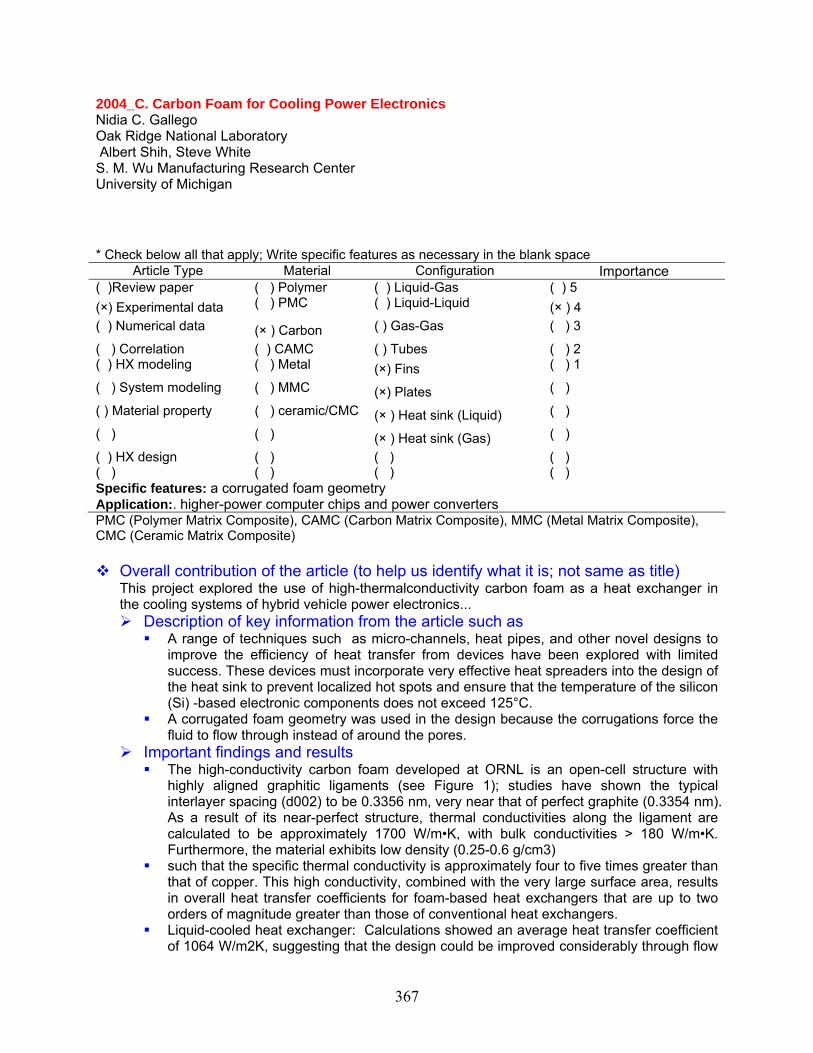
367
2004_C. Carbon Foam for Cooling Power Electronics Nidia C. Gallego Oak Ridge National Laboratory Albert Shih, Steve White S. M. Wu Manufacturing Research Center University of Michigan * Check below all that apply; Write specific features as necessary in the blank space
Article Type Material Configuration Importance ( )Review paper ( ) Polymer ( ) Liquid-Gas ( ) 5 (×) Experimental data ( ) PMC ( ) Liquid-Liquid (× ) 4 ( ) Numerical data (× ) Carbon ( ) Gas-Gas ( ) 3
( ) Correlation ( ) CAMC ( ) Tubes ( ) 2 ( ) HX modeling ( ) Metal (×) Fins ( ) 1
( ) System modeling ( ) MMC (×) Plates ( )
( ) Material property ( ) ceramic/CMC (× ) Heat sink (Liquid) ( )
( ) ( ) (× ) Heat sink (Gas) ( )
( ) HX design ( ) ( ) ( ) ( ) ( ) ( ) ( ) Specific features: a corrugated foam geometry Application:. higher-power computer chips and power converters PMC (Polymer Matrix Composite), CAMC (Carbon Matrix Composite), MMC (Metal Matrix Composite), CMC (Ceramic Matrix Composite)
Overall contribution of the article (to help us identify what it is; not same as title) This project explored the use of high-thermalconductivity carbon foam as a heat exchanger in the cooling systems of hybrid vehicle power electronics...
Description of key information from the article such as A range of techniques such as micro-channels, heat pipes, and other novel designs to
improve the efficiency of heat transfer from devices have been explored with limited success. These devices must incorporate very effective heat spreaders into the design of the heat sink to prevent localized hot spots and ensure that the temperature of the silicon (Si) -based electronic components does not exceed 125°C.
A corrugated foam geometry was used in the design because the corrugations force the fluid to flow through instead of around the pores.
Important findings and results The high-conductivity carbon foam developed at ORNL is an open-cell structure with
highly aligned graphitic ligaments (see Figure 1); studies have shown the typical interlayer spacing (d002) to be 0.3356 nm, very near that of perfect graphite (0.3354 nm). As a result of its near-perfect structure, thermal conductivities along the ligament are calculated to be approximately 1700 W/m•K, with bulk conductivities > 180 W/m•K. Furthermore, the material exhibits low density (0.25-0.6 g/cm3)
such that the specific thermal conductivity is approximately four to five times greater than that of copper. This high conductivity, combined with the very large surface area, results in overall heat transfer coefficients for foam-based heat exchangers that are up to two orders of magnitude greater than those of conventional heat exchangers.
Liquid-cooled heat exchanger: Calculations showed an average heat transfer coefficient of 1064 W/m2K, suggesting that the design could be improved considerably through flow

368
rate control and foam porosity, based on comparisons with carbon foam characterization studies at ORNL. While we cannot verify the expected pressure drop of the system to be less than 0.5 psi (engineering specification 4), we can conclude that the drop is relatively small.
Forced-air heat exchanger: Both design teams found the convective coefficient of the foam to be lower than expected, possibly because of the lack of a bonding agent between the foam and the heat sink, lack of data on the heating element, and the inability to control water and air flow rates over a large range. More precise test setups and heater designs should be used in future testing.
Comparison with other data None
Something to remember If someone other than the reviewer reads this document, he/she should not
miss anything important in the article: Processing Foams with Varied Pore Structures.
Review opinion Critical evaluation of the paper by the reviewer
Questionable items: less important Alternative explanations:.
Remarks on importance (relevance) to our project Possible sections of final report to be mentioned in • Lit. review > Carbon > Carbon foam> Heat Sink • Exploitation > Carbon > Carbon foam> Heat Sink • Performance modeling > Carbon > Carbon foam> Heat Sink

369

370
2004_Graphite Foam for Cooling of Automotive Power Electronics_less important. Steve B. White', * Check below all that apply; Write specific features as necessary in the blank space
Article Type Material Configuration Importance ( )Review paper ( ) Polymer ( ) Liquid-Gas ( ) 5 (× ) Experimental data ( ) PMC ( ) Liquid-Liquid (× ) 4 ( ) Numerical data (× ) Carbon ( ) Gas-Gas ( ) 3 ( ) Correlation ( ) CAMC ( ) Tubes ( ) 2 ( ) HX modeling ( ) Metal (× ) Fins ( ) 1 ( ) System modeling ( ) MMC (× ) Plates ( ) ( ) Material property ( ) ceramic/CMC (× ) Heat sink (Liquid) ( ) ( ) ( ) (× ) Heat sink (Gas) ( ) ( ) HX design ( ) ( ) ( ) ( ) ( ) ( ) ( ) Specific features: a corrugated foam geometry Application:. higher-power computer chips and power converters PMC (Polymer Matrix Composite), CAMC (Carbon Matrix Composite), MMC (Metal Matrix Composite), CMC (Ceramic Matrix Composite)
Overall contribution of the article (to help us identify what it is; not same as title) Similar to 2004_C. Carbon Foam for Cooling Power Electronics_less important..
Description of key information from the article such as Important findings and results Comparison with other data
None Something to remember
If someone other than the reviewer reads this document, he/she should not miss anything important in the article: s.
Review opinion Critical evaluation of the paper by the reviewer
Questionable items: less important Alternative explanations:.
Remarks on importance (relevance) to our project Possible sections of final report to be mentioned in • Lit. review > Carbon > Carbon foam> Heat Sink • Exploitation > Carbon > Carbon foam> Heat Sink • Performance modeling > Carbon > Carbon foam> Heat Sink

371
Parametric investigation of a graphite foam evaporator in a thermosyphon with fluorinert and a silicon CMOS chip Klett, J.W. (Metals & Ceramics Div., Oak Ridge Nat. Lab., TN, USA); Trammell, M. Source: IEEE Transactions on Device and Materials Reliability, v 4, n 4, Dec. 2004, p 626-37 Database: Inspec * Check below all that apply; Write specific features as necessary in the blank space
Article Type Material Configuration Importance ( )Review paper ( ) Polymer ( ) Liquid-Gas ( ) 5 (×) Experimental data ( ) PMC ( ) Liquid-Liquid (× ) 4 ( ) Numerical data (× ) Carbon ( ) Gas-Gas ( ) 3
( ) Correlation ( ) CAMC ( ) Tubes ( ) 2 ( ) HX modeling ( ) Metal (×) Fins ( ) 1
( ) System modeling ( ) MMC (×) Plates ( )
( ) Material property ( ) ceramic/CMC (× ) Heat sink (Liquid) ( )
( ) ( ) ( ) Heat sink (Gas) ( ) ( ) HX design ( ) ( ) ( ) ( ) ( ) ( ) ( ) Specific features: thermosyphon Application:. thermosyphon. PMC (Polymer Matrix Composite), CAMC (Carbon Matrix Composite), MMC (Metal Matrix Composite), CMC (Ceramic Matrix Composite)
Overall contribution of the article (to help us identify what it is; not same as title) High thermal conductivity graphitic foam was utilized as the evaporator in a modified thermosyphon...
Description of key information from the article such as The foam was soldered directly to the back of a silicon CMOS die and mounted in a
standard PGA. Fluorinert FC-87 and FC-72 were evaluated as the working fluids of choice and a variety of variables on the foams were explored.
The most significant effect on performance was the modifications to the foam structure. Slotted patterns were found to enhance the rate of return of fluid to the foam closest to the die, thus improving performance.
The National Security Agency (NSA) has conducted research on thermosyphons using state of the art polycrystalline diamond wafers with thermal conductivities up to 1600 W/m K (about four times that of copper) as the heat spreader. As a result of the limited surface area of the diamond spreader, the maximum power density achieved without over heating the system was 28 W/cm [11].
Important findings and results
the density of the foam evaporators affected the thermal performance of the system. However, the fluid level and fluid type had very little effect on the overall performance in the system, making fabrication of a commercial device less challenging..
With a slotted foam evaporator, a heat flux of 150 W/cm2 resulted in wall superheats of only 11 C..
In addition, it was found that critical heat flux was not reached in these experiments with graphite foam evaporators at heat fluxes as high as 150 W/cm2
In one case, foam with a lower density performed significantly better than a higher density foam. However, the mechanism for the improvement is not fully understood.
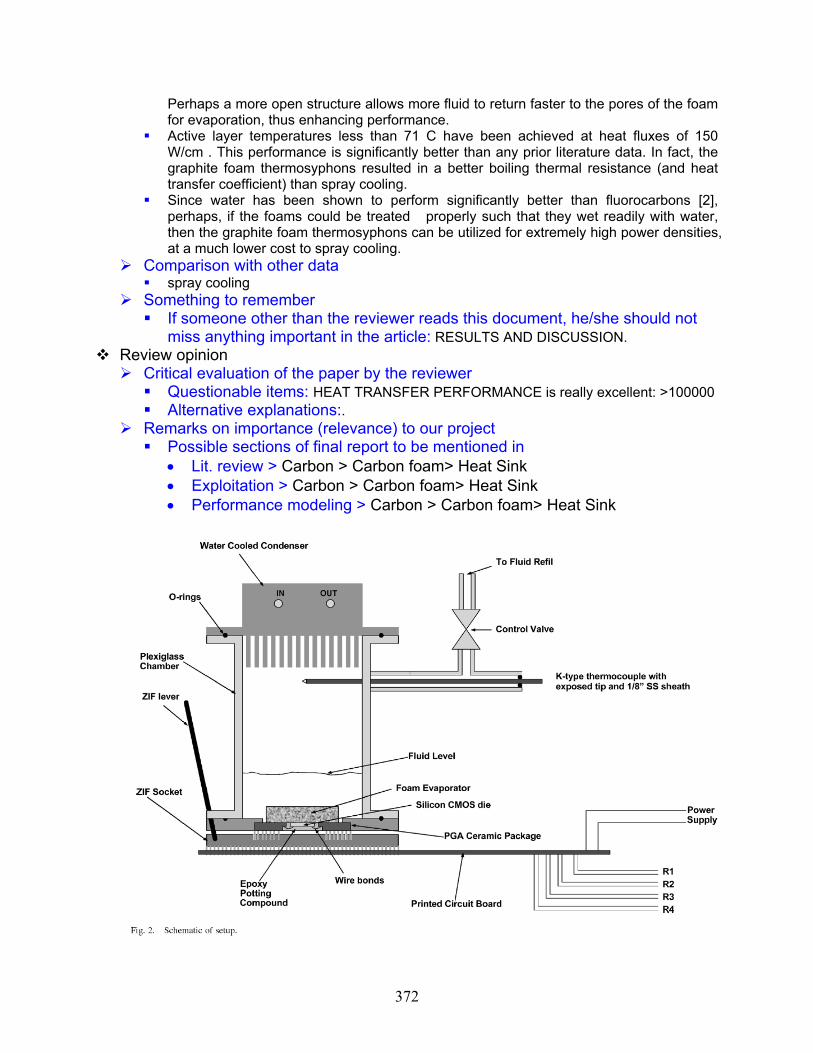
372
Perhaps a more open structure allows more fluid to return faster to the pores of the foam for evaporation, thus enhancing performance.
Active layer temperatures less than 71 C have been achieved at heat fluxes of 150 W/cm . This performance is significantly better than any prior literature data. In fact, the graphite foam thermosyphons resulted in a better boiling thermal resistance (and heat transfer coefficient) than spray cooling.
Since water has been shown to perform significantly better than fluorocarbons [2], perhaps, if the foams could be treated properly such that they wet readily with water, then the graphite foam thermosyphons can be utilized for extremely high power densities, at a much lower cost to spray cooling.
Comparison with other data spray cooling
Something to remember If someone other than the reviewer reads this document, he/she should not
miss anything important in the article: RESULTS AND DISCUSSION. Review opinion
Critical evaluation of the paper by the reviewer Questionable items: HEAT TRANSFER PERFORMANCE is really excellent: >100000 Alternative explanations:.
Remarks on importance (relevance) to our project Possible sections of final report to be mentioned in • Lit. review > Carbon > Carbon foam> Heat Sink • Exploitation > Carbon > Carbon foam> Heat Sink • Performance modeling > Carbon > Carbon foam> Heat Sink

373
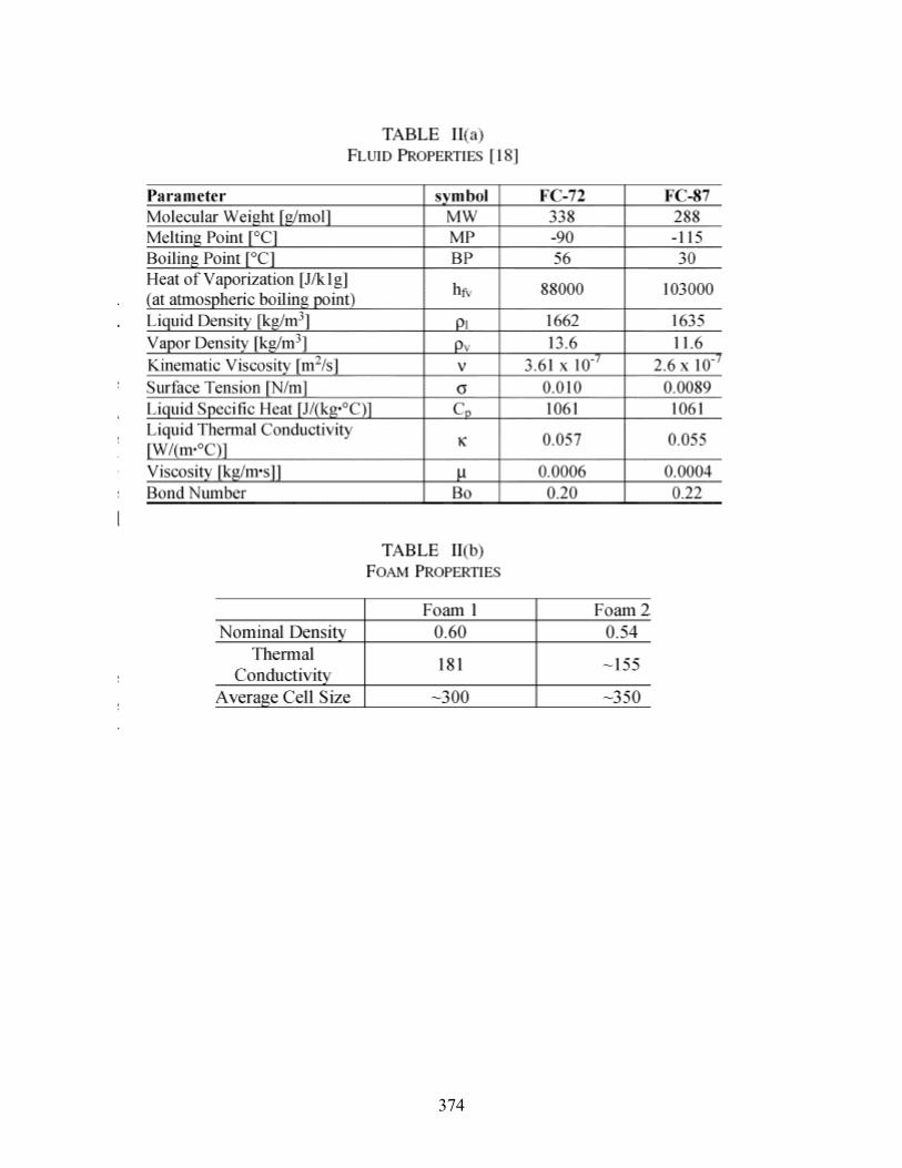
374

375

376
Carbon foam - New generation of enhanced surface compact recuperators for gas turbines (hard copy) Yu, Q. (Department of Mechanical and Materials Engineering, University of Western Ontario); Thompson, B.E.; Straatman, A.G. Source: Proceedings of the ASME Turbo Expo, v 1, Proceedings of the ASME Turbo Expo 2005, 2005, p 1023-1028 Database: Compendex * Check below all that apply; Write specific features as necessary in the blank space
Article Type Material Configuration Importance ( )Review paper ( ) Polymer ( ) Liquid-Gas ( ) 5 ( ) Experimental data ( ) PMC ( ) Liquid-Liquid (× ) 4 ( ) Numerical data (× ) Carbon (×) Gas-Gas ( ) 3
( ) Correlation ( ) CAMC ( ) Tubes ( ) 2 ( ) HX modeling ( ) Metal (×) Fins ( ) 1
( ) System modeling ( ) MMC (×) Plates ( )
( ) Material property ( ) ceramic/CMC ( ) Heat sink (Liquid) ( ) ( ) ( ) ( ) Heat sink (Gas) ( ) (× ) HX design ( ) ( ) ( )
( ) ( ) ( ) ( ) Specific features: a heat exchanger (radiator) , propylence glycol and water Application:. A natural gas engine-driven heat pump PMC (Polymer Matrix Composite), CAMC (Carbon Matrix Composite), MMC (Metal Matrix Composite), CMC (Ceramic Matrix Composite)
Overall contribution of the article (to help us identify what it is; not same as title) The potential of porous carbon foam is explored in the context of compact recuperators for microturbine applications.
Description of key information from the article such as Porous carbon foam has an open, interconnected pore structure and an extremely high
solid-phase conductivity, which render the material a viable alternative in compact heat exchanger design.
The material is also mechanically stable, non-corrosive and relatively inert to temperatures up to approximately 500°C, which make it particularly attractive for high-temperature non-oxydizing and moderate temperature oxidizing applications.
See hard copy Important findings and results
Hydrodynamic and thermal engineering models are proposed based on recent work applied to air-water heat exchangers. The models are developed based on a unit-cube geometric model for carbon foam, a heat transfer model and well-established convective correlations that are extended to account for the effects of the carbon foam.
The present calculations suggest that the use of carbon foam in a relatively simple configuration results in a significant reduction in thermal resistance accompanied by a rise in the hydrodynamic resistance.
These preliminary results suggest that very compact heat transfer devices could be developed. With further investigation it is felt that the hydrodynamic resistance could be reduced while preserving the heat transfer performance resulting in very high-performance, compact heat transfer devices...
Figure 1counter flow, forced through a volume of porous carbon foam Table 1: fin, full length block, shortened configurations

377
Comparison with other data None..
Something to remember If someone other than the reviewer reads this document, he/she should not
miss anything important in the article: Model. Review opinion
Critical evaluation of the paper by the reviewer Questionable items: Good idea of application Alternative explanations: heat recover system
Remarks on importance (relevance) to our project Possible sections of final report to be mentioned in • Lit. review > Carbon > Carbon foam> G-G • Exploitation > Carbon > Carbon foam> G-G • Performance modeling > Carbon > Carbon foam> G-G

378
2004_Parametric investigation of a graphite foam evaporator in a thermosyphon with fluorinert and a silicon CMOS chip. Klett, J. * Check below all that apply; Write specific features as necessary in the blank space
Article Type Material Configuration Importance ( )Review paper ( ) Polymer ( ) Liquid-Gas ( ) 5 (×) Experimental data ( ) PMC ( ) Liquid-Liquid (× ) 4 ( ) Numerical data (× ) Carbon ( ) Gas-Gas ( ) 3
( ) Correlation ( ) CAMC ( ) Tubes ( ) 2 ( ) HX modeling ( ) Metal (×) Fins ( ) 1
( ) System modeling ( ) MMC (×) Plates ( )
( ) Material property ( ) ceramic/CMC (× ) Heat sink (Liquid) ( )
( ) ( ) ( ) Heat sink (Gas) ( ) ( ) HX design ( ) ( ) ( ) ( ) ( ) ( ) ( ) Specific features: thermosyphon Application:. thermal management of electronics.. PMC (Polymer Matrix Composite), CAMC (Carbon Matrix Composite), MMC (Metal Matrix Composite), CMC (Ceramic Matrix Composite)
Overall contribution of the article (to help us identify what it is; not same as title) The use of graphite foam as the evaporator of a thermosyphon is investigated due to its potential to transfer large amounts of energy without the need for external pumping....
Description of key information from the article such as A preliminary optimization of the parameters governing evaporator performance is
performed using 2-level factorial design. Performance of the system with both PF-5060 and PF-5050 were examined as well as the effects of liquid level and chamber pressure. r, the maximum power density achieved without over heating the system was 28 W/cm
A two-phase closed thermosyphon consists of an evaporator, a condenser, and an adiabatic section that allows a working fluid to travel between the other two components.
Working Fluid. Both PF-5060 and PF-5050 (95% pure FC-72 and FC-87, respectively) were used.
Important findings and results This preliminary investigation has shown that heat fluxes approaching 50 W/cm2 while
maintaining the wall temperature below 85 °C are possible with little optimization. It was also determined that thermosyphon performance is not significantly different when
the working fluid is changed from PF-5060 to PF-5050, although results may vary for foams with different pore sizes.
These results will be used to design a more comprehensive parameterization study that will investigate pore size, geometry, and other effects as the limits of graphite foam evaporator performance is explored.
Comparison with other data None
Something to remember If someone other than the reviewer reads this document, he/she should not
miss anything important in the article: EXPERIMENTAL METHOD. Review opinion

379
Critical evaluation of the paper by the reviewer Questionable items: worse than the results of Klett, J Alternative explanations:.
Remarks on importance (relevance) to our project Possible sections of final report to be mentioned in • Lit. review > Carbon > Carbon foam> Heat Sink • Exploitation > Carbon > Carbon foam> Heat Sink • Performance modeling > Carbon > Carbon foam> Heat Sink

380

381
1998_ Forced Convection in a Channel Filled with High Thermal Conductivity Carbon Foams.pdf Klett, J. * Check below all that apply; Write specific features as necessary in the blank space
Article Type Material Configuration Importance ( )Review paper ( ) Polymer ( ) Liquid-Gas ( ) 5 (×) Experimental data ( ) PMC ( ) Liquid-Liquid (× ) 4
(×) Numerical data (× ) Carbon ( ) Gas-Gas ( ) 3
( ) Correlation ( ) CAMC (× ) Tubes ( ) 2
( ) HX modeling ( ) Metal (×) Fins ( ) 1
( ) System modeling ( ) MMC ( ) Plates ( ) ( ) Material property ( ) ceramic/CMC ( ) Heat sink (Liquid) ( ) ( ) ( ) (×) Heat sink (Gas) ( )
( ) HX design ( ) ( ) ( ) ( ) ( ) ( ) ( ) Specific features: forced-convection cooler Application:. Microelectronics cooling PMC (Polymer Matrix Composite), CAMC (Carbon Matrix Composite), MMC (Metal Matrix Composite), CMC (Ceramic Matrix Composite)
Overall contribution of the article (to help us identify what it is; not same as title) The feasibility of using a channel filled with carbon foam as a heat sink for a highperformance forced-convection cooler in microelectronics was studied.
Description of key information from the article such as the foam was attached to the metals while they were in a molten state...
Important findings and results The thermal conductivity of the carbon foam used in this study falls into a range of
120~180 W/m·K.. The Forchheimer equation is valid for the air permeability in the forced-convection
cooling of the carbon foam. Comparison with other data
None Something to remember
If someone other than the reviewer reads this document, he/she should not miss anything important in the article:None.
Review opinion Critical evaluation of the paper by the reviewer
Questionable items: excellent results? Alternative explanations:.
Remarks on importance (relevance) to our project Possible sections of final report to be mentioned in • Lit. review > Carbon > Carbon foam> Heat Sink • Exploitation > Carbon > Carbon foam> Heat Sink • Performance modeling > Carbon > Carbon foam> Heat Sink

382

383
Racing Radiators Utilizing ORNL's Graphic Foam Klett, J. (Oak Ridge National Lab., TN.) Sponsor: Department of Energy, Washington, DC. Report: C/ORNL98-0551, Aug 2000, 15p (Date Published October 10, 1998) Database: NTIS * Check below all that apply; Write specific features as necessary in the blank space
Article Type Material Configuration Importance ( )Review paper ( ) Polymer (×) Liquid-Gas ( ) 5
(×) Experimental data ( ) PMC ( ) Liquid-Liquid (× ) 4 ( ) Numerical data (× ) Carbon ( ) Gas-Gas ( ) 3
( ) Correlation ( ) CAMC (× ) Tubes ( ) 2
( ) HX modeling ( ) Metal (×) Fins ( ) 1
( ) System modeling ( ) MMC ( ) Plates ( ) ( ) Material property ( ) ceramic/CMC ( ) Heat sink (Liquid) ( ) ( ) ( ) ( ) Heat sink (Gas) ( ) (× ) HX design ( ) ( ) ( )
( ) ( ) ( ) ( ) Specific features: a heat exchanger (radiator) Application:. a passenger automobile PMC (Polymer Matrix Composite), CAMC (Carbon Matrix Composite), MMC (Metal Matrix Composite), CMC (Ceramic Matrix Composite)
Overall contribution of the article (to help us identify what it is; not same as title) To further demonstrate this phenomenon, a heat exchanger (radiator) for a passenger automobile has been developed that is significantly smaller in size, and testing has demonstrated feasibility to improve the automobiles aerodynamic efficiency and reduce weight..
Description of key information from the article such as A simple shell and tube heat exchanger with the foam as the core of the shell side of the
exchanger was fabricated.. participant glued the foam into the heat exchanger,. thermocouples are accurate to 1-2°C and the overall change in temperature of the
waterside was no more than 2°C, giving concerns to the accuracy of these numbers. Important findings and results
Carbon foam core radiator heat transfer coefficients more than two orders of magnitude greater than traditional radiators were measured.
With a thermal conductivity equivalent to aluminum 6061 and 1/5th the weight, this material is an enabling technology for thermal management problems ranging from heat sinks to radiators and satellite panels to aircraft heat exchangers...
the open porosity will lead to novel designs that incorporate porous media heat exchangers and phase change materials..
As can be seen, the heat transfer coefficients are rather large, up to 3500 W/m2·K. A typical automobile heat exchanger exhibits a overall heat transfer coefficient of about 250 W/m2·K.
It was shown in other research that glues could reduce the heat transfer from a metal surface to the foam by over fifty percent.
It has been shown that the brazing technique will not reduce the heat transfer from the tubes to the foam by more than five percent
The humidity in the air can dramatically affect the heat capacity of the air and, therefore, affect the amount of heat removed.

384
Comparison with other data typical automobile heat exchanger, humidity..
Something to remember If someone other than the reviewer reads this document, he/she should not
miss anything important in the article: Actual design. Review opinion
Critical evaluation of the paper by the reviewer Questionable items: excellent results? Alternative explanations:.
Remarks on importance (relevance) to our project Possible sections of final report to be mentioned in • Lit. review > Carbon > Carbon foam> L-G • Exploitation > Carbon > Carbon foam> L-G • Performance modeling > Carbon > Carbon foam> L-G

385

386
1999_Foam Core Sandwich Panels Made From High Thermal Conductivity Mesophase Pitch-based Carbon Foam. Klett, J. * Check below all that apply; Write specific features as necessary in the blank space
Article Type Material Configuration Importance ( )Review paper ( ) Polymer (× ) Liquid-Gas ( ) 5
(×) Experimental data ( ) PMC ( ) Liquid-Liquid (× ) 4 ( ) Numerical data (× ) Carbon (×) Gas-Gas ( ) 3
( ) Correlation ( ) CAMC (×) Tubes ( ) 2
( ) HX modeling ( ) Metal (×) Fins ( ) 1
( ) System modeling ( ) MMC (×) Plates ( )
( ) Material property ( ) ceramic/CMC ( ) Heat sink (Liquid) ( ) ( ) ( ) (×) Heat sink (Gas) ( )
( ) HX design ( ) ( ) ( ) ( ) ( ) ( ) ( ) Specific features: heat exchangers, radiators, and heat pipes. Application:. require high thermal conductivity and low weight. PMC (Polymer Matrix Composite), CAMC (Carbon Matrix Composite), MMC (Metal Matrix Composite), CMC (Ceramic Matrix Composite)
Overall contribution of the article (to help us identify what it is; not same as title) Foam core sandwich structures were investigated to improve the mechanical properties without sacrificing the thermal properties..
Description of key information from the article such as Several 38.1 mm thick foam blocks were made from AR Mesophase pitch with the
standard ORNL process. Sandwich panels were constructed from a 12.7 mm thick, 152.4 mm diameter foam core sections machined from the thick blocks. Both aluminum 3003-H14 and copper 110, 0.635 mm thick, were used as facesheets. A thermally conductive film adhesive, T-gon 1/KA-08-128 (0.203 mm, 8 W/m· K), was used to bond the facesheets to the foam core with a cure at 0.241 MPa, 150°C for 30 minutes....
Important findings and results The results of the thermal conductivity testing (Table 3) indicated that the sandwich
specimens had a through the thickness thermal conductivity of between 50 and 65 W/m· K with little difference between the aluminum and the copper sandwich panels. Although the thermal conductivity was decreased due to the relatively low conductivity interface, the specific conductivity of the sandwich panels is comparable to aluminum..
The average interface thickness in the sandwich panels was between 0.127 and 0.203 mm. With a thermal conductivity of only 8 W/m· K the interface was the limiting factor for the through thickness conductivity.

387
Several additional sandwich panels have been successfully bonded with thinner bondlines of filled epoxies (approximately 0.0254 mm). Also, a brazing technique has been developed for bonding aluminum facesheets (thermal conductivity of the brazing material is approximately 45 W/m· K).
Comparison with other data None
Something to remember If someone other than the reviewer reads this document, he/she should not
miss anything important in the article: Preliminary tests were conducted to determine the core shear, compression of sandwich structures with facesheets consisting of copper and aluminum..
Review opinion Critical evaluation of the paper by the reviewer
Questionable items: need photos to show? Alternative explanations:.
Remarks on importance (relevance) to our project Possible sections of final report to be mentioned in • Lit. review > Carbon > Carbon foam> Heat Sink • Exploitation > Carbon > Carbon foam> Heat Sink • Performance modeling > Carbon > Carbon foam> Heat Sink

388
2003_Carbon foams for thermal management_a good review of ORAL Klett, James * Check below all that apply; Write specific features as necessary in the blank space
Article Type Material Configuration Importance (× )Review paper ( ) Polymer ( ) Liquid-Gas ( × ) 5 ( ) Experimental data ( ) PMC ( ) Liquid-Liquid ( ) 4 ( ) Numerical data (×) Carbon ( ) Gas-Gas ( ) 3
( ) Correlation ( ) CAMC ( ) Tubes ( ) 2 ( ) HX modeling ( ) Metal ( ) Fins ( ) 1 ( ) System modeling ( ) MMC ( ) Plates ( ) ( ) Material property ( ) ceramic/CMC ( ) Heat sink (Liquid) ( ) ( ) ( ) (×) Heat sink (Gas) ( )
( ) ( ) ( ) ( ) ( ) ( ) ( ) ( ) Specific features: Application: PMC (Polymer Matrix Composite), CAMC (Carbon Matrix Composite), MMC (Metal Matrix Composite), CMC (Ceramic Matrix Composite)
Overall contribution of the article (to help us identify what it is; not same as title) A unique process for the fabrication of high-thermal-conductivity carbon foam was developed at Oak Ridge National Laboratory (ORNL)..
Description of key information from the article such as A Good review of carbon foam. Because of its low density, its high thermal conductivity, its relatively high surface area,
and its open-celled structure, the ORNL carbon foam is an ideal material for thermal management applications.
. Important findings and results
This process does not require the traditional blowing and stabilization steps and therefore is less costly.
The resulting foam can have density values of between 0.2 and 0.6 g/cc and can develop a bulk thermal conductivity of between 40 and 180 W/m K.
Initial studies have shown the overall heat transfer coefficients of carbon foam-based heat sinks to be up to two orders of magnitude greater than those of conventional heat sinks..
Table 2: Comparison of air-cooled heat transfer coefficients obtained for graphite foam and aluminum foam
Table 3 :Comparison of air-cooled and water-cooled heat transfer coefficients obtained for carbon foam
Comparison with other data None
Review opinion Critical evaluation of the paper by the reviewer
Questionable items: The tables are not color table. Alternative explanations:.
Remarks on importance (relevance) to our project Possible sections of final report to be mentioned in • Lit. review > Carbon > Carbon foam> Heat sink and heat exchangers

389
• Exploitation > Carbon > Carbon foam> Heat sink and heat exchangers • Performance modeling > Carbon > Carbon foam> Heat sink and heat
exchangers Something to remember
If someone other than the reviewer reads this document, he/she should not miss anything important in the article: complete properties in tables

390

391
Strength Enhancement and Application Development of Carbon Foam for Thermal Management Systems Duston, C.; Watts, R.; Seghi, S.; Carney, B. (Ceramic Composites, Inc., Millersville, MD.), 2004, 10p Database: NTIS * Check below all that apply; Write specific features as necessary in the blank space
Article Type Material Configuration Importance (× )Review paper ( ) Polymer ( ) Liquid-Gas ( × ) 5 ( ) Experimental data ( ) PMC ( ) Liquid-Liquid ( ) 4 ( ) Numerical data (×) Carbon ( ) Gas-Gas ( ) 3
( ) Correlation ( ) CAMC ( ) Tubes ( ) 2 ( ) HX modeling ( ) Metal ( ) Fins ( ) 1 ( ) System modeling ( ) MMC ( ) Plates ( ) ( ) Material property ( ) ceramic/CMC ( ) Heat sink (Liquid) ( ) ( ) ( ) (×) Heat sink (Gas) ( )
( ) ( ) ( ) ( ) ( ) ( ) ( ) ( ) Specific features: Application: PMC (Polymer Matrix Composite), CAMC (Carbon Matrix Composite), MMC (Metal Matrix Composite), CMC (Ceramic Matrix Composite)
Overall contribution of the article (to help us identify what it is; not same as title) An overview of the technical approach will be presented, along with the envelope of enhanced material properties achieved under the program.
Description of key information from the article such as A Good review of carbon foam. Carbon foam is recognized as having the great potential to replacement for metal fins in
thermal management systems such as heat exchangers, space radiators, and thermal protection systems. An initial barrier to implementation was the inherent weakness and friability of the carbon foams. Ceramic Composites Inc. has demonstrated the ability to increase the compressive strength by 2½ times through the treatment of the carbon foam ligaments with a uniform silicon carbide coating, serving to enhance strength and reduce friability, with minimal influence upon the thermal properties.
Important findings and results Implementation of carbon foam into these various thermal management systems has
been prohibited by its inherent low strength. This makes the carbon foam difficult to work with, friable, and subject to physical damage during use.
Through the application of a silicon carbide coating, via polymeric precursor, to the carbon foam, a uniform ligament coating has been applied to the structure which increases the compressive strength by up to 2.5x and the compressive modulus by up to 3.5x, while reducing the thermal conductivity by only 5%.
Each of these approaches has produced composites which have negatively affected the thermal conductivity of the product, added excessively to the mass, or reduced the thermal operational limit..
Comparison with other data None
Review opinion Critical evaluation of the paper by the reviewer
Questionable items: The description of coating or composite is not clear. Alternative explanations:.

392
Remarks on importance (relevance) to our project Possible sections of final report to be mentioned in • Lit. review > Carbon > Carbon foam> Heat sink and heat exchangers • Exploitation > Carbon > Carbon foam> Heat sink and heat exchangers • Performance modeling > Carbon > Carbon foam> Heat sink and heat
exchangers Something to remember
If someone other than the reviewer reads this document, he/she should not miss anything important in the article: a lot tables and figures

393
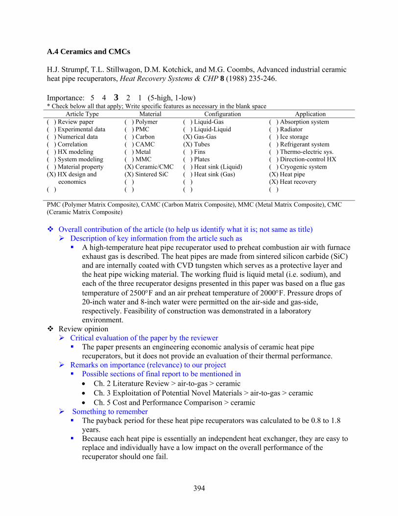
394
A.4 Ceramics and CMCs H.J. Strumpf, T.L. Stillwagon, D.M. Kotchick, and M.G. Coombs, Advanced industrial ceramic heat pipe recuperators, Heat Recovery Systems & CHP 8 (1988) 235-246. Importance: 5 4 3 2 1 (5-high, 1-low) * Check below all that apply; Write specific features as necessary in the blank space
Article Type Material Configuration Application ( ) Review paper ( ) Polymer ( ) Liquid-Gas ( ) Absorption system ( ) Experimental data ( ) PMC ( ) Liquid-Liquid ( ) Radiator ( ) Numerical data ( ) Carbon (X) Gas-Gas ( ) Ice storage ( ) Correlation ( ) CAMC (X) Tubes ( ) Refrigerant system ( ) HX modeling ( ) Metal ( ) Fins ( ) Thermo-electric sys. ( ) System modeling ( ) MMC ( ) Plates ( ) Direction-control HX ( ) Material property (X) Ceramic/CMC ( ) Heat sink (Liquid) ( ) Cryogenic system (X) HX design and (X) Sintered SiC ( ) Heat sink (Gas) (X) Heat pipe economics ( ) ( ) (X) Heat recovery ( ) ( ) ( ) ( ) PMC (Polymer Matrix Composite), CAMC (Carbon Matrix Composite), MMC (Metal Matrix Composite), CMC (Ceramic Matrix Composite)
Overall contribution of the article (to help us identify what it is; not same as title) Description of key information from the article such as
A high-temperature heat pipe recuperator used to preheat combustion air with furnace exhaust gas is described. The heat pipes are made from sintered silicon carbide (SiC) and are internally coated with CVD tungsten which serves as a protective layer and the heat pipe wicking material. The working fluid is liquid metal (i.e. sodium), and each of the three recuperator designs presented in this paper was based on a flue gas temperature of 2500°F and an air preheat temperature of 2000°F. Pressure drops of 20-inch water and 8-inch water were permitted on the air-side and gas-side, respectively. Feasibility of construction was demonstrated in a laboratory environment.
Review opinion Critical evaluation of the paper by the reviewer
The paper presents an engineering economic analysis of ceramic heat pipe recuperators, but it does not provide an evaluation of their thermal performance.
Remarks on importance (relevance) to our project Possible sections of final report to be mentioned in • Ch. 2 Literature Review > air-to-gas > ceramic • Ch. 3 Exploitation of Potential Novel Materials > air-to-gas > ceramic • Ch. 5 Cost and Performance Comparison > ceramic
Something to remember The payback period for these heat pipe recuperators was calculated to be 0.8 to 1.8
years. Because each heat pipe is essentially an independent heat exchanger, they are easy to
replace and individually have a low impact on the overall performance of the recuperator should one fail.

395
R. Smyth, The use of high temperature heat exchangers to increase power plant thermal efficiency, ???? Conf. Proceedings, Article No. 97089 (1997) 1690-1695. Importance: 5 4 3 2 1 (5-high, 1-low) * Check below all that apply; Write specific features as necessary in the blank space
Article Type Material Configuration Application (X) Review paper ( ) Polymer ( ) Liquid-Gas ( ) Absorption system ( ) Experimental data ( ) PMC ( ) Liquid-Liquid ( ) Radiator ( ) Numerical data ( ) Carbon (X) Gas-Gas ( ) Ice storage ( ) Correlation ( ) CAMC (X) Tubes ( ) Refrigerant system ( ) HX modeling ( ) Metal ( ) Fins ( ) Thermo-electric sys. ( ) System modeling ( ) MMC ( ) Plates ( ) Direction-control HX (X) Material property (X) Ceramic/CMC ( ) Heat sink (Liquid) ( ) Cryogenic system ( ) ( ) ( ) Heat sink (Gas) ( ) Heat pipe ( ) ( ) (X) Shell and tube HX (X) Steam turbine inlet ( ) ( ) ( ) superheater PMC (Polymer Matrix Composite), CAMC (Carbon Matrix Composite), MMC (Metal Matrix Composite), CMC (Ceramic Matrix Composite)
Overall contribution of the article (to help us identify what it is; not same as title) Description of key information from the article such as
Motivated by the desire to increase the steam turbine inlet temperature to 1300°C (and therefore the overall thermal efficiency up to 55%), this paper examines a novel, ceramic shell-and-tube heat exchanger design. In current power plants, steam is produced at a temperature of 565°C at pressures exceeding 100 bars. This ceramic design would enable the production at steam at temperatures exceeding 1000°C and would permit the heat exchanger to be operated in the more efficient counter-flow mode instead of the parallel flow mode. In the ash fusion mode, steam temperatures up to 1000°C would be possible. However, when operating a conventional coal or oil fire steam power plant in the slagging mode, temperatures in excess of 1000°C could now be considered. Moreover, it was pointed out that while high superheat temperatures can have a pronounced effect on cycle efficiencies, higher pressures only produce relatively modest improvements. The proposed heat exchanger design would necessitate the hot combustion gases flowing inside the tubes and the high pressure steam on the outside to keep the heat transfer tubes in compression. The steel pressure retaining shell of the exchanger would operate at a low temperature and be separated by internal insulation from the heat transfer components of the heat exchanger. It was also proposed that the seals between the ceramic heat exchanger tubes and the pressure shell be located in a relatively cool region of the heat exchanger. The paper identifies a carbon gasket seal design that enables continuous operation at 20.3 bar internal pressure and 982°C for the ceramic-to-ceramic seal, and 20.3 bar internal pressure and 332°C for the ceramic-to-metal seal.

396
Several ceramic materials were examined as possible candidates—silicon carbide, silicon nitrate, alumina, zirconia, aluminium titanate, aluminium nitrate, and ceramic matrix-ceramic fiber reinforcement composites. The following attributes were identified:
1. Silicon carbide (SiC) – reaction bonded SiC has a high melting point (1426°C) and high thermal conductivity (approx. 4x that of steel)
2. Silicon nitride (Si3N4) – good strength and creep resistance; however susceptible to oxidation at high temperatures (1000°C)
3. Alumina (Al2O3) – highly resistant to chemical attack; however, low thermal shock resistance
4. Zirconia (ZeO2) – prone to thermal shock failure and maximum useful temperature of 1300°C
5. Aluminum titanate(Al2TiO5) – exhibit very low thermal conductivity and are therefore useful as insulating materials
6. Aluminum nitride (AlN) – high thermal stability and good oxidation resistance up to 1300°C; however at elevated temperature, Al2O3 scale can crack the oxide layer promoting rapid oxidation of the base material
Ultimately, silicon carbide, silicon nitride, and alumina were chosen for further investigation because they do not lose significant strength until bulk material temperatures of approx. 1400 to 1650°C are reached. The design variables for the shell-and-tube heat exchanger were chosen to be:
• Inlet shell-side steam temperature, 850°C • Outlet shell-side steam temperature, 1200°C • Inlet tube-side flue gas temperature, 2000°C • Outlet tube-side flue gas temperature, 1500°C • Flue gas linear velocity, 100m/s • Heat transfer rate, 14MW
Review opinion
Remarks on importance (relevance) to our project Possible sections of final report to be mentioned in • Lit. review > material characteristics >ceramic • Lit. review > gas-to-gas > ceramic
Something to remember Thermal cycle efficiency improvements of 20-25% appear feasible with the
incorporation and use of a ceramic superheater in a fossil fueled steam power plant.

397
M. Belmonte, Advanced ceramic materials for high temperature applications, Adv. Engr. Materials 8 (2006) 693-703. Importance: 5 4 3 2 1 (5-high, 1-low) * Check below all that apply; Write specific features as necessary in the blank space
Article Type Material Configuration Application (X) Review paper ( ) Polymer ( ) Liquid-Gas ( ) Absorption system ( ) Experimental data ( ) PMC ( ) Liquid-Liquid ( ) Radiator ( ) Numerical data ( ) Carbon ( ) Gas-Gas ( ) Ice storage ( ) Correlation ( ) CAMC ( ) Tubes ( ) Refrigerant system ( ) HX modeling ( ) Metal ( ) Fins ( ) Thermo-electric sys. ( ) System modeling ( ) MMC ( ) Plates ( ) Direction-control HX (X) Material property (X) Ceramic/CMC ( ) Heat sink (Liquid) ( ) Cryogenic system ( ) ( ) ( ) Heat sink (Gas) ( ) Heat pipe ( ) ( ) ( ) ( ) ( ) ( ) ( ) ( ) PMC (Polymer Matrix Composite), CAMC (Carbon Matrix Composite), MMC (Metal Matrix Composite), CMC (Ceramic Matrix Composite)
Overall contribution of the article (to help us identify what it is; not same as title) Description of key information from the article such as
This review paper presents the current state-of-the-art of ceramic materials and their properties. Ceramic matrix composites (CMCs), thermal barrier coatings (TBCs), and environmental barrier coatings (EBCs) are all reviewed. Because ceramic materials are inherently brittle, CMCs have the advantage of a reinforcement phase that enhances the fracture toughness of the material. C/SiC and SiC/SiC composites have the desirable features of high thermal conductivity, excellent thermal shock stability, creep resistance, oxidation resistance, wear resistance, and the aforementioned toughness. According to the article, manufacturing these CMCs can be accomplished using: (i) chemical vapor infiltration (CVI) where the interphase, matrix, and external coating are deposited sequentially from gaseous precursors, (ii) polymer impregnation pyrolysis (PIP) which consists in impregnating a nD-fibre preform with Si-C precursor, (iii) liquid silicon infiltration (LSI) or melt infiltration (MI) processes that use CVI or PIP in the first step before introducing liquid silicon to fill the remaining structure to get SiC by reaction with the carbon, (iv) a ceramic process based on the sintering of stacked layers, or (v) combination of the previous.
Another new process called nano-infiltration and transient eutectic phase (NITE) was
also recently developed for the manufacture of CMCs where metal oxide additives are added to the SiC starting nanopowders to promote a lower sintering temperature. This technique leads to lower fiber degradation and very low residual porosity.
Self-healing matrices which utilize boron or boron-based particles promote a viscous
oxide phase at high temperatures which can help penetrate and seal microcracks that form in the matrix under high loading.

398
Nickel-based super-alloys have a melting temperature of approx. 1350°C. Therefore, TBCs are often employed to allow for higher temperatures thereby improving the performance. A TBC usually consists of (i) a thermally grown oxide (TGO), usually α-Al2O3, with a thickness of 1-10 μm, and (ii) the thermal insulator ceramic top-coat, usually yttria-stabilized zirconia (YSZ) with thicknesses of 100-500 μm. YSZ is commonly used because of its excellent mechanical and thermal properties—it has one of the lowest ceramic thermal conductivities at high temperature (~2.3 W⋅m-1K-1 at 1000°C). Another ceramic that is being explored is ceria-stabilized zirconia (CeSZ) because its thermal conductivity is lower than YSZ while still maintaining good corrosion resistance and phase stability.
In environments containing water vapor, however, EBCs are often employed to
reduce the volatilization of the silica layer due to reaction with the water vapor. In essence, these ceramic coatings must enhance the oxidation resistance of the surface. A three layer EBC is common which consists of a low activity top-coat of BSAS (BaO-SrO-Al2O3-SiO2), a crack-resistant mullite + BSAS intermediate layer, and finally a silicon bond coat. Other multilayer architectures also exist such as a cordierite-based EBC on C/C-SiC composites, which contains a cordierite top-coat and a SiC-B4C-SiC intermediate tri-layer.
Review opinion
Critical evaluation of the paper by the reviewer An excellent presentation of CMCs and common ceramic materials; however, the
paper is a bit scarce on actual data Remarks on importance (relevance) to our project
Possible sections of final report to be mentioned in • Lit. review > material characteristics > ceramic and CMC
Something to remember The reinforcement phase of CMCs improves their damage tolerance over that of
monolithic ceramic materials.

399
C. Luzzatto, A. Morgana, S. Chaudourne, T. O’Doherty, G. Sorbie, A new concept composite heat exchanger to be applied in high-temperature industrial processes, App. Thermal Engr. 17 (1997) 789-797. Importance: 5 4 3 2 1 (5-high, 1-low) * Check below all that apply; Write specific features as necessary in the blank space
Article Type Material Configuration Application ( ) Review paper ( ) Polymer ( ) Liquid-Gas ( ) Absorption system ( ) Experimental data ( ) PMC ( ) Liquid-Liquid ( ) Radiator (X) Numerical data ( ) Carbon (X) Gas-Gas ( ) Ice storage ( ) Correlation ( ) CAMC (X) Bayonet Tubes ( ) Refrigerant system (X) HX modeling ( ) Metal ( ) Fins ( ) Thermo-electric sys. ( ) System modeling ( ) MMC ( ) Plates ( ) Direction-control HX (X) Material property (X) Ceramic/CMC ( ) Heat sink (Liquid) ( ) Cryogenic system ( ) (X) SiCp/Al2O3 ( ) Heat sink (Gas) ( ) Heat pipe ( ) ( ) ( ) (X) High temp HX ( ) ( ) ( ) ( ) PMC (Polymer Matrix Composite), CAMC (Carbon Matrix Composite), MMC (Metal Matrix Composite), CMC (Ceramic Matrix Composite)
Overall contribution of the article Description of key information from the article such as
The article describes a modular, gas-gas CMC high temperature heat exchanger (HTHE) consisting of seventeen bayonet tubes arranged in pseudo-cross-flow due to the use of ceramic baffles on the shell side
Identified applications include: a syngas production facility, an aluminum reheating furnace, a glass production plant, and a waste incineration plant; these applications would require a maximum temperature of 1500°C, a max pressure of 2.5 MPa, and a max differential pressure between the gases of 0.6 MPa
ANSYS software was used to identify the critical points in the structure and RECUP and COHEX were used to simulate the thermal performance; these simulations were then compared to experimental data collected from the CLAIRE high-temperature test loop
The entire bayonet tube was layered with the CMC; however, the torospheric dished enclosure was made from AISI 316 austenitic steel
Working Conditions: gas-side/air-side inlet temp = 1200°C/400°C gas-side/air-side mass flow rates = 0.422 kg/s/0.126 kg/s External tube external diameter = 51 mm Internal tube external diameter = 22 mm Tube length = 0.80 m

400
Review opinion Critical evaluation of the paper by the reviewer
Very little information is provided regarding the software code (COHEX, ANSYS, RECUP) used to simulate the mechanical and thermal behavior of this HX; however, the paper is quite thorough in most other regards
Remarks on importance (relevance) to our project Possible sections of final report to be mentioned in • Lit. review > material characteristics > CMC • Lit. review > gas-to-gas > CMC
Something to remember Material property data is provided for SiCp/Al2O3

401
R. Smyth, A proposal for the use of a very high temperature ceramic heat exchanger in gas turbine power production, 97088 (????) 1696-1701. Importance: 5 4 3 2 1 (5-high, 1-low) * Check below all that apply; Write specific features as necessary in the blank space
Article Type Material Configuration Application ( ) Review paper ( ) Polymer ( ) Liquid-Gas ( ) Absorption system ( ) Experimental data ( ) PMC ( ) Liquid-Liquid ( ) Radiator ( ) Numerical data ( ) Carbon (X) Gas-Gas ( ) Ice storage ( ) Correlation ( ) CAMC ( ) Tubes ( ) Refrigerant system ( ) HX modeling ( ) Metal ( ) Fins ( ) Thermo-electric sys. (X) System modeling ( ) MMC ( ) Plates ( ) Direction-control HX ( ) Material property (X) Ceramic/CMC ( ) Heat sink (Liquid) ( ) Cryogenic system ( ) (X) Silicon carbide ( ) Heat sink (Gas) ( ) Heat pipe ( ) ( ) (X) Shell-n-tube HX (X) Heat recovery in gas ( ) ( ) ( ) turbine cycle PMC (Polymer Matrix Composite), CAMC (Carbon Matrix Composite), MMC (Metal Matrix Composite), CMC (Ceramic Matrix Composite)
Overall contribution of the article (to help us identify what it is; not same as title) Description of key information from the article such as
A heat exchanger is proposed for heat recuperation in a gas turbine cycle where the combustion gases flow through the inside of silicon carbide tubes in a shell and tube heat exchanger and pressurized working fluid (steam or gases) flowing over the tube bundle within the shell. (Note: This is opposite the conventional design where the process fluid flows through the tubes.) This is done to keep the ceramic tubes in compression.
This system would raise the thermal efficiency of a closed gas turbine power cycle to approx. 65%. The cycle in examination was a 100 MW unit with a turbine inlet temperature of 1260°C. The compression ratio was 14:1 with an air mass flow rate of 150 kg/s.
Important findings and results pertaining to ceramic HX Problematic design areas identified with ceramics • Stress prediction and control on structural components, esp. joints • Fouling and cleaning issues • Repairability with the capability to selectively replace parts • Endurance to thermal cycling • Gas tight bonding of metallic-ceramic interfaces
Material exploitation strategies for ceramic • Ceramic components maintained in compression (perhaps by a pressurized
process fluid) have much better strength than ceramic components in tension Review opinion
Critical evaluation of the paper by the reviewer The paper presents a complete cycle analysis for a combined cycle gas turbine
(CCGT) power plant using two-stage compression with inter-cooling, reheat, and complete exhaust gas heat recuperation

402
Remarks on importance (relevance) to our project Possible sections of final report to be mentioned in • Lit. review > gas-to-gas > ceramic • Exploitation of potential novel materials > ceramic
Something to remember Ceramic materials are more durable in compression than tension and therefore should
be exploited with this feature in mind

403
K.W. Kelly, C. Harris, L.S. Stephens, C. Marques, D. Foley, Industrial applications for LIGA-fabricated micro heat exchangers, MEMS Components and Applications for Industry, Automobiles, Aerospace, and Communication, H. Helvajian, S.W. Janson, F. Lärmer, eds. Proc. of SPIE 4559 (2001) 73-84. Importance: 5 4 3 2 1 (5-high, 1-low) * Check below all that apply; Write specific features as necessary in the blank space
Article Type Material Configuration Application ( ) Review paper ( ) Polymer (X) Liquid-Gas ( ) Absorption system (X) Experimental data ( ) PMC ( ) Liquid-Liquid ( ) Radiator ( ) Numerical data ( ) Carbon ( ) Gas-Gas ( ) Ice storage ( ) Correlation ( ) CAMC ( ) Tubes ( ) Refrigerant system ( ) HX modeling ( ) Metal ( ) Fins ( ) Thermo-electric sys. ( ) System modeling ( ) MMC ( ) Plates ( ) Direction-control HX ( ) Material property (X) Ceramic/CMC ( ) Heat sink (Liquid) ( ) Cryogenic system (X) HX construction (X) Silicon Nitride ( ) Heat sink (Gas) ( ) Heat pipe ( ) ( ) ( ) ( ) ( ) ( ) ( ) ( ) PMC (Polymer Matrix Composite), CAMC (Carbon Matrix Composite), MMC (Metal Matrix Composite), CMC (Ceramic Matrix Composite)
Overall contribution of the article (to help us identify what it is; not same as title) Description of key information from the article such as
This article’s main contribution is its description of potential applications for cross-flow, micro heat exchangers manufactured using a variation of the LIGA process. Materials being used to make these heat exchangers include PMMA (polymer), nickel (metal), Si3N4 (ceramic), and alumina (ceramic). Preliminary heat transfer and pressure drop data were provided and compared against model predictions, but only for the case of the polymer and nickel cross-flow μ-HXs.
Possible applications for these simple cross-flow μ-HXs include the surface cooling of gas turbine components and mechanical seals/journal bearings as well as catalytic converters.
To fabricate a silicon nitride μ-HX, a derivative of the LIGA process is used where a PMMA part is bonded to another PMMA part to produce an enclosed PMMA “lost mold.” This mold is then injected with silicon nitride precursor and solidified at relatively low temperatures. The polymer is then dissolved, and the remaining solid is sintered to form a dense ceramic part.
This unique method of fabrication has also been used to produce complex metal μ-HXs on nonplanar surfaces through an electroplating process.
Important findings and results The heat transfer/mass (or heat transfer/volume) of μ-HXs is shown to be superior to
conventional cross flow HXs since the exit temperature of a gas flowing through this type of HX is constant for a given value of L/Dh
2 at fixed velocity and constant fluid/material properties. This means that a reduction in the hydraulic diameter allows for a significant reduction in the required flow depth.
Strengths and weaknesses

404
The paper elaborates nicely on the manufacturing methods used in making μ-HXs and the theory behind their expected merits, but it provides very little supporting heat transfer data and none for the ceramic μ-HX.
Only the most simplified models for analyzing the thermo-physical performance of μ-HXs are presented, and these models are only applied to the nickel μ-HX. More accurate forms were apparently used in the generation of some of the plots, but these models are never presented to the reader.
Review opinion
Remarks on importance (relevance) to our project Possible sections of final report to be mentioned in • Lit. review > air-to-air > ceramic • Lit. review > air-to-liquid > ceramic

405
Y. Islamoglu, Finite element model for thermal analysis of ceramic heat exchanger tube under axial non-uniform convective heat transfer coefficient, Materials and Design 25 (2004) 479-482. Importance: 5 4 3 2 1 (5-high, 1-low) * Check below all that apply; Write specific features as necessary in the blank space
Article Type Material Configuration Application ( ) Review paper ( ) Polymer ( ) Liquid-Gas ( ) Absorption system ( ) Experimental data ( ) PMC ( ) Liquid-Liquid ( ) Radiator (X) Numerical data ( ) Carbon ( ) Gas-Gas ( ) Ice storage ( ) Correlation ( ) CAMC (X) Tubes ( ) Refrigerant system ( ) HX modeling ( ) Metal ( ) Fins ( ) Thermo-electric sys. ( ) System modeling ( ) MMC ( ) Plates ( ) Direction-control HX ( ) Material property (X) Ceramic/CMC ( ) Heat sink (Liquid) ( ) Cryogenic system ( ) (X) SiC ( ) Heat sink (Gas) ( ) Heat pipe ( ) ( ) ( ) ( ) ( ) ( ) ( ) ( ) PMC (Polymer Matrix Composite), CAMC (Carbon Matrix Composite), MMC (Metal Matrix Composite), CMC (Ceramic Matrix Composite)
Overall contribution of the article (to help us identify what it is; not same as title) Description of key information from the article such as
The paper describes the thermally-induced stresses (both radial and hoop) of a ceramic heat exchanger in the entrance region of the tube where the convection coefficient varies with tube length of the tube. For this FEM simulation, the bulk fluid temperature was kept constant at 300 K, and the heat transfer coefficient was varied from 1500 W/m2-K at the inlet to 100 W/m2-K at the outlet. The inner diameter of the modeled tube was 40 mm, and the outer diameter was 44 mm. Although it is not explicitly stated, the fluid is air. The Reynolds number and the entrance length for fully-developed flow (i.e. xfd, t ) were not stated. The commercial software package ANSYS was used to solve for the thermal stresses.
Important findings and results
The radial and tangential stresses for the non-uniform convective boundary condition were both found to be significant. The radial stress variation fluctuated between tensile, compressive, and then tensile again within in the first 4 mm of tube length. By contrast, the hoop (tangential) stress variation started compressive in nature but became (and remained) tensile for the majority of the entrance region of the tube.
Strengths and weaknesses
No comparison was made between the thermal stresses in a ceramic tube and those in a conventional metallic tube under the same operating conditions.
Review opinion Critical evaluation of the paper by the reviewer

406
Questionable items • In assigning the non-uniform convective boundary condition, the authors use a
linear profile to describe the axial variation of the heat transfer coefficient when in reality this relationship is nonlinear.
• The technical discussion in this paper was rather light. For example, the authors never discuss the following relationship for laminar flow and its relevance to this problem:
PrRe05.0D
xD
lam
t,fd ≈⎟⎟⎠
⎞⎜⎜⎝
⎛
Remarks on importance (relevance) to our project
Possible sections of final report to be mentioned in • Lit. review > material characteristics > ceramic • Performance modeling >ceramic
Something to remember The axial variation of the heat transfer coefficient in the thermally-developing region
of a SiC ceramic tube may result in large radial and tangential stresses.

407
C. Schmitt, D.W. Agar, F. Platte, S. Buijssen, B. Pawlowski, M. Duisberg, Ceramic plate heat exchanger for heterogeneous gas-phase reactions, Chem. Eng. Technol. 28 (2005) 337-343. Importance: 5 4 3 2 1 (5-high, 1-low) * Check below all that apply; Write specific features as necessary in the blank space
Article Type Material Configuration Application ( ) Review paper ( ) Polymer ( ) Liquid-Gas ( ) Absorption system ( ) Experimental data ( ) PMC ( ) Liquid-Liquid ( ) Radiator ( ) Numerical data ( ) Carbon ( ) Gas-Gas ( ) Ice storage ( ) Correlation ( ) CAMC ( ) Tubes ( ) Refrigerant system ( ) HX modeling ( ) Metal ( ) Fins ( ) Thermo-electric sys. ( ) System modeling ( ) MMC (X) Plates ( ) Direction-control HX ( ) Material property (X) Ceramic/CMC ( ) Heat sink (Liquid) ( ) Cryogenic system (X) HX construction ( ) ( ) Heat sink (Gas) ( ) Heat pipe ( ) ( ) ( ) (X) Micro-reactors ( ) ( ) ( ) ( ) PMC (Polymer Matrix Composite), CAMC (Carbon Matrix Composite), MMC (Metal Matrix Composite), CMC (Ceramic Matrix Composite)
Overall contribution of the article (to help us identify what it is; not same as title) Description of key information from the article such as
The construction of a catalytic ceramic micro-structured plate micro-reactor is described. The manufacturing process begins with the casting of the ceramic “green” tape. The raw α-alumina tape is then cut into sheets, stacked into the desired arrangement, and laminated before being sintered together. This porous ceramic structure is then externally and internally sealed, and finally the reaction chamber is coated with catalyst.
Important findings and results The connections to external equipment were accomplished using perfluorinated
rubbed O-rings which can withstand temperatures up to approx. 320°C. This places a significant limitation on the maximum operating temperature of the HX.
Complete sealing the internal porous partition plates which separate the reaction and cooling chambers was difficult to obtain. Sealing by ceramic binder, sol-gel process, and chemical vapor deposition (CVD) were all explored. Using CVD, reductions in permeability from 29,500 nano-Perm to 270 nano-Perm after 40 hours of reaction time were achieved.
Strengths and weaknesses Strengths • The paper provides a thorough and honest assessment of the manufacturing
challenges facing ceramic HXs. Weaknesses • The paper does not offer comparison with other data. Moreover, it presents very
little experimental data. The focus is clearly on the technique used to fabricate the HX.
Review opinion

408
Critical evaluation of the paper by the reviewer The paper lacks sufficient technical depth to be of significant benefit to the ARTI
project Remarks on importance (relevance) to our project
Possible sections of final report to be mentioned in • Lit. review > gas-to-gas > ceramic
Something to remember Because of their porosity, ceramic materials have the advantage of being easier to
coat with catalyst than conventional materials. Moreover, the inclusion of catalyst into the microstructure of conventional materials can often present other problems such a limitation on the operating temperature.
409
E.Velasco Gómez, F.J. Rey Martínez, F. Varela Diez, M.J. Molina Leyva, R. Herrero Martín, Description and experimental results of a semi-indirect ceramic evaporative cooler, Int. J. Refrig. 28 (2005) 654-662. Importance: 5 4 3 2 1 (5-high, 1-low) * Check below all that apply; Write specific features as necessary in the blank space
Article Type Material Configuration Application ( ) Review paper ( ) Polymer ( ) Liquid-Gas ( ) Absorption system (X) Experimental data ( ) PMC ( ) Liquid-Liquid ( ) Radiator ( ) Numerical data ( ) Carbon ( ) Gas-Gas ( ) Ice storage ( ) Correlation ( ) CAMC (X) Tubes ( ) Refrigerant system ( ) HX modeling ( ) Metal ( ) Fins ( ) Thermo-electric sys. ( ) System modeling ( ) MMC ( ) Plates ( ) Direction-control HX ( ) Material property (X) Ceramic/CMC ( ) Heat sink (Liquid) ( ) Cryogenic system ( ) ( ) ( ) Heat sink (Gas) ( ) Heat pipe ( ) ( ) (X) Gas-Liquid/Gas (X) Room cooling/heat recovery( ) ( ) ( ) ( ) PMC (Polymer Matrix Composite), CAMC (Carbon Matrix Composite), MMC (Metal Matrix Composite), CMC (Ceramic Matrix Composite)
Overall contribution of the article (to help us identify what it is; not same as title) Description of key information from the article such as
A tube bank consisting of 7 columns and 7 rows in a staggered arrangement was used to recover heat from the return air leaving a room for the purpose of preconditioning the supply air to the room. The tubes were a porous ceramic material primarily composed of Al2O3. The density of these tubes was approx. 2.5 g/cm3. The porosity was 22-25%, and their absorption in water was 9-10%. This “semi-indirect evaporative cooler” utilized heat and mass transfer in the return air stream, heat transport through the porous wall, and evaporation (or condensation) in the supply air stream to deliver the air to the occupied space at comfort conditions (22°C, 50% RH). This design was tested for tropical climates as well as continental summer and winter conditions. Its intended application is for cooling in subtropical to tropical climates where the temperature and humidity are both high. However, it may also be used in winter conditions to humidify the supply air.
The ceramic pipes had an external diameter of 25 mm, thickness of 5 mm, and length
of 600 mm. Tested air flow rates were 140-380 m3/h, and the average water flow rate was 100 l/h.
Evaporative recuperators take advantage of the hydrothermal conditions of the indoor
air to cool the water in the porous ceramic tubes to a lower temperature than would ordinarily be achieved using the outdoor air, esp. when the outdoor air is humid.
Important findings and results

410
The authors point out that these porous tubes prevent the exchange of harmful agents such as those causing Legionnaire’s disease (i.e. tubes serve as a filter). However, because water can wick through the structure, these recuperators are labeled ‘semi-indirect.”
The authors also point to a related work where this recuperator was compared to an indirect system using an aluminum flat-plate HX in cross-flow with everything held the same. The thermal efficiency and overall cooling capacity was found to be higher for the ceramic recuperator.
The authors suggest that a similar device could be made from ceramic materials used in building construction to make the recuperator cheaper.
Strengths and weaknesses
This type of recuperator is limited to non-pressurized applications and probably best suited for warmer, more humid environments limiting its realizable benefit.
Review opinion
Critical evaluation of the paper by the reviewer Paper has some merit and novelty and should be considered for possible simulation.
Remarks on importance (relevance) to our project
Possible sections of final report to be mentioned in • Lit. review > air-to-air > ceramic

411
B. Alm, R. Knitter, J. Haußelt, Development of a ceramic micro heat exchanger design, construction, and testing, Chem. Eng. Technol. 28 (2005) 1554-1560. Importance: 5 4 3 2 1 (5-high, 1-low) * Check below all that apply; Write specific features as necessary in the blank space
Article Type Material Configuration Application ( ) Review paper ( ) Polymer ( ) Liquid-Gas ( ) Absorption system (X) Experimental data ( ) PMC (X) Liquid-Liquid ( ) Radiator ( ) Numerical data ( ) Carbon ( ) Gas-Gas ( ) Ice storage ( ) Correlation ( ) CAMC ( ) Tubes ( ) Refrigerant system ( ) HX modeling ( ) Metal ( ) Fins ( ) Thermo-electric sys. ( ) System modeling ( ) MMC (X) Plates ( ) Direction-control HX ( ) Material property (X) Ceramic/CMC ( ) Heat sink (Liquid) ( ) Cryogenic system (X) HX construction (X) Al2O3 ( ) Heat sink (Gas) ( ) Heat pipe ( ) ( ) ( ) ( ) ( ) ( ) ( ) ( ) PMC (Polymer Matrix Composite), CAMC (Carbon Matrix Composite), MMC (Metal Matrix Composite), CMC (Ceramic Matrix Composite)
Overall contribution of the article (to help us identify what it is; not same as title) Description of key information from the article such as
The thermal performance of an alumina micro ceramic heat exchanger comprised of 26.25 mm x 26.25 mm plates containing channels 250 μm wide and 500 μm tall and 12.25mm in length is described. The micro-components were fabricated using a rapid prototyping assembly approach. First, a polymer master model was made of the original using stereolithography, and then a silicon mold was made. Next, “green bodies” were produced from an alumina/binder (MR52) dispersion through a low-pressure, injection molding process. Finally, the green bodies undergo a debinding step at 500°C and a sintering step at 1700°C.
The joining of ceramic components was performed two ways—(1) by the hot joining of green bodies followed by group debindering/sintering, or (2) the joining of already sintered micro-components by glass solder. It was found that the hot joining of green bodies was less reproducible at higher pressures. Therefore, joining by glass solder was preferred but sometimes resulted in partially blocked (or completely blocked) channel passages.
Geometry and materials details The thermal conductivity of the Al2O3 MR52 ceramic was 30.9 W/mK at 28°C, 27.0 W/mK at 100°C, and 9.1 W/mK at 750°C.
Operating conditions Mass flow rates ranged from 12.4 kg/h to 80.6 kg/h. For the first test conducted at 12.4 kg/h, the hot water stream entered at 93.7°C and exited at 75.8°C, whereas the cold water stream entered at 11°C and exited at 26.7°C at a flow rate of 12.6 kg/h. The system operating pressure for these tests was 8 bar.
Methodology
412
-- FLUENT was used to guide the initial heat exchanger design parameters although very little discussion of these simulations were provided; moreover, a flow distribution model was used in these simulations to estimate the mass flow through these channels -- Reduction of the experimental data was performed using a simple, 1-D planar thermal resistance model
Important findings and results The experimental overall heat transfer coefficient (UA) ranged from 7-15 kW/m2K. The associated pressure drop penalty ranged from 0.15 bar at 12.4 kg/h to more than 6 bar at 80 kg/h (attributed to problems w/ the glass soldering technique for joining the plates).
Review opinion Critical evaluation of the paper by the reviewer
The paper represents progress in the area of ceramic HX development and construction but was found wanting in the area of heat transfer analysis. Questionable items
The authors mention that axial conduction may be important in microchannel HXs, but then perform a simple 1-D thermal analysis when interpreting their data
Remarks on importance (relevance) to our project Possible sections of final report to be mentioned in • Lit. review > liquid-to-liquid > ceramic > 2.5.1 L-L HXs (plate, no fin)
Something to remember Modular Al2O3 HXs may be limited to operating temperatures below 1000°C The authors note that microstructured HXs (not limited to ceramics) have been
reported in the literature to provide thermal capacities of up to 200 kW, UA values of up to 25 kW/m2K (for cross-flow) and 54.5 kW/m2K (for columnar structure) at high throughputs of 7000 L/h.

413
C. Bower, A. Ortega, P. Skandakumaran, R. Vaidyanathan, T. Phillips, Heat transfer in water-cooled silicon carbide milli-channel heat sinks for high power electronic applications, J. Heat Transfer 127 (2005) 59-65. Importance: 5 4 3 2 1 (5-high, 1-low) * Check below all that apply; Write specific features as necessary in the blank space
Article Type Material Configuration Application ( ) Review paper ( ) Polymer ( ) Liquid-Gas ( ) Absorption system ( X) Experimental data ( ) PMC ( ) Liquid-Liquid ( ) Radiator ( ) Numerical data ( ) Carbon ( ) Gas-Gas ( ) Ice storage ( ) Correlation ( ) CAMC ( ) Tubes ( ) Refrigerant system ( ) HX modeling ( ) Metal ( ) Fins ( X) Thermo-electric sys. ( ) System modeling ( ) MMC ( ) Plates ( ) Direction-control HX ( ) Material property ( X) Ceramic/CMC ( X) Heat sink (Liquid) ( ) Cryogenic system ( ) ( ) ( ) Heat sink (Gas) ( ) Heat pipe ( ) ( ) ( ) ( ) ( ) ( ) ( ) ( ) PMC (Polymer Matrix Composite), CAMC (Carbon Matrix Composite), MMC (Metal Matrix Composite), CMC (Ceramic Matrix Composite)
Overall contribution of the article (to help us identify what it is; not same as title) Description of key information from the article such as
Geometry and materials details • Six different SiC heat sinks, 3.2 cm x 2.2 cm in planform area of varying
thickness, channel diameter, no. of channel rows, and no. of channels per row were fabricated by co-extruding multiple layers of SiC filaments filled w/ a water-soluble polymer core (later removed during thermal processing)
Operating conditions • Water was passed through these heat sinks at 500 mL/min and the thermal
performance was measured using type-K thermocouples and pressure taps and compared to laminar theory
Important findings and results • The bulk thermal conductivity of SiC (in this study) is only 15 W/m-°C, but
because its thermal expansion coefficient (TEC) closely matches silicon, it is an ideal candidate for integration into microelectronic applications
• Despite the low k value, these SiC heat sinks compared similarly to a copper validation heat sink at the same flow rate
• Thermal resistance and Nusselt number data suggest that multiple row SiC heat sinks perform better than single row ones. However, the authors conjecture that an optimum number of rows exists.
• Article noted that air-cooled heat sinks are limited to 100W/cm2 heat rejection; water-cooled, microchannel heat sinks can achieve up to 790 W/cm2
Comparison with other data

414
• Friction factor data compared favorable to Shah and London; Nusselt # data compared favorably to the solution by Hausen for thermally-developing, hydrodynamically developed flow
Strengths and weaknesses • Experiments were performed with great attention to detail. • However, physical irregularities (size and shape distribution) were observed in
the channels due to the fabrication method. Incomplete mixing of the exiting fluid required the authors to estimate the outlet fluid temp. by indirect means.
Review opinion
Remarks on importance (relevance) to our project Paper may be of little relevance to the ARTI project but is worth mentioning as an
interesting application for ceramics

415
J. Schulte-Fischedick, V. Dreißigacker, R. Tamme, An innovative ceramic high temperature plate-fin heat exchanger for EFCC processes, Appl. Thermal Engr. 27 (2007) 1285-1294. Importance: 5 4 3 2 1 (5-high, 1-low) * Check below all that apply; Write specific features as necessary in the blank space
Article Type Material Configuration Application ( ) Review paper ( ) Polymer ( ) Liquid-Gas ( ) Absorption system ( ) Experimental data ( ) PMC ( ) Liquid-Liquid ( ) Radiator ( ) Numerical data ( ) Carbon (X) Gas-Gas ( ) Ice storage ( ) Correlation ( ) CAMC ( ) Tubes ( ) Refrigerant system (X) HX modeling ( ) Metal ( ) Fins ( ) Thermo-electric sys. ( ) System modeling ( ) MMC ( ) Plates ( ) Direction-control HX (X) Material property (X) Ceramic/CMC ( ) Heat sink (Liquid) ( ) Cryogenic system (X) HX construction ( ) ( ) Heat sink (Gas) ( ) Heat pipe ( ) ( ) ( ) (X) EFCC heat recovery ( ) ( ) ( ) ( ) PMC (Polymer Matrix Composite), CAMC (Carbon Matrix Composite), MMC (Metal Matrix Composite), CMC (Ceramic Matrix Composite)
Overall contribution of the article (to help us identify what it is; not same as title) Description of key information from the article such as
Geometry and materials details • A sintered silicon carbide (SSC) offset strip fin (OSF-) heat exchanger coated with 100
μm cordierite environmental barrier coating (EBC) is presented with a focus on the design of the HX and the thermal-mechanical stresses induced during normal operation and sudden thermo-mechanical loading. Construction consists of 127 flue gas plates and 128 process plates sintered together to produce a counterflow HX block 2 x 2 x 0.5 m in size with a fin spacing of 11 mm.
Operating Conditions • Duty: 10.1 MW Inlet/outlet process gas: 700/1015°C Inlet/outlet flue gas:
1215/900°C Process/flue press: 14/1 bar Process/flue press drop: 0.7/0.4 bar Methodology
• Thermal design of the recuperator was performed using empirical correlations via LMTD. Stress analysis was performed using FEM.
Important findings and results • Thermo-physical property data is included for sintered SiC • Al2O3 was disallowed due to its high CTE and low k which create high thermal stresses • Yttrium silicate EBCs (a suggested alternative coating) can withstand temps up to
1500°C Comparison with other data
Strengths • A prototype of an actual ceramic SSC HX was designed and constructed.
Weaknesses • Comparisons with other data were not provided. The HX was designed for a single
application under a specific set of operating conditions (i.e. generality??)
Review opinion Might want to consider this HX design for an air-to-air heat recovery simulation

416
Remarks on importance (relevance) to our project Possible sections of final report to be mentioned in
• Lit. review > gas-to-gas > ceramic • Performance modeling > gas-to-gas
Something to remember This construction approach has one distinct advantage. Because all the joints in this ceramic
heat exchanger design are sintered, no pressure-tight seals are necessary. However, the modularity of this approach is limited since damaged plates cannot be isolated for removal from a stack after joint sintering.

417
M. Steen, L. Ranzani, Potential of SiC as a heat exchanger material in a combined cycle plant, Ceramics International 26 (2000) 849-854. Importance: 5 4 3 2 1 (5-high, 1-low) * Check below all that apply; Write specific features as necessary in the blank space
Article Type Material Configuration Application ( ) Review paper ( ) Polymer ( ) Liquid-Gas ( ) Absorption system ( ) Experimental data ( ) PMC ( ) Liquid-Liquid ( ) Radiator ( ) Numerical data ( ) Carbon (X) Gas-Gas ( ) Ice storage ( ) Correlation ( ) CAMC ( ) Tubes ( ) Refrigerant system ( ) HX modeling ( ) Metal ( ) Fins ( ) Thermo-electric sys. ( ) System modeling ( ) MMC ( ) Plates ( ) Direction-control HX (X) Material property (X) Ceramic/CMC ( ) Heat sink (Liquid) ( ) Cryogenic system ( ) ( ) ( ) Heat sink (Gas) ( ) Heat pipe ( ) ( ) ( ) ( ) ( ) ( ) ( ) ( ) PMC (Polymer Matrix Composite), CAMC (Carbon Matrix Composite), MMC (Metal Matrix Composite), CMC (Ceramic Matrix Composite)
Overall contribution of the article (to help us identify what it is; not same as title) Description of key information from the article such as
This paper is exclusively concerned with the material properties of sintered α-silicon carbide as supplied by the manufacturer (Carborundum, USA). No specific heat exchanger geometry is indicated, and no thermal performance testing is conducted.
The short-term strength of the α-SiC was determined by flexural tests in air. A Weibull modulus of 7 was observed for the material from room temperature up to 1400°C indicating that the same flaw population is limiting the strength at all temperatures. In the time-dependent regime, failure occurs by sub-critical crack growth (SCG) from surface-located inherent defects at high stresses. Below a threshold stress, oxidation blunting of these surface defects occurs and causes a transition from SCG to diffusion creep as the life-limiting mechanism. Unlike other ceramics, the threshold stress for subcritical crack growth falls within the low probability range for fast fracture. For specimens having an effective surface area of 1000 mm2, the experimentally-obtained threshold stress at 1250°C was 215 MPa and at 1400°C, it was 150 MPa— indicating that the sintered silicon carbide investigated here is susceptible to SCG at both temperatures.
Strengths and weaknesses of the paper The paper includes experimental data from other researchers and presents a fair
evaluation of both the short-term and long-term mechanical properties of SiC as a heat exchanger material. However, the reviewer’s lack of familiarity with ASTM material testing procedures precludes his ability to comment on the methodology that was used and the tests that were performed.
Review opinion Remarks on importance (relevance) to our project
Possible sections of final report to be mentioned in • Lit. review > material characteristics > ceramic

418
W. Krenkel, F. Berndt, C/C-SiC composites for space applications and advanced friction systems, Materials Science and Engr. A 412 (2005) 177-181. Importance: 5 4 3 2 1 (5-high, 1-low) * Check below all that apply; Write specific features as necessary in the blank space
Article Type Material Configuration Application ( ) Review paper ( ) Polymer ( ) Liquid-Gas ( ) Absorption system ( ) Experimental data ( ) PMC ( ) Liquid-Liquid ( ) Radiator ( ) Numerical data ( ) Carbon ( ) Gas-Gas ( ) Ice storage ( ) Correlation ( ) CAMC ( ) Tubes ( ) Refrigerant system ( ) HX modeling ( ) Metal ( ) Fins ( ) Thermo-electric sys. ( ) System modeling ( ) MMC ( ) Plates ( ) Direction-control HX (X) Material property (X) Ceramic/CMC ( ) Heat sink (Liquid) ( ) Cryogenic system ( ) ( ) ( ) Heat sink (Gas) ( ) Heat pipe ( ) ( ) ( ) ( ) ( ) ( ) ( ) ( ) PMC (Polymer Matrix Composite), CAMC (Carbon Matrix Composite), MMC (Metal Matrix Composite), CMC (Ceramic Matrix Composite)
Overall contribution of the article (to help us identify what it is; not same as title) Description of key information from the article such as
This paper compiles property information data from the open literature for several different manufactured CMC materials. It also describes (in some detail) the liquid silicon infiltration (LSI) technique which impregnates porous carbon/carbon composites with molten silicon to convert the preform material to silicon carbide.
Review opinion Critical evaluation of the paper by the reviewer
The paper does not have very strong or relevant applications to the ARTI project outside of its data compilation tables.
Remarks on importance (relevance) to our project Possible sections of final report to be mentioned in • Lit. review > material characteristics >CMCs
Something to remember The microstructure and properties of C-fibre reinforced SiC composites (C/C-SiC)
can be widely tailored.

419
H.-C. Liu, H. Tsuru, A.G. Cooper, F.B. Prinz, Rapid prototyping methods of silicon carbide micro heat exchangers, Proc. IMechE Vol. 219 Part B: J. Engineering Manufacture (2005) 525-538. Importance: 5 4 3 2 1 (5-high, 1-low) * Check below all that apply; Write specific features as necessary in the blank space
Article Type Material Configuration Application ( ) Review paper ( ) Polymer ( ) Liquid-Gas ( ) Absorption system ( ) Experimental data ( ) PMC (X) Liquid-Liquid ( ) Radiator ( ) Numerical data ( ) Carbon (X) Gas-Gas ( ) Ice storage ( ) Correlation ( ) CAMC ( ) Tubes ( ) Refrigerant system ( ) HX modeling ( ) Metal ( ) Fins ( ) Thermo-electric sys. ( ) System modeling ( ) MMC ( ) Plates ( ) Direction-control HX (X) Material property (X) Ceramic/CMC ( ) Heat sink (Liquid) ( ) Cryogenic system (X) HX manufacturing ( ) ( ) Heat sink (Gas) ( ) Heat pipe ( ) ( ) ( ) (X) μ-HX / micro-reactor ( ) ( ) ( ) ( ) PMC (Polymer Matrix Composite), CAMC (Carbon Matrix Composite), MMC (Metal Matrix Composite), CMC (Ceramic Matrix Composite)
Overall contribution of the article (to help us identify what it is; not same as title) Description of key information from the article such as
This paper focused on the methods used to manufacture compact heat exchangers made of high thermal-conductivity ceramic material rather than the performance of these micro heat exchangers. A method utilizing mould shape deposition manufacturing (Mould SDM) and gelcasting were used together to fabricate these ceramic HX’s. The “green part” was made by performing separate drying, debinding, and sintering steps. Fabrication of the sacrificial metal alloy mould was a lengthy process and required complex machining and tooling. Another technique that was explored for fabricating more complicated moulds was stereolithography apparatus (SLA) process.
Review opinion Remarks on importance (relevance) to our project
Possible sections of final report to be mentioned in • Lit. review > material characteristics and properties> ceramic
Something to remember The thermal conductivity of SiC can be improved by reducing the secondary phases,
increasing the grain sizes, and/or minimizing mass loss during the sintering process.
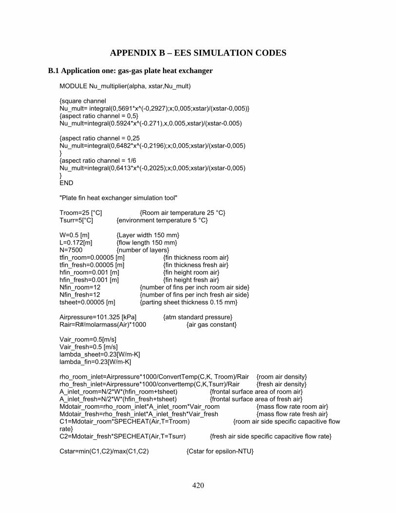
420
APPENDIX B – EES SIMULATION CODES B.1 Application one: gas-gas plate heat exchanger
MODULE Nu_multiplier(alpha, xstar,Nu_mult) {square channel Nu_mult= integral(0,5691*x^(-0,2927);x;0,005;xstar)/(xstar-0,005)} {aspect ratio channel = 0,5} Nu_mult=integral(0.5924*x^(-0.271),x,0.005,xstar)/(xstar-0.005) {aspect ratio channel = 0,25 Nu_mult=integral(0,6482*x^(-0,2196);x;0,005;xstar)/(xstar-0,005) } {aspect ratio channel = 1/6 Nu_mult=integral(0,6413*x^(-0,2025);x;0,005;xstar)/(xstar-0,005) } END "Plate fin heat exchanger simulation tool" Troom=25 [°C] {Room air temperature 25 °C} Tsurr=5[°C] {environment temperature 5 °C} W=0.5 [m] {Layer width 150 mm} L=0.172[m] {flow length 150 mm} N=7500 {number of layers} tfin_room=0.00005 [m] {fin thickness room air} tfin_fresh=0.00005 [m] {fin thickness fresh air} hfin_room=0.001 [m] {fin height room air} hfin_fresh=0.001 [m] {fin height fresh air} Nfin_room=12 {number of fins per inch room air side} Nfin_fresh=12 {number of fins per inch fresh air side} tsheet=0.00005 [m] {parting sheet thickness 0.15 mm} Airpressure=101.325 [kPa] {atm standard pressure} Rair=R#/molarmass(Air)*1000 {air gas constant} Vair_room=0.5[m/s] Vair_fresh=0.5 [m/s] lambda_sheet=0.23[W/m-K] lambda_fin=0.23[W/m-K] rho_room_inlet=Airpressure*1000/ConvertTemp(C,K, Troom)/Rair {room air density} rho_fresh_inlet=Airpressure*1000/converttemp(C,K,Tsurr)/Rair {fresh air density} A_inlet_room=N/2*W*(hfin_room+tsheet) {frontal surface area of room air} A_inlet_fresh=N/2*W*(hfin_fresh+tsheet) {frontal surface area of fresh air} Mdotair_room=rho_room_inlet*A_inlet_room*Vair_room {mass flow rate room air} Mdotair_fresh=rho_fresh_inlet*A_inlet_fresh*Vair_fresh {mass flow rate fresh air} C1=Mdotair_room*SPECHEAT(Air,T=Troom) {room air side specific capacitive flow rate} C2=Mdotair_fresh*SPECHEAT(Air,T=Tsurr) {fresh air side specific capacitive flow rate} Cstar=min(C1,C2)/max(C1,C2) {Cstar for epsilon-NTU}

421
Fp_room=0.0254[m]/Nfin_room {fin pitch room air side} Fp_fresh=0.0254[m]/Nfin_fresh {fin pitch fresh air side} Afin_room=N/2*round(W/Fp_room)*2*(L*hfin_room+tfin_room*hfin_room) {room air side fin surface area} Afin_fresh=N/2*round(W/Fp_fresh)*2*(L*hfin_fresh+tfin_fresh*hfin_fresh) {fresh air side fin surface area} Asheet_fresh=(N-1)*(W-round(W/Fp_fresh)*tfin_fresh)*L {room air side parting sheet surface} Asheet_room=(N-1)*(W-round(W/Fp_room)*tfin_room)*L {room air side parting sheet surface} Dh_room=2*(Fp_room-tfin_room)*hfin_room/(Fp_room-tfin_room+hfin_room) {hydraulic diameter room air side} Dh_fresh=2*(Fp_fresh-tfin_fresh)*hfin_fresh/(Fp_fresh-tfin_fresh+hfin_fresh) {hydraulic diameter fresh air side} alpha_channel_room=min((Fp_room-tfin_room)/hfin_room,hfin_room/(Fp_room-tfin_room)) alpha_channel_fresh=min((Fp_fresh-tfin_fresh)/hfin_fresh,hfin_fresh/(Fp_fresh-tfin_fresh)) Mdotair_channel_room=Mdotair_room/(round(W/Fp_room)-1)/(N/2) {mass flow rate per channel room air side} Mdotair_channel_fresh=Mdotair_fresh/(round(W/Fp_fresh)-1)/(N/2) {mass flow rate per channel fresh air side} Re_room=Mdotair_channel_room*Dh_room/((Fp_room-tfin_room)*hfin_room)/viscosity(AIR,T=Troom) {Reynolds number room air side based on Dh} Re_fresh=Mdotair_channel_fresh*Dh_fresh/((Fp_fresh-tfin_fresh)*hfin_fresh)/viscosity(AIR,T=Tsurr) {Reynolds number room air side based on Dh} {Nusselt number multiplication for developing flow} xstar_room=L/(Re_room*Prandtl(air,T=Troom)*Dh_room) xstar_fresh=L/(Re_fresh*Prandtl(air,T=Tsurr)*Dh_fresh) CALL Nu_multiplier(alpha_channel_room, xstar_room,Nu_mult_room) CALL Nu_multiplier(alpha_channel_fresh, xstar_fresh,Nu_mult_fresh) {friction factor for natural convection (H2) or Filonenko for turbulent room air side} f_room=IF(Re_room,2300,24*(1-1.3553*alpha_channel_room+1.9467*alpha_channel_room^2-1.7012*alpha_channel_room^3+0.9564*alpha_channel_room^4-0.2537*alpha_channel_room^5)/Re_room,(1.56*LN(Re_room)-3)^(-2),(1.56*LN(Re_room)-3)^(-2)) f_fresh=IF(Re_fresh,2300,24*(1-1.3553*alpha_channel_fresh+1.9467*alpha_channel_fresh^2-1.7012*alpha_channel_fresh^3+0.9564*alpha_channel_fresh^4-0.2537*alpha_channel_fresh^5)/Re_fresh,(1.56*LN(Re_fresh)-3)^(-2),(1.56*LN(Re_fresh)-3)^(-2)) {Nusselt number for natural convection or Gnielinski for turbulent fresh air side} Nu_turb=(f_room/2)*(8000-1000)*Prandtl(AIR,T=Troom)*(1+(Dh_room/L)^(2/3))/(1+12.7*sqrt(f_room/2)*(Prandtl(AIR,T=Troom)^(2/3)-1)) {Nusselt constant temperature boundary} Nu_lam_room=7.54*(1-2.61*alpha_channel_room+4.97*alpha_channel_room^2-5.119*alpha_channel_room^3+2.702*alpha_channel_room^4-0.548*alpha_channel_room^5) Nu_lam_fresh=7.54*(1-2.61*alpha_channel_fresh+4.97*alpha_channel_fresh^2-5.119*alpha_channel_fresh^3+2.702*alpha_channel_fresh^4-0.548*alpha_channel_fresh^5) Nusselt_room=IF(Re_room, 2000,Nu_mult_room*Nu_lam_room,Nu_mult_room*Nu_lam_room, (1.33-Re_room/6000)*Nu_mult_room*Nu_lam_room+(1-1.33+Re_room/6000)*Nu_turb)

422
Nusselt_fresh=IF(Re_fresh, 2000,Nu_mult_fresh*Nu_lam_fresh,Nu_mult_fresh*Nu_lam_fresh, (1.33-Re_fresh/6000)*Nu_mult_fresh*Nu_lam_fresh+(1-1.33+Re_fresh/6000)*Nu_turb) {Nusselt H1 boundary condition Nu_lam_room=8,235*(1-2,042*alpha_channel_room+3,0583*alpha_channel_room^2-2,4765*alpha_channel_room^3+1,057*alpha_channel_room^4-0,1861*alpha_channel_room^5) Nu_lam_fresh=8,235*(1-2,042*alpha_channel_fresh+3,0583*alpha_channel_fresh^2-2,4765*alpha_channel_fresh^3+1,057*alpha_channel_fresh^4-0,1861*alpha_channel_fresh^5) Nusselt_room=IF(Re_room; 2000;Nu_mult_room*Nu_lam_room;Nu_mult_room*Nu_lam_room; (1,33-Re_room/6000)*Nu_mult_room*Nu_lam_room+(1-1,33+Re_room/6000)*Nu_turb) Nusselt_fresh=IF(Re_fresh; 2000;Nu_mult_fresh*Nu_lam_fresh;Nu_mult_fresh*Nu_lam_fresh; (1,33-Re_fresh/6000)*Nu_mult_fresh*Nu_lam_fresh+(1-1,33+Re_fresh/6000)*Nu_turb) } {Nusselt H2 boundary condition Nu_lam_room=8,2351*(1-10,6044*alpha_channel_room+61,1755*alpha_channel_room^2-155,1803*alpha_channel_room^3+176,9203*alpha_channel_room^4-72,9236*alpha_channel_room^5) Nu_lam_fresh=8,2351*(1-10,644*alpha_channel_fresh+61,1755*alpha_channel_fresh^2-155,1803*alpha_channel_fresh^3+176,9203*alpha_channel_fresh^4-72,9236*alpha_channel_fresh^5) Nusselt_room=IF(Re_room; 2000;Nu_mult_room*Nu_lam_room;Nu_mult_room*Nu_lam_room; (1,33-Re_room/6000)*Nu_mult_room*Nu_lam_room+(1-1,33+Re_room/6000)*Nu_turb) Nusselt_fresh=IF(Re_fresh; 2000;Nu_mult_fresh*Nu_lam_fresh;Nu_mult_fresh*Nu_lam_fresh; (1,33-Re_fresh/6000)*Nu_mult_fresh*Nu_lam_fresh+(1-1,33+Re_fresh/6000)*Nu_turb) } h_room=Nusselt_room*conductivity(AIR,T=Tavg_room)/Dh_room h_fresh=Nusselt_fresh*conductivity(AIR,T=Tavg_fresh)/Dh_fresh {fin efficiency} eta_fin_room=tanh(sqrt(2*h_room/(lambda_fin*tfin_room))*hfin_room/2)/(sqrt(2*h_room/(lambda_fin*tfin_room))*hfin_room/2) eta_fin_fresh=tanh(sqrt(2*h_fresh/(lambda_fin*tfin_fresh))*hfin_fresh/2)/(sqrt(2*h_fresh/(lambda_fin*tfin_fresh))*hfin_fresh/2) {surface efficiency} eta_room=1-(1-eta_fin_room)*Afin_room/(Afin_room+Asheet_room) eta_fresh=1-(1-eta_fin_fresh)*Afin_fresh/(Afin_fresh+Asheet_fresh) {overall heat transfer coefficient based on the room air side} UA=(1/(eta_fresh*h_fresh*(Afin_fresh+Asheet_fresh))+1/(eta_room*h_room*(Afin_room+Asheet_room))+tsheet/(lambda_sheet*L*W))^(-1) NTU=UA/min(C1,C2)*convert(W/K,kW/K) {Number of Transfer Units} epsilon=(1-exp(-NTU*(1-Cstar)))/(1-Cstar*exp(-NTU*(1-Cstar))) {heat exchanger effectiveness} Qmax=min(C1,C2)*convert(kW/K,W/K)*(Troom-Tsurr)*convert(K,°C) {maximum heat transfer rate} Q=epsilon*Qmax {heat transfer rate} Troom_out=Troom-Q*convert(W,kW)/C1*convert(°C,K) {outlet temperature room air side} Tfresh_out=Tsurr+Q*convert(W,kW)/C2*convert(°C,K) {outlet temperature fresh air side} Tavg_room=(Troom+Troom_out)/2 {average temperature room air side} Tavg_fresh=(Tsurr+Tfresh_out)/2 {average temperature fresh air side}

423
{pressure drop} DeltaP_room=4*f_room*(L/Dh_room)*(Mdotair_channel_room/(hfin_room*(Fp_room-tfin_room)))^2/2/(Airpressure*1000/ConvertTemp(C,K, Tavg_room)/Rair) DeltaP_fresh=4*f_fresh*(L/Dh_fresh)*(Mdotair_channel_fresh/(hfin_fresh*(Fp_fresh-tfin_fresh)))^2/2/(Airpressure*1000/ConvertTemp(C,K, Tavg_fresh)/Rair) Rfresh=(1/(eta_fresh*h_fresh*(Afin_fresh+Asheet_fresh)))/(1/UA) {fresh air side heat transfer resistance contribution} Rroom=(1/(eta_room*h_room*(Afin_room+Asheet_room)))/(1/UA) {room air side heat transfer resistance contribution} Rwall=(tsheet/(lambda_sheet*L*W))/(1/UA) {conductive wall heat transfer resistance contribution} Volume=L*W*N/2*(hfin_room+hfin_fresh+2*tsheet) {heat exchanger volume} rel_vol=Volume/0.1574[m^3] rho_PEEK=1300 [kg/m^3] rho_AL=2700 [kg/m^3] volume_mat=N/2*(2*tsheet*L*W+round(W/Fp_room)*L*hfin_room*tfin_room+round(W/Fp_fresh)*L*hfin_fresh*tfin_fresh) mass=volume_mat*rho_PEEK
B.2 Application two: liquid-gas polymer tube heat exchanger
"tube bundle simulation tool" Tair_in=25 [°C] {air inlet temperature} Twater_in=75[°C] {liquid inlet temperature} {bundle parameters; assumed all tubes are set in parallel} L=0.5[m] {tube length} d_ext=0.00381[m] {tube exterior diameter} d_int=0.00341[m] {tube interior diameter} {d_ext=0,00953[m] d_int=0,00597[m]} Xl=Xl_star*d_ext {longitudinal tube spacing} Xt=Xt_star*d_ext {transversal tube spacing} N=10 {number of tube rows} N_T=108 {number of tubes per row} lambda_tube=0.3[W/m-K] {tube material thermal conductivity} {fin parameters Wang # 10 reference case tfin=0,00015 [m] {fin thickness} Fp=0,00208 [m] {fin pitch} lambda_fin=200[W/m-K] {fin material thermal conductivity} lambda_tube=370[W/m-K] {tube material thermal conductivity} Dc=0,01042[m] {collar diameter} d_ext=Dc-2*tfin twall=0,0009[m] d_int=d_ext-2*twall Lh=0,0014[m] {louver height} Lp=0,0024[m] {louver pitch} Xl=0,01905[m] {longitudinal tube spacing}

424
Xt=0,02504[m] {transversal tube spacing} N=4 {number of tube rows} L=0,5 N_T=8 sigma=(Fp-tfin)*(Xt-Dc)/(Fp*Xt) Re_Dc=Vair/sigma*Dc*density(AIR;T=Tair_in;P=Airpressure)/viscosity(AIR;T=Tair_avg) Dh=4*(Fp-tfin)*(Xt-Dc)/(N*Xl) J1=-0,991-0,1055*(Xl/Xt)^3,1*LN(Lh/Lp) J2=-0,7344+2,1059*N^0,55/(LN(Re_Dc)-3,2) J3=0,08485*(Xl/Xt)^(-4,4)*N^(-0,68) J4=-0,1741*LN(N) J5=-0,6027+0,02593*(Xl/Dh)^0,52*N^(-0,5)*LN(Lh/Lp) J6=-0,4776+0,40774*N^0,7/(LN(Re_dc)-4,4) J7=-0,58655*(Fp/Dh)^2,3*(Xl/Xt)^(-1,6)*N^(-0,65) J8=0,0814*(LN(Re_Dc)-3) j=IF(Re_Dc;1000;14,3117*Re_Dc^J1*(Fp/Dc)^J2*(Lh/Lp)^J3*(Fp/Xl)^J4*(Xl/Xt)^(-1,724);1,373*Re_Dc^J5*(Fp/Xl)^J6*(Lh/Lp)^J7*(Xl/Xt)^J8*N^0,3545;1,373*Re_Dc^J5*(Fp/Xl)^J6*(Lh/Lp)^J7*(Xl/Xt)^J8*N^0,3545) Nu_air=j*Prandtl(AIR;T=Tair_in)^(1/3)*Re_Dc F1=0,1691+4,4118*(Fp/Xt)^(-0,3)+(Lh/Lp)^(-2)*LN(Xl/Xt)*(Fp/Xt)^3 F2=-2,6642-14,3809/LN(Re_Dc) F3=-0,6816*LN(Fp/Xl) F4=6,4668*(Fp/Xt)^1,7*LN(Aext/Atube) F5=0,1395-0,0101*(Fp/Xl)^0,58*(Lh/Lp)^(-2)*LN(Aext/Atube)*(Xl/Xt)^1,9 F6=-6,4367/LN(Re_Dc) F7=0,07191*LN(Re_dc) F8=-2,0585*(Fp/Xt)^1,67*LN(Re_Dc) F9=0,1036*LN(Xl/Xt) f=IF(N;1;0,00317*Re_Dc^F1*(Fp/Xl)^F2*(Dh/Dc)^F3*(Lh/Lp)^F4*(LN(Aext/Atube))^(-6,0483);0,06393*Re_Dc^F5*(Fp/Dc)^F6*(Dh/Dc)^F7*(Lh/Lp)^F8*N^F9*(LN(Re_Dc)-4)^(-1,093);0,06393*Re_Dc^F5*(Fp/Dc)^F6*(Dh/Dc)^F7*(Lh/Lp)^F8*N^F9*(LN(Re_Dc)-4)^(-1,093)) Ac=(round(L/Fp)-1)*N_T*(Xt-Dc)*(Fp-tfin) Gc=mdotair/Ac DeltaPair=(f*Aext*density(AIR;T=Tair_in;P=Airpressure)/(Ac*density(AIR;T=Tair_avg;P=Airpressure))+(1+sigma^2)*(density(AIR;T=Tair_in;P=Airpressure)/density(AIR;T=Tair_out;P=Airpressure)-1))*Gc^2/2/density(AIR;T=Tair_in;P=Airpressure) } Airpressure=101.325 [kPa] {atm standard pressure} Pwater=200[kPa] {water pressure} Vair=2[m/s] {air inlet velocity} Vwater=0.125 [m/s] {water inlet velocity} rho_air_inlet=Airpressure*1000/ConvertTemp(C,K, Tair_in)/Rair {room air density} Rair=R#/molarmass(Air)*1000 {air gas constant} A_front=N_T*Xt*L {frontal surface area} Mdotair=rho_air_inlet*A_front*Vair {mass flow rate air} Cair=Mdotair*SPECHEAT(Air,T=Tair_in) {air side capacitive flow rate} Mdotwater=N*N_T*(PI*d_int^2/4)*density(WATER,T=Twater_in,P=Pwater)*Vwater {water mass flow rate} Cwater=Mdotwater*SPECHEAT(WATER,T=Twater_in,P=Pwater) {capacitive flow rate water} Cstar=min(Cwater,Cair)/max(Cwater,Cair) {Cstar for epsilon-NTU} {Xl_star=Xl/d_ext

425
Xt_star=Xt/d_ext} Xd_star=sqrt(Xt^2+Xl^2)/d_ext {finned bundle calculations Afin=N*N_T*round(L/Fp)*(2*Xl*Xt-Pi/4*d_ext^2)+round(L/Fp)*Xt*N_T*tfin*2 Atube=N*N_T*PI*d_ext*(L-round(L/Fp)*tfin) Aext=Afin+Atube Aint=N*N_T*PI*d_int*L XMF=Xt/2 XLF=sqrt((Xt/2)^2+(Xl/2)^2) Req=1,27*2*XMF/d_ext*sqrt(XLF/XMF-0,3) phi_f=(Req-1)*(1+0,35*LN(Req)) m=sqrt(2*h_air/(lambda_fin*tfin)) eta_fin=tanh(m*d_ext/2*phi_f)/(m*d_ext/2*phi_f) eta_air=1-(1-eta_fin)*Afin/Aext UA=(1/(eta_air*h_air*Aext)+1/(h_water*Aint)+LN(d_ext/d_int)/(2*PI*N*N_T*L*lambda_tube))^(-1) } {Reynolds number air} Re_liquid=Vwater*d_int*density(WATER,T=Twater_in,P=Pwater)/viscosity(WATER,T=Twater_avg,P=Pwater) {unfinned bundle calculations} Aext=N*N_T*PI*d_ext*L Aint=N*N_T*PI*d_int*L UA=(1/(h_air*Aext)+1/(h_water*Aint)+LN(d_ext/d_int)/(2*PI*N*N_T*L*lambda_tube))^(-1) {inline tube bundle Um=Vair*Xt_star/(Xt_star-1) Re_air=Um*d_ext*density(AIR;T=Tair_in;P=Airpressure)/viscosity(AIR;T=Tair_in) Hg_lam=140*Re_air*((sqrt(Xl_star)-0,6)^2+0,75)/(Xt_star^1,6*(4*Xl_star*Xt_star/PI-1)) Hg_turb=((0,11+0,6*(1-0,94/Xl_star)^0,6/(Xt_star-0,85)^1,3)*10^(0,47*(Xl_star/Xt_star-1,5))+0,015*(Xt_star-1)*(Xl_star-1))*Re_air^(2-0,1*Xl_star/Xt_star)+phi_tn*Re_air^2 phi_tn=IF(Xl_star;sqrt(2*Xt_star+1)/2;2*((Xd_star-1)/(Xt_star*(Xt_star-1)))^2*(1/N-1/10);0,5/Xt_star^2*(1/N-1/10);0,5/Xt_star^2*(1/N-1/10)) Hg=Hg_lam+Hg_turb*(1-exp(1-(Re_air+1000)/2000)) Lq=1,18*Hg*Prandtl(AIR;T=Tair_in)*((4*Xt_star/PI-1)/Xl_star) Nu_air=0,404*Lq^(1/3)*((Re_air+1)/(Re_air+1000))^0,1 deltaPair=viscosity(AIR; T=Tair_avg)^2/density(AIR;T=Tair_avg; P=Airpressure)*N/d_ext^2*Hg } {staggered tube bundle} Um=IF(Xl_star,sqrt(2*Xt_star+1)/2,Vair*Xt_star/(2*(Xd_star-1)),Vair*Xt_star/(Xt_star-1),Vair*Xt_star/(Xt_star-1)) Re_air=Um*d_ext*density(AIR,T=Tair_in,P=Airpressure)/viscosity(AIR,T=Tair_in) Hg_lam=IF(Xl_star,sqrt(2*Xt_star+1)/2,140*Re_air*((sqrt(Xl_star)-0.6)^2+0.75)/(Xt_star^1.6*(4*Xl_star*Xd_star/PI-1)),140*Re_air*((sqrt(Xl_star)-0.6)^2+0.75)/(Xt_star^1.6*(4*Xl_star*Xt_star/PI-1)),140*Re_air*((sqrt(Xl_star)-0.6)^2+0.75)/(Xt_star^1.6*(4*Xl_star*Xt_star/PI-1))) Hg_turb=((1.25+0.6/(Xt_star-0.85)^1.08)+0.2*(Xl_star/Xt_star-1)^3-0.005*(Xt_star/Xl_star-1)^3)*Re_air^1.75+phi_tn*Re_air^2 phi_tn=IF(Xl_star,sqrt(2*Xt_star+1)/2,2*((Xd_star-1)/(Xt_star*(Xt_star-1)))^2*(1/N-1/10),0.5/Xt_star^2*(1/N-1/10),0.5/Xt_star^2*(1/N-1/10)) Hg=Hg_lam+Hg_turb*(1-exp(1-(Re_air+200)/1000))

426
Lq=IF(Xl_star,1,0.92*Hg*Prandtl(AIR,T=Tair_in)*(4*Xt_star*Xl_star/PI-1)/(Xl_star*Xd_star),0.92*Hg*Prandtl(AIR,T=Tair_in)*(4*Xt_star/PI-1)/(Xd_star),0.92*Hg*Prandtl(AIR,T=Tair_in)*(4*Xt_star/PI-1)/Xd_star) Nu_air=0.404*Lq^(1/3) deltaPair=viscosity(AIR, T=Tair_avg)^2/density(AIR,T=Tair_avg, P=Airpressure)*N/d_ext^2*Hg {tube side h eat transfer} f_water=IF(Re_liquid, 2300,16/Re_liquid,(1.56*LN(Re_liquid)-3)^(-2),(1.56*LN(Re_liquid)-3)^(-2)) Nu_turb=(f_water/2)*(8000-1000)*Prandtl(WATER,T=Twater_in,P=Pwater)*(1+(d_int/L)^(2/3))/(1+12.7*sqrt(f_water/2)*(Prandtl(WATER,T=Twater_in,P=Pwater)^(2/3)-1)) Nu_liquid=IF(Re_liquid,2000,4.364,(1.33-Re_liquid/6000)*4.364+(1-1.33+Re_liquid/6000)*Nu_turb,(1.33-Re_liquid/6000)*4.364+(1-1.33+Re_liquid/6000)*Nu_turb) h_air=Nu_air*conductivity(AIR,T=Tair_avg)/(Pi/2*d_ext) h_water=Nu_liquid*conductivity(WATER,T=Twater_avg,P=Pwater)/d_int NTU=UA/min(Cair,Cwater)*convert(W/K,kW/K) {Number of Transfer Units} epsilon=(1-exp(-Cstar*(1-exp(-NTU))))/Cstar {heat exchanger effectiveness - crossflow} Qmax=min(Cair,Cwater)*convert(kW/K,W/K)*(Twater_in-Tair_in)*convert(K,°C) {maximum heat transfer rate} epsilon*Qmax=Q {heat transfer rate} Tair_out=Tair_in+Q*convert(W,kW)/Cair*convert(°C,K) {outlet temperature room air side} Twater_out=Twater_in-Q*convert(W,kW)/Cwater*convert(°C,K) {outlet temperature fresh air side} Tair_avg=(Tair_in+Tair_out)/2 {average temperature room air side} Twater_avg=(Twater_in+Twater_out)/2 {average temperature fresh air side} R_wall=(LN(d_ext/d_int)/(2*PI*N*N_T*L*lambda_tube))/(1/UA) R_air=(1/(h_air*Aext))/(1/UA) R_water=(1/(h_water*Aint))/(1/UA) deltaPwater=4*f_water*L/d_int*density(WATER,T=Twater_avg, P=Pwater)*Vwater^2/2 Volume=L*N*Xt*N_T*Xl vol_mat=N*N_T*PI*(d_ext^2-d_int^2)/4*L mass=vol_mat*1000[kg/m^3] Volume_metal=0.5*4*8*0.01905*0.02504 rel_vol=Volume/Volume_metal mass_metal=4*8*round(0.5/0.00208)*(PI*(0.01042^2-0.00862^2)/4*0.00208*8230+(0.01905*0.02504*0.00015-PI*0.01042^2/4*0.00015)*2700) rel_mass=mass/mass_metal test=sqrt(2*Xt_star+1)/2
B.3 Application three: porous fin heat exchanger
{ Comparison of flat-tube heat exchangers with louver fins and porous fins } { Volume goodness factor method from Kays and London (1950) } { Louver fin correlations from Chang and Wang(1997), Chang et al. (2000) -- Sample #35 }

427
{ Porous fin correlations from Calmidi and Mahajan (2000) and Bhattacharya et al (2002) -- sample #10 } rho = density(air, T=25, P=101) { kg/m^3 } cp = specheat(air, T=25) { J/kg K } mu = viscosity(air, T=25) { N s/m^2 } nu = mu/rho { m^2/s } Pr = Prandtl(air, T=25) { - } k = conductivity(air, T=25) { W/mK } k_fin = k_(aluminum, T=25 [C]) { Baseline: louver fin heat exchanger parameters, m, deg } lp_flat = 1.42e-3 [m] ll_flat = 17.18e-3 [m] theta = 28 {[deg]} fp_flat = 2e-3 [m] td_flat = 22e-3 [m] fd_flat = 22e-3 [m] fl_flat = 19e-3 [m] t_flat = 0.16e-3 [m] tp_flat = 24e-3 [m] dh_flat = 3.374e-3 [m] dm_flat = tp_flat-fl_flat th_flat = fl_flat Re_lp = vc_flat*lp_flat/nu Re_dh_flat = Re_lp*dh_flat/lp_flat sigma_flat = (fl_flat*(fp_flat-t_flat))/(tp_flat*fp_flat) { Flat tube j-correlation } j_flat = Re_lp^(-0.49)*(theta/90)^.27*(fp_flat/lp_flat)^(-.14)& *(fl_flat/lp_flat)^(-.29)*(td_flat/lp_flat)^(-.23)*(ll_flat/lp_flat)^.68& *(tp_flat/lp_flat)^(-.28)*(t_flat/lp_flat)^(-.05) { Flat tube f-correlation for 100<Re_lp<150 } f_lo_flat = FL1_flat*FL2_flat*FL3_flat FL1_flat = 14.39*Re_lp^(-0.805*fp_flat/fl_flat)*(ln(1.0+fp_flat/lp_flat))^3.04 FL2_flat = (ln((t_flat/fp_flat)^0.48+0.9))^(-1.435)*(dh_flat/lp_flat)^(-3.01)& *(ln(0.5*Re_lp))^(-3.01) FL3_flat = (fp_flat/ll_flat)^(-0.308)*(fd_flat/ll_flat)^(-0.308)& *exp(-0.1167*tp_flat/dm_flat)*theta^0.35 { Flat tube f-correlation for 150<Re_lp<5000 } f_hi_flat = FH1_flat*FH2_flat*FH3_flat FH1_flat = 4.97*Re_lp^(0.6049-1.064/theta^0.2)*(ln((t_flat/fp_flat)^0.5+0.9))^(-0.527) FH2_flat = ((dh_flat/lp_flat)*ln(0.3*Re_lp))^(-2.966)& *(fp_flat/ll_flat)^(-0.7931*tp_flat/th_flat) FH3_flat = (tp_flat/dm_flat)^(-0.0446)*ln(1.2+(lp_flat/fp_flat)^1.4)^(-3.553)& *theta^(-0.477) { 40-ppi porous fin heat exchanger parameters, m } phi = 0.9272 { Porosity } df = 0.00025 [m] { Fiber diameter } dp = 0.00202 [m] { Pore diameter } ff = 0.089 [-] { Inertial coefficient } KK = 0.61e-7 [m^2] { Permeability }

428
beta = 3*pi*df/dp^2 fl_prs = fl_flat{*.5} { Important to affect fin efficiency } fd_prs = {fd_flat*.5}16e-3 { Irrelevant, interestingly } k_prs = 5.48 [W/m-K] { Effective thermal conductivity of porsous fin } Re_df = vd*df/nu { vd = Darcian velocity } { Porous fin heat transfer correlation for 1 <= Re_df < 40, Zukauskas (1987) Table 6.1 } h_lo = 0.76 * Re_df^0.4*Pr^0.37*k/df { Porous fin heat transfer correlation for 40 <= Re_df < 1000, Zukauskas (1987) Table 6.1 } h_hi = 0.52 * Re_df^0.5*Pr^0.37*k/df { Porous fin pressure drop correlation } dpdx = mu/KK*vd + ff*rho/sqrt(KK)*vd^2 DELTAP_prs = dpdx*fd_prs { Volume goodness factors } { Q = HTR rate per unit HX volume and unit temp. difference } { P = Fan power per unit HX volume } Q_flat = eta_flat*cp*mu/Pr^(2/3)*4*sigma_flat/dh_flat^2*j_flat*Re_dh_flat h_flat = Q_flat*dh_flat/(4*sigma_flat) m_flat = sqrt(h_flat*(2*(fd_flat+t_flat))/(k_fin*fd_flat*t_flat)) "Fin parameter" eta_flat_fin = tanh(m_flat*fl_flat/2)/(m_flat*fl_flat/2){*0+1} "1D, Adiabatic tip" eta_flat = 1 - (fl_flat*fd_flat)/((fl_flat+fp_flat-t_flat)*fd_flat)*(1-eta_flat_fin) "Total surface efficiency " P_lo_flat = .5*mu^3/rho^2*4*sigma_flat/dh_flat^4*f_lo_flat*Re_dh_flat^3 P_hi_flat = .5*mu^3/rho^2*4*sigma_flat/dh_flat^4*f_hi_flat*Re_dh_flat^3 P_flat = IF(Re_lp, 150, P_lo_flat, P_lo_flat, P_hi_flat) DELTAP_flat = P_flat/(vc_flat*sigma_flat)*fd_flat h_prs = IF(Re_df, 40, h_lo, h_lo, h_hi) m_prs = sqrt(h_prs*(1[m^3]*beta/fl_prs)/(k_prs*1[m^3]/fl_prs)) "Fin parameter" eta_prs_fin = tanh(m_prs*fl_prs/2)/(m_prs*fl_prs/2){*0+1} "1D, Adiabatic tip" eta_prs = 1 - (1[m^3]*beta)/(1[m^3]*beta+2[m^3]/fl_prs*phi)*(1-eta_prs_fin) "Total surface efficiency " Q_prs = eta_prs*h_prs*beta P_prs = dpdx*vd*phi P_flat = P_prs $AutoSetUnits ON

429
APPENDIX C – BRAINSTORMING LOG Participants
ARTI project team (Jacobi, Park, Qin, Han, Sommers, T’Joen) Internal group members (Graduate research assistants) Experts in ACRC (Bullard, Hrnjak, Field)
Questions Q1: How can we make better heat exchangers using the alternate materials? Q2: What other materials can we use to make heat exchangers? Q3: Given total freedom in construction method, how would you configure a heat exchanger?
Ideas
(1) System built into walls and structural supports of the building (e.g. evaporators) (2) Furnishing combined with heat exchangers (3) Use polymers to form around the heat source (e.g. microprocessors) (4) Plastic heat exchangers on automobile roofs to absorb or reject heat (5) Use plastic materials to integrate vortex generators into heat exchangers (6) Paper (or PDMS) air-to-air heat exchangers (7) Titania as window blind heat exchanger material (self cleaning) (8) Use ice in cryogenic heat exchangers (9) Use glass to make heat exchangers (maybe in windows) (10) Use wood (11) “smart” heat exchangers that adapt to the operating condition (12) Plastic surface with microstructures to manipulate wettability (13) Use “flags” to agitate liquid/gas flow (14) Configure heat exchangers like human kidney/lung/organs (15) Acoustic excitations using speakers (16) Fan blades as heat exchangers (17) Plastic to make compressor (18) Use natural movement (occupants) in the building to adapt the system (19) High thermal expansion material to increase area with temperature increase (20) Use materials with good radiation properties (21) Phase-change materials/ high mc material/ ice slurry (22) Heat recovery system in building (e.g. coolant ports in each room) (23) Ceramic foam (24) Shape heat exchanger surfaces to optimize acoustic enhancement (25) Rubber composite (26) Direction-controllable conductivity (27) Plastic for space heating radiator (28) Layer-combined materials (29) Plastic heat exchanger that will melt in emergency (30) Tube filled with metal foam (31) Thermo-electric heat rejection by metal foam (32) Plastic heat exchanger for ice storage system (33) Heat exchanger as clothing (34) Living heat exchangers (35) Plastic heat exchanger for LiBr absorption system