FIELD EMISSION DEVICE AND NANOFIBER ... - MyScienceWork
24
Printed by Jouve, 75001 PARIS (FR) (19) EP 2 650 409 A1 TEPZZ 65Z4Z9A_T (11) EP 2 650 409 A1 (12) EUROPEAN PATENT APPLICATION published in accordance with Art. 153(4) EPC (43) Date of publication: 16.10.2013 Bulletin 2013/42 (21) Application number: 11846331.4 (22) Date of filing: 27.04.2011 (51) Int Cl.: D01D 5/00 (2006.01) D01D 4/00 (2006.01) D01D 13/00 (2006.01) B82Y 40/00 (2011.01) (86) International application number: PCT/KR2011/003056 (87) International publication number: WO 2012/077865 (14.06.2012 Gazette 2012/24) (84) Designated Contracting States: AL AT BE BG CH CY CZ DE DK EE ES FI FR GB GR HR HU IE IS IT LI LT LU LV MC MK MT NL NO PL PT RO RS SE SI SK SM TR (30) Priority: 06.12.2010 JP 2010272071 24.02.2011 KR 20110016676 (71) Applicants: • Toptec Co., Ltd. Gumi-shi, Gyeonbuk 730-853 (KR) • Shinshu University Matsumoto-shi, Nagano 390-8621 (JP) (72) Inventors: • LEE, Jae Hwan Gumi-si Gyeongsangbuk-do 730-853 (KR) • KIM, Ick Soo Ueda-shi Nagano 386-8567 (JP) (74) Representative: Stolmár & Partner Blumenstraße 17 80331 München (DE) (54) FIELD EMISSION DEVICE AND NANOFIBER MANUFACTURING DEVICE (57) Disclosed herein is a field emission device which makes it possible to reliably mass-produce nanofibers having satisfactory quality, even if field emission is con- ducted in such a way that high voltage is applied to a collector while a nozzle block is grounded. The field emis- sion device includes a collector (150), a nozzle block (110) and a power supply (160) which has a positive elec- trode connected to the collector, and a negative electrode that is connected to the nozzle block in such a way that the potential of the negative electrode drops to the ground potential. The field emission device further includes an auxiliary belt device (170) which has: an auxiliary belt (172) that is made of an insulating and porous endless belt and encircles the collector; and an auxiliary belt drive unit (174) rotating the auxiliary belt at a transfer speed of the long sheet.
-
Upload
khangminh22 -
Category
Documents
-
view
1 -
download
0
Transcript of FIELD EMISSION DEVICE AND NANOFIBER ... - MyScienceWork
Printed by Jouve, 75001 PARIS (FR)
(19)E
P2
650
409
A1
TEPZZ 65Z4Z9A_T(11) EP 2 650 409 A1
(12) EUROPEAN PATENT APPLICATIONpublished in accordance with Art. 153(4) EPC
(43) Date of publication: 16.10.2013 Bulletin 2013/42
(21) Application number: 11846331.4
(22) Date of filing: 27.04.2011
(51) Int Cl.:D01D 5/00 (2006.01) D01D 4/00 (2006.01)
D01D 13/00 (2006.01) B82Y 40/00 (2011.01)
(86) International application number: PCT/KR2011/003056
(87) International publication number: WO 2012/077865 (14.06.2012 Gazette 2012/24)
(84) Designated Contracting States: AL AT BE BG CH CY CZ DE DK EE ES FI FR GB GR HR HU IE IS IT LI LT LU LV MC MK MT NL NO PL PT RO RS SE SI SK SM TR
(30) Priority: 06.12.2010 JP 201027207124.02.2011 KR 20110016676
(71) Applicants: • Toptec Co., Ltd.
Gumi-shi, Gyeonbuk 730-853 (KR)• Shinshu University
Matsumoto-shi, Nagano 390-8621 (JP)
(72) Inventors: • LEE, Jae Hwan
Gumi-siGyeongsangbuk-do 730-853 (KR)
• KIM, Ick SooUeda-shiNagano 386-8567 (JP)
(74) Representative: Stolmár & PartnerBlumenstraße 1780331 München (DE)
(54) FIELD EMISSION DEVICE AND NANOFIBER MANUFACTURING DEVICE
(57) Disclosed herein is a field emission device whichmakes it possible to reliably mass-produce nanofibershaving satisfactory quality, even if field emission is con-ducted in such a way that high voltage is applied to acollector while a nozzle block is grounded. The field emis-sion device includes a collector (150), a nozzle block(110) and a power supply (160) which has a positive elec-trode connected to the collector, and a negative electrodethat is connected to the nozzle block in such a way thatthe potential of the negative electrode drops to the groundpotential. The field emission device further includes anauxiliary belt device (170) which has: an auxiliary belt(172) that is made of an insulating and porous endlessbelt and encircles the collector; and an auxiliary belt driveunit (174) rotating the auxiliary belt at a transfer speedof the long sheet.
EP 2 650 409 A1
2
5
10
15
20
25
30
35
40
45
50
55
Description
Technical Field
[0001] The present invention relates to a field emissiondevice and a nanofiber manufacturing device.
Background Art
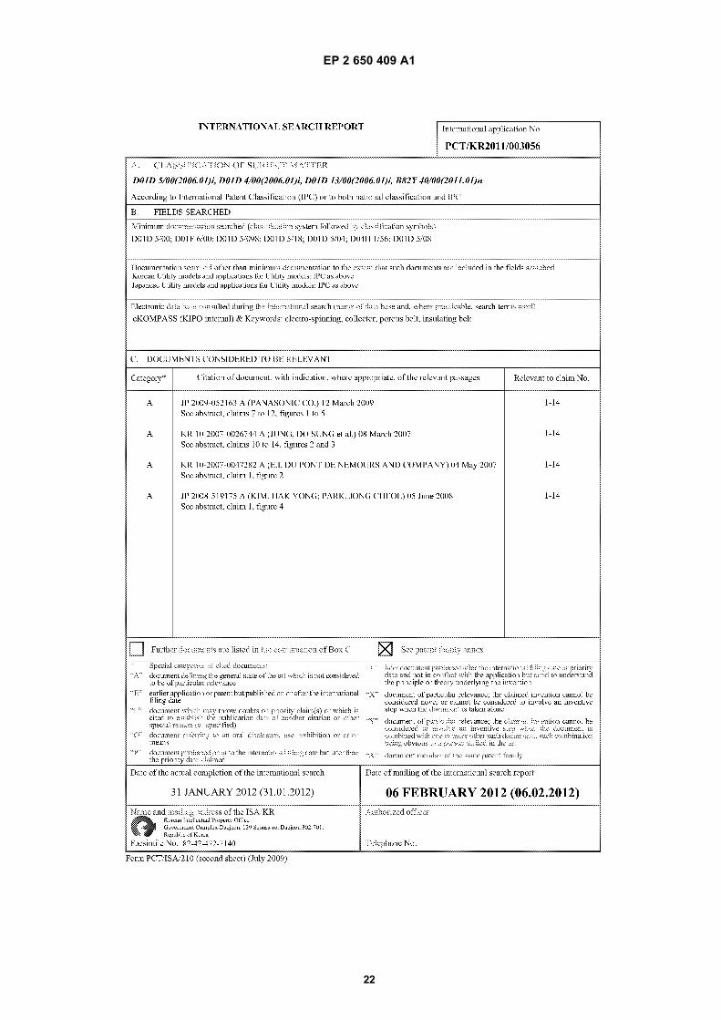
[0002] A field emission device which conducts fieldemission in such a way as to apply high voltage to acollector while a nozzle block is grounded was proposedin Japanese Patent laid-open Publication No.2008-506864 (hereinafter, referred to as "Patent docu-ment 1").[0003] Fig. 11 is a view illustrating a field emission de-vice 900 disclosed in Patent document 1. As shown inFig. 11, the field emission device 900 proposed in Patentdocument 1 includes: a material tank 901 which storesa polymer solution therein; a nozzle block 902 which in-cludes a solution discharge nozzle 904 that dischargesa polymer solution, and a gas nozzle which forms theflow of gas; a collector 920 which is made of a conductiveelement; and a feed roll 924 and a winding roll 926 whichare used to transfer a long sheet 918. In Fig. 11, referencenumeral 912 denotes a suction blower, 914 denotes agas collection pipe, and 922 denotes a support.[0004] In the field emission device 900 disclosed inPatent document 1, negative high voltage is applied tothe collector 920 and, simultaneously, the solution dis-charge nozzle 904 discharges a polymer solution whilethe nozzle block 902 is grounded, thus forming nanofib-ers on the long sheet, which is being transferred, throughfield emission.[0005] According to the field emission device 900 dis-closed in Patent document 1, all of the nozzle block 902,the Ópolymer solution before being discharged from thesolution discharge nozzle 904Ì, Óthe material tank 901for storing the polymer solutionÌ and Óa polymer solutiontransfer unit (for example, a pipe and a pump) for trans-ferring the polymer solution from the material tank 901to the nozzle block 902J become ground potentials.Therefore, it is unnecessary for the material tank 901 orthe polymer solution transfer unit to have high resistanceagainst voltage. As a result, a problem of the structureof the field emission device being complicated, whichmay occur if the material tank 901 or the polymer solutiontransfer unit is required to have a high voltage-resistancestructure, can be fundamentally prevented.[0006] Furthermore, in the field emission device 900disclosed in Patent document 1, high voltage is appliedto the collector 920 capable of having a comparativelysimple shape and structure, and the nozzle block 902,which has a comparatively complex shape and structure,is grounded. Under these conditions, field emission isconducted. Therefore, undesirable voltage discharge ordrop can be prevented from occurring, whereby the fieldemission can be conducted continuously under stable
conditions.
Disclosure
Technical Problem
[0007] However, in the field emission device 900 dis-closed in Patent document 1, comparatively large elec-trostatic attractive force is generated between the col-lector and the long sheet due to high voltage applied tothe collector. Thereby, the long sheet is pulled towardsthe collector, whereby the transfer of the long sheet maybe impeded. Therefore, uniform conditions cannot bemaintained for a long period of time during the processof forming nanofibers through field emission. In a severecase, the operation of the field emission device may haveto be interrupted. As a result, it becomes very difficult tomass- produce, with high productivity, nanofibers havinguniform quality (for example, related to an average diam-eter of nanofibers, diameter distribution of nanofibers,the amount of deposition of nanofibers, the meshes of ananofiber layer, the thickness of the nanofiber layer, thegas permeability of the nanofiber layer, etc.) .[0008] Accordingly, the present invention has beenmade keeping in mind the above problems occurring inthe prior art, and an object of the present invention is toprovide a field emission device and a nanofiber manu-facturing device which make it possible to reliably mass-produce nanofibers having satisfactory quality, even iffield emission is conducted in such a way that high volt-age is applied to a collector while a nozzle block isgrounded.
Technical Solution
[0009] In order to accomplish the above object, in anaspect, the present invention provides a field emissiondevice, including a collector, a nozzle block disposed fac-ing the collector, the nozzle block being provided with aplurality of nozzles discharging a polymer solution, anda power supply applying high voltage between the col-lector and the nozzle block, wherein one of a positiveelectrode and a negative electrode of the power supplyis connected to the collector, while a remaining one ofthe positive electrode and the negative electrode of thepower supply is connected to the nozzle block and apotential of the remaining one drops to a ground potential.The field emission device forms, through field emission,nanofibers on a long sheet that is being transferred at apredetermined transfer speed. The field emission devicefurther includes an auxiliary belt device, having: an aux-iliary belt comprising an insulating and porous endlessbelt rotatably provided in such a way as to encircle thecollector; and an auxiliary belt drive unit rotating the aux-iliary belt at the transfer speed of the long sheet.[0010] In the field emission device according to thepresent invention, preferably, the auxiliary belt is madeof a polymer substrate that has a thickness ranging from
1 2

EP 2 650 409 A1
3
5
10
15
20
25
30
35
40
45
50
55
0.7 mm to 10.0 mm. The polymer substrates may bemade of polyamide such as polyethylene, polyacetylene,polyurethane, polypropylene, nylon, etc., polyacetal,polycarbonate, modified polyphenylene ether, polybuty-leneterephtalate, polyethylene terephthalate, amor-phous polyallylate, polysulfone, polyethersulfone,polyphenylene sulfide, polyether ether keton, polyimid,poly ethyl imide, fluorine resin, liquid crystal polymer, andso on. A plurality of openings, each of which has an arearanging from 0.001 mm2 to 1.0 mm2, are preferablyformed in the auxiliary belt.[0011] In the field emission device according to thepresent invention, the auxiliary belt drive unit may includea plurality of auxiliary belt rollers around which the aux-iliary belt is wrapped so that the auxiliary belt is rotatedby the auxiliary belt rollers, and a drive motor rotating atleast one of the auxiliary belt rollers.[0012] In the field emission device according to thepresent invention, the auxiliary belt drive unit may furtherinclude an auxiliary belt position control device controllinga position of an end of one of auxiliary belt rollers withrespect to with respect to a direction from an inside ofthe auxiliary belt towards an outside thereof, thus con-trolling a position of the auxiliary belt with respect to alongitudinal direction of the auxiliary belt roller.[0013] In the field emission device according to thepresent invention, the auxiliary belt position control de-vice may include: a pair of air springs disposed on oppo-site sides of a support shaft, the support shaft rotatablysupporting the end of the auxiliary belt roller; and an ex-pansion-rate control unit independently controlling ex-pansion rates of the air springs.[0014] In the field emission device according to thepresent invention, the auxiliary belt drive unit may furtherinclude an auxiliary belt position sensor measuring theposition of the auxiliary belt with respect to the longitudi-nal direction of the auxiliary belt roller and control theposition of the auxiliary belt with respect to the longitudi-nal direction of the auxiliary belt roller based on a resultof measurement of the auxiliary belt position sensor.[0015] In the field emission device according to thepresent invention, the auxiliary belt drive unit may furtherinclude a tension control device controlling a position ofat least one of the auxiliary belt rollers with respect to thedirection from the inside of the auxiliary belt towards theoutside thereof, thus controlling tension applied to theauxiliary belt.[0016] In the field emission device according to thepresent invention, the tension control device may controla position of the auxiliary belt roller with respect to thedirection from the inside of the auxiliary belt towards theoutside thereof in such a way that the auxiliary belt rolleris moved to a position at which the auxiliary belt can beeasily wrapped around the auxiliary belt rollers or can beeasily removed therefrom.[0017] In the field emission device according to thepresent invention, a width of the auxiliary belt may begreater than a width of the collector that corresponds to
a width of the long sheet.[0018] In the field emission device according to thepresent invention, an opening ratio of the auxiliary beltmay range from 1% to 40%.[0019] In the field emission device according to thepresent invention, the auxiliary belt may include a net-shaped substrate formed by weaving threads having di-ameters ranging from 0.1 mm to 2.0 mm.[0020] In the field emission device according to thepresent invention, the net-shaped substrate may com-prise a plurality of net-shaped substrates, and the auxil-iary belt may be configured such that the net-shaped sub-strates are stacked on top of one another.[0021] In another aspect, the present invention pro-vides a nanofiber manufacturing device, including: atransfer device transferring a long sheet at a predeter-mined transfer speed; and the field emission device de-positing nanofibers on the long sheet that is being trans-ferred by the transfer device.[0022] In the nanofiber manufacturing device accord-ing to the present invention, the field emission devicemay comprise a plurality of field emission devices ar-ranged in series in a direction in which the long sheet istransferred.[0023] In the nanofiber manufacturing device accord-ing to the present invention, the auxiliary belt device mayinclude: one or a plurality of auxiliary belts provided insuch a way as to encircle the collectors of two throughall of the field emission devices; and an auxiliary beltdrive unit rotating the one or the plurality of auxiliary beltsat a speed corresponding to the transfer speed of thelong sheet.
Advantageous Effects
[0024] A field emission device according to the presentinvention is provided with a power supply, one electrodeof which is connected to a collector while the other elec-trode is connected to a nozzle block in such a way thatthe potential of the electrode connected to the nozzleblock drops to the ground potential. Thus, all of the nozzleblock, polymer solution before being discharged fromnozzlesÌ, Óa material tank for storing the polymer solu-tionÌ and Óa polymer solution transfer unit (for example,a pipe and a pump) for transferring the polymer solutionfrom the material tank to the nozzlesÌ become groundpotentials. Therefore, in the same manner as the caseof the field emission device disclosed in Patent document1, it is unnecessary for the material tank or the polymersolution transfer unit to have high resistance against volt-age. As a result, the present invention can prevent a prob-lem of the structure of the field emission device beingcomplicated, which may occur if the material tank or thepolymer solution transfer unit is configured to have highresistance against voltage.[0025] Because the field emission device according tothe present invention is provided with the power supply,one electrode of which is connected to the collector while
3 4

EP 2 650 409 A1
4
5
10
15
20
25
30
35
40
45
50
55
the other electrode is connected to the nozzle block 110in such a way that the potential of the electrode connectedto the nozzle block 110 drops to the ground potential,field emission is conducted under conditions, in whichhigh voltage is applied to the collector capable of havinga comparatively simple shape and structure, and the noz-zle block, which has a comparatively complex shape andstructure, is grounded, in the same manner as the caseof the field emission device disclosed in Patent document1. Therefore, undesirable voltage discharge or drop canbe prevented from occurring, whereby the field emissioncan be conducted continuously under stable conditions.[0026] In addition, the field emission device accordingto the present invention is also provided with an auxiliarybelt device, which includes an auxiliary belt which is ro-tatably provided in such a way as to encircle the collectorand is made of an insulating and porous endless belt,and an auxiliary belt drive unit which rotates the auxiliarybelt at a speed corresponding to the speed at which thelong sheet is transferred. Accordingly, even if compara-tively large electrostatic attractive force occurs betweenthe collector and the long sheet, because the auxiliarybelt is present between the long sheet and the collector,the long sheet W can be reliably prevented from beingpulled towards the collector, or the long sheet can besmoothly transferred without being impeded. As a result,it is possible that nanofibers are formed under uniformconditions through field emission, and the field emissiondevice can be continuously operated without being inter-rupted. Thereby, nanofibers having uniform quality (forexample, an average diameter of nanofibers, diameterdistribution of nanofibers, the amount of deposition ofnanofibers, the thickness of nanofiber nonwoven fabric,gas permeability of nanofiber nonwoven fabric, etc.) canbe mass- produced with high productivity.[0027] Furthermore, in the field emission device ac-cording to the present invention, since the auxiliary beltrotates at a speed corresponding to the transfer speedof the long sheet, there is no problem of the auxiliary beltof having a bad influence on the transfer of the long sheet.Moreover, in the field emission device of the present in-vention, the auxiliary belt is an insulating and porous end-less belt, thus not affecting electric field distribution be-tween the collector and the nozzle block.[0028] Moreover, in the field emission device accord-ing to the present invention, the auxiliary belt drive unitincludes a plurality of auxiliary belt rollers which rotatethe auxiliary belt wrapped around them, and a drive motorwhich rotates at least one of the auxiliary belt rollers.Therefore, the auxiliary belt can be reliably rotated at aspeed corresponding to the transfer speed of the longsheet.[0029] Meanwhile, in the field emission device accord-ing to the present invention, the auxiliary belt drive unitfurther includes an auxiliary belt position control devicewhich controls the position of an end of one of the auxiliarybelt rollers with respect to a direction from the inside ofthe auxiliary belt towards the outside thereof so that the
position of the auxiliary belt with respect to the longitudi-nal direction of the auxiliary belt roller can be controlled.As such, the inclination of the auxiliary belt roller can becontrolled, and this makes it possible to maintain the po-sition of the auxiliary belt with respect to the longitudinaldirection of the auxiliary belt roller within an appropriaterange over a long period of time.[0030] In the field emission device according to thepresent invention, the auxiliary belt position control de-vice includes a pair of air springs which are disposed onopposite sides of a support shaft that is coupled to oneend of the corresponding auxiliary belt roller and rotatablysupports it, and an expansion-rate control unit which in-dependently controls the expansion rate of each airspring. Therefore, the auxiliary belt position control de-vice can smoothly control the position of the auxiliary beltwith respect to the longitudinal direction of the auxiliarybelt roller.[0031] Furthermore, in the field emission device ac-cording to the present invention, the auxiliary belt driveunit includes an auxiliary belt position sensor whichmeasures the position of the auxiliary belt with respectto the longitudinal direction of the auxiliary belt roller.Based on the result of the measurement of the auxiliarybelt position sensor, the position of the auxiliary belt withrespect to the longitudinal direction of the auxiliary beltroller is controlled. Therefore, the position of the auxiliarybelt with respect to the longitudinal direction of the aux-iliary belt roller can be more precisely and reliably con-trolled.[0032] Meanwhile, in the field emission device accord-ing to the present invention, the auxiliary belt drive unitfurther includes a tension control device which adjuststhe position of the auxiliary belt roller with respect to thedirection from the inside of the auxiliary belt towards theoutside thereof and thus controls the tension applied tothe auxiliary belt. Hence, even if comparatively largeelectrostatic attractive force occurs between the collectorand the auxiliary belt, because it is possible for the ten-sion of the auxiliary belt to be adjusted to a degree toovercome the electrostatic attractive force, not only canthe long sheet be prevented from being pulled towardsthe collector, but the transfer of the long sheet can alsobe reliably prevented from being impeded.[0033] Moreover, in the field emission device accord-ing to the present invention, the tension control devicecan adjust the position of the corresponding auxiliary beltroller with respect to the direction from the inside of theauxiliary belt towards the outside thereof in such a waythat the auxiliary belt roller is moved to a position at whichthe auxiliary belt can be easily wrapped around the aux-iliary belt rollers or can be easily removed therefrom.Therefore, the operation of wrapping the auxiliary beltaround the auxiliary belt rollers or removing it therefromcan be facilitated.[0034] In the field emission device according to thepresent invention, the width of the auxiliary belt is greaterthan that of the collector that corresponds to the width of
5 6

EP 2 650 409 A1
5
5
10
15
20
25
30
35
40
45
50
55
the long sheet. Thus, the auxiliary belt is reliably disposedbetween the long sheet and the collector, whereby thelong sheet can be prevented from being pulled towardsthe collector, or the long sheet can be smoothly trans-ferred without being impeded.[0035] In addition, in the field emission device of thepresent invention, the opening ratio of the auxiliary beltranges from 1% to 40%. The reason for this is due to thefact that, when the opening ratio of the auxiliary belt is1% or more, it does not greatly influence electro fielddistribution formed between the collector and the nozzleblock, and when the opening ratio of the auxiliary belt is40% or less, it does not greatly reduce the mechanicalstrength of the auxiliary belt.[0036] In the field emission device according to thepresent invention, because the auxiliary belt is made ofnet-shaped substrates which are formed by weavingthreads of 0.1 mm to 2.0 mm in diameter, the auxiliarybelt has both high mechanical strength and flexibility.Therefore, the auxiliary belt can be smoothly rotated withstrong tension applied thereto.[0037] Furthermore, in the field emission device ac-cording to the present invention, because the auxiliarybelt is configured in such a way that net- shaped sub-strates are stacked on top of one another, the auxiliarybelt has sufficient mechanical strength, thus making itpossible to rotate the auxiliary belt with increased ten-sion.[0038] In this case, it is preferable that the net-shapedsubstrates which are stacked on top of one another toform the auxiliary belt are made of different kinds of ma-terials. Thereby, the mechanical strength and durabilityof the auxiliary belt can be further enhanced. For in-stance, a substrate formed on a surface of the auxiliarybelt that faces the long sheet may be made of soft ma-terial, and a substrate formed on a surface of the auxiliarybelt that faces the collector may be made of material hav-ing high mechanical strength. The stacked structure ofthe net-shaped substrates may be a two-, three-, four-or more-layer structure, or it may be a 2.5-layer structure.The term Ó2.5-layer structureÌ refers to a structure suchthat the thread density of one layer of the two-layer struc-ture is higher than that of the other layer so that the sur-face planarity and the abrasion resistance of the auxiliarybelt can be enhanced without increasing the weightthereof.[0039] Meanwhile, a nanofiber manufacturing deviceaccording to the present invention uses the field emissiondevice having the above- mentioned construction. There-fore, even if field emission is conducted in such a waythat high voltage is applied to the collector while the noz-zle block is grounded, the nanofiber manufacturing de-vice can mass- produce nanofibers having uniform qual-ity with high productivity.[0040] Furthermore, the nanofiber manufacturing de-vice according to the present invention includes severalfield emission devices. Because the several field emis-sion devices are used to manufacture nanofibers, the
nanofiber manufacturing device can mass- produce na-nofibers with further enhanced productivity.[0041] Moreover, the nanofiber manufacturing deviceaccording to the present invention may be configuredsuch that one or more auxiliary belt devices are provided,and one or each auxiliary belt device includes an auxiliarybelt which is wrapped around two or more collectors ofthe field emission devices, and an auxiliary belt drive unitwhich rotates the auxiliary belt at a speed correspondingto the transfer speed of the long sheet. In this case, thenumber of the auxiliary belt drive units can be reduced.For example, in the case of the nanofiber manufacturingdevice that is provided with eight field emission devices,a single auxiliary belt device may be installed for everytwo field emission devices. Alternatively, a single auxil-iary belt device may be installed for every four field emis-sion devices. As a further alternative, a single auxiliarybelt device may be installed for all of eight field emissiondevices.[0042] The field emission device or the nanofiber man-ufacturing device according to the present invention canmanufacture different kinds of nanofilbers for various pur-poses of use, for example, medical supplies such as high-ly functional and highly sensitive textiles, health andbeauty related products such as health or skin care prod-ucts, industrial material such as cloths, filters, etc., elec-tronic-mechanical material such as separators for sec-ondary batteries, separators for condensers, carriers fordifferent kinds of catalysts, material for a variety of sen-sors, and medical material such as regenerative medicalmaterial, bio-medical material, medical MEMS material,biosensor material, etc.
Description of Drawings
[0043]
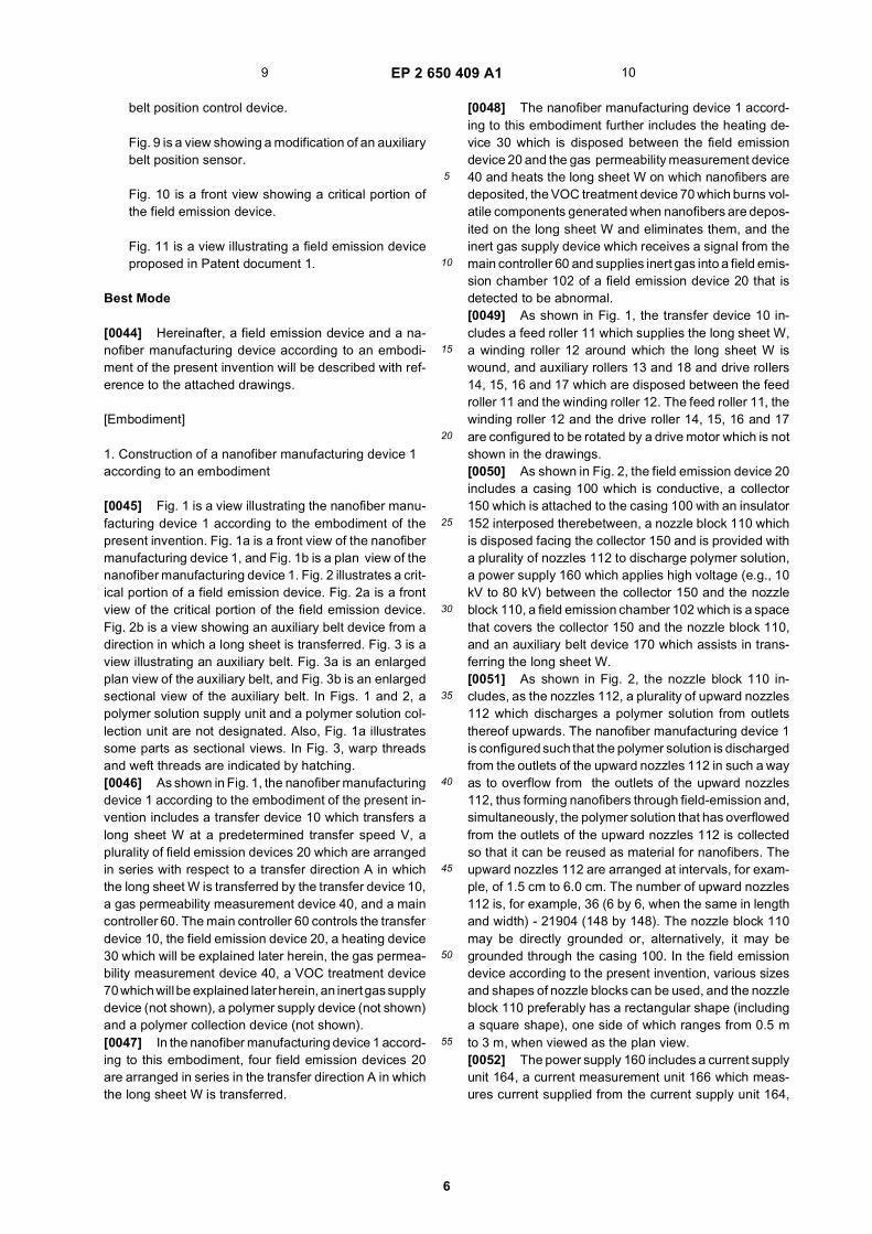
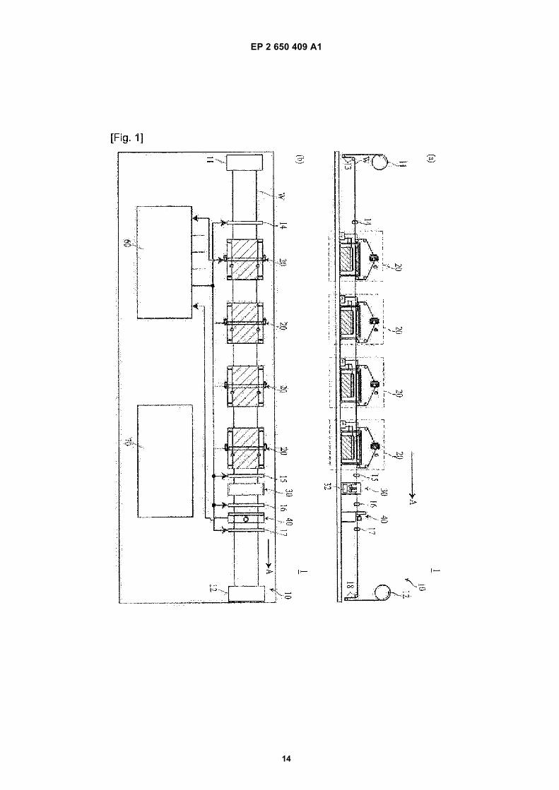
Fig. 1 is a view illustrating a nanofiber manufacturingdevice according to a first embodiment of the presentinvention.
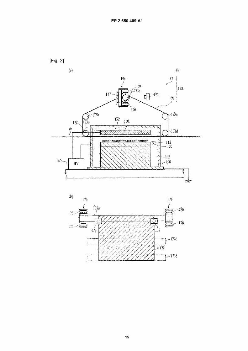
Fig. 2 illustrates a critical portion of a field emissiondevice.
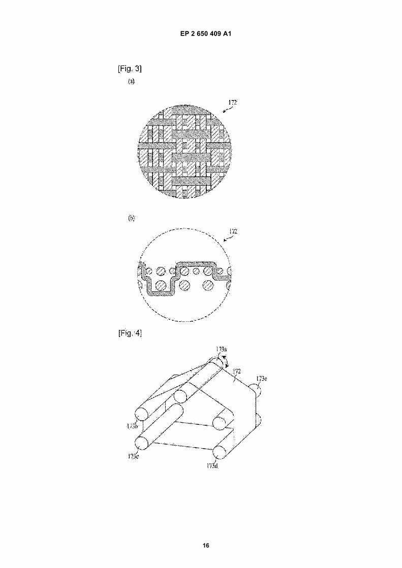
Fig. 3 is a view illustrating an auxiliary belt.
Fig. 4 is a view showing the operation of an auxiliarybelt position control device.
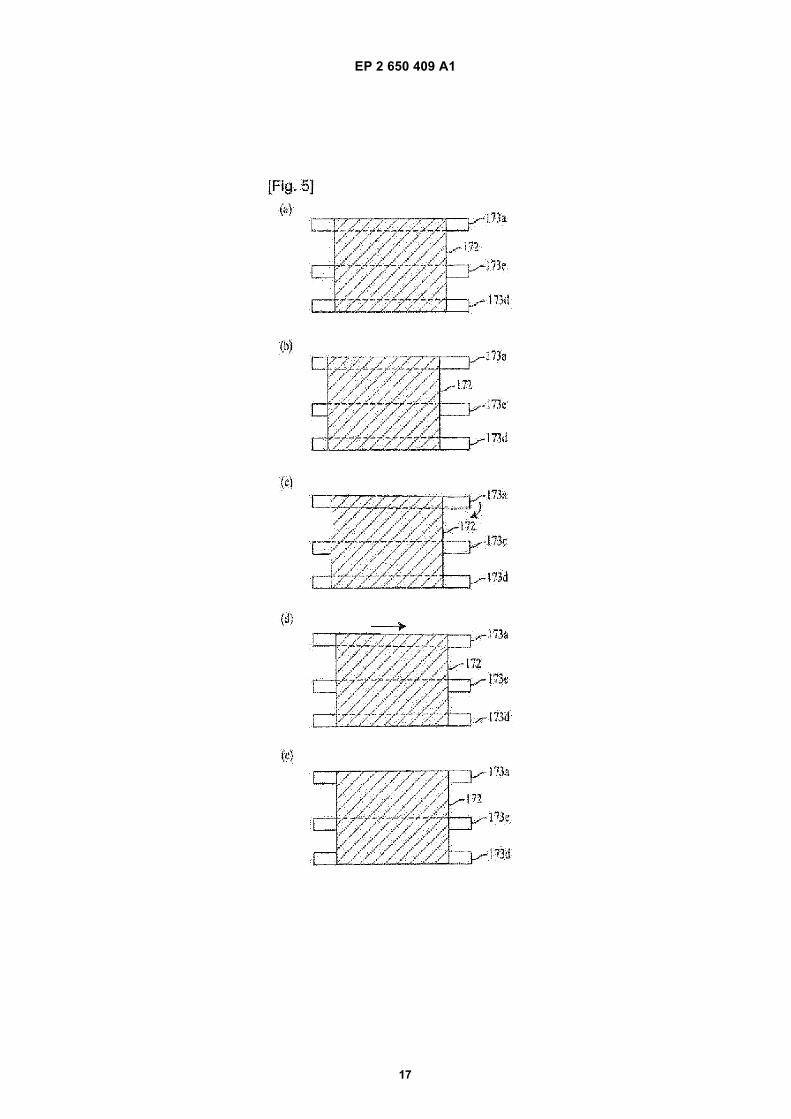
Fig. 5 illustrates the operation of the auxiliary beltposition control device.
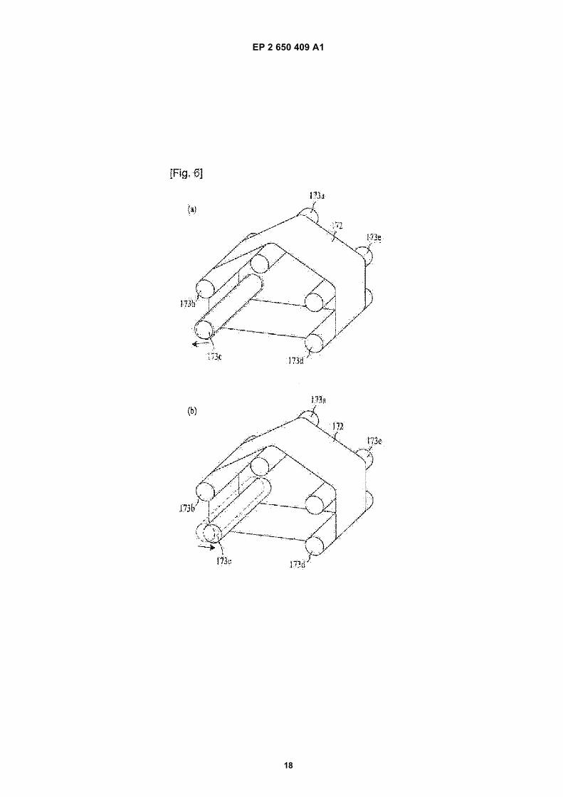
Fig. 6 illustrates the operation of a tension controldevice.
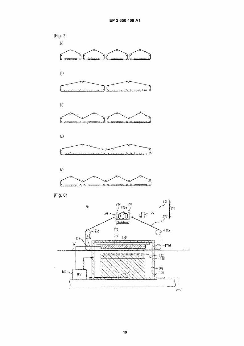
Fig. 7 illustrates a modification of the auxiliary belt.
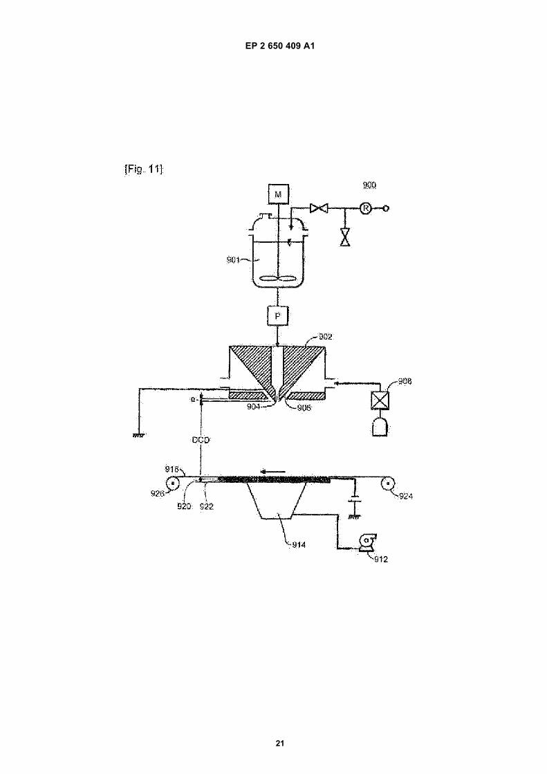
Fig. 8 is a view showing a modification of the auxiliary
7 8
EP 2 650 409 A1
6
5
10
15
20
25
30
35
40
45
50
55
belt position control device.
Fig. 9 is a view showing a modification of an auxiliarybelt position sensor.
Fig. 10 is a front view showing a critical portion ofthe field emission device.
Fig. 11 is a view illustrating a field emission deviceproposed in Patent document 1.
Best Mode
[0044] Hereinafter, a field emission device and a na-nofiber manufacturing device according to an embodi-ment of the present invention will be described with ref-erence to the attached drawings.
[Embodiment]
1. Construction of a nanofiber manufacturing device 1 according to an embodiment
[0045] Fig. 1 is a view illustrating the nanofiber manu-facturing device 1 according to the embodiment of thepresent invention. Fig. 1a is a front view of the nanofibermanufacturing device 1, and Fig. 1b is a plan view of thenanofiber manufacturing device 1. Fig. 2 illustrates a crit-ical portion of a field emission device. Fig. 2a is a frontview of the critical portion of the field emission device.Fig. 2b is a view showing an auxiliary belt device from adirection in which a long sheet is transferred. Fig. 3 is aview illustrating an auxiliary belt. Fig. 3a is an enlargedplan view of the auxiliary belt, and Fig. 3b is an enlargedsectional view of the auxiliary belt. In Figs. 1 and 2, apolymer solution supply unit and a polymer solution col-lection unit are not designated. Also, Fig. 1a illustratessome parts as sectional views. In Fig. 3, warp threadsand weft threads are indicated by hatching.[0046] As shown in Fig. 1, the nanofiber manufacturingdevice 1 according to the embodiment of the present in-vention includes a transfer device 10 which transfers along sheet W at a predetermined transfer speed V, aplurality of field emission devices 20 which are arrangedin series with respect to a transfer direction A in whichthe long sheet W is transferred by the transfer device 10,a gas permeability measurement device 40, and a maincontroller 60. The main controller 60 controls the transferdevice 10, the field emission device 20, a heating device30 which will be explained later herein, the gas permea-bility measurement device 40, a VOC treatment device70 which will be explained later herein, an inert gas supplydevice (not shown), a polymer supply device (not shown)and a polymer collection device (not shown).[0047] In the nanofiber manufacturing device 1 accord-ing to this embodiment, four field emission devices 20are arranged in series in the transfer direction A in whichthe long sheet W is transferred.
[0048] The nanofiber manufacturing device 1 accord-ing to this embodiment further includes the heating de-vice 30 which is disposed between the field emissiondevice 20 and the gas permeability measurement device40 and heats the long sheet W on which nanofibers aredeposited, the VOC treatment device 70 which burns vol-atile components generated when nanofibers are depos-ited on the long sheet W and eliminates them, and theinert gas supply device which receives a signal from themain controller 60 and supplies inert gas into a field emis-sion chamber 102 of a field emission device 20 that isdetected to be abnormal.[0049] As shown in Fig. 1, the transfer device 10 in-cludes a feed roller 11 which supplies the long sheet W,a winding roller 12 around which the long sheet W iswound, and auxiliary rollers 13 and 18 and drive rollers14, 15, 16 and 17 which are disposed between the feedroller 11 and the winding roller 12. The feed roller 11, thewinding roller 12 and the drive roller 14, 15, 16 and 17are configured to be rotated by a drive motor which is notshown in the drawings.[0050] As shown in Fig. 2, the field emission device 20includes a casing 100 which is conductive, a collector150 which is attached to the casing 100 with an insulator152 interposed therebetween, a nozzle block 110 whichis disposed facing the collector 150 and is provided witha plurality of nozzles 112 to discharge polymer solution,a power supply 160 which applies high voltage (e.g., 10kV to 80 kV) between the collector 150 and the nozzleblock 110, a field emission chamber 102 which is a spacethat covers the collector 150 and the nozzle block 110,and an auxiliary belt device 170 which assists in trans-ferring the long sheet W.[0051] As shown in Fig. 2, the nozzle block 110 in-cludes, as the nozzles 112, a plurality of upward nozzles112 which discharges a polymer solution from outletsthereof upwards. The nanofiber manufacturing device 1is configured such that the polymer solution is dischargedfrom the outlets of the upward nozzles 112 in such a wayas to overflow from the outlets of the upward nozzles112, thus forming nanofibers through field-emission and,simultaneously, the polymer solution that has overflowedfrom the outlets of the upward nozzles 112 is collectedso that it can be reused as material for nanofibers. Theupward nozzles 112 are arranged at intervals, for exam-ple, of 1.5 cm to 6.0 cm. The number of upward nozzles112 is, for example, 36 (6 by 6, when the same in lengthand width) - 21904 (148 by 148). The nozzle block 110may be directly grounded or, alternatively, it may begrounded through the casing 100. In the field emissiondevice according to the present invention, various sizesand shapes of nozzle blocks can be used, and the nozzleblock 110 preferably has a rectangular shape (includinga square shape), one side of which ranges from 0.5 mto 3 m, when viewed as the plan view.[0052] The power supply 160 includes a current supplyunit 164, a current measurement unit 166 which meas-ures current supplied from the current supply unit 164,
9 10

EP 2 650 409 A1
7
5
10
15
20
25
30
35
40
45
50
55
and a control unit 162 which controls the operation of thecurrent supply unit 164 and processes the result of cur-rent measurement of current measurement unit 166. Fur-thermore, the power supply 160 applies high voltage be-tween the collector 150 and the nozzles 112, measurescurrent supplied from the power supply 160, and trans-mits a measured value to the main controller 60. Whenthe power supply 160 receives a current interruption sig-nal from the main controller 60, power supply is interrupt-ed.[0053] As shown in Fig. 2, the auxiliary belt device 170includes an auxiliary belt 172 which is rotatably providedin such a way as to encircle the collector 150 and is madeof an insulating and porous endless belt, and an auxiliarybelt drive unit 171 which rotates the auxiliary belt 172 ata speed corresponding to the speed at which the longsheet W is transferred.[0054] As shown in Figs. 2 or 3, the auxiliary belt 172is configured in such a way that net-shaped substrates,each of which is fabricated by weaving threads havingdiameters of 0.1 mm to 2.0 mm, are stacked on top ofone another. The auxiliary belt 172 has an opening ratioranging from 1% to 40%, and the width thereof is greaterthan that of the collector 150 that corresponds to the widthof the long sheet W. In detail, for example, a first layernet, in which polyethylene threads, the diameters ofwhich are 0.27 mm and 0.18 mm, are alternately ar-ranged, and a second layer net, in which polyacetylenethreads of 0.35 mm in diameter and polyethylene threadsof 0.35 mm in diameter are alternately arranged, areweaved with polyethylene warp threads of 0.25 mm indiameter, thus forming a net-shaped substrate (refer toFig. 3a). Net-shaped substrates are stacked on top ofone another, thus forming a belt having a 2.5-layer struc-ture (refer to Fig. 3b). The width of the auxiliary belt 172is 2 m, and a plurality of holes are formed in the auxiliarybelt 172 such that the opening ratio thereof is 4%. Theperipheral length of the auxiliary belt is preferably 6 m,although it is changed depending on the length of thecollector 150.[0055] As shown in Fig. 2, the auxiliary belt drive unit171 includes five auxiliary belt rollers 173a, 173b, 173c,173d and 173e (hereinafter, also denoted by 173) aroundwhich the auxiliary belt is wrapped so that the auxiliarybelt is rotated by the auxiliary belt rollers, a drive motor(not shown) which rotates the auxiliary belt rollers 173,an auxiliary belt position control device 174 which con-trols the position of the auxiliary belt 172 with respect tothe longitudinal direction of the auxiliary belt roller 173a,an auxiliary belt position sensor 173 which measures theposition of the auxiliary belt 172 with respect to the lon-gitudinal direction of the auxiliary belt roller 173a, and atension control device 178 which controls the tension ap-plied to the auxiliary belt 172.[0056] Each of the auxiliary belt rollers 173 which rotatethe auxiliary belt 172 has a length of 2.2 m with respectto the transverse direction of the auxiliary belt 172. Theauxiliary belt roller 173a receives a signal from the aux-
iliary belt position control device 174 so that one end ofthe auxiliary belt roller 173a is controlled in position withrespect to the direction from the inside of the auxiliarybelt 172 towards the outside thereof. The auxiliary beltroller 173c receives a signal from the tension control de-vice 178 and is controlled in position with respect to thedirection from the inside of the auxiliary belt 172 towardsthe outside thereof. The auxiliary belt roller 173d is ro-tated by the drive motor (not shown).[0057] In other words, the auxiliary belt roller 173d isa drive roller, and the other auxiliary belt rollers are drivenrollers. The field emission device of the present inventionmay have two or more drive rollers.[0058] The auxiliary belt position control device 174includes a pair of air springs 176 and an expansion-ratecontrol unit 177. The air springs 176 are disposed onopposite upper and lower sides of a support shaft, whichis coupled to one end of the auxiliary belt roller 173a androtatably supports it. The expansion-rate control unit 177independently controls the expansion rate of each airspring 176.[0059] Based on the result of measurement of the aux-iliary belt position sensor 175, the expansion-rate controlunit 177 transmits a signal to control the expansion-ratesof the air springs 176 so that one end of the auxiliary beltroller 173a moves upwards or downwards whereby theauxiliary belt roller 173a is tilted and the auxiliary belt ismoved to a predetermined position in the transverse di-rection of the long sheet W.[0060] The air springs 176 function to move the oneend of the auxiliary belt roller 173a upwards or down-wards and tilt the auxiliary belt roller 173a. For example,if the lower air spring is expanded while the upper airspring is contracted, the one end of the auxiliary belt roller173a is moved upwards so that the auxiliary belt roller173a is tilted in a corresponding direction. If the lower airspring is contracted while the upper air spring is expand-ed, the support shaft side of the auxiliary belt roller 173ais moved downwards so that the auxiliary belt roller 173ais tilted in the other direction. A typical air spring can beused as each air spring 176.[0061] The auxiliary belt position sensor 175 is a posi-tion sensor which measures the position of the auxiliarybelt with respect to the transverse of the auxiliary belt172. The auxiliary belt position sensor 175 transmits theresult of measurement to the auxiliary belt position con-trol device 174. A camera can be used as the positionsensor.[0062] The tension control device 178 controls the ten-sion applied to the auxiliary belt 172 in such a way thatthe tension applied to the auxiliary belt is measured and,when necessary, the auxiliary belt roller 173c is movedby pneumatic pressure. Furthermore, the tension controldevice 178 is used to facilitate work of wrapping the aux-iliary belt 172 around the auxiliary belt rollers 173 or re-moving it therefrom.[0063] The field emission device 20 is installed in aroom set at an ambient temperature ranging from 20°C
11 12

EP 2 650 409 A1
8
5
10
15
20
25
30
35
40
45
50
55
to 40°C and an ambient humidity ranging from 20% to60%.[0064] The heating device 30 is disposed between thefield emission device 20 and the gas permeability meas-urement device 40 and functions to heat the long sheetW on which nanofibers are deposited. Although the tem-perature to which the long sheet W is heated can bechanged depending on the kind of long sheet W or na-nofiber, it is preferable that the long sheet W is heatedto a temperature ranging from 50°C to 300°C.[0065] The gas permeability measurement unit 40measures the gas permeability of the long sheet W onwhich nanofibers are deposited by the field emission de-vices 20.[0066] The main controller 60 controls the transfer de-vice 10, the field emission devices 20, the heating device30, the gas permeability measurement device 40, theVOC treatment device 70, the inert gas supply device,the polymer supply device and the polymer collection de-vice.[0067] The VOC treatment device 70functions to burnvolatile components generated when nanofibers are de-posited on the long sheet, thus eliminating them.
2. A method of manufacturing nanofibers using the na-nofiber manufacturing device according to an embodi-ment
[0068] Hereinafter, a method of manufacturing na-nofiber nonwoven fabric using the nanofiber manufactur-ing device 1 having the above- mentioned constructionwill be described.[0069] Fig. 4 is a view illustrating an auxiliary belt po-sition control device 174. Fig. 5 illustrates the operationof the auxiliary belt position control device 174. Fig. 5athrough 5e are process views. Fig. 6 is a view illustratinga tension control device 178. Fig. 6a is a view illustratingthe operation of the tension control device 178 when op-eration of controlling the tension applied to the auxiliarybelt 172 is conducted. Fig. 6b is a view illustrating theoperation of the tension control device 178 when opera-tion of removing the auxiliary belt 172 from the auxiliarybelt rollers is conducted. In Figs. 4 through 6, to simplifythe drawings, illustration of elements, other than the aux-iliary belt 172 and the auxiliary belt rollers 173, is omitted.[0070] First, the long sheet W is set on the transferdevice 10. Thereafter, while the long sheet W is trans-ferred from the feed roller 11 to the winding roller 12 ata predetermined transfer speed V, the field emissiondevices 20 successively deposit nanofibers on the longsheet W. Subsequently, the heating device 30 heats thelong sheet W on which nanofibers have been deposited.In this way, nanofiber nonwoven fabric including the longsheet on which nanofibers are deposited is manufac-tured.[0071] During this process, the auxiliary belt device170 rotates the auxiliary belt 172 at a speed correspond-ing to a speed, at which the long sheet W is transferred,
uses the auxiliary belt position sensor 175 to measurethe position of the auxiliary belt 172 with respect to thelongitudinal direction of the auxiliary belt roller 173a, anduses the tension control device 178 to measure the ten-sion applied to the auxiliary belt 172.[0072] If the auxiliary belt position sensor 175 detectsthat the auxiliary belt 172 has been dislocated from acorrect position with respect to the longitudinal directionof the auxiliary belt roller 173a, the auxiliary belt positioncontrol device 174 moves the one end of the auxiliarybelt roller 173a upwards or downwards, as shown in Fig.4, thus controlling the position of the auxiliary belt 172with respect to the longitudinal direction of the auxiliarybelt roller 173a such that it is located at the correct posi-tion.[0073] For example, if the auxiliary belt is moved in theleft-right direction and displaced from its original position(refer to Figs. 5a and 5b), the auxiliary belt position sensor175 transmits the result of position measurement to theauxiliary belt position control device 174. Then, the aux-iliary belt position control device 174 calculates a dis-placement to move the end (in this embodiment, the rightend) of the auxiliary belt roller 173a downwards and con-trols the air springs 176 based on the calculated displace-ment in such a way as to adjust the expansion rates ofthe air springs 176 (refer to Fig. 5c). As a result, the aux-iliary belt 172 is moved to the right with respect to theground (Fig. 5d) and is eventually returned to the correctposition (Fig. 5e).[0074] Meanwhile, if the tension control device 179 de-tects that the tension applied to the auxiliary belt 172 hasbeen reduced, loosening the auxiliary belt 172, as shownin Fig. 6a, the auxiliary belt roller 173c is moved outwardswith respect to the direction from the inside of the auxiliarybelt 172 towards the outside thereof, thus returning thetension of the auxiliary belt to a predetermined value.[0075] As shown in Fig. 6b, to wrap the auxiliary belt172 around the auxiliary belt rollers 173 before field emis-sion begins or remove the auxiliary belt 172 from theauxiliary belt roller 173 after the field emission has fin-ished, the auxiliary belt roller 173c is moved inwards (inthe direction from the inside of the auxiliary belt 172 to-wards the outside thereof) to a position at which the aux-iliary belt wrapping or removal operation can be facilitat-ed.[0076] The main controller 60 controls the transferspeed V, at which the transfer device 10 transfers thelong sheet W, based on a gas permeability measured bythe gas permeability measurement device 40 or an av-erage gas permeability. For example, if field emissionconditions are changed in such a way that the measuredgas permeability becomes greater than a predeterminedgas permeability, the main controller 60 reduces thetransfer speed V such that the amount of cumulative na-nofibers deposited on the long sheet per a unit area isincreased, thus reducing the gas permeability. Further-more, the main controller 60 also controls the auxiliarybelt drive unit 171 so that the auxiliary belt 172 rotates
13 14

EP 2 650 409 A1
9
5
10
15
20
25
30
35
40
45
50
55
at a speed corresponding to the controlled transfer speedof the long sheet W.[0077] During the manufacturing process, when eachfield emission device carries out field emission while volt-age, e.g., of 35kV, is applied between the collector 150and the nozzle block 110, if it is detected that currentsupplied from one of the power supplies 160 or morethan one power supply 160 is larger than 0.24 mA, themain controller 60 transmits a current interruption signalto the corresponding one or more power supplies 160.[0078] Furthermore, when it is detected that current ofless than 0.18 mA is supplied from one ore more powersupplies 160, the main controller 60 generates an alarm(a warning sound or warning sign) to notify that the oneor more power supplies 160 are abnormal.[0079] Moreover, when a current interruption signal istransmitted to an associated one or more power supplies160, the main controller 60 also transmits a transferspeed reduction signal to the transfer device 10 so as tomaintain the amount of cumulative nanofibers depositedon the long sheet W per a unit area within a predeter-mined range.[0080] Here, when the number of power supplies 160that have supplied current for a first period before thetransfer speed is reduced is ÓnÌ and the number of powersupplies 160 that supply power for a second period afterthe transfer speed has been reduced is ÓmÌ, the maincontroller 60 controls the transfer device such that thetransfer speed for the second period is Óm/ nÌ times thetransfer speed for the first period. Subsequently, the maincontroller 60 more finely controls the transfer speedbased on the gas permeability measured by the gas per-meability measurement device 40. Also, the main con-troller 60 controls the auxiliary belt drive unit 171 suchthat the auxiliary belt 172 is rotated at a speed corre-sponding to the transfer speed at which the long sheetW is transferred.[0081] The control of the transfer speed V can be em-bodied by controlling the rpm of the drive rollers 14, 15,16 and 17.[0082] Hereinafter, field emission conditions in the na-nofiber manufacturing method according to the presentinvention will be described by example.[0083] Nonwoven fabric, cloth, knitted fabric, a filmetc., which are made of different kinds of materials, canbe used as the long sheet. Preferably, the thickness ofthe long sheet ranges from 5 mm to 500 mm, and thelength thereof ranges from 10 m to 10 km.[0084] Polylactic acid (PLA), polypropylene (PP), pol-yvinyl acetate (PVAc), polyethylene terephthalate (PET),polybutylene terephthalate (PBT), polyethylene naph-thalate (PEN), polyamide PA, polyurethane (PUR), pol-yvinyl alcohol (PVA), polyacrylonitrile (PAN), polyetherlmide (PEI), polycaprolactone (PCL), polylactic acid gly-colic acid (PLGA), silk, cellulose, chitosan, etc. can beused as material of the polymer for nanofibers.[0085] Dichloromethane, dimethylformaide, dimethylsulfoxide, methyl ethyl ketone, chloroform, acetone, wa-
ter, formic acid, acetic acid, cyclohexane, THF, etc. canbe used as a solvent which is used for the polymer so-lution. A mixture of different kinds of solvents may beused, and an addition agent such as a conductivity im-prover may be added to the polymer solution.[0086] The gas permeability P of nanofiber nonwovenfabric ranges from 0.15 cm3/cm2/s to 200 cm3/cm2/s. Thetransfer speed V is preferably set to a speed of 0.2 m/minute to 100 m/minute. The voltage which is applied tothe nozzles, the collector 150 and the nozzle block 110can be set to a voltage of 10 kV to 80 kV (in the fieldemission device 20 according to this embodiment, it ispreferable for the voltage to be set to about 50 kV).[0087] The temperature in the emission area is prefer-ably set to 25°C, and the humidity in the emission areais set to 30%.
3. The effects of the field emission device and the man-ufacturing device according to the embodiment
[0088] The field emission device 20 according to theembodiment is provided with the power supply 160, oneelectrode of which is connected to the collector 150 whilethe other electrode is connected to the nozzle block 110and the potential thereof drops to the ground potential.All of the nozzle block 110, polymer solution before beingdischarged from the nozzles 112J , Óa material tank forstoring the polymer solutionJ and Óa polymer solutiontransfer unit (for example, a pipe and a pump) for trans-ferring the polymer solution from the material tank to thenozzles 112Ì become ground potentials. Therefore, inthe same manner as the case of the field emission devicedisclosed in Patent document 1, it is unnecessary for thematerial tank or the polymer solution transfer unit to havehigh resistance against voltage. As a result, the presentinvention can prevent a problem of the structure of thefield emission device being complicated, which may oc-cur if the material tank or the polymer solution transferunit is configured to have high resistance against voltage.[0089] Furthermore, because the field emission device20 according to the embodiment is provided with the pow-er supply 160, one electrode of which is connected to thecollector 150 while the other electrode is connected tothe nozzle block 110 and the potential thereof drops tothe ground potential, field emission is conducted underconditions, in which high voltage is applied to the collector150 capable of having a comparatively simple shape andstructure, and the nozzle block 110, which has a com-paratively complex shape and structure, is grounded, inthe same manner as the case of the field emission devicedisclosed in Patent document 1. Therefore, undesirablevoltage discharge or drop can be prevented from occur-ring, whereby the field emission can be conducted con-tinuously under stable conditions.[0090] In addition, the field emission device 20 accord-ing to the embodiment is also provided with the auxiliarybelt device 170, which includes the auxiliary belt 172which is rotatably provided in such a way as to encircle
15 16

EP 2 650 409 A1
10
5
10
15
20
25
30
35
40
45
50
55
the collector 150 and is made of an insulating and porousendless belt, and an auxiliary belt drive unit 171 whichrotates the auxiliary belt 172 at a speed correspondingto the speed at which the long sheet W is transferred.Accordingly, even if comparatively large electrostatic at-tractive force occurs between the collector 150 and thelong sheet W, because the auxiliary belt 172 is presentbetween the long sheet W and the collector 150, the longsheet W can be reliably prevented from being pulled to-wards the collector 150, or the long sheet W can besmoothly transferred without being impeded. As a result,it is possible that nanofibers are formed under uniformconditions through field emission, and the field emissiondevice 1 can be continuously operated without being in-terrupted. Thereby, nanofibers having uniform quality (forexample, an average diameter of nanofibers, diameterdistribution of nanofibers, the amount of deposition ofnanofibers, the thickness of nanofiber nonwoven fabric,gas permeability of nanofiber nonwoven fabric, etc.) canbe mass-produced with high productivity.[0091] Further, in the field emission device 20 accord-ing to the embodiment, since the auxiliary belt 172 rotatesat a speed corresponding to the transfer speed of thelong sheet W, there is no problem of the auxiliary belt172 of having a bad influence on the transfer of the longsheet W. Moreover, in the field emission device 20 of thepresent invention, the auxiliary belt 172 is an insulatingand porous endless belt, thus not affecting electric fielddistribution between the collector 150 and the nozzleblock 110.[0092] Also, in the field emission device 20 accordingto the embodiment of the present invention, the auxiliarybelt drive unit 171 includes the several auxiliary belt roll-ers 173 which rotate the auxiliary belt 172 wrappedaround them, and the drive motor 176 which rotates theauxiliary belt roller 173c. Therefore, the auxiliary belt 172can be reliably rotated at a speed that corresponds tothe transfer speed of the long sheet W.[0093] Furthermore, in the field emission device 20 ac-cording to the embodiment of the present invention, theauxiliary belt drive unit 171 includes an auxiliary belt po-sition control device 174 which controls the position ofone end of the auxiliary belt roller 173a with respect tothe direction from the inside of the auxiliary belt 172 to-wards the outside thereof so that the position of the aux-iliary belt 172 with respect to the longitudinal direction ofthe auxiliary belt roller 173a can be controlled. As such,the inclination of the auxiliary belt roller 173a can be con-trolled, and this makes it possible to maintain the positionof the auxiliary belt 172 with respect to the longitudinaldirection of the auxiliary belt roller 173a within an appro-priate range over a long period of time.[0094] Particularly, in the field emission device 20 ac-cording to the embodiment, the auxiliary belt positioncontrol device 174 includes the two air springs 176 whichare disposed on opposite sides of the support shaft thatis coupled to one end of the auxiliary belt roller 173a androtatably supports it, and the expansion- rate control unit
177 which independently controls the expansion rate ofeach air spring 176. Therefore, the auxiliary belt positioncontrol device 174 can smoothly control the position ofthe auxiliary belt with respect to the longitudinal directionof the auxiliary belt roller.[0095] Furthermore, in the field emission device 20 ac-cording to the embodiment, the auxiliary belt drive unit171 includes the auxiliary belt position sensor 175 whichmeasures the position of the auxiliary belt 172 with re-spect to the longitudinal direction of the auxiliary belt roller173a. Based on the result of the measurement of theauxiliary belt position sensor 175, the operation of con-trolling the position of the auxiliary belt 172 with respectto the longitudinal direction of the auxiliary belt roller 173ais conducted. Therefore, the position of the auxiliary beltwith respect to the longitudinal direction of the auxiliarybelt roller can be more precisely and reliably controlled.[0096] Also, in the field emission device 20 accordingto the embodiment, the auxiliary belt drive unit 171 furtherincludes the tension control device 178 which adjusts theposition of the auxiliary belt roller 173c with respect tothe direction from the inside of the auxiliary belt 172 to-wards the outside thereof and thus controls the tensionapplied to the auxiliary belt 172. Hence, even if compar-atively large electrostatic attractive force occurs betweenthe collector 150 and the auxiliary belt 172, because it ispossible for the tension of the auxiliary belt 172 to beadjusted to a degree to overcome the electrostatic at-tractive force, not only can the long sheet W be preventedfrom being pulled towards the collector 150, but the longsheet W can be smoothly transferred without being im-peded.[0097] Moreover, in the field emission device 20 ac-cording to the embodiment, the tension control device178 can adjust the position of the auxiliary belt roller 173cwith respect to the direction from the inside of the auxiliarybelt 172 towards the outside thereof in such a way thatthe auxiliary belt roller 173c is moved to a position atwhich the auxiliary belt 172 can be easily wrapped aroundthe auxiliary belt rollers 173 or can be easily removedtherefrom. Therefore, the operation of wrapping the aux-iliary belt 172 around the auxiliary belt rollers 173 or re-moving it therefrom can be facilitated.[0098] Furthermore, in the field emission device 20 ac-cording to the embodiment, the width of the auxiliary belt172 is greater than that of the collector 150 that corre-sponds to the width of the long sheet W. Thus, the aux-iliary belt 172 is reliably disposed between the long sheetW and the collector 150, whereby the long sheet W canbe prevented from being pulled towards the collector 150,or the transfer of the long sheet W can be prevented frombeing impeded.[0099] In addition, according to the field emission de-vice 20 of the embodiment, the opening ratio of the aux-iliary belt 172 ranges from 1% to 40%. The reason whythe opening ratio of the auxiliary belt 172 ranges from1% to 40% is due to the fact that, when the opening ratioof the auxiliary belt 172 is 1% or more, the opening ratio
17 18
EP 2 650 409 A1
11
5
10
15
20
25
30
35
40
45
50
55
can be regarded to be a level that does not greatly influ-ence electro field distribution formed between the collec-tor 150 and the nozzle block 110, and when the openingratio of the auxiliary belt 172 is 40% or less, it does notgreatly reduce the mechanical strength of the auxiliarybelt 172.[0100] Further, in the field emission device 20 accord-ing to the embodiment, because the auxiliary belt 172 ismade of net- shaped substrates which are formed byweaving threads of 0.1 mm to 2.0 mm in diameter, theauxiliary belt 172 has both high mechanical strength andflexibility. Therefore, the auxiliary belt 172 can besmoothly rotated with strong tension applied thereto.[0101] Also, in the field emission device 20 accordingto the embodiment of the present invention, the auxiliarybelt 172 is configured in such a way that net- shapedsubstrates are stacked on top of one another. As a result,the auxiliary belt 172 has sufficient mechanical strength,thus making it possible to rotate the auxiliary belt 172with increased tension. More preferably, the net- shapedsubstrates of the auxiliary belt 172 are made of differentkinds of materials. In this case, the mechanical strengthand durability of the auxiliary belt 172 can be further en-hanced. For instance, a substrate formed on a surfaceof the auxiliary belt 172 that faces the long sheet W maybe made of soft material, and a substrate formed a sur-face of the auxiliary belt 172 that faces the collector 150may be made of material having high mechanicalstrength. The stacked structure of the net- shaped sub-strates may be a two-, three-, four- or more- layer struc-ture, or it may be a 2.5- layer structure. The term Ó2.5-layer structureÌ refers to a structure such that the threaddensity of one layer of the two- layer structure is higherthan that of the other layer so that the surface planarityand the abrasion resistance of the auxiliary belt can beenhanced without increasing the weight thereof.[0102] Meanwhile, the nanofiber manufacturing device1 according to the embodiment of the present inventionuses the field emission device having the above- men-tioned construction. Therefore, even if field emission isconducted in such a way that high voltage is applied tothe collector while the nozzle block is grounded, the na-nofiber manufacturing device 1 can mass- produce na-nofibers having uniform quality with high productivity.[0103] Furthermore, the nanofiber manufacturing de-vice 1 according to the embodiment includes several fieldemission devices 20 which are arranged in series in atransfer direction A in which the long sheet W is trans-ferred. Therefore, because the several field emission de-vices are used to manufacture nanofibers, the nanofibermanufacturing device can mass- produce nanofiberswith further enhanced productivity.[0104] Although the preferred embodiments of thepresent invention have been disclosed for illustrative pur-poses, the present invention is not limited to the embod-iments. Those skilled in the art will appreciate that variousmodifications are possible, without departing from thescope and spirit of the invention. For instance, the fol-
lowing modifications are also possible.
(1) in the above-mentioned embodiment, althoughthe nanofiber manufacturing device of the presentinvention has been illustrated as including four fieldemission devices, the present invention is not limitedto this construction. For example, the present inven-tion may be applied to a nanofiber manufacturingdevice which includes two, three, five or more fieldemission devices.
(2) in the above-mentioned embodiments, althoughthe nanofiber manufacturing device has been illus-trated as including four field emission devices andeach field emission device has been illustrated ashaving a single auxiliary belt device (refer to Fig. 7a),the present invention is not limited to this construc-tion. Fig. 7 illustrates modifications of the auxiliarybelt device 170 according to the embodiment of thepresent invention. As shown in Fig. 7, the nanofibermanufacturing device according to the present in-vention may be configured such that one or moreauxiliary belt devices 170 are provided, and one oreach auxiliary belt device 170 includes an auxiliarybelt 172 which is wrapped around two or more col-lectors 150 of the field emission devices 20, and anauxiliary belt drive unit 171 which rotates the auxiliarybelt 172 at a speed corresponding to the transferspeed of the long sheet W. In this case, the numberof the auxiliary belt drive units 171 can be reduced.For example, in the nanofiber manufacturing devicethat is provided with four field emission devices 20,a single auxiliary belt device 170 may be installedfor every two field emission devices (refer to Figs.7b or 7c), or a single auxiliary belt device 170 maybe installed for all of the four field emission devices20 (refer to Figs. 7d or 7e).
(3) in the above-mentioned embodiment, each fieldemission device of the nanofiber manufacturing de-vice of the present invention has been illustrated asbeing a bottom-up type field emission device provid-ed with upward nozzles, the present invention is notlimited to this. For instance, the present inventionmay be applied to a nanofiber manufacturing devicewhich includes a top-down type field emission deviceprovided with downward nozzles or a side type fieldemission device provided with side nozzles.
(4) in the above-mentioned embodiment, the fieldemission device of the nanofiber manufacturing de-vice has been illustrated as being configured suchthat the positive electrode of the power supply 160is connected to the collector 150 while the negativeelectrode of the power supply 160 is connected tothe nozzle block 110 and the casing 100, the presentinvention is not limited to this. For example, thepresent invention may be applied to a nanofiber man-
19 20
EP 2 650 409 A1
12
5
10
15
20
25
30
35
40
45
50
55
ufacturing device which includes a field emission de-vice that is configured such that the negative elec-trode of the power supply is connected to the collec-tor 150 while the positive electrode of the power sup-ply is connected to the nozzle block 110 and the cas-ing 100.
(5) in the above-mentioned embodiment, althoughthe two air spring 181 have been illustrated as beingdisposed on opposite upper and lower sides of thesupport, the present invention is not limited to thisconstruction. Fig. 8 is a view showing a modificationof the auxiliary belt position control device. For ex-ample, as shown in Fig. 8, two air springs 176 maybe configured such that they are disposed on oppo-site left and right sides of the support shaft. In thiscase, the position of the auxiliary belt 172 with re-spect to the longitudinal direction of the auxiliary beltroller 173a can be controlled by horizontally movingthe end of the auxiliary belt roller 173a.
(6) in the above-mentioned embodiment, the camerais used as the position sensor, but the present inventis not limited to this. Fig. 9 illustrates a modificationof the auxiliary belt position sensor. As shown in Fig.9, for example, a disk-shaped position measurementsensor may be used as the position sensor. Also, atypical laser distance measurement device or othertypical position measurement sensors may be usedas the position sensor.
(7) in the above-mentioned embodiment, althoughthe nanofiber manufacturing device of the presentinvention has been illustrated as being configuredsuch that a single nozzle block is installed in eachfield emission device, the present invention is notlimited to this construction. Fig. 10 is a front viewillustrating a critical portion of a field emission device20a. As shown in Fig. 10, two nozzle blocks 110a1and 110a2 may be installed in each field emissiondevice 20a. In addition, the present invention maybe applied to a nanofiber manufacturing device inwhich two or more nozzle blocks are provided in eachfield emission device.
[0105] In this case, all of the nozzle blocks may havethe same nozzle arrangement interval. Alternatively, thenozzle blocks may be configured such that the nozzlearrangement intervals thereof differ from each other. Fur-thermore, all of the nozzle blocks may have the sameheight or, alternatively, the heights of the nozzle blocksmay differ from each other.(8) the nanofiber manufacturing device of the presentinvention may further include a reciprocating unit whichreciprocates the nozzle block at a predetermined periodin the transverse direction of the long sheet. In the casewhere the field emission operation is performed while thenozzle block is reciprocated at a predetermined period
by the reciprocating unit, the amount of cumulative na-nofibers deposited on the long sheet can be uniform withrespect to the transverse direction of the long sheet. Inthis case, preferably, each field emission device or eachnozzle block is independently controlled with regard tothe period or distance of the reciprocating motion of thenozzle block. Therefore, all of the nozzle blocks may beconfigured to be reciprocated on the same cycle. Thenozzle blocks may be reciprocated of different cycles.Furthermore, all of the nozzle blocks may be configuredsuch that the distances of the reciprocating motion of thenozzle blocks are the same as each other. Alternatively,the distances of the reciprocating motion of the nozzleblocks may be different from each other.
Claims
1. A field emission device, comprising:
a collector;a nozzle block disposed facing the collector, thenozzle block being provided with a plurality ofnozzles discharging a polymer solution; anda power supply applying high voltage betweenthe collector and the nozzle block, wherein oneof a positive electrode and a negative electrodeof the power supply is connected to the collector,while a remaining one of the positive electrodeand the negative electrode of the power supplyis connected to the nozzle block and a potentialof the remaining one drops to a ground potential,the field emission device forming, through fieldemission, nanofibers on a long sheet that is be-ing transferred at a predetermined transferspeed, the field emission device further compris-ingan auxiliary belt device, comprising: an auxiliarybelt comprising an insulating and porous end-less belt rotatably provided in such a way as toencircle the collector; and an auxiliary belt driveunit rotating the auxiliary belt at the transferspeed of the long sheet.
2. The field emission device according to claim 1,wherein the auxiliary belt drive unit comprises a plu-rality of auxiliary belt rollers around which the auxil-iary belt is wrapped so that the auxiliary belt is rotatedby the auxiliary belt rollers, and a drive motor rotatingat least one of the auxiliary belt rollers.
3. The field emission device according to claim 2,wherein the auxiliary belt drive unit further comprisesan auxiliary belt position control device controlling aposition of an end of one of auxiliary belt rollers withrespect to with respect to a direction from an insideof the auxiliary belt towards an outside thereof, thuscontrolling a position of the auxiliary belt with respect
21 22
EP 2 650 409 A1
13
5
10
15
20
25
30
35
40
45
50
55
to a longitudinal direction of the auxiliary belt roller.
4. The field emission device according to claim 3,wherein the auxiliary belt position control devicecomprises: a pair of air springs disposed on oppositesides of a support shaft, the support shaft rotatablysupporting the end of the auxiliary belt roller; and anexpansion-rate control unit independently control-ling expansion rates of the air springs.
5. The field emission device according to claim 3 or 4,wherein the auxiliary belt drive unit further comprisesan auxiliary belt position sensor measuring the po-sition of the auxiliary belt with respect to the longitu-dinal direction of the auxiliary belt roller and controlsthe position of the auxiliary belt with respect to thelongitudinal direction of the auxiliary belt roller basedon a result of measurement of the auxiliary belt po-sition sensor.
6. The field emission device according to any one ofclaims 2 through 5, wherein the auxiliary belt driveunit further comprises a tension control device con-trolling a position of at least one of the auxiliary beltrollers with respect to the direction from the insideof the auxiliary belt towards the outside thereof, thuscontrolling tension applied to the auxiliary belt.
7. The field emission device according to claim 6,wherein the tension control device controls a positionof the auxiliary belt roller with respect to the directionfrom the inside of the auxiliary belt towards the out-side thereof in such a way that the auxiliary belt rolleris moved to a position at which the auxiliary belt canbe easily wrapped around the auxiliary belt rollers orcan be easily removed therefrom.
8. The field emission device according to any one ofclaims 1 through 7, wherein a width of the auxiliarybelt is greater than a width of the collector that cor-responds to a width of the long sheet.
9. The field emission device according to any one ofclaims 1 through 8, wherein an opening ratio of theauxiliary belt ranges from 1% to 40%.
10. The field emission device according to any one ofclaims 1 through 8, wherein the auxiliary belt com-prises a net-shaped substrate formed by weavingthreads having diameters ranging from 0.1 mm to2.0 mm.
11. The field emission device according to claim 10,wherein the net-shaped substrate comprises a plu-rality of net-shaped substrates, and the auxiliary beltis configured such that the net-shaped substratesare stacked on top of one another.
12. A nanofiber manufacturing device, comprising:
a transfer device transferring a long sheet at apredetermined transfer speed; anda field emission device depositing nanofibers onthe long sheet that is being transferred by thetransfer device, wherein the field emission de-vice comprises the field emission device accord-ing to any one of claims 1 through 11.
13. The field emission device according to claim 12,wherein the field emission device comprises a plu-rality of field emission devices arranged in series ina direction in which the long sheet is transferred.
14. The field emission device according to claim 13,wherein the auxiliary belt device comprises: one ora plurality of auxiliary belts provided in such a wayas to encircle the collectors of two through all of thefield emission devices; and an auxiliary belt driveunit rotating the one or the plurality of auxiliary beltsat a speed corresponding to the transfer speed ofthe long sheet.
23 24
EP 2 650 409 A1
14
EP 2 650 409 A1
15
EP 2 650 409 A1
16
EP 2 650 409 A1
17
EP 2 650 409 A1
18
EP 2 650 409 A1
19

EP 2 650 409 A1
20
EP 2 650 409 A1
21
EP 2 650 409 A1
22
EP 2 650 409 A1
23

EP 2 650 409 A1
24
REFERENCES CITED IN THE DESCRIPTION
This list of references cited by the applicant is for the reader’s convenience only. It does not form part of the Europeanpatent document. Even though great care has been taken in compiling the references, errors or omissions cannot beexcluded and the EPO disclaims all liability in this regard.
Patent documents cited in the description
• JP 2008506864 A [0002]