MOTION DEVICE-CONTROL.pdf - Amerimation Inc.
137
OOT SWITCHES WER RELAYS POWER NDICATORS LED INDIC USHBUTTON RIAL AUTOMATION DEVICES BEACONS TERMINAL BLO AUTOMATION COMPONENTS RELAY TERMINAL BARRIER TERMINAL UL CE TUV RoHS EX IP67 ISO9001 BARRIER TERMINAL HOLE P CPS TOWER LIGHTS HOLE PLUGS HOLE PLUGS MOTION SIGNAL LIGHTS O BUZZERS PIEZO B SOCKETS SWITCH BOXES ANDON LIGHTS PLASTIC ENCLOSURES SWITCH BOXES INDUSTRIA INDUSTRIAL SWITCHES SWITCH BOXES REVOLVING CHAIN ABLE GLANDS PUSHBUTTON FUSE HOLDERS MINAL BLOCKS CABLE GLA RELAY TEMINAL BLOCKS SCREW CLAMP DIODE TERMINAL BLO TOWER LIGHTS BLOCKS TOWER LIGHTS TERMINAL LIMIT SWITCHES TORS LED INDICAT LED INDICATORS LOCKS CABLE CHAINS TERMINAL BLOCKS DIN R BOXCO WITCHES SOLID STATE RELAYS PLASTIC SWITCH BOXES OOT SWITCHES WER RELAYS POWER NDICATORS LED INDIC USHBUTTON RIAL AUTOMATION DEVICES BEACONS TERMINAL BLO AUTOMATION COMPONENTS RELAY TERMINAL BARRIER TERMINAL UL CE TUV RoHS EX IP67 ISO9001 BARRIER TERMINAL HOLE P CPS TOWER LIGHTS HOLE PLUGS HOLE PLUGS MOTION SIGNAL LIGHTS O BUZZERS PIEZO B SOCKETS SWITCH BOXES ANDON LIGHTS PLASTIC ENCLOSURES SWITCH BOXES INDUSTRIA INDUSTRIAL SWITCHES SWITCH BOXES REVOLVING CHAIN ABLE GLANDS PUSHBUTTON FUSE HOLDERS MINAL BLOCKS CABLE GLA RELAY TEMINAL BLOCKS SCREW CLAMP DIODE TERMINAL BLO TOWER LIGHTS BLOCKS TOWER LIGHTS TERMINAL LIMIT SWITCHES TORS LED INDICAT LED INDICATORS LOCKS CABLE CHAINS TERMINAL BLOCKS DIN R BOXCO WITCHES SOLID STATE RELAYS PLASTIC SWITCH BOXES
-
Upload
khangminh22 -
Category
Documents
-
view
2 -
download
0
Transcript of MOTION DEVICE-CONTROL.pdf - Amerimation Inc.

FOOT SWITCHES
POWER RELAYS
POWER RELAYS
LED INDICATORS
LED INDICATORSPUSHBUTTON
INDUSTRIAL AUTOMATION DEVICESBEACONS
TERMINAL BLOCKS
AUTOMATION COMPONENTSRELAY TERMINAL
BARRIER TERMINAL
UL CE TUV RoHS EX IP67 ISO9001BARRIER TERMINAL
HOLE PLUGS
CPSTOWER LIGHTSHOLE PLUGS
HOLE PLUGSMOTION DEVICES
SIGNAL LIGHTSPIEZO BUZZERS
PIEZO BUZZERS
SOCKETS
SWITCH BOXES
ANDON LIGHTSPLASTIC ENCLOSURES
SWITCH BOXESINDUSTRIAL SWITCHES
INDUSTRIAL SWITCHES
SWITCH BOXES
REVOLVING CHAINS
CABLE GLANDS
PUSHBUTTONFUSE HOLDERS
SCREW CLAMP DIODE TERMINAL BLOCKSCABLE GLANDSRELAY TEMINAL BLOCKS
SCREW CLAMP DIODE TERMINAL BLOCKS
TOWER LIGHTS
TERMINAL BLOCKS
TOWER LIGHTSTERMINAL BLOCKS
LIMIT SWITCHES
LED INDICATORSLED INDICATORS
LED INDICATORS
TERMINAL BLOCKS CABLE CHAINSTERMINAL BLOCKS
DIN RAILSBOXCO
LIMIT SWITCHES
SOLID STATE RELAYSPLASTIC SWITCH BOXES

MO
TIO
N D
EVIC
E/CO
NTR
OL
Closed Loop Stepper AiC-D-CL Series AiC-D Series AiCA-D Series AiS-D Series AiSA-D Series Ai-M Series
2 Phase Stepper MD2 Series 5 phase Stepper MD5 Series AK Series AK-B Series AHK Series AK-G Series AK-GB Series AK-R Series AK-RB Series Motion Control PMC-2HSN/2HSP Series PMC-1HS/2HS Series PMC-4B-PCI Series
11325374961
72
80101101109112112112112
116122129
MO
TIO
N D
EVIC
E/CO
NTR
OL

SENSORS
CONTROLLERS
MOTION DEVICES
SOFTWARE
(Y)Closed Loop Stepper System
(Z)Stepper Motors
(AA)Drivers
(AB)Motion Controllers
-|Transparent setting guide|-
AiC-D-CL Series
Features
Controller Integrated 2-Phase Closed-Loop Stepper Motor Driver
Filed requiring preciseness such as semiconductor equipment, 3D printer, optical inspection equipment, chip mounter, cartesian robot, conveying equipment, and alignment stage.
atMotion is a comprehensive motion device management program that can be used with Autonics motion controllers. atMotion provides GUI control for easy and convenient parameter setting and monitoring data management of multiple devices. Visit our website (www.autonics.com) to download the user manual and software.
Applications
Software (atMotion)
CC-Link communication type Ai-SERVO Real-time position control with closed-loop system Controllable maximum 42 axis Able to check alarm and status with Alarm/Status display part (7 segment) Motor driver and controller integral type Faster response and performing low-speed/high torque for short-distance continuous
drive to compare with the servo system. Applicable to the precision equipment such as optical inspection equipment with the
features of having no micro vibration (hunting) in stop Dedicated Windows program (atMotion) provided for parameter setting and monitoring Easy and various gain setting supported through the program(GUI) Containing 10-level resolutions Frame size 20mm, 28mm, 35mm, 42mm, 56mm, 60mm motors supported
(applied motor: Ai-M Series)
ManualFor the detail information and instructions, please refer to user manual, user manual for communication manual and library manual and be sure to follow cautions written in the technical descriptions (catalog, website).Visit our website (www.autonics.com) to download manuals.
<atMotion screen> <Computer specification for using software>
Item Minimum requirements
System IBM PC compatible computer with Intel Pentium Ⅲ or above
Operations Microsoft Windows 98/NT/XP/Vista/7/8/10Memory 256MB+Hard disk 1GB+ of available hard disk spaceVGA Resolution: 1024×768 or higherOthers RS-232 serial port (9-pin), USB port
Please read “Safety Considerations” in the instruction manual before using.
1

AiC-D-CL Series -|Transparent setting guide|-
Configuration Diagram
Ordering Information
External I/OI/O cable
PowerPower cable
Ai-M Series(Motor)
AiC-D-CL Series(Controller Integrated
Motor Driver)
Settings of start, stop, rotation direction, etc.Rated current
Motor+Encoder cable
Brake I/OBrake cableUSB / RS232C /
Wi-Fi
SCM Series Comm. Converter
RS485 cable
CC-Link cable
PLC
PC & atMotion
Series
Item
Motor frame size
Motor length
Encoder resolution
Brake
Comm. Type
Category
DAi 42 CLL A
20 20×20mm
28 28×28mm
35 35×35mm
42 42×42mm
56 57.2×57.2mm
60 60×60mm
C
CL CC-Link
No mark Standard typeB※1 Built-in brake type
A※2 4,000PPR (1,000PPR×4-multiply)B※3 16,000PPR (4,000PPR×4-multiply)A※4 10,000PPR (2,500PPR×4-multiply)
Standard type Built-in brake typeM 41.2mm -L 53.1mm -
S 46mm -M 59mm -L 65mm -
S 41.5mm -M 52mm -L 68.5mm -
S 67.5mm 102.3mmM 73.5mm 108.3mmL 81.5mm 116.3mm
S 77.3mm 112.1mmM 90.3mm 125.1mmL 111.3mm 146.1mm
S 81.9mm 116.7mmM 102.8mm 137.6mmL 119.8mm 154.6mm
D Driver
C Controller
Ai Artificial intelligence
2

2-Phase Closed-Loop Stepper Motor Driver
SENSORS
CONTROLLERS
MOTION DEVICES
SOFTWARE
(Y)Closed Loop Stepper System
(Z)Stepper Motors
(AA)Drivers
(AB)Motion Controllers
-|Transparent setting guide|-
Specifications
※1: The model name indicates driver type. (none: standard type, B: built-in brake type) E.g.) AiC-D-42LA-B-CL: built-in brake type stepping motor driver.
※2: Based on the ambient temperature 25, ambient humidity 55%RH, and STOP current 50%.※3: Max. power consumption during operation. When changing the load rapidly, instantaneous peak current may increase.
The capacity of power supply should be over 1.5 to 2 times of max. power consumption.※4: Run current varies depending on the input RUN frequency and max. RUN current at the moment varies also.※5: Settable with the dedicated program (atMotion).※6: The weight includes packaging. The weight in parenthesis is for unit only.※Environment resistance is rated at no freezing or condensation.
Model※1- AiC-D-28SB-CL AiC-D-35SB-CL AiC-D-42SA(-B)-CL AiC-D-56SA(-B)-CL AiC-D-60SA(-B)-CLAiC-D-20MA-CL AiC-D-28MB-CL AiC-D-35MB-CL AiC-D-42MA(-B)-CL AiC-D-56MA(-B)-CL AiC-D-60MA(-B)-CLAiC-D-20LA-CL AiC-D-28LB-CL AiC-D-35LB-CL AiC-D-42LA(-B)-CL AiC-D-56LA(-B)-CL AiC-D-60LA(-B)-CL
Power supply 24VDCᜡAllowable voltage range 90 to 110% of the rated voltage
Power Consumption
STOP※2 Max. 10W Max. 10W Max. 12W Max. 15WMax. during operation※3 Max. 60W Max. 60W Max. 120W Max. 240W
Max. RUN current※4 0.6A/Phase 1.0A/Phase 1.2A/Phase 1.7A/Phase 3.5A/PhaseSTOP current※5 20 to 100% of max. RUN current (factory default: 50%)Rotation speed 0 to 3000rpm
Resolution※5
500(factory default), 1000, 1600, 2000, 3600, 4000, 5000, 6400, 7200, 10000 [Pulse/Rev]
500(factory default), 1000, 1600, 2000, 3600, 5000, 6400, 7200, 10000, 16000 [Pulse/Rev]
500 (factory default), 1000, 1600, 2000, 3200, 3600, 5000, 6400, 7200, 10000PPR
Speed filter※5 0 (disable), 2, 4, 6, 8, 10, 20, 40, 60 (factory default), 80, 100, 120, 140, 160, 180, 200ms
Positioning Gain※5 (P Gain, I Gain)= (1, 1), (2, 1), (3, 1), (4, 1), (5, 1), (1, 2), (2, 2), (3, 2), (4, 2), (5, 2), (1, 3), (2, 3), (3, 3), (4, 3), (5, 3), user setting
Positioning range -2,147,483,648 to +2,147,483,647In-Position Fast Response: 0(factory default) to 7, Accurate Response: 0 to 7Motor rotation direction※5 CW, CCW
Status indicator Power/Alarm indicator: green/red LED In-Position indicator: yellow LED Servo On/Off indicator: orange LED Alarm/Warning status display part: red LED 7 segment CC-Link status indicator: red, green LED
I/O voltage level [H]: 5-30VDCᜡ, [L]: 0-2VDCᜡ
I/OInput Exclusive input: 3, general input: 8Output General output: 7
External power supply VEX(recommended: 24VDCᜡ), GEX(GND)Operation mode Jog, Continuous, Index, Program modeIndex step numbers 64 steps
Program function
Step 256 steps
Control command
ABS (move absolute position), INC (move incremental position), HOM (home search), ICJ (jump input condition), IRD (waiting input), OPC (on/off of output port), OPT (on pulse from output port), JMP (jump), REP (start repetition), RPE (end repetition), END (end program), POS (position set), TIM (timer)
Start Power On Program auto-start functionHome search Power On Home Search auto-start function
Home search mode Home, limit home, zero home, torque homeRS485 comm. Comm. speed※5 9600, 19200, 38400, 57600, 115200(factory default) bps
Alarm output
Overcurrent, overspeed, position tracking, overload, overheat, motor connection, encoder connection, regenerative voltage, motor misalignment, command speed, input voltage,in-position, memory, emergency stop, program mode, index mode, home search mode, comm. station setting, comm. mode setting, comm. station setting change, comm. mode setting change, comm. failure
Warning output ±software limit, ±hardware limit, overloadInsulation resistance Over 100MΩ (500VDCᜡ megger)Dielectric strength 1,000VACᜠ 60Hz for 1 minVibration 1.5mm amplitude at frequency of 10 to 55Hz (for 1 min) in each X, Y, Z direction for 2 hoursShock 300m/s2 (approx. 30G) in each X, Y, Z direction for 3 times
EnvironmentAmbient temp. 0 to 50, storage: -10 to 60Ambient humi. 35 to 85%RH, storage: 10 to 90%RH
Protection structure IP20(IEC standard)Approval ᜢ
Weight※6 Approx 470g (approx 320g)
3

AiC-D-CL Series -|Transparent setting guide|-
Dimensions
Unit Descriptions
(unit: mm)
1. Power connector (CN1: PWR)2. Motor+Encoder connector (CN2: Motor / Encoder)3. I/O connector (CN3: Signal I/O)4-1. RS485 Communication connector (CN4: RS485)4-2. Brake connector (CN5: BRAKE)5-1. Servo On/Off indicator (Servo, Orange)5-2. In-Position indicator (INP, Yellow)5-3. Power/Alarm indicator (PWR/AL, Green/Red)6. Alarm/Warning status display part (7 segment, Red)7: CC-Link status indicator (L.ERR/L.RUN, Red/Green)8: CC-Link station setting DIP switch (SW1)9: CC-Link comm. speed setting rotary switch (B-RATE)10: CC-Link station setting rotary switch (STATION NO.)11: CC-Link connector (CN6: DA DB DG SH FG)
61.5
11.5
150144
144
34.
414
.5
134 87.53.3
25.5
11109
54321
78 6
4

2-Phase Closed-Loop Stepper Motor Driver
SENSORS
CONTROLLERS
MOTION DEVICES
SOFTWARE
(Y)Closed Loop Stepper System
(Z)Stepper Motors
(AA)Drivers
(AB)Motion Controllers
-|Transparent setting guide|-
Status Indicators
Driver Setting
Status indicator LED color Function Descriptions
PWR GreenPower indicator Turns ON when the unit operates normally after supplying power.Warning indicator Flashes when limit signal is input or overload status is maintained
AL Red Alarm indicator When alarm occurs, it flashes in various ways depending on the situation.Refer to ' Control Input/Output → Output → 3. Alarm/Warning'.
INP. Yellow In-Position indicator Turns ON when motor is placed at command position after positioning input. SERVO Orange Servo On/Off indicator Turns ON when Servo is operating, turns OFF when servo is not operating.L.RUN Green
CC-Link comm. indicatorTurns ON when communication operates normally.
L.ERR Red Turns ON when communication failure.
※Set the CC-Link comm. station.※Available setting range is 01 to 64.
Setting Comm. speed (bps) Setting Comm. speed (bps)
B-RATE
0 156k 5
Disable1 625k 62 2.5M 73 5M 84 10M 9
CC-Link comm. speed setting rotary switch (B-RATE)
Setting Station No. (×10) Setting Station No. (×1)
×10
0 0×10
×1
0 01 1×10 1 12 2×10 2 23 3×10 3 34 4×10 4 45 5×10 5 56 6×10 6 67
Disable7 7
8 8 89 9 9
CC-Link station setting rotary switch (STATION NO.)
Setting CC-Link station settingON 2 stations occupiedOFF(factory default) 1 station occupied
CC-Link station setting DIP switch (SW1)
5

AiC-D-CL Series -|Transparent setting guide|-
Control Input/OutputInner signal of all input/output consists of photocoupler. ON, [H]: photocoupler power ON OFF, [L]: photocoupler power OFF※Brake operation is only for built-in brake type.
Functions can be assigned in general input IN0 to IN7.Assignable functions are as below.
Input1. Exclusive input (3)
Signal name Descriptions Pin no.ORG Home sensor 10+Limit +direction limit sensor 11-Limit -direction limit sensor 12
2. General input (8)
Signal name Descriptions Pin no.IN0 General input 0 2IN1 General input 1 3IN2 General input 2 4IN3 General input 3 5IN4 General input 4 6IN5 General input 5 7IN6 General input 6 8IN7 General input 7 9
Function Descriptions Function DescriptionsUser Input0
User input
+Jog + jog driveUser Input1 -Jog - jog driveUser Input2 Pause PuaseUser Input3 Servo On/Off Servo ON/OFFUser Input4 Home Home searchUser Input5 Alarm Reset Alarm resetUser Input6 SD Slow DownUser Input7 Clear Pos. Clear position, set current position as 0Reset Driver reset Step0
Step number setting(the combination of 6 bit, 0 to 5, selectable 0 to 64)
Start Program mode driver start Step1Start Index Index drive start Step2Stop Drive stop Step3EMG Driver emergency stop Step4+RUN + continuous drive Step5-RUN - continuous drive -
3. Example of input circuit connection- All input circuits are insulated with photocoupler, and separate external power (recommended: 24VDC) is necessary.-Case of using external power 24VDC does not require RL.- In case using external power over 24VDC, select RL value that IF (forward current of primary LED) of photocoupler to be around 2.5mA (max. 10mA).
※N: Input pin number of CN3
10kΩ
Driver
VEX
RLNInput
signal
※RL= VEX-1.25V
- 10×103 Ω 0.0025A
6

2-Phase Closed-Loop Stepper Motor Driver
SENSORS
CONTROLLERS
MOTION DEVICES
SOFTWARE
(Y)Closed Loop Stepper System
(Z)Stepper Motors
(AA)Drivers
(AB)Motion Controllers
-|Transparent setting guide|-
2. Alarm/Warning Alarm
-This function stops motor to protect driver, depending on the error status such as overcurrent or overspeed.-In case of normal status, output turns ON, and in case of alarming status, output turns OFF.-When alarm occurs, brake operates.-When supplying alarm reset, driver returns to the normal status.※Refer to '6. Example of output circuit connection'.
Alarm status Alarm type Descriptions Motor
statusTorque status
c1 Comm. station setting error CC-Link station setting error
Remain Remainc2 Comm. speed setting error CC-Link speed setting errorc3 Comm. station setting change CC-Link station setting changec4 Comm. speed setting change CC-Link speed setting changec5 Comm. failure Communication with CC-Link master is disconnectede1 Overcurrent error When overcurrent flows at motor RUN element
Stop Release
e2 Overspeed error When motor speed is over 4,000rpm
e3 Position tracking error When the gap between position command value and current position value is over 90˚
e4 Overload error When applying load over the rated load for over 1 sec.e5 Overheat error When driver inner temperature is over 80e6 Motor connection error When motor cable connection error occurs at drivere7 Encoder connection error When encoder cable connection error occurs at drivere8 Regenerative voltage error When regenerative voltage is over 78Ve9 Motor misalignment When motor is in misalignmentea Command speed error When command speed is over 3,500rpmeb Input voltage error When input voltage is out of 24VDC ±10%ec In-Position error When position error (over 1) is kept over 3 sec, after motor stoppeded Memory error When memory error is detected as power suppliedee Emergency stop When emergently stopped with emergency stop command
Stop Remainef Program mode error When 'END' command is not exist at the last step
eg Index mode error When other instruction is used but 'INC', 'ABS'When index command is not completed due to the stop command
eh Home search mode error When failed to find home
Control Input/Output Output
1. In-Position-In-Position output represents output is output of positioning completion signal.- If the gap between target position and real position is under In-Position setting value after position command pulse has finished, In-Position output turns ON and In-Position indicator turns ON.
- In reverse, when the gap is over In-Position setting value, In-Position output turns OFF and the In-Position indicator turns OFF.※For accurate drive, check the In-Position output again and execute the next drive.※Refer to '6. Example of output circuit connection'.
Fast Response Accurate ResponseSetting Value Setting Value0 (factory default) 0 8 01 ±1 9 ±12 ±2 10 ±23 ±3 11 ±34 ±4 12 ±45 ±5 13 ±56 ±6 14 ±67 ±7 15 ±7
In-Position(fast response)
In-Position(accurate response)
Time
Position
Delay time: 50ms
Target position
Time
※ When ee to eh alarm occurs, the motor stops, but the current flowing into the motor is not blocked.
7

AiC-D-CL Series -|Transparent setting guide|-
Control Input/Output
4. Example of output circuit connection- All output circuits are insulated with photocoupler.- External power input is available from 5VDC to 80VDC with the open collector method. Select RL value that IC (collector current of secondary LED) of photocoupler to be around 10mA.
※RL= VEX-0.7V
0.01A Driver
VEX
GEX
RL
N
※N: Output pin number of CN3
Output signal
5. Brake output-In order to reduce heat in the brake, connected to the motor, the driver outputs DC power to turn off the brake.
- When supplying power to the driver after connecting the driver and brake, the rated excitation voltage is supplied and the brake power is released after approx. 1 sec. Then after approx. 0.2 sec, the excitation voltage is decreased to 11.5VDC and the released brake power is maintained.※ While power is supplied to the driver, the brake is kept turning on, except in the Servo On status.
Time
Power
24VDCDriverpower
Brakepower
0VDC
24VDC11.5VDC
0VDC1 sec 0.2 sec
3. General output (7)
※ Even though warning occurs, it drives as normal status and it may cause damage by fire. It is recommend not to use the unit during warning status.
※The alarm/warning flashes 0.4 sec repeatedly.
<In case of no. 3 alarm>
0.4 sec
1 42 53 6
Signal name Descriptions Pin no.OUT0 General output 0 13OUT1 General output 1 14OUT2 General output 2 15OUT3 General output 3 16OUT4 General output 4 17OUT5 General output 5 18OUT6 General output 6 19
Function DescriptionsUser Output0
User output
User Output1User Output2User Output3User Output4User Output5User Output6In-Position In-Position outputAlarm Alarm outputWarning Warning output
Warning status Warning type Descriptions Motor
statusTorque status
w1 + software limit When normal direction (CW) software limit is ON
Stop Remainw2 - software limit When reverse direction (CCW) software limit is ONw3 + hardware limit When normal direction (CW) hardware limit is ONw4 - hardware limit When reverse direction (CCW) hardware limit is ON
w5 Overload warning When maximum load is kept connected over 10 sec(motor or driver can be overheated) Remain Remain
Warning -This function notices dangers with the alarm indicator prior to motor stop with limit signal or overload alarm.-When turning out from the alarming condition, driver returns to the normal status automatically.
Functions can be assigned in general output OUT0 to OUT7.Assignable functions are as right table.
8

2-Phase Closed-Loop Stepper Motor Driver
SENSORS
CONTROLLERS
MOTION DEVICES
SOFTWARE
(Y)Closed Loop Stepper System
(Z)Stepper Motors
(AA)Drivers
(AB)Motion Controllers
-|Transparent setting guide|-
Driver Connectors
CN1: Power connector Connector function
CN2: Motor+Encoder connector
CN3: I/O connector
Connector specifications
Pin arrangement Pin no. Function Pin no. Function
8913 ………14
………7 6 2 1
1 GND 8 +5VDC2 Encoder A 9 Encoder A3 Encoder B 10 Encoder B4 Encoder Z 11 Encoder Z5 F.G. 12 N.C6 Motor A 13 Motor B7 Motor A 14 Motor B
Pin arrangement Pin no. Function
12 1 24VDC
2 GND
Pin arrangement Pin no. I/O Function Pin no. I/O Function
108 .....1 4..
... 2014..11 13..
1 - VEX 11 Exclusive input +Limit2 General input IN0 12 Exclusive input -Limit3 General input IN1 13 General output OUT04 General input IN2 14 General output OUT15 General input IN3 15 General output OUT26 General input IN4 16 General output OUT37 General input IN5 17 General output OUT48 General input IN6 18 General output OUT59 General input IN7 19 General output OUT6
10 Exclusive input ORG 20 - GEX
Pin arrangement Pin no. Function
12
1 Brake-
2 Brake+
Brake connector (CN5: BRAKE)
Pin arrangement Pin no. Function
12
1 RS485 DATA-
2 RS485 DATA+
RS 485 comm. connector (CN4: RS485)
Pin arrangement Pin no. Function Pin no. Function
12345
1 F.G. 4 DB
2 SLD 5 DA
3 DG -
CC-Link comm. connector (CN6: DA DB DG SH FG)
※1: CC-Link dedicated cable must be used and performance can not be guaranteed when using other cables.※ Above connectors are suitable for AiC-D-CL Series. The connectors can be used with equivalent or substitute.
※RS485 comm. is for parameter setting and operation test instead of driver operation. When operating with CC-Link, disconnect the RS485 comm. from the device.
※Corresponding connector is built-in brake type only.
※Functions can be assigned in general input/output. For more information, refer to 'user manual'.
Type Specifications ManufactureConnector Connector terminal Housing
CN1Driver LAD1140-02 - -
HANLIMPower CHD1140-02 CTD1140 -
CN2Driver 35318-1420 -
- MolexMotor+Encoder 5557-14R 5556T
CN3Driver 10220-52A2 PL - -
3MI/O connector
10150-3000PE - 10350-52F0-008CO20-MP-R (Sold separately) - - Autonics
CN4Driver 053254-0270 - -
MolexRS485 connector 51065-0200 50212-8000 -
CN5Driver 5268-02A - -Brake 5264-02 5263PBT -
CN6Driver 2EHDRC-05P-OR※1 - -
DinkleCC-Link connector 2ESDV-05P-OR - -
9

AiC-D-CL Series -|Transparent setting guide|-
Power cable
Sold Separately
※ of model name indicates cable length (1, 2, 3, 5, 7, 10, 15, 20)(B) of model name indicates the built-in brake type, none indicates the standard type.E.g.) C1DF14MB-10: 10m moving type, built-in brake type motor+encoder cable.
Motor+Encoder cable Normal: C1D14MB- , Moving: C1DF14MB-
※It is recommended to use ferrite core at power cable, I/O cable and Motor+Encoder cable.
※ of model name indicates cable length (010, 020) E.g.) CJ-PW-010: 1m power cable.
CJ-PW-
I/O cable
※ of model name indicates cable length (010, 020, 030, 050, 070, 100, 150, 200) E.g.) CO20-MP070-R: 7m I/O cable.
CO20-MP-R(standard: AiC-CL TAG)
Pin no.
Function (Name TAG)
Cable color
Dot line color- numbers
Pin no.
Function (Name TAG)
Cable color
Dot line color- numbers
1 VEX
Yellow
Black-1 11 +Limit
White
Black-12 IN0 Red-1 12 -Limit Red-13 IN1 Black-2 13 OUT0 Black-24 IN2 Red-2 14 OUT1 Red-25 IN3 Black-3 15 OUT2 Black-36 IN4 Red-3 16 OUT3 Red-37 IN5 Black-4 17 OUT4 Black-48 IN6 Red-4 18 OUT5 Red-49 IN7 Black-5 19 OUT6 Black-5
10 ORG Red-5 20 GEX Red-5
Communication OutputIt is for parameter setting and monitoring via external devices (PC, PLC, etc.).In CC-Link setting, the communication speed must be same between PLC and the driver.The settable station number is 01 to 64, the station number must not be overlapped. (65 to 99 is not available)
InterfaceComm. standard CC-Link Ver.1.10 Max. transmit distance Depend on comm. speed
Station type Remote Device station Remote I/O 1 station occupied: Ryn/RXn 32 points each 2 stations occupied: Ryn/RXn 64 points each
Connection cable CC-Link dedicated cable Remote register 1 station occupied: RWrn/RWwn 4 words each 2 stations occupied: RWrn/RWwn 8 words each
Comm. speed 156k, 625k, 2.5M, 5M, 10M bps CommandPoint table read/write, parameter read/write, read only, special command monitor only, network connection, drive control, motion control, drive status
Station number 01 to 64 Comm. setting switch 10 bit rotary switch (0 to 9): 3, 1 bit DIP switch (ON/OFF)Number of occupied stations
1 station occupied, 2 stations occupied -
10

2-Phase Closed-Loop Stepper Motor Driver
SENSORS
CONTROLLERS
MOTION DEVICES
SOFTWARE
(Y)Closed Loop Stepper System
(Z)Stepper Motors
(AA)Drivers
(AB)Motion Controllers
-|Transparent setting guide|-
Connection for Motor and Driver
※Index: Input: Output: I/O: N.C
※1: Corresponding pins are only in built-in brake type.※The Connection diagram is base on built-in brake type.
1
2
12
5
M O T O R
E
N
C
O
D
E
R
6
7
13
14
2
9
3
10
4
11
8
1
2
1
10
20
1
2 ~9
11
12
13 ~19
2
1
2
5
4
3
1
10kΩ
10kΩ
+-
CN4
CN3
CN6
CN1
POWER 24VDCᜡ
CN2
24VDCᜡRS485 DATA+ BRAKE+※1
MOTOR
ENCODER
BRAKE-※1
A
A
B
B
A
A
B
B
Z
Z
+5VDCᜡ
GND
F.G.
N.C
RS485 DATA-
VEX
IN0~IN7
ORG
+Limit
-Limit
OUT0~OUT6
GEX
DA
DB
DG
SLD
F.G.
CN5
11

AiC-D-CL Series -|Transparent setting guide|-
Proper Usage Follow instructions in 'Proper Usage'.
Otherwise, It may cause unexpected accidents. 24VDC power supply should be insulated and limited voltage/current or Class 2, SELV power supply device. Re-supply power after min. 1 sec from disconnected power. In case communication is unstable due to the noise generated by supplied power or peripheral device,
use ferrite core at communication line. It is recommended to use 485 converter with the separate power.
(Autonics product, SCM Series recommended) The thickness of cable should be same or thicker than the motor cable's when extending the motor cable. Keep the distance between power cable and signal cable more than 10cm. Motor vibration and noise can occur in specific frequency period ① Change motor installation method or attach the damper. ② Use the unit out of the dedicated frequency range when vibration and noise occurs due to changing motor RUN speed.
For using motor, it is recommended to maintenance and inspection regularly. ① Unwinding bolts and connection parts for the unit installation and load connection ② Strange sound from ball bearing of the unit ③ Damage and stress of lead cable of the unit ④ Connection error with motor ⑤ Inconsistency between the axis of motor output and the center, concentric (eccentric, declination) of the load, etc.
This product does not prepare protection function for a motor. This unit may be used in the following environments. ① Indoors (in the environment condition rated in 'Specifications') ② Altitude max. 2,000m ③ Pollution degree 2 ④ Installation category II
TroubleshootingMalfunction Causes Troubleshooting
When communication is not connected
The communication cable is not connected.
Check communication cable wiring.
Check communication cable connection correctly.
The communication port or speed settings are not correct. Check communication port and speed settings are correct.
When motor does not exciteServo is not On. Check that servo On/Off input signal is Off.
In case of On, servo is Off and excitation of motor is released.
Alarm occurs. Check the alarm type and remove the cause of alarm.
When motor rotates to the opposite direction of the designated direction
MotorDir parameter setting is not correct. Check the MotorDir parameter settings.
When motor drive is unstableConnection between motor and encoder is unstable. Check the Motor+Encoder connection cable.
Motor gain value is not correct. Change the Motor Gain parameter as the certain value.
12

-|Transparent setting guide|-
SENSORS
FIELD INSTRUMENTS
CONTROLLERS
MOTION DEVICES
SOFTWARE
(A)Closed Loop Stepper System
(B)Stepper Motors
(C)Stepper MotorDrivers
(D)Motion Controllers
FeaturesController Integrated 2-Phase Closed-Loop Stepper Motor Driver
Filed requiring preciseness such as semiconductor equipment, 3D printer, optical inspection equipment, chip mounter, cartesian robot, conveying equipment, and alignment stage.
atMotion is a comprehensive motion device management program that can be used with Autonics motion controllers.atMotion provides GUI control for easy and convenient parameter setting and monitoring data management of multiple devices.Visit our website (www.autonics.com) to download the user manual and software.
Applications
Software (atMotion)
Brake operation for safe control of vertical load at power OFF and alarm occur. (built-in brake type) Motor driver and controller integral type Competitive price compared to the servo motor and closed-loop function and fast response for short-distance continuous drive Controllable maximum 31 axis with RS485 communication Realizing a wide variety of operation up to 256 steps using 14 control commands combination 4 type of operation mode: jog mode, continuous mode, index mode, program mode Improved user convenience with providing 50 I/O pins C language library provided (32-bit, 64-bit) Dedicated Windows program (atMotion) provided Responding rapidly and maintaining torque in stop without hunting Easy to use without tuning (various gain settings via programming) Applicable to the precision equipment such as optical inspection equipment with the features of maintaining torque in stop and having no micro vibration (hunting) Containing 10-level resolutions (electric gear) Various alarms out : overcurrent, overspeed, overheat, motor connection error, encoder connection error, and etc., overall 17 types
Frame size 20mm, 28mm, 35mm, 42mm, 56mm, 60mm motors supported
ManualFor the detail information and instructions, please refer to user manual, user manual for communication manual and library manual and be sure to follow cautions written in the technical descriptions (catalog, website).Visit our website (www.autonics.com) to download manuals.
< atMotion screen > < Computer specification for using software>
Item Minimum requirements
System IBM PC compatible computer with Intel Pentium Ⅲ or above
Operations Microsoft Windows 98/NT/XP/Vista/7/8/10Memory 256MB+Hard disk 1GB+ of available hard disk spaceVGA Resolution: 1024×768 or higherOthers RS-232 serial port (9-pin), USB port
Please read “Safety Considerations” in the instruction manual before using.
AiC-D Series
13

-|Transparent setting guide|-
AiC-D Series
Configuration Diagram
Ordering Information
DAi 42 L A
Series
Item
Motor frame size
Motor length
Encoder resolution
20 20×20mm
28 28×28mm
35 35×35mm
42 42×42mm
56 57.2×57.2mm
60 60×60mm
No mark Standard typeB※1 Built-in brake type
A※2 4,000PPR(1,000PPR×4-multiply)B※3 16,000PPR(4,000PPR×4-multiply)A※4 10,000PPR(2,500PPR×4-multiply)
Standard type Built-in brake typeM 41.2mm -L 53.1mm -
S 46mm -M 59mm -L 65mm -
S 41.5mm -M 52mm -L 68.5mm -
S 67.5mm 102.3mmM 73.5mm 108.3mmL 81.5mm 116.3mm
S 77.3mm 112.1mmM 90.3mm 125.1mmL 111.3mm 146.1mm
S 81.9mm 116.7mmM 102.8mm 137.6mmL 119.8mm 154.6mm
D Driver
C Controller
Ai Artificial intelligence
C
Brake
Category
AiC-D Series(Controller Integrated
Motor driver)
PC & atMotion
PLC
Settings of start, stop, rotation direction, etc.
USB /RS232C /
Wi-FiRS485
SCM Series Communication
converter
External I/OI/O Cable
PowerPower cable
Ai-M Series(Motor)
Rated currentMotor+Encodere cable
14

2-Phase Closed-Loop Stepper Motor Driver-|Transparent setting guide|-
SENSORS
FIELD INSTRUMENTS
CONTROLLERS
MOTION DEVICES
SOFTWARE
(A)Closed Loop Stepper System
(B)Stepper Motors
(C)Stepper MotorDrivers
(D)Motion Controllers
Specifications
Model※1- AiC-D-28SB AiC-D-35SB AiC-D-42SA(-B) AiC-D-56SA(-B) AiC-D-60SA(-B)AiC-D-20MA AiC-D-28MB AiC-D-35MB AiC-D-42MA(-B) AiC-D-56MA(-B) AiC-D-60MA(-B)AiC-D-20LA AiC-D-28LB AiC-D-35LB AiC-D-42LA(-B) AiC-D-56LA(-B) AiC-D-60LA(-B)
Power supply 24VDCᜡAllowable voltage range 90 to 110% of the rated voltage
Power consumption
STOP※2 Max. 10W Max. 10W Max. 12W Max. 15WMax. during operation※3 Max. 60W Max. 60W Max. 120W Max. 240W
Max. RUN current※4 0.6A/Phase 1.0A/Phase 1.2A/Phase 1.7A/Phase 3.5A/PhaseSTOP current※5 20 to 100% of max. RUN current (factory default: 50%)Rotation speed 0 to 3000rpm
Resolution※5
500 (factory default), 1000, 1600, 2000, 3600, 4000, 5000, 6400, 7200, 10000PPR
500 (factory default), 1000, 1600, 2000, 3600, 5000, 6400, 7200, 10000, 16000PPR
500 (factory default), 1000, 1600, 2000, 3200, 3600, 5000, 6400, 7200, 10000PPR
Speed filter※5 0 (disable), 2, 4, 6, 8, 10, 20, 40, 60 (factory default), 80, 100, 120, 140, 160, 180, 200ms
Positioning Gain※5 (P Gain, I Gain)= (1, 1), (2, 1), (3, 1), (4, 1), (5, 1), (1, 2), (2, 2), (3, 2), (4, 2), (5, 2), (1, 3), (2, 3), (3, 3), (4, 3), (5, 3), user setting
Positioning range -2,147,483,648 to +2,147,483,647In-Position Fast Response: 0(factory default) to 7, Accurate Response: 0 to 7Motor rotation direction※5 CW, CCW
Status indicator Power/Warning indicator: green LED Alarm indicator: red LED In-Position indicator: yellow LED Servo On/Off indicator: orange LED RS485 DATA IN/OUT indicator: green, yellow LED
I/O voltage level [H]: 5-30VDCᜡ, [L]: 0-2VDCᜡ
I/OInput※6 Exclusive input: 20, general input: 9
Output Standard type - exclusive output: 4, general output: 10 Built-in brake type - exclusive output: 6, general output: 9
External power supply VEX(recommended: 24VDCᜡ): 2, GEX(GND): 2Operation mode Jog, Continuous, Index, Program modeIndex step numbers 64 stpes
Program function
Step 256 steps
Control command
ABS (move absolute position), INC (move incremental position), HOM (home search), ICJ (jump input condition), IRD (waiting input), OPC (on/off of output port), OPT (on pulse from outuput port), JMP (jump), REP (start repetition), RPE (end repetition), END (end program), POS (position set), TIM (timer), CMP (compare output)
Start Power On Program auto-start functionHome search Power On Home Search auto-start function
Home search mode Home, limit home, zero home, torque homeRS485 comm. Comm. speed※5 9600, 19200, 38400, 57600, 115200(factory default) bpsMultiaxial control 31-axisID setting switch 16-bit rotary switch (0 to F), 1-bit DIP switch (ON/OFF)
Alarm outputOvercurrent, overspeed, position tracking, overload, overheat, motor connection, encoder connection, regenerative voltage, motor misalignment, command speed, input voltage, in-position, memory, emergency stop, program drive, index drive, home search drive
Warning output ±software limit, ±hardware limit, overload, position overrideInsulation resistance Over 100MΩ (500VDC negger)Dielectric strength 1,000VAC 60Hz for 1 minVibration 1.5mm amplitude at frequency of 10 to 55Hz (for 1 min) in each X, Y, Z direction for 2 hoursShock 300m/s2 (approx. 30G) in each X, Y, Z direction for 3 times
Envoronment Ambient temp. 0 to 50, storage: -10 to 60Ambient humi. 35 to 85%RH, storage: 10 to 90%RH
Protection structure IP20(IEC standard)Approval ᜢWeight※6 Approx 460g (approx 300g)
※1: The model name indicates driver type. (none: standard type, B: built-in brake type) E.g.) AiC-D-42LA-B: built-in brake type stepping motor driver.
※2: Based on the ambient temperature 25, ambient humidity 55%RH, and STOP current 50%.※3: Max. power consumption during operation. When changing the load rapidly, instantaneous peak current may increase.
The capacity of power supply should be over 1.5 to 2 times of max. power consumption.※4: Run current varies depending on the input RUN frequency and max. RUN current at the moment varies also.※5: Settable with the edicated program (atMotion).※6: Brake ON/OFF function can be changed in general input IN8 in built-in brake type.※7: The weight includes packaging. The weight in parenthesis is for unit only.※Environment resistance is rated at no freezing or condensation.
15

AiC-D Series -|Transparent setting guide|-
Dimensions
Unit Descriptions
(unit: mm)150
144
73
11.5
4.4
25.5
5.5 87.5
144 2-R3
4.4
14.5
134
8
45
9
0
C6
ED2
A
1
3
B7
F
1. Power connector (CN1: PWR)2. Motor+Encoder connector (CN2: Motor / Encoder)3. I/O connector (CN3: Signal I/O)4. Servo On/Off indicator (Servo, Orange)5. In-Position indicator (INP., Yellow)6. Power/Alarm indicator (PWR/AL, Green/Red)7. Communication ID setting rotary switch (ID Selection SW1)8. RS485 Communication connector (CN4: RS485 OUT / RS485 IN)9. Communication ID setting/Terminating resistance setting DIP switch (SW2)
8
0
4
C
6
E
D
2
A
1
9
3
B
5
7
F
1 2 3
7
654
98
16

2-Phase Closed-Loop Stepper Motor Driver-|Transparent setting guide|-
SENSORS
FIELD INSTRUMENTS
CONTROLLERS
MOTION DEVICES
SOFTWARE
(A)Closed Loop Stepper System
(B)Stepper Motors
(C)Stepper MotorDrivers
(D)Motion Controllers
Status Indicators
Driver Setting
Statusindicator Location LED color Function Descriptions
PWR
Front
GreenPower indicator Turns ON when the unit operates normally after supplying power.Warning indicator Flashes when limit signal is input or overload status is maintained
AL Red Alarm indicator When alarm occurs, it flashes in various ways depending on the situation.Refer to ' Control Input/Output → Output → 3. Alarm/Warning'.
INP. Yellow In-Position indicator Turns ON when motor is placed at command position after positioning input. SERVO Orange Servo On/Off indicator Turns ON when Servo is operating, turns OFF when servo is not operating.RXD IN※1
Right sideYellow
RS485 Data I/O displayFlashes when receives data.
TXD OUT※1 Green Flashes when sending data.※1: Although RS485 OUT is disconnected, RXD IN/TXD OUT operates normally, if RS485 IN is communicating.
SW1: ID setting switch※ Set Node ID of the driver.※ Depending on the 1 switch setting of the SW2, it is possible to connect max. 31-axis.
Setting switch Setting ID Setting IDSW2 1 OFF SW2 1 ON SW2 1 OFF SW2 1 ON
8
0
4
C
6
E2
A
1
9
3
BD
5
7
F
ID SelectionSW1
0 Disable 16 8 8 241 1 (factory default) 17 9 9 252 2 18 A 10 263 3 19 B 11 274 4 20 C 12 285 5 21 D 13 296 6 22 E 14 307 7 23 F 15 31
SW2: ID setting/Terminating resistance DIP switch※Set Node ID of the driver.※Set to use terminating resistance.
1 2
No. FunctionSwitch positionON OFF (factory default)
1 ID setting ID: 16 to 31 ID: 1 to 152 Terminating resistance Use terminating resistance (120Ω) Do not use terminating resistance
17

AiC-D Series -|Transparent setting guide|-
Control Input/OutputInner signal of all input/output consists of photocoupler. ON, [H]: photocoupler power ON OFF, [L]: photocoupler power OFF※Brake operation is only for built-in brake type.
Input1. Exclusive input (20)Signal name Descriptions Pin no. Signal name Descriptions Pin no.Reset Reset command 3 Pause Pause 15Start Drive start command 4 Servo On/Off Servo On/Off 16Stop Drive stop command 5 Home Home search 17EMG Drive emergency stop command 6 Alarm Reset Alarm reset command 18Step0/+Run/+Jog Step designate 0 / +Run / +Jog 7 +Limit +direction limit sensor 19Step1/-Run/-Jog Step designate 1 / -Run / -Jog 8 -Limit -direction limit sensor 20Step2/SSP0 Step designate 2 / Start speed designate 0 9 ORG Home sensor 21Step3/SSP1 Step designate 3 / Start speed designate 1 10 SD Deceleration (deceleration stop) signal 22
Step4/MSP0 Step designate 4 / Max. speed designate 0 11 Brake ON/OFF Brake ON/OFF 35
Step5/MSP1 Step designate 5 / Max. speed designate 1 12
-MD0/HMD0 Operation mode designate 0 /Home search mode designate 0 13
MD1/HMD1 Operation mode designate 1 /Home search mode designate 1 14
2. General input (9)Signal name Descriptions Pin no.IN0 to IN2 General input 0 to 2 26 to 28IN3 to IN8 General input 3 to 8 30 to 35
3. Example of input circuit connection- All input circuits are insulated with photocoupler, and separate external power (recommended: 24VDC) is necessary.-Case of using external power 24VDC does not require RL.- In case using external power over 24VDC, select RL value that IF (forward current of primary LED) of photocoupler to be around 2.5mA (max. 10mA).
※N: Input pin number of CN3
10kΩ
Driver
VEX
RLNInput
signal
RL=
VEX-1.25V - 10×103 Ω 0.0025A
Output1. Exclusive output (AiC-D: 4, AiC-D-B: 6)Signal name Descriptions Pin no. Signal name Descriptions Pin no.Brake+ Brake output (24VDC) 1 Alarm Alarm output 38Brake- Brake output (GND) 2 Compare1 (trigger) Comparison output1 39In-Position Drive ending pulse 23 Compare2 (trigger) Comparison output2 40
2. In-Position-In-Position output represents output is output of positioning completion signal.- If the gap between target position and real position is under In-Position setting value after position command pulse has finished, In-Position output turns ON and In-Position indicator turns ON.
- In reverse, when the gap is over In-Position setting value, In-Position output turns OFF and the In-Position indicator turns OFF.※For accurate drive, check the In-Position output again and execute the next drive.※Refer to '6. Example of output circuit connection'.Fast Response Accurate ResponseSetting Value Setting Value0 (factory default) 0 8 01 ±1 9 ±12 ±2 10 ±23 ±3 11 ±34 ±4 12 ±45 ±5 13 ±56 ±6 14 ±67 ±7 15 ±7
In-Position(fast response)
In-Position(accurate response)
Time
Position
Delay time: 50ms
Target position
Time
※
18

2-Phase Closed-Loop Stepper Motor Driver-|Transparent setting guide|-
SENSORS
FIELD INSTRUMENTS
CONTROLLERS
MOTION DEVICES
SOFTWARE
(A)Closed Loop Stepper System
(B)Stepper Motors
(C)Stepper MotorDrivers
(D)Motion Controllers
3. Alarm/Warning Alarm
-This function stops motor to protect driver, depending on the error status such as overcurrent or overspeed.-In case of normal status, output turns ON, and in case of alarming status, output turns OFF.-When alarm occurs, brake operates.-When supplying alarm reset, driver returns to the normal status.※Refer to '6. Example of output circuit connection'.
Warning -This function notices dangers with the alarm indicator prior to motor stop with limit signal or overload alarm.-When turning out from the alarming condition, driver returns to the normal status automatically.
Alarm indicator
No. of flashing Alarm type Descriptions Motor
statusTorque status
Brake status
AL(red)
1 Overcurrent error When overcurrent flows at motor RUN element
Stop Release Lock
2 Overspeed error When motor speed is over 4,000rpm
3 Position tracking error When the gap between position command value and current position value is over 90˚
4 Overload error When applying load over the rated load for over 1 sec.5 Overheat error When driver inner temperature is over 806 Motor connection error When motor cable connection error occurs at driver7 Encoder connection error When encoder cable connection error occurs at driver8 Regenerative voltage error When regenerative voltage is over 78V9 Motor misalignment When motor is in misalignment10 Command speed error When command speed is over 3,500rpm11 Input voltage error When input voltage is out of 24VDC ±10%12 In-Position error When position error (over 1) is kept over 3 sec, after motor stopped13 Memory error When memory error is detected as power supplied14 Emergency stop When emergently stopped with emergency stop command
Stop Remain Release15 Program mode error When 'END' command is not exist at the last step
16 Index mode error When other instruction is used but 'INC', 'ABS'When index command is not completed due to the stop command
17 Home search mode error When failed to find homeWarningindicator
No. of flashing Warning type Descriptions Motor
statusTorque status
Brake status
PWR(green)
1 + software limit When normal direction (CW) software limit is ON
Stop Remain Release2 - software limit When reverse direction (CCW) software limit is ON3 + hardware limit When normal direction (CW) hardware limit is ON4 - hardware limit When reverse direction (CCW) hardware limit is ON
5 Overload warning When maximum load is kept connected over 10 sec(motor or driver can be overheated) Remain Remain Release
6 Position override warning When position override is failed to operate Stop Remain Release
0.4 sec 0.8 sec1 12 23 3
※ Even though warning occurs, it drives as normal status and it may cause damage by fire. It is recommend not to use the unit during warning status.
※ Depending on alarm/warning type, it flashes 0.4 sec interval and it turns OFF for 0.8 sec repeatedly.<In case of no. 3 alarm>
4. Comparison output (compare1, compare2)
Mode Descriptions0 Not use comparison output.1 Comparison output turns ON when the present absolute position value is same or bigger than the set position value.2 Comparison output turns ON when the present absolute position value is same or smaller than the set position value.3 Trigger pulses output with the set interval and width.
Outputs trigger pulse on the certain interval that user has set.
※Please refer to the user manual to learn how to set.
Standard type
Built-in brake type
5. General output (AiC-D: 10, AiC-D-B: 9)
Signal name Descriptions Pin no.OUT0 to OUT9 General output 0 to 9 41 to 50
Signal name Descriptions Pin no.OUT0 to OUT8 General output 0 to 8 41 to 49
Control Input/Output
19

AiC-D Series -|Transparent setting guide|-
6. Example of output circuit connection- All output circuits are insulated with photocoupler.- External power input is available from 5VDC to 80VDC with the open collector method. Select RL value that IC (collector current of secondary LED) of photocoupler to be around 10mA.
RL= VEX-0.7V
0.01A Driver
VEX
GEX
RL
N
※N: Output pin number of CN3
Output signal
Communication OutputIt is for parameter setting and monitoring via external devices (PC, PLC, etc.).
Interface
※It is not allowed to set overlapping communication address at the same communication line. Use twisted pair wire for RS485 communication.
Comm. protocol Modbus RTU Comm. speed 9600, 19200, 38400, 57600, 115200 bpsConnection type RS485 Comm. response wait time 5 to 99msApplication standard Compliance with EIA RS485 Start bit 1-bit (fixed)Max. connection 31 units (address: 01 to 31) Data bit 8-bit (fixed)Synchronous method Asynchronous Parity bit None, Odd, EvenComm. method Two-wire half duplex Stop bit 1-bit, 2-bit Comm. distance Max. 800m
Application of system organization
※It is recommended to use Autonics communication converter; SCM-WF48 (Wi-Fi to RS485·USB wireless communication converter, sold separately), SCM-US48I (USB to RS485 converter, sold separately), SCM-38I (RS232C to RS485 converter, sold separately). Please use twisted pair wire, which is suitable for RS485 communication, for SCM-WF48, SCM-US48I and SCM-38I.
※Only for RS485 communication output model.
B(-)
B(-)
ON OFF
A(+)
A(+)
A(+) B(-) A(+) B(-) A(+) B(-)
Terminating resistance (100 to 120Ω)
RS485DEVICE
#1
RS485DEVICE
#2
RS485DEVICE
#30
RS485DEVICE
#31
Computer
RS232C/USB/Wi-Fi
Comm. converter
RS485
Control Input/Output
7. Brake output-In order to reduce heat in the brake, connected to the motor, the driver outputs DC power to turn off the brake.
- When supplying power to the driver after connecting the driver and brake, the rated excitation voltage is supplied and the brake power is released after approx. 1 sec. Then after approx. 0.2 sec, the excitation voltage is decreased to 11.5VDC and the released brake power is maintained.※ While power is supplied to the driver, the brake is kept turning on, except in the Servo On status.
Time
Power
24VDCDriverpower
Brakepower
0VDC
24VDC11.5VDC
0VDC1 sec 0.2 sec
※
20

2-Phase Closed-Loop Stepper Motor Driver-|Transparent setting guide|-
SENSORS
FIELD INSTRUMENTS
CONTROLLERS
MOTION DEVICES
SOFTWARE
(A)Closed Loop Stepper System
(B)Stepper Motors
(C)Stepper MotorDrivers
(D)Motion Controllers
Driver Connectors
Pin arrangement Pin no. Function
12
2 GND
1 24VDC
CN1: Power connector Connector function
CN2: Motor+Encoder connectorPin arrangement Pin no. Function Pin no. Function
8913
………
………14
7 6 2 1
1 GND 8 +5VDC2 Encoder A 9 Encoder A3 Encoder B 10 Encoder B4 Encoder Z 11 Encoder Z5 F.G. 12 N.C6 Motor A 13 Motor B7 Motor A 14 Motor B
CN3: I/O connectorPin arrangement Pin no. I/O Function Pin no. I/O Function
12
34
56
25 504520
2631
.........
......
.....
1※1 Output Brake+ 26 Input IN02※1 Output Brake- 27 Input IN13 Input Reset 28 Input IN24 Input Start 29 - N.C5 Input Stop 30 Input IN36 Input EMG 31 Input IN47 Input Step0/+Run/+Jog 32 Input IN58 Input Step1/-Run/-Jog 33 Input IN69 Input Step2/SSP0 34 Input IN710 Input Step3/SSP1 35 Input IN8, Brake ON/OFF※3
11 Input Step4/MSP0 36 Input VEX12 Input Step5/MSP1 37 Input GEX13 Input MD0/HMD0 38 Output Alarm14 Input MD1/HMD1 39 Output Compare1 (Trigger)15 Input Pause 40 Output Compare2 (Trigger)16 Input Servo On/Off 41 Output OUT017 Input Home 42 Output OUT118 Input Alarm Reset 43 Output OUT219 Input +Limit 44 Output OUT320 Input -Limit 45 Output OUT421 Input ORG 46 Output OUT522 Input SD 47 Output OUT623 Output In-Position 48 Output OUT724 Input VEX 49 Output OUT825 Input GEX 50※2 Output OUT9
Pin arrangement Pin no. I/O Function Pin no. I/O Function
8 ... 1 8 ... 1
1 - N.C 5 - N.C
2 - N.C 6 Input/Output RS485 DATA-3 Input/Output RS485 DATA+ 7 - N.C
4 - N.C 8 - N.C
CN4: RS485 communication cable connector
Connector specifications
Type Specifications ManufactureConnector Connector terminal Housing
CN1 Driver 3930-1020 (5569-02A2) - - MolexPower CHD1140-02 CTD1140 - HANLIM
CN2Driver 35318-1420 -
- MolexMotor+EncoderFrame size 20, 28, 35mm
5557-14R5556T2
Frame size 42, 56, 60mm 5556T
CN3 Driver 10250-52A2 PL - - 3MI/O connector 10150-3000PE 10350-52F0-008CN4 Driver KRM-U-02-8-8-4-7M5 - - KINNEXA※Above connectors are suitable for AiC-D Series. You can use equivalent or substitute connectors.
※1: N.C for standard type motor. ※2: N.C for built-in brake type motor.※3: Brake ON/OFF function cna be changed in built-in brake type.
21

AiC-D Series -|Transparent setting guide|-
Power cable
Motor+Encoder cable
Communication converter
※ of model name indicates cable length (1, 2, 3, 5, 7, 10, 15, 20) E.g.) C1DF14M-10: 10m moving type motor+encoder cable.
Sold Separately
SCM-38I (RS232C to RS485 converter)
SCM-US48I (USB to RS485 converter)
SCM-WF48 ( Wi-Fi to RS485·USB wireless communication converter)
Normal: C1D14M- , Moving: C1DF14M-
I/O cablePin no.
Function(name tag)
Cable color
Dot line color-numbers
Pin no.
Function(name tag)
Cable color
Dot line color-numbers
1 Brake+
Orange
Black-1 26 IN0
White
Red-32 Brake- Red-1 27 IN1 Black-43 Reset Black-2 28 IN2 Red-44 Start Red-2 29 N.C Black-55 Stop Black-3 30 IN3 Red-56 EMG Red-3 31 IN4
Gray
Black-17 Step0/+RUN/+JOG Black-4 32 IN5 Red-18 Step1/-RUN/-JOG Red-4 33 IN6 Black-29 Step2/SSP0 Black-5 34 IN7 Red-2
10 Step3/SSP1 Red-5 35 IN8, Brake ON/OFF Black-3
11 Step4/MSP0
Yellow
Black-1 36 VEX Red-312 Step5/MSP1 Red-1 37 GEX Black-413 MD0/HMD0 Black-2 38 Alarm Red-414 MD1/HMD1 Red-2 39 Compare1 Black-515 Pause Black-3 40 Compare2 Red-516 Servo On/Off Red-3 41 OUT0
Pink
Black-117 Home Black-4 42 OUT1 Red-118 Alarm Reset Red-4 43 OUT2 Black-219 +Limit Black-5 44 OUT3 Red-220 -Limit Red-5 45 OUT4 Black-321 ORG
White
Black-1 46 OUT5 Red-322 SD Red-1 47 OUT6 Black-423 In-Position Black-2 48 OUT7 Red-424 VEX Red-2 49 OUT8 Black-525 GEX Black-3 50 OUT9 Red-5
※ of model name indicates cable length (010, 020) E.g.) CJ-PW-010: 1m power cable.
※It is recommended to use ferrite core at power cable, I/O cable and Motor+Encoder cable.
CO50-MP -R (standard: AiC TAG)
CJ-PW-+ 24V
GND
※ of model name indicates cable length (010, 020, 030, 050, 070, 100, 150, 200) E.g.) CO50-MP070-R: 7m I/O cable.
22
2-Phase Closed-Loop Stepper Motor Driver-|Transparent setting guide|-
SENSORS
FIELD INSTRUMENTS
CONTROLLERS
MOTION DEVICES
SOFTWARE
(A)Closed Loop Stepper System
(B)Stepper Motors
(C)Stepper MotorDrivers
(D)Motion Controllers
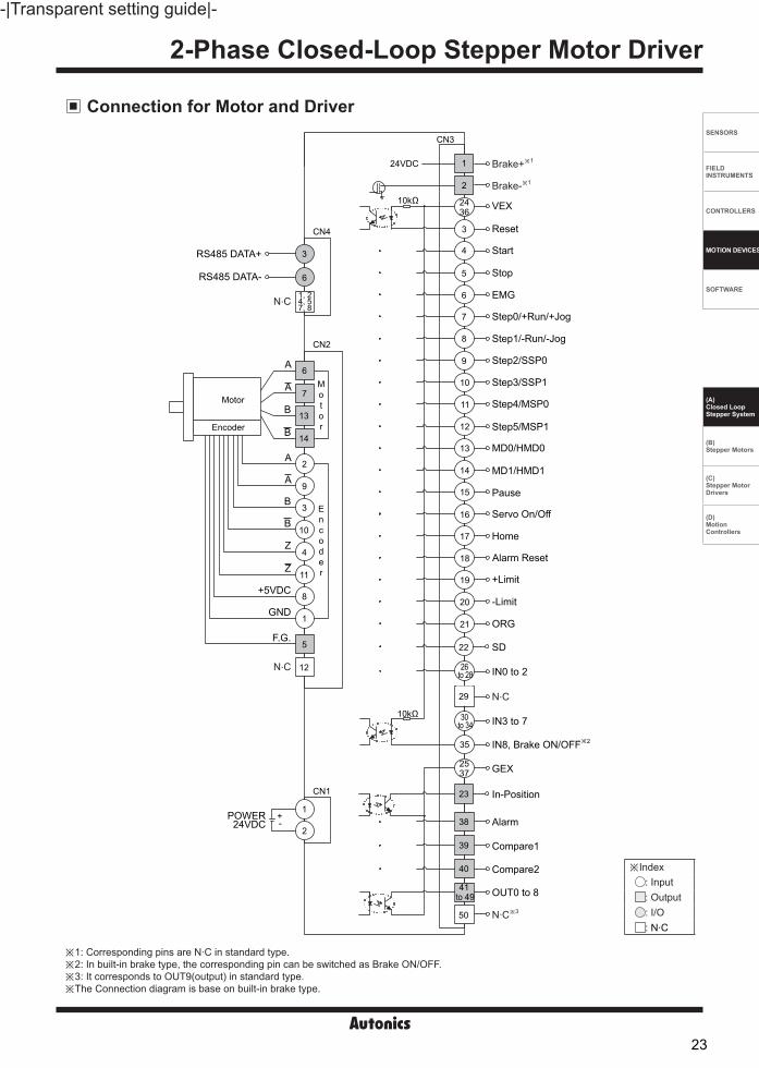
Connection for Motor and Driver
※Index: Input: Output: I/O: N.C
※1: Corresponding pins are N.C in standard type.※2: In built-in brake type, the corresponding pin can be switched as Brake ON/OFF.※3: It corresponds to OUT9(output) in standard type.※The Connection diagram is base on built-in brake type.
A
A
A
A
B
B
B
Reset
Start
Stop
EMG
Step0/+Run/+Jog
RS485 DATA+
RS485 DATA-
Step1/-Run/-Jog
Step2/SSP0
Step3/SSP1
Step4/MSP0
Step5/MSP1
MD0/HMD0
MD1/HMD1
Pause
Servo On/Off
Home
VEX
+Limit
-Limit
ORG
SD
Alarm Reset
POWER +-24VDC
In-Position
GEX
Alarm
Compare1
Compare2
OUT0 to 8
1, 24, 57, 8
2537
1
1
8
4
3
9
2
7
6
6
3
5
4
2
5
6
7
8
9
10
11
12
13
14
15
16
17
18
19
20
21
22
12
11
10
14
13
23
38
39
40
41 to 49
CN4
CN3
CN2
CN1
10kΩ
10kΩ
N.C
B
Z
Z
+5VDC
GND
F.G.
N.C
Motor
Encoder
Motor
Encoder
Brake-※1
3
2436
26 to 28
29
35
IN0 to 2
N.C
IN8, Brake ON/OFF※2
Brake+※11
2
50 N.C※3
24VDC
IN3 to 730 to 34
23

AiC-D Series -|Transparent setting guide|-
Troubleshooting1. When driver communication is failed ①Check whether the connection between driver and communication cable is correct.②Check whether the port and communication speed is set correctly in the dedicated communication program.
2. When operation of motor is unstable ①Check that driver, motor, and brake are connected correctly. ②Checkwhetheroperationcommandissetcorrectly(e.g. speed, accel/deceleration speed).
Proper Usage Follow instructions in 'Proper Usage'. Otherwise, It may cause unexpected accidents. 24VDC power supply should be insulated and limited voltage/current or Class 2, SELV power supply device. Re-supply power after min. 1 sec from disconnected power. In case communication is unstable due to the noise generated by supplied power or peripheral device, use ferrite core at communication line. It is recommended to use 485 converter with the separate power. (Autonics product, SCM Series recommended) The thickness of cable should be same or thicker than the motor cable's when extending the motor cable. Keep the distance between power cable and signal cable more than 10cm. Motor vibration and noise can occur in specific frequency period ①Change motor installation method or attach the damper. ②Use the unit out of the dedicated frequency range when vibration and noise occurs due to changing motor RUN speed. For using motor, it is recommended to maintenance and inspection regularly. ①Unwinding bolts and connection parts for the unit installation and load connection ②Strange sound from ball bearing of the unit ③Damage and stress of lead cable of the unit ④Connection error with motor ⑤Inconsistency between the axis of motor output and the center, concentric (eccentric, declination) of the load, etc. This product does not prepare protection function for a motor. This unit may be used in the following environments. ①Indoors (in the environment condition rated in 'Specifications') ②Altitude max. 2,000m ③Pollution degree 2 ④Installation category II
24

AiCA-D Series
A-79
-|Transparent setting guide|-
FeaturesAC Type Controller Integrated 2-Phase Closed-Loop Stepper Motor Driver
Ordering Information
Brake operation for safe control of vertical load at power OFF and alarm occur. (Built-in brake type) Real-time position controllable with closed-loop system Motor driver and controller integral type As AC power type, possible to omit SMPS and perform higher torque than DC power type Able to check alarm and status with Alarm/Status display part (7 segment) Controllable maximum 31 axis with RS485 communication Auto Current Down Mode available C language library provided (32-bit, 64-bit) Dedicated Windows program (atMotion) provided Easy to set various Gain with program (GUI) Applicable to the precision equipment such as optical inspection equipment with the features of
maintaining torque in stop and having no micro vibration (hunting) 10 levels of resolutions available Frame size 42mm, 56mm, 60mm motor supported (Applied motor: AiA-M Series)
Filed requiring preciseness such as semiconductor equipment, 3D printer, optical inspection equipment, chip mounter, cartesian robot, conveying equipment, and alignment stage.
Applications
ManualFor the detail information and instructions, please refer to user manual, user manual for communication manual and library manual and be sure to follow cautions written in the technical descriptions (catalog, website).Visit our website (www.autonics.com) to download manuals.
atMotion is a comprehensive motion device management program that can be used with Autonics motion controllers. atMotion provides GUI control for easy and convenient parameter setting and monitoring data management of multiple devices. Visit our website (www.autonics.com) to download the user manual and software.
Software (atMotion)
< atMotion screen > < Computer specification for using software>
Item Minimum requirementsSystem IBM PC compatible computer with Intel Pentium Ⅲ or aboveOperations Microsoft Windows 98/NT/XP/Vista/7/8/10Memory 256MB+Hard disk 1GB+ of available hard disk spaceVGA Resolution: 1024×768 or higherOthers RS-232 serial port (9-pin), USB port
Please read “Safety Considerations” in the instruction manual before using.
Series
Item
Cateory
Motor frame size
Motor axial lengthEncoder resolution
Brake
Ai 60D M A
60 (60×60mm)
86 (86×86mm)
No mark Standard typeB Built-in brake type
A 10,000PPR(2,500PPR×4-multiply)
M 48mmL 69mm
M 60mmL 75mm
D Driver
A AC power
C Controller
Ai Artificial intelligence
C A
Voltage
25

AC Type Controller Integrated 2-Phase-Loop Stepper Motor Driver
A-78
-|Transparent setting guide|-
SENSORS
FIELD INSTRUMENTS
CONTROLLERS
MOTION DEVICES
SOFTWARE
(A)Closed Loop Stepper System
(B)Stepper Motors
(C)Stepper MotorDrivers
(D)Motion Controllers
Configuration Diagram
※ The thickness of cable should be same or thicker than the below specifications when connecting the cable for connector.① CN1(motor+encoder connector): AWG22, AWG24② CN2(power connector): AWG18③ CN3(communication connector): AWG28④ CN4(I/O connector): AWG28⑤ CN5(brake connector): AWG22
※ In case of unstable communication due to noise from peripherals and power, use ferrite core in the wiring.※ is sold separately.
-Connect Pin no. 1, 2 on power connector (CN2).-Use in condition of the high inertia load or the short deceleration time.-Forced cooling is required in condition of high surface temperature of regenerative resistance.
Model Specification Manufacture
IRC100 Resistance: 100Ω ±5%, Rated Power: 60W(standby), 100W(heatsink attached) Rara Electronics Corp.
Regenerative resistance
Protect the product from external noise and surge by connecting power.※ Be sure to disconnect the surge protector when testing internal pressure.
It may result in porduct damage.Model Specification Manufacture
LT-C12G801W Nomial discharge current: 2500A Max. discharge current: 5000A Voltage protection level: 1.5kV
OTOWA Electric Co. Ltd
Surge protector
-Connect the power to suppress external noise.-The wires should be connected as short as possible and grounded.
Model Specification Manufacture
RNS-2006 Rated voltage: 250V Rated current: 6A Max. leakage current: 1mA
Orient Electronics
Noise filter for power
-Connect to wiring to suppress external noise.-Depending on frequency, filtered noise may different.
Model Specification ManufactureMotor line, I/O signal line 28A5776-0A2
LairdtechComm. line 28A2025-0A2Power line 28A5131-0A2
Noise filter for signal line
I/O Terminal Block
CN3
CN4
AiA-M Series(motor)
CN1
AiCA-D Series(motor driver)
PLC PC (atMotion)
USB /RS232C /
Wi-Fi
SCM Series(Comm. converter)
Noise filterfor signal line
200-240 VACᜠ
Surge protector
Circuit breaker
Noise filterfor power
LNPE
RG1 CN2
RG2Regenerativeresistance
RS485
※ is for built-in brake type only.
24 VDCᜡ
26

AiCA-D Series
A-81
-|Transparent setting guide|-
SpecificationsModel ※1 AiCA-D-60MA(-B) AiCA-D-60LA(-B) AiCA-D-86MA(-B) AiCA-D-86LA(-B)
Power consumption
Power supply 200-240 VACᜠ 50/60 HzSTOP ※2 Max. 60 W Max. 65 W Max. during operation Max. 160 W Max. 220 W Max. 250 W Max. 300 W
Max. Run current ※3 2.0 A/PhaseAuxiliary power※4
Power supply 24 VDCᜡ
Input current 0.3 A 0.5 ASTOP current 20 to 100 % of max. RUN currentRotation speed ※5 0 to 3000 rpmResolution ※5 500 (factory default), 1000, 1600, 2000, 3200, 3600, 5000, 6400, 7200, 10000 PPRSpeed filter 0 (disable) (factory default), 2, 4, 6, 8, 10, 20, 40, 60, 80, 100, 120, 140, 160, 180, 200 msMotor GAIN 0 (factory default) to 30, Fine GainPositioning range -2,147,483,648 to +2,147,483,647In-Position Fast Response: 0 (factory default) to 7, Accurate Response: 0 to 7Motor rotation direction ※5 CW, CCW
Status indicator Alarm/Status display part: orange LED 7seg. Power/Alarm indicator: green/red LED In-Position indicator: orange LED Servo On/Off indicator: blue LED
I/OInput ※6 Exclusive input: 20, general input: 9Output Exclusive output: 4, general output: 10
External power supply VEX (24 VDCᜡ Fixed): 2, GEX (GND): 2Operation mode Jog / Continuous / Index / Program / Position / Torque modeIndex step 64 steps
Program function
Step 256 steps
Control command
ABS (move absolute position), INC (move incremental position), HOM (home search), ICJ (jump input condition), IRD (waiting input), OPC (ON/OFF of output port), OPT (on pulse from output port), JMP (jump), REP (start repetition), RPE (end repetition), END (end program), POS (position set), TIM (timer), CMP (compare output), TOQ (torque control)
Start Power ON program auto-start functionHome start Power ON home search auto-start function
RS485 Comm. Comm. Speed ※5 9600, 19200, 38400, 57600, 115200 (factory default) bpsMultiaxial control 31-axisID setting switch 16-bit rotary switch (0 to F), 1-bit DIP switch (ON/OFF)
AlarmOvercurrent, overspeed, position tracking, overload, overheat, motor connection, encoder connection, overvoltage, undervoltage, motor misalignment, command speed, in-position, memory, emergency stop, program mode, index mode,home search mode, brake
Warning ±Software limit, ±hardware limit, overloadInput resistance 4.7 kΩ (Anode Pull-up)Insulation resistance Over 200 MΩ (at 500 VDCᜡ megger)Dielectric strength 1,500 VACᜠ 60 Hz for 1 minVibration 1.5 mm amplitude at frequency of 10 to 55 Hz (for 1 min) in each X, Y, Z direction for 2 hoursShock 300 m/s2 (approx. 30 G) in each X, Y, Z direction for 3 times
EnvironmentAmbient temp. 0 to 50 , storage: -10 to 60 Ambient humi. 35 to 85 %RH, storage: 10 to 90 %RH
Protection structure IP20 (IEC standard)Approval ᜢ
Weight ※7 Standard type: Approx. 1,080 g (approx. 800 g) Built-in brake type: Approx. 1050 g (approx. 780 g)
※1: The model name indicates driver type. (none: standard type, B: built-in brake type) E.g.) AiCA-D-60MA-B: built-in brake type stepping motor driver.
※2: Based on the ambient temperature 25 , ambient humidity 55 %RH and STOP current 20 %.※3: RUN current varies depending on the input RUN frequency and max. RUN current at the moment varies also.※4: Auxiliary power is only available in built-in brake type. Corresponding specification is not available in standared type.※5: Settable with the dedicated program (atMotion).※6: Brake ON/OFF function can be changed in general input IN8 in case of built-in brake type only.※7: The weight includes packaging. The weight in parenthesis is for unit only.※ Environment resistance is rated at no freezing or condensation.
27
AC Type Controller Integrated 2-Phase-Loop Stepper Motor Driver
A-80
-|Transparent setting guide|-
SENSORS
FIELD INSTRUMENTS
CONTROLLERS
MOTION DEVICES
SOFTWARE
(A)Closed Loop Stepper System
(B)Stepper Motors
(C)Stepper MotorDrivers
(D)Motion Controllers
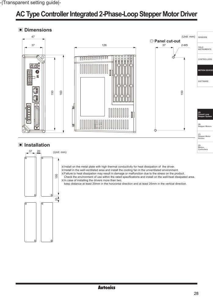
Dimensions(Unit: mm)
Panel cut-out47
37 126 37 2-M5
150
160
150
Installation
※Install on the metal plate with high thermal conductivity for heat dissipation of the driver.※Install in the well-ventilated area and install the cooling fan in the unventilated environment.※ Failure to heat dissipation may result in damage or malfunction due to the stress on the product.
Check the environment of use within the rated specifications and install on the well-heat dissipated area.※ In case of installing the drivers more than two,
keep distance at least 20mm in the horizontal direction and at least 25mm in the vertical direction.
(Unit: mm)37 20
150
25
28

AiCA-D Series
A-83
-|Transparent setting guide|-
Driver Status Indicators
Driver SettingID Sel: Communication ID setting switch
ID, TERM: Communication ID setting/Terminating resistance DIP switch
※Set Node ID of the driver.※Depending on the ID setting of the ID/Term switch, it is possible to connect max. 31-axis.
※Set Node ID of the driver.※Set to use terminating resistance.
※1: Although RS485 OUT is disconnected, RXD IN/TXD OUT operates normally, if RS485 IN is communicating.
Setting switch SettingID
SettingID
ID OFF ID ON ID OFF ID ON
ID Sel
0 Disable 16 8 8 241 1 (factory default) 17 9 9 252 2 18 A 10 263 3 19 B 11 274 4 20 C 12 285 5 21 D 13 296 6 22 E 14 307 7 23 F 15 31
No. FunctionSwitch positionON OFF(factory default)
1 ID setting ID: 16~31 ID: 1~15
2 Terminat ing resistance Use terminating resistance (120Ω) Do not use terminating resistance
Indicator & Display part
LED color Function Descriptions
PWR/ALMGreen Power indicator Turns ON when the unit operates normally after supplying power.
Red Alarm indicator When alarm occurs, it flashes in various ways depending on the situation.Refer to ' Control Input/Output → Output → 3. Alarm/Warning'.
INP. Orange In-Position indicator Turns ON when motor is placed at command position after positioning input.SERVO Blue Servo On/Off indicator Turns ON when Servo is operating, turns OFF when servo is not operating.Alarm/Statusdisplay part Red Alarm, status indicator Displays the corresponding number, status, model, etc. when Alarm occurs.
RxD IN※1 YellowRS485 Data I/O display
Flashes when receiving data.TxD OUT※1 Green Flashes when sending data.
Unit Descriptions
1. Alarm/Status display part (orange)2. Power/Alarm indicator (PWR/ALM) (green/red)3. In-Position indicator (INP) (orange)4. Servo On/Off indicator (SERVO) (blue)5. Communication ID setting rotary switch (ID Sel setting: 0 to F)6. Communication ID setting/Terminating resistance DIP switch (ID, TERM)7. Motor+Encoder connector (CN1)8. Power connector (CN2)9. Communication cable connector (CN3)10. I/O connector (CN4)11. Brake connector (CN5)※1
※1: Corresponding connector is for built-in brake type only.
234
9
8
7
1
56
10
11
29

AC Type Controller Integrated 2-Phase-Loop Stepper Motor Driver
A-82
-|Transparent setting guide|-
SENSORS
FIELD INSTRUMENTS
CONTROLLERS
MOTION DEVICES
SOFTWARE
(A)Closed Loop Stepper System
(B)Stepper Motors
(C)Stepper MotorDrivers
(D)Motion Controllers
CN1: Motor+Encoder connector Connector function
Driver Connectors
CN2: Power connector
CN3: RS485 Communication cable connector
CN4: I/O connector
Connector Specifications
Pin arrangement Pin no. Fuction Pin no. Function
89
13……
…
……
…
1476
21
1 GND 8 +5VDCᜡ
2 Encoder A 9 Encoder A3 Encoder B 10 Encoder B4 Encoder Z 11 Encoder Z5 PE 12 N.C6 Motor A 13 Motor B7 Motor A 14 Motor B
Pin arrangement Pin no. Function Pin no. Function
8...
18
...1 1 N.C 5 N.C
2 N.C 6 RS485 DATA-
3 RS485 DATA+ 7 N.C
4 N.C 8 N.C
Pin arrangement Pin no. Function
123456
1 Connect regenerative resistance2
3 N.C
4AC power input
5
6 PE
※Above connectors are suitable for AiCA-D Series
※Brake ON/OFF function is added for built-in brake type.
TypeSpecifications
ManufactureConnector Connector terminal Housing
CN1 Motor+Encoder 5557-14R 5556T - MolexCN2 Power 5ESDVM-06P-OR - - DinkleCN3 Communication LS-CV-J45BBKZ - - EPN.CN4 I/O connector 10150-3000PE - 10350-52F0-008 3MCN5 Brake connector ESC250V-S2330704P - - Dinkle
Pin arrangement Pin I/O Function Pin I/O Function Pin I/O Function Pin I/O Function
16
25 504520
2631
........
......
1 - N·C 14 Input MD1/HMD1 27 Input IN1 40 Output Compare2 (Trigger)
2 - N·C 15 Input Pause 28 Input IN2 41 Output OUT03 Input Reset 16 Input Servo On/Off 29 - N·C 42 Output OUT14 Input Start 17 Input Home 30 Input IN3 43 Output OUT25 Input Stop 18 Input Alarm Reset 31 Input IN4 44 Output OUT36 Input EMG 19 Input +Limit 32 Input IN5 45 Output OUT47 Input Step0/+Run/+Jog 20 Input -Limit 33 Input IN6 46 Output OUT58 Input Step1/-Run/-Jog 21 Input ORG 34 Input IN7 47 Output OUT6
9 Input Step2/SSP0 22 Input SD 35 Input IN8/ Brake ON/OFF※1 48 Output OUT7
10 Input Step3/SSP1 23 Output In-Position 36 Input VEX 49 Output OUT811 Input Step4/MSP0 24 Input VEX 37 Input GEX 50 Output OUT912 Input Step5/MSP1 25 Input GEX 38 Output Alarm
-13 Input MD0/HMD0 26 Input IN0 39 Output Compare1
(Trigger)
CN4: Brake connectorPin arrangement Pin no. Function
1234
1 24 VDCᜡ
2 GND
3 Brake+
4 Brake-
※Corresponding connector is for built-in brake type only.
30

AiCA-D Series
A-85
-|Transparent setting guide|-
I/O Cable
Motor+Encoder cable
Communication converter
Sold Separately
Pin no.
Function(Name TAG)
Cable color
Dot line color-numbers
Pin no.
Function(Name TAG)
Cable color
Dot line color-numbers
1 Brake+
Orange
Black-1 26 IN0
White
Red-32 Brake- Red-1 27 IN1 Black-43 Reset Black-2 28 IN2 Red-44 Start Red-2 29 N.C Black-55 Stop Black-3 30 IN3 Red-56 EMG Red-3 31 IN4
Gray
Black-17 Step0/+Run/+Jog Black-4 32 IN5 Red-18 Step1/-Run/-Jog Red-4 33 IN6 Black-29 Step2/SSP0 Black-5 34 IN7 Red-210 Step3/SSP1 Red-5 35 IN8/Brake ON/OFF Black-311 Step4/MSP0
Yellow
Black-1 36 VEX Red-312 Step5/MSP1 Red-1 37 GEX Black-413 MD0/HMD0 Black-2 38 Alarm Red-414 MD1/HMD1 Red-2 39 Compare1 Black-515 Pause Black-3 40 Compare2 Red-516 Servo On/Off Red-3 41 OUT0
Pink
Black-117 Home Black-4 42 OUT1 Red-118 Alarm Reset Red-4 43 OUT2 Black-219 +Limit Black-5 44 OUT3 Red-220 -Limit Red-5 45 OUT4 Black-321 ORG
White
Black-1 46 OUT5 Red-322 SD Red-1 47 OUT6 Black-423 In-Position Black-2 48 OUT7 Red-424 VEX Red-2 49 OUT8 Black-525 GEX Black-3 50 OUT9 Red-5
※ of model name indicates cable length (1, 2, 3, 5, 7, 10, 15, 20). E.g.) C1DF14M-10: 10m moving type motor+encoder cable
※Recommended to use ferrite core at both ends of the I/O cable and Motor+Encoder cable.
※ of model name indicates cable length (010, 020, 030, 050, 070, 100, 150, 200).E.g.)CJ-MP50-HP070: 7m I/O cable
SCM-38I(RS232C to RS485 converter)
SCM-US48I(USB to RS485 converter)
SCM-WF48( Wi-Fi to RS485·USB wirelesscommunication converter)
Normal: C1D14M- , Moving: C1DF14M-
CO50-MP -R (Standard: AiC TAG)
31

AC Type Controller Integrated 2-Phase-Loop Stepper Motor Driver
A-84
-|Transparent setting guide|-
SENSORS
FIELD INSTRUMENTS
CONTROLLERS
MOTION DEVICES
SOFTWARE
(A)Closed Loop Stepper System
(B)Stepper Motors
(C)Stepper MotorDrivers
(D)Motion Controllers
Control Input/OutputInner signal of all input/output consists of photocoupler.ON [H]: photocoupler power ONOFF [L]: photocoupler power OFF
Input1. Exclusive input (20)
2. General input (9)
Signal name Descriptions Pin no.IN0~IN2 General input 0 to 2 26 to 28IN3~IN8 General input 3 to 8 30 to 35
3. Example of input circuit connection- In case of input, use external power (VEX) 24VDCᜡ.
-In-Position output represents output is output of positioning completion signal.- If the gap between target position and real position is under In-Position setting value after position command pulse has finished,
In-Position output turns ON and In-Position indicator turns ON.-In reverse, when the gap is over In-Position setting value, In-Position output turns OFF and the In-Position indicator turns OFF.※For accurate drive, check the In-Position output again and execute the next drive.※Refer to '6. example of output circuit connection'.
※N: Input pin number of CN4
Output
2. In-Position
1. Exclusive output (4)
Fast Response Accurate ResponseSetting Value Setting Value0 (factory default) 0 8 01 ±1 9 ±12 ±2 10 ±23 ±3 11 ±34 ±4 12 ±45 ±5 13 ±56 ±6 14 ±67 ±7 15 ±7
In-Position(Fast Response)
In-Position(Accurate Response)
Time
Position
Delay time: 50ms
Target position
Time
Signal name Descriptions Pin no. Signal name Descriptions Pin no.
Reset Reset command 3 Pause Pause 15
Start Drive start command 4 Servo On/Off Servo On/Off 16
Stop Drive stop command 5 Home Home search 17EMG Drive emergency stop command 6 Alarm Reset Alarm reset command 18Step0/+Run/+Jog Step designate 0 / +Run / +Jog 7 +Limit +direction limit sensor 19Step1/-Run/-Jog Step designate 1 / +Run / +Jog 8 -Limit -direction limit sensor 20Step2/SSP0 Step designate 2 / Start speed designate 0 9 ORG Home sensor 21Step3/SSP1 Step designate 3 / Start speed designate 1 10 SD Dceleration (deceleration stop) signal 22Step4/MSP0 Step designate 4 / Max. Speed designate 0 11 Brake ON/OFF Brake ON/OFF 35Step5/MSP1 Step designate 5 / Max. Speed designate 1 12
-MD0/HMD0 Operation mode designate 0 / Home search mode designate 0 13
MD1/HMD1 Operation mode designate 1 / Home search mode designate 1 14
Signal name Descriptions Pin no. Signal name Descriptions Pin no.In-Position Drive ending pulse 23 Compare1(Trigger) Comparison output 1 39Alarm Alarm output 38 Compare2(Trigger) Comparison output 2 40
Input signal
10kΩ
Driver
VEX
2436
N C
BE
32

AiCA-D Series
A-87
-|Transparent setting guide|-
3. Alarm/Warning Alarm
-This function stops motor to protect driver, depending on the error status such as overcurrent or overspeed.-In case of normal status, output turns ON, and in case of alarming status, output turns OFF.-When supplying alarm reset, driver returns to the normal status.※Refer to '6. example of output circuit connection'.
Warning -This function notices dangers with the alarm indicator prior to motor stop with limit signal or overload alarm.-When turning out from the alarming condition, driver returns to the normal status automatically.
Alarm/Warning indicator -When alarm occurs, the alarm indicator (ALM, red) flashes as the times of corresponding alarm type.-The alarm/status display part displays the number of the corresponding alarm type.
※Depending on the alarm/warning type, it displays as a segment on the Alarm/Status display part.
※1: Corresponding information is for built-in brake type only.※ Even though warning occurs, it drives as normal status and it may cause damage by fire.
It is recommended not to use the unit during warning status.※ When alarm/warning occurs, indicators flash with interval of 0.4 sec until the alarm/warning is cleared.
<E.g. when alarm no. 3 occurs>
Control Input/Output
Alarm/Status Alarm type Descriptions Motor
statusTorque status
Brake status※1
E1 Overcurrent error When overcurrent flows at motor RUN element
Stop Release Lock
E2 Overspeed error When motor speed is over 4,000rpm
E3 Position tracking error When the gap between position command value and current position value is over 90
E4 Overload error When applying load over the rated load for over 1 secE5 Overheat error When heatsink temperature is over 80E6 Motor connection error When motor cable connection error occurs at driverE7 Encoder connection error When encoder cable connection error occurs at driverE8 Overvoltage error When input voltage is over 240VACᜠ +10%E9 Undervoltage error When input voltage is under 200VACᜠ -10%EA Motor misalignment When motor is in misalignment
EB Command pulse errorWhen input pulse is over 3,500rpmWhen pulse is input before initial alignment
EC In-Position error When position error (over 1) is kept over 3 sec, after motor stopped.ED Memory error When memory error is detected as power suppliedEE Emergency stop When emergently stopped with emergency stop command
Stop Remain ReleaseEF Program mode errer When 'END' command is not exist at the last step
EG Index mode errorWhen other instruction is used but 'INC', 'ABS'When index command is not completed du to the stop command
EH Home search mode error When failed to find homeEJ Brake error※1 When brake failed to operate Stop Release Lock
Warning/Stauts Warning type Descriptions Motor
statusTorque status
Brake status※1
W1 +Software limit When normal direction (CW) software limit is ON.
Stop Remain ReleaseW2 -Software limit When reverse direction (CCW) software limit is ON.W3 +Hardware limit When normal direction (CW) hardware limit is ON.W4 -Hardware limit When reverse direction (CCW) hardware limit is ON.
W5 Overload warning When maximum load is kept connected over 10 sec.(may cause overheat on motor and driver) Remain Remain Release
W6 Position override warning When it is impossible to operate position override. Stop Remain Release
0.4 sec 0.8 sec
1 12 23 3
33

AC Type Controller Integrated 2-Phase-Loop Stepper Motor Driver
A-86
-|Transparent setting guide|-
SENSORS
FIELD INSTRUMENTS
CONTROLLERS
MOTION DEVICES
SOFTWARE
(A)Closed Loop Stepper System
(B)Stepper Motors
(C)Stepper MotorDrivers
(D)Motion Controllers
6. Example of output circuit connection- In case of output, use external power (VEX) max. 12 to 24 VDCᜡ, 100mA. When current exceeds 10mA, use an external resistor RL to adjust the current value.
※RL = VEX - 0.7V - VF 0.01A
※N: Output pin numer of CN4
Control Input/Output
Communication OutputIt is for parameter setting and monitoring via external devices (PC, PLC, etc.).
Interface
Application of system organization
Comm. protocol Modbus RTU Comm. speed 9600, 19200, 38400, 57600, 115200 bpsConnection type RS485 Comm. response wait time 5 to 99msApplication standard Compliance with EIA RS485 Start bit 1bit (fixed)Max. connections 31 units (address: 01 to 31) Data bit 8bit (fixed)Synchronous method Asynchronous Parity bit None, Even, OddComm. method Two-wire half duplex Stop bit 1-bit, 2-bitComm. distance Max. 800m
※ It is recommended to use Autonics communication converter; SCM-WF48 (Wi-Fi to RS485·USB wireless communication converter, sold separately), SCM-US48I (USB to RS485 converter, sold separately), SCM-38I (RS232C to RS485 converter, sold separately). Please use twisted pair wire, which is suitable for RS485 communication, for SCM-WF48, SCM-US48I and SCM-38I.
※ It is not allowed to set overlapping communication address at the same communication line.Use twisted pair wire for RS485 communication.
※Only for RS485 communication output model.
B(-)
B(-)
ON OFF
A(+)
A(+)
A(+) B(-) A(+) B(-) A(+) B(-)
Terminating resistance(100 to 120Ω)
RS485DEVICE
#1
RS485DEVICE
#2
RS485DEVICE
#30
RS485DEVICE
#31
Computer
RS232C/USB/Wi-Fi
Comm. Converter
RS485
4. Comparison output (Compare1, Compare2)
5. General output (10)
Mode Description0 Not use comparison output.1 Comparison output turns ON when the present absolute position value is same or bigger than the set position value.2 Comparison output turns ON when the present absolute position value is same or smaller than the set position value.3 Trigger pulses output with the set interval and width.
It outputs trigger pulse at the designated cycle.
※Please refer to the user manual to learn how to set.
Signal name Descriptions Pin no.OUT0 to OUT9 General output 0 to 9 41 to 50
Driver
GEX
RL Outputsignal
VEX
2537
N
34

AiCA-D Series
A-89
-|Transparent setting guide|-
Connection of Motor and Driver
※Index: Input: Output: I/O: N.C
1
2
4
3
Brake-
Brake+
POWER24VDCᜡ
CN5※1
※1: Corresponding connector is for built-in brake type only.※2: In built-in brake type, the corresponding pin can be swithed as Brake ON/OFF.
A
A
A
A
B
B
B
Reset
Start
Stop
EMG
Step0/+Run/+Jog
Step1/-Run/-Jog
Step2/SSP0
Step3/SSP1
Step4/MSP0
Step5/MSP1
MD0/HMD0
MD1/HMD1
Pause
Servo On/Off
Home
VEX
+Limit
-Limit
ORG
Alarm Reset
In-Position
GEX
Alarm
Compare1
Compare2
OUT0~9
B
Z
Z
+5VDCᜡ
GND
PE
N.C
N.C
IN0~2
N.C
IN3~7
Regenerative resistance
Regenerative resistance
N.C
SD
2537
4
3
9
2
7
6
5
4
5
6
7
8
9
10
11
12
13
14
15
16
17
18
19
20
21
2212
11
10
14
13
23
38
39
40
41~50
CN4
CN1
10kΩ
10kΩ
Motor
Encoder
Motor
Encoder
12
3
2436
26~28
29
30~34CN2
L
N
PE
3
Source200-240VACᜠ 50/60Hz
1
8
1
2
RS485 DATA+
RS485 DATA-
N.C1, 24, 57, 8
6
3
CN3
35 IN8, Brake ON/OFF※2
35

AC Type Controller Integrated 2-Phase-Loop Stepper Motor Driver
A-88
-|Transparent setting guide|-
SENSORS
FIELD INSTRUMENTS
CONTROLLERS
MOTION DEVICES
SOFTWARE
(A)Closed Loop Stepper System
(B)Stepper Motors
(C)Stepper MotorDrivers
(D)Motion Controllers
Troubleshooting
Proper Usage Follow instructions in 'Proper Usage'.
Otherwise, It may cause unexpected accidents. It is recommended to use 485 converter with the separate power.
(Autonics product, SCM-38I, recommended) Install vertically so that the Alarm/Status display part located on top. Keep the distance between power cable and signal cable more than 10cm. Do not input external signal until the driver is initialized (In-Position LED ON) after power is applied. Motor vibration and noise can occur in specific frequency period
① Change motor installation method or attach the damper.② Use the unit out of the dedicated frequency range when vibration and noise occurs due to changing motor RUN speed.
For using motor, it is recommended to maintenance and inspection regularly.① Unwinding bolts and connection parts for the unit installation and load connection② Strange sound from ball bearing of the unit③ Damage and stress of lead cable of the unit④ Connection error with motor⑤ Inconsistency between the axis of motor output and the center, concentric (eccentric, declination) of the load, etc.
This product does not prepare protection function for a motor. This unit may be used in the following environments.
① Indoors (in the environment condition rated in 'Specifications')② Altitude max. 2,000m③ Pollution degree 2④ Installation category II
Malfunction Causes Troubleshooting
When communication is not connected
The communication cable is not connected.
Check communication cable wiring. Check communication cable connection correctly.
The communication port or speed settings are not correct. Check communication port and speed settings are correct.
When motor does not excite
Servo is not ON. Check that servo On/Off input signal is [L].In case of [H], servo is off and excitation of motor is released.
Alarm occurs. Check the alarm type and remove the cause of alarm.When motor rotates to the opposite direction of the designated direction
MotorDir parameter setting is not correct. Check the MotorDir parameter settings.
When motor drive is unstable
Connection between motor and encoder is unstable. Check the Motor+Encoder connection cable.
Motor gain value is not correct. Change the Motor Gain parameter as the certain value.
36
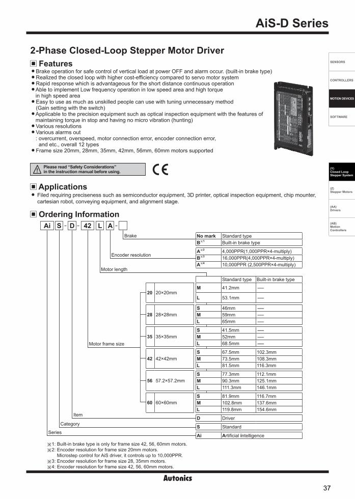
SENSORS
CONTROLLERS
MOTION DEVICES
SOFTWARE
(Y)Closed Loop Stepper System
(Z)Stepper Motors
(AA)Drivers
(AB)Motion Controllers
AiS-D Series
Features2-Phase Closed-Loop Stepper Motor Driver
Brake operation for safe control of vertical load at power OFF and alarm occur. (built-in brake type)Realized the closed loop with higher cost-efficiency compared to servo motor systemRapid response which is advantageous for the short distance continuous operation Able to implement Low frequency operation in low speed area and high torquein high speed area Easy to use as much as unskilled people can use with tuning unnecessary method(Gain setting with the switch) Applicable to the precision equipment such as optical inspection equipment with the features ofmaintaining torque in stop and having no micro vibration (hunting) Various resolutionsVarious alarms out: overcurrent, overspeed, motor connection error, encoder connection error,
and etc., overall 12 typesFrame size 20mm, 28mm, 35mm, 42mm, 56mm, 60mm motors supported
Filed requiring preciseness such as semiconductor equipment, 3D printer, optical inspection equipment, chip mounter, cartesian robot, conveying equipment, and alignment stage.
Ordering Information
Applications
DAi 42 L A
Series
Item
Motor frame size
Motor length
Encoder resolution
20 20×20mm
28 28×28mm
35 35×35mm
42 42×42mm
56 57.2×57.2mm
60 60×60mm
No mark Standard typeB※1 Built-in brake type
A※2 4,000PPR(1,000PPR×4-multiply)B※3 16,000PPR(4,000PPR×4-multiply)A※4 10,000PPR (2,500PPR×4-multiply)
Standard type Built-in brake type
M 41.2mm -
L 53.1mm -
S 46mm -M 59mm -L 65mm -
S 41.5mm -M 52mm -L 68.5mm -
S 67.5mm 102.3mmM 73.5mm 108.3mmL 81.5mm 116.3mm
S 77.3mm 112.1mmM 90.3mm 125.1mmL 111.3mm 146.1mm
S 81.9mm 116.7mmM 102.8mm 137.6mmL 119.8mm 154.6mm
D Driver
S Standard
Ai Artificial intelligence
SBrake
Category
※1: Built-in brake type is only for frame size 42, 56, 60mm motors. ※2: Encoder resolution for frame size 20mm motors.
Microstep control for AiS driver, it controls up to 10,000PPR.※3: Encoder resolution for frame size 28, 35mm motors. ※4: Encoder resolution for frame size 42, 56, 60mm motors.
Please read “Safety Considerations” in the instruction manual before using.
37

AiS-D Series
Model AiS-D-20MA
AiS-D-20LA
AiS-D-28SB
AiS-D-28MB
AiS-D-28LB
AiS-D-35SB
AiS-D-35MB
AiS-D-35LB
AiS-D-42SA-
AiS-D-42MA-
AiS-D-42LA-
AiS-D-56SA-
AiS-D-56MA-
AiS-D-56LA-
AiS-D-60SA-
AiS-D-60MA-
AiS-D-60LA-
Power supply 24VDCᜡAllowable voltage range 90 to 110% of the rated voltage
Pow
er c
onsu
mpt
ion
STOP※1
Standard type Max. 10W Max.
7WMax. 7.5W
Max. 8W
Max. 9.5W
Max. 10W
Max. 11W
Max. 12W
Max. 13W
Max. 14W
Built-in brake type - Max. 16W Max.
17W Max. 23W Max. 25W Max. 26W
Max. during operation※2
Standard type Max. 50W Max. 60W
Max. 60W Max. 120W Max. 240WBuilt-in brake type -
Max. RUN current※3 0.6A/Phase 1.0A/Phase 1.2A/Phase 1.7A/Phase 3.5A/PhaseSTOP current 25% or 50% of max. RUN current (factory default: 50%) Rotation speed 0 to 3,000rpm
Resolution
500 (factory default), 1000, 1600, 2000, 3600, 4000, 5000, 6400, 7200, 10000PPR
500 (factory default), 1000, 1600, 2000, 3600, 5000, 6400, 7200, 10000, 16000PPR
500 (factory default), 1000, 1600, 2000, 3200, 3600, 5000, 6400, 7200, 10000PPR
Speed filter 0 (disable), 2, 4, 6, 8, 10, 20, 40, 60 (factory default), 80, 100, 120, 140, 160, 180, 200msPosition control gain (P Gain, I Gain)= (1, 1), (2, 1), (3, 1), (4, 1), (5, 1), (6, 1), (1, 2), (2, 2), (3, 2), (4, 2), (5, 2), (1, 3), (2, 3), (3, 3), (4, 3), (5, 3)In-Position Within the range of Fast response: 0 to 7 or Accurate response: 0 to 7Pulse input method 1-pulse or 2-pulse input (factory default) methodMotor rotation direction CW (factory default), CCW
Status indicator Power/Warning indicator: green LED Alarm indicator: red LED In-position indicator: yellow LED Servo On/Off indicator: orange LED
Input signal RUN pulse, servo On/Off, alarm reset (photocoupler input)
Output signal In-position, alarm out (photocoupler output), Encoder signal (A, A, B, B, Z, Z phase,
corresponding to 26C31) (line driver output),
In-position, alarm out (photocoupler output), Encoder signal (A, A, B, B, Z, Z phase, corresponding
to 26C31) (line driver output), Brake (built-in brake type) (at supplying moment:
24VDC for 0.2 sec, in normal status: 11.5VDC ±10%)
Inpu
t pul
se
spec
ifica
tions Pulse width
CW, CCW : input pulse frequency duty 50% (min. 2),
Serve On/Off : min. 1ms,
Alarm reset : min. 20ms
CW, CCW : input pulse frequency duty 50% (min. 1.25),
Serve On/Off: min. 1ms, Alarm reset: min. 20ms
CW, CCW: input pulse frequency duty 50%, Serve On/Off: min. 1ms, Alarm reset: min. 20ms
Rising/Falling time CW, CCW: max. 0.5μsPulse input voltage CW, CCW - [H]: 4-8VDCᜡ, [L]: 0-0.5VDC Servo On/Off, alarm reset - [H]: 24VDCᜡ, [L]: 0-0.5VDCMax. input pulse freq.※4 CW, CCW: 500kHz
Input resistance 220Ω (CW, CCW), 10kΩ (servo On/Off, alarm reset)Insulation resistance Over 100MΩ (at 500VDC megger)Dielectric strength 1,000VAC 60Hz for 1 minVibration 1.5mm amplitude at frequency 10 to 55Hz (for 1 min) in each X, Y, Z direction for 2 hoursShock 300m/s2 (approx. 30G) in each X, Y, Z direction for 3 times
EnvironmentAmbient temp. 0 to 50, storage: -20 to 70 0 to 50, storage: -10 to 60 (standard type),
-20 to 70 (built-in brake type)Ambient humi. 35 to 85%RH, storage: 10 to 90%RH
ApprovalProtection structure IP20 (IEC standard)Weight※5 Approx. 400g (approx. 290g)
Specifications
※1: Based on the ambient temperature 25, ambient humidity 55%RH, and STOP current 50%.※2: Max. power consumption during operation. When changing the load rapidly, instantaneous peak current may increase.
The capacity of power supply should be over 1.5 to 2 times of max. power consumption.※3: RUN current varies depending on the input RUN frequency and max. RUN current at the moment varies also.※4: Max. input pulse frequency is max. frequency to be input and is not the same as max. pull-out frequency or max. slewing frequency. ※5: The weight includes packaging. The weight in parenthesis is for unit only.※Environment resistance is rated at no freezing or condensation.
38

SENSORS
CONTROLLERS
MOTION DEVICES
SOFTWARE
(Y)Closed Loop Stepper System
(Z)Stepper Motors
(AA)Drivers
(AB)Motion Controllers
2-Phase Closed-Loop Stepper Motor Driver
Dimensions
Driver Status Indicators
(unit: mm)
Status indicator LED color Function Descriptions
PWR GreenPower indicator Turns ON when the unit operates normally after supplying powerWarning indicator Flashes when over load status is maintained
AL Red Alarm indicator When alarm occurs, it flashes in various ways depending on the situation.Refer to ' Control Input/Output → Output → 2. Alarm/Warning'
INP. Yellow In-Position indicator Turns ON when motor is placed at command position after positioning input.SERVO Orange Servo On/Off indicator Turns ON when servo is operating, turns OFF when servo is not operating.
150
144
73
4.4
11.5
25.5
87.53.42-R3
4.4
14.5
134
144
Configuration Diagram
PC & atMotion
PLCFlexible coupling
ERB Series (sold separately)
AiS-D Series(Motor driver)
PMC Series(Motion controller)
Power
Settings of start, stop,rotationdirection,etc.
Pulse signal
Positioning completion signal/ Warning signal
External I/O
Power
Encoder feedback signal
I/O cable (sold separately)CABLE
Ratedcurrent
CABLEMotor+Encoder cable
(sold separately)
Ai-M, Ai-M-B Series(Motor)
39

AiS-D Series
Driver Unit Descriptions
Driver Setting
Setting switch Setting Delay time Setting Delay time
8
0
4 C
6
E2
A
1
9
3
BD
5
7
F
S.F./Gain
0 Disable 8※1 60ms1 2ms 9 80ms2 4ms A 100ms3 6ms B 120ms4 8ms C 140ms5 10ms D 160ms6 20ms E 180ms7 40ms F 200ms
SW1: Speed filter setting switch or position control gain setting switch-SW1 shifts its mode between the speed filter setting or the position control gain setting, depending on 4th pin in SW4 as follows.-Modified setting values are not applied in the running status, and the values will be applied after motor stopped.
<Graph for input speed and motor response>
Delay time
Motor position
Input pulse position
Time
Position
4th pin in SW4 SettingOFF Speed filterON Position control gain
-Speed filter decides operation responsiveness of the motor to input pulse.- Set the delay time between the position of input pulse and the position of motor to prevent load changing or disturbance with soft operation function.
※If the setting value is too high, the synchronous response by command is decreased.
※
-Position control gain decides responsiveness of the motor to position command.-Gain setting in motor stationary state, depending on load of motor, realizes rapid positioning and stabilized performance.-P_Gain: Adjust vibration in running drive.-I_Gain: Adjust vibration in accelerating/decelerating drive.
Speed filter setting
Position control gain setting
Setting switch SettingGain
SettingGain
P I P I
8
0
4
C
6
E2
A
1
9
3
BD
5
7
F
S.F./Gain
0 1 1 8 (factory default) 3 21 2 1 9 4 22 3 1 A 5 23 4 1 B 1 34 5 1 C 2 35 6 1 D 3 36 1 2 E 4 37 2 2 F 5 3
Function selectionDIP switch (SW4)
Powerconnector (CN1)
Motor+Encoderconnector (CN2) I/O connector (CN3)
Speed filter/position controlgain setting switch (SW1)
Resolution settingswitch (SW2)
In-Position settingswitch (SW3)
Servo On/Offindicator (orange)
Alarm indicator (red)Power/Warning indicator (green)
In-Positionindicator (yellow)
Mountinghole
Mountinghole
40

SENSORS
CONTROLLERS
MOTION DEVICES
SOFTWARE
(Y)Closed Loop Stepper System
(Z)Stepper Motors
(AA)Drivers
(AB)Motion Controllers
2-Phase Closed-Loop Stepper Motor Driver
STOP current
CW[H][L]
CCW [H][L]
Rotation angle position CW CCW
Rotation angle position CW CCW
[H][L]
[L][H]
CW
CCW
※[H]: photocoupler ON (voltage of both ends 4-8VDC) [L]: photocoupler OFF (voltage of both ends 0-0.5VDC)
SW3: In-Position setting swtich
SW4: Function selection DIP switch
Setting switch SettingFrame size 20mm Frame size 28/35mm Frame size 42/56/60mmPulse/Revolution Resolution Pulse/Revolution Resolution Pulse/Revolution Resolution
5
0
1
23
4 6
78
9
RES.
0 (factory default) 500 2.5 500 2.5 500 2.51 1000 5 1000 5 1000 52 1600 8 1600 8 1600 83 2000 10 2000 10 2000 104 3600 18 3600 18 3200 165 4000 20 5000 25 3600 186 5000 25 6400 32 5000 257 6400 32 7200 36 6400 328 7200 36 10000 50 7200 369 10000 50 16000 80 10000 50
SW2: Resolution setting switch-Set the resolution of driver.-Refer to the table below for the number of pulses per 1 rotation by resolution.-Modified setting values are not applied in the running status, and the values will be applied after motor stopped.
Setting switchFast response Accurate responseSetting Value Setting Value
8
0
4
6
E2
A
1
9
3
BD
5
7
F
INP.
0 (factory default) 0 8 01 ±1 9 ±12 ±2 A ±23 ±3 B ±34 ±4 C ±45 ±5 D ±56 ±6 E ±67 ±7 F ±7
In-Position(fast response)
In-Position(accurate response)
Time
Position
Delay time: 50ms
Commandposition
Time
Setting switch No. Name Function Switch positionON OFF (factory default)
ON1 2 3 4 5
1※1 DIR Rotation direction CCW CW2※1 1P/2P Pulse input method 1-pulse input method 2-pulse input method3※2 C.D. STOP current 25% of max. RUN current 50% of max. RUN current4※2 SW1 Mode SW1 setting Position control gain Speed filter5※3 Reserved Test mode Test mode Normal mode
-Set rotation direction, pulse input method, STOP current, SW1 setting, and test mode.
-After position command pulse has finished, if the gap between target position and real position is under In-Position setting value, positioning completion pulse is output.-Modified setting values are not applied in the running status, and the values will be applied after motor stopped.
※1: When motor runs or stops, modified setting values will be applied immediately.※2: Modified setting values are not applied in the running status, and the values will be applied after motor stopped.※3: Set to OFF when using the device. It is only for the operation test in manufacturing process.
※2-pulse input method CW: forward rotation signal inputCCW: reverse rotation signal input
Pulse input method※1-pulse input method
CW: rotation operation signal inputCCW: rotation direction signal input
([H]: forward rotation, [L]: reverse rotation)
-In order to decrease motor heat and current consumption at motor stopping moment (in case there is no input during the time of the doublewidth of last input pulse), set the stop current supplied to the motor phase.
41

AiS-D Series
A. Pull-Up
A. Pull-Up
C. Circuit with NPN (not-reversed)
C. Circuit with NPN (not-reversed)
B. Pull-Down
B. Pull-Down
D. Circuit with PNP (reversed)
D. Circuit with PNP (reversed)
Inner signal of all input/output consists of photocoupler.ON, [H]: photocoupler power ON / OFF, [L]: photocoupler power OFF.※Brake operation is only for built-in brake type.
Input
Control Input/Output
VCC
RL
+
-220Ω
Driver
220ΩDriver
VCC RL+
-
220ΩDriver
VCC
RL
CB
E
+
-
+
-220Ω
Driver
VCC
RLC
BE
External input (Servo On/Off, Alarm Reset)
+24VDC
+
-Driver
C
B E
Driver
+24VDC10kΩ
+
-
2. Servo On/Off-Servo On/Off signal maintains over 1ms as [H]: Regarded as Servo Off signal and phase current is cut to release torque.
The Servo On indicator, the In-Position output and indicator turns OFF. Brake operates.-Servo On/Off signal maintains over 1ms as [L]: Regarded as Servo On signal and phase current is supplied to gain torque.
The Servo On indicator, the In-Position output and indicator turns ON. Brake is released.※Use this function after stopping the motor.※Refer to '4. Example of input circuit connection'.
3. Alarm Reset-This signal is for clearing the alarm.-Alarm reset signal maintains over 20ms as [H]: Alarm is cleared, the alarm indicator and alarm output turns OFF,
and the driver returns to normal status. Brake is released.※If the causes of the alarm are not removed, driver may not be returned to the normal status even with alarm reset.※Refer to '4. Example of input circuit connection'.
4. Example of input circuit connectionInput pulse (CW, CCW)
-It is recommended to use 5VDC at VCC and short the RL.-In case VCC is over 5VDC, calculate RL value using following formula and use VCC below 30VDC.-In case VCC is 12, 24VDC, refer to the table below for RL.
※RL= VCC-2.17V - 220Ω
0.011A
1. Position command pulse- Pulse input is selectable from 1-pulse input method and 2-pulse input method. (Refer to ' SW4: Function selection DIP switch'.)- When using extending cable, it is recommended to connect Common mode choke coil (2mH) to the CW, CCW terminal in series connection.
VCC RL
12VDC 680Ω (min. 0.25W)24VDC 1.8kΩ (min. 0.5W)
+24VDC
+
DriverCB
E
-
10kΩ
10kΩ
Driver
+24VDC
+
-
10kΩ
42

SENSORS
CONTROLLERS
MOTION DEVICES
SOFTWARE
(Y)Closed Loop Stepper System
(Z)Stepper Motors
(AA)Drivers
(AB)Motion Controllers
2-Phase Closed-Loop Stepper Motor Driver
2. Alarm/Warning Alarm
-This function stops motor to protect driver, depending on the error status such as over current or over speed.-In case of normal status, output is [H], and in case of alarming status, output is [L].-When supplying alarm reset, driver returns to the normal status.※Refer to '3. Example of output circuit connection'.
Warning- This function notices dangers with the alarm indicator prior to over load alarm.- When turning out from the alarming condition, driver returns to the normal status automatically.
Alarm indicator
No. of flashing Alarm type Descriptions Motor
stopMaintaintorque
AL(red)
1 Overcurrent error When over current flows at motor RUN element
O ×
2 Overspeed error When motor speed is over 4,000rpm
3 Position tracking error When the gap between position command value and current position value is over 90˚
4 Overload error When applying load over the rated load for over 1 sec5 Overheat error When driver inner temperature is over 806 Motor connection error When motor cable connection error occurs at driver7 Encoder connection error When encoder cable connection error occurs at driver8 Regenerative voltage error When regenerative voltage is over 78V9 Motor misalignment When motor is in misalignment10 Command pulse error
11Input voltage error
Frame size 20, 28, 35mm When Input voltage is out of 21-27VDC ±5%
Frame size 42, 56, 60mm When Input voltage is out of 24VDC ±10%
12 In-Position error When position error (over 1) is kept over 3 sec, after motor stopped.Warning indicator
No. of flashing Warning type Descriptions Motor
stopMaintaintorque
PWR(green) 4 Overload warning When maximum load is kept connected over 10 sec.
(motor or driver can be overheated) × O
B. Circuit with pull up (reversed) C. Circuit with pull down (not-reversed)
0.4 sec 0.8 sec
1 12 23 3
A. Circuit with photocoupler
3. Example of output circuit connection-It is recommend to use below 50VDC at VCC. Use the RL for IC (collector current of secondary detector) of photocoupler inside the driver to be within 25mA following the below formula.
※A: RL= VCC-0.3V-VF - 10Ω ※B, C: RL=
VCC-0.3V - 10Ω
0.025A 0.025A(VF is LED forward voltage of primary photocoupler.)
※ Even though warning occurs, it drives as normal status and it may cause damage by fire.It is recommend not to use the unit during warning status.
※Depending on the alarm/warning type, it flashes for 0.4 sec interval and it turns OFF for 0.8 sec repeatedly.< E.g. case of alarm 3 >
10Ω
DriverVCC
RL
Controller+
-
-
+
10Ω DriverVCC
RL
+
-
10Ω Driver
VCC
RL
+
-
-In-Position output is output condition of positioning completion signal.-If the gap between target position and real position is under In-Position setting value after position command pulse has finished, In-Position output turns to [H] and the In-Position indicator turns ON.-In reverse, when the gap is over In-Position setting value, In-Position output turns to [L] and In-Position indicator turns OFF.-For accurate drive, check the In-Position output again and execute the next drive.※Refer to '3. Example of output circuit connection'.
Output1. In-Position
43

AiS-D Series
4. Encoder output waveforms
Pin arrangement Pin no. Function Pin no. Function
8913
………
………14
7 6 2 1
1 GND 8 +5VDC2 Encoder A 9 Encoder A3 Encoder B 10 Encoder B4 Encoder Z 11 Encoder Z5 F.G. 12 N.C6 Motor A 13 Motor B7 Motor A 14 Motor B
CN2: Motor+Encoder Connector
Pin arrangement Pin no. Function
12
2 GND
1 24VDC
CN1: Power connector
Driver Connectors Connector function
※It is recommended to use Line driver output (corresponding to 26C32) at RECEIVER end of encoder output and terminating resisters (100-150Ω) in parallel at both ends of each phase (A, A, B, B, Z, Z, corresponding to 26C31).
5. Brake output-In order to reduce heat in the brake, connected to the motor, the driver outputs DC power to turn off the brake.
- When supplying power to the driver after connecting the driver and brake, the rated excitation voltage is supplied and the brake power is released after approx. 1 sec. Then after approx. 0.2 sec, the excitation voltage is decreased to 11.5VDC and the released brake power is maintained.
※While power is supplied to the driver, the brake is kept turning on, except in the Servo On status.Time
Power
24VDCDriverpower
Brakepower
0VDC
24VDC11.5VDC
0VDC1 sec 0.2 sec
Frame size 20, 28, 35mm Frame size 42, 56, 60mm
CW
[H]
[H]
[H]
[H]
[H]
[H]
[L]
[L]
[L]
[L]
[L]
[L]
A phase
A phase
B phase
B phase
Z phase
Z phase
Clockwise (CW) ※T=1 cycle of A, B phase
T
T4
T2 ±
T2T±
T8
T4 ±
T
T3
T2 ±
T8±
T4
T4 ±
[H]
[H]
[H]
[H]
[H]
[H]
[L]
[L]
[L]
[L]
[L]
[L]
A phase
A phase
B phase
B phase
Z phase
Z phase
T4
Clockwise (CW) ※T=1 cycle of A, B phase
44

SENSORS
CONTROLLERS
MOTION DEVICES
SOFTWARE
(Y)Closed Loop Stepper System
(Z)Stepper Motors
(AA)Drivers
(AB)Motion Controllers
2-Phase Closed-Loop Stepper Motor Driver
TypeSpecifications
ManufactureConnector Connector terminal Housing
CN1Driver 0039301020 - - MolexPower CHD1140-02 CTD1140 - HANLIM
CN2Driver 35318-1420 - - MolexMotor+Encoder
Frame size 20, 28, 35mm5557-14R
5556T2- Molex
Frame size 42, 56, 60mm 5556T
CN3
Driver 10220-52A2 PL - - 3M
I/O connector10120-3000PE - 10320-52F0-008 3MCJ-MP20-HP(sold separately) - - Autonics
※Above connectors are suitable for AiS-D Series. You can use equivalent or substitute connectors.
Connector specifications
Power cable
Motor+Encoder cable
※ of model name indicates cable length (1, 2, 3, 5, 7, 10) E.g.) C1DF14M-10: 10m moving type motor+encoder cable.
Normal: C1D14M- , Moving: C1DF14M-
I/O cable
※ of model name indicates cable length (010, 020) E.g.) CJ-PW-010: 1m power cable.
CJ-MP20-HP (standard: AiS TAG)
CJ-PW-
※ of model name indicates cable length (010, 020, 030, 050, 070, 100, 150, 200) E.g.) CJ-MP20-HP070: 7m I/O cable.
Sold Separately
Pinno.
Function (name tag)
Cablecolor
Dot line color-numbers
Pinno.
Function (name tag)
Cablecolor
Dot line color-numbers
1 CW+
Yellow
Black-1 11 In-Position+
White
Black-12 CW- Red-1 12 In-Position- Red-13 CCW+ Black-2 13 Brake+ Black-24 CCW- Red-2 14 Brake- Red-25 Servo On/Off+ Black-3 15 Encoder A+ Black-36 Servo On/Off- Red-3 16 Encoder A- Red-37 Alarm Out+ Black-4 17 Encoder B+ Black-48 Alarm Out- Red-4 18 Encoder B- Red-49 Alarm Reset+ Black-5 19 Encoder Z+ Black-510 Alarm Reset- Red-5 20 Encoder Z- Red-5
Pin arrangement Pin no. Input/Output Function Pin no. Input/
Output Function
1……
…… 11
10
20
1 Input CW+ 11 Output In-Position+2 Input CW- 12 Output In-Position-3 Input CCW+ 13 Output Brake+4 Input CCW- 14 Output Brake-5 Input Servo On/Off+ 15 Output Encoder A6 Input Servo On/Off- 16 Output Encoder A7 Output Alarm Out+ 17 Output Encoder B8 Output Alarm Out- 18 Output Encoder B9 Input Alarm Reset+ 19 Output Encoder Z10 Input Alarm Reset- 20 Output Encoder Z
CN3: I/O connector Driver Connectors
45

AiS-D Series
MOTOR
ENCODER
※Index: Input
: Output
: N.C
1
2
3
4
5
6
7
8
9
10
12
11
13
14
15
16
17
18
19
20
1
2
6
7
5
13
14
12
2
9
3
10
4
11
8
1
CN3
CN2
CN1
POWER24VDC
+-
Motor
Encoder
A
A
B
B
A
A
B
B
Z
Z
+5VDC
GND
GND EARTH
N.C
220Ω
220Ω
10kΩ
10Ω
10kΩ
10Ω
CW+
CCW+
CCW-
CW-
Servo On/Off+
Servo On/Off-
Alarm Out+
Alarm Out-
In-Position+
N.C
In-Position-
N.C
Encoder A
Encoder B
Encoder Z
Encoder A
Encoder B
Encoder Z
Alarm Reset+
Alarm Reset-
Connection for Motor and Driver Standard type, Frame size 20, 28, 35mm
46
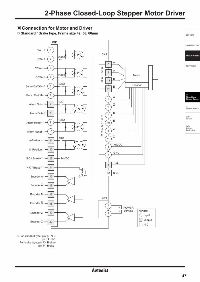
SENSORS
CONTROLLERS
MOTION DEVICES
SOFTWARE
(Y)Closed Loop Stepper System
(Z)Stepper Motors
(AA)Drivers
(AB)Motion Controllers
2-Phase Closed-Loop Stepper Motor Driver
Connection for Motor and Driver
MOTOR
ENCODER
※Index: Input
: Output
: N.C
1
2
3
4
5
6
7
8
9
10
12
11
13
14
15
16
17
18
19
20
1
2
6
7
5
13
14
12
2
9
3
10
4
11
8
1
CN3
CN2
CN1
POWER24VDC
+-
Motor
Encoder
A
A
B
B
A
A
B
B
Z
Z
+5VDC
GND
F.G.
N.C
220Ω
220Ω
10kΩ
10Ω
10kΩ
10Ω
CW+
CCW+
CCW-
CW-
Servo On/Off+
Servo On/Off-
Alarm Out+
Alarm Out-
In-Position+
N.C / Brake+※
In-Position-
N.C / Brake-※
Encoder A
Encoder B
Encoder Z
Encoder A
Encoder B
Encoder Z
Alarm Reset+
Alarm Reset-
24VDC
Standard / Brake type, Frame size 42, 56, 60mm
※ For standard type, pin 13: N.C pin 14: N.C
For brake type, pin 13: Brake+ pin 14: Brake-
47

AiS-D Series
Troubleshooting1. When motor does not rotate
①Check the connection status between controller and driver, and pulse input specifications (voltage, width).②Check the pulse and direction signal are connected correctly.
2. When motor rotates to the opposite direction of the designated direction①When RUN mode is 1-pulse input method, CCW input [H] is for forward, [L] is for backward.②When RUN mode is 2-pulse input method, check CW and CCW pulse input are changed or not.
3. When motor drive is unstable①Check that driver and motor are connected correctly.②Check the driver pulse input specifications (voltage, width).
Follow instructions in 'Proper Usage'. Otherwise, it may cause unexpected accidents. 24VDC power supply should be insulated and limited voltage/current or Class 2, SELV power supply device. Re-supply power after min. 1 sec from disconnected power. Do not input CW, CCW signal at the same time in 2-pulse input method. When the signal input voltage is exceeded the rated voltage, connect additional resistance at the outside. Use twisted pair (over 0.2mm2) for the signal cable which should be shorter than 2m. The thickness of cable should be same or thicker than the motor cable's when extending the motor cable. Keep the distance between power cable and signal cable more than 10cm. Motor vibration and noise can occur in specific frequency period.
①Change motor installation method or attach the damper. ② Use the unit out of the dedicated frequency range when vibration and noise occurs due to changing motor RUN speed.
For using motor, it is recommended to maintenance and inspection regularly. ①Unwinding bolts and connection parts for the unit installation and load connection②Strange sound from ball bearing of the unit③Damage and stress of lead cable of the unit④Connection error with motor⑤ Inconsistency between the axis of motor output and the center, concentric (eccentric, declination) of the load, etc.
This product does not prepare protection function for a motor. This unit may be used in the following environments.
①Indoors (in the environment condition rated in 'Specifications')②Altitude max. 2,000m③Pollution degree 2④Installation category II
Proper Usage
48

AiSA-D Series-|Transparent setting guide|-
FeaturesAC Type 2-Phase Closed-Loop Stepper Motor Driver
Brake operation for safe control of vertical load at power OFF and alarm occur. (Built-in brake type) Higher cost-efficiency compared to servo motor drivers Torque control mode supported Able to check alarms and status with Alarm/Status display part (7 segment) Rapid response which is advantageous for the short distance continuous operation Able to implement Low frequency operation and high torque in low speed area Low current drive at middle.high speed area Max. stop torque at current down mode (available vertical load attaching) Easy to set various Gain with rotary switch Applicable to the precision equipment such as optical inspection equipment
with the features of maintaining torque in stop and having no micro vibration (hunting) Various resolutions
: 500, 1000, 1600, 2000, 3200, 3600, 5000, 6400, 7200, 10000 (10 steps) 10-levels of resolution setting Frame size 60mm, 86mm (Applied Motor: AiA-M Series)
Filed requiring preciseness such as semiconductor equipment, 3D printer, optical inspection equipment, chip mounter,cartesian robot, conveying equipment, and alignment stage.
Applications
Please read “Safety Considerations” in the instruction manual before using.
Ordering Information
Series
Item
Category
Motor frame size
Motor axial lengthEncoder resolutions
Brake
Ai 60D M A
60 60×60mm
86 86×86mm
No mark Standard typeB Built-in brake type
A 10,000PPR(2,500PPR×4-multiply)
M 48mmL 69mm
M 60mmL 75mm
D Driver
A AC Power
S Standard
Ai Artificial intelligence
S A
Power
49

AC Type 2-Phase Closed-Loop Stepper Motor Driver
SENSORS
FIELD INSTRUMENTS
CONTROLLERS
MOTION DEVICES
SOFTWARE
(A)Closed Loop Stepper System
(B)Stepper Motors
(C)Stepper MotorDrivers
(D)Motion Controllers
-|Transparent setting guide|-
Configuration Diagram
※ The thickness of cable should be same or thicker than the below specifications when connecting the cable for connector. ① CN1(motor+encoder connector): AWG22② CN2(power connector): AWG18③ CN3(I/O connector): AWG28④ CN4(brake connector): AWG22
※ In case of unwanted noise generating from peripherals and power, use ferrite core in the wiring.※ is sold separately.
-Connect Pin no. 1, 2 on power connector (CN2).-Use in condition of the high inertia load or the short deceleration time.-Forced cooling is required in condition of high surface temperature of regenerative resistance.
Model Specification Manufacture
IRC100 Resistance: 100Ω ±5%, Rated Power: 60W(standby), 100W(heatsink attached) Rara Electronics Corp.
Regenerative resistance
Protect the product from external noise and surge by connecting power.※ Be sure to disconnect the surge protector when testing internal pressure.
It may result in porduct damage.Model Specification Manufacture
LT-C12G801W Nomial discharge current: 2500A Max. discharge current: 5000A Voltage protection level: 1.5kV
OTOWA Electric Co. Ltd
Surge protector
-Connect the power to suppress external noise.-The wires should be connected as short as possible and grounded.
Model Specification Manufacture
RNS-2006 Rated voltage: 250V Rated current: 6A Max. leakage current: 1mA
Orient Electronics
Noise filter for power
-Connect to wiring to suppress external noise.-Depending on frequency, filtered noise may different.
Model Specification ManufactureMotor line, I/O signal line 28A5776-0A2
LairdtechPower line 28A5131-0A2
Noise filter for signal line
Noise filterfor signal line
Regenerativeresistance
RG1 CN2
RG2
Surge protector
Circuit breaker
Noise filterfor power
I/O Terminal
CN3
AiA-M Series (motor)
CN1
AiSA-D Series(motor driver)
200-240 VACᜠ
LNPE
PLC
CN4
※ is for built-in brake type only.
24 VDCᜡ
50

AiSA-D Series-|Transparent setting guide|-
Model※1 AiSA-D-60MA(-B) AiSA-D-60LA(-B) AiSA-D-86MA(-B) AiSA-D-86LA(-B)
Power consumption
Power supply 200-240 VACᜠ 50/60 HzSTOP※2 Max. 60 W Max. 65 W Max. 70 W Max. during operation Max. 160 W Max. 220 W Max. 250 W Max. 300 WMax. Run current※3 2.0 A/Phase
Auxiliary power※4
Power supply 24 VDCᜡ
Input current 0.3 A 0.5 A
STOP currentStandard type 20% or 30% of max. RUN current (factory default: 30%)Built-in brake type 20 to 100% of max. RUN current
Rotation speed 0 to 3000 rpmResolution※5 500 (factory default), 1000, 1600, 2000, 3200, 3600, 5000, 6400, 7200, 10000 PPRSpeed filter※5 0 (disable) (factory default), 2, 4, 6, 8, 10, 20, 40, 60, 80, 100, 120, 140, 160, 180, 200 ms
Motor GAIN※5 Standard type Within the range of motor gain: 1 to 32Built-in brake type Standard GAIN: 0 to F, Inertia GAIN: 0 to F
In-Position※5 Fast Response: 0 (factory default) to 7, Accurate Response: 0 to 7Pulse input method※5 1-pulse or 2-pulse input (factory default) methodMotor rotation direction※5 CW (factory default), CCW
Status indicator
Alarm/Status display part: orange LED 7 seg. (built-in brake type: red LED 8 seg.) Power/Alarm indicator: green/red LED In-Position indicator: orange LED Servo On/Off indicator: blue LED
I/OInput
CW, CCW (Run pulse)Servo On/Off (photocoupler input) - [H]: 24 VDCᜡ, [L]: 0-0.5 VDCᜡ, Pulse width - min. 1 msAlarm reset (photocoupler input) - [H]: 24 VDCᜡ, [L]: 0-0.5 VDCᜡ, Pulse width - min. 10 ms
Output Photocoupler: In-Position, Alarm out Line driver: encoder signal (phase A, A, B, B, Z, Z)
Operation mode※4 Standard, Torque mode
Input pulsespecifications
Pulse width CW, CCW: input pulse frequency duty 50 %, Rising/Falling time CW, CCW: max. 0.5 Pulse input voltage CW, CCW - [H]: 4-8 VDCᜡ, [L]: 0-0.5 VDCᜡ
Max. input pulse freq.※6 CW, CCW: 500 kHz
Alarm Overcurrent, overspeed, position tracking, overload, overheat, motor connection, encoder connection, overvoltage, undervoltage, motor misalignment, command pulse, in-position, brake※4
Input resistanceStandard type 220Ω (CW, CCW), 10kΩ (Servo On/Off, alarm reset)Built-in brake type 4.7 kΩ (Anode Pull-up)
Insulation resistance
Standard type Over 100MΩ (at 500VDCᜡ megger)Built-in brake type Over 200 MΩ (at 500 VDCᜡ megger)
Dielectric strength 1,500 VACᜠ 60 Hz for 1 minVibration 1.5 mm amplitude at frequency of 10 to 55 Hz (for 1 min) in each X, Y, Z direction for 2 hoursShock 300 m/s2 (approx. 30 G) in each X, Y, Z direction for 3 times
EnvironmentAmbient temp. 0 to 50 , storage: -10 to 60 Ambient humi. 35 to 85 %RH, storage: 10 to 90 %RH
Protection structure IP20 (IEC standard)Approval ᜢ ᜥ
Weight※7 Standard type Approx. 920 g (approx. 800 g)Built-in brake type Approx. 1,020 g (approx. 780 g)
※1: The model name indicates driver type. (none: standard type, B: built-in brake type) E.g.) AiSA-D-60MA-B: built-in brake type stepping motor driver.
※2: Based on the ambient temperature 25 , ambient humidity 55 %RH, and STOP current 20 %.※3: RUN current varies depending on the input RUN frequency and max. RUN current at the moment varies also.※4: Corresponding specification is only available in built-in brake type and is not available in standared type.※5: Settings are available with the switches located on the front. When setting, the power must not be applied and cannot be set after power
is applied.※6: Max. input pulse frequency is max. frequency to be input and is not the same as max. pull-out frequency or max. slewing frequency. ※7: The weight includes packaging. The weight in parentheses is for unit only.※ Environment resistance is rated at no freezing or condensation.
Specifications
51

AC Type 2-Phase Closed-Loop Stepper Motor Driver
SENSORS
FIELD INSTRUMENTS
CONTROLLERS
MOTION DEVICES
SOFTWARE
(A)Closed Loop Stepper System
(B)Stepper Motors
(C)Stepper MotorDrivers
(D)Motion Controllers
-|Transparent setting guide|-
Dimensions
Installation
※Install on the metal plate with high thermal conductivity for heat dissipation of the driver.※Install in the well-ventilated area and install the cooling fan in the unventilated environment.※ Failure to heat dissipation may result in damage or malfunction due to the stress on the product.
Check the environment of use within the rated specifications and install on the well-heat dissipated area.※ In case of installing the drivers more than two,
keep distance at least 20mm in the horizontal direction and at least 25mm in the vertical direction.
(Unit: mm)
Unit Descriptions1. Alarm/Status display part (orange)
2. Power/Alarm indicator (PWR/ALM) (green/red)
3. In-Position indicator (INP) (orange)
4. Servo On/Off indicator (SERVO) (blue)
5. Function selection DIP switch
6. Resolution rotary switch (RES)
7. Motor gain setting rotary switch (GAIN)
8. Speed filter / Limit setting rotary switch (S.F) ※1
9. In-Position setting rotary switch (INP)
10. Motor+Encoder connector (CN1)
11. Power connector (CN2)
12. I/O connector (CN3)
13. Brake connector (CN4) ※1
※1: Corresponding connector and switch are for built-in brake type only.
234
6
11
10
1
5
13
12
7
8
9
234
6
11
10
1
5
12
7
9
Panel cut-out
2-M537
150
1264737
150
160
37 20
150
25
52
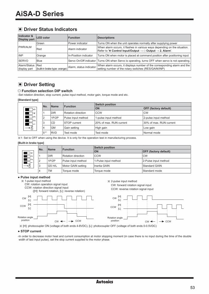
AiSA-D Series-|Transparent setting guide|-
Driver Status IndicatorsIndicator &Display part LED color Function Descriptions
PWR/ALMGreen Power indicator Turns ON when the unit operates normally after supplying power
Red Alarm indicator When alarm occurs, it flashes in various ways depending on the situation.Refer to ' Control Input/Output → Output → 2. Alarm'.
INP Orange In-Position indicator Turns ON when motor is placed at command position after positioning input.
SERVO Blue Servo On/Off indicator Turns ON when Servo is operating, turns OFF when servo is not operating.Alarm/Statusdisplay part
Red (built-in brake type: orange) Alarm, status indicator When alarm occurs, it displays number of the corresponding alarm and the
setting number of the rotary switches (RES/GAIN/INP)
Driver Setting Function selection DIP switch
-Set rotation direction, stop current, pulse input method, motor gain, torque mode and etc.
ON
12
34
No. Name Function Switch positionON OFF (factory default)
1 DIR Rotation direction CCW CW
2 1P/2P Pulse input method 1-Pulse input method 2-Pulse input method
3 GS H/L Motor GAIN setting Inertia GAIN Standard GAIN
4 TM Torque mode Torque mode Standard mode
STOP current
CW[H][L]
CCW [H][L]
Rotation angle position CW CCW
Rotation angle position CW CCW
[H][L]
[L][H]
CW
CCW
※ [H]: photocoupler ON (voltage of both ends 4-8VDC), [L]: photocoupler OFF (voltage of both ends 0-0.5VDC)
※ 2-pulse input method CW: forward rotation signal input CCW: reverse rotation signal input
Pulse input method※ 1-pulse input method
CW: rotation operation signal input CCW: rotation direction signal input
([H]: forward rotation, [L]: reverse rotation)
-In order to decrease motor heat and current consumption at motor stopping moment (in case there is no input during the time of the doublewidth of last input pulse), set the stop current supplied to the motor phase.
[Standard type]
[Built-in brake type]
ON
12
34
5
No. Name Function Switch positionON OFF (factory default)
1 DIR Rotation direction CCW CW
2 1P/2P Pulse input method 1-pulse input method 2-pulse input method
3 CD STOP current 20% of max. RUN current 30% of max. RUN current
4 GM Gain setting High gain Low gain
5※1 RVD Test mode Test mode Normal mode
※ 1: Set to OFF when using the device. It is only for the operation test in manufacturing process.
53

AC Type 2-Phase Closed-Loop Stepper Motor Driver
SENSORS
FIELD INSTRUMENTS
CONTROLLERS
MOTION DEVICES
SOFTWARE
(A)Closed Loop Stepper System
(B)Stepper Motors
(C)Stepper MotorDrivers
(D)Motion Controllers
-|Transparent setting guide|-
RES: Resolution setting switch-Set the resolution of driver. -The number of pulses per 1 rotation by resolution is each 500, 1000, 1600, 2000, 3200, 3600, 5000, 6400, 7200, 10000.-Modified setting values are not applied in the running status, and the values will be applied after motor stopped.
5 01
2346
7 8 9
RES
Setting Pulse/Revolution Resolution Setting Pulse/Revolution Resolution0(factory default) 500 2.5 5 3600 181 1000 5 6 5000 252 1600 8 7 6400 323 2000 10 8 7200 364 3200 16 9 10000 50
GAIN: Motor gain setting switch-Depending on GM OFF or GS H/L switch setting, the motor sets GAIN.-Motor GAIN is selectable from 32 GAIN.- The larger gain is, the more improved transient response becomes and the less error occurs.※ At the lowest system load status, raise the gain value until motor vibrates and set to 1 to 2 level lower.
S.F: Speed Filter / Limit setting switch-Corresponding switch is only available in built-in brake type.-Depending on TM switch setting, speed filter and speed limit function can be set.
Standard type GM OFF - Low GAIN GM ON - High GAINBuilt-in brake type GS H/L OFF - Standard GAIN GS H/L ON - Inertia GAIN
8 0
4
C
6
E
2
A
1
9
3
B D
5
7
F
GAIN
Setting GAIN Setting GAIN Setting GAIN Setting GAIN0 ×1 8 ×9 0 ×17 8 ×251 ×2 9 ×10 1 ×18 9 ×262 ×3 A ×11 2 ×19 A ×273 ×4 B ×12 3 ×20 B ×284 ×5 C ×13 4 ×21 C ×295 ×6 D ×14 5 ×22 D ×306 ×7 E ×15 6 ×23 E ×317 ×8 F ×16 7 ×24 F ×32
Spee
d
GAIN
ProperGAIN OverUnder
Status
Speed Filter-In standard mode, it sets the delay time between the command position and the motor position.- It determines the responsiveness of the motor to the command and smoothly follows the speed even if the load changes or disturbance occurs. Speed Limit-In torque mode, it sets the speed limit.- When the rotation speed reaches the speed limit value, the torque control may become unstable. Set value greater than the speed to be limited.
8 0
4
C
6
E
2
A
1
9
3
B D
5
7
F
GAIN
Speed Filter (TM OFF) Speed Limit (TM ON)Setting Delay time Setting Delay time Setting Limit speed Setting Limit speed0 Disable 8 60 ms 0 10 rpm 8 90 rpm1 2 ms 9 80 ms 1 20 rpm 9 120 rpm2 4 ms A 100 ms 2 30 rpm A 150 rpm3 6 ms B 120 ms 3 40 rpm B 200 rpm4 8 ms C 140 ms 4 50 rpm C 250 rpm5 10 ms D 160 ms 5 60 rpm D 300 rpm6 20 ms E 180 ms 6 70 rpm E 380 rpm7 40 ms F 200 ms 7 80 rpm F 500 rpm
INP: In-Position setting swtich
8 0
4
C
6
E
2
A
1
9
3
B D
5
7
F
INP
Fast response Accurate responseSetting Value Setting Value0 (factory default) 0 8 01 ±1 9 ±12 ±2 A ±23 ±3 B ±34 ±4 C ±45 ±5 D ±56 ±6 E ±67 ±7 F ±7
In-Position(fast response)
In-Position(accurate response)
Time
Position
Delay time: 50ms
Commandposition
Time
- After position command pulse has finished, if the gap between target position and real position is under In-Position setting value, positioning completion pulse is output.
-Modified setting values are not applied in the running status, and the values will be applied after motor stopped.
<Graph for input speed and motor response>
Delay time
Motor position
Input pulse position
Time
Posi
tion
54

AiSA-D Series-|Transparent setting guide|-
Driver Connectors Connector function
CN1: Motor+Encoder Connector
CN3: I/O connector
89
13……
…
……
…
1476
21
Pin no. Function Pin no. Function1 GND 8 +5VDC2 Encoder A 9 Encoder A3 Encoder B 10 Encoder B4 Encoder Z 11 Encoder Z5 PE 12 N.C6 Motor A 13 Motor B7 Motor A 14 Motor B
1
……
……
11
10 20
Pin no. I/O Function Pin no. I/O Function1 Input CW+ 11 Output In-Position+2 Input CW- 12 Output In-Position-3 Input CCW+ 13 - N.C4 Input CCW- 14 - N.C5 Input Servo On/Off+ 15 Output Encoder A 6 Input Servo On/Off- 16 Output Encoder A7 Output Alarm Out+ 17 Output Encoder B8 Output Alarm Out- 18 Output Encoder B9 Input Alarm Reset+ 19 Output Encoder Z10 Input Alarm Reset- 20 Output Encoder Z
CN2: Power connector
123456
Pin no. Function1 Regenerative
resistance23 N.C4
Power56 PE
Connector specifications
※Above connectors are suitable for AiSA-D Series.
Type Specifications ManufactureConnector Connector terminal HousingCN1 Motor+Encoder 5557-14R 5556T - MolexCN2 Power 5ESDVM-06P-OR - - DinkleCN3 I/O connector 10120-3000PE - 10320-52F0-008 3MCN4 Brake connector ESC250V-S2330704P - - Dinkle
Motor+Encoder cable
※ of model name indicates cable length (1, 2, 3, 5, 7, 10) E.g.) C1DF14M-10: 10m moving type motor+encoder cable.
※It is recommended to use ferrite core at I/O cable and Motor+Encoder cable.
Normal: C1D14M-, Moving: C1DF14M-
I/O cable CO20-MP-R
(standard: AiS TAG)
※ of model name indicates cable length (010, 020). For corresponding EMC standard, cable length should be below 2m.E.g.) CO20-MP020-R: 2m I/O cable.
Sold Separately
Pinno.
Function (name tag)
Cablecolor
Dot line color-numbers
Pinno.
Function (name tag)
Cablecolor
Dot line color-numbers
1 CW+
Yellow
Black-1 11 In-Position+
White
Black-12 CW- Red-1 12 In-Position- Red-13 CCW+ Black-2 13 - Black-24 CCW- Red-2 14 - Red-25 Servo On/Off+ Black-3 15 Encoder A+ Black-36 Servo On/Off- Red-3 16 Encoder A- Red-37 Alarm Out+ Black-4 17 Encoder B+ Black-48 Alarm Out- Red-4 18 Encoder B- Red-49 Alarm Reset+ Black-5 19 Encoder Z+ Black-510 Alarm Reset- Red-5 20 Encoder Z- Red-5
CN4: Brake connector
1234
Pin no. Function1 24 VDC2 GND3 Brake+4 Brake-
※Corresponding connector is for built-in brake type only.
55

AC Type 2-Phase Closed-Loop Stepper Motor Driver
SENSORS
FIELD INSTRUMENTS
CONTROLLERS
MOTION DEVICES
SOFTWARE
(A)Closed Loop Stepper System
(B)Stepper Motors
(C)Stepper MotorDrivers
(D)Motion Controllers
-|Transparent setting guide|-
Contol Input/OutputInner signal of all input/output consists of photocoupler.ON, [H]: photocoupler power ONOFF, [L]: photocoupler power OFF
3. Alarm Reset-This signal is for clearing the alarm. - Alarm reset signal maintains over 20ms as [H] : Alarm is cleared, the alarm indicator and alarm output turns OFF, and the driver returns to normal status.
※ If the causes of the alarm are not removed, driver may not be returned to the normal status even with alarm reset.※Refer to '4. Example of input circuit connection'.
2. Servo On/Off-This signal is for rotating axis of motor using external force or used for manual positioning.-Servo On/Off signal maintains over 1ms as [H] : Regarded as Servo Off signal and phase current is cut to release torque.The Servo ON indicator, the In-Position output and indicator turns OFF.
-Servo On/Off signal maintains over 1ms as [L] : Regarded as Servo On signal and phase current is supplied to gain torque.The Servo ON indicator, the In-Position output and indicator turns ON.
※Stop the motor for using the signal.※Refer to '4. Example of input circuit connection'.
Input1. Position command pulse- Pulse input is selectable from 1-pulse input method and 2-pulse input method. (Refer to ' SW1: Function selection DIP switch'.)
- When using extending cable, it is recommended to connect Common mode choke coil (2mH) to the CW, CCW terminal in series connection.
B. Pull-DownVCC
RL
+
-220Ω
Driver
A. Pull-Up
220ΩDriver
VCC RL+
-
C. Circuit with NPN (not-reversed)
220ΩDriver
VCC
RL
CB
E
+
-
D. Circuit with PNP (reversed)
+
-220Ω
Driver
VCC
RLC
BE
External input (Servo On/Off, Alarm Reset)
C. Circuit with NPN (not-reversed)+24VDC
+
DriverCB
E
-
10kΩ
D. Circuit with PNP (reversed)+24VDC
+
-Driver
C
B E
10kΩ
A. Pull-Up
Driver
+24VDC10kΩ
+
-
B. Pull-Down
Driver
+24VDC
+
-
10kΩ
4. Example of input circuit connection[Standard type]
Input pulse (CW, CCW)- It is recommended to use 5VDC at VCC and short the RL.-In case VCC is over 5VDC, calculate RL value using following formula and use VCC below 30VDC.-In case Vcc is 12, 24VDC, refer to the table as follow.
※RL= VCC-2.17V - 220Ω 0.011A
VCC RL
12VDC 680Ω (min. 0.25W)24VDC 1.8kΩ (min. 0.5W)
56

AiSA-D Series-|Transparent setting guide|-
[Built-in brake type] Input pulse (CW, CCW)-Use external power (VEX) 5 VDCᜡ in pulse input.-When input power is exceeded, it may result the product damage.-In case the external pulse input power (VEX) is over 5VDC, use external resistor RL.-In case the external pulse input power (VEX) is over 12, 24VDC, refer to the RL as table below.
※RL= VEX-2.17V - 220Ω 0.011A
VCC RL
12VDC 680Ω(Min. 0.25W)24VDC 1.7kΩ(Min.0.5W)
A. Differential line driver
-
+2kΩ
220ΩDriver
B. Open collector
-
+2kΩ
220ΩDriver
VEX
External Input (Servo On/Off, Alarm Reset)-Use external power (VEX) 24 VDCᜡ in external input Servo On/Off and Alarm Reset.
No. of flashing
Alarm/Status Alarm type Descriptions Motor
stopMaintain torque
1 E1 Overcurrent error When overcurrent flows at motor RUN element
O X
2 E2 Overspeed error When motor speed is over 3,500rpm
3 E3 Position tracking error When the gap between position command value and current position value is over 90°
4 E4 Overload error When applying load over the rated load for over 1 sec5 E5 Overheat error When heatsink temperature is over 906 E6 Motor connection error When motor cable connection error occurs at driver7 E7 Encoder connection error When encoder cable connection error occurs at driver8 E8 Overvoltage error When input voltage is over 240VAC +10%9 E9 Undervoltage error※1 When input voltage is under 200VAC -10%10 EA Motor misalignment When motor is in misalignment
11 EB Command pulse errorWhen input pulse is over 3,500rpmWhen pulse is input before initial alignment
12 EC In-Position error When position error (over 1) is kept over 3 sec, after motor stopped.13 ED Brake error※2 When brake failed to operate.
2. Alarm Alarm
-This function stops motor to protect driver, depending on the error status such as overcurrent or overspeed.-In case of normal status, output is [H], and in case of alarming status, output is [L].-When supplying alarm reset, driver returns to the normal status.※ Refer to '3. Example of output circuit connection'.
Alarm/Status display-When alarm occurs, the alarm indicator (ALM, red) flashes as the times of corresponding alarm type. -The alarm/status display part displays the number of the corresponding alarm type.
※ 1: When cutting off the power, the undervoltage error occurring is normal operation.※ 2: Corresponding alarm is only available in built-in brake type.※ Depending on the alarm type, it flashes for 0.4 sec interval and it turns OFF for 0.8 sec repeatedly.
0.4 sec 0.8 sec
1 12 23 3<E.g. case of alarm 3>
Output1. In-Position-In-Position output is output condition of positioning completion signal.- If the gap between target position and real position is under In-Position setting value after position command pulse has finished, In-Position output turns to [H] and the In-Position indicator turns ON.
- In reverse, when the gap is over In-Position setting value, In-Position output turns to [L] and the In-Position indicator turns OFF.-For accurate drive, check the In-Position output again and execute the next drive.※Refer to '3. Example of output circuit connection'.
B. NPN circuit
-
+10kΩ
Driver
VEXA. PNP circuit
-
+
VEX
10kΩ
Driver
57

AC Type 2-Phase Closed-Loop Stepper Motor Driver
SENSORS
FIELD INSTRUMENTS
CONTROLLERS
MOTION DEVICES
SOFTWARE
(A)Closed Loop Stepper System
(B)Stepper Motors
(C)Stepper MotorDrivers
(D)Motion Controllers
-|Transparent setting guide|-
[Built-in brake type] External output signal ciruit-Use external power (VCC) max. 30 VDC, 10mA for output.-When current is over 10mA, use external resistor RL to control
current.
VF: LED forward voltage of primary photocoupler
Encoder output signal circuit-Encoder output signal uses a line driver (26C32).-Connect the terminal resistance RL of 100 to 150Ω in parallel to
both ends (A, A, B, B, Z, Z) of each phase of encoder.
Differential line driver
+
-RL
Driver
Open collector
+
-
10Ω RL
Driver
VCC
※RL = VCC-0.7V-VF - 10Ω 0.01A
4. Encoder output waveforms
CW
※ It is recommended to use Line driver output (corresponding to 26C32) at RECEIVER end of encoder output and terminating resisters (100-150Ω) in parallel at both ends of each phase (A, A, B, B, Z, Z, corresponding to 26C31).
[H]
[H]
[H]
[H]
[H]
[H]
[L]
[L]
[L]
[L]
[L]
[L]
A
A
B
B
Z
ZClockwise (CW) ※T: 1 cycle of A, B phase
T
T4
T2 ±
T2T ±
T8
T4 ±
A. Circuit with photocoupler
10Ω
DriverVCC
RL
Controller+
-
-
+
C. Circuit with pull down (not-reversed)
10Ω DriverVCC
RL
+
-
B. Circuit with pull up (reversed)
10Ω Driver
VCC
RL
+
-
3. Example of output circuit connection[Standard type]- It is recommended to use below 50VDC at VCC. Use the RL for IC (collector current of secondary detector) of photocoupler inside the driver tobe within 25mA following the below formula.
(VF is LED forward voltage of primary photocoupler.)
※A: RL= VCC-0.3V-VF - 10Ω ※B, C: RL= VCC-0.3V - 10Ω
0.025A 0.025A
58

AiSA-D Series-|Transparent setting guide|-
Connection for Motor and Driver
※Index: Input: Output: I/O: N.C
2
1
3
L
N
PE
9
10
5
6
3
4
1
2
8
7
12
11
16
15
18
17
20
19
1
2
3
4
11
4
10
3
9
2
5
12
14
13
7
6
1
8
13
14
Motor
Motor
Encoder
Encoder
CN1CN4※1
CN3
CN2
A
A
B
B
A
A
B
B
Z
Z
+5VDC
GND
PE
N.C
Regenerative resistance
Regenerative resistance
N.C
220Ω
220Ω10kΩ
10Ω
10kΩ
10Ω
10kΩ
2kΩ
2kΩ
CW+
Brake+
CCW+
CCW-
CW-
Brake-
POWER24VDCᜡ
Servo On/Off+
Servo On/Off-
Alarm Out+
Alarm Out-
In-Position+
N.C
In-Position-
N.C
Encoder A
Encoder B
Encoder Z
Encoder A
Encoder B
Encoder Z
Alarm Reset+
Alarm Reset-
Source200-240VAC 50/60Hz
※1: Corresponding connector is for built-in brake type only.
59

AC Type 2-Phase Closed-Loop Stepper Motor Driver
SENSORS
FIELD INSTRUMENTS
CONTROLLERS
MOTION DEVICES
SOFTWARE
(A)Closed Loop Stepper System
(B)Stepper Motors
(C)Stepper MotorDrivers
(D)Motion Controllers
-|Transparent setting guide|-
Follow instructions in 'Proper Usage'. Otherwise, it may cause unexpected accidents. Do not input CW, CCW signal at the same time in 2-pulse input method. When the signal input voltage is exceeded the rated voltage, connect additional resistance at the outside. To extend the motor+encoder cable, use the designated the cable. Keep the distance between power cable and signal cable more than 10cm. Install the unit vertically on the alarm/status display part upper side. For heat radiation of the driver, install a fan. Do not change any setting switches (function, resolution, motor gain, in-position switches) during the operation or after supplying power.
Failure to follow this instruction may result in malfunction. Do not input external signal until the driver is initialized (In-Position LED ON) after power is applied. Motor vibration and noise can occur in specific frequency period.
① Change motor installation method or attach the damper.② Use and set the gain value.
For using motor, it is recommended to maintenance and inspection regularly.① Unwinding bolts and connection parts for the unit installation and load connection② Strange sound from ball bearing of the unit③ Damage and stress of lead cable of the unit④ Connection error with motor⑤ Inconsistency between the axis of motor output and the center, concentric (eccentric, declination) of the load, etc.
This product does not prepare protection function for a motor. This unit may be used in the following environments.
① Indoors (in the environment condition rated in 'Specifications')② Altitude max. 2,000m③ Pollution degree 2④ Installation category II
Proper Usage
TroubleshootingMalfunction Causes Troubleshooting
When motor does not excite
Servo is not ON. Check that servo On/Off input signal is [L].In case of [H], servo is off and excitation of motor is released.
Alarm occurs. Check the alarm type and remove the cause of alarm.When motor rotates to the opposite direction of the designated direction
Rotation direction setting is not correct. Check the DIR setting in the function selection DIP switch.
When motor drive is unstable
Connection between motor and encoder is unstable. Check the Motor+Encoder connection cable. Motor gain value is not correct. Check motor GAIN setting rotary switch (GAIN) value.
60

Ai-M Series
Ordering Information
Features2-Phase Closed-Loop Stepper Motor
Minimal heat generating, high torque motor(control voltage 55V) Higher cost-efficiency compared to conventionalservo motors Available in motor frame size 20mm, 28mm, 35mm, 42mm, 56mm, 60mm
※1: Encoder resolution for frame size 20mm motors. Microstep control for AiS driver, it controls up to 10,000PPR.
※2: Encoder resolution for frame size 28, 35mm motors. ※3: Encoder resolution for frame size 42, 56, 60mm motors.
MAi 42 L A
Series
Item
Motor frame size
Motor length
Encoder resolution
20 20×20mm
28 28×28mm
35 35×35mm
42 42×42mm
56 57.2×57.2mm
60 60×60mm
A※1 4,000PPR(1,000PPR×4-multiply)B※2 16,000PPR(4,000PPR×4-multiply)A※3 10,000PPR(2,500PPR×4-multiply)
M 41.2mm
L 53.1mm
S 46mmM 59mmL 65mm
S 41.5mmM 52mmL 68.5mm
S 67.5mmM 73.5mmL 81.5mm
S 77.3mmM 90.3mmL 111.3mm
S 81.9mmM 102.8mmL 119.8mm
M Motor
Ai Artificial intelligence
Please read “Safety Considerations” in the instruction manual before using.
Frame size 20 mm 28mm 35mm
Frame size 42 mm 56mm 60mm
61

SENSORS
CONTROLLERS
MOTION DEVICES
SOFTWARE
(Y)Closed Loop Stepper System
(Z)Stepper Motors
(AA)Drivers
(AB)Motion Controllers
2-Phase Closed-Loop Stepper Motor
Specifications Motor
※1: Max. holding torque is maintenance torque of stopping the motor when supplying the rated current (2-phase excitation) and is the standard for comparing the performance of motors.
※2: The weight includes packaging. The weight in parenthesis is for unit only.
Frame size 42mm
Frame size 20mm
Frame size 56mm
Frame size 28mm
Frame size 60mm
Frame size 35mm
Model Ai-M-42SA Ai-M-42MA Ai-M-42LAMax. holding torque※1 2.55kgf.cm (0.25N.m) 4.08kgf.cm (0.4N.m) 4.89kgf.cm (0.48N.m)Rotor moment of inertia 35g.cm2 (35×10-7kg.m2) 54g.cm2 (54×10-7kg.m2) 77g.cm2 (77×10-7kg.m2)Rated current 1.7A/PhaseResistance 1.7Ω/Phase ±10% 1.85Ω/Phase ±10% 2.1Ω/Phase ±10%Inductance 1.9mH/Phase ±20% 3.5mH/Phase ±20% 4.4mH/Phase ±20%Weight※2 Approx. 0.45kg (approx. 0.34kg) Approx. 0.52kg (approx. 0.41kg) Approx. 0.59kg (approx. 0.48kg)
Model Ai-M-20MA Ai-M-20LAMax. holding torque※1 0.183kgf.cm (0.018N.m) 0.357kgf.cm (0.035N.m)Rotor moment of inertia 2g.cm2 (2×10⁻⁷kg.m2)Rated current 0.6A/PhaseResistance 6.6Ω/Phase ±10% 10.5Ω/Phase ±10%Inductance 2.1mH/Phase ±20% 4.0mH/Phase ±20%Weight※2 Approx. 0.192kg (approx. 0.092kg) Approx. 0.219kg (approx. 0.120kg)
Model Ai-M-56SA Ai-M-56MA Ai-M-56LAMax. holding torque※1 6.12kgf.cm (0.6N.m) 12.24kgf.cm (1.2N.m) 20.39kgf.cm (2.0N.m)Rotor moment of inertia 140g.cm2 (140×10-7kg.m2) 280g.cm2 (280×10-7kg.m2) 480g.cm2 (480×10-7kg.m2)Rated current 3.5A/PhaseResistance 0.55Ω/Phase ±10% 0.57Ω/Phase ±10% 0.93Ω/Phase ±10%Inductance 1.05mH/Phase ±20% 1.8mH/Phase ±20% 3.7mH/Phase ±20%Weight※2 Approx. 0.76kg (approx. 0.62kg) Approx. 0.99kg (approx. 0.85kg) Approx. 1.36kg (approx. 1.22kg)
Model Ai-M-28SB Ai-M-28MB Ai-M-28LBMax. holding torque※1 0.51kgf.cm (0.05N.m) 1.42kgf.cm (0.14N.m) 1.63kgf.cm (0.16N.m)Rotor moment of inertia 9g.cm2 (9×10⁻⁷kg.m2) 12g.cm2 (12×10-7kg.m2) 18g.cm2 (18×10-7kg.m2)Rated current 1.0A/PhaseResistance 5.78Ω/Phase ±10% 8.8Ω/Phase ±10% 10.1Ω/Phase ±10%Inductance 3.2mH/Phase ±20% 6.0mH/Phase ±20% 6.2mH/Phase ±20%Weight※2 Approx. 0.260kg (approx. 0.162kg) Approx. 0.318kg (approx. 0.222kg) Approx. 0.342kg (approx. 0.248kg)
Model Ai-M-60SA Ai-M-60MA Ai-M-60LAMax. holding torque※1 11.22kgf.cm (1.1N.m) 22.43kgf.cm (2.2N.m) 29.57kgf.cm (2.9N.m)Rotor moment of inertia 240g.cm2 (240×10-7kg.m2) 490g.cm2 (490×10-7kg.m2) 690g.cm2 (690×10-7kg.m2)Rated current 3.5A/PhaseResistance 1.0Ω/Phase ±10% 1.23Ω/Phase ±10% 1.3Ω/Phase ±10%Inductance 1.5mH/Phase ±20% 2.6mH/Phase ±20% 3.8mH/Phase ±20%Weight※2 Approx. 0.89kg (approx. 0.75kg) Approx. 1.27kg (approx. 1.13kg) Approx. 1.58kg (approx. 1.44kg)
Model Ai-M-35SB Ai-M-35MB Ai-M-35LBMax. holding torque※1 0.714kgf.cm (0.07N.m) 1.326kgf.cm (0.13N.m) 3.162kgf.cm (0.31N.m)Rotor moment of inertia 8g.cm2 (8×10⁻⁷kg.m2) 14g.cm2 (14×10-7kg.m2) 22g.cm2 (22×10-7kg.m2)Rated current 1.2A/PhaseResistance 2.1Ω/Phase ±10% 3.25Ω/Phase ±10% 5.0Ω/Phase ±10%Inductance 1.25mH/Phase ±20% 2.85mH/Phase ±20% 5.6mH/Phase ±20%Weight※2 Approx. 0.278g (approx. 0.180kg) Approx. 0.347kg (approx. 0.250kg) Approx. 0.456kg (approx. 0.366kg)
62

Ai-M Series
Specifications
Encoder
Item Incremental rotary encoderResolution 10,000PPR (2,500PPR×4-multiply)
Elec
trica
l spe
cific
atio
n
Output phase A, A, B, B, Z, Z phase
Output duty rate T ± T (T=1 cycle of A phase) 2 4
Phase difference of output Output between A and B phase: T ± T (T=1 cycle of A phase) 4_
8_
Control output Line driver output • [Low] - Load current: max. 20mA, residual voltage: max. 0.5VDCᜡ• [High] - Load current: max. -20mA, output voltage: min. 2.5VDCᜡ
Response time (rise, fall) Max. 0.5μs (cable length: 2m, I sink = 20mA)Max. response frequency 300kHzPower supply 5VDCᜡ ±5% (ripple P-P: max. 5%)Current consumption Max. 50mA (disconnection of the load)
Common specifications
Frame size 20, 28, 35mm
Frame size 42, 56, 60mm
Standard step angle 1.8°/0.9° (Full/Half step)Motor phase 2-phaseRun method BipolarInsulation class B type (130)Insulation resistance Over 100MΩ (at 500VDC megger), between motor coil-caseDielectric strength 500VAC 50/60Hz for 1 min between motor coil-caseVibration 1.5mm amplitude at frequency 10 to 55Hz (for 1 min) in each X, Y, Z direction for 2 hoursShock Approx. max. 50G
EnvironmentAmbient temperature 0 to 50, storage: -20 to 70Ambient humidity 20 to 85%RH, storage: 15 to 90%RH
ApprovalProtection structure IP30 (IEC34-5 standard)Stop angle error※1 ±0.09°Shaft vibration※2 0.03mm T.I.R.Radial Movement※3
Frame size 20, 28, 35mm Max. 0.025mm (load 450g)Frame size 42, 56, 60mm Max. 0.025mm (load 25N)
Axial Movement※4
Frame size 20, 28, 35mm Max. 0.05mm (load 920g)Frame size 42, 56, 60mm Max. 0.01mm (load 50N)
Concentricity for shaft of setup in-low 0.05mm T.I.R.Perpendicularity of set-up plate shaft 0.075mm T.I.R.※1: Specifications are for full-step angle, without load. (values may vary by load size)※2: T.I.R. (Total Indicator Reading)
- Indicates total quantity of dial gauge in case of 1 rotation of measuring part around the reference point.
※3: Amount of radial shaft displacement when adding a radial load (450g for frame size 20, 28, 35mm and 25N for frame size 42, 56, 60mm) to the tip of the motor shaft.
※4: Amount of axial shaft displacement when adding a axial load (920g for frame size 20, 28, 35mm and 50N for frame size 42, 56, 60mm) to the shaft.
※Environment resistance is rated at no freezing or condensation.
A
A0.075
A0.05
0.03 A
※1: Microstep control for AiS driver, it controls up to 10,000PPR.
Item Magnetic incremental rotary encoder
Resolution Frame size 20mm※1 4,000PPR (1,000PPR×4-multiply)Frame size 28, 35mm 16,000PPR (4,000PPR×4-multiply)
Elec
trica
l spe
cific
atio
n
Output phase A, A, B, B, Z, Z phase
Output duty rate T ± T (T=1 cycle of A phase) 2 3
Phase difference of output Output between A and B phase: T ± T (T=1 cycle of A phase) 4_
4_
Controloutput Line driver output • [Low] - Load current: max. 20mA, residual voltage: max. 0.5VDCᜡ
• [High] - Load current: max. -20mA, output voltage: min. 2.5VDCᜡResponse time (rise, fall)
Frame size 20mm Max. 1.5μs (cable length: 2m, I sink = 20mA)Frame size 28, 35mm Max. 1μs (cable length: 2m, I sink = 20mA)
Max. response frequency
Frame size 20mm 200kHzFrame size 28, 35mm 1,000kHz
Power supply 5VDCᜡ ±5% (ripple P-P: max. 5%)Current consumption Max. 50mA (disconnection of the load)
63

SENSORS
CONTROLLERS
MOTION DEVICES
SOFTWARE
(Y)Closed Loop Stepper System
(Z)Stepper Motors
(AA)Drivers
(AB)Motion Controllers
2-Phase Closed-Loop Stepper Motor
Encoder Control Output Diagram
※All output circuits of A, A, B, B, Z, Z phase are the same.
Line driver outputRotary encoder circuit Load connection
Main circuit
0V
A phase output
A phase output
+V
Encoder Output Waveforms
Red/Black(A)
Blue/Black(A-)
Yellow/Black(B)
White/Black(B-)
Motor
Connection DiagramAutonics 2 phase closed-loop stepper motors take bipolar wiring methods.The wiring colors for each phase and lead-wire are as the followings:
Frame size 20, 28, 35mm Frame size 42, 56, 60mm
CW
[H]
[H]
[H]
[H]
[H]
[H]
[L]
[L]
[L]
[L]
[L]
[L]
A phase
A phase
B phase
B phase
Z phase
Z phase
Clockwise (CW) ※T=1 cycle of A, B phase
T
T4
T2 ±
T2T±
T8
T4 ±
T
T3
T2 ±
T8±
T4
T4 ±
[H]
[H]
[H]
[H]
[H]
[H]
[L]
[L]
[L]
[L]
[L]
[L]
A phase
A phase
B phase
B phase
Z phase
Z phase
T4
Clockwise (CW) ※T=1 cycle of A, B phase
64

Ai-M Series
Dimensions Frame size 20mm
Frame size 28mm
Frame size 35mm
Model LAi-M-20MA 41.2Ai-M-20LA 53.1
Model LAi-M-28SB 46Ai-M-28MB 59Ai-M-28LB 65
Model LAi-M-35SB 41.5Ai-M-35MB 52Ai-M-35LB 68.5
28 23±0.2 4-M2.5
DP2.5
15±1 L±1.5
1.7
10±0.2
4.5±0
.1
Ø8.5, 0.4m
Ø22
Ø5
0
-0.0
3
0
-0.0
13
35 26±0.2 4-M3
DP4
20±1
4.5±0
.1
L±1.5
2.511±0.2
Ø8.5, 0.4m
Ø5
Ø22
0
-0.0
13
0
-0.0
3
Ø8.5, 0.4m
20 16±0.2 4-M2
DP2.5
10±1 L±1.5
1.57±0.2
3.5±0
.1
Ø4
Ø16
0
-0.0
13
0
-0.0
3
65

SENSORS
CONTROLLERS
MOTION DEVICES
SOFTWARE
(Y)Closed Loop Stepper System
(Z)Stepper Motors
(AA)Drivers
(AB)Motion Controllers
2-Phase Closed-Loop Stepper Motor
Dimensions(unit: mm)
Frame size 42mm
Frame size 56mm
Frame size 60mm
20±1 L+33.4(±1.5)
L±11.8
0
-0.0
3Ø
22
0-0
.012
Ø5
4.5
15±0.2
Ø10, 0.18m
4-M3×0.5DP 4
42 31±0.2
4-Ø5+0.3 0
60
50±0.25
Ø38
.1±0
.05 7.
5
0
-0.0
13Ø
8
20.6±1 L+33.8(±1.5)
L±1
Ø10, 0.18m
1.6
15±0.2
20.6±1 L+33.8(±1.5)
L±11.6
Ø38
.1±0
.05 7.5
0
-0.0
13Ø
8
15±0.2
Ø10, 0.18m
57.15
47.14±0.2
4-Ø5+0.3 0
Model LAi-M-42SA 34.1Ai-M-42MA 40.1Ai-M-42LA 48.1
Model LAi-M-56SA 43.5Ai-M-56MA 56.5Ai-M-56LA 77.5
Model LAi-M-60SA 48.1Ai-M-60MA 69Ai-M-60LA 86
66
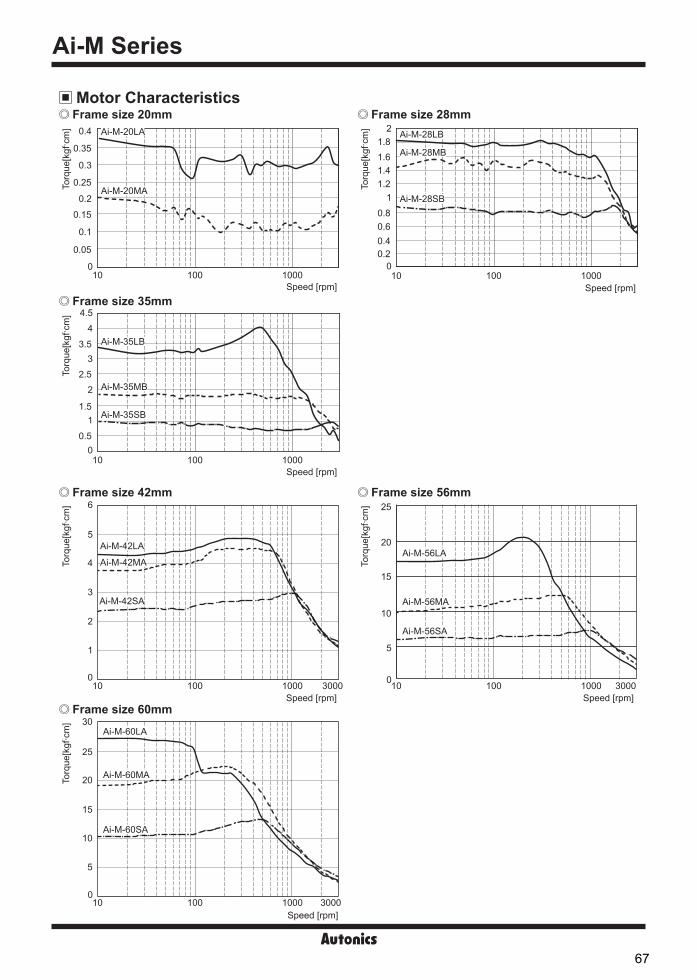
Ai-M Series
Motor Characteristics
Frame size 42mm Frame size 56mm
Frame size 60mm
Torq
ue[k
gf. c
m]
5
4
3
2
1
0
6
10 100 1000 3000Speed [rpm]
Ai-M-42SA
Ai-M-42MA
Ai-M-42LA
Speed [rpm]
25
20
15
10
5
0
Torq
ue[k
gf. c
m]
10 100 1000 3000
Ai-M-56LA
Ai-M-56MA
Ai-M-56SA
30
25
20
10
15
5
0
Torq
ue[k
gf. c
m]
10 100 1000 3000Speed [rpm]
Ai-M-60LA
Ai-M-60MA
Ai-M-60SA
Frame size 35mm4.5
43.5
2
11.5
32.5
0.50
Torq
ue[k
gf. c
m]
10 100 1000Speed [rpm]
Ai-M-35LB
Ai-M-35MB
Ai-M-35SB
Frame size 20mm
Torq
ue[k
gf. c
m]
0.25
0.35
0.2
0.15
0.1
0.05
0
0.3
0.4
10 100 1000Speed [rpm]
Ai-M-20MA
Ai-M-20LA
Frame size 28mm
1.61.8
2
1.41.2
1
0.40.60.8
0.20
Torq
ue[k
gf. c
m]
10 100 1000Speed [rpm]
Ai-M-28LB
Ai-M-28MB
Ai-M-28SB
67

SENSORS
CONTROLLERS
MOTION DEVICES
SOFTWARE
(Y)Closed Loop Stepper System
(Z)Stepper Motors
(AA)Drivers
(AB)Motion Controllers
2-Phase Closed-Loop Stepper Motor
Motor Connectors
Cable (sold separately)
CN2: Motor+Encoder ConnectorPin arrangement Pin no. Function Pin no. Function
1 2 3 4 5 6 7
141312111098
1 GND 8 +5VDC2 Encoder A 9 Encoder A3 Encoder B 10 Encoder B4 Encoder Z 11 Encoder Z5 F.G. 12 N.C6 Motor A 13 Motor B7 Motor A 14 Motor B
※Above connectors are suitable for Ai-M Series. You can use equivalent or substitute connectors.
TypeSpecifications
ManufactureConnector Connector terminal Housing
CN2 Motor+Encoder
Frame size 20, 28, 35mm5557-14R
5556T2- Molex
Frame size 42, 56, 60mm 5556T
Type ModelMotor+Encoder cable Normal Moving
C1D14M- ※1 C1DF14M-
※1
※1: indicates cable length (1, 2, 3, 5, 7, 10). E.g.) C1DF14M-10: 10m moving type motor+encoder cable.
Motor Installation1. Mounting directionMotor can be mounted in any directions-facing up, facing down and side ways. No matter which direction motors to be mounted, make sure not to apply overhung or thrust load on the shaft. Refer to the table below for allowable shaft overhung load / thrust load.
Do not apply excessive force to motor cable when mounting motors. Do not forcibly pull or insert the cable. It may cause poor connection or disconnection of the cable by force.In case of frequent cable movement required application, proper safety countermeasures must be ensured.
Motor sizeThe distance from the shaft in front (mm), Allowable overhung load [kgf (N)] Allowable
thrust loadD=0 D=5 D=10 D=15Frame size 20mm 1.22 (12) 1.53 (15) - -
Under the load of motor
Frame size 28mm 2.55 (25) 3.46 (34) 5.3 (52) -Frame size 35mm 2 (20) 2.55 (25) 3.46 (34) 5.3 (52)Frame size 42mm 2 (20) 2.6 (25) 3.5 (34) 5.3 (52)Frame size 56mm
5.5 (54) 6.8 (67) 9.1 (89) 13.3 (130)Frame size 60mm
Facing up, downThrustload
Thrustload
Side waysOverhung
load
D※1
※1: The distance from the shaft in front (mm)
68

Ai-M Series
2. Mounting method
※Do not draw the wire with over strength 30N after wiring the encoder.
※Do not draw the wire with over strength 5N after wiring the encoder.
※Do not draw the wire with over strength 5N after wiring the encoder.
※Do not draw the wire with over strength 5N after wiring the encoder.
With considering heat radiation and vibration isolation, mount the motor as tight as possible against a metal panel having high thermal conductivity such as iron or aluminum.When mounting motors, use hexagon socket screws, hexagon nuts, spring washers and flat washers. Refer to the table below for allowable thickness of mounting plate and using bolt.
Tap holeThrough hole
Spring washer
Hexagon socket screw (M3)Pilot for flange(Counter bore or Through hole)
Mounting plate(thickness: min. 4mm)
31±0.2
Ø3.5
31±0
.2
Ø22+0.0210
(Through hole)
[Mounting plate]
Motor Installation
Tap holeThrough hole
Spring washer
Hexagon socket screw (M2)Pilot for flange(Counter bore or Through hole)
Mounting plate(thickness: min. 3mm)
Tap holeThrough hole
Spring washer
Hexagon socket screw (M2.5)Pilot for flange(Counter bore or Through hole)
Mounting plate(thickness: min. 4mm)
Tap holeThrough hole
Spring washer
Hexagon socket screw (M3)Pilot for flange(Counter bore or Through hole)
Mounting plate(thickness: min. 4mm)
23±0.2
23±0
.2
4-Ø2.8
Ø22+0.3 +0.1
[Mounting plate]
(Through hole)
26±0.2
26±0
.2
4-Ø3.3
Ø22+0.3 +0.1
[Mounting plate]
(Through hole)
16±0.2
4-Ø2.3
16±0
.2
Ø16 +0.021 0
(Through hole)
[Mounting plate]
Frame size 20mm
Frame size 28mm
Frame size 35mm
Frame size 42mm
69

SENSORS
CONTROLLERS
MOTION DEVICES
SOFTWARE
(Y)Closed Loop Stepper System
(Z)Stepper Motors
(AA)Drivers
(AB)Motion Controllers
2-Phase Closed-Loop Stepper Motor
※Do not draw the wire with over strength 30N after wiring the encoder.
Hexagonnut
Springwasher
Hexagon socket screw (M4)
Pilot for flange(Counter bore or Through hole)
Mounting plate(thickness: min. 5mm)Through hole
47.14/50±0.2
47.1
4/50
±0.2 Ø4.5
Ø38.1 +0.3 +0.1
(Through hole)
[Mounting plate]
Tap holeMounting plate(thickness: min. 5mm)
Through hole
Pilot for flange(Counter bore or Through hole)
Hexagon socket screw (M4)
Spring washer
M4
Ø38.1+0.3 +0.1
(Tap hole)
[Mounting plate]
47.1
4/50
±0.2
47.14/50±0.2
Frame size 56mm/60mm
3. Connection with loadWhen connecting the load, be sure of the center, tension of the belt, and parallel of the pulley. When connecting the load such as a pulley, a belt, be sure of the allowable thrust load, radial load, and shock. Tighten the screw for a coupling or a pulley not to be unscrewed. When connecting a coupling or a pulley on the motor shaft, be sure of damage of the motor shaft and the motor shaft bearing. Do not disassemble or modify the motor shaft to connect with the load.
Direct load connection with coupling Load connection with pulley, belt, and wire Load connection with gear
※ Use Autonics flexible coupling (ERB Series).
Flexible couplingBall screw or TM screw
When connecting the load directly (ball screw, TM screw, etc) to the motor shaft, use a flexible coupling as shown in the above figure. If the center of the load is not aligned with that of shaft, it may cause severe vibration, shaft damage or shorten life cycle of the shaft bearing.
The motor shaft and the load shaft should be parallel. Connect the motor shaft and the line which connects the center of two pulleys to a right angle.
The motor shaft and the load shaft should be parallel. Connect the motor shaft to the center of gear teeth side to be interlocked.
4. Installation conditionInstall the motor in a place that meets certain conditions specified below.It may cause product damage if it is used out of following conditions.① Inside of the housing which is installed indoors
(This unit is manufactured for the purpose of attaching to equipment. Install a ventilation device.)②Within 0 to 50 (at non-freezing status) of ambient temperature③Within 20 to 85%RH (at non-dew status) of ambient humidity④The place without explosive, flammable and corrosive gas⑤The place without direct ray of light⑥The place where dust or metal scrap does not enter into the unit ⑦The place without contact with water, oil, or other liquid⑧The place without contact with strong alkali or acidity⑨The place where easy heat dissipation could be made⑩The place without continuous vibration or severe shock⑪The place with less salt content⑫The place with less electronic noise occurs by welding machine, motor, etc.⑬ The place where no radioactive substances and magnetic fields exist. It shall be no vacuum status as well.
70

Ai-M Series
Proper Usage Follow instructions in 'Proper Usage'.
Otherwise, it may cause unexpected accidents. Using motors at low temperature may cause reducing ball bearing's grease consistency and friction torque is increased.
Start the motor in a steady manner since motor's torque is not to be influenced. If wiring encoder cable, separate it from high voltage line or power cable for preventing surge and inductive noise.
The cable length should be as short as possible. Failure to follow this instruction may result in raised cable resistance, residual voltage, and output waveform noise
Must connect the encoder shield cable to the F.G. terminal. For using motor, it is recommended to maintenance and inspection regularly. ①Unwinding bolts and connection parts for the unit installation and load connection②Strange sound from ball bearing of the unit③Damage and stress of lead cable of the unit④Connection error with driver⑤Inconsistency between the axis of motor output and the center, concentric (eccentric, declination) of the load, etc.
This unit may be used in the following environments.①Indoors (in the environment condition rated in 'Specifications')②Altitude max. 2,000m③Pollution degree 2④Installation category II
Troubleshooting1. When motor does not rotate①Check the connection status between controller and driver, and pulse input specifications (voltage, width).②Check the pulse and direction signal are connected correctly.
2. When motor rotates to the opposite direction of the designated direction ①When RUN mode is 1-pulse input method, CCW input [H] is for forward, [L] is for backward. ②When RUN mode is 2-pulse input method, check CW and CCW pulse input are changed or not.
3. When motor drive is unstable①Check that driver and motor are connected correctly. ②Check the driver pulse input specifications (voltage, width).
71

SENSORS
CONTROLLERS
MOTION DEVICES
SOFTWARE
(Y)Closed Loop Stepper System
(Z)Stepper Motors
(AA)Drivers
(AB)Motion Controllers
MD2U Series
MD2U-MD20 MD2U-ID20
FeaturesCompact and High-Performance of 2-Phase Stepper Motor Driver
Unipolar constant current drive type Enable to brake when it stops by STOP current
adjustment Low speed and precise control with microstep
(MD2U-MD20) Insulate using photocoupler to minimize the influence
by external noise Power supply: 24-35VDC
Ordering Information
Specifications
※1: Since torque characteristics are improved but the driver temperature rises with the 30VDC power supply, the driver should be installedat the well ventilated environment. Torque is variable by power supply.
※2: Based on the ambient temperature 25, ambient humidity 55%RH.※3: RUN current varies depending on the input RUN frequency, and the max. instantaneous RUN current varies also.※4: Max. input pulse frequency is max. frequency to be input and is not same as max. pull-out frequency or max. slewing frequency.※5: The weight includes packaging. The weight in parenthesis is for unit only. ※Environment resistance is rated at no freezing or condensation.
Model MD2U-MD20 MD2U-ID20 Power supply※1 24-35VDCᜡAllowable voltage range 90 to 110% of the rated voltageMax. current consumption※2 3ARUN current※3 0.5-2A/Phase STOP current 20 to 70% of RUN current (set by STOP current volume)Drive method Unipolar constant current drive typeBasic step angle 1.8˚/StepMax. drive speed - 1500rpmResolution 1, 2, 4, 5, 8, 10, 16, 20-division (1.8˚ to 0.09˚/Step)
-
Inpu
t pul
se
char
acte
ristic
Input pulse width Min. 10μs (CW, CCW), min. 1ms (HOLD OFF)Duty rate 50% (CW, CCW)Rising/Falling time Max. 0.5 (CW, CCW)Pulse input voltage [H]: 4-8VDCᜡ, [L]: 0-0.5VDCᜡMax. input current 4mA (CW, CCW), 10mA (HOLD OFF)Max. input pulse freq.※4 Max. 50kHz (CW, CCW)
Input resistance 300Ω (CW, CCW), 390Ω (HOLD OFF) 3.3kΩ (CW/CCW, RUN/STOP, HOLD OFF) Insulation resistance Over 200MΩ (at 500VDC megger, between all terminals and case)Dielectric strength 1000VAC 50/60Hz for 1 min (between all terminals and case)Noise immunity ±500V the square wave noise (pulse width: 1μs) by the noise simulatorVibration 1.5mm amplitude at frequency of 10 to 55Hz (for 1 min) in each X, Y, Z direction for 2 hoursShock Vibration 300m/s² (approx. 30G) in each X, Y, Z direction for 3 times
EnvironmentAmbient temp. 0 to 50, storage: -10 to 60Ambient humi. 35 to 85%RH, storage: 35 to 85%RH
ApprovalWeight※5 Approx. 295g (approx. 180g) Approx. 303g (approx. 190g)
MD 202 U M D
20 2A/Phase
D 24-35VDC
M Micro Step (20-division)I Intelligent type
U Unipolar drive
2 2-phase
MD Motor Driver
RUN current
Power supply
Step method (resolution)
Drive method
Motor phase
Item
Please read “Safety Considerations” in the instruction manual before using.
72

MD2U Series
Function selection DIP switch Microstep, pulse input method setting
Resolution setting (MS1/MS2/MS3)Select the step angle (motor rotation angle per 1 pulse).The set step angle is dividing basic step angle(1.8°) of 2-phase stepping motor by set resolution value.
E.g.) Set step angle = Basic angle (1.8°)
Resolution※Change resolution setting value only when the motor stops.
1P/2PThe switch is to select pulse input method.1-pulse input method: CW → operating rotation signal input, CCW → rotation direction signal input ([H]: CW, [L]: CCW)2-pulse input method: CW → CW rotation signal input, CCW → CCW rotation signal input.
Setting RUN current RUN current setting is for the current provided to the motor in running status.
※When RUN current is increased, RUN torque of the motor is also increased.※When RUN current is set too high, the heat of the motor is increased.※Set RUN current properly for the load within the rated current range of the motor.※RUN current setting range: 0.5 to 2.0A ※RUN current setting method: Measure the voltage by connecting a DC voltage meter to both CT+ and
CT- terminals while the motor is running (max. 150rpm)
E.g.) Input voltage (3V) × 2 = 2A (motor excitation current) 3 ※Change RUN current only when the motor stops.
2-Phase Micro Stepper Driver [MD2U-MD20]
Power indicator
Functionselection DIP switch
RUN current volume STOP current volume
Inputterminal
Powerterminal
Motorconnection
terminal
No. Name FunctionSwitch positionON OFF
1 MS1
Microstep setting
MS1 MS2 MS3 ResolutionON ON ON 1 (Full-step)ON ON OFF 2-divisionON OFF ON 4-divisionON OFF OFF 5-divisionOFF ON ON 8-divisionOFF ON OFF 10-divisionOFF OFF ON 16-divisionOFF OFF OFF 20-division
2 MS2
3 MS3
4 1P/2P Pulse input method 1-pulse input method
2-pulse input method
Unit Descriptions
Functions
2.0A0.5A
RUNCURRENT
CT CT
※Refer to ' Secifications'.
73

SENSORS
CONTROLLERS
MOTION DEVICES
SOFTWARE
(Y)Closed Loop Stepper System
(Z)Stepper Motors
(AA)Drivers
(AB)Motion Controllers
2-Phase Unipolar Stepper Motor Driver
HOLD OFF function This signal is for rotating axis of the motor with external force or manual positioning. When hold off signal maintains over 1ms as [H], motor excitation is released. When hold off signal maintains over 1ms as [L], motor excitation is in a normal status.
※Use this function only when the motor stops.※Refer to ' I/O Circuit and Connections'.
STOP current setting is for the current provided to the motor in stopped status, preventing severe heat of the motor. This function is for reducing the heat by variable resistance ratio setting within 0 to 100% of RUN current setting range (actual setting range: 20 to 70%). E.g.) In case of RUN current setting value is 2A and
STOP current setting value is 0% (actual setting range: 20%), STOP current 2A × 0.2 = 0.4A
※When STOP current is decreased, STOP torque of the motor is also decreased.※When STOP current is set low, the heat of the motor is also low.※Change STOP current only when the motor stops.
Setting STOP current
I/O Circuit and Connections
STOPCURRENT
20% 70%
※1: If the power for driving pulse from external is over than+5VDC, please connect resistor at the outside.(input power max. 24VDC, input current 10-20mA)
※CW2-pulse input method (CW rotation signal input)1-pulse input method (operating rotation signal input)
※CCW2-pulse input method (CCW rotation signal input)1-pulse input method (rotation direction signal input)→[H]: CW, [L]: CCW
※HOLD OFFControl signal for motor excitation OFF→ [H]: Motor excitation OFF
6
5
4
3
2
1
6
5
4
3
2
1
DC+
DC-
A-com (black)
B-com (white)
A (brown)
B (red)
B (yellow)
24-35VDC
Motor
+
-
※1
300Ω
300Ω
390Ω
+5VDC
CCW
CW
HOLDOFF
A (orange)
[Signal]
[Motor]
[Power]
GND
74

MD2U Series
Dimensions
Time Chart
(unit: mm)
1 pulse input method
2 pulse input method
※Do not input CW, CCW signals at the same time in 2-pulse input method.It may not operate properly if another direction signal is inputted when one of CW or CCW is [H].
CW[H][L]
CCW [H][L]
Rotationposition
CW CCW
CW CCW
[H][L]
[L][H]
CW
CCW
Rotationposition
CW
4.5
20
39.5
100
8676.5
7438
4.5
94 100
105
75

SENSORS
CONTROLLERS
MOTION DEVICES
SOFTWARE
(Y)Closed Loop Stepper System
(Z)Stepper Motors
(AA)Drivers
(AB)Motion Controllers
START speed volume ACC time setting volumeDEC time settingvolume
RUN speed volume
RUN current volume STOP current volume
Functionselection DIP switch
Power indicator
Inputterminal
Powerterminal
Motorconnection
terminal
2-Phase Intelligent Stepper Motor Driver [MD2U-ID20]
Intelligent type stepper motor driver?MD2U-ID20 is an intelligent type stepper motor driver including all features to control 2-phase stepper motors so that no controllers are required. Realizing AC motor's driving features to stepper motors Controlling START speed, RUN speed and ACC/DEC speed User-friendly design to realize various functions (front switch and volume)
Selection of Symmetry/Asymmetry※The function to make the ACC/DEC time of run-speed as asymmetry or symmetry using DIP switch No. 1.
※It is able to set the gradient (acceleration and deceleration time) as ACC/DEC time.Selection of max. speed (MS2, MS3)
※The function to select the max. speed of motors.※The max. speed of stepper motor is changed by MS2/MS3 and Hi/Low speed.※The features of run and vibration are able to change depending on MS2, MS3.※Lower the max. speed to run a motor smoothly.
Selection of H/L SPEED※H/L SPEED mode selection switch
: Accel/deceleration control is not available in Low speed mode since all sections are included in Pull-in range.※Low speed mode: It is able to drive a motor up to 150rpm of max. drive speed.※High speed mode: It is able to drive a motor up to 1500rpm of max. drive speed.
※1: D=Don't care※Reboot the driver after changing function selection switch.
A AD D
Symmetry of accel/deceleration
ACC time and DEC time are repeated as a symmetrical figureTime (sec)
Speed(rpm)
Unit Descriptions
Functions
A AD D
Asymmetry (normal) of accel/deceleration
ACC time and DEC time are repeated as a asymmetrical figureTime (sec)
Speed(rpm)
No. Name FunctionSwitch positionON OFF
1 SYM/NORMAL SYM/NORMAL Symmetry Asymmetry
2 MS2
Max. speed
MS2 MS3 H/L SPEED Max. speed(rpm)
ON ON
ON: High speed
1500ON OFF 1350OFF ON 1000OFF OFF 500D※1 D※1 OFF: Low speed 150
3 MS3
4 H/L SPEED High/Low speed
ON 1 2 3 4
Function selection DIP switch
※Refer to ' Specifications'.
2-Phase Unipolar Intelligent Stepper Motor Driver
76

MD2U Series
Setting RUN current RUN current setting is for the current provided to the motor in running status.
※When RUN current is increased, RUN torque of the motor is also increased.※When RUN current is set too high, the heat of the motor is increased.※Set RUN current properly for the load within the rated current range of the motor.※RUN current setting range: 0.5 to 2.0A ※RUN current setting method: Measure the voltage by connecting a DC voltage meter to both CT+ and
CT- terminals while the motor is running (max. 150rpm)
E.g.) Input voltage (3V) × 2
= 2A (motor excitation current) 3 ※Change RUN current only when the motor stops.
Setting STOP current STOP current setting is for the current provided to the motor in stopped status, preventing severe heat of the motor. This function is for reducing the heat by variable resistance ratio setting within 0 to 100% of RUN
current setting range (actual setting range: 20 to 70%).E.g.) In case of RUN current setting value is 2A and
STOP current setting value is 0%(actual setting range: 20%), STOP current 2A × 0.2 = 0.4A
※When STOP current is decreased, STOP torque of the motor is also decreased.※When STOP current is set low, the heat of the motor is also low.※Change STOP current only when the motor stops.
Setting RUN speed※It sets max. RUN speed.※Max. RUN speed can be different depending on max. speed setting (MS2, MS3) and driving mode
setting (Hi/Low speed).※Since missing step can occur due to max. input pulse frequency of motors, consider motor type and
its RUN current when setting max. RUN speed.※Set the value only when the motor stops.
Setting START speed ※It sets START speed.※Max. START speed value is same with RUN speed value.※Although START speed must be set within max. starting frequency, it is recommended to set up
START speed within 0 to 50% for stable driving.※Set the value only when the motor stops.
Setting ACC time※It sets the acceleration time from START speed to max. RUN speed.※Operates in AT_1 operation mode when ACC time is under 33.3%, AT_2 operation mode when
ACC time is under 66.6%, and AT_3 operation mode when ACC time is over 66.6%.※AT_1 is 0.5 sec when RUN speed=100%, START speed=0%.※AT_2 is 1 sec when RUN speed=100%, START speed=0%.※AT_3 is 2 sec when RUN speed=100%, START speed=0%.※Set the value only when the motor stops.
Setting DEC time※It sets the deceleration time from max. RUN speed to STOP.※Operates in DT_1 operation mode when DEC time is under 33.3%, DT_2 operation mode when
DEC time is under 66.6%, and DT_3 operation mode when DEC time is over 66.6%.※DT_1 is 0.5 sec when RUN speed=100%, START speed=0%.※DT_2 is 1 sec when RUN speed=100%, START speed=0%.※DT_3 is 2 sec when RUN speed=100%, START speed=0%.※Set the value only when the motor stops.
※ACC Time and DEC Time are declined in proportion to the setting value of START speed.※The figures above indicate the factory default for each value.
HOLD OFF function This signal is for rotating axis of the motor with external force or manual positioning. When hold off signal maintains over 1ms as [H], motor excitation is released. When hold off signal maintains over 1ms as [L], motor excitation is in a normal status.
※Use this function only when the motor stops.※Refer to ' I/O Circuit and Connections'.
STOPCURRENT
20% 70%
RUN SPEED
0% 100%
START SPEED
0% 100%
ACC TIME
0% 100%
DEC TIME
0% 100%
RUNCURRENT
2.0A0.5A
CT CT
77

SENSORS
CONTROLLERS
MOTION DEVICES
SOFTWARE
(Y)Closed Loop Stepper System
(Z)Stepper Motors
(AA)Drivers
(AB)Motion Controllers
Inner adjuster control(Adjusting RUN speed with front VR)
Make the connection between terminal No.5 and No.6.
External adjuster control (Adjusting RUN speedwith connecting external variable resistance)
Connect variable resistance 2kΩ (1 to 3kΩ) for external adjuster control. If variable resistance is too low, full range setting might not be possible. Make sure to adjust RUN speed VR to maximum for external adjuster control.
External voltage control (Adjusting RUN speedwith external voltage input)
Make sure to adjust RUN speed VR to maximum external voltage control.
RUN speed
COM
5VDC (Inner)External adjuster2kΩ (1 to 3kΩ)
1
2
34
5
6
RUN speed
COM External voltage0-5VDC
4
5
6
+-
Time Chart High speed mode
I/O Circuit and Connections
※It accelerates up to RUN speed during ACC time after RUN signal is ON and decelerates during DEC time after it is OFF.※It is disable to change the direction during the signal is ON.※It takes 0.5sec for deceleration when DEC time is "0%".
Low speed modeMax. RUN speed is 150rpm and ACC and DEC time are not available.It is same with High speed to change RUN/STOP and direction.
※RUN/STOP signal input→ [ON]: RUN, [OFF]: STOP
※Direction signal input→ [ON]: CW, [OFF]: CCW
※HOLD OFF signal iuput→ [ON]: HOLD OFF, [OFF]: HOLD ON
※Inner adjuster is correlated to external adjuster control andexternal voltage control. Make sure that inner adjustermust be set to maximum in order to set maximum RUNspeed using external adjuster and external voltage.
RUN speed
COM
5VDC (Inner)
4
5
6
A-com (black)
B-com (white)
COM
CW/CCW
RUN/STOP
Inner power (24-35VDC)
RUN speed
Inneradjustercontrol
※External adjuster
control 2kΩ(1 to 3kΩ)
※External voltage
control
HOLD OFF
0-5VDC
24-35VDC
3.3kΩ
3.3kΩ
3.3kΩ
5VDC (Inner)
DC+
DC-Power
Motor
1
1
2
2
3
3
4
4
5
5
6
6
A (brown)
A (orange)
B (red)
B (yellow)
+
+
-
-
CW
RUN/STOPON
ON
OFF
OFFCW/CCW
Rotation speedand direction
(symmetry mode) ACC timeDEC time
MotorstopCW CCW
ACC time(same as DEC time)
2-Phase Unipolar Intelligent Stepper Motor Driver
78
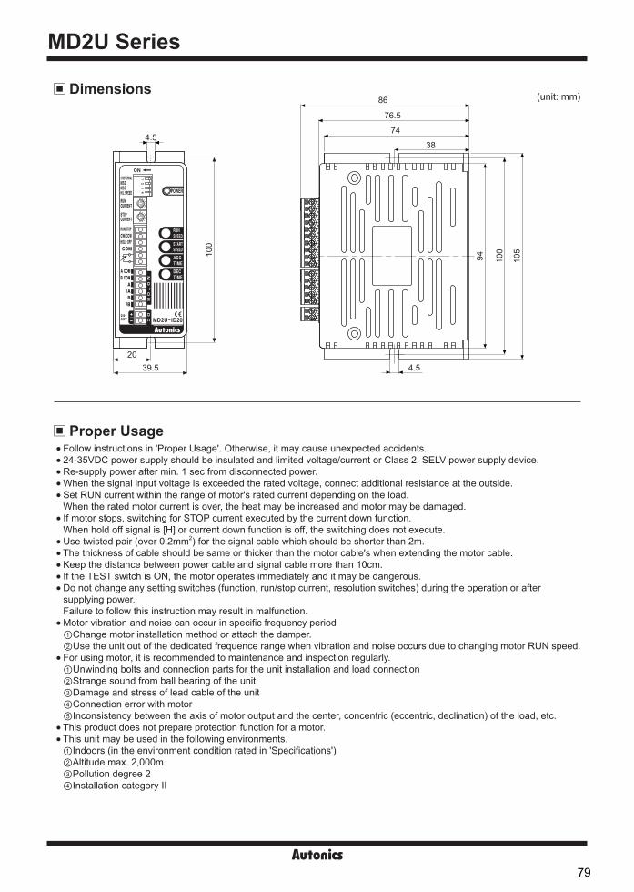
MD2U Series
Proper Usage
Dimensions (unit: mm)
Follow instructions in 'Proper Usage'. Otherwise, it may cause unexpected accidents.24-35VDC power supply should be insulated and limited voltage/current or Class 2, SELV power supply device.Re-supply power after min. 1 sec from disconnected power.When the signal input voltage is exceeded the rated voltage, connect additional resistance at the outside. Set RUN current within the range of motor's rated current depending on the load.When the rated motor current is over, the heat may be increased and motor may be damaged. If motor stops, switching for STOP current executed by the current down function.When hold off signal is [H] or current down function is off, the switching does not execute.Use twisted pair (over 0.2mm2) for the signal cable which should be shorter than 2m.The thickness of cable should be same or thicker than the motor cable's when extending the motor cable.Keep the distance between power cable and signal cable more than 10cm.If the TEST switch is ON, the motor operates immediately and it may be dangerous. Do not change any setting switches (function, run/stop current, resolution switches) during the operation or aftersupplying power.Failure to follow this instruction may result in malfunction. Motor vibration and noise can occur in specific frequency period①Change motor installation method or attach the damper.②Use the unit out of the dedicated frequence range when vibration and noise occurs due to changing motor RUN speed. For using motor, it is recommended to maintenance and inspection regularly.①Unwinding bolts and connection parts for the unit installation and load connection②Strange sound from ball bearing of the unit③Damage and stress of lead cable of the unit④Connection error with motor⑤Inconsistency between the axis of motor output and the center, concentric (eccentric, declination) of the load, etc.This product does not prepare protection function for a motor. This unit may be used in the following environments.①Indoors (in the environment condition rated in 'Specifications')②Altitude max. 2,000m③Pollution degree 2④Installation category II
4.5
2039.5
100
86
76.5
74
38
4.5
94 100
105
79
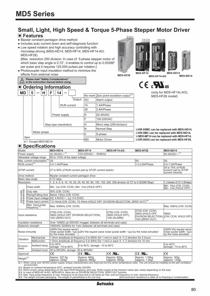
MD5 Series-|Transparent setting guide|-
Small, Light, High Speed & Torque 5-Phase Stepper Motor Driver Bipolar constant pentagon drive method Includes auto current down and self-diagnosis function Low speed rotation and high accuracy controlling with
microstep-driving (MD5-HD14, MD5-HF14, MD5-HF14-AO,MD5-HF28)[Max. resolution 250 division: In case of 5-phase stepper motor ofwhich basic step angle is 0.72°, it enables to control up to 0.00288°per pulse and it requires 125,000 pulses per rotation.]
Photocoupler input insulation method to minimize theeffects from external noise
Ordering Information
Specifications
Features
Item
Motor phase
Step type (resolution)
Power supply
RUN current
Output
MD 145 H FNo mark Zero point excitation output※1
AO Alarm output
14 1.4A/Phase28 2.8A/Phase
D 20-35VDCF 100-220VAC
H Micro step (250-division)N Normal Step
5 5-phase
MD Motor Driver※1: Except MD5-ND14
※KR-55MC can be replaced with MD5-HD14.※KR-5MC can be replaced with MD5-ND14.※MD5-MF14 can be replaced with MD5-HF14.※KR-505G can be replaced with MD5-HF28.
MD5-HD14MD5-ND14MD5-HF14-AO
MD5-HF14MD5-HF28
Model MD5-HD14 MD5-HF14 MD5-HF14-AO MD5-HF28 MD5-ND14 Power supply 20-35VDCᜡ
※1 100-220VACᜠ 50/60Hz 20-35VDCᜡ※1
Allowable voltage range 90 to 110% of the rated voltageMax. current consumption※2 3A 5A 3ARUN current※3 0.4-1.4A/Phase 1.0-2.8A/Phase 0.5-1.5A/Phase
STOP current 27 to 90% of RUN current (set by STOP current switch)25 to 75% of RUN current (set by STOP current volume)
Drive method Bipolar constant current pentagon drive Basic step angle 0.72˚/stepResolution 1, 2, 4, 5, 8, 10, 16, 20, 25, 40, 50, 80, 100, 125, 200, 250-division (0.72 to 0.00288 /Step) 1, 2-division (0.72, 0.36/step)
Inpu
t pul
sech
arac
teris
tic
Pulse width Min. 1 (CW, CCW), Min. 1ms (HOLD OFF) Min. 10 (CW, CCW), Min. 1ms (HOLD OFF)
Duty rate 50% (CW, CCW)Rising/Falling time Below 130ns (CW, CCW)Pulse input voltage [H]: 4-8VDCᜡ, [L]: 0-0.5VDC Pulse input current 7.5-14mA (CW, CCW), 10-16mA (HOLD OFF, DIVISION SELECTION, ZERO OUT)※4
Max. input pulse frequency※5 Max. 500kHz (CW, CCW) Max. 50kHz (CW, CCW)
Input resistance270Ω (CW, CCW), 390Ω (HOLD OFF, DIVISION SELECTION), 10Ω (ZERO OUT)
270Ω (CW, CCW), 390Ω (HOLD OFF), 10Ω (ALARM)
270Ω (CW, CCW), 390Ω (HOLD OFF,DIVISION SELECTION),10Ω (ZERO OUT)
390Ω (CW, CCW, HOLD OFF)
Insulation resistance Over 100MΩ (at 500VDC megger, between all terminals and case)Dielectric strength 1000VAC 50/60Hz for 1min (between all terminals and case)
Noise immunity±500V the square wave noise (pulse width: 1μs) by the noise simulator
±2kV the square wave noise (pulse width: 1μs) by the noise simulator±500V the square wave noise (pulse width: 1μs) by the noise simulator
Vibration Mechanical 1.5mm amplitude at frequency 5 to 60Hz (for 1 min) in each X, Y, Z direction for 2 hoursMalfunction 1.5mm amplitude at frequency 5 to 60Hz (for 1 min) in each X, Y, Z direction for 10 min
Environ-ment
Ambient temp. 0 to 40, storage: -10 to 60 0 to 50, storage: -10 to 60 0 to 40,
storage: -10 to 60Ambient humi. 35 to 85%RH, storage: 35 to 85%RH
Approval ᜢ ᜢ ᜧ ᜢ ᜧ ᜢ ᜧ ᜢ
Weight※6 Approx. 327.5g (approx. 220g)
Approx. 840g (approx. 680g)
Approx. 820g (approx. 660g)
Approx. 1.35kg (approx. 1.2kg)
Approx. 183g (approx. 130g)
※1: When using over 30VDC power supply, torque characteristics are improved but the driver temperature raise. The unit should be installed at the well ventilation environment.
※2: Based on ambient temperature 25, ambient humidity 55%RH. ※3: RUN current varies depending on the input RUN frequency and max. RUN current at the moment varies also varies depending on the load.※4: In case of MD5-HF14-AO, MD5-ND14, there are no DIVISION SELECTION, ZERO OUT function.※5: Max. input pulse frequency is max. frequency to be input and is not same as max. pull-out frequency or max. slewing frequency. ※6: The weight includes packaging. The weight in parenthesis is for unit only. ※Environment resistance is rated at no freezing or condensation.
(only for MD5-HF14(-AO), MD5-HF28 model)
Please read “Safety Considerations” in the instruction manual before using.
80

SENSORS
FIELD INSTRUMENTS
CONTROLLERS
MOTION DEVICES
SOFTWARE
(A)Closed Loop Stepper System
(B)Stepper Motors
(C)Stepper MotorDrivers
(D)Motion Controllers
-|Transparent setting guide|-
Function selection DIP switch
TEST Self diagnosis function is for motor and driver test. This function makes the motor rotate with 30rpm in full step. Rotation speed varies with resolution settings. Rotation speed = 30rpm/resolution In 1-pulse input method, it rotates to CCW, and in 2-pulse input method, it rotates to CW.
※ Be sure that the TEST switch is OFF before supplying the power. If the TEST switch is ON, the motor operates immediately and it may be dangerous. 1/2 CLK 1/2 CLK switch is to select pulse input method.1-pulse input method: CW → operating rotation signal input, CCW → rotation direction signal input ([H]: CW, [L]: CCW) 2-pulse input method: CW → CW rotation signal input, CCW → CCW rotation signal input.
C/D (auto current down) This function is to reduce the current provided for motor automatically for preventing severe motor's heat when motor stops. If motor RUN pulse is not applied, the current provided for motor reduces as the set STOP current.
※ Be sure that when motor RUN current is reduced, the stop torque of motor also reduced. ※ Set the STOP current by the STOP current switch.
Setting RUN current
5-Phase Micro Stepper Motor Driver [MD5-HD14]Resolution switch RUN current switch
STOP current switch
Functionselection
DIP switch
Power indicator Inputterminal Zero
outputPowerterminal
Motorconnection
terminal
Switch No. 0 1 2 3 4 5 6 7 8 9 A B C D E F
Current (A/Phase) 0.4 0.5 0.57 0.63 0.71 0.77 0.84 0.9 0.96 1.02 1.09 1.15 1.22 1.27 1.33 1.4
Switch No. 0 1 2 3 4 5 6 7 8 9 A B C D E F
% 27 31 36 40 45 50 54 58 62 66 70 74 78 82 86 90
Unit Description
No. Name FunctionSwitch positionON OFF (default)
1 TEST Self diagnosis function 30rpm rotation Not use2 1/2 CLK Pulse input method 1-pulse input method 2-pulse input method3 C/D Auto current down Not use Use
Setting RUN current is for the current provided for motor when the motor runs.※When RUN current is increased, RUN torque of the motor is also increased. ※When RUN current is set too high, the heat is severe.※Set RUN current within the range of motor's rated current according to its load. ※Change RUN current only when the motor stops.
Setting STOP current is for the current provided for motor when the motor stops for preventing severe motor's heat. This setting is applied when using C/D (current down) function. Setting value of STOP current is percentage (%) ratio of the set RUN current.E.g.) Set RUN current as 1.4A and STOP current as 40%.
STOP current is set as 1.4A×0.4=0.56A※When STOP current is decreased, STOP torque of the motor is also decreased. ※When STOP current is set too low, the heat is lower.※Change STOP current only when the motor stops.
Setting STOP current
Functions※Refer to ' Specifications'.
5-Phase Stepper Motor Driver (1.4A/Phase, DC Power)
81

MD5 Series-|Transparent setting guide|-
Zero point excitation output signal (ZERO OUT)CW Pulse
CCW Pulse
ZERO OUT
ONOFFON
OFF
ONOFF
0 0 01 1 12 23 4 5 6 7 8 9
Switch No. 0 1 2 3 4 5 6 7 8 9 A B C D E FResolution 1 2 4 5 8 10 16 20 25 40 50 80 100 125 200 250Step angle 0.72° 0.36° 0.18° 0.144° 0.09° 0.072° 0.045° 0.036° 0.0288° 0.018° 0.0144° 0.009° 0.0072° 0.00576° 0.0036° 0.00288°
This output indicates the initial step of excitation order of stepper motor and rotation position of motor axis. This signal outputs every 7.2° of rotation of the motor axis regardless of resolution. (50 outputs per 1 rotation of the motor.) E.g.) Full step: outputs one time by 10 pulses input, 20-division: outputs one time by 200 pulses input.
This signal is for rotating motor's axis using external force or used for manual positioning. When hold off signal maintains over 1ms as [H], motor excitation is released. When hold off signal maintains over 1ms as [L], motor excitation is in a normal status.
※Must stop the motor for using this function. ※Refer to ' I/O Circuit and Connections'.
HOLD OFF function
Setting Microstep (microstep: resolution)
Setting Resolution (same as MS1, MS2) The MS1, MS2 switches is for resolution setting. Select MS2 or MS2 by DIVISION SELECTION signal ([L]: MS1, [H]: MS2) Select the step angle (motor rotation angle per 1 pulse). The set step angle is dividing basic step angle (0.72°) of 5-phase stepper motor by setting value. The calculation formula of divided step angle is as below.
When using geared type motor, the angle is step angle divided by gear ratio. Step angle / gear ratio = Step angle applied gear E.g) 0.72° / 10 (1:10) = 0.072°
※Must stop the motor before changing the resolution.
Set step angle = Basic step angle (0.72°)
Resolution
※CW 2-pulse input method (CW rotation signal input)1-pulse input method (operating rotation signal input)※CCW2-pulse input method (CCW rotation signal input)1-pulse input method (rotation direction signal input)→ [H]: CW, [L]: CCW ※HOLD OFFControl signal for motor excitation OFF→ [H]: Motor excitation OFF※DIVISION SELECTIONDivision selection signal→ [L]: Operated by MS1 setting resolution [H]: Operated by MS2 setting resolution※ZERO OUTZero point excitation output signal → Zero point status ON※If the power for driving pulse from external is over
than +5VDC, please connect resistor at the outside.(input power max. 24VDC, input current 10-20mA)
I/O Circuit and Connections
Motor
270Ω
270Ω CW
+5VDC
CCW
HOLD OFF
DIVISION SELECTION
390Ω
390Ω
[Signal]
[Motor]
[Power]
10Ω
GND
ZERO OUT
BLUE
RED
ORANGE
GREEN
5
4
3
2
1
1
2
3
4
5
6
7
8
9
10
1
2
BLACK※This connection cable color is only for Autonics motors.
It may different cable color when using other motors.
Power 20-35VDC
+
-
Pentagon connection
Standard connection
Blue Gray+Red
Red Yellow+Black
Orange Orange+White
Green Brown+Green
Black Blue+Purple
82

SENSORS
FIELD INSTRUMENTS
CONTROLLERS
MOTION DEVICES
SOFTWARE
(A)Closed Loop Stepper System
(B)Stepper Motors
(C)Stepper MotorDrivers
(D)Motion Controllers
-|Transparent setting guide|-
Connections
Dimensions(unit: mm)
※ In case of standard connection, refer to 'Stepper Motors' section.
Division selectionsignalZero pointexcitation
output signalCW
+C
W-
CC
W+
CC
W-
HOLD
OFF
+HO
LD O
FF-
UserController
+
+
+
-
-
-Black
GreenOrange
RedBlue
POWER20-35VDC
Motor
4.5
2039.5
100
8676.5
7438
4.5
94 100
105
5-Phase Stepper Motor Driver (1.4A/Phase, DC Power)
83

MD5 Series-|Transparent setting guide|-
5-Phase Micro Stepper Motor Driver [MD5-HF14]
Function selection DIP switch
※Refer to ' Specifications'.
Resolution switchRUN current switch
STOP current switchFunction selection DIP switch
Power indicator Inputterminal
Alarm indicator (red)
Powerterminal
Motorconnection
terminal
Unit Description
No. Name Function Switch positionON OFF (default)
1 TEST Self diagnosis function 30rpm rotation Not use2 2/1 CLK Pulse input method 1-pulse input method 2-pulse input method3 C/D Auto current down Not use Use
TEST Self diagnosis function is for motor and driver test. This function makes the motor rotate with 30rpm in full step. Rotation speed varies with resolution settings. Rotation speed = 30rpm/resolution In 1-pulse input method, it rotates to CCW, and in 2-pulse input method, it rotates to CW.
※ Be sure that the TEST switch is OFF before supplying the power. If the TEST switch is ON, the motor operates immediately and it may be dangerous.
2/1 CLK 2/1 CLK switch is to select pulse input method.1-pulse input method: CW → operating rotation signal input, CCW → rotation direction signal input ([H]: CW, [L]: CCW) 2-pulse input method: CW → CW rotation signal input, CCW → CCW rotation signal input.
C/D (auto current down) This function is to reduce the current provided for motor automatically for preventing severe motor's heat when motor stops. If motor RUN pulse is not applied, the current provided for motor reduces as the set STOP current.
※Be sure that when motor RUN current is reduced, the stop torque of motor also reduced. ※ Set the STOP current by the STOP current switch.
Setting RUN currentSwitch No. 0 1 2 3 4 5 6 7 8 9 A B C D E F
Current (A/Phase) 0.4 0.5 0.57 0.63 0.71 0.77 0.84 0.9 0.96 1.02 1.09 1.15 1.22 1.27 1.33 1.4
Switch No. 0 1 2 3 4 5 6 7 8 9 A B C D E F
% 27 31 36 40 45 50 54 58 62 66 70 74 78 82 86 90
Setting RUN current is for the current provided for motor when the motor runs.※When RUN current is increased, RUN torque of the motor is also increased. ※When RUN current is set too high, the heat is severe.※Set RUN current within the range of motor's rated current according to its load. ※Change RUN current only when the motor stops.
Setting STOP current is for the current provided for motor when the motor stops for preventing severe motor's heat. This setting is applied when using C/D (current down) function. Setting value of STOP current is percentage (%) ratio of the set RUN current. E.g.) Set RUN current as 1.4A and STOP current as 40%.
STOP current is set as 1.4A×0.4=0.56A※When STOP current is decreased, STOP torque of the motor is also decreased. ※When STOP current is set too low, the heat is lower.※Change STOP current only when the motor stops.
Setting STOP current
Functions
84
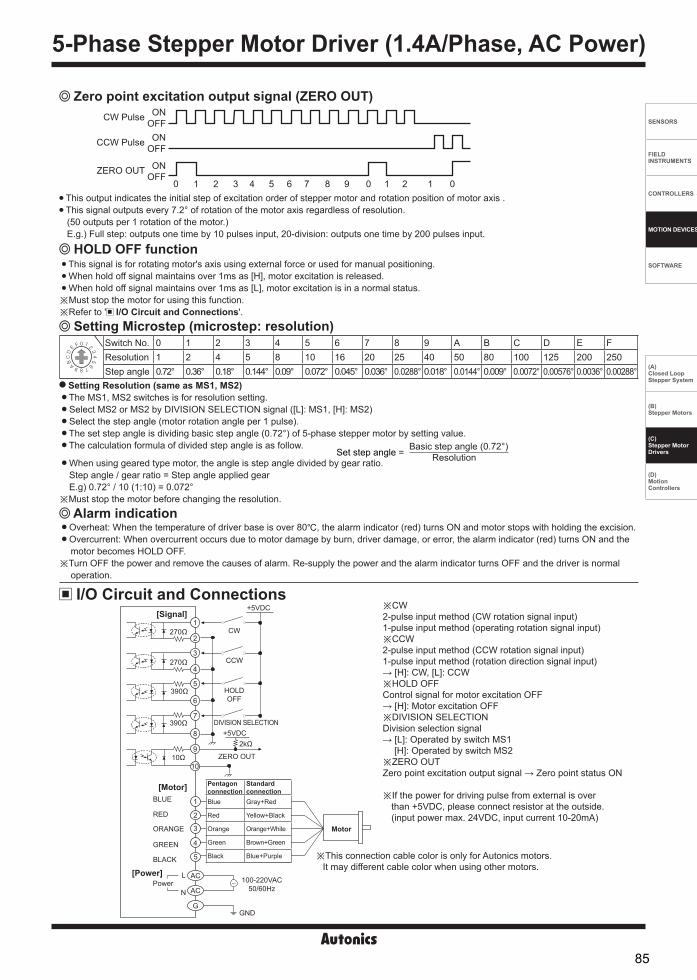
SENSORS
FIELD INSTRUMENTS
CONTROLLERS
MOTION DEVICES
SOFTWARE
(A)Closed Loop Stepper System
(B)Stepper Motors
(C)Stepper MotorDrivers
(D)Motion Controllers
-|Transparent setting guide|-
Zero point excitation output signal (ZERO OUT)CW Pulse
CCW Pulse
ZERO OUT
ONOFFON
OFF
ONOFF
0 0 01 1 12 23 4 5 6 7 8 9 This output indicates the initial step of excitation order of stepper motor and rotation position of motor axis . This signal outputs every 7.2° of rotation of the motor axis regardless of resolution. (50 outputs per 1 rotation of the motor.) E.g.) Full step: outputs one time by 10 pulses input, 20-division: outputs one time by 200 pulses input.
This signal is for rotating motor's axis using external force or used for manual positioning. When hold off signal maintains over 1ms as [H], motor excitation is released. When hold off signal maintains over 1ms as [L], motor excitation is in a normal status.
※Must stop the motor for using this function. ※Refer to ' I/O Circuit and Connections'.
HOLD OFF function
Alarm indication
Switch No. 0 1 2 3 4 5 6 7 8 9 A B C D E FResolution 1 2 4 5 8 10 16 20 25 40 50 80 100 125 200 250Step angle 0.72° 0.36° 0.18° 0.144° 0.09° 0.072° 0.045° 0.036° 0.0288° 0.018° 0.0144° 0.009° 0.0072° 0.00576° 0.0036° 0.00288°
Setting Microstep (microstep: resolution)
Setting Resolution (same as MS1, MS2) The MS1, MS2 switches is for resolution setting. Select MS2 or MS2 by DIVISION SELECTION signal ([L]: MS1, [H]: MS2) Select the step angle (motor rotation angle per 1 pulse). The set step angle is dividing basic step angle (0.72°) of 5-phase stepper motor by setting value. The calculation formula of divided step angle is as follow.
When using geared type motor, the angle is step angle divided by gear ratio. Step angle / gear ratio = Step angle applied gear E.g) 0.72° / 10 (1:10) = 0.072°
※Must stop the motor before changing the resolution.
Set step angle = Basic step angle (0.72°)
Resolution
Overheat: When the temperature of driver base is over 80, the alarm indicator (red) turns ON and motor stops with holding the excision. Overcurrent: When overcurrent occurs due to motor damage by burn, driver damage, or error, the alarm indicator (red) turns ON and the motor becomes HOLD OFF.
※Turn OFF the power and remove the causes of alarm. Re-supply the power and the alarm indicator turns OFF and the driver is normal operation.
I/O Circuit and Connections※CW 2-pulse input method (CW rotation signal input)1-pulse input method (operating rotation signal input)※CCW2-pulse input method (CCW rotation signal input)1-pulse input method (rotation direction signal input)→ [H]: CW, [L]: CCW ※HOLD OFFControl signal for motor excitation OFF→ [H]: Motor excitation OFF※DIVISION SELECTIONDivision selection signal→ [L]: Operated by switch MS1
[H]: Operated by switch MS2※ZERO OUTZero point excitation output signal → Zero point status ON
※If the power for driving pulse from external is over than +5VDC, please connect resistor at the outside.(input power max. 24VDC, input current 10-20mA)
[Signal]
[Motor]
[Power]
※This connection cable color is only for Autonics motors. It may different cable color when using other motors.
Power
BLUE
RED
ORANGE
GREEN
BLACK
L
N
100-220VAC50/60Hz
GNDG
AC
AC
5
4
3
2
1
1
2
3
4
5
6
7
8
9
10
270Ω
270Ω
390Ω
390Ω
10Ω
CW
CCW
HOLDOFF
+5VDC
+5VDC
ZERO OUT
DIVISION SELECTION
2kΩ
Motor
Pentagon connection
Standard connection
Blue Gray+Red
Red Yellow+Black
Orange Orange+White
Green Brown+Green
Black Blue+Purple
5-Phase Stepper Motor Driver (1.4A/Phase, AC Power)
85

MD5 Series-|Transparent setting guide|-
Connections
Dimensions(unit: mm)
※In case of standard connection, refer to 'Stepper Motors' section.
Division selectionsignal
F.G.
Zero point excitationoutput signal
+-
+-
BlackGreenOrangeRedBlue
Motor 100-220VAC 50/60HzC
W+
CW
-C
CW
+C
CW
-HO
LD O
FF+
HOLD
OFF
-
UserController
5
4240
156
20 108
122133.5
5.4
4-M4 Tap Depth: 8
7
120
170
86

SENSORS
FIELD INSTRUMENTS
CONTROLLERS
MOTION DEVICES
SOFTWARE
(A)Closed Loop Stepper System
(B)Stepper Motors
(C)Stepper MotorDrivers
(D)Motion Controllers
-|Transparent setting guide|-
5-Phase Micro Stepper Motor Driver [MD5-HF14-AO]
Function selection DIP switch
Resolution switch
Function selection DIP switch
Power indicatorAlarm indicator (red)
Powerterminal
Motorconnection
terminal
RUN current switchSTOP current switch
Input/Outputterminal
※Refer to ' Specifications'.
Unit Description
TEST Self diagnosis function is for motor and driver test. This function makes the motor rotate with 30rpm in full step. Rotation speed varies with resolution settings. Rotation speed = 30rpm/resolution In 1-pulse input method, it rotates to CCW, and in 2-pulse input method, it rotates to CW.
※ Be sure that the TEST switch is OFF before supplying the power. If the TEST switch is ON, the motor operates immediately and it may be dangerous.
2/1 CLK 2/1 CLK switch is to select pulse input method.1-pulse input method: CW → operating rotation signal input, CCW → rotation direction signal input ([H]: CW, [L]: CCW) 2-pulse input method: CW → CW rotation signal input, CCW → CCW rotation signal input.
C/D (auto current down) This function is to reduce the current provided for motor automatically for preventing severe motor's heat when motor stops. If motor RUN pulse is not applied, the current provided for motor reduces as the set STOP current.
※ Be sure that when motor RUN current is reduced, the stop torque of motor also reduced. ※ Set the STOP current by the STOP current switch.
Setting RUN currentSwitch No. 0 1 2 3 4 5 6 7 8 9 A B C D E F
Current (A/Phase) 0.4 0.5 0.57 0.63 0.71 0.77 0.84 0.9 0.96 1.02 1.09 1.15 1.22 1.27 1.33 1.4
Switch No. 0 1 2 3 4 5 6 7 8 9 A B C D E F
% 27 31 36 40 45 50 54 58 62 66 70 74 78 82 86 90
Setting RUN current is for the current provided for motor when the motor runs.※When RUN current is increased, RUN torque of the motor is also increased. ※When RUN current is set too high, the heat is severe.※Set RUN current within the range of motor's rated current according to its load. ※Change RUN current only when the motor stops.
Setting STOP current is for the current provided for motor when the motor stops for preventing severe motor's heat. This setting is applied when using C/D (current down) function. Setting value of STOP current is percentage (%) ratio of the set RUN current.E.g.) Set RUN current as 1.4A and STOP current as 40%.
STOP current is set as 1.4A×0.4=0.56A※When STOP current is decreased, STOP torque of the motor is also decreased. ※When STOP current is set too low, the heat is lower.※Change STOP current only when the motor stops.
Setting STOP current
No. Name FunctionSwitch positionON OFF (default)
1 TEST Self diagnosis function 30rpm rotation Not use2 2/1 CLK Pulse input method 1-pulse input method 2-pulse input method3 C/D Auto current down Not use Use
Functions
5-Phase Stepper Motor Driver (1.4A/Phase, AC Power, Alarm Output)
87

MD5 Series-|Transparent setting guide|-
This signal is for rotating motor's axis using external force or used for manual positioning. When hold off signal maintains over 1ms as [H], motor excitation is released. When hold off signal maintains over 1ms as [L], motor excitation is in a normal status.
※Must stop the motor for using this function. ※Refer to ' I/O Circuit and Connections'.
HOLD OFF function
Switch No. 0 1 2 3 4 5 6 7 8 9 A B C D E FResolution 1 2 4 5 8 10 16 20 25 40 50 80 100 125 200 250Step angle 0.72° 0.36° 0.18° 0.144° 0.09° 0.072° 0.045° 0.036° 0.0288° 0.018° 0.0144° 0.009° 0.0072° 0.00576° 0.0036° 0.00288°
Setting Microstep (microstep: resolution)
Setting Resolution (MS1) The set step angle is dividing basic step angle (0.72°) of 5-phase stepper motor by setting value. The calculation formula of divided step angle is as below.
When using geared type motor, the angle is step angle divided by gear ratio. Step angle / gear ratio = Step angle applied gear E.g) 0.72° / 10 (1:10) = 0.072°
※Must stop the motor before changing the resolution.
Set step angle = Basic step angle (0.72°)
Resolution
※CW 2-pulse input method (CW rotation signal input)1-pulse input method (operating rotation signal input)
※CCW2-pulse input method (CCW rotation signal input)1-pulse input method (rotation direction signal input)→ [H]: CW, [L]: CCW
※HOLD OFFControl signal for motor excitation OFF→ [H]: Motor excitation OFF
※When alarm occurs, the motor becomes HOLD OFF. Turn OFF the power and remove the causes to normal operation.
Over heat:
Over current:
※If the power for driving pulse from external is over than +5VDC, please connect resistor at the outside.(input power max. 24VDC, input current 10-24mA)
I/O Circuit and Connections
BLUE
RED
ORANGE
GREEN
BLACK
L
N100-220VAC
50/60Hz
GND
Motor
G
AC
AC
5
4
3
2
1
1
2
3
4
5
6
7
9
10
270Ω
270Ω
390Ω
10Ω
2kΩ
CW
CCW
HOLD OFF
5-24VDC
+5VDC
Alarm OUT -
Alarm OUT +8
Power
Pentagon connection
Standard connection
Blue Gray+Red
Red Yellow+Black
Orange Orange+White
Green Brown+Green
Black Blue+Purple
[Motor]
[Power]
[Signal]
※This connection cable color is only for Autonics motors. It may different cable color when using other motors.
Alarm indication/output Overheat: When the temperature of driver base is over 80, the alarm indicator (red) turns ON and motor stops and alarm output turns ON with holding the excision.
Overcurrent: When overcurrent occurs due to motor damage by burn, driver damage, or error, the alarm indicator (red) turns ON and alarm output turns ON. The motor becomes HOLD OFF.
※Turn OFF the power and remove the causes of alarm. Re-supply the power and the alarm indicator turns OFF and alarm output turns OFF. The driver is normal operation.
88
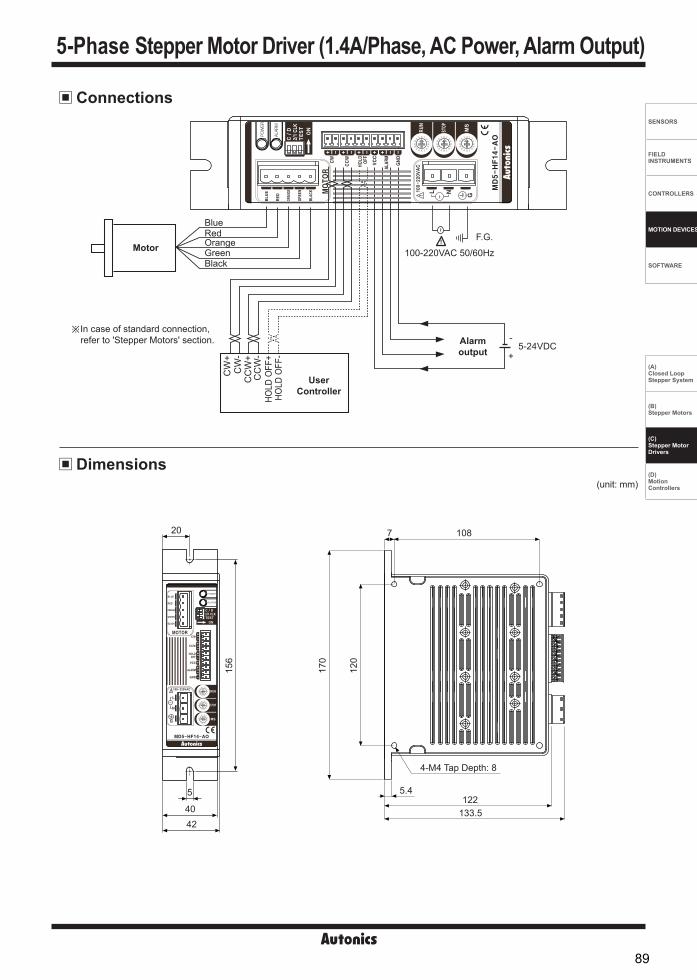
SENSORS
FIELD INSTRUMENTS
CONTROLLERS
MOTION DEVICES
SOFTWARE
(A)Closed Loop Stepper System
(B)Stepper Motors
(C)Stepper MotorDrivers
(D)Motion Controllers
-|Transparent setting guide|-
Dimensions
Connections
(unit: mm)
CW
+C
W-
CC
W+
CC
W-
HOLD
OFF
+HO
LD O
FF-
UserController
Alarm output +
-
BlackGreenOrangeRedBlue
MotorF.G.
100-220VAC 50/60Hz
5-24VDC
※In case of standard connection, refer to 'Stepper Motors' section.
20
42
5
40
156
108
122133.5
5.4
4-M4 Tap Depth: 8
7
120
170
5-Phase Stepper Motor Driver (1.4A/Phase, AC Power, Alarm Output)
89

MD5 Series-|Transparent setting guide|-
※KR-505G can be replaced with MD5-HF28. ※ Power supply 100-220VAC and socket type wire terminal blocks are
upgraded comparing to KR Series.
5-Phase Microstep Motor Driver [MD5-HF28]Resolution switch
RUN current switchSTOP current switch
Functionselection
DIP switch
Power indicatorAlarm indicator (red)
※Refer to ' Specifications'.
Unit Description
Function selection DIP switchNo. Name Function Switch position
ON OFF (default)1 TEST Self diagnosis function 30rpm rotation Not use2 2/1 CLK Pulse input method 1-pulse input method 2-pulse input method3 C/D Auto Current Down Not use Use
TEST Self diagnosis function is for motor and driver test. This function makes the motor rotate with 30rpm in full step. Rotation speed varies with resolution settings. Rotation speed = 30rpm/resolution In 1-pulse input method, it rotates to CCW, and in 2-pulse input method, it rotates to CW.
※ Be sure that the TEST switch is OFF before supplying the power. If the TEST switch is ON, the motor operates immediately and it may be dangerous.2/1 CLK 2/1 CLK switch is to select pulse input method.1-pulse input method: CW → operating rotation signal input, CCW → rotation direction signal input ([H]: CW, [L]: CCW) 2-pulse input method: CW → CW rotation signal input, CCW → CCW rotation signal input.
C/D (auto current down) This function is to reduce the current provided for motor automatically for preventing severe motor's heat when motor stops. If motor RUN pulse is not applied, the current provided for motor reduces as the set STOP current.
※Be sure that when motor RUN current is reduced, the stop torque of motor also reduced. ※ Set the STOP current by the STOP current switch.
Setting RUN currentSwitch No. 0 1 2 3 4 5 6 7 8 9 A B C D E F
Current (A/Phase) 1.14 1.25 1.36 1.50 1.63 1.74 1.86 1.97 2.10 2.20 2.30 2.40 2.50 2.60 2.78 2.88
Switch No. 0 1 2 3 4 5 6 7 8 9 A B C D E F
% 27 31 36 40 45 50 54 58 62 66 70 74 78 82 86 90
Setting RUN current is for the current provided for motor when the motor runs.※When RUN current is increased, RUN torque of the motor is also increased. ※When RUN current is set too high, the heat is severe.※Set RUN current within the range of motor's rated current according to its load. ※Change RUN current only when the motor stops.
Setting STOP current is for the current provided for motor when the motor stops for preventing severe motor's heat. This setting is applied when using C/D (current down) function. Setting value of STOP current is percentage (%) ratio of the set RUN current. E.g.) Set RUN current as 2.5A and STOP current as 40%.
STOP current is set as 2.5A×0.4=1A※When STOP current is decreased, STOP torque of the motor is also decreased. ※When STOP current is set too low, the heat is lower.※Change STOP current only when the motor stops.
Setting STOP current
Functions
5-Phase Stepper Motor Driver (2.8A/Phase, AC Power)
90

SENSORS
FIELD INSTRUMENTS
CONTROLLERS
MOTION DEVICES
SOFTWARE
(A)Closed Loop Stepper System
(B)Stepper Motors
(C)Stepper MotorDrivers
(D)Motion Controllers
-|Transparent setting guide|-
Zero point excitation output signal (ZERO OUT)CW Pulse
CCW Pulse
ZERO OUT
ONOFFON
OFF
ONOFF
0 0 01 1 12 23 4 5 6 7 8 9
Switch No. 0 1 2 3 4 5 6 7 8 9 A B C D E FResolution 1 2 4 5 8 10 16 20 25 40 50 80 100 125 200 250Step angle 0.72° 0.36° 0.18° 0.144° 0.09° 0.072° 0.045° 0.036° 0.0288° 0.018° 0.0144° 0.009° 0.0072° 0.00576° 0.0036° 0.00288°
This output indicates the initial step of excitation order of stepper motor and rotation position of motor axis. This signal outputs every 7.2° of rotation of the motor axis regardless of resolution. (50 outputs per 1 rotation of the motor.) E.g.) Full step: outputs one time by 10 pulses input, 20-division: outputs one time by 200 pulses input.
This signal is for rotating motor's axis using external force or used for manual positioning. When hold off signal maintains over 1ms as [H], motor excitation is released. When hold off signal maintains over 1ms as [L], motor excitation is in a normal status.
※Must stop the motor for using this function. ※Refer to ' I/O Circuit and Connections'.
HOLD OFF function
Setting Microstep (microstep: resolution)
Setting Resolution (same as MS1, MS2) The MS1, MS2 switches is for resolution setting. Select MS2 or MS2 by DIVISION SELECTION signal ([L]: MS1, [H]: MS2) Select the step angle (motor rotation angle per 1 pulse). The set step angle is dividing basic step angle (0.72°) of 5-phase stepper motor by setting value. The calculation formula of divided step angle is as follow.
When using geared type motor, the angle is step angle divided by gear ratio. Step angle / gear ratio = Step angle applied gear E.g) 0.72° / 10 (1:10) = 0.072°
※Must stop the motor before changing the resolution.
Set step angle = Basic step angle (0.72°)
Resolution
I/O Circuit and Connections
※This connection cable color is only for Autonics motors. It may different cable color when using other motors.
※CW 2-pulse input method (CW rotation signal input)1-pulse input method (operating rotation signal input)※CCW2-pulse input method (CCW rotation signal input)1-pulse input method (rotation direction signal input)→ [H]: CW, [L]: CCW ※HOLD OFFControl signal for motor excitation OFF→ [H]: Motor excitation OFF※DIVISION SELECTIONDivision selection signal→ [L]: Operated by switch MS1
[H]: Operated by switch MS2※ZERO OUTZero point excitation output signal → Zero point status ON※If the power for driving pulse from external is over
than +5VDC, please connect resistor at the outside.
[Signal]
[Motor]
[Power]Power
BLUE
RED
ORANGE
GREEN
BLACK
L
N100-220VAC
50/60Hz
GNDG
AC
AC
5
4
32
1
1
2
3
4
5
6
7
8
9
10
270Ω
270Ω
390Ω
390Ω
10Ω
CW
CCW
HOLDOFF
+5VDC
+5VDC
ZERO OUT
DIVISION SELECTION
2kΩ
Motor
Pentagon connection
Standard connection
Blue Gray+Red
Red Yellow+Black
Orange Orange+White
Green Brown+Green
Black Blue+Purple
Alarm indication Overheat: When the temperature of driver base is over 80, the alarm indicator (red) turns ON and motor stops with holding the excision. Overcurrent: When overcurrent occurs due to motor damage by burn, driver damage, or error, the alarm indicator (red) turns ON and the motor becomes HOLD OFF.
※Turn OFF the power and remove the causes of alarm. Re-supply the power and the alarm indicator turns OFF and the driver is normal operation.
5-Phase Stepper Motor Driver (2.8A/Phase, AC Power)
91

MD5 Series-|Transparent setting guide|-
CW
+C
W-
CC
W+
CC
W-
HO
LD O
FF+
HO
LD O
FF-
UserController
+-
+-
BlackGreenOrangeRedBlue
Motor
※In case of standard connection, refer to 'Stepper Motors' section.
Division selectionsignal
Zero point excitationoutput signal
F.G.100-220VAC 50/60Hz
Connections
Dimensions (unit: mm)
54.1
R5 146
145.3127.5 10.5
5.516
3
200
211.
5
4-Ø
6
4-R0.5Ø5
185
5
4920
92

SENSORS
FIELD INSTRUMENTS
CONTROLLERS
MOTION DEVICES
SOFTWARE
(A)Closed Loop Stepper System
(B)Stepper Motors
(C)Stepper MotorDrivers
(D)Motion Controllers
-|Transparent setting guide|-
Function selection DIP switch
5-Phase Stepper Motor Driver [MD5-ND14]
Inputterminal
STOPcurrentvolume
RUN currentvolume
Functionselection DIP switch
Powerterminal
Motorconnection
terminal
※Refer to ' Specifications'.
Unit Description
※Changing pulse input method or resolution is available only when stepper motor stops. If changing the resolution during operation, the motor may be out of phase.
ON1 2
No. Nameplate FunctionSwitch positionON OFF (default)
1 1/2 CLK Pulse input method 1-pulse input method 2-pulse input method2 FULL↔HALF Select resolution 1-division (0.72°) 2-division (0.36°)
1/2 CLK 1/2 CLK switch is to select pulse input method.1-pulse input method: CW → operating rotation signal input, CCW → rotation direction signal input ([H]: CW, [L]: CCW) 2-pulse input method: CW → CW rotation signal input, CCW → CCW rotation signal input.
FULL ↔ HALF FULL ↔ HALF switch is to set basic step angle for 5-phase stepper motor.
※Change resolution only when the motor stops.
Setting RUN current RUN CURRENT
0.5A 1.5A
1.0A Setting RUN current is for the current provided for motor when the motor runs.※When RUN current is increased, RUN torque of the motor is also increased. ※When RUN current is set too high, the heat is severe.※Set RUN current within the range of motor's rated current according to its load. ※Change RUN current only when the motor stops.
Setting STOP current
25% 75%
STOP CURRENT Setting STOP current is for the current provided for motor when the motor stops. Setting value of STOP current is percentage (%) ratio of the set RUN current. E.g.) Set RUN current as 1.4A and STOP current as 40%.
STOP current is set as 1.4A×0.4=0.56A.※When STOP current is decreased, STOP torque of the motor is also decreased. ※When STOP current is set too low, the heat is lower.※Change STOP current only when the motor stops.
This signal is for rotating motor's axis using external force or used for manual positioning. When hold off signal maintains over 1ms as [H], motor excitation is released. When hold off signal maintains over 1ms as [L], motor excitation is in a normal status.
※Must stop the motor for using this function. ※Refer to ' I/O Circuit and Connections'.
HOLD OFF function
Functions
5-Phase Stepper Motor Driver (1.5A/Phase, DC Power)
93

MD5 Series-|Transparent setting guide|-
I/O Circuit and Connections
※CW 2-pulse input method (CW rotation signal input)1-pulse input method (operating rotation signal input)
※CCW2-pulse input method (CCW rotation signal input)1-pulse input method (rotation direction signal input)→ [H]: CW, [L]: CCW
※HOLD OFFControl signal for motor excitation OFF→ [H]: Motor excitation OFF
※If the power for driving pulse from external is over than +5VDC, please connect resistor at the outside.(input voltage max. 24VDC, input current 10-20mA)
※This connection cable color is only for Autonics motors. It may different cable color when using other motors.
※In case of standard connection, refer to 'Stepper Motors' section.
+5VDC
390Ω
390Ω
390Ω
CCW
CW
+5VDC Max. 30mA output
Power 20-35VDC
6
5
4
3
1
2
+
-
GND
HOLDOFF
[Motor]
[Power]
[Signal]
1
2
3
BLUE
RED
ORANGE
GREEN
BLACK
Motor
Pentagon connection
Standard connection
Blue Gray+Red
Red Yellow+Black
Orange Orange+White
Green Brown+Green
Black Blue+Purple5
4
3
1
2
94

SENSORS
FIELD INSTRUMENTS
CONTROLLERS
MOTION DEVICES
SOFTWARE
(A)Closed Loop Stepper System
(B)Stepper Motors
(C)Stepper MotorDrivers
(D)Motion Controllers
-|Transparent setting guide|-
2-pulse input method
1-pulse input method
CW[H][L]
CCW [H][L]
Rotation position CW CCW
CW CCW
[H][L]
[L][H]
CW
CCW
Rotation position
CW
(unit: mm)
80
87
93 55.5
87
4.5 20
32
4.5
22.5
45
Time Chart
Dimensions
※ Do not input CW, CCW signals at the same time in 2-pulse input method. It may not operate properly if another direction signal is inputted when one of CW or CCW is [H].
5-Phase Stepper Motor Driver (1.5A/Phase, DC Power)
95
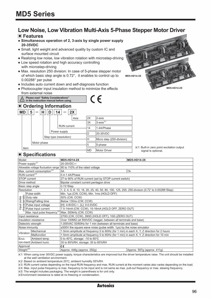
MD5 Series-|Transparent setting guide|-
MD5-HD14-3X
MD5-HD14-2X
※ 1: Built-in zero point excitation outputsignal is optional.
FeaturesLow Noise, Low Vibration Multi-Axis 5-Phase Stepper Motor Driver Simultaneous operation of 2, 3-axis by single power supply
20-35VDC Small, light weight and advanced quality by custom IC and
surface mounted circuit Realizing low noise, low vibration rotation with microstep-driving Low speed rotation and high accuracy controlling
with microstep-driving Max. resolution 250 division: In case of 5-phase stepper motor
of which basic step angle is 0.72°, it enables to control up to0.00288° per pulse
Includes auto current down and self-diagnosis function Photocoupler input insulation method to minimize the effects
from external noise
Ordering Information
SpecificationsItem
Motor phase
Step type (resolution)
Power supply
RUN current
Axis
MD 14 2X5 H D2X 2-axis3X 3-axis※ 1
14 1.4A/Phase
D 20-35VDC
H Micro step (250-division)
5 5-phase
MD Motor Driver
Model MD5-HD14-2X MD5-HD14-3XPower supply※1 20-35VDCᜡAllowable voltage fluctuation range 90 to 110% of the rated voltageMax. current consumption※2 5A 7ARUN current※3 0.4-1.4A/PhaseSTOP current 27 to 90% of RUN current (set by STOP current switch)Drive method Bipolar constant current pentagon driveBasic step angle 0.72 /StepResolution 1, 2, 4, 5, 8, 10, 16, 20, 25, 40, 50, 80, 100, 125, 200, 250-division (0.72 to 0.00288 /Step)
Inpu
t pul
se
char
acte
ristic
Pulse width Min. 1μs (CW, CCW), Min. 1ms (HOLD OFF)Duty rate 50% (CW, CCW)Rising/Falling time Below 130ns (CW, CCW)Pulse input voltage [H]: 4-8VDCᜡ, [L]: 0-0.5VDCPulse input current 7.5-14mA (CW, CCW), 10-16mA (HOLD OFF, ZERO OUT)Max. input pulse frequency※4 Max. 500kHz (CW, CCW)
Input resistance 270Ω (CW, CCW), 390Ω (HOLD OFF), 10Ω (ZERO OUT)Insulation resistance Over 100MΩ (at 500VDC megger, between all terminals and base)Dielectric strength 1,000VAC 50/60Hz for 1 min (between all terminals and base)Noise immunity ±500V the square wave noise (pulse width: 1μs) by the noise simulator
Vibration Mechanical 1.5mm amplitude at frequency 5 to 60Hz (for 1 min) in each X, Y, Z direction for 2 hoursMalfunction 1.5mm amplitude at frequency 5 to 60Hz (for 1 min) in each X, Y, Z direction for 10 min
Envi-ron-ment
Ambient temp. 0 to 40, storage: -10 to 60 Ambient humi. 35 to 85%RH, storage: 35 to 85%RH
ApprovalWeight※5 Approx. 446g (approx. 292g) Approx. 597g (approx. 411g)※1: When using over 30VDC power supply, torque characteristics are improved but the driver temperature raise. The unit should be installed
at the well ventilation environment.※2: Based on ambient temperature 25, ambient humidity 55%RH.※3: RUN current varies depending on the input RUN frequency and max. RUN current at the moment varies also varies depending on the load. ※4: Max. input pulse frequency is max. frequency to be input and is not same as max. pull-out frequency or max. slewing frequency.※5: The weight includes packaging. The weight in parenthesis is for unit only.※Environment resistance is rated at no freezing or condensation.
Please read “Safety Considerations” in the instruction manual before using.
96

SENSORS
FIELD INSTRUMENTS
CONTROLLERS
MOTION DEVICES
SOFTWARE
(A)Closed Loop Stepper System
(B)Stepper Motors
(C)Stepper MotorDrivers
(D)Motion Controllers
-|Transparent setting guide|-
Functions Function selection DIP switch
No. Name Function Switch positionON OFF (default)
1 TEST Self diagnosis function 30rpm rotation Not use2 1/2 CLK Pulse input method 1-pulse input method 2-pulse input method3 C/D Auto Current Down Not use Use
TEST Self diagnosis function is for motor and driver test. This function makes the motor rotate with 30rpm in full step. Rotation speed varies with resolution settings. Rotation speed = 30rpm/resolution In 1-pulse input method, it rotates to CCW, and in 2-pulse input method, it rotates to CW.
※ Be sure that the TEST switch is OFF before supplying the power. If the TEST switch is ON, the motor operates immediately and it may be dangerous.1/2 CLK 1/2 CLK switch is to select pulse input method.1-pulse input method: CW → operating rotation signal input, CCW → rotation direction signal input ([H]: CW, [L]: CCW) 2-pulse input method: CW → CW rotation signal input, CCW → CCW rotation signal input.
C/D (auto current down) This function is to reduce the current provided for motor automatically for preventing severe motor's heat when motor
stops. If motor RUN pulse is not applied, the current provided for motor reduces as the set STOP current.
※ Be sure that when motor RUN current is reduced, the stop torque of motor also reduced. ※ Set the STOP current by the Setting STOP current switch.
Setting RUN current
Setting RUN current is for the current provided for motor when the motor runs.※When RUN current is increased, RUN torque of the motor is also increased. ※When RUN current is set too high, the heat is severe.※Set RUN current within the range of motor's rated current according to its load. ※Change RUN current only when the motor stops.
Setting STOP current is for the current provided for motor when the motor stops. This setting is applied when using C/D (current down) function. Setting value of STOP current is percentage (%) ratio of the set RUN current. E.g.) Set RUN current as 1.4A and STOP current as 40%.
STOP current is set as 1.4A×0.4=0.56A※When STOP current is decreased, STOP torque of the motor is also decreased. ※When STOP current is set too low, the heat is lower.※Change STOP current only when the motor stops.
Setting STOP current
Zero point excitation output signal (ZERO OUT) [Option]CW Pulse
CCW Pulse
ZERO OUT
ONOFFON
OFF
ONOFF
0 0 01 1 12 23 4 5 6 7 8 9 This output indicates the initial step of excitation order of stepper motor and rotation position of motor axis. This signal outputs every 7.2° of rotation of the motor axis regardless of resolution. (50 outputs per 1 rotation of the motor.) E.g.) Full step: outputs one time by 10 pulses input,
20-division: outputs one time by 200 pulses input.
Switch No. 0 1 2 3 4 5 6 7 8 9 A B C D E F
Current (A/Phase) 0.4 0.5 0.57 0.63 0.71 0.77 0.84 0.9 0.96 1.02 1.09 1.15 1.22 1.27 1.33 1.4
Switch No. 0 1 2 3 4 5 6 7 8 9 A B C D E F
% 27 31 36 40 45 50 54 58 62 66 70 74 78 82 86 90
This signal is for rotating motor's axis using external force or used for manual positioning. When hold off signal maintains over 1ms as [H], motor excitation is released. When hold off signal maintains over 1ms as [L], motor excitation is in a normal status.
※Must stop the motor for using this function. ※Refer to ' I/O Circuit and Connections'.
HOLD OFF function
5-Phase Stepper Motor Driver (1.4A/Phase, DC Power, Multi-Axis)
97

MD5 Series-|Transparent setting guide|-
Setting Microstep (microstep: resolution)
Resolution (MS1) The set step angle is dividing basic step angle (0.72°) of 5-phase stepper motor by setting value. The calculation formula of divided step angle is as below.
When using geared type motor, the angle is step angle divided by gear ratio. Step angle/gear ratio = Step angle applied gear E.g) 0.72°/10 (1:10) = 0.072°
※Must stop the motor before changing the resolution.
Set step angle = Basic step angle (0.72°)
Resolution
I/O Circuit and Connections
※ Power input of 2/3-axis are used as same and I/O terminals are proportional to the number of axes.
※ This connection cable color is only for Autonics motors. It may different cable color when using other motors.
※ CW2-pulse input method (CW rotation signal input)1-pulse input method (operating rotation signal input)
※ CCW2-pulse input method (CCW rotation signal input)1-pulse input method (rotation direction signal input)→ [H]: CW, [L]: CCW
※ HOLD OFF Control signal for motor excitation OFF→ [H]: Motor excitation OFF
※ ZERO OUT (option) Zero point excitation output signal → Zero point status ON
※ If the power for driving pulse from external is over than +5VDC, please connect resistor at the outside.(input voltage max. 24VDC, input current 10-20mA)
※In case of standard connection, refer to 'Stepper Motors' section
Switch No. 0 1 2 3 4 5 6 7 8 9 A B C D E FResolution 1 2 4 5 8 10 16 20 25 40 50 80 100 125 200 250Step angle 0.72° 0.36° 0.18° 0.144° 0.09° 0.072° 0.045° 0.036° 0.0288° 0.018° 0.0144° 0.009° 0.0072° 0.00576° 0.0036° 0.00288°
[Signal]
[Motor]
[Power]
GND
BLUE
RED
ORANGE
GREEN
BLACK 5
4
3
2
1
1
2
3
4
5
6
7
8
270Ω
270Ω
390Ω
10Ω
CW
CCW
HOLD OFF
+5VDC
ZERO OUT
Pentagon connection
Standard connection
Blue Gray+Red
Red Yellow+Black
Orange Orange+White
Green Brown+Green
Black Blue+Purple
Power 20-35VDC
+
-
1
2
Motor
※Each axis structure is same.
MD5-HD14-3X
MD5-HD14-2X
RUN current switch
Resolutionswitch
STOP current switch
3-axis 2-axis
2-axis
1-axis
1-axis
Functionselection
DIP switch
Motor connector terminal
I/O terminal Powerterminal
Unit Description
98

SENSORS
FIELD INSTRUMENTS
CONTROLLERS
MOTION DEVICES
SOFTWARE
(A)Closed Loop Stepper System
(B)Stepper Motors
(C)Stepper MotorDrivers
(D)Motion Controllers
-|Transparent setting guide|-
Dimensions MD5-HD14-2X
MD5-HD14-3X
(unit: mm)
520
180
40
80
40
80
5
245
AccessoryConnector Qty.Manufacturer Model No. MD5-HD14-2X MD5-HD14-3X
A Power 2-wire housing
JST
VHR-2N 1 1 B Motor 5-wire housing VHR-5N 2 3 C Signal 6-wire housing XAP-06V-1 2 3 - Power/Motor terminal pin SVH-21T-P1.1 12 17- Signal terminal pin SXA -001T-P0.6 12 18
※Accessory connector specification
Time Chart1-pulse input method 2-pulse input method
CW[H][L]
CCW [H][L]
Rotation position CW CCW
CW CCW
[H][L]
[L][H]
CW
CCW
Rotation position
※ Do not input CW, CCW signals at the same time in 2-pulse input method. It may not operate properly if another direction signal is inputted when one of CW or CCW is [H].
CW
1904-M3 Tap
5 66 80
180
2-axis 1-axis ABC
260
5 66
249 4-M3 Tap
3-axis 2-axis 1-axisABC
5-Phase Stepper Motor Driver (1.4A/Phase, DC Power, Multi-Axis)
99

MD5 Series-|Transparent setting guide|-
5. For installation① The unit must be installed with heat protection.
The conditions of ②, ③ should be satisfied.(※MD5-ND14)
② In order to increase heat protection efficiency of the driver, must install the heat sink close to metal panel and keep it well-ventilated.
③Excessive heat generation may occur on driver. Keep the heat sink under 80 when installing the unit. (at over 80, forcible cooling shall be required.)
④ If the unit is installed in distribution panel, enclosed space or place with heat, it may cause product damage by heat. Install a ventilation. (only for MD5-HF28)
⑤For heat radiation of driver, install a fan as below figure. (distance between the fan and the unit: approx. within 70mm, min. airflow: 0.71m3/min at least)(only for MD5-HF28)
6. For using setting switches① Be sure that the TEST switch is OFF before supplying the power.
If the TEST switch is ON, the motor operates immediately and it may be dangerous. (except MD5-ND14)
② Do not change any setting switch during the operation or after supplying power. It may cause malfunction.
7. Autonics motor driver does not prepareprotection function for a motor.
8. This product may be used in the followingenvironments.
① Indoors② Altitude max. 2,000m③ Pollution degree 2④ Installation category Ⅱ
Cautions during Use (Common Specifications of 5-Phase Stepper Motor Driver)1. For signal input① Do not input CW, CCW signal at the same time in 2-pulse
input method. Failure to follow this instruction may result in malfunction. It may not operate properly if another direction signal is inputted when one of CW or CCW is [H].
② When the signal input voltage is exceeded the rated voltage, connect additional resistance at the outside.
2. For RUN current, STOP current setting① Set RUN current within the range of motor's rated current. Failure
to follow this instruction may result in severe heat of motor or motor damage.
② If motor stops, switching for STOP current executed by thecurrent down function. When hold off signal is [H] or current down function is OFF, the switching does not execute. (except MD5-ND14)
③ Use the power for supplying sufficient current to the motor.④Check the polarity of power before operating the unit. (only for
MD5-HD14, HD14-2X/3X, ND14)
3. For rotating motor(only for MD5-HD14, HD14-2X/3X, ND14)
①For rotating the motor when driver power turns OFF, separate the motor from the driver.
(if not, the driver power turns ON)② For rotating the motor when driver power turns ON, use Hold
OFF function.
4. For cable connection① Use twisted pair (over 0.2mm2) for the signal cable which should
be shorter than 2m.② The thickness of cable should be same or thicker than the motor
cable's when extending the motor cable. ③ Must separate between the signal cable and the power cable
over 10cm.
Air Flow
100

SENSORS
CONTROLLERS
MOTION DEVICES
SOFTWARE
(Y)Closed Loop Stepper System
(Z)Stepper Motors
(AA)Drivers
(AB)Motion Controllers
AK/AK-B Series
Dimensions
Features
Frame Size 24mm/42mm/60mm/85mm Shaft Type Motor Frame Size 42mm/60mm/85mm Built-in Brake Type Motor
Compact design and light weight with high accuracy,speed and torque
Suitable for small-sized equipment applications Frame size 42mm/60mm/85mm built-in brake
of shaft type for compact equipment (AK-B Series) Brake force is released (AK-B Series) when applying
power on brake wire Cost-effective
Frame size 24mm
Frame size 42mm
(unit: mm)
(unit: mm)
※These dimensions are for dual shaft models. Single shaft models do not include shafts indicated in the dotted lines.※For flexible coupling (ERB series) information, refer to 'ERB Series' in 'Rotary encoder'. (frame size 24mm, 48mm, 60mm (shaft type))※Brake is non-polar and be sure to observe rated excitation voltage (24VDC). (except frame size 24mm)SW1 ON: brake release / SW1 OFF: brake execute
Model L02K-S523(W) 30.504K-S525(W) 46.5
<Built-in brake type>
(unit: mm)Model LA1K-S543(W)- B 33A2K- 544(W)- B 39A3K-S545(W)- B 47
4-M2.6 TapDP 2.5
2419±0.25
AWG26UL3265
Sectioned A-A'
4.5±0.2
Min
.200
15±0.5 10±1L±1
10±0.51.5
Ø5 0 -0
.012
Ø18
0 -0.0
25
Ø5 0 -0
.012
<Standard type>
4-M3 TapDP 4.5
42 31±0.2
4.5±0.15
20±0.5 15±1L±1
15±0.25
2
AWG26UL3266
Ø5 0 -0
.012
Ø22
0 -0.0
21
Ø5 0 -0
.012
Frame size24mm 42mm 60mm 85mm
Frame size42mm Brakebuilt-in type
60mm Brakebuilt-in type
85mm Brakebuilt-in type
Ø5, 0.6m
Sectioned A-A'
A
A'
A
A'
A
A'
A
A'
SW1
20±0.5 23L±1
15±0.25
2
Ø22
0 -0.0
21
Ø50 -0
.012
Ø5, 0.6m
A
A' Ø37
Ø1.5×2-wire, 0.6m
Brake lead wire
Please read “Safety Considerations” in the instruction manual before using.
101

AK/AK-B Series
Dimensions
(unit: mm)
(unit: mm)
Model L A4K- 564(W)- B 48.5A8K- 566(W)- B 59.5A16K- 569(W)- B 89
Frame size 60mm
Frame size 85mm
<Built-in brake type>
<Built-in brake type>
(unit: mm)Model LA21K- 596(W)- B 68A41K- 599(W)- B 98A63K- 5913(W)- B 128
4-Ø4.5Hole
6050±0.3
AWG24UL3266
7.5±0
.15
7.5±0.15
90°
24±1 21±1L±1
A
A'
20±0.2520±0.25
1.5 7
Ø8 0 -0
.015
Ø36
0 -0.0
39
Ø8 0 -0
.015
4-Ø6.5Hole
85 70±0.3
13±0
.15
13±0.15
90°
AWG22UL3266
<Standard type>
<Standard type>
Ø5, 0.6m
37±1 32±1L±1
A
A'
25±0.25 25±0.252 10
Ø14
0 -0.0
18
Ø14
0 -0.0
18
Ø60
0 -0.0
46
Ø7, 0.6m
Sectioned A-A'
Sectioned A-A'
A
A'
A
A'
SW1
24±1 26.5L±1
A
A'
20±0.25
1.5 7
Ø55
Ø36
0 -0.0
39
Ø8
0 -0.0
15
Ø5, 0.6mØ1.5×2-wire, 0.6m
Brake lead wire
SW1 Ø1.5×2-wire, 0.6m
Brake lead wire
37±1 35L±1
A
A'
25±0.252 10
Ø81
Ø14
0 -0.0
18
Ø60
0 -0.0
46
Ø7, 0.6m
102

SENSORS
CONTROLLERS
MOTION DEVICES
SOFTWARE
(Y)Closed Loop Stepper System
(Z)Stepper Motors
(AA)Drivers
(AB)Motion Controllers
5-Phase Stepper Motor
Characteristic
02K-S523
A1K-S543 / A1K-S543-B
A3K-S545 / A3K-S545-B
04K-S525
A2K- 544 / A2K- 544-B
400
300
200
100
0
Torque (gf.cm)
Speed (PPS)102 103 104
Driver MD5-ND14, Power 24VDC Setting current 0.75A/Phase
Driver MD5-HD14, Power 24VDC Setting current 0.75A/Phase
Driver MD5-HF14, Power 220VAC Setting current 0.75A/Phase
fs Full Step: 3.6kpps, Half Step: 7.1kpps fs Full Step: 3.7kpps, Half Step: 7.2kpps fs Full Step: 3.8kpps, Half Step: 7.5kpps
FULL STEPHALF STEP
※fs: max. starting torque
Speed (PPS)
400
300
200
100
0102 103 104
Driver MD5-ND14, Power 24VDC Setting current 0.75A/Phase
Driver MD5-HD14, Power 24VDC Setting current 0.75A/Phase
Driver MD5-HF14, Power 220VAC Setting current 0.75A/Phase
fs Full Step: 3.1kpps, Half Step: 6.1kppsfs Full Step: 3.2kpps, Half Step: 6.3kppsfs Full Step: 3.3kpps, Half Step: 6.5kpps
FULL STEPHALF STEP
Torque (gf.cm) ※fs: max. starting torque
Speed (PPS)102 103 104
2.0
1.5
1.0
0.5
0
Driver MD5-ND14, Power 24VDC Setting current 0.75A/Phase
Driver MD5-HD14, Power 24VDC Setting current 0.75A/Phase
Driver MD5-HF14, Power 220VAC Setting current 0.75A/Phase
fs Full Step: 3.3kpps, Half Step: 6.6kppsfs Full Step: 3.4kpps, Half Step: 6.7kppsfs Full Step: 3.5kpps, Half Step: 6.8kpps
FULL STEPHALF STEP
Torque (kgf.cm) ※fs: max. starting torque
Speed (PPS)102 103 104
4
3
2
1
0
Driver MD5-ND14, Power 24VDC Setting current 0.75A/Phase
Driver MD5-HD14, Power 24VDC Setting current 0.75A/phase
Driver MD5-HF14, Power 220VAC Setting current 0.75A/phase
FULL STEPHALF STEP
Torque (kgf.cm) ※fs: max. starting torque
fs Full Step: 3.2kpps, Half Step: 6.3kppsfs Full Step: 3.3kpps, Half Step: 6.5kppsfs Full Step: 3.4kpps, Half Step: 6.7kpps
4
3
2
1
0
Speed (PPS)102 103 104
Driver MD5-ND14, Power 24VDC Setting current 0.75A/Phase
Driver MD5-HD14, Power 24VDC Setting current 0.75A/Phase
Driver MD5-HF14, Power 220VAC Setting current 0.75A/Phase
FULL STEPHALF STEP
Torque (kgf.cm) ※fs: max. starting torque
fs Full Step: 3kpps, Half Step: 5.9kppsfs Full Step: 3.1kpps, Half Step: 6.1kppsfs Full Step: 3.2kpps, Half Step: 6.4kpps
A4K- 564 / A4K-M564-B
8
6
4
2
0
Speed (PPS)102 103 104
FULL STEPHALF STEP
Torque (kgf.cm) ※fs: max. starting torque
fs Full Step: 2.7kpps, Half Step: 5.3kppsfs Full Step: 2.7kpps, Half Step: 5.8kppsfs Full Step: 3.7kpps, Half Step: 7.2kppsfs Full Step: 3.4kpps, Half Step: 6.8kpps
Driver MD5-ND14, Power 24VDC Setting current 1.4A/Phase
Driver MD5-HD14, Power 24VDC Setting current 1.4A/Phase
Driver MD5-HF14, Power 220VAC Setting current 1.4A/Phase
Driver MD5-HF28, Power 220VAC Setting current 2.8A/Phase
103

AK/AK-B Series
Characteristic
A21K- 596 / A21K- 596-B
A63K- 5913 / A63K- 5913-B
A16K- 569 / A16K- 569-B
A41K- 599 / A41K- 599-B
20
15
10
5
0Speed (PPS)
102 103 104
Driver MD5-ND14, Power 24VDC, Setting current 1.4A/PhaseDriver MD5-HD14, Power 24VDC, Setting current 1.4A/PhaseDriver MD5-HF14, Power 220VAC, Setting current 1.4A/PhaseDriver MD5-HF28, Power 220VAC, Setting current 2.8A/Phase
FULL STEPHALF STEP
Torque (kgf.cm) ※fs: max. starting torque
fs Full Step: 1.8kpps, Half Step: 3.5kppsfs Full Step: 1.9kpps, Half Step: 3.5kppsfs Full Step: 2.6kpps, Half Step: 5.2kppsfs Full Step: 3.4kpps, Half Step: 6.8kpps
40
30
20
10
0Speed (PPS)
102 103 104
Driver MD5-ND14, Power 24VDC Setting current 1.4A/Phase
Driver MD5-HD14, Power 24VDC Setting current 1.4A/Phase
Driver MD5-HF14, Power 220VAC Setting current 1.4A/Phase
Driver MD5-HF28, Power 220VAC Setting current 2.8A/Phase
FULL STEPHALF STEP
Torque (kgf.cm) ※fs: max. starting torque
fs Full Step: 1.5kpps, Half Step: 2.9kppsfs Full Step: 1.6kpps, Half Step: 3.1kppsfs Full Step: 2.2kpps, Half Step: 4.4kppsfs Full Step: 2.3kpps, Half Step: 4.6kpps
80
60
40
20
0
Speed (PPS)102 103 104
Driver MD5-ND14, Power 24VDC Setting current 1.4A/Phase
Driver MD5-HD14, Power 24VDC Setting current 1.4A/Phase
Driver MD5-HF14, Power 220VAC Setting current 1.4A/Phase
Driver MD5-HF28, Power 220VAC Setting current 2.8A/Phase
FULL STEPHALF STEP
Torque (kgf.cm) ※fs: max. starting torque
fs Full Step: 1.4kpps, Half Step: 2.7kppsfs Full Step: 1.5kpps, Half Step: 2.9kppsfs Full Step: 1.8kpps, Half Step: 3.6kppsfs Full Step: 2.1kpps, Half Step: 4.3kpps
80
60
40
20
0
Speed (PPS)102 103 104
FULL STEPHALF STEP
Torque (kgf.cm) ※fs: max. starting torque
Driver MD5-ND14, Power 24VDC, Setting current 1.4A/PhaseDriver MD5-HD14, Power 24VDC, Setting current 1.4A/PhaseDriver MD5-HF14, Power 220VAC, Setting current 1.4A/PhaseDriver MD5-HF28, Power 220VAC, Setting current 2.8A/Phasefs Full Step: 1kpps, Half Step: 2.1kppsfs Full Step: 1.1kpps, Half Step: 2.2kppsfs Full Step: 1.8kpps, Half Step: 3.6kppsfs Full Step: 1.9kpps, Half Step: 3.8kpps
A8K- 566 / A8K-M566-B
16
12
8
4
0
Speed (PPS)102 103 104
Driver MD5-ND14, Power 24VDC Setting current 1.4A/Phase
Driver MD5-HD14, Power 24VDC Setting current 1.4A/Phase
Driver MD5-HF14, Power 220VAC Setting current 1.4A/Phase
Driver MD5-HF28, Power 220VAC Setting current 2.8A/Phase
FULL STEPHALF STEP
Torque (kgf.cm) ※fs: max. starting torque
fs Full Step: 2.1kpps, Half Step: 4.1kppsfs Full Step: 2.1kpps, Half Step: 4.2kppsfs Full Step: 3.2kpps, Half Step: 6.3kppsfs Full Step: 3.3kpps, Half Step: 6.6kpps
104

SENSORS
CONTROLLERS
MOTION DEVICES
SOFTWARE
(Y)Closed Loop Stepper System
(Z)Stepper Motors
(AA)Drivers
(AB)Motion Controllers
AK/AK-B Series
Dimensions
Features
Frame Size 24mm/42mm/60mm/85mm Shaft Type Motor Frame Size 42mm/60mm/85mm Built-in Brake Type Motor
Compact design and light weight with high accuracy,speed and torque
Suitable for small-sized equipment applications Frame size 42mm/60mm/85mm built-in brake
of shaft type for compact equipment (AK-B Series) Brake force is released (AK-B Series) when applying
power on brake wire Cost-effective
Frame size 24mm
Frame size 42mm
(unit: mm)
(unit: mm)
※These dimensions are for dual shaft models. Single shaft models do not include shafts indicated in the dotted lines.※For flexible coupling (ERB series) information, refer to 'ERB Series' in 'Rotary encoder'. (frame size 24mm, 48mm, 60mm (shaft type))※Brake is non-polar and be sure to observe rated excitation voltage (24VDC). (except frame size 24mm)SW1 ON: brake release / SW1 OFF: brake execute
Model L02K-S523(W) 30.504K-S525(W) 46.5
<Built-in brake type>
(unit: mm)Model LA1K-S543(W)- B 33A2K- 544(W)- B 39A3K-S545(W)- B 47
4-M2.6 TapDP 2.5
2419±0.25
AWG26UL3265
Sectioned A-A'
4.5±0.2
Min
.200
15±0.5 10±1L±1
10±0.51.5
Ø5 0 -0
.012
Ø18
0 -0.0
25
Ø5 0 -0
.012
<Standard type>
4-M3 TapDP 4.5
42 31±0.2
4.5±0.15
20±0.5 15±1L±1
15±0.25
2
AWG26UL3266
Ø5 0 -0
.012
Ø22
0 -0.0
21
Ø5 0 -0
.012
Frame size24mm 42mm 60mm 85mm
Frame size42mm Brakebuilt-in type
60mm Brakebuilt-in type
85mm Brakebuilt-in type
Ø5, 0.6m
Sectioned A-A'
A
A'
A
A'
A
A'
A
A'
SW1
20±0.5 23L±1
15±0.25
2
Ø22
0 -0.0
21
Ø50 -0
.012
Ø5, 0.6m
A
A' Ø37
Ø1.5×2-wire, 0.6m
Brake lead wire
Please read “Safety Considerations” in the instruction manual before using.
105

AK/AK-B Series
Dimensions
(unit: mm)
(unit: mm)
Model L A4K- 564(W)- B 48.5A8K- 566(W)- B 59.5A16K- 569(W)- B 89
Frame size 60mm
Frame size 85mm
<Built-in brake type>
<Built-in brake type>
(unit: mm)Model LA21K- 596(W)- B 68A41K- 599(W)- B 98A63K- 5913(W)- B 128
4-Ø4.5Hole
6050±0.3
AWG24UL3266
7.5±0
.15
7.5±0.15
90°
24±1 21±1L±1
A
A'
20±0.2520±0.25
1.5 7
Ø8 0 -0
.015
Ø36
0 -0.0
39
Ø8 0 -0
.015
4-Ø6.5Hole
85 70±0.3
13±0
.15
13±0.15
90°
AWG22UL3266
<Standard type>
<Standard type>
Ø5, 0.6m
37±1 32±1L±1
A
A'
25±0.25 25±0.252 10
Ø14
0 -0.0
18
Ø14
0 -0.0
18
Ø60
0 -0.0
46
Ø7, 0.6m
Sectioned A-A'
Sectioned A-A'
A
A'
A
A'
SW1
24±1 26.5L±1
A
A'
20±0.25
1.5 7
Ø55
Ø36
0 -0.0
39
Ø8
0 -0.0
15
Ø5, 0.6mØ1.5×2-wire, 0.6m
Brake lead wire
SW1 Ø1.5×2-wire, 0.6m
Brake lead wire
37±1 35L±1
A
A'
25±0.252 10
Ø81
Ø14
0 -0.0
18
Ø60
0 -0.0
46
Ø7, 0.6m
106

SENSORS
CONTROLLERS
MOTION DEVICES
SOFTWARE
(Y)Closed Loop Stepper System
(Z)Stepper Motors
(AA)Drivers
(AB)Motion Controllers
5-Phase Stepper Motor
Characteristic
02K-S523
A1K-S543 / A1K-S543-B
A3K-S545 / A3K-S545-B
04K-S525
A2K- 544 / A2K- 544-B
400
300
200
100
0
Torque (gf.cm)
Speed (PPS)102 103 104
Driver MD5-ND14, Power 24VDC Setting current 0.75A/Phase
Driver MD5-HD14, Power 24VDC Setting current 0.75A/Phase
Driver MD5-HF14, Power 220VAC Setting current 0.75A/Phase
fs Full Step: 3.6kpps, Half Step: 7.1kpps fs Full Step: 3.7kpps, Half Step: 7.2kpps fs Full Step: 3.8kpps, Half Step: 7.5kpps
FULL STEPHALF STEP
※fs: max. starting torque
Speed (PPS)
400
300
200
100
0102 103 104
Driver MD5-ND14, Power 24VDC Setting current 0.75A/Phase
Driver MD5-HD14, Power 24VDC Setting current 0.75A/Phase
Driver MD5-HF14, Power 220VAC Setting current 0.75A/Phase
fs Full Step: 3.1kpps, Half Step: 6.1kppsfs Full Step: 3.2kpps, Half Step: 6.3kppsfs Full Step: 3.3kpps, Half Step: 6.5kpps
FULL STEPHALF STEP
Torque (gf.cm) ※fs: max. starting torque
Speed (PPS)102 103 104
2.0
1.5
1.0
0.5
0
Driver MD5-ND14, Power 24VDC Setting current 0.75A/Phase
Driver MD5-HD14, Power 24VDC Setting current 0.75A/Phase
Driver MD5-HF14, Power 220VAC Setting current 0.75A/Phase
fs Full Step: 3.3kpps, Half Step: 6.6kppsfs Full Step: 3.4kpps, Half Step: 6.7kppsfs Full Step: 3.5kpps, Half Step: 6.8kpps
FULL STEPHALF STEP
Torque (kgf.cm) ※fs: max. starting torque
Speed (PPS)102 103 104
4
3
2
1
0
Driver MD5-ND14, Power 24VDC Setting current 0.75A/Phase
Driver MD5-HD14, Power 24VDC Setting current 0.75A/phase
Driver MD5-HF14, Power 220VAC Setting current 0.75A/phase
FULL STEPHALF STEP
Torque (kgf.cm) ※fs: max. starting torque
fs Full Step: 3.2kpps, Half Step: 6.3kppsfs Full Step: 3.3kpps, Half Step: 6.5kppsfs Full Step: 3.4kpps, Half Step: 6.7kpps
4
3
2
1
0
Speed (PPS)102 103 104
Driver MD5-ND14, Power 24VDC Setting current 0.75A/Phase
Driver MD5-HD14, Power 24VDC Setting current 0.75A/Phase
Driver MD5-HF14, Power 220VAC Setting current 0.75A/Phase
FULL STEPHALF STEP
Torque (kgf.cm) ※fs: max. starting torque
fs Full Step: 3kpps, Half Step: 5.9kppsfs Full Step: 3.1kpps, Half Step: 6.1kppsfs Full Step: 3.2kpps, Half Step: 6.4kpps
A4K- 564 / A4K-M564-B
8
6
4
2
0
Speed (PPS)102 103 104
FULL STEPHALF STEP
Torque (kgf.cm) ※fs: max. starting torque
fs Full Step: 2.7kpps, Half Step: 5.3kppsfs Full Step: 2.7kpps, Half Step: 5.8kppsfs Full Step: 3.7kpps, Half Step: 7.2kppsfs Full Step: 3.4kpps, Half Step: 6.8kpps
Driver MD5-ND14, Power 24VDC Setting current 1.4A/Phase
Driver MD5-HD14, Power 24VDC Setting current 1.4A/Phase
Driver MD5-HF14, Power 220VAC Setting current 1.4A/Phase
Driver MD5-HF28, Power 220VAC Setting current 2.8A/Phase
107

AK/AK-B Series
Characteristic
A21K- 596 / A21K- 596-B
A63K- 5913 / A63K- 5913-B
A16K- 569 / A16K- 569-B
A41K- 599 / A41K- 599-B
20
15
10
5
0Speed (PPS)
102 103 104
Driver MD5-ND14, Power 24VDC, Setting current 1.4A/PhaseDriver MD5-HD14, Power 24VDC, Setting current 1.4A/PhaseDriver MD5-HF14, Power 220VAC, Setting current 1.4A/PhaseDriver MD5-HF28, Power 220VAC, Setting current 2.8A/Phase
FULL STEPHALF STEP
Torque (kgf.cm) ※fs: max. starting torque
fs Full Step: 1.8kpps, Half Step: 3.5kppsfs Full Step: 1.9kpps, Half Step: 3.5kppsfs Full Step: 2.6kpps, Half Step: 5.2kppsfs Full Step: 3.4kpps, Half Step: 6.8kpps
40
30
20
10
0Speed (PPS)
102 103 104
Driver MD5-ND14, Power 24VDC Setting current 1.4A/Phase
Driver MD5-HD14, Power 24VDC Setting current 1.4A/Phase
Driver MD5-HF14, Power 220VAC Setting current 1.4A/Phase
Driver MD5-HF28, Power 220VAC Setting current 2.8A/Phase
FULL STEPHALF STEP
Torque (kgf.cm) ※fs: max. starting torque
fs Full Step: 1.5kpps, Half Step: 2.9kppsfs Full Step: 1.6kpps, Half Step: 3.1kppsfs Full Step: 2.2kpps, Half Step: 4.4kppsfs Full Step: 2.3kpps, Half Step: 4.6kpps
80
60
40
20
0
Speed (PPS)102 103 104
Driver MD5-ND14, Power 24VDC Setting current 1.4A/Phase
Driver MD5-HD14, Power 24VDC Setting current 1.4A/Phase
Driver MD5-HF14, Power 220VAC Setting current 1.4A/Phase
Driver MD5-HF28, Power 220VAC Setting current 2.8A/Phase
FULL STEPHALF STEP
Torque (kgf.cm) ※fs: max. starting torque
fs Full Step: 1.4kpps, Half Step: 2.7kppsfs Full Step: 1.5kpps, Half Step: 2.9kppsfs Full Step: 1.8kpps, Half Step: 3.6kppsfs Full Step: 2.1kpps, Half Step: 4.3kpps
80
60
40
20
0
Speed (PPS)102 103 104
FULL STEPHALF STEP
Torque (kgf.cm) ※fs: max. starting torque
Driver MD5-ND14, Power 24VDC, Setting current 1.4A/PhaseDriver MD5-HD14, Power 24VDC, Setting current 1.4A/PhaseDriver MD5-HF14, Power 220VAC, Setting current 1.4A/PhaseDriver MD5-HF28, Power 220VAC, Setting current 2.8A/Phasefs Full Step: 1kpps, Half Step: 2.1kppsfs Full Step: 1.1kpps, Half Step: 2.2kppsfs Full Step: 1.8kpps, Half Step: 3.6kppsfs Full Step: 1.9kpps, Half Step: 3.8kpps
A8K- 566 / A8K-M566-B
16
12
8
4
0
Speed (PPS)102 103 104
Driver MD5-ND14, Power 24VDC Setting current 1.4A/Phase
Driver MD5-HD14, Power 24VDC Setting current 1.4A/Phase
Driver MD5-HF14, Power 220VAC Setting current 1.4A/Phase
Driver MD5-HF28, Power 220VAC Setting current 2.8A/Phase
FULL STEPHALF STEP
Torque (kgf.cm) ※fs: max. starting torque
fs Full Step: 2.1kpps, Half Step: 4.1kppsfs Full Step: 2.1kpps, Half Step: 4.2kppsfs Full Step: 3.2kpps, Half Step: 6.3kppsfs Full Step: 3.3kpps, Half Step: 6.6kpps
108

SENSORS
CONTROLLERS
MOTION DEVICES
SOFTWARE
(Y)Closed Loop Stepper System
(Z)Stepper Motors
(AA)Drivers
(AB)Motion Controllers
AHK Series
Frame size 42mm 60mm 85mm
4-M3 TapDepth 4.5
Taper 1/5(11.421186˚)
Taper 1/5(11.421186˚)
4-Ø4.5 Hole
428.5
3.5
7.5 1.5
7
10 10
7
8
60
31±0.2
50±0.3
Ø7.
4
Ø11
Ø9.
2
Ø6.
2
Min. 600
Min. 600
AB
B
A
AWG26
AWG24
UL3266
UL3266
Taper 1/5(11.421186˚)
4-Ø6.5 Hole
9
15 18
1085
70±0.3
Ø14
.8
Min. 600
B
A
AWG22UL3266
FeaturesFrame Size 42mm/60mm/85mm Hollow Shaft Type Motor
Removable coupling connecting Ball-screw,TM-screw directly
Remove resonance (vibration, noise) without coupling Compact design and light weight with high accuracy,
speed and torque Suitable for small-sized equipment applications Cost-effective
Dimensions
(unit: mm)
(unit: mm)
(unit: mm)
Model A BAH1K-S543- 33 38AH2K-S544- 39 44AH3K-S545- 47 52
Model A BAH4K- 564(W)- 48.5 49.3AH8K- 566(W)- 59.5 60.3AH16K- 569(W)- 89 89.8
Model A BAH21K- 596(W)- 68 73AH41K- 599(W)- 98 102.5AH63K- 5913(W)- 128 133
Frame size 60mm
Frame size 42mm Hole dimensions
Hole dimensions
Hole dimensions Frame size 85mm
※Depending on processing of shaft to be assembled, hollow shaft type can be used both single and dual shaft.
Ø12
.2+
0.2
0
Ø9+
0.01
5 0
Ø10
+ 0.
015
0
Ø10
.2+
0.1
0
Ø16
.2+
0.1
0
Ø60
- 0.0
1- 0
.04
Ø6+
0.01
5 0
Ø28
- 0.0
1- 0
.021
Ø36
- 0.0
1- 0
.025
Ø36
- 0.0
1- 0
.025
8.7
Please read “Safety Considerations” in the instruction manual before using.
109

AHK Series
Characteristic
2.0 4 4
20168
40 80 80
1.5 3 3
15126
30 60 60
1.0 2 2
1084
20 40 40
0.5 1 1
542
10 20 20
0 0 0
000
0 0 0
AH1K-S543-
AH4K-S(M) 564(W)-
AH21K-M(G) 596(W)-
AH2K-S544-
AH8K-S(M) 566(W)-
AH41K-M(G) 599(W)-
AH3K-S545-
AH16K-M(G) 569(W)-
AH63K-M(G)5913(W)-
Speed (PPS)
Speed (PPS) Speed (PPS) Speed (PPS)
Speed (PPS)
Speed (PPS)
Speed (PPS)
Speed (PPS)
Speed (PPS)
102
102 102 102
102
102
102
102
102
103
103 103 103
103
103
103
103
103
104
104 104 104
104
104
104
104
104
Torque (kgf·cm)
Torque (kgf·cm)
Torque (kgf·cm) Torque (kgf·cm)
Torque (kgf·cm)
Torque (kgf·cm) Torque (kgf·cm)
Torque (kgf·cm)
Torque (kgf·cm)
※fs : Max. starting torque
※fs : Max. starting torque ※fs : Max. starting torque
※fs : Max. starting torque ※fs : Max. starting torque ※fs : Max. starting torque
※fs : Max. starting torque
※fs : Max. starting torque※fs : Max. starting torque
① Driver MD5-ND14, Power 24VDC Setting current 0.75A/Phase② Driver MD5-HD14, Power 24VDC Setting current 0.75A/Phase③ Driver MD5-HF14, Power 220VAC Setting current 0.75A/Phase
① Driver MD5-ND14, Power 24VDC Setting current 0.75A/Phase② Driver MD5-HD14, Power 24VDC Setting current 0.75A/Phase③ Driver MD5-HF14, Power 220VAC Setting current 0.75A/Phase
① Driver MD5-ND14, Power 24VDC Setting current 0.75A/Phase② Driver MD5-HD14, Power 24VDC Setting current 0.75A/Phase③ Driver MD5-HF14, Power 220VAC Setting current 0.75A/Phase
① Driver MD5-ND14, Power 24VDC Setting current 1.4A/Phase② Driver MD5-HD14, Power 24VDC Setting current 1.4A/Phase③ Driver MD5-HF14, Power 220VAC Setting current 1.4A/Phase
① Driver MD5-ND14, Power 24VDC Setting current 1.4A/Phase② Driver MD5-HD14, Power 24VDC
Setting current 1.4A/Phase③ Driver MD5-HF14, Power 220VAC
Setting current 1.4A/Phase④ Driver MD5-HF28, Power 220VAC Setting current 2.8A/Phase
① Driver MD5-ND14, Power 24VDC Setting current 1.4A/Phase② Driver MD5-HD14, Power 24VDC
Setting current 1.4A/Phase③ Driver MD5-HF14, Power 220VAC
Setting current 1.4A/Phase④ Driver MD5-HF28, Power 220VAC Setting current 2.8A/Phase
① Driver MD5-ND14, Power 24VDC Setting current 1.4A/Phase② Driver MD5-HD14, Power 24VDC Setting current 1.4A/Phase③ Driver MD5-HF14, Power 220VAC Setting current 1.4A/Phase
① fs Full Step: 3.3kpps, Half Step: 6.6kpps② fs Full Step: 3.4kpps, Half Step: 6.7kpps③ fs Full Step: 3.5kpps, Half Step: 6.8kpps
① fs Full Step: 3.2kpps, Half Step: 6.3kpps② fs Full Step: 3.3kpps, Half Step: 6.5kpps③ fs Full Step: 3.4kpps, Half Step: 6.7kpps
① fs Full Step: 3kpps, Half Step: 5.9kpps② fs Full Step: 3.1kpps, Half Step: 6.1kpps③ fs Full Step: 3.2kpps, Half Step: 6.4kpps
① Driver MD5-ND14, Power 24VDC, Setting current 1.4A/Phase② Driver MD5-HD14, Power 24VDC, Setting current 1.4A/Phase③ Driver MD5-HF14, Power 220VAC, Setting current 1.4A/Phase④ Driver MD5-HF28, Power 220VAC, Setting current 2.8A/Phase
① Driver MD5-ND14, Power 24VDC, Setting current 1.4A/Phase② Driver MD5-HD14, Power 24VDC, Setting current 1.4A/Phase③ Driver MD5-HF14, Power 220VAC, Setting current 1.4A/Phase④ Driver MD5-HF28, Power 220VAC, Setting current 2.8A/Phase
① fs Full Step: 1.8kpps, Half Step: 3.5kpps② fs Full Step: 1.9kpps, Half Step: 3.5kpps③ fs Full Step: 2.6kpps, Half Step: 5.2kpps④ fs Full Step: 3.4kpps, Half Step: 6.8kpps
① fs Full Step: 1kpps, Half Step: 2.1kpps② fs Full Step: 1.1kpps, Half Step: 2.2kpps③ fs Full Step: 1.8kpps, Half Step: 3.6kpps④ fs Full Step: 1.9kpps, Half Step: 3.8kpps
① fs Full Step: 1.4kpps, Half Step: 2.7kpps② fs Full Step: 1.5kpps, Half Step: 2.9kpps③ fs Full Step: 1.8kpps, Half Step: 3.6kpps④ fs Full Step: 2.1kpps, Half Step: 4.3kpps
① fs Full Step: 1.5kpps, Half Step: 2.9kpps② fs Full Step: 1.6kpps, Half Step: 3.1kpps③ fs Full Step: 2.2kpps, Half Step: 4.4kpps④ fs Full Step: 2.3kpps, Half Step: 4.6kpps
FULL STEPHALF STEP
FULL STEPHALF STEP
FULL STEPHALF STEP
FULL STEPHALF STEP
FULL STEPHALF STEP
FULL STEPHALF STEP
FULL STEPHALF STEP
FULL STEPHALF STEP
FULL STEPHALF STEP
③
③ ③
③
③③
③
③③
①
①①
①
①
①①
① ①
④④
④
④
②
② ②
②
②
②②
②②
① fs Full Step: 2.7kpps, Half Step: 5.3kpps② fs Full Step: 2.7kpps, Half Step: 5.8kpps③ fs Full Step: 3.7kpps, Half Step: 7.2kpps
① fs Full Step: 2.1kpps, Half Step: 4.1kpps② fs Full Step: 2.1kpps, Half Step: 4.2kpps③ fs Full Step: 3.2kpps, Half Step: 6.3kpps
110

SENSORS
CONTROLLERS
MOTION DEVICES
SOFTWARE
(Y)Closed Loop Stepper System
(Z)Stepper Motors
(AA)Drivers
(AB)Motion Controllers
5-Phase Stepper Motor
Taper 1/5
Taper 1/5
Taper 1/5
Taper 1/5
Taper 1/5
Taper 1/5
7
7
7
10
10
15.5
10
10
15
15
12
12
20
32.5
8.520
R1
R1
22
4
4
A
A
A
A
A
A
M6×0.5
M6×0.5
M9×0.5
M10×0.5
M5×0.8
M6×1.0
O.D 5.8
O.D 5.8
O.D 8.8
O.D 9.8
DP 8
DP 10
Ø6.
2Ø
6.2
Ø9.
2Ø
9.2
Ø12
Ø12
Ø5.
8Ø
5.8
Ø8.
8
Ø8.
8
Ø9.
8
Ø9.
8
Processing Example for Shaft Assembly
(unit: mm)
(unit: mm)
※Lock nut is included.
※Lock nut is included.
※Lock nut is included.
※Lock nut is included.
Model AAH1K-S543- 42.5AH2K-S544- 48.5AH3K-S545- 56.5
(unit: mm)Model AAH1K- 543W- 42.5AH2K- 544W- 48.5AH3K- 545W- 56.5
(unit: mm)
※ Hexagon wrench bolt, flatwasher, spring washer andlock washer are included.
※ Hexagon wrench bolt, flatwasher, spring washer andlock washer are included.
Model AAH4K- 564- 46AH8K- 566- 57AH16K- 569- 86.5
(unit: mm)Model AAH4K- 564W- 56.5AH8K- 566W- 67.5AH16K- 569W- 97
Model AAH21K- 596- 64.5AH41K- 599- 94AH63K- 5913- 124.5
(unit: mm)
(unit: mm)Model AAH21K- 596W- 79.5AH41K- 599W- 109.5AH63K- 5913W- 139.5
Single shaft type of frame size 42mm
Dual shaft type of frame size 42mm
Dual shaft type of frame size 60mm
Single shaft type of frame size 60mm
Single shaft type of frame size 85mm
Dual shaft type of frame size 85mm
In order to assemble external shafts into Autonics motors, the shafts must be processed as shown in the figures below.Ø
7.6
0 - 0.0
5Ø
7.6
0 - 0.0
5Ø
11.2
0 - 0.0
5Ø
11.2
0 - 0.0
5Ø
15 0 - 0
.015
Ø15
0 - 0.0
15
Ø6
0 -0.0
15Ø
60 -0.0
15
Ø9
0 -0.0
15Ø
90 -0.0
15
Ø10
0 -0.0
15Ø
100 -0.0
15
Ø5
0.0
1- 0
.02
Ø8- 0
.01
- 0.0
25
Ø8- 0
.01
- 0.0
2
111

AK-G/AK-GB/AK-R/AK-RB Series
Frame Size 42mm/60mm/85mm Geared Type /Geared+Built-in Brake Type Motor Frame Size 60mm Rotary Actuator Type /Rotary Actuator+Built-in Brake Type Motor
Frame size 42mm
<Geared+built-in brake type>
Dimensions
Features Compact design and light weight with high accuracy,
speed and torque Cost-effective Backlash
Frame size 42mm: ±35' (0.58°),60mm: ±20' (0.33°), 85mm: ±15' (0.25°)
Brake force is released when applying 24VDCon brake wire
Basic step angle1:5→ 0.144°, 1:7.2→ 0.1°, 1:10→ 0.072°
Allowable speed1:5→ 0 to 360rpm, 1:7.2→ 0 to 250rpm1:10→ 0 to 180rpm
42mm Geared type
Frame size
Frame size
Frame size
42mm Geared+Built-in brake type
60mm Geared type
60mm Rotary Actuator type
60mm Geared+Built-in brake type
85mmGeared type
85mm Geared+Built-in brake type
60mm Rotary Actuator+Built-in brake type
SW1
※These dimensions are for dual shaft models. Single shaft models do not include shafts indicated in the dotted lines.※For flexible coupling (ERB series) information, refer to 'ERB Series' in 'Rotary encoder'.
(frame size 60mm, 85mm: geared type, geared+built-in brake type)※Brake is non-polar and be sure to observe rated excitation voltage (24VDC). ※SW1 ON: brake release / SW1 OFF: brake execute
42
4-M4 Tap 31±0.2
AWG26UL3266
DP 8
(unit: mm)
<Geared type>
7
Sectioned A-A'
4.5
Sectioned B-B'
28±1
74.512 1089.5
15±1
Ø26
- 0.0
1- 0
.02
Ø8
- 0.0
1- 0
.015 Ø
15- 0
.003
- 0.0
08
Ø5, 0.6m
A
A'
B
B'
55.5
12
0.5
10
7
27.5
2347±1
Ø37
Ø25
.5
Ø1.5×2-wire, 0.6mØ5, 0.6m
Ø26
-0.0
1-0
.02
Ø8
-0.0
1-0
.015
Brake lead wire
A
A'
Please read “Safety Considerations” in the instruction manual before using.
112

SENSORS
CONTROLLERS
MOTION DEVICES
SOFTWARE
(Y)Closed Loop Stepper System
(Z)Stepper Motors
(AA)Drivers
(AB)Motion Controllers
5-Phase Stepper Motor
Dimensions (unit: mm)
<Rotary actuator+built-in brake type>
<Rotary actuator type>
Frame size 60mm
Sectioned B-B'
7.5±0
.15
7.5±0.15
90°
60Ø
55
Ø82
0
-0.0
35
3.2 33
47.534
10 59.5±1 26.5
Ø5, 0.6m Ø1.5, 0.6m
Ø43
+0.0
18
0
Ø44
0
-0.0
25
Ø60
0
-0.0
25
Brake lead wire
SW1
604-M5 Tap
Ø70±0.5
AWG24UL3266
DP 10
<Geared type>
Sectioned A-A'
4 0 -0.03
2.5 +
0.1
0
Sectioned B-B'
7.5±0
.15
7.5±0.15
90°
25±0.2
Parallel key
4 0 -0.03
4 0 -0.
03
<Geared+built-in brake type>
38±1 35
25 10
59.5±1 21±1
20±0.25
B'
B
Ø37
0 -0.
025
Ø12
0 -0.
018 Ø8
0
- 0
.015
SW1
Ø5, 0.6m
59.5±1
Brake lead wire
38±1
25 1035 26.5±1
Ø55
Ø37
0 -0.0
25
Ø12
0 -0.0
18
Ø1.5×2-wire, 0.6mØ5, 0.6m
A
A'
A
A'
4-M5 Hole P.C.D. 72
4-M4 Tap DP 6P.C.D. 19
4-M4 Tap DP 8P.C.D. 53
R15±0.01
Ø13 HoleDP 3.5
0-0.018
DP 3Ø3+0.01
0 Hole
4-M4 Hole P.C.D. 70
60
Ø82
0 -0.0
35
3.2 3
3 34
10 59.5±1
47.5
21±1
20±0.25
Ø5, 0.6m
Ø43
+0.0
18 0
Ø44
0 -0.0
25
Ø60
0 -0.0
25 Ø8
0 -0.01
5
B
B'
113
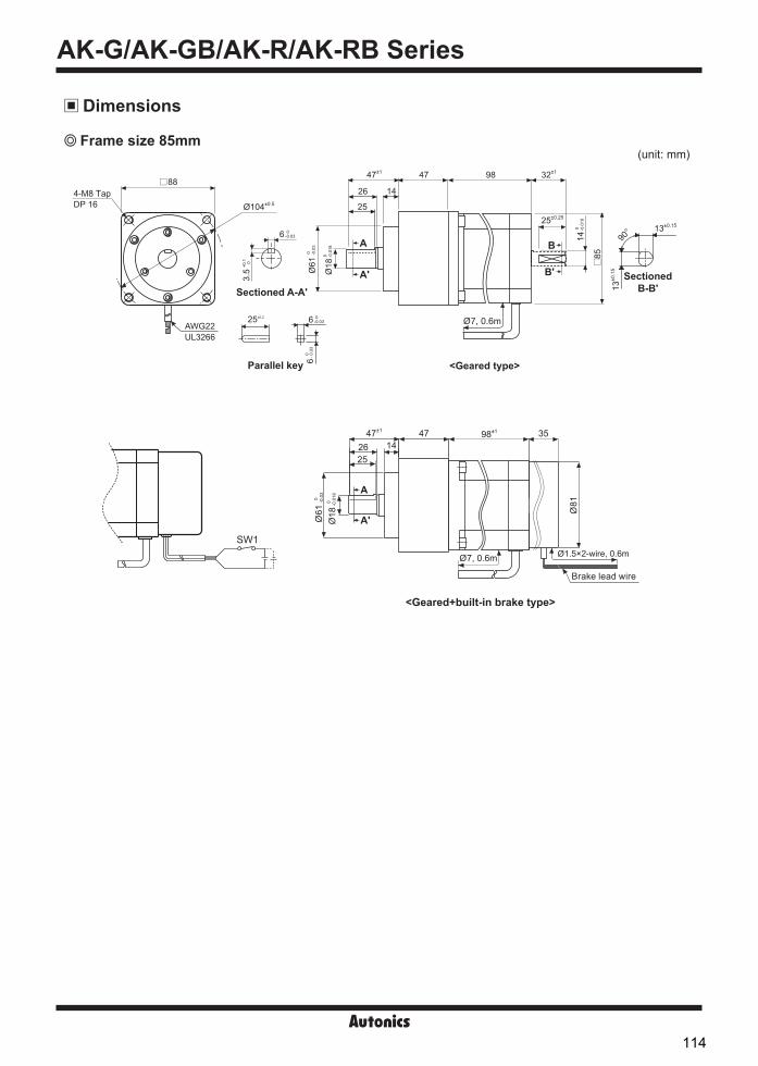
AK-G/AK-GB/AK-R/AK-RB Series
(unit: mm) Frame size 85mm
88
85
4-M8 TapØ104±0.5
47±1 47
25
26 14
98 32±1
25±0.25
AWG22UL3266
DP 16
<Geared type>
<Geared+built-in brake type>
14 0
-0.
018
Ø18
0 -0.
018
Ø61
0 -
0.03
SectionedB-B'13
±0.1
5
13±0.15
90°
Sectioned A-A'
6 0 -0.03
3.5
+0.1
0
25±0.2
Parallel key 6 0
- 0
.03
6 0 -0.03
SW1
Ø7, 0.6m
Dimensions
98±1
Ø61
0 -0.0
3
47±1
2625
1447 35
Ø18
0 -0.0
18
Ø81
Ø7, 0.6m Ø1.5×2-wire, 0.6m
Brake lead wire
B
B'
A
A'
A
A'
114

SENSORS
CONTROLLERS
MOTION DEVICES
SOFTWARE
(Y)Closed Loop Stepper System
(Z)Stepper Motors
(AA)Drivers
(AB)Motion Controllers
5-Phase Stepper Motor
20 20
15 15
10 10
20
15
10
5
40
30
20
10
40
30
20
10
50
150 250 250
40
120 200 200
20
60 100 100
30
90 150 150
10
30 50 50
5 5
0
0
0 0
0
00
0
0
0
0
0 0
0
00
0
0
(0)
(0)
(0) (0)
(0)
(0)(0)
(0)
(0)
(10)
(10)
(10) (10)
(10)
(10)(6)
(6)
(6)
(20)
(20)
(20) (20)
(20)
(20)(30)
(30)
(30) (30)
(30)
(30)(30)
(30)
(30)
5
5
5 5
5
53
3
3
10
10
10 10
10
1015
15
15 15
15
1515
15
15
120
120
120 60
60
6050
50
50
(12)6
100
(12)6
100
(12)6
100
(18)9
150
(18)9
150
(18)9
150
(24)12
200
(24)12
200
(24)12
200
240
240
240 120
120
120360
360
360 180
180
180250
250
250
Speed[rpm]
Speed[rpm]
Speed[rpm] Speed[rpm]
Speed[rpm]
Speed[rpm]Speed[rpm]
Speed[rpm]
Speed[rpm]
Full Step
Full Step
Full Step Full Step
Full Step
Full StepFull Step
Full Step
Full Step
(half step)
(half step)
(half step) (half step)
(half step)
(half step)(half step)
(half step)
(half step)
①드드드드 MD5-HF14, 드드드드 220VDC 드드드드 1.4A/드②드드드드 MD5-HF28, 드드드드 220VDC 드드드드 2.8A/드
Characteristic A10K-S545(W)-G5
A10K-S545-GB5
A35K-M566(W)- 5 A35K-M566- B5
A140K- 599(W)-G5 A140K- 599-GB5
A15K-S545(W)-G7.2A15K-S545-GB7.2
A40K-M566(W)- 7.2 A40K-M566- B7.2
A200K- 599(W)-G7.2 A200K- 599-GB7.2
A15K-S545(W)-G10 A15K-S545-GB10
A50K-M566(W)- 10 A50K-M566- B10
A200K- 599(W)-G10 A200K- 599-GB10
Torque (kgf·cm)
Torque (kgf·cm)
Torque (kgf·cm)
Torque (kgf·cm)
Torque (kgf·cm)
Torque (kgf·cm)
Torque (kgf·cm)
Torque (kgf·cm)
Torque (kgf·cm)
※fs: max. starting torque
※fs: max. starting torque
※fs: max. starting torque
※fs: max. starting torque
※fs: max. starting torque
※fs: max. starting torque
※fs: max. starting torque
※fs: max. starting torque
※fs: max. starting torque
Driver input frequency[kHz]①Driver MD5-ND14, Power 24VDC,
Setting current 1.4A/Phase②Driver MD5-HD14, Power 24VDC,
Setting current 1.4A/Phase③Driver MD5-HF14, Power 220VAC,
Setting current 1.4A/Phase
①fs: 3.1kpps②fs: 3.2kpps③fs: 3.2kpps
Driver input frequency[kHz]
①Driver MD5-ND14, Power 24VDC,Setting current 1.4A/Phase
②Driver MD5-HD14, Power 24VDC,Setting current 1.4A/Phase
③Driver MD5-HF14, Power 220VAC,Setting current 1.4A/Phase
①fs: 2.3kpps②fs: 2.3kpps③fs: 2.6kpps
Driver input frequency[kHz]
①Driver MD5-HF14, Power 220VAC, Setting current 1.4A/Phase②Driver MD5-HF28, Power 220VAC,
Setting current 2.8A/Phase
①fs: 1.8kpps②fs: 2.1kpps
Driver input frequency[kHz]①Driver MD5-ND14, Power 24VDC,
Setting current 1.4A/Phase②Driver MD5-HD14, Power 24VDC,
Setting current 1.4A/Phase③Driver MD5-HF14, Power 220VAC,
Setting current 1.4A/Phase
①fs: 3.2kpps②fs: 3.3kpps③fs: 3.4kpps
Driver input frequency[kHz]①Driver MD5-ND14, Power 24VDC,
Setting current 1.4A/Phase②Driver MD5-HD14, Power 24VDC,
Setting current 1.4A/Phase③Driver MD5-HF14, Power 220VAC,
Setting current 1.4A/Phase
①fs: 2.2kpps②fs: 2.3kpps③fs: 2.6kpps
Driver input frequency[kHz]
①Driver MD5-HF14, Power 220VAC,Setting current 1.4A/Phase
②Driver MD5-HF28, Power 220VAC,Setting current 2.8A/Phase
①fs: 1.8kpps②fs: 2.1kpps
Driver input frequency[kHz]①Driver MD5-ND14, Power 24VDC,
Setting current 1.4A/Phase②Driver MD5-HD14, Power 24VDC,
Setting current 1.4A/Phase③Driver MD5-HF14, Power 220VAC,
Setting current 1.4A/Phase
①fs: 3.3kpps②fs: 3.3kpps③fs: 3.4kpps
Driver input frequency[kHz]
①Driver MD5-ND14, Power 24VDC,Setting current 1.4A/Phase
②Driver MD5-HD14, Power 24VDC,Setting current 1.4A/Phase
③Driver MD5-HF14, Power 220VAC,Setting current 1.4A/Phase
①fs: 2.3kpps②fs: 2.3kpps③fs: 2.8kpps
Driver input frequency[kHz]
①Driver MD5-HF14, Power 220VAC,Setting current 1.4A/Phase
②Driver MD5-HF28, Power 220VAC,Setting current 2.8A/Phase
①fs: 1.9kpps②fs: 2.1kpps
③
③ ③③
③ ③
①①
①
①
①①①
①①
②
②
②②
②
②
②
②②
115

PMC-2HSP/PMC-2HSN Series-|Transparent setting guide|-
Features2-axis High Speed Interpolation/Normal Motion Controller
Independent 2-axis controlling with high operating speed of max. 4Mpps Linear/Circular interpolation control (PMC-2HSP) Realizing a wide variety of operation up to 200 steps using 17 control
commands combination (13 commands except arc/linear interpolationcommand for PMC-2HSN series)
Various control interface available (USB, RS232C, RS485, Parallel I/F) Controlling up to 32 axes (16-unit)
via RS485 serial communication (Modbus RTU) 4 operation modes: Jog, Continuous, Index, Program mode Symmetrical/asymmetrical trapezoid, S-shaped de/acceleration driving function
Please refer to user manual for detailed instructions and specifications.Visit our website (www.autonics.com) to download user manual and software [atMotion]. User manual describes installing software, setting parameter and program, operation mode, and multi-axis operation, etc. to operate motion controller.
atMotion is the windows software designed to operate motion control for motion device. Compatible with Microsoft Windows 98, NT, XP (32-bit, 64-bit), Vista (32-bit, 64-bit), 7 (32-bit, 64-bit),8 (32-bit, 64-bit)
and 10 (32-bit, 64-bit) Supports 1200, 2400, 4800, 9600, 19200, 38400, 57600, 115200 bps communication speeds Available to use on all OS supported COM ports (COM1 to COM256) Multilingual support (Korean, English) Provides the calculator for convenience (calculates PPS, center of interpolation, end coordinates)
Ordering Information
User Manual
Software (atMotion)
Item
Axis/Type
PMC 2HSPCommunication type
USBUSB USB / RS232C485 RS485 / RS232C
2HSP 2-axis high speed interpolation2HSN 2-axis high speed normal
PMC Programmable Motion Controller
PMC-2HS -USBPMC-2HS -485
(except for PMC-2HS -485)
Please read “Safety Considerations” in the instruction manual before using.
Standard Operation MethodThere are three methods to operate the motion controller. Operation by PC
Connect a PC and the controller with communication cable and run dedicated program (atMotion). Operation by Parallel I/F
Connect a sequence controller or switch to Parallel I/F. Operation by serial communication (dedicated communication protocol)
Using serial communication protocol, operate according to program writing by user.
< atMotion screen > < Computer specification for using software>
Item Minimum requirementsSystem IBM PC compatible computer with Intel Pentium Ⅲ or aboveOperations Microsoft Windows 98/NT/XP/Vista/7/8/10Memory 256MB+Hard disk 1GB+ of available hard disk spaceVGA Resolution: 1024×768 or higherOthers RS-232 serial port (9-pin), USB port
116

SENSORS
CONTROLLERS
MOTION DEVICES
SOFTWARE
(Y)Closed Loop Stepper System
(Z)Stepper Motors
(AA)Drivers
(AB)Motion Controllers
2-axis High Speed Interpolation/Normal Motion Controller-|Transparent setting guide|-
※1: These commands are only for PMC-2HSP series.※2: The weight includes packaging. The weight in parenthesis is for unit only.※Environment resistance is rated at no freezing of condensation.
SpecificationsModel PMC-2HSP-USB PMC-2HSP-485 PMC-2HSN-USB PMC-2HSN-485 Control axes 2-axisMotor for control Pulse train input stepper motor or servo motorPower supply 24VDCᜡAllowable voltage range 90 to 110% of rated voltagePower consumption Max. 6WIn-Position range -8,388,608 to 8,388,607 (selectable absolute/relative value, available pulse-scaling function)Drive speed 1pps to 4Mpps (1 to 8,000pps×magnification 1 to 500)Pulse output method 1-Pulse/2-Pulse output method (line driver output)Operation mode Jog / Continuous / Index / Program modeNumber of index steps 64 indexes per axis
Programfunction
Steps 200-stepControl command ABS, INC, HOM, LID※1, CID※1, FID※1, RID※1, TIM, JMP, REP, RPE, ICJ, IRD, OPC, OPT, NOP, ENDStart Available power On program auto start settingHome search Available power On home search setting
Home search mode High speed near home search (Step 1) → Low speed near home search (Step 2) → Encoder Z phase search (Step 3) → Offset movement (Step 4)
I/O • Parallel I/F (CN3): 13 inputs, 4 outputs• X-axis (CN4) / Y-axis (CN5): 8 inputs, 6 outputs (general-purpose I/O, two of each)
Environ-ment
Ambient temperature 0 to 45, storage: -15 to 70Ambient humidity 20 to 90%RH, storage: 20 to 90%RH
Accessory • [Common] Power connector, I/O connector: 3 (PI/F, X-axis, Y-axis), RS232C communication cable (1.5m): 1• [USB type] USB communication cable 1m: 1 •[RS485 type] RS485 connector: 1
Approval ᜢ ᜣ ᜢ ᜢ ᜣ ᜢ
Weight※2 Approx. 344g(approx. 101.5g)
Approx. 308.7g (approx. 101.6g)
Approx. 344g (approx. 101.5g)
Approx. 308.7g (approx. 101.6g)
Program CommandsCommand type Code Description
Drive commands
ABS Move absolute positionINC Move relative positionHOM Home searchLID※1 2-axis linear interpolationCID※1 2-axis CW circular interpolationFID※1 2-axis CW arc interpolationRID※1 2-axis CCW arc interpolation
I/O commands
ICJ Jump input conditionIRD Stand-by external inputOPC ON/OFF output portOPT ON pulse from output port
Program control commands
JMP JumpREP Start repetitionRPE End repetitionEND End program
OthersTIM TimerNOP No operation
※1: These commands are only for PMC-2HSP series.
117

PMC-2HSP/PMC-2HSN Series-|Transparent setting guide|-
Connections
PMC-2HSP/PMC-2HSN
PC
XP+PXP+NXP-PXP-N
+ direction limitsensor
- direction limitsensor
HOME sensor
XLMT+XLMT- XSTOP1
< Basic configuration of the motion controller (configuration only for X-axis) >
5-phase micro stepmotor driver
CW+
CW-
CCW+
CCW-
RS232CRS485USB
5-phase stepper motor
Dimensions (unit: mm)
644
35.55
90 97 104
35m
m D
IN ra
ilco
nnec
tabl
e
118

SENSORS
CONTROLLERS
MOTION DEVICES
SOFTWARE
(Y)Closed Loop Stepper System
(Z)Stepper Motors
(AA)Drivers
(AB)Motion Controllers
2-axis High Speed Interpolation/Normal Motion Controller-|Transparent setting guide|-
Unit Descriptions
Pin no. Signal name I/O Description
1 TXD Output Receiving data
2 RXD Input Transmitting data
3 GND - Ground
4 - -
N.C5 - -
6 - -
※The internal connection diagram of RS232C communication cable is shown on the right.
CN2 RS232C connector Cable length 1.5m
6-wireconnector
Cable
Connectorfor PC
TXD
16
6-wire modularconnector
< Internal connection diagram of RS232C communication cable>
RXDGND
DE-9S
DCDRXDTXDDTRGNDDSRRTSCTSRI
123456
123456789
1. Power / Status indicatorUsed to indicate power, communication status of thecontroller, and operation status of each axis.
2. Power connector terminalUsed to connect power for controller
3. RS232C connector terminalUsed to connect RS232 serial (RJ12-DSUB9) connection cable
4. USB/RS485 connector terminalUsed to connect USB and RS485 connection cable
5. External I/O connector terminalUsed to operate various drives through input and output ofParallel I/F, X, Y
6. ID select switchUsed to set unique ID for each node in case of RS485communication
External I/O Terminal Connection
Connector no. DescriptionCN1 Power connectorCN2 RS232C connectorCN3 Parallel I/F connectorCN4 X-axis I/O connectorCN5 Y-axis I/O connector
CN6 PMC-2HSP/2HSN-USB: USB connectorPMC-2HSP/2HSN-485: RS485 connector
IDS ID selection switch
ConnectorPMC-2HS -485
CN2
CN1
CN3
CN6
CN4
CN5
IDS
PMC-2HS -USB
CN2
CN1
CN3
CN6
CN4
CN5
PMC-2HS -USB PMC-2HS -485
6
1
2
3 4
5
4
5
3
2
1
Pin no. Signal name
1 24VDC
2 GND (0V)
CN1: Power Connector
CN2: RS232C Connector
119

PMC-2HSP/PMC-2HSN Series-|Transparent setting guide|-
+5V
10k 2.7k7.2k
3k3.3k
Input(1 to 13)
Output(14 to 17)
GEX(18, 19)
GEX(18, 19)
VEX (+24VDC)
Innercircuit
+24V
Pin no. Signal name I/O Description
1 RESET Input Reset
2 HOME Input Home search start command
3 STROBE Input Drive start command
4 X/JOG Y+ Input X-axis designate/Jog Y+
5 Y/JOG Y- Input Y-axis designate/Jog Y-
6 STEPSL0/RUN+/JOG X+ Input Register designate 0/Run+/Jog X+
7 STEPSL1/RUN-/JOG X- Input Register designate 1/Run-/Jog X-
8 STEPSL2/SPD0 Input Register designate 2/Drive speed designate 0
9 STEPSL3/SPD1 Input Register designate 3/Drive speed designate 1
10 STEPSL4/JOG Input Register designate 4/Jog designate
11 STEPSL5/STOP Input Register designate 5/Drive stop
12 MODE0 Input Operation mode designate 0
13 MODE1 Input Operation mode designate 1
14 X DRIVE/END Output X-axis drive/Drive end pulse
15 Y DRIVE/END Output Y-axis drive/Drive end pulse
16 X ERROR Output X-axis error
17 Y ERROR Output Y-axis error
18 GEX - Ground
19 GEX - Ground
20 VEX - Power supply for sensor (24VDC, max. 100mA)
20 1918 1716 1514 1312 1110 98 76 54 32 1
<CN3 pin number>
The Parallel I/F connector which is connected with a sequencer or mechanical contacts operates motion controller same as PC program. When input signal is ON, the input signal terminal and GEX terminal are connected by mechanical contacts or open collector output and open collector output transistor is ON when the output signal is ON.
CN3: Parallel I/F Connector
[Hirose connector]: HIF3BA-20PA-2.54DS[Connector socket specification]: Contact the manufacture for the socket and cable.
Specifications ManufactureConnector socket HIF3BA-20D-2.54R Hirose ElectricI/O cable (sold separately) CO20-HP -L, CO20-HP -R Autonics
Input/Output Connections of CN3
120

SENSORS
CONTROLLERS
MOTION DEVICES
SOFTWARE
(Y)Closed Loop Stepper System
(Z)Stepper Motors
(AA)Drivers
(AB)Motion Controllers
2-axis High Speed Interpolation/Normal Motion Controller-|Transparent setting guide|-
Pin no. Signal name I/O Description
1 n P+P Output Drive pulse in the CW + direction
2 n P+N Output Drive pulse in the CW - direction
3 n P-P Output Drive pulse in the CCW + direction
4 n P-N Output Drive pulse in the CCW - direction
5 n OUT0 Output General output 0
6 n OUT1 Output General output 1
7 n IN0 Input General input 0
8 n IN1 Input General input 1
9 n STOP2 Input Encoder Z-phase
10 n STOP1 Input Home
11 n STOP0 Input Near Home
12 n LMT+ Input + direction limit
13 n LMT- Input - direction limit
14 EMG Input Emergency stop
15 GEX - Ground
16 VEX - Power supply for sensor (24VDC, max. 100mA)
CN4 and CN5 are I/O signals for X-axis and Y-axis respectively. The pin arrangement of CN4 and CN5 are equal. 'n' in the table means X for CN4 and Y for CN5.
※ CN4, 5 input/output is same as CN3 input/output connections.Drive pulse output of motion controller which is inputted to motor driver is line driver output.
CN4, CN5: X, Y-Axis Input/Output Connector
1 23 45 67 89 10
11 1213 1415 16
<CN4, CN5 pin no.>
[Hirose connector]: HIF3BA-16PA-2.54DS[Connector socket specification]: Contact the manufacture for
the socket and cable.
Specifications ManufactureConnector socket HIF3BA-16D-2.54R Hirose Electric
Pin no. Signal name I/O Description
1 B (-) I/O Transmitting / Receiving data
2 A (+) I/O Transmitting / Receiving data
3 G - ※1※1: Connect the ground when it is required depending on communication environments.
G
A
B
CN6: RS485 Connector
VEX (+24V) 16
12
13
10
15
n LMT++ direction limit switch
- direction limit switch
Home sensor
n LMT-
n STOP1
GEX
CN4, CN5E.g. Connect of Limit and Home signal
CN4, CN5 Motor driverE.g. Connection with a motor driver
n P+P1 CW+
n P+N2
CW-
n P-P3 CCW+
n P-N4
CCW-
121

SENSORS
CONTROLLERS
MOTION DEVICES
SOFTWARE
(Y)Closed LoopStepper System
(Z)Stepper Motors
(AA)Drivers
(AB)MotionControllers
-|Transparent setting guide|-
PMC-1HS/PMC-2HS Series
PMC-1HS(USB)
PMC-2HS(USB)
PMC-2HS(232)
PMC-1HS(232)
Features Max. 4Mpps high-speed operation 4 operation modes: Jog, Continuous, Index, Program mode 12 control command and 64 steps of operations Parallel I/O terminal built in which is connectable on PLC Create and edit operating programs, parameters by
dedicated software Easy to operation of X, Y stage with joy stick RS232C port for all types Teaching and monitoring function by using teaching unit
(PMC-2TU-232, sold separately)
Ordering Information
1·2-Axis High Speed Programmable Motion Controller
Item
Axis/Type
PMC 2HSCommunication type
USB232 RS232CUSB USB, RS232C multiple use
1HS 1-axis high speed stand-alone2HS 2-axis high speed stand-alone
PMC Programmable Motion Controller
PMC-2TU-232, sold separately
There are four methods to operate PMC-1HS/PMC-2HS. Start with PC
Connect a PC and the motion controller body via a communication cable, starts the operation program. Start with Parallel I/F
Connect a sequence controller or switch to the Parallel I/F. Start with teaching unit (PMC-2TU-232, sold separately)
Connect a communication cable annexed to a teaching unit (PMC-2TU-232). It is available to execute Jog output, home output and programs by drive operation of teaching unit.
Control by serial communication The PMC-1HS/2HS Series provides serial communication commands. The PMC-1HS/2HS is connected to a PC or a sequence controller via an USB cable or RS-232C communication cable and it can control axes by means of user's independent program.
atMotion is a comprehensive motion device management program that can be used with Autonics motion controllers. atMotion provides GUI control for easy and convenient parameter setting and monitoring data management of multiple devices. Visit our website (www.autonics.com) to download the user manual and software.
Software (atMotion)
Standard Operation Method
ManualFor the detail information and instructions, please refer to user manual andbe sure to follow cautions written in the technical descriptions (catalog, website).Visit our website (www.autonics.com) to download manuals.
< atMotion screen > < Computer specification for using software>
Item Minimum requirementsSystem IBM PC compatible computer with Intel Pentium Ⅲ or aboveOperations Microsoft Windows 98/NT/XP/Vista/7/8/10Memory 256MB+Hard disk 1GB+ of available hard disk spaceVGA Resolution: 1024×768 or higherOthers RS-232 serial port (9-pin), USB port
Please read “Safety Considerations”in the instruction manual before using.
122
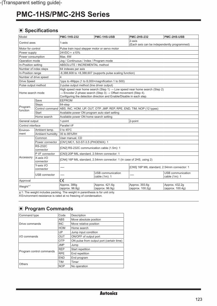
PMC-1HS/PMC-2HS Series-|Transparent setting guide|-
SpecificationsModel PMC-1HS-232 PMC-1HS-USB PMC-2HS-232 PMC-2HS-USB
Control axes 1-axis 2-axis(Each axis can be independently programmed)
Motor for control Pulse train input stepper motor or servo motorPower supply 24VDCᜡ ±10%Power consumption Max. 6WOperation mode Jog / Continuous / Index / Program modeIn-Position setting ABSOLUTE / INCREMENTAL methodNumber of index steps 64 indexes per axisIn-Position range -8,388,608 to +8,388,607 (supports pulse scaling function)Number of drive speed 4Drive Speed 1pps to 4Mpps (1 to 8,000×magnification 1 to 500)Pulse output method 2-pulse output method (line driver output)
Home search modeHigh speed near home search (Step 1) → Low speed near home search (Step 2)→ Encoder Z-phase search (Step 3) → Offset movement (Step 4).Configuring the detection direction and Enable/Disable in each step.
Program function
Save EEPROMSteps 64-stepControl command ABS, INC, HOM, IJP, OUT, OTP, JMP, REP, RPE, END, TIM, NOP (12 types)Start Available power ON program auto start settingHome search Available power ON home search setting
General output 1-point 2-pointControl interface Parallel I/FEnviron-ment
Ambient temp. 0 to 45 Ambient humidity 35 to 85%RH
Accessory
Common User manual, CDPower connector [CN1] MC1, 5/2-ST-3.5 (PHOENIX): 1RS-232C connector [CN2] RS-232C communication cable (1.5m): 1
P I/F connector [CN3] 20P MIL standard, 2.54mm connector: 1X-axis I/O connector [CN4] 16P MIL standard, 2.54mm connector: 1 (In case of 2HS, using 2)
Y-axis I/O connector - [CN5] 16P MIL standard, 2.54mm connector: 1
USB connector - USB communication cable (1m): 1 - USB communication
cable (1m): 1Approval
Weight※1 Approx. 386g(approx. 96.8g)
Approx. 421.6g(approx. 96.9g)
Approx. 393.6g(approx. 100.2g)
Approx. 432.2g(approx. 100.4g)
※1: The weight includes packing. The weight in parenthesis is for unit only.※Environment resistance is rated at no freezing of condensation.
Program CommandsCommand type Code Description
Drive commandsABS Move absolute positionINC Move relative positionHOM Home search
I/O commandsIJP Jump input conditionOUT ON/OFF of output portOTP ON pulse from output port (certain time)
Program control commands
JMP JumpREP Start repetitionRPE End repetitionEND End program
OthersTIM TimerNOP No operation
123

SENSORS
CONTROLLERS
MOTION DEVICES
SOFTWARE
(Y)Closed LoopStepper System
(Z)Stepper Motors
(AA)Drivers
(AB)MotionControllers
1·2-Axis High Speed Programmable Motion Controller-|Transparent setting guide|-
PMC-1HS/PMC-2HS
PC
XP+P
XP+N
XP-P
XP-N
XLMT+XLMT- XSTOP1
< Basic configuration of the motion controller (configuration only for X-axis) >
5-phase micro stepmotor driver
CW+
CW-
CCW+
CCW-
RS232CUSB
Connections
Dimensions (unit: mm)
Sold separately (teaching unit, PMC-2TU-232)
5-phase stepper motor
+ directionlimit sensor
- directionlimit sensor
HOME sensor
150
61.7
23
644
35.55
90 97 104
35m
m D
IN ra
ilco
nnec
tabl
e
124

PMC-1HS/PMC-2HS Series-|Transparent setting guide|-
CN1: Power Connector
CN2: RS232C Connector
Pin No. Signal name1 24VDC 2 GND (0V)
Pin No. Signal name Input/Output Description1 TXD Output Transmitting data2 RXD Input Receiving data3 GND - Ground4 - -
N.C5 - -6 - -
※The internal connection diagram of RS232Ccommunication cable is as shown below.
CN2 RS232C connector Cable length 1.5m
6P connector Cable
PC connection connector
TXD
16
6P modularconnector
< Internal connection diagram of RS232C communication cable>
RXDGND
DE-9S
DCDRXDTXDDTRGNDDSRRTSCTSRI
123456
123456789
Unit Descriptions
Connector No. DescriptionCN1 Power connectorCN2 RS232C connector (connect with PMC-2TU-232)CN3 Parallel I/F connectorCN4 X-axis I/O connectorCN5 Y-axis I/O connectorCN6 USB connector※PMC-1HS-232 does not have CN5 and CN6,
PMC-1HS-USB does not have CN5, and PMC-2HS-232 does not have CN6.
CN2
CN1
CN3
CN6
CN4
CN5
External I/O Terminal Connection
4
5
3
2
1
1. Power / Status indicatorUsed to indicate power, communication status of thecontroller, and operation status of each axis.
2. Power connector terminalUsed to connect power for controller
3. RS232C connector terminalUsed to connect RS232 serial (RJ12-DSUB9) connection cable
4. USB/RS485 connector terminalUsed to connect USB and RS485 connection cable
5. External I/O connector terminalUsed to operate various drives through input and output ofParallel I/F, X, Y
125
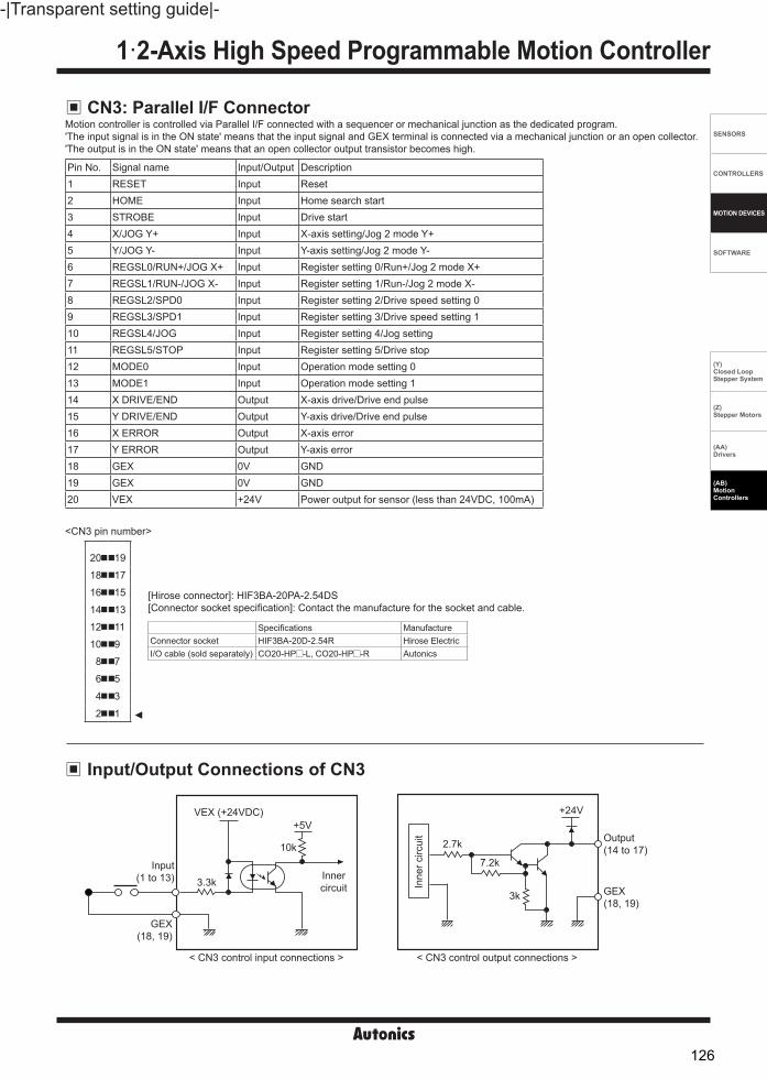
SENSORS
CONTROLLERS
MOTION DEVICES
SOFTWARE
(Y)Closed LoopStepper System
(Z)Stepper Motors
(AA)Drivers
(AB)MotionControllers
1·2-Axis High Speed Programmable Motion Controller-|Transparent setting guide|-
Input/Output Connections of CN3
VEX (+24VDC)
Innercircuit
+5V
10k
3.3k
2.7k
7.2k
3k
+24V
Output(14 to 17)
GEX(18, 19)
Input(1 to 13)
GEX(18, 19)
Inne
r circ
uit
< CN3 control input connections > < CN3 control output connections >
Pin No. Signal name Input/Output Description1 RESET Input Reset 2 HOME Input Home search start3 STROBE Input Drive start4 X/JOG Y+ Input X-axis setting/Jog 2 mode Y+5 Y/JOG Y- Input Y-axis setting/Jog 2 mode Y-6 REGSL0/RUN+/JOG X+ Input Register setting 0/Run+/Jog 2 mode X+7 REGSL1/RUN-/JOG X- Input Register setting 1/Run-/Jog 2 mode X-8 REGSL2/SPD0 Input Register setting 2/Drive speed setting 09 REGSL3/SPD1 Input Register setting 3/Drive speed setting 110 REGSL4/JOG Input Register setting 4/Jog setting11 REGSL5/STOP Input Register setting 5/Drive stop12 MODE0 Input Operation mode setting 013 MODE1 Input Operation mode setting 114 X DRIVE/END Output X-axis drive/Drive end pulse15 Y DRIVE/END Output Y-axis drive/Drive end pulse16 X ERROR Output X-axis error17 Y ERROR Output Y-axis error18 GEX 0V GND19 GEX 0V GND20 VEX +24V Power output for sensor (less than 24VDC, 100mA)
Motion controller is controlled via Parallel I/F connected with a sequencer or mechanical junction as the dedicated program.'The input signal is in the ON state' means that the input signal and GEX terminal is connected via a mechanical junction or an open collector. 'The output is in the ON state' means that an open collector output transistor becomes high.
CN3: Parallel I/F Connector
20 1918 1716 1514 1312 1110 9
8 76 54 32 1
<CN3 pin number>
[Hirose connector]: HIF3BA-20PA-2.54DS[Connector socket specification]: Contact the manufacture for the socket and cable.
Specifications ManufactureConnector socket HIF3BA-20D-2.54R Hirose ElectricI/O cable (sold separately) CO20-HP -L, CO20-HP -R Autonics
126

PMC-1HS/PMC-2HS Series-|Transparent setting guide|-
Pin No. Signal name Input/Output Description1 nP+P Output CW +direction drive pulse2 nP+N Output CW -direction drive pulse3 nP-P Output CCW +direction drive pulse4 nP-N Output CCW -direction drive pulse5 n OUT0 Output General output 0/DCC6 n INPOS Input Servo In-Position complete7 n ALARM Input Servo alarm8 GEX 0V GND9 n STOP2 Input Encoder Z-phase10 n STOP1 Input Home11 n STOP0 Input Near Home12 n LMT+ Input LMT+13 n LMT- Input LMT-14 EMG Input Emergency stop15 GEX 0V GND16 VEX +24V Power output for sensor (less than 24VDC, 100mA)
CN4 and CN5 are the I/O signal connector for X-axis and Y-axis respectively.The pin arrangement of CN4 and CN5 are equal. PMC-1HS does not have CN5.'n' in the below table means X for CN4 and Y for CN5.
CN4, CN5: X, Y-Axis Input/Output Connector
CN4, CN5 Motor driver
nP+P 1
2
3
4
nP+N
nP-P
nP-N
E.g. Connection with a motor driverCN4, CN5
+ direction limit
- direction limit
Home
VEX (+24V)nLMT+
nLMT-
nSTOP1
GEX
16
12
13
10
15
E.g. Connect of Limit and Home signal
1 23 45 67 89 1011 1213 1415 16
<CN4, CN5 pin number>
※CN4, 5 input/output circuit except drive pulse is same as CN3 input/output circuit.Drive pulse output of motion controller which input by motor driver is line driver output.
[Hirose connector]: HIF3BA-16PA-2.54DS[Connector socket specification]: Contact the manufacture for the socket and cable.
Specifications ManufactureConnector socket HIF3BA-16D-2.54R Hirose Electric
127

SENSORS
CONTROLLERS
MOTION DEVICES
SOFTWARE
(Y)Closed LoopStepper System
(Z)Stepper Motors
(AA)Drivers
(AB)MotionControllers
1·2-Axis High Speed Programmable Motion Controller-|Transparent setting guide|-
1
2 3
4
56
The teaching unit (PMC-2TU-232) is a device that builds the operation mode parameter and operation program for the main body without a PC. In addition, it can carry out the start of the operation program, the home search and Jog operation.The teaching unit is used by connection the private cable (1.5m) to the RS-232C connector (CN2) of the main body.
Teaching Unit PMC-2TU-232 (sold separately)
Teaching unit consists of data edit mode and drive operation mode.The data edit mode displays a register number to the REG of the display part, and the drive handling mode displays dp (drive operation).When turned on, it starts as the drive handling mode (dp display).The [DP] button is used to convert the status of the data edit mode and the drive operation mode.
1. Reset: Reset the controller and teaching unit.2. X/Y display: Display the currently selected axis.3. Register number display/dp
: Displays the currently selected register number when data is editing and dp when operating drive.4. Data display
: Displays the data of each register when data is editing and the current position of the selected axis when operatingdrive.
5. Input button• X/Y: Converts the selecting axis. It is used to convert the sign of an input value when the value is entered and a mode
data that the mode data is entered.• REG: It is used to input the register number to display.
If this button is pressed on the data input, the data input is canceled and returns to the state before the data input.• ↑↓: Increases / decreases the displayed register number.• EXC: Runs the displayed command. However, this command is only valid for ABS, INC, OUT, OTP and HOM 1 to 4
commands.• DP: Converts the drive handling status and the data edit status.• WRT: Adds a value when data is editing.
6. Button display for drive operation : Displays button function as yellow letters to the left or the top of the input button in drive handling status.The top end and the bottom end of the button handle X-axis and Y-axis respectively.
The front panel of the teaching unit is as shown below;
Mode Operation REG display
Data edit • Adding operation mode parameter and operation program• Index drive operation Register number
Drive handling
• Displaying the current position• Jog operation• Home search• Program execution
DP(drive operation)
PMC-2TU-232connection cable (accessory)
128

SENSORS
CONTROLLERS
MOTION DEVICES
SOFTWARE
(Y)Closed Loop Stepper System
(Z)Stepper Motors
(AA)Drivers
(AB)Motion Controllers
PMC-4B-PCI
Features4-axis Board Type Programmable Motion Controller Available to control 4-axis independent AC servo motor
and stepper motor PC-PCI card Auto home search and synchronous operation Interpolation on circular/linear, bit pattern/continuous/
accel/deceleration drive 2/3-axis constant linear velocity. Compatible with windows 98, NT, 2000, XP, 7 Supports Labview library and help, C language library and
examples (download at Autonics website)
SpecificationsModel PMC-4B-PCI Control axes 4-axisPower supply 5VDCᜡ (uses PC inner power)External power supply 12-24VDCᜡAllowable voltage range 90 to 110% of rated voltageCPU data bus 8/16-bit selectable2/3-axislinearinterpolation
Range -2,147,483,648 to 2,147,483,647 for each axisSpeed 1pps to 4MppsPosition accuracy Max. ±0.5LSB (within all interpolation range)
Circularinterpolation
Range -2,147,483,648 to 2,147,483,647 for each axisSpeed 1pps to 4MppsPosition accuracy Max. ±1 LSB (within all interpolation range)
2/3-axis bit patterninterpolation speed 1 to 4Mpps (depends on CPU data setup time)
Other interpolations Selectable the axis, constant linear velocity, consecutive interpolation, interpolation step transmission (command, external signal)
Driver pulse output(X, Y-axis common specifications)
Output speed range: 1pps to 4MppsOutput speed accuracy: max ±0.1% (for setting value)Speed magnification: 1 to 500S jerk speed: 954 to 62.5×10⁶pps/sec (mag.=1)
(accel/decel increase rate) 477×103 to 31.25×10⁹pps/sec (mag.=500)Accel/Decel: 125 to 1×10⁶pps/sec (mag.=1)
62.5×10³ to 500×106pps/sec (mag.=500)Initial velocity: 1 to 8,000pps (mag.=1) / 500 to 4×10⁶pps (mag.=500)Drive speed: 1 to 8,000pps (mag.=1) / 500 to 4×10⁶pps (mag.=500)Number of output pulses: 0 to 4,294,967,295 (fixed pulse drive)Speed curve: constant speed, symmetric/asymmetric linear accel/decel, parabola S curve driveFixed pulse drive deceleration mode auto deceleration (asymmetric linear accel/decel function)/Manual decelerationChangeable output pulse for driving, drive speedSelectable individual 2-pulse/1-pulse direction methodSelectable drive pulse logic level, changeable output terminal
Encoder input pulse Inputtable 2-phase pulse/Up-Down pulse, selectable 2-phase pulse 1/2/4 multiply
※Visit our website (www.autonics.com) todownload manual and software.
Ordering Information
Item
Axis/Type
Connection typePCI PCI
4B 4-axis board type
PMC Programmable motion controller
PMC 4B PCI
atMotion is the windows software designed to operate motion control for motion device. Compatible with Microsoft Windows 98, NT, XP (32-bit, 64-bit), Vista (32-bit, 64-bit), 7 (32-bit, 64-bit),
8 (32-bit, 64-bit) and 10 (32-bit, 64-bit) Supports 1200, 2400, 4800, 9600, 19200, 38400, 57600, 115200 bps communication speeds Available to use on all OS supported COM ports (COM1 to COM256) Multilingual support (korean, english) Provides the calculator for convenience (calculates PPS, center of interpolation, end coordinates)
Software (atMotion)
Please read “Safety Considerations” in the instruction manual before using.
129

PMC-4B-PCI
SpecificationsPosition counter Logic position counter (for output pulse) count range: -2,147,483,648 to +2,147,483,647
Actual position counter (for input pulse) count range: -2,147,483,648 to 2,147,483,647
Compare register
Comp. +register position comparison range: -2,147,483,648 to +2,147,483,647Comp. -register position comparison range: -2,147,483,648 to +2,147,483,647Output/Signal output when the present value of the counter and the user position counter are same by comparingEnables to operate as software limit
Auto home search High speed near home search (Step1) → Low speed near home search (Step2)
Interrupt function(except interpolation)
1 drive pulse outputwhen changing position counter ≥ Comp.-, when changing position counter ≥ Comp.+,when changing position counter < Comp.-, when changing position counter < Comp.+,when starting constant speed in accel/decel drive, when ending constant speed in accel/decel drive when ending drive, when ending auto home search, when running synchronous operation
Drive adjustment by external signalEnable to fixed/continuous pulse drive of +/- direction by EXP+/EXP- signalEnable to drive 2-phase encoder signal mode (encoder input)
External deceleration stop/immediate stop signal
IN 0 to 3 each axis 4-pointSelectable signal valid/invalid and logical level, usable as general input
Input signal for servo motor Selectable alarm, INPOS signal valid/invalid and logic levelGeneral output signal OUT 4 to 7 each axis 4-point (uses same terminal with drive status output signal)Drive status signal output ASND (accelerating), DSND (decelerating)
Overrun limit signal inputSelectable + direction, - direction each 1-point and logic levelAt active, selectable immediate stop/decelerate stop
Emergency stop signal input EMG 1-point, stops drive pulse of all axes by low levelIntegral filter Built-in integral filter at each input signal input terminal, selectable pass time (8 types)
Others Selectable the axis, constant linear velocity, consecutive interpolation, interpolation step transmission (command, external signal)
EnvironmentAmbient temperature 0 to 45, storage: -10 to 55Ambient humidity 35 to 85%RH, storage: 35 to 85%RH
Approval
Weight※1 Approx. 654.4g (approx. 100.4g)※1: The weight includes packaging. The weight in parenthesis is for unit only. ※Environment resistance is rated at no freezing of condensation.
Drivers & Motor (example)Motion controller
PMC-4B-PCI
X-axis
Z-axis
Y-axis
U-axis
System
Host controller
PC
Steppermotor
&Servo motor
Steppermotor driver
&Servo
motor driver
130

SENSORS
CONTROLLERS
MOTION DEVICES
SOFTWARE
(Y)Closed Loop Stepper System
(Z)Stepper Motors
(AA)Drivers
(AB)Motion Controllers
4-axis Motion Controller
Connections Connection of pulse output signal (nP+P/N, nP-P/N)Drive pulse output generates drive pulse signal of +/- direction using line driver (AM26c31) of differential output. Followings are examples of connection with motor drivers with photocoupler or line driver input.
Examplefortheconnectionwithamotordriverofphotocouplerinput
※It is recommended to use twisted pair shield wire for pulse output signal of driver operation regarding EMC.
Connection of common output signal (nOUT4 to 7) Output signal is outputted by buffer (74LS06), and all outputs are OFF after reset.
Examplefortheconnectionwithamotordriveroflinedriver
PMC-4B-PCI
nP+P
nP+N
nP-P
nP-N
CW+
CW-
CCW+
CCW-
AM26c31
PMC-4B-PCI Motor driver
nOUT7
nOUT6
nOUT5
nOUT4
Dimensions (unit: mm)174.6
106.
7
nP+P
nP+N
nP-P
nP-N
CW+
CW-
CCW+
CCW-
AM26c31
PMC-4B-PCI Motor driver
131

PMC-4B-PCI
Connectionofencoderinputsignal(nECAP/N,nECBP/N)andnlNO+/-signal Examplefortheconnectionwithlinedriverofdifferentialoutput
ExamplefortheconnectionwithencoderofNPNopencollectoroutput
Connectionofinputsignal(nIN1to3,nINPOS,nALRAM,nEXP+/-,EMG)
Connectionoflimitinputsignal(nLMIT+/-)The outgoing cable of limit signal can be affected by noise. Since it can not be removed only with photocoupler, the filter circuit is built in PMC-4B-PCI. Please set enough passing time (FL=2, 3).
PMC-4B-PCI
+5V
Input signal
VEX
GND
External voltage Resistance (R)
5V 0
12V 820Ω 1/4W
24V 2kΩ 1W
PMC-4B-PCI Encoderoutputcircuit
nECAP/nIN0+
nECAP/nIN0- EC-A
PMC-4B-PCI R
Encoderoutputcircuit
Externalpower
nECAP/nIN0+
nECAP/nIN0-
VEX
GND
EC-A
PMC-4B-PCIExternalpower
Noise removalfilter
VEX
VEX
GND
OUT+
-XLIT+
Connections
※Encoder A, B, Z phase are same connection.
132

SENSORS
CONTROLLERS
MOTION DEVICES
SOFTWARE
(Y)Closed Loop Stepper System
(Z)Stepper Motors
(AA)Drivers
(AB)Motion Controllers
4-axis Motion Controller
※Connected resistance for no. 15, 17, 19,23, 25, 27 is 1/2W 220Ω, for the othernumbers is 1/2W 3.3kΩ.
※Diode specification for general output pinshould be over 50/0.1A.
※Use NPN open collector output (+12VDC)for encoder.
※Only axis A 50-pin are shown on the figure.Other 50-pin of axis B are having sameconnection.However, No. 2 of axis B is not for use.
※For connection, refer to ' Connections'.
Input/Output Connections
B1
A1 A50
B50
Z-phase
B-phase
A-phase
B50B49B48B47B46B45B44B43B42B41B40B39B38B37B36B35B34B33B32B31B30B29B28B27B26B25B24B23B22B21B20B19B18B17B16B15B14B13B12B11B10B9B8B7B6B5B4B3B2B1
A50A49A48A47A46A45A44A43A42A41A40A39A38A37A36A35A34A33A32A31A30A29A28A27A26A25A24A23A22A21A20A19A18A17A16A15A14A13A12A11A10A9A8A7A6A5A4A3A2A1
CCW-
CCW-
Black
Black
Green
Green
Orange
Orange
Red
Red
Blue
Blue
CCW+
CCW+
CW-
CW-
CW+
CW+
Y-axis motor driver
PMC-4B-PCI
X-axis motor driver
Y-axisstepper motor
X-axisstepper motor
Y-axis encoder
X-axis encoder
Power
24VDC
VEX GND
Z-phase
B-phase
A-phase
133

PMC-4B-PCI
Input/Output SpecificationsPin no. Signal Description Pin no. Signal Pin description
A1 VEX 12-24VDC B1 VEX 12-24VDC
A2 EMG Emergency stop (4-axis stop) B2 - N.CA3 XLMIT+ X-axis + direction limit B3 ZLMIT+ Z-axis + direction limit
A4 XLMIT- X-axis - direction limit B4 ZLMIT- Z-axis – direction limit
A5 XIN1 X-axis input signal (home signal) B5 ZIN1 Z-axis input signal (home signal)
A6 XIN0 X-axis input signal (near home signal) B6 ZIN0 Z-axis input signal (near home signal)
A7 XIN3 X-axis input signal (encoder Z phase signal) B7 ZIN3 Z-axis input signal (encoder Z phase signal)
A8 YLMIT+ Y-axis + direction limit B8 ULMIT+ U-axis +direction limit
A9 YLMIT- Y-axis - direction limit B9 ULMIT- U-axis -direction limit
A10 YIN1 Y-axis input signal (home signal) B10 UIN1 U-axis input signal (home signal)
A11 YIN0 Y-axis input signal (near home signal) B11 UIN0 U-axis input signal (near home signal)
A12 YIN3 Y-axis input signal (encoder Z phase signal) B12 UIN3 U-axis input signal (encoder Z phase signal)
A13 XINPOS X-axis In-Position input B13 ZINPOS Z-axis In-Position input
A14 XALRAM X-axis alarm input B14 ZALRAM Z-axis alarm input
A15 XECAP X-axis Encoder A phase+ B15 ZECAP Z-axis Encoder A phase+
A16 XECAN X-axis Encoder A phase- B16 ZECAN Z-axis Encoder A phase-
A17 XECBP X-axis Encoder B phase+ B17 ZECBP Z-axis Encoder B phase+
A18 XECBN X-axis Encoder B phase- B18 ZECBN Z-axis Encoder B phase-
A19 XECZP X-axis Encoder Z phase+ B19 ZECZP Z-axis Encoder Z phase+
A20 XECZN X-axis Encoder Z phase- B20 ZECZN Z-axis Encoder Z phase-
A21 YINPOS Y-axis In-Position input B21 UINPOS U-axis In-Position input
A22 YALARM Y-axis alarm input B22 UALARM U-axis alarm input
A23 YECAP Y-axis Encoder A phase+ B23 UECAP U-axis Encoder A phase+
A24 YECAN Y-axis Encoder A phase- B24 UECAN U-axis Encoder A phase-
A25 YECBP Y-axis Encoder B phase+ B25 UECBP U-axis Encoder B phase+
A26 YECBN Y-axis Encoder B phase- B26 UECBN U-axis Encoder B phase-
A27 YECZP Y-axis Encoder Z phase+ B27 UECZP U-axis Encoder Z phase+
A28 YECZN Y-axis Encoder Z phase- B28 UECZN U-axis Encoder Z phase-
A29 XEXP+ X-axis manual + drive B29 ZEXP+ Z-axis manual + drive
A30 XEXP- X-axis manual - drive B30 ZEXP- Z-axis manual - drive
A31 YEXP+ Y-axis manual + drive B31 UEXP+ U-axis manual + drive
A32 YEXP- Y-axis manual - drive B32 UEXP- U-axis manual - drive
A33 GND GND B33 GND GND
A34 XOUT4/CMPP X-axis general output B34 ZOUT4/CMPP Z-axis general output
A35 XOUT5/CMPM X-axis general output B35 ZOUT5/CMPM Z-axis general output
A36 XOUT6/ASND X-axis general output B36 ZOUT6/ASND Z-axis general output
A37 XOUT7/DSND X-axis general output B37 ZOUT7/ DSND Z-axis general output
A38 XP+P X-axis +direction +drive signal output B38 ZP+P Z-axis +direction +drive signal output
A39 XP+N X-axis +direction -drive signal output B39 ZP+N Z-axis +direction -drive signal output
A40 XP-P X-axis -direction +drive signal output B40 ZP-P Z-axis -direction +drive signal output
A41 XP-N X-axis -direction -drive signal output B41 ZP-N Z-axis -direction -drive signal output
A42 GND GND B42 GND GND
A43 YOUT4/CMPP Y-axis general output B43 UOUT4/CMPP U-axis general output
A44 YOUT5/CMPM Y-axis general output B44 UOUT5/CMPM U-axis general output
A45 YOUT6/ASND Y-axis general output B45 UOUT6/ASND U-axis general output
A46 YOUT7/DSND Y-axis general output B46 UOUT7/DSND U-axis general output
A47 YP+P Y-axis +direction +drive signal output B47 UP+P U-axis +direction +drive signal output
A48 YP+N Y-axis +direction -drive signal output B48 UP+N U-axis +direction -drive signal output
A49 YP-P Y-axis -direction +drive signal output B49 UP-P U-axis -direction +drive signal output
A50 YP-N Y-axis -direction -drive signal output B50 UP-N U-axis -direction -drive signal output
134

192
TOWER LIGHTS POWER RELAYSLED INDICATORSPIEZO BUZZERS
KACON
SOLID STATE RELAY
PLASTIC ENCLOSURESPUSHBUTTONSWITCHES INDUSTRIAL AUTOMATION DEVICES
AUTOMATION PARTS
AUTOMATION PARTS
AUTOMATION PARTS
RELAYMENICS
PILOT LAMPS
PUSHBUTTONS
MICRO & LIMIT SWITCHES
UL CE TUV RoHS EX IP67 ISO9001HOLE PLUGS
TOWER LIGHTSMOTION DEVICES
ENCLOSUREPIEZO BUZZERS
ROBOT KITS
SWITCH BOXES
LIMIT SWITCHES
AUDIBLE ALARM
ANDON LIGHTS
ANDON LIGHTS
ALUMINUM SWITCH BOXES
PLASTIC SWITCH BOXES
INDUSTRIAL SWITCHESSWITCH BOXES
BEACON LIGHTSCERAMIC FUSE
HEAVY DUTY FOOT SWITCHESBEACON LIGHTSCERAMIC FUSE
FOOT SWITCHES
PUSHBUTTONFUSE HOLDERS
RELAY TEMINAL BLOCKSSCREW CLAMP DIODE TERMINAL BLOCKS
TOWER LIGHTS
TERMINAL BLOCKS
TERMINAL BLOCKS
TERMINAL BLOCKS
SOLID STATE RELAYS
SOLID STATE RELAYSTOWER LIGHTS
LED INDICATORS
LED INDICATORS
TERMINAL BLOCKS
CABLE CHAINS
PUSHBUTTONS
BOXCO
LIMIT SWITCHES
SOLID STATE RELAYSPLASTIC SWITCH BOXES
SOLID STATE RELAYSPLASTIC SWITCH BOXES
Address 108 Terrace Drive, Mundelein, Illinois 60060
Telephone +1. 847. 388. 7189Facsimile +1. 847. 388. 7194
Email [email protected] www.amerimation.net
9 E College Dr, Arlington Heights, IL 60004