FEASIBILITY REPORT - Environmental Clearance
125
STEEL AUTHORITY OF INDIA LIMITED CENTRE FOR ENGINEERING & TECHNOLOGY RANCHI - 834002 CET/20/RN/4241/FR/CC/01/R=0 JANUARY, 2017 FEASIBILITY REPORT INSTALLATION OF NEW COKE OVEN BATTERY NO.9 AT BSL WITH STAMP CHARGING TECHNOLOGY AT GREENFIELD SITE BOKARO STEEL PLANT BOKARO STEEL CITY
-
Upload
khangminh22 -
Category
Documents
-
view
0 -
download
0
Transcript of FEASIBILITY REPORT - Environmental Clearance

STEEL AUTHORITY OF INDIA LIMITED CENTRE FOR ENGINEERING & TECHNOLOGY RANCHI - 834002
CET/20/RN/4241/FR/CC/01/R=0 JANUARY, 2017
FEASIBILITY REPORT
INSTALLATION OF NEW COKE OVEN BATTERY NO.9 AT BSL WITH STAMP
CHARGING TECHNOLOGY AT GREENFIELD SITE
BOKARO STEEL PLANT
BOKARO STEEL CITY

Experience that delivers
This document has been prepared for Bokaro Steel Plant, Bokaro by:
Centre for Engineering & Technology R.K.Barman – HOD lead section S.C.Chaudhary, C, C&C (Task Force Leader) Jyoti Dayal, C, C&C P.S.Khetwal, Refractory Sourav Manna, Refractory A.Rituraj, Mechanical Sushil Kumar, Mechanical Arvind Tirkey, Mechanical R.Naval Kishore, U&S Tarun Mittal, U&S R.K.Jha, Electrical Akshya Pandya, Electrical Neeraj, Electrical Ruma Bharti, PC&A C.M.Chugh, Civil M.K.Singh, Civil G.K.Mitra, Structural C.H.Deepak Ranga Rao, Structural M.K.Verma, BOSC M.K.Mishra, CTEB S. P. Das, PFC
Document Identification No. CET/20/RN/4241/FR/CC/01/R=0
REVISION HISTORY
Revision No. Brief Description Revision Date
Disclaimer
This document is the property of CET and is exclusively for the use of the intended client. This document has been prepared based on the inputs provided by the client. No part of this report will be reproduced or transmitted in any form whatsoever without the written permission from the owner.

BSL Installation of stamp charge COB#9
i CET/20/RN/4241/FR/CC/01/R=0
Experience that delivers
UPSHOT Stamp charge coke oven battery with Coke Dry Cooling Plant (CDCP) will be installed in Benzol Rectification Plant-2 area. Use of cheaper coal in the coal blend of stamp charge battery and generation of power from CDCP is the added advantage compared to conventional top charge battery with wet quenching. The project will be taken up in 2018-19 to meet the coke requirement of blast furnace operation. The project is techno-economically viable and recommended for implementation.
This project will be commissioned in 42 months from the date of stage II approval. Environment clearance from MoEF is required for setting up of the battery. The capital cost of the project with forward premium rate is estimated at Rs.2094.94 crore net of CENVAT Credit of Rs. 175.79 crore including IDC of Rs. 265.67 crore.
The capital cost of the project with forward premium rate is estimated at Rs.2094.94 crore net of CENVATCredit of Rs. 175.79 crore including IDC of Rs. 265.67 crore.

Experience that delivers
BSL Installation of stamp charge COB#9
ii CET/20/RN/4241/FR/CC/01/R=0
CONTENTS - CHAPTERS
Chapter no. Description Page no.
1 Summary 1.1-1.2
2 Background 2.1-2.3
3 Selection of Alternatives 3.1
4 Project Description 4.1-4.86
5 Implementation Schedule & Strategy 5.1-5.3
6 Capital Cost & Financial Analysis 6.1-6.4
7 Recommendations 7.1
Annexures
Drawings

BSL Installation of stamp charge COB#9
iii CET/20/RN/4241/FR/CC/01/R=0
Experience that delivers
ANNEXURES
Annexure No. Description No. of pages
2.3.3-1 Coke Balance with Installation of Stamp charge Battery No. 9
1
2.3.6-1 Assignment Letter from Corporate office along with committee report for Installation of Stamp Charge Battery No. 9 at BSL
10
2.3.6-2 Acceptance letter from CET 1
4.7.1-1 Ministry of Environment & Forests (MOEF), Notification, New Delhi, 31st March 2012
7
5.1.2-1 Schedule of pre-ordering activities after stage-I approval
1
5.1.2-2 Implementation schedule (post ordering activities, after stage – II approval)
1
5.2.7-1 Note sheet related to removal of LD slag 2
6.1.1-1 Summary of Capital Cost Estimate 1
6.5.1-1 Gross Margin Calculation 1
6.6.2-1 Techno-economic indices 1

Experience that delivers
BSL Installation of stamp charge COB#9
iv CET/20/RN/4241/FR/CC/01/R=0
DRAWINGS
Sl. No. Drawing No. Description
1. CET RN 4241 CC2 00 001 R=0
PROPOSED LAYOUT OF STAMP CHARGE COB#9 COMPLEX
2. CET RN 4241 CC2 00 002 R=0
CROSS-SECTION ALONG OVEN-STAMP CHARGE COB#9
3. CET RN 4241 CC2 00 003 R=0
GENERAL LAYOUT-EXISTING BENZOL RECTIFICATION PLANT (BRP-2)
4. CET RN 4241 CC1 00 001 R=0
FLOW DIAGRAM OF BY-PRODUCT UNITS FOR PROPOSED STAMP CHARGE COB#9
5. CET RN 4241 CC1 00 002 R=0
FLOW DIAGRAM OF CDCP FOR PROPOSED STAMP CHARGE COB#9
6. CET RN 4241 ME1 00 001 R=0
FLOW DIAGRAM (COAL HANDLING) FOR PROPOSED STAMP CHARGE COB#9
7. CET RN 4241 ME1 00 002 R=0
ELEVATION OF COAL CONVEYORS FOR PROPOSED STAMP CHARGE COB#9
8. CET RN 4241 CC1 00 003 R=0
FLOW DIAGRAM OF COKE HANDLING FOR PROPOSED STAMP CHARGE COB#9
9. CET RN 4241 CC1 00 004 R=0
COKE HANDLING SECTIONS FOR PROPOSED STAMP CHARGE COB#9
10. CET RN 4241 UT1 00 001 R=0
FLOW DIAGRAM OF STEAM & WATER FOR PROPOSED STAMP CHARGE COB#9
11. CET RN 4241 UT0 00 002 R=0
FLOW DIAGRAM OF GAS HANDLING FOR PROPOSED STAMP CHARGE COB#9
12. CET RN 4241 EE1 00 001 R=0
SLD OF ELECTRICAL POWER DISTRIBUTION
13. CET RN 4241 CA1 00 001 R=0
SYSTEM CONFIGURATION DIAGRAM

Experience that delivers
BSL Installation of stamp charge COB#9
Page no. 1.1 CET/20/RN/4241/FR/CC/01/R=0
SUM
MA
RY
1. SUMMARY 1.1 The coke oven complex at Bokaro Steel Plant consists of 8 by-product recovery
type coke oven batteries. Battery No. 1 to 4 was commissioned at 1.7Mt stage and Battery No. 5 to 7 was commissioned at 4Mt stage. Battery No.8 was commissioned in 1993 to serve as a “Rebuilding Reserve” during rebuilding of other batteries in a phased manner.
These batteries are of compound, regenerative with partial recirculation of waste gases, twin flue, under jet type. Each battery is of 69 ovens in single block. The ovens are 5 m tall, 15040 mm long and have average width of 410mm.
1.2 Due to ageing, old batteries are being rebuilt /repaired on regular basis. Because of this, only six (6) out of eight (8) batteries are in operation most of the time. This in turn is resulting short-fall of BF grade coke for supplying to Blast Furnaces.
1.3 As per on-going expansion plan of BSL the targeted HM production is 5.77 Mtpa (up-to the year 2020-21), there will be a shortfall of BF coke even after the rebuilding of existing batteries. BF coke requirement will be 3.328 Mtpa for which installation of Battery No. 9 is required.
1.4 A committee was constituted vide Office Order No.: SAIL/DT/02 dated 10.09.2016 to examine the possibility of installation of new coke oven battery No.9 with stamp charging technology at green field site. Based on observation/recommendation of committee, Corporate Office, New Delhi has assigned CET to study the installation of a new coke oven battery No.9 with stamp charging technology. Accordingly, a feasibility report for installing a new, one million ton (1Mtpa) approx. coal throughput per year, is prepared.
1.5 The proposed battery will be stamp charge, twin flue, under jet, compound, regenerative heating type with partial recirculation of waste gases system. This Battery will have 92 ovens in two blocks of 46 ovens each. The ovens will be 5 m to 5.5 m tall, 14 m long (max) and have average width of 500 mm (min). Battery will be provided with two sets oven machines. The enhancement of coal handling unit, coke processing unit and conveyors as proposed in this FR will be suitable for operating one new stamp charge coke oven battery along with the existing batteries, to meet the overall coke demand of the BF complex.
1.6 The proposed battery will be provided with two sets (1W+1S) of oven machines i.e., stamping cum charging cum pushing machine, coke transfer car, charging gas transfer car, self-propelled coke bucket car and one set of coke electric loco & coke quenching wagon.
1.7 A 120tph single chamber Coke Dry Cooling Plant (CDCP) along with DM water plant has been envisaged for cooling of hot coke. A Back Pressure Turbine Generator (BPTG) of around 6.5MW power generation potential with about 55tph of steam at 8kg/cm2 has also been included. Wet quenching of coke has

Experience that delivers
BSL Installation of stamp charge COB#9
Page no. 1.2 CET/20/RN/4241/FR/CC/01/R=0
SUM
MA
RY
also been considered as a standby facility to facilitate boiler inspection of CDCP plant as per the statutory requirement.
1.8 Further, a dedicated new By-product Plant of 50000Nm3/h gas handling capacity for removal of tar, naphthalene, ammonia, sulphur has also been envisaged.
1.9 Liquid effluent disposal, a new BOD unit of 50m3/h capacity has also been included for treatment of effluent generated from this battery. Other facilities will also be incorporated in the proposed battery to meet the statutory requirements of emission norms notified by Govt. of India.
1.10 It is proposed to execute the project under the following five packages:-
Package -1 : Geo-Technical Investigation & Survey Works
Package- 2 : Battery proper, Refractories, Oven machines,
Wet quenching, Coal handling & Coke sorting plants
Package-3 : Coke Dry Cooling Plant, DM water plant, BPTG
Package-4 : By-product Plant
Package-5 : Benzol Storage Unit
1.11 The project will be implemented in 42 months from the date of stage -II approval.
1.12 The indicative requirement of manpower for the entire facility including battery proper, coal handling, coke sorting, CDCP and By-products is 460 nos.
1.13 The capital cost of the project is estimated to be Rs.2094.94 crore (Net of CENVAT credit of Rs.175.79 crore) including IDC of Rs.265.67 crore.
1.14 Installation of proposed stamp charge coke oven Battery No 9 is technically feasible and is also techno-economically viable. Hence, the proposed project is recommended for implementation.

Experience that delivers
BSL Installation of stamp charge COB#9
Page no. 2.1 CET/20/RN/4241/FR/CC/01/R=0
BACK
GRO
UN
D
2. BACKGROUND
2.1 COKE OVEN BATTERIES AT BSL
The coke oven complex at Bokaro Steel Plant consists of eight by-product recovery type coke oven batteries (No.1 to 8) with associated coal, coke and gas handling facilities. Battery No.1–4 was commissioned in 1.7Mt stage and Battery No 5–7 in 4Mt stage. Battery No.8 was commissioned in September 1993 as "Rebuilding Reserve" for the rebuilding of Batteries No. 1 to 7 in a phased manner.
The date of commissioning of coke oven batteries at Bokaro Steel Plant and their age as in January, 2017 is given below:
Battery No
Date of Commissioning
(after rebuilding)
Age as in January, 2017
1 28.06.2011 5 years 7 months
2 11.02.2012 4 years 11 months
3 20.10.2000 16 years 3 months
4 04.06.1996 20 years 7 months
5 21.09.2007 9 years 4 months
6 28.12.1982 34 years 1 month
7 23.02.1985 Under rebuilding
8 21.09.1993 Under rebuilding
2.2 Each battery has 69 ovens in single block, compound, regenerative with partial recirculation of waste gases, twin-flue, under jet type.
The oven dimensions (cold) of the existing batteries are as under
Parameter Total length : 15040 mm Total height : 5000 mm Average width : 410 mm Taper : 40 mm Useful volume : 27.3 m3 Gas collecting main : 2 Charging holes : 3

BSL Installation of stamp charge COB#9
Page no. 2.2 CET/20/RN/4241/FR/CC/01/R=0
Experience that delivers
BACK
GRO
UN
D
2.1.1 Present Condition of Batteries
Out of eight batteries at BSL, six coke oven batteries comprising of 1, 2, 3, 4, 5, and 6 are presently in operation. The present condition of the batteries is described below:
Battery No.1:
Battery has been constructed with all pollution control facilities and commissioned in June 2011. The battery is under operation.
Battery No. 2:
Battery has been constructed with all pollution control facilities and commissioned in Feb 2012. The battery is under operation.
Battery No. 3:
Battery No 3 was commissioned in October 2000 and is more than 16 years old. Battery was taken for cold repair and put into operation in June 2015.
Battery No. 4:
Battery was commissioned in June 1996 and is more than 20 years old. Battery was taken for cold repair and put into operation in February 2014.
Battery No. 5:
Battery has been constructed with all pollution control facilities and commissioned in September 2007. The battery is under operation.
Battery No. 6:
Battery No. 6 was commissioned in December 1982 and is more than 34 years old. Repairs are being taken up from time to time and due for rebuilding.
Battery No. 7:
Battery No. 7 is being rebuilt with pollution control facilities and is planned to be commissioned in October 2017.
Battery No. 8:
Battery is being rebuilt with pollution control facilities and will be commissioned in May 2019.
2.3 Action Plan of BSL for Repair/Rebuilding of batteries:
2.3.1 At present, Battery No. 7 & 8 is under rebuilding through separate project.
2.3.2 Battery No. 6 is more than 34 years old and is also due for rebuilding. Although the condition of Battery No. 6 has become critical and oven availability has decreased considerably, it is planned to rebuild this battery after commissioning of Battery No. 7.

Experience that delivers
BSL Installation of stamp charge COB#9
Page no. 2.3 CET/20/RN/4241/FR/CC/01/R=0
BACK
GRO
UN
D
2.3.3 As per on-going expansion plan of BSL the targeted HM production is 5.77Mtpa (up-to the year 2020-21), there will be a shortfall of BF coke even after the rebuilding of existing batteries mentioned above. BF coke requirement will be 3.328Mtpa for which installation of Battery No. 9 is required. In this regard, a coke balance has been prepared and enclosed at Annexure No.2.3.3-1.
2.3.4 To tide over the short-fall in coke production, a one million coal through-put per year stamp charge battery on BOO (build, own & operate) basis was initially envisaged. However, even after multiple re-tendering, suitable bidders were not forth coming.
2.3.5 In view of the above and to improve the coke availability, BSL assigned CET to study the installation of a new 7 meter tall Coke Oven Battery No.9. Accordingly, a feasibility report (R=0) for installing a new, one million ton (1Mtpa) coal throughput per year, 7 meter tall battery was submitted to BSL in Jan’14.
2.3.6 Subsequently, a committee was constituted vide Office Order No.: SAIL/DT/02 dated 10.09.2016 to examine the possibility of installation of new Coke Oven Battery No.9 with stamp charging technology at green field site. Based on observation/recommendation of committee, Corporate Office, New Delhi has assigned CET to study possibility for installation of a new Coke Oven Battery No.9 with stamp charging technology. A copy of assignment letter from Corporate Office, dated 29.09.2016 along with committee report is attached at Annexure No. 2.3.6-1. The assignment was formally accepted vide letter no. CET-17(3)/018/16/356 dated 19.10.2016. Copy of the letter is attached at ANNEXURE No. 2.3.6-2.
2.4 The co-operation, help and assistance received from officials of BSL in the preparation of this report is gratefully acknowledged.


Experience that delivers
BSL Installation of stamp charge COB#9
Page no. 3.1 CET/20/RN/4241/FR/CC/01/R=0
SELE
CTIO
N O
F AL
TERN
ATIV
ES
3. SELECTION OF ALTERNATIVES 3.1 Based on the available alternatives with respect to the various pre carbonisation
technologies, stamp charging is one of the most preferred technologies. Use of inferior coal in the coal blend is the major advantage of this technology. A committee constituted vide Office Order No.: SAIL/DT/02 dated 10.09.2016 has also recommended for installation of new Coke Oven Battery No.9 with stamp charging technology at BSL. Therefore, no other alternative has been considered in this Feasibility Report.


BSL Installation of stamp charge COB#9
Page no. 4.1 CET/20/RN/4241/FR/CC/01/R=0
Experience that delivers
PRO
JECT
DES
CRIP
TIO
N
4. PROJECT DESCRIPTION 4.1 TECHNOLOGY
4.1.1 The proposed stamp charge battery having coal throughput of approx. 1 million ton per year will be installed along with Coke Dry Cooling Plant (CDCP), Back Pressure Turbine Generator (BPTG), DM water plant and By-product plant. Wet quenching of coke has also been considered as a standby facility to facilitate boiler inspection of CDCP plant as per the statutory requirement. Required blended coal will be received from the existing coal handling network for Battery No.9 after suitable modification/extension/addition.Produced gross coke will be processed in coke sorting plant to convert it into BF coke, nut coke and breeze coke.BF coke will be dispatched to all the furnaces by connecting to the existing BF coke conveyors. Similarly, breeze coke will be dispatched to both SP-1 and SP-2.
4.1.2 Plant Layout:
The battery will be located in front of the existing BOD plant, perpendicular to COB#8. The battery will be installed in two blocks for ease of oven repair and maintenance. Each block will comprise of 46 ovens each, named as 9A & 9B. End benches will be provided on either side of the entire battery for locating repair and auxiliary facilities. Coal tower will be located between the two blocks over the pusher car track.
Single chamber coke dry cooling plant (CDCP) will be located on the wagon tippler side where as a stand-by wet quenching facility along with a wharf will be provided towards COB#8 side. Coke from either quenching tower or CDCP will move towards the coal tower meeting a common point, then onwards will move to the further processing steps. Single chamber with standby wet quenching concept has been considered for easy operation and maintenance. By-product plant will be located towards pusher side to clean the raw coke gas generated from the proposed stamp charge battery. Refer layout drawing Drg. No. CET RN 4241 CC2 00 001 R=0, for battery proper, CDCP, By-product, coal & coke handling and all the other facilities.
4.1.3 The battery will operate for 24 hours a day, 365 days a year. Coal consumption and coke production and coke quality for proposed battery are as indicated below:
Coke Production:
Parameter Envisaged, Mtpa
Dry coal charge : 1.02 (min)
Run-off oven coke (dry) 76% : 0.77
25mm to 80mm BF coke (dry) 69 to 71%
: 0.70
BSL Installation of stamp charge COB#9
Page No. 4.2 CET/20/RN/4241/FR/CC/01/R=0
Experience that delivers
PRO
JECT
DES
CRIP
TIO
N
(-) 25mm breeze coke (dry) : 0.07
Coke quality:
Parameter Envisaged
Ash content : 14-15%
Moisture content : < 0.5%
Volatile matter : 0.8%
M40 : 84% (min.)
M10 : 5.5 to 6.5%
CSR : 65 (min.)
CRI : 25 (max.)
Characteristics of coal blend:
Parameter Envisaged
Ash content 11-12%
Sulphur content 0.57 to 0.58%
Phosphorus 0.092 to 0.093%
Volatile matter 24 to 26%
Moisture content 9-11% (avg.)
CSN 4.5 (min.) to 6.5 (max.)
Ro (Mean Reflectance 1-1.05
-3.15 mm coal size 90% (min.)
-0.5 mm coal size 50% (max.)
Yields and parameters of products:
Parameter Envisaged
Oven pushing/day 90 (max.)
Dry Bulk density of blend 1t/m3 (min.)
Cake volume 31.0 m3
Yield of run-off oven coke from dry coal charge
76%
Yield of 25 mm to 80 mm BF grade 90.8%

BSL Installation of stamp charge COB#9
Page no. 4.3 CET/20/RN/4241/FR/CC/01/R=0
Experience that delivers
PRO
JECT
DES
CRIP
TIO
N
coke from run-off oven coke
Yield of 25 mm to 80 mm BF grade coke from gross dry coal charge
69 to 71%
Yield of (-) 25 mm coke from run-off oven coke (dry)
9.2%
Yield of coke oven gas per ton of dry coal blend
320-340Nm3/tonne of dry coal
Yield of Tar per ton of dry coal blend 32kg
Gas 45000Nm3/h (max.)
Tar 37000TPA (max.)
4.1.4 Calorific value of Blast furnace (BF) gas is about 800Kcal/normal cubic meter. Mixed gas with calorific value of 1000Kcal/normal cubic meter will be used for under firing of the battery. Coke oven gas used will have calorific value of minimum 4200Kcal/normal cubic meter.
4.1.5 Coal Preparation
Existing coal handling plant has been provided with 81 silos of 2500 ton capacity each. Required coal blend is prepared on the conveyors below the silos through belt feeders. These silos have been installed in three rows of 27 nos. each. 11 nos. of existing silos from each row “A” and “C” will be allocated to COB#9 by splitting the conveyors below (Y-9 & Y-10A). Out of these, 6 nos. of coal silos from both rows “A” and “C” in combination will be allocated for PCI/non coking coal. The tail portion of these two conveyors will be extended and drives will be provided in new junction houses. Flap gates and chute will be provided for transporting high HGI coal to intermediate hopper and PCI/non coking coal having low HGI to primary hammer crusher. Two nos. of primary hammer crushers (1W + 1S) of 200tph capacity each will be installed. The crushed coal will be fed into a conveyor Y-53 for coal blend as per requirement. The crushed coal and high HGI coal from intermediated hopper through vibro feeder will be transported to the secondary crusher house for crushing of coal blend. Three nos. of secondary hammer crushers (1W + 2S) of 600tph each will be installed. Secondary crusher will receive coal through reversible shuttle conveyor. The coal blend will be crushed to minimum 90% (-) 3 mm and (-) 0.5 mm would be limited to max. 50%. The crushed and blended coal from the secondary crushers shall be transported to new coal tower no.5 using a series of new coal conveyors. This new coal conveying route passes over the existing coal conveyor Y-20. Provision shall be made at this location to feed Y-20 conveyor also. This

BSL Installation of stamp charge COB#9
Page No. 4.4 CET/20/RN/4241/FR/CC/01/R=0
Experience that delivers
PRO
JECT
DES
CRIP
TIO
N
provision will provide another route to the coal conveyors of the existing batteries through Y-20 conveyor. Coal blend shall be as per requirement.
4.1.6 Battery Proper
The indicative salient features of the stamp charge battery are:
No. of ovens/battery 46 +46
Oven dimensions (cold)
Height of ovens, mm 5000 (min.) 5500(max.)
Length of ovens, mm 14000 (max.)
Avg. width of ovens, mm 500 (min.) to 550(max.)
Oven taper, mm 20 (min.)
Coal cake weight (dry), t 31.5( BD=1.0)
Coking period, hrs 25 (max.)
No of pushing per day 90 (max.)
Pushing sequence 5-2
Heating system twin flue, under-jet, compound, regenerative type with re-circulation of waste gases
Specific heat consumption per kg of coal blend with 10% moisture content is expected to be around with 600Kcal with CO gas and 650Kcal with mixed gas.
Each block of the battery will be fully independent with respect to the heating system, raw gas evacuation system and flushing liquor system. Two blocks of battery will share common battery machines (one operating and one stand by) and a common coal tower. Under-firing heating system will be based on both lean gas (mixed gas) and rich gas (CO gas) one at a time.
Battery will be heated with coke oven gas during start-up. Battery will be provided with one set of heating up pipe work inclusive of control valves, burner pipes, regulating cocks for burners, etc. This pipe work will be dismantled once the battery is under-fired.
Supply and return ammonia liquor line, compressed air line, industrial water, drinking water & fire fighting water lines, steam line, gas condensate services including condensate pots, condensate removal pumps, faecal sewerage and draining lines etc.
Twin reversing valves will be provided for connecting to the flue ducts. Common flues of both the blocks will be connected to a common chimney located on pusher side.

BSL Installation of stamp charge COB#9
Page no. 4.5 CET/20/RN/4241/FR/CC/01/R=0
Experience that delivers
PRO
JECT
DES
CRIP
TIO
N
Hydraulic reversing mechanism for the reversal of battery heating system will be provided with provision of standby manual operation for each block. Centralized grease lubrication system common to both the blocks will be provided. A new gas mixing station will be provided for increasing the calorific value of lean gas.
Computerized Heating Control (COHC) system will be provided for ensuring proper coking. The model will include generation of dynamic oven scheduling for pushing – charging operation.
The battery brickwork will be supported on a concrete nozzle deck with concrete buttress walls on either side. Brickwork will be held with the help of oven anchorage system comprising of fabricated buck stays with single piece flash plates, top cross tie rods (with suitable protection for entire length) and bottom cross tie rod, longitudinal tie rods and necessary regenerator bracings in fireclay zone. Battery will be provided with temporary oven protection roof during construction and heating-up period.
Cast iron flash plates will be provided behind buckstays. Flash plates will cover the wall ends through entire width of oven wall as well as the oven cell and lintel brickwork. Buck stays will be of fabricated design of welded box type plate construction. They will be provided with springs for applying loads the flash plates.
Air-cooled oven doors with diaphragm type design will be provided. The doors will be spring-loaded with self-adjusting sealing arrangement.
Stainless steel foil of 0.2mm thick will be provided at oven top and regenerator faces to prevent gas leakage through brick joints. RCC Chimney will be located at pusher side.
At end benches there will facilities for carrying out the repairs of doors, stamping bars, trays and pushing rams of SCP machine & stationary hoisting devices. Service benches will be provided along the coke oven block both from coke and pusher sides, SCP machine tracks will be located on pusher side, Quenching car tracks and coke dust free pushing unit trestle will be located on coke side. Coke spillage chain conveyor both on pusher and coke side platform, hammer changing & maintenance station will also be provided.
Wharf will have a capacity to hold four ovens and will be provided with drag plough arrangement. Land based pushing emission control facility will also be provided.
4.1.6.1 Mode of Coke Oven Battery Operation
After the SCP machine bunker has been filled with blend coal from the coal tower, SCP machine moves up to the oven to be pushed. Simultaneously, coal cake is getting formed by means of stamping bars in the SCP (stamping time taken would vary between 7 – 8 minutes).

BSL Installation of stamp charge COB#9
Page No. 4.6 CET/20/RN/4241/FR/CC/01/R=0
Experience that delivers
PRO
JECT
DES
CRIP
TIO
N
Along with the coke pushing, the process of cleaning the extracted doors takes place. After the coke pushing is over, the frame is being cleaned. Then, the machine is moved into the position for putting the coal cake, the door of stamping chamber is opened, and the coal cake, being placed at the charging tray, is moved into the oven chamber. After the coal cake is charged into the oven chamber, the charging tray is being taken out. The process of charging is over as soon as the charging tray and supporting post are retracted into the initial position.
After that, the coal blend is supplied into the stamping chamber, and the process of stamping the next coal cake begins, after which the SCP machine is turned into the position for installing the doors. Duration of all the operations for one oven processing is maximum 12 minutes.
At battery top there will be provided a machine (CGT) or servicing the gas withdrawing equipment along with HPLA. The gases being generated during charging are sucked into the gas collecting main in coke side through the standpipes of the oven being charged by means of HPLA system as well as through the U tubes of CGT car which will transfer the gases to another two ovens.
For the purpose of increasing the efficiency of smokeless charging of the stamped cake into the oven, provision is made for sealing the gaps between the oven frame and the coal cake by means of installing the special protective arrangement. The drive for inserting the tray with coal cake into the oven is VFD controlled.
In the chamber roofing, there will be a standpipe which is connected to gas collecting main. Gas off-take system will include ascension pipe lids with water sealing arrangement to prevent emissions and goose-necks .Flushing liquor system will be provided for cooling the raw gas in goosenecks and gas collecting main.
The heating wall consists of the vertical heating channels – vertical flues. Each two neighboring vertical flues are interconnected by the cross-over port there in the upper part and with recirculation holes there in the lower part. From the recirculation holes, the part of waste products from the vertical flue, which is operating on the downward flow, is sucked into the vertical flue, which is operating on the upward flow, i.e. the recirculation of waste products takes place. The degree of recirculation is determined based on the condition of providing the uniformity of ovens heating along the coal cake height.
Vertical flues and regenerators are interconnected by means of inclined flues. Two regenerators are provided under each oven. Sliding joint is being provided at junction point of different materials.
At heating the ovens with mixed gas, mixture of coke oven and blast furnace gas is supplied from mixed gas pipelines to gas-air valves into gas regenerators,

BSL Installation of stamp charge COB#9
Page no. 4.7 CET/20/RN/4241/FR/CC/01/R=0
Experience that delivers
PRO
JECT
DES
CRIP
TIO
N
where from it is getting into vertical flues through inclined flues. Registers of various widths are installed in the basement of vertical flues for regulating the amount of gas being supplied. Air for burning is supplied via gas-air valves into air regenerators; afterwards it is getting into vertical flues via inclined flues.
There will be provision for continuous monitoring of CO and stack emission in the chimney as per CPCB norms. Accesses structural stair case will be provided for taking flue gas samples from chimney. Suitable instrumentation will be provided for flue gas analysis from sampling the chimney gases.
4.1.7 Oven Machines
The proposed battery will be provided with following oven machines:
- Stamping cum Charging cum Pushing (SCP) machine-2 Nos.
- Charging Gas Transfer Car (CGT)-2 Nos.
- Coke Transfer Car (CTC)-2 Nos.
- Self-propelled coke bucket car for dry quenching-2 Nos.
- Electric Loco for wet quenching-1 No.
- Coke Quenching wagon for wet quenching-1 No.
4.1.8 Coke Quenching
4.1.8.1 General
Coke pushed from the oven will be at around 1050oC temperature. For quenching this hot coke, two types of quenching systems will be provided. The primary system will be based on single chamber Coke Dry Cooling Plant (CDCP) and the stand-by system will be based on conventional wet quenching. Normally CDCP will be used for quenching hot coke. When CDCP is not working due to breakdown and scheduled maintenance, coke will be quenched in the conventional quenching tower.
4.1.8.2 Coke Dry Cooling Plant
1. Dry cooling of coke produces a stabilized metallurgical coke of better strength & low moisture which is useful for blast furnace. Hot coke at temperature of 1050oC pushed from oven will be received in the coke bucket. Hot coke will be discharged into a single cooling chamber of 120tph capacity (5 ovens per hour) with the help of a coke bucket lifter. Sensible heat of hot coke will be recovered with the circulation of inert nitrogen and producing steam. The CDCP will comprise of the technological units viz., cooling chamber (refractory lined steel vessel) with matching waste heat boiler followed by backpressure turbine to handle the steam, dust recovery & transportations system, feed water storage & supply to waste heat boiler, ventilation facilities and a new DM water plant and other related facilities.

BSL Installation of stamp charge COB#9
Page No. 4.8 CET/20/RN/4241/FR/CC/01/R=0
Experience that delivers
PRO
JECT
DES
CRIP
TIO
N
2. Two self-propelled hot coke cars (1W+1S) each with a single bucket stand will be provided. Coke will be received in the bucket, taken to the CDCP where EOT crane will lift the bucket, move towards the chamber, the chamber cap opens, hot coke discharges into the chamber, the crane returns the empty bucket to the coke car. The entire system will be suitable for achieving an average cycle time of 9 minutes from pushing to pushing. Additional four spare buckets will be provided for maintenance purpose.
3. The typical technological parameters/ features of coke dry cooling plant envisaged are indicated below:
Description Unit Value
Dry cooling chamber No 1
Chamber capacity tph 120
Temperature of coke charged in the chamber 0 C 950-1050
Temperature of coke after cooling 0 C <180
Temperature of circulating gas before entering cooling chamber
0 C 150-160
Pressure of steam generated bar(g) 66
Temperature of steam generated 0 C 500
Cycle time Min 9 (max)
Generation of steam from boiler t/t of coke
0.55(min.)
Generation of steam from boiler tph 55
Daily working system of CDQ hr 24
Annual working of CDQ day 345
Annual maintenance day 20
Circulating gas composition after boiler with respect to the following component would be in the following range for safe operation.
H2 Less than 1%
CO Less than 1%
4. Hot coke is pushed out from coke oven into the bucket placed over hot coke car. Cooled coke is discharged from discharging device of CDCP on the conveyors below.

BSL Installation of stamp charge COB#9
Page no. 4.9 CET/20/RN/4241/FR/CC/01/R=0
Experience that delivers
PRO
JECT
DES
CRIP
TIO
N
5. Cooling gas is circulated through the system of dry cooling chamber, dust catcher and waste heat boiler using a primary exhauster supported by an auxiliary exhauster. Generated steam is fed to a back pressure turbine to produce power and tail steam.
6. Gases are collected from the chamber receiving portion and chamber discharging portion and fed to a cyclone and bag filter unit to collect dust and deposit in a bunker and then to the dust disposal unit.
7. Dust collected in the dust catcher is collected in hoppers and is transported by pneumatically/closed belt system and deposited in the dust disposal bunker.
8. All dust collected in dust recovery unit, ventilation system and from coke de-dusting unit will be transported to dust disposal bunker. From this unit dust will be disposed through trucks /dumpers.
9. Coke dust will be drawn from following units by pneumatic conveying pipelines to the central dust catching /disposal station.
Dust catchers
Heat recovery boilers
Cyclones
Bag filter station of coke discharge system /tunnel ventilation system/ Dust free charging of coke into chamber.
Bag-filter station of coke de-dusting unit.
The complete handling and transportation system including the bunkers with all equipment’s, electrics, automation, civil, structural etc. will be provided.
10. Sub-units envisaged are:
Auxiliary building with boiler feed water de-aeration system CDCP air pollution control and dust disposal systems Air compressor station for CDCP. Air Conditioning and Ventilation Systems (ACVS) Water management systems for CDCP including boiler feed water
system, cooling water systems, DM water plant, pump houses, etc. Waste water disposal systems Gas recirculation systems with ID/FD fans, dampers, ducts,
cyclones etc. Back pressure turbine generator and its associated system
11. Back pressure turbine receives approximately 55t/h of steam from the waste heat boiler. It will generate about 6.5MW of power which will be fed to the new substation and discharge 55t/h of steam at a pressure of 8kg/cm2. The

BSL Installation of stamp charge COB#9
Page No. 4.10 CET/20/RN/4241/FR/CC/01/R=0
Experience that delivers
PRO
JECT
DES
CRIP
TIO
N
steam generated will be suitably interconnected with the existing steam network of BSL as available in the battery area.
4.1.8.3 Wet Quenching:
Conventional wet quenching system will be provided as a stand-by system to CDCP, when CDCP boiler will be under annual shut down for 20-30 days for boiler maintenance & inspection as per IBR requirement. The quenching system will consist of quenching tower, vapour suppression, spraying system at top, quenching pump house, settling pond etc. Settling pond will have EOT crane grab bucket (1m3) for removing the coke breeze from the pond. The removed breeze will be loaded into a ground bunker which drains the water. Then the same grab crane will load it into a truck/ dumper for transporting to final dumping place. Treated waste waters from the BOD plant of COB#9 will be supplied to the settling pond of the wet quenching station as make up water for quench station evaporation losses. Settling pond of quenching station will be have suitable designs which prevent overflow or drainages from it to escape to any other sewerage system and the quench water will be exclusively re-circulated under ‘zero-discharge’ concept.
4.1.8.4 Coke Processing:
Hot coke discharged from the battery, after getting quenched either in CDCP unit or conventional wet quenching unit will move to a coke de-dusting unit for the removal of dry dust through blowing of pneumatic air. From here, it will move to 80mm grizzly screen and a coke cutter. The (-) 80mm coke thus generated will pass through a 25mm grizzly screen further. The (-) 25mm fraction will be further screened in a 25mm vibrating screen. All the (+) 25mm and (-) 80mm fractions will be fed to conveyors leading to Blast Furnace. In one route, a loading point will be provided along with a feeding point to KD5-1 and KD5-2 BF conveyors. In another route, BF grade coke will be fed to KD5-1 and KD5-2 conveyors, PSD-1 and emergency yard.
Breeze coke (-) 25mm fraction will be further screened in to (-) 15mm fraction and (+) 15mm. They will be loaded in breeze/nut bunkers from which they can be either loaded into wagons or conveyed to Sinter Plant-1 or Sinter Plant-2 by joining at Junction-6.
Two tracks will be provided for Gross /BF coke conveyors and one track will be provided for the Breeze coke conveyors.
Capacity of Blast Furnace coke carrying conveyors KD5-1 and KD5-2 will also be enhanced from 350tph to 500tph.

BSL Installation of stamp charge COB#9
Page no. 4.11 CET/20/RN/4241/FR/CC/01/R=0
Experience that delivers
PRO
JECT
DES
CRIP
TIO
N
4.1.9 By-Product Plant
4.1.9.1 General
A new By-product plant (BPP-2) will be installed to clean the raw coke oven gas generated from battery with removal of tar, ammonia, hydrogen sulphide and naphthalene.
Production of clean coke oven gas: 50000Nm3/h (approx.) with a net calorific value of 4200Kcal/Nm3.
Coke oven gas composition & impurities at the inlet and outlet of BPP-2 battery limit will be as mentioned below (indicative):
Composition of cleaned Coke Oven Gas % by volume Hydrogen 52 to 59 Carbon monoxide 6 to 7 Carbon dioxide 3 to 4 Oxygen 0.3 to 0.7 Methane 24 to 28 Nitrogen 4 to 7 CnHm 1.5 to 2.5 Impurities in raw Coke Oven Gas gm/Nm3 Tar 100 to 200 Benzol Hydrocarbons 30 to 36 Hydrogen Sulphide 4 to 5 Ammonia 10 to 12 Naphthalene 8 to 10 Impurities in clean Coke Oven Gas gm/Nm3 Tar 0.02 Hydrogen Sulphide 0.8 Ammonia 0.03 Naphthalene 0.05 Quality of flushing liquor supplied to coke oven battery
pH 9 to 9.5 Suspended solids ≈50 ppm Temperature 80 to 82oC
Tentative Output quantity Tar 37000tpa (max) Sulphur 1220tpa (max)
The BPP-2 will mainly consist of following technological units.
Gas condensation plant H2S removal unit & recovery of sulphur.

BSL Installation of stamp charge COB#9
Page No. 4.12 CET/20/RN/4241/FR/CC/01/R=0
Experience that delivers
PRO
JECT
DES
CRIP
TIO
N
Ammonium removal through cracking Naphthalene removal & recovery unit. Chilled water plant Cooling water system BOD unit Storage facilities:
(a) Raw material storage
- Solar oil - Caustic soda (b) Finished product storage
- Tar - Rich solar oil (buffer) - Sulphur (buffer)
4.1.9.2 Gas Condensation Plant (GCP)
1) General
Two streams of coke oven gas and flushing liquor will be provided, one each for each block of COB#9. Raw gas from each block of COB#9 will reach a common header provided with isolating valves near the Gas condensation plant.
2) Primary Gas Cooler:
Coke Oven Gas (COG) generated from battery gets separated from tar & liquor in down comer and is sucked by the exhauster through Primary Gas Cooler (PGC). In PGC, gas is first cooled by cooling water followed by chilled water to 20-250C from 800C–850C (saturated with water vapour). The primary gas coolers will have tubes horizontally placed with certain inclination in a rectangular vertical box. The coke oven gas will flow in the shell side and cooling water/chilled water will flow in the tube side of PGC.
Cooling tower and chilled water plant will be installed for catering the requirement of PGC and other process equipment.
3) Exhauster:
Two no. of electrically driven exhausters and one no. of dual drive type (both steam turbine and electrical motor) exhauster (1 working+1 hot standby + one cold standby) will be provided to suck the coke oven gas leaving PGC and discharge the same with a positive head of about 800mm WG of CO gas at the battery limit of BPP-2 for exporting the clean CO gas to the plant network.
4) Electrostatic Tar Precipitator:
Electrostatic Tar Precipitators (ETP.) is required to remove the remaining tar fog in gas & the same will be installed before exhauster. Arrangement for

BSL Installation of stamp charge COB#9
Page no. 4.13 CET/20/RN/4241/FR/CC/01/R=0
Experience that delivers
PRO
JECT
DES
CRIP
TIO
N
removal of deposited tar in the ETP tubes will be provided. Inert atmosphere by allowing nitrogen flow in insulator boxes will be maintained. Provision of steam coming directly in contact with insulator box will be avoided.
5) Tar & Ammonical Liquor
The coke oven gas in gas collecting main is cooled to 80-850C by spraying flushing/ ammonical liquor. The ammonical liquor flows in a closed cycle from down-comer to decanter; to intermediate ammonical liquor tank and then back to gas collecting main via ammonical /flushing liquor pump. Major portion of tar content in coke oven gas is condensed in gas main by flushing liquor/ ammonical liquor. The tar together with flushing liquor, gas condensate and coal fines from coke oven flowing through gas collecting main goes to decanter. The coal fines mixed with tar & flushing liquor is known as sludge. The decanter serves to separate tar & sludge from ammonical liquor by settling. Tar & sludge being heavier, settle at the bottom of decanter and sludge is continuously scrapped off by scrapping conveyors into bunkers from where it is removed by a dumper/truck. Collection & mechanized disposal of sludge will be provided for transporting sludge by dumper/truck. The ammonical liquor from the flushing liquor decanter overflows into intermediate flushing liquor tank and is returned to the gas mains of coke ovens by the flushing liquor pump. Surplus ammonical liquor is generated due to moisture present in the coal. This excess ammonical liquor will be stored in excess flushing liquor tanks. The tar from the flushing liquor decanter flows continuously to pressure separator tank with tar heating facilities. Then tar will be stored in tar storage tanks and pumped to existing tar plant. Tar storage tanks will be provided with heater.
Excess ammonical liquor will be sent to NH3 stripper unit for the removal of (free & fixed) & accompanying acid gases. Facilities for removal of fixed ammonia will also be provided.
6) Major technological equipment/facilities for gas condensation plant
Facility Unit Working Standby Primary Gas Coolers (25000Nm3/h)
Nos. 2 2
Electrical driven exhausters (2) + Dual drive Exhauster (1) - (60000Nm3/h)
Nos. 1 1 hot+1cold
E.T.P. (35000Nm3/h) Nos. 2 1 Liquor Decanter (650m3/h) Nos. 2 1 Intermediate flushing liquor tank Nos. 2 1
BSL Installation of stamp charge COB#9
Page No. 4.14 CET/20/RN/4241/FR/CC/01/R=0
Experience that delivers
PRO
JECT
DES
CRIP
TIO
N
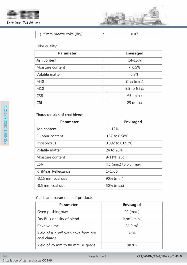
Gas condensate tank Nos. 1 1 Flushing liquor pumps (1000m3/h) Nos. 1 1hot+1cold Tar storage tanks (1000m3) Nos. 2 Liquor tanks (700m3) Nos. 2 1
Apart from the above, two (2) nos. of the existing tar storage tanks (1000m3 capacity) in the existing tar plant will be replaced. Tar loading facilities will be provided in the new tar storage area for loading into road tankers.
4.1.9.3 Ammonia & Hydrogen Sulphide removal
1) NH3& H2S Scrubber
This unit contains two parts – one scrubber for absorbing H2S and another scrubber for absorbing NH3.
a) H2S absorption:
Coke oven gas is passed through the H2S scrubber from bottom to top. Absorption of H2S is performed by the counter current flow of ammonia contained in the de-acidified water coming from NH3 scrubber circuit. Further absorption is carried out by the counter current flow of enriched NH3 water which is also coming from NH3 scrubber circuit.
Due to the exothermic nature of H2S absorption, the heat generated is removed by the counter current flow of washing water. The lower section of H2S Scrubber will be designed for final cooling stage to reduce the temperature increased in exhauster. By means of a cooling loop comprising of cooling stage pumps & cooling heat exchanger in which circulating water is cooled by chilled water, the gas is cooled to a temperature of 22oC to 230C.
Further removal of H2S and removal of major portion of NH3 can be achieved in NH3 scrubbing system by means of stripped ammonia water.
b) NH3 absorption:
Coke oven gas from H2S scrubber is passed through the NH3scrubber from bottom to top. Stripped ammonia water from ammonia stripper is passed counter current. The exothermic reaction heat is removed by cooling the enriched NH3 water through heat exchanger which cools it indirectly using chilled water. This enriched NH3 water is fed to the H2S scrubber. The enriched water from the H2S scrubber is sent to the stripper/de-acidifier unit.
Finally, the cleaned coke oven gas is directed to the naphthalene scrubber.

BSL Installation of stamp charge COB#9
Page no. 4.15 CET/20/RN/4241/FR/CC/01/R=0
Experience that delivers
PRO
JECT
DES
CRIP
TIO
N
2) Ammonia stripper/ de-acidifier unit
This unit consists of two parts–one stripper for ammonia and another stripper for de-acidifier.
a) De-acidifier unit:
The enriched water from the H2S scrubber is indirectly pre-heated using hot stripped water coming from NH3 stripper and also hot de-acidified water coming from de-acidifier. Then it is fed to the top of de-acidifier facing ammonia vapours and steam coming in counter current flow from NH3 stripper. The gases leaving de-acidifier now contains H2S, CO2, HCN & NH3. They are directed to a condenser. The condensate is returned to the de-acidifier while the gases are directed to the Claus unit.
Sl. No.
Description Unit Capacity Nos.
H2S Scrubber Unit 1. H2S Scrubbing Unit 50000Nm3/h 1
2. Pumps, Heat Exchangers
NH3 Scrubbing Unit
1. NH3 Scrubbing Unit 50000Nm3/h 1
2. Pumps, Heat Exchangers
COMBI / Flexi Scrubber
1. COMBI / Flexiscrubbing Unit 50000 Nm3/h 1
Distillation Unit (H2S & NH3 stripper)
1. H2S Stripper 1w+1s
2. NH3 Stripper 1w+1s
3. Heat exchangers, Pumps
4.1.9.4 Ammonia Cracking & Sulphur Removal
The top gases leaving de-acidifier unit and ammonia stripper (sour gas) mainly contain H2S, NH3, HCN, hydrocarbons. Sour gas is brought to sulphur recovery unit for recovery of sulphur from H2S and decomposition of ammonia to nitrogen and hydrogen and HCN to hydrogen, nitrogen and carbon monoxide. The unit is based on Claus process and mainly consists of Claus Kiln (vapour burner & crack reactor with catalyst), waste heat boiler, Claus reactor (with catalyst), sulphur condenser, sulphur storage tank, sulphur palletizing unit, heat exchangers.

BSL Installation of stamp charge COB#9
Page No. 4.16 CET/20/RN/4241/FR/CC/01/R=0
Experience that delivers
PRO
JECT
DES
CRIP
TIO
N
The Claus Kiln is a cylindrical vertical vessel inside lining with refractory. At the top of the kiln a set of burners are provided for firing with coke oven gas to get suitable temperature for decomposition of ammonia and HCN.
Sour vapour containing H2S, NH3, HCN is first fed into the Claus Kiln where partial oxidation takes place in which 1/3rd of H2S is burnt with air to form SO2 and rest 2/3rd H2S react with SO2 to give elemental sulphur. The whole reaction is exothermic. High temperature is maintained in the kiln by chemical reaction which helps in dissociation of ammonia and HCN. If the sour gas volume is less, the heat released by chemical reaction will be less which is not sufficient to maintain the furnace temperature for decomposing ammonia. So a small amount of coke oven gas is fed to maintain the inside temperature of kiln.
NH3 and HCN vapours are decomposed to H2, N2 and CO at temperature 1150oC by catalytic cracking (nickel catalyst). Hydrocarbons in sour gas are also decomposed or burnt. Secondary air is fed at the bottom of the furnace for further oxidation of process gas. The amount of secondary air is controlled by H2S/SO2 analyser.
High temperature process gas from the Claus kiln is passed through the waste heat boiler for heat recovery and then it is continuously passed through two stages of Claus reactor to produce elemental sulphur. Then it is passed through the sulphur condenser and sulphur separator where liquid sulphur is separated.
The tail gas is sent to the process gas cooler where it is cooled to 80oC by spraying condensate tarry liquor from the upper condensate tank and it goes to the foul gas main before primary cooler. Liquid sulphur condensed at waste heat boiler and separator is sent to the sulphur storage tank. Then from sulphur storage tank, it will be pumped to the sulphur palletizing unit. These pellets will be transported to the existing sulphur storage unit.
4.1.9.5 Naphthalene Scrubber Unit
1) Naphthalene Scrubber
The cooled gas from H2S & NH3 scrubbers is taken to naphthalene scrubber for naphthalene recovery to the extent of 0.05gm/Nm3. Most part of naphthalene in CO gas is separated out with tar in hydraulic mains of coke oven battery, primary gas cooler and part of the remaining portion in naphthalene scrubber. The scrubber is packed with suitable packing to provide larger surface area. A measured quantity of make-up solar oil is continuously added from the top of the scrubber (lean solar oil) and proportionate quantity of benzol rich solar oil is removed from the bottom section of scrubber to storage tank. Rich solar oil is to be sent to naphthalene stripping section for recovery of naphthalene rich oil by steam stripping and to get lean solar oil for further use in scrubber.
This plant will comprise of the following major technological equipment

BSL Installation of stamp charge COB#9
Page no. 4.17 CET/20/RN/4241/FR/CC/01/R=0
Experience that delivers
PRO
JECT
DES
CRIP
TIO
N
Facility Unit Working Standby Naphthalene scrubber (50000Nm3/h) Nos. 1 1 Oil drop separators Nos. 2 Heat exchangers, pumps, tanks, seal pots
2) Naphthalene Stripping
The naphthalene rich oil will be bled continuously from the naphthalene scrubber and will be brought into this section for recovery of naphthalene oil. The lean oil thus obtained is returned to the scrubbing section continuously for reuse.
The naphthalene rich solar oil will be fed to the naphthalene stripper from where naphthalene will be stripped off by steam. Almost naphthalene free solar oil will be taken out from stripping column for reuse in naphthalene scrubber after proper cooling.
The vapour coming out from naphthalene stripper will contain naphthalene with oil & water vapour which will be condensed in water cooled condenser. Naphthalene rich oil getting separated from water is sent to tar storage tanks. Contaminated water will be taken into a separator where water & oil will get separated.
This unit will comprise technological equipment like naphthalene stripping column (1 no), condenser, rich solar oil pre-heater, lean solar oil coolers, lean solar oil pumps, separator etc.
4.2.3.6 Chilled Water Plant
One centralized chilled water plant which will meet the chilled water requirement of primary gas coolers and other process equipment of BPP-2 will be provided.
The chilled water plant will be based on vapour absorption process complete with chilled water pumps, refrigerant pumps, condensate pumps, cooling towers, pipe, valves, instrumentation and other associated accessories.
4.2.3.7 Effluent Treatment Plant BOD Plant
All chemically contaminated waste waters from the various units and systems of the COB#9 complex contaminated with various organic and inorganic contaminants such as phenolic compounds, ammonium salts, coal tar and oils, etc., generally called phenolic effluents having a high Bio-chemical Oxygen Demand (BOD5) will be suitably handled in an exclusive phenolic effluent sewerage network of COB#9. This network will be designed to bring all such chemically contaminated waste waters arising out of excess flushing liquor, coke oven gas condensates, process vessel drains, contaminated overflows and washings, etc. will be suitably treated in a new Phenolic Effluent Treatment Plant

BSL Installation of stamp charge COB#9
Page No. 4.18 CET/20/RN/4241/FR/CC/01/R=0
Experience that delivers
PRO
JECT
DES
CRIP
TIO
N
[PETP), generally called BOD plant]. The new BOD plant will have a treatment capacity to treat all such waste waters and the capacity will be 50m3/h (min.). BOD plant will be located by the side of the existing BOD plant of CO-BPP.
The BOD plant will be designed considering the input effluent quality as indicated:
Parameter Unit Quantity Phenol mg/l 500 Total Ammonia mg/l 500 Tar & Oil mg/l 100 to 350 Cyanides mg/l 50 Thio-cynides mg/l 100 pH mg/l 7.5 to 9 Temperature mg/l 50o to 60oC
The treated effluent will generally conform to the following quality parameters:
Parameter Unit Quantity pH of treated effluent mg/l 6 to 8 Suspended solids mg/l <100 Phenols mg/l <1 Cyanides mg/l <0.2 Ammonical nitrogen mg/l <50 Free ammonia mg/l <5 Oil & grease mg/l <5 Nitrate nitrogen mg/l <10 BOD (3 days, 27oC) mg/l <30 COD mg/l <250
The proposed effluent treatment plant will broadly consist of the following units-
Sl. No.
Description Unit Capacity
Nos.
1. Tar – Oil skimming tank unit along with skimmer (retention 1 h)
80m3 1 Set
2. Equalization tank also with skimming arrangement (retention 1 day)
1 Set
3. Skimmed oil sump 1 Set 4. Dissolved air floatation unit along with all
accessories 50m3/h 1 Set
5. pH adjustment tank along with agitator (retention 30min.)
1 Set
6. Ammonia stripping tower 1 Set

BSL Installation of stamp charge COB#9
Page no. 4.19 CET/20/RN/4241/FR/CC/01/R=0
Experience that delivers
PRO
JECT
DES
CRIP
TIO
N
7. Aeration tank-I (retention 12hrs.) 1 Set 8. Settling tank-I (retention 2.5hrs.) 1 Set 9. Aeration tank-II (retention 40hrs.) Settling tank-II (retention 2.5hrs.)
10. De-nitrification tank along with agitators (retention 2hrs.)
Settling tank-III (retention 2.5hrs.) 11. Aeration tank –III (retention 1 hrs.)
Sludge tump 12. Thickener (retention 2.5hrs.) 13. Sludge drying bed 14. Sludge sump & pump house 15. Treated effluent sump & pump house. 16. Chemical preparation & dosing system 17. Chemical storage and laboratory 18. Slope oil tank 19. Biological culture tank
The treated effluents from the BOD plant will be used as industrial make up water within the COB#9 complex to the extent practical in conformity to the zero-discharge principles. Facilities for recycling the treated effluents to internal consumption points will be provided accordingly.
All floor washings which are likely to be contaminated with chemical impurities, gas condensates, chemical equipment and vessel washings and excess ammonical liquor will be brought to the new BOD plant for treatment and recycled appropriately for industrial use for wet quenching and make up for industrial cooling water circuits.
4.1.10 New Benzol Storage Facility
This new benzol storage facility will be installed near the existing tar storage tanks in front of existing Benzol Recovery Plant (BRP-1) to accommodate the existing benzol storage facility working presently in BRP-2 area. Storage of 3000m3 will be created by installing four tanks of 750m3 capacity each. Tanker loading facilities will be provided. Foam based fire fighting facilities will be provided for this area. The road between the tanks and the refractory storage sheds will be suitably diverted. In the existing BRP-2 area, a partition wall will be erected for isolating the existing benzol storage area. After the erection of the new boundary wall, the balance area of the BRP-2 will be license-altered and the new license will cover only the equipment located within the new boundary wall.

BSL Installation of stamp charge COB#9
Page No. 4.20 CET/20/RN/4241/FR/CC/01/R=0
Experience that delivers
PRO
JECT
DES
CRIP
TIO
N
All equipment presently located in the balance area outside the new boundary wall (license-altered area) will be disposed-off by BSL separately.
After the commissioning of the new Benzol storage area, the balance equipment of BRP-2 (now located within the new boundary wall) will be dismantled after getting this area within the new boundary wall de-licensed. Dismantling of this balance equipment (within the new boundary wall) will be included in By-product package. Existing facilities of Benzol Rectification plant is shown in Drg: CET RN 4241 CC2 00 003 R=0.
4.2 REFRACTORY
4.2.1 Battery Proper
4.2.1.1 Refractory work of battery will be a combination of mainly silica and fireclay bricks. There will be provision of control of air distribution to individual flues for proper burning of gaseous fuel. Around 550 shapes of refractory will be used in different zone of coke oven battery. The approximate quantity of refractory bricks including all shapes is about 26000 tonne which includes silica, fireclay and insulation bricks for coke oven battery proper. Approximately 5000 tonne refractory bricks are also required for chimney, waste gas flue, quenching tower and coke wharf.
4.2.1.2 According to the process and operation requirement, various types of refractory will be used in different portions of coke oven. Refractory materials of different zone of coke oven battery are being envisaged as follow.
Sole flue
Horizontal sole flues and valve controls are used for controlling the supply of lean gas fuel, such as blast furnace gas or any other lean gas, selectively to the gas flues in heating zones of the coke oven chamber walls and the recirculation of waste gas.
There is much temperature difference between upward flow (pre-heated gas or air) and downward flow (high temperature waste gas out of combustion chamber) in sole flue, to bear sudden temperature variation and prevent gas corrosion on sole flue, the sole flue will be lined with fire-clay brick.
Concrete of sole flue zone will be lined with combination of high strength and thermal shock resistant fireclay category (3) and mica/fireclay insulation bricks to protect the concrete from the excessive heat.
Regenerator
In order to improve energy efficiency, regenerators are located right under the ovens, exchanging heat from flue gases with combustion air or blast furnace gas.
The wall of regenerator will be constructed with silica bricks and fireclay bricks. Checker chamber of regenerator will be filled with fireclay checker bricks to fully
BSL Installation of stamp charge COB#9
Page no. 4.21 CET/20/RN/4241/FR/CC/01/R=0
Experience that delivers
PRO
JECT
DES
CRIP
TIO
N
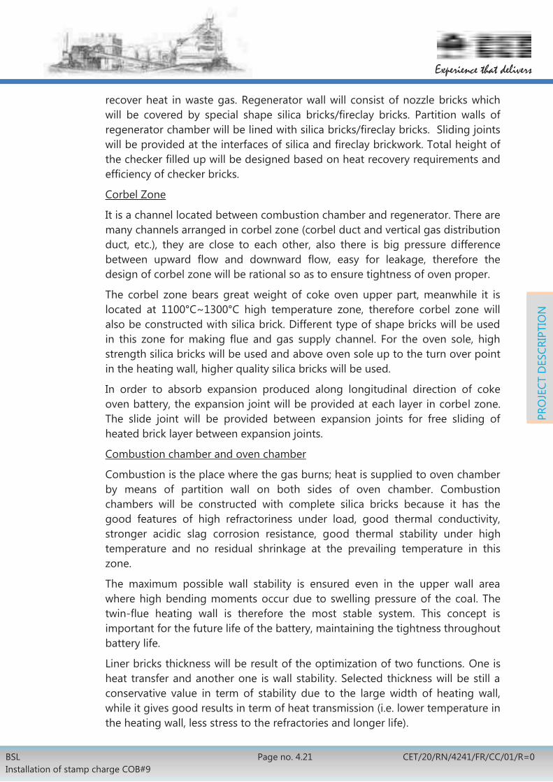
recover heat in waste gas. Regenerator wall will consist of nozzle bricks which will be covered by special shape silica bricks/fireclay bricks. Partition walls of regenerator chamber will be lined with silica bricks/fireclay bricks. Sliding joints will be provided at the interfaces of silica and fireclay brickwork. Total height of the checker filled up will be designed based on heat recovery requirements and efficiency of checker bricks.
Corbel Zone
It is a channel located between combustion chamber and regenerator. There are many channels arranged in corbel zone (corbel duct and vertical gas distribution duct, etc.), they are close to each other, also there is big pressure difference between upward flow and downward flow, easy for leakage, therefore the design of corbel zone will be rational so as to ensure tightness of oven proper.
The corbel zone bears great weight of coke oven upper part, meanwhile it is located at 1100°C~1300°C high temperature zone, therefore corbel zone will also be constructed with silica brick. Different type of shape bricks will be used in this zone for making flue and gas supply channel. For the oven sole, high strength silica bricks will be used and above oven sole up to the turn over point in the heating wall, higher quality silica bricks will be used.
In order to absorb expansion produced along longitudinal direction of coke oven battery, the expansion joint will be provided at each layer in corbel zone. The slide joint will be provided between expansion joints for free sliding of heated brick layer between expansion joints.
Combustion chamber and oven chamber
Combustion is the place where the gas burns; heat is supplied to oven chamber by means of partition wall on both sides of oven chamber. Combustion chambers will be constructed with complete silica bricks because it has the good features of high refractoriness under load, good thermal conductivity, stronger acidic slag corrosion resistance, good thermal stability under high temperature and no residual shrinkage at the prevailing temperature in this zone.
The maximum possible wall stability is ensured even in the upper wall area where high bending moments occur due to swelling pressure of the coal. The twin-flue heating wall is therefore the most stable system. This concept is important for the future life of the battery, maintaining the tightness throughout battery life.
Liner bricks thickness will be result of the optimization of two functions. One is heat transfer and another one is wall stability. Selected thickness will be still a conservative value in term of stability due to the large width of heating wall, while it gives good results in term of heat transmission (i.e. lower temperature in the heating wall, less stress to the refractories and longer life).

BSL Installation of stamp charge COB#9
Page No. 4.22 CET/20/RN/4241/FR/CC/01/R=0
Experience that delivers
PRO
JECT
DES
CRIP
TIO
N
Silica brick for construction of oven chamber adopts groove and tongue structure so as to reduce leakage of crude gas and increase brickwork strength. Silica brick lining in the heating walls will be totally keyed and interlocked throughout the design from oven floor to oven roof, to preclude displacement of the wall.
No expansion joints will be provided for heating wall construction.
Oven top
Oven top is located at topmost of coke oven battery. The lowest layer of oven top is the oven roof layer of oven chamber. It will be constructed with silica brick so as to ensure the same expansion of oven chamber.
To reduce heat dispersion from oven top, the layer of oven chamber roof will be constructed with fire clay brick and insulating brick. It will also minimize cracks formation during heating up and operation of the battery.
The thickness of oven top will be such that it will ensure oven proper strength and lowering oven top temperature. Special shape fireclay bricks are used to cover the heating chamber.
To drain rain water, the oven roof will be designed with a slope of 50 mm between the centre of the coke oven battery oven and both extremities on the coke and pusher side.
4.2.1.3 Material specifications are indicated in following tables. However, if stamp charge battery requires any other/different materials specification, same will be furnished by the battery designer.
Specification of Silica Bricks
Physico-Chemical Properties
S. No. Property Unit Type A Type B Type C
1 Chemical SiO2, min Al2O3, max. Fe2O3, max. CaO, max.
% % % %
95 1.2 1.4 2.5
95 1.2 1.4 2.5
95 1.2 1.4 2.5
2 P.C.E, min. SK 31 31 31 3 Apparent Porosity,
Av. of 5 samples < No single value
% 19 20
23
24
16
17 4 Specific gravity,
Av. of 5 samples < No single value
- 2.34 2.35
2.34
2.35
2.34
2.35 5 Bulk Density, min. gm/cm3 1.79 1.76 1.85

BSL Installation of stamp charge COB#9
Page no. 4.23 CET/20/RN/4241/FR/CC/01/R=0
Experience that delivers
PRO
JECT
DES
CRIP
TIO
N
S. No. Property Unit Type A Type B Type C
6 Cold Crushing Strength Av. of 5 samples, >
No single value <
kg/cm2
350 300
300
270
500
450 7 P.L.C for 2 h, max
at temp. % 0C
+ 0.2 1500
(-) value not
allowed
+ 0.2 1500
(-) value not
allowed
+ 0.2 1500
(-) value not
allowed 8 R.U.L, .ta value at 2kg/cm2
, min.
oC
1650
1650
1650
9 R.T.E, max. at 10000C % 1.30 1.30 1.30 10 Residual Quartz content,
Av. of 5 samples < No single value
% 1.5 2.0
1.5 2.0
1.5 2.0
Note: Type A bricks will be used in heating wall with coke face, Type C in oven sole & Type B in other areas. Coke face will be indicated in brick shape drawings.
Material Specification of Silica Mortar
Physico-Chemical properties
S. No. Property Unit Value 1 Chemical
SiO2, min Al2O3+TiO2, max. Fe2O3, max.
% % %
91 5
1.5
2 P.C.E, min. SK 29 3 Drying Shrinkage at 110oC with
requisite quantity of water, max.
% 3
4 Grain composition. +2mm
+1.0 mm, max. -0.20mm , -0.08mm ,
% % % %
Nil 3
65-80 45-60
5 Workability - Good6 R.U.L.
A 10mm thick layer of mortar contained between 2 silica brick cylinders each of diameter 50
BSL Installation of stamp charge COB#9
Page No. 4.24 CET/20/RN/4241/FR/CC/01/R=0
Experience that delivers
PRO
JECT
DES
CRIP
TIO
N
S. No. Property Unit Value mm & height 20mm under load of 2kg/cm2
Ta Value, min Te Value, min
oC oC
14501520
7 Bonding Strength - Satisfactory 8 True Density Kg/m3 26009 Type - Heat setting
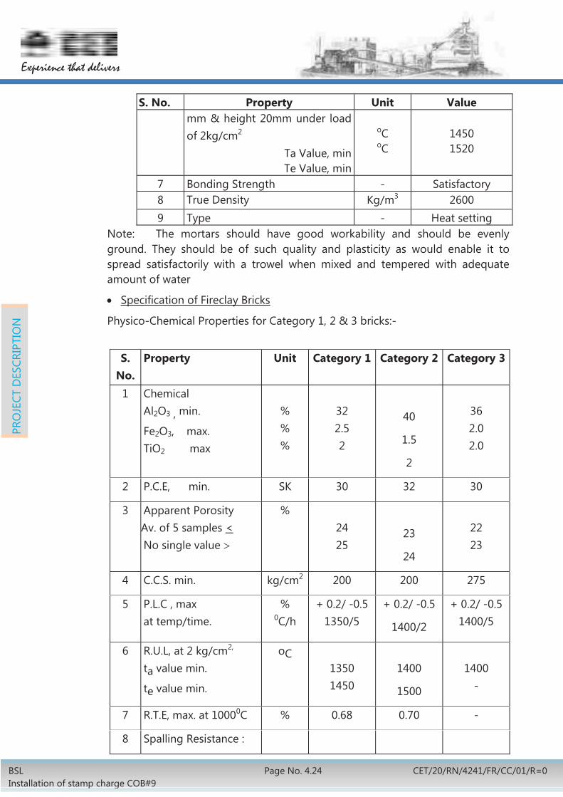
Note: The mortars should have good workability and should be evenly ground. They should be of such quality and plasticity as would enable it to spread satisfactorily with a trowel when mixed and tempered with adequate amount of water
Specification of Fireclay Bricks
Physico-Chemical Properties for Category 1, 2 & 3 bricks:-
S.
No. Property Unit Category 1 Category 2 Category 3
1 Chemical Al2O3 , min.
Fe2O3, max. TiO2 max
% % %
32 2.5 2
40
1.5
2
36 2.0 2.0
2 P.C.E, min. SK 30 32 30
3 Apparent Porosity Av. of 5 samples < No single value
% 24 25
23
24
22 23
4 C.C.S. min. kg/cm2 200 200 275
5 P.L.C , max at temp/time.
% 0C/h
+ 0.2/ -0.5 1350/5
+ 0.2/ -0.5
1400/2
+ 0.2/ -0.51400/5
6 R.U.L, at 2 kg/cm2,
ta value min.
te value min.
oC 1350 1450
1400
1500
1400
-
7 R.T.E, max. at 10000C % 0.68 0.70 -
8 Spalling Resistance :

BSL Installation of stamp charge COB#9
Page no. 4.25 CET/20/RN/4241/FR/CC/01/R=0
Experience that delivers
PRO
JECT
DES
CRIP
TIO
N
S. No.
Property Unit Category 1 Category 2 Category 3
-at 1000oC (small prism test) - at 350oC& air cooling on full brick (for checkers only)
cycles +20 +20 +20
Physico-Chemical Properties for Category 4, 5 & 6 bricks
S. No. Property Unit Category 4 Category 5 Category 6 1 Chemical
Al2O3 , min.
Fe2O3, max. TiO2 max
% % %
36 2.5 2.0
38 2.0 2.0
39 2.52.0
2 P.C.E. min. SK 31 32 32 3 Apparent Porosity
Av. of 5 samples < No single value
% 17 18
18 19
16 17
4 C.C.S. min. kg/cm2 500 300 400 5 P.L.C , max
at temp/ time. %
0C/h + 0.2/ -0.5
1380/5 + 0.2/ -0.5
1400/5 + 0.2/ -0.5
1400/5 6 R.U.L, at 2kg/cm2,
ta value min.
te value min.
oC 1380 1550
1400
-
1400
-
7 R.T.E, max. at 10000C % 0.60 - - 8 Spalling Resistance at
1000oC , (small prism test)
cycles
+20
+20
-
Specification for Insulation Bricks
SL. No
Property Unit Fireclay type 1 Fireclay type 2
1 Chemical Composition Al2O3 + TiO2 min. ,
% 38
-
2 P.C.E Min. SK 32
BSL Installation of stamp charge COB#9
Page No. 4.26 CET/20/RN/4241/FR/CC/01/R=0
Experience that delivers
PRO
JECT
DES
CRIP
TIO
N
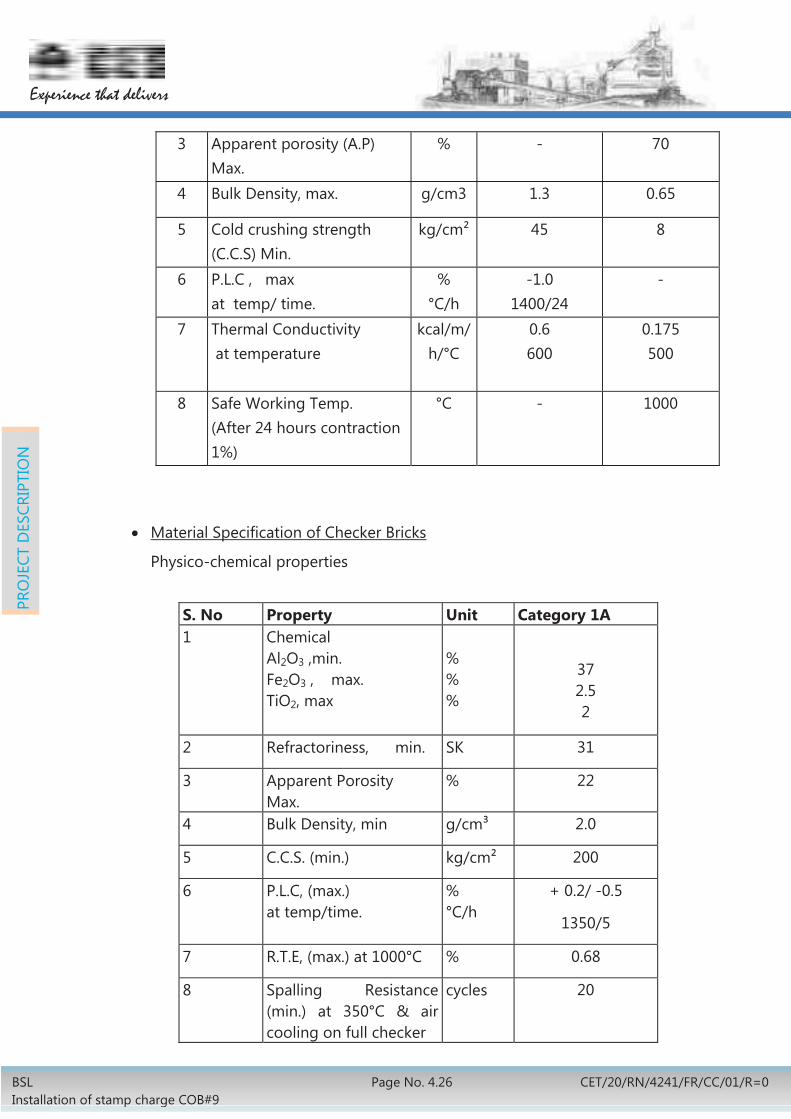
Material Specification of Checker Bricks
Physico-chemical properties
3 Apparent porosity (A.P) Max.
% - 70
4 Bulk Density, max. g/cm3 1.3 0.65
5 Cold crushing strength (C.C.S) Min.
kg/cm² 45 8
6 P.L.C , max at temp/ time.
% °C/h
-1.0 1400/24
-
7 Thermal Conductivity at temperature
kcal/m/h/°C
0.6 600
0.175 500
8 Safe Working Temp. (After 24 hours contraction 1%)
°C - 1000
S. No Property Unit Category 1A 1 Chemical
Al2O3 ,min. Fe2O3 , max. TiO2, max
% % %
37 2.5 2
2 Refractoriness, min. SK 31
3 Apparent Porosity Max.
% 22
4 Bulk Density, min g/cm³ 2.0
5 C.C.S. (min.) kg/cm² 200
6 P.L.C, (max.) at temp/time.
% °C/h
+ 0.2/ -0.5
1350/5
7 R.T.E, (max.) at 1000°C % 0.68
8 Spalling Resistance (min.) at 350°C & air cooling on full checker
cycles 20

BSL Installation of stamp charge COB#9
Page no. 4.27 CET/20/RN/4241/FR/CC/01/R=0
Experience that delivers
PRO
JECT
DES
CRIP
TIO
N
Specification of Fireclay & Insulation Mortar
Sl. No Property Unit Fireclay Insulation 1 Chemical composition
Al2O3, min. TiO₂ max Fe2O3, max.
% 30 2.0 2.5
- -
2 P .C.E Min. SK 29 -3 Drying Shrinkage
at 110°C, max. % 3
-4 Firing Shrinkage at 1250°C for
5 hours, max. % 3.5
-5 Loose Bulk Density kg/m3 - 600-650 6 Grain composition.
+1.0 mm , max. -0.5 mm , min
%
Nil
85%
Nil
90%7 Workability Good Good 8 Bonding Strength Satisfactory Satisfactory
Typical specification of coke wharf bricks
Sl. No.
Properties Specification
Chemical composition (%) 1 Al₂O₃(min.)
Fe₂O₃(max.) 54% 1.5%
2. Bulk density (BD) g/cm³
min. 2.5
3. Apparent porosity (%) (A.P.) max. 16
4. Cold crushing strength (C.C.S) Kg/cm²
min. 650
5 PCE (min) 1710°C 6 Abradability index on natural skin (Max) 80 Morgan Marwill
5. Spalling resistance at 1000°C(small prism test)
+ 30
Specification of Calcium Silicate Insulation (950oC)
Material Quality As per IS : 9428-1993 Typical specification of Acid Resistant refractories for quenching tower
Acid proof refractory bricks: IS 4860-1968 class I Acid proof refractory cement/ mortar as per IS 4832 part I

BSL Installation of stamp charge COB#9
Page No. 4.28 CET/20/RN/4241/FR/CC/01/R=0
Experience that delivers
PRO
JECT
DES
CRIP
TIO
N
4.2.1.4 Chimney of coke oven battery will be lined with insulation and fireclay bricks (Category -1). One layer insulation bricks will be used as back up lining and fireclay bricks are used as working lining.
4.2.1.5 Coke wharf area will be lined with abrasion resistant, high spalling resistant high alumina bricks with minimum 54% Al2O3.
4.2.1.6 Quenching tower will be lined with acid proof bricks and mortar.
4.2.1.7 Waste gas flue line will be lined with fireclay bricks and mortar.
4.2.1.8 Inspection and testing of refractories will be done as per relevant parts of IS: 1528-2002 or equivalent ISO standard. For testing procedures not covered by IS1528-2002, the existing practice of BSL will be followed.
4.2.1.9 The selection of refractory for oven decking will be such so as to ensure battery top temperature does not exceed 55°C in the hottest season at a distance of 1m above oven top.
4.2.1.10 All refractory & auxiliary materials including silica bricks and silica mortar for this project will be procured by battery designer.
4.2.1.11 Inspection & storage of all refractories and auxiliary materials including silica bricks & silica mortar will be in the scope of battery designer. For entire silica bricks 100% physical inspection will be done by the battery designer at manufacturer’s premises.
4.2.1.12 It has been envisaged that approximately 16000 tonnes silica refractory, 10500 tonnes fireclay refractory and 700 tonnes insulation refractory will be required for battery proper.
4.2.2 Refractory for Coke Dry Cooling Plant
4.2.2.1 Refractory work will be a combination of mainly fireclay and insulation bricks.
4.2.2.2 Refractory in the CDCP chambers will be totally keyed and interlocked throughout the design, to preclude displacement of the brick work.
4.2.2.3 All refractory shapes, Fireclay and Insulation, are desirable to be machine made.
4.2.2.4 Mullite bricks will be used in abrasion prone areas like inclined flue & dust settling bunker arch & partition wall.
4.2.2.5 Saw dust / ceramic fiber will be used for filling the expansion joints in CDCP.
4.2.2.6 Keeping in line with the material specifications presently in use in CDCP, Purchaser has identified material specifications for fireclay & insulation refractories. The same are given in following tables.
4.2.2.7 Bidder based on his design requirements, may select from the specifications given in the tables or, bidder will provide bricks of better specification to meet their design requirement. However purchaser intends to use the Mullite quality bricks (min 63% Al2O3) in high impact zones of CDCP like inclined flue zone

BSL Installation of stamp charge COB#9
Page no. 4.29 CET/20/RN/4241/FR/CC/01/R=0
Experience that delivers
PRO
JECT
DES
CRIP
TIO
N
(pillar brick area), DCB partition wall areas, chamber mouth, arch of DCB boiler side after partition wall up to end of boiler arch. From bottom to top of inclined flue area (coke face area) one layer of mullite brick to be provided. Ring channel to be provided with category-4 fire clay bricks. Ceramic fibre board (along the inside of shell) & insulation bricks will be used as back up lining in cooling chambers in the following areas:-
a) Cooling zone
b) Inclined flue zone
c) Cylindrical part of pre chamber
d) Conical part of pre chamber
e) Dust collecting bunker
4.2.2.8 Specification of Fireclay, Light weight fireclay bricks, Insulation bricks and Mortars
The bricks and mortars of following specification are being used in the Indian Coke Dry Cooling Plant. However, bidder will be free to provide bricks of better specification to meet their design requirement.
Sl. No.
Properties Specification
Category 2 Category 3 Category 4
1 Chemical compo-sition (%) Al2O3+TiO2(min.) TiO2(max.) Fe₂O₃(max.)
39
2
1.5
38
2
1.5
41
2.0
1.5
2. Refractoriness (PCE) min.
1730°C 1750°C 1750°C
3. Apparent porosity (A.P.) max.
22% - 16%
4. Cold crushing strength (C.C.S) Kg/Cm² min.
(2a) 300
(2b) 400 75 500
5. Refractories under load (RUL) at 2 Kg/Cm² load (min.)
Ta 1400°C - Ta 1440°C
6. Permanent linear change (PLC) max.
(+) 0.4% (at 1350°C for 4
hrs.)
(+) 1.0% (at 1400°C for 4
hrs.)
(+) 0.3% (at 1450°C for 4
hrs.)
7. Reversible Thermal - - -

BSL Installation of stamp charge COB#9
Page No. 4.30 CET/20/RN/4241/FR/CC/01/R=0
Experience that delivers
PRO
JECT
DES
CRIP
TIO
N
Sl. No.
Properties Specification
Category 2 Category 3 Category 4
expansion (RTE) max.
8. Spalling resistance (min.)
20 cycles - -
9. Bulk density (BD) max.
- 1.3gm/cc -
10. Thermal conductivity (at 600 °C) max.
- 0.6kcal/ m/h/°C
-
Specific Specification for Insulation Bricks: SL. No Property Unit value
1 Chemical Composition
Al2O3 + TiO2 min. ,
%
-
2 P.C.E Min. SK
3 Apparent porosity (A.P) Max. % 70
4 Bulk Density, max. g/cm3 0.65
5 Cold crushing strength (C.C.S) Min.
kg/cm² 8
6 P.L.C , max
at temp/time.
%
°C/h
-
7 Thermal Conductivity
at temperature
kcal/m/h/°C
°C
0.175
500
8 Safe Working Temp.
(After 24 hours contraction 1%)
°C 1000
Specification of Mortar
Sl. No.
Properties Specification
1. The mortar should be usable

BSL Installation of stamp charge COB#9
Page no. 4.31 CET/20/RN/4241/FR/CC/01/R=0
Experience that delivers
PRO
JECT
DES
CRIP
TIO
N
Specification for Mullite bricks:
Sl. No.
Properties Specification
Chemical compo-sition (%)
S Al₂O₃ (min.)
Fe₂O₃ (max.)
63%
1%
2. Bulk density (BD) gm/cm³ min. 2.5
3. Apparent porosity (%) (A.P.) max. 13.5
4. Cold crushing strength (C.C.S) Kg/Cm²
min. 600
5. Refractories under load (RUL) at 4Kg/Cm² load (min.)0C
1500
6. Permanent linear change (PLC) at 15000C max.
+0.2
7. Refractoriness (PCE) 0C min. 1825
8. MOR Kg/cm² 150-200
9. Thermal conductivity kcal/m/h/0C 1.6 at 15350C 1.8 at 14500C
as building binder for bricks made of similar materials.
2. Chemical composition (%) Al2O3 (min.) Fe2O3 (max.)
42 1.5
3. Refractoriness (min) 17500C . Drying shrinkage should not
exceed (with 22% water dried at 110 +/-50C).
3% (max)
5. Firing shrinkage (max.) 3.5% at 1250 °C for 5 hours 6. Fineness (min.) Screen size mm
1 .0 .6 0 .09
% passing through (min) 100 95 60
7. Workability Good 8 Bonding strength Satisfactory

BSL Installation of stamp charge COB#9
Page No. 4.32 CET/20/RN/4241/FR/CC/01/R=0
Experience that delivers
PRO
JECT
DES
CRIP
TIO
N
Specification of Ceramic Fibre Board:
S. No. Properties Units Value
1 Chemical
Al2O3
SiO2
Fe2O3+TiO2,Max
Others, Max
%
%
%
%
38-42
57-61
1
1
2 Service temperature, max °C 1260
3 Bulk Density, max g/cc 0.38
4 Thermal Conductivity
At 250 oC
At 550oC
At 850oC
At 1000 oC
W/m°K
0.10
0.11
0.14
0.19
5 PLC, 24h at 1200°C, max % 0 to (-) 2
4.2.2.9 All refractory materials & auxiliary materials for this project will be procured by battery designer.
4.2.2.10 Inspection & storage of all refractories and auxiliary materials will be in the scope of the battery designer.
4.2.2.11 It has been envisaged that approximately 2300 tonnes refractory materials will be required for CDCP.
4.3 MECHANICAL EQUIPMENT
4.3.1 Coal Handling
4.3.1.1 Coal handling plant will use 22 nos. (2 rows x 11) of silos out of 81 existing silos having capacity of 2500t each for storage of coal for stamp charged battery. 11 nos. of silos from series A & C will be allocated for coal storage of stamp charged battery only.
4.3.1.2 Existing conveyor Y9 & Y10A will be splitted before the silo allocated for stamp charged battery. Necessary dismantling of the rest conveyors with technological structure will be done. Existing drive system & tail pulley will be utilised for the Y9 & Y10A. Technological structures, take up system, monorail with chain pulley block for tail pulley handling will be provided.

BSL Installation of stamp charge COB#9
Page no. 4.33 CET/20/RN/4241/FR/CC/01/R=0
Experience that delivers
PRO
JECT
DES
CRIP
TIO
N
The details of existing conveyors Y9 and Y10A are as follows:
Conv. No.
Capcity (tph)
Existing BW (mm)
Existing Horz. Length/Lift (approx in m)
Modified Horz. Length/Lift (approx. in m)
Y-9 400 1200 365/4.7 220/4.7
Y-10A 600 1200 365/4.7 220/4.7
4.3.1.3 New conveyors Y-47 and Y-48 shall be provided in the balance portion of splitted conveyors. The dismantled technological structure will be utilised as far as possible. These conveyors will receive coal from 11 nos. of silos only in each row.
4.3.1.4 Conveyor Y-49 will receive soft coal from either conveyors Y-47 or Y-48 and will be fed to an intermediate bunker through conveyor Y-51. The coal from intermediate bunker will be subsequently discharged into conveyor Y-53 through vibro feeder.
Conveyor Y-50 will receive hard coal from either conveyors Y-47 or Y-48 and will be fed to primary coal crusher through conveyor Y-52. A primary coal crushing station of 200 tph capacity has been considered with 1W+1S coal crusher for crushing of hard coal. The crushed coal will be fed to conveyor Y-53.
Secondary coal crushing station with 1W+2S coal crusher of capacity 600 tph each will receive blended coal through shuttle conveyor Y-53A. Crushed coal will be discharged into conveyor Y-55 through belt feeder Y-54.
The crushed coal then will be transported up to coal tower no. 5 of stamp charge battery no. 9 through a series of belt conveyors Y-56, Y-57, Y-58, Y-59, Y-60, Y-61 and Y-62. Provision shall also be made to feed existing Y-20 conveyor from one of the junction house.
All these conveyors will have trough angle 350 with double drive arrangement.
Refer drawing no. CET RN 4241 ME0 00 001, R=0 for Flow Diagram of Coal Handling and CET RN 4241 ME0 00 002, R=0 for elevations of critical conveyors envisaged for proposed stamp charge battery.
4.3.1.5 Provision for handling of coal due to coal cake breakage has also been envisaged. Conveyor Y-63, parallel to battery on pusher side, will receive coal from service bench and cake breakage unit. The coal will be transported to junction house JNC9-9 through conveyors Y-64 & Y-65 and subsequently fed back to coal tower through conveyor Y-60 for reutilisation. Capacity of these conveyors will be 100 tph.

BSL Installation of stamp charge COB#9
Page No. 4.34 CET/20/RN/4241/FR/CC/01/R=0
Experience that delivers
PRO
JECT
DES
CRIP
TIO
N
Details of proposed new coal conveyors are as follows:
Sl. No.
Conv. No.
Belt width (mm)
capacity (tph)
Location
1. Y-47 1400 600 From discharge of weigh feeder beneath silo to either conveyor Y-49 or Y-50 in Junction house JNC9-2
2. Y-48 1400 600 From discharge of weigh feeder beneath silo to either conveyor Y-49 or Y-50 in Junction house JNC9-1
3. Y-49 1400 600 From discharge of conveyor Y-48 in Junction house JNC9-1 to conveyor Y-51 in Junction house JNC9-3
4. Y-50 1000 200 From discharge of conveyor Y-48 in Junction house JNC9-1 to conveyor Y-52 in Junction house JNC9-3
5. Y-51 1400 600
From discharge of conveyor Y-49 in Junction house JNC9-3 to intermediated hopper in primary crusher house
6. Y-52 1000 200
From discharge of conveyor Y-50 in Junction house JNC9-3 to primary hammer crushers in primary crusher house
7. Y-53 1400 600
From discharge of hammer crushers & discharge of intermediate hopper through vibro feeder to shuttle conveyor Y-53A in secondary crusher building
8. Y-53A 1600 600 From discharge of conveyor Y-53 to hammer crushers in secondary crusher house
9. Y-54 1400 600 From discharge of secondary crusher in secondary crusher house to Y-55 in Junction house JNC9-4
10. Y-55 1400 600 For discharging to Y-56 conveyor in Junction house JNC9-5
11. Y-56 1400 600 For discharging to conveyor Y-57 in Junction house JNC9-6

BSL Installation of stamp charge COB#9
Page no. 4.35 CET/20/RN/4241/FR/CC/01/R=0
Experience that delivers
PRO
JECT
DES
CRIP
TIO
N
Sl. No.
Conv. No.
Belt width (mm)
capacity (tph)
Location
12. Y-57 1400 600
For discharging to conveyor Y-58 in Junction house JNC9-7 or to existing conveyor Y-20 through bifurcated chute with motorised flap gate in Junction house JNC9-7
13. Y-58 1400 600 For discharging to conveyor Y-59 in Junction house JNC9-8
14. Y-59 1400 600 For discharging to conveyor Y-60 in Junction house JNC9-9
15. Y-60 1400 600 For feeding to shuttle conveyors Y-61 /Y-62 in coal tower
16. Y-61 1400 600 Shuttle conveyor in coal tower
17. Y-62 1400 600 Shuttle conveyor in coal tower
18. Y-63 800 100 Spillage coal conveyor parallel to battery on pusher side
19. Y-64 800 100 From discharge of conveyor Y-63 in Junction house JNC9-11 to conveyor Y-65 in Junction house JNC9-12
20. Y-65 800 100 From discharge of Y-64 in junction house JNC9-12 to Y-60 in junction house JNC9-9
4.3.1.6 Primary Hammer Crusher station
There will be 2 nos. (1W+1S) of hammer crushers of capacity 200tph each for primary crushing of hard coal only. These crushers will receive coal from conveyors Y-52 through bifurcated chutes with motorised flap gate.
Both the hammer crushers will deliver coal to a common conveyor Y-53 which will be blended with soft coal and carry the coal to secondary crusher house.
Proper vibration isolation system shall be provided.
4.3.1.7 Secondary Hammer Crusher station
There will be 3 nos. (1W+2S) of adjustable type hammer crushers of capacity 600tph each which will be able to deliver the required coal size of -3.2mm (90%). These crushers will receive coal from shuttle conveyor Y-53A.
All the three hammer crushers will deliver coal to a common conveyor Y-54 which will carry the coal to next junction house.

BSL Installation of stamp charge COB#9
Page No. 4.36 CET/20/RN/4241/FR/CC/01/R=0
Experience that delivers
PRO
JECT
DES
CRIP
TIO
N
Proper vibration isolation system shall be provided.
4.3.1.8 Suitable dust suppression / extraction systems will be provided for the proposed coal handling route.
4.3.2 Coke Handling Area
Flow Diagram of coke handling is shown in Drg. No: CET RN 4241 CC0 00 003, R=0. Hot coke after getting quenched either in CDCP unit will move to a coke de-dusting unit for the removal of dry dust through blowing of pneumatic air or from conventional wet quenching unit will be transferred to coke crushing unit via JN9-3 & JN9-4. In coke crusher house it will pass through 80 mm grizzly screen and a coke cutter. From coke crushing unit it will be transferred to coke screening unit. Here, the (-) 80 mm coke generated will pass through a 25 mm grizzly screen. The (-) 25mm fraction will be further screened in a 25 mm vibrating screen.
All the (+) 25mm and (-) 80 mm fractions will be fed to conveyors leading to Blast Furnace.
In one route, a wagon loading point will be provided along with a feeding point to KD5-1 and KD5-2 BF conveyors.
In another route, BF grade coke will be fed to KD5-1 and KD5-2 conveyors, PSD-1 and emergency yard.
Breeze coke (-) 25mm fraction will be further screened in to (-) 15 mm fraction and (+) 15mm. They will be loaded in 300 ton breeze/nut bunkers from which they can be either loaded into wagons or conveyed to Sinter Plant-1 or Sinter Plant-2 by joining at Junction-6.
Thus two tracks will be provided for Gross / BF coke conveyors and one track will be provided for the Breeze coke conveyors.
The conveyors handling coke will have Belt Width (BW) 1200 mm for conveyors K-13 to K-38 with capacity 150tph, 350 trough angle, speed 1.8m/s & for breeze coke will have BW 800 mm for conveyors KB-1 to KB-5 with capacity 40tph, 350 trough angles, speed 1.8m/s. Other detail of the conveyors is as follows:
Sl. No. Conv. No Location
1. K-13 Wharf conveyor
2. K-14
From wharf conveyor discharge to conveyor K-19 & K-20 through bifurcated chute with motorized flap gate in Junction house JN9-3
3. K-15 From beneath dry quenching chamber to conveyor K-17 in CDU building
4. K-16 From beneath dry quenching chamber to conveyor K-

BSL Installation of stamp charge COB#9
Page no. 4.37 CET/20/RN/4241/FR/CC/01/R=0
Experience that delivers
PRO
JECT
DES
CRIP
TIO
N
Sl. No. Conv. No Location
18 in CDU building
5. K-17 From discharge of K-15 in CDU building to conveyor K-19 in Junction house JN9-3
6. K-18 From discharge of K-16 in CDU building to conveyor K-20 in Junction house JN9-3
7. K-19 From discharge of conveyor K-14, K-17, K-18 in JN9-3 to conveyor K-21 in JN9-4
8. K-20 From discharge of conveyor K-14, K-17, K-18 in J9-3 to conveyor K-22 in JN9-4
9. K-21
From discharge of conveyor K-19 in JN9-4 to conveyor K-23 in crusher house through grizzly screen and crusher
10. K-22
From discharge of conveyor K-20 in JN9-4 to conveyor K-24 in crusher house through grizzly screen and crusher
11. K-23
From discharge of coke crusher in crusher house to conveyor K-27 through grizzly screen (oversize) in screen house
12. K-24
From discharge of coke crusher in crusher house to conveyor K-28 through grizzly screen(oversize) in screen house
13. K-25 From discharge of vibrating screen (oversize) to conveyor K-26 in screen house
14. K-26 From discharge of conveyor K-26 to conveyor K-27 or K-28 in screen house
15. K-27 From discharge of conveyor K-26 and grizzly screen (oversize) to conveyor K-29 in JN9-5
16. K-28 From discharge of conveyor K-26 and grizzly screen (oversize) to conveyor K-32 in JN9-5
17. K-29 From discharge of conveyor K-27 to conveyor K-31or K-30 in breeze bunker house
18. K-30 From discharge of conveyor K-29 in Breeze bunker house to wagon at wagon loading point
19. K-31 From discharge of conveyor K-29 in Breeze bunker house to conveyor KD-4 or KD-5 in Junction house

BSL Installation of stamp charge COB#9
Page No. 4.38 CET/20/RN/4241/FR/CC/01/R=0
Experience that delivers
PRO
JECT
DES
CRIP
TIO
N
Sl. No. Conv. No Location
JN9-6
20. K-32 From discharge of conveyor K-28 in Junction house JN9-5 to conveyor K-33 in Junction house JN9-7
21. K-33 From discharge of conveyor K-32 in Junction house JN9-7 to conveyor K-34 in Junction house JN9-8
22. K-34 From discharge of K-33 in JN9-8 to conveyor KD-5 or KD-4 or K-35 in Junction house JN9-9
23. K-35 From discharge of K-34 in JN9-8 to conveyor K-36 or K-38 in Junction house JN9-10
24. K-36 From discharge of K-35 in JN9-10 to existing conveyor in PSD-1
25. K-37 From discharge of K-35 in JN9-10 to conveyor K-38 in Junction house JN9-11
26. K-38 From discharge of K-37 in JN9-11 to conveyor KK-1 in Junction house JN9-12
27. KB-1 Undersize (-25) from vibrating screen in screen house to conveyor KB-2 in screen house
28. KB-2 From discharge of conveyor KB-1 in screen house to conveyor KB-3 in Junction house JN9-5
29. KB-3
From discharge of conveyor KB-2 in Junction house JN9-5 to conveyor KB-4 in Breeze bunker house through vibrating screen and bunker
30. KB-4 From discharge bunker in Breeze bunker house to wagon at wagon loading point
31. KB-5 From discharge bunker at Breeze bunker house to Junction-6.
The capacity of the following conveyors will be increased in coke handling area by increasing the trough angle to 350 & by changing the motor and gear box. The details are as follows:
Sl. No.
Conv. No.
Material Belt width
(mm) Existing
capacity (tph) Proposed
capacity (tph)
1 KD5-1 Coke 1400 350 500
2 KD5-2 Coke 1400 350 500

BSL Installation of stamp charge COB#9
Page no. 4.39 CET/20/RN/4241/FR/CC/01/R=0
Experience that delivers
PRO
JECT
DES
CRIP
TIO
N
4.3.2.1 The following equipment will be provided for the coke processing:
Item Material Capacity
(tph) Working
(no)
Stand- by
(no)
Location
Track-1
80mm grizzly Gross coke 150 1 nil Crusher house
80mm two roll crusher
Gross coke 90 1 nil
Crusher house
25mm grizzly BF coke 150
1 nil Screen house
25mm screen BF coke
60 1 nil Screen house
Track-2
80mm grizzly Gross coke 150 1 nil Crusher house
80mm two roll crusher
Gross coke 90 1 nil
Crusher house
25mm grizzly BF coke 150
1 nil Screen house
25mm screen BF coke
60 1 nil Screen house
Breeze track 15mm screen Breeze
coke 40 1 1 Breeze
bunker house
Dust suppression / extraction systems will be provided for the system.
4.3.3 Oven Machines
4.3.3.1 Following new oven machines are envisaged for the proposed stamp charged battery:
Facility Unit Working Standby
Stamping-Charging-Pushing Machine (SCP) Nos. 1 1
Charging Gas Transfer Car (CGT) Nos. 1 1
Coke Transfer car (CTC) Nos. 1 1

BSL Installation of stamp charge COB#9
Page No. 4.40 CET/20/RN/4241/FR/CC/01/R=0
Experience that delivers
PRO
JECT
DES
CRIP
TIO
N
Self-Propelled Hot Coke cars for dry quenching with coke buckets
Nos. 1 1
Wet quenching loco Nos. 1
Wet quenching wagon Nos. 1
4.3.3.2 While only one set of machine will be required for the normal operation of battery at any moment, the second set is required in view of their criticality for operation of the battery. This spare set of machine will be used as and when the need arises.
4.3.3.3 Machines will be compatible with software/ hardware for oven scheduling, oven identification and oven machine interlocking. It will be capable of major data transfer to process computer as per requirement of the Computerised Heating Control (COHC) system.
4.3.3.4 The new oven machines will be equipped with various modern features. The new machines will also be equipped with facilities, necessary to control emissions from the battery. These machines will be able to meet the overall cycle time of battery operation. The features of the oven machines have been outlined in the subsequent paragraphs.
4.3.3.5 General
1. In general, LT speed of all oven machines will be kept on lower side subject to fulfilment of average pushing rate of 90 ovens per day and other technical requirements. Cycle time of the machines will be decided accordingly.
2. Machines will be provided with interconnecting stairs, platforms, walkways and other structures.
3. Various cabins (operator/ hydraulic/ electronic etc.) of the oven machines will be of double walled construction with insulation. Heat resistant safety glass will be provided on the front and sidewalls of operator’s cabin. The hydraulic, electronic and operator’s cabins will be provided with heavy-duty industrial air conditioner. Other cabins will also be provided with air circulating arrangement (exhaust).
4. All cabins and other vulnerable areas of the oven machines will be provided with portable fire extinguisher of suitable size/ rating.
5. Most of the mechanism in oven machines will be hydraulically actuated. The hydraulic power pack will be provided with one working and one standby pump with all accessories. In addition, one foot pump and accumulators will also be considered for emergency purpose. Hydraulic cylinder will be equipped with distance measuring system (LDT), wherever required for accurate positioning.

BSL Installation of stamp charge COB#9
Page no. 4.41 CET/20/RN/4241/FR/CC/01/R=0
Experience that delivers
PRO
JECT
DES
CRIP
TIO
N
6. All oven machines will be provided with motorised centralised dual line lubrication system with provision of manual lubrication.
7. All oven machines will be provided with compressed air facility with outlet points and long hose on every floor to facilitate proper cleaning apart from the regular operational needs.
8. Doors with spring-loaded latch, membrane type sealing frame and flexible spring-loaded knife-edge have been envisaged. SCP & CTC machines will be suitable to service the same. Proven design door cleaner and doorframe cleaner will be considered.
9. Suitable facility (lifter/ elevated platform) in SCP and CTC for regulating the oven doors will be provided.
10. Rail size and track gauge will be selected suiting to the total weight and maximum wheel load of oven machines.
11. Emergency stop provision will be provided in all oven machines at suitable location. Local control switches at service platform level for movements of vital mechanism have been envisaged.
12. Inter-changeability of components between similar drives will be ensured in new machines.
13. Apart from auto-positioning system, laser spotting is also envisaged to facilitate accurate positioning.
14. Proper heat shield and suitable material selection will be ensured for the components of the machine exposed to high temperature.
15. Good illumination and state of the art PLC interface and control has been envisaged in all the oven machines.
16. Itemised price list of the recommended spares will be obtained from the tenderers along with bid for the oven machines to enable procurement of spares, separately.
17. Supply of ordering specifications/ manufacturing drawings of fast wearing items and maintenance spares by the successful Tenderer will be ensured.
4.3.3.6 Stamping-Charging-Pushing Machine (SCP)
1. SCP machine will be portal type designed for two spot operations in 5-2 series. First spot is for opening of the door and pushing operation and second spot is for charging of coal cake and again to first spot for closing of door. Approximate length & weight of machine will be 25 m & 1000 t respectively.
2. SCP machine will be equipped with the following mechanisms to meet the operational requirement of servicing an oven:-
Long travel mechanism capable of accurate positioning within (+5)

BSL Installation of stamp charge COB#9
Page No. 4.42 CET/20/RN/4241/FR/CC/01/R=0
Experience that delivers
PRO
JECT
DES
CRIP
TIO
N
mm in front of the oven to be pushed. Door extractor mechanism for opening/ closing and swivelling of oven
door to parking position and refixing the door after cleaning. Pushing mechanism to push out the ready carbonised coke. Door and door frame cleaning mechanism. Coal hopper for storage of coal equivalent to 4.5 times of a coal cake
weight from stationary coal tower. Stamping unit to stamp the coal cake. Charging system to charge the ready stamped coal cake with the help
of charging plate, charging cake locking device and sealing frame. Coal cake surrounded by sealing frame will be supported over doorframe/ buckstay to minimise air ingress during charging operation.
Coal cake levelling device Spillage chain conveyor below stamping unit for disposal of collected
coal in belt conveyor running parallel to the battery Coal cake scrapper unit Counter thrust device for clamping the SCP machine with outer rail
during pushing and charging operation Compressed air systems for operational needs like pusher ram
cleaning, de-graphitising of oven etc. Emergency diesel drive for hydraulic pump/ motor for retraction of
mechanisms from oven 3. The main frame of the car will house all the above mechanisms along with
various cabins and will be supported on four numbers, 4-wheeled bogies. Two wheels of each bogie will be connected to the separate LT drive. LT drive will be provided with VFD control for precise positioning of the machine. Capacity of LT drive will be selected such that it will be possible to run the machine even with half of the drives (at reduced speed/acceleration).
4. Long travel, charging, pushing and stamping unit will have VFD control drive.
5. Hydraulic motor & hand operated winch for emergency operation of pusher beam, charging plate etc. has been envisaged. Winches will be provided with fast unwinding (on no load) by means of suitable gearing.
6. One maintenance beam with 5t hoist will be provided for maintenance needs. Necessary facilities for replacement of pusher beam/ head, stamping hammers will be provided at a suitable location. Bonding press which is a special tool required to bond the friction liners to the stamping hammers will be considered with the machine.

BSL Installation of stamp charge COB#9
Page no. 4.43 CET/20/RN/4241/FR/CC/01/R=0
Experience that delivers
PRO
JECT
DES
CRIP
TIO
N
7. Cycle time for the SCP machine has been envisaged as less than or equal to 11 minutes
4.3.3.7 Charging Gas Transfer Car (CGT)
1. CGT machine will run on the battery top. The main function of this machine is to transfer the excessive gas generated in the charging oven due to high temperature difference between the charged coal and oven wall temperature causing evaporation of volatile matters and water to the neighbour ovens through U-type tube. Approximate length & weight of machine will be 10 m & 70 t respectively.
2. CGT machine will be equipped with the following mechanisms to meet the operational requirement of servicing an oven:
Long travel mechanism capable of accurate positioning within (+5)mm with the oven to be charged.
Cover lifting device inside the U-tubes to lift (open) /lower (close) the suction hole caps.
Lifting / lowering device for U-tubes.
Gripping / releasing of the suction hole.
Opening / closing device for HPLA valves.
Opening / closing of by-pass valve.
Regulation of flow rate of HPLA.
Feeding of water to mini stand pipes.
Sealing frame forward/ backward.
AP and gooseneck cleaner.
3. The main frame of the car will house all the above mechanisms along with various cabins and will be supported on four numbers, 2-wheeled bogies. One wheel of each bogie will be connected to the LT drive. LT drive will be provided with VFD control for precise positioning of the machine. Capacity of LT drive will be selected such that it will be possible to run the machine even with half of the drives (at reduced speed/acceleration).
4. This machine will work in association with HPLA system, water sealing system and sealing frame.
5. To ensure proper gas tightness, both ends of U-tubes will be dipped into water caps of water sealing system provided around the suction hole at oven top.
6. The sealing frame provided in the SCP machine will cover the gap between door frame/ buckstay and the wet coal cake which will reduce the oxygen ingress into the GC main.

BSL Installation of stamp charge COB#9
Page No. 4.44 CET/20/RN/4241/FR/CC/01/R=0
Experience that delivers
PRO
JECT
DES
CRIP
TIO
N
7. With the application of charging gas transfer unit, the visible emission during charging will be reduced.
8. Cycle time for the CGT machine has been envisaged as less than or equal to 10 minutes
4.3.3.8 Coke Transfer Car (CTC)
1. CTC machine will run on the coke side of the battery and will service an oven from single spot. Approximate length & weight of CTC will be 17m & 250t respectively.
2. CTC machine will be equipped with the following mechanisms to meet the operational requirement of servicing an oven:
Long travel mechanism capable of accurate positioning within (+5)mm in front of the oven to be pushed.
Door extractor mechanism for opening/ closing and swivelling of oven door to parking position and refixing the door after cleaning.
Door and door frame cleaning mechanism. Coke guide cage to guide the coke from oven to quenching/ bucket
wagon. Suction hood over door extractor and coke discharge side to trap dust
laden gas and minimise the pushing emission. Belt lifting car for connection of coke transfer car with suction pipe
running parallel to battery. Coke spillage collection system.
3. The main frame of the car will house all the above mechanisms along with various cabins and will be supported on four numbers, 2-3 wheeled bogies. One wheel of each bogie will be connected to the LT drive. LT drive will be provided with VFD control for precise positioning of the machine. Capacity of LT drive will be selected such that it will be possible to run the machine even with half of the drives (at reduced speed/acceleration).
4. Roof of the CTC machine will be provided with SS sheeting.
5. Manually operated arrangement like hand operated winch is envisaged for withdrawing the guide cage, in case of emergency. Guide cage and draught hood repair/ replacement facility will be provided at suitable location at end bench of the battery.
6. 3 nos. of pyrometer on each side of guide cage will be provided for measurement of coke mass temperature at different level.
7. Cycle time for the CTC has been envisaged as less than or equal to 10 minutes.
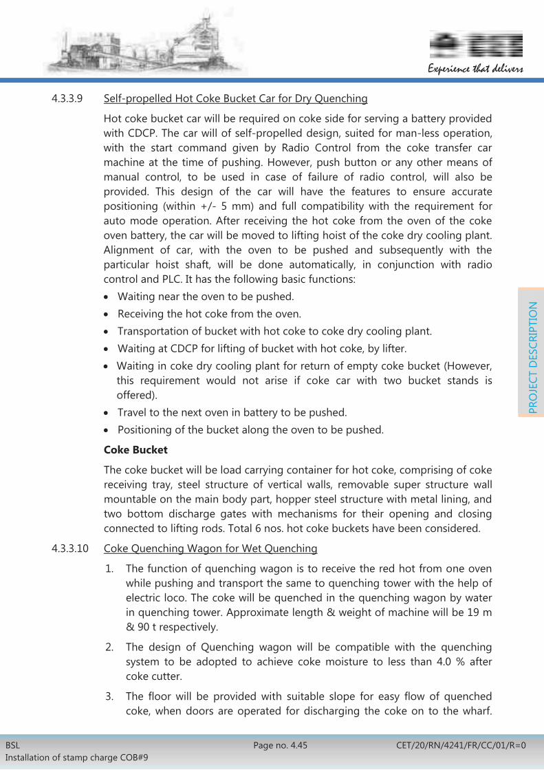
BSL Installation of stamp charge COB#9
Page no. 4.45 CET/20/RN/4241/FR/CC/01/R=0
Experience that delivers
PRO
JECT
DES
CRIP
TIO
N
4.3.3.9 Self-propelled Hot Coke Bucket Car for Dry Quenching
Hot coke bucket car will be required on coke side for serving a battery provided with CDCP. The car will of self-propelled design, suited for man-less operation, with the start command given by Radio Control from the coke transfer car machine at the time of pushing. However, push button or any other means of manual control, to be used in case of failure of radio control, will also be provided. This design of the car will have the features to ensure accurate positioning (within +/- 5 mm) and full compatibility with the requirement for auto mode operation. After receiving the hot coke from the oven of the coke oven battery, the car will be moved to lifting hoist of the coke dry cooling plant. Alignment of car, with the oven to be pushed and subsequently with the particular hoist shaft, will be done automatically, in conjunction with radio control and PLC. It has the following basic functions: Waiting near the oven to be pushed. Receiving the hot coke from the oven. Transportation of bucket with hot coke to coke dry cooling plant. Waiting at CDCP for lifting of bucket with hot coke, by lifter. Waiting in coke dry cooling plant for return of empty coke bucket (However,
this requirement would not arise if coke car with two bucket stands is offered).
Travel to the next oven in battery to be pushed. Positioning of the bucket along the oven to be pushed.
Coke Bucket
The coke bucket will be load carrying container for hot coke, comprising of coke receiving tray, steel structure of vertical walls, removable super structure wall mountable on the main body part, hopper steel structure with metal lining, and two bottom discharge gates with mechanisms for their opening and closing connected to lifting rods. Total 6 nos. hot coke buckets have been considered.
4.3.3.10 Coke Quenching Wagon for Wet Quenching
1. The function of quenching wagon is to receive the red hot from one oven while pushing and transport the same to quenching tower with the help of electric loco. The coke will be quenched in the quenching wagon by water in quenching tower. Approximate length & weight of machine will be 19 m & 90 t respectively.
2. The design of Quenching wagon will be compatible with the quenching system to be adopted to achieve coke moisture to less than 4.0 % after coke cutter.
3. The floor will be provided with suitable slope for easy flow of quenched coke, when doors are operated for discharging the coke on to the wharf.

BSL Installation of stamp charge COB#9
Page No. 4.46 CET/20/RN/4241/FR/CC/01/R=0
Experience that delivers
PRO
JECT
DES
CRIP
TIO
N
Bogie of the car will be of CASNUB design.
4. Each end of the quenching wagon will be fitted with 2 (two) spring loaded end buffers and one auto coupler conforming to relevant Indian Railway Standards. Location of coupler and end buffers will match with the electric locomotives.
5. The pneumatic door operating mechanism will be actuated by means of valves fitted in the driver’s cabin of the loco. Only SS pipelines & fittings will be used for all piping work on the quenching wagon.
6. Pneumatic braking system of the quenching wagon will be actuated from the operator’s cabin of the Loco. Braking of electric loco and quenching wagon will be actuated in synchronised manner.
4.3.3.11 Electric Loco
1. The function of electric loco is to pull and push the coke quenching wagon (for wet quenching) with load of hot coke from one oven. Haulage capacity of the loco will be more than 200t. Approximate length & weight of machine will be 10 m & 60 t respectively.
2. Electric Loco will be equipped with the following mechanisms to meet the operational requirement of servicing an oven:
Long travel mechanism capable of accurate positioning within (+5)mm with the oven to be pushed.
Pneumatic system for provision of compressed air for flap opening/closing of quenching wagon and pneumatic braking system in electric loco and quenching wagon.
3. Either two LT mechanisms connected to one pair of the front and rear wheels of the Loco or separate LT drive for each travel bogie will be considered. Capacity of the LT mechanism will be sufficient enough to carry to run the car with half of drive mechanism only. VFD control will be provided for the LT drive to facilitate smooth operation and precise synchronising speed with pusher beam. Wheel specification will be selected as per latest Indian Railway Standards for broad gauge wagons.
4. Air compressor system of the loco will have two compressors, one working and one stand-by with 2-3 air receivers having minimum capacity of 1500 litres. Only SS pipes and fittings will be used in pneumatic lines.
5. Height of the loco will be such that it can pass under the hood of the CTC. At each end of the loco, two springs loaded buffer and one automatic coupler will be provided as per Indian Railway Standards.
6. A manually operated mechanical braking mechanism for emergency hand operation from the operator’s cabin, independent of pneumatic brake, will be provided.

BSL Installation of stamp charge COB#9
Page no. 4.47 CET/20/RN/4241/FR/CC/01/R=0
Experience that delivers
PRO
JECT
DES
CRIP
TIO
N
7. Operator will be provided with an emergency stop switch for stopping pushing operation while oven is being pushed.
8. Top of loco will be totally covered with protection plate against any possible hot spillage coke.
9. Remote operation of electric loco may also be considered in addition to control from operator cabin mounted over electric loco.
4.3.4 Maintenance Facilities
4.3.4.1 The following maintenance facilities will also be provided in the battery area
Auxiliary Facility Unit Working Standby
Hydro-jet door cleaner stations of pressure 600bar (min) – One on pusher side another on coke side
sets 1 -----
Door lowering racks for repair of doors - One on pusher side another on coke side
sets 2 -----
Door rotary stands for refractory bricking– One on pusher side another on coke side
sets 1 -----
Fixed door racks - One on pusher side another on coke side
sets 4 -----
Door rack with door frame at end bench for alignment purpose
sets 1 -----
Overhead double girder with overhang/extensions on pusher and coke sides 10ton Telpher at end bench for lifting material to repair the pusher car/coke transfer car/charging car and doors.
nos. 1 -----
5ton Jib cranes on end benches nos. 2 -----
Spillage conveyor - One on pusher side another on coke side with a common bunker with skip arrangement
sets 1 -----
A skip hoist for recycling the spillage coal on pusher side located at coal tower
nos. 1 -----
Passenger cum goods lift at coal tower. nos. 1 -----
Pusher beam changing station for keeping 2 spare pusher beams and 2 spare leveler bars with rollers etc. on the end bench whit necessary facilities for mechanized means for changing the beams
sets 1 -----

BSL Installation of stamp charge COB#9
Page No. 4.48 CET/20/RN/4241/FR/CC/01/R=0
Experience that delivers
PRO
JECT
DES
CRIP
TIO
N
One set each of bench grinder, vertical drilling machine of 25mm dia. in steel, fitter’s bench with vice and four sets of welding transformer, etc. will be provided on the intermediate and end benches.
Set 1 -----
Welding transformer on the end benches. nos. 4 -----
Bench grinder on the end benches. nos. 2 -----
Vertical drilling machine of 25mm dia on the end benches.
nos. 2 -----
Fitter’s bench with vice on the end benches. nos. 2 -----
One row of dummy charging hole frame & lid and dummy stand pipes at end benches for testing and alignment purpose.
sets 2 -----
4.3.4.2 One Mechanical cum Electrical repair shop will be provided for each area (Battery, CDCP and BPP)
4.3.4.3 The following heavy equipment will also be provided:
Sl. No.
Description Capacity Quantity
1. Dumper 15t 2
2. Hydra 5t 1
3. Bobcat 0.5m3 3
4. Battery operated trolley
2t 2
5. Pay loader 3m3 1
6. Fork lift 3t 1
4.3.4.4 Coke Car Repair Garage
Coke Car Repair Garage with complete handling system with all equipment, electrics, automation etc., will be provided. This will be suitable for both types of coke car envisaged for dry and wet quenching.
4.3.5 Material Handling Facilities
Equipment Capacity Location Unit Qty
COB#9 area
Under slung crane
5ton T.O.P.R No 2
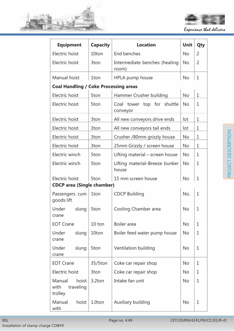
BSL Installation of stamp charge COB#9
Page no. 4.49 CET/20/RN/4241/FR/CC/01/R=0
Experience that delivers
PRO
JECT
DES
CRIP
TIO
N
Equipment Capacity Location Unit Qty
Electric hoist 10ton End benches No 2
Electric hoist 3ton Intermediate benches (heating room)
No 2
Manual hoist 1ton HPLA pump house No 1
Coal Handling / Coke Processing areas
Electric hoist 5ton Hammer Crusher building No 1
Electric hoist 5ton Coal tower top for shuttle conveyor
No 1
Electric hoist 3ton All new conveyors drive ends lot 1
Electric hoist 3ton All new conveyors tail ends lot 1
Electric hoist 3ton Crusher /80mm grizzly house No 1
Electric hoist 3ton 25mm Grizzly / screen house No 1
Electric winch 5ton Lifting material – screen house No 1
Electric winch 5ton Lifting material–Breeze bunker house
No 1
Electric hoist 5ton 15 mm screen house No 1 CDCP area (Single chamber)
Passengers cum goods lift
1ton CDCP Building No. 1
Under slung crane
5ton Cooling Chamber area No 1
EOT Crane 10 ton Boiler area No 1
Under slung crane
10ton Boiler feed water pump house No 1
Under slung crane
5ton Ventilation building No 1
EOT Crane 35/5ton Coke car repair shop No 1
Electric hoist 3ton Coke car repair shop No 1
Manual hoist with traveling trolley
3.2ton Intake fan unit No 1
Manual hoist with
1.0ton Auxiliary building No 1

BSL Installation of stamp charge COB#9
Page No. 4.50 CET/20/RN/4241/FR/CC/01/R=0
Experience that delivers
PRO
JECT
DES
CRIP
TIO
N
Equipment Capacity Location Unit Qty
traveling trolley
Manual hoist with traveling trolley
5.0ton Over head water pump No 1
Manual hoist with traveling trolley
1.0ton Circulating water
pump house
No 1
Manual hoist with traveling trolley
3.2ton Intake fan unit No 1
Chain pulley block
5ton Above Group of
Cyclones
No 1
Chain pulley block
5ton Dust collection area No 1
Chain pulley block
5ton recovery/disposal area No 1
EOT Crane 5ton Backpressure turbine house No 1 Wet quenching area
Electric hoist 1ton Vapour spray pump house No 1
EOT crane 5ton Settling pond grab bucket No 1
EOT crane 5ton Pump house No Gas Mixing Station area
Manual hoist 5ton Gas mixing station No 1 BPP-2 area
EOT crane 15ton Exhauster House No 1
Manual hoist 5ton Flushing liquor pump house No 1
Manual hoist 5ton Condensation pump house No 1
Manual hoist 5ton H2S/NH3 scrubber pump house
No 1
Electric hoist 5ton De-acidifier unit No 1
Electric hoist 5ton Elemental Sulphur unit No 1
Manual hoist 5ton Water Service pump house No 1
Manual hoist 5ton Fire water pump house No 1

BSL Installation of stamp charge COB#9
Page no. 4.51 CET/20/RN/4241/FR/CC/01/R=0
Experience that delivers
PRO
JECT
DES
CRIP
TIO
N
Equipment Capacity Location Unit Qty
Electric hoist 2.5ton Cooling tower pump house No 1
Electric hoist 5ton Chilled water plant No 1
Manual hoist 5ton DM water house No 1
4.4 CIVIL WORKS
4.4.1 Battery Proper:
1. Battery foundation, cellar, nozzle deck, flue duct, bench supporting structures on pusher side, RCC slab for benches and buttress walls at both ends. Buttress wall and nozzle deck slab will be of heat resistant concrete (HRC) of grade M30C.
2. Construction of foundation for hydraulic reversing winches including room for hydraulic winch along with hydraulic winch foundation.
3. Coal tower
New RCC framed coal tower building with coal bunker, which will be located between the two blocks of the battery. Necessary inserts will be provided for fixing of liner. The substructure below the oven top floor level will house the operators’ amenities, control room, electric switch board room, etc. Access staircase and lift tower will be provided up to the coal tower top.
4. Oven Machine Tracks Construction of RCC foundations rail tracks for stamping, charging and Pushing (SCP) car, coke transfer car and quenching car including all inserts for fixing rails as per requirement.
5. Waste Heat Flue Tunnel
Construction of new waste heat flue tunnel on both pusher and coke side will be connected to the chimney. The waste gas tunnel will be pressure grouted. Proper de-watering arrangement will be provided inside the tunnel. Heat resistant concrete (HRC) of grade M30C will be used.
6. Chimney
There will be one chimney to serve both the blocks of Battery No.9. The chimney will be of RCC construction lined with fire clay and insulation bricks throughout the height. Heat resistant concrete (HRC) of grade M30C will be used.

BSL Installation of stamp charge COB#9
Page No. 4.52 CET/20/RN/4241/FR/CC/01/R=0
Experience that delivers
PRO
JECT
DES
CRIP
TIO
N
7. Service Platforms
Service benches on pusher side and coke side consisting of RCC slab will be supported over steel beams & columns and will have a provision for installing spillage coke conveyors on both coke side and pusher side.
8. Red brick panelling with grills at the top portion will be provided between the service platform columns all along the battery, end benches, intermediate benches, and coal tower.
9. End and Intermediate benches
Two intermediate benches on the either sides of new coal tower and two end benches beyond battery blocks will be provided. These benches will be of RCC construction. Each bench will have 2 floors and access stairs.
10. Spillage conveyor bunker
Foundations for the new coke spillage bunker and conveyor trestles for both pusher side & coke side.
11. HPALA pump house
RCC framed building for HPALA pump house with brick cladding for housing pumps & electrics and foundations for equipment & finishes as per technological requirement.
12. Compressor house
RCC framed compressor house with brick cladding including compressor foundation and finishes as per technological requirement.
13. Office building for officers and control building.
A two storey RCC framed office/ control building (size ≈ 30mX10m) will be provided. Approximately 15mx10m space will be provided in this building for housing the instrumentation & automation and computerized control system in the 1st floor. Space will be provided for housing UPS along with battery pack with suitable ventilation & air-conditioning system will be housed in the ground floor. The control room will be provided with false ceiling & false flooring. Balance space will have 8 nos. of office rooms with one mini conference room and toilet blocks for ladies and gents.
14. RCC framed workers welfare building (30 m X 10 m) will be provided separately along with toilet blocks for ladies and gents. It will have coke oven offices and rest rooms for workers as well. Facilities like canteen, toilets etc. will be provided as per norms.
15. Foundation for cable gallery.
16. RCC foundations for gas mixing station building and related equipment as per technological, process and system requirement.

BSL Installation of stamp charge COB#9
Page no. 4.53 CET/20/RN/4241/FR/CC/01/R=0
Experience that delivers
PRO
JECT
DES
CRIP
TIO
N
4.4.2 Coal Handling System
All civil works related to all coal supply new conveyors from silo to coal tower of COB#9; including foundations for trestles, hammer crusher building & Junction houses etc. as per process, system and technological requirements. Dismantling of existing temporary buildings, rerouting of existing cable trench/tunnel, existing drains, existing underground & overhead pipe lines etc. will be as per technological requirements.
4.4.3 Coke Processing
Civil works related to all coke processing and delivery to blast furnace and sinter plant including:
Trestle foundations for all conveyor galleries Pre-cast RCC slabs in galleries Crusher building Screen house with provision for housing Instrumentation & automation
system, officer/ worker rooms with furniture, toilets etc. Loading point Junction houses MCC & control rooms Breeze and nut coke storage bunker etc. Vibration isolation system for crusher.
4.4.4 CDCP Area
4.4.4.1 CDCP building
All Civil works related to foundations of CDCP structure, coke cooling chamber, coke bucket lifter, blowing device, coke charging & discharging devices, main & auxiliary mill fans, columns of the dust catcher, boiler house and the foundations for the Boilers etc. RCC underground coke conveyor tunnel from the CDCP to the CDU.
4.4.4.2 Auxiliary building
Two storied Auxiliary Building (40mX15m) will be made in RCC framed construction with brick cladding and finishes as per the technological requirements. Control rooms will be housed in the 1st floor of the building which will be adjoining the main CDCP-Boiler house including the following rooms with suitable aluminium framed glass partitions as listed below:
Operator room.
Engineering stations, servers & software/ hard-ware related documentation room.
Room for DCS & PLC Panels, I/O panels, Instrumentation panels, Weighing panels, & all other electronic panels.
Room for Laboratory facility for coke dry cooling plant.

BSL Installation of stamp charge COB#9
Page No. 4.54 CET/20/RN/4241/FR/CC/01/R=0
Experience that delivers
PRO
JECT
DES
CRIP
TIO
N
Control room floor will also have facility of Toilet block, Conference room & Pantry. Part of the building in the ground floor will be housing the transformer, electrics, de-aerator etc. Boiler feeding pumps will be housed in the 1st floor.
4.4.4.3 CDCP dust collection station building
RCC framed CDCP dust collection station along with foundations for fans, cyclones & bag filters and finishes as per technological requirement.
4.4.4.4 CDCP dust settling station building
RCC framed dust settling station with brick cladding, equipment foundation (steam jet ejectors & cyclones) and finishes as per technological requirement.
4.4.4.5 Air Compressor station building
RCC framed air compressor Building with brick cladding along with foundation for the CDCP ventilation unit, foundation for the service water cooling tower of air-conditioning system along with basin for the cooling tower.
4.4.4.6 Circulating water supply pump house
RCC framed circulating water supply pump-house with brick cladding and finishes as per technological requirement.
4.4.4.7 Contaminated condensate pump house
RCC framed contaminated condensate pump-house with brick cladding and finishes as per technological requirement.
4.4.4.8 Back pressure turbine generator building
This building will house generator, electrics and associated auxiliaries.
4.4.4.9 RCC framed DM water plant building and finishes as per technological requirement.
4.4.4.10 Foundation for electrical repair cum storage shed (8m x12m) with suitable rooms and mechanical storage shed (10m x 15m) with suitable rooms along with brick cladding, flooring and finishes as per requirement.
4.4.4.11 RCC framed air conditioned office building (20m x 10m) with, conference room, computer room, technical archive, toilets and pantry with suitable fittings, fixtures including parking facilities.
4.4.4.12 RCC framed load centre substation with brick cladding wall for LT loads of CDCP including all necessary finishes as per technological requirement.
4.4.4.13 CDCP car repair yard
Foundations for CDCP car repair yard (approx. 30m x 30m). This shop will be used for the repairs of hot coke bucket cars and also conventional wet quenching loco and wagon. This facility will be provided with suitable repair pit

BSL Installation of stamp charge COB#9
Page no. 4.55 CET/20/RN/4241/FR/CC/01/R=0
Experience that delivers
PRO
JECT
DES
CRIP
TIO
N
and handling facilities for lifting hot coke bucket car/ quenching loco. Flooring of yard will be of RCC.
4.4.4.14 Workers room
Workers rest rooms, toilet block with drinking water facility and other amenities.
4.4.5 Quenching tower
Civil works for quenching tower pump house for main as well as auxiliary vapour spray pumps, settling tank, coke wharf, operator cabin etc. Minimum grade of RCC for quenching tower and settling tank will be M-30. All inserts and handrails etc.in quenching tower and settling tank will be of stainless steel.
4.4.6 By-Product Plant (BPP-2)
4.4.6.1 Civil works related to all the sub-units of by-product plant.
4.4.6.2 Phenolic water network with collection pits (with manhole) close to effluent generation unit of By-product plant. Common collection pit with pumping facility for sending the effluent to BOD plant.
4.4.6.3 Administrative cum Control room buildings
RCC framed administrative cum control room building (tentative size 30m x 15m) is planned for centralized monitoring and data acquisition related to all the plant units, as required. The control room will also house MIS server with peripherals and provision for connectivity of BPP-2 network with existing plant wide network. Officer’s rooms, mini conference hall, pantry, toilets, etc. will also be housed in this building. The building will house:
Three nos. zonal control rooms will be provided for housing the instrumentation & automation system of gas condensation unit, NH3 & H2S removal unit & naphthalene unit
Rest room each for mechanical, electrical, operation and Instrumentation.
3 nos. store rooms for keeping tools, tackle etc. 2 nos. toilet blocks each for both ladies and gents. Parking space for four & two wheelers
4.4.7 Load Centre Substation Buildings
Following new load centre substations have been envisaged:
RCC framed Load centre substation three storeyed with lift of approx. size 40m X 15m for battery proper including oven machines and coal & coke handling facilities with brick cladding and finishes as per technological requirement. Building shall be three storied with lift facility.

BSL Installation of stamp charge COB#9
Page No. 4.56 CET/20/RN/4241/FR/CC/01/R=0
Experience that delivers
PRO
JECT
DES
CRIP
TIO
N
RCC framed CDCP HT substation of approx. size 15m X 15m and two LT substations of approx. size 25m x 10m each with brick cladding and finishes as per technological requirement.
RCC framed Hammer crusher substation building of approx. size 30m X 15m two storied building with brick cladding and finishes as per technological requirement.
RCC framed three nos. LT substation buildings of approx. size 25m x 10m have been envisaged for BPP, Coke handling and coal handling units with brick cladding and finishes as per technological requirement.
4.4.8 Benzol Storage Unit
1) Construction of new RCC foundation, concrete flooring, pipe trestle foundation etc. for new benzol storage tank.
2) Construction of RCC fire water reservoir as per technological requirement.
3) Construction of RCC framed with brick boundary wall.
4.4.9 General
Dense Bituminous Macadam (DBM) & Bituminous Concrete road all around the facilities including the offices stores and other units within the proposed complex, as required and drainage/ sewerage system (normal as well as storm water) within the proposed complex will be provided.
Construction of roads, RCC/pipe culverts, kerbstones and drains within battery limit.
Necessary cable tunnel, Pipe tunnel etc. to be constructed as per requirements.
Diversion of Under Ground Services (UGS) within the battery limits Dismantling and re-location of some of the metal roofed structures
and other structures in the alignment of coal conveyors Facilities for suitable disposal of faecal sewages will be provided and
no raw faecal sewage will be allowed to be mixed with any other sewerage systems such as storm sewerage or industrial sewerages.
4.4.10 Soil Investigation:
Geodetic survey and soil investigation of the area will be carried out through a separate package. The report of this investigation will be made available to the bidder during tendering of other packages. Recommendations contained in the final report will form the basis for designing of civil foundations.
However pile capacity for 450mm dia and 550mm dia pile has been assumed as 60 tonne and 80 tonne respectively and the net bearing capacity has been assumed as 15 ton/Sqm at a depth of 2.5m below ground level.

BSL Installation of stamp charge COB#9
Page no. 4.57 CET/20/RN/4241/FR/CC/01/R=0
Experience that delivers
PRO
JECT
DES
CRIP
TIO
N
4.4.11 Major activities relating to civil works are earthwork, plain & reinforced concrete work, flooring, plastering and finishing etc. Following criteria will be adopted in the design of civil engineering works:
R.C.C : M-25C in general RCC M30 : Quenching Tower and Settling tank HRC M-30 : Buttress walls HRC M-30 D: Deck slabs PCC P.C.C : M-10B Anchor pocket grouting: Non-shrinking compound (Shrinkomp-30
of M/s. ACC or equivalent) / M-30 D. Flooring : As per requirement Floor finish : As per requirement Ceiling : As per requirement Brickwork : 5 Designation bricks Cement mortar in Brick work : 1:6 Cement plaster for walls : 1:6 Cement plaster for ceiling : 1:4 Doors & windows : Steel / Aluminum, glazed doors & windows /
rolling shutters, as per requirement Outside finish for buildings : Anti algal weather proof paint Inside finish for buildings: Acrylic emulsion paint, white / colour
washing, as per technological requirement.
Drainage: Proper drainage will be provided around the building. Roof Treatment: 4 mm thick Atactic Poly propylene modified
Plastomeric Bitumen based.
4.5 STRUCTURAL WORK
4.5.1 Battery Proper
4.5.1.1 Temporary Oven Protection Roof (TOPR): New TOPR has been considered
4.5.1.2 Protective shed: New protective shed has been considered.
Structures of TOPR and protective shed will be dismantled and stacked for future use.
4.5.1.3 SCP machine track consisting of crane rails for wheels and guide wheels mounted over steel sleepers/RCC foundation with shock absorbing material and fixed securely with the foundation will be laid covering the length as defined in the battery limit. Rails will also be provided for horizontal guide wheels.

BSL Installation of stamp charge COB#9
Page No. 4.58 CET/20/RN/4241/FR/CC/01/R=0
Experience that delivers
PRO
JECT
DES
CRIP
TIO
N
4.5.1.4 Coke transfer car track consisting of rail mounted over coke side service bench beam and column on battery side and on steel girder supported over bracket / column on the other side with walkway / maintenance platform, access stair, ladder, handrail etc. as per technological requirements covering the entire length as defined in battery limit.
4.5.1.5 Gas transfer car track consisting of rail over oven top will be laid covering the length as defined in the battery limit.
4.5.1.6 Structural arrangement consisting of trestles, girders and columns to support dust free coke pushing collector for entire length as defined in the battery limit.
4.5.1.7 Suction main bridge supported on brackets from buck stays at the battery side and on trestles at the stockade side. Suction main bridge will have provision for walkway and platform.
4.5.1.8 Bridge to support cross over mains and access platforms.
4.5.1.9 Platform over gas collecting main along the length of battery as per operational and technological requirement.
4.5.1.10 Bracket supports for gas collecting main.
4.5.1.11 Supports for power line for coke oven machines. This includes:
SCP machine power cable support. Trolley line /catenary bracket supports for Coke Transfer car. Trolley line/catenary bracket supports for quenching car loco. Catenary supporting structures/ brackets/ portals for gas transfer car. Safety guard and net for power lines.
4.5.1.12 Service benches on both sides consisting of RCC slab supported over steel beams and columns over the entire length as defined. RCC slab will have cast iron paving / refractory brick covering as per technological requirement. Service bench will have provisions for spillage chain conveyor as per operational requirement.
4.5.1.13 Trestles, girders, walkways, hopper and shed of spillage belt conveyor
4.5.1.14 Structural arrangements at oven top and service bench level in intermediate and end bench areas as per operational and technological requirement.
4.5.1.15 Cellar platforms over gas mains.
4.5.1.16 Trestles, structural bridges for all overhead out door gas pipe lines in front and behind battery along with walkway, maintenance platforms, access stairs, ladders & handrails as per operational and technological requirement.
4.5.1.17 Structural building for gas mixing station with maintenance and handling facilities as per technological and operational requirement.
4.5.1.18 Structures for passenger lift in coal tower.

BSL Installation of stamp charge COB#9
Page no. 4.59 CET/20/RN/4241/FR/CC/01/R=0
Experience that delivers
PRO
JECT
DES
CRIP
TIO
N
4.5.1.19 Steel structural frame work, roof covering, working platforms, stair etc. for hammer changing station.
4.5.1.20 Structures for new load lifting device of at the oven top level to carry materials from one side of the battery to the other.
4.5.1.21 Working platform with structural stair tower up to the location of stack monitoring level. Cage ladder and platforms at different levels for access to RCC chimney top.
4.5.1.22 Structural arrangements for overhead electrical cable galleries.
4.5.1.23 Miscellaneous structures like maintenance platforms, access stairs, ladders, handrails & handling facilities etc. as per requirements.
4.5.1.24 Covered coal conveyor gallery from new junction house (by the side of coal silo) to the location of new coal tower with supporting trestles along with CGS roof & side sheeting, walkway on both sides with pre cast RCC slab supported on structural frame as per technological scope of work.
4.5.1.25 New junction houses in coal handling circuit along with CGS roof, side & gable end sheeting, RCC floor supported over structural steel beams in different levels with access stairs, handrails & handling facilities as per technological scope of work.
4.5.1.26 Structural related to primary and secondary crusher house in coal handling area along with CGS roof, side & gable end sheeting, RCC floor supported over structural steel beams in different level with access stairs, handrails & handling facilities as per requirement.
4.5.2 Coke Dry Cooling Plant (CDCP)
4.5.2.1 CDCP building structures complete with bucket lifter & bucket transfer facilities as per technological/ technical requirements. The major structures include beam/column/bracing arrangements for supporting structures for boiler block, auxiliary block, bucket lifter, crane girder, covered passenger lift structures, pipe supports, working/ maintenance platforms, access stairs, ladders, handrails & handling facilities etc. as per technological requirements.
4.5.2.2 Structures for coke dust transport system as per technological/ technical requirements.
4.5.2.3 Bucket car repair shed with suitable repair pit along with maintenance facilities for quenching car and coke buckets.
4.5.2.4 BPTG building structures as per technological / technical requirements.
4.5.3 Coke Sorting Plant
4.5.3.1 New coke conveyor gallery with supporting trestles along with CGS roof & side sheeting, walkway on both sides of the belt with pre cast RCC slab supported on structural frame as per technological layout drawing.

BSL Installation of stamp charge COB#9
Page No. 4.60 CET/20/RN/4241/FR/CC/01/R=0
Experience that delivers
PRO
JECT
DES
CRIP
TIO
N
4.5.3.2 New junction house along with CGS roof, side & gable end sheeting, RCC floor supported over structural steel beams in different level with access stairs, ladders, handrails & handling facilities as per technological requirement.
4.5.3.3 Structural crusher house, screen house, breeze bunker house along with CGS roof, side & gable end sheeting, RCC floor supported over structural steel beams in different level with access stairs, ladders, handrails & handling facilities as per technological requirement.
4.5.3.4 Covered structural loading point.
4.5.3.5 Necessary modifications in existing PSD-1 for accommodating new coke conveyor.
4.5.3.6 Necessary modifications in existing conveyor gallery mkd. KD 5-1, KD 5-2 as per technological requirement.
4.5.4 By-product Plant
4.5.4.1 Steel structural trestles, bridges and brackets for support of different overhead gas pipe lines with maintenance walkways, platforms, access stairs, ladders, handrails & handling facilities etc.
4.5.4.2 Chilled water building structures with CGS roof, side & gable end sheeting, working platforms, technological supporting structures, working/ maintenance platforms, access stairs, ladders, handrails & handling facilities etc.
4.5.4.3 Working/maintenance/access platforms with stairs, ladder & handrail etc. for different vertical and horizontal vessels, tanks as per technical requirements.
4.5.4.4 Structural steel roof structures for RCC pump houses and other buildings housing different equipment with CGS roof sheeting, brick cladding on side & handling facilities as per requirements.
4.5.4.5 Exhauster building structures with brick cladding as per technological requirement. The building will be of structural steel frame work with working platform. Roof will of RCC construction along with access stairs, ladders, handling facilities & handrails etc. as per technological requirements. Exhauster foundation work will be isolated from new building structures/ platforms.
4.5.5 Design Considerations
All steel structures will be designed to meet the technological requirements with due consideration to the existing plant and facilities.
Design of steel structures will be as per IS: 800-1984. Conveyor and junction house structures will be designed as per the
provision of IS: 11592-2000. Apart from technological loads to be supported on steel structures, self
weight and superimposed loads for the design will be according to IS: 875-1987. Structures will be analysed either for wind or seismic as applicable. Wind load on structures will be considered as per IS: 875-1987

BSL Installation of stamp charge COB#9
Page no. 4.61 CET/20/RN/4241/FR/CC/01/R=0
Experience that delivers
PRO
JECT
DES
CRIP
TIO
N
whereas seismic loads will be taken as per IS: 1893 Part-1 (2002) & Part4 (2005).
All structural steel work will be of welded construction. Due allowance are to be kept for impact, vibration and temperature load.
4.5.6 Technical Specification
Material for structural steel will be as per IS: 2062 –2011 (Grades as applicable). All CGS sheeting will conform to IS: 277-2003. Crane rail section will be as per IS: 3443-1980.
The welding and the welded work will generally conform to IS: 816 -1969 and 9595 -1996 unless otherwise specified. Electrodes will conform to IS: 814 -2004. As much work as possible will be welded in shops and the layout and sequence of operations will be so arranged as to eliminate distortion and shrinkage stresses.
Fabrication and erection of steel structures will conform to IS: 800-1984 and tolerances of fabrication will be as per IS: 7215-1974. All the structures will be duly inspected and made defect free.
For battery proper & By-product structures paint system will consist of two coats of primer paint and one coat of intermediate paint at shop and two coats of final paint at site. Primer coats will be done with two coats of a single pack air drying high build chlorinated rubber based zinc phosphate primer to achieve even shade and a minimum dry film thickness of 100 microns (50 microns/Coat). The minimum chlorine content will be 12 to 15%. Phenolic-alkyd based compatible with primer paint will comprise intermediate paint at shop total dry film thickness of 50 micron. Finishing coat will be done with two coats of a single pack air-drying plasticized chloro rubber paint suitably pigmented to achieve even shade and a minimum dry film thickness of 100 microns (50 microns/Coat). The minimum chlorine content will be 12 to 15%.
Structures other than battery proper & By product area will receive two coats of single pack air drying phenolic modified alkyd composition with zinc phosphate as a primer with total dry film thickness of 80 microns (DFT/coat 40 micron) and two coats of single pack air drying high gloss phenolic alkyd modified synthetic enamel paint suitably pigmented with total dry film thickness 50 microns (DFT/coat 25 micron). One coat of primer will be applied at shop before despatch. The other coat will be applied after erection at site. The finish paint will be applied over the primer coat at site.
For open trestles/other outdoor structures in addition to the above one intermediate coat after the primer will be applied. The paint will be single pack high build phenolic based paint with micaceous iron oxide (MIO).The dry film thickness will be not less than 75 microns.

BSL Installation of stamp charge COB#9
Page No. 4.62 CET/20/RN/4241/FR/CC/01/R=0
Experience that delivers
PRO
JECT
DES
CRIP
TIO
N
4.6 UTILITIES
4.6.1 The following utilities will be provided from the existing facilities and newly installed facilities at their respective battery limits:
Clean coke oven gas
Blast furnace/ mixed gas
Steam
DM water
Nitrogen
Compressed air
Make-up water
Industrial water /emergency water
Flushing ammonia liquor
4.6.2 The following utilities generated from the proposed coke oven battery will be suitably transported to respective area with isolation valve for further processing to make it reusable with required make-up:
Raw coke oven gas
Gas condensate from battery
Return ammonia liquor
4.6.3 System Envisaged
The interfacing / take over points or terminating points of utilities are shown in the Drg. No. CET RN 4241 CC2 00 001 R=0.Flow diagram of steam & water is shown in Drg No: CET RN 4241 UT0 00 001 R=0.
Flow diagram of gas handling is shown in Drg. No. CET RN 4241 UT0 00 002 R=0.
4.6.3.1 Gas Mixing Station
The pressure of COG available at TOP near COB#8 is around 700mmWC The pressure of mixed gas available at TOP near COB#8 is around 600mmWC. A New gas mixing station for under firing will be provided along with necessary valves and instrumentation behind the COB#8. New pipeline will be laid from this new mixing station to COB#9 complex.
4.6.3.2 Heating gas to battery and export of clean gas
CO gas for pre-heating will be taken from the pipeline behind the COB#8 near the existing mixing station. After that, CO gas for heating will be provided from the new system.

BSL Installation of stamp charge COB#9
Page no. 4.63 CET/20/RN/4241/FR/CC/01/R=0
Experience that delivers
PRO
JECT
DES
CRIP
TIO
N
Export CO gas will be connected to pipeline behind the COB#8 near the existing mixing station.
On line tapping will be taken from the existing coke oven gas header behind COB#8. It will reach the COB#9 through a new stockade. From the stockade in-front of COB#9, this line will feed both the blocks through two different lines for initial heating. Once the battery is commissioned, this line will be used for exporting the clean gas produced from COB#9. Suitable isolation valves will be provided for this.
4.6.3.3 The requirement of gases import and export is:
Facility Unit Average Maximum CO gas for pre-heating COB#9 Nm3 /h 6000 7000 CO gas for regular heating of COB#9
Nm3 /h 17000
Mixed gas for regular heating of COB#9
Nm3 /h 75000
CO gas for CDCP for heating Nm3/h 1000 1300 Export CO gas to network Nm3 /h 36930 50000
4.6.3.4 Nitrogen:
Nitrogen will be required for the CDCP unit as well as some units of BPP-2. The required N2 will be tapped from the BOO oxygen plant. Boosting facilities and a new pipeline will be laid upto the COB#9 complex from BOO oxygen plant.
The requirement of N2 at 7 to 8Kg/cm2 is as indicated below:
Facility Unit Average Maximum Remarks
COB#9 for control valves
Nm3 /h 50
CDCP Nm3 /h 1500 2000 O2 less than 3% BPP-2 Nm3 /h 400
4.6.3.5 Compressed air:
Compressed air will be required for pneumatic blow-down system in coal tower, process requirements in CDCP (de-dusting system) & BPP-2, instrumentation requirements for control valves etc. and other cleaning and general purposes. The requirement is:
Facility Qty (Nm3 /h)
Purpose Pressure (Kg/cm2)
COB#9 300 Pneumatic blow down 6
COB#9 150 General purpose 8
COB#9 10 Instrumentation 6
CDCP 500 De-dusting 8

BSL Installation of stamp charge COB#9
Page No. 4.64 CET/20/RN/4241/FR/CC/01/R=0
Experience that delivers
PRO
JECT
DES
CRIP
TIO
N
system/cleaning
CDCP 220 Instrumentation 8
CDCP 200 Miscellaneous 8 BPP-2 50 Process/cleaning 5 BPP-2 500 Instrumentation 8
One compressed air station will be installed in front of coal tower with two (1W+1S) compressors for battery needs.
One compressed air station will be installed near the De-dusting unit with two (1W+1S) compressors for CDCP needs.
One compressed air station will be installed near the main control room with two (1W+1S) compressors for BPP-2 needs.
Output of these compressors will be used for both the process as well as instrumentation needs. Suitable conditioned for Instrumentation needs will be carried out.
4.6.3.6 Steam
Steam will be required for CO gas pre-heater for battery heating, de-aeration of boiler feed water in CDCP, heating requirements of various facilities of BPP-2 for stripping and heating, steam jacketing, emergency operation of exhausters and also for purging & cleaning purposes. The requirement is:
Facility Regular Qty (tph)
Intermittent Qty (tph)
Purpose Pressure (Kg/cm2)
COB#9 1 COG pre-heater 7 COB#9 1 Purging / start-up 7 CDCP 4 Steam ejectors of
dust collection 12
CDCP 7 Boiler (de-aeration) 8 BPP-2 3.5 NH3 & H2S scrubber 8 BPP-2 14.5 NH3 & H2S stripper 8 BPP-2 3 Sulphur recovery 8 BPP-2 8 Chilled water unit 6 BPP-2 0.5 ETP/ liquor drain tank 6 BPP-2 0.5 Decanter /
intermediate tar tank 6
BPP-2 0.66 Tar storage 6 BPP-2 1.95 Back wash sand
filter/wash water 6
BPP-2 1 Tar dosing 6 BPP-2 2.6 Naphthalene stripper

BSL Installation of stamp charge COB#9
Page no. 4.65 CET/20/RN/4241/FR/CC/01/R=0
Experience that delivers
PRO
JECT
DES
CRIP
TIO
N
Facility Regular Qty (tph)
Intermittent Qty (tph)
Purpose Pressure (Kg/cm2)
unit BPP-2 15 Exhauster steam drive 30 BPP-2 0.5 Process 66 BPP-2 8 Purging / start-up 7 TOTAL 48.71 24
CDCP boiler produces around 55t/h of steam at 66 bar (g) and 500oC. This steam is fed to a Back Pressure Turbine (BPT) for producing about 6.5MW of electric power. The BPT is expected to discharge about 55t/h of steam at about 8 kg/cm2 pressure. This low pressure (LP) steam from the BPT will be connected to the plant steam network. Apart from this, a new PRDU will also be provided in the CDCP area to generate medium pressure and low pressure steam as well as per technical requirement.
It is envisaged to take a tapping from the existing PRDUs of existing BPP-1 and use the steam for meeting start up and contingency steam requirements of proposed BPP-2 when internal steam production is not sufficient to meet the requirements of BPP-2. When the internal requirement of steam is lower than the steam production in CDCP, the excess steam would flow to the existing process steam network for use elsewhere.
After commissioning of the entire system, steam produced from BPT will be mostly sufficient to fulfill the needs of COB#9 complex. Only the shortfall will be compensated from the existing PRDU. Existing PRDUs will be suitably upgraded / revamped to generate medium pressure and low pressure steam as well as per technical requirement.
4.6.3.7 Ammonical liquor:
Ammonical Liquor from the condensation pump house will be pumped to battery under pressure. A tapping will be taken from the discharge line for feeding HPALA pumps.
The ammonical liquor going to battery is returned to condensation unit after getting separated in the separators. This way it is re-circulated within the system. The return liquor flows to the condensation unit under gravity.
Facility Qty (m3/h)
Purpose Pressure (Kg/cm2)
Flushing liquor to COB#9 930 Gas cooling 5 HPALA system to COB#9 80 Suction in oven 40 Return liquor from COB#9 1000 For tar Gravity

BSL Installation of stamp charge COB#9
Page No. 4.66 CET/20/RN/4241/FR/CC/01/R=0
Experience that delivers
PRO
JECT
DES
CRIP
TIO
N
separation 4.6.3.8 De-mineralized (DM) Water Unit
De-mineralized water is required for the preparation of boiler feed water of CDCP and also for other miscellaneous uses in the BPP-2. One DM water plant (DMP) unit having a peak production capacity of about 80 m3/h is being envisaged for this purpose. The requirement of DM water is:
Facility Qty (m3/h)
Purpose
CDCP 55 Boiler feed BPP-2 5 Process
The DM water for boiler feed purposes would be stored in a DM water tank having a storage capacity sufficient for running the boilers for a minimum of 6 hours even without the DMP in production cycle.
The DMP will be based on cation/anion exchange technology and is envisaged as fully automatic. It will have necessary chemical handling, storage and preparation facilities with offline and online water testing facilities. DMP is proposed to be located near the CDCP unit
The DM water will be pumped to the de-aerators of the CDCP boilers after chemical conditioning from which it is further pumped to the boilers using the boiler feed pumps.
Required quality parameters for DM water and the conditioned boiler feed water are:
4.6.3.9 Required quality parameters for DM water and the conditioned boiler feed water are:
Parameter Unit DM Water Boiler Feed Water Total Hardness ppm as CaCO3 1 Max 3 Max Fe ppm 5 Max 10 Max O2 ppm 10 Max 0.002 Max Silica ppm 0.02 Max 0.02 Max Ph 6.8-7.2 8.8-9.1 Conductivity micromho/cm 5 Max 10 Max
4.6.3.10 Wet quenching pump house
Two no. of pumps (1W+1S) will be provided for quenching. Two no. of pumps (1W+1S) will be provided for auxiliary spray to suppress grit.Necessary piping and other accessories for the system will be provided.
Arrangement will be such that no effluent from the wet quenching area drains out to the storm drainage or industrial sewerage. All overflows and drainages will be recycled back to the system.

BSL Installation of stamp charge COB#9
Page no. 4.67 CET/20/RN/4241/FR/CC/01/R=0
Experience that delivers
PRO
JECT
DES
CRIP
TIO
N
Quenching tower will be provided with grit arrestors to meet the norms.
4.6.3.11 Water services
Industrial water is available at the sump of service water pump house of BPP-1. Water services pump house will be installed for taking water from this source and meet the water requirements of the COB#9 complex.
Fire-fighting water network will also be created by taping water from the new water service pump house. Water tanks will be installed at suitable locations for emergency fire fighting requirements.
All waste waters and effluents of the COB#9 /BPP-2 complex will be managed by the provision of suitably designed waste water collection sewerage networks with suitable treatment and recycling facilities.
Rain and storm water from the complex will be connected for draining out through the existing storm water network of BSL.
4.6.3.12 The maximum demand of water is estimated to be as given below:
Service Battery CDCP BPP-2 Industrial water (m3/h) 15 35 300 Fire fighting water (m3/h) 410
4.6.3.13 Sump Pumps of battery area
Sump pumps along with electric drive, interconnecting pipelines and valves will be provided for following areas:
Area Qty Cellar of Battery no. 9A & 9B (Pumps will have flame proof type motors)
4
Quenching Pump House 2 Coke wharf pit 2 Chimney pit 2 Vapour spray Pump House 2 HPALA Pump House 2 RAL Tunnel 1
All auxiliary pump houses, tunnels and other underground installations will be provided with sump pumps with 100% stand-by configuration.
4.6.3.14 Service lines for battery proper:
Compressed air line and water lines will be laid below the entire length of both service platforms with suitable tapping points for cleaning purpose.
4.6.4 Air Conditioning & Ventilation
Air conditioning and ventilation will be provided wherever required in addition to those specifically mentioned.
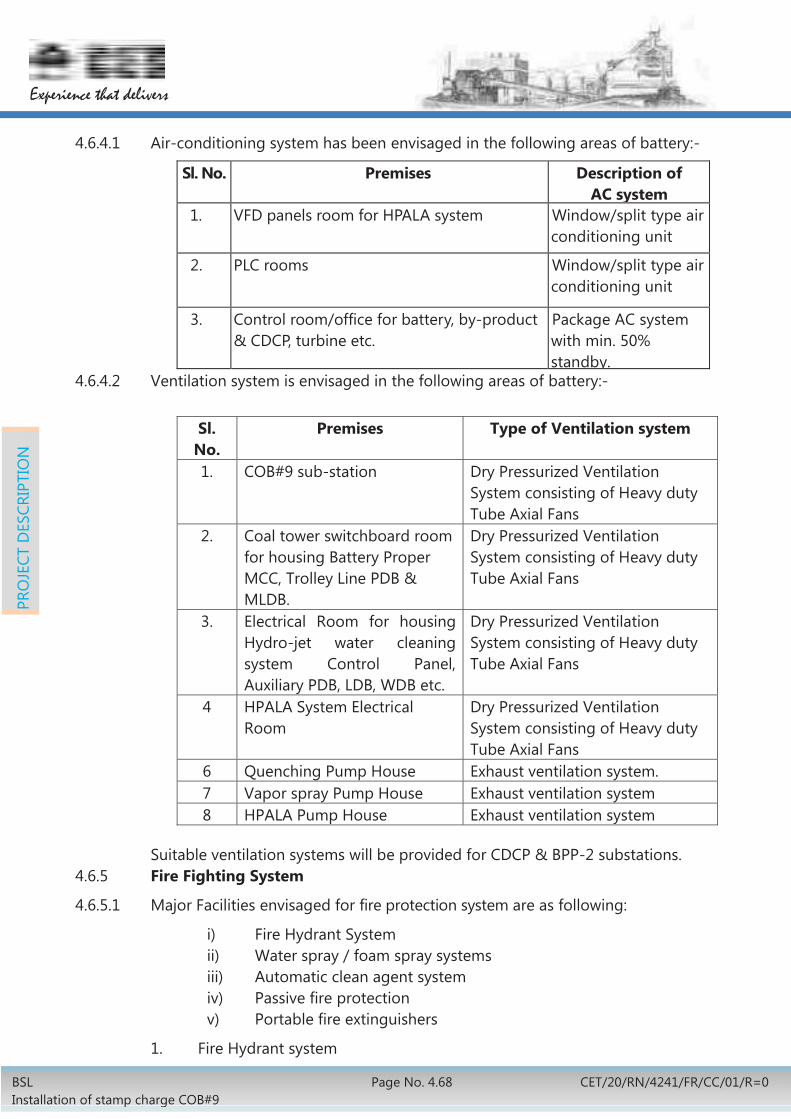
BSL Installation of stamp charge COB#9
Page No. 4.68 CET/20/RN/4241/FR/CC/01/R=0
Experience that delivers
PRO
JECT
DES
CRIP
TIO
N
4.6.4.1 Air-conditioning system has been envisaged in the following areas of battery:-
Sl. No. Premises Description of AC system
1. VFD panels room for HPALA system Window/split type air conditioning unit
2. PLC rooms Window/split type air conditioning unit
3. Control room/office for battery, by-product & CDCP, turbine etc.
Package AC system with min. 50% standby.
4.6.4.2 Ventilation system is envisaged in the following areas of battery:-
Sl.
No. Premises Type of Ventilation system
1. COB#9 sub-station
Dry Pressurized Ventilation System consisting of Heavy duty Tube Axial Fans
2. Coal tower switchboard room for housing Battery Proper MCC, Trolley Line PDB & MLDB.
Dry Pressurized Ventilation System consisting of Heavy duty Tube Axial Fans
3. Electrical Room for housing Hydro-jet water cleaning system Control Panel, Auxiliary PDB, LDB, WDB etc.
Dry Pressurized Ventilation System consisting of Heavy duty Tube Axial Fans
4 HPALA System Electrical Room
Dry Pressurized Ventilation System consisting of Heavy duty Tube Axial Fans
6 Quenching Pump House Exhaust ventilation system. 7 Vapor spray Pump House Exhaust ventilation system 8 HPALA Pump House Exhaust ventilation system
Suitable ventilation systems will be provided for CDCP & BPP-2 substations.
4.6.5 Fire Fighting System
4.6.5.1 Major Facilities envisaged for fire protection system are as following:
i) Fire Hydrant System ii) Water spray / foam spray systems iii) Automatic clean agent system iv) Passive fire protection v) Portable fire extinguishers
1. Fire Hydrant system

BSL Installation of stamp charge COB#9
Page no. 4.69 CET/20/RN/4241/FR/CC/01/R=0
Experience that delivers
PRO
JECT
DES
CRIP
TIO
N
Fire Hydrant system consisting of internal as well as external hydrants for the entire area, of COB#9 complex.
2. Water spray system
High velocity water spray system (HVWS) for transformers (above 10 MVA or having oil more than 2000 litre) and Medium velocity water spray system (MVWS) for cable tunnels/galleries in the CDCP complex.
3. Foam spray system
Foam based spray system for Benzol storage area will be provided.
4. Automatic clean agent system
Automatic CO2 total flooding system for oil cellars/hydraulic rooms and automatic clean agent (IG541- Inergen) total flooding system for computer rooms/ PLC room/control rooms along with associated piping and equipment are envisaged.
5. Passive Fire Protection System
Suitable Passive fire protection system will be provided for electrical cables
6. Portable fire extinguisher
Fire Extinguishers and Sand Buckets will be provided in all electrical & instrument control rooms, shift office and oven machines as per Statutory /TAG norms.
4.6.6 Dry Fog Dust Suppression System
4.6.6.1 Dry Fog dust Suppression System has been envisaged at 2 nos. locations in coal handling area.
4.6.6.2 For each area, compressed air facility with 2 nos. (1W+1S) compressors of around 110Nm3/h, 7kg/cm2 (g) rating and 1 No. air receiver of 2m3 capacity has been envisaged. Requisite compressed air piping with valves and accessories has also been envisaged. 2 nos. (1W+1S) water pumps of capacity 2m3/h, 0.55kW motor rating along with piping, valves, fittings, spray nozzles has been considered.
4.7 POLLUTION CONTROL SYSTEM
4.7.1 The new battery will meet the norms published in official gazette dated 31st march 2012 by Ministry of Environment & Forests, Government of India for by-product recovery type coke ovens. The notification is enclosed as Annexure No.-4.7.1-1

BSL Installation of stamp charge COB#9
Page No. 4.70 CET/20/RN/4241/FR/CC/01/R=0
Experience that delivers
PRO
JECT
DES
CRIP
TIO
N
4.7.2 Fugitive Emission
4.7.2.1 For PLD (Percent Leaking Door)
Air cooled spring loaded diaphragm type doors with self-sealing arrangement.
Machine mounted door cleaner for doors and doorframe.
Hydro jet door cleaner of 600 bar pressure.
Mechanised frame cleaner.
Hydraulic governors to control fluctuation of collecting main pressure within + 1 mm WC.
4.7.2.2 For PLO (Percent Leaking Off-take)
Ceramic rope sealing at base socket of AP.
Water sealed ascension pipe (AP) caps.
Proper sealing arrangement between IV and goose neck..
Arrangement for easy cleaning of gooseneck.
4.7.2.3 For PLL (Percent Leaking lids)
Water seal in the U-tube connecting mechanism in the oven top.
Manual lid luting arrangement.
4.7.3 For Charging Emissions
High pressure ammonia liquor aspiration (HPLA) system for on main charging.
Gas collecting main along with u tube facility in CGT car for transferring the gas in adjacent ovens for easy evacuation of gas during on-main charging.
Speedy coal cake charging along with hood for extracting the gases.
Charging frame in the SCP car.
4.7.4 Pushing Emissions
Land based pushing emission control system to prevent pushing time emissions.
Computerised Heating Control system.
4.7.5 Quenching Emission
New quenching tower will be erected which will have grit arrestor and vapour spray system.

BSL Installation of stamp charge COB#9
Page no. 4.71 CET/20/RN/4241/FR/CC/01/R=0
Experience that delivers
PRO
JECT
DES
CRIP
TIO
N
4.7.6 Stack Emissions
4.7.6.1 For SO2
Since coal blend has less sulphur content, SO2 emission is always less than the stipulated norm. Additionally sulphur removal from by product gases is envisaged in the by-product plant
4.7.6.2 For NOx
Provision for re-circulation of waste gas in flues.
4.7.6.3 For SPM
Improved design of battery anchorage, e.g.
Load transfer from buckstay to heating through liner bricks and not through central axis of heating wall.
Door frame to keep in contact with armour frame through ceramic ropes.
Proper location of intermediate springs transferring the load on armour frame from buckstay to ensure a positive load during regular operation.
Improvement in quality of refractories & mortar particularly with reference to porosity, bulk density & residual quartz.
4.7.6.4 For CO
Proper combustion by control of air gas mixture.
Combustion monitoring as a routine job.
Temperature monitoring as a routine job.
Monitoring through computerised heating control system.
4.7.6.5 Other pollution control system includes the following:
1) Spillage conveyor on pusher side service platform and spillage disposal system of coal from the cake breakage.
2) Ceramic rope replacing asbestos rope.
3) All noise control measures.
4) Continuous monitoring of SO2, NOx, CO and SPM
5) Air Pollution Control systems such as dust/fume extraction and dust suppression systems wherever necessary
4.8 ELECTRICAL & DRIVE AUTOMATION
4.8.1 Power Distribution
The electrical system has been proposed to facilitate the load requirements and control of the drives for the proposed COB#9

BSL Installation of stamp charge COB#9
Page No. 4.72 CET/20/RN/4241/FR/CC/01/R=0
Experience that delivers
PRO
JECT
DES
CRIP
TIO
N
4.8.1.1 Power requirement
The tentative power requirement of the proposed system is as under:
Area Connected Load
Max Demand
Emergency Load Req.
Equipment
Battery Proper, Oven Machines and
Coal handling& Coke sorting
10700 kW 6800 kW 0 -
Coke Dry Cooling Plant (CDCP)
4200 kW 3500 kW 1000 kW Lifter and charging hatch lid
By Product Plant (BPP)
4300 kW 3000 kW 2000 kW Exhauster, flushing liquor pump, cooling
water pump Total 19200kW 13300
kW 3000 kW
However, the total average load is envisaged as 9.5 MW approximately. 4.8.1.2 Power source
To meet the normal & emergency power requirement, following power distribution arrangement has been envisaged:
i. Normal power- normal power will be tapped from existing 11 kV HT Switch board at MSDS-IV (Extension). This MSDS-IV is fed from 2x 40 MVA 132/11 kV transformers. Two numbers of available feeders (feeder no 10 & 39) of the existing 11 kV board will be used for feeding normal power requirement of the project.
ii. Emergency power- Existing 11 kV board at 1RP1-1 will be extended with one number 1250A VCB feeder. Emergency power required for the project will be taken from above extended feeder. For this, existing loads of hammer crushers (8x 630 kW) which are presently being fed from 1RP1, will be suitably shifted to new 6.6 KV switchboard being proposed at HTSS-1 at existing hammer crusher site.
4.8.1.3 Power Distribution
Please refer Single Line Diagram No: CET RN 4241 EE1 00 001 R=0
The Power distribution will comprise of the following major components:
1) 11 kV power supply arrangement:

BSL Installation of stamp charge COB#9
Page no. 4.73 CET/20/RN/4241/FR/CC/01/R=0
Experience that delivers
PRO
JECT
DES
CRIP
TIO
N
A new 11 kV switch board (HT Board-1) is envisaged to be installed in proposed battery main substation in COB#9 complex. Proposed HT switchboard will be of 2-incomer 1 bus coupler type. The incoming power to the proposed 11 kV board will be fed from the feeder no. 10 & 39 of existing 11 kV Board at MSDS- IV (Extn.)
A dedicated 11 kV emergency Board (HT Board-EM) with two incomers (one from ‘HT Board-1’ and other from extended 1RP-1 new) and bus coupler will be provided to cater all emergency loads of the new coke oven complex.
2) Main 6.6 kV Substations Three no. of 6.6 kV HT Substations have been envisaged for feeding HT drives of:
Existing hammer crushers (08 nos.), new hammer crushers (03 nos.), primary crusher & secondary crusher of coal handling area
HT motors of BPP-2 area of COB#9 HT motors of CDCP area
In the Hammer crusher substation, 11/6.6 kV 6.3 MVA transformers are considered. In other 6.6 kV substations 11/6.6 kV 4 MVA transformers are considered. Proposed 6.6 kV HT switchboard will be of 2-incomer 1 bus coupler type.
3) Load Centre Substations (LCSS)
New double ended load centre substations with 11/0.433 kV, 2x2000 kVA Dry type transformers & LT Switch Board (PCC) for feeding following LT Loads:
Battery Proper including Oven Machines-2 no.
Coal Handling facilities- 1 no.
Coke sorting facilities- 1 no
CDCP area- 2 nos.
By Product Plant (BPP-2) - 2 nos.
4) Evacuation of CDCP generated power
CDCP will generate an approximate power of 6.5 MW through turbo generator. This power will be suitably hooked through synchronization panel to new 11 kV HT Board (HT Board-1).
4.8.1.4 HT Switchgear
The 11 kV and 6.6 kV switchgear envisaged will be indoor type sheet metal clad, draw out type with Vacuum circuit breakers and will be provided with numerical protection system, control gear, metering and audiovisual alarm annunciation system. The circuit breaker mechanism will be mechanically and electrically trip free. The circuit breakers will be electrically operated, stored energy type and will be operated on 240 V DC control power supply.

BSL Installation of stamp charge COB#9
Page No. 4.74 CET/20/RN/4241/FR/CC/01/R=0
Experience that delivers
PRO
JECT
DES
CRIP
TIO
N
HT capacitor Bank will be provided to improve Power factor at 11kV bus of HT switchboard.
4.8.1.5 415 V Switchgear
The 415 V switchboards will comprise of air circuit breakers, in draw out design and multi-tier formation. The switchboard will have two bus sections and a bus coupler breaker with provision for auto changeover in the event of loss of power on any one bus section.
The circuit breakers will be electrically operated and equipped with microprocessor / static type direct acting releases for over load and short circuit as well as earth fault protection.
All motor control centers (MCCs), motor control panels (above 90 KW and up to 132 KW) and power distribution boards (PDBs) will be supplied power from the 415V switchboard. The 415V switchgear will confirm to IS-8623 and IS 60947.
Intelligent type MCC & MCP has been considered as per requirement.
The motor feeders will be provided with Intelligent Motor control and protection device, in place of overload relay, in the power circuit. Intelligent MCC modules will have state of the art controllers complete with I/O interface cards, communication facilities etc.
4.8.1.6 Cables & laying
Power inside the plant will be distributed through cables to various premises. Wherever necessary and where the cables are in small number, these will be directly buried underground. Wherever cables are in large number, concrete cable channels will be used. GI pipes/pipe blocks will be used at road/ rail crossings and paved area. Walkable cable bridge has been considered between various load centres as per requirement.
Inside the substations and covered premises, the cables will be laid in basement or in concrete channels (over cable supporting structures) and other available structures. Power cables will be laid on ladder type GI cable trays, whereas control cable will be laid on perforated cable trays.
All 11 kV & 6.6 kV cables will be heavy duty, XLPE insulated, PVC sheathed multi core, aluminum conductor steel wire armoured and unearthed type suitable for resistance-earthed system. Cables for 415V system will be heavy duty, 1.1 kV grade, XLPE insulated PVC sheathed aluminum conductor, armoured / unarmored as required.
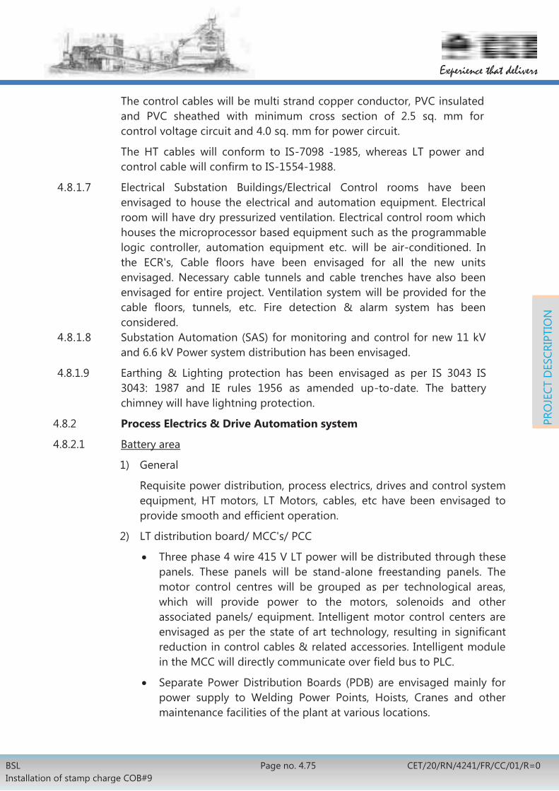
BSL Installation of stamp charge COB#9
Page no. 4.75 CET/20/RN/4241/FR/CC/01/R=0
Experience that delivers
PRO
JECT
DES
CRIP
TIO
N
The control cables will be multi strand copper conductor, PVC insulated and PVC sheathed with minimum cross section of 2.5 sq. mm for control voltage circuit and 4.0 sq. mm for power circuit.
The HT cables will conform to IS-7098 -1985, whereas LT power and control cable will confirm to IS-1554-1988.
4.8.1.7 Electrical Substation Buildings/Electrical Control rooms have been envisaged to house the electrical and automation equipment. Electrical room will have dry pressurized ventilation. Electrical control room which houses the microprocessor based equipment such as the programmable logic controller, automation equipment etc. will be air-conditioned. In the ECR's, Cable floors have been envisaged for all the new units envisaged. Necessary cable tunnels and cable trenches have also been envisaged for entire project. Ventilation system will be provided for the cable floors, tunnels, etc. Fire detection & alarm system has been considered.
4.8.1.8 Substation Automation (SAS) for monitoring and control for new 11 kV and 6.6 kV Power system distribution has been envisaged.
4.8.1.9 Earthing & Lighting protection has been envisaged as per IS 3043 IS 3043: 1987 and IE rules 1956 as amended up-to-date. The battery chimney will have lightning protection.
4.8.2 Process Electrics & Drive Automation system
4.8.2.1 Battery area
1) General
Requisite power distribution, process electrics, drives and control system equipment, HT motors, LT Motors, cables, etc have been envisaged to provide smooth and efficient operation.
2) LT distribution board/ MCC's/ PCC
Three phase 4 wire 415 V LT power will be distributed through these panels. These panels will be stand-alone freestanding panels. The motor control centres will be grouped as per technological areas, which will provide power to the motors, solenoids and other associated panels/ equipment. Intelligent motor control centers are envisaged as per the state of art technology, resulting in significant reduction in control cables & related accessories. Intelligent module in the MCC will directly communicate over field bus to PLC.
Separate Power Distribution Boards (PDB) are envisaged mainly for power supply to Welding Power Points, Hoists, Cranes and other maintenance facilities of the plant at various locations.

BSL Installation of stamp charge COB#9
Page No. 4.76 CET/20/RN/4241/FR/CC/01/R=0
Experience that delivers
PRO
JECT
DES
CRIP
TIO
N
Necessary provision (including Transformer, rectifier, Distribution board etc.) will be made for 24 V DC power supply for Solenoid Valves.
Intelligent Type single front, Non-Draw-out type, Motor Control Panels are envisaged for Motors rated 110 kW to 200 kW. Motor protection relays (micro-processor based) will be provided for motor protection.
3) AC Motors HT/LT AC motors will be selected to match the driven equipment as regards power and duty requirements, speed/torque characteristics etc. and will be able to accelerate smoothly the driven equipment/machine without undue heating. LT motors will be energy efficient motors.
4) AC Drives Variable frequency drives are considered for HPALA pumps lifts etc.
5) Local Control Station Local control stations housing Local-Remote selector switch, push buttons, indication lamps etc. for all drives. Ammeters will be provided on Local control stations for all motors rated 15kW and above.
6) Trolley line/ Catenary system Dedicated Power supply trolley wire/ trolley line system for oven machines including necessary MCCBs, trolley line rails, posts, brackets, trolley line holders for rail, insulators, permanent jointing plates, steel aluminium strap, compensators, bi-directional signal lamps (traffic lights) etc has been considered.
7) Safety Switch as Limit switches, proximity switches, Conveyor protection switches like Belt sway, pull cord switches, proximity type zero speed switches, Hooters/Sirens, solenoids, level sensors, Junction boxes have been considered for termination of cables to field devices, brake and brake rectifier panels etc.
8) Illumination system for Battery proper & coal handling conveyors. 9) Earthing & lighting protection
4.8.2.2 Electrics for Machines
Oven Machine electrics will generally comprise of the following:
1) Complete electrics including current collector, control panels, AC motors, brakes, limit and safety switches, sensors, VFD, control desk with HMI, radio communication with required hardware and software, hopper weighing system, UPS, LCS, illumination receptacles / maintenance sockets, all types of cables, earthing etc. for oven machines have been considered.

BSL Installation of stamp charge COB#9
Page no. 4.77 CET/20/RN/4241/FR/CC/01/R=0
Experience that delivers
PRO
JECT
DES
CRIP
TIO
N
2) CRD for incoming power
AC Motors- LT AC motors will be selected to match the driven equipment as regards power and duty requirements, speed/torque characteristics etc. and will be able to accelerate smoothly the driven equipment/machine without undue heating.
3) VFD system for variable speed drives.
4.8.2.3 Electrics for coal & coke handling Coal and coke handling electrics will generally comprise of the following:
1) Complete electrics including motors for hammer crushers, conveyor drive units, control panel, limit switches/sensor, LCS, cabling, earthing etc. for coal conveyors.
2) Complete electrics including motors for conveyor drive units, Control panel, Limit switches/sensor, LCS, Cabling, earthing etc. for coke conveyors, two roll crusher, grizzlies, screens etc. including air-conditioning, ventilation and dust extraction systems.
4.8.3 CDCP Area
CDCP Area electrics will generally comprise of the following:
1) LTSS and Intelligent draw-out type motor control centers (MCCs) for control of drives.
2) Intelligent type Motor control panels (MCPs) for control of drives of rating from 110kW up to 200kW.
3) HT/ LT AC motors as per requirement. 4) VFD System for variable speed drives. 5) Power distribution boards (PDB) for repair network like welding
sockets, maintenance cranes and hoists. 6) Generated power evacuation scheme with protection 7) Illumination system of the Coke Dry Cooling Plant 8) HT, LT, Control & special cable as per requirement. 9) Complete electrics and controls for the following:
i. Main Mill Fan drives, feed Water Pump Drives including HT Squirrel cage Induction Motors, Auxiliary Drive Motors, Local control panels/stations, cables etc.
ii. Waste Heat Boilers including squirrel cage induction motors complete with necessary accessories, electrically operated valve actuators, various type of limit switches, safety switches, cables etc.
iii. DM water system, cooling tower system, dust extraction system including motors, control panel, bag filters, solenoid valves, limit switches, power and control cables etc.
iv. Pneumatic Transport System for coke dust.

BSL Installation of stamp charge COB#9
Page No. 4.78 CET/20/RN/4241/FR/CC/01/R=0
Experience that delivers
PRO
JECT
DES
CRIP
TIO
N
v. Air conditioning/ Ventilation system vi. Crane and hoists, DSL system for cranes (minimum 75x75x6
angle) including angles/rails, aluminum strips/supporting brackets, insulator assembly, danger signal boards and festoon cable trolley system for hoists.
vii. Charging Device/ discharging covering Squirrel cage induction motors, Brakes, limit switches, cables etc.
viii. Coke bucket car including Main and signal current collectors, control panels, AC motors, Brakes, Resistances, Limit and safety switches, sensors, VFD, Control desk with HMI, Radio communication with required hardware and software, UPS, LCS, Illumination, receptacles/maintenance sockets, all types of cables, earthing, erection materials etc.
4.8.4 By-product Plant Area By product Plant Area electrics will generally comprise of the following:
1) Intelligent motor control centers (MCCs) for control of drives of all technological units of By-product plant. One additional MCC will be provided for other Auxiliaries.
2) Intelligent type Motor control panels (MCPs) for control of drives of rating from 110kW up to 200kW.
3) HT/ LT AC Motor. 4) VFD system for variable speed drives. 5) Local control stations with in-built Ammeter housing Local-Remote
selector switch, push buttons, indication lamps and other control devices for all drives including HT drives.
6) 24 V DC power supply for Solenoid Valves (including transformer, rectifier, Distribution board etc).
7) All flame proof/non-flame proof limit switches, proximity switches, proximity type zero speed switches, Hooters/Sirens, solenoids, level sensors, Junction boxes for termination of cables to field devices , brake and brake rectifier panels etc.
8) Complete electrics and controls for Exhauster drives including flame proof HT motors, flame proof auxiliary drive motors, flame proof local control panels/ local control stations, flame proof signaling & warning panels.
9) Complete electrics and controls for Electrostatic Tar Precipitators including Transformer Rectifier sets with HT Isolators, High Voltage DC Cables, Insulator Boxes, TR controller panel with micro-processor based TR controller unit opacity optimization software features with energy saving features etc.
10) Illumination system of the sub-station rooms, MCC rooms, control rooms, cable cellar, cable tunnels / bridge, various technological floors
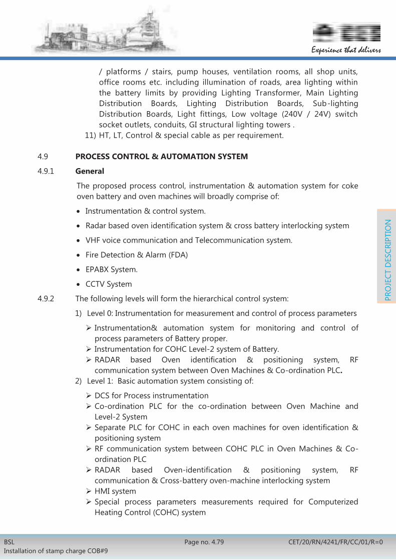
BSL Installation of stamp charge COB#9
Page no. 4.79 CET/20/RN/4241/FR/CC/01/R=0
Experience that delivers
PRO
JECT
DES
CRIP
TIO
N
/ platforms / stairs, pump houses, ventilation rooms, all shop units, office rooms etc. including illumination of roads, area lighting within the battery limits by providing Lighting Transformer, Main Lighting Distribution Boards, Lighting Distribution Boards, Sub-lighting Distribution Boards, Light fittings, Low voltage (240V / 24V) switch socket outlets, conduits, GI structural lighting towers .
11) HT, LT, Control & special cable as per requirement.
4.9 PROCESS CONTROL & AUTOMATION SYSTEM
4.9.1 General
The proposed process control, instrumentation & automation system for coke oven battery and oven machines will broadly comprise of:
Instrumentation & control system.
Radar based oven identification system & cross battery interlocking system
VHF voice communication and Telecommunication system.
Fire Detection & Alarm (FDA)
EPABX System.
CCTV System
4.9.2 The following levels will form the hierarchical control system:
1) Level 0: Instrumentation for measurement and control of process parameters
Instrumentation& automation system for monitoring and control of process parameters of Battery proper.
Instrumentation for COHC Level-2 system of Battery. RADAR based Oven identification & positioning system, RF communication system between Oven Machines & Co-ordination PLC.
2) Level 1: Basic automation system consisting of:
DCS for Process instrumentation Co-ordination PLC for the co-ordination between Oven Machine and Level-2 System
Separate PLC for COHC in each oven machines for oven identification & positioning system
RF communication system between COHC PLC in Oven Machines & Co-ordination PLC
RADAR based Oven-identification & positioning system, RF communication & Cross-battery oven-machine interlocking system
HMI system Special process parameters measurements required for Computerized Heating Control (COHC) system

BSL Installation of stamp charge COB#9
Page No. 4.80 CET/20/RN/4241/FR/CC/01/R=0
Experience that delivers
PRO
JECT
DES
CRIP
TIO
N
3) Level 2: Process Management System consisting of computer systems, peripherals, system & application software etc. Process optimization models for COHC system will be part of level-2 system. The system will have provision for suitable interface so that process and operations data will be made available to the computer system through the PLC/DCS systems in level-1 via Ethernet network.
4.9.3 Instrumentation and Control System
The proposed Instrumentation & control system will generally comprise of followings:
1) Primary sensors (orifice plates, thermocouples, Resistance Temperature Detectors, level sensor probes etc.), transmitters, back-up secondary instruments, final control element, alarm annunciator, jumbo displays for battery heating , GCM pressure & waste heat draft etc. with Back up instrument panel, transmitter cubicle, power supply cubicle, control desk etc.
2) A DCS system in redundant mode for monitoring & control of process parameters like pressure, temperature, flow etc. DCS system will be workstation based. DCS will have redundancy at CPU, PSU & communication module level. PC based HMI’s (Human Machine Interface) will be available with necessary software for monitoring & display of all the process parameter , alarms, over view loop and trend. Trend recording will also be provided for real time and historical trending. The DCS along with HMIs will be connected to dual 24 port 10/100/1000 Mbps Switches for data communication. The system will be complete with required nos. of HMI, Engineering cum operator station and printers.
Dedicated PLCs will be considered for each area as oven machines, CDCP, co-ordination PLC, coal & coke handling etc.
Ref: Drg No CET RN 4241 CA1 00 001 R=0- System configuration diagram
3) Hopper weighing system will be hooked up with the COHC PLC system of charging car, through which weighing data will be communicated to COHC system/co-ordination PLC over radio network. Connectivity of weighing system with the charging car COHC PLC & communication with Co-ordination PLC at Main Control Room will be done.
4) All the control valves will be with Electro-hydraulic actuator except for steam valves, which will be with Pneumatic actuator. All the Electro hydraulic actuators will be compact type and pneumatic actuators will have SMART type positioners.
5) It is envisaged that compressed air at adequate pressure is available in Coke ovens for providing air to instruments. Heatless drier cum moisture

BSL Installation of stamp charge COB#9
Page no. 4.81 CET/20/RN/4241/FR/CC/01/R=0
Experience that delivers
PRO
JECT
DES
CRIP
TIO
N
separator is envisaged for providing instrument grade air to the instrumentation system.
4.9.4 List of Measurement for Battery Proper
1. Coke Oven gas under firing
Pressure and temperature measurement in CO gas header.
CO gas flow measurement to battery coke side and pusher side.
CO gas pressure in coke side and pusher side.
Temperature and pressure of steam in header.
Flow of steam in header.
Temperature of CO gas after heater.
2. Mixed Gas Under firing
Pressure and temperature of mixed gas.
Mixed gas flow measurement.
3. Gas collecting mains (GCM)
Temperature and pressure of CO gas from pusher side and coke side in GCM.
Temperature and pressure of suction main.
Temperature, pressure and flow of LPAL to GCM.
Differential pressure between coke side and pusher side of GCM.
4. Waste Gas
CO, CO2, and O2 content measurement in waste gas, coke side and pusher side.
SOX, NOX, CO and SPM measurement in chimney.
Waste gas draught and temperature measurement in coke side and pusher side.
5. HPLA System
Flow measurement of HPLA to battery.
Pressure of HPLA header.
Differential pressure across strainer.
6. Gas Mixing Station
Pressure, Flow and temperature measurement of BF gas & CO gas to GMS.
Calorific value measurement.

BSL Installation of stamp charge COB#9
Page No. 4.82 CET/20/RN/4241/FR/CC/01/R=0
Experience that delivers
PRO
JECT
DES
CRIP
TIO
N
7. General
Goose-neck temperature measurement. Moisture measurement of coal before stamping. Measurement of coke mass temperature Pushing emission system measurement Level measurement in coal silos and coal bunkers. Measurement and control of quenching system
4.9.5 The list of proposed control Loops.
Pressure control in Gas Collecting Main (GCM). Differential Pressure control in Gas Collecting Main (GCM). Ammonia Liquor pressure control of HPAL System. Under firing coke oven gas pressure control. Temperature control of under firing coke oven gas after pre-heater. Under firing mixed gas pressure control. Waste Gas draught control. Coke oven gas control for mixing. Pressure control in mixed gas header. Pressure control of CO gas. Differential pressure control of Blast furnace gas and CO gas at gas
mixing station. Coal moisture control before stamping.
4.9.6 Oven Identification System
Oven Identification, machine positioning and machine interlocking system OIS and MIS) in all machines - SCP-2 nos., CGT Car – 2 nos., CTC Car – 2 nos., Self-propelled coke bucket car- 2 nos., quenching loco-1 no. OIS system in all machines will communicate through each other. Control of OIS in all machines is from main control room. OIS and MIS system will also communicate with L-2 system
4.9.7 Coke Dry Cooling Plant
4.9.7.1 Automation & control system
Monitoring, control, alarm & interlocking functions for the process parameters & equipment will be achieved through DCS based system.
CDCP DCS will be interfaced with Battery DCS. For this, required hardware and software will be considered.
Oven Identification and positioning system (OIS) will be installed in the loco of bucket car. This OIS system in bucket car will communicate with CDCP, oven machines and battery proper system to achieve overall positioning system.
Monitoring, control and other operational activities of the coke dry cooling plant will be carried out from a CDCP control room, which will be part of a control building, to be suitably located adjacent to the main unit.

BSL Installation of stamp charge COB#9
Page no. 4.83 CET/20/RN/4241/FR/CC/01/R=0
Experience that delivers
PRO
JECT
DES
CRIP
TIO
N
a) The Instrumentation system will be installed in the following area of coke dry quenching plant:
Coke dry cooling plant chamber and circulating gas. Thermal power plant system. Common and auxiliary facility system. Water circulating system.
1. Following are the important measurements:
Temperature measurement CDQ chamber and circulating gas. Temperature measurement of discharged coke. Level measurement of coke in CDQ furnace. Temperature measurement of discharged coke Flow measurement of gases. Pressure measurement of CDQ furnace chamber and circulating gas. Analysis of gas for composition of CO, CO2, O2 and H2. Material level detection of primary dust catcher. Steam drums liquid level detection of boiler. Flow measurement of boiler feed water and superheated steam. Flow measurement of circulating water. Flow measurement of demineralized water. Temperature measurement of boiler feed water and superheated steam.
4.9.8 Power Plant (BPTG, Boiler, DM Plant)
4.9.8.1 Automation & control system
Proposed Power plant will be provided with state of the art Control and Instrumentation system adequate for efficient operation as well as monitoring of the plant. Remote operation, monitoring and intelligent control from dedicated control room is being envisaged. DCS based system has been considered for process monitoring, feedback auto controls, data acquisition, alarm annunciation as well process interlocks, drive sequencing etc. for power plant control.
Common DCS complete with hot redundant CPUs, communication controllers as well as power supply cards will be provided for BPTG, Boiler, DM plant and its auxiliaries. Interface with CDCP DCS is proposed.
DCS will basically consist of:
a) Measurement & control system b) HMI c) System programming & documentation facility d) Data communication system e) Sequence of events recording system f) Annunciation system
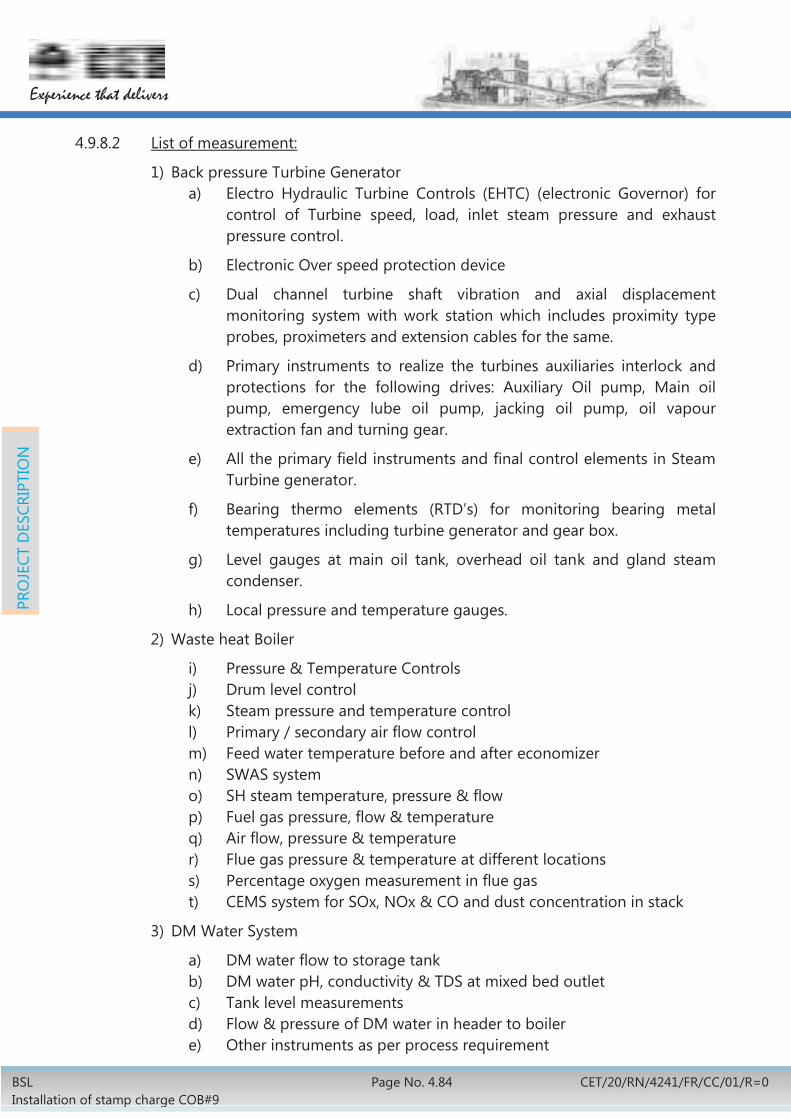
BSL Installation of stamp charge COB#9
Page No. 4.84 CET/20/RN/4241/FR/CC/01/R=0
Experience that delivers
PRO
JECT
DES
CRIP
TIO
N
4.9.8.2 List of measurement:
1) Back pressure Turbine Generator a) Electro Hydraulic Turbine Controls (EHTC) (electronic Governor) for
control of Turbine speed, load, inlet steam pressure and exhaust pressure control.
b) Electronic Over speed protection device
c) Dual channel turbine shaft vibration and axial displacement monitoring system with work station which includes proximity type probes, proximeters and extension cables for the same.
d) Primary instruments to realize the turbines auxiliaries interlock and protections for the following drives: Auxiliary Oil pump, Main oil pump, emergency lube oil pump, jacking oil pump, oil vapour extraction fan and turning gear.
e) All the primary field instruments and final control elements in Steam Turbine generator.
f) Bearing thermo elements (RTD’s) for monitoring bearing metal temperatures including turbine generator and gear box.
g) Level gauges at main oil tank, overhead oil tank and gland steam condenser.
h) Local pressure and temperature gauges.
2) Waste heat Boiler
i) Pressure & Temperature Controls j) Drum level control k) Steam pressure and temperature control l) Primary / secondary air flow control m) Feed water temperature before and after economizer n) SWAS system o) SH steam temperature, pressure & flow p) Fuel gas pressure, flow & temperature q) Air flow, pressure & temperature r) Flue gas pressure & temperature at different locations s) Percentage oxygen measurement in flue gas t) CEMS system for SOx, NOx & CO and dust concentration in stack
3) DM Water System
a) DM water flow to storage tank b) DM water pH, conductivity & TDS at mixed bed outlet c) Tank level measurements d) Flow & pressure of DM water in header to boiler e) Other instruments as per process requirement

BSL Installation of stamp charge COB#9
Page no. 4.85 CET/20/RN/4241/FR/CC/01/R=0
Experience that delivers
PRO
JECT
DES
CRIP
TIO
N
4.9.9 By-Product Plant
In By-product Plant Monitoring, Control, Alarm & Interlocking functions for the process parameters & equipment will be achieved through DCS based system. All the field equipment/ facilities will accordingly be interfaced with the automation system.
1. The Instrumentation automation system will be installed in the all the sub-units of By-Product plant:
2. Following are the important measurements:
Pressure and temperature measurement of CO gas in each stream of PGC and its control by regulation of damper at exhauster inlet.
Measurement of temperature and flow of water in the header of each stream of PGC.
Measurement of Temperature and pressure of CO gas after ETP. Measurement and control of temperature of insulator box of ETP through
steam flow control. Pressure at the delivery of flushing liquor pumps, Ammonia liquor pump,
Gas condensate pump and tar transfer pump. Flow of flushing liquor to battery. Level of intermediate flushing liquor tank and tar tank. Pressure and temperature of CO gas in the header at inlet and outlet of
each exhauster. Measurement of flow and pressure of water at inlet/outlet of coolers of
each exhauster. Regulating damper at the exhauster inlet.
4.9.10 Coke Handling Plant
Monitoring, control, alarm & interlocking functions for the process parameters & equipment of coke sorting & conveyor system will be provided. Suitable field instrumentation facilities will be provided.
4.9.11 Control Room
There will be four numbers of control rooms, one number each for battery proper, coke dry cooling plant, BPP and Boiler cum BPTG. All control rooms will be connected to each other through Ethernet switch. Each control room will have following equipment:
PLC/DCS with system software for process control and monitoring. Human Machine Interface/Operator Station/ Engineering Station. HMI Server Redundant. Network Printer. Network Switches. FDA panel. CCTV monitors and recording.

BSL Installation of stamp charge COB#9
Page No. 4.86 CET/20/RN/4241/FR/CC/01/R=0
Experience that delivers
PRO
JECT
DES
CRIP
TIO
N
EPABX system. UPS CCTV System
Air-conditioning will be considered for each control room.
4.9.12 UPS System
Required nos. of Parallel redundant UPS system to cater all field instruments and control room equipment.
4.9.13 CCTV System for the Supervision & Monitoring of Process & PA System
CCTV system will be provided for process/equipment monitoring and functioning of oven machines from a central location by installing Microprocessor based CCTV system at various strategic locations. This system will assist in monitoring various areas on a continuous basis from a central location and for taking timely action in the event of any dysfunction.
4.9.14 FDA System
Microprocessor based intelligent addressable type automatic Fire detection and audio-visual alarm system will be provided for early warning in case of smoke, heat and/or fire in all fire sensitive locations so that same can be put off in time. Areas to be covered under such system will include Control rooms, electrical rooms, UPS room, DCS/PLC room, computer room, cable basement/ gallery, false floor/ ceiling, hydraulic rooms, transformer rooms.
4.9.15 EPBAX Communication System
Existing plant wise telephone network will be extended to different rooms/locations (approx. 30 sets or as required) of proposed COB#9 complex including CDCP & BPP-2
4.9.16 Earthing & Surge Protection as per IE Rule.
Suitable electronic earthing & surge protection will be provided as per prevailing rule.
4.10 DISMANTLING/ DISPOSAL
The existing Benzol rectification unit (BRP-2) which is presently out of operation will be disposed-off by BSL.
Few existing semi-permanent sheet metal roofed structures are in the alignment of the proposed coal conveying route will be dismantled. They will be suitable relocated wherever required.
Slag dump existing in the location behind the BOD unit will be emptied by BSL.

BSL Installation of stamp charge COB#9
Page no. 5.1 CET/20/RN/4241/FR/CC/01/R=0
Experience that delivers
PRO
JECT
IMPL
EMEN
TATI
ON
5. IMPLEMENTATION SCHEDULE AND STRATEGY 5.1 IMPLEMENTATION SCHEDULE
5.1.1 The project is envisaged to be implemented within a period of 42 months from the date of Stage-II approval. Pre-ordering activities are envisaged to be completed within 6 months from the date of Stage-I approval.
5.1.2 Implementation schedules, in the form of bar charts, for pre-ordering and post-ordering activities are shown at Annexure – 5.1.2-1 & 5.1.2-2 respectively.
5.2 IMPLEMENTATION STRATEGY
5.2.1 Mode of execution and number of packages:
The project is proposed to be executed through four turnkey packages and one through non-turnkey package, as follows:
1. Package-1: Geo-technical investigation and survey works will consist of jobs pertaining to land survey and soil analysis of the area within the battery limits which will be used for designing civil works.
(It is proposed to execute this package in non-turnkey basis, in advance prior to processing for obtaining stage-I approval).
2. Package-2 (Turnkey): Battery Proper along with oven machines, refractories, coal handling & coke sorting will consist of following equipment.
i. Entire Battery proper area including supply of refractory.
ii. Coal handling conveyors, junction house, coal crushing stations.
iii. Quenching tower, settling pond and wharf.
iv. Supply of all oven machines i.e. SCP machine (2 nos.), charging gas transfer car (2 nos.), coke transfer cars (2 nos.), quenching car (1 no.) and quenching loco (1 no.)
v. Coke sorting conveyors, junction house, coke crushing and screen house.
vi. Facility for receiving category-2 power from MSDS-4, category-1 power from 1RP.
3. Package-3 (Turnkey): Coke dry cooling plant with power generation, DM water plant will consist of following items-
i. Dry quenching chamber, boiler and dust disposal system.
ii. Two nos. of coke bucket car.
iii. Turbine generator unit along with power evacuation system.
iv. DM Water plant.

BSL Installation of stamp charge COB#9
Page No. 5.2 CET/20/RN/4241/FR/CC/01/R=0
Experience that delivers
PRO
JECT
IMPL
EMEN
TATI
ON
4. Package-4 (Turnkey): By-product plant will consist of following items-
i. Gas condensation unit. ii. Primary gas cooler, ETP, gas exhauster iii. NH3 cracking and Sulphur recovery, iv. Naphthalene recovery system, v. Chilled water, cooling water, BOD plant.
5. Package-5 (Turnkey): Benzol storage unit
i. In the existing BRP-2 area, a partition wall will be erected for isolating the benzol storage area.
ii. After the erection of the new boundary wall, the balance area of the BRP-2 will be license-altered and the new license will cover only the equipment located within the new boundary wall.
iii. All equipment presently located outside the proposed new boundary wall (license-altered area) will be disposed-off by BSL separately.
iv. Installation of 4 X 750m3 new benzol storage tanks along with all accessories and fire-protection facilities.
v. After the commissioning of the new Benzol storage unit, the balance equipment of BRP-2 (located within the proposed new boundary wall) will be dismantled after getting this area de-licensed. Dismantling of equipment (within the new boundary wall) is also included in this package.
5.2.2 The following activities package wise (except package-1) can be started after obtaining “Stage-I” approval:
Issue of Tender enquiry. Receipt of offers. Scrutiny and evaluation of Technical & Commercial offers. Techno-commercial discussions. Evaluation of offer and Tender recommendation. Opening of price bids and finalisation of bidder. Package-1 to be finalised and ordered prior to Stage-1 approval and based
on the final soil & survey report, the tender specification for all other packages will be finalised.
5.2.3 After completion of above activities, investment proposal with firmed up cost will be put up to Board for “Stage-II” approval.
5.2.4 BSL will take all the required statutory clearances (environmental, pollution, electrical installations, consent to establish, consent to operate) from the concerned government agencies prior to processing for obtaining stage-II approval.

BSL Installation of stamp charge COB#9
Page no. 5.3 CET/20/RN/4241/FR/CC/01/R=0
Experience that delivers
PRO
JECT
IMPL
EMEN
TATI
ON
5.2.5 Statutory clearance will be required from the concerned authority such as PESO (Petroleum and Explosives Safety Organisation) relating to existing BRP-2 area alteration for disposal/dismantling.
5.2.6 Specialist agency will be engaged by BSL to conduct environmental impact assessment (EIA) studies and prepare environmental management plan (EMP). This EIA & EMP report will address all the elements proposed under the latest guidelines. Based on this, required clearances from state and central regulatory authorities will be obtained. Cost of the same has not been included in the FR.
5.2.7 Slag Removal will be carried out by BSL separately through a rate contract which already exists at BSL with FSNL. BSL has furnished an estimate in this regard and the same has been included in the cost for this project. Note Sheet in this regard is enclosed as Annexure-5.2.7-1.
5.2.8 Package-1: Soil investigation and survey works, Package-5: Benzol storage unit & slag removal jobs will be considered as enabling works.
5.3 DETAILS OF PRE-SHUTDOWN ACTIVITIES WITH DURATION
Battery complex will be installed in green field area after dismantling and disposal of BRP-2. Hence, no pre shut down activities are envisaged for erection of battery, CDCP and by-product plant.
5.4 DETAILS OF SHUTDOWN ACTIVITIES WITH DURATION
5.4.1 Max. 7 days shutdown will be required for modification and interconnection of each belt in the existing conveyor below coal silos. Complete shutdown of the existing coal feeding plant is not required as the coal can be fed through other existing conveyors to the existing batteries.
5.4.2 Max. 7 days shutdown will be required for capacity enhancement of each coke conveyor KD5-1 and KD5-2. One of these conveyors will be working during modification of another conveyor. As such coke feeding to the blast furnace through this route will be continuous. Intermittent shutdown of 2 days each will be required for interconnecting new coke conveyors to the existing conveyors.
5.4.3 Max. 2 days shut down is required for interconnection of clean coke oven gas, steam water with existing network.
5.5 Normal power will be tapped from existing feeders of MSDS-IV (extension). Hence, shut down is not required. For tapping of emergency power one panel is to be extended in 1RP 1. Eight hour shut down will be required in 1RP1 substation. Preparatory job will be done during regular maintenance period.
5.6 Proposed coal blend is to be tested at RDCIS Laboratory to test the suitability of a particular coal blend for proposed stamp charge battery before finalising the TS.
5.7 BSL will hand over the site free of any debris after dismantling and disposal of existing BRP-2 plant

BSL Installation of stamp charge COB#9
Page no. 6.1 CET/20/RN/4241/FR/CC/01/R=0
Experience that delivers
CAPI
TAL
COST
& F
INA
NCI
AL A
NAL
YSIS
6. CAPITAL COST &FINANCIAL ANAYLSIS 6.1 CAPITAL COST ESTIMATES:
6.1.1 The capital cost of the project with forward premium rate is estimated at Rs. 2094.94 crore net of CENVAT Credit of Rs.175.79 crore including IDC of Rs.265.67 crore. FE component considered in it is Rs.564.42 crore. The summary capital cost estimate is appended at Annexure - 6.1.1-1. However, the capital cost of the project without forward premium rate is estimated at Rs.2018.09 crore net of CENVAT Credit.
6.1.2 The capital cost is based on budgetary quotations for few critical items like SCP machines, CTC machines & CDCP and engineering estimates for remaining items. Base date for the estimate is 1st Quarter 2017. FE parity has been considered as 1 USD=Rs. 68.12 and 1 EURO=Rs. 72.78. Additionally, forward premium rates as Rs. 6.78 and Rs. 7.24 considered for USD and EURO respectively.
6.1.3 Necessary statutory provisions have been made in the estimates as per the details given below:
a) For indigenous items:
i) Excise duty: @ 12.5% on basic cost of equipment, refractory & structures.
ii) CST: @ 2% on basic cost of equipment, refractory & structures and on excise duty.
iii) VAT: @ 12.5% on 60% of civil & erection jobs.
iv) Service tax: @ 15% on engineering & construction (contractor), freight & insurance and 40 % of civil & erection jobs.
v) Entry tax has not been considered as the same is not applicable in the state of Jharkhand.
b) For imported components:
i) Ocean freight & insurance: @7% on FOB cost;
ii) CD @ 7.5% on (CIF+1% landing charges);
iii) CVD @ 12.5% on (CIF+1% landing +CD);
iv) Edu. cess @3% on CD+CVD;
v) ADC @4% on (CIF+1% landing +CD +CVD + educational cess);
vi) Income Tax @ 11.11% grossed-up of Design & Engineering and foreign services;
vii) Service Tax @ 15% on Design & Engineering and foreign services + Income Tax.

BSL Installation of stamp charge COB#9
Page No. 6.2 CET/20/RN/4241/FR/CC/01/R=0
Experience that delivers
CAPI
TAL
COST
& F
INA
NCI
AL A
NAL
YSIS
viii) Entry tax has not been considered as the same is not applicable in the state of Jharkhand.
6.1.4 Freight & insurance charges for indigenous equipment @2% of basic cost and for indigenous structure & refractory @9% of basic cost has been considered. Inland freight & insurance charges for imported equipment has been taken @3% of CIF cost.
6.1.5 Erection & commissioning charges has been taken @ 12% on basic cost of indigenous equipment, @ 20% of basic cost of structure and 6% on CIF cost of imported equipment. Erection for refractory has been taken on unit rate based on similar jobs executed in SAIL plants.
6.1.6 Engineering & Construction (E&C): E&C (contractor) @ 5% and E&C (owner) @ 2.5 % on basic cost of equipment, structures, refractory, civil work and erection & commissioning charges.
6.1.7 Contingencies: @ 5 % on overall basis has been considered.
6.2 MODE OF FINANCING:
The total capital requirement of the project is proposed to be provided from 100% debt with an interest @ 10% per annum on loan.
6.3 PHASING OF CAPITAL EXPENDITURE:
With the project duration of 42 months from the date of Stage – II approval, the phasing of capital expenditure is proposed as indicated below:
Rs. In crore
Year Plant cost
Equity Loan IDC Total incl. IDC
1st year 200.51 200.51 10.03 210.53
2nd year 601.52 601.52 50.13 651.64
3rd year 802.02 802.02 120.30 922.33
4th year (6 months) 200.51 200.51 85.21 285.72
Post Comm. 200.51 200.51 200.51
Capital cost 265.67 2270.73
CENVAT credit 175.79
Capital cost net of CENVAT 2094.94

BSL Installation of stamp charge COB#9
Page no. 6.3 CET/20/RN/4241/FR/CC/01/R=0
Experience that delivers
CAPI
TAL
COST
& F
INA
NCI
AL A
NAL
YSIS
6.4 INTEREST DURING CONSTRUCTION (IDC):
Based on the mode of financing and phasing of capital expenditures indicated above, total IDC has been worked out to Rs.265.67 crore.
6.5 COST - BENEFIT ANALYSIS:
6.5.1 Gross margin calculation for the project is based on the assumption that in case the proposed Coke Oven Battery is not installed, the entire requirement of BF coke i.e. 703,800 t per annum would be met from purchased coke. Considering purchased price of equivalent BF coke @ Rs.20,287/t (based on average price of MMTC’s price circular from May’16 to Dec’16), savings on account of avoidance of equivalent purchase of BF coke works out to Rs.1,428 crore per annum. Other benefits considered are on account of following:
credit for CO gas Rs. 131 Cr. credit for crude tar Rs. 22 Cr. contribution from electrical power generated Rs. 24 Cr. contribution from low pressure steam generated Rs. 35 Cr. contribution from coke breeze generated Rs. 45 Cr. contribution from saving of BF coke due to better M10 value Rs. 42 Cr.
Thus, total benefit works out to Rs.1,727crore per annum.
Production cost of equivalent own BF coke has been computed considering associated cost of imported & indigenous coal blend (weighted average rate of different type of coal for the period July'16 to Dec'16 as forwarded by Coal Import group of CO) whereas operating cost including repair & maintenance and overhead costs for battery operation has been considered same as that of battery operation of BSL (actual cost sheet 2016-17 H1 of BSL). However, operating cost including repair & maintenance and overhead costs for CDCP & coke sorting has been considered same as that of CDCP operation at RSP (actual cost sheet 2016-17 Q1 of RSP). Considering above, total production expenditure (works cost) works out to Rs.1,108 crore per annum.
Based on above, gross margin works out to Rs.619 crore per annum. Detail of gross margin calculation is shown at Annexure – 6.5.1-1.
6.6 FINANCIAL ANALYSIS:
6.6.1 Cash flow analysis has been carried out for 24 years considering the life of project of 20 years after its commissioning.
6.6.2 Techno-economic indices are presented at Annexure - 6.6.2-1. Some of the important indices are indicated below:
NPV @ 10% (Post tax): Rs. 1655.60 Cr. IRR (Post tax): 23.20 %

BSL Installation of stamp charge COB#9
Page No. 6.4 CET/20/RN/4241/FR/CC/01/R=0
Experience that delivers
CAPI
TAL
COST
& F
INA
NCI
AL A
NAL
YSIS
6.6.3 Market price of BF coke & coal is volatile and fluctuates abnormally which gives wide variation in techno-economic indices.
6.6.4 Sensitivity analysis has been carried out as follow:
Item IRR (Post tax)
Base case 23.20%
Capital cost (+) 10% 21.52%
Gross Margin (-) 10% 21.34%
Combined effect of (i) Capital cost increased by 10% and (ii) Gross Margin decreased by 10%
19.69%
Purchased price of BF Coke (-) 5 % 20.97%

Experience that delivers
BSL Installation of stamp charge COB#9
Page no. 7.1 CET/20/RN/4241/FR/CC/01/R=0
RECO
MM
END
ATIO
NS
7. RECOMMENDATIONS 7.1 Installation of proposed stamp charge coke oven Battery No 9 is technically
feasible and is also techno-economically viable. Hence, the proposed project is recommended for implementation.


BSL Installation of stamp charge COB#9
Page 1 of 1 CET/20/RN/4241/FR/CC/01/R=0
Experience that delivers
ANNEXURE – 2.3.3-1
Repair/Rebuilding Plan and Coke Balance at BSL
Batt No. & comm.date 2015-16 2016-17 2017-18 2018-19 2019-20 2020-21 2021-22 2022-23 2023-24Battery 1
(28 June 2011)Battery 2
(11 Feb 2012)Battery 3
(20 Oct 2000)Battery 4
(4 June 1996)Battery 5
(21 Sept 2007 )Battery 6
(28 Dec 1982)Battery 7
(23 Feb 1985 )Battery 8
(20 Sep 1993) Battery 9
(New Tall Battery)
Parameters 2015-16 2016-17 2017-18 2018-19 2019-20 2020-21 2021-22 2022-23 2023-24Small battery in operation 6 6 6 6 6 8 8 7 6
Stamp charge battery in operation0 0 0 0 0 0 1 1 1
Avaialble ovens, (Nos.) (small batteries)(Nos.)
390 369 373 355 486 476 493 449 397
Avaialble ovens, (Nos.) (Stamp charge battery) (Nos.)
0 0 0 0 0 0 46 92 92
Oven pushings/day, (Nos.) (small batteries)(Nos.)
456 428 424 412 579 577 594 546 487
Oven pushings/day, (Nos.) (Stamp Charge battery)(Nos.)
0 0 0 0 0 0 44 90 90
Working days/year 365 365 365 365 365 365 365 365 365
Coal charge/oven, (small battery) (t)
19.5 19.5 19.5 19.5 19.5 19.5 19.5 19.5 19.5
Coal charge/oven, (Stamp charge battery) (t)
0.0 0.0 0.0 0.0 31.0 31.0 31.0 31.0 31.0
BF coke yield, % 69.0 69.0 69.0 69.0 69.0 69.0 69.0 69.0 69.0
BF Coke production, (Mtpa) 2.238 2.100 2.084 2.026 2.846 2.833 3.263 3.387 3.093Screen loss, % 14.0 14.0 14.0 14.0 14.0 14.0 14.0 14.0 14.0Skip coke prodn, (Mtpa) 1.924 1.806 1.792 1.742 2.447 2.436 2.806 2.913 2.660
Hot metal prodn.(Mta)Existing BFs 4.40 4.60 5.25 5.38 4.75 5.77 5.77 5.77 5.77
Coke rate 498 497 500 496 496 496 496 496 496
Skip coke reqnt.(Mta) 2.191 2.286 2.625 2.668 2.356 2.862 2.862 2.862 2.862
BF coke reqnt.(Mta) 2.548 2.658 3.052 3.103 2.740 3.328 3.328 3.328 3.328
Overall skip coke Surplus/Shortfall, (Mta)
-0.267 -0.480 -0.833 -0.926 0.091 -0.426 -0.056 0.051 -0.202
BF coke Surplus/Shortfall -0.310 -0.559 -0.969 -1.077 0.106 -0.495 -0.065 0.059 -0.235
NOTE:
COKE BALANCE
1. Battery No. 4 & 3 will be closed down from April 2022. & April 2023 respectively.2. Installation of battery No. 9 will be from April 2018.
OCT 2017
June'2015
Nov 2017
Cold RepairRebuilding
Dec 2016
Stamp charge battery
April 2020
JAN 2019 June 2020
Sept 2021
May 2019
ClosedDown
April 2022
April 2023
April 2018


Experience that delivers
BSL Installation of stamp charge COB#9
Annexure No. 2.3.6-1 Page 1 of 10
CET/20/RN/4241/FR/CC/01/R=0
ANNEXURE – 2.3.6-1

BSL Installation of stamp charge COB#9
Annexure No. 2.3.6-1 Page 2 of 10
CET/20/RN/4241/FR/CC/01/R=0
Experience that delivers

Experience that delivers
BSL Installation of stamp charge COB#9
Annexure No. 2.3.6-1 Page 3 of 10
CET/20/RN/4241/FR/CC/01/R=0

BSL Installation of stamp charge COB#9
Annexure No. 2.3.6-1 Page 4 of 10
CET/20/RN/4241/FR/CC/01/R=0
Experience that delivers

Experience that delivers
BSL Installation of stamp charge COB#9
Annexure No. 2.3.6-1 Page 5 of 10
CET/20/RN/4241/FR/CC/01/R=0

BSL Installation of stamp charge COB#9
Annexure No. 2.3.6-1 Page 6 of 10
CET/20/RN/4241/FR/CC/01/R=0
Experience that delivers

Experience that delivers
BSL Installation of stamp charge COB#9
Annexure No. 2.3.6-1 Page 7 of 10
CET/20/RN/4241/FR/CC/01/R=0

BSL Installation of stamp charge COB#9
Annexure No. 2.3.6-1 Page 8 of 10
CET/20/RN/4241/FR/CC/01/R=0
Experience that delivers

Experience that delivers
BSL Installation of stamp charge COB#9
Annexure No. 2.3.6-1 Page 9 of 10
CET/20/RN/4241/FR/CC/01/R=0

BSL Installation of stamp charge COB#9
Annexure No. 2.3.6-1 Page 10 of 10
CET/20/RN/4241/FR/CC/01/R=0
Experience that delivers

Experience that delivers
BSL Installation of stamp charge COB#9
Page 1 of 1 CET/20/RN/4241/FR/CC/01/R=0
ANNEXURE – 2.3.6-2

BSLInstallation of Stamp Charge COB#9
Annexure – 4.7.1–1 PAGE 1 of 7
CET/20/RN/4241/FR/CC/01/R=0
ANNEXURE-4.7.1-1
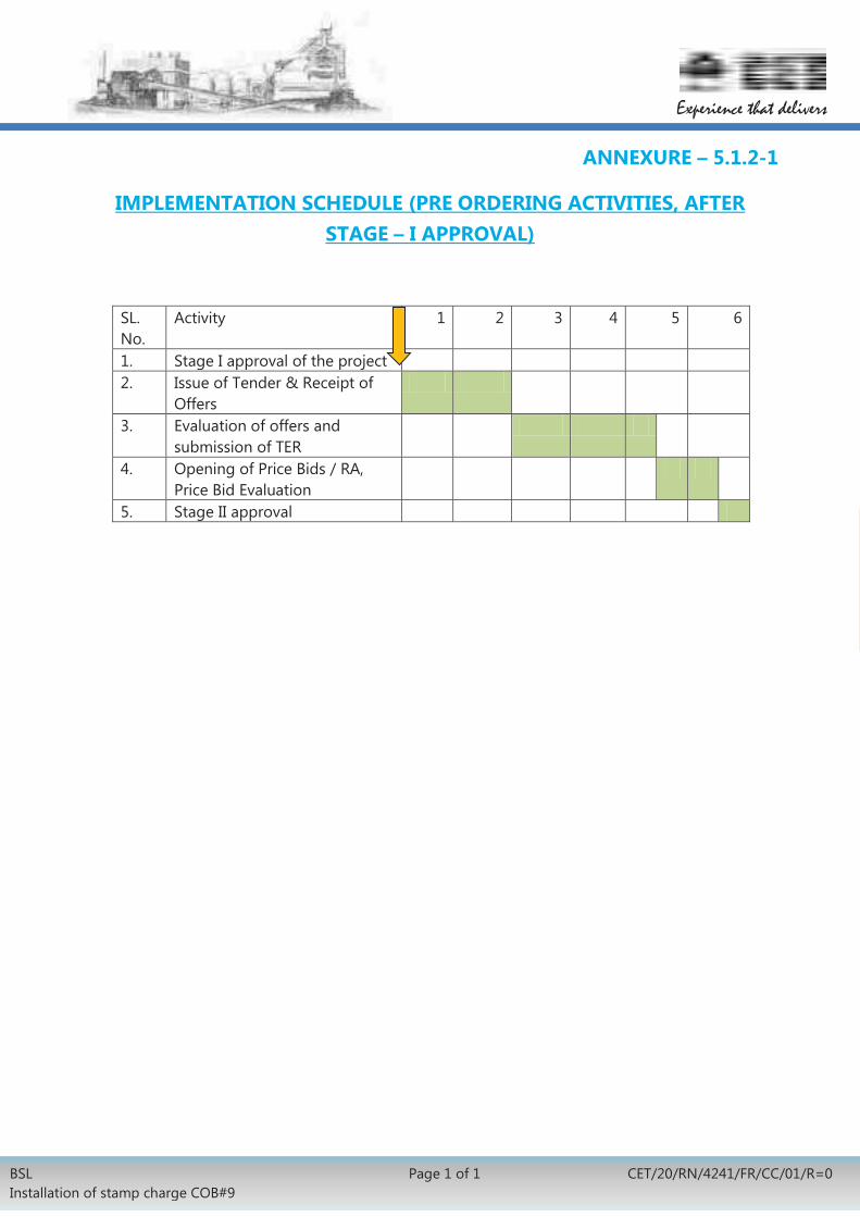
BSL Installation of stamp charge COB#9
Page 1 of 1 CET/20/RN/4241/FR/CC/01/R=0
Experience that delivers
ANNEXURE – 5.1.2-1
IMPLEMENTATION SCHEDULE (PRE ORDERING ACTIVITIES, AFTER STAGE – I APPROVAL)
SL. No.
Activity 1 2 3 4 5 6
1. Stage I approval of the project 2. Issue of Tender & Receipt of
Offers
3. Evaluation of offers and submission of TER
4. Opening of Price Bids / RA, Price Bid Evaluation
5. Stage II approval

BSL
Inst
alla
tion
of s
tam
p ch
arge
CO
B#9
Page
1 o
f 1
CET/
20/R
N/4
241/
FR/C
C/01
/R=
0
Exper
ience
that d
eliver
s
AN
NEX
URE
–5.
1.2-
2 IM
PLEM
ENTA
TIO
N S
CHED
ULE
(PO
ST O
RDER
ING
ACT
IVIT
IES,
AFT
ER S
TAG
E –
II A
PPRO
VA
L)
S.N
O.
ACT
IVIT
IES
12
34
56
78
910
1112
1314
1516
1718
1920
2122
2324
2526
2728
2930
3132
3334
3536
3738
3940
4142
1St
age-
II A
ppro
val
2Pl
acem
ent o
f Ord
er &
Si
gn. o
f Con
trac
t3
Des
ign
& E
ngin
eeri
ng4
Site
Sur
vey,
leve
ling
5Pi
ling
& E
xcav
atio
n
6M
ajor
Civ
il W
orks
in
Bat
trey
, CD
CP &
By-
7TO
PRa
Supp
lyb
Erec
tion
8R
efra
ctor
ya
Man
ufac
turi
ng,
bEr
ectio
n9
Equi
pmen
t (B
atte
ry,
CDCP
& B
y-pr
oduc
t)a
Supp
lyb
Erec
tion
10El
ectr
ical
, Ins
t. &
Aut
omat
ion
aSu
pply
bEr
ectio
n11
Ove
n M
achi
nes
eM
anuf
actu
ring
f
Supp
ly a
nd E
rect
ion
at
site
gPA
Th
Com
mis
sion
ing
12R
eadi
ness
of o
ther
uni
ts13
Hea
ting
-up
& C
omm
issi
onin
g
NO
TE:It
is e
nvis
aged
that
Pkg
-1 w
ill b
e im
plem
ente
d be
fore
Sta
ge-I
app
rova
l and
Pkg
-5 w
ill b
e im
plem
ente
d so
on a
fter
the
stag
e -I
app
rova
l. Sc
hedu
le o
f pac
kage
-1 is
3 m
onth
and
Pkg
-5 is
15
mon
ths
MO
NTH
S