
Facile synthesis of UV-white light emission ZnSe/ZnS:Mn core/(doped) shell nanocrystals in aqueous...
7
Facile synthesis of UV-white light emission ZnSe/ ZnS:Mn core/(doped) shell nanocrystals in aqueous phase Bich Thi Luong, ab Eunsu Hyeong, a Sujin Yoon, a Jongwan Choi a and Nakjoong Kim * a ZnSe/ZnS:Mn core/(doped) shell and ZnSe/ZnS:Mn/ZnS core/(doped) shell/shell nanocrystals (NCs) that emit white light were synthesized in aqueous media. White light emission of as-prepared NCs is a result of combined emission of blue light (emission from band gap of ZnSe core) and yellow/orange light ( 4 T 1 – 6 A 1 emission from Mn 2+ ions doped in ZnS of the first shell). Especially, the green emission generated from surface defects was found as a key factor that affects the photoluminescence quantum yields of core/(doped) shell and core/(doped) shell/shell NCs. Photoluminescence from the Mn:ZnS d-dots was easily tuned from 580–600 nm by regulating feeding molar ratio [Zn]/[Mn]. Under the sufficiently low Mn 2+ dopant concentration, ZnSe/ZnS:Mn and ZnSe/ZnS:Mn/ZnS NCs emit white light with a quantum yield about 27.6% and 20.5%, respectively. Introduction White-light emission from semiconductor nanostructures is presently a research area of interest due to their unique elec- trical, optical and chemical properties. Therefore, it is of great importance for many applications to nd high-quality single source. White-light emitters through low-cost chemical synthesis approach which will allow the production of white light while meeting the needs of industry. Specically, a need exists for efficient pure white light LED (light emitting diode) as a replacement for conventional lighting sources. 1 Presently, there are different methods to generate white light by three different paths according to three principles: (1) mixing fully visible light or mixing fully all visible phosphor nanocrystals (NCs); (2) combining green, red, and blue phosphor NCs; (3) combination of yellow and blue light. However, when the white light is generated by simply mixing phosphor NCs of different colors together, the observed efficiencies are oen decreased due to the re-absorption of light and subsequent undesirable energy transfer. Thus, the undesirable changes in the chroma- ticity coordinate and photometric performance would be led due to the different relative temporal stabilities of the compo- nents. Hence the use at a single-emitting component offers many advantages over multiple component systems for white- light emitting sources such as LEDs, among which are greater reproducibility, lower cost preparation, ease of modication, simpler fabrication process. Recent research on quantum dots (QDs) that emit white light has been focused on cadmium chalcogenides by simply mixing red, green, and blue light from CdS, CdSe and CdTe QDs, 2,3 magic-sized CdSe QDs, 4 ultrasmall white-light emission CdSe (ref. 5) and manganese-doped sulde QDs such as Mn:CdS, Mn:ZnS. 6–9 However, the intrinsic toxicity of cadmium, and the low total optical efficiency of cadmium chalcogenide QDs caused by self-absorption limit these QDs in large-scale applications. 10 The Mn-doped ZnSe d-dots core/shell that emit white light were synthesized by modifying a nucle- ation-doping strategy. Thus, the surface trap state emission of these QDs was realized and controlled. 11 The white light emis- sion of manganese and copper co-doped ZnSe QDs were synthesized in a two-step process. 12 White emission was realized for Mn-doped ZnS NCs which synthesized in aqueous-phase. 13 The tunable color from yellow to orange emission of ZnSe/ ZnS:Mn/ZnS core/(doped) shell/shell NCs synthesized in organic solvent 14 and in aqueous media with three-step single ask. 17 Since the blue light of ZnSe at 395–400 nm and surface trap emission at 500 nm wavelength have been found, the white emission was obtained when the Mn 2+ ions concentration was doped low enough. 10 The model of schematic representation to different emissions from ZnSe/ZnS:Mn core/(doped) shell NCs is ascribed in Fig. 1. Herein, we report the most green and simple synthetic route to produce ZnSe/ZnS:Mn core/(doped) shell and ZnSe/ZnS:Mn/ZnS core/(doped) shell/shell NCs that emit white light in aqueous medium. The mechanism is illus- trated in Fig. 2, the blue circle elucidates the ZnSe core that emits blue light, the green layers represent the surface defects that give out green trap-state emission, the yellow layer a Organic Photonic and Electronic Materials Lab, Department of Chemistry and Research Institute for Natural Sciences, Hanyang University, 17 Haengdang-Dong, Seongdong-Gu, Seoul, 133-791, South Korea. E-mail: [email protected]; [email protected]; Fax: +82-2-2295-0572; Tel: +82-2-2220-0935 b Institute of Applied Materials Science, Vietnam Academy of Science and Technology, 01 Mac Dinh Chi Street, Ben Nghe Ward, Ho Chi Minh City, Vietnam. Fax: +84-8- 3823-6073; Tel: +84-8-3823-7927 Cite this: RSC Adv., 2013, 3, 23395 Received 5th August 2013 Accepted 1st October 2013 DOI: 10.1039/c3ra44154g www.rsc.org/advances This journal is ª The Royal Society of Chemistry 2013 RSC Adv., 2013, 3, 23395–23401 | 23395 RSC Advances PAPER Published on 14 October 2013. Downloaded by Hanyang University on 14/11/2013 03:39:43. View Article Online View Journal | View Issue
Transcript of Facile synthesis of UV-white light emission ZnSe/ZnS:Mn core/(doped) shell nanocrystals in aqueous...
RSC Advances
PAPER
Publ
ishe
d on
14
Oct
ober
201
3. D
ownl
oade
d by
Han
yang
Uni
vers
ity o
n 14
/11/
2013
03:
39:4
3.
View Article OnlineView Journal | View Issue
aOrganic Photonic and Electronic Materia
Research Institute for Natural Sciences, H
Seongdong-Gu, Seoul, 133-791, South Kor
[email protected]; Fax: +82-2-2295-057bInstitute of Applied Materials Science, Vietn
01 Mac Dinh Chi Street, Ben Nghe Ward,
3823-6073; Tel: +84-8-3823-7927
Cite this: RSC Adv., 2013, 3, 23395
Received 5th August 2013Accepted 1st October 2013
DOI: 10.1039/c3ra44154g
www.rsc.org/advances
This journal is ª The Royal Society of
Facile synthesis of UV-white light emission ZnSe/ZnS:Mn core/(doped) shell nanocrystals in aqueousphase
Bich Thi Luong,ab Eunsu Hyeong,a Sujin Yoon,a Jongwan Choia and Nakjoong Kim*a
ZnSe/ZnS:Mn core/(doped) shell and ZnSe/ZnS:Mn/ZnS core/(doped) shell/shell nanocrystals (NCs) that
emit white light were synthesized in aqueous media. White light emission of as-prepared NCs is a result
of combined emission of blue light (emission from band gap of ZnSe core) and yellow/orange light
(4T1–6A1 emission from Mn2+ ions doped in ZnS of the first shell). Especially, the green emission
generated from surface defects was found as a key factor that affects the photoluminescence quantum
yields of core/(doped) shell and core/(doped) shell/shell NCs. Photoluminescence from the Mn:ZnS
d-dots was easily tuned from 580–600 nm by regulating feeding molar ratio [Zn]/[Mn]. Under the
sufficiently low Mn2+ dopant concentration, ZnSe/ZnS:Mn and ZnSe/ZnS:Mn/ZnS NCs emit white light
with a quantum yield about 27.6% and 20.5%, respectively.
Introduction
White-light emission from semiconductor nanostructures ispresently a research area of interest due to their unique elec-trical, optical and chemical properties. Therefore, it is of greatimportance for many applications to nd high-quality singlesource. White-light emitters through low-cost chemicalsynthesis approach which will allow the production of whitelight while meeting the needs of industry. Specically, a needexists for efficient pure white light LED (light emitting diode) asa replacement for conventional lighting sources.1 Presently,there are different methods to generate white light by threedifferent paths according to three principles: (1) mixing fullyvisible light or mixing fully all visible phosphor nanocrystals(NCs); (2) combining green, red, and blue phosphor NCs; (3)combination of yellow and blue light. However, when the whitelight is generated by simply mixing phosphor NCs of differentcolors together, the observed efficiencies are oen decreaseddue to the re-absorption of light and subsequent undesirableenergy transfer. Thus, the undesirable changes in the chroma-ticity coordinate and photometric performance would be leddue to the different relative temporal stabilities of the compo-nents. Hence the use at a single-emitting component offersmany advantages over multiple component systems for white-
ls Lab, Department of Chemistry and
anyang University, 17 Haengdang-Dong,
ea. E-mail: [email protected];
2; Tel: +82-2-2220-0935
am Academy of Science and Technology,
Ho Chi Minh City, Vietnam. Fax: +84-8-
Chemistry 2013
light emitting sources such as LEDs, among which are greaterreproducibility, lower cost preparation, ease of modication,simpler fabrication process. Recent research on quantum dots(QDs) that emit white light has been focused on cadmiumchalcogenides by simply mixing red, green, and blue light fromCdS, CdSe and CdTe QDs,2,3 magic-sized CdSe QDs,4 ultrasmallwhite-light emission CdSe (ref. 5) andmanganese-doped suldeQDs such as Mn:CdS, Mn:ZnS.6–9 However, the intrinsic toxicityof cadmium, and the low total optical efficiency of cadmiumchalcogenide QDs caused by self-absorption limit these QDs inlarge-scale applications.10 The Mn-doped ZnSe d-dots core/shellthat emit white light were synthesized by modifying a nucle-ation-doping strategy. Thus, the surface trap state emission ofthese QDs was realized and controlled.11 The white light emis-sion of manganese and copper co-doped ZnSe QDs weresynthesized in a two-step process.12White emission was realizedfor Mn-doped ZnS NCs which synthesized in aqueous-phase.13
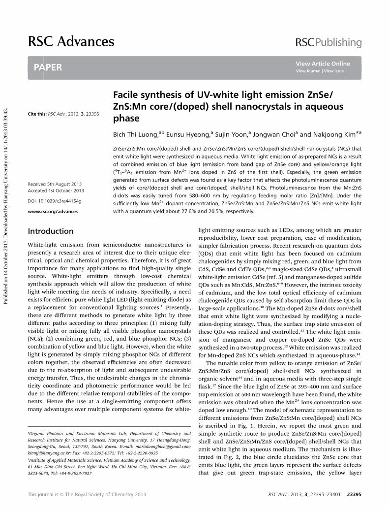
The tunable color from yellow to orange emission of ZnSe/ZnS:Mn/ZnS core/(doped) shell/shell NCs synthesized inorganic solvent14 and in aqueous media with three-step singleask.17 Since the blue light of ZnSe at 395–400 nm and surfacetrap emission at 500 nm wavelength have been found, the whiteemission was obtained when the Mn2+ ions concentration wasdoped low enough.10 The model of schematic representation todifferent emissions from ZnSe/ZnS:Mn core/(doped) shell NCsis ascribed in Fig. 1. Herein, we report the most green andsimple synthetic route to produce ZnSe/ZnS:Mn core/(doped)shell and ZnSe/ZnS:Mn/ZnS core/(doped) shell/shell NCs thatemit white light in aqueous medium. The mechanism is illus-trated in Fig. 2, the blue circle elucidates the ZnSe core thatemits blue light, the green layers represent the surface defectsthat give out green trap-state emission, the yellow layer
RSC Adv., 2013, 3, 23395–23401 | 23395
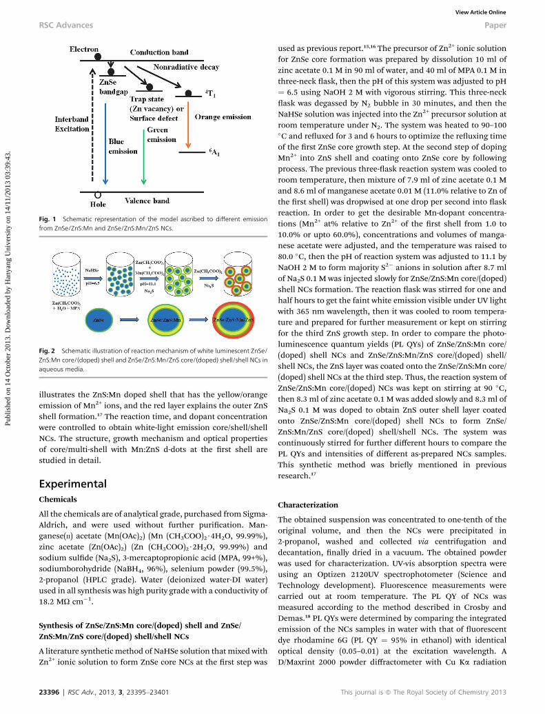
Fig. 1 Schematic representation of the model ascribed to different emissionfrom ZnSe/ZnS:Mn and ZnSe/ZnS:Mn/ZnS NCs.
Fig. 2 Schematic illustration of reaction mechanism of white luminescent ZnSe/ZnS:Mn core/(doped) shell and ZnSe/ZnS:Mn/ZnS core/(doped) shell/shell NCs inaqueous media.
RSC Advances Paper
Publ
ishe
d on
14
Oct
ober
201
3. D
ownl
oade
d by
Han
yang
Uni
vers
ity o
n 14
/11/
2013
03:
39:4
3.
View Article Online
illustrates the ZnS:Mn doped shell that has the yellow/orangeemission of Mn2+ ions, and the red layer explains the outer ZnSshell formation.17 The reaction time, and dopant concentrationwere controlled to obtain white-light emission core/shell/shellNCs. The structure, growth mechanism and optical propertiesof core/multi-shell with Mn:ZnS d-dots at the rst shell arestudied in detail.
ExperimentalChemicals
All the chemicals are of analytical grade, purchased from Sigma-Aldrich, and were used without further purication. Man-ganese(II) acetate (Mn(OAc)2) (Mn (CH3COO)2$4H2O, 99.99%),zinc acetate (Zn(OAc)2) (Zn (CH3COO)2$2H2O, 99.99%) andsodium sulde (Na2S), 3-mercaptopropionic acid (MPA, 99+%),sodiumborohydride (NaBH4, 96%), selenium powder (99.5%),2-propanol (HPLC grade). Water (deionized water-DI water)used in all synthesis was high purity grade with a conductivity of18.2 MU cm�1.
Synthesis of ZnSe/ZnS:Mn core/(doped) shell and ZnSe/ZnS:Mn/ZnS core/(doped) shell/shell NCs
A literature synthetic method of NaHSe solution that mixed withZn2+ ionic solution to form ZnSe core NCs at the rst step was
23396 | RSC Adv., 2013, 3, 23395–23401
used as previous report.15,16 The precursor of Zn2+ ionic solutionfor ZnSe core formation was prepared by dissolution 10 ml ofzinc acetate 0.1 M in 90 ml of water, and 40 ml of MPA 0.1 M inthree-neck ask, then the pH of this system was adjusted to pH¼ 6.5 using NaOH 2 M with vigorous stirring. This three-neckask was degassed by N2 bubble in 30 minutes, and then theNaHSe solution was injected into the Zn2+ precursor solution atroom temperature under N2. The system was heated to 90–100�C and reuxed for 3 and 6 hours to optimize the reuxing timeof the rst ZnSe core growth step. At the second step of dopingMn2+ into ZnS shell and coating onto ZnSe core by followingprocess. The previous three-ask reaction system was cooled toroom temperature, then mixture of 7.9 ml of zinc acetate 0.1 Mand 8.6 ml of manganese acetate 0.01 M (11.0% relative to Zn ofthe rst shell) was dropwised at one drop per second into askreaction. In order to get the desirable Mn-dopant concentra-tions (Mn2+ at% relative to Zn2+ of the rst shell from 1.0 to10.0% or upto 60.0%), concentrations and volumes of manga-nese acetate were adjusted, and the temperature was raised to80.0 �C, then the pH of reaction system was adjusted to 11.1 byNaOH 2 M to form majority S2� anions in solution aer 8.7 mlof Na2S 0.1 M was injected slowly for ZnSe/ZnS:Mn core/(doped)shell NCs formation. The reaction ask was stirred for one andhalf hours to get the faint white emission visible under UV lightwith 365 nm wavelength, then it was cooled to room tempera-ture and prepared for further measurement or kept on stirringfor the third ZnS growth step. In order to compare the photo-luminescence quantum yields (PL QYs) of ZnSe/ZnS:Mn core/(doped) shell NCs and ZnSe/ZnS:Mn/ZnS core/(doped) shell/shell NCs, the ZnS layer was coated onto the ZnSe/ZnS:Mn core/(doped) shell NCs at the third step. Thus, the reaction system ofZnSe/ZnS:Mn core/(doped) NCs was kept on stirring at 90 �C,then 8.3 ml of zinc acetate 0.1 M was added slowly and 8.3 ml ofNa2S 0.1 M was doped to obtain ZnS outer shell layer coatedonto ZnSe/ZnS:Mn core/(doped) shell NCs to form ZnSe/ZnS:Mn/ZnS core/(doped) shell/shell NCs. The system wascontinuously stirred for further different hours to compare thePL QYs and intensities of different as-prepared NCs samples.This synthetic method was briey mentioned in previousresearch.17
Characterization
The obtained suspension was concentrated to one-tenth of theoriginal volume, and then the NCs were precipitated in2-propanol, washed and collected via centrifugation anddecantation, nally dried in a vacuum. The obtained powderwas used for characterization. UV-vis absorption spectra wereusing an Optizen 2120UV spectrophotometer (Science andTechnology development). Fluorescence measurements werecarried out at room temperature. The PL QY of NCs wasmeasured according to the method described in Crosby andDemas.18 PL QYs were determined by comparing the integratedemission of the NCs samples in water with that of uorescentdye rhodamine 6G (PL QY ¼ 95% in ethanol) with identicaloptical density (0.05–0.01) at the excitation wavelength. AD/Maxrint 2000 powder diffractometer with Cu Ka radiation
This journal is ª The Royal Society of Chemistry 2013
Paper RSC Advances
Publ
ishe
d on
14
Oct
ober
201
3. D
ownl
oade
d by
Han
yang
Uni
vers
ity o
n 14
/11/
2013
03:
39:4
3.
View Article Online
(l ¼ 1.5418 A) was used to perform X-ray diffraction measure-ments. The X-ray photo electron spectra (XPS) were taken on aThermo scientic K-alpha electron energy spectrometer usingAl Ka (1486.6 eV) as the X-ray excitation source (VG Multi-labESCA 200 systemmodel). High resolution transmission electron(HRTEM) micrograph image was acquired using a TEM 2100Fwith acceleration voltage of 200 kV. TEM samples were preparedby dropping the samples dispersed in water onto carbon coatedcopper grids with excess solvent evaporated. The average size ofNCs was determined using J-image soware from TEM images.
Result and discussionInuence of experimental parameters
The optimal reaction conditions to produce ZnSe/ZnS:Mn core/(doped) shell and ZnSe/ZnS:Mn/ZnS core/(doped) shell/shellNCs with white light emission were determined.
White light emission mechanism of ZnSe/ZnS:Mn core/shellNCs and ZnSe/ZnS:Mn/ZnS core/shell/shell NCs
The white light emission is theoretically the combination ofyellow and blue light. Nevertheless, in this work the greenluminescent emission of surface defects appear to favor thegeneration of white light aer incorporation of the Mn ions intothe host ZnS lattice in the second step of ZnS:Mn shell depo-sition onto the ZnSe core. And this result was found to berelated to previous research.12 Hence, the white light emissionof ZnSe/ZnS:Mn core/shell and ZnSe/ZnS:Mn/ZnS core/shell/shell NCs is the result of a well-controlled combination ofemission of yellow/orange light given by Mn2+ based 4T1 to
6A1
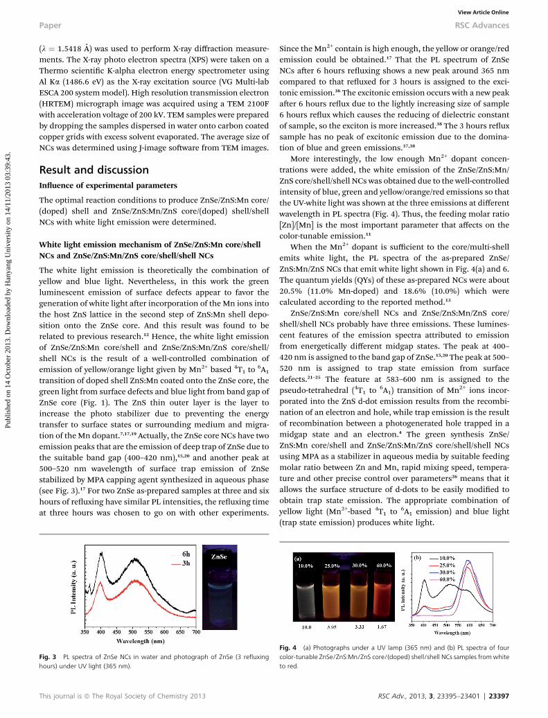
transition of doped shell ZnS:Mn coated onto the ZnSe core, thegreen light from surface defects and blue light from band gap ofZnSe core (Fig. 1). The ZnS thin outer layer is the layer toincrease the photo stabilizer due to preventing the energytransfer to surface states or surrounding medium and migra-tion of the Mn dopant.7,17,19 Actually, the ZnSe core NCs have twoemission peaks that are the emission of deep trap of ZnSe due tothe suitable band gap (400–420 nm),15,20 and another peak at500–520 nm wavelength of surface trap emission of ZnSestabilized by MPA capping agent synthesized in aqueous phase(see Fig. 3).17 For two ZnSe as-prepared samples at three and sixhours of reuxing have similar PL intensities, the reuxing timeat three hours was chosen to go on with other experiments.
Fig. 3 PL spectra of ZnSe NCs in water and photograph of ZnSe (3 refluxinghours) under UV light (365 nm).
This journal is ª The Royal Society of Chemistry 2013
Since the Mn2+ contain is high enough, the yellow or orange/redemission could be obtained.17 That the PL spectrum of ZnSeNCs aer 6 hours reuxing shows a new peak around 365 nmcompared to that reuxed for 3 hours is assigned to the exci-tonic emission.36 The excitonic emission occurs with a new peakaer 6 hours reux due to the lightly increasing size of sample6 hours reux which causes the reducing of dielectric constantof sample, so the exciton is more increased.38 The 3 hours reuxsample has no peak of excitonic emission due to the domina-tion of blue and green emissions.37,38
More interestingly, the low enough Mn2+ dopant concen-trations were added, the white emission of the ZnSe/ZnS:Mn/ZnS core/shell/shell NCs was obtained due to the well-controlledintensity of blue, green and yellow/orange/red emissions so thatthe UV-white light was shown at the three emissions at differentwavelength in PL spectra (Fig. 4). Thus, the feeding molar ratio[Zn]/[Mn] is the most important parameter that affects on thecolor-tunable emission.11
When the Mn2+ dopant is sufficient to the core/multi-shellemits white light, the PL spectra of the as-prepared ZnSe/ZnS:Mn/ZnS NCs that emit white light shown in Fig. 4(a) and 6.The quantum yields (QYs) of these as-prepared NCs were about20.5% (11.0% Mn-doped) and 18.6% (10.0%) which werecalculated according to the reported method.13
ZnSe/ZnS:Mn core/shell NCs and ZnSe/ZnS:Mn/ZnS core/shell/shell NCs probably have three emissions. These lumines-cent features of the emission spectra attributed to emissionfrom energetically different midgap states. The peak at 400–420 nm is assigned to the band gap of ZnSe.15,20 The peak at 500–520 nm is assigned to trap state emission from surfacedefects.21–25 The feature at 583–600 nm is assigned to thepseudo-tetrahedral (4T1 to 6A1) transition of Mn2+ ions incor-porated into the ZnS d-dot emission results from the recombi-nation of an electron and hole, while trap emission is the resultof recombination between a photogenerated hole trapped in amidgap state and an electron.4 The green synthesis ZnSe/ZnS:Mn core/shell and ZnSe/ZnS:Mn/ZnS core/shell/shell NCsusing MPA as a stabilizer in aqueous media by suitable feedingmolar ratio between Zn and Mn, rapid mixing speed, tempera-ture and other precise control over parameters26 means that itallows the surface structure of d-dots to be easily modied toobtain trap state emission. The appropriate combination ofyellow light (Mn2+-based 4T1 to 6A1 emission) and blue light(trap state emission) produces white light.
Fig. 4 (a) Photographs under a UV lamp (365 nm) and (b) PL spectra of fourcolor-tunable ZnSe/ZnS:Mn/ZnS core/(doped) shell/shell NCs samples fromwhiteto red.
RSC Adv., 2013, 3, 23395–23401 | 23397
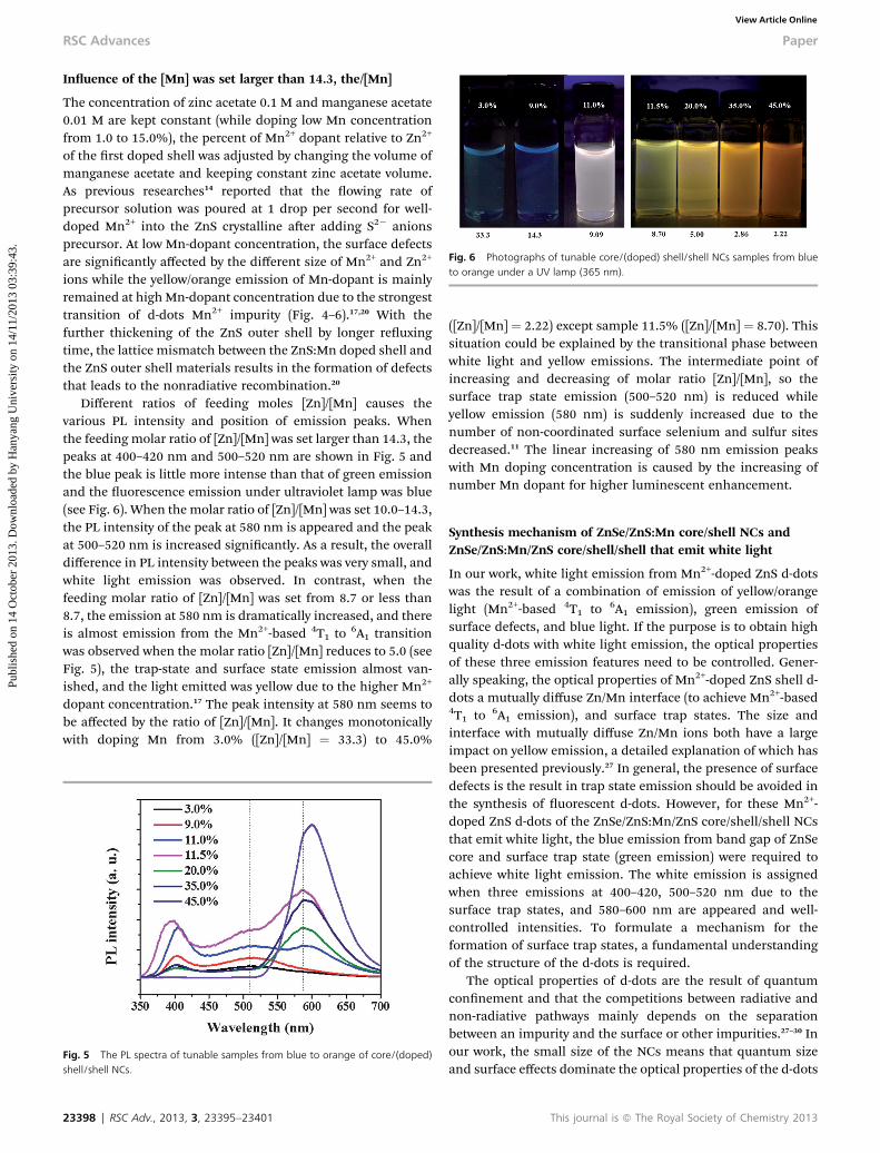
Fig. 6 Photographs of tunable core/(doped) shell/shell NCs samples from blueto orange under a UV lamp (365 nm).
RSC Advances Paper
Publ
ishe
d on
14
Oct
ober
201
3. D
ownl
oade
d by
Han
yang
Uni
vers
ity o
n 14
/11/
2013
03:
39:4
3.
View Article Online
Inuence of the [Mn] was set larger than 14.3, the/[Mn]
The concentration of zinc acetate 0.1 M and manganese acetate0.01 M are kept constant (while doping low Mn concentrationfrom 1.0 to 15.0%), the percent of Mn2+ dopant relative to Zn2+
of the rst doped shell was adjusted by changing the volume ofmanganese acetate and keeping constant zinc acetate volume.As previous researches14 reported that the owing rate ofprecursor solution was poured at 1 drop per second for well-doped Mn2+ into the ZnS crystalline aer adding S2� anionsprecursor. At low Mn-dopant concentration, the surface defectsare signicantly affected by the different size of Mn2+ and Zn2+
ions while the yellow/orange emission of Mn-dopant is mainlyremained at highMn-dopant concentration due to the strongesttransition of d-dots Mn2+ impurity (Fig. 4–6).17,20 With thefurther thickening of the ZnS outer shell by longer reuxingtime, the lattice mismatch between the ZnS:Mn doped shell andthe ZnS outer shell materials results in the formation of defectsthat leads to the nonradiative recombination.20
Different ratios of feeding moles [Zn]/[Mn] causes thevarious PL intensity and position of emission peaks. Whenthe feeding molar ratio of [Zn]/[Mn] was set larger than 14.3, thepeaks at 400–420 nm and 500–520 nm are shown in Fig. 5 andthe blue peak is little more intense than that of green emissionand the uorescence emission under ultraviolet lamp was blue(see Fig. 6). When the molar ratio of [Zn]/[Mn] was set 10.0–14.3,the PL intensity of the peak at 580 nm is appeared and the peakat 500–520 nm is increased signicantly. As a result, the overalldifference in PL intensity between the peaks was very small, andwhite light emission was observed. In contrast, when thefeeding molar ratio of [Zn]/[Mn] was set from 8.7 or less than8.7, the emission at 580 nm is dramatically increased, and thereis almost emission from the Mn2+-based 4T1 to 6A1 transitionwas observed when the molar ratio [Zn]/[Mn] reduces to 5.0 (seeFig. 5), the trap-state and surface state emission almost van-ished, and the light emitted was yellow due to the higher Mn2+
dopant concentration.17 The peak intensity at 580 nm seems tobe affected by the ratio of [Zn]/[Mn]. It changes monotonicallywith doping Mn from 3.0% ([Zn]/[Mn] ¼ 33.3) to 45.0%
Fig. 5 The PL spectra of tunable samples from blue to orange of core/(doped)shell/shell NCs.
23398 | RSC Adv., 2013, 3, 23395–23401
([Zn]/[Mn] ¼ 2.22) except sample 11.5% ([Zn]/[Mn] ¼ 8.70). Thissituation could be explained by the transitional phase betweenwhite light and yellow emissions. The intermediate point ofincreasing and decreasing of molar ratio [Zn]/[Mn], so thesurface trap state emission (500–520 nm) is reduced whileyellow emission (580 nm) is suddenly increased due to thenumber of non-coordinated surface selenium and sulfur sitesdecreased.11 The linear increasing of 580 nm emission peakswith Mn doping concentration is caused by the increasing ofnumber Mn dopant for higher luminescent enhancement.
Synthesis mechanism of ZnSe/ZnS:Mn core/shell NCs andZnSe/ZnS:Mn/ZnS core/shell/shell that emit white light
In our work, white light emission from Mn2+-doped ZnS d-dotswas the result of a combination of emission of yellow/orangelight (Mn2+-based 4T1 to 6A1 emission), green emission ofsurface defects, and blue light. If the purpose is to obtain highquality d-dots with white light emission, the optical propertiesof these three emission features need to be controlled. Gener-ally speaking, the optical properties of Mn2+-doped ZnS shell d-dots a mutually diffuse Zn/Mn interface (to achieve Mn2+-based4T1 to 6A1 emission), and surface trap states. The size andinterface with mutually diffuse Zn/Mn ions both have a largeimpact on yellow emission, a detailed explanation of which hasbeen presented previously.27 In general, the presence of surfacedefects is the result in trap state emission should be avoided inthe synthesis of uorescent d-dots. However, for these Mn2+-doped ZnS d-dots of the ZnSe/ZnS:Mn/ZnS core/shell/shell NCsthat emit white light, the blue emission from band gap of ZnSecore and surface trap state (green emission) were required toachieve white light emission. The white emission is assignedwhen three emissions at 400–420, 500–520 nm due to thesurface trap states, and 580–600 nm are appeared and well-controlled intensities. To formulate a mechanism for theformation of surface trap states, a fundamental understandingof the structure of the d-dots is required.
The optical properties of d-dots are the result of quantumconnement and that the competitions between radiative andnon-radiative pathways mainly depends on the separationbetween an impurity and the surface or other impurities.27–30 Inour work, the small size of the NCs means that quantum sizeand surface effects dominate the optical properties of the d-dots
This journal is ª The Royal Society of Chemistry 2013
Paper RSC Advances
Publ
ishe
d on
14
Oct
ober
201
3. D
ownl
oade
d by
Han
yang
Uni
vers
ity o
n 14
/11/
2013
03:
39:4
3.
View Article Online
because most atoms are on their surface, which results inreduced coordination between atoms, and more danglingbonds. The presence of point defects (vacancies or interstitialatoms) from the different ionic sizes of Zn2+ and Mn2+ couldintroduce surface trap states that allow the recombination of anelectron and hole, resulting in white emission due to increasingthe trap state emission at 500–520 nm. This proposition issupported by the presence of surface trap states in seleniumhydrate NCs as reported by Underwood et al.24,25 ZnSe core NCshave two features that blue emission (390–420 nm) is from ZnSeband gap and green emission (500–520 nm) is a result ofrecombination of electrons and holes at surface trap states orwhich is induced by hole-trapping thiolates on the NC surfaceor the zinc-vacancy from different ionic size of Zn2+ and Mn2+
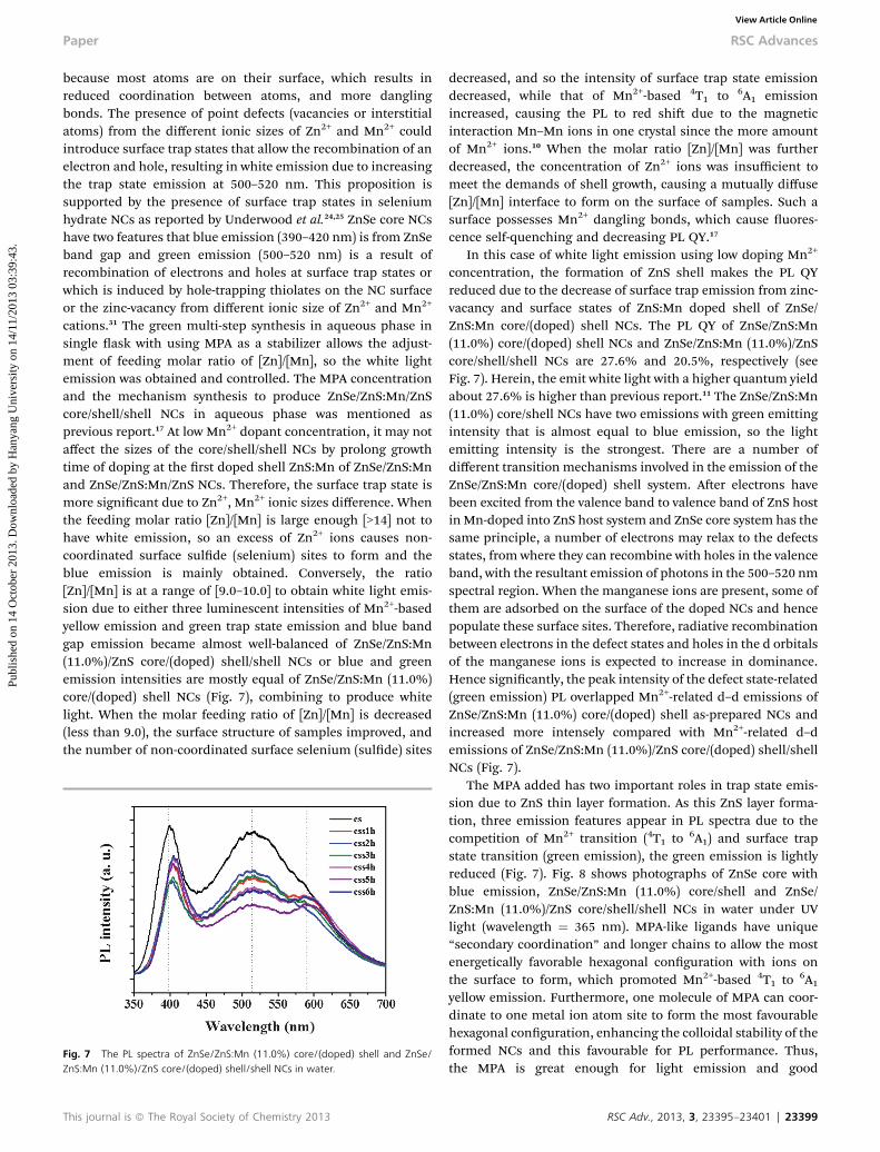
cations.31 The green multi-step synthesis in aqueous phase insingle ask with using MPA as a stabilizer allows the adjust-ment of feeding molar ratio of [Zn]/[Mn], so the white lightemission was obtained and controlled. The MPA concentrationand the mechanism synthesis to produce ZnSe/ZnS:Mn/ZnScore/shell/shell NCs in aqueous phase was mentioned asprevious report.17 At low Mn2+ dopant concentration, it may notaffect the sizes of the core/shell/shell NCs by prolong growthtime of doping at the rst doped shell ZnS:Mn of ZnSe/ZnS:Mnand ZnSe/ZnS:Mn/ZnS NCs. Therefore, the surface trap state ismore signicant due to Zn2+, Mn2+ ionic sizes difference. Whenthe feeding molar ratio [Zn]/[Mn] is large enough [>14] not tohave white emission, so an excess of Zn2+ ions causes non-coordinated surface sulde (selenium) sites to form and theblue emission is mainly obtained. Conversely, the ratio[Zn]/[Mn] is at a range of [9.0–10.0] to obtain white light emis-sion due to either three luminescent intensities of Mn2+-basedyellow emission and green trap state emission and blue bandgap emission became almost well-balanced of ZnSe/ZnS:Mn(11.0%)/ZnS core/(doped) shell/shell NCs or blue and greenemission intensities are mostly equal of ZnSe/ZnS:Mn (11.0%)core/(doped) shell NCs (Fig. 7), combining to produce whitelight. When the molar feeding ratio of [Zn]/[Mn] is decreased(less than 9.0), the surface structure of samples improved, andthe number of non-coordinated surface selenium (sulde) sites
Fig. 7 The PL spectra of ZnSe/ZnS:Mn (11.0%) core/(doped) shell and ZnSe/ZnS:Mn (11.0%)/ZnS core/(doped) shell/shell NCs in water.
This journal is ª The Royal Society of Chemistry 2013
decreased, and so the intensity of surface trap state emissiondecreased, while that of Mn2+-based 4T1 to 6A1 emissionincreased, causing the PL to red shi due to the magneticinteraction Mn–Mn ions in one crystal since the more amountof Mn2+ ions.10 When the molar ratio [Zn]/[Mn] was furtherdecreased, the concentration of Zn2+ ions was insufficient tomeet the demands of shell growth, causing a mutually diffuse[Zn]/[Mn] interface to form on the surface of samples. Such asurface possesses Mn2+ dangling bonds, which cause uores-cence self-quenching and decreasing PL QY.17
In this case of white light emission using low doping Mn2+
concentration, the formation of ZnS shell makes the PL QYreduced due to the decrease of surface trap emission from zinc-vacancy and surface states of ZnS:Mn doped shell of ZnSe/ZnS:Mn core/(doped) shell NCs. The PL QY of ZnSe/ZnS:Mn(11.0%) core/(doped) shell NCs and ZnSe/ZnS:Mn (11.0%)/ZnScore/shell/shell NCs are 27.6% and 20.5%, respectively (seeFig. 7). Herein, the emit white light with a higher quantum yieldabout 27.6% is higher than previous report.11 The ZnSe/ZnS:Mn(11.0%) core/shell NCs have two emissions with green emittingintensity that is almost equal to blue emission, so the lightemitting intensity is the strongest. There are a number ofdifferent transition mechanisms involved in the emission of theZnSe/ZnS:Mn core/(doped) shell system. Aer electrons havebeen excited from the valence band to valence band of ZnS hostin Mn-doped into ZnS host system and ZnSe core system has thesame principle, a number of electrons may relax to the defectsstates, from where they can recombine with holes in the valenceband, with the resultant emission of photons in the 500–520 nmspectral region. When the manganese ions are present, some ofthem are adsorbed on the surface of the doped NCs and hencepopulate these surface sites. Therefore, radiative recombinationbetween electrons in the defect states and holes in the d orbitalsof the manganese ions is expected to increase in dominance.Hence signicantly, the peak intensity of the defect state-related(green emission) PL overlapped Mn2+-related d–d emissions ofZnSe/ZnS:Mn (11.0%) core/(doped) shell as-prepared NCs andincreased more intensely compared with Mn2+-related d–demissions of ZnSe/ZnS:Mn (11.0%)/ZnS core/(doped) shell/shellNCs (Fig. 7).
The MPA added has two important roles in trap state emis-sion due to ZnS thin layer formation. As this ZnS layer forma-tion, three emission features appear in PL spectra due to thecompetition of Mn2+ transition (4T1 to 6A1) and surface trapstate transition (green emission), the green emission is lightlyreduced (Fig. 7). Fig. 8 shows photographs of ZnSe core withblue emission, ZnSe/ZnS:Mn (11.0%) core/shell and ZnSe/ZnS:Mn (11.0%)/ZnS core/shell/shell NCs in water under UVlight (wavelength ¼ 365 nm). MPA-like ligands have unique“secondary coordination” and longer chains to allow the mostenergetically favorable hexagonal conguration with ions onthe surface to form, which promoted Mn2+-based 4T1 to 6A1
yellow emission. Furthermore, one molecule of MPA can coor-dinate to one metal ion atom site to form the most favourablehexagonal conguration, enhancing the colloidal stability of theformed NCs and this favourable for PL performance. Thus,the MPA is great enough for light emission and good
RSC Adv., 2013, 3, 23395–23401 | 23399

Fig. 8 Photographs of ZnSe core, ZnSe/ZnS:Mn (11.0%) core/(doped) shell andZnSe/ZnS:Mn (11.0%)/ZnS core/(doped) shell/shell NCs in water under a UV lamp(365 nm).
RSC Advances Paper
Publ
ishe
d on
14
Oct
ober
201
3. D
ownl
oade
d by
Han
yang
Uni
vers
ity o
n 14
/11/
2013
03:
39:4
3.
View Article Online
water-dispersion of either core/(doped) shell or core/(doped)shell/shell NCs. Overall, both the feeding molar ratio of [Zn]/[Mn] and mass of adding MPA inuence the optical propertiesof ZnSe/ZnS:Mn and ZnSe/ZnS:Mn/ZnS NCs that emit whitelight.
Structural characterization of ZnSe/ZnS:Mn/ZnS NCs
Fig. 9(a) shows the wide-angle XRD patterns of the as-preparedZnSe core, ZnSe/ZnS:Mn (11.0%) core/shell and ZnSe/ZnS:Mn(11.0%)/ZnS core/shell/shell. The three main peaks that corre-spond to the (111), (220) and (311) planes, respectively, showingthat the as-prepared core, core/shell and core/shell/shell NCshave a cubic (zinc blend) structure mainly. Meanwhile, itsupports the hypothesis that Mn2+ is more facile to incorporatein cubic ZnS NCs more than wurtzite and rock-salt crystals.17,33
Moreover, the doping Mn2+ into the host ZnS of the rst shellNCs of core/multi-shell NCs does not totally bring about a phasetransformation of the crystal structure. However, there areseveral sharp peaks appeared in the XRD pattern of CS (11%)and CS (11%) S samples. This could be explained that twophases of zinc-blend and hetaerolite were formed, but the
Fig. 9 (a) XRD patterns, and (c and d) XPS spectra of ZnSe core, ZnSe/ZnS:Mn(11.0%) core/shell – cs (11.0%), ZnSe/ZnS:Mn (11.0%)/ZnS core/shell/shell – cs(11.0%)s NCs (b) TEM images of ZnSe/ZnS:Mn (11.0%) – cs (11.0%) NCs.
23400 | RSC Adv., 2013, 3, 23395–23401
hetaerolite is minor and the phase transformation is appearedsecondary.37 We found that the diffraction peaks shied to alarger angles as the shell increasing thickness.34,35 Fig. 9(b) isthe TEM images of ZnSe/ZnS:Mn (11.0%) shows that thedistribution is good. The average size of core/(doped) shell NCs(5.3� 0.2 nm) is larger than ZnSe core (4.6� 0.2 nm).17 The XPSspectra of ZnSe core, ZnSe/ZnS:Mn (11.0%) core/shell, andZnSe/ZnS:Mn (11.0%)/ZnS core/shell/shell NCs are shown inFig. 9(c) and (d). The binding energy assigned to S 2p shiedfrom 163.0 eV for the ZnSe NCs to 162.0 eV for the ZnSe/ZnS:Mn(11.0%) and ZnSe/ZnS:Mn (11.0%)/ZnS NCs, which veried theproposed core/shell/shell structure and was consistent withprevious reports.17,32 Furthermore, Fig. 9(d) provides furtherevidence for growth of the ZnS:Mn(S) on the ZnSe core, and ZnSshell on the ZnSe/ZnS:Mn (11.0%) core/shell NCs. The XPSinformation of Zn intensity has been lightly increase from ZnSecore, to ZnSe/ZnS:Mn (11.0%) core/shell and ZnSe/ZnS:Mn/ZnScore/shell/shell NCs due to the layers of the shell increase. It isshown in Fig. 9(d) that the Zn concentration is increased in thecore NCs, core/shell NCs and core/shell/shell NCs.
Conclusions
In summary, we report white light emission of water-solubleZnSe/ZnS:Mn core/(doped) shell and ZnSe/ZnS:Mn/ZnS core/(doped) shell/shell NCs synthesized by a green and facilemethod in aqueous phase. The obtained NCs give out the whiteemission with using Mn2+ d-dots at a range of feeding concen-tration 10.0–11.0% relative to Zn of the d-dot shell (doped shell)related to a range of feeding molar ratio [Zn]/[Mn] from 9.0 to10.0 and possess a high degree of crystallinity, good quantumefficiencies, and narrow size distribution, making them poten-tial candidates for white LEDs, and biological labels.
Acknowledgements
This work was supported by the National Research Foundationof Korea (NRF) grant funded by the Korea government (MSIP)through the Active Polymer Center for Pattern Integration (no.2007-0056091).
Notes and references
1 J. Y. Tsao, Light Emitting Diodes (LEDs) for GeneralIllumination-an OIDA Technology Roadmap Update, 2002,http://www.netl.doe.gov/ssl/publications.html.
2 J. Lee, V. C. Sundar and J. R. Heine, Adv. Mater., 2000, 12,1102–1105.
3 A. Lita, A. L. Washington II, L. Burgt, G. F. Strouse andA. E. Stiegman, Adv. Mater., 2010, 22, 3987–3991.
4 M. J. Bowers II, J. R. McBride and S. J. Rosenthal, J. Am. Chem.Soc., 2005, 127, 15378–15379.
5 T. E. Ronsson, S. M. Claiborne, J. R. McBride, B. S. Strattonand S. J. Rosenthal, J. Am. Chem. Soc., 2012, 134, 8006–8009.
6 A. Nag and D. D. Sarma, J. Phys. Chem. C, 2007, 111, 13641–13644.
This journal is ª The Royal Society of Chemistry 2013
Paper RSC Advances
Publ
ishe
d on
14
Oct
ober
201
3. D
ownl
oade
d by
Han
yang
Uni
vers
ity o
n 14
/11/
2013
03:
39:4
3.
View Article Online
7 S. Kar and S. Biswas, J. Phys. Chem. C, 2008, 112, 11144–11149.
8 X. D. Lu, J. Yang, Y. Q. Fu, Q. Q. Liu and B. Qi,Nanotechnology, 2010, 21, 115702–115711.
9 H. Z. Wang, H. Nakamura, M. Uehara, Y. Yamaguchi andM. Miyazaki, Adv. Funct. Mater., 2005, 15, 603–608.
10 A. H. Mueller, M. A. Petruska, M. Achermann, D. J. Werder,E. A. Akhadov, D. D. Koleske, M. A. Hoauer andV. I. Klimov, Nano Lett., 2005, 5, 1039–1044.
11 P. Shao, H. Z. Wang, Q. H. Zhang and Y. G. Li, J. Mater.Chem., 2011, 22, 17972–17977.
12 S. K. Panda, S. G. Hicky, H. V. Demir and A. Eychmuller,Angew. Chem., Int. Ed., 2011, 50, 4432–4436.
13 N. Pradhan and X. G. Peng, J. Am. Chem. Soc., 2007, 129,3339–3347.
14 R. Thakar, Y. C. Chen and P. T. Snee, Nano Lett., 2007, 7,3429–3432.
15 A. Shavel, N. Gaponik and A. Eychmuller, J. Phys. Chem. B,2004, 108, 5905–5908.
16 D. L. Klayman and T. S. Griffin, J. Am. Chem. Soc., 1973, 95(1),197–199.
17 B. T. Luong, E. S. Hyeong, S. H. Ji and N. J. Kim, RSC Adv.,2012, 2, 12132–12135.
18 J. N. Demas and G. A. Crosby, J. Phys. Chem., 1971, 75, 991–1024.
19 Y. Yang, O. Chen, A. Angerhofer and Y. C. Cao, J. Am. Chem.Soc., 2006, 128, 12428–12429.
20 Z. Fang, P. Wu, X. Zhong and Y. J. Yang, Nanotechnology,2010, 21, 305604–305609.
21 C. Wang, X. Gao, Q. Ma and X. G. Su, J. Mater. Chem., 2009,19, 7016–7022.
22 Y. L. Guo, W. L. Yang, F. H. Yu and T. C. Huan, J. Mater.Chem., 2007, 17, 2661–2666.
This journal is ª The Royal Society of Chemistry 2013
23 T. J. Norman Jr, D. Magana, T. Wilson, C. Burns andJ. Z. Zhang, J. Phys. Chem. B, 2003, 107, 6309–6317.
24 N. A. Hill and K. B. Whaley, J. Chem. Phys., 1994, 100, 2831–2837.
25 D. F. Underwood, T. C. Kippeny and S. J. Rosenthal, J. Phys.Chem. B, 2001, 105, 436–443.
26 X. X. Zhu, Q. H. Zhang, Y. G. Li and H. Z. Wang, J. Mater.Chem., 2008, 18, 5060–5062.
27 P. T. Shao, Q. H. Zhang, Y. G. Li and H. Z. Wang, J. Mater.Chem., 2011, 21, 151–156.
28 N. Pradhan, D. Goorskeym, J. Thessing and X. G. Peng, J. Am.Chem. Soc., 2005, 127, 17586–17587.
29 H. Zhang, L. P. Wang, H. M. Xiong, L. H. Hu, B. Yang andW. Li, Adv. Mater., 2003, 15, 1712–1715.
30 Z. Y. Tang, N. A. Kotov and M. Giersig, Science, 2002, 297,237–240.
31 Z. Deng, F. L. Lie, S. Shen, I. Ghosh, M. Mansuripur andA. J. Muscat, Langmuir, 2009, 25, 434–442.
32 Y. He, H. T. Lu, L. M. Sai, Y. Y. Su, M. Hu, C. H. Fan,W. Huang and L. H. Wang, Adv. Mater., 2008, 20, 3416–3421.
33 S. C. Erwin, L. Zu, M. I. Hael, A. L. Efros, T. A. Kennedy andD. J. Norris, Nature, 2005, 436, 91–94.
34 B. Dong, L. Cao, G. Su and W. Liu, Chem. Commun., 2010, 46,7331–7333.
35 D. Zhu, X. X. Jiang, C. Zhao, X. L. Sun, J. R. Zhang andJ. J. Zhu, Chem. Commun., 2010, 46, 5226–5228.
36 N. Murase and M. Gao, Mater. Lett., 2004, 58, 3898–3902.37 E. Sotelo-Gonzalez, L. Roces, S. Garcia-Granda,
M. T. Fernander-Arguelles, J. M. Costa-Fernandez andA. Sanz-Medel, Nanoscale, 2013, 5, 9156–9161.
38 I. Pelant and J. Valenta, Luminescence Spectroscopy ofSemiconductors, Oxford University Press, Oxford, 2012, ch.7, pp. 161–204.
RSC Adv., 2013, 3, 23395–23401 | 23401