A New Metal-Organic Open Framework Enabling Facile ...
26
A New Metal-Organic Open Framework Enabling Facile Synthesis of Carbon Encapsulated Transition Metal Phosphide/Sulfide Nanoparticle Electrocatalysts Journal: Journal of Materials Chemistry A Manuscript ID TA-ART-01-2019-000404.R1 Article Type: Paper Date Submitted by the Author: 19-Feb-2019 Complete List of Authors: Weng, Baicheng; University of Toledo, Wang, Xiaoming; University of Toledo Grice, Corey; University of Toledo Xu, Fenghua; University of Toledo Yan, Yanfa; University of Toledo, Department of Physics and Astronomy Journal of Materials Chemistry A
-
Upload
khangminh22 -
Category
Documents
-
view
0 -
download
0
Transcript of A New Metal-Organic Open Framework Enabling Facile ...
A New Metal-Organic Open Framework Enabling Facile Synthesis of Carbon Encapsulated Transition Metal Phosphide/Sulfide Nanoparticle Electrocatalysts
Journal: Journal of Materials Chemistry A
Manuscript ID TA-ART-01-2019-000404.R1
Article Type: Paper
Date Submitted by the Author: 19-Feb-2019
Complete List of Authors: Weng, Baicheng; University of Toledo, Wang, Xiaoming; University of ToledoGrice, Corey; University of ToledoXu, Fenghua; University of ToledoYan, Yanfa; University of Toledo, Department of Physics and Astronomy
Journal of Materials Chemistry A

1
A New Metal-Organic Open Framework Enabling Facile
Synthesis of Carbon Encapsulated Transition Metal
Phosphide/Sulfide Nanoparticle Electrocatalysts†
Baicheng Weng, Xiaoming Wang, Corey R. Grice, Fenghua Xu, and Yanfa Yan*
Department of Physics and Astronomy and Center for Photovoltaics Innovation and
Commercialization, The University of Toledo, Toledo, Ohio 43606, United States* Email: [email protected].
† Electronic supplementary information (ESI) available: Methods, and Supporting
Figures and Tables
ABSTRACT
Engineering the 3d to 5d nonprecious transition metal electrocatalysts to demonstrate
both high activity and superior durability for both the oxygen evolution reaction (OER)
and hydrogen evolution reaction (HER), which would be ideal for enabling low-cost
hydrogen production from water splitting, remains a serious challenge. Herein, we
report a rational design and experimental realization of a new metal-organic open
framework (MOF) to enable a facile and scalable synthesis of transition metal
phosphide (TMP) and sulfide (TMS) composite nanoparticle electrocatalysts
encapsulated by heteroatom-doped carbon (TMP/C and TMS/C) as bifunctional
electrocatalysts for water splitting. Using this new MOF, we synthesized NiP/NiFeP/C
and MoWS/MoP/C composite nanoparticle electrocatalysts that exhibited outstanding
electrocatalytic activities and durability that are among the higher yet reported in
literature for HER and OER electrocatalysts. A two-electrode water-splitting device
using our bifunctional NiP/NiFeP/C catalyst reached 10 mA cm–2 at a cell voltage of
1.53 V and 100 mA cm–2 at 1.68 V in 1.0 M KOH. The device showed an excellent
Page 1 of 25 Journal of Materials Chemistry A

2
stability for overall water splitting with almost 98% retention of its initial current of
100 mA cm–2 for over 20 h. Our results demonstrate the versatility of the new MOF to
synthesize highly active and stable TM-based electrocatalysts for water splitting.
KEYWORDS: Water splitting, Bifunctional electrocatalysts, Metal-organic
framework, Heteroatom-doping
Page 2 of 25Journal of Materials Chemistry A

3
Introduction
Producing clean and recyclable hydrogen fuels by electrochemical water splitting is part of a
desirable strategy to address the energy shortage and environmental pollution issues that modern society
is facing.[1-6] Water splitting involves an oxygen evolution reaction (OER) and a complimentary
hydrogen evolution reaction (HER).[7-22] Presently, noble metals, such as Pt, and their oxides, such as
RuO2, exhibits high efficiencies both on activities and stabilities for HER and OER, respectively.[7-22]
However, their scarcity, high cost and large overpotentials at high current densities (> 50 mA cm−2)
significantly limit the economical viability of large-scale production of hydrogen fuels through
electrochemical water splitting.[6-10] Furthermore, the use of bifunctional electrocatalysts, which have
high activities for both HER and OER operation, can be desirable to simplify the design and reduce the
cost of commercial water splitting devices. Extensive efforts have been made to develop active catalysts
based on low-cost and earth-abundant elements, including transition metal (TM) alloys, oxides, metal-
doped metal oxides, (oxy)hydroxides, phosphides and chalcogenides.[23-38] For instance, a two-step
electrochemical activated oxide, Co-300/Li, shows nearly zero overpotential at reasonable OER based
current densities.[36] Among them, TM phosphides (TMPs) have shown promising activities for both
HER and OER, making them excellent candidates for efficient bifunctional electrocatalysts.[11-38]
However, TMPs typically exhibit poor long-term stability during OER testing due to oxidation and
corrosion. Encapsulation with heteroatom-doped carbon shells has been proven as an effective approach
to mitigate this issue and improve the electrocatalytic activity.[27] For instance, our recent work has shown
that a CoP electrocatalyst embedded in N-doped carbon matrix can achieve improved HER and OER
activities.[30] The carbon matrix not only protects the CoP electrocatalyst core, but also further improves
the electrocatalytic activity since N-doping enhances the conductivity of the carbon by tailoring the
electron donor–acceptor behavior due to its higher electronegativity with respect to carbon.[30]
Synthesizing TMP and TM sulfide (TMS) nanostructures encapsulated in heteroatom-doped carbon
matrix faces significant challenges. Metal organic compounds (e.g. metal organic frameworks, MOFs)
have been commonly used for synthesizing core/shell nanostructures, since the metal moieties and the
N- and S-containing organic linkers in the MOFs can be transformed into metal cores and doped carbon
shells, respectively. Currently, the most commonly used MOFs contain 2-methylimidazole-based
linkages (e.g. ZIF-67 and ZIF-8). But the short molecular distance between adjacent TM atoms in the
Page 3 of 25 Journal of Materials Chemistry A

4
linkages may result in poor metal distributions during pyrolysis at high temperature.[29] Engineering the
building blocks of the MOFs to use longer spacer molecules (ligands) provides a solution for mitigating
this issue.[29] In addition, the introduction of longer N-containing ligands into the structure will induce
the evolution of more desirable topology (e.g. larger and deformed pore structures). More importantly,
the spare d-orbitals of vacant TM sites can coordinate additional heteroatom-containing ligands such as
thiocyanide and P- containing small molecules due to weakened steric effects. The obtained MOF thus
possesses advantages over conventional zeolite frameworks in introducing secondary 4d or 5d TMs (e.g.
W and Mo, which are difficult to incorporate into most MOF structures through conventional methods)
and avoiding post-synthetic phosphorization steps required to form TMPs[27-29] for zeolite framework
precursors. The phosphorization process not only adds extra cost to the synthesis process, but may also
result in the aggregation or uneven distribution of heteroatom dopants, limiting the activity of the catalyst.
Therefore, it is highly desirable to develop alternative MOFs with ligands containing homogeneously
distributed S, N, and P atoms and metal moieties that have proper metal cation-to-cation distances.
Herein, we report a rational design and experimental realization of a new 3-dimensional MOF that
consists of phosphine, pyridine, and thiocyanate ligands, providing both TMs and P, N as well as S
sources. This new MOF enables the facile preparation of TMP and TMS nanoparticles embedded in
heteroatom-doped carbon matrix (TMP/C and TMS/C) without the need of the post-synthetic
phosphorization or sulfurization. Using this MOF, we have successfully synthesized an electrocatalyst
featuring blended NiP/NiFeP nanoparticles encapsulated by (N, P)-codoped carbon (NiP/NiFeP/C). The
obtained NiP/NiFeP/C catalyst exhibited excellent activities for both HER and OER. When NiP/NiFeP/C
was used as both the anode and the cathode in a two-electrode alkaline water electrolyzer, low cell
voltages of 1.53 V and 1.68 V were achieved to reach stable current densities of 10 and 100 mA cm−2,
respectively. Furthermore, using the same strategy, we have also synthesized mixed Mo0.5W0.5S2 and
MoP ultrafine nanoparticles encapsulated in (N, S)-codoped carbon matrix (MoWS/MoP/C), which
showed higher activities than both MoS2 and WS2 catalysts, revealing the potential of the new MOF
approach for facile synthesis of other TMP/TMS nanoparticles encapsulated in doped carbon matrix.
Experimental section
Page 4 of 25Journal of Materials Chemistry A

5
Materials: Nickel chloride (NiCl2, 99%), 1,3-dichloropropane (99%), glyoxal (40% solution), potassium
hydroxide (KOH, 99%), potassium thiocyanate (99.7%), nickel hydroxide, [1,3-
Bis(diphenylphosphino)propane (DPPP), nickel chloride (NiCl2), iron (II) chloride (FeCl2),
Molybdenum hexacarbonyl (98%), Octadecene (99%), octylamine (70%), Sulfur (99%), Sodium
hypophosphite (99%, NaH2PO2), Sodium acetate (99%, NaAc), hydrochloric acid (HCl), ammonium
water and methanol were purchased from Sigma-Aldrich Co. Ltd. Nafion solution (5 wt%, D521) and
Nafion 117 proton exchange membrane were purchased from Fuel cell store. 1,3-Di(4-pyridyl)propane
and 2-(2-(1H-imidazol-2-yl)propyl)-3H-imidazole were synthesized according to the literature reports.[39,
40] (Bu3N)3W(CN)8 and (Bu3N)3Mo(CN)8 were synthesized according to our previous report.[27]
Electrocatalysts synthesis: [NiFeDPPP(1,3-Di(4-pyridyl)propane)2]n: 1,3-Di(4-pyridyl)propane, KOH,
DPPP, NiCl2 and FeCl2 were mixed in methanol with a molar ratio of 2:4:1:0.95:0.5. And the mixture
was stirred at room temperature. The red-colored mixture turned to transparent red-colored solution and
then turned light red, then yellowish-red, then yellowish green and then green slurry. Turquoise solid
was obtained after filtrations and washed with methanol and dried in vacuum at 80°C overnight.
[Mo0.5W0.5DPPP(SCN)3]n: (Bu3N)3W(CN)8 and (Bu3N)3Mo(CN)8 were dissolved in methanol, then
DPPP and potassium thiocyanate were added. The dark-red precipitation was collected after filtrations
and washed with methanol and dried in vacuum at 80°C overnight. The as-synthesized solids were placed
in the center of a tube furnace and was anneal for 3 h at various temperatures with a temperature ramping
rate of 5 °C min-1.
Synthesis of Ni12P5, MoS2, WS2, and RuO2 and IrO2 control samples: Ni12P5: Commercial Ni
nanoparticles (1.0 g) were dispersed in deionized water (50 mL) to become a black slurry, and then
NaH2PO2 and NaAc powders were added to the slurry under stirring with a molar ratio of 1:6:1
(Ni:NaH2PO2:NaAc). The pH level was then adjusted to be 8.0 using 1.0 M KOH and the slurry was
further heated to 90 °C for 1 h under N2 atmosphere. The color of the slurry turns darker, and the black
product was collected by filtration and dispersed in 5.0 M HCl to remove unreacted Ni and then filtrated
and washed with deionized water. Synthesis of MoS2, WS2, MoP samples: M(CO)6 (M = Mo, W, 1mmol)
was dissolved in octadecene (10 mL), the solution was further heated to 320 °C at 3.3 °C min-1 and then
was kept at this temperature for 2 h. The black perceptions were washed with ethanol and filtrated to be
a sticky solid. S was dissolved in octylamine at 140 °C under nitrogen atmosphere and the solution was
Page 5 of 25 Journal of Materials Chemistry A

6
cooled down to room temperature to form a clear red solution. Then, the sticky solid was dissolved in
the red solution, and the solution was heated rapidly to 200 °C and hold for 3h under nitrogen atmosphere
to obtained MSx. The sticky solid was placed in the center of a tube furnace and NaH2PO2 (molar ratio
of 10 to 1) was placed in the upstream of the furnace and the MP can be obtained at 450 °C for 3h under
nitrogen flow of 200 sccm. RuO2 and IrO2 were synthesized according to the literature.[41, 42] Cyclic
voltammetry was performed at the potential region from 0.06 to 0.96 V (vs Ag/AgCl/KCl) with a scan
rate of 50 mV s−1. After electrodeposition, the obtained films were annealed at 200°C for 3 h in air. The
solution was 0.45 g RuCl3/IrCl3, 2.98 g KCl and 0.01 M HCl. The as-prepared nanoparticles have an
average grain size of 500 nm.
Materials characterizations: The structure and phase of the synthesized materials were examined by X-
ray diffraction (XRD) (Ultima III, Rigaku, Japan) and Raman spectroscopy (Bruker FT Raman
Spectrometer with laser wavelength of 532 nm). The morphology of the films was characterized by a
scanning electron microscope (SEM) (Hitachi S-4800, Hitachi, Japan), a transmission electron
microscope (TEM) (JEOL 3011, JEOL, Japan), and scanning transmission electron microscope (STEM)
(Hitachi HD-2300A, Hitachi, Japan). Elemental compositions were measured by energy-dispersive X-
ray spectroscopy (EDX) (Oxford Instruments, UK) and inductively coupled plasma mass spectrometry
(ICP-MS, Thermo Scientific XSeries 2 ICPMS, USA). Proton nuclear magnetic resonance (1H NMR)
spectra were collected at 600 MHz on a Bruker model AMX 600 spectrometer. Fourier-transform
infrared (FT-IR) spectra were collected on a Nexus spectrometer (Nicolet, USA) using KBr disks. X-ray
photoelectron spectroscopy (XPS) was performed on a VG ESCALABMK II spectrometer using an Al
Kα (1486.6 eV) photon source.
Electrochemical measurements: 2 mg of catalyst was dissolved in 2 mL ethanol and 100 μL Nafion
solution was added. Then the mixture was sonicated for 30 min to form a homogenous mixture. Then 90
μL of the slurry was loaded onto the surface of a glassy carbon electrode (GCE, 0.196 cm2) and the
electrode was dried at room temperature. Electrolyte was purified to remove trace Fe using Ni(OH)2
powder.[43] The electrochemical measurements were performed using a Voltalab PGZ-301
potentiostat/galvanostat (Radiometer Analytical, France), with a platinum foil and an Ag/AgCl electrode
used as the counter and reference electrodes, respectively. The HER and OER characterization were
carried out on a glassy carbon rotating disk electrode. For preparing water splitting electrodes, 1.5 mm
Page 6 of 25Journal of Materials Chemistry A

7
thick nickel foam (>99.5%, 1.5 mm, MTI Corporation, USA) was compressed to ~1 mm using a
hydraulic press, which helped increase the adhesion of the catalysts and to define the geometric area. The
as-prepared catalysts and RuO2 and IrO2 are dropped on the surface of Ni foam and dried in Air. The
loading amount of catalysts is 0.168 mg cm-2. The potentials were displayed versus reversible hydrogen
electrode (RHE) by: E(RHE) = E(Ag/AgCl) + 0.197 + 0.0591 × pH. All the linear sweep voltammetry
measurements were carried out at a scan rate of 1 mV·s−1. All of the electrochemical measurements were
not iR-compensated. The stability test was performed using the controlled current electrolysis method.
The H2 and O2 evolution was conducted under potentiostatic mode. Gaseous products from the outlet of
the electrode compartment were vented directly into the gas-sampling loop of the gas chromatograph
(GC, InficonMicro 3000 GC), with a GC run initiated every 25 min. The gas concentration was averaged
over three measurements. Faradaic efficiency was calculated according to that 96485 C of electrons can
generate 0.5 mol of H2 and 0.25 mol of O2. Electrochemical impedance spectroscopy (EIS) measurements
were carried out at 1.23 V (vs. RHE) in the frequency range of 100 kHz to 0.1 Hz with a single modulated
AC potential of 5 mV. Turnover frequency was calculated according to literature report, and the number
of metal ions was determined from ICP analysis.[25] Briefly, TOF = numbers of O2 turnovers/numbers of
metal ions, and the numbers of O2 turnovers = (j (@1.51 VRHE) A atoms)/96485n = 3.062 1017 O2
s-1 per Acm-2, where A = 0.1963 cm2 (5 mm diameter), atoms = 6.02 1023 mol-1, and n = 4.
Results and discussion
Owing to the unpopulated metal 3d electrons in both eg and t2g orbitals, TM ions (Ni, Co, Fe, W,
Mo, etc) usually can produce up to six (for Co, Ni, Fe, etc) or eight (for W, Mo, etc) coordination
polyhedrons.[27] The P and N atoms in phosphine- and pyridine-based (or imidazole-based) ligands,
respectively, can donate one electron from their sp2 orbitals to the unoccupied orbitals of TMs through σ
bonds.[27] Based on this, a class of 3d TM-organic open framework (Fig. 1a) was designed and then
synthesized at room temperature by coordinating Ni and Fe ions with 1,3-
bis(diphenylphosphino)propane, 1,3-bis(4-pyridyl)propane (or 2-(2-(1H-imidazol-2-yl)propyl)-3H-
imidazole (the synthesis and proton nuclear magnetic resonance characterizations are provided in the
supporting information and Fig. S1). The formula of the obtained Ni/Fe-MOF is (Ni/Fe)N2P2C42H37. Fig.
1a presents a single unit cell and Fig. 1b shows 8 unit cells (4 in a-axial and 4 in b-axial) of the Ni/Fe-
Page 7 of 25 Journal of Materials Chemistry A

8
MOF. Each Ni/Fe cation chelate–bridges two P from the 1,3-bis(diphenylphosphino)propane and two N
from 1,3-bis(4-pyridyl)propane, while adjacent TM atoms are separated by at least two propanebenzene
rings. Thus, the issue of insufficient distance between metal atoms, as found in imidazole-based zeolitic
imidazolate frameworks (ZIFs), is mitigated. Compared to ZIFs, each Ni/Fe cation in the Ni/Fe-MOF is
also bonded with two additional P atoms besides the same amount of N atoms by using 2-(2-(1H-
imidazol-2-yl)propyl)-3H-imidazole as a linker molecule, which enables us to avoid post-synthetic
processing for further phosphorization. X-ray diffraction (XRD) analysis (Fig. 1c) reveals a triclinic
space group P1 (with lattice parameters of a = 21.00631 Å, b = 12.96327 Å, c = 17.19418 Å) for the
obtained Ni/Fe-MOF. The experimental and simulated XRD patterns match closely (Fig. 1c), indicating
high phase purity for the synthesized samples. The corresponding Fourier-transform infrared
spectroscopy (FTIR, Fig. S2) pattern shows two characteristic peaks located at 1020 and 1613 cm−1,
which can be ascribed to the in-plane bending and the stretching vibrations of pyridine rings,
respectively.[31] The peak at 1426 cm−1 can be ascribed to the stretching and asymmetrical deformation
vibrations of aromatic phosphines (P-Ar).[32] The Ni/Fe-MOF was then treated under 50 sccm Ar flow at
600, 700, and 800 °C with a heating rate of 5 °C min−1. The corresponding XRD patterns (Fig. 1d)
suggest that the resultant samples are amorphous at 600 °C and crystallized into cubic-structured Ni
(space group: Fm3m, No. 225) at 700 °C (Ni/C). Notably, the sample obtained at 800 °C shows the main
tetragonal-structured Ni12P5 phase (space group of I4/m, No. 87) with minor hexagonal-structured NiFeP
phase (space group of P62m, No. 189) and is denoted as NiP/NiFeP/C. Further examination shows that
the peak positions of the sample NiP/NiFeP/C obtained at 800 °C shift toward smaller angles by 0.1° to
0.15°, suggesting Fe doping into Ni12P5 (Fig. S3).[8] Compared to traditional methods of synthesizing
TM phosphides, which usually have residues of P2O5 or red phosphorus,[2-5] our approach is easy and
free of hazardous P residues, enabling fast sample preparation. In addition, the supporting carbon matrix,
which is beneficial for the electron transportation, can also be produced at the same time using our facile
method.
The obtained NiP/NiFeP/C sample consists of nanoparticles (NPs, Fig. 2a, labeled with white arrows)
with diameters of 40 - 200 nm dispersed in the carbon matrix. Interestingly, some carbon nanostructures
are seen in the form of nanofibers with an average diameter of 40 nm and an average length of 2 µm
(Fig. S4). Further transmission electron microscopy (TEM) characterization shows ~50 nm nanoparticles
Page 8 of 25Journal of Materials Chemistry A
9
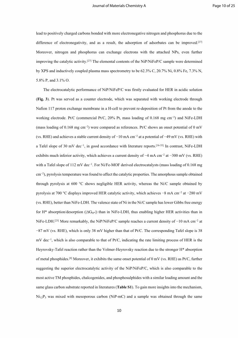
with a ~5 nm amorphous shell embedded in the carbon matrix (Fig. S5). To further verify the composition,
elemental distribution measurements were carried out using scanning transmission electron microscopy
(STEM) equipped with energy dispersive X-ray (EDX) elemental mapping and EDX linear scanning
(Fig. 2b to 2j). As indicated, Ni and Fe are homogeneously distributed in the NPs, while N, P and O are
also distributed in the carbon matrix, indicating N-, P-, and O-doping of the carbon matrix. The STEM-
EDX linear scanning further reveals that the NP is composed of Ni and Fe phosphides, and a thin NiFeOx
shell on its surface. The presence of O indicates slight oxidation of the phosphides, which may arise from
the oxidation of phosphide in the ambient air or the O-containing small molecules (i.e. water and
methanol as solvent for the synthesis) during the pyrolysis process.
X-ray photoelectron spectroscopy (XPS) measurements were also carried out (Fig. S6). The peaks
at 855.4 and 873.3 eV for Ni 2p are assigned to Ni 2p3/2 and Ni 2p1/2, respectively,[1] which can be fitted
with three oxidation states of Ni0+, Ni2+, and Ni3+, located at 855.1, 856.4, and 858.3 eV, respectively.[44]
The Fe 2p peaks are comprised of both Fe3+ and Fe4+.[19] Fe4+, which may arise from the surface
oxidation,[1] can also contribute to the high OER performance by creating a higher degree of metal-
oxygen covalency, thus facilitating the interactions between adjacent adsorbed oxygen atoms forming
oxygen molecules.[19] The P 2p peaks at 129.8 and 130.7 eV correspond to P 2p3/2 and P 2p1/2 orbitals,
respectively, which are characteristic of metal phosphides, and the peaks located at 134.4 and 133.1 can
be ascribed to P-O and P-C.[27] The spectrum also contains strong P-O peak at 134.3 eV, which is
consistent with the STEM-EDX observations. The C 1s peak centered at approximately 285.7 eV is
assigned to sp2 hybridized graphitic carbon in C=N bonds, which is common for N-doped carbon.[27] The
peak positioned at 284.2 eV can be ascribed to graphitic carbon,[27] while the peak positioned at 287.0
eV corresponds to oxidized carbon, which has better aqueous wetting properties and facilitates electrolyte
uptake, hence favoring the improvement of the activity for water splitting reactions. The N 1s peaks
around 398.7 eV and 399.5 eV are ascribed to pyridine and pyrrolic nitrogen, respectively,[27] which are
believed to be the active sites for both HER and OER.[27] To further verify the N and P doping in the
carbon matrix, Raman measurement was also conducted. As indicated in Fig. S7, Raman spectrum
contains two characteristic peaks positioned at 1349 and 1586 cm-1, corresponding to the D and G bands
of N-doped carbon, respectively.[26] The corresponding intensity ratio (ID/IG), which is correlated to the
quantity of defects, is estimated to be 1.31, indicating successful doping of N and P.[26] N- and P-doping
Page 9 of 25 Journal of Materials Chemistry A
10
lead to positively charged carbons bonded with more electronegative nitrogen and phosphorus due to the
difference of electronegativity, and as a result, the adsorption of adsorbates can be improved.[27]
Moreover, nitrogen and phosphorus can exchange electrons with the attached NPs, even further
improving the catalytic activity.[27] The elemental contents of the NiP/NiFeP/C sample were determined
by XPS and inductively coupled plasma mass spectrometry to be 62.3% C, 20.7% Ni, 0.8% Fe, 7.3% N,
5.8% P, and 3.1% O.
The electrocatalytic performance of NiP/NiFeP/C was firstly evaluated for HER in acidic solution
(Fig. 3). Pt was served as a counter electrode, which was separated with working electrode through
Nafion 117 proton exchange membrane in a H-cell to prevent re-deposition of Pt from the anode to the
working electrode. Pt/C (commercial Pt/C, 20% Pt, mass loading of 0.168 mg cm−2) and NiFe-LDH
(mass loading of 0.168 mg cm−2) were compared as references. Pt/C shows an onset potential of 0 mV
(vs. RHE) and achieves a stable current density of −10 mA cm−2 at a potential of −49 mV (vs. RHE) with
a Tafel slope of 30 mV dec−1, in good accordance with literature reports.[16-35] In contrast, NiFe-LDH
exhibits much inferior activity, which achieves a current density of −4 mA cm−2 at −300 mV (vs. RHE)
with a Tafel slope of 112 mV dec−1. For Ni/Fe-MOF derived electrocatalysts (mass loading of 0.168 mg
cm−2), pyrolysis temperature was found to affect the catalytic properties. The amorphous sample obtained
through pyrolysis at 600 °C shows negligible HER activity, whereas the Ni/C sample obtained by
pyrolysis at 700 °C displays improved HER catalytic activity, which achieves −8 mA cm−2 at −280 mV
(vs. RHE), better than NiFe-LDH. The valence state of Ni in the Ni/C sample has lower Gibbs free energy
for H* absorption/desorption (|∆GH*|) than in NiFe-LDH, thus enabling higher HER activities than in
NiFe-LDH.[23] More remarkably, the NiP/NiFeP/C sample reaches a current density of −10 mA cm−2 at
−87 mV (vs. RHE), which is only 38 mV higher than that of Pt/C. The corresponding Tafel slope is 38
mV dec−1, which is also comparable to that of Pt/C, indicating the rate limiting process of HER is the
Heyrovsky-Tafel reaction rather than the Volmer-Heyrovsky reaction due to the stronger H* absorption
of metal phosphides.[8] Moreover, it exhibits the same onset potential of 0 mV (vs. RHE) as Pt/C, further
suggesting the superior electrocatalytic activity of the NiP/NiFeP/C, which is also comparable to the
most active TM phosphides, chalcogenides, and phosphosulphides with a similar loading amount and the
same glass carbon substrate reported in literatures (Table S1). To gain more insights into the mechanism,
Ni12P5 was mixed with mesoporous carbon (NiP-mC) and a sample was obtained through the same
Page 10 of 25Journal of Materials Chemistry A
11
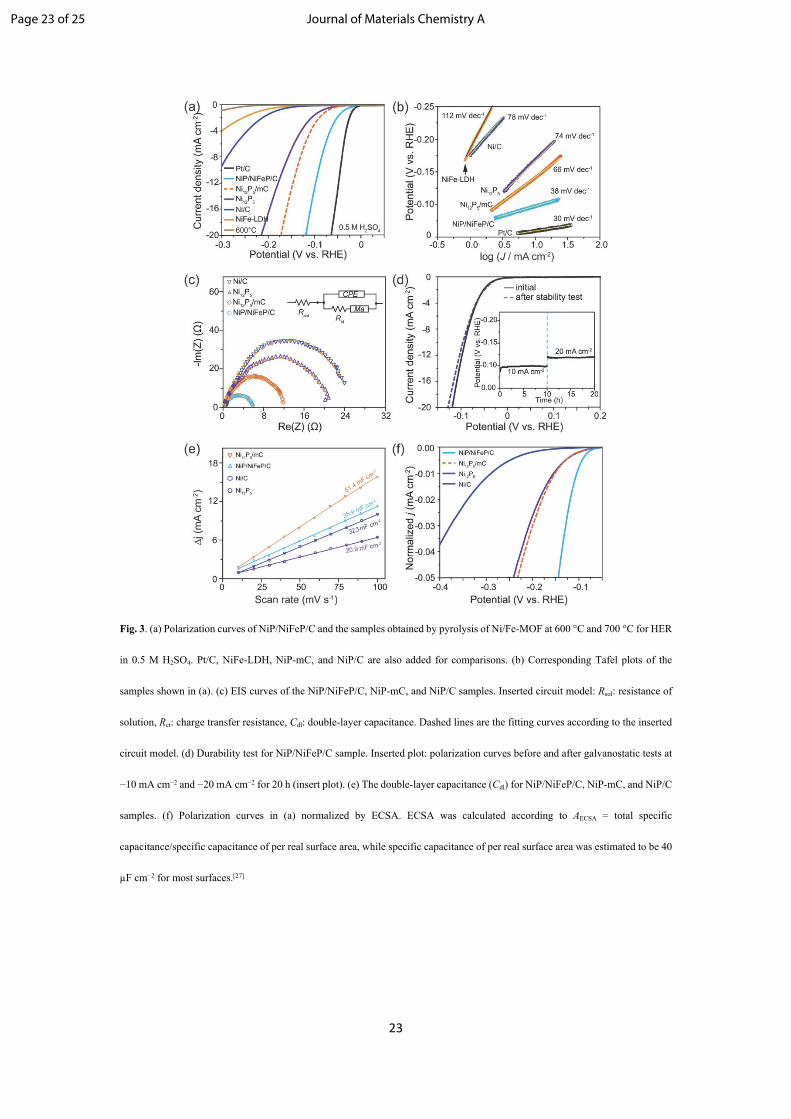
precursor process but without Fe addition (NiP/C) as a control. NiP-mC achieves −10 mA cm−2 at a
potential of −175 mV (vs. RHE), with the corresponding Tafel slope is 72 mV dec−1, while the NiP/C
sample can deliver the same current density at −131 mV (vs. RHE), with a corresponding Tafel slope of
61 mV dec−1. NiP/C, therefore, has better catalytic activity than NiP-mC, suggesting that the more
electrochemically active metal phosphide/carbon interfaces of NiP/C were formed by the in-situ
transformation from MOF structure. More importantly, NiP/NiFeP/C exhibits even superior catalytic
activity to NiP/C, indicating that the presence of minor NiFeP secondary components further favors the
activity. Electrochemical impedance spectroscopy (EIS) was also carried out to evaluate the charge
transfer during hydrogen evolution (Fig. 3c). Circuit model fitting analysis showed that the impedance
data can be modeled using a modified Randles circuit consisting of a series resistance (Rs), constant phase
element (CPE), charge transfer resistance (Rct), and modified mass-transport impedance element (Ma).[27]
The impedance data and associated Randles equivalent circuit are shown in Fig. 3c. The radius of the
semi-arc corresponds to CPE and Rct. The smaller Rct of 6.8 Ω for NiP/C than NiP-mC (9.9 Ω) indicates
that the interfaces of the conductive carbon matrix and the NiP/NiFeP NPs facilitate the charge transfer
and thereby improve the electrocatalytic activity. Notably, the NiP/NiFeP/C sample shows the smallest
Rct of 2.5 Ω, compared to NiP/C and NiP-mC, suggesting that a little amount of NiFeP can further
facilitate the charge transfer and the catalytic activity. The results show that the superior activity of
NiP/NiFeP/C can be ascribed to the synergistic effect of Ni12P5, NiFeP, and carbon matrix. Long-term
stability is crucial for the electrocatalyst to be used practically. Herein, the NiP/NiFeP/C sample also
manifests superior stability over 98% potential retaining when performed galvanostatically for 20 h (Fig.
3d inserted plot), and the linear sweep voltammetry also only shows only slight degradation after 20 h
stability test, indicating excellent stability of NiP/NiFeP/C (Fig. 3d).
To further study the intrinsic catalytic activities, the geometric current densities are normalized by
the relative electrochemical surface areas (ECSA). The double-layer capacitance (Cdl), proportional to
the electrochemically active surface area and derived from the cyclic voltammetry measurements, is one
of the descriptors for determining the ECSA.27 Although the electrochemical capacitances of the carbon
matrix contribute to the Cdl and thereby affect the ECSA, the normalization of the geometric current
densities by the estimated ECSA can still reflect the intrinsic activities. NiP-mC shows the highest Cdl,
followed by NiP/NiFeP/C and NiP/C (Fig. 3e). The higher Cdl indicates more contact between active
Page 11 of 25 Journal of Materials Chemistry A

12
sites and electrolyte for electron transfer.[27] The higher Cdl of NiP-mC than that of NiP/NiFeP/C may be
caused by the higher electrochemical surface area of mesoporous carbon, which is electrochemically
active for supercapacitors but inert for HER. The normalized current densities, which stand for the
number of active sites per relative surface area, are given in Fig. 3f. NiP/NiFeP/C is the most active
compared to NiP/C and NiP-mC, even though the ECSA contribution of carbon is also counted. It,
therefore, is rational to believe that the intrinsic activity of NiP/NiFeP/C will be higher without counting
the carbon. In addition, the exchange current densities are then normalized by the relative surface areas.
The normalized exchange current densities (J0, normalized), which stands for the number of active sites per
relative surface area, are given in Table S2. The NiP/NiFeP/C shows the highest J0, normalized, compared
to NiP/C and NiP-mC samples, and therefore, exposes much more active sites, enabling the improvement
of HER catalytic activity. The high intrinsic activity of NiP/NiFeP/C arises from its unique architecture,
which results in the good interfaces facilitating the charge transfer and the synergistic effect of Ni12P5
and NiFeP in the NPs. The incorporation of Fe facilitates the HER activities. We also measured the HER
electrocatalytic performance of NiP/NiFeP/C in alkaline solution with Pt as counter electrode.
NiP/NiFeP/C exhibits −138 mV (vs. RHE) to achieve −10 mA cm−2. The corresponding Tafel slope is
68 mV dec−1. (Fig. S8). Moreover, the NiP/NiFeP/C electrocatalyst maintains over 90% of its current
and/or potential retention after 20 h of stability testing. The results show that NiP/NiFeP/C also has
favorable HER electrocatalytic activity and stability in alkaline electrolyte (Table S3).
The NiP/NiFeP/C sample was then tested for OER in alkaline solution. RuO2 and NiFe-LDH (mass
loading of 0.168 mg cm−2) were added for comparison. RuO2 shows (Fig. 4a) an onset potential of 1.45
V (vs. RHE) and achieves a stable current density of 10 mA cm−2 at a potential of 1.55 V (vs. RHE) with
a Tafel slope of 81 mV dec−1, in good accordance with literature reports.[1] NiFe-LDH shows an onset
potential of 1.42 V (vs. RHE) and achieves a stable current density of 10 mA cm−2 at a potential of 1.53
V (vs. RHE) with a Tafel slope of 62 mV dec−1, consistent with literature reports.[6] All of the Ni-based
samples show current bump/peak during positive scanning (Fig. S9, labeled with a red arrow), which is
contributed by the redox feature of Ni, i.e. current density from the oxidation of low valence state of Ni
atoms, while the reverse scan shows a cathodic peak, correlated to the reduction of NiOOH.[50] The
Faradaic current from Ni2+ oxidation does not contribute to the water oxidation, so the reverse scan (Fig.
S9, labeled with a black arrow) should well represent the OER activity of the sample. The NiP/NiFeP/C
Page 12 of 25Journal of Materials Chemistry A

13
sample exhibits better performance than RuO2, NiFe-LDH, and the samples obtained at low pyrolysis
temperatures. It is worth mentioning that given the carbon content of 62.3 %, the actual loading amount
of active NiP/NiFeP is much lower. NiP/NiFeP/C achieves 10 mA cm−2 at a potential of 1.48 V (vs.
RHE) with a corresponding Tafel slope of 58 mV dec−1 (Fig. 4b). In contrast, the corresponding MOF
pyrolyzed at 600 °C reaches a current density of 5 mA cm−2 at 1.69 V (vs. RHE) with a corresponding
Tafel slope of 116 mV dec−1; the sample Ni/C obtained through the corresponding MOF pyrolyzed at
700 °C shows a potential of 1.59 V (vs. RHE) at a current density of 10 mA cm−2 with a corresponding
Tafel slope of 70 mV dec−1 (Fig. 4b). The OER activities of the NiP/C and NiP-mC were also compared.
NiP/C reaches a current density of 10 mA cm−2 at 1.50 V (vs. RHE) with a corresponding Tafel slope of
60 mV dec−1, while the NiP-mC needs 1.57 V (vs. RHE) to deliver the same current density. NiP/C,
therefore, shows the better OER catalytic activity than NiP-mC, due to the good interfaces between
Ni12P5 and carbon matrix. More remarkably, given the synergistic effect of Ni12P5 and NiFeP in the NPs,
NiP/NiFeP/C has further enhanced OER catalytic activity, further demonstrating that the incorporation
of Fe will further boost the electrocatalytic activities both on HER and OER. Then, the mass activity
(MA), obtained by the normalization of the geometric current density to the oxide mass loading, was also
calculated and compared to other reported OER electrocatalysts (Fig. 4c). The NiP/NiFeP/C catalyst
delivers much better MA than NiFe-LDH and some other OER electrocatalysts. Specifically, the catalyst
exhibits a MA of 78.3 A g−1cat, which is ~1.3 times higher than that of NiFe-LDH.[6] EIS measurements
exhibit that the NiP/NiFeP/C has the smallest Rct (Fig. S10), suggesting the superior charge transfer,
which is in good agreement with the electrocatalytic activity analysis. Moreover, the turnover frequency
(TOF) was estimated by normalizing the rate of O2 generation to the total number of metal ions.[25] The
TOF of NiP/NiFeP/C at 1.51 V (vs. RHE) was estimated to be 0.133 s−1 (See Supporting Information for
details), indicating the outstanding OER activity of NiP/NiFeP/C, which is higher than that of the
majority of the most active OER catalysts (Table S4). For example, IrO2 delivers a TOF of 0.050 s−1 at
1.53 V (vs. RHE);[51] NiCeOx–Au delivers a TOF of 0.080 s−1 at 1.51 V (vs. RHE);[25] NiFe-LDH reaches
a TOF of 0.036 s−1 at 1.51 V (vs. RHE) and 0.075 s−1 at 1.65 V (vs. RHE).[6] Notably, the estimation of
TOF for NiP/NiFeP/C is based on the presumption that all of the metal cations are involved in the water
oxidation reactions, although some may not participate in the reactions. If only the active sites on the
surface are counted, the actual TOF of NiP/NiFeP/C would be even higher. The stability of NiP/NiFeP/C
Page 13 of 25 Journal of Materials Chemistry A

14
was also evaluated in an alkaline electrolyte at a constant potential of 1.52 V (vs. RHE) (Fig. 4e). The
NiP/NiFeP/C maintains a stable current density with almost 98% retention after 20 h of stability testing.
For pristine TM phosphides, surface oxidation leads to the formation of TM hydroxides and phosphates;
the dissolution of the phosphates results in the leaching of P.[2-5] Consequently, the OER performance
will decrease during the long-term operation. For our material of NiP/NiFeP/C, the thin amorphous shell
(indicated in Fig. 2j) and the carbon matrix can effectively mitigate the activity decay during the long-
term operation in alkaline solution due to P leaching. After OER durability test, NiP/NiFeP/C still
maintains the same morphology (Fig. S11). The STEM-EDX of NiP/NiFeP/C after stability test shows
that the oxygen content in the composite increases (Fig. S12). The increase of O content in the carbon is
consistent with the experimental observation of the enhancement in hydrophilicity of the sample after
stability test. Further XRD measurement (Fig. S13) confirms the presence of NiFe(OOH)x, in good
agreement with the STEM-EDX result, implying that the amorphous NiFeOx shell of the NiP/NiFeP/C
sample can be converted to the NiFe(OOH)x shell,[10] which can prevent leaching of the phosphide core.
The XPS measurement (Fig. S14) shows that the NiP/NiFeP/C sample only has slight increase of the P-
O peak intensity after the stability test, indicating negligible P leaching during long-term test, and thus
further confirming the good stability of NiP/NiFeP/C. Therefore, the double protection of the
NiFe(OOH)x shell and the carbon matrix confer NiP/NiFeP/C the outstanding stability.
Both electrochemical water splitting and CO2 reduction require OER electrocatalysts, and
electrochemical water splitting prefers alkaline solutions, while CO2 reduction prefers neutral aqueous
solutions due to the difference in the solubility of active intermediates.[52] The OER performance of
NiP/NiFeP/C, therefore, was also evaluated in a neutral pH aqueous electrolyte (Fig. 4f). The
NiP/NiFeP/C sample manifests a potential of 1.55 V (vs. RHE) at 1 mA cm−2 and a corresponding Tafel
slope of 132.8 mV dec−1, which is superior to that of RuO2 (potential at 1.0 mA cm−2: 1.58 V (vs. RHE)
and Tafel slope: 199.3 mV dec−1). Importantly, the NiP/NiFeP/C is among the most active OER
electrocatalysts in neutral solution. For instance, CoO2/CoSe2-Ti[7] and CoP@Co-Bi-Pi/Ti[9] exhibit 1.74
and 1.65 V (vs. RHE), respectively, at 1.0 mA cm−2 in neutral solutions. Therefore, NiP/NiFeP/C is a
good OER electrocatalyst in both alkaline and neutral solutions.
Both excellent HER and OER activities could enable NiP/NiFeP/C to be an efficient bifunctional
catalyst for overall water splitting. To validate this, a two-electrode water-splitting device using
Page 14 of 25Journal of Materials Chemistry A

15
NiP/NiFeP/C coated on Ni foam (NiP/NiFeP/C-NiF) as both anode and cathode was assembled and
tested in 1.0 M KOH. The half-cell reactions were firstly examined. NiP/NiFeP/C-NiF reaches the
cathodic current density (Fig. 5a) of 10 mA cm−2 and 100 mA cm−2 at potentials of −75 and −179 mV,
respectively, reflecting the good HER catalytic activity. NiP/NiFeP/C-NiF requires 1.40 and 1.46 V (vs.
RHE) to deliver the anodic current density of 10 and 100 mA cm−2, respectively (Fig. 5a), also
manifesting the good OER catalytic activity. When combined together, the two-electrode water-splitting
device achieves a current density of 10 and 100 mA cm−2 at a potential of 1.53 V and 1.68 V in alkaline
solution (Fig. 5b), superior to the benchmark of noble metal combination, RuO2(+)||Pt(–) and comparable
to the most highly active bifunctional electrocatalysts reported in literature (Fig. 5c). Stability test was
further undertaken for the full water-splitting configuration at 100 mA cm−2. The potential was observed
to be stable for over 20 h under continuous operation (Fig. 5d). Gas chromatography measurement
confirms a high faradic efficiency of 99.8% and generated H2 and O2 concentrations at a predicted ratio
of 2:1 (Fig. S15). The result indicates that NiP/NiFeP/C-NiF is a good and efficient bifunctional
electrocatalyst for overall water splitting.
To demonstrate the versatility of the new MOF for producing heteroatom-doped carbon
encapsulated non-3d TM phosphide or sulfide nanoparticles for HER or OER, 4d-Mo and 5d-W based
phosphide/sulfide have also been synthesized. The XRD pattern (Fig. S16) of the synthesized Mo, W-
MOF indicates a triclinic space group P1 (with lattice parameters of a = 10.83525 Å, b = 11.24025 Å, c
= 16.45438 Å), and the corresponding XRD pattern (Fig. S17a) of the sample obtained by pyrolysis of
Mo, W-MOF at 800 °C suggests the main trigonal-structured Mo0.5W0.5S2 phase (space group of P3m1,
No. 156) with a small portion of the hexagonal-structured MoP phase (space group of P62m, No. 187).
The structure of Mo0.5W0.5S2 (Fig. S17) is similar to its counterpart, 2H-MoS2, but has greatly expanded
interlayer spacing (~ 12.6 Å), which means the Mo0.5W0.5S2 can be treated as 2-dimensional Janus
MoS2/WS2 layers.[62, 63] The XRD measurement also indicates that Mo0.5W0.5S2 has the highest edge-to-
plane ratio among all of the reported 2H-WS2 or MoS2 nanostructures, and the electrochemically inert
(001) plane is remarkably inhabited. The obtained sample (denoted as MoWS/MoP/C) has a particle
diameter of 100 to 600 nm, composed of small nanoparticles with diameter of ~ 6 nm homogenously
dispersed in a carbon shell (Fig. S18).
Page 15 of 25 Journal of Materials Chemistry A

16
The electrochemical activity of MoWS/MoP/C was also evaluated for HER in acidic solution (Fig.
S19). Apart from Pt/C, (NH4)2Mo3S13•nH2O was also compared as reference, because
(NH4)2Mo3S13•nH2O, which was also synthesized using a straightforward wet-chemistry method at room
temperature (Fig. S20),[64] was reported recently as a robust electrocatalyst for HER. MoWS/MoP/C
achieves –10 mA cm−2 at –149 mV (vs. RHE), and the corresponding Tafel slope is 45 mV dec−1. In
contrast, (NH4)2Mo3S13•nH2O delivers a current density of –10 mA cm−2 at –250 mV (vs. RHE) with a
Tafel slope of 61 mV dec−1, which is better than that of MoS2, but the activity is still much inferior to
that of MoWS/MoP/C, which may be caused by the still poor electron collection properties of
(NH4)2Mo3S13•nH2O.[64] The results well demonstrate that our proposed approach is feasible and easy to
synthesize 3d to 5d TM phosphide or sulfide NPs encapsulated in heteroatom-doped carbon matrix for
highly efficient water splitting.
Conclusions
We have designed and synthesized new MOFs that enable facile, one-step preparation of 3d to 5d
TM phosphide or sulfide nanoparticles e.g., Ni12P5/NiFeP NPs (NiP/NiFeP/C) and Mo0.5W0.5S2/MoP
ultrafine NPs (MoWS/MoP/C), encapsulated in heteroatom-doped carbon matrix. The NiP/NiFeP/C
electrocatalyst shows competitive HER catalytic activity to the best HER electrocatalysts reported in
literature and higher OER activity than noble metal oxide catalysts, such as RuO2. A two-electrode water-
splitting device using bifunctional NiP/NiFeP/C catalysts achieves 10 mA cm–2 at a cell voltage of 1.53
V and 100 mA cm–2 at 1.68 V with excellent stability for overall water splitting at 100 mA cm–2 for over
20 h. Moreover, the MoWS/MoP/C catalyst exhibits better HER activity than MoS2 and
(NH4)2Mo3S13•nH2O reported in literature. Our results demonstrate the potential of the new MOFs for
facile synthesis of highly efficient TM electrocatalysts.
Acknowledgement
This paper presents results from an NSF project (award number CBET−1433401)
competitively−selected under the solicitation “NSF 14−15: NSF/DOE Partnership on Advanced
Frontiers in Renewable Hydrogen Fuel Production via Solar Water Splitting Technologies”, which was
co−sponsored by the National Science Foundation, Division of Chemical, Bioengineering,
Page 16 of 25Journal of Materials Chemistry A

17
Environmental, and Transport Systems (CBET), and the U.S. Department of Energy, Office of Energy
Efficiency and Renewable Energy, Fuel Cell Technologies Office. Y. Y. acknowledges the financial
support by the Ohio Research Scholar Program (ORSP).
References
[1] B. Weng, F. Xu, C. Wang, W. Meng, C. R. Grice and Y. Yan, Energy Environ. Sci., 2017, 10, 121.
[2] F. Hu, S. Zhu, S. Chen, Y. Li, L. Ma, T. Wu, Y. Zhang, C. Wang, C. Liu, X. Yang, L. Song, X. Yang
and Y. Xiong, Adv. Mater., 2017, 29, 1606570.
[3] W. J. Yin, B. Weng, J. Ge, Q. Sun, Z. Li and Y. Yan, Energy Environ. Sci., 2019,12, 442.
[4] X. Han, X. Wu, Y. Deng, J. Liu, J. Lu, C. Zhong and W. Hu, Adv. Energy Mater., 2018, 1800935.
[5] L. A. Stern, L. Feng, F. Song and X. Hu, Energy Environ. Sci., 2015, 8, 2347.
[6] X. Lu and C. Zhao, Nat. Commun., 2015, 6, 6616.
[7] X. Liu, H. Zheng, Z. Sun, A. Han and P. Du, ACS Catal., 2015, 5, 1530.
[8] Z. Zhang, Y. Qin, M. Dou, J. Ji and F. Wang, Nano Energy, 2016, 30, 426.
[9] W. Wang, D. Liu, S. Hao, F. Qu, Y. Ma, G. Du, A. M. Asiri, Y. Yao and X. Sun, Inorg. Chem., 2017,
56, 3131.
[10] Z. M. Peng and H. Yang, J. Am. Chem. Soc., 2009, 131, 7542.
[11] Y. Y. Liang, Y. G. Li, H. L. Wang, J. G. Zhou, J. Wang, T. Regier and H. J. Dai, Nat. Mater., 2011, 10,
780.
[12] E. J. Popczun, C. G. Read, C. W. Roske, N. S. Lewis and R. E. Schaak, Angew. Chem. Int. Ed., 2014,
53, 5427.
[13] M. W. Kanan and D. G. Nocera, Science, 2008, 321, 1072.
[14] M. Cabán-Acevedo, M. L. Stone, J. R. Schmidt, J. G. Thomas, Q. Ding, H. C. Chang, M. L. Tsai, J. H.
He and S. Jin, Nat mat., 2005, 14, 1245.
[15] X. Yang, A. Y. Lu, Y. Zhu, M. N. Hedhili, S. Min, K. W. Huang, Y. Han, L and J. Li, Nano Energy,
2015, 15, 634.
[16] C. W. Tung, Y. Y. Hsu, Y. P. Shen, Y. Zheng, T. S. Chan, H. S. Sheu, Y. C. Cheng and H. M. Chen,
Nat. Commun., 2015, 6, 8106.
[17] H. W. Liang, S. Bruller, R. Dong, J. Zhang, X. Feng and K. Muller, Nat. Commun., 2015, 6, 7992.
Page 17 of 25 Journal of Materials Chemistry A

18
[18] P. Chen, K. Xu, Z. Fang, Y. Tong, J. Wu, X. Lu, X. Peng, H. Ding, C. Wu and Y. Xie, Angew. Chem.
Int. Ed., 2015, 54, 14710.
[19] S. Yagi, I. Yamada, H. Tsukasaki, A. Seno, M. Murakami, H. Fujii, H. Chen, N. Umezawa, H. Abe, N.
Nishiyama and S. Mori, Nat. Commun., 2015, 6, 8249.
[20] G. Cai, W. Zhang, L. Jiao, S. H. Yu and H. L. Jiang, Chem., 2017, 2, 791.
[21] J. Luo, J. H. Im, M. T. Mayer, M. Schreier, M. K. Nazeeruddin, N. G. Park, D. T. Tilley, H. J. Fan and
M. Grätzel, Science, 2014, 345, 1593.
[22] S. Jin, ACS Energy Lett., 2017, 2, 1937.
[23] H. Sun, Y. Lian, C. Yang, L. Xiong, P. Qi, Q. Mu, X. Zhao, J. Guo, Z. Deng and Y. Peng, Energy
Environ. Sci., 2018, 11, 2363.
[24] H. Wang, Z. Lu, S. XU, D. Kong, J. J. Cha, G. Zheng, P. C. Hsu, K. Yan, D. Bradshaw, F. B. Prinz and
Y. Cui, PNAS., 2013, 110, 19701.
[25] J. W. Desmond Ng, M. García-Melchor, M. Bajdich, P. Chakthranont, C. Kirk, A. Vojvodic and T. F.
Jaramillo, Nature Energy, 2016, 1, 16053.
[26] K. Qu, Y. Zheng, X. Zhang, K. Davey, S. Dai and S. Z. Qiao, ACS Nano, 2017, 11, 7293.
[27] B. Weng, C. R. Grice, W. Meng, L. Guan, F. Xu, Y. Yu, C. Wang, D. Zhao and Y. Yan, ACS Energy
Lett., 2018, 3, 1434.
[28] R. Wang, X. Y. Dong, J. Du, J. Y. Zhao and S.Z. Qiao, Adv. Mater., 2018, 30, 1703711.
[29] M. Zhang, Q. Dai, H. Zheng, M. Chen and L. Dai, Adv. Mater., 2018, 1705431.
[30] B. Weng, W. Wei, Yiliguma, H. Wu, A. M. Alenizi and G. Zheng, J. Mater. Chem. A, 2016, 4, 15353.
[31] T. P. Gerasimova and S. A. Katsyuba, Dalton Trans., 2013, 42, 1787.
[32] R. Scaffaro, L. Botta, G. L. Re, R. Bertani, R. Milani and A. Sassic, J. Mater. Chem., 2011, 21, 3849.
[33] N. H. Attanayake, A. C. Thenuwara, A. Patra, Y. V. Aulin, T. M. Tran, H. Chakraborty, E. Borguet, M.
L. Klein, J. P. Perdew and D. R. Strongin, ACS Energy Lett., 2018, 3, 7.
[34] J. Miao, F. X. Xiao, H. B. Yang, S. Y. Khoo, J. Chen, Z. Fan, Y. Y. Hsu, H. M. Chen, H. Zhang and B.
Liu, Sci. Adv., 2015, 1, e1500259.
[35] M. R. Gao, M. K. Y. Chan and Y. Sun, Nat. Commun., 2015, 6, 7493.
[36] H. Schäfer, K. Kuepper, J. Koppe, P. Selter, M. Steinhart, M. R. Hansen, and D. Daum, ACS Catal.,
2018, 8, 10914.
Page 18 of 25Journal of Materials Chemistry A
19
[37] H. Schäfer, and M. Chatenet, ACS Energy Lett., 2018, 3, 574.
[38] H. Schäfer, S. Sadaf, L. Walder, K. Kuepper, S. Dinklage, J. Wollschläger, L. Schneider, M. Steinhart, J.
Hardege, and D. Daum, Energy Environ Sci. 2015, 8, 2685.
[39] B. F. Fieselmann, D. N. Hendrickson and G. D. Stucky, Inorg. Chem., 1978, 17, 2078.
[40] Z. Y. Fu, S. M. Hu, J. C. Dao, J. J. Zjamg and X. T. Wu, Eur. J. Inorg. Chem. 2003, 2670.
[41] C. C. L. McCrory, S. Jung, I. M. Ferrer, S. M. Chatman, J. C. Peters and T. F. Jaramillo, J. Am. Chem.
Soc. 2015, 137, 4347.
[42] E. Tsuji, A. K. Imanishi, I. Fukui and Y. Nakato, Electrochim. Acta 2011, 56, 2009.
[43] L. Trotochaud, S. L. Young, J. K. Ranney and S. W. Boettcher, J. Am. Chem. Soc. 2014, 136, 6744.
[44] P. F. Liu, X. Li, S. Yang, M. Y. Zu, P. Liu, B. Zhang, L. R. Zheng, H. Zhao and H. G. Yang, ACS Energy
Lett., 2017, 2, 2257.
[45] B. You, N. Jiang, M. Sheng, M. W. Bhushan and Y. Sun, ACS Catal., 2016, 6, 714.
[46] X. Xiao, C. T. He, S. Zhao, J. Li, W. Lin, Z. Yuan, Q. Zhang, S. Wang, L. Dai and D. Yu, Energy
Environ. Sci., 2017, 10, 893.
[47] H. Liang, A. N. Gandi, C. Xia, M. N. Hedhili, D. H. Anjum, U. Schwingenschlögl and H. N. Alshareef,
ACS Energy Lett., 2017, 2, 1035.
[48] X. Cui, P. Ren, D. Deng, J. Deng and X. Bao, Energy Environ. Sci., 2016, 9, 123.
[49] K. Fan, H. Chen, Y. Ji, H. Huang, P. M. Claesson, Q. Daniel, B. Philippe, H. Rensmo, F. Li, Y. Luo and
L. Sun, Nat. Commun., 2016, 7, 11981.
[50] A. L. Strickler, M. Escudero-Escribano and T. F. Jaramillo, Nano Lett., 2017, 17, 6040.
[51] B. Zhang, X. Zheng, O. Voznyy, R. Comin, M. Bajdich, M. Garcia-Melchor, L. Han, J. Xu, M. Liu, L.
Zheng, F. P. G. D. Arquer, C. T. Dinh, F. Fan, M. Yuan, E. Yassitepe, N. Chen, T. Regier, P. Liu. Y. Li,
P. D. Luna, A. Janmohamed, H. L. Xin, H. Yang, A. Vojvodic and E. H. Sargent, Science, 2016, 352,
333.
[52] X. Zheng, B. Zhang, P. D. Luna, Y. Liang, R. Comin, O. Voznyy, L. Han, F. P. Garcia de Arquer, M.
Liu, C. T. Dinh, T. Regier, J. J. Dynes, S. He, H. L. Xin, H. Peng, D. Prendergast, X. Du and E. H.
Sargent, Nature Chem., 2018, 10, 149.
[53] J. Li, Y. Wang, T. Zhou, H. Zhang, X. Sun, J. Tang, L. Zhang, A. M. Al-Enizi, Z. Yang and G. Zheng,
J. Am. Chem. Soc., 2015, 137, 14305.
Page 19 of 25 Journal of Materials Chemistry A
20
[54] L. Yu, H. Zhou, J. Sun, F. Qin, F. Yu, J. Bao, Y. Yu, S. Chen and Z. Ren, Energy Environ. Sci., 2017,
10, 1820.
[55] X. Han, X. Wu, Y. Deng, J. Liu, J. Lu, C. Zhong and W. Hu, Adv. Energy Mater., 2018, 1800935.
[56] H. Liang, A. N. Gandi, D. H. Anjum, X. Wang, U. Schwingenschlögl and H. N. Alshareef, Nano Lett.,
2016, 16, 7718.
[57] G. F. Chen, T. Y. Ma, Z. Q. Liu, N. Li, Y. Z. Su, K. Davey and S. Z. Qiao, Adv. Funct. Mater., 2016, 26,
3314.
[58] E. Hu, Y. Feng, J. Nai, D. Zhao, Y. Hu and X. W. Lou, Energy Environ. Sci., 2018, 11, 872.
[59] N. Jiang, B. You, M. Sheng and Y. Sun, Angew. Chem. Int. Ed., 2015, 54, 6251.
[60] J. Luo, J. H. Im, M. T. Mayer, M. Schreier, M. K. Nazeeruddin, N. G. Park, D. T. Tilley, H. J. Fan and
M. Grätzel, Science, 2014, 345, 1593.
[61] H. Wang, H. W. Lee, Y. Deng, Z. Lu, P. C. Hsu, Y. Liu, D. Lin and Y. Cui, Nat. Commun., 2015, 6,
7261.
[62] K. Kobayashi and J. Yamauchi, Phys. Rev. B, 1995, 51, 17085.
[63] C. Tsai, F. Abild-Pedersen and J. K. Norskov, Nano Lett., 2014, 14, 1381.
[64] J. Kibsgaard, T. F. Jaramillo and F. Besenbacher, Nat. Chem., 2014, 6, 248.
Page 20 of 25Journal of Materials Chemistry A

21
Fig. 1. (a) Unit-cell content of the crystal structure of the Ni/Fe-MOF with atoms labeled. Hydrogen and carbon atoms are not
labeled for clarity. Green balls: open sites of TM bonded to C. (b) The crystal structure of Ni/Fe-MOF with 4 4 3 unit cells (b
c a). (c) Experimental and simulated PXRD patterns of Ni/Fe-MOF. (d) XRD patterns of Ni/Fe-MOF samples pyrolyzed at
600, 700, and 800 °C, respectively. To better identify the various diffraction peaks, the XRD patterns are plotted in logarithmic
scale. Reference diffraction patterns of standard Ni, Ni12P5, and NiFeP are also shown.
Page 21 of 25 Journal of Materials Chemistry A

22
Fig. 2. Morphologies of the obtained NiP/NiFeP/C. (a) SEM image of NiP/NiFeP/C. (b) STEM image of NiP/NiFeP/C. (c) to (i)
STEM-EDX elemental mapping of NiP/NiFeP/C. (j) STEM-EDX linear scanning of NiP/NiFeP/C. The scanning area is shown
with the yellow lines in (b). The inserted image in (j) also shows the schematics of the composition of the NPs according to the
STEM-EDX results.
Page 22 of 25Journal of Materials Chemistry A
23
Fig. 3. (a) Polarization curves of NiP/NiFeP/C and the samples obtained by pyrolysis of Ni/Fe-MOF at 600 °C and 700 °C for HER
in 0.5 M H2SO4. Pt/C, NiFe-LDH, NiP-mC, and NiP/C are also added for comparisons. (b) Corresponding Tafel plots of the
samples shown in (a). (c) EIS curves of the NiP/NiFeP/C, NiP-mC, and NiP/C samples. Inserted circuit model: Rsol: resistance of
solution, Rct: charge transfer resistance, Cdl: double-layer capacitance. Dashed lines are the fitting curves according to the inserted
circuit model. (d) Durability test for NiP/NiFeP/C sample. Inserted plot: polarization curves before and after galvanostatic tests at
−10 mA cm−2 and −20 mA cm−2 for 20 h (insert plot). (e) The double-layer capacitance (Cdl) for NiP/NiFeP/C, NiP-mC, and NiP/C
samples. (f) Polarization curves in (a) normalized by ECSA. ECSA was calculated according to AECSA = total specific
capacitance/specific capacitance of per real surface area, while specific capacitance of per real surface area was estimated to be 40
µF cm−2 for most surfaces.[27]
Page 23 of 25 Journal of Materials Chemistry A

24
Fig. 4. Electrochemical characterizations of NiP/NiFeP/C and the samples obtained by pyrolysis of Ni/Fe-MOF at 600 °C and 700
°C for OER in 1.0 M KOH. RuO2, NiFe-LDH, NiP-mC, and NiP/C are also added for comparisons. (a) Polarization curves. (b)
Corresponding Tafel plots. (d) Comparison of the electrochemical activity (mass activity at 1.50 V (vs. RHE) and Tafel slopes)
with the benchmark of reported phosphides and oxides, such as Ni2P/Ni on Ni foam,[45] CoNi-P NSs,[46] NiFe-LDH,[6] NiCeOx on
Au,[25] NiFeP on Ni foam,[47] FeNi@NC,[48] Co3O4/N-rm-GO,[11] Ni-V-LDH,[49] m-Ni2P/Fe2P on Ni foam,[44] and Ni2P.[5] *: the mass
loading was not provided, and the mass activity was estimated according to 2.0 mg cm−2. (d) Calculated TOF plots for oxygen
evolution. (e) Durability test for the NiP/NiFeP/C sample at 1.52 V (vs. RHE) for 20 h. (f) Polarization curves of NiP/NiFeP/C and
RuO2 in a phosphate buffer (pH 6.8) and their corresponding Tafel slopes (inserted plots).
Page 24 of 25Journal of Materials Chemistry A

25
Fig. 5. Electrochemical characterizations of NiP/NiFeP/C-NiF for OER and HER as well as its overall water splitting performance
as a bifunctional electrocatalyst in 1.0 M KOH. (a) Polarization curves for OER (black line) and HER (blue line). The absolute
cathodic current densities of HER are used. (b) J-V curve of a two-electrode system composed of bifunctional NiP/NiFeP/C-NiF
as the anode and the cathode (red line). A two-electrode water splitting system using noble metals (RuO2 as the anode and Pt as
the cathode) is also compared (black line). (c) Comparison of the electrochemical activities (cell voltage at 10 mA cm−2 and 100
mA cm−2) with reported bifunctional electrocatalysts and noble metal pairs, such as CoMnO@CN,[53] Cu@NiFe-LDH,[54] Pt-
CoS2/CC,[55] NiCoP/NF,[56] Ni/NixMy,[57] Ni-Co-P HNBS,[58] Co-P,[59] NiFe-LDH/NF,[60] NiFeOx/CFP,[561] RuO2(+)||Pt(-), and
Ir/C(+)||Pt/C(-).[62] The dark area means that the activity is superior to that of the combinations of noble metal and its compounds.
(d) Durability test of the overall water splitting system at 100 mA cm−2 for 20 h. Inserted photograph shows generation of H2 and
O2 bubbles on the bifunctional NiP/NiFeP/C, powered by a 1.5 V D-type battery.
Page 25 of 25 Journal of Materials Chemistry A