Additive manufacturing of high tensile strength steel for ...
This article was downloaded by: [Texas A&M University Libraries]On: 13 August 2014, At: 14:13Publisher: Taylor & FrancisInforma Ltd Registered in England and Wales Registered Number: 1072954 Registered office: Mortimer House,37-41 Mortimer Street, London W1T 3JH, UK
International Journal of Pavement EngineeringPublication details, including instructions for authors and subscription information:http://www.tandfonline.com/loi/gpav20
Evolution of asphalt binder microstructure due totensile loading determined using AFM and imageanalysis techniquesRezwan Jahangira, Dallas Littleb & Amit Bhasinc
a Zachry Department of Civil Engineering, Texas A&M University, 3136 TAMU, CollegeStation, TX 77843-3136, USAb Zachry Department of Civil Engineering, Texas A&M University, Spence Street, CE-TTIBuilding, College Station, TX 77802, USAc Department of Civil, Architectural and Environmental Engineering, The University of Texasat Austin, 301 E. Dean Keeton St. Stop C1761, Austin, TX 78712-1172, USAPublished online: 07 Aug 2014.
To cite this article: Rezwan Jahangir, Dallas Little & Amit Bhasin (2014): Evolution of asphalt binder microstructure due totensile loading determined using AFM and image analysis techniques, International Journal of Pavement Engineering, DOI:10.1080/10298436.2014.942863
To link to this article: http://dx.doi.org/10.1080/10298436.2014.942863
PLEASE SCROLL DOWN FOR ARTICLE
Taylor & Francis makes every effort to ensure the accuracy of all the information (the “Content”) containedin the publications on our platform. However, Taylor & Francis, our agents, and our licensors make norepresentations or warranties whatsoever as to the accuracy, completeness, or suitability for any purpose of theContent. Any opinions and views expressed in this publication are the opinions and views of the authors, andare not the views of or endorsed by Taylor & Francis. The accuracy of the Content should not be relied upon andshould be independently verified with primary sources of information. Taylor and Francis shall not be liable forany losses, actions, claims, proceedings, demands, costs, expenses, damages, and other liabilities whatsoeveror howsoever caused arising directly or indirectly in connection with, in relation to or arising out of the use ofthe Content.
This article may be used for research, teaching, and private study purposes. Any substantial or systematicreproduction, redistribution, reselling, loan, sub-licensing, systematic supply, or distribution in anyform to anyone is expressly forbidden. Terms & Conditions of access and use can be found at http://www.tandfonline.com/page/terms-and-conditions
Evolution of asphalt binder microstructure due to tensile loading determined using AFM andimage analysis techniques
Rezwan Jahangira, Dallas Littleb and Amit Bhasinc*aZachry Department of Civil Engineering, Texas A&M University, 3136 TAMU, College Station, TX 77843-3136, USA;
bZachry Department of Civil Engineering, Texas A&M University, Spence Street, CE-TTI Building, College Station, TX 77802, USA;cDepartment of Civil, Architectural and Environmental Engineering, The University of Texas at Austin, 301 E. Dean Keeton St. Stop
C1761, Austin, TX 78712-1172, USA
(Received 19 June 2014; accepted 5 July 2014)
In this study atomic force microscopy (AFM) creep indentations were performed to extract viscoelastic properties of thedifferent domains (defined as microrheology) observed in bitumen samples from two different sources. The microrheologyand geometry obtained using the AFM were used to perform finite element (FE) simulations to study the effect of bitumenmicrostructure on internal stress distribution. FE analyses suggest that microstructures with varying mechanical propertiescause localised stress amplification that can lead to cracking/phase separation. A custom-made loading frame in conjunctionwith an AFM was used to examine the effects of tensile strain on bitumen microstructure. FE simulation and experimentalresults show that applying strain resulted in damage/phase separation concentrated in the interstitial zone betweenneighbouring bee structures, defined as load-induced phase separation. This study suggests that evaluating the bitumenmicrostructure and microrheology is critical to understanding the mechanisms of damage evolution in bitumen andengineering binders with higher inherent durability.
Keywords: asphalt; AFM; microrheology; microstructure; load induced phase separation; image analysis; micro scaleresponse; finite element analysis
1. Introduction
The study of the physical properties of asphalt binder or
bitumen is motivated by economic implications. Due to the
significant rise in bitumen prices over the last few decades,
engineering of modified binders with enhanced properties
has become one of the main focuses of the asphalt industry.
In order to engineer binders that can deliver improved field
performancewith longer durability, a better understandingof
the complexmechanisms that drive the degradation of binder
properties is necessary. Technological advancement in the
field of microscopy has greatly facilitated this aspect of
asphalt research. The development of experimental tech-
niques such as atomic force microscopy (AFM), scanning
electron microscopy and X-ray tomography has allowed
researchers to examine bitumen and asphalt mixtures at a
much smaller scale (Loeber et al. 1996, Pauli et al. 2001,
2011, Jager et al. 2004,Masson et al. 2005, 2007, Allen et al.
2012,Allen2013). These techniques have led to an improved
understanding of the link between the microstructure of the
bitumen (or bitumen–aggregate composite) and the result-
ing mechanical processes during loading that lead to
distresses such as fatigue damage and cracking.
During the last few decades the ability to examine
bitumen using an AFM has resulted in considerable
improvements in the understanding of the bitumen
microstructure and behaviour. Techniques for using the
AFM to investigate the bitumen microstructure have also
significantly improved during this time. Loeber et al.
(1996, 1998) were among the first to report the existence of
the so-called ‘bee’ structures with an oblong-shaped
outline and rippled topography (see Figure 1). They
reported an increase in these ‘bee’ structures with an
increase in asphaltene content. Jager et al. (2004) and
Tarefder et al. (2010) were able to use AFM indentation
and nanoindentation, respectively, to measure the differ-
ences in stiffness among the different phases found in
bitumen. Following the work of Loeber et al. (1996, 1998)
and Pauli and Grimes (2003) also examined the correlation
of asphaltene content with the formation of the bee
structures. Their initial work was in good agreement with
Loeber’s work and they also reported that for some AFM
devices, the laser used during the imaging process seemed
to dissolve the bee structures. Subsequent work by Pauli
et al. (2011) demonstrated that the formation of such
structures was attributed to the presence of waxes in
asphalt binders. A more recent study by Allen et al. (2012)
also examined these bee structures. They reported an
increase in the formation of bee structures with ageing of
the asphalt binder. They were able to use AFM indentation
to measure viscoelastic creep properties for the different
identifiable phases within the binder. Allen et al. (2013)
further developed this work and studied chemically doped
The work was performed by researchers and in the materials testing laboratory at the Texas A&M University and The University of Texas at Austin for research that was funded
by the Federal Highway Administration (Contract No. DTFH61-07-H-00009) and the National Science Foundation (Grant No. CMMI 1053925), respectively.
*Corresponding author. Email: [email protected]
International Journal of Pavement Engineering, 2014
http://dx.doi.org/10.1080/10298436.2014.942863
Dow
nloa
ded
by [
Tex
as A
&M
Uni
vers
ity L
ibra
ries
] at
14:
13 1
3 A
ugus
t 201
4

asphalt binders. They also used chemical force microscopy
with the AFM to study the characteristics of the
microstructure with respect to the change in relative
proportions of different asphalt fractions based on their
polarity. Allen reported that an increase in the saturate
content led to an increase in the size and concentration of
bee structures at the bitumen surface. In some respects, the
findings reported by Allen et al. (2012) are consistent with
the findings reported by Pauli et al. (2011), since waxes are
a subset of the saturates present in the asphalt binder. In
addition, Allen et al. (2013) and Pauli et al. (2011) both
discussed that the formation of bee structures cannot be
attributed to just one factor, but rather a combination of
factors and quite possibly may be the result of
incompatibility of different molecular species interacting
with one another. Das et al. (2013) referred to this process
as phase separation and described that the mobility of the
different phases found within the bitumen correlated well
with the results from differential calorimetry. They
concluded that the phase separation mostly occurred
within the crystallisation temperature range for each
bitumen sample tested.
Although there are a considerable number of
publications on the formation of microstructures at the
surface of the bitumen, very little research has been done
on the relationship between these microstructures and
failure mechanisms in the binder. Kringos et al. (2009)
discussed the possibility of weak interstitial zones existing
between the bee phase and the surrounding phases.
Kringos suggested that the composite response of the
material due to loading would result in high stress regions
at the boundaries of the bee structures which could serve as
nucleation sites for cracking and damage, assuming all
regions have comparable strength. Another possible theory
for crack nucleation was proposed by Allen (2013).
According to Allen (2013) the bee structures themselves
might serve as crack nucleation sites. Based on this
assumption, Allen used fracture mechanics to describe
crack growth resulting from high tensile strains induced in
the material. Das et al. (2013) examined damage evolution
by applying thermal cycles to various bitumen samples
with different chemical compositions. They proposed that
an increase in wax content increased crack formation
during thermal cycling of bitumen samples. All the
aforementioned studies discuss various hypotheses regard-
ing damage mechanisms in bitumen at a micrometer
length scale. One of the main purposes of this study was to
examine the role of the microstructure of bitumen on
damage initiation and propagation.
2. Background
The overall goal of this study was to better understand the
relationship between bitumen microstructure and damage
evolution. As mentioned before, the three main elements
to achieve this goal were the following:
. Observe the microstructure and measure micro-
rheology of different domains using the AFM.. Use the microrheology and geometry obtained using
the AFM with finite element (FE) analysis to
evaluate the internal stress distribution of a bitumen
specimen subjected to tensile strain.. Image a test specimen of the bitumen before and
after applying a tensile strain under an AFM with
the aid of a loading frame.
This section presents the background relevant to each of the
aforementioned three steps. It is assumed that the reader is
familiarwith the basics ofAFM imaging.Also, the following
terminology will be used in the remainder of this paper to
avoid any ambiguity. The term phase will be used to refer to
the microstructural entities or domains observed using AFM
phase imaging. The term ‘phase’ is used for brevity and does
not imply a different physical structure with the same
chemical composition (as in the case of the traditional
definition of phase). The term microstructure refers to the
spatial distribution of different phases observed on the
surface of the bitumen sample. The term microrheology
refers to the time-dependent properties of different phases.
2.1 Microstructure and microrheology
The creep response of an AFM tip indenting into a soft
time-dependent material is a function of material proper-
ties, geometry of the indenting tip and external factors
such as temperature. Galin (1953) and Sneddon (1965)
Figure 1. AFM phase image of VALERO PG 70-22 binder(20 £ 20).
R. Jahangir et al.2
Dow
nloa
ded
by [
Tex
as A
&M
Uni
vers
ity L
ibra
ries
] at
14:
13 1
3 A
ugus
t 201
4
relate the applied load to the depth of indentation for an
elastic material indented using different tip geometries.
Hertz also provides a solution for the indentation of elastic
bodies using a spherical indenter (Hertz 1896). Both
solutions are based on the assumption of infinitesimal
strains, and a semi-infinite half space. More recent work
involving nanoindentation was carried out by Fischer-
Cripps (2004), and Vandamme and Ulm (2006) who
provide viscoelastic solutions for creep indentation of
materials exhibiting time-dependent behaviour. Fischer-
Cripps (2004) used the work of Lee and Radok (1960) and
Hertz to construct viscoelastic solutions for the spherical
and conical indenters. These solutions are based on
mechanical analog models that utilise springs and
dashpots to represent viscoelastic behaviour. Van
Damme used Laplace transforms to obtain the time-
dependent solutions from Radok and Lee’s linear
solutions. Van Damme derived solutions for viscoelastic
materials that can be represented by a three-parameter
Maxwell model, four-parameter Kelvin–Voigt model and
five-parameter Kelvin–Voigt–Maxwell model. Jones and
Grasley (2011) derived a viscoelastic solution using a
method similar to Van Damme. This solution is not limited
to mechanical analog models and can be used with any
creep compliance function. Jones assumed a constant
Poisson’s ratio and a conical indenter for his solution.
The extent of AFM research involving the extraction
or quantification of micro-scale properties of bitumen has
been fairly limited. For example, Jager et al. (2004) used
AFM indentation and reported relative differences in
stiffness values among asphalt phases. Jager et al. (2004)
also stated that measuring the micro-mechanical properties
of constituent phases of a bitumen is an important step in
order to establish a chemo-mechanical link between the
chemical composition and rheology of the bitumen. In this
study, AFM imaging and indentation combined with a
solution similar to the one developed by Fischer-Cripps
(2004) and Jones and Grasley (2011) was used to
determine microrheology of the bitumen samples.
2.2 FE analysis
The finite element method (FEM) is a common tool that is
used to obtain numerical solutions to problems that are
difficult to analyse analytically. In the area of asphalt
materials, several researchers have used this method to
study the composite behaviour of hot mix asphalt (HMA)
(Masad et al. 2001, Masad and Somadevan 2002, Mo et al.
2008, Dai 2010, You et al. 2011). X-ray tomography or
other microscopy techniques such as AFM are typically
used to obtain the geometry required for the FE model. For
example, Dai (2010) used X-ray tomography images of
HMA samples to develop two-dimensional and three-
dimensional FE models to predict viscoelastic properties
such as dynamic modulus and phase angle of the HMA
composite. She simulated a uniaxial compression test
using the FE model and compared the results from the
model with actual experiments performed under similar
loading conditions. She found that two-dimensional
simulation provided reasonably accurate results, which
improved with the use of three-dimensional simulation.
You et al. (2011) also used X-ray tomography to obtain a
three-dimensional microstructural image of HMA core
samples. Using these three-dimensional images and a
combination of viscoelastic and viscoplastic damage
material models, they were able to determine the
composite properties of HMA samples.
In summary, several researchers have used the FE
method to evaluate local stress distributions and properties
of asphalt composites as a function of the properties and
spatial distribution of their constituent materials. These
studies have also demonstrated that results from such
computational methods compare well with experimental
results. However, to best of the authors’ knowledge, such
studies have only been applied to the material at a
millimeter or higher length scale and have not been used to
evaluate the bitumen. In this study, two-dimensional FE
analysis was used at a micrometer length scale to model
the bitumen as a composite. The geometry of this
composite was obtained using AFM imaging and material
properties for different phases were obtained by AFM
indentation.
2.3 Microscale tensile testing
Microscale tensile testing has been used in many fields to
obtain mechanical properties of thin film specimens. Tuck
et al. (2005) and Paryab et al. (2006) used micro-scale
tensile testing to evaluate creep in thermal actuators by
investigating fatigue properties of poly-silicon. Several
other researchers (Larsen et al. 2003, Modlinski et al.
2004, Eberl et al. 2006, Park et al. 2006) used micro-scale
tensile testing to evaluate the relaxation and creep
behaviour of switches made of aluminium and gold
films. Sontheimer (2002) used this method to address wear
issues in micro-meters.
The use of microscale testing has been relatively non-
existent in the area of asphalt research. Small scale
evaluation of bitumen properties has been based on the
testing of thin films. For example, Marek and Herrin
(1958) were among the first to report the tensile behaviour
of bitumen thin films. They determined that film thickness
and tensile strength are inversely related when the film
thickness exceeds 100mm. Poulikakos and Partl (2011)
performed uniaxial tensile tests on thin bitumen films at
multiple temperatures in order to investigate the failure
mechanism. More recently, Sultana et al. (2014)
demonstrated that bitumen films under a similar state of
stress had similar tensile strength irrespective of film
thickness.
International Journal of Pavement Engineering 3
Dow
nloa
ded
by [
Tex
as A
&M
Uni
vers
ity L
ibra
ries
] at
14:
13 1
3 A
ugus
t 201
4

3. Methodology
One of the main objectives of this paper is to determine the
role of bitumen microstructure in damage evolution at a
micrometer length scale. Figure 2 provides a visual
representation of the methodology adopted for this study.
Each element of this methodology is described in the
following sections.
3.1 Materials
Bitumen samples from two different sources were selected
for this study. The two selected binders were used
extensively in previous research projects by the authors
and several other research agencies in the USA.
Specifically, one of these binders is from the materials
reference library developed and used by the Asphalt
Research Consortium (ARC) and designated as binder
BI0002 in the various reports that were generated by the
ARC. The other binder was from the materials reference
library developed and used by the Strategic Highway
Research Program (SHRP) and designated as binder AAD.
In this work asphalt binder BI0002 is referred to as binder
A and asphalt binder AAD is referred to as binder
B. Additional information regarding these two binders can
be found in Allen (2013).
3.2 Specimen preparation
Several studies on AFM imaging of bitumen have used
spin coating to prepare thin film samples on glass
substrates. This process produces a thin and homogeneous
smooth surface that is ideal for AFM imaging. Although
specimen preparation using spin coating is advantageous
for AFM imaging, it is not known whether this process
influences the microstructure of the binder compared with
a hot melt specimen preparation. In order to prepare the
test specimens for this study, a custom-made Teflon mould
was fabricated. The purpose of the Teflon mould was to
shape and support the test specimens formed to a specified
thickness that could then be used in conjunction with a
loading frame apparatus to study the effects of tensile
loads. Figure 3 shows the custom-designed mould used to
prepare the asphalt binder test specimen for this study. The
mould can be used to extend the specimen length from 10
to 20mm, while the specimen width and thickness are
fixed at 14 and 3.5mm, respectively.
The specimen preparation procedure is as follows:
. Sufficient amount of bitumen was placed into the
Teflon mould and the binder was heated to 1508C,comparable to mixing temperatures for asphalt
mixtures.. The specimen was then cooled by lowering the
temperature by 108C every 5min.
Figure 2. Flowchart of methodology adopted for this study.
Figure 3. Teflon mould used to prepare asphalt binder samples.
R. Jahangir et al.4
Dow
nloa
ded
by [
Tex
as A
&M
Uni
vers
ity L
ibra
ries
] at
14:
13 1
3 A
ugus
t 201
4

. Once the sample reached 508C, it was maintained at
that temperature for a period of 20min and then
allowed to cool to the ambient temperature.. The sample was then kept in a sealed container
overnight before testing was performed.
3.3 Microrheology using AFM creep indentation
The AFM creep indentation test was used to obtain
viscoelastic properties of the bitumen by generally
following the work of Allen et al. (2012, 2013) and
Allen (2013). The procedure used to obtain microrheology
for different phases on the bitumen surface is briefly
described below.
. Two replicate specimens for each of the two binders
A and B were prepared using the heat-casting
method on glass slides.. The Agilent 5400 AFM system was used to perform
imaging and indentation using silicon nitride tips.
The tests were carried out at room temperature
(258C). The main component of the system is a
microscope, which includes the scanner, sample
stage, high-resolution probe/tip and detector. Other
essential equipment included a high-speed compu-
ter, an AFM controller and head electronics box, an
environmental enclosure and vibration isolation
stage to control vibrations, air turbulence and
acoustic noise. All aspects of the AFM, including
alignment, calibration and imaging, were controlled
by a software package called PicoViewq.. AFM imaging was used to determine the presence of
different phases on the bitumen surface. A cono-
spherical tip was used to image a 50mm £ 50mmportion of the bitumen surface.
. Immediately after imaging, the AFM tip was
directed to seven randomly selected points within
each of the identifiable phases to perform the
indentation experiment. A constant load using a
voltage value of 0.2V was applied at each location
while the indentation depth was recorded. The
voltage was transformed into a force value by
multiplying it with the deflection sensitivity and the
spring constant of the cantilever used for the test.. The results from the randomly selected points for
each phase were averaged for further analyses.
A three-elementVoigt spring–dashpot analogmodelwas
used to model the viscoelastic behaviour of the different
phases observed in the bitumen (Figure 4). The creep
compliance for this analog model is defined as follows:
DðtÞ ¼ 1
E1
þ 1
E2
ð12 e2tE2=hÞ� �
;
where DðtÞ is the creep compliance, E1 is the instantaneous
modulus, E2 and h are time-dependent parameters. The data
from the indentation tests were used to determine the
instantaneous modulus and the time-dependent parameters
for each of the identifiable phases for each bitumen specimen.
3.4 FE analysis
In order to study the composite effect of individual phases
present within the asphalt binder, a FE model was
developed for each of the two binders. The phase images
obtained using the AFM were used as geometry inputs for
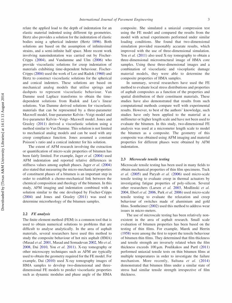
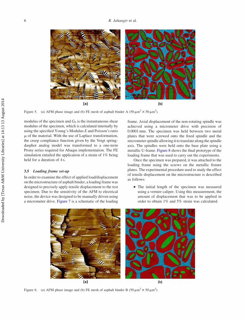
the FE model. Figures 5 and 6 show the FE meshes along
with the corresponding AFM phase images. The ‘bee’
phases are highlighted in green, the ‘bee casing’ regions
are highlighted in red and the ‘interstitial’ regions are
highlighted in light blue in Figures 5 and 6.
The measurements obtained using the AFM indenta-
tion tests were used as the material property inputs for the
FE model. More specifically, the Abaqus FE software used
in this study requires a Prony series stress relaxation
function to model the viscoelastic response. The
expression is given by
gðtÞ ¼ 12Xni¼1
gi 12 exp 2t
ti
� �� �;
where gðtÞ ¼ GðtÞ=G0 is a non-dimensional shear relax-
ation modulus. The terms gi and t are the time-dependent
Prony series parameters, and gi is calculated based on G0
and Gn (time-dependent Prony series shear modulus
parameter). GðtÞ is the time-dependent shear relaxation
Figure 4. Voigt spring and dashpot viscoelastic model.
International Journal of Pavement Engineering 5
Dow
nloa
ded
by [
Tex
as A
&M
Uni
vers
ity L
ibra
ries
] at
14:
13 1
3 A
ugus
t 201
4
modulus of the specimen and G0 is the instantaneous shear
modulus of the specimen, which is calculated internally by
using the specified Young’s Modulus E and Poisson’s ratio
m of the material. With the use of Laplace transformation,
the creep compliance function given by the Voigt spring-
dasphot analog model was transformed to a one-term
Prony series required for Abaqus implementation. The FE
simulation entailed the application of a strain of 1% being
held for a duration of 4 s.
3.5 Loading frame set-up
In order to examine the effect of applied load/displacement
on themicrostructure of asphalt binder, a loading framewas
designed to precisely apply tensile displacement to the test
specimen. Due to the sensitivity of the AFM to electrical
noise, the device was designed to be manually driven using
a micrometer drive. Figure 7 is a schematic of the loading
frame. Axial displacement of the non-rotating spindle was
achieved using a micrometer drive with precision of
0.0001mm. The specimen was held between two metal
plates that were screwed onto the fixed spindle and the
micrometer spindle allowing it to translate along the spindle
axis. The spindles were held onto the base plate using a
metallic U-frame. Figure 8 shows the final prototype of the
loading frame that was used to carry out the experiments.
Once the specimen was prepared, it was attached to the
loading frame using the screws on the metallic fixture
plates. The experimental procedure used to study the effect
of tensile displacement on the microstructure is described
as follows:
. The initial length of the specimen was measured
using a vernier caliper. Using this measurement, the
amount of displacement that was to be applied in
order to obtain 1% and 5% strain was calculated.
Figure 5. (a) AFM phase image and (b) FE mesh of asphalt binder A (50mm2 £ 50mm2).
Figure 6. (a) AFM phase image and (b) FE mesh of asphalt binder B (50mm2 £ 50mm2).
R. Jahangir et al.6
Dow
nloa
ded
by [
Tex
as A
&M
Uni
vers
ity L
ibra
ries
] at
14:
13 1
3 A
ugus
t 201
4

. Once the sample was mounted on the loading frame,
it was allowed to rest for 10min to allow the binder
to relieve any stresses that may have built up during
the mounting of the specimen.. The sample was then imaged using AFM phase
imaging in its initial condition without any load
being applied.. The amount of displacement necessary to obtain 1%
tensile strain was then applied. The specimen was
allowed to relax for a period of 5min in order for it to
reach a steady state condition. The specimen was
then re-imaged to obtain the microstructure after
deformation.. Each time a minimum of five 50mm2 £ 50mm2
images were obtained.. This processwas repeated andAFM images of binder
microstructure were obtained after 1% and 5%
applied tensile strain.
4. Results
4.1 AFM creep indentation results
Using the creep indentation technique discussed in the
methodology section, viscoelastic properties for the ‘bee’
phase, the ‘bee casing’ phase and the ‘interstitial’ phase
were obtained. Figures 9 and 10 show the creep
indentation response of different phases in bitumens A
and B. The applied constant load was calculated to be
approximately 1mN. The load was applied for a period of
4 s and the indentation response was fit to a conical
Sneddon viscoelastic solution in order to obtain the
viscoelastic creep compliance parameters for each phase.
Table 1 summarises these results.
4.2 Results from the FE analysis
Figure 11(a),(b) shows the von Mises stress contours for
FE simulations of stress relaxation experiments performed
on binders (a) A and (b) B. The highest stresses were
observed in the interstitial phase and the lowest stresses
were observed in the bee phase. The bee casing phase
exhibits an intermediate level of stresses compared to the
other phases. Figure 12(a),(b) shows the internal
distribution of tensile strains experienced by both binders.
The contours here show that the bee regions experience the
highest local tensile strains, while the interstitial zones
experience the lowest amount of local tensile strains, which
is consistent with the results shown in Figure 11(a),(b).
Figure 7. Micro-loading frame design.
Figure 8. Micro-loading frame final prototype.
International Journal of Pavement Engineering 7
Dow
nloa
ded
by [
Tex
as A
&M
Uni
vers
ity L
ibra
ries
] at
14:
13 1
3 A
ugus
t 201
4

Table 2 shows the maximum and minimum von Mises,
and tensile strain values for both binders based on the FEM
simulations. The maximum stress for binders A and B is
approximately 2.5 and 3.5 times the minimum stress,
respectively.
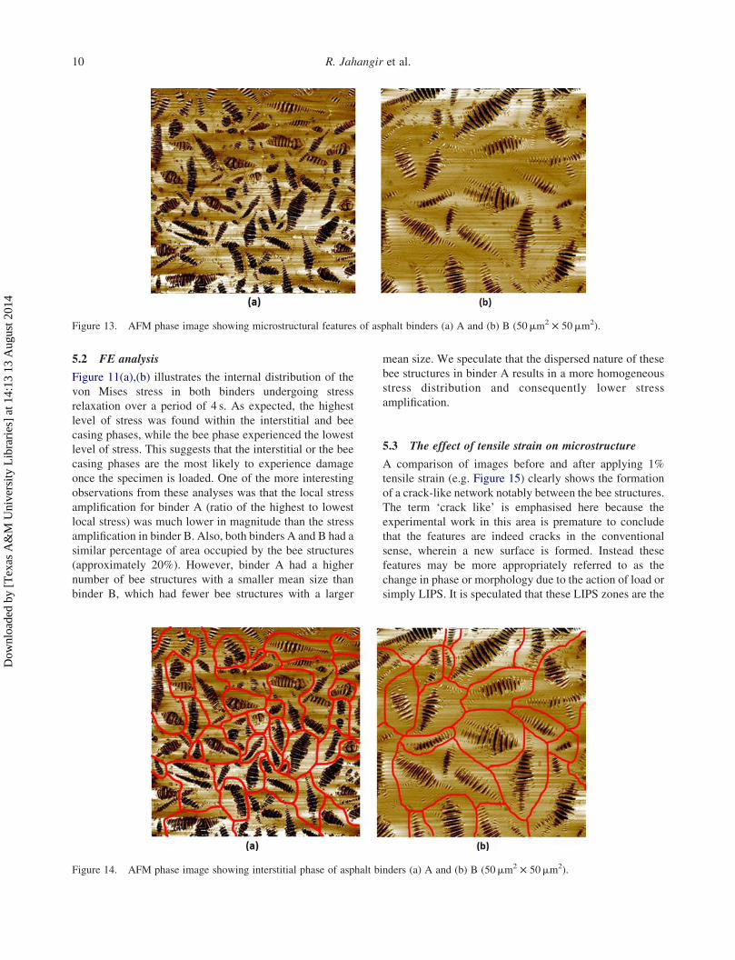
4.3 AFM imaging before and after load application
Three distinct phases were observed in the AFM images of
each of the two binders (Figure 13). The first phase can be
described as the ‘bee’ phase, a second phase that surrounds
the ‘bee’ phase is referred to as the ‘bee casing’ phase and
a third phase is referred to as the ‘interstitial phase’ that
occupies the space between the bee casing. The interstitial
phase is not clearly visible without image enhancement
and has been highlighted for the convenience of the reader
in Figure 14.
Figure 15 shows AFM phase images of binders A and
B after the application of 1% strain. Both test specimens
show clear signs of load-induced phase separation (LIPS).
It is also evident from the microstructural changes in the
images that the LIPS occurs around the bee casing phases
and goes through the interstitial zones highlighted in red in
Figure 14. Figure 16 shows AFM phase images of binders
A and B after 5% strain. Microstructural changes observed
here are consistent with that of Figure 15. Here the LIPS
zones are more prominent.
In order to quantitatively assess the changes in the
microstructure due to the applied tensile strain, we employed
image analysis techniques using the open source image
analysis tool ImageJ. Various geometric attributes were
obtained anda comparisonof these attributeswasdonebefore
and after strain was applied to the test specimens. Due to
phase separation and changes that occurred in the bee casing
and interstitial phases, comparisons here are onlymade on the
basis of the discrete bee phase. Table 3 compares the
distribution of the bee structures before and after load is
applied to binders A and B.
5. Discussion
5.1 Microrheology
A creep AFM indentation technique was used to obtain the
microrheology of the three different phases observed in
each binder (Figures 9 and 10). The indentation response
for a similar phase was distinctly different for each binder;
this would be expected given that the two binders were
from very different sources and had different chemical
composition and mechanical properties. The rank order of
instantaneous modulus for each of the three phases was
similar for both binders. The bee phase had the lowest
while the interstitial phase had the highest magnitude of
instantaneous modulus. The time-dependent response
showed a slightly different trend for binder A compared
with binder B. Although the interstitial phase was
determined to be the least compliant for binder A, it
showed an intermediate level of compliance compared
with the two other phases for binder B. Dourado et al.
(2011) and Allen et al. (2012) reported similar trends
between the bee and the surrounding phases using similar
indentation techniques. The findings from this study and
the studies of Dourado et al. (2011) and Allen et al. (2012)
strongly suggest that the mechanical properties of the
different phases are substantially different. A corollary to
this observation is that stress localisation is likely to occur
within the bitumen when subjected to external loads. Such
Figure 9. Viscoelastic creep indentation response of asphaltbinder A unaged.
Figure 10. Viscoelastic creep indentation response of asphaltbinder B unaged.
Table 1. AFM creep indentation analysis of asphalt binders Aand B.
Binder Parameter (unit) Bee Bee casing Interstitial
A E1 (Pa) 2.66E þ 09 4.12E þ 09 5.25E þ 09A E2 (Pa) 2.00E þ 04 9.00E þ 05 9.00E þ 06A eta (Pa s) 1.79E þ 08 3.52E þ 08 8.02E þ 08B E1 (Pa) 1.75E þ 09 2.53E þ 09 4.35E þ 09B E2 (Pa) 5.00E þ 04 8.00E þ 04 9.00E þ 04B eta (Pa s) 2.43E þ 07 1.32E þ 08 6.82E þ 07
R. Jahangir et al.8
Dow
nloa
ded
by [
Tex
as A
&M
Uni
vers
ity L
ibra
ries
] at
14:
13 1
3 A
ugus
t 201
4

localisation will be a function of the rheology and
geometric distribution of phases. However, further work is
needed to determine whether there exists any consistent
relationship between different structural features and rank
order of stiffness.
Note that the authors recognise that the properties
obtained for different phases through such microrheolo-
gical measurements and analyses are not absolute
properties. For example, the properties are obtained by
surface indentation and as such the material structure
beneath the surface even for a thick melt specimen will
influence the results obtained. Similarly, the indentation
using a conospherical tip is not the same as one-
dimensional uniaxial loading. However, despite these
biases, the measured microrheology does show substantial
and consistent differences in mechanical properties of the
different phases. While such measurements may not be
perfect, they are nonetheless a good semi-quantitative
representation of the properties of different phases within
the binder.
Figure 11. Von Mises stress contours for FE simulations of asphalt binders (a) A and (b) B (50mm2 £ 50mm2).
Figure 12. Tensile strain contours for FE simulations of asphalt binders (a) A and (b) B (50mm2 £ 50mm2).
Table 2. FE results of stress relaxation simulation of asphaltbinders A and B.
BinderMax tensile
strainMin tensile
strain
Max vonMises stress
(GPa)
Min vonMises stress
(GPa)
A 0.169 0.0613 0.628 0.258B 0.194 0.0503 0.558 0.167
International Journal of Pavement Engineering 9
Dow
nloa
ded
by [
Tex
as A
&M
Uni
vers
ity L
ibra
ries
] at
14:
13 1
3 A
ugus
t 201
4
5.2 FE analysis
Figure 11(a),(b) illustrates the internal distribution of the
von Mises stress in both binders undergoing stress
relaxation over a period of 4 s. As expected, the highest
level of stress was found within the interstitial and bee
casing phases, while the bee phase experienced the lowest
level of stress. This suggests that the interstitial or the bee
casing phases are the most likely to experience damage
once the specimen is loaded. One of the more interesting
observations from these analyses was that the local stress
amplification for binder A (ratio of the highest to lowest
local stress) was much lower in magnitude than the stress
amplification in binder B. Also, both binders A and B had a
similar percentage of area occupied by the bee structures
(approximately 20%). However, binder A had a higher
number of bee structures with a smaller mean size than
binder B, which had fewer bee structures with a larger
mean size. We speculate that the dispersed nature of these
bee structures in binder A results in a more homogeneous
stress distribution and consequently lower stress
amplification.
5.3 The effect of tensile strain on microstructure
A comparison of images before and after applying 1%
tensile strain (e.g. Figure 15) clearly shows the formation
of a crack-like network notably between the bee structures.
The term ‘crack like’ is emphasised here because the
experimental work in this area is premature to conclude
that the features are indeed cracks in the conventional
sense, wherein a new surface is formed. Instead these
features may be more appropriately referred to as the
change in phase or morphology due to the action of load or
simply LIPS. It is speculated that these LIPS zones are the
Figure 13. AFM phase image showing microstructural features of asphalt binders (a) A and (b) B (50mm2 £ 50mm2).
Figure 14. AFM phase image showing interstitial phase of asphalt binders (a) A and (b) B (50mm2 £ 50mm2).
R. Jahangir et al.10
Dow
nloa
ded
by [
Tex
as A
&M
Uni
vers
ity L
ibra
ries
] at
14:
13 1
3 A
ugus
t 201
4
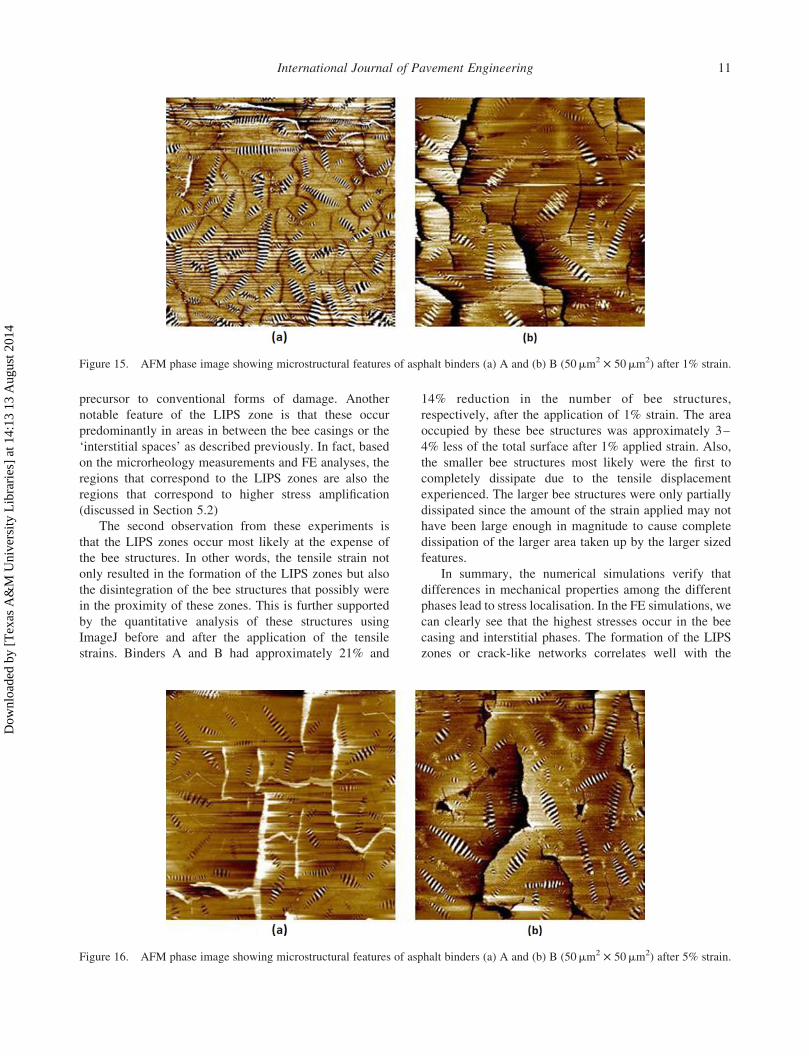
precursor to conventional forms of damage. Another
notable feature of the LIPS zone is that these occur
predominantly in areas in between the bee casings or the
‘interstitial spaces’ as described previously. In fact, based
on the microrheology measurements and FE analyses, the
regions that correspond to the LIPS zones are also the
regions that correspond to higher stress amplification
(discussed in Section 5.2)
The second observation from these experiments is
that the LIPS zones occur most likely at the expense of
the bee structures. In other words, the tensile strain not
only resulted in the formation of the LIPS zones but also
the disintegration of the bee structures that possibly were
in the proximity of these zones. This is further supported
by the quantitative analysis of these structures using
ImageJ before and after the application of the tensile
strains. Binders A and B had approximately 21% and
14% reduction in the number of bee structures,
respectively, after the application of 1% strain. The area
occupied by these bee structures was approximately 3–
4% less of the total surface after 1% applied strain. Also,
the smaller bee structures most likely were the first to
completely dissipate due to the tensile displacement
experienced. The larger bee structures were only partially
dissipated since the amount of the strain applied may not
have been large enough in magnitude to cause complete
dissipation of the larger area taken up by the larger sized
features.
In summary, the numerical simulations verify that
differences in mechanical properties among the different
phases lead to stress localisation. In the FE simulations, we
can clearly see that the highest stresses occur in the bee
casing and interstitial phases. The formation of the LIPS
zones or crack-like networks correlates well with the
Figure 15. AFM phase image showing microstructural features of asphalt binders (a) A and (b) B (50mm2 £ 50mm2) after 1% strain.
Figure 16. AFM phase image showing microstructural features of asphalt binders (a) A and (b) B (50mm2 £ 50mm2) after 5% strain.
International Journal of Pavement Engineering 11
Dow
nloa
ded
by [
Tex
as A
&M
Uni
vers
ity L
ibra
ries
] at
14:
13 1
3 A
ugus
t 201
4

locations where highest levels of stresses occurred in the
FE simulations. This verifies that the differences in
material properties most likely lead to high levels of
localised stresses that lead to damage initiation in the
interstitial and the bee casing phases.
6. Conclusions
The objective of this study was to evaluate the inter-
relationship of tensile load, damage nucleation and
microstructure of the bitumen. A combination of AFM
imaging and creep indentation measurements was used to
obtain geometry and microrheology of the phases
observed on the bitumen surface. This information was
used with the FE method to examine the internal stresses in
the binder and potential evolution of damage. The
following conclusions are drawn from the study:
. AFM phase imaging revealed three different phases
for each of the two binders studied. AFM
indentation was used to semi-quantitatively evaluate
the rheology of these phases for a given bitumen,
referred to as microrheology. Results clearly show
that the compliance of different phases within a
bitumen is substantially different. In other words,
viscoelastic properties obtained through AFM creep
indentation experiments show that material in
homogeneity exists within the bitumen at a
micrometre length scale.. The composite FE simulations show that the
differences in properties of the different phases
result in high levels of localised stress or stress
amplification within the interstitial zones. The stress
amplification was higher for the binder with larger
but fewer bee structures than for the binder with
smaller but more bee structures.. The application of tensile load or displacement
causes cracks or phase separation zones to appear
which are referred to as LIPS zones.. The high-stress regions observed from the FE
simulation coincide with the areas within which the
LIPS zones form. This suggests that material
inhomogeneity leads to the development of high
stresses within interstitial zones which leads to
damage nucleation and propagation.
The above conclusions suggest that the ability to
manipulate the microstructure of bitumen (e.g. using
chemical or other modifiers) has a significant influence on
the durability and inherent ability of the bitumen to resist
damage. Further work is required to (i) more accurately
characterise the microrheology of bitumen, (ii) more
accurately and quantitatively assess the relationship
between damage evolution in the bitumen and its
microstructure and (iii) establish a better understanding
of the relationship between the chemical composition of
the bitumen and its microstructure.
Funding
This work is part of the research being undertaken by the AsphaltResearch Consortium (ARC) and is funded by the FederalHighway Administration (FHWA). The authors would also liketo acknowledge NSF [grant number CMMI-1053925] forpartially supporting this study.
References
Allen, R., Little, D., and Bhasin, A., 2012. Structuralcharacterization of micromechanical properties in asphaltusing atomic force microscopy. Journal of Materials in CivilEngineering, 24, 1317–1327.
Allen, R.G., 2013. Microstructural characterization of thechemomechanical behavior of asphalt in terms of aging andfatigue performance properties. Thesis (PhD). Texas A&MUniversity.
Allen, R.G., et al., 2013. The effects of chemical composition onasphalt microstructure and their association to pavementperformance. International Journal of Pavement Engineering,15 (1), 1–14.
Dai, Q., 2010. Two- and three-dimensional micromechanicalviscoelastic finite element modeling of stone-based materialswith X-ray computed tomography images. Construction andBuilding Materials, 25 (2), 1102–1114.
Das, P.K., et al., 2013. Micromechanical investigation of phaseseparation in bitumen by combining atomic forcemicroscopy with differential scanning calorimetry results.Road Materials and Pavement Design, 14, 25–37.
Dourado, E.R., Simao, R.A., and Leite, L.F.M., 2011.Mechanical properties of asphalt binders evaluated byatomic force microscopy. Journal of Microscopy, 245,119–128.
Eberl, C., et al., 2006. Ultra high-cycle fatigue in pure Al filmsand line structures. Materials Science and Engineering, 421,68–76.
Fischer-Cripps, A.C., 2004. A simple phenomenologicalapproach to nanoindentation creep. CSIRO Division ofTelecommunications and Industrial Physics, 385 (1), 74–82.
Galin, L.A., 1953. Contact problems in theory of elasticity.Moscow: Gostekhizdat.
Hertz, H. 1896.Miscellaneous Papers. New York: McMillan andCompany.
Jager, A., et al., 2004. Identification of microstructuralcomponents of bitumen by mean of atomic force microscopy(AFM). Proceedings in Applied Mathematics and Mech-anics, 4, 400–401.
Jones, C.A. and Grasley, Z.C., 2011. Short-term creep of cementpaste during nanoindentation. Cement and ConcreteComposites, 33 (1), 12–18.
Table 3. Microstructural analysis of asphalt binders A and B.
Strain level Total count Mean area (mm2) % Area
Before (binder A) 743 2.93 21.391% (binder A) 586 2.99 17.075% (binder A) 490 2.61 12.35Before (binder B) 369 5.40 19.581% (binder B) 317 5.29 16.265% (binder B) 272 3.21 8.69
R. Jahangir et al.12
Dow
nloa
ded
by [
Tex
as A
&M
Uni
vers
ity L
ibra
ries
] at
14:
13 1
3 A
ugus
t 201
4
Kringos, N., et al., 2009. A finite element based chemo-mechanical model to simulate healing of bitumen. In:Chemo-mechanics of bituminous materials. Delft, Nether-lands: TU Delft, 69–75.
Larsen, K.P., et al., 2003. MEMS device for bending test:measurements of fatigue and creep of electroplated nickel.Sensors and Actuators A, 103, 156–164.
Lee, E. and Radok, J., 1960. The contact problem for viscoelasticbodies. Journal of Applied Mechanics–Transactions of theASME, 27, 438–444.
Loeber, L., et al., 1996. New direct observations of asphalts andasphalt binders by scanning electron microscopy and atomicforce microscopy. Journal of Microscopy, 182 (1), 32–39.
Loeber, L., et al., 1998. Bitumen in colloid science: a chemical,structural and rheological approach. Fuel, 77 (13), 1443–1450.
Marek, C.M. and Herrin, M., 1958. Tensile behavior and failurecharacteristics of asphalt cements in thin films. Proceedings ofthe association of asphalt Pavint technologists, 37, 386–421.
Masad, E. and Somadevan, N., 2002. Microstructural finite-element analysis of influence of localized strain distributionon asphalt mix properties. Journal of EngineeringMechanics, 128 (10), 1105–1114.
Masad, E., et al., 2001. Modeling and experimental measure-ments of strain distribution in asphalt mixes. Journal ofTransportation Engineering, 127 (6), 477–485.
Masson, J.F., Leblond, V., and Margeson, J., 2005. Bitumenmorphologies by phase-detection atomic force microscopy.Journal of Microscopy, 221 (1), 17–29.
Masson, J.F., Leblond, V., and Margeson, J., 2007. Low-temperature bitumen stiffness and viscous paraffinic nano-and micro-domains by cryogenic AFM and PDM. Journal ofMicroscopy, 227 (3), 191–202.
Mo, L., et al., 2008. 2D and 3D meso-scale finite element modelsfor ravelling analysis of porous asphalt concrete. FiniteElements in Analysis and Design, 44, 186–196.
Modlinski, R., et al., 2004. Creep as reliability problem inMEMS. Microelectronics Reliability, 44, 1733–1738.
Park, J.H., Kim,Y.J., andChoa, S.H., 2006.Mechanical propertiesof AL-3 thin films for reliability analysis of RFMEMS switch.Key Engineering Materials, 306, 1319–1324.
Paryab, N., Jahed, H., and Khajepour, A., 2006. Failuremechanisms of MEMS thermal actuators. In: Proceedings
of the AME IMECE. New York, NY: American Society ofMechanical Engineers, 397–406.
Pauli, A.T. and Grimes, R.W., 2003. Surface morphologicalstability modeling of SHRP asphalts. ACS Division of FuelChemistry Preprints, 1, 19–23.
Pauli, A., et al., 2001. Atomic force microscopy investigation ofSHRP asphalts. Symposium on heavy oil and residcompatiblity and stability. San Diego, CA: Division ofPetroleum Chemistry, American Chemical Society,110–114.
Pauli, A.T., et al., 2011. Morphology of asphalts, asphaltfractions and model wax-doped asphalts studied by atomicforce microscopy. International Journal of PavementEngineering, 12 (4), 291–309.
Poulikakos, L.D. and Partl, M.N., 2011. Micro scale tensilebehaviour of thin bitumen films. Experimental Mechanics,51, 1171–1183.
Sneddon, I., 1965. The relation between load and penetration inthe axisymmetric boussinesq problem for a punch ofarbitrary profile. International Journal of EngineeringScience, 3 (638), 47–57.
Sontheimer, A.B., 2002. Digital micromirror device (DMD)hinge memory lifetime reliability modeling. Proceedings ofIEEE international reliability physics symposium. Dallas,TX: IEEE.
Sultana, S., Bhasin, A., and Liechti, K.M., 2014. Rate andconfinement effects on the tensile strength of asphalt binder.Construction and Building Materials, 53, 604–611.
Tarefder, R.A., Zaman, A.M., and Uddin, W., 2010. Determininghardness and elastic modulus of asphalt nanoindentation.International Journal of Geometchanics, 10, 106–116.
Tuck, K., et al., 2005. A study of creep in polysilicon MEMSdevices. Journal of Engineering Materials and Technology,127, 90–96.
Vandamme, M. and Ulm, F., 2006. Viscoelastic solutions forconical indentation. International Journal of Solids andStructures, 43 (10), 3142–3165.
You, T., et al., 2011. Three-dimensionalmicrostructuralmodelingof asphalt concrete using a unified viscoelastic-viscoplastic–viscodamage model. Construction and Building Materials,28, 531–548.
International Journal of Pavement Engineering 13
Dow
nloa
ded
by [
Tex
as A
&M
Uni
vers
ity L
ibra
ries
] at
14:
13 1
3 A
ugus
t 201
4
Copyright © 2022 FDOKUMEN


![Binder 200, Small families [Trematoda Taxon Notebooks]](https://static.fdokumen.com/doc/165x107/6324444cb104cba27a091035/binder-200-small-families-trematoda-taxon-notebooks.jpg)