Meeting Binder for Court Facilities Advisory Committee
827
Meeting Binder for Court Facilities Advisory Committee OCTOBER 1 , 2019
-
Upload
khangminh22 -
Category
Documents
-
view
0 -
download
0
Transcript of Meeting Binder for Court Facilities Advisory Committee
Meeting Binder for
Court Facilities Advisory Committee
OCTOBER 1, 2019

Meeting Binder
Court Facilities Advisory Committee October 1, 2019 CONTENTS
1 Agenda
2
Report on Reassessment of Trial Court Capital-Outlay Projects
Presentation slides
3
Updated Revision of Prioritization Methodology for Trial Court Capital-Outlay Projects
Draft policy – dated 10/1/19
4
Draft Statewide List of Trial Court Capital-Outlay Projects
Draft list in summary
Draft list with details
5 Public Comments
Letters/Correspondence
6 Court Facilities Advisory Committee Roster

C O U R T F A C I L I T I E S A D V I S O R Y C O M M I T T E E
O P E N M E E T I N G A G E N D A
Open to the Public (Cal. Rules of Court, rule 10.75(c)(1)) THIS MEETING IS BEING RECORDED
Date: October 1, 2019
Time: Open Session (Open to Public) 9:30 a.m. – 10:00 a.m. – Registration 10:00 a.m. – 12:30 p.m. – Open Session (Open to Public) 12:30 p.m. – 1:00 p.m. – Anticipated Lunch Break 1:00 p.m. – 2:00 p.m. – Open Session (Open to Public)
Location: 455 Golden Gate Avenue San Francisco, California 94102-3688 Third-Floor – Malcolm M. Lucas Board Room
Public Call-In Number: (877) 820-7831 and enter Passcode: 7004216
Meeting materials will be posted on the advisory body web page on the California Courts website at least three business days before the meeting.
Agenda items are numbered for identification purposes only and will not necessarily be considered in the indicated order.
I . O P E N M E E T I N G ( C A L . R U L E S O F C O U R T , R U L E 1 0 . 7 5 ( C ) ( 1 ) )
Call to Order, Roll Call and Opening Remarks
I I . P U B L I C C O M M E N T ( C A L . R U L E S O F C O U R T , R U L E 1 0 . 7 5 ( K ) ( 2 ) )
Members of the public requesting to speak during the public comment portion of the meeting must place the speaker’s name, the name of the organization that the speaker represents if any, and the agenda item that the public comment will address, on the public comment sign-up sheet. The sign-up sheet will be available at the meeting location at least one hour prior to the meeting start time. The Chair will establish speaking limits at the beginning of the public comment session. While the advisory body welcomes and encourages public comment, time may not permit all persons requesting to speak to be heard at this meeting.
www.courts.ca.gov/cfac.htm [email protected]

M e e t i n g A g e n d a | O c t o b e r 1 , 2 0 1 9
2 | P a g e C o u r t F a c i l i t i e s A d v i s o r y C o m m i t t e e
Written Comment
In accordance with California Rules of Court, rule 10.75(k)(1), written comments pertaining to any agenda item of a regularly noticed open meeting can be submitted up to one complete business day before the meeting. For this specific meeting, comments should be e-mailed to [email protected] or mailed or delivered to 455 Golden Gate Avenue, San Francisco, CA 94102, attention: Chris Magnusson. Only written comments received by 5:00 PM on September 30, 2019, will be provided to advisory body members.
I I I . D I S C U S S I O N A N D P O S S I B L E A C T I O N I T E M S ( I T E M 1 )
Item 1
Reassessment of Trial Court Capital-Outlay Projects (Action Required)
Review of Judicial Council Facilities Services’ progress on the reassessment of trial court capital-outlay projects and recommendation to move the reassessment documents forward for Judicial Council review/action. The following will be discussed: (1) public comments on the draft Revision of Prioritization Methodology for Trial Court Capital-Outlay Projects and draft statewide list of capital projects (prioritized on needs-based/cost-based scores per the council’s updated draft prioritization methodology) reviewed at the Court Facilities Advisory Committee meeting on August 29, 2019, and posted subsequently for comment, (2) finalization of Court Facility Plans for all 58 trial courts, (3) final updates to the council’s draft prioritization methodology, and (4) final updates to the draft statewide list of capital projects. Senate Bill 847 (Committee on Budget and Fiscal Review) revises Government Code section 70371.9 to require the Judicial Council to update its 2008 prioritization methodology as well as to reassess capital projects in its Trial Court Capital-Outlay Plan. This reassessment is due to the Legislature by December 31, 2019.
Presenters: Mr. Mike Courtney, Director, Judicial Council Facilities Services Ms. Pella McCormick, Deputy Director, Judicial Council Facilities Services
I V . A D J O U R N M E N T O F M E E T I N G
Adjourn

Report onReassessment of Trial Court
Capital-Outlay Projects
Court Facilities Advisory Committee Meeting October 1, 2019

Agenda• Project Update
• Review of Comments
• Methodology Revisions in Response to Comments (August – September, 2019 )
• Draft Statewide List of Trial Court Capital-Outlay Projects
• Future Activities and Recommended Action
2

PROJECT UPDATE
3

Activities Completed to Date
4

REVIEW OF COMMENTS
5

Public Comments Received
Between August 30th and September 13th
86 Public Comments (approx. 750 pages) were received• Comments were received on projects submitted by 20 of the
41 courts proposing projects• Over 100 comments were received on 35 separate buildings• Over 120 scorecard corrections associated with Technical
Comments on FCAs, land costs and other scoring comments have been made since August 29, 2019
• This process will continue in October
6

Summary of Public Comments
7
PUBLIC COMMENT TYPECOMMENTS RECEIVED RESPONSE
1Technical Comment(s) on a Specific Building or Project 25
Letters have been provided to the Court Advisory Facility Committee for their consideration.Technical comments on specific buildings or projects will be provided to individual courts.
2 Letter of Support for a Specific Project 55Letters have been provided to the Court Advisory Facility Committee for their consideration.
3Support for Increased Emphasis on Seismic Risk in the Methodology 8
Letters have been provided to the Court Advisory Facility Committee for their consideration.
4 Policy Comments on Needs-Based Score Criteria 12Letters have been provided to the Court Advisory Facility Committee for their consideration.
5 Policy Comments on Cost-Based Score Criteria 6Letters have been provided to the Court Advisory Facility Committee for their consideration.
6Policy Comments on General Methodology (not specific to a Scoring Category) 9
Letters have been provided to the Court Advisory Facility Committee for their consideration.
7 “Other” Comments 1Letters have been provided to the Court Advisory Facility Committee for their consideration.

Technical CommentsCourt Facility Plans
Draft Court Facility Plans were provided to the Courts in late July 2019• 12 Courts submitted corrections to the narratives and
other information in their Court Facility Plan• 3 courts changed proposed project scopes or court
priorities
Final Drafts of Court Facility Plans will be sent to the Courts in November
8
Technical CommentsFacility Condition Assessments (FCAs)
Draft Facility Condition Assessments were provided to the Courts in late July 2019. The comments received from the courts included:• Corrections to the building descriptions.• Concerns that Americans with Disabilities Act (ADA) and
Environmental Hazards were not fully assessed and the costs were not included. Note that scores for these areas are included in the Physical Condition Needs-Based Criteria.
• Disagreement with the conclusions of the FCA, including the definition of the condition of the building/FCI Number.
9

Technical CommentsScoring and Scorecards
Draft Scorecards were provided to the Courts in late July, early August and at the end of August. The most common comments received about the scores and scorecards include:• Concerns about which buildings were scored or not scored. Examples:
Historic MOU Courthouses were not assessed.• Concerns about errors in scoring, which have been reviewed and
corrected upon confirmation. • Disagreement about the way the scores are calculated, particularly in
Overcrowding and Access to Court Services. • Concerns project land costs were too high.
10

Comments on Methodology
Most frequent comments on the Methodology were related to: • Seismic Risk Mitigation – the Methodology has not considered seismic risk
with enough emphasis, especially for large buildings• Funding Process – the language in the Methodology was not clear about
what factors the JCC could consider when funding projects
Both of the comments are addressed in the following slides
11

METHODOLOGY REVISIONS IN RESPONSE TO COMMENTS AUGUST – SEPTEMBER, 2019
12

Summary of Methodology Changes
• Seismic Risk Factor• Needs-Based Criteria: Physical Condition/Seismic
Rating• Needs-Based Criteria: Access to Court Services• Cost-Based Criteria • Funding Process: Establishment of a Statewide List
13

Seismic Risk Factor
• In response to Public Comments, a Seismic Risk Factor has been added to the Methodology.
• The Seismic Risk Factor points do not change the total number of points available and do not change the Priority Group point ranges.
14

Seismic Risk Factor Language
15
Refer to Methodology Page 11, paragraph F

Needs-Based CriteriaPhysical Condition – Seismic Rating
• Correction to previously published Methodology changed the risk definitions ranges for the FEMA P-154 scores.
• This correction changed the Seismic Rating score for 8 projects.
16
August 29, 2019 Draft Methodology
October 1, 2019 Draft Methodology
Very High Risk 0.6 or below 0.5 and below
High Risk 0.7 to 1.5 0.6 to 1.4
Moderate Risk 1.6 to 2.4 1.5 to 2.4
Acceptable Risk 2.5 and higher 2.5 and higher

Needs-Based CriteriaAccess to Court Services
17
August 29, 2019 Draft Version
• Data from “The Need for New Judgeships in the Superior Courts: Preliminary 2018 Update of Judicial Needs, November 2018”
October 1, 2019 Draft Version – Updates Data Source
• Uses data from the “Judicial Workload Assessment: 2018 Judicial Workload Study Update, approved by the Judicial Council on September 24, 2019”
• In addition to the Access to Court Services score, the Cost Avoidance, Minimization of Security and O&M Costs, and Project Cost/Court User scores were also updated, as those formulas use the AJP and/or AJN in the calculation of the scores.

Cost-Based Criteria
18
All previous versions of the Methodology identified that the points for the Cost-Based Criteria would be awarded once the range of costs for each category were identified.
Per the Methodology, cost points are distributed linearly based on a statistical analysis of all provided cost data.
In this final draft of the Methodology, the ranges are identified on page 14.

Funding ProcessEstablishment of a Statewide List
19
The following edits appear on page 15 of the Draft Methodology, October 1, 2019:

Funding ProcessEstablishment of a Statewide List
20
The following additions to the Methodology appear on page 15 of the Draft Methodology, October 1, 2019:

DRAFT STATEWIDE LIST OFTRIAL COURT CAPITAL-OUTLAY PROJECTS
21
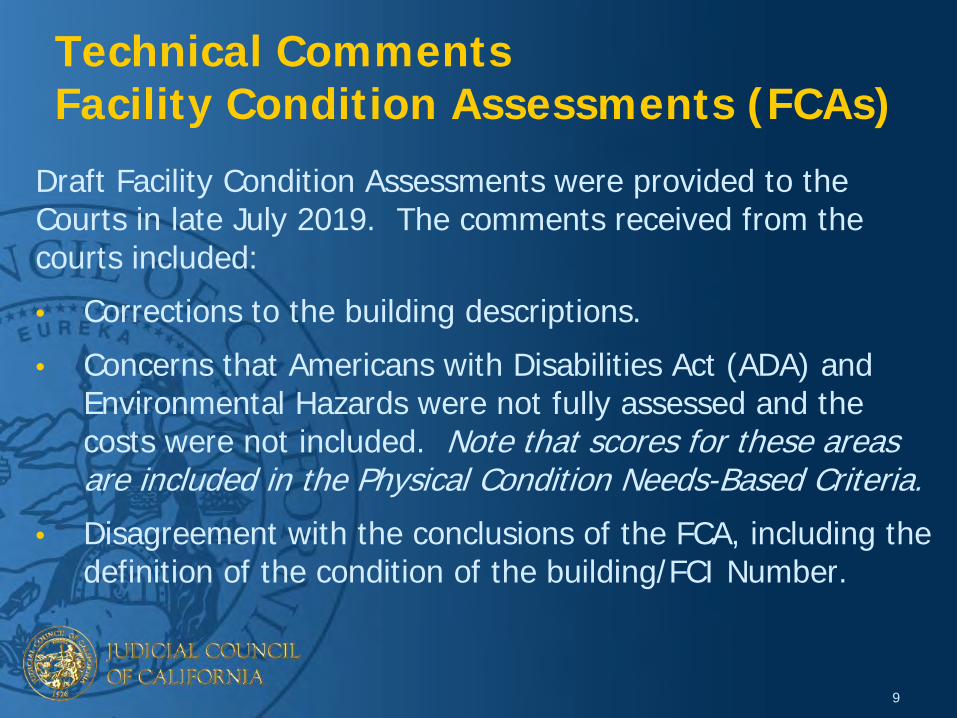
Overview of the Needs-Based Criteria
22
Facility Conditions Index (FCI) 5 Points
Facility Seismic, Fire, Life and Safety (FLS), ADA and Environmental Hazards 5 Points
Security 5 Points
Overcrowding 5 Points
Access to Court Services 5 Points
Total Points for Needs-Based Criteria 25 Points

Cost Avoidance or Savings realized through Operational or Organizational Efficiencies
25
Minimization of Increases in Ongoing Security and Operations & Maintenance (O&M) Costs
25
Cost of Project per Court User 25
Total Costs Spent on a Project as of December 31, 2018 25
Total Rating Points for Cost-Based Criteria 100
23
Overview of the Cost-Based Criteria
The overall total of 100 available rating points is converted to a 2 point adjustment to the project ranking within a Priority Group.

Prioritized Groups - Seismic Factor
• The Seismic Risk Factor points are applied to the Needs-Based Score, but do not change the total number of points available and do not change the Priority Group point ranges.
• To address the issue of seismic risk to court users, projects proposed to replace or renovate courtrooms in existing High Risk or Very High Risk buildings, would receive additional points in accordance with the following table.
24

Summary of Trial Court Capital-Outlay Projects
80 total proposed projects identified by 41 courts
25
Type of Proposed Projects
# of Proposed Projects
Total Estimated Costs of Projects
New Construction 56 $10.6B
Renovations/Additions 24 $2.6B
TOTAL 80 $13.2B

Distribution of Prioritized Groups usingOctober 1, 2019 Revised Methodology
• 18 Immediate Need • 29 Critical Need• 15 High Need• 9 Medium Need• 9 Low Need
26

27
Immediate Need Priority GroupPart 1 of 3
County Project Name Priority Group# of
Court-rooms
Project Cost (in millions) Needs Score Cost Score Priority
Group Score
Lake New Lakeport Courthouse
Immediate Need 4 $51.2 20.5 1.0 21.5
Mendocino New Ukiah Courthouse Immediate Need 7 $89.6 17.5 1.2 18.7
Nevada New Nevada City Courthouse
Immediate Need 6 $91.8 18.0 0.6 18.6
Butte Butte County Juvenile
Hall Addition and Renovation
Immediate Need 1 $2.3 18.0 0.6 18.6
Monterey New Fort Ord Courthouse Immediate Need 7 $130.1 17.4 0.6 18.0
Lake New Clearlake Courthouse
Immediate Need 1 $15.0 17.5 0.4 17.9
San Bernardino
San Bernardino Juvenile Dependency Courthouse Addition and Renovation
Immediate Need 2 $8.8 17.0 0.6 17.6
Solano New Solano Hall of Justice (Fairfield)
Immediate Need 12 $170.2 17.0 0.6 17.6
Fresno New Fresno Courthouse Immediate Need 36 $483.1 16.5 1.0 17.5
Kern New Ridgecrest Courthouse
Immediate Need 2 $42.2 17.0 0.4 17.4
28
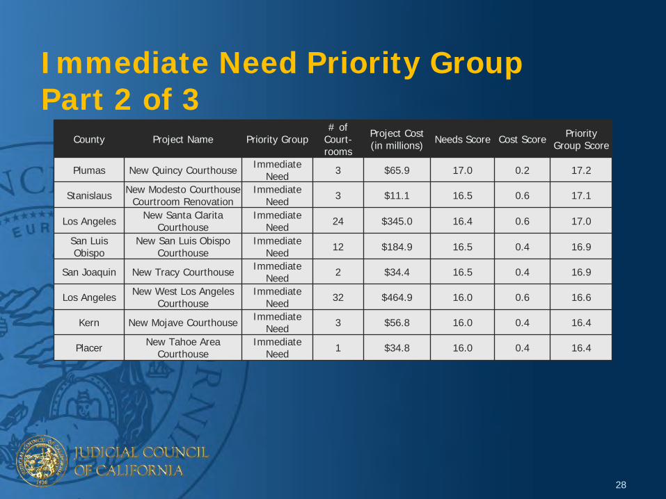
Immediate Need Priority GroupPart 2 of 3
County Project Name Priority Group# of
Court-rooms
Project Cost (in millions) Needs Score Cost Score Priority
Group Score
Plumas New Quincy Courthouse Immediate Need 3 $65.9 17.0 0.2 17.2
Stanislaus New Modesto Courthouse Courtroom Renovation
Immediate Need 3 $11.1 16.5 0.6 17.1
Los Angeles New Santa Clarita Courthouse
Immediate Need 24 $345.0 16.4 0.6 17.0
San Luis Obispo
New San Luis Obispo Courthouse
Immediate Need 12 $184.9 16.5 0.4 16.9
San Joaquin New Tracy Courthouse Immediate Need 2 $34.4 16.5 0.4 16.9
Los Angeles New West Los Angeles Courthouse
Immediate Need 32 $464.9 16.0 0.6 16.6
Kern New Mojave Courthouse Immediate Need 3 $56.8 16.0 0.4 16.4
Placer New Tahoe Area Courthouse
Immediate Need 1 $34.8 16.0 0.4 16.4

29
Critical Need Priority Group Part 1 of 3
County Project Name Priority Group# of
Court-rooms
Project Cost (in millions) Needs Score Cost Score Priority
Group Score
Los Angeles New Inglewood Courthouse Critical Need 30 $432.1 15.7 0.6 16.3
Contra Costa New Richmond Courthouse Critical Need 6 $107.7 15.5 0.6 16.1
San Francisco New San Francisco Hall of Justice Critical Need 24 $460.1 15.5 0.4 15.9
Orange New Orange County Collaborative Courthouse Critical Need 3 $113.4 15.0 0.8 15.8
Santa Barbara New Santa Barbara Criminal Courthouse Critical Need 8 $102.8 14.5 1.2 15.7
El Dorado New Placerville Courthouse Critical Need 6 $92.2 14.8 0.6 15.4
Los Angeles New Van Nuys
Courthouse (East/new + West/reno)
Critical Need 55 $922.4 14.8 0.6 15.4
Los Angeles New Downtown Los Angeles Courthouse (Mosk Replacement)
Critical Need 47 $731.1 14.3 1.0 15.3
Fresno Fresno Juvenile
Delinquency Courthouse Renovation
Critical Need 2 $5.3 13.6 1.6 15.2
Inyo New Inyo County Courthouse Critical Need 2 $43.8 14.6 0.6 15.2

30
Critical Need Priority Group Part 2 of 3
County Project Name Priority Group# of
Court-rooms
Project Cost (in millions) Needs Score Cost Score Priority
Group Score
San Bernardino New Victorville Courthouse Critical Need 31 $392.5 14.6 0.6 15.2
Santa Cruz New Santa Cruz Courthouse Critical Need 8 $127.6 13.9 1.0 14.9
Mariposa New Mariposa Courthouse Critical Need 2 $42.6 14.5 0.4 14.9
Los Angeles Chatsworth Courthouse Renovation Critical Need 7 $37.7 13.9 1.0 14.9
Riverside New Riverside Juvenile Courthouse Critical Need 5 $77.9 14.0 0.6 14.6
San Diego New San Diego Juvenile Courthouse Critical Need 10 $121.4 14.0 0.6 14.6
Tulare New Tulare North County Courthouse Critical Need 14 $198.9 14.0 0.6 14.6
Los Angeles New West Covina Courthouse Critical Need 15 $215.5 13.9 0.6 14.5
Los Angeles New Eastlake Courthouse Critical Need 6 $119.1 14.1 0.4 14.5
Kern New Bakersfield Superior Courthouse Critical Need 33 $434.2 13.8 0.6 14.4

31
Critical Need Priority GroupPart 3 of 3
County Project Name Priority Group# of
Court-rooms
Project Cost (in millions) Needs Score Cost Score Priority
Group Score
Sonoma New Sonoma Civil Courthouse Critical Need 8 $102.8 13.4 1.0 14.4
San Luis Obispo
New Grover Beach Branch Courthouse Critical Need 1 $18.0 13.8 0.4 14.2
Alameda New Alameda County Community Justice
Center Critical Need 57 $895.8 13.5 0.6 14.1
Imperial Winterhaven Branch
Courthouse Addition and Renovation
Critical Need 1 $3.6 13.5 0.6 14.1
Los Angeles Los Angeles Metropolitan Courthouse Renovation Critical Need 14 $215.6 13.5 0.6 14.1
Los Angeles New North Central Los Angeles Courthouse Critical Need 12 $196.3 13.5 0.6 14.1
Riverside New Palm Springs Courthouse Critical Need 9 $98.6 13.0 0.6 13.6
Orange New Orange South County Courthouse Critical Need 16 $232.0 13.0 0.6 13.6
Los Angeles Foltz Courthouse Renovation Critical Need 60 $1,400.9 13.0 0.4 13.4

32
High Need Priority GroupPart 1 of 2
County Project Name Priority Group# of
Court-rooms
Project Cost (in millions) Needs Score Cost Score Priority
Group Score
San Diego San Diego South County
Regional Courthouse Renovation
High Need 4 $10.5 12.5 0.6 13.1
San Mateo New San Mateo Northern Branch Courthouse High Need 5 $94.4 12.3 0.6 12.9
Los Angeles New Pasadena Courthouse High Need 17 $256.9 12.0 0.6 12.6
Solano New Solano Justice Building (Vallejo) High Need 6 $100.9 12.0 0.6 12.6
Monterey New South Monterey County Courthouse High Need 1 $27.9 11.9 0.6 12.5
Del Norte New Del Norte County Main Courthouse High Need 3 $59.4 11.8 0.4 12.2
San Francisco San Francisco Civic Center Courthouse
RenovationHigh Need 7 $44.9 11.2 0.8 12.0
San Diego San Diego North Regional
Courthouse Complex Renovation - North
Building High Need 14 $135.1 11.0 0.6 11.6
Riverside New Riverside Hall of Justice Annex High Need 10 $133.3 11.0 0.6 11.6
Riverside New Moreno Valley Courthouse High Need 9 $109.8 10.9 0.6 11.5

33
High Need Priority Group Part 2 of 2
County Project Name Priority Group# of
Court-rooms
Project Cost (in millions) Needs Score Cost Score Priority
Group Score
Humboldt New Eureka Courthouse High Need 9 $135.1 11.0 0.4 11.4
Merced New Merced Courthouse Annex High Need 1 $18.1 10.1 1.0 11.1
Yuba New Yuba County Courthouse High Need 6 $84.7 10.5 0.6 11.1
San Bernardino San Bernardino
Courthouse Annex Renovation
High Need 11 $46.5 10.2 0.8 11.0
Modoc New Barclay Justice Center High Need 2 $43.1 10.6 0.2 10.8

34
Medium Need Priority Group County Project Name Priority Group
# of Court-rooms
Project Cost (in millions) Needs Score Cost Score Priority
Group Score
Ventura New Ventura East County Courthouse Medium Need 7 $94.1 9.4 0.6 10.0
Colusa Colusa Courthouse Annex Renovation Medium Need 1 $17.4 9.1 0.8 9.9
Santa Clara New Santa Clara Hall of Justice Medium Need 36 $521.0 9.0 0.6 9.6
Los Angeles Edelman Courthouse Renovation Medium Need 6 $112.1 8.4 0.6 9.0
Los Angeles New Los Angeles Mental Health Courthouse Medium Need 4 $112.3 8.5 0.4 8.9
Los Angeles New Lancaster Dependency Court Medium Need 6 $89.1 8.2 0.6 8.8
San Diego San Diego East County
Regional Center Renovation
Medium Need 17 $169.7 8.0 0.6 8.6
Los Angeles New Torrance
Dependency Court and Traffic Annex
Medium Need 7 $94.2 7.7 0.6 8.3
Los Angeles Compton Courthouse Renovation Medium Need 31 $340.7 7.5 0.6 8.1

35
Low Need Priority Group
County Project Name Priority Group# of
Court-rooms
Project Cost (in millions) Needs Score Cost Score Priority
Group Score
Riverside Riverside Southwest Justice Center Renovation Low Need 1 $14.9 6.0 0.8 6.8
San Diego New San Diego Traffic Courthouse Low Need 4 $55.3 6.0 0.6 6.6
Santa Barbara Santa Maria Building G Renovation Low Need 1 $5.1 5.5 0.8 6.3
Butte Butte County Courthouse Addition and Renovation Low Need 2 $20.2 5.5 0.6 6.1
Sacramento Sacramento Juvenile Courthouse Renovation Low Need 2 $11.1 5.0 0.8 5.8
Riverside Banning Justice Center Addition Low Need 2 $21.9 4.5 0.6 5.1
Tehama Tehama Courthouse Renovation Low Need 2 $3.0 4.0 0.6 4.6
Yolo Yolo Superior Court Renovation Low Need 0 $0.9 3.5 0.8 4.3
Santa Clara Santa Clara Family Justice Center Renovation Low Need 0 $1.9 2.5 0.8 3.3

FUTURE ACTIVITIES AND RECOMMENDED ACTION
36

Future Activities
37

Recommended Action
1. Recommend that the Drafts of the Revised Methodology & Statewide List be submitted to the Council in November for approval
2. Delegate to the CFAC Chair and Vice-Chair the review of the final report to the Council
38

QUESTIONS?
39

Revision of Prioritization Methodology for Trial Court Capital-Outlay Projects
JUDICIAL COUNCIL OF CALIFORNIA
COURT FACILITIES ADVISORY COMMITTEE
OCTOBER 1, 2019*
*PLEASE NOTE: This draft document captures all edits made since it was last reviewed by the CFAC at its meeting on August 29, 2019. AS REQUIRED BY 2018 BUDGET ACT TRAILER BILL
(SB 847: COMMITTEE ON BUDGET AND FISCAL REVIEW)

i
Contents
I. 2018 Budget Act Trailer Bill (SB 847: Committee on Budget and Fiscal Review): Reassessment of Trial Court Capital-Outlay Plan ............................................................................... 1
II. Current Methodology ........................................................................................................................... 1
III. Revised Methodology .......................................................................................................................... 2
IV. Reassessment Process .......................................................................................................................... 3 A. Methodology and Scoring ............................................................................................................. 3 B. Needs-Based Physical Conditions Assessments ........................................................................... 3 C. Needs-Based Court Facility Plans and Project Lists ..................................................................... 3 D. Needs-Based Statewide Project List ............................................................................................. 4 E. Cost-Based Evaluations: Avoidance, Savings, and Cost Minimization Strategies ....................... 4 F. Calculations for Projects Affecting More Than One Existing Facility ......................................... 5
V. Needs-Based Scoring of Projects ......................................................................................................... 5 A. Facility Condition Index ................................................................................................................ 6 B. Physical Condition ........................................................................................................................ 6
1. Seismic Rating ......................................................................................................................... 6 2. Fire & Life Safety .................................................................................................................... 7 3. Environmental Hazards ........................................................................................................... 7 4. Americans with Disabilities Act .............................................................................................. 8 5. Conversion of Rating Points .................................................................................................... 8
C. Security .......................................................................................................................................... 9 D. Overcrowding .............................................................................................................................. 10 E. Access to Court Services ............................................................................................................. 10 F. Seismic Risk Factor ..................................................................................................................... 11
VI. Cost-Based Scoring of Projects ......................................................................................................... 12 A. Cost Avoidance or Savings Realized Through Operational or Organizational Efficiencies ....... 13 B. Minimization of Increases in Ongoing Security, Operating, and Maintenance Costs ................ 14 C. Cost of Project per Court User .................................................................................................... 14 D. Total Costs Spent on a Project as of March 31, 2019 ................................................................. 14
VII. Funding Process ................................................................................................................................. 15
A. Establishment of a Statewide Project List ................................................................................... 15 B. Changes to Statewide Project List ............................................................................................... 16 C. Project Phase Adjustments .......................................................................................................... 16 D. No Substitutions of Projects Between Groups ............................................................................ 16 E. How Requests for Funding Will Be Determined ........................................................................ 16
VIII. Process for Adding or Deleting Projects in the Trial Court Capital-Outlay Plan .............................. 16
Appendices A. Trial Court Capital-Outlay Plan Reassessment–Required by the 2018 Budget Act Trailer Bill
(SB 847: Committee on Budget and Fiscal Review) B. Terms in Draft Revision of Prioritization Methodology for Trial Court Capital-Outlay Projects C. 2018 Judicial Workload Study Update (September 2019)

1
I. 2018 BUDGET ACT TRAILER BILL (SB 847: COMMITTEE ON BUDGET AND FISCAL REVIEW): REASSESSMENT OF TRIAL COURT CAPITAL-OUTLAY PLAN
Senate Bill 847 revises Government Code section 70371.9 and requires the Judicial Council of California to reassess projects identified in its update to Trial Court Capital-Outlay Plan and Prioritization Methodology adopted on October 24, 2008 (see Appendix A). SB 847 provides that other projects may be included for reassessment at the discretion of the Judicial Council and specifies the criteria to be used in the reassessment. The reassessment is to be submitted to the Senate Committee on Budget and Fiscal Review and the Assembly Committee on Budget by December 31, 2019. SB 847 requires the reassessment to be based on existing criteria along with the newly mandated criteria, necessitating the revision of the current prioritization methodology. The list of prioritized projects to be developed in response to SB 847—referred to as the Trial Court Capital-Outlay Plan—will be adopted annually by the Judicial Council and submitted to the Department of Finance. Projects can be for new construction or acquisition, renovations, building additions, and conversion of structures to court use. This reassessment will be conducted by the Judicial Council’s Court Facilities Advisory Committee (CFAC) with support from Judicial Council Facilities Services. The CFAC will submit its report and recommended prioritization of court facilities to the Judicial Council in November 2019. Please note the following:
1. The reassessment will be expedited due to the legislatively mandated December 2019 deadline. The CFAC may need to update or revise any part of the revised methodology if anomalies are discovered during the reassessment process.
2. The application of this methodology is intended to develop a system for comparing one building to another. It is not intended to survey existing seismic, fire & life safety (FLS), Americans with Disabilities Act (ADA), or environmental hazards conditions in judicial branch facilities for compliance with codes, regulations, or requirements. To this end, separate assessments of conditions related to seismic ratings, FLS conditions, ADA requirements, and environmental hazards will be conducted for capital-outlay projects that become authorized for funding.
II. CURRENT METHODOLOGY In October 2008, the Judicial Council issued its Prioritization Methodology for Trial Court Capital-Outlay Projects (Prioritization Methodology). This methodology was utilized to prioritize all new court facility capital-outlay projects and was the basis for those projects authorized under Senate Bills 1407 and 1732. The last projects to be funded utilizing the current methodology were funded in the 2018–19 State Budget. During the budget deliberation process, the Legislature noted the need to revise the current methodology and reassess all court facilities due to the current methodology’s age. Development of a revised prioritization and methodology is a condition of any future funding requests for capital-outlay projects. A link to the current 2008 Prioritization Methodology can be found here: http://www.courts.ca.gov/documents/methodology-080124.pdf.

2
III. REVISED METHODOLOGY The revised methodology has been prepared for use in developing a new set of prioritized trial court capital-outlay projects as required by SB 847, and enabling recommendations to the Judicial Council for the submission of funding requests for such projects. Trial court capital-outlay projects are considered those that increase a facility’s gross area, such as a building addition, that substantially renovate a major portion of a facility, that comprise a new facility or an acquisition, or that change the use of a facility, such as the conversions from non-court to court use. Generally, the methodology provides that projects will be scored based on need and placed into one of five priority groups. The projects within each priority group will then be ranked based on the scoring of the cost criteria identified in SB 847. Needs identified in the methodology inform the Trial Court Capital-Outlay Plan and the selection of projects proposed for funding. A point range has been established for each of the five need-based priority groups. For example, projects scoring very high in each of the evaluated criteria will fall into the “Immediate Need” group. The Critical, High, Medium, and Low Needs represent sets of projects that score lower in the various needs-based criteria categories. A scale of 25 points is used for the total of all needs-based criteria. The details of the scoring are described later in this document.
Prioritized Groups of Trial Court Capital-Outlay Projects:
Immediate Need: 16 – 25 points Critical Need: 13 – 15.9 points High Need: 10 – 12.9 points
Medium Need: 7.5 – 9.9 points Low Need: 0 – 7.4 points
Cost-based criteria as identified in SB 847 will impact the ranking of the projects within each of the five priority groups identified above. Terms used in this document are defined in the attached Appendix B.
IV. REASSESSMENT PROCESS The process for reassessment of the projects identified in Trial Court Capital-Outlay Plan consists of five activities:
1. Revision of the prioritization methodology consistent with SB 847;
2. Assessment of facilities occupied by trial courts, including physical condition assessments, as well as assessments related to security, access to court services, and overcrowding;
3. Development of court facility plans and court needs-based project lists;
4. Application of the prioritization methodology to all projects; and
5. Development of a statewide list of prioritized projects.
3
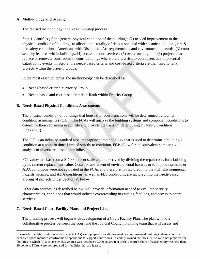
A. Methodology and Scoring The revised methodology involves a two-step process. Step 1 identifies (1) the general physical condition of the buildings; (2) needed improvement to the physical condition of buildings to alleviate the totality of risks associated with seismic conditions, fire & life safety conditions, Americans with Disabilities Act requirements, and environmental hazards; (3) court security features within buildings; (4) access to court services; (5) overcrowding; and (6) projects that replace or renovate courtrooms in court buildings where there is a risk to court users due to potential catastrophic events. In Step 2, the needs-based criteria and cost-based criteria are then used to rank projects within the priority groups. In the most essential terms, the methodology can be described as: • Needs-based criteria = Priority Group
• Needs-based and cost-based criteria = Rank within Priority Group
B. Needs-Based Physical Conditions Assessments
The physical condition of buildings that house trial court functions will be determined by facility condition assessments (FCA).1 The FCAs will analyze the building systems and component conditions to determine their remaining useful life and provide the basis for determining a Facility Condition Index (FCI). The FCI is an industry standard asset management methodology that is used to determine a building’s condition at a point in time. Limited strictly to condition, FCIs allow for an equivalent comparative analysis of diverse real estate portfolios. FCI values are based on a 0–100 percent scale and are derived by dividing the repair costs for a building by its current replacement value. Costs for abatement of environmental hazards or to improve seismic or ADA conditions were not evaluated in the FCAs and therefore not factored into the FCI. Environmental hazards, seismic, and ADA conditions, as well as FLS conditions, are factored into the needs-based scoring of projects under Section V. below. Other data sources, as described below, will provide information needed to evaluate security characteristics, conditions that would indicate overcrowding in existing facilities, and access to court services.
C. Needs-Based Court Facility Plans and Project Lists The planning process will begin with development of a Court Facility Plan. The plan will be a collaborative process between the court and the Judicial Council planning team that will assess and
1 Primarily, facility condition assessments (FCAs) were prepared for state-owned or county-owned buildings where a court’s occupied space included courtrooms or operations to support courtrooms. In county-owned facilities, FCAs were not prepared for facilities in which (a) a court’s exclusive area was less than 10,000 square feet or (b) a court’s share of space equity was less than 20 percent. FCAs were not prepared for facilities that are leased.

4
document how each court intends to operate its facilities to provide judicial services to the public, as well as identify any additional facility needs or deficiencies. The Court Facility Plan will be based on data provided by the planning team to the court including:
• Organization of the court and how court facilities are utilized to ensure public access to services;
• Relevant information and data from the 2002/2003 Statewide Court Facilities Master Plan to support the project updates;
• Authorized judgeships (as defined in the attached Appendix C) for access to services; and
• Relationship of judicial need to facility need.
The planning process will also include an asset management evaluation. The asset management evaluation will identify: • Opportunities for lease consolidation;
• Building consolidations that would provide future revenue or operating cost savings; and
• Unique real estate and funding opportunities associated with the project.
Information that will be utilized to develop the asset management evaluation will include current leases, closed facilities, and justice partners’ plans (e.g., new jail locations, move of county partner functions, etc.). The Court Facility Plan will articulate the optimum approach for use of court facilities for each court and identify projects that address deficiencies in the needs-based criteria. The Court Facility Plan will be the basis for future project requests for new facilities, facility renovations, replacements and/or consolidations, and will include a list of projects. The projects in the plan will be scored using the criteria in the approved methodology. Needs-based criteria will be applied to the data generated by the FCA and Court Facilities Plan processes, and will place projects into the priority groups identified above.
D. Needs-Based Statewide Project List
The Statewide Project List will be developed by consolidating the court project lists. The Statewide Project List will categorize the projects into five groups (Immediate, Critical, High, Medium, Low), in accordance with the approved prioritization methodology.
E. Cost-Based Evaluations: Avoidance, Savings, and Cost Minimization Strategies
SB 847 requires that projects be assessed considering cost avoidance, cost savings, and cost minimization strategies. Court projects identified in the Court Facility Plans and the project lists will identify costs, savings, and avoidances relative to each project, including: • The cost avoidance or savings that would be achieved through operational or organizational
efficiencies created for the court or the state;

5
• Ways to minimize increased ongoing costs, including, but not limited to, trial court security and operating and maintenance costs;
• The projected cost of each proposed project, per court user; and
• The total costs spent on the project as of the date of March 31, 2019.
The criterion identified in SB 847 as a comparison of the cost to repair or renovate the existing facility versus the cost of replacement will not be scored within the cost-based evaluation. Rather, it will be addressed in the Court Facility Plan and on the project list in terms of the type of project to be pursued (e.g., new construction vs. renovation). Needs-based and cost-based criteria will be used to rank projects within the priority grouping.
F. Calculations for Projects Affecting More Than One Existing Facility
For projects affecting only one building, the ratings of the single building will be used as explained above. In the case of multiple buildings affected by a project, the proportional share of the court-occupied area of each building will be used to determine each criterion’s rating. As shown below, the proportional share of court-occupied area of each building is multiplied by the total of each criterion’s rating to develop the portion of the rating for that building affected by the project. For each criterion, these portions are then summed to develop the total rating as shown in the example below using the needs-based FCI criteria. Sample FCI rating–Multiple Buildings:
Existing Facility
Facility Area
% of Total
FCI Points
Facility Pt. Contribution
Main Courthouse 80,000 80% 5 5 x 0.8 = 4 Branch Courthouse 20,000 20% 3 3 x 0.2 = 0.6 Total 100,000 100% 4.6
V. NEEDS-BASED SCORING OF PROJECTS Use of the needs-based criteria will enable the placement of every project into one of five priority groups: Immediate Need, Critical Need, High Need, Medium Need, and Low Need. The total points for the needs-based criteria will be 25. The 25 points will be allocated equally as follows, based on the five following criteria:
1. Facility Condition Index 5 Points 2. Physical Condition – composed of Seismic Rating, Fire
& Life Safety, ADA, and Environmental Hazards 5 Points
3. Security 5 Points 4. Overcrowding 5 Points 5. Access to Court Services 5 Points
Total Points for Needs-Based Criteria 25 Points

6
To address the issue of seismic risk to court users, projects proposed to replace or renovate courtrooms in existing High Risk or Very High Risk buildings, would receive up to three additional points in accordance with the table under Section V.F. below. A. Facility Condition Index
FCI is defined as the cost to repair divided by replacement cost; and is represented by a percentage.
Approach:
• A 10-year horizon will be used in applying the FCI; and
• A 5-point scale will be used, and points will be allocated in accordance with the following table:
Points 0 0.5 1.0 1.5 2.0 2.5 3.0 3.5 4.0 4.5 5.0 FCI Range % 0 1–5 6–10 11–15 16–20 21–25 26–30 31–35 36–40 41–45 >46
B. Physical Condition Seismic, Fire & Life Safety, ADA, and Environmental Hazards will combine to contribute 5 points. These categories will be scored with a total score of 120 rating points, distributed as follows: Seismic 40, FLS 40, ADA 20, and Environmental Hazards 20. The total 120 rating points will be converted to a 5-point scale as will be explained below:
1. Seismic Rating is defined as the score calculated using the Federal Emergency Management Agency
(FEMA) P-154 Rapid Visual Screening of Buildings for Potential Seismic Hazards. FEMA P-154 will be used to establish consistent seismic scores for all 213 buildings. FEMA P-154 is a procedure to identify and screen buildings that are potentially seismically hazardous. This tool calculates a score based on the building’s structural system, age, visually identifiable deficiencies, seismicity and soil type. Approach:
• Points will be assigned based on FEMA P-154 scores.
• A 40-rating point scale will be used, and points will be distributed in accordance with the following table:
Table Footnote:
1. The rating points listed above may be adjusted downward based upon further evaluation.
Very High Risk
High Risk Moderate Risk
Acceptable Risk
FEMA P-154 Seismic Score
0.5 and below
0.6 to 1.4
1.5 to 2.4
2.5 and higher
Rating Points¹ 40 20 10 5

7
2. Fire & Life Safety is defined as a combination of FLS systems: automatic fire sprinklers, fire alarms, smoke control, and site fire-water tank and building height.
Approach:
• FLS systems will be a checklist of yes/no items based on the number of FLS systems in a building with extra emphasis on inclusion of fire sprinklers.
• Building Height will assume that the greater risk exists in taller buildings, based on fire ladder reach. The purpose of the definition of Highest Risk/Least safe (below) is consistency with the California Building Code, which defines a High-Rise building as more than 75 feet above the lowest level of fire department vehicle access. This definition does not include subterranean levels or open parking garages.
• A 40-rating point scale will be used, and points will be distributed in accordance with the following table:
Highest Risk/Least
Safe
Middle Risk Lowest Risk/Safest
Number of “no” answers to: does the building have (a) automatic fire sprinklers (partial would be considered as “no”), (b) fire alarms, (c) smoke control¹, and (d) site fire-water tank¹?
4 “no” answers
3 “no” answers
2 “no” answers 1 “no” answer
0 “no” answers
Rating Points 30 24 18 12 0 Building Height: High score = greater risk/taller building
Over 8 stories
4 to 7 stories 1 to 3 stories
Rating Points 10 6 2
Table Footnote:
1. These features are not required by code in buildings that are 1–3 stories in height.
3. Environmental Hazards include products that contain asbestos or lead, or other hazardous materials such as polychlorinated biphenyls (PCBs) and may be determined based on the age of the building or other existing data.
Approach:
• Ten rating points will be assigned to buildings that could contain materials made from asbestos-containing materials.

8
• Ten rating points will be assigned to buildings that could contain materials made from lead or other hazardous materials, such as PCBs.
• A 20–rating point scale will be used, and points will be distributed in accordance with the following table:
Environmental Hazards Rating Points Risk of Asbestos Containing Materials
10
Risk of Lead or Other Hazardous Materials (e.g., PCBs)
10
Total Possible Points 20
4. Americans with Disabilities Act accessibility will be determined based on a checklist of yes/no items
defined by ADA elements with emphasis on public areas (pathways, toilet rooms, etc.). The application of this methodology is not intended to produce a comprehensive ADA compliance survey. Rather, this scoring effort utilizes a checklist and visual inspection process to identify if accessible public spaces of a specific type exist in an individual building, thus providing a system for comparing one building to another. Approach:
• Twenty rating points will be assigned based on whether areas are accessible. The more “no” answers, the less accessible the building is, and the more points are provided.
• A 20–rating point scale will be used, and points will be distributed in accordance with the following table:
Categories Yes No Exterior Path of Travel 0 4 Building Entrances 0 4 Interior Accessible Routes; Stairways and Elevators
0 4
Courtroom: Jury Box, Witness Stand, Clerk’s Station, Bench
0 4
Toilet Rooms– Public, Jury Deliberation
0 4
Total Possible Points 20
5. Conversion of Rating Points: As a final step, the accumulated physical condition rating points for
each project, which can total up to 120, will be converted to the 5-point scale as follows:
Total: 5 Points 0.5 1 1.5 2 2.5 3 3.5 4 4.5 5.0 Total: 120 Rating Points
0–12 13–24 25–36 37–48 49–60 61–72 73–84 85–96 97–108 109–120

9
C. Security The security criterion will be used to identify:
1. the extent to which judicial/staff circulation paths are separate from those for the public and
in-custody individuals. Judicial/staff circulation refers to the degree of compliance with guidelines for private circulation paths exclusively dedicated to permit the judiciary and staff to enter and move through the facility separate and secure from both the public and in-custody individuals;
2. the extent to which in-custody circulation paths are also separate. Secure Circulation refers to the degree of compliance with guidelines for separate, secure means by which in-custody individuals are brought into the facility and moved from holding areas to the courtroom. A secure circulation route is completely separated from areas used by the public and by the judiciary and court staff; and
3. the capacity of the building entrance to accommodate security screening. Approach:
• Eighty rating points will be assigned based on whether there is an area at the facility entrance that can adequately accommodate a screening system and judicial/staff circulation and secure circulation is:
o Deficient: Functional condition fails in one or more major aspects.
o Marginal: Functional condition has notable deficiencies.
o Adequate: Functional condition is acceptable or better.
o Not Applicable: Functional element is not applicable for this facility.
• The 80 rating points will be distributed as defined in accordance with the following table:
Judicial/Staff Circulation Circulation deficient Circulation marginal
Circulation adequate or not applicable to this facility
Points 35 17 0 Secure Circulation Circulation deficient Circulation
marginal Circulation adequate or not
applicable to this facility
Points 35 17 0 Ability to Accommodate Security Screening
No space to provide screening
Space for minimal screening
Space available for screening or not applicable
to this facility
Points 10 6 0
The following conversion table will then be applied to the total of the rating points:
Total: 5 Points 0.5 1 1.5 2 2.5 3 3.5 4 4.5 5.0 Total: 80 Rating Points
0–8 9–16 17–25 26–32 33–40 41–48 49–56 57–64 65–72 73–80

10
D. Overcrowding The Overcrowding criterion is a measure of the difference between current area occupied by a court and the area that the court should occupy, according to the California Trial Court Facilities Standards. In this methodology, this criterion is measured by information on current area compared to current standards. Overcrowding ratings range from a low of 0 to a high of 160. Approach:
• The following calculation is performed to translate the space shortfall into a rating:
Formula Weight Rating Scale
𝑂𝑂𝑂𝑂𝑂𝑂𝑂𝑂𝑂𝑂𝑂𝑂𝑂𝑂𝑂𝑂𝑂𝑂𝑂𝑂𝑂𝑂𝑂𝑂 = �1 − �𝐶𝐶𝐶𝐶𝑂𝑂𝑂𝑂𝑂𝑂𝑂𝑂𝐶𝐶 𝐴𝐴𝑂𝑂𝑂𝑂𝐴𝐴
𝐶𝐶𝐴𝐴𝐶𝐶𝑂𝑂𝐶𝐶𝑂𝑂𝑂𝑂𝑂𝑂𝑂𝑂𝐴𝐴 𝑇𝑇𝑂𝑂𝑂𝑂𝐴𝐴𝐶𝐶 𝐶𝐶𝑂𝑂𝐶𝐶𝑂𝑂𝐶𝐶 𝐹𝐹𝐴𝐴𝑂𝑂𝑂𝑂𝐶𝐶𝑂𝑂𝐶𝐶𝑂𝑂𝑂𝑂𝐹𝐹 𝑆𝑆𝐶𝐶𝐴𝐴𝑂𝑂𝑂𝑂𝐴𝐴𝑂𝑂𝑂𝑂𝐹𝐹 𝐴𝐴𝑂𝑂𝑂𝑂𝐴𝐴�� 𝑥𝑥 160
160 (in the
formula)
0–160
• The following conversion table will then be applied to the total of the rating points:
Total: 5 Points 0.5 1 1.5 2 2.5 3 3.5 4 4.5 5.0 Total: 160 Rating Points
0–16 17–32 33–48 49–64 65–80 81–96 97–113 114–129 130–144 145–160
This criterion measures the extent to which a facility may be physically overburdened by court user traffic impairing court user access. Overcrowding reveals buildings that are overburdened because the space provided—for example in courtrooms, clerk offices, and jury rooms—is substandard.
E. Access to Court Services This Access to Court Services criterion uses the relative deficiency in judicial resources among the 58 superior courts to measure relative access to current court services. The following data is compared to measure this deficiency for each court:
• Assessed Judicial Need (AJN) is the need for judgeships based on the three-year average filings most
recently available. This measure translates current filings into weighted caseload, based on the judicial workload standards adopted by the Judicial Council, and then translates the weighted caseload into an assessment of judgeship needs.
• Authorized Judicial Positions (AJP) is the current number of judges, commissioners, and referees
authorized under the law for each court. AJP does not account for vacancies or temporary subordinate judicial officers.
The difference between the AJN and the AJP identifies the relative deficiency in judicial resources or judicial need for a court. The ratio between the judicial need and the AJP defines the relative access to court services.
11
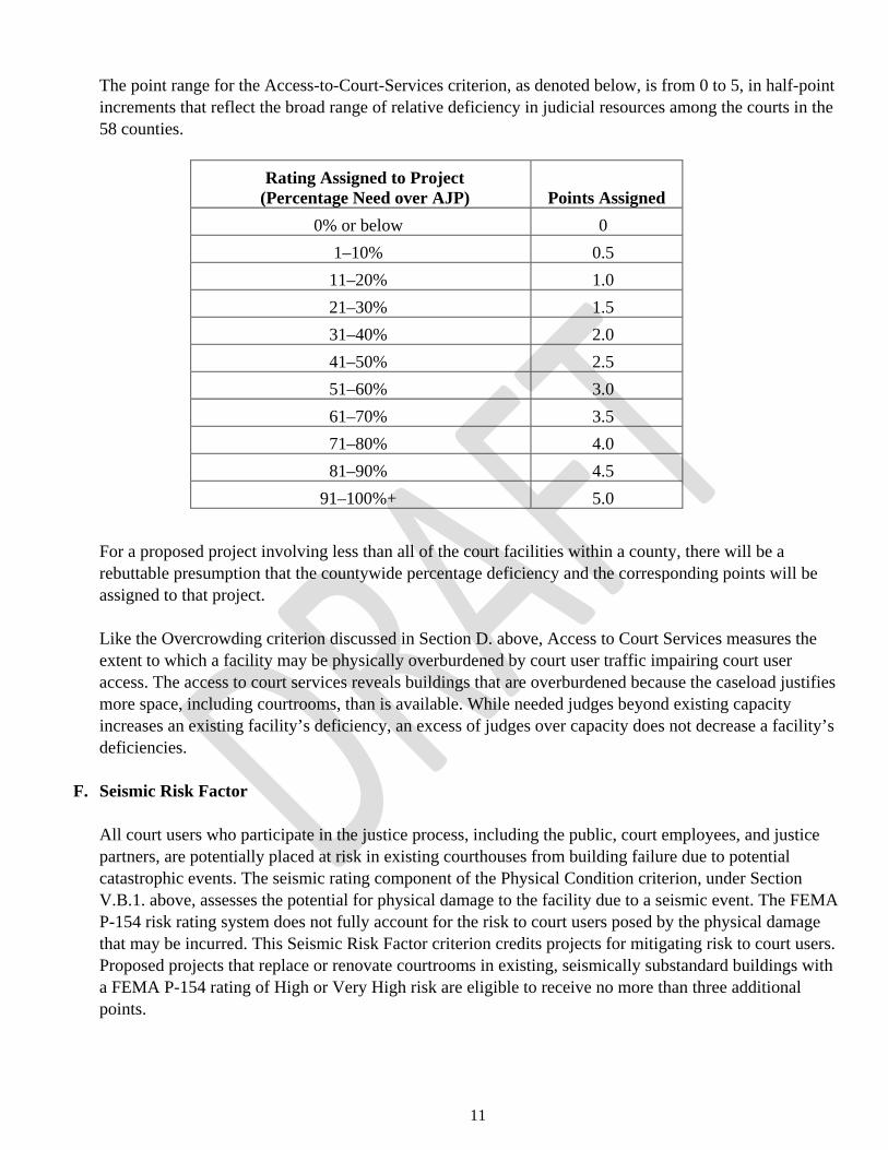
The point range for the Access-to-Court-Services criterion, as denoted below, is from 0 to 5, in half-point increments that reflect the broad range of relative deficiency in judicial resources among the courts in the 58 counties.
Rating Assigned to Project
(Percentage Need over AJP)
Points Assigned 0% or below 0
1–10% 0.5 11–20% 1.0 21–30% 1.5 31–40% 2.0 41–50% 2.5 51–60% 3.0 61–70% 3.5 71–80% 4.0 81–90% 4.5
91–100%+ 5.0
For a proposed project involving less than all of the court facilities within a county, there will be a rebuttable presumption that the countywide percentage deficiency and the corresponding points will be assigned to that project. Like the Overcrowding criterion discussed in Section D. above, Access to Court Services measures the extent to which a facility may be physically overburdened by court user traffic impairing court user access. The access to court services reveals buildings that are overburdened because the caseload justifies more space, including courtrooms, than is available. While needed judges beyond existing capacity increases an existing facility’s deficiency, an excess of judges over capacity does not decrease a facility’s deficiencies.
F. Seismic Risk Factor All court users who participate in the justice process, including the public, court employees, and justice partners, are potentially placed at risk in existing courthouses from building failure due to potential catastrophic events. The seismic rating component of the Physical Condition criterion, under Section V.B.1. above, assesses the potential for physical damage to the facility due to a seismic event. The FEMA P-154 risk rating system does not fully account for the risk to court users posed by the physical damage that may be incurred. This Seismic Risk Factor criterion credits projects for mitigating risk to court users. Proposed projects that replace or renovate courtrooms in existing, seismically substandard buildings with a FEMA P-154 rating of High or Very High risk are eligible to receive no more than three additional points.

12
Approach:
• As shown in the table under Section V.B.1. above, existing court buildings, evaluated as part of this reassessment, have been assigned seismic scores within four categories: Acceptable Risk, Moderate Risk, High Risk, or Very High Risk. To address the issue of seismic risk to court users, projects proposed to replace or renovate courtrooms in existing High Risk or Very High Risk buildings, would receive additional points in accordance with the following table:
• Moderate Risk or Acceptable Risk buildings would not receive additional points.
• Three points will be the maximum number of additional points available to any project.
VI. COST-BASED SCORING OF PROJECTS The cost-based scoring is used to rank projects within each of the five needs-based priority groups. Needs-based scoring and the cost-based scoring are entirely separate from one another. When combined, needs-based and cost-based scores do not change the priority group a project is placed in, only the rank of the project within the priority group. This is because the prioritization methodology is primarily a needs-based instrument designed to detect physical deficiencies that endanger court users or restrict access to justice. The cost-based factors enable the most effective expenditure of public funds to overcome the physical deficiencies. Cost-based criteria are scored on a 100-point scale, with the 100 points distributed per the following table:
1. Cost Avoidance or Savings Realized through Operational or Organizational Efficiencies
25
2. Minimization of Increases in Ongoing Security, Operations, and Maintenance Costs
25
3. Cost of Project per Court User 25 4. Total Costs Spent on a Project as of March 31, 2019 25
Total Points for Cost-Based Criteria 100
As a final step, the accumulated cost-based rating points for each project, which can total up to 100, will be converted to the 2-point scale as follows:
Total: 2 Points 0.2 0.4 0.6 0.8 1.0 1.2 1.4 1.6 1.8 2.0 Total: 100 Rating Points
0–10 11–20 21–30 31–40 41–50 51–60 61–70 71–80 81–90 91–100
Per the methodology, cost points are distributed linearly based on a statistical analysis of all provided cost data. Should cost data be revised or amended, points scales may need to be revised accordingly.
Very High Risk High Risk FEMA P-154 Seismic Score
0.5 and below
0.6 to 1.4
Additional Points 3 2

13
The formula below, in conjunction with the data provided in the following table, provides the point values for each criterion described below under Sections A.–D. Any point calculation exceeding 25 has been capped at 25 points, and likewise, any values returning less than 0 has been capped at 0 points.
𝑃𝑃𝑂𝑂𝑂𝑂𝑂𝑂𝐶𝐶𝐹𝐹 = 𝐴𝐴 ∗ (𝐶𝐶𝑂𝑂𝐹𝐹𝐶𝐶 𝑉𝑉𝐴𝐴𝐶𝐶𝐶𝐶𝑂𝑂) + 𝐵𝐵 Cost Avoidance
($/court user) Cost Minimization
($/court user) Project Cost Per User
($/court user) Total Spent as of
3/31/19 ($) A 2.83 3.45 * 10-2 -9.39 * 10-3 5.16 * 10-6 B 0 -6.21 * 10-3 25.5 -0.813
Representative Points 0 Points $0 $0 $2,712 $157,702
6.25 Points $2 $181 $2,046 $1,370,002 12.5 Points $4 $363 $1,380 $2,582,302
18.75 Points $7 $544 $715 $3,794,601 25 Points $9 $725 $49 $5,006,901
As previously stated, in the most essential terms the methodology can be described as:
• Needs-based criteria = Priority Group
• Needs-based and cost-based criteria = Rank within Priority Group
A. Cost Avoidance or Savings Realized Through Operational or Organizational Efficiencies
The CFAC and Judicial Council Facilities Services will engage with the courts to assess the potential cost avoidance or savings that may be realized based on the implementation of each project. Generally, it is expected that such savings may be realized based on consolidation of multiple facilities into one larger facility and elimination of certain short-term leases in exchange of building a new facility, or a combination of the consolidation of owned facilities and elimination of leases within the same project. Any cost savings due to staff efficiencies related to consolidation or any other factors will be identified by the courts. Cost savings information identified by various courts will be reviewed for general conformance and consistency. Any anomalies will be discussed with the courts for resolution. Any potential anomalies that are not resolved with the courts will be referred to the CFAC for resolution. The total identified cost avoidance or savings for each project will be “normalized” and converted to Cost Avoidance or Savings per Court User. This conversion will be accomplished taking into consideration the population of the county, the AJPs for the court, and the number of courtrooms that are impacted by the project.

14
B. Minimization of Increases in Ongoing Security, Operating, and Maintenance Costs Judicial Council Facilities Services will calculate any potential minimization of increases to court security costs, using existing building security systems data. Minimization of planned increases to security costs is defined as the costs that will be incurred in the existing building(s) if it remains in operation and is not being replaced by an approved project. Approach:
• The following formula will be used:
Cost (security cameras, access control, fencing and gates) + Screening Equipment Costs = Minimization of Increases in Ongoing Security Costs
Judicial Council Facility Services will also calculate any potential for minimization of increases in ongoing operations and maintenance costs. Minimization of increases in ongoing operations and maintenance costs is defined as the cost of operating and maintaining the current facilities if the proposed project does not proceed compared to the cost of operating a new building designed to meet current codes. The delta is the minimization of costs. Approach:
• The following formula will be used:
Cost of current building maintenance + Cost of current building utilities + Cost of building Deferred Maintenance – Cost of Operating and Maintaining the New Building = Minimization of Increases in Ongoing Operating and Maintenance Costs
C. Cost of Project per Court User The cost per court user is calculated based on the population of the county, the AJPs for the court, and the number of proposed project courtrooms. This value will be adjusted to compensate for counties with minimal population that are awarded the statutory minimum AJP of 2.3. (Note: The judicial branch’s smallest courts are statutorily provided with a minimum of two judgeships and are authorized to have at least 0.3 full-time equivalent [FTE] of a federally funded child support commissioner, for a total of 2.3 FTE judicial officers.) The following formula will be used to determine the cost per court user:
𝐶𝐶𝑂𝑂𝐹𝐹𝐶𝐶 𝑝𝑝𝑂𝑂𝑂𝑂 𝐶𝐶𝑂𝑂𝐶𝐶𝑂𝑂𝐶𝐶 𝑈𝑈𝐹𝐹𝑂𝑂𝑂𝑂 = 𝐶𝐶𝑂𝑂𝐹𝐹𝐶𝐶 ÷ �𝐶𝐶𝑂𝑂𝐶𝐶𝑂𝑂𝐶𝐶𝐶𝐶 𝑃𝑃𝑂𝑂𝑝𝑝𝐶𝐶𝐶𝐶𝐴𝐴𝐶𝐶𝑂𝑂𝑂𝑂𝑂𝑂 𝑥𝑥 # 𝑃𝑃𝑂𝑂𝑂𝑂𝑃𝑃𝑂𝑂𝑂𝑂𝐶𝐶 𝐶𝐶𝑂𝑂𝐶𝐶𝑂𝑂𝐶𝐶𝑂𝑂𝑂𝑂𝑂𝑂𝐶𝐶𝐹𝐹𝐴𝐴𝐴𝐴𝑃𝑃 𝑂𝑂𝐶𝐶 𝐸𝐸𝑂𝑂𝐶𝐶𝑂𝑂𝑂𝑂𝑂𝑂 𝐶𝐶𝑂𝑂𝐶𝐶𝑂𝑂𝐶𝐶
�
D. Total Costs Spent on a Project as of March 31, 2019
The total costs spent as of March 31, 2019, on previously authorized projects that were placed on hold will be tabulated from the accounting records.

15
VII. FUNDING PROCESS A. Establishment of a Statewide Project List
The Judicial Council will adopt a list of projects categorized by Priority Group. This list will be reviewed by the CFAC, Executive and Planning Committee, and any other council-appointed body with responsibility for advising the Judicial Council on facility matters. In adopting a list of projects for submission to the California Department of Finance (DOF) for requested inclusion in the Governor’s Budget proposal to the Legislature, the Judicial Council will follow these principles:
1. Projects will be prioritized on the needs-based program criteria established by this methodology,
which ranks the projects into priority groupings. The cost-based criteria will be assigned points and will be used to sort projects within each priority group.
2. For submission to the DOF for consideration of inclusion in the Governor’s Budget, the Judicial Council may select projects based upon additional substantive considerations, including, without limitation, additional economic opportunity considerations, upon seismic safety and other risk factors, upon historical utilization of single-courtroom facilities, and/or upon changed circumstances.
3. Economic opportunities include, but are not limited to, free or reduced costs of land for new construction, viable financing partnerships or fund contributions by other government entities or private parties that result in lower project delivery costs, cost savings resulting from adaptive reuse of existing facilities or from build-outs using available shelled space, operational efficiencies from consolidation of court calendars and operations, and building operational costs savings from consolidation of facilities.
Consideration of economic opportunity allows the Judicial Council to request funding for projects that have documented capital or operating savings for the state. Judicial Council staff will work in collaboration with local courts to evaluate and document the economic opportunity of each eligible project.
4. Seismic safety and other risk factors include conditions related to expert evaluation, commissioned or adopted by the Judicial Council, beyond this methodology establishing that the building is at risk of causing loss of human life or significant disruption to a court’s/courts’ ability to operate in the event of an earthquake, fire, or other event. The Judicial Council may consider the need to phase projects and to engage in multiple projects to mitigate risk to a court(s) in determining the priority of a project and the order of funding for associated projects.
5. In the case of a proposed project to replace or renovate a single-courtroom facility in a county with more than one court facility, the Judicial Council may exclude the project after considering public access adjacency to the other courthouses in the county along with the historical frequency and volume of courtroom proceedings in the subject facility.
6. Changed circumstances include any developments, conditions, or new facts, which arose after the CFAC’s submission of this report and related Statewide Project List to the Judicial Council, provided that such circumstances bear upon the needs and/or cost criteria contained herein.
7. Any considerations so identified by the Judicial Council shall be described in its submission to the DOF.

16
B. Changes to Statewide Project List
Any additions or deletions to the list of projects shall be adopted by the Judicial Council. The CFAC, Executive and Planning Committee, or any other council-appointed body with responsibility for advising the Judicial Council on facility matters will review recommended changes to the list.
C. Project Phase Adjustments
The final draft list of project priority groups described above will be reviewed to identify any phased projects. Should the second-phase of a multiphase project fall in a higher priority group than its first phase, staff will switch the group assignment of those projects, in order to correct the phasing discrepancy. As a result, the first-phase project will move to the higher-priority group, and the second-phase project will take the place of the first in its lower-priority group. These phasing corrections, if required, will be documented in a report to the Judicial Council that details the results of this methodology’s application.
D. No Substitutions of Projects Between Groups
Substitution of a court’s project between groups will not be allowed. E. How Requests for Funding Will Be Determined
Based on the Judicial Council’s approved update to the Trial Court Capital-Outlay Plan and Prioritization Methodology and five-year infrastructure plan, Judicial Council Facilities Services will prepare documentation to request approval of capital-outlay funding through the Judicial Council-approved budget change proposal process. This process consists of submission of initial funding requests and budget change proposal concepts for consideration of approval and prioritization through the CFAC and the Judicial Branch Budget Committee, and finally the Judicial Council.
VIII. PROCESS FOR ADDING OR DELETING PROJECTS IN THE TRIAL COURT CAPITAL-OUTLAY PLAN
If a court wishes to add or delete projects in the Trial Court Capital-Outlay Plan, the court may submit a written request including the project name; its description including size, number of courtrooms, and type of calendars planned; and other descriptive information about the project. The request shall be presented to CFAC, which has responsibility for advising the Judicial Council on facility matters for its consideration and direction. At the direction of the Judicial Council, staff will include any changes in the next annual update to the Trial Court Capital-Outlay Plan.

Date: 6-12-18
Trial Court Capital-Outlay Plan Reassessment – Required by the 2018 Budget Act Trailer Bill (SB 847: Committee on Budget and Fiscal Review)
The following is required verbatim by Government Code section 70371.9:
(a) (1) The Judicial Council shall conduct, or contract with an independent contractor toconduct, a reassessment of those projects identified in its Update to Trial Court Capital-Outlay Plan and Prioritization Methodology adopted on October 24, 2008, or the most recent version of that update, if any. Other projects may be included for reassessment at the discretion of Judicial Council. The reassessment shall be submitted to the Senate Committee on Budget and Fiscal Review and the Assembly Committee on Budget by December 31, 2019.
(2) The Judicial Council may exclude from the reassessment those projects that werecanceled prior to June 30, 2018, and those that were approved in the Budget Act of2018.
(b) A project subject to this section shall be reassessed and ranked, at minimum, on each ofthe following:
(1) The criteria identified in the Update to Trial Court Capital-Outlay Plan andPrioritization Methodology adopted on October 24, 2008, or the most recent versionof that update, if any.
(2) The level of seismic risk, environmental hazards, and other health and safetyhazards.
(3) The impact on court users, including, but not limited to, the level of public access tocourt services, such as accessibility to the courthouse.
(4) The cost avoidance or savings that would be achieved due to the project throughoperational or organizational efficiencies created for the court or the state.
(5) Ways to minimize increased ongoing costs, including, but not limited to, trial courtsecurity and operating and maintenance costs.
(6) A comparison of the cost to repair or renovate the existing facility versus the cost ofreplacement.
(7) The projected cost of each proposed project, per court user.
(8) The total costs spent on the project as of the date of the assessment.
Appendix A
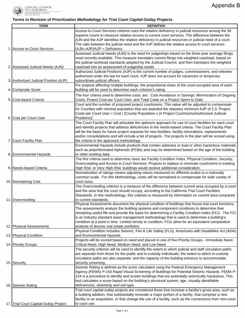
Terms in Revision of Prioritization Methodology for Trial Court Capital-Outlay ProjectsTERM DEFINITION
1. Access to Court Services
Access to Court Services criterion uses the relative deficiency in judicial resources among the 58 superior courts to measure relative access to current court services. The difference between the AJN and the AJP identifies the relative deficiency in judicial resources or judicial need of a court. The ratio between the judicial need and the AJP defines the relative access to court services: (AJN–AJP)/AJP = Deficiency
2. Assessed Judicial Needs (AJN)
Assessed Judicial Needs (AJN) is the need for judgeships based on the three-year average filings most recently available. This measure translates current filings into weighted caseload, based on the judicial workload standards adopted by the Judicial Council, and then translates the weighted caseload into an assessment of judgeship needs.
3. Authorized Judicial Position (AJP)
Authorized Judicial Positions (AJP) is the current number of judges, commissioners, and referees authorized under the law for each court. AJP does not account for vacancies or temporary subordinate judicial officers.
4. Composite ScoreFor projects affecting multiple buildings, the proportional share of the court-occupied area of each building will be used to determine each criterion’s rating.
5. Cost-based CriteriaThe four criteria used to determine costs are: Cost Avoidance or Savings; Minimization of Ongoing Costs; Project Cost per Court User; and Total Costs on a Project Spent to Date.
6. Cost per Court User
Court and the number of proposed project courtrooms. This value will be adjusted to compensate for Counties with minimal population that are awarded the statutory minimum AJP of 2.3. Project Costs per Court User = Cost / [County Population x (# Project Courtrooms/Authorized Judicial Positions)]
7. Court Facility Plan
The Court Facility Plan will articulate the optimum approach for use of court facilities for each court and identify projects that address deficiencies in the needs-based criteria. The Court Facility Plan will be the basis for future project requests for new facilities, facility renovations, replacements and/or consolidations and will include a list of projects. The projects in the plan will be scored using the criteria in the approved methodology.
8. Environmental Hazards
Environmental Hazards include products that contain asbestos or lead or other hazardous materials, such as polychlorinated biphenyls (PCBs) and may be determined based on the age of the building or other existing data.
9. Needs-based Criteria
The five criteria used to determine need are Facility Condition Index, Physical Condition, Security, Overcrowding and Access to Court Services. Projects to replace or renovate courtrooms in existing High Risk or Very High Risk buildings would receive additional consideration.
10. Normalizing Cost
Normalization of ratings means adjusting values measured on different scales to a notionally common scale. For this Methodology, costs will be normalized to compensate for wide variety of court sizes.
11. Overcrowding
The Overcrowding criterion is a measure of the difference between current area occupied by a court and the area that the court should occupy, according to the California Trial Court Facilities Standards. In this methodology, this criterion is measured by information on current area compared to current standards.
12. Physical Assessments
Physical Assessments document the physical condition of buildings that house trial court functions. The assessments analyze the building systems and component conditions to determine their remaining useful life and provide the basis for determining a Facility Condition Index (FCI). The FCI is an industry standard asset management methodology that is used to determine a building’s condition at a point in time. Limited strictly to condition, FCIs allow for an equivalent comparative analysis of diverse real estate portfolios.
13. Physical ConditionPhysical Condition includes Seismic, Fire & Life Safety (FLS), Americans with Disabilities Act (ADA) and Environmental Hazards.
14. Priority GroupsProjects will be scored based on need and placed in one of five Priority Groups - Immediate Need, Critical Need, High Need, Medium Need, and Low Need.
15. Security
The security criterion will be used to identify the extent to which judicial and staff circulation paths are separate from those for the public and in-custody individuals; the extent to which in-custody circulation paths are also separate; and the capacity of the building entrance to accommodate security screening.
16. Seismic Rating
Seismic Rating is defined as the score calculated using the Federal Emergency Management Agency (FEMA) P-154 Rapid Visual Screening of Buildings for Potential Seismic Hazards. FEMA P-154 is a procedure to identify and screen buildings that are potentially seismically hazardous. This tool calculates a score based on the building’s structural system, age, visually identifiable deficiencies, seismicity and soil type.
17. Trial Court Capital-Outlay Project
Trial court capital-outlay projects are considered those that increase a facility’s gross area, such as a building addition, that substantially renovate a major portion of a facility, that comprise a new facility or an acquisition, or that change the use of a facility, such as the conversions from non-court to court use.
Page 1 of 1
Appendix B

Attachment B2018 Judicial Workload Study Update: Draft Assessed Judge Need
Cluster Court Authorized and
Funded Judicial
Positions
Preliminary Reported Assessed
Judgeship Need
Preliminary Judicial
Officer Need (+)
Draft % need
over AJP (C/A)
Draft Assessed
Judgeship Need
Difference Need and
Authorized (E-A)
Draft Judicial Officer
Need (+)
Draft % need
over AJP (F/A)
A B D E F G H4 Alameda* 83 77.1 -7% 65.5 -17.5 -21%1 Alpine 2.3 0.2 -93% 0.1 -2.2 -95%1 Amador 2.3 2.6 14% 2.7 0.4 20%2 Butte 13 13.0 0% 13.7 0.7 5%1 Calaveras 2.3 2.4 5% 2.5 0.2 9%1 Colusa 2.3 1.5 -34% 1.7 -0.6 -26%3 Contra Costa 42 39.6 -6% 39.4 -2.6 -6%1 Del Norte 2.8 2.3 -18% 2.3 -0.5 -19%2 El Dorado 9 7.8 -13% 7.7 -1.3 -15%3 Fresno 49 56.9 7 16% 62.2 13.2 13 27%1 Glenn 2.3 1.8 -22% 2.0 -0.3 -12%2 Humboldt 8 9.4 1 17% 9.8 1.8 1 22%2 Imperial 11.3 12.3 1 9% 12.7 1.4 1 12%1 Inyo 2.3 1.4 -41% 1.5 -0.8 -33%3 Kern 43 53.5 10 24% 59.1 16.1 16 37%2 Kings 8.6 11.0 2 28% 11.4 2.8 2 33%2 Lake 4.7 5.3 14% 5.9 1.2 1 26%1 Lassen 2.3 2.2 -3% 2.3 0.0 1%4 Los Angeles 585.25 533.3 -9% 520.0 -65.2 -11%2 Madera 9.3 9.4 1% 11.4 2.1 2 22%2 Marin 12.7 10.1 -21% 9.5 -3.2 -25%1 Mariposa 2.3 0.9 -61% 1.1 -1.2 -52%2 Mendocino 8.4 7.0 -16% 7.6 -0.8 -9%2 Merced 12 13.2 1 10% 15.1 3.1 3 26%1 Modoc 2.3 0.8 -66% 1.0 -1.3 -58%1 Mono 2.3 0.9 -59% 1.1 -1.2 -53%3 Monterey 21.2 19.1 -10% 21.1 -0.1 0%2 Napa 8 7.0 -12% 7.3 -0.7 -9%2 Nevada 7.6 4.5 -40% 4.8 -2.8 -36%4 Orange 144 135.0 -6% 143.4 -0.6 0%2 Placer 14.5 17.4 2 20% 17.4 2.9 2 20%1 Plumas 2.3 1.2 -50% 1.2 -1.1 -46%4 Riverside 80 116.2 36 45% 117.3 37.3 37 47%4 Sacramento 72.5 84.3 11 16% 93.1 20.6 20 28%1 San Benito 2.3 2.6 13% 2.9 0.6 25%4 San Bernardino 88 126.2 38 43% 137.8 49.8 49 57%4 San Diego 154 132.3 -14% 133.9 -20.1 -13%4 San Francisco 55.9 43.8 -22% 39.3 -16.6 -30%3 San Joaquin 33.5 38.6 5 15% 41.8 8.3 8 25%2 San Luis Obispo 15 14.6 -2% 15.2 0.2 1%3 San Mateo 33 28.6 -13% 29.2 -3.8 -12%3 Santa Barbara 24 21.8 -9% 23.1 -0.9 -4%4 Santa Clara 82 62.2 -24% 66.8 -15.2 -19%2 Santa Cruz 13.5 12.2 -9% 12.8 -0.7 -5%2 Shasta 12 14.4 2 20% 15.9 3.9 3 33%1 Sierra 2.3 0.2 -90% 0.2 -2.1 -90%2 Siskiyou 5 3.1 -37% 3.6 -1.4 -29%3 Solano 23 21.5 -6% 22.6 -0.4 -2%3 Sonoma 23 22.4 -3% 22.8 -0.2 -1%3 Stanislaus 24 28.2 4 18% 30.0 6.0 5 25%2 Sutter 5.3 6.6 1 24% 6.8 1.5 1 29%2 Tehama 4.33 5.4 1 25% 5.9 1.6 1 36%1 Trinity 2.3 1.4 -39% 1.5 -0.8 -33%3 Tulare 23 25.6 2 11% 27.7 4.7 4 20%2 Tuolumne 4.75 4.6 -3% 4.8 0.1 1%3 Ventura 33 36.3 3 10% 37.7 4.7 4 14%2 Yolo 12.4 10.9 -12% 12.7 0.3 2%2 Yuba 5.33 5.4 2% 5.6 0.3 5%
1956 1930 127 1976 173
*
**
1 For 2018, the three year average filings used to estimate need are FY2014-15, 2015-16, 2016-172 For 2019, the three year average filings used to estimate need are FY2015-16, 2016-17, 2017-18
2019 2
The preliminary 2018 assessed judge need for the Superior Court of California, County of Alameda was based on filings counts that were later amended in JBSIS. The resulting judicial need was higher than if the amended filings had been used.The qualifying threshold only applies to those courts with a judicial need between 0.8 FTE and .99 FTE. To illustrate, a court with a judicial need of 0.85 would get one judgeship eligible for prioritization. But a court with a judicial need of 2.85 FTE would have two judgeships eligible for prioritization—not three.
2018 1
Appendix CApproved by the Judicial Council on September 24, 2019 - Attachment B excerpted from Judicial Council report titled, Judicial Workload Assessment: 2018 Judicial Workload Study Updated Caseweights

County Project Name Priority Group Court-rooms
Project Cost
(in millions)
Needs Score Cost Score Group
Score
Lake New Lakeport Courthouse Immediate Need 4 $51.2 20.5 1.0 21.5
Mendocino New Ukiah Courthouse Immediate Need 7 $89.6 17.5 1.2 18.7
Nevada New Nevada City Courthouse Immediate Need 6 $91.8 18.0 0.6 18.6
Butte Butte County Juvenile Hall Addition and Renovation Immediate Need 1 $2.3 18.0 0.6 18.6
Monterey New Fort Ord Courthouse Immediate Need 7 $130.1 17.4 0.6 18.0
Lake New Clearlake Courthouse Immediate Need 1 $15.0 17.5 0.4 17.9
San Bernardino San Bernardino Juvenile Dependency Courthouse Addition and Renovation
Immediate Need 2 $8.8 17.0 0.6 17.6
Solano New Solano Hall of Justice (Fairfield) Immediate Need 12 $170.2 17.0 0.6 17.6
Fresno New Fresno Courthouse Immediate Need 36 $483.1 16.5 1.0 17.5
Kern New Ridgecrest Courthouse Immediate Need 2 $42.2 17.0 0.4 17.4
Plumas New Quincy Courthouse Immediate Need 3 $65.9 17.0 0.2 17.2
Stanislaus New Modesto Courthouse Courtroom Renovation Immediate Need 3 $11.1 16.5 0.6 17.1
Los Angeles New Santa Clarita Courthouse Immediate Need 24 $345.0 16.4 0.6 17.0
San Luis Obispo New San Luis Obispo Courthouse Immediate Need 12 $184.9 16.5 0.4 16.9
San Joaquin New Tracy Courthouse Immediate Need 2 $34.4 16.5 0.4 16.9
Los Angeles New West Los Angeles Courthouse Immediate Need 32 $464.9 16.0 0.6 16.6
Kern New Mojave Courthouse Immediate Need 3 $56.8 16.0 0.4 16.4
Placer New Tahoe Area Courthouse Immediate Need 1 $34.8 16.0 0.4 16.4
Los Angeles New Inglewood Courthouse Critical Need 30 $432.1 15.7 0.6 16.3Contra Costa New Richmond Courthouse Critical Need 6 $107.7 15.5 0.6 16.1
San Francisco New San Francisco Hall of Justice Critical Need 24 $460.1 15.5 0.4 15.9
Orange New Orange County Collaborative Courthouse Critical Need 3 $113.4 15.0 0.8 15.8
Santa Barbara New Santa Barbara Criminal Courthouse Critical Need 8 $102.8 14.5 1.2 15.7
El Dorado New Placerville Courthouse Critical Need 6 $92.2 14.8 0.6 15.4
Los Angeles New Van Nuys Courthouse (East/new + West/reno) Critical Need 55 $922.4 14.8 0.6 15.4
DRAFT Statewide List of Trial Court Capital-Outlay Projects
Critical Need
Immediate Need
Court Facilities Advisory Committee Meeting October 1, 2019 Page 1 of 3
DRAFT

Los Angeles New Downtown Los Angeles Courthouse (Mosk Replacement) Critical Need 47 $731.1 14.3 1.0 15.3
Fresno Fresno Juvenile Delinquency Courthouse Renovation Critical Need 2 $5.3 13.6 1.6 15.2
Inyo New Inyo County Courthouse Critical Need 2 $43.8 14.6 0.6 15.2
San Bernardino New Victorville Courthouse Critical Need 31 $392.5 14.6 0.6 15.2Santa Cruz New Santa Cruz Courthouse Critical Need 8 $127.6 13.9 1.0 14.9Mariposa New Mariposa Courthouse Critical Need 2 $42.6 14.5 0.4 14.9
Los Angeles Chatsworth Courthouse Renovation Critical Need 7 $37.7 13.9 1.0 14.9
Riverside New Riverside Juvenile Courthouse Critical Need 5 $77.9 14.0 0.6 14.6
San Diego New San Diego Juvenile Courthouse Critical Need 10 $121.4 14.0 0.6 14.6
Tulare New Tulare North County Courthouse Critical Need 14 $198.9 14.0 0.6 14.6
Los Angeles New West Covina Courthouse Critical Need 15 $215.5 13.9 0.6 14.5
Los Angeles New Eastlake Courthouse Critical Need 6 $119.1 14.1 0.4 14.5
Kern New Bakersfield Superior Courthouse Critical Need 33 $434.2 13.8 0.6 14.4
Sonoma New Sonoma Civil Courthouse Critical Need 8 $102.8 13.4 1.0 14.4
San Luis Obispo New Grover Beach Branch Courthouse Critical Need 1 $18.0 13.8 0.4 14.2
Alameda New Alameda County Community Justice Center Critical Need 57 $895.8 13.5 0.6 14.1
Imperial Winterhaven Branch Courthouse Addition and Renovation Critical Need 1 $3.6 13.5 0.6 14.1
Los Angeles Los Angeles Metropolitan Courthouse Renovation Critical Need 14 $215.6 13.5 0.6 14.1
Los Angeles New North Central Los Angeles Courthouse Critical Need 12 $196.3 13.5 0.6 14.1
Riverside New Palm Springs Courthouse Critical Need 9 $98.6 13.0 0.6 13.6
Orange New Orange South County Courthouse Critical Need 16 $232.0 13.0 0.6 13.6
Los Angeles Foltz Courthouse Renovation Critical Need 60 $1,400.9 13.0 0.4 13.4
San Diego San Diego South County Regional Courthouse Renovation
High Need 4 $10.5 12.5 0.6 13.1
San Mateo New San Mateo Northern Branch Courthouse High Need 5 $94.4 12.3 0.6 12.9
Los Angeles New Pasadena Courthouse High Need 17 $256.9 12.0 0.6 12.6
Solano New Solano Justice Building (Vallejo) High Need 6 $100.9 12.0 0.6 12.6
Monterey New South Monterey County Courthouse High Need 1 $27.9 11.9 0.6 12.5
Del Norte New Del Norte County Main Courthouse High Need 3 $59.4 11.8 0.4 12.2
San Francisco San Francisco Civic Center Courthouse Renovation High Need 7 $44.9 11.2 0.8 12.0
San Diego San Diego North Regional Courthouse Complex Renovation - North Building
High Need 14 $135.1 11.0 0.6 11.6
High Need
Court Facilities Advisory Committee Meeting October 1, 2019 Page 2 of 3
DRAFT

Riverside New Riverside Hall of Justice Annex High Need 10 $133.3 11.0 0.6 11.6
Riverside New Moreno Valley Courthouse High Need 9 $109.8 10.9 0.6 11.5
Humboldt New Eureka Courthouse High Need 9 $135.1 11.0 0.4 11.4
Merced New Merced Courthouse Annex High Need 1 $18.1 10.1 1.0 11.1
Yuba New Yuba County Courthouse High Need 6 $84.7 10.5 0.6 11.1
San Bernardino San Bernardino Courthouse Annex Renovation High Need 11 $46.5 10.2 0.8 11.0
Modoc New Barclay Justice Center High Need 2 $43.1 10.6 0.2 10.8
Ventura New Ventura East County Courthouse Medium Need 7 $94.1 9.4 0.6 10.0
Colusa Colusa Courthouse Annex Renovation Medium Need 1 $17.4 9.1 0.8 9.9
Santa Clara New Santa Clara Hall of Justice Medium Need 36 $521.0 9.0 0.6 9.6
Los Angeles Edelman Courthouse Renovation Medium Need 6 $112.1 8.4 0.6 9.0
Los Angeles New Los Angeles Mental Health Courthouse Medium Need 4 $112.3 8.5 0.4 8.9
Los Angeles New Lancaster Dependency Court Medium Need 6 $89.1 8.2 0.6 8.8
San Diego San Diego East County Regional Center Renovation Medium Need 17 $169.7 8.0 0.6 8.6
Los Angeles New Torrance Dependency Court and Traffic Annex Medium Need 7 $94.2 7.7 0.6 8.3
Los Angeles Compton Courthouse Renovation Medium Need 31 $340.7 7.5 0.6 8.1
Riverside Riverside Southwest Justice Center Renovation Low Need 1 $14.9 6.0 0.8 6.8
San Diego New San Diego Traffic Courthouse Low Need 4 $55.3 6.0 0.6 6.6
Santa Barbara Santa Maria Building G Renovation Low Need 1 $5.1 5.5 0.8 6.3
Butte Butte County Courthouse Addition and Renovation Low Need 2 $20.2 5.5 0.6 6.1
Sacramento Sacramento Juvenile Courthouse Renovation Low Need 2 $11.1 5.0 0.8 5.8
Riverside Banning Justice Center Addition Low Need 2 $21.9 4.5 0.6 5.1
Tehama Tehama Courthouse Renovation Low Need 2 $3.0 4.0 0.6 4.6
Yolo Yolo Superior Court Renovation Low Need 0 $0.9 3.5 0.8 4.3
Santa Clara Santa Clara Family Justice Center Renovation Low Need 0 $1.9 2.5 0.8 3.3
Low Need
Medium Need
Court Facilities Advisory Committee Meeting October 1, 2019 Page 3 of 3
DRAFT

County Project Name Priority Group Court-rooms
Project Cost
(in millions)FCI Physical
Condition Over-crowding Access to Court Services
Seismic Risk Factor
Needs Score
Cost Avoidance Minimization Project Cost
per Court User Spent To DateTotal Cost
Points Cost Score Group Score
Lake New Lakeport Courthouse Immediate Need 4 $51.2 5.00 3.50 3.50 1.50 2.00 20.5 3.82 3.10 16.78 25.00 48.70 1.0 21.5
Mendocino New Ukiah Courthouse Immediate Need 7 $89.6 4.00 3.50 3.00 0.00 2.00 17.5 17.70 4.30 14.12 15.44 51.56 1.2 18.7
Nevada New Nevada City Courthouse Immediate Need 6 $91.8 3.50 3.20 3.27 0.00 3.00 18.0 3.62 2.61 14.42 2.35 23.00 0.6 18.6
Butte Butte County Juvenile Hall Addition and Renovation Immediate Need 1 $2.3 3.00 3.00 4.50 0.50 2.00 18.0 0.00 0.01 24.24 0.00 24.25 0.6 18.6
Monterey New Fort Ord Courthouse Immediate Need 7 $130.1 4.00 4.00 1.44 0.00 3.00 17.4 9.23 1.65 17.15 0.00 28.03 0.6 18.0
Lake New Clearlake Courthouse Immediate Need 1 $15.0 4.00 3.00 3.00 1.50 2.00 17.5 0.00 4.49 15.32 0.00 19.81 0.4 17.9
San Bernardino San Bernardino Juvenile Dependency Courthouse Addition and Renovation
Immediate Need 2 $8.8 5.00 0.50 3.50 3.00 0.00 17.0 0.00 3.42 23.81 0.00 27.23 0.6 17.6
Solano New Solano Hall of Justice (Fairfield) Immediate Need 12 $170.2 3.00 4.00 2.00 0.00 3.00 17.0 0.00 3.13 18.52 0.00 21.65 0.6 17.6
Fresno New Fresno Courthouse Immediate Need 36 $483.1 2.50 4.00 1.66 1.50 2.00 16.5 9.94 1.91 19.40 11.29 42.54 1.0 17.5
Kern New Ridgecrest Courthouse Immediate Need 2 $42.2 5.00 1.86 3.77 2.00 0.00 17.0 2.58 1.58 16.16 0.00 20.32 0.4 17.4
Plumas New Quincy Courthouse Immediate Need 3 $65.9 2.50 4.50 2.00 0.00 3.00 17.0 0.00 2.06 1.48 1.38 4.92 0.2 17.2
Stanislaus New Modesto Courthouse Courtroom Renovation Immediate Need 3 $11.1 3.00 2.50 4.50 1.50 0.00 16.5 5.78 0.00 23.97 0.00 29.75 0.6 17.1
Los Angeles New Santa Clarita Courthouse Immediate Need 24 $345.0 2.05 4.37 2.02 0.00 3.00 16.4 0.00 5.91 17.76 1.19 24.86 0.6 17.0
San Luis Obispo New San Luis Obispo Courthouse Immediate Need 12 $184.9 3.50 2.50 3.50 0.50 2.00 16.5 0.71 1.59 17.72 0.00 20.02 0.4 16.9
San Joaquin New Tracy Courthouse Immediate Need 2 $34.4 5.00 2.50 3.50 1.50 0.00 16.5 0.00 1.43 18.43 0.00 19.86 0.4 16.9
Los Angeles New West Los Angeles Courthouse Immediate Need 32 $464.9 2.32 4.24 1.90 0.00 3.00 16.0 0.00 6.50 17.67 0.00 24.17 0.6 16.6
Kern New Mojave Courthouse Immediate Need 3 $56.8 3.00 2.00 4.50 2.00 0.00 16.0 0.00 0.38 17.11 0.12 17.61 0.4 16.4
Placer New Tahoe Area Courthouse Immediate Need 1 $34.8 2.50 3.00 4.50 1.00 0.00 16.0 1.25 0.22 13.53 0.00 15.00 0.4 16.4
Los Angeles New Inglewood Courthouse Critical Need 30 $432.1 2.23 4.16 1.90 0.00 3.00 15.7 0.00 6.30 17.74 0.00 24.04 0.6 16.3Contra Costa New Richmond Courthouse Critical Need 6 $107.7 3.50 3.50 1.50 0.00 2.00 15.5 0.00 2.35 19.33 0.00 21.68 0.6 16.1
San Francisco New San Francisco Hall of Justice Critical Need 24 $460.1 4.00 3.00 2.00 0.00 2.00 15.5 0.00 3.58 14.08 0.00 17.66 0.4 15.9
Orange New Orange County Collaborative Courthouse Critical Need 3 $113.4 3.00 3.50 1.98 0.00 2.00 15.0 0.00 25.00 9.60 0.00 34.60 0.8 15.8
Santa Barbara New Santa Barbara Criminal Courthouse Critical Need 8 $102.8 3.00 3.00 2.00 0.00 2.00 14.5 14.01 2.18 19.09 25.00 60.28 1.2 15.7
El Dorado New Placerville Courthouse Critical Need 6 $92.2 3.17 2.27 2.33 0.00 2.00 14.8 3.31 2.06 18.69 3.48 27.54 0.6 15.4
Los Angeles New Van Nuys Courthouse (East/new + West/reno) Critical Need 55 $922.4 2.36 3.90 1.83 0.00 3.00 14.8 0.00 4.72 16.47 0.00 21.19 0.6 15.4
DRAFT Statewide List of Trial Court Capital-Outlay Projects
4.50
5.00
3.68
Critical Need4.465.00
4.50
4.51
4.50
4.00
4.48
4.50
5.00
4.81
4.32
5.00
5.00
4.93
5.00
5.00
4.00
5.00
5.00
Security
Immediate Need5.00
5.00
5.00
Court Facilities Advisory Committee Meeting October 1, 2019 Page 1 of 3
DRAFT

Los Angeles New Downtown Los Angeles Courthouse (Mosk Replacement) Critical Need 47 $731.1 2.00 4.50 1.46 0.00 3.00 14.3 25.00 2.67 17.12 0.00 44.79 1.0 15.3
Fresno Fresno Juvenile Delinquency Courthouse Renovation Critical Need 2 $5.3 2.21 3.00 1.21 1.50 2.00 13.6 25.00 25.00 24.27 0.00 74.27 1.6 15.2
Inyo New Inyo County Courthouse Critical Need 2 $43.8 2.50 3.00 4.07 0.00 0.00 14.6 25.00 1.86 0.03 0.60 27.49 0.6 15.2
San Bernardino New Victorville Courthouse Critical Need 31 $392.5 2.15 2.71 2.25 3.00 2.00 14.6 0.00 0.37 20.69 0.00 21.06 0.6 15.2Santa Cruz New Santa Cruz Courthouse Critical Need 8 $127.6 2.44 3.15 1.64 0.00 2.00 13.9 25.00 2.16 18.10 0.00 45.26 1.0 14.9Mariposa New Mariposa Courthouse Critical Need 2 $42.6 2.50 2.50 4.50 0.00 0.00 14.5 10.14 2.52 0.00 0.00 12.66 0.4 14.9
Los Angeles Chatsworth Courthouse Renovation Critical Need 7 $37.7 1.88 3.53 1.64 0.00 3.00 13.9 0.00 25.00 22.58 0.00 47.58 1.0 14.9
Riverside New Riverside Juvenile Courthouse Critical Need 5 $77.9 2.50 1.00 3.00 2.50 0.00 14.0 0.00 0.60 20.66 0.00 21.26 0.6 14.6
San Diego New San Diego Juvenile Courthouse Critical Need 10 $121.4 4.00 2.00 3.00 0.00 0.00 14.0 0.00 1.25 20.22 0.00 21.47 0.6 14.6
Tulare New Tulare North County Courthouse Critical Need 14 $198.9 2.50 3.00 2.50 1.00 0.00 14.0 0.76 0.90 19.05 0.00 20.71 0.6 14.6
Los Angeles New West Covina Courthouse Critical Need 15 $215.5 3.38 3.12 1.18 0.00 3.00 13.9 0.00 6.02 17.76 0.00 23.78 0.6 14.5
Los Angeles New Eastlake Courthouse Critical Need 6 $119.1 2.50 3.00 3.13 0.00 2.00 14.1 0.00 1.23 14.82 0.17 16.22 0.4 14.5
Kern New Bakersfield Superior Courthouse Critical Need 33 $434.2 2.66 3.00 1.54 2.00 0.00 13.8 4.95 1.39 19.66 0.00 26.00 0.6 14.4
Sonoma New Sonoma Civil Courthouse Critical Need 8 $102.8 2.50 3.00 2.05 0.00 2.00 13.4 18.06 7.98 19.92 0.00 45.96 1.0 14.4
San Luis Obispo New Grover Beach Branch Courthouse Critical Need 1 $18.0 2.50 3.00 3.22 0.50 0.00 13.8 0.00 0.81 16.41 0.00 17.22 0.4 14.2
Alameda New Alameda County Community Justice Center Critical Need 57 $895.8 3.13 2.62 1.18 0.00 3.00 13.5 8.66 2.14 18.12 0.00 28.92 0.6 14.1
Imperial Winterhaven Branch Courthouse Addition and Renovation Critical Need 1 $3.6 5.00 2.00 3.50 1.00 0.00 13.5 0.00 1.50 23.43 0.00 24.93 0.6 14.1
Los Angeles Los Angeles Metropolitan Courthouse Renovation Critical Need 14 $215.6 5.00 3.00 0.50 0.00 0.00 13.5 0.00 10.77 17.21 0.00 27.98 0.6 14.1
Los Angeles New North Central Los Angeles Courthouse Critical Need 12 $196.3 3.04 2.83 1.63 0.00 3.00 13.5 0.00 3.35 16.69 2.39 22.43 0.6 14.1
Riverside New Palm Springs Courthouse Critical Need 9 $98.6 1.50 3.00 3.00 2.50 0.00 13.0 0.00 0.18 22.09 0.00 22.27 0.6 13.6
Orange New Orange South County Courthouse Critical Need 16 $232.0 3.50 2.50 2.00 0.00 0.00 13.0 1.98 1.78 19.37 0.00 23.13 0.6 13.6
Los Angeles Foltz Courthouse Renovation Critical Need 60 $1,400.9 1.50 3.50 1.50 0.00 2.00 13.0 0.00 1.61 12.95 0.00 14.56 0.4 13.4
San Diego San Diego South County Regional Courthouse Renovation
High Need 4 $10.5 4.00 1.50 2.00 0.00 0.00 12.5 0.00 4.79 24.33 0.00 29.12 0.6 13.1
San Mateo New San Mateo Northern Branch Courthouse High Need 5 $94.4 4.50 2.00 1.33 0.00 0.00 12.3 4.28 5.37 17.90 0.00 27.55 0.6 12.9
Los Angeles New Pasadena Courthouse High Need 17 $256.9 4.00 3.00 2.50 0.00 0.00 12.0 0.00 3.83 17.36 0.00 21.19 0.6 12.6
Solano New Solano Justice Building (Vallejo) High Need 6 $100.9 4.50 2.50 0.50 0.00 2.00 12.0 0.00 3.74 17.23 0.00 20.97 0.6 12.6
Monterey New South Monterey County Courthouse High Need 1 $27.9 4.50 2.00 2.69 0.00 0.00 11.9 1.13 3.10 12.98 8.56 25.77 0.6 12.5
Del Norte New Del Norte County Main Courthouse High Need 3 $59.4 3.00 1.50 2.29 0.00 0.00 11.8 3.03 3.23 6.45 0.00 12.71 0.4 12.2
San Francisco San Francisco Civic Center Courthouse Renovation High Need 7 $44.9 3.50 2.00 0.98 0.00 2.00 11.2 2.83 12.33 21.65 0.00 36.81 0.8 12.0
San Diego San Diego North Regional Courthouse Complex Renovation - North Building
High Need 14 $135.1 1.50 2.50 2.00 0.00 0.00 11.0 0.00 1.80 21.30 0.00 23.10 0.6 11.6
2.74
5.00
2.72
5.00
High Need
5.00
4.50
2.50
2.50
5.00
2.96
3.00
5.00
4.50
4.65
3.83
4.56
3.61
2.00
5.00
5.00
5.00
3.24
3.45
5.00
2.534.665.00
3.91
3.37
3.71
Court Facilities Advisory Committee Meeting October 1, 2019 Page 2 of 3
DRAFT

Riverside New Riverside Hall of Justice Annex High Need 10 $133.3 3.50 2.00 0.50 2.50 0.00 11.0 0.00 3.57 21.36 0.00 24.93 0.6 11.6
Riverside New Moreno Valley Courthouse High Need 9 $109.8 3.50 2.00 0.50 2.50 0.00 10.9 4.73 3.97 21.71 0.00 30.41 0.6 11.5
Humboldt New Eureka Courthouse High Need 9 $135.1 2.00 3.00 2.03 1.50 2.00 11.0 0.00 1.77 17.12 0.00 18.89 0.4 11.4
Merced New Merced Courthouse Annex High Need 1 $18.1 2.27 0.73 0.83 1.50 0.00 10.1 13.51 13.92 18.24 0.00 45.67 1.0 11.1
Yuba New Yuba County Courthouse High Need 6 $84.7 3.00 2.00 2.50 0.50 0.00 10.5 3.23 1.49 16.39 0.00 21.11 0.6 11.1
San Bernardino San Bernardino Courthouse Annex Renovation High Need 11 $46.5 3.00 2.50 0.50 3.00 0.00 10.2 10.08 1.59 23.86 0.00 35.53 0.8 11.0
Modoc New Barclay Justice Center High Need 2 $43.1 3.00 2.50 2.15 0.00 0.00 10.6 2.04 4.90 0.00 0.00 6.94 0.2 10.8
Ventura New Ventura East County Courthouse Medium Need 7 $94.1 1.91 2.41 1.41 1.00 2.00 9.4 0.00 5.20 20.60 0.00 25.80 0.6 10.0
Colusa Colusa Courthouse Annex Renovation Medium Need 1 $17.4 2.50 1.00 3.30 0.00 0.00 9.1 16.25 6.50 8.48 0.00 31.23 0.8 9.9
Santa Clara New Santa Clara Hall of Justice Medium Need 36 $521.0 3.16 2.34 1.67 0.00 0.00 9.0 0.00 1.35 19.76 0.00 21.11 0.6 9.6
Los Angeles Edelman Courthouse Renovation Medium Need 6 $112.1 2.06 1.68 1.75 0.00 2.00 8.4 0.00 8.52 15.44 0.00 23.96 0.6 9.0
Los Angeles New Los Angeles Mental Health Courthouse Medium Need 4 $112.3 2.00 1.50 1.50 0.00 2.00 8.5 0.00 2.72 10.41 0.00 13.13 0.4 8.9
Los Angeles New Lancaster Dependency Court Medium Need 6 $89.1 2.00 1.62 1.50 0.00 2.00 8.2 0.00 8.10 17.50 0.00 25.60 0.6 8.8
San Diego San Diego East County Regional Center Renovation Medium Need 17 $169.7 1.50 2.00 0.50 0.00 0.00 8.0 0.00 2.44 21.15 0.00 23.59 0.6 8.6
Los Angeles New Torrance Dependency Court and Traffic Annex Medium Need 7 $94.2 2.10 1.53 1.57 0.00 2.00 7.7 0.00 7.14 18.24 0.00 25.38 0.6 8.3
Los Angeles Compton Courthouse Renovation Medium Need 31 $340.7 2.00 3.00 2.00 0.00 0.00 7.5 0.00 1.85 19.57 0.00 21.42 0.6 8.1
Riverside Riverside Southwest Justice Center Renovation Low Need 1 $14.9 1.50 1.00 0.50 2.50 0.00 6.0 0.00 13.93 20.87 0.00 34.80 0.8 6.8
San Diego New San Diego Traffic Courthouse Low Need 4 $55.3 3.00 1.50 0.50 0.00 0.00 6.0 0.00 4.92 19.50 0.00 24.42 0.6 6.6
Santa Barbara Santa Maria Building G Renovation Low Need 1 $5.1 3.00 1.50 0.50 0.00 0.00 5.5 0.00 10.16 22.92 0.00 33.08 0.8 6.3
Butte Butte County Courthouse Addition and Renovation Low Need 2 $20.2 1.50 2.00 1.00 0.50 0.00 5.5 0.00 5.85 20.01 0.00 25.86 0.6 6.1
Sacramento Sacramento Juvenile Courthouse Renovation Low Need 2 $11.1 2.00 0.50 0.50 1.50 0.00 5.0 0.00 9.95 23.02 0.00 32.97 0.8 5.8
Riverside Banning Justice Center Addition Low Need 2 $21.9 0.50 0.50 0.50 2.50 0.00 4.5 0.00 0.83 22.09 0.00 22.92 0.6 5.1
Tehama Tehama Courthouse Renovation Low Need 2 $3.0 0.50 0.50 0.50 2.00 0.00 4.0 0.00 2.05 24.51 0.00 26.56 0.6 4.6
Yolo Yolo Superior Court Renovation Low Need 0 $0.9 0.50 1.50 0.50 0.50 0.00 3.5 0.00 7.30 25.00 0.00 32.30 0.8 4.3
Santa Clara Santa Clara Family Justice Center Renovation Low Need 0 $1.9 0.50 1.00 0.50 0.00 0.00 2.5 2.38 8.41 24.72 0.00 35.51 0.8 3.3
0.50
0.50
0.50
1.00
0.50
0.50
0.50
0.50
4.00
0.50
0.50
Low Need0.50
2.33
1.84
1.04
2.50
1.19
2.98
Medium Need0.68
2.41
0.50
4.78
0.95
1.50
2.50
Court Facilities Advisory Committee Meeting October 1, 2019 Page 3 of 3
DRAFT

ALAMEDA


COLUSA

1
Robinson, Akilah
From: Valencia, ErikaSent: Friday, September 13, 2019 10:42 AMTo: CFACSubject: FW: REMINDER: FOR YOUR REVIEW - DRAFT Statewide List of Capital Projects and Latest
Update to DRAFT Revised MethodologyAttachments: 20190822 - ProjectNeedsScorecard - Colusa.pdf
Good morning,
In reviewing the updated Project Needs Scorecard for Colusa, we would like to provide additional information for your consideration:
The court would realize the following cost savings/avoidance with this project: $1,200.00 a year in file storage fees paid to the county. Additionally, upon completion of the project the court may be able to better utilize interpreters and realize some savings while maintaining the same level of service to the public. Potential interpreter savings could be approximately $34,000 a year. Another potential cost savings would be the elimination of a part‐time position in the Self‐Help Office that would no longer be needed. This would amount to an additional $20,000 in savings. The total cost savings would amount to approximately $55,200.00 per year.
The Physical Condition of the Courthouse Annex was assigned a score of 1.0. However, the other locations that would be consolidated into the Courthouse Annex and included in renovation project were not assessed. Without the assessment of the both The Historic Courthouse and Family Law (the Bunker) the Project Need Scorecard is not truly capturing Colusa’s critical need. The security risk of these buildings along with the unacceptable working conditions was a major factor in proposing this renovation. Completion of this project would provide Colusa County with facilities adequate to serve the public potentially for the next 20‐30 years at a faction of the cost of building an entirely new courthouse. Based on our own assessment of Family Law (the Bunker), this area should have a Physical Condition score of 4.0. Upon entry of the building there is an aroma of mold and mildew permeating from the carpet. The carpet area in the Mediator’s Office is lifting and the entrance area of the Facilitator’s Office shows significant signs of wear and tear that have created a tripping hazard. This office is not ADA compliant and we are unable to meet the needs of litigants needing access to both Facilitator and Mediator’s Office due to this issue. There is water damage on the ceiling tiles in the main office and there is no access to bathroom facilities for both the public or employees. The Physical Condition of the Historic Courthouse should be assigned a score of 4 based on the failing and/or flawed condition of the heating and cooling system. The main area of concern is an area that is used by the jury, and therefore the public, which is irregularly cooled and often ranging between 5‐10 degrees warmer than the other side of the building. Judges Chambers is also an area that experiences this problem. Our Presiding Judge and Commissioner have complained about this issue on a regular basis. Also in chambers there is a bubble in the carpet that is a tripping hazard for Judges, Commissioner, and employees. Considering this additional scoring, the overall Physical Condition should be increased to at least 2.63.
In the Project Needs‐Based Scorecard the Courthouse Annex is scored under overcrowding at a 3.0. This score does not truly capture the court’s current situation. The space occupied by the court at the annex lacks both work and storage space. There is not enough workspace to accommodate all court staff. There are 12 cubicles that lack the space needed to store all of the Clerk's working files. Clerk’s are having to place their buckets full of case files in the walk space surrounding their cubicle which creates a hazard. There is no more space to add any cubicles should the Court need to hire additional staff over time to address court needs. Our current facilities provide few options for accommodating this increase. There is no office space available to house the Operations Supervisor and the Court Analyst. This makes it difficult for both of these positions to carry out their daily tasks. The Operations Supervisor has no meeting space where she can speak privately with staff to discuss personnel/performance issues or concerns. The Operations Manager does not have sufficient office space to conduct meetings with more than one employee at a time and the workspace is significantly limited. The Court Analyst handles confidential information on a regular basis yet has to work in the clerk public area. In the past, there were two file rooms available to store court files. However, one was eliminated and
2
turned into an office to house the CEO, leaving only one. The more recently filed cases are located downstairs while the majority are stored upstairs in the unfinished space. This means court staff is constantly having to run upstairs to grab any files they may need or that are requested by the public. Not only is this is not time efficient but with the area only partially constructed, there are an abundance of safety hazards. Additionally, the court has no conference room where training and/or meetings can be held. The lack of a conference room has become a real burden. Business meetings and conferences are being held in areas that should be for courtroom use only. The Courthouse Annex is extremely overcrowded and should be rated at a 5.0, bringing the total score for Overcrowding to at least 4.49. The score for Access to Court Services was assessed at 0 for all three locations. The Historic Courthouse has very limited services in that the only services available at this location are court proceedings; given this information we would assess this location to have a score of 4.0. The Courthouse Annex has limited services windows; no public kiosk to access case records; signage including the availability of language access is minimal; and there is no attorney client conference room access. For these reasons stated, we would assess the Courthouse Annex a score of 3.5. Lastly, Family Law (the Bunker) has limited public service terminals; there is no space to conduct workshops; and there is no service for the public on Thursdays and Fridays due to the location being completely separate from the Clerk’s Office. All things considered, it is our belief that the score for Family Law (the Bunker) should be 4.0. The total score for Access to Court Services should therefore be 3.7. In conclusion, given the modification to the scoring for the condition of all three locations, the new Needs Score for Colusa would be 15.62, indicating a critical need. I humbly request your reconsideration in the condition of these areas and ask you elevate the prioritization category for Colusa County Superior Court to 15.62 Critical Need. Thank you for your time and consideration in this matter. I look forward to your reply. Erika F. Valencia Court Executive Officer Colusa County Superior Court (530)458‐0695
From: Magnusson, Chris [mailto:[email protected]] Sent: Thursday, September 05, 2019 2:20 PM To: JCC PJs ‐ All Trial Courts <PJs‐[email protected]>; JCC Court Execs ‐ ALL Trial Courts <CourtExecs‐[email protected]> Cc: Hill, Brad <[email protected]>; Lucas, Patricia M <[email protected]>; Gaumnitz, Renee <[email protected]>; Hoshino, Martin <[email protected]>; Tidwell, Millicent <[email protected]>; Wordlaw, John <[email protected]>; Courtney, Mike <[email protected]>; McCormick, Pella <[email protected]>; Singh, Jagandeep <[email protected]>; Jasperson, Cory <[email protected]>; Theodorovic, Zlatko <[email protected]>; Cowan, Angela <[email protected]>; Allen, Peter <[email protected]>; Robinson, Akilah <[email protected]>; Ludwig‐T, Ann <Ann.Ludwig‐[email protected]>; Corren, Blaine <[email protected]> Subject: REMINDER: FOR YOUR REVIEW ‐ DRAFT Statewide List of Capital Projects and Latest Update to DRAFT Revised Methodology Good Afternoon – This is a reminder to submit any comments you may have on the drafts of the statewide list and the methodology by next Fri., Sept. 13, 2019, at the CFAC’s e‐mail inbox: [email protected]

Co
urt
:C
olus
a A
JP:
2.30
Po
pu
lati
on
:22
,117
AJN
:1.
50
Nee
d C
ateg
ory
Low
Med
ium
Hig
hC
ritic
alIm
med
iate
Rat
ing
Poi
nts
0-7.
47.
5-9.
910
-12.
913
-15.
916
-25
FC
IP
hysi
cal C
ondi
tion
Sec
urity
Ove
rcro
wdi
ngA
cces
s to
Cou
rt S
ervi
ces
Bui
ldin
g ID
Bui
ldin
g N
ame
CG
SF¹
FC
I(1
0 yr
)S
core²
Wei
ght
Tot
alS
core²
Wei
ght
Tot
alS
core²
Wei
ght
Tot
alS
core²
Wei
ght
Tot
alS
core²
Wei
ght
Tot
alN
eeds
S
core
2.5
1.0
2.3
3.3
0.0
9.1
06-A
1H
isto
ricC
ourt
hous
e3,
071
5.0
34.1
%1.
703.
534
.1%
1.19
0.0
34.1
%0.
002.
90
06-A
2C
ourt
hous
e A
nnex
5,33
921
.9%
2.5
100.
0%2.
501.
010
0.0%
1.00
0.5
59.2
%0.
303.
059
.2%
1.78
0.0
59.2
%0.
005.
57
06-A
3F
amily
Law
(th
eB
unke
r)60
55.
06.
7%0.
345.
06.
7%0.
340.
06.
7%0.
000.
67
Pro
ject
Nam
e:C
olu
sa C
ou
rth
ou
se A
nn
ex R
eno
vati
on
Pro
ject
ID:
P06
-R-0
1
Des
crip
tio
n:
The
pro
ject
pro
vide
s re
nova
tion
of a
ppro
xim
atel
y 8,
000
SF
of e
xisi
tng
cour
t spa
ce o
n fir
st fl
oor
and
build
-out
app
roxi
mat
ely
13,5
00 S
F o
f she
lled
spac
e on
the
seco
nd fl
oor
with
in th
e ex
istin
g tw
o st
ory
build
ing.
Pro
ject
sco
pe a
lso
incl
udes
inst
alla
tion
of a
n el
evat
or fo
r ju
dici
al s
taff
and
site
sec
urity
fenc
ing
at
park
ing.
Pro
ject
Nee
ds-B
ased
Sco
reca
rdG
ener
ated
: 8/2
2/20
19 1
2:31
PM
9.1
| Med
ium
Nee
d
1 -
Com
pone
nt G
ross
Squ
are
Fee
t2
- T
he C
FA
C a
ppro
ved
faci
lity
cond
ition
ass
essm
ents
for
cour
t occ
upie
d bu
ildin
gs th
at a
re J
CC
or
Cou
nty
owne
d/m
anag
ed, w
ith th
e fo
llow
ing
exce
ptio
ns: H
isto
ric M
OU
s, L
ease
d sp
ace/
priv
atel
y ow
ned
build
ings
, Jai
l F
acili
ties,
Mod
ular
bui
ldin
gs (
with
som
e ex
cept
ions
), B
uild
ings
whe
re th
e JC
C h
as le
ss th
an 2
0% e
quity
, B
uild
ings
whe
re J
CC
occ
upie
s le
ss th
an 1
0% o
f the
spa
ce in
the
build
ing.
FC
I and
Phy
sica
l Con
ditio
n sc
ores
fo
r pr
ojec
ts w
ith b
uild
ings
that
wer
e no
t ass
esse
d ar
e ca
lcul
ated
to in
clud
e on
ly th
e as
sess
ed b
uild
ings
.
Su
per
ior
Co
urt
of
Cal
ifo
rnia
, Co
un
ty o
f:
Co
lusa
To
tal N
eed
s S
core
| P
rio
riti
zati
on
Cat
ego
ry
****
****
****
***N
OT
ASSE
SSED
****
****
****
****
*
****
****
****
***N
OT
ASSE
SSED
****
****
****
****
*

EL DORADO

From: Tania G. Ugrin-Capobianco <[email protected]> Sent: Thursday, September 12, 2019 11:32 AMTo: Courtney, Mike <[email protected]>Subject: 495 Main St. Placerville-Assessment
Dear Mike.
I have been reviewing the detail on the assessment for our Main Street facility. I am very concerned about what I perceive as a very superficial look rather than a comprehensive evaluation. I would like to direct your attention to a number of what I would consider failures on the part of the contractor.
There are a number of areas where the building was rated “fair” as to condition, when they are clearly “poor to end of life”.
1: Fire Escape, pg 5, rated good. I would rate “poor”. It is rusted, corroded.2: Exterior Walls, pg 6, rated good. I would rate “poor. There are cracks, unstable corbels.3: Partition Walls, pg 17, rated good. They photographed gypsum board and did not address the asbestos laden plaster with cracks. I would rate Poor4: Stairs, pg 23, rated good. Condition is fair, but clearly dangerous. Not to code for treads and rise.(may go to safety)5: Elevator, pg 37, rated fair. I would rate poor. It is not compliant, cannot be replace with appropriate since shaft is too small, company no longer exist so parts must be hand machined. The last time was out for 3-4 months, with challenged staff and litigants having to be carried up to clerk’s office and/or courtrooms. At that time the Sheriff was bringing in custodials up the fire escape, and then it was deemed not In good enough condition to be used. (see number 1)
Under the Date/Asset Checklist for Prioritization Points.
6a. rated yes, only partial. ADA entrance has no screeningc. rated yes, clearly no. They do not have space. It is at the top step of entry steps and encroaches
on the subsequent stairwell.7a. rated partial, there is NONEb. rated partial, there is NONE
I have concerns over the HVAC conditions, as we have had repeated water leaks in the areas below the compressors right at the security screening station.
Thank you for your consideration, and I am happy to discuss any/all concerns with you or your team.
Tania
Tania G. Ugrin-Capobianco Court Executive Officer El Dorado Superior Court


CouNTY OF EL DoRADO
330 Fair Lane Placerville, CA 95667
(530) 621-5390
(530) 622-3645 Fax
Kim Dawson Clerk of the Board
September 10, 2019
Judicial Council of California
Administrative Office of the Courts
~DO C'O 0 G,
(), ~
;;: f '·a- ·. J-< 0 . l """ ~ i .~;·;'·.fj .. ' ' ' . :.,0
0 ·~·.<.td~ '";- ' # .~
00 ·;.'':.~;,:? .. -.. . _:; :l'
C'o6ii~lt:,oo"o~,?: '1LIFOR
BOARD OF SUPERVISORS
JOHN HIDAHL District I
SHIVA FRENTZEN District II
BRIAN K. VEERKAMP District Ill
LORI PARLIN District IV
SUE NOVASEL District V
Sent via Email
This comment letter is submitted in response to the Judicial Council's recently circulated Draft Statewide List of Capital Projects and Latest Update to Draft Revised Methodology. In 2008, replacement of the Placerville Courthouse was identified by the Judicial Council as a "critical need." The Preliminary Report and updated Priority List for new State courthouse construction projects has determined that 29 courthouses are now in greater need of replacement than El Dorado County's Court facilities, effectively eliminating the possibility of there being a new Placerville Courthouse any time in the near future .
In El Dorado County, those facilities include the Main Street Courthouse in Placerville, the court in Cameron Park, the court facility in South Lake Tahoe, and the court facilities located in County operation buildings, including our recently vacated Placerville Juvenile Hall.
El Dorado County has consistently supported the development and construction of a new Placerville Courthouse. In order to consolidate all work space for the Courts, and to provide for a new facility, a 7.7-acre site located immediately west of the existing County Jail was selected by the Judicial Council. The County acquired 5.2 acres of private land adjacent to the county-owned property, and has committed to transferring title to the 7.7 +/- acres to the State of California for the new court facility. Due to the delay in the funding and construction of the new courthouse, the County continues to house Court operations in buildings partially occupied by County staff, and retains the Main Street Placerville Courthouse as well as the 7.7 acres of vacant land.
Additionally, the County has committed to funding roadway improvements for access to the new facility, and therefore has annually budgeted $3 million for the approximate cost of those improvements, carrying this funding over from year to year. As part of the FY 2019-20 Recommended Budget, these funds were placed in a separate designation (reserve). At this point, in anticipation of a new Courthouse, these funds are not available to fund on going, critical County services.

Judicial Council of California September 10, 2019
El Dorado County New Courthouse
Additionally, the City of Placerville, in conjunction with the El Dorado County Transportation Commission, has programmed funds for improvements related to the anticipated new Courthouse. Specifically, the City of Placerville has incurred approximately $24 million in the development of the Western Placerville Interchange, which supports, in part, the anticipated additional traffic related to the new Courthouse.
This letter summarizes, for the record, the current circumstances of the court transfer agreements and arrangements, the commitments that the County has made toward the project and the impact to the County of a significant delay in the Courthouse construction project. The letter does not propose to support or oppose the revised assessments themselves, as this lies outside the expertise of County staff. However, we feel it is important to emphasize a couple of facts that relate to the condition of the El Dorado County (Main Street) Courthouse.
First, in 2009 the County was pursuing the transfer of the El Dorado County Courthouse to the State as required by SBl 732 State Mandate. During that process the attached letter was received outlining the State's refusal to accept transfer due to the environmental condition of the building (see attached letter).
Second, in a February 3, 2016 letter (attached) the Judicial Council of California concluded, "The existing courthouse locations no longer meet the basic needs of the court system. Any further delay in the courthouse project presents the potential to impact the construction of this important project", referring to the Western Placerville Interchange. The continued investment by the City and County in transportation improvements supports the new Courthouse construction.
While this is a State of California and Courts project, the courthouse project is interwoven with County needs and priorities, and has the potential to impact the County's decision making ability far into the future.
Sin~ ttil!¥ Brian K. Veerkamp, Vice-Chair El Dorado County Board of Supervisors
Attachment
c. Honorable Suzanne N. Kingsbury, Presiding Judge, El Dorado County Superior Court Honorable Brian Dahle, California State Senate Honorable Frank Bigelow, California State Assembly Honorable Kevin Kiley, California State Assembly Cleve Morris, Manager, City of Placerville California State Association of Counties (CSAC) Rural County Representatives of California (RCRC)


Voice: 530.949.6888 E-mail: [email protected]
Alexander B. Aikman c/o Perryman, 3091 Island Drive
Redding, California 96001
September 13, 2019
Justice Brad Hill, Chair Court Facilities Advisory Committee c/o Judicial Council of California 455 Golden Gate Avenue San Francisco, CA 94102-3688
Re: Need for a new courthouse in El Dorado County
Dear Justice Hill: I was the CEO in El Dorado County from mid-1996 through 2000. Although it has been a
number of years since I left the court, I continue to have fond memories of my tenure there and still follow its fortunes and travails. The decision of the Court Facilities Advisory Committee not to put El Dorado County in its top tier for funding a new Placerville courthouse in, I believe, the third iteration of the ranking process, is one of its major travails. I also have followed a number of decisions of the Judicial Council regarding priorities for new courthouses and efforts to build those courthouses throughout the state. Courthouses, inside and out, have been a keen interest of mine throughout my more-than 45 years in court administration. The Court Facilities Advisory Committee’s evaluation and scoring of El Dorado County’s need is very troubling; it should be withdrawn and El Dorado County added to the top tier.
The efforts of the El Dorado Superior Court to obtain a new courthouse preceded my tenure and, obviously, have extended well beyond my tenure. I am unaware of any courthouse in any state that was built before World War I that meets even the most basic needs of a 21st Century trial court. I have been a court executive in two other states and a management consultant to courts across the United States; I have visited hundreds of local courthouses: less than five years old, starting to age, and outdated. I also have helped with design decisions in other jurisdictions and led the effort in El Dorado to design 95% of a new courthouse before the county withdrew funding. I love the external appearance and, sometimes, the internal appearance of pre-World War I courthouses, but they all pose significant management and security challenges.
The inefficiencies and risks associated with the Placerville court facilities plus the one in Cameron Park are—and should be—apparent to anyone looking at the operations of the Court on what is colloquially referred to as the Western Slope of the county. I am not current with all the management and facility changes in El Dorado since 2000, but based on what I know and my long consulting career, I am sure many of the challenges we had in 2000 remain challenges in 2019.
While I was CEO I saw prisoners brought into the 1912 courthouse at the unsecured basement level, taken by an unsecured elevator to the second floor courtrooms, and moved to the courtroom past victims, witnesses, and potential jurors sitting in the lobby. Normally, one or two Sheriff’s deputies were the escorts. It has been more dumb luck than good security practices that there have not been significant security issues, escapes, and injuries to innocents. Similar risks exist in each court facility on the Western Slope. As your committee no-doubt knows, there are no holding cells in the 1912 courthouse. The security screening areas in each Western Slope facility are gerry-rigged. There are no attorney-client rooms in the 1912 courthouse. When the client is a prisoner, that is not acceptable.

Voice: 530.949.6888 E-mail: [email protected]
I oversaw the removal of asbestos from the attic of the 1912 courthouse. The two courtrooms on the second floor were unusable for, I believe, four (maybe five) months. We had to scramble to find rooms we could use as courtrooms throughout that time. I was told all the asbestos had been removed, but in a building that old, I have my doubts. I understand that the condition of this courthouse, in particular the asbestos and mold issues, led the Judicial Council to decline to take ownership of the courthouse because of its deterioration. That, alone, says volumes about the need for a new courthouse.
We had to deal with leaks in the 1912 courthouse’s roof from time to time. As Presiding Judge Kingsbury—and I assume others—have advised your committee, the building is falling apart, starting at the roof level. I replaced all of the jury box chairs on the Western Slope before I left, but those chairs now are 20 years old. Even with a decreasing number of jury trials, it is likely that those chairs now need replacement. If I am right, this is not a good face to present to citizen-jurors.
While I was the El Dorado CEO and in several consulting assignments since, I have challenged the use of statewide weighted caseloads for staff. The need for staff, more than the need for new judgeships, is impacted, in part, by the ability or lack of ability to achieve economies of scale in the use of staff. A smaller court with 100 staff and one courthouse will be more efficient than 100 staff in a similar court with three or more locations. (As you know, El Dorado now has four facilities on the Western Slope.) Software today is much better than while I was in El Dorado, but it cannot overcome the multiple-courthouse problem. One of the first things I heard after starting as the CEO was that the court needed more staff. Throughout my tenure the judges and I worked to consolidate case types and staff on the Western Slope to try to improve efficiencies. Other consolidations have occurred since. Even so, we had to add three clerical positions for operations plus add a few new positions encouraged by the Judicial Council. A new courthouse in Placerville will eliminate that issue, which should have an ongoing positive budget impact.
When I arrived in El Dorado, all of the court’s software was on the county’s mainframe. We had to add special wiring in and between every branch to create a court-only network for our new software. That was 22 years ago. I have not checked on the technical demands of today’s software and hardware packages, but it is quite likely that our work in 1996 and 1997, if still in place, is dated and probably unable to support today’s hardware and software needs. A new courthouse will respond to this need and further improve efficiency.
Over the years I have engaged in several conferences about court facilities and have read articles and books on the subject for my work in El Dorado and for clients around the country. In all of the discussions about courthouses, one of the items first mentioned for a courthouse is that it be a centerpiece for the community and, if possible—at least for some federal courts—a gathering place for the community beyond the court community. It should reflect the solemnity and majesty of the law proceeding within the courthouse. It should be designed to last at least 50 years. (Some pessimists say 75 years.) The 1912 courthouse was (and is) a community show piece in Placerville and a source of pride—but only from the outside and that has been falling apart for a number of years now. It now is 107 years old—well beyond any longevity standard being used by your committee and the Judicial Council. It is inefficient and poses security risks to everyone who works there and visits. I have not seen the scores assigned to each element of your ranking process, but the local El Dorado newspaper reports that El Dorado is less than one-half of one point outside the top tier of counties needing a new facility. Based on what I worked in and with and knowing the subjective nature of many assigned “scores” in rankings such as these, I urge the committee to revisit its rankings, reassess El Dorado’s needs, and include it within your top tier for the next round of funding.
Very truly yours, /s/ Alexander B. Aikman

September 13, 2019
Judicial Council of California
Administrative Office of the Courts
Dear Judicial Council,
It has come to my attention that recently our County Board of Supervisors and our
Placerville City Council approved sending the State letters requesting to have a new
courthouse moved up on the Courthouse Capital Investment list.
I would ask that you not move the El Dorado County Courthouse up the list.
This project has been one of the most subversive, corrupt projects from its inception.
So much so that there should be a formal investigation into the whole mess.
John Briggs bought the property and has lobbied the State for decades to put the
Courthouse on this property. When this first came out, the City of Placerville objected
to the project due to many impacts to the City. Eventually after many changes of the
Boards, the Board of Supervisors along with the City of Placerville City Council began to
then lobby the Courts to move the Courthouse out of the Historic Downtown.
When the draft EIR came out for the new Courthouse, the City of Placerville neglected
to inform the public. It was only by accident that someone found the draft EIR on the
shelf at the library and then were able to get comments in, but without much research.
We later discovered archived comments from the City that laid out impacts that should
have been reported to the Court.
When Supervisor Susan Novasel was running for Supervisor she failed to report her
interest in the property. When the Briggs were going to lose the property, the company
belonging to her husband, Western Highland Mortgage, lent Briggs the money to keep
the property from going into foreclosure. The information regarding this was submitted
to the FPPC in which Novasel received a $100.00 slap on the hand.
http://www.fppc.ca.gov/enforcement/EnfDivCaseResults/stipulated-agreements/2016-
sdo/december-sdo/susan-novasel.html
When the public and merchants complained the City created a bogus “Blue Ribbon
Committee” to come up with a way to mitigate the loss of the Courthouse, the City held
an illegal meeting on a Sunday which was noticed on the door of the non-government
building which was not accessible to the General Public since it was held on the second
floor of an old historic building without an elevator. The meeting was stacked with
government officials that high-jacked the agenda. They later used this meeting, when
this project was litigated, to justify that they had mitigated the impact to downtown due
to holding this meeting. Even though there was nothing mitigated with the State for
funding.

Recently the City of Placerville has collaborated with the newly formed Art and Culture
of El Dorado, to acquire grants. They just received $100,000 from the NEA in which the
City had to match. The match is allowing the Art and Culture to have free rent in their
old town hall building. 3 different engineers have reported that the building they are in
is not safe for habitation. (A wall is bowing and there is no positive connection between
the wall and the roof or second story floor). I have linked the article that questions
Terri LeMoncheck who is the director of this new Art and Culture. I bring this up
because the City and the County are looking at turning the historic courthouse over to
these people if the new courthouse was to be built.
https://www.pasadenastarnews.com/2015/11/06/pasadena-arts-council-finds-400k-
was-misused-by-organization/
The letter that the County put together was a shock to find out that the City of
Placerville has funded $24 million for an unnecessary interchange. The City has no
funds to fix even our potholes. They passed a sales tax to fix the roads 2 years ago
and to this day few roads have been repaired. The manager of this project is retired
Sheriff Neves daughter-in-law in which I was told that her and her husband’s past
employer had been given contracts by the City.
The beneficiary of the $24 million project is the County of Supervisor Veerkamp’s
brother. I’ve been told that Veerkamp’s ex-supervisor is now the City Public Works
Operations Manager and that something very strange happened with the Phase 1A on
the original bid. Teichert withdrew its low bid, supposedly for leaving out
approximately $500K of retaining walls. The award was then made to Doug Veerkamp,
after which the bulk of the retaining walls were removed from the project.
The City Council and Board of Supervisors hold 2 on 2 meetings together so as to avoid
public involvement and the Brown Act. Supervisor Veerkamp is a member of that
committee.
Then there is the question of why Caltrans would allow this interchange project to be
built in the first place. It is too close to the Placerville Interchange. For some reason
Caltrans is allowing the local jurisdiction do what they want along the freeway since the
last Caltrans representative was removed from having oversight.
The land swap that happened between the County and the Briggs family was fishy. The
county had a parcel north of the jail in which it would have been a good location for the
new Sheriff’s facility. Instead they swapped that land with Briggs, saying the properties
were equal in value, putting the courthouse below the jail, on the backside of the
mountain. As soon as Briggs acquired this better piece of property (someone did an
independent appraisal and the county loss money on the swap) he illegally cut down all
the oak trees without a permit that we could find. A complaint was filed, but nothing
happened.
With the new interchange being built they have cut down the hill, thus creating frontage
property for the Briggs. Before, one would have had to drive to the jail to gain access
to the property.

Then this year during the State budget hearings, $2.8 million was slipped into the State
Budget to fund purchasing land for the courthouse without any explanation. This was
strange since the County had already offered to donate the land to the State for the
Courthouse and include $3 million for the Court’s driveway. We contacted the
governor’s office and he did a line item veto on the funding.
We have a judge that is running around with one of the corbels from the historic
building to demonstrate how dangerous the building is. She needs to return it to its
rightful plan and the State needs to have it epoxied back into the building. I think the
State has already secured the rest of the corbels so that this is no longer an issue. The
County claims the water is not potable at the Courthouse, which if true is an easy fix. I
think maintenance issues are not being addressed so they can claim the need for a new
building.
Our Courthouse needs to remain a Courthouse. It is a beautiful building that needs
some maintenance. As a building designer I would love to discuss this with someone
from the State.
I have documentation substantiating the numerous issues that I have presented. If the
Council would like that information, or to meet with a group of us, I would be happy to
submit requested documentation or meet with the Council.
These are the key points of this case:
1. Local corruption by government agencies and political officials continues regarding
this project.
2. Self-dealing by 3 County supervisors, Briggs, Novasel and Veerkamp, using
taxpayer dollars benefiting their family member by millions of dollars
3. Circumventing public involvement, review and comments.
4. New location devastating to the City of Placerville Downtown community.
5. Secret behind the scenes agreements hidden from the public.
6. Why did they not put the Sheriff’s new facility on the property adjacent to the jail as
historically planned?
Please do not fund a new courthouse for our county. I use to work for El Dorado
County Facilities and I can tell you that there are other options that should be looked at
which would be much more beneficial for our communities, rather than for a handful of
elected officials. Instead of being on the State’s list to build this building at this
location there should be an investigation into the corruption surrounding this project.
Do you really want to build a courthouse on a corrupted process?
Thank you for your consideration,
s/Sue Taylor
El Dorado County Resident

HUMBOLDT

SUPERIOR COURT OF CALIFORNIACOUNTY OF HUMBOLDT
Kim M. Bartleson, CCE Joyce D. HinrichsCourt Executive Officer/ Presiding Judge
Jury Commissioner
September 13, 2019
Chris MagnussonFacilities SupervisorFacilities Services/Administrative DivisionJudicial Council of California455 Golden Gate Avenue, gth FloorSan Francisco, CA 94102-3688
Sent electronically
Re Court Facility Plan and Capital Project Needs-based Scorecard — Humboldt Superior Court
Dear Mr. Magnusson:
Good afternoon. After further review of the final draft there are additional deficiencies in thereport which must be considered in scoring the Humboldt facility needs.
The space available to accommodate the daily large number of court litigants on the courtroomfloor is inadequate resulting in excessive hallway temperatures, litigants with protection ordersbeing placed in proximity of one another, victims of crimes being placed in proximity to thealleged perpetrator as well as parties in family law matters being co-located in the same spaces.In addition to the litigants identified above, when a jury has been assigned to a courtroom fortrial, the jurors are also placed in the same spaces thereby further compromising safety of thelitigants and the integrity ofjury trial process.
As previously stated, four of the judicial chambers are located in the older portion of the buildingwhich does not have a separate path of access thereby requiring them to walk through the massof individuals packed into the courtroom floor hallways. In some situations, an angered litigantcaused a judicial officer to “wait it out” in the CEO’s office until the party left the court floor.
Inmates are transported into courtrooms via a hallway that includes jury rooms and judicialchambers thereby creating an additional security issue. There have been some occasions when adefendant has inappropriately entered judicial chambers during the transport process.
825 Fifth Street Eureka, California 95501 (707) 445-7256

The regional facility, which was not evaluated in this study, wherein the in-custody juveniledelinquency matters are heard is also inadequate. The court uses a room at the facility (sharedroom), there is no security screening and there is limited capacity to allow required partiesinvolved in the hearing to sit. Recently an angered father took issue with a ruling made in hischild’s case which was threatening thereby placing the judicial officer as well as court staff inharm’s way.
When in-custody juveniles are transported to the main courthouse, they are statutorily required tobe held in an area which is out of sight and sound of adult in-custody individuals. There is not aholding area which allows this to occur, thereby resulting in non-compliance of the statutoryrequirement.
Water pipes are rusted and deteriorating throughout the court space. When water pressure to thebuilding is increased more pipe leaking issues arise. Water from the faucets is not drinkable.Additionally, due to the age of all plumbing in the facility, sewage continues to drain intocourtrooms and chambers, the technology department continues to have overflow from the thirdfloor cafeteria plumbing flood areas which damages technology equipment.
While there has been some work done to improve some airflow within court occupied spaces, theself-help center temperatures frequently rise over 85 degrees and cannot be controlled by courtstaff windows in judicial chambers do not all open which further contributes to excessive heatand negatively affecting the physical health of staff and jurors.
Sincerely,
Kim M. Bartleson, CCECourt Executive Officer
825 Fifth Street Eureka, California 95501 (707) 445-7256

I.---. L1.
— I. —
La-

-I I F” ci
r
I-I
I j A
S

INYO


KERN


LAKE


LOS ANGELES


111 NORTH HILL STREET
LOS ANGELES , CALIFORNIA 90012
CHAM BERS OF
KEVIN C. BRAZILE PRESIDING JUDGE
TELEPHONE (213) 633-0400
September 13, 2019
The Honorable Brad R. Hill, Chair Court Facilities Advisory Committee 455 Golden Gate Avenue San Francisco, California 94102-3688
Subject: Superior Court of California, County of Los Angeles Comments to Proposed Prioritization of Trial Court Capital Outlay Projects
Dear Justice Hill: On August 29, 2019, the CFMAC met to consider comments raised by the Superior Court of California, County of Los Angeles (Court) as well as those of other counties regarding the Scoring Methodology for the Prioritization of Trial Court Capital Outlay Projects. It is understood that the CFMAC and the Judicial Council of California (JCC) are actively working to address these concerns. Since no changes have been finalized or published, and as work to refine the scoring process continues, it is important to take advantage of this comment period to reemphasize and update concerns raised in my letter dated August 23, 2019. The following comments will document how the current algorithm misses critical attributes of the Court’s needs and the reasons why the projects we propose are a highly responsible and efficient use of scarce public funds. THE PSM FAILS TO ADEQUATELY VALUE SEISMIC RISK, POPULATION DENSITY, AND THE EFFECT ON COURT OPERATIONS The population density of Los Angeles County should be a significant factor in the methodology since remediation of a seismic and fire-life safety hazard in a building used by thousands of persons daily has more benefit than a replacement of a courthouse used by only dozens of persons daily. Refer to Attachments 1 and 2 illustrating the close proximity of Stanley Mosk, Foltz and Spring Street courthouses which collectively represent approximately 30% of the courtrooms in Los Angeles County. The proposed formula, particularly its crucial needs-scoring components, does not adequately account for the number of people who are placed at risk in a particular building nor the JCC’s liability for such. A multiplier for all the needs rankings should be applied to take into account the number of people each building serves in terms of actual occupants on an average working day.

The Honorable Brad R. Hill, Chair Court Facilities Advisory Committee September 13, 2019 Page 2 of 5 The JCC’s decision to rely on FEMA-154 ratings for seismic vulnerability negatively impacts the projects Los Angeles County has established as a top priority. The FEMA ratings consider only the probability of failure but not the impacts associated with those risks. For example, the tiny one-courtroom Clearlake Courthouse has seismic deficiencies as does the 99-courtroom Stanley Mosk Courthouse. Yet, the Clearlake Courthouse project ranks significantly higher than Mosk. If the existing Clearlake Courthouse was rendered unusable, its operations could easily be absorbed elsewhere. If the 99-courtroom Stanley Mosk Courthouse was rendered inoperable, and its operations would have to be accommodated elsewhere, the ramifications would be felt statewide. This is a serious flaw in the ranking system and must be addressed. THE PSM FAILS TO ALLOT SUFFICIENT CREDIT FOR THIS COURT’S INTEGRATED STRATEGIC PLAN As the most populous County in California, Los Angeles County contains an extensive portfolio of court buildings that perform as part of an integrated network of services that is greater than the sum or assessed value of its parts. Within this interconnected system, individual courthouses vary dramatically in size, case types heard, and operational requirements. From an operational perspective, that means their priority needs and impact to court services does not have a direct correlation to local building conditions. In general terms, the JCC’s scoring methodology focuses on conditions and performance of buildings in the portfolio on a stand-alone basis, with individual courthouses reviewed independently. This allows identification of the poorest performing building. For the many counties moving towards a single service-delivery point or a very small number of operating locations, the algorithm adopted in response to the Trailer Bill mandate has value. However, it does not account for the role of a given courthouse within the county it serves when there are multiple interrelated facilities involved. The majority of projects proposed by Los Angeles County include multiple facilities, particularly in regard to the effort to find a viable path forward to replace one of the most seismically deficient courthouses in the state (also the largest courthouse in the state in terms of courtroom count), i.e. the Stanley Mosk Courthouse which supports central family, probate and civil dockets, and all executive administrative operations for the county, in downtown Los Angeles. It is prudent to evaluate multiple projects as a single endeavor for scoring purposes when attempting to balance the needs and caseloads of the largest trial court in the nation, while also trying to overhaul a rundown portfolio comprehensively. However, the current scoring mechanisms appear to penalize projects with such complexity by awarding lower scores as component parts are evaluated in isolation. The proposed scoring methodology does not specifically consider the Court’s strategic facility planning efforts, particularly the multi-part effort to find a path forward to replace Mosk using existing land assets.

The Honorable Brad R. Hill, Chair Court Facilities Advisory Committee September 13, 2019 Page 3 of 5 Acquiring a site, especially in a populated urban area, is a challenging, time-consuming, and costly task. Yet, a proposed project which solves this problem, such as the Mosk Replacement Project or the Torrance Dependency Project, received insufficient credit for the cost savings and efficiencies of an innovative approach which utilizes existing resources, even though this is of great benefit to the project schedule and budget. When facilities in Los Angeles County were closed, the caseloads for these buildings were transferred to other courthouses which increased the congestion in the remaining open courthouses. These closures placed additional operational and maintenance burdens on centralized buildings like Mosk and Foltz that further elevate their critical importance to the overall health and long-term resilience of the courthouses in Los Angeles County. Yet, the significance of these facilities is not reflected in the proposed scoring methodology. This issue must also be addressed. The proposed algorithm is incapable of rewarding projects that take advantage of existing resources that are in good condition. For example, the proposed Chatsworth Project ranks very low, yet it is the most efficient use of taxpayer dollars since it maximizes the use of existing facilities. It defies logic that such economically prudent projects would be ranked so low. THE PSM FAILS TO FULLY CREDIT ONGOING CONSOLIDATION ACTIVITY IN LOS ANGELES THAT HAS RESULTED IN SUBSTANTIAL COST SAVINGS Over the past several years, Los Angeles County has allowed the JCC to reduce their portfolio by the divesting of underused properties. This included San Pedro, West Los Angeles, Kenyon, and the Mental Health courthouses. In 2012, we also allowed Huntington Park Courthouse to be closed. Additionally, in 2008, the Court allowed the San Pedro Annex and Redondo Beach Annex to be shuttered. These actions have saved the JCC hundreds of thousands of dollars in maintenance and upkeep costs and provided an infusion of funds into the ICNA. The proposed scoring methodology does not consider the savings the JCC realized by the divesting of the underused properties, and it does not provide an adjustment for these savings to scores assigned to projects proposed by Los Angeles County. This issue must be addressed. Further, leased facilities (that do not eventually become JCC-owned facilities) should not receive ratings. These facilities are temporary solutions since there is no way of knowing if these leases can or will be renewed. The current ranking system includes Spring Street and Central Civil West courthouses in the Mosk evaluation, which reduced the score of the Mosk Replacement Project. The prioritization narrative encouraged such consolidations, yet the methodology failed to reward them. Instead, the Court appears to have been penalized for its proactive savings efforts.

The Honorable Brad R. Hill, Chair Court Facilities Advisory Committee September 13, 2019 Page 4 of 5 THE PSM USE OF NUMBER OF JUDICIAL OFFICERS AS A MAJOR COMPONENT IN A FACILITIES ANALYSIS UNFAIRLY INVERTS THE SIGNIFICANCE OF THE NUMBERS There is no correlation between the condition of facilities and the need to replace them, to the number of judicial officers. There is no history of the Governor/Legislature providing new judgeships on an ongoing basis. As a result, the current formula is significantly flawed as it may promote the construction of new/modern courthouses with excess space to serve judicial officers that do not exist, while discounting the needs of existing courthouses that are fully staffed with judicial officers with large caseloads and who are extremely busy providing a high level of service to the citizens. Therefore, the use of the number of judicial officers as part of this facilities methodology appears to invert the significance of the number of judicial officers. THE COURT’S SECURITY ASSESSMENT INFORMATION REQUIRES FURTHER REVIEW AND SUPPLEMENTATION The Court submitted corrected security assessments to the JCC on August 23, 2019. Since that time, JCC staff have been working with Court staff to adjust scores. It is understood that most, if not all, of the recommended adjustments will be accepted and reflected in corrected scoring. THE PSM DOES NOT ACCURATELY CAPTURE THE CONDITIONS ASSOCIATED WITH THE FACILITY PORTFOLIO IN LOS ANGELES COUNTY The average age of a courthouse in Los Angeles County is over 44 Years. Consider that for much of the last quarter of this average life span upgrades and maintenance to building systems were either deferred or minimally performed due to the pending transfers of the facilities from the county to the state and/or due to the lack of funding related to a lengthy state budget crisis. Building systems were routinely run to the point of failure. Some systems were shut down or taken offline. As a result of this practice, Los Angeles County currently accounts for approximately 50% of the JCC’s facility modification expenditures, even though the Los Angeles County portfolio is approximately 30% of the State total by area. The TCFMAC allocates resources based on objective needs criteria, which illustrates their recognition that the Court is disproportionally burdened with a backlog of deferred facility maintenance issues. We should appreciate the magnitude of investment that can only address maintenance and “run to fail” issues from the inadequacy of maintenance funding. If left unabated, the JCC will be left with a substantial deferred maintenance burden, and chronic system failures. This model results in the continued consumption of greater than 50% of the maintenance and TCFMAC modification funds. This is not adequately reflected in the scoring criteria.

The Honorable Brad R. Hill, Chair Court Facilities Advisory Committee September 13, 2019 Page 5 of 5 ADDITIONAL STUDY IS REQUIRED TO FULLY DEFINE THE STRATEGIC FACILITY PLAN PROPOSED BY LOS ANGELES The integrated strategic facility plan proposed by the Court attempts to address the complexity, significance and scale of facility issues in Los Angeles County by outlining a broad approach. Due to the short time frame presented, it was not possible to fully define the scope of each project proposed. The plan would benefit greatly if the five projects which precede and support the Stanley Mosk Replacement Project and the Foltz Renovation Project. This would allow the phasing, scope and funding requirements of each to be better defined and understood. The Court requests that the JCC fund this study to assure our projects are adequately defined so they are in a position to be funded when the opportunity arises. Furthermore, it should be recognized that the Integrated Strategic Facility Plan is comprised of various projects which are sequential and highly dependent upon each other. Refer to Attachments 3 and 4 which describe the initial projects and their relationship to each other. Several of the projects within this plan may require special consideration to advance the entire plan. The Funding process outlined under Section VII A.3 of the proposed methodology appears to provide the JCC such flexibility. Should revisions to this part of the methodology be proposed, please retain and reinforce this opportunity. In summary, the previously published ranking algorithm does not work for the multi-faceted populous courthouse facilities in Los Angeles County. Unless significant changes can be made, the Court believes it is necessary to utilize either an alternate or augmented scoring tool to capture the complexities around providing access to justice to the 10 million citizens within Los Angeles County or recommend a separate funding allocation methodology to address these critical issues. Thank you for considering our comments. We realize this is a complicated process that requires many factors to be evaluated and the time constraints created by the Trailer Bill. Sincerely, KEVIN C. BRAZILE Presiding Judge KCB:rm c: Hon. Eric C. Taylor, Assistant Presiding Judge, Los Angeles Superior Court
Sherri R. Carter, Executive Officer/Clerk of Court, Los Angeles Superior Court Jeremy Cortez, Chief Deputy, Finance & Administration, Los Angeles Superior Court Allen Leslein, Director, Facilities Services & Capital Projects, Los Angeles Superior Court Mike Courtney, Director, Facilities Services, Judicial Council of California Pella McCormick, Deputy Director, Facilities Services, Judicial Council of California

ATTA
CHM
ENT
1

ATTA
CHM
ENT
2

Attachment 3

LASC PROJECT PROPOSALS
1

2
LAS
C P
roje
ct P
ropo
sals
PR
OJE
CT
PR
IOR
ITIZ
ATIO
N
Proj
ect
Prio
rity
Proj
ect N
ame
Tota
l Co
urtr
oom
s1
New
San
ta C
larit
a Co
urth
ouse
242
Chat
swor
th B
uild
out
73
New
Van
Nuy
s Cou
rtho
use
324
New
Wes
t LA
Cour
thou
se32
5N
ew In
glew
ood
Cour
thou
se30
6N
ew D
ownt
own
LA C
ourt
hous
e(M
osk
Repl
acem
ent)
477
Foltz
Ren
ovat
ion
60

3
MO
SK(1
7)
SYLM
AR(3
)SAN
TA
CLAR
ITA
(4)
Tota
l Cou
rtroo
ms:
24
•W
ould
hea
r crim
inal
and
civ
il ca
ses
•W
ould
hea
r juv
enile
del
inqu
ency
Rea
lloca
tes
case
load
from
:
•S
anta
Cla
rita
Cou
rthou
se (4
) •
Syl
mar
(3)
•M
osk
(17)
Loca
tion:
Loca
ted
in S
anta
Cla
rita
at a
new
site
to b
e id
entif
ied
How
this
pro
ject
hel
ps L
AS
C m
eet g
oals
:
•Th
is p
roje
ct e
xpan
ds o
pera
tions
in S
anta
Cla
rita
to o
ffer
basi
c se
rvic
es s
uch
as U
D, S
mal
l Cla
ims,
and
Tra
ffic
•Th
is p
roje
ct a
cts
as a
regi
onal
just
ice
cent
er th
at c
an
hear
spe
cial
ty c
aset
ypes
incl
udin
g de
linqu
ency
, and
pr
obat
e
PR
OJE
CT
1N
EW
SA
NTA
CLA
RIT
A C
OU
RTH
OU
SE
PR
IOR
ITY
1 N
EW
SA
NTA
CLA
RIT
A C
OU
RTH
OU
SE
Ref
eren
ce N
ew
Van
Nuy
s

4
CHAT
SWO
RTH
Tota
l New
Cou
rtroo
ms:
7
•B
uild
out
of 7
she
lled
cour
troom
s
Rea
lloca
tes
case
load
from
:
•M
osk
(7)
How
this
pro
ject
hel
ps L
AS
C m
eet g
oals
:
•C
ould
ser
ve a
s te
mpo
rary
cou
rt fa
cilit
ies
for V
an N
uys
East
dur
ing
cons
truct
ion
of th
at p
roje
ct.
PR
IOR
ITY
2 C
HAT
SW
OR
TH B
UIL
DO
UT
PR
OJE
CT
2C
HAT
SW
OR
TH B
UIL
D O
UT
VAN
NU
YS
MO
SK (7
)

5
VAN
NU
YS
COU
RTHO
USE
(17)
MO
SK (1
5)
Tota
l Cou
rtroo
ms:
32
•W
ould
hea
r crim
inal
and
civ
il ca
ses
Rea
lloca
tes
case
load
from
:
•S
ome
Mos
k(1
5)
Wou
ld c
reat
e a
phys
ical
bui
ldin
g lin
k to
Van
Nuy
s W
est.
Pos
sibl
e sh
ared
ent
ranc
e an
d lin
ked
hold
ing
area
s.Lo
catio
n:
Loca
ted
in V
an N
uys
at o
r nea
r exi
stin
g bu
ildin
g
How
this
pro
ject
hel
ps L
AS
C m
eet g
oals
:
•Th
is p
roje
ct m
aint
ains
dis
trict
leve
l cov
erag
e of
Sm
all
Cla
ims,
Unl
awfu
l Det
aine
r, Fa
mily
, and
Tra
ffic
Ren
ovat
e Va
n N
uys
Wes
t to
allo
w fo
r dec
oupl
ing
build
ing
syst
ems
from
Van
Nuy
s E
ast.
Tem
pora
ry s
win
g sp
ace
prov
ided
by
new
crim
inal
cou
rtroo
ms
at C
hats
wor
th.
Tota
l New
Cou
rtroo
ms:
0
•A
dds
boile
rs
•R
emov
es s
yste
ms
conn
ectio
ns to
Van
Nuy
s E
ast
•S
eism
ic R
etro
fit
PR
OJE
CT
3N
EW
VA
N N
UYS
CO
UR
THO
US
E
PR
IOR
ITY
3 N
EW
VA
N N
UYS
CO
UR
THO
US
E
Ref
eren
ce C
hats
wor
th
Bui
ld O
ut P
roje
ct
PH
AS
E 1
: Ren
ovat
e VN
W
PH
AS
E 2
: Rep
lace
VN
E

6
BEVE
RLY
HILL
S (1
)
SAN
TA
MO
NIC
A (1
5)
Tota
l Cou
rtroo
ms:
32
•W
ould
hea
r crim
inal
and
civ
il ca
ses
Rea
lloca
tes
case
load
from
:
•S
anta
Mon
ica
(15)
•B
ever
ly H
ills
(1)
•M
osk
(16)
Loca
tion:
Pote
ntia
lly lo
cate
d in
Cul
ver C
ity o
r nea
r a tr
ansi
t hu
b at
a n
ew s
ite to
be
iden
tifie
d
How
this
pro
ject
hel
ps L
AS
C m
eet g
oals
:
•Th
is p
roje
ct m
aint
ains
dis
trict
leve
l cov
erag
e of
Sm
all
Cla
ims,
Unl
awfu
l Det
aine
r, Fa
mily
, and
Tra
ffic
in th
e W
est
Dis
trict
PR
OJE
CT
4N
EW
WE
ST
LA C
OU
RTH
OU
SE
PR
IOR
ITY
4 N
EW
WE
ST
LA C
OU
RTH
OU
SE
MO
SK (1
6)

7
INGL
EWO
OD
(12)
Tota
l Cou
rtroo
ms:
30
•W
ould
hea
r crim
inal
and
civ
il ca
ses
•W
ould
hea
r juv
enile
del
inqu
ency
Rea
lloca
tes
case
load
from
:
•In
glew
ood
(9)
•In
glew
ood
Juve
nile
(3)
•M
osk
(18)
Loca
tion:
Loca
ted
at a
site
in In
glew
ood
to b
e de
term
ined
How
this
pro
ject
hel
ps L
AS
C m
eet g
oals
:
•Th
is p
roje
ct m
aint
ains
dis
trict
leve
l cov
erag
e of
Sm
all
Cla
ims,
Unl
awfu
l Det
aine
r, Fa
mily
, Tra
ffic
and
Crim
inal
in
the
Sout
hwes
t Dis
trict
PR
OJE
CT
5N
EW
ING
LEW
OO
D C
OU
RTH
OU
SE
PR
IOR
ITY
5 N
EW
ING
LEW
OO
D C
OU
RH
TOU
SE
MO
SK (1
8)

PR
OJE
CT
6N
EW
DO
WN
TOW
N L
A C
OU
RTH
OU
SE
(MO
SK
RE
PLA
CE
ME
NT)
8
MO
SK (3
0)
Tota
l Cou
rtroo
ms:
47
•W
ould
hea
r crim
inal
and
civ
il ca
ses
Rea
lloca
tes
case
load
from
:
•S
prin
g S
treet
(24)
•M
osk
(23)
Loca
tion:
Cou
ld b
e ph
ased
to b
e bu
ilt a
t exi
stin
g M
osk
site
or
built
nea
rby
in d
ownt
own
area
How
this
pro
ject
hel
ps L
AS
C m
eet g
oals
:
•Th
is p
roje
ct in
crea
ses
resi
lienc
y to
the
cour
t sys
tem
How
this
pro
ject
is fe
asib
le:
The
new
47
cour
troom
cou
rthou
se w
ould
par
tially
repl
ace
Mos
k’s
role
, the
rem
aini
ng c
ourtr
oom
s w
ould
be
dece
ntra
lized
.
Dec
entra
lizat
ion:
73
cour
troom
s sp
read
acr
oss
coun
ty
•15
at N
ew V
an N
uys
Cou
rthou
se•
18 a
t New
Ingl
ewoo
d•
16 a
t New
Wes
t LA
•17
at N
ew S
anta
Cla
rita
•7
at C
hats
wor
th
PR
IOR
ITY
6 N
EW
DO
WN
TOW
N C
OU
RTH
OU
SE
15
17
18
16
7
SPRI
NG
STRE
ET (2
4)

9
PR
OJE
CT
7FO
LTZ
RE
NO
VATI
ON
PR
IOR
ITY
7 FO
LTZ
RE
NO
VATI
ON
Tota
l New
Cou
rtroo
ms:
-?
•S
eism
ic R
etro
fit
•R
epla
ces
build
ing
syst
ems
•Fu
ll bu
ildin
g ab
atem
ent
•Pa
rtial
rem
odel
to a
llow
for s
ecur
e, a
cces
sibl
e pa
th
of tr
avel
for i
n-cu
stod
y de
fend
ants
from
the
lock
ups
to th
e co
urtro
oms.
Im
pact
on
num
ber o
f co
urtro
oms
need
s co
nfirm
atio
n.
•Th
is p
roje
ct w
ould
requ
ire p
hasi
ng to
allo
w
cont
inuo
us o
pera
tion
of th
e fa
cilit
y. T
empo
rary
re
loca
tion
of c
ourtr
oom
s w
ould
be
requ
ired.
If t
he
over
all n
umbe
r of c
ourtr
oom
s at
Fol
tz d
ecre
ases
du
e to
the
reno
vatio
n, th
ose
cour
troom
s w
ould
nee
d pe
rman
ent r
eloc
atio
n.
How
this
pro
ject
hel
ps L
AS
C m
eet g
oals
:
•Fo
ltz C
ourth
ouse
is th
e la
rges
t JC
C f
acili
ty in
the
stat
e an
d is
crit
ical
to L
ASC
ope
ratio
ns.
Its s
ize
and
role
mak
e it
diffi
cult
to re
plac
e in
its
entir
ety.
Rat
her
than
dec
entra
lize
this
faci
lity
in a
sim
ilar s
trate
gy
used
for M
osk,
a re
nova
tion
will
allo
w fo
r thi
s cr
itica
l as
set t
o co
ntin
ue o
pera
tions
into
the
futu
re w
ithou
t m
ajor
dis
rupt
ion
to c
ourt
oper
atio
ns.
FOLT
Z

Attachment 3

LASC Project Proposal Overview: Project proposals 1-6 are not intended to be considered as stand-alone projects. They work together as part of a broader strategy of reallocating civil, family law and other cases from the Central District (Mosk). This effort recognizes the challenges both from an operational and cost standpoint of an in-kind replacement of Stanley Mosk Courthouse, which is near the end of its useful life and has major seismic and security deficiencies. The strategy is to create regional hubs in areas of the county that have and are expected to continue to experience population growth in the coming decades. These hubs would be larger than the existing courthouses to accommodate courtrooms to be reallocated from Mosk. Once completed, half of Mosk could be demolished and replaced with a new 47-courtroom facility. Once that project is complete, the other half could be demolished. This new facility would also be able to accommodate all of the caseload at Spring Street, which is a leased facility.
PROJECT 1
NEW SANTA CLARITA COURTHOUSE
Total Courtrooms: 24
• Would hear criminal and civil cases
• Would hear juvenile delinquency
Reallocates caseload from:
• Santa Clarita Courthouse (4)
• Sylmar (3)
• Mosk (17)
Located in Santa Clarita at a new site to be identified
Project Priority Project Name Total Courtrooms
1 New Santa Clarita Courthouse 24
2 Chatsworth Buildout 7
3 New Van Nuys Courthouse 32
4 New West LA Courthouse 32
5 New Inglewood Courthouse 30
6 New Downtown LA Courthouse (Mosk Replacement) 54
7 Foltz Renovation 60

How this project helps LASC meet goals:
Helps decentralize Mosk as part of a broader strategy to replace that facility.
Expands operations in Santa Clarita to offer basic services such as UD, Small Claims, and Traffic.
Acts as a regional justice center that can hear specialty case types including delinquency, and probate.
PROJECT 2
CHATSWORTH BUILD OUT
Total New Courtrooms: 7
• Build out of 7 shelled courtrooms
Reallocates caseload from:
• Mosk (7)
How this project helps LASC meet goals:
Helps decentralize Mosk as part of a broader strategy to replace that facility.
Could serve as temporary court facilities for Van Nuys East and/or West during construction of that project.
PROJECT 3
NEW VAN NUYS COURTHOUSE
Phase 1: Renovate Van Nuys West
Renovate Van Nuys West to allow for decoupling building systems from Van Nuys East.
Temporary swing space provided by new criminal courtrooms at Chatsworth
• Adds boilers
• Removes connections to Van Nuys East
• Seismic Retrofit
Phase 2: Replace Van Nuys East
Total Courtrooms: 32
• Would hear criminal and civil cases
Reallocates caseload from:
• Some Mosk (15)

Would create a physical building link to Van Nuys West. Possible shared entrance and linked holding areas.
How this project helps LASC meet goals:
Helps decentralize Mosk as part of a broader strategy to replace that facility.
This project maintains district level coverage of Small Claims, Unlawful Detainer, Family, and Traffic.
PROJECT 4
NEW WEST LA COURTHOUSE
Total Courtrooms: 32
• Would hear criminal and civil cases
Reallocates caseload from:
• Santa Monica (15)
• Beverly Hills (1)
• Mosk (16)
Potentially located in Culver City or near a transit hub at a new site to be identified
How this project helps LASC meet goals:
Helps decentralize Mosk as part of a broader strategy to replace that facility.
This project maintains district level coverage of Small Claims, Unlawful Detainer, Family, and Traffic in the West District.
PROJECT 5
NEW INGLEWOOD COURTHOUSE
Total Courtrooms: 30
• Would hear criminal and civil cases
• Would hear juvenile delinquency
Reallocates caseload from:
• Inglewood (19)
• Inglewood Juvenile (3)
• Mosk (18)

Located at a site in Inglewood to be determined
How this project helps LASC meet goals:
Helps decentralize Mosk as part of a broader strategy to replace that facility.
This project maintains district level coverage of Small Claims, Unlawful Detainer, Family, Traffic and Criminal in the Southwest District.
PROJECT 6
NEW DOWNTOWN LA COURTHOUSE (MOSK REPLACEMENT)
Total Courtrooms: 47
• Would hear criminal and civil cases
Reallocates caseload from:
• Spring Street (24)
• Mosk (30)
Location: Could be phased to be built at existing Mosk site or built nearby in downtown area
How this project helps LASC meet goals:
This project increases resiliency to the court system
How this project is feasible:
The new 54 courtroom courthouse would partially replace Mosk’s role, the remaining courtrooms would be decentralized.
Decentralization: 68 courtrooms spread across county
• 15 at New Van Nuys East Courthouse
• 18 at New Inglewood Courthouse
• 16 at New West LA Courthouse
• 17 at New Santa Clarita Courthouse
• 7 at Chatsworth
PROJECT 7
FOLTZ RENOVATION
Total New Courtrooms: -?
• Seismic Retrofit

• Replaces building systems
• Full building abatement
• Partial remodel to allow for secure, accessible path of travel for in-custody defendants from the lockups to the courtrooms. Impact on number of courtrooms needs confirmation.
• This project would require phasing to allow continuous operation of the facility. Temporary relocation of courtrooms would be required. If the overall number of courtrooms at Foltz decreases due to the renovation, those courtrooms would need permanent relocation.
How this project helps LASC meet goals:
Foltz Courthouse is the largest JCC facility in the state and is critical to LASC operations. Its size and role make it difficult to replace in its entirety. Rather than decentralize this facility in a similar strategy used for Mosk, a renovation will allow for this critical asset to continue operations into the future without major disruption to court operations.

111 NORTH HILL STREET
LOS ANGELES , CALIFORNIA 90012
CHAM BERS OF
KEVIN C. BRAZILE PRESIDING JUDGE
TELEPHONE (213) 633-0400
August 23, 2019
The Honorable Brad R. Hill, Chair Court Facilities Advisory Committee 455 Golden Gate Avenue San Francisco, California 94102-3688
Subject: Superior Court of California, County of Los Angeles Comments to Proposed Prioritization of Trial Court Capital Outlay Projects
Dear Justice Hill: The proposed scoring methodology (PSM) intended to prioritize capital outlay projects does not provide accurate or reliable results for the Superior Court of California, County of Los Angeles (Court). It does not work to serve the needs of the people in Los Angeles County due to the complexity of providing justice in the largest unified trial court in the United States, and the largest county in the state of California. It serves a constituency of over 10 million people, a population larger than 43 of the 50 states, larger than half of the 28 countries in the European community and three times the size of the next largest county in California. The Court serves an area encompassing 88 cities, 140 unincorporated areas, and more than 90 law enforcement agencies. The Court’s portfolio includes 40 courthouses totaling over seven million square feet, which are in 12 judicial Districts throughout the county's 4,752 square miles. All but one of these facilities suffer from a significant backlog of deferred maintenance as a result of years of underfunding as well as other significant and inherent deficiencies. Anchoring this portfolio is the largest civil courthouse in the nation, Stanley Mosk Courthouse (Mosk), and the largest criminal courthouse in the nation, Clara Shortridge Foltz Criminal Justice Center (Foltz). This uniqueness coupled with insufficient funding to address and maintain these courthouses is not reflected in the scoring parameters and results in a formula which misses key elements of our needs. Therefore, the Court believes it is necessary to utilize either an alternate scoring tool to capture the complexity of providing justice in Los Angeles County or recommend a separate funding allocation methodology to address these complex and critical elements. The following comments will document how the current algorithm misses critical attributes of the Courts needs and the reasons why the projects proposed are a highly efficient use of scarce public funds.

The Honorable Brad R. Hill, Chair Court Facilities Advisory Committee August 23, 2019 Page 2 of 5 THE PSM FAILS TO ADEQUATELY VALUE SEISMIC RISK, POPULATION DENSITY, AND THE EFFECT ON COURT OPERATIONS The population density of Los Angeles County should be a significant factor in the methodology since remediation of a seismic and fire-life safety hazard in a building used by thousands of persons daily has more benefit than a replacement of a courthouse used by only dozens of persons daily. The proposed formula, particularly its crucial needs-scoring components, does not adequately account for the number of people in a building which are at risk nor the JCC’s liability for such. A multiplier for all the needs rankings should be applied to take into account the number of people each building serves in terms of actual occupants on an average working day. The JCC’s decision to rely on FEMA-154 ratings for seismic vulnerability negatively impacts the projects Los Angeles County has established as a top priority. The FEMA ratings consider only the probability of failure but not the impacts associated with those risks. For example, the tiny one-courtroom Clearlake Courthouse has seismic deficiencies as does the 99-courtroom Stanley Mosk Courthouse. Yet, the Clearlake Courthouse project ranks significantly higher than Mosk. If the existing Clearlake Courthouse was rendered unusable, its operations could easily be absorbed elsewhere. If the 99-courtroom Stanley Mosk Courthouse was rendered inoperable, and its operations would have to be accommodated elsewhere, the ramifications would be felt statewide. This is a serious flaw in the ranking system and must be addressed. THE PSM FAILS TO ALLOT SUFFICIENT CREDIT FOR THIS COURT’S INTEGRATED STRATEGIC PLAN As the most populous County in California, Los Angeles County contains an extensive portfolio of court buildings that perform as part of an integrated network of services that is greater than the sum or assessed value of its parts. Within this interconnected system, individual courthouses vary dramatically in size, case types heard, and operational requirements. From an operational perspective, that means their priority needs, and impact to court services does not have a direct correlation to local building conditions. In general terms, the JCC’s scoring methodology focuses on conditions and performance of buildings in the portfolio on a stand-alone basis, with individual courthouses reviewed independently. This allows identification of the poorest performing building. For the many counties moving towards a single service-delivery point or a very small number of operating locations, the algorithm adopted in response to the Trailer Bill mandate has value. However, it does not account for the role of a given courthouse within the county it serves when there are multiple interrelated facilities involved. The majority of projects proposed by Los Angeles County include multiple facilities, particularly in regard to the effort to find a viable path forward to replace one of the most seismically deficient courthouses in the state (also the

The Honorable Brad R. Hill, Chair Court Facilities Advisory Committee August 23, 2019 Page 3 of 5 largest courthouse in the state in terms of courtroom count), i.e. the Stanley Mosk Courthouse which supports central family, probate and civil dockets, and all executive administrative operations for the county, in downtown Los Angeles. It is prudent to evaluate multiple projects as a single endeavor for scoring purposes when attempting to balance the needs and caseloads of the largest trial court in the nation while also trying to overhaul a haphazardly rundown portfolio comprehensively. However, the scoring mechanisms appear to penalize projects with such complexity by awarding lower scores as component parts are evaluated in isolation. The proposed scoring methodology does not specifically consider the Courts strategic facility planning efforts, particularly the multi-part effort to find a path forward to replace Mosk using existing land assets. Acquiring a site, especially in a populated urban area, is a challenging, time-consuming, and costly task. Yet, a proposed project which solves this problem, such as the Mosk Replacement Project or the Torrance Dependency Project, received insufficient credit for the cost savings and efficiencies of an innovative approach in utilizing existing resources, even though this is of great benefit to the project schedule and budget. When facilities in Los Angeles County were closed, the caseloads for these buildings were transferred to other courthouses which increased the congestion in the remaining open courthouses. These closures placed additional operational and maintenance burdens on centralized buildings like Mosk and Foltz that further elevate their critical importance to the overall health and long-term resilience of the courthouses in Los Angeles County. Yet, the significance of these facilities is not reflected in the proposed scoring methodology. This issue must also be addressed. The proposed algorithm is incapable of rewarding projects that take advantage of existing resources that are in good condition. For example, the proposed Chatsworth Project ranks very low, yet it is the most efficient use of taxpayer dollars since it maximizes the use of existing facilities. It defies logic that such economically prudent projects would be ranked so low. THE PSM FAILS TO FULLY CREDIT ONGOING CONSOLIDATION ACTIVITY IN LOS ANGELES THAT HAS RESULTED IN SUBSTANTIAL COST SAVINGS Over the past several years, Los Angeles County has allowed the JCC to reduce their portfolio by the divesting of underused properties. This included San Pedro, West Los Angeles, Kenyon, and the Mental Health courthouses. In 2012, we also allowed Huntington Park Courthouse to be closed. Additionally, in 2008, the Court allowed the San Pedro Annex and Redondo Beach Annex to be shuttered. These actions have saved the JCC hundreds of thousands of dollars in maintenance and upkeep costs and provided an infusion of funds into the ICNA. The proposed scoring methodology does not consider the savings the JCC realized by the divesting of the

The Honorable Brad R. Hill, Chair Court Facilities Advisory Committee August 23, 2019 Page 4 of 5 underused properties, and it does not provide an adjustment for these savings to scores assigned to projects proposed by Los Angeles County. This issue must be addressed. Leased facilities (that do not eventually become JCC-owned facilities) should not receive ratings. These facilities are temporary solutions since there is no way of knowing if these leases can or will be renewed. The current ranking system includes Spring Street and Central Civil West courthouses in the Mosk evaluation, which reduced the score of the Mosk Replacement Project. The prioritization narrative encouraged such consolidations, yet the methodology failed to reward them. Instead, the Court appears to have been penalized for its proactive savings efforts. THE PSM USE OF NUMBER OF JUDICIAL OFFICERS AS A MAJOR COMPONENT IN A FACILITIES ANALYSIS UNFAIRLY INVERTS THE SIGNIFICANCE OF THE NUMBERS There is no correlation between the condition of facilities and the need to replace them, to the number of judicial officers. There is no history of the Governor/Legislature providing new judgeships on an ongoing basis. As a result, the current formula is significantly flawed as it may promote the construction of new/modern courthouses with excess space to serve judicial officers that do not exist, while discounting the needs of existing courthouses that are fully staffed with judicial officers with large caseloads and who are extremely busy providing a high level of service to the citizens. Therefore, the use of the number of judicial officers as part of this facilities methodology appears to invert the significance of the number of judicial officers. THE COURT’S SECURITY ASSESSMENT INFORMATION REQUIRES FURTHER REVIEW AND SUPPLEMENTATION Due to the number of courthouses within Los Angeles County and the lack of time to provide consistent and uniform responses regarding security, we were unable to confirm and coordinate the information provided by local court management prior to the due date. The Court is working on confirming the security data reported in the survey and will provide updated information by August 28, 2019, so the Committee has the correct information about the serious security gaps for the Los Angeles County courthouses. Many of our urban-based courthouses lack fully functional segregated circulation systems and are far from safe for the public, court and county employees and other Court users. THE PSM DOES NOT ACCURATELY CAPTURE THE CONDITIONS ASSOCIATED WITH THE FACILITY PORTFOLIO IN LOS ANGELES COUNTY The average age of a courthouse in Los Angeles County is over 44 Years. Consider that for much of the last quarter of this average life span upgrades and maintenance to building systems were either deferred or minimally performed due to the pending transfers of the facilities from the county to the state and/or due to the lack of funding related to a lengthy state budget crisis.

The Honorable Brad R. Hill, Chair Court Facilities Advisory Committee August 23, 2019 Page 5 of 5 Building systems were routinely run to the point of failure. Some systems were shut down or taken offline. As a result of this practice, Los Angeles County currently accounts for approximately 50% of the JCC’s facility modification expenditures, even though the Los Angeles County portfolio is approximately 30% of the State total by area. The TCFMAC allocates resources based on objective needs criteria, which illustrates their recognition that the Court is disproportionally burdened with a backlog of deferred facility maintenance issues. Recognizing and appreciating this magnitude of investment that can only address maintenance and “run to fail” issues from the inadequacy of maintenance funding, if left unabated will leave the JCC with a substantial deferred maintenance burden, and chronic system failures that will continue to consume greater than 50% of the maintenance and TCFMAC modification funds due to the level of disrepair. This is not adequately reflected in the scoring criteria. In summary, the ranking algorithm does not work for the multi-faceted populous courthouse facilities in Los Angeles County. Therefore, the Court believes it is necessary to utilize either an alternate or augmented scoring tool to capture the complexities around providing access to justice to the 10 million citizens within Los Angeles County or recommend a separate funding allocation methodology to address these critical issues. Thank you for considering our comments. We realize this is a complicated process that requires many factors to be evaluated and the time constraints created by the Trailer Bill. We intend to send a representative to the Court Facilities Advisory Committee meeting on August 29, 2019, recognizing the importance of this effort by the Judicial Council to present a reasonable slate of capital projects to the Legislature for funding. Sincerely, KEVIN C. BRAZILE Presiding Judge KCB:rm c: Hon. Eric C. Taylor, Assistant Presiding Judge, Los Angeles Superior Court
Sherri R. Carter, Executive Officer/Clerk of Court, Los Angeles Superior Court Jeremy Cortez, Chief Deputy, Finance & Administration, Los Angeles Superior Court Allen Leslein, Director, Facilities Services & Capital Projects, Los Angeles Superior Court Mike Courtney, Director, Facilities Services, Judicial Council of California Pella McCormick, Deputy Director, Facilities Services, Judicial Council of California

From: Judge Barbara MeiersTo: CFACSubject: Invitation to Comment: Draft Revised Prioritization Methodology for Trial Court Capital-Outlay Projects Or
Statewide ListDate: Friday, September 06, 2019 9:10:51 AM
My understanding is that a report was compiled several years ago stating that the Mosk courthouseis extraordinarily unstable and subject to very serious damage in an earthquake. Nevertheless, manyjudges and a large number of support staff individuals are working here in what has been identifiedas an exceedingly dangerous locale. Talk about “premises liability!” Since all judges were informedof the existence of this report a few months ago, despite its issuance years before, I assume that thePresiding Judge would be able to produce a copy. In terms of “priority,” it seems to me that issuesof danger to life and limb ought to take precedence over all other matters. Please consider. JudgeBarbara Meiers

SCOPESCOPESCOPESCOPE Santa Clarita Organization for Planning and the Environment
TO PROMOTE, PROTECT AND PRESERVE THE ENVIRONMENT, ECOLOGY
AND QUALITY OF LIFE IN THE SANTA CLARITA VALLEY
POST OFFICE BOX 1182, SANTA CLARITA, CA 91386
www.scope.org
9-10-19
Court Facilities Advisory Committee
Sent via email to: [email protected]
Re: Santa Clarita Courthouse
Honorable Sirs and Madames:
While we concur that our current facilities are old and may not be up to current seismic standards,
we are mystified as to why we would need 24 new courtrooms. Our City continuously touts itself
as one of the nations and state’s safest paces to live. So why would we need so many additional
court rooms?
Of even more concern is that a large nationwide and politically well-situated developer in our
community has long sought a new sheriff station and courthouse as anchor developments for one
of their projects. While we support the revitalization and earthquake safety renovations that may
be needed on our now centrally located court house, we are concerned about the influence this
developer may have in promoting a court house to help enable his project, which would not result
in the best court building location for our community or for the State Court system.
In 2016 this developer attempted to change the floodway maps of the Santa Clara River behind the
scenes in the Los Angeles County Public Works Department to accommodate their desire to have
the Sheriff’s station located on their property (where they also proposed a courthouse). Luckily a
floodmap change requires an ordinance, triggering public notice and two readings. We saw it on
the agenda, cited the lack of review for this filling into the Santa Clara River and brought it to our
decisionmakers. Unfortunately it took a court order to say that it was wrong (which we have
attached). The Courthouse and Sheriif station were sidelined due to this failure to review (not to
mention that it is just a plain bad location).
We fully supported the new sherrif station now being built in a centrally located and non-
environmentally sensitive location. We hope that any new Courthouse can be located next to the
new Sheriff station on Golden Valley Road where it will be central to all residents of the Santa
Clarita Valley.. Our old courthouse is now located next to the original sheriff’s station and this
configuration seems to work well for residents in need of County/State services.
We also support a satellite facility concept to support communities in outlying areas of our valley,
such as Castaic, but environmentally sensitive areasshould be avoided.
While we don’t oppose funding for this project, we urge the committee to ask for more
information on the proposed location before allocating any funding. Building in sensitive areas of
the Santa Clara River floodplain, Los Angeles County’s last free flowing river, is not acceptable.
This is especially true when more centrally located land may be available.We urge you to tie

Page 2
funding to the location and to ensure our community is better served by making sure that the new
location of this facility is central to other County and state services.
Thank you in advance for your consideration of our concerns. We appreciate your efforts to make
our Courts and their facilities work more efficiently for the public interest.
Sincerely,
President
661 255-6899

Page 2

MENDOCINO


MONTEREY

SUPERIOR COURT OF CALIFORNIA COUNTY OF MONTEREY
240 Church Street, Salinas, California 93901 - (831) 775-5400 www.monterey.courts.ca.gov
JULIE R. CULVER Asst. Presiding Judge
CHRIS RUHL Court Executive Officer
LYDIA M. VILLARREAL Presiding Judge
2018 - 2020
It is the mission of the Monterey County Superior Court to serve the public in a respectful, courteous and efficient manner promoting trust and confidence in the legal system by providing fair, equal and open access to justice.
August 15, 2019
Michael Courtney Via Email Director, Facilities Services Judicial Council of California [email protected]
RE: Comments on Draft Court Facility Plan (CFP) and Capital Project Needs-Based and Cost-Based Scorecards – Monterey
Dear Mr. Courtney:
Thank you very much for the opportunity to comment on the above documents. We also appreciate all of the work you and your staff have done to create these documents and to move the statewide prioritization process to this point.
Monterey County Superior Court has proposed two projects – a Monterey Courthouse replacement and a new South Monterey Courthouse. Both are addressed separately below. We have reviewed the CFP and the scorecards. In that review, we have identified several significant errors and/or omissions that directly impact the scores assigned to the Monterey County Court’s proposed projects. After correcting the noted errors, we request that the needs-based score for the Monterey replacement be adjusted to 16.5, and the South County courthouse score be adjusted to 13.7.
I. Monterey Courthouse Replacement (Fort Ord)
a. Physical Condition
Monterey County Superior Court (MCSC) suggests the following corrections to the FacilityCondition Assessment (FCA or Facility Assessment) under the Fire & Life Safety category:
1. MCSC has four (4) “no” answers to the fire suppression questions.

Page 2 of 7
a. There is no automatic sprinkler system. There is no automated fire sprinkler system to protect staff and the public while they evacuate, before the firefighters arrive. (Please see page 130 of the Facility Assessment.) The fire suppression system is a fire hose system which can only be used by firefighters.
b. There is no digital fire alarm. c. There is no smoke control.
d. There is no on-site water tank. The absence of these fire suppression tools provides 30 points.
2. The height of our building is four (4) stories. Each story in the building is above
ground. It is hard to discern four floors from the front of the building due to the courthouse being built on a slope. Due to the slope, the public entrance is located on what is labeled as the first floor; however, it is in reality the second floor. If one were to walk a few paces from the front of the building, one would see that the building is on a slope and there are accessible windows and doors on the level below the public entrance. Authorized personnel access the building from the rear of the building on the “B” level (lower level). Authorized persons may also enter on the sides of the building on the “B” level to access county offices. Almost every wall on the “B” level has large windows and there are several points to exit directly outside. The “B” level has windows and doors that are accessible and viewable to anyone outside the building. One does not need to enter the building on another floor to then access the “B” level, as would be the case if the “B” level were a basement. There are three floors above the “B” level.
Significantly, if there is a fire, firefighters would need a ladder that can reach four floors, plus the roof. If a courtroom on the top floor of the courthouse required access by a ladder, anything short of a
Figure 2 – B Level Entrance
Figure 3- B Level Entrance
Figure 1 - Fire Hose inside the B Level public hallway

Page 3 of 7
four story ladder would be inadequate, and possibly tragic. The attached photos were taken of our courthouse showing the four stories. A building with four (4) stories provides 6 points.
The Monterey Superior Court agrees with the determinations in the other categories: Americans with Disabilities Act: The courtrooms do not have ADA accessible jury boxes, witness stands, or benches. The jury deliberation rooms do not have accessible toilets. The public restrooms on floors two, three or four do not have ADA accessible restrooms. 8 points. Our court was determined to be a Very High Risk in the JCC Seismic study. 40 points. The court has asbestos and lead throughout the building. 20 points. The total points in Physical Condition should be 104, for a conversion to 4.5 points.
b. Overcrowding
The court requests that the JCC use the published methodology for calculating Overcrowding for this project. The published, transparent and proper calculation is logical and captures the need of a project as a whole. The overcrowding methodology contained in the “Revision of Prioritization Methodology for Trial Court Capital-Outlay Projects” is a straightforward calculation that uses the current area and compares it to the California Trial Court Facilities standard area to determine overcrowding. It is as follows:
Overcrowding = [1-Current Area/California Trial Court Facilities Standards Area] * 160 The above published calculation is not the calculation that was used to determine Overcrowding on the Project Needs-Based Scorecard (the “Scorecard”). Based on the published calculation for Overcrowding, the New Fort Ord Courthouse would have received a score of 2.5 as opposed to the 1.4 shown on the draft Scorecard. Applying the published formula to the proposed Monterey replacement yields the following: Overcrowding = [1-Current Area/California Trial Court Facilities Standards Area] * 160 Current Area= 40423 sq. ft. (33463 Monterey, 5791 Annex, 1179 Juvenile) Trial Court Facilities Standard Area = 70000 sq. ft. (10,000 per courtroom)
Court Courtrooms Current Total
Sq. Ft. Facility
Standard Area
Score Points
Monterey Project
7 40423 70,000 sq. ft. 67.6046 2.5
The unpublished methodology that was used on the Scorecard differed from the published original in one key way. Undersized courtrooms currently in use are weighted differently

Page 4 of 7
(and less) than adequate courtrooms currently in use. The result of this weighting serves to “punish” courts that have been using undersized facilities. By way of example, a juvenile court occupying a small physical footprint accounts for only 3% of the score in our particular circumstance when it is one of 7 courtrooms being scored. If we looked at each courtroom equally, the courtrooms would each account for roughly 14% of the overcrowding score. In effect, current highly overcrowded small courtrooms are further undervalued because the weighting further minimizes their impact on the Scorecard. Each courtroom is equally important. The published Overcrowding criteria is the appropriate way to recognize this. The project should have an Overcrowding score of 2.5 rather than 1.4.
c. Access
The scores for Access are expected to be adjusted using the revised Assessed Judicial Need expected to be approved by the Judicial Council soon. The revised AJN will show a need of approximately one judicial FTE for Monterey, resulting in a rating of approximately 5% and .5 points. In addition, on April 11, 2019 this court submitted an Argument to Rebut the Presumption Regarding our Access to Court Services score. That argument is attached for reference. (Exhibit 1)
d. Facility Condition Index (FCI)
The Monterey County Superior Court does not have any corrections to FCI for the Monterey Courthouse. However, the MCSC would like to highlight the County of Monterey’s plans for the Monterey Courthouse, which provides additional context. Monterey County, owner of the Monterey Courthouse, projected in its Capital Improvement Program in 2017 that the cost to renovate the courthouse will be $66,863,637. The County projects it will have the necessary funds in fiscal year 2021-22. (Please see Exhibit 3 in the Exhibit Package.) Per the Joint Occupancy Agreement for the Monterey Courthouse (#27-C1), the Judicial Council of California’s Monterey Share of project costs is 50.14 percent of all facility improvements in common areas, including operational preventive maintenance work. Assuming costs have not increased since this estimate, and assuming the JCC will pay for at least 50.14% of these costs, the percentage cost in fiscal year 2021-22 to renovate will be over $33 million. The County’s estimate presumes the work can be done with containment and phasing. Please see the 2007 Asbestos Survey Report for the Monterey Courthouse (Exhibit 4 in the Exhibit Package). (According to the Court Building Renovation Feasibility Study Project Report, October 12, 2018, the cost of phased construction is $90 a sq. ft. The cost of renovating with temporary relocation is $220 per sq. ft.) It is very unlikely that the project work to renovate the Monterey Courthouse can be accomplished in phases because of the asbestos.

Page 5 of 7
When the Salinas courthouse was renovated in the early 2000’s, the estimated cost was projected to be $17 million. Because of the asbestos and other issues, the final cost was over $65 million. The $65 million does not include settlement agreements with individuals exposed to asbestos during the renovation of the occupied facility. Because of repeated high asbestos exposures, requiring repeated emergency evacuation of the courthouse, the court moved into trailers. Court staff, sheriff deputies, visiting attorneys and one judge – over 150 in all – sued for asbestos exposure. When assessing the need for a replacement courthouse, this proposed expenditure by the County is necessary to anticipate financial impacts to the court, as well as to evaluate the potential costs.
e. Cost-Based Scorecard The Cost-Based Scorecard lists a total project cost of $146 million. The JCC Project Budgeting Model that itemizes the project costs shows a land acquisition cost of $48.5 million. A resolution from the City of Seaside indicates the City’s intention to convey the proposed courthouse site under “terms of sale which shall convey property necessary for the Family Justice Center upon price and terms beneficial and financially feasible to the State of California and the court system.”
f. Conclusion Based on the above, we request an adjustment to the Needs-Based Scorecard from a score of 14.4 to a score of 16.5. We would request an increase to the Cost-Based score to reflect the reduction in the total estimated project cost as a result of the nominal site acquisition cost.
II. New South County Courthouse (Greenfield)
a. Overcrowding The court incorporates by reference the comments regarding Overcrowding for the Monterey Replacement project, above. In applying the published and transparent formula for calculating Overcrowding, the score for this project would be 115.64. This yields an Overcrowding score of 4.0.
b. Access The scores for Access are expected to be adjusted using the revised Assessed Judicial Need expected to be approved by the Judicial Council soon. The revised AJN will show a need of approximately one judicial FTE for Monterey, resulting in a rating of approximately 5% and .5 points. In addition, on April 11, 2019 this court submitted an Argument to Rebut the Presumption Regarding our Access to Court Services score. That argument is attached for reference. (Exhibit 1)

Page 6 of 7
c. Prior (2006) Ranking
In 2006/2008, under a different Methodology for the Trial Court Capital- Outlay, the Greenfield Courthouse replacement received a higher ranking. Based on the 2006/2008 Methodology, the JCC prioritized the Greenfield Courthouse. The high ranking was based, in part, on the economic opportunity provided by the donation of land by the City of Greenfield. In 2012, when funding was no longer available, the Greenfield Courthouse was placed on Indefinite Delay. The south county population has been waiting for this courthouse. The Monterey County Superior Court asks that you take this into consideration in your current ranking.
d. Physical Condition
Monterey County Superior Court (MCSC) suggests the following corrections to the Facility Condition Assessment (FCA or Facility Assessment) for the King City Courthouse under the Fire & Life Safety category: Americans with Disabilities Act: The courtrooms do not have ADA accessible jury boxes, witness stands, or benches. The jury deliberation room does not have accessible toilets. The public restrooms are not ADA accessible. 8 points. The total points in this category should be 58; the conversion remains at 2.5.
e. Cost-Based Scorecard
Total Spent as of 3/31/19: The JCC incurred substantial costs on the design of the proposed Greenfield courthouse before the project was put on indefinite hold in 2012. We estimate those costs to have been at least $1 million. The JCC would have the precise cost figures. We raise this point because it is difficult to discern from the Cost-Based Scorecard and the Cost-Based Scorecard Notes whether, or to what extent, those incurred costs were taken into account in scoring this project.
CDCR Operational Cost Savings: Referring to information from Ann Ludwig, as of this date the court is unable to provide documentation from CDCR confirming their annual operational cost savings. We will seek to obtain and provide that documentation from the CDCR as soon as possible.
f. Conclusion
Based on the above, we request an adjustment to the Needs-Based Scorecard from a score of 11.9 to a score of 13.7. We request an increase to the Cost-Based Scorecard to reflect the total spent as of 3/31/19, in case the JCC costs have not yet been taken into account.

Page 7 of 7
III. Court Facility Plan
Attached to this letter you will also find a spreadsheet that sets forth in detail the errors, omissions, and suggested changes to the CFP and the scorecards (Exhibit 2). A separate Exhibit Package will be sent by overnight mail that will include this cover letter, Exhibits 1 and 2, and the following additional Exhibits: Exhibit 3: County of Monterey Capital Improvement Program – 5 Year Plan 2018-2023 Exhibit 4: Environmental Report – Monterey Exhibit 5: Environmental Report – King City Exhibit 6: Seismic Assessment – King City
IV. Conclusion For all of the above reasons, the court requests the needs-based score for the Monterey replacement be increased to 16.5, the South County courthouse score be increased to 13.7, and the cost-based scores for both projects be increased as outlined above. Once again, thank you for the opportunity to comment. Sincerely,
Lydia M. Villarreal Presiding Judge Monterey County Superior Court

SUPERIOR COURT OF CALIFORNIA COUNTY OF MONTEREY
240 Church Street, Salinas, California 93901 - (831) 775-5400 www.monterey.courts.ca.gov
JULIE R. CULVER Asst. Presiding Judge
CHRIS RUHL Court Executive Officer
LYDIA M. VILLARREAL Presiding Judge
2018 - 2020
It is the mission of the Monterey County Superior Court to serve the public in a respectful, courteous and efficient manner promoting trust and confidence in the legal system by providing fair, equal and open access to justice.
April 11, 2019
Mike Courtney Via Email Director, Facilities Services Judicial Council of California
RE: Access to Court Services Criterion – Rebuttal of Presumption – Monterey Superior Court
Dear Mr. Courtney:
Thank you for the opportunity to present our rebuttal to the presumption concerning the Needs-Based factor of Access to Court Services in the Revised Prioritization Methodology for Trial Court Capital-Outlay Projects. We proffer our rebuttal in connection with this court’s proposal to consolidate several court facilities, most notably the Monterey Courthouse, into a new courthouse facility on the former Fort Ord.
The Feb. 21, 2019 “Revision of Prioritization Methodology for Trial Court Capital-Outlay Projects” sets forth five major needs-based criteria for scoring proposed capital-outlay projects. The fifth of those is “Access to Court Services”. Under that criterion, the methodology provides:
For a proposed project involving less than all of the court facilities within a county, there will be a rebuttable presumption that the countywide percentage deficiency and the corresponding points will be assigned to that project.
Like the Overcrowding criterion discussed in Section D above, Access to Court Services measures the extent to which a facility may be physically overburdened by court user traffic impairing court user access. The access to court services reveals buildings that are overburdened because the caseload justifies more space, including courtrooms, than is available. (Revision of Prioritization Methodology for Trial Court Capital-Outlay Projects, sec. V.E, p. 11 (emphasis added).)1
1 We make the following assumptions about this rebuttable presumption: It shifts the burden of proof to the court. Usually the standard is a preponderance of the evidence (sometimes called 51%).
EXHIBIT 1

Page 2 of 3
The Monterey Court proposes a project to replace the current Monterey Courthouse by closing and consolidating that courthouse with other current facilities into one new facility. While a significant portion of our case types will be heard in the proposed new facility, the project involves less than all of the court facilities in Monterey County. As explained below, the Monterey Courthouse is a building that is significantly “overburdened because the caseload justifies more space, including courtrooms, than is available.” In this case, the caseload justifies much more space than is available. The Monterey facility houses our Civil, Family and Probate Divisions. The Salinas facility houses our Criminal Division. In late 2018, in response to the recent changes and new constraints in the Assigned Judges Program (AJP), the Monterey Court undertook a painstaking internal assessment of the judicial workload of this court. That internal assessment was intended to provide a basis for reallocating judicial assignments to better reflect workload, and to maximize this court’s efficiency in its use of available judicial resources. The assessment included calculating the total annual judicial time spent in this court (in minutes), based on our most recent year case filings (broken down by individual JBSIS case types) and the 2011 judicial caseweights for each case type (see attached). The calculation yielded an average case-related judge year value of 76,326 minutes for each judicial officer in this court.2 That figure is very close to the 77,400-minute figure currently used for the judge year value in calculating the Assessed Judicial Need (AJN) for California superior courts. (See attached excerpt from the 2001 AJN report.) We recently confirmed with Leah Rose-Goodwin in the Office of Court Research that 77,400 is still the figure being used to calculate AJN.3 Using the data generated from the above assessment, we calculated the judicial workload for the case types heard at the Monterey Courthouse. The attached spreadsheet sets forth that calculation. Using the 77,400-minute judge year value figure, the caseload at the Monterey Courthouse currently requires 7.1 judicial positions. That is consonant with the court’s current judicial assignments, under which the caseload is heard by some percentage of eight (8) different judicial officers in Monterey. However, the Monterey courthouse only has five (5) courtrooms. Thus, the Monterey courthouse is clearly “overburdened because the caseload justifies more space, including courtrooms, than is available”. This is not an adjustable problem, as there is a lack of space in other courthouses miles away. Not surprisingly given the above numbers, the substantial shortage of courtrooms in Monterey presents several negative consequences. For example:
2 We would be happy to provide background information and documents that set forth the detailed basis for the assessment if you would find it helpful. 3 In making these calculations, we have estimated a judicial caseweight of 497 minutes for Complex Civil cases. That estimate is derived by comparing the difference between the current Resource Assessment Study (RAS) Complex Civil and Unlimited Civil caseweights, with the average of the current Unlimited Civil judicial caseweights. Per Leah Rose-Goodwin, the Workload Assessment Advisory Committee (WAAC) is still determining what judicial caseweight to assign to Complex Civil cases; but she anticipates it will likely fall somewhere between the average Unlimited Civil caseweight (186) and the Asbestos caseweight (628).

Page 3 of 3
1. Judicial officers have to split their calendars. For example, one family law commissioner has to trail some of her cases on the Family Law calendar in Monterey to be heard in Marina. This is a challenge as we must stagger the trailed cases around the schedule in Marina. This can cause confusion for litigants regarding which courthouse to appear in.
2. The Civil Complex Law and Motion calendar is generally heard in Monterey on a single
day in order not to conflict with that department’s other case types. However, if there is a Monday holiday, then the complex civil calendar will conflict with the priority Unlawful Detainer matters regularly scheduled in that department. This results in the Complex calendar being moved to another department on the same day, which causes confusion for the litigants and CourtCall. If the other regularly calendared departments have a trial going out, then the Complex calendar will trail the Unlawful Detainers, which can take up a good part of the day. If, in a complex case, there is a request for extended argument, the hearing on that matter is then moved to the Salinas courthouse. All Complex Civil trials are tried in our Salinas Criminal Courthouse due to the lack of space in Monterey. Typically, this means the Complex Civil judge must find a courtroom that is not being used on that particular day or week by the regularly scheduled department.
3. As another example of the problem, one of our civil judges, who does not have her own courtroom, had a civil jury trial. During the civil jury trial, each day she, her jury, and the attorneys had to move to a courtroom that was not being used that particular day. At the end of each day, an announcement was made directing the jurors where to report the next day. One of the exhibits in that trial was a tree. The trial attorney had to move the tree from courtroom to courtroom. He asked the bailiff to move it for him; but rules restrict bailiffs from moving trees. At one point the attorney wanted to know what was wrong with our court that we could not keep a trial in a single courtroom. The problem was that the Monterey courthouse is clearly “overburdened because the caseload justifies more space, including courtrooms, than is available”. Again, this is not an adjustable problem as there is a lack of space in other courthouses miles away.
We contend we have rebutted the presumption, supported by the above workload data and anecdotal experiences, and have established the basis to assess the Monterey Courthouse’s access deficiency separately from the county wide percentage deficiency in determining the Access to Court Services score for our proposed project to replace that courthouse. Thank you and CFAC for the opportunity to offer this submission. We would be happy to discuss this further with you, and/or provide any additional information concerning the above. Sincerely, Chris Ruhl Executive Officer Superior Court of California, County of Monterey
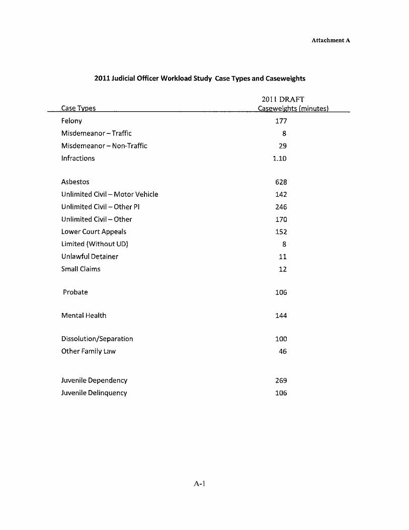


FilingsCase Type Case Weight Filings - 2016 Filings - 2017 Filings - 2018 fiscal 16-17 fiscal 17-18 AverageCivil Lmtd 8 2774 3323 3381 3025 3186 3138Auto/Tort Unlmt 142 172 209 192 192 202 193PI/PD Unltd 246 125 138 154 160 150 145Other Civil Unlmt 170 1160 1109 1141 1076 1155 1128Complex Civil 497 14 35 45 24 30 30SC Appeal 152 14 28 30 17 36 25Family 100 1431 1263 1232 1366 1239 1306Family Petitions 46 1161 1226 1149 1282 1161 1196Probate 106 547 549 547 520 579 548
Total 7398 7880 7871 7662 7738 7710
Case Type Case Weight Filings - 2016 Filings - 2017 Filings - 2018 fiscal 16-17 fiscal 17-18 AverageCivil Lmtd 8 22192 26584 27048 24200 25488 25102Auto/Tort Unlmt 142 24424 29678 27264 27264 28684 27463PI/PD Unltd 246 30750 33948 37884 39360 36900 35768Other Civil Unlmt 170 197200 188530 193970 182920 196350 191794Complex Civil 497 6958 17395 22365 11928 14910 14711SC Appeal 152 2128 4256 4560 2584 5472 3800Family 100 143100 126300 123200 136600 123900 130620Family Petitions 46 53406 56396 52854 58972 53406 55007Probate 106 57982 58194 57982 55120 61374 58130
Total Minutes 538140 541281 547127 538948 546484 542396
CalculationsCategory Column1 Filings - 2016 Filings - 2017 Filings - 2018 fiscal 16-17 fiscal 17-18 AverageJudicial minutes per courtroom 5 courtrooms 107628 108256 109425 107790 109297 108479
Per Judge 5 Judges 107628 108256 109425 107790 109297 1084796 judges 89690 90214 91188 89825 91081 903997 judges 76877 77326 78161 76993 78069 774858 judges 67268 67660 68391 67369 68311 67800
Total Minutes per judge (6.8 current Judges in Monterey) 6.8 79138.2 79600.1 80459.9 79257.1 80365.3 79764.1
Judicial Need
Total minutes/ 77,400 minute standard 7.0 7.0 7.1 7.0 7.1 7.0
Judicial Officer Monterey %Anderson 1Hayes 1Lavorato 1Matcham 1Vallarta 1Culver 0.8Villarreal 0.4Stoner 0.6Total 6.8
Monterey Judicial Caseload
Judicial Workload in minutes
Standard minutes per year per judge: 77,400


1
Robinson, Akilah
From: Franz, Isabelle R. <[email protected]>Sent: Thursday, September 12, 2019 4:34 PMTo: CFACCc: Alejo, LuisSubject: FW: URGENT: Comments on the Draft Statewide List of Trial Court Capital Project: Greenfield & Ft.
Ord Courthouse Proposals, Records RequestAttachments: SeismicEvaluation_MontereyCourthouse_June302018.pdf; City of King City- Greenfield.pdf; City of
Soledad- Greenfield.pdf; City of Gonzales- Greenfield.pdf; City of Salinas- Greenfield.pdf; GreenfieldResolution_May2.pdf; Four Mayors- Greenfield.pdf; SEIU- Greenfield.pdf; SV Chamber of Commerce- Greenfield (002).pdf; Grower Shipper Association- Greenfield.pdf; AlejoLopezLetter_May21.pdf; June3_CoverLetter_JudicialCouncil.pdf
Follow Up Flag: Follow upFlag Status: Flagged
Categories: Orange Category
On behalf of Monterey County Supervisor Luis A. Alejo, please see the below email and attached documents regarding the Draft Statewide List of Trial Court Capital Project: Greenfield & Ft. Ord Courthouse Proposals, Records Request. Please note that Supervisor Alejo’s original email bounced back at 2:39 PM due to large file size. As such, there will be a second email following this one with additional comments and attachments on the Draft Statewide List of Trial Court Capital Project: Greenfield & Ft. Ord Courthouse Proposals, Records Request. If you have any questions, please call our office at 831‐755‐5011. Thank you, Isabelle Franz Office of Monterey County Supervisor Luis A. Alejo District One Begin forwarded message:
From: "Alejo, Luis" <[email protected]> To: "[email protected]" <[email protected]> Cc: "legal‐[email protected]" <legal‐[email protected]>, "[email protected]" <[email protected]>, "'Lopez, Christopher M. x5729'" <[email protected]>, "[email protected]" <[email protected]>, "[email protected]" <[email protected]>, "[email protected]" <[email protected]>, "[email protected]" <[email protected]>, "[email protected]" <[email protected]>, "[email protected]" <[email protected]>, "[email protected]" <[email protected]> Subject: URGENT: Comments on the Draft Statewide List of Trial Court Capital Project: Greenfield & Ft. Ord Courthouse Proposals, Records Request
Dear Judicial Council of California, Please find my attached detailed letter, “Comments on the Draft Statewide List of Trial Court Capital Projects and the Revision of Prioritization Methodology for Trial Court Capital‐Outlay Projects.” I am also resubmitting the June 30, 2018 “Seismic Evaluation Report: Monterey Courthouse, Annex & Parking Garage” which demonstrates that the current Monterey Courthouse is structurally sound. Our

2
County report had actual engineers come and inspect the facility for this study. On the contrary, the study conducted by the Judicial Council and used as a pretextual basis to claim the Monterey Courthouse was “high risk” had no engineers come and inspect the building, according to our County Resource Management Agency Director Carl Holm. I am also attaching past letters of support urging the Monterey County Superior Court to prioritize the long‐promised Greenfield courthouse proposal over the new Seaside proposal or demonstrating support for a new courthouse in South Monterey County:
‐ City of King City ‐ City of Soledad ‐ City of Gonzales ‐ City of Salinas ‐ Resolution dated May 2, 2019 by the Greenfield City Council (stating their contribution of up to
$10 million towards the Greenfield Courthouse) ‐ Four South Monterey County Mayors ‐ SEIU Local 521 ‐ Salinas Valley Chamber of Commerce ‐ Grower Shipper Association of Central California ‐ May 21, 2019 Letter by Supervisor Chris Lopez and me ‐ Prior June 3, 2019 cover letter of documents we submitted prior to public comments period
Can you please confirm that you have received these comments and attached documents. If you have any questions please do not hesitate to contact our office at 831‐755‐5011, or email me directly at this address. Sincerely, LUIS A. ALEJO Monterey County Supervisor, District 1 Former State Assemblymember, District 30


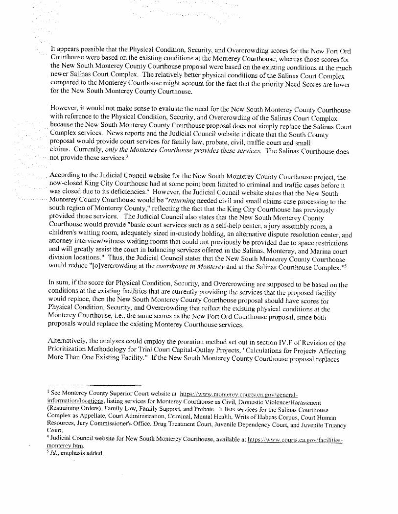


Seismic Evaluation ReportMonterey County Courthouse, Annex & Parking Garage1200 Aguajito Road, Monterey, CA 93940
June 30, 2018
Prepared For:County of Monterey
Prepared By:

June 30, 2018
Dave Pratt Project Manager II County of Monterey Resource Management Agency 1441 Schilling Pl, 2nd Floor Salinas, CA 93901
Re: County of Monterey Seismic Evaluation of 3 Facilities at 1200 Aquajito Road Monterey, California
Dear Mr. Pratt,
We are pleased to submit the following Final Seismic Evaluation Report and Cost Estimate for review and comment.
Objective of Report
This Seismic Evaluation Report covers three buildings; the Monterey County Courthouse, the Courthouse annex, and the adjacent parking structure. These buildings have been reviewed for Life Safety performance level using the ASCE 41-13 Standard for Seismic Evaluation and Retrofit of Existing Buildings, Tier 1 and Tier 2 Evaluations. This standard is based on structural and non-structural damage that has occurred in previous earthquakes and provides a means to identify general deficiencies based on anticipate behavior of specific building types.
The objective of the Report is to: 1. Complete a Seismic Evaluation of these three structures to current ASCE/SEI
Standards. 2. Identify necessary structural improvements to bring the building into
compliance. 3. Identify the architectural, mechanical, electrical, and data scope impacts for
anticipated structural improvements. 4. Prepare a conceptual cost estimate identifying the costs of all improvements.
Summary of Methodology
This Seismic Evaluation was initiated with a site investigation by RIM Architects and ZFA structural engineers on September 30, 2017. The purpose of the site visit was to

June 30, 2018Seismic Evaluation Report
www.rimarchitects.com Page 2 of 2
visually identify existing deficiencies in the structures, and to further understand the design of the structure and existing Architectural and Engineering features that might be affected.
ZFA Structural Engineers completed their analysis, and provided structural recommendations on improvements to shear walls, columns, pre-cast panels, and other structural components. Based on the improvements within the building, RIM Architects provided architectural input as to what floor finishes, partitions, ceilings, and other specialty finishes were affected by the structural upgrades. Electrical, mechanical, and data scope were also identified.
From this information O’Conner Construction Management completed the cost estimate, working in collaboration with RIM Architects and ZFA Structural Engineers.
We are proud of the depth of analysis contained in this report. Please review and comment. We are open to any discussion on any aspect of our report. Thank you for the opportunity to provide you this service.
Sincerely,
RIM
Eric R. Nelson, AIA, NCARB Principal

Table of Contents
Section 1: Seismic Evaluation ReportAppendix A - PhotographsAppendix B - MapsAppendix C - Summary Data SheetAppendix D - Tier 1 ChecklistsAppendix E - Structural Calculations
Section 2: Conceptual Design Cost Estimate

Section 1Seismic Evaluation Report

Final Seismic Evaluation Report Monterey County Courthouse, Annex,
and Parking Garage 1200 Aguajito Road, Monterey, CA 93940
ZFA Project: 17661
June 30, 2018
Prepared For:
RIM Architects
San Francisco, CA
Prepared By:
Chelsea Drenick, Senior Engineer
Ryan Bogart, Senior Associate
Mark A. Moore, Principal in Charge

SEISMIC EVALUATION REPORT – Monterey County Courthouse and Parking Garage | 1 1200 Aguajito Road, Monterey, CA 93940
TABLE OF CONTENTS
EXECUTIVE SUMMARY ..................................................................................................................................... 2
INTRODUCTION ................................................................................................................................................. 4
EVALUATION OVERVIEW.................................................................................................................................. 4
STRUCTURE OVERVIEW ................................................................................................................................... 5
General Site Description .................................................................................................................................. 5
Structural Performance Objective ..................................................................................................................... 5
Site Seismicity (Earthquake Activity) ................................................................................................................ 5
Structural System and Materials Description .................................................................................................... 7
Building Type ................................................................................................................................................. 11
Historical Performance ................................................................................................................................... 11
Benchmark Buildings ..................................................................................................................................... 11
ANALYSIS OVERVIEW..................................................................................................................................... 12
FINDINGS AND RECOMMENDATIONS............................................................................................................ 13
Structural ....................................................................................................................................................... 13
Nonstructural ................................................................................................................................................. 19
SCHEMATIC RETROFIT SCOPE ...................................................................................................................... 20
Courthouse .................................................................................................................................................... 20
Annex ............................................................................................................................................................ 23
Parking Garage.............................................................................................................................................. 25
RELIABILITY OF SEISMIC EVALUATIONS...................................................................................................... 29
CLOSING .......................................................................................................................................................... 29
APPENDIX A – PHOTOGRAPHS...................................................................................................................... 30
APPENDIX B – MAPS ....................................................................................................................................... 37
Location Map ................................................................................................................................................. 38
APPENDIX C – SUMMARY DATA SHEET ........................................................................................................ 40
Summary Data Sheet - Courthouse ................................................................................................................ 41
Material Properties ......................................................................................................................................... 42
Summary Data Sheet – Courthouse Parking Garage ...................................................................................... 43
Material Properties ......................................................................................................................................... 44
APPENDIX D –TIER 1 CHECKLISTS ................................................................................................................ 45
APPENDIX E – STRUCTURAL CALCULATIONS ............................................................................................. 58

SEISMIC EVALUATION REPORT – Monterey County Courthouse and Parking Garage | 2 1200 Aguajito Road, Monterey, CA 93940
EXECUTIVE SUMMARY The Monterey County Courthouse, Annex, and Parking Garage, located at 1200 Aguajito Road in Monterey, California, have been reviewed for a Life Safety performance level using the ASCE 41-13 Standard for Seismic Evaluation and Retrofit of Existing Buildings, Tier 1 and Tier 2 Evaluations. The buildings were reviewed using the original construction documents, structural Tier 1 checklists, and site visits. Nonstructural elements were not included in the scope of this review; however, one nonstructural item is included within the recommendations based on the as-built drawings and observations on site. Items indicated as “noncompliant” or “unknown” by Tier 1 checklists were reviewed using Tier 2 evaluation procedures, unless sufficient information was not available to perform a Tier 2 analysis (e.g. Liquefaction). The review resulted in the following structural and geotechnical findings. Summary tables are provided for each structure indicating noncompliant and unknown items only. COURTHOUSE AND ANNEX As-built drawings were provided for the Courthouse only, not the adjacent Annex structure. However, due to the similar methods, materials, and date of construction, deficiencies noted for the Courthouse building can be reasonably assumed to be present in the Annex.
Structural Check Tier 1 Tier 2 Basic Configuration Checklist
Adjacent buildings Noncompliant n/a
Liquefaction Unknown n/a
Slope failure Unknown n/a
Surface fault rupture Unknown n/a
Checklist for Building Type C1
Column shear stress Noncompliant Noncompliant
No shear failures Noncompliant Noncompliant
Strong column-weak beam Noncompliant Noncompliant
Beam bars Noncompliant Noncompliant
Column-bar splices Noncompliant Noncompliant
Beam-bar splices Noncompliant Noncompliant
Column-tie spacing Noncompliant Noncompliant
Stirrup spacing Noncompliant Noncompliant
Joint transverse reinforcing Noncompliant Compliant
Deflection Compatibility Noncompliant n/a
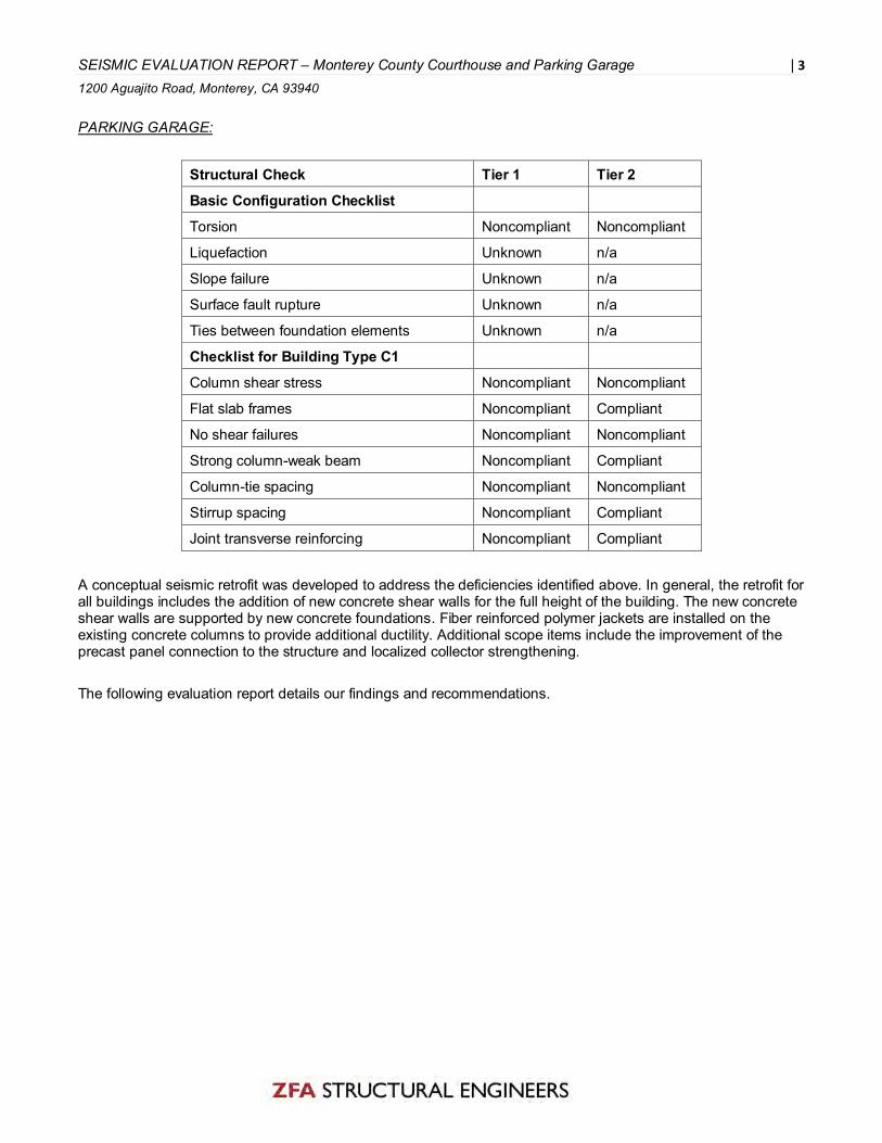
SEISMIC EVALUATION REPORT – Monterey County Courthouse and Parking Garage | 3 1200 Aguajito Road, Monterey, CA 93940
PARKING GARAGE:
Structural Check Tier 1 Tier 2 Basic Configuration Checklist
Torsion Noncompliant Noncompliant
Liquefaction Unknown n/a
Slope failure Unknown n/a
Surface fault rupture Unknown n/a
Ties between foundation elements Unknown n/a
Checklist for Building Type C1
Column shear stress Noncompliant Noncompliant
Flat slab frames Noncompliant Compliant
No shear failures Noncompliant Noncompliant
Strong column-weak beam Noncompliant Compliant
Column-tie spacing Noncompliant Noncompliant
Stirrup spacing Noncompliant Compliant
Joint transverse reinforcing Noncompliant Compliant
A conceptual seismic retrofit was developed to address the deficiencies identified above. In general, the retrofit for all buildings includes the addition of new concrete shear walls for the full height of the building. The new concrete shear walls are supported by new concrete foundations. Fiber reinforced polymer jackets are installed on the existing concrete columns to provide additional ductility. Additional scope items include the improvement of the precast panel connection to the structure and localized collector strengthening. The following evaluation report details our findings and recommendations.

SEISMIC EVALUATION REPORT – Monterey County Courthouse and Parking Garage | 4 1200 Aguajito Road, Monterey, CA 93940
INTRODUCTION The purpose of this evaluation is to review and evaluate the structural systems of the subject buildings using criteria provided by ASCE 41-13. The evaluation criteria have been tailored for specific building types and desired levels of building performance. This standard is based on criteria developed from observation of structural and nonstructural damage occurring in previous earthquakes and provides a means to identify general deficiencies based on anticipated behavior of specific building types. The evaluation begins with a Screening Phase (Tier 1) to assess primary components and connections in the seismic force-resisting system through the use of standard checklists and simplified structural calculations. Checklist items are general in nature and are intended to highlight building components that do not exceed conservative construction guidelines. If the element is compliant, it is anticipated to perform adequately under seismic loading without additional review or strengthening. Items indicated as noncompliant in a Tier 1 checklist are considered potential deficiencies that require further analysis. A limited, deficiency-based Evaluation Phase (Tier 2) can then be used to review the items determined to be potential deficiencies by Tier 1 checklists and simplified calculations. Noncompliant items are evaluated for calculated linear seismic demands as determined by ASCE 41-13. If the element is compliant with Tier 2 analysis procedures, the Tier 1 deficiency is waived. However, if the element remains noncompliant after the more detailed Tier 2 analysis, repair or remediation of the deficiency is recommended. In certain cases, a more detailed Systematic Evaluation (Tier 3) may be more appropriate for complex structures where a Tier 2 analysis may be considered significantly conservative. A Tier 3 structural evaluation generally requires a substantially greater level of effort than a Tier 2 review. A Tier 3 evaluation was not performed for these buildings.
EVALUATION OVERVIEW This seismic evaluation report for the existing buildings located at 1200 Aguajito Road in Monterey, California is based on the following:
• The American Society of Civil Engineers / Structural Engineering Institute (ASCE/SEI 41-13) Standard for Seismic Evaluation and Retrofit of Existing Buildings - Tier 1 and Tier 2 (noncompliant items only), Life Safety-level structural evaluation criteria.
• One site visit for general review of structures performed on September 30, 2017. No destructive testing or
removal of finishes was performed or included in scope. • Review of following original drawings by Wallace Holm AIA Architect and Associates:
o Structural and architectural drawings for the Courthouse, dated Nov. 29, 1966 (15 & 23 sheets) o Architectural drawings for the Annex, dated Feb. 1, 1965 (3 sheets) o Structural and architectural drawings for the Parking Garage, dated Jan. 2, 1973 (10 & 3 sheets)
• Existing material properties as indicated in Appendix C.
• A Geotechnical report was not available. Minimal Geotechnical information showing boring profiles is
present on the Parking Garage architectural drawings.

SEISMIC EVALUATION REPORT – Monterey County Courthouse and Parking Garage | 5 1200 Aguajito Road, Monterey, CA 93940
• A formal Tier 1 evaluation of nonstructural elements is not included. (One nonstructural item is noted inthe recommendations based on information in the as-built drawings.)
STRUCTURE OVERVIEW
General Site Description
The site is located on a gently sloping lot approximately 100 feet southeast of Highway 1 and approximately 1.5 miles west of the Monterey Regional Airport on Aguajito Road. The campus is located with the main entrance facing east towards Aguajito Road, and the Courthouse building on the north side of the site, the Annex immediately south of the Courthouse, and the Parking Garage approximately 100 feet south of the Annex. The site and structures are currently occupied by Monterey County and in use as office, health, and courthouse facilities.
Structural Performance Objective
Per ASCE 41-13, a structural performance objective consists of a target performance level for structural elements in combination with a specific seismic hazard level. For seismic assessment of the subject building, the Basic Performance Objective for Existing Buildings (BPOE) was selected. While the BPOE seeks safety for occupants with reasonable confidence, it allows existing structures to be assessed for seismic forces that are less than those required for the design of new structures under the current building code. Buildings meeting the BPOE are expected to experience nominal damage from relatively frequent, moderate earthquakes, but have the potential for significant damage and economic loss from the most severe, though less frequent, seismic events.
For the purposes of this review to the BPOE, the specified level of performance is Life Safety (3-C) for this non-essential structure (Risk Category II as defined by ASCE 7). The Life Safety Performance Level as described by ASCE/SEI 41-13: ‘Structural Performance Level S-3 is defined as the post-earthquake damage state in which a structure has damaged components but retains a margin against the onset of partial or total collapse. Nonstructural Performance Level N-C is the post-earthquake damage state in which Nonstructural Components may be damaged, but the consequential damage does not pose a Life Safety threat.’
Site Seismicity (Earthquake Activity)
Per ASCE 41-13, ‘seismicity’, or the potential for ground motion, is classified into regions defined as Low, Moderate, or High. These regions are based upon mapped site accelerations Ss and S1 which are then modified by site coefficients Fa and Fv to produce the Design Spectral Accelerations, SDS (short period) and SD1 (1-second period). The successful performance of buildings in areas of high seismicity depends on a combination of strength, ductility of structural components, and the presence of a fully interconnected, balanced, and complete seismic force-resisting system. Where buildings occur in lower levels of seismicity, the strength and ductility required for better performance is significantly reduced, and building components or connections with additional strength capacity can in some cases be adequate despite lacking ductility.
Since sufficient data for the determination of the building Site Class at the subject site was not provided for review, a soil profile of Site Class D shall be assumed per ASCE 41-13, Section 2.4.1.6.2, for use in determination of site coefficients Fa and Fv.
Per the site values indicated by USGS data and evaluated using seismic acceleration equations and tables of ASCE 41-13, the site is located in a region of High Seismicity with a design short-period spectral response acceleration parameter (SDS) of 1.009g and a design spectral response acceleration parameter at a one second period (SD1) of 0.555g. Per the table shown below, both of these parameters exceed the lower boundaries for high seismicity classification, 0.5g for SDS and 0.2g for SD1.

SEISMIC EVALUATION REPORT – Monterey County Courthouse and Parking Garage | 6 1200 Aguajito Road, Monterey, CA 93940
Level of Seismicity* SDS SD1
Low < 0.167g < 0.067g
Moderate ≥ 0.167g < 0.500g
≥ 0.067g < 0.200g
High ≥ 0.500g ≥ 0.200g
*Where SDS and SD1 values fall in different levels of seismicity, the higher level shall be used.
The spectral response parameters SS and S1 were obtained for the BSE-1E seismic hazard level for existing structures (BPOE). The acceleration values were adjusted for the maximum direction and site class in accordance with ASCE 41 Section 2.4.1, and compared to BSE-1N (used by current building code for design of new buildings) to determine the design values for the Tier 1 and Tier 2 analyses, since values obtained for the BSE-1E hazard level need not exceed the hazard levels for new construction.
The following chart depicts the response spectra for the multiple seismic hazard levels defined by ASCE 41-13: two existing hazard levels and two hazard levels corresponding to code design of new structures (ASCE 7).
0
0.2
0.4
0.6
0.8
1
1.2
1.4
1.6
0 0.2 0.4 0.6 0.8 1 1.2 1.4
Spec
tral
Acc
eler
atio
n (
g)
Period (sec)
BSE-1E
BSE-1N
BSE-2E
BSE-2N
Maximum Considered Earthquake (BSE-2E and BSE-2N) – For Reference Only
BPOE Seismic Hazard (BSE-1E)
New Construction Seismic Hazard (BSE-1N)

SEISMIC EVALUATION REPORT – Monterey County Courthouse and Parking Garage | 7 1200 Aguajito Road, Monterey, CA 93940
Structural System and Materials Description
General There are three buildings on the subject site: A four-story Courthouse building, a two-story Annex building immediately adjacent to the Courthouse, and a three-level parking garage located approximately 100 feet south of the Annex. These structures are shown on the site map in Figure 1.
Figure 1: Site map
Courthouse: The Courthouse building is a four-story concrete structure with precast concrete façade panels that was designed in 1966. It is approximately 57,300 square feet in total building area, and the ground floor is partially built into the hillside such that it daylights on the north and west faces. The building currently houses courtrooms and administration offices, and floor-to-floor heights are 13’-6” at the basement level, 16’-6” at the plaza level, and 15’-0” at the third and fourth floor levels. The overall building height is approximately 60’-0” to the roof slab. Figure 2 shows a longitudinal section through the building looking north, and Figure 3 shows a transverse section through the building and adjacent Annex looking west. Annex: The Annex building is a two-story concrete structure with precast concrete façade panels that was designed in 1965. It is approximately 24,200 square feet, and the ground floor is partially underground, daylighting on the west face and on the west portion of the south face. The Annex is joined to the Courthouse at the basement level and is separated from the Courthouse by approximately three inches at the above-grade second level. Floor-to-floor heights are 13’-6” at both levels. Figure 3 shows a section through the Annex and Courthouse buildings. Parking Structure: The Parking structure is a three-level concrete structure (including parking on the roof level) designed in 1973. It is approximately 34,200 square feet and is located on a sloping grade (sloping down to the west). Figure 4 shows a plan and section view of the Parking Garage.

SEISMIC EVALUATION REPORT – Monterey County Courthouse and Parking Garage | 8 1200 Aguajito Road, Monterey, CA 93940
Figure 2: Longitudinal section through Courthouse looking North
Figure 3: Transverse section through Courthouse (right) and Annex (left) looking West
Figure 4: Plan view of Parking Garage (left); Section through Parking Garage looking north
Roof Framing
Courthouse: The roof level of the Courthouse building is approximately 60 feet above the basement level floor. Roof framing consists of one-way concrete slabs over metal deck that span to concrete roof beams at 8’-0” spacing. The roof beams span east-west across 36’-0” bays to concrete girders. The concrete

SEISMIC EVALUATION REPORT – Monterey County Courthouse and Parking Garage | 9 1200 Aguajito Road, Monterey, CA 93940
girders span north-south across 24’-0” bays to concrete columns. At the east and west sides of the building, the beams cantilever 8’-0” past the last girder line. At the north and south sides of the building, the girders cantilever 5’-6” past the column line to support a beam at the edge of the slab. Over the framing is a built-up roofing system that drains to a number of interior drains. In the center of the roof slab is a mechanical penthouse that occurs over two framing bays (~36’-0” x 48’-0”) and is 16’-0” tall. This penthouse structure is steel-framed with a corrugated steel un-topped roof deck that spans to steel beams at 6’-0” spacing supported by steel girders and steel wide flange columns. Annex: The structural drawings for the Annex were not available for review. Based on the information in the Courthouse drawings, limited architectural drawings of the Annex, and the construction type observed on site, the framing at the Annex is assumed to be similar to the Courthouse.
Parking Garage: See Floor Framing section.
Floor Framing
Courthouse: The floor levels of the Courthouse building are framed very similarly to each other, and in a similar configuration to the roof. One-way concrete slabs over metal deck span to concrete beams at 8’-0” spacing. Beams span east-west across 36’-0” bays to concrete girders, and girders span north-south across 24’-0” bays to concrete columns. The framing cantilevers on all four sides of the building similar to the roof framing, and the exterior glazing occurs at the edge of the slab typically on the upper two floors. At the lower floors, including the daylighting basement, glazing typically is typically set back from the edge of the slab, occurring along the column lines. A balcony occurs around the perimeter of the plaza level, and at numerous locations on the third and fourth floors. Columns are on a regular grid (24x36 feet) and are typically 18-inch square at the third and fourth floors and 24-inch square at the basement and plaza floors. Annex: The structural drawings for the Annex were not available for review. Based on the information in the Courthouse drawings, limited architectural drawings of the Annex, and the construction type observed on site, the framing at the Annex is assumed to be similar to the Courthouse. Parking Garage: Each of the three floors of the parking garage is framed the same using post-tensioned slabs and girders. The slab is post-tensioned in both directions, but only spans one direction (north-south) to girders spaced at approximately 25-foot spacing. The girders are also post-tensioned and are supported by two columns each, oriented with a middle span of 34 feet between the columns and a cantilever of 13.5 feet at each end. Columns are 24-inches square between the first and second level and between the second and third level. Below the first level, the columns increase to 32-inch diameter and vary in height above grade depending on the slope of the hillside.
Walls
Courthouse: All interior and exterior walls at the Courthouse are non-bearing partitions constructed of light-gage metal studs. Most interior walls are one-hour fire rated; shaft walls have a two-hour rating. Annex: The structural drawings for the Annex were not available for review. The framing at the Annex is assumed to be similar to the Courthouse. Parking Garage: Only one structural wall occurs at the parking garage, which is a 10-inch-thick concrete shear wall along the east face of the building. At the upper level, the wall occurs in one bay (approximately 25-foot length) and at the lower floor, the wall occurs in two bays (approximately 50-foot length, with openings).

SEISMIC EVALUATION REPORT – Monterey County Courthouse and Parking Garage | 10 1200 Aguajito Road, Monterey, CA 93940
Seismic Force-Resisting Systems Courthouse: The de-facto lateral system at the Courthouse building is concrete moment frames. However, the reinforcement design and detailing in the beams and columns does not provide sufficient ductility to resist design seismic forces required by modern building codes.
Annex: The structural drawings for the Annex were not available for review. The lateral system at the Annex is assumed to be the same as the Courthouse.
Parking Garage: In the north-south direction, one reinforced concrete shear wall occurs at the east face of the building. As the rest of the system in this direction consists of flat slabs framing to concrete columns, the structure is expected to be extremely torsionally irregular in this direction. The de-facto lateral system in the east-west direction is concrete moment frames, formed by post-tensioned beams and cast-in-place columns. These frames were not designed and detailed to provide sufficient ductility to resist design seismic forces required by modern building codes.
Foundations Courthouse: The Courthouse is supported by shallow pad footings at interior and exterior column locations. The footings range in size from 9’-4” square to 10’-8” square and are typically 36 inches deep. They are typically well-reinforced with #9 bars at approximately 4-inch spacing in both directions, placed with three inches clear to the bottom of the footing. Concrete columns are concentric to the footings and column reinforcement typically continues into the bottom of the footing. A 6-inch slab on grade is present throughout the basement floor, and retaining walls occur on the south and east sides of the building.
Annex: The structural drawings for the Annex were not available for review. The foundation system at the Annex is assumed to be similar to the Courthouse, though the pad footings are expected to be significantly smaller since the building loads are expected to be approximately half of what they are at the Courthouse.
Parking Garage: Concrete columns that support the post-tensioned beam systems at the Parking Garage continue into the ground and support the building as drilled caissons. Caissons are 36-inches in diameter and extend approximately 26 feet below grade. At the west column line, the columns above the caissons (32-inch diameter) extend above grade three to seven feet up to the first floor.
Field Verification and Condition Assessment The structures on the campus appear to be in generally good structural condition with minimal structural damage or deterioration apparent, and appear to be constructed in general accordance with the provided structural drawings, although there are a few items of note.
Courthouse: Localized damage to the exterior sidewalk slab and stair on the southeast side of the building was observed. The cracking appears to have been caused by settlement of the slab adjacent to the building, but does not appear to be structurally significant to the building itself. See Photo 6 in Appendix A.
Annex: Spalling of an exterior concrete column was observed at the northeast corner of the Annex. The spalling appears to be isolated to this column and does not appear to be structurally significant. See Photo 7 in Appendix A.
A large crack was observed in a concrete beam and exterior concrete wall at the exterior of the northwest corner of the Annex building adjacent to the Courthouse. The crack may have been caused by differential settlement between the two buildings, although no signs of settlement were readily observed in the rest of

SEISMIC EVALUATION REPORT – Monterey County Courthouse and Parking Garage | 11 1200 Aguajito Road, Monterey, CA 93940
the building. Therefore, the crack does not appear to be structurally significant. See Photo 8 in Appendix A. Parking Garage: Systemic corrosion was observed in nonstructural components throughout the parking garage, particularly in guardrails and associated hardware. Dry rot and or deterioration due to pests was also observed in wood members on the roof. None of these conditions are judged to be structurally significant. See Photos 9 and 10 in Appendix A.
Material Properties Basic properties for existing structural materials found on existing building documentation, through testing or ASCE 41 code prescribed minimum structural values utilized in the analysis calculations can be found in Appendix C. Building Type
Per ASCE/SEI 41-13, these building can be classified as Building Type C1: Concrete Moment Frames. As described by ASCE/SEI 41-13: ‘These buildings consist of a frame assembly of cast-in-place concrete beams and columns. Floor and roof framing consists of cast-in-place concrete slabs, concrete beams, one-way joists, two-way waffle joists, or flat slabs. Seismic forces are resisted by concrete moment frames that develop their stiffness through monolithic beam-column connections. In older construction, or in levels of low seismicity, the moment frames may consist of the column strips of two-way flat slab systems. Modern frames in levels of high seismicity have joint reinforcing, closely spaced ties, and special detailing to provide ductile performance. This detailing is not present in older construction. The foundation system may consist of a variety of elements.’ Note that the Parking Garage consists of concrete moment frames in the east-west direction and a dual system in the north-south direction, composed of a concrete shear wall and moment frames. For the purpose of this evaluation, this structure was evaluated using the criteria for Building Type C1. However, retrofit solutions included a review of the contributions from the concrete shear wall. Historical Performance
Modern concrete lateral-resisting systems, including moment frames, are designed to be ductile. When subjected to strong ground motions, earthquake-induced cyclic loading forms “plastic hinges”—deformations that absorb earthquake energy and dissipate forces—before the concrete fails in shear. The design of semi-ductile and ductile concrete systems began in the late 1960s and the early 1970s when prescriptive rules for lateral-resisting elements were implemented to govern design. Structures built prior to this were non-ductile and tended to be relatively weak. Prior to the prescriptive requirements of the late 1960s, when spiral/shear ties were not always included in design, columns could fail in shear before plastic hinges could form. These buildings are known to perform poorly and may collapse when ground motion is strong enough to initiate shear failures in the columns. The semi-ductile and ductile system designs that began in the late 1960s include many of the modern design features and are expected to perform satisfactorily per code in a seismic event, provided there are no vertical or horizontal configuration irregularities that will concentrate demand on individual components. Benchmark Buildings
In addition to classifying buildings by type of construction, ASCE 41 identifies ‘Benchmark Buildings’ for each type. The detailing of seismic force-resisting systems in Benchmark Buildings is generally considered to meet the performance requirements of ASCE 41. When a building is determined to meet Benchmark Building requirements through field verification of construction compliant with benchmark code requirements, only the review of foundation and nonstructural elements is required. Even though a building appears to meet the benchmark criteria, a full analysis may still be recommended under certain circumstances.

SEISMIC EVALUATION REPORT – Monterey County Courthouse and Parking Garage | 12 1200 Aguajito Road, Monterey, CA 93940
For building type C1, the 1993 seismic design provisions are referenced as the oldest permitted standard. Since the Courthouse and Annex were designed in 1966 and 1965, respectively, they are assumed to have been designed to the 1964 Uniform Building Code. The Parking Garage documents indicate that the design is in accordance with the 1970 Uniform Building Code. Therefore, none of the subject buildings meet the criteria of a Benchmark Building and a complete Tier 1 analysis is required. ANALYSIS OVERVIEW Tier 1 analysis requires only hand-calculations to check existing conditions against “quick check” procedures listed in the Tier 1 checklists. These analyses are detailed in Appendix E of this report and described conceptually in the Findings and Recommendations section below. The Tier 2 analysis of each building requires a full-building model to be created to analyze each building’s response to seismic forces. A full-building, three-dimensional model was constructed in ETABS analysis software for the Courthouse and Parking Garage buildings, as shown in Figures 5 and 6. Modeled elements include concrete roof and floor slabs, concrete beams and girders, concrete columns, and the concrete shear wall in the Parking Garage. The seismic analysis procedure used was a Linear Static Procedure with seismic accelerations in accordance with Seismic Hazard Level BSE-1E in ASCE 41-13.
Figure 5: Courthouse model in ETABS software
Figure 6: Parking Garage model in ETABS software

SEISMIC EVALUATION REPORT – Monterey County Courthouse and Parking Garage | 13 1200 Aguajito Road, Monterey, CA 93940
FINDINGS AND RECOMMENDATIONS Structural
The ASCE 41-13 Tier 1 Basic Life Safety and Building Type Specific Checklists indicate multiple noncompliant and unknown areas for Life Safety Performance. For the Courthouse, 11 items were found to be noncompliant with the Tier 1 checks and an additional three items were unknown. The Annex is assumed to have the same deficiencies as the Courthouse. For the Parking Garage, eight items were found to be noncompliant with the Tier 1 checks, and an additional four items were unknown. The noncompliant and unknown deficiencies for each building are listed below, along with the Tier 2 evaluation results (where applicable) and recommended actions.
Courthouse (and Annex)
a. ADJACENT BUILDINGS (ASCE Section 4.3.1.2): “The clear distance between the building being evaluated and any adjacent building is greater than 4% of the height of the shorter building.” The height of the Annex above grade is approximately 13’-6”. Four percent of 13’-6” is approximately 6.5 inches. Because the gap between the Courthouse and Annex is only approximately three inches, this Tier 1 deficiency is applicable.
RECOMMENDATION: The addition of new shear walls in both buildings will provide additional stiffness and will decrease the anticipated lateral deformations of the buildings during an earthquake. Additional analysis should be performed to estimate horizontal movement in a seismic event with the additional stiffness considered. Minor damage may occur due to pounding between structures during a seismic event; however, damage due to this condition is not anticipated to cause life safety structural concerns within the subject building. Improved anchorage of the precast panel finish at these locations may also be prudent to reduce the probability of the panels being dislodged in a seismic event.
b. COLUMN SHEAR STRESS CHECK: “The shear stress in the concrete columns, calculated using
the Quick Check procedure of Section 4.5.3.2, is less than the greater of 100 lb/in.2 or 2√f′c.” The shear stress in the columns were found to be 1.5 to 2.7 times higher than the allowable stress in the quick check procedure and were therefore found to be noncompliant with the Tier 1 check.
The Tier 2 analysis was performed in accordance with ASCE 41-13 Section 5.5.2.1.4. The maximum demands on the structure were extracted from the 3D ETABS model to compare with the capacities listed in Chapter 10 of ASCE 41-13. Calculations were performed to determine if the columns are shear- or flexure-controlled, which is required to determine the specific m-factor of the columns. Using the appropriate m-factor and knowledge factor, the capacities were found and compared to the demands. Columns have a demand-capacity ratio of 1.5 to 2.5 at each floor level and therefore remain noncompliant in the Tier 2 evaluation. RECOMMENDATIONS: Because columns were found to be inadequate to resist the BSE-1E seismic demands at the Life Safety performance level, a retrofit of the building is recommended to improve seismic performance. The recommended retrofit scope includes the addition of concrete shear walls in both directions at all levels. This new lateral system will significantly reduce building drifts and seismic demands on the concrete columns and provide the building with adequate strength and stiffness to meet the Life Safety performance objective at the BSE-1E hazard level. Additionally, we recommend “jacketing” the concrete columns at all floor levels with fiber-reinforced polymer (FRP) to provide adequate deformation compatibility with the new shear wall system.

SEISMIC EVALUATION REPORT – Monterey County Courthouse and Parking Garage | 14 1200 Aguajito Road, Monterey, CA 93940
c. NO SHEAR FAILURES: “The shear capacity of frame members is able to develop the moment capacity at the ends of the members.” The columns in the basement level and some columns at the plaza level do not have sufficient capacity to develop the flexural strength of the section and therefore will experience a shear failure before a flexural failure. Columns at the third and fourth floor levels, as well as all beams and girder, are able to fully develop the strength in flexure before a shear failure occurs. Because of the deficiency in the basement and plaza level columns, the Tier 1 deficiency is applicable.
The Tier 2 analysis was performed in accordance with ASCE 41-13 Section 5.5.2.3.4. The Tier 2 check of these elements was included in the analysis of the previous item for Column Shear Stress. The columns remain noncompliant in the Tier 2 evaluation for this deficiency. RECOMMENDATIONS: See the recommendations for Column Shear Stress above.
d. STRONG COLUMN-WEAK BEAM: “The sum of the moment capacity of the columns is 20%
greater than that of the beams at frame joints.” None of the interior girder-to-column connections meet the “strong column-weak beam” ratio required; therefore, the building was found to be noncompliant with the Tier 1 check.
The Tier 2 analysis was performed in accordance with ASCE 41-13 Section 5.5.2.1.5 and evaluated the interior girder-to-column connections. Similar calculations to Column Shear Stress Check were performed for this deficiency. The maximum shear and moment demands were extracted from the ETABS model and compared to the calculated capacities. All columns were found to be deficient in both shear and flexure, hence this deficiency remains noncompliant in the Tier 2 evaluation. RECOMMENDATIONS: See the recommendations for Column Shear Stress above.
e. BEAM BARS: “At least two longitudinal top and two longitudinal bottom bars extend continuously
throughout the length of each frame beam. At least 25% of the longitudinal bars provided at the joints for either positive or negative moment are continuous throughout the length of the members.” The as-built structural drawings (Sheet S4) show that the beams and girders all have discontinuous reinforcement at certain locations; therefore, the structure is noncompliant with this Tier 1 check.
The Tier 2 analysis was performed in accordance with ASCE 41-13 Section 5.5.2.3.5 whereby flexural demands of noncompliant beams and girders were analyzed at the middle and ends of their span using an m-factor of 1.0. Maximum demands for the beams were extracted from the ETABS model to be compared to the capacity. All beams and girders had adequate capacity at the middle of their span, but none of the beams had adequate capacity at their ends. The only girders that had adequate capacity at their ends were at the roof level; all other girders did not have adequate capacity at their ends. Therefore, the beams and girders remain noncompliant in the Tier 2 evaluation for this deficiency. RECOMMENDATION: See the recommendations for Column Shear Stress above. These recommendations will similarly relieve stresses on the beams as they do for the columns.
f. COLUMN-BAR SPLICES: “All column-bar lap splice lengths are greater than 35db and are
enclosed by ties spaced at or less than 8db. Alternatively, column bars are spliced with mechanical couplers with a capacity of at least 1.25 times the nominal yield strength of the spliced bar.” Most of the columns in the building do not meet this requirement based on the

SEISMIC EVALUATION REPORT – Monterey County Courthouse and Parking Garage | 15 1200 Aguajito Road, Monterey, CA 93940
reinforcement detailed in the as-built drawings. Therefore, the structure is noncompliant with this Tier 1 check. The Tier 2 analysis was performed in accordance with ASCE 41-13 Section 5.5.2.3.6 whereby the flexural demands at noncompliant column splices were calculated. These occur at the plaza, third, and fourth floor levels. None of the Tier 1 noncompliant columns passed the Tier 2 check, and therefore the columns remain noncompliant for the Tier 2 evaluation of this deficiency. RECOMMENDATIONS: See the recommendations for Column Shear Stress above.
g. BEAM-BAR SPLICES: “The lap splices or mechanical couplers for longitudinal beam reinforcing
are not located within lb/4 of the joints and are not located in the vicinity of potential plastic hinge locations.” The lap splices in the beams are nearly always located in the regions noted based on the reinforcement detailed in the as-built drawings. Therefore, the structure is noncompliant with this Tier 1 check. The Tier 2 analysis was performed in accordance with ASCE 41-13 Section 5.5.2.3.6. The beams were analyzed in the same manner as the check for Beam Bars, but the m-factor was increased to 1.5 in accordance with Table 10-13 in ASCE 41-13. Even considering this increased m-factor value, the beams were still found to be noncompliant, and therefore the beams remain noncompliant for the Tier 2 evaluation of this deficiency. RECOMMENDATIONS: See the recommendations for Column Shear Stress above. These recommendations will similarly decrease stresses in the beams as they do for the columns.
h. COLUMN-TIE SPACING: “Frame columns have ties spaced at or less than d/4 throughout their
length and at or less than 8db at all potential plastic hinge locations.” Both 18-inch square and 24-inch square columns have ties spaced at 18 inches typical throughout their height and at 9 inches in the hinge zones. These spacings do not meet the requirements of this check and therefore the structure is noncompliant with this Tier 1 check. The Tier 2 analysis was performed in accordance with ASCE 41-13 Section 5.5.2.3.7. Column shear and flexural demands were checked in the Column Shear Stress and Column-Bar Splices checks and were found to be noncompliant. Therefore, the columns remain noncompliant for the Tier 2 evaluation of this deficiency. RECOMMENDATIONS: See the recommendations for Column Shear Stress above.
i. STIRRUP SPACING: “All beams have stirrups spaced at or less than d/2 throughout their length.
At potential plastic hinge locations, stirrups are spaced at or less than the minimum of 8db or d/4.” Typical girder stirrup spacing is 14 inches (including in hinge zones), and typical beam stirrup spacing is 18 inches (including hinge zones). For girders, stirrup spacing outside the hinge zone is compliant, but at all other locations (girders in the hinge zone, beams in all locations), the stirrup spacing is noncompliant. Therefore, the structure is noncompliant with this Tier 1 check. The Tier 2 analysis was performed in accordance with ASCE 41-13 Section 5.5.2.3.7 whereby seismic shear demands from ETABS were checked against shear capacities for typical beams and girders at each floor (at mid-span and over columns). All beams were noncompliant, with demand-to-capacity ratios ranging from 1.0 (just barely compliant) to 4.2. Roof girders were found to be compliant, but all other girders were noncompliant, with demand-to-capacity ratios ranging

SEISMIC EVALUATION REPORT – Monterey County Courthouse and Parking Garage | 16 1200 Aguajito Road, Monterey, CA 93940
from 1.2 to 2.5. Therefore, the beams remain noncompliant for the Tier 2 evaluation of this deficiency. RECOMMENDATIONS: See the recommendations for Column Shear Stress above. These recommendations will similarly decrease stresses in the beams as they do for the columns.
j. JOINT TRANSVERSE REINFORCING: “Beam-column joints have ties spaced at or less than
8db.” Based on the two checks above, this item is noncompliant with this Tier 1 check. The Tier 2 analysis was performed in accordance with ASCE 41-13 Section 5.5.2.3.8. At all conditions, the shear demands from the ETABS model were found to be less than the capacities calculated in accordance with ASCE 41-13 Section 10.4.2.3.2. Therefore, this deficiency is waived in the Tier 2 analysis. RECOMMENDATIONS: None.
k. DEFLECTION COMPATIBILITY: “Secondary components have the shear capacity to develop the flexural strength of the components.” Precast concrete panel façade connections are nonductile and not designed to resist the forces generated when the structure experiences lateral movement from seismic forces. Therefore, the structure is noncompliant with this Tier 1 check. The Tier 2 model of the structure did not model the precast concrete façade panel connections, as these are considered a nonstructural component. RECOMMENDATIONS: Retrofit to the precast panel connections is recommended to achieve a more ductile attachment that can better respond to seismic building movement.
l. UNKNOWN ITEMS: Items present in the Tier 1 checklist that were noted to be “Unknown” due to
lack of documentation or geotechnical information include the following:
i. LIQUEFACTION: “Liquefaction-susceptible, saturated, loose granular soils that could jeopardize the building’s seismic performance shall not exist in the foundation soils at depths within 50 feet under the building.”
ii. SLOPE FAILURE: “The building site is sufficiently remote from potential earthquake-induced slope failures or rockfalls to be unaffected by such failures or is capable of accommodating any predicted movements without failure.”
iii. SURFACE FAULT RUPTURE: “Surface fault rupture and surface displacement at the building site are not anticipated.”
RECOMMENDATIONS: It is recommended that a Geotechnical Engineer is consulted and engaged to provide a report at the subject site that addresses the above “unknown” items.
Parking Garage
a. TORSION: “The estimated distance between the story center of mass and the story center of
rigidity is less than 20% of the building width in either plan dimension.” A concrete shear wall is present only on one side of the building, a condition that moves the center of rigidity to the east side of the building when considering seismic forces in the north-south direction. Therefore, by inspection, the building is noncompliant for this Tier 1 check.

SEISMIC EVALUATION REPORT – Monterey County Courthouse and Parking Garage | 17 1200 Aguajito Road, Monterey, CA 93940
The Tier 2 analysis was performed in accordance with ASCE 41-13 Section 5.3.2.6 whereby the torsional response was modeled in ETABS and a retrofit solution was investigated to mitigate the irregularity.
RECOMMENDATIONS: The addition of another concrete shear all on the west side of the building is recommended to remove the torsional irregularity.
b. COLUMN SHEAR STRESS CHECK: “The shear stress in the concrete columns, calculated usingthe Quick Check procedure of Section 4.5.3.2, is less than the greater of 100 lb/in.2 or 2√f′c.” Theshear stresses in the columns were found to be up to 2.0 times higher than the allowable stress inthe quick check procedure and were therefore found to be noncompliant with the Tier 1 check.
The Tier 2 analysis was performed in accordance with ASCE 41-13 Section 5.5.2.1.4 whereby the maximum seismic force demands were determined from the ETABS model for the columns at each floor and compared to capacities calculated with the appropriate m-factor for each element. The columns below the first floor were found to be just under 100% stressed, but columns at the first and second floors were overstressed by 38% and 28% respectively. Therefore, the columns remain noncompliant in the Tier 2 evaluation for this deficiency.
RECOMMENDATIONS: The retrofit recommendation to remedy this item is twofold. First, in the north-south direction, another concrete shear wall is recommended to be added along the west face of the building. This will significantly reduce the seismic forces that are resisted by the columns and remove the torsional irregularity. Second, to accommodate seismic demands in the east-west direction, the columns on both floors are recommended to be “jacketed” in fiber-reinforced polymer (FRP) to increase shear capacity and ductility and improve lateral deflections (drift).
c. FLAT SLAB FRAMES: “The seismic-force-resisting system is not a frame consisting of columnsand a flat slab or plate without beams.” The configuration of the structure in the north-southdirection does not meet this requirement, and therefore the building is noncompliant for this Tier 1check.
The Tier 2 analysis was performed in accordance with ASCE 41-13 Section 5.5.2.3.1 whereby the flexural capacities of the flat slab were checked for seismic demands derived from the ETABS model. The slab was found to be adequate in flexure. Punching shear is not a concern with the configuration present because transverse beams are present between the flat slab and columns. Therefore, this deficiency is waived in the Tier 2 analysis.
RECOMMENDATIONS: None.
d. NO SHEAR FAILURES: “The shear capacity of frame members is able to develop the momentcapacity at the ends of the members.” The columns at the first and second floors do not havesufficient capacity to develop the flexural strength and therefore will experience a shear failurebefore a flexural failure. Columns at the ground floor (below the first floor) and beams at all floorsare able to fully develop the strength in flexure before a shear failure occurs. Because of thedeficiency in the first and second floor columns, the building is noncompliant for this Tier 1 check.
The Tier 2 analysis was performed in accordance with ASCE 41-13 Section 5.5.2.3.4. Because only the columns at the first and second floors were noncompliant in the Tier 1 check, the Tier 2 check of these elements was included in the analysis of the previous item for Column Shear Stress. The columns remain noncompliant in the Tier 2 evaluation for this deficiency.

SEISMIC EVALUATION REPORT – Monterey County Courthouse and Parking Garage | 18 1200 Aguajito Road, Monterey, CA 93940
RECOMMENDATIONS: See the recommendations for Column Shear Stress above.
e. STRONG COLUMN-WEAK BEAM: “The sum of the moment capacity of the columns is 20%
greater than that of the beams at frame joints.” The beam-to-column connections in the transverse direction (beam-column) at the second floor and roof do not meet the “strong column-weak beam” ratio required, therefore the building was found to be noncompliant with the Tier 1 check.
The Tier 2 analysis was performed in accordance with ASCE 41-13 Section 5.5.2.1.5. The seismic demands were derived from the ETABS model and compared to the interior girder-to-column capacities using an m-factor of 2.0. Using this check, all connections were found to be compliant, with a maximum demand-to-capacity ratio of 0.88 occurring at the roof level in the transverse direction. Therefore, this deficiency is waived in the Tier 2 analysis. RECOMMENDATIONS: None.
f. COLUMN-TIE SPACING: “Frame columns have ties spaced at or less than d/4 throughout their
length and at or less than 8db at all potential plastic hinge locations.” The 32-inch diameter columns that occur below the first floor have spirals spaced at 2.5 inches, which meets the requirements for this check in both hinge and non-hinge zones. The 24-inch square columns at the first and second floors have ties at 12 inch spacing typical, which does not meet the requirement of this check. The tie spacing in the hinge zones for the 24-inch diameter columns are 6 inches and 2.25 inches at the roof and second floor respectively; the roof level spacing is noncompliant. Therefore, the structure is noncompliant with this Tier 1 check. The Tier 2 analysis was performed in accordance with ASCE 41-13 Section 5.5.2.3.7 whereby the force demand in noncompliant columns was calculated and the adequacy of the elements was evaluated. Column shear demands were checked in the Column Shear Stress check and were found to be noncompliant. Therefore, considering that no increases to the capacity (m-factors) are allowed, the columns remain noncompliant for the Tier 2 evaluation of this deficiency. RECOMMENDATIONS: See the recommendations for Column Shear Stress above.
g. STIRRUP SPACING: “All beams have stirrups spaced at or less than d/2 throughout their length.
At potential plastic hinge locations, stirrups are spaced at or less than the minimum of 8db or d/4.” Typical beam stirrup spacing is 18 inches and hinge zone stirrup spacing is 4 inches. Therefore, stirrup spacing outside the hinge zone is noncompliant, but hinge zone stirrup spacing is compliant. Therefore, the structure is noncompliant with this Tier 1 check. The Tier 2 analysis was performed in accordance with ASCE 41-13 Section 5.5.2.3.7 whereby seismic shear demands derived from the ETABS model were checked against shear capacities for typical beams (at mid-span and over columns). At all beam locations the shear demands were found to be less than the capacities. Therefore, this deficiency is waived in the Tier 2 analysis. RECOMMENDATIONS: None.
h. JOINT TRANSVERSE REINFORCING: “Beam-column joints have ties spaced at or less than
8db.” Based on the two checks above, this item is noncompliant with this Tier 1 check.

SEISMIC EVALUATION REPORT – Monterey County Courthouse and Parking Garage | 19 1200 Aguajito Road, Monterey, CA 93940
The Tier 2 analysis was performed in accordance with ASCE 41-13 Section 5.5.2.3.8. At all conditions, the shear demands from the ETABS model were found to be less than the capacities calculated in accordance with ASCE 41-13 Section 10.4.2.3.2. Therefore, this deficiency is waived in the Tier 2 analysis. RECOMMENDATIONS: None.
i. UNKNOWN ITEMS: Items present in the Tier 1 checklist that were noted to be “Unknown” due to lack of documentation, geotechnical information, or access to view existing conditions include the following:
iv. LIQUEFACTION: “Liquefaction-susceptible, saturated, loose granular soils that could
jeopardize the building’s seismic performance shall not exist in the foundation soils at depths within 50 feet under the building.”
v. SLOPE FAILURE: “The building site is sufficiently remote from potential earthquake-induced slope failures or rockfalls to be unaffected by such failures or is capable of accommodating any predicted movements without failure.”
vi. SURFACE FAULT RUPTURE: “Surface fault rupture and surface displacement at the building site are not anticipated.”
vii. TIES BETWEEN FOUNDATION ELEMENTS: “The foundation has ties adequate to resist seismic forces where footings, piles, and piers are not restrained by beams, slabs, or soils classified as Site Class A, B, or C.” Ties are not present, but the Site Class is unknown due to a lack of geotechnical information.
RECOMMENDATIONS: It is recommended that a Geotechnical Engineer is consulted and engaged to provide a report at the subject site that addresses the above “unknown” items.
Nonstructural
The buildings were not evaluated for nonstructural elements. However, one nonstructural element of note at the Courthouse/Annex buildings was the precast panel façade. Based on the building type and precast panel connections documented in the as-built drawings, we estimate that the precast panel connections to the structure are not adequate to satisfy deflection compatibility requirements to accommodate expected seismic movements (drifts) of the building. Therefore, the precast panel façade elements are expected to present a falling hazard when the structure is subjected to significant ground motions. Retrofit scope will be required to address this concern to mitigate the hazard posed by these panels.

SEISMIC EVALUATION REPORT – Monterey County Courthouse and Parking Garage | 20 1200 Aguajito Road, Monterey, CA 93940
SCHEMATIC RETROFIT SCOPE Courthouse
The Courthouse building has eight deficiencies in accordance with the Tier 2 procedures of ASCE 41-13. The deficiency-only retrofit recommendations provide remediation of these deficiencies to meet a Life Safety performance level in response to a BSE-1E seismic hazard level. Concrete Shear Walls The main retrofit scope for this structure is the addition of two 12-inch-thick, 25-foot-long concrete shear walls in each direction (4 walls total). The walls will be continuous from the basement to the roof of the structure. These walls are indicated on Figure 7 with an “A” symbol and are located where there appear to be the fewest conflicts with the existing architectural layout (the locations are flexible as long as they can be installed continuously from basement to roof). Door openings and mechanical penetrations through the walls are acceptable and can be detailed in the retrofit. An approximate estimate of wall concrete and reinforcement quantities based on the retrofit solution analyzed in the Tier 2 evaluation is provided for each level below. This is based on a linear static, fixed-base analysis model.
Floor Volume of Concrete in
New Shear Walls (cubic yards)
Weight of Reinforcing Steel (pounds per cubic yard of
concrete)
Basement 48 270
Plaza 60 185
Third 56 130
Fourth 56 90
Reinforcing steel will be doweled through each existing concrete slab and beams and lap spliced to the wall reinforcing above and below such that the reinforcing is continuous over the height of the wall. Assume two layers of dowels at 18-inch spacing at each floor. Concrete Columns The addition of concrete shear walls will greatly reduce the seismic forces in the existing columns. However, the columns will still require deformation compatibility with the expected seismic drift of the structure. Given the lack of shear reinforcing in the columns, we propose to apply fiber-reinforced polymer (FRP) to the columns, which will increase their ductility and accommodate the imposed lateral deflections. The FRP would wrap completely around each column to provide confinement. We anticipate two to four layers of FRP at each column, and column corners will need to be chamfered to install the FRP. This may not be economically viable for the exterior columns, as the windows and waterproofing would have to be altered. Another option for the exterior columns would be to provide a secondary gravity system, such as a tube steel columns, directly inside of each concrete column. This would provide redundancy in case of a large seismic event that could cause shear failures in the concrete columns and potentially affect the column’s vertical load carrying capability. HSS column sizes are provided as an alternate in the table below. All columns will have a steel base and top plate with four epoxy anchors to the beam above and below.
Floor HSS Column Size
Basement & Plaza HSS9x9x5/8

SEISMIC EVALUATION REPORT – Monterey County Courthouse and Parking Garage | 21 1200 Aguajito Road, Monterey, CA 93940
Third & Fourth HSS7x7x1/2
Exterior column locations are typically noted with a “B” symbol on Figures 7 and 8 (16 per floor); interior columns are noted with a “C” symbol (9 per floor). Assume that one HSS column will be placed at each exterior concrete column on each floor in this alternate, and that FRP will still be used at interior columns. Foundation New spread footings will be required below the new shear walls, as shown on the foundation plan in Figure 8. Connections from new to existing footings will be required at all new-to-existing interfaces. An approximate estimate of foundation concrete and reinforcement quantities based on the retrofit solution analyzed in the Tier 2 evaluation is provided for each level below. This is based on a linear static, fixed base analysis model.
Volume of Concrete in New Footings 130 yd3
Weight of Reinforcing Steel in New Footings 175 lbs/yd3
Epoxy Dowel Quantity #5 @ 12”oc top and bottom at all interfaces
Precast Connections Precast panel elements form the façade of the building and are typically noted with a “D” symbol on Figure 7. The precast panel connections are nonductile attachments that have the potential to fail in a seismic event. Two options are available to mitigate this concern:
1. Replace each connection with a ductile connection. This connection will include two post-installed anchors to the panel and two to the structure with a ductile steel connector in between. Approximately 1,000 precast panel connections occur in the existing structure and need to be replaced.
2. Replace the precast panels with a façade that is compatible with the expected seismic deflections of the structure. This façade will likely be more lightweight than the existing, and will reduce the seismic mass of the structure and decrease the overall retrofit cost as well.
Collector Strengthening Collector strengthening is required at the new concrete shear wall north of Gridline 6 at all levels. Collector strengthening may consist of either a steel angle (approximate weight = 50 plf) with epoxy anchors at 16-inch spacing to the existing concrete beam or unidirectional FRP applied to the top of the slab above the new shear wall. The steel angle or FRP strengthening would extend approximately 30 feet beyond the new shear wall. Base Isolation As an alternate, base isolation is a possible retrofit solution at this structure. This would consist of shoring the structure and providing base-isolating devices at all columns in the basement floor. Shear walls and column jacketing retrofit recommendations discussed above would largely not be required as base isolation reduces the seismic forces on the elements in a building. This option appears to be a cost-competitive alternate to the retrofit scope discussed above, and we recommend that this option be considered in further detail in subsequent design phases. ZFA has consulted with a base isolation manufacturer for a rough cost estimate for the isolation equipment (excluding shoring and installation costs). They estimate a cost of $200,000 for the isolation equipment.

SEISMIC EVALUATION REPORT – Monterey County Courthouse and Parking Garage | 22 1200 Aguajito Road, Monterey, CA 93940
Additional Cost Items If a seismic retrofit is performed on the building, destructive testing of structural components will likely be required to verify the existing material strengths. The extent of the testing will be dependent on the jurisdiction’s requirements, but for estimating purposes, we anticipate approximately six concrete cores and three reinforcing steel coupons will be required to be removed from the existing structural components and tested. Further Recommendations In order to investigate the “unknown” items on the Tier 1 checklist, we recommend the development of geotechnical report including a geological hazards assessment.
Figure 7: Typical floor plan at Courthouse indicating: A=proposed locations of retrofitted shear walls; B=exterior concrete
columns; C=interior concrete columns; D=exterior precast concrete façade panels
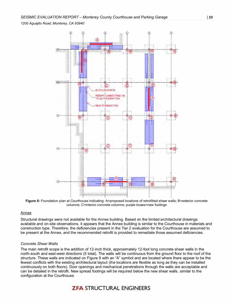
SEISMIC EVALUATION REPORT – Monterey County Courthouse and Parking Garage | 23 1200 Aguajito Road, Monterey, CA 93940
Figure 8: Foundation plan at Courthouse indicating: A=proposed locations of retrofitted shear walls; B=exterior concrete
columns; C=interior concrete columns; purple boxes=new footings
Annex
Structural drawings were not available for the Annex building. Based on the limited architectural drawings available and on-site observations, it appears that the Annex building is similar to the Courthouse in materials and construction type. Therefore, the deficiencies present in the Tier 2 evaluation for the Courthouse are assumed to be present at the Annex, and the recommended retrofit is provided to remediate those assumed deficiencies. Concrete Shear Walls The main retrofit scope is the addition of 12-inch thick, approximately 12-foot long concrete shear walls in the north-south and east-west directions (5 total). The walls will be continuous from the ground floor to the roof of the structure. These walls are indicated on Figure 9 with an “A” symbol and are located where there appear to be the fewest conflicts with the existing architectural layout (the locations are flexible as long as they can be installed continuously on both floors). Door openings and mechanical penetrations through the walls are acceptable and can be detailed in the retrofit. New spread footings will be required below the new shear walls, similar to the configuration at the Courthouse.

SEISMIC EVALUATION REPORT – Monterey County Courthouse and Parking Garage | 24 1200 Aguajito Road, Monterey, CA 93940
Concrete Columns The addition of concrete shear walls will greatly reduce the seismic forces in the existing columns. However, the columns will still require deformation compatibility with the expected seismic drift of the structure. Given the assumed lack of shear reinforcing in the columns, we propose to apply fiber-reinforced polymer (FRP) to the columns, which will greatly increase their ductility and accommodate the imposed lateral deflections. The FRP would wrap completely around each column to provide confinement. We anticipate two to four layers of FRP at each column, and column corners will need to be chamfered to install the FRP. This may not be economically viable for the exterior columns, as the windows and waterproofing would have to be altered. Another option for the exterior columns would be to provide a secondary gravity system, such as tube steel columns, directly inside of each concrete column. This would provide redundancy in case of a large seismic event that could cause shear failures in the concrete columns and potentially affect the column’s vertical load carrying capability. Column locations are typically noted with a “B” symbol on Figure 9. Precast Connections See the information presented in the Courthouse section above. Collector Strengthening Collector strengthening, similar to that for the Courthouse, may also be required in the Annex. Additional Cost Items If a seismic retrofit is performed on the building, destructive testing of structural components will likely be required to verify the existing material strengths. The extent of the testing will be dependent on the jurisdiction’s requirements as well as the availability of original construction drawings, but for estimating purposes, we anticipate approximately three concrete cores and two reinforcing steel coupons will be required to be removed from the existing structural components and tested. Further Recommendations The seismic retrofit scope for the Annex is based on the findings for the Courthouse. Original construction documents would be helpful in verifying the proposed scope for the Annex. If existing documentation is not available, extensive destructive and nondestructive testing may be required to determine the existing conditions. In order to investigate the “unknown” items on the Tier 1 checklist, we recommend the development of geotechnical report including a geological hazards assessment.

SEISMIC EVALUATION REPORT – Monterey County Courthouse and Parking Garage | 25 1200 Aguajito Road, Monterey, CA 93940
Figure 9: Typical floor plan at Annex indicating: A=proposed locations of retrofitted shear walls; B=concrete columns; C=
exterior precast concrete façade panels
Parking Garage
The Parking Garage building has four deficiencies in accordance with the Tier 2 procedures of ASCE 41-13. The deficiency-only retrofit recommendations provide remediation of these deficiencies to meet a Life Safety performance level in response to a BSE-1E hazard. Concrete Shear Walls The main retrofit scope in the north-south direction is the addition of one 10-inch-thick concrete wall with two mats of #5 rebar at 18-inch spacing each way. The wall will be continuous from the grade to the roof of the structure (3 levels) and is placed such that no parking spaces will be affected. The wall is indicated in Figure 10 with an “A” symbol and is located across from the existing concrete shear wall on the uphill (east) side of the structure. Reinforcing from the wall above and below each floor will need to be doweled through the existing slabs at each level, as shown in Figure 11. The existing slab surface will be roughened to ¼” amplitude.

SEISMIC EVALUATION REPORT – Monterey County Courthouse and Parking Garage | 26 1200 Aguajito Road, Monterey, CA 93940
An approximate estimate of concrete and reinforcement quantities based on the retrofit solution analyzed in the Tier 2 evaluation is provided for each level below. This is based on a linear static, fixed-base analysis model.
Floor Volume of Concrete in
New Shear Walls (cubic yards)
Weight of Reinforcing Steel (pounds per cubic yard of
concrete)
Ground 70 95
First 70 95
Second 70 95
Concrete Columns Given the lack of shear reinforcing in the columns, we propose to apply two layers of fiber-reinforced polymer (FRP) to the second level columns and three layers to the first level columns, which will greatly increase their shear capacity, ductility, and accommodate the imposed lateral deflections. The FRP will wrap completely around the columns to provide confinement. The square columns will require all four corners to be chamfered prior to FRP application and the surface will need to be cleaned of corrosion. Foundation The new concrete shear wall will require a foundation consisting of three to six helical piles at each end of the wall (six to 12 helical piles total). A minimum 6-foot square pile cap with 36” depth will be required. Piers will be battered to resist lateral loads. The pile caps will be tied together with a minimum 36-inch-wide by 24-inch-deep concrete grade beam. Foundations will be designed per the recommendations of a geotechnical investigation and report. An approximate estimate of foundation concrete and reinforcement quantities based on the retrofit solution analyzed in the Tier 2 evaluation is provided for each level below. This is based on a linear static, fixed base analysis model.
Volume of Concrete in New Footings 15 yd3
Weight of Reinforcing Steel in New Footings 175 lbs/ yd3
Helical Pile Quantity (Total) 6 to 12
Additional Cost Items If a seismic retrofit is performed on the building, destructive testing of structural components will likely be required to verify the existing material strengths. The extent of the testing will be dependent on the jurisdiction requirements as well as the availability of original construction drawings, but for estimating purposes, we anticipate approximately six concrete cores and three reinforcing steel coupons will be required to be removed from the existing structural components and tested. Because the structure is comprised of post-tensioned slabs and beams, all areas that require doweling or anchorage through the existing structure will required scanning to identify the location of the post-tensioning strands to avoid damage during construction. Further Recommendations In order to investigate the “unknown” items on the Tier 1 checklist and to determine the foundation design below the new shear wall, we recommend the development of geotechnical report including a geological hazards assessment.

SEISMIC EVALUATION REPORT – Monterey County Courthouse and Parking Garage | 27 1200 Aguajito Road, Monterey, CA 93940
Figure 10: Typical floor plan at Parking Garage indicating: A=proposed location of retrofitted shear wall; B=concrete columns;
C=new footing (also shown as purple boxes)

SEISMIC EVALUATION REPORT – Monterey County Courthouse and Parking Garage | 28 1200 Aguajito Road, Monterey, CA 93940
Figure 11: Section A through proposed new shear wall at the Parking Garage

SEISMIC EVALUATION REPORT – Monterey County Courthouse and Parking Garage | 29 1200 Aguajito Road, Monterey, CA 93940
RELIABILITY OF SEISMIC EVALUATIONS
In general, structural engineers do not have the ability to predict the exact damage to a building as a result of an earthquake. There will be a wide variation of damage from building to building due to the variations in ground motion and varying types and quality of construction. In addition, engineers cannot predict the exact ground motions of the earthquake that may occur at a given building. Design and evaluation of buildings are performed using general guidelines and information from past earthquakes. Engineers and the codes used for design and evaluation have been conservative when attempting to ensure that building design meets minimum standards of life safety. This effort is based on science and technology as well as on observations made from actual seismic events. Building design and evaluation codes are constantly evolving to better meet performance targets based on this information. Continued research will improve predictive methods and facilitate performance-based engineering. It has been estimated that, given design ground motions, a small percent of new buildings and a slightly greater percent of retrofit buildings may fail to meet their expected performance. CLOSING The seismic review and analyses associated with this evaluation were based on available original structural drawings, and the site reviews were based on that which was plainly visible. No attempt was made to uncover hidden conditions or perform any destructive or non-destructive testing. The items discussed in this report are subject to revision should more information become available. This report is general in nature and does not imply that the recommendations listed above are the only structural requirements that must be made to the existing structure to meet current building code criteria. We understand you may have questions regarding this evaluation and are available for comment and explanations. Please call with any questions you may have. Sincerely, Chelsea Drenick, SE Senior Engineer Ryan Bogart, SE Senior Associate Mark A. Moore, SE Executive Principal

SEISMIC EVALUATION REPORT – Monterey County Courthouse and Parking Garage | 30 1200 Aguajito Road, Monterey, CA 93940
APPENDIX A – PHOTOGRAPHS

SEISMIC EVALUATION REPORT – Monterey County Courthouse and Parking Garage | 31 1200 Aguajito Road, Monterey, CA 93940
Photo 1: Courthouse Building Entrance
Photo 2: Courthouse Building East Elevation

SEISMIC EVALUATION REPORT – Monterey County Courthouse and Parking Garage | 32 1200 Aguajito Road, Monterey, CA 93940
Photo 3: Seismic Gap Between Courthouse and Annex

SEISMIC EVALUATION REPORT – Monterey County Courthouse and Parking Garage | 33 1200 Aguajito Road, Monterey, CA 93940
Photo 4: Parking Garage Interior
Photo 5: Parking Garage Foundation Below First Floor

SEISMIC EVALUATION REPORT – Monterey County Courthouse and Parking Garage | 34 1200 Aguajito Road, Monterey, CA 93940
Photo 6: Cracked Exterior Sidewalk Slab at the Courthouse
Photo 7: Spalled Concrete at Existing Column at the Annex

SEISMIC EVALUATION REPORT – Monterey County Courthouse and Parking Garage | 35 1200 Aguajito Road, Monterey, CA 93940
Photo 8: Cracked Concrete Beam and Wall at Annex Exterior
Photo 9: Corrosion at Parking Garage Guardrail

SEISMIC EVALUATION REPORT – Monterey County Courthouse and Parking Garage | 36 1200 Aguajito Road, Monterey, CA 93940
Photo 10: Deteriorated Wood at Parking Garage

SEISMIC EVALUATION REPORT – Monterey County Courthouse and Parking Garage | 37 1200 Aguajito Road, Monterey, CA 93940
APPENDIX B – MAPS

SEISMIC EVALUATION REPORT – Monterey County Courthouse and Parking Garage | 38 1200 Aguajito Road, Monterey, CA 93940
Location Map
1200 Aguajito Rd Monterey, CA 93940
North
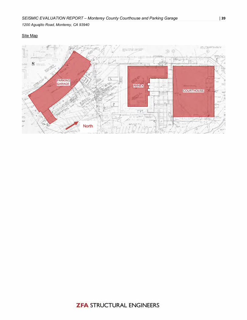
SEISMIC EVALUATION REPORT – Monterey County Courthouse and Parking Garage | 39 1200 Aguajito Road, Monterey, CA 93940
Site Map
North

SEISMIC EVALUATION REPORT – Monterey County Courthouse and Parking Garage | 40 1200 Aguajito Road, Monterey, CA 93940
APPENDIX C – SUMMARY DATA SHEET

SEISMIC EVALUATION REPORT – Monterey County Courthouse and Parking Garage | 41 1200 Aguajito Road, Monterey, CA 93940
Summary Data Sheet - Courthouse
BUILDING DATA
Building Name: Monterey County Courthouse Date: 11/29/1966
Building Address: 1200 Aguajito Road, Monterey, CA 93940
Latitude: 36.590 Longitude: -121.880 By: Wallace Holm
Year Built: 1966 Year(s) Remodeled: Unknown Original Design Code: Unknown (1964 UBC assumed)
Area (sf): 68000 Length (ft): 160 feet Width (ft): 104 feet
No. of Stories: 4 Story Height: ~15 feet Total Height: 60 feet
USE Industrial Off ice Warehouse Hospital Residential Educational Other: Courthouse
CONSTRUCTION DATA
Gravity Load Structural System: Concrete columns, beams, slab
Exterior Transverse Walls: N/A Openings?
Exterior Longitudinal Walls: N/A Openings?
Roof Materials/Framing: Concrete beams and slab
Intermediate Floors/Framing: Concrete beams and slab
Ground Floor: Slab-on-grade
Columns: Concrete Foundation: Spread footings
General Condition of Structure: Good
Levels Below Grade? Partial story below grade
LATERAL-FORCE-RESISTING SYSTEM
Longitudinal Transverse
System: Concrete moment frames Concrete moment frames
Vertical Elements: Concrete columns Concrete columns
Diaphragms: Concrete slab Concrete slab
EVALUATION DATA
BSE-1N Spectral Response Accelerations:
SXS= 1.009 g SX1= 0.555 g
Soil Factors: Class= D (assumed)
BSE-1E Spectral Response Accelerations:
SXS= 0.739 g SX1= 0.391 g
Level of Seismicity: High Performance Level: Life Safety
Building Period: T= 0.717 sec
Spectral Acceleration: Sa= 0.545 g
Modification Factor: CmC1C2= 0.88 Building Weight: W= 10,660 kips
Pseudo Lateral Force: V=CmC1C2SaW= 0.479W

SEISMIC EVALUATION REPORT – Monterey County Courthouse and Parking Garage | 42 1200 Aguajito Road, Monterey, CA 93940
BUILDING CLASSIFICATION: C1 – Concrete Moment Frames
COMPLETED TIER 1 CHECKLISTS Yes No
Basic Configuration Checklist
Building Type C1 Structural Checklist
Nonstructural Component Checklist
Material Properties
To account for uncertainty in the as-built data, a knowledge factor, κ, is determined according to ASCE 41 Table 6-1.
Default Value per ASCE 41, 4.2.3?
Alternate Value Source?
Concrete Table (4-2)
Beams, Columns and Slabs:
f’c= 4,000 psi
Construction drawings
Slab-on-grade: f’c= 3,000 psi
Construction drawings
Reinforcing Steel Table (4-3)
All Bars: fy= 40 or 50 ksi
Construction drawings

SEISMIC EVALUATION REPORT – Monterey County Courthouse and Parking Garage | 43 1200 Aguajito Road, Monterey, CA 93940
Summary Data Sheet – Courthouse Parking Garage
BUILDING DATA
Building Name: Monterey County Courthouse Parking Garage
Building Address: 1200 Aguajito Road, Monterey, CA 93940
Latitude: 36.590 Longitude: -121.880
Year Built: 1966 Year(s) Remodeled: Unknown Original Design Code: Unknown (1964 UBC assumed)
Area (sf): 33000 Length (ft): 175 feet Width (ft): 61 feet
No. of Stories: 3 Story Height: ~9.5 feet Total Height: 28 feet
USE Industrial Off ice Warehouse Hospital Residential Educational Other: Parking Garage
CONSTRUCTION DATA
Gravity Load Structural System: Concrete post-tensioned beams and slab; CIP columns
Exterior Transverse Walls: N/A Openings?
Exterior Longitudinal Walls: N/A Openings?
Roof Materials/Framing: Concrete post-tensioned beams and slab
Intermediate Floors/Framing: Concrete post-tensioned beams and slab
Ground Floor: Concrete post-tensioned beams and slab
Columns: CIP concrete Foundation: Concrete piers
General Condition of Structure: Good
Levels Below Grade? Partial story below grade
LATERAL-FORCE-RESISTING SYSTEM
Longitudinal Transverse
System: Concrete slab/column moment frames/concrete shear wall
Concrete moment frames
Vertical Elements: Concrete columns Concrete columns
Diaphragms: Post-tensioned concrete slab Post-tensioned concrete slab
EVALUATION DATA
BSE-1N Spectral Response Accelerations:
SXS= 1.009 g SX1= 0.555 g
Soil Factors: Class= D (assumed)
BSE-1E Spectral Response Accelerations:
SXS= 0.739 g SX1= 0.391 g
Level of Seismicity: High Performance Level: Life Safety
Building Period: T= 0.361 sec
Spectral Acceleration: Sa= 0.74 g
Modification Factor: CmC1C2= 0.99 Building Weight: W= 3,829 kips
Pseudo Lateral Force: V=CmC1C2SaW= 0.73W

SEISMIC EVALUATION REPORT – Monterey County Courthouse and Parking Garage | 44 1200 Aguajito Road, Monterey, CA 93940
BUILDING CLASSIFICATION: C1 – Concrete Moment Frames
COMPLETED TIER 1 CHECKLISTS Yes No
Basic Configuration Checklist
Building Type C1 Structural Checklist
Nonstructural Component Checklist
Material Properties
To account for uncertainty in the as-built data, a knowledge factor, κ, is determined according to ASCE 41 Table 6-1.
Default Value per ASCE 41, 4.2.3?
Alternate Value Source?
Concrete Table (4-2)
Columns, Post-tensioned Beams and Slab:
f’c= 4,000 psi
Construction drawings
Lower story columns: f’c= 5,000 psi
Construction drawings
All other concrete: f’c= 3,000 psi
Construction drawings
Reinforcing Steel Table (4-3)
#5 and smaller in ramps and walls:
fy= 40 ksi
Construction drawings
All other bars: fy= 60 ksi
Construction drawings
Post-tensioned tendons
fu= 270 ksi Construction drawings

SEISMIC EVALUATION REPORT – Monterey County Courthouse and Parking Garage | 45 1200 Aguajito Road, Monterey, CA 93940
APPENDIX D –TIER 1 CHECKLISTS

SEISMIC EVALUATION REPORT – Monterey Courthouse | 46 1200 Aguajito Road, Monterey, California
16.1.2LS Life Safety Basic Configuration Checklist
This Basic Configuration Checklist shall be completed for all building types, except buildings in very low seismicity, being evaluated to the Life Safety Performance Level. Once this checklist has been completed, complete the appropriate building type checklist for the desired seismic performance level as shown in Table 4-7. Tier 1 evaluation shall include on-site investigation and condition assessment as required by Section 4.2.1. Each of the evaluation statements on this checklist shall be marked Compliant (C), Non-compliant (NC), Unknown (U), or Not Applicable (N/A) for a Tier 1 Evaluation. Compliant statements identify issues that are acceptable according to the criteria of this standard, while non-compliant and unknown statements identify issues that require further investigation. Certain statements may not apply to the buildings being evaluated. For non-compliant and unknown evaluation statements, the design professional may choose to conduct further investigation using the corresponding Tier 2 Evaluation procedure; corresponding section numbers are in parentheses following each evaluation statement.
Low Seismicity
Building System
General
C NC N/A U
LOAD PATH: The structure shall contain a complete, well defined load path, including structural elements and connections, that serves to transfer the inertial forces associated with the mass of all elements of the building to the foundation. (Commentary: Sec. A.2.1.1. Tier 2: Sec. 5.4.1.1)
ADJACENT BUILDINGS: The clear distance between the building being evaluated and any adjacent building is greater than 4% of the height of the shorter building. This statement shall not apply for the following building types: W1, W1A, and W2. (Commentary: Sec. A.2.1.2. Tier 2: Sec. 5.4.1.2) The height of the annex is approximately 14’, 4% of the height = 6.75”. The gap between the two is approximately 2-3 inches
MEZZANINES: Interior mezzanine levels are braced independently from the main structure or are anchored to the seismic-force-resisting elements of the main structure. (Commentary: Sec. A.2.1.3. Tier 2: Sec. 5.4.1.3) There are no mezzanines shown on the existing drawings.
C16.1.2LS Life Safety Basic Configuration Checklist For buildings in low, moderate, and high seismicity the following evaluation statements represent general configuration issues applicable for most building based on observed earthquake structural damage during actual earthquakes. This checklist should be completed for all buildings in low, moderate, and high seismicity for Life Safety Performance Level. The section numbers in parentheses following each evaluation statement refer to the commentary in Appendix A regarding the statement’s purpose and the corresponding Tier 2 Evaluation procedures. If additional information on the evaluation statement is required, refer to the commentary in the Tier 2 procedure for that evaluation statement.

SEISMIC EVALUATION REPORT – Monterey Courthouse | 47 1200 Aguajito Road, Monterey, California
Building Configuration
C NC N/A U
WEAK STORY: The sum of the shear strengths of the seismic-force-resisting system in any story in each direction is not less than 80% of the strength in the adjacent story above. (Commentary: Sec. A2.2.2. Tier 2: Sec. 5.4.2.1) See calculations
SOFT STORY: The stiffness of the seismic-force-resisting system in any story is not less than 70% of the seismic-force-resisting system stiffness in an adjacent story above or less than 80% of the average seismic-force-resisting system stiffness of the three stories above. (Commentary: Sec. A.2.2.3. Tier 2: Sec. 5.4.2.2) See calculations
VERTICAL IRREGULARITIES: All vertical elements in the seismic-force-resisting system are continuous to the foundation. (Commentary: Sec. A.2.2.4. Tier 2: Sec. 5.4.2.3) All columns are continuous from footings up to the roof.
GEOMETRY: There are no changes in the net horizontal dimension of the seismic-force-resisting system of more than 30% in a story relative to adjacent stories, excluding one-story penthouses and mezzanines. (Commentary: Sec. A.2.2.5. Tier 2: Sec. 5.4.2.4) Building plan is regular at all stories.
MASS: There is no change in effective mass more than 50% from one story to the next. Light roofs, penthouses, and mezzanines need not be considered. (Commentary: Sec. A.2.2.6. Tier 2: Sec. 5.4.2.5) Building plans are similar in size and mass at all stories.
TORSION: The estimated distance between the story center of mass and the story center of rigidity is less than 20% of the building width in either plan dimension. (Commentary: Sec. A.2.2.7. Tier 2: Sec. 5.4.2.6) By inspection the building plans are regular and will have similar center of mass to center of rigidity.
Medium Seismicity: Complete the Following Items in Addition to the Items for Low Seismicity
Geologic Site Hazards
C NC N/A U
LIQUEFACTION: Liquefaction-susceptible, saturated, loose granular soils that could jeopardize the building’s seismic performance shall not exist in the foundation soils at depths within 50 ft under the building. (Commentary: Sec. A.6.1.1. Tier 2: 5.4.3.1) Geotechnical information on the existing architectural drawings does not address liquefaction susceptibility. Review of the soil borings indicates the site is unlikely to experience liquefaction. However more information, or review by a geotechnical engineer is required.
SLOPE FAILURE: The building site is sufficiently remote from potential earthquake-induced slope failures or rockfalls to be unaffected by such failures or is capable of accommodating any predicted movements without failure. (Commentary: Sec. A.6.1.2. Tier 2: 5.4.3.1) No geotechnical information available
SURFACE FAULT RUPTURE: Surface fault rupture and surface displacement at the building site are not anticipated. (Commentary: Sec. A.6.1.3. Tier 2: 5.4.3.1) No geotechnical information available
High Seismicity: Complete the Following Items in Addition to the Items for Low and Moderate Seismicity
Foundation Configuration

SEISMIC EVALUATION REPORT – Monterey Courthouse | 48 1200 Aguajito Road, Monterey, California
C NC N/A U
OVERTURNING: The ratio of the least horizontal dimension of the seismic-force-resisting system at the foundation level to the building height (base/height) is greater than 0.6Sa. (Commentary: Sec. A.6.2.1. Tier 2: Sec. 5.4.3.3) See calculations.
TIES BETWEEN FOUNDATION ELEMENTS: The foundation has ties adequate to resist seismic forces where footings, piles, and piers are not restrained by beams, slabs, or soils classified as Site Class A, B, or C. (Commentary: Sec. A.6.2.2. Tier 2: Sec. 5.4.3.4) Ties are not present, but site class is unknown. Given geotechnical borings showing the soil as weathered shale it is possible it will be site class C and will restrain the footings.

SEISMIC EVALUATION REPORT – Monterey Courthouse | 49 1200 Aguajito Road, Monterey, California
16.9LS Building Type C1
Life Safety Structural Checklist For Building Type C1: Concrete Moment Frames This Life Safety Structural Checklist shall be completed where required by Table 4-7 and where the building configuration complies with the description of C1 building type defined in Table 3-1. Tier 1 evaluation shall include on-site investigation and condition assessment as required by Section 4.2.1. Each of the evaluation statements on this checklist shall be marked Compliant (C), Non-compliant (NC), Not Applicable (N/A), or Unknown (U) for a Tier 1 Evaluation. Compliant statements identify issues that are acceptable according to the criteria of this standard, while non-compliant and unknown statements identify issues that require further investigation. Certain statements may not apply to the buildings being evaluated. For non-compliant and unknown evaluation statements, the design professional may choose to conduct further investigation using the corresponding Tier 2 Evaluation procedure; corresponding section numbers are in parentheses following each evaluation statement.
Low Seismicity
Seismic-Force-Resisting System
C NC N/A U
REDUNDANCY: The number of lines of moment frames in each principal direction is greater than or equal to 2. The number of bays of moment frames in each line is greater than or equal to 2. (Commentary: Sec. A.3.1.1.1. Tier 2: Sec. 5.5.1.1) There are 5 existing frame lines in each direction
COLUMN AXIAL STRESS CHECK: The axial stress caused by unfactored gravity loads in columns subjected to overturning forces because of seismic demands is less than 0.20f′c. Alternatively, the axial stress caused by overturning forces alone, calculated using the Quick Check procedure of Section 4.5.3.6, is less than 0.30f′c. (Commentary: Sec. A.3.1.4.2. Tier 2: Sec. 5.5.2.1.3) See supplemental calculations, maximum axial stress is 310 psi and allowable is 900 psi
Connections
C NC N/A U
C16. 9LS Life Safety Structural Checklist for Building Type C1 Building Type C1 These buildings consist of a frame assembly of cast-in-place concrete beams and columns. Floor and roof framing consists of cast-in-place concrete slabs, concrete beams, one-way joists, two-way waffle joists, or flat slabs. Seismic forces are resisted by concrete moment frames that develop their stiffness through monolithic beam-column connections. In older construction, or in levels of low seismicity, the moment frames may consist of the column strips of two-way flat slab systems. Modern frames in levels of high seismicity have joint reinforcing, closely spaced ties, and special detailing to provide ductile performance. This detailing is not present in older construction. Foundations consist of concrete spread footings, mat foundations, or deep foundations. Refer to Sections A.3.1 and A.3.1.4 for additional commentary related to concrete moment frames.

SEISMIC EVALUATION REPORT – Monterey Courthouse | 50 1200 Aguajito Road, Monterey, California
CONCRETE COLUMNS: All concrete columns are doweled into the foundation with a minimum of 4 bars. (Commentary: Sec. A.5.3.2. Tier 2: Sec. 5.7.3.1) The existing drawings show (12) #11 bar dowels at each column
Moderate Seismicity: Complete the Following Items in Addition to the Items for Low Seismicity
Seismic-Force-Resisting System
C NC N/A U
INTERFERING WALLS: All concrete and masonry infill walls placed in moment frames are isolated from structural elements. (Commentary: Sec. A.3.1.2.1. Tier 2: Sec. 5.5.2.1.1) No infill concrete or masonry walls appear to be present based on existing drawings
COLUMN SHEAR STRESS CHECK: The shear stress in the concrete columns, calculated using the Quick Check procedure of Section 4.5.3.2, is less than the greater of 100 lb/in.2 or 2√f′c. (Commentary: Sec. A.3.1.4.1. Tier 2: Sec. 5.5.2.1.4) See calculations.
FLAT SLAB FRAMES: The seismic-force-resisting system is not a frame consisting of columns and a flat slab or plate without beams. (Commentary: Sec. A.3.1.4.3. Tier 2: Sec. 5.5.2.3.1) Building system has girders and beams.
High Seismicity: Complete the Following Items in Addition to the Items for Low and Moderate Seismicity
Seismic-Force-Resisting System
C NC N/A U
PRESTRESSED FRAME ELEMENTS: The seismic-force-resisting frames do not include any prestressed or posttensioned elements where the average prestress exceeds the lesser of 700 lb/in.2 or f′c/6 at potential hinge locations. The average prestress is calculated in accordance with the Quick Check procedure of Section 4.5.3.8. (Commentary: Sec. A.3.1.4.4. Tier 2: Sec. 5.5.2.3.2)
CAPTIVE COLUMNS: There are no columns at a level with height/depth ratios less than 50% of the nominal height/depth ratio of the typical columns at that level. (Commentary: Sec. A.3.1.4.5. Tier 2: Sec. 5.5.2.3.3) No captive columns based on existing drawings.
NO SHEAR FAILURES: The shear capacity of frame members is able to develop the moment capacity at the ends of the members. (Commentary: Sec. A.3.1.4.6. Tier 2: Sec. 5.5.2.3.4) See calculations.
STRONG COLUMN—WEAK BEAM: The sum of the moment capacity of the columns is 20% greater than that of the beams at frame joints. (Commentary: Sec. A.3.1.4.7. Tier 2: Sec. 5.5.2.1.5) See calculations.
BEAM BARS: At least two longitudinal top and two longitudinal bottom bars extend continuously throughout the length of each frame beam. At least 25% of the longitudinal bars provided at the joints for either positive or negative moment are continuous throughout the length of the members. (Commentary: A.3.1.4.8. Tier 2: Sec. 5.5.2.3.5) See calculations.
COLUMN-BAR SPLICES: All column-bar lap splice lengths are greater than 35db and are enclosed by ties spaced at or less than 8db. Alternatively, column bars are spliced with

SEISMIC EVALUATION REPORT – Monterey Courthouse | 51 1200 Aguajito Road, Monterey, California
mechanical couplers with a capacity of at least 1.25 times the nominal yield strength of the spliced bar. (Commentary: Sec. A.3.1.4.9. Tier 2: Sec. 5.5.2.3.6) See calculations.
BEAM-BAR SPLICES: The lap splices or mechanical couplers for longitudinal beam reinforcing are not located within lb/4 of the joints and are not located in the vicinity of potential plastic hinge locations. (Commentary: Sec. A.3.1.4.10. Tier 2: Sec. 5.5.2.3.6) See calculations.
COLUMN-TIE SPACING: Frame columns have ties spaced at or less than d/4 throughout their length and at or less than 8db at all potential plastic hinge locations. (Commentary: Sec. A.3.1.4.11. Tier 2: Sec. 5.5.2.3.7) See calculations.
STIRRUP SPACING: All beams have stirrups spaced at or less than d/2 throughout their length. At potential plastic hinge locations, stirrups are spaced at or less than the minimum of 8db or d/4. (Commentary: Sec. A.3.1.4.12. Tier 2: Sec. 5.5.2.3.7) See calculations.
JOINT TRANSVERSE REINFORCING: Beam–column joints have ties spaced at or less than 8db. (Commentary: Sec. A.3.1.4.13. Tier 2: Sec. 5.5.2.3.8) See calculations.
DEFLECTION COMPATIBILITY: Secondary components have the shear capacity to develop the flexural strength of the components. (Commentary: Sec. A.3.1.6.2. Tier 2: Sec. 5.5.2.5.2) Precast concrete panel façade connections are nonductile and not designed to resist the forces generated when the structure experiences lateral movement from seismic forces.
FLAT SLABS: Flat slabs or plates not part of the seismic-force-resisting system have continuous bottom steel through the column joints. (Commentary: Sec. A.3.1.6.3. Tier 2: Sec. 5.5.2.5.3) The floor throughout the building is concrete over metal deck with only one layer of reinforcement.
Diaphragms
C NC N/A U
DIAPHRAGM CONTINUITY: The diaphragms are not composed of split-level floors and do not have expansion joints. (Commentary: Sec. A.4.1.1. Tier 2: Sec. 5.6.1.1)
Connections
C NC N/A U
UPLIFT AT PILE CAPS: Pile caps have top reinforcement, and piles are anchored to the pile caps. (Commentary: Sec. A.5.3.8. Tier 2: Sec. 5.7.3.5)

SEISMIC EVALUATION REPORT – Monterey Courthouse Parking Garage | 52 1200 Aguajito Road, Monterey, California
16.1.2LS Life Safety Basic Configuration Checklist
This Basic Configuration Checklist shall be completed for all building types, except buildings in very low seismicity, being evaluated to the Life Safety Performance Level. Once this checklist has been completed, complete the appropriate building type checklist for the desired seismic performance level as shown in Table 4-7. Tier 1 evaluation shall include on-site investigation and condition assessment as required by Section 4.2.1. Each of the evaluation statements on this checklist shall be marked Compliant (C), Non-compliant (NC), Unknown (U), or Not Applicable (N/A) for a Tier 1 Evaluation. Compliant statements identify issues that are acceptable according to the criteria of this standard, while non-compliant and unknown statements identify issues that require further investigation. Certain statements may not apply to the 34buildings being evaluated. For non-compliant and unknown evaluation statements, the design professional may choose to conduct further investigation using the corresponding Tier 2 Evaluation procedure; corresponding section numbers are in parentheses following each evaluation statement.
Low Seismicity
Building System
General
C NC N/A U
LOAD PATH: The structure shall contain a complete, well defined load path, including structural elements and connections, that serves to transfer the inertial forces associated with the mass of all elements of the building to the foundation. (Commentary: Sec. A.2.1.1. Tier 2: Sec. 5.4.1.1)
ADJACENT BUILDINGS: The clear distance between the building being evaluated and any adjacent building is greater than 4% of the height of the shorter building. This statement shall not apply for the following building types: W1, W1A, and W2. (Commentary: Sec. A.2.1.2. Tier 2: Sec. 5.4.1.2)
MEZZANINES: Interior mezzanine levels are braced independently from the main structure or are anchored to the seismic-force-resisting elements of the main structure. (Commentary: Sec. A.2.1.3. Tier 2: Sec. 5.4.1.3)
Building Configuration
C16.1.2LS Life Safety Basic Configuration Checklist For buildings in low, moderate, and high seismicity the following evaluation statements represent general configuration issues applicable for most building based on observed earthquake structural damage during actual earthquakes. This checklist should be completed for all buildings in low, moderate, and high seismicity for Life Safety Performance Level. The section numbers in parentheses following each evaluation statement refer to the commentary in Appendix A regarding the statement’s purpose and the corresponding Tier 2 Evaluation procedures. If additional information on the evaluation statement is required, refer to the commentary in the Tier 2 procedure for that evaluation statement.
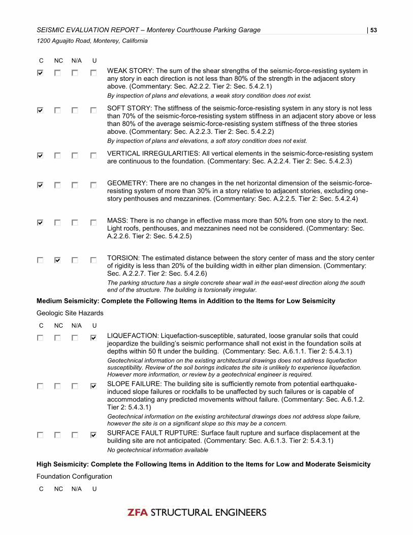
SEISMIC EVALUATION REPORT – Monterey Courthouse Parking Garage | 53 1200 Aguajito Road, Monterey, California
C NC N/A U
WEAK STORY: The sum of the shear strengths of the seismic-force-resisting system in any story in each direction is not less than 80% of the strength in the adjacent story above. (Commentary: Sec. A2.2.2. Tier 2: Sec. 5.4.2.1) By inspection of plans and elevations, a weak story condition does not exist.
SOFT STORY: The stiffness of the seismic-force-resisting system in any story is not less than 70% of the seismic-force-resisting system stiffness in an adjacent story above or less than 80% of the average seismic-force-resisting system stiffness of the three stories above. (Commentary: Sec. A.2.2.3. Tier 2: Sec. 5.4.2.2) By inspection of plans and elevations, a soft story condition does not exist.
VERTICAL IRREGULARITIES: All vertical elements in the seismic-force-resisting system are continuous to the foundation. (Commentary: Sec. A.2.2.4. Tier 2: Sec. 5.4.2.3)
GEOMETRY: There are no changes in the net horizontal dimension of the seismic-force-resisting system of more than 30% in a story relative to adjacent stories, excluding one-story penthouses and mezzanines. (Commentary: Sec. A.2.2.5. Tier 2: Sec. 5.4.2.4)
MASS: There is no change in effective mass more than 50% from one story to the next. Light roofs, penthouses, and mezzanines need not be considered. (Commentary: Sec. A.2.2.6. Tier 2: Sec. 5.4.2.5)
TORSION: The estimated distance between the story center of mass and the story center of rigidity is less than 20% of the building width in either plan dimension. (Commentary: Sec. A.2.2.7. Tier 2: Sec. 5.4.2.6) The parking structure has a single concrete shear wall in the east-west direction along the south end of the structure. The building is torsionally irregular.
Medium Seismicity: Complete the Following Items in Addition to the Items for Low Seismicity
Geologic Site Hazards
C NC N/A U
LIQUEFACTION: Liquefaction-susceptible, saturated, loose granular soils that could jeopardize the building’s seismic performance shall not exist in the foundation soils at depths within 50 ft under the building. (Commentary: Sec. A.6.1.1. Tier 2: 5.4.3.1) Geotechnical information on the existing architectural drawings does not address liquefaction susceptibility. Review of the soil borings indicates the site is unlikely to experience liquefaction. However more information, or review by a geotechnical engineer is required.
SLOPE FAILURE: The building site is sufficiently remote from potential earthquake-induced slope failures or rockfalls to be unaffected by such failures or is capable of accommodating any predicted movements without failure. (Commentary: Sec. A.6.1.2. Tier 2: 5.4.3.1) Geotechnical information on the existing architectural drawings does not address slope failure, however the site is on a significant slope so this may be a concern.
SURFACE FAULT RUPTURE: Surface fault rupture and surface displacement at the building site are not anticipated. (Commentary: Sec. A.6.1.3. Tier 2: 5.4.3.1) No geotechnical information available
High Seismicity: Complete the Following Items in Addition to the Items for Low and Moderate Seismicity
Foundation Configuration
C NC N/A U

SEISMIC EVALUATION REPORT – Monterey Courthouse Parking Garage | 54 1200 Aguajito Road, Monterey, California
OVERTURNING: The ratio of the least horizontal dimension of the seismic-force-resisting system at the foundation level to the building height (base/height) is greater than 0.6Sa. (Commentary: Sec. A.6.2.1. Tier 2: Sec. 5.4.3.3) See calculations
TIES BETWEEN FOUNDATION ELEMENTS: The foundation has ties adequate to resist seismic forces where footings, piles, and piers are not restrained by beams, slabs, or soils classified as Site Class A, B, or C. (Commentary: Sec. A.6.2.2. Tier 2: Sec. 5.4.3.4) Ties are not present, but site class is unknown. Geotechnical information is required.

SEISMIC EVALUATION REPORT – Monterey Courthouse Parking Garage | 55 1200 Aguajito Road, Monterey, California
16.9LS Building Type C1
Life Safety Structural Checklist For Building Type C1: Concrete Moment Frames This Life Safety Structural Checklist shall be completed where required by Table 4-7 and where the building configuration complies with the description of C1 building type defined in Table 3-1. Tier 1 evaluation shall include on-site investigation and condition assessment as required by Section 4.2.1. Each of the evaluation statements on this checklist shall be marked Compliant (C), Non-compliant (NC), Not Applicable (N/A), or Unknown (U) for a Tier 1 Evaluation. Compliant statements identify issues that are acceptable according to the criteria of this standard, while non-compliant and unknown statements identify issues that require further investigation. Certain statements may not apply to the buildings being evaluated. For non-compliant and unknown evaluation statements, the design professional may choose to conduct further investigation using the corresponding Tier 2 Evaluation procedure; corresponding section numbers are in parentheses following each evaluation statement.
Low Seismicity
Seismic-Force-Resisting System
C NC N/A U
REDUNDANCY: The number of lines of moment frames in each principal direction is greater than or equal to 2. The number of bays of moment frames in each line is greater than or equal to 2. (Commentary: Sec. A.3.1.1.1. Tier 2: Sec. 5.5.1.1) There are 2 lines in the E-W direction and 8 lines in the N-S direction.
COLUMN AXIAL STRESS CHECK: The axial stress caused by unfactored gravity loads in columns subjected to overturning forces because of seismic demands is less than 0.20f′c. Alternatively, the axial stress caused by overturning forces alone, calculated using the Quick Check procedure of Section 4.5.3.6, is less than 0.30f′c. (Commentary: Sec. A.3.1.4.2. Tier 2: Sec. 5.5.2.1.3) See supplemental calculations, check is compliant.
Connections
C NC N/A U
C16. 9LS Life Safety Structural Checklist for Building Type C1 Building Type C1 These buildings consist of a frame assembly of cast-in-place concrete beams and columns. Floor and roof framing consists of cast-in-place concrete slabs, concrete beams, one-way joists, two-way waffle joists, or flat slabs. Seismic forces are resisted by concrete moment frames that develop their stiffness through monolithic beam-column connections. In older construction, or in levels of low seismicity, the moment frames may consist of the column strips of two-way flat slab systems. Modern frames in levels of high seismicity have joint reinforcing, closely spaced ties, and special detailing to provide ductile performance. This detailing is not present in older construction. Foundations consist of concrete spread footings, mat foundations, or deep foundations. Refer to Sections A.3.1 and A.3.1.4 for additional commentary related to concrete moment frames.

SEISMIC EVALUATION REPORT – Monterey Courthouse Parking Garage | 56 1200 Aguajito Road, Monterey, California
CONCRETE COLUMNS: All concrete columns are doweled into the foundation with a minimum of 4 bars. (Commentary: Sec. A.5.3.2. Tier 2: Sec. 5.7.3.1) See S1, (4) dowels from column to foundation.
Moderate Seismicity: Complete the Following Items in Addition to the Items for Low Seismicity
Seismic-Force-Resisting System
C NC N/A U
INTERFERING WALLS: All concrete and masonry infill walls placed in moment frames are isolated from structural elements. (Commentary: Sec. A.3.1.2.1. Tier 2: Sec. 5.5.2.1.1) More field investigation is required to determine if infill walls are isolated from the column and beam system.
COLUMN SHEAR STRESS CHECK: The shear stress in the concrete columns, calculated using the Quick Check procedure of Section 4.5.3.2, is less than the greater of 100 lb/in.2 or 2√f′c. (Commentary: Sec. A.3.1.4.1. Tier 2: Sec. 5.5.2.1.4) See calculations.
FLAT SLAB FRAMES: The seismic-force-resisting system is not a frame consisting of columns and a flat slab or plate without beams. (Commentary: Sec. A.3.1.4.3. Tier 2: Sec. 5.5.2.3.1) There are beams in one direction, but in the other direction it is prestressed slab without beams.
High Seismicity: Complete the Following Items in Addition to the Items for Low and Moderate Seismicity
Seismic-Force-Resisting System
C NC N/A U
PRESTRESSED FRAME ELEMENTS: The seismic-force-resisting frames do not include any prestressed or posttensioned elements where the average prestress exceeds the lesser of 700 lb/in.2 or f′c/6 at potential hinge locations. The average prestress is calculated in accordance with the Quick Check procedure of Section 4.5.3.8. (Commentary: Sec. A.3.1.4.4. Tier 2: Sec. 5.5.2.3.2) See calculations
CAPTIVE COLUMNS: There are no columns at a level with height/depth ratios less than 50% of the nominal height/depth ratio of the typical columns at that level. (Commentary: Sec. A.3.1.4.5. Tier 2: Sec. 5.5.2.3.3) All ramps are exterior to the structure. There are columns supporting the ramps that are less than 50% of nominal height of typical columns, but the ramps are separated by expansion joints from the structure and therefore are not analyzed as part of the structure.
NO SHEAR FAILURES: The shear capacity of frame members is able to develop the moment capacity at the ends of the members. (Commentary: Sec. A.3.1.4.6. Tier 2: Sec. 5.5.2.3.4) See calculations.
STRONG COLUMN—WEAK BEAM: The sum of the moment capacity of the columns is 20% greater than that of the beams at frame joints. (Commentary: Sec. A.3.1.4.7. Tier 2: Sec. 5.5.2.1.5) See calculations.
BEAM BARS: At least two longitudinal top and two longitudinal bottom bars extend continuously throughout the length of each frame beam. At least 25% of the longitudinal bars provided at the joints for either positive or negative moment are continuous throughout the length of the members. (Commentary: A.3.1.4.8. Tier 2: Sec. 5.5.2.3.5) See beam section on existing drawing sheet S1, (2)#8 continuous top and bottom.

SEISMIC EVALUATION REPORT – Monterey Courthouse Parking Garage | 57 1200 Aguajito Road, Monterey, California
COLUMN-BAR SPLICES: All column-bar lap splice lengths are greater than 35db and are enclosed by ties spaced at or less than 8db. Alternatively, column bars are spliced with mechanical couplers with a capacity of at least 1.25 times the nominal yield strength of the spliced bar. (Commentary: Sec. A.3.1.4.9. Tier 2: Sec. 5.5.2.3.6) Column splices at the 1st level are compliant. No other column splices occur per sheet S1.
BEAM-BAR SPLICES: The lap splices or mechanical couplers for longitudinal beam reinforcing are not located within lb/4 of the joints and are not located in the vicinity of potential plastic hinge locations. (Commentary: Sec. A.3.1.4.10. Tier 2: Sec. 5.5.2.3.6) Lap splices are located lb/4 from center of joint, see sheet S1.
COLUMN-TIE SPACING: Frame columns have ties spaced at or less than d/4 throughout their length and at or less than 8db at all potential plastic hinge locations. (Commentary: Sec. A.3.1.4.11. Tier 2: Sec. 5.5.2.3.7) See calculations, some locations are compliant, but others fail. Will need further investigation in tier 2.
STIRRUP SPACING: All beams have stirrups spaced at or less than d/2 throughout their length. At potential plastic hinge locations, stirrups are spaced at or less than the minimum of 8db or d/4. (Commentary: Sec. A.3.1.4.12. Tier 2: Sec. 5.5.2.3.7) Hinge zone is compliant but the typical is noncompliant.
JOINT TRANSVERSE REINFORCING: Beam–column joints have ties spaced at or less than 8db. (Commentary: Sec. A.3.1.4.13. Tier 2: Sec. 5.5.2.3.8) See calculations.
DEFLECTION COMPATIBILITY: Secondary components have the shear capacity to develop the flexural strength of the components. (Commentary: Sec. A.3.1.6.2. Tier 2: Sec. 5.5.2.5.2)
FLAT SLABS: Flat slabs or plates not part of the seismic-force-resisting system have continuous bottom steel through the column joints. (Commentary: Sec. A.3.1.6.3. Tier 2: Sec. 5.5.2.5.3) The post-tensioned slab is inherently part of the seismic force resisting system. There are no flat slabs or plates not part of the system.
Diaphragms
C NC N/A U
DIAPHRAGM CONTINUITY: The diaphragms are not composed of split-level floors and do not have expansion joints. (Commentary: Sec. A.4.1.1. Tier 2: Sec. 5.6.1.1) The diaphragms are continuous at each floor level. The expansion joints occur at the ramps that are not attached to the structure.
Connections
C NC N/A U
UPLIFT AT PILE CAPS: Pile caps have top reinforcement, and piles are anchored to the pile caps. (Commentary: Sec. A.5.3.8. Tier 2: Sec. 5.7.3.5)

SEISMIC EVALUATION REPORT – Monterey County Courthouse and Parking Garage | 58 1200 Aguajito Road, Monterey, CA 93940
APPENDIX E – STRUCTURAL CALCULATIONS

County of Monterey CourthouseStructural Calculations
Monterey, CaliforniaZFA Project Number: 17661
Final Report
Prepared For:
RIM ArchitectsSan Francisco, California
Prepared By:
Chelsea Drenick, SE, Senior EngineerRyan Bogart, SE, Senior AssociateMark Moore, SE, Principal-in-ChargeSan Francisco, California
June 30, 2018
601 montgomery street | suite 1450 | san francisco ca 94111 | 415 243 4091 zfa.com

Job #17661TOC
Engineer: CCD12/5/2017
Monterey Courthouse
TABLE OF CONTENTS
Description
Structural NarrativeDesign CriteriaFlat WeightsWall WeightsMass TakeoffVertical DistributionSeismic Hazard (Tier 1)Tier 1 Checklist Calculations(E) Beam CapacitySeismic Hazard (Tier 2)LSP (Tier 2)Tier 2 Deficiency EvaluationLSP (Tier 2 Retrofit)Retrofit Vertical DistributionTier 2 RetrofitETABS Output
60

Job #17661Structural Narrative
Engineer: CCD12/5/2017
Monterey Courthouse
STRUCTURAL NARRATIVE
The following calculations support the ASCE 41-13 Tier 1 and Tier 2 checks for the County of Monterey County Courthouse and parking garage. Deficiencies remain after the Tier 2 evaluation. A Tier 2 deficiency based retrofit is then designed. Concrete shear walls are added to reduce seismic load to the existing structure and mitigate deficiencies to achieve compliance with Life Safety at BSE-1E.
61

Job #17661Design Criteria
Engineer: CCD12/5/2017
Monterey Courthouse
DETAILED DESIGN CRITERIA
BUILDING CODE
BUILDING SYSTEM DESCRIPTION
17000 ft2
68000 ft2
17000 ft2
60 ft 0.00 :12
SEISMIC DESIGN PARAMETERS
36.590 -121.880 degUSGS
Section 2.4.1.6.1
Table 3-1Table 3-1
Ct, N-S = 0.02 Section 4.5.2.4
Ct, E-W = 0.02 Section 4.5.2.4
βN-S = 0.90 Section 4.5.2.4
βE-W = 0.90 Section 4.5.2.4
Ta, N-S= 0.717 Section 4.5.2.4
Ta, E-W = 0.717 Section 4.5.2.4
TIER 1 SEISMIC EVALUATION PARAMETERSTable 2-1
Table 2-1
0.541 USGS
0.193 USGS
0.739 USGS
0.391 ASCE 7 Table 1.5-1
Table 2-5
Sa, N-S = 0.545 Section 4.5.2.3
Sa, E-W = 0.545 Section 4.5.2.3
CN-S = 1.000 Table 4-8
CE-W = 1.000 Table 4-8
0.545 Section 4.5.2.10.545 Section 4.5.2.1
Roof Area:
Date of Construction: 1966No. Stories: 4
Governing Code: 2016 California Building CodeAuthority Having Jurisdiction: City of Monterey
Gravity System: Concrete beams and columns
Mean Building Height:Roof Pitch:
SS = g Mapped spectral response acceleration parameter
Diaphragm System: Concrete slab over metal deckFoundation System: Concrete Footings
ASCE 41-13 Reference UNO:
Footprint:Floor Area:
Building Use: Courthouse
S1 = g Mapped spectral response acceleration parameter
Latitude: deg Longitude:
Risk Category:Soil Site Class = D Per Geotech Report, Site Class D otherwise
II
Seismic Hazard Level: BSE-1E 20%/50 yearsPerformance Objective: LS Life Safety
Seismicity: High
Diaphragm= Rigid Diaphragm Concrete slab over metal deck
SXS = g Mapped spectral response acceleration parameterSX1 = g Mapped spectral response acceleration parameter
Approximate Period Parameter, Ct, N-SApproximate Period Parameter, Ct, E-WApproximate Period Parameter, β, N-S
Building System, N-S: C1 Concrete Moment FrameBuilding System, E-W: C1 Concrete Moment Frame
g Spectral Response Acceleration, N-Sg Spectral Response Acceleration, E-W
Modification Factor
Approximate Period Parameter, β, E-Wsec Approximate Fundamental Period, N-Ssec Approximate Fundamental Period, E-W
Modification FactorVN-S = *W Pseudo-Seismic Base Shear, N-SVE-W = *W Pseudo-Seismic Base Shear, N-S
62

Job #17661Design Criteria
Engineer: CCD12/5/2017
Monterey Courthouse
TIER 2 / 3 SEISMIC EVALUATION PARAMETERSTable 2-1
Table 2-1
0.541 USGS
0.193 USGS
0.739 USGS
0.391 USGS
Table 2-5
1.000 Equation 7-22
1.000 Equation 7-23
1.100 Table 7-3
Yes1.1000.800 Table 7-4
1.000 Equation 7-22
1.000 Equation 7-23
1.100 Table 7-3
Yes1.1000.800 Table 7-4
0.544 Equation 2-9
0.544 Equation 2-9
0.479 Equation 7-21
0.479 Equation 7-21
MATERIAL STRENGTH AND SPECIFICATIONS
CONCRETE:Table 6-1
3000 psi Table 10-2
4500 psi Table 10-1
3000 psi Table 10-2
4500 psi Table 10-1
3000 psi Table 10-2
4500 psi Table 10-1
4000 psi Table 10-2
6000 psi Table 10-1
4000 psi Table 10-2
6000 psi Table 10-1
4000 psi Table 10-2
6000 psi Table 10-1
4000 psi Table 10-2
6000 psi Table 10-1
150 pcf110 pcf
CONCRETE REINFORCING:Table 6-1
40 ksi Table 10-3
50 ksi Table 10-1
70 ksi Table 10-3
87.5 ksi Table 10-1
40 ksi Table 10-3
50 ksi Table 10-1
70 ksi Table 10-3
87.5 ksi Table 10-1
Weight of Concrete =
Use Alternate (C1C2)N-S?
Sa,E-W =
(C1C2)N-S =Cm, N-S =C1, E-W =C2, E-W =Alternate (C1C2)E-W =Use Alternate (C1C2)E-W?(C1C2)E-W =Cm, E-W =Sa,N-S =
C1, N-S =C2, N-S =Alternate (C1C2)N-S =
VN-S (ULT) =VE-W (ULT) =
Inelastic-to-elastic displacement factorHysteresis shape factor
2 ≤ mmax < 6
Effective mass factorInelastic-to-elastic displacement factor
Hysteresis shape factor2 ≤ mmax < 6
Effective mass factorSpectral Response AccelerationSpectral Response Acceleration
Pseudo-Seismic Base Shear, N-SPseudo-Seismic Base Shear, E-W
*W*W
SS = g Mapped spectral response acceleration parameterS1 = g Mapped spectral response acceleration parameterSXS = g Mapped spectral response acceleration parameterSX1 = g Mapped spectral response acceleration parameterSeismicity: High
0.75
Concrete Knowledge Factor
Default Lower Bound: 3000 psi - 4000 psi
Default Lower Bound: 3000 psi - 4000 psi
Default Lower Bound: 3000 psi - 4000 psi
Weight of Light Wt. Concrete =
Structural walls, f'ce =
Beams, f'ce =
Fill over metal deck, f'ce =
Elevated slabs, f'ce =
Reinforcing Steel ties, fye =
Reinforcing Steel, fye =Reinforcing Steel, fy =Reinforcing Steel, fye =
Reinforcing Steel ties, fy =Reinforcing Steel ties, fye =
Default Lower-Bound: 33, 40, 50, 60, 65, 70 ksi
Default Lower-Bound: 33, 40, 50, 60, 65, 70 ksi
Default Lower-Bound: 55, 70, 80, 90, 75, 80, 100 ksi
Beams, f'c =
Fill over metal deck, f'c =
Elevated slabs, f'c =
Knowledge Factor, κ Reinforcing Knowledge FactorReinforcing Steel, fy =
Reinforcing Steel ties, fy =
Default Lower-Bound: 55, 70, 80, 90, 75, 80, 100 ksi
Foundations, f'c =
Slab on grade, f'c =
Structural walls, f'c =
Default Lower Bound: 2500 psi - 3000 psi
Default Lower Bound: 3000 psi - 4000 psi
Default Lower Bound: 2500 psi - 4000 psi
Foundations, f'ce =
Slab on grade, f'ce =
Knowledge Factor, κ 0.75
Performance Objective: LS Life SafetySeismic Hazard Level: BSE-1E 20%/50 years
ASCE 41-13 Reference UNO:
Columns, f'c =Columns, f'ce =
Default Lower Bound: 3000 psi - 6000 psi
63

Job #17661Flat Weights
Engineer: CCD12/5/2017
Monterey Courthouse
GRAVITY / SEISMIC FLAT WEIGHT TAKEOFF (PSF)
Typical FloorCBC Live Load Category: [Table 1607.1]
Sloped Deck Joists Girders Columns Model Seismic Model Seismic
0.0 0.0 0.0 0.0 0.0 0.0 0.00.0 0.0 0.0 0.0 0.0 0.0 0.043.0 43.0 43.0 43.0 43.0 43.0 43.00.0 0.0 0.0 0.0 0.0 0.0 0.00.0 0.0 0.0 0.0 0.0 0.0 0.02.0 2.0 2.0 2.0 2.0 2.0 2.0
7.0 7.0 7.0 7.0 7.0 7.01.5 1.5 1.5 1.5 1.5 1.552.1 52.1 52.1 52.1
15.8 15.8 15.89.5 9.5
15.0 15.0 15.0 15.0 15.0 15.0 15.060.0 120.6 136.4 145.9 68.5 145.9 68.560.0 120.6 136.4 145.9 68.5 145.9 68.50.0 0.0 0.0 0.0 0.0 0.0 0.050.0 50.0 50.0 50.0 50.0 0.0 0.0
1.00 50.0 50.0 50.0 50.0 50.0 0.0 0.0110.0 170.6 186.4 195.9 118.5 145.9 68.5
RoofCBC Live Load Category: [Table 1607.1]
Slope: 0.00:12
Sloped Deck Joists Girders Columns Model Seismic Model Seismic
0.0 0.0 0.0 0.0 0.0 0.0 0.00.0 0.0 0.0 0.0 0.0 0.0 0.043.0 43.0 43.0 43.0 43.0 43.0 43.00.0 0.0 0.0 0.0 0.0 0.0 0.00.0 0.0 0.0 0.0 0.0 0.0 0.02.0 2.0 2.0 2.0 2.0 2.0 2.0
7.0 7.0 7.0 7.0 7.0 7.01.5 1.5 1.5 1.5 1.5 1.552.1 52.1 52.1 52.1
15.8 15.8 15.84.9 4.9
15.0 15.0 15.0 15.0 15.0 15.0 15.060.0 120.6 136.4 141.3 68.5 141.3 68.560.0 120.6 136.4 141.3 68.5 141.3 68.50.0 0.0 0.0 0.0 0.0 0.0 0.020.0 20.0 20.0 20.0 20.0 0.0 0.0
1.00 20.0 20.0 20.0 20.0 20.0 0.0 0.080.0 140.6 156.4 161.3 88.5 141.3 68.5
PartitionsLive LoadLive Load - Reduced R2 =Total Load
JoistsGirdersColumnsMisc.Dead LoadDead Load - Horiz Projection
ToppingSheathing / DeckingInsulationM.E.P.Ceiling Sprinklers
Live Load - Reduced R2 =Total Load
26. Roof: ordinary
Material
FinishSolar / Other
Dead Load - Horiz ProjectionPartitionsLive Load
InsulationM.E.P.Ceiling - 7/8" plasterSprinklersJoistsGirders
22. Office: offices
Material
FinishSolar / Other4.5" conc over metal deck
ColumnsMisc.Dead Load
64

Job #17661Wall Weights
Engineer: CCD12/5/2017
Monterey Courthouse
GRAVITY / SEISMIC WALL WEIGHT TAKEOFF (PSF)
Material Weight Material Weight50.0 150.0
TOTAL 50.0 TOTAL 150.0
Precast 4" panel 12" thick shear walls
Precast 4" panel 18" concrete
65

Job #17661Mass Takeoff
Engineer: CCD12/5/2017
Monterey Courthouse
Diaphragm Weight Information:
Area Diaphragm Diaphragm Wall Wall Wall Shear Shear Shear Wall Level
Unit Weight WeightUnit
WeightTrib
Height LengthWall
weightTrib
HeightWall
Length Weight Weight(sq ft) (psf) (kips) (psf) (ft) (ft) (psf) (ft) (ft) (kips) (kips)
0 0 00 0 00 0 0
ROOF 17120 141 2,419 50 4.0 534.0 150.0 0.0 0.0 107 2,5263rd 17120 146 2,498 50 8.0 534.0 150.0 0.0 0.0 214 2,7112nd 17120 146 2,498 50 8.0 534.0 150.0 0.0 0.0 214 2,7111st 17120 146 2,498 50 8.0 534.0 150.0 0.0 0.0 214 2,711
Σ 9,912 0 748 10,660
Retrofit Diaphragm Weight Information:
Area Diaphragm Diaphragm Wall Wall Wall Shear Shear Shear Wall Level
Unit Weight WeightUnit
WeightTrib
Height LengthWall
weightTrib
HeightWall
Length Weight Weight(sq ft) (psf) (kips) (psf) (ft) (ft) (psf) (ft) (ft) (kips) (kips)
0 0 00 0 00 0 0
ROOF 17120 141 2,419 50 4.0 534.0 150.0 7.5 100.0 219 2,6393rd 17120 146 2,498 50 8.0 534.0 150.0 15.0 100.0 439 2,9362nd 17120 146 2,498 50 8.0 534.0 150.0 15.8 100.0 450 2,9481st 17120 146 2,498 50 8.0 534.0 150.0 15.0 100.0 439 2,936
Σ 9,912 1,546 11,459
Level
Level
66

Job #17661Vertical Distribution
Engineer: CCD12/5/2017
Monterey Courthouse
Vertical Distribution (LSP) - TIER 1
Vertical Distribution of Seismic Forces (North-South) Y Direction ASCE 41-13 §7.4.1.3.2
VN/S = 5,812 kips Total Base Sheark = 1.1 For T = 0.72 sec
w x (kips) h x (ft) w x h kx Cvx Fx (kips) V x (kips)
Roof 2,526 60.00 236,404 0.40 2,340 2,3404th Level 2,711 45.00 184,453 0.31 1,826 4,1663rd Level 2,711 30.00 117,672 0.20 1,165 5,331Plaza Level 2,711 13.50 48,555 0.08 481 5,812
Total 10,660 587,084 1.00 5,812
Vertical Distribution of Seismic Forces (East-West) X Direction ASCE 41-13 §7.4.1.3.2
VE/W = 5,812 kips Total Base Sheark = 1.1 For T = 0.72 sec
w x (kips) h x (ft) w x h kx Cvx Fx (kips) V x (kips)
Roof 2,526 60.00 236,404 0.40 2,340 2,3404th Level 2,711 45.00 184,453 0.31 1,826 4,1663rd Level 2,711 30.00 117,672 0.20 1,165 5,331Plaza Level 2,711 13.50 48,555 0.08 481 5,812
Total 10,660 587,084 1.00 5,812
67

Job #17661Seismic Hazard (Tier 1)
Engineer: CCD12/5/2017
Monterey Courthouse
SEISMIC HAZARD ANALYSIS (TIER 1) ASCE 41-13 §2.4
Site Coordinates
Latitude = 36.5901 deg County of Monterey CourthouseLongitude = -121.8804 deg Monterey, California
Spectral Response Acceleration Parameters ASCE 41-13 §2.4.1.4
Site Class = D Site Soil ClassificationSS = 0.541 g Mapped Short-period Spectral Response AccelerationS1 = 0.193 g Mapped 1-sec period Spectral Response Acceleration
SXS = 0.739 g Short-period Spectral Response Acceleration at BSE-1ESX1 = 0.391 g 1-sec period Spectral Response Acceleration at BSE-1E
SEISMIC FORCE ASCE 41-13 §4.5.2
Building Properties
Type N/S = C1 Building Type in North-South Direction ASCE 41-13 Table 3-1Type E/W = C1 Building Type in East-West Direction ASCE 41-13 Table 3-1Height, hn = 60.00 ft Height above base to roof level
Stories = 4 Number of storiesWeight N/S = 10659.9 k Seismic Weight of Building in North-South Direction
Weight E/W = 10659.9 k Seismic Weight of Building in East-West Direction
Building Period ASCE 41-13 §4.5.2.4
North-South Direction:Ct = 0.02 Period Adjustment Factorβ = 0.90 Empirical Fundamental Period Adjustment FactorT = 0.717 sec Fundamental Period =C t *h n
β
East-West Direction:Ct = 0.02 Period Adjustment Factorβ = 0.90 Empirical Fundamental Period Adjustment FactorT = 0.717 sec Fundamental Period =C t *h n
β
Pseudo-Seismic Force ASCE 41-13 §4.5.2.1
North-South Direction:Sa = 0.55 g Spectral Response Acceleration =S x1 /T < S xs
C = 1.00 Modification Factor Table 4-8V = 0.55 *W Pseudo-Seismic Force in Terms of Weight =C*Sa*WV = 5812.0 k Pseudo-Seismic Force
East-West Direction:Sa = 0.55 g Spectral Response Acceleration =S x1 /T < S xs
C = 1.00 Modification Factor Table 4-8V = 0.55 *W Pseudo-Seismic Force in Terms of Weight =C*Sa*WV = 5812.0 k Pseudo-Seismic Force
68

Job #17661Tier 1 Checklist Calculations
Engineer: CCD12/5/2017
Monterey Courthouse
Column Axial Stress Caused by Overturningf'c= 4000 psi
0.3f'c= 1200 psi
Eqn (4-12)
N-S Direction E-W Directionnf = 5 nf = 5V = 5811.96098 kips V = 5812 kips
hn = 60 ft hn = 60 ftL = 144 ft L = 96 ft
Ms = 2 Ms = 2Acol = 4 ft2 Acol = 4 ft2
p= 40.4 k/ft2 p= 60.5 k/ft2p= 280.3 psi p= 420 psi
DCR= 0.23 OK DCR= 0.35 OK
Compliant
Column Shear Stress Check
stress check < 126.5 psi
N-S Direction & E-W Directionnc = 25nf = 5
Ms = 2
Ac Vj vj vj DCRft2 kips k/ft2 psi
Roof 56.25 2,340 26.0 180.6 1.4 Non Compliant4th 56.25 4,166 46.3 321.5 2.5 Non Compliant3rd 100 5,331 33.3 231.4 1.8 Non Compliant
Plaza 100 5,812 36.3 252.3 2.0 Non Compliant
No floors pass the column shear stress test, check is non-compliant
�=1
��
23
�ℎ����
1����
�=1
��
����− ��
�ℎ����
69

Job #17661Tier 1 Checklist Calculations
Engineer: CCD12/5/2017
Monterey Courthouse
No Shear FailuresColumns
f'c= 4000 psi
b (in) d (in)area (in2)
stl area (in2) ρl Av s (in) fyl
(ksi)fyv
(ksi)Roof 18 18 324 10.16 0.03136 0.44 18 40 40
4th 18 18 324 10.16 0.03136 0.44 18 40 403rd (1) 24 24 576 8 0.01389 0.44 18 50 403rd (2) 24 24 576 12.48 0.02167 0.44 18 50 40Plaza 24 24 576 16.92 0.02938 0.44 18 50 40
Vo P Mp L Vp = 2M/L Failure MechanismVc+Vs demand Spcol
Roof 57.1 66.1 276 12.5 44.2 FLEXURE4th 57.1 134.4 300 12.5 48.0 FLEXURE
3rd (1) 94.9 202.7 490 14 70.0 FLEXURE3rd (2) 94.9 271.0 700 14 100.0 SHEARPlaza 94.9 339.2 815 11 148.2 SHEAR
First floor columns have shear failures and so do some of the second floor columnsCheck is non-compliant
Girders
V Mp L Vp = 2M/L Failure MechanismRoof 106.7 948.9 23 82.5 FLEXURE
4th 106.7 1106.8 23 96.2 FLEXURE3rd 106.7 1176.1 23 102.3 FLEXURE
Plaza 106.7 794.5 23 69.1 FLEXURE
All girders are flexure controlled, check is compliant
BeamsThere are multiple beam reinforcing details, typical chosen for ea flr
V Mp L Vp = 2M/L Failure MechanismRoof 65.4 340.2 35 19.4 FLEXURE
4th 65.4 624.5 35 35.7 FLEXURE3rd 65.4 522.8 35 29.9 FLEXURE
Plaza 65.4 624.5 35 35.7 FLEXURE
All beams are flexure controlled, check is compliant
70

Job #17661Tier 1 Checklist Calculations
Engineer: CCD12/5/2017
Monterey Courthouse
Strong Column - Weak BeamMcol 1.2(Mbm)
Roof 276 1139 Non Compliant4th 600 1822 Non Compliant
3rd (1) 980 2441 Non Compliant3rd (2) 1400 2441 Non CompliantPlaza 1630 1907 Non Compliant
All levels are non-compliant for strong column - weak beam check. Note this is checking strongest beam which is the girders. Other direction may pass and further checks will be done in tier 2
Beam BarsBased on existing drawing sheet S4 all beams have locations of noncontinuoustop and bottom longitudinal rebarCheck is non-compliant
Column Bar Splices
rebar35db
(inches)per S1
(inches)4th #10 44 42 Non Compliant
3rd (1) #11 49 45 Non Compliant3rd (2) #9 39 48 OKPlaza #11 49 48 Non CompliantBase #11 49 60 OK
rebar 8db spacing4th #10 10 9 Non Compliant
3rd (1) #11 11 9 Non Compliant3rd (2) #9 9 9 OKPlaza #11 11 9 Non CompliantBase #11 11 9 Non Compliant
Column Splices are non-compliant but are close to passing. In the tier 2 check m-factors will be reduced slightly and checked for this reduction in ductility.
Beam Bar Spliceslap splices are located directly adjacent to columns. Non-Compliant
Column Tie Spacingd/4
(inches) 8db (inches)spacing (inches)
24" TYP 6.0 - 18 Non Compliant18" TYP 4.5 - 18 Non Compliant
hinge - 3.0 9 Non Compliant
Check is non-compliant
71

Job #17661Tier 1 Checklist Calculations
Engineer: CCD12/5/2017
Monterey Courthouse
Stirrup Spacing
d/2 (inches)
min(8db,d/4) (inches)
spacing (inches)
Girder TYP 17.3 - 14 OKGirder hinge - 8.6 14 Non CompliantBeam TYP 14.3 - 18 Non CompliantBeam hinge - 7.1 18 Non Compliant
Check is non-compliant
Joint Transverse ReinforcingNon-compliant based on two checks above
Weak/Soft Storyprecast concrete panels will add additional stiffness at the third and fourth levels
panel strengthf'c= 3000 psiVc= 5258 plf
North-South Direction#col Vcol Lwall Vwall Vtot
kips ft kipsRoof 25 1428 120 631 2059
4th 25 1428 120 631 20593rd 25 2371 0 0 2371
Plaza 25 2371 0 0 2371
East-West Direction#col Vcol Lwall Vwall Vtot
kips ft kipsRoof 25 1428 59 312 1740
4th 25 1428 59 312 17403rd 25 2371 0 0 2371
Plaza 25 2371 0 0 2371
Compliant, there are no weak or soft stories.
Overturningleast horizontal dimension / building height = 1.6
0.6Sa = 0.3 OK
Compliant
72

Job #17661(E) Beam Capacity
Engineer: CCD12/5/2017
Monterey Courthouse
Beam: Girder Plaza, M- & M+Properties Flexural Reinf. Shear Reinf.
f'c = 4000 psi 5 #10 bars 2 Legsfy = 50 ksi As = 6.35 in2 OK #4 @ 14 "ocfyt = 50 ksi As,min = 0.91 in2
a = 6.67 in Vc = 59.1 kBeam Dimensions β1 = 0.85 Vs = 47.7 k
Width = 14.0 in c = 7.85 in Vn = 106.7 kDepth = 36.0 in εs = 0.010Cover = 1.5 in
d = 33.4 in Mn = 794.5 k-ft
Beam: Girder 3rd, M-Properties Flexural Reinf. Shear Reinf.
f'c = 4000 psi 3 #10 bars + 4 #11 bars 2 Legsfy = 50 ksi As = 10.05 in2 OK #4 @ 14 "ocfyt = 50 ksi As,min = 0.91 in2
a = 10.56 in Vc = 59.1 kBeam Dimensions β1 = 0.85 Vs = 47.7 k
Width = 14.0 in c = 12.42 in Vn = 106.7 kDepth = 36.0 in εs = 0.005Cover = 1.5 in
d = 33.4 in Mn = 1176.1 k-ft
Beam: Girder 3rd, M+Properties Flexural Reinf. Shear Reinf.
f'c = 4000 psi 3 #10 bars + 2 #11 bars 2 Legsfy = 50 ksi As = 6.93 in2 OK #4 @ 14 "ocfyt = 50 ksi As,min = 0.91 in2
a = 7.28 in Vc = 59.1 kBeam Dimensions β1 = 0.85 Vs = 47.7 k
Width = 14.0 in c = 8.56 in Vn = 106.7 kDepth = 36.0 in εs = 0.009Cover = 1.5 in
d = 33.4 in Mn = 858.3 k-ft
73

Job #17661(E) Beam Capacity
Engineer: CCD12/5/2017
Monterey Courthouse
Beam: Girder 4th, M-Properties Flexural Reinf. Shear Reinf.
f'c = 4000 psi 6 #11 bars 2 Legsfy = 50 ksi As = 9.36 in2 OK #4 @ 14 "ocfyt = 50 ksi As,min = 0.91 in2
a = 9.83 in Vc = 59.0 kBeam Dimensions β1 = 0.85 Vs = 47.6 k
Width = 14.0 in c = 11.57 in Vn = 106.5 kDepth = 36.0 in εs = 0.006Cover = 1.5 in
d = 33.3 in Mn = 1106.8 k-ft
Beam: Girder 4th, M+Properties Flexural Reinf. Shear Reinf.
f'c = 4000 psi 2 #11 bars 2 Legsfy = 50 ksi As = 3.12 in2 OK #4 @ 14 "ocfyt = 50 ksi As,min = 0.91 in2
a = 3.28 in Vc = 59.0 kBeam Dimensions β1 = 0.85 Vs = 47.6 k
Width = 14.0 in c = 3.86 in Vn = 106.5 kDepth = 36.0 in εs = 0.023Cover = 1.5 in
d = 33.3 in Mn = 411.5 k-ft
Beam: Girder Roof, M- & M+Properties Flexural Reinf. Shear Reinf.
f'c = 4000 psi 5 #11 bars 2 Legsfy = 50 ksi As = 7.80 in2 OK #4 @ 14 "ocfyt = 50 ksi As,min = 0.91 in2
a = 8.19 in Vc = 59.0 kBeam Dimensions β1 = 0.85 Vs = 47.6 k
Width = 14.0 in c = 9.64 in Vn = 106.5 kDepth = 36.0 in εs = 0.007Cover = 1.5 in
d = 33.3 in Mn = 948.9 k-ft
74
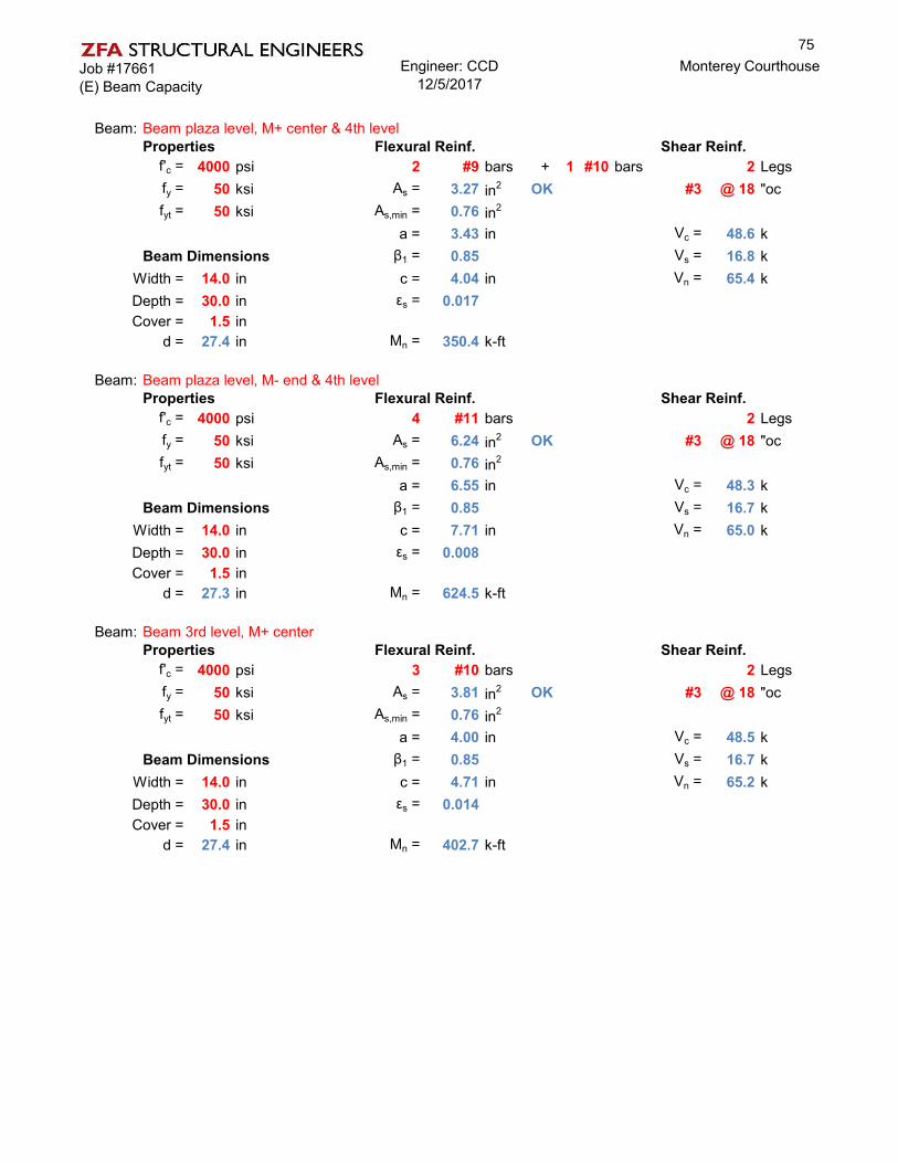
Job #17661(E) Beam Capacity
Engineer: CCD12/5/2017
Monterey Courthouse
Beam: Beam plaza level, M+ center & 4th levelProperties Flexural Reinf. Shear Reinf.
f'c = 4000 psi 2 #9 bars + 1 #10 bars 2 Legsfy = 50 ksi As = 3.27 in2 OK #3 @ 18 "ocfyt = 50 ksi As,min = 0.76 in2
a = 3.43 in Vc = 48.6 kBeam Dimensions β1 = 0.85 Vs = 16.8 k
Width = 14.0 in c = 4.04 in Vn = 65.4 kDepth = 30.0 in εs = 0.017Cover = 1.5 in
d = 27.4 in Mn = 350.4 k-ft
Beam: Beam plaza level, M- end & 4th levelProperties Flexural Reinf. Shear Reinf.
f'c = 4000 psi 4 #11 bars 2 Legsfy = 50 ksi As = 6.24 in2 OK #3 @ 18 "ocfyt = 50 ksi As,min = 0.76 in2
a = 6.55 in Vc = 48.3 kBeam Dimensions β1 = 0.85 Vs = 16.7 k
Width = 14.0 in c = 7.71 in Vn = 65.0 kDepth = 30.0 in εs = 0.008Cover = 1.5 in
d = 27.3 in Mn = 624.5 k-ft
Beam: Beam 3rd level, M+ centerProperties Flexural Reinf. Shear Reinf.
f'c = 4000 psi 3 #10 bars 2 Legsfy = 50 ksi As = 3.81 in2 OK #3 @ 18 "ocfyt = 50 ksi As,min = 0.76 in2
a = 4.00 in Vc = 48.5 kBeam Dimensions β1 = 0.85 Vs = 16.7 k
Width = 14.0 in c = 4.71 in Vn = 65.2 kDepth = 30.0 in εs = 0.014Cover = 1.5 in
d = 27.4 in Mn = 402.7 k-ft
75

Job #17661(E) Beam Capacity
Engineer: CCD12/5/2017
Monterey Courthouse
Beam: Beam 3rd level, M- endProperties Flexural Reinf. Shear Reinf.
f'c = 4000 psi 4 #10 bars 2 Legsfy = 50 ksi As = 5.08 in2 OK #3 @ 18 "ocfyt = 50 ksi As,min = 0.76 in2
a = 5.34 in Vc = 48.5 kBeam Dimensions β1 = 0.85 Vs = 16.7 k
Width = 14.0 in c = 6.28 in Vn = 65.2 kDepth = 30.0 in εs = 0.010Cover = 1.5 in
d = 27.4 in Mn = 522.8 k-ft
Beam: Beam roof, M+ centerProperties Flexural Reinf. Shear Reinf.
f'c = 4000 psi 3 #8 bars 2 Legsfy = 50 ksi As = 2.37 in2 OK #3 @ 18 "ocfyt = 50 ksi As,min = 0.76 in2
a = 2.49 in Vc = 48.7 kBeam Dimensions β1 = 0.85 Vs = 16.8 k
Width = 14.0 in c = 2.93 in Vn = 65.5 kDepth = 30.0 in εs = 0.025Cover = 1.5 in
d = 27.5 in Mn = 259.3 k-ft
Beam: Beam roof, M- at endProperties Flexural Reinf. Shear Reinf.
f'c = 4000 psi 4 #8 bars 2 Legsfy = 50 ksi As = 3.16 in2 OK #3 @ 18 "ocfyt = 50 ksi As,min = 0.76 in2
a = 3.32 in Vc = 48.7 kBeam Dimensions β1 = 0.85 Vs = 16.8 k
Width = 14.0 in c = 3.91 in Vn = 65.5 kDepth = 30.0 in εs = 0.018Cover = 1.5 in
d = 27.5 in Mn = 340.2 k-ft
76

Job #17661Seismic Hazard (Tier 2)
Engineer: CCD12/5/2017
Monterey Courthouse
SEISMIC HAZARD ANALYSIS (TIER 2) ASCE 41-13 §2.4.1
Site Coordinates
Latitude = 36.5901 deg County of Monterey CourthouseLongitude = -121.880 deg Monterey, California
Spectral Response Acceleration Parameters ASCE 41-13 §2.4.1.4
Site Class = D Site Soil ClassificationSS = 0.541 g Mapped Short-period Spectral Response AccelerationS1 = 0.193 g Mapped 1-sec period Spectral Response Acceleration
SXS = 0.739 g Short-period Spectral Response Acceleration at BSE-1ESX1 = 0.391 g 1-sec period Spectral Response Acceleration at BSE-1E
General Horizontal Response Spectrum ASCE 41-13 §2.4.1.7
β = 5% Effective Viscous Damping RatioB1 = 1.00 Damping Coefficient = 4 / ( 5.6 - ln(100β) )TS = 0.53 sec Period at Constant Velocity Region = S X1 / S XS
T0 = 0.11 sec Period at Constant Acceleration Region = 0.2 T S
0.4SXS= 0.30 g Peak Ground AccelerationSXS/B1 = 0.74 g Short period Spectral Response AccelerationSX1/B1 = 0.39 g 1-sec period Design Spectral Response Acceleration
Spectral Acceleartion at Building Period ASCE 41-13 §2.4
Existing ConditionsNorth-South Direction
T= 0.717 sec Building period in N-S direction Per LSP calcsSa= 0.544 Spectral Response Acceleration at Building Period Eq. 2-10
East-West DirectionT= 0.717 sec Building period in N-S direction Per LSP calcs
Sa= 0.544 Spectral Response Acceleration at Building Period Eq. 2-10
Retrofit StructureNorth-South Direction
T= 0.431 sec Building period in N-S direction Per LSP calcsSa= 0.737 Spectral Response Acceleration at Building Period Eq. 2-10
East-West DirectionT= 0.431 sec Building period in N-S direction Per LSP calcs
Sa= 0.737 Spectral Response Acceleration at Building Period Eq. 2-10
77

Job #17661LSP (Tier 2)
Engineer: CCD12/5/2017
Monterey Courthouse
LINEAR STATIC PROCEDURE (LSP) - Tier 2 ASCE 41-13 §7.4.1
# Stories = 4 Number of stories in building
Period Determination for LSP - Method 2 - Empirical ASCE 41-13 §7.4.1.2
North-South DirectionBuilding Type = C1
Ct = 0.018 Factor for adjustment of period ASCE 41-13 §7.4.1.2.2β = 0.90 Factor for adjustment of periodhn = 60.0 ft Roof HeightT = 0.717 sec Building period in N-S direction ASCE 41-13 Eq. 7-18
East-West DirectionBuilding Type = C1
Ct = 0.018 Factor for adjustment of periodβ = 0.90 Factor for adjustment of periodhn = 60.0 ft Roof HeightT = 0.717 sec Building period in E-W direction ASCE 41-13 Eq. 7-18
Pseudo-Seismic Force for LSP (North-South) ASCE 41-13 §7.4.1.3.1
V = C1 C2 Cm Sa W Pseudo-Lateral Force ASCE 41-13 Eq. 7-21
C1 = 1.0 Modification Factor, Inelastic Displacements ASCE 41-13 Eq. 7-22C2 = 1.0 Modification Factor, Cyclic Behavior ASCE 41-13 Eq. 7-23
C1 C2 = 1.1 Alternative Value for Modification Factors ASCE 41-13 Table 7-3Use alternate C1C2? Yes
Cm = 0.9 Effective Mass Factor ASCE 41-13 Table 7-4
Sa(T) = 0.544 g Spectral Response Acceleration for T = 0.72sec
W = 10659.9 kips Effective Seismic Weight
VN/S = 0.538 *W Pseudo-Lateral ForceVN/S = 5,740.3 kips Pseudo-Lateral Force
Pseudo-Seismic Force for LSP (East-West) ASCE 41-13 §7.4.1.3.1
V = C1 C2 Cm Sa W Pseudo-Lateral Force ASCE 41-13 Eq. 7-21
C1 = 1.0 Modification Factor, Inelastic Displacements ASCE 41-13 Eq. 7-22C2 = 1.0 Modification Factor, Cyclic Behavior ASCE 41-13 Eq. 7-23
C1 C2 = 1.1 Alternative Value for Modification Factors ASCE 41-13 Table 7-3Use alternate C1C2? Yes
Cm = 0.9 Effective Mass Factor ASCE 41-13 Table 7-4
Sa(T) = 0.544 g Spectral Response Acceleration for T = 0.72sec
W = 10659.9 kips Effective Seismic Weight
VE/W = 0.538 *W Pseudo-Lateral ForceVE/W = 5,740.3 kips Pseudo-Lateral Force
78

Job #17661Tier 2 Deficiency Evaluation
Engineer: CCD12/5/2017
Monterey Courthouse
Column Shear Stress CheckTier 2: Section 5.5.2.1.4
k= 0.9 f'ce= 6000 psiper table 6-1
b (in) d (in) area (in2)
stl area (in2)
ρl Av s (in) fyl (ksi) fyv (ksi)
ρv
Roof 18 18 324 10.16 0.03136 0.44 18 50 50 0.00144th 18 18 324 10.16 0.03136 0.44 18 50 50 0.0014
3rd (1) 24 24 576 8 0.01389 0.44 18 62.5 50 0.00103rd (2) 24 24 576 12.48 0.02167 0.44 18 62.5 50 0.0010Plaza 24 24 576 16.92 0.02938 0.44 18 62.5 50 0.0010
Vo P Mp L Vp = 2M/L Vp/Vo Vn P/AF'c V/bdfc mVc+Vs demand Spcol kips
Roof 70.4 58 325 12.5 52.0 0.74 ii 52.0 0.03 4.77 1.164th 70.4 114 360 12.5 57.6 0.82 ii 57.6 0.06 8.32 1.16
3rd (1) 116.7 174 560 14 80.0 0.69 ii 80.0 0.05 6.71 1.093rd (2) 116.7 174 775 14 110.7 0.95 ii 110.7 0.05 6.71 1.09Plaza 116.7 232 1055 11 191.8 1.64 iii 116.7 0.07 6.30 1
Max V Eqx (kips)
Max V Eqy (kips) mkVn DCR
Roof 109.8 109.8 73.20 1.54th 191.5 190.1 73.20 2.63rd 280.6 272.3 114.96 2.4
Plaza 263.5 259.3 105.06 2.5
Tier 2 check is non-compliant
No Shear FailuresTier 2: Section 5.5.2.3.4
All columns are noncompliant, the adequacy of the columns for shear was checked in the previous section. The beams are all controlled by flexural failure and therefore do not need to be check
79

Job #17661Tier 2 Deficiency Evaluation
Engineer: CCD12/5/2017
Monterey Courthouse
Strong column - Weak BeamTier 2: Section 5.5.2.1.5
Evaluate columns for shear & flexure with m=2. Column shear demands per shear check above
Max V Eqx (kips)
Max V Eqy (kips) m Vn mkVn DCR
Roof 109.8 109.8 2 52.0 93.6 1.24th 191.5 190.1 2 57.6 103.7 1.8
3rd (1) 280.6 272.3 2 80.0 144.0 1.93rd (2) 280.6 272.3 2 110.7 199.3 1.4Plaza 263.5 259.3 2 116.7 210.1 1.2
all columns fail the shear check with m=2
Max M Eqx (k-ft)
Max M Eqy (k-ft) m Mn mkMn DCR
Roof 1075 1054 2 325 585.0 1.84th 1400 1365 2 360 648.0 2.2
3rd (1) 2184 2037 2 560 1008.0 2.23rd (2) 2184 2037 2 775 1395.0 1.6Plaza 2865 2820 2 1055 1899.0 1.5
all columns fail the flexure check with m=2
Beam BarsTier 2: Section 5.5.2.3.5
flexural demand of noncompliant beams shall be checked at ends and middle with an m-factor = 1
BeamsMax Mu
(k-ft) m Mn mkMn DCRroof end 600 1 259.3 233.3 2.3roof middle 213 1 259.3 233.3 0.84th end 1345 1 624.5 562.0 2.24th middle 230 1 350.4 315.4 0.73rd end 2044 1 522.8 470.5 3.93rd middle 275 1 402.7 362.4 0.7
plaza end 2848 1 624.5 562.0 4.6plaza middle 350 1 350.4 315.4 1.0
80

Job #17661Tier 2 Deficiency Evaluation
Engineer: CCD12/5/2017
Monterey Courthouse
GirdersMax Mu
(k-ft) m Mn mkMn DCRroof end 895 1 949 854.1 0.9roof middle 310 1 949 854.1 0.34th end 1980 1 1107 996.1 1.84th middle 320 1 412 370.4 0.83rd end 3000 1 1176 1058.5 2.63rd middle 390 1 858 772.5 0.5
plaza end 4500 1 795 715.1 5.7plaza middle 290 1 795 715.1 0.4
Most beams fail induced end moments. All of the beams pass the demand at the beam middle
Column-Bar SplicesTier 2: Section 5.5.2.3.6
The flexural demands at noncompliant column splices shall be calculated and the adequacy shallbe evaluated.
There are non-conforming column splices at the 3rd, 4th and roof levels. The m is taken as 1 fornon-conforming lap lengths
Max M Eqx (k-ft)
Max M Eqy (k-ft) m Mn mkMn DCR
Roof 1075 1054 1.00 325.0 292.5 3.74th 1400 1365 1.00 360.0 324.0 4.3
3rd (1) 2184 2037 1.00 560.0 504.0 4.33rd (2) 2184 2037 1.00 775.0 697.5 3.1
All columns fail the flexural check
Beam-Bar SplicesTier 2: Section 5.5.2.3.6
This check is similar to the Beam Bar check above, except instead of an m=1 it is allowed to usean m=1.5 per Table 10-13. However, upon inspection of the results from m=1, even with an increased m, beams will still fail.
Column-Tie SpacingTier 2: Section 5.5.2.3.7
The force demand in in noncompliant columns shall be calculated and the adequacy of the elementsshall be evaluated
The column shear and flexural demand were checked with the reduced m factors above in the Column Shear Stress check and the Column- Bar splices. All column checks are non compliant.
81
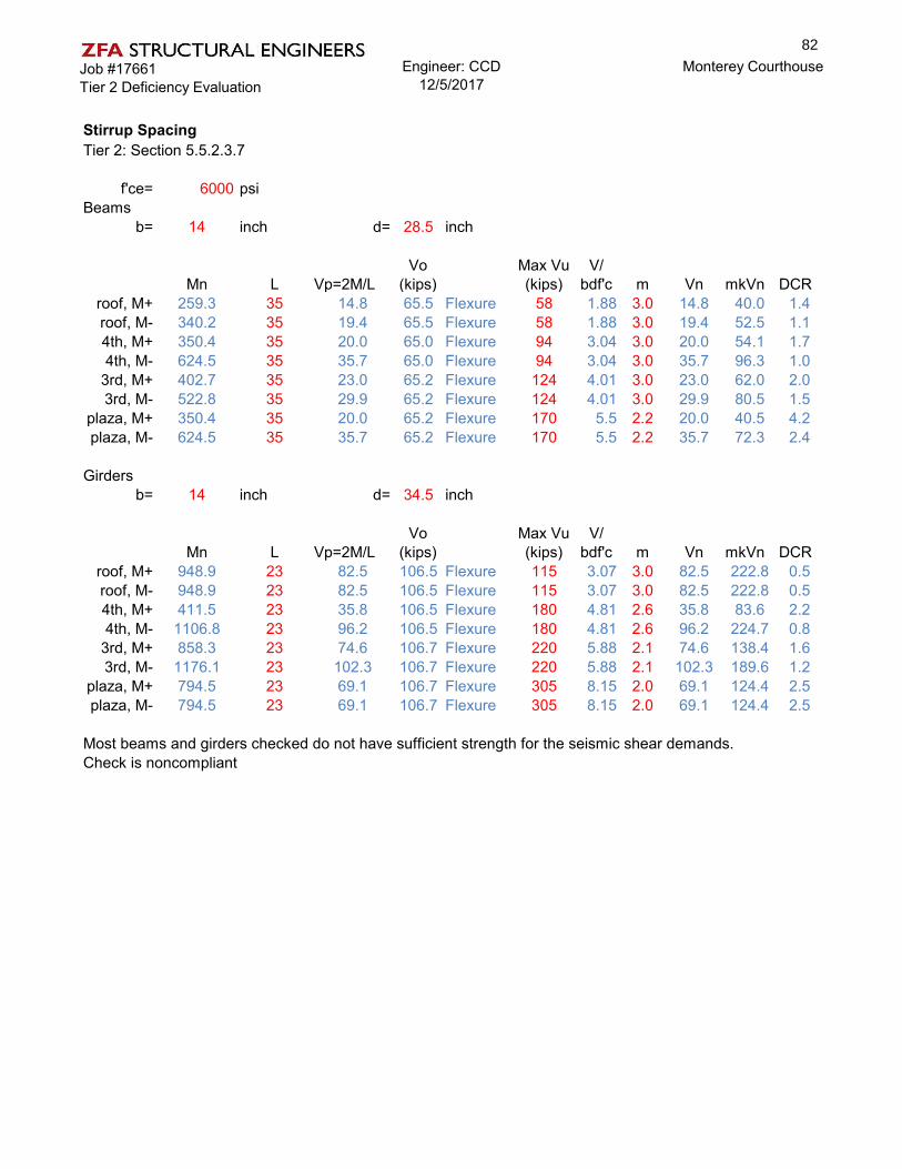
Job #17661Tier 2 Deficiency Evaluation
Engineer: CCD12/5/2017
Monterey Courthouse
Stirrup SpacingTier 2: Section 5.5.2.3.7
f'ce= 6000 psiBeams
b= 14 inch d= 28.5 inch
Mn L Vp=2M/LVo
(kips)Max Vu (kips)
V/bdf'c m Vn mkVn DCR
roof, M+ 259.3 35 14.8 65.5 Flexure 58 1.88 3.0 14.8 40.0 1.4roof, M- 340.2 35 19.4 65.5 Flexure 58 1.88 3.0 19.4 52.5 1.14th, M+ 350.4 35 20.0 65.0 Flexure 94 3.04 3.0 20.0 54.1 1.74th, M- 624.5 35 35.7 65.0 Flexure 94 3.04 3.0 35.7 96.3 1.0
3rd, M+ 402.7 35 23.0 65.2 Flexure 124 4.01 3.0 23.0 62.0 2.03rd, M- 522.8 35 29.9 65.2 Flexure 124 4.01 3.0 29.9 80.5 1.5
plaza, M+ 350.4 35 20.0 65.2 Flexure 170 5.5 2.2 20.0 40.5 4.2plaza, M- 624.5 35 35.7 65.2 Flexure 170 5.5 2.2 35.7 72.3 2.4
Girdersb= 14 inch d= 34.5 inch
Mn L Vp=2M/LVo
(kips)Max Vu (kips)
V/bdf'c m Vn mkVn DCR
roof, M+ 948.9 23 82.5 106.5 Flexure 115 3.07 3.0 82.5 222.8 0.5roof, M- 948.9 23 82.5 106.5 Flexure 115 3.07 3.0 82.5 222.8 0.54th, M+ 411.5 23 35.8 106.5 Flexure 180 4.81 2.6 35.8 83.6 2.24th, M- 1106.8 23 96.2 106.5 Flexure 180 4.81 2.6 96.2 224.7 0.8
3rd, M+ 858.3 23 74.6 106.7 Flexure 220 5.88 2.1 74.6 138.4 1.63rd, M- 1176.1 23 102.3 106.7 Flexure 220 5.88 2.1 102.3 189.6 1.2
plaza, M+ 794.5 23 69.1 106.7 Flexure 305 8.15 2.0 69.1 124.4 2.5plaza, M- 794.5 23 69.1 106.7 Flexure 305 8.15 2.0 69.1 124.4 2.5
Most beams and girders checked do not have sufficient strength for the seismic shear demands.Check is noncompliant
82

Job #17661Tier 2 Deficiency Evaluation
Engineer: CCD12/5/2017
Monterey Courthouse
Joint Transverse ReinforcingTier 2: Section 5.5.2.3.8
f'ce= 6000 psi
Beams (4th and roof level)col width = 18 inch
beam width = 14 inch beam width + joint depth = 32 inchjoint depth = 18 inch beam width + 2x = 18 inch
x from bm to col = 2 inch
Beams (plaza and 3rd level)col width = 24 inch
beam width = 14 inch beam width + joint depth = 38 inchjoint depth = 24 inch beam width + 2x = 24 inch
x from bm to col = 5 inch
Aj (in2) γ Vn (Kips) m mkVn Vu DCR
4th 324.0 8.0 200.8 1.0 180.7 58.0 0.293rd 324.0 8.0 200.8 1.0 180.7 94.0 0.472nd 576.0 8.0 356.9 1.0 321.2 124.0 0.351st 576.0 8.0 356.9 1.0 321.2 170.0 0.48
Girders (4th and roof level)col width = 18 inch
beam width = 14 inch beam width + joint depth = 32 inchjoint depth = 18 inch beam width + 2x = 18 inch
x from bm to col = 2 inch
Girders (plaza and 3rd level)col width = 24 inch
beam width = 14 inch beam width + joint depth = 38 inchjoint depth = 24 inch beam width + 2x = 24 inch
x from bm to col = 5 inch
Aj (in2) γ Vn (Kips) m mkVn Vu DCR
4th 324.0 8.0 200.8 1.0 180.7 115.0 0.573rd 324.0 8.0 200.8 1.0 180.7 180.0 0.902nd 576.0 8.0 356.9 1.0 321.2 220.0 0.621st 576.0 8.0 356.9 1.0 321.2 305.0 0.85
Adjacent BuildingsTier 2: Section 5.4.1.2
The courthouse and annex are only a few inches apart directly over the entrance to the courthouseThis condition should be mitigated to prevent pounding of the structures
OKOKOKOK
Compliance
OKOKOK
OK
Compliance
83

Job #17661LSP (Tier 2 Retrofit)
Engineer: CCD12/5/2017
Monterey Courthouse
LINEAR STATIC PROCEDURE (LSP) - Tier 2 - RETROFIT STRUCTURE ASCE 41-13 §7.4.1
# Stories = 4 Number of stories in building
Period Determination for LSP - Method 2 - Empirical ASCE 41-13 §7.4.1.2
North-South DirectionBuilding Type = C2
Ct = 0.020 Factor for adjustment of period ASCE 41-13 §7.4.1.2.2β = 0.75 Factor for adjustment of periodhn = 60.0 ft Roof HeightT = 0.431 sec Building period in N-S direction ASCE 41-13 Eq. 7-18
East-West DirectionBuilding Type = C2
Ct = 0.020 Factor for adjustment of periodβ = 0.75 Factor for adjustment of periodhn = 60.0 ft Roof HeightT = 0.431 sec Building period in E-W direction ASCE 41-13 Eq. 7-18
Pseudo-Seismic Force for LSP (North-South) ASCE 41-13 §7.4.1.3.1
V = C1 C2 Cm Sa W Pseudo-Lateral Force ASCE 41-13 Eq. 7-21
C1 = 1.0 Modification Factor, Inelastic Displacements ASCE 41-13 Eq. 7-22C2 = 1.0 Modification Factor, Cyclic Behavior ASCE 41-13 Eq. 7-23
C1 C2 = 1.1 Alternative Value for Modification Factors ASCE 41-13 Table 7-3Use alternate C1C2? Yes
Cm = 0.8 Effective Mass Factor ASCE 41-13 Table 7-4
Sa(T) = 0.737 g Spectral Response Acceleration for T = 0.43sec
W = 11458.7 kips Effective Seismic Weight
VN/S = 0.649 *W Pseudo-Lateral ForceVN/S = 7,434.2 kips Pseudo-Lateral Force
Pseudo-Seismic Force for LSP (East-West) ASCE 41-13 §7.4.1.3.1
V = C1 C2 Cm Sa W Pseudo-Lateral Force ASCE 41-13 Eq. 7-21
C1 = 1.0 Modification Factor, Inelastic Displacements ASCE 41-13 Eq. 7-22C2 = 1.0 Modification Factor, Cyclic Behavior ASCE 41-13 Eq. 7-23
C1 C2 = 1.1 Alternative Value for Modification Factors ASCE 41-13 Table 7-3Use alternate C1C2? Yes
Cm = 0.8 Effective Mass Factor ASCE 41-13 Table 7-4
Sa(T) = 0.737 g Spectral Response Acceleration for T = 0.43sec
W = 11458.7 kips Effective Seismic Weight
VE/W = 0.649 *W Pseudo-Lateral ForceVE/W = 7,434.2 kips Pseudo-Lateral Force
84

Job #17661Retrofit Vertical Distribution
Engineer: CCD12/5/2017
Monterey Courthouse
Vertical Distribution (LSP) - Tier 2 Retrofit
Vertical Distribution of Seismic Forces (North-South) Y Direction ASCE 41-13 §7.4.1.3.2
VN/S = 7,434 kips Total Base Sheark = 1.0 For T = 0.43 sec
w x (kips) h x (ft) w x h kx Cvx Fx (kips) V x (kips) Fpx (kips)
Roof 2,526 60.00 151,563 0.39 2,878 2,878 2,8784th Level 2,711 45.00 122,008 0.31 2,317 5,195 2,6893rd Level 2,711 30.00 81,339 0.21 1,544 6,739 2,299Plaza Level 2,711 13.50 36,602 0.09 695 7,434 1,891
Total 10,660 391,513 1.00 7,434
Vertical Distribution of Seismic Forces (East-West) X Direction ASCE 41-13 §7.4.1.3.2
VE/W = 7,434 kips Total Base Sheark = 1.0 For T = 0.43 sec
w x (kips) h x (ft) w x h kx Cvx Fx (kips) V x (kips) Fpx (kips)
Roof 2,526 60.00 151,563 0.39 2,878 2,878 2,8784th Level 2,711 45.00 122,008 0.31 2,317 5,195 2,6893rd Level 2,711 30.00 81,339 0.21 1,544 6,739 2,299Plaza Level 2,711 13.50 36,602 0.09 695 7,434 1,891
Total 10,660 391,513 1.00 7,434
85

Job #17661Tier 2 Retrofit
Engineer: CCD12/5/2017
Monterey Courthouse
Deficiency Based RetrofitThe deficiences that remain after the Tier 2 evaluation will now be mitigated with a retrofit. The scope of the Tier 2 deficiency-based retrofit need not expand beyond that necessary to modify the building to comply with a Tier 1 screening or a Tier 2 Evaluation.
k= 0.9 per table 6-1 f'ce= 6000 psi ( existing concrete)fye= 75 ksi f'ce= 5200 psi (new walls)
New concrete Shear Wallstwall = 12 inch Lwall = 24 ft k= 1
max axial (kips) from ETABSX X Y Y
Pier 2 Pier 7 Pier J Pier M MINroof 243 110 155 140 110
Story4 345 188 238 230 188Story3 480 270 340 310 270Story2 530 320 390 360 320
max shear (kips) from ETABSX X Y Y
Pier 2 Pier 7 Pier J Pier M MAXroof 1608 1315 1290 1630 1630
Story4 2800 2355 2540 2610 2800Story3 3500 2980 3252 3210 3500Story2 3900 3550 3640 3820 3900
max moment (kip-ft) from ETABSX X Y Y
Pier 2 Pier 7 Pier J Pier M MAXroof 25700 23200 21250 23200 25700
Story4 54600 55200 51000 52000 55200Story3 81500 101500 85900 94400 101500Story2 109000 147000 119000 139100 147000
New Shear Wall DesignAcv (in2) α ρt Vn m mkVn DCR
roof 3456 2 0.00287 1242.3 2.5 3105.8 0.52Story4 3456 2 0.00287 1242.3 2.5 3105.8 0.90Story3 3456 2 0.00407 1553.4 2.5 3883.4 0.90Story2 3456 2 0.00407 1553.4 2.5 3883.4 1.00
Mn (kip-ft) ρl mkMn DCR steel lbs/yd3roof 15500 0.00390 38750 0.66 #6@18"oc 90
Story4 25200 0.00690 63000 0.88 #6@18"oc, (4)#11 EE 129Story3 42000 0.00990 105000 0.97 #7@18"oc, (6)#11 EE 185Story2 55000 0.01630 137500 1.07 #7@9"oc, (8)#11 EE 269
86

Job #17661Tier 2 Retrofit
Engineer: CCD12/5/2017
Monterey Courthouse
All demands from ETABS model are output with walls in the model to determine reduced loads to existing structure.
Column Shear Stress CheckTier 2: Section 5.5.2.1.4
Max V Eqx
(kips)Max V
Eqy (kips) m mkVn DCRRoof 13.0 23.2 1.16 73.20 0.32
4th 17.6 33.3 1.16 73.20 0.453rd 26.6 57.2 1.09 114.96 0.50
Plaza 7.1 12.4 1.00 105.06 0.12
Tier 2 check is compliant with new loads
No Shear FailuresTier 2: Section 5.5.2.3.4
Per check above, the shear controlled elements (columns) are no longer over-stressed. Checkis compliant
Strong column - Weak BeamTier 2: Section 5.5.2.1.5
Evaluate columns for shear & flexure with m=2. Column shear demands per shear check above
Max V Eqx (kips)
Max V Eqy (kips) m Vn mkVn DCR
Roof 13.0 23.2 2 52.0 93.6 0.254th 17.6 33.3 2 57.6 103.7 0.32
3rd (1) 26.6 57.2 2 80.0 144.0 0.403rd (2) 26.6 57.2 2 110.7 199.3 0.29Plaza 7.1 12.4 2 116.7 210.1 0.06
all columns pass the shear check with m=2
Max M Eqx (k-ft)
Max M Eqy (k-ft) m Mn mkMn DCR
Roof 128 227 2 325 585.0 0.394th 125 241 2 360 648.0 0.37
3rd (1) 216 446 2 560 1008.0 0.443rd (2) 216 446 2 775 1395.0 0.32Plaza 80 120 2 1055 1899.0 0.06
all columns pass the flexure check with m=2
87

Job #17661Tier 2 Retrofit
Engineer: CCD12/5/2017
Monterey Courthouse
Beam BarsTier 2: Section 5.5.2.3.5
flexural demand of noncompliant beams shall be checked at ends and middle with an m-factor = 1
BeamsMax Mu
(k-ft) m Mn mkMn DCRroof end 112 1 259.3 233.3 0.5roof middle 96 1 259.3 233.3 0.44th end 132 1 624.5 562.0 0.24th middle 90 1 350.4 315.4 0.33rd end 140 1 522.8 470.5 0.33rd middle 85 1 402.7 362.4 0.2
plaza end 124 1 624.5 562.0 0.2plaza middle 82 1 350.4 315.4 0.3
GirdersMax Mu
(k-ft) m Mn mkMn DCRroof end 180 1 949 854.1 0.2roof middle 180 1 949 854.1 0.24th end 200 1 1107 996.1 0.24th middle 155 1 412 370.4 0.43rd end 230 1 1176 1058.5 0.23rd middle 160 1 858 772.5 0.2
plaza end 205 1 795 715.1 0.3plaza middle 155 1 795 715.1 0.2
All beams pass the retrofit load check, check is compliantThe above demand does not include beams directly adjacent to shear walls.Beams at shear walls will likely need FRP for induced forces
Column-Bar SplicesTier 2: Section 5.5.2.3.6
The flexural demands at noncompliant column splices shall be calculated and the adequacy shallbe evaluated.
There are non-conforming column splices at the 3rd, 4th and roof levels. The m is taken as 1 fornon-conforming lap lengths
Max M Eqx (k-ft)
Max M Eqy (k-ft) m Mn mkMn DCR
Roof 128 227 1.00 325.0 292.5 0.784th 125 241 1.00 360.0 324.0 0.74
3rd (1) 216 446 1.00 560.0 504.0 0.883rd (2) 216 446 1.00 775.0 697.5 0.64
All columns pass the flexure check
88

Job #17661Tier 2 Retrofit
Engineer: CCD12/5/2017
Monterey Courthouse
Beam-Bar SplicesTier 2: Section 5.5.2.3.6
This check is similar to the Beam Bar check above, except instead of an m=1 it is allowed to usean m=1.5 per Table 10-13. All beams pass with m=1 so therefore with an increased m, will still becompliant. Check is compliant
Column-Tie SpacingTier 2: Section 5.5.2.3.7
The force demand in in noncompliant columns shall be calculated and the adequacy of the elementsshall be evaluated
The column shear and flexural demand were checked with the reduced m factors above in the Column Shear Stress check and the Column- Bar splices. All column checks are compliant.
Stirrup SpacingTier 2: Section 5.5.2.3.7
f'ce= 6000 psiBeamsb= 14 inch d= 28.5 inch
Mn L Vp=2M/LVo
(kips)Max Vu (kips)
V/bdf'c m Vn mkVn DCR
roof, M+ 259.3 35 14.8 65.5 Flexure 6 0.19 3.0 14.8 40.0 0.1roof, M- 340.2 35 19.4 65.5 Flexure 26 0.84 3.0 19.4 52.5 0.54th, M+ 350.4 35 20.0 65.0 Flexure 6 0.19 3.0 20.0 54.1 0.14th, M- 624.5 35 35.7 65.0 Flexure 27 0.87 3.0 35.7 96.3 0.3
3rd, M+ 402.7 35 23.0 65.2 Flexure 6 0.19 3.0 23.0 62.1 0.13rd, M- 522.8 35 29.9 65.2 Flexure 27 0.87 3.0 29.9 80.7 0.3
plaza, M+ 350.4 35 20.0 65.2 Flexure 6 0.19 3.0 20.0 54.1 0.1plaza, M- 624.5 35 35.7 65.2 Flexure 26 0.84 3.0 35.7 96.3 0.3
Girdersb= 14 inch d= 34.5 inch
Mn L Vp=2M/LVo
(kips)Max Vu (kips)
V/bdf'c m Vn mkVn DCR
roof, M+ 948.9 23 82.5 106.5 Flexure 20 0.53 3.0 82.5 222.8 0.1roof, M- 948.9 23 82.5 106.5 Flexure 68 1.82 3.0 82.5 222.8 0.34th, M+ 411.5 23 35.8 106.5 Flexure 20 0.53 3.0 35.8 96.6 0.24th, M- 1106.8 23 96.2 106.5 Flexure 71 1.90 3.0 96.2 259.9 0.3
3rd, M+ 858.3 23 74.6 106.7 Flexure 20 0.53 3.0 74.6 201.5 0.13rd, M- 1176.1 23 102.3 106.7 Flexure 69 1.84 3.0 102.3 276.1 0.2
plaza, M+ 794.5 23 69.1 106.7 Flexure 13 0.34 3.0 69.1 186.5 0.1plaza, M- 794.5 23 69.1 106.7 Flexure 60 1.60 3.0 69.1 186.5 0.3
All beams and girders have sufficient strengh for shear demands. Check is compliant
89

Job #17661Tier 2 Retrofit
Engineer: CCD12/5/2017
Monterey Courthouse
Adjacent BuildingsTier 2: Section 5.4.1.2
The courthouse and annex are only a few inches apart directly over the entrance to the courthouseThis condition is to be mitigated to prevent pounding of the structures
Additional Retrofit ConsiderationsConceptual Foundation Design
Per architectural drawings, geotechnical borings determined soil to be silty, fine grained sand with shalefragments with shale below. Per CBC table 1806.2 allowable pressures:
Vertical Foundation Pressure: 1500 psfqc = 3qallow = 4500 psf
m = 3 life safety, ASCE 41-13 8.4.2.3.2.1q = 13500 psf
Shear Wall Gridline Jnew ftg width = 10 ftnew ftg depth = 5 ft
length total = 120 ftOverturning = 3305.6 kips each end
Deadload from cols = 690 kDeadload from wall = 230 k
(e) ftg weight = 45 knew ftg weight = 412.5 k
3x per ASCE 41 = 4132.5 kDCR = 0.80
Shear Wall Gridline Mnew ftg width = 10 ftnew ftg depth = 5 ft
length total = 108 ftOverturning = 3863.9 kips each end
Deadload from cols = 690 kDeadload from wall = 230 k
(e) ftg weight = 45 knew ftg weight = 367.5 k
3x per ASCE 41 = 3997.5 kDCR = 0.97
Shear Wall Gridline 2new ftg width = 10 ftnew ftg depth = 5 ft
length total = 72 ftOverturning = 3406.3 kips each end
90

Job #17661Tier 2 Retrofit
Engineer: CCD12/5/2017
Monterey Courthouse
Deadload from cols = 690 kDeadload from wall = 230 k
(e) ftg weight = 45 knew ftg weight = 232.5 k
3x per ASCE 41 = 3592.5 kDCR = 0.95
Shear Wall Gridline 7new ftg width = 10.5 ftnew ftg depth = 5 ft
length total = 63 ftOverturning = 3062.5 kips each end
Deadload from cols = 690 kDeadload from wall = 230 k
(e) ftg weight = 45 knew ftg weight = 208.6875 k
3x per ASCE 41 = 3521.063 kDCR = 0.87
Diaphragm and Drag Connection CheckFpx/Fx
Roof 1.04th 1.2
3rd 1.5Plaza 2.7
Diaphragm Loads each Wall Line
X X Y YPier 2 Pier 7 Pier J Pier M
roof 1608 1315 1290 1630Story4 1384 1207 1451 1138Story3 1042 930 1060 893Story2 1088 1551 1056 1660
Diaphragm strength
fye= 62.5 ksi Av= 0.11 in2f'ce= 6 ksi s= 6.5 in
t slab= 4.5 inch
Vn = 13.39 klf
Each wall length is 25' determine load to be transferred at wall:
��= 2 ∗ �∗ �∗ �′ �+ �����/ �
91

Job #17661Tier 2 Retrofit
Engineer: CCD12/5/2017
Monterey Courthouse
m = 2mkVn = 24.1 klfmkVn = 602.5 kips at wallmkVn = 1205.1 kips at wall (where slab is both sides)
Remaining load to transfer to wall through beam dragX X Y Y
Pier 2 Pier 7 Pier J Pier Mroof 403 712 85 425
Story4 179 605 246 0Story3 0 328 0 0Story2 0 948 0 0
Beam NameX X Y Y
Pier 2 Pier 7 Pier J Pier Mroof RG-2 none RB-J RB-M
Story4 4G-2 4B-m 4B-J 4B-MStory3 3G-2 3B-m 3B-J 3B-MStory2 2G-2 2B-m 2B-J 2B-M
X X Y YPier 2 Pier 7 Pier J Pier M
roof (4)#8 none(2)#9+(2)#8 (6)#8
Story4 (4)#9(2)#6+(2)#8 (4)#9 (4)#9
Story3 (4)#10(2)#6+(2)#8 (4)#9 (4)#9
Story2(2)#9+(2)#10
(2)#6+(2)#6 (4)#11 (4)#8
Existing Continuous Longitudinal steelX X Y Y
Pier 2 Pier 7 Pier J Pier Mroof 3.16 0.00 3.58 4.74
Story4 4.00 2.46 4.00 4.00Story3 5.08 2.46 4.00 4.00Story2 4.54 1.76 6.24 3.16
fy= 50F=fyAb force controlledeach X X Y Yside Pier 2 Pier 7 Pier J Pier M
roof 316 0 358 474Story4 400 246 400 400Story3 508 246 400 400Story2 454 176 624 316
92

Job #17661Tier 2 Retrofit
Engineer: CCD12/5/2017
Monterey Courthouse
remaining force to be transferredX X Y Y
Pier 2 Pier 7 Pier J Pier M additional ft of diaphragm required PIER 7roof none 712 none none 30
Story4 none 359 none none 15Story3 none none none none noneStory2 none 772 none none 32
provide steel or frp drag at gridline 7fy= 36
Area of steel required for dragroof 14.8 50plf
Story4 7.5 25 plf
93

Job #17661ETABS Output
Engineer: CCD12/5/2017
Monterey Courthouse
TABLE: Material Properties - ConcreteName E ν α G Unit Weight Unit Mass Fc Lightweight?
lb/in² 1/F lb/in² lb/ft³ lb-s²/ft⁴ lb/in²4000Psi 3604996.5 0.2 0.0000055 1502081.88 150 4.662 4000 No
TABLE: Material Properties - RebarName E α Unit Weight Unit Mass Fy Fu
lb/in² 1/F lb/ft³ lb-s²/ft⁴ lb/in² lb/in²A615Gr40 29000000 0.0000065 490 15.23 40000 60000A615Gr50 29000000 0.0000065 490 15.23 50000 60000A615Gr60 29000000 0.0000065 490 15.23 60000 90000
TABLE: Frame SectionsName Material Shape t3 t2 Area AS2 AS3
in in in² in² in²CONC BEAM - B 4000Psi Concrete Rectangular 25.5 14 357 297.5 297.5CONC BEAM - G 4000Psi Concrete Rectangular 31.5 14 441 367.5 367.5CONC COL 1st 4000Psi Concrete Rectangular 24 24 576 480 480CONC COL 2nd (1) 4000Psi Concrete Rectangular 24 24 576 480 480CONC COL 2nd (2) 4000Psi Concrete Rectangular 24 24 576 480 480CONC COL 3rd 4000Psi Concrete Rectangular 18 18 324 270 270CONC COL 4th 4000Psi Concrete Rectangular 18 18 324 270 270ConcBm 4000Psi Concrete Rectangular 24 18 432 360 360ConcCol 4000Psi Concrete Rectangular 18 18 324 270 270
TABLE: Shell Sections - WallName Material Element Type Thickness f11 Modifier f22 Modifier f12 Modifierm11 Modifierm22 Modifier
in12" Wall 4000Psi Shell-Thin 12 0.5 1 1 0.01 0.01
TABLE: Modal Periods and FrequenciesCase Mode Period Frequency
sec cyc/secModal 1 0.512 1.952Modal 2 0.481 2.078Modal 3 0.342 2.923Modal 4 0.288 3.468Modal 5 0.261 3.828Modal 6 0.249 4.014Modal 7 0.245 4.087Modal 8 0.237 4.214
94

Job #17661ETABS Output
Engineer: CCD12/5/2017
Monterey Courthouse
TABLE: Base ReactionsLoad Case/Combo FX FY FZ
kip kip kipDead 0.00 0.00 6473.02Live 0.00 0.00 2616.60SuperDead 0.00 0.00 5228.53EQx -7462.87 0.00 0.00 <- compare with calculated 7,434. OKEQy 0.00 -7462.87 0.00 <- compare with calculated 7,434. OKEnv Dead 0.00 0.00 11701.54 <- compare with calculated 11,459. OK
TABLE: Load CombinationsName Load Case/Combo Scale Factor Type
Env Dead Dead 1 Linear AddEnv Dead SuperDead 11.1(D+L)+EQx Dead 1.1 Linear Add1.1(D+L)+EQx SuperDead 1.11.1(D+L)+EQx Live 1.11.1(D+L)+EQx EQx 11.1(D+L)+EQy Dead 1.1 Linear Add1.1(D+L)+EQy SuperDead 1.11.1(D+L)+EQy Live 1.11.1(D+L)+EQy EQy 10.9D+EQx Dead 0.9 Linear Add0.9D+EQx SuperDead 0.90.9D+EQx EQx 10.9D+EQy Dead 0.9 Linear Add0.9D+EQy SuperDead 0.90.9D+EQy EQy 1Eqx Combo ENV 1.1(D+L)+EQx 1 EnvelopeEqx Combo ENV 0.9D+EQx 1Eqy Combo ENV 1.1(D+L)+EQy 1 EnvelopeEqy Combo ENV 0.9D+EQy 1
house95
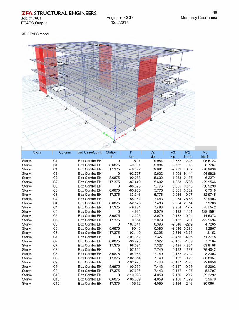
Job #17661ETABS Output
Engineer: CCD12/5/2017
Monterey Courthouse
3D ETABS Model
Example Column output looking at Eqx at 4th story columnsTABLE: Column Forces
Story Column Load Case/Combo Station P V2 V3 M2 M3ft kip kip kip kip-ft kip-ft
Story4 C1 Eqx Combo ENV Max 0 -51.7 9.984 -2.732 -24.5 95.5123Story4 C1 Eqx Combo ENV Max8.6875 -49.061 9.984 -2.732 -0.8 8.7767Story4 C1 Eqx Combo ENV Max17.375 -46.422 9.984 -2.732 40.52 -70.9936Story4 C2 Eqx Combo ENV Max 0 -92.727 5.602 1.068 9.414 54.8928Story4 C2 Eqx Combo ENV Max8.6875 -90.088 5.602 1.068 0.137 6.2274Story4 C2 Eqx Combo ENV Max17.375 -87.449 5.602 1.068 -5.86 -29.9546Story4 C3 Eqx Combo ENV Max 0 -88.623 5.776 0.065 0.813 56.9299Story4 C3 Eqx Combo ENV Max8.6875 -85.985 5.776 0.065 0.302 6.7519Story4 C3 Eqx Combo ENV Max17.375 -83.346 5.776 0.065 -0.07 -32.9745Story4 C4 Eqx Combo ENV Max 0 -55.162 7.483 2.954 28.58 72.9903Story4 C4 Eqx Combo ENV Max8.6875 -52.523 7.483 2.954 2.914 7.9783Story4 C4 Eqx Combo ENV Max17.375 -49.884 7.483 2.954 -17.7 -51.542Story4 C5 Eqx Combo ENV Max 0 -4.964 13.079 0.132 1.101 128.1591Story4 C5 Eqx Combo ENV Max8.6875 -2.325 13.079 0.132 -0.04 14.5373Story4 C5 Eqx Combo ENV Max17.375 0.314 13.079 0.132 -1.1 -92.9694Story4 C6 Eqx Combo ENV Max 0 187.841 0.396 -2.646 -22.9 4.7265Story4 C6 Eqx Combo ENV Max8.6875 190.48 0.396 -2.646 0.093 1.2867Story4 C6 Eqx Combo ENV Max17.375 193.119 0.396 -2.646 43.73 -2.153Story4 C7 Eqx Combo ENV Max 0 -101.362 7.327 -0.435 -4.96 71.3718Story4 C7 Eqx Combo ENV Max8.6875 -98.723 7.327 -0.435 -1.09 7.7184Story4 C7 Eqx Combo ENV Max17.375 -96.084 7.327 -0.435 4.964 -53.9108Story4 C8 Eqx Combo ENV Max 0 -107.592 7.749 0.152 1.537 75.4042Story4 C8 Eqx Combo ENV Max8.6875 -104.953 7.749 0.152 0.214 8.2303Story4 C8 Eqx Combo ENV Max17.375 -102.314 7.749 0.152 -0.29 -58.8957Story4 C9 Eqx Combo ENV Max 0 -102.973 7.443 -0.137 -1.28 72.8656Story4 C9 Eqx Combo ENV Max8.6875 -100.335 7.443 -0.137 -0.09 8.2002Story4 C9 Eqx Combo ENV Max17.375 -97.696 7.443 -0.137 4.97 -52.797Story4 C10 Eqx Combo ENV Max 0 -110.998 4.059 2.166 20.2 39.2292Story4 C10 Eqx Combo ENV Max8.6875 -108.359 4.059 2.166 1.379 3.9679Story4 C10 Eqx Combo ENV Max17.375 -105.72 4.059 2.166 -2.46 -30.0651
96

Job #17661ETABS Output
Engineer: CCD12/5/2017
Monterey Courthouse
Story4 C11 Eqx Combo ENV Max 0 -215.181 0.396 -2.039 -17.2 4.6289Story4 C11 Eqx Combo ENV Max8.6875 -212.542 0.396 -2.039 0.471 1.1901Story4 C11 Eqx Combo ENV Max17.375 -209.903 0.396 -2.039 38.83 -2.2449Story4 C12 Eqx Combo ENV Max 0 -113.237 6.607 0.677 5.52 64.5796Story4 C12 Eqx Combo ENV Max8.6875 -110.598 6.607 0.677 -0.21 7.1825Story4 C12 Eqx Combo ENV Max17.375 -107.959 6.607 0.677 -4.53 -49.6683Story4 C13 Eqx Combo ENV Max 0 -101.498 8.14 0.51 4.868 79.2821Story4 C13 Eqx Combo ENV Max8.6875 -98.859 8.14 0.51 0.44 8.5653Story4 C13 Eqx Combo ENV Max17.375 -96.221 8.14 0.51 -0.36 -59.403Story4 C14 Eqx Combo ENV Max 0 -99.67 9.362 -0.757 -7.18 90.947Story4 C14 Eqx Combo ENV Max8.6875 -97.032 9.362 -0.757 -0.6 9.6175Story4 C14 Eqx Combo ENV Max17.375 -94.393 9.362 -0.757 13.05 -67.5457Story4 C15 Eqx Combo ENV Max 0 -132.545 11.7 0.104 -0.19 114.1759Story4 C15 Eqx Combo ENV Max8.6875 -129.906 11.7 0.104 -1.1 12.6896Story4 C15 Eqx Combo ENV Max17.375 -127.268 11.7 0.104 17.55 -88.7967Story4 C16 Eqx Combo ENV Max 0 -110.124 10.784 -1.268 -9.65 105.2658Story4 C16 Eqx Combo ENV Max8.6875 -107.485 10.784 -1.268 1.364 11.5815Story4 C16 Eqx Combo ENV Max17.375 -104.847 10.784 -1.268 29.82 -80.6763Story4 C17 Eqx Combo ENV Max 0 -110.417 7.287 -0.048 -1.16 71.6281Story4 C17 Eqx Combo ENV Max8.6875 -107.779 7.287 -0.048 -0.7 8.3234Story4 C17 Eqx Combo ENV Max17.375 -105.14 7.287 -0.048 1.368 -53.1027Story4 C18 Eqx Combo ENV Max 0 -93.364 7.593 2.849 27 74.7843Story4 C18 Eqx Combo ENV Max8.6875 -90.725 7.593 2.849 2.245 8.8167Story4 C18 Eqx Combo ENV Max17.375 -88.086 7.593 2.849 -8.48 -53.6105Story4 C19 Eqx Combo ENV Max 0 -53.695 7.435 -4.636 -44.5 73.3383Story4 C19 Eqx Combo ENV Max8.6875 -51.056 7.435 -4.636 -4.27 8.7495Story4 C19 Eqx Combo ENV Max17.375 -48.417 7.435 -4.636 53.12 -49.5066Story4 C20 Eqx Combo ENV Max 0 -88.286 8.606 3.523 31.42 84.829Story4 C20 Eqx Combo ENV Max8.6875 -85.647 8.606 3.523 0.819 10.0825Story4 C20 Eqx Combo ENV Max17.375 -83.009 8.606 3.523 -8.94 -63.0608Story4 C21 Eqx Combo ENV Max 0 -69.929 4.843 -2.193 -19.2 45.7235Story4 C21 Eqx Combo ENV Max8.6875 -67.29 4.843 -2.193 -0.1 3.7879Story4 C21 Eqx Combo ENV Max17.375 -64.652 4.843 -2.193 32.18 -36.3322Story4 C22 Eqx Combo ENV Max 0 -99.255 8.117 -0.382 -4.27 75.436Story4 C22 Eqx Combo ENV Max8.6875 -96.616 8.117 -0.382 -0.95 4.9222Story4 C22 Eqx Combo ENV Max17.375 -93.977 8.117 -0.382 4.543 -53.3389Story4 C23 Eqx Combo ENV Max 0 -94.627 8.331 -0.505 -5.14 76.9471Story4 C23 Eqx Combo ENV Max8.6875 -91.988 8.331 -0.505 -0.75 4.5736Story4 C23 Eqx Combo ENV Max17.375 -89.349 8.331 -0.505 5.457 -55.7802Story4 C24 Eqx Combo ENV Max 0 -99.272 8.876 -1.786 -16.7 82.2259Story4 C24 Eqx Combo ENV Max8.6875 -96.633 8.876 -1.786 -1.2 5.1134Story4 C24 Eqx Combo ENV Max17.375 -93.995 8.876 -1.786 19.71 -59.3662Story4 C25 Eqx Combo ENV Max 0 -81.528 9.632 3.572 31.89 90.9338Story4 C25 Eqx Combo ENV Max8.6875 -78.889 9.632 3.572 0.856 7.2538Story4 C25 Eqx Combo ENV Max17.375 -76.25 9.632 3.572 -11.8 -67.2357
97

Job #17661ETABS Output
Engineer: CCD12/5/2017
Monterey Courthouse
Example graphic of Beam Moment Demands under Max Eqy Combo at Gridline K (k-ft)
Example graphic of Beam Shear Demands under Max Eqy Combo at Gridline K (kips)
98
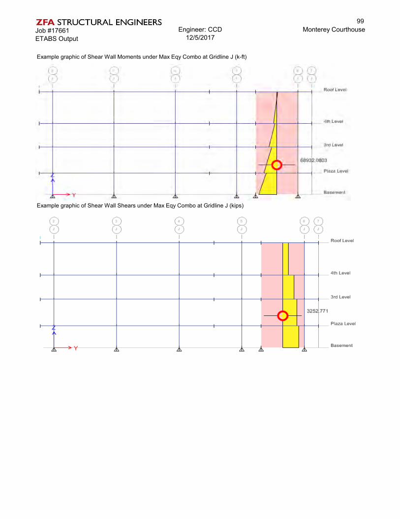
Job #17661ETABS Output
Engineer: CCD12/5/2017
Monterey Courthouse
Example graphic of Shear Wall Moments under Max Eqy Combo at Gridline J (k-ft)
Example graphic of Shear Wall Shears under Max Eqy Combo at Gridline J (kips)
99

County of Monterey Courthouse Parking GarageStructural Calculations
Monterey, CaliforniaZFA Project Number: 17661
Final Report
Prepared For:
RIM ArchitectsSan Francisco, California
Prepared By:
Ryan Bogart, SE, Senior AssociateChelsea Drenick, SE, Senior EngineerMark Moore, SE, Principal-in-ChargeSan Francisco, California
June 30, 2018
601 montgomery street | suite 1450 | san francisco ca 94111 | 415 243 4091 zfa.com
100

Job #17661Structural Narrative
Engineer: GJC/CCD12/6/2017
Monterey Courthouse
STRUCTURAL NARRATIVE
The following calculations support the ASCE 41-13 Tier 1 and Tier 2 checks for the County of Monterey Courthouse parking garage. Deficiencies remain after the Tier 2 evaluation. A Tier 2 deficiency base retrofit is then designed. Concrete shear walls are added to reduce seismic load to the existing structure and mitigate deficiencies to achieve compliance with Life Safety BSE-1E.
101

Job #17661Design Criteria
Engineer: GJC/CCD12/6/2017
Monterey Courthouse
DETAILED DESIGN CRITERIA
BUILDING CODE
BUILDING SYSTEM DESCRIPTION
17000 ft2
68000 ft2
17000 ft2
28 ft 0.00 :12
SEISMIC DESIGN PARAMETERS
36.590 -121.880 degUSGS
Section 2.4.1.6.1
Table 3-1Table 3-1
Ct, N-S = 0.02 Section 4.5.2.4
Ct, E-W = 0.02 Section 4.5.2.4
βN-S = 0.90 Section 4.5.2.4
βE-W = 0.90 Section 4.5.2.4
Ta, N-S= 0.361 Section 4.5.2.4
Ta, E-W = 0.361 Section 4.5.2.4
TIER 1 SEISMIC EVALUATION PARAMETERSTable 2-1
Table 2-1
0.541 USGS
0.193 USGS
0.739 USGS
0.391 ASCE 7 Table 1.5-1
Table 2-5
Sa, N-S = 0.739 Section 4.5.2.3
Sa, E-W = 0.739 Section 4.5.2.3
CN-S = 1.000 Table 4-8
CE-W = 1.000 Table 4-8
0.739 Section 4.5.2.10.739 Section 4.5.2.1
Modification FactorVN-S = *W Pseudo-Seismic Base Shear, N-SVE-W = *W Pseudo-Seismic Base Shear, N-S
g Spectral Response Acceleration, N-Sg Spectral Response Acceleration, E-W
Modification Factor
Approximate Period Parameter, β, E-Wsec Approximate Fundamental Period, N-Ssec Approximate Fundamental Period, E-W
Seismicity: High
Diaphragm= Rigid Diaphragm Post tensioned slab
SXS = g Mapped spectral response acceleration parameterSX1 = g Mapped spectral response acceleration parameter
Approximate Period Parameter, Ct, N-SApproximate Period Parameter, Ct, E-WApproximate Period Parameter, β, N-S
Building System, N-S: C1 Concrete Moment FrameBuilding System, E-W: C1 Concrete Moment Frame
S1 = g Mapped spectral response acceleration parameter
Latitude: deg Longitude:
Risk Category:Soil Site Class = D Per Geotech Report, Site Class D otherwise
II
Seismic Hazard Level: BSE-1E 20%/50 yearsPerformance Objective: LS Life Safety
Gravity System: Concrete columns and beam
Mean Building Height:Roof Pitch:
SS = g Mapped spectral response acceleration parameter
Diaphragm System: Post tensioned slabFoundation System: Piles
ASCE 41-13 Reference UNO:
Footprint:Floor Area:
Building Use: Parking Garage
SEOR STAMP
Governing Code: 2016 California Building CodeAuthority Having Jurisdiction: City of Monterey
Date of Construction: 1966No. Stories: 3
Roof Area:
1100033000
102

Job #17661Design Criteria
Engineer: GJC/CCD12/6/2017
Monterey Courthouse
TIER 2 / 3 SEISMIC EVALUATION PARAMETERSTable 2-1
Table 2-1
0.541 USGS
0.193 USGS
0.739 USGS
0.391 USGS
Table 2-5
1.000 Equation 7-22
1.000 Equation 7-23
1.100 Table 7-3
Yes1.1000.900 Table 7-4
1.000 Equation 7-22
1.000 Equation 7-23
1.100 Table 7-3
Yes1.1000.900 Table 7-4
0.737 Equation 2-9
0.737 Equation 2-9
0.730 Equation 7-21
0.730 Equation 7-21
MATERIAL STRENGTH AND SPECIFICATIONS
CONCRETE:Table 6-1
3000 psi Table 10-2
4500 psi Table 10-1
3000 psi Table 10-2
4500 psi Table 10-1
3000 psi Table 10-2
4500 psi Table 10-1
4000 psi Table 10-2
6000 psi Table 10-1
4000 psi Table 10-2
6000 psi Table 10-1
3000 psi Table 10-2
4500 psi Table 10-1
4000 psi Table 10-2
6000 psi Table 10-1
150 pcf110 pcf
CONCRETE REINFORCING:Table 6-1
40 ksi Table 10-3
50 ksi Table 10-1
70 ksi Table 10-3
87.5 ksi Table 10-1
40 ksi Table 10-3
50 ksi Table 10-1
70 ksi Table 10-3
87.5 ksi Table 10-1
ASCE 41-13 Reference UNO:
Columns, f'c =Columns, f'ce =
Default Lower Bound: 3000 psi - 6000 psi
Foundations, f'c =
Slab on grade, f'c =
Structural walls, f'c =
Default Lower Bound: 2500 psi - 3000 psi
Default Lower Bound: 3000 psi - 4000 psi
Default Lower Bound: 2500 psi - 4000 psi
Foundations, f'ce =
Slab on grade, f'ce =
Knowledge Factor, κ 0.75
Performance Objective: LS Life SafetySeismic Hazard Level: BSE-1E 20%/50 years
Default Lower-Bound: 55, 70, 80, 90, 75, 80, 100 ksi
Beams, f'c =
Fill over metal deck, f'c =
Elevated slabs, f'c =
Knowledge Factor, κ Reinforcing Knowledge FactorReinforcing Steel, fy =
Reinforcing Steel ties, fy =
Default Lower-Bound: 33, 40, 50, 60, 65, 70 ksi
Default Lower-Bound: 33, 40, 50, 60, 65, 70 ksi
Default Lower-Bound: 55, 70, 80, 90, 75, 80, 100 ksi
Reinforcing Steel ties, fye =
Reinforcing Steel, fye =Reinforcing Steel, fy =Reinforcing Steel, fye =
Reinforcing Steel ties, fy =Reinforcing Steel ties, fye =
SX1 = g Mapped spectral response acceleration parameterSeismicity: High
0.75
Concrete Knowledge Factor
Default Lower Bound: 3000 psi - 4000 psi
Default Lower Bound: 3000 psi - 4000 psi
Default Lower Bound: 3000 psi - 4000 psi
Weight of Light Wt. Concrete =
Structural walls, f'ce =
Beams, f'ce =
Fill over metal deck, f'ce =
Elevated slabs, f'ce =
SS = g Mapped spectral response acceleration parameterS1 = g Mapped spectral response acceleration parameterSXS = g Mapped spectral response acceleration parameter
C1, N-S =C2, N-S =Alternate (C1C2)N-S =
VN-S (ULT) =VE-W (ULT) =
Inelastic-to-elastic displacement factorHysteresis shape factor
2 ≤ mmax < 6
Effective mass factorInelastic-to-elastic displacement factor
Hysteresis shape factor2 ≤ mmax < 6
Effective mass factorSpectral Response AccelerationSpectral Response Acceleration
Pseudo-Seismic Base Shear, N-SPseudo-Seismic Base Shear, E-W
*W*W
Sa,E-W =
(C1C2)N-S =Cm, N-S =C1, E-W =C2, E-W =Alternate (C1C2)E-W =Use Alternate (C1C2)E-W?(C1C2)E-W =Cm, E-W =Sa,N-S =
Weight of Concrete =
Use Alternate (C1C2)N-S?
103

Job #17661Flat Weights
Engineer: GJC/CCD12/6/2017
Monterey Courthouse
GRAVITY / SEISMIC FLAT WEIGHT TAKEOFF (PSF)
Typical FloorCBC Live Load Category: [Table 1607.1]
Sloped Deck Joists Girders Columns Model Seismic Model Seismic
0.0 0.0 0.0 0.0 0.0 0.0 0.00.0 0.0 0.0 0.0 0.0 0.0 0.087.5 87.5 87.5 87.5 87.5 87.5 87.50.0 0.0 0.0 0.0 0.0 0.0 0.00.0 0.0 0.0 0.0 0.0 0.0 0.02.0 2.0 2.0 2.0 2.0 2.0 2.0
0.0 0.0 0.0 0.0 0.0 0.01.5 1.5 1.5 1.5 1.5 1.50.0 0.0 0.0 0.0
13.2 13.2 13.26.9 6.9
5.0 5.0 5.0 5.0 5.0 5.0 5.094.5 96.0 109.2 116.1 96.0 116.1 96.094.5 96.0 109.2 116.1 96.0 116.1 96.00.0 0.0 0.0 0.0 0.0 0.0 0.040.0 40.0 40.0 40.0 40.0 0.0 0.0
1.00 40.0 40.0 40.0 40.0 40.0 0.0 0.0134.5 136.0 149.2 156.1 136.0 116.1 96.0
RoofCBC Live Load Category: [Table 1607.1]
Slope: 0.00:12
Sloped Deck Joists Girders Columns Model Seismic Model Seismic
0.0 0.0 0.0 0.0 0.0 0.0 0.00.0 0.0 0.0 0.0 0.0 0.0 0.087.5 87.5 87.5 87.5 87.5 87.5 87.50.0 0.0 0.0 0.0 0.0 0.0 0.00.0 0.0 0.0 0.0 0.0 0.0 0.02.0 2.0 2.0 2.0 2.0 2.0 2.0
0.0 0.0 0.0 0.0 0.0 0.01.5 1.5 1.5 1.5 1.5 1.50.0 0.0 0.0 0.0
13.2 13.2 13.23.5 3.5
5.0 5.0 5.0 5.0 5.0 5.0 5.094.5 96.0 109.2 112.6 96.0 112.6 96.00.0 0.0 0.0 0.0 0.0 0.0 0.040.0 40.0 40.0 40.0 40.0 0.0 0.0134.5 136.0 149.2 152.6 136.0 112.6 96.0
14. Garages: passenger
Material
FinishSolar / Other7" concrete slab
ColumnsMisc.Dead LoadDead Load - Horiz ProjectionPartitionsLive Load
InsulationM.E.P.Ceiling - 7/8" plasterSprinklersJoistsGirders
ToppingSheathing / DeckingInsulationM.E.P.Ceiling Sprinklers
Live Load - Reduced R2 =Total Load
14. Garages: passenger
Material
FinishSolar / Other
PartitionsLive LoadTotal Load
JoistsGirdersColumnsMisc.Dead Load
104

Job #17661Mass Takeoff
Engineer: GJC/CCD12/6/2017
Monterey Courthouse
Diaphragm Weight Information:
Area Diaphragm Diaphragm Wall Wall Wall Wall LevelUnit Weight Weight Unit Weight Trib Height Length Weight Weight
(sq ft) (psf) (kips) (psf) (ft) (ft) (kips) (kips)0 0 00 0 00 0 00 0 0
ROOF 11102 113 1,251 0 0.0 0.0 0 1,2512nd 11102 116 1,289 0 0.0 0.0 0 1,2891st 11102 116 1,289 0 0.0 0.0 0 1,289
Σ 3,829 0 3,829
Level
105

Job #17661Vertical Distribution-Tier 1
Engineer: GJC/CCD12/6/2017
Monterey Courthouse
Vertical Distribution (LSP)-TIER 1
Vertical Distribution of Seismic Forces (North-South) Y Direction ASCE 41-13 §7.4.1.3.2
VN/S = 2,829 kips Total Base Sheark = 1.0 For T = 0.36 sec
w x (kips) h x (ft ) w x h kx Cvx Fx (kips) V x (kips)
Roof 1,251 28.00 35,017 0.49 1,381 1,3812nd Level 1,289 19.00 24,491 0.34 966 2,3461st Level 1,289 9.50 12,245 0.17 483 2,829
Total 3,829 71,753 1.00 2,829
Vertical Distribution of Seismic Forces (East-West) X Direction ASCE 41-13 §7.4.1.3.2
VE/W = 2,829 kips Total Base Sheark = 1.0 For T = 0.36 sec
w x (kips) h x (ft ) w x h kx Cvx Fx (kips) V x (kips)
Roof 1,251 28.00 35,017 0.49 1,381 1,3812nd Level 1,289 19.00 24,491 0.34 966 2,3461st Level 1,289 9.50 12,245 0.17 483 2,829
Total 3,829 71,753 1.00 2,829
106
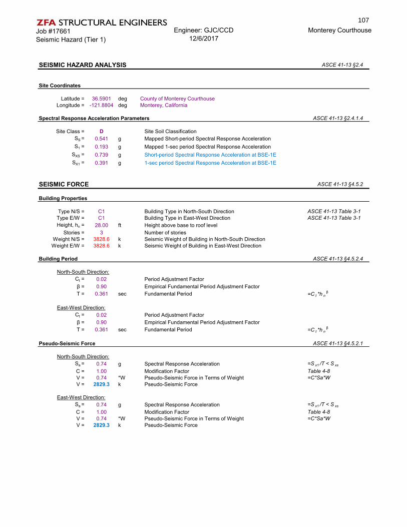
Job #17661Seismic Hazard (Tier 1)
Engineer: GJC/CCD12/6/2017
Monterey Courthouse
SEISMIC HAZARD ANALYSIS ASCE 41-13 §2.4
Site Coordinates
Latitude = 36.5901 deg County of Monterey CourthouseLongitude = -121.8804 deg Monterey, California
Spectral Response Acceleration Parameters ASCE 41-13 §2.4.1.4
Site Class = D Site Soil ClassificationSS = 0.541 g Mapped Short-period Spectral Response AccelerationS1 = 0.193 g Mapped 1-sec period Spectral Response Acceleration
SXS = 0.739 g Short-period Spectral Response Acceleration at BSE-1ESX1 = 0.391 g 1-sec period Spectral Response Acceleration at BSE-1E
SEISMIC FORCE ASCE 41-13 §4.5.2
Building Properties
Type N/S = C1 Building Type in North-South Direction ASCE 41-13 Table 3-1Type E/W = C1 Building Type in East-West Direction ASCE 41-13 Table 3-1Height, hn = 28.00 ft Height above base to roof level
Stories = 3 Number of storiesWeight N/S = 3828.6 k Seismic Weight of Building in North-South DirectionWeight E/W = 3828.6 k Seismic Weight of Building in East-West Direction
Building Period ASCE 41-13 §4.5.2.4
North-South Direction:Ct = 0.02 Period Adjustment Factorβ = 0.90 Empirical Fundamental Period Adjustment FactorT = 0.361 sec Fundamental Period =C t *h n
β
East-West Direction:Ct = 0.02 Period Adjustment Factorβ = 0.90 Empirical Fundamental Period Adjustment FactorT = 0.361 sec Fundamental Period =C t *h n
β
Pseudo-Seismic Force ASCE 41-13 §4.5.2.1
North-South Direction:Sa = 0.74 g Spectral Response Acceleration =S x1 /T < S xs
C = 1.00 Modification Factor Table 4-8V = 0.74 *W Pseudo-Seismic Force in Terms of Weight =C*Sa*WV = 2829.3 k Pseudo-Seismic Force
East-West Direction:Sa = 0.74 g Spectral Response Acceleration =S x1 /T < S xs
C = 1.00 Modification Factor Table 4-8V = 0.74 *W Pseudo-Seismic Force in Terms of Weight =C*Sa*WV = 2829.3 k Pseudo-Seismic Force
107

Job #17661Tier 1 Checklist Calculations
Engineer: GJC/CCD12/6/2017
Monterey Courthouse
Column Axial Stress Caused by Overturningf'c= 4000 psi
0.3f'c= 1200 psi
Eqn (4-12)
(Section 4.5.3.6)
N-S Direction E-W Directionnf = 8 nf = 2V = 2829 kips V = 2829 kips
hn = 28 ft hn = 28 ftL = 61 ft L = 182 ft
Ms = 2 Ms = 2Acol = 4 ft2 Acol = 4 ft2
p= 13.5 k/ft2 p= 18.1 k/ft2p= 93.9 psi p= 126 psi
DCR= 0.08 OK DCR= 0.1 OK
Compliant
Column Shear Stress Check
(Section 4.5.3.2)
stress check < 126.5 psi
N-S Directionnc = 16nf = 8
Ms = 2
Ac Vj vj vj DCRft2 kips k/ft2 psi
2nd 64 1,381 21.6 149.8 1.2 Non Compliant1st 64 2,346 36.7 254.6 2.0 Non Compliant
Ground 89 2,829 31.8 221.0 1.7 Non Compliant
E-W Directionnc = 16nf = 2
Ms = 2
Ac Vj vj vj DCRft2 kips k/ft2 psi
2nd 64 1,381 12.3 85.6 0.7 OK1st 64 2,346 21.0 145.5 1.2 Non Compliant
Ground 89 2,829 18.2 126.3 1.0 OK
No floors pass the column shear stress test, check is non-compliant.
�=1
��
23
�ℎ����
1����
�=1
��
����− ��
�ℎ����
108

Job #17661Tier 1 Checklist Calculations
Engineer: GJC/CCD12/6/2017
Monterey Courthouse
Prestressed Frame Elements
Max. Fe in slab = 23 kip/ft Max. Fe in beam = 635 kipslab t = 7 inch beam + slab area = 2271 inch
fp= 274 psi fp= 280 psi
Max allowed= 700 psi or 666.7 psi
Check is compliant
No Shear Failuresf'c= 4000 psi f'c= 5000 psi - 1st flr & 2nd flr
b (in) d (in)area (in2)
stl area (in2) ρl Av s (in) fyl
(ksi)fyv
(ksi)2nd 24 24 576 6.24 0.01083 0.2 12 60 601st 24 24 576 6.24 0.01083 0.2 11.5 60 60
Ground - 32 804 9.36 0.01164 0.11 2.25 60 60
V P Mp L Vp = 2M/L Failure MechanismVc+Vs demand Spcol
2nd 95.4 85.9 375 7.5 100.0 SHEAR1st 104.9 174.4 450 8 112.5 SHEAR
Ground 203.2 263.0 800 8 200.0 FLEXURE
First and second floor columns have shear failures, therefore the check is non-compliant.
Typical Beam
Properties Shear Reinf.f'c = 4000 psi 2 Legsfy = 40 ksi #3 @ 4 "ocfyt = 40 ksi
Beam DimensionsWidth = 24.0 in Vc = 49.0 kDepth = 18.5 in Vs = 35.5 kCover = 1.5 in
d = 16.1 in
Pre-Stressed Concrete Beam Checks Failure MechanismLower Limit: Vn = 84.4 k FlexureUpper Limit: Vn = 157.9 k
Vp= 2M/L Shear based on flexural capacityVp= 41.2 k
All beams are flexure controlled, check is compliant.
109
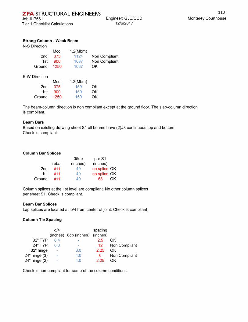
Job #17661Tier 1 Checklist Calculations
Engineer: GJC/CCD12/6/2017
Monterey Courthouse
Strong Column - Weak BeamN-S Direction
Mcol 1.2(Mbm)2nd 375 1124 Non Compliant1st 900 1087 Non Compliant
Ground 1250 1087 OK
E-W DirectionMcol 1.2(Mbm)
2nd 375 159 OK1st 900 159 OK
Ground 1250 159 OK
The beam-column direction is non compliant except at the ground floor. The slab-column directionis compliant.
Beam BarsBased on existing drawing sheet S1 all beams have (2)#8 continuous top and bottom.Check is compliant.
Column Bar Splices
rebar35db
(inches)per S1
(inches)2nd #11 49 no splice OK1st #11 49 no splice OK
Ground #11 49 63 OK
Column splices at the 1st level are compliant. No other column splicesper sheet S1. Check is compliant.
Beam Bar SplicesLap splices are located at lb/4 from center of joint. Check is compliant
Column Tie Spacing
d/4 (inches) 8db (inches)
spacing (inches)
32" TYP 6.4 - 2.5 OK24" TYP 6.0 - 12 Non Compliant
32" hinge - 3.0 2.25 OK24" hinge (3) - 4.0 6 Non Compliant24" hinge (2) - 4.0 2.25 OK
Check is non-compliant for some of the column conditions.
110

Job #17661Tier 1 Checklist Calculations
Engineer: GJC/CCD12/6/2017
Monterey Courthouse
Stirrup Spacing
d/2 (inches)
min(8db,d/4) (inches)
spacing (inches)
Beam TYP 8.5 - 18 Non CompliantBeam hinge - 4.3 4 OK
Check is non-compliant.
Joint Transverse ReinforcingNon-compliant based on two checks above
Overturningleast horizontal dimension / building height = 1.2
0.6Sa = 0.4 OK
Compliant
111
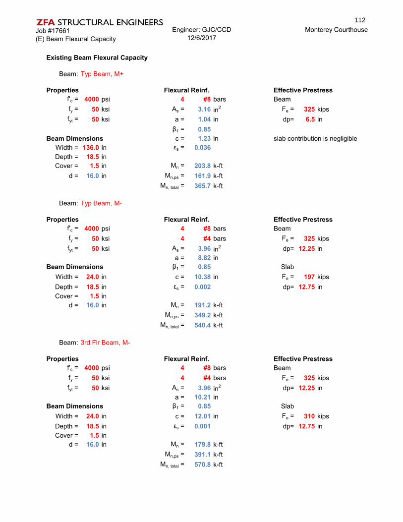
Job #17661(E) Beam Flexural Capacity
Engineer: GJC/CCD12/6/2017
Monterey Courthouse
Existing Beam Flexural Capacity
Beam: Typ Beam, M+
Properties Flexural Reinf. Effective Prestressf'c = 4000 psi 4 #8 bars Beamfy = 50 ksi As = 3.16 in2 Fe = 325 kipsfyt = 50 ksi a = 1.04 in dp= 6.5 in
β1 = 0.85Beam Dimensions c = 1.23 in slab contribution is negligible
Width = 136.0 in εs = 0.036Depth = 18.5 inCover = 1.5 in Mn = 203.8 k-ft
d = 16.0 in Mn,ps = 161.9 k-ftMn, total = 365.7 k-ft
Beam: Typ Beam, M-
Properties Flexural Reinf. Effective Prestressf'c = 4000 psi 4 #8 bars Beamfy = 50 ksi 4 #4 bars Fe = 325 kipsfyt = 50 ksi As = 3.96 in2 dp= 12.25 in
a = 8.82 inBeam Dimensions β1 = 0.85 Slab
Width = 24.0 in c = 10.38 in Fe = 197 kipsDepth = 18.5 in εs = 0.002 dp= 12.75 inCover = 1.5 in
d = 16.0 in Mn = 191.2 k-ftMn,ps = 349.2 k-ft
Mn, total = 540.4 k-ft
Beam: 3rd Flr Beam, M-
Properties Flexural Reinf. Effective Prestressf'c = 4000 psi 4 #8 bars Beamfy = 50 ksi 4 #4 bars Fe = 325 kipsfyt = 50 ksi As = 3.96 in2 dp= 12.25 in
a = 10.21 inBeam Dimensions β1 = 0.85 Slab
Width = 24.0 in c = 12.01 in Fe = 310 kipsDepth = 18.5 in εs = 0.001 dp= 12.75 inCover = 1.5 in
d = 16.0 in Mn = 179.8 k-ftMn,ps = 391.1 k-ft
Mn, total = 570.8 k-ft
112

Job #17661(E) Beam Flexural Capacity
Engineer: GJC/CCD12/6/2017
Monterey Courthouse
Existing Slab Flexural CapacityASCE 41-13, section 10.4.4.3
1 be= 3.75 ft column = 2 ft2 be= 4.92 ft slab thickness = 0.58 ft
b1= 2.58 ft γf = 0.6b2= 2.58 ft γv = 0.4
Beam: Slab, M+, ASCE 41 10.4.4.3 #1Properties Flexural Reinf. Effective Prestress
f'c = 4000 psi 2.5 #5 barsfy = 50 ksi As = 0.78 in2 Fe = 86.25 kipsfyt = 50 ksi a = 0.82 in dp= 5.75 in
β1 = 0.85Beam Dimensions c = 0.96 in
Width = 45.0 in εs = 0.012Depth = 7.0 in Mn = 13.8 k-ftCover = 1.5 in Mn,ps = 38.4 k-ft
d = 4.7 in Mn, total = 52.2 k-ft
Beam: Slab, M-, ASCE 41 10.4.4.3 #1Properties Flexural Reinf. Effective Prestress
f'c = 4000 psi 2.5 #5 barsfy = 50 ksi As = 0.78 in2 Fe = 86.25 kipsfyt = 50 ksi a = 0.82 in dp= 1.25 in
β1 = 0.85Beam Dimensions c = 0.96 in
Width = 45.0 in εs = 0.001Depth = 7.0 in Mn = 2.5 k-ftCover = 5.0 in Mn,ps = 6.0 k-ft
d = 1.2 in Mn, total = 8.6 k-ft
∑Mn = 60.8 kips∑Mn/γv = 151.9 kips
113

Job #17661(E) Beam Flexural Capacity
Engineer: GJC/CCD12/6/2017
Monterey Courthouse
Beam: Slab, M+, ASCE 41 10.4.4.3 #2Properties Flexural Reinf. Effective Prestress
f'c = 4000 psi 3.28 #5 barsfy = 50 ksi As = 1.02 in2 Fe = 113.1 kipsfyt = 50 ksi a = 0.82 in dp= 5.75 in
β1 = 0.85Beam Dimensions c = 0.96 in
Width = 59.0 in εs = 0.012Depth = 7.0 in Mn = 18.1 k-ftCover = 1.5 in Mn,ps = 50.3 k-ft
d = 4.7 in Mn, total = 68.5 k-ft
Beam: Slab, M-, ASCE 41 10.4.4.3 #2Properties Flexural Reinf. Effective Prestress
f'c = 4000 psi 3.28 #5 barsfy = 50 ksi As = 1.02 in2 Fe = 113.1 kipsfyt = 50 ksi a = 0.82 in dp= 1.25 in
β1 = 0.85Beam Dimensions c = 0.96 in
Width = 59.0 in εs = 0.001Depth = 7.0 in Mn = 3.3 k-ftCover = 5.0 in Mn,ps = 7.9 k-ft
d = 1.2 in Mn, total = 11.2 k-ft
∑Mn = 79.7 kips∑Mn/γf = 132.8 kips
114

Job #17661Seismic Hazard (Tier 2 & 3)
Engineer: GJC/CCD12/6/2017
Monterey Courthouse
SEISMIC HAZARD ANALYSIS (TIER 2) ASCE 41-13 §2.4.1
Site Coordinates
Latitude = 36.5901 deg County of Monterey CourthouseLongitude = -121.880 deg Monterey, California
Spectral Response Acceleration Parameters ASCE 41-13 §2.4.1.4Site Class = D Site Soil Classification
SS = 0.541 g Mapped Short-period Spectral Response AccelerationS1 = 0.193 g Mapped 1-sec period Spectral Response Acceleration
SXS = 0.739 g Short-period Spectral Response Acceleration at BSE-1ESX1 = 0.391 g 1-sec period Spectral Response Acceleration at BSE-1E
General Horizontal Response Spectrum ASCE 41-13 §2.4.1.7β = 5% Effective Viscous Damping Ratio
B1 = 1.00 Damping Coefficient = 4 / ( 5.6 - ln(100β) )TS = 0.53 sec Period at Constant Velocity Region = S X1 / S XS
T0 = 0.11 sec Period at Constant Acceleration Region = 0.2 T S
0.4SXS= 0.30 g Peak Ground AccelerationSXS/B1 = 0.74 g Short period Spectral Response AccelerationSX1/B1 = 0.39 g 1-sec period Design Spectral Response Acceleration
Spectral Acceleartion at Building Period ASCE 41-13 §2.4
Existing BuildingNorth-South Direction
T= 0.361 sec Building period in N-S direction Per LSP calcsSa= 0.737 Spectral Response Acceleration at Building Period Eq. 2-9
East-West DirectionT= 0.361 sec Building period in N-S direction Per LSP calcs
Sa= 0.737 Spectral Response Acceleration at Building Period Eq. 2-9
Retrofit BuildingNorth-South Direction
T= 0.243 sec Building period in N-S direction Per LSP calcsSa= 0.737 Spectral Response Acceleration at Building Period Eq. 2-10
East-West DirectionT= 0.361 sec Building period in N-S direction Per LSP calcs
Sa= 0.737 Spectral Response Acceleration at Building Period Eq. 2-10
115

Job #17661LSP (Tier 2 & 3)
Engineer: GJC/CCD12/6/2017
Monterey Courthouse
LINEAR STATIC PROCEDURE (LSP)-TIER 2 ASCE 41-13 §7.4.1
# Stories = 3 Number of stories in building
Period Determination for LSP - Method 2 - Empirical ASCE 41-13 §7.4.1.2
North-South DirectionBuilding Type = C1
Ct = 0.018 Factor for adjustment of period ASCE 41-13 §7.4.1.2.2β = 0.90 Factor for adjustment of periodhn = 28.0 ft Roof HeightT = 0.361 sec Building period in N-S direction ASCE 41-13 Eq. 7-18
East-West DirectionBuilding Type = C1
Ct = 0.018 Factor for adjustment of periodβ = 0.90 Factor for adjustment of periodhn = 28.0 ft Roof HeightT = 0.361 sec Building period in E-W direction ASCE 41-13 Eq. 7-18
Pseudo-Seismic Force for LSP (North-South) ASCE 41-13 §7.4.1.3.1
V = C1 C2 Cm Sa W Pseudo-Lateral Force ASCE 41-13 Eq. 7-21
C1 = 1.0 Modification Factor, Inelastic Displacements ASCE 41-13 Eq. 7-22C2 = 1.0 Modification Factor, Cyclic Behavior ASCE 41-13 Eq. 7-23
C1 C2 = 1.1 Alternative Value for Modification Factors ASCE 41-13 Table 7-3Use alternate C1C2? Yes
Cm = 0.9 Effective Mass Factor ASCE 41-13 Table 7-4
Sa(T) = 0.737 g Spectral Response Acceleration for T = 0.36sec
W = 3828.6 kips Effective Seismic Weight
VN/S = 0.730 *W Pseudo-Lateral ForceVN/S = 2,794.4 kips Pseudo-Lateral Force
Pseudo-Seismic Force for LSP (East-West) ASCE 41-13 §7.4.1.3.1
V = C1 C2 Cm Sa W Pseudo-Lateral Force ASCE 41-13 Eq. 7-21
C1 = 1.0 Modification Factor, Inelastic Displacements ASCE 41-13 Eq. 7-22C2 = 1.0 Modification Factor, Cyclic Behavior ASCE 41-13 Eq. 7-23
C1 C2 = 1.1 Alternative Value for Modification Factors ASCE 41-13 Table 7-3Use alternate C1C2? Yes
Cm = 0.9 Effective Mass Factor ASCE 41-13 Table 7-4
Sa(T) = 0.737 g Spectral Response Acceleration for T = 0.36sec
W = 3828.6 kips Effective Seismic Weight
VE/W = 0.730 *W Pseudo-Lateral ForceVE/W = 2,794.4 kips Pseudo-Lateral Force
116

Job #17661Vertical Distribution-Tier 2
Engineer: GJC/CCD12/6/2017
Monterey Courthouse
Vertical Distribution (LSP)-TIER 2
Vertical Distribution of Seismic Forces (North-South) Y Direction ASCE 41-13 §7.4.1.3.2
VN/S = 2,794 kips Total Base Sheark = 1.0 For T = 0.36 sec
w x (kips) h x (ft ) w x h kx Cvx Fx (kips) V x (kips) Fpx (kips)
Roof 1,251 28.00 35,017 0.49 1,364 1,364 1,3642nd Level 1,289 19.00 24,491 0.34 954 2,318 1,1761st Level 1,289 9.50 12,245 0.17 477 2,794 941
Total 3,829 71,753 1.00 2,794
Vertical Distribution of Seismic Forces (East-West) X Direction ASCE 41-13 §7.4.1.3.2
VE/W = 2,794 kips Total Base Sheark = 1.0 For T = 0.36 sec
w x (kips) h x (ft ) w x h kx Cvx Fx (kips) V x (kips) Fpx (kips)
Roof 1,251 28.00 35,017 0.49 1,364 1,364 1,3642nd Level 1,289 19.00 24,491 0.34 954 2,318 1,1761st Level 1,289 9.50 12,245 0.17 477 2,794 941
Total 3,829 71,753 1.00 2,794
117

Job #17661Vertical Distribution-Model
Engineer: GJC/CCD12/6/2017
Monterey Courthouse
Vertical Distribution (LSP)-TIER 2 MODEL
Vertical Distribution of Seismic Forces (North-South) Y Direction ASCE 41-13 §7.4.1.3.2
VN/S = 1,854 kips Total Base Sheark = 1.0 For T = 0.36 sec
w x (kips) h x (ft ) w x h kx Cvx Fx (kips) V x (kips)
Roof 1,251 18.67 23,349 0.65 1,213 1,2132nd Level 1,289 9.58 12,353 0.35 642 1,854
Total 2,540 35,701 1.00 1,854
Vertical Distribution of Seismic Forces (East-West) X Direction ASCE 41-13 §7.4.1.3.2
VE/W = 1,854 kips Total Base Sheark = 1.0 For T = 0.36 sec
w x (kips) h x (ft ) w x h kx Cvx Fx (kips) V x (kips)
Roof 1,251 18.67 23,349 0.65 1,213 1,2132nd Level 1,289 9.58 12,353 0.35 642 1,854
Total 2,540 35,701 1.00 1,854
118

Job #17661Tier 2 Defeciency Evaluation
Engineer: GJC/CCD12/6/2017
Monterey Courthouse
Column Shear Stress CheckTier 2: Section 5.5.2.1.4
k= 0.9 f'ce= 6000 psi 3rd Floorper table 6-1 f'ce= 7500 psi 1st & 2nd Floor
b (in) d (in)area (in2)
stl area (in2) ρl Av s (in) fyl
(ksi) fyv (ksi) ρv
2nd 24 21.1875 508.5 6.24 0.01227 0.4 12 62.5 50 0.00141st 24 21.1875 508.5 6.24 0.01227 0.4 11.5 62.5 50 0.0014
Ground - 28.125 621.262 9.36 0.01507 0.22 2.25 62.5 50 0.0004
Vo P Mp L Vp = 2M/L Vp/Vo Cond. Vn P/AgF'c V/bd√fcVc+Vs demand Spcol kips
2nd 111.6 85.89 450 7.5 120.0 1.08 iii 111.6 0.03 3.521st 122.3 174.42 550 8 137.5 1.12 iii 122.3 0.05 3.70
Ground 237.8 262.95 915 8 228.8 0.96 ii 228.8 0.06 3.25
Max V Eqx
(kips)Max V Eqy
(kips) mkVn DCR2nd 47.07 128.79 100.43 1.281st 67.78 151.42 110.08 1.38
Ground 127.18 210.82 214.00 0.99
Tier 2 check is non-compliant.
Flat Slab FramesSee Tier 2- Beam Flexure spreadsheet for flexure compliance.Punching shear is not a failure mechanism for the flat slab frames due to continuous beams over each column.
No Shear FailuresSec 5.5.2.3.4
1st and 2nd floor columns are noncompliant, the adequacy of the columns for shear was checked in the previous section. The beams are all controlled by flexural failure and therefore do not need to be check
119

Job #17661Tier 2 Defeciency Evaluation
Engineer: GJC/CCD12/6/2017
Monterey Courthouse
Strong column - Weak BeamTier 2: Section 5.5.2.1.5
Evaluate columns for shear and flexure demands with m=2Column shear demands per shear check above.
Max V Eqx
(kips)Max V Eqy
(kips) m Vn mkVn DCR2nd 47.07 128.79 2 107.8 194.1 0.71st 67.78 151.42 2 117.8 212.0 0.7
Ground 127.18 210.82 2 228.8 411.8 0.5
All columns pass the shear check with m=2
Max M Eqx (k-
ft)Max M Eqy
(k-ft) m Mn mkMn DCR2nd 180.28 522.02 2 450.0 810.0 0.61st 461.08 876.1 2 550.0 990.0 0.9
Ground 508.72 843.28 2 915.0 1647.0 0.5
All columns pass the flexure check with m=2
Column Tie SpacingTier 2: Section 5.5.2.3.7
Vp/Vo Condition P/AgF'c V/bd√fc m
2nd 1.08 iii 0.03 3.52 11st 1.12 iii 0.05 3.70 1
Ground 0.96 ii 0.06 3.25 1
The slab-column direction is compliant per Tier 1 checks. The beam- column direction is compliant per Tier 2 Checks
Column force demands were checked in previous sections and were found non-compliant. The m-factor for column tie spacing matches that of the previous section. Therefore, the columns are non-compliant for tie spacing as well.
120

Job #17661Tier 2 Defeciency Evaluation
Engineer: GJC/CCD12/6/2017
Monterey Courthouse
Stirrup SpacingTier 2: Section 5.5.2.3.7
Beam: Typical End of Beam
Properties Shear Reinf.f'ce = 6000 psi 2 Legsfye = 75 ksi #3 @ 4 "ocfyte = 75 ksi k= 0.75
m= 2.00Beam Dimensions Vc = 60.0 k
Width = 24.0 in Vs = 66.5 kDepth = 18.5 inCover = 1.5 in
d = 16.1 in
Pre-Stressed Concrete Beam ChecksLower Limit: mkVn = 189.7 k DCR= 0.27 OKUpper Limit: mkVn = 324.6 k
Vp= 2M/L Shear based on flexural capacityVp= 51.0 k
Beam: Typical Mid span of Beam
Properties Shear Reinf.f'ce = 6000 psi 2 Legsfye = 75 ksi #3 @ 18 "ocfyte = 75 ksi k= 0.75
m= 2.00Beam Dimensions Vc = 60.0 k
Width = 24.0 in Vs = 14.8 kDepth = 18.5 inCover = 1.5 in
d = 16.1 in
Pre-Stressed Concrete Beam ChecksLower Limit: ϕv Vn = 112.1 k DCR= 0.39 OKUpper Limit: ϕv Vn = 247.0 k
Vp= 2M/L Shear based on flexural capacityVp= 44.0 k
See Beam Flexural Capacity Spreadsheet for moment check.
Check is compliant for flexure and shear.
121

Job #17661Tier 2 Defeciency Evaluation
Engineer: GJC/CCD12/6/2017
Monterey Courthouse
Joint Transverse ReinforcingSection 5.5.2.3.8
Typical Joint:f'ce= 6000 psi
k= 0.75
Aj (in2) γ Vn (Kips) m mkVn V DCR
Roof 576.0 10.0 446.2 1.0 334.6 128.8 0.292nd 576.0 10.0 446.2 1.0 334.6 151.4 0.341st 1017.9 10.0 788.4 1.0 591.3 210.8 0.27
Check is compliant.
Torsional Irregularity
Bldg Width: x-dir 61 fty-dir 183.75 ft
XCM (ft) YCM (ft) XCR (ft) YCR (ft)% DIFF X-DIR
Roof 91.9 30.2 91.9 60.2 0.002nd 91.9 29.8 93.0 60.1 -0.01
The overall structure is non-compliant for tosional irregularity in the 'Y-direction'.Half of the first floor is founded but assumed torsionally irregular.
% DIFF Y-DIR0.490.50
OK
ComplianceNon-CompliantNon-Compliant
ComplianceOKOK
122

Job #17661Tier 2- Beam Flexure
Engineer: GJC/CCD12/6/2017
Monterey Courthouse
Beam CapacitiesTypical Beam
Vp/V0= 0.65
Beam: Typ Beam, M+ρ-ρ'/ρbal= 0 (Same reinforcement top and bot)
V/bwd√f'c= 0.0002m= 3
Properties Flexural Reinf. Effective Prestressf'ce = 6000 psi 4 #8 bars Beamfye = 62.5 ksi As = 3.16 in2 Fe = 325 kipsfyte = 62.5 ksi a = 0.75 in dp= 6.5 in
β1 = 0.75Beam Dimensions c = 1.00 in slab contribution is negligible
Width = 136.0 in εs = 0.045Depth = 18.5 inCover = 1.5 in Mn = 257.1 k-ft
d = 16.0 in Mn,ps = 165.8 k-ftMn, total = 423.0 k-ft
mkMn= 951.7 k-ftMu= 576.9 k-ftDCR= 0.6 OK
Beam: Typ Beam, M-ρ-ρ'/ρbal= 0 (Same reinforcement top and bot)
V/bwd√f'c= 0.0014m= 3
Properties Flexural Reinf. Effective Prestressf'ce = 6000 psi 4 #8 bars Beamfye = 62.5 ksi 4 #4 bars Fe = 325 kipsfyte = 62.5 ksi As = 3.96 in2 dp= 12.25 in
a = 6.29 inBeam Dimensions β1 = 0.75 Slab
Width = 24.0 in c = 8.38 in Fe = 197 kipsDepth = 18.5 in εs = 0.003 dp= 12.75 inCover = 1.5 in
d = 16.0 in Mn = 265.2 k-ftMn,ps = 404.3 k-ft
Mn, total = 669.5 k-ftmkMn= 1506.4 k-ftMu= 572.3 k-ftDCR= 0.4 OK
Flexure Controlled
123

Job #17661Tier 2- Beam Flexure
Engineer: GJC/CCD12/6/2017
Monterey Courthouse
Slab CapacitiesASCE 41-13, section 10.4.4.3
1 be= 3.75 ft column = 2 ft2 be= 4.92 ft slab thickness = 0.58 ft
b1= 2.58 ft γf = 0.6b2= 2.58 ft γv = 0.4
k= 0.9m= 2 (Punching shear not a failure mechanism. Vg/V0 goes to 0)
Beam: Slab, M+, ASCE 41 10.4.4.3 #1Properties Flexural Reinf. Effective Prestress
f'ce = 6000 psi 2.5 #5 barsfye = 62.5 ksi As = 0.78 in2 Fe = 86.25 kipsfyte = 62.5 ksi a = 0.59 in dp= 5.75 in
β1 = 0.75Beam Dimensions c = 0.78 in
Width = 45.0 in εs = 0.015Depth = 7.0 in Mn = 17.7 k-ftCover = 1.5 in Mn,ps = 39.2 k-ft
d = 4.7 in Mn, total = 102.5 k-ft
Beam: Slab, M-, ASCE 41 10.4.4.3 #1Properties Flexural Reinf. Effective Prestress
f'ce = 6000 psi 2.5 #5 barsfye = 62.5 ksi As = 0.78 in2 Fe = 86.25 kipsfyte = 62.5 ksi a = 0.59 in dp= 1.25 in
β1 = 0.75Beam Dimensions c = 0.78 in
Width = 45.0 in εs = 0.002Depth = 7.0 in Mn = 3.6 k-ftCover = 5.0 in Mn,ps = 6.9 k-ft
d = 1.2 in Mn, total = 18.9 k-ft
∑Mn = 121.4 k-ft∑Mn/γv = 303.5 k-ft
124

Job #17661Tier 2- Beam Flexure
Engineer: GJC/CCD12/6/2017
Monterey Courthouse
Beam: Slab, M+, ASCE 41 10.4.4.3 #2Properties Flexural Reinf. Effective Prestress
f'ce = 6000 psi 3.28 #5 barsfye = 62.5 ksi As = 1.02 in2 Fe = 113.1 kipsfyte = 62.5 ksi a = 0.59 in dp= 5.75 in
β1 = 0.75Beam Dimensions c = 0.78 in
Width = 59.0 in εs = 0.015Depth = 7.0 in Mn = 23.3 k-ftCover = 1.5 in Mn,ps = 51.4 k-ft
d = 4.7 in Mn, total = 134.4 k-ft
Beam: Slab, M-, ASCE 41 10.4.4.3 #2Properties Flexural Reinf. Effective Prestress
f'ce = 6000 psi 3.28 #5 barsfye = 62.5 ksi As = 1.02 in2 Fe = 113.1 kipsfyte = 62.5 ksi a = 0.59 in dp= 1.25 in
β1 = 0.75Beam Dimensions c = 0.78 in
Width = 59.0 in εs = 0.002Depth = 7.0 in Mn = 4.7 k-ftCover = 5.0 in Mn,ps = 9.0 k-ft
d = 1.2 in Mn, total = 24.7 k-ft
∑Mn = 159.2 k-ft∑Mn/γf = 265.3 k-ft
StoryMu (k-
ft) DCR CheckRoof 22.37 0.084 OK2nd 23.87 0.090 OK1st 23.87 0.090 OK
Slab Demand
125

Job #17661LSP (Tier 2 & 3) Retrofit
Engineer: GJC/CCD12/6/2017
Monterey Courthouse
LINEAR STATIC PROCEDURE (LSP)-RETROFIT ASCE 41-13 §7.4.1
# Stories = 3 Number of stories in building
Period Determination for LSP - Method 2 - Empirical ASCE 41-13 §7.4.1.2
North-South DirectionBuilding Type = C1
Ct = 0.018 Factor for adjustment of period ASCE 41-13 §7.4.1.2.2β = 0.90 Factor for adjustment of periodhn = 28.0 ft Roof HeightT = 0.361 sec Building period in N-S direction ASCE 41-13 Eq. 7-18
East-West DirectionBuilding Type = C2
Ct = 0.020 Factor for adjustment of periodβ = 0.75 Factor for adjustment of periodhn = 28.0 ft Roof HeightT = 0.243 sec Building period in E-W direction ASCE 41-13 Eq. 7-18
Pseudo-Seismic Force for LSP (North-South) ASCE 41-13 §7.4.1.3.1
V = C1 C2 Cm Sa W Pseudo-Lateral Force ASCE 41-13 Eq. 7-21
C1 = 1.0 Modification Factor, Inelastic Displacements ASCE 41-13 Eq. 7-22C2 = 1.0 Modification Factor, Cyclic Behavior ASCE 41-13 Eq. 7-23
C1 C2 = 1.1 Alternative Value for Modification Factors ASCE 41-13 Table 7-3Use alternate C1C2? Yes
Cm = 0.9 Effective Mass Factor ASCE 41-13 Table 7-4
Sa(T) = 0.737 g Spectral Response Acceleration for T = 0.36sec
W = 3828.6 kips Effective Seismic Weight
VN/S = 0.730 *W Pseudo-Lateral ForceVN/S = 2,794.4 kips Pseudo-Lateral Force
Pseudo-Seismic Force for LSP (East-West) ASCE 41-13 §7.4.1.3.1
V = C1 C2 Cm Sa W Pseudo-Lateral Force ASCE 41-13 Eq. 7-21
C1 = 1.0 Modification Factor, Inelastic Displacements ASCE 41-13 Eq. 7-22C2 = 1.0 Modification Factor, Cyclic Behavior ASCE 41-13 Eq. 7-23
C1 C2 = 1.1 Alternative Value for Modification Factors ASCE 41-13 Table 7-3Use alternate C1C2? Yes
Cm = 0.9 Effective Mass Factor ASCE 41-13 Table 7-4
Sa(T) = 0.737 g Spectral Response Acceleration for T = 0.24sec
W = 3828.6 kips Effective Seismic Weight
VE/W = 0.730 *W Pseudo-Lateral ForceVE/W = 2,794.4 kips Pseudo-Lateral Force
126

Job #17661Tier 2 Retrofit
Engineer: GJC/CCD12/6/2017
Monterey Courthouse
Deficiency Based RetrofitThe deficiences that remain after the Tier 2 evaluation will now be mitigated with a retrofit. The scope of the Tier 2 deficiency-based retrofit need not expand beyond that necessary to modify the building to comply with a Tier 1 screening or a Tier 2 Evaluation.
Design Values
6000 psi fye= 75 ksi7500 psi - 1st flr & 2nd flr k= 0.9 (Table 6-1)5200 psi
twall = 10 inch Lwall = 25 ft k= 1
max axial (kips) from ETABSDirection X X
Pier A Pier D MIN2nd 118 118 1181st 307 307 307
Gound 496 - 496
max shear (kips) from ETABSDirection X X
Pier A Pier D MAX2nd 644 644 6441st 977 977 977
Gound 1216 - 1216
max moment (kip-ft) from ETABSDirection X X
Pier A Pier D MAX2nd 5796 5796 57961st 15108 15108 15108
Gound 26660 - 26660
New Shear Wall DesignAcv (in2) α ρt Vn m mkVn DCR
2nd 3000 2 0.00344 1207.7 2.5 3019.2 0.211st 3000 2 0.00344 1207.7 2.5 3019.2 0.32
Gound 3000 2 0.00344 1207.7 2.5 3019.2 0.40
Mn (kip-ft) ρl mkMn DCR Typ. Reinf steel lbs/yd32nd 12000 0.00344 30000 0.19 (2) #5@18"oc 911st 14000 0.00344 35000 0.43 (2) #5@18"oc 91
Gound 16100 0.00344 40250 0.66 (2) #5@18"oc 91
Column f'ce=Column f'ce=
Shear wall f'ce=
New Concrete Shear walls
127

Job #17661Tier 2 Retrofit
Engineer: GJC/CCD12/6/2017
Monterey Courthouse
ѵ (kip/in) V (kips) Reinf Av µ Vn mkVn DCRRoof 2.15 38.6 (2) #5@18"oc 0.62 1 46.5 104.6 0.372nd 3.26 58.6 (2) #5@18"oc 0.62 1 46.5 104.6 0.561st 4.05 73.0 (2) #5@18"oc 0.62 1 46.5 104.6 0.70
t= 10 in Ltyp= 30 ft fye= 75 ksiAcv (in2) α ρt Vn V/twlw√f'c m mkVn DCR
2nd 3600 2 0.00258 1216.7 0.00248 2.5 3041.7 0.211st 6600 2 0.00258 2230.6 0.00376 2.5 5576.5 0.18
ѵ (kip/in) V (kips) Reinf Av µ Vn mkVn DCRRoof 2.15 25.7 #5@12"oc 0.31 1 23.3 52.3 0.492nd 3.26 39.1 #5@12"oc 0.31 1 23.3 52.3 0.75
Vc (kip/ft) Vs (kip/ft) Vn (kip/ft) mL of Failure Plane (ft) mkVn (kip/ft) V (kip) DCR
Roof 13.01 3.89 16.9 2.5 30.5 1159.9 584.5 0.52nd 13.01 3.89 16.9 2.5 30.5 1159.9 504.1 0.41st 13.01 3.89 16.9 2.5 30.5 1159.9 403.2 0.3
Existing Concrete Shear Wall
Shear Transfer (Shear Friction) New Wall
Shear Transfer (Shear Friction) Existing Wall
Diaphragm Capacity Check at Shearwall
128

Job #17661Tier 2 Retrofit
Engineer: GJC/CCD12/6/2017
Monterey Courthouse
Column Shear Stress CheckTier 2: Section 5.5.2.1.4
b (in) d (in) area (in2)stl area
(in2) ρl Av s (in) fyl (ksi) fyv (ksi) ρv
2nd 24 21.1875 508.5 6.24 0.012271386 0.4 12 62.5 50 0.00141st 24 21.1875 508.5 6.24 0.012271386 0.4 11.5 62.5 50 0.0014
Gound - 28.125 621.2622191 9.36 0.015066102 0.22 2.25 62.5 50 0.0004
Vo P Mp L Vp = 2M/L Vp/Vo Vn P/AF'c V/bdfcVc+Vs demand Spcol kips
2nd 128.4 85.89 450 7.5 120.0 0.93 ii 120.0 0.03 2.741st 157.9 174.42 550 8 137.5 0.87 ii 137.5 0.05 3.54
Gound 237.8 262.95 915 8 228.8 0.96 ii 228.8 0.06 3.15
Max V Eqx (kips)
Max V Eqy (kips) m mkVn DCR
2nd 1.59 100.19 1 128.43 0.781st 4.2 144.702 1 157.92 0.92
Gound 6.81 204.102 1 214.00 0.95
Tier 2 check after retrofit results in all columns compliant with new loads.
No Shear FailuresSec 5.5.2.3.4
Torsional Irregularity
Bldg Width: x-dir 61 fty-dir 183.75 ft
XCM (ft) YCM (ft) XCR (ft) YCR (ft) % DIFF X-DIRRoof 91.875 30.5 91.875 30.5 0.002nd 91.875 30.5 92.02 30.33 0.00
With the addition of a concrete shear wall, the building is compliant for torsional irregularity.
Helical Pile Foundation
Overturning Demand606 k318 k
Helical Pile Capacity Chance Helical Anchors Table-1A with an increase per ASCE 41 8.4.1.1
Comp Pall
(Kips)Ten. Pall
(Kips)m
Comp mkPall (Kips)
Ten. mkPall (Kips)
72 80 3 216 2403.0 2.0
152.0 kips*Lateral Capacity to be verified from analysis once soils report obtained.
Min spacing= 42 inches (3ø)
Lateral Demand Per Anchor (4 anchors EA side)=
Compression=Uplift=
Anchors Req'd:
Tier 2 check after FRP retrofit results in all columns compliant as shown in the previous section.
0.00 OK
% DIFF Y-DIR Compliance0.00 OK
129

Job #17661ETABS Output
Engineer: GJC/CCD12/6/2017
Monterey Courthouse
TABLE: Material Properties - ConcreteName E ν α G Unit Weight Unit Mass Fc
lb/in² 1/F lb/in² lb/ft³ lb-s²/ft⁴ lb/in²3000Psi 3122018.6 0.2 0.0000055 1300841.1 150 4.662 30004000Psi 3604996.5 0.2 0.0000055 1502081.9 150 4.662 40005000Psi 4030508.7 0.2 0.0000055 1679378.6 150 4.662 5000
TABLE: Material Properties - RebarName E α Unit Weight Unit Mass Fy Fu
lb/in² 1/F lb/ft³ lb-s²/ft⁴ lb/in² lb/in²A615Gr40 29000000 0.0000065 490 15.23 40000 60000A615Gr60 29000000 0.0000065 490 15.23 60000 90000
TABLE: Material Properties - TendonName E α Unit Weight Unit Mass Fy Fu
lb/in² 1/F lb/ft³ lb-s²/ft⁴ lb/in² lb/in²A416Gr270 28500000 0.0000065 490 15.23 245100 270000
TABLE: Frame Sections
Name Material Shape t3 t2 Area AS2 AS3I22
ModifierI33
Modifierin in in² in² in²
ConcBm 4000Psi Concrete Rectangular 18.5 24 444 370 370 1 1ConcCol 4000psi 4000Psi Concrete Rectangular 24 24 576 480 480 0.3 0.3ConcCol 5000psi 5000Psi Concrete Rectangular 24 24 576 480 480 0.3 0.3
TABLE: Shell Sections - Slab
Name Material Slab TypeElement
TypeSlab
Thickness m11 Modifierm22
Modifierm12
Modifierv13
Modifierv23
Modifierin
7" Prestressed Slab4000Psi Uniform Shell-Thin 7 0.5 0.5 0.5 0.4 0.4
TABLE: Shell Sections - Wall
Name Material Element Type Thicknessm11
Modifier m22 Modifierm12
Modifierv13
Modifierv23
Modifierin
Conc Shearwall 3000Psi Shell-Thin 10 0.5 0.5 0.5 0.4 0.4
TABLE: Modal Periods and FrequenciesCase Mode Period Frequency
sec cyc/secModal 1 0.429 2.329Modal 2 0.28 3.574Modal 3 0.278 3.593Modal 4 0.244 4.097Modal 5 0.238 4.203Modal 6 0.237 4.223Modal 7 0.236 4.234Modal 8 0.236 4.237Modal 9 0.232 4.315Modal 10 0.23 4.351
130

Job #17661ETABS Output
Engineer: GJC/CCD12/6/2017
Monterey Courthouse
TABLE: Base ReactionsLoad Case/Combo FX FY FZ
kip kip kipDead 0 0 2716.476Live 0 0 896.7EQx -2029.569 0 0 <- Compare with calculated model base shear 1,834, OKEQy 0 -2029.569 0 <- Compare with calculated model base shear 1,834, OKSuperDead 0 0 156.923
TABLE: Load Combinations
NameLoad
Case/Comb Scale Factor Type AutoEQx+1.1(D+L) Dead 1.1 Linear Add NoEQx+1.1(D+L) EQx 1EQx+1.1(D+L) Live 1.1EQy+1.1(D+L) Dead 1.1 Linear Add NoEQy+1.1(D+L) Live 1.1.9D+EQx Dead 0.9 Linear Add No.9D+EQx EQx -1.9D+EQy Dead 0.9 Linear Add NoEQx Env EQx 1 Envelope NoEQy Env EQy 1 Envelope NoEQx+1.1(D+L) EnvEQx 1 Envelope NoEQx+1.1(D+L) EnvDead 1.1EQx+1.1(D+L) EnvLive 1.1EQy+1.1(D+L) EnvEQy 1 Envelope NoEQy+1.1(D+L) EnvDead 1.1EQy+1.1(D+L) EnvLive 1.1.9D+EQx Env Dead 0.9 Envelope No.9D+EQx Env EQx -1.9D+EQy Env Dead 0.9 Envelope No.9D+EQy Env EQy -1
131
Load Case
Load Case/CoLoad Case

Job #17661ETABS Output
Engineer: GJC/CCD12/6/2017
Monterey Courthouse
3D ETABS Model
Example Column output looking at Eqx at the 1st story columns.TABLE: Column Forces
Story Column Load Station P V2 V3 T M2 M3Case/Combo ft kip kip kip kip-ft kip-ft kip-ft
Story1 C9 EQx+1.1(D+L) Env Max 0 1.871 1.591 4.451 0.0165 26.7091 13.5106Story1 C9 EQx+1.1(D+L) Env Max 4.0208 1.871 1.591 4.451 0.0165 8.8104 7.1129Story1 C9 EQx+1.1(D+L) Env Max 8.0417 1.871 1.591 4.451 0.0165 0.4469 36.3453Story1 C9 EQx+1.1(D+L) Env Min 0 -114.812 -7.277 0.143 -1.5835 1.0939 -22.1755Story1 C9 EQx+1.1(D+L) Env Min 4.0208 -112.159 -7.277 0.143 -1.5835 0.5175 3.2318Story1 C9 EQx+1.1(D+L) Env Min 8.0417 -109.505 -7.277 0.143 -1.5835 -9.0883 0.7153Story1 C9 .9D+EQx Env Max 0 -1.871 -1.591 0.207 1.5835 2.0336 -13.5106Story1 C9 .9D+EQx Env Max 4.0208 -1.871 -1.591 0.207 1.5835 1.1996 5.7967Story1 C9 .9D+EQx Env Max 8.0417 -1.871 -1.591 0.207 1.5835 9.0883 29.7371Story1 C9 .9D+EQx Env Min 0 -93.937 -5.954 -4.451 0.0135 -26.7091 -18.1436Story1 C9 .9D+EQx Env Min 4.0208 -91.766 -5.954 -4.451 0.0135 -8.8104 -7.1129Story1 C9 .9D+EQx Env Min 8.0417 -89.595 -5.954 -4.451 0.0135 0.3656 -0.7153Story1 C10 EQx+1.1(D+L) Env Max 0 0.77 1.817 3.236 0.0165 19.3121 14.1994Story1 C10 EQx+1.1(D+L) Env Max 4.0208 0.77 1.817 3.236 0.0165 6.302 6.892Story1 C10 EQx+1.1(D+L) Env Max 8.0417 0.77 1.817 3.236 0.0165 3.1066 -0.4155Story1 C10 EQx+1.1(D+L) Env Min 0 -198.864 0.117 -0.271 -1.5835 0.3506 0.3538Story1 C10 EQx+1.1(D+L) Env Min 4.0208 -196.21 0.117 -0.271 -1.5835 0.7799 -0.271Story1 C10 EQx+1.1(D+L) Env Min 8.0417 -193.556 0.117 -0.271 -1.5835 -6.7081 -1.2946Story1 C10 .9D+EQx Env Max 0 -0.77 0.208 -0.222 1.5835 0.7588 0.6158Story1 C10 .9D+EQx Env Max 4.0208 -0.77 0.208 -0.222 1.5835 1.6503 -0.2217Story1 C10 .9D+EQx Env Max 8.0417 -0.77 0.208 -0.222 1.5835 6.7081 0.4155Story1 C10 .9D+EQx Env Min 0 -162.707 -1.817 -3.236 0.0135 -19.3121 -14.1994Story1 C10 .9D+EQx Env Min 4.0208 -160.535 -1.817 -3.236 0.0135 -6.302 -6.892Story1 C10 .9D+EQx Env Min 8.0417 -158.364 -1.817 -3.236 0.0135 2.5418 -1.0593Story1 C21 EQx+1.1(D+L) Env Max 0 -1.005 3.401 3.237 0.0165 19.3175 23.8082Story1 C21 EQx+1.1(D+L) Env Max 4.0208 -1.005 3.401 3.237 0.0165 6.3003 10.132Story1 C21 EQx+1.1(D+L) Env Max 8.0417 -1.005 3.401 3.237 0.0165 -1.916 -0.5762Story1 C21 EQx+1.1(D+L) Env Min 0 -199.304 0.11 0.519 -1.5835 2.2543 0.3095Story1 C21 EQx+1.1(D+L) Env Min 4.0208 -196.65 0.11 0.519 -1.5835 0.1692 -0.3055Story1 C21 EQx+1.1(D+L) Env Min 8.0417 -193.997 0.11 0.519 -1.5835 -6.7169 -3.5442Story1 C21 .9D+EQx Env Max 0 1.005 0.195 1.09 1.5835 4.7511 0.5354Story1 C21 .9D+EQx Env Max 4.0208 1.005 0.195 1.09 1.5835 0.3695 -0.25Story1 C21 .9D+EQx Env Max 8.0417 1.005 0.195 1.09 1.5835 6.7169 3.5442Story1 C21 .9D+EQx Env Min 0 -163.067 -3.401 -3.237 0.0135 -19.3175 -23.8082Story1 C21 .9D+EQx Env Min 4.0208 -160.896 -3.401 -3.237 0.0135 -6.3003 -10.132Story1 C21 .9D+EQx Env Min 8.0417 -158.725 -3.401 -3.237 0.0135 -4.0122 -1.0353Story1 C22 EQx+1.1(D+L) Env Max 0 -0.4 3.393 2.011 0.0165 11.8881 23.7838Story1 C22 EQx+1.1(D+L) Env Max 4.0208 -0.4 3.393 2.011 0.0165 3.8023 10.1398Story1 C22 EQx+1.1(D+L) Env Max 8.0417 -0.4 3.393 2.011 0.0165 -2.8481 -0.2552
132

Job #17661ETABS Output
Engineer: GJC/CCD12/6/2017
Monterey Courthouse
Story1 C22 EQx+1.1(D+L) Env Min 0 -195.255 0.046 0.709 -1.5835 2.8513 0.1139Story1 C22 EQx+1.1(D+L) Env Min 4.0208 -192.601 0.046 0.709 -1.5835 -0.0253 -0.1971Story1 C22 EQx+1.1(D+L) Env Min 8.0417 -189.948 0.046 0.709 -1.5835 -7.5027 -3.5042Story1 C22 .9D+EQx Env Max 0 0.4 0.104 1.522 1.5835 6.0972 0.2588Story1 C22 .9D+EQx Env Max 4.0208 0.4 0.104 1.522 1.5835 -0.0207 -0.1612Story1 C22 .9D+EQx Env Max 8.0417 0.4 0.104 1.522 1.5835 4.2834 3.5042Story1 C22 .9D+EQx Env Min 0 -159.754 -3.393 -2.011 0.0135 -11.8881 -23.7838Story1 C22 .9D+EQx Env Min 4.0208 -157.583 -3.393 -2.011 0.0135 -3.8023 -10.1398Story1 C22 .9D+EQx Env Min 8.0417 -155.412 -3.393 -2.011 0.0135 -6.1385 -0.5813Story1 C22 .9D+EQx Env Min 0 42.306 0.104 1.522 0.1135 6.0972 0.2588Story1 C23 EQx+1.1(D+L) Env Max 0 3.843 3.407 9.452 0.0165 30.6038 23.8248Story1 C23 EQx+1.1(D+L) Env Max 4.0208 3.843 3.407 9.452 0.0165 0.6559 10.1266Story1 C23 EQx+1.1(D+L) Env Max 8.0417 3.843 3.407 9.452 0.0165 -5.1681 -1.7411Story1 C23 EQx+1.1(D+L) Env Min 0 -169.877 0.343 1.448 -1.5835 6.4798 1.0191Story1 C23 EQx+1.1(D+L) Env Min 4.0208 -167.224 0.343 1.448 -1.5835 -7.402 -0.7961Story1 C23 EQx+1.1(D+L) Env Min 8.0417 -164.57 0.343 1.448 -1.5835 -45.4078 -3.7755Story1 C23 .9D+EQx Env Max 0 -3.843 0.606 7.734 1.5835 25.0395 1.7864Story1 C23 .9D+EQx Env Max 4.0208 -3.843 0.606 7.734 1.5835 -0.6559 -0.6513Story1 C23 .9D+EQx Env Max 8.0417 -3.843 0.606 7.734 1.5835 5.1681 3.5715Story1 C23 .9D+EQx Env Min 0 -138.991 -3.407 -1.448 0.0135 -6.4798 -23.8248Story1 C23 .9D+EQx Env Min 4.0208 -136.819 -3.407 -1.448 0.0135 -6.0562 -10.1266Story1 C23 .9D+EQx Env Min 8.0417 -134.648 -3.407 -1.448 0.0135 -37.1518 -3.0891Story1 C24 EQx+1.1(D+L) Env Max 0 -3.753 3.404 9.59 0.0165 31.0606 23.817Story1 C24 EQx+1.1(D+L) Env Max 4.0208 -3.753 3.404 9.59 0.0165 -0.3807 10.1291Story1 C24 EQx+1.1(D+L) Env Max 8.0417 -3.753 3.404 9.59 0.0165 4.7434 3.9649Story1 C24 EQx+1.1(D+L) Env Min 0 -170.101 -0.808 -1.274 -1.5835 -5.5048 -2.5316Story1 C24 EQx+1.1(D+L) Env Min 4.0208 -167.447 -0.808 -1.274 -1.5835 -7.4976 0.3318Story1 C24 EQx+1.1(D+L) Env Min 8.0417 -164.794 -0.808 -1.274 -1.5835 -46.0558 -3.5587Story1 C24 .9D+EQx Env Max 0 3.753 -0.661 7.846 1.5835 25.4133 -2.0713Story1 C24 .9D+EQx Env Max 4.0208 3.753 -0.661 7.846 1.5835 0.3807 0.5863Story1 C24 .9D+EQx Env Max 8.0417 3.753 -0.661 7.846 1.5835 -4.7434 3.5587Story1 C24 .9D+EQx Env Min 0 -139.174 -3.404 1.274 0.0135 5.5048 -23.817Story1 C24 .9D+EQx Env Min 4.0208 -137.002 -3.404 1.274 0.0135 -6.1344 -10.1291Story1 C24 .9D+EQx Env Min 8.0417 -134.831 -3.404 1.274 0.0135 -37.682 3.244
133

Job #17661ETABS Output
Engineer: GJC/CCD12/6/2017
Monterey Courthouse
Example graphic of Beam Moment Demands under Max Eqy combo at Gridline 2. (k-ft)
Example graphic of Beam Shear Demands under Max Eqy combo at Gridline 2. (kips)
134

Job #17661ETABS Output
Engineer: GJC/CCD12/6/2017
Monterey Courthouse
Example graphic of Shear Wall Moments under Max Eqx Combo at Gridline A. (k-ft)
Example graphic of Shear Wall Shears under Max Eqx Combo at Gridline A. (kips)
135

Job #17661FRP Column Retrofit-3rd
Engineer: GJC/CCD12/6/2017
Monterey Courthouse
TITLE/PROJECT NAMEMont. Count. Court. GarageSECTION2nd Floor Column
Col. Level: 2 to 3 Col. Group: 1 m= 1.00 k= 0.90
Column Data FRP data Column Shear Enhancementf'c = 6 ksi n = 2 plies ACI 440.2R-08Fy= 75 ksi tf = 0.051 in Vf = Afvffe(sina + cosa)dfv/sf
Fv= 50 ksi wf = 12 in Vf = 58.75 kAfv = 2ntfwf in2
Col. Clr Ht. = 9 ft Afv = 2.448 Seible and InnamoratoBC = 2 Fix-Fix ej = 0.004 q = 45 deg
Leff = 54 in eju = 0.022 Vf = 2fjtjDcotf Lp = 0.08Leff+0.15Fydbl Ej = 3000 ksi Vf = 58.75 k
Lp = 19.79 in fj = 12 ksifju = 66 ksi ICC-ES AC125
Column Dimensions q = 90 ° Vf = 2.86tjfjHsin2f
h = 24 in sj = 12 in Vf = 67.15 kb = 24 in yf = 0.95
coverties = 2 in rj = 2tf((B+H)/(BH)) Design Shear Strengthd = 20.813 in rj = 0.017 fVn = f(Vc + Vs + yfVf)
Ag = 452.39 in2 f = 0.85fVn = 128.43 k
Column ReinforcingReinflong = (4) # 11
As = 4.50 in2
ties = # 4spacing = 12 in o.c.
Av = 0.40 in2
rv = 0.0018Vc = 77.38 kVs = 34.69 k
GJC 1
DATE JOB #11/29/17 17661ENG/CKR PAGE
136

Job #17661FRP Column Retrofit-2nd
Engineer: GJC/CCD12/6/2017
Monterey Courthouse
TITLE/PROJECT NAMEMont. Count. Court. GarageSECTION1st Floor Column
Col. Level: 1 to 2 Col. Group: 1 m= 1.00 k= 0.90
Column Data FRP data Column Shear Enhancementf'c = 7.5 ksi n = 3 plies ACI 440.2R-08Fy= 75 ksi tf = 0.051 in Vf = Afvffe(sina + cosa)dfv/sf
Fv= 50 ksi wf = 12 in Vf = 88.13 kAfv = 2ntfwf in2
Col. Clr Ht. = 9 ft Afv = 3.672 Seible and InnamoratoBC = 2 Fix-Fix ej = 0.004 q = 45 deg
Leff = 54 in eju = 0.022 Vf = 2fjtjDcotf Lp = 0.08Leff+0.15Fydbl Ej = 3000 ksi Vf = 88.13 k
Lp = 19.79 in fj = 12 ksifju = 66 ksi ICC-ES AC125
Column Dimensions q = 90 ° Vf = 2.86tjfjHsin2f
h = 24 in sj = 12 in Vf = 100.72 kb = 24 in yf = 0.95
coverties = 2 in rj = 2tf((B+H)/(BH)) Design Shear Strengthd = 20.813 in rj = 0.0255 fVn = f(Vc + Vs + yfVf)
Ag = 452.39 in2 f = 0.85fVn = 157.92 k
Column ReinforcingReinflong = (4) # 11
As = 4.50 in2
ties = # 4spacing = 11.5 in o.c.
Av = 0.40 in2
rv =Vc = 86.52 kVs = 36.20 k
GJC 1
DATE JOB #11/29/17 17661ENG/CKR PAGE
137
0.0018

Section 2Conceptual Design Cost Estimate

County of Monterey Monterey Courthouse Complex Seismic Retrofit
Monterey, CA
RIM Architects
CONCEPTUAL DESIGN COST ESTIMATE – R2
Job No. 17257.000
20 December 2017

Monterey Courthouse Complex Seismic Retrofit
Monterey, CA
CONCEPTUAL DESIGN COST ESTIMATE – R2 OCMI JOB #: 17257.000 | 20 December 2017
INTRODUCTORY NOTES
1
This estimate is based on verbal direction from the client and the following items, received 02 December 2017:
As-Built Plans - Courthouse 1966 Architectural A1 thru A30 (23 sheets) 1966 Structural S1 thru S15 (15 sheets) 1970 Architectural/Structural A1 thru S4 (08 sheets)
As-Built Plans - Annex 1965 Architectural A1 (01 sheet) 1965 Architectural A3 (01 sheet) 1966 Architectural A4 (01 sheet)
Photos Courthouse Interior (09 photos) Annex Interior (15 photos) Exterior (152 photos) Basement Interior (16 photos) Multipurpose Room (01 photo) Parking Garage (64 photos) Roof (12 photos)
Specifications and Reports Tier 1 Screening Procedure Initial Findings, ZFA Structural Engineers, November 27, 2017
The following items are excluded from this estimate:
• Professional fees.
• Building permits and fees.
• Inspections and tests.
• Furniture, fixtures & equipment.
• Moving of existing furniture and equipment.
• Installation of owner furnished equipment.
• Construction change order contingency.
• Overtime.
• Hazardous material abatement/removal.
• Items referenced as NOT INCLUDED or NIC in estimate.
The midpoint of construction of February 2021 is based on:
• Construction start date of May 2020
• Estimated construction duration of 18 months
• This estimate is based on a Design-Bid-Build delivery method.
• This estimate is based on prevailing wage labor rates.
• This estimate is based on a detailed measurement of quantities. We have made allowances for items that were notclearly defined in the drawings. The client should verify these allowances.
• This estimate is based on a minimum of four competitive bids and a stable bidding market.

Monterey Courthouse Complex Seismic Retrofit
Monterey, CA
CONCEPTUAL DESIGN COST ESTIMATE – R2 OCMI JOB #: 17257.000 | 20 December 2017
INTRODUCTORY NOTES
2
• This estimate should be updated if more definitive information becomes available, or if there is any change in scope.
• We strongly advise the client to review this estimate in detail. If any interpretations in this estimate appear to differ
from those intended by the design documents, they should be addressed immediately.

Monterey Courthouse Complex Seismic Retrofit
Monterey, CA
CONCEPTUAL DESIGN COST ESTIMATE - R2 OCMI JOB #: 17257.000 | 20 December 2017
ELEMENT TOTAL COST GFA $/SF AREA
01. MAIN BUILDING $7,639,070 57,300 $133.32
02. ANNEX $3,162,716 24,210 $130.64
03. PARKING STRUCTURE $469,822 34,200 $13.74
TOTAL CONSTRUCTION COST $11,271,608
PROJECT SUMMARY
Prepared by: O'Connor Construction Management, Inc. Sheet 1 of 18

Monterey Courthouse Complex Seismic Retrofit Monterey Courthouse Complex Seismic Retrofit
Monterey, CA
CONCEPTUAL DESIGN COST ESTIMATE - R2 OCMI JOB #: 17257.000 | 20 December 2017
ELEMENT TOTAL COST GFA $/SF AREA
01. MAIN BUILDING $4,524,429 57,300 $78.96
02. ANNEX $1,873,197 24,210 $77.37
03. PARKING STRUCTURE $278,264 34,200 $8.14
TOTAL NET DIRECT COST $6,675,890
GENERAL MARKUPS
Design Contingency 20.0% $1,335,178General Conditions/Requirements 13.0% $1,041,439Contractor Overhead and Profit 7.0% $633,675Insurance 1.0% $96,862Bonds: Contractor 1.0% $97,830Bonds: Subcontractor 1.3% $123,511Escalation to Midpoint 02/2021 12.7% $1,267,222
TOTAL CONSTRUCTION COST $11,271,608
DETAILED PROJECT SUMMARY
Prepared by: O'Connor Construction Management, Inc. Sheet 2 of 18

Monterey Courthouse Complex Seismic Retrofit
MAIN BUILDINGMonterey, CA
CONCEPTUAL DESIGN COST ESTIMATE - R2 OCMI JOB #: 17257.000 | 20 December 2017
ELEMENT TOTAL COST $/SF AREA
01 FOUNDATIONS $151,179 $2.6402 SUBSTRUCTURE $43,657 $0.7603 SUPERSTRUCTURE $1,973,225 $34.4404 EXTERIOR CLOSURE $1,200,000 $20.9405 ROOFING $20,000 $0.3506 INTERIOR CONSTRUCTION $968,815 $16.9107 CONVEYING08 MECHANICAL $70,000 $1.2209 ELECTRICAL $80,000 $1.4010 EQUIPMENT11 SITEWORK $17,553 $0.31
NET DIRECT BUILDING COST $4,524,429 $78.96DESIGN CONTINGENCY 20.00% $904,886 $15.79
SUBTOTAL $5,429,315 $94.75GENERAL CONDITIONS/REQUIREMENTS 13.00% $705,811 $12.32
SUBTOTAL $6,135,126 $107.07CONTRACTOR OVERHEAD AND PROFIT 7.00% $429,459 $7.49
SUBTOTAL $6,564,585 $114.57INSURANCE 1.00% $65,646 $1.15
SUBTOTAL $6,630,230 $115.71BONDS: CONTRACTOR 1.00% $66,302 $1.16
SUBTOTAL $6,696,533 $116.87BONDS: SUBCONTRACTOR 1.25% $83,707 $1.46
SUBTOTAL $6,780,239 $118.33ESCALATION TO MIDPOINT 02/2021 12.67% $858,830 $14.99
TOTAL BUILDING COST $7,639,070 $133.32
GROSS FLOOR AREA: 57,300 SF
BUILDING SUMMARY
Prepared by: O'Connor Construction Management, Inc. Sheet 3 of 18

Monterey Courthouse Complex Seismic Retrofit
MAIN BUILDINGMonterey, CA
CONCEPTUAL DESIGN COST ESTIMATE - R2 OCMI JOB #: 17257.000 | 20 December 2017
TOTAL ELEMENT AMOUNT TOTAL COST $/SF AREA $/SF AREA01 FOUNDATIONS $151,179 $2.64
011 Standard Foundations $151,179 $2.64012 Special Foundations
02 SUBSTRUCTURE $43,657 $0.76021 Slab On Grade $43,657 $0.76022 Basement Excavation
023 Basement Walls
03 SUPERSTRUCTURE $1,973,225 $34.44031 Floor and Roof Construction $1,973,225 $34.44032 Stair Construction
04 EXTERIOR CLOSURE $1,200,000 $20.94041 Exterior Walls $1,200,000 $20.94042 Exterior Doors/Windows
05 ROOFING $20,000 $0.35051 Roofing $20,000 $0.35
06 INTERIOR CONSTRUCTION $968,815 $16.91061 Partitions
062 Interior Finishes $968,315 $16.90063 Specialties
064 Interior Doors/Windows $500 $0.0107 CONVEYING
071 Elevators
08 MECHANICAL $70,000 $1.22081 Plumbing $25,000 $0.44082 H.V.A.C. $30,000 $0.52083 Fire Protection $15,000 $0.26084 Special Mechanical
09 ELECTRICAL $80,000 $1.40091 Standard Electrical $80,000 $1.40092 Special Electrical
10 EQUIPMENT101 Fixed/Movable Equipment
102 Furnishings
103 Special Construction
11 SITEWORK $17,553 $0.31111 Site Preparation $17,553 $0.31112 Site Improvements
113 Site Utilities
114 Off-Site Work
NET DIRECT BUILDING COST $4,524,429 $78.96
DETAILED BUILDING SUMMARY
Prepared by: O'Connor Construction Management, Inc. Sheet 4 of 18

Monterey Courthouse Complex Seismic Retrofit
MAIN BUILDINGMonterey, CA
CONCEPTUAL DESIGN COST ESTIMATE - R2 OCMI JOB #: 17257.000 | 20 December 2017
DESCRIPTION QUANTITY UNIT UNIT RATE ESTIMATED COST
ELEMENT - FOUNDATIONS011 STANDARD FOUNDATIONS
Spread footings below shear walls, dowel to existingfootings
Excavation, hand 328 CY 82.92 $27,236Drill in and epoxy dowel, #5 at 12" o.c. top and bottom at 292 EA 76.41 $22,313
all interfacesRebar at 175 LBS/CY 36,925 LB 1.36 $50,372Concrete 211 CY 187.93 $39,653Backfill with sand 117 CY 36.97 $4,342Haul 211 CY 34.42 $7,263
TOTAL - 011 STANDARD FOUNDATIONS $151,179
ELEMENT - SUBSTRUCTURE021 SLAB ON GRADE
Slab on grade, 5" 2,178 SF 11.28 $24,569Drill in and epoxy dowel to join existing 360 EA 41.41 $14,928Incidental to steel columns installation, patch 64 EA 65.00 $4,160
TOTAL - 021 SLAB ON GRADE $43,657
ELEMENT - SUPERSTRUCTURE031 FLOOR AND ROOF CONSTRUCTION
Shear wall, cast in place concrete, 12" thick, 25' 0" long4 EA per floor
QuantitiesFormwork
Basement 5,200 SF 19.25 $100,093Plaza level 6,400 SF 19.25 $123,192Third floor 6,400 SF 19.25 $123,192Fourth floor 6,400 SF 19.25 $123,192
ConcreteBasement 48 CY 341.90 $16,411Plaza level 60 CY 341.90 $20,514Third floor 56 CY 341.90 $19,146Fourth floor 56 CY 341.90 $19,146
RebarBasement 270 LBS/CY 12,960 LB 1.70 $22,084Plaza level 185 LBS/CY 11,100 LB 1.70 $18,915Third floor 130 LBS/CY 7,280 LB 1.70 $12,405Fourth floor 90 LBS/CY 5,040 LB 1.70 $8,588
Dowel through existing beamsBasement to plaza level 141 EA 395.01 $55,829Plaza level to level 02 141 EA 395.01 $55,829Level 02 to level 03 141 EA 395.01 $55,829
Prepared by: O'Connor Construction Management, Inc. Sheet 5 of 18

Monterey Courthouse Complex Seismic Retrofit
MAIN BUILDINGMonterey, CA
CONCEPTUAL DESIGN COST ESTIMATE - R2 OCMI JOB #: 17257.000 | 20 December 2017
DESCRIPTION QUANTITY UNIT UNIT RATE ESTIMATED COST
Level 03 to roof structure 141 EA 395.01 $55,829
ColumnsExterior and/or adjacently to curtainwall
Secondary gravity systemTube steel directly inside of columns
Basement, HSS9x9x5/8 12,533 LB 6.69 $83,847Plaza level, HSS9x9x5/8 11,078 LB 6.69 $74,114Third floor, HSS7x7x1/2 555 LB 6.69 $3,713Fourth floor, HSS7x7x1/2 1,665 LB 6.69 $11,140Anchor to existing slab/beam
Basement, 8 EA per column 128 EA 248.40 $31,795Plaza level, HSS9x9x5/8 88 EA 248.40 $21,859Third floor, HSS7x7x1/2 8 EA 248.40 $1,987Fourth floor, HSS7x7x1/2 24 EA 248.40 $5,962
Interior and/or not adjacently to curtainwallFRP reinforcement
2-4 layersBasement 1,512 SF 58.00 $87,696Plaza level, HSS9x9x5/8 3,024 SF 58.00 $175,392Third floor, HSS7x7x1/2 4,608 SF 58.00 $267,264Fourth floor, HSS7x7x1/2 1,728 SF 58.00 $100,224
Chamfer column corners 30,942 LF 5.00 $154,710
Collector strengtheningat north of gridline 6 at all levels
Option Asteel angle app. 50 LBS/LF with epoxy anchors at16" o.c. spacing to the existing concrete beam would extend app. 30 LF beyond the new shear wall
L8x8x2 16,800 LB 5.50 $92,400Epoxy anchor 261 EA 45.00 $11,728
Destructive testingConcrete cores 6 EA 500.00 $3,000Reinforcing steel coupons 3 EA 400.00 $1,200
Scanning 1 LS 15,000.00 $15,000
TOTAL - 031 FLOOR AND ROOF CONSTRUCTION $1,973,225
ELEMENT - EXTERIOR CLOSURE041 EXTERIOR WALLS
Precast connectionsPrecast panel elements from the façade of the building
Replace each existing connection with ductile 1,000 EA 1,200.00 $1,200,000connection, per connection
Prepared by: O'Connor Construction Management, Inc. Sheet 6 of 18

Monterey Courthouse Complex Seismic Retrofit
MAIN BUILDINGMonterey, CA
CONCEPTUAL DESIGN COST ESTIMATE - R2 OCMI JOB #: 17257.000 | 20 December 2017
DESCRIPTION QUANTITY UNIT UNIT RATE ESTIMATED COST
TOTAL - 041 EXTERIOR WALLS $1,200,000
ELEMENT - ROOFING051 ROOFING
Cut and patch existing incidental to shear wall and HSS 1 LS 20,000.00 $20,000column anchoring to roof structure
TOTAL - 051 ROOFING $20,000
ELEMENT - INTERIOR CONSTRUCTION061 PARTITIONS
Included in Element 062
TOTAL - 061 PARTITIONS
ELEMENT - INTERIOR CONSTRUCTION062 INTERIOR FINISHES
Cut and patch existing improvements as necessary for theinstallation of shear walls, HSS columns and FRP wraps
FloorWith regular finish, carpet, vct, per location 102 EA 450.00 $45,900With ceramic tile finish, per location 9 EA 760.00 $6,840With premium finish, such as wood, per location 46 EA 1,100.00 $50,600With regular finish, carpet, vct, per location 1,635 SF 12.00 $19,620With ceramic tile finish, per location 72 SF 25.00 $1,800With premium finish, such as wood, per location 513 SF 45.00 $23,085
WallWith regular finish, per location 117 EA 2,080.00 $243,360With ceramic tile finish, per location 9 EA 2,460.00 $22,140With premium finish, per location 46 EA 3,080.00 $141,680Finish exposed HSS columns 371 LF 60.00 $22,230
CeilingACT, per location 102 EA 400.00 $40,800Hard Lid, per location 9 EA 680.00 $6,120With premium finish, such as wood, per location 46 EA 1,050.00 $48,300
Cut and patch existing incidental to exterior precast panelanchoring
Floor, per location 500 EA 310.00 $155,000Ceiling, per location 500 EA 190.00 $95,000
Paint as needed, Allowance per floor area 57,300 SF 0.80 $45,840
TOTAL - 062 INTERIOR FINISHES $968,315
Prepared by: O'Connor Construction Management, Inc. Sheet 7 of 18

Monterey Courthouse Complex Seismic Retrofit
MAIN BUILDINGMonterey, CA
CONCEPTUAL DESIGN COST ESTIMATE - R2 OCMI JOB #: 17257.000 | 20 December 2017
DESCRIPTION QUANTITY UNIT UNIT RATE ESTIMATED COST
ELEMENT - INTERIOR CONSTRUCTION064 INTERIOR DOORS/WINDOWS
DoorsRemove and reinstall 2 EA 250.00 $500
TOTAL - 064 INTERIOR DOORS/WINDOWS $500
ELEMENT - MECHANICAL081 PLUMBING
Minor incidental work, Allowance 1 LS 25,000.00 $25,000
TOTAL - 081 PLUMBING $25,000
ELEMENT - MECHANICAL082 H.V.A.C.
Minor incidental work, Allowance 1 LS 30,000.00 $30,000
TOTAL - 082 H.V.A.C. $30,000
ELEMENT - MECHANICAL083 FIRE PROTECTION
Minor incidental work, Allowance 1 LS 15,000.00 $15,000
TOTAL - 083 FIRE PROTECTION $15,000
ELEMENT - ELECTRICAL091 STANDARD ELECTRICAL
Minor incidental work, Allowance 1 LS 80,000.00 $80,000
TOTAL - 091 STANDARD ELECTRICAL $80,000
ELEMENT - SITEWORK111 SITE PREPARATION
DemolitionIncidental to new footings
Sawcut slab on grade 360 LF 12.98 $4,679Slab on grade 2,178 SF 2.68 $5,834
Incidental to steel columns installation, cut and patch 64 EA 110.00 $7,040existing concrete
Prepared by: O'Connor Construction Management, Inc. Sheet 8 of 18

Monterey Courthouse Complex Seismic Retrofit
ANNEXMonterey, CA
CONCEPTUAL DESIGN COST ESTIMATE - R2 OCMI JOB #: 17257.000 | 20 December 2017
ELEMENT TOTAL COST $/SF AREA
01 FOUNDATIONS $53,445 $2.2102 SUBSTRUCTURE $6,313 $0.2603 SUPERSTRUCTURE $907,267 $37.4704 EXTERIOR CLOSURE $504,000 $20.8205 ROOFING $8,400 $0.3506 INTERIOR CONSTRUCTION $325,613 $13.4507 CONVEYING08 MECHANICAL $29,400 $1.2109 ELECTRICAL $33,600 $1.3910 EQUIPMENT11 SITEWORK $5,159 $0.21
NET DIRECT BUILDING COST $1,873,197 $77.37DESIGN CONTINGENCY 20.00% $374,639 $15.47
SUBTOTAL $2,247,836 $92.85GENERAL CONDITIONS/REQUIREMENTS 13.00% $292,219 $12.07
SUBTOTAL $2,540,055 $104.92CONTRACTOR OVERHEAD AND PROFIT 7.00% $177,804 $7.34
SUBTOTAL $2,717,859 $112.26INSURANCE 1.00% $27,179 $1.12
SUBTOTAL $2,745,038 $113.38BONDS: CONTRACTOR 1.00% $27,450 $1.13
SUBTOTAL $2,772,488 $114.52BONDS: SUBCONTRACTOR 1.25% $34,656 $1.43
SUBTOTAL $2,807,144 $115.95ESCALATION TO MIDPOINT 02/2021 12.67% $355,572 $14.69
TOTAL BUILDING COST $3,162,716 $130.64
GROSS FLOOR AREA: 24,210 SF
BUILDING SUMMARY
Prepared by: O'Connor Construction Management, Inc. Sheet 9 of 18

Monterey Courthouse Complex Seismic Retrofit
ANNEXMonterey, CA
CONCEPTUAL DESIGN COST ESTIMATE - R2 OCMI JOB #: 17257.000 | 20 December 2017
TOTAL ELEMENT AMOUNT TOTAL COST $/SF AREA $/SF AREA01 FOUNDATIONS $53,445 $2.21
011 Standard Foundations $53,445 $2.21012 Special Foundations
02 SUBSTRUCTURE $6,313 $0.26021 Slab On Grade $6,313 $0.26022 Basement Excavation
023 Basement Walls
03 SUPERSTRUCTURE $907,267 $37.47031 Floor and Roof Construction $907,267 $37.47032 Stair Construction
04 EXTERIOR CLOSURE $504,000 $20.82041 Exterior Walls $504,000 $20.82042 Exterior Doors/Windows
05 ROOFING $8,400 $0.35051 Roofing $8,400 $0.35
06 INTERIOR CONSTRUCTION $325,613 $13.45061 Partitions
062 Interior Finishes $325,113 $13.43063 Specialties
064 Interior Doors/Windows $500 $0.0207 CONVEYING
071 Elevators
08 MECHANICAL $29,400 $1.21081 Plumbing $10,500 $0.43082 H.V.A.C. $12,600 $0.52083 Fire Protection $6,300 $0.26084 Special Mechanical
09 ELECTRICAL $33,600 $1.39091 Standard Electrical $33,600 $1.39092 Special Electrical
10 EQUIPMENT101 Fixed/Movable Equipment
102 Furnishings
103 Special Construction
11 SITEWORK $5,159 $0.21111 Site Preparation $5,159 $0.21112 Site Improvements
113 Site Utilities
114 Off-Site Work
NET DIRECT BUILDING COST $1,873,197 $77.37
DETAILED BUILDING SUMMARY
Prepared by: O'Connor Construction Management, Inc. Sheet 10 of 18

Monterey Courthouse Complex Seismic Retrofit
ANNEXMonterey, CA
CONCEPTUAL DESIGN COST ESTIMATE - R2 OCMI JOB #: 17257.000 | 20 December 2017
DESCRIPTION QUANTITY UNIT UNIT RATE ESTIMATED COST
ELEMENT - FOUNDATIONS011 STANDARD FOUNDATIONS
Spread footings below shear walls, Figure 8Connect new to existing footing
Spread footingsExcavation, hand 80 CY 82.92 $6,592Drill in and epoxy dowel, #5 at 12" o.c. top and bottom at 292 EA 76.41 $22,313
all interfacesRebar at 175 LBS/CY 9,275 LB 1.36 $12,653Concrete 53 CY 187.93 $9,960Backfill with sand 27 CY 36.97 $998Haul 27 CY 34.42 $929
TOTAL - 011 STANDARD FOUNDATIONS $53,445
ELEMENT - SUBSTRUCTURE021 SLAB ON GRADE
Slab on grade 540 SF 2.68 $1,446Drill in and epoxy dowel to join existing 89 EA 41.41 $3,697Incidental to steel columns installation, patch 18 EA 65.00 $1,170
TOTAL - 021 SLAB ON GRADE $6,313
ELEMENT - SUPERSTRUCTURE031 FLOOR AND ROOF CONSTRUCTION
Shear wall, cast in place concrete, 12" thick, 12' 0" long5 EA per floor
QuantitiesFormwork
Basement 1,320 SF 19.25 $25,408Plaza level 1,320 SF 19.25 $25,408
ConcreteBasement 24 CY 341.90 $8,358Plaza level 24 CY 341.90 $8,358
RebarBasement 270 LBS/CY 2,673 LB 1.70 $4,555Plaza level 185 LBS/CY 2,673 LB 1.70 $4,555
Dowel through existing beamsBasement to plaza level 80 EA 324.81 $25,985Plaza level to level 02 80 EA 324.81 $25,985Level 03 to roof structure 80 EA 324.81 $25,985
ColumnsExterior and/or adjacently to curtainwall
Secondary gravity systemTube steel directly inside of columns
Prepared by: O'Connor Construction Management, Inc. Sheet 11 of 18

Monterey Courthouse Complex Seismic Retrofit
ANNEXMonterey, CA
CONCEPTUAL DESIGN COST ESTIMATE - R2 OCMI JOB #: 17257.000 | 20 December 2017
DESCRIPTION QUANTITY UNIT UNIT RATE ESTIMATED COST
Basement, HSS9x9x5/8 14,883 LB 6.69 $99,568Plaza level, HSS9x9x5/8 19,135 LB 6.69 $128,016Anchor to existing slab/beam
Basement, 8 EA per column 152 EA 318.60 $48,427Plaza level, HSS9x9x5/8 152 EA 318.60 $48,427
Interior and/or not adjacently to curtainwallFRP reinforcement
2-4 layersBasement 3,024 SF 58.00 $175,392Plaza level 3,024 SF 58.00 $175,392
Chamfer column corners 1,584 LF 5.00 $7,920
Collector strengtheningat north of gridline 6 at all levels
Option ASteel angle app. 50 LBS/LF with epoxy anchors at16" o.c. spacing to the existing concrete beam would extend app. 30 LF beyond the new shear wall
L8x8x2 7,056 LB 5.50 $38,808Epoxy anchor 256 EA 45.00 $11,520
Destructive testingConcrete cores 6 EA 500.00 $3,000Reinforcing steel coupons 3 EA 400.00 $1,200
Scanning 1 LS 15,000.00 $15,000
TOTAL - 031 FLOOR AND ROOF CONSTRUCTION $907,267
ELEMENT - EXTERIOR CLOSURE041 EXTERIOR WALLS
Precast connectionsPrecast panel elements from the façade of the building
Replace each existing connection with ductile 420 EA 1,200.00 $504,000connection, per connection
TOTAL - 041 EXTERIOR WALLS $504,000
ELEMENT - ROOFING051 ROOFING
Cut and patch existing incidental to shear wall and HSS 1 LS 8,400.00 $8,400column anchoring to roof structure
TOTAL - 051 ROOFING $8,400
Prepared by: O'Connor Construction Management, Inc. Sheet 12 of 18

Monterey Courthouse Complex Seismic Retrofit
ANNEXMonterey, CA
CONCEPTUAL DESIGN COST ESTIMATE - R2 OCMI JOB #: 17257.000 | 20 December 2017
DESCRIPTION QUANTITY UNIT UNIT RATE ESTIMATED COST
ELEMENT - INTERIOR CONSTRUCTION061 PARTITIONS
Included in Element 062
TOTAL - 061 PARTITIONS
ELEMENT - INTERIOR CONSTRUCTION062 INTERIOR FINISHES
Cut and patch existing improvements as necessary for theinstallation of shear walls, HSS columns and FRP wraps
FloorWith regular finish, carpet, vct, per location 43 EA 450.00 $19,278With ceramic tile finish, per location 2 EA 760.00 $1,520With premium finish, such as wood, per location 2 EA 1,100.00 $2,200With regular finish, carpet, vct, per location 687 SF 12.00 $8,240
WallWith regular finish, per location 49 EA 2,080.00 $102,211With ceramic tile finish, per location 2 EA 2,460.00 $4,920With premium finish, per location 2 EA 3,080.00 $6,160Finish exposed HSS columns 396 LF 60.00 $23,760
CeilingACT, per location 43 EA 400.00 $17,136Hard Lid, per location 4 EA 680.00 $2,720With premium finish, such as wood, per location 12 EA 1,050.00 $12,600
Cut and patch existing incidental to exterior precast panelanchoring
Floor, per location 210 EA 310.00 $65,100Ceiling, per location 210 EA 190.00 $39,900
Paint as needed, Allowance per floor area 24,210 SF 0.80 $19,368
TOTAL - 062 INTERIOR FINISHES $325,113
ELEMENT - INTERIOR CONSTRUCTION064 INTERIOR DOORS/WINDOWS
DoorsRemove and reinstall 2 EA 250.00 $500
TOTAL - 064 INTERIOR DOORS/WINDOWS $500
ELEMENT - MECHANICAL081 PLUMBING
Minor incidental work, Allowance 1 LS 10,500.00 $10,500
Prepared by: O'Connor Construction Management, Inc. Sheet 13 of 18
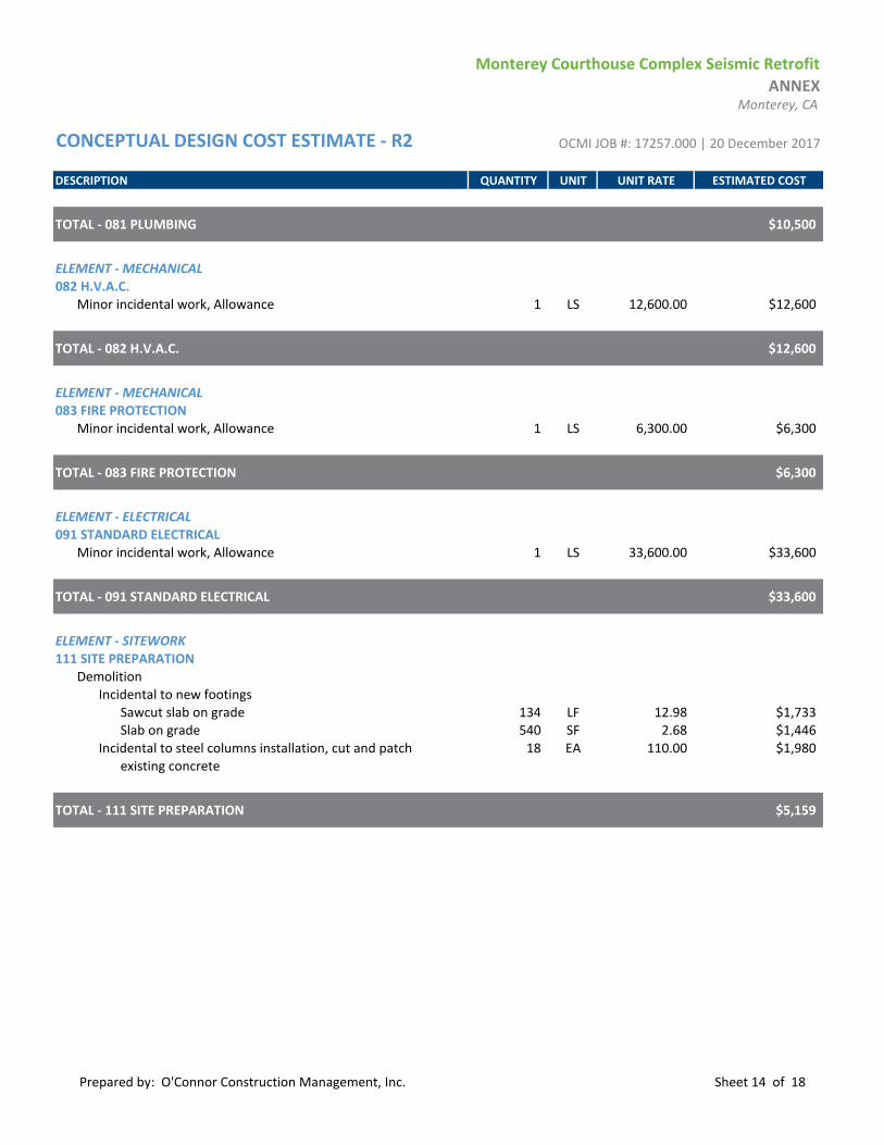
Monterey Courthouse Complex Seismic Retrofit
ANNEXMonterey, CA
CONCEPTUAL DESIGN COST ESTIMATE - R2 OCMI JOB #: 17257.000 | 20 December 2017
DESCRIPTION QUANTITY UNIT UNIT RATE ESTIMATED COST
TOTAL - 081 PLUMBING $10,500
ELEMENT - MECHANICAL082 H.V.A.C.
Minor incidental work, Allowance 1 LS 12,600.00 $12,600
TOTAL - 082 H.V.A.C. $12,600
ELEMENT - MECHANICAL083 FIRE PROTECTION
Minor incidental work, Allowance 1 LS 6,300.00 $6,300
TOTAL - 083 FIRE PROTECTION $6,300
ELEMENT - ELECTRICAL091 STANDARD ELECTRICAL
Minor incidental work, Allowance 1 LS 33,600.00 $33,600
TOTAL - 091 STANDARD ELECTRICAL $33,600
ELEMENT - SITEWORK111 SITE PREPARATION
DemolitionIncidental to new footings
Sawcut slab on grade 134 LF 12.98 $1,733Slab on grade 540 SF 2.68 $1,446
Incidental to steel columns installation, cut and patch 18 EA 110.00 $1,980existing concrete
TOTAL - 111 SITE PREPARATION $5,159
Prepared by: O'Connor Construction Management, Inc. Sheet 14 of 18

Monterey Courthouse Complex Seismic Retrofit
PARKING STRUCTUREMonterey, CA
CONCEPTUAL DESIGN COST ESTIMATE - R2 OCMI JOB #: 17257.000 | 20 December 2017
ELEMENT TOTAL COST $/SF AREA
01 FOUNDATIONS $24,843 $0.7302 SUBSTRUCTURE03 SUPERSTRUCTURE $238,421 $6.9704 EXTERIOR CLOSURE05 ROOFING06 INTERIOR CONSTRUCTION $15,000 $0.4407 CONVEYING08 MECHANICAL09 ELECTRICAL10 EQUIPMENT11 SITEWORK
NET DIRECT BUILDING COST $278,264 $8.14DESIGN CONTINGENCY 20.00% $55,653 $1.63
SUBTOTAL $333,917 $9.76GENERAL CONDITIONS/REQUIREMENTS 13.00% $43,409 $1.27
SUBTOTAL $377,326 $11.03CONTRACTOR OVERHEAD AND PROFIT 7.00% $26,413 $0.77
SUBTOTAL $403,739 $11.81INSURANCE 1.00% $4,037 $0.12
SUBTOTAL $407,776 $11.92BONDS: CONTRACTOR 1.00% $4,078 $0.12
SUBTOTAL $411,854 $12.04BONDS: SUBCONTRACTOR 1.25% $5,148 $0.15
SUBTOTAL $417,002 $12.19ESCALATION TO MIDPOINT 02/2021 12.67% $52,820 $1.54
TOTAL BUILDING COST $469,822 $13.74
GROSS FLOOR AREA: 34,200 SF
BUILDING SUMMARY
Prepared by: O'Connor Construction Management, Inc. Sheet 15 of 18

Monterey Courthouse Complex Seismic Retrofit
PARKING STRUCTUREMonterey, CA
CONCEPTUAL DESIGN COST ESTIMATE - R2 OCMI JOB #: 17257.000 | 20 December 2017
TOTAL ELEMENT AMOUNT TOTAL COST $/SF AREA $/SF AREA01 FOUNDATIONS $24,843 $0.73
011 Standard Foundations $6,443 $0.19012 Special Foundations $18,400 $0.54
02 SUBSTRUCTURE021 Slab On Grade
022 Basement Excavation
023 Basement Walls
03 SUPERSTRUCTURE $238,421 $6.97031 Floor and Roof Construction $238,421 $6.97032 Stair Construction
04 EXTERIOR CLOSURE041 Exterior Walls
042 Exterior Doors/Windows
05 ROOFING051 Roofing
06 INTERIOR CONSTRUCTION $15,000 $0.44061 Partitions
062 Interior Finishes $15,000 $0.44063 Specialties
064 Interior Doors/Windows
07 CONVEYING071 Elevators
08 MECHANICAL081 Plumbing
082 H.V.A.C.
083 Fire Protection
084 Special Mechanical
09 ELECTRICAL091 Standard Electrical
092 Special Electrical
10 EQUIPMENT101 Fixed/Movable Equipment
102 Furnishings
103 Special Construction
11 SITEWORK111 Site Preparation
112 Site Improvements
113 Site Utilities
114 Off-Site Work
NET DIRECT BUILDING COST $278,264 $8.14
DETAILED BUILDING SUMMARY
Prepared by: O'Connor Construction Management, Inc. Sheet 16 of 18

Monterey Courthouse Complex Seismic Retrofit
PARKING STRUCTUREMonterey, CA
CONCEPTUAL DESIGN COST ESTIMATE - R2 OCMI JOB #: 17257.000 | 20 December 2017
DESCRIPTION QUANTITY UNIT UNIT RATE ESTIMATED COST
ELEMENT - FOUNDATIONS011 STANDARD FOUNDATIONS
Pile caps 8 CY 805.44 $6,443
TOTAL - 011 STANDARD FOUNDATIONS $6,443
ELEMENT - FOUNDATIONS012 SPECIAL FOUNDATIONS
Helical piles, 8 EA, assume 20' 0" depth 160 LF 65.00 $10,400Mobilization 1 LS 8,000.00 $8,000
TOTAL - 012 SPECIAL FOUNDATIONS $18,400
ELEMENT - SUPERSTRUCTURE031 FLOOR AND ROOF CONSTRUCTION
Shear wall, cast in place concrete, 10" thick, rebar #518" on center each way, each sidefrom grade to the roof structure, 3 levelsDowel reinforcing through the existing slabsRoughen existing slab surfaces to 1/4" amplitudeQuantities
FormGround 587 SF 15.25 $8,950First floor 405 SF 13.25 $5,363Second floor 380 SF 13.25 $5,034
ConcreteGround 107 CY 314.90 $33,799First floor 75 CY 281.90 $21,049Second floor 70 CY 281.90 $19,733
RebarGround floor 95 LBS/CY of concrete 10,197 LB 1.60 $16,356First floor 95 LBS/CY of concrete 7,537 LB 1.40 $10,582Second floor 95 LBS/CY of concrete 6,650 LB 1.40 $9,337
Dowel through existing slabsGround 36 EA 76.41 $2,734First floor 36 EA 76.41 $2,734Second floor 36 EA 76.41 $2,734
Column reinforcement with fiber reinforced polymer jacketing
First floor 768 SF 62.00 $47,616Second floor 720 SF 55.00 $39,600Chamfer column corners 720 LF 5.00 $3,600
Destructive testing
Prepared by: O'Connor Construction Management, Inc. Sheet 17 of 18

Monterey Courthouse Complex Seismic Retrofit
PARKING STRUCTUREMonterey, CA
CONCEPTUAL DESIGN COST ESTIMATE - R2 OCMI JOB #: 17257.000 | 20 December 2017
DESCRIPTION QUANTITY UNIT UNIT RATE ESTIMATED COST
Concrete cores 6 EA 500.00 $3,000Reinforcing steel coupons 3 EA 400.00 $1,200
Scanning 1 LS 5,000.00 $5,000
TOTAL - 031 FLOOR AND ROOF CONSTRUCTION $238,421
ELEMENT - INTERIOR CONSTRUCTION062 INTERIOR FINISHES
Miscellaneous incidental work 1 LS 15,000.00 $15,000
TOTAL - 062 INTERIOR FINISHES $15,000
Prepared by: O'Connor Construction Management, Inc. Sheet 18 of 18


Gonzales will continue to be a safe, clean, family-friendly community, diverse in heritage, and committed to working collaboratively to preserve and retain its small town charm
P.O. BOX 647 147 FOURTH ST. GONZALES, CALIFORNIA 93926 PHONE: (831) 675-5000 FAX: (831) 675-2644 www.gonzalesca.gov
Maria Orozco Mayor
Scott Funk Mayor Pro Tem Liz Silva Councilmember Lorraine Worthy Councilmember Paul Miller Councilmember René L. Mendez City Manager
June 21, 2019 Honorable Lydia M. Villareal and Court Executive Officer Chris Ruhl 240 Church Street, #365 Salinas, CA, 93901 Re: Prioritizing Greenfield Courthouse for South County Dear Presiding Judge Villareal and Mr. Ruhl, On behalf of the City of Gonzales, I am writing this letter to urge you and our local judicial bench to support prioritizing the Greenfield Courthouse out of the two projects that you submitted to the Judicial Council on May 31, 2019. South County was promised a new courthouse over a decade ago and land has already been set aside for the new courthouse in Greenfield. The City of Greenfield has committed up to $10 million to reduce project costs. As you are aware, South County residents are facing hardships due to the lack of access to courthouse services in South County due to the only courthouse closed in the City of King in 2013. Our families have suffered with transportation and lost wages trying to use courts in Salinas and on the coast. Unequal access to courts and the legal system affects many in our South County communities. Gonzales supports working together to fulfill the promise to South county on the new courthouse in Greenfield then working together on the Seaside opportunity. I hope our local court leadership and judges will recognize that this request is fair, just, and the equitable approach for our superior court to take. Approving a courthouse in Greenfield would be the right message to our residents. This would also reassure our South County communities of fairness as we have been waiting for over 10 years for convenient access to the legal system. If you have any questions, please contact me directly at (831) 596-4927 or you may email me at [email protected]. Thank you for considering Gonzales’ position. Maria Orozco Mayor Cc: Luis Alejo, District 1 Supervisor Chris Lopez, District 3 Supervisor Paul Wood, Greenfield City Manager


2 1 2 S . V A N D E R H U R S T A V E N U E ● K I N G C I T Y , C A 9 3 9 3 0 P H O N E : ( 8 3 1 ) 3 8 5 - 3 2 8 1 ● F A X : ( 8 3 1 ) 3 8 6 - 5 9 3 5
W W W . K I N G C I T Y . C O M
September 13th, 2019
VIA EMAIL
Honorable Tani G. Cantil-Sakauye, Chief Justice of California Members of the Judicial Council of California 455 Golden Gate Avenue San Francisco, CA 94102-3688 [email protected]
Re: Comments on the Draft Statewide List of Trial Court Capital-Outlay Projects
and the Revisions of Prioritization for Trial Court Capital-Outlay Projects
Dear Chair Cantil-Sakauye and Members of the Judicial Council: Greenfield was selected as the site for the new courthouse to replace the now closed
courthouse in King City. Since 2013 residents of South County have had to travel farther, spend
more time, and still carried their fair share of jury duty. In fact, when you consider that South
County has probably the highest percentage of undocumented workers, our residents are
summoned at a higher percent than the rest of the County.
We understood that this additional burden would be short term as we all believed the promise
that the next courthouse in Monterey County would be in Greenfield. Afterall there are already
3 court houses on the peninsula. Yet, in quiet, efforts were made to create a new project to
replace one of those 3 just in time for this re-ranking process.
We still believe that the promise to build the courthouse in Greenfield will be fulfilled and that
decision will be made by you.
Our residents are primarily Hispanic, with our demographics on average around 85%, household
income significantly lower than the state average, and household size significantly higher than
the state average. Meaning our residents have less money to provide for more people. One may
think that traveling to access court services is not much of a burden but for our residents even
one day from the job represents a 20% decrease in there much needed income that week.
Equitable access to government services, especially to judicial services, should rank high on any
priority list. Ranking the Fort Ord project higher in need disvalues the continued burden
residents face and denies equitable access of services to our residents.

2 1 2 S . V A N D E R H U R S T A V E N U E ● K I N G C I T Y , C A 9 3 9 3 0 P H O N E : ( 8 3 1 ) 3 8 5 - 3 2 8 1 ● F A X : ( 8 3 1 ) 3 8 6 - 5 9 3 5
W W W . K I N G C I T Y . C O M
There are numerous concerns regarding this process and the seemingly dispassionate approach
to the promise made to South County. One concern relates to how the Fort Ord project ranked
higher due to seismic concerns. This is contradicted by Monterey County’s own inspection that
does not list seismic concerns. Removing the seismic concern from the ranking would change
the outcome and since the validity of this point has not been made clear the fair decision would
be to remove the project from consideration until this issue is cleared up.
Additionally, it is important to note that not only did Greenfield provide land for the courthouse
but offered to pay 10 million dollars because they know how important and needed these
services are to South County. No other project has offered this and still the courthouse with
ocean views ranks higher.
I ask for your consideration to remedy the unequal distribution of judicial services and failure to
deliver on the promise of the Greenfield courthouse by either,
Combine both projects as one as this would provide the equitable and fair distribution of judicial
services that is needed. This can be achieved at the same cost as the Fort Ord project when you
factor in the funding Greenfield is offering and by slightly scaling down or build in phases the
Fort Ord project.
Or, removing from the list the Fort Ord project until the seismic concern is cleared up.
This is extremely important to all South County residents and your decision will affect how our
residents receive and access judicial services for decades to come.
Sincerely, Mike LeBarre Mayor, King City California
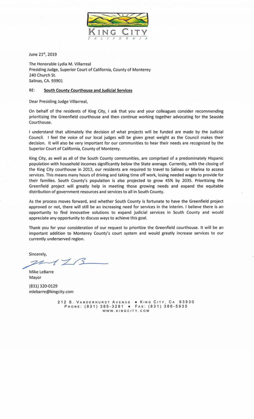

City of SalinasOFFICE OFTHE MAYOR.200 Lincoln Avenue. Salinas, Calliornia 93901 . (831) 758-7201 . Fax (831) 758-7368
July 2,2019
Honorable Lydia Villarreal
& Court Administrative Officer Chris Ruhl
240 Church St. #365Salinas, CA 93901
Re: Support for Prioritization of the Greenfield Courthouse
Dear Presiding Judge Villarreal and Mr. Ruhl,
On behalf of the City of Salinas, l'm writing to urge you to give priority to the Greenfield Courthouse outof two projects that you submitted to the Judicial Council on May 30. As you know, Greenfield waspromised a new courthouse 10 years ago, but the Great Recession and a lack of court constructionfunding delayed that project. Salinas joins with the other four South County cities, the County ofMonterey, the Grower shipper Association of Central California SEIU Local 521 to urge the MontereyCounty Superior Court to give Greenfield the priority they deserve. During the upcoming all-judgesmeeting, you have the opportunity to demonstrate your commitment in providing access to justice to all
our county residents. lt's a reasonable request in light of thousands of South County residents facinggreat difficulty and hardship accessing the court services at the two existing courthouses on theMonterey Peninsula over the last 6 years. Our region has been so committed to act as a partner that thecity of Greenfield donated land to the project, and even committed to fund a substantial amount tomake the project come to fruition.
All the cities of the Salinas Valley are demonstrating steep growth curves over the next 5-10 years, as
plans have emerged to add a combined 4,000 new homes in the cities of Gonzales and Soledad.
Greenfield is also growing with multiple projects currently being developed that provide hundreds oflow-income and moderate-income units. There are also projects that will provide 168 farmworkerhousing units, which will house several hundred farmworkers. ln King City, nearly 550 additional homes
and 550 additional multi-family units have either been approved and,/or are under construction.
Multiple projects are under development that will add several hundred additional affordable housing
and seasonal employee housing units, and over 50 acres is dedicated for additional housing
developments anticipated in the next 5-10-year period.
With the closing of Superior Court facility in King City in 2013, the entire Salinas Valley was left with a
void related to safe and easy access to the court system. A large segment of our population works in the
agricultural industry, and many of them are farm laborers. The ag industry in the Salinas Valley defines
us. lt is a multi-billion-dollar industry that provides jobs to thousands of families in Monterey County,
especially in the Salinas Valley. lf any of the Salinas Valley families or individuals are required to appear

City of SalinasOFFICE OF THE MAYOR.200 Lincoln Avenue. Salinas, California 93901 . (831) 758-7201 . Fax (831) 758-7368
Given the history of disparity in Monterey County, we fear that, our communities will again be neglectedby the local power structure for the purpose of gratifying better-financed constituencies. We invite youto stand with us to be a part of that dream. To me, the courthouse is more than a building, it's a symbolthat clearly states that every single member of our county matters. The access ofjustice is a basic rightthat should not come down to who is better financed.
I thank you in advance for your time and attention to this matter.
Sincerely,
Ho rable Joseph G unterMayor
City of Sa linas
cc: Luis Alejo, Monterey County Supervisor District L
in court, it can be a challenge for them not to only find a way to get there (as public transportation is noteasily accessed), but it is also a financial burden (because an individual may have to take the entire dayoff of work to travel to the Monterey Peninsula to attend court). This is a problem now, and with thegrowth outlined above, will only get worse as time goes on. A courthouse in Greenfield addresses theseissues.


(831) 751-7725 www.SalinasChamber.com
119 E Alisal St, Salinas CA 93901
July 2, 2019
Honorable Lydia M. Villarreal Court Executive Officer Chris Ruhl Monterey County Superior Court 240 Church Street, #365 Salinas, CA 93901 SUBJECT: Chamber Input on Greenfield Courthouse Dear Presiding Judge Villarreal and Mr. Ruhl: In recent weeks, there has been much attention to an apparent proposal to shift funding priorities from a court facility in Greenfield to a court facility in Seaside. The Salinas Valley Chamber of Commerce represents members that are based in South County and do business in South County. We are aware that South County communities can be overlooked and overshadowed when public services are distributed.
Without delving into the details of various proposals and claims about court needs, we are concerned that the Monterey County Superior Court is undermining a public expectation that Greenfield would be next to have a courthouse, which reduces the need for South County residents to travel long distances to the Peninsula for all civil and family court-related business.
Some of our member organizations and businesses are routinely asked to take steps to reduce greenhouse gas emissions resulting from employee commuting and other commercial activity. We encourage the Monterey County Superior Court to examine its own services and determine whether a facility in Greenfield would more effectively reduce greenhouse gas emissions produced by residents who utilize our court system.
Finally, we would be interested in hearing more often from Monterey County Superior Court about its administrative activities and plans. The courts are for The People, yet they get much less attention than the legislative and executive branches of government in Monterey County.
We thank you for your attention to this letter. If you have any questions, please contact me at (831) 751-7725. Sincerely,
Paul J. Farmer President & CEO, Salinas Valley Chamber of Commerce www.SalinasChamber.com
cc: Governor Gavin Newsom, Judicial Council of California, Congressman Jimmy Panetta, Senator Bill Monning, Senator Anna Caballero, Assemblymember Robert Rivas, Assemblymember Mark Stone, Monterey County Board of Supervisors, Greenfield City Council

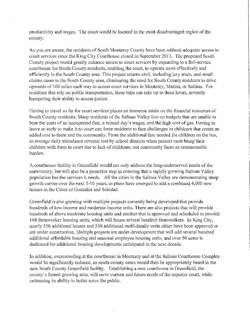


From: 831 TransparencyTo: CFACSubject: Courthouse Project in Greenfield, CaliforniaDate: Friday, September 13, 2019 10:49:26 PM
Dear Chief Justice Tani G Cantil-Sakauye:
Greenfield was formerly in the top tier of priorities for new court facilities. It was the onlyidentified project on the list in Monterey County, now a new facility overlooking theMonterey Bay has been proposed at nearly four times the cost and it has leapt to the top of thelist.
As a 30+ year resident, business owner, advocate, and friend of Southern Monterey County, Iask you to bring justice to our region by reprioritizing the proposed courthouse project inGreenfield, California.
This facility would serve an entire region of the state that has gone without access to justicesince our local court closed their last facility in the region in 2013. Residents of our countyhave to drive more than two hours to access court facilities. We believe that our judicialsystem should serve every one of our California’s citizens equitably.
We ask that you make the application process more transparent, so we too can assess theircontents, arguments, opinions and logic. As taxpayers, we believe this is important becausewe know the outcome will be the expenditure of over one billion dollars of our tax dollars.
Thank you for considering rural California and its citizens in your decision making process.
Sincerely,
831Transparency
#JusticeForGreenfield#WeWontBackDown

From: Antonia AlejoTo: CFACSubject: Court HouseDate: Wednesday, September 11, 2019 7:59:54 PM
Dear Chief Justice Tani G Cantil-Sakauye:
As a resident of Southern Monterey County, I ask you to bring justice to our region byreprioritizing the proposed courthouse project in Greenfield, California.
This facility would serve an entire region of the state that has gone without access to justicesince our local court closed their last facility in the region in 2013. Some residents of ourcounty have to drive more than two hours to access court facilities. We believe that ourjudicial system should serve every one of our California’s citizens equitably.
We ask that you make the application process more transparent, so we too can assess theircontents, arguments, opinions and logic. As taxpayers, we believe this is important becausewe know the outcome will be the expenditure of over one billion dollars of our tax dollars.
Thank you for considering rural California and its citizens in your decision making process.
Thank you,Antonia A


From: David ArmanascoTo: CFACCc: Rusty Areias; [email protected]; Mary F. Lerner; Pamela SilkwoodSubject: Monterey County needs a new Courthouse in Greenfield!Date: Thursday, September 12, 2019 11:05:06 AM
September 12, 2019 Via Electronic MailJudicial Council of California ([email protected])2860 Gateway Oaks DriveSuite 400Sacramento, CA 95833-4336 RE: Support of Courthouse Facility in City of Greenfield Honorable Judicial Council:
You have an opportunity to right a wrong. For too long the awarding of newcourthouses has been awarded to communities with the loudest voice and those who areunderserved continue to be passed over. This letter is to support the construction of a newcourthouse facility in the City of Greenfield. I am a native of Monterey County and have seenthe decisions made “in the public good” from Sacramento that overlook where the greatestneed exists for a new courthouse. It is clear the ranking system developed to rank thecommunities based on needs is inaccurate, misleading and poorly portrays the dire necessity ofa courthouse in south Monterey County. Another new courthouse facility along the MontereyPeninsula simply does not make sense. We never hear citizens complaining of the existingfacilities in Monterey, only those who would like nicer offices complain. More importantly,already existing courthouse facilities in Marina, Monterey and Salinas are located within milesof one another whereas no such facility exists for the residents of southern inland portion ofMonterey County, many of whom are disadvantaged minorities. Those communities of theSalinas Valley are growing faster in population than the Peninsula because that is where youngand underserved families can afford to live.
For example, those residents residing in King City would need to trek about 50 miles
to the nearest courthouse in Salinas. Simply stated, there is no reason to construct yet anothernew courthouse in Monterey Peninsula when land is made available for such a facility in theCity of Greenfield – a central location for those folks residing in southern inland MontereyCounty.
I fully support a courthouse facility in the City of Greenfield out of justice, fairness andequal treatment to the southern inland Monterey County residents. I sincerely hope you givemy plea and those of others sincere consideration.
Sincerely, David Armanasco

___________________________________David Armanasco President PartnerArmanasco Public Relations, Inc California Strategies Central CoastOfficeOffice: 831-372-2259 831-372-6271
www.armanasco.com www.calstrat.com **************************************************PRIVILEGED AND CONFIDENTIAL - This message, together with any attachments, is intended only for the use ofthe individual or entity to which it is addressed and may contain information that is legally privileged, confidentialand exempt from disclosure. If you are not the intended recipient, you are hereby notified that any dissemination,distribution, or copying of this message, or any attachment, is strictly prohibited. If you have received this messagein error, please notify the original sender immediately by telephone or by return E-mail and delete this message,along with any attachments, from your computer. Thank you. **************************************************


To: Honorable Brad R. Hill, Chair
Judicial Council of California
Court Facilities Advisory Committee
Dear Mr. Hill and the Court Facilities Advisory Committee,
My name is David Kong. I live in Greenfield, CA. I urge you and the committee to reconsider the current recommendation for the Greenfield Courthouse and give it a higher priority. At least give it a higher priority that the Seaside Courthouse. There used to be a courthouse in King City that is now closed. Residents in South Monterey County now travel long distances of 35 to 75 miles to Salinas for court services and even further if they need to go to a courthouse in Marina or Monterey. There are already courthouses in Marina and Monterey and adding a Seaside courthouse will not be an additional benefit to the local residents. We have many residents in South Monterey County that have trouble with transportation and having a courthouse in Greenfield would be much more convenient for the South Monterey County residents. These residents are some of the most economically disadvantaged people in the county. They would not have to miss as much work and would not have to pull their kids from school for the day in order to make a visit to the courthouse. I understand that the land is already set aside for the courthouse in Greenfield. That is not the case in Seaside. The courthouse in Greenfield would also be a source of jobs for residents in the area and would help the local economy, which is the poorest in the County.
Please give the courthouse in Greenfield a much higher priority.
Thank you for your consideration,
David Kong
348 Barbera Way
Greenfield, CA 93927
[email protected] 831-682-2812

From: ingrid hansenTo: CFACSubject: New Monterey County Courthouse decision 9/13Date: Thursday, September 12, 2019 3:57:14 PM
Ladies and Gentlemen,It was brought to my attention that tomorrow you are going to decide, if the New Monterey CountyCourthouse will be build in Seaside or Greenfield.May I remind you that King City had a Courthouse, which was closed with the intentions to build anew Courthouse in Greenfield. What happened to that idea? Was it just a hoax?Now several years of this building sitting empty and rotting away to an unsightly mess, we are, atleast it looks like, being again pushed out from an opportunity of development and a new boost toour economy “down South”. There are many people living here, and from what I can see people aremoving this way to leave the cities. Why can’t you people understand that South County is part ofMonterey County just as much as Monterey and surrounding towns. It takes the people down southa full day to appear in Court and plead their case. You already have a Courthouse, let South Countyhave theirs, creating jobs and revenue. Have the people from the cities spend their day in Court andfeel the hardship. Make this a fairdeal and don’t put the burden just on South County residence. Give us an opportunity to grow, forwhich we continue to work so hard for. Sincerely, Ingrid A Hansen Sent from Mail for Windows 10

From: I. MerrillTo: CFACSubject: proposed courthouse for Greenfield, Monterey CountyDate: Thursday, August 29, 2019 3:56:28 PM
To Whom It May Concern:
I am writing to express my shock and dismay that the Greenfield Courthouse, whichhas been in the works for a decade, has been moved far down the priority list and thata courthouse in Seaside is now considered a top priority - when there is a perfectlyviable courthouse less than 5 miles away in Monterey.
I am also concerned about the lack of transparency regarding the prioritizationprocess. County Supervisor Luis Alejo has tried repeatedly to obtain documents fromthe commission and was never given a good reason for being denied. The public hasa right to that information.
South Monterey County - which covers a large geographic area - lost its onlycourthouse when the one in King City was closed. The population of South MontereyCounty is predominantly Hispanic, predominantly Mexican, and includes a strongpopulation of Triqui and Mixtec immigrants in Greenfield. This population is low-income and works primarily in agriculture. The population in this geographic area isgrossly under-served by the court system; the public transportation system for themto get to either Salinas or Monterey is beyond some of them.
I live in Salinas. But I want to see services for South Monterey County and itsresidents. And I am astounded that Greenfield - as I said, on the books for 10 years -gets shoved down the priority list because "somebody" wants a sparkly newcourthouse in the Monterey Bay area - when there is a perfectly serviceablecourthouse in existence there already.
The Monterey Herald today published an investigative piece on this mess. I hope theycontinue to dog the heels of the committee until Greenfield gets its much-neededcourthouse. If we can only build one in Monterey County - it needs to be Greenfield.
sincerely,
Irene MerrillSalinas, CA 93906
for the Herald article, go to:New Fort Ord courthouse favored over Greenfield facility in state rankings

New Fort Ord courthouse favored over Greenfieldfacility in state rankingsSAN FRANCISCO — Monterey County Supervisor Luis Alejo hascalled for a state audit of a state courthouse project...

From: Jenine DavisonTo: CFACSubject: Courthouse for GreenfieldDate: Friday, September 13, 2019 8:20:18 PM
To whom it may concern:I am a white teacher and school counselor living and working in South Monterey County, andI'm very concerned about the decision to rank Greenfield way below Seaside for a newcourthouse. After years of work in Greenfield, King City, Soledad, San Lucas, and San Ardo, Ihave seen first-hand how fewer and inferior services are given to people of color in thesepoorer and overwhelmingly Latinx communities. I see this decision to not bring a courthouse to Greenfield as another racist decision, in whichthe wealthier, whiter, Northern parts of Monterey County get nice facilities, and SouthMonterey County gets third class or nothing. Please reconsider your decision and give thehard-working people of South Monterey County closer access to a courthouse that will servicetheir needs. Thank you, Jenine Davison

117 N. 1st Street - King City, CA 93930 Office: 831-385-1263 Fax: 831-385-3340
September 12, 2019 Via Electronic Mail Judicial Council of California ([email protected]) 2860 Gateway Oaks Drive Suite 400 Sacramento, CA 95833-4336 RE: Support of Courthouse Facility in City of Greenfield Honorable Judicial Council:
This letter is to support the construction of a new courthouse facility in the City of Greenfield. It is clear the ranking system developed to rank the communities based on needs is inaccurate, misleading and poorly portrays the dire necessity of a courthouse in south Monterey County. Another new courthouse facility along the Monterey Peninsula simply does not make sense. Already existing courthouse facilities in Marina, Monterey and Salinas are located within miles of one another whereas no such facility exists for the residents of southern inland portion of Monterey County, many of whom are disadvantaged minorities.
For example, those residents residing in King City would need to trek about 50 miles to the nearest
courthouse in Salinas. Simply stated, there is no reason to construct yet another new courthouse in Monterey Peninsula when land is made available for such a facility in the City of Greenfield – a central location for those folks residing in southern inland Monterey County.
We fully support a courthouse facility in the City of Greenfield out of justice, fairness and equal treatment to the southern inland Monterey County residents. Sincerely, John DeCarli Regulatory & Compliance Coordinator Mission Ranches Company, LLC Cc: Paul Wood <[email protected]>

From: Jazmin LopezTo: CFACSubject: Court Facility Priorities- GreenfieldDate: Friday, September 13, 2019 3:34:16 PM
Dear Chief Justice Tani G Cantil-Sakauye:
As a resident of Southern Monterey County, I ask you to bring justice to our region by re-prioritizing the proposed courthouse project in Greenfield, California. Those of us living inrural southern Monterey County were disappointed to see that the Seaside projected was givenmore priority over our project which we have been waiting years for.
Our region of the state has gone without access to justice since our local court closed their lastfacility in the region in 2013. Some of my friends that live even further south than I do have todrive 2 hours just to access court facilities. I work for a farming operation, the majority of mycoworkers and I live in Greenfield. I've had coworkers who had to take a full day off just to goto the court. AND if they don't drive or have a car, the "raiteros" (that's people who give othersrides), charge $100 to take someone to Monterey and back. It is an injustice that ourcommunities have to go through so many hoops just to access the court system.
It seems the courts decision to prioritize Seaside over the Greenfield project failed to factor inequity. And, I would ask that a seismic study of the Monterey Court House be conducted bysomeone with no ties to our local judges, and that the results be available to all, since that'stheir main argument for building the Seaside Court House.
We ask that you make this process more transparent. That you recognize that those of us livingin small towns and rural areas also deserve and need access to the courts. Thank you forconsidering my comments in your decision making process.
Sincerely,
Jazmin Lopez831-809-7077Resident of Greenfield, CA


From: Karen JerniganTo: CFACSubject: Courthouse in GreenfieldDate: Thursday, September 12, 2019 5:08:22 AM
Please consider this my letter of support for a new courthouse in Greenfield in South Monterey County.
Residents of rural Southern Monterey County experience greater difficulty in being able to get to court appointmentsoften requiring the need to take a full day off work to drive to courts in Salinas and Seaside. Many of these peopleare working-class people as evidenced by our demographics and location in the heart of an agricultural area..
Justice for all should not favor people who live in cities when there is an opportunity to have a smaller satellitefacility in our area. We are certain that much more money will be spent in Seaside if you give that priority over ourlong-promised facility. When you closed our King City branch, it was with the understanding that a newer, moremodern facility would be in the works for the Salinas Valley.
Sincerely, -- Karen Jernigan, 206 North Mildred Avenue, King City, CA 93930831-385-6112 [email protected]

Keith Roberts
5565 Tesla Road Livermore, CA 94550
September 12, 2019 Via Electronic Mail Judicial Council of California ([email protected]) 2860 Gateway Oaks Drive Suite 400 Sacramento, CA 95833-4336 RE: Support of Courthouse Facility in City of Greenfield Honorable Judicial Council: This letter is to support the construction of a new courthouse facility in the City of Greenfield. It is clear the ranking system developed to rank the communities based on needs is inaccurate, misleading and poorly portrays the dire necessity of a courthouse in south Monterey County. Another new courthouse facility along the Monterey Peninsula simply does not make sense. Already existing courthouse facilities in Marina, Monterey and Salinas are located within miles of one another whereas no such facility exists for the residents of southern inland portion of Monterey County, many of whom are disadvantaged minorities. For example, those residents residing in King City would need to trek about 50 miles to the nearest courthouse in Salinas. Simply stated, there is no reason to construct yet another new courthouse in Monterey Peninsula when land is made available for such a facility in the City of Greenfield – a central location for those folks residing in southern inland Monterey County. We fully support a courthouse facility in the City of Greenfield out of justice, fairness and equal treatment to the southern inland Monterey County residents. Sincerely, KLR Keith Roberts Director of Vineyard Operations Cc: Paul Wood <[email protected]>

From: Lisa GardnerTo: CFACSubject: Greenfield Courthouse Yes, Seaside NoDate: Wednesday, September 11, 2019 1:06:12 PM
Hello,
I live in Seaside and I say NO to a courthouse in my city.
Greenfield needs it, South Monterey County needs it.
I served on a jury at the Salinas courthouse and listened to one of my companion jurors talkabout having to drive from King City to Salinas to fulfill their duty. Every day for two weeks.
That's absolutely ridiculous, particularly now with climate change about to destroy coastalcities. It's only 18 miles from King City to Greenfield, but 63 miles to Seaside. It's 51 milesfrom Greenfield to Seaside.
We cannot afford to be so short-sighted. Particularly when it's going to cost millions to dealwith the effects of ocean inundation of the infrastructure a Seaside Courthouse wouldrequire (fresh water, sewage and waste water treatment, power and telecommunications).And even more millions to buy up ocean-eroding properties, and move families and businessesinto the area identified for a courthouse.
We can do better. You must do better for all your constituents across Monterey County byselecting Greenfield for a new Courthouse, and not Seaside.
Thank you.
L Gardner93955


Via Electronic Mail Judicial Council of California ([email protected]) 2860 Gateway Oaks Drive Suite 400 Sacramento, CA 95833-4336 RE: Support of Courthouse Facility in City of Greenfield Honorable Judicial Council:
This letter is to support the construction of a new courthouse facility in the City of Greenfield. It is clear the ranking system developed to rank the communities based on needs is inaccurate, misleading and poorly portrays the dire necessity of a courthouse in south Monterey County. Another new courthouse facility along the Monterey Peninsula simply does not make sense. Already existing courthouse facilities in Marina, Monterey and Salinas are located within miles of one another whereas no such facility exists for the residents of southern inland portion of Monterey County, many of whom are disadvantaged minorities.
For example, those residents residing in King City would need to trek about 50
miles to the nearest courthouse in Salinas. Simply stated, there is no reason to construct yet another new courthouse in Monterey Peninsula when land is made available for such a facility in the City of Greenfield – a central location for those folks residing in southern inland Monterey County.
We fully support a courthouse facility in the City of Greenfield out of justice, fairness and equal treatment to the southern inland Monterey County residents. Sincerely,
Michael Griva
Owner, F&G Vineyard, LLC. President, Franscioni-Griva Corp.
September12,2019

From: Monica SanchezTo: CFACSubject: California Courthouses ProjectsDate: Thursday, September 05, 2019 2:40:32 PM
To: Judicial Council of California's Court Facilities Advisory Committee:
My name is Monica Sanchez I was born and raise in the Monterey County. I am a currentresident of Greenfield California. The reason for this email is concerning the newcourthouse's list that was release on the 29 of August of 2019. To my surprise the courthouseproject of South Monterey County was rank #45 of 80. I am heartbroken after the fact thatthis project was approve on 2010 and the only reason for the delay of the construction of thecourthouse was the Great Recession. As a community and even though we had a great needfor this courthouse we understood the situation. Through all this years we have work veryhard and with a lot of sacrifices donated the land and also 10 million dollars for theconstruction of this courthouse. To show you the great critical need that we have as acommunity and county. This courthouse will not only help our city but our near neighborcities. Some of our South Monterey County residence have to drive more than an hour to thenearest court. I ask you to please reconsider your decision you had promise our community acourthouse we have jump through many hoops we have shown are good faith by providingyou with the land and also money. Please make justice for our South Monterey CountyResidence we are hard working people.
Thank You
Monica Sanchez

From: Priscilla BarbaTo: CFACSubject: Greenfield, CA CourthouseDate: Wednesday, September 11, 2019 9:41:58 AM
Dear Chief Justice Tani G Cantil-Sakauye,
As a community member of Southern Monterey County, I ask you to bring justice to our region byreprioritizing the proposed courthouse project in Greenfield, California.
Driving down to attend traffic court can take a person almost 2 hours and 4 hours total of theirday. I have seen my father take an entire day off from work in order to attend traffic court in theMonterey Bay. When I asked him why he felt it was necessary to take the day off to attend court,he responded "I want to be early, on time, and I know by the time I'm done, my whole day willhave gone by."
This facility would serve an entire region of the state that has gone without access to justice sinceour local court closed their last facility in the region in 2013. As I mentioned above, someresidents of our county like my father, have to drive more than two hours to access court facilities.We believe that our judicial system should serve every one of our California’s citizens equitably.
We ask that you make the application process more transparent, so we too can assess theircontents, arguments, opinions and logic. As taxpayers, we believe this is important because weknow the outcome will be the expenditure of over one billion dollars of our tax dollars.
Thank you for considering rural California and its citizens in your decision making process.
Sincerely,Priscilla Barba

From: Phil FranscioniTo: CFACSubject: Courthouse Monterey CountyDate: Thursday, September 05, 2019 12:00:27 PM
To whom is concerned;
As a 2nd generation Monterey County resident. A few years ago, I was thrilled that a NewCourthouse was proposed to be built in Greenfield. There used to be a court in King City but hasbeen closed. The City of Greenfield Donated 4 acres of land on El Camino Real and kicked in a $10 Million dollar inkind donation to win the bid for construction. Now your organization has pulled the rug out fromunder the people of Southern Monterey County saying that you would put the new courthouse inSeaside. Monterey Peninsula already has a superior court in Salinas and Monterey plus a Municipalcourt in Marina. Residents of Southern Monterey County have to drive over 90 miles to appear incourt, while Northern Monterey County has a court in their back yard and building another…. UNFAIR, Discriminatory !!! Be fair, Put the new Courthouse in Greenfield, serve all the people of Monterey County. Phil Franscioni36900 Colony RoadSoledad, Ca. 93960

From: Paul MillerTo: CFACSubject: Greenfield CourthouseDate: Wednesday, September 11, 2019 5:09:09 PM
Dear Chief Justice Tani G Cantil-Sakauye:
As a Council Member for the City of Gonzales in Southern Monterey County, I ask that you correct an injustice byreprioritizing the proposed Courthouse project in Greenfield, California.
Prior to being Council Member I was a Peace Officer for the City of Gonzales for 34 years, the last 10 as the Chiefof Police. I was Chief in 2013 when the Monterey County Superior Court held a meeting with four SouthernMonterey County Police Chiefs to ask for our support in closing the then King City Courthouse for budgetaryreasons. During that meeting we were promised by the Presiding Judge, that a new Courthouse would be built inGreenfield in several years or at worse they would reopen the King City Courthouse as their top priority. While thiswas going to create a hardship for our region, we supported it.
During the time the Courthouse has been closed, residents and officers of Southern Monterey County have had todrive long distances, up to two hours, to access court services or participate in jury duty. I understand that the courtsneeded to wait until funding was available, as such we were unable to build or reopen a Southern MontereyCourthouse until now.
With that being said, I was disheartened to find out that our local courts have elected to place the building of a newSeaside Courthouse over the much needed and promised South County Courthouse in Greenfield. How are people totrust the court system when our own local court officials fail to keep their word?
Our local court officials have given several excuses why a Courthouse in Seaside is a higher priority then theGreenfield Courthouse, but all of these excuses are not supported by the facts. Even sadder is the fact that our localcourt officials have not been honest about their actions behind their priorities and have been less then transparentwhen information has been requested from them.
The Greenfield Courthouse Project would provide a central location to service all of the residents and lawenforcement agencies in Southern Monterey County. The project also has a monetary commitment from the City ofGreenfield.
Thank you for considering the needs of the hard working residents of Southern Monterey County as you make yourdecisions.
Sincerely,
Paul MillerCouncil MemberCity of Gonzales
Paul Miller Have a Great Day

From: R BorenTo: CFACSubject: Greenfield Courthouse as a PriorityDate: Thursday, September 12, 2019 8:18:10 AM
Dear Chief Justice Tani G Cantil-Sakauye:
As a resident of Southern Monterey County, I ask you to bring justice to our region byreprioritizing the proposed courthouse project in Greenfield, California.
This facility would serve an entire region of the state that has gone without access to justicesince our local court closed their last facility in the region in 2013. Some residents of ourcounty have to drive more than two hours to access court facilities. We believe that ourjudicial system should serve every one of our California’s citizens equitably.
We ask that you make the application process more transparent, so we too can assess theircontents, arguments, opinions and logic. As taxpayers, we believe this is important becausewe know the outcome will be the expenditure of over one billion dollars of our tax dollars.
Thank you for considering rural California and its citizens in your decision making process.
Sincerely,
Rachel Boren

1
Robinson, Akilah
From: Rebecca Phillips <[email protected]>Sent: Friday, September 13, 2019 1:08 AMTo: CFACSubject: South County Courthouse
As Chris Lopez said, our need is real, and it is immediate. Please reconsider the great need for the importance of a courthouse in South County! Thank you, Rebecca DeHart Current drive to Salinas courthouse is 120 minutes.

From: [email protected]: CFACSubject: Put the Courthouse in Greenfield CADate: Wednesday, September 11, 2019 1:13:14 PM
Southern Monterey County is underserved. Please reconsider placing the Courthouse in Greenfield. From Greenfield to the Southern end of Monterey County is over an hour drive and choosing to livein this area should not limit our services. For most anything major I have to drive to Salinas 40 milesaway or go to Paso Robles 60 miles away which is in another county for any major grocery shopping,housewares, vehicles, etc. I was summoned to Jury Duty last year to appear in Monterey. That wasover 60 miles away and it took with traffic which is all the time these days 1 ½ hours each way to getthere. I was not compensated because as soon as the judge saw I was from South County sheimmediately released you. How is this a fair system of justice if its only certain zipcodes that areallowed to be on jury. This is not a fair system of justice if you only take people to serve on a jurythat live the closest nor does that seem impartial. There is a world south of Salinas that is a beautifulplace that deserves to have a just as many services as the population on the Peninsula. Pleasereconsider putting a courthouse in the community of South County, Greenfield , CA. I would muchrather serve when its 6 miles from my home than 60 miles away. Renee Rianda36780 Ashley AvenueGreenfield, CA 93927831-674-5891


1
Robinson, Akilah
From: Sir Knight Jaime Ayala <[email protected]>Sent: Friday, September 13, 2019 9:43 AMTo: CFACSubject: Greenfield’s Needs
I’m writing on behalf of many many South Monterey county residents that are b omg neglected by not having a court house. You expect them to continue to drive 40 min to Salians or the peninsula to get justice. That’s just not fair Simply because they are of a lower education demographic and because they do not have the kind of money the peninsula has to throw at judicial elections. This just makes our current system even More bias and against the less fortunate. Please consider giving Greenfield and all south Monterey county residents a judicial Voice. A voice so badly needed Jim

Clark Colony Water Company 33 El Camino Real
Greenfield, Ca 93927 September 12, 2019 Via Electronic Mail Judicial Council of California ([email protected]) 2860 Gateway Oaks Drive Suite 400 Sacramento, CA 95833-4336 RE: Support of Courthouse Facility in City of Greenfield Honorable Judicial Council:
This letter is to support the construction of a new courthouse facility in the City of Greenfield. It is clear the ranking system developed to rank the communities based on needs is inaccurate, misleading and poorly portrays the dire necessity of a courthouse in south Monterey County. Another new courthouse facility along the Monterey Peninsula simply does not make sense. Already existing courthouse facilities in Marina, Monterey and Salinas are located within miles of one another whereas no such facility exists for the residents of southern inland portion of Monterey County, many of whom are disadvantaged minorities.
For example, those residents residing in King City would need to trek about 50
miles to the nearest courthouse in Salinas. Simply stated, there is no reason to construct yet another new courthouse in Monterey Peninsula when land is made available for such a facility in the City of Greenfield – a central location for those folks residing in southern inland Monterey County.
We fully support a courthouse facility in the City of Greenfield out of justice, fairness and equal treatment to the southern inland Monterey County residents. Sincerely,
Michael Griva President, Clark Colony Water Company
Cc: Paul Wood <[email protected]>
From: Robin ButterworthTo: CFACSubject: The Courthouse to be built in GreenfieldDate: Thursday, September 12, 2019 1:31:58 PM
I am a resident of Monterey County at 71 Spring Rd. Royal Oaks, Ca. 95076Here in this opposite side of the county, where this controversy exists we as resident have been asked forever todrive 32 miles to our closest Courthouse in Salinas. Greenfield is 37 miles away from the Salinas Courthouse.Never have any local supervisors come to our rescue or seen us as needy or having hardships when it comes toaccess of our designated Courthouse business. As far as I am concerned, it would be an easier access to put theCourthouse in Seaside. A nicer drive and less traffic. Please stay with your original decision and build it in Seaside.
ThankyouRobin Butterworth71 Spring Rd.Royal Oaks, Ca. [email protected]

NEVADA

Presentation Slides

Nevada City CourthouseRenovation & Reuse Concept

Nevada City CourthouseRenovation & Reuse Concept

OFFICECOURTROOMS
& HOLDING


PHASED IMPLEMENTATION


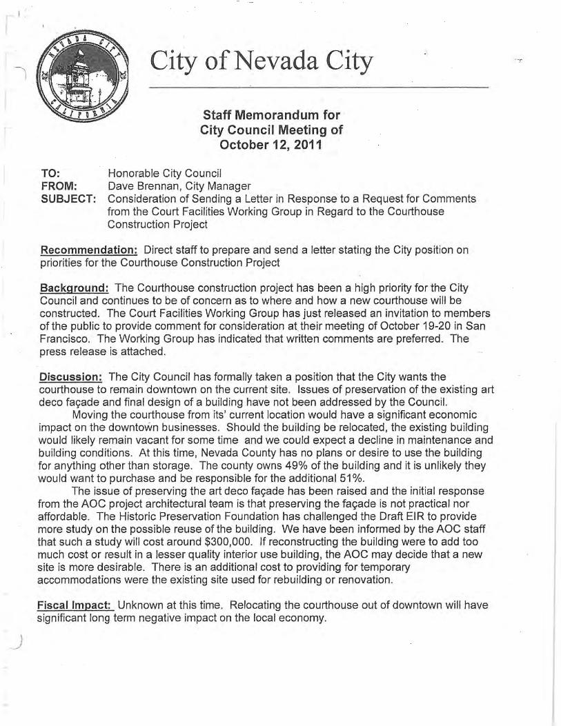


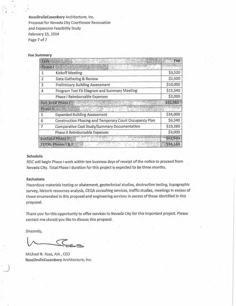


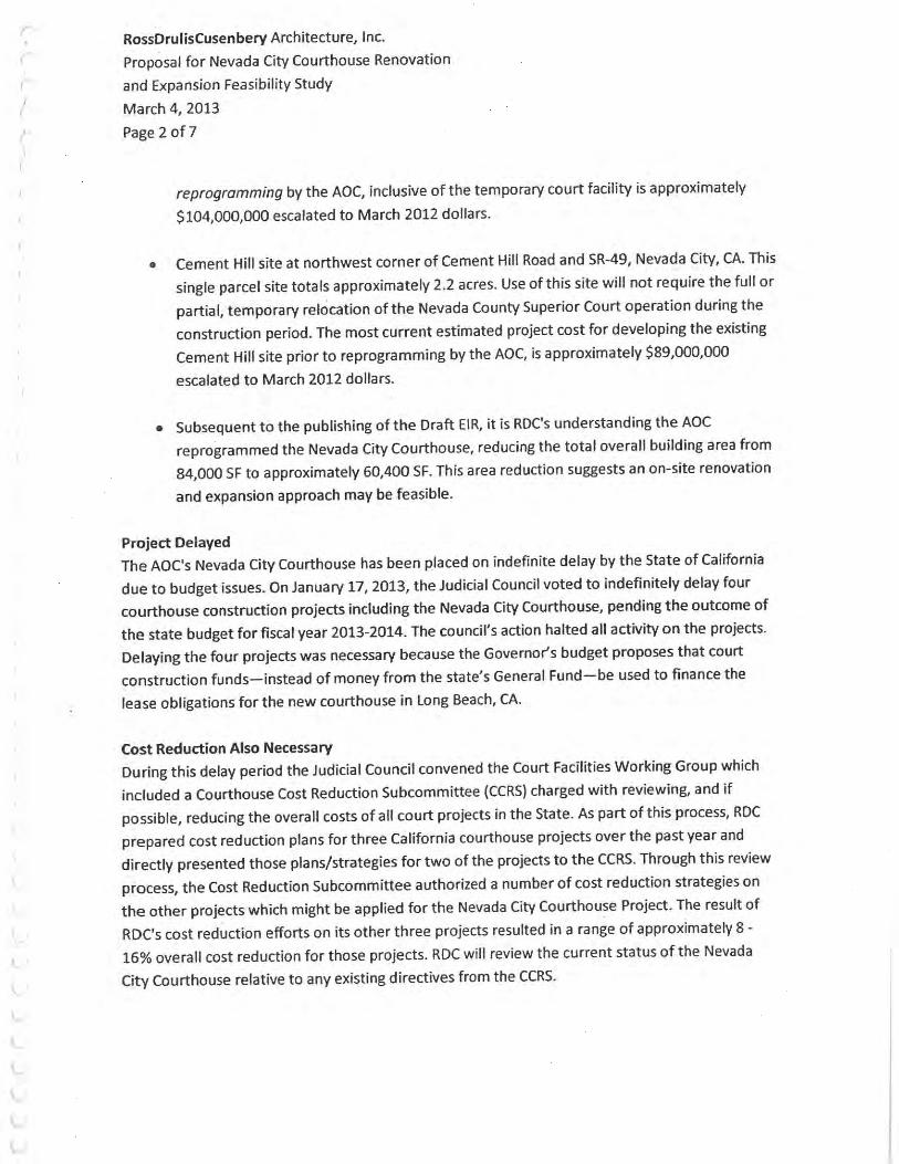


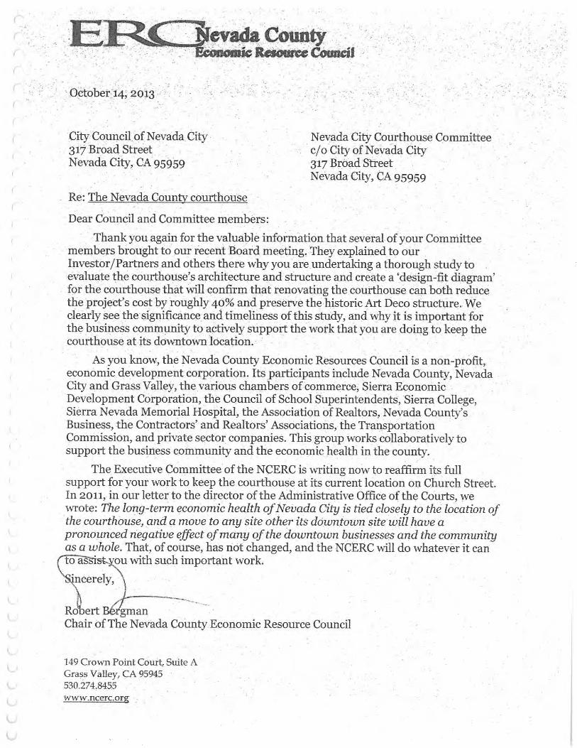


Prepared for:
Judical Council Of
NEVADA CITY COURTHOUSEPhase II Facility Feasibility Study
December 4, 2015
DRAFTPrepared by:
California


TOC-iDecember 4, 2015 NEVADA CITY COURTHOUSEFacility Feasibility Study
TABLE OF CONTENTS
Chapter 01: Summary Findings
Chapter 02: Project Background & Methodology
Chapter 03: Existing Conditions Observations
Chapter 04: Conceptual Design Option
Chapter 05: Engineering Narratives
Chapter 06: Central Holding Capacity Analysis
Chapter 07: Cost Estimate

TOC-ii NEVADA CITY COURTHOUSE December 4, 2015Facility Feasibility Study

TOC-iiiDecember 4, 2015 NEVADA CITY COURTHOUSEFacility Feasibility Study
ACKNOWLEDGEMENTS
The Judicial Council acknowledges the contributions of the following individuals and groups for their input and guidance during the creation of the Nevada City Courthouse Facility Feasibility Study.
Superior Court of California, County of Nevada Thomas Anderson, Presiding Judge, 2010 - 2012Candace Heidelberger, Presiding Judge, 2013 - PresentSean Metroka, Executive Officer Nevada County Courts
Judicial Council of California Kristine Metzker, Manager of Planning, Judicial Council Capital Program Paul Menard, Senior Facilities Manager, Judicial Council Capital Program Kelly Quinn, Assistant Division Director Business and Planning Team Theresa Dunn, Real Estate Division
Nevada City Courthouse CommitteePaul Matson, ChairmanRobert Bergman, City Council Member Conley Weaver, ArchitectBruce Boyd, ArchitectGary Tintle, ContractorBill Falconi, Nevada City EngineerGene Albaug, Past City ManagerDave Brennan, Past City ManagerMark T. Prestwich, City Manager
City of Nevada CityNevada City City Council, Staff and Planning CommissionCliff Nolan, City Attorney
Nevada CountyNevada County Board of SupervisorsNate Beason, District 1 Supervisor Steve Monaghan, Nevada County Sheriff’s Department
City of Grass ValleyCity of Grass Valley City Council
Community StakeholdersNevada County Contractors AssociationNevada City Chamber of CommerceGreater Grass Valley Chamber of CommerceNevada County Historical Society
ArchitectRossDrulisCusenbery, Architecture Inc. (RDC)Michael B. Ross, AIAMallory Scott Cusenbery, AIATom Larson, AIAYu Chen SuSean FlanaganArn AbadinesTina Harris
Consulting EngineersKevin Zucco, ZFA Structural EngineersTodd See, WSP MEP EngineersNick Mata, Cumming Cost Consultants Ryan Zuehike, Cumming Cost ConsultantsPatric Thomas, WSP MEP Engineers
Nevada County Sheriff’s DepartmentSheriff-Coroner-Public Administrator, Keith RoyalSergeant James CasciSergeant Gary Smith

TOC-iv NEVADA CITY COURTHOUSE December 4, 2015Facility Feasibility Study

01-1November 12, 2015 NEVADA CITY COURTHOUSEFacility Feasibility Study
Summary Findings
INTRODUCTIONThe Nevada City Courthouse Facility Feasibility Study (Study) examines the feasibility for the potential reuse, renovation and expansion of the existing Nevada City Courthouse at its historic location at 201 Church Street, Nevada City, CA. The project was ranked in the Critical Need priority group of the Trial Court Capital-Outlay Plan adopted by the Judicial Council in 2008. In June 2013 the project was placed on “indefinitely delayed” status by the Judicial Council of California in response to the estimated cost of the new courthouse project and ongoing cuts to the judicial branch budget.
This Study tests the feasibility of a less costly on site renovation/expansion approach for the Nevada City Courthouse. The Study provides a program responsive renovation/expansion concept and compares the total project cost of renovating and expanding the current court facility with that of building a new six courtroom courthouse elsewhere in Nevada City or Nevada County.
Providing 150 Years of Continuous Judicial ServiceThe Nevada City Courts have been in continuous operation
at the current site for over 150 years. The Nevada City Courthouse is a major contributing factor to the economic vitality of the Nevada City Central Business District. Relocating the courts from this location would create economic hardship on the Nevada City community, and should it occur, leave behind a large vacant court building with few development options. Subsequent to the project being indefinitely delayed, the community formed the ad hoc Nevada City Courthouse Committee to work with all relevant governmental agencies and local organizations to reevaluate the merits of using the historic courthouse site. This Study is a direct outgrowth of that effort.
The Study was prepared by RossDrulisCusenbery Architecture, Inc. (RDC), Sonoma CA with input from a broad range of court, local and governmental agencies including, The Judicial Council of California, the Superior Court of Nevada County, the City of Nevada City, the County of Nevada, the Nevada City Courthouse Committee and numerous other community stakeholders.
C H A P T E R 0 1 SUMMARY FINDINGS

01-2 NEVADA CITY COURTHOUSE November 12, 2015Facility Feasibility Study
Summary Findings
ON SITE RENOVATION/EXPANSION OPTIONThe study proposes an on-site renovation/expansion option which preserves the historic Nevada City Courthouse, strategically repurposes the existing facilities and provides six new courtrooms in 79,065 GSF of renovated/expanded courthouse area at the current site.
SUMMARY OF FINDINGSRenovating and expanding the existing Nevada City Courthouse at its present site is feasible. The on-site renovation/expansion approach is approximately $41 M - $60 M less costly than building a new six courtroom facility on site or elsewhere in Nevada County.
The above cost comparison table compares the cost of renovating/expanding the existing court facility with that of constructing a new courthouse on the existing site or at another site in Nevada County.
RECOMMENDED ACTION Based on these findings the most cost effective and timely approach for addressing and mitigating the Nevada City Courthouse’s critical ongoing security and facility issues is to renovate and expand onsite. The recommended action is to reclassify the project from that of “new construction” to a “renovation” project type, purse funding, and remove the project from the JCC’s indefinitely delayed project list.
COST COMPARISON TABLENEVADA CITY COURTHOUSE NEW CONSTRUCTION VS. RENOVATION/EXPANSION OPTION
OPTION Total Building Area Number of New Courtrooms
Total Estimated Cost Escalated to MPOC 4/4/17
Cost Difference of New Construction vs. Renovation/Expansion Option
NEW CONSTRUCTION/ EXISTING SITE
83,782 GSF Six $126,202,000* $60,101,000 more costly
NEW CONSTRUCTION/NEW SITE
83,782 GSF Six $107,633,000** $41,100,000 more costly
RENOVATION/EXPANSION OPTION EXISTING SITE
79,065 GSF Six $66,532,000*** Least costly alternative
*Construction cost to replace (E) Courthouse with new on existing site based on the Feb 2009 report cost analysis of $103,699,000 + (4 year escalation at 5.04%) = $126,202,000.**Judicial branch AB 1473 five year infrastructure plan fiscal year 2016-2017 table “10 indefinitely delayed SB 1407 trail courts AC 9706 outlay projects” dated August 2015. Nevada City Courthouse estimated total project costs $107,633,000***Adaptive reuse feasibility study cost analysis project total dated November 9, 2015.

02-1December 4, 2015 NEVADA CITY COURTHOUSEFacility Feasibility Study
Methodology & Project Background
STATEMENT OF PROJECT NEEDNevada County court facilities are decentralized and serve population centers principally located in the cities of Nevada City, Grass Valley and Truckee. The existing Nevada City Courthouse is located on a 1.83 acre hillside site in the Nevada City central business district. The courts have continually provided justice services from this site for over 150 years. The existing facility is a multi part assemblage of existing buildings including the 1864 (modified in 1937) Historic Courthouse and the 1964 Courthouse Annex. Use of the facility is shared by the courts with a variety of Nevada County agencies or programs. Combined the two buildings provide approximately 77,390 SF of building area. The current facility has significant deficiencies which adversely impacts the delivery of justice services to the community including undersized, overcrowded court spaces, unsafe and non secure in-custody transfer systems,
PROJECT BACKGROUND & METHODOLOGYC H A P T E R 0 2
INTRODUCTIONThe Nevada City Courthouse Facility Feasibility Study (Study) examines the feasibility for the potential reuse, renovation and expansion of the existing Nevada City Courthouse at its historic location at 201 Church Street, Nevada City, CA. The Study compares the total project cost of the onsite renovation/expansion approach with that of building a new six courtroom courthouse elsewhere in Nevada City or Nevada County.
This Study was prepared by RossDrulisCusenbery, Architecture, Inc. (RDC), Sonoma CA. with input from a broad range of city and county governmental agencies, including the Judicial Council of California, the Superior Court of Nevada County, the City of Nevada City, the County of Nevada, the Nevada City Courthouse Committee and numerous other community stakeholders.

02-2 NEVADA CITY COURTHOUSE December 4, 2015Facility Feasibility Study
Methodology & Project Background
seismic structural deficiencies, ADA compliance issues and undersized and inefficiently planned spaces.
PROJECT OVERVIEWThe following background information is based on or from a number of sources including documents from the Judicial Council Facilities Program web site (http://www.courts.ca.gov/programs-facilities.htm), Yuba.Net and the Study’s professional planning team.
The Superior Court of Nevada County currently provides services in the Nevada City Courthouse and Annex located at 201 Church Street, Nevada City, CA. The existing court facility is approximately 77,390 SF. This complex includes two interconnected buildings, one constructed in 1865 (twice remodeled and expanded) and the Courthouse Annex constructed in 1964. The Nevada County Courts have been in continuous operation from this site for over 150 years. The judicial functions of the Nevada City Courthouse is a major contributing factor to the economic vitality of the Nevada City Central Business District (CBD). Relocating the courts from this location would create an economic hardship on the community and should it occur, leave behind a large vacant court building with few available development options. The court occupies a little over a third of the space in existing buildings, with the balance being underutilized or shared by Nevada County programs.
The court’s current space is functionally deficient, unsafe, substandard and overcrowded. Facility and operational deficiencies include: the building lacks secure hallways and holding cells adjacent to courtrooms requiring orange suited in-custody defendants being escorted by uniformed officers through the same hallways as the public and staff. Approximately 800 people enter the building each day, using single doors, and requiring most queuing to take place outdoors, exposed to the elements. The entrance has room for only one security screening station, so it can take up to 15 minutes to clear security screening at peak times. The building lacks a jury assembly room, so current juror check-in and assembly takes place in the hallways. The court’s space is located on multiple levels and in many instances
not compliant with the Americans With Disabilities Act (ADA).
The original new courthouse project (now indefinitely delayed) proposed to replace this facility with a new, +/- 83,782 SF modern courthouse improving security with secure and separate hallways for in-custody defendants, court staff, and visitors, and adequately sized in-custody holding. It was also planned to provide much-needed additional space, for appropriately sized courtrooms, a jury assembly room, and other services. The original new courthouse project also included secure parking for judges as well as 210 parking spaces for staff, visitors, and jurors.
Two Sites Studied for the New Courthouse ProjectIn accordance with CEQA for the New Nevada City Courthouse project the Judicial Council completed preparation of a Draft Environmental Impact Report (EIR) on July 8, 2011. The EIR evaluated two potential sites for the proposed new courthouse location:
• Existing Courthouse Site, 201 Church Street, Nevada City, CA. Use of this 1.83 acre site for a new courthouse included the proposed demolition of existing historic courthouse and required the temporary relocation of the entire Nevada County Superior Court operation during the construction period. The 2012 estimated project cost for developing the existing Nevada City Courthouse site for a new courthouse (inclusive of the temporary court facility costs) was approximately $104,000,000 escalated to March 2012 dollars. When escalated to 2016 dollars, the 2016 estimated cost of utilizing the existing site for a new courthouse is approximately $126,202,000.
• Cement Hill Site, northwest corner of Cement Hill/SR-49, Nevada City. This site totals approximately 2.2 acres. Use of this site did not require the temporary relocation of the Nevada County Superior Court operation during the construction period. The 2012 estimated project cost for developing the Cement Hill site for a new courthouse was approximately $89,000,000 escalated

02-3December 4, 2015 NEVADA CITY COURTHOUSEFacility Feasibility Study
Methodology & Project Background
to March 2012 dollars. The Judicial Council’s most recent published (2015) estimated project cost for this or similar site is $107,633,000.
• Study of Two Sites Stopped: Due to significant cuts to the judicial branch budget, the study of the above referenced two sites was stopped. The project was placed on “indefinitely delayed” status, by the Judicial Council’s January 17, 2013 decision.
AREAS OF CONTROVERSY ADDRESSEDIn the July 2011 DRAFT Environmental Impact Report (EIR) for the New Nevada City Courthouse, under Section 2.6 Areas Of Controversy, a list was provided for issues needing further study and consideration, including:
• Need for meaningful preservation option/alternatives to demolition of courthouse
• Demolition of the historic downtown courthouse• Critical relationship of the courthouse to the economic,
social and cultural life of the city• Negative economic impact for Nevada City if the
courthouse function is moved out of downtown• Need to consider the option of phasing construction of
the proposed project to reduce the need for relocation of the existing court”
Notably the proposed renovation/expansion option addresses or mitigates these issues of concern.
NEVADA CITY COURTHOUSE COMMITTEE FORMED TO EXPLORE OTHER OPTIONSSubsequent to the project being indefinitely delayed, the Nevada City community formed the ad hoc Nevada City Courthouse Committee to work with all relevant government agencies and local organizations to reevaluate the merits of using the historical Courthouse site at 201 Church Street. Three members of the Courthouse Committee Nevada City Engineer Bill Falconi, and local architects Bruce Boyd and Conley Weaver conducted an in-house study to review the possible merits of reusing the buildings now serving the Nevada County Court system. Their preliminary conclusion
was with modest adjustments to the program, a renovation/expansion approach appeared feasible for the project, and significant savings would accrue to the state by re-using and upgrading the existing court property and buildings. This approach would maintain court operations in the Nevada City CBD and should the court relocate, avoid leaving a large vacant building in the heart of the city. Subsequent to this preliminary assessment RossDrulisCusenbery Architecture Inc. (RDC), justice facility architects was independently commissioned by the City of Nevada City and later by the Judicial Council to test the feasibility of the earlier assumptions. RDC’s work is documented in this report.
Program Modifications in Support of Cost Savings At the onset of the Study it became apparent program modifications and adjustments to the original design criteria were necessary for the proposed renovation/expansion approach to succeed and save costs. In response, program area and design criteria adjustments were proposed and vetted through an interactive process with the various stakeholders. Importantly no scope adjustments were approved that would negatively impact public safety, long term court operations or security during this process. The approved modifications to the program and design criteria include but are not limited to the following:
• Reduction of the total building program area from 83,782 SF to 79,065 SF
• Application of JCC’s 11/15/13 “metric for central holding capacity cells in new courthouse capital projects.” Refer to chapter 6 for calculation.
• City of Nevada City agrees to allow parking from existing sources thereby deleting the 210 space public parking requirement from the project
• City of Nevada City agrees to fund and provide off site street and curb, gutter and sidewalk improvements should they be required
• Nevada County agrees to allow for the construction and operation of a temporary three courtroom modular court facility, directly adjacent to the County Jail at the Rood Center during the courthouse construction period.

02-4 NEVADA CITY COURTHOUSE December 4, 2015Facility Feasibility Study
Methodology & Project Background
• City of Nevada City agrees to allow for the daytime use of the City Council chambers as a temporary civil courtroom during the courthouse construction period should it be necessary.
• The County agrees that portions of the downtown Veterans Building would be used to provide temporary housing of the court administration court clerks and jury services should it be necessary.
• Judicial Council agrees to allow for the new courtrooms within the renovated Nevada City Courthouse to vary somewhat from the approved Catalog of Courtroom Layouts for California Trial Courts
• Judicial Council indicates some existing modular courtrooms may be available from other projects for temporary courtroom use
• Local court agrees four of the six new courtrooms in the renovated facility will be completely fungible courtrooms directly connected to central holding via the vertical secure in custody circulation system. Two remaining civil courtrooms will be not be directly connected to the secure vertical circulation system.
STUDY METHODOLOGYThe Study methodology included the following processes and deliverables:
• Data Gathering• Review of previously published documents, cost
estimates and draft EIR • Site visit, measurements and observation• Program verification interviews with representatives of
the judiciary and local court administration• Approved modifications to design criteria and program
areas• Engineer site visits and building systems assessment• Structural systems assessment• Preparation of As Built Drawings• Development of three space plan options• Selection of optimum space plan concept as basis of
design• Development of temporary modular court facility plan
• Development of project temporary court occupancy plan
• Development of conceptual construction phasing plan • Cost estimation• Design Workshop Meetings• Preparation of Draft Study Document with Judicial
Council review• Preparation of Revised Final Study Document and
submission to Judicial Council
PROGRAM SUMMARYThe following program summary table compares the approved renovation/expansion program with the original “new” courthouse program.

02-5December 4, 2015 NEVADA CITY COURTHOUSEFacility Feasibility Study
Methodology & Project Background
NEVADA CITY COURTHOUSE FACILITY FEASIBILITY STUDYProgram Area Comparison & Summary Table
"New" Courthouse Program Renovation /Expansion OptionJCC Dept Dept
Net Areas Net Areas
1.0 PUBLIC AREA: Entry Lobby & Security Screening
1,414 1,800
2.0 COURT SETS 16,870 16,528 Six new courtrooms3.0 JUDICIAL CHAMBERS & COURTROOM
SUPPORT2,984 3,695
4.0 COURT OPERATIONS 256 198 5.0 CRIMINAL/TRAFFIC DIVISION 3,084 2,464 6.0 CIVIL / FAMILY DIVISION 1,814 795 7.0 FAMILY COURT MEDIATION &
FACILITATOR2,696 3,147
8.0 PUBLIC LAW CENTER / SELF HELP - - 9.0 COLLABORATIVE COURTS 1,080 224
10.0 COURT ADMINISTRATION 2,496 2,794 11.0 JURY SERVICES 1,884 1,395 12.0 SHERIFF OPERATIONS 1,157 1,070 13.0 CENTRAL HOLDING 2,232 2,903 14.0 BUILDING SUPPORT 6,547 7,548 Includes Judges Secure Parking & Vehicle Sallyport
Total NET AREAS 44,514 44,561 Internal & Building Gross 39,288 34,504
TOTAL GROSS AREA 83,802 GSF 79,065
RENOVATION / EXPANSION OPTION BUILDING AREAS BY FLOORAnnex Building Areas of Renovation
1 Third Floor / Roof Level2 Second Floor Space 16,855 GSF3 First Floor Space 16,855 GSF4 Lower Level 18,579 GSF
52,289 GSF
Historic Courthouse Areas of Renovation1 Forth Floor / Roof Level2 Third Floor / Roof Level 4,675 GSF3 Second Floor Space 4,675 GSF4 First Floor Space 6,555 GSF5 Lower Level
15,905 GSF
New Northern Addition1 Third Floor North Addition 2,385 GSF2 Second Floor North Addition 2,385 GSF3 First Floor Space 2,385 GSF
7,155 GSF
New Southern Entry Connector Addition1 Second Floor Space 1,550 GSF2 First Floor Space 2,166 GSF
3,716 GSF
Renovation/Expansion Option 79,065

02-6 NEVADA CITY COURTHOUSE December 4, 2015Facility Feasibility Study
Methodology & Project Background

03-1December 4, 2015 NEVADA CITY COURTHOUSEFacility Feasibility Study
Existing Conditions Observations
of space planning, security, code, structural and building system upgrades. A summary of existing building conditions that will need to be addressed to support a successful renovation concept include but are not limited to:
• Site accessibility enhancements to provide proper onsite parking as well as a path of travel to the main entry.
• Building wide accessibility upgrades.• Appropriately sized security screening area and
separation of public and restricted/secure circulation.• Reconfigure the spaces to create separate and distinct
public, restricted and secured circulation routes. • Replace the undersized courtrooms with those that
comply with current courthouse design standards. • Structural upgrades to Historic Courthouse. Preserving
the iconic four story southern facade and upgrading the circa 1865 non reinforced brick walls.
• Structural upgrades to Annex Building. Reinforcing selected concrete columns and adding portions of concrete shear walls.
EXISTING CONDITIONS OBSERVATIONSC H A P T E R 0 3
The following provides details on the existing courthouse site. Included are descriptions of the existing site conditions and a brief opportunities and constraints analysis.
SUMMARY OF EXISTING CONDITIONSThe Nevada City Courthouse has occupied the same site in Nevada City for over 150 years. The multi-building facility is located at Church and Main Streets in Nevada City on a steep sloping site adjacent to the Nevada City central business district. The Nevada City Courthouse includes Historic Courthouse and the Courthouse Annex. The Historic Courthouse is an assemblage of additions and modifications surrounding the original 1865 courthouse building. The Historic Courthouse is identifiable by its 1934 Art Deco facade additions which wrap the older courthouse inner structure. The adjoining Courthouse Annex is a 1960’s mid century building originally constructed as County offices and jail which was later adapted to court use following the County’s relocation to the Rood Center on Highway 49.
The existing facility indisputably requires a broad range

03-2 NEVADA CITY COURTHOUSE December 4, 2015Facility Feasibility Study
Existing Conditions Observations
• Mechanical and electrical system upgrades to replace defective systems with new energy efficient equipment.
• Replace the exterior windows and doors with new energy efficient units.
• Add a Fire Sprinkler System• Replacement or refurbishment of materials and
finishes.
ParkingA court operated parking lot is located northeast of the site. Other parking is distributed throughout the Nevada City CBD. Nevada City and the local court have agreed the current parking facilities are adequate for the proposed renovated facility.
Existing Structural ConditionsBoth the Historic Courthouse and Courthouse Annex require structural upgrades or strengthening as part of any renovation program. A general overview of the structural requirements for each building is summarized below:
Historic Courthouse Structural Upgrades • Conduct additional detailed field investigation and
testing to evaluate specific conditions to determine the appropriate structural retrofit strategies.
• Selected foundation system upgrades• Structural upgrades to the iconic four-story historic art
deco southern facade. • Structural upgrades to the circa 1865 non reinforced
brick walls. • Demolish the unused non reinforced brick walled north
wing additions.• The level of structural retrofit work may be reduced if
it is determined that the state will allow conformance to the Historic Building Code as the design standard.
Courthouse Annex Structural Upgrades• Conduct additional detailed field investigation and
testing to evaluate specific conditions to determine the appropriate structural retrofit strategies
• Structural upgrades to selected concrete columns with a seismic reinforcing wrapping material
EXISTING SITE: MULTIPLE CHANGES OVER TIME

03-3December 4, 2015 NEVADA CITY COURTHOUSEFacility Feasibility Study
Existing Conditions Observations
• Add portions of concrete shear walls. Conceptual design would be infill a minimum of four bays in the east west direction and four bays in the north south direction.
• The existing structural system is flexible and will allow the removal of sections of floor slabs and columns without impacting large portions of the structure.
• Demolish the roof top exercise area framing system.• The exterior precast concrete walls are non structural
and can be replaced where needed to provide new openings or re-cladding.
OPERATIONAL CONFIGURATION & (E) BUILDINGSThe current facility has significant deficiencies which adversely impacts the delivery of justice services to the community including undersized, overcrowded court spaces, unsafe and non secure in-custody transfer systems, seismic structural deficiencies, ADA compliance issues and inefficiently sized and located spaces.
Currently, court operations are sized and distributed based on availability of space, and not upon optimal operational configurations or approved courthouse design standards. Many of the courtrooms are awkwardly configured or dramatically undersized. The combination of existing building structural systems and inefficient space planning create a hindrance to smooth workflow and customer service. While some programs are competing for space, other spaces are underutilized due to awkward or limited access and inefficiencies in getting to them, resulting in an unexpected combination of both overcrowding and underutilized spaces.
From a security standpoint, there are numerous conditions that violate recommended practices. Orange jump-suited prisoners are transported through public corridors. The building has many entrances that due to the distances and building layout, are difficult to secure to prevent individuals from breaching the secure envelope. Prisoner vans share the same garage as judges and staff.
View of historic courthouse on approach up hill from downtown.
View of Annex
Walls of local granite View from Courthouse parking area, as well as adjacent residential neighborhood.
Historic Courthouse Wing, and relationship to context
SITE PHOTOS

03-4 NEVADA CITY COURTHOUSE December 4, 2015Facility Feasibility Study
Existing Conditions Observations
EXISTING FLOOR PLANS & BUILDING USAGE
The above floor plan diagrams indicate the current program distribution and circulation systems.

03-5December 4, 2015 NEVADA CITY COURTHOUSEFacility Feasibility Study
Existing Conditions Observations
EXISTING FLOOR PLANS & BUILDING USAGE

03-6 NEVADA CITY COURTHOUSE December 4, 2015Facility Feasibility Study
Existing Conditions Observations
BUILDING SECTION
The accretion of incremental modifications over many years have “backed the courts” into the current situation. However, opportunities exist. The Annex has a rational structural grid that is not significantly different than what new courthouses offer. It also has large floor plates that with proper reconfiguration could accommodate a variety of layouts. The Historic Courthouse, though its narrow historic structural bays are not conducive to modern courtroom sizes, it could adequately function if its role is repurposed to office uses. In total, a re-thinking and re-configuration of the existing buildings could address many of the current programmatic requirements.
OPPORTUNITIES AND CONSTRAINTSThe following list of observations summarize potential pros and cons for renovating and expanding the existing courthouse site:
Opportunities• The renovation/expansion option is less costly than
building new.
• The continued operation of the Nevada City Courthouse at its present site is an important urban and economic resource for the community.
• Builds upon 150 years of precedent and sustainably reuses an existing facility asset.
• Leverages the historic facade to create a significant civic presence for the Nevada City downtown area.
• Takes advantage of the hardy concrete superstructure of the Annex building.
• Takes advantage of the “courtroom ready” column-bay spacing of the Annex.
• Creates new additions that both respect the existing architecture, and update it to the needs both operational and symbolic of a contemporary 21st century courthouse.
• Reduces the cost of the project by maximize usage of existing buildings.
• Reduces the cost of the project by not acquiring new real estate or new site development costs.
• Leverages existing amenities such as the central courtyard that are currently underutilized.

03-7December 4, 2015 NEVADA CITY COURTHOUSEFacility Feasibility Study
Existing Conditions Observations
SITE PHOTOS
• Reduces the impact of the courthouse on the adjacent residential neighborhood by reducing the overall height of portions of the building.
• Visually integrates the Annex with the existing courthouse to rectify a missed design opportunity from previous expansions.
• Hides/screens equipment currently visibly intrusive. • Removes existing precast concrete exterior walls on
Annex and updates it with a facade more consistent with current contextual preferences.
• Solves the functional, operational, security and symbolic shortcomings of the existing facility.
Constraints• The existing building complex is split level, and
has numerous sub-levels per floor, complicating accessibility.
• The Historic Courthouse has narrow structural bays and is not conducive to the sightlines and clear spans required of contemporary courtrooms.
• Both buildings require structural retrofits and strengthening.
• The local court will require temporary court facilities during the construction period.
• The significant slopes of the neighborhood streets complicate accessibility.
• The existing Annex concrete structure has flexibility limitations related to removing/revising the concrete slab floors.
STUDYING OPTIONS As a method to address the above opportunities and constraints, the design team tested the existing buildings with a series of conceptual courthouse layouts and configurations. The existing campus was fitted with state standard courtrooms, public areas, security configurations, office locations, etc. Several options were generated and one selected as the basis of design. The chapters that follow provide further detail on these studies.

03-8 NEVADA CITY COURTHOUSE December 4, 2015Facility Feasibility Study
Existing Conditions Observations

04-1December 4, 2015 NEVADA CITY COURTHOUSEFacility Feasibility Study
Conceptual Design Study
C H A P T E R 0 4
The following chapter contains a test fit study to determine the feasibility of renovating and expanding the existing Nevada City Courthouse to accommodate contemporary courthouse requirements. This study utilizes a program developed initially for the new Nevada City Courthouse project, then modified in collaboration with the State of California JCC and the Nevada County Courts.
Though this feasibility study shows significant detail in the plan development, the layouts are not intended as a final design. The purpose of the study is strictly to establish whether or not the existing buildings have the holding capacity to accommodate the court program, provide adequate access, and are configured in such a way as to allow for safe, secure, efficient and effective spatial layouts.
CONCEPTUAL DESIGN STUDY

04-2 NEVADA CITY COURTHOUSE December 4, 2015Facility Feasibility Study
Conceptual Design Study
CONCEPTUAL MODIFICATION DIAGRAMS
OVERVIEW OF THE APPROACHThis Study is based on achieving the greatest level of program conformance and courthouse design flexibility for the least cost. The strategy is to retain as much of the existing buildings as is feasible, strategically demolishing and re-configuring only what precludes optimal operational layouts. From a civic design standpoint the goal is to return the historic courthouse to a position of prominence, revise the Annex to be more compatible with the older building, and demonstrate that the proposed exterior courtyard can provide clear and light-filled public space for public orientation and benefit. The proposal is a courthouse design that reflects a strategic and intelligent reuse of an existing resource.
STRATEGIC DEMOLITIONThe following narrative describes the proposed demolition process assumed in the feasibility design.
Annex Strategic Demolition. The Annex interiors are demolished and its exterior skin removed, retaining only the superstructure and the concrete slab floors/roof, providing maximum flexibility in layouts while retaining the significant superstructure. Non-functional legacy elements of the Annex – such as the rooftop jail exercise – are removed in their entirety. Exit stairs cluttering the existing court yard are removed.

04-3December 4, 2015 NEVADA CITY COURTHOUSEFacility Feasibility Study
Conceptual Design Study
Historic Courthouse Focused Demolition. The entry steps are demolished and re-configured as needed to provide for accessibility. Exterior “fire escape” stairs are removed. Security elements are removed from the historic lobby. Throughout the building, the historic brick walls are retained wherever feasible, and partitions are demolished for new program layouts. The building will have additional selective demolition as needed to accommodate seismic retrofitting.
DESIGN FLEXIBILITYOnce the demolition is complete, The existing cluster of buildings is provided with a rational three part circulation
system and greater flexibility for new courthouse layouts. Provision of a new exterior treatment on the Annex will re-integrate this building with the neighboring historic courthouse.

N P
INE
STR
EET
WASHINGTON STREET
04-4 NEVADA CITY COURTHOUSE December 4, 2015Facility Feasibility Study
Conceptual Design Study
LOWER LEVEL PLAN
ENTRY LEVEL PLAN
CONCEPTUAL FLOOR PLANS
CONCEPTUAL BUILDING LAYOUTThe proposed reuse of existing building is based on a simple premise: place all of the court rooms suites and Sheriff’s functions within the Annex, and repurpose the historic courthouse for office functions. This reduces the programmatic demand on the older building, and moves the larger spaces to the Annex which has a suitable column spacing and floor area. Direct street access to the lowest Annex level – currently the parking garage – allows for convenient in-custody holding and prisoner transfer. This new space plan organization is then connected by a doughnut shaped public corridor loop that rationalizes
movement within the courthouse, and revolves around a central courtyard to give it light, view, and air.
The historic courthouse uses are simplified, and the modifications to the exterior are kept to a minimum. Existing exterior, surface-mounted fire escapes are removed and replaced with exit stair cores. The 1930’s addition in the courtyard is partially removed, allowing seismic strengthening of that wall and enlargement of the courtyard space. All courtroom functions are relocated outside of this historic building, and more spatially appropriate office functions are backfilled into it. Historic
CHURCH STREET
MAI
N S
TREE
T

04-5December 4, 2015 NEVADA CITY COURTHOUSEFacility Feasibility Study
Conceptual Design Study
LEVEL 2 PLAN
LEVEL 3 PLAN
resources such as the entry lobby and historic corridors are retained, and where feasible, can be used as display areas for historic artifacts. The public entry and security functions are all removed from this building.
The Annex is configured to hold all six courtrooms and related judicial suite functions. There will be three juried courtrooms per floor, with two that have direct access to a court-level holding area and a secure prisoner transfer system. Judge’s chambers are located along the north side of the Annex, with a restricted corridor linking them directly to the courtrooms. Public access to the courtrooms
and chambers will be from the “public corridor loop” that defines the core of the project. Rooftop functions are removed, effectively reducing the height of the Annex.
Connecting these two wings, are a new entry volume to the south, and a jury services wing to the north. The entry volume contains primary public circulation and security screening. The new north wing contains staff circulation, program support, and a courtyard-oriented jury assembly room.

04-6 NEVADA CITY COURTHOUSE December 4, 2015Facility Feasibility Study
Conceptual Design Study
MITIGATING THE SPLIT LEVELSThe proposed layouts rely upon a strategy to mitigate the multiple levels existing within the annex, and between the annex and historic courthouse. The primary differential between levels is reduced by introducing an access floor system to raise the lowest levels, and reduce the delta between adjacent spaces. This access floor system will also be used for data and HVAC service, allowing ceiling equipment and finishes to be removed, and ceiling heights raised in courtrooms and public corridors.
The remaining floor level differentials are addressed with strategically located ramps within the restricted and public circulation zones. These ramps and sloped floors can be placed within the natural linear flow of circulation in these zones, making their presence non-obtrusive and subtle.
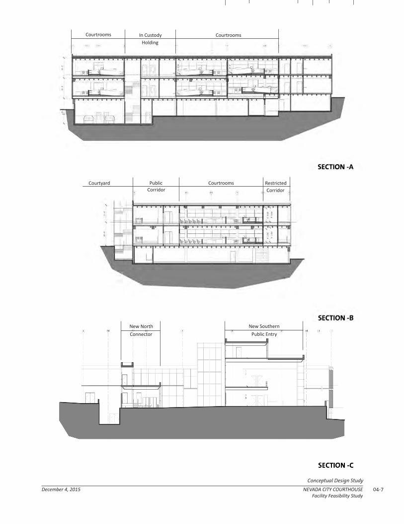
04-7December 4, 2015 NEVADA CITY COURTHOUSEFacility Feasibility Study
Conceptual Design Study
Courtrooms
New North New SouthernConnector Public Entry
CourtroomsIn CustodyHolding
Courtyard Courtrooms RestrictedCorridor
PublicCorridor

04-8 NEVADA CITY COURTHOUSE December 4, 2015Facility Feasibility Study
Conceptual Design Study
PHASINGIt is feasible to minimize construction-period displacement of the courts, throughout the use of temporary court facilities and construction phasing techniques. There are a variety of potential phasing approaches available including:
1. A temporary criminal courts facility will be located by the Rood Admin. Center, and will be accommodated utilizing modular buildings. This will include three criminal courtroom suites, Jury Assembly, and associated clerk functions. The temporary buildings will be connected directly to the Wayne Brown Correctional Facility for in-custody transfer.
2. The City Hall Council Chambers will be available for use as a hearing room.
3. The Veterans Hall may be utilized for some Court Administration functions.
Once these temporary accommodations are in place, the existing courthouse complex can be phased in the following way:
PHASE I -- ANNEX REMODELThe Annex is the location of most Phase I activities. During Phase 1 the existing Historic Courthouse retains all its current functions, and continues to serve as the primary entry to the building. Temporary HVAC equipment is staged at an exterior location (most likely the NW corner of the site) to supplement equipment to be removed from the Annex. The Annex is strategically renovated (as described previously, and in the diagrams to the right), and fully remodeled to accommodate six courtroom suites, public spaces, circulation, parking, holding, and central plant. The Annex is also equipped with a temporary entry corridor, temporary security, and temporary circulation core for use
ABOVE: The associated temporary facilities available during the project construction process.

04-9December 4, 2015 NEVADA CITY COURTHOUSEFacility Feasibility Study
Conceptual Design Study

04-10 NEVADA CITY COURTHOUSE December 4, 2015Facility Feasibility Study
Conceptual Design Study
as the primary building entry during Phase II. Only 4 or 5 of the six courtrooms will be fitted to function as courts during this phase, leaving those spaces for temporary civil clerk/administration functions.
PHASE IIPhase II remodels the historic courthouse, and the constructs of two new wings that connect the Historic Courthouse and the Annex. During Phase II, the newly remodeled Annex will provide the main entry to the facility (from the Main Street side), and will have active courtroom, judicial, public functions, as well as parking and Central Plant. The Historic Courthouse will have selective demolition (as described previously, and diagrammed on the previous page); it will then be seismically upgraded and renovated, with historic elements restored and returned to their previous prominence. Two new wings will be built to connect the entire facility, including the new southern entry/security/circulation “connector” along Church Street, and a new staff/jury wing to the north. The courtyard will be cleared and renovated as a central orientation element, and available for public use. The facility entry will be
reconfigured to create generous courthouse steps, and appropriate site accessibility.
PHASE IIIPhase III focuses on removing any remaining temporary accommodations, and completing improvements on remaining interior spaces. The temporary circulation core will be removed from the Annex. The temporary public entry from Main Street will be removed. The courtroom shells being used as clerk areas will be fitted as courtrooms. All temporary equipment, site accommodations, etc. will be removed. The full project will be open for business upon completion of this phase.
ABOVE: View of Historic Courthouse within the Central Business District.

04-11December 4, 2015 NEVADA CITY COURTHOUSEFacility Feasibility Study
Conceptual Design Study
ABOVE: Downtown Nevada City Civic Context

04-12 NEVADA CITY COURTHOUSE December 4, 2015Facility Feasibility Study
Conceptual Design Study

05-1December 4, 2015 NEVADA CITY COURTHOUSEFacility Feasibility Study
Engineering Reports
C H A P T E R 0 5
SUPPLEMENTAL INFORMATIONThe following reports summarize the structural and mechanical systems assumptions for this project. The contents of these reports are conceptual in nature, and are not final proposals for how best to remodel/renovate the existing facilities. They do, however, outline the assumptions underlying conceptual approach, and offer a framework upon which the cost estimation could be based.
ENGINEERING REPORTS

05-2 Nevada City Courthouse December 4, 2015Facility Feasibility Study
Engineering Reports
Structural Narrative For the Adaptive Reuse Study For the Nevada City Courthouse
11/30/2015 Prepared by RossDrulisCusenbery Architecture inc. 1
The NVCC courthouse site consists of two buildings built on a steep one block urban site located at 201 Church Street, Nevada City, California. The courthouse fills a city block with parking located on an adjacent parcel north east of the site. The courthouse consists of two buildings. The first building is the west Historic Courthouse (HC) that is divided into a north wing and south wing. The HC north (jail) wing, built in 1880 then added to in 1930, is a two story brick building with wood framed floors and roof and is on a granite block foundation. The HC south wing was originally a two story brick and wood framed building built prior to1865 when it was destroyed by fire. In 1865 the two brick building was rebuilt. In 1900 a third story was added. Then in 1936 the south wing was seismically “upgraded” and expanded with a "u-shaped" concrete framed additions. The east and west cast in place concrete west additionsare one story. The south wing addition added a partial fourthstoryfront elevation and is also constructed ofcast in place concrete. The second building is the east Annex building and southern connector. The annex is a three story concrete framed building with reinforced concretesquare and rectangular columns and a concrete waffle slab floor and roof framing system. The lower level is below grade on two sides and has concrete framed bearing walls and reinforced concrete square and rectangularcolumns. The exterior cladding is non-structural pre-cast concrete panels. On the roof there is a steel framed exercise yard and a steel framed roof top mechanical room. The south connector is a two story steel framed structure with sloping floors to connect to the floor levels of the annex to those in the HC. The north portion of the basement has below grade mechanical spaces. The Annex is built on steep sloped site where the basement floor elevations varies in height 8 feet from the lower southern end to the with higher northern mechanical room. The southern two thirds is a sloped parking garage. The annex and connector were built in one phase in 1962. The fourth story exercise yard was added some time after the building was completed. The HC and the Annex Buildings are to be renovated in two phases. During the first phase the Annex building is renovated while the HC remains operational. During Phase one temporary power and HVAC systems are installed in the north west corner of the parcel to serve the HC. At this time the Geotechnical Investigation and Geologic Hazards Evaluations are notcomplete;thus the foundation systems and site specific seismic design parameters are notavailable. Phase One - Annex Building Renovation: A. The annex renovation consists of the following areas of demolition:
In the basement the southern third of the sloped floor will be removed and a level floor level is constructed.
On the second and third floors new structural steel and concrete reinforcedopenings in the existing slab system will be required for the new stairs and elevators.
The existing stair and elevator openings will be filled in with new structural steel and concrete framing.

05-3December 4, 2015 NEVADA CITY COURTHOUSEFacility Feasibility Study
Engineering Reports
Structural Narrative For the Adaptive Reuse Study For the Nevada City Courthouse
11/30/2015 Prepared by RossDrulisCusenbery Architecture inc. 2
On the roof, the exercise yard and mechanical room will be removed. On the roof the existing stair and mech duct opening will be filled in with new
structural steel and concrete framing. The exterior northwest below grade mechanical spaces will be removed and a new
below grade areaway is created for the chiller. The southern connector is demolished.
B. Foundations of the Annex:
The concrete pad footings at columns and parameter concrete footings and grade beams are modified and reinforcedby the addition of new foundations for new shotcrete shear walls.
It is believed that that the modifications to the foundations will require excavation into and anchoring to bedrock that is near to or at the bottom of the existing footings.
C. Structural Frame of the Annex:
The vertical reinforced concrete framingcolumns are modified and reinforced specifically at ends of new shear walls and possibly other locations throughout.
The columns will be strengthened by adding Fiber Reinforced Polymer (FRP) around the circumference of the columns to provide confinement.
This project adds infill shotcrete or cast in place concrete shear walls on the three levels.
The existing perimeter concrete walls at the lowest level will remain and may be modified for new openings with new foundation and steel and concrete reinforcement.
In the lower level, there will be new saw cut openings in existing concrete shear / retaining walls which will require new concrete and or structural steel reinforcement at jambs / headers.
Additional modifications of existing concrete beams and columns as occur will require significant concrete and structural steel or FRP reinforcement.
D. Horizontal Frame of the Annex:
The basement level has sections of concrete slab on grade with areas of partial height retaining walls and raised concrete floors to accommodate the various floor levels.
In the northern section of the basement a three foot high section of the stepped floor is to be removed. This will include excavation and underpinning of existing walls with new cast in place concrete foundations and retaining walls.
The first, second and roof levels are a concrete “waffle” slab assembly. Newsteel framed openings for stairs, elevators and mechanical shafts are required
with structural steel and concrete horizontal and vertical members with foundations. The existing openings are to be in filled as noted above.
At the first and second floors a new lightweight modular raised accessible floor system is to be installed to align the floor levels in the annex with those in the HC.
At the roof, the structural loads will be reduced with the removal of the roof top mechanical room and exercise yard. However, provisions are to be made to add future photovoltaic panels over the entire roof area.

05-4 Nevada City Courthouse December 4, 2015Facility Feasibility Study
Engineering Reports
Structural Narrative For the Adaptive Reuse Study For the Nevada City Courthouse
11/30/2015 Prepared by RossDrulisCusenbery Architecture inc. 3
E. Exterior Cladding Of the Annex : The existing precast concrete panels are nonstructural and will be removed. The new cladding systems of similar or less weight.
Phase Two - Historic Courthouse (HC) Renovation During Phase Two the renovated Annex is to be occupied and the main public entry is relocated from the first floor on the south to the basement level on the east side of the annex. As a registered historical building, the California Historical Building Code (CHBC) can be used to retrofit the structure. However, the lower (75% current seismic design forces) CHBC design levelsand allowance of historic systems may not provide desired resilience; in which case American Society of Civil Engineers Standard for Seismic Retrofit of Existing Buildings (ASCE41) will be used to justify existing structural systems as appropriate and provide for performance based retrofit where needed. A. The renovation of the HC includes the following areas of demolition:
The two story north wing. The granite stone foundations systems are to be salvaged and reused. They are to be shaped for reuse as an exterior cladding material.
The one story east wing.
B. Foundations of the HC Existing South Wing HC Pre 1936 - The foundation of the south wing of the historic
courthouse are not known and exploratory investigation is required. It is assumedto be Unreinforced Brick Masonry on Granite Blocks and will required substantial concrete foundation retrofit/strengthening where structure above is alteredfor new conditionsor retrofitted.
Existing South Wing HC 1936 Additions -Concrete Spread Footing per partial original structural plans which are available. Further exploratory investigation is required. Substantial concrete footing
For this project analysis,new or strengthened concrete spread footings are to be provided at the new primary structural steel frames, shear walls, and columns.
Shoring and foundation underpinning modifications may be required along north (Along Grid line 15) and east sides (Along Grid line S) where the building additions are removed.
C. Structural Frame of the HC: The vertical structural elements are Existing
Existing South Wing HC Pre 1936 - Unreinforced brick masonry (URM) walls on top of granite bearing walls/foundations. Masonry walls support the floor and roof framing. The longitudinal exterior Courthouse walls are supported by the steel framing of the 1936 1st Floor Addition.The wall along grid line 15 of the Courthouse provides vertical and lateral support north wing
Existing South Wing HC 1936 Additions - Cast-in-place concrete slabs supported by reinforced concrete walls and columns. Continuous spread footings. The steel framing supports the longitudinal exterior Courthouse walls above.
D. Lateral Systems for the HC:
Existing South Wing HC Pre 1936 - Horizontal: Metal roofing diagonal bracing roof and wood plank sheathing floor diaphragms. Lateral: Unreinforced brick and granite shear walls.

05-5December 4, 2015 NEVADA CITY COURTHOUSEFacility Feasibility Study
Engineering Reports
Structural Narrative For the Adaptive Reuse Study For the Nevada City Courthouse
11/30/2015 Prepared by RossDrulisCusenbery Architecture inc. 4
Existing South Wing HC 1936 Additions - Horizontal: Concrete slabs. Lateral: Concrete shear walls.
The extent of structural “retrofit” that occurred in 1936 is unknown. Based on the stiffness of the URM historic system, significant new lateral bracing elements are appropriate.
a) Concrete/shotcrete shear walls b) Structural steel braced frames c) The CHBC or ASCE41could possibly be used to justify existing un-reinforced brick
shear wall lines P, O,R, and S above the second floor as URM without increasing openings in these walls or adding steel frames/concrete shear walls; however more extensive analysis is required.
d) For this analysis the following locations of new shear walls / braced frame assemblies At existing bearing/ shear wall lines (P, 0, R, S, 15, 11.5) and 2 interior locations running transverse (east - west) lines (12, 14) new lateral bracing elements and foundations are recommended.
a. Placement of the elements has some flexibility. b. Each lateral element would ideally be as long as the floor to floor height. c. Attached is the diagram of shear walls or braces.
e) Out of plane wall strengthening (structural steel strong backs) is required - more extensive analysis is needed.
f) Wall anchorage connections at floors and roof are required at all exterior and interior URM and concrete walls.
g) Floor and roof diaphragm strengthening by adding layers of plywood to the floors/ceilings may be required, or possibly justified with CHBC/ASCE41.
h) Bracing of existing ceilings and attic spaces is likely required.
E. Horizontal Frame of the HC :
Existing South Wing HC Pre 1936 o It is assumedthat the first floor is a concrete slab on grade; however
exploratory investigation is recommended. o The second and third floors are assumed to be wood framed with solid sawn
lumber o The roof is a Sloped metal roof supported by steel trusses.
Existing South Wing HC 1936 Additions - The extent of modifications that was implemented in the 1936 renovation is based on limited information.
o The first floor is a slab on grade. o The roof and floors are concrete slab o Reinforced concrete walls and columns and beams provide support
The renovation will most likely include new structural steel framing members, new connectors and new diaphragm construction on portions of the building.
Structural enhancement to the truss framing and roof diaphragm connections will be required.
Roof and Floor to wall connections are required. Bracing of ceiling/attic spaces may be required.
F. Exterior Cladding of the HC:
Existing South Wing HC Pre 1936 - The exterior of the courthouse is plaster over unreinforced brick masonry

05-6 Nevada City Courthouse December 4, 2015Facility Feasibility Study
Engineering Reports
Structural Narrative For the Adaptive Reuse Study For the Nevada City Courthouse
11/30/2015 Prepared by RossDrulisCusenbery Architecture inc. 5
Existing South Wing HC 1936 Additions - The exterior of the courthouse is partially plaster over cast in place concrete .
The structural strategy is to retain, protect, and seismically secure the Four Story 1936 Historic Facade. The facade is a significant and integral part of the structure. The historical design and detailing does not meet current standards therefore CHBC/ASCE41 codes will be implemented. Significant structural steel reinforcement interior, wall anchorage, and diaphragm connections would be required. New foundation strengthening and additions to support the new structural components would likely be required. Extensive analysis is needed to determine the true extents of requirements. Phase Two - South and North Building Additions The second phase of the project includes the addition of new building areas. The first is new three story southern connector. The second is the two story north addition that also connects the east and west buildings creating a central courtyard. A. The Site Preparation for the Phase Two New Additions:
The North and South Additions will be placed adjacent to existing buildings and where building demolition has occurred. Site Soil preparation will be required. Temporary shoring of existing structures and possible underpinning is to be addressed.
The additions will be specifically seismically separated from the HC building and may be separated from the Annex.
B. Foundations for the Phase Two New Additions -
The columns of the building will either be supported on isolated concrete spread footings with a slab on grade or a thicker concrete mat slabfoundation system.
A part of the South addition is a lower level exit corridor from the basement of the building. It is roughly 12ft below grade, requiring reinforced concrete basement retaining walls on three sides that will be restrained at the top by a first floor concrete flat slab. This slab will extend out into the new raised entry plaza.
The lower level floor slab will either be a reinforced concrete slab on grade or a mat slab.
C. Structural Frame for the Phase Two New Additions
The gravity load resisting system of the building will be a composite steel frame with concrete filledsteel deck floor system. The typical structural bays dimensions varydepending on location. In the south addition there are open interior areas whichextend vertically the three stories.
The concrete filled steel deck will either be4 1/2" of normal weight concrete over 2" deep deck or 3" deep deck depending on whichsystem provides the most economy while meeting the structural, vibration and fire ratingrequirements for the building.
Composite structural steel W beams and girders will support the deck Structural steel W columns will support the beams/girders

05-7December 4, 2015 NEVADA CITY COURTHOUSEFacility Feasibility Study
Engineering Reports
NEVADA CITY COURTHOUSE ADAPTIVE REUSE - DIAGRAMS -

05-8 Nevada City Courthouse December 4, 2015Facility Feasibility Study
Engineering Reports
DN
UP
UP
UPUP
UP
UP
UP
UP
UP
UP
UP
DN
DN
DN
DN
UP
DN
DN
UP
D
6
CBA
1
2
3
4
4.A
5
AA C.5B.5
0.8
5' - 0"
5' - 0"
0' - 0"
8' - 0"
33' -
0"
33' -
0"
33' -
0"
33' -
0"
33' -
0"
5' - 0"
5' - 0"
REMOVE EXISTING BELOW GRADEENCLOSURES AND PATCH OPENINGINSIN WALL
EXCAVATE AND PROVIDE NEWRETAINING WALLS FOR STAIRS ANDELEVATOR
Chi
ller
Main Panel
ServerRoom
Elev.
Phase One Exit Corridor
50' - 8"
33' -
0"
27' -
8"
To Be Demo'd
15' - 5"
EmergencyGenerator
MechicalServicesRoom
PROVIDE NEW OPENINGS IN (E)RETAINING WALL
REMOVESLOPING SLABAND EXCAVATEAND INSTALLNEW LEVELSLAB
EXCAVATE AREA AND PROVIDE RETAININGWALL FOR NEW EXIT ENCLOSURE
0' 4' 8' 16' 32' 64'
D
6
CBA
1
2
3
4
4.A
5
AATSPO
10
11
15
16
1.5
C.5B.5
1.3
0.8
5.5
R
12
13
14
DemoCoolingTower
DemoTrans
RelocateGasMeter
DemoAreaway
COURTROOM #1E?
COURTROOM #2E?
NEW FRAMED OPENINGSFOR STAIRS ORELEVATOR
NEW FRAMED OPENINGSFOR STAIRS ORELEVATOR
FRAME IN EXISTINGOPENING IN FLOOR
DEMO BELOWGRADE MECHENCLOSURES
0' 4' 8' 16' 32' 64'
D
6
CBA
1
2
3
4
4.A
5
TSPO
10
11
15
16
1.5
C.5B.5
1.3
0.8
5.5
R
12
13
14
FRAME IN EXISTINGOPENING IN FLOOR
NEW FRAMED OPENINGFOR NEW STAIRS ORELEVATOR
NEW FRAMEDOPENING FOR NEWSTAIRS OR ELEVATOR
0' 4' 8' 16' 32' 64'
-
-
D
6
CBA
1
2
3
4
4.A
5
SPO
10
11
15
16
1.5
C.5B.5
1.3
0.8
5.5
R
12
13
14
P3.0
1
0' - 0"
0' - 0"
1' - 9"
Existing Roof TopMechanical Room ToBe Demolished
Existing Fan RoomTo Be Demolished
Existing Skylights ToBe Removed AndInfilled Typ
0' 4' 8' 16' 32' 64'
AREAS WHERE NO WORKOCCURS OIN THIS PHASE
AREAS THAT ARE TO BEDEMOLISHED IN THEBEGINNING OF THE NEXTPHASE
TEMPORARY CIRCULATIONROUTE
MECHANICAL SPACESAND OR SHAFTS
NEW CONC SHEAR WALL ELEMENTSNEW CONTINUOUS FOOTINGS WILL BEREQUIRED. PROBABLE WIDTH OF SHEARWALLS AT LOWER LEVEL AND FIRSTLEVEL = 12”, AT SECOND LEVEL 10”, ATUPPER LEVEL 8”.
NEW MAJOR STEEL FRAME AND NEWFOUNDATIONS
LOCALIZED STRENGTHENING OF, ORADDITION TO, ROOF FRAMING MEMBERS
PROVIDE SHORING OF (E) BUILDINGAND INSTALLATION OF NEWFOUNDATION
NEW MECHANICAL EQUIPMENTREQUIRING STRUCTURAL SUPPORT
STRUCTURALIMPROVEMENTS LEGEND
COLUMNS TO BE STRENGTHENEDBY ADDING FIBER REINFORCEDPOLYMER (FRP) JACKETS TOPROVIDE CONFINEMENT. TYPICAL ,GRAVITY COLUMNS ARE EXPECTEDTO NEED TO BE ENLARGED.
AREA OF RAISED FLOOR FORBELOW FLOOR MECHANICALCONDITIONING 14" FROMSLAB TO FF
AREAS OF NEWCONSTRUCTION
NEW MINOR STEEL FRAME BRACE AT NEWOPENINGS
REMOVE AND REPLACE EXISTING FLOORSTRUCTURE
REINFORCE CONCRETE FACADE WALLSWITH CARBON FIBER REINFORCINGSYSTEM
NEW ELEVATORS
All drawings and written material appearing herein constitute the original and unpublished work of the architect and may not be duplicated, used, or disclosed without the prior written consent of RossDrulisCusenbery, Architecture, Inc. Copyright 2014 RossDrulisCusenbery, Architecture, Inc.
ST-PHASE DIAGRAM - EXISTINGNevada City Courthouse Adaptive Reuse10/26/2015
ST 0.0
3/64" = 1'-0"1 LOWER LEVEL - EXISTING STRUCTURAL MODIFICATIONS
3/64" = 1'-0"2 1ST LEVEL - EXISTING STRUCTURAL MODIFICATIONS
3/64" = 1'-0"3 2ND LEVEL - EXISTING STRUCTURAL MODIFICATIONS
3/64" = 1'-0"4 3RD LEVEL - EXISTING STRUCTURAL MODIFICATIONS
1/4" = 1'-0"Color Legend For Structural Improvements
REMOVEEXTERIORSTAIRS
REMOVESOUTHERNCONNECTOR
ST-PHASE DIAGRAM - EXISTINGST 0.0
Nevada City Courthouse Adaptive Reuse

05-9December 4, 2015 NEVADA CITY COURTHOUSEFacility Feasibility Study
Engineering Reports
DN
UP
UP
UPUP
UP
UP
UP
UP
UP
UP
UP
DN
DN
DN
DN
UP
DN
DN
UP
D
6
CBA
1
2
3
4
4.A
5
AA C.5B.5
0.8
5' - 0"
5' - 0"
0' - 0"
8' - 0"
33' -
0"
33' -
0"
33' -
0"
33' -
0"
33' -
0"
5' - 0"
5' - 0"
REMOVE EXISTING BELOW GRADEENCLOSURES AND PATCH OPENINGINSIN WALL
EXCAVATE AND PROVIDE NEWRETAINING WALLS FOR STAIRS ANDELEVATOR
Chi
ller
Main Panel
ServerRoom
Elev.
Phase One Exit Corridor
50' - 8"
33' -
0"
27' -
8"
To Be Demo'd
15' - 5"
EmergencyGenerator
MechicalServicesRoom
PROVIDE NEW OPENINGS IN (E)RETAINING WALL
REMOVESLOPING SLABAND EXCAVATEAND INSTALLNEW LEVELSLAB
EXCAVATE AREA AND PROVIDE RETAININGWALL FOR NEW EXIT ENCLOSURE
0' 4' 8' 16' 32' 64'
D
6
CBA
1
2
3
4
4.A
5
AATSPO
10
11
15
16
1.5
C.5B.5
1.3
0.8
5.5
R
12
13
14
DemoCoolingTower
DemoTrans
RelocateGasMeter
DemoAreaway
COURTROOM #1E?
COURTROOM #2E?
NEW FRAMED OPENINGSFOR STAIRS ORELEVATOR
NEW FRAMED OPENINGSFOR STAIRS ORELEVATOR
FRAME IN EXISTINGOPENING IN FLOOR
DEMO BELOWGRADE MECHENCLOSURES
0' 4' 8' 16' 32' 64'
D
6
CBA
1
2
3
4
4.A
5
TSPO
10
11
15
16
1.5
C.5B.5
1.3
0.8
5.5
R
12
13
14
FRAME IN EXISTINGOPENING IN FLOOR
NEW FRAMED OPENINGFOR NEW STAIRS ORELEVATOR
NEW FRAMEDOPENING FOR NEWSTAIRS OR ELEVATOR
0' 4' 8' 16' 32' 64'
-
-
D
6
CBA
1
2
3
4
4.A
5
SPO
10
11
15
16
1.5
C.5B.5
1.3
0.8
5.5
R
12
13
14
P3.0
1
0' - 0"
0' - 0"
1' - 9"
Existing Roof TopMechanical Room ToBe Demolished
Existing Fan RoomTo Be Demolished
Existing Skylights ToBe Removed AndInfilled Typ
0' 4' 8' 16' 32' 64'
AREAS WHERE NO WORKOCCURS OIN THIS PHASE
AREAS THAT ARE TO BEDEMOLISHED IN THEBEGINNING OF THE NEXTPHASE
TEMPORARY CIRCULATIONROUTE
MECHANICAL SPACESAND OR SHAFTS
NEW CONC SHEAR WALL ELEMENTSNEW CONTINUOUS FOOTINGS WILL BEREQUIRED. PROBABLE WIDTH OF SHEARWALLS AT LOWER LEVEL AND FIRSTLEVEL = 12”, AT SECOND LEVEL 10”, ATUPPER LEVEL 8”.
NEW MAJOR STEEL FRAME AND NEWFOUNDATIONS
LOCALIZED STRENGTHENING OF, ORADDITION TO, ROOF FRAMING MEMBERS
PROVIDE SHORING OF (E) BUILDINGAND INSTALLATION OF NEWFOUNDATION
NEW MECHANICAL EQUIPMENTREQUIRING STRUCTURAL SUPPORT
STRUCTURALIMPROVEMENTS LEGEND
COLUMNS TO BE STRENGTHENEDBY ADDING FIBER REINFORCEDPOLYMER (FRP) JACKETS TOPROVIDE CONFINEMENT. TYPICAL ,GRAVITY COLUMNS ARE EXPECTEDTO NEED TO BE ENLARGED.
AREA OF RAISED FLOOR FORBELOW FLOOR MECHANICALCONDITIONING 14" FROMSLAB TO FF
AREAS OF NEWCONSTRUCTION
NEW MINOR STEEL FRAME BRACE AT NEWOPENINGS
REMOVE AND REPLACE EXISTING FLOORSTRUCTURE
REINFORCE CONCRETE FACADE WALLSWITH CARBON FIBER REINFORCINGSYSTEM
NEW ELEVATORS
All drawings and written material appearing herein constitute the original and unpublished work of the architect and may not be duplicated, used, or disclosed without the prior written consent of RossDrulisCusenbery, Architecture, Inc. Copyright 2014 RossDrulisCusenbery, Architecture, Inc.
ST-PHASE DIAGRAM - EXISTINGNevada City Courthouse Adaptive Reuse10/26/2015
ST 0.0
3/64" = 1'-0"1 LOWER LEVEL - EXISTING STRUCTURAL MODIFICATIONS
3/64" = 1'-0"2 1ST LEVEL - EXISTING STRUCTURAL MODIFICATIONS
3/64" = 1'-0"3 2ND LEVEL - EXISTING STRUCTURAL MODIFICATIONS
3/64" = 1'-0"4 3RD LEVEL - EXISTING STRUCTURAL MODIFICATIONS
1/4" = 1'-0"Color Legend For Structural Improvements
REMOVEEXTERIORSTAIRS
REMOVESOUTHERNCONNECTOR
ST-PHASE DIAGRAM - EXISTINGST 0.0
Nevada City Courthouse Adaptive Reuse
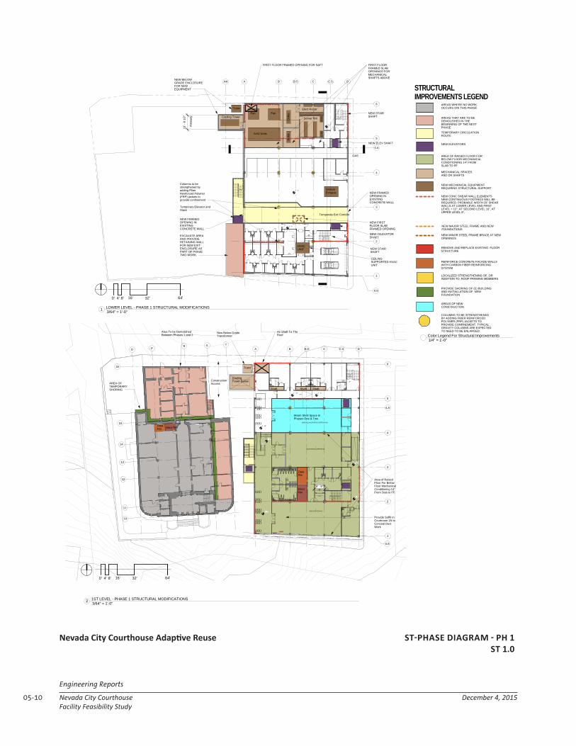
05-10 Nevada City Courthouse December 4, 2015Facility Feasibility Study
Engineering Reports
ST-PHASE DIAGRAM - PH 1ST 1.0
Nevada City Courthouse Adaptive Reuse
UP
UP
UP
UP
UP
UP
UP
UP
DN
UP
DN
UP
D
6
CBA
1
2
3
4
4.A
5
AA C.5B.5
0.8
0' - 0"
-5' - 0"
3' - 0"
Elect Room
crac
cracServer RmCooling Tower
13' -
8 1
/2"
Area
way
AHU Units
Fan Fan
FIRST FLOORFRAMED SLABOPENINGS FORMECHANICALSHAFTS ABOVE
VehicleExhaust
HVACUNIT
Temporary Elevator andStairs
Temporary Exit Corridor
Chi
ller
Boile
r
NEW ELEV SHAFT
NEW I ELEVATORSHAFT
NEW BELOWGRADE ENCLOSUREFOR NEWEQUIPMENT
Trans
FIRST FLOOR FRAMED OPENING FOR SAFT
CEILINGSUPPORTED HVACUNIT
NEW FIRSTFLOOR SLABFRAMED OPENING
GAS
NEW FRAMEDOPENING INEXISTINGCONCRETE WALL
NEW STAIRSHAFT
NEW STAIRSHAFT
Columns to bestrengthened byadding FiberReinforced Polymer(FRP) jackets toprovide confinement
EXCAVATE AREAAND PROVIDERETAINING WALLFOR NEW EXITENCLOSURE ASPART OF PHASETWO WORK.
NEW FRAMEDOPENING INEXISTINGCONCRETE WALL
0' 4' 8' 16' 32' 64'
D
6
CBA
1
2
3
4
4.A
5
TSPO
10
11
15
16
C.5B.5
0.8
R
12
13
14
0' - 0"
0' - 6"
1' - 10"
0' - 0"
0' - 6"
9' - 9"
1' - 10" 2' - 4"
DataRm
ElectRm
CoolingTower Below
Shaft Shaft Shaft
Warm Shell Space InPhases One & Two
Area of RaisedFloor For BelowFloor MechanicalConditioning 14"From Slab to FF.
Area To be DemolishedBetween Phases 1 and 2
ConstructionAccess
Air Shaft To TheRoof
New Below GradeTransformer
Trans
LARGE COURTROOM #1N?
MULTIPURPOSE COURTROOM #2N?
WARM SHELL (MULTIPURPOSE COURTROOM #3N)?
Provide Soffit InCourtroom 1N toConceal DuctWork
DataRm Elect Rm
AREA OFTEMPORARYSHORING
0' 4' 8' 16' 32' 64'
D
6
CBA
1
2
3
4
4.A
5
AATS
PO
10
11
15
16
1.5
C.5B.5
1.3
0.8
5.5
R
12
13
140' - 0"
0' - 10"
0' - 10"1' - 4"
1' - 4"
0' - 6"
Area of Raised Floor For BelowFloor Mechanical Conditioning14" From Slab to FF.
MECH
MULTIPURPOSE COURTROOM #4N?
MULTIPURPOSE COURTROOM #5N?
MULTIPURPOSE COURTROOM #6N?
COURTROOM #5E?
Data Elect
Warm Shell Space inPhases One & Two
AREA OFTEMPORARYSHORING
0' 4' 8' 16' 32' 64'
D
6
CBA
2
3
4
4.A
5
AATS
PO
10
11
15
16
C.5B.5
0.8
R
12
13
14
COURTROOM #6E?
Data Elect
AREA OFTEMPORARYSHORING
0' 4' 8' 16' 32' 64'
AREAS WHERE NO WORKOCCURS OIN THIS PHASE
AREAS THAT ARE TO BEDEMOLISHED IN THEBEGINNING OF THE NEXTPHASE
TEMPORARY CIRCULATIONROUTE
MECHANICAL SPACESAND OR SHAFTS
NEW CONC SHEAR WALL ELEMENTSNEW CONTINUOUS FOOTINGS WILL BEREQUIRED. PROBABLE WIDTH OF SHEARWALLS AT LOWER LEVEL AND FIRSTLEVEL = 12”, AT SECOND LEVEL 10”, ATUPPER LEVEL 8”.
NEW MAJOR STEEL FRAME AND NEWFOUNDATIONS
LOCALIZED STRENGTHENING OF, ORADDITION TO, ROOF FRAMING MEMBERS
PROVIDE SHORING OF (E) BUILDINGAND INSTALLATION OF NEWFOUNDATION
NEW MECHANICAL EQUIPMENTREQUIRING STRUCTURAL SUPPORT
STRUCTURALIMPROVEMENTS LEGEND
COLUMNS TO BE STRENGTHENEDBY ADDING FIBER REINFORCEDPOLYMER (FRP) JACKETS TOPROVIDE CONFINEMENT. TYPICAL ,GRAVITY COLUMNS ARE EXPECTEDTO NEED TO BE ENLARGED.
AREA OF RAISED FLOOR FORBELOW FLOOR MECHANICALCONDITIONING 14" FROMSLAB TO FF
AREAS OF NEWCONSTRUCTION
NEW MINOR STEEL FRAME BRACE AT NEWOPENINGS
REMOVE AND REPLACE EXISTING FLOORSTRUCTURE
REINFORCE CONCRETE FACADE WALLSWITH CARBON FIBER REINFORCINGSYSTEM
NEW ELEVATORS
All drawings and written material appearing herein constitute the original and unpublished work of the architect and may not be duplicated, used, or disclosed without the prior written consent of RossDrulisCusenbery, Architecture, Inc. Copyright 2014 RossDrulisCusenbery, Architecture, Inc.
ST - PHASING DIAGRAM - PH 1Nevada City Courthouse Adaptive Reuse10/26/2015
ST 1.0
3/64" = 1'-0"1 LOWER LEVEL - PHASE 1 STRUCTURAL MODIFICATIONS
3/64" = 1'-0"2 1ST LEVEL - PHASE 1 STRUCTURAL MODIFICATIONS
3/64" = 1'-0"3 2ND LEVEL - PHASE 1 STRUCTURAL MODIFICATIONS
3/64" = 1'-0"4 3RD LEVEL - PHASE 1 STRUCTURAL MODIFICATIONS
1/4" = 1'-0"Color Legend For Structural Improvements
Localizedstrengthening of,or addition to,roof framingmembers

05-11December 4, 2015 NEVADA CITY COURTHOUSEFacility Feasibility Study
Engineering Reports
UP
UP
UP
UP
UP
UP
UP
UP
DN
UP
DN
UP
D
6
CBA
1
2
3
4
4.A
5
AA C.5B.5
0.8
0' - 0"
-5' - 0"
3' - 0"
Elect Room
crac
cracServer RmCooling Tower
13' -
8 1
/2"
Area
way
AHU Units
Fan Fan
FIRST FLOORFRAMED SLABOPENINGS FORMECHANICALSHAFTS ABOVE
VehicleExhaust
HVACUNIT
Temporary Elevator andStairs
Temporary Exit Corridor
Chi
ller
Boile
r
NEW ELEV SHAFT
NEW I ELEVATORSHAFT
NEW BELOWGRADE ENCLOSUREFOR NEWEQUIPMENT
Trans
FIRST FLOOR FRAMED OPENING FOR SAFT
CEILINGSUPPORTED HVACUNIT
NEW FIRSTFLOOR SLABFRAMED OPENING
GAS
NEW FRAMEDOPENING INEXISTINGCONCRETE WALL
NEW STAIRSHAFT
NEW STAIRSHAFT
Columns to bestrengthened byadding FiberReinforced Polymer(FRP) jackets toprovide confinement
EXCAVATE AREAAND PROVIDERETAINING WALLFOR NEW EXITENCLOSURE ASPART OF PHASETWO WORK.
NEW FRAMEDOPENING INEXISTINGCONCRETE WALL
0' 4' 8' 16' 32' 64'
D
6
CBA
1
2
3
4
4.A
5
TSPO
10
11
15
16
C.5B.5
0.8
R
12
13
14
0' - 0"
0' - 6"
1' - 10"
0' - 0"
0' - 6"
9' - 9"
1' - 10" 2' - 4"
DataRm
ElectRm
CoolingTower Below
Shaft Shaft Shaft
Warm Shell Space InPhases One & Two
Area of RaisedFloor For BelowFloor MechanicalConditioning 14"From Slab to FF.
Area To be DemolishedBetween Phases 1 and 2
ConstructionAccess
Air Shaft To TheRoof
New Below GradeTransformer
Trans
LARGE COURTROOM #1N?
MULTIPURPOSE COURTROOM #2N?
WARM SHELL (MULTIPURPOSE COURTROOM #3N)?
Provide Soffit InCourtroom 1N toConceal DuctWork
DataRm Elect Rm
AREA OFTEMPORARYSHORING
0' 4' 8' 16' 32' 64'
D
6
CBA
1
2
3
4
4.A
5
AATS
PO
10
11
15
16
1.5
C.5B.5
1.3
0.8
5.5
R
12
13
140' - 0"
0' - 10"
0' - 10"1' - 4"
1' - 4"
0' - 6"
Area of Raised Floor For BelowFloor Mechanical Conditioning14" From Slab to FF.
MECH
MULTIPURPOSE COURTROOM #4N?
MULTIPURPOSE COURTROOM #5N?
MULTIPURPOSE COURTROOM #6N?
COURTROOM #5E?
Data Elect
Warm Shell Space inPhases One & Two
AREA OFTEMPORARYSHORING
0' 4' 8' 16' 32' 64'
D
6
CBA
2
3
4
4.A
5
AATS
PO
10
11
15
16
C.5B.5
0.8
R
12
13
14
COURTROOM #6E?
Data Elect
AREA OFTEMPORARYSHORING
0' 4' 8' 16' 32' 64'
AREAS WHERE NO WORKOCCURS OIN THIS PHASE
AREAS THAT ARE TO BEDEMOLISHED IN THEBEGINNING OF THE NEXTPHASE
TEMPORARY CIRCULATIONROUTE
MECHANICAL SPACESAND OR SHAFTS
NEW CONC SHEAR WALL ELEMENTSNEW CONTINUOUS FOOTINGS WILL BEREQUIRED. PROBABLE WIDTH OF SHEARWALLS AT LOWER LEVEL AND FIRSTLEVEL = 12”, AT SECOND LEVEL 10”, ATUPPER LEVEL 8”.
NEW MAJOR STEEL FRAME AND NEWFOUNDATIONS
LOCALIZED STRENGTHENING OF, ORADDITION TO, ROOF FRAMING MEMBERS
PROVIDE SHORING OF (E) BUILDINGAND INSTALLATION OF NEWFOUNDATION
NEW MECHANICAL EQUIPMENTREQUIRING STRUCTURAL SUPPORT
STRUCTURALIMPROVEMENTS LEGEND
COLUMNS TO BE STRENGTHENEDBY ADDING FIBER REINFORCEDPOLYMER (FRP) JACKETS TOPROVIDE CONFINEMENT. TYPICAL ,GRAVITY COLUMNS ARE EXPECTEDTO NEED TO BE ENLARGED.
AREA OF RAISED FLOOR FORBELOW FLOOR MECHANICALCONDITIONING 14" FROMSLAB TO FF
AREAS OF NEWCONSTRUCTION
NEW MINOR STEEL FRAME BRACE AT NEWOPENINGS
REMOVE AND REPLACE EXISTING FLOORSTRUCTURE
REINFORCE CONCRETE FACADE WALLSWITH CARBON FIBER REINFORCINGSYSTEM
NEW ELEVATORS
All drawings and written material appearing herein constitute the original and unpublished work of the architect and may not be duplicated, used, or disclosed without the prior written consent of RossDrulisCusenbery, Architecture, Inc. Copyright 2014 RossDrulisCusenbery, Architecture, Inc.
ST - PHASING DIAGRAM - PH 1Nevada City Courthouse Adaptive Reuse10/26/2015
ST 1.0
3/64" = 1'-0"1 LOWER LEVEL - PHASE 1 STRUCTURAL MODIFICATIONS
3/64" = 1'-0"2 1ST LEVEL - PHASE 1 STRUCTURAL MODIFICATIONS
3/64" = 1'-0"3 2ND LEVEL - PHASE 1 STRUCTURAL MODIFICATIONS
3/64" = 1'-0"4 3RD LEVEL - PHASE 1 STRUCTURAL MODIFICATIONS
1/4" = 1'-0"Color Legend For Structural Improvements
Localizedstrengthening of,or addition to,roof framingmembers
ST-PHASE DIAGRAM - PH 1ST 1.0
Nevada City Courthouse Adaptive Reuse

05-12 Nevada City Courthouse December 4, 2015Facility Feasibility Study
Engineering Reports
UP
UP UP
UP
UP
DN
UP
UP
UP
UP
UP
UP
UP
UP
DN
UP
DN
UP
UP
UP
UP
UP
UP
D
6
CBA
1
2
3
4
4.A
5
AA C.5B.5
0.8
0' - 0"
-5' - 0"
3' - 0"
33' - 0" 33' - 0" 33' - 0"
33' -
0"
33' -
0"
33' -
0"
33' -
0"
33' -
0"
Below GradeEmergency Generator Located in anAreaway
Below GradeExcavation and shoringfor new below gradeexit to street level.
0' 4' 8' 16' 32' 64'
D
6
CBA
1
2
3
4
4.A
5
SPO
10
11
15
16
C.5B.5
0.8
R
12
13
14
0' - 0"
0' - 6"
1' - 10"
0' - 0"
0' - 6"
0' - 0"-1' - 2"
-1' - 2" 1' - 10"1' - 10" 2' - 4"
2' - 4"
0' - 0"
0' - 0"
-9' - 2"
-9' - 2"
4' - 10"
Below Grade Cooling Tower in an Areaway
Below Grade Emergency Generator Areaway
Below Grade Transformer
Utility Trench
LARGE COURTROOM #1N?
MULTIPURPOSE COURTROOM #2N?
WARM SHELL (MULTIPURPOSE COURTROOM #3N)?
SOUTH ADDITION
RAISED ENTRYPLAZA
NORTH ADDITION
OUTLINE OF NEW BELOWGRADE EXIT CORRIDOR TOSTREET
COURTYARD
New Exit To Grade
0' 4' 8' 16' 32' 64'
D
6
CBA
1
2
3
4
4.A
5
SPO
10
11
15
16
1.5
C.5B.5
1.3
0.8
5.5
R
12
13
14
DataRoom
0' - 0"
0' - 10"
0' - 10"1' - 4"
1' - 4"
0' - 6"
0' - 0"0' - 11"
0' - 11" 0' - 10"
MULTIPURPOSE COURTROOM #4N?
MULTIPURPOSE COURTROOM #5N?
MULTIPURPOSE COURTROOM #6N?
OpentoBelow
ROOF DECK
OPEN TOCOURTYARD
NORTH ADDITION
SOUTH ADDITION
0' 4' 8' 16' 32' 64'
D
6
CBA
2
3
4
4.A
5
AATS
PO
10
11
15
16
C.5B.5
0.8
R
12
13
14
ROOF DECK
NEWROOFAREA
NEW ROOF AREA
CONVERT 4TH LEVEL CONF ROOM ABOVE TO NEW MECH ROOM
ROOF TOP ABOVE
NEW PACKAGE UNITSABOVE FOR NORTHERNADDITION
0' 4' 8' 16' 32' 64'
AREAS WHERE NO WORKOCCURS OIN THIS PHASE
AREAS THAT ARE TO BEDEMOLISHED IN THEBEGINNING OF THE NEXTPHASE
TEMPORARY CIRCULATIONROUTE
MECHANICAL SPACESAND OR SHAFTS
NEW CONC SHEAR WALL ELEMENTSNEW CONTINUOUS FOOTINGS WILL BEREQUIRED. PROBABLE WIDTH OF SHEARWALLS AT LOWER LEVEL AND FIRSTLEVEL = 12”, AT SECOND LEVEL 10”, ATUPPER LEVEL 8”.
NEW MAJOR STEEL FRAME AND NEWFOUNDATIONS
LOCALIZED STRENGTHENING OF, ORADDITION TO, ROOF FRAMING MEMBERS
PROVIDE SHORING OF (E) BUILDINGAND INSTALLATION OF NEWFOUNDATION
NEW MECHANICAL EQUIPMENTREQUIRING STRUCTURAL SUPPORT
STRUCTURALIMPROVEMENTS LEGEND
COLUMNS TO BE STRENGTHENEDBY ADDING FIBER REINFORCEDPOLYMER (FRP) JACKETS TOPROVIDE CONFINEMENT. TYPICAL ,GRAVITY COLUMNS ARE EXPECTEDTO NEED TO BE ENLARGED.
AREA OF RAISED FLOOR FORBELOW FLOOR MECHANICALCONDITIONING 14" FROMSLAB TO FF
AREAS OF NEWCONSTRUCTION
NEW MINOR STEEL FRAME BRACE AT NEWOPENINGS
REMOVE AND REPLACE EXISTING FLOORSTRUCTURE
REINFORCE CONCRETE FACADE WALLSWITH CARBON FIBER REINFORCINGSYSTEM
NEW ELEVATORS
All drawings and written material appearing herein constitute the original and unpublished work of the architect and may not be duplicated, used, or disclosed without the prior written consent of RossDrulisCusenbery, Architecture, Inc. Copyright 2014 RossDrulisCusenbery, Architecture, Inc.
ST - PHASING DIAGRAM - PH 2Nevada City Courthouse Adaptive Reuse10/26/2015
ST 2.0
3/64" = 1'-0"1 LOWER LEVEL - PHASE 2 STRUCTURAL MODIFICATIONS
3/64" = 1'-0"2 1ST LEVEL - PHASE 2 STRUCTURAL MODIFICATIONS
3/64" = 1'-0"3 2ND LEVEL - PHASE 2 STRUCTURAL MODIFICATIONS
3/64" = 1'-0"4 3RD LEVEL - PHASE 2 STRUCTURAL MODIFICATIONS
1/4" = 1'-0"Color Legend For Structural Improvements
NORTH ADDITION
SOUTH ADDITION
ST-PHASE DIAGRAM - PH 2ST 2.0
Nevada City Courthouse Adaptive Reuse

05-13December 4, 2015 NEVADA CITY COURTHOUSEFacility Feasibility Study
Engineering Reports
UP
UP UP
UP
UP
DN
UP
UP
UP
UP
UP
UP
UP
UP
DN
UP
DN
UP
UP
UP
UP
UP
UP
D
6
CBA
1
2
3
4
4.A
5
AA C.5B.5
0.8
0' - 0"
-5' - 0"
3' - 0"
33' - 0" 33' - 0" 33' - 0"
33' -
0"
33' -
0"
33' -
0"
33' -
0"
33' -
0"
Below GradeEmergency Generator Located in anAreaway
Below GradeExcavation and shoringfor new below gradeexit to street level.
0' 4' 8' 16' 32' 64'
D
6
CBA
1
2
3
4
4.A
5
SPO
10
11
15
16
C.5B.5
0.8
R
12
13
14
0' - 0"
0' - 6"
1' - 10"
0' - 0"
0' - 6"
0' - 0"-1' - 2"
-1' - 2" 1' - 10"1' - 10" 2' - 4"
2' - 4"
0' - 0"
0' - 0"
-9' - 2"
-9' - 2"
4' - 10"
Below Grade Cooling Tower in an Areaway
Below Grade Emergency Generator Areaway
Below Grade Transformer
Utility Trench
LARGE COURTROOM #1N?
MULTIPURPOSE COURTROOM #2N?
WARM SHELL (MULTIPURPOSE COURTROOM #3N)?
SOUTH ADDITION
RAISED ENTRYPLAZA
NORTH ADDITION
OUTLINE OF NEW BELOWGRADE EXIT CORRIDOR TOSTREET
COURTYARD
New Exit To Grade
0' 4' 8' 16' 32' 64'
D
6
CBA
1
2
3
4
4.A
5
SPO
10
11
15
16
1.5
C.5B.5
1.3
0.8
5.5
R
12
13
14
DataRoom
0' - 0"
0' - 10"
0' - 10"1' - 4"
1' - 4"
0' - 6"
0' - 0"0' - 11"
0' - 11" 0' - 10"
MULTIPURPOSE COURTROOM #4N?
MULTIPURPOSE COURTROOM #5N?
MULTIPURPOSE COURTROOM #6N?
OpentoBelow
ROOF DECK
OPEN TOCOURTYARD
NORTH ADDITION
SOUTH ADDITION
0' 4' 8' 16' 32' 64'
D
6
CBA
2
3
4
4.A
5
AATS
PO
10
11
15
16
C.5B.5
0.8
R
12
13
14
ROOF DECK
NEWROOFAREA
NEW ROOF AREA
CONVERT 4TH LEVEL CONF ROOM ABOVE TO NEW MECH ROOM
ROOF TOP ABOVE
NEW PACKAGE UNITSABOVE FOR NORTHERNADDITION
0' 4' 8' 16' 32' 64'
AREAS WHERE NO WORKOCCURS OIN THIS PHASE
AREAS THAT ARE TO BEDEMOLISHED IN THEBEGINNING OF THE NEXTPHASE
TEMPORARY CIRCULATIONROUTE
MECHANICAL SPACESAND OR SHAFTS
NEW CONC SHEAR WALL ELEMENTSNEW CONTINUOUS FOOTINGS WILL BEREQUIRED. PROBABLE WIDTH OF SHEARWALLS AT LOWER LEVEL AND FIRSTLEVEL = 12”, AT SECOND LEVEL 10”, ATUPPER LEVEL 8”.
NEW MAJOR STEEL FRAME AND NEWFOUNDATIONS
LOCALIZED STRENGTHENING OF, ORADDITION TO, ROOF FRAMING MEMBERS
PROVIDE SHORING OF (E) BUILDINGAND INSTALLATION OF NEWFOUNDATION
NEW MECHANICAL EQUIPMENTREQUIRING STRUCTURAL SUPPORT
STRUCTURALIMPROVEMENTS LEGEND
COLUMNS TO BE STRENGTHENEDBY ADDING FIBER REINFORCEDPOLYMER (FRP) JACKETS TOPROVIDE CONFINEMENT. TYPICAL ,GRAVITY COLUMNS ARE EXPECTEDTO NEED TO BE ENLARGED.
AREA OF RAISED FLOOR FORBELOW FLOOR MECHANICALCONDITIONING 14" FROMSLAB TO FF
AREAS OF NEWCONSTRUCTION
NEW MINOR STEEL FRAME BRACE AT NEWOPENINGS
REMOVE AND REPLACE EXISTING FLOORSTRUCTURE
REINFORCE CONCRETE FACADE WALLSWITH CARBON FIBER REINFORCINGSYSTEM
NEW ELEVATORS
All drawings and written material appearing herein constitute the original and unpublished work of the architect and may not be duplicated, used, or disclosed without the prior written consent of RossDrulisCusenbery, Architecture, Inc. Copyright 2014 RossDrulisCusenbery, Architecture, Inc.
ST - PHASING DIAGRAM - PH 2Nevada City Courthouse Adaptive Reuse10/26/2015
ST 2.0
3/64" = 1'-0"1 LOWER LEVEL - PHASE 2 STRUCTURAL MODIFICATIONS
3/64" = 1'-0"2 1ST LEVEL - PHASE 2 STRUCTURAL MODIFICATIONS
3/64" = 1'-0"3 2ND LEVEL - PHASE 2 STRUCTURAL MODIFICATIONS
3/64" = 1'-0"4 3RD LEVEL - PHASE 2 STRUCTURAL MODIFICATIONS
1/4" = 1'-0"Color Legend For Structural Improvements
NORTH ADDITION
SOUTH ADDITION
ST-PHASE DIAGRAM - PH 2ST 2.0
Nevada City Courthouse Adaptive Reuse

05-14 Nevada City Courthouse December 4, 2015Facility Feasibility Study
Engineering Reports
Nevada City Courthouse Adaptive Reuse
UP
UP UP
UP
UP
DN
UP
UP
UP
UP
UP
UP
UP
UP
UP
DN
UP
DN
UP
UP
UP
UP
D
6
CBA
1
2
3
4
4.A
5
AA C.5B.5
0.8
0' - 0"
-5' - 0"
3' - 0"
-5' - 0"
-5' - 0"
New Emergency GeneratorLocated Below Ground in anAreaway
RENOVATE THEAREA THAT WASTHE TEMPORARYEXIT CORRIDORAND SCREENINGAREA
0' 4' 8' 16' 32' 64'
D
6
CBA
1
2
3
4
4.A
5
SPO
10
11
15
16
C.5B.5
0.8
R
12
13
14
0' - 0"
0' - 6"
1' - 10"
0' - 0"
0' - 6"
0' - 0"
-1' - 2"
-3' - 8 5/8"
-1' - 2"
-1' - 2"1' - 10"
1' - 10"
118.45'
MULTIPURPOSE COURTROOM #2N(2.2)
MULTIPURPOSE COURTROOM #3N(2.2)
LARGE COURTROOM #1N(2.1)
RENOVATE WARM SHELLSPACE INTO ACOURTROOM
0' 4' 8' 16' 32' 64'
D
6
CBA
1
2
3
4
4.A
5
SPO
10
11
15
16
1.5
C.5B.5
1.3
0.8
5.5
R
12
13
140' - 0"
0' - 10"
0' - 10"
0' - 6"
0' - 0"
0' - 11"
0' - 10"0' - 11"
MULTIPURPOSE COURTROOM #6N(2.2)
MULTIPURPOSE COURTROOM #5N(2.2)
MULTIPURPOSE COURTROOM #4N(2.2)
RENOVATE WARM SHELLSPACE INTO ACOURTROOM
0' 4' 8' 16' 32' 64'
D
6
CBA
2
3
4
4.A
5
AATS
PO
10
11
15
16
C.5B.5
0.8
R
12
13
14
0' - 0"
0' - 0"
0' - 0"
0' 4' 8' 16' 32' 64'
AREAS WHERE NO WORKOCCURS OIN THIS PHASE
AREAS THAT ARE TO BEDEMOLISHED IN THEBEGINNING OF THE NEXTPHASE
TEMPORARY CIRCULATIONROUTE
MECHANICAL SPACESAND OR SHAFTS
NEW CONC SHEAR WALL ELEMENTSNEW CONTINUOUS FOOTINGS WILL BEREQUIRED. PROBABLE WIDTH OF SHEARWALLS AT LOWER LEVEL AND FIRSTLEVEL = 12”, AT SECOND LEVEL 10”, ATUPPER LEVEL 8”.
NEW MAJOR STEEL FRAME AND NEWFOUNDATIONS
LOCALIZED STRENGTHENING OF, ORADDITION TO, ROOF FRAMING MEMBERS
PROVIDE SHORING OF (E) BUILDINGAND INSTALLATION OF NEWFOUNDATION
NEW MECHANICAL EQUIPMENTREQUIRING STRUCTURAL SUPPORT
STRUCTURALIMPROVEMENTS LEGEND
COLUMNS TO BE STRENGTHENEDBY ADDING FIBER REINFORCEDPOLYMER (FRP) JACKETS TOPROVIDE CONFINEMENT. TYPICAL ,GRAVITY COLUMNS ARE EXPECTEDTO NEED TO BE ENLARGED.
AREA OF RAISED FLOOR FORBELOW FLOOR MECHANICALCONDITIONING 14" FROMSLAB TO FF
AREAS OF NEWCONSTRUCTION
NEW MINOR STEEL FRAME BRACE AT NEWOPENINGS
REMOVE AND REPLACE EXISTING FLOORSTRUCTURE
REINFORCE CONCRETE FACADE WALLSWITH CARBON FIBER REINFORCINGSYSTEM
NEW ELEVATORS
All drawings and written material appearing herein constitute the original and unpublished work of the architect and may not be duplicated, used, or disclosed without the prior written consent of RossDrulisCusenbery, Architecture, Inc. Copyright 2014 RossDrulisCusenbery, Architecture, Inc.
ST - PHASING DIAGRAM - PH 3Nevada City Courthouse Adaptive Reuse10/26/2015
ST 3.0
3/64" = 1'-0"1 LOWER LEVEL - PHASE 3 STRUCTURAL MODIFCATIONS
3/64" = 1'-0"2 1ST LEVEL - PHASE 3 STRUCTURAL MODIFICATIONS
3/64" = 1'-0"3 2ND LEVEL - PHASE 3 STRUCTURAL MODIFICATIONS
3/64" = 1'-0"4 3RD LEVEL - PHASE 3 STRUCTURAL MODIFICATIONS
1/4" = 1'-0"Color Legend For Structural Improvements
ST-PHASE DIAGRAM - PH 3ST 3.0

05-15December 4, 2015 NEVADA CITY COURTHOUSEFacility Feasibility Study
Engineering Reports
UP
UP UP
UP
UP
DN
UP
UP
UP
UP
UP
UP
UP
UP
UP
DN
UP
DN
UP
UP
UP
UP
D
6
CBA
1
2
3
4
4.A
5
AA C.5B.5
0.8
0' - 0"
-5' - 0"
3' - 0"
-5' - 0"
-5' - 0"
New Emergency GeneratorLocated Below Ground in anAreaway
RENOVATE THEAREA THAT WASTHE TEMPORARYEXIT CORRIDORAND SCREENINGAREA
0' 4' 8' 16' 32' 64'
D
6
CBA
1
2
3
4
4.A
5
SPO
10
11
15
16
C.5B.5
0.8
R
12
13
14
0' - 0"
0' - 6"
1' - 10"
0' - 0"
0' - 6"
0' - 0"
-1' - 2"
-3' - 8 5/8"
-1' - 2"
-1' - 2"1' - 10"
1' - 10"
118.45'
MULTIPURPOSE COURTROOM #2N(2.2)
MULTIPURPOSE COURTROOM #3N(2.2)
LARGE COURTROOM #1N(2.1)
RENOVATE WARM SHELLSPACE INTO ACOURTROOM
0' 4' 8' 16' 32' 64'
D
6
CBA
1
2
3
4
4.A
5
SPO
10
11
15
16
1.5
C.5B.5
1.3
0.8
5.5
R
12
13
140' - 0"
0' - 10"
0' - 10"
0' - 6"
0' - 0"
0' - 11"
0' - 10"0' - 11"
MULTIPURPOSE COURTROOM #6N(2.2)
MULTIPURPOSE COURTROOM #5N(2.2)
MULTIPURPOSE COURTROOM #4N(2.2)
RENOVATE WARM SHELLSPACE INTO ACOURTROOM
0' 4' 8' 16' 32' 64'
D
6
CBA
2
3
4
4.A
5
AATS
PO
10
11
15
16
C.5B.5
0.8
R
12
13
14
0' - 0"
0' - 0"
0' - 0"
0' 4' 8' 16' 32' 64'
AREAS WHERE NO WORKOCCURS OIN THIS PHASE
AREAS THAT ARE TO BEDEMOLISHED IN THEBEGINNING OF THE NEXTPHASE
TEMPORARY CIRCULATIONROUTE
MECHANICAL SPACESAND OR SHAFTS
NEW CONC SHEAR WALL ELEMENTSNEW CONTINUOUS FOOTINGS WILL BEREQUIRED. PROBABLE WIDTH OF SHEARWALLS AT LOWER LEVEL AND FIRSTLEVEL = 12”, AT SECOND LEVEL 10”, ATUPPER LEVEL 8”.
NEW MAJOR STEEL FRAME AND NEWFOUNDATIONS
LOCALIZED STRENGTHENING OF, ORADDITION TO, ROOF FRAMING MEMBERS
PROVIDE SHORING OF (E) BUILDINGAND INSTALLATION OF NEWFOUNDATION
NEW MECHANICAL EQUIPMENTREQUIRING STRUCTURAL SUPPORT
STRUCTURALIMPROVEMENTS LEGEND
COLUMNS TO BE STRENGTHENEDBY ADDING FIBER REINFORCEDPOLYMER (FRP) JACKETS TOPROVIDE CONFINEMENT. TYPICAL ,GRAVITY COLUMNS ARE EXPECTEDTO NEED TO BE ENLARGED.
AREA OF RAISED FLOOR FORBELOW FLOOR MECHANICALCONDITIONING 14" FROMSLAB TO FF
AREAS OF NEWCONSTRUCTION
NEW MINOR STEEL FRAME BRACE AT NEWOPENINGS
REMOVE AND REPLACE EXISTING FLOORSTRUCTURE
REINFORCE CONCRETE FACADE WALLSWITH CARBON FIBER REINFORCINGSYSTEM
NEW ELEVATORS
All drawings and written material appearing herein constitute the original and unpublished work of the architect and may not be duplicated, used, or disclosed without the prior written consent of RossDrulisCusenbery, Architecture, Inc. Copyright 2014 RossDrulisCusenbery, Architecture, Inc.
ST - PHASING DIAGRAM - PH 3Nevada City Courthouse Adaptive Reuse10/26/2015
ST 3.0
3/64" = 1'-0"1 LOWER LEVEL - PHASE 3 STRUCTURAL MODIFCATIONS
3/64" = 1'-0"2 1ST LEVEL - PHASE 3 STRUCTURAL MODIFICATIONS
3/64" = 1'-0"3 2ND LEVEL - PHASE 3 STRUCTURAL MODIFICATIONS
3/64" = 1'-0"4 3RD LEVEL - PHASE 3 STRUCTURAL MODIFICATIONS
1/4" = 1'-0"Color Legend For Structural Improvements
Nevada City Courthouse Adaptive Reuse ST-PHASE DIAGRAM - PH 3ST 3.0

05-16 Nevada City Courthouse December 4, 2015Facility Feasibility Study
Engineering Reports

05-17December 4, 2015 NEVADA CITY COURTHOUSEFacility Feasibility Study
Engineering Reports
Nevada City Courthouse Nevada City, CA
Conceptual Mechanical, Electrical, and Plumbing and Fire Protection Systems Description Report
Prepared for: Ross Drulis Cusenbery Architecture 18294 Sonoma Highway Sonoma, CA 95476 Prepared by: WSP Group 405 Howard Street, Suite 500 San Francisco, CA 94105 October 26, 2015 (Update)

05-18 Nevada City Courthouse December 4, 2015Facility Feasibility Study
Engineering Reports
Conceptual MEP Systems Description Report (Update)
Nevada City Courthouse Nevada City, CA
WSP Group Table of Contents Ref. No: B15.05720.00 October 26, 2015 TOC
TABLE OF CONTENTS
ARTICLE PAGE
I. HEATING, VENTILATING, AND AIR CONDITIONING ....................................................1
II. ELECTRICAL ....................................................................................................................4
III. PLUMBING/FIRE PROTECTION .....................................................................................6
IV. SPACE REQUIREMENTS ................................................................................................8

05-19December 4, 2015 NEVADA CITY COURTHOUSEFacility Feasibility Study
Engineering Reports
Conceptual MEP Systems Description Report (Update)
Nevada City Courthouse Nevada City, CA
WSP Group Heating, Ventilating Ref. No.: B150572.00 and Air Conditioning October 26, 2015 1
I. HEATING, VENTILATING, AND AIR CONDITIONING
A. CODES AND STANDARDS
1. 2013 California Building Code
2. 2013 California Mechanical Code
3. State of California Energy Code: 2013 California Code of Regulations (CCR), Title 24, Building Standards
4. Judicial Council of California Trial Court Facilities Standards
5. California State Fire Marshal Requirements
6. American National Standards Institute (ANSI)
7. ASHRAE Standards
8. SMACNA Duct Construction Standards
9. National Fire Protection Association (NFPA)
10. Underwriters Laboratories (UL)
B. DESIGN CRITERIA / DESIGN CALCULATION GUIDELINES
1. Outdoor Design Conditions – Nevada City, CA:
a. Summer: 101F dry bulb/70F wet bulb – ASHRAE 0.4% 70°F wet bulb (evaporation) – ASHRAE 0.4%
b. Winter: 31F dry bulb – ASHRAE 99.6%
2. Indoor Design Conditions:
a. Per JCC Standards
3. Noise Criteria:
a. Per JCC Standards
C. ENERGY CONSERVATION FEATURES
1. The HVAC design shall utilize the above design criteria as a basis and shall also comply with the State of California Energy Code: 2013 California Code of Regulations (CCR), Title 24, Building Standards.

05-20 Nevada City Courthouse December 4, 2015Facility Feasibility Study
Engineering Reports
Conceptual MEP Systems Description Report (Update)
Nevada City Courthouse Nevada City, CA
WSP Group Heating, Ventilating Ref. No.: B150572.00 and Air Conditioning October 26, 2015 2
D. HVAC SYSTEMS
1. Historic Courthouse:
a. The existing historic courthouse HVAC systems are considered non reusable with all systems being replaced as part of the refurbishment and restoration of the facility.
b. It is anticipated that this building will be provided with a new localized heating and cooling system such as a heating/cooling Variable Refrigerant flow system for local space temperature control with connections for chilled and heating hot water from the Annex Central Plant.
c. Outside air ventilation will either be provided with a DX or chilled water cooled and hot water heated using a 100% outside air unit.
2. Annex Building
a. The existing central systems serving the Annex building are considered in good condition and reusable under the general refurbishment and restoration of the facility. This equipment includes the following:
(1) Water chiller (2) Heating hot water boiler boilers (3) Domestic hot water heaters
b. It is proposed to upgrade and supplement the retained equipment in order to generally serve both the Annex and Historic Courthouse with additional central plant equipment of similar capacity, generally providing a redundant capacity level of 75 percent. That is, the water chillers and heating hot water boiler capacity would be two units at 75% capacity.
c. A new chiller is anticipated to be added at 150 tons capacity. A new cooling tower would serve both the existing reused chiller and the new unit for a total of approximately 250 tons of total cooling capacity. The new cooling tower would be located underground with an areaway above for discharge air. This cooling tower may also provide emergency generator cooling or an independent air cooled heat rejection unit could be provided in the same underground enclosure.
d. A new heating hot water boiler is anticipated to be added to supplement the existing unit at 1.5 MBTU capacity.
e. All secondary circulation pumps for chilled and heating hot water will be provided with variable frequency drives to allow for efficient operation a less than full load conditions.
f. With multiple central plant equipment, there is a level of redundancy and the ability to operate the equipment efficiently at part loads.
g. It is anticipated that the new air handing system for the Annex would consist of multiple central plant units with variable speed fans and VAV reheat terminal units. Two Courtrooms and associated areas would be

05-21December 4, 2015 NEVADA CITY COURTHOUSEFacility Feasibility Study
Engineering Reports
Conceptual MEP Systems Description Report (Update)
Nevada City Courthouse Nevada City, CA
WSP Group Heating, Ventilating Ref. No.: B150572.00 and Air Conditioning October 26, 2015 3
served with under floor supply air. The third Courtroom would be provided with a displacement ventilation system. Other areas would be traditional overhead supply systems.
h. The Hold Room area would consist of a 100% outside air unit with 100% exhaust serving only this area.
E. PROCESS ROOMS
1. Process loads rooms (Electrical, MPOE, MDF Room, IDF Room, and Elevator Control rooms) will be served by direct expansion (DX) split air conditioning system to allow for efficient off hours operation.
F. SMOKE CONTROL
1. The building is not a high rise building so no dedicated system of smoke exhaust or stairway pressurization is anticipated.
G. AUTOMATIC TEMPERATURE AND BUILDING CONTROLS
1. A 100% Direct Digital Control (DDC) system will be provided as required to properly maintain building conditions and include operating, monitoring, and safety controls for all HVAC.
2. Control system shall be open protocol and nonproprietary for interoperability. The control system shall comply with ASHRAE/ANSI/ISO Standard 135n: Native BACnet only or Lonmark by Echelon and ANSI/EIA/CEA 709.1 Standards including Addenda to these Standards.

05-22 Nevada City Courthouse December 4, 2015Facility Feasibility Study
Engineering Reports
Conceptual MEP Systems Description Report (Update)
Nevada City Courthouse Nevada City, CA
WSP Group Electrical Ref. No.: B1505720.00 October 26, 2015 4
II. ELECTRICAL
A. CODES AND STANDARDS
1. 2013 California Building Code
2. 2013 California Electrical Code
3. 2013 California Fire Code
4. California Code of Regulations (CCR), Title 24 Building Standards
5. Judicial Council of California Trial Court Facilities Standards
6. American National Standards Institute (ANSI)
7. Illuminating Engineering Society of North America (IESNA)
8. National Fire Protection Association (NFPA)
9. Underwriters Laboratories (UL)
10. American with Disabilities Act (ADA)
11. Sacramento Municipal Utility District (SMUD) Utility Construction Standards
B. DESIGN CRITERIA / DESIGN CALCULATION GUIDELINES
1. Lighting and Receptacle Loads:
a. Per JCC and NEC Guidelines.
C. ENERGY CONSERVATION CALCULATIONS
1. The electrical lighting design will utilize the above design criteria as a basis of design which also complies with the State of California Energy Code: 2013 California Code of Regulations (CCR), Title 24, Building Standards.
D. ELECTRICAL SYSTEMS
1. The existing 120/208V, 3-phase 2,000 Amp electrical service comes from York Street for the facility with the SMUD transformer and main switchgear located at the Annex.
2. The service for the Historic Courthouse is served from the main switchboard in the Annex.
3. It is proposed to upgrade the existing service to serve both refurbished buildings with a new 120/208V, 3-phase 4,000 Amp electrical service. The service entrance would remain from York Street with the transformer located in an underground vault and the main switchgear located in the Annex building.

05-23December 4, 2015 NEVADA CITY COURTHOUSEFacility Feasibility Study
Engineering Reports
Conceptual MEP Systems Description Report (Update)
Nevada City Courthouse Nevada City, CA
WSP Group Electrical Ref. No.: B1505720.00 October 26, 2015 5
4. The service for the Historic Courthouse would remain as a subfeed from the Annex main switchboard.
5. A single utility meter will be provided for the building with the building served under SMUD electric rate schedules.
E. ELECTRICAL DISTRIBUTION
1. None of the existing electrical panels and associated distribution equipment will be reused for the renovation and restoration. All new equipment will be provided.
2. Electrical power will be distributed at 120/208V, 3-phase, 4-wire through distribution panels and branch circuit panelboards located in electrical closets at the two levels. Separate panelboards for receptacle, lighting, and motor branch circuits will be provided in accordance with Title 24.
F. EMERGENCY POWER SYSTEMS
1. The existing emergency generator is located in the Annex with the remote water-cooled radiator located in the areaway between the buildings.
2. It is anticipated that a new generator of 200 kW capacity would be required for Life Safety functions and additional critical equipment (IT and security) to allow for limited operations during power outages. The unit would be located in an external underground location with an areaway above. Cooling would be provided with a new remote water-cooled radiator located in the new cooling tower areaway or be served directly from the chilled water plant cooling tower system.
3. A point of connection is anticipated to allow a larger, portable generator to be connected directly to the incoming service to allow for extended building operations during longer periods of power outage.
G. FIRE ALARM SYSTEM
1. The existing fire alarm system is based in the Annex with required circuits extended to the existing courthouse building. As the system is relatively new, it is anticipated to retain and extend the system for the renovated and refurbished facility.
H. LIGHTNING PROTECTION SYSTEM
1. Lightning protection is not planned for this building.
I. LIGHTING CONTROLS
1. Lighting controls will meet California Code Title 24 requirements.
2. Photocells or astronomical time clocks will be used to control exterior lighting.

05-24 Nevada City Courthouse December 4, 2015Facility Feasibility Study
Engineering Reports
Conceptual MEP Systems Description Report (Update)
Nevada City Courthouse Nevada City, CA
WSP Group Plumbing/Fire Protection Ref. No.: B1505720.00 October 26, 2015 6
III. PLUMBING/FIRE PROTECTION
A. CODES AND STANDARDS
1. 2013 California Building Code with Local Building Code Requirements
2. 2013 California Plumbing Code Local Building Code Requirements
3. 2013 California Fire Code Local Building Code Requirements
4. Judicial Council of California Trial Court Facilities Standards
5. Local Fire Department Requirements
6. California Code of Regulations (CCR), Title 24 Building Standards
7. National Fire Protection Association (NFPA)
8. American with Disabilities Act (ADA)
9. Pacific Gas & Electric (PG&E) Utility Construction Standards
B. ENERGY CONSERVATION CALCULATIONS
1. The plumbing design shall comply with the State of California Energy Code: 2013 California Code of Regulations (CCR), Title 24, and Building Standards.
C. WATER SUPPLY
1. The existing water enters both buildings independently with separate metered connections with connections from York Street.
2. A new single water service is proposed at the Annex serving both buildings from Main Street. City water pressure seems sufficient for distribution so no booster pumps are anticipated.
D. DOMESTIC HOT AND COLD WATER
1. The Annex has a relatively new natural gas fired domestic hot water heating system and the Historic Courthouse has an electrical central heater.
2. It is proposed to reuse the existing Annex equipment for domestic hot water with an additional unit added in order to serve both buildings.
3. A central recirculation system will be provided to serve all plumbing fixtures requiring hot water.
E. NATURAL GAS SYSTEM
1. Natural gas is currently provided by Pacific Gas & Electric (PG&E) Utility from York Street into the areaway between the buildings entering the Annex. Natural gas is then piped to the Historic Courthouse.

05-25December 4, 2015 NEVADA CITY COURTHOUSEFacility Feasibility Study
Engineering Reports
Conceptual MEP Systems Description Report (Update)
Nevada City Courthouse Nevada City, CA
WSP Group Plumbing/Fire Protection Ref. No.: B1505720.00 October 26, 2015 7
2. A new service connection is anticipated, entering into a gas meter room in the Annex from Main Street with direct access to the room from outside.
3. It is not anticipated that natural gas will be required at the Historic Courthouse but a future connection from the Annex will be provided.
F. SANITARY SEWER AND WASTE SYSTEM
1. A complete sanitary waste and vent system will be provided in accordance with California Plumbing Code (CPC) throughout the building, arranged for gravity flow. Soil, waste, and vent lines shall be sized in accordance with CPC.
2. It is anticipated that the new sanitary piping would connect into the existing laterals from the buildings to the adjacent streets or Main Street and North Pine Street.
3. All sanitary lines will drain by gravity.
G. STORM DRAINAGE SYSTEM
1. Storm drainage system will include gutter drains, roof drains and secondary drains where required and connect to interior rainwater leader systems. The storm drainage system and overflow drainage system will be combination system within the building flowing by gravity to the existing on-site storm sewer.
2. The existing underground storm drain that currently runs underground from the areaway between the two buildings will either be protected and retained or relocated due to construction activities.
H. FIRE PROTECTION SYSTEM
1. Water Supply
a. The existing fire water serves limited areas in the Annex with the supply coming from York Street with no booster pumps.
2. Fire Protection System
a. Fire main shall connect to the City water distribution system and will have a dedicated supply from the new water service at Main Street into the Annex and will serve both buildings.
b. City water pressure seems sufficient so no booster pumps are anticipated, but a water flow test should be performed to confirm this.
c. The new fire sprinkler system will meet the requirements of NFPA 13.

05-26 Nevada City Courthouse December 4, 2015Facility Feasibility Study
Engineering Reports
Conceptual MEP Systems Description Report (Update)
Nevada City Courthouse Nevada City, CA
WSP Group Plumbing/Fire Protection Ref. No.: B1505720.00 October 26, 2015 8
IV. SPACE REQUIREMENTS
A. ANNEX BUILDING
1. Space requirements for the central plant equipment is as follows:
a. Chiller/Boiler Plant: 54 feet x 40 feet
b. Courtroom Air Handling Unit Rooms: 3 at 20 feet x 15 feet preferably located near the respective Courtrooms each serves with main duct risers located nearby.
c. Hold Room Air Handling Unit Room: 12 feet x 12 feet
d. Fire Sprinkler Valve Room: 10 feet x 8 feet (preferably on exterior wall with street access)
e. Main Switch Room: 20 feet x 20 feet
f. Internal Emergency Generator: 20 feet x 15 feet (preferably on exterior wall)
g. Internal Emergency Generator Switch Room: 10 feet x 8 feet
h. External Generator Only: 22 feet x 14 feet outside space
i. Assumes the Electrical transformer is outside, underground (to be confirmed with SMUD)
j. Natural Gas Meter Room: 15 feet x 10 feet (with direct access from the street)
B. HISTORIC COURTHOUSE
1. For an Air Handling Unit providing cooled and tempered outside air for the building with local terminal DX providing space heating and cooling: 12 feet x 10 feet (if internal to the building). The unit could be roof mounted as well.
C. MISCELLENOUS EQUIPMENT
1. For a remote generator cooling unit: 12 feet x 15 feet (unit is 6 feet x 8 feet
2. Cooling tower for water chillers (assume located underground): 20 feet x 15 feet (unit is 6 feet by 10 feet).

05-27December 4, 2015 NEVADA CITY COURTHOUSEFacility Feasibility Study
Engineering Reports
Conceptual MEP Systems Description Report (Update)
Nevada City Courthouse Nevada City, CA
WSP Group Space Requirements Ref. No.: B15.05720.00 October 26, 2015 9
V. PHASING
A. PHASE 1
1. Provide temporary connections serving the existing Historic Courthouse as follows:
a. Electricity (Normal Power) from York Street
b. Emergency Generator (on grade)
c. Air cooled chiller (on grade)
d. Natural Gas from York Street
e. Relocated existing electric domestic hot water heater
f. Data/Telephone/Security from York Street
g. Fire Alarm/Security from York Street
B. PHASE 2
1. Provide future permanent connections for the Historic Courthouse from the Annex as follows:
a. Electricity (Normal Power) from York Street as a sub feed
b. Emergency Generator (on grade) as a sub feed
c. Chilled Water
d. Heating Hot Water
e. Domestic Hot and Cold Water and Fire Sprinklers
f. Natural Gas (possible future to the Historic Courthouse)
g. Data/Telephone/Security
h. Fire Alarm/Security
2. Services noted above to be installed via the proposed new Utility Tunnel between the two buildings
3. On Completion, connect the services across the new Utility Tunnel and complete the installation.
C. PHASE 3
1. Extend the future connections to the Historic Courthouse and complete the installation.

05-28 Nevada City Courthouse December 4, 2015Facility Feasibility Study
Engineering Reports
DN
UP
UP
UPUP
UP
UP
UP
UP
UP
UP
UP
DN
DN
DN
DN
UP
UP
DN
DN
UP
D
6
CBA
1
2
3
4
4.A
5
AA C.5B.5
0.8
5' - 0"
5' - 0"
0' - 0"
8' - 0"
33' -
0"
33' -
0"
33' -
0"
33' -
0"
33' -
0"
5' - 0"
5' - 0"
ElectricalPowerService
Signal,Tele/DataService ToBuilding
Chi
ller Bo
ilers
Main Panel
Pane
l
Panel
ServerRoom
Elev.
Phase One Exit Corridor
50' - 8"
33' -
0"
27' -
8"
To Be Demo'd
15' - 5"
EmergencyGenerator
MechicalServicesRoom
D
6
CBA
1
2
3
4
4.A
5
AATSPO
10
11
15
16
1.5
C.5B.5
1.3
0.8
5.5
R
12
13
14
DemoCoolingTower
DemoTrans
RelocateGasMeter
DemoAreaway
COURTROOM #1E?
COURTROOM #2E?
D
6
CBA
1
2
3
4
4.A
5
TSPO
10
11
15
16
1.5
C.5B.5
1.3
0.8
5.5
R
12
13
14
0' - 0"2' - 1"
0' - 0"
2' - 0"
2' - 0"
2' - 0"
2' - 1"
2' - 1"3' - 1"
MechanicaRoom
COURTROOM #3E?
COURTROOM #4E?
COURTROOM #5E?
D
6
CBA
1
2
3
4
4.A
5
SPO
10
11
15
16
1.5
C.5B.5
1.3
0.8
5.5
R
12
13
14
0' - 0"
0' - 0"
1' - 9"
Existing Roof TopAHU Room To BeDemolished
Existing Fan RoomTo Be Demolished
Areas Where No Work Occurs InThis Phase
Areas That Are to BeDemolished In The BeginningOf The Next Phase
Temporary Circulation Route
Elevators
Mechanical Spaces andShafts
Emergency Power
Electrical Power
Signal SystemsTele/Data etc.
Natural Gas
Sewer
Fire Sprinklers
Water
Mechanical Equipment
Utility Systems Legend
Vertical Utility ShaftLocation
Area of Raised Floor For BelowFloor Mechanical Conditioning14" From Slab to FF.
Areas of NewConstruction
All drawings and written material appearing herein constitute the original and unpublished work of the architect and may not be duplicated, used, or disclosed without the prior written consent of RossDrulisCusenbery, Architecture, Inc. Copyright 2014 RossDrulisCusenbery, Architecture, Inc.
PHASING DIAGRAM - EXISTINGNevada City Courthouse Adaptive Reuse10/12/2015
MEP 0.0
3/64" = 1'-0"1 LOWER LEVEL - EXISTING
3/64" = 1'-0"2 1ST LEVEL - EXISTING
3/64" = 1'-0"3 2ND LEVEL - EXISTING
3/64" = 1'-0"4 3RD LEVEL - EXISTING
= 1'-0"r Legend For Utilities
Existing RaisedExercise Yard To BeDemolished
PHASING DIAGRAM - EXISTINGMEP 0.0
Nevada City Courthouse Adaptive Reuse

05-29December 4, 2015 NEVADA CITY COURTHOUSEFacility Feasibility Study
Engineering Reports
DN
UP
UP
UPUP
UP
UP
UP
UP
UP
UP
UP
DN
DN
DN
DN
UP
UP
DN
DN
UP
D
6
CBA
1
2
3
4
4.A
5
AA C.5B.5
0.8
5' - 0"
5' - 0"
0' - 0"
8' - 0"
33' -
0"
33' -
0"
33' -
0"
33' -
0"
33' -
0"
5' - 0"
5' - 0"
ElectricalPowerService
Signal,Tele/DataService ToBuilding
Chi
ller Bo
ilers
Main Panel
Pane
l
Panel
ServerRoom
Elev.
Phase One Exit Corridor
50' - 8"
33' -
0"
27' -
8"
To Be Demo'd
15' - 5"
EmergencyGenerator
MechicalServicesRoom
D
6
CBA
1
2
3
4
4.A
5
AATSPO
10
11
15
16
1.5
C.5B.5
1.3
0.8
5.5
R
12
13
14
DemoCoolingTower
DemoTrans
RelocateGasMeter
DemoAreaway
COURTROOM #1E?
COURTROOM #2E?
D
6
CBA
1
2
3
4
4.A
5
TSPO
10
11
15
16
1.5
C.5B.5
1.3
0.8
5.5
R
12
13
14
0' - 0"2' - 1"
0' - 0"
2' - 0"
2' - 0"
2' - 0"
2' - 1"
2' - 1"3' - 1"
MechanicaRoom
COURTROOM #3E?
COURTROOM #4E?
COURTROOM #5E?
D
6
CBA
1
2
3
4
4.A
5
SPO
10
11
15
16
1.5
C.5B.5
1.3
0.8
5.5
R
12
13
14
0' - 0"
0' - 0"
1' - 9"
Existing Roof TopAHU Room To BeDemolished
Existing Fan RoomTo Be Demolished
Areas Where No Work Occurs InThis Phase
Areas That Are to BeDemolished In The BeginningOf The Next Phase
Temporary Circulation Route
Elevators
Mechanical Spaces andShafts
Emergency Power
Electrical Power
Signal SystemsTele/Data etc.
Natural Gas
Sewer
Fire Sprinklers
Water
Mechanical Equipment
Utility Systems Legend
Vertical Utility ShaftLocation
Area of Raised Floor For BelowFloor Mechanical Conditioning14" From Slab to FF.
Areas of NewConstruction
All drawings and written material appearing herein constitute the original and unpublished work of the architect and may not be duplicated, used, or disclosed without the prior written consent of RossDrulisCusenbery, Architecture, Inc. Copyright 2014 RossDrulisCusenbery, Architecture, Inc.
PHASING DIAGRAM - EXISTINGNevada City Courthouse Adaptive Reuse10/12/2015
MEP 0.0
3/64" = 1'-0"1 LOWER LEVEL - EXISTING
3/64" = 1'-0"2 1ST LEVEL - EXISTING
3/64" = 1'-0"3 2ND LEVEL - EXISTING
3/64" = 1'-0"4 3RD LEVEL - EXISTING
= 1'-0"r Legend For Utilities
Existing RaisedExercise Yard To BeDemolished
PHASING DIAGRAM - EXISTINGMEP 0.0
Nevada City Courthouse Adaptive Reuse
DN
UP
UP
UPUP
UP
UP
UP
UP
UP
UP
UP
DN
DN
DN
DN
UP
UP
DN
DN
UP
D
6
CBA
1
2
3
4
4.A
5
AA C.5B.5
0.8
5' - 0"
5' - 0"
0' - 0"
8' - 0"
33' -
0"
33' -
0"
33' -
0"
33' -
0"
33' -
0"
5' - 0"
5' - 0"
ElectricalPowerService
Signal,Tele/DataService ToBuilding
Chi
ller Bo
ilers
Main Panel
Pane
l
Panel
ServerRoom
Elev.
Phase One Exit Corridor
50' - 8"
33' -
0"
27' -
8"
To Be Demo'd
15' - 5"
EmergencyGenerator
MechicalServicesRoom
D
6
CBA
1
2
3
4
4.A
5
AATSPO
10
11
15
16
1.5
C.5B.5
1.3
0.8
5.5
R
12
13
14
DemoCoolingTower
DemoTrans
RelocateGasMeter
DemoAreaway
COURTROOM #1E?
COURTROOM #2E?
D
6
CBA
1
2
3
4
4.A
5
TSPO
10
11
15
16
1.5
C.5B.5
1.3
0.8
5.5
R
12
13
14
0' - 0"2' - 1"
0' - 0"
2' - 0"
2' - 0"
2' - 0"
2' - 1"
2' - 1"3' - 1"
MechanicaRoom
COURTROOM #3E?
COURTROOM #4E?
COURTROOM #5E?
D
6
CBA
1
2
3
4
4.A
5
SPO
10
11
15
16
1.5
C.5B.5
1.3
0.8
5.5
R
12
13
14
0' - 0"
0' - 0"
1' - 9"
Existing Roof TopAHU Room To BeDemolished
Existing Fan RoomTo Be Demolished
Areas Where No Work Occurs InThis Phase
Areas That Are to BeDemolished In The BeginningOf The Next Phase
Temporary Circulation Route
Elevators
Mechanical Spaces andShafts
Emergency Power
Electrical Power
Signal SystemsTele/Data etc.
Natural Gas
Sewer
Fire Sprinklers
Water
Mechanical Equipment
Utility Systems Legend
Vertical Utility ShaftLocation
Area of Raised Floor For BelowFloor Mechanical Conditioning14" From Slab to FF.
Areas of NewConstruction
All drawings and written material appearing herein constitute the original and unpublished work of the architect and may not be duplicated, used, or disclosed without the prior written consent of RossDrulisCusenbery, Architecture, Inc. Copyright 2014 RossDrulisCusenbery, Architecture, Inc.
PHASING DIAGRAM - EXISTINGNevada City Courthouse Adaptive Reuse10/12/2015
MEP 0.0
3/64" = 1'-0"1 LOWER LEVEL - EXISTING
3/64" = 1'-0"2 1ST LEVEL - EXISTING
3/64" = 1'-0"3 2ND LEVEL - EXISTING
3/64" = 1'-0"4 3RD LEVEL - EXISTING
= 1'-0"r Legend For Utilities
Existing RaisedExercise Yard To BeDemolished

05-30 Nevada City Courthouse December 4, 2015Facility Feasibility Study
Engineering Reports
UP
UP
UP
UP
UP
UP
UP
UP
DN
UP
DN
UP
D
6
CBA
1
2
3
4
4.A
5
AA C.5B.5
0.8
0' - 0"
-5' - 0"
3' - 0"
Elect Room
crac
cracServer RmCooling Tower
42' -
0"
52' - 11"24' - 7 1/2"
13' -
8 1
/2"
22' - 4"
10' -
6"
20' -
9"
Main Mechanical RoomAreaway ForCooling Tower
Electrical &Server Room
Mai
n M
echa
nica
l Roo
m
Area
way
New Gas Meter
AHU Units
Fan Fan
Mechanical Shafts Up Thru First Floorto Second Floor Ceiling
VehicleExhaust
HVACUNIT
Temporary Elevator andStairs
Temporary Exit Corridor
Chi
ller
Boile
r
Judges Elevator
In Custody Elevator
New Below GradeTransformer
Trans
New Electric Service
New Water Service
New Fire SprinklerServiceAnd Back Flow
Stub Utilities in new areaway.In Phase 2 the utility lines willgo up and over the JuryAssembly Room
Power and Data ServicesUp to Stacked Data andElectrical Rooms Above
Maximum Width of the MEP Spaces
86' - 7"
Max
imum
Hei
ght o
f the
MEP
Spa
ces
47' -
3"
The size of the MEP spaces canBe Expanded into the AreasHighlighted in YellowPer MC 7/24/2015
Air Shaft To The Roof
Service Access for the HVACUnit Over the In Custody AreaCould Be From The SallyPort
The HVAC Unit Serviing theIn Custody Area Req's ASmoke Exhaust Shaft ToThe Roof
Mech. Supply Ducts to ServeCourtrooms 1N & 2N. Theducts are to penetrate theConcrete Slab to serve theraised floor areas. Encaseducts in a rated horizontalshaft .
Mech. Supply Ducts toServeCourtroom 3N. The ducts areto penetrate the concretefloor to serve the the raisedjury box and judges bench.Encase ducts in a ratedhorizontal shaft .
GAS
Temporary SecurityScreening Area
D
6
CBA
1
2
3
4
4.A
5
TSPO
10
11
15
16
C.5B.5
0.8
R
12
13
14
0' - 0"
0' - 6"
1' - 10"
0' - 0"
0' - 6"
9' - 9"
1' - 10" 2' - 4"
DataRm
ElectRm
CoolingTower Below
Shaft Shaft Shaft
Warm Shell Space InPhases One & Two
Area of RaisedFloor For BelowFloor Conditioning14" From Slab toFF.
Area To be DemolishedBetween Phases 1 and 2
ConstructionAccess
Mech Return Ductfor Courtrooms1N,2N & 3NLocated AboveLower Ceiling.
42' - 3 3/8"
New Utility Trench
Air Shaft To TheRoof
New Below GradeTransformer
Mobile EmergencyGenerator
Trans
LARGE COURTROOM #1N?
MULTIPURPOSE COURTROOM #2N?
WARM SHELL (MULTIPURPOSE COURTROOM #3N)?
Temporary UndergroundPower Service
TemporaoryUnderground SignalService
Temporary AirCooled Chiller andBoiler With ServiceLines to ExistingMech Room
TempororayEmergency ElecticalGeneraor
Temporary ElectricalLoad Panels WithService to NewElectrical Room
Temporary Tele/DataRoom
Temporary ElectricalRoom
TemporoaryServices
Mech Supply Ductto serve raisedFloor InCourtrooms 4N, 5N& 6N. LocateDucts AboveLower Ceiling.
Provide Soffit InCourtroom 1N toConceal DuctWork
DataRm Elect Rm
New Vertical ShaftTo Distribute UtilitiesUp Into the ExistingCourthouse Building
5' -
5 1/
4"
D
6
CBA
1
2
3
4
4.A
5
AATS
PO
10
11
15
16
1.5
C.5B.5
1.3
0.8
5.5
R
12
13
140' - 0"
0' - 10"
0' - 10"1' - 4"
1' - 4"
0' - 6"
Area of Raised Floor For BelowFloor Mechanical Conditioning14" From Slab to FF.
MECH
MULTIPURPOSE COURTROOM #4N?
MULTIPURPOSE COURTROOM #5N?
MULTIPURPOSE COURTROOM #6N?
COURTROOM #5E? Mech Return Duct for
Courtrooms 4N, 5N & 6N.Located above Lower Ceiling
Mech Supply Duct forCourtroom 6N. Located in newperimeter ceiling soffit
Data Elect
Warm Shell Space inPhases One & Two
D
6
CBA
2
3
4
4.A
5
AATS
PO
10
11
15
16
C.5B.5
0.8
R
12
13
14
COURTROOM #6E?
Data Elect
Areas Where No Work Occurs InThis Phase
Areas That Are to BeDemolished In The BeginningOf The Next Phase
Temporary Circulation Route
Elevators
Mechanical Spaces andShafts
Emergency Power
Electrical Power
Signal SystemsTele/Data etc.
Natural Gas
Sewer
Fire Sprinklers
Water
Mechanical Equipment
Utility Systems Legend
Vertical Utility ShaftLocation
Area of Raised Floor For BelowFloor Mechanical Conditioning14" From Slab to FF.
Areas of NewConstruction
All drawings and written material appearing herein constitute the original and unpublished work of the architect and may not be duplicated, used, or disclosed without the prior written consent of RossDrulisCusenbery, Architecture, Inc. Copyright 2014 RossDrulisCusenbery, Architecture, Inc.
PHASING DIAGRAM - PHASE 1Nevada City Courthouse Adaptive Reuse10/12/2015
MEP 1.0
3/64" = 1'-0"1 LOWER LEVEL - PHASE 1
3/64" = 1'-0"2 1ST LEVEL - PHASE 1
3/64" = 1'-0"3 2ND LEVEL - PHASE 1
3/64" = 1'-0"4 3RD LEVEL - PHASE 1
DataRm
ElectRm
PHASING DIAGRAM - PHASE 1MEP 1.0
Nevada City Courthouse Adaptive Reuse

05-31December 4, 2015 NEVADA CITY COURTHOUSEFacility Feasibility Study
Engineering Reports
UP
UP
UP
UP
UP
UP
UP
UP
DN
UP
DN
UP
D
6
CBA
1
2
3
4
4.A
5
AA C.5B.5
0.8
0' - 0"
-5' - 0"
3' - 0"
Elect Room
crac
cracServer RmCooling Tower
42' -
0"
52' - 11"24' - 7 1/2"
13' -
8 1
/2"
22' - 4"
10' -
6"
20' -
9"
Main Mechanical RoomAreaway ForCooling Tower
Electrical &Server Room
Mai
n M
echa
nica
l Roo
m
Area
way
New Gas Meter
AHU Units
Fan Fan
Mechanical Shafts Up Thru First Floorto Second Floor Ceiling
VehicleExhaust
HVACUNIT
Temporary Elevator andStairs
Temporary Exit Corridor
Chi
ller
Boile
r
Judges Elevator
In Custody Elevator
New Below GradeTransformer
Trans
New Electric Service
New Water Service
New Fire SprinklerServiceAnd Back Flow
Stub Utilities in new areaway.In Phase 2 the utility lines willgo up and over the JuryAssembly Room
Power and Data ServicesUp to Stacked Data andElectrical Rooms Above
Maximum Width of the MEP Spaces
86' - 7"
Max
imum
Hei
ght o
f the
MEP
Spa
ces
47' -
3"
The size of the MEP spaces canBe Expanded into the AreasHighlighted in YellowPer MC 7/24/2015
Air Shaft To The Roof
Service Access for the HVACUnit Over the In Custody AreaCould Be From The SallyPort
The HVAC Unit Serviing theIn Custody Area Req's ASmoke Exhaust Shaft ToThe Roof
Mech. Supply Ducts to ServeCourtrooms 1N & 2N. Theducts are to penetrate theConcrete Slab to serve theraised floor areas. Encaseducts in a rated horizontalshaft .
Mech. Supply Ducts toServeCourtroom 3N. The ducts areto penetrate the concretefloor to serve the the raisedjury box and judges bench.Encase ducts in a ratedhorizontal shaft .
GAS
Temporary SecurityScreening Area
D
6
CBA
1
2
3
4
4.A
5
TSPO
10
11
15
16
C.5B.5
0.8
R
12
13
14
0' - 0"
0' - 6"
1' - 10"
0' - 0"
0' - 6"
9' - 9"
1' - 10" 2' - 4"
DataRm
ElectRm
CoolingTower Below
Shaft Shaft Shaft
Warm Shell Space InPhases One & Two
Area of RaisedFloor For BelowFloor Conditioning14" From Slab toFF.
Area To be DemolishedBetween Phases 1 and 2
ConstructionAccess
Mech Return Ductfor Courtrooms1N,2N & 3NLocated AboveLower Ceiling.
42' - 3 3/8"
New Utility Trench
Air Shaft To TheRoof
New Below GradeTransformer
Mobile EmergencyGenerator
Trans
LARGE COURTROOM #1N?
MULTIPURPOSE COURTROOM #2N?
WARM SHELL (MULTIPURPOSE COURTROOM #3N)?
Temporary UndergroundPower Service
TemporaoryUnderground SignalService
Temporary AirCooled Chiller andBoiler With ServiceLines to ExistingMech Room
TempororayEmergency ElecticalGeneraor
Temporary ElectricalLoad Panels WithService to NewElectrical Room
Temporary Tele/DataRoom
Temporary ElectricalRoom
TemporoaryServices
Mech Supply Ductto serve raisedFloor InCourtrooms 4N, 5N& 6N. LocateDucts AboveLower Ceiling.
Provide Soffit InCourtroom 1N toConceal DuctWork
DataRm Elect Rm
New Vertical ShaftTo Distribute UtilitiesUp Into the ExistingCourthouse Building
5' -
5 1/
4"
D
6
CBA
1
2
3
4
4.A
5
AATS
PO
10
11
15
16
1.5
C.5B.5
1.3
0.8
5.5
R
12
13
140' - 0"
0' - 10"
0' - 10"1' - 4"
1' - 4"
0' - 6"
Area of Raised Floor For BelowFloor Mechanical Conditioning14" From Slab to FF.
MECH
MULTIPURPOSE COURTROOM #4N?
MULTIPURPOSE COURTROOM #5N?
MULTIPURPOSE COURTROOM #6N?
COURTROOM #5E? Mech Return Duct for
Courtrooms 4N, 5N & 6N.Located above Lower Ceiling
Mech Supply Duct forCourtroom 6N. Located in newperimeter ceiling soffit
Data Elect
Warm Shell Space inPhases One & Two
D
6
CBA
2
3
4
4.A
5
AATS
PO
10
11
15
16
C.5B.5
0.8
R
12
13
14
COURTROOM #6E?
Data Elect
Areas Where No Work Occurs InThis Phase
Areas That Are to BeDemolished In The BeginningOf The Next Phase
Temporary Circulation Route
Elevators
Mechanical Spaces andShafts
Emergency Power
Electrical Power
Signal SystemsTele/Data etc.
Natural Gas
Sewer
Fire Sprinklers
Water
Mechanical Equipment
Utility Systems Legend
Vertical Utility ShaftLocation
Area of Raised Floor For BelowFloor Mechanical Conditioning14" From Slab to FF.
Areas of NewConstruction
All drawings and written material appearing herein constitute the original and unpublished work of the architect and may not be duplicated, used, or disclosed without the prior written consent of RossDrulisCusenbery, Architecture, Inc. Copyright 2014 RossDrulisCusenbery, Architecture, Inc.
PHASING DIAGRAM - PHASE 1Nevada City Courthouse Adaptive Reuse10/12/2015
MEP 1.0
3/64" = 1'-0"1 LOWER LEVEL - PHASE 1
3/64" = 1'-0"2 1ST LEVEL - PHASE 1
3/64" = 1'-0"3 2ND LEVEL - PHASE 1
3/64" = 1'-0"4 3RD LEVEL - PHASE 1
DataRm
ElectRm
PHASING DIAGRAM - PHASE 1MEP 1.0
Nevada City Courthouse Adaptive Reuse
UP
UP
UP
UP
UP
UP
UP
UP
DN
UP
DN
UP
D
6
CBA
1
2
3
4
4.A
5
AA C.5B.5
0.8
0' - 0"
-5' - 0"
3' - 0"
Elect Room
crac
cracServer RmCooling Tower
42' -
0"
52' - 11"24' - 7 1/2"
13' -
8 1
/2"
22' - 4"
10' -
6"
20' -
9"
Main Mechanical RoomAreaway ForCooling Tower
Electrical &Server Room
Mai
n M
echa
nica
l Roo
m
Area
way
New Gas Meter
AHU Units
Fan Fan
Mechanical Shafts Up Thru First Floorto Second Floor Ceiling
VehicleExhaust
HVACUNIT
Temporary Elevator andStairs
Temporary Exit Corridor
Chi
ller
Boile
r
Judges Elevator
In Custody Elevator
New Below GradeTransformer
Trans
New Electric Service
New Water Service
New Fire SprinklerServiceAnd Back Flow
Stub Utilities in new areaway.In Phase 2 the utility lines willgo up and over the JuryAssembly Room
Power and Data ServicesUp to Stacked Data andElectrical Rooms Above
Maximum Width of the MEP Spaces
86' - 7"
Max
imum
Hei
ght o
f the
MEP
Spa
ces
47' -
3"
The size of the MEP spaces canBe Expanded into the AreasHighlighted in YellowPer MC 7/24/2015
Air Shaft To The Roof
Service Access for the HVACUnit Over the In Custody AreaCould Be From The SallyPort
The HVAC Unit Serviing theIn Custody Area Req's ASmoke Exhaust Shaft ToThe Roof
Mech. Supply Ducts to ServeCourtrooms 1N & 2N. Theducts are to penetrate theConcrete Slab to serve theraised floor areas. Encaseducts in a rated horizontalshaft .
Mech. Supply Ducts toServeCourtroom 3N. The ducts areto penetrate the concretefloor to serve the the raisedjury box and judges bench.Encase ducts in a ratedhorizontal shaft .
GAS
Temporary SecurityScreening Area
D
6
CBA
1
2
3
4
4.A
5
TSPO
10
11
15
16
C.5B.5
0.8
R
12
13
14
0' - 0"
0' - 6"
1' - 10"
0' - 0"
0' - 6"
9' - 9"
1' - 10" 2' - 4"
DataRm
ElectRm
CoolingTower Below
Shaft Shaft Shaft
Warm Shell Space InPhases One & Two
Area of RaisedFloor For BelowFloor Conditioning14" From Slab toFF.
Area To be DemolishedBetween Phases 1 and 2
ConstructionAccess
Mech Return Ductfor Courtrooms1N,2N & 3NLocated AboveLower Ceiling.
42' - 3 3/8"
New Utility Trench
Air Shaft To TheRoof
New Below GradeTransformer
Mobile EmergencyGenerator
Trans
LARGE COURTROOM #1N?
MULTIPURPOSE COURTROOM #2N?
WARM SHELL (MULTIPURPOSE COURTROOM #3N)?
Temporary UndergroundPower Service
TemporaoryUnderground SignalService
Temporary AirCooled Chiller andBoiler With ServiceLines to ExistingMech Room
TempororayEmergency ElecticalGeneraor
Temporary ElectricalLoad Panels WithService to NewElectrical Room
Temporary Tele/DataRoom
Temporary ElectricalRoom
TemporoaryServices
Mech Supply Ductto serve raisedFloor InCourtrooms 4N, 5N& 6N. LocateDucts AboveLower Ceiling.
Provide Soffit InCourtroom 1N toConceal DuctWork
DataRm Elect Rm
New Vertical ShaftTo Distribute UtilitiesUp Into the ExistingCourthouse Building
5' -
5 1/
4"
D
6
CBA
1
2
3
4
4.A
5
AATS
PO
10
11
15
16
1.5
C.5B.5
1.3
0.8
5.5
R
12
13
140' - 0"
0' - 10"
0' - 10"1' - 4"
1' - 4"
0' - 6"
Area of Raised Floor For BelowFloor Mechanical Conditioning14" From Slab to FF.
MECH
MULTIPURPOSE COURTROOM #4N?
MULTIPURPOSE COURTROOM #5N?
MULTIPURPOSE COURTROOM #6N?
COURTROOM #5E? Mech Return Duct for
Courtrooms 4N, 5N & 6N.Located above Lower Ceiling
Mech Supply Duct forCourtroom 6N. Located in newperimeter ceiling soffit
Data Elect
Warm Shell Space inPhases One & Two
D
6
CBA
2
3
4
4.A
5
AATS
PO
10
11
15
16
C.5B.5
0.8
R
12
13
14
COURTROOM #6E?
Data Elect
Areas Where No Work Occurs InThis Phase
Areas That Are to BeDemolished In The BeginningOf The Next Phase
Temporary Circulation Route
Elevators
Mechanical Spaces andShafts
Emergency Power
Electrical Power
Signal SystemsTele/Data etc.
Natural Gas
Sewer
Fire Sprinklers
Water
Mechanical Equipment
Utility Systems Legend
Vertical Utility ShaftLocation
Area of Raised Floor For BelowFloor Mechanical Conditioning14" From Slab to FF.
Areas of NewConstruction
All drawings and written material appearing herein constitute the original and unpublished work of the architect and may not be duplicated, used, or disclosed without the prior written consent of RossDrulisCusenbery, Architecture, Inc. Copyright 2014 RossDrulisCusenbery, Architecture, Inc.
PHASING DIAGRAM - PHASE 1Nevada City Courthouse Adaptive Reuse10/12/2015
MEP 1.0
3/64" = 1'-0"1 LOWER LEVEL - PHASE 1
3/64" = 1'-0"2 1ST LEVEL - PHASE 1
3/64" = 1'-0"3 2ND LEVEL - PHASE 1
3/64" = 1'-0"4 3RD LEVEL - PHASE 1
DataRm
ElectRm

05-32 Nevada City Courthouse December 4, 2015Facility Feasibility Study
Engineering Reports
UP
UP UP
UP
UP
UP
UP
UP
UP
UP
DN
UP
UP
UP
DN
UP
DN
UP
UP
UP
UP
UP
UP
D
6
CBA
1
2
3
4
4.A
5
SPO
10
11
15
16
C.5B.5
0.8
R
12
13
14
0' - 0"
0' - 6"
1' - 10"
0' - 0"
0' - 6"
0' - 0"-1' - 2"
-1' - 2" 1' - 10"1' - 10" 2' - 4"
2' - 4"
0' - 0"
0' - 0"
-9' - 2"
-9' - 2"
4' - 10"
Below Grade Cooling Tower in an Areaway
Below Grade Emergency Generator
Below Grade Transformer
Utility Trench
Gas Meter
LARGE COURTROOM #1N?
MULTIPURPOSE COURTROOM #2N?
WARM SHELL (MULTIPURPOSE COURTROOM #3N)?
New Vertical ShaftTo Distribute UtilitiesUp Into the ExistingCourthouse Building
D
6
CBA
1
2
3
4
4.A
5
AA C.5B.5
0.8
0' - 0"
-5' - 0"
3' - 0"
33' - 0" 33' - 0" 33' - 0"
33' -
0"
33' -
0"
33' -
0"
33' -
0"
33' -
0"
Below GradeEmergency Generator Located in anAreaway
D
6
CBA
1
2
3
4
4.A
5
SPO
10
11
15
16
1.5
C.5B.5
1.3
0.8
5.5
R
12
13
14
DataRoom
0' - 0"
0' - 10"
0' - 10"1' - 4"
1' - 4"
0' - 6"
0' - 0"
0' - 11"
0' - 11" 0' - 10"
MULTIPURPOSE COURTROOM #4N?
MULTIPURPOSE COURTROOM #5N?
MULTIPURPOSE COURTROOM #6N?
OpentoBelow
ROOF DECK
OPEN TOCOURTYARD
VERTICAL DUCT SUPPLYFROM FLOOR ABOVE
D
6
CBA
2
3
4
4.A
5
AATS
PO
10
11
15
16
C.5B.5
0.8
R
12
13
14
ROOF DECK
NEWROOFAREA
NEW ROOF AREA
CONVERT CONF ROOM ABOVE TO NEW MECH ROOM
ROOF TOP ABOVE
NEW PACKAGE UNITSABOVE FOR NORTHERNADDITION
VERTICALDUCTWORK DOWN TOTHE LOWER FLOORS
Areas Where No Work Occurs InThis Phase
Areas That Are to BeDemolished In The BeginningOf The Next Phase
Temporary Circulation Route
Elevators
Mechanical Spaces andShafts
Emergency Power
Electrical Power
Signal SystemsTele/Data etc.
Natural Gas
Sewer
Fire Sprinklers
Water
Mechanical Equipment
Utility Systems Legend
Vertical Utility ShaftLocation
Area of Raised Floor For BelowFloor Mechanical Conditioning14" From Slab to FF.
Areas of NewConstruction
All drawings and written material appearing herein constitute the original and unpublished work of the architect and may not be duplicated, used, or disclosed without the prior written consent of RossDrulisCusenbery, Architecture, Inc. Copyright 2014 RossDrulisCusenbery, Architecture, Inc.
PHASING DIAGRAM - PHASE 2Nevada City Courthouse Adaptive Reuse10/12/2015
MEP 2.0
3/64" = 1'-0"2 1ST LEVEL - PHASE 2
3/64" = 1'-0"1 LOWER LEVEL - PHASE 2 3/64" = 1'-0"3 2ND LEVEL - PHASE 2
3/64" = 1'-0"4 3RD LEVEL - PHASE 2
1/4" = 1'-0"Color Legend For Utilities
RADIANT FLOOR SYSTEM
New VerticalShaft ToDistributeUtilities Up Intothe ExistingCourthouseBuilding
New Vertical Shaft ToDistribute Utilities Up Intothe Existing CourthouseBuilding
PHASING DIAGRAM - PHASE 2MEP 2.0
Nevada City Courthouse Adaptive Reuse

05-33December 4, 2015 NEVADA CITY COURTHOUSEFacility Feasibility Study
Engineering Reports
UP
UP UP
UP
UP
UP
UP
UP
UP
UP
DN
UP
UP
UP
DN
UP
DN
UP
UP
UP
UP
UP
UP
D
6
CBA
1
2
3
4
4.A
5
SPO
10
11
15
16
C.5B.5
0.8
R
12
13
14
0' - 0"
0' - 6"
1' - 10"
0' - 0"
0' - 6"
0' - 0"-1' - 2"
-1' - 2" 1' - 10"1' - 10" 2' - 4"
2' - 4"
0' - 0"
0' - 0"
-9' - 2"
-9' - 2"
4' - 10"
Below Grade Cooling Tower in an Areaway
Below Grade Emergency Generator
Below Grade Transformer
Utility Trench
Gas Meter
LARGE COURTROOM #1N?
MULTIPURPOSE COURTROOM #2N?
WARM SHELL (MULTIPURPOSE COURTROOM #3N)?
New Vertical ShaftTo Distribute UtilitiesUp Into the ExistingCourthouse Building
D
6
CBA
1
2
3
4
4.A
5
AA C.5B.5
0.8
0' - 0"
-5' - 0"
3' - 0"
33' - 0" 33' - 0" 33' - 0"33
' - 0
"33
' - 0
"33
' - 0
"33
' - 0
"33
' - 0
"
Below GradeEmergency Generator Located in anAreaway
D
6
CBA
1
2
3
4
4.A
5
SPO
10
11
15
16
1.5
C.5B.5
1.3
0.8
5.5
R
12
13
14
DataRoom
0' - 0"
0' - 10"
0' - 10"1' - 4"
1' - 4"
0' - 6"
0' - 0"
0' - 11"
0' - 11" 0' - 10"
MULTIPURPOSE COURTROOM #4N?
MULTIPURPOSE COURTROOM #5N?
MULTIPURPOSE COURTROOM #6N?
OpentoBelow
ROOF DECK
OPEN TOCOURTYARD
VERTICAL DUCT SUPPLYFROM FLOOR ABOVE
D
6
CBA
2
3
4
4.A
5
AATS
PO
10
11
15
16
C.5B.5
0.8
R
12
13
14
ROOF DECK
NEWROOFAREA
NEW ROOF AREA
CONVERT CONF ROOM ABOVE TO NEW MECH ROOM
ROOF TOP ABOVE
NEW PACKAGE UNITSABOVE FOR NORTHERNADDITION
VERTICALDUCTWORK DOWN TOTHE LOWER FLOORS
Areas Where No Work Occurs InThis Phase
Areas That Are to BeDemolished In The BeginningOf The Next Phase
Temporary Circulation Route
Elevators
Mechanical Spaces andShafts
Emergency Power
Electrical Power
Signal SystemsTele/Data etc.
Natural Gas
Sewer
Fire Sprinklers
Water
Mechanical Equipment
Utility Systems Legend
Vertical Utility ShaftLocation
Area of Raised Floor For BelowFloor Mechanical Conditioning14" From Slab to FF.
Areas of NewConstruction
All drawings and written material appearing herein constitute the original and unpublished work of the architect and may not be duplicated, used, or disclosed without the prior written consent of RossDrulisCusenbery, Architecture, Inc. Copyright 2014 RossDrulisCusenbery, Architecture, Inc.
PHASING DIAGRAM - PHASE 2Nevada City Courthouse Adaptive Reuse10/12/2015
MEP 2.0
3/64" = 1'-0"2 1ST LEVEL - PHASE 2
3/64" = 1'-0"1 LOWER LEVEL - PHASE 2 3/64" = 1'-0"3 2ND LEVEL - PHASE 2
3/64" = 1'-0"4 3RD LEVEL - PHASE 2
1/4" = 1'-0"Color Legend For Utilities
RADIANT FLOOR SYSTEM
New VerticalShaft ToDistributeUtilities Up Intothe ExistingCourthouseBuilding
New Vertical Shaft ToDistribute Utilities Up Intothe Existing CourthouseBuilding
PHASING DIAGRAM - PHASE 2MEP 2.0
Nevada City Courthouse Adaptive Reuse
UP
UP UP
UP
UP
UP
UP
UP
UP
UP
DN
UP
UP
UP
DN
UP
DN
UP
UP
UP
UP
UP
UP
D
6
CBA
1
2
3
4
4.A
5
SPO
10
11
15
16
C.5B.5
0.8
R
12
13
14
0' - 0"
0' - 6"
1' - 10"
0' - 0"
0' - 6"
0' - 0"-1' - 2"
-1' - 2" 1' - 10"1' - 10" 2' - 4"
2' - 4"
0' - 0"
0' - 0"
-9' - 2"
-9' - 2"
4' - 10"
Below Grade Cooling Tower in an Areaway
Below Grade Emergency Generator
Below Grade Transformer
Utility Trench
Gas Meter
LARGE COURTROOM #1N?
MULTIPURPOSE COURTROOM #2N?
WARM SHELL (MULTIPURPOSE COURTROOM #3N)?
New Vertical ShaftTo Distribute UtilitiesUp Into the ExistingCourthouse Building
D
6
CBA
1
2
3
4
4.A
5
AA C.5B.5
0.8
0' - 0"
-5' - 0"
3' - 0"
33' - 0" 33' - 0" 33' - 0"
33' -
0"
33' -
0"
33' -
0"
33' -
0"
33' -
0"
Below GradeEmergency Generator Located in anAreaway
D
6
CBA
1
2
3
4
4.A
5
SPO
10
11
15
16
1.5
C.5B.5
1.3
0.8
5.5
R
12
13
14
DataRoom
0' - 0"
0' - 10"
0' - 10"1' - 4"
1' - 4"
0' - 6"
0' - 0"
0' - 11"
0' - 11" 0' - 10"
MULTIPURPOSE COURTROOM #4N?
MULTIPURPOSE COURTROOM #5N?
MULTIPURPOSE COURTROOM #6N?
OpentoBelow
ROOF DECK
OPEN TOCOURTYARD
VERTICAL DUCT SUPPLYFROM FLOOR ABOVE
D
6
CBA
2
3
4
4.A
5
AATS
PO
10
11
15
16
C.5B.5
0.8
R
12
13
14
ROOF DECK
NEWROOFAREA
NEW ROOF AREA
CONVERT CONF ROOM ABOVE TO NEW MECH ROOM
ROOF TOP ABOVE
NEW PACKAGE UNITSABOVE FOR NORTHERNADDITION
VERTICALDUCTWORK DOWN TOTHE LOWER FLOORS
Areas Where No Work Occurs InThis Phase
Areas That Are to BeDemolished In The BeginningOf The Next Phase
Temporary Circulation Route
Elevators
Mechanical Spaces andShafts
Emergency Power
Electrical Power
Signal SystemsTele/Data etc.
Natural Gas
Sewer
Fire Sprinklers
Water
Mechanical Equipment
Utility Systems Legend
Vertical Utility ShaftLocation
Area of Raised Floor For BelowFloor Mechanical Conditioning14" From Slab to FF.
Areas of NewConstruction
All drawings and written material appearing herein constitute the original and unpublished work of the architect and may not be duplicated, used, or disclosed without the prior written consent of RossDrulisCusenbery, Architecture, Inc. Copyright 2014 RossDrulisCusenbery, Architecture, Inc.
PHASING DIAGRAM - PHASE 2Nevada City Courthouse Adaptive Reuse10/12/2015
MEP 2.0
3/64" = 1'-0"2 1ST LEVEL - PHASE 2
3/64" = 1'-0"1 LOWER LEVEL - PHASE 2 3/64" = 1'-0"3 2ND LEVEL - PHASE 2
3/64" = 1'-0"4 3RD LEVEL - PHASE 2
1/4" = 1'-0"Color Legend For Utilities
RADIANT FLOOR SYSTEM
New VerticalShaft ToDistributeUtilities Up Intothe ExistingCourthouseBuilding
New Vertical Shaft ToDistribute Utilities Up Intothe Existing CourthouseBuilding

05-34 Nevada City Courthouse December 4, 2015Facility Feasibility Study
Engineering Reports
UP
UP UP
UP
UP
UP
UP
UP
UP
UP
UP
DN
UP
UP
UP
DN
UP
DN
UP
UP
UP
UP
D
6
CBA
1
2
3
4
4.A
5
SPO
10
11
15
16
C.5B.5
0.8
R
12
13
14
0' - 0"
0' - 6"
1' - 10"
0' - 0"
0' - 6"
0' - 0"
-1' - 2"
-3' - 8 5/8"
-1' - 2"
-1' - 2"1' - 10"
1' - 10"
118.45'
MULTIPURPOSE COURTROOM #2N(2.2)
MULTIPURPOSE COURTROOM #3N(2.2)
LARGE COURTROOM #1N(2.1)
RENOVATE WARM SHELLSPACE INTO ACOURTROOM
D
6
CBA
1
2
3
4
4.A
5
AA C.5B.5
0.8
0' - 0"
-5' - 0"
3' - 0"
-5' - 0"
-5' - 0"
New Emergency GeneratorLocated Below Ground in anAreaway
RENOVATE THEAREA THAT WASTHE TEMPORARYEXIT CORRIDORAND SCREENINGAREA
D
6
CBA
1
2
3
4
4.A
5
SPO
10
11
15
16
1.5
C.5B.5
1.3
0.8
5.5
R
12
13
140' - 0"
0' - 10"
0' - 10"
0' - 6"
0' - 0"
0' - 11"
0' - 10"0' - 11"
MULTIPURPOSE COURTROOM #6N(2.2)
MULTIPURPOSE COURTROOM #5N(2.2)
MULTIPURPOSE COURTROOM #4N(2.2)
D
6
CBA
2
3
4
4.A
5
AATS
PO
10
11
15
16
C.5B.5
0.8
R
12
13
14
0' - 0"
0' - 0"
0' - 0"
Areas Where No Work Occurs InThis Phase
Areas That Are to BeDemolished In The BeginningOf The Next Phase
Temporary Circulation Route
Elevators
Mechanical Spaces andShafts
Emergency Power
Electrical Power
Signal SystemsTele/Data etc.
Natural Gas
Sewer
Fire Sprinklers
Water
Mechanical Equipment
Utility Systems Legend
Vertical Utility ShaftLocation
Area of Raised Floor For BelowFloor Mechanical Conditioning14" From Slab to FF.
Areas of NewConstruction
All drawings and written material appearing herein constitute the original and unpublished work of the architect and may not be duplicated, used, or disclosed without the prior written consent of RossDrulisCusenbery, Architecture, Inc. Copyright 2014 RossDrulisCusenbery, Architecture, Inc.
PHASING DIAGRAM - PHASE 3Nevada City Courthouse Adaptive Reuse10/12/2015
MEP 3.0
3/64" = 1'-0"2 1ST LEVEL - PHASE 3
3/64" = 1'-0"1 LOWER LEVEL - PHASE 3 3/64" = 1'-0"3 2ND LEVEL - PHASE 3
3/64" = 1'-0"4 3RD LEVEL - PHASE 3
RENOVATE WARMSHELL SPACE INTOA COURTROOM
UP
UP UP
UP
UP
UP
UP
UP
UP
UP
UP
DN
UP
UP
UP
DN
UP
DN
UP
UP
UP
UP
D
6
CBA
1
2
3
4
4.A
5
SPO
10
11
15
16
C.5B.5
0.8
R
12
13
14
0' - 0"
0' - 6"
1' - 10"
0' - 0"
0' - 6"
0' - 0"
-1' - 2"
-3' - 8 5/8"
-1' - 2"
-1' - 2"1' - 10"
1' - 10"
118.45'
MULTIPURPOSE COURTROOM #2N(2.2)
MULTIPURPOSE COURTROOM #3N(2.2)
LARGE COURTROOM #1N(2.1)
RENOVATE WARM SHELLSPACE INTO ACOURTROOM
D
6
CBA
1
2
3
4
4.A
5
AA C.5B.5
0.8
0' - 0"
-5' - 0"
3' - 0"
-5' - 0"
-5' - 0"
New Emergency GeneratorLocated Below Ground in anAreaway
RENOVATE THEAREA THAT WASTHE TEMPORARYEXIT CORRIDORAND SCREENINGAREA
D
6
CBA
1
2
3
4
4.A
5
SPO
10
11
15
16
1.5
C.5B.5
1.3
0.8
5.5
R
12
13
140' - 0"
0' - 10"
0' - 10"
0' - 6"
0' - 0"
0' - 11"
0' - 10"0' - 11"
MULTIPURPOSE COURTROOM #6N(2.2)
MULTIPURPOSE COURTROOM #5N(2.2)
MULTIPURPOSE COURTROOM #4N(2.2)
D
6
CBA
2
3
4
4.A
5
AATS
PO
10
11
15
16
C.5B.5
0.8
R
12
13
14
0' - 0"
0' - 0"
0' - 0"
Areas Where No Work Occurs InThis Phase
Areas That Are to BeDemolished In The BeginningOf The Next Phase
Temporary Circulation Route
Elevators
Mechanical Spaces andShafts
Emergency Power
Electrical Power
Signal SystemsTele/Data etc.
Natural Gas
Sewer
Fire Sprinklers
Water
Mechanical Equipment
Utility Systems Legend
Vertical Utility ShaftLocation
Area of Raised Floor For BelowFloor Mechanical Conditioning14" From Slab to FF.
Areas of NewConstruction
All drawings and written material appearing herein constitute the original and unpublished work of the architect and may not be duplicated, used, or disclosed without the prior written consent of RossDrulisCusenbery, Architecture, Inc. Copyright 2014 RossDrulisCusenbery, Architecture, Inc.
PHASING DIAGRAM - PHASE 3Nevada City Courthouse Adaptive Reuse10/12/2015
MEP 3.0
3/64" = 1'-0"2 1ST LEVEL - PHASE 3
3/64" = 1'-0"1 LOWER LEVEL - PHASE 3 3/64" = 1'-0"3 2ND LEVEL - PHASE 3
3/64" = 1'-0"4 3RD LEVEL - PHASE 3
RENOVATE WARMSHELL SPACE INTOA COURTROOM
Nevada City Courthouse Adaptive Reuse PHASING DIAGRAM - PHASE 3MEP 3.0

05-35December 4, 2015 NEVADA CITY COURTHOUSEFacility Feasibility Study
Engineering Reports
UP
UP UP
UP
UP
UP
UP
UP
UP
UP
UP
DN
UP
UP
UP
DN
UP
DN
UP
UP
UP
UP
D
6
CBA
1
2
3
4
4.A
5
SPO
10
11
15
16
C.5B.5
0.8
R
12
13
14
0' - 0"
0' - 6"
1' - 10"
0' - 0"
0' - 6"
0' - 0"
-1' - 2"
-3' - 8 5/8"
-1' - 2"
-1' - 2"1' - 10"
1' - 10"
118.45'
MULTIPURPOSE COURTROOM #2N(2.2)
MULTIPURPOSE COURTROOM #3N(2.2)
LARGE COURTROOM #1N(2.1)
RENOVATE WARM SHELLSPACE INTO ACOURTROOM
D
6
CBA
1
2
3
4
4.A
5
AA C.5B.5
0.8
0' - 0"
-5' - 0"
3' - 0"
-5' - 0"
-5' - 0"
New Emergency GeneratorLocated Below Ground in anAreaway
RENOVATE THEAREA THAT WASTHE TEMPORARYEXIT CORRIDORAND SCREENINGAREA
D
6
CBA
1
2
3
4
4.A
5
SPO
10
11
15
16
1.5
C.5B.5
1.3
0.8
5.5
R
12
13
140' - 0"
0' - 10"
0' - 10"
0' - 6"
0' - 0"
0' - 11"
0' - 10"0' - 11"
MULTIPURPOSE COURTROOM #6N(2.2)
MULTIPURPOSE COURTROOM #5N(2.2)
MULTIPURPOSE COURTROOM #4N(2.2)
D
6
CBA
2
3
4
4.A
5
AATS
PO
10
11
15
16
C.5B.5
0.8
R
12
13
14
0' - 0"
0' - 0"
0' - 0"
Areas Where No Work Occurs InThis Phase
Areas That Are to BeDemolished In The BeginningOf The Next Phase
Temporary Circulation Route
Elevators
Mechanical Spaces andShafts
Emergency Power
Electrical Power
Signal SystemsTele/Data etc.
Natural Gas
Sewer
Fire Sprinklers
Water
Mechanical Equipment
Utility Systems Legend
Vertical Utility ShaftLocation
Area of Raised Floor For BelowFloor Mechanical Conditioning14" From Slab to FF.
Areas of NewConstruction
All drawings and written material appearing herein constitute the original and unpublished work of the architect and may not be duplicated, used, or disclosed without the prior written consent of RossDrulisCusenbery, Architecture, Inc. Copyright 2014 RossDrulisCusenbery, Architecture, Inc.
PHASING DIAGRAM - PHASE 3Nevada City Courthouse Adaptive Reuse10/12/2015
MEP 3.0
3/64" = 1'-0"2 1ST LEVEL - PHASE 3
3/64" = 1'-0"1 LOWER LEVEL - PHASE 3 3/64" = 1'-0"3 2ND LEVEL - PHASE 3
3/64" = 1'-0"4 3RD LEVEL - PHASE 3
RENOVATE WARMSHELL SPACE INTOA COURTROOM
PHASING DIAGRAM - PHASE 3MEP 3.0
Nevada City Courthouse Adaptive Reuse

05-36 Nevada City Courthouse December 4, 2015Facility Feasibility Study
Engineering Reports

06-1December 4, 2015 NEVADA CITY COURTHOUSEFacility Feasibility Study
Central Holding Capacity Analysis
C H A P T E R 0 6 CENTRAL HOLDING CAPACITY ANALYSIS
CENTRAL HOLDING CAPACITY ANALYSIS PROCESSThe following analysis was utilized in sizing the In-Custody holding areas for the Nevada City Courthouse. The analysis is based on the attached Average Daily Transfer (ADT) quantities provided by the Nevada County sheriff on November 30, 2015. This analysis utilizes the process outlined in the, JCC memo “Metric for Central Holding Capacity” dated November 15, 2013.
The total number of holding areas required are:
Adults: 3 large holding areas 2 small holding areas
Juveniles: 2 large holding areas
Total Required: 7 holding areas

06-2 NEVADA CITY COURTHOUSE December 4, 2015Facility Feasibility Study
Central Holding Capacity Analysis

06-3December 4, 2015 NEVADA CITY COURTHOUSEFacility Feasibility Study
Central Holding Capacity Analysis
In-custody Population Group ADT1
Adult Males 20
Adult Females 12
32 Adults
Juvenile Males 2
Juvenile Females 2
4 Juveniles
Total Building Rated In-custody Capacity 36
Table Footnote:
1. This data was provided by sheriff Guy Selleck on 11/30/2015
Table 1.1: Nevada City Courthouse - Rated Capacity

06-4 NEVADA CITY COURTHOUSE December 4, 2015Facility Feasibility Study
Central Holding Capacity Analysis
a b c d e f
In-custodyPopulation Group ADT
MetricCapacity
Percentage1Population
(b x c)
CellRated
Capacity2No. of Cells
(d / e)
Adult Males 20 0.20 4 4 1
Adult Females 12 0.20 2 4 1
Juvenile Males 2 0.20 0 4 0
Juvenile Females 2 0.20 0 4 0
Total 36 - 7 - 2 Small
Table Footnote:
1. This percentage falls within the metric's allowable range as described.
2. Four persons is the rated capacity for small cells as defined.
3. The ADT Inforamtion was provided by Sheriff Guy Selleck on 11/30/2015
a b c d e f
In-custodyPopulation Group ADT
Small Cells Population1
Large Cells Population
(b - c)
CellRated
Capacity2No. of Cells
(d / e)
Adult Males 20 4 16 8 2
Adult Females 12 2 10 8 1
Juvenile Males 2 0 2 8 1
Juvenile Females 2 0 2 8 1
Total 36 7 29 - 5 Large
Table Footnote:
1. This column is the same as Column D in Table 2.1.
Table 2.2: Nevada City Courthouse - Large Cells
Table 2.1: Nevada City Courthouse - Small Cells
2. For the purposes of this example, eight persons has been chosen as the rated capacity for large cells.

06-5December 4, 2015 NEVADA CITY COURTHOUSEFacility Feasibility Study
Central Holding Capacity Analysis
In-custodyPopulation Group
Small Cells Population
No. ofSmall Cells
Large Cells Population
No. ofLarge Cells
Total Capacity in Central Holding
Total Cells in Central Holding
Adult Males 4 1 16 2 20 3
Adult Females 2 1 10 1 12 2
Juvenile Males 0 0 2 1 2 1
Juvenile Females 0 0 2 1 2 1
Total 7 2 29 5 36 7
Table 2.3: Nevada City Courthouse - Capacity and Holding Cell Totals

06-6 NEVADA CITY COURTHOUSE December 4, 2015Facility Feasibility Study
Central Holding Capacity Analysis

06-7December 4, 2015 NEVADA CITY COURTHOUSEFacility Feasibility Study
Central Holding Capacity Analysis
1
Thomas R. Larson
From: Sean Metroka [[email protected]]Sent: Monday, November 30, 2015 9:03 AMTo: Thomas R. LarsonCc: 'Michael Ross'; 'Paul Menard '; 'Mark Prestwich ( NVCC)'Subject: FW: NVCC: Request for Information From the Sheriff to define the "ADT" RFI 6.01
Good morning Tom: The ADT numbers from our SO are listed below. s From: Guy Selleck [mailto:[email protected]] Sent: Monday, November 30, 2015 8:59 AM To: Sean Metroka Subject: RE: NVCC: Request for Information From the Sheriff to define the "ADT" RFI 6.01 Hi Sean, here is the info Average Daily Transport: Males ‐20 Females ‐6 Juveniles ‐4 Average Daily Maximum: Males‐28 Females‐12 Juveniles‐8 Daily Classification Averages: Males‐6 Females‐2 Juveniles‐2 Cells Needed: Large‐3, 2‐males and 1‐female Small‐2, 1‐Male and 1‐Female “Hold Separates” 6 From: Sean Metroka [mailto:[email protected]]Sent: Thursday, November 12, 2015 3:08 PM To: Guy Selleck Cc: Alicia Burget Subject: FW: NVCC: Request for Information From the Sheriff to define the "ADT" RFI 6.01 Hello Guy: Will you please assist us by completing the average daily transport analysis? This is needed by the architects who are completing the renovation study for the Nevada City courthouse. They’ve requested a response by November 17. Thanks,
Local Sheriff’s Report of Average Daily Transports

06-8 NEVADA CITY COURTHOUSE December 4, 2015Facility Feasibility Study
Central Holding Capacity Analysis

07-1December 4, 2015 NEVADA CITY COURTHOUSEFacility Feasibility Study
Cost Estimates
C H A P T E R 0 7
ORDER-OF-MAGNITUDE COST SUMMARYThe following is a rough order-of-magnitude (R.O.M.) construction cost analysis. This cost analysis is preliminary in nature and is based on a combination of program level information and conceptual plan layouts.
The primary purpose of this estimate is twofold: 1) to provide a cost for comparing the remodel/expansion approach with existing figures developed for the new ground-up project approach; 2) to further test the feasibility of the remodel/expansion approach.
The total estimated project cost is $66.5 million, escalated to an assumed bid date of 4/2017. Details on this amount follow.
COST ESTIMATES

07-2 NEVADA CITY COURTHOUSE December 4, 2015Facility Feasibility Study
Cost Estimates
Judicial Council of California
2495 NATOMAS PARK DR, SUITE 640 • SACRAMENTO • CALIFORNIA • 95833PHONE: 916-660-9030 • FAX: 916-660-9045
Nevada City Courthouse Renovation & ExpansionNevada City, CA
Feasibility Study Statement of Probable CostNovember 9, 2015
Cumming Project No. 15-00474.00
Prepared for Ross Drulis Cusenbery Architecture Inc.

07-3December 4, 2015 NEVADA CITY COURTHOUSEFacility Feasibility Study
Cost Estimates
Judicial Council of CaliforniaNevada City, CAFeasibility Study
Page
a. Introduction…………………………………………………………………………………………………………… 3
a. Owners Summary…………………………………………………………………………………………………… 6b. Construction Cost Summary - Uniformat………………………………………………………………………… 7c. Construction Cost Summary…………………………………... ………………………………………………… 8d. Construction Cost Summary - CSI…………………………………... …………………………………………… 9d. Construction Cost Summary - Variance…………………………………... …………………………………… 10
a. Schedule Of Areas And Control Quantities……………………………………………………………………… 11
a. Renovation And Expansion Courthouse………………………………………………………………………… 13i. Renovation And Expansion Courthouse Summary By System…………………………………………… 14ii. Courthouse……………………………………………………………………………………………………… 15
b. Sitework……………………………………………………………………………………………………………… 26i. Sitework Summary By System……………………………………………………………………………… 27ii. Site Development……………………………………………………………………………………………… 28ii. Site Improvements…………………………………………………………………………………………… 30
4. Construction Cost Back Up
TABLE OF CONTENTS
November 9, 2015
1. Project Introduction / Qualifications
2. Cost Summaries
3. Control Areas
Prepared by Cumming Page 2 of 32

07-4 NEVADA CITY COURTHOUSE December 4, 2015Facility Feasibility Study
Cost Estimates
Judicial Council of CaliforniaNevada City, CAFeasibility Study 11/09/15
1 MEP phasing plan2 Massing Plan3 Color plan4 Narratives
Contractors overhead and profit are determined as part of the CMAR and the AOC. These predetermined value can be found as part of the summary level mark-up.
Wherever possible, this estimate has been based upon the actual measurement of different items of work. For the remaining items, parametric measurements were used in conjunction with references from other projects of a similar nature.
Costs included herein have been based upon a construction period of 34 months. Any costs for excessive overtime to meet accelerated schedule milestone dates are not included in this estimate.
General Contractor's Overhead and Profit
Basis for Unit CostsUnit costs as contained herein are based on current Nevada City, CA prices. Subcontractor’s overhead and profit is included in each line item unit cost. This overhead and profit covers each subcontractor’s cost for labor burden, materials and equipment sales taxes, field overhead, home office overhead, and profit. The general contractor’s overhead and profit is shown separately on the Summary.
Sources for Pricing
Basis for Quantities
This estimate was prepared by a team of qualified cost consultants experienced in estimating construction costs at all stages of design. These consultants have used pricing data from Cumming database for construction, updated to reflect current conditions in the Nevada City, CA area. In some cases, quotes were solicited from outside sources to substantiate in-house pricing data.
Subcontractor's Mark-upsDepending on the trade, subcontractor mark-ups can range from 5% to 15% of the raw cost for that particular item of work. It should be noted that Design Assist Sub Contractors may influence Sub Contractor costs.
Design AllowancesAn allowance of 15.0% for undeveloped design details has been included in the summary of this estimate. As the design of each system is further developed, details which historically increase cost became apparent and must be incorporated into the estimate.
INTRODUCTION
Project Description
Basis of Estimate
This estimate is based on the Feasibility Study drawing package dated 9/17/15, prepared by RDC, received on10/15/15 along with verbal direction by the architect and engineer.
Construction Schedule
The Portion of Work for this estimate involves the renovation and expansion of the exiting courthouse in Nevada City, CA. The feasibility study includes interior demolition, addition of 6 courtrooms and sitework upgrades around the courthouse property.
pages 1-4pages 1pages 1Structural, MEP dated (10/26/15)
Prepared by Cumming Page 3 of 32
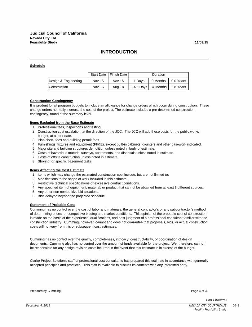
07-5December 4, 2015 NEVADA CITY COURTHOUSEFacility Feasibility Study
Cost Estimates
Judicial Council of CaliforniaNevada City, CAFeasibility Study 11/09/15
INTRODUCTION
Start Date Finish Date
Design & Engineering Nov-15 Nov-15 -1 Days 0 Months 0.0 Years
Construction Nov-15 Aug-18 1,025 Days 34 Months 2.8 Years
1 Professional fees, inspections and testing.2
3 Plan check fees and building permit fees.45 Major site and building structures demolition unless noted in body of estimate.6 Costs of hazardous material surveys, abatements, and disposals unless noted in estimate.7 Costs of offsite construction unless noted in estimate.8 Shoring for specific basement tasks
Items Affecting the Cost Estimate1 Items which may change the estimated construction cost include, but are not limited to:2 Modifications to the scope of work included in this estimate.3 Restrictive technical specifications or excessive contract conditions.4 Any specified item of equipment, material, or product that cannot be obtained from at least 3 different sources.5 Any other non-competitive bid situations.6 Bids delayed beyond the projected schedule.
Furnishings, fixtures and equipment (FF&E), except built-in cabinets, counters and other casework indicated.
Construction cost escalation, at the direction of the JCC. The JCC will add these costs for the public works budget, at a later date.
Schedule
Cumming has no control over the cost of labor and materials, the general contractor’s or any subcontractor’s method of determining prices, or competitive bidding and market conditions. This opinion of the probable cost of construction is made on the basis of the experience, qualifications, and best judgment of a professional consultant familiar with the construction industry. Cumming, however, cannot and does not guarantee that proposals, bids, or actual construction costs will not vary from this or subsequent cost estimates.
Clarke Project Solution's staff of professional cost consultants has prepared this estimate in accordance with generally accepted principles and practices. This staff is available to discuss its contents with any interested party.
Duration
Construction Contingency
Items Excluded from the Base Estimate
Statement of Probable Cost
Cumming has no control over the quality, completeness, intricacy, constructability, or coordination of design documents. Cumming also has no control over the amount of funds available for the project. We, therefore, cannot be responsible for any design revision costs incurred in the event that this estimate is in excess of the budget.
It is prudent for all program budgets to include an allowance for change orders which occur during construction. Thesechange orders normally increase the cost of the project. The estimate includes a pre-determined construction contingency, found at the summary level.
Prepared by Cumming Page 4 of 32

07-6 NEVADA CITY COURTHOUSE December 4, 2015Facility Feasibility Study
Cost Estimates
Judicial Council of CaliforniaNevada City, CAFeasibility Study 11/09/15
INTRODUCTION
It is recommended that further cost estimates be prepared throughout design by Cumming to determine overall cost changes subsequent to the preparation of this preliminary estimate. These future estimates will have detailed breakdowns indicating materials by type, kind, and size, priced by their respective units of measure.
Cumming recommends that the Owner and the Architect carefully review this entire document to insure that it reflects their design intent. Requests for modifications of any apparent errors or omissions to this document must be made to Cumming within ten days of receipt of this estimate, otherwise, it will be understood that the contents have been concurred with and accepted. If the project is over budget, or there are unresolved budgeting issues, alternate systems/schemes should be evaluated before proceeding into further design phases.
Recommendations for Cost Control
Prepared by Cumming Page 5 of 32

07-7December 4, 2015 NEVADA CITY COURTHOUSEFacility Feasibility Study
Cost Estimates
Nevada City Courthouse Renovation & ExpansionNevada City, CAFeasibility Study 11/9/15
Element Subtotal Total Cost / SF
Site Development $1,266,845 $16Site Preparation and Demolition $173,090 $2Site Paving, Structures and Landscaping $569,955 $7Site Utilities $138,800 $2Site Electrical $385,000 $5
Building $29,073,752 $364Superstructure and Shell $8,756,901 $110Interiors $7,668,277 $96Equipment and Vertical Transport $1,573,743 $20Mechanical and Electrical $11,074,831 $139
SUBTOTAL - HARD CONSTRUCTION COST $30,340,597 $380
Design Contingency $4,551,089
SUBTOTAL - DIRECT COST $34,891,686 $437
CM Contingency $1,046,751General Conditions $3,593,844Bond and Insurance $790,646Contractor OH & Fee $1,512,110Owner Contingency $2,928,452Phasing $895,270
SUBTOTAL - CONSTRUCTION BUDGET COST $45,658,758 $572
FF&E Budget (based on Yuba City Courthouse) $2,250,000IT Budget $1,470,965
SUBTOTAL - FF&E & IT COST $49,379,723 $619
Purchase County equity - June 2011 value + 20% $3,057,600Acquisition soft costs $987,594Design Fees $4,937,972Inspection/Testing/Comissioning/CM $1,975,189Temporary Rood Modular Facility $124 23,534 sf $2,918,216
SUBTOTAL - FF&E & IT COST $63,256,295 $793
$63,256,295
Escalation MPOC (4/4/17) $3,275,917
SUBTOTAL - ESCALATION $66,532,211
$66,532,211
Owner's Construction Cost Summary
2.00%10.00%
15.00%
TOTAL ESCALATED PROJECT COST
7.17%
3.00%
7.00%
TOTAL PROJECT COST
2.00%
4.00%10.00%
3.75%
2.00%
Prepared by Cumming Page 6 of 32

07-8 NEVADA CITY COURTHOUSE December 4, 2015Facility Feasibility Study
Cost Estimates
Palo Alto Public Safety BuildingPalo Alto, CaliforniaRough Order of Magnitude Rev2
Schedule of Areas and Control Quantities
Prepared by Page 9 of 18
Judicial Council of CaliforniaNevada City, CAFeasibility Study 11/09/15
Element Area Cost / SF Total
A10 Foundations $230.50 $1,940,780
B10 Superstructure $172.78 $1,454,786
B20 Exterior Closure $560.76 $4,721,616
B30 Roofing $75.98 $639,719
C10 Interior Construction $575.32 $4,844,225
C20 Staircases $42.52 $358,000
C31 Interior Finishes $292.88 $2,466,051
D10 Conveying Systems $106.89 $900,000
D20 Plumbing $142.14 $1,196,797
D30 HVAC $405.19 $3,411,708
D40 Fire Protection $51.19 $431,001
D50 Electrical $436.40 $3,674,468
D55 Low Voltage $280.39 $2,360,858
E10 Equipment
E20 Furnishings $80.02 $673,743
G10 Site Preparation $20.56 $173,090
G20 Site Improvements $67.69 $569,955
G30 Site Civil / Mechanical Utilities $16.48 $138,800
G40 Site Electrical $45.72 $385,000
G90 General requirements
ESTIMATED TOTAL CURRENT COSTS: 8,420 SF $3,603.40 $30,340,597
PROJECT COST SUMMARY - UNIFORMAT
Prepared by Cumming Page 7 of 32

07-9December 4, 2015 NEVADA CITY COURTHOUSEFacility Feasibility Study
Cost Estimates
Judicial Council of CaliforniaNevada City, CAFeasibility Study 11/09/15
Element Area Cost / SF Total
A Renovation and Expansion Courthouse 79,815 $364.26 $29,073,752
Courthouse 79,815 $364.26 $29,073,752
B Sitework 13,000 $97.45 $1,266,845
Site Development 13,000 $13.31 $173,090
Site Improvements 13,000 $84.14 $1,093,755
TOTAL ESTIMATED CONSTRUCTION COST 79,815 SF $380.14 / SF $30,340,597
CONSTRUCTION COST SUMMARY
Courthouse96%
Site Development0%
Site Improvements4%
Prepared by Cumming Page 8 of 32

07-10 NEVADA CITY COURTHOUSE December 4, 2015Facility Feasibility Study
Cost Estimates
Construction Cost Summary by SystemFeasibility Study 11/09/15
Sitework TOTAL
CSI Category 79,815 SF 13,000 SFTotal Cost/SF Total Cost/SF Total Cost/SF
1 General Requirements $304,815 $3.82 $0 $0.00 $304,815 $3.822 Existing Conditions $1,233,176 $15.45 $0 $0.00 $1,233,176 $15.453 Concrete $1,189,733 $14.91 $0 $0.00 $1,189,733 $14.914 Masonry $338,140 $4.24 $0 $0.00 $338,140 $4.245 Metals $1,310,489 $16.42 $0 $0.00 $1,310,489 $16.426 Wood, Plastics, & Composites $1,242,399 $15.57 $0 $0.00 $1,242,399 $15.577 Thermal & Moisture Protection $1,324,797 $16.60 $0 $0.00 $1,324,797 $16.608 Openings $3,083,821 $38.64 $0 $0.00 $3,083,821 $38.649 Finishes $6,399,307 $80.18 $0 $0.00 $6,399,307 $80.1810 Specialties $542,969 $6.80 $0 $0.00 $542,969 $6.8011 Equipment $0 $0.00 $0 $0.00 $0 $0.0012 Furnishings $129,274 $1.62 $0 $0.00 $129,274 $1.6213 Special Construction $0 $0.00 $0 $0.00 $0 $0.0014 Conveying Equipment $900,000 $11.28 $0 $0.00 $900,000 $11.2821 Fire Suppression $431,001 $5.40 $0 $0.00 $431,001 $5.4022 Plumbing $1,196,797 $14.99 $0 $0.00 $1,196,797 $14.9923 HVAC $3,411,708 $42.75 $0 $0.00 $3,411,708 $42.7526 Electrical $2,996,040 $37.54 $385,000 $29.62 $3,381,040 $42.3627 Communications $678,428 $8.50 $0 $0.00 $678,428 $8.5028 Electronic Safety & Security $2,360,858 $29.58 $0 $0.00 $2,360,858 $29.5831 Earthwork $0 $0.00 $173,090 $13.31 $173,090 $2.1732 Exterior Improvements $0 $0.00 $569,955 $43.84 $569,955 $7.1433 Utilities $0 $0.00 $138,800 $10.68 $138,800 $1.74
Subtotal Subcontractors Cost $29,073,752 $364.26 $1,266,845 $97.45 $30,340,597 $380.14
General Conditions See Summary $0.00 $0.00 $0 $0.00Bonds & Insurance See Summary $0.00 $0.00 $0 $0.00General Contractor Fee See Summary $0.00 $0.00 $0 $0.00Design Contingency See Summary $0.00 $0.00 $0 $0.00Escalation to MOC, 04/04/17 See Summary $0.00 $0.00 $0 $0.00
TOTAL CONSTRUCTION COST $29,073,752 $364.26 $1,266,845 $97.45 $30,340,597 $380.14
Judicial Council of California
79,815 SF
Renovation and Expansion Courthouse
Prepared by Cumming Page 9 of 32
07-11December 4, 2015 NEVADA CITY COURTHOUSEFacility Feasibility Study
Cost Estimates
Judicial Council of CaliforniaNevada City, CAFeasibility Study
Schedule of Areas and Control Quantities
Prepared by Cumming Page 10 of 32

07-12 NEVADA CITY COURTHOUSE December 4, 2015Facility Feasibility Study
Cost Estimates
Judicial Council of CaliforniaSchedule of Areas and Control QuantitiesFeasibility Study 11/09/15
Schedule of Areas Courthouse Renovation Addition
1. Enclosed Areas (x 100%)
Basement 17,990 17,990 - Level 1 28,650 24,580 4,070Level 2 25,260 22,880 2,380Level 3 7,915 5,945 1,970
Total Enclosed 79,815 71,395 8,420
2. Unenclosed Areas
Vehicular Sallyport (incl. above) 1,040 1,040 -Judicial Parking (incl. above) 4,000 4,000 -Roof deck 400 400Exterior courtyard 1580 1,580
Total Unenclosed
Total Gross Floor Area 79,815 71,395 8,420
Control Quantities Courthouse QTY
1.0 BasisGross Area 79815 sf 79,815 sfEnclosed Area 79815 sf 79,815 sfTotal Site Area 41,650 sfFinished Site Area 13,000 sf
Prepared by Cumming Page 11 of 32

07-13December 4, 2015 NEVADA CITY COURTHOUSEFacility Feasibility Study
Cost Estimates
Judicial Council of CaliforniaNevada City, CAFeasibility Study
Renovation and Expansion Courthouse
Prepared by Cumming Page 12 of 32

07-14 NEVADA CITY COURTHOUSE December 4, 2015Facility Feasibility Study
Cost Estimates
Judicial Council of CaliforniaRenovation And Expansion Courthouse Summary by SystemFeasibility Study 11/09/15
1 Courthouse TOTAL
CSI CategoryTotal Cost/SF Total Cost/SF
1 General Requirements $304,815 $3.82 $304,815 $3.822 Existing Conditions $1,233,176 $15.45 $1,233,176 $15.453 Concrete $1,189,733 $14.91 $1,189,733 $14.914 Masonry $338,140 $4.24 $338,140 $4.245 Metals $1,310,489 $16.42 $1,310,489 $16.426 Wood, Plastics, & Composites $1,242,399 $15.57 $1,242,399 $15.577 Thermal & Moisture Protection $1,324,797 $16.60 $1,324,797 $16.608 Openings $3,083,821 $38.64 $3,083,821 $38.649 Finishes $6,399,307 $80.18 $6,399,307 $80.1810 Specialties $542,969 $6.80 $542,969 $6.8011 Equipment12 Furnishings $129,274 $1.62 $129,274 $1.6213 Special Construction14 Conveying Equipment $900,000 $11.28 $900,000 $11.2821 Fire Suppression $431,001 $5.40 $431,001 $5.4022 Plumbing $1,196,797 $14.99 $1,196,797 $14.9923 HVAC $3,411,708 $42.75 $3,411,708 $42.7526 Electrical $2,996,040 $37.54 $2,996,040 $37.5427 Communications $678,428 $8.50 $678,428 $8.5028 Electronic Safety & Security $2,360,858 $29.58 $2,360,858 $29.5831 Earthwork32 Exterior Improvements33 Utilities34 Transportation
Subtotal Subcontractors Cost 29,073,752$ $364.26 $29,073,752 $364.26
General Conditions See SummaryBonds & Insurance See SummaryGeneral Contractor Fee See SummaryDesign Contingency See SummaryEscalation to MOC, 04/04/17 See Summary
TOTAL CONSTRUCTION COST $29,073,752 $364.26 $29,073,752 $364.26
79,815 SF79,815 SF
Prepared by Cumming Page 13 of 32

07-15December 4, 2015 NEVADA CITY COURTHOUSEFacility Feasibility Study
Cost Estimates
Judicial Council of CaliforniaRenovation and Expansion CourthouseNevada City, CAFeasibility Study 11/09/15
Element Total Cost / SF
1 General Requirements $304,815 $3.82
2 Existing Conditions $1,233,176 $15.45
3 Concrete $1,189,733 $14.91
4 Masonry $338,140 $4.24
5 Metals $1,310,489 $16.42
6 Wood, Plastics, & Composites $1,242,399 $15.57
7 Thermal & Moisture Protection $1,324,797 $16.60
8 Openings $3,083,821 $38.64
9 Finishes $6,399,307 $80.18
10 Specialties $542,969 $6.80
11 Equipment12 Furnishings $129,274 $1.62
13 Special Construction14 Conveying Equipment $900,000 $11.28
21 Fire Suppression $431,001 $5.40
22 Plumbing $1,196,797 $14.99
23 HVAC $3,411,708 $42.75
26 Electrical $2,996,040 $37.54
27 Communications $678,428 $8.50
28 Electronic Safety & Security $2,360,858 $29.58
31 Earthwork32 Exterior Improvements33 Utilities34 Transportation
TOTAL ESTIMATED CONSTRUCTION COST $29,073,752 $364.26
Total Area: 79,815 SF
PROJECT SUMMARY - Courthouse
Prepared by Cumming Page 14 of 32

07-16 NEVADA CITY COURTHOUSE December 4, 2015Facility Feasibility Study
Cost Estimates
Judicial Council of CaliforniaRenovation and Expansion CourthouseNevada City, CAFeasibility Study 11/09/15
DETAIL ELEMENTS - Courthouse
Element Quantity Unit Unit Cost Total
1 General RequirementsFinal clean interior and exterior 79,815 sf $1.00 $79,815Scaffolding around the building 1 ls $200,000 $200,000Mock-up, in place on exterior skin 1 ls $25,000.00 $25,000
Total - General Requirements $304,815
2 Existing ConditionsRemove exercise yard 1 ls $100,000.00 $100,000Remove mechanical room 3,000 sf $20.00 $60,000Remove below grade mechanical spaces 2,000 sf $20.00 $40,000Demo southern connector 1,000 sf $20.00 $20,000Hazmat and Abatement allowance 1 ls $230,000.00 $230,000Remove exterior skin at annex 58,013 sf $3.00 $174,039Interior Demolition & exterior addition skin 174,039 sf $3.50 $609,137
Total - Existing Conditions $1,233,176
3 ConcreteMisc. Concrete Patch & Repair 79,815 sf $0.30 $23,945
Grade beams6'W x 3'D, new addition
Concrete, 4,000 psi 440 cy $215.00 $94,600Formwork 1,134 sf $15.00 $17,010Reinforcement, 180# / CY 79,200 lbs $1.20 $95,040Excavation 660 cy $50.00 $33,000Backfill 220 cy $20.00 $4,400Haul excess 440 cy $17.00 $7,480
6'W x 3'D, @ brace frameConcrete, 4,000 psi 48 cy $215.00 $10,248Formwork 1,134 sf $15.00 $17,010Reinforcement, 180# / CY 8,580 lbs $1.20 $10,296Excavation 72 cy $50.00 $3,575Backfill 24 cy $20.00 $477Haul excess 48 cy $17.00 $810
Cast-In-Place Concrete Columns, seismic 15 eaColumns shotcrete 68 cy $215.57 $14,755Fiber reinforced Polymer 4,000 sf $10.00 $40,000
Concrete SlabSlab On Grade, new areas 4,070
Concrete, 6" thick 83 cy $215.00 $17,825Reinforcement 2#/cy 8,140 lb $1.20 $9,768Edge form 1,202 lf $6.50 $7,813Vapor barrier 4,070 sf $0.25 $1,018Gravel base, 4" 4,070 sf $0.85 $3,460Sand base, 2" 4,070 sf $0.80 $3,256Slab finish 4,070 sf $0.30 $1,221
Prepared by Cumming Page 15 of 32

07-17December 4, 2015 NEVADA CITY COURTHOUSEFacility Feasibility Study
Cost Estimates
Judicial Council of CaliforniaRenovation and Expansion CourthouseNevada City, CAFeasibility Study 11/09/15
DETAIL ELEMENTS - Courthouse
Element Quantity Unit Unit Cost Total
Slab On Grade, replace 1/3 of the basement 5,000Concrete, 6" thick 102 cy $215.00 $21,898Reinforcement 2#/cy 10,000 lb $1.20 $12,000Edge form 750 lf $6.50 $4,875Vapor barrier 5,000 sf $0.25 $1,250Gravel base, 4" 5,000 sf $0.85 $4,250Sand base, 2" 5,000 sf $0.80 $4,000Slab finish 5,000 sf $0.30 $1,500Thickened SOG, 18" w x 18" D at CMU 56 cy $350.00 $19,603Concrete judges platforms & ramps, incl formwork, rebar 1,750 sf $35.00 $61,250Concrete service counter platforms & ramps, incl formwork, rebar 1,150 sf $35.00 $40,250
Concrete Decks infill in Metal decking4 1/2" conc. fill, incl reinforcement 8,420 sf $7.00 $58,940
Shotcrete wallsShotcrete walls, allow 6" thick in annex 7,341 sf $50.00 $367,050
MiscellaneousMiscellaneous concrete, allow 79,815 sf $1.50 $119,723
Cast-in-place concrete equipment / house keeping / walking pads 30 cy $300.00 $8,889Concrete curbs for HVAC, allow 125 lf $350.00 $43,750Concrete treads and landings 10 cy $350.00 $3,500
Total - Concrete $1,189,733
4 MasonryCMU
CMU, interior fully grouted precision block with rebar 16" O.C. 15,370 sf $22.00 $338,140
Total - Masonry $338,140
5 Metals
Structural SteelWF columns and beams, new addition 18#/sf 76 tn $4,200.00 $318,276Structural and seismic at the annex 65#/lf, braces frames allow 25 tn $4,500.00 $111,881Structural supports for stair and elevator openings 15 tn $4,500.00 $67,500Miscellaneous bolts, plates and connections, 20% 20 tn $3,900.00 $78,501Spray applied fireproofing to steel 136 tn $375.00 $50,914
Mechanical Screen WallsStructural tube steel, 8'H 9 tn $3,900.00 $34,087Miscellaneous bolts, plates and connections, 20% 2 tn $3,900.00 $6,817Corrogated metal panel, 4' H of panels 940 sf $35.00 $32,900
Metal Deck1.5-2" 18 GA metal deck 8,420 sf $5.50 $46,310Deck Edging, 16 Ga 835 lf $8.59 $7,173
Prepared by Cumming Page 16 of 32
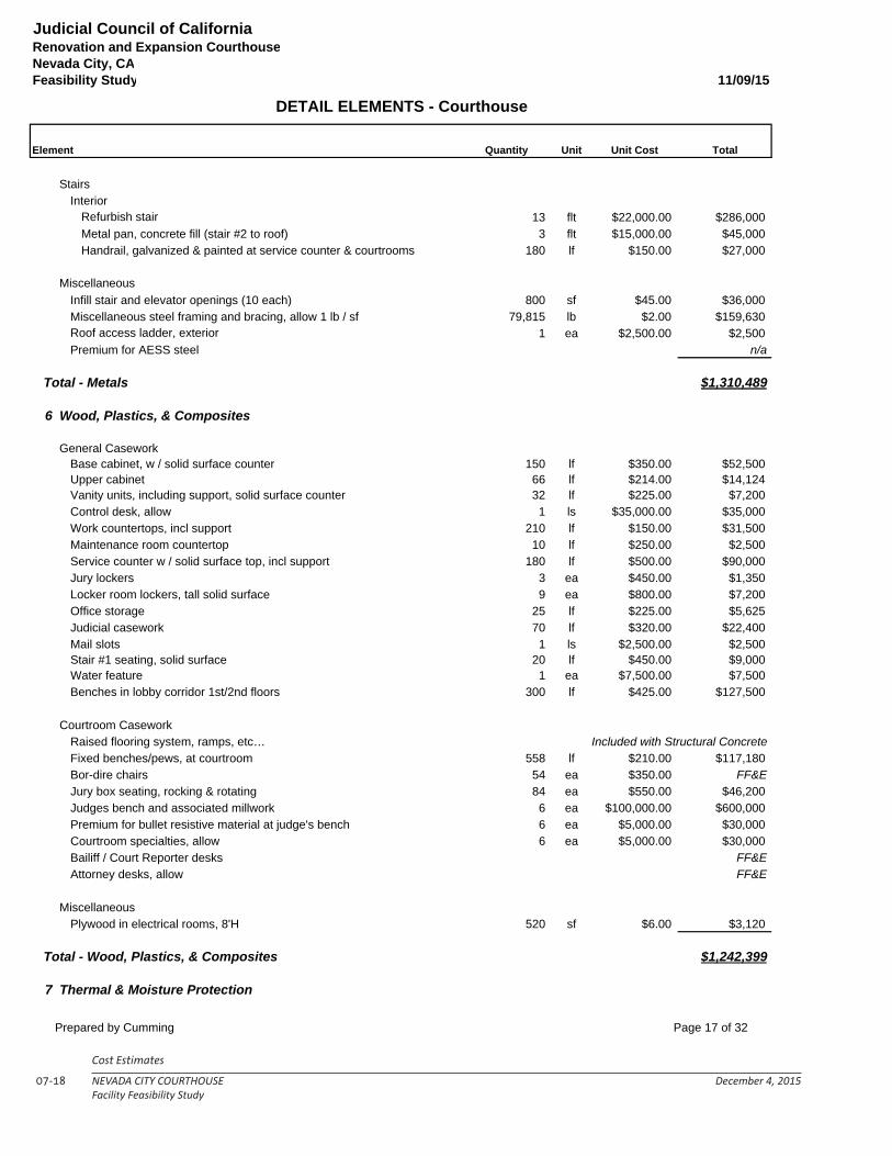
07-18 NEVADA CITY COURTHOUSE December 4, 2015Facility Feasibility Study
Cost Estimates
Judicial Council of CaliforniaRenovation and Expansion CourthouseNevada City, CAFeasibility Study 11/09/15
DETAIL ELEMENTS - Courthouse
Element Quantity Unit Unit Cost Total
StairsInterior
Refurbish stair 13 flt $22,000.00 $286,000Metal pan, concrete fill (stair #2 to roof) 3 flt $15,000.00 $45,000Handrail, galvanized & painted at service counter & courtrooms 180 lf $150.00 $27,000
MiscellaneousInfill stair and elevator openings (10 each) 800 sf $45.00 $36,000Miscellaneous steel framing and bracing, allow 1 lb / sf 79,815 lb $2.00 $159,630Roof access ladder, exterior 1 ea $2,500.00 $2,500Premium for AESS steel n/a
Total - Metals $1,310,489
6 Wood, Plastics, & Composites
General CaseworkBase cabinet, w / solid surface counter 150 lf $350.00 $52,500Upper cabinet 66 lf $214.00 $14,124Vanity units, including support, solid surface counter 32 lf $225.00 $7,200Control desk, allow 1 ls $35,000.00 $35,000Work countertops, incl support 210 lf $150.00 $31,500Maintenance room countertop 10 lf $250.00 $2,500Service counter w / solid surface top, incl support 180 lf $500.00 $90,000Jury lockers 3 ea $450.00 $1,350Locker room lockers, tall solid surface 9 ea $800.00 $7,200Office storage 25 lf $225.00 $5,625Judicial casework 70 lf $320.00 $22,400Mail slots 1 ls $2,500.00 $2,500Stair #1 seating, solid surface 20 lf $450.00 $9,000Water feature 1 ea $7,500.00 $7,500Benches in lobby corridor 1st/2nd floors 300 lf $425.00 $127,500
Courtroom CaseworkRaised flooring system, ramps, etc… Included with Structural ConcreteFixed benches/pews, at courtroom 558 lf $210.00 $117,180Bor-dire chairs 54 ea $350.00 FF&EJury box seating, rocking & rotating 84 ea $550.00 $46,200Judges bench and associated millwork 6 ea $100,000.00 $600,000Premium for bullet resistive material at judge's bench 6 ea $5,000.00 $30,000Courtroom specialties, allow 6 ea $5,000.00 $30,000Bailiff / Court Reporter desks FF&EAttorney desks, allow FF&E
MiscellaneousPlywood in electrical rooms, 8'H 520 sf $6.00 $3,120
Total - Wood, Plastics, & Composites $1,242,399
7 Thermal & Moisture Protection
Prepared by Cumming Page 17 of 32

07-19December 4, 2015 NEVADA CITY COURTHOUSEFacility Feasibility Study
Cost Estimates
Judicial Council of CaliforniaRenovation and Expansion CourthouseNevada City, CAFeasibility Study 11/09/15
DETAIL ELEMENTS - Courthouse
Element Quantity Unit Unit Cost Total
Exterior Sheathing1/2" Densdeck sheathing, at roof 28,650 sf $2.50 $71,6251/2" Densglass sheathing, at parapet 2,460 sf $2.50 $6,150
Roofing FinishesPVC single ply roofing system, 60 mil, at roof & insulation 28,650 sf $12.00 $343,800PVC single ply roofing system, 60 mil, at parapet 4' H avg. 2,460 sf $8.00 $19,680Roof pavers and waterproofing 400 sf $37.00 $14,800
FlashingFlashings and counter flashings 1,230 lf $35.00 $43,050Parapet cap system, pre-finished 1,230 lf $25.00 $30,750
WaterproofingWaterproof elevator pits 4 ea $1,500.00 $6,000Waterproof behind basement wall, grace 4000 existingWaterproof behind metal panels 11,603 sf $12.00 $139,231Waterproof metal and stucco soffits 18,984 sf $12.00 $227,807
Wall InsulationBatt insulation exterior wall- R19 unfaced 32,772 sf $1.00 $32,772Batt insulation interior walls- R11 unfaced 104,752 sf $0.85 $89,039Edge of slab, 2nd floor 1,230 lf $10.00 $12,300Head of wall at full height walls 5,108 lf $18.00 $91,944Additional sound attenuation, resilient channels, etc… 1 ls $10,000.00 $10,000
Ceiling InsulationAcoustic blanket above wood ceilings, black 4,800 sf $5.00 $24,000Spray foam for acoustics at basement ceiling 17,990 sf $1.50 $26,985
SkylightsSolar tubes 10 ea $2,500.00 $25,000
MiscellaneousRoof protection 28,650 sf $1.00 $28,650Expansion joints 155 lf $215.00 $33,325Rough carpentry, caulking and sealants 79,815 sf $0.60 $47,889
Total - Thermal & Moisture Protection $1,324,797
8 Openings
Exterior GlazingAluminum curtainwall window system, 10% allow 5,801 sf $110.00 $638,143Aluminum storefront, allow 15% 8,702 sf $95.00 $826,685Bullet resistant glazing system, 5% 2,901 sf $220.00 $638,143Metal louvers screen 75 sf $100.00 $7,500
Exterior Doors, Frames and HardwareAluminum Storefront Entries
Prepared by Cumming Page 18 of 32

07-20 NEVADA CITY COURTHOUSE December 4, 2015Facility Feasibility Study
Cost Estimates
Judicial Council of CaliforniaRenovation and Expansion CourthouseNevada City, CAFeasibility Study 11/09/15
DETAIL ELEMENTS - Courthouse
Element Quantity Unit Unit Cost Total
Single door, 3'-0" x 8'-0" 5 ea $4,500.00 $22,500Double door, 6'-0" x 8'-0" 2 ea $9,000.00 $18,000
HM Door in HM FrameSingle door, 3'-0" x 8'-0" 10 ea $1,900.00 $19,000Double door, 6'-0" x 8'-0" 1 ea $4,000.00 $4,000
PremiumsSpecialty hardware, openers, closers, etc. 1 ls $10,000.00 $10,000Paint finish 11 ea $115.00 $1,265
Interior GlazingSingle vision glazing, allow 500 sf $65.00 $32,500Sidelights at doors 960 sf $65.00 $62,400Lobby glass dividing wall 800 sf $75.00 $60,000Guardrail, 4' H glazed 100 lf $250.00 $25,000
Interior Doors, Frames and HardwareAluminum Storefront Entries
Double door, 6'-0" x 8'-0" 1 ea $7,500.00 $7,500Courtroom Entry Door
Double doors, 6'-0" x 8'-0" 11 ea $5,500.00 $60,500SC Wood Door in HM frame
Single door, 3'-0" x 8'-0" 146 ea $1,900.00 $277,400Double doors, 6'-0" x 8'-0" 2 ea $4,500.00 $9,000Half-height door, 2'-6" x 5'-0", at courtrooms 6 ea $1,200.00 $7,200Judicial closet doors, bifold 7 ea $1,200.00 $8,400
Secure Holding DoorSingle door, 3'-0" x 7'-0" 42 ea $6,000.00 $252,000
HM Door in HM FrameSingle door, 2'-6" x 8'-0", MEP closet 12 ea $1,400.00 $16,800
PremiumsPanic hardware 25 ea $1,000.00 $25,000Card reader 36 ea $350.00 $12,600Rated door, 90 minute 6 ea $135.00 $810Premium for acoustical doors, per leaf 42 ea $500.00 $21,000Paint finish doors and frame 54 ea $150.00 $8,100Paint finish frames 165 ea $75.00 $12,375
Total - Openings $3,083,821
9 Finishes
Exterior wall framingMetal stud framing, 8", 16 Ga. at 16" O.C. 31,907 sf $18.00 $574,329Parapet wall 800 sf $18.00 $14,400
Exterior FinishPrecast concrete panel, 20% allow 11,603 sf $65.00 $754,169Stucco, 25% allow 14,503 sf $17.00 $246,555Stone veneer , 10% 5,801 sf $30.00 $174,039Paint existing skin, 15% 8,702 sf $3.00 $26,106
Prepared by Cumming Page 19 of 32

07-21December 4, 2015 NEVADA CITY COURTHOUSEFacility Feasibility Study
Cost Estimates
Judicial Council of CaliforniaRenovation and Expansion CourthouseNevada City, CAFeasibility Study 11/09/15
DETAIL ELEMENTS - Courthouse
Element Quantity Unit Unit Cost Total
Paint stucco 14,503 sf $1.50 $21,755Miscellaneous trim, fascia's, ornamentation, etc… 1 ls $15,000.00 $15,000
Exterior Trellis / SoffitsStucco soffit and framing 1,580 sf $30.00 $47,400
Interior Finish to Exterior wallsGypsum board finish, taped, sanded and painted 31,907 sf $4.00 $127,629Ballistic drywall premium, allow 1 ls $7,500.00 $7,500
Interior PartitionsFraming
2" steel wall at holding cells, detention grade grout walls 6,820 sf $45.00 $306,9003 5/8" metal stud framing, 18GA, 16" O.C., standard 12,300 sf $8.00 $98,4006" metal stud framing, 18GA, 16" O.C., standard 44,024 sf $8.25 $363,1984" metal stud framing, 18GA, 16" O.C., shaft walls 6,992 sf $9.00 $62,9283 5/8" Furred walls 37,376 sf $7.75 $289,664Welded headed studs @12"OC 4,356 ea $3.00 $13,068
Partition SurfacingGypsum board finish, taped, sanded and painted 184,108 sf $4.00 $736,432Gypsum board finish, unfinished - sf $1.551" thick coreboard at shaft walls 6,992 sf $6.00 $41,952Backer board at tile walls 5,680 sf $5.00 $28,400
MiscellaneousMiscellaneous backing, blocking and bracing 79,815 sf $0.50 $39,908
Floor FinishesPorcelain tile at lobby/corridors 10,100 sf $20.00 $202,000Porcelain tile bathrooms 3,590 sf $18.00 $64,620Sealed concrete 11,300 sf $1.75 $19,775Protect existing flooring 10,000 sf $3.50 $35,000Carpet tile 40,260 sf $5.00 $201,300Carpet tile- judicial chamber 1,800 sf $6.00 $10,800LVT 1,100 sf $7.50 $8,250VCT 815 sf $3.75 $3,056Static VCT 850 sf $6.00 $5,100Vapor barrier for carpet and resilient flooring, Koster n/aRaised access flooring n/a
BaseRubber base, 4" reveal 12,826 lf $3.50 $44,891Rubber base, 6" reveal 2nd floor corridor and judicial chamber 681 lf $4.50 $3,065Porcelain tile base 250 lf $10.00 $2,500
Wall FinishesWall tile window sill cap, aluminum cap & brackets 272 sf $35.00 $9,520Ceramic wall tile, 4' wainscot at unisex & judicial restrooms 1,280 sf $16.00 $20,480Ceramic wall tile, 8'H, at public restrooms 5,680 sf $16.00 $90,880PLAM at lobby service counter 11'H 550 sf $30.00 $16,500
Prepared by Cumming Page 20 of 32

07-22 NEVADA CITY COURTHOUSE December 4, 2015Facility Feasibility Study
Cost Estimates
Judicial Council of CaliforniaRenovation and Expansion CourthouseNevada City, CAFeasibility Study 11/09/15
DETAIL ELEMENTS - Courthouse
Element Quantity Unit Unit Cost Total
PLAM at courtroom entrance 8'H 480 sf $30.00 $14,400Wood paneling at courtrooms 3,000 sf $46.00 $138,000Wood paneling, silent wall, deacoustics 453 sf $50.00 $22,650Fabric wrapped acoustic panel, 2" thick 4'H 1,600 sf $40.00 $64,000Courtroom entry door frame, marble 192 sf $25.00 $4,800Vinyl panel 48" wainscot at jury deliberation restrooms 360 sf $15.00 $5,400Fabric wrapped acoustical panels 7' H wainscot 420 sf $12.00 $5,040FRP-1, 8'H janitors rooms 288 sf $10.00 $2,880Paint at walls 152,580 sf $1.10 $167,838Premium to Scuff master paint in corridors 15,000 sf $3.00 $45,000Enhanced wall finishes, at courtrooms 1 ls $25,000.00 $25,000
Ceiling FinishesACT 2'x 4' x 3/4", lay-in 39,000 sf $7.50 $292,500Metal wood-look suspended ceiling 4,800 sf $40.00 $192,000Translucent 2x4' panels 500 sf $50.00 $25,000Metal ceiling panels at holding cells 6,400 sf $30.00 $192,000Gypsum board ceilings & framing 22,365 sf $14.00 $313,110Gypsum board vertical soffits, incl framing 3,245 sf $15.00 $48,675Paint gyp ceiling 25,610 sf $1.20 $30,732Paint to underside of exposed structure and stair 1,200 sf $2.50 $3,000Exposed structure 5,550 sf Not Required
MiscellaneousInterior finishes, allowance 79,815 sf $1.00 $79,815
Total - Finishes $6,399,307
10 Specialties
Wall ProtectionCorner guards and wall protection 1 ls $15,000.00 $15,000
7 Fire Extinguishers & cabinets8 Fire extinguisher, semi recessed 16 ea $375.00 $6,000
Toilet SpecialtiesToilet partitions
Standard, assume pheonolic 30 ea $1,300.00 $39,000ADA, assume pheonolic 10 ea $1,500.00 $15,000Urinal screens, assume solid surface 6 ea $800.00 $4,800
Toilet accessories, per toilet 40 ea $640.00 $25,600Restroom accessories, single user 12 ea $1,500.00 $18,000Stainless steel shelf 40 lf $35.00 $1,400Grab bars 44 ea $250.00 $11,000
General Building SpecialtiesInterior signage and directories, code required 79,815 sf $1.25 $99,769LED signs above public counter windows 6 ea $2,500.00 $15,000Interior court name signage 1 ea $15,000.00 $15,000
Prepared by Cumming Page 21 of 32

07-23December 4, 2015 NEVADA CITY COURTHOUSEFacility Feasibility Study
Cost Estimates
Judicial Council of CaliforniaRenovation and Expansion CourthouseNevada City, CAFeasibility Study 11/09/15
DETAIL ELEMENTS - Courthouse
Element Quantity Unit Unit Cost Total
Exterior building signage 1 ls $25,000.00 $25,000Janitor's shelf and mop rack 2 ea $400.00 $800Knox box, surface mount 1 ea $1,500.00 $1,500Active file storage, high density 1 ls $85,000.00 $85,000Marker boards, 5'-0" x 10'-0", allow 8 ea $1,200.00 $9,600Recessed entrance mats 100 sf $125.00 $12,500TV mounts rotating and 50" TV 4 ea $4,000.00 $16,000Qmatic System 1 ea $65,000.00 $65,000Jury assembly seating, at jury assembly FF&EWalk through metal detectors FF&EX-ray machines FF&ERefigerator in breakrooms 2 ea $1,500.00 $3,000
Detention SpecialtiesBenches, Holding Cells 120 lf $300.00 $36,000Miscellaneous detention specialties 1 ls $15,000.00 $15,000Evidence lockers 5 ea $10,000.00 FF&EEvidence lockers, refirgerated - ea $16,000.00 n/aGun lockers 2 ea $4,000.00 $8,000
Total - Specialties $542,969
12 Furnishings
Window CoveringRoller shades, motorized surface mount with fascia 3,626 sf $20.00 $72,516Horizontal fabric manual shades, surface mount 3,626 sf $10.00 $36,258Horizontal fabric manual shades, clerk window 6 ea $250.00 $1,500Projection screens in courtrooms, ceiling mount 5 ea $3,000.00 $15,000Projection screens in conference rooms, surface mt. 2 ea $2,000.00 $4,000
Total - Furnishings $129,274
14 Conveying Equipment
ElevatorsRefurbish and new elevator 12 stp $75,000.00 $900,000
Total - Conveying Equipment $900,000
21 Fire Suppression
Wet-pipe sprinklers, schedule 40 79,815 sf $5.40 $431,001
Total - Fire Suppression $431,001
22 PlumbingDemo Plumbing 79,815 sf $1.00 $79,815Plumbing
Waste and Vent 79,815 sf $2.64 $210,712Domestic Hot & Cold Water 79,815 sf $4.96 $395,882
Prepared by Cumming Page 22 of 32

07-24 NEVADA CITY COURTHOUSE December 4, 2015Facility Feasibility Study
Cost Estimates
Judicial Council of CaliforniaRenovation and Expansion CourthouseNevada City, CAFeasibility Study 11/09/15
DETAIL ELEMENTS - Courthouse
Element Quantity Unit Unit Cost Total
Natural Gas 6,837 sf $3.66 $25,023Storm Drainage 79,815 sf $1.04 $83,008Condensate Drainage 1,600 lf $21.40 $34,240Detention Toilets 20 ea $733.40 $14,668
Complete rough-in per fixture 20 ea $1,783.00 $35,660ADA WC's 10 ea $1,162.00 $11,620
Complete rough-in per fixture 10 ea $1,783.00 $17,830Public WC's 13 ea $943.30 $12,263
Complete rough-in per fixture 13 ea $1,783.00 $23,179Public Urinals 12 ea $716.90 $8,603
Complete rough-in per fixture 12 ea $1,783.00 $21,396Public Lav's 21 ea $1,670.00 $35,070
Complete rough-in per fixture 21 ea $1,783.00 $37,443Casework Sinks 5 ea $837.70 $4,189
Complete rough-in per fixture 5 ea $1,783.00 $8,915Miscellaneous Plumbing 79,815 sf $1.72 $137,282
Total - Plumbing $1,196,797
23 HVACHVAC Demo
Demo and relocate 100-ton existing chiller 1 ea $20,000.00 $20,000Demo and relocate existing HHW Boilers 2 ea $15,000.00 $30,000Remove ductwork & registers 79,815 sf $1.29 $102,961
HVACVRF heat pump equip w/ HR 30 ton $3,485.00 $104,550Refrigerant piping for VRF heat pump system w/ HR 30 ton $1,387.00 $41,610New Cooling Tower 250 ton $258.90 $64,725New Cooling Tower Air Separator 1 ea $2,885.00 $2,885Cooling tower rough-in 2 ea $7,954.00 $15,908Condenser rough-in at pump 2 ea $2,441.00 $4,882Condenser piping to chiller 2 ea $5,768.00 $11,536New Chiller 150 ton $729.50 $109,425New Chiller Air Separator 1 ea $1,902.00 $1,902Chiller connect, weld 2 ea $4,037.00 $8,074CHW pump connect, weld, end suct 2 ea $3,602.00 $7,204CHW expansion tank, steel, diaphragm 1 ea $4,185.00 $4,185Exhaust Fans 15,970 cfm $1.71 $27,309Air Handlers 103,760 cfm $5.63 $584,169New Boiler 1,500.00 mbh $29.24 $43,860New Boiler Air Separator 1 ea $1,704.00 $1,704HW expansion tank, steel, diaphragm 1 ea $4,185.00 $4,185Boiler stack, 10" 40 lf $150.60 $6,024HW rough-in at boiler 2 ea $4,539.00 $9,078HW rough-in at pump, 2" 2 ea $1,576.00 $3,152New Secondary & Primary Pumps - 10HP 6 ea $7,095.00 $42,570VFD to HW pump, 10 hp 6 ea $3,676.00 $22,056New 100% OSA Unit for Holding Areas 6,000 cfm $5.63 $33,780New 100% Exhaust Unit for Holding Areas 6,000 cfm $1.71 $10,260VAV Boxes w/Reheat Coils & Attenuator 80 ea $597.60 $47,808
Prepared by Cumming Page 23 of 32

07-25December 4, 2015 NEVADA CITY COURTHOUSEFacility Feasibility Study
Cost Estimates
Judicial Council of CaliforniaRenovation and Expansion CourthouseNevada City, CAFeasibility Study 11/09/15
DETAIL ELEMENTS - Courthouse
Element Quantity Unit Unit Cost Total
3/4" VAV/CV coil conn assembly 80 ea $647.00 $51,760Air Distribution - Supply 439 ea $153.30 $67,299Air Distribution - Return 220 ea $143.70 $31,614Supply & Return Ductwork 71,834 lb $6.57 $471,949Insulation Wrap 95,000 sf $2.17 $206,150Insulation Liner 4,500 sf $2.52 $11,340CHW Piping 79,815 sf $0.99 $79,017HHW Piping 79,815 sf $3.77 $300,903Combination fire / smoke damper 80 ea $743.10 $59,448DDC controls, controls workstation 1 ls $22,890.00 $22,890DDC controls 79,815 sf $3.44 $274,564Test / balance / firestopping / misc. 79,815 sf $1.79 $142,869
Start-up/check-out 120 hr $74.05 $8,886Commissioning assist 160 hr $74.05 $11,848MEP Coordination 200 hr $74.05 $14,810BIM Modeling 280 hr $74.05 $20,734Pressure testing (piping) 35 ea $844.20 $29,547Duct leakage testing 35 ea $1,266.00 $44,310Seismic bracing 79,815 sf $0.33 $26,339Hoisting and rigging 2 ls $5,000.00 $10,000Premium for Phasing 79,815 sf $2.00 $159,630
Total - HVAC $3,411,708
26 Electrical
Normal Service and Distribution 79,815 sf $7.00 $558,705
HVAC and Equipment Connections 79,815 sf 2.30 $183,575
Lighting and Lighting Control Light fixtures 79,815 sf $12.00 $957,780Lighting conduit and cable 79,815 sf $4.99 $398,277Lighting Controls 79,815 sf $2.50 $199,538
Convenience Power 79,815 sf 5.75 $458,936
MiscellaneousSeismic braces and supports 8,420 gsf 0.35 $2,947Fire stopping and seals 79,815 gsf 0.22 $17,559Temporary power 1 ls 24,500.00 $24,500Electrical general conditions and cad 3D 1 ls 194,223.77 $194,224
Total - Electrical $2,996,040
27 Communications
Telephone / data communication system conduit / cable 79,815 sf $6.50 $518,798
Prepared by Cumming Page 24 of 32

07-26 NEVADA CITY COURTHOUSE December 4, 2015Facility Feasibility Study
Cost Estimates
Judicial Council of CaliforniaRenovation and Expansion CourthouseNevada City, CAFeasibility Study 11/09/15
DETAIL ELEMENTS - Courthouse
Element Quantity Unit Unit Cost Total
AV System (Rough Conduit and Boxes Only) Allowance 79,815 sf $2.00 $159,630
Total - Communications $678,428
28 Electronic Safety & Security
Special Electrical SystemsFire alarm system 79,815 sf $4.00 $319,260
Security System, PA Systems Rough Conduit Only OFCI 79,815 sf $3.98 $317,664
Security systems equipment, cable allowance 79,815 gsf $9.00 $718,335Assistive listening system 79,815 gsf $0.40 $31,926DAS Radio antenna system 79,815 gsf $0.20 $15,963CATV system (rough conduit) 79,815 gsf $0.42 $33,522AV contractor equipment, labor & cable and install 1 ls $761,823 $761,823Electrical Contractor markup and labor, management of AV 20% allow 1 ls $152,364.60 $152,365Electric window shades controls and switches, excludes EMS 20 ea $500.00 $10,000
Total - Electronic Safety & Security $2,360,858
Prepared by Cumming Page 25 of 32

07-27December 4, 2015 NEVADA CITY COURTHOUSEFacility Feasibility Study
Cost Estimates
Judicial Council of CaliforniaNevada City, CAFeasibility Study
Sitework
Prepared by Cumming Page 26 of 32

07-28 NEVADA CITY COURTHOUSE December 4, 2015Facility Feasibility Study
Cost Estimates
Judicial Council of CaliforniaSitework Summary by SystemFeasibility Study 11/09/15
1 2 Site Development Site Improvements TOTAL
CSI CategoryTotal Cost/SF Total Cost/SF Total Cost/SF
1 General Requirements2 Existing Conditions3 Concrete4 Masonry5 Metals6 Wood, Plastics, & Composites7 Thermal & Moisture Protection8 Openings9 Finishes
10 Specialties11 Equipment12 Furnishings13 Special Construction14 Conveying Equipment21 Fire Suppression22 Plumbing23 HVAC26 Electrical $385,000 $29.62 $385,000 $29.6227 Communications28 Electronic Safety & Security31 Earthwork $173,090 $13.31 $173,090 $13.3132 Exterior Improvements $569,955 $43.84 $569,955 $43.8433 Utilities $138,800 $10.68 $138,800 $10.6834 Transportation
Subtotal Subcontractors Cost $173,090 $13.31 $1,093,755 $84.14 $1,266,845 $97.45
General Conditions See SummaryBonds & Insurance See SummaryGeneral Contractor Fee See SummaryDesign Contingency See SummaryEscalation to MOC, 04/04/17 See Summary
TOTAL CONSTRUCTION COST $173,090 $13.31 $1,093,755 $84.14 $1,266,845 $97.45
13,000 SF13,000 SF 13,000 SF
Prepared by Cumming Page 27 of 32

07-29December 4, 2015 NEVADA CITY COURTHOUSEFacility Feasibility Study
Cost Estimates
Judicial Council of CaliforniaSiteworkNevada City, CAFeasibility Study 11/09/15
Element Total Cost / SF
1 General Requirements2 Existing Conditions3 Concrete4 Masonry5 Metals6 Wood, Plastics, & Composites7 Thermal & Moisture Protection8 Openings9 Finishes
10 Specialties11 Equipment12 Furnishings13 Special Construction14 Conveying Equipment21 Fire Suppression22 Plumbing23 HVAC26 Electrical27 Communications28 Electronic Safety & Security31 Earthwork $173,090 $13.31
32 Exterior Improvements33 Utilities34 Transportation
TOTAL ESTIMATED CONSTRUCTION COST $173,090 $13.31
Total Area: 13,000 SF
PROJECT SUMMARY - Site Development
Prepared by Cumming Page 28 of 32

07-30 NEVADA CITY COURTHOUSE December 4, 2015Facility Feasibility Study
Cost Estimates
Judicial Council of CaliforniaSiteworkNevada City, CAFeasibility Study 11/09/15
DETAIL ELEMENTS - Site Development
Element Quantity Unit Unit Cost Total
31 Earthwork
DemolitionSawcut existing AC 1,000 lf $5.00 $5,000Remove existing concrete curb & sidewalk 13,000 sf $6.00 $78,000
EarthworkField staking / layout 13,000 sf $0.18 $2,340Clear and grub site 13,000 sf $0.25 $3,250Fine grading 13,000 sf $2.50 $32,500Erosion control & SWPPP maintenance 13,000 sf $4.00 $52,000
Total - Earthwork $173,090
32 Exterior ImprovementsSee Site Improvements
Total - Exterior Improvements
33 Utilities See Site Improvements
Total - Utilities
Prepared by Cumming Page 29 of 32

07-31December 4, 2015 NEVADA CITY COURTHOUSEFacility Feasibility Study
Cost Estimates
Judicial Council of CaliforniaSiteworkNevada City, CAFeasibility Study 11/09/15
Element Total Cost / SF
1 General Requirements2 Existing Conditions3 Concrete4 Masonry5 Metals6 Wood, Plastics, & Composites7 Thermal & Moisture Protection8 Openings9 Finishes
10 Specialties11 Equipment12 Furnishings13 Special Construction14 Conveying Equipment21 Fire Suppression22 Plumbing23 HVAC26 Electrical $385,000 $29.62
27 Communications28 Electronic Safety & Security31 Earthwork32 Exterior Improvements $569,955 $43.84
33 Utilities $138,800 $10.68
34 Transportation
TOTAL ESTIMATED CONSTRUCTION COST $1,093,755 $84.14
Total Area: 13,000 SF
PROJECT SUMMARY - Site Improvements
Prepared by Cumming Page 30 of 32

07-32 NEVADA CITY COURTHOUSE December 4, 2015Facility Feasibility Study
Cost Estimates
Judicial Council of CaliforniaSiteworkNevada City, CAFeasibility Study 11/09/15
DETAIL ELEMENTS - Site Improvements
Element Quantity Unit Unit Cost Total
26 ElectricalSite Electrical Systems
Site Distribution 1 LS $180,000.00 $180,000Generator, diesel 200 kW 480/277v 3ph 4w 1 ea $120,000.00 $120,000
Site Lighting and Control (work with some existing) 1 ls $25,000.00 $25,000
Site Telephone / Data Systems allowance if needed 1 ls $60,000.00 $60,000
Total - Electrical $385,000
31 EarthworkEarthwork See Site Development
Total - Earthwork
32 Exterior Improvements
AC Paving3" AC over 9" AB 2,500 sf $6.00 $15,000
HardscapeReinforced concrete paving incl base, assume 4" th, broom finish & thickened edge 13,000 sf $9.00 $117,000Concrete stairs and walls at entry, railings 1 ls $100,000.00 $100,000Concrete ramp, 4" and 4" AB (landscape area) 2,000 sf $12.00 $24,000
Concrete Curbs and RampsConcrete vertical curbs, assume 6" 250 lf $27.00 $6,750Truncated domes 270 sf $75.00 $20,250
Parking Lot Striping / SignageStandard stall, incl. basement 20 ea $30.00 $600ADA stall 7 ea $90.00 $630Red curb, 15% of curb allow 500 lf $10.00 $5,000Concrete wheel stops, allow at basement 10 ea $50.00 $500Directional signage 2,500 sf $0.25 $625ADA stall signage & post 7 ea $500.00 $3,500Hatched striping, allow 200 sf $5.00 $1,000
LandscapingLandscape area and irrigation 1,500 sf $8.00 $12,000Tree, 24" box 12 ea $450.00 $5,400Tree, existing protect 8 ea $150.00 $1,200
Fencing and GatesUpgrade entrance security gate 1 ls $10,000.00 $10,000Knox box on security gates 1 ea $1,500.00 $1,500
Site Walls and Structures
Prepared by Cumming Page 31 of 32

07-33December 4, 2015 NEVADA CITY COURTHOUSEFacility Feasibility Study
Cost Estimates
Judicial Council of CaliforniaSiteworkNevada City, CAFeasibility Study 11/09/15
DETAIL ELEMENTS - Site Improvements
Element Quantity Unit Unit Cost Total
Walls 200 lf $350.00 $70,000Granite Veneer 800 sf $75.00 $60,000
MiscellaneousMisc. site amenities 13,000 sf $5.00 $65,000Monument signage, incl footing 1 ls $50,000.00 $50,000
Total - Exterior Improvements $569,955
33 Utilities
Site UtilitiesFire Water
Water line, 10" pvc, incl t & bf 50 lf $90.00 $4,500Fire hydrants 2 ea $7,500.00 $15,000Fire Water 2 way FDC 1 ea $5,000.00 $5,000Connect to existing 1 ea $1,500.00 $1,500New Fire service riser & backflow preventer 1 ea $18,500.00 $18,500
Gas lineGas line 60 lf $80.00 $4,800Gas meter, allow <3 1 ea $5,000.00 $5,000
Domestic WaterWater line, 4" pvc, incl t & bf 10 lf $75.00 $750Connect to existing 1 ea $2,500.00 $2,500Domestic double detector backflow preventer 1 ea $8,500.00 $8,500
Irrigation WaterIrrigation line, 3" pvc, incl t & bf 50 lf $55.00 $2,750Connect to existing 1 ea $1,500.00 $1,500Irrigation reduced pressure detector detector assembly 1 ea $5,000.00 $5,000
Sanitary Sewer6" Sanitary sewer line, incl t & bf 50 lf $110.00 $5,500Connect to existing 1 ea $2,500.00 $2,500Cleanouts 2 ea $1,000.00 $2,000
Storm Drainage8" PVC pipe, incl t & bf 400 lf $65.00 $26,000Storm drain catch basin 5 ea $2,500.00 $12,500Storm drain area drain 5 ea $2,000.00 $10,000Connect to existing 2 ea $2,500.00 $5,000
Off site improvements, relocations and significant utility demolition Not Anticipated
Total - Utilities $138,800
Prepared by Cumming Page 32 of 32

07-34 NEVADA CITY COURTHOUSE December 4, 2015Facility Feasibility Study
Cost Estimates

PLACER
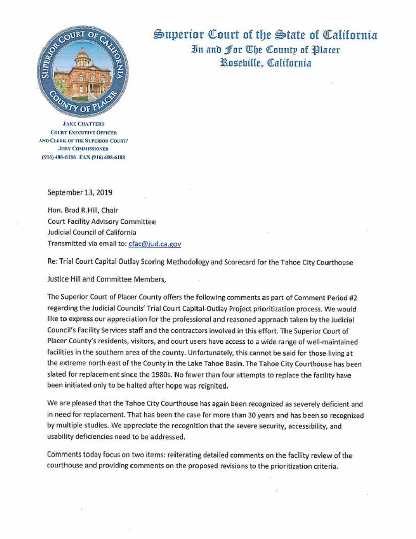
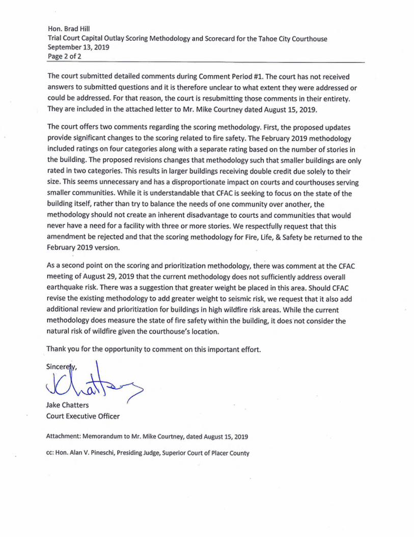


September 16, 2019 The Honorable Brad Hill, Chair Court Facility Advisory Committee Judicial Council of California Transmitted via email to: [email protected] RE: TRIAL COURT CAPITAL OUTLAY AND THE TAHOE CITY/BURTON CREEK COURTHOUSE Dear Justice Hill and Committee Members, Thank you for the opportunity to review and comment on the Court Facility Advisory Committee’s (CFAC) capital outlay prioritization process. As the Sheriff of Placer County, I am encouraged by the recognition that the Tahoe City Courthouse is in need of replacement. The existing facility is aged, does not offer the level of accessibility the community needs and deserves, and presents significant security concerns for court users, judicial officers, court staff, and court security personnel. While the CFAC acknowledges these conditions, I would encourage you to give additional consideration to two unique conditions at this location. First, replacement of the Tahoe City Sheriff’s Substation is one of my major priorities. Discussions are active and ongoing within Placer County government on this replacement project, including a review of capital outlay priorities by the Placer County Board of Supervisors in early-October. This presents a unique and timely opportunity for the Judicial Council. It remains my goal to co-locate our new substation with the courthouse, a goal that can only be accomplished if there is fast action to move the Tahoe City Courthouse project forward on the same timeline. A co-located facility would reduce construction costs by eliminating duplicate and high cost holding functions and preserve existing operational efficiencies. I encourage you to consider this significant opportunity as part of your scoring criteria for the Tahoe City Courthouse. Second, I would encourage the committee to consider the external fire risk at this location. The current location is in a heavily wooded area with a single egress point. In the event of a wild fire, this facility is an immediate concern. Including some level of external fire risk as part of your criteria, in addition to the internal fire control scoring you currently include, will be a critical component.
The Honorable Brad Hill, Chair TRIAL COURT CAPITAL OUTLAY AND THE TAHOE CITY/BURTON CREEK COURTHOUSE September 16, 2019 Page 2 of 2
Replacement of the Tahoe City Courthouse has been on our radar since the 1980s. It is time to recognize the replacement of this facility as an immediate need and to capitalize on the opportunity to co-locate a new courthouse with a new substation in the North Lake Tahoe basin. Thank you for your consideration. Sincerely, DEVON BELL Sheriff-Coroner-Marshal cc: Honorable Alan V. Pineschi, Presiding Judge, Superior Court of Placer County

RIVERSIDE

W. SAMUEL HAMRICK, JR.
Court Executive Officer
Superior Court of California County of Riverside
Executive Office
4050 Main Street
Riverside, CA 92501
Telephone 951-777-3173
Fax 951-777-3164
Via email
September 13, 2019 The Honorable Brad R. Hill, Chair Court Facilities Advisory Committee Judicial Council of California 455 Golden Gate Avenue San Francisco, CA 94102-3688 Re: Court Facility Plan and Capital Project Needs- Riverside Superior Court Dear Justice Hill, In our initial response to the Committee, we asked for reconsideration of the scoring for the “Access to Court Services” component of the prioritization methodology. At the Court Facilities Advisory Committee meeting on August 29, 2019, it was recommend that the “Access to Court Services” category be lowered. We strongly disagree with that recommendation and ask the committee to give equal standing to all five categories in the methodology. The Riverside Superior Court is a chronically under-judged court. Over the past several years, the Legislature and the Governor have taken several meaningful steps to address this issue. In September of 2017, Governor Brown and the Legislature approved the reallocation of two vacant judgeships from other counties to our court. In FY 2018/19, the Governor and the Legislature approved two new judgeships for Riverside. In the FY 2019/20 Budget, the Budget Act included twenty-five (25) new judgeships for the Judiciary. Based upon the Workload Assessment Advisory Committee’s 2018 Judicial Workload Study, the committee will be recommending that the Riverside Superior Court receive five new judgeships of the twenty-five approved by the Governor and the Legislature. We will continue to work with our Legislators and the Governor’s Office on providing new judgeships for the Riverside Superior Court, as there is clearly a history that the Governor and the Legislature want to address the need for additional judgeships in the State. Having added four new judges, with a potential for five more, in as little as three years compels us to consider the future space needs of new judgeships as part of our short-range and long-range facility plans. To do otherwise would be negligent. Even with these additional judgeships, Riverside remains chronically under-judged with a need of thirty-seven (37) judgeships. Therefore, we propose an alternative method for scoring the “Access to Court Services” category that, we believe, addresses access to justice and gives this category equal weight in the methodology:

As part of our review of the cost avoidance portion of the draft ranking, we note that the plan to use an existing courthouse design (Menifee Justice Center) was not considered as a cost avoidance item for the new Riverside Juvenile Courthouse, the new Palm Springs Courthouse and the new Moreno Valley Courthouse. Two of these projects scored a zero in cost avoidance. As the Menifee Justice Center is a JCC project, JCC staff would have access to the amount that would be saved by taking this approach. In addition, we identified the potential to relocate administrative staff out of lease space as part of the new Riverside Juvenile Courthouse project. This would eliminate leased space in Riverside at our 10th Avenue location and at the Riverside Center location.
Finally, for the overcrowding criteria, our new Moreno Valley Courthouse score for overcrowding was inappropriately tied to the Riverside Hall of Justice. The Riverside Hall of Justice is a criminal courthouse. The proposed new Moreno Valley Courthouse is anticipated to be a civil only courthouse. These are both stand alone projects. We appreciate being given the opportunity to provide feedback on this important endeavor. Sincerely, W. Samuel Hamrick, Jr. Court Executive Officer
Rating Assigned to Project
Judicial Need/Authorized Judicial Positions Points
Assigned
0 or below 0
1 to 5 judges needed 0.5
6 to 10 judges needed 1
11 to 15 judges needed 1.5
16 to 20 judges needed 2
21 to 25 judges needed 2.5
26 to 30 judges needed 3
31 to 35 judges needed 3.5
36 to 40 judges needed 4
41 to 45 judges needed 4.5
46 to 50 judges needed 5
round down to nearest whole number
shamrick
Sam signature

SAN BERNARDINO


SAN FRANCISCO

1
Robinson, Akilah
From: Green, Heather (ADM) <[email protected]>Sent: Friday, September 13, 2019 1:17 PMTo: CFACSubject: msg 1 of 2 for file size | public comment on CFAC items 19-01 and 19-02Attachments: SF Courts Letter re HOJ File 1 of 2.pdf
Good afternoon, Attached here please find a joint letter of public comment on the draft court capital‐outlay projects methodology and list from San Francisco Mayor London Breed, Board of Supervisors President Norman Yee, and City Administrator Naomi Kelly. San Francisco knows that the Hall of Justice needs to be replaced immediately. The letter here attached provides information about local exigent circumstances that make the Hall of Justice an especially time‐sensitive need, as well as information relevant to the building’s needs score and cost score. The letter includes enclosures demonstrating San Francisco’s commitment at the Board level to exiting and rebuilding the Hall of Justice, prior communications that show the Hall of Justice has a long history of need, additional information on the building’s seismic vulnerability and associated risks, and additional information on the building’s accessibility as it relates to the reliability of the elevators. Due to the size of the file with the enclosures, I have split the PDF in two pieces. Please let me know if you have any trouble with the files. I hope this information is helpful as the Judicial Council refines its assessment. If you have any questions about the attached, please be in touch. Thank you, Heather Heather Green Capital Planning Director and Deputy Resilience Officer Office of Resilience and Capital Planning Office of the City Administrator City & County of San Francisco 415.554.5162 [email protected]


BOARD ACTION ADOPTING SAN FRANCISCO'S FY2020-29 CAPITAL PLAN, WHICH INCLUDES THE JUSTICE FACILITIES IMPROVEMENT PROGRAM AND HALL OF JUSTICE EXIT


Justice Facilities Improvement Program The Justice Facilities Improvement Program (JFIP) was originally developed in 2008 to initiate the closure of the Hall of Justice (the Hall or HOJ) and the construction of replacement spaces for that facility.
The HOJ stands seven stories tall and was originally built in 1958. It contains the County courthouse, office space for various justice-related staff, and two County jails. The jails on its two top floors (County Jails #3 and #4) were built on an antiquated model of corrections with linear jails and limited program space. County Jail #3 is closed, but County Jail #4 remains open, with approximately 350 prisoners in the building 24 hours a day. The linear model of this facility creates limited visibility of prisoners, leaving them vulnerable to assault and self-harm. The County Jail #4 kitchen and laundry and some of the building’s core subsystems support operations at the nearby County Jails #1 and #2. A major earthquake is likely to generate significant damage to the building and render it unusable.
As San Francisco is responsible for the lives of the persons in custody and the staff who work with them, closing the dangerous HOJ facility has been a top priority of the City’s Capital Plan since its inception and remains so.
Since the last Capital Plan, the City has taken several significant steps towards the closure of the Hall. To vacate the building as expediently as possible per direction from the City Administrator, staff from the District Attorney, Police, and Adult Probation departments will be relocated to leased space by the end of 2020. Their exit, combined with the recent relocation of the Office of the County Medical Examiner in 2017 and the forthcoming Traffic Company and Forensic Services Division building, both funded by ESER 2014, will leave reduced operations in the building.
Capital investments to end the reliance of the downtown justice campus on the Hall have also begun. The renewal of the County Jail #2 kitchen was funded with General Fund as part of the Capital Budget in FY2019.
The Hall of Justice Exit Projects funded in the Certificates of Participation Program will further advance the JFIP effort. The few remaining City offices in the Hall will be consolidated on the Harriet Street side of the building and acquired properties once obtained. Any remaining dependencies on the Hall jails such as holding required for Courts operations will need to be addressed. The data hub in Room 125 will need to be relocated, which will be a major interdepartmental capital and IT effort; the equipment required for this project is not included within the COPs project. Together with the relocation of prisoners if the jail count is not sufficiently reduced through alternative strategies, these projects should enable the demolition of the Hall's Bryant Street wing.
Demolishing the Bryant Street wing and enclosing the remaining part of the building will leave a regular rectangular structure with better expected seismic performance. The demolition will also create room to begin construction of a replacement Hall of Justice while the Courts remain operational.
The last Capital Plan slated projects for administrative staff and prisoner relocations in the COP Program. With leases now secured for nearly all administrative staff in the short-term, the capital construction projects related to the Hall Exit has been removed from the early years of the COP Program. The COP Program now planned shows a replacement Hall of Justice Consolidation Project in FY2028 instead, envisioned at the downtown campus once the Courts secure State funding.
EXCERPT (REFORMATTED) FROM SAN FRANCISCO'SFY2020-29 CAPITAL PLAN, AVAILABLE IN FULL ATWWW.ONESANFRANCISCO.ORG

The full vacation, demolition, and consolidation of the Hall of Justice will not be possible as long as County Jail #4 is open.
Working with input from criminal justice reform advocates through the Re-Envisioning the Jail Work Group convened by then-Board President Breed, the City continues to pursue and fund strategies to reduce the jail population. Co-chaired by the Sheriff, the Director of Public Health, and a leading community advocate, the Work Group prioritized strategies of housing, expansion of community-based and Department of Public Health behavioral health treatment facilities, a reentry navigation center for justice-involved persons, renovations to County Jail #2 to accommodate a portion of the County Jail #4 population, and the creation of an interagency intake and discharge planning center in County Jail #1. The construction of a replacement jail facility for the beds at the Hall was not prioritized by a majority of Work Group members, nor was a centralized Behavioral Health Justice Center. The City has put resources behind the Work Group’s prioritized strategies. Still the jail count remains too high to allow for the permanent closure of County Jail #4.
A solution that will permanently close the Hall of Justice jails is still needed. San Francisco historically has been averse to the construction of new jail facilities. However, given the City’s responsibility for prisoners and staff, it will be necessary to relocate them from the Hall one way or another. The solution may require the construction of a replacement facility and/or operational changes such as out-of-county placements.
Efforts to finally close the Hall once and for all may involve the allocation of General Fund Debt, Capital Planning Fund, and/or General Fund.
SFFD Fire Station 5,Photo Credit: © Alejandro Velarde


Certificates of Participation
The Plan anticipates $963 million in Certificates of Participation (COPs), also known as General Fund debt, over the next 10 years. COPs are backed by a physical asset in the City’s capital portfolio, and repayments are appropriated each year out of the General Fund.
Table 1.6 shows the Capital Plan’s COP Program for the next 10 years.
Chart 1.2 illustrates the COP program against the City’s policy constraint for General Fund debt not to exceed 3.25% of General Fund Discretionary Revenue.
All amounts attributed to future debt programs are estimates and may need to be adjusted.
COPs FY2020-29 (Dollars in Millions) Year of Issuance Project Amount FY2019 Public Health 101 Grove Exit 108
FY2019 HOPE SF Horizontal Infrastructure 57
FY2020 Family Services Center/City Offices 50
FY2020 Hall of Justice Relocation Projects 131
FY2022 Critical Repairs Recession Allowance 60
FY2023 Critical Repairs Recession Allowance 60
FY2025 Hall of Justice Demolition & Enclosure 55
FY2026 Public Works Yards Consolidation 25
FY2028 Hall of Justice Consolidation Plan 417
Total 963

FILE NO. 190897 ORDINANCE NO. RO#20003 SA#70-03
Mayor Breed BOARD OF SUPERVISORS Page 1
1
2
3
4
5
6
7
8
9
10
11
12
13
14
15
16
17
18
19
20
21
22
23
24
25
[Appropriation - Certificates of Participation to the General Services Agency to Fund the Tenant Improvement Costs for the Hall of Justice Improvement Project - $62,000,000 - FY2019-2020]
Ordinance appropriating $62,000,000 of Certificates of Participation to the General
Services Agency to fund tenant improvements involving the construction, acquisition,
improvement, renovation, and retrofitting of City-owned properties as needed for the
Hall of Justice Improvement Project enabling staff and offices to be consolidated in
acquired City-owned properties in FY2019-2020; and placing $62,000,000 on
Controller’s Reserve, pending sales of Certificates of Participation.
Note: Unchanged Code text and uncodified text are in plain Arial font. Additions to Codes are in single-underline italics Times New Roman font. Deletions to Codes are in strikethrough italics Times New Roman font. Board amendment additions are in double-underlined Arial font. Board amendment deletions are in strikethrough Arial font. Asterisks (* * * *) indicate the omission of unchanged Code subsections or parts of tables.
Be it ordained by the People of the City and County of San Francisco:
Section 1. The sources of funding outlined below are herein appropriated in the General
Services Agency for Fiscal Year 2019-2020. Commercial Paper may be used as a funding
source in the interim, prior to sale of the Certificates of Participation.
BOARD OF SUPERVISORS ACTIONS THAT AUTHORIZE SITE PURCHASES AND DEBT AUTHORIZATIONS FOR THE JUSTICE FACILITIES IMPROVEMENT PROGRAM (ACTIONS FOR THOSE UNSIGNED ARE CALENDARED SEPT 2019)

Mayor Breed BOARD OF SUPERVISORS Page 2
1
2
3
4
5
6
7
8
9
10
11
12
13
14
15
16
17
18
19
20
21
22
23
24
25
Sources
Fund /
Department ID
Project & Activity /
Authority
Account Description Amount
15382 / 228875
CPXCF COP HOJ
Relo-Tenant Imp /
ADM Real Estate
Division
10035309 – 0001 /
20886
ADRE HOJ Relo –
Non-CPC / ADRE
HOJ Relocation
480141
Proceeds fr
Certificates of
Participation
Proceeds from
Certificates of
Participation
$62,000,000
Total Sources $62,000,000
Section 2. The uses of funding outlined below are herein appropriated in the General
Services Agency to fund the construction, acquisitions, improvement, renovation, and
retrofitting for the Hall of Justice Improvement Project.
Uses
Fund /
Department ID
Project & Activity /
Authority
Account Description Amount
15382 / 228875
CPXCF COP HOJ
Relo-Tenant Imp /
ADM Real Estate
Division
10035309 – 0001 /
20886
ADRE HOJ Relo –
Non-CPC / ADRE
HOJ Relocation
567000
Bldgs,Struct&Imprv
Proj-Budget
Buildings,
Structures, &
Improvements
Project Budget
$51,635,000

Mayor Breed BOARD OF SUPERVISORS Page 3
1
2
3
4
5
6
7
8
9
10
11
12
13
14
15
16
17
18
19
20
21
22
23
24
25
Fund /
Department ID
Project & Activity /
Authority
Account Description Amount
15382 / 228875
CPXCF COP HOJ
Relo-Tenant Imp /
ADM Real Estate
Division
10035309 – 0001 /
20886
ADRE HOJ Relo –
Non-CPC / ADRE
HOJ Relocation
581130
GF-CON-Internal
Audit
CSA 0.2%
Controller’s Audit
Fund
$103,270
15382 / 228875
CPXCF COP HOJ
Relo-Tenant Imp /
ADM Real Estate
Division
10035309 – 0001 /
20886
ADRE HOJ Relo –
Non-CPC / ADRE
HOJ Relocation
573110
Bond Issuance
Cost - Unamortized
Debt Service
Reserve Fund
$4,588,397
15382 / 228875
CPXCF COP HOJ
Relo-Tenant Imp /
ADM Real Estate
Division
10035309 – 0001 /
20886
ADRE HOJ Relo –
Non-CPC / ADRE
HOJ Relocation
573110
Bond Issuance
Cost - Unamortized
Capital Interest
Fund / CP Interest
& Fees
$2,563,381
15382 / 228875
CPXCF COP HOJ
10035309 – 0001 / 573110 Cost of Issuance $803,864

Mayor Breed BOARD OF SUPERVISORS Page 4
1
2
3
4
5
6
7
8
9
10
11
12
13
14
15
16
17
18
19
20
21
22
23
24
25
Fund /
Department ID
Project & Activity /
Authority
Account Description Amount
Relo-Tenant Imp /
ADM Real Estate
Division
20886
ADRE HOJ Relo –
Non-CPC / ADRE
HOJ Relocation
Bond Issuance
Cost - Unamortized
15382 / 228875
CPXCF COP HOJ
Relo-Tenant Imp /
ADM Real Estate
Division
10035309 – 0001 /
20886
ADRE HOJ Relo –
Non-CPC / ADRE
HOJ Relocation
573110
Bond Issuance
Cost - Unamortized
Underwriter’s
Discount
$451,088
15382 / 228875
CPXCF COP HOJ
Relo-Tenant Imp /
ADM Real Estate
Division
10035309 – 0001 /
20886
ADRE HOJ Relo –
Non-CPC / ADRE
HOJ Relocation
573110
Bond Issuance
Cost - Unamortized
Reserve for Market
Uncertainty
$1,855,000
Total Uses $62,000,000
Section 3. The uses of funding outlined above for $62,000,000 are herein placed on
Controller’s Reserve pending sales of Certificates of Participation.

Mayor Breed BOARD OF SUPERVISORS Page 5
1
2
3
4
5
6
7
8
9
10
11
12
13
14
15
16
17
18
19
20
21
22
23
24
25
Section 4. The Controller is authorized to record transfers between funds and adjust the
accounting treatment of sources and uses appropriated in this Ordinance as necessary to
conform with Generally Accepted Accounting Principles and other laws.
APPROVED AS TO FORM: FUNDS AVAILABLE: DENNIS J. HERRERA, City Attorney BEN ROSENFIELD, Controller
By: By: BUCK DELVENTHAL BEN ROSENFIELD Deputy City Attorney Controller

FILE NO. 190896 ORDINANCE NO.
Mayor Breed BOARD OF SUPERVISORS Page 1
1
2
3
4
5
6
7
8
9
10
11
12
13
14
15
16
17
18
19
20
21
22
23
24
25
[Authorizing Certificates of Participation - Multiple Capital Improvement Projects - Not to Exceed $62,000,000]
Ordinance authorizing the execution and delivery of Certificates of Participation, in one
or more series from time to time, on a tax-exempt or taxable basis, evidencing and
representing an aggregate principal amount not to exceed $62,000,000 to finance and
refinance the acquisition of certain real property located within the City for the
improvement and equipping of certain existing real property and improvements owned
and maintained by the City, including but not limited to the improvement and equipping
of the existing Hall of Justice facilities located at 850 Bryant Street within the City and
adjacent and related facilities, and the retirement of certain commercial paper notes of
the City issued on an interim basis for such purposes; approving the form of
Supplement to Trust Agreement between the City and County of San Francisco and
U.S. Bank National Association, as trustee (“Trustee”) (including certain indemnities
contained therein); approving respective forms of Supplements to Property Lease and
Project Lease, each between the City and the Trustee, for the lease and lease back of
all or a portion of certain real property and improvements located at 375 Laguna Honda
Boulevard or other property as determined by the Director of Public Finance;
approving the form of an Official Notice of Sale and a Notice of Intention to Sell the
Certificates of Participation; approving the form of an official statement in preliminary
and final form; approving the form of a Continuing Disclosure Certificate; granting
general authority to City officials to take necessary actions in connection with the
authorization, sale, execution and delivery of the Certificates of Participation;
approving modifications to documents; and ratifying previous actions taken in
connection therewith, as defined herein.

Mayor Breed BOARD OF SUPERVISORS Page 2
1
2
3
4
5
6
7
8
9
10
11
12
13
14
15
16
17
18
19
20
21
22
23
24
25
NOTE: Unchanged Code text and uncodified text are in plain Arial font. Additions to Codes are in single-underline italics Times New Roman font. Deletions to Codes are in strikethrough italics Times New Roman font. Board amendment additions are in double-underlined Arial font. Board amendment deletions are in strikethrough Arial font. Asterisks (* * * *) indicate the omission of unchanged Code subsections or parts of tables.
Be it ordained by the People of the City and County of San Francisco:
WHEREAS, The Board of Supervisors (“Board of Supervisors” or “Board”) of the
City and County of San Francisco (“City”) desires to provide funds for the (i) the acquisition
of certain real property located within the City, including but not limited to the improvement
and equipping of certain existing real property and improvements owned and maintained by
the City, including but not limited to the improvement and equipping of the existing Hall of
Justice facilities located at 850 Bryant Street within the City and adjacent and related
facilities, and (ii) the retirement of certain commercial paper notes of the City issued on an
interim basis for such purposes (collectively, the “Project”), and the City is authorized
pursuant to its charter (“Charter”) and the laws of the State to enter into lease financings for
such purpose; and
WHEREAS, The City and the Trustee have previously entered into a Property
Lease, dated as of May 1, 2009 (“Original Property Lease”), pursuant to which the City has
leased certain real property and all improvements thereon (collectively, the “Prior Leased
Property”) to the Trustee; and
WHEREAS, The Trustee and the City have previously entered into a Project Lease,
dated as of May 1, 2009 (“Original Project Lease’), pursuant to which the Trustee has
leased the Prior Leased Property back to the City; and
WHEREAS, The City previously caused the execution and delivery of the City and
County of San Francisco Certificates of Participation, Series 2009A (Multiple Capital

Mayor Breed BOARD OF SUPERVISORS Page 3
1
2
3
4
5
6
7
8
9
10
11
12
13
14
15
16
17
18
19
20
21
22
23
24
25
Improvement Projects) (“2009A Certificates”) pursuant to a Trust Agreement, dated as of
May 1, 2009, by and between the City and the Trustee (“Original Trust Agreement” and,
together with the Original Property Lease and the Original Project Lease, the “Original
Agreements”); and
WHEREAS, The 2009A Certificates evidence direct undivided interests in the lease
payments made by the City under the Original Project Lease; and
WHEREAS, The Original Trust Agreement provides for the issuance of additional
certificates of participation by the execution and delivery of a supplement to the Original Trust
Agreement, and authorizes the principal and interest with respect to said certificates of
participation to be secured by a supplement to the Original Property Lease and to be paid
from amounts paid by the City under a supplement to the Original Project Lease;
WHEREAS, The City subsequently caused the execution and delivery of the City and
County of San Francisco Certificates of Participation, Series 2009B (Multiple Capital
Improvement Projects) (the “2009B Certificates”) pursuant to a First Supplement to Trust
Agreement, dated as of September 1, 2009 (“First Supplement to Trust Agreement”),
supplementing the Original Trust Agreement; and
WHEREAS, In connection therewith, the City and the Trustee have previously entered
into a First Supplement to Property Lease, dated as of September 1, 2009 (“First Supplement
to Property Lease”), supplementing the Original Property Lease; and
WHEREAS, In connection therewith, the City and the Trustee have previously entered
into a First Supplement to Project Lease, dated as of September 1, 2009 (“First Supplement
to Project Lease”), supplementing the Original Project Lease; and
WHEREAS, The 2009B Certificates evidence direct undivided interests in the lease
payments made by the City under the Original Project Lease, as supplemented by the First
Supplement to Project Lease, on a parity basis with the 2009A Certificates; and

Mayor Breed BOARD OF SUPERVISORS Page 4
1
2
3
4
5
6
7
8
9
10
11
12
13
14
15
16
17
18
19
20
21
22
23
24
25
WHEREAS, The City subsequently caused the execution and delivery of the City and
County of San Francisco Certificates of Participation, Series 2012A (Multiple Capital
Improvement Projects) (“2012A Certificates”) pursuant to a Second Supplement to Trust
Agreement, dated as of June 1, 2012 (“Second Supplement to Trust Agreement”),
supplementing the Original Trust Agreement; and
WHEREAS, In connection therewith, the City and the Trustee have previously entered
into a Second Supplement to Property Lease, dated as of June 1, 2012 (“Second Supplement
to Property Lease”), supplementing the Original Property Lease; and
WHEREAS, In connection therewith, the City and the Trustee have previously entered
into a Second Supplement to Project Lease, dated as of June 1, 2012 (“Second Supplement
to Project Lease”), supplementing the Original Project Lease; and
WHEREAS, The 2012A Certificates evidence direct undivided interests in the lease
payments made by the City under the Original Project Lease, as supplemented by the First
Supplement to Project Lease and Second Supplement to Project Lease, on a parity basis with
the 2009A Certificates and 2009B Certificates; and
WHEREAS, The Board desires to finance the Project and to cause the execution and
delivery of one or more additional series of certificates of participation (as further defined
herein, the “Certificates”) in an aggregate principal amount not to exceed $62,000,000
therefor; and
WHEREAS, The Certificates will be executed and delivered in one or more series, from
time to time, on a tax-exempt and/or taxable basis pursuant to one or more supplements to
the Original Trust Agreement (each, a “Supplement to Trust Agreement”), by and between the
City and the Trustee, supplementing the Original Trust Agreement; and
WHEREAS, In connection with the execution and delivery of the Certificates, the Board
desires to cause the execution of one or more supplements to the Original Property Lease
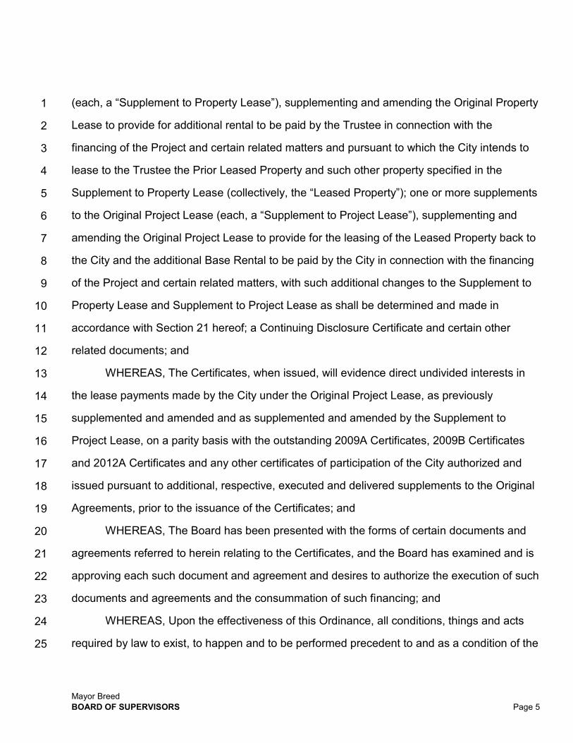
Mayor Breed BOARD OF SUPERVISORS Page 5
1
2
3
4
5
6
7
8
9
10
11
12
13
14
15
16
17
18
19
20
21
22
23
24
25
(each, a “Supplement to Property Lease”), supplementing and amending the Original Property
Lease to provide for additional rental to be paid by the Trustee in connection with the
financing of the Project and certain related matters and pursuant to which the City intends to
lease to the Trustee the Prior Leased Property and such other property specified in the
Supplement to Property Lease (collectively, the “Leased Property”); one or more supplements
to the Original Project Lease (each, a “Supplement to Project Lease”), supplementing and
amending the Original Project Lease to provide for the leasing of the Leased Property back to
the City and the additional Base Rental to be paid by the City in connection with the financing
of the Project and certain related matters, with such additional changes to the Supplement to
Property Lease and Supplement to Project Lease as shall be determined and made in
accordance with Section 21 hereof; a Continuing Disclosure Certificate and certain other
related documents; and
WHEREAS, The Certificates, when issued, will evidence direct undivided interests in
the lease payments made by the City under the Original Project Lease, as previously
supplemented and amended and as supplemented and amended by the Supplement to
Project Lease, on a parity basis with the outstanding 2009A Certificates, 2009B Certificates
and 2012A Certificates and any other certificates of participation of the City authorized and
issued pursuant to additional, respective, executed and delivered supplements to the Original
Agreements, prior to the issuance of the Certificates; and
WHEREAS, The Board has been presented with the forms of certain documents and
agreements referred to herein relating to the Certificates, and the Board has examined and is
approving each such document and agreement and desires to authorize the execution of such
documents and agreements and the consummation of such financing; and
WHEREAS, Upon the effectiveness of this Ordinance, all conditions, things and acts
required by law to exist, to happen and to be performed precedent to and as a condition of the

Mayor Breed BOARD OF SUPERVISORS Page 6
1
2
3
4
5
6
7
8
9
10
11
12
13
14
15
16
17
18
19
20
21
22
23
24
25
execution and delivery of the Supplement to Property Lease, the Supplement to Project
Lease, the Supplement to Trust Agreement, the Continuing Disclosure Certificate, the Official
Statement (as defined herein) and the Certificates will exist, have happened and have been
performed in due time, form and manner in accordance with applicable law, and the City shall
be authorized pursuant to its Charter and other applicable law to execute and deliver the
Supplement to Property Lease, the Supplement to Project Lease, the Continuing Disclosure
Certificate, the Supplement to Trust Agreement and the Official Statement and to cause the
execution and delivery of the Certificates in the manner and form provided in this Ordinance;
and
WHEREAS, The City has paid and expects to pay certain expenditures in connection
with the Project to be financed by the Certificates prior to the execution and delivery of the
Certificates, and the City intends to reimburse itself and to pay third parties for such prior
expenditures from the proceeds of the Certificates; and
WHEREAS, Section 1.150-2 of the Treasury Regulations promulgated under the
Internal Revenue Code of 1986, as amended (“Reimbursement Regulations”) requires the
City to declare its reasonable official intent to reimburse prior expenditures with the proceeds
of a subsequent borrowing; and
WHEREAS, The Reimbursement Regulations require that any reimbursement
allocation of proceeds of the Certificates to be made with respect to expenditures incurred
prior to the execution and delivery of the Certificates will occur not later than eighteen (18)
months after the later of (i) the date on which the expenditure is paid or (ii) the date on which
the facilities are placed in service, but in no event later than three (3) years after the
expenditure is paid; and
WHEREAS, The adoption of this Ordinance constitutes authorization of the Certificates
within the meaning of Section 864 of the California Code of Civil Procedure and any Validation

Mayor Breed BOARD OF SUPERVISORS Page 7
1
2
3
4
5
6
7
8
9
10
11
12
13
14
15
16
17
18
19
20
21
22
23
24
25
Act that is effective after this Ordinance takes effect; and
NOW THEREFORE,
Be it ordained by the People of the City and County of San Francisco, as follows:
Section 1. Findings. The Board hereby finds and determines that the recitals set
forth above are true and correct.
Section 2. Conditions Precedent. All conditions, things and acts required by law to
exist, to happen and to be performed precedent to the execution and delivery of the
Certificates exist, have happened and have been performed in due time, form and manner in
accordance with applicable law, and the City is now authorized pursuant to its Charter and
applicable law to incur indebtedness in the manner and form provided in this Ordinance.
Section 3. File Documents. The documents presented to the Board and on file with
the Clerk of the Board of Supervisors or her designee (collectively, the “Clerk”) are contained
in File No. ____________.
Section 4. Authorization of the Certificates. The Board hereby authorizes and
approves the execution and delivery of the Certificates in one or more series and on one or
more delivery dates in accordance with the applicable Supplement to Trust Agreement. The
proceeds of the Certificates will be used to (i) finance and/or refinance the Project, including
through the retirement of certain commercial paper notes of the City issued therefor; (ii) fund a
debt service or other similar reserve, as appropriate; and (iii) pay costs of issuance of the
Certificates. The Certificates shall be designated as “City and County of San Francisco
Certificates of Participation (Multiple Capital Improvement Projects)” with such other
designations as to series and the year of execution and delivery as determined by the
Controller’s Director of Public Finance (“Director of Public Finance”) or her designee.
Section 5. Certain Terms of the Certificates. The Certificates shall evidence an
aggregate principal amount of not to exceed Sixty Two Million Dollars ($62,000,000), and
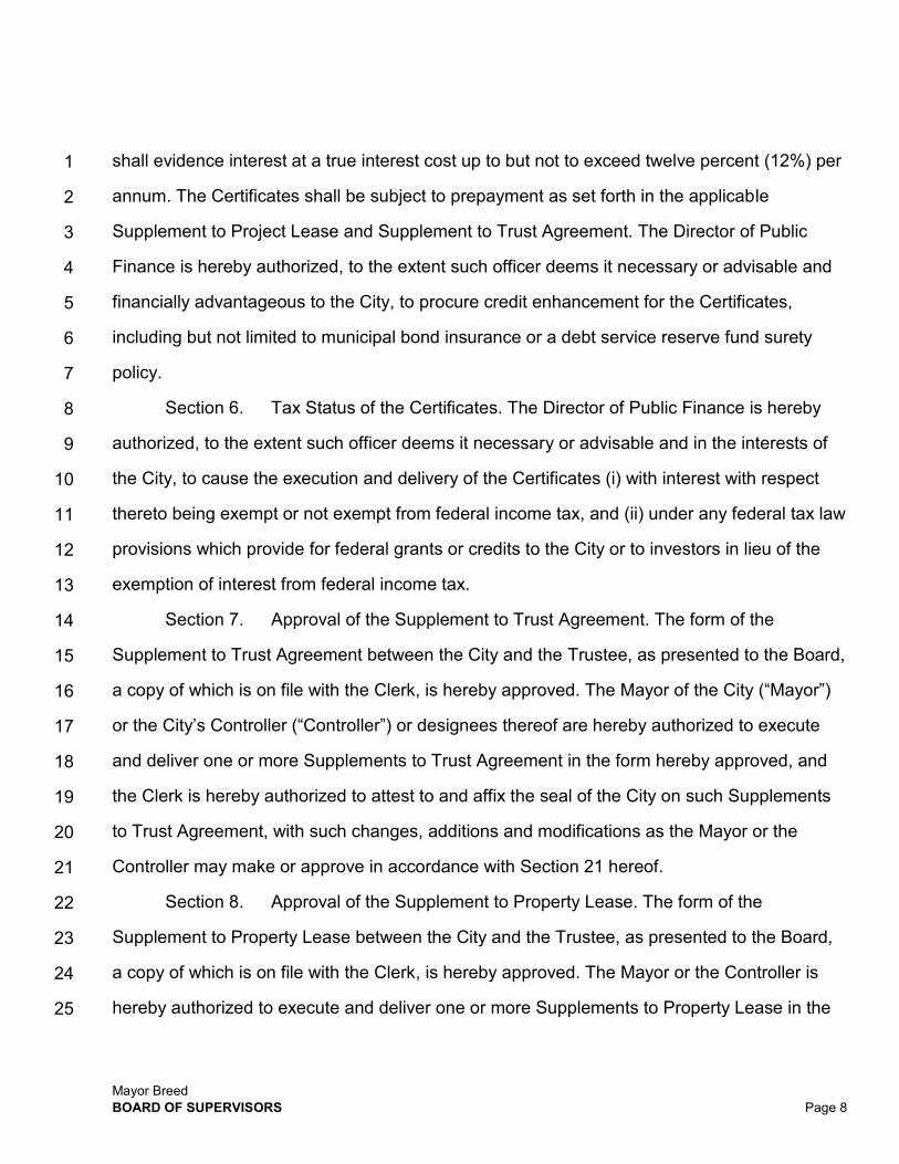
Mayor Breed BOARD OF SUPERVISORS Page 8
1
2
3
4
5
6
7
8
9
10
11
12
13
14
15
16
17
18
19
20
21
22
23
24
25
shall evidence interest at a true interest cost up to but not to exceed twelve percent (12%) per
annum. The Certificates shall be subject to prepayment as set forth in the applicable
Supplement to Project Lease and Supplement to Trust Agreement. The Director of Public
Finance is hereby authorized, to the extent such officer deems it necessary or advisable and
financially advantageous to the City, to procure credit enhancement for the Certificates,
including but not limited to municipal bond insurance or a debt service reserve fund surety
policy.
Section 6. Tax Status of the Certificates. The Director of Public Finance is hereby
authorized, to the extent such officer deems it necessary or advisable and in the interests of
the City, to cause the execution and delivery of the Certificates (i) with interest with respect
thereto being exempt or not exempt from federal income tax, and (ii) under any federal tax law
provisions which provide for federal grants or credits to the City or to investors in lieu of the
exemption of interest from federal income tax.
Section 7. Approval of the Supplement to Trust Agreement. The form of the
Supplement to Trust Agreement between the City and the Trustee, as presented to the Board,
a copy of which is on file with the Clerk, is hereby approved. The Mayor of the City (“Mayor”)
or the City’s Controller (“Controller”) or designees thereof are hereby authorized to execute
and deliver one or more Supplements to Trust Agreement in the form hereby approved, and
the Clerk is hereby authorized to attest to and affix the seal of the City on such Supplements
to Trust Agreement, with such changes, additions and modifications as the Mayor or the
Controller may make or approve in accordance with Section 21 hereof.
Section 8. Approval of the Supplement to Property Lease. The form of the
Supplement to Property Lease between the City and the Trustee, as presented to the Board,
a copy of which is on file with the Clerk, is hereby approved. The Mayor or the Controller is
hereby authorized to execute and deliver one or more Supplements to Property Lease in the

Mayor Breed BOARD OF SUPERVISORS Page 9
1
2
3
4
5
6
7
8
9
10
11
12
13
14
15
16
17
18
19
20
21
22
23
24
25
form hereby approved, and the Clerk is hereby authorized to attest to and affix the seal of the
City on such Supplements to Property Lease, with such changes, additions and modifications
as the Mayor or the Controller may make or approve in accordance with Section 21 hereof.
Section 9. Approval of the Supplement to Project Lease. The form of the
Supplement to Project Lease between the City and the Trustee, as presented to the Board, a
copy of which is on file with the Clerk, is hereby approved. The Mayor or the Controller is
hereby authorized to execute and deliver one or more Supplements to Project Lease in the
form hereby approved, and the Clerk is hereby authorized to attest to and affix the seal of the
City on such Supplements to Project Lease with such changes, additions and modifications as
the Mayor or Controller may make or approve in accordance with Section 21 hereof; provided,
however, that the maximum Base Rental (as defined in the Project Lease) to be paid under all
Supplements to Project Lease in any fiscal year shall not exceed Five Million Four Hundred
Thousand Dollars ($5,400,000) and the term of any Supplement to Project Lease shall not
extend beyond the 25th year following its date of execution, as such initial term may be
extended in accordance with the Project Lease.
Section 10. Approval of the Leased Property and the Base Rental Payments. The
Board hereby approves the leasing, pursuant to the terms of the Supplement to Property
Lease and the Supplement to Project Lease, of all or a portion of the Leased Property. The
Board also hereby approves the payment by the City of the Base Rental with respect thereto.
Section 11. Sale and Award of Certificates by Competitive Sale. In the event the
Director of Public Finance determines to sell the Certificates by competitive sale, the Director
of Public Finance, on behalf of the Controller, is hereby authorized and directed to receive
bids for the purchase of the Certificates, and the Controller is hereby authorized and directed
to award the Certificates to the bidder whose bid represents the lowest true interest cost to the
City, all in accordance with the procedures described in the Official Notice of Sale (as defined

Mayor Breed BOARD OF SUPERVISORS Page 10
1
2
3
4
5
6
7
8
9
10
11
12
13
14
15
16
17
18
19
20
21
22
23
24
25
herein).
Section 12. Approval of Form of Official Notice of Sale. The form of an official notice
of sale relating to the Certificates (“Official Notice of Sale”), as presented to this Board, a copy
of which is on file with the Clerk, is hereby approved. The Controller or the Director of Public
Finance is authorized to approve the distribution of an Official Notice of Sale for the
Certificates, with such changes, additions and modifications as such official may make or
approve in accordance with Section 21 hereof.
Section 13. Approval of Notice of Intention to Sell Relating to the Certificates. The
form of a notice of intention to sell relating to the Certificates (“Notice of Intention to Sell”), as
presented to this Board, a copy of which is on file with the Clerk, is hereby approved. The
Controller or the Director of Public Finance is hereby authorized to approve the publication of
the Notice of Intention to Sell relating to the Certificates, with such changes, additions and
modifications as such official may make or approve in accordance with Section 21 hereof.
Section 14. Sale of Certificates by Negotiated Sale. If the Controller or the Director of
Public Finance determines to sell the Certificates by negotiated sale, the Controller or the
Director of Public Finance is hereby authorized to sell the Certificates by negotiated sale
pursuant to one or more purchase contracts (each, a “Purchase Contract”) by and between
the City and the underwriters named therein; provided, however, that the underwriters’
discount under any such Purchase Contract shall not exceed one percent (1.0%) of the
principal amount of the Certificates. The form of Purchase Contract, as presented to the
Board, a copy of which is on file with the Clerk, is hereby approved.
Section 15. Authorization to Appoint Underwriters. To accomplish the sale of the
Certificates by negotiated sale, if applicable, the Controller or the Director of Public Finance is
hereby authorized to appoint one or more financial institutions to act as underwriter(s) for the
Certificates in accordance with City policies and procedures, including but not limited to the

Mayor Breed BOARD OF SUPERVISORS Page 11
1
2
3
4
5
6
7
8
9
10
11
12
13
14
15
16
17
18
19
20
21
22
23
24
25
City’s policy to provide locally disadvantaged business enterprises an equal opportunity to
participate in the performance of all City contracts.
Section 16. Approval of the Official Statement in Preliminary and Final Form. The
form of an official statement relating to the Certificates (“Official Statement”), as presented to
this Board, a copy of which is on file in preliminary form with the Clerk, is hereby approved.
The Controller is hereby authorized to approve the preliminary Official Statement in
substantially said form, with such changes, additions, modifications (including but not limited
to the inclusion of the most current City financial information) or deletions as such official may
make or approve in accordance with Section 21 hereof, and to deem the preliminary Official
Statement final for purposes of the Rule 15c2-12 of the Securities and Exchange Act of 1934,
as amended, to execute a certificate to that effect, and to cause the preliminary Official
Statement to be delivered, in printed or electronic form, to potential purchasers of the
Certificates, such approval to be conclusively evidenced by the delivery of said deemed-final
certificate. The Controller is hereby further authorized and directed to sign and deliver the
Official Statement in final form to purchasers of the Certificates.
Section 17. Approval of the Continuing Disclosure Certificate. The form of a
Continuing Disclosure Certificate of the City relating to the Certificates, as presented to the
Board, a copy of which is on file with the Clerk, is hereby approved. The Controller or the
Director of Public Finance is hereby authorized to execute the Continuing Disclosure
Certificate, with such changes, additions, modifications or deletions as the Controller or the
Director of Public Finance may approve upon consultation with the City Attorney; such
approval to be conclusively evidenced by the execution and delivery of the Continuing
Disclosure Certificate.
Section 18. Reimbursement. The City declares its official intent to reimburse prior
expenditures of the City incurred prior to the execution and delivery of the Certificates in

Mayor Breed BOARD OF SUPERVISORS Page 12
1
2
3
4
5
6
7
8
9
10
11
12
13
14
15
16
17
18
19
20
21
22
23
24
25
connection with the Project or portions thereof with the proceeds of the Certificates. The
Board of Supervisors declares the City’s intent to reimburse the City with the proceeds of the
Certificates for the expenditures with respect to the Project (the “Expenditures” and each an
“Expenditure”) made on and after that date that is no more than 60 days prior to adoption of
this Ordinance. The City reasonably expects on the date of adoption of this Ordinance that it
will reimburse the Expenditures with the proceeds of the Certificates.
Section 19. Terms of Reimbursement. Each Expenditure was and will be either (a) of
a type properly chargeable to a capital account under general federal income tax principles
(determined in each case as of the date of the Expenditure), (b) a cost of issuance with
respect to the Certificates, (c) a nonrecurring item that is not customarily payable from current
revenues, or (d) a grant to a party that is not related to or an agent of the City so long as such
grant does not impose any obligation or condition (directly or indirectly) to repay any amount
to or for the benefit of the City. The maximum aggregate principal amount of the Certificates
expected to be executed and delivered for the Project is $62,000,000. The City shall make a
reimbursement allocation, which is a written allocation by the City that evidences the City’s
use of proceeds of the Certificates to reimburse an Expenditure, no later than 18 months after
the later of the date on which the Expenditure is paid or the Project is placed in service or
abandoned, but in no event more than three years after the date on which the Expenditure is
paid. The City recognizes that exceptions are available for certain “preliminary expenditures,”
costs of issuance, certain de minimis amounts, expenditures by “small issuers” (based on the
year of issuance and not the year of expenditure) and expenditures for construction projects
of at least five (5) years.
Section 20. General Authority. The Mayor, the Treasurer, the City Attorney, the
Controller, the City Administrator, the Director of Public Finance, the Clerk and other officers
of the City and their duly authorized deputies, designees and agents are hereby authorized

Mayor Breed BOARD OF SUPERVISORS Page 13
1
2
3
4
5
6
7
8
9
10
11
12
13
14
15
16
17
18
19
20
21
22
23
24
25
and directed, jointly and severally, to take such actions and to execute and deliver such
certificates, agreements, requests or other documents as they may deem necessary or
desirable to accomplish the purposes of this Ordinance, including but not limited to the
execution and delivery of any Supplement to Property Lease, any Supplement to Project
Lease, any Supplement to Trust Agreement, the Official Statement, the Continuing Disclosure
Certificate and the Certificates, to obtain bond insurance or other credit enhancements or a
surety policy with respect to the Certificates, to obtain title insurance, to clear any
encumbrances to title and to carry out other title work. Any such actions are solely intended to
further the purposes of this Ordinance and are subject in all respects to the terms of this
Ordinance. No such actions shall increase the risk to the City or require the City to spend any
resources not otherwise granted herein. Final versions of any such documents shall be
provided to the Clerk for inclusion in the official file within 30 days of execution (or as soon
thereafter as final documents are available) by all parties.
Section 21. Modifications, Changes and Additions. The Mayor, the Treasurer, the
Controller and the Director of Public Finance each are hereby authorized to make such
modifications, changes and additions to the documents and agreements approved hereby,
upon consultation with the City Attorney, as may be necessary or desirable and in the
interests of the City, and which changes do not materially increase the City’s obligations or
reduce its rights thereunder or hereunder. The respective official’s approval of such
modifications, changes and additions shall be conclusively evidenced by the execution and
delivery by such official and the Clerk of the applicable Supplement to Property Lease,
Supplement to Project Lease and Supplement to Trust Agreement or any of the other
documents approved in this Ordinance. Any such actions are solely intended to further the
purposes of this Ordinance and are subject in all respects to the terms of this Ordinance. No
such actions shall increase the risk to the City or require the City to spend any resources not

Mayor Breed BOARD OF SUPERVISORS Page 14
1
2
3
4
5
6
7
8
9
10
11
12
13
14
15
16
17
18
19
20
21
22
23
24
25
otherwise granted herein. Final versions of any such documents shall be provided to the Clerk
for inclusion in the official file within 30 days (or as soon thereafter as final documents are
available) of execution by all parties.
Section 22. Partial Invalidity. Any provision of this Ordinance found to be prohibited
by law shall be ineffective only to the extent of such prohibition, and shall not invalidate the
remainder of this Ordinance.
Section 23. Effective Date. This Ordinance shall take effect immediately.
Section 24. Ratification of Prior Actions. All actions authorized consistent with any
documents presented herein and approved by this Ordinance but heretofore taken are hereby
ratified, approved and confirmed by the Board.
APPROVED AS TO FORM: DENNIS J. HERRERA, City Attorney
By: Mark D. Blake Deputy City Attorney n:\financ\as2019\1300182\01388690.docx

1
2
3
4
5
6
E;I
9
10
11
12
1191
14
15
16
17
18
19
20
21
22
23
24
25
FILE NO. ORDINANCE NO.
[Authorizing Certificates of Participation - Multiple Capital Improvement Projects - Not to Exceed $94,600,000]
Ordinance authorizing the execution and delivery of Certificates of Participation, in one
or more series from time to time, on a tax-exempt or taxable basis, evidencing and
representing an aggregate principal amount of not to exceed $94,600,000 to (i) finance
and refinance the acquisition of certain real property located at 814-820 Bryant Street
and 470 6th Street within the City and related site demolition, preparation and
improvement, and (ii) the repayment of certain taxable commercial paper notes of the
City issued for such purposes, and the acquisition of certain additional property
located at 1828 Egbert Avenue within the City and related site demolition, preparation
and improvement; approving the form of Supplement to the Trust Agreement between
the City and County of San Francisco and U.S. Bank National Association, as trustee
("Trustee") (including certain indemnities contained therein); approving respective
forms of Supplements to Property Lease and Project Lease, each between the City and
the Trustee, for the lease and lease back of all or a portion of certain real property and
improvements located at 375 Laguna Honda Boulevard or other property as determined'
by the Director of Public Finance; approving the form of an Official Notice of Sale and a
Notice of Intention to Sell the Certificates of Participation; approving the form of an
official statement in preliminary and final form; approving the form of a Continuing
Disclosure Certificate; granting general authority to City officials to take necessary
actions in connection with the authorization, sale, execution and delivery of the
Certificates of Participation; approving modifications to documents; and ratifying
previous actions taken in connection therewith, as defined herein.
NOTE: Unchanged Code text and uncodified text are in plain Anal font. Additions to Codes are in single-underline italics Times New Roman font. Deletions to Codes are in strikcthrough italics Times New Roman font. Board amendment additions are in double-underlined Anal font.
Mayor Breed BOARD OF SUPERVISORS Page 1

Board amendment deletions are in strikethrough Anal font. Asterisks (* * * *) indicate the omission of unchanged Code subsections or parts of tables.
Be it ordained by the People of the City and County of San Francisco:
WHEREAS, The Board of Supervisors ("Board of Supervisors" or "Board") of the City
and County of San Francisco ("City") desires to provide funds for the (i) the acquisition of
certain real property located at 814-820 Bryant Street and 470 6th Street within the City and
related site demolition, preparation and improvement, including the repayment of certain
taxable commercial paper notes of the City issued for such purposes, and (ii) the acquisition
of certain additional property located at 1828 Egbert Avenue within the City and related site
demolition, preparation and improvement (collectively, the "Project"), all in connection with the
City's planned relocation of certain Hall of Justice facilities currently located at and adjacent to
850 Bryant Street within the City, and the City is authorized pursuant to its charter ("Charter")
and the laws of the State to enter into lease financings for such purpose; and
WHEREAS, The City and the Trustee have previously entered into a Property
Lease, dated as of May 1, 2009 ("Original Property Lease"), pursuant to which the City has
leased certain real property and all improvements thereon (collectively, the "Prior Leased
Property") to the Trustee; and
WHEREAS, The Trustee and the City have previously entered into a Project Lease,
dated as of May 1, 2009 ("Original Project Lease'), pursuant to which the Trustee has
leased the Prior Leased Property back to the City; and
WHEREAS, The City previously caused the execution and delivery of the City and
County of San Francisco Certificates of Participation, Series 2009A (Multiple Capital
Improvement Projects) ("2009A Certificates") pursuant to a Trust Agreement, dated as of
2511 May 1, 2009, by and between the City and the Trustee ("Original Trust Agreement" and,
Mayor Breed BOARD OF SUPERVISORS Page 21
1
2
3
4
5
6
7
8
9
10
11
12
13
14
15
16
17
18
19
20
21
22
ffl
24

1 together with the Original Property Lease and the Original Project Lease, the "Original
2 Agreements"); and
3 WHEREAS, The 2009A Certificates evidence direct undivided interests in the lease
4 payments made by the City under the Original Project Lease; and
5 WHEREAS, The Original Trust Agreement provides for the issuance of additional
6 certificates of participation by the execution and delivery of a supplement to the Original Trust
7 Agreement, and authorizes the principal and interest with respect to said certificates of
8 participation to be secured by a supplement to the Original Property Lease and to be paid
9 from amounts paid by the City under a supplement to the Original Project Lease;
10 WHEREAS, The City subsequently caused the execution and delivery of the City and
11 County of San Francisco Certificates of Participation, Series 2009B (Multiple Capital
12 Improvement Projects) (the "200913 Certificates") pursuant to a First Supplement to Trust
13 Agreement, dated as of September 1, 2009 ("First Supplement to Trust Agreement"),
14 supplementing the Original Trust Agreement; and
15 WHEREAS, In connection therewith, the City and the Trustee have previously entered
16 into a First Supplement to Property Lease, dated as of September 1, 2009 ("First Supplement
17 to Property Lease"), supplementing the Original Property Lease; and
18 WHEREAS, In connection therewith, the City and the Trustee have previously entered
19 into a First Supplement to Project Lease, dated as of September 1, 2009 ("First Supplement
20 to Project Lease"), supplementing the Original Project Lease; and
21 WHEREAS, The 2009B Certificates evidence direct undivided interests in the lease
22 payments made by the City under the Original Project Lease, as supplemented by the First
23 Supplement to Project Lease, on a parity basis with the 2009A Certificates; and
24 WHEREAS, The City subsequently caused the execution and delivery of the City and
25 H County of San Francisco Certificates of Participation, Series 2012A (Multiple Capital
Mayor Breed BOARD OF SUPERVISORS Page 3

I Improvement Projects) ("2012A Certificates") pursuant to a Second Supplement to Trust
2 Agreement, dated as of June 1, 2012 ('Second Supplement to Trust Agreement"),
3 supplementing the Original Trust Agreement; and
4 WHEREAS, In connection therewith, the City and the Trustee have previously entered
5 into a Second Supplement to Property Lease, dated as of June 1, 2012 ("Second Supplement
6 to Property Lease"), supplementing the Original Property Lease; and
7 WHEREAS, In connection therewith, the City and the Trustee have previously entered
8 into a Second Supplement to Project Lease, dated as of June 1, 2012 ("Second Supplement
9 to Project Lease"), supplementing the Original Project Lease; and
10 WHEREAS, The 2012A Certificates evidence direct undivided interests in the lease
11 payments made by the City under the Original Project Lease, as supplemented by the First
12 Supplement to Project Lease and Second Supplement to Project Lease, on a parity basis with
13 the 2009A Certificates and 2009B Certificates; and
iI WHEREAS, The Board desires to finance the Project and to cause the execution and
15 delivery of one or more additional series of certificates of participation (as further defined
16 herein, the "Certificates") in an aggregate principal amount not to exceed $94,600,000
17 therefor; and
18 WHEREAS, The Certificates will be executed and delivered in one or more series, from
19 time to time, on a tax-exempt and/or taxable basis pursuant to one or more supplements to
20 the Original Trust Agreement (each, a "Supplement to Trust Agreement"), by and between the
21 City and the Trustee, supplementing the Original Trust Agreement; and
22 WHEREAS, In connection with the execution and delivery of the Certificates, the Board
23 desires to cause the execution of one or more supplements to the Original Property Lease
24 (each, a "Supplement to Property Lease"), supplementing and amending the Original Property
25 Lease to supplement the Leased Property (defined below), pursuant to Section 18 of the
Mayor Breed BOARD OF SUPERVISORS Page 4 1

1 Original Property Lease, Section 702 of the Original Trust Agreement and Sections 16 and 20
2 of the Original Project Lease (collectively, the "Leased Property Amendment Provisions"), by
3 the addition of sites and improvements adjacent to the Prior Leased Property, and to provide
4 for additional rental to be paid by the Trustee in connection with the financing of the Project
5 and certain related matters and pursuant to which the City intends to lease to the Trustee the
6 Prior Leased Property and such other property specified in the Supplement to Property Lease
7 (collectively, the "Leased Property"); one or more supplements to the Original Project Lease
8 (each, a "Supplement to Project Lease"), supplementing and amending the Original Project
9 Lease to supplement the Leased Property pursuant to the Leased Property Amendment
10 Provisions, by the addition of sites and improvements adjacent to the Prior Leased Property,
11 and to provide for the leasing of the Leased Property back to the City, the additional Base
12 Rental to be paid by the City in connection with the financing of the Project and certain related
13 matters, with such additional changes to the Leased Property description to be set forth in the
14 Supplement to Property Lease and Supplement to Project Lease as shall be determined by
15 the City's Director of Public Finance (defined below); a Continuing Disclosure Certificate and
16 certain other related documents; and
17 WHEREAS, The Certificates, when issued, will evidence direct undivided interests in
18 the lease payments made by the City under the Original Project Lease, as previously
19 supplemented and amended and as supplemented and amended by the Supplement to
20 Project Lease, on a parity basis with the outstanding 2009A Certificates, 2009B Certificates
21 and 2012A Certificates and any other certificates of participation of the City authorized and
22 issued pursuant to additional, respective, executed and delivered supplements to the Original
23 Agreements, prior to the issuance of the Certificates; and
24 WHEREAS, The Board has been presented with the forms of certain documents and
25 agreements referred to herein relating to the Certificates, and the Board has examined and is
Mayor Breed BOARD OF SUPERVISORS Page 5
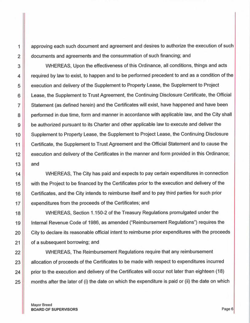
1 approving each such document and agreement and desires to authorize the execution of such
2 documents and agreements and the consummation of such financing; and
3 WHEREAS, Upon the effectiveness of this Ordinance, all conditions, things and acts
4 required by law to exist, to happen and to be performed precedent to and as a condition of the
5 execution and delivery of the Supplement to Property Lease, the Supplement to Project
6 Lease, the Supplement to Trust Agreement, the Continuing Disclosure Certificate, the Official
7 Statement (as defined herein) and the Certificates will exist, have happened and have been
8 performed in due time, form and manner in accordance with applicable law, and the City shall
9 be authorized pursuant to its Charter and other applicable law to execute and deliver the
10 Supplement to Property Lease, the Supplement to Project Lease, the Continuing Disclosure
11 Certificate, the Supplement to Trust Agreement and the Official Statement and to cause the
12 execution and delivery of the Certificates in the manner and form provided in this Ordinance;
13 and
14 WHEREAS, The City has paid and expects to pay certain expenditures in connection
15 with the Project to be financed by the Certificates prior to the execution and delivery of the
16 Certificates, and the City intends to reimburse itself and to pay third parties for such prior
17 expenditures from the proceeds of the Certificates; and
18 WHEREAS, Section 1.150-2 of the Treasury Regulations promulgated under the
19 Internal Revenue Code of 1986, as amended ('Reimbursement Regulations") requires the
20 City to declare its reasonable official intent to reimburse prior expenditures with the proceeds
21 of a subsequent borrowing; and
22 WHEREAS, The Reimbursement Regulations require that any reimbursement
23 allocation of proceeds of the Certificates to be made with respect to expenditures incurred
24 prior to the execution and delivery of the Certificates will occur not later than eighteen (18)
25 months after the later of (i) the date on which the expenditure is paid or (ii) the date on which
Mayor Breed BOARD OF SUPERVISORS Page 61

1 the facilities are placed in service, but in no event later than three (3) years after the
2 expenditure is paid; and
3 WHEREAS, The adoption of this Ordinance constitutes authorization of the Certificates
4 within the meaning of Section 864 of the California Code of Civil Procedure and any Validation
5 Act that is effective after this Ordinance takes effect; and
6 NOW THEREFORE,
7 Be it ordained by the People of the City and County of San Francisco, as follows:
8 Section 1. Findings. The Board hereby finds and determines that the recitals set
9 forth above are true and correct.
10 Section 2. Conditions Precedent. All conditions, things and acts required by law to
11 exist, to happen and to be performed precedent to the execution and delivery of the
12 Certificates exist, have happened and have been performed in due time, form and manner in
13 accordance with applicable law, and the City is now authorized pursuant to its Charter and
14 applicable law to incur indebtedness in the manner and form provided in this Ordinance.
15 Section 3. File Documents. The documents presented to the Board and on file with
16 the Clerk of the Board of Supervisors or her designee (collectively, the "Clerk") are contained
17 in File No.
18 Section 4. Authorization of the Certificates. The Board hereby authorizes and
19 approves the execution and delivery of the Certificates in one or more series and on one or
20 more delivery dates in accordance with the applicable Supplement to Trust Agreement. The
21 proceeds of the Certificates will be used to (i) finance and/or refinance the Project, including
22 through the repayment of certain taxable commercial paper notes of the City issued therefor;
23 (ii) fund a debt service or other similar reserve, as appropriate; and (iii) pay costs of issuance
24 of the Certificates. The Certificates shall be designated as "City and County of San Francisco
25 Certificates of Participation (Multiple Capital Improvement Projects)" with such other
Mayor Breed BOARD OF SUPERVISORS Page 71

1 designations as to series and the year of execution and delivery as determined by the
2 Controller's Director of Public Finance ("Director of Public Finance") or her designee.
3 Section 5. Certain Terms of the Certificates. The Certificates shall evidence an
4 aggregate principal amount of not to exceed Ninety Four Million Six Hundred Thousand
5 Dollars ($94,600,000), and shall evidence interest at a true interest cost up to but not to
6 exceed twelve percent (12%) per annum. The Certificates shall be subject to prepayment as
7 set forth in the applicable Supplement to Project Lease and Supplement to Trust Agreement.
8 The Director of Public Finance is hereby authorized, to the extent such officer deems it
9 necessary or advisable and financially advantageous to the City, to procure credit
10 enhancement for the Certificates, including but not limited to municipal bond insurance or a
11 debt service reserve fund surety policy.
12 Section 6. Tax Status of the Certificates. The Director of Public Finance is hereby
13 authorized, to the extent such officer deems it necessary or advisable and in the interests of
14 the City, to cause the execution and delivery of the Certificates (i) with interest with respect
15 thereto being exempt or not exempt from federal income tax, and (ii) under any federal tax
16 law provisions which provide for federal grants or credits to the City or to investors in lieu of
17 the exemption of interest from federal income tax.
18 Section 7. Approval of the Supplement to Trust Agreement. The form of the
19 Supplement to Trust Agreement between the City and the Trustee, as presented to the Board,
20 a copy of which is on file with the Clerk, is hereby approved. The Mayor of the City ("Mayor")
21 or the City's Controller ("Controller") or designees thereof are hereby authorized to execute
22 and deliver one or more Supplements to Trust Agreement in the form hereby approved, and
23 the Clerk is hereby authorized to attest to and affix the seal of the City on such Supplements
24 to Trust Agreement, with such changes, additions and modifications as the Mayor or the
25 Controller may make or approve in accordance with Section 21 hereof.
Mayor Breed BOARD OF SUPERVISORS Page 8

1
2
3
4
5
6
7
8
9
10
11
12
13
14
15
16
17
18
19
20
21
22
23
25
Section 8. Approval of the Supplement to Property Lease. The form of the
Supplement to Property Lease between the City and the Trustee, as presented to the Board,
a copy of which is on file with the Clerk, is hereby approved. The Mayor or the Controller is
hereby authorized to execute and deliver one or more Supplements to Property Lease in the
form hereby approved, and the Clerk is hereby authorized to attest to and affix the seal of the
City on such Supplements to Property Lease, with such changes, additions and modifications
as the Mayor or the Controller may make or approve in accordance with Section 21 hereof.
Section 9. Approval of the Supplement to Project Lease. The form of the
Supplement to Project Lease between the City and the Trustee, as presented to the Board, a
copy of which is on file with the Clerk, is hereby approved. The Mayor or the Controller is
hereby authorized to execute and deliver one or more Supplements to Project Lease in the
form hereby approved, and the Clerk is hereby authorized to attest to and affix the seal of the
City on such Supplements to Project Lease with such changes, additions and modifications as
the Mayor or Controller may make or approve in accordance with Section 21 hereof; provided,
however, that the maximum Base Rental (as defined in the Project Lease) to be paid under all
Supplements to Project Lease in any fiscal year shall not exceed Eight Million Two Hundred
Fifty Thousand Dollars ($8,250,000) and the term of any Supplement to Project Lease shall
not extend beyond the 25th year following its date of execution, as such initial term may be
extended in accordance with the Project Lease.
Section 10. Approval of the Leased Property and the Base Rental Payments. The
Board hereby approves the leasing, pursuant to the terms of the Supplement to Property
Lease and the Supplement to Project Lease, of all or a portion of the Leased Property,
including as such Leased Property shall be supplemented pursuant to the Leased Property
Amendment Provisions. The Board also hereby approves the payment by the City of the Base
Rental with respect thereto.
Mayor Breed BOARD OF SUPERVISORS Page 91

1 Section 11. Sale and Award of Certificates by Competitive Sale. In the event the
2 Director of Public Finance determines to sell the Certificates by competitive sale, the Director
3 of Public Finance, on behalf of the Controller, is hereby authorized and directed to receive
4 bids for the purchase of the Certificates, and the Controller is hereby authorized and directed
5 to award the Certificates to the bidder whose bid represents the lowest true interest cost to the
6 City, all in accordance with the procedures described in the Official Notice of Sale (as defined
7 herein).
8 Section 12. Approval of Form of Official Notice of Sale. The form of an official notice
9 of sale relating to the Certificates ("Official Notice of Sale"), as presented to this Board, a copy
10 of which is on file with the Clerk, is hereby approved. The Controller or the Director of Public
11 Finance is authorized to approve the distribution of an Official Notice of Sale for the
12 Certificates, with such changes, additions and modifications as such official may make or
13 approve in accordance with Section 21 hereof.
14 Section 13. Approval of Notice of Intention to Sell Relating to the Certificates. The
15 form of a notice of intention to sell relating to the Certificates ("Notice of Intention to Sell"), as
16 presented to this Board, a copy of which is on file with the Clerk, is hereby approved. The
17 Controller or the Director of Public Finance is hereby authorized to approve the publication of
18 the Notice of Intention to Sell relating to the Certificates, with such changes, additions and
19 modifications as such official may make or approve in accordance with Section 21 hereof.
20 Section 14. Sale of Certificates by Negotiated Sale. If the Controller or the Director of
21 Public Finance determines to sell the Certificates by negotiated sale, the Controller or the
22 Director of Public Finance is hereby authorized to sell the Certificates by negotiated sale
23 pursuant to one or more purchase contracts (each, a "Purchase Contract") by and between
24 the City and the underwriters named therein; provided, however, that the underwriters'
25 discount under any such Purchase Contract shall not exceed one percent (1.0%) of the
Mayor Breed BOARD OF SUPERVISORS Page 101

1 principal amount of the Certificates. The form of Purchase Contract, as presented to the
2 Board, a copy of which is on file with the Clerk, is hereby approved.
3 Section 15. Authorization to Appoint Underwriters. To accomplish the sale of the
4 Certificates by negotiated sale, if applicable, the Controller or the Director of Public Finance is
5 hereby authorized to appoint one or more financial institutions to act as underwriter(s) for the
6 Certificates in accordance with City policies and procedures, including but not limited to the
7 City's policy to provide locally disadvantaged business enterprises an equal opportunity to
8 participate in the performance of all City contracts.
9 Section 16. Approval of the Official Statement in Preliminary and Final Form. The
10 form of an official statement relating to the Certificates ("Official Statement"), as presented to
11 this Board, a copy of which is on file in preliminary form with the Clerk, is hereby approved.
12 The Controller is hereby authorized to approve the preliminary Official Statement in
13 substantially said form, with such changes, additions, modifications (including but not limited
14 to the inclusion of the most current City financial information) or deletions as such official may
15 make or approve in accordance with Section 21 hereof, and to deem the preliminary Official
16 Statement final for purposes of the Rule 15c2-12 of the Securities and Exchange Act of 1934,
17 as amended, to execute a certificate to that effect, and to cause the preliminary Official
18 Statement to be delivered, in printed or electronic form, to potential purchasers of the
19 Certificates, such approval to be conclusively evidenced by the delivery of said deemed-final
20 certificate. The Controller is hereby further authorized and directed to sign and deliver the
21 Official Statement in final form to purchasers of the Certificates.
22 Section 17. Approval of the Continuing Disclosure Certificate. The form of a
23 Continuing Disclosure Certificate of the City relating to the Certificates, as presented to the
24 Board, a copy of which is on file with the Clerk, is hereby approved. The Controller or the
25 Director of Public Finance is hereby authorized to execute the Continuing Disclosure
Mayor Breed BOARD OF SUPERVISORS Page 11

I Certificate, with such changes, additions, modifications or deletions as the Controller or the
PA Director of Public Finance may approve upon consultation with the City Attorney; such
3 approval to be conclusively evidenced by the execution and delivery of the Continuing
4 Disclosure Certificate.
5 Section 18. Reimbursement. The City declares its official intent to reimburse prior
6 expenditures of the City incurred prior to the execution and delivery of the Certificates in
7 connection with the Project or portions thereof with the proceeds of the Certificates. The
8 Board of Supervisors declares the City's intent to reimburse the City with the proceeds of the
9 Certificates for the expenditures with respect to the Project (the 'Expenditures" and each an
10 "Expenditure") made on and after that date that is no more than 60 days prior to adoption of
11 this Ordinance. The City reasonably expects on the date of adoption of this Ordinance that it
12 will reimburse the Expenditures with the proceeds of the Certificates.
13 Section 19. Terms of Reimbursement. Each Expenditure was and will be either (a) of
14 a type properly chargeable to a capital account under general federal income tax principles
15 (determined in each case as of the date of the Expenditure), (b) a cost of issuance with
16 respect to the Certificates, (c) a nonrecurring item that is not customarily payable from current
17 revenues, or (d) a grant to a party that is not related to or an agent of the City so long as such
18 grant does not impose any obligation or condition (directly or indirectly) to repay any amount
19 to or for the benefit of the City. The maximum aggregate principal amount of the Certificates
20 expected to be executed and delivered for the Project is $94,600,000. The City shall make a
21 reimbursement allocation, which is a written allocation by the City that evidences the City's
22 use of proceeds of the Certificates to reimburse an Expenditure, no later than 18 months after
pal the later of the date on which the Expenditure is paid or the Project is placed in service or
24 abandoned, but in no event more than three years after the date on which the Expenditure is
25 paid. The City recognizes that exceptions are available for certain "preliminary expenditures,"
Mayor Breed BOARD OF SUPERVISORS Page 121
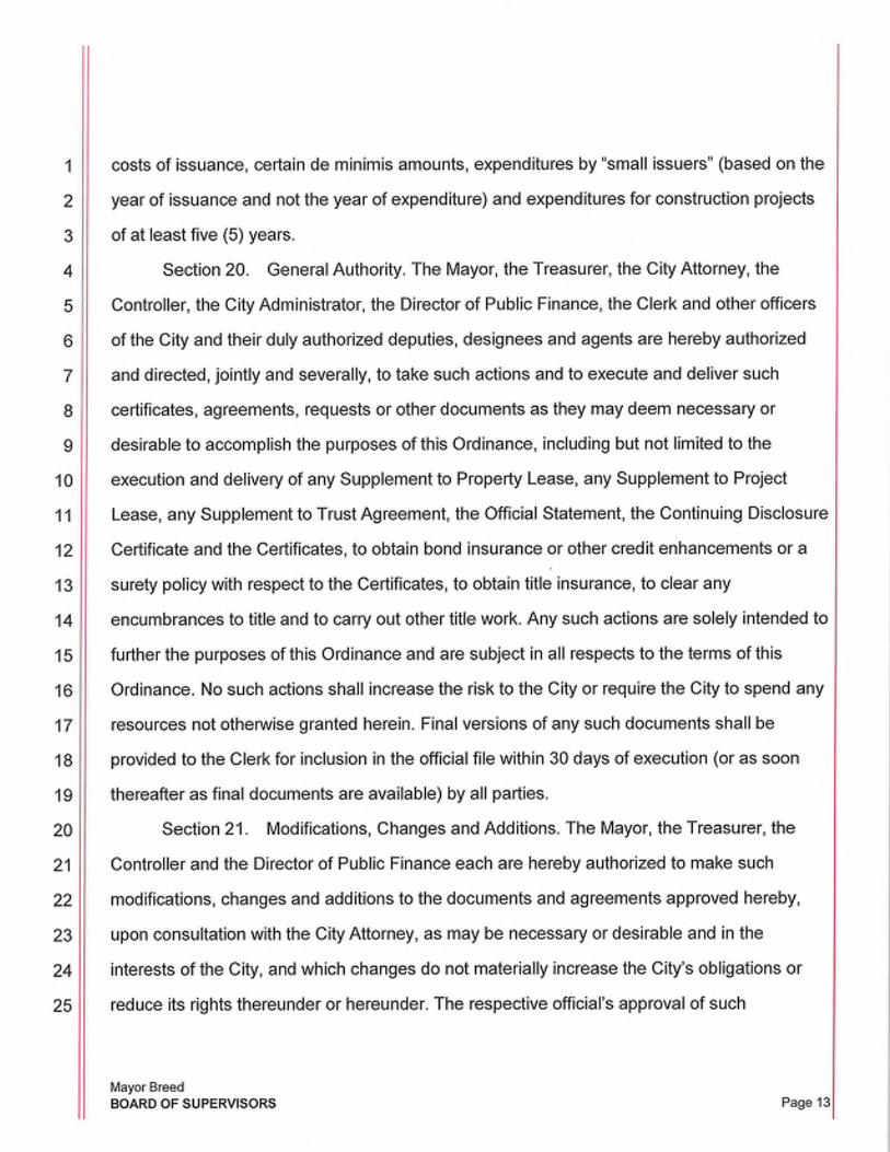
1 costs of issuance, certain de minimis amounts, expenditures by "small issuers" (based on the
2 year of issuance and not the year of expenditure) and expenditures for construction projects
3 of at least five (5) years.
4 Section 20. General Authority. The Mayor, the Treasurer, the City Attorney, the
5 Controller, the City Administrator, the Director of Public Finance, the Clerk and other officers
6 of the City and their duly authorized deputies, designees and agents are hereby authorized
7 and directed, jointly and severally, to take such actions and to execute and deliver such
8 certificates, agreements, requests or other documents as they may deem necessary or
9 desirable to accomplish the purposes of this Ordinance, including but not limited to the
10 execution and delivery of any Supplement to Property Lease, any Supplement to Project
11 Lease, any Supplement to Trust Agreement, the Official Statement, the Continuing Disclosure
12 Certificate and the Certificates, to obtain bond insurance or other credit enhancements or a
13 surety policy with respect to the Certificates, to obtain title insurance, to clear any
14 encumbrances to title and to carry out other title work. Any such actions are solely intended to
15 further the purposes of this Ordinance and are subject in all respects to the terms of this
16 Ordinance. No such actions shall increase the risk to the City or require the City to spend any
17 resources not otherwise granted herein. Final versions of any such documents shall be
18 provided to the Clerk for inclusion in the official file within 30 days of execution (or as soon
19 thereafter as final documents are available) by all parties.
20 Section 21. Modifications, Changes and Additions. The Mayor, the Treasurer, the
21 Controller and the Director of Public Finance each are hereby authorized to make such
22 modifications, changes and additions to the documents and agreements approved hereby,
23 upon consultation with the City Attorney, as may be necessary or desirable and in the
24 interests of the City, and which changes do not materially increase the City's obligations or
25 reduce its rights thereunder or hereunder. The respective official's approval of such
Mayor Breed BOARD OF SUPERVISORS Page 131

modifications, changes and additions shall be conclusively evidenced by the execution and
delivery by such official and the Clerk of the applicable Supplement to Property Lease,
Supplement to Project Lease and Supplement to Trust Agreement or any of the other
documents approved in this Ordinance. Any such actions are solely intended to further the
purposes of this Ordinance and are subject in all respects to the terms of this Ordinance. No
such actions shall increase the risk to the City or require the City to spend any resources not
otherwise granted herein. Final versions of any such documents shall be provided to the Clerk
for inclusion in the official file within 30 days (or as soon thereafter as final documents are
available) of execution by all parties.
Section 22. Partial Invalidity. Any provision of this Ordinance found to be prohibited
by law shall be ineffective only to the extent of such prohibition, and shall not invalidate the
remainder of this Ordinance.
Section 23. Effective Date. This Ordinance shall take effect immediately.
I/I
I/I
I/I
I/I
I/I
'I-
//I
I/I
I/I
"I
l/I
III
Mayor Breed BOARD OF SUPERVISORS Page 14
1
2
3
4
5
6
7
8
9
10
11
12
13
14
15
16
17
18
19
20
21
22
23
24
25
Section 24. Ratification of Prior Actions. All actions authorized consistent with any
documents presented herein and approved by this Ordinance but heretofore taken are hereby
ratified, approved and confirmed by the Board.
APPROVED AS TO FORM: DENNIS J. F$ERRERA, City Attorney
Deputy City Attorney n:\financ\as2019\1300182\01388687.docx
Mayor Breed BOARD OF SUPERVISORS Page 15

FILE NO. 190416 ORDINANCE NO. 101-19 R0#19022 SA#?0-22
1 [Appropriation - Certificates of Participation to the General Services Agency to Fund Hall of Justice Relocation Project - $16,000,000 - FY2018-2019]
2
3 Ordinance appropriating $16,000,000 of Certificates of Participation to the General
4 Services Agency to purchase the property located at 814-820 Bryant Street and 470-6th
5 Street; and to fund the Hall of Justice Relocation Project with related demolition, site
6 preparation, and other acquisition costs in FY2018-2019.
7
8
9
10
11
12
Note: Unchanged Code text and uncodified text are in plain Arial font. Additions to Codes are in single-underline italics Times New Roman font. Deletions to Codes are in strikethrough, italics Times }kw Roman font. Board amendment additions are in double-underlined Arial font. Board amendment deletions are in strikethrough /\rial font. Asterisks (* * * *) indicate the omission of unchanged Code subsections or parts of tables.
13 Be it ordained by the People of the City and County of San Francisco:
14
15 Section 1. The sources of funding outlined below are herein appropriated in the General
16 Services Agency for Fiscal Year 2018-2019. Commercial Paper may be used as a funding
17 source in the interim, prior to sale of the Certificates of Participation.
18
19
20
21
22
23
24
25
Sources
Fund I Project & Activity I
Department ID Authority
15381/228875 10001289/0016
CPXCF COP 820 20886 ADRE Capital
Bryant St I ADM Real lmprovements/ADRE
Estate Division 820 Bryant Acquisition
Mayor Breed; Supervisors Haney, Peskin BOARD OF SUPERVISORS
Account Description
80141 Proceeds from
Proceeds fr Certificates of
Certificates of Participation
Participation
Amount
$16,000,000
Page 1

1
2
3
4
5
6
7
8
9
10
11
12
13
14
15
16
17
18
19
20
21
22
23
24
25
Total Sources $16,000,000
Section 2. The uses of funding outlined below are herein appropriated in the General
Services Agency to fund the purchase of the property located at 814-820 Bryant Street and
470 6th Street and the related demolition, site preparation, and other acquisition costs.
Uses
Fund/ Project & Activity I
Department ID Authority
15381/ 228875 10001289 & 0016/
CPXCF COP 820 20886
Bryant St I ADM Real ADRE Capital
Estate Division Improvements/
ADRE 820 Bryant
Acquisition
15381/ 228875 10001289 & 0016/
CPXCF COP 820 20886
Bryant St I ADM Real ADRE Capital
Estate Division Improvements/
ADRE 820 Bryant
Acquisition
Mayor Breed; Supervisors Haney, Peskin BOARD OF SUPERVISORS
Account Description Amount
567000 Purchase of $11,520,000
Bldgs,Struct&lmprv Property
Proj-Budget
506070 Demolition, Site $480,000
Programmatic Preparation,
Projects-Budget Other
Acquisition
Costs
Page 2

1
2
3
4
5
6
7
8
9
10
11
12
13
14
15
16
17
18
19
20
21
22
23
24
25
Fund/ Project & Activity I
Department ID Authority
15381/ 228875 10001289 & 0016/
CPXCF COP 820 20886
Bryant St I ADM Real ADRE Capital
Estate Division Improvements/
ADRE 820 Bryant
Acquisition
15381/ 228875 10001289 & 0016/
CPXCF COP 820 20886
Bryant St I ADM Real ADRE Capital
Estate Division Improvements/
ADRE 820 Bryant
Acquisition
15381/ 228875 10001289 & 0016/
CPXCF COP 820 20886
Bryant St I ADM Real ADRE Capital
Estate Division Improvements/
ADRE 820 Bryant
Acquisition
Mayor Breed; Supervisors Haney, Peskin BOARD OF SUPERVISORS
Account Description Amount
581130 CSA 0.2% $24,000
GF-CON-lnternal Controller's
Audit Audit Fund
573110 Debt Service $1,233,237
Bond Issuance Reserve Fund
Cost - Unamortized
573110 Capital Interest $1,337,138
Bond Issuance Fund
Cost - Unamortized
Page 3

1
2
3
4
5
6
7
8
9
10
11
12
13
14
15
16
17
18
19
20
21
22
23
24
25
Fund/ Project & Activity I
Department ID Authority
153811228875 10001289 & 0016/
CPXCF COP 820 20886
Bryant St I ADM Real ADRE Capital
Estate Division Improvements/
ADRE 820 Bryant
Acquisition
15381/ 228875 10001289 & 0016/
CPXCF COP 820 20886
Bryant St I ADM Real ADRE Capital
Estate Division Improvements/
ADRE 820 Bryant
Acquisition
153811228875 10001289 & 0016/
CPXCF COP 820 20886
Bryant St I ADM Real ADRE Capital
Estate Division Improvements/
ADRE 820 Bryant
Acquisition
Total Uses
Mayor Breed; Supervisors Haney, Peskin BOARD OF SUPERVISORS
Account Description Amount
573110 Cost of Issuance $807,525
Bond Issuance
Cost - Unamortized
573110 Underwriter's $133, 100
Bond Issuance Discount
Cost - Unamortized
573110 Reserve for $465,000
Bond Issuance Market
Cost - Unamortized Uncertainty
$16,000,000
Page 4

1 Section 3. The uses of funding outlined above for $16,000,000 are herein placed on
2 Controller's Reserve pending sales of Certificates of Participation.
3
4 Section 4. The Controller is authorized to record transfers between funds and adjust the
5 accounting treatment of sources and uses appropriated in this Ordinance as necessary to
6 conform with Generally Accepted Accounting Principles and other laws.
7
8
9
10
11
12
13
14
15
16
1 "1
18
19
20
21
22
23
24
25
APPROVED AS TO FORM: DENNIS J. HERRERA, City Attorney
By:
Mayor Breed; Supervisors Haney, Peskin BOARD OF SUPERVISORS Page 5

City and County of San Francisco
Tails
Ordinance
City Hall 1 Dr. Carlton B. Goodlett Place San Francisco, CA 94102-4689
File Number: 190416 Date Passed: May 14, 2019
Ordinance appropriating $16,000,000 of Certificates of Participation to the General Services Agency to purchase the property located at 814-820 Bryant Street and 4 70-6th Street; and to fund the Hall of Justice Relocation Project with related demolition, site preparation, and other acquisition costs in FY2018-2019.
May 01, 2019 Budget and Finance Sub-Committee - RECOMMENDED
May 07, 2019 Board of Supervisors - PASSED ON FIRST READING
Ayes: 11 - Brown, Fewer, Haney, Mandelman, Mar, Peskin, Ronen, Safai, Stefani, Walton and Yee
May 14, 2019 Board of Supervisors - FINALLY PASSED
Ayes: 9 - Brown, Fewer, Haney, Mandelman, Mar, Peskin, Safai, Stefani and Yee
Excused: 2 - Ronen and Walton
File No. 190416
London N. Breed Mayor
City and County of San Francisco Page 1
I hereby certify that the foregoing Ordinance was FINALLY PASSED on 5/14/2019 by the Board of Supervisors of the City and County of San Francisco.
Angela Calvillo Clerk of the Board
Date Approved
Printed at 9:34 am on 5115119

1
2
3
4
5
6
7
8
9
10
11
12
13
14
15
16
17
18
FILE NO. 190420 RESOLUTION NO. 225-19
[Acquisition of Real Property- 814-820 Bryant Street and 470-6th Street; $11,520,000 Certificates of Participation and Commercial Paper Notes - Not to Exceed $16,000,000]
Resolution authorizing the Director of the Real Estate Division to acquire real property
located at 814-820 Bryant Street and 470-6th Street, from Wen-Chiao Wayne Lin and
Mei-Huei Grace Lin as to an undivided 60% interest, and Tony Chih-Tung Lin and Jenny
Chun-Hsing Lin as to an undivided 40% interest, to facilitate the replacement of the Hall
of Justice known as the Justice Facilities Improvement Program, for the purchase price
of $11 ,520,000; authorizing the Controller to cause the execution and delivery of
taxable or tax-exempt Certificates of Participation evidencing and representing an
aggregate principal amount not to exceed $16,000,000 to finance the costs of the
acquisition of said real property, including demolition and related site preparation
costs; authorizing the Controller to cause the issuance from time to time of the City's
commercial paper notes in anticipation of the execution and delivery of said
Certificates of Participation; adopting findings that the conveyance is consistent with
the General Plan, and the eight priority policies of Planning Code, Section 101.1; and
authorizing the Controller and the Director of Property to execute such documents and
take necessary actions in furtherance of this Resolution, as defined herein.
19 WHEREAS, On December 15, 2015 the San Francisco Board of Supervisors gave the
20 Real Estate Division verbal direction to begin acquisition negotiations with the property
21 owners adjacent to 850 Bryant Street; and
22 WHEREAS, This Board of Supervisors adopted a FY2018-2027 Ten-Year Capital Plan
23 on April 25, 2017, showing that the City could fully fund the replacement of the Hall of Justice,
24 known as the Justice Facilities Improvement Program through the issuance of General Fund
25
Mayor Breed; Supervisors Haney, Peskin BOARD OF SUPERVISORS Page 1

1 backed certificates of participation, and such project was included in the proposed
2 FY2020-2029 Ten-Year Capital Plan, introduced for Board of Supervisors consideration on
3 March 5, 2019; and
4 WHEREAS, On July 21, 2015, this Board of Supervisors adopted Resolution
5 No. 261-15, a copy of which is on file with the Clerk of the Board of Supervisors in File
6 No. 150701 and is incorporated herein by reference, to adopt the Mitigated Negative
7 Declaration and Mitigation Monitoring and Reporting Program relative to the Program Site;
8 and
9 WHEREAS, In 2015 the City has identified five separate lots to acquire (Lot
10 Nos. 009, 012, 014, 043 and 045), all within Assessor's Parcel Block No. 3759 (collectively,
11 the "Program Site") to facilitate the replacement of the Hall of Justice through relocation of
12 certain as-yet determined elements of the existing occupancy; and
13 WHEREAS, This Board of Supervisors adopted on June 28,2016 Resolution
14 No. 263-16 to approve the acquisition of property at 450-6th Street ("6th Street Property"),
15 Assessor's Parcel Block No. 3759, Lot No. 43; and
16 WHEREAS; Acquisition of 814-820 Bryant Street and 470-6th Street (together each of
17 said properties are referred to herein as the "Property"), along with the previous acquisition of
18 the 6th Street Property, will create a viable assemblage of parcels, adjacent to 850 Bryant
19 Street; and
20 WHEREAS, Seller and City have negotiated a purchase and sale agreement, a copy of
21 which is on file with the Clerk of the Board of Supervisors in File No. 190420 ("Purchase
22 Agreement"), for purchase of the Property to the City for $11 ,520,000; and
23 WHEREAS, The Property shall be placed in the jurisdiction of City Administrator upon
24 acquisition; and
25
Mayor Breed; Supervisors Haney, Peskin BOARD OF SUPERVISORS Page 2

1 WHEREAS, Per Administrative Code, Section 23.3, an independent appraisal and
2 review of that appraisal, confirmed that the purchase price is the fair market value of the
3 Property; and
4 WHEREAS, The Planning Department, by letter dated April 11, 2019, found that the
5 acquisition of the Property is not considered a project under the California Environmental
6 Quality Act ("CEQA", Pub. Resources Code, Section 21000 et seq.) pursuant to CEQA
7 Guidelines, Section 15060, and Administrative Code, Chapter 31, and is consistent with the
8 General Plan, and the eight priority policies of Planning Code, Section 101.1, which letter is
9 on file with the Clerk of the Board of Supervisors in File No. 190420, and incorporated herein
10 by this reference; and
11 WHEREAS, In order to provide funds for the acquisition of the Property, this Board of
12 Supervisors also authorizes and directs the Controller to cause the execution and delivery of
13 Certificates of Participation on a tax-exempt or taxable basis evidencing and representing an
14 aggregate principal amount of not to exceed $16,000,000 to finance the costs demolition and
15 site preparation costs for the Program Site and the acquisition of the Property and other
16 authorized expenses; authorizing the issuance of commercial paper notes in advance of the
17 delivery of the Certificates of Participation; and
18 WHEREAS, Pursuant to Charter, Section 9.113(e), the Board of Supervisors has the
19 authority to borrow money on an interim basis through the issuance from time to time of its
20 commercial paper notes ("CP Notes"); and
21 WHEREAS, In order to finance the costs related to the Program Site and the
22 acquisition of the Property on an interim basis, this Board of Supervisors also authorizes the
23 Controller to authorize the use of the City's commercial paper program, together with other
24 available funds, to acquire the Property and the payment of costs related to the Program Site
25 in an aggregate amount not to exceed $16,000,000; and, consistent with applicable law,
Mayor Breed; Supervisors Haney, Peskin
BOARD OF SUPERVISORS Page 3

1 anticipates repayment of such CP Notes from subsequent delivery of the Certificates of
2 Participation; now, therefore, be it
3 RESOLVED, That in accordance with the recommendation of the Director of Property,
4 the Board of Supervisors approves the Purchase Agreement in substantially the form
5 presented to the Board, and authorizes the Director of Property to take all actions necessary
6 or appropriate to acquire the Property as set forth in the Purchase Agreement; and, be it
7 FURTHER RESOLVED, That the Director of Property shall provide the Clerk of the
8 Board of Supervisors with a fully executed copy of the Purchase Agreement within thirty (30)
9 days (or as soon thereafter as final documents are available) of execution by all parties; and,
10 be it
11 FURTHER RESOLVED, That the Board hereby approves the execution and delivery of
12 Certificates of Participation evidencing an aggregate principal amount not to exceed
13 $16,000,000 to pay the costs of the Project and other costs of issuance thereto; provided
14 however the Controller and/or the Director of the Controller's Office of Public Finance shall
15 return to this Board prior to the execution and delivery of said Certificates of Participation to
16 seek the approval of the terms of the Certificates of Participation, the sale and security
17 documents, including the Preliminary Official Statement prepared in connection with the
18 Certificates of Participation and such other information as required by law; and, be it
19 FURTHER RESOLVED, That this Board hereby authorizes the Controller and the
20 Director of the Controller's Office of Public Finance to cause the execution and delivery of CP
21 Notes to finance on an interim basis the Project in anticipation of the execution and delivery of
22 the Certificates of Participation, such CP Notes to be repaid with proceeds of the Certificates
23 of Participation; and, be it
24
25
Mayor Breed; Supervisors Haney, Peskin BOARD OF SUPERVISORS Page

1 FURTHER RESOLVED, That the Board of Supervisors authorizes and directs the Clerk of
2 the Board of Supervisors, the Director of Property, the Director of Public Finance, the Director of
3 San Francisco Public Works and the City Administrator, and any other officer of the City involved
4 in the jurisdictional assignment to take all action and modification necessary or appropriate to
5 effectuate the purpose of this Resolution.
6 Ill
7 Ill
8
9
10
11
12
13
14
15
16
17
18
19
20
21
22
23
24
25
Mayor Breed; Supervisors Haney, Peskin BOARD OF SUPERVISORS Page

1
2 RECOMMENDED:
3
4
5
6
7
8
9
10
11
12
13
14
15
16
17
18
19
20
21
22
23
24
25
Mayor Breed; Supervisors Haney; Peskin· BOARD OF SUPERVISORS Page 5

City and County of San Francisco
Tails
City Hall I Dr. Carlton B. Goodlett Place San Francisco, CA 94102-4689
Resolution
File Number: 190420 Date Passed: May 07, 2019
Resolution authorizing the Director of the Real Estate Division to acquire real property located at 814-820 Bryant Street and 470-6th Street, from Wen-Chiao Wayne Lin and Mei-Huei Grace Lin as to an undivided 60% interest, and Tony Chih-Tung Lin and Jenny Chun-Hsing Lin as to an undivided 40% interest, to facilitate the replacement of the Hall of Justice known as the Justice Facilities Improvement Program, for the purchase price of $11 ,520,000; authorizing the Controller to cause the execution and delivery of taxable or tax-exempt Certificates of Participation evidencing and representing an aggregate principal amount not to exceed $16,000,000 to finance the costs of the acquisition of said real property, including demolition and related site preparation costs; authorizing the Controller to cause the issuance from time to time of the City's commercial paper notes in anticipation of the execution and delivery of said Certificates of Participation; adopting findings that the conveyance is consistent with the General Plan, and the eight priority policies of Planning Code, Section 101.1; and authorizing the Controller and the Director of Property to execute such documents and take necessary actions in furtherance of this Resolution, as defined herein.
May 01, 2019 Budget and Finance Sub-Committee - RECOMMENDED
May 07, 2019 Board of Supervisors- ADOPTED
Ayes: 11 -Brown, Fewer, Haney, Mandelman, Mar, Peskin, Ronen, Safai, Stefani, Walton and Yee
File No. 190420
London N. Breed Mayor
City and County of San Francisco Pagel
I hereby certify that the foregoing Resolution was ADOPTED on 5/7/2019 by the Board of Supervisors of the City and County of San Francisco.
Date Appro ed
Printed at 8:33am on 518119

1
2
3
4
5
6
7
8
9
10
11
12
13
14
ILE NO. 190774
AMENDED IN COMMITTEE 7/24/2019
RESOLUTION NO. 363-19
[Real Property Acquisition - 1828 Egbert Avenue- San Francisco Self Storage Ill, LLC$67,300' 000]
Resolution approving and authorizing the Real Estate Division to acquire real
property located at 1828 Egbert Avenue, from San Francisco Self Storage Ill, LLC, dba
1828 Egbert Avenue, LLC, for a purchase price of $67,300,000 subject to future
authorization of Certificates of Participation; placing the real property under the
jurisdiction of the Real Estate Division for use of storing evidence and moving
property from the Hall of Justice and other locations; adopting findings that the
acquisition is consistent with the General Plan, and the eight priority policies of
Planning Code, Section 101.1; and authorizing the Director of Property to execute
documents, enter into the Leaseback, and make certain modifications and take
certain actions in furtherance of the Purchase Agreement and this Resolution, as
defined herein.
15 WHEREAS, The City has negotiated the purchase of real property, located at 1828
16 Egbert Avenue in San Francisco (the "Property"), from San Francisco Self Storage Ill, LLC
17 dba 1828 Egbert Avenue, LLC ("Seller"), for storing evidence and other property. Seller and
18 City have negotiated a purchase and sale agreement, a copy of which is on file with the
19 Clerk of the Board of Supervisors in File No. 19077 4 (the "Purchase Agreement"), for the
20 sale of the Property to the City for $67,300,000 ("Purchase Price"), subject to the City's
21 successful issuance of Certificates of Participation ("COP") or other forms of indebtedness
22 to pay the Purchase Price and other conditions set forth in the Purchase Agreement; and
23 WHEREAS, The San Francisco Police Department's ("SFPD") Property and
24 Evidence Storage (collectively, "Evidence") facilities are currently located at two separate
25
Supervisor Walton BOARD OF SUPERVISORS
Page 1 7/25/2019

1 locations: one at the Hall of Justice (HOJ) and the other at Building 606 in the Hunters Point
2 Naval Shipyard; and
3 WHEREAS, The Justice Facilities Improvement Program (JFIP) proposes the
4 vacation, demolition and reconstruction of the HOJ, requiring the relocation of the Evidence
5 stored at that site; and
6 WHEREAS, The Evidence located in leased property at 606 Manseau Street must
7 also be relocated; and
8 WHEREAS, The SFPD and the Department of Public Works have evaluated the
9 Property and confirmed that it will accommodate all of the SFPD's storage space needs; and
10 WHEREAS, An independent appraisal and an appraisal review confirmed that the
11 Purchase Price is less than the fair market value of the Property; and
12 WHEREAS, The Planning Department, by letter dated May 17, 2019 ("Planning
13 Letter"), found that the acquisition of the Property is not considered a project under the
14 California Environmental Quality Act ("CEQA") pursuant to CEQA Guidelines Sections
15 15378 and 15060(c)(2) of the City Administrative Code, and is consistent with the General
16 Plan, and the eight priority policies of Planning Code, Section 101.1, which letter is on file
17 with the Clerk of the Board of Supervisors in File No. 19077 4, and incorporated herein by
18 this reference; and
19 WHEREAS, The Property is currently used as a self-storage business with
20 approximately 900 month-to-month self-storage occupants, each occupying the Property
21 under a "Storage Agreement"; and
22 WHEREAS, Concurrent with City's acquisition of the Property, City intends to lease
23 the Property back to Seller at the nominal lease rate of $1,000 per month ("Leaseback") for
24 a period of up to six (6) months, with an option to extend for an additional 3 (three) months,
25
Supervisor Walton BOARD OF SUPERVISORS
Page 2 7/25/2019
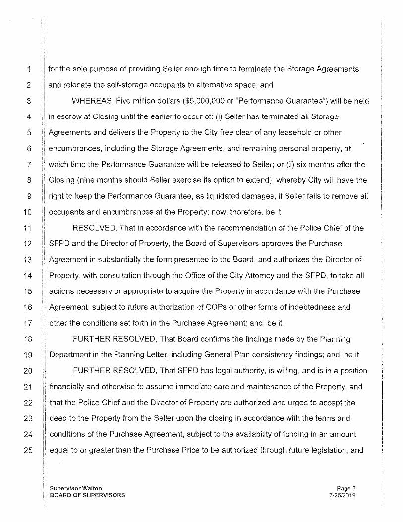
1 for the sole purpose of providing Seller enough time to terminate the Storage Agreements
2 and relocate the self-storage occupants to alternative space; and
3 WHEREAS, Five million dollars ($5,000,000 or "Performance Guarantee") will be held
4 in escrow at Closing until the earlier to occur of: (i) Seller has terminated all Storage
5 Agreements and delivers the Property to the City free clear of any leasehold or other
6 encumbrances, including the Storage Agreements, and remaining personal property, at
7 which time the Performance Guarantee will be released to Seller; or (ii) six months after the
8 Closing (nine months should Seller exercise its option to extend), whereby City will have the
9 right to keep the Performance Guarantee, as liquidated damages, if Seller fails to remove all
1 0 occupants and encumbrances at the Property; now, therefore, be it
11 RESOLVED, That in accordance with the recommendation of the Police Chief of the
12 SFPD and the Director of Property, the Board of Supervisors approves the Purchase
13 Agreement in substantially the form presented to the Board, and authorizes the Director of
14 Property, with consultation through the Office of the City Attorney and the SFPD, to take all
15 actions necessary or appropriate to acquire the Property in accordance with the Purchase
16 Agreement, subject to future authorization of COPs or other forms of indebtedness and
17 other the conditions set forth in the Purchase Agreement; and, be it
18 FURTHER RESOLVED, That Board confirms the findings made by the Planning
19 Department in the Planning Letter, including General Plan consistency findings; and, be it
20 FURTHER RESOLVED, That SFPD has legal authority, is willing, and is in a position
21 financially and otherwise to assume immediate care and maintenance of the Property, and
22 that the Police Chief and the Director of Property are authorized and urged to accept the
23 deed to the Property from the Seller upon the closing in accordance with the terms and
24 conditions of the Purchase Agreement, subject to the availability of funding in an amount
25 equal to or greater than the Purchase Price to be authorized through future legislation, and
Supervisor Walton BOARD OF SUPERVISORS
Page 3 7/25/2019

1 to take any and all steps (including, but not limited to, the execution and delivery of any and
2 all certificates, agreements, notices, consents, escrow instructions, the Leaseback, closing
3 documents, and other instruments or documents) as the Director of Property, with
4 consultation from the Office of the City Attorney, deems necessary or appropriate in order to
5 acquire the Property under the Purchase Agreement, or to other effectuate the purpose and
6 intent of this Resolution, such determination to be conclusively evidenced by the execution
7 and delivery by the Director of Property of any such documents; and be it
8 FURTHER RESOLVED, That within thirty (30) days of the City acquiring the
9 Property, the Director of Property shall provide a copy of the fully executed Purchase
1 0 Agreement to the Clerk of the Board for inclusion into the official file.
11 FURTHER RESOLVED, That, the Director of Property shall report back to the Board
12 of Supervisors in January 2020 on the plan for the City's use of 777 Brannan Street.
13
14
15
16
17
18
19
20
21
22
23
24
25
Supervisor Walton BOARD OF SUPERVISORS
Page 4 7/25/2019

1
2
3 RECOMMENDED:
4 SAN FRANCISCO POLICE DEPARTMENT
5
6
7
8
9
10
11
12
13
14
15
16
17
18
19
20
21
22
23
24
25
William Scott Chief of Police San Francisco Police Department
REAL ESTATE DIVISION
Andrico Q. Penick Director of Property
Supervisor Walton BOARD OF SUPERVISORS
Page 5 7/24/2019

City and County of San Francisco
Tails
City Hall 1 Dr. Carlton B. Goodlett Place San Francisco, CA 94102-4689
Resolution
File Number: 190774 Date Passed: July 30, 2019
Resolution approving and authorizing the Real Estate Division to acquire real property located at 1828 Egbert Avenue, from San Francisco Self Storage Ill, LLC, db a 1828 Egbert Avenue, LLC, for a purchase price of $67,300,000 subject to future authorization of Certificates of Participation; placing the real property under the jurisdiction of the Real Estate Division for use of storing evidence and moving property from the Hall of Justice and other locations; adopting findings that the acquisition is consistent with the General Plan, and the eight priority policies of Planning Code, Section 101.1; and authorizing the Director of Property to execute documents, enter into the Leaseback, and make certain modifications and take certain actions in furtherance of the Purchase Agreement and this Resolution, as defined herein.
July 24, 2019 Budget and Finance Sub-Committee- AMENDED
July 24, 2019 Budget and Finance Sub-Committee- RECOMMENDED AS AMENDED
July 30, 2019 Board of Supervisors -ADOPTED
Ayes: 11 -Brown, Fewer, Haney, Mandelman, Mar, Peskin, Ronen, Safai, Stefani, Walton and Yee
File No. 190774
London N. Breed Mayor
City and County of San Francisco Pagel
I hereby certify that the foregoing Resolution was ADOPTED on 7/30/2019 by the Board of Supervisors of the City and County of San Francisco.
Angela Calvillo Clerk of the Board
~-l-l~ Date Approved
Printed at 1:29pm on 7131119

FILE NO. 160645
AMENDED IN COMMITTEE 6/16/16
RESOLUTION NO. 263-16
1 [Real Property Purchase - 450 Sixth Street - Multiple Party Ownership - $2,403,333]
2
3 Resolution authorizing the execution and acceptance of a Purchase and Sale
4 Agreement by and between the City and Joan Spargo, in Trust, as Trustee of the "Stella
5 Arnold 1987 Exempt Trust FBO Joan Spargo" dated April 4, 2001, as to an undivided
6 3/8 interest; Walter A. Arnold, in Trust, as Trustee of the "Stella Arnold 1987 Exempt
7 Trust FBO Walter A. Arnold" dated April 4, 2001, as to an undivided 3/8 interest;
8 Kenneth Musso, as to an undivided 1/12 interest; David Musso, as to an undivided 1/12
9 interest; and Arlene Ripley, as to an undivided 1/12 interest ("Seller"), for the real
10 property located at 450 Sixth Street (Assessor's Parcel Block No. 3759, Lot No. 043) for
11 $2,403,333; and finding the proposed transactions are in conformance with the City's
12 General Plan, and the eight priority policies of Planning Code, Section 101.1.
13
14 WHEREAS, The Capital Planning Committee and Board of Supervisors have
15 previously approved a Hall of Justice replacement project known as the Justice Facilities
16 Improvement Project (JFIP); and
17 WHEREAS, The Board of Supervisors directed City staff in December of 2015 to
18 pursue property acquisitions within Assessor's Parcel Block No. 3759 for purposes consistent
19 with the JFIP; and
20 WHEREAS, 450 Sixth Street is Assessor's Parcel Block No.3759, Lot No. 43; and
21 WHEREAS, The acquisition of this property is key to the potential development of any
22 project adjacent to existing Hall of Justice facilities consistent with the JFIP; and
23 WHEREAS, The Planning Department, through General Plan Referral letter dated May
24 26, 2016, ("Planning Letter"), which is on file with the Clerk of the Board of Supervisors under
25 File No. 160645, has verified that the City's acquisition of 450 Sixth Street is consistent with
Mayor Lee BOARD OF SUPERVISORS Page 1

1 the General Plan, and the eight priority policies under Planning Code, Section 101.1, and the
2 acquisition was fully evaluated in the 850 Bryant Street - Hall of Justice Mitigated Negative
3 Declaration, Planning Case No. 2014.0198E, upheld by the Board of Supervisors on July 21,
4 2015, Motion No. 150702; and
5 WHEREAS, The Director of Property, in consultation with the Office of the City
6 Attorney, negotiated the proposed Purchase and Sale Agreement for 450 Sixth Street
7 (Assessor's Parcel Block No. 3759, Lot No. 43), which is on file with the Clerk of the Board of
8 Supervisors under File No. 160645 (the "Agreement"), with a purchase price of $2,403,333
9 (the "Purchase Price"); and
10 WHEREAS, The property is currently leased to Beauty Systems Group Inc., a
11 Delaware Corporation ("Tenant") through April 30, 2026 (the "Lease", a copy of which is on file
12 with the Clerk of the Board of Supervisors under File No. 160645) at a industrial gross rent of
13 $9,250 per month which will provide income to the City during the JFIP design and permitting
14 process; and
15 WHEREAS, An independent MAI appraisal of 450 Sixth Street, by Carneghi and
16 Partners Inc. in October 2015, determined that fair market value for the property to be
17 acquired at $2,750,000; now, therefore, be it
18 RESOLVED, That the Board of Supervisors hereby finds that the acquisition of 450
19 Sixth Street is consistent with the City's General Plan and Eight Priority Policies of Planning
20 Code Section 101.1 and hereby incorporates such findings by reference as though fully set
21 forth in this Resolution; and, be it
22 FURTHER RESOLVED, That the Board of Supervisors hereby finds that the purchase
23 of the Property, as contemplated by the Purchase Agreement is consistent with the General
24 Plan, and with the eight Priority Policies of Planning Code Section 101.1 and has been fully
25 evaluated in the 850 Bryant Street - Hall of Justice Mitigated Negative Declaration for the
Mayor Lee BOARD OF SUPERVISORS Page 2

1 same reasons as set forth in the letter of the Department of City Planning, dated May 26,
2 2016, and hereby incorporates such findings by reference as though fully set forth in this
3 Resolution; and, be it
4 FURTHER RESOLVED, That in accordance with the recommendation of the Director
5 of Property and Mayor, the jurisdiction of the Acquisition Site will be assigned upon close of
6 escrow to Real Estate; and, be it
7 FURTHER RESOLVED, That the execution, delivery and performance of the
8 Agreement is hereby approved and the Director of Property (or his designee) are hereby
9 authorized to execute the Agreement, in substantially the form of Agreement referenced
10 herein, on behalf of the City and any such other documents that are necessary or advisable to
11 complete the transaction contemplated by the Agreement and effectuate the purpose and
12 intent of this Resolution; and, be it
13 FURTHER RESOLVED, That the Board of Supervisors authorizes the Director of
14 Property (or his designee), in consultation with the City Attorney, to enter into any additions,
15 amendments or other modifications to the Agreement and any other documents or
16 instruments, including but not limited to an Assignment of Lease, necessary in connection
17 therewith, that the Director of Property determines are in the best interests of the City, do not
18 f materially decrease the benefits to the City with respect to the Property, do not materially
19 increase the obligations or liabilities of the City, and are necessary or advisable to complete
20 the transaction contemplated in the Agreement and that effectuate the purpose and intent of
21 this Resolution, such determination to be conclusively evidenced by the execution and
22 delivery by the Director of Property (or his designee) of any such additions, amendments, or
23 other modifications; and, be it
24
25
Mayor Lee BOARD OF SUPERVISORS Page 3

1 FURTHER RESOLVED, That the Board of Supervisors authorizes the
2 assignment of the Lease; and, be it
3 FURTHER RESOLVED, That all actions authorized and directed by this
4 Resolution and heretofore taken are hereby ratified, approved and confirmed by this
5 Board of Supervisors; and, be it
6 FURTHER RESOLVED, That the Director of Property shall provide the Clerk
7 of the Board of Supervisors a fully executed copy of the Purchase and Sale
8 Agreement within thirty (30) days of signature of same.
9
10
11
12
13
14
15
16
17
18
19
20
21
22
23
24
25
RECOMMENDED:
I Mayor Lee BOARD OF SUPERVISORS
$2,403,333 Available
Controller Availability of funds for future fiscal years is subject to the enactment of the annual appropriation ordinance.
Page4

City and County of San Francisco
Tails
Resolution
City Hall 1 Dr. Carlton B. Goodlett Place San Francisco, CA 94102-4689
File Number: 160645 Date Passed: June 28, 2016
Resolution authorizing the execution and acceptance of a Purchase and Sale Agreement by and between the City and Joan Spargo, in Trust, as Trustee of the "Stella Arnold 1987 Exempt Trust FBO Joan Spargo" dated April 4, 2001, as to an undivided 3/8 interest; Walter A. Arnold, in Trust, as Trustee of the "Stella Arnold 1987 Exempt Trust FBO Walter A. Arnold" dated April 4, 2001, as to an undivided 3/8 interest; Kenneth Musso, as to an undivided 1 /12 interest; David Musso, as to an undivided 1/12 interest; and Arlene Ripley, as to an undivided 1/12 interest ("Seller"), for the real property located at 450 Sixth Street (Assessor's Parcel Block No. 3759, Lot No. 043) for $2,403,333; and finding the proposed transactions are in conformance with the General Plan, and the eight priority policies of Planning Code, Section 101.1.
June 16, 2016 Budget and Finance Committee -AMENDED
June 16, 2016 Budget and Finance Committee - RECOMMENDED AS AMENDED
June 28, 2016 Board of Supervisors -ADOPTED
Ayes: 11 - Avalos, Breed, Campos, Cohen, Farrell, Kim, Mar, Peskin, Tang, Wiener and Yee
File No. 160645 I hereby certify that the foregoing Resolution was ADOPTED on 6/28/2016 by the Board of Supervisors of the City and County of San Francisco.
Mayor Date Approved
City and County of San Francisco Pagel3 Printed at 1:34 pm on 6/29116

2018 LETTER FROM SAN FRANCISCO LEADERSHIP ABOUT THE URGENT NEEDS AT THE HALL OF JUSTICE


CC
SF H
AZ
US
Ana
lysi
sO
ffic
e of
the
City
Adm
inist
rato
rC
apita
l Pla
nnin
g Pr
ogra
m--
----
----
----
----
----
From
2011
-201
7,th
eC
apita
lPl
anni
ngPr
ogra
m,
inco
llabo
ratio
nw
ithth
eD
ept.
ofPu
blic
Wor
ks,R
ealE
stat
eD
ept.,
Dep
t.of
Build
ing
Insp
ectio
n,D
ept.
ofEm
erge
ncy
Man
agem
ent,
Risk
Man
agem
ent,
and
Con
trol
ler’s
Off
ice,
cond
ucte
da
seism
icre
view
stud
yon
high
prio
rity
Gen
eral
Fund
facil
ities
.Th
ere
sults
help
prio
ritiz
ese
ismic
impr
ovem
ents
tore
duce
post
-disa
ster
reco
very
cost
sfo
rthe
City
.
San
And
reas
M7.
9 (3
.8%
)Sa
n A
ndre
as M
7.2
(0.6
%)
San
And
reas
M6.
5 (N
/A)
Hay
war
d M
6.9
(9.9
%)
EAR
THQ
UA
KE
SCEN
AR
IOS
(with
USG
S 30
yea
r pro
babi
lity)
ALL
LOSS
ES IN
$
MIL
LIO
NH
ayw
ard
M6.
9
San
And
reas
M
6.5
San
And
reas
M
7.2
San
And
reas
M
7.9
Stru
ctur
al D
amag
e10
7.2
133.
4 21
2.3
353.
1
Non
-Str
uctu
ral D
amag
e39
8.3
545.
4 85
9.7
1,48
9.3
Tota
l Bui
ldin
g D
amag
e50
5.5
678.
8 1,
072.
0 1,
842.
4
Con
tent
Dam
age
130.
1 42
6.7
523.
6 71
4.3
Ope
ratio
nal L
osse
s; R
ent,
Relo
catio
n &
Los
t Inc
ome
154.
8 19
1.9
314.
7 52
7.2
Tota
l Eco
nom
ic Im
pact
790.
4 1,
297.
3 1,
910.
3 3,
083.
8
Hay
war
d M
6.9
San
And
reas
M
6.5
San
And
reas
M
7.2
San
And
reas
M
7.9
Mea
n bu
ildin
g da
mag
e (%
of
build
ing
valu
e)9%
12%
19%
33%
Occ
upan
cy T
aggi
ng (
Num
ber
of B
uild
ings
in E
ach
Cat
egor
y):
# G
reen
Tag
ged
195
183
127
75#
Yel
low
Tag
ged
3244
8974
# R
ed T
agge
d12
1223
90To
tal #
Bui
ldin
gs23
923
923
923
9C
olla
pse
Prob
abili
ties (
Num
ber
of B
uild
ings
in E
ach
Cat
egor
y):
<5%
235
233
215
156
5 –
10%
46
2468
10 –
15%
00
015
Tota
l # B
uild
ings
239
239
239
239
ALL
CA
SUA
LTIE
S A
T PE
AK
O
CC
UPA
NC
YH
ayw
ard
M6.
9
San
And
reas
M
6.5
San
And
reas
M
7.2
San
And
reas
M
7.9
Tota
l#C
asua
lties
597
1,09
91,
798
3,24
8To
tal #
Cas
ualti
es (N
umbe
r of
Bui
ldin
gs in
Eac
h C
ateg
ory)
Non
eEx
pect
ed16
514
310
668
10or
Few
er60
8111
013
011
to25
118
1119
26to
502
34
951
to10
00
03
510
1or
Mor
e1
45
8
CA
SUA
LTIE
S
BUIL
DIN
GDA
MA
GE
ECO
NO
MIC
IMPA
CT
LIQ
UEF
AC
TIO
N S
USC
EPTI
BILI
TY
Im
prov
es c
apita
l pla
nnin
g
Iden
tify
whe
re f
urth
er s
eism
ic a
naly
sis is
nee
ded
Pr
iorit
ize
capi
tal p
roje
cts
G
uide
s im
port
ant e
mer
genc
y re
spon
se p
lann
ing
deci
sion
s
Info
rm e
mer
genc
y re
spon
se a
ctio
ns p
lans
In
crea
se a
bilit
y to
trac
k ch
ange
s in
vul
nera
bilit
y ov
er ti
me
Pr
ovid
es lo
ss e
stim
ates
for
gran
t app
licat
ions
Pr
e-di
sast
er m
itiga
tion
Po
st-d
isast
er re
cove
ry
CC
SF S
TUD
YD
ETA
ILS
A
naly
zed
239
high
-prio
rity,
Gen
eral
Fun
d bu
ildin
gs
Pr
iorit
ized
em
erge
ncy
resp
onse
and
vul
nera
ble
build
ings
H
ighe
st p
riorit
y bu
ildin
gs a
re p
rimar
y de
part
men
t ope
ratio
n ce
nter
s (D
OC
s), e
mer
genc
y sh
elte
r lo
catio
ns, a
nd e
mer
genc
y re
spon
se c
ente
rs
M
odel
ed fo
ur e
arth
quak
e sc
enar
ios
and
estim
ated
the
impa
ct
on e
ach
build
ing
Si
gnifi
cant
driv
ing
fact
ors
incl
ude
build
ing
desi
gn le
vel,
build
ing
occu
panc
y, b
uild
ing
expo
sure
val
ue, a
nd li
quef
actio
n po
tent
ial
HA
ZU
S BE
NEF
ITS
Resu
lts c
ontin
ue o
n ne
xt p
age
RES
ULT
S
SUM
MAR
Y RE
PORT
OF
SAN
FRA
NCI
SCO
'S 2
017
HAZU
S AN
ALYS
IS

Hig
him
pact
build
ings
are
thos
eth
atw
ere
iden
tifie
das
havi
ngsig
nific
antf
inan
cial
impa
ctto
the
city
ora
high
num
ber
ofca
sual
ties
insp
ecifi
cea
rthq
uake
scen
ario
s.Be
low
are
the
resu
ltsfo
rth
egr
eate
stm
agni
tude
eart
hqua
kesc
enar
io.
RES
ULT
S (C
ON
TIN
UED
)
HIG
HIM
PAC
TBU
ILD
ING
S
San
And
reas
M7.
9Ec
onom
ic Im
pact
>
$50
MO
pera
tiona
l Los
ses
> $
5MR
ed-T
agge
d>
70%
Bui
ldin
g D
amag
ePr
obab
ility
of
Col
laps
e >
10%
Cas
ualti
es
> 1
00C
asua
lty R
ate
> 1
0%A
DM
AD
MA
DM
AD
MA
DM
AD
M1
Sout
h V
an N
ess*
1 So
uth
Van
Nes
s*A
nim
al C
are
and
Con
trol
Fac
ility
Ani
mal
Car
e an
d C
ontr
ol F
acili
tyBi
ll G
raha
m C
ivic
Aud
itoriu
mA
nim
al C
are
and
Con
trol
Fac
ility
Hal
l of
Just
ice
1650
Miss
ion
Hal
l of
Just
ice
Prod
uce
Build
ing-
Sout
hH
all o
f Ju
stic
eBr
ooks
Hal
lM
osco
ne C
ente
r (S
outh
)25
Van
Nes
s*Pr
oduc
e Bu
ildin
g-So
uth
Mun
icip
al R
ailw
ay O
verh
ead
Line
sM
osco
ne C
ente
r (S
outh
)Pr
oduc
e Bu
ildin
g-So
uth
Mos
cone
Wes
t30
Van
Nes
s*Pr
oduc
e M
arke
t-N
orth
Bui
ldin
g L
The
Old
Min
tM
osco
ne N
orth
Prod
uce
Mar
ket-
Nor
th B
uild
ing
LTh
e O
ld M
int
Hal
l of
Just
ice
Prod
uce
Mar
ket-
Nor
th B
uild
ing
ND
PHM
osco
ne W
est
Prod
uce
Mar
ket-
Sout
h Bu
ildin
g M
DPH
Mos
cone
Cen
ter
(Sou
th)
Prod
uce
Mar
ket-
Pub
Doc
k 1
mid
dle*
Tom
Wad
dell
Clin
icFA
MM
unic
ipal
Rai
lway
Ove
rhea
d Li
nes
SFG
H -
Build
ing
100
Mos
cone
Nor
thPr
oduc
e M
arke
t-Pu
b D
ock
2 m
iddl
e*D
PWde
You
ng M
useu
m*
DPH
SFG
H -
Build
ing
80M
osco
ne W
est
Prod
uce
Mar
ket-
Pub
Doc
k 3a
mid
dle*
DPW
-C
arpo
rt 1
-DR
ESM
axin
e H
all H
ealth
Cen
ter
SFG
H -
Build
ing
5 (M
ain
Hos
pita
l)D
PHPr
oduc
e M
arke
t-So
uth
Build
ing
KD
PW -
Car
port
4-G
,H,J
Keza
r Pa
vilio
nSF
City
Clin
icSF
GH
-Bu
ildin
g 1*
DPH
Cen
tral
Off
ice
(101
Gro
ve)
Prod
uce
Mar
ket-
Sout
h Bu
ildin
g M
Pow
er H
ouse
SCI
SFG
H -
Build
ing
10 (C
OR.
10-1
B)FA
MLa
guna
Hon
da H
ospi
tal (
A &
B W
ings
)M
unic
ipal
Rai
lway
Ove
rhea
d Li
nes
FIR
Aca
dem
y of
Sci
ence
sSF
GH
-Bu
ildin
g 1A
de Y
oung
Mus
eum
*La
guna
Hon
da H
ospi
tal (
H W
ing)
AR
TSF
FD E
quip
men
t Uni
t Hea
dqua
rter
sSF
GH
-Bu
ildin
g 1B
Legi
on o
f H
onor
*SF
GH
-Bu
ildin
g 10
0H
unte
rs P
oint
Art
Stu
dios
Fire
Chi
efs
Resid
ence
*SF
GH
-Bu
ildin
g 1C
HSA
SFG
H -
Build
ing
80D
PHFi
re S
tatio
n #
17SF
GH
-Bu
ildin
g 20
(CO
R. 2
0-10
)17
0 O
tisSF
GH
-Bu
ildin
g 9
DPH
Cen
tral
Off
ice
(101
Gro
ve)
Fire
Sta
tion
#35
/Fire
Boa
t HD
QSF
GH
-Bu
ildin
g 30
(CO
R. 3
0-40
)SH
FSF
GH
-Bu
ildin
g 90
Max
ine
Hal
l Hea
lth C
ente
rR
ECSF
GH
-Bu
ildin
g 4
Sher
iff's
Faci
lity
(Inm
ate
Hou
sing)
SFG
H -
Build
ing
5 (M
ain
Hos
pita
l)To
m W
adde
ll C
linic
McL
aren
Lod
geTo
m W
adde
ll C
linic
WA
RSF
GH
-M
AIN
HO
SPIT
AL
(M W
ING
)D
PWG
enev
a C
ar B
arn
FIR
War
Mem
oria
l Ope
ra H
ouse
SFG
H -
Men
tal H
ealth
Bui
ldin
gD
PW -
Car
port
1-D
Ash
bury
Str
eet T
ank
& T
ank
Hou
seSF
GH
-Bu
ildin
g 3*
DPW
-C
arpo
rt 4
-G,H
,JSF
FD E
quip
men
t Uni
t Hea
dqua
rter
sSF
GH
-Bu
ildin
g 1*
Pow
er H
ouse
Fire
Chi
efs
Resid
ence
*H
SAFI
RFi
re S
tatio
n #
1017
0 O
tisSF
FD E
quip
men
t Uni
t Hea
dqua
rter
sFi
re S
tatio
n #
17SH
FFi
re C
hief
s Re
siden
ce*
Fire
Sta
tion
#21
Sher
iff's
Faci
lity
(Inm
ate
Hou
sing)
Fire
Sta
tion
#17
Fire
Sta
tion
#22
RED
Fire
Sta
tion
#22
Fire
Sta
tion
#24
440
Turk
Fire
Sta
tion
#25
*Fi
re S
tatio
n #
25*
Fire
Sta
tion
#34
Fire
Sta
tion
#34
Fire
Sta
tion
#35
/Fire
Boa
t HD
QFi
re S
tatio
n #
35/F
ire B
oat H
DQ
Fire
Sta
tion
#40
*Fi
re S
tatio
n #
37Fi
re S
tatio
n #
6*Fi
re S
tatio
n #
39Pu
mp
Stat
ion
#2
(For
t Mas
on)
Fire
Sta
tion
#44
Fire
Sta
tion
#30
(ina
ctiv
e)Fi
re S
tatio
n #
6*PO
LPu
mp
Stat
ion
#2
(For
t Mas
on)
Park
Pol
ice
Stat
ion
JUV
REC
W-1
Cot
tage
: Bui
ldin
g 19
Cor
p Ya
rd (W
areh
ouse
)W
-3 C
otta
ge: B
uild
ing
17Ke
zar
Pavi
lion
POL
Cor
p. Y
ard
(Pai
nt/C
arpe
nter
Sho
p)*
Gol
den
Gat
e Pa
rk P
olic
e St
able
s*M
cLar
en L
odge
Park
Pol
ice
Stat
ion
Park
Sen
ior
Cen
ter
Rich
mon
d Po
lice
Stat
ion
Build
ing
1M
othe
rs B
uild
ing
Rich
mon
d Po
lice
Stat
ion
Build
ing
2R
ECC
orp
Yard
(War
ehou
se)
Cor
p. Y
ard
(Pai
nt/C
arpe
nter
Sho
p)*
McL
aren
Lod
geM
issio
n Re
c C
ente
r (M
ain
Build
ing)
Miss
ion
Rec
Cen
ter
(Clu
bhou
se)
Park
Sen
ior
Cen
ter

HALL OF JUSTICE SEISMIC HAZARD RATING REPORT


City and County of San Francisco Department of Public Works Seismic Assessment of Various City-Owned Buildings
Dept~7~1 __ Fae ID# 312 Building Hall of Justice Group C Number _4-'-----
EXECUTIVE SUMMARY
This report presents the results of a seismic vulnerability and conceptual strengthening
evaluation performed by EQE/AGS on the Hall of Justice located at 850 Bryant Street in San
Francisco. This evaluation was one of nearly eighty performed for various City of San
Francisco-owned buildings.
The Hall of Justice is an 8-story L-shaped reinforced-concrete building. Constructed circa 1958,
the building has approximately 610,000 square feet of floor space with outside leg dimensions
on the "L" measuring approximately 304 feet and 515 feet. An addition was constructed, circa
1979 to expand the court facilities, atop the coroner's office at the north wing. The building has
an occupancy class "C", essential, designation and has a peak occupancy load of 400 persons.
Structural and some architectural drawings were available tor review. Details of the building are
contained on the attached Form A: Current Building Data.
The existing building was evaluated using the requirements of the National Earthquake Hazard
Reduction Program (NEHRP) Handbook for the Seismic Evaluation of Existing Buildings. A
summary of the analysis parameters utilized are contained in the attached Form B: Evaluation
Analysis Summary. The conclusion of the analysis calculations was the building was found to
be vulnerable to severe structural and non-structural damage in the event of a major
earthquake. This would pose an appreciable life/safety risk to the occupants. Based on the
results of this evaluation, .a seismic hazard rating (SHA) of 3 has been assigned to the existing
Hall of Justice.
Major deficiencies include: significant torsional behavior (due to the L-shape of the building);
concrete piers, walls, and floor slabs are severely overstressed; lack of adequate ties and
collectors throughout the building, particular1y at the re-entrant corner; geometric and vertical
irregularities of concrete shear walls; and inadequacy of the existing foundation system to resist
wall overturning. A complete list of identified building deficiencies' is attached.
Several concepts were considered as alternatives to improving the seismic performance of the
building structure. They included strengthening the existing building, separation of the building
into two structures, and base isolation.
Each of these concepts involved significant building modifications. Strengthening the existing
building involved the addition of four new concrete walls in the transverse direction of the west
wing, infilling of a significant number of windows, thickening of selected portions of the perimeter
30978-66/Fin-HJ v
hgreen
Highlight
hgreen
Highlight


City and County of San Francisco FIE: EQE/AGS Seismic Assessment of Various City-Owned Buildings Building: Hall of Justice
Table 1.4.1 City of San Francisco Seismic Hazard Ratings
(Source: San Francisco Department of Public Works}
The Seismic Hazard Rating (SHA) is a number assigned to a building as a means of estimating building performance during a great earthquake as well as the amount of damage the building will sustain. The ratings, and the policy implications, are described here:
Damage SHR Estimate Description
1 Minor damage Some structural or nonstructural damage and/or falling (Good performance) hazards may occur, but these would pose minimal life
hazards to occupants. The damage can be repaired while the building is occupied and with minimum disruption to functions. Buildings and structures with this rating represent an acceptable level of earthquake safety, and funds need not be spent to improve their seismic resistance to gain greater life safety.
2 Moderate damage Structural and nonstructural damage and/or falling (Fair Performance) hazards are anticipated which would pose low life
hazards to occupants. The damage can be repaired while the building is occupied. Buildings and structures with this rating will be given a low priority for expenditures to improve seismic performance and/or falling hazards to the "good performance" level.
3 Major damage Structural and nonstructural damage are anticipated (Poor performance) which would pose appreciable life hazarqs to
occupants. The building has to be vacated during repairs, or possibly cannot be repaired due to the extent (sic) and/or economic considerations. Buildings and structures with this rating will be given a high priority for expenditures to improve seismic performance and/or falling hazards to the "good performance" level, or would be considered for other abatement programs such as reduction of occupancy.
4 Partial/total collapse Extensive structural and nonstructural damage, (Very poor potential structural collapse and/or falling hazards are performance) anticipated which would pose high life hazards to
occupants. There is a good likelihood that damage repairs would not be feasible. Buildings and structures with this rating will be given the highest priority for expenditures to improve seismic performance and/or falling hazards to the "good performance" level, or would be considered for other abatement programs such as reduction of occupancy or vacation.
30978-66/Fin-HJ 1-6
hgreen
Highlight
hgreen
Highlight


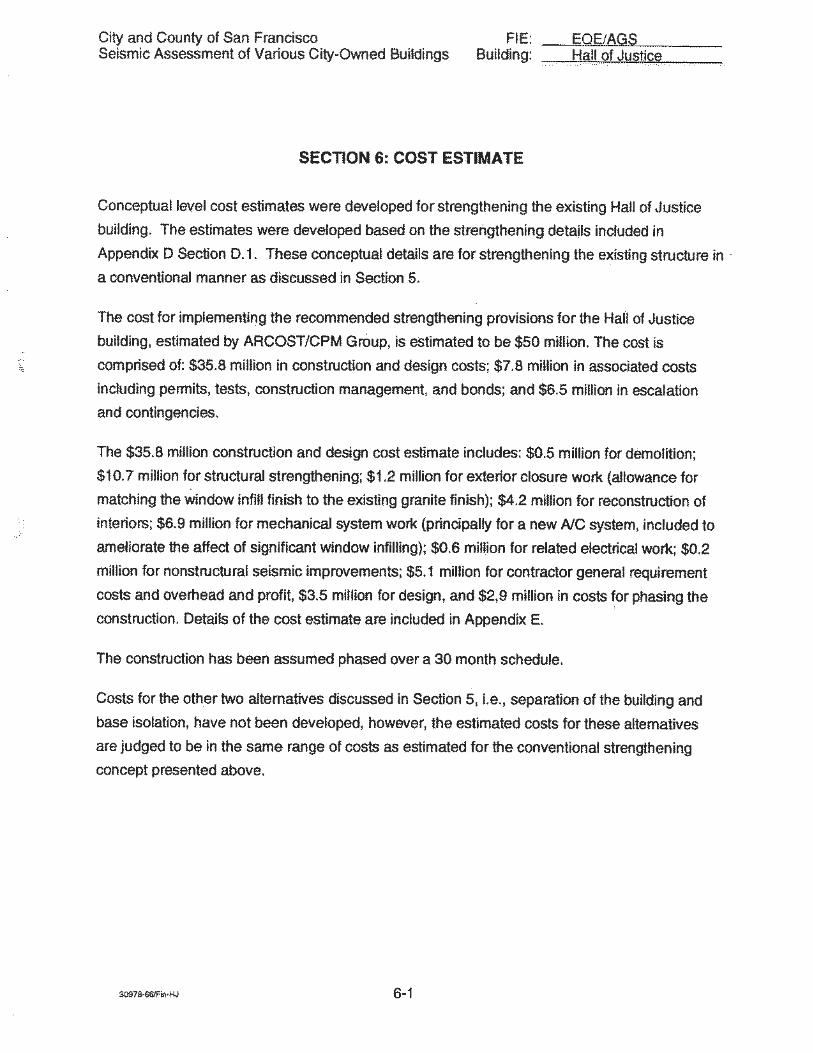


HALL OF JUSTICE ELEVATOR DOCUMENTATION
This page and the following one contain a sampling of recent communications and work records related to the Hall of Justice elevators, which are an essential system for the building’s accessibility. Taken together and as representative of an ongoing challenge, they show that the Hall’s elevators are relevant to the building’s accessibility as much as its facilities condition.
From: O'Connor, Brian (ADM) Sent: Wednesday, August 14, 2019 8:37 AM To: O'Connor, Brian (ADM) <brian.o'[email protected]>; [email protected]; [email protected]; Brandon E. Riley <[email protected]>; Mark Culkins <[email protected]>; Pecot, Johna (SHF) <[email protected]>; Jamison, Felicia (SHF) <[email protected]>; Ramirez, John (SHF) <[email protected]>; Santizo, Dan (SHF) <[email protected]>; O'Brien, Alexa (POL) <[email protected]>; Minner, Joseph (POL) <[email protected]>; Tave, Anthony (POL) <[email protected]>; Fletcher, Karen (ADP) <[email protected]>; Lim, Diane (ADP) <[email protected]>; Clendinen, Eugene (DAT) <[email protected]>; Arcelona, Sheila (DAT) <[email protected]>; Brown, Herman (DAT) <[email protected]>; Geiger, Jessica (DAT) <[email protected]> Cc: Penick, Andrico <[email protected]>; Gorham, Claudia (ADM) <[email protected]>; Cline, Scott (ADM) <[email protected]>; Kirovsky, Mark (ADM) <[email protected]>; Li, Nam (ADM) <[email protected]>; Zhao, Jing (ADM) <[email protected]>; Rodriguez, Victor (ADM) <[email protected]> Subject: Re: HOJ ELEVATORS
To Single Point of Contacts:
Unfortunately all 4 elevators off the entrance are now out of service. The elevator vendor is on-site.
We are directing people to elevetor 7 & 8 down the hallway towards 7th street side of HOJ (nearthe traffic court office) and the closest stairs leading to the Courts on the 2nd and 3rd floors.
Thank you for your continued patience and understanding.
From: O'Connor, Brian (ADM) Sent: Wednesday, August 7, 2019 8:22 AM To: Gorham, Claudia (ADM) <[email protected]>; Cline, Scott (ADM) <[email protected]>; Penick, Andrico <[email protected]> Subject: Elevator Entrapments
HOJ entrapment at approx. 1:50 a.m. last night. KONE called, about an hour to free the person.

HOJ Elevator Reconciliation
Master Contract
7/19/2017 5,400.00$ troubleshoot #18/4/2017 4,025.00$ Spare car door panels for elevator #3
8/16/2017 1,800.00$ elevator #5 - bayonet apart, change bearings, adj9/26/2017 21,600.00$ troubleshoot #310/2/2017 10,800.00$ complete rope repair #5 - original invoice $28,80010/2/2017 3,600.00$ elevator assessment
10/26/2017 9,595.84$ elevator #5 motor & generator repairs (phase I)11/10/2017 66,907.76$ elevator #5 motor & generator repairs (phase II)
12/9/2017 1,800.00$ elevator #3 troubleshootTotal: 125,528.60$
Capital Project
3/3/2017 14,753.88$ #4 & #5 elevator edge detectors
3/15/2017 38,547.90$ #4 passenger elevator re-rope due to roof leak wa4/4/2017 68,804.82$ Elevator #2 & #3 motor generator work4/4/2017 99,515.12$ #1-5 & #7-8 door operator/music box rebuild 6/8/2017 7,350.00$ change order (trouble shoot #3) from 4-4-17 propo
7/25/2017 48,191.56$ additional repairs #21/4/2018 14,753.00$ #2 & #3 elevator edge detectors4/4/2018 6,447.00$ Smart Traq operators 4/4/2018 7,200.00$ Trouble-shoot Fire Service Recall
5/30/2018 1,611.75$ Additional Traq operator6/7/2018 1,874.25$ Trouble-shoot Fire Service Operation7/1/2018 7,200.00$ Fire Service Repair
Total: 316,249.28$

SAN MATEO
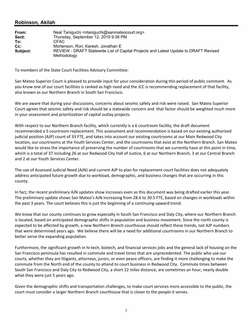
1
Robinson, Akilah
From: Neal Taniguchi <[email protected]>Sent: Thursday, September 12, 2019 9:36 PMTo: CFACCc: Mortenson, Ron; Karesh, Jonathan ESubject: REVIEW - DRAFT Statewide List of Capital Projects and Latest Update to DRAFT Revised
Methodology
To members of the State Court Facilities Advisory Committee: San Mateo Superior Court is pleased to provide input for your consideration during this period of public comment. As you know one of our court facilities is ranked as high need and the JCC is recommending replacement of that facility, also known as our Northern Branch in South San Francisco. We are aware that during your discussions, concerns about seismic safety and risk were raised. San Mateo Superior Court agrees that seismic safety and risk should be a statewide concern and that factor should be weighted much more in your assessment and prioritization of capital outlay projects. With respect to our Northern Branch facility, which currently is a 6 courtroom facility, the draft document recommended a 5 courtroom replacement. This assessment and recommendation is based on our existing authorized judicial position (AJP) count of 33 FTE, and takes into account our existing courtrooms at our Main Redwood City location, our courtrooms at the Youth Services Center, and the courtrooms that exist at the Northern Branch. San Mateo would like to stress the importance of preserving the number of courtrooms that we currently have at this point in time, which is a total of 37 including 26 at our Redwood City Hall of Justice, 6 at our Northern Branch, 3 at our Central Branch and 2 at our Youth Services Center. The use of Assessed Judicial Need (AJN) and current AJP to plan for replacement court facilities does not adequately address anticipated future growth due to workload, demographic, and business changes that are occurring in this county. In fact, the recent preliminary AJN updates show increases even as this document was being drafted earlier this year. The preliminary update shows San Mateo’s AJN increasing from 28.6 to 30.5 FTE, based on changes in workloads within the past 3 years. The court believes this is just the beginning of a continuing upward trend. We know that our county continues to grow especially in South San Francisco and Daly City, where our Northern Branch is located, based on anticipated demographic shifts in population and business movement. Since the north county is expected to be affected by growth, a new Northern Branch courthouse should reflect these trends, not AJP numbers that were determined years ago. We believe there will be a need for additional courtrooms in our Northern Branch to better serve the expanding population. Furthermore, the significant growth in hi‐tech, biotech, and financial services jobs and the general lack of housing on the San Francisco peninsula has resulted in commute and travel times that are unprecedented. The public who use our courts, whether they are litigants, attorneys, jurors, or even peace officers, are finding it more challenging to make the commute from the North end of the county to attend to court business in Redwood City. Commute times between South San Francisco and Daly City to Redwood City, a short 22 miles distance, are sometimes an hour, nearly double what they were just 5 years ago. Given the demographic shifts and transportation challenges, to make court services more accessible to the public, the court must consider a larger Northern Branch courthouse that is closer to the people it serves.

2
The currently proposed project calls for consolidation of our Northern and Central Branches, currently with a total of 9 courtrooms, into one facility with 5 courtrooms. The Court does not believe that a net loss of 4 courtrooms is justified. We ask that the committee consider these anticipated demographic and transportation factors as future discussions are held, and at the least, preserve the 37 courtrooms that this court currently maintains. Thank you again for the opportunity to present our viewpoint. We look forward to hearing more from you on this topic. Neal Taniguchi Court Executive Officer San Mateo Superior Court 400 County Center, 2nd Fl Redwood City, CA 94063 [email protected] (650) 261‐5030

SANTA BARBARA

SANTA CRUZ

Superior Court of California COUNTY OF SANTA CRUZ
Justice With Dignity and Respect
Alex Calvo 701 Ocean Street, Room 101c Court Executive Officer Santa Cruz, CA 95060 Phone: (831) 420-2200 Fax: (831) 420-2260
September 13, 2019
Ms. Ann Ludwig Mr. Chris Magnusson Facilities Services|Administrative Division Judicial Council of California 455 Golden Gate Ave., 8th Floor San Francisco, CA 94102
Re: Final Comments on Court Facilities Planning Scorecards Dear Ms. Ludwig and Mr. Magnusson: Thank you for the opportunity to comment on the drafts of the facilities planning documents provided to us on August 23, 2019. Overall, we do not believe the Total Needs Score of 11.7 adequately reflects this court’s current facility need. We strongly believe that our project should have received a score of 13 or greater which would have placed this court’s project in the “Critical Need” prioritization category. Please refer to our previous comments (attached). Our comments here are a reiteration of our previous comments.
1. Seismic Issues a. The current assessment of the Santa Cruz Court facilities does not adequately address the significant seismic risk to the main courthouse.

2. Security a. All ten courtrooms lack the segregation between in-custody defendants and judges and court staff. b. Weapons screening only is not in place for 3 of the ten courtrooms on this site, the clerks' offices and jury assembly modular building.
3. ADA/Accessibility
a. Courtrooms – not a single courtroom meets any of the current accessibility requirements to access the jury box, the witness stand, the judge's bench and the clerk’s work station.
4. Fire, Life and Safety a. The calculation for the 44-A1 facility is inaccurate since each system rated was deficient and equal to “no”. Should be assessed at 32 points and was also rated as poor on FCA. Building 44-A2 should have a score of 36 since it contains equivalent deficiencies and the facility is a total of 6 floors.
5. HVAC
a. The main courthouse does not have any HVAC system in place for the public hallways and waiting areas.
6. Asbestos Containing Materials
a. The main courthouse and county administration building were opened in 1967 and both contain extensive amounts of “ACMs” in pipe insulation, flooring and other materials.
7. Jury Assembly Room
a. Jurors assemble in a 30-year-old modular building located adjacent to the courthouse. It does not have a restroom. It is located outside of a weapons screening station. is severely deficient in areas of physical condition, security and overcrowding. As documented in the 44-A3 survey, this facility poses severe difficulties for jurors with mobility issues. (See previous comments.)
8. Needs-Based Scorecard:
a. This scorecard continues to describe the proposed project as “a new 8
courtroom courthouse of approximately 94,000 SF to consolidate 2 court
buildings” when our proposal was for a 10 courtroom courthouse providing a consolidation of 5 court buildings (1 – main courthouse, 2- jury assembly room modular, 3- Court space in the adjacent County Administration building, 4 – Jail Courtroom and Chambers, 5 – Juvenile Courthouse in Felton). b. The scorecard does list the Jail Courtroom even though the jail courtroom was not accessed. c. The Jury Assembly Room was assessed but not provided scores on the scorecard and is severely deficient in the areas of physical condition, security and overcrowding.

Thank you for considering our comments. Michell Duarte and I are available to discuss our comments or answer any questions you may have. Sincerely,
ALEX CALVO Court Executive Officer cc: Hon. Paul Burdick, Presiding Judge Michelle Duarte, Santa Cruz Superior Court Facilities Director Encl: August 15, 2019 Letter: Comments on Court Facilities Planning Draft Documents

Superior Court of California COUNTY OF SANTA CRUZ
Justice with Dignity and Respect
ALEX CALVO Court Executive Officer
701 Ocean Street, Room 101c Santa Cruz, CA 95060 Phone: (831) 420-2200
Fax: (831) 420-2260
1 | P a g e
August 15, 2019 Ms. Ann Ludwig Mr. Chris Magnusson Facilities Services|Administrative Division Judicial Council of California 455 Golden Gate Ave., 8th Floor San Francisco, CA 94102 Re: Comments on Court Facilities Planning Draft Documents Dear Ms. Ludwig and Mr. Magnusson: Thank you for the opportunity to comment on the drafts of the facilities planning documents provided to us on July 29. We have organized our comments in two sections: “General Comments” and “Comments Specific to Each Draft Document”. GENERAL COMMENTS: To document the many deficiencies in Santa Cruz Court Facilities, we are re-stating them here: Seismic Deficiencies: As stated in the Seismic Renovation Project Feasibility Report, the Main Santa Cruz Courthouse has a Seismic Risk Rating of 6.3 (High Risk). The JCC staff selected the option to replace this facility with a new facility that meets the 2016 CBC. Infrastructure Deficiencies: As noted in current and past evaluations, the Santa Cruz Court facilities, the buildings comprising the facilities located in Santa Cruz have significant infrastructure deficiencies that make conducting court operations extremely challenging. The Main Courthouse and the County Administration building were both built-in 1965 and still contain ACMs in flooring materials, pipe insulation. Each time modifications or

Santa Cruz Comments on Court Facilities Planning Draft Documents
2 | P a g e
repairs are done within the buildings, ACM abatement must be considered as part of the project. As a recent example of failing infrastructure, in June of this year, an aging water supply line failed in a judge's chambers restroom. The failure occurred on a Saturday afternoon and was not discovered for over 14 hours. The flood damaged carpet within the judge's chambers and courtrooms and it had to be removed and replaced. During the process of removing the damaged carpet, we discovered that the adhesive used to adhere the cove base to the wall contained asbestos. This required abatement before the remediation of the flood could proceed. As of the date of this later, restoration of the building is ongoing. Also, the aging plumbing systems are frequently failing leading to flooding and sewage spills. As has been noted in many evaluations, large portions of the main courthouse have NO HVAC systems in place. The temperatures can become uncomfortably warm or cold, depending on the outside temperatures. Accessibility Issues and the Jury Assembly Room: Although entries the Main Courthouse and the County Administration Building are reasonably accessible, access to the Jury Assembly Room is not. As has been noted before, the path of travel from the closest “Accessible Parking Space” requires a person with mobility issues to travel 900 feet to reach the Jury Assembly Room and then more than 900 feet to reach the courthouse entrance. Because the Jury Assembly Room is a modular building, it was not included in the “Project Needs-Based Scorecard.” We ask that this decision be reconsidered as it is an integral facility in our court’s operation. Security Deficiencies: The main courthouse (7 courtrooms) has a single point of entry with a weapons screening station. However, there are NO weapons screening stations for the those entering the following spaces, Dept. 10 Courtroom, Jail Courtroom, Civil Clerks office, Criminal Clerk’s Office, Finance Division, Jury Assembly Room, Court Technology Division, Law Library/Self-Help Center. Also, The Main Courthouse does not have separate and secure paths of travel for in-custody inmates from the holding cells to the courtrooms. Current Opportunities for Collaboration: The County of Santa Cruz is in conducting a study for a “Facilities Master Plan” for all facilities located on the campus that are shared with the Court. County and Court leadership believe that there are currently opportunities for collaboration that would be advantageous to both the County and Court. Time is of the essence to take advantage of this opportunity.

Santa Cruz Comments on Court Facilities Planning Draft Documents
3 | P a g e
COMMENTS SPECIFIC TO EACH DRAFT DOCUMENT: 1. Santa Cruz Court Facility Plan (Courthouse Needs Assessment)
• Need to add ACM to the County Administration Building • 1-5 The New Santa Cruz Courthouse: The proposal should be for ten courtrooms, not eight (The ten courtrooms are the seven in the Main Courthouse, one in the County Administration Building, one at the Jail and 1 at the Juvenile Hall.) • 3-3 The Watsonville Courthouse has 4 courtrooms (only three of which contain jury boxes.,) The Jury Assembly Room used as a meeting room and an overflow hearing room one-time each week. • 3-5 includes FEMA rating of 0.8 and a 1.2 for the County Administration Building. • 3-5 – Typo at the bottom of the page: Replace “Main Merced Courthouse” with “Main Santa Cruz Courthouse”. • 3-3 Findings states that the Main Courthouse is severely deficient and should be replaced. • 3-9 Jurors: Up to 200 jurors appear for jury duty each week at the Santa Cruz Jury Assembly Room for between two and five trails. • 3-11 Jail Courtroom. There is no space for weapons screening. Court security must provide two bailiffs for each session. Once bailiff is stationed inside the courtroom, and one is stationed at the courtroom door and conducts weapons screening with a hand-held metal detector. • 4-3 Include in the Santa Cruz Courthouse Self-Help Services co-located with the County Law Library in the basement of the County Administration Building. • 5-3 Project Specifications change “eight-courtroom facility” to “ten-courtroom facility.”
2. 44-A1 Santa Cruz Main Courthouse – Facility Condition Assessment Draft Final
• No comments. 3. 44-A2 - Santa Cruz County Administration Building -Facility Condition
Assessment Draft Final
• Page 12 courthouse building rated good condition through 2023 and in 2025 rated poor. Good is defined as “In a new or well-maintained condition, with no visual evidence of wear, soiling or other deficiencies.” We disagree. The building was built in 1965 and at a minimum should be rated currently as “Fair” (Subject to wear and soling but still in serviceable and functioning condition.)
• Concrete walls rated “good” page 23, where there is clear evidence of wear and water deposit buildup from previous occurrences of water intrusion. This building has sustained significant water intrusion over the life of the building.
• Does the facility have Hazmat and ACM reports available for the assessment team? If so, have they been reviewed?
• Pg. 125, question 4. Tenants have in the past reported air quality issues. Many times, particulate matter emitted from the air vents has been found on work stations. Air quality tests have historically only reflected dust matter.

Santa Cruz Comments on Court Facilities Planning Draft Documents
4 | P a g e
4. 44-A3 - Jury Assembly Room -Facility Condition Assessment Draft Final
• Page 3: This modular building was installed on the site in 1990. The building already
10 years old at the time it was installed. • Page 8: The building description should include a description of accessing this facility,
as discussed in the general comments above.
5. Santa Cruz Overcrowding Output Packet (Parametric Estimating Tool) • As stated above the proposed plan for a new facility in Santa Cruz would consolidate five facilities into one with ten courtrooms and all other court space (i.e., jury assembly, clerk’s offices, administrative offices). • Should account for reasonable jury numbers (up to 200 each week). The maximum occupancy of the Jury Assembly Room is 100 persons.
6. 20190726 – Project Needs Scorecard – Santa Cruz
• The description only consolidates two buildings, not 5. • FCI scores are inconsistent with courthouse vs. county admin building. Conditions are similar. The County Administration Building is arguably in slightly better operating condition than the courthouse • Jail courtroom is listed as a court facility, yet not scored. • Physical condition scores do not account for areas of methodology including
o Seismic Rating – The 2018 report states that the courthouse is in need of replacement. This is not considered in the overall scoring of the building o 2017 JCC report rated high-risk building:
o https://www.courts.ca.gov/documents/Seismic-Risk-Rating-of-California-Superior-Court-Buildings.pdf
o 2018 Seismic renovation report: o https://www.courts.ca.gov/documents/facilities-44A1-SantaCruz-
SantaCruzCourthouse.pdf o Fire life safety should have a higher rating based on page 7 of the methodology. The issues stated in FCA summary page 8, but not reflective in scoring. Two sounders in the entire first floor and unable to hear in main courthouse courtrooms and some judges’ chambers. o Environmental hazards – Assessments state there is no ACM, yet the building contains many known hazards (tile mastic, cove base mastic, water line coating). Not included. o ADA – Current courthouse was not documented according to point scale. Should have considered access to the Jury Assembly Room since this building was not included in the study at all; witness stands in Courtroom Departments One and Two are unsafe and not ADA compliant. None of the courtrooms are accessible for judges, clerks, attorneys or witnesses. Also, the well areas in all

Santa Cruz Comments on Court Facilities Planning Draft Documents
5 | P a g e
courtrooms do not provide enough unobstructed space for attorneys and litigants with mobility challenges.
• Security does not take into consideration the circulation which is mentioned in the court supplied survey response; does not mention Courtroom Department 10, Department 11, the Juvenile Courtroom or the Juvenile Hall security screening deficiencies.
7. P44-N-01 New Santa Cruz Courthouse
• The proposed plan for the new courthouse should be for ten courtrooms (not eight as stated on this document).
• In the section titled “Buildings Affected by Proposed Project”, add the Juvenile Court Facility.
Thank you for considering our comments. Michell Duarte and I are available to discuss our comments or answer any questions you may have. Sincerely,
ALEX CALVO Court Executive Officer

STANISLAUS

From: Swift, HughTo: CFACSubject: Invitation to Comment: Draft Revised Prioritization Methodology for Trial Court Capital-Outlay Projects Or
Statewide ListDate: Friday, September 13, 2019 3:45:45 PM
The Stanislaus Superior Court supports the adoption of both the DRAFT Statewide List of Trial CourtCapital-Outlay Projects and latest update to the DRAFT Revision of Prioritization Methodology forTrial Court Capital-Outlay Projects, and offers the following comments: The Statewide List includes Stanislaus’ new Modesto Courthouse Courtroom Renovation project. Insummary, this project adds three courtrooms to the already funded New Modesto Courthouseproject. We believe the Critical Need ranking of this project validates the Methodology. The projectwould replace courtrooms at a Juvenile Hall facility, which present significant safety, security,overcrowding, and accessibility issues. The Methodology focuses on determining relative need and prioritizes projects based on objectiveand verifiable data. The Judicial Council can rely on the updated Statewide List to make importantfunding decisions in a transparent and impartial manner. Furthermore, the language of Section VII,A.2., provides the Judicial Council with discretion to deviate from the Statewide List if it determines aparticular project presents an “economic opportunity”, which can only be realized within a limitedperiod of time. As an example, the currently funded New Modesto Courthouse Project presents an economicopportunity the Judicial Council might consider as an additional factor in the funding selectionprocess. Incorporating the additional courtrooms into the construction of the currently funded NewModesto Courthouse project, will result in cost savings that can only be achieved if the project wereapproved for funding in the near future, which may require it to move forward before other projectswith a higher priority ranking. Section VII, A.2., also gives the Judicial Council the discretion to request funding for projects when itpresents an economic opportunity, by the way of operational efficiencies from consolidation of courtcalendars and operations. This project would consolidate all court operations into a single facility,the New Modesto Courthouse, which is scheduled to begin construction in the Spring of 2020. Thank you for your consideration of these comments. Hugh K. SwiftCourt Executive OfficerSuperior Court of California, County of [email protected]
It is the mission and vision of the Stanislaus County Superior Court to provide equal access tojustice; serving the needs of our community and organization with integrity, quality, andfairness.


TULARE

Tulare County Superior Court - Responses September 12, 2019
Tulare County Superior Court Reponses to the
Revisions of Prioritization Methodology for Trial Court Capital-Outlay Projects
Comparisons of Prior rating to Current Rating
In the prior methodology Tulare County Superior Court ranked as #13 with priority group identified as an Immediate Need. In the revised methodology we are ranked as #22 within the priority group Critical Need. We understand that SB 847 requires the reassessment to be based on existing criteria along with the newly mandated criteria. However, it has not clearly understood how we now rank in the lower priority group. The Court is a tenant in the Visalia Courthouse Facility and have observed the lack of improvements to the building. The courthouse roof still has original 1955 segments. The building is not up to ADA standards. Daily we endure constant struggles with being in this building. We are overcrowded, there is not adequate space for judicial officers, employees and the public. The electrical power is not sufficient throughout the building to support court operations. Therefore, we are limited to upgrading our information technological needs without ample power supply. The elevators consistently are non-operational, which have required inmates to be transported through judicial and public access halls. Additionally, there several challenges to maintain appropriate security levels with limited space, downed inmate elevators and mediocre power supply. There is asbestos in the building, which requires remediation and containment this increases project costs and lengthen the time for project completion. The courthouse facility does not have secured judicial parking. As a matter of fact, the parking lot is unsafe with uneven payment and deterioration in several areas. The Visalia Courthouse Facility is not meeting the needs to support all the various operations of the Tulare County Superior Court. With this information, we request to know how our priority level has changed and why we are no longer considered an Immediate Need.
New Methodology: Does not Address “No” Courthouse Facility Available
The main Visalia Courthouse is a full-service court with 14 operational courtrooms serving the North County. As we
are in a shared facility with the County of Tulare, the current methodology does not take into consideration the
potential abandonment of the building from our County partner. This was included in our responses to the Court
Facility Assessment Plan, the County expressed interest to the Court Executive Officer (CEO) to vacate the Visalia
Courthouse building. If the County vacates the building, the Court would be without a place to conduct court
operations, essentially homeless. In the proposed new methodology, there is no formula or method to account for a
such an occurrence. We respectfully request, this major factor be considered in our ranking for a New Tulare North
County Courthouse.

Court Facilities Advisory Committee As of August 6, 2019
Page 1 of 2
Hon. Brad R. Hill, Chair Administrative Presiding Justice of the Court of Appeal, Fifth Appellate District
Hon. Patricia M. Lucas, Vice-Chair Judge of the Superior Court of California, County of Santa Clara
Hon. JoAnn M. Bicego Judge of the Superior Court of California, County of Siskiyou
Hon. Donald Cole Byrd Presiding Judge of the Superior Court of California, County of Glenn
Mr. Anthony P. Capozzi Attorney at Law
Mr. Stephan Castellanos, FAIA Principal Architect Derivi Castellanos Architects Former State Architect of California
Hon. Keith D. Davis Judge of the Superior Court of California, County of San Bernardino
Hon. Robert D. Foiles Judge of the Superior Court of California, County of San Mateo
Ms. Melissa Fowler-Bradley Court Executive Officer Superior Court of California, County of Shasta
Hon. William F. Highberger Judge of the Superior Court of California, County of Los Angeles
Hon. Steven E. Jahr (Ret.) Judge of the Superior Court of California, County of Shasta
Hon. Jeffrey W. Johnson Associate Justice of the Court of Appeal Second Appellate District, Division One
Mr. Stephen Nash Former Court Executive Officer Superior Court of California, County of Contra Costa
Hon. Gary R. Orozco Judge of the Superior Court of California, County of Fresno
Hon. David Edwin Power (Ret.) Judge of the Superior Court of California, County of Solano
Ms. Linda Romero Soles Former Court Executive Officer Superior Court of California, County of Merced
Mr. Larry Spikes Former County Administrative Officer, County of Kings
Mr. Val Toppenberg Consultant Former Redevelopment Director for the City of West Sacramento and the City of Merced
Hon. Robert J. Trentacosta Judge of the Superior Court of California, County of San Diego
Mr. Thomas J. Warwick, Jr. Attorney at Law

Court Facilities Advisory Committee As of August 6, 2019
Page 2 of 2
SUBCOMMITTEES
Courthouse Cost Reduction Subcommittee Hon. Jeffrey W. Johnson, Chair Hon. Donald Cole Byrd Mr. Stephan Castellanos, FAIA Hon. Keith D. Davis Ms. Melissa Fowler-Bradley Hon. William F. Highberger Hon. Steven E. Jahr (Ret.) Hon. Gary R. Orozco Mr. Thomas J. Warwick, Jr.
Independent Outside Oversight Consultant (IOOC) Procurement Subcommittee
Hon. Patricia M. Lucas, Chair Mr. Stephen Nash Hon. Gary R. Orozco Hon. David Edwin Power (Ret.) Mr. Thomas J. Warwick, Jr.
Subcommittee on Courthouse Names Hon. Keith D. Davis, Chair Hon. Donald Cole Byrd Mr. Anthony P. Capozzi Hon. Jeffrey W. Johnson Hon. Gary R. Orozco Hon. David Edwin Power (Ret.) Mr. Thomas J. Warwick, Jr.


![Binder 216, Terminology [Trematoda Taxon Notebooks]](https://static.fdokumen.com/doc/165x107/63338ab23108fad7760f19c8/binder-216-terminology-trematoda-taxon-notebooks.jpg)


![Binder 200, Small families [Trematoda Taxon Notebooks]](https://static.fdokumen.com/doc/165x107/6324444cb104cba27a091035/binder-200-small-families-trematoda-taxon-notebooks.jpg)