
Advisory Circular - EVA Fing
183
U.S. Department of Transportation Federal Aviation Administration Advisory Circular Subject: AIRPORT PAVEMENT DESIGN AND Date: EVALUATION Initiated by: AC No: Change: 1. PURPOSE. This advisory circular provides guidance to the public for the design and evaluation of pavements at civil airports. 2. CANCELLATION. AC Airport Pavement Design and Evaluation, dated December 7, 1978, is canceled. 3. APPLICATION. The guidelines contained herein are recommended by the Federal Aviation Administration for applications at airports as appropriate. 4. RELATED READING MATERIAL. The publications listed in Appendix 4 provide further guidance and detailed information on the design and evaluation of airport pavements. 5. METRIC UNITS. To an orderly transition to metric units, this advisory circular includes both English and metric dimensions. The conversions may not be the exact equivalents, and until an official changeover to metric units is effected, the English dimensions will be used. RAYMOND T. UHL Acting Director, Office of Airport Safety and Standards
-
Upload
khangminh22 -
Category
Documents
-
view
1 -
download
0
Transcript of Advisory Circular - EVA Fing

U.S. Departmentof Transportation
Federal AviationAdministration
AdvisoryCircular
Subject: AIRPORT PAVEMENT DESIGN AND Date:EVALUATION Initiated by:
AC No: Change:
1. PURPOSE. This advisory circular provides guidance to the public for the design and evaluation of pavements atcivil airports.
2. CANCELLATION. AC Airport Pavement Design and Evaluation, dated December 7, 1978, iscanceled.
3. APPLICATION. The guidelines contained herein are recommended by the Federal Aviation Administration forapplications at airports as appropriate.
4. RELATED READING MATERIAL. The publications listed in Appendix 4 provide further guidance and detailedinformation on the design and evaluation of airport pavements.
5. METRIC UNITS. To an orderly transition to metric units, this advisory circular includes both English andmetric dimensions. The conversions may not be the exact equivalents, and until an official changeover to metricunits is effected, the English dimensions will be used.
RAYMOND T. UHLActing Director, Office of Airport Safety and Standards

AC
CONTENTSFOREWORD .. . . . . . . . . . . . . . . . . . . . . . . . . . . . . . . . . . . . . . . . . . . . . . . . . . . . . . . . . . . . . . . . . . . . . . . . . . . . . . . . . . . . . . . . . . . . . . . . . . . . . . . . . . . . . . . . . . . . . . . .
CHAPTER 1. AIRPORT PAVEMENTS THEIR FUNCTION AND PURPOSES . . . . . . . . . . . . . 1
100. GENERAL. . . . . . . . . . . . . . . . . . . . . . . . . . . . . . . . . . . . . . . . . . . . . . . . . . . . . . . . . . . . . . . . . . . . . . . . . . . . . . . . . . . . . . . . . . . . . . . . . . . . . . . . . . . . . . . . . 110 1. SPECIFICATIONS AND STANDARDS . . . . . . . . . . . . . . . . . . . . . . . . . . . . . . . . . . . . . . . . . . . . . . . . . . . . . . . . . . . . . . . . . 1102. SPECIAL CONSIDERATIONS. . . . . . . . . . . . . . . . . . . . . . . . . . . . . . . . . . . . . . . . . . . . . . . . . . . . . . . . . . . . . . . . . . . . . . . . . . . . . . . . 2103. STAGE CONSTRUCTION OF AIRPORT PAVEMENTS . . . . . . . . . . . . . . . . . . . . . . . . . . . . . . . . . . . . . . 2
CHAPTER 2. SOIL INVESTIGATIONS AND EVALUATION............................................ 3200. GENERAL.. ................................................................................................................ 320 1. SOIL INVESTIGATIONS.. ....................................................................................... 3202. SURVEYING AND SAMPLING. ............................................................................ 4
TABLE 1. RECOMMENDED SOIL BORING SPACINGS ANDDEPTHS. ................................................................................................................... 4
203. SOIL TESTS.. ............................................................................................................ 5FIGURE 1. TYPICAL BORING LOG .................................................................. 6
204. UNIFIED SOIL CLASSIFICATION SYSTEM. ....................................................... 8TABLE 2-2. CLASSIFICATION OF SOILS FOR AIRPORTPAVEMENT APPLICATIONS ................................................................................. 8
205. EXAMPLES. ............................................................................................................. 9FIGURE 2-2. SOIL CLASSIFICATION CRITERIA.. ............................................. 10FIGURE 2-3. FLOW CHART FOR UNIFIED SOILCLASSIFICATION SYSTEM .................................................................................. 11TABLE 2-3. SOIL CHARACTERISTICS PERTINENT TOPAVEMENT FOUNDATIONS ................................................................................ 12
206. SOIL STRENGTH TESTS. ......................................................................................FIGURE 2-4. EFFECT OF SUBBASE ON MODULUS OF
REACTION.. ......................................................................................207. STABILIZATION............................................................................... 16208. SEASONAL FROST. ...............................................................................................
FIGURE 2-5. DISTRIBUTION OF DESIGN AIR FREEZINGINDEXES IN THE CONTINENTAL U.S . ............................................................... 17FIGURE 2-6. DISTRIBUTION OF DESIGN AIR FREEZINGINDEX VALUES IN ALASKA ...............................................................................TABLE 2-4. SOIL FROST GROUPS.. .....................................................................
209. PERMAFROST. .......................................................................................................FIGURE 2-7 DEPTH OF FROST PENETRATION ................................................. 20FIGURE 2-8 RELATIONSHIP BETWEEN AIR THAWING INDEXAND THAW PENETRATION INTO GRANULAR, NON-FROSTSUSCEPTIBLE SOIL ....................................................................... 1
CHAPTER 3. PAVEMENT DESIGNS . . . . . . . . . . . . . . . . . . . . . . . . . . . . . . . . . . . . . . . . . . . . . . . . . . . . . . . . . . . . . . . . . . . . . . . . . . . . . . 23
SECTION 1. DESIGN CONSIDERATIONS . . . . . . . . . . . . . . . . . . . . . . . . . . . . . . . . . . . . . . . . . . . . . . . . . . . . . . . . . . . . . . . . . . . . 23300. SCOPE. . . . . . . . . . . . . . . . . . . . . . . . . . . . . . . . . . . . . . . . . . . . . . . . . . . . . . . . . . . . . . . . . . . . . . . . . . . . . . . . . . . . . . . . . . . . . . . . . . . . . . . . . . . . . . . . . . . . . . . 2330 1. DESIGN PHILOSOPHY. . . . . . . . . . . . . . . . . . . . . . . . . . . . . . . . . . . . . . . . . . . . . . . . . . . . . . . . . . . . . . . . . . . . . . . . . . . . . . . . . . . . . . . . . . . 23302. BACKGROUND. . . . . . . . . . . . . . . . . . . . . . . . . . . . . . . . . . . . . . . . . . . . . . . . . . . . . . . . . . . . . . . . . . . . . . . . . . . . . . . . . . . . . . . . . . . . . . . . . . . . . . . 23
i

AC

7/7/95 AC 150/5320-6D
317. DESIGN INPUTS ........................................................................................................ 49 TABLE 3-4. MINIMUM BASE COURSE THICKNESS........................................ 49
318. CRITICAL AND NONCRITICAL AREAS.................................................................. 49 TABLE 3-5. PAVEMENT THICKNESS FOR HIGH DEPARTURE LEVELS ...... 49
319. DESIGN EXAMPLE.................................................................................................... 49 320. STABILIZED BASE AND SUBBASE......................................................................... 51 321. SUBBASE AND BASE EQUIVALENCY FACTORS ................................................. 51
TABLE 3-6. RECOMMENDED EQUIVALENCY FACTOR RANGES FOR HIGH QUALITY GRANULAR SUBBASE ................................................................. 52 TABLE 3-7. RECOMMENDED EQUIVALENCY FACTOR RANGES FOR STABILIZED SUBBASE............................................................................................. 52 TABLE 3-8. RECOMMENDED EQUIVALENCY FACTOR RANGES FOR GRANULAR BASE ..................................................................................................... 52 TABLE 3-9. RECOMMENDED EQUIVALENCY FACTOR RANGES FOR STABILIZED BASE .................................................................................................... 52
322. FULL-DEPTH ASPHALT PAVEMENTS.................................................................... 53 323. FROST EFFECTS ........................................................................................................ 53
SECTION 3. RIGID PAVEMENT DESIGN ........................................................................... 55 324. GENERAL ................................................................................................................. 55 325. CONCRETE PAVEMENT........................................................................................... 55 326. SUBBASE .................................................................................................................. 55
TABLE 3-10. CONDITIONS WHERE NO SUBBASE IS REQUIRED ................... 55 327. SUBBASE QUALITY.................................................................................................. 55 328. STABILIZED SUBBASE............................................................................................. 55 329. SUBGRADE ............................................................................................................... 55 330. DETERMINATION OF FOUNDATION MODULUS (k VALUE) FOR
RIGID PAVEMENT .................................................................................................... 56 FIGURE 3-16. EFFECT OF STABILIZED SUBBASE ON SUBGRADE MODULUS .................................................................................................................. 56
331. DETERMINATION OF CONCRETE SLAB THICKNESS ......................................... 58 332. USE OF DESIGN CURVES......................................................................................... 58 333. CRITICAL AND NONCRITICAL AREAS.................................................................. 58
FIGURE 3-17. RIGID PAVEMENT DESIGN CURVES, SINGLE WHEEL GEAR .......................................................................................................................... 59 FIGURE 3-18. RIGID PAVEMENT DESIGN CURVES, DUAL WHEEL GEAR .......................................................................................................................... 60 FIGURE 3-19. RIGID PAVEMENT DESIGN CURVES, DUAL TANDEM WHEEL GEAR ............................................................................................................ 61 FIGURE 3-20. RIGID PAVEMENT DESIGN CURVES, A-300 MODEL B2 ........... 62 FIGURE 3-21. RIGID PAVEMENT DESIGN CURVES, A-300 MODEL B4 ........... 63 FIGURE 3-22. RIGID PAVEMENT DESIGN CURVES, B-747-100, SR, 200 B, C, F ................................................................................................................... 64 FIGURE 3-23. RIGID PAVEMENT DESIGN CURVES, B-747-SP .......................... 65 FIGURE 3-24. RIGID PAVEMENT DESIGN CURVES, B-757................................ 66 FIGURE 3-25. RIGID PAVEMENT DESIGN CURVES, B-767................................ 67
iii
AC 150/5320-6D CHG 2 6/3/02
FIGURE 3-26. RIGID PAVEMENT DESIGN CURVES, C-130................................68 FIGURE 3-27. RIGID PAVEMENT DESIGN CURVES, DC 10-10, 10CF................69 FIGURE 3-28. RIGID PAVEMENT DESIGN CURVES, DC 10-30, 30CF, 40, 40CF .......................................................................................................................70 FIGURE 3-29. RIGID PAVEMENT DESIGN CURVES, L-1011-1, 100 ...................71 FIGURE 3-30. RIGID PAVEMENT DESIGN CURVES, L-1011-100, 200 ...............72 FIGURE 3-31. OPTIONAL RIGID PAVEMENT DESIGN CURVES, DUAL TANDEM GEAR ..............................................................................................73 FIGURE 3-32. OPTIONAL RIGID PAVEMENT DESIGN CURVES, A-300 MODEL B2 ..................................................................................................................74 FIGURE 3-33. OPTIONAL RIGID PAVEMENT DESIGN CURVES, B-747-100, SR, 200 B, D, F.............................................................................................................75 FIGURE 3-34. OPTIONAL RIGID PAVEMENT DESIGN CURVES, B-747-SP ......76 FIGURE 3-35. OPTIONAL RIGID PAVEMENT DESIGN CURVES, A300 MODEL B-4 .................................................................................................................77 FIGURE 3-36. OPTIONAL RIGID PAVEMENT DESIGN CURVES, B-757............78 FIGURE 3-37. OPTIONAL RIGID PAVEMENT DESIGN CURVES, B-767............79 FIGURE 3-38. OPTIONAL RIGID PAVEMENT DESIGN CURVES, DC 10-10, 10CF ...........................................................................................................80 FIGURE 3-39. OPTIONAL RIGID PAVEMENT DESIGN CURVES DC 10-30, 30CF, 40, 40CF ...........................................................................................81 FIGURE 3-40. OPTIONAL RIGID PAVEMENT DESIGN CURVES, L1011-1, 100 ................................................................................................................82 FIGURE 3-41. OPTIONAL RIGID PAVEMENT DESIGN CURVES, L1011-100, 200 ...........................................................................................................83
334. DESIGN EXAMPLE ....................................................................................................84 335. FROST EFFECTS ........................................................................................................84 336. HIGH TRAFFIC VOLUMES........................................................................................84 337. JOINTING OF CONCRETE PAVEMENTS.................................................................85
FIGURE 3-42. RIGID PAVEMENT JOINT TYPES AND DETAILS ........................86 FIGURE 3-42A.RIGID PAVEMENT JOINT TYPES AND DETAILS ........................86-1 TABLE 3-10A. PAVEMENT JOINT TYPES ..............................................................86-2 TABLE 3-11. RECOMMENDED MAXIMUM JOINT SPACINGS RIGID PAVEMENT WITHOUT STABILIZED SUBBASE ........................................87
338. SPECIAL JOINTING CONSIDERATIONS.................................................................87 339. JOINTING STEEL .......................................................................................................88
TABLE 3-12. DIMENSIONS AND SPACING OF STEEL DOWELS......................88 340. JOINT SEALANTS AND FILLERS.............................................................................88 341. JOINT LAYOUT..........................................................................................................88 342. REINFORCED CONCRETE PAVEMENT ..................................................................89 343 TYPE AND SPACING OF REINFORCEMENT..........................................................89 344 AMOUNT OF REINFORCEMENT..............................................................................89
FIGURE 3-43. TYPICAL JOINT LAYOUT PATTERN FOR RUNWAY, PARALLEL TAXIWAY AND CONNECTOR .............................................................90 TABLE 3-13. YIELD STRENGTHS OF VARIOUS GRADES OF REINFORCING STEEL...............................................................................................91
iv
AC
V

AC
vi

5/23/06 AC 150/5320-6D Change 4
vii
605. APPLICATION OF RIGID PAVEMENT EVALUATION PROCEDURES.................139 606. USE OF RESULTS ..........................................................................................................139 607. REPORTING PAVEMENT STRENGTH .......................................................................139
CHAPTER 7. LAYERED ELASTIC PAVEMENT DESIGN
SECTION 1. DESIGN CONSIDERATIONS ...........................................................................141
701. PURPOSE .......................................................................................................................141 702. APPLICATION................................................................................................................141 703. BACKGROUND..............................................................................................................141 704. COMPUTER PROGRAM................................................................................................141 705. PAVEMENT DESIGN CONSIDERATIONS.................................................................142 706. FLEXIBLE PAVEMENT DESIGN.................................................................................142 707. RIGID PAVEMENT DESIGN ........................................................................................143 708. LAYERED ELASTIC OVERLAY DESIGN ..................................................................144 TABLE 7-1. RIGID PAVEMENT DISTRESS TYPES USED TO CALCULATE THE STRUCTURAL CONDITION INDEX, SCI .........................................................145
CHAPTER 8. PAVEMENT DESIGN FOR AIRFIELD SHOULDERS
801. PURPOSE .......................................................................................................................147 802. APPLICATION................................................................................................................147 803. BACKGROUND..............................................................................................................147 804. PURPOSE OF DESIGN PROCEDURE..........................................................................147 805. DESIGN PROCEDURE...................................................................................................147 806. PAVEMENT LAYER THICKNESS AND MATERIAL REQUIREMENTS................148 807. EMERGENCY AND MAINTENANCE VEHICLE CONSIDERATIONS. ..................148 808. AREAS SUSCEPTIBLE TO FROST HEAVE................................................................149
APPENDIX 1. ECONOMIC ANALYSIS .................................................................................... 1
1. BACKGROUND................................................................................................................... 1 2. ANALYSIS METHOD ......................................................................................................... 1 3. STEP BY STEP PROCEDURE .............................................................................................1 4. EXAMPLE PROBLEM - LIGHT-LOAD GENERAL AVIATION AIRPORT ..................2 TABLE 1. COSTS OF REHABILITATION ACTIVITIES .............................................. 4 TABLE 3. SUMMARY OF ALTERNATIVES .................................................................5 TABLE 4. COMPARATIVE RANKING OF ALTERNATIVES......................................5 5. SUMMARY .......................................................................................................................... 5
APPENDIX 2. DEVELOPMENT OF PAVEMENT DESIGN CURVES ................................ 1
1. BACKGROUND................................................................................................................... 1 TABLE 1. SINGLE WHEEL ASSEMBLY........................................................................1 TABLE 2. DUAL WHEEL ASSEMBLY.......................................................................... 1 TABLE 3. DUAL TANDEM ASSEMBLY........................................................................1 2. RIGID PAVEMENTS............................................................................................................1 TABLE 4. PASS-TO-COVERAGE RATIOS FOR RIGID PAVEMENTS .....................2 FIGURE 1. ASSEMBLY POSITIONS FOR RIGID PAVEMENT ANALYSIS................3 FIGURE 2. PERCENT THICKNESS VS. COVERAGES ................................................. 4 3. FLEXIBLE PAVEMENTS ....................................................................................................5

AC 150/5320-6D Change 4 5/23/06
viii
TABLE 5. PASS-TO-COVERAGE RATIOS FOR FLEXIBLE PAVEMENTS .............. 5 FIGURE 3. LOAD REPETITION FACTOR VS. COVERAGES ...................................... 6
APPENDIX 3. DESIGN OF STRUCTURES FOR HEAVY AIRCRAFT ................................ 1
1. BACKGROUND ................................................................................................................... 1 2. RECOMMENDED DESIGN PARAMETERS ..................................................................... 1 FIGURE 1. TYPICAL GEAR CONFIGURATIONS FOR DESIGN OF STRUCTURES ...................................................................................................................... 2
APPENDIX 4. RELATED READING MATERIAL................................................................... 1
APPENDIX 5. AIRFIELD PAVEMENT DESIGN SOFTWARE ............................................. 1

4/30/2004 AC 150/5320-6D Change 3
FOREWORD
This AC provides guidance on the structural design and evaluation of airport pavements.
Although aircraft landing gears play a role in airport pavement design and evaluation, this AC does not dictate any facetof landing gear design. In 1958, the FAA adopted a policy of limiting maximum Federal participation in airportpavements to a pavement section designed to serve a 350,000-pound (159 000 kg) aircraft with a DC-8-50 serieslanding gear configuration. The intent of the policy was to ensure that future aircraft were equipped with landing gearsthat would not stress pavements more than the referenced 350,000-pound (159 000 kg) aircraft.
Throughout the 20th century, aircraft manufacturers accepted and followed the 1958 policy and designed aircraftlanding gears that conformed to it—even though aircraft gross weights have long exceeded 350,000 pounds (159 000kg). Despite the greater weights, manufacturers were able to conform to the policy by increasing the number and spacing of landing gear wheels. This AC does not affect the 1958 policy with regard to landing gear design.
The pavement design guidance presented in Chapter 3 is based on methods of analysis that resulted from experience andpast research. The methods employed in Chapter 3 were adopted in 1978 to exploit advances in pavement technologyand thus provide better performing pavements and easier-to-use design curves than were previously available.Generally speaking, the Chapter 3 guidance requires somewhat thicker pavement sections than were required prior to1978.
Chapter 6 presents the pavement evaluation portion of this AC. It relates back to the previous FAA method of design toensure continuity. An aircraft operator could be penalized unfairly if an existing facility was evaluated using a methoddifferent from that employed in the original design. A slight change in pavement thickness can have a dramatic effect on the payload or range of an aircraft. Since the new pavement design methodology might produce different pavementthicknesses, an evaluation of an existing pavement using the new methodology could result in incompatible results. Toavoid this situation, the evaluation should be based whenever possible on the same methodology as was used for thedesign.
Where new aircraft have been added to the traffic mixture at an existing facility, it may not be possible to evaluate thepavement with the original design procedure. For example, when a triple dual tandem (TDT) gear aircraft is added tothe traffic mixture at a facility originally designed in accordance with Chapter 3, it will be impossible to assess theimpact of the new aircraft using the procedures in Chapter 3. In instances where it is not appropriate to evaluate thepavement with the original design procedure, the pavement must be evaluated with the newer design procedures.
The pavement design guidance presented in Chapter 7 implements layered elastic theory based design procedures. TheFAA adopted this methodology to address the impact of new landing gear configurations such as the TDT gear, whichaircraft manufacturers developed and implemented in the early 1990s. The TDT gear produces an unprecedentedairport pavement loading configuration, which appears to exceed the capability of the previous methods of design.Previous methods incorporated some empiricism and have limited capacity for accommodating new gear and wheel arrangements.
ix

4/30/2004 AC 150/5320-6D Change 3
THIS PAGE INTENTIONALLY BLANK
x
AC
This advisory circular is intended to provide guidance on the structural design and evaluation of airport pavements.
Although aircraft landing gears are involved in airport pavement design and evaluation, this circular is not intended todictate any facet of landing gear design. In 1958, the FAA adopted a policy of limiting maximum Federalparticipation in airport pavements to a pavement section designed to serve a (159 000 kg) aircraft witha DC-S-50 series landing gear configuration. In addition, the intent of the policy was to insure that future aircraft wereequipped with lauding gears which would not stress Pavements more than the referenced (159 000 kg)aircraft.
Aircraft have accepted and followed the 1958 policy and have designed aircraft landing gear whichconform to the policy even though aircraft gross weights have substantially exceeded 350,000 pounds (159 000 kg).This has been accomplished by increasing the number and spacing of landing gear wheels. This circular does notaffect the 1958 policy with regard to landing gear design.
The pavement design guidance presented in Chapter 3 of this circular is based on methods of analysis which haveresulted from experience and recent research. The change in methods was adopted to exploit these advances inpavement technology and thus provides better performing pavements and easier-to-use design curves. Generallyspeaking, the new design guidance will require somewhat thicker pavement sections than were required in the past.
The pavement evaluation portion of this circular is presented in Chapter 6 and is related back to the previous FAAmethod of design to insure continuity. An aircraft operator could be penalized unfairly if an existing facility wereevaluated using a method different from that employed in the original design. A slight change in pavement thicknesscan have a dramatic effect on the payload or range of an aircraft. Since the new pavement design methodologygenerally requires slightly greater pavement thicknesses, an evaluation of an existing pavement using the newmethodology would likely reduce allowable loads and penalize operators. To avoid this situation the evaluationshould be based on the same methodology as was used for design.
ix

AC
CHAPTER
AIRPORT PAVEMENTS FUNCTION AND PURPOSES
100. GENERAL. Airport pavements are constructed to provide adequate support for the loads imposed by aircraft
using an airport and to produce a firm, stable, smooth, all-year, all-weather surface free from dust or other particles that
may be blown or picked up by propeller wash or jet blast. In order to satisfactorily fulfill these requirements, the
pavement must be of such quality and thickness that it will not fail under the load imposed. In addition, it must possess
sufficient inherent stability to withstand, without damage, the abrasive action of traffic, adverse weather conditions, and
other deteriorating influences. To produce such pavements requires a coordination of many factors of design,
construction, and inspection to assure the best possible combination of available materials and a high standard of
workmanship.
a. Types of Pavement. Pavements discussed in this circular are flexible, rigid, hot mix asphalt overlays,
and rigid overlays. Various combinations of pavement types and stabilized layers can result in complex pavements
which would be classified in between flexible and rigid. The design and evaluation guidance in this circular can be
adapted to any pavement type.
b. Economic Analysis and Design Selection. When properly designed and constructed, any pavement
type (rigid, flexible, composite, etc.) can provide a satisfactory pavement for any civil aircraft. However, some designs
may be more economical than others and still provide satisfactory performance. The engineer is required to provide a
rationale for the selected design in the engineer’s report (see AC Often this rationale will be based on
economic factors derived from evaluating several design alternatives. Life-cycle cost analysis should be used if the
design selection is based on least cost. An example of a life-cycle cost analysis of alternatives for pavement rehabilitation
is shown in Appendix 1. More details on life-cycle cost analysis can be found in research report
(see Appendix 4). Many new developments in construction have evolved in recent times which can significantly affect
pavement costs, such as, recycling. In instances where no clear cost advantage can be established in the design process,
alternate bids should be taken. Design selection is not always controlled by economic factors. Operational constraints,
funding limitations, future expansion, etc., can override economic factors in the design selection. These considerations
should be addressed in the engineer’s report.
C. Pavement Courses.
Surface. Surface courses include cement concrete, hot mix asphalt, sand-bituminous
mixture, and sprayed bituminous surface treatments.
Base. Base courses consist of a variety of different materials which generally fall into two
main classes, treated and untreated. The untreated bases consist of crushed or uncrushed aggregates. The treated bases
normally consist of a crushed or uncrushed aggregate that has been mixed with a stabilizer such as cement, bitumen, etc.
Subbase. Subbase courses consist of a granular material, a stabilized granular material, or a
stabilized soil.
Geotextile. Geotextiles are permeable, flexible, textile materials sometimes used to provide
separation between pavement aggregate and the underlying subgrade. Geotextile needs and requirements within a
pavement section are dependent upon soil and groundwater conditions and on the type of overlying pavement
aggregate.
101. SPECIFICATIONS AND STANDARDS.
a. Specifications. Reference is made by Item Number throughout the text to construction material
specifications contained in AC Standards for Specifying Construction of Airports.
b. Geometric Standards. Geometric standards concerning pavement lengths, widths, grades, and slopes
1

AC
are presented in advisory circulars listed in Appendix 4.
102. SPECIAL CONSIDERATIONS. Airport pavements should provide a surface which is not slippery and will
provide good traction during any weather conditions. AC Measurement, Construction and Maintenance of
Skid Resistant Airport Pavement Surfaces, presents information on skid resistant surfaces.
103. STAGE CONSTRUCTION OF AIRPORT PAVEMENTS. In some instances it may be necessary to
construct the airport pavement in stages; that is, to build up the pavement profile, layer by layer, as the traffic using the
facility increases in weight and number. Lateral staging, i.e., planning for future widening of pavements is sometimes
advantageous to accommodate larger aircraft. If stage construction is to be undertaken, the need for sound planning
cannot be overemphasized. The complete pavement should be designed prior to the start of any stage, and each stage
must provide an operational surface. The planning of a stage constructed pavement should recognize a number of
considerations.
a. Economics. Careful economic studies are required to determine if staged construction is warranted.
Construction materials and labor costs follow inflationary trends and can be expected to increased as later stages are
constructed. The costs and time involved in any pavement shutdown or diversion of traffic necessitated by the
construction of any stage should be considered. The costs of mobilizing construction equipment several times should be
compared with mobilizing once. The costs of maintaining an intermediate stage should be considered.
b. Adequacy of Each Stage. Each stage should be designed to adequately accommodate the traffic
which will use the pavement until the next stage is constructed.
C. Drainage. The underlying layers and drainage facilities of a stage constructed pavement should be
built to the standards required for the final cross section. Providing the proper foundation and drainage facilities in the
first stage is mandatory as the underlying layers will not be readily accessible for upgrading in the future.
d. Communication. All parties concerned and, insofar as practicable, the general public should be
informed that staged construction is planned. Staged construction sometimes draws unjust criticism when relatively new
facilities are upgraded for the next stage.
AC
CHAPTER 2. SOIL INVESTIGATIONS AND EVALUATION
200. GENERAL. The importance of accurate identification and evaluation of pavement foundations cannot be
overemphasized. Although it is impossible to explore the entire field of soil mechanics in a publication such as this, the
following text will highlight those aspects which are particularly important to the airport paving engineer.
a. Classification System. The Unified Soil Classification (USC) system should be used in engineering
matters concerning civil airport pavements. To avoid misunderstanding, certain terms employed are defined below:
Definition. For engineering purposes, and particularly as it applies to airports, soil includes
all natural deposits which can be moved with earth moving equipment, without requiring blasting under unfrozen
conditions. Harder materials are considered to be rock.
Conditions and Properties. Soil conditions include such items as the elevation of the water
table, the presence of water bearing strata, and the field properties of the soil. Field properties of the soil include the
soil’s density, moisture content, and frost penetration.
Profile. The soil profile is the vertical arrangement of layers of soils, each of which possesses
different physical properties from the adjacent layer.
Subgrade. soil is that soil which forms the foundation for the pavement. It is the
soil directly beneath the pavement structure.
b. Costs. Soil conditions and the local prices of suitable construction materials are important items
affecting the cost of construction of airport pavements. Earthwork and grading costs are directly related to the difficulty
with which excavation can be accomplished and compaction obtained.
C. Support. It should be remembered that the soil ultimately provides support for
the pavement and the imposed loads. The pavement serves to distribute the imposed load to the over an area
greater than that of the tire contact area. The greater the thickness of pavement, the greater is the area over which the
load on the is distributed. It follows, therefore, that the more unstable the soil, the greater is the
required area of load distribution and consequently the greater is the required thickness of pavement. The soils having
the best engineering characteristics encountered in the grading and excavating operations should be incorporated in the
upper layers of the by selective grading if economically feasible.
d. Drainage. In addition to the relationship which soil conditions bear to grading and paving operations,
they determine the necessity for underdrains and materially influence the amount of surface runoff. Thus, they have a
resulting effect on the size and extent of other drainage structures and facilities. (See FAA publication, AC
Airport Drainage.)
201. SOIL INVESTIGATIONS.
a. Distribution and Properties. To provide essential information on the various types of soils,
investigations should be made to determine their distribution and physical properties. This information combined with
data on site topography and area climatic records, provides basic planning material essential to the logical and effective
development of the airport. An investigation of soil conditions at an airport site will include:
Survey. A soil survey to determine the arrangement of different layers of the soil profile with
relation to the proposed elevation.
Sampling. Collection of representative samples of the layers of soil.
Testing. Testing of samples to determine the physical properties of the various soil materials
with respect to in-place density and support.
3

AC
Availability. A survey to determine the availability of materials for use in construction of the
and pavement.
b. Procedures. With respect to sampling and surveying procedures and techniques, ASTM D 420,
Investigating and Sampling Soils and Rock for Engineering Purposes, is one of the most frequently used. This method is
based entirely on the soil profile. In the field, ASTM D 2488, Description of Soils (Visual-Manual Procedures) is
commonly used to identify soils by such characteristics as color, texture, structure, consistency, compactness,
cementation, and to varying degrees, chemical composition.
Maps. The use of Department of Agriculture soils maps, United States Geodetic Survey(USGS) geologic maps, and USGS engineering geology maps can prove valuable aids in the study of soils at and in the
vicinity of the airport. Although the pedological classification, determined from these maps, does not treat soil as an
engineering or construction material, data so obtained are extremely useful to the agronomist in connection with the
development of turf areas on airports and to the engineer concerned with preliminary investigations of site selection,
development costs, and alignment.
Aerial Photography. The practice of determining data on soils by use of aerial photographs
is established and commonly acceptable. Relief, drainage, and soil patterns may be determined from the photographs,
and an experienced photo interpreter can define differences in characteristics of soils. By employing this method of
investigation, it is possible to expedite soil studies and reduce the amount of effort required to gather data.
202. SURVEYING AND SAMPLING.
a. Soil Borings. The initial step in an investigation of soil conditions is a soil survey to determine the
quantity and extent of the different types of soil, the arrangement of soil layers, and the depth of any subsurface water.These profile borings are usually obtained with a soil auger or similar device. Washed borings are not recommended due
to inaccuracies of depth determinations. The intent of the borings is to determine the soil or rock profile and its lateral
extent. Inasmuch as each location presents its particular problems and variations, the spacing of borings cannot always be
definitely specified by rule or preconceived plan. Suggested criteria for the location, depth, and number of borings are
given in Table 2-1. Wide variations in these criteria can be expected due to local conditions.
TABLE 2-1. RECOMMENDED SOIL BORING SPACINGS AND DEPTHS
AREA SPACING DEPTH
Runways and Random across pavement at 200 Cut Areas (3.5 m) Below
foot (68 m) intervals Finished Grade
Fill Areas 10’ (3.5 m) Below
Existing Ground’
Other Areas of Pavement 1 Boring per 10,000 Square Feet Cut Areas (3.5 m) Below
(930 sq m) of Area Finished Grade
Fill Areas (3.5 m) Below
Existing Ground’
Borrow Areas Sufficient Tests to Clearly Define To Depth of Borrow Excavation
the Borrow Material
‘For deep fills, boring depths shall be sufficient to determine the extent of consolidation and/or slippage the fill
may cause.
b. Number of Borings, Locations, and Depths. Obviously, the locations, depths, and numbers of
borings must be such that all important soil variations can be determined and mapped. Whenever past experience at the
location in question has indicated that settlement or stability in deep fill areas may be a problem or, if in the opinion of
the engineer, additional investigations are warranted, more or deeper borings may be required in order that the proper
design, location, and construction procedures may be determined. Cdnversely, where uniform soil conditions are
encountered, fewer borings may be acceptable.

C. Boring Log. A graphic log of soil conditions can be of great value in assessing conditions.
It is recommended that the graphic log be developed which summarizes the results of the soil explorations. A typical
graphic log is included as Figure 2-1. The graphic log should include:
Location
Date Performed
Type of exploration
Surface elevation
Depth of materials
Sample identification numbers
Classification
Water table
d. Soil Survey Areas. The soil survey is not confined to soils encountered in grading or necessarily to
the area within the boundaries of the airport site. Possible sources of locally available material that may be used as
borrow areas or aggregate sources should be investigated.
e. Undisturbed Samples. Samples representative of the different layers of the various soils encountered
and various construction material discovered should be obtained and tested in the laboratory to determine their physical
and engineering properties. In-situ properties such as in-place density, shear strength, consolidation characteristics, etc.
may necessitate obtaining “undisturbed” core samples. ASTM D 1587, Thin Walled Tube Sampling of Soils, describes a
method of obtaining “undisturbed” soil samples. Because the results of a test can only be as good as the sampling, it is of
utmost importance that each sample be representative of a particular type of soil material and not be a careless and
indiscriminate mixture of several materials.
f. Testing. Pits, open cuts, or both may be required for making bearing tests, for the
taking of undisturbed samples, for charting variable soil strata, etc. This type of supplemental soil investigation is
recommended for situations which warrant a high degree of accuracy or when in situ conditions are complex and require
extensive investigation,
203. SOIL TESTS.
a. Physical Soil Properties. To determine the physical properties of a soil and to provide an estimate of
its behavior under various conditions, it is necessary to conduct certain soil tests. A number of field and laboratory tests
have been developed and standardized. Detailed methods of pet forming soil tests are completely covered in publications
of the American Society for Testing and Materials (ASTM).
b. Testing Requirements. Soil tests are usually identified by terms indicating the soil characteristics
which the tests will reveal. Terms which identify the tests considered to be the minimum or basic requirement for airport
pavement, with their ASTM designations and brief explanations, follow:
5

AC
6 9 7 0 7 2
3 2 3 3
BORING S A N D , S P
T O P S O I L HEAVY BROWN CLAY, CH
� SANDY WATER TABLE
FIGURE 2-1 TYPICAL BORING LOG

6/3/02 AC 150/5320-6D CHG 2
(1) Dry Preparation of Soil Samples for Particle-Size Analysis and Determination of Soil
Constants (ASTM D 421) or Wet Preparation of Soil Samples for Grain-Size Analysis and Determination of Soil
Constants (ASTM D 2217). The dry method (D 421) should be used only for clean, cohesiveless granular materials.
The wet method (D 2217) should be used for all cohesive or borderline materials. In case of doubt, the wet method
should be used.
(2) Particle-Size Analysis of Soils (ASTM D 422). This analysis provides a quantative
determination of the distribution of particles sizes in soils.
(3) Liquid Limit, Plastic Limit, and Plasticity Index of Soils (ASTM D 4318). The plasticity
and liquid limits of soil define in a standard manner the lowest moisture contents at which a soil will change from a
semisolid to a plastic state and at which a solid passes from a plastic to a liquid state, respectively. The plasticity index
is the numerical difference between the plastic limit and the liquid limit. It indicates the range in moisture content over
which a soil remains in a plastic state prior to changing into a liquid. The plastic limit, liquid limit, and plasticity index
of soils are used in engineering classification in accordance with the Unified Soil Classification System (ASTM D
2487). In conjunction with particle size analysis, natural moisture content and other soil properties or conditions, the
limits may be used to estimate engineering properties or behavior of soils, such as shrink/swell potential, consolidation
characteristics, construction/stabilization characteristics, permeability, and strength characteristics.
(4) Moisture-Density Relations of Soils (ASTM D 698, D 1557). For purposes of compaction
control during construction, tests to determine the moisture-density relations of the different types of soils should be
performed.
(i) Heavy-Load Pavements. For pavements designed to serve aircraft weighing 60,000 pounds
(27,000 kg) or more, use ASTM D 1557.
(ii) Light-Load Pavements. For pavements designed to serve aircraft weighing less than 60,000
pounds (27,000 kg), use ASTM D 698.
(5) Bearing Ratio of Laboratory-Compacted Soils (ASTM D 1883). This test is used to
assign a California Bearing Ratio (CBR) value to subgrade soils for use in the design of flexible pavements.
(6) Modulus of Soil Reaction (AASHTO T 222). This test is used to determine the modulus of
soil reaction, K, for use in the design of rigid pavements.
c. Supplemental Tests. In many cases, additional soil tests will be required over those listed in
Paragraph 203b above. It is not possible to cover all the additional tests that may be required; however, a few examples
are presented below. This list should not be considered all-inclusive.
(1) Shrinkage Factors of Soils (ASTM D 427). This test may be required in areas where
swelling soils might be encountered.
(2) Permeability of Granular Soils (ASTM D 2434). This test may be needed to assist in the
design of subsurface drainage.
(3) Determination of Organic Material in Soils by Wet Combustion (AASHTO T 194). This
test may be needed in areas where deep pockets of organic material are encountered or suspected.
(4) California Bearing Ratio, Field In-Place Tests (Mil-Std 621, Method 101). Field-bearing
tests can be performed when the in-situ conditions satisfy density and moisture conditions that will exist under the
pavement being designed. The method is also described in Manual Series No. 10, Soils Manual, The Asphalt Institute,
College Park, MD.
7

AC 150/5320-6D 7/7/95
204. UNIFIED SOIL CLASSIFICATION SYSTEM.
a. Purpose. The standard method of classifying soils for engineering purposes is ASTM D 2487,
commonly called the Unified system. The primary purpose in determining the soil classification is to enable the
engineer to predict probable field behavior of soils. The soil constants in themselves also provide some guidance on
which to base performance predictions. The Unified system classifies soils first on the basis of grain size, then further
subgroups soils on the plasticity constants. Table 2-2 presents the classification of soils by the Unified system.
b. Initial Division. As indicated in Table 2-2, the initial division of soils is based on the separation of
coarse- and fine-grained soils and highly organic soils. The distinction between coarse and fine grained is determined
by the amount of material retained on the No. 200 sieve. Coarse-grained soils are further subdivided into gravels and
sands on the basis of the amount of material retained on the No. 4 sieve. Gravels and sands are then classed according
to whether or not the fine material is present. Fine-grained soils are subdivided into two groups on the basis of liquid
limit. A separate division of highly organic soils is established for materials which are generally suitable for
consideration purposes.
TABLE 2-2. CLASSIFICATION OF SOILS FOR AIRPORT PAVEMENT APPLICATIONS
MAJOR DIVISIONS GROUP SYMBOLS
Coarse-grained soils more
than 50% retained on No.
200 sieve1
Gravels 50% or more of coarse fraction
retained on No. 4 sieve
Clean
Gravels
GW
GP
Gravels with
Fines
GM
GC
Sands less than 50% of coarse fraction retained
on No. 4 sieve
Clean
Sands
SW
SP
Sands with
Fines
SM
SC
Fine-grained soils 50% or
less retained on No. 200
sieve
Silts and clays liquid limit 50% or less ML
CL
OL
Silts and clays liquid limit greater than 50% MH
CH
OH
Highly Organic Soils PT1Based on the material passing the 3-in (75-mm) sieve
c. Soil Groups. Soils are further subdivided into 15 different groupings. The group symbols and a brief
description of each is given below:
(1) GW Well-graded gravels and gravel-sand mixtures, little or no fines. (2) GP Poorly graded gravels and gravel-sand mixtures, little or no fines. (3) GM Silty gravels, gravel-sand-silt mixtures. (4) GC Clayey gravels, gravel-sand-clay mixtures. (5) SW Well-graded sands and gravelly sands, little or no fines. (6) SP Poorly graded sand and gravelly sands, little or no fines. (7) SM Silty sands, sand-silt mixtures. (8) SC Clayey sands, sand-clay mixtures. (9) ML Inorganic silts, very fine sands, rock flour, silty or clayey fine sands. (10) CL Inorganic clays of low to medium plasticity, gravelly clays, silty clays, lean clays. (11) OL Organic silts and organic silty clays of low plasticity. (12) MH Inorganic silts, micaceous or diatomaceous fine sands or silts, plastic silts.
8

AC
(13) CH Inorganic clays or high plasticity, fat clays.
(14) OH Organic clays of medium to high plasticity.
(15) PT Peat, muck and other highly organic soils.
d. Final Classification. Determination of the final classification group requires other criteria in addition
to that given in Table 2-2. These additional criteria are presented in Figure 2-2 and have application to both coarse and
tine soils.
e. Flow Chart. A flow chart which outlines the soil classification process has been developed and is
included as Figure 2-3. This flow chart indicates the steps necessary to classify soils in accordance with ASTM D 2487.
f. Field Identification. ASTM D 2488, Description of Soils (Visual-Manual Procedure), presents a
simple, rapid method of field identification of soils. This procedure provides techniques for classifying soils rather
accurately with a minimum of time and equipment.
Characteristics as Pavement Foundations. A table of pertinent characteristics of soils used for
pavement foundations is presented in Table 2-3. These characteristics are to be considered as approximate, and the
values listed are generalizations which should not be used in lieu of testing.
205. EXAMPLES. The following examples illustrate the classification of soils by the Unified system. The
classification process progresses through the flow chart shown in Figure 2-3.
a. Example 1. Assume a soil sample has the following properties and is to be classified in accordance
with the Unified system.
Fines. Percent passing No. 200 sieve = 98%.
Liquid Limit. Liquid limit on minus 40 material 30%.
(3) Plastic Limit. Plastic limit on minus 40 material 10%.
(4) Plasticity Chart. Above “A” line, see Figure 2-2. The soil would be classified as CL, lean
clay of low to medium plasticity. Table 2-3 indicates the material would be of fair to poor value as a foundation when
not subject to frost action. The potential for frost action is medium to high.
b. Example 2. Assume a soil sample with the following properties is to be classified by the Unified
system.
Fines. Percent passing No. 200 sieve = 48%.
9

AC
CLASSIFICATION CRITERIA
C G r e a t e r t h a n
3
D1 3
Not meeting both cri ter ia for
3 x 0 0Atterberg I imits plot below “A” J inc Atterberg l imits plott ing
or plasticity index less than in hatched area are
borderl ine
Atterberg l imits plot “A” l ine requiring use of dual
and index greater than symbols ,
3
and 3
Not meeting both cri ter ia for
S E Atterberg I imi ts plot below “A” line Atterberg l imits plott ing
or plasticity index less than i n h a t c h e d a r e a a r e
borderl ine
Atterberg I ts plot above “A” I ine requiring use of
and plastici ty index greater than symbol
FIGURE 2-2 SOIL CLASSIFICATION CRITERIA
10

Mak
e o
f t
o de
term
ine
whe
ther
IS
or
In
case
sde
term
ine
No.
I1
Mor
e 5
0%
No.
200
Hig
hly
Coa
rse
Fibr
ous
text
ure,
o
dor,
very
or less
pass
No.
200
sie
ve.
con
tent
, o
fve
geta
ble
mat
ter
(stic
k,et
c.)
Run
and
o
n 4
0
Gre
ater
of
fra
ctio
n p
erce
ntag
e of
coa
rse
fract
ion
ch
art
char
t
LL
and
PL
on
oven
I
r1
to s
ym-
bol
to J
nd
e.g
.,S
W-S
M
Run
LL
gram
-siz
eto
gra
ding
on
min
us
No.
40
siev
e
CW
-CM
Col
or,
odor
. po
ssrb
ly J
nd P
L on
ove
ndr
y
Inor
gani
c
1
ML
ML-
CL
II
I
ch
art
Not
e:S
ieve
si
zes
are
U.S.
St
anda
rd.
�
If p
rope
rtie
s us
e s
ymbo
l su
ch
GW-G
M,
Fig
ure
Flo
w c
hart
for U
nif
ied
Soil
Cla
ssif
icati
on
Syst
em

TAB
LE 2
-3. S
oil C
hara
cter
istic
s P
ertin
ent t
o P
avem
ent F
ound
atio
ns
Lett
er
Na
me
Valu
e as
Fo
un
da
tio
n
Wh
en
No
t S
ub
jec
t to
Fro
st
Ac
tio
n
Valu
e
as
Ba
se
Dir
ec
tly
un
de
r
We
ari
ng
Su
rface
Po
ten
tia
l
Fro
st
Ac
tio
n
bil
ity
a
nd
Ex
pa
ns
ton
Ch
ara
cte
risti
cs
Co
mp
ac
tio
n
Eq
uip
me
nt
Un
it
Dry
We
igh
tM
od
ulu
s
Gra
vel
or
san
dy
gra
vel.
Excellen
tG
oo
dN
on
e
to
very
Ah
no
st
no
ne
Excellen
tC
raw
ler-
typ
e
tracto
r.6
0-8
0300
or
mo
re
we
ll g
rad
ed
ly
or
gra
vel,
Gra
veland
GU
Gra
vel
or
san
dy
gra
vel,
gra
de
d
avcl
Cla
yey
gra
vel
san
dy g
ravel
or
cla
yey
sli
gh
t
to
P
oo
r to
fa
irN
on
e
to
very
n
on
e
sli
gh
t
Go
od
Po
or
No
ne
to
very
Alm
os
t n
on
e
sli
gh
t
to
F
air
to
g
oo
dV
ery
slig
ht
me
diu
m
Go
od
Po
or
Sli
gh
t to
me
diu
m
Sli
gh
t
rub
be
r-ti
red
e
qu
ipm
en
t.
ste
el-
wh
eele
d
roller
Cra
wle
r-ty
pe
300
or
mo
re
rub
be
r-ti
red
e
qu
ipm
en
t.
ste
el-
wh
eele
d
roller
Excellen
tC
raw
ler-
typ
e
tracto
r,300
or
mo
re
rub
be
r-ti
red
e
qu
ipm
en
t
to
p
oo
rR
ub
be
r-ti
red
3tJ
tJo
r
sh
eep
sfo
ot
roller,
clo
se
o
f m
ois
ture
Po
or
to p
rac
ti-
Ru
bb
er-
tire
d
eq
uip
me
nt,
12
0-1
40
im
perv
iou
s
roller
SW
o
r g
ravelly san
d,
Po
or
No
ne
to
very
Alm
ost
no
ue
Excellen
tC
raw
ler-
typ
e
tracto
r.I
IO-1
30
20
-40
20
0-3
00
we
ll g
rad
ed
sli
gh
tru
bb
er-
tire
d
eq
uip
me
ut
San
d o
r g
ravelly san
d.
po
orl
y g
rad
ed
Fa
ir t
o g
oo
dP
oo
r n
ot
No
ne
to
very
su
ita
ble
sli
gh
t
Alm
os
t n
on
e
.E
xcellen
tC
raw
ler-
typ
e
tracto
r.
rub
be
r-ti
red
e
qu
ipm
en
t
20
0-3
00
Sa
nd
a
nd
san
dy s
oils
SM
San
do
r g
ravelly san
d,
un
ifo
rmly
g
rad
ed
Sil
tyo
r s
ilty
san
d
to
go
od
Go
od
No
t su
itab
leN
on
e
to
very
Alm
ost
no
ne
Excellen
tC
raw
ler-
typ
e
tracto
r,IO
-20
20
0-3
00
sli
gh
tru
bb
er-
tire
d
eq
uip
me
nt
Po
or
to
hig
hV
ery
s
lig
ht
Fa
ir to
p
oo
rR
ub
be
r-ti
red
e
qu
ipm
en
t,2
0-4
0
sh
eep
sfo
ot
roller.
clo
se
o
f m
ois
ture
SC
Cla
yey san
d o
r cla
yey
to
go
od
No
t s
uit
ab
leS
lig
ht
to h
igh
Sli
gh
tP
oo
r to
p
rac
ti-
Ru
bb
er-
tire
d
qu
ipm
en
t.JO
-20
20
0-3
00
Lo
w
co
mp
res
si-
bil
ity
LL
50
ML
CL
gra
velly san
d
Silts
, san
dy silts
, g
ravelly
o
r d
iato
maceo
us
so
ils
Lean
cla
ys,
san
dy cla
ys,
or
gra
velly
cla
ys
Org
an
ic silts
o
r le
an
Fa
ir t
o g
oo
d
to
go
od
Po
or
No
t s
uit
ab
le
No
t s
uit
ab
le
No
t s
uit
ab
le
Me
diu
m
to
very
h
igh
Me
diu
m
to
hig
h
Me
diu
m
to
me
diu
m
imp
erv
iou
ss
he
ep
sfo
ot
roll
er
Sli
gh
t to
Fa
ir to
p
oo
rR
ub
be
r-ti
red
e
qu
ipm
en
t,IO
O-2
00
me
diu
m
roller,
clo
se
co
ntr
ol
of
mo
istu
re
Me
diu
mP
racti
cally
Ru
bb
er-
tire
d
eq
uip
men
t,It
-IO
-125
5-1
51
00
-20
0
imp
erv
iou
ss
he
ep
sfo
ot
roll
er
Me
diu
m
toP
oo
rR
ub
be
r-ti
red
q
uip
me
ut.
4-8
IOO
-200
So
ils
org
an
ic cla
ys
hig
hh
igh
sh
ee
ps
foo
t ro
lle
r
Mic
aceo
us cla
ys o
rP
oo
rN
ot
su
ita
ble
Me
diu
m
toff
igh
Fa
ir to
p
oo
rR
ub
be
r-ti
red
q
uip
me
nt,
4-g
IOO
-200
dia
tom
aceo
us s
oils
very
h
igh
sh
ee
ps
foo
t ro
lle
r
Fat
cla
ys
Po
or
to v
ery
p
oo
rN
ot
su
ita
ble
Me
diu
mff
igh
Pra
cti
cally
Ru
bb
er-
tire
d
eq
uip
me
nt.
90-I
IO
3-5
imp
erv
iou
ss
he
ep
sfo
ot
roll
er
LL
50
Fa
t c
lays
Po
or
to v
ery
p
oo
rN
ot
su
ita
ble
Me
diu
mP
racti
cally
Ru
bb
er-
tire
d
qu
ipm
eu
t,S
O-1
05
3-5
a
nd
o
the
r P
ea
t, h
um
us
an
d o
the
rN
ot
su
ita
ble
No
t s
uit
ab
leS
lig
ht
Ve
ry
hig
h
imp
erv
iou
s
Fa
ir to
p
oo
r
sh
ee
ps
foo
t ro
lle
r
Co
mp
ac
tio
n
no
t p
rac
tic
al
org
an
ic s
oil
s
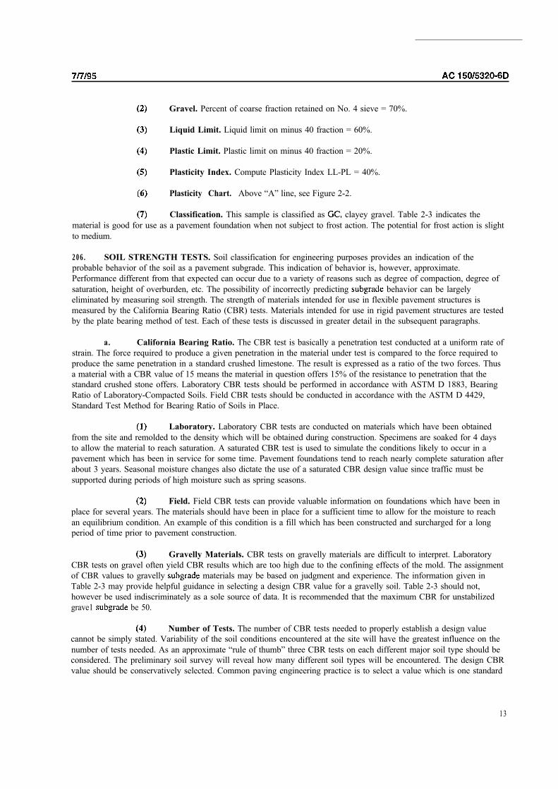
Gravel. Percent of coarse fraction retained on No. 4 sieve = 70%.
Liquid Limit. Liquid limit on minus 40 fraction = 60%.
Plastic Limit. Plastic limit on minus 40 fraction = 20%.
Plasticity Index. Compute Plasticity Index LL-PL = 40%.
Plasticity Chart. Above “A” line, see Figure 2-2.
Classification. This sample is classified as clayey gravel. Table 2-3 indicates the
material is good for use as a pavement foundation when not subject to frost action. The potential for frost action is slight
to medium.
206. SOIL STRENGTH TESTS. Soil classification for engineering purposes provides an indication of the
probable behavior of the soil as a pavement subgrade. This indication of behavior is, however, approximate.
Performance different from that expected can occur due to a variety of reasons such as degree of compaction, degree of
saturation, height of overburden, etc. The possibility of incorrectly predicting behavior can be largely
eliminated by measuring soil strength. The strength of materials intended for use in flexible pavement structures is
measured by the California Bearing Ratio (CBR) tests. Materials intended for use in rigid pavement structures are tested
by the plate bearing method of test. Each of these tests is discussed in greater detail in the subsequent paragraphs.
a. California Bearing Ratio. The CBR test is basically a penetration test conducted at a uniform rate of
strain. The force required to produce a given penetration in the material under test is compared to the force required to
produce the same penetration in a standard crushed limestone. The result is expressed as a ratio of the two forces. Thus
a material with a CBR value of 15 means the material in question offers 15% of the resistance to penetration that the
standard crushed stone offers. Laboratory CBR tests should be performed in accordance with ASTM D 1883, Bearing
Ratio of Laboratory-Compacted Soils. Field CBR tests should be conducted in accordance with the ASTM D 4429,
Standard Test Method for Bearing Ratio of Soils in Place.
Laboratory. Laboratory CBR tests are conducted on materials which have been obtained
from the site and remolded to the density which will be obtained during construction. Specimens are soaked for 4 days
to allow the material to reach saturation. A saturated CBR test is used to simulate the conditions likely to occur in a
pavement which has been in service for some time. Pavement foundations tend to reach nearly complete saturation after
about 3 years. Seasonal moisture changes also dictate the use of a saturated CBR design value since traffic must be
supported during periods of high moisture such as spring seasons.
Field. Field CBR tests can provide valuable information on foundations which have been in
place for several years. The materials should have been in place for a sufficient time to allow for the moisture to reach
an equilibrium condition. An example of this condition is a fill which has been constructed and surcharged for a long
period of time prior to pavement construction.
Gravelly Materials. CBR tests on gravelly materials are difficult to interpret. Laboratory
CBR tests on gravel often yield CBR results which are too high due to the confining effects of the mold. The assignment
of CBR values to gravelly materials may be based on judgment and experience. The information given in
Table 2-3 may provide helpful guidance in selecting a design CBR value for a gravelly soil. Table 2-3 should not,
however be used indiscriminately as a sole source of data. It is recommended that the maximum CBR for unstabilized
grave1 be 50.
Number of Tests. The number of CBR tests needed to properly establish a design value
cannot be simply stated. Variability of the soil conditions encountered at the site will have the greatest influence on the
number of tests needed. As an approximate “rule of thumb” three CBR tests on each different major soil type should be
considered. The preliminary soil survey will reveal how many different soil types will be encountered. The design CBR
value should be conservatively selected. Common paving engineering practice is to select a value which is one standard
13

AC
deviation below the mean. As a rule, a design CBR value of 3 the lowest practical value which should be assigned. In
instances where the strength is lower than CBR = 3, the should be improved through stabilization or
other means to raise the design CBR value.
Lime Rock Ratio. Some areas of the country use the lime rock ratio, LBR, to express soil
strength. To convert LBR to CBR, multiply LBR by 0.8.
b. Plate Bearing Test. As the name indicates, the plate bearing test measures the bearing capacity of the
pavement foundation. The result, k value, can be envisioned as the pressure required to produce a unit deflection of the
pavement foundation. The plate bearing test result, k value, has the units of pounds per cubic inch (Mega-Newtons per
cubic meter). Plate bearing tests should be performed in accordance with the procedures contained in AASHTO T 222.
Sensitivity. Rigid pavement design is not too sensitive to the k value. An error in
establishing a k value will not have a drastic impact on the design thickness of the rigid pavement. Plate bearing tests
must be conducted in the field and are best performed on test sections which are constructed to the design compaction
and moisture conditions. A correction to the k value for saturation is required to simulate the moisture conditions likely
to be encountered by the in-service pavement.
Number of Tests. Plate bearing tests are relatively expensive to perform and thus the number
of tests which can be conducted to establish a design value is limited. Generally only 2 or 3 tests can be performed for
each pavement feature. The design k value should be conservatively selected.
Plate Size. The rigid pavement design and evaluation curves presented in this circular are
based on a k value determined by a static plate load test using a 30-inch (762 mm) diameter plate. Use of a plate of
smaller diameter will result in a higher k value than is represented in the design and evaluation curves.
Subbase Effects. It is recommended that plate bearing tests be conducted on the
and the results adjusted to account for the effect of subbase. Figure 2-4 shows the increase in k value for various
thicknesses of subbase over a given k. Plate bearing tests conducted on top of subbase courses can sometimes
yield erroneous results since the depth of influence beneath a 30” inch (762 mm) bearing plate is not as great as the depth
of influence beneath a slab loaded with an aircraft landing gear assembly. In this instance a subbase layer can influence
the response of a bearing plate more than the response of a loaded pavement.
Stabilized Subbase. The determination of k value for stabilized layers is a difficult problem.
The k value normally has to be estimated. It is recommended that the k value be estimated as follows. The thickness of
the stabilized layer should be multiplied by a factor ranging from 1.2 to 1.6 to determine the equivalent thickness of
well-graded crushed aggregate. The actual value in the 1.2 1.6 range should be based on the quality of the stabilized
layer and the thickness of the slab relative to the thickness of the stabilized layer. High quality materials which are
stabilized with high percentages of stabilizers should be assigned an equivalency factor which is higher than a lower
quality stabilized material. For a given rigid pavement thickness, a thicker stabilized layer will influence pavement
performance more than a thin stabilized layer and should thus be assigned a higher equivalency factor.
Maximum k Value. It is recommended that a design k value of 500 (136 not
be exceeded for any foundation. The information presented in Table 2-3 gives general guidance as to probable k values
for various soil types.
Additional Soil Strength Tests. Where stability of the underlying section is questionable, additional
soil strength tests may be necessary. Direct shear tests (ASTM D 3080) or field vane tests (ASTM D 2573) may be
required to adequately design the pavement structure.
14

400
300
AC CHG 1
-
-
- 75
- 4 0
30
20
- IS
4 5
0
12 22 20 32 34I I I I I I I I
W E L L - GRADED CRUSHED AGGREGATE
0
2 2 24 20 39 3 4t
w500
400
30 0
roo
00
- R U N SAND GRAVEL PI
40
30
20
FIGURE 2-4. EFFECT OF SUBBASE ON MODULUS OF REACTION

!
AC 7/7/95
207.
conditions exist: poor drainage, adverse surface drainage, frost, or need for a stable working platform. Subgradestabilization can be accomplished through the addition of chemical agents or by mechanical methods.
STABILIZATION. Subgrade stabilization should be considered if one or more of the following
a. Chemical Stabilization. Different soil types require different stabilizing agents for best results. The
following are recommended to determine the appropriate type and amount of chemical stabilization for
subgrade soils. US Army, Corps of Engineers, Technical Manual TM 5-818-UAFM 88-6Chapter 6 Technical Manual 88-6 Chapter 2; Technical Manual Chapter 3; Soil Cement Handbook. Portland
Cement Association; and The Asphalt Institute Manual Series A Basic Asphalt Emulsion Manual.
b. Mechanical Stabilization. In some instances subgrades cannot be adequately stabilized through the
use of chemical additives. The underlying soils may be so soft that stabilized materials cannot be mixed and compacted over the underlying soils without failing the soft soils. Extremely soft soils may require bridging in order to construct the
pavement section. Bridging can be accomplished with the use of thick layers of shot rock or cobbles. Thick layers oflean, porous concrete have also been used to bridge extremely soft soils. Geotextiles should be considered as mechanical
stabilization over soft, fine-grained soils. Geotextiles can facilitate site access over soft soils and aid in reducing
subgrade soil disturbance due to construction traffic. The geotextile will also function as a separation material to limitlong-term weakening of pavement aggregate associated with contamination of the aggregate with underlying fine-grained
soils. More information regarding construction over soft soils using geotextiles is provided in (see
Appendix 4).
208. SEASONAL FROST. The design of pavements in areas subject to seasonal frost action requires special consideration. The detrimental effects of frost action may be manifested by nonuniform heave and in loss of soil strength
during frost melting. Other related detrimental effects include: possible loss of compaction, development of pavement
roughness, restriction of drainage, and cracking and deterioration of the pavement surface. Detrimental frost action requires three conditions be met simultaneously: first, the soil must be frost susceptible; secondly, freezing temperatures must penetrate into the frost susceptible soil; thirdly, free moisture must be available in sufficient quantities to form ice
lenses.
a. Frost Susceptibility. The frost susceptibility of soils is dependent to a large extent on the size and
distribution of voids in the soil mass. Voids must be of a certain critical size for the development of ice lenses. Empiricalrelationships have been developed correlating the degree of frost susceptibility with the soil classification and the amount
of material finer than 0.02 by weight. Soils are categorized into four groups for frost design purposes, Frost Group 1
(FG-I), FG-2, FG-3, and FG-4. The higher the frost group number the more susceptible the soil, soils in frost group
4 more frost susceptible than soils in frost groups 2, or 3. Table 2-4 defines the frost groups.
b. Depth of Frost Penetration. The depth of frost penetration is a function of the thermal properties ofthe pavement and mass, the surface temperature, and the of the pavement and soil mass at the start of the
freezing season. Several methods are available to calculate the depth of frost penetration and subsurface temperatures.The method presented here is a simplification of a method based on the modified Berggren equation. This methodrequires the use of the air freezing index and the dry unit weight of the soil.
(1) Air Freezing Index. The air freezing index is a measure of the combined duration andmagnitude of below freezing temperatures occurring during any given freezing season. the average daily temperature is
used in the calculation of freezing index. For example, assume average daily temperature is degrees belowfreezing for days. The freezing index would be calculated as follows, degrees X days degree days.Ideally, air freezing indices should be based on actual data obtained a meteorological station located in close
proximity to the construction site. The air freezing index used for design (design air freezing index) should be based on
the average of the 3 coldest winters in a 30 year period. if available, or the coldest winter observed in a year period. Figures 2-6 and 2-7 show the approximate design air freezing indices for the lower United States and Alaska,
respectively. The values shown in Figures 2-6 and 2-7 do not show local variation which may be substantial, especially
in mountainous areas.
16
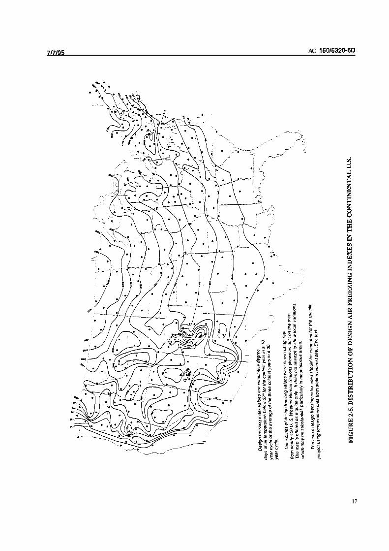
AC
17
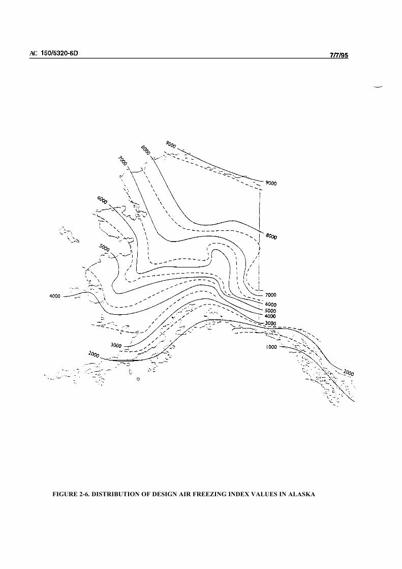
AC
FIGURE 2-6. DISTRIBUTION OF DESIGN AIR FREEZING INDEX VALUES IN ALASKA

Depth of Frost Penetration. The relationship between air freezing index and depth of frost
penetration is shown in Figure 2-8. The thermal properties of the soil mass are reflected by differences in the dry unit
weight of the soil. In the development of this method, the pavement is assumed to be either a 12 inch (300 mm)
thick rigid pavement or a 20 inch (5 mm) thick flexible pavement. The depths of frost penetration shown on Figure 2-8
are measured from the pavement surface downward.
Frost Kind of Soil
TABLE 2-4. SOIL FROST GROUPS
Percentage finer than Soil Classification
Group
FG- Gravelly Soils
0.02 mm by weight
3to 10 GW, GP, GW-GM, GP-GM
FG-2 Gravelly Soils
Sands 3to 15
GM, GW-GM, GP-GM,
SW, SP, SM, SW-SM
SP-SM
FG-3
FG-4
Gravelly Soils
Sands, except very fine silty
sands
Clays, PI above 12
Very fine silty sands
All Silts
Clays, PI = or less
Varied Clays and other fine
prained banded sediments.
Over 20
Over
Over
GM, GC
SM, SC
CL, CH
SM
ML, MH
CL, CL-ML
CL, CH, ML, SM
Free Water. The availability of free water in the soil mass to freeze and form ice lenses is the third
consideration which must be present for detrimental frost action to occur. Water may be drawn from considerable depths
by capillary action, by infiltration from the surface or sides, or by condensation of atmospheric water vapor. Generally
speaking, if the degree of saturation of the soil is 70% or greater, frost heave will probably occur. For all practical
purposes, the designer should assume that sufficient water to cause detrimental frost action will be present.
d. Frost Design. The design of pavements to offset seasonal frost effects is presented in Chapter 3. A
more detailed and rigorous discussion of frost action and its effects can be found in Research Report No.
see Appendix 3.
209. PERMAFROST. In arctic regions soils are often frozen at considerable depths year round. Seasonal thawing
and refreezing of the upper layer of permafrost can lead to severe loss of bearing capacity and/or differential heave. In
areas with continuous high-ice-content permafrost at shallow depths, satisfactory pavements are best ensured by
restricting seasonal thawing to the pavement and to a non-frost susceptible base course. This approach is intended to
prevent degradation (thawing) of the permafrost layer.
a. Susceptibility. The frost susceptibility of soils in permafrost areas is classified the same as given
above in paragraph 206.
b. Depth of Thaw Penetration. Pavement design for permafrost areas must consider the depth of
seasonal thaw penetration, The depth to which thawing temperatures penetrate into permafrost may be estimated using
Figure 2-9. Use of Figure 2-9 requires inputs air thawing index, average wind speed during the thaw period, pavement
type, and density of the permafrost layer. The air thawing index is expressed in degree days and is the difference between
average daily temperature and 32 degrees Fahrenheit (0 degrees Celsius) multiplied by the number of days the
temperature exceeds freezing. The thawing index used for design (design thawing index) should be based on the 3
warmest summers in the last 30 years of record. If 30 year records are not available, data from the warmest summer in
the latest 10 year period may be used.
19

AC
20

All
Soi
l Moi
stur
e A
ssum
ed F
roze
n A
tS
tart
of T
haw
Per
iod
--
Rig
id P
avem
ent
= D
ry U
nit
Wei
ght
Subq
rade
Soi
l=
Con
tent
of S
oil
=
RELATIONSHIP B
ETWEEN A
IR T
HAWING I
NDEX A
ND T
HAW
Not
e:1
foot
= 0
.304
8m
1pc
f 1
6.0
2
mp
h =
1.6
09
km
/h
1000
2000
3000
4000
5000
FIG
UR
E 2
-8.
RE
LA
TIO
NS
HIP
BE
TW
EE
N A
IR T
HA
WIN
G I
ND
EX
AN
D T
HA
W P
EN
ET
RA
TIO
N I
NT
O
GR
AN
UL
AR
, N
ON
-FR
OS
T S
US
CE
PT
AB
LE
S
OIL

AC
Muskeg. Muskeg is sometimes encountered in arctic areas. Muskeg is a highly organic soil deposit
which is essentially a swamp. Every effort should be made to avoid pavement construction on this material. If
construction in areas of muskeg is unavoidable and the soil survey shows the thickness of muskeg is less than 5 feet (1.5
m), the muskeg should be removed and replaced with granular fill. If the thickness of muskeg is too great to warrant
removal and replacement, a 5 foot (1.5 m) granular fill should be placed over the muskeg. These thicknesses are based
on experience and it should be anticipated that differential settlement will occur and considerable maintenance will be
required to maintain a smooth surface. Use of a geotextile between the muskeg surface and the bottom of granular fill is
recommended to prevent migration of the muskeg up into the granular till. In this application, the geotextile is
considered to perform the function of separation. Additional information on the design and construction of geotextiles
performing the separation function within pavement sections is provided in FHWA-HI-90-001 (see Appendix 4).
d. Permafrost Design. Design of pavements in areas of permafrost is discussed in Chapter 3. Further
information on permafrost can be found in Research Report No. see Appendix 4.
22

4/30/2004 AC 150/5320-6D Change 3
CHAPTER 3. PAVEMENT DESIGN
SECTION 1. DESIGN CONSIDERATIONS
300. SCOPE. This chapter covers pavement design for airports serving aircraft with gross weights of 30,000pounds (13 000 kg) or more. Chapter 5 discusses the design of pavements serving lighter aircraft with gross weightsunder 30,000 pounds (13 000 kg).
301. DESIGN PHILOSOPHY. The Foreword of this AC describes the FAA policy of treating the design of aircraft landing gear and the design and evaluation of airport pavements as separate entities. The design of airport pavements is a complex engineering problem that involves a large number of interacting variables. The design curvespresented in this chapter are based on the California Bearing Ratio (CBR) method of design for flexible pavements and a jointed edge stress analysis for rigid pavements. Other design procedures, such as those based on layered elasticanalysis and those developed by the Asphalt Institute and the Portland Cement Association may be used to determinepavement thicknesses when approved by the FAA. These procedures will yield slightly different pavement thicknessesdue to different basic design assumptions.
All manual and electronic pavement designs should be summarized on FAA Form 5100-1, Airport Pavement Design,which is considered part of the Engineer’s Report. The Engineer’s Report should be submitted for FAA review andapproval along with initial plans and specifications.
Because of thickness variations, the evaluation of existing pavements should be performed using the same methodemployed for design. Chapter 6 describes in detail procedures to use when evaluating pavements. Details on thedevelopment of the FAA method of design are as follows:
a. Flexible Pavements. The flexible pavement design curves presented in this chapter are based on theCBR method of design. The CBR design method is basically empirical; however, a great deal of research has beendone with the method, resulting in the development of reliable correlations. Gear configurations are considered using theoretical concepts as well as empirically developed data. The design curves provide the required total thickness offlexible pavement (surface, base, and subbase) needed to support a given weight of aircraft over a particular subgrade.The curves also show the required surface thickness. Minimum base course thicknesses are given in a separate table. Amore detailed discussion of CBR design is presented in Appendix 2.
b. Rigid Pavements. The rigid pavement design curves in this chapter are based on the Westergaardanalysis of edge loaded slabs. The edge loading analysis has been modified to simulate a jointed edge condition.Pavement stresses are higher at the jointed edge than at the slab interior. Experience shows practically all load-inducedcracks develop at jointed edges and migrate toward the slab interior. Design curves are furnished for areas where trafficwill travel primarily parallel or perpendicular to joints and where traffic is likely to cross joints at an acute angle. The thickness of pavement determined from the curves is for slab thickness only. Subbase thicknesses are determinedseparately. A more detailed discussion of the basis for rigid pavement design is presented in Appendix 2.
302. BACKGROUND. An airfield pavement and the aircraft that operate on it represent an interactive system thatmust be addressed in the pavement design process. Design considerations associated with both the aircraft and thepavement must be recognized in order to produce a satisfactory design. Producing a pavement that will achieve theintended design life will require careful construction control and some degree of maintenance. Pavements are designedto provide a finite life, and fatigue limits are anticipated. Poor construction and a lack of preventative maintenance will usually shorten the service life of even the best-designed pavement.
a. Variables. The determination of pavement thickness requirements is a complex engineering problem.Pavements are subject to a wide variety of loading and climatic effects. The design process involves a large number ofinteracting variables, which are often difficult to quantify. Despite considerable research on this subject, it has beenimpossible to arrive at a direct mathematical solution for thickness requirements. For this reason, pavement engineersmust base pavement thickness on a theoretical analysis of load distribution through pavements and soils, the analysis ofexperimental pavement data, and a study of the performance of pavements under actual service conditions. The FAA developed the thickness curves presented in this chapter by correlating the data obtained from these sources. Pavementsdesigned in accordance with these standards should have a structural life of 20 years. In addition, as long as there are
23
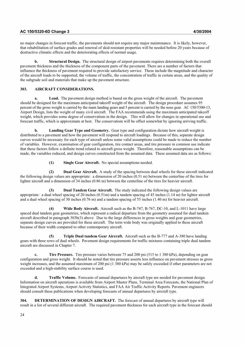
AC 150/5320-6D Change 3 4/30/2004
no major changes in forecast traffic, the pavements should not require any major maintenance. It is likely, however,that rehabilitation of surface grades and renewal of skid-resistant properties will be needed before 20 years because of destructive climatic effects and the deteriorating effects of normal usage.
b. Structural Design. The structural design of airport pavements requires determining both the overallpavement thickness and the thickness of the component parts of the pavement. There are a number of factors thatinfluence the thickness of pavement required to provide satisfactory service. These include the magnitude and characterof the aircraft loads to be supported, the volume of traffic, the concentration of traffic in certain areas, and the quality ofthe subgrade soil and materials that make up the pavement structure.
303. AIRCRAFT CONSIDERATIONS.
a. Load. The pavement design method is based on the gross weight of the aircraft. The pavementshould be designed for the maximum anticipated takeoff weight of the aircraft. The design procedure assumes 95percent of the gross weight is carried by the main landing gears and 5 percent is carried by the nose gear. AC 150/5300-13,Airport Design, lists the weight of many civil aircraft. The FAA recommends using the maximum anticipated takeoffweight, which provides some degree of conservatism in the design. This will allow for changes in operational use andforecast traffic, which is approximate at best. The conservatism will be offset somewhat by ignoring arriving traffic.
b. Landing Gear Type and Geometry. Gear type and configuration dictate how aircraft weight is distributed to a pavement and how the pavement will respond to aircraft loadings. Because of this, separate design curves would be necessary for each type of aircraft unless some valid assumptions could be made to reduce the numberof variables. However, examination of gear configuration, tire contact areas, and tire pressure in common use indicatethat these factors follow a definite trend related to aircraft gross weight. Therefore, reasonable assumptions can bemade, the variables reduced, and design curves constructed from the assumed data. These assumed data are as follows:
(1) Single Gear Aircraft. No special assumptions needed.
(2) Dual Gear Aircraft. A study of the spacing between dual wheels for these aircraft indicatedthe following design values are appropriate: a dimension of 20 inches (0.51 m) between the centerline of the tires for lighter aircraft and a dimension of 34 inches (0.86 m) between the centerline of the tires for heavier aircraft.
(3) Dual Tandem Gear Aircraft. The study indicated the following design values areappropriate: a dual wheel spacing of 20 inches (0.51m) and a tandem spacing of 45 inches (1.14 m) for lighter aircraftand a dual wheel spacing of 30 inches (0.76 m) and a tandem spacing of 55 inches (1.40 m) for heavier aircraft.
(4) Wide Body Aircraft. Aircraft such as the B-747, B-767, DC-10, and L-1011 have largespaced dual tandem gear geometries, which represent a radical departure from the geometry assumed for dual tandemaircraft described in paragraph 303b(3) above. Due to the large differences in gross weights and gear geometries,separate design curves are provided for these aircraft. The term wide body was originally applied to these aircraft because of their width compared to other contemporary aircraft.
(5) Triple Dual tandem Gear Aircraft. Aircraft such as the B-777 and A-380 have landinggears with three rows of dual wheels. Pavement design requirements for traffic mixtures containing triple dual tandemaircraft are discussed in Chapter 7.
c. Tire Pressure. Tire pressure varies between 75 and 200 psi (515 to 1 380 kPa), depending on gearconfiguration and gross weight. It should be noted that tire pressure asserts less influence on pavement stresses as grossweight increases, and the assumed maximum of 200 psi (1 380 kPa) may be safely exceeded if other parameters are notexceeded and a high-stability surface course is used.
d. Traffic Volume. Forecasts of annual departures by aircraft type are needed for pavement design.Information on aircraft operations is available from Airport Master Plans, Terminal Area Forecasts, the National Plan of Integrated Airport Systems, Airport Activity Statistics, and FAA Air Traffic Activity Reports. Pavement engineersshould consult these publications when developing forecasts of annual departures by aircraft type.
304. DETERMINATION OF DESIGN AIRCRAFT. The forecast of annual departures by aircraft type willresult in a list of several different aircraft. The required pavement thickness for each aircraft type in the forecast should
24

4/30/2004 AC 150/5320-6D Change 3
be checked using the appropriate design curve and the forecast number of annual departures for that aircraft. Thedesign aircraft is the aircraft type that produces the greatest pavement thickness. It will not necessarily be the heaviestaircraft in the forecast.
305. DETERMINATION OF EQUIVALENT ANNUAL DEPARTURES BY THE DESIGN AIRCRAFT.
a. Conversions. Since the traffic forecast is a mixture of aircraft having different landing gear types anddifferent weights, the effects of all traffic must be accounted for in terms of the design aircraft. First, all aircraft must beconverted to the same landing gear type as the design aircraft. The FAA has established factors to accomplish thisconversion. These factors are constant and apply to both flexible and rigid pavements. They represent an approximation of the relative fatigue effects of different gear types. Much more precise and theoretically rigorousfactors could be developed for different types and thicknesses of pavement. However, at this stage of the designprocess, such precision is not warranted and would be impractical for hand calculation since design changes wouldrequire numerous iterations and adjustments.
The following conversion factors should be used to convert from one landing gear type to another:
To Convert From ToMultiply
Departures By
single wheel dual wheel 0.8single wheel dual tandem 0.5dual wheel single wheel 1.3dual wheel dual tandem 0.6dual tandem single wheel 2.0dual tandem dual wheel 1.7double dual tandem dual tandem 1.0double dual tandem dual wheel 1.7
After the aircraft have been grouped into the same landing gear configuration, the following formula should be used toconvert to equivalent annual departures of the design aircraft:
W
WRLogRLog
1
221
where:R1 = equivalent annual departures by the design aircraftR2 = annual departures expressed in design aircraft landing gearW1 = wheel load of the design aircraftW2 = wheel load of the aircraft in question
This computation assumes that 95 percent of the gross weight of the aircraft is carried by the main landing gears. Theprocedure discussed above is a relative rating that compares different aircraft to a common design aircraft. Since widebody aircraft have significantly different landing gear assembly spacing than other aircraft, special considerations areneeded to maintain the relative effects. This is done by treating each wide body as a 300,000-pound (136 100 kg) dualtandem aircraft when computing equivalent annual departures. Wide body aircraft should be treated this way in everyinstance—even when the design aircraft is a wide body. After the equivalent annual departures are determined, thedesign should proceed using the appropriate design curve for the design aircraft. For example, if a wide body is thedesign aircraft, all equivalent departures should be calculated as described above; then the design curve for the widebody should be used with the calculated equivalent annual departures.
25

AC 150/5320-6D Change 3 4/30/2004
b. Example. Assume an airport pavement is to be designed for the following forecast traffic.
Aircraft Gear TypeAverage Annual
DeparturesMaximum Takeoff
Weight (lbs.)Maximum Takeoff
Weight (kg)
727-100 dual 3,760 160,000 72 580727-200 dual 9,080 190,500 86 410707-320B dual tandem 3,050 327,000 148 330DC-9-30 dual 5,800 108,000 49 000CV-880 dual tandem 400 184,500 83 690737-200 dual 2,650 115,500 52 390L-1011-100 dual tandem 1,710 450,000 204 120747-100 double dual tandem 85 700,000 317 520
(1) Determine Design Aircraft. A pavement thickness is determined for each aircraft in theforecast with the appropriate design curves. The pavement input data, CBR, k value, flexural strength, etc. should be thesame for all aircraft. Aircraft weights and departure levels must correspond to the particular aircraft in the forecast. In this example, the 727-200 requires the greatest pavement thickness and thus is the design aircraft.
(2) Group Forecast Traffic into Landing Gear of Design Aircraft. In this example, the design aircraft is equipped with a dual wheel landing gear, so all traffic must be grouped into the dual wheelconfiguration.
(3) Convert Aircraft to Equivalent Annual Departures of the Design Aircraft. After the aircraft mixture has been grouped into a common landing gear configuration, the equivalent annual departures of thedesign aircraft can be calculated.
Wheel LoadWheel Load of Design
AircraftAircraftEquiv. Dual
GearDeparts. (lbs) (kg) (lbs) (kg)
Equiv. AnnualDepartures Design
Aircraft
727-100 3,760 38,000 17 240 45,240 20 520 1,891727-200 9,080 45,240 20 520 45,240 20 520 9,080707-320B 5,185 38,830 17 610 45,240 20 520 2,764DC-9-30 5,800 25,650 11 630 45,240 20 520 682CV-880 680 21,910 9 940 45,240 20 520 94737-200 2,650 27,430 12 440 45,240 20 520 463L-1011-100 2,907 35,6251 16 160 45,240 20 520 1,184747-100 145 35,6251 16 160 45,240 20 520 83
Total = 16,2411 Wheel loads for wide body aircraft are taken as the wheel load for a 300,000-pound (136 100 kg) dualtandem aircraft for equivalent annual departure calculations.
(4) Final Result. In this example, the pavement would be designed for 16,241 annualdepartures of a dual wheel aircraft weighing 190,500 pounds (86 410 kg). The design, however, should provide for theheaviest aircraft in the traffic mixture, the B747-100, when considering depth of compaction, thickness of asphaltsurface, drainage structures, etc.
c. Other Methods. More refined methods of considering mixed traffic are possible. These refinedmethods might consider variations in material properties due to climatic effects, takeoff versus landing loads, aircrafttread dimensions, etc. The FAA allows the use of these refined methods under the conditions given in paragraph 301.
306. TRAFFIC DISTRIBUTION. Research studies have shown that aircraft traffic is distributed laterally acrossrunways and taxiways according to statistically normal (bell-shaped) distribution. FAA Report No. FAA-RD-36, FieldSurvey and Analysis of Aircraft Distribution on Airport Pavements, dated February 1975, contains research informationon traffic distribution. The design procedures presented in this AC incorporate the statistically normal distribution inthe departure levels. In addition to the lateral distribution of traffic across pavements, it also considers trafficdistribution and the nature of loadings for aprons and high-speed turnoffs.
26

AC
307. TYPICAL SECTIONS. Airport pavements are generally constructed in uniform, full width sections.Runways may be constructed with a transversely variable section, if practical. A variable section permits a reductionin the quantity of materials required for the upper paving layers of the runway. However, more complex constructionoperations are associated with variable sections and are usually more costly. The additional construction costs maynegate any savings realized from reduced material quantities. Typical plan and section drawings for transverselyvariable section runway pavements are shown in Figure 3-1. Deviations from these typical sections will be commondue to the change inherent in staged construction projects where runways are extended and the location of isuncertain. As a general rule-of-thumb the designer should specify full pavement thickness T where departing trafficwill be using the pavement; pavement thickness of will be specified where traffic will be arrivals such as highspeed turnoffs; and pavement thickness of will be specified where pavement is required but traffic is unlikelysuch as along the extreme outer edges of the runway. Note the full-strength keel section is 50 feet (15 m) on thebasis of the research study discussed in paragraph 306a.
308. FROST AND PERMAFROST DESIGN. The design of an airport pavement must consider the climaticconditions which will act on the pavement during its construction and service life. The protection of pavements fromthe adverse effects of seasonal frost and permafrost effects are considered in the design of airport pavements asdiscussed below.
a. Seasonal Frost. The adverse effects of seasonal frost have been discussed in Chapter 2. The designof pavements in seasonal frost areas may be based on either of two approaches. The first approach is based on thecontrol of pavement deformations resulting from frost action. Under this approach, sufficient combined thickness ofpavement and non-frost-susceptible material must be provided to eliminate, or limit to an acceptable amount, frostpenetration into the and its adverse effects. The second approach is based on providing adequate pavementload carrying capacity during the critical frost melting period. The second approach provides for the loss of loadcarrying capacity due to frost melting but ignores the effects of frost heave. Three design procedures have beendeveloped which encompass the above approaches and are discussed below.
Complete Frost Protection. Complete frost protection is accomplished by providing asufficient thickness of pavement and non-frost-susceptible material to totally contain frost penetration. This method isintended to prevent underlying frost susceptible materials from freezing. To use the complete protection method , thedepth of frost penetration is determined by the procedure given in Chapter 2. The thickness of pavement required forstructural support is compared with the depth of frost penetration computed. The difference between the pavementthickness required for structural support and the computed depth of frost penetration is made up with susceptible material. Depending on grades and other considerations, provision for complete protection may involveremoval and replacement of a considerable amount of material. Complete frost protection is the mostpositive, and is usually the most costly, method of providing frost protection.
Limited Frost Penetration. The limited frost penetration method isbased on holding frost heave to a tolerable level. Frost is allowed to penetrate a limited amount into the underlyingfrost susceptible subgrade. Sixty five (65%) of the depth of frost penetration is made up with non-frost-susceptiblematerial. Use of the method is to the complete protection method. Additional frost protection is required if thethickness of the section is less than 65% of the frost penetration. The limited frost penetrationmethod allows a tolerable (based on experience) amount of frost heave.
Reduced Strength. The reduced strength method is based on theconcept of providing a pavement with adequate load carrying capacity during the frost melting period. This methoddoes not consider the effects of frost heave. Use of the reduced strength method involves assigning a
strength rating to the pavement for the frost melting period. The various soil frost groups as defined inChapter 2, should be assigned strength ratings as shown below:
27
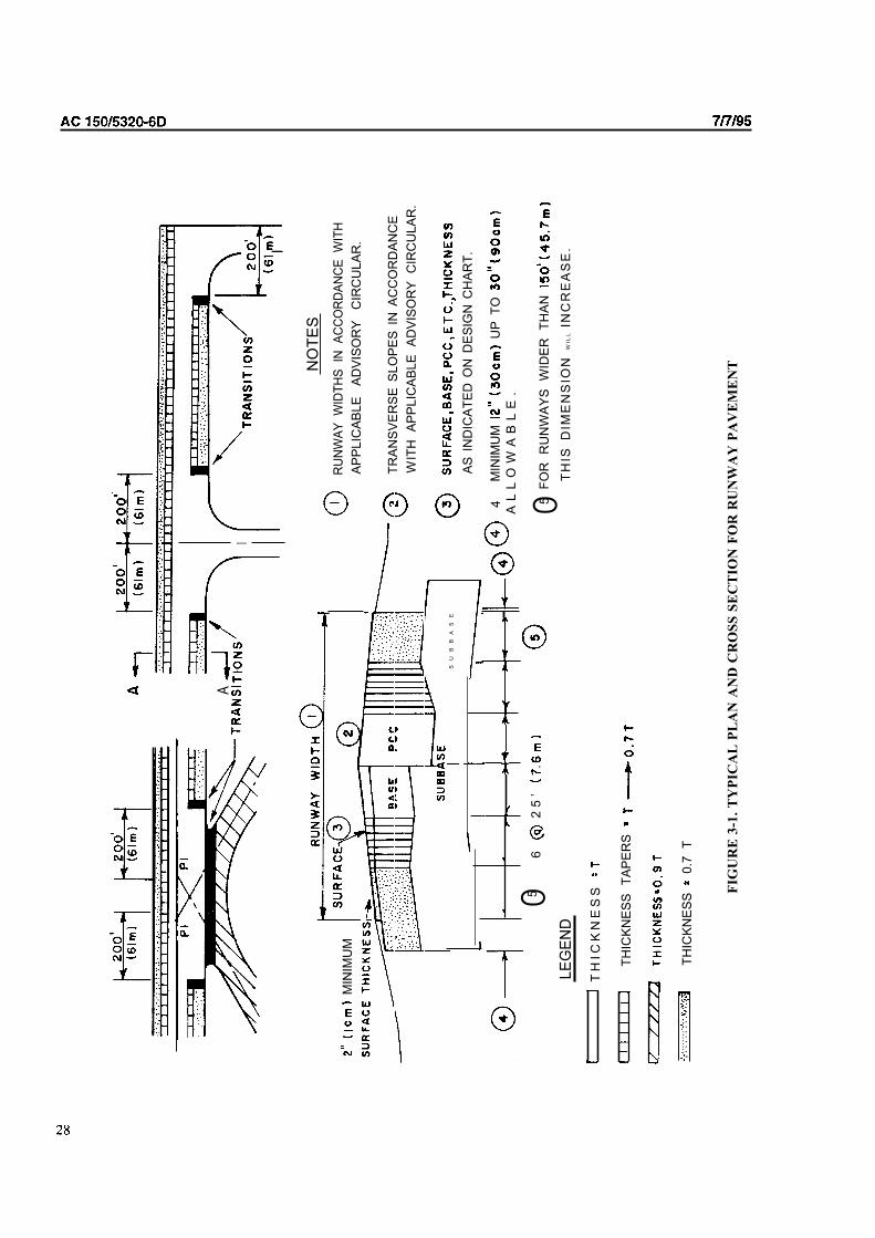
AI
NO
TE
S
M
INIM
UM
SU
BB
AS
E3
AS
IN
DIC
AT
ED
ON
DE
SIG
N C
HA
RT
.
4M
INIM
UM
U
P T
O
056
2
5’
A
LL
OW
AB
LE
.
5
05
FO
R
RU
NW
AY
S
WID
ER
T
HA
N
RU
NW
AY
W
IDT
HS
IN
A
CC
OR
DA
NC
E
WIT
H
AP
PL
ICA
BL
E
AD
VIS
OR
Y
CIR
CU
LA
R.
TR
AN
SV
ER
SE
SL
OP
ES
IN
AC
CO
RD
AN
CE
WIT
H
AP
PL
ICA
BL
E
AD
VIS
OR
Y
CIR
CU
LA
R.
LE
GE
ND
TH
IS D
IME
NS
ION
W
IL
LIN
CR
EA
SE
.
T
HIC
KN
ES
S
TH
ICK
NE
SS
T
AP
ER
S
. . . . .
. . , .
. . .
. . .
T
HIC
KN
ES
S
0.7
T
FIG
UR
E 3
-1.
TY
PIC
AL
PL
AN
AN
D C
RO
SS
SE
CT
ION
FO
R R
UN
WA
Y P
AV
EM
EN
T

AC
TABLE 3-l. REDUCED STRENGTH RATINGS
Frost Group Flexible Pavement CBR Value Rigid Pavement k-value
FG-1 9 50
FG-2 7 40
FG-3 4 25
FG-4 Reduced Strength Method Does Not Apply
The required pavement thicknesses are determined from the appropriate design curves using the reduced
strength ratings. Pavement thicknesses thus established reflect the requirements for the in its weakened
condition due to frost melting.
b. Applications. Due to economic considerations, the maximum practical depth of frost protection that
should be provided is normally 72 inches (1.8 m). The recommended applications of the three methods of frost
protection discussed above are as follows. In addition to these recommended applications, local experience should be
given strong consideration when designing for frost conditions.
Complete Frost Protection. The complete frost protection method applies only to FG-3 and
FG-4 soils which are extremely variable in horizontal extent. These soil deposits are characterized by very large,
frequent, and abrupt changes in frost heave potential. The variability is such that the use of transition sections is not
practical.
Limited Frost Penetration. This design method should be used for FG-4 soils
except where the conditions require complete protection, see (1) above. The method also applies to soils in frost groups
FG-1, FG-2, and FG-3 when the functional requirements of the pavement permit a minor amount of frost heave.
Consideration should be given to using transition sections where horizontal variability of frost heave potential permits.
Reduced Strength. The reduced strength method is recommended for
FG-2, and FG-3 subgrades which are uniform in horizontal extent or where the functional requirements of the
pavement will permit some degree of frost heave. the method may also be used for variable FG-1 through FG-3
subgrades for less sensitive pavements which are subject to slow speed traffic and heave can be tolerated.
C. Permafrost, The design of pavements in permafrost regions must consider not only the effects of
seasonal thawing and refreezing, but also the effects of construction on the existing thermal equilibrium. Changes in the
subsurface thermal regime may cause degradation of the permafrost table, resulting in severe differential settlements
drastic reduction of pavement load carrying capacity. Gravel surfaced pavements are rather common in permafrost areas
and generally will provide satisfactory service. These pavements often exhibit considerable distortion but are rather
easily regraded. The absence of a waterproof surface is not a great problem because these areas are usually have low
precipitation. Three design methods for asphaltic or concrete surfaced pavements are discussed below.
Complete Protection Method. The objective of the complete protection method is to ensure
that the underlying permafrost remains frozen year round. Seasonal thawing is restricted to non-frost-susceptible
materials. This method is analogous to the complete frost protection method of design for seasonal frost. The thickness
of pavement required for structural support is first determined. The depth of seasonal thaw is then computed as described
in Chapter 2 or using information based on local experience. The difference between the depth of seasonal thaw and the
thickness needed for structural support is the amount of non-frost-susceptible material which must be provided to fully
contain the depth of seasonal thaw. The use of relatively high moisture retaining soils, such as uniformly graded sands,
should be considered. If some heaving can be tolerated, the use of frost-susceptible soils in the FG- 1 or FG-2 groups may
also be considered. If FG-1 or FG-2 soils are used, they must be placed so as to be as uniform as possible. Normally
economic considerations will limit the depth of treatment to a maximum of 6 feet (1.8 m).
Reduced Strength Method. If conditions are such that the complete protection
method of design is not practical, the design may be based on the reduced strength method. The use of this
29

AC
method for permafrost design is identical to that presented in paragraph above. this method should provide a
pavement with sufficient structural support during the seasonal permafrost thaw period but will likely result in
differential heaving. If practical, it may be advisable to delay paving for 2 or 3 years to allow the embankment to reach
equilibrium.
Insulating Panels. A third approach which is not as common is the use of insulating panels
beneath the pavement structure to protect against degradation of the permafrost. This method can lead to problems if the
insulating panels are crushed by the weight of the overburden or by the live loads. Crushing of the cell structure of the
insulation results in loss of insulating properties and failure to serve its intended purpose. Pavements using this technique
must be very carefully constructed and may be subject to load limitations because of the need to guard against crushing
the insulating panels. A significant change in the weight of using aircraft may fail the insulating panels. Since the FAA
has no standards or design criteria for the use of insulating panels, their use on federally funded construction requires
FAA approval on a case-by-case basis.
30

SECTION 2. FLEXIBLE PAVEMENT DESIGN
309. GENERAL. Flexible pavements consist of a hot mix asphalt wearing surface placed on a base course and,
when required by conditions, a subbase. The entire flexible pavement structure is ultimately supported by the
subgrade. Definitions of the function of the various components are given in the following paragraphs. For some aircraft
the base and subbase should be constructed of stabilized materials. The requirements for stabilized base and subbase are
also discussed in this section.
310. HOT MIX ASPHALT SURFACING. The hot mix asphalt surface or wearing course must prevent the
penetration of surface water to the base course; provide a smooth, well-bonded surface free from loose particles which
might endanger aircraft or persons; resist the shearing stresses induced by aircraft loads; and furnish a texture of nonskid
qualities, yet not cause undue wear on tires. To successfully fulfill these requirements, the surface must be composed of
mixtures of aggregates and bituminous binders which will produce a uniform surface of suitable texture possessing
maximum stability and durability. Since control of the mixture is of paramount importance, these requirements can best
be achieved by use of a central mixing plant where proper control can be most readily obtained. A dense-graded hot mix
asphalt concrete such as Item P-401 produced in a central mixing plant will most satisfactorily meet all the above
requirements. Whenever a hot mix asphalt surface is subject to spillage of fuel, hydraulic fluid, or other solvents; such as
at aircraft fueling positions and maintenance areas, protection should be provided by a solvent resistant surface.
311. BASE COURSE. The base course is the principal structural component of the flexible pavement. It has the
major function of distributing the imposed wheel loadings to the pavement foundation, the subbase and/or subgrade. The
base course must be of such quality and thickness to prevent failure in the subgrade, withstand the stresses produced in
the base itself, resist vertical pressures tending to produce consolidation and resulting in distortion of the surface course,
and resist volume changes caused by fluctuations in its moisture content. In the development of pavement thickness
requirements, a minimum CBR value of 80 is assumed for the base course. The quality of the base course depends upon
composition, physical properties and compaction. Many materials and combinations thereof have proved satisfactory as
base courses. They are composed of select, hard, and durable aggregates. Specifications covering the quality of
components, gradation, manipulation control, and preparation of various types of base courses for use on airports for
aircraft design loads of 30,000 pounds (14 000 kg) or more are as follows:
Item P-208 Aggregate Base Course’
Item P-209 Crushed Aggregate Base Course
Item P-21 1 Lime Rock Base Course
Item P-304 Cement Treated Base Course
Item P-306 Econocrete Subbase Course
Item P-401 Plant Mix Bituminous Pavements
‘The use of Item P-208, Aggregate Base Course, as base course is limited to pavements designed for
gross loads of 60,000 Ibs. (27 000 kg) or Item P-208 is used as base course the thickness of
the hot mix asphalt surfacing should be increased inch (25 mm) over that shown on the design
curves.
312. SUBBASE, A subbase is included as an integral part of the flexible pavement structure in all pavements except
those on subgrades with a CBR value of 20 or greater (usually GW or GP type soils). The function of the subbase is
similar to that of the base course. However, since it is further removed from the surface and is subjected to lower
loading intensities, the material requirements are not as strict as for the base course. In the development of pavementthickness requirements the CBR value of the subbase course is a variable.
Quality. Specifications covering the quality of components, gradations, manipulation control, and
of various types of subbase courses for use on airports for aircraft design loads of 30,000 pounds (14 000 kg)
or more are as follows:
Item P-154 Subbase Course
Item P-210 Base Course
Item P-212 Shell Base Course
31

AC
(4) Item P-213 Sand Clay Base Course’
Item P-301 Soil Cement Base Course’
‘Use of Items P-21 3 and P-301 as subbase course is not recommended where frost penetration into the
subbase is anticipated. Any material suitable for use as base course can also be used on subbase if
economy and practicality dictate.
b. Sandwich Construction. Pavements should not be configured such that a pervious granular layer is
located between two impervious layers. This type of section is often called “sandwich” construction. Problems are often
encountered in “sandwich” construction when water becomes trapped in the granular layer causing a dramatic loss of
strength and results in poor performance.
313. SUBGRADE. The soils are subjected to lower stresses than the surface, base, and subbase courses.
stresses attenuate with depth, and the controlling stress is usually at the top of the subgrade, unless
unusual conditions exist. Unusual conditions such as a layered or sharply varying water contents or densities
can change the location of the controlling stress. The ability of a particular soil to resist shear and deformation vary with
its density and moisture content. Such unusual conditions should be revealed during the soils investigation.
Specification Item P-152, Excavation and Embankment, covers the construction and density control of soils.
Table 3-2 shows depths below the surface to which compaction controls apply.
a. Contamination. A loss of structural capacity can result from contamination of base or subbase
elements with fines from underlying soils. This contamination occurs during pavement construction and during
pavement loading. Aggregate contamination results in a reduced ability of the aggregate to distribute and reduce stresses
applied to the subgrade. Fine soils are most likely to contaminate pavement aggregate. This process is not
limited to soft conditions. Problematic soils may be cohesive or noncohesive and usually exhibit poor drainage
properties. Chemical and mechanical stabilization of the subbase or can be effectively used to reduce
aggregate contamination (refer to Section 207). Geotextiles have been found to be effective at providing separation
between fine-grained soils and overlying pavement aggregates Appendix 4). In this application, the
geotextile is not considered to act as a structural element within the pavement. For separation applications the geotextile
is designed based on survivability properties. Refer to FHWA-90-001 (see Appendix 4) for additional information
regarding design and construction using separation geotextiles.
b. Example. An apron extension is to be built to accommodate a (154 000 kg) dual
tandem geared aircraft, a soils investigation has shown the will be noncohesive. In-place densities of the soils
have been determined at even foot increments below the ground surface. Design calculations indicate that the top of
in this area will be approximately inches (0.3 m) below the existing grade. Depths and densities may be
tabulated as follows:
Depth Below Depth Below In-Place Density
Existing Grade Finished Grade
1’ (0.3 m) 2” (50 mm) 70%
2’ (0.6 m) 14” (0.36 m) 84%
3’ (0.9 m) 26” (0.66 m) 86%
4’ (1.2 m) 38” (0.97 m) 90%
5’ (1.5 m) (1.27 m) 93%
Using Table 3-2 values for non-cohesive soils and applying linear interpolation the compaction requirements are as
follows:
100% 95% 90% 85%
o-21 21-37 37-52 52-68
Comparison of the tabulations show that for this example in-place density is satisfactory at a depth of 38 inches (0.97 m),
being 90 percent within the required 90 percent zone. It will be necessary to compact an additional 1 inch (0.03 m) at 95
percent, and the top 21 inches (0.53 of at 100 percent density.
32

AC
TABLE 3-2.
DESIGN
AIRCRAFT
Gross
Weight
Ibs.
30,000 8
50,000
75,000
50,000 12
100,000 17
150,000 19
200,000
100,000 14
200,000 17
300,000 20
400,000 23
400,000 21
600,000 23
800,000 23
COMPACTION REQUIREMEI TS FOR FLEXIBLE PAVEMENTS
NON-COHESIVE SOILS COHESIVE SOILS
Depth of Compaction In. Depth of Compaction In.
100%
12-30 30-40 40-52
12-28 28-38 38-50
17-30 30-42 42-55
19-32 32-46 46-60
21-37 37-53 53-69
14-26 26-38 38-49
17-30 30-43 43-56
20-34 34-48 48-63
23-4 1 41-59 59-76
21-36 36-55 55-70
23-4 1 41-59 59-76
23-4 59-76
95%
6
6
6
6
6
7
9
6
6
7
9
8
9
9
6-12 12-19
6-10 10-17
6-12 12-19
7-14 14-21
8-16 16-24
6-10 10-17
6-12 12-18
7-14 14-229-18 18-27
8-15 15-20
9-18 18-27
9-18 18-27
80%
12-17
16-20
19-25
17-22
19-25
21-28
24-32
17-22
18-26
22-29
27-36
20-28
27-36
27-36
1. Noncohesive soils, for the purpose of determining compaction control, are those with a plasticity index
(P.I.) of less than 6.
2. Tabulated values denote depths below the finished above which densities should equal or
exceed the indicated percentage of the maximum dry density as specified in Item P-152.
3. The in cut areas should have natural densities shown or should (a) be compacted from the
surface to achieve the required densities, (b) be removed and replaced at the densities shown, or (c) when
economics and grades permit, be covered with sufficient select or subbase material so that the
uncompacted is at a depth where the in-place densities are satisfactory.
4. For intermediate aircraft weights use linear interpolation.
5. For swelling soils refer to paragraph 314.
6. 1 inch = 25.4 mm
1 lb. 0.454 kg
314. SWELLING SOILS. Swelling soils are clayey soils which exhibit significant volume changes brought on by
moisture variations. The potential for volumetric change of a soil due to moisture variation is a function of the type of
soil and the likelihood of for moisture fluctuation. Airport pavements constructed on these soils are subject to
differential movements causing surface roughness and cracking. The design of pavements in areas of swelling soils
should incorporate methods that prevent or reduce the effects of soil volume changes.
a. Soil Type. Only clayey soils containing a significant amount of particular clay minerals are prone to
swelling. The clay minerals which cause swelling are, in descending order of swelling activity, are: smectite, illite, and
kaolinite. These soils usually have liquid limits above 40 and plasticity indexes above 25.
b. Identification. Soils which exhibit a swell of greater than 3 percent when tested for the California
Bearing Ratio (CBR), ASTM D 1883, require treatment. Experience with soils in certain locales is often used to
determine when treatment is required.
C. Treatment. Treatment of swelling soils consist of removal and replacement, stabilization, modified
compaction efforts and careful control of compaction moisture. Provisions for adequate drainage is of paramount
importance when dealing with swelling soils. Recommended treatments for swelling soils are shown in Table 3-3. Local
experience and judgment should be applied in dealing with swelling soils to achieve the best results. Care should be
taken to minimize water flow along the contact plane between the material.
33

TABLE 3-3. RECOMMENDED TREATMENT OF SWELLING SOILS
Swell Potential Percent Swell Potential for Treatment
(Based on
Experience)
Low
Medium
High
Measured (ASTM Moisture
D 1883) Fluctuation’
3-5 Low
High
6-10 Low
High
Over 10 Low
High
Compact soil on wet side of optimum to
to not greater than 90% of appropriate maximum
density.
Stabilize soil to a depth of at least 6 in. (150 mm)
Stabilize soil to a depth of at least 12 in. (300 mm)
Stabilize soil to a depth of at least 12 in. (300 mm)
Stabilize soil to a depth of at least 12 in. (300 mm)
For uniform soils, i.e., redeposited clays, stabilize soil
to a depth of at least 36 in. (900 mm) or raise grade to
bury swelling soil at least 36 in. (900 mm) below
pavement section or remove and replace with
swelling soil.
For variable soil deposits depth of treatment should be
increased to 60 in. (1300 mm).
Notes: ‘Potential for moisture fluctuation is a judgmental determination and should consider proximity of water
table, likelihood of variations in water table, as well as other sources of moisture, and thickness of the
swelling soil layer.
‘When control of swelling is attempted by compacting on the wet side of optimum and reduced density,
the design strength should be based on the higher moisture content and reduced density.
d. Additional Information. Additional information on identifying and handling swelling soils is
presented in FAA Reports No. FAA-RD-76-66, Design and Construction of Airport Pavements on Expansive Soils, by
R. Gordon dated June 1976 and DOT/FAA/PM-85115, Validation of Procedures for Pavement Design on
Expansive Soils, by R. Gordon dated July 1985. See Appendix 4.
315. SELECTION OF DESIGN CBR VALUE. soils are usually rather variable and the selection of a
design CBR value requires some judgment. As a general rule of thumb the design CBR value should be equal to or less
than 85% of all the CBR values. This corresponds to a design value of one standard deviation below the mean
as recommended in Chapter 2. In some cases soils which are significantly different in strength occur in
different layers. In these instances several designs should be examined to determine the most economical pavement
section. It may be more economical to remove and replace a weak layer than designing for it. On the other hand,
circumstances may be such that designing for the weakest layer is more economical. Local conditions will dictate which
approach should be used.
316. DESIGN CURVES. Due to the differences in stress distribution characteristics, separate flexible pavement
design curves for several gear configurations have been prepared and are presented in Figures 3-2 through 3-15,
inclusive. The thicknesses determined from these design charts are for untreated granular bases and subbases and do not
include frost effects or stabilized materials. Frost effects and stabilized materials must be handled separately.
34

AC
FIGURE 3-2 FLEXIBLE PAVEMENT DESIGN CURVES, SINGLE WHEEL GEAR
35

AC1
FIGURE 3-3 FLEXIBLE PAVEMENT DESIGN CURVES, DUAL WHEEL GEAR
36

AC
FIGURE 3-4 FLEXIBLE PAVEMENT DESIGN CURVES, DUAL TANDEM GEAR
37
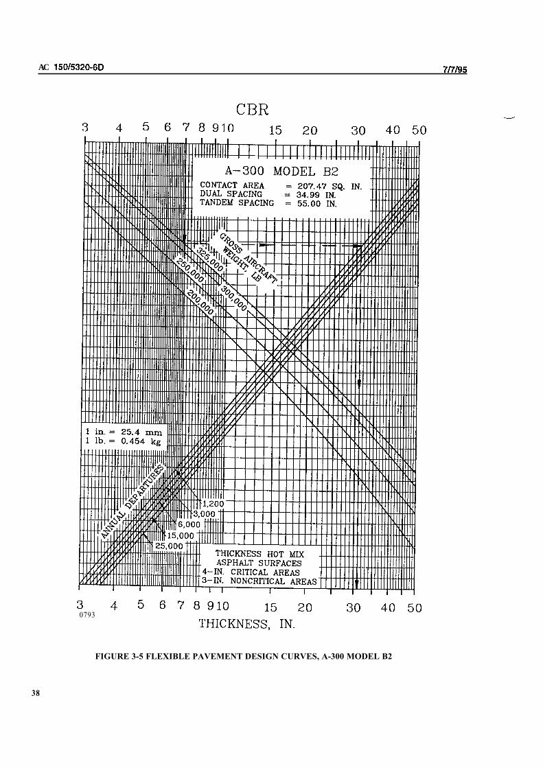
AC
0793
FIGURE 3-5 FLEXIBLE PAVEMENT DESIGN CURVES, A-300 MODEL B2
38

AC
I I I I I I II I I I I I I I I I
CONTACT AREA = 217.08 SQ. IN.DUAL SPACING = 36.17 IN.TANDEM SPACING = 55.00 IN.
THICKNESS HOT MIXASPHALT SURFACES
4-IN. CRITICAL AREAS3-IN. NONCRITICAL AREAS
0793
FIGURE 3-6 FLEXIBLE PAVEMENT DESIGN CURVES, A-300 MODEL B4
39

AC
i i
FIGURE 3-7 FLEXIBLE PAVEMENT DESIGN CURVES, 200 B, C, F

AC
FIGURE FLEXIBLE PAVEMENT DESIGN CURVES,
41

AC
CONTACT 166.35 SQ. IN.DUAL SPACING
0793
FIGURE 3-9 FLEXIBLE PAVEMENT DESIGN CURVES, B-757

0793
FIGURE 3-10 FLEXIBLE PAVEMENT DESIGN CURVES, B-767
43

0793
FIGURE 3-11 FLEXIBLE PAVEMENT DESIGN CURVES, C-130
44
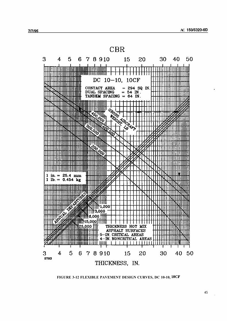
AC
FIGURE 3-12 FLEXIBLE PAVEMENT DESIGN CURVES, DC 10-10,
45 .

AC
FIGURE 3-13 FLEXIBLE PAVEMENT DESIGN CURVES, DC

AC
FIGURE 3-14 FLEXIBLE PAVEMENT CURVES, L-1011-1,100
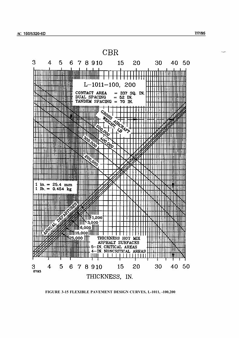
AC
FIGURE 3-15 FLEXIBLE PAVEMENT DESIGN CURVES, L-1011, -100,200

317. DESIGN INPUTS. Use of the design curves for flexible pavements requires a CBR value for the
material, a CBR value for the subbase material, the gross weight of the design aircraft, and the number of annual
departures of the design aircraft. The design curves presented in Figures 3-2 through 3-15 indicate the total pavement
thickness required and the thickness of hot mix asphalt surfacing. Table 3-4 gives the minimum thicknesses of base
course for various materials and design loadings. For annual departures in excess of 25,000 the total pavement thickness
should be increased in accordance with Table 3-5. l-inch (25 mm) of the thickness increase should be hot mix asphalt
surfacing; the remaining thickness increase should be proportioned between base and subbase.
TABLE 3-4. MINIMUM BASE COURSE THICKNESS
Design Design Load Range Minimum Base
Aircraft Course Thickness
lbs. in.
Single Wheel 30,000 50,000 (13600 22 700) 4
50,000 75,000 (22700 34 000) 6
Dual 50,000 100,000 (22700 45 000) 6
Wheel 100,000 200,000 (45 90 700) 8
Dual 100,000 250,000 (45 000 113 400) 6 (150)
Tandem 250,000 400,000 (113400 181 000) 8
757 200,000 400,000 (90700 181000) 6 (150)767
DC-10 400,000 600,000 (181 000 272000) 8
B-747 400,000 600,000 (181 000 272000) 6 (150)
600,000 850,000 (272 000 385 700) 8
c-130 75,000 125,000 (34 000 56 700) 4
125,000 175,000 (56700 79 400) 6 (150)
Note: The calculated base course thicknesses should be compared with the
minimum base course thicknesses listed above. The greater thickness,
calculated or minimum, should be specified in the design section.
318. CRITICAL AND NONCRITICAL AREAS. The design curves, Figures 3-2 through 3-15, are used to
determine the total critical pavement thickness, and the surface course thickness requirements. The factor for
the noncritical pavement applies to the base and subbase courses; the surface course thickness is as noted on the design
curves. For the variable section of the transition section and thinned edge, the reduction applies only to the base course.
The thickness for base shall be the minimum permitted. The subbase thickness shall be increased or varied to
provide positive surface drainage of the surface. Surface course thicknesses are as shown in Figure 3-l. For
fractions of an inch of 0.5 or more, use the next higher whole number; for less than 0.5, use the next lower whole
number.
TABLE 3-5. PAVEMENT THICKNESS
FOR HIGH DEPARTURE LEVELS
Annual Departure Percent of 25,000 Departure
Level Thickness
50,000 104
100,000 108
150,000 110
200,000 112
Note:
The values given in Table 3-5 are based on
extrapolation of research data and observations
of in-service pavements. Table 3-5 was
developed assuming a logarithmic relationship
between percent of thickness and departures.
49

AC
319. DESIGN EXAMPLE. As an example of the use of the design curves, assume a flexible pavement is to be
designed for a dual gear aircraft having a gross weight of 75,000 pounds (34 000 kg) and 6,000 annual equivalent
departures of the design aircraft. Design CBR values for the subbase and are 20 and 6, respectively.
a. Total Pavement Thickness. The total pavement thickness required is determined from Figure 3-3.
Enter the upper abscissa with the CBR value, 6. Project vertically downward to the gross weight of the design
aircraft, 75,000 pounds (34 000 kg). At the point of intersection of the vertical projection and the aircraft gross weight,
make a horizontal projection to the equivalent annual departures, 6000. From the point of intersection of the horizontal
projection and the annual departure level, make a vertical projection down to the lower abscissa and read the total
pavement thickness; in this example 23 inches (584 mm).
b. Thickness of Subbase Course. The thickness of the subbase course is determined in a manner similar
to the total pavement thickness. Using Figure 3-3, enter the upper abscissa with the design CBR value for the subbase,
20. The chart is used in the same manner as described in “a” above, i.e., vertical projection to aircraft gross weight,
horizontal projection to annual departures, and vertical projection to lower abscissa. In this example the thickness
obtained is 9.5 inches (241 mm). This means that the combined thickness of hot mix asphalt surface and base course
needed over a 20 CBR subbase is 9.5 inches (241 mm), thus leaving a subbase thickness of 23 9.5 = 13.5 inches (343
mm).
C. Thickness of Hot Mix Asphalt Surface. As indicated by the note in Figure 3-3, the thickness of hot
mix asphalt surface for critical areas is 4 inches (100 mm) and for noncritical, 3 inches (76 mm).
a. Thickness of Base Course. The thickness of base course can be computed by subtracting the
thickness of hot mix asphalt surface from the combined thickness of surface and base determined in above; in this
example 9.5 4.0 = 5.5 (150 mm) of base course. The thickness of base course thus calculated should be compared with
the minimum base course thickness required as in Table 3-4. Note that the minimum base course thickness is 6
inches (150 mm) from Table 3-4. Therefore the minimum base course thickness from Table inches (152 mm),
would control. If the minimum base course thickness from Table 3-4 had been less than the calculated thickness, the
calculated thickness would have controlled. Note also that use of Item P-208, Aggregate Base Course, as base course is
not permissible since the weight of the design aircraft exceeds 60,000 Ibs. (27 000 kg).
e. Thickness of Noncritical Areas. The total pavement thickness for noncritical areas is obtained by
taking 0.9 of the critical pavement base and subbase thicknesses plus the required hot mix asphalt surface thickness given
on the design charts. For the thinned edge portion of the critical and noncritical pavements, the factor applies only
to the base course because the subbase should allow for transverse drainage. The transition section and surface course
requirements are as noted in Figure 1.
f. Summary. The thickness calculated in the above paragraphs should be rounded off to even
increments as discussed in paragraph 3 18. If conditions for detrimental frost action exist, another analysis is required.
The final design thicknesses for this example would be as follows:
THICKNESS REQUIREMENTS
Critical Non-Critical
in. (mm) in. (mm)
Hot Mix Asphalt Surface 4 (100) 3 (75)(P-209 Base)
Base Course 6 (200) 5 (1’25)
(P-209, or P-21 1)
Subbase Course 14 (355) 13 (330)
(P-154)
Transverse Drainage 3 (75)Course
Edge
in. (mm)
2 (50)
4 (100)
10 (255)
8 (205)
50

320. STABILIZED BASE AND SUBBASE. Stabilized base and subbase courses are necessary for new pavements
designed to accommodate jet aircraft weighing 100,000 pounds (45 350 kg) or more. These stabilized courses may be
substituted for granular courses using the equivalency factors discussed in paragraph 322. These equivalency factors are
based on research studies which measured pavement performance. See FAA Report No. FAA-RD-73-198, Volumes I,
II, and III. Comparative Performance of Structural Layers in Pavement Systems. See Appendix 3. A range of
equivalency factors is given because the factor is sensitive to a number of variables such as layer thickness, stabilizing
agent type and quantity, location of stabilized layer in the pavement structure, etc. Exceptions to the policy requiring
stabilized base and subbase may be made on the basis of superior materials being available, such as 100 percent crushed,
hard, closely graded stone. These materials should exhibit a remolded soaked CBR minimum of 100 for base and 35 for
subbase. In areas subject to frost penetration, the materials should meet permeability and susceptibility tests in
addition to the CBR requirements. Other exceptions to the policy requiring stabilized base and subbase should be based
on proven performance of a granular material such as lime rock in the State of Florida. Proven performance in this
instance means a history of satisfactory airport pavements using the materials. This history of satisfactory performance
should be under aircraft loadings and climatic conditions comparable to those anticipated.
321. SUBBASE AND BASE EQUIVALENCY FACTORS. It is sometimes advantageous to substitute higher
quality materials for subbase and base course than the standard FAA subbase and base material. The structural benefits
of using a higher quality material is expressed in the form of equivalency factors. Equivalency factors indicate the
substitution thickness ratios applicable to various higher quality layers. Stabilized subbase and base courses are designed
in this way. Note that substitution of lesser quality materials for higher quality materials, regardless of thickness, is not
permitted. The designer is reminded that even though structural considerations for flexible pavements with high quality
subbase and base may result in thinner flexible pavements; frost effects must still be considered and could require
thicknesses greater than the thickness for structural considerations.
a. Minimum Total Pavement Thickness. The minimum total pavement thickness calculated, after all
substitutions and have been made, should not be less than the total pavement thickness required by a 20
CBR on the appropriate design curve.
b. Granular Subbase. The FAA standard for granular subbase is Item P-154, Subbase Course. In some
instances it may be advantageous to utilize nonstabilized granular material of higher quality than P-154 as subbase
course. Since these materials possess higher strength than P-154, equivalency factor ranges are established whereby a
lesser thickness of high quality granular may be used in lieu of the required thickness of P-154. In developing the
equivalency factors the standard granular subbase course, P-154, was used as the basis. Thicknesses computed from the
design curves assume P-154 will be used as the subbase. If a granular material of higher quality is substituted for Item
154, the thickness of the higher quality layer should be less than P-154. lesser thickness is computed by dividing the
required thickness of granular subbase, P-154, by the appropriate equivalency factor. In establishing the equivalency
factors the CBR of the standard granular subbase, P-154, was assumed to be 20. The equivalency factor ranges are given
below in Table 3-6:
TABLE 3-6. RECOMMENDED EQUIVALENCY FACTOR
RANGES FOR HIGH QUALITY GRANULAR SUBBASE
Material Equivalency Factor Range
P-208, Aggregate Base Course 1.0 1.5
P-209, Crushed Aggregate Base Course 1.2 1.8
P-2 I Lime Rock Base Course 1.5
51

C. Stabilized Subbase. Stabilized subbases also offer considerably higher strength to the pavement than
P-154. Recommended equivalency factors associated with stabilized subbase are presented in Table 3-7.
TABLE 3-7. RECOMMENDED EQUWALENCY FACTOR
RANGES FOR STABILIZED SUBBASE
Material Equivalency Factor Range
P-301, Soil Cement Base Course 1.0 1.5
P-304, Cement Treated Base Course 1.6 2.3
P-306, Econocrete Subbase Course 1.6 2.3
P-401, Plant Mix Bituminous Pavements 1.7 2.3
d. Granular Base. The FAA standard for granular base is Item P-209, Crushed Aggregate Base Course.
In some instances it may be advantageous to utilize other nonstabilized granular material as base course. Other materials
acceptable for use as granular base course are as follows:
TABLE 3-8. RECOMMENDED EQUIVALENCY FACTOR RANGES
FOR GRANULAR BASE
Material Equivalency Factor Range
P-208, Aggregate Base Course 1.0’
P-21 1, Lime Rock Base Course 1.0
‘Substitution of P-208 for P-209 is permissible only if the gross weight of the
design aircraft is 60,000 (27 000 kg) or less. In addition, if P-208 is
substituted for P-209, the required thickness of hot mix asphalt surfacing shown
on the design curves should be increased 1 inch (25 mm).
e. Stabilized Base. Stabilized base courses offer structural benefits to a flexible pavement in much the
same manner as stabilized subbase. The benefits are expressed as equivalency factors similar to those shown for
stabilized subbase. In developing the equivalency factors Item P-209, Crushed Aggregate Base Course, with an assumed
CBR of 80 was used as the basis for comparison. The thickness of stabilized base is computed by dividing the granular
base course thickness requirement by the appropriate equivalency factor. The equivalency factor ranges are given below
in Table 3-9. Ranges of equivalency factors are shown rather than single values since variations in the quality of
materials, construction techniques, and control can influence the equivalency factor. In the selection of equivalency
factors, consideration should be given to the traffic using the pavement, total pavement thickness, and the thickness of
the individual layer. For example, a thin layer in a pavement structure subjected to heavy loads spread over large areas
will result in an equivalency factor near the low end of the range. Conversely, light loads on thick layers will call for
equivalency factors near the upper end of the ranges.
--
TABLE 3-9. RECOMMENDED EQUIVALENCY FACTOR RANGES
FOR STABILIZED BASE
Material Eauivalencv Factor
P-304, Cement Treated Base Course 1.2 1.6
P-306, Econocrete Subbase Course 1.2 1.6
P-401, Plant Mix Bituminous Pavements 1.2 1.6
Note: Reflection cracking may be encountered when P-304 or P-306 is used as
base for a flexible pavement. The thickness of the hot mix asphalt surfacing
course should be at least 4 inches (100 mm) to minimize reflection cracking in
these instances.
f. Example. As an example of the use of equivalency factors, assume a flexible pavement is required to
serve a design aircraft weighing 300,000 pounds (91 000 kg) with a dual tandem gear. The equivalent annual departures
are 15,000. The design CBR for the is 7. Item P-401 will be used for the base course and the subbase course.
52
5/23/06 AC 150/5320-6D Change 4
53
(1) Total Pavement Thickness Unstabilized. Enter Figure 3-4 with the subgrade CBR value of 7 and read a total pavement thickness of 37.5 inches (953 mm). This thickness includes surfacing, granular base (P-209) and granular subbase (P-154)
(2) Thickness of Base and Surface Unstabilized. Re-enter Figure 3-4 with the assumed subbase CBR (P-154) of 20 (see paragraph 321 b.) and read a thickness of 17.0 inches (432 mm). This thickness includes surfacing and granular base (P-209). The note on Figure 3-4 states that the thickness of surfacing for critical areas is 4 inches (100 mm).
(3) Unstabilized Section. The unstabilized section would thus consist of 4 inches (100 mm) of surfacing, 13 inches (330 mm) of granular base (P-209) and 20 l/2 inches (520 mm) of granular subbase (P-154). (4) Stabilized Base Thickness. Assume the equivalency factor for P-401 base material to be 1.4. The required thickness of stabilized base is determined by dividing the thickness of granular base calculated in step (3) above by the equivalency factor. In this example 13 inches (330 mm) would be divided by 1.4 yielding 9 inches (230 mm).
(5) Stabilized Subbase Thickness. Referring to Table 3-7, assume the equivalency factor for P-401 used as subbase is 2.0. Divide the thickness of granular subbase 20 l/2 inches (520 mm) by 2.0 which yields 10 inches (255 mm) of P-401 subbase.
(6) Stabilized Section. The stabilized section would be 4 inches (100 mm) of surfacing, 9 inches (230 mm) of stabilized base (P-401) and 10 inches (255 mm) of stabilized subbase (P-401).
(7) Check Minimum Thickness. The total pavement thickness given above 4 + 9 + 10 = 23 inches (585 mm) is then compared to the total pavement thickness required for a CBR of 20. This was done in step (2) above and gave a thickness of 17.0 inches (430 mm). Since the calculated thickness of 23 inches (585 mm) is larger than the CBR=20 minimum thickness of 17 inches (430 mm), the design is adequate. Had the CBR=20 thickness exceeded the calculated thickness, the subbase thickness would have been increased to make up the difference.
322. FULL-DEPTH ASPHALT PAVEMENTS. Full-depth asphalt pavements contain asphaltic cement in all components above the prepared subgrade. The design of full-depth asphalt pavements can be accomplished using the equivalency factors presented in paragraph 321 and illustrated in paragraph 321f. Manual Series No. 11 prepared by the Asphalt Institute, dated January 1973, can also be used to design full-depth asphalt pavements when approved by the FAA.
323. FROST EFFECTS. Frost protection should be provided in areas where conditions conductive to detrimental frost action exist. Levels of frost protection are given in paragraph 308b of this document. Frost considerations may result in thicker subbase courses than the thicknesses needed for structural support.
a. Example. An example of pavement design for seasonal frost follows. Assume the same design conditions as in paragraph 321f above.
(1) Structural Requirements. The structural requirements for the example are: 4 inches (100 mm) of surfacing, 9 inches (230 mm) of stabilized base, and 10 inches (255 mm) of stabilized subbase. This section provides a total pavement thickness of 23 inches (585 mm).
(2) Determine Soil Frost Group. Assume the subgrade soil is a clayey sand SC with 10% of the material finer than 0.02 mm. The unit dry weight of the subgrade soil is 115 pcf (184 kg/cu m). The soil frost group is found in Table 2-4 and in this example is FG-2.
(3) Determine the Depth of Frost Penetration. The design air freezing index for the area is 350 degree days. Referring to figure 2-6 the depth of frost penetration is found to be 28 inches.
(4) Types of Frost protection. Several levels of frost protection are possible as follows:

AC 150/5320-6D Change 4 5/23/06
54
(i) Complete Frost Protection. Complete frost protection would require the pavement section be increased from 23 inches (585 mm) to 28 inches (710 mm). This would require placing 5 inches (125 mm) of nonfrost susceptible material beneath the structural section.
(ii) Limited Frost Protection. Limited subgrade frost penetration provides nonfrost susceptible material to a depth of 65% of the depth of frost penetration. In this example, 65% of 28 inches (710 mm) equals 18 inches (460 mm). Since the structural design section provides a total pavement thickness of 23 inches (585 mm), no further protection is required. The structural section provides more than enough protection to satisfy the limited subgrade frost penetration requirements.
(iii) Reduced Subgrade Strength. The reduced subgrade strength rating for an FG-2 soil is found in paragraph 308a.(3) and is a CBR of 7. Since the design CBR used in the example was 7, the structural design is adequate for the reduced subgrade strength method of frost protection. As has been previously mentioned, this method is intended to provide adequate structural support when the frost is melting.
(5) Summary. In summary, for areas sensitive to pavement heave due to frost action the complete protection method should be used. This would add 4 inches (100 mm) of nonfrost susceptible material to the structural section. In areas where some degree of pavement heave due to frost action can be tolerated, the structural section will be adequate. The same is true for providing structural support during periods of frost melting, i.e. the structural section is adequate.
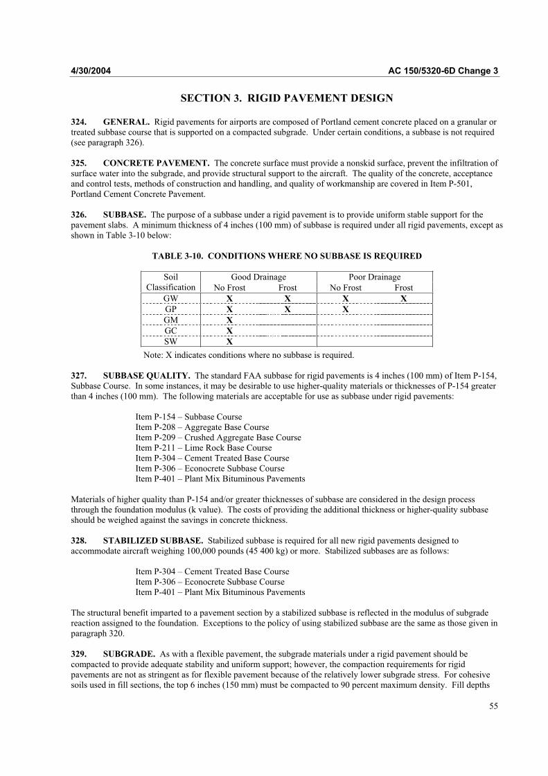
4/30/2004 AC 150/5320-6D Change 3
SECTION 3. RIGID PAVEMENT DESIGN
324. GENERAL. Rigid pavements for airports are composed of Portland cement concrete placed on a granular ortreated subbase course that is supported on a compacted subgrade. Under certain conditions, a subbase is not required(see paragraph 326).
325. CONCRETE PAVEMENT. The concrete surface must provide a nonskid surface, prevent the infiltration ofsurface water into the subgrade, and provide structural support to the aircraft. The quality of the concrete, acceptanceand control tests, methods of construction and handling, and quality of workmanship are covered in Item P-501, Portland Cement Concrete Pavement.
326. SUBBASE. The purpose of a subbase under a rigid pavement is to provide uniform stable support for thepavement slabs. A minimum thickness of 4 inches (100 mm) of subbase is required under all rigid pavements, except as shown in Table 3-10 below:
TABLE 3-10. CONDITIONS WHERE NO SUBBASE IS REQUIRED
Good Drainage Poor DrainageSoilClassification No Frost Frost No Frost Frost
GW X X X X
GP X X X
GM X
GC X
SW X
Note: X indicates conditions where no subbase is required.
327. SUBBASE QUALITY. The standard FAA subbase for rigid pavements is 4 inches (100 mm) of Item P-154,Subbase Course. In some instances, it may be desirable to use higher-quality materials or thicknesses of P-154 greaterthan 4 inches (100 mm). The following materials are acceptable for use as subbase under rigid pavements:
Item P-154 – Subbase CourseItem P-208 – Aggregate Base CourseItem P-209 – Crushed Aggregate Base CourseItem P-211 – Lime Rock Base CourseItem P-304 – Cement Treated Base CourseItem P-306 – Econocrete Subbase CourseItem P-401 – Plant Mix Bituminous Pavements
Materials of higher quality than P-154 and/or greater thicknesses of subbase are considered in the design processthrough the foundation modulus (k value). The costs of providing the additional thickness or higher-quality subbaseshould be weighed against the savings in concrete thickness.
328. STABILIZED SUBBASE. Stabilized subbase is required for all new rigid pavements designed toaccommodate aircraft weighing 100,000 pounds (45 400 kg) or more. Stabilized subbases are as follows:
Item P-304 – Cement Treated Base CourseItem P-306 – Econocrete Subbase CourseItem P-401 – Plant Mix Bituminous Pavements
The structural benefit imparted to a pavement section by a stabilized subbase is reflected in the modulus of subgradereaction assigned to the foundation. Exceptions to the policy of using stabilized subbase are the same as those given inparagraph 320.
329. SUBGRADE. As with a flexible pavement, the subgrade materials under a rigid pavement should becompacted to provide adequate stability and uniform support; however, the compaction requirements for rigidpavements are not as stringent as for flexible pavement because of the relatively lower subgrade stress. For cohesivesoils used in fill sections, the top 6 inches (150 mm) must be compacted to 90 percent maximum density. Fill depths
55

AC 150/5320-6D Change 3 4/30/2004
greater than 6 inches (150 mm) must be compacted to 90 percent maximum density or meet the requirements of Table3-2. For cohesive soils in cut sections, the top 6 inches (150 mm) of the subgrade must be compacted to 90 percentmaximum density. For noncohesive soils used in fill sections, the top 6 inches (150 mm) of fill must be compacted to100 percent maximum density, and the remainder of the fill must be compacted to 95 percent maximum density or meet the requirements of Table 3-2. For cut sections in noncohesive soils, the top 6 inches (150 mm) of subgrade must be compacted to 100 percent maximum density and the next 18 inches (460 mm) of subgrade must be compacted to 95percent maximum density. Swelling soils require special considerations. Paragraph 314 contains guidance on theidentification and treatment of swelling soils.
a. Contamination. In rigid pavement systems, repeated loading might cause intermixing of softsubgrade soils and aggregate base or subbase. This mixing can create voids below the pavement in which moisture canaccumulate, causing pumping to occur. Chemical and mechanical stabilization of the subbase or subgrade caneffectively reduce aggregate contamination (see paragraph 207). Geotextiles have been found to be effective at providing separation between fine-grained subgrade soils and pavement aggregates (FHWA-HI-90-001 GeotextileDesign and Construction Guidelines). Geotextiles should be considered for separation between fine-grained soils andoverlying pavement aggregates. In this application, the geotextile is not considered to act as a structural element withinthe pavement. Therefore, the modulus of the base or subbase is not increased when a geotextile is used for stabilization.For separation applications, the geotextile is designed based on survivability properties. FHWA-HI-90-001 containsadditional information about design and construction using separation geotextiles.
330. DETERMINATION OF FOUNDATION MODULUS (k VALUE) FOR RIGID PAVEMENT. Inaddition to the soils survey and analysis and classification of subgrade conditions, rigid pavement design also requiresthe determination of the foundation modulus. The k value should be assigned to the material directly beneath theconcrete pavement. However, the FAA recommends that a k value be established for the subgrade and then corrected toaccount for the effects of the subbase.
a. Determination of k Value for Subgrade. The preferred method of determining the subgrademodulus is by testing a limited section of embankment that has been constructed to the required specifications. Theplate bearing test procedures are given in AASHTO T 222, Nonrepetitive Static Plate Load Test of Soils and FlexiblePavement Components for Use in Evaluation and Design of Airport and Highway Pavements. If the construction andtesting of a test section of embankment is impractical, the values listed in Table 2-3 may be used. The values in Table2-3, however, are approximate, and engineering judgment should be used when selecting a design value. Fortunately,rigid pavement is not overly sensitive to k value, and an error in estimating k will not have a large impact on rigidpavement thickness.
b. Determination of k Value for Granular Subbase. It is usually not practical to determine afoundation modulus on top of a subbase by testing, at least in the design phase. Usually, the embankment and subbasewill not be in place in time to perform any field tests, so the k value will have to be assigned without the benefit oftesting. The probable increase in k value associated with various thicknesses of different subbase materials is shown in Figure 2-4. The upper graph in Figure 2-4 should be used when the subbase is composed of well-graded crushedaggregate, such as P-209. The lower graph in Figure 2-4 applies to bank-run sand and gravel, such as P-154. Bothcurves in Figure 2-4 apply to unstabilized granular materials. Values shown in Figure 2-4 are guides and can betempered by local experience.
c. Determination of k Value for Stabilized Subbase. As with granular subbase, the effect of stabilized subbase is reflected in the foundation modulus. Figure 3-16 shows the probable increase in k value with variousthicknesses of stabilized subbase located on subgrades of varying moduli. Figure 3-16 is applicable to cement stabilized(P-304), Econocrete (P-306), and bituminous stabilized (P-401) layers. Figure 3-16 assumes a stabilized layer is twiceas effective as well-graded crushed aggregate in increasing the subgrade modulus. Stabilized layers of lesser qualitythan P-304, P-306, or P-401 should be assigned somewhat lower k values. After a k value is assigned to the stabilizedsubbase, the concrete slab thickness design procedure is the same as that described in paragraph 331.
56
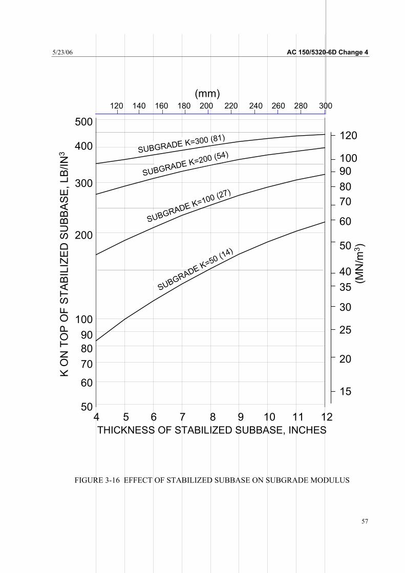
5/23/06 AC 150/5320-6D Change 4
FIGURE 3-16 EFFECT OF STABILIZED SUBBASE ON SUBGRADE MODULUS
57
THICKNESS OF STABILIZED SUBBASE, INCHES
4 5 6 7 8 9 10 11 12
500
400
300
200
100
90
80
70
60
50
120 140 160 180 200 220 240 260 280 300
120
100
90
80
70
60
50
40
35
30
25
20
15
(MN
/m3)
K O
N T
OP
OF
ST
AB
ILIZ
ED
SU
BB
AS
E,
LB
/IN
3
(mm)
SUBGRADE K=50 (14)
SUBGRADE K=100 (27)
SUBGRADE K=200 (54)SUBGRADE K=300 (81)
AC 150/5320-6D Change 4 5/23/06
58
331. DETERMINATION OF CONCRETE SLAB THICKNESS. Design curves have been prepared for rigid pavements similar to those for flexible pavements; i.e., separate curves for a variety of landing gear types and aircraft. See Figures 3-17 through 3-29. These curves are based on a jointed edge loading assumption where the load is located either tangent or perpendicular to the joint. Use of the design curves requires four design input parameters: concrete flexural strength, subgrade modulus, gross weight of the design aircraft, and annual departure of the design aircraft. The rigid pavement design curves indicate the thickness of concrete only. Thicknesses of other components of the rigid pavement structure must be determined separately.
a. Concrete Flexural Strength. The required thickness of concrete pavement is related to the strength of the concrete used in the pavement. Concrete strength is assessed by the flexural strength, as the primary action of a concrete pavement slab is flexure. Concrete flexural strength should be determined by ASTM C 78 test method. The design flexural strength of the concrete should be based on the age and strength the concrete will be required to have when it is scheduled to be opened to traffic. Thickness design strength of 600 to 650 psi is recommended for most airfield applications. Unless expedited construction is required, the strength specified for material acceptance during construction should be specified as a 28 day strength and be 5 percent less than the strength used for thickness design.
b. k Value. The k value is in effect, a spring constant for the material supporting the rigid pavement and is indicative of the bearing capacity of the supporting material.
c. Gross Weight of Design Aircraft. The gross weight of the design aircraft is shown on each design curve. The design curves are grouped in accordance with either main landing gear assembly type or as separate curves for individual aircraft. A wide range of gross weights is shown on all curves to assist in any interpolations which may be required. In all cases, the range of gross weights shown is adequate to cover weights of the aircraft represented.
d. Annual Departures of Design Aircraft. The fourth input parameter is annual departures of the design aircraft. The departures should be computed using the procedure explained in paragraph 305.
332. USE OF DESIGN CURVES.
a. Rigid Pavement Design Curves. The rigid pavement design curves are constructed such that the design inputs are entered in the same order as they are discussed in paragraph 331. Dashed “chase around lines” are shown on the curves to indicate the order of progression through the curves. Concrete flexural strength is the first input. The left ordinate of the design curve is entered with concrete flexural strength. A horizontal projection is made until it intersects with the appropriate foundation modulus line. A vertical projection is made from the intersection point to the appropriate gross weight of the design aircraft. A horizontal projection is made to the right ordinate showing annual departures. The pavement thickness is read from the appropriate annual departure line. The pavement thickness shown refers to the thickness of the concrete pavement only, exclusive of the subbase. This thickness is that shown as “T” in Figure 3-1, referred to as the critical thickness.
b. Optional Design Curves. When aircraft loadings are applied to a jointed edge, the angle of the landing gear relative to the jointed edge influences the magnitude of the stress in the slab. Single wheel and dual wheel landing gear assemblies produce the maximum stress when the gear is located parallel or perpendicular to the joint. Dual tandem assemblies often produce the maximum stress when positioned at an acute angle to the jointed edge. Figures 3-30 through 3-41, have been prepared for dual tandem gears located tangent to the jointed edge but rotated to the angle causing the maximum stress. These design curves can be used to design pavement in areas where aircraft are likely to cross the pavement joints at acute angles such as runway holding aprons, runway ends, runway-taxiway intersections, aprons, etc. Use of Figures 3-30 through 3-41 is optional and should only be applied in areas where aircraft are likely to cross pavement joints at an acute angle and at low speeds.
333. CRITICAL AND NONCRITICAL AREAS. The design curves, Figures 3-17 through 3-41, are used to determine the concrete slab thickness for the critical pavement areas shown as “T” in Figure 3-l. The 0.9T thickness for noncritical areas applies to the concrete slab thickness. For the variable thickness section of the thinned edge and transition section, the reduction applies to the concrete slab thickness. The change in thickness for the transitions should be accomplished over an entire slab length or width. In areas of variable slab thickness, the subbase thickness must be adjusted as necessary to provide surface drainage from the entire subgrade surface. For fractions of an inch of 0.5 or more, use the next higher whole number; for less than 0.5, use the next lower number.
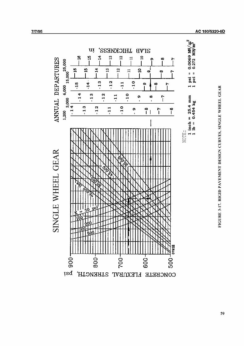
SIN
GL
E W
HE
EL
GE
AR
1,2
00
3,0
00
6,0
00
25,0
00
15
,00
0
NOTE:
1 in
ch
-1
4
-1
4
-1
3
-1
3
-1
2
-1
2
-1
1
-11
-1
0
-1
0
-9
-9
-8
25.4
m
m1 lb
0.4
54 k
g
-15
-14
-1
3
-1
2
-11
-1
0
13
12
11
13
12
11 10
9
FIG
UR
E 3
-17
. R
IGID
PA
VE
ME
NT
DE
SIG
N C
UR
VE
S,
SIN
GL
E W
HE
EL
GE
AR1
psi
=1 pci
=0.0
069 M
N
0.2
72
MN
m

850
800
i
I
ANNUAL DEPARTURES
1,2
00
6,0
00
25
,00
03,0
00
15,0
00
i
II
I
t i
i
-2
2
-2
1
-2
0
-1
9
-1
8
-1
5
-1
4
-1
3
-1
2
-11
-1
0
-9
-0
-7
-2
3
-2
2
-2
1
-2
0
-1
9
-1
8
-1
7
-1
6
-1
5
-1
4
-1
3
-1
2
-1
1
-1
0
-9
-7
-2
4
-2
3
-2
2
-2
1
-2
0
-1
9
-1
0
-1
5
-1
4
-1
3
-1
2
-1
1
-1
0
-9
-8
-2
6
-2
5
-2
4
-2
3
-2
2
-1
9-
20
-1
9
-1
7
-1
6-1
7
-1
6-1
5-1
5-
14
-1
4
-1
3-1
2-1
2
-
11
-
10
-
9
-
6
NOTE
:1
inch
= 25.4
m
m1
psi
=0.0
069
MN
1lb
=
0.4
54 k
g1
pci
=0
.27
2 m
FIG
UR
E 3
-18
. R
IGID
PA
VE
ME
NT
DE
SIG
N C
UR
VE
S,
DU
AL
WH
EE
L G
EA
R
� �

1,2
00
6,0
00
25
,00
03,0
00
15
,00
0
22
21
20
19
10
17
16
15
14
13
12
11 10 9 7
-2
3
-2
2
-2
1
-2
0
-1
9
-1
8
-1
7
-1
6
-1
5
-1
3
-1
2
-1
1
-1
0
-9
-8
-7
24
23
22
21
20
19
10
17
16
15
14
13
12
11 10 9 7
26
25
24
23
22
21
20
19
17
15
14
13 12 11 10 9
-2
7
-2
6
-2
5
-2
4
-2
3
-2
2
-2
1
-2
0
-1
9
-1
8
‘-1
6
-1
5
-1
4
-1
3
-1
2
-1
1
-1
0
-9
-8
NOTE
:1
inch
= 25.4
m
m1
psi
=1
lb =
0.4
54 k
g1
pci
=
FIG
UR
E 3
-19
. R
IGID
PA
VE
ME
NT
DE
SIG
N C
UR
VE
S,
DU
AL
TA
ND
EM
GE
AR
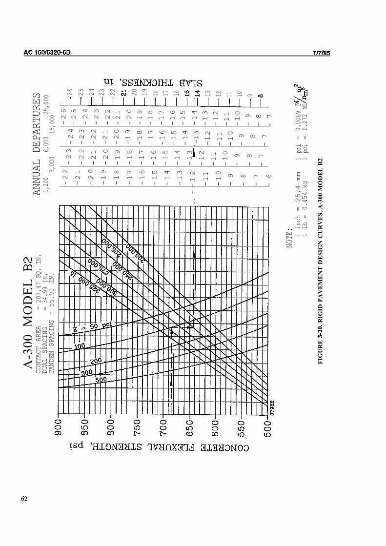
A-3
00
M
OD
EL
CONTACT AREA
= 207.47 SQ. IN.
DUAL SPACING
= 34.99 IN.
TANDEM SPACING = 55.00 IN.
ANNUAL DEPARTURES
1,200
6,000
25,000
3,000
15,0
00
-22
-21
-20
-19
-18
-17
-16
-15
-14
-13
--12
-11
-10
-9
-8
-7
-6
-23
-22
-21
-20
-19
-18
-17
-16
-15
-14
-13
-12
-11
-10
-9
-8
-7
-24
-23
-22
-21
-20
-19
-18
-17
-16
-15
-14
'-13
-12
-11
-10
-9
-8
-7
-26
-25
-24
-23
-22
-21
-20
-19
-18
-17
-16
-15
-14
-13
-12
-11
-10
-9
-8
-7
26
25
24
23
22
20
19
18 17 16 13 12 11 10 9
NOTE:
1inch= 25.4 mm
1psi=
0.0069MN
1lb =
0.454 kg
1pc
i=
0.272
MN
FIG
UR
E R
IGID
PA
VE
ME
NT
DE
SIG
N C
UR
VE
S,
A-3
00
MO
DE
L B
2

I I II
63
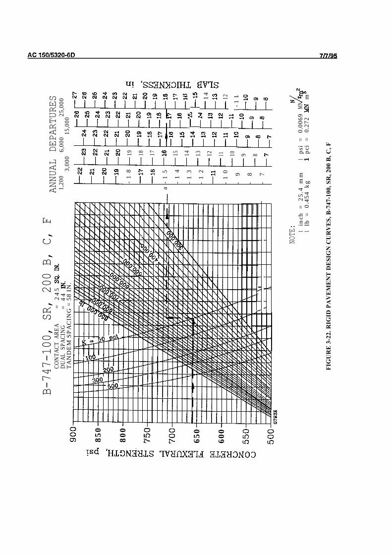
B-747-100, SR, 200 B, C, F
CON
TACT
ARE
A=
24
5
DUAL
SPA
CIN
G=
44
TA
ND
EM
SPA
CIN
G =
58
IN.
850
800
650
600
ANNUAL DEPARTURES
1,20
06,
000
3,00
025
,000
15,0
00
-1
8
a-
15
-1
4
-1
3
-1
2
-1
0
-9
-8
-7
19 18 17 15 14 13 12 11 10 9 8
13 1213
14
1211
12
l-1
1
NOTE
: 1in
ch=
25.
4 m
m1
psi
=0.
0069
1lb
=0.
454
kgpc
i=
0.27
2MN
m
FIG
UR
E 3
-22
. R
IGID
PA
VE
ME
NT
DE
SIG
N C
UR
VE
S,
B-7
47
-10
0,
SR
, 2
00
B,
C,
F

B-7
47
S
PANNUAL DEPARTURES
CONTACT AREA
210 SQ. IN.
DUAL SPACING
= 4
3.2
5 I
N.
TANDEM SPACING = 54 IN.
nn
n
650
600
i
ii
ii
I
1,200
0,000
25
,00
03,0
00
15,0
00
-2
2
-2
1
-2
0
-1
9
-1
0
-1
7
-1
6
-1
5
-1
4
-1
3
-1
2 11
-1
0
-9
-7
1in
ch =
25.4
mm
1 lb
=
0.4
54 kg
FIG
UR
E 3
-23
. R
IGID
PA
VE
ME
NT
DE
SIG
N C
UR
VE
S,
-2
3
-2
2
-2
1
-2
0
-1
9
-1
8
-17
-1
6-1
7
-1
5-1
6
-1
5-
14
-1
4-1
3-1
3-1
2-
-1
2-1
1-1
1
-1
0
-
9
-
7
-2
6
-2
5
-1
9-
20
-1
0-1
8
-1
6-1
7
-1
6-1
5-1
5-1
4-
14
-1
1-1
1
-1
0
-
9
1 p
si
=1 p
ci
=

AC
66

CON
TACT
AR
EA=
202.
46 S
Q.
IN.
DU
AL
SPAC
ING
= 4
5.0
0
TAN
DE
M S
PAC
ING
= 5
6.00
IN
.1,
200
6,00
025
,000
3,00
015
,000
-2
2
-2
1
-2
0
-1
9
-1
8
-1
7
-1
6
-1
5
-1
4
-1
3
-1
2-
--
-1
1
-1
0
-9
-8
-7
-6
-2
3
-2
2
-2
1
-2
0
-1
9
-1
8
-1
7
-1
6
-1
5
-1
4
-1
3
-1
1
-1
0
-9
-8
-7
-2
4
-2
3
-2
2
-2
1
-2
0
-1
9
-1
8
-1
7
-1
6
-1
5
-1
4
--
13
-1
2
-1
1
-1
0
-9
-8
-7
26 25 24 23 22 21 20 19 18 17 16 15 10 9 8
26 25 24 23 22� ��
19 13 12 11 10 9 8
1in
ch=
25
.4
1ps
i=
0.00
691
lb =
0.45
4 kg
1p
ci=
0.27
2M
NMN
FIG
UR
E 3
-25
. R
IGID
PA
VE
ME
NT
DE
SIG
N C
UR
VE
S,
B-7
67

c-130
CONTACT AREA
= 440
SQ
. IN
.TANDEM SPACING = 60 IN.
850
800
650
600
550
I\I\ I
II
ANNUAL DEPARTURES
1,200
6,000
25,000
3,000
15,000
-14
-13
-12
-11
-10
-9
-8
-7
-6
-15
-17
-15
-16
-14
-16
-15
-14
-15
-13
-14
-13
-12
� �
-13
-12
-11
-12
-11
-10
-11
-10
-9
-13
-12
-11
-10
-9
-6
-10
-9
-9
-8
-8
-7
-8
-7
-7
1inch= 25.4 mm
1ps
i=
0.0069
1 =
0.454 kg
1pci=
0.272
MNMN m
FIG
UR
E 3
-26
. R
IGID
PA
VE
ME
NT
DE
SIG
N C
UR
VE
S,
C-1
30
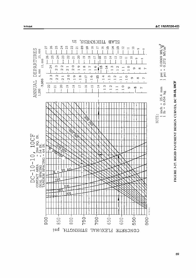
DC-10-10,
ANNUAL DEPARTURES
1,2
00
6,000
25,0
0015
,000
CO
NTA
CT A
RE
A= 2
94 S
Q.
IN.
DU
AL S
PA
CIN
G= 54 IN
.TA
ND
EM
SPA
CIN
G =
64 I
N.
24
26
25
24
23
22
21 20
19 18 17 15 14 13
27
26
25
24
850
800
650
600
22
21
20
19
18 17
16 15
-2
3
-2
2
-2
1
-2
0
-1
9
-1
8
17
-1
6
-1
4
-1
3
-1
2
-1
1
-1
0
-9
-8
-7
-2
3
-2
2
-2
1
-2
0
-1
9
-1
8
-1
7
-1
6
-1
3
-1
2
-1
1
-1
0
-9
-8
-7
23
22
21
i
II\
\II
\
18 17 16
14
-1
3
-1
2
-1
1
-1
0
-9
-7
12 1112 11 10 9 8
10 9 8I
v
07
93
3
NOTE
:1 in
ch
= 25.4
m
m1 lb
= 0.4
54 kg
1 psi
=0.0
069 M
N
1 pci
= 0.2
72
MN
FIG
UR
E 3
-27
. R
IGID
PA
VE
ME
NT
DE
SIG
N C
UR
VE
S,
DC

DC-10-30,
40, 40CF
850
800
W650
W
CO
NTA
CT A
RE
A= 331
IN
.D
UA
L S
PA
CIN
G=
54 IN
.TA
ND
EM
SPA
CIN
G =
64 I
N.
CE
NTE
R G
EA
R SPA
CIN
G = 37.5
IN
.
1,2
00
25,0
003,000
:15
07
93
3
22 21 20 19 18 17 16 15 14 13 12 11
-23
-22
-21
-20
-1
9
-1
0
-17
-16
-1
5
-12
24 23 22 21 20 19 10 16 15 14 13 12
21 20 19 18 16 15 14 13
21 20 19 16 15 14 13
NOTE
:1
inch
=25.4
mm
1psi
=0.0
069
1lb
=
0.4
54 kg
1pci
=0.272
FIG
UR
E R
IGID
PA
VE
ME
NT
DE
SIG
N C
UR
VE
S,
DC

AC
71

L-1
01
1-1
00
, 2
00
DU
AL
SPA
CIN
G 6
2 I
N.
1,2
00
SPA
CIN
G
70 I
N.
II
\I
\I
II
I
/A
//
I/
/l
/I
/
Y
v
v
-2
2
-19
-18
-17
-16
-10
-9
-8
-2
2
-19
-18
-17
-14
-13
-10
-8
-7
-2
4
-20
-2
0
-18
-17
-10
-10
-8
� 7
-8
1 2
6.4
mm
10.0
069
MN
10.
272
MN
FIG
UR
E 3
-30.
RIG
ID P
AV
EM
EN
T D
ESIG
N C
UR
VE
S,
L-1
011-1
00,2
00
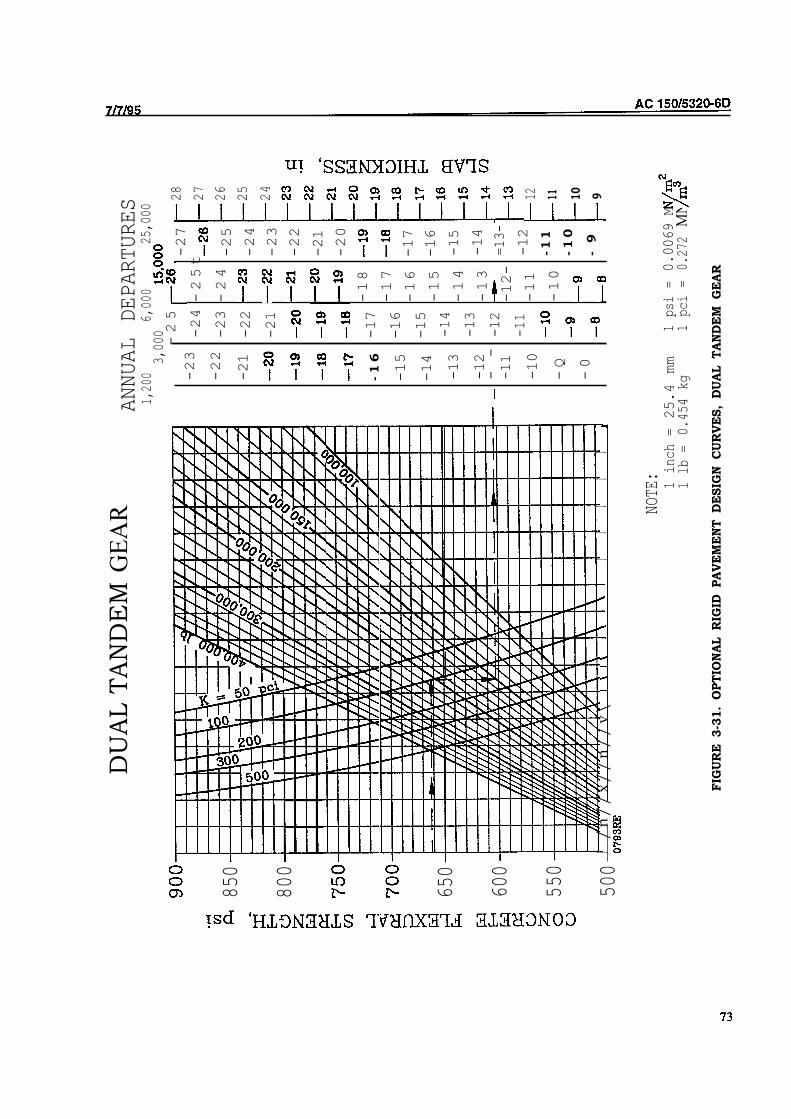
850
800
650
600
550
500
DU
AL T
AN
DE
M G
EA
RANNUAL DEPARTURES
1,20
06,000
25,000
3,000-25
t
-23
-22
-21
-1
6
-15
-14
-13
-12
--
-11
-10
-Q
-0
-24-25
-23-24
-22
-21
28
27
26
25
24
-17
-18
-16
-17
-16
-15
-15
-14-14
-13
-13
-12
-12-
-11
-11
-10
-27
-25
-24
-23
-22
-21
-20
-17
-16
-15
-14
=13-
-12
-1
1
-1
0
-9
12 11 10 9
I/n//x//n//v\
II
II
I
NOTE:
1 inch =25.4 mm
1 psi =
0.0069 MN
1 lb =
0.454 kg
1 pci =
0.272MN
FIG
UR
E 3-3
1.
OPT
ION
AL R
IGID
PA
VE
ME
NT
D
ESIG
N C
UR
VE
S,
DU
AL T
AN
DE
M G
EA
R

I I I I I I I
74
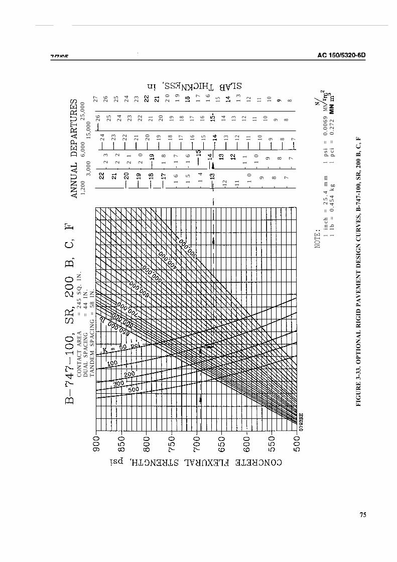
CO
NTA
CT
AR
EA
= 24
5 S
Q.
IN.
DU
AL S
PACI
NG
= 44
IN
.TA
ND
EM
SPA
CIN
G =
58
IN.
1,20
06,
000
25,0
003,
000
15,0
00
-2
3
-2
2
-2
1
-2
0
-1
8
-1
6 -
17
-1
5 -
16
-1
4
-12
-11
-1
1-
10
-1
0-
9-
9-
8-
8-
7-
7
24 23 22 21 20 19 18 17 16 15 13 12 11 10 9 8 7
26 25 24 23 22 21 20 19 18 17 16 14 13 12 11 10 9 8
27 26 25 24 23 20
19
17
16
15 13
12 11 10 9 8
NOTE
:1
inch
= 2
5.4
mm
1ps
i=
0.00
691
lb =
0.45
4 k
g1
pci
=0.
272MNMN
FIG
UR
E 3
-33
. O
PT
ION
AL
RIG
ID P
AV
EM
EN
T D
ES
IGN
CU
RV
ES
, B
-74
7-1
00
, S
R,
20
0 B
, C
, F

CO
NTA
CT
AR
EA
= 21
0 SQ
. IN
.D
UAL
SPA
CIN
G=
43.2
5 IN
.TA
ND
EMSP
AC
ING
=54
IN.
1,20
06,
000
25,0
003,
000
15,0
00
I I
-1
9
-1
8
-1
7
-1
6
-1
5
-1
4
-1
3
-1
2
-1
0
-9
-8
-7
NOTE
:1
inch
=2
5.
4m
m1
psi
=0
.00
69
1lb
=0
.45
4k
g1
pci
=0
.27
2M
NMN
FIG
UR
E 3
-34
. O
PT
ION
AL
RIG
ID P
AV
EM
EN
T D
ES
IGN
CU
RV
ES
,

A-3
00
M
OD
EL
B
4
nnn
CON
TACT
ARE
A 2
17.0
8 I
N.
DU
AL S
PACI
NG
= 36
.17
IN.
TAN
DE
M S
PAC
ING
= 5
5.00
IN
.
ANNUAL DEPARTURES
1,20
06,
000
25,0
003,
000
15,0
00
850
800
750
650
600
II
ii i
i
,
v I
II
II
I \
I \
I\
-22
-21
-20
-1
9
-1
8
-1
5
-1
4
-1
3
-1
2 11
I
9 7 6
-2
6
-24-25
-23
-24
-23
-22
-22
-21
-21
-20-20
-1
9-18
-18
-1
7
-1
6
-1
5
14
-13
-1
2 -
11
-1
0
NOTE: 1
=25
.4 mm
1ps
i=
0.00
69MN
1lb
=0.454
kg1
pci
=0.
272
MN
FIG
UR
E 3
-35
. O
PT
ION
AL
RIG
ID P
AV
EM
EN
T D
ES
IGN
CU
RV
ES
, A
-30
0 M
od
el
B4

78

AC
79

AC
80

81

AC
82

L-1
01
1-1
00
, 2
00
CONTACT AREA
= 337 SQ.
DUAL SPACING
= 52 IN.
TANDEM SPACING = 70 IN.
nn
n
65
0
600
ANNUAL DEPARTURES
1,20
06,000
25,000
3,000
15,000
-1
0
-17
-16
-15
-14
-13
-12
-11
-9
-8
-7
19
18
17
16
15
14
13
12
11 10 9 7
-20
-21
-19-20
-10
-17
-16
-15
-14
-13
-12
-13 12
-11
-11
-10
-10
-9
-9
-0
-7
23
22
21
20
19
18
17
16 15
14
13 12
11 10 9
NOTE
:1inch= 25.4 mm
1ps
i=
1lb =
0.454 kg
1pci=
FIG
UR
E.
3-4
1.
OP
TIO
NA
L P
AV
EM
EN
T D
ES
IGN
CU
RV
ES
, L
-10
11
-10
0,2
00

AC
334. DESIGN EXAMPLE. As an example of the use of the design curves, assume that a rigid pavement is to be
designed for dual tandem aircraft having a gross weight of 350,000 pounds (160 000 kg) and for 6,000 annual equivalent
departures of the design aircraft. The equivalent annual departures of 6,000 include 1,200 annual departures of B-747
aircraft weighing 780,000 pounds (350 000 kg) gross weight. The modulus of 100 (25 with poor
drainage and frost penetration is 18 inches (460 mm). The feature to be designed is a primary runway and requires 100
percent frost protection. The soil is CL. Concrete mix designs indicate a strength of 650 PSI (4.5
MN/m*) can be readily produced with locally available aggregates. The gross weight of the design aircraft dictates the
use of a stabilized subbase. Several thicknesses of stabilized subbases should be tried to determine the most economical
section. Assume a stabilized subbase of P-304 will be used. Try a subbase thickness of 6 inches (150 mm). Using
Figure 3-16, a 6-inch (150 mm) thickness of P-304 would likely increase the foundation modulus from 100 (25
to 210 (57 Using Figure 3-19, dual tandem design curve, with the assumed design data, yields a
concrete pavement thickness of 16.6 inches (422 mm). This thickness would be rounded off to 17 inches (430 mm).
Since the frost penetration is only 18 inches (460 mm) and the combined thickness of concrete pavement and stabilized
subbase is 23 inches (585 mm), no further frost protection is needed. Even though the wide body aircraft did not control
the thickness of the slab, the wide bodies would have to be considered in the establishment of jointing requirements and
design of drainage structures. Other stabilized subbase thicknesses should be tried to determine the most economical
section.
335. FROST EFFECTS. As with flexible pavements, frost protection should be provided for rigid pavements in
areas where conditions conducive to detrimental frost action exist. Frost protection considerations for rigid pavements
are similar to those for flexible pavements. The determination of the depth of frost protection required is given in
paragraph 308.b. Local experience may be used to refine the calculations.
a. Example. Assume the above design example is for a primary runway and requires complete frost
protection. The soil is CL, weighing 115 ft (184 m). The design freezing index is 500 degree
days. Referring to Figure 2-6 shows the depth of frost penetration to be 34 inches (865 mm). The structural
considerations yield a 23 inch (585 mm) thickness of non-frost susceptible material. Since the frost penetration is only
18 inches (460 mm) and the combined thickness of concrete pavement and stabilized subbase is 23 inches (585 mm), no
further frost protection is needed. Even though the wide body aircraft did not control the thickness of the slab, the wide
bodies would have to be considered in the establishment of jointing requirements and design of drainage structures.
Other stabilized subbase thicknesses should be tried to determine the most economical section.
Complete Frost Protection. The complete frost protection method applies only to FG-3 and
FG-4 soils which are extremely variable in horizontal extent. These soil deposits are characterized by very large,
frequent, and abrupt changes in frost heave potential. The variability is such that the use of transition sections is not
practical.
Limited Frost Penetration. This design method should be used for FG-4 soils
except where the conditions require complete protection, see (1) above. The method also applies to soils in frost groups
FG-1, FG-2, and FG-3 when the functional requirements of the pavement permit a minor amount of frost heave.
Consideration should be given to using transition sections where horizontal variability of frost heave potential permits.
Reduced Strength. The reduced strength method is recommended for
FG-1, FG-2, and FG-3 subgrades which are uniform in horizontal extent or where the functional requirements of the
pavement will permit some degree of frost heave. the method may also be used for variable FG-1 through FG-3
subgrades for less sensitive pavements which are subject to slow speed traffic and heave can be tolerated.
336. HIGH TRAFFIC VOLUMES. There are a number of airports which experience traffic intensities in excess of
those indicated on the design curves. Pavement maintenance is difficult and costly at high activity airports due to traffic
intensity and the potential for aircraft delays. Performance of airport pavements under high traffic intensities has been
reported in FAA-PM-84/14 (see Appendix 4). Rigid pavement designed to serve in situations where traffic intensity is
high should reflect the following considerations.
a. Foundation. The foundation for the pavement provides the ultimate support to the structure. Every
effort should be made to provide a stable foundation as problems arising later from an inadequate foundation cannot be
practicably corrected after the pavement is constructed. The use of stabilized subbase will aid greatly in providing a

6/3/02 AC 150/5320-6D CHG 2
uniform, stable foundation.
b. Thickness. Pavements subjected to traffic intensities greater than the 25,000 annual departure level
shown on the design curves will require more thickness to accommodate the traffic volume. Additional thickness can be
provided by increasing the pavement thickness in accordance with Table 3-5.
c. Panel Size. Slab panels should be constructed to minimize joint movement. Panel sizes given in
Paragraph 337 should be selected conservatively. Small joint movement tends to provide for better load transfer across
joints and reduces the elongation the joint sealant materials must accommodate when the slabs expand and contract.
High-quality joint sealants should be specified to provide the best possible performance.
337. JOINTING OF CONCRETE PAVEMENTS. Variations in temperature and moisture content can cause
volume changes and slab warping, resulting in significant stresses. In order to reduce the detrimental effects of these
stresses and to minimize random cracking, it is necessary to divide the pavement into a series of slabs of predetermined
dimensions by means of joints. These slabs should be as nearly square as possible when no reinforcement is used.
a. Joint Categories. Pavement joints are categorized according to the function that the joint is intended
to perform. The categories are expansion, contraction, and construction joints. All joints, regardless of type, should be
finished in a manner that permits the joint to be sealed. Pavement joint details are shown in Figures 3-42 and 3-42A
and are summarized in Table 3-10A. These various joints are described as follows:
(1) Expansion Joints. The function of an expansion joint is to isolate intersecting pavements
and to isolate structures from the pavement. There are two types of expansion joints.
(i) Type A. Type A is used when load transfer across the joint is required. This joint
contains a 3/4-inch (19 mm) nonextruding compressible material and is provided with dowel bars for load transfer.
(ii) Type B. Type B is used when conditions preclude the use of load transfer devices
that span across the joint, such as where the pavement abuts a structure or where horizontal differences in movement of
the pavements may occur. These joints are formed by increasing the thickness of the pavement along the edge of slab.
No dowel bars are provided.
(2) Contraction Joints. The function of contraction joints is to provide controlled cracking of
the pavement when the pavement contracts due to decrease in moisture content or a temperature drop. Contraction
joints also decrease stresses caused by slab warping. Details for contraction joints are shown as Types F, G, and H in
Figure 3-42.
(3) Construction Joints. Construction joints are required when two abutting slabs are placed at
different times, such as at the end of a day’s placement, or between paving lanes. Details for construction joints are
shown as Types C, D, and E in Figure 3-42.
b. Joint Spacing.
(1) Without Stabilized Subbase. A rule-of-thumb for joint spacing given by the Portland
Cement Association is applicable for rigid pavements without stabilized subbase: “As a rough guide, the joint spacing
(in feet) should not greatly exceed twice the slab thickness (in inches).” Table 3-11 shows the recommended maximum
joint spacings. Shorter spacings may be more convenient in some instances and may be required to provide minimum
clearance between pavement joints and in-pavement obstructions such as light cans. The recommended maximum
spacing for slabs thicker than 12 inches (305 mm) should only be used when historical records can verify satisfactory
performance. In lieu of historical performance records, a maximum spacing of 20 feet (6.1 m) is recommended. The
ratio of slab length to slab width should not exceed 1.25 in unreinforced pavements.
85


FIG
UR
E 3
-42.
RIG
ID P
AV
EM
EN
T J
OIN
T T
YP
ES
AN
D D
ET
AIL
S
AC 150/5320-6D CHG 2
6/3/02
86

Longit
udin
al J
oin
t T
ype
A o
r D
Tra
nsv
erse
Join
tT
ype
A, D
, or
F
PL
AN
VIE
WP
osi
tio
n o
f D
ow
els
at E
dg
e o
f Jo
int
Ty
pe
A,
D,
F
Bar
Len
gth
Var
ies
3"
(76m
m)
Min
imum
10"
(254m
m)
Min
imum
Bar
Len
gth
Var
ies
Const
ruct
ion J
oin
t B
etw
een S
labs
Rod B
ackup
Mat
eria
l
Sea
lant
Mat
eria
l 1/4
" -
3/8
" (6
-10m
m)
Bel
ow
Surf
ace
1 1
/4"
(32m
m)
Min
imum
W
D
DE
TA
IL 3
CO
NS
TR
UC
TIO
N J
OIN
T
Sea
lant
Mat
eria
l 1/4
" -
3/8
"(6
-10m
m)
Bel
ow
Surf
ace
1 1
/4"
(32m
m)
Min
imum
Rod B
ackup M
ater
ial
DE
TA
IL 2
CO
NT
RA
CT
ION
JO
INT
D
W
T/4
±1/4
"(±
6m
m)
3/4
"±1/8
"(1
9±
3m
m)
Sea
lant
Mat
eria
l 1/4
" -
3/8
" (6
-10m
m)
Bel
ow
Surf
ace
Non-E
xtr
udin
g P
rem
old
ed C
om
pre
ssib
le
Mat
eria
l
1/4
" (6
mm
) R
adiu
sor
Cham
fer DE
TA
IL 1
EX
PA
NS
ION
JO
INT
3/4
"±1/8
"(1
9±
3m
m)
NO
TE
S:
1. SH
AP
E F
AC
TO
RS
FO
R O
PT
IMU
M P
ER
FO
RM
AN
CE
.2.
3. 4.
HIG
H T
RA
FF
IC V
OL
UM
ES
.
Opti
onal
1/4
" X
1/4
" C
ham
fer
Rod B
ackup M
ater
ial
FIG
UR
E 3
-42A
. R
IGID
PA
VE
ME
NT
JO
INT
TY
PE
S A
ND
DE
TA
ILS
6/3/02 AC 150/5320-6D
CHG 2
86-1
AS
TM
D-1
751 o
r 1752
FIE
LD
PO
UR
ED
AN
D P
RE
FO
RM
ED
SE
AL
AN
TS
RE
QU
IRE
DIF
FE
RE
NT
S
EA
LA
NT
RE
SE
RV
OIR
SIZ
ED
TO
PR
OV
IDE
PR
OP
ER
SH
AP
E F
AC
TO
R, W
/D.
RO
D B
AC
KU
P M
AT
ER
IAL
MU
ST
BE
CO
MP
AT
IBL
E W
ITH
TH
E T
YP
E O
F S
EA
LA
NT
US
ED
AN
D S
IZE
D T
O P
RO
VID
E T
HE
DE
SIR
ED
SH
AP
E F
AC
TO
R.
RE
CE
SS
SE
AL
ER
3/8
" -
1/2
" F
OR
JO
INT
S P
ER
PE
ND
ICU
LA
R T
O R
UN
WA
Y G
RO
OV
ES
CH
AM
FE
RE
D E
DG
ES
AR
E R
EC
OM
ME
ND
ED
FO
R D
ET
AIL
S 2
AN
D 3
WH
EN
PA
VE
ME
NT
S A
RE
SU
BJE
CT
TO
SN
OW
RE
MO
VA
L E
QU
IPM
EN
T O
R

AC 150/5320-6D CHG 2 6/3/02
TABLE 3-10A PAVEMENT JOINT TYPES
JOINT TYPES - DESCRIPTION AND USE (Chapter 3 designations)
TYPE DESCRIPTION LONGITUDINAL TRANSVERSE
A Doweled Expansion
Joint
Not used. Use near intersections to isolate different
pavement areas. Not recommended to
isolate different joint patterns.
B Thickened Edge
Expansion Joint
Use at intersections where dowels are
not suitable and where pavements abut
structures. Consider at locations along
a pavement edge where future
expansion is possible.
Provide thickened edge where pavement
extension is likely. On thinner pavement
sections the thickened edge will provide
additional section for placement of future
dowel bars. Recommended to isolate
different joint patterns.
C Keyed Construction
Joint
Acceptable for all construction joints
except where type E is required.
Not used.
D Doweled
Construction Joint
Acceptable for all construction joints. Use at locations where paving operations
are delayed or stopped.
E Hinged Construction
Joint
Acceptable for use on all construction
joints of taxiways and for all other
construction joints placed 25' or less
from the pavement edge unless wide
body aircraft are expected. See
paragraph 338b for wide body aircraft
requirements.
Not used.
F Doweled Contraction
Joint
May be considered for general use. Use on all contraction joints for a
distance of at least three joints from a
free edge, for the first two joints on each
side of expansion joints, and for all
contraction joints in reinforced
pavements. May be considered for
general use.
G Hinged Contraction
Joint
For all contraction joints of the taxiway
and for all other contraction joints
placed 25' or less from the pavement
edge unless wide body aircraft are
expected. See paragraph 338b for wide
body aircraft requirements.
Not used.
H Dummy Contraction
Joint
For all other contraction joints in
pavement.
For all remaining contraction joints in
non-reinforced pavements.
86-2

6/3/02 AC 150/5320-6d CHG 2
TABLE 3-11. RECOMMENDED MAXIMUM JOINT SPACINGS - RIGID PAVEMENT WITHOUT STABILIZED SUBBASE
Slab Thickness Transverse Longitudinal
Inches Millimeters Feet Meters Feet Meters
6 150 12.5 3.8 12.5 3.8
7-9 175-230 15 4.6 15 4.6
9-12 230-305 20 6.1 20 6.1
> 12 >305 25 7.6 25 7.6
Note: Joint spacings shown in this table are maximum values that may be acceptable under ideal
conditions. Smaller joint spacings should be used if indicated by past experience. Pavements subject
to extreme seasonal temperature differentials or extreme temperature differentials during placement
may require smaller joint spacings. See also Chapter 5 for light-load rigid pavement jointing.
(2) With Stabilized Subbase. Rigid pavements supported on stabilized subbase are subject to higher
warping and curling stresses than those supported on unstabilized foundations. When designing a rigid pavement
supported on a stabilized subbase a different procedure is recommended to determine joint spacing. Joint spacing should
be a function of the radius of relative stiffness of the slab. The joint spacing should be selected such that the ratio of the
joint spacing, in inches, to the radius of relative stiffness is 5.0 or less to control transverse cracking. In the absence of
conclusive local experience, a maximum joint spacing of 20 feet (6.1 m) is recommended. The radius of relative stiffness
is defined by Westergaard as the stiffness of the slab relative to the stiffness of the foundation. It is determined by the
following formula: 1
⎛ Eh3 ⎞ 4
l = ⎜⎜⎝12(1− u 2 ) k ⎠⎟⎟
Where: l = radius of relative stiffness, inches. E = modulus of elasticity of the concrete, usually 4 million psi. h = slab thickness, inches. u = Poisson’s ratio for concrete, usually 0.15. k = modulus of subgrade reaction, pci.
338. SPECIAL JOINTING CONSIDERATIONS. A number of special considerations are required when
designing the jointing system for a Portland cement concrete pavement. Several considerations are discussed below.
a. Keyed Joints. Keyed construction joints should not be used for slabs less than 9 inches (230 mm) in
thickness. Keyed joints in slabs of lesser thickness result in very small keys and key-ways with limited strength.
b. Jointing Systems for Wide Body Jet Aircraft. Experience indicates poor performance may result from
keyed longitudinal construction joints supported on low-strength foundations when wide body aircraft loadings are
encountered. Special jointing recommendations are discussed below.
(1) Low Strength Foundations. For foundation moduli of 200 pci (54 MN/m3) or less, a doweled or
thickened edge construction joint, Type D or B, is recommended. Keyed joints should not be used as poor performance
will likely result. In areas of low traffic usage, such as extreme outer lanes of runways and aprons, keyed joints, Type C,
may be used.
(2) Medium Strength Foundations. For foundation moduli between 200 pci (54 MN/m3) and 400 pci
(109 MN/m3), hinged construction joints, Type E, may be used as well as doweled or thickened edge. The maximum
width of pavement that can be tied together depends on several factors such as subgrade frictional restraints, pavement
thickness, and climatic conditions. Normally, the maximum width of tied pavement should not exceed 75 feet (23 m).
Type C joints may be used in low traffic areas.
(3) High Strength Foundations. For foundation moduli of 400 pci (109 MN/m3) or greater
conventional keyed joints, Type C, may be used regardless of traffic usage. Note, however, that the prohibition
87

AC 150/5320-6D 7/7/95
against keyed joints in pavements less than 9 inches (230 mm) thick shall still remain in effect.
c. Future Expansion. When a runway or taxiway is likely to be extended at some future date, it is
recommended that a thickened edge joint be provided at that end of the runway or taxiway. Likewise, if any pavement is
to be widened in the future, a key-way or thickened edge should be provided at the appropriate edge.
339. JOINTING STEEL.
a. Tie Bars. Tie bars are used across certain longitudinal contraction joints and keyed construction joints to
hold the slab faces in close contact. The tie bars themselves do not act as load transfer devices. By preventing wide
opening of the joint, load transfer is provided by the keyed joint or by aggregate interlock in the crack below the groove-
type joint. Tie bars should be deformed bars conforming to the specifications given in Item P-501. The bars should be
5/8 inches (16 mm) in diameter and 30 inches (760 mm) on center.
b. Dowels. Dowels are used at joints to provide for transfer of load across the joint and to prevent relative
vertical displacement of adjacent slab ends. Dowels permit longitudinal movement of adjacent slabs.
(1) Where used. Provision for load transfer by dowels is provided at all transverse expansion joints and
all butt-type construction joints. Dowels for contraction joints should be provided at least three joints from a free edge.
Contraction joints in the interior of the pavement may be the dummy groove type.
(2) Size Length and Spacing. Dowels should be sized such that they will resist the shearing and bending
stresses produced by the loads on the pavement. They should be of such length and spacing that the bearing stresses
exerted on the concrete will not cause failure of the concrete slab. Table 3-12 indicates the dowel dimensions and
spacing for various pavement thicknesses.
Table 3-12. DIMENSIONS AND SPACING OF STEEL DOWELS
Thickness of Slab Diameter Length Spacing
6-7 in
(150-180 mm)
8-12 in
(210-305 mm)
13-16 in
(330-405 mm)
17-20 in
(430-510 mm)
21-24 in
(535-610 mm)
3/4 in 18 in 12 in
(20 mm) (460 mm) (305 mm)
1 in 19 in 12 in
(25 mm) (480 mm) (305 mm)
1 1/4 in1 20 in 15 in
(30 mm) (510 mm) (380 mm)
1 1/2 in1 20 in 18 in
(40 mm) (510 mm) (460 m)
2 in1 24 in 18 in
(50 mm) (610 mm) (460 mm)1Dowels noted may be solid bar or high-strength pipe. High-strength pipe dowels must
be plugged on each end with a tight-fitting plastic cap or with bituminous or mortar mix.
(3) Dowel Positioning. The alignment and elevation of dowels is extremely important in obtaining a
satisfactory joint. Transverse dowels will require the use of a fixture, usually a wire cage or basket firmly anchored to
the subbase, to hold the dowels in position. During the concrete placement operations, it is advisable to place plastic
concrete directly on the dowel assembly immediately prior to passage of the paver to prevent displacement of the
assembly by the paving equipment. Some paving machines have a dowel placer, which can be used to accurately
position dowels.
340. JOINT SEALANTS AND FILLERS. Sealants are used in all joints to prevent the ingress of water and
foreign material in the joint. Premolded compressible filler are used in expansion joints to permit expansion of the
slabs. Joint sealants are applied above the filler in expansion joints to prevent infiltration of water and foreign material.
In areas subject to fuel spillage, fuel-resistant sealants should be used. Specifications for joint sealants are given in Item
P-605.
88
6/3/02 AC 150/5320-6D CHG 2
341. JOINT LAYOUT. Pavement joint layout is a matter of selecting the proper joint types and dimensions so that
the joints can perform their intended function. Construction considerations are also vitally important in determining the
joint layout pattern. Paving lane widths will often dictate how the pavement should be jointed. Generally speaking, it is
more economical to keep the number of passes of the paving train to a minimum while maintaining proper joint
function. Figure 3-43 shows a typical jointing plan for a runway end, parallel taxiway, and connector. In-pavement
light fixtures may also affect joint spacing. Joint patterns should be such that the nearest edge of a light fixture is
approximately 2 feet (610 mm) from any joint. It is impossible to illustrate all of the variations that can occur at
pavement intersections. Reference 8 in Appendix 4 contains further information on jointing patterns. Two important
considerations in designing joint layouts for intersections are isolation joints and odd-shaped shapes. More discussion
on these follows:
a. Isolation Joints. Two intersecting pavements, such as a taxiway and runway, should be isolated to
allow the pavements to move independently. Isolation can best be accomplished by using a Type B expansion joint
between the two pavements. The expansion joint should be positioned such that the two pavements can expand and
contract independently; normally this can be accomplished by using a Type B expansion joint where the two pavements
abut. One isolation joint is normally sufficient to allow independent movement.
b. Odd-Shaped Slabs. Cracks tend to form in odd-shaped slabs; therefore, it is good practice to
maintain sections that are nearly square or rectangular in shape. Pavement intersections that involve fillets are difficult
to design without a few odd-shaped slabs. In instances where odd-shaped slabs cannot be avoided, steel reinforcement is
recommended. Steel reinforcement should consist of 0.050 percent steel in both directions in slabs where the length-to-
width ratio exceeds 1.25 or in slabs that are not rectangular in shape. The steel reinforcement should be placed in
accordance with the recommendations given in paragraph 342, Reinforced Concrete Pavement. Fillets may also be
defined by constructing slabs to the normal, full dimensions and painting out the unused portion of the slab with
bitumen.
342. REINFORCED CONCRETE PAVEMENT. The main benefit of steel reinforcing is that, although it does
not prevent cracking, it keeps the cracks that form tightly closed so that the interlock of the irregular faces provides
structural integrity and usually maintains pavement performance. By holding the cracks tightly closed, the steel
minimizes the infiltration of debris into the cracks. The thickness requirements for reinforced concrete pavements are
the same as plain concrete and are determined from the appropriate design curves, Figures 3-17 through 3-41. Steel
reinforcement allows longer joint spacing; thus the cost benefits associated with fewer joints must be considered in the
decision to use plain or reinforced concrete pavement.
343. TYPE AND SPACING OF REINFORCEMENT. Reinforcement may be either welded wire fabric or bar
mats installed with end and side laps to provide complete reinforcement throughout the slab panel. End laps should be a
minimum of 12 inches (305 mm) but not less than 30 times the diameter of the longitudinal wire or bar. Side laps
should be a minimum of 6 inches (150 mm) but not less than 20 times the diameter of the transverse wire or bar. End
and side clearances should be a maximum of 6 inches (150 mm) and a minimum of 2 inches (50 mm) to allow for nearly
complete reinforcement and yet achieve adequate concrete cover. Longitudinal members should be spaced not less than
4 inches (100 mm) nor more than 12 inches (305 mm) apart; transverse members should be spaced not less than 4
inches (100 mm) nor more than 24 inches (610 mm) apart.
344. AMOUNT OF REINFORCEMENT.
a. The steel area required for a reinforced concrete pavement is determined from the subgrade drag
formula and the coefficient of friction formula combined. The resultant formula is expressed as follows:
A = (3.7 )L LtS
f s
Where: As = area of steel per foot of width or length, square inches L = length or width of slab, feet T = thickness of slab, inches fs = allowable tensile stress in steel, psi
89
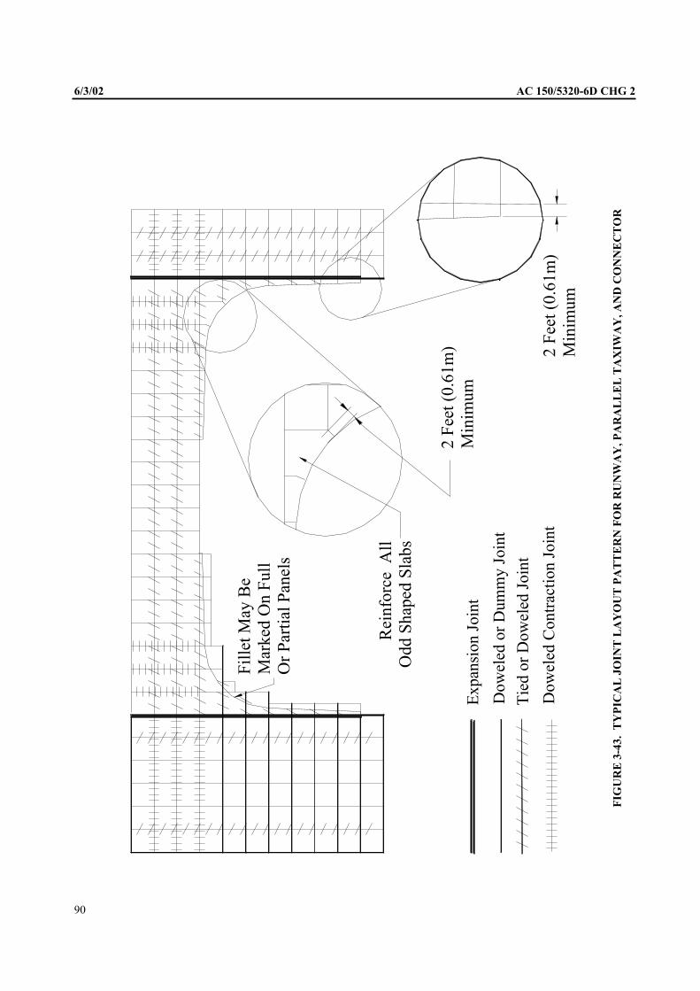
6/3/02 AC 150/5320-6D CHG 2
Tie
d o
r D
ow
eled
Join
t
Dow
eled
or
Dum
my J
oin
t
Expan
sion J
oin
t
Dow
eled
Contr
acti
on J
oin
t
Rei
nfo
rce
Od
d S
hap
ed S
lab
s
2 F
eet
(0.6
1m
) M
inim
um
2 F
eet
(0.6
1m
) M
inim
um
Fil
let
May
Be
Mar
ked
On
Fu
ll
Or
Par
tial
Pan
els A
ll
FIG
UR
E 3
-43.
TY
PIC
AL
JO
INT
LA
YO
UT
PA
TT
ER
N F
OR
RU
NW
AY
, P
AR
AL
LE
L T
AX
IWA
Y,
AN
D C
ON
NE
CT
OR
90

NOTE: To determine the area of steel in metric units:
L should be expressed in meters
t should be expressed in millimeters
should be expressed in newtons per square meter
The constant 3.7 should be changed to 0.64.
A, will then be in terms of square centimeters per meter.
b. In this formula the slab weight is assumed to be 12.5 pounds per square foot, per inch of thickness
(23.6 MN/m*). The allowable tensile stress in steel will vary with the type and grade of steel. It is recommended that
allowable tensile stress be taken as two-thirds of the yield strength of the steel. Based on current specifications the yield
strengths and corresponding design stresses (fs) are as listed in Table 3-13.
C. The minimum percentage of steel reinforcement should be 0.05%. The percentage of steel is
computed by dividing the area of steel, As, by the area of concrete per unit of length (or width) and multiplying by 100.
The minimum percentage of steel considered the least amount of steel which can be economically placed is 0.05%. Steel
reinforcement allow larger slab sizes and thus decreases the number of transverse contraction joints. The costs
associated with providing a reinforced pavement must be compared with the savings realized in eliminating some of the
transverse contraction joints to determine the most economical steel percentage. The maximum allowable slab length
regardless of steel percentage is 75 feet (23 m).
TABLE 3-13. YIELD STRENGTHS OF VARIOUS GRADES OF REINFORCING STEEL
ASTM Type Grade of Steel Yield Strength FS
Designation psi (MN/m’) psi (MN/n?)
A 615 Deformed Billet Steel, Grade 40 40,000 (300) 27,000 (200)
A 616 Deformed Rail Steel, Grade 50 50,000 (370) 33,000 (240)
A 616 Deformed Rail Steel, Grade 60 60,000 (440) 40,000 (300)
A 615 Deformed Billet Steel, Grade 60 60,000 (440) 40,000 (300)
A 185 Cold Drawn Welded Steel Wire Fabric 65,000 (480) 43,000 (320)
A 497 Cold Drawn Welded Deformed Steel Wire 70,000 (520) 47,000 (350)
TABLE 3-14. DIMENSIONS AND UNIT WEIGHTS OF DEFORMED STEEL
REINFORCING BARS
NOMINAL DIMENSIONS
Number Diameter Area Perimeter Unit Weight
in. in. (cm) (kg/m)
3 0.375 (9.5) 0.11 (0.71) 1.178 (3.0) 0.376 (0.56)4 0.500 (12.7) 0.20 (1.29) 1.57 1 (4.0) 0.668 (15 0.625 (15.9) 0.31 (2.00) 1.963 (5.0) 1.043 (1.57)6 0.750 (19.1) 0.44 (2.84) 2.356 (6.0) 1.502 (2.26)7 0.875 (22.2) 0.60 (3.86) 2.749 (7.0) 2.044 (3.07)
345. DIMENSIONS AND WEIGHTS OF REINFORCEMENT. Dimensions and unit weights of standard
deformed reinforcing bars are given in Table 3-14, and wire size number, diameters, areas, and weights of wires used in
welded wire fabric are given in Table 3-15.
346. WELDED WIRE FABRIC. The use of welded wire fabric requires some special design considerations to
achieve the most economical design. The use of smooth welded wire fabric or deformed welded wire fabric is the option
of the designer. The choice should be based on the difference in allowable design stresses, the availability of the desired
sizes (smooth wire fabric is available in a wider range of sizes), and the costs associated with each style of fabric. It is
recommended that the minimum size of longitudinal wire by or D5. The minimum transverse wire should be no
smaller than W4 or D4. In addition, should calculated area of longitudinal steel be less than 0.05 percent of the
91

AC
cross-sectional area of slab, the size and spacing of the steel members (bars or wire) should be determined on the premise
that the minimum area should not be less than 0.05 percent. This percentage applies in the case of steel having a yield
strength of 65,000 PSI (480 MN/m’). If lower grades are used, the percentage should be revised proportionately
upward. For example, Table 3-15 shows that wires, spaced inches (255 mm) apart, furnish an area of 0.12
square inches (77 which satisfies the requirement for pavements up to 20 inches (510 mm) thick. Sizing of
individual sheets of welded wire fabric is also important in providing an economical design. Not all fabricators supply
all wire sizes in all spacings. While nearly any fabric style can be produced on special order, it is generally more
economical to specify a standard production configuration. Sheet and roll widths in excess of 8 feet (2.5 m) can result in
higher shipping costs.
TABLE 3-15. SECTIONAL AREAS OF WELDED FABRIC
Wire Size Number Nominal Nominal Center-to-Center Spacing
Smooth Deformed Diameter Weight
Inches4” 6” 8” 10” 12”
0.628 1.054
D30 0.618 1.020
W28 D28 0.597
W26 D26 0.575
W24 D24 0.553
w22 D22 0.529
W18
W16
w 1 2
D20 0.504
D18 0.478
D16 0.45
D14 0.422
D12 0.390
0.374
0.366
0.356
w9.5 0.348
0.338
W8.5 0.329
W8 D8 0.319
w7.5 0.309
w 7 D7 0.298
W6.5 0.288
W6 D6 0.276
w5.5 0.264
0.252
w4.5 0.240
w 4 D4 0.225
Note: 1 inch = 2.54 cm
1 ft. = 1.5 kg/m
347. JOINTING OF REINFORCED PAVEMENTS. Contraction joints in reinforced pavements may be spaced
up to 75 feet (23 m) apart, and all joints should be provided with load transfer devices as shown in Figure 3-44. Also,
this figure presents other reinforcement details such as clearance at joints and edges of pavement and depth below the
surface. The longer joint spacing allowed with reinforced pavements will result in larger joint openings. The joints must
be sealed carefully to accommodate the larger movements at the joints.
92

5/23/06 AC 150/5320-6D Change 4
93
LANE WIDTH LANE WIDTH
2 INCH MINIMUM
6 INCH MAXIMUM
[5 cm to 15 cm]
STEEL
TRANSVERSE CROSS SECTION OF PAVING LANES
LONGITUDINAL CROSS SECTION
STEEL REINFORCING
DOWELS AS
REQUIRED
45' TO 75'
[5M TO 23M]
N @ 45' TO 75'
[14M TO 23M]
45' TO 75'
[5M TO 23M]
2 INCH MINIMUM
6 INCH MAXIMUM
[5 cm to 15 cm]
T [2.5cm]
T4
+ 1"
(SEE NOTE 3)
LONGITUDINAL CONTRACTION JOINT
SEE NOTES 1 AND 2
3. USE THIS JOINT WHEN THE SLAB THICKNESS IS 10 INCHES [25 CM] OR LESS AND PAVING
2. JOINT DETAILS ARE SIMULAR TO FIGURES 3-42 AND 3-42A EXCEPT FOR STEEL REINFORCING
1. SEE FIGURES 3-42 AND 3-43 FOR GROOVE DETAILS
NOTES:
FEET [4 M].1EXCEEDS 12
2
DOWELS AS
REQUIRED
FIGURE 3-44 JOINTING OF REINFORCED RIGID PAVEMENTS
AC 150/5320-6D 7/7/95
94
348. CONTINUOUSLY REINFORCED CONCRETE PAVEMENT. A continuously reinforce concrete pavement (CRCP) is a Portland cement concrete pavement with continuous longitudinal steel reinforcement and no intermediate transverse expansion or contraction joints. Continuously reinforced concrete pavements normally contain from 0.5 to 1.0 percent longitudinal steel reinforcement. The main advantage of continuously reinforced concrete pavement is the elimination of transverse joints which are costly to construct, require periodic resealing, and are often a source of maintenance problems. Continuously reinforced concrete pavements usually provide a very smooth riding surface. A properly designed CRCP will develop random transverse cracks at 2 to 10 feet (0.6 to 3 m) intervals. The resultant pavement is composed of a series of articulated short slabs held tightly together by the longitudinal reinforcing steel. A high degree of shear transfer across the cracks can be achieved because the cracks are held tightly closed.
a. Foundation Support. The reinforcing steel in a CRCP provides continuity of load transfer however good uniform foundation support must still be provided for satisfactory performance. The embankment and subbase requirements given earlier in this Chapter for plain concrete pavements also apply to CRCP.
b. Thickness Design. The thickness requirements for CRCP are the same as plain concrete and are determined from the appropriate design curves, Figures 3-17 through 3-41. Design inputs are the same for concrete strength, foundation strength, aircraft weight and departure level.
c. Longitudinal Steel Design. The design of steel reinforcement for CRCP is critical to providing a satisfactory pavement. The steel percentage must be properly selected to provide optimum crack spacing and crack width. Crack widths must be small to provide a high degree of shear transfer across the crack and to prevent the ingress of water through the crack. The design of longitudinal steel reinforcement must satisfy three conditions. The maximum steel percentage determined by any of the three following requirements should be selected as the design value. In no case should the longitudinal steel percentage be less than 0.5 percent.
(1) Steel to Resist Subgrade Restraint. The longitudinal steel reinforcement required to resist the forces generated by the frictional restraint between the CRCP and the subbase should be determined by using the nomograph shown on Figure 3-45. Use of the nomograph requires three parameters: allowable working stress for steel, tensile strength of concrete and a friction factor for the subbase. The recommended working stress for steel is 75 percent of the specified minimum yield strength. The tensile strength of concrete may be estimated as 67 percent of the flexural strength. The recommended friction factor for stabilized subbase is 1.8. While not recommended as subbase for CRCP, friction factors for unbound fine-grained soils and coarse-grained soils are usually assumed to be 1.0 and 1.5 respectively.
(2) Steel to Resist Temperature Effects. The longitudinal steel reinforcement must be capable of withstanding the forces generated by the expansion and contraction of the pavement due to temperature changes. The following formula is used to compute the temperature reinforcement requirements.
T195f
50fP
S
SS
where: Ps = steel reinforcement in percent f t = tensile strength of concrete f s = working stress for steel usually taken as 75% of specified minimum yield strength T = maximum seasonal temperature differential for pavement in degrees Fahrenheit
Reinforcing steel should be specified on the basis of minimum yield strength. All deformed reinforcing steel bars should conform to ASTM A 615, A 616 or A 617. Deformed welded wire fabric should conform to ASTM A 497.
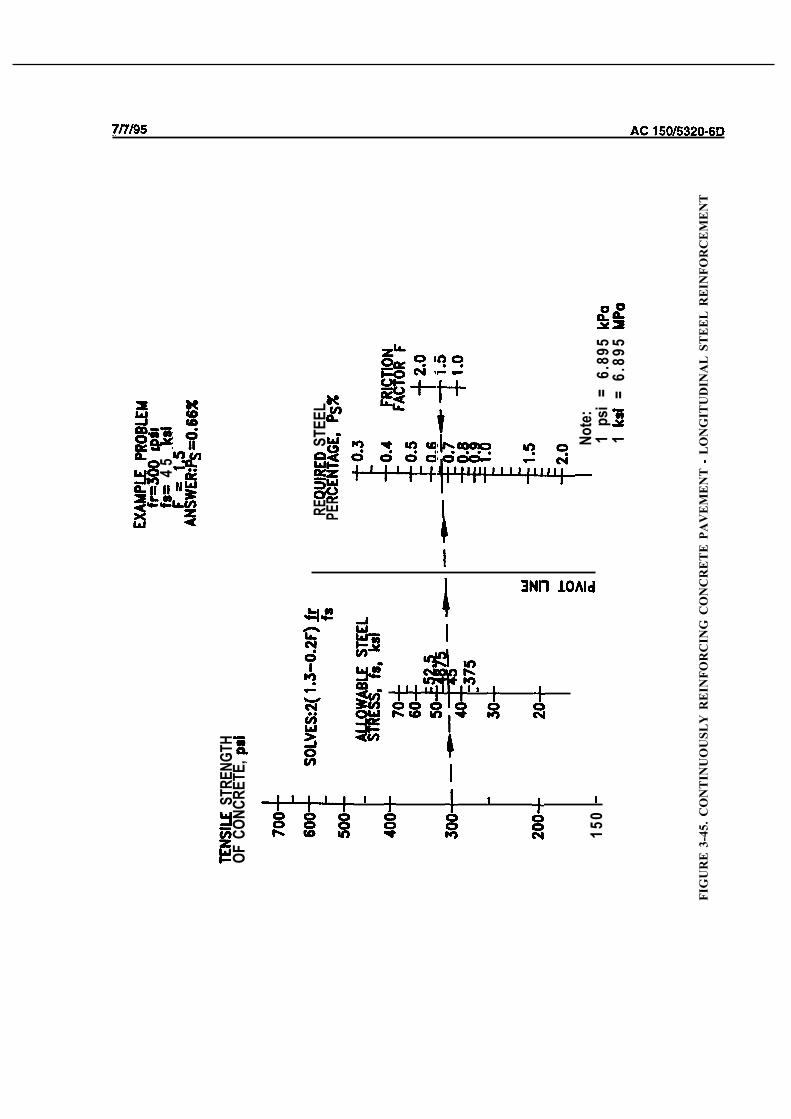
ST
RE
NG
TH
OF
CO
NC
RE
TE
,
15
0
45
RE
PE
R S
TE
EL
N
ote
:1
psi
=
6.8
95
1=
6.8
95
FIG
UR
E 3
-45
. C
ON
TIN
UO
US
LY
RE
INF
OR
CIN
G C
ON
CR
ET
E P
AV
EM
EN
T
LO
NG
ITU
DIN
AL
ST
EE
L R
EIN
FO
RC
EM
EN
T

Concrete to Steel Strength Ratio. The third consideration in selecting the amount of
longitudinal steel reinforcement is the ratio of concrete tensile strength to the specified minimum yield strength of steel.
The steel percentage is obtained by multiplying the ratio of the concrete strength to the yield strength of steel by 100.
Y
where:
= steel reinforcement in percent
= tensile strength of concrete
= minimum yield strength of steel
d. Transverse Steel Design. Transverse steel reinforcement is recommended for CRC airport pavements
to control “chance” longitudinal cracks which sometimes form. It is also aids in construction by supporting and
maintaining longitudinal steel reinforcement spacing. A nomograph for determining transverse steel requirements is
shown in Figure 3-46.
e. Steel Detailing. Longitudinal steel reinforcement should be located at mid depth of the slab or slightly
above. Transverse steel may be located either above or below the longitudinal steel. A minimum concrete cover of 3
inches (75 mm) should be maintained over all steel reinforcement, Longitudinal steel spacing should be 6 to 12 inches
(150 to 3 mm). Transverse steel should be spaced at 12 inches (3 mm) or greater. The recommended overlap for
splicing of reinforcing bars is 25 diameters of 16 inches (405 mm), whichever is greater. The recommended overlap for
splicing deformed welded wire fabric is 32 diameters or 16 inches (405 mm), whichever is greater. When splicing
longitudinal steel bar reinforcing it is recommended that the lap splices be made on a 60 degree skew from centerline or
staggered such that not more than of the bars are spliced on the same transverse plane.
349. CRCP JOINTING. Even though transverse contraction joints can be eliminated with CRCP, some joints will
be needed to accommodate construction and to control warping stresses. The two types of joints are discussed below:
a. Construction Joints. Two types of construction joints are necessary for CRCP. Because pavements
are constructed in multiple lanes, a longitudinal construction joint is required between lanes. A transverse construction
joint must be provided where paving ends and begins, such as at the finish of a day’s paving and the start of the next day’s
paving. Typical construction joint details are shown in Figure 3-47.
b. Warping Joints. Warping joints or hinged joints are needed when paving lane width exceeds the
recommended maximum longitudinal joint spacings shown in Table 3-l 1. Transverse steel is carried through the joint to
provide continuity and positive aggregate interlock across the joint. Since carrying the steel through the joint eliminates
any expansion or contraction capacity, the maximum width of tied pavement should not exceed 75 feet (23 m), see
paragraph Typical warping joint details are shown in Figure 3-47.
350. CRCP TERMINAL TREATMENT. Since long slabs of CRCP are constructed with no transverse joints,
provisions must be made to either restrain or accommodate end movements wherever the CRCP abuts other pavements
or structures. Rather large end movements, up to 2 inches (50 mm), are experienced with CRCP due to thermal
expansion and contraction. End movement is normally not a problem except where CRCP abuts another pavement or
structure. Experience with highway CRCP shows that attempts to restrain end movement have not been too successful.
More favorable results are achieved where end movement is accommodated rather than restrained. Joints designed to
accommodate large movements are required where CRCP intersects other pavements or abuts another structures. Failure
to do so may result in damage to the CRCP, pavement or other structure. Wide flange beam type joints or “finger” type
expansion joints can accommodate the movements. The wide flange beam type joint is recommended due to its
relatively lower costs. A sketch of the wide flange beam joint is shown on Figure 3-48.
96

SO
LV
ES
:PS
70 so 40 20 10
EX
AM
PLE
PR
OB
LEM
FT
f
ps
i =
6
.89
51
= 6
.89
51
0
.30
48
0.00
70.
009
.
I
ITU
RN
ING
UN
E
:s
20. . . . .
WH
ER
E:
f W
OR
KIN
G S
TR
ES
S I
N S
TE
EP
S(0
.75
OF
YIE
LD
ST
RE
NG
TH
RE
CO
MM
EN
D D
,TH
EE
QU
IVA
LE
NT
OF
SA
FE
TY
FA
CT
OR
OF
1.3
3)

A C
C
C
C
C

Transverse Steel
Steel
KEYED
THICKENED EDGE
Deformed Tie Bor
Long on
Centers
TIED KEYED
LO
NG
ITU
DIN
AL
CO
NS
TR
UC
TIO
N
IN
FIG
UR
E C
ON
TIN
UO
US
LY
RE
INF
OR
CE
D C
ON
CR
ET
E P
AV
EM
EN
T J
OIN
TIN
G D
ET
AIL
S
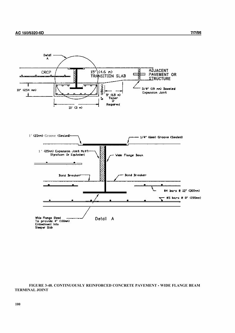
JACENTVEMENT ORRUCTURE
1’ Groove
1 ’
FIGURE 3-48. CONTINUOUSLY REINFORCED CONCRETE PAVEMENT WIDE FLANGE BEAM
TERMINAL JOINT
100
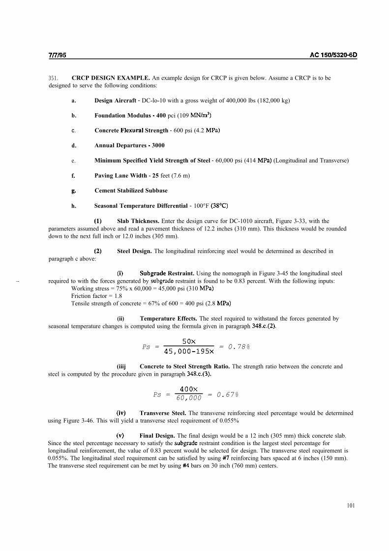
351. CRCP DESIGN EXAMPLE. An example design for CRCP is given below. Assume a CRCP is to be
designed to serve the following conditions:
a. Design Aircraft DC-lo-10 with a gross weight of 400,000 lbs (182,000 kg)
b. Foundation Modulus 400 pci (109
C. Concrete Strength 600 psi (4.2
d. Annual Departures 3000
e. Minimum Specified Yield Strength of Steel 60,000 psi (414 (Longitudinal and Transverse)
f. Paving Lane Width 25 feet (7.6 m)
Cement Stabilized Subbase
h. Seasonal Temperature Differential 100°F
Slab Thickness. Enter the design curve for DC-1010 aircraft, Figure 3-33, with the
parameters assumed above and read a pavement thickness of 12.2 inches (310 mm). This thickness would be rounded
down to the next full inch or 12.0 inches (305 mm).
paragraph c above:
Steel Design. The longitudinal reinforcing steel would be determined as described in
Restraint. Using the nomograph in Figure 3-45 the longitudinal steel
required to with the forces generated by restraint is found to be 0.83 percent. With the following inputs:
Working stress = 75% x 60,000 = 45,000 psi (310
Friction factor = 1.8
Tensile strength of concrete = 67% of 600 = 400 psi (2.8
(ii) Temperature Effects. The steel required to withstand the forces generated by
seasonal temperature changes is computed using the formula given in paragraph
Ps = = 0.78%
(iiij Concrete to Steel Strength Ratio. The strength ratio between the concrete and
steel is computed by the procedure given in paragraph
Ps =60,000
= 0.67%
Transverse Steel. The transverse reinforcing steel percentage would be determined
using Figure 3-46. This will yield a transverse steel requirement of 0.055%
Final Design. The final design would be a 12 inch (305 mm) thick concrete slab.
Since the steel percentage necessary to satisfy the restraint condition is the largest steel percentage for
longitudinal reinforcement, the value of 0.83 percent would be selected for design. The transverse steel requirement is
0.055%. The longitudinal steel requirement can be satisfied by using reinforcing bars spaced at 6 inches (150 mm).
The transverse steel requirement can be met by using bars on 30 inch (760 mm) centers.
101

352. PRESTRESSED CONCRETE PAVEMENT. Prestressed concrete pavements have been used in airport
applications in Europe and to a limited extent in the United States. Prestressed concrete airport pavements are usually
post-tensioned with high strength steel strands. These pavements are usually considerably thinner than plain, jointed
reinforced, or continuously reinforced concrete pavements yet provide high load carrying capacity. Slab lengths on the
order of 400 to 500 feet (120 to 150 m) are generally used. A design procedure for prestressed airport pavements was
developed under an FAA research effort and is reported in Research Report Number FAA-RD-74-34, Volume II. Use of
prestressed concrete airport pavements on Federally assisted projects will require FAA approval on a case by case basis.
102

CHAPTER 4. AIRPORT PAVEMENT
OVERLAYS AND RECONSTRUCTION
400. GENERAL. Airport pavement overlays or reconstruction may be required for a variety of reasons. A
pavement may require an overlay or reconstruction because the original pavement has served its design life and it is
simply “worn out.” A pavement may have been damaged by overloading in such a way that it cannot be economically
maintained at a serviceable level. Similarly, a pavement in good condition may require strengthening to serve heavier
aircraft than those for which the pavement was originally designed. Generally, airport pavement overlays consist of
either cement concrete or hot mix asphalt concrete. Techniques and equipment are now available to recycle old
pavement materials into reconstructed sections. Pavements which are severely distressed in the center portions can
sometimes be economically reconstructed by building a keel section using recycled materials. Use of this method of
reconstruction is essentially the same as building a new pavement.
401. CONDITION OF EXISTING PAVEMENT. Assessment of the condition of the existing pavement is one of
the most important and difficult steps in design of a reconstruction or overlay project. Determination of the properties of
the existing pavement should include the thickness, condition and strength of each layer, the soil classification,
and some estimate of foundation strength (CBR or modulus). An assessment of the structural integrity of the
existing pavement is necessary. Failed areas in the existing pavement should be carefully studied to determine the
probable cause of failure. Subsurface drainage conditions should be assessed carefully and corrected if found to be
deficient. In some instances subsurface drainage corrections are best performed through reconstruction. Overlaying an
existing pavement without correcting poor subsurface drainage will usually result in poor overlay performance. A
valuable technique for assessing the condition of the existing pavement is nondestructive pavement testing (NDT). See
Appendix 3. NDT can be used to estimate foundation strength, measure joint condition, and possibly detect voids in
existing pavements.
402. MATERIAL SELECTION CONSIDERATIONS. Criteria are presented in this circular for both hot mix
asphalt and concrete reconstruction or overlays. The selection of the material type should be made after careful
consideration of many factors. The designer should consider the total life cycle cost of the reconstructed or overlay
pavement. (see l/78, Appendix 4). Life cycle costs should include initial construction and maintenance
costs over the design life of the pavement. Other considerations such as allowable down time of the pavement and
availability of alternate pavements to use during construction will have a significant impact on the material selected.
403. OVERLAY DESIGN. The remainder of this chapter is devoted to the design of overlay pavements. As
previously mentioned, the design of reconstructed pavements is essentially the same as for new construction.
a. Typical Overlay Cross Sections and Definitions. Typical overlay pavement cross sections are
shown in Figure 4-l. Definitions applicable to overlay pavements are as follows:
Overlay Pavement. Pavement which is constructed on top of an existing pavement.
Hot Mix Asphalt Overlay. Hot mix asphalt pavement placed on an existing pavement.
Concrete Overlay. Portland cement concrete pavement placed on an existing pavement.
Sandwich Pavement. Overlay pavement sections containing granular separation courses between the
old and new impervious surfaces are called sandwich pavements.
b. Sandwich Pavements. Regardless of the type of overlay, FAA criteria does not permit the
construction of sandwich overlay pavements. They are not allowed because the granular separation course usually
becomes saturated with water and provides poor or, at best, unpredictable performance. Saturation of the separation
course can be caused by the infiltration of surface water, ingress of ground or capillary water, or the condensation of
water from the atmosphere. In any event, the water in the separation course usually cannot
water drastically reduces the stability of the overlay.
103
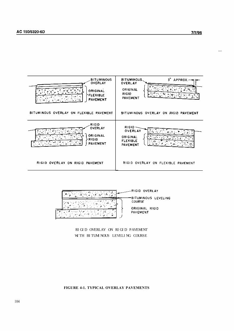
RIGID OVERLAY ON RIGID PAVEMENTWITH BITUMINOUS LEVELING COURSE
FIGURE 4-1. TYPICAL OVERLAY PAVEMENTS
104

7/7/95 AC 150/5320-6D
404. DESIGN OF STRUCTURAL HOT MIX ASPHALT OVERLAYS. Structural hot mix asphalt overlays can
be applied to either flexible or rigid pavements. Certain criteria and design assumptions are different for hot mix
asphalt overlays of flexible or rigid pavements. The design procedures are presented separately.
405. HOT MIX ASPHALT OVERLAYS ON EXISTING FLEXIBLE PAVEMENT. The design of structural
hot mix asphalt overlays on existing flexible pavements is based on a thickness deficiency approach. That is, the
existing pavement is compared to what is needed for a new pavement, and any deficiency is made up in the overlay.
a. Calculate New Pavement Requirements. Using the appropriate flexible pavement design curves
(Figures 3-2 through 3-15), calculate the thickness requirements for a flexible pavement for the desired load and number
of equivalent design departures. A CBR value is required for the subgrade material and subbase. Thicknesses of all
pavement layers must be determined.
b. Compare New Pavement Requirements With Existing Pavement. The thickness requirements for a
new pavement are compared with the existing pavement to determine the overlay requirements. Adjustments to the
various layers of the existing pavement may be necessary to complete the design. This is particularly difficult when
overlaying old pavement. Hot mix asphalt surfacing may have to be converted to base, and/or base converted to
subbase. Note that a high-quality material may be converted to a lower quality material, such as surfacing to base or
base to subbase. A lesser-quality material may not be converted to a higher-quality material. For example, excess
subbase cannot be converted to base. The equivalency factors shown in Tables 3-6 through 3-8 may be used as guidance
in the conversion of layers. It must be recognized that the values shown in Tables 3-6 through 3-8 are for new
materials, and the assignment of factors for existing pavement must be based on judgment and experience. Surface
cracking, high degree or oxidation, evidence of low stability, etc. are a few of the considerations that would tend to
reduce the equivalency factor. Any hot mix asphalt layer located between granular courses in the existing pavement
should be evaluated inch for inch as granular base or subbase course.
c. Example. To illustrate the procedure of designing a hot mix asphalt overlay, assume an existing
taxiway pavement composed of the following section: the subgrade CBR is 7, the hot mix asphalt surface course is 4
inches (10 mm) thick, the base course is 6 inches (150 mm) thick, the subbase is 10 inches (250 mm) thick, and the
subbase CBR is 15. Frost action is negligible. Assume the existing pavement is to be strengthened to accommodate a
dual wheel aircraft weighing 100,000 pounds (45,000 kg) and an annual departure level of 3,000. The flexible
pavement required (referring to Figure 3-3) for these conditions is:
Hot mix asphalt surface 4 inches (100 mm)
Base 9 inches (230 mm)
Subbase 10 inches (250 mm)
Total pavement thickness 23 inches (585 mm)
The total pavement thickness must be 23 inches (585 mm) in order to protect the CBR 7 subgrade. The combined
thicknesses of surfacing and base must be 13 inches (330 mm) to protect the CBR 15 subbase. The existing pavement
is 3 inches (75 mm) deficient in total pavement thickness. All of the thickness deficiency is in the base course. For the
sake of illustration, assume the existing hot mix asphalt surface is in such condition that surfacing can be substituted for
base at an equivalency ratio of 1.3 to 1. Converting 2.5 inches (64 mm) of surfacing to base yields a base course
thickness of 9.2 inches (234 mm) leaving 1.5 inches (40 mm) of unconverted surfacing. A 2.5-inch (54-mm) overlay
would be required to achieve a 4-inch (100-mm) thick surface.
d. Summary. Structurally, a 2.5-inch-thick overlay should satisfy the design conditions. The overlay
thickness calculated from structural considerations should be compared with that required to satisfy geometric
requirements. Geometric requirements include, for example, provision of drainage, correcting crown and grade,
meeting grade of other adjacent pavements and structures, etc. The most difficult part of designing hot mix asphalt
overlays for flexible pavements is the determination of the properties of the existing pavement. Subgrade and subbase
CBR values can be determined by conducting field in place CBR tests. Field CBR tests should be performed in
accordance with the procedures given in Manual Series No. 10 (MS-10 by the Asphalt Institute. See Appendix 4.). The
subgrade and
105

AC 150/5320-6D CHG 2 6/3/02
subbase must be at the equilibrium moisture content when field CBR tests are conducted. Normally, a pavement that
has been in place for at least 3 years will be in equilibrium. Procedures for calculating CBR values from NDT tests are
also available. Layer conversions (i.e., converting base to subbase, etc.) are largely a matter of engineering judgment.
When performing the conversions, it is recommended that any converted thicknesses not be rounded off.
406. HOT MIX ASPHALT OVERLAY ON EXISTING RIGID PAVEMENT. The design of a hot mix asphalt
overlay on an existing rigid pavement is also based on a thickness deficiency approach. However, new pavement
thickness requirements for rigid pavements are used to compare with the existing rigid pavement. The formula for
computing overlay thickness is as follows:
t = 2.5(Fhd − Cbh e ) Where: t = thickness of hot mix asphalt overlay, inches (mm). F = a factor which controls the degree of cracking in the base rigid pavement. hd = thickness of new rigid pavement required for design conditions, inches (mm). Use the exact
value for hd; do not round off. In calculating hd use the k value of the existing foundation and
the flexural strength of the existing concrete as design parameters.
Cb = a condition factor that indicates the structural integrity of the existing rigid pavement. Values
range from 1.0 to 0.75.
he = thickness of existing rigid pavement, inches (mm).
a. F Factor. The "F" factor is an empirical method of controlling the amount of cracking that will occur
in the rigid pavement beneath the hot mix asphalt overlay. It is a function of the amount of traffic and the foundation
strength. The assumed failure mode for a hot mix asphalt overlay on a existing rigid pavement is that the underlying
rigid pavement cracks progressively under traffic until the average size of the slab pieces reaches a critical value.
Further traffic beyond this point results in shear failures within the foundation, producing a drastic increase in
deflections. Since high strength foundations can better resist deflection and shear failure, the F factor is a function of
subgrade strength as well as traffic volume. Photographs of various overlay and base pavements shown in Figure 4-2
illustrate the meaning of the F factor. Figures 4-2a, b, and c show how the overlay and base pavements fail as more
traffic is applied to a hot mix asphalt overlay on an existing rigid pavement. Normally an F factor of 1.0 is
recommended unless the existing pavement is in quite good condition, see paragraph 406b(1) below. Figure 4-3 should
be used to determine the appropriate F factor for pavements in good condition.
b. Cb Factor. The condition factor "Cb" applies to the existing rigid pavement. The Cb factor is an
assessment of the structural integrity of the existing pavement.
(1) Selection of Cb Factor. The overlay formula is rather sensitive to the Cb value. A great deal
of care and judgement are necessary to establish the appropriate Cb. NDT can be a valuable tool in determining a proper
value. A Cb value of 1.0 should be used when the existing slabs contain nominal structural cracking and 0.75 when the
slabs contain structural cracking. The designer is cautioned that the range of Cb values used in hot mix asphalt overlay
designs is different from the "Cr" values used in rigid overlay pavement design. A comparison of Cb and Cr and the
recommended F factor to be used for design is shown below:
Cr Cb Recommended F factor
0.35 to 0.50 0.75 to 0.80 1.00
0.51 to 0.75 0.81 to 0.90 1.00
0.76 to 0.85 0.91 to 0.95 1.00
0.86 to 1.00 0.96 to 1.00 Use Figure 4.3
The minimum Cb value is 0.75. A single Cb should be established for an entire area. The Cb value should not be varied
along a pavement feature. Figures 4-4 and 4-5 illustrate Cb values of 1.0 and 0.75, respectively.
106

7/7/95 AC 150/5320-6D
SURFACE OF OVERLAY BASE PAVEMENT
SURFACE OF OVERLAY BASE PAVEMENT
SURFACE OF OVERLAY BASE PAVEMENT
FIGURE 4-2. ILLUSTRATION OF VARIOUS "F" FACTORS FOR HOT MIX ASPHALT OVERLAY
107
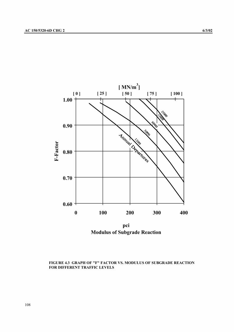
AC 150/5320-6D CHG 2 6/3/02
[ MN/m3]
[ 0 ] [ 25 ] [ 50 ] [ 75 ] [ 100 ]
1.00
0.90
0.80
0.70
0.60
0 100 200 300 400
pci Modulus of Subgrade Reaction
FIGURE 4.3 GRAPH OF "F" FACTOR VS. MODULUS OF SUBGRADE REACTION
FOR DIFFERENT TRAFFIC LEVELS
F-F
acto
r
108

AC
FIGURE 4.4 ILLUSTRATION OF A FACTOR OF 1.0 FOR HOT MIX ASPHALT OVERLAYDESIGN
109

110

5/23/06 AC 150/5320-6D Change 4
111
(2) Increasing Cb Factor. A value of Cb lower than 0.75 represents a severely cracked base slab, which would not be advisable to overlay without modification due to the likelihood of severe reflection cracking. See paragraph 406 f. In some instances it may be advantageous to replace several slabs and restore load transfer along inadequate joints to raise the Cb value. Increasing the Cb value will decrease the required overlay thickness. A detailed condition survey of the existing pavement which examines the subsurface drainage conditions, structural capacity of the slabs, foundation strength, flexural strength of the concrete, load transfer along joints and thickness of the component layers is strongly encouraged to properly design a hot mix asphalt overlay.
c. Example. An example of the hot mix asphalt overlay design method is given below:
(1) Assumptions. Assume an existing rigid pavement 12 inches (305 mm) thick is to be strengthened to accommodate 3000 departures of a dual wheel aircraft weighing 180,000 pounds (81,800 kg). The flexural strength of the existing concrete is 725 psi (5.00 MN/m’) and the foundation modulus is 300 pci (81.6 MN/m’). The condition factor of the existing pavement is 0.95.
(2) Single Slab Thickness. Compute the single slab thickness required to satisfy the design conditions given in (1) above. Using Figure 3-17 the slab thickness is found to be 13.9 inches (353 mm). The F factor is determined from Figure 4-3 and equals 0.93. Applying the overlay formula given in paragraph 406 yields:
t =2.5 (0.93 x13.9 - 0.95 x12)
t = 3.82 inches (97 mm)
This thickness would be rounded up to 4 inches (100 mm) for practicality of construction.
d. Previously Overlaid Rigid Pavement. The design of a hot mix asphalt overlay for a rigid pavement which already has an existing hot mix asphalt overlay is slightly different. The designer should treat the problem as if the existing hot mix asphalt overlay were not present, calculate the overlay thickness required, and then adjust the calculated thickness to compensate for the existing overlay. If this procedure is not used, inconsistent results will often be produced.
e. Example. An example of a hot mix asphalt overlay design for a rigid pavement which already has an existing hot mix asphalt overlay is given below:
(1) Assumptions. An example of the procedure follows. Assume an existing pavement consists of a 10-inch (255 mm) rigid pavement with a 3-inch (75 mm) hot mix asphalt overlay. The existing pavement is to be strengthened to be equivalent to a single rigid pavement thickness of 14 inches (355 mm). Assume an “F” factor of 0.9 and “Cb” of 0.9 are appropriate for the existing conditions.
(2) Ignore Existing Overlay. Calculate the required thickness of hot mix asphalt overlay as if the existing 3-inch (75 mm) overlay were not present.
t = 2.5 (0.9 xl4 - 0.9 x10)
t = 9 inches (230 mm)
(3) Thickness Allowance For Existing Overlay. An allowance is then made for the existing hot mix asphalt overlay. In this example assume the existing overlay is in such a condition that its effective thickness is only 2.5 inches (64 mm). The required overlay thickness would then be 9 - 2.5 = 6.5 inches (165 mm). The determination of the effective thickness of the existing overlay is a matter of engineering judgment.
f. Limitations. The formula for hot mix asphalt overlay thickness assumes the existing rigid pavement will support load through flexural action. As the overlay thickness becomes greater, at some point the existing rigid pavement will tend to act more like a high quality base material. When this condition is reached, the overlay should be designed as a flexible pavement with the existing pavement treated as a high quality base course.
407. NONSTRUCTURAL HOT MIX ASPHALT OVERLAYS. In some instances overlays are required to correct nonstructural problems such as restoration of crown, improve rideability, etc. Thickness calculations are not required in these situations, as thickness is controlled by other design considerations or minimum practical overlay

AC 150/5320-6D Change 4 5/23/06
112
thickness. Information concerning runway roughness correction can be found in FAA Report No. FAA-RD-75-110, Methodology for Determining, Isolating and Correcting Runway Roughness. See Appendix 4.
408. REFLECTION CRACKING IN HOT MIX ASPHALT OVERLAYS. Reflection cracking is often a problem in hot mix asphalt overlays particularly overlays of rigid pavement. Numerous materials and techniques have been tried attempting to solve the problem with varying degrees of success. The following methods have met with some success:
a. Coarse Aggregate Binders. The use of coarse aggregate binder course is recommended where economically feasible. Use of the largest practical size coarse aggregate in the hot mix asphalt layer immediately above the existing pavement is recommended. This practice provides some measure of protection against reflection cracking.
b. Rubblization of Existing PCC Pavement. If the condition of the existing rigid pavement is very poor (i.e., extensive structural cracking, joint faulting, “D” cracking, etc.), consideration may be given to using the “rubblization” technique. Subgrade support conditions must be considered, as weak subgrade support can cause difficulties in rubblizing the existing pavement and cause premature failures in the completed pavement. Rubblization involves purposely breaking the existing rigid pavement into small pieces and then rolling the broken pieces to firmly seat them in the foundation. A hot mix asphalt layer is then placed over the pavement. This type of section is designed as a flexible pavement, treating the broken rigid pavement as base course. Reflective cracking is reduced or eliminated with this type of construction.
c. Engineering Fabrics. Research studies and field performance have shown that fabric membranes are effective in retarding reflection cracking. While fabrics will not eliminate reflection cracking all together, they do provide some degree of water-proofing beneath reflection cracks thus protecting the existing pavement and foundation. At present, the water-proofing capability of fabrics, assuming the capacity of the asphalt impregnated fabric to resist rupture is not lost, appears to be the most significant contribution fabrics provide in a hot mix asphalt overlay system. Existing pavements, whether flexible or rigid, that show evidence of excessive deflections, substantial thermal stresses, and/or poor drainage, probably will exhibit no improvement by including a fabric in a structural overlay. The following conditions are recommended for fabric usage:
(1) Fabric Properties. The fabric should have a minimum tensile strength of 90 lbs (41 kg) when tested in accordance with ASTM D 4632 and a density in the range of 3 to 5.5 ounces per square yard (70 to 130 grams per square meter).
(2) Application. Fabric membranes should not be used where the horizontal displacements exceed 0.05 inch (1.3 mm) or where vertical displacements will exceed 0.02 inch (0.5 mm). Fabric should not be used when the overlay thickness is less than 3 inches (75 mm) or more than 7 inches (178 mm).
(3) Tack Coat. The proper amount of tack coat applied to the fabric is critical. Emulsified asphalt applied at a rate of from 0.15 to 0.30 gallons per square yard (0.7 to 1.4 liters per square meter) is recommended. The optimum amount of tack coat will depend on the type of fabric and the surface on which the fabric is placed.
d. Asphalt Reinforcement. Destructive tensile stresses in asphalt pavements may be reduced by incorporating a reinforcement material. Reinforcement materials are similar to fabric membranes except the reinforcement is either a woven fabric or a grid- shaped material. These materials have very high tensile strength and very low strain capacity. Products with a combination of fabric materials and reinforcement grids have been developed and appear to be successful in retarding reflective cracking. Depending upon the material type and the intended purpose, reinforcing materials may be applied across the full width of the pavement or may be limited to the immediate area around joints and cracks.
409. DESIGN OF CONCRETE OVERLAYS. Concrete overlays can be constructed on existing rigid or flexible pavements. The minimum allowable thickness for concrete overlays is 5 inches (127 mm) when placed on a flexible pavement, directly on a rigid pavement, or on a leveling course. The minimum thickness of concrete overlay which is bonded to an existing rigid pavement is 3 inches (75 mm). The design of concrete overlays is based on a thickness deficiency approach. The existing base pavement and overlay section are equated to a single slab thickness. The empirical formulas presented were developed from research on test track pavements and observations of in-service pavements.

6/3/02 AC 150/5320-6D CHG 2
410. CONCRETE OVERLAY ON FLEXIBLE PAVEMENT. The design of concrete overlays on existing
flexible pavements assumes the existing flexible pavement is a foundation for the overlay slab. Overlay slab thickness is
based on the design curves in Figures 3-17 through 3-40. The existing flexible pavement should be assigned a k value
using Figure 2-4 or 3-16 or by conducting a plate-bearing test on the existing flexible pavement or by NDT testing. In
any case, the k value assigned should not exceed 500. When frost conditions require additional thickness, the use of
nonstabilized material below the rigid pavement overlay is not allowed, as this would result in a sandwich pavement.
Frost protection must be provided by stabilized material.
411. CONCRETE OVERLAY ON RIGID PAVEMENT. The design of concrete overlays on existing
rigid pavements is also predicated on the rigid pavement design curves, Figures 3-17 through 3-40. The rigid
pavement design curves indicate the thickness of concrete required to satisfy the design conditions for a single
thickness of concrete pavement. Use of this method requires the designer to assign a k value to the existing
foundation. The k value may be determined by field NDT tests or by bearing tests conducted in test pits cut
through the existing rigid pavement, they may also estimated from construction records for the existing
pavement. The design of a concrete overlay on a rigid pavement requires an assessment of the structural integrity
of the existing rigid pavement. The condition factor, Cr , should be selected after an extensive pavement
condition survey. The selection of a condition factor is a matter of engineering judgment. The use of
nondestructive testing can be of considerable value in assessing the condition of an existing pavement. NDT can
also be used to determine sites for test pits. NDT procedures are given in Advisory Circular 150/5370-11, Use of
Nondestructive Testing Devices in the Evaluation of Airport Pavements. See Appendix 4. In order to provide a
more uniform assessment of condition factors, the following values are defined:
Cr = 1.0 for existing pavement in good condition - some minor cracking evident, but no structural
defects
Cr = 0.75 for existing pavement containing initial corner cracks due to loading but no progressive
cracking or joint faulting
Cr = 0.35 for existing pavement in poor structural condition, badly cracked or crushed and faulted
joints
The three conditions discussed above are used to illustrate the condition factor rather than establish the only values
available to the designer. Conditions at a particular location may require the use of an intermediate value of Cr within
the recommended range. Sketches of three different values of Cr are shown in Figures 4-6, 4-7, and 4-8.
a. Concrete Overlay Without Leveling Course. The thickness of the concrete overlay slab applied
directly over the existing rigid pavement is computed by the following formula.
h = c
Where: hc = required thickness of concrete overlay h = required single slab thickness determined from design curves he = thickness of existing rigid pavement Cr = condition factor
1.4 1.4
er
1.4 hCh −
Due to the inconvenient exponents in the above formula, graphic solutions are given in Figures 4-9 and 4-10. These
graphs were prepared for only two different condition factors, Cr = 1.0 and 0.75. The use of a concrete overlay
pavement directly on an existing rigid pavement with a condition factor of less than 0.75 is not recommended because of
the likelihood of reflection cracking. The above equation assumes the flexural strength of the concrete used for the
overlay will be approximately equal to that of the base pavement. If the flexural strengths differ by more than 100 psi
(0.7 MN/m2), the following modified equation should be used to determine the required thickness of the overlay
h = 1.4c
1.4
e
b
r
1.4 hh
hCh ⎟⎟
⎠
⎞ ⎜⎜ ⎝
⎛ ×−
Where:
113
AC 150/5320-6D CHG 2 6/3/02
hb = required single slab thickness determined from design curves based on the flexural strength of the base
pavement
Other factors are the same as previous formula.
b. Concrete Overlay With Leveling Course. In some instances it may be necessary to apply a leveling
course of hot mix asphalt concrete to an existing rigid pavement prior to the application of the concrete overlay. Under
these conditions a different formula for the computation of the overlay thickness is required. When the existing
pavement and overlay pavement are separated, the slabs act more independently than when the slabs are in contact with
each other. The formula for the thickness of an overlay slab when a leveling course is used is as follows:
h = c
2
er
2 hCh −
Where: hc = required thickness of concrete overlay h = required single slab thickness determined from design curves he = thickness of existing rigid pavement Cr = condition factor
When the flexural strength of the overlay and the existing pavements differ by more than 100 psi (0.7 MN/m2), the
equation is modified as follows:
h =c
2
e
b
r
2 hh
hC-h ⎟⎟
⎠
⎞ ⎜⎜ ⎝
⎛ ×
Where:
hb = required single slab thickness determined from design curves based on the flexural strength of
the base pavement
The leveling course must be constructed of highly stable hot mix asphalt concrete. A granular separation course is not
allowed as this would constitute sandwich construction. Graphic solutions of the above equation are shown in Figures
4-11 and 4-12. These graphs were prepared for condition factors of 0.75 and 0.35. Other condition factors between
these values can should be computed as part of the design.
412. BONDED CONCRETE OVERLAYS. Concrete overlays bonded to existing rigid pavements are sometimes
used under certain conditions. By bonding the concrete overlay to the existing rigid pavement, the new section behaves
as a monolithic slab. The thickness of bonded overlay required is computed by subtracting the thickness of the existing
pavement from the thickness of the required slab thickness determined from design curves.
hc = h - he
Where: hc = required thickness of concrete overlay h = required single slab thickness determined from design curves using the flexural strength of
the existing concrete
he = thickness of existing rigid pavement
Bonded overlays should be used only when the existing rigid pavement is in good condition. Defects in the existing
pavement are more likely to reflect through a bonded overlay than other types of concrete overlays. The major problem
likely to be encountered with bonded concrete overlays is achieving adequate bond. Elaborate surface preparation and
exacting construction techniques are required to ensure the bond.
413. JOINTING OF CONCRETE OVERLAYS. Where a rigid pavement is to receive the overlay, some modification
to jointing criteria may be necessary because of the design and joint arrangement of the existing pavement. The following
points may be used as guides in connection with the design and layout of joints in concrete overlays.
114

Le
ge
nd
:
W
idth
--
--
Le
ss
T
ha
n
in
ch
(6
mm
)
Gre
ate
r T
ha
n
in
ch
(6
mm
)
No
te: o
f S
lab
s
Wit
hin
T
raff
ic
Are
a
Bro
ke
n
2
to
3
Pie
ce
s.
No
W
ork
ing
C
rac
ks
, C
orn
er
Bre
ak
s,
or
Fa
ult
ed
J
oin
ts.
Tra
ffic
Are
a
FIG
UR
E 4
-6.
ILL
US
TR
AT
ION
OF
A
FA
CT
OR
OR
1.0

0
116

Tra
ffic
Are
a
Le
ge
nd
:
Cra
ck W
idth
A-
- -L
ess
Th
an
inch
6m
m)
Gre
ote
r T
han
14
inch
(6
mm
)
No
te:
Wit
hin
T
raff
ic
Are
a,
50%
o
f S
lab
s
Bro
ken
ln
to
6
Pie
ces,
50%
o
f S
lab
s
Bro
ken
In
to
2
or
Mo
re
Pie
ces.
Co
rner
Bre
aks,
Wo
rkin
g
Cra
cks,
an
d/o
r F
au
lted
Jo
ints
an
d
Patc
hin
g
Are
E
vid
en
t
FIG
UR
E 4
-8.
ILL
US
TR
AT
ION
OF
A
FA
CT
OR
OF
0.3
5
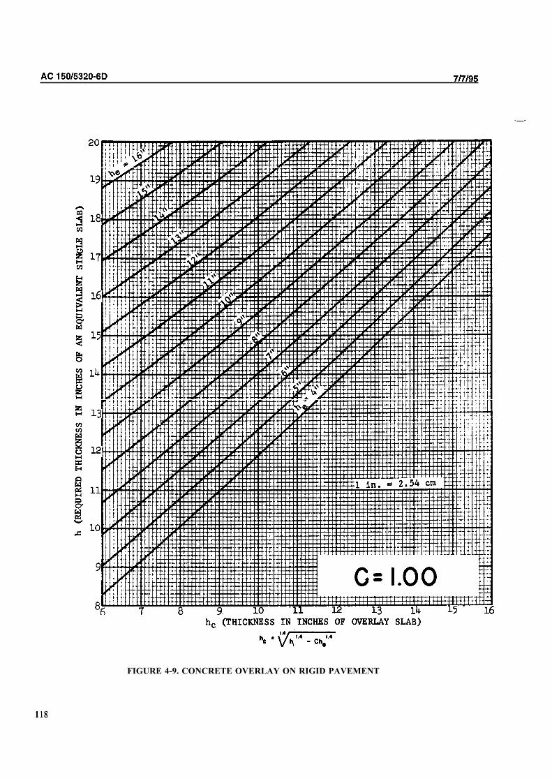
FIGURE 4-9. CONCRETE OVERLAY ON RIGID PAVEMENT

AC
�
FIGURE CONCRETE OVERLAY ON RIGID PAVEMENT
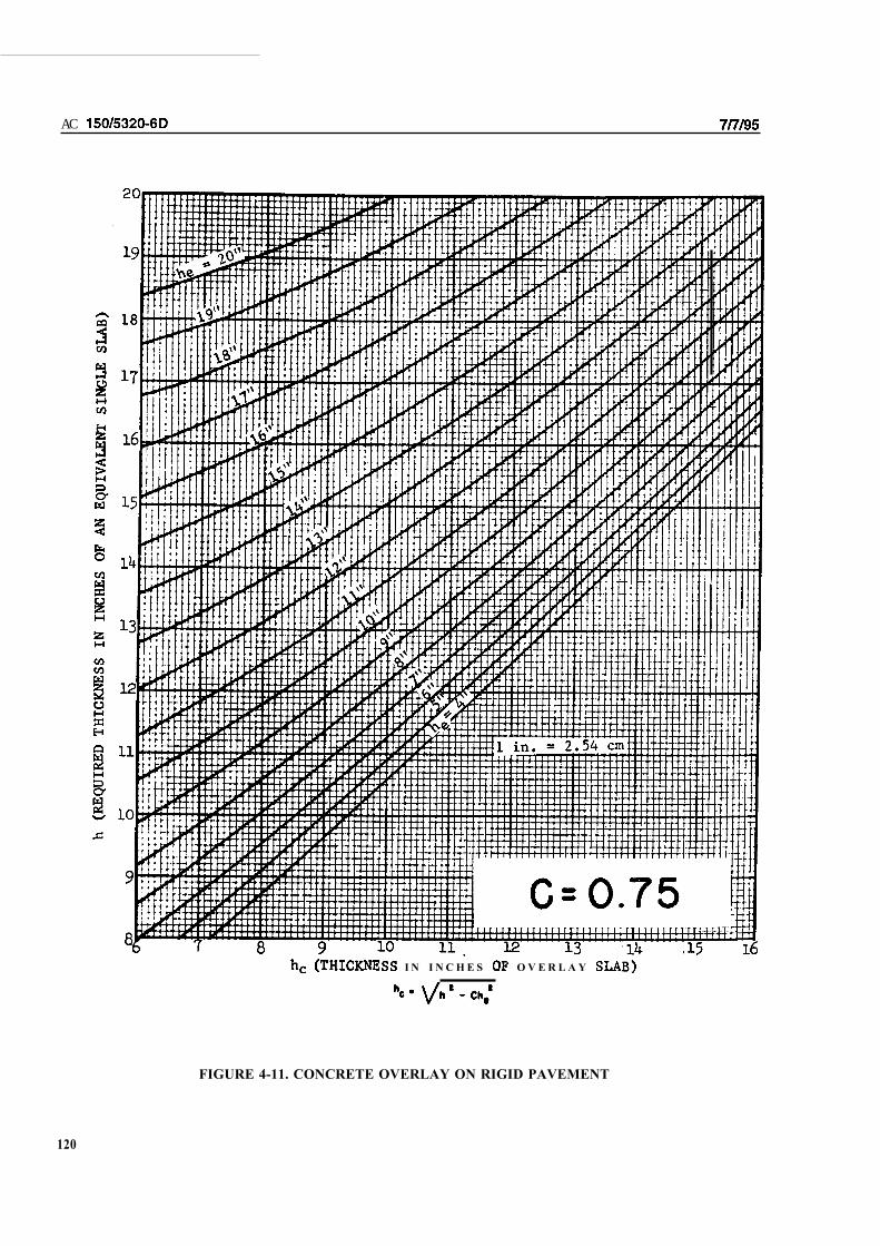
AC
I N I N C H E S O V E R L A Y
FIGURE 4-11. CONCRETE OVERLAY ON RIGID PAVEMENT
120

AC
I N I N C H E S
FIGURE 4-12. CONCRETE OVERLAY ON RIGID PAVEMENT
121
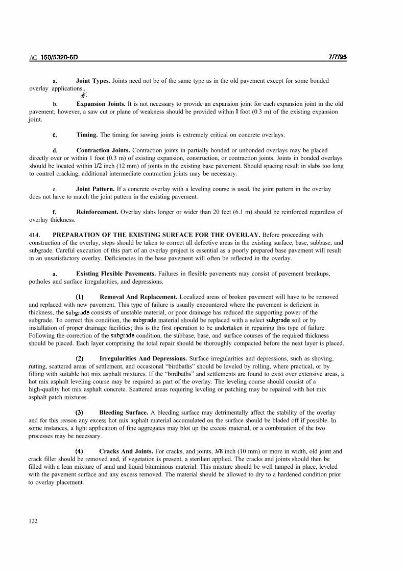
AC
a. Joint Types. Joints need not be of the same type as in the old pavement except for some bonded
overlay applications.,
b. Expansion Joints. It is not necessary to provide an expansion joint for each expansion joint in the old
pavement; however, a saw cut or plane of weakness should be provided within foot (0.3 m) of the existing expansion
joint.
C. Timing. The timing for sawing joints is extremely critical on concrete overlays.
d. Contraction Joints. Contraction joints in partially bonded or unbonded overlays may be placed
directly over or within 1 foot (0.3 m) of existing expansion, construction, or contraction joints. Joints in bonded overlays
should be located within inch (12 mm) of joints in the existing base pavement. Should spacing result in slabs too long
to control cracking, additional intermediate contraction joints may be necessary.
e. Joint Pattern. If a concrete overlay with a leveling course is used, the joint pattern in the overlay
does not have to match the joint pattern in the existing pavement.
f. Reinforcement. Overlay slabs longer or wider than 20 feet (6.1 m) should be reinforced regardless of
overlay thickness.
414. PREPARATION OF THE EXISTING SURFACE FOR THE OVERLAY. Before proceeding with
construction of the overlay, steps should be taken to correct all defective areas in the existing surface, base, subbase, and
subgrade. Careful execution of this part of an overlay project is essential as a poorly prepared base pavement will result
in an unsatisfactory overlay. Deficiencies in the base pavement will often be reflected in the overlay.
a. Existing Flexible Pavements. Failures in flexible pavements may consist of pavement breakups,
potholes and surface irregularities, and depressions.
Removal And Replacement. Localized areas of broken pavement will have to be removed
and replaced with new pavement. This type of failure is usually encountered where the pavement is deficient in
thickness, the consists of unstable material, or poor drainage has reduced the supporting power of the
subgrade. To correct this condition, the material should be replaced with a select soil or by
installation of proper drainage facilities; this is the first operation to be undertaken in repairing this type of failure.
Following the correction of the condition, the subbase, base, and surface courses of the required thickness
should be placed. Each layer comprising the total repair should be thoroughly compacted before the next layer is placed.
Irregularities And Depressions. Surface irregularities and depressions, such as shoving,
rutting, scattered areas of settlement, and occasional “birdbaths” should be leveled by rolling, where practical, or by
filling with suitable hot mix asphalt mixtures. If the “birdbaths” and settlements are found to exist over extensive areas, a
hot mix asphalt leveling course may be required as part of the overlay. The leveling course should consist of a
high-quality hot mix asphalt concrete. Scattered areas requiring leveling or patching may be repaired with hot mix
asphalt patch mixtures.
Bleeding Surface. A bleeding surface may detrimentally affect the stability of the overlay
and for this reason any excess hot mix asphalt material accumulated on the surface should be bladed off if possible. In
some instances, a light application of fine aggregates may blot up the excess material, or a combination of the two
processes may be necessary.
Cracks And Joints. For cracks, and joints, inch (10 mm) or more in width, old joint and
crack filler should be removed and, if vegetation is present, a sterilant applied. The cracks and joints should then be
filled with a lean mixture of sand and liquid bituminous material. This mixture should be well tamped in place, leveled
with the pavement surface and any excess removed. The material should be allowed to dry to a hardened condition prior
to overlay placement.
122

Potholes. Potholes should be thoroughly cleaned and filled with a suitable bituminous
mixture and tamped in place.
b. Existing Rigid Pavements. In rigid pavements, narrow transverse, longitudinal, and corner cracks
will need no special attention unless there is an appreciable amount of displacement and faulting between the separate
slabs. If the is stable and no pumping has occurred, the low areas can be taken care of as part of the overlay
and no other corrective measures are needed. On the other hand, if pumping has occurred at the slab ends or the slabs
are subject to rocking under the movement of aircraft, support should be improved by pumping cement grout or
asphalt cement under the pavement to fill the voids that have developed. Pressure grouting requires considerable skill to
avoid cracking slabs or providing uneven support for the overlay.
Slab Removal And Replacement. If the pavement slabs are badly broken and subject to
rocking because of uneven bearing on the subgrade, the rocking slabs can be broken into smaller slabs to obtain a more
firm seating. Badly broken slabs that do not rock will not require repairs since the criteria make adjustments for such a
condition in the pavement thickness. In some cases, it may be desirable to replace certain badly broken slabs with new
slabs before starting construction of the overlay. The decision in such cases will have to be made according to the merits
of the individual project.
Leveling Course. Where the existing pavement is rough due to slab distortion, faulting, or
settlement, a provision should be made for a leveling course of hot mix asphalt concrete before the overlay is
commenced.
Cracks And Joints. Cracks, and joints, inch (10 mm) or more in width, should be filled
with a lean mixture of sand and liquid bituminous material. This mixture should be tamped firmly in place, leveled with
the pavement surface and any excess removed.
Surface Cleaning. After all repairs have been completed and prior to the placing of the
overlay, the surface should be swept clean of all dirt, dust, and foreign material that may tend to break the bond between
the overlay and the existing pavement. Any extruding joint-sealing material should be trimmed from rigid pavements.
Bonded Concrete Overlays. Bonded concrete overlays will require special attention to
insure bond with the existing pavement. Surface cleaning and preparation by shot peening or mechanical texturing by
cold milling are two techniques which have been used to provide a surface which will allow bonding. Adequate bond has
been achieved by placing the overlay directly on the dry prepared surface. In other instances, bond was achieved by
placing a neat cement grout on the prepared surface immediately ahead of the overlay placement.
415. MATERIALS AND METHODS. With regard to quality of materials and mixes, control tests, methods of
construction, and workmanship the overlay pavement components are governed by AC Standards for
Specifying Construction of Airports.
a. Tack Coat. If a hot mix asphalt overlay is specified, the existing pavement should receive a light tack
coat (Item P-603) or fog coat immediately after cleaning. The overlay should not extend to thekdges of the pavement
but should be cut off approximately 3 inches (75 mm) from each edge.
b. Forms. Should the existing pavement require drilling to provide anchorage for the overlay pavement
forms, the size and number of holes should be the minimum necessary to accomplish that purpose. Holes should not be
located close to joints or cracks. Location of holes for form anchors should be such as to avoid causing additional
cracking or
416. NEW OVERLAY MATERIALS. In recent years, some new pavement overlay materials have been used with
varying degrees of success. These materials include fibrous concrete, roller compacted concrete, and rubberized
asphalt. Use of materials other than conventional cement concrete (Item P-501) or Plant Mix Bituminous
Surface (Item P-401) require special approval on a case-by-case basis.
123

AC1
417. POSSIBLE ANOMALIES. The basic design concepts applied to rigid and flexible pavements are different
because of differences in behavior and in failure mechanisms for these pavements. These differences can produce
anomalous results for rigid and hot mix asphalt overlay designs using the above overlay design procedures. These cases
sometimes occur with strong soil or with existing composite pavements, i.e., flexible over rigid pavement.
Engineering judgment should be applied to ensure adequate performance of the overlay, regardless of type, for the
particular pavement and design conditions.
124

6/3/02 AC 150/5320-6D CHG 2
500. GENERAL. Pavements for light aircraft are defined as those intended to serve aircraft weights of less than
30,000 pounds (13,000 kg). Aircraft of this size are usually engaged in nonscheduled activities, such as agricultural,
instructional, or recreational flying. Pavements designed to serve these aircraft may be flexible or rigid-type pavements.
The design of pavements serving aircraft of 30,000 pounds (13,000 kg) gross weight or more should be based on the
criteria contained in Chapter 3 of this publication. Some areas of airports serving light aircraft may not require paving.
In these areas, the development of an aggregate-turf or turf surface may be adequate for limited operations of these light
aircraft. Aggregate-turf surfaces are constructed by improving the stability of a soil with the addition of aggregate prior
to development of the turf. Aggregate-turf construction is covered in some detail in the latter part of this chapter.
Information on stabilization of soils can be found in Chapter 2 of this circular and in AC 150/5370-10, Standards for
Airport Construction.
501. TYPICAL SECTIONS. Typical cross-sections for light aircraft pavements are shown in Figure 5-1. No
distinction is made between critical and noncritical pavement sections for pavements serving light aircraft.
502. FLEXIBLE PAVEMENT MATERIALS. Flexible pavements for light aircraft are composed of hot mix asphalt
surfacing, base course, subbase, and prepared subgrade. The function of these layers and applicable specifications are
discussed below.
a. Hot Mix Asphalt Surfacing. The function of the hot mix asphalt surface or wearing course is the
same as discussed earlier in Chapter 3. Specifications covering the composition and quality of hot mix asphalt mixtures
are given in Item P-401, Plant Mix Bituminous Mixtures. Note that under certain conditions, state highway hot mix
asphalt mixtures may be used for pavements intended to serve aircraft weighing 12,500 pounds (5,700 kg) or less.
b. Base Course. As in heavy loaded pavements, the base course is the primary load-carrying component
of a flexible pavement. Specifications covering materials suitable for use as base courses for light-load pavements are
as follows:
(1) Item P-208 - Aggregate Base Course
(2) Item P-209 - Crushed Aggregate Base Course
(3) Item P-220 - Caliche Base Course
(4) Item P-211 - Lime Rock Base Course
(5) Item P-212 - Shell Base Course
(6) Item P-213 - Sand-Clay Base Course
(7) Item P-301 - Soil-Cement Base Course
(8) Item P-304 - Cement-Treated Base Course
(9) Item P-306 - Econocrete Subbase Course
(10) Item P-401 - Plant Mix Bituminous Pavement
Note: Use of some of the above materials in areas where frost penetrates into the base course may
result in some degree of frost heave and/or may require restricted loading during spring thaw.
c. Subbase Coarse. A subbase course is usually required in flexible pavement except those on subgrades
with CBR value of 20 or greater (usually GW or GP type soils). Materials conforming to specification Item P-154,
Subbase Course, may be used as subbase course. Also any items listed above in paragraph 502b may be used as subbase
course if economy and practicality dictate. Since the loads imposed on these pavements are much less than those on
pavements designed for heavier aircraft, compaction control for base and subbase layers should be based upon ASTM D
698, Test Method for Laboratory Compaction Characteristics of Soil Using Standard Effort (12,400 ft-lbf/ft3 [600 kN-
m/m3]).
d. Stabilized Base and Subbase. Stabilized base and subbase courses may be used in light-load
pavements. Reduced thicknesses of base and subbase may result. Thickness equivalencies for stabilized materials are
given in Chapter 3.
125

AC 150/5320-6D 7/7/95
RU
NW
AY
AN
D T
AX
IWA
Y W
IDT
HS
IN
A
CC
OR
DA
NC
E W
ITH
AP
PR
OP
RIA
TE
A
DV
ISO
RY
CIR
CU
LA
RS
.
TR
AN
SV
ER
SE
SL
OP
ES
IN
AC
CO
RD
AN
CE
W
ITH
AP
PR
OP
RIA
TE
AD
VIS
OR
Y C
IRC
UL
AR
S.
SU
RF
AC
ING
, B
AS
E, P
CC
, E
TC
., A
S R
EQ
UIR
ED
.
MIN
IMU
M 1
2"
(30cm
) T
YP
ICA
L [
UP
TO
30"
(76cm
) A
LL
OW
AB
LE
FO
R S
LIP
- F
OR
ME
D P
CC
]
RU
NW
AY
TAXIWAY
TAXIWAY
AL
L P
AV
EM
EN
T A
RE
AS
S
AM
E T
HIC
KN
ES
S "
T "
PC
C
SU
BB
AS
ES
UB
BA
SE
BA
SE
SU
RF
AC
E
12"
(30cm
)
12"
(30cm
)
32
4
PA
VE
ME
NT
WID
TH
1
1 2 3 4
FIG
UR
E5-1
.T
YP
ICA
L S
EC
TIO
NS
FO
R L
IGH
T A
IRC
RA
FT
PA
VE
ME
NT
S
126

AC
e. Subgrade. materials should be compacted in accordance with Item P-152 to the depths
shown on Table 5-1.
TABLE 5-1. COMPACTION REQUIREMENTS FOR LIGHT
LOAD FLEXIBLE PAVEMENTS
Noncohesive Soils Cohesive Soils
Design Aircraft Depth of Compaction (in.) Depth of Compaction (in.)
Gross Weight
100% 95% 90% 85% 95% 90% 85% 80%
12,500 or less 6 6-9 9-18 18-24 4 4-8 8-12 12-15
12,501 or more 8 8-12 1 2 - 2 4 2 4 - 3 6 6 6-9 9-12 12-15
Notes:
1. Noncohesive soils, for the purpose of determining compaction control, are those with
a plasticity index (P.I.) of less than 6.
2. Tabulated values denote depths below the finished above which densities
should equal or exceed the indicated percentage of the maximum dry density as specified
in Item P- 152.
3. The in cut areas should have natural densities shown or should (a) be
compacted from the surface to achieve the required densities, (b) be removed and
replaced at the densities shown, or (c) when economics and grades permit, be covered
with sufficient select or subbase material so that the uncompacted is at a depth
where the in-place densities are satisfactory.
4. For intermediate aircraft weights use linear interpolation.
5. For swelling soils refer to paragraph 314.
6. 1 inch = 25.4 mm, 1 lb. = 0.454 kg
503. FLEXIBLE PAVEMENT DESIGN. Figure 5-2 shows the pavement thickness requirements for aircraft
weighing up to 30,000 pounds (13 000 kg) gross weight. The pavement thickness determined from Figure 5-2 should be
used on all areas of the airport pavement. No reduction in thickness should be made for “noncritical” areas of
pavements. For very light load pavements, the design should also consider the weight of maintenance and fueling
equipment. It is possible that these types of equipment may require a thicker pavement section than the aircraft.
a. Total Pavement Thickness. Use of the curve requires a CBR value for the and the gross
weight of the design aircraft. The preferred method of establishing the CBR is by testing. The testing
procedures described in Chapter 3 should also be applied to light load pavements. In instances where CBR tests are not
practical, the values listed in Table 2-3 may be used.
b. Thickness of Surfacing and Base. The thickness of surfacing and base is determined by using the
CBR-20 line. The difference between the total pavement thickness required and the CBR-20 line thickness, composed of
surfacing and base, yields the thickness of subbase. Note that the minimum thickness of hot mix asphalt surfacing over a
granular base is 2 inches (50 mm).
C. Thin Lifts. The reason for the minimum surfacing thickness is that layers thinner than 2 inches (50
mm) are difficult to place and compact on granular bases. Hot mix asphalt surfacing thickness of less than 2 inches (50
mm) is permissible on stabilized base materials if proper and compaction can be achieved. The base course
thicknesses in Figure 5-2 range from 3 inches (75 mm) to 6 inches (150 mm) while the subbase thicknesses vary from
O-14 inches (O-355 mm). In some instances difficulties may be encountered in compacting thin bases or subbases. In
these cases the base or subbase thicknesses may be increased to facilitate construction even though the additional
thickness is not needed for structural capacity.
127

128

6/3/02 AC 150/5320-6D CHG 2
d. Example. As an example of the use of Figure 5-2, assume a pavement is to be designed for the
following conditions:
Aircraft gross weight = 24,000 pounds (10,900 kg)
Subgrade CBR = 7.5
(1) Total Pavement Thickness. Enter the upper abscissa of Figure 5-2 with the subgrade CBR
value of 7. Make a vertical projection downward to the aircraft gross weight line of 24,000 pounds (10,900 kg). At the
point of intersection of the vertical projection and the aircraft gross weight line, make a horizontal projection to the
pivot line. At the point of intersection of the horizontal projection and the pivot line, make a vertical projection down to
the lower abscissa and read the total pavement thickness required, in this example 12.3 inches (312 mm).
(2) Thickness of Surfacing and Base. To determine the thickness of surfacing and base,
proceed as in the steps above using a CBR value of 20. In this example, a thickness of 6.7 inches (170 mm) is read on
the lower abscissa. This represents the combined thickness of surfacing and base.
(3) Final Design Section. The design section would thus consist of 2 inches (50 mm) of hot mix
asphalt surfacing, 5 inches (102 mm) of base, and 6 inches (152 mm) of subbase. Should difficulties be anticipated in
compacting the 5-inch (102-mm) base course, the base course thickness should be increased. The thickness increase can
be accomplished by substituting some of the subbase material with base course. If base material is substituted for
subbase material, a thickness credit can be taken. The thickness credit should be determined using the equivalency
factors given in Table 3-7.
e. Omission of Hot Mix Asphalt Surfacing. Under certain conditions, it may be desirable to utilize a
bituminous surface treatment on a prepared base course in lieu of hot mix asphalt. In such instances, the strength of the
pavement is furnished by the base, subbase, and subgrade. Additional base course thickness will be necessary to make
up for the missing surface course. Additional base should be provided at a ratio of 1.2 to 1.6 inches (30 to 41 mm) of
base for each 1 inch (25 mm) of surfacing.
f. Full-Depth Asphalt Pavements. Pavements to serve light aircraft may be constructed of full-depth
asphalt using the criteria specified in paragraph 322. The Asphalt Institute has published guidance on the design of full
depth asphalt pavements for light aircraft in Information Series No. 154, Full Depth Asphalt Pavements for General
Aviation. Use of the Asphalt Institute method of design for full-depth asphalt pavements requires approval on a case-by-
case basis.
g. Local Materials. Since the base and subbase course materials discussed in Chapter 3 are more than
adequate for light aircraft, full consideration should be given to the use of locally available, less-expensive materials.
These locally available materials may be entirely satisfactory for light-load pavements. These materials may include
locally available granular materials, soil aggregate mixtures, or soils stabilized with portland cement, bituminous
materials, or lime. The designer is cautioned, however, if the ultimate design of the pavement is greater than 30,000
pounds (13,000 kg), higher quality materials should be specified at the outset.
504. RIGID PAVEMENT MATERIALS. Rigid pavements for light aircraft are composed of Portland cement
concrete surfacing, subbase, and prepared subgrade. The functions of these layers and applicable specifications are
discussed below:
a. Portland Cement Concrete. Specifications concerning the quality and placement of Portland cement
concrete should be in accordance with Item P-501, Portland Cement Concrete Pavement. Local state highway
specifications for paving quality concrete may be substituted for Item P-501 if desired.
b. Subbase. Rigid pavements designed to serve aircraft weighing between 12,500 pounds (5,700 kg) and
30,000 pounds (13,000 kg) will require a minimum subbase thickness of 4 inches (100 mm) except as shown in Table 3-
4 of Chapter 3. No subbase is required for designs intended to serve aircraft weighing 12,500 pounds (5,700 kg) or less,
except when soil types OL, MH, CH, or OH are encountered. When the above soil types are present, a minimum 4-inch
(100-mm) subbase should be provided. The materials suitable for subbase courses are covered in Item P-154, Subbase
Course.
129

AC 150/5320-6D CHG 2 6/3/02
c. Subgrade. Subgrade materials should be compacted in accordance with Item P-152 to the following
depths. For cohesive soils used in fill sections, the entire fill shall be compacted to 90-percent maximum density. For
cohesive soils in cut sections, the top 6 inches (150 mm) of the subgrade shall be compacted to 90-percent maximum
density. For noncohesive soils used in fill sections, the top 6 inches (150 mm) of fill shall be compacted to 100-percent
maximum density, and the remainder of the fill shall be compacted to 95-percent maximum density. For cut sections in
noncohesive soils, the top 6 inches (150 mm) of subgrade shall be compacted to 100-percent maximum density and the
next 18 inches (460 mm) of subgrade shall be compacted to 95-percent maximum density. For treatment of swelling
soils refer to paragraph 3-14.
505. RIGID PAVEMENT THICKNESS. No design curves for light-duty rigid pavements are presented since
there are only two thickness requirements. Rigid pavements designed to serve aircraft weighing 12,500 pounds (5,700
kg) or less should be 5 inches (127 mm) thick. Those designed to serve aircraft weighing between 12,501 pounds (5,700
kg) and 30,000 pounds (13,000 kg) should be 6 inches (150 mm) thick.
a. Jointing of Light Load Rigid Pavements. The maximum spacing of joints for light-load rigid
pavements should be 12.5 feet (3.8 m) for longitudinal joints and 15 feet (4.6 m) for transverse joints. Jointing details
are shown in Figure 5-3. Note that several differences exist between light-load and heavy-load rigid pavement joints.
For instance, butt-type construction and expansion joints are permitted when an asphalt or cement stabilized subbase is
provided. Also, half-round keyed joints are permitted even though the slab thicknesses are less than 9 inches (230 mm).
Odd-shaped slabs should be reinforced with 0.05 percent steel in both directions. Odd-shaped slabs are defined as slabs
that are not rectangular in shape or rectangular slabs with length-to-width ratios that exceed 1.25. Two recommended
joint layout patterns are shown in Figure 5-4 for 60-foot (18-m) and Figure 5-5 for 50-foot (15-m) wide pavements.
The concept behind the jointing patterns shown is the creation of a “tension ring” around the perimeter of the pavement
to hold joints within the interior of the paved area tightly closed. A tightly closed joint will function better than an open
joint. The last three contraction joints and longitudinal joints nearest the free edge of the pavement are tied with #4
deformed bars, 20 inches (510 mm) long, spaced at 36 inches (1 m) center to center. At the ends of the pavement and in
locations where aircraft or vehicular traffic would move onto or off the pavement, a thickened edge should be
constructed. The thickened edge should be 1.25 times the thickness of the slab and should taper to the slab thickness
over a distance of 3 feet (1 m).
The intent of this paragraph is to allow the use of the tension ring design but limit it to pavements less than 60 feet in
width. Also, the use of the half-round keyway is limited to those pavements utilizing the tension ring concept. Use of
the half-round keyway as a standard construction joint is not acceptable in pavements that do not use the tension ring
concept.
Pavements that do not use the tension ring design should be designed in a manner similar to Chapter 3. The designer is
reminded that the use of any type of keyway is not permitted in pavements less than 9 inches thick (except with the
tension ring concept). The general recommendations of Table 3-10A may be employed for Chapter 5 pavements not
using the tension ring concept; however, the designer should note that the joint designations and steel sizes and spacing
discussed in Chapter 5 are different those in Chapter 3.
506. AGGREGATE TURF. Aggregate-turf differs from normal turf in that the stability of the underlying soil is
increased by the addition of granular materials prior to establishment of the turf. The objective of this type of
construction is to provide a landing areas that will not soften appreciably during wet weather and yet has sufficient soil
to promote the growth of grass. Aggregate-turf should be considered only for areas designed to serve aircraft having
gross weights of 12,500 pounds (5,700 kg) or less.
a. Materials. Construction details and material requirements are covered in Item P-217, Aggregate-Turf
Pavement. A minimum CBR of 20 is recommended for aggregate-soil layers.
b. Thickness. The thickness to be stabilized with the granular materials varies with the type of soil and
the drainage and climatic conditions. The total thickness of aggregate stabilized soil should be read directly from the
thickness scale of Figure 5-2 using the CBR of the subgrade, (disregard the note concerning the surfacing course).
507. OVERLAYS. Overlays of pavements intended to serve light aircraft are designed in the same manner as
overlays for heavy aircraft.
130

6/3/02 AC 150/5320-6D CHG 2
508. HELIPORT/VERTIPORT DESIGN. The guidance contained in paragraph 500 of this section is appropriate
for pavements designed to serve rotary-wing aircraft. Where direct thermal effects of jet blast is a concern (e. g., at
vertiports serving tiltrotor traffic), incorporation of unique pavement formulations specific to thermal resistance may be
required. Any pavement that is subjected to the direct thermal effects of high temperature exhaust gases can become
progressively damaged with repeated thermal cycles, resulting in surface spalling, a potential for foreign object damage
(FOD), as well as subsequent deterioration of the affected slab. An example formulation for thermal resistant pavement
can be found in TR-2079-SHR, Development of Mix Designs for F/A-18 Resistant Pavement Systems, Naval Facilities
Engineering Service Center, July 1997.
130-1

THIS PAGE INTENTIONALLY LEFT BLANK
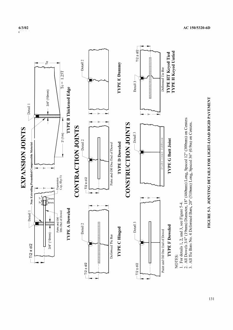
CHG 2
FIG
UR
E 5
-3.
-LO
AD
RIG
ID P
AV
EM
EN
T
131
6/3/02 AC 150/5320-6D
JO
INT
ING
DE
TA
ILS
FO
R L
IGH
T
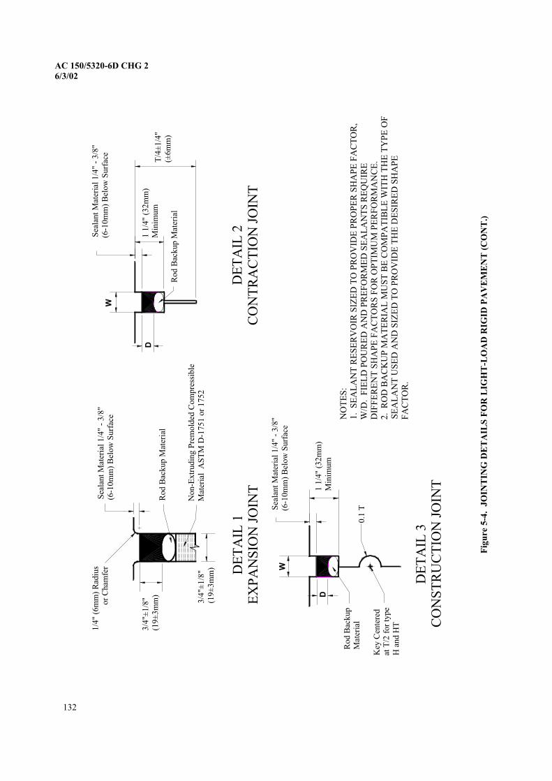
6/3/02
Rod B
ackup
Mat
eria
l
Sea
lant
Mat
eria
l 1/4
" -
3/8
" (6
-10m
m)
Bel
ow
Surf
ace
1 1
/4"
(32m
m)
Min
imum
W
D
DE
TA
IL 3
CO
NS
TR
UC
TIO
N J
OIN
T
Sea
lant
Mat
eria
l 1/4
" -
3/8
"(6
-10m
m)
Bel
ow
Surf
ace
1 1
/4"
(32m
m)
Min
imum
Rod B
ackup M
ater
ial
DE
TA
IL 2
CO
NT
RA
CT
ION
JO
INT
D
W
T/4
±1/4
"(±
6m
m)
3/4
"±1/8
"(1
9±
3m
m)
Sea
lant
Mat
eria
l 1/4
" -
3/8
" (6
-10m
m)
Bel
ow
Surf
ace
Non-E
xtr
udin
g P
rem
old
ed C
om
pre
ssib
le
Mat
eria
l
1/4
" (6
mm
) R
adiu
sor
Cham
fer DE
TA
IL 1
EX
PA
NS
ION
JO
INT
3/4
"±1/8
"(1
9±
3m
m)
NO
TE
S:
1.
W/D
.D
IFF
ER
EN
T S
HA
PE
FA
CT
OR
S F
OR
OP
TIM
UM
PE
RF
OR
MA
NC
E.
2. SE
AL
AN
T U
SE
D A
ND
SIZ
ED
TO
PR
OV
IDE
TH
E D
ES
IRE
D S
HA
PE
F
AC
TO
R.
Rod B
ackup M
ater
ial
Key
Cen
tere
dat
T/2
for
type
H a
nd H
T
0.1
T
Fig
ure 5
-4.
-LO
AD
RIG
ID P
AV
EM
EN
T (
CO
NT
.)
132
AC 150/5320-6D CHG 2
AS
TM
D-1
751 o
r 1752
SE
AL
AN
T R
ES
ER
VO
IR S
IZE
D T
O P
RO
VID
E P
RO
PE
R S
HA
PE
FA
CT
OR
, F
IEL
D P
OU
RE
D A
ND
PR
EF
OR
ME
D S
EA
LA
NT
S R
EQ
UIR
E
RO
D B
AC
KU
P M
AT
ER
IAL
MU
ST
BE
CO
MP
AT
IBL
E W
ITH
TH
E T
YP
E O
F
JO
INT
ING
DE
TA
ILS
FO
R L
IGH
T
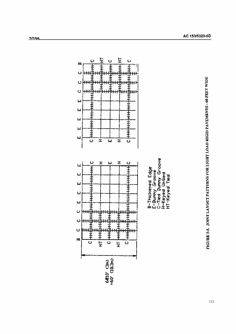
1
133

=
B-T
hic
ke
ne
d
Ed
ge
E-D
um
my
Gro
ove
C-T
ied
D
um
my
H-K
ey
ed
T
ied
FIG
UR
E 5
-6.
JO
INT
LA
YO
UT
PA
TT
ER
NS
FO
R L
IGH
T L
OA
D R
IGID
PA
VE
ME
NT
S
50 F
EE
T W
IDE

CHAPTER 6. PAVEMENT EVALUATION
600. PURPOSES OF PAVEMENT EVALUATION. Airport pavement evaluations are necessary to assess the
ability of an existing pavement to support different types, weights, or volumes of aircraft traffic. The load carrying
capacity of existing bridges, culverts, storm drains, and other structures should also be considered in these evaluations.
Evaluations may also necessary to determine the condition of existing pavements for use in the planning or design of
improvements to the airport. Evaluation procedures are essentially the reversal of design procedures. This chapter
covers the evaluation of pavements for all weights of aircraft.
601. EVALUATION PROCESS, The evaluation of airport pavements should be a methodical step-by-step process.
The recommended steps in the evaluation process are given in the subsequent paragraphs regardless of the type of
pavement.
a. Records Research. A thorough review of construction data and history, design considerations,
specifications, testing methods and results, as-built drawings, and maintenance history should be performed. Weather
records and the most complete traffic history available are also parts of a usable records file.
b. Site Inspection. The site in question should be visited and the condition of the pavements noted by
visual inspection. This should include, in addition to the inspection of the pavements, an examination of the existing
drainage conditions and drainage structures at the site. Evidence of the adverse effects of frost action, swelling soils,
reactive aggregates, etc. should also be noted. The principles set forth in Chapter 2 of this circular and in AC
Airport Drainage, apply.
C. Sampling And Testing. The need for and scope of physical tests and materials analyses will be based
on the findings made from the site inspection, records research, and type of evaluation. A complete evaluation for
detailed design will require more sampling and testing than, for example, an evaluation intended for use in a master
plan. Sampling and testing is intended to provide information on the thickness, quality, and general condition of the
pavement elements.
Direct Sampling Procedures. The basic evaluation procedure for planning and design will
be visual inspection and reference to the FAA design criteria, supplemented by the additional sampling, testing, and
research which the evaluation processes may warrant. For relatively new pavement constructed to FAA standards and
without visible sign of wear or stress, strength may be based on inspection of the FAA Form 5100-1, Airport Pavement
Design, and the as-constructed sections, with modification for any material variations or deficiencies of record. Where
age or visible distress indicates the original strength no longer exists, further modification should be applied on the basis
of judgment or a combination of judgment and supplemental physical testing. For pavements which consist of sections
not readily comparable to FAA design standards, evaluation should be based on FAA standards after material
comparison and have been applied.
Nondestructive Testing. Several methods of nondestructive testing of pavements are
available. For purposes of this discussion, NDT means of observing pavement response to a controlled loading. provides
a means of evaluating pavements which tends to remove some of the subjective judgment needed in other evaluation
procedures. FAA Advisory Circular 150/5370-l 1, Use of Nondestructive Testing Devices in the Evaluation of Airport
Pavements, contains guidance on nondestructive testing. The major advantages of nondestructive testing are: the
pavement is tested in place under actual conditions of moisture, density, etc.; the disruption of traffic is minimal; and the
need for destructive tests is minimized. Research efforts are continuing in the area of nondestructive testing to broaden
its application. Several different NDT procedures are available in addition to that described in AC 150/5370-l 1. These
other procedures may be used when approved by FAA.
d. Other Evaluation Tools. There are a number of other tools available to assist the evaluator. These
tools include: pavement condition index, ground penetrating radar, infrared thermography, etc.
Pavement Condition Index. The determination of the Pavement Condition Index (PCI) is
often a useful tool in the evaluation of airport pavements. The is a numerical rating of the surface condition of a
135
AC
pavement and is a measure of functional performance with implications of structural performance. values range from
100 for a pavement with no defects to 0 for a pavement with no remaining functional life. The index is useful in
describing distress and comparing pavements on an equal basis. Advisory Circular Guidelines and
Procedures for Maintenance of Airport Pavements, contains detailed information on surveys.
Ground Penetrating Radar. Ground penetrating radar can be useful in studying subsurface
conditions nondestructively. Ground penetrating radar depends on differences in dielectric constants to discriminate
between materials. The technique is sometimes used to locate voids or foreign objects, such as, abandoned fuel tanks,
tree stumps, etc. in embankments.
Infrared Thermography. Infrared thermography is a nondestructive testing procedure
whereby differences in infrared emissions are observed allowing certain physical properties of the pavement to be
determined. Infrared thermography is purportedly capable of detecting delaminations in bonded rigid overlay pavements
and in reinforced rigid pavements.
e. Evaluation Report. The analyses, findings, and test results should be incorporated in an evaluation
report which becomes a permanent record for future reference. While evaluation reports need not be in any particular
form, it is recommended that a drawing identifying limits of the evaluation be included. Analysis of information gained
in the above steps should culminate in the assignment of load carrying capacity to the pavement sections under
consideration. When soil, moisture, and weather conditions conductive to detrimental frost action exist, an adjustment
to the evaluation may be required.
602. FLEXIBLE PAVEMENTS. Evaluation of flexible pavements requires, as a minimum, the determination of
the thickness of the component layers, and the CBR of the subgrade.
a. Layer Thicknesses. The thickness of the various layers in the flexible pavement structure must be
known in order to evaluate the pavement. Thicknesses may be determined from borings or test pits. As-built drawings
and records can also be used to determine thicknesses if the records are sufficiently complete and accurate.
b. CBR. Laboratory CBR tests should be performed on soaked specimens in accordance with
ASTM D 1883, Bearing Ratio of Laboratory-Compacted Soils. Field should be performed in accordance with the
procedure given in The Asphalt Institute Manual Series 10 (MS-IO), Soils Manual. Field CBR tests on existing
pavements less than 3 years old may not be representative unless the moisture content has stabilized. The
evaluation process assumes a soaked CBR is and will not give reliable results if the moisture content has not
reached the ultimate in situ condition. In situations where it is impractical to perform laboratory or field CBR tests, an
estimate of CBR based on soil classification is possible. Table 2-3 may be used to estimate CBR on the basis of the
Unified Soil Classification System. Prior to adoption of the Unified Soil Classification System, soils were classified
using the FAA classification system. Some old records may contain data using the FAA classification system. Figure
6-l shows the approximate relationship between the FAA soil classification and CBR.
C. Material Comparisons and For the purposes of design and evaluation, flexible
pavements are assumed to be constructed of asphaltic concrete surfacing, granular base, and granular subbase courses of
a predetermined quality. When the materials in a pavement structure to be evaluated are at variance with these
assumptions, the materials have to be compared and equated to a standard section. The nonstandard sections after
conversion have to be checked for load carrying capacity based on the following considerations:
Total pavement section thickness.
Surface plus base course thickness.
Minimum base course thickness.
Minimum surface thickness.
requirement yielding the lesser strength will control the evaluation.
136
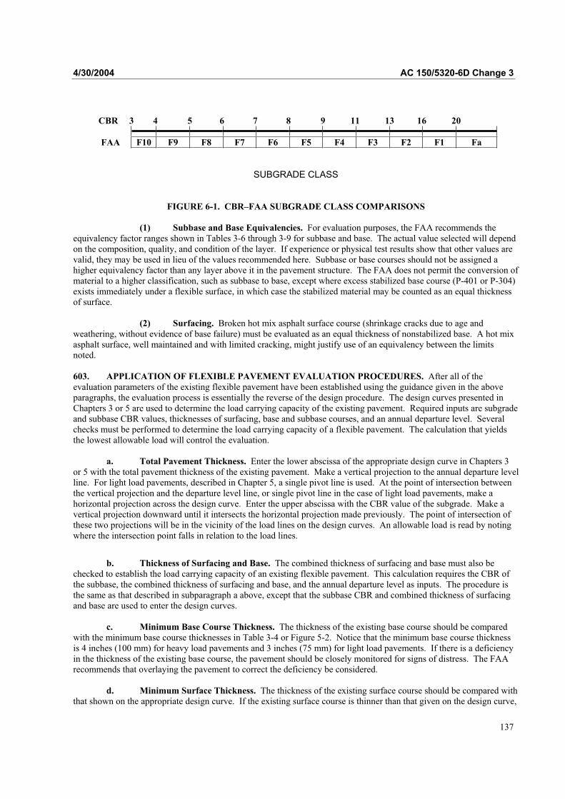
4/30/2004 AC 150/5320-6D Change 3
CBR 3 4 5 6 7 8 9 11 13 16 20
FAA F10 F9 F8 F7 F6 F5 F4 F3 F2 F1 Fa
SUBGRADE CLASS
FIGURE 6-1. CBR–FAA SUBGRADE CLASS COMPARISONS
(1) Subbase and Base Equivalencies. For evaluation purposes, the FAA recommends theequivalency factor ranges shown in Tables 3-6 through 3-9 for subbase and base. The actual value selected will dependon the composition, quality, and condition of the layer. If experience or physical test results show that other values are valid, they may be used in lieu of the values recommended here. Subbase or base courses should not be assigned ahigher equivalency factor than any layer above it in the pavement structure. The FAA does not permit the conversion ofmaterial to a higher classification, such as subbase to base, except where excess stabilized base course (P-401 or P-304) exists immediately under a flexible surface, in which case the stabilized material may be counted as an equal thicknessof surface.
(2) Surfacing. Broken hot mix asphalt surface course (shrinkage cracks due to age andweathering, without evidence of base failure) must be evaluated as an equal thickness of nonstabilized base. A hot mixasphalt surface, well maintained and with limited cracking, might justify use of an equivalency between the limitsnoted.
603. APPLICATION OF FLEXIBLE PAVEMENT EVALUATION PROCEDURES. After all of theevaluation parameters of the existing flexible pavement have been established using the guidance given in the aboveparagraphs, the evaluation process is essentially the reverse of the design procedure. The design curves presented inChapters 3 or 5 are used to determine the load carrying capacity of the existing pavement. Required inputs are subgradeand subbase CBR values, thicknesses of surfacing, base and subbase courses, and an annual departure level. Severalchecks must be performed to determine the load carrying capacity of a flexible pavement. The calculation that yields the lowest allowable load will control the evaluation.
a. Total Pavement Thickness. Enter the lower abscissa of the appropriate design curve in Chapters 3 or 5 with the total pavement thickness of the existing pavement. Make a vertical projection to the annual departure levelline. For light load pavements, described in Chapter 5, a single pivot line is used. At the point of intersection betweenthe vertical projection and the departure level line, or single pivot line in the case of light load pavements, make a horizontal projection across the design curve. Enter the upper abscissa with the CBR value of the subgrade. Make a vertical projection downward until it intersects the horizontal projection made previously. The point of intersection ofthese two projections will be in the vicinity of the load lines on the design curves. An allowable load is read by notingwhere the intersection point falls in relation to the load lines.
b. Thickness of Surfacing and Base. The combined thickness of surfacing and base must also bechecked to establish the load carrying capacity of an existing flexible pavement. This calculation requires the CBR ofthe subbase, the combined thickness of surfacing and base, and the annual departure level as inputs. The procedure isthe same as that described in subparagraph a above, except that the subbase CBR and combined thickness of surfacingand base are used to enter the design curves.
c. Minimum Base Course Thickness. The thickness of the existing base course should be comparedwith the minimum base course thicknesses in Table 3-4 or Figure 5-2. Notice that the minimum base course thicknessis 4 inches (100 mm) for heavy load pavements and 3 inches (75 mm) for light load pavements. If there is a deficiencyin the thickness of the existing base course, the pavement should be closely monitored for signs of distress. The FAArecommends that overlaying the pavement to correct the deficiency be considered.
d. Minimum Surface Thickness. The thickness of the existing surface course should be compared withthat shown on the appropriate design curve. If the existing surface course is thinner than that given on the design curve,
137

AC 150/5320-6D Change 3 4/30/2004
the pavement should be closely observed for surface failures. The FAA recommends that correction of the deficiency insurfacing thickness be considered.
604. RIGID PAVEMENTS. Evaluation of rigid pavements requires, at a minimum, the determination of thethickness of the component layers, the flexural strength of the concrete, and the modulus of subgrade reaction.
a. Layer Thicknesses. The thickness of the component layers is sometimes available from constructionrecords. Where information is not available or of questionable accuracy, thicknesses may be determined by borings ortest pits in the pavement.
b. Concrete Flexural Strength. The flexural strength of the concrete is most accurately determinedfrom test beams sawed from the existing pavement and tested in accordance with ASTM C 78. However, this method is often impractical, as sawed beams are expensive to obtain and costs incurred in obtaining sufficient numbers of beamsto establish a representative sample are prohibitive. Construction records, if available, may be used as a source of concrete flexural strength data, but the construction data will probably have to be adjusted for age, as concrete strengthincreases with time.
(1) Correlations with Other Strength Tests. Correlations between concrete flexural strengthand other concrete strength tests are available, but the correlations between flexural strength and other strength tests areapproximate, and considerable variations are likely.
(i) Tensile Split Strength. An approximate relationship between concrete flexuralstrength and tensile splitting strength (ASTM C 496) exists and can be computed with the following formula:
R = 1.02( T ) + 117
where:R = flexural strength, psiT = tensile split strength, psi
Note: For conversions in metric units, the above formula remains the same—exceptthe 117 psi constant should be changed to 0.81 MPa.
This equation can be used with 85 percent confidence that the estimated flexural strength is at least as strong as the strengthderived from the original regression analysis detailed in Concrete Strength Relationships, Miscellaneous Report Number S-74-30, published by the US Army Engineer Waterways Experiment Station, December 1974.
(ii) Compressive Strength. Flexural strength can be estimated from compressivestrength (ASTM C 39) using the formula below:
'
cf9R
where:R = flexural strength
= compressive strength'
cf
138

4/30/2004 AC 150/5320-6D Change 3
c. Modulus of Subgrade Reaction. The modulus of subgrade reaction is determined by plate bearing tests performed on the subgrade. These tests should be made in accordance with the procedures established inAASHTO T 222. An important part of the test procedure for determining the subgrade reaction modulus is thecorrection for soil saturation that is contained in the prescribed standard. The normal application utilizes a correctionfactor determined by the consolidation testing of samples at in situ and saturated moisture content. For evaluation ofolder pavement where evidence exists that the subgrade moisture has stabilized or varies through a limited range, thecorrection for saturation is not necessary. If a field plate bearing test is not practical, the modulus of subgrade reactionmay be determined by nondestructive testing or estimated by using Table 2-3 in Chapter 2 of this AC. Fortunately,pavement evaluation is not too sensitive to the modulus of subgrade reaction.
(1) Adjustment for Subbase. An adjustment to the modulus of subgrade reaction will be required if a subbase exists beneath the existing pavement. The thickness of the subbase is required to calculate an adjusted k value. The subbase thickness can be determined from construction records or from borings. The guidancecontained in Chapter 3, Section 3, should be used in assigning a k value to a subbase.
605. APPLICATION OF RIGID PAVEMENT EVALUATION PROCEDURES. The evaluation of rigidpavements for aircraft weighing more than 30,000 pounds (13 600 kg) requires concrete flexural strength, k value of thefoundation, slab thickness, and annual departure level as inputs. The rigid pavement design curves in Chapter 3 areused to establish load carrying capacity. The design curves are entered on the left ordinate with the flexural strength ofthe concrete. A horizontal projection is made to the k value of the foundation. At the point of intersection of thehorizontal projection and the k line, a vertical projection is made into the vicinity of the load lines. The slab thickness isentered on the appropriate departure level scale on the right side of the chart. A horizontal projection is made from thethickness scale until it intersects the previous vertical projection. The point of intersection of these projections will bein the vicinity of the load lines. The load carrying capacity is read by noting where the intersection point falls in relation to the load lines.
606. USE OF RESULTS. If the evaluation is being used for planning purposes and the existing pavement is foundto be deficient in accordance with the design standards given in Chapters 3 or 5, the sponsor should be notified as to the deficiency and should consider corrective action. If the evaluation is being used as part of the design for a project to reconstruct or upgrade the facility, the procedures given in Chapters 3, 4, or 5 should be used to design thereconstruction or overlay project. In the latter case, the main concern is not the load carrying capacity, but thedifference between the existing pavement structure and the section that is needed to support forecast traffic.
607. REPORTING PAVEMENT STRENGTH. The International Civil Aviation Organization (ICAO)developed a standardized method of reporting airport pavement strength known as the Aircraft ClassificationNumber/Pavement Classification Number (ACN/PCN). This method is based on the concept of reporting strength interms of a standardized equivalent single wheel load. This method of reporting pavement strength is discussed in FAAAC 150/5335-5, Standardized Method of Reporting Airport Pavement Strength–PCN.
608. EVALUATIONS OF EXISTING PAVEMENT WITH LAYERED ELASTIC PROCEDURES. When anexisting pavement must be evaluated for use by new aircraft not covered in the nomographs provided in Chapter 3, thelayered elastic design procedures described in Chapter 7 may be used. However, an evaluation with these proceduresmight present unique difficulties when trying to correlate results to original thickness requirements. In many cases, the original traffic mixture might not be known and only the design aircraft gross weight and annual departures beavailable. Since the evaluation is for current usage, the existing and forecasted traffic mixture should be used toevaluate the pavement requirements.
Existing pavements may also be evaluated for use by new aircraft with the ACN/PCN system described in AC 150/5335-5.The ACN value of new aircraft can be compared to the existing PCN value of the pavement to determine whetherrestricted or unrestricted operations of the new aircraft should be permitted.
139

AC 150/5320-6D Change 3 4/30/2004
THIS PAGE INTENTIONALLY BLANK
140

4/30/2004 AC 150/5320-6D Change 3
CHAPTER 7. LAYERED ELASTIC PAVEMENT DESIGN
701. PURPOSE. The design procedure presented in this chapter provides a method of design based on layeredelastic analysis developed to calculate design thicknesses for airfield pavements. Layered elastic design theory wasadopted to address the impact of new gear and wheel arrangements such as the triple dual tandem (TDT) main gear.The Boeing 777 and the Airbus A-380 are examples of aircraft that utilize this gear geometry. The TDT gear producesan airport pavement loading configuration that appears to exceed the capability of the previous methods of design,which incorporate some empiricism and have limited capacity for accommodating new gear and wheel arrangements.This design method is computationally intense and is thus in the form of a computer program called LEDFAA.
702. APPLICATION. The procedures and design software identified in this chapter are primarily intended to provide pavement thickness design standards for airfield pavement intended to serve aircraft traffic mixtures thatinclude aircraft utilizing TDT or other complex main gear configurations. The pavement design procedures presented inthis chapter may also be used as a design alternate for the design procedures presented in Chapters 3 and 4. In instanceswhere newer aircraft gear configuration, tire pressures, and/or wheel loads are not appropriate for the nomographspresented in Chapters 3 and 4, the FAA recommends using the layered elastic design procedures. Pavement designs fortraffic mixes that do not include aircraft with the TDT main gear must conform to the minimum pavement sectionsdefined in Chapters 3, and 4. A companion design prepared in accordance with Chapters 3 and 4 must be submittedwith the layered elastic design for FAA approval. To aid in the design review, the summary information from thedesign software should be printed and included with the pavement design submittal.
The LEDFAA program may not be used to compare individual aircraft pavement thickness requirements for pavementdesigns, in accordance with Chapters 3 and 4, to individual aircraft thickness requirements for pavement designs basedon the layered elastic design methodology. The program may not be used to evaluate existing pavement structuresdesigned in accordance with Chapters 3 and 4 against single aircraft thickness requirements using the layered elastic design methodology. Any comparison between the design methodology of LEDFAA and Chapters 3 and 4 must be performed utilizing the entire traffic mixture (see paragraph 704e).
703. BACKGROUND. The TDT main landing gear is unique in that it has six wheels arranged as three pairs of wheels in a row. When the TDT main gear assembly is analyzed using the conventional FAA design methodology, thepavement thickness requirements are considered to be unduly conservative. This is particularly noticeable for flexiblepavements. In 1995, the FAA adopted a layered elastic airport pavement design methodology for the Boeing 777 toreduce some of the conservatism experienced with the methods presented in Chapters 3 and 4 and to phase in a moremechanistic approach. The U.S. Army Corps of Engineers, Waterways Experiment Station, Vicksburg, MS, originallydeveloped the layered elastic method of design for flexible and rigid pavements and overlays of rigid pavements.Verification of the new flexible pavement design procedure was performed by full-scale pavement testing at theNational Airfield Pavement Test Facility, William J. Hughes Technical Center, Atlantic City, NJ.
704. COMPUTER PROGRAM. The design method is computer-based and is called LEDFAA. The coreprogram is LEAF, a layered elastic computational program implemented as a Microsoft WindowsTM ActiveX dynamiclink library written in Visual BasicTM 6.0. The remainder of the program is written in Visual BasicTM and operatesunder Microsoft WindowsTM.
a. Aircraft Considerations. A wide variety of aircraft with pertinent pavement design characteristicsare stored in the program library. The designer has considerable latitude in selecting and adjusting aircraft parameters.
b. Metric Units. The program may be operated with U.S. customary or metric dimensions.
c. Availability. LEDFAA can be downloaded from the Office of Airport Safety and Standards website(http://www.faa.gov/arp/).
d. Related Reference Material. The internal help file for LEDFAA contains a user’s manual, whichprovides detailed information on proper execution of the program. The manual also contains additional technicalreferences for specific details of the LEDFAA design procedure.
e. Aircraft Traffic Mixture. LEDFAA was developed and calibrated specifically to produce pavementthickness designs consistent with previous methods based on a mixture of different aircraft rather than individual
141

AC 150/5320-6D Change 3 4/30/2004
aircraft. If a single aircraft is used for design, a warning will appear in the Aircraft Window indicating a non-standardaircraft list is used in the design. This warning is intended to alert the user that the program was intended for use with a mixture of different aircraft types. Nearly any traffic mix can be developed from the aircraft in the program library.Solution times are a function of the number of aircraft in the mix. The LEDFAA design procedure deals with mixedtraffic differently than did previous design methods. Determination of a design aircraft is not required to operateLEDFAA. Instead, the program calculates the damaging effects of each aircraft in the traffic mix. The damagingeffects of all aircraft are summed in accordance with Miner's Law. When the cumulative damage factor (CDF) sums to a value of 1.0, the design conditions have been satisfied.
705. PAVEMENT DESIGN CONSIDERATIONS. There are distinct differences between the designmethodology presented in Chapters 3 and 4 and the methodology contained in LEDFAA. These differences, along withsome common design assumptions between the two methods, are discussed below.
a. Design Life. The FAA design standard for pavements is based on a 20-year design life. Thecomputer program is capable of considering other design life time frames, but the use of a design life other than 20years constitutes a deviation from FAA standards.
b. Traffic Mix. As noted in paragraph 704e, traffic mix considerations are handled differently by thelayered elastic design method. The procedures described in Chapters 3 and 4 require the traffic mixture to be convertedinto a single design aircraft and all annual departures converted to equivalent annual departures of the design aircraft.The design aircraft is determined by selecting the most damaging aircraft based on the anticipated gross weight and thenumber of departures for each aircraft. The layered elastic design program does not convert the traffic mixture; instead,it analyzes the damage to the pavement section for each aircraft and determines a final thickness for the total cumulativedamage. LEDFAA considers the placement of each aircraft’s main gear in relationship to the pavement centerline. It also allows the pavement damage associated with a particular aircraft to be completely isolated from one or more of theother aircraft in the traffic mixture.
c. Design Reliability. The reliability of the layered elastic method of design should be approximatelythe same as the reliability of the CBR method of pavement design.
d. Materials. In the layered elastic design procedure, pavement materials are characterized bythickness, elastic moduli, and Poisson's ratio. Layer thicknesses can be varied, except where minimum thicknesses are required. Elastic moduli are either fixed or variable, depending on the material. The permissible range of variability forelastic moduli is fixed to ensure reasonable values. Poisson's ratio for all material is fixed. Materials are identified withtheir corresponding FAA specification designations; for example, crushed stone base course is identified as Item P-209.The list of materials contains an undefined layer with variable properties. If an undefined layer is used, a warning willappear in the Structure Window stating that a non-standard material has been selected and its use in the structure willrequire FAA approval.
e. Minimum Layer Thickness. When the layered elastic design procedure is used in lieu of the designprocedures in Chapters 3 and 4, LEDFAA will not automatically establish the minimum layer thickness for each layer, as required. The user must consult paragraphs 706, 707, and 708 below to assure the minimum thickness requirementsare obtained.
706. FLEXIBLE PAVEMENT DESIGN. The design process considers two modes of failure for flexiblepavement: vertical strain in the subgrade and horizontal strain in the asphalt layer. Limiting vertical strain in thesubgrade is intended to preclude failure by subgrade rutting. Limiting horizontal strain at the bottom of the asphaltsurfacing layer guards against pavement failure initiated by cracking of the asphalt surface layer.
a. Hot Mix Asphalt Surfacing. Hot mix asphalt surfacing should meet the requirements of FAA ItemP-401. A minimum thickness of 5 inches (127 mm) of hot mix surfacing is required for traffic mixes that includeaircraft with the TDT gear. The minimum thickness of hot mix surfacing, as shown in Figures 3-2 through 3-15, is required for traffic mixes that do not include aircraft with the TDT gear. A fixed modulus value for hot mix surfacing isset in the program at 200,000 psi (1 380 MPa). This modulus value was chosen to produce results that closely matchedthickness requirements for pavements designed with the CBR methodology.
b. Base Course. A minimum 5-inch-thick (127 mm) stabilized base course is required for pavementsserving aircraft with the TDT gear. LEDFAA includes two stabilized flexible base options, designated P-401 and
142

4/30/2004 AC 150/5320-6D Change 3
Variable. The word flexible is used to indicate that these bases have a higher Poisson's ratio (0.35), act as flexiblelayers as opposed to rigid layers, and are not likely to crack. P-401 is the standard FAA Item P-401 bituminous base,which has a fixed modulus of 400,000 psi (2 760 MPa). The variable stabilized flexible base can be used to characterizea bound base, which does not conform to the properties of P-401. It has a variable modulus ranging from 150,000 to400,000 psi (1 035 to 2 760 MPa). This modulus range was selected to closely duplicate results obtained from using anequivalency factor range of 1.2 to 1.6 in the CBR method of design. Stabilized (rigid) bases, P-304, and P-306 may also be used as base course; although, they are subject to cracking and can induce reflection cracking in the hot mix asphaltsurfacing. Item P-301, Soil Cement Base, is not acceptable for use as a base course for these pavements.
When the layered elastic design procedure is used in lieu of the design procedures in Chapters 3 and 4, the minimumbase thickness will be determined in a manner similar to the procedure described in paragraph 319b. The minimumbase thickness must be determined by increasing the subgrade CBR value to 20 and removing all subbase layers. Theminimum thickness required will be the greater of the resulting base thickness from the LEDFAA program or theminimum base thickness in Table 3-4.
For traffic mixtures with aircraft exceeding 100,000 lbs (45 350 kg) but not containing a TDT gear aircraft, a stabilizedbase course is required, as noted in paragraph 320. When using the LEDFAA design procedure, the minimum stabilizedbase thickness is 6 inches (150 mm).
c. Subbase Course. Subbases may be aggregate or bound materials. The minimum thickness ofsubbase for structural purposes is 3 inches (76 mm). Additional thickness might be required for practical constructionlimitations. Acceptable aggregate materials are P-209, Crushed Aggregate Base Course; P-208 Aggregate Base Course;or P-154, Subbase Course. Acceptable bound materials are P-401, P-304, and P-306. Use of Item P-301 is limited to locations not subject to freeze-thaw cycles. More than one layer of subbase material may be used, i.e., P-209 over alayer of P-154. Layering must be done so as not to produce a sandwich (granular layer between two bound layers)section and to assure that material quality increases toward the top of the pavement section.
For traffic mixtures with aircraft exceeding 100,000 lbs (45 350 kg), a stabilized subbase is required, as noted inparagraph 320. Acceptable materials are specified in Tables 3-6 and 3-7.
d. Subgrade. The subgrade is assumed to be infinite in thickness and is characterized by either a modulus or CBR value. LEDFAA converts CBR to modulus by multiplying it by 1,500. Subgrade compaction and embankment construction should be in accordance with Table 3-2.
e. Seasonal Frost and Permafrost. Seasonal frost and permafrost effects should be considered by applying the techniques in Chapter 2.
707. RIGID PAVEMENT DESIGN. The design process considers one mode of failure for rigid pavement,cracking of the concrete slab. Failure of subbase and subgrade layers is not considered. Limiting the horizontal stressat the bottom surface of the concrete surfacing layer guards against failure by cracking of the surface layer. LEDFAAiterates on the concrete layer thickness until the CDF reaches a value of 1.0. Once a CDF of 1.0 is achieved, the sectionsatisfies the design conditions.
a. Concrete Pavement Surfacing. Concrete pavement surfacing should meet the requirements of Item P-501. The minimum concrete surfacing thickness is 6 inches (152 mm).
b. Subbase Course. When the layered elastic design procedure is used in lieu of the design proceduresin Chapters 3 and 4, the subbase must meet the requirement of paragraphs 326, 327, and 328.
c. Stabilized Subbase Course. Bound materials are required for subbase under rigid pavements servingaircraft with the TDT gear. Acceptable bound materials are P-304, P-306, and P-401, variable stabilized rigid and variable stabilized flexible. The minimum thickness of subbase is 4 inches (102 mm). More than one layer of subbasemay be used, i.e., P-306 over a layer of P-209. Layering must be done so as not to produce a sandwich (granular layer between two bound layers) section.
d. Subgrade. The subgrade is assumed to be infinite in thickness and is characterized by either a modulus or k value. The computer converts k to modulus by using the logarithmic relationship log E = 1.415 + 1.284
143
AC 150/5320-6D Change 3 4/30/2004
log k. Subgrade compaction requirements and embankment construction should be in accordance with Chapter 3 andAC 150/5370-10.
e. Seasonal Frost and Permafrost. Seasonal frost and permafrost effects should be considered by applying the techniques in Chapter 2.
f. Jointing Details. Jointing details for rigid pavements are presented in Chapter 3. The limitations onjointing of rigid pavements for wide body aircraft also apply to pavements designed to serve aircraft with the TDT gear.
708. LAYERED ELASTIC OVERLAY DESIGN. Layered system design permits a direct design approach foroverlays. The overlay design method in Chapter 4 relies on an empirically based thickness deficiency approach. Thelayered system design calculates the thickness of overlay required to provide a 20-year life, which satisfies the layeredelastic failure criteria for limiting stress or strain. The 20-year life thickness is defined as the design thickness. Dr. R.S. Rollings designed the design method for overlays of rigid pavement through an FAA-funded research effort, as listedin Appendix 4. Overlay pavements are grouped into four different types as follows:
Hot Mix Asphalt Overlay of Existing Flexible PavementConcrete Overlay of Existing Flexible PavementHot Mix Asphalt Overlay of Existing Rigid PavementConcrete Overlay of Existing Rigid Pavement
a. Overlays of Existing Flexible Pavements. The design of an overlay for an existing flexiblepavement is essentially the same as designing a new pavement. The existing flexible pavement is characterized byassigning the appropriate thicknesses and moduli of the existing layers. A qualified engineer should be consulted tocharacterize the existing pavement layers.
(1) Hot Mix Overlay of an Existing Flexible Pavement. A trial thickness of overlay is selected,and the program iterates until a CDF of 1.0 is reached. The overlay thickness required to achieve a CDF of 1.0 is thedesign thickness.
(2) Concrete Overlay of an Existing Flexible Pavement. The design of a concrete overlay on anexisting flexible pavement is essentially the same as designing a new rigid pavement. The existing flexible pavement ischaracterized by assigning the appropriate thicknesses and moduli of the existing layers. A trial thickness of overlay is selected, and the program iterates until a CDF of 1.0 is reached. The overlay thickness required to achieve a CDF of 1.0is the design thickness. The design process is relatively simple; however, the characterization of the existing pavementlayers requires judgment by a qualified engineering. The program assumes the interface between the concrete overlayand the existing flexible surface is frictionless.
b. Overlays of Existing Rigid Pavements. The design of overlays for an existing rigid pavement iscomplex because deterioration of the underlying pavement as well as deterioration of the overlay must be considered.The condition of the existing rigid pavement prior to overlay is important and is expressed in terms of the structuralcondition index (SCI). The SCI is derived from the pavement condition index (PCI). (Additional guidance on derivingan SCI is provided in the LEDFAA user’s manual.) The PCI is a numerical rating indicating the operational conditionof an airport pavement based on visual survey. The scale ranges from a high of 100 to a low of 0, with 100 representinga pavement in excellent condition. The PCI is measured using ASTM standard test method D 5340, Standard TestMethod for Airport Pavement Condition Index Survey. For rigid pavements, 15 different types of distress are considered in measuring the PCI. These distress types all reduce the PCI of a pavement, depending on their severityand relative effect on performance. Not all distress types are indicative of structural distress. Rollings has identified 6distress types that are indicative of the structural condition of the pavement. Table 7-1 lists these 6 distress types.
144

4/30/2004 AC 150/5320-6D Change 3
TABLE 7-1. RIGID PAVEMENT DISTRESS TYPES USED TO CALCULATE THE
STRUCTURAL CONDITION INDEX, SCI
Corner BreakLongitudinal/Transverse/Diagonal CrackingShattered SlabShrinkage Cracksa (cracking partial width of slab)Spalling–JointSpalling–Corner
a Used only to describe a load-induced crack that extends only part of the way across a slab.The SCI does not include conventional shrinkage cracks due to curing problems.
An SCI of 80 is consistent with the current FAA definition of initial failure of a rigid pavement, i.e., 50 percent of theslabs in the traffic area exhibit initial structural cracking. The SCI allows a more precise and reproducible rating of a pavement’s condition than previous FAA condition factor ratings, Cb and Cr.
(1) Hot Mix Asphalt Overlays of Existing Rigid Pavements. The design process for hot mixoverlays of rigid pavements considers two conditions for the existing rigid pavement to be overlaid: a SCI of theexisting pavement that is equal to or less than 100.
(i) Structural Condition Index Less Than 100. The most likely situation is one inwhich the existing pavement is exhibiting some structural distress, i.e., the SCI is less than 100. If the SCI is less than100, the overlay and base pavement deteriorate at a given rate until failure is reached. LEDFAA assumes an overlaythickness and iterates on the thickness of overlay until a 20-year life is predicted. A 20-year predicted life satisfies thedesign requirements.
(ii) Structural Condition Index Equal to 100. An existing pavement with an SCI of100 might require an overlay to strengthen the pavement in order to accept heavier aircraft. If the SCI of the basepavement is equal to 100, an additional input is required—the CDFU, cumulative damage factor used, which estimatesthe amount of pavement life used up prior to overlay. LEDFAA assumes the base pavement will deteriorate at one ratewhile the SCI is equal to 100 and at a different rate after the SCI drops below 100. As with an SCI less than 100, a trial overlay thickness is input, and the program iterates on that thickness until a 20-year life is predicted. The designthickness is the thickness that provides a 20-year predicted life.
(2) Concrete Overlays of Existing Concrete Pavements. The design of a concrete overlay ofan existing rigid pavement is the most complex type of overlay to be designed. Deterioration of the concrete overlayand existing rigid pavement must be considered as well as the degree of bond between the overlay and existingpavement. LEDFAA considers two degrees of bond and addressed each separately for thickness design.
(i) Fully Unbonded Concrete Overlay. An unbonded concrete overlay of an existingrigid pavement is one in which steps are taken to intentionally eliminate bonding between the overlay and existingpavement. Commonly, the bond is broken by applying a thin hot mix layer to the existing rigid pavement. Theinterface friction coefficient between the overlay and existing pavement is set to reflect an unbonded condition. Theinterface coefficient is fixed and cannot be changed by the user. As with hot mix asphalt overlays, an SCI is required todescribe the condition of the existing pavement. A trial overlay thickness is input, and LEDFAA iterates until a 20-yearservice life is predicted. The thickness that yields a 20-year service life is the design thickness.
(ii) Partially Bonded Concrete Overlay. A partially bonded overlay is one in whichno particular effort is made to either eliminate or achieve bond between the concrete overlay and the existing rigidpavement. Such overlays are normally appropriate for existing rigid pavements when the SCI is 77 or greater. Theinterface coefficient is set to reflect a small degree of friction between the overlay and base pavement. This coefficientis fixed and cannot be changed by the user. An SCI for the existing pavement is required. A trial overlay thickness isinput, and LEDFAA iterates until a 20-year service life is predicted. The thickness that yields a 20-year service life is the design thickness.
145

AC 150/5320-6D Change 3 4/30/2004
THIS PAGE INTENTIONALLY BLANK
146
5/23/06 AC 150/5320-6D Change 4
147
CHAPTER 8. PAVEMENT DESIGN FOR AIRFIELD SHOULDERS
801. PURPOSE. This chapter provides a design procedure for paved airfield shoulders.
802. APPLICATION. The design procedure for paved or surfaced shoulders applies to all airports that accommodate Design Group III or higher aircraft.
803. BACKGROUND. The need for paved or surfaced shoulders is created due to erosion and generation of debris from jet blast. As aircraft grew in size, so did the size of the aircraft engines and their respective increase in jet thrust orjet blast. Jet blast can cause problems with erosion of unprotected soil immediately adjacent to airfield pavements. To mitigate this problem, FAA recommends paved shoulders for runways, taxiway, and aprons that will accommodate Group III and higher aircraft. In addition to providing protection from jet blast, the shoulder must be capable of safely supporting “occasional” passage of the most demanding aircraft as well as emergency and maintenance vehicles.
804. PURPOSE OF DESIGN PROCEDURE. The procedure for shoulder pavement thickness design is intended to provide a minimum pavement structure to support limited operations of aircraft. The design is intended to provide sufficient support for unintentional or emergency operations of an aircraft on the shoulder pavement. Use standard airfield pavement design requirements to design all areas of pavement where aircraft regularly operate.
The minimum section provided by the shoulder pavement design procedure will not perform in the same fashion as full strength airfield pavements. The shoulder pavement is intended to allow safe operation of the aircraft across the paved area without damage to the aircraft. Flexible shoulder pavement sections may experience noticeable vertical movements with each passage of an aircraft and may require inspection and/or limited repair after each operation. Rigid shoulder pavement sections may experience cracking with each operation.
805. DESIGN PROCEDURE. The design procedure is based upon the FAA Layered Elastic pavement design software (LEDFAA) and utilizes a modified design procedure to determine the most demanding aircraft (MDA) for shoulder pavement design purposes. Several of the procedural assumptions in the standard pavement design (traffic distribution, pass-to-coverage ratios, etc,) are not valid and are not used for the shoulder pavement design procedure. The procedure determines the minimum pavement section required for the MDA, assuming a total of 10 departures. A composite traffic mixture is not considered for the shoulder design.
The shoulder pavement design procedure determines the MDA by calculating pavement thickness requirements for all aircraft utilizing or expected to utilize the airport. The aircraft requiring the thickest pavement section is considered the MDA. The following steps are used to complete the design procedure:
1 Use the LEDFAA software to create a new job file and proposed pavement section for the shoulder design. Include all desired pavement layers, e.g. surface course, base course, stabilized course, subbase course, etc. Adjust layer thickness to observe minimum thickness requirements for shoulder design.
NOTE: Due to minimum pavement layer requirements in the formal airfield pavement design procedure, it may be necessary to use the “undefined” pavement layer to represent the proposed shoulder pavement cross-section.
2 Input one aircraft from the traffic mixture for analysis.
a. Adjust aircraft operating weights as appropriate.
b. Change annual departures to 1.0 departure. 3 Return to the Structure screen and confirm that the design period is 10 years.
NOTE: The intent of this design procedure is to design a pavement for 10 total departures of the most demanding aircraft. By setting annual departures to 1 and the design period to 10, the total departures is 10.

AC 150/5320-6D Change 4 5/23/06
148
4 Confirm the composition and thickness of pavement layers and that the correct layer is designated for thickness iteration. The iteration layer will be shown with a small arrow along the left side.
5 Click on the “Design Structure” button to establish the minimum pavement section for the individual aircraft.
6 Repeat steps 1 through 5 for all aircraft in the traffic mixture. The pavement section with the greatest thickness requirement is the design for the shoulder pavement.
EVALUATION AID: To reduce the list of individual aircraft requiring evaluation, include all aircraft from the airport traffic mixture and set annual departures of all aircraft to 1,200 annual departures. Create the proposed shoulder pavement section in the structure screen, then click the “Life” button instead of the “Design Structure” button. Return to the aircraft mixture, and scroll over to the column labeled “CDF Max for Aircraft”. The aircraft with the highest CDF Max value will be the most demanding aircraft in most instances and will control the shoulder design. However, the top few aircraft with the highest CDF Max values should be evaluated because the thickness of the pavement section being evaluated will influence which aircraft is the most demanding.
806. PAVEMENT LAYER THICKNESS AND MATERIAL REQUIREMENTS.
a. Asphalt Surface Course Materials. The minimum recommended thickness for asphalt surfacing material is 3 inches. The material should be of high quality, similar to FAA Item P-401, and compacted to an average target density of 94 percent of maximum theoretical density. Material produced for use with high traffic volume highway pavement is acceptable provided the compaction specified for the highway application is obtained.
b. Portland Cement Concrete Surface Course Materials. The minimum recommended thickness for rigid pavement design is 6 inches. Portland Cement Concrete (PCC) must be a high quality, durable material capable of resisting deterioration due to environmental factors. The PCC should be similar to FAA Item P-501, with a minimum design flexural strength of 600 psi. Material produced for use with high traffic volume highway pavement is acceptable provided that environmental durability is addressed.
b. Base Course Materials. Base course materials must be high quality crushed stone or stabilized materials similar to FAA Items P-208, P-209, P-301, or P-304. Materials produced for use with high traffic volume highway pavement may be acceptable provided they possess qualities similar to the FAA specification items. Crushed stone material must possess a minimum CBR value of 80. The recommended minimum thickness of the base course material is 6 inches. The minimum base course thickness may be reduced to 4 inches by increasing the minimum asphalt thickness by 1.0 inch. Place base course material in accordance with the appropriate standard from AC 150/5370-10 or in accordance with the applicable State Highway standard. Additional consideration should be given to frost heave susceptibility of the material when used in frost-susceptible zones.
c. Subbase Course Materials. Subbase course material must provide a minimum CBR value of 20. Materials produced by State Highway standards are acceptable provided the minimum CBR value is obtained. Place subbase course material in accordance with AC 150/5370-10, Item P-154 or in accordance with the applicable State Highway standard. Additional consideration should be given to frost heave susceptibility of the material when used in frost susceptible zones. The minimum recommended thickness is 4 inches. See paragraph 808 below.
d. Subgrade Materials. Preparation of subgrade materials should be in accordance with AC 150/5370-10, Item P-152.
807. EMERGENCY AND MAINTENANCE VEHICLE CONSIDERATIONS. In most cases, the pavement design selected by the shoulder design procedure should provide sufficient strength for unlimited operations of maintenance and emergency vehicles. If high operations of these vehicles are anticipated, the shoulder design should be verified for the anticipated service.
808. AREAS SUSCEPTIBLE TO FROST HEAVE. In areas prone to frost heave, it may be necessary to increase the thickness of the shoulder pavement to avoid differential frost heave. Additional thickness of the pavement beyond that necessary for structural design may be achieved with any material suitable for pavement construction. The material

5/23/06 AC 150/5320-6D Change 4
149
should possess a CBR value higher than the subgrade and have non-frost susceptible properties. Place the additional layer immediately on the subgrade surface below all base and subbase layers.

AC 150/5320-6D Change 4 5/23/06
150
This page intentionally left blank.

ACAPPENDIX 1
APPENDIX 1. ECONOMIC ANALYSIS
1. BACKGROUND. The information presented in this appendix was developed from research report
The cost data used are probably not current, however, the principles and procedures are
applicable. An example is given for illustrative purposes.
2. ANALYSIS METHOD.
a. Present worth or present value economic analyses are considered the best methods for evaluating
airport pavement design or rehabilitation alternatives. A discount rate of 4 percent is suggested together with an analysis
period of 20 years. Residual salvage values should be calculated on the straight-line depreciated value of the alternative
at the end of the analysis period. The initial cost and life expectancy of the various alternatives should be based on the
engineer’s experience with consideration given to local materials, environmental factors and contractor capability.
b. The basic equation for determining present worth is shown below:
Where:
PW = Present Worth
C = Present Cost of initial design or rehabilitation activity
m = Number of maintenance or rehabilitation activities
= Cost of the ith maintenance or rehabilitation alternative in terms of present costs, i.e., constant
dollars
= Discount rate (four percent suggested)
= Number of years from the present of the ith maintenance or rehabilitation activity
S = Salvage value at the end of the analysis period
Z = Length of analysis period in years (20 years suggested)
The term:
is commonly called the single payment present worth factor in most engineering economic textbooks. From a
practical standpoint, if the difference in the present worth of costs between two design or rehabilitation
alternatives is 10 percent or less, it is normally assumed to be insignificant and the present worth of the two
alternatives can be assumed to be the same.
3. STEP BY STEP PROCEDURE. The information presented in this appendix is intended to demonstrate how
to calculate cost comparisons for airport pavement alternatives using the present worth method. The following is a step
by step procedure illustrating the analysis method.
a. Identify and record key project descriptions such as:
Project Number and Location
Type of Facility
1

ACAPPENDIX 1
(3) Design Aircraft
(4) Annual Departure of Design Aircraft
Strength
b. If appropriate, determine the condition of existing pavement and record data such as:
Existing Pavement Layers (thicknesses, etc.)
Condition of Pavement (description of distress, pavement condition index, [see AC
etc.)
(3) Skid Resistance
(4) Required Thickness of New Pavement
C. Identify what feasible alternatives are available:
d. Determine costs associated with each feasible alternative in terms of present day costs.
Initial Cost
Maintenance
(3) Future Rehabilitation
e. Calculate life-cycle cost for each alternative to be evaluated.
f. Summarize life-cycle costs, length of time required to perform and the chance for success for each
alternative.
Evaluated the most promising alternatives based on costs, time required, operational constraints,
chance for success, etc.
h. If the selection cannot be narrowed to one alternative in the evaluation process, the most promising
alternatives should each be bid and the selection made on the basis of the lowest bid.
4. EXAMPLE PROBLEM LIGHT-LOAD GENERAL AVIATION AIRPORT. An example problem is
discussed below which illustrates the use of the present worth life-cycle costing techniques described above.
A general aviation airport runway is in need of rehabilitation. The existing pavement contains alligator,
and longitudinal cracking. The design aircraft for the facility has a gross weight of 24,000 lbs. (10 890 kg).
Using the procedures in Chapter 5 of this circular, a 3 inch (76 mm) thick bituminous overlay is required to rehabilitate
the pavement. Pertinent data are presented in the Project Summary.
PROJECT SUMMARY
Location Muddville, TX Design Aircraft: 24,000 (10 890 kg)
Number A.I.P. 12-34-567 Annual Departures of Design Aircraft: 3,000
Type of Facility: General Aviation Runway Strength: CBR 4
length 3,200 ft. (75 m)

ACAPPENDIX 1
width = 75 ft. (23 m)
Existing Pavement:
Layer and Type Thickness Condition
AC Surface 4in. (102 mm) Poor
Untreated Base (254 mm) Good
Condition of Existing Pavement:
Condition Survey: Alligator cracking, moderate 15% of area
Trans. cracking, moderate,
Long. cracking, moderate,
= 35
Skid Resistance: Good
Req’d Thickness New Pave. 18 in. (487 mm) total2 in. (51 mm) surf.
5 in. (127 mm) base
in. (279 mm) subbase
b. Seven rehabilitation alternatives including surface, in-place, and hot-mix recycling are considered
feasible. The alternatives under consideration are:
Asphalt-rubber chip seal to delay overlay
Full width (76 mm) direct overlay
(3) Surface recycle l-inch (25 mm) deep + (5 1 mm) overlay
(4) Asphalt-rubber interlayer + (76 mm) overlay
Fabric (76 mm) overlay
Cold recycle with asphalt emulsion (152 mm) deep + (51 mm) overlay
(7) Hot recycle and re base
C. The present day costs of activities associated with these alternatives are estimated as shown in
Table 1.
TABLE 1. COSTS OF REHABILITATION ACTIVITIES
Rehabilitation Activity cost
Asphalt-Rubber Chip Senl
Asphalt-Rubber Interlayer
Fabric Interlayer
Surface Recycling
Concrete 1 in. (25 mm)
Cold Recycle + 2 in. (5 1 mm) Overlay
Hot Recycle + Rework Base
1.25 (1.50)
1.25 (1.50)
1.20 (1.44)
0.90 (1.08)
1.65 (1.97)
6.60 (7.89)
8.10 (9.69)
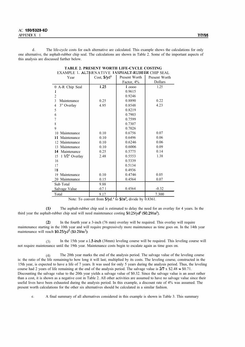
ACAPPENDIX 1
d. The life-cycle costs for each alternative are calculated. This example shows the calculations for only
one alternative, the asphalt-rubber chip seal. The calculations are shown in Table 2. Some of the important aspects of
this analysis are discussed further below.
TABLE 2. PRESENT WORTH LIFE-CYCLE COSTING
EXAMPLE
Year
RNATIVE
Cost,
CHIP SEAL
Present Worth
Dollars
1.25
Present Worth
Factor, 4%
.oooo
0.9615
0.9246
0.25 0.8890
4.95 0.8548
0.8219
0.7903
0.7599
0.7307
0.7026
0.10 0.6756
0.10 0.6496
0.10 0.6246
0.10 0.6006
0.25 0.5775
2.48 0.5553
0.5339
0.5134
0.4936
0.10 0.4746
0.15 0.4564
9.88
-0.7 1 0.4564
9.17
Note: To convert from to divide by 0.8361.
0 A-R Chip Seal
2
3 Maintenance
4 3” Overlay
5
6
7
8
9
10 Maintenance
Maintenance
12 Maintenance
13 Maintenance
Maintenance
15 1 Overlay
16
17
19 Maintenance
20 Maintenance
Sub Total
Salvage Value
Total
0.22
4.23
0.07
0.06
0.06
0.09
0.14
1.38
0.05
0.07
-0.32
7.300
The asphalt-rubber chip seal is estimated to delay the need for an overlay for 4 years. In the
third year the asphalt-rubber chip seal will need maintenance costing
In the fourth year a 3-inch (76 mm) overlay will be required. This overlay will require
maintenance starting in the 10th year and will require progressively more maintenance as time goes on. In the 14th year
maintenance will reach
(3) In the 15th year a (38mm) leveling course will be required. This leveling course will
not require maintenance until the 19th year. Maintenance costs begin to escalate again as time goes on.
(4) The 20th year marks the end of the analysis period. The salvage value of the leveling course
is: the ratio of the life remaining/to how long it will last; multiplied by its costs. The leveling course, constructed in the
15th year, is expected to have a life of 7 years. It was used for only 5 years during the analysis period. Thus, the leveling
course had 2 years of life remaining at the end of the analysis period. The salvage value is x $2.48 $0.71.
Discounting the salvage value to the 20th year yields a salvage value of $0.32. Since the salvage value is an asset rather
than a cost, it is shown as a negative cost in Table 2. All other activities are assumed to have no salvage value since their
useful lives have been exhausted during the analysis period. In this example, a discount rate of 4% was assumed. The
present worth calculations for the other six alternatives should be calculated in a similar fashion.
e. A final summary of all alternatives considered in this example is shown in Table 3. This summary
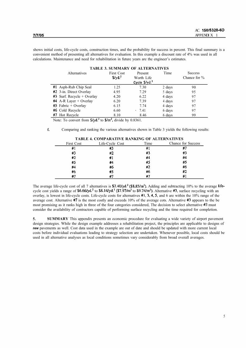
ACAPPENDIX 1
shows initial costs, life-cycle costs, construction times, and the probability for success in percent. This final summary is a
convenient method of presenting all alternatives for evaluation. In this example a discount rate of 4% was used in all
calculations. Maintenance and need for rehabilitation in future years are the engineer’s estimates.
TABLE 3. SUMMARY OF ALTERNATIVES
Alternatives First Cost Present Time
Worth Life
Cycle
Asph-Rub Chip Seal 1.25 7.30 2 days
3-in. Direct Overlay 4.95 7.29 5 days
Surf. Recycle + Overlay 4.20 6.22 4 daysA-R Layer + Overlay 6.20 7.39 4 days
Fabric + Overlay 6.15 7.74 4 days
Cold Recycle 6.60 7.41 6 days
Hot Recycle 8.10 8.46 6 days
Note: To convert from to divide by 0.8361.
Success
Chance for %
90
95
97
97
97
97
99
f. Comparing and ranking the various alternatives shown in Table 3 yields the following results:
TABLE 4. COMPARATIVE RANKING OF ALTERNATIVES
First Cost Life-Cycle Cost Time Chance for Success
The average life-cycle cost of all 7 alternatives is Adding and subtracting 10% to the average
cycle cost yields a range of to to Alternative surface recycling with an
overlay, is lowest in life-cycle costs. Life-cycle costs for alternatives and 6 are within the 10% range of the
average cost. Alternative is the most costly and exceeds 10% of the average cots. Alternative appears to the be
most promising as it ranks high in three of the four categories considered, The decision to select alternative must
consider the availability of contractors capable of performing surface recycling and the time required for completion.
5. SUMMARY This appendix presents an economic procedure for evaluating a wide variety of airport pavement
design strategies. While the design example addresses a rehabilitation project, the principles are applicable to designs of
new pavements as well. Cost data used in the example are out of date and should be updated with more current local
costs before individual evaluations leading to strategy selection are undertaken. Whenever possible, local costs should be
used in all alternative analyses as local conditions sometimes vary considerably from broad overall averages.
5
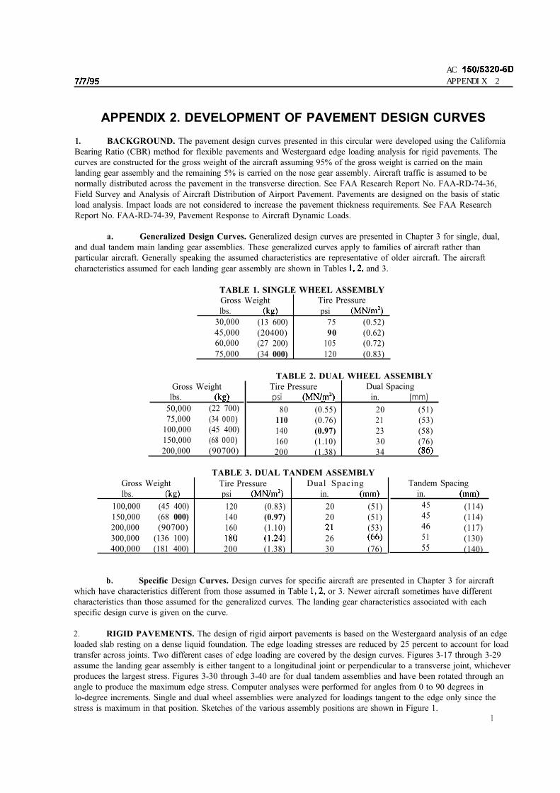
ACAPPENDIX 2
APPENDIX 2. DEVELOPMENT OF PAVEMENT DESIGN CURVES
1. BACKGROUND. The pavement design curves presented in this circular were developed using the California
Bearing Ratio (CBR) method for flexible pavements and Westergaard edge loading analysis for rigid pavements. The
curves are constructed for the gross weight of the aircraft assuming 95% of the gross weight is carried on the main
landing gear assembly and the remaining 5% is carried on the nose gear assembly. Aircraft traffic is assumed to be
normally distributed across the pavement in the transverse direction. See FAA Research Report No. FAA-RD-74-36,
Field Survey and Analysis of Aircraft Distribution of Airport Pavement. Pavements are designed on the basis of static
load analysis. Impact loads are not considered to increase the pavement thickness requirements. See FAA Research
Report No. FAA-RD-74-39, Pavement Response to Aircraft Dynamic Loads.
a. Generalized Design Curves. Generalized design curves are presented in Chapter 3 for single, dual,
and dual tandem main landing gear assemblies. These generalized curves apply to families of aircraft rather than
particular aircraft. Generally speaking the assumed characteristics are representative of older aircraft. The aircraft
characteristics assumed for each landing gear assembly are shown in Tables and 3.
TABLE 1. SINGLE WHEEL ASSEMBLY
Gross Weight Tire Pressure
lbs. psi
30,000 (13 600) 75 (0.52)
45,000 (20400) 90 (0.62)60,000 (27 200) 105 (0.72)
75,000 (34 000) 120 (0.83)
Gross Weight
lbs.
50,000 (22 700)
75,000 (34 000)100,000 (45 400)
150,000 (68 000)200,000 (90700)
TABLE 2. DUAL WHEEL ASSEMBLY
Tire Pressure Dual Spacing
psi in. (mm)
80 (0.55) 20 (51)
110 (0.76) 21 (53)
140 (0.97) 23 (58)
160 (1.10) 30 (76)
200 (1.38) 34
Gross Weight
lbs.
100,000 (45 400)
150,000 (68 000)
200,000 (90700)
300,000 (136 100)
400,000 (181 400)
TABLE 3. DUAL TANDEM ASSEMBLY
Tire Pressure Dual Spacing
psi in.
120 (0.83) 20 (51)
140 (0.97) 20 (51)
160 (1.10) (53)
26
200 (1.38) 30 (76)
Tandem Spacing
in.
45 (114)45 (114)46 (117)51 (130)55 (140)
b. Specific Design Curves. Design curves for specific aircraft are presented in Chapter 3 for aircraft
which have characteristics different from those assumed in Table or 3. Newer aircraft sometimes have different
characteristics than those assumed for the generalized curves. The landing gear characteristics associated with each
specific design curve is given on the curve.
2. RIGID PAVEMENTS. The design of rigid airport pavements is based on the Westergaard analysis of an edge
loaded slab resting on a dense liquid foundation. The edge loading stresses are reduced by 25 percent to account for load
transfer across joints. Two different cases of edge loading are covered by the design curves. Figures 3-17 through 3-29
assume the landing gear assembly is either tangent to a longitudinal joint or perpendicular to a transverse joint, whichever
produces the largest stress. Figures 3-30 through 3-40 are for dual tandem assemblies and have been rotated through an
angle to produce the maximum edge stress. Computer analyses were performed for angles from 0 to 90 degrees in
lo-degree increments. Single and dual wheel assemblies were analyzed for loadings tangent to the edge only since the
stress is maximum in that position. Sketches of the various assembly positions are shown in Figure 1.1
ACAPPENDIX 2
a. Load Repetitions. Fatigue effects are considered in the design process by increasing slab thickness for
increased numbers of load repetitions. Load repetitions are expressed in coverages. For rigid pavements, coverages equal
the number of times a pavement slab experiences a maximum stress application due to applied traffic. One coverage
occurs when each point in the pavement within the limits of the traffic lane has experienced a maximum stress, assuming
the stress is equal under the full tire print. The coverage concept provides a means of normalizing pavement performance
data which can consist of a variety of wheel sizes, spacings and loads for pavements of different cross sections. Each
pass (departure) of an aircraft can be converted to coverages using a single pass-to-coverage ratio which is developed
assuming a normal distribution and applying standard statistical techniques. The pass-to-coverage ratios used in
developing the rigid pavement design curves in Chapter 3 are given in Table 4. Annual departures are converted to
coverages assuming a 20-year design life. Coverages are determined by multiplying annual departures by 20 and
dividing that product by the pass-to-coverage ratio shown in Table 4.
TABLE 4. PASS-TO-COVERAGE
RATIOS FOR RIGID PAVEMENTS
Design Curve Pass-to-Coverage
Ratio
Single Wheel 5.18
Dual Wheel 3.48
Dual Tandem 3.68
A-300 Model B2 3.5 1
A-300 Model B4 3.45
B-747 3.70
B-757 3.88
B-767 3.90
c-130 4.15
DC 3.64
DC 3.38
L-101 I 3.62
b. Basic Thickness Calculation. Pavement thickness requirements for 5,000 coverages are computed for
various concrete strengths and moduli. Allowable concrete stress for 5,000 coverages is computed by dividing
the concrete strength by 1.3 (analogous to a safety factor). The thickness of pavement required to sustain 5,000
coverages of the design loading is considered to be 100 percent thickness.
C. Thickness Adjustment. The basic slab thicknesses are multiplied by the percent thickness shown in
Figure 2 for other coverage levels. accordance with the fatigue curve developed by the Corps of Engineers from test track
data and observation of in-service pavements. The fatigue relationship is applicable to the pavement structure; i.e., the
slab and foundation are both included in the relationship. Any coverage level could have been selected as the 100
percent thickness level as long as the relative thicknesses for other coverage levels shown in Figure 2 is maintained.

ACAPPENDIX 2
SLAB EDGE SLAB EDGE
S I N G L E W H E E L D U A L W H E E L
TANGENT TANGENT
SLAB EDGE
0
0D U A L T A N D E M O U A L T A N O E M
T A N G E N T P E R P E N D I C U L A R
SLAB EDG
SLAB EDGE
0 0
D U A L T A N D E M
ROTATED
FIGURE 1. ASSEMBLY POSITIONS FOR RIGID PAVEMENT ANALYSIS
3

AC
APPENDIX 2
0 0

ACAPPENDIX 2
3. FLEXIBLE PAVEMENTS. The design curves for flexible pavements in Chapter 3 of this circular are based
on the CBR method of design. The CBR is the ratio of the load required to produce a specified penetration of a standard
piston into the material in question to the load required to produce the same penetration in a standard well-graded,
crushed limestone. Pavement thicknesses necessary to protect various CBR values from shear failure have been
developed through test track studies and observations of in-service pavements. These thicknesses have been developed
for single wheel loadings. Assemblies other than single wheel are designed by computing the equivalent single wheel
load for the assembly based on deflection. Once the equivalent single wheel is established, the pavement section
thickness can be determined from the relationships discussed above.
a. Load Repetitions. Load repetitions are indicated on the design curves in terms of annual departures.
The annual departures are assumed to occur over a 20-year life. In the development of the design curves, departures are
converted to coverages. For flexible pavements, coverage is a measure of the number of maximum stress applications
that occur on the surface of the pavement due to the applied traffic. One coverage occurs when all points on the pavement
surface within the traffic lane have been subjected to one application of maximum stress, assuming the stress is equal
under the full tire print. Each pass (departure) of an aircraft can be converted to coverages using a single
pass-to-coverage ratio which is developed assuming a normal distribution and applying standard statistical techniques.
The pass-to-coverages ratios used in developing the flexible pavement design curves in Chapter 3 are given in Table 5.
Annual departures are converted to coverages by multiplying by 20 and dividing that product by the pass-to-coverage
ratios given in Table 5. Figure 3 shows the relationship between load repetition factor and coverages. The pavement
section thickness determined in accordance with paragraph a. above is multiplied by the appropriate load repetition
factor, Figure 3, to give the final pavement thickness required for various traffic levels.
TABLE 5.
PASS-TO-COVERAGE
RATIOS FOR FLEXIBLE
PAVEMENTS
Design Curve
Converge
Ratio
Single Wheel 5.18
Dual Wheel 3.48
Dual Tandem 1.84
A-300 Model B2 1.76
A-300 Model B4 1.73
B-747 1.85
B-757 1.94
B-767 1.95
c-130 2.07
DC 1.82
DC IO-30 1.69
L-101 1 1.81

ACAPPENDIX 2
W
COVERAGES
FIGURE 3. LOAD REPETITION FACTOR VS. COVERAGES

ACAPPENDIX 3
APPENDIX 3. DESIGN OF STRUCTURES FOR HEAVY AIRCRAFT--
1. BACKGROUND. Airport structures such as culverts and bridges are usually designed to last for the
foreseeable future of the airport. Information concerning the landing gear arrangement of future heavy aircraft is
speculative. It may be assumed with sufficient confidence that strengthening of pavements to accommodate future aircraft
can be performed without undue problems. Strengthening of structures, however, may prove to be extremely difficult,
costly, and time-consuming. Point loadings on some structures may be increased; while on overpasses, the entire aircraft
weight may be imposed on a deck span, pier, or footing.
2. RECOMMENDED DESIGN PARAMETERS.
a. Structural Considerations. For many structures the design is highly dependent upon the aircraft gear
configuration. Our assessment indicates that three basic configurations, shown in Figure 1, will, if all are considered in
the design of the bridge components, provide sufficient support for any aircraft which may be forthcoming. These consist
of two areas enclosing eight wheels each, or 16 wheels per aircraft comprising the main gear. Nose gears, as such, are
not considered, except as they occur in the static load. The “area” dimensions are 6 to 8 feet by 20 feet (2-3 m by 6 m)
each supporting half of the aircraft gross weight. Wheel prints are uniformly spaced within their respective areas.
b. Foundation Design. Foundation design will vary with soil type and depth. No departure from
accepted methodology is anticipated; except that for shallow structures, such as inlets and culverts, the concentrated loads
may require heavier and wider spread footings than those presently provided by the structural standards in current use.
For buried structures, such as culverts, the following guidance from AASHTO is recommended.
When the depth of fill is less than 2 feet the wheel loads shall be treated as concentrated loads.
When the depth of fill is 2 feet or more, wheel loads shall be considered as uniformly
distributed over a square with sides equal to times the depth of the fill. When such areas from several
concentrations overlap, the total load shall be uniformly distributed over the area defined by the outside limits of the
individual areas, but the total width of distribution shall not exceed the total width of the supporting slab.
C. Loads. It should be noted that all loads discussed herein are to be considered as dead load plus live
loads. The design of structures subject to direct wheel loads should also anticipate braking loads as high as 0.7 G (for
no-slip brakes).
d. Direct Loading. Decks and covers subject to direct heavy aircraft loadings such as manhole covers,
inlet grates, utility tunnel roofs, bridges, etc., should be designed for the following loadings:
pressure.
Manhole covers for 100,000 lb. (45 000 kg) wheel loads with 250 psi (1.72 tire
For spans of 2 feet (0.6 m) or less in the least direction, a uniform live load of 250 psi (1.72
(3) For spans of 2 feet (0.6 m) or greater in the least direction, the design shall be based on the
number of wheels which will fit the span. Wheel loads of 50,000 to 75,000 pounds (22 700 to 34 000 kg) should be
considered.
(4) Special consideration shall be given to structures that will be required to support both in-line
and diagonal traffic lanes, such as diagonal or apron taxi routes. If structures require expansion joints, load
transfer may not be possible.

AC
3
( N O T T O S C A L E )
T Y P E A
B I C Y C L E
T Y P E C
T R I C Y C L E
FIGURE 1. TYPICAL GEAR CONFIGURATIONS FOR DESIGN OF STRUCTURES
2

4/30/2004 AC 150/5320-6D Change 3
APPENDIX 4. RELATED READING MATERIAL
1. Electronic copies of the latest versions of the following FAA publications are available on the FAA website at http://www.faa.gov/. Printed copies can be requested from the Department of Transportation, Subsequent DistributionOffice, Ardmore East Business Center, 3341 Q 75th Ave, Landover, MD 20785. The Department of Transportation,however, will charge a fee for some of these documents. Advisory Circular 00-2, Advisory Circular Checklist, providesa list of all current ACs.
a. AC 00-2, Advisory Circular Checklist and Status of Other FAA Publications.
b. AC 150/5300-13, Airport Design.
c. AC 150/5320-5, Airport Drainage.
d. AC 150/5320-12, Measurement, Construction, and Maintenance of Skid Resistant Airport PavementSurfaces.
e. AC 150/5300-9, Predesign, Prebid, and Preconstruction Conferences for Airport Grant Projects.
f. AC 150/5335-5, Standardized Method of Reporting Airport Pavement Strength–PCN.
g. AC 150/5370-10, Standards for Specifying Construction of Airports.
h. AC 150/5370-11, Use of Nondestructive Testing Devices in the Evaluation of Airport Pavements.
i. AC 150/5380-6, Guidelines and Procedures for Maintenance of Airport Pavements.
2. Copies of the following reports can be obtained from the National Technical Information Service, 5285 PortRoyal Road, Springfield, VA 22161 or at http://www.ntis.gov/.
a. FAA-RD-73-169, Review of Soil Classification Systems Applicable to Airport Pavement Design,May 1974, by Yoder; AD-783-190.
b. FAA-RD-74-30, Design of Civil Airfield Pavement for Seasonal Frost and Permafrost Conditions,October 1974, by Berg; ADA-006-284.
c. FAA-RD-74-36, Field Survey and Analysis of Aircraft Distribution on Airport Pavements, February1975, by Ho Sang; ADA-011-488.
d. FAA-RD-76-66, Design and Construction of Airport Pavements on Expansive Soils, June 1976, byMcKeen; ADA-28-094.
e. FAA-RD-73-198-1, Design and Construction and Behavior Under Traffic of Pavement Test Sections,June 1974, by Burns, Rone, Brabston, Ulery; AD-785-024.
f. FAA-RD-74-33, III, Design Manual for Continuously Reinforced Concrete Pavements, May 1974, byTreybig, McCullough, Hudson; AD-780-512.
g. FAA-RD-75-110-II, Methodology for Determining, Isolating and Correcting Runway Roughness,June 1977, by Seeman and Nielsen; ADA-044-378.
h. FAA-RD-73-198-111, Design and Construction of MESL, December 1974, by Hammitt; AD-005-893.
i. FAA-RD-76-179, Structural Design of Pavements for Light Aircraft, December 1976, by Ladd,Parker, Pereira; ADA-04 l-300.
1

AC 150/5320-6D Change 3 4/30/2004
j. FAA-RD-74-39, Pavement Response to Aircraft Dynamic Loads, Volume II–Presentation andAnalysis of Data, 1974, by Ledbetter; ADA-022-806.
k. DOT/FAA/RD-74/199, Development of a Structural Design Procedure for Flexible AirportPavements, November 1974, by Barker and Brabston, ADA-019-205.
l. DOT/FAA/RD-77/81, Development of a Structural Design Procedure for Rigid Airport Pavements,April 1979, by Parker, Barker, Gunkel, and Odom, ADA-069-548.
m. FAA-RD-81-78, Economic Analysis of Airport Pavement Rehabilitation Alternatives, October 1981,by Epps and Wootan, ADA-112-550
n. DOT/FAA/PM-87/19, Design of Overlays for Rigid Airport Pavements, April 1988, by R. S.Rollings, ADA-194-331.
3. Copies of ASTM standards can be obtained from the ASTM International, 100 Barr Harbor Drive, P.O. BoxC700, West Conshohocken, PA 19428 or at http://www.astm.org/.
4. Copies of AASHTO standards can be obtained from the American Association of State Highway and
Transportation Officials, 444 North Capitol Street NW, Suite 249, Washington, DC 20001 or at
http://www.transportation.org/aashto/home.nsf/FrontPage/.
5. Copies of UFC 3-260-02, Pavement Design for Airfields, Department of the Army, Unified Facility Criteria (UFC), June, 2001 can be obtained from http://65.204.17.188//report/doc_ufc.html
The Unified Facility Criteria supersedes the following technical manuals previously noted in this AC:TM5-824-2, Flexible Airfield Pavements, Department of the Army Technical ManualTM5-824-3, Rigid Pavements for Airfields Other than Army, Departments of the Army and the Air Force,TM5-818-2, Pavement Design for Frost Conditions, Department of the Army
6. Copies of MS-11, Full Depth Asphalt Pavements for Air Carrier Airports, January 1973; IS-154, Full DepthAsphalt Pavements for General Aviation, January 1973; and MS-10, Soils Manual, Fourth Edition (1986), can beobtained from the Asphalt Institute, Research Park Drive, PO Box 14052, Lexington, KY 40512 or at http://www.asphaltinstitute.org/.
7. Copies of Special Technical Publication M-5, The Estimation of Concrete Flexural Strength from Other Typesof Strength Tests, DATE, by W. Charles Greer, can be obtained from MACTEC Inc., Director of Publications, 1105Sanctuary Parkway, Suite 300 Alpharetta, Georgia. 30004.
8. Copies of FHWA-HI-90-001, Geotextile Design and Construction Guidelines, October 1989, can be obtainedfrom the Department of Transportation, Federal Highway Administration, Turner Fairbanks Highway Research Center,6300 Georgetown Pike, McLean, VA 22101.
2

4/30/2004 AC 150/5320-6D Change 3
APPENDIX 5. AIRFIELD PAVEMENT DESIGN SOFTWARE
1. BACKGROUND. This appendix announces software to aid with the design of airfield pavements inaccordance with the methods presented in Chapters 3 and 4 of this AC. The software presented in this appendix uses
Microsoft Excel as a platform with Visual Basic for Applications (VBA) Macros to facilitate the design process.
2. AVAILABLE SOFTWARE AND SUPPORT MATERIAL. Two programs (spreadsheets) are available to determine pavement thickness requirements in accordance with this AC. Program F805FAA.XLS determinespavement thickness requirements for flexible pavement sections and bituminous overlays on existing flexible pavementsections. Program R805FAA.XLS determines pavement thickness requirements for rigid pavement sections andbituminous or Portland cement concrete overlays on existing rigid or flexible pavement sections.
Reference manuals, which guide users through each step, are available for both programs. The manuals assume usersare familiar with the design requirements of the AC.
Pavement designs developed using the Frost Design feature of the spreadsheets are consistent with the ReducedSubgrade Strength method described in Chapter 3.
The spreadsheets will produce thickness designs consistent with the nomographs provided in this AC. Small variationsshould be expected due to difficulties with visual interpretation of the nomographs.
3. ACCESS TO SOFTWARE. Design software and user manuals may be downloaded directly from the FAAOffice of Airport Safety and Standards website (http://www.faa.gov/arp/). Software links are located on the"resources" and "engineering" pages of this site. Updates or additions to the design software and manuals will be postedonline, as well.
4. USE OF SOFTWARE. Numerical results from the programs may be used to complete FAA Form 5100-1,Airport Pavement Design. When used to develop the pavement design, the printed results of the software should beattached to Form 5100-1. Results from the program design summary and the aircraft mixture data provide sufficientinformation to reproduce and review the pavement thickness design. Additional design information is required tocomplete Form 5100-1.
1
![2-[Eva Fedi]-Formazione “Aree Comuni” Operatori Sportivi [Eva Fedi]](https://static.fdokumen.com/doc/165x107/63209e83c5de3ed8a70dcef1/2-eva-fedi-formazione-aree-comuni-operatori-sportivi-eva-fedi.jpg)