Reviews Encapsulation of Exenatide in Poly-(D,L-Lactide-Co ...
Upload
khangminh22Category
view
1download
0
doi:10.3993/tbis2010094 www.tbisociety.org
Electrospun Poly(lactide-co-glycolide)/Nanotube Composite Nanofibers
for Drug Encapsulation and Sustained Release
Rui-Ling Qi1,2
, Jian-Yong Yu1,3
, Xiang-Yang Shi1,4*
1Key Laboratory of Textile Science & Technology, Ministry of Education
2College of Textiles
3Modern Textile Institute
4College of Chemistry, Chemical Engineering and Biotechnology, Donghua University, Shanghai 201620, China
* Corresponding author’s email: [email protected]
Abstract: In this report, we present a novel electrospun composite nanofiber-based drug delivery system. In
this system, nanotubular materials halloysite nanotubes (HNTs) were first used to encapsulate a model drug,
tetracycline hydrochloride (TCH). Then, the drug-loaded nanotubes with an optimized drug encapsulation
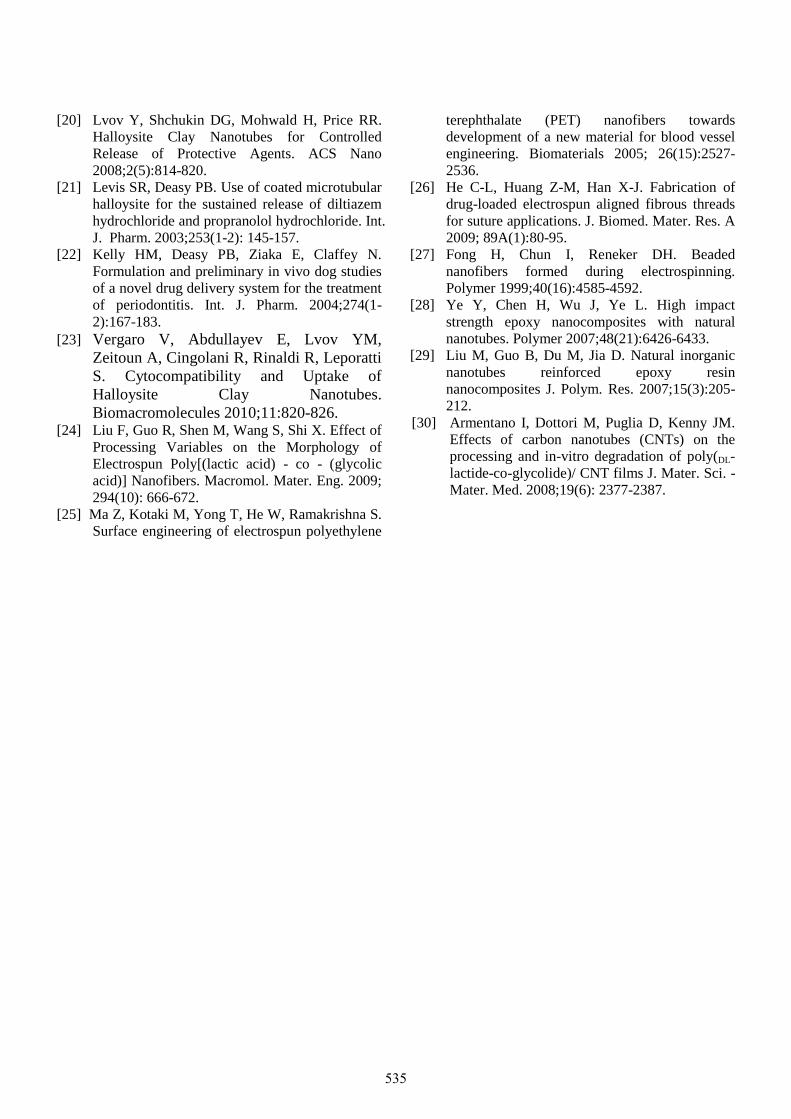
percentage were mixed with poly (lactide-co-glycolide) (PLGA) polymer solution for subsequent
electrospinning to form drug-loaded composite nanofibrous mats. The structure, morphology, and
mechanical properties of the formed electrospun composite nanofibrous mats were characterized using
scanning electron microscopy (SEM), Fourier transform infrared (FTIR) spectroscopy, and tensile testing. In
vitro drug release behavior was examined using UV-vis spectroscopy. We show that the incorporation of
HNTs within the nanofibrous mats does not significantly change the morphology of the mats. In addition,
our results indicate that this double-container drug delivery system (both PLGA polymer and HNTs are drug
carriers) is beneficial to avoid the burst release of the drug and the introduction of HNTs can improve the
tensile strength of the polymer nanofibrous mats. The drug loaded elctrospinning composite nanofibrous
mats developed in this study may find various applications in tissue engineering and pharmaceutical
sciences.
Keywords: poly(lactide-co-glycolide); halloysite nanotubes; tetracycline hydrochloride; composite
nanofibers; drug delivery system.
1. Introduction
In recent years, a tremendous progress in the
research of tissue engineering and drug delivery has
been witnessed due to their unlimited potential to
improve human health. Meanwhile, the development of
electrospinning nanotechnology provides opportunities
for fabricating fibers with a diameter from nanometer
to a few micrometers [1-3]. This special dimension
endows electrospun fibers with a large specific surface
area and a porous structure. Therefore, the electrospun
scaffold has the priority to closely mimic the natural
extracellular matrix (ECM) [4].
Beyond the widespread applications in tissue
engineering, electrospun nanofibers can also be used as
a drug delivery system. Since Kenawy et al. first
examined the drug release properties from electrospun
fibrous mats [5], drug delivery systems based on
nanofibers have attracted an increasing interest in the
pharmaceutical field. The controlled drug delivery
systems are used to improve therapeutic efficacy and
safety of drugs by delivering them at a rate dictated by
the need of the physiological environment over a
period treatment to the site of action [6]. By using
various electrospinning techniques such as
conventional, coaxial, and emulsion electrospinning, a
number of different drug-loading methods have been
developed. For example, drugs can be coated
onto/within the nanofibers through exposure of the
nanofibers into drug solutions [7,8], embedded within
the nanofibers through electrospinning the mixture
solution of the polymers and drugs [9,10], or
encapsulated within the nanofibers by coaxial [11,12]
and emulsion electrospinning [13,14]. However, the
methods of coating/embedding drugs onto or within
nanofibers generally exhibit apparent initial burst
release. The coaxial and emulsion electrospinning
approaches allow the formation of core-shell
nanofibers which may effectively eliminate the initial
burst release and achieve sustained release profiles.
Nevertheless, it has been difficult to optimize the
coaxial electrospinning conditions. In addition, the
emulsifier used in emulsion electrospinning is difficult
to remove and may induce biocompatibility issues for
528
the formed fibers. Development of a new composite
nanofiber system allowing for effective loading and
sustained release of drugs still remains a great
challenge.
Nanotubular structured materials have attracted
much attention in the development of drug delivery
vehicles with sustained release properties [15-18].
Halloysite (Al2 Si2 O5 (OH)4. nH2O) is a double-
layered aluminosilicate with a chemical structure
similar to kaolin. However, morphologically, it has a
hollow tubular structure, which is very different from
the stacked-plate structure possessed by kaolin [19].
Halloysite is a cheap natural material with a large
amount of production [20]. Potential applications of
halloysite nanotubes (HNTs) as a drug delivery vehicle
were previously reported in literature [20-22], and the
drug release rate could be retarded by coating polymers
onto the drug-loaded HNTs. Likewise, HNTs are
reported to be biocompatible [23]. This suggests that
halloysite is a promising drug container. In general, the
drug-loaded HNTs is presenting as a formulation of
powders or suspensions, which may limit its
application in the development of drug-loading devices.
It is expected that by combination of the drug loading
capability of halloysite and eletrospinning technique, a
new drug delivery system with sustained release could
be developed for various applications in tissue
engineering and pharmaceutical sciences.
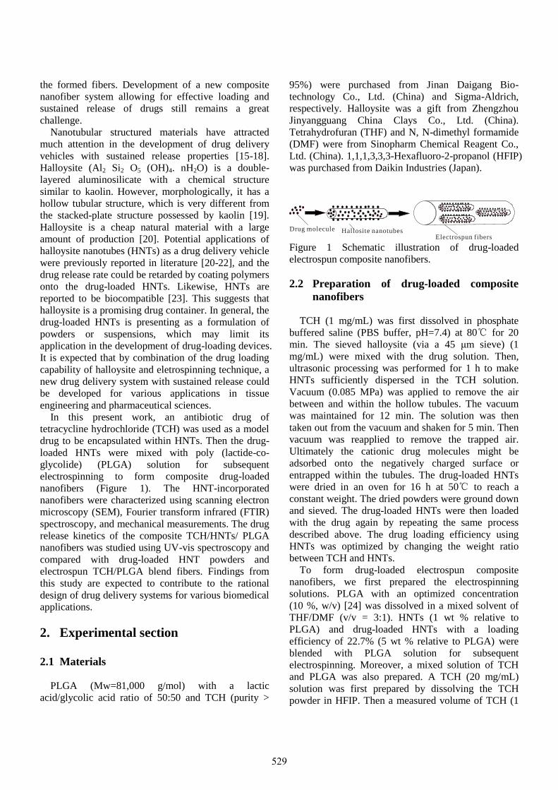
In this present work, an antibiotic drug of
tetracycline hydrochloride (TCH) was used as a model
drug to be encapsulated within HNTs. Then the drug-
loaded HNTs were mixed with poly (lactide-co-
glycolide) (PLGA) solution for subsequent
electrospinning to form composite drug-loaded
nanofibers (Figure 1). The HNT-incorporated
nanofibers were characterized using scanning electron
microscopy (SEM), Fourier transform infrared (FTIR)
spectroscopy, and mechanical measurements. The drug
release kinetics of the composite TCH/HNTs/ PLGA
nanofibers was studied using UV-vis spectroscopy and
compared with drug-loaded HNT powders and
electrospun TCH/PLGA blend fibers. Findings from
this study are expected to contribute to the rational
design of drug delivery systems for various biomedical
applications.
2. Experimental section
2.1 Materials
PLGA (Mw=81,000 g/mol) with a lactic
acid/glycolic acid ratio of 50:50 and TCH (purity >
95%) were purchased from Jinan Daigang Bio-
technology Co., Ltd. (China) and Sigma-Aldrich,
respectively. Halloysite was a gift from Zhengzhou
Jinyangguang China Clays Co., Ltd. (China).
Tetrahydrofuran (THF) and N, N-dimethyl formamide
(DMF) were from Sinopharm Chemical Reagent Co.,
Ltd. (China). 1,1,1,3,3,3-Hexafluoro-2-propanol (HFIP)
was purchased from Daikin Industries (Japan).
Drug molecule Hallosite nanotubesElectrospun fibers
Figure 1 Schematic illustration of drug-loaded
electrospun composite nanofibers.
2.2 Preparation of drug-loaded composite
nanofibers
TCH (1 mg/mL) was first dissolved in phosphate
buffered saline (PBS buffer, pH=7.4) at 80℃ for 20
min. The sieved halloysite (via a 45 μm sieve) (1
mg/mL) were mixed with the drug solution. Then,
ultrasonic processing was performed for 1 h to make
HNTs sufficiently dispersed in the TCH solution.
Vacuum (0.085 MPa) was applied to remove the air
between and within the hollow tubules. The vacuum
was maintained for 12 min. The solution was then
taken out from the vacuum and shaken for 5 min. Then
vacuum was reapplied to remove the trapped air.
Ultimately the cationic drug molecules might be
adsorbed onto the negatively charged surface or
entrapped within the tubules. The drug-loaded HNTs
were dried in an oven for 16 h at 50℃ to reach a
constant weight. The dried powders were ground down
and sieved. The drug-loaded HNTs were then loaded
with the drug again by repeating the same process
described above. The drug loading efficiency using
HNTs was optimized by changing the weight ratio
between TCH and HNTs. To form drug-loaded electrospun composite
nanofibers, we first prepared the electrospinning
solutions. PLGA with an optimized concentration
(10 %, w/v) [24] was dissolved in a mixed solvent of
THF/DMF (v/v = 3:1). HNTs (1 wt % relative to
PLGA) and drug-loaded HNTs with a loading
efficiency of 22.7% (5 wt % relative to PLGA) were
blended with PLGA solution for subsequent
electrospinning. Moreover, a mixed solution of TCH
and PLGA was also prepared. A TCH (20 mg/mL)
solution was first prepared by dissolving the TCH
powder in HFIP. Then a measured volume of TCH (1
529

wt % relative to PLGA) solution was added into PLGA
solution with continuous stirring for 1 h until a clear
and homogeneous solution was obtained.
The electrospinning system used in this study is
similar to that used in our previous work [24]. The
electrospinning process was carried out under ambient
conditions. A fixed electrical potential of 20 kV was
employed to charge the steel capillary. The distance
between the tip of the needle and the collector was set
at 15 cm. The electrospinning solution was fed at a
speed of 1.0 mL/h by a syringe pump. Under these
conditions, the electrospun PLGA fibers, HNTs/PLGA
fibers, TCH/HNTs/PLGA composite fibers, and
TCH/PLGA blend fibers were fabricated. Note that the
percentage of HNTs, TCH/HNTs, and TCH relative to
PLGA in the above 3 cases were 1%, 5%, and 1%,
respectively. The PLGA concentration used for
fabricating all nanofibers was fixed at 10 wt%. The
formed fibrous mats were dried for at least 2 days in
vacuum oven at ambient temperature to remove the
residual organic solvent and moisture.
2.3 Characterizations
Morphologies of the composite nanofibers were
observed under scanning electron microscopy (SEM,
JEOL JSM-5600LV, Japan) and field emission
scanning electron microscopy (EFSEM, HITACHI S-
4800, Japan), respectively. Both of the accelerating
voltage was set at 15 kV. Before SEM observations,
the samples were sputter-coated with gold films with a
thickness of 10 nm, whereas the samples for EFSEM
measurements were sputter-coated with carbon films
with a thickness of 10 nm. The hollow tubular structure
of HNTs was characterized using transmission electron
microscopy (TEM, JZM-2100, Japan) at an operating
voltage of 200 kV and EFSEM. An aqueous
suspension of HNTs (5 μL) was dropped onto carbon-
coated copper grid before TEM measurements. The
diameters of the electrospun fibers and the dimensions
of the HNTs were measured using Image J software
(National Institutes of Health, USA). At least 200
nanofibers or HNTs at different images were analyzed
for each sample. Attenuated total reflection-Fourier
transform infrared spectroscopy (ATR-FTIR) was
performed using a Nicolet Nexus670 FTIR
spectrometer in a spectral range from 500 to 4000 cm-
1. The raw PLGA sample was made by using a film-
casting technique. The eletrospun composite
nanofibrous mats and the raw PLGA film were cut into
a round piece with a diameter of 20 mm and then put
onto the sample holder before measurements. Zeta
potential measurements were performed using a
Zetasizer Nano ZS (Malvern, U.K.) equipped with a
standard 633 nm laser. Dilute HNT suspensions (0.1
mg/mL) in aqueous solution containing 1 mM KCl was
first prepared. The pH value of the solution was
adjusted using 0.1 M HCl or 0.1 M NaOH.
The thickness of the electrospun nanofibrous mats
was measured with a micrometer. In order to
accurately calculate the porosity, five small strips
(10×50 mm2) were cut from the center of the
electrospun fibrous mats. The apparent density (ρa)
and porosity (p) were obtained from the following
equations [25]:
)()(
)()/(
2
3
cmscmd
gmcmga
(1)
%100)/(
)/(1
3
3
cmg
cmgp
b
a
(2)
Where m, d, and s stand for mass, thickness, and area
of the strips, respectively. The bulk density (ρb) of
PLGA is 1.25g/cm3.
Tensile test of the electrospun fibrous mats were
performed by a material testing machine (H5K-S,
Hounsfield, UK) at constant temperature (20℃) and
humidity (63%) with a cross-head speed of 10 mm/min.
The five strips of the samples (10×50mm2) were tested.
From the machine-recorded data, stress-strain (δ-ε)
curves of the specimens can be obtained through
mathematical conversions:
)()(10
)()(
mmdmm
NPMPa
(3)
%1000
l
l (4)
Where σ, ε, P, l, and l0 is the stress, strain, load,
extended length, and gauge length, respectively.
Breaking strength, failure strain, and Young’s modulus
were obtained from the strain-stress curves.
2.4 In vitro drug release
To test the drug release from the HNTs, TCH/HNTs
powder was weighed out and dispersed into 5 mL
phosphate buffer saline (PBS, pH=7.4). Then the
dispersed solution was loaded into a dialysis bag and
dialyzed against 55 mL PBS buffer. The experiment
was done in triplicate. For electrospun nanofiber
samples, the TCH/PLGA and TCH/HNTs/PLGA
composite nanofibrous mats were both cut into three
pieces and their weights were accurately measured.
The samples were then placed in different vials
530

containing 12 mL of PBS buffer. All the samples for
release experiments were incubated in a vapor-bathing
constant temperature vibrator at 37℃ for a period of
30 days. At selected time intervals, a 3-mL solution
was taken out from the vials and equal volume of fresh
PBS buffer was replenished to them. The release
kinetics of TCH was evaluated using an UV-vis
spectrophotometer (PerkinElmer Lambda 25, USA).
The characteristic absorption peak of 270 nm for TCH
was monitored.
3. Results and discussion
3.1 Loading of drug within HNTs
The HNTs used in this study were all sieved and had
a uniform tubular structure. SEM and TEM were
utilized to characterize the morphology of the HNTs
(Figure 2). Relative uniform rod-like structure of
HNTs was demonstrated by SEM images (Figure 2a).
Some occasional double nanotubular (tube-in-tube)
structures are also shown (Figure 2a, marked with a
letter “A”). TEM images further verified the existence
of the hollow interior of the HNTs (Figure 2b). The
measured outer and lumen diameters were estimated to
be 75.8 ± 17.5 nm and 17.2 ± 4.6 nm, respectively, and
the average length of HNTs was estimated to be 445 ±
256 nm.
The surface potential of the HNTs was tested over a
wide range of pH (pH 1.5-12.5). We showed that
HNTs were negatively charged (-16 ~ -48 mV) at the
studied pH range. The zeta potential values at different
pH conditions are all lower than those reported in
literature [19]. This could be ascribed to the larger
specific surface area of our HNTs having a smaller
diameter. The negative charged HNTs could allow the
electrostatic attraction of the cationic drug TCH,
leading to adsorption of TCH onto the surface and
inside the lumen of halloysite when vacuum was
applied.
The drug loading efficiency of halloysite was
optimized by changing the weight ratio between TCH
and HNTs. We found that the maximum loading
efficiency could be achieved at the ratio of 1:1. The
single loading of halloysite reached an encapsulation
efficiency of 23.9%, while the double loading process
could reach up to 37% when the total amount of HNTs
and TCH was relatively low (e.g., 3 mg for both HNTs
and TCH). However, when a relatively large amount of
HNTs and TCH were used (e.g., 100 mg), the double
loading efficiency decreased to 22.7%. This could be
attributable to the fast deposition and aggregation of
the halloysite when vacuum was applied, leading to the
existence of relatively more gas in the aggregation and
thus less drug loading. The drug-loaded samples used
in this study had an encapsulation efficiency of 22.7%.
(b)
(a)
A
(b)
Figure 2 SEM (a) and TEM (b) micrograph of
halloysite nanotubes.
3.2 Characterization of electrospun composite
nanofibrous mats
The electrospun PLGA fibers, HNTs/PLGA
composite fibers, TCH/PLGA blend fibers were
fabricated and characterized using SEM (Figure 3). It
is clear that the diameter of HNTs/PLGA fibers (Figure
3e) is close to that of pure PLGA fibers (Figure 3d).
The morphology of the PLGA fibers does not
significantly change after the incorporation of HNTs
(Figure 3a,b). However, the diameter of the
TCH/PLGA blend fibers (Figure 3c) became much
smaller when compared to that of pure PLGA
nanofibers. It is generally known that the properties of
an electrospinning solution could be significantly
affected by an addition of a cationic species. The
addition of the cationic TCH drug into the
electrospinning solution results in an increase of the
surface charge density of the spinning jet [26], which is
beneficial for the formation of fibers with a smaller
diameter [27].
531

20μm15kV ×1,000
20μm15kV ×1,000
(e)
(d)
(f)
20μm15kV ×1,000
(c)
(b)
(a)
400 600 800 1000 1200 1400 16000
5
10
15
20
25
Fre
qu
ency
(%)
Fiber Diameter(nm)
Average diameter = 842 nm
σ = 200 nm
400 600 800 1000 1200 14000
2
4
6
8
10
12
14
16
18Average diameter = 798 nm
σ = 215 nm
Fre
qu
ency
(%)
Fiber Diameter (nm)
200 300 400 500 6000
5
10
15
20
25
30
35
40
Average diameter = 298 nmσ= 69 nm
Fre
qu
ency
(%)
Fiber Diameter (nm) Figure 3 SEM micrographs of the electrospun (a)
PLGA fibers, (b) HNTs/PLGA composite fibers, and
(c) TCH/PLGA blend fibers. (d), (e), and (f) shows the
diameter distribution histogram of the PLGA,
HNTs/PLGA, and TCH/PLGA fibers, respectively.
3.3 Porosity and tensile properties
Porosity and tensile properties are important
parameters for the application of the electrospun fibers.
These porous electrospun fibrous mats can mimic
nature extracellular matrix (ECM) for cell attachment,
proliferation, and differentiation and can be helpful for
drug delivery from the fibers. Likewise, the fibrous
mats with a high tensile strength should be required in
order for them to be used in practical applications.
The porosities of PLGA and HNTs/PLGA are listed
in Table 1. The addition of a small quantity of HNTs (1
wt%, relative to PLGA) does not significantly change
the porosity of the mats. However, the mechanical
properties of the PLGA fibrous mat were significantly
improved. The representative strain-stress curves of the
electrospun fibrous mats of PLGA and HNTs/PLGA
are shown in Figure 4, and the mechanical parameters
are listed in Table 2. Compared with PLGA fibrous
mats, the breaking strength, Young’s modulus, and
failure strain significantly increased with the addition
of only a small amount of HNTs (1 wt %), in
agreement with literature data [28,29]. The
enhancement of the mechanical property of the
composite HNTs/PLGA nanofibrous mats should be
ascribed to the alignment of HNTs in parallel to the
PLGA fibers (Figure 3b). Therefore, the load can be
efficiently transferred from the PLGA matrix to the
HNTs.
0 20 40 60 80 100 1200
1
2
3
4
5
6
7
8
Str
ess(
MP
a)
Strain(%)
(a) PLGA(b) HNTs/PLGA
a
b
Figure 4 Strain-stress curves of electrospun (a) PLGA
and (b) HNTs /PLGA nanofibrous mats.
3.4 ATR-FTIR analysis
4000 3500 3000 2500 2000 1500 1000
Wavenumber cm-1
2950
1754
1673
1452
14231389
11671132
1090
2997
a
b
c
d
Figure 5 ATR-FTIR spectra of PLGA casting film (a)
and electrospun (b) PLGA, (c) HNTs/PLGA, (d)
TCH/PLGA nanofibrous mats.
FTIR spectroscopy was used to further characterize
the composite nanofibrous mats (Figure 5). It is clear
that the FTIR spectra of all electrospun mats are very
similar to that of the PLGA casting film, even if HNTs
or TCH were incorporated into the fibers. The peaks at
around 2997 and 2950 cm-1
were attributed to aliphatic
C-H stretching vibrations. Meanwhile, the strong peak
at 1754 cm-1
was related to the absorption by an ester
carbonyl (C=O) stretch from PLGA. The copolymer
PLGA also had characteristic peaks at 1452 cm-1
532

(methyl group C-H stretching), two peaks at 1423 and
1389 cm-1
(wagging vibrations from saturated C-H
bonds), and C-O peaks at 1271, 1167, 1132, 1090 and
1052 cm-1
[24,30]. The peak at 1673 cm-1
for PLGA
casting film (Figure 5, curve a) may be caused by the
C=O stretching vibration from amide bands of the
residual solvent DMF. However, this peak was not
prominent in the spectra of all electrospun nanofibers.
This should be due to the large surface area of the
nanofiber structures, allowing easy evaporation of the
solvent.
Table 1 Apparent density and porosity of electrospun PLGA and HNTs /PLGA nanofibrous mats. Data are
representative of independent experiments and all data are given as means±SD (n=5).
Sample Apparent density (g/cm3) Porosity (%)
PLGA 0.307 ± 0.007 75.48 ± 0.56
HNTs/PLGA 0.316 ± 0.019 74.75 ± 1.49
Table 2 Tensile properties of electrospun PLGA and HNTs/PLGA nanofibrous mats under the same processing
conditions. Data are representative of independent experiments and all data are given as means±SD (n=5).
Sample Breaking Strength
(MPa)
Failure Strain (%) Young’s Modulus
(MPa)
PLGA 4.21 ±0.35 76.15 ± 8.38 118.8 ± 10.5
HNTs/PLGA 6.61 ±1.66 93.6 ± 21.0 141.8 ± 6.7
3.5 Release properties of drug-loaded composite
nanofibrous mats
The release profiles of TCH from TCH/HNTs
powders, electrospun TCH/PLGA and TCH/HNTs/
PLGA nanofibrous mats are shown in Figure 6. TCH
embedded in the PLGA nanofibers formed by
electrospinning the mixture solution of PLGA and
TCH exhibited an obvious initial burst release. Within
the first 24 h, 83.8 % of the drug was released. The
drug release reached to a plateau after 48 h. While both
drug-loaded TCH/HNTs powders and
TCH/HNTs/PLGA fibrous mats had a sustained release
within a month, with only 36 % and 32 % of TCH
released after 28 days, respectively. The release of
TCH from TCH/HNTs powders is slower than that
reported by Kelly et al [22]. In their work, they showed
that 88 % of TCH was released at day 9. The slower
release of TCH from HNTs in our study could be due
to the fact that the specific surface area of HNTs used
in our study is much larger than that they used [19].
The HNTs they used had typical dimensions of 2-3 μm
length and 0.3/0.1 μm outer/inner diameter, which are
much bigger than those used in our current study. The
TCH/HNTs powders encapsulated within the PLGA
nanofibers further slowed down the release of TCH.
This suggests that the PLGA nanofibers can be used to
hinder the release of TCH from the HNTs to the
solution. More importantly, after incorporated within
the nanofibrous mats, the TCH/HNTs could be
formulated as a drug-containing scaffolding material
for both tissue engineering and sustained drug delivery.
0 5 10 15 20 25 300
20
40
60
80
100
%A
ccum
ula
ted
TC
HR
elea
se
Time (days)
(a) TCH/HNTs(b) TCH/PLGA(c) TCH/HNTs/PLGA
ac
b
Figure 6 In vitro release of TCH from (a) drug loaded
TCH/HNTs powders and electrospun (b) TCH/PLGA
and (c) TCH/HNTs/PLGA nanofibrous mats. The
samples were incubated in PBS buffer (pH=7.4) at
37℃.
4. Conclusion
In summary, we have successfully fabricated
electrospun HNT-containing composite polymer
nanofibers for efficient drug loading and sustained
release. The incorporation of drug-loaded HNTs not
only significantly improved the mechanical properties
of the fibrous mats, but also prolonged the release rate
of the drug, appreciably eliminating the initial burst
release characteristics. We show that the addition of
HNTs does not change the uniformity of the
533

electrospun PLGA nanofibers. The prolonged release
profile achieved using the double encapsulation of
drugs within HNTs and PLGA could be extended for
encapsulation and release of other drugs. With the
excellent biocompatibility of HNTs and PLGA
polymers, the developed system should be amendable
for the applications in tissue engineering and
pharmaceutical sciences.
Acknowledgements
This research is financially supported by Key
Laboratory of Textile Science & Technology, Ministry
of Education, “111 Project”, B07024, the Program for
Professor of Special Appointment (Eastern Scholar) at
Shanghai Institutions of Higher Learning, and the
National Basic Research Program of China (973
Program, 2007CB936000).
References:
[1] Reneker DH, Chun I. Nanometre diameter fibres
of polymer, produced by electrospinning.
Nanotechnology 1996;7:216-223.
[2] Huang Z-M, Zhang YZ, Kotaki M, Ramakrishna
S. A review on polymer nanofibers by
electrospinning and their applications in
nanocomposites. Compos. Sci. Technol.
2003;63(15):2223-2253.
[3] Andreas G, Joachim HW. Electrospinning: A
Fascinating Method for the Preparation of
Ultrathin Fibers. Angew. Chem. Int. Edit. 2007;
46(30):5670- 5703.
[4] Li W-J, Laurencin CT, Caterson EJ, Tuan RS,
Ko FK. Electrospun nanofibrous structure: A
novel scaffold for tissue engineering. J. Biomed.
Mater. Res. 2002; 60(4):613-621.
[5] Kenawy E-R, Bowlin GL, Mansfield K, Layman
J, Simpson DG, Sanders EH, Wnek GE. Release
of tetracycline hydrochloride from electrospun
poly (ethylene-co-vinylacetate), poly(lactic acid),
and a blend. J. Control. Release 2002;81(1-
2):57-64.
[6] Wise DL, Klibanov AM, Langer R, Mikos AG,
Peppas NA, Trantolo DJ, Wnek GE, Yaszemski
MJ. Handbook of Pharmaceutical Controlled
Release Technolofy. Marcel Dekker, editor. New
York, 2000.
[7] Bolgen N, Vargel I, Korkusuz P, Menceloglu YZ,
Piskin E. In vivo performance of antibiotic
embedded electrospun PCL membranes for
prevention of abdominal adhesions. J. Biomed.
Mater. Res. B 2007; 81B(2):530-543.
[8] Nie H, Wang C-H. Fabrication and
characterization of PLGA/HAp composite
scaffolds for delivery of BMP-2 plasmid DNA. J.
Control. Release 2007;120 (1-2):111-121.
[9] Kim K, Luu YK, Chang C, Fang D, Hsiao BS,
Chu B, Hadjiargyrou M. Incorporation and
controlled release of a hydrophilic antibiotic
using poly(lactide-co-glycolide)-based electro-
spun nanofibrous scaffolds. J. Control. Release
2004;98(1):47-56.
[10] Liang D, Luu YK, Kim K, Hsiao BS,
Hadjiargyrou M, Chu B. In vitro non-viral gene
delivery with nanofibrous scaffolds. Nucl. Acids
Res. 2005;33(19): 1-8.
[11] Zhang YZ, Wang X, Feng Y, Li J, Lim CT,
Ramakrishna S. Coaxial Electrospinning of
(Fluorescein Isothiocyanate-Conjugated Bovine
Serum Albumin)-Encapsulated Poly(ε-
caprolactone) Nanofibers for Sustained Release.
Biomacromolecules 2006;7(4):1049-1057.
[12] Jiang H, Hu Y, Li Y, Zhao P, Zhu K, Chen W. A
facile technique to prepare biodegradable coaxial
electrospun nanofibers for controlled release of
bioactive agents. J. Control. Release
2005;108(2-3): 237-243.
[13] Xu X, Yang L, Wang X, Chen X, Liang Q,
Zeng J, Jing X. Ultrafine medicated fibers
electrospun from W/O emulsions. J. Control.
Release 2005;108(1): 33-42.
[14] Qi H, Hu P, Xu J, Wang A. Encapsulation of
Drug Reservoirs in Fibers by Emulsion
Electrospinning: Morphology Characterization
and Preliminary Release Assessment.
Biomacromolecules 2006;7(8): 2327-2330.
[15] Bianco A, Kostarelos K, Prato M. Applications
of carbon nanotubes in drug delivery. Curr. Opin.
Chem. Biol. 2005;9(6):674-679.
[16] Kam NWS, Dai H. Carbon Nanotubes as
Intracellular Protein Transporters:Generality and
Biological Functionality. J. Am. Chem. Soc.
2005;127(16):6021- 6026.
[17] Liu Z, Sun X, Nakayama-Ratchford N, Dai H.
Supramolecular Chemistry on Water-Soluble
Carbon Nanotubes for Drug Loading and
Delivery. ACS Nano 2007;1(1):50-56.
[18] Feazell RP, Nakayama-Ratchford N, Dai H,
Lippard SJ. Soluble Single-Walled Carbon
Nanotubes as Longboat Delivery Systems for
Platinum(IV) Anticancer Drug Design. J Am.
Chem. Soc. 2007; 129(27):8438-8439.
[19] Levis SR, Deasy PB. Characterisation of
halloysite for use as a microtubular drug delivery
system. Int. J. Pharm. 2002;243(1-2): 125-134.
534
[20] Lvov Y, Shchukin DG, Mohwald H, Price RR.
Halloysite Clay Nanotubes for Controlled
Release of Protective Agents. ACS Nano
2008;2(5):814-820.
[21] Levis SR, Deasy PB. Use of coated microtubular
halloysite for the sustained release of diltiazem
hydrochloride and propranolol hydrochloride. Int.
J. Pharm. 2003;253(1-2): 145-157.
[22] Kelly HM, Deasy PB, Ziaka E, Claffey N.
Formulation and preliminary in vivo dog studies
of a novel drug delivery system for the treatment
of periodontitis. Int. J. Pharm. 2004;274(1-
2):167-183.
[23] Vergaro V, Abdullayev E, Lvov YM,
Zeitoun A, Cingolani R, Rinaldi R, Leporatti
S. Cytocompatibility and Uptake of
Halloysite Clay Nanotubes.
Biomacromolecules 2010;11:820-826. [24] Liu F, Guo R, Shen M, Wang S, Shi X. Effect of
Processing Variables on the Morphology of
Electrospun Poly[(lactic acid) - co - (glycolic
acid)] Nanofibers. Macromol. Mater. Eng. 2009;
294(10): 666-672.
[25] Ma Z, Kotaki M, Yong T, He W, Ramakrishna S.
Surface engineering of electrospun polyethylene
terephthalate (PET) nanofibers towards
development of a new material for blood vessel
engineering. Biomaterials 2005; 26(15):2527-
2536.
[26] He C-L, Huang Z-M, Han X-J. Fabrication of
drug-loaded electrospun aligned fibrous threads
for suture applications. J. Biomed. Mater. Res. A
2009; 89A(1):80-95.
[27] Fong H, Chun I, Reneker DH. Beaded
nanofibers formed during electrospinning.
Polymer 1999;40(16):4585-4592.
[28] Ye Y, Chen H, Wu J, Ye L. High impact
strength epoxy nanocomposites with natural
nanotubes. Polymer 2007;48(21):6426-6433.
[29] Liu M, Guo B, Du M, Jia D. Natural inorganic
nanotubes reinforced epoxy resin
nanocomposites J. Polym. Res. 2007;15(3):205-
212.
[30] Armentano I, Dottori M, Puglia D, Kenny JM.
Effects of carbon nanotubes (CNTs) on the
processing and in-vitro degradation of poly(DL-
lactide-co-glycolide)/ CNT films J. Mater. Sci. -
Mater. Med. 2008;19(6): 2377-2387.
535

doi:10.3993/tbis2010095 www.tbisociety.org
Electromagnetic Shielding Characterisation of Several Conductive Fabrics
for Medical Applications
Renata Redondo Bonaldi*, Elias Siores, Tahir Shah
The University of Bolton, Deane Road, Bolton, Lancashire, BL3 5AB, UNITED KINGDOM
* Corresponding author’s email: [email protected]
Abstract: This paper evaluates and compares the electromagnetic (EM) shielding of a diverse range of
conductive fabrics in order to analyse their suitability for use in wearable medical applications. The
Shielding Effectiveness (SE) was characterised in terms of fabric structures, conductive materials, mass,
thickness and washing durability. Experiments were carried out on single and double layers of fabrics using
broad frequency range and SE was measured using different methodologies. EM shielding is the process of
limiting the flow of EM fields between two locations by a barrier. The shielding barrier needs to have high
conductivity, dielectric constant or high magnetic permeability, and the shielding happens due to reflection,
absorption or multiple reflections of the incident radiation by the barrier. Therefore, shielding is important to
block electromagnetic radiation that could be harmful to electronic devices, environment and humans.
Keywords: electromagnetic interference; shielding effectiveness; conductive fabrics; medical textiles.
1. Introduction
Textiles have been highly considered in applications
for electromagnetic interference (EMI) shielding in the
electrical & electronic industries as well as for the
production of protective garments due to the increasing
concern about health issues caused by human exposure
to radiation. The emerging role of textiles in EMI
shielding is mainly due to their desirable properties in
terms of flexibility, versatility, low mass and low cost.
Textiles are intrinsically non EMI shielding materials
and are rather insulating materials; however, they can
successfully turn to be EMI shielding after
raw-material changes, new production process or
process adaptations that can make them electrically
conductive [1].
Some of the methods to obtain conductive fabrics are
fibres and yarns made of copper, aluminium, stainless
steel, intrinsically conductive polymers (ICP), and/or
metallic fillers or coatings incorporated in the yarn
production. These processes are based on mixing the
fibre polymer with metal fillers during the chemical
processes such as melt or wet spinning; or by twisting
and wrapping a synthetic fibre with metallic yarns
using mechanical spinning processes. These
technologies are less often used due to their inherent
complexities [2-20].
Other approaches include the application of
conductive materials on the surface of the fabric itself
using lamination, coating, spraying, ionic plating,
electroless plating, vacuum metallisation, cathode
sputtering, and chemical vapour deposition. Coating
usually does not change the flexibility of the fabrics and
is applied in very thin layer, low mass and closed
fabrics. When coating is applied during the yarn
production, it is possible to obtain small diameter
conductive yarns, and therefore, very flexible and light
weight fabrics. Most of the conductive fabrics in the
market made by coating technologies have very
homogeneous and closed structures thus exhibiting high
EMI shielding capabilities and isotropic behaviour.
[21-41].
Conductive fabrics can also be made of metallic
yarns (i.e. stainless steel, copper); however, they are
difficult to process. These types of yarns tend to have
low flexibility due to their large diameter, which
produces a heavier and uncomfortable fabric. To reduce
this effect, metallic yarns are used to replace a few
synthetic yarns in the structure, thereby reducing the
overall stiffness of the fabric. There are several research
works using this method, where the fabrics are analysed
having diverse fabric constructions, different densities,
patterns, yarn diameters, quantity of conductive yarns
in the structure, layers and yarn direction
[2-14,17-19,33,42-48].
1.1 Shielding Effectiveness (SE) measurement
The shielding effectiveness characterisation is
usually evaluated by coaxial transmission line methods,
waveguide methods and open space methods. However,
there is a lack of generally accepted and official
536

standard methods for measuring shielding effectiveness
of fabrics. The following methods are normally used for
research work and quality control purposes [49].
The “ASTM D 4935-99- coaxial transmission line
method for planar materials” is the most common and
easiest to use. The shielding effectiveness
measurements are normally carried out from 30 MHz to
1.5 GHz. The measurement device consists of a
network analyser, which is capable of measuring
incident, transmitted and reflected powers, and a
sample holder. The shielding effectiveness is de-
termined by comparing the difference in attenuation of
a reference sample to the test sample, taking into
account the incident and transmitted power. This
method can be applied assuming the following
prerequisites: the measurements obtained pertain to the
far-field (plane wave) and the thickness of the tested
materials cannot exceed 1/100 of the wavelength of the
EM wave in open space.
The “IEEE-STD 299-2006” (replaced the cancelled
“MIL-Standard 285”) is probably the most frequently
referenced standard covering attenuation measurements
for shielded enclosures within the frequency range of
100 kHz to 10 GHz. There are numerous adaptations of
this method which have been devised to evaluate the
properties of flat shielding materials. Measuring
shielding effectiveness using this test setup is
time-consuming and troublesome. It requires excellent
proficiency and measurement experience. It consists of
a transmitting and receiving antenna, a network
analyser or similar equipments and an anechoic
chamber with a probe window where the fabric is
placed.
Some less used methods are: “ASTM ES7-83 coaxial
transmission line method” and open space methods.
These methods are not used commonly due to their
complexity. The first one requires a network analyzer
and a coaxial transmission-line cell, whereas the second
one requires a network analyser, transmitting and
receiving antennas.
2. Experimental work
In this study, the evaluation of the EM shielding
fabrics was made by measuring the Shielding
Effectiveness (SE). SE is expressed in decibels (dB)
and is a logarithmic representation of a ratio
measurement. It is most commonly used for expressing
power ratio at high frequencies (Eq. 1), where P1 is the
transmitted EM power with the fabric and the P2 is the
transmitted EM power without the fabric, or P2 can
also be assumed as the total incident EM power itself.
SE [dB] = 10 log (P1/P2) (1)
2.1 Materials
The tested fabrics were knitted, woven, and
nonwoven nylon and polyester fabrics, and were coated
with metals, conductive polymers, or made by carbon
fibres. Coated fabrics were chosen as they are isotropic,
have high shielding effectiveness, high flexibility and
low mass. The fabrics and their characteristics are
summarised in Table 1.
Table 1 List of fabrics
Fabric Material Weight
[g/m2]
Thickness
[mm]
1 Nonwoven “Bonn” Ag na 0.235
2 Woven ”Berlin” Pu Ag 60 0.114
3 Woven “Nora Dell” NiCuAg 95 0.130
4 Woven “Zell” SnCuAg 72 0.073
5 Nonwoven Carbon 34 0.640
6 Knit Ag 40 0.250
7 Woven “Zelt” SnCu 72 0.064
8 Woven “Flectron” Cu 80 0.152
9 Stretch Knit Ag 130 0.500
10 Nonwoven "SPB15" Ag 62 0.240
11 Knit "STUL35" Ag 35 0.250
12 Nonwoven Carbon 12 0.150
13 Mesh “Eeontex” Ppy 72 na
14 Woven "TCS72T" SnCuAg 72 0.076
15 Woven "SBRM48" Ag 48 0.114
16 Woven "CSR68" CuAg 68 0.076
17 Woven “Eeontex” Ppy 223 0.500
18 Nonwoven“Eeontex” Ppy na 0.600
19Woven“ShielditSuper” NiCu 230 0.170
2.2 Shielding Effectiveness methods
The shielding effectiveness was determined using
two methods, one for measurements up to 1 GHz and
another from 1 GHz to 6 GHz.
2.2.1 Method under 1 GHz
The standard method ASTM D 4935 was used. The
fabrics were tested in a flat configuration, with the
same direction and side in relation to the sample holder.
The shielding effectiveness was determined by
comparing the difference in attenuation of a reference
sample to the test sample, taking into account the
incident and transmitted radiations.
537

2.2.2 Method above 1 GHz
The fabrics were tested using the open space method,
up to 6 GHz, using a transmitting and receiving horn
antenna and a set up including a network analyser,
amplifier and absorbing foam to avoid diffraction. Not
all fabrics were able to be tested due to the high size of
the sample needed and the low dynamic range, which
permitted only fabrics with less than 85 dB of SE to be
tested.
3. Results and discussion
3.1 EM shielding results
The two methods used showed similar results. The
fabrics maintained basically the same SE when at both
low and high frequencies. The SE results of less than 1
GHz are found in Figure 2, whereas results from 2 GHz
to 6 GHz are depicted in Figure 1.
3.2 EM shielding results in relation to fabric
structure
The SE results showed that metal coated woven
fabrics have the highest SE, usually > 70 dB. Woven
structures have a very closed and tight structure, thus
having very little space between the yarns, and a very
flat and homogenous surface.
Metal coated nonwovens have SE about 50-60 dB,
whereas carbon fibre nonwovens have SE < 40dB. The
nonwoven structure is usually very light and loose;
therefore, having greater space openness between
fibres.
Metal coated knitted fabrics have lower SE, about 40
dB, due to the open space structure and flexibility of the
fabric, therefore, allowing EM radiation to pass through
the structure at shorter wavelengths.
All the polypyrrole (Ppy) coated fabrics tested
showed a SE ≤ 20 dB, which is more due to the poor
conductivity of polypyrrole rather than the fabric’s
structure itself. The polypyrrole coated mesh tested
(fabric number 13) showed the lowest SE, which is also
related to the highly open structure.
All conductive coated fabrics showed similar behaviour
within the frequency range tested, possibly because of
their homogeneity and isotropic structure.
3.3 Absorption and reflection behaviour of EM
shielding
During the SE measurements it was also possible to
obtain the value of the reflected radiation (also known
as Return Loss or S11 parameter) from the sample
under test. It was straightforward to calculate the
absorbed radiation by the fabric, once the transmitted
radiation is known by the SE results.
Figure 1 SE results above 1 GHz.
Figure 2 SE results under 1 GHz.
-100
-80
-60
-40
-20
0
2 3 4 5 6Frequency [GHz]
SE
[dB
]
4
16
14
2
10
1
15
9
5
11
18
17
-110
-100
-90
-80
-70
-60
-50
-40
-30
-20
-10
0
100 1000Frequency [MHz]
SE
[dB
]
3
16
4
7
14
19
2
8
10
15
1
11
9
6
5
18
12
17
13
538

Results obtained in decibels can be transformed into
percentage, making it easier to understand which part of
radiation is reflected, absorbed and transmitted by the
fabric (Table 2).
Table 2 Percentage of SE
SE [dB] SE [%] SE [dB] SE [%]
1 20.6 50 99.999
5 68.4 60 99.9999
10 90.0 70 99.99999
20 99.0 80 99.999999
30 99.9 90 99.9999999
40 99.99 100 99.99999999
The percentage of SE was calculated using Eq. 2, the
percentage of transmission (T), reflection (R) and
absorption (A) by Eq. 3, Eq. 4 and Eq. 5 respectively,
and P3 of Eq. 4 relates to the EM power that is reflected
by the fabric.
SE [%] = 100- (P1/P2)*100 (2)
T [%] = (P1/P2)*100 (3)
R [%] = (P3/P2)*100 (4)
A [%] = 100 - T [%] - R [%] (5)
Conductive materials have different absorption and
reflection behaviours: metals are known for having high
reflectivity; whereas carbon fibre and conductive
polymers are known for having high absorption
behaviour. This trend was also observed in the results
obtained.
Knitted fabrics, carbon fibre nonwovens, heavier and
polypyrrole coated fabrics showed higher absorbance;
however, it was not a standard behaviour for all the
fabrics analysed and it highly fluctuated within the
frequency spectrum tested.
The reflection (Return Loss) of most of the fabrics at
500 MHz varied from 1.5 dB to 2.5 dB, which meant
the fabrics reflected between 55% and 75% of the
incident radiation, and thus, they absorbed between
25% and 45% of the incident radiation, since the
transmitted radiation through the fabric was considered
to be 0%.
The fabrics tested were relatively thin, and most of
them had very low resistivity, which meant that the
obtained absorption percentage was likely to be due to
multiple reflections within the internal fibres rather than
actual absorbance.
Results also showed that the absorption increased
with higher frequency up to 1 GHz (± 1 dB, ± 20%),
and then reduced at 1.5 GHz (± 5%), while highly
fluctuated within the frequency spectrum tested.
Some fabrics were tested in double layers in order to
better understand the relation with SE and thickness.
The double layers did not show a significant change in
percentage of absorption, which confirmed that the
absorption is not related to thickness, it is rather related
to the dielectric properties of fibres and their structure
configuration.
3.4 Conductive materials used for EM shielding
The metals normally used for coating are: Ag, Sn, Cu,
Ni. Each one has its own properties: Ni and Sn are
usually coated after copper as it prevents corrosion and
helps to provide mechanical protection; Ag is usually
the first metal coated and this is then coated with other
metals to obtain better properties.
Fabrics with more than one metal coated usually
have higher SE, and metal coating has higher SE than
coatings from Polypyrrole (Ppy) or carbon fibres.
However, the quantity of material used, type of coating
and structural homogeneity also influences the SE.
The optical microscope images showed that all of the
fabrics used were coated after their construction, which
produced a conductive path on the surface of the fabric.
The surface coating was very homogenous and also
penetrated within the internal fibres in some parts. With
this type of coating, any change in the structure such as
stretch and friction could cause damage to the
conductive path of the surface.
3.5 Durability of EM shielding after washing
Washing tests were undertaken in order to evaluate
further the SE. The washing cycles were performed
using a washing machine at two conditions:
A: 5 cycles of 45 minutes at room temperature with
washing powder, and hang dried also at room
temperature after each cycle.
B: 1 cycle of 90 minutes at 40 Celsius degrees with
washing powder, and hang dried at room temperature.
Condition “A” was performed in all of the fabrics,
whereas, condition “B” was performed only in fabrics
having different metallic coatings. Ag and Ni coatings
were not visually damaged after washing treatments.
Cu and Tin coatings were highly damaged after hot
washing, as well as the polypyrrole coating. Fabrics
number 14 and 16 can be observed in Figure 3 and
Figure 4, after hot washing.
539

Figure 3 Fabric number 14 after hot washing
Figure 4 Fabric number 16 after hot washing.
The SE after washings was not significantly affected
in fabrics coated with Ag. On the other hand, the SE
after washings was reduced on fabrics coated with Sn,
Cu and Ni: ± 15 dB less after cold washes and ± 30 dB
less after hot washing. It was not a drastic reduction of
performance observed as the fabrics had very high SE
and 30 dB less represents ± 0.01 % less in fabrics with >
99.9% of attenuation. Ag coated fabrics number 10, 11
and 15 are showed in Figure 5, 6 and 7 respectively.
Whereas fabrics number 3, 14 and 17 are illustrated in
Figure 8, 9 and 10 respectively, where it can be seen the
high influence of the washing treatments in SE. In the
figures, the green lines represents the original fabric,
the blue lines the washing condition “A”, and the red
lines washing condition “B”.
The SE values after washing were highly reduced
with Ppy coated fabrics: ± 10 dB less, which represents
a reduction of ± 20% in attenuation in the case of low
SE fabrics.
Fabrics made of carbon fibres were not possible to
wash because of the very light and fragile structure.
These fabrics were not coated, instead, the carbon
fibres itself were used as component within the
structure. Therefore, the SE behaviour believed not to
have been affected after the washing treatments.
Figure 5 SE results after washing treatments.
Figure 6 SE results after washing treatments.
Figure 7 SE results after washing treatments.
3.6 EM shielding in relation to thickness of
fabrics
In the case of the two carbon fibre nonwovens tested,
the results showed that a thicker and heavier fabric had
higher SE (± 10 dB on ± 20 g/m2 of higher mass). On
the other hand, the different Ag coated knitted fabrics
tested did not show a significant change in SE because
10- Nonwoven- Ag, 62 g/m2-100
-80
-60
-40
-20
0
0 500 1000 1500
Frequency [MHz]
SE
[d
B]
11- Knit- Ag, 35 g/m2-100
-80
-60
-40
-20
0
0 500 1000 1500Frequency [MHz]
SE
[d
B]
15- Woven- Ag, 48 g/m2-100
-80
-60
-40
-20
0
0 500 1000 1500Frequency [MHz]
SE
[d
B]
540

of the mass. In addition, also similar woven fabrics
tested did not show the same SE results.
Figure 8 SE results after washing treatments.
Figure 9 SE results after washing treatments.
Figure 10 SE results after washing treatments.
Some fabrics were tested in double layers; they
showed a slight increase in SE values which was likely
related to less free space present in the fabric.
The SE values of knitted fabrics (number 11)
increased around 10 dB; on nonwoven fabrics (numbers
12 and 10) around 10 dB and 20 dB respectively; on
woven fabrics (number 8 and 15) about 10 dB; and on
the low SE fabrics coated with polypyrrole (number 13
and 17) increased about 2 dB and 5 dB. The increase on
SE values had more impact on low SE fabrics than on
high SE fabrics (Table 3).
Table 3 SE results at 1GHz
Fabric [dB]
single
[dB]
double
[%]
single
[%]
double
8 70 80 99.99999 99.999999
10 60 80 99.9999 99.999999
15 60 70 99.9999 99.99999
11 40 45 99.99 99.997
12 20 30 99 99.9
17 12 17 94 98
13 2.5 4.5 44 65
4. Conclusions
All fabrics tested exhibited more than 99%
electromagnetic shielding capabilities, apart from
fabrics 13 and 17, which meant that they block the
radiation almost totally in original and flat condition up
to 6 GHz.
Most fabrics tested blocked the radiation after 5 cold
and 1 hot washes; however, the metal coating properties
begun to deteriorate due to damage caused during
repeated cycles. Ag coated fabrics were the only ones
not damaged after hot washing.
Therefore, the best fabrics for wearable medical
applications considering cost, durability in terms of
washing, flexibility, health, and low mass are fabrics
number: 1, 10, 11, 12, and 15.
These fabrics were coated with Ag, which is already
used in the textile field and has also well known
antimicrobial and anti-odour properties. Fabric number
12 was the only one not coated with any metal or
conductive polymer, but made of carbon fibres. This
fabric was not washed due to the high fragility and low
mass characteristics. It was chosen to be evaluated
during further application tests.
References:
[1] Perumalraj R and Dasaradhan BS.
Electromagnetic shielding fabric. Asian Textile J
2008; 17(10):60-62+65-68.
[2] Chen HC, Lee KC, Lin JH and Koch M.
Comparison of electromagnetic shielding
effectiveness properties of diverse conductive
textiles via various measurement techniques. J
Mater Processing Tech 2007; 192-193:549-554.
[3] Chen HC, Lee KC, Lin JH and Koch M.
Fabrication of conductive woven fabric and
analysis of electromagnetic shielding via
3- Woven- Ni/Cu/Ag, 95 g/m2-110
-90
-70
-50
-30
-10
0 500 1000 1500Frequency [MHz]
SE
[d
B]
14- Woven- Tin/Cu/Ag, 72 g/m2-100
-80
-60
-40
-20
0
0 500 1000 1500Frequency [MHz]
SE
[d
B]
17- Woven- Ppy, 223g/m2 -100
-80
-60
-40
-20
0
0 500 1000 1500Frequency [MHz]
SE
[d
B]
541

measurement and empirical equation. J Mater
Processing Tech 2007; 184(1-3):124-130.
[4] Chen HC, Lin JH and Lee KC. Electromagnetic
shielding effectiveness of copper/stainless
steel/polyamide fiber co-woven-knitted fabric
reinforced polypropylene composites. J
Reinforced Plastics and Composites 2008;
27(2):187-204.
[5] Cheng KB. Production and electromagnetic
shielding effectiveness of the knitted stainless
steel/polyester fabrics. J Textile Eng 2000;
46(2):42-52.
[6] Cheng KB, Cheng TW, Lee KC, Ueng TH and
Hsing WH. Effects of yarn constitutions and
fabric specifications on electrical properties of
hybrid woven fabrics. Composites Part A:
Applied Sci and Mfg 2003; 34(10):971-978.
[7] Cheng KB, Cheng TW, Nadaraj RN, Dev VRG
and Neelakandan R. Electromagnetic shielding
effectiveness of the twill copper woven fabrics. J
Reinforced Plastics and Composites 2006;
25(7):699-709.
[8] Cheng KB, Lee KC, Ueng TH and Mou KJ.
Electrical and impact properties of the hybrid
knitted inlaid fabric reinforced polypropylene
composites. Composites Part A: Applied Sci and
Mfg 2002; 33(9):1219-1226.
[9] Cheng KB, Lee ML, Ramakrishna S and Ueng
TH. Electromagnetic shielding effectiveness of
stainless steel/polyester woven fabrics. Textile
Research J 2001; 71(1):42-49.
[10] Cheng KB, Ramakrishna S and Lee KC.
Electromagnetic shielding effectiveness of
copper/glass fiber knitted fabric reinforced
polypropylene composites. Composites Part A:
Applied Sci and Mfg 2000; 31(10):1039-1045.
[11] Lin JH and Lou CW. Electrical properties of
laminates made from a new fabric with
PP/stainless steel commingled yarn. Textile
Research J 2003; 73(4):322-326.
[12] M hl T and Obolens i B. Knitted and
warp-knitted fabrics offering electromagnetic
shielding. Melliand Textilberichte 2004;
85(7-8):E88+587-588.
[13] M hl T and Obolens i B. Textiles and
electromagnetic radiation (basics). Melliand
Textilberichte 2004; 85(3):E24+190-192.
[14] M hl T and Obolens i B. Woven fabric offering
electromagnetic shielding. Melliand
Textilberichte 2004; 85(5):E45, 348-349.
[15] Perumalraj R and Dasaradan BS. Electromagnetic
shielding effectiveness of copper core yarn
knitted fabrics. Indian J Fibre and Textile
Research 2009; 34(2): 149-154.
[16] Ramachandran T and Vigneswaran C. Design and
development of copper core conductive fabrics
for smart textiles. J Industrial Textiles 2009;
39(1): 81-93.
[17] Roh J, Chi Y, Kang TJ and Nam S.
Electromagnetic shielding effectiveness of
multifunctional metal composite fabrics. Textile
Research J 2008; 78(9):825-835.
[18] Su C and Chern J. Effect of stainless
steel-containing fabrics on electromagnetic
shielding effectiveness. Textile Research J 2004;
74(1):51-54.
[19] Ueng TH and Cheng KB. Friction core-spun
yarns for electrical properties of woven fabrics.
Composites - Part A: Applied Sci and Mfg 2001;
32(10):1491-1496.
[20] Zhao S and Wang E. The development of a new
anti-electromagnetic radiation fabric. J Donghua
Uni 2009; 26(2): 200-203.
[21] Avloni J, Lau R,Ouyang M, Florio L, Henn AR
and Sparavigna A. Polypyrrole-coated
Nonwovens for Electromagnetic Shielding. J
Industrial Textiles 2008; 38:55
[22] Dhawan SK, Singh N and Venkatachalam S.
Shielding behaviour of conducting
polymer-coated fabrics in X-band, W-band and
radio frequency range. Synthetic Metals 2002;
129(3):261-267.
[23] Dhawan SK, Singh N and Venkatachalam S.
Shielding effectiveness of conducting polyaniline
coated fabrics at 101 GHz. Synthetic Metals 2002:
125(3):389-393.
[24] Du N, Luo X and Wang X. Preparation and
properties of electromagnetic interference
shielding poly(ethylene terephthalate) fabrics by
the electroless deposition method. J Beijing Uni
of Chem Tech 2007; 34(3):275-278.
[25] Geetha S, Kumar KKS and Trivedi DC.
Conducting fabric-reinforced polyaniline film
using p-chlorophenol as secondary dopant for the
control of electromagnetic radiations. J
Composite Mater 2005; 39(7):647-658.
[26] Guo RH, Jiang SQ, Yuen CWM and NG MCF.
Microstructure and electromagnetic interference
shielding effectiveness of electroless Ni-P plated
polyester fabric. J Mater Sci: Mater Elec 2008;
1-6.
[27] Guo RH, Jiang SQ, Yuen CWM and NG MCF.
An alternative process for electroless copper
plating on polyester fabric. J Mater Sci: Mater
Elec 2009; 20(1):33-38.
542

[28] ansson E, Amiet A and Kaynak A.
Electromagnetic shielding properties of
polypyrrole/polyester composites in the 1-18 GHz
frequency range. Synthetic Metals 2006;
156(14-15):917-925.
[29] ansson E, Amiet A, Nahavandi S and kaynak
A. Electromagnetic interference shielding and
radiation absorption in thin polypyrrole films.
European Polymer J 2007;43(1):205-213.
[30] Han EG, Kim EA and OH KW. Electromagnetic
interference shielding effectiveness of electroless
Cu-plated PET fabrics. Synthetic Metals 2001;
123(3):469-476.
[31] Hong YK, Lee CY, Jeong CK, Sim JH, Kim K,
Joo J, Kim MS, Lee JY and Jeong SH.
Electromagnetic interference shielding
characteristics of fabric complexes coated with
conductive polypyrrole and thermally evaporated
Ag. Current Applied Physics 2001; 1(6):439-442.
[32] Jung BR, Kwon YR, Ko JM, Kim MS, Cho SH,
Lee JY and Joo J. Pet
fabric/poly(3,4-ethylenedioxythiophene)
composite with high electrical conductivity for
EMI shielding. Mol Cryst and Liq Cryst 2006;
464(1):109-117.
[33] Kan L, Sun R, Chen M, Hui W and Zha A.
Electromagnetic shielding effectiveness of fabrics
with metallized polyester filaments. Textile
Research J 2007; 77(4):242-246.
[34] Kaynak A and Håkansson E. Characterization of
conducting polymer coated fabrics at microwave
frequencies. Intern J Clothing Sci and Tech
2009;21(2-3): 117-126.
[35] Kim HK, Kim MS, Chun SY, Park YH, Jeon BS,
Lee JY, Hong YK, Joo J and Kim SH.
Characteristics of electrically conducting
polymer-coated textiles. Mol Cryst and Liq Cryst
2003; 405:161-169.
[36] Kim MS, Kim HK, Byun SW, Jeong SH, Hong
YK, Joo JS, Song KT, Kim JK, Lee CJ and Lee
JY. PET fabric/polypyrrole composite with high
electrical conductivity for EMI shielding.
Synthetic Metals 2002; 126(2-3):233-239.
[37] Kim SH, Jang SH, Byun SW, Lee JY, Joo JS,
Jeong, SH and Park M. Electrical properties and
EMI shielding characteristics of
polypyrrole-nylon 6 composite fabrics. J Applied
Pol Sci 2003; 87(12):1969-1974.
[38] Koprowska J, Pietranik M and Stawski W. New
type of textiles with shielding properties. Fibres
and Textiles in Eastern Europe 2004; 12(3):39-42.
[39] Lee CY, Lee DE, Jeong CK, Hong YK, Shim JH,
Joo J, Kim MS, Lee JY, Jeong SH, Byun SW,
Zang DS and Yang HG. Electromagnetic
interference shielding by using conductive
polypyrrole and metal compound coated on
fabrics. Polymers for Advanced Tech 2002;
13(8):577-583.
[40] Liu R, Zhang H and Luo S. Study on electroless
silver and nickel plating on PET fabric. J Tianjin
Poly Uni 2008; 27(2):36-39.
[41] Onar N, Aksit AC, EbeoglugiL MF, Birlik I and
Celik E. Structural, electrical, and
electromagnetic properties of cotton fabrics
coated with polyaniline and polypyrrole. J
Applied Polymer Sci 2009; 114(4):2003-2010.
[42] Brzezinski S, Rybicki T, Malinowska G,
Karbownik I, Rybicki E and Szugajew L.
Effectiveness of shielding electromagnetic
radiation, and assumptions for designing the
multi-layer structures of textile shielding
materials. Fibres and Textiles in Eastern Europe
2009; 72(1):60-65.
[43] Brzezinski S, Rybicki T, Karbownik I,
Malinowska G, Rybicki E, Szugajew L, Lao M
and Sledzinska K. Textile multi-layer systems for
protection against electromagnetic radiation.
Fibres and Textiles in Eastern Europe 2009;
73(2):66-71.
[44] Das A, Kothari VK., Kothari A, Kumar A and
TULI S. Effect of various parameters on
electromagnetic shielding effectiveness of textile
fabrics. Indian J Fibre and Textile Research 2009;
34(2): 144-148.
[45] Jou WS. A Novel Structure of Woven
Continuous-Carbon Fiber Composites with High
Electromagnetic Shielding. J Elec Mater 2004;
33(3):162-170.
[46] Kim T and Chung DDL. Mats and fabrics for
electromagnetic interference shielding. J Mater
Eng and Perform 2006; 15(3):295-298.
[47] Sun R, Lai K and Zhang J. Study on shielding
effectiveness of fabric for electromagnetic wave
with different inlaid distances of metal fibres. J
Donghua Uni 2005; 22(3):133-135.
[48] Zhu H, Chen P, Wu R and Zhang H. Microwave
absorption properties of carbon fibre containing
nonwovens. Indian J Fibre and Textile Research
2007; 32(4):391-398.
[49] Wieckowski TW and Janukiewicz, JM. Methods
for evaluating the shielding effectiveness of
textiles. Fibres and Textiles in Eastern Europe
2006; 14(5):18-22.
543

doi:10.3993/tbis2010096 www.tbisociety.org
Biodegradability of Flax Noil Fibers Reinforced
Poly(Lactic Acid) Composites
Rui Wang, Chun-Hong Wang*, Zhao-Hui Jiang
Textile College, Tianjin Polytechnic University, Tianjin 300160, China
*Corresponding author’s email: [email protected]
Abstract: The composites of poly(lactic acid) (PLA) with untreated or alkali treated (A-) or silane-coupling
treated (SC-) flax noil fibers (flax) were prepared using non-woven method and hot pressing technology. The
biodegradability of the composites was evaluated by activated soil-burial test. The presence of untreated flax
or A-flax or SC-flax led to the acceleration of weight loss due to preferential degradation of flax, which was
shown by the SEM micrographs and FTIR spectra. Rates of weight loss decreased in the order flax/PLA
(24.0%/35days) >A-flax/PLA (20.6%/35days) >SC-flax/PLA (17.8%/35days) and decreased with interface
shear strengths of the composites. The weight losses of PLA and flax after 35 days are 4% and 52.5%
respectively.
Keywords: biodegradability; poly (lactic acid) (PLA); flax; non-woven method; interface property
1. Introduction
Natural flax noil fibers offer good opportunities as
reinforcement materials for composites attributing to its
advantages, such as renewability, high specific
properties, low cost, biodegradability, non-hazardous
nature and so on [1-5]. For the purpose of making
completely biodegradable green composite,
biodegradable polymers has been chosen as matrix.
Among all kinds of biodegradable polymers, PLA seem
to score well on all the necessary properties: the
density is low; degradation behavior, mechanical
properties and glass transition temperatures are
acceptable and their melt points are almost ideal in
producing flax fiber reinforced composites; above all,
PLA is not quite expensive and already commercially
available [6].
Some researchers have already identified the
possibilities for biodegradable composite products by
combining PLA with flax fibers [7-10]. In order to
improve the interfacial bonding of the composite, S.
Goutianos[9] and R. A. Shanks [10] adopted alkali
treatment to treat the fibers. Although biodegradability
is one of the most important properties of the
bio-composites, little was reported on this aspect of the
composite.
Cao Y et al [12] performed the biodegradability test
in a series of plastic boxes containing characterized soil,
which was 1:1(mass ratio) mixture of red gravel soil
and leaf mold for gardening. The pH of the soil was
about 7 and each specimen was buried at a depth of
8cm from the surface in the soil. Cao Y et al [12] found
that the addition of bagasse fiber to the
polycaprolactone composite caused the acceleration of
weight loss as a result of the preferential
biodegradation of fiber. The weight loss increased with
the increase of the fiber content. Wu CS et al. [13] did
the biodegradability test in soil environment. Five
samples were weighed and then buried in boxes of
alluvial-type soil, obtained in May 2005 from farmland
topsoil before planting. The soil was sifted to remove
large clumps and plant debris. The Soil was maintained
at ~20% moisture in weight and samples were buried at
a depth of 15 cm. Wu CS et al. [13] found the
biodegradation of the poly(3-hydroxybutyric acid)
composite increased with the increase of the wood
fiber.
In our previous reports, we have revealed that the
mechanical properties of the flax noil fibers (flax)
reinforced PLA (flax/PLA) composites are quite
promising compared with flax/PP composites, which
has been used as automotive interiors recently [7,11].
In this paper the alkali and silane-coupling reagents
were used so as to improve the interface bonding
property of the composites. The objective of this work
is to study the effect of fiber content and interface
bonding property on the biodegradability of the
composites, which will be used to build the
biodegradability prediction model in the future.
2. Experimental
544

2.1 Materials
A commercially available PLA fiber is used as the
polymeric matrix. The PLA fibers are in length of
38mm, melting point of 168℃. Flax noil fibers are
used as the reinforcement, whose diameter ranges from
15 to 155μm. The average length, diameter and tensile
strength of flax are 71.3mm, 63.89μm and 417.57MPa
respectively.
2.2 Surface modification
Flax noil fibers are initially treated before mixing
with PLA fibers. The fibers are firstly opened by the
opener so as to wipe off the impurities, over-length &
under-length fibers and improve the orderliness level of
the length and fineness of the fibers. Then the fibers are
immersed into the 1% alkali solution at room
temperature for 1h, followed by washing with distilled
water until no sodium hydroxide is left. Subsequently,
the fibers are dried at 80℃ for 2h followed by drying
to constant weight in air.
As far as silane-coupling treatment, the fibers are
soaked in 1% H2N (CH2)3Si(OC2H5)3 solution for 2h,
then being dried at 80℃ for 1.5h followed by being
dried in the air to constant weight.
The flax fibers with no treatment, alkali treatment
(A-) and silane-coupling treatment (SC-) are prepared
separately before performing the composite.
With the addition of 45 w.t.% flax the PLA
composite showed the best mechanical properties
according to our earlier results[11], by which this
fraction of flax is selected to perform the composites
with surface treatment.
2.3 Composite preparation
The flax and PLA fibers are mixed together by
non-woven technology. First, the pulling fibers are
opened and scotched by the opener and then the
mixture is carded by the carding machine in order to
make the even fiber web. Second, the fiber web was
piled up longitudinally so as to make the preform with
the density of 1400g/m3 and fibers weight fraction of
40, 45, 50, 60% respectively. Third, the preform is
molded into composite at a temperature of 190℃,
pressure of 12.5MPa and time period of 20min.
2.4 Characterization
Biodegradability of the composites is determined by
measuring the weight loss of the thin-plate specimens
[12-13]. The specimens are buried in the activated soil
(soil) provided by Tianjin Wastewater Treatment Plant.
The microorganism content of the soil is 2g/L.
According to ISO 14852:1999(E) [14], the solid
concentration of the soil is 20g/L. In order to maintain
the concentration, the container of the soil is sealed
with black plastic bag.
The samples are vertically buried in the soil at a
depth of 10cm. The plastic web bags are used to hold
the samples in the liquid soil, followed by being picked
out from the soil after 5, 10, 15, 20, 25, 30, 35days,
respectively. The specimens are picked out from the
bag and washed with distilled water, followed by being
dried to a constant weight at 80℃ in an oven.
Digital pictures of the specimens are taken by a
digital camera (Canon PC 1192, Canon, Japan).
The morphology of the specimen surface is observed
by a scanning electron microscope (SEM) (KYKY
2800, the Research and Development Center of
Scientific Instruments of Chinese Academy of Science,
China). Prior to the observation, the specimens are
coated with silver so as to achieve optimal imaging.
The FTIR of the specimens are taken by the Fourier
transform infrared spectrometer (Vertor 2.2, Bruker,
Germany).
3. Results and discussion
3.1 Composite surface
Figure 1 shows the surfaces of 45flax/PLA (the
weight fraction of the flax is 45%) before and after
biodegradation of 35 days. It can be seen that there is a
significant difference between Figure 1(a) and Figure 1
(b). The 45flax/PLA buried for 35 days could not be
fully recovered because of a considerable
fragmentation. There are lots of cavities on the surface
of the composite, by which it can be seen the
biodegradation has occurred on the surface of the
composite.
3.2 Effect of fiber content on the
biodegradability of composites
Figure 2 shows that the weight loss increases with
burial-period for all the samples. It can be seen the flax
has a much higher biodegradability than PLA. The
biodegradability of the composites increase with the
fiber content, which agrees well with the results
reported by Yong Cao [12] and Chin-San Wu [13]. It is
marked that the weight loss of 60flax/PLA (42.1%) is
about twice as much as 40flax/PLA (20.6%). As shown
545

in Figure 3, the SEM micrographs of 60flax/PLA after
35days burial shows more hollows and gaps than
40flax/PLA. Based on the phenomena above we could
conclude that the biodegradation of flax is the main
reason for the biodegradation of flax/PLA, which can
be also supported by the results of Teramoto N [15].
(a) Before biodegradation
(b) After biodegradation
Figure 1 45flax/PLA surface before and after
biodegradation of 35 days.
Figure 2 Weight loss data of the specimens of
composite, flax fibers and PLA.
(a) 40w.t. %
(b) 60 w.t. %
Figure 3 SEM micrographs of the composites with
different fiber content.
3.3 Effect of interface property on the
biodegradability of composites
As shown in Figure 4 (a), rates of weight loss
decreased in the order of 45flax/PLA
(24.0%/35days)>A-45flax/PLA(20.6%/35days)>SC-45
flax/PLA(17.8%/35days). As far as interface shear
strength, as shown in Figure 4 (b), the order is reverse,
which is 45flax/PLA (2.27 MPa) < A-45flax/PLA (4.54
MPa) < SC-45flax/PLA (4.62 MPa). This means the
interface bonding property of the composite is in
negative correlation with its biodegradability.
546

(a) Weight loss data during biodegradation
(b) Interface shear property
Figure 4 Properties of the composites before and after
surface treatments.
As shown in Figure 5 (a) there are gaps between the
fibers and matrix, while Figure 5 (b) shows after
biodegradation the matrix breaks from the composite as
a result of the accumulation of fibers biodegradation.
As shown in Figure 6 (a) the shoulders at 3328.81cm-1
and 1756.38cm-1
are associated with the hydroxyl band
of flax fibers and carbonyl band of PLA matrix
respectively. It can be seen the flax fibers biodegrades
from the composite shown by Figure 6 (a) and (b), and
the sharp decrease at 1756.38cm-1
in Figure 6 (a)
indicates the biodegradation of the PLA in the
flax/PLA.
Because the effective interface between the flax
fibers and microbes size getting smaller with the
increase of interface shear strength, the composite with
higher interface shear strength is equipped with lower
biodegradability.
(a)Before biodegradation
(b)After biodegradation
Figure 5 SEMs of 45flax/PLA before and after
biodegradation.
(a) 45flax/PLA
547

(b) flax fibers
Figure 6 FTIR of 45flax/PLA and flax before and after
biodegradation.
4. Conclusions
Green composites composed of flax fibers (untreated,
alkali treated and silane coupling treated) and
biodegradable polyesters (PLA) were prepared by
non-woven and hot-molding methods.
As a result of the activated soil test, lots of cavities
are found on the surface of the composite caused by the
biodegradation of the composite.
The addition of flax fibers into the composites
causes acceleration of biodegradation for the
preferential biodegradation of the flax fibers.
The biodegradability of the composites increases
with the fiber content. The interface bonding property
is in negative correlation with the biodegradability of
the composite.
References:
[1] Brouwer WD. Natural fiber composites: where
can flax compete with glass?. SAMPE J 2000;
36:18-23.
[2] Holbery J, Houston D. Natural-fiber-reinforced
polymer composites in automotive application.
JOM 2006; 58: 80-86.
[3] Alcides L, Silvia S, Jose C. Natural fibers based
composites-technical and social issues. Molecular
Crystals & Liquid Crystals 2006; 448:161-763.
[4] Cunha AM, Campos AR, Cristovao C. Sustainable
materials in automotive applications. Plastics,
Rubber and Composites 2006, 35:233-241.
[5] Mueller DH, Andreas K. New discovery in the
properties of composites reinforced with natural
fibers. Journal of Indian Textile 2003; 33:111-130.
[6] Van de Velde K, Kiekens P. Biopolymers:
overview of several properties and consequences
on their applications. Polym. Test 2002; 21:
433-42.
[7] WANG CH, WANG R, Liu M, et al.Research on
flax fiber reinforced polylactide environmental
friendly composite. Journal of Donghua
University 2006; 23:49-53.
[8] Oksmana K, Skrifvarsb M, Selinc JF. Natural
fibres as reinforcement in polylactic acid (PLA)
composites[J]. Composite Science and
Technology 2003; 63:1317–1324.
[9] Goutianos S, Peijs T, Nystrom B. Development of
flax fibre based textile reinforcements for
composite applications[J]. Appl. Compos. Mater
2006; 13: 199–215.
[10] Shanks RA, Hodzic A, Ridderhof D. Composites
of poly (lactic acid) with flax fibers modified by
interstitial polymerization. J. Appl. Polym. Sci
2006;101:3620-3629.
[11] WANG CH, WANG R, Shen L, et al. Forming
technology of flax noil fibers reinforced
polylactide biodegradable composites. Acta
Materiae Compositae Sinica 2008;25:63-67.
[12] Cao Y, Shibata S, Goda K. Biodegradation of
bagasse fiber reinforced biodegradable composites.
Key Eng. Mater 2007;334-335:221-224.
[13] Wu CS. Assessing biodegradability and
mechanical, thermal and morphological properties
of an acrylic acid-modified poly
(3-hydroxybutyric acid)/wood flours biocomposite.
J. Appl. Polym. Sci 2006; 102:3565–3574.
[14] International Organization for Standard, ISO
14852:1999(E) ,Determination of the ultimate
aerobic biodegradability of plastic materials in an
aqueous medium-Method by analysis of evolved
carbon dioxide, Swizerland:ISO 1999
[15] Teramoto N, Urata K, Ozawa K. Biodegradation
of aliphatic polyester composites reinforced by
abaca fiber. Polym. Degrad. Stab 2004;
86:401-409.
548

doi:10.3993/tbis2010097 www.tbisociety.org
A Study on the Antimicrobial Effect of Germitol on Some Pathogenic
Microbes Observed on Building Worker’s Clothes
Ali Ashjaran1*
, Reza Ghazi-saeidi2, Abusaeid Rashidi
3, Ramin Khajavi
2, Morteza Sattari
4
1Department of Textile and Chemistry, Islamic Azad University, from Young Research Club, Shahre rey Branch-
Tehran-Iran 2Department of Textile, Islamic Azad University, South of Tehran Branch -Tehran-Iran
3Department of Textile, Islamic Azad University, Science and Research Branch -Tehran-Iran
4Department of Microbiology, Tarbiat-Modarres University -Tehran-Iran
*Email: [email protected]
Abstract: The most clothing products are in direct contact to human body and they are a very suitable
substrate for growing and increasing pathogenic microbes especially bacteria and fungus. In this research,
the main aim is to investigate the antimicrobial effectiveness of germitol solutions finishing on Building
Worker’s Clothes with immersion method. 60 healthy male subjects (building workers) participated in this
study. They were dressed in a cotton/polyester uniform for 14 days and some microbes found on them were
investigated. The antimicrobial effect of different germitol solutions on the identified microbes was studied
by the zone inhabitation method in vitro. In the next step the cotton/polyester uniforms were treated with
different solutions of germitol like before and the antimicrobial effectiveness was assessed by colony count
method at different times and the results were compared whit untreated ones. Some mechanical properties of
treated cotton/polyester yarn were measured after 30 days and were compared with untreated one. Finally
after finishing, scanning electron microscopy (SEM) was used to compare the surfaces of the finished and
unfinished specimen. The results showed the presence of eight pathogenic microbes on building worker’s
clothes such as Escherichia coli, Staphylococcus aureus, Aspergillus and Mucor. The inhalation time for
treatment on building worker’s clothes improved. The amount of colony growth on treated clothes reduced
considerably and moreover the mechanical tests results showed no significant deterioration effect of
properties in comparison to the untreated yarn. The visual examination of the SEM indicated that the
antimicrobial treatments were applied usefully on fabrics.
Keywords: Pathogenic microbes, Building Worker’s Clothes, Germitol, Escherichia coli, Fusarium.
1. Introduction
A Wide array of microorganisms lives in a compost
pile. Bacteria are especially abundant and are usually
divided into several classes based upon the
temperatures at which they grow best. The low
temperature bacteria are the psychrophiles, which can
grow at a temperature down to -10˚C, but whose
optimum temperature is 15˚C (59˚F) or lower. The
mesophiles live at medium temperatures, 20-45˚C (68-
113˚F), and include human pathogens. Thermophiles
thrive at above 45˚C (113˚F), and some live at or even
above the boiling point of water [17]. Most of the
pathogenic microbes on textile goods are the
mesophiles class [1].
The growth of microbes on textiles during use and
storage negatively affects the wearer as well as the
textile itself [1]. The growth of microorganisms on
textiles inflicts a range of unwanted effects not only on
the textile itself but also on the wearer. These effects
include the generation of unpleasant odor, stains and
discoloration in the fabric, a reduction in fabric
mechanical strength and an increased likelihood of
contamination [2,18]. For these reasons, it is highly
desirable that the growth of microbes on textiles be
minimized during their use and storage [3].
In order to obtain the greatest benefit, an ideal
antimicrobial treatment of textiles should satisfy a
number of requirements [1,5]. Firstly, it should be
effective against a broad spectrum of bacterial and
fungal species, but at the same time exhibit low
toxicity to consumers, e.g. not cause toxicity, allergy or
irritation to the user. Antimicrobial-treated textiles
have to meet standards in compatibility tests
(cytotoxicity, irritation and sensitization) before
marketing. Secondly, the finishing should be durable to
laundering, dry cleaning and hot pressing. This is the
greatest challenge as textile products are subjected to
repeated washing during their life. Thirdly, the
finishing should not negatively affect the quality (e.g.
549

physical strength and handle) or appearance of the
textile. Finally, the finishing should preferably be
compatible with textile chemical processes such as
dyeing, be cost effective and not produce harmful
substances to the manufacturer and the environment
[2,11].Several major classes of antimicrobial agents are
used in the textile industry. They are generally not new
as such and have been in use in other industries, e.g. as
food preservatives, disinfectants, swimming pool
sanitizers or in wound dressings. These agents are
potent in their bactericidal activity, as indicated by
their Minimal Inhibitory Concentration (MIC) values
[2,9,10].
Quaternary ammonium compounds (QACs),
particularly those containing chains of 12-18 carbon
atoms, have been widely used as disinfectants [6,22].
These compounds carry a positive charge at the N
atom in solution and inflict a variety of detrimental
effects on microbes, including damage to cell
membranes, denaturation of proteins and disruption of
the cell structure [2,7,19]. During inactivation of
bacterial cells, the quaternary ammonium group
remains intact and retains its antimicrobial ability as
long as the compound is attached to textiles [2,20].
Quaternary ammonium halide cationic surfactants
are widely used for antibacterial surface-active and
detergent properties [13-17].
Germitol shown in Fig. 1 is one of the conventional
quaternary ammonium salts. Its solutions rapidly actas
anti-infective agents with a moderately long duration
of action. They are active against bacteria some viruses,
fungi and protozoa. Solutions are bacteriostatic or
bactericidal according to their concentration [3,4,16].
R: C12H25
Figure 1 Molecular structure of Germitol.
The exact mechanism of bacterial action is unknown
but it is thought to be due to enzyme inactivation.
Activity generally increases with increasing
temperature and pH. It has been used in textile industry,
as an insecticidal or antimicrobial agent [6,7,19].
In this study a conventional antiseptic agent,
Germitol was applied through immersing method for
improving clothes’s inhibition against some pathogenic
microbes and the antibacterial effectiveness of the
clothes was evaluated by standard test methods.
2. Material and Methods
2.1. Materials
Germitol was purchased from Asalib Co. (Table 1).
The clothes were purchased from Kosha Co.
Polyester/Cotton blend yarns were prepared from
Kosha Co. (20/2 Nm). The pure bacteria were supplied
by the Bouali Hospital, Tehran, Iran and all tests were
done in the Laboratories of Tarbiat modarres
University, Islamic Azad University Science and
Research Campus Branch and Islamic Azad University
of Shahre-Rey in 2009.
Table 1 Technical data of the applied Germitol
2.2. Methods
Immersing method was used for adding antibacterial
finishes on the test clothes. A polyester/cotton blend
fabric was used in this study because it is one of the
most frequently used fabric for scrub suits, lab coats
and uniforms [1]. Agar Diffusion Test is used in this
research.The agar diffusion tests include AATCC 147-
2004 (American Association of Textile Chemists and
Colorists), JIS L 1902-2002 (Japanese Industrial
Standards) and SN 195920- 1992 (Swiss Norm). They
are only qualitative, but are simple to perform and are
most suitable when a large number of samples are to be
screened for the presence of antimicrobial activity. In
these tests, bacterial cells are inoculated on nutrient
agar plates over which textile samples are laid for
intimate contact. The plates are then incubated at 37°C
for 18–24 h and examined for growth of bacteria
directly underneath the fabrics and immediately around
the edges of the fabrics (zone of inhibition). No
bacterial growth directly underneath the fabric sample
indicates the presence of antimicrobial activity. The
zone of inhibition should not be expected if the
antimicrobial agent is firmly attached to the textile (e.g.
550

covalently) which prevents its diffusion into the agar.
If the antimicrobial agent can diffuse into the agar, a
zone of inhibition becomes apparent and its size
provides some indication of the potency of the
antimicrobial activity or the release rate of the active
agent. Suspension Test is exemplified by AATCC 100-
2004, JIS L 1902-2002 and SN 195924-1992. These
methods provide quantitative values on the
antimicrobial finishing, but are more time-consuming
than agar diffusion tests. Typically, a small volume
(e.g. 1 ml) of bacterial inoculum in a growth media is
fully absorbed into fabric samples of appropriate size
without leaving any free liquid. This ensures intimate
contact between the fabric and the bacteria. After
incubating the inoculated fabrics in sealed jars at 37˚C
or 27˚C for up to 24 h, the bacteria in the fabric are
eluted and the total number is determined by serial
dilution and plating on nutrient agar plates.
Antimicrobial activity, expressed as percentage of
reduction, is calculated by comparing the size of the
initial population with that following the incubation.
Appropriate controls, e.g. samples that have gone
through the same processing except the antimicrobial
finishing, should be included in each experiment to
ascertain that the observed decrease in bacterial
number is truly due to the antimicrobial finishing.
Choosing a calculation equation may be important. It
has been observed that two different equations can
produce very different results for the same set of data
[2]. The test fabric, supplied by the Testfabrics Inc.
with a code #7409, was 65% Dacron polyester/35%
cotton.
60 Male healthy Building Workers (age 21±3 years,
stature 185±3 cm, and weight74±10 kg) participated in
this study. The subjects were dressed in a
cotton/polyester uniform for 14 days. For investigating
the kind of bacteria on clothes, (especially pathogenic
ones), some fibres were cut from the clothes randomly
and immersed in Thioglycolate and Nutrient broth
mediums. After incubating for 24 hrs at 37°C, the
solutions of each media were sub-cultured in Nutrient
and Blood agar mediums and after incubating in
Nutrient and Blood agar mediums for 48 h at 37°C the
colonies of microbes were cultured by streak test
method. For identifying the kind of cultured microbes
the gram stain, catalase, oxidase, citrate agar,
Christensen’s urea broth and TSI agar tests were done.
The cultured microbes were kept in skimmed milk as
the next step. Ditch plates method was used for
evaluating the antibacterial effectiveness of Germitl
against the detected bacteria on the clothes. Ditch
plates were prepared by allowing the Mueller Hinton
Agar to solidify in a Petri dish and ditches (with
diameter of approximately 4 mm) were produced on it
by removing the agar. Ditches were inoculated by
different Germitol solutions (1/100, 1/500, 1/1000 and
1/2000 v/v solutions of Germitol). The dishes were
incubated for 18 hrs at 370C to let the Germitol
solutions penetrate into the agar medium. Microbes
(stored in skim milk) were mixed with a semi liquid
Mueller Hinton Agar (Agar conc. <1%) and added to
the inoculated plates. The plates were incubated at
370c and the zone of inhibition at different time
intervals (12, 24, 48, 72, 96, 120, 148, 172, 196, 220,
244 and 268 hrs) were determined. The positive results
were repeated three times and the mean of the zone of
inhibition was reported for 120hrs. fibers were sprayed
with in different solutions of Germitol (1/100, 1/500,
1/1000, 1 /2000 v/v solutions of Germitol) and after
drying they entered in plates containing the pure
microbes and the zone of inhibition was observed until
the zone of inhibition disappeared. Every 24 hrs the
plates were replaced with new plates of pure Microbes.
For comparing the antibacterial effectiveness of
Germitol on clothes, the subjects were dressed in a new
treated cotton/polyester uniform for 14 days and some
microbes found on them were investigated again. First
remained untreated and the second was treated with
Germitol solution (1/500 v/v solution of Germitol by
immersing method).
After using clothes used by workers, some fibers cut
out of two samples and the previously described
methods were used for culturing and separating the
microbes and the antimicrobial effectiveness of
Germitol on clothes was measured by colony count
method.
Some mechanical properties of untreated and treated
(1/500 % v/v solution of Germitol) polyester/cotton
blend yarns were measured by Tensorapid (SDL Co.)
after 30 days. The length of every sample was 300 mm
and the speed of test was 999.9 mm/min. An
International Standards Instrument ISX-430 SEM was
used to compare the surfaces of the finished and
unfinished specimen.
3. Results and Discussion
The presence of some microbes were proved in the
experimental clothes, including Escherichia coli,
Staphylococcus aureus, Pseudomonas, Aspergillus,
Trichophyton rubrum, Candida, Fusarium and Mucor.
The antimicrobial effectiveness of Germitol
solutions on the detected microbes after 120 hr is
shown in (Table 2). According to the results the 1/2000
551

v/v solution of Germitol shows no significant
antimicrobial effect.
Antibacterial effects of treated fibers with different
solutions of Germitol assessed for the remaining time
in the zone of inhibition are shown in (Table 3).
Comparing results of the treated and untreated clothes
is shown in (Table 4). It can be seen that the number of
colonies growth were decreased about 56, 97 and 90%
for Stapylococcus, Pseudomonas and Escherichia coli
respectively.
Table 2 Antimicrobial effect of Germitol solutions on
the found Microbes on clothes
Table 3 Antimicrobial effect of treated clothes with
Germitol
Table 4 The Number of colonies growth on untreated
and treated clothes with 1/100 Germitol (v/v) after 14
days
The effect of 1/100 v/v solution of Germitol on
some mechanical properties of treated clothes in
comparison with untreated one is shown in (Table 5).
There is no significant deterioration effect on the
studied mechanical properties (e.g. the significant level
of =0.05, about Table 5). A successfully finished
specimen should look smoother and more uniform
compared to the unfinished specimen because the
finish improves the surface properties of fibers and
yarns. At 1,000 times magnification, the swatch with
no treatment showed an unevenness on the fiber
surfaces (see Fig. 2). Fiber surfaces with Germitol
treatments looked smooth (see Fig. 3). The visual
examination of the SEM indicated that the antibacterial
treatments were applied successfully to second swatch.
Table 5 Effect of treating cotton/polyester yam with
Germitol on some mechanical properties after 30 days
Figure 2 Scanning electron microscopy no treatment
swatch.
Figure 3 Scanning electron microscopy of Germitol
treated swatch.
552

4. Conclusions
Germitol was chosen for this study because it is a
common antiseptic and it belongs to the Group of
cationic surface active agents. Considering its charge it
can act link a cationic dye and tend to take up and hold
on the surface of natural substrate such as
polyester/cotton blend. According to the results the
presence of some pathogenic microbes on the clothes
including Escherichia coli and Staphylococcus which
can be causing many infections was confirmed. So it is
worthy to enhance the antimicrobial activity of the
clothes with a proper antimicrobial finishing. Although
the kind of microbes on the clothes depends
considerably to the environment of course, but it was
shown that treating fabric with Germitol inhibits
considerably the growth amount of studied bacteria
and in some cases up to 99%.
The wash fastness or durability of the effect against
washing of the treated clothes in the study was not
under attention because the interval of washing periods
for militarism textile clothes are not short and during
these intervals usually the activity of the antibacterial
agent vanishes, as it was seen in the case of Germitol
whose maximum inhibition time with a high
concentration (1/100 v/v) was just 260 hrs. Fiber
surfaces with Germitol treatments looked smooth and
the antibacterial treatments were applied successfully
to improve surface of the clothes.
References:
[1] Chen-Yu J.H, Eberhardt D.M, Kincade DH.
Fabric for Health Care Workers'
UniformsAntibacterial and Laundering Properties
of AMS and PHMB as Finishing Agents on.
Clothing and TRJ 2007; 25: 258-272.
[2] Gao Y, Cranston R. Recent Advances in
Antimicrobial Treatments of Textiles. TRJ 2008;
78: 60-72.
[3] Lee J, Broughton R. M, Akdag A, Worley SD,
Huang TS. Antimicrobial fibers created via
polycarboxylic acid durable press finishing. TRJ
2007; 77: 604-611.
[4] Gupta D, Laho A. Antimicrobial Activity of
Cotton Fabric Treated with Quercus Extract.
Indian J. Fiber TextileRes. 2007; 32: 3, 88–92.
[5] Lee H. J, Jeong S.H. Bacteriostasis and Skin
Innoxiousness of Nanosize Silver Colloids on
Textile Fabrics. TRJ. 2005; 75: 7, 551–556.
[6] Khajavi R, Satari M, Ashjaran A. The
Antimicrobial effect of benzalkonium Chloride
On some pathogenic microbes observed on fibers
of acrylic carpet. Pakistan Journal of Biological
Sciences. 2007; 10: p. 598-601.
[7] Ashjaran A and et al. Investigation of antibacterial
effect of benzalip on some bacteria observed on
acrylic carpet by spraying method. 86th
International Textiles Congress in Hong Kong.
2008; p. 27.
[8] White WC, McGee JB, Malek JR, New
antimicrobial treatment for carpet applications:
American Dyestuff Reporter, 2006.
[9] Nakashima T, Sakagami Y, Matsua M.
Antibacterial activity of cellulose fabrics modified
with metallic salts, TRJ. 2001; 71: 688-694.
[10] Han S, Yang Y. Antimicrobial activity of wool
fabric treated with curcumin. Dyes and Pigment.
2005; 64:157-161.
[11] Anand SC, Kennedy JF, Miraftab M, Rajendran S.
Medical textiles and biomaterial for healthcare.
Woodhead publishing limited, Cambridge
England. 2006; p. 177-186.
[12] Lim S, Hundson SM. Application of a fiber
reactive chitosan derivative to cotton as an
antimicrobial textile finish, Carbohydrate
Polymers. 2004; 56: 227-234.
[13] Young H, Chang Woo KN, Jae Won C, Jinho J.
Durable antimicrobial treatment of cotton fabrics
using N-(2-hydroxy) propyl-3-
trimethylammonium chitosan chloride and
polycarboxylic acids. Applied Polymer Sci. 2003;
88: 1567-1572.
[14] Schindler W.D, Hauser P.J. Chemical Finishing of
Textiles, Woodhead Publishing Limited.
Cambridge England. 2004; p.165–174.
[15] Vigo T.L. Textile Processing and Properties:
Preparation, Dyeing, Finishing and Performance.
Elsevier Science B.V. 1997; P.252–258.
[16] Ashjaran A and et al. Investigation of presence
some pathogenic micro organism on acrylic carpet.
3rd International Technical Textiles Congress.
2007; p.265-270.
[17] Shao H, Jiang L, Meng W, Qing F. Sunthesis and
antimicrobial activity of a Perfloroalkyl-
Containing quaternary ammonium salt, J. Fluorine
Chem. 2003; 124: p.89-91.
[18] Huang R, Du Y, Zheng L, Liu H, Fan L. A new
approach to chemically modified chitosan sulfates
and study of their influences on the inhibition of
Escerichia coli and Staphylococcus aureus growth.
Reactive and Functional Polymers. 2004; 59:
p.41-51.
[19] Tatsuo T, Masahiro I, Kyoji K, Yukio S.
Synthesis and antibacterial activity of copolymers
553

having a quaternary ammonium salt side group. J.
Applied Polymer Sci. 1989; 37: p.2837–2843.
[20] Gloor M, Schorch B, Hoeffler U. The feasibility
of replacing Antibiotics by quaternary ammonium
compounds in topical antimicrobial acne therapy.
Arc. Dermato. Res. 1979; 265, p.207–212.
[21] Bahgat M.A, Falaha A.El, Russell A.D, Furr J.R,
Rogers D.T. Activity of Benzalkonium Chloride
and Chlorhexidine Diacetate Against Wild –
Type and Envelope Mutants of Escherichia Coli
and Pseudomonas aeruginosa. Intl. J.
Pharmaceutics. 1985; 25: p.329- 337.
[22] Marple B, Roland P, Benninger M. Safety review
of Benzalkonium chloride used as a preservative
in intranasal solutions: An overview of conflicting
data and opinions, American Academy of
Otolaryngology– Head and Neck Surgery
Foundation. Inc. 2003; p.131-142.
554

doi:10.3993/tbis2010098 www.tbisociety.org
Quantum Cellular Automata as Bio-information Processing Tool--A
Perspective
D. N. T. Kumar, Qu-Fu Wei*, Dan Tao
Key Laboratory of Eco-Textiles, Ministry of Education, Jiangnan University, Wuxi, 214122, P.R. China
*Corresponding author’s email: [email protected]
Abstract: It was proposed that Quantum Cellular Automata concept could be used as a biological
information processing tool in a broad sense to perform nano-bio simulations using QCA concepts.
Molecular Quantum Cellular Automata (QCA) is an exploratory computing tool in which information is
encoded in the electronic charge configuration of a QCA cell (built from one or two individual molecules).
The charge interaction between neighboring cells enables the transmission and processing of information. It
is understood that the biological systems work in a complex matrix of electrical responses to control various
activities based on a number bio-physical publications. Biological Systems are open, continually exchanging
matter and energy with their surroundings.QCA plays an important role not only because it provides a
solution to build circuits at nano-scale, but also offers a new methodology of computation and information
transformation. In this present work simulations of basic biological concepts of Proto-cell were performed
based on QCA theory using open source QCA simulation software, provided an analysis on how to model
and simulate cellular level based mathematical concepts using logical elements. QCA circuits are extremely
area efficient for digital circuits design. As the area of one QCA cell is 100 nm2 with 10 nm cell dimensions,
the total area of a QCA full-adder is around 0.04 mm2. The first step is to construct molecular computational
systems to be able to develop simple units. The possibility of making logic gates with Proto-cells implies
that we are not very far in reaching this objective. NOT, AND and XOR gates have been constructed with
Proto-cell. The inputs and the output of these gates have the same nature this is why it is quite reasonable to
think about the interconnection of these basic elements for various applications.
It is certain that in the near future quantum cellular automata could form an excellent simulating platform
for Bio-Sensor Research. In-addition to the above mentioned observations these computational aspects could
be extended to design and implement intelligent-textiles for Biomedical and Space Applications.
Keywords: QCA; proto-cells; molecular computation; bio-sensors; intelligent-textiles
1. Introduction:
In 1959, Richard Feynman, a future Nobel Laureate,
gave a visionary talk entitled. ―There’s Plenty of Room
at the Bottom‖ on miniaturization to nanometer-scales.
Later, the work of Drexler [4] also gave futuristic
visions of nano technology. Feynman and Drexler’s
visions inspired many researchers in physics, material
science, chemistry, biology and engineering to become
nano technologists.
Cells are the building blocks of biological
complexity. They are complex systems sustained by
the coordinated cooperative dynamics of several
biochemical networks. Their replication, adaptation
and computational features emerge as a consequence
of appropriate molecular feedbacks that somehow
define what life is.
Even though the scientific community has reached a
consensus on the requirements and properties of a
minimal living system (Pohorille & New 2001;
Deamer 2005), the materialization of this vision into a
concrete laboratory prototype is still incomplete. In this
theoretical review we further explore and highlight the
concepts and rationale behind the design, simulation
and construction of artificial cellular systems and
usage of the same for the Bio-Sensoric applications in
diverse areas of Nano Technology domain.
To achieve the above mentioned aspects we observe
proto-cellular activities as computational logic gates,
including protein-directed genetic information that led
to a more modern DNA-based information system, are
the link between chemical and biochemical unity of
proto-life and modern life, that this wholeness is part
of nature encompassed by cosmo-genesis, and that the
mind of man can comprehend this unity.
2. Descriptions
555

2.1 Basic molecular and cellular signaling
mechanisms
The fields of biological, medical physics and
biomedical engineering are broad, multidisciplinary
and dynamic, they lie at the cross roads of frontier
research in Physics, biology, chemistry and Medicine,
established in the emerging areas of Science including
molecular membrane/mathematical Bio Physics, Photo
synthetic energy harvesting and conversion,
information processing, physical principles of genetics,
sensory communications, automata networks, neural
networks, cellular automata and Quantum Cellular
Automata.
Cells partition their core cellular processes into a
fixed infrastructure and a control layer. Proteins in the
control layer function as signals as receptors of the
signals, as transcription factors that turn genes on and
off as signaling transducers and intermediaries. The
Signaling and regulatory proteins and associated small
molecules make contact with the fixed infrastructure
responsible for metabolism, growth, replication and
reproduction at well defined control points where the
signals are converted into cellular responses.
Biological systems are stunningly well engineered.
Proof of this can be seen all around us. The Good
engineering of biological systems is exemplified by the
above mentioned partition of cellular processes into the
fixed infrastructure and the control layer. This makes
possible machinery/Bio-devices that always work the
same way in any cell at any time and whose
interactions can be exactly known while allowing for
the machinery's regulation by the variable control layer
at well defined control points.
Another example of good engineering design is that
of modularity of design. Proteins especially signaling
proteins are modular in design and their components
can be transferred, arranged and rearranged to make
many different proteins. The proteins components
interact with one another in the largely independent
components, but also in the DNA regulatory sequences.
These sequences serve as control points for the
networks that regulate gene-expression.
One of the great conceptual breakthroughs in
investigating the control mechanisms of layers is that
the signaling proteins involved in Cell-Cell
communications are organized into signaling pathways.
In a signaling pathway, there is a starting point, usually
a receptor at the plasma membrane and an ending point
(control point), more often than not a transcription
regulatory site in the nucleus and there is a linear route
leading from one to the other. Inspite of the enormous
complexity of the metazoans, there are only about
dozen or such path ways.
For Example, some pathways are prominent during
development and are best understood in that context.
Other path ways are associated with stress responses
and are best understood within that framework and still
others are associated with immune responses.
Signaling and the cellular responses are controlled
by a plethora of positive and negative feedback loops.
The presence of the feedback complicates the simple
picture of a linear path way, but it is essential part of
the signal ling process. Positive feedback ensures that
once the appropriate thresholds are passed there will be
a firm commitment to a specific action and the systems
will not jump back and forth between alternative
responses. Negative feedback generates the thresholds
that ensure random excursions and perturbations do not
unnecessarily commit the cell to some irreversible
response when it ought not to and it permits the cells to
turn off the signaling once it has served its purpose.
Hence to model fully functional and highly efficient
biosensors understanding of linear signaling path ways
is important.
We further point out that this particular topic is a
vast one and it is not fully possible to discuss all the
related concepts on an in-depth basis in just one
review.
Proto-cells as computational logic gates that were
considered for modeling based on QCA.
2.2 Enzyme-driven, information-free
proto-cells
Based on an early suggestion by the Russian
bio-mathematician Nicolas Rashevsky, it has been
shown that the stability of a spherical closed membrane
can be lost by providing an appropriate set of
metabolic reactions (Rashevsky 1960). Specifically,
Rashevsky conjectured that a vesicle having enzymes
allowing metabolic reactions occur inside the
compartment could experience a destabilization
eventually leading to cell division.We illustrate the
generalization using Figure1a and explain further using
Figure1b&Figure1c as basis for our QCA simulation
It has been recently shown that this is the case for a
very simple model involving, for simplicity, two
enzyme molecules, placed at the two opposite poles of
the cell (Figure 1b). If these enzymes catalyze a
reaction transforming a given precursor (R in Figure 1b)
into a new molecule G, then close to the location of
each enzyme, the concentration of G would increase
and eventually trigger a heterogeneous pressure
556

distribution along the membrane (Macı´a & Sole´
2007a). Additionally, surrounding lipid molecules L
become incorporated into the vesicle as membrane
bounded molecules (here indicated as Lm). Since the
process is necessarily linked to enzymatic activity, the
splitting is a single event, not able to be repeated.
2.3 Turing-like proto-cells
These model proto-cells introduce a very simple
coupling between a reaction– diffusion (RD) system
defining a metabolism and membrane dynamics
(Figure 1b). In this scenario, there is no need for
spatially localized enzymes. Instead, externally
provided precursors R1, R2 are supplied, entering the
membrane and being transformed into new molecules
through a set of simple reactions. The reactions inside
and outside the cell are represented by a set of n RD
equations (Murray 1989), namely
with i=1, n, the index associated to the i
th morphogen
having a local concentration Ci. Each term Фi describes
how the ith molecular species reacts to the other
molecules. The last term on the right hand side is the
diffusion term accounting for the spontaneous, random
movement of molecules through space. However, the
formalism needs to be extended by incorporating a
changing boundary which now acts as a permeable
membrane, also coupled to the reactions described by
Фi. These reactions will define the proto-cell
metabolism.
Further information could be found in Macı´a &
Sole ́2007b. & [5].
2.4 Diagrams of proto-cells based on the models
mentioned above
Figure 2a Proto-cells could be used to perform
simple types of computations. Here, two very simple
examples are given, for illustrative purposes only.
Computation is linked to cell division (D): as the
output to some given inputs, the cell can (D=1) or
cannot (D=0) replicate itself. Here, we use a proto-cell
model (Macı´a & Sole´ 2007a) where two enzyme
molecules (E) are used as catalytic systems,
transforming an external precursor R into a new
molecule G. If the enzymes can be repressed by using
given inhibitor molecules (I), then simple switches can
be made. In(a,b), we show how to implement a NOT
gate (c), whereas the second example (d, e) illustrates a
more complex, two-input gate (f) (the NOR gate).
Figure 1a A schematic self reproduction-cycle of
protocell, requiring growth(G), deformation(D) and
replication(R) phases in order to be completed. When
dealing with nanoscale phenomenon both internal and
external fluctuations() are also considered. Ref [5].
Figure 1b Simple systems with a simple replication
cycle. Ref [5].
557

Figure 1c Turing proto-cells. Ref [5].
Figure 2a Logical Gates. Ref [5].
Figure 3a Simple NOT GATE implementation using
QCAD Simulation Tool. In a similar way NOR GATE
implementation could be realized to study the cellular
switching mechanism in Complex Systems.
[NOT Gate depicted in Fig2a is implemented.]
2.5 QCA application analysis and discussions
Most of these basic cell models can be used to
implement computational tasks. Here, computation
means some sort of predictable response to external
signals. In Figure 2a, we show two simple examples of
explicit designs of two basic logic gates (the NOT and
NOR gates, respectively) from the first model
described in this section.
Here, the external signals correspond to some type
of inhibitor of enzyme activity.
As a measure of the output, we use cell division: the
output D will be one if division takes place and zero
otherwise. In other possible scenarios, the output can
correspond to some type of produced molecule
resulting from cell reactions.
The NOT gate can be obtained by using an enzyme
having a single inhibitor I: under the presence of I no
division occurs, whereas if absent the vesicle
experiences reproduction. A simple generalization of this using two enzyme inhibitors (here indicated as I1
and I2) leads to a NOR gate: unless both are absent, no
reproduction can occur. Although these are rather
trivial examples, they illustrate possible ways of
designing simple types of computational cell structures.
Once we incorporate as inputs the produced molecules
or alternatively introduce different types of cells
responding to different signals, it is not difficult to
generate (at least at this theoretical level) more
complex systems able to describe switches or even
memory structures. It is worth mentioning that very
complex computational devices (including Turing
machines) are currently being developed
experimentally at the molecular level (Shapiro &
Benenson 2006). These molecular automata could
benefit in the future from the current advances in
Nano-Bio Computational platforms and devices.
3. Conclusions for future work
In this review we have considered simple biological
concepts, with the help of QCA concepts and available
QCA simulation software provided an analysis on how
to model and simulate cellular level based
mathematical concepts using logical elements. It is
quite challenging to model bio-nano logical circuits
and implementation of digital devices, it is hoped that
this review could form a basis or useful reference in
558

the vast field of computational molecular systems.
Information Technology forms the Key to the
Chemical Artificial cell based bio-medical devices and
in the evolving field of Intelligent Textiles
Acknowledgements
We sincerely thank all the members of TBIS2010
committee involved in making this Review paper a
possibility.
Further, we thank Jiangnan University and the
authors of the references for giving us permission to
reproduce some of their information in our review
paper.
References:
[1] Information on
http://www.mina.ubc.ca/project_qcadesigner-cad-
tool-qca
[2] Tang R, Zhang FM, Yong-Bin K. Design
metal-dot based QCA circuits using SPICE model.
Microelectr J 2006;37:821-827.
[3] Martin B. In: Green Baum E, editor. Molecular
and Cellular Signaling. New York: AIP Press,
2005. Series Preface 5, 7, 8, 9, p.171-172.
[4] Ranjan D, Tripathi AK. Computational
NanoTechnology an Assessment. DJNB 2009;
4:233 – 241.
[5] Ricard VS, Andreea M, Carlos RC, Javier M.
Synthetic protocell biology: from reproduction to
computation. Phil Trans R Soc B 2007; 362:
1727-1739.
[6] Barker SA. Immobilization of biological
component of biosensors. In: Turner APF, Karube
I, Wilson GS, editors. Biosensors: Fundamentals
and Applications. Oxford: Oxford Science,
1987.p.85–99.
[7] Figeys D, Pinto D. Lab-on-a-chip: A revolution in
biological and medical sciences—a look at some
of the basic concepts and novel components used
to construct prototype devices. Anal Chem 2000;
330A-335A.
[8] Baronas R, Ivanauskas F, Kulys J. Modeling a
biosensor based on the heterogeneous
microreactor, J Math Chem 1999; 25:245–252.
[9] Baronas R, Ivanauskas F, Kulys J. The influence
of the enzyme membrane thickness on the
response of amperometric biosensors. Nonlinear
Analysis: Modeling and Control 2002; 7: 3–14.
[10] March WF, Rabinovitch B, Adam R, Wise JR,
Melton M. Ocular glucose sensor. Trans Am Soc
Artif Intern Organs 1982; 28:232–235.
[11] Wang J. Glucose biosensor: 40 years of advances
and challenges. Electroanalysi 2001; 13:983–988.
[12] Hjelmfelt A, Weinberger ED, Ross J. Chemical
implementation of neural networks and turning
machines. Proc Natl Acad Sci 1991;
88:10983-10987.
[13] Information on:
http://www.princeton.edu/~rweiss/papers/dim
acs99-evocomp.pdf [14] Thomas R. Boolean formalization of genetic
control circuits. J Theor Biol 1973; 42:563-585.
[15] Sugita M. Functional analysis of chemical
systems in vivo uses a logical circuit equivalent,
II. The idea of a molecular automaton. J Theor
Biol 1963; 4:179–192.
[16]Informationon:http://www.lanl.gov/discover/nanot
echnology_saves_lives
[17] Information on http://nanohub.org
[18] Information on
http://www.chemie.uni-jena.de/institute/ac/weiga
nd/akwgroups/synthcells_pub
[19]Informationon:http://www.mitpressjournals.org/do
i/abs/10.1162
[20]Informationon:http://bruckner.biomip.rub.de/bmc
myp/Data/PACE/WWW/PACE/Web_Final_Repo
rt
[21]Informationon:http://www.mdpi.com/1422-0067/1
0/3/835/pdf
559

doi:10.3993/tbis2010099 www.tbisociety.org
Advances on the Clinical Application of Stent Placement for Colorectal
Cancers (CRCs)
Gang Li1, Ping Lan
2, Yi Li
1*, Hong Hu
1
1Institute of Textiles and Clothing, The Polytechnic University of Hong Kong, Hung Hom, Hong Kong
2Gastrointestinal Institute of Sun Yat-Sen University, Department of Colorectal Surgery, The Sixth Affiliated
Hospital of Sun Yat-Sen University, Guangzhou 510655, Guangdong Province, China
*Corresponding author‟s email: [email protected]
Abstract: Colorectal stents have been reported as an effective alternative to surgery for the palliation or as a
“bridge to surgery” for patients with obstructing colorectal cancers. This review discusses the need for
colorectal stent placement, distinction from colostomy and resection with primary anastomosis, the
requirements for placement, and the many efforts over the past century to accomplish this goal
experimentally and clinically. This work briefly presents both commercially available stents and relevant
newly developed experimental bio-functional materials, including elastic polymers (polyurethane), the
biodegradable and bioresorbable materials, and the naturally occurring materials, focusing on their potential
applications in the development of future colorectal substitutes. This paper also examines the critical issues
and scientific challenges that require further research and cooperation of multidisciplinary teams.
Keywords: colorectal stents; colorectal cancer; obstruction; palliation; biomaterials; multidisciplinary.
1. Introduction
Colorectal cancer (CRC) is one of the most common
cancers in terms of both incidence and mortality in the
world [1]. According to the World Health Organization,
globally there are more than 800,000 newly diagnosed
cases of colorectal cancer each year, with an overall
annual mortality of more than 500,000 [2-4]. In
particular, over 30,000 new cases are diagnosed in
England and Wales each year, of which about half will
have colorectal cancer registered as the underlying
cause of death [5,6]; in the United States in 2009,
146,970 new cases of CRC were diagnosed with
49,920 dying of disease [7]; it comprises 10% of the
over 500,000 annual cancer deaths, making it the third
most common cancer in men and women; in the UK, it
is about 25,000 new cases annually [3,8,9]. The same
tendency is in China mainland and HK area and other
countries and areas [10-12]. These data strongly
suggest that more attention should be paid to the
prevention and control of CRCs.
CRC is the principal cause of large bowel
obstruction. Up to 75% of colorectal cancers occur in
the left colon and a significant proportion (8-29%) of
these will cause acute large bowel obstruction [12-14].
In 10-20% of all cases, partial colonic obstruction will
develop, and complete obstruction occurs in an
additional 5-20% [15,16].
Although surgery is considered the standard
treatment for neoplastic large bowel obstruction,
complications after surgery for large bowel obstruction
are relatively frequent, with reported mortality rates
ranging from 8.8% to 27% [17-21]. In addition, many
of these patients couldn‟t undergo curative surgical
treatment because they were unfit for general
anesthesia, in poor general health, nor had concomitant
disseminated neoplastic disease [22]. However, in case
of without surgery, these patients have a median
survival of 7 months [23]. Death occurs within 5 years
from diagnosis in 80-90% of cases [24]. Moreover,
these patients have complications that considerably
worsen their quality of life [25], including intractable
pain, occlusion, bleeding, perforation, and septic
diseases [26]. Therefore, only palliative treatment is
possible relief for these symptoms.
Resection can provide excellent palliative treatment,
but this treatment has a morbidity rate of 4%-60% and
a mortality rate of 3%-11% [8]. Colostomy to resolve
bowel decompression is an alternative treatment, but
one with high morbidity and mortality rates in patients
with large-bowel obstruction caused by neoplasm [22].
Thus, resection and colostomy are also avoided, and
space is created for other types of complementary
therapeutic symptom relief.
2. Stent placement
560

A recent systematic review found colonic stenting,
when used as a bridge to surgery, can prevent acute
colonic obstruction in patients who have impending
obstruction detected either by colonoscopy or by
diagnostic imaging (computed tomography canning,
barium enema or water-soluble enema). This method is
to be safe, with low mortality rates, and to have
technical and clinical success in 92% and 88% of cases,
respectively [27]. Earlier studies [28-30] have also
demonstrated colonic stenting under combined
endoscopic and fluoroscopic guidance in acute colonic
obstruction is a minimally invasive, low-risk treatment
for rapid relief of acute ileus. It allows relief of
obstruction while avowing stoma formation in
palliative cases, or it facilitates the completion of
staging investigations, bowel decompression and
preparation as a „„bridge to surgery‟‟ for those with
resectable disease [31]. It allows optimal preoperative
planning and gives the opportunity for the
administration of any neoadjuvant chemo/radiotherapy
if required [32]. In addition, it can provide time for
systematic support and obviate the need for faecal
diversion or on table lavage. The method rapidly
resolve bowel obstruction and/or bleeding without the
risk involved in surgical treatment [33].
2.1 Basic principles
Stents are composed of a variety of metal alloys or
compound materials with varying shapes and sizes
depending on the individual manufacturer and organ of
placement, which will allow bowel motions to pass
through an area of the bowel which has become
blocked, either by scarring or by tumor [34]. During
patient‟s colonoscopy, the blockage will be passed with
the endoscope. This may require the blockage to be
stretched (dilated), using a balloon passed through the
endoscope. A thin wire will then be placed through the
blockage and the endoscope removed. The stent will
then be passed over the wire, through the blockage
using x-ray control. At this point the stent is “released”
which allows it to open up and hold open the blockage.
2.2 Materials
Since 1992 an increasing number of reports have
described the use of stents for recanalization of
malignant and benign bowel obstruction [35-40]. The
common materials approved by FDA are listed in Table
1, 2 as below [41-48]. As the development of molecular
biology and biology engineering in recent years, some
new bio-functional materials such as fibrin glue have
been used for the treatment of colorectal diseases [25].
2.3 The types of stents
The first SEMS, the Z stent (Wilson Cook) was
designed by Gianturco for use in vascular stenoses and
described in use by Wright et al. [48] in 1985. They are
available in a variety of diameters and lengths and are
found in helical (eg, Esophacoil, Instent, Eden Prairie,
MN), knitted (eg, Ultraflex, Boston Scientific, Oakland,
NJ) and braided (Wallstent, Schneider, Zurich,
Switzerland) varieties [31,49]. Different types of
colorectal stents are as shown in Figure 1.
Table1 FDA-approved expandable metal esophageal stents
Ultraflex ZStent
Material Nickel Titanium Stainless Steel
Delivery system diameter (F)
Covering
Degree of shortening
Radial force
Design
Lumen diameter flanges
Lumen diameter shaft
16
Yes
30-40%
+
Mesh
23, 28
18, 23
28
0-10%
++
zig-zag
21, 25
18
Table2 FDA-approved self-expanding metal stents
Type
Metal and Design
Delivery
System
(F)
Deployed
Length
(cm)
Deployed
Shaft
Diameter
(mm)
Deployed
Flare
Diameter
(mm)
Enteral Wallstent
Z stent
Stainless steel, wire mesh
Stainless steel open wire spring
10 Fr
30Fr
6,9
4,6,8,10,12
18-22
25
N/A
35
561

Figure 1 Photographs of colorectal stents.
(a) Depolyment systems. (b) Deployed covered and uncovered stents.
2.3.1 Uncovered stent
Kim et al. [50] explored metal stents that lack a
covering membrane (uncovered stents), with good
flexibility and stability and therefore easier to deploy
[51-60], which have been successfully used for both
preoperative decompression of acute neoplastic large
bowel obstruction and long-term palliation of patients
who are not candidates for surgery [49,50,61-63].
However, stent occlusion due to tumor ingrowth has
been reported in 10% to 30% of cases in which
uncovered stents were used [62,64].
2.3.2 Covered stent
Repici et al. [62], Tominaga et al. [65] reported the
primary advantage of stents with covering membranes
is the prevention of tissue ingrowth (tumor or mucosal
hyperplasia, and subsequent recurrent obstruction)
through the mesh wall for patients who require stents
for long-term colonic decompression [66,67]. This
advantage is often outweighed by the stent‟s increased
rigidity and tendency to migrate. Guan et al. [68]
investigated the stent membranes using 5-FU and taxol
particles; once deployed, the stent material becomes
incorporated into both the tumor and surrounding tissue
by pressure necrosis. This reaction allows both on
curing colorectal tumors directly and anchoring of the
stent and helps to prevent stent migration. With the use
of covered stents, this integration does not always
occur and a higher rate of stent migration is seen. Stent
embedment accounts for some of the adverse effects
seen when the pressure from expansion causes stent
material to erode [64, 69].
2.3.3 Self-expanding metallic stent (SEMS)
Self-expanding metal stents (SEMS) are currently
used to treat variable sites of the gastrointestinal tract
and biliary obstruction [70-72]. Three different
self-expandable colonic stents are approved by the food
and drug administration (FDA) in the United States for
treatment of malignant obstruction [37,73,74]. These
are (a) the colonic Z-stent (Wilson–Cook Medical,
Winston-Salem, NC) with diameters of 28 mm flanged
ends and 25 mm mid-body; (b) the Enteral Wallstent
(Mi-crovasive Corp., Natick, MA) with dimensions of
20 and 22 mm diameters; and (c) the Ultraflex
Precision Colonic Stent (Microvasive, Boston
Scientific Corp., Natick, MA) with a 30 mm diameter
proximal flare and 25mm body [75].
The advantage of using the Enteral Wallstent over
the other colonic stents is the much longer and smaller
diameter (10 Fr) delivery system that allows passage of
stents directly through the working channel of the
endoscope. A theoretical advantage of the Wilson-Cook
Z-stent and the Ultraflex Precision stent is the larger
diameter of the lumen compared to the Enteral
Wallstent. One further advantage of the Z-stent is that it
does not shorten during deployment. [75]
2.3.4 Biodegradable stents
In 1996, Goldin et al. [76] firstly reported a kind of
biodegradable stent. Sandha et al. [77] indicated this
kind of novel stent is unnecessary to be recollected and
the ideal colorectal stent. Guan et al. [68] indicated this
biodegradable stent can be absorbed and catabolized in
alternative term, which facilitates both local medicine
release and temporary bracing; it can provide time for
systematic support and obviate the need for faecal
diversion or on-table lavage [78].
2.3.5 Other stents
Guan et al. [68] reported the radioactivity stent binding
562

with 192
Bo, Strontium and 125
Iodine particles etc curing
tumors directly; genophore-membrane stent was used
to change the genetics codes of the surrounding tissues
by medical intervention.
2.4 Stent selection
Baron et al. [74] indicated the stent selection is
subject to many factors, including the tumor sites, size,
potential passages, fistula, degree of obstruction, length
of stricture and personal experiences. Guan et al. [68]
thought the uncovered and covered stents are often
used for large bowl obstruction as a role of bridge to
surgery and the long-term colonic decompression,
respectively.
2.5 Description of procedure
Stent placement can be divided into several distinct
phases and is usually accomplished with a combination
of endoscopic and fluoroscopic techniques
[37,79-82].The Schematic of non-through the scope
(TTS) stent placement is briefly presented as 5 steps: (a)
A guide wire has been passes across the lesion under
endoscopic and fluoroscopic guidance and exchanged
for a super-stiff wire. (b) The endoscope is withdrawn
leaving the guide wire in place across the stricture. (c)
The predeployed stent is passed over the guide wire
under fluoroscopic guidance. (d) The endoscope is
reinserted alongside the predeployed stent to confirm
proper positioning across the lesion before and during
deployment. (e) Under endoscopic and fluoroscopic
guidance, the stent is deployed. The stent application
procedure is as shown in figure 1 [83-87].
Figure 1 Stent application procedure in patients with large bowel obstruction.
X-RAY TABLE
ND: YAG LASER
STENT APPLICATION PROCEDURE
RECTUM PREPARATION
ENEMA/WASHOUT SEDATION&ANALGESIA POSITIONING
CANALIZATION ENDOSCOPE
LOCALIZATION OF LESION
STENT DEPLOYMENT
FLUOROSCOPY
GUIDE WIRE INSERTION STENT EXPANSION POSITION CHECK SEMS
BALLOON
DILATION
EXCLUSION OF PERFORATION
POSTPROCEDURAL CARE
563

2.6 Indication
Many different endoluminal stents have been used
by various investigators for different indications.
2.6.1 Malignant Fistulae
Patients with malignancy within the pelvis may
suffer from fistulae to surrounding structures such as
the vagina or bladder. Anastomotic leakage is the
common and severe complication after colorectal
surgeries. Intestinal canal being drawn repeatedly,
over-cutting of the colorectal membrane all lead to the
over tension at the stoma, which causes the phenomena
of anastomotic leakage. So the key of surgery is to
allow free drainage for the healing of leakage.
Colorectal stents have been used to close such fistulae
and allow for nonsurgical palliation [34,88-91].
2.6.2 Obstruction
It has been estimated that between 8% and 29% of
patients with colorectal cancer will have complete or
partial intestinal obstruction [15,92,93]. Colorectal
stent placement may serve as a palliative modality of
obstruction.
2.6.2.1 Benign stricture
Benign stoma stricture is the common complication,
especially at the stoma of low rectum [94]. Guan et al.
[95] indicated that patients with local pelvic tumors
(ovarian carcinoma) or metastatic disease to the pelvis
and colonic obstruction may achieve palliation of
obstruction with colonic stenting. Forshaw et al. [96]
reported SEMS was used for curing benign stoma
stricture. However, this work has not given sufficient
weight to the practical use in clinic [94,97]. Meisner et
al. [98] thought SEMS placement didn‟t induce good
result but with a high complication. There is few of
materials at present mentioned the SEMS application
status curing benign stoma stricture or obstruction.
2.6.2.2 Malignant obstruction
Gukovsky-Reicher et al. [99] concluded that it‟s
difficult to find effective cure solutions to malignant
diseases. Carter et al. [100] and Ren et al. [101]
reported that stenting technology is successful both in
curing primary colorectal cancers and large bowl
obstruction caused by benign diseases. Shang et al.
[102] illustrated that stent placement is a perspective
solution for CRC, avoiding colostomy induced high
morbidity and mortality.
Mauro et al. [103] reviewed the indications of stent
placement as follows, (a) temporary decompression; It
allows optimal preoperative planning and gives the
opportunity for the administration of any neoadjuvant
chemo/radiotherapy if required. (b) palliative treatment;
it can provide palliation of obstruction in patients who
are either unsuitable for laparotomy or in capable of
surviving [2,104-105]. Evidence suggests that
colorectal stents offer good palliation, and are safe and
effective as a “bridge to surgery”. Stent usage can
avoid the need for a stoma, and is associated with low
rates of morbidity and mortality [101,104-108].
2.7 Complication
Stent placement may be resulting in varying rates of
success and complications, some of them are fatal
cases including stent reobstruction, stent migration,
bleeding, perforation, fistula and so on [109-118].
Suzuki et al. [119] analyzed the complications (Table 3,
4) were defined as early and late (occurring≤30 days
or>30 days after the procedure, respectively). It was
shown that in table 3 the complications of early 30 days
are more than in late days. Khot and colleagues [27]
were able to identify the complication in 598 instances.
From table 4, it was analyzed that the migration is the
most among all complications. All of reports indicated
stent placement is a feasible, effective and alternative
to surgery for acute colorectal obstruction [120].
Carter et al. [100] concluded that two important tips
are helpful to avoid intra-procedural perforation. The
first is limiting the amount of air insufflation during the
exam, especially in patients with a dilated cecum. The
second is avoiding present or post-stent dilation. Baron
et al. [74] analyzed the improper stents cause
reobstruction of large bowl. Keymling et al. [121] and
Lagattolla et al. [122] explored the restenting is the
most effective method, namely, “stent-graft”. Few
report presents bleeding occurrence severely [123,124].
Spinelli et al. [125] and Mauro et al. [103] indicated
perforation is a fatal complication and analyzed the
reasons causing perforation. If balloon dilatation was
avoided, the perforation ratio would be below 5%.
564

Table 3 Complications after stent insertion
Early(≤30 Days) Late (>30 Days)
Nature of
Stricture
Complication n Complication n
Benign (n=6) Migration (2 and 4.5 mo)
Reobstruction (24 mo)
Fistula (eroded into terminal ileum) (3 mo)
2
1
1
Malignant
(n=30)
Migration
Perforation
Incontinence
Bleeding(self-limited)
Inflammation/ulceration
Reobstruction
5
2
1
3
2
1
Reobstruction (6, 11, and14 mo)
Fracture(5 mo)
3
1
Total (n=36) 14 8
Remark: 42 insertions in 30 malignant and 6 benign strictures.
Table 4 Complications of colorectal stent insertion [27]
Complication number Mean incidence
Death 3 1%
Bleeding 27 5%
Perforation 22 4%
Migration 54 10%
Reobstruction 52 10% Total instances: 598
2.8 Efficacy / Safety
Colorectal stents have been used to relieve acute
obstruction of the lower bowel for the last ten years
[6,126-128]. Evidence on which to based estimates of
their efficacy and safety remains sparse. They have not
been the object of any randomized controlled trials,
though numerous case reports and small case series
have established that by their use obstruction can be
successfully relieved.
In a literature search by Khot and colleagues [27]
provided satisfactory evidence that stent placement is a
relatively safe and effective alternative to colostomy,
either as a “bridge to surgery” or for the palliative
treatment of inoperable malignant disease.
Another reviewer Tack et al. [39] who included
many of the same reports, reported the length of
follow-up [129,130]. Diaz et al [131] followed up 16
consecutive patients after palliative stent placement
until death, or termination of the study at 44 months.
The stents successfully resolved the clinical obstruction
in all patients except one who required colostomy. No
patients showed clinical symptoms of obstruction at the
time of death or termination of the study. Camunez et al.
[105] used stent placement as palliative treatment in 35
patients with a mean follow-up of 93 days. It was
proved that it‟s safe and effective.
We may conclude from the above that for present
purposes palliative stent use may offer improved
quality of life after placement, depending on the stage
of disease, and is a satisfactory alternative to colostomy
as a bridge to surgery.
2.9 New comprehensive stenting approach
Over the last 7 years, CRC death rates in men and
women have decreased steadily (17% and 24%,
respectively). These advances may be attributed to a
better understanding of the disease genetics, improved
surveillance, technical advances in the operations,
increasing indications for the use neoadjuvant and
adjuvant chemotherapy, radiation and better palliation
[7].
2.9.1 Stenting integrated with laser technology
Nowadays, comprehensive stent treatment
techniques are becoming more reliable. They are the
combination with laser (Nd: YAG) photocoagulation,
electrocoagulation, cryotherapy, and the placement of
metal stents in patients with a limited life expectancy.
These methods rapidly resolve bowel obstruction
and/or bleeding without the risk involved in surgical
treatment [17,33].
The advantages of endoscopic placement of stents
over interventional radiologic placement occurs
because of greater accessibility to these sites and
improved mechanical advantage of being able to pass
some stents directly through the working channel of the
endoscope.
2.9.2 Stenting integrated with chemotherapy and
radiation
565

Many of these patients cannot undergo curative
surgical treatment because who are unfit for general
anesthesia, are in poor general health, or have
concomitant disseminated neoplastic disease. Stent
placement integrated with chemotherapy and radiation
is the better solution for increasing survival by 3-6
months without increasing adverse effects on quality of
life [13,16,117,118]. In the work of Camunez et al.
[105] and Shang et al. [27], they presented that external
radiotherapy used alone eases pain in a high proportion
of patients with locally advanced rectal cancer. In some
patients, tumors have gone into complete remission or
regressed sufficiently to permit curative surgery after
prolonged fractionated radiotherapy of 45-50 Gy.
3. Future studies and directions
Despite the recent advances in stent technology in
which it is still facing many problems, the search for
the ideal enteral stent continues. The current studies
mainly focus on the clinical therapies. Lan et al. [25]
indicated the importance of using biomaterials for
colorectal stents. However, few works are found to
optimize the design and fabrication of new stents using
bio-functional materials.
3.1 Biomaterials innovation
Biomedical materials and their production have been
developed rapidly in the recent years. The global
consumption of biomedical fibers and their products in
2006 reached above 318,000 tons; the current annual
growth rate is about 3.5%. The growth rate of
biomedical textiles has reached 25%-30% (data of
2008).
Synthetic polymers, used extensively, can be divided
into permanent e.g. polyamide, polyester, polyethylene,
polypropylene, PTFE and polyurethane and
biodegradable which are mainly used in sutures and
tissue engineering structures e.g. PHB
polyhydroxybutyrate, PCL polycaprolactone, PLA
poly(lactic acid), PMA polymerthylacrylate, PGLA
copolymer of PLA and PGA poly(glycolic acid) and
PLLA poly(L-lactic acid) [136-148]. Natural biological
fibers include chitin (from the cells of crustacea) a
polysaccharide renowned for its wound healing
properties and incorporated into wound dressings;
collagen (a fibrous protein found in connective tissue,
tendons, etc.) used in cell engineering structures, for
example artificial skin; and alginate fibers which can
interact with the wound to form an absorbent gel, that
acts as a protective barrier and still allows the wound to
breathe [149-167]. However, the colorectal stents using
the above biomaterials are sparse.
3.2 Design and fabrication innovations
On a worldwide basis, biomedical textile stents with
braiding, knitting and woven technologies have been in
routine clinical use for nearly five decades and have
been implanted in hundreds of thousands of patients, due
to their many advantages, such as good compatibility,
softness, easy-bending, small quantity and a
low-strength request on yarns [168-172]. Examples of
these products are stents/scafford/graft/prosthesis of
tracheobronchial [173-183], esophageal [184-188],
nerve [189,190], ligament [191-193] and vascular
prosthesis [194-199] have been used to numerous
patients. However, systematic investigations of
colorectal stents made from braided and knitted
structures using bio-functional materials are still limited.
Until now, design and manufacture of the colorectal
stents with good mechanical and biological performance
remain a great challenge for material and medical
specialists. It requires creativity and inspiration for the
design and optimization of stent structures to simulate
human colorectal functions. In addition, it is necessary
to analyze and design stents by scientific models,
including mathematical and animal models.
3.3 Modifications and biotechnology
The surface properties of materials in contact with
biological systems play a key role in determining the
outcome of biological-material interactions. Surface
modification is a unique method to modify and
optimize the surface properties of materials and
components [200]. There are a multitude of surface
modification methods available to engineer custom
designed interfaces, including micro and
nanostructuring of surfaces via various lithographic
techniques, imprinting and laser micromaching; shot
peening, laser ablation, plasma spraying, gas plasma
treatments, ion bombardment, chemical etching,
chemical and physical vapor deposition, as well as
coatings of polymers, ceramics, metals, molecular
self-assembled coatings, as well as biopolymeric
coatings of proteins, sugars, lipids, polyelectrolyte
coatings and more several surface modification
methods [201,202]. The optimal surface will vary
depending on the particular application, such as
location of use for medical implants. More significantly,
the optimal surface will vary with time, raising an
566

interest in dynamic surfaces, as well as smart surfaces
which react to a changing local biological environment.
So, modifications and biotechnology may be facilitates
to better biocompatible colorectal stents.
3.4 Biomechanical properties
The mechanical properties play an important role in
the colorectal stents practical application, but few
studies have been conducted on this aspect about how
to optimize its structure and process [203-205].
Dumoulin et al. [206], Francesco et al. [207] used FEM
to set up the 3-D models of tracheal stents, and
attempted to simulate the stress distribution. The work
by Kawaguchia et al. [208] also concentrated on the
fabrication of mesh-type knitted structural tracheal
Prostheses only, with PP for composite reinforcement.
However, the colorectal stents using the above
approaches are scarce. In particular, what is missing is a
precise mechanical analysis on the structures and
process using mathematics models, offering no basis
and effective methods for the application and
optimization of colorectal stents.
4. Conclusion
As current operative and non-operative therapies
have evolved and improved, the management of CRC
is more complex and dependent upon a cooperative,
multidisciplinary team approach, particularly in the
face of advanced disease. It is the multidisciplinary
field involving biology, medicine, material engineering
and mathematics that is likely to revolutionize the ways
we improve the health and quality of life for millions of
people worldwide by restoring, maintaining, or
enhancing tissue and organ function.
References:
[1] Watson AJM, Shanmugam V, Mackay I,
Chaturvedi S, Loudon MA, Duddalwar V,
Hussey JK. Outcomes after Placement of
Colorectal Stents. Colorectal Dis 2005;7:70-73.
[2] Tilney HS, Lovegrove RE, Purkayastha S.
Comparison of colonic stenting and open surgery
for malignant large bowel obstruction. Surg
Endosc 2007;21:225-233.
[3] Athreya S, Moss J, Urquhart G. Colorectal
stenting for colonic obstruction: the indications,
complications, effectiveness and outcome 5 year
review. Eur J Radiol 2006;60:91-94.
[4] Xinopoulos D, Dimitroulopoulos D,
Theodosopoulos T. Stenting or stoma creation
for patients with in operable malignant colonic
obstruction? Results of a study and
cost-effectiveness analysis. Surg Endosc
2004;18:421-426.
[5] Lewis R, Flynn A, Dean ME, Melville A,
Eastwood A, Booth A. Management of
Colorectal Cancers. Qual Saf Health Care
2004;13:400-404.
[6] National Institute for Clinical Excellence.
Guidance on the Use of Irinotecan Oxaliplatin
and Raltirexed for the Treatment of Advanced
Colorectal Cancer, Tech. Appraisal Guidance No.
33. London: National Institute for Clinical
Excellence 2002;
http://www.nice.org.uk/docref.asp?d=28735.
[7] Chokshi RJ, Abdel-Misih S, Bloomston M.
Surgical Management of Colorectal Cancer: a
Review of the Literature. Indian J Surg
2009;71:350-355.
[8] Deans GT, Krukowski ZH, Irwin ST. Malignant
Obstruction of the Left Colon. Br J Surg 1994;
81: 1270-1276.
[9] Overgaard M, Overgaard J, Sell A. Dose
response relationship for radiation therapy of
recurrent, residual and primarily inoperable
colorectal cancer. Radiother Oncol
1984;1:217-225.
[10] Lu JB, Sun XB, Dai DX, Zhu SK, Chang QL,
Liu SZ, Duan WJ. Epidemiology of
Gastroenterologic Cancer in Henan Province,
China. World J Gastroenterol 2003;9:2400-2403.
[11] Xu AG, Jiang B, Yu ZJ, Zhong XH, Gan AH, Liu
JH, Luo QY, Xiong LS. Epidemiology
Investigation of Colorectal Cancer on
Community Group in Guangdong Province.
Chin Med J 2007;87:1950-1953.
[12] Wei YS, Lu JC, Wang L, Lan P, Zhao HJ, Pan
ZZ, Huang J, Wang JP. Risk Factors for Sporadic
Colorectal Cancer in Southern Chinese. World J
Gastroenterol 2009; 15: 2526-2530.
[13] Baron TH, Kozarek RA. Endoscopic stenting of
colonic tumours. Best Pract Res Clin.
Gastroenterol 2004; 18: 209-229.
[14] Kings Fund Forum. Cancer of the colon and
rectum: consensus statement. Br J Surg
1990;70:1063-1065.
[15] Park JJ, Del Pino A, Orsay CP. Stoma
complications: The Cook County Hospital
experience. Dis Colon Rectum
1999;42:1575-1580.
[16] Fan YB, Cheng YS, Chen NW, Xu HM, Yang Z,
Wang Y, Huang YY, Zheng Q. Clinical
567

application of self-expanding metallic stent in
the management of acute left-sided colorectal
malignant obstruction. World J Gastroenterol
2006;12:755-759.
[17] Tekkis PP, Kinsman R, Thompson MR,
Stamatakis JD. The Association of
Coloproctology of Great Britain and Ireland
study of large bowel obstruction caused by
colorectal cancer. Ann Surg 2004;240:76-81.
[18] Valerio D, Jones PF. Immediate resection in the
treatment of large bowel emergencies. Br J Surg
1978;65:712-716.
[19] Serpell JW, McDermott FT, Katrivessis H,
Hughes ES. Obstructing carcinomas of the colon.
Br J Surg 1989;76:965-969.
[20] Phillips RK, Hittinger R, Fry JS, Fielding LP.
Malignant large bowel obstruction. Br J Surg
1985;72:296-302.
[21] Buechter KJ, Boustany C, Caillouette R, Cohn I.
Surgical management of the acutely obstructed
colon: a review of 127 cases. Am J Surg
1988;156:163-168.
[22] Gregorio MAD, Mainar A, Tejero E. Acute
Colorectal Obstruction: Stent Placement for
Palliative Treatment-Results of a Multicenter
Study. Radiol 1998;209:117-120.
[23] Gunderson LL, Sosin H. Areas of failure found
at reoperation (second or symptomatic look)
following curative surgery for adeno-carcinoma
of the rectum: clinicopathologic correlation and
implications for adjuvant therapy. Cancer
1974;34:1272-1292.
[24] Turk PS, Wanebo HJ. Results of surgical
treatment of non-hepatic recurrence of colorectal
carcinoma. Cancer 1993;71 (Suppl):4267-4269.
[25] Lan P, Peng H. Devoting Much Attention to
Heritage and Development of Colorectal and
Anal Benign Disease. Chin J Bases Clin General
Surg 2010;17:105-108.
[26] Coco C, Cogliandolo S, Riccioni ME. Use of a
self-expanding stent in the palliation of rectal
cancer recurrences. Surg Endosc
2000;14:708-711.
[27] Khot UP, Lang AW, Murali K, Parker MC.
Systematic review of the efficacy and safety of
colorectal stents. Br J Surg 2002;89:1096-1102.
[28] Binkert CA, Ledermann HP, Jost R, Saurenmann
P, Decurtins M, Zollikofer CL. Acute colonic
obstruction: Clinical aspects and cost
effectiveness of preoperative and palliative
treatment with self-expanding metallic stents. A
preliminary report. Radiol 1998;206:199-204.
[29] Zollikofer CL, Jost R, Schoch E, Decurtins M.
Gastrointestinal stenting. Eur Radiol
2000;10:320-341.
[30] Zollikofer CL, Jost R, Schoch E, Decurtins M.
Gastroduodenal and colonic stents: Review
article. Semin Intervent Radiol 2001;18:265-280.
[31] Harris GJ, Senagore AJ, Lavery IC, Fazio VW.
The management of neoplastic colorectal
obstruction with colonic endo-lumenal stenting
devices. Am J Surg 2001;181:499-506.
[32] Ell C, Hochberger J, May A, Fleig WE, Hahn EG.
Coated and uncoated self-expanding metal stents
for malignant stenosis in the upper GI tract:
preliminary clinical experiences with Wallstents.
Am J Gastroenterol 1994;89:1496-1500.
[33] Baraza W, Lee F, Brown S, Hurlstone DP.
Combination endo-radiological colorectal
stenting: a prospective 5-year clinical evaluation.
Colorectal Dis 2008;10:901-906.
[34] Baron TH. Colorectal Stents, Techniques in
Gastrointestinal Endosc 2003;5:182-190.
[35] Spinelli P, Dal Fante M, Mancini A. Self
expanding mesh stent for endoscopic palliation
of rectal obstructing tumors: a preliminary report.
Surg Endosc 1992;6:72-74.
[36] Itabashi M, Hamano K, Kameoka S, Asahina K.
Self-expanding stainless steel stent application in
rectosigmoid stricture. Dis Colon Rectum
1993;36:508-511.
[37] Baron TH, Dean PA, Yates MR, Canon C,
Koeheler RE. Expandable metal stents for the
treatment of colonic obstruction: techniques and
outcome. Gastrointest Endosc 1998;47:277-285.
[38] Rey JF, Romanczyk T, Greff M. Metal stents for
palliation of rectal carcinoma: a preliminary
report on 12 patients. Endosc 1995;27:501-504.
[39] Tack J, Gevers AM, Rutgeerts P. Self-expandable
metallic stents in the palliation of rectosigmoid
carcinoma: a follow-up study. Gastrointest
Endosc 1998;48:267-271.
[40] Mainar A, Teyero E, Mainar M, Ferral H,
Castaneda W. Colorectal obstruction: treatment
with metallic stents. Radiol 1996;198:761-764.
[41] Dohomoto M, Hunerbein M, Schlag PM.
Application of rectal stents for palliation of
obstructing rectosigmoid cancer. Surg Endosc
1997;11:758-761.
[42] Dohomoto M. Endoscopic implantation of rectal
stents in palliative treatment of malignant
stenosis [in Japanese]. Endosc Dig
1991;3:1507-1512.
[43] Arnell T, Stamos MJ, Takahashi P, Ojha S, Sze G,
Eysselein V. Colonic stents in colorectal
obstruction. Ann Surg 1998;64:986-988.
568

[44] Wallis F, Campbell KL, Eremin O, Hussey JK.
Self-expanding metal stents in the management
of colorectal carcinoma: a preliminary report.
Clin Radiol 1998;53:251-254.
[45] Mathus-Vliegen EM, Tytgat GN. Laser photo
coagulation in the palliation of colorectal
malignancies. Cancer 1986;57:2212-2216.
[46] Saida SY, Sumiyama Y, Nagao J, Takase M.
Stent endoprosthesis for obstructing colorectal
cancers. Dis Colon Rectum 1996;39:552-555.
[47] Paul DL, Pinto PI, Fernandez LR, Montes LC.
Palliative treatment of malignant colorectal
strictures with metallic stent. Cardiovasc
Intervent Radiol 1999;22:29-36.
[48] Wright KC, Wallace S, Charnsangavej C.
Percutaneous endo-vascular stents: an
experimental evaluation. Radiol 1985;156:69-72.
[49] Park KB, Do YS, Kang WK, Choo SW, Han YH,
Suh SW, Lee SJ, Park KS, Choo IW. Malignant
obstruction of gastric outlet and duodenum:
palliation with flexible covered metallic stents.
Radiol 2001;219:679-683.
[50] Kim JH, Lee KM, Lee KJ. Comparison of
uncovered and covered through-the-scope (TTS)
stent for malignant colorectal obstruction: long
term results. Endosc 2003;35(Suppl):A55.
[51] Baere T, Harry G, Ducreux M. Self-expanding
metallic stents as palliative treatment of
malignant gastroduodenal stenosis. Am J
Roentgenol 1997;169:1079-1083.
[52] Yates MR, Morgan DE, Baron TH. Palliation of
malignant and small intestinal strictures with
self-expanding metal stents. Endosc
1998;30:266-272.
[53] Binkert CA, Jost R, Steiner A. Benign and
malignant stenoses of the stomach and
duodenum: treatment with self-expanding
metallic endoprostheses. Radiol
1996;199:335-338.
[54] Feretis C, Benakis P, Dimopoulos C. Palliation
of malignant gastric outlet obstruction with
self-expanding metal stents, Endosc
1996;28:225-228.
[55] Freeman ML, Cas OW. Interlocking expandable
metal stents for simultaneous treatment of
malignant biliary and duodenal obstruction.
Gastroin test Endosc 1996;44:98-99.
[56] Keymling M, Wagner JH, Vakil N. Relief of
malignant duodenal obstruction by percutaneous
insertion of a metal stent. Gastroin test Endosc
1993;39:439-441.
[57] Kozarek RA, Ball TJ, Patterson DJ. Metallic
self-expanding stent application in the upper
gastrointestinal tract: caveats and concerns.
Gastroin test Endosc 1992;38:1-6.
[58] Maetani I, Inoue H, Sato M. Peroral insertion
techniques of self-expanding metal stents for
malignant gastric outlet and duodenal stenoses.
Gastroin test Endosc 1996;44:468-471.
[59] Nevitt AW, Vida F, Kozarek RA. Expandable
metallic prostheses for malignant obstructions of
gastric outlet and proximal small bowel.
Gastroin test Endosc 1998;47:271-276.
[60] Pinto IT. Malignant gastric and duodenal
stenosis: palliation by peroral implantation of a
self-expanding metallic stent. Cardiovasc
Intervent Radiol 1997;20:431-434.
[61] Lo S. Expandable metal stents for colonic
obstruction. Gastrointest Endosc Clin N Am
1999;9:459-446.
[62] Repici A, Reggio D, Angelis CD. Covered metal
stents for management of inoperable malignant
colorectal strictures. Gastro intestinal endosc
2000;52:735-740.
[63] Liu XS, Ni CF, Ding Y. Metallic stent in the
management of acute malignant colorectal
obstruction. Foreign Med Sci Clin Radiol
Fascicle 2000;4:196.
[64] Lee HP, Gourley L, Duffy SW, Estève J, Lee J,
Day NE. Colorectal cancer and diet in an Asian
population-a case-control study among
Singapore Chinese. Int J Cancer
1989;43:1007-1016.
[65] Tominaga K, Yoshida M, Maetani I. Expandable
metal stent placement in the treatment of a
malignant anastomotic stricture of the transverse
colon. Gastrointest Endosc 2001;53:524.
[66] Song HY, Yang DH, Kuh JH, Choi KC.
Obstructing cancer of the gastricantrum:
palliative treatment with covered metallic stents.
Radiol 1993;187:357-358.
[67] Bethge N, Sommer A, Gross U. Human tissue
responses to metal stents implanted in vivo for
the palliation of malignant stenoses, Gastrointest
Endosc 1996;43:596-602.
[68] Guan YS, Sun L, Li X. Successful management
of a benign anastomotic colonic stricture with
self-expanding metallic stents: a case report,
World J Gastroenterol 2004;10:3534.
[69] Soetikno RM, Lichtenstein DR, Vander-voort J.
Palliation of malignant gastric outlet obstruction
using an endo-scopically placed Wallstent.
Gastroin test Endosc 1998;47:267-270.
[70] Mainar A, De Gregorio Ariza MA, Tejero, E,
Eloy Tejero, Tobío R, Alfonso E, Isabel Pinto I,
Marcos Herrera M, Fernández JA. Acute
569

colorectal obstruction: treatment with
self-expandable metallic stents before scheduled
surgery results of a multicenter study. Radiol
1999;210:65-69.
[71] Baron TH. Expandable metal stents for the
treatment of cancerous obstruction of the
gastrointestinal tract. N Engl J Med
2001;344:1681-1687.
[72] Saida Y, Sumiyama Y, Nagao J. Self-expandable
metallic stent in the treatment of colorectal
obstruction. Nippon Geka Gakkai Zasshi
2003;104:554.
[73] Whynes DK, Neilson AR. Symptoms before and
after surgery for colorectal cancer. Qual Life Res
1997;3:191.
[74] Baron TH, Rey JF, Spinelli P. Expandable metal
stent placement for malignant colorectal
obstruction. Endosc 2002;34:823-830.
[75] Baron TH. Indications and Results of
Endoscopic Rectal Stenting. Soc Surg
Alimentary Trac 2004;8:266-269.
[76] Goldin, E, Fiorini, A, Ratan, Y. A new
biodegradable and self-expanding stent for
benign esophageal strictures, Gastrointest
Endosc 1996;43:294.
[77] Sandha, GS, Marcon, NE. Expandable metal
stents for benign esophageal obstruction.
Gastrointest Endosc, Clin N Am 1999;9:437.
[78] Tejero E, Mainar A, Fermandez L. Tobío R, De
Gregorio MA. New procedure for the treatment
of colorectal neoplastic obstructions. Dis Colon
Rectum 1994;37:l158-1159.
[79] Alcantara M, Serra X, Bombardó J, Falcó J,
Perandreu J. Ayguavives I, Mora L, Hernando R,
Navarro S. Colorectal stenting as an effective
therapy for preoperative and palliative treatment
of large bowel obstruction: 9 years‟ experience,
Tech Coloproctol 2007;11:316-322.
[80] Baigrie RJ, Berry AR. Management of advanced
rectal cancer Br J Surg 1994;81:343-352.
[81] Paul Diaz L, Pabon IP, Lobato RF, Lopez CM.
Palliative treatment of malignant colorectal
strictures with metallic stents. Cardiovasc
Intervent Radiol 1999;22:29-36.
[82] Rupp KD, Dohmoto M, Meffert R. Cancer of the
rectum-palliative endoscopic treatment. Eur J
Surg Oncol 1995;21:644-647.
[83] Lopera JE, Ferral H, Wholey M. Treatment of
colonic obstructions with metallic stents:
Indications, technique and complications. A J R
1997;169:1285-1290.
[84] Dohmoto M, Hunerbein M, Schlag PM.
Application of rectal stents for palliation of
obstructing recto sigmoid cancer. Surg Endosc
1997;11:758-761.
[85] Canon CL, Baron TH, Morgan DE. Treatment of
colonic obstruction with expandable metal stents:
radio logic features. A J R 1997;168:199-205.
[86] Cwiekiel W, Andren-Sandberg A. Malignant
stricture with colovesical fistula: stent insertion
in the colon. Radiol 1993;186:563-564.
[87] Mainar A, Tejero E, Maynar M. Colorectal
obstruction: treatment with metallic stents.
Radiol 1996;198:761-764.
[88] Zeng P. Metallic stent therapy for malignant
rectal obstruction. J Clin Exp Med
2006;5:1780-1782.
[89] Umpleby HC, Williamson RCN, Chin M.
Survival in acute obstructing colonectal
carcinoma. Dis Colon Rectum 1984;27:299-304.
[90] Regland JJ, Londe AM, Spratt JS. Correlation of
the prognosis of obstructing colorectal
carcinoma with clinical and pathologic variables.
Am J Surg 1971;121:552-556.
[91] The SCOTIA Study Group. Single-stage
treatment forma lignant left-sided colonic
obstruction: a prospective randomized clinical
trial comparing subtotal colectomy with
segmental resection following intraoperative
irrigation. Br J Surg 1995;82:1622-1627.
[92] Pérez-Díaz, Turégano-Fuentes, Calvo-Serrano,
De Tomás-Palacios J, De Fuenmayor-Valera ML,
Del Valle Hernández E, Muñoz Jiménez F,
Quintans-Rodríguez. Emergency subtotal
colectomy as treatment of choicein obstructing
carcinomas of the left colon. Colorectal Dis
1999;1:15-18.
[93] Lan P, Wang JP. Current therapy of short bowel
syndrome. Chin J Practical Surg 1999;19:684.
[94] Yu ZY, Liu L, Zhang CQ, Li F. The analysis and
control of 32 cases with benign colorectal
anastomotic stricture. Sichuan Med J
2006;27:1043-1045.
[95] Guan YS, Sun L. Clinical Application of Stents
Deployment. Chin J Bases Clin Gen Surg
2004;11:369.
[96] Forshaw MJ, Sankararajah D, Stewart M.
Self-expanding metallic stents in the treatment of
benign colorectal disease: indications and
outcomes. Colorectal Dis 2006;8:102.
[97] Rees JR, Carney L, Gill TS. Management of
recurrent anastomotic stricture and iatrogenic
stenosis by circular stapler. Dis Colon Rectum
2004;47:944.
[98] Meisner S, Hensler M, Knop FK. Self-expanding
metal stents for colonic obstruction: experiences
570

from 104 procedures in a single center. Dis
Colon Rectum 2004;47:444.
[99] Gukovsky-Reicher S, Lin RM, Sial S.
Self-expandable metal stents in palliation of
malignant gastrointestinal obstruction: review of
the current literature data and 5-year experience
at Harbor-UCLA Medical Center. Med Gen Med
2003;5:16.
[100] Carter J, Valmadre S, Dalrymple C. Management
of large bowel obstruction in advanced ovarian
cancer with intraluminal stents. Gynecol Oncol
2002; 84: 176-179.
[101] Ren MY, Huang W. The application of colorectal
stent on obstructive large bowel cancer J
coloproctological surg 2004;10:292.
[102] Shang PZ, Liu JZ, Lu YQ, Zhou FT, Wang TS,
Zhang ZH. Shape Memory Alloy Stent for
Intestinal Obstruction Due to Rectal Cancer
Chinese Journal of Bases and Clinics In General
Surg 2002;9:34.
[103] Mauro MA, Koehler RE, Baron TH. Advances in
gastrointestinal intervention: the treatment of
gastroduodenal and colorectal obstructions with
metallic stents. Radiol 2000;215:659.
[104] Sebastian S, Johnston S, Geoghegan T,
Torreggiani W, Buckley M. Pooled analysis of
the efficacy and safety of self-expanding metal
stenting in malignant colorectal obstruction. Am
J Gastroenterol 2004;99:2051-2057.
[105] Camunez F, Echenagusia A, Simo G, Turegano F,
Vazquez J, Barreiro-Meiro I. Malignant
colorectal obstruction treated by means of
self-expanding metallic stents: effectiveness
before surgery and in palliation. Radiol
2000;216:492-497.
[106] Ohman U. Prognosis in patients with obstructing
colorectal carcinoma. Am J Surg
1982;143:742-747.
[107] Yao JH, Yue B, Hu LB. Obstruction of sigmoid
and rectum cancer treated by metal stent in colon.
Beijing Med J 2006;28:665.
[108] Fiori E , Lamazza A , De Cesare A, Bononi M,
Volpino P, Schillaci A, Cavallaro A, Cangemi V.
Palliative management of malignant
rectosigmoidal obstruction. Colostomy vs.
endoscopic stenting. A randomized prospective
trial. Anticancer Res 2004;24:265.
[109] Makela J, Haukipuro K, Laitinen S, Kairaluoma
MI. Surgical treatment of recurrent colorectal
cancer. Arch Surg 1989;124:1029-1032.
[110] Giovannucci E. Metabolic syndrome,
hyperinsulinemia, and colon cancer: a review.
Am J Clin Nutr 2007;86:836S-842S.
[111] Lan P. Colorectal Cancer in Inflammatory Bowel
Disease. Chin J Bases Clin Gen Surg
2005:12:10-12.
[112] Ravo B, Ger R. Temporary colostomy-an
outmoded procedure? A report on the
intracolonic bypass. Dis Colon Rectum
1985;28:904-907.
[113] Wholey MH, Levine EA, Ferral H,
Castaneda-Zuniga W. Initial clinical experience
with colonic stent placement. Am J Surg
1998;175:194-197.
[114] Raijman I, Siemens M, Marcon N. Use of an
expandable Ultraflex stent in the treatment of
malignant rectal stricture. Endosc
1995;27:273-276.
[115] Jost RS, Jost R, Decurtins M, Schoch E, Brunner
B, Zollikofer CL. Colorectal stenting: An
effective and cost saving therapy in a cute
left-sided obstruction [abstract].Eur Radiol Suppl
2004;6:N39.
[116] Chen WQ, Chen CQ, Zhan WH, Chen ZX, Qin
JZ, Lan P. Complication and indication of
re-operation following pancreatoduodenectomy.
Guangdong Med J 2000;21:129.
[117] Fernandez Lobato R, Pinto I, Paul L, Tejero E,
Montes C, Fernandez L. Self-expanding
prostheses as a palliative method in treating
advanced colorectal cancer. Int Surg
1999;84:159-162.
[118] Riedl S, Wiebelt H, Bergmann U, Hermanek PJr.
Post operative complications and fatalities in
surgical therapy of colon carcinoma: Results of
the German multicenter study by the Colorectal
Carcinoma Study Group [in German]. Chirurgie
1995;66:597-606.
[119] Suzuki N, Saunders BP, Thomas-Gibson S.
Colorectal Stenting for Malignant and Benign
Disease, Outcomes in Colorectal Stenting. Dis
Colon Rectum 2004;47:1201-1207.
[120] Kapadia, I., and Ibrahim, M., “Arterial Graft”,
WO Patent No. 89/00031, 1989.
[121] Keymling M. Colorectal stenting. Endosc
2003;35:234.
[122] Lagattollan RF, Rowe PH, Anderson H, Dunka A.
Restenting malignant oesophageal strictures. Br
J Surg 1998;85:261.
[123] Lobato RF, Pinto I, Paul L, Tejero E, Montes C,
Fernández L, Moreno Azcoita M, Lozano R.
Self-expanding protheses as a palliative method
in treating advanced colorectal cancer Int Surg
1999;84:159-162.
[124] Han YM, Lee JM, Lee TH. Delayed colon
perforation after palliative t reatment for rectal
571

carcinoma wit h bare rectal stent: a case report.
Korean J Radiol 2000;1:169.
[125] Spinelli P, Mancini A. Use of self-expanding
metal stents for palliation of rectosigmoid cancer.
Gastrointest Endosc 2001;53:203.
[126] Benz S, Pfeffer F. “Suction stent” US Patent No.
2006/0095124 A1, 2006.
[127] Dohmoto M. New method-endoscopic
implantation of a rectal stent in palliative
treatment of malignant stenosis. Endosc Dig
1991;3:1507-1512.
[128] Spinelli P, Dal Fante M, Mancini A. Rectal metal
stents for palliation of colorectal malignant
stenosis. Bildgebung 1993;60:48-50.
[129] Egozi L, Sorrento JJ, Golub R, Schultz EH.
Complication of the intracolonic bypass. Dis
Colon Rectum 1993;36:191-193.
[130] Nugent KP, Daniels P, Stewart B, Patankar R,
Johnson CD. Quality of life in stoma patients.
Dis Colon Rectum 1999;42:1569-1574.
[131] Diaz LP, Pabón IP, Lobato RF, López CM.
Palliative treatment of malignant colorectal
strictures with metallic stents. Cardiovasc
Intervent Radiol 1999;22:29-36.
[132] Gordon NL, Dawson AA, Bennett B, Innes G,
Eremin O, Jones PF. Outcome in colorectal
adenocarcinoma: two seven-year studies of a
population. B M J 1993;307:707-710.
[133] Colorectal Cancer Collaborative Group.
Palliative chemotherapy for advanced colorectal
cancer: systematic review and meta-analysis.
Colorectal Cancer Collaborative Group. B M J,
2000;321:531-535.
[134] Jonker DJ, Maroun JA, Kocha W. Survival
benefit of chemotherapy in metastatic colorectal
cancer: a meta-analysis of randomized controlled
trials. Br J Cancer 2000;82:1789-1794.
[135] Wang JP, Ding WX, Deng YH, Lan P, Pan K,
Dong GH, Deng JZ, Wang L, Wu XJ, Guo XF,
Zheng J. Preoperative chemoradiotherapy with
FOLFOX in low rectal cancer: a multicenter
study. Chin J Gastrointestinal Surg
2008;11:116-119.
[136] Bao QB, McCullen GM, Higham PA,
Dumbleton JH, Yuan HA. The artificial disc:
theory, design and materials. Biomaterials
1996;17:1157-1167.
[137] Bonfield W, Grynpas MD, Tully AE, Bowman J,
Abram J. Hydroxyapatite reinforced
polyethylene-a mechanically compatible implant
material for bone replacement. Biomaterials
1981;2:185-186.
[138] Bostman O, Hirvensalo E, Makinen J, Rokkanen
P. Foreign-body reactions to fracture fixation
implants of biodegradable synthetic polymers. J
Bone and Joint Surg 1990;72-B:592-596.
[139] Dauner M, Caramaro L, Missirlis Y,
Panagiotopoulos E. Resorbable continuous-fiber
reinforced polymers for osteosynthesis. J
Materials Science: Mater in Medicine
1998;9:173-179.
[140] Davy KWM, Parker S, Braden M, Ward IM,
Ladizesky H. Reinforcement of polymers of 2, 2
bis-4(2-hydroxy-3-methacryloyloxy propoxy)
phenyl propane by ultra-high modulus
polyethylene fibers. Biomaterials 1998;13:17-19.
[141] Goldner JL, Urbaniak JR. The clinical
experience with silicone-Dacron
metacarpophalangeal and interphalangeal joint
prostheses. J Biomed Mater Res Symposium
1973;4:137-163.
[142] Deb S, Wang M, Tanner KE, Bonfield W.
Hydroxyapatite-polyethylene composites: effect
of grafting and surface treatment of
hydroxyapatite. J Materials Sci: Mater in
Medicine 1996;7:191-193.
[143] Dehl RE. On the characterization of porosity in
PTFE-carbon composite implant materials by
mercury porosimetry. J Biomed Mater Res
1982;16:715-719.
[144] Deng M, Shalaby SW. Properties of
self-reinforced ultra-high-molecular weight
polyethylene composites. Biomaterials
1997;18:645-655.
[145] Galletti PM, Aebischer P, Sasken HF, Goddard
MB, Chiu TH. Experience with fully
bioresorbable aortic grafts in the dog. Surg
1988;103:231-241.
[146] Feofilova EP, Nemtsev DV, Tereshina VM,
Kozlov VP. Polyaminosaccharides of mycelial
fungi: New biotechnological use and practical
implications (review). Appl Biochem Microbio
1996;32:437-445.
[147] Hake U, Gabbert H, Iversen S, Jakob H,
Schmiedt W, Oelert H. Evaluation of the healing
of precoated vascular dacron prostheses.
Langenbecks Arch Chir 1991;376:323-329.
[148] Tokimitsu H, Ichikawa H, Saha TK, Fukumori Y,
Block LH. Design and preparation of
gadolinium-loaded chitosan particles for cancer
neutron capture therapy. S T P Pharma Sci
2000;10:39-49.
[149] van der Lubben IM, Verhoef JC, can Aelst AC,
Borchard G, Junginger HE. Chitosan
microparticles for oral vaccination: preparation,
characterization and preliminary in vivo uptake
572

studies in murine Peyer‟s patches. Biomaterials
2001;22:687-694.
[150] Yusof NL, Lim LY, Khor E. Preparation and
characterization of chitin beads as a wound
dressing precursor. J Biomed Matls Res
2001;541:59-68.
[151] Li JS, Li Y, Li L, Mak AFT, Ko F, Qin L.
Fabrication of poly (L-laticacid) scaffolds with
wool keratin for osteoblast cultivation. Advanced
Mater Res 2008;47:845-848.
[152] Gerhart TN, Miller RL, Kleshinski SJ, Hayes
WC. In vitro characterization and biomechanical
optimization of a biodegradable particulate
composite bone cement. J Biomed Mater Res
1988;22:1071-1082.
[153] Gershon B, Cohn D, Marom G. Utilization of
composite laminate theory in the design of
synthetic soft tissues for biomedical prostheses.
Biomaterials 1990;11:548-552.
[154] Gershon B, Cohn D, Marom G. Compliance and
ultimate strength of composite arterial prostheses.
Biomaterials 1992;13:38-43.
[155] Gilbert JL, Ney DS, Lautenschlager EP.
Self-reinforced composite poly(methyl
methacrylate): static and fatigue properties.
Biomaterials 1995;16:1043-1055.
[156] Li JS, Li Y, Li L, Mak AFT, Ko F, Qin L.
Fabrication and degradation of poly (L-lacticacid)
scaffolds with wool keratin. Comp: PartB
2009;40:664-667.
[157] Li L, Li Y, Li JS. Antibacterial Properties of
Nanosilver PLLA Fibrous Membranes. J
Nanomater 2009;1-5.
[158] Li Y, Yuen CWM, Hu JY, Cheng YF. Analysis of
the Structural Characteristics of Nanoscale Silk
Particles. J Appl Polym Sci 2006;100:268-274.
[159] Sparrow L, Robinson C, Caine J, McMahon D,
Strike P. Type II intermediate-filament proteins
from wool. The amino acid sequence of
component 5 and comparison with component 7c.
Biochem J 1992;282:291-297.
[160] Wilson BW, Edwards KJ, Sleigh MJ, Byrne CR,
Ward KA. Complete sequence of a type-I
microfibrillar wool keratin gene. Gene
1988;73:21-31.
[161] Fuchs E, Weber K. Intermediate filaments:
structure, dynamics, function, and disease. Ann
Rev Bio chem 1994;63:345-382.
[162] Powell BC, Beltrame JS. Characterisation of a
hair (wool) keratin intermediate filament gene
domain. J Invest Dermatol 1994;102:171-177.
[163] Plowman JE, Paton LN, Bryson WG. The
differential expression of proteins in the cortical
cells of wool and hair fibres. Review article. Exp
Dermatol 2007;16:707-714.
[164] Plowman JE, Bryson WG. Protein composition
of orthocortical and paracortical cells in New
Zeal and merino wool fibres. Proceedings of the
International Wool Textile Research Conference,
Leeds, U.K.; 2005. CD publication.
[165] Ambrosio L, Carotenuto Nicolais L. Composite
materials. In: Black J, Hastings G, editors.
Handbook of Biomaterial Properties, Editors.
London, UK: Chapman and Hall 1998;214-269.
[166] Plowman JE. The proteomics of keratin proteins.
J Chromatography B 2007;849:181-189.
[167] Louise N. Paton, Juliet A. Gerrard, Warren G.
Two-dimensional gel electrophoresis of wool
intermediate filament proteins. J proteomics
2008;71:439-447.
[168] Summers AP, Koob TJ. The evolution of
tendon-morphology and material properties.
Comp Biochem Physiol A 2002;133:1159-1170.
[169] Ramakrishna S, Mayer J, Wintermantel E, Leong
KW. Biomedical Application of
Polymer-composite materials: a Review,
Composite Sci and Technol 2001;61,1189-1224.
[170] Zhao HJ, Wang L, King MW. “Proceedings of
Fourth International Conference on Healthcare
and Medical Textiles”, Bolton University, UK
2007;July:16-18.
[171] Huang ZM, Ramakrishna S. Development of
knitted fabric reinforced composite material for
prosthetic application. Advanced Composites
Letters 1999;86:289-294.
[172] Mei YF, Li YL, Chen XW. Research on Insertion
the Continuous Weft by Rigid Rapier. Melliand
China 2007;2:39-41.
[173] Li Y, Zhang PH, Wang WZ. Fabrication of
Knitted Composite Artificial Trachea (Stents). J
Donghua Univ 2003;29:64-67.
[174] Wang WZ. Research and Development of
Biological Composites Artificial Tracheal. Tech
Tex 2002;20:18-19.
[175] Korpela A, Aarnio P, Sariola H. Sariola H,
Törmälä P, Harjula A. Bioabsorbable
self-reinforced poly-l-lactide, metallic, and
silicone stents in the management of experimental
tracheal stenosis. Chest 1999;115:490-495.
[176] Hashem FK, Al Homsi M, Mahasin ZZ, Gammas
MA. Laryngotracheoplasty using the Medpor
implant: an animal model. J Otolaryngol
2001;30:334-349.
[177] Dumon JR. A dedicated tracheobronchial stent.
Chest 1990;97:328-332.
[178] Suh SW, Kim J, Baek CH, Kim H. Development
573

of new tracheal Prostheses: autogenous
mucosa-lined Prostheses made from
polypropylene mesh. Int J Artif Organs
2000;23:261-267.
[179] Kojima K, Bonassar LJ, Roy AK, Vacanti CA,
Cortiella J. Autologous tissue-engineered trachea
with sheep nasal chondrocytes. J Thorac
Cardiovasc Surg 2002;123:1177-1184.
[180] Sakata J, Vacanti CA, Schloo B, Healy GB,
Langer R, Vacanti JP. Tracheal composites tissue
engineered from chondrocytes, tracheal epithelial
cells, and synthetic degradable scaffolding.
Transplant Proc 1994;26:3309-3310.
[181] Schultz P, Vautier D, Chluba J, Marcellin L,
Debry C. Survival analysis of rats implanted with
porous titanium tracheal Prostheses. Ann Thorac
Surg 2002;73:1747-1751.
[182] Teramachi M, Nakamura T, Yamamoto Y,
Kiyotani T, Takimoto Y, Shimizu Y. Porous-type
tracheal Prostheses sealed with collagen sponge.
Ann Thorac Surg 1997;64:965-969.
[183] Grillo HC. Tracheal Replacement: a Critical
Review. Ann Thorac Surg 2002;73:1995-2004.
[184] Purushotham A D, CarachiR, Gorham S D,
French DA, Shivas AA. Use of a collagen coated
vicryl tube in reconstruction of the porcine
esophagus. Eur J Pediatr Surg 1991;1:80-84.
[185] Takimoto Y, Okumura N, Nakamura T, Natsume
T, Shimizu Y. Long-term follow-up of the
experimental replacement of the esophagus with
a collagen-silicone composite tube. ASAIO J
1993;39:736-739.
[186] TakimotoY, NakamuraT, YamamotoY, Kiyotani
T, Teramachi M, Shimizu Y. The experimental
replacement of a cervical esophageal segment
with an artificial prosthesis with the use of
collagen matrix and a silicone stent. J Thorac
Cardiovasc Surg 1998,116:98-106.
[187] Saito M, Sakamoto T, Fujimaki M, Tsukada K,
Honda T, Nozaki M. Experimental study of an
artificial esophagus using a collagen sponge, a
latissimus dorsimuscle flap, and split-thickness
skin. Surg Today 2000;30:606-613.
[188] Hayashi K, Ando N, Ozawa S, Kitagawa Y, Miki
H, Sato M, Kitajima M. A neo-esophagus
reconstructed by cultured human esophageal
epithelial cells, smoothmuscle cells, fibroblasts,
and collagen. ASAIO J 2004;50:261-266.
[189] Chen YS, Hsieh CL, Tsai CC, Chen TH, Cheng
WC, Hu CL, Yao CH. Peripheral nerve
regeneration using silicone rubber chambers
filled with collagen, laminin and fibronectin.
Biomaterials 2000,21:1541-1547.
[190] Yoshii S, Oka M. Collagen filaments as a
scaffold for nerve regeneration. J Biomed Mater
Res 2001,5:401-405.
[191] Ambrosio L, De Santis R, Iannace S, Netti PA,
Nicolais L. Viscoelastic Behavior of Composite
Ligament Prosthesis. J Biomed Mater
Res1998;42:6-12.
[192] Berry JL, Berg WS, Stahurski TM, Moran JM,
Morgan EM, Greenwald AS. Evaluation of
Dacron-covered and plain bovine xenografts as
replacements for the anterior cruciate ligament.
Clin. Orthop 1988;236:270-278.
[193] Iannace S, Sabatini G, Ambrosio L, Nicolais L.
„„Mechanical behaviour of composite artificial
tendons and ligaments,‟‟ Biomaterials
1995;16:675.
[194] Lian X, Howard PG. Biomaterials in the
Development and Future of Vascular Grafts. J
Vasc Surg 2003;37:472-480.
[195] King MW. Designing Fabrics for Blood Vessel
Replacement. Canadian Tex J 1991;108:25-28.
[196] Li G, Li YL, ChenXW, Ding X, Wang L. Design
and Manufacturing of Multi-layers Woven
Artificial Vascular. J Donghua Univ (Natural
Science Edition) 2009;35:264-269.
[197] Li G, Li YL, Chen XW. Research on the
Manufacture of Bifurcated Artificial Vascular.
Tech Tex 2008;26:9-12.
[198] Blanchemain N, Haulon S, Boschin F. Vascular
Prostheses with Controlled Release of
Antibiotics Part 1: Surface Modification with
Cyclodextrins of PET Prostheses. Biomol Eng
2007;24:149-150.
[199] Li YL, Li G, Ding X, Wang L. Manufacture and
Design of Multi-layer Bifurcated Weaving
Vascular Prosthesis. Published Conference: 2008
international Symposium on Based Scaffolds for
Tissue Engineering. ISTP.
[200] Gold J. Surface modification of biomaterials
from an academic research perspective. Eur
Cells and Mater 2005;10:2.
[201] Jiao YP, Cui FZ. Surface modification of
polyester biomaterials for tissue engineering
2007 Biomed Mater 2007;2:24-37.
[202] Lan P, Yan L, Xiao L. Induction of islet
transplantation tolerance with anti-CD4,
anti-CD8 immunotoxins and donor soluble
antigen. Chin Med J 1999;112:1109-1111.
[203] Claes LE. Mechanical characterization of
biodegradable implants. Clin Mater
1992;10:41-46.
[204] Hu H, Wan S, Zhou RX. Prediction of the
thermo-elastic properties of knitted structural
574

composites using FEM. J Southeast Univ
2003;19:280-282.
[205] De Haan J, Peijs T, Mayer J, Wintermantel E.
Modeling of the deformation behavior of flexible
knitted composites. In: Proc. ECCM-7, London:
Woodhead Publishing Limited 1996;421-427.
[206] Dumoulin C, Cochelin B. Mechanical behavior
modeling of balloon-expandable stents. J
Biomech 2000;4:1461-1470.
[207] Migliavacca F, Petrini L, Colombo M, Auricchio
F and Pietrabissa R. Colombo M. Mechanical
behavior of coronary stents investigated through
the finite element method. J Biomech
2002,35:803-811.
[208] Kawaguchia S, Nakamurab T, Shimizub Y.
Mechanical properties of artificial tracheas
composed of a mesh cylinder and a spiral stent.
Biomaterials 2001;22:3085-3090.
575

doi:10.3993/tbis2010101 www.tbisociety.org
Haemostatic Effect of Neutral Wool Hydrolyzed Polypeptides
Dang-Xia Zhou1,2
, Yi Li2*
, Jing Zhang1
1Department of Pathology, Xi’an Jiaotong University, Xi’an, 710061, China
2Institute of Textiles and Clothing, The Hong Kong Polytechnic University, Hong Kong, China
*Corresponding author’s email: [email protected]
Abstract: Neutral Wool hydrolyzed polypeptide (NWHP) is a new biomaterial derived from natural wool.
This study was designed to explore the haemostatic effect of NWHP by using different animal bleeding
models. The results indicated that wool hydrolyzed polypeptide obviously shortens bleeding time. The
NWHP is capable of producing haemostatic effect.
Keywords: neutral wool hydrolyzed polypeptide; haemostatic effect; bleeding model 1. Introduction
Wool is primarily (85-95%) composed of keratin
protein which is composed of 19 amino acids
constituted by five elements: carbon, hydrogen, oxygen,
nitrogen, and sulphur, linked together in a ladder-like
polypeptide chains by peptide bonds [1].
Wool keratin and its derivates are widely used in
textile, cosmetic industries. In textiles industries, wool
keratin solution is also used as finishing agent for
cotton fabric [2]. In cosmetic industries, wool is used
because of desirable properties such as strength,
insolubility and moisture regain. Wool keratin could
improve compatibility, feel, moisturisation and
elasticity of skin, wool keratin and its hydrolysates
have long been used in skin and hair personal care
products [3-4].
Nowdays, wool polypeptide has its new applications
in biomedical field. For example, wool material
including hydrolysates and powders can provide a rich
resource for the production of modified keratin-based
biomaterials [5]. Furthermore, Yang et al utilize the
extracted water-soluble wool keratin as the building
block for the layer by layer (LbL) assembly, which is
helpful to prepare a biocompatible surface for tissue
engineering [6].
In our previous study [7], the composite amino acide
hydrolysate was produced by alkaline hydrolysis of
wool. By using ion exchange technique, the alkaline,
neutral and acidic amino acids were separated from the
composite hydrolysate, and their corresponding dry
powders were collected by spray drying.
The aim of this work is to explore the haemostatic
effect of Neutral Wool hydrolyzed polypeptide
(NWHP) by using different animal bleeding models.
2. Materials and methods
2.1 Materials
NWHP was supplied by Institute of Textile and
Clothing, POLYU Hong Kong. It was prepared from
natural wool by alkaline hydrolysis. Then by using ion
exchange technique, the alkaline, neutral and acidic
amino acids were separated from the composite
hydrolysate, and their corresponding dry powders were
collected by spray drying [7].
2.2 Animals bleeding model
2.2.1 Rabbit ear margin vein bleeding model
New Zealand White rabbits weighing 1.8-2.0 kg are
obtained from Experimental Animal Center of Xi’an
Jiaotong University in Xi’an, China. All rabbits
selected for the study must be in good health; any
rabbit exhibiting sniffles, hair loss, loose stools, or
apparent weight loss is rejected and replaced. All
animals were housed in solid-bottomed polycarbonate
cages in SPF animal laboratory with a temperature 21-
25℃ and a relative humidity of 40-60%. Animals were
acclimatized at a 12 h light / 12 h dark cycle and fed a
standard diet and tap water ad libitum for a week
before the experiments. Experiments were performed
in accordance with the Animal Experimentation
Committee Regulation. The animals were randomly divided into 3 groups
(NWHP group, Negative control and Positive control)
of 5 males and 5 females per group. Physiological
saline and Yunnan White Drug-Powder were given as
a negative control and a positive control, respectively.
576

Bleeding model was formed in right marginal ear
vein with a razor blade. Bleeding time was measured
using a stopwatch from the time of puncture until the
time bleeding stopped and was determined by the same
person.
2.2.2 Rat tail bleeding model
Healthy Sprague-Dawley rats weighing 220-250g
are obtained from Experimental Animal Center of
Xi’an Jiaotong University in Xi’an, China. All animals
selected for the study must be in good health; any
rabbit exhibiting sniffles, hair loss, loose stools, or
apparent weight loss is rejected and replaced. All
animals were housed in solid-bottomed polycarbonate
cages in SPF animal laboratory with a temperature 21-
25℃ and a relative humidity of 40-60%. Animals were
acclimatized at a 12 h light / 12 h dark cycle and fed a
standard diet and tap water ad libitum for a week
before the experiments. Experiments were performed
in accordance with the Animal Experimentation
Committee Regulation. The animals were randomly divided into 3 groups
(NWHP group, Negative control and Positive control)
of 5 males and 5 females per group. Physiological
saline and Yunnan White Drug-Powder were given as
a negative control and a positive control, respectively. Bleeding model was formed in rat tail transected by
surgical scissors. Bleeding time was measured using a
stopwatch from the time of puncture until the time
bleeding stopped and was determined by the same
person.
2.3 Statistical analysis
All statistical analyses were carried out using SPSS
statistical software version 13.0 (SPSS Inc, Chicago,
IL, USA). Data on bleeding time were analyzed using
one-way ANOVA. P<0.05 was set as significant.
3. Results
3.1 Rabbit ear margin vein bleeding model
The rabbit ear margin veins were injured in all 30
animals and significant bleeding occurred in each case
(Figure 1). The damaged vein in each animal was also
similar in depth and site, respectively.
The mean bleeding times in NWHP group were 162
s, ranging from 108 to 205 s (Table 1). Compared with
physiological saline group, the bleeding time in NWHP
was significantly reduced (P<0.05), but still longer
than that of Yunnan White Drug-Powder group
(P<0.05).
Figure 1 Rabbit ear margin vein bleeding model.
Table 1 Effect of NWHP on bleeding time in rabbit ear
margin vein bleeding model Group
Bleeding time
Mean±SD Range
Physiological saline 77.40±22.99 44-119
Yunnan White Drug 214.30±40.09 149-285
NWHP 162.00±28.03a, b 108-205 a P<0.05, compared with Physiological saline group
b P<0.05, compared with Yunnan White drug powder group
3.2 Rat tail bleeding model
The Rat tails were injured in all 30 animals and
significant bleeding occurred in each case (Figure 2).
The damaged tail in each animal was also similar in
depth and site, respectively.
Figure 2 Rat tail bleeding model.
The mean bleeding times in NWHP group were 162s,
ranging from 108 to 205 s (Table 1). Compared with
577

physiological saline group, the bleeding time in NWHP
was significantly reduced (P<0.05), but still longer
than that of Yunnan White Drug-Powder group
(P<0.05).
Table 2 Effect of NWHP on bleeding time in rat tail
bleeding model Group
Bleeding time
Mean±SD Range
Physiological saline 69.70±17.85 39-96
Yunnan White Drug 199.70±29.79 152-247
NWHP 134.70±29.84a, b 93-186 a P<0.05, compared with Physiological saline group
b P<0.05, compared with Yunnan White drug powder group
4. Discussion
Neutral Wool hydrolyzed polypeptide (NWHP) is a
new biomaterial derived from natural wool.
Our previous study [7] showed that this new
material, NWHP have components in crystalline form,
which is quite different from the amorphous form of
wool before hydrolysis, The Fourier transform infrared
spectroscopy (FTIR) measurement also indicates the
chemical changes after hydrolysis. The different
characteristics of these hydrolyzed polypeptides have
various potential applications as functional
biomaterials. Therefore, in this study we explore the
haemostatic effect of NWHP by using different animal
bleeding models.
Rabbit ear is a favorite object for investigations in
the field of microcirculation. Marginal vein in rabbit’s
ear (v. auricularis posterior) is a large thick vessel,
situated superficially and very easily accessible for
visual research and control [8,9].
Tail bleeding model is another favorite model for
pharmacology or toxicology studies, particularly in
early discovery work [10,11].
The present study showed that the mean bleeding
times in NWHP group were significantly shorter than
that in physilogical saline control group in two
bleeding animal models. From the above results, we
could conclude that that NWHP has a haemostatic
potential. According to the phenomena that we
observed in the process of animal experiment, we
presumed that hemostasis is achieved through
extremely rapid adsorption of water content in the
blood or activates the coagulation factor of body. The
detailed mechanisms are worthy of further
inverstigation.
Wound care is a specialized field with a very long
history. The speed of stopping bleeding, risk of
infection, speed of healing, and side effects are the four
important issues of wound care [12].
Stopping the bleeding is the important step for
wound care, it is also an important criteria for judging
a wound-care product. So NWHP is a potential
material for developing wound care product.
5. Conclusion
This study indicates that NWHP reduced the
bleeding time in vivo. NWHP could be a cost-effective
haemostatic agent and material for wound dressing.
Acknowledgments
We are grateful to Institute of Textiles&Clothing,
The Hong Kong Polytechnic University for providing
funding support.
References:
[1] Tung WS, Daoud WA. Photocatalytic self-
cleaning keratin: A feasibility study. Acta
Biomater 2009;5:50-56.
[2] Chen LP, Cui P, He LZ. Finishing of cotton fabric
with wool keratin solution. Wool Textile Journal
2009;37(2): 20-22.
[3] Barba C, Mendez S, Roddick-Lanzilotta A, Kelly
R, Parra JL. Cosmetic effectiveness of topically
applied hydrolysed keratin peptides and lipids
derived from wool. Skin Res Technol 2008;
14(2):243-248.
[4] Barba C, Mendez S, Roddick-Lanzilotta A, Kelly
R, Parra JL. Wool peptide derivatives for hand
care. J Cosmet Sci 2007; 58(2):99-107.
[5] Cardamone JM, Phillips JG. Enzyme-mediated
crosslinking of wool. Part Ⅱ: keratin and
transglutaminase. Textile Research Journal 2007;
77(5): 277-283.
[6] Yang X, Zhang H, Yuan X, Cui S. Wool-keratin:
a novel building block for layer-by-layer self
assembly. J Colloid Interface Sci 2009;
336(2):756-760.
[7] Chen AZ. Zhao Z, Han YX, Li Y, Hu JY.
Characterization of Amino acids group from
alkaline hydrolyzed wool. Textile bioengineering
and informatics symposium proceedings 2009; 1-
2: 122-126.
[8] Sevebryakova TN, Sharkova TS, Podorolskaya
LV. Experimental model of thrombosis in rabbit’s
marginal ear vein. Journal of Thrombosis and
Haemostasis 2007;5:402.
578

[9] Marder VJ. Thrombolytic therapy for deep vein
thrombosis: potential application of plasmin.
Thrombosis Research 2009; 123(S4):56-61.
[10] Hui YH, Huang NJ, Ebbert L, Bina H, Chiang A.
Pharmacokinetic comparisons of tail-bleeding
with cannula-or retro-orbital bleeding techniques
in rats using six marketed drugs. Journal of
pharmacological and toxicological methods 2007;
56(2):256-264.
[11] Ryan KL, Cortez DS, Dick EJ, Pusateri AE.
Efficacy of FDA-approved hemostatic drugs to
improve survival and reduce bleeding in rat
models of uncontrolled hemorrhage. Resuscitation
2006; 70:1-6.
[12] Qin YM. The gel swelling properties of alginate
fibers and their application in wound management.
Polym adv technol 2008; 19:6-14.
579

doi:10.3993/tbis2010102 www.tbisociety.org
Electric Resistances of 24 Jingluo Starting Points in Idiopathic
Infertile Men
Dang-Xia Zhou1,2
, Yi Li2*
Hai-Xu Wang3
1Department of Pathology, Xi’an Jiaotong University, Xi’an, 710061, China
2Institute of Textiles and Clothing, The Hong Kong Polytechnic University, Hong Kong, China
3Reproductive center, Xi’an Jiaotong University, Xi’an, 710061, China
*Corresponding author’s email: [email protected]
Abstract: Infertility affects 10-15% of couples, male factors account for nearly half of all
infertility cases. Although modern diagnostic and therapeutic methods are available, unfortunately,
approximately 50% of infertility cases are still unexplained. Traditional Chinese Medicine (TCM)
has a comprehensive theoretical framework on the essence of body health status among body parts
and internal organ systems. This study was designed to explore the relationship between Electric
resistances at 24 Jingluo starting points and male infertility. The preliminary results indicate that
compared to the normal male population, the inferile men have obvious different electric
resistances values in Fei Jing, Gan Jing, Pi Jing, Wei Jing, Dan Jing, Shen Jing, Pangguang Jing
(P<0.05) et al, which may lay down the scientific foundation for the next generation of
underclothes bioengineering design.
Keywords: male infertility; electric resistance; jingluo
1. Introduction
Infertility affects 10-15% of couples, Male
factors account for nearly half of all infertility cases
[1]. Although modern diagnostic methods detect
more and more organic causes of infertility,
unfortunately, approximately 50% of infertility cases
are still unexplained or idiopathic for men [2].
Traditional Chinese Medicine (TCM) is one
theory system which considers the human body as a
whole and determines the treatment based on
pathogenesis obtained from differentiation of
symptoms and signs. Thus, TCM has a
comprehensive advantage in knowing the essence of
body health status [3].
Jingluo is a core principle of TCM, the Jingluo
plays a central role in the regulation of human health
and vitality [4].
In our previous study [5], we found that Jingluo
health status determined by a mathematical model of
human sickness symptoms are significantly related to
the age and the Jingluo balance status measured by
the electric resistance at the starting points of each
Jingluo. The preliminary results indicate that
development of quantitative TCM model to simulate
human health is feasible.
Therefore, this study was designed to measure
point resistance of 24 starting points of Jingluo in the
hands and feet by Ceping appartus in idiopathic male
infertility population and normal population, and to
further investigate the relationship between Jingluo
and male infertility.
2. Materials and methods
2.1 Subject selections
This study was conducted between August 2009
and December 2009 in Reproductive center and
Reproductive Hospitals in Shaanxi Province. All
studies were approved by the Institutional Review
Board and the National Medical Ethics Committee,
and consents were obtained from all patients.
Study participants seeking treatment for infertility
were recruited from the offices of reproductive
specialists. All infertility patients met the accepted
medical definition of infertility according to WHO
criteria. Each man was questioned about his medical
and surgical history and underwent a thorough
andrological examination. Karyotype,
immunological examination of serum,
bacteriological examination of the seminal fluid,
seminal markers of duct patency (alpha glucosidase,
fructose) was measured, and ultrasonography of male
reproductive organs was also performed for all
patients.
Finally, 199 infertile patients and 36 fertile men
(with at least one child) were examined, and then 61
580

infertile men were selected for the study as idiopathic
infertility samples. They did not have child after
having sexual life for more than 2 years without
contraceptive, varicocele, cryptorchidism, testicular
cancer, immune, infection and biochemical
abnormality were all excluded. And their female
partners were apparently fertile as indicated by
various physical and laboratory examination.
2.2 Measuring point resistance of 24 starting
points in hands and feet using Ceping
appartus
Environmental temperature is 20-25℃, and relative
humidity is 50-60%. After 30 minutes rest, point
resistance of 24 starting points in the hands and feet
will be measured by Ce ping Apparatus (ZCS-6,
DaoPing Ltd., Nanjing, China).
2.3 Statistical analysis
Descriptive analysis was performed including
general baseline information on demographics.
All statistical analysis were carried out using SPSS
statistical software version 13.0 (SPSS Inc, Chicago,
IL, USA). Comparison between idiopathic infertility
and normal population were analyzed using t test.
P<0.05 was set as significant.
3. Results
3.1 Demographics
Totally 61 idiopathic infertile and 36 fertile men
were finally enrolled in the study, they are all from
Han nationality. The mean age in idiopathic infertile
men is 29.92±3.56, that is not statistically different
from age (29.14±2.85) of normal fertile men.
3.2 Point resistance of 24 starting points in
hands and feets
Compared with normal male fertile population, the
idiopathic inferile men have obvious different
electric resistances values in Fei Jing, Gan Jing, Pi
Jing, Wei Jing, Dan Jing, Shen Jing, Pangguang Jing
(P<0.05) (Table 1).
4. Discussion
As a medical issue, impaired fertility affects
approximately 80 million people from all parts of the
world [1]. Male factors account for nearly half of all
infertility cases. Although the rates of infertility vary
throughout the world (ranging from less than 5% to
over 30%), unfortunately, infertility affects more
people in developing countries [6].
TCM is one of the oldest healing systems. In 2006,
TCM provided care for over 200 million outpatients
and some 7 million inpatients, accounting for 10-
20% of health care in China [7]. Despite decades of
research and integration, the fundamentals of TCM
remain largely unchanged and its theories
inexplicable to science [8].
Table 1 Point electric resistances in 24 jingluo
starting points in hands and feets in idiopathic
infertile men and normal fertile men
Jingluo Idiopathic
infertile men
(n=61)
Fertile men
(n=36)
P
Feijing (L)
4.06±0.85 3.33±0.88 0.000*
Feijing (R) 3.85±0.80 3.48±0.96
0.041*
Dachangjing( L) 3.66±0.68 3.48±0.96
0.395
Dachangjing(R)
3.81±0.77 3.52±0.91 0.358
Xinbaojing(L) 3.85±0.95 3.97±1.02
0.544
Xinbaojing(R) 3.79±0.81 3.53±0.81
0.127
Sanjiaojing(L) 4.11±1.05 3.78±0.90
0.112
Sanjiaojing(R) 3.94±0.96 3.79±0.55
0.390
Xinjing(L)
4.13±1.08 3.77±0.59 0.070
Xinjing(R) 4.07±0.97 3.75±0.75
0.090
Xiaochangjing(L) 3.73±0.85 3.56±0.76
0.332
Xiaochangjing(R)
3.77±0.76 3.72±1.04 0.793
Pijing(L) 2.79±0.79 3.59±0.91
0.000*
Pijing(R) 2.61±0.77 3.44±0.83
0.000*
Ganjing(L) 6.59±2.99 3.69±0.97
0.000*
Ganjing(R) 6.29±2.11 4.01±0.98
0.000*
Weijing(L) 3.23±1.08 3.62±0.79
0.065
Weijing(R) 3.14±0.79 3.61±0.66
0.003*
Danjing(L) 3.29±0.84 3.65±0.74
0.037*
Danjing(R)
3.36±0.89 3.69±0.80 0.070
Shenjing(L) 2.07±0.89 3.32±0.63
0.000*
Shenjing(R) 2.00±0.81 3.21±0.81
0.000*
Pangguangjing(L) 1.43±0.87 3.21±1.09
0.000*
Pangguangjing(R) 1.27±0.77 2.77±0.90
0.000*
* P<0.05, compared with fertile group
581

This study is the first using objective methods to
explore the Jingluo changes in idiopathic male
patients.
In this study, we found that the idiopathic inferile
men have obvious different electric resistances
values in Fei Jing, Gan Jing, Pi Jing, Wei Jing, Dan
Jing, Shen Jing, Pangguang Jing from that of normal
fertile men. These study results are consistent with
the old TCM theory and results of other authors [9-
11].
Jingluo is the pathway that regulates symmetry
and balance to optimize and maintain human health.
Our study further confirmed the
electrohydrodynamics characteristics of Jingluo, and
these study results may lay down the scientific
foundation for exploring new methods for diagnosis
and male infertility therapy, and also lay down the
scientific foundation for the next generation of
underclothes bioengineering design.
5. Conclusion
The preliminary results indicate that compared
with normal male population, the infertile men have
obvious different electric resistances values in Fei
Jing, Gan Jing, Pi Jing, Wei Jing, Dan Jing, Shen
Jing, Pangguang Jing (P<0.05) et al, which may lay
down the scientific foundation for exploring new
methods for diagnosis and therapy male infertility,
and also lay down the scientific foundation for the
next generation of underclothes bioengineering
design.
Acknowledgments
We are grateful to Textile Bioengineering and
Informatics Society and The Hong Kong Polytechnic
University for providing funding support.
References:
[1] Irvine DS. Epidemiology and aetiology of male
infertility. Hum Reprod. 1998; 13: 33-44.
[2] Zhang J, Qiu SD, Lin SB, Zhou DX. Tian H.
Novel mutations in ubiquity-specific protease
26 gene might cause spermatogenesis
impairment and male infertility. Asian J Andeol.
2007; 996): 809-814
[3] Huo YH. The epidemiologic investigation of
sub-health state and saliva metabolomics study
of deficiency of its spleen-QI syndrome. PhD
Thesis of First military medical university, 2007.
p. 19-36.
[4] Zhang RX, Zhang RJ. The theoretical summary
and mathematics expression on the regulation of
life in meridian science. Engineering Sciences
2007;5:32-39.
[5] Zhou DX, Li Y, Li QH. Relationships among
electric resistances and temperature of 24
Jingluo starting points and body health. Textile
bioengineering and informatics symposium
proceedings. 2009; 1-2: 161-165.
[6] Tara M. Psychological impact of infertility. Best
Pract Res Clin Obstet Gynaecol. 2007; 21(2):
293-308.
[7] General office of the State Administration of
Traditional Chinese Medicine and School of
Beijing University of Chinese Medicine. China
statistical yearbook of Chinese medicine 2006.
[8] Tang JL, Liu BY, Ma KW. Tradition Chinese
Medicine. The lancet (online) 2008;372:1938-
1940.
[9] Cakmak YO, Akpinar IN, Ekinci G, Bekiroglu
N. Point- and frequency-specific response of the
testicular artery to abdominal
electroacupuncture in humans. Fertil Steril.
2008; 90(5):1732-1738.
[10] Gurifinkel E, Cedenho AP, Yamamura Y,
Srougi M. Effects of acupuncture and moxa
treatment in patients with semen abnormalities.
Asian J Androl. 2003; 5(4): 345-348.
[11] Min Z, Cui HN, Wang JH. The traditional
Chinese medical basis of male infertility from
the relationship of liver and kidney. Beijing
Zhong Yi Yao. 2009;28(10):783-784
582
Copyright © 2022 FDOKUMEN