Screening of antibacterial activity of lactic acid bacteria ... - arXiv
Upload
independentCategory
view
3download
0
This content has been downloaded from IOPscience. Please scroll down to see the full text.
Download details:
IP Address: 204.187.23.196
This content was downloaded on 16/10/2014 at 15:36
Please note that terms and conditions apply.
Creation of highly aligned electrospun poly-L-lactic acid fibers for nerve regeneration
applications
View the table of contents for this issue, or go to the journal homepage for more
2009 J. Neural Eng. 6 016001
(http://iopscience.iop.org/1741-2552/6/1/016001)
Home Search Collections Journals About Contact us My IOPscience
IOP PUBLISHING JOURNAL OF NEURAL ENGINEERING
J. Neural Eng. 6 (2009) 016001 (15pp) doi:10.1088/1741-2560/6/1/016001
Creation of highly aligned electrospunpoly-L-lactic acid fibers for nerveregeneration applications
Han Bing Wang1, Michael E Mullins1, Jared M Cregg2,Andres Hurtado3,4, Martin Oudega3,4, Matthew T Trombley2
and Ryan J Gilbert2
1 Department of Chemical Engineering, Michigan Technological University, Houghton, MI 49931, USA2 Regeneration and Repair Laboratory, Department of Biomedical Engineering, Michigan TechnologicalUniversity, Houghton, MI 49931, USA3 International Center for Spinal Cord Injury, Hugo W Moser Research Institute at Kennedy Krieger,Baltimore, MD 21205, USA4 Department of Neurology, Johns Hopkins University School of Medicine, Baltimore, MD 21205, USA
E-mail: [email protected]
Received 25 November 2008Accepted for publication 25 November 2008Published 22 December 2008Online at stacks.iop.org/JNE/6/016001
Abstract
Aligned, electrospun polymer fibers have shown considerable promise in directingregenerating axons in vitro and in vivo. However, in several studies, final electrospinningparameters are presented for producing aligned fiber scaffolds, and alignment where minimalfiber crossing occurs is not achieved. Highly aligned species are necessary for neural tissueengineering applications to ensure that axonal extension occurs through a regeneratingenvironment efficiently. Axonal outgrowth on fibers that deviate from the natural axis ofgrowth may delay axonal extension from one end of a scaffold to the other. Therefore,producing aligned fiber scaffolds with little fiber crossing is essential. In this study, thecontributions of four electrospinning parameters (collection disk rotation speed, needle size,needle tip shape and syringe pump flow rate) were investigated thoroughly with the goal offinding parameters to obtain highly aligned electrospun fibers made from poly-L-lactic acid(PLLA). Using an 8 wt% PLLA solution in chloroform, a collection disk rotation speed of1000 revolutions per minute (rpm), a 22 gauge, sharp-tip needle and a syringe pump rate of2 ml h−1 produced highly aligned fiber (1.2–1.6 μm in diameter) scaffolds verified using a fastFourier transform and a fiber alignment quantification technique. Additionally, the applicationof an insulating sheath around the needle tip improved the rate of fiber deposition(electrospinning efficiency). Optimized scaffolds were then evaluated in vitro using embryonicstage nine (E9) chick dorsal root ganglia (DRGs) and rat Schwann cells (SCs). To demonstratethe importance of creating highly aligned scaffolds to direct neurite outgrowth, scaffolds werecreated that contained crossing fibers. Neurites on these scaffolds were directed down the axisof the aligned fibers, but neurites also grew along the crossed fibers. At times, these crossedfibers even stopped further axonal extension. Highly aligned PLLA fibers generated underoptimized electrospinning conditions guided neurite and SC growth along the aligned fibers.Schwann cells demonstrated the bipolar phenotype seen along the fibers. Using a noveltechnique to determine fiber density, an increase in fiber density correlated to an increase in thenumber of neurites, but average neurite length was not statistically different between the twodifferent fiber densities. Together, this work presents methods by which to produce highly
1741-2560/09/016001+15$30.00 1 © 2009 IOP Publishing Ltd Printed in the UK
J. Neural Eng. 6 (2009) 016001 H B Wang et al
aligned fiber scaffolds efficiently and techniques for assessing neurite outgrowth ondifferent fiber scaffolds, while suggesting that crossing fibers may be detrimental infostering efficient, directed axonal outgrowth.
(Some figures in this article are in colour only in the electronic version)
1. Introduction
The development of novel scaffolds able to guide axonalgrowth is important to facilitate axonal regeneration throughinjured environments in the peripheral nervous system (PNS)and central nervous system (CNS). The material should bebiocompatible and closely resemble native extracellular matrixenvironments that neurons use to guide axonal extensionsduring development; it should also be degradable so that thescaffold degrades as axons grow through the injury site. Themechanical properties of the material are also an importantparameter as tough, rigid materials may induce additionaldamage following implantation and/or make it difficult forregenerating axons to penetrate into the material (Balgudeet al 2001)
Although the desired properties of a neural scaffold,such as biodegradability, biocompatibility and biomechanicalcharacter, have been extensively studied, creating a system thatsatisfies all such properties remains elusive. Recently, othershave used novel fabrication techniques to design materialsthat guide axonal outgrowth. Aligned conduits (Hadlock et al2000, Stokols and Tuszynski 2006), fibers/filaments (Chauhanet al 1999, Rangappa et al 2000, Ngo et al 2003, Cai et al 2005,Wen et al 2006, Schnell et al 2007, Corey et al 2007, 2008,Kim et al 2008) and hydrogels (Ceballos et al 1999, Luoet al 2004, Prang et al 2006, Dodla and Bellamkonda 2006,2008) which facilitate directed growth of axons in vitro andin vivo have all shown promise in assisting axonal extensionin a directed manner. However, there is no standard materialor fabrication technique that is generally accepted as beingoptimum for facilitating directional outgrowth. Thus, furtherdevelopment of novel scaffolds is necessary.
Electrospinning is increasingly being investigated tocreate scaffolds for tissue engineering applications. In neuraltissue engineering, the longitudinal distribution of axons inboth the CNS and the PNS makes it imperative to designscaffolds able to guide regenerating axons along their naturalaxis of growth. To date, in vitro experiments using ratDRGs on PLLA (Corey et al 2007) or poly(acrylonitrile-co-methylacrylate (Kim et al 2008), chick DRGs on poly-ε-caprolactone (Schnell et al 2006), neural stem cells onPLLA (Yang et al 2004, 2005) and primary motor neurons(from spinal cord) and sensory neurons (from DRGs) from raton PLLA (Corey et al 2008) have demonstrated the abilityof aligned fibers to facilitate directed neurite outgrowth incomparison to randomly oriented fiber species. Further,aligned, electrospun fibers have shown promise in fosteringrobust regeneration in vivo within a rat peripheral nerve injurymodel either without neurotrophin (Kim et al 2008) or with
neurotrophin (Chew et al 2007). While fibers in these studieswere more aligned than randomly oriented fibers, a number offibers still crossed. Crossing fibers are significant since theymay restrict or divert axonal outgrowth from occurring downthe longitudinal axis of the implant. Therefore, manipulationof electrospinning parameters is essential to produce highlyaligned fiber species that facilitate nerve regeneration throughan injury site as quickly and as efficiently as possible.
In this study, electrospinning parameters have beenmanipulated to produce highly aligned fiber specimens bymanipulating four electrospinning parameters: the rotationspeed of the collection disk, the needle size, the needletip shape and the syringe pump flow rate. A novelinsulating sheath was introduced to the needle tip to increaseelectrospinning efficiency. Samples were imaged usingscanning electron microscopy (SEM) and the fiber densityand alignment were characterized. A novel procedure fordetermining fiber density was established. E9 chick DRGexplants and rat SCs were cultured on optimized scaffolds thatcontained aligned fibers at two different densities, respectively.By manipulating electrospinning conditions to produce fiberswith little to no crossing, highly aligned fiber scaffolds directedneurite outgrowth parallel to the fibers and neurites growingperpendicular to the orientation of the fibers did not occur.The SCs also attached on and grew along the PLLA fibers. Incomparison, DRGs grown on fiber specimens that containedcrossed fibers grew along the axis of most of the fibers.However, several did also grow along the crossed fibers, andsome axons were impeded by the crossed fibers. Using anovel technique to quantify neurite density, it was observedthat increasing PLLA fiber density correlated to an increasein neurite density without affecting the length of extendingneurites.
2. Materials and methods
2.1. Preparation of aligned PLLA electrospun fibers
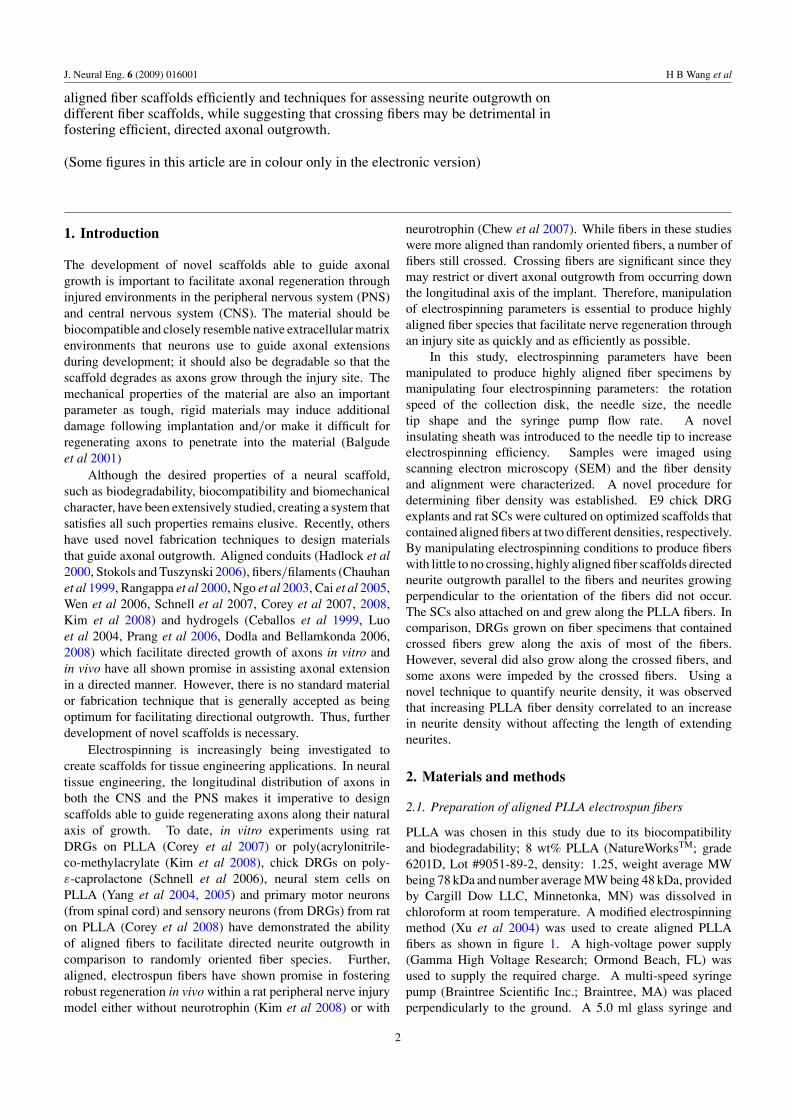
PLLA was chosen in this study due to its biocompatibilityand biodegradability; 8 wt% PLLA (NatureWorksTM; grade6201D, Lot #9051-89-2, density: 1.25, weight average MWbeing 78 kDa and number average MW being 48 kDa, providedby Cargill Dow LLC, Minnetonka, MN) was dissolved inchloroform at room temperature. A modified electrospinningmethod (Xu et al 2004) was used to create aligned PLLAfibers as shown in figure 1. A high-voltage power supply(Gamma High Voltage Research; Ormond Beach, FL) wasused to supply the required charge. A multi-speed syringepump (Braintree Scientific Inc.; Braintree, MA) was placedperpendicularly to the ground. A 5.0 ml glass syringe and
2
J. Neural Eng. 6 (2009) 016001 H B Wang et al
Table 1. Electrospinning parameters varied in the optimization tests.
Variables Fixed parameters
Rotation speed of the collector 250 rpm 22 G sharp-tip needle, 4 mL h−1, 1 h500 rpm1000 rpm
Needle tip shape and gauge Flat tip 20 G needle, 1000 rpm, 4 mL h−1, 1 hSharp tip
Insulated needle Insulated needle 22 G sharp-tip needle, 1000 rpm, 4 mL h−1, 1 hFlow rate of the syringe pump 2 mL h−1 22 G sharp-tip needle, 1000 rpm, 1 h
4 mL h−1
Figure 1. Schematic of the setup to create aligned PLLA fibers byelectrospinning using an insulated sharp needle and a rotating diskcollector.
one of several needles (20G flat and sharp tip needles with aninner diameter of 0.6 mm, and a 22G sharp-tip needle with aninner diameter of 0.4 mm (Fisher Chemicals; Fair Lawn, NJ))were used to generate fibers. The needle was connected to thepower supply to charge the polymer solution. An aluminumrotating disk (220 mm in diameter with a thickness of 10 mm)attached to a laboratory mixer motor (IKA Works Inc.;Wilmington, NC) was used as the fiber collector. Rotationspeeds of 250 rpm (linear distance 172.7 cm min−1), 500 rpm(linear distance 345.4 cm min−1) and 1000 rpm (linear distance690.8 cm min−1) were used in this study.
The following fixed conditions were used in theexperiments: (a) applied voltage: 20 kV, (b) distance betweenthe needle tip and the collector: 5.5 cm, (c) collecting time: 1 h(unless stated otherwise), and (d) a constant room temperatureof 26◦C and a constant relative humidity of 58%. The fiberswere spun onto 12-by-12 mm glass coverslips (Proscitech,Australia) attached on the edge of the rotating disk using apiece of double-sided tape (3M; St Paul, MN).
To determine the optimal electrospinning parameters suchas fiber alignment and fiber density for neuronal outgrowth,different electrospinning conditions were tested (table 1). Thediameters of the fibers were measured using Scion Imagesoftware.
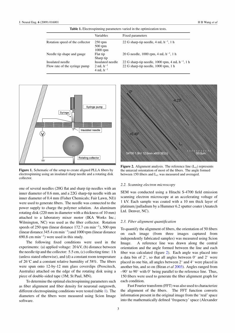
Figure 2. Alignment analysis. The reference line (Lr1) representsthe uniaxial orientation of most of the fibers. The angle formedbetween 150 fibers and Lr1 was measured and averaged.
2.2. Scanning electron microscopy
SEM was conducted using a Hitachi S-4700 field emissionscanning electron microscope at an accelerating voltage of1 kV. Each sample was coated with a 10 nm thick layer ofplatinum/palladium by a Hummer 6.2 sputter coater (AnatechLtd. Denver, NC).
2.3. Fiber alignment quantification
To quantify the alignment of fibers, the orientation of 50 fiberson each image (from three images captured fromindependently fabricated samples) was measured using ScionImage. A reference line was drawn along the centralorientation and the angle formed between the line and eachfiber was calculated (figure 2). Each angle was placed intoa data bin of 2◦, so that all angles between 0◦ and 2◦ wereplaced in one bin, all angles between 2◦ and 4◦ were placed inanother bin, and so on (Biran et al 2003). Angles ranged from–90◦ to 90◦ with 0◦ being parallel to the reference line. Thus,150 fibers were used to generate the fiber alignment graph foreach condition.
Fast Fourier transform (FFT) was also used to characterizethe alignment of the fibers. The FFT function convertsinformation present in the original image from the ‘real’ spaceinto the mathematically defined ‘frequency’ space (Alexander
3
J. Neural Eng. 6 (2009) 016001 H B Wang et al
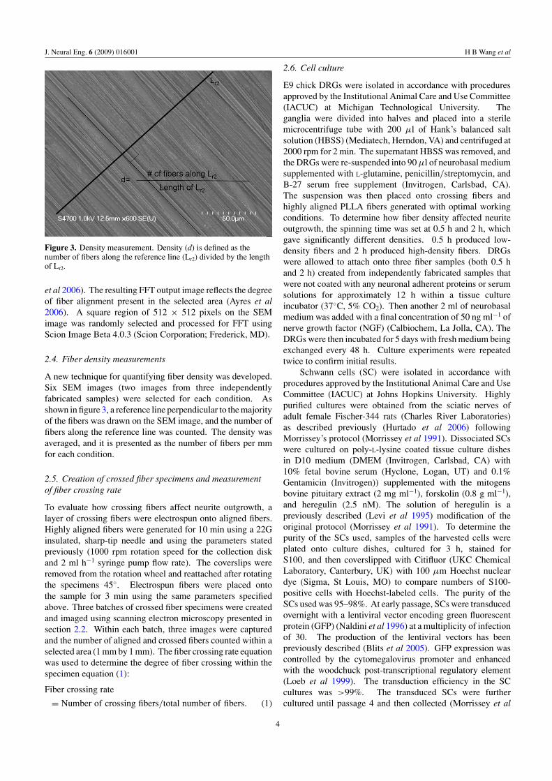
Figure 3. Density measurement. Density (d) is defined as thenumber of fibers along the reference line (Lr2) divided by the lengthof Lr2.
et al 2006). The resulting FFT output image reflects the degreeof fiber alignment present in the selected area (Ayres et al2006). A square region of 512 × 512 pixels on the SEMimage was randomly selected and processed for FFT usingScion Image Beta 4.0.3 (Scion Corporation; Frederick, MD).
2.4. Fiber density measurements
A new technique for quantifying fiber density was developed.Six SEM images (two images from three independentlyfabricated samples) were selected for each condition. Asshown in figure 3, a reference line perpendicular to the majorityof the fibers was drawn on the SEM image, and the number offibers along the reference line was counted. The density wasaveraged, and it is presented as the number of fibers per mmfor each condition.
2.5. Creation of crossed fiber specimens and measurementof fiber crossing rate
To evaluate how crossing fibers affect neurite outgrowth, alayer of crossing fibers were electrospun onto aligned fibers.Highly aligned fibers were generated for 10 min using a 22Ginsulated, sharp-tip needle and using the parameters statedpreviously (1000 rpm rotation speed for the collection diskand 2 ml h−1 syringe pump flow rate). The coverslips wereremoved from the rotation wheel and reattached after rotatingthe specimens 45◦. Electrospun fibers were placed ontothe sample for 3 min using the same parameters specifiedabove. Three batches of crossed fiber specimens were createdand imaged using scanning electron microscopy presented insection 2.2. Within each batch, three images were capturedand the number of aligned and crossed fibers counted within aselected area (1 mm by 1 mm). The fiber crossing rate equationwas used to determine the degree of fiber crossing within thespecimen equation (1):
Fiber crossing rate
= Number of crossing fibers/total number of fibers. (1)
2.6. Cell culture
E9 chick DRGs were isolated in accordance with proceduresapproved by the Institutional Animal Care and Use Committee(IACUC) at Michigan Technological University. Theganglia were divided into halves and placed into a sterilemicrocentrifuge tube with 200 μl of Hank’s balanced saltsolution (HBSS) (Mediatech, Herndon, VA) and centrifuged at2000 rpm for 2 min. The supernatant HBSS was removed, andthe DRGs were re-suspended into 90 μl of neurobasal mediumsupplemented with L-glutamine, penicillin/streptomycin, andB-27 serum free supplement (Invitrogen, Carlsbad, CA).The suspension was then placed onto crossing fibers andhighly aligned PLLA fibers generated with optimal workingconditions. To determine how fiber density affected neuriteoutgrowth, the spinning time was set at 0.5 h and 2 h, whichgave significantly different densities. 0.5 h produced low-density fibers and 2 h produced high-density fibers. DRGswere allowed to attach onto three fiber samples (both 0.5 hand 2 h) created from independently fabricated samples thatwere not coated with any neuronal adherent proteins or serumsolutions for approximately 12 h within a tissue cultureincubator (37◦C, 5% CO2). Then another 2 ml of neurobasalmedium was added with a final concentration of 50 ng ml−1 ofnerve growth factor (NGF) (Calbiochem, La Jolla, CA). TheDRGs were then incubated for 5 days with fresh medium beingexchanged every 48 h. Culture experiments were repeatedtwice to confirm initial results.
Schwann cells (SC) were isolated in accordance withprocedures approved by the Institutional Animal Care and UseCommittee (IACUC) at Johns Hopkins University. Highlypurified cultures were obtained from the sciatic nerves ofadult female Fischer-344 rats (Charles River Laboratories)as described previously (Hurtado et al 2006) followingMorrissey’s protocol (Morrissey et al 1991). Dissociated SCswere cultured on poly-L-lysine coated tissue culture dishesin D10 medium (DMEM (Invitrogen, Carlsbad, CA) with10% fetal bovine serum (Hyclone, Logan, UT) and 0.1%Gentamicin (Invitrogen)) supplemented with the mitogensbovine pituitary extract (2 mg ml−1), forskolin (0.8 g ml−1),and heregulin (2.5 nM). The solution of heregulin is apreviously described (Levi et al 1995) modification of theoriginal protocol (Morrissey et al 1991). To determine thepurity of the SCs used, samples of the harvested cells wereplated onto culture dishes, cultured for 3 h, stained forS100, and then coverslipped with Citifluor (UKC ChemicalLaboratory, Canterbury, UK) with 100 μm Hoechst nucleardye (Sigma, St Louis, MO) to compare numbers of S100-positive cells with Hoechst-labeled cells. The purity of theSCs used was 95–98%. At early passage, SCs were transducedovernight with a lentiviral vector encoding green fluorescentprotein (GFP) (Naldini et al 1996) at a multiplicity of infectionof 30. The production of the lentiviral vectors has beenpreviously described (Blits et al 2005). GFP expression wascontrolled by the cytomegalovirus promoter and enhancedwith the woodchuck post-transcriptional regulatory element(Loeb et al 1999). The transduction efficiency in the SCcultures was >99%. The transduced SCs were furthercultured until passage 4 and then collected (Morrissey et al
4
J. Neural Eng. 6 (2009) 016001 H B Wang et al
1991) for plating onto three high- and three low-density fibersamples with a cell density of 150 000 cells/100 μl D-10medium. SCs were allowed to attach onto three fiber samplesof independently fabricated samples for approximately 12 hwithin a tissue culture incubator (37◦C, 5% CO2), after whichanother 2 ml of D-10 medium was added. The SCs were thenincubated within the fiber scaffolds for 2 days. Experimentswere repeated to confirm initial results (N = 2).
2.7. Immunocytochemistry
After 5 days in culture, DRGs were fixed in a PBS (10 mMphosphate, 150 mM sodium chloride) solution containing4% (wt/volume) paraformaldehyde (Sigma-Aldrich; St Louis,MO) for 30 min. DRGs were washed three times with PBS, andthen blocked with a PBS solution containing 1% normal goatserum (Chemicon, Temecula, CA), 2% non-fat dry milk (TVCInc.; Brevard, NC) and 0.05% triton X-100 (EMD Chemicals,Gibbstown, NJ) for 15 min. After washing the specimens threetimes with PBS, DRGs were incubated (37◦, 5% CO2) withrabbit anti-neurofilament primary antibody (1:200 dilution,Chemicon, Temecula, CA) for 1 h, washed three times withPBS; specimens were incubated with an Alexa Fluor 488 goatanti-rabbit secondary antibody (Invitrogen; Carlsbad, CA) foranother hour, and washed three times with PBS. The SCs werewashed three times with PBS before fluorescence microscopy.Both DRGs and SCs were imaged using a Zeiss Axiovert200 M microscope equipped with an AxioCam fluorescencecamera. Zeiss filter set 10 was used where fluorescent dyeswith excitation wavelengths between 450 and 490 nm andemission wavelengths between 515 and 565 nm are analyzed.Using this filter set, autofluorescence from the electrospunfibers was not observed.
2.8. Quantification of the density of neurite outgrowth
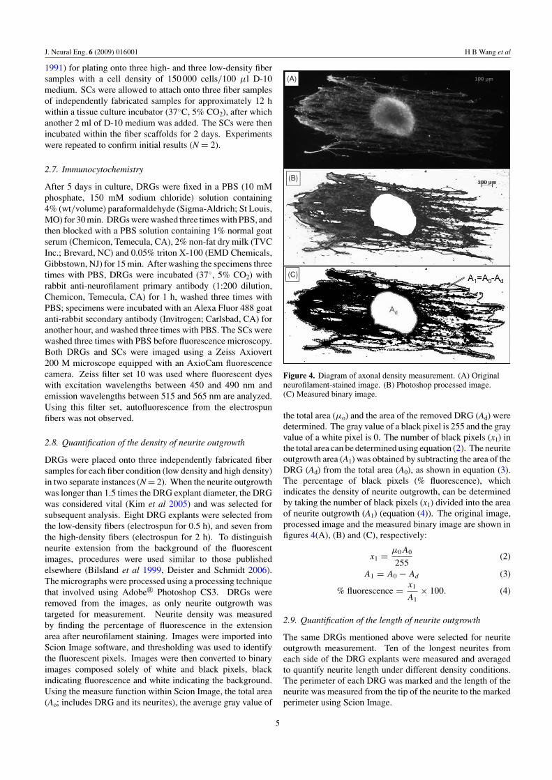
DRGs were placed onto three independently fabricated fibersamples for each fiber condition (low density and high density)in two separate instances (N = 2). When the neurite outgrowthwas longer than 1.5 times the DRG explant diameter, the DRGwas considered vital (Kim et al 2005) and was selected forsubsequent analysis. Eight DRG explants were selected fromthe low-density fibers (electrospun for 0.5 h), and seven fromthe high-density fibers (electrospun for 2 h). To distinguishneurite extension from the background of the fluorescentimages, procedures were used similar to those publishedelsewhere (Bilsland et al 1999, Deister and Schmidt 2006).The micrographs were processed using a processing techniquethat involved using Adobe R© Photoshop CS3. DRGs wereremoved from the images, as only neurite outgrowth wastargeted for measurement. Neurite density was measuredby finding the percentage of fluorescence in the extensionarea after neurofilament staining. Images were imported intoScion Image software, and thresholding was used to identifythe fluorescent pixels. Images were then converted to binaryimages composed solely of white and black pixels, blackindicating fluorescence and white indicating the background.Using the measure function within Scion Image, the total area(Ao; includes DRG and its neurites), the average gray value of
(A)
(B)
(C)
Figure 4. Diagram of axonal density measurement. (A) Originalneurofilament-stained image. (B) Photoshop processed image.(C) Measured binary image.
the total area (μo) and the area of the removed DRG (Ad) weredetermined. The gray value of a black pixel is 255 and the grayvalue of a white pixel is 0. The number of black pixels (x1) inthe total area can be determined using equation (2). The neuriteoutgrowth area (A1) was obtained by subtracting the area of theDRG (Ad) from the total area (A0), as shown in equation (3).The percentage of black pixels (% fluorescence), whichindicates the density of neurite outgrowth, can be determinedby taking the number of black pixels (x1) divided into the areaof neurite outgrowth (A1) (equation (4)). The original image,processed image and the measured binary image are shown infigures 4(A), (B) and (C), respectively:
x1 = μ0A0
255(2)
A1 = A0 − Ad (3)
% fluorescence = x1
A1× 100. (4)
2.9. Quantification of the length of neurite outgrowth
The same DRGs mentioned above were selected for neuriteoutgrowth measurement. Ten of the longest neurites fromeach side of the DRG explants were measured and averagedto quantify neurite length under different density conditions.The perimeter of each DRG was marked and the length of theneurite was measured from the tip of the neurite to the markedperimeter using Scion Image.
5
J. Neural Eng. 6 (2009) 016001 H B Wang et al
2.10. Statistical analysis
Statistical analyses were performed using JMP IN software(Release 5.1.2; SAS; Cary, NC). A one-way ANOVA was runfirst to determine statistical differences between groups in fiberdensity (N = 6), neurite density measurement (N = 8 for lowdensity and N = 7 for high density) and neurite length (N = 160for low density and N = 140 for high density). For those thatshowed differences in ANOVA, post-hoc Tukey–Kramer HSDtests were used to compare all pairs individually. The Brown–Forsythe test was run to determine statistical differences infiber alignment (N = 150). A value of P < 0.05 was consideredto be statistically significant.
3. Results
3.1. The effect of rotation speed
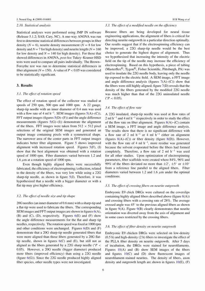
The effect of rotation speed of the collector was studied atspeeds of 250 rpm, 500 rpm and 1000 rpm. A 22 gauge,sharp-tip needle with an inner diameter of 0.4 mm was usedwith a flow rate of 4 ml h−1. SEM images (figures 5(A)–(C)),FFT output images (figures 5(D)–(F)) and the angle differencemeasurements (figures 5(G)–(I)) demonstrate the alignmentof the fibers. FFT images were taken from 512 × 512 pixelselections of the original SEM images and generated anoutput image containing pixels with a symmetrical shape.The narrower area of the center parts in FFT output imagesindicates better fiber alignment. Figure 5 shows improvedalignment with increased rotation speed. Figures 5(F), (I)show that the best alignment was obtained with a rotationspeed of 1000 rpm. Fiber diameters varied between 1.2 and1.6 μm at a rotation speed of 1000 rpm.
Even though highly aligned fibers were successfullyfabricated, the efficiency of electrospinning/collection, relatedto the density of the fibers, was very low while using a 22Gsharp-tip needle, as shown in figure 5(J). Therefore, it washypothesized that a needle with a bigger diameter or with aflat tip may give higher efficiency.
3.2. The effect of needle size and tip shape
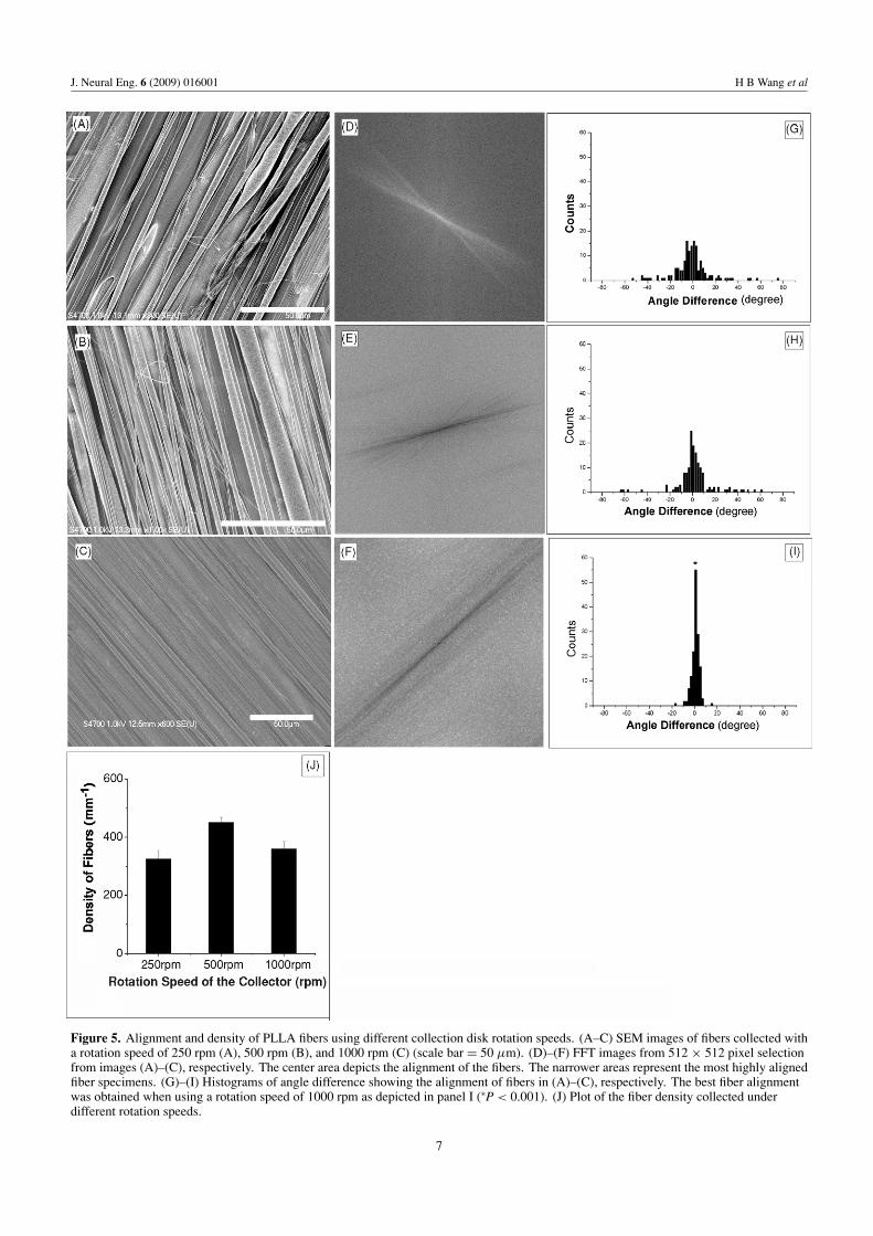
20G needles (an inner diameter of 0.6 mm) with a sharp-tip anda flat-tip were used to fabricate the fibers. The correspondingSEM images and FFT output images are shown in figures 6(A),(B) and (C), (D), respectively. Figures 6(E) and (F) showthe angle difference measurements for the flat and sharp tipneedles, respectively. The rotation speed was fixed at 1000 rpmand other conditions were unchanged. Figures 6(D) and (F)demonstrate that a 20G sharp-tip needle generated fibers thatwere more aligned than those fibers generated by a 20G flat-tip needle, shown in figures 6(C) and (E), but still not asaligned as the fibers generated by a 22G sharp needle (∗P <
0.05). However, a 20G needle (bigger diameter) producedmore fibers (improved efficiency) than using a 22G needle(figure 6(G)). Since the 22G needle produced highly alignedfiber species, other needle types were not investigated.
3.3. The effect of a modified needle on the efficiency
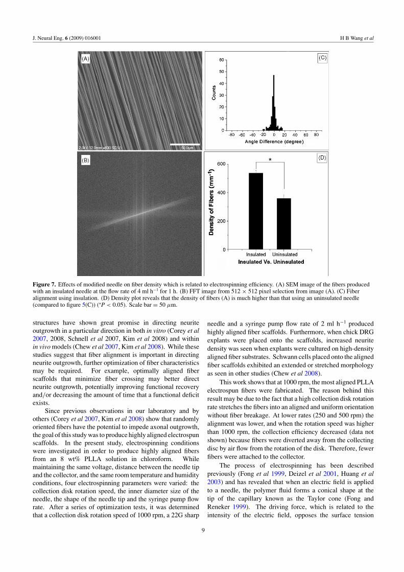
Because fibers are being developed for neural tissueengineering applications, the alignment of fibers is critical fordirecting neurite outgrowth in a particular direction optimally.Our results suggest that if the electrospinning efficiency canbe improved, a 22G sharp-tip needle would be the bestchoice to generate the highest degree of alignment. Thuswe hypothesized that increasing the intensity of the electricfield on the tip of the needle may increase the efficiency ofelectrospinning. Based on this hypothesis, a piece of tubing(Masterflex R©, Tygon R©, Fisher Scientific, Pittsburgh, PA) wasused to insulate the 22G needle body, leaving only the needletip exposed to the electric field. A SEM image, a FFT imageand angle difference analysis (figures 7(A)–(C)) show thatthe fibers were still highly aligned; figure 7(D) reveals that thedensity of the fibers generated by the modified 22G needlewas much higher than that of the 22G uninsulated needle(∗P < 0.05).
3.4. The effect of flow rate
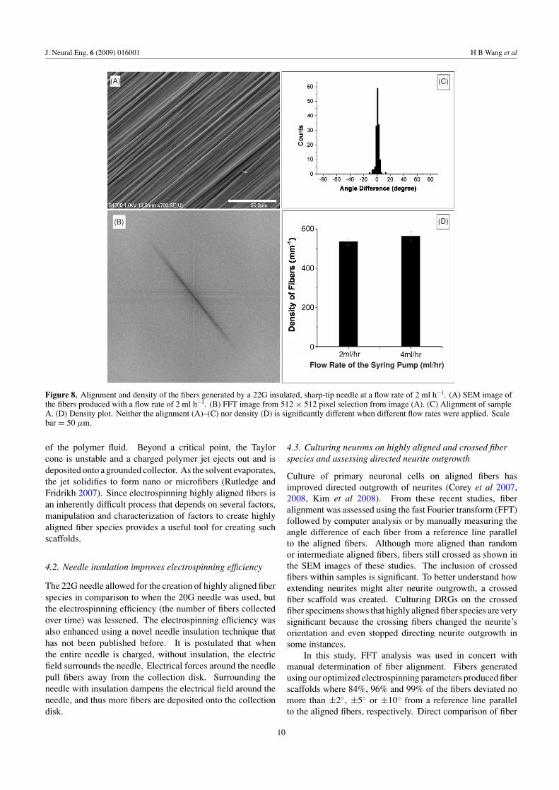
A 22G insulated, sharp-tip needle was used at flow rates of2 ml h−1 and 4 ml h−1 respectively in order to study the effectof the flow rate on fiber alignment. Figures 8(A)–(C) containa SEM image, a FFT image and angle difference analysis.The results show that there is no significant difference witha flow rate of 2 ml h−1 or 4 ml h−1 either on alignment(figures 8(A)–(C)) or fiber density (figure 8(D)). However,with the flow rate of 4 ml h−1, more residue was generatedbecause the solvent evaporated before the fibers had formedcompletely. Therefore, a flow rate of 2 ml h−1 was usedfor all other studies. Upon optimization of electrospinningparameters, fiber scaffolds were created where 84%, 96% and99% of the fibers deviated no more than ±2◦, ±5◦ or ±10◦
from a reference line parallel to the aligned fibers. Fiberdiameters varied between 1.2 and 1.6 μm under the optimalconditions.
3.5. The effect of crossing fibers on neurite outgrowth
Embryonic E9 chick DRGs were cultured on the coverslipscontaining highly aligned fibers described above (figure 8(A))and crossing fibers with a crossing rate of 28%. The averagecrossed angle was 45◦ to the previous aligned fibers as shownin figure 9(A). Figure 9(B) clearly demonstrates that neuriteorientation was diverted away from the axis of alignment andin some cases restricted by the crossing fibers.
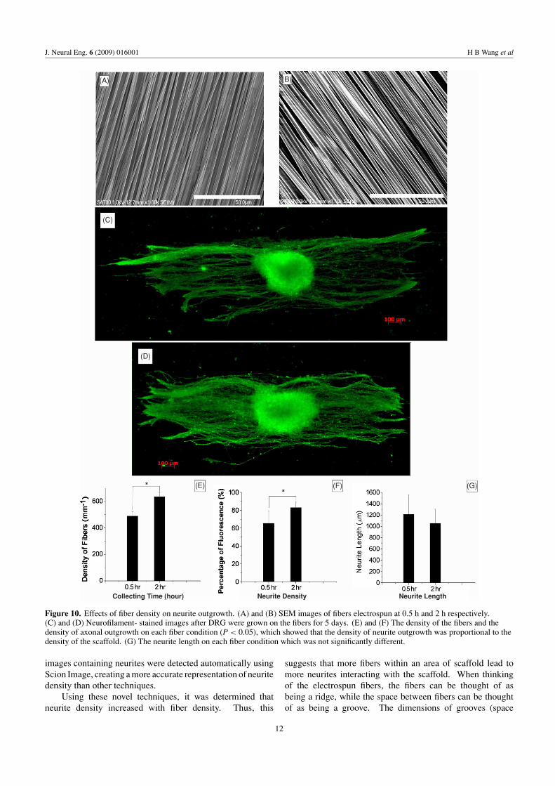
3.6. The effect of fiber density on neurite outgrowth
Embryonic E9 chicken DRGs were selected on low-density(0.5 h) and high-density (2 h) fibers to investigate the effect ofthe PLLA fiber density on neurite outgrowth. After 5 daysof incubation, the DRGs were stained for neurofilaments.Figures 10(A) and (B) show SEM images of the fibersand figures 10(C) and (D) show fluorescent images ofneurofilament-stained neurites. The density of fibers, axondensity and outgrowth length are shown in figures 10(E), (F)
6
J. Neural Eng. 6 (2009) 016001 H B Wang et al
Figure 5. Alignment and density of PLLA fibers using different collection disk rotation speeds. (A–C) SEM images of fibers collected witha rotation speed of 250 rpm (A), 500 rpm (B), and 1000 rpm (C) (scale bar = 50 μm). (D)–(F) FFT images from 512 × 512 pixel selectionfrom images (A)–(C), respectively. The center area depicts the alignment of the fibers. The narrower areas represent the most highly alignedfiber specimens. (G)–(I) Histograms of angle difference showing the alignment of fibers in (A)–(C), respectively. The best fiber alignmentwas obtained when using a rotation speed of 1000 rpm as depicted in panel I (∗P < 0.001). (J) Plot of the fiber density collected underdifferent rotation speeds.
7
J. Neural Eng. 6 (2009) 016001 H B Wang et al
Figure 6. Effects of needle size and tip shape on fiber alignment and density. SEM images of fibers produced using a 20G, flat-tip (A) andsharp-tip (B) needle (scale bar = 50 μm). (C) and (D) FFT images from 512 × 512 pixel selection from images of (A) and (B), respectively.(E) and (F) represent the fiber alignment analyses. The best fiber alignment was obtained with a sharp 20G needle as compared to the flat20G one (∗P < 0.001). (G) Density plot showing that the 20G needle is more efficient than the 22G needle (∗P < 0.05).
and (G), respectively. The results suggest that highly alignedfibers guide neurite outgrowth in a directed manner. Thedensity of neurites (figure 9(F)) increased with increasing fiberdensity, 65% ± 14 of the fluorescence for the low density and83% ± 6 for the high density (∗P < 0.05). The length of theneurite outgrowth for 0.5 h was 1210 ± 345 μm and for 2 h was1054 ± 249 μm (mean ± standard deviation). Statisticalanalysis showed no significant difference in neuritelength.
3.7. Schwann cells on PLLA fibers
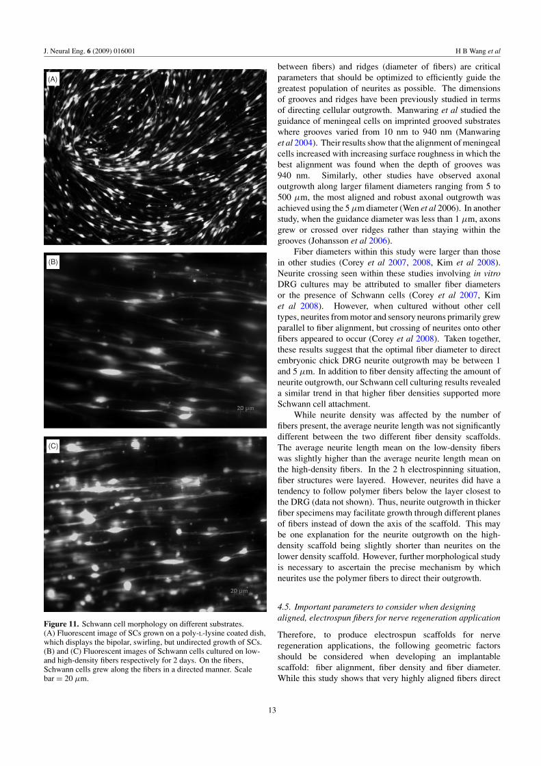
Schwann cells display a typical bipolar, swirling morphologywhen cultured on a poly-L-lysine coated dish (figure 11(A)).
Schwann cell growth on a dish is not directed. Within thefiber cultures, SCs grew in a directed manner along the fibersin both the low (figure 11(B)) and high (figure 11(C)) densitysamples. More Schwann cells were seen in the higher densityfiber sample.
4. Discussion
4.1. Alignment of electrospun fiber species
Aligned, electrospun fibers have been fabricated (Teo et al2005, Pan et al 2006) for drug delivery (Chew et al 2005)or tissue engineering applications (Baker et al 2008, Chewet al 2008, Choi et al 2008). Recently, electrospun fiber
8
J. Neural Eng. 6 (2009) 016001 H B Wang et al
Figure 7. Effects of modified needle on fiber density which is related to electrospinning efficiency. (A) SEM image of the fibers producedwith an insulated needle at the flow rate of 4 ml h−1 for 1 h. (B) FFT image from 512 × 512 pixel selection from image (A). (C) Fiberalignment using insulation. (D) Density plot reveals that the density of fibers (A) is much higher than that using an uninsulated needle(compared to figure 5(C)) (∗P < 0.05). Scale bar = 50 μm.
structures have shown great promise in directing neuriteoutgrowth in a particular direction in both in vitro (Corey et al2007, 2008, Schnell et al 2007, Kim et al 2008) and withinin vivo models (Chew et al 2007, Kim et al 2008). While thesestudies suggest that fiber alignment is important in directingneurite outgrowth, further optimization of fiber characteristicsmay be required. For example, optimally aligned fiberscaffolds that minimize fiber crossing may better directneurite outgrowth, potentially improving functional recoveryand/or decreasing the amount of time that a functional deficitexists.
Since previous observations in our laboratory and byothers (Corey et al 2007, Kim et al 2008) show that randomlyoriented fibers have the potential to impede axonal outgrowth,the goal of this study was to produce highly aligned electrospunscaffolds. In the present study, electrospinning conditionswere investigated in order to produce highly aligned fibersfrom an 8 wt% PLLA solution in chloroform. Whilemaintaining the same voltage, distance between the needle tipand the collector, and the same room temperature and humidityconditions, four electrospinning parameters were varied: thecollection disk rotation speed, the inner diameter size of theneedle, the shape of the needle tip and the syringe pump flowrate. After a series of optimization tests, it was determinedthat a collection disk rotation speed of 1000 rpm, a 22G sharp
needle and a syringe pump flow rate of 2 ml h−1 producedhighly aligned fiber scaffolds. Furthermore, when chick DRGexplants were placed onto the scaffolds, increased neuritedensity was seen when explants were cultured on high-densityaligned fiber substrates. Schwann cells placed onto the alignedfiber scaffolds exhibited an extended or stretched morphologyas seen in other studies (Chew et al 2008).
This work shows that at 1000 rpm, the most aligned PLLAelectrospun fibers were fabricated. The reason behind thisresult may be due to the fact that a high collection disk rotationrate stretches the fibers into an aligned and uniform orientationwithout fiber breakage. At lower rates (250 and 500 rpm) thealignment was lower, and when the rotation speed was higherthan 1000 rpm, the collection efficiency decreased (data notshown) because fibers were diverted away from the collectingdisc by air flow from the rotation of the disk. Therefore, fewerfibers were attached to the collector.
The process of electrospinning has been describedpreviously (Fong et al 1999, Deizel et al 2001, Huang et al2003) and has revealed that when an electric field is appliedto a needle, the polymer fluid forms a conical shape at thetip of the capillary known as the Taylor cone (Fong andReneker 1999). The driving force, which is related to theintensity of the electric field, opposes the surface tension
9
J. Neural Eng. 6 (2009) 016001 H B Wang et al
Flow Rate of the Syring Pump (ml/hr)
(A)
(B)
(C)
(D)
Figure 8. Alignment and density of the fibers generated by a 22G insulated, sharp-tip needle at a flow rate of 2 ml h−1. (A) SEM image ofthe fibers produced with a flow rate of 2 ml h−1. (B) FFT image from 512 × 512 pixel selection from image (A). (C) Alignment of sampleA. (D) Density plot. Neither the alignment (A)–(C) nor density (D) is significantly different when different flow rates were applied. Scalebar = 50 μm.
of the polymer fluid. Beyond a critical point, the Taylorcone is unstable and a charged polymer jet ejects out and isdeposited onto a grounded collector. As the solvent evaporates,the jet solidifies to form nano or microfibers (Rutledge andFridrikh 2007). Since electrospinning highly aligned fibers isan inherently difficult process that depends on several factors,manipulation and characterization of factors to create highlyaligned fiber species provides a useful tool for creating suchscaffolds.
4.2. Needle insulation improves electrospinning efficiency
The 22G needle allowed for the creation of highly aligned fiberspecies in comparison to when the 20G needle was used, butthe electrospinning efficiency (the number of fibers collectedover time) was lessened. The electrospinning efficiency wasalso enhanced using a novel needle insulation technique thathas not been published before. It is postulated that whenthe entire needle is charged, without insulation, the electricfield surrounds the needle. Electrical forces around the needlepull fibers away from the collection disk. Surrounding theneedle with insulation dampens the electrical field around theneedle, and thus more fibers are deposited onto the collectiondisk.
4.3. Culturing neurons on highly aligned and crossed fiberspecies and assessing directed neurite outgrowth
Culture of primary neuronal cells on aligned fibers hasimproved directed outgrowth of neurites (Corey et al 2007,2008, Kim et al 2008). From these recent studies, fiberalignment was assessed using the fast Fourier transform (FFT)followed by computer analysis or by manually measuring theangle difference of each fiber from a reference line parallelto the aligned fibers. Although more aligned than randomor intermediate aligned fibers, fibers still crossed as shown inthe SEM images of these studies. The inclusion of crossedfibers within samples is significant. To better understand howextending neurites might alter neurite outgrowth, a crossedfiber scaffold was created. Culturing DRGs on the crossedfiber specimens shows that highly aligned fiber species are verysignificant because the crossing fibers changed the neurite’sorientation and even stopped directing neurite outgrowth insome instances.
In this study, FFT analysis was used in concert withmanual determination of fiber alignment. Fibers generatedusing our optimized electrospinning parameters produced fiberscaffolds where 84%, 96% and 99% of the fibers deviated nomore than ±2◦, ±5◦ or ±10◦ from a reference line parallelto the aligned fibers, respectively. Direct comparison of fiber
10

J. Neural Eng. 6 (2009) 016001 H B Wang et al
(A)
(B)
Figure 9. Effects of crossing fibers on neurite outgrowth. (A) SEM image of crossing fibers with a crossing angle of 45◦. 28% of the totalfibers were crossing fibers. Scale bar = 50 μm. (B) Neurofilament-stained image of DRGs cultured for 5 days on crossing fiber scaffolds.Neurites extended along the crossed fibers and in some instances were impeded by the crossing fibers (circled area) Scale bar = 100 μm.
alignment from our study with others (Corey et al 2007, 2008)is difficult since alignment in these studies is computed fromFFT images and full width–half max analysis (FWHM). WhileFWHM analysis provided insight into the aligned characterof fiber scaffolds, additional alignment characterization usingother approaches provide clearer characterization of fiberalignment.
Corresponding neurite outgrowth from DRGs was lessaligned than the fiber alignment (Corey et al 2007) whereassimilar when dissociated primary neurons were used (Coreyet al 2008). Our culture data also show directed neuriteoutgrowth from our DRG explants, but neurite outgrowth wasnot as aligned as fiber alignment. This is likely due to thefibers separating from the glass coverslip during cell stainingand not because of the lack of fiber alignment in our createdscaffolds. As the ultimate goal is to apply the aligned fibersubstrates into a three-dimensional model for in vivo study,our laboratory is developing strategies to secure aligned fibersin place for in vitro analysis and for incorporation into a three-dimensional nerve bridge. Strategies using polymer filmsplaced onto coverslips prior to electrospinning (Chew et al2007) is one method being pursued to stabilize fiber alignment(Corey et al 2008). However, the use of films may shield
fibers from the grounded collecting disk, requiring additionalmanipulation of electrospinning parameters to achieve highlyaligned fiber specimens.
4.4. Increased polymer fiber density correlates to higherneurite density but unchanged average neurite length
None of these recent studies have examined how fiber densityaffects neurite outgrowth. Our laboratory has developeda rational technique for determining fiber density where aline is drawn perpendicular to the axis of fiber alignment.The number of fibers on this line is counted to yield thenumber of fibers per millimeter (figure 3). Additionally, theneurite density was computed using a technique similar tothat presented elsewhere (Bilsland et al 1999, Deister andSchmidt 2006). In our method, black pixels (figure 4(C)),which represented neurite outgrowth, were divided by the totalnumber of pixels in the whole neurite area (A1) to calculatethe fluorescent percentage as the neurite density. Othershave used the area of the actual neurite coverage divided bythe entire neurite coverage area to calculate neurite density(Shah et al 2004). Here, instead of using the stained areato indicate the neurite density, the fluorescent pixels within
11
J. Neural Eng. 6 (2009) 016001 H B Wang et al
Collecting Time (hour) Neurite Density Neurite Length
(A)
(C)
(B)
(D)
(E) (F) (G)
Figure 10. Effects of fiber density on neurite outgrowth. (A) and (B) SEM images of fibers electrospun at 0.5 h and 2 h respectively.(C) and (D) Neurofilament- stained images after DRG were grown on the fibers for 5 days. (E) and (F) The density of the fibers and thedensity of axonal outgrowth on each fiber condition (P < 0.05), which showed that the density of neurite outgrowth was proportional to thedensity of the scaffold. (G) The neurite length on each fiber condition which was not significantly different.
images containing neurites were detected automatically usingScion Image, creating a more accurate representation of neuritedensity than other techniques.
Using these novel techniques, it was determined thatneurite density increased with fiber density. Thus, this
suggests that more fibers within an area of scaffold lead tomore neurites interacting with the scaffold. When thinkingof the electrospun fibers, the fibers can be thought of asbeing a ridge, while the space between fibers can be thoughtof as being a groove. The dimensions of grooves (space
12
J. Neural Eng. 6 (2009) 016001 H B Wang et al
(A)
(B)
(C)
Figure 11. Schwann cell morphology on different substrates.(A) Fluorescent image of SCs grown on a poly-L-lysine coated dish,which displays the bipolar, swirling, but undirected growth of SCs.(B) and (C) Fluorescent images of Schwann cells cultured on low-and high-density fibers respectively for 2 days. On the fibers,Schwann cells grew along the fibers in a directed manner. Scalebar = 20 μm.
between fibers) and ridges (diameter of fibers) are criticalparameters that should be optimized to efficiently guide thegreatest population of neurites as possible. The dimensionsof grooves and ridges have been previously studied in termsof directing cellular outgrowth. Manwaring et al studied theguidance of meningeal cells on imprinted grooved substrateswhere grooves varied from 10 nm to 940 nm (Manwaringet al 2004). Their results show that the alignment of meningealcells increased with increasing surface roughness in which thebest alignment was found when the depth of grooves was940 nm. Similarly, other studies have observed axonaloutgrowth along larger filament diameters ranging from 5 to500 μm, the most aligned and robust axonal outgrowth wasachieved using the 5 μm diameter (Wen et al 2006). In anotherstudy, when the guidance diameter was less than 1 μm, axonsgrew or crossed over ridges rather than staying within thegrooves (Johansson et al 2006).
Fiber diameters within this study were larger than thosein other studies (Corey et al 2007, 2008, Kim et al 2008).Neurite crossing seen within these studies involving in vitroDRG cultures may be attributed to smaller fiber diametersor the presence of Schwann cells (Corey et al 2007, Kimet al 2008). However, when cultured without other celltypes, neurites from motor and sensory neurons primarily grewparallel to fiber alignment, but crossing of neurites onto otherfibers appeared to occur (Corey et al 2008). Taken together,these results suggest that the optimal fiber diameter to directembryonic chick DRG neurite outgrowth may be between 1and 5 μm. In addition to fiber density affecting the amount ofneurite outgrowth, our Schwann cell culturing results revealeda similar trend in that higher fiber densities supported moreSchwann cell attachment.
While neurite density was affected by the number offibers present, the average neurite length was not significantlydifferent between the two different fiber density scaffolds.The average neurite length mean on the low-density fiberswas slightly higher than the average neurite length mean onthe high-density fibers. In the 2 h electrospinning situation,fiber structures were layered. However, neurites did have atendency to follow polymer fibers below the layer closest tothe DRG (data not shown). Thus, neurite outgrowth in thickerfiber specimens may facilitate growth through different planesof fibers instead of down the axis of the scaffold. This maybe one explanation for the neurite outgrowth on the high-density scaffold being slightly shorter than neurites on thelower density scaffold. However, further morphological studyis necessary to ascertain the precise mechanism by whichneurites use the polymer fibers to direct their outgrowth.
4.5. Important parameters to consider when designingaligned, electrospun fibers for nerve regeneration application
Therefore, to produce electrospun scaffolds for nerveregeneration applications, the following geometric factorsshould be considered when developing an implantablescaffold: fiber alignment, fiber density and fiber diameter.While this study shows that very highly aligned fibers direct
13
J. Neural Eng. 6 (2009) 016001 H B Wang et al
neurite outgrowth, the spacing between fibers (width ofgroove) which is related to fiber density also influences theamount of axonal attachment. The diameter of regeneratingaxons in relation to the fiber diameter is another aspect toconsider. In vertebrates, there is a large variation in the sizeof axons, ranging between less than 1 μm and up to 50 μm(Rydmark 1981, Matthews 1998). In the present study, thefiber diameter was on the same scale as the neurites. Based onthese results, the diameter of the fiber scaffold should be relatedto the axonal diameter. Fiber diameters one- to three-foldgreater than axonal diameters might be of sufficient diameterfor nerve scaffold design.
5. Conclusion
According to these results, highly aligned PLLA fiberscan be fabricated by carefully manipulating electrospinningparameters. These fibers directed the outgrowth of neuritesand facilitated the attachment of Schwann cells. Further,increasing fiber density increased Schwann cell attachmentand supported more neurite extension than when cultured onthe low-density scaffolds. Crossing fibers seemed to divertneurite outgrowth and in some cases stopped neurite outgrowthfrom occurring. Future work is focusing on maintaining fiberalignment for in vitro and in vivo experimentation. Further,studies on how fiber density and fiber diameter influenceneurite outgrowth in both in vitro and in vivo systems are alsocurrently under way. The goal is to best construct scaffoldscontaining aligned, electrospun fibers for nerve regenerationapplications.
Acknowledgments
This work was supported by grants from the Departmentof Energy, USA, and Seed and Infrastructure EnhancementGrants from Michigan Technological University. The authorswould like to thank Dr P Heiden (MTU, Houghton, MI) forher suggestions on electrospinning, Dr D Clupper (MTU,Houghton, MI) and his student D Jaroch for assistance indesigning the electrospinning set up, and Eric Minner formanuscript editing and assistance with statistics.
References
Alexander J K, Fuss B and Colello R J 2006 Electric field-inducedastrocyte alignment directs neurite outgrowth Neuron Glia Biol.2 93–103
Ayres C, Bowlin G L, Henderson S C, Taylor L, Shultz J,Alexander J, Telemeco T A and Simpson D G 2006Modulation of anisotropy in electrospun tissue engineeringscaffolds: analysis of fiber alignment by the fast Fouriertransform Biomaterials 27 5524–34
Baker B M, Gee A O, Metter R B, Nathan A S, Marklein R A,Burdick J A and Mauck R L 2008 The potential to improve cellinfiltration in composite fiber-aligned electrospun scaffolds bythe selective removal of sacrificial fibers Biomaterials29 2348–58
Balgude A P, Yu X, Szymanski A and Bellamkonda R V 2001Agarose gel stiffness determines rate of DRG neurite extensionin 3D cultures Biomaterials 22 1077–84
Bilsland J, Migby M, Young L and Harper S 1999 A rapid methodfor semi-quantitative analysis of neurite outgrowth from chickDRG explants using image analysis J. Neurosci. Methods92 75–85
Biran R, Noble M D and Tresco P A 2003 Directed nerve outgrowthis enhanced by engineered glial substrates Exp. Neurol.184 141–52
Blits B, Kitay B M, Farahvar A, Caperton C V, Dietrich W D andBunge M B 2005 Lentiviral vector-mediated transduction ofneural progenitor cells before implantation into injured spinalcord and brain to detect their migration, deliver neurotrophicfactors and repair tissue Restor. Neurol. Neurosci. 23 313–24
Cai J, Peng X, Nelson K D, Eberhard R and Smith G M 2005Permeable guidance channels containing microfilamentscaffolds enhance axon growth and maturation J. Biomed.Mater. Res. A 75 374–86
Ceballos D, Navarro X, Dubey N, Wendelschafer-Crabb G,Kennedy W R and Tranquillo R T 1999 Magnetically alignedcollagen gel filling a collagen nerve guide improves peripheralnerve regeneration Exp. Neurol. 158 290–300
Chauhan N B, Figlewicz H M and Khan T 1999 Carbon filamentsdirect the growth of postlesional plastic axons after spinal cordinjury Int. J. Dev. Neurosci. 17 255–64
Chew S Y, Mi R, Hoke A and Leong K W 2007 Alignedprotein–polymer composite fibers enhance nerve regeneration:a potential tissue-engineering platform Adv. Funct. Mater.17 1288–96
Chew S Y, Mi R, Hoke A and Leong K W 2008 The effect of thealignment of electrospun fibrous scaffolds on Schwann cellmaturation Biomaterials 29 653–61
Chew S Y, Wen J, Yim E K F and Leong K W 2005 Sustainedrelease of proteins from electrospun biodegradable fibersBiomacromolecules 6 2017–24
Choi J S, Lee S J, Christ G J, Atala A and Yoo J J 2008 The influenceof electrospun aligned poly(epsilon-caprolactone)/collagennanofiber meshes on the formation of self-aligned skeletalmuscle myotubes Biomaterials 29 2899–906
Corey J M, Gertz C C, Wang B S, Birrell L K, Johnson S L,Martin D C and Feldman E L 2008 The design of electrospunPLLA nanofiber scaffolds compatible with serum-free growthof primary motor and sensory neurons Acta Biomaterial.4 863–75
Corey J M, Lin D Y, Mycek K B, Chen Q, Samuel S, Feldman E Land Martin D C 2007 Aligned electrospun nanofibers specifythe direction of dorsal root ganglia neurite growth J. Biomed.Mater. Res. A 83 636–45
Deister C and Schmidt C E 2006 Optimizing neurotrophic factorcombinations for neurite outgrowth J. Neural Eng. 3 172–9
Deizel J M, Kleinmeyer J, Harris D and Beck Tan N C 2001 Theeffect of processing variables on the morphology ofelectrospun nanofibers and textiles Polymer 42 261–72
Dodla M C and Bellamkonda R V 2006 Anisotropic scaffoldsfacilitate enhanced neurite extension in vitro J. Biomed. Mater.Res. A 78 213–21
Dodla M C and Bellamkonda R V 2008 Differences between theeffect of anisotropic and isotropic laminin and nerve growthfactor presenting scaffolds on nerve regeneration across longperipheral nerve gaps Biomaterials 29 33–46
Fong H, Chun I and Reneker D H 1999 Beaded nanofibers formedduring electrospinning Polymer 40 4585–92
Fong H and Reneker D H 1999 Elastomeric nanofibers ofstyrene–butadiene–styrene triblock copolymer J. Polym. Sci B37 3488–93
Hadlock T, Sundback C, Hunter D, Cheney M and Vacanti J P 2000A polymer foam conduit seeded with Schwann cells promotesguided peripheral nerve regeneration Tissue Eng. 6 119–27
Huang Z-M, Zhang Y Z, Kotaki M and Ramakrishna S 2003 Areview on polymer nanofibers by electrospinning and theirapplications in nanocomposites Compos. Sci. Technol.63 2223–53
14
J. Neural Eng. 6 (2009) 016001 H B Wang et al
Hurtado A, Moon L D F, Maquet V, Blits B, Jerome R andOudega M 2006 Poly (D, L-lactic acid) macroporous guidancescaffolds seeded with Schwann cells genetically modified tosecrete a bi-functional neurotrophin implanted in thecompletely transected adult rat thoracic spinal cordBiomaterials 27 430–42
Johansson F, Carlberg P, Danielsen N, Montelius L and Kanje M2006 Axonal outgrowth on nano-imprinted patternsBiomaterials 27 1251–8
Kim I A, Park S A, Kim Y J, Kim S H, Shin H J, Lee Y J, Kang S Gand Shin J W 2005 Effects of mechanical stimuli andmicrofiber-based substrate on neurite outgrowth and guidanceJ. Biosci. Bioeng. 101 120–6
Kim Y T, Haftel V K, Kumar S and Bellamkonda R V 2008 Therole of aligned polymer fiber-based constructs in the bridgingof long peripheral nerve gaps Biomaterials 29 3117–27
Levi A D, Bunge R P, Lofgren J A, Meima L, Hefti F, Nikolics Kand Sliwkowski M X 1995 The influence of heregulins onhuman Schwann cell proliferation J. Neurosci. 15 1329–40
Loeb J E, Cordier W S, Harris M E, Weitzman M D and Hope T J1999 Enhanced expression of transgenes fromadeno-associated virus vectors with the woodchuck hepatitisvirus posttranscriptional regulatory element: implications forgene therapy Hum. Gene Ther. 10 2295–305
Manwaring M E, Walsh J F and Tresco P A 2004 Contact guidanceinduced organization of extracellular matrix Biomaterials25 3631–8
Matthews G G 1998 Generation of nerve action potentials CellularPhysiology of Nerve and Muscle (Malden: Blackwell Science)pp 61–94
Morrissey T K, Kleitman N and Bunge R P 1991 Isolation andfunctional characterization of Schwann cells derived from adultperipheral nerve J. Neurosci. 11 2433–42
Naldini L, Blomer U, Gage F H, Trono D and Verma I M 1996Efficient transfer, integration, and sustained long-termexpression of the transgene in adult rat brains injected with alentiviral vector Proc. Natl Acad. Sci. USA 93 11382–8
Ngo T-T B, Waggoner P J, Romero A A, Nelson K D, Eberhart R Cand Smith G M 2003 Poly(L-lactide) microfilaments enhanceperipheral nerve regeneration across extended nerve lesionsJ. Neurosci. Res. 72 227–38
Pan H, Li L, Hu L and Cui X 2006 Continuous aligned polymerfibers produced by a modified electrospinning method Polymer47 4901–4
Prang P, Miller R, Eljaouhari A, Heckmann K, Kunz W, Weber T,Faber C, Vroemen M, Bogdahn U and Weidner N 2006 Thepromotion of oriented axonal regrowth in the injured spinalcord by alginate-based anisotropic capillary hydrogelsBiomaterials 27 3560–9
Rangappa N, Romero A, Nelson K D, Eberhard R C and Smith G M2000 Laminin-coated poly(L-lactide) filaments induce robustneurite growth while providing directional orientationJ. Biomed. Mater. Res. 51 625–34
Rutledge G C and Fridrikh S V 2007 Formation of fibers byelectrospinning Adv. Drug Deliv. Rev. 59 1384–91
Rydmark M 1981 Nodal axon diameter correlates linearly withintermodal axon diameter in spinal roots of the cat Neurosci.Lett. 24 247–50
Shah A, Fischer C, Knapp C F and Sisken B F 2004 Quantificationof neurite growth parameters in explants cultures using a newimage processing program J. Neurosci. Methods 136 123–31
Stokols S and Tuszynski M H 2006 Freeze-dried agarose scaffoldswith unaxial channels stimulate and guide linear axonal growthfollowing spinal cord injury Biomaterials 27 443–51
Teo W E, Kotaki M, Mo X M and Ramakrishna S 2005 Poroustubular structures with controlled fibre orientation using amodified electrospinning method Nanotechnology 16 918–24
Wen X and Tresco P A 2006 Effect of filament diameter andextracellular matrix molecule precoating on neurite outgrowthand Schwann cell behavior on multifilament entubulationbridging device in vitro J. Biomed. Mater. Res. A 76 626–37
Xu C Y, Inai R, Kotaki M and Ramakrishna S 2004 Alignedbiodegradable nanofibrous structure: a potential scaffold forblood vessel engineering Biomaterials 25 877–86
Yang F, Murugan R, Wang S and Ramakrishna S 2005Electrospinning of nano/micro scale poly(L-lactic acid)aligned fibers and their potential in neural tissue engineeringBiomaterials 26 2603–10
Yang F, Xu C Y, Kotaki M, Wang S and Ramakrishna S 2004Characterization of neural stem cells on electrospunpoly(L-lactic acid) nanofibrous scaffold J. Biomater. Sci. Polym.Ed. 15 1483–97
15
Copyright © 2022 FDOKUMEN