Drug analysis by capillary electrophoresis and laser-induced fluorescence
Bull. Mater. Sci., Vol. 38, No. 1, February 2015, pp. 1–6. c© Indian Academy of Sciences.
Electrospun TiO2 nanofibre-based gas sensors fabricated by ACelectrophoresis deposition
E Z KARIMI1,∗, J ESMAEILZADEH2 and E MARZBANRAD3
1Department of Metallurgy and Ceramics, Islamic Azad University, Mashhad Branch, Mashhad 9187147578, Iran2Department of Ceramics, Materials and Energy Research Center, Tehran 14155-4777, Iran3Department of Mechanical and Mechatronics Engineering, University of Waterloo, Waterloo, Ontario N2L 3GI, Canada
MS received 26 November 2013; revised 14 March 2014
Abstract. In this paper, gas sensing properties of the sensor based on titanium dioxide (TiO2) nanofibres arereported. These nanofibres were synthesized through electrospinning of polyvinyl pyrrolidone (PVP) / titanium tetraisopropoxide. Calcination of the obtained amorphous PVP/TiO2 nanofibres resulted in nanofibres of TiO2 withthe same morphology. In this step, scanning electron microscopy and X-ray diffraction were applied in order toanalyse these nanofibres. Then, nanofibres of TiO2 were deposited selectively by AC electrophoretic deposition oninterdigitated electrodes and exposed to different concentrations of NO2 (8–50 p.p.m.) at 450–550◦C. Gas sensingmeasurements illustrated that this sensor had adequate response to target gas at 450◦C. The maximum response ofgas sensors, S (the ratio of sensor resistances S = Rgas/RN2), achieved was around 30 for 50 p.p.m. NO2 at 450◦C.
Keywords. TiO2 nanofibres; electrospinning process; AC electrophoretic deposition; NO2 gas sensor.
1. Introduction
Semiconductor metal oxide-based gas sensors with differentworking temperatures have enabled us to detect low levelsof gases in a wide range of temperatures. Dependingon the application of interest and availability of fabricationmethods, different surface morphology and configurationsof the metal oxides have been achieved.1–3 Of these,one-dimensional (1D) nanostructures are particularly suitedto this application because of their high surface-to-volumeratio as well as good chemical and thermal stabilities underdifferent operating conditions.4,5 Among different strate-gies for producing 1D nanaostructures, electrospinning (ES)offers several advantages including ease of fabrication andversatility.6,7
ES is a top to bottom approach to produce continuousnanofibre of polymers. Synthesis of metal oxide nanostruc-tures by ES process recently gained increasing attention dueto the prospect of its application in producing 1D nanos-tructure on a commercial scale. A large number of metaloxides are synthesized as nanofibre by ES.8 In a typical ESprocess, under the effect of high voltage, the jet of precur-sor ejects from the tip of the needle towards the collector.As a result, the jet whips rapidly and the solvent evaporatesforming a nonwoven fibrous mat on the collector.9 If thepolymeric solution contains metal ions required for formingan inorganic solid, then appropriate post-annealing producescontinuous nanofibre of reduced diameters than the parentpolymeric fibre.
∗Author for correspondence ([email protected])
The metal oxide selected in this research is titaniumdioxide (TiO2). The reason of this choice is the applicabil-ity of this metal oxide as a high temperature gas sensor andits chemical and thermal stability at elevated temperatures.These characteristics have stimulated intense research on thismaterial.10–14 Some of these researches address issues likepoor conductivity and addition of doping agents;9,12,13 oth-ers focus on synthesizing 1D TiO2 nanostructures.15 Recentreports show that nanocrystalline TiO2 gas sensors pro-duced by ES demonstrate excellent performance in terms ofgas sensitivity, reversibility and response time. For instance,Dan et al16 and Maensiri et al17 have fabricated electrospunTiO2nanofibres by carefully controlling the ES parametersand the composition of the precursor solution. Furthermore,Kim et al18,19 and Landau et al20 have reported ultra highsensitivity of TiO2 nanofibres towards CO and NO2 gases.
In this research, in addition to applying ES for obtainingTiO2 nanofibres, another electric field-based technique wasalso used. Named ‘alternative current electrophoretic depo-sition (AC EPD)’, the technique was used to transfer thenanofibres, once suspended in an organic medium, on to asubstrate. The AC EPD technique, which is well establishedfor polymer and biomaterial film deposition can also be used,in principle, for the deposition of metal oxide nanoparticles.In fact, in this method, sensing material is deposited froma liquid media and morphology of the layer can be engi-neered by controlling different process parameters such asvoltage, frequency and time of the deposition.21 AC EPD isa technique based on movement of particles in the presenceof electric field, which guarantees a gentle mechanism totransfer particles suspended in the alcoholic media on to the
1

2 E Z Karimi et al
substrate. The material of interest is suspended in avolatile and interaction-free solvent with a low concen-tration. These suspended particles are forced to followa specific path by properly designed electric field andcover the desired region of the substrate.22 This tech-nique has already been employed for fabrication of thesensors based on mesoporous WO3,23 ZnO nanowiresand nanoparticles,24,25 TiO2 nanoparticles26,27 and In2O3
nanoparticles and nanoribbons.28,29
In our previous work regarding TiO2 nanoparticles, sta-ble sensors with high responses in the temperature rangeof 450–550◦C using AC EPD were obtained.26 In this newresearch, after deposition of electrospun TiO2 nanofibres byAC EPD on interdigitated substrates, their gas sensing prop-erties towards NO2 were investigated by electrical measure-ments in controlled environment and working temperature.
2. Experimental
2.1 Synthesis of electrospun TiO2 nanofibres
The electrospun solution comprised 0.225 g polyvinylpyrrolidone (PVP, Mw = 1300000 g mol−1, Aldrich) dis-solved in 5 ml of ethanol (Merck), onto which 0.75 ml of tita-nium(IV) isopropoxide (TTIP, Aldrich) and 1.5 ml of aceticacid (AA, Merck) were added dropwise. The resulting solu-tion was stirred for 60 min and then loaded into a 50-mlplastic syringe with stainless steel needle (inner diameter of0.495 mm, 21G and length of 0.5 inch) connected to a high-voltage supply (Glassman High Voltage Inc.), which is capa-ble of generating high direct currents (DCs). An electric fieldof 15 kV cm−1 was applied between the stainless steel orificeand the collector. An aluminium plate was used as a collec-tor and the distance between the capillary and the collectorwas set at 15 cm. The precursor solution was electrospun atroom temperature on aluminium plate and the feed rate wascontrolled by an electrical syringe pump (Top 5300) fixed at1.0 ml h−1 to produce nanofibres. The as-electrospun nanofi-bres were placed under vacuum at room temperature for 12 hin order to remove the solvent residuals, and then calcined atthree different temperatures of 450, 500 and 600◦C for 3 hwith a heating rate of 5◦C min−1.
X-ray diffraction (XRD) patterns of the TiO2 nanostruc-tures, after calcination, were recorded by Unisantis-XMD300system with CuKα1 (λ = 0.154056 nm) radiation with2θ ranging between 10 and 90◦ with step size of 0.02◦.The microstructure of the obtained deposit was ana-lysed using scanning electron (Cambridge, S360) and optical(Olympus DP72) microscopes. The average diameter of thefibres was obtained by measuring 50 fibres on SEM images,using ImageJ software.
2.2 Sensor fabrication and sensor response measurement
AC EPD was carried out in the deposition setup thatconsisted of a signal generator (Rigol, DG1022) and a
voltage amplifier (HP, 6826A Signal Amplifier). TiO2
(0.003 g) nanofibres were suspended in 10 ml pure ace-tone by ultrasonic and then deposited by AC EPD on inter-digitated electrode in frequency of 1 Hz, voltage of 35 Vand by a symmetric sinusoid wave. Interdigitated platinumelectrodes with a gap of 200 μm designed on an aluminasheet were used for sensor fabrication. In order to reach thedesired working temperature, this alumina-based sensor wasequipped with a micro heater. The response of sensor towardsvarious concentrations of NO2 gas at different temperatureswas measured and recorded in a fully automated dynamic gassensor testing setup. Sensor was stabilized by exposing toN2 gas for 1 h before each sensing test. NO2 was diluted bymixing the gas with N2 (base gas) to reach pre-designed con-centrations using digital flow controller. Then, the gaseousmixture was made to pass through a chamber equipped withsensor.
3. Results and discussion
Crystallographic information obtained from XRD analysesof the ES products calcined at 450, 500 and 600◦C is pre-sented in figure 1. These reflections can be indexed to(004), (200), (105) and (204) planes of the TiO2 anataseform with JCPDS No. 00-004-0472. Also, the strong andsharp peak in 2θ=25◦ is assigned to (101) crystal plane. Asreported by, Landau et al20 the minimum temperature neces-sary to remove the organic compounds in the ES layer is450◦C. However, it can be clearly seen that, enhancing thecalcining temperature increased the characteristic peak inten-sity, which indicates higher degree of crystalinity at 600◦C.Moreover, XRD measurements illustrated that calcinationof TiO2 nanofibres in the temperature range of 450–600◦Cmade TiO2 anatase remain stable and not transform to rutilephase up to 800◦C. TiO2 is used in anatase form becauseof its lower resistance and higher response to the gas spe-cimen compared to that of the rutile phase, which isstable at higher temperatures.30 Figure 2a and b show
Figure 1. X-ray diffraction patterns of TiO2 nanofibres obtainedafter calcination in 450, 500 and 600◦C, respectively.

Gas sensors fabricated by AC EPD 3
the SEM images of as-prepared nanofibres with differentmagnifications. Figure 2c depicts their related diameter sizedistributions, which were acquired by measuring of fibrediameters on SEM images using ImageJ software. Asexhibited, uniform, smooth, long and continuous compositefibres were formed. The region of distribution of TiO2/PVPnanofibre (figure 2c) was broadly distributed in the rangeof 40–300 nm, but the majority of the fibres were in therange of 120–200 nm. The average diameter of TiO2/PVPnanofibres was 245 nm.
Figure 2. (a and b) Different magnifications of SEM imagesand (c) diameter size distribution of as-electrospun TiO2/PVPnanofibres.
TiO2 fibre mats were calcinated at 600◦C in air for 3 hto remove the PVP. As it can be seen from figure 3a, thenanofibres have shrunk and remained single with diametersin the range of 40–320 nm. Distribution graph (figure 3b)supports this claim and indicates that after calcination, theaverage diameter of TiO2 nanofibres was 165 nm. As shownin figure 3a, nevertheless, the removal of PVP from hybridfibres during calcination, the network and continues struc-ture of nanofibres were well maintained. Besides, there wasa dimensional change percentage of about 20–30 in fibrediameters after calcination, caused by burning-out of PVPfrom composite fibres (as shown in figure 3b).
The optical image of deposition pattern of TiO2 nanofi-bres on interdigitated platinum electrode is presentedin figure 4. As it is seen, the sensing materials have filledthe gap between electrodes leaving almost no material onthe surface of electrodes. In fact, the left over material onthe electrode surface does not participate in the sensing pro-cess. SEM photographs of the obtained deposition patternwith different magnifications are shown in figure 5a–c. Itseems that these nanofibres have filled the inter-electroderegion randomly and the 1D morphology of these nanofi-bres leads to a porous layer. This morphology can providethe high-diffusivity path for target gas—especially for gas
Figure 3. (a) SEM image and (b) related diameter size distribu-tion graph of TiO2 nanofibres obtained after calcination in 600◦Cfor 3 h.

4 E Z Karimi et al
Figure 4. Optical microscopy image of electrophoreticallydeposited TiO2 nanofibres in the frequency of 1 Hz and voltage of35 V on interdigitated platinum electrodes.
with large molecular size such as NO2—in order to max-imize surface reactions. Sensor response to different NO2
concentrations operating in the temperature range of 450–550◦C is plotted in figure 6. Here, and according to theliterature,28,29 the response towards NO2 is defined as (S =Rg/Ro), where Rg and Ro are resistance in the presence ofNO2 and in N2 (carrier gas), respectively. As the conduc-tance of these sensors seemed to be too low for practicaltemperature, less than 450◦C, the sensor working tempera-ture have been varied between 450 and 550◦C in order tofind the optimal operating temperature to detect NO2 gas. Ateach operating temperature, TiO2 nanofibres are sensitive toNO2 and follow an increment trend by increasing gas concen-tration. The optimum operating temperature for this sensoris 450◦C and further increase in temperature decreases thevariation in primary resistance for all concentrations. Byextrapolating the results to lower gas concentrations, one canestimate the detection limit to be ∼500 p.p.b. for NO2. Theother feature of these results which is desirable for NO2 gassensors is the linear behaviour of sensor for the concentrationrange.
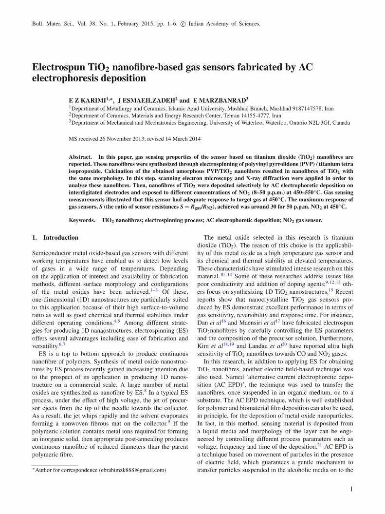
Figure 7 shows the dynamic response curves for thissensor during gas sensing measurement at different tem-peratures. The sensor exhibits reversible and reasonablyfast responses, with NO2 gases switching on and off. Theresponse time (tres) and recovery time (trec) are two signifi-cant parameters identifying rate of sensors to gas specimen.tres and trec are calculated based on the time period duringwhich the resistance of film reaches 90% of the saturatedresistance (when switching to the target gas) and 10% ofthe saturated resistance (after switching back to N2 as thebase gas), respectively. As it can be seen in figure 7, theresponse time is about 2–4 min and recovery time is lessthan 20 s. These values are comparable with those dopedTiO2 gas sensor reported in literature. For instance, Li andXia31 reported a response time of about 85 s and recovery
Figure 5. (a–c) SEM image of deposited layer of TiO2 nanofibresin the frequency of 1 Hz and voltage of 35 V on platinum electrodeswith different magnifications.
Figure 6. Response values of sensor towards different NO2 con-centrations at the temperature range of 450–550◦C.
Gas sensors fabricated by AC EPD 5
Figure 7. Dynamic response curves of gas sensor towards dif-ferent NO2 concentrations at the operating temperature range of450–550◦C.
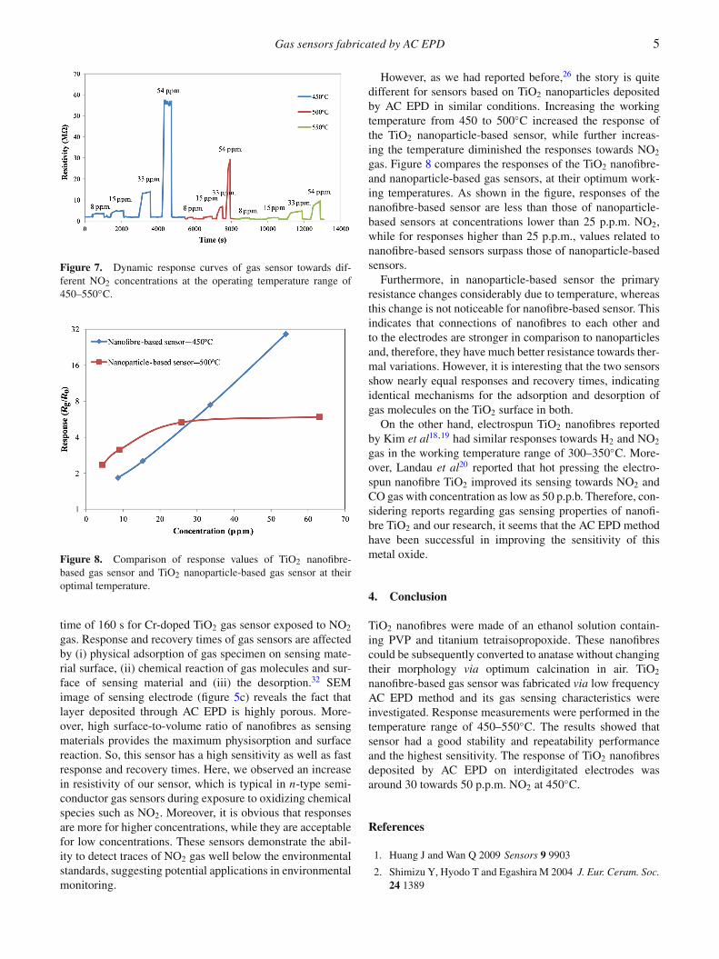
Figure 8. Comparison of response values of TiO2 nanofibre-based gas sensor and TiO2 nanoparticle-based gas sensor at theiroptimal temperature.
time of 160 s for Cr-doped TiO2 gas sensor exposed to NO2
gas. Response and recovery times of gas sensors are affectedby (i) physical adsorption of gas specimen on sensing mate-rial surface, (ii) chemical reaction of gas molecules and sur-face of sensing material and (iii) the desorption.32 SEMimage of sensing electrode (figure 5c) reveals the fact thatlayer deposited through AC EPD is highly porous. More-over, high surface-to-volume ratio of nanofibres as sensingmaterials provides the maximum physisorption and surfacereaction. So, this sensor has a high sensitivity as well as fastresponse and recovery times. Here, we observed an increasein resistivity of our sensor, which is typical in n-type semi-conductor gas sensors during exposure to oxidizing chemicalspecies such as NO2. Moreover, it is obvious that responsesare more for higher concentrations, while they are acceptablefor low concentrations. These sensors demonstrate the abil-ity to detect traces of NO2 gas well below the environmentalstandards, suggesting potential applications in environmentalmonitoring.
However, as we had reported before,26 the story is quitedifferent for sensors based on TiO2 nanoparticles depositedby AC EPD in similar conditions. Increasing the workingtemperature from 450 to 500◦C increased the response ofthe TiO2 nanoparticle-based sensor, while further increas-ing the temperature diminished the responses towards NO2
gas. Figure 8 compares the responses of the TiO2 nanofibre-and nanoparticle-based gas sensors, at their optimum work-ing temperatures. As shown in the figure, responses of thenanofibre-based sensor are less than those of nanoparticle-based sensors at concentrations lower than 25 p.p.m. NO2,while for responses higher than 25 p.p.m., values related tonanofibre-based sensors surpass those of nanoparticle-basedsensors.
Furthermore, in nanoparticle-based sensor the primaryresistance changes considerably due to temperature, whereasthis change is not noticeable for nanofibre-based sensor. Thisindicates that connections of nanofibres to each other andto the electrodes are stronger in comparison to nanoparticlesand, therefore, they have much better resistance towards ther-mal variations. However, it is interesting that the two sensorsshow nearly equal responses and recovery times, indicatingidentical mechanisms for the adsorption and desorption ofgas molecules on the TiO2 surface in both.
On the other hand, electrospun TiO2 nanofibres reportedby Kim et al18,19 had similar responses towards H2 and NO2
gas in the working temperature range of 300–350◦C. More-over, Landau et al20 reported that hot pressing the electro-spun nanofibre TiO2 improved its sensing towards NO2 andCO gas with concentration as low as 50 p.p.b. Therefore, con-sidering reports regarding gas sensing properties of nanofi-bre TiO2 and our research, it seems that the AC EPD methodhave been successful in improving the sensitivity of thismetal oxide.
4. Conclusion
TiO2 nanofibres were made of an ethanol solution contain-ing PVP and titanium tetraisopropoxide. These nanofibrescould be subsequently converted to anatase without changingtheir morphology via optimum calcination in air. TiO2
nanofibre-based gas sensor was fabricated via low frequencyAC EPD method and its gas sensing characteristics wereinvestigated. Response measurements were performed in thetemperature range of 450–550◦C. The results showed thatsensor had a good stability and repeatability performanceand the highest sensitivity. The response of TiO2 nanofibresdeposited by AC EPD on interdigitated electrodes wasaround 30 towards 50 p.p.m. NO2 at 450◦C.
References
1. Huang J and Wan Q 2009 Sensors 9 9903
2. Shimizu Y, Hyodo T and Egashira M 2004 J. Eur. Ceram. Soc.24 1389

6 E Z Karimi et al
3. Kiriakidis G, Moschovis K, Kortidis I and Binas V 2011Vacuum 1 12
4. Comini E, Baratto C, Faglia G, Ferroni M, Vomiero A andSberveglieri G 2009 Prog. Mater. Sci. 54 1
5. Arafat M M, Dinan B, Akbar S A and Haseeb A S 2012Sensors 12 7207
6. Ding B, Wang M, Yu J and Sun G 2009 Mater. Today 91624
7. Ding B, Wang M, Wang X, Yu J and Sun G 2010 Mater. Today13 16
8. Archana P S, Jose R, Jin T M, Vijila C, Yusoff M M andRamakrishna M 2010 J. Am. Ceram. Soc. 93 4096
9. Rutledge G C and Fridrikh S V 2007 Adv. Drug Deliv. Rev. 591384
10. Dutta P K, Frank M, Hunter G W and George M 2005 Sens.Actuators B 106 810
11. Al-Homoudi I A, Thakur J S, Naik R, Auner G W andNewaz G 2007 Appl. Surf. Sci. 253 8607.
12. Moon H G, Jang H W, Kim J S, Park H H and Yoon S J 2010aElectron Mater. Lett. 6 135
13. Moon J, Park J A, Lee S J, Zyung T and Kim I D 2010b Sens.Actuators B 149 305
14. Seeley Z M, Bandyopadhyay A and Bose S 2010 Thin SolidFilms 519 434
15. Wang C, Tong Y, Sun Z, Xin Y, Yan E and Huang Z 2007Mater. Lett. 61 5125
16. Dan L and Younan X 2003 Nano Lett. 3 555
17. Maensiri S, Nuansing W, Ninmuang S, Jarernboon W andSeraphin S 2006 Mater. Sci. Eng. B 131 147
18. Kim I D, Rothschild A, Tuller H L, Kim D Y and Jo S M 2006aNSTI-Nanotech. 3 483
19. Kim I D, Rothschild A, Lee B H, Kim D Y and Jo S M 2006bNano Lett. 6 2009
20. Landau O, Rothschild A and Zussman E 2009Chem. Mater. 21 9
21. Riahifar R, Raissi B, Marzbanrad E and Zamani C 2011 J.Mater. Sci. Mater. Electron. 22 40
22. Besra L and Liu M 2007 Prog. Mater. Sci. 52 1
23. Heidari E K, Zamani C, Marzbanrad E, Raissi B andNazarpour S 2010 Sens. Actuators B 146 170
24. Mahmoodi S R, Raissi B, Marzbanrad E, Shojayi N, Aghaei Aand Zamani C 2009 Procedia Chem. 1 947
25. Ghashghaie S, Marzbanrad E, Raissi B, Zamani C andRiahifar R 2012 Am. Ceram. Soc. 95 1843
26. Esmaeilzadeh J, Marzbanrad E, Zamani C and Raissi B 2011Sens. Actuators B 161 401
27. Esmaeilzadeh J, Ghashghaie S, Raissi B, Marzbanrad E,Zamani C and Riahifar R 2012 Ceram. Int. 38 5613
28. Khiabani S, Marzbanrad E, Zamani C, Riahifar R and Raissi B2012a Sens. Actuators B 166 128
29. Khiabani S, Hosseinmardi A, Marzbanrad E, Ghashghaie S,Zamani C, Kianpour-Rad M and Raissi B 2012b Sens. Actua-tors B 162 102
30. Wisitsoraat A, Tuantranont A, Comini E, Sberveglieri G andWlodarski W 2009 Thin Solid Films 517 2775
31. Li D and Xia Y 2003 Nano Lett. 3 555
32. Esmaeilzadeh J, Ghashghaie S, Khiabani S, Hosseinmardi A,Marzbanrad E, Raissi B and Zamani C 2014 J. Eur. Ceram.Soc. 34 1201
Copyright © 2022 FDOKUMEN