Electrochemical capacitance spectroscopy and capacitive relaxation of the changeover process in iron...
9
Electrochimica Acta 55 (2010) 6147–6155 Contents lists available at ScienceDirect Electrochimica Acta journal homepage: www.elsevier.com/locate/electacta Electrochemical capacitance spectroscopy and capacitive relaxation of the changeover process in iron hexacyanoferrate molecular compound Paulo Roberto Bueno a,∗ , David Giménez-Romero b , Fabio Furlan Ferreira c , Grazielle Oliveira Setti a a Instituto de Química, Universidade Estadual Paulista, C. Postal 355, 14801-907 Araraquara, SP, Brazil b Departament de Química Física, Universitat de València, C/Dr Moliner 50, 46100 Burjassot, València, Spain c Laboratório Nacional de Luz Síncrotron, C. Postal 6192, 13083-970 Campinas, SP, Brazil article info Article history: Received 4 June 2009 Received in revised form 28 August 2009 Accepted 31 August 2009 Available online 4 September 2009 Keywords: Impedance spectroscopy Capacitance spectroscopy Changeover Molecular compounds Hexacyanoferrates Prussian Blue abstract In this work it was proposed the use electrochemical capacitance spectroscopy (ECS) to evaluate the storage process during changeover in FeHCF compound. The approach is equivalent to electrochemi- cal impedance spectroscopy (EIS) albeit from such analysis it was possible to focus attention on the capacitive and dielectric relaxation instead of the dispersive relaxation related to charge transfer. From such approach it was possible to obtain complementary information on the role played by [Fe 2+ (CN) 6 ] 4− vacancies during the changeover process. It was observed that Fe 3+ (NC) 5 OH − clusters located in these vacancies mediate an electronic and ionic coupled trapping/detrapping process giving rise to what was considered an electrochemical dipolar relaxation whose K + ionic specie with Fe 3+ (NC) 5 OH − clusters are the key entities in controlling the general process. The capacitive response reaches its maximum value at the changeover due to saturation of the electronic occupation at Fe 3+ (NC) 5 OH − clusters. The nature and the dynamics of the capacitive relaxation process were either discussed. © 2009 Elsevier Ltd. All rights reserved. 1. Introduction The changeover process in the iron hexacyanoferrate compound (FeHCF) is described as a specific electrochemical potential or com- positional point (narrow in range) where all properties of this molecular material change drastically [1,2]. The iron hexacyanofer- rate compound is classically known as Prussian Blue and is widely studied although its chemistry is still not totally understood [3]. The mechanism of the changeover process was better under- stood from a recent structural analysis that surprisingly showed that [Fe(CN) 6 ] group is absent in ∼25% of the structure, invalidating the previous presumable KFe 3+ [Fe 2+ (CN) 6 ] 4− soluble structure for FeHCF compound electrochemically synthesized [4,5]. This infor- mation lead to the conclusions that the real structure of the Prussian Blue or FeHCF electrochemically synthesized after stabilization process is Fe 4 [Fe(CN) 6 ] 3 ·mH 2 O with a certain fraction of K + ions inserted [4,5]. Indeed, based on electrogravimetric analysis [6,7] complemented by the Fourier maps it was possible to affirm that the K + was found to be part of coordinated water crystal substruc- ture [4,5]. Taking into account the latter assumption, the chemical for- mula of the compound was considered to be Fe 4 [Fe(CN) 6 ] 3 · ∗ Corresponding author. E-mail addresses: [email protected] (P.R. Bueno), [email protected] (D. Giménez-Romero). (K h + ·OH h − ·mH 2 O) [4]. Furthermore, from structural information allied to electrochemical analysis it was observed that the changeover occurs exactly when the Fe 2+ Fe 3+ 3 [Fe 2+ (CN) 6 ] 3 ·[K h + ·OH h − ·mH 2 O] composition is reached, i.e. when all the Fe 3+ (iron nitrogen octahedral coordinated sites) is converted to Fe 2+ in 4a crystallographic sites of the structure adjacent to the [Fe 2+ (CN) 6 ] 4− vacancies [4,8]. Therefore, it was shown that the changeover process occurs exactly when 25% of total electronic charge is injected in the FeHCF compound by the ne − external circuit, i.e. when 25% of the total Fe 3+ is converted to Fe 2+ . Furthermore, this fraction of Fe 3+ converted was inferred to be exactly located at Fe 3+ (NC) 5 OH − clusters, penta-coordinated Fe 3+ iron metals which are the bridges between the main FeHCF framework, i.e. Fe 2+ –CN–Fe 3+ chains and water substructure by means of OH − local chemical entities. The mechanism involved with the amount of [Fe 2+ (CN) 6 ] 4− vacancies existing in the FeHCF compounds is capable of explaining the electrochromism [8] of these materials and also the magnetic switch [2] as well. The sites for electronic charge occupation injected from exter- nal circuit during in situ compositional variation are Fe 3+ metals. The full occupancy is thus reached when all the material’s bulk has Fe 2+ –CN–Fe 3+ chains with all of Fe 3+ entities converted to Fe 2+ , i.e. Fe 2+ –CN–Fe 2+ . In the general formula it means that all atoms of the Fe 3+ 4 [Fe 2+ (CN) 6 ] 3 ·[K h + ·OH h − ·mH 2 O] structure residing at the 4a crystallographic sites receive an electron from the external circuit, which means Fe 2+ 4 [Fe 2+ (CN) 6 ] 3 ·[K h + ·OH h − ·mH 2 O]. Accord- ingly, it was assumed that the sites for electronic charge occupation 0013-4686/$ – see front matter © 2009 Elsevier Ltd. All rights reserved. doi:10.1016/j.electacta.2009.08.060
Transcript of Electrochemical capacitance spectroscopy and capacitive relaxation of the changeover process in iron...
Ec
Pa
b
c
a
ARRAA
KICCMHP
1
(pmrs
sttFmBpictt
m
d
0d
Electrochimica Acta 55 (2010) 6147–6155
Contents lists available at ScienceDirect
Electrochimica Acta
journa l homepage: www.e lsev ier .com/ locate /e lec tac ta
lectrochemical capacitance spectroscopy and capacitive relaxation of thehangeover process in iron hexacyanoferrate molecular compound
aulo Roberto Buenoa,∗, David Giménez-Romerob, Fabio Furlan Ferreirac, Grazielle Oliveira Setti a
Instituto de Química, Universidade Estadual Paulista, C. Postal 355, 14801-907 Araraquara, SP, BrazilDepartament de Química Física, Universitat de València, C/Dr Moliner 50, 46100 Burjassot, València, SpainLaboratório Nacional de Luz Síncrotron, C. Postal 6192, 13083-970 Campinas, SP, Brazil
r t i c l e i n f o
rticle history:eceived 4 June 2009eceived in revised form 28 August 2009ccepted 31 August 2009vailable online 4 September 2009
a b s t r a c t
In this work it was proposed the use electrochemical capacitance spectroscopy (ECS) to evaluate thestorage process during changeover in FeHCF compound. The approach is equivalent to electrochemi-cal impedance spectroscopy (EIS) albeit from such analysis it was possible to focus attention on thecapacitive and dielectric relaxation instead of the dispersive relaxation related to charge transfer. Fromsuch approach it was possible to obtain complementary information on the role played by [Fe2+(CN)6]4−
eywords:mpedance spectroscopyapacitance spectroscopyhangeover
vacancies during the changeover process. It was observed that Fe3+(NC)5OH− clusters located in thesevacancies mediate an electronic and ionic coupled trapping/detrapping process giving rise to what wasconsidered an electrochemical dipolar relaxation whose K+ ionic specie with Fe3+(NC)5OH− clusters arethe key entities in controlling the general process. The capacitive response reaches its maximum value atthe changeover due to saturation of the electronic occupation at Fe3+(NC) OH− clusters. The nature and
citive
olecular compoundsexacyanoferratesrussian Bluethe dynamics of the capa
. Introduction
The changeover process in the iron hexacyanoferrate compoundFeHCF) is described as a specific electrochemical potential or com-ositional point (narrow in range) where all properties of thisolecular material change drastically [1,2]. The iron hexacyanofer-
ate compound is classically known as Prussian Blue and is widelytudied although its chemistry is still not totally understood [3].
The mechanism of the changeover process was better under-tood from a recent structural analysis that surprisingly showedhat [Fe(CN)6] group is absent in∼25% of the structure, invalidatinghe previous presumable KFe3+[Fe2+(CN)6]4− soluble structure foreHCF compound electrochemically synthesized [4,5]. This infor-ation lead to the conclusions that the real structure of the Prussian
lue or FeHCF electrochemically synthesized after stabilizationrocess is Fe4[Fe(CN)6]3·mH2O with a certain fraction of K+ ions
nserted [4,5]. Indeed, based on electrogravimetric analysis [6,7]omplemented by the Fourier maps it was possible to affirm that
he K+ was found to be part of coordinated water crystal substruc-ure [4,5].Taking into account the latter assumption, the chemical for-ula of the compound was considered to be Fe4[Fe(CN)6]3·
∗ Corresponding author.E-mail addresses: [email protected] (P.R. Bueno),
[email protected] (D. Giménez-Romero).
013-4686/$ – see front matter © 2009 Elsevier Ltd. All rights reserved.oi:10.1016/j.electacta.2009.08.060
5
relaxation process were either discussed.© 2009 Elsevier Ltd. All rights reserved.
(Kh+·OHh
−·mH2O) [4]. Furthermore, from structuralinformation allied to electrochemical analysis it wasobserved that the changeover occurs exactly when theFe2+Fe3+
3[Fe2+(CN)6]3·[Kh+·OHh
−·mH2O] composition is reached,i.e. when all the Fe3+ (iron nitrogen octahedral coordinated sites)is converted to Fe2+ in 4a crystallographic sites of the structureadjacent to the [Fe2+(CN)6]4− vacancies [4,8]. Therefore, it wasshown that the changeover process occurs exactly when 25% oftotal electronic charge is injected in the FeHCF compound by thene− external circuit, i.e. when 25% of the total Fe3+ is converted toFe2+. Furthermore, this fraction of Fe3+ converted was inferred tobe exactly located at Fe3+(NC)5OH− clusters, penta-coordinatedFe3+ iron metals which are the bridges between the main FeHCFframework, i.e. Fe2+–CN–Fe3+ chains and water substructure bymeans of OH− local chemical entities. The mechanism involvedwith the amount of [Fe2+(CN)6]4− vacancies existing in the FeHCFcompounds is capable of explaining the electrochromism [8] ofthese materials and also the magnetic switch [2] as well.
The sites for electronic charge occupation injected from exter-nal circuit during in situ compositional variation are Fe3+ metals.The full occupancy is thus reached when all the material’s bulkhas Fe2+–CN–Fe3+ chains with all of Fe3+ entities converted to Fe2+,
i.e. Fe2+–CN–Fe2+. In the general formula it means that all atomsof the Fe3+4[Fe2+(CN)6]3·[Kh+·OHh
−·mH2O] structure residing atthe 4a crystallographic sites receive an electron from the externalcircuit, which means Fe2+
4[Fe2+(CN)6]3·[Kh+·OHh
−·mH2O]. Accord-ingly, it was assumed that the sites for electronic charge occupation

6 imica Acta 55 (2010) 6147–6155
idbtiooeiatso
sfiu[cfpbwocdtttie
bcc
FFep
148 P.R. Bueno et al. / Electroch
njected from external circuit previously to the changeover pointuring in situ compositional variation is preferentially occupiedy Fe3+ sites adjacent to the [Fe2+(CN)6]4− vacancies, meaninghe electrons occupy Fe3+ sites with unsatisfied CN–Fe3+ chem-cal bonding adjacent to the vacancies [9]. This particular sitef the structure is Fe3+ iron metals penta-coordinated insteadf Fe2+ hexa-coordinated fully satisfying chemical bonding. Thisxplains why there is no color, magnetic or electronic conductiv-ty changes up to the changeover potential [2,8], since these sitesre fully depleted at the changeover point and the mechanism ofhe changeover must take into account the role played by theseites inevitably. Fig. 1 illustrates these sites and Fig. 2 shows itsccupation in a FeHCF electrode.
These sites will be here represented by Fe3+(NC)5OH−, i.e. Fe3+
ites adjacent to the [Fe2+(CN)6]4− vacancies coordinated by therst shell water crystal substructure. There are, in the whole vol-me of the [Fe2+(CN)6]4− vacancy entities, six of these units, i.e.Fe3+(NC)5OH−]6. It is important to clarify that the OH− entity isonsequence of the first shell coordinated with the main structureramework [4,10]. This kind of site is a very important and alsoarticular environment of the structure because it is the bridgeetween the coordinated water substructure and the main frame-ork represented by the Fe2+–CN–Fe3+ chains [4]. Such a bridge
r connection is made mainly by means of the Fe3+ atoms at 4arystallographic sites chemically bonded to OH− entities (first coor-inated water substructure). It is also important to stress out thathere is also a second kind of structural water [10], a second shellhat is not represented in Figs. 1 or 2. The water crystal substruc-ure is non-stoichiometric and this characteristic is very importantn controlling the occupancy of ionic sites by K+, H+ and/or H3O+
ntities [4,6,11,12].These three entities are the main ionic species exchanged
etween electrolyte and FeHCF compound junction during in situompositional variation [4,6,11,12]. However, the changeover pro-ess is preferentially dependent of K+ species albeit this is not the
ig. 1. Planar schematic representation of a [Fe2+(CN)6]4− vacancy environment ineHCF compound. The arrows indicate the preferential Fe3+(NC)5OH− clusters orntities where electronic charge is preferentially occupied prior to the changeoverrocess takes place.
Fig. 2. Planar schematic representation of interconnected [Fe2+(CN)6]4− vacancies,forming an internal electrolyte channel. Note the occupancy of the vacancy by K+
ions. The transport to K+ goes through the interconnected net of [Fe2+(CN)6]4− vacan-cies.
ionic specie that is mainly exchanged during the changeover [1]with the liquid electrolyte. The changeover process in FeHCF is welland better illustrated in references [1,2,13].
2. Transfer function analysis applied to FeHCF compounds
On the electroanalysis of FeHCF compounds, frequency responsetechniques were explored in the past by Gabrielli et al. [14,15] tostudy, in details, the role played by the K+, H+ and/or H3O+ entitiesand to separate their contribution and kinetics on the whole pro-cess of ionic exchange in FeHCF [6,11,12]. This work was extremelyimportant because it was the basis of a better understanding ofthe ionic exchange mechanism in the FeHCF compound, showingthe importance played by the water substructure [6], for instance.Later, a detailed structural analysis was carefully conducted todefinitively show the importance played by [Fe2+(CN)6]4− vacan-cies and the relationship between coordinate water substructureand [Fe2+(CN)6]4− vacancies in FeHCF compounds [4,5,8].
Of special importance were the studies conducted by ac-electrogravimetric technique and theory developed by Gabrielliet al. [14,15] which specifically separates intercalation kinetics ofthe different species involved in the ionic interplay mechanismof FeHCF compound [6]. Accordingly, it was possible to constructthe isothermal compositional curves of these species for the FeHCFcompounds [11,12] and determine what were the species that con-tribute and control the impedance pattern at low frequency region[11,14]. At potentials proceeding to the changeover the main specie
exchanged with the solution was evidenced to be K+ [11]. Thechangeover is exactly characterized by a maximum electronic cur-rent concomitantly to a minimum variation on mass/charge ratio,indicating an internal rearrangement or configuration change onFeHCF compound [1,2].
imica Acta 55 (2010) 6147–6155 6149
paittrupIpp
bwtcicbe
2
cm[spivt[cfwtisfdcm
ttcIgemtap
itHiatetpa
Fig. 3. Schematic representation of boundary conditions of FeHCF system and theimportance of the [Fe2+(CN)6]4− vacancies, i.e. liquid electrolyte/FeHCF/conductorsubstrate junction. Note that there is an ionic connection path between liquid elec-trolyte and the coordinated water substructure inside [Fe2+(CN)6]4− vacancy. The
P.R. Bueno et al. / Electroch
Based on the previous assumption, the main purpose of theresent work is to use electrochemical capacitance spectroscopyround the changeover process of the FeHCF compounds to studyn details the charge relaxation and to identify, according tohe structural information, the exact sites or environment andhe structural rules that control the changeover process and itselaxation feature. The capacitance spectroscopy analysis can beseful to evaluate electronic solid state processes when they areredominant capacitive or negligibly conductive. Electrochemical
mpedance Analysis was never studied in depth at changeoverotentials due to the lack of information about this process in theast.
In electrochemistry, the capacitance spectroscopic analysis cane useful if it is linked with the concept of dielectric relaxation, asill be shown in the present work. The approach will then be used
o evaluate the charge relaxation involved with the changeover pro-ess of FeHCF compound and to study the local charge dynamics,.e. a physical–chemistry approach will also be proposed for thehangeover process considering the importance and role playedy [Fe2+(CN)6]4− vacancies and charge dynamics imposed by thisnvironment in FeHCF compound.
.1. Transport and nanoscale effects in FeHCF
At this moment, it is very important to establish the boundaryonditions for FeHCF system, which will be here based on infor-ation given by a careful structural analysis conducted previously
4]. Therefore, it is possible to consider that the FeHCF system is apatially macrohomogeneous system of two closely homogeneoushases [16–18] in which [Fe2+(CN)6]4− vacancies is one phase act-
ng as the ionic channel and ionic conductive path along the wholeolume of the FeHCF compound. On the one hand, this ionic conduc-ive phase is formed by coordinated water substructure (located atFe2+(CN)6]4− vacancies [4]) which acts as a volumetric electrolytehannels inside the FeHCF system linking spatially each other,orming a nanostructured channel for K+ to be freely exchangedith liquid electrolyte solutions (see Fig. 2). On the other hand,
he Fe2+–CN–Fe3+ entities act as electrically connected channels,.e. electronic transportation path up to Fe3+(NC)5OH− clusters thaterve as bridges between the main electronically conductive FeHCFramework, i.e. Fe2+–CN–Fe3+ chains, and structural water coor-inated substructure. The Fe3+(NC)5OH− sites are electronicallyompensated by K+, H+ or H3O+ species unbonded to it, whicheans interacting weakly.A metal–FeHCF film of such form is illustrated in Fig. 3 and
he system can be loaded with K+ ions that enter the filmhrough coordinated water substructures at [Fe2+(CN)6]4− vacan-ies, charge-compensated by electrons entering from the substrate.t will be assumed that the FeHCF electrode material is a enoughood electronic conductor [19] so that the chemical potential oflectronic species are essentially uniform throughout the FeHCFaterial and only the ion transport needs to be examined. Fur-
hermore, the K+ ion dynamics dominates the changeover process,lthough the H+ and H3O+ are also important in the whole exchangerocess [6].
In this context electrochemical capacitance spectroscopy (ECS)s essentially synonymous of electrochemical impedance spec-roscopy (EIS) represented as its inverse, i.e. in terms of admittance.owever, it is very important to mention that the capacitive behav-
or of the junction represented in Fig. 3 is not usually regarded aspart of the electrochemical analysis, since generally it is usual
o emphasize the charge transfer resistive and/or transport pref-rentially to capacitive processes. The purpose here is to performhe capacitive analysis to stress out the charge storage relaxationrocess, specially the one occurring in electrochemical potentialround changeover process.
blocking characteristic in the impedance response will be determined by this kindof boundary conditions, and each [Fe2+(CN)6]4− vacancy will operate as a capacitiveelectrochemistry surface with Fe3+(NC)5OH− clusters acting as electronic and ionicbridges with a K+ ionic bond and unbonded relaxation process associated to it.
The K+ ion transport throughout [Fe2+(CN)6]4− vacancies chan-nels can be theoretically well described by considering the diffusionimpedance model [18,20]. The general expression is given by[18,20]:
Z(ω) = (�m�m)1/2coth[
L(
�m
�m
)]. (1)
Here �m is an impedance per unit length (� m−1), which in themodels treated in this paper has the form of a simple resistance [20],as show in Fig. 4, where the transmission line impedance is used asan equivalent circuit to represent the K+ ion transport throughout[Fe2+(CN)6]4− vacancies. �m is given by:
�m = r−CN− =R−CN−
L(2)
where r–CN– is the distributed resistance of Fe2+–CN–Fe3+ channelsover L, which is the thickness of the FeHCF compound electrode.
2.2. The ionic relaxation process at [Fe2+(CN)6]4− vacanciesenvironment
To complement the arguments for the reason of why ECS is notwell considered as EIS in the context of electrochemical junctionsis based on the fact that the admittance functions (Y*(ω) = Y′ + jY′′√
in which ω = 2�f is the angular frequency and j = −1) are usuallyused instead. However, it is important to demonstrate that phys-ically the capacitive interpretation is more useful to give physicalinformation about the storage processes in the internal interfacesof the electrochemical junctions, even considering that admittance
6150 P.R. Bueno et al. / Electrochimica
Fig. 4. (a) Transmission line representing the ionic diffusion transport through the[Fe2+(CN)6]4− vacancies interconnected path. Note that r–CN– represents the elec-t[d
at
C
C
t((c
aritcinfm[ahsctrs
wtg[eee
ut
i
ronic path given by Fe2+–CN–Fe3+ chains. (b) The relaxation inside the interconnectFe2+(CN)6]4− vacancies are represented by the transversal impedance �m which isefined in the text (see for instance Eq. (1)).
nd capacitance functions are mathematically direct proportionalo each other as showed below:
∗(ω) = (jω)−1Y(ω), (2)
∗(ω) =(
Y ′′
ω− jY ′
ω
)= C ′ + jC ′′. (3)
The real part (C′) of the complex capacitance function is relatedo parallel capacitance (C′ = Y′′/ω = Cp) while the imaginary partC′′) is related to a conductive term (C′′ = Y′/ω = Gp/ω) [21]. The Gp
or Gp/ω) conductive term is a parameter that includes the dc-onductance and other relaxation-associated loss [22].
As our purpose here is to study the ionic relaxation processt [Fe2+(CN)6]4− vacancies environment around the changeoveregion, now we will detail an appropriate kinetic model foronic relaxation that can physically and chemically representshe changeover process. It is important to emphasize that thehangeover process is related to coordinated water sites and K+
ons [1]. Therefore, we will consider that the changeover is an inter-al transition, a bulk electrochemical process in which K+ ions goes
rom Fe3+(NC)5OH− sites, i.e. coordinated water to sites inside theain FeHCF framework represented by the Fe2+–CN–Fe3+ chains
8]. This process will be proposed and explained fully based onn ionic relaxation at [Fe2+(CN)6]4− vacancies environment furthererein. However, at this point, it is important only to empha-ize that from such a picture each local coordinated water, athangeover, act as an internal electrolyte in the role length andhickness of FeHCF compound, and [Fe2+(CN)6]4− vacancies envi-onment acts as internal interfaces, or internal nanostructuredurface capacitors.
Nevertheless, the most important contribution of the presentork is to give a kinetic meaning to the charge transfer reaction
aking place along FeHCF compound considering this macrohomo-eneous description of the FeHCF in which the three-dimensionalFe2+(CN)6]4− vacancies environment network act as a nanoscalelectrolyte along FeHCF length L and Fe2+–CN–Fe3+ entities act aslectronic channel of this macrohomogeneous description of FeHCF
lectrode.To start the discussing and the constructing of the model, lets consider the following general nanoscale heterogeneous oxida-ion/reduction reaction at the equilibrium or close to it inside each
Acta 55 (2010) 6147–6155
[Fe2+(CN)6]4− vacancy environment:
⟨Fe2+⟩
V
kr�kt
⟨Fe3+⟩
V+ ze (4)
where 〈Fe3+〉V (alternatively named as nr,V, for simplification) is thedensity of Fe3+(NC)5OH− oxidized species at [Fe2+(CN)6]4− vacancyenvironment and 〈Fe2+〉V (alternatively named as nt,V) is the densityof the reduced species at the [Fe2+(CN)6]4− vacancy of FeHCF, i.e.Fe2+(NC)5OH−. In Eq. (4) e is the elementary charge. Note that forz = 1 in Eq. (4), these sites are only capable to receive one electronper site.
At this point it is important to describe a uniform volumetricdensity of active sites—iron sites coordinated to water substructureat [Fe2+(CN)6]4− vacancy environment as h, which is the numberdensity of unbonded K+ ions inside the structure. On the otherhand, the ht will be the concentration of bonded K+ ions. In terms of[Fe2+(CN)6]4− vacancies environment and coordinated water sub-structure reaction h and ht can then be, respectively, pictured as:
K+, Fe2 + (NC)5OH−kr−→K+, Fe3+(NC)5OH−(unbonded)+ e− (5)
K+, Fe3 + (NC)5OH− + e−kt−→K+, Fe2 + (NC)5OH−(bonded) (6)
Note that Eq. (6) represents an ionic dipolar environment. There-fore, it is important to stress that nt,V is the number of Fe2+(NC)5OH−
sites energy, where the K+ species locally compensate the electroniccharges by stronger interaction referred as bounded dynamics. Thissituation gives rise to Eq. (6) in which the electronic dynamics isdependent of the K+ ion inside the vacancies. Furthermore, it isalso important to stress out that the sites represented in Eqs. (5)and (6) are spatially the same local only changing its reduced orthe oxidized states with K+ bonded or unbonded to it. Therefore,by assuming that nr,V and nt,V are governed by a limited num-ber of active sites in the FeHCF volume, which depends only onthe amount of [Fe2+(CN)6]4− vacancies of the FeHCF compound, itis possible to describe nr,V and nt,V in terms of a complementaryfraction.
Accordingly, ht = nt/Nt,V, where Nt,V is the number density ofFe2+(NC)5OH− site that is related to the number of [Fe2+(CN)6]4−
vacancy. Therefore, Nt,V is a number density proportional to thesize of the FeHCF compound, i.e. the total number of Fe2+(NC)5OH−
sites with K+ bonded (trapped) on it along L thickness.For the calculation of the theoretical complex capacitance func-
tion of the changeover kinetic mechanism, it is important toemphasize that the derivative of nt,V as a function of the appliedpotential with respect to the equilibrium potential, dnt,V/dV, iscalculated by considering the reduction and oxidation states as ele-mentary steps. Furthermore, it will be assumed that the reductionand oxidation kinetic constants follow a Buttler–Volmer depen-dence with regard to the applied potential, so that:
ki = ki exp(biV) (7)
where V is the applied potential and ki is the pre-exponential factorof the kinetic constant. The index i indicates the two possibili-ties given here: bonded or unbonded states. Therefore, bi is theexponential factor of the kinetic constant for the reduction or theoxidation faradaic process – bt =−(eˇ)/kBT and br = [e(1−ˇ)]/kBT –where ˇ is the transfer coefficient, e is the elementary charge, andkB is the Boltzmann constant. Now considering a small oscillatingvoltage perturbation over this potential, Eq. (7) turns into:
ki = ki exp(bi(V + V)) = k0 exp(biV) (8)
where V is the steady-state potential and V is an oscillating voltageperturbation of small amplitude around a stationary value V , duringa given steady-state measurement. Finally, k0
iis the kinetic constant
at steady-state.

imica
m
V
d
wv
n
n
d
wav
af
Ai(e
j
Ntob
wde(io
trt
q
s
C
NpucvtEmtc
�
the blocking capacitors surfaces at [Fe2+(CN)6]4− vacancies. The K+
ion charges the [Fe2+(CN)6]4− vacancies. Through this connectednetwork of [Fe2+(CN)6]4− vacancies the K+ moves rapidly and isdistributed according to equilibrium thermodynamic properties
P.R. Bueno et al. / Electroch
Therefore, V can be related to V during an ac perturbation byeans of the following expression:
= V + V = V +�V exp(jωt), (9)
V = jωV dt, (10)
here j is the square root of −1 and �V is the amplitude of theariation of the electrochemical potential perturbation.
For sufficiently small amplitude potential perturbations, nt,V andr,V can be represented in terms of complex functions by means of:
t,V = nt,V + nt,V = nt,V +�nt,V exp(jωt), (11)
nt,V = jωnt,V dt, (12)
here nr,V is the number of Fe2+(NC)5OH− sites with K+ bondedt a given steady-state potential V , �nt,V is the amplitude of theariation of these Fe2+(NC)5OH− reduced sites caused by �V .
As a result, taking into account the kinetic laws of this mech-nism, the variation of nt,V with time can be calculated from theollowing expression:
dnt,V
dt= jωnt,V = ktnr,V − krnt,V . (13)
s already mentioned, it is considered that Nr,V does not vary dur-ng the measurements and, therefore, after differentiation of Eq.13) as a function of potential it is possible to obtain the followingxpression:
ωdnt,V
dV= jω
dnr,V
dV= btktnr,V − kr
dnt,V
dV− brkrnt,V − kt
dnt,V
dV. (14)
ote that in Eq. (14) it has been considered that the variation inhe concentration of the bonded and unbonded species due to thescillation perturbation is sufficiently small to be neglected. Now,y rearranging Eq. (14), it is possible to obtain:
dnt,V
dV= btktnr,V − brkrnt,V
(kt + kr)+ jω, (15)
dCVR
dV= G
K + jω, (16)
here G = btktnr,V−brkrnt,V and K = kt + kr are two constant termsefined at equilibrium or even at a given steady-state close to thequilibrium. The equilibrium (or steady-state) bonded capacitanceC∗t,V ) can be easily defined from Faraday’s law, considering that thenitial current density is about zero (i.e. for overpotential differentf zero, the C∗t,V can be also considered the steady-state capaci-
ance). The charge trapped at Fe2+(NC)5OH− capacitor is thereforeelated to the concentration of Fe2+(NC)5OH− sites with K+ bondedo it according to:
t = zeVsnt,V (17)
o that, and considering z = 1:
∗t,V =
dqt
dV= eVs
dnt,V
dV= eVs
G
K + jω. (18)
ote that in Eq. (18) it has been considered that the oscillatingerturbation is sufficiently small to neglect the variation in thenbonded concentration of the species in the [Fe2+(CN)6]4− vacan-ies in respect to liquid electrolyte. In Eqs. (17) and (18), Vs is theolume of the solid phase; i.e. the geometric area multiplied by thehickness (Vs = AL). The complex capacitance function described inq. (18) leads to the transversal impedance (�m) of the process byeans of the following relationship Z(ω) = 1/[jωC(ω)], so that the
ransversal element indicated in Fig. 4, i.e. �m, after geometricalorrections, is given by:
m = 1zeVs
K + jω
G(19)
Acta 55 (2010) 6147–6155 6151
3. Experimental
The FeHCF compounds used here were prepared according tothe procedures indicated in references [1,2,6,23,24] as well asthe electrochemical analyses performed. Briefly, the electrochem-ical experiments were carried out in a typical three-electrodecell, where the working electrode was a transparent conductiveelectrode (ITO) with covering surface of 1 cm2. A platinum platewas the counter electrode and Ag/AgCl/KCl saturated was used asthe reference electrode. FeHCF compounds were galvanostaticallydeposited. FeCl3, KFe(CN)6 and HCl were used for the synthesis ofthe FeHCF compounds. The galvanostatic experiments were carriedout by means of a potentiostat–galvanostat (AUTOLAB PGSTAT30).The working electrode was immersed into a 0.02 M K3Fe(CN)6,0.02 M FeCl3 and 0.01 M HCl solution and controlled with a cathodiccurrent of 40 �A cm−2, which was applied during 150 s to obtain theelectrodeposited FeHCF electrodes. After that, the FeHCF films werestabilized before the EIS measurements by means of cyclic voltam-metry around the Everit’s salt↔ FeHCF transition [0.60,−0.20] V in0.25 M KCl, pH about 2.
EIS measurements were carried out in a typical electrochem-ical three-electrode cell. The EIS measurements were performedby using an AUTOLAB PGSTAT30 with FRA module with oscillat-ing perturbation of 10 mV RMS amplitude from 50 kHz to 5 mHz atdifferent steady-state conditions around changeover potential.
4. Results and discussion
4.1. Electrochemical impedance and capacitance spectroscopy
Fig. 5 shows the impedance Nyquist diagram of FeHCF com-pound. This is a typical pattern already observed in previous papers[14,18,20]. What is possible to observe is the presence of theclassical diffusion blocking pattern as expected, according to themodel previously stated herein [18,20]. However, this pattern isnot related to the spatially restricted ionic diffusion (ordinary dif-fusion) thought the interstices of the structure. The diffusion path,in the present case, arises due to structural features in whichthe K+ diffuses through the channels formed by [Fe2+(CN)6]4−
vacancies. It is possible to say that [Fe2+(CN)6]4− vacancies actas nanometric porous connecting the liquid electrolyte (solution).In this picture, the water substructure acts as an ionic channelinside FeHCF structure that connects the liquid electrolyte with
Fig. 5. Nyquist impedance complex plane plots for FeHCF in an aqueous solution of0.25 M KCl. The insets show the high frequency region of the spectra.

6152 P.R. Bueno et al. / Electrochimica
Fo
[mtcrhWic
rtvi[s
ict
ttdiislto
4
edtrkwratp
pensation for electronic change due to ne− external variation wasalready described in Ref. [6] and can be ascribed to K+, H+ and/orH3O+. However, the H+ and/or H3O+ were not considered in thepresent analysis since K+ strongly dominates the changeover pro-
ig. 6. Nyquist capacitance complex plane plots for FeHCF in an aqueous solutionf 0.25 M KCl. The inset shows the high frequency region of the spectra.
25]. It is important to mention that in order to simplify the treat-ent and exposition of the data, electrolyte resistance associated to
he electrolyte/FeHCF interface has been neglected. The traditionalharge transfer resistance and double layer capacitance are not rep-esented and were also neglected. This can be done by fitting theigh frequency end of experimental data to a Randles circuit with aarburg impedance as diffusion element and correcting the total
mpedance with the particular contribution of the resistances andapacitance elements obtained in this partial fit.
From Figs. 5 and 6 it is possible to observe that the maximumestricted ionic blocking behavior occurs exactly at 0.2 V which ishe potential where the changeover starts operating. This potentialalue also corresponds to about 25% of the total electronic chargenjected in the FeHCF system, not coincidently the same amount ofFe2+(CN)6]4− vacancies founded in the whole volume of the FeHCFystem, i.e. Fe4[Fe(CN)6]3.
The capacitive Nyquist diagrams show a maximum on the capac-tance exactly at 0.2 V as can be observed in Fig. 6. This behaviorannot be predicted by traditional intercalation models existing inhe literature [20,26].
Fig. 7 shows the Bode capacitive diagrams of the FeHCF sys-em. What is remarkable in examining Bode capacitive plots ishat the response of FeHCF is mainly described by a unique, well-efined relaxation process at low frequency region. From Figs. 5–7
t is also possible to note that the storage process, i.e. the capac-tive response dominates the global response over the diffusion,pecially at low frequencies, which means that by focusing the ana-yzes at the capacitive behavior it will be possible to understandhe effects of storage previously to changeover and discharge thatccurs after it (Fig. 8).
.2. The [Fe2+(CN)6]4− vacancies and energetic K+ bonding
Considering that the Fe3+(NC)5OH− site is favorably and pref-rentially occupied by the electrons inserted from external circuituring in situ compositional variation [4,8,9], indicating that this ishe most energetically favorable site for electrons (energeticallyepresented in Fig. 9 by E0,e) it is possible to say that from thenowledge of the structure and from structural rules that comes
ith this particular insoluble structure that these sites shall satu-ates exactly when 25% of Fe3+ in the Fe3+(NC)5OH− environmentre fully occupied. In other words, it is being considered that allhe electronic charge imposed to the system up to the changeoveroint is going to fulfill the Fe3+(NC)5OH− sites [8]. At this exact elec-
Acta 55 (2010) 6147–6155
tronic charge fraction, i.e. about 25% of all Fe3+ sites being occupied,which is linked to the exact amount of [Fe2+(CN)6]4− vacancies, thechangeover occurs. This picture is in very agreement to the proposalthat all the charge is occupying exactly the Fe3+(NC)5OH− enti-ties, i.e. the bridge sites between FeHCF main framework formedby Fe2+–CN–Fe3+ chains and water substructure. However, it isimportant to add to this picture, according to what was discussedpreviously, that when Fe3+(NC)5OH− sites are electronically occu-pied, i.e. Fe2+(NC)5OH, there is a coupled ionic process to it. In otherwords, the process is accompanied by a K+ trapping or bonding pro-cess. The trapping processes in intercalation system were alreadydiscussed in several works [16,17,20,25,27] albeit for the first timeherein the dynamic is clearly evidenced and the exact trapping siteis located.
It is important to be mentioned that the picture of thechangeover described here, by combination of ionic and electronicaspects, is totally in agreement to the fact that the K+ ions arelocated into the coordinated water crystalline substructure andthat this is crucial for the occurrence of the changeover, reinforcingdiscussions made in previous works [1,6,13].
Although K+ and [Fe2+(CN)6]4− vacancies are key to changeoverprocess, it is important to observe that electronic charge can beeither compensated by H+ and/or H3O+ [11], i.e. the ionic com-
Fig. 7. Bode capacitance complex plane plots for FeHCF in an aqueous solution of0.25 M KCl. All marked frequencies in mHz: (a) real part (C′) and (b) imaginary partof the complex capacitance.

P.R. Bueno et al. / Electrochimica Acta 55 (2010) 6147–6155 6153
F ntial.t tated
ctt
FccbstbuVtb
−wzcoocpaeucc
Foi(ae
ig. 8. (a) The maximum value of the K+ bounding process at the changeover poterapping states at [Fe2+(CN)6]4− vacancies, which in the physical chemistry model s
ess and only the sites related to K+ will then be taken into accounto facilitate the analyses of the changeover process and FeHCF elec-rochemical charging.
Therefore, at this moment it is important to treat thee3+
4[Fe2+(CN)6]3·[Kh+·OHh
−·mH2O] insoluble structure as an inter-alation (or host) compound so that the ECS analysis can beompleted and the sites located in the [Fe2+(CN)6]4− vacancies wille treated from a physical–chemistry approach. In an intercalationystem or compound there are always electronic and ionic sites andhe compositional variation that compensates electronic charge cane described in terms of an occupancy fraction, i.e. h = nr,V/Nr,V, fornbonded K+ ion. The steady-state voltage of the working electrode,, is related to the chemical potential of the K+ intercalated ions inhe working electrode, , and that in the reference electrode, 0,y:
zeV = −0 (20)
here e stands for the positive elementary charge [7,28]. Note that= 1 for any one of the K+, H+ and/or H3O+ entities that can be inter-alated in FeHCF compounds. The term the −zeV is the work donen the cell per ionic entities intercalated under a voltage differencef V. Therefore, the voltage V is determined by the variation of thehemical potential of the FeHCF electrode as a function of com-osition, (h) (see Fig. 9). Note that by measuring the cell voltage
t equilibrium versus the charge passed between the electrodes isquivalent to measure the chemical potential as a function of h, i.e.nbonded K+ content of the Fe3+4[Fe2+(CN)6]3·[Kh+·OHh
−·mH2O]ompound. The thermodynamics requires that increases with theoncentration of guest ions, and so V decreases as ions are added to
ig. 9. Schematic diagram of the electronic energy level occupation and the counter partf Fe3+ in 4a crystallographic sites by electronic charge injected (here it is specifically pronjected can be compensated by K+, H+ and/or H3O+. E0,e is the energy for the occupatioindex 1) is related here to the occupancy of Fe3+(NC)5OH− clusters. The index i indicatesnd E1,t refers to ionic energetic level for compensation of K+. Since the electronic and iolectronic, for instance (due to the concept of electrochemical relaxation process introdu
(b) The �C means the maximum of Eq. (26). In other words, the saturation of thein the paper is the Fe3+(NC)5OH− sites.
the positive electrode. Therefore, it is possible to define the equi-librium intercalation capacitance of unbonded K+ at [Fe2+(CN)6]4−
vacancies as:
Cr,V = −dqr
dV= −LAenr,V
dh
dV= Vse
2nr,Vdh
d(21)
where qr = LAnr,Ve = eVsnr,V is the total extent of unbonded or chargepassed through the FeHCF that are not located at Fe3+(NC)5OH−
sites along L, i.e. the film thickness of the electrode, and A is the area[7,28]. Note that this is a bulk capacitance and not a surface capaci-tance. Thus the charge is considered to occupy a volume. Neglectingthe electronic contributions to the chemical potential and consider-ing that there is no interaction particles that occupy identical sites,as already demonstrated in a previous work [12], the probabilityof occupancy h = nr,V/Nr,V = F(E0,) at equilibrium is determined byFermi–Dirac statistic [12,28]:
F(E0, ) = E0 + kBT ln(
h
1− h
)(22)
and in this case, the intercalation capacitance, Cr,V, at the vacanciesis given by [27]:
Cr,V =Le2Nr,V
kBTh(1− h). (23)
Note that the total capacitance is given by:
C = Cr,V + Ct,V . (24)
From Eq. (18) it is possible to demonstrate that the characteristicfrequency of the K+ bonding and unbonding relaxation process is
related to ionic occupation sites. The electronic sites are related to the occupationposed that such Fe3+ are that adjacent to Fe(CN)6 vacancies). The electronic chargen of electronic sites at Fe2+–CN–Fe3+ (index 0). The other electronic sites involved
ionic state counterpart, i.e. K+ unbonded and bonded, respectively. Therefore, E0,t
nic movements are coupled one could focus in the ionic movement and ignore theced in the text).
6 imica
g
ω
C
Fmtaiwa
tv0pttsdawdsfaF[
cvbvaait
4d
tofonapev
cw
nitnaiF
sites at [Fe2+(CN)6]4− vacancies surfaces.Finally, it can be detailed that Eq. (18), which describes the relax-
ation process is not an ideal Debye phenomenological relaxationfunction, but the electrochemical relaxation process discussed
154 P.R. Bueno et al. / Electroch
iven by:
t,V =1
kr + kt. (25)
Furthermore, Ct,V−Cr,V is given by, i.e. for ω→0:
t,V − Cr,V = eVsG
K. (26)
rom Figs. 5 and 6 it is possible to note that Eq. (26) reaches theaximum value at the changeover point, i.e. Ct,V predominates and
he conductance is minimum, the majority of the electronic chargesre trapped at Fe2+(NC)5OH− sites with K+ bonded to it as suggestedn a previous work. The maximum of the conductance or current
ithout mass variation occurs immediately after this point, wheren electronic and ionic rearrangement is presumable to occur.
In Fig. 8b, as expected from the phenomenon and model,he maximum value of the trapping capacitance at [Fe2+(CN)6]4−
acancies, Ct,V, occurs also around the changeover potential, i.e..2 V. After this process, as Ct,V capacitance starts to decreasing,robably the occupation of other sites at Fe2+–CN–Fe3+ chains startso competing and force, due to electronic occupation and repulsiono decrease the electronic and ionic saturation of Fe2+(NC)5OH−
ites, according to the model proposed previously herein. The ioniciffusion through [Fe2+(CN)6]4− vacancies interconnected channelslso has a maximum value at the changeover potential (not shown),hich reinforces the physical–chemical picture of the process,emonstrating that the electronic saturation of the Fe3+(NC)5OH−
ites is accompanied by a saturation of the K+ ionic bonding and dif-usion through [Fe2+(CN)6]4− vacancies where Fe3+(NC)5OH− sitesre accessed to be bonded by K+ ions. Note that the patterns ofig. 8b is similar, but not the same to that observed in references22,26].
Finally, from Fig. 8a it is possible to conclude that ωt,V, i.e. theharacteristic frequency of the trapping process at [Fe2+(CN)6]4−
acancies, reaches its maximum value at the changeover potentialecause at this particular potential kr + kt reaches their minimumalues. This means the trapping process has this maximum facilityt this particular potential and maximum [Fe2+(CN)6]4− vacanciesdsorption rates is reached by K+ ions and electrons, which is evenn agreement with the Gauss law that states that any conductor hashe excess of charge located at the interfaces.
.3. Electrochemical dipolar relaxation and polarization: aielectric model at [Fe2+(CN)6]4− vacancies of FeHCF compounds
It is classically known that in a dielectric compound the elec-rons in the outermost shell of the atoms, bonded to the atomsr molecules coupled with the free charges, interact with externalorces, such as electric fields, magnetic fields, mechanical stress,r temperature, resulting in the occurrence of all dielectric phe-omena. However, in electrochemistry it is not usually to foundprocess that can be so clearly described as an internal dielectrichenomenon as was the case of the classical FeHCF system and thelectrochemical relaxation process that occurs inside [Fe2+(CN)6]4−
acancies.Electronically, it means that electrons injected in Fe2+–CN–Fe3+
hains of FeHCF, in the steady-state situations, are in equilibriumith Fe3+(NC)5OH− sites at [Fe2+(CN)6]4− vacancies.
This is the electronic relaxation counter part that is accompa-ied by the equilibrium between these sites and K+ ionic movement
n the [Fe2+(CN)6]4− vacancies. The relaxation dynamics is con-
rolled by K+ bonding and unbonding to Fe3+(NC)5OH− site at theanometric surface of the [Fe2+(CN)6]4− vacancies. The electronicnd ionic coupled relaxation intermediated by Fe3+(NC)5OH− sitess a model of electrochemical relaxation. Electronic junctions areermi-level equilibrium between two different electronic conduc-Acta 55 (2010) 6147–6155
tors material, generally an electron conductor material in contactwith a hole-only conductor, for instance macroscopic p–n junctions.In electrochemistry, one deals with an electronic material in contactwith an electrolyte, i.e. an ionic conductor. This kind of junctionsoperates by means of an electrochemical potential which meansthe sum of electrical potential and chemical potential.
Therefore, following the above fundamental picture, which isthe definition of electrochemistry it is now possible to propose thatan electrochemical relaxation process will operates by entities orsites capable to couple electronic and ionic dynamics by means ofelectrochemical dipoles. In the present case of FeHCF compound,the electrochemical dipoles can be represented as:
K+Fe(NC)5OH−←→ e−, (27)
i.e. K+ ionic trapped to e− by means of Fe(NC)5OH− sites. Naturally,this can be also associated to some kind of electrochemical interfa-cial polarization (in nanometric scale), in which Fe(NC)5OH− servesas nanometric sized interfaces, but the difference between this kindof interfacial polarization and that traditional found in p–n junc-tions is the fact that one of the species involved is an ion and theother is an electronic entity. Note that this kind of relaxation is alsovery different from that found in bulk electrolytes.
5. Conclusions
As a conclusion, it is important to say that FeHCF compoundcan be understood as a host model material for alkali-metal ions asguest entities. Specially, it is possible to mention about the particu-lar K+ ion, the guest entity that allied to a very important structuraldefect such as [Fe2+(CN)6]4− vacancies is capable to control theswitch on properties of such FeHCF compounds, i.e. the changeover.
Furthermore, for the first time we believe it was possible tounderstand the changeover process in terms of its relaxation char-acteristic so that it was possible to represent the relaxation processas an electrochemical dipolar relaxation. The Fe3+(NC)5OH− sitesare described as sites that mediate the electronic and ionic dynam-ics, both dependent processes at this particular internal interfacial
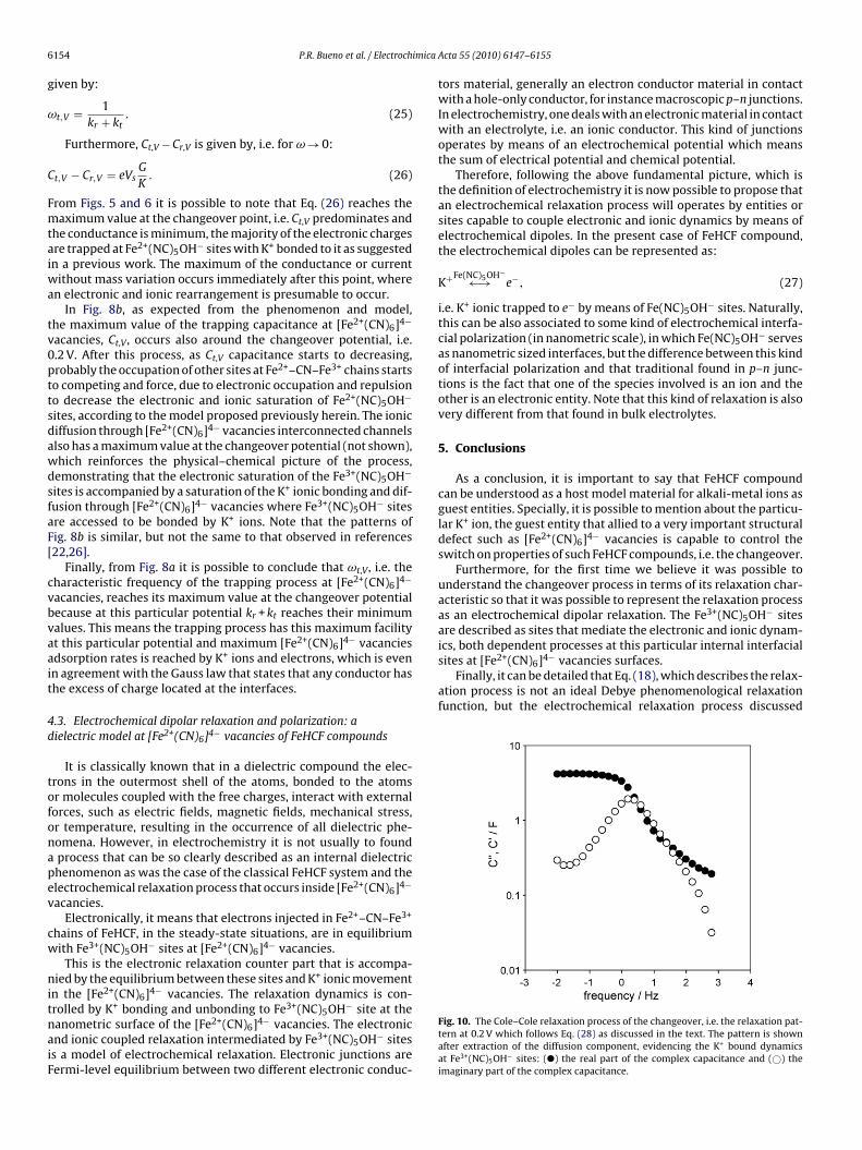
Fig. 10. The Cole–Cole relaxation process of the changeover, i.e. the relaxation pat-tern at 0.2 V which follows Eq. (28) as discussed in the text. The pattern is shownafter extraction of the diffusion component, evidencing the K+ bound dynamicsat Fe3+(NC)5OH− sites: (�) the real part of the complex capacitance and (©) theimaginary part of the complex capacitance.

imica
hp
C
mtia
A
drawtfw
at
R
[[
[
[
[
[
[[
[
[
[
[
[[
[
[[
P.R. Bueno et al. / Electroch
erein, as usual, can be better represented as a Cole–Cole relaxationrocess [22,25] in a way that Eq. (18) can be rewritten as:
∗ = 1
1+ (jω/ωt)˛ (28)
eaning that here are some certain trapping distributed relaxationimes. Fig. 10 shows the electrochemical relaxation process andts distributed characteristics at changeover, i.e. 0.2 V with ˛ valueround 0.8.
cknowledgements
Dr. Paulo R. Bueno and Dr. David Giménez Romero would like toedicate a special acknowledgement to Dr. Claude Gabrielli for hisesearch teaching activity and his kindly attention with us duringll the time we have been together in the marvelous city of Parisorking with impedance and transfer function among other elec-
rochemical subjects. It is also a very special moment and an honoror us to write this paper in this special issue dedicated to Claude’sork on transfer functions.
This work was supported by the São Paulo state research fundinggency FAPESP. D. Gimenez-Romero acknowledges his position tohe Generalitat Valenciana.
eferences
[1] P.R. Bueno, D. Gimenez-Romero, C. Gabrielli, J.J. Garcia-Jareno, H. Perrot, F.Vicente, Journal of the American Chemical Society 128 (2006) 17146.
[2] D. Gimenez-Romero, J. Agrisuelas, J.J. Garcia-Jareno, J. Gregori, C. Gabrielli, H.Perrot, F. Vicente, Journal of the American Chemical Society 129 (2007) 7121.
[3] N.R. de Tacconi, K. Rajeshwar, R.O. Lezna, Chemistry of Materials 15 (2003)
3046.[4] P.R. Bueno, F.F. Ferreira, D. Gimenez-Romero, G.O. Setti, R.C. Faria, C. Gabrielli, H.Perrot, J.J. Garcia-Jareno, F. Vicente, Journal of Physical Chemistry C 112 (2008)13264.
[5] F.F. Ferreira, P.R. Bueno, G.O. Setti, D. Gimenez-Romero, J.J. Garcia-Jareno, F.Vicente, Applied Physics Letters 92 (2008) 3.
[[
Acta 55 (2010) 6147–6155 6155
[6] D. Gimenez-Romero, P.R. Bueno, J.J. Garcia-Jareno, C. Gabrielli, H. Perrot, F.Vicente, Journal of Physical Chemistry B 110 (2006) 2715.
[7] D. Gimenez-Romero, P.R. Bueno, J.J. Garcia-Jareno, C. Gabrielli, H. Perrot, F.Vicente, Journal of Physical Chemistry B 110 (2006) 19352.
[8] P.R. Bueno, D. Gimenez-Romero, F.F. Ferreira, O.S. Grazielle, J.J. Garcia-Jareno, J. Agrisuelas, F. Vicente, Journal of Physical Chemistry C 113 (2009)9916.
[9] J. Agrisuelas, P.R. Bueno, F.F. Ferreira, C. Gabrielli, J.J. Garcia-Jareno, D. Gimenez-Romero, H. Perrot, F. Vicente, Journal of the Electrochemical Society 156 (2009)P74.
10] F. Herren, P. Fischer, A. Ludi, W. Halg, Inorganic Chemistry 19 (1980) 956.11] D. Gimenez-Romero, P.R. Bueno, C. Gabrielli, J.J. Garcia-Jareno, H. Perrot, F.
Vicente, Journal of Physical Chemistry B 110 (2006) 19352.12] D. Gimenez-Romero, P.R. Bueno, J.J. Garcia-Jareno, C. Gabrielli, H. Perrot, F.
Vicente, Journal of Physical Chemistry B 110 (2006) 19364.13] J. Agrisuelas, P.R. Bueno, F.F. Ferreira, D. Gimenez-Romero, J.J. Garcia-Jareno, F.
Vicente, Journal of the Electrochemical Society 154 (2009) P74.14] C. Gabrielli, J.J. Garcia-Jareno, M. Keddam, H. Perrot, F. Vicente, Journal of Phys-
ical Chemistry B 106 (2002) 3182.15] C. Gabrielli, J.J. Garcia-Jareno, M. Keddam, H. Perrot, F. Vicente, Journal of Phys-
ical Chemistry B 106 (2002) 3192.16] P.R. Bueno, E.R. Leite, Journal of Physical Chemistry B 107 (2003) 8868.17] P.R. Bueno, E.R. Leite, T.R. Giraldi, L.O.S. Bulhoes, E. Longo, Journal of Physical
Chemistry B 107 (2003) 8878.18] J.P. Diard, B. Le Gorrec, C. Montella, Journal of Electroanalytical Chemistry 471
(1999) 126.19] J.J. Garcia-Jareno, A. Sanamatias, J. Navarro-Laboulais, D. Benito, F. Vicente,
Electrochemica Acta 43 (1998) 235.20] J. Bisquert, G. Garcia-Belmonte, F. Fabregat-Santiago, P.R. Bueno, Journal of
Electroanalytical Chemistry 475 (1999) 152.21] P.R. Bueno, J.A. Varela, E. Longo, Journal of the European Ceramic Society 27
(2007) 4313.22] P.R. Bueno, C. Gabrielli, H. Perrot, Electrochimica Acta 53 (2008) 5533.23] J. Agrisuelas, C. Gabrielli, J.J. Garcia-Jareno, D. Gimenez-Romero, J. Gregori, H.
Perrot, F. Vicente, Journal of the Electrochemical Society 154 (2007) F134.24] K. Itaya, H. Akahoshi, S. Toshima, Journal of the Electrochemical Society 129
(1982) 1498.25] J. Bisquert, Electrochimica Acta 47 (2002) 2435.26] F. Fabregat-Santiago, G. Garcia-Belmonte, J. Bisquert, N.S. Ferriols, P.R. Bueno,
E. Longo, J.S. Anton, S. Castro-Garcia, Journal of the Electrochemical Society 148(2001) E302.
27] J. Bisquert, V.S. Vikhrenko, Electrochimica Acta 47 (2002) 3977.28] W.R. McKinnon, R.R. Haering, in: R.E. White, J.O.M. Bockris, B.E. Conway (Eds.),
Modern Aspects of electrochemistry Vol. 15, Plenum Press, New York, 1983, p.235.