Rules for integrating fast changeover capabilities into new equipment design
10
Robotics and Computer Integrated Manufacturing 18 (2002) 205–214 Rules for integrating fast changeover capabilities into new equipment design Dirk Van Goubergen a,b, *, Hendrik Van Landeghem b a P&M Productivity Improvement gcv, Vosselaar, Belgium b Department of Industrial Management, Ghent University, Ghent, Belgium Abstract The importance of short set-up times is becoming more and more important in every type of industry nowadays. How to address this problem is already known for about 20 years. The SMED method, originally developed by the Japanese Industrial Engineer Shigeo Shingo for reducing the time to exchange dies, gives a really straightforward approach to improve existing set-ups and to easily obtain a reduction of up to 90%, with mostly a moderate investment. In these past decade, several people have also realized that instead of improving an ‘‘a posteriori’’ situation, a lot of problems can be prevented during the design phase of the equipment. Only a few authors proposed design rules. These rules generally have a technical or engineering point of view. In several cases, the authors have noted that, even for a brand new equipment, the design can still be improved substantially. This paper extends the already published set of design rules considerably with the rules based on practical experiences from more than 60 set-up reduction projects in different industries over the last 10 years. In addition, the authors strongly believe that the responsibility of the equipment designer goes beyond these technical aspects. An efficient and effective set-up method also needs to be designed. Several basic industrial engineering tools can be used to this end. r 2002 Elsevier Science Ltd. All rights reserved. Keywords: Set-up reduction; Rapid changeover; Equipment design 1. Introduction 1.1. Why short set-up times? The need for short set-up times is not new; it has been around for quite a while. Indeed, the time between producing the last product of a series and producing the first product of a new series that meets all quality requirements has always been considered as waste or as ‘added cost’. More recently, in all types of industries an increased focus on set-up times is perceived, so the need for short set-ups is now bigger than ever. Globalization of the market, customization of products and the continuous effort for better efficiency of the existing production equipment are the main driving forces of this phenom- enon. Many companies around the world are implementing lean concepts and customer-pull-based production systems. For these systems, short set-up times are a sine qua non [1,2]. Van Goubergen [3] categorizes the different reasons for short set-up times into three main groups: * Flexibility: Due to an increasing number of products and product variants that have to be offered to the customer and a decrease of the corresponding order quantities, a company has to be able to react very quickly. If you need to produce small lot sizes, then you need to have short set-up times [4,5]. * Bottleneck-capacities: Especially on these machines, every minute that is lost is wasted. Set-ups need to be minimized to maximize the capacity available for production. * Cost minimization: Since direct production costs are related to the machine performance, an overall equipment effectiveness (OEE) calculation [6] can easily show the impact of set-up reduction on overall machine performance. An overview of other financial benefits of short set-up times can be found in Ref. [7]. 1.2. Basic elements of a set-up [3] A set-up can be defined as the elapsed time between the last product A leaving the machine and the first good *Corresponding author. Department of Industrial Management, Ghent University, Ghent, Belgium. 0736-5845/02/$ - see front matter r 2002 Elsevier Science Ltd. All rights reserved. PII:S0736-5845(02)00011-X
-
Upload
independent -
Category
Documents
-
view
0 -
download
0
Transcript of Rules for integrating fast changeover capabilities into new equipment design

Robotics and Computer Integrated Manufacturing 18 (2002) 205–214
Rules for integrating fast changeover capabilities intonew equipment design
Dirk Van Goubergena,b,*, Hendrik Van Landeghemb
aP&M Productivity Improvement gcv, Vosselaar, BelgiumbDepartment of Industrial Management, Ghent University, Ghent, Belgium
Abstract
The importance of short set-up times is becoming more and more important in every type of industry nowadays. How to address
this problem is already known for about 20 years. The SMED method, originally developed by the Japanese Industrial Engineer
Shigeo Shingo for reducing the time to exchange dies, gives a really straightforward approach to improve existing set-ups and to
easily obtain a reduction of up to 90%, with mostly a moderate investment. In these past decade, several people have also realized
that instead of improving an ‘‘a posteriori’’ situation, a lot of problems can be prevented during the design phase of the equipment.
Only a few authors proposed design rules. These rules generally have a technical or engineering point of view.
In several cases, the authors have noted that, even for a brand new equipment, the design can still be improved substantially. This
paper extends the already published set of design rules considerably with the rules based on practical experiences from more than 60
set-up reduction projects in different industries over the last 10 years. In addition, the authors strongly believe that the responsibility
of the equipment designer goes beyond these technical aspects. An efficient and effective set-up method also needs to be designed.
Several basic industrial engineering tools can be used to this end. r 2002 Elsevier Science Ltd. All rights reserved.
Keywords: Set-up reduction; Rapid changeover; Equipment design
1. Introduction
1.1. Why short set-up times?
The need for short set-up times is not new; it has beenaround for quite a while. Indeed, the time betweenproducing the last product of a series and producingthe first product of a new series that meets all qualityrequirements has always been considered as waste or as‘added cost’.
More recently, in all types of industries an increasedfocus on set-up times is perceived, so the need for shortset-ups is now bigger than ever. Globalization of themarket, customization of products and the continuouseffort for better efficiency of the existing productionequipment are the main driving forces of this phenom-enon.
Many companies around the world are implementinglean concepts and customer-pull-based productionsystems. For these systems, short set-up times are a sinequa non [1,2].
Van Goubergen [3] categorizes the different reasonsfor short set-up times into three main groups:
* Flexibility: Due to an increasing number of productsand product variants that have to be offered to thecustomer and a decrease of the corresponding orderquantities, a company has to be able to react veryquickly. If you need to produce small lot sizes, thenyou need to have short set-up times [4,5].
* Bottleneck-capacities: Especially on these machines,every minute that is lost is wasted. Set-ups need to beminimized to maximize the capacity available forproduction.
* Cost minimization: Since direct production costs arerelated to the machine performance, an overallequipment effectiveness (OEE) calculation [6] caneasily show the impact of set-up reduction on overallmachine performance. An overview of other financialbenefits of short set-up times can be found in Ref. [7].
1.2. Basic elements of a set-up [3]
A set-up can be defined as the elapsed time betweenthe last product A leaving the machine and the first good
*Corresponding author. Department of Industrial Management,
Ghent University, Ghent, Belgium.
0736-5845/02/$ - see front matter r 2002 Elsevier Science Ltd. All rights reserved.
PII: S 0 7 3 6 - 5 8 4 5 ( 0 2 ) 0 0 0 1 1 - X

product B coming out. The ‘quality’ of a set-up isdetermined by three key elements, as depicted in Fig. 1:technical aspects of equipment and tools, the organiza-tion of the work (‘who does what when’) and the methodused (‘how’). All three key elements have to beoptimized. The final necessary condition for having a‘good quality’ set-up is the motivation of the peopleperforming the set-up. They are usually productionoperators or sometimes machine setters from thetechnical/maintenance department. This motivation isalso determined by appropriate training.
Even with a perfectly designed machine, made toenable fast set-ups, and the most efficient method andorganization of work, described in a set-up instruction,there will be no good set-up if the people who have toperform the work do not see the importance of a shortset-up or are not motivated or trained for obtainingshort set-up times. This is illustrated by a globalmanufacturer of weaving looms, who designed anadvanced loom with automatic beam exchange. Theyhad extreme difficulties in selling this equipment, as theirmain markets were in countries where labour is plentifuland cheap. Set-up reduction was viewed there as a wayto destroy employment.
1.3. Set-up reduction approaches
There are several publications and case studiesavailable on how set-up times can be reduced in existingsituations [4,8,9–11]. Basically, all the approaches arederived from the ‘single minute exchange of die’ method(SMED), originally developed by the Japanese Indus-trial Engineer Shigeo Shingo for reducing the time toexchange dies [4]. This method gives a straightforwardapproach to improve existing set-ups and to easilyobtain a reduction of up to 90%, with mostly amoderate investment.
According to the SMED method all activities relatedto a set-up can be divided into two categories:
* Internal or on-line activities which are performedwhile the machine is down and thus the productionprocess is stopped.
* External or off-line activities which take place whilethe machine is running. These can be performedeither before or after the actual downtime of themachine.
The set-up reduction process then consists of threesteps:
Step 1: Separating on-line and off-line activities: In thisstep, all set-up activities are reviewed and one simplequestion is asked: ‘‘Does the machine have to be stoppedfor this activity, yes or no? If the answer is ‘no’, then thisactivity is moved off-line.
Step 2: Transferring on-line activities to off-line: Thiscan be done by technical modifications, e.g., instead ofexchanging 10 small parts on-line, a sub-assemblycontaining these parts is exchanged, and the preparationand after care (the actual removing and attaching of the10 parts on the sub-assembly) is done off-line.
Step 3: Minimizing or streamlining on-line and off-line
activities: Can the on-line and off-line activities bedone in a different/smarter way, which takes less time?In this step, all the adjusting and readjusting issues areconsidered.
Sekine et al. [8] identify three types of waste involvedin doing set-ups: set-up waste (motions of searching,finding, selecting, lining up and transporting), replace-ment waste (removing and attaching items) and adjust-ment waste (due to changeover settings that do not fullymeet the relevant standards and specifications). Suzaki[9] adds the use of routing diagrams. Hay [10] andGilmore et al. [11] give some more case studies.
2. Equipment design
2.1. General
In general, set-up reduction is considered a problemfor production people. It is true that production is theplace where the problem can be seen, but many otherfunctional areas in an organization can impact theduration of set-up times. Van Goubergen [3] identifiesthese other responsibilities such as the role of theequipment designer. Compared to the other responsiblefunctional areas, there is one substantial element that isdifferent when considering the role of the equipmentdesign engineer. Indeed, he is the only one who caninfluence set-up times in advance, before actual set-upsare performed. He is responsible for all the technicalaspects of a set-up (depicted as one of the key elementsin Fig. 1) since these are determined by the concept andthe construction of the machine. The awareness of theimportance of having short set-up times and some
MOTIVATION
Method
Organization
Technical aspects
SET-UP
Fig. 1. Key elements of a set-up.
D. Van Goubergen, H. Van Landeghem / Robotics and Computer Integrated Manufacturing 18 (2002) 205–214206

design principles or guidelines can help the designer tobuild ‘set-up friendly’ equipment. This way the need foran ‘a posteriori’ set-up reduction project becomes lesslikely. In general, it is easier and cheaper to maketechnical changes to a design than to modify existingmachines and equipment.
Several authors have already recognized the need forthis ‘a priori’ approach [12,13]. Indeed, during thedesign phase the set-up times can be influenced in asubstantial way. Mileham et al. [12] identify thisapproach as ‘design for changeover’ (DFC). Besidesimpact on product design, a set of design rules formachines are given as good practice guidelines for use atthe design stage. These rules are established from atechnical or engineering point of view and are aimed atreducing the excess physical effort, excess adjustmentand excess variety involved with changeovers.
Too often the responsibility of equipment designengineers is limited to these technical issues. We believethat it goes far beyond that. Also, the aspects of‘Method’ and ‘Organization’ as depicted in Fig. 1 arepart of the equipment designer’s responsibilities andneed to be considered during the design phase of theequipment. When one buys new equipment, it is normalthat the machine be accompanied with guidelines/instructions on how to operate it. It is also obviousthat maintenance procedures be described. Why arethere no guidelines on how a set-up must be performedin the most efficient and effective way? In practice, acustomer often obtains just a one-time demonstration bya technician of the machine manufacturer on how a set-up needs to be done (which does not guarantee that hisway of working is indeed the best one).
The following section treats the technical issuesinvolved in fast set-ups at the design stage, while thenext one will give some ideas on the organization andmethod. Also relations with the different steps of theSMED set-up reduction method are discussed.
2.2. Technical design guidelines
The basic philosophy for the designer should be thatset-up must be as easy as possible to minimize mistakesand to make sure that no special technical skills areneeded to do the set-up. This way, the persons operatingthe machine can perform the set-up. For any company,this is the most flexible way of working. The operatorsare present when the last product A comes out and canstart immediately with the set-up. If technical peopleneed to do the set-up, then there will almost always be awaiting time before they arrive and start working, sinceprobably doing set-ups is not their only task, or theycover multiple machines and most of the time they willbe busy doing other activities.
The two most important technical issues that need tobe considered for short set-ups deal with exchanging
parts of a machine (how many parts, how is it done) andthe setting/re-adjusting of parameters. These are relatedto steps 2 and 3 of the SMED methods as described inSection 1.3.
Mileham et al. [12] have established a set of designrules; Table 1 gives an overview of these rules. Ourpractical experience in more than 60 set-up reductionprojects in different industries during the last 10 yearshas shown that this list can be considerably extendedand that some rules need to be adapted.
Table 2 gives an overview (using the same classifica-tion as in Table 1) of our proposition. The adapted rulesare printed in italics:
* Rule 2.3: In Table 1, this rule stresses the eliminationof the need to remove complete assemblies. Accord-ing to our experience, it is in general less time-consuming to exchange a complete assembly ormodule on-line than exchanging a lot of smallerparts on-line. The assembly/module can then beprepared off-line. For example, the set-up of a high-frequency welding machine in a company thatmanufactures plastic bags for medical use took about1.5 h. The process can be described in a simple way as
Table 1
Design rules according to Ref. [12]
1. Less weight
1.1 Use lighter materials
1.2 Use less material
2. Simplification
2.1 Reduce number of mechanisms
2.2 Eliminate the need to remove non changeover parts
2.3 Eliminate the need to remove complete assemblies
2.4 Eliminate pipe connections or use quick release couplings
2.5 Reduce the number of hand/powertools required
2.6 Reduce the total number of components in a tool
2.7 Simplify control procedures such as timing diagrams
2.8 Use short power drive connections
3. Standardization
3.1 Use the same size shut heights for presses
3.2 Use the same size securing bolts
3.3 Use the same type of electrical motors
4. Securing
4.1 Use the minimum number of fasteners consistent with strength
4.2 Eliminate manually operated clamps
4.3 Use 14turn devices
5. Location and adjustment
5.1 Eliminate on-machine adjustments
5.2 Provide intelligent adjustment and monitoring
5.3 Eliminate the use of spacers and shims
5.4 Provide dead stop positioning
6. Handling
6.1 Eliminate the need for or ensure easy cleaning/purging
6.2 Eliminate the need to handle hot items
6.3 Eliminate the need to handle awkward items
6.4 Provide power aids
6.5 Provide remote actuation
6.6 Ensure easy delivery of tools etc. to the machine
6.7 Provide good access
D. Van Goubergen, H. Van Landeghem / Robotics and Computer Integrated Manufacturing 18 (2002) 205–214 207
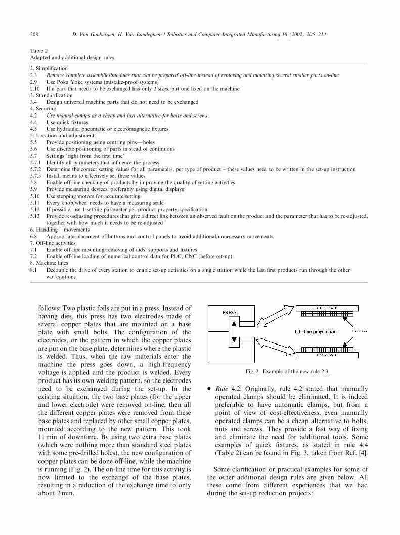
follows: Two plastic foils are put in a press. Instead ofhaving dies, this press has two electrodes made ofseveral copper plates that are mounted on a baseplate with small bolts. The configuration of theelectrodes, or the pattern in which the copper platesare put on the base plate, determines where the plasticis welded. Thus, when the raw materials enter themachine the press goes down, a high-frequencyvoltage is applied and the product is welded. Everyproduct has its own welding pattern, so the electrodesneed to be exchanged during the set-up. In theexisting situation, the two base plates (for the upperand lower electrode) were removed on-line, then allthe different copper plates were removed from thesebase plates and replaced by other small copper plates,mounted according to the new pattern. This took11min of downtime. By using two extra base plates(which were nothing more than standard steel plateswith some pre-drilled holes), the new configuration ofcopper plates can be done off-line, while the machineis running (Fig. 2). The on-line time for this activity isnow limited to the exchange of the base plates,resulting in a reduction of the exchange time to onlyabout 2min.
* Rule 4.2: Originally, rule 4.2 stated that manuallyoperated clamps should be eliminated. It is indeedpreferable to have automatic clamps, but from apoint of view of cost-effectiveness, even manuallyoperated clamps can be a cheap alternative to bolts,nuts and screws. They provide a fast way of fixingand eliminate the need for additional tools. Someexamples of quick fixtures, as stated in rule 4.4(Table 2) can be found in Fig. 3, taken from Ref. [4].
Some clarification or practical examples for some ofthe other additional design rules are given below. Allthese come from different experiences that we hadduring the set-up reduction projects:
Table 2
Adapted and additional design rules
2. Simplification
2.3 Remove complete assemblies/modules that can be prepared off-line instead of removing and mounting several smaller parts on-line
2.9 Use Poka Yoke systems (mistake-proof systems)
2.10 If a part that needs to be exchanged has only 2 sizes, put one fixed on the machine
3. Standardization
3.4 Design universal machine parts that do not need to be exchanged
4. Securing
4.2 Use manual clamps as a cheap and fast alternative for bolts and screws
4.4 Use quick fixtures
4.5 Use hydraulic, pneumatic or electromagnetic fixtures
5. Location and adjustment
5.5 Provide positioning using centring pinsFholes
5.6 Use discrete positioning of parts in stead of continuous
5.7 Settings ‘right from the first time’
5.7.1 Identify all parameters that influence the process
5.7.2 Determine the correct setting values for all parameters, per type of product – these values need to be written in the set-up instruction
5.7.3 Install means to effectively set these values
5.8 Enable off-line checking of products by improving the quality of setting activities
5.9 Provide measuring devices, preferably using digital displays
5.10 Use stepping motors for accurate setting
5.11 Every knob/wheel needs to have a measuring scale
5.12 If possible, use 1 setting parameter per product property/specification
5.13 Provide re-adjusting procedures that give a direct link between an observed fault on the product and the parameter that has to be re-adjusted,
together with how much it needs to be re-adjusted
6. HandlingFmovements
6.8 Appropriate placement of buttons and control panels to avoid additional/unnecessary movements
7. Off-line activities
7.1 Enable off-line mounting/removing of aids, supports and fixtures
7.2 Enable off-line loading of numerical control data for PLC, CNC (before set-up)
8. Machine lines
8.1 Decouple the drive of every station to enable set-up activities on a single station while the last/first products run through the other
workstations
Fig. 2. Example of the new rule 2.3.
D. Van Goubergen, H. Van Landeghem / Robotics and Computer Integrated Manufacturing 18 (2002) 205–214208

* Rule 2.10: A packaging machine has a steel cylinderaround which a corrugated cardboard is folded.The diameter of the cylinder is determined by thediameter of the product that needs to be put in thepackaging, in this case light bulbs. There are only twodifferent outside diameters for the light bulbs, sothere are two different cylinders. Instead ofexchanging the cylinders, the smallest one can stayon the machine, while instead of replacing it with thebig one, it is only needed to slide a hollow cylinderover it, which constitutes a ‘‘nesting’’ mechanism. Inthis case, the application of this rule resulted in areduction of about 90% of the exchange time.
* Rule 3.4: Standardization to eliminate exchange andsetting activities can be done not only on the productside but also on the machine side. For example, auniversal product holder prevents the total exchangeof all product holders on a machine when onechanges from one product to another. During oneproject on a machine line that produces sub-assemblies for lamps mainly used in street andhighway lighting, about 120min of the total set-uptime of 310min were eliminated when standardiza-tion was applied.
* Rule 5.7: If one cannot measure, then one will neverbe able to have a setting ‘right from the first time’.Measuring devices should be accurate enough: in oneplant there was a very critical setting, the accuracywas in the order of 10ths of a millimetre, but theoperators were only using a flexible steel rule to dothe setting. On several occasions, we noticed theabsence of ‘official’ setting values. Every operatorhad his own ‘private’ setting values. It is obvious thatthis is not a good manufacturing practice. All thesetting values have to be written in a set-up instruc-tion that is available to everyone.
* Rule 5.8: When the quality of the setting activities isimproved, there is less need for on-line checking ofproducts. Sometimes a limited set of influencingparameters is difficult to control. If the probability ofobtaining out-of-tolerance conditions due to theseparameters is sufficiently low, then it is acceptable tostart the process immediately after the set-up and to
check the first product off-line. It will generally takeless time and be more cost-effective to produce somescrap after the start-up (which after all has a lowprobability of occurrence) compared to having adowntime after every set-up, while the first product ischecked on-line. For example, in a metal factory, aset-up of a bending machine was examined. Weidentified ten parameters that could influence thebending angle of the metal. Eight out of ten could bemeasured or controlled in advance. Two parameterswere hard to control, but the occurrence of a problemwith these was very low (about 2–5%). Therefore, itwas decided to start production and check theproduct off-line. In maybe 2–5% of the cases, therewill be some scrap made during the time it takes tocheck the first product, but this is better from a cost-benefit point of view than a systematic check of theproduct on-line, while the machine remains unused.
* Rule 5.9: With a digital display every operator readsthe same value, the probability of misreading isminimized. (Niebel [16]).
* Rule 5.11: When a setting knob does not have anymeasuring scale, it is impossible to make a settingright from the first time; also, readjusting will alwaysbe on a trial and error basis.
* Rule 5.12: If there are two parameters that need to beset to obtain a certain product specification, then theoperator has to set the right combination of thesetwo. Due to interactions, this is not only moredifficult, but also leaves more room for not havingstandardized work methods and takes more timewhen it comes to readjusting.
* Rule 5.13: Just as there is a need for standard workmethods for doing set-ups, even re-adjusting needs tobe done in a standard way. It is typical that when youtake different operators and they are faced with thesame setting problem, everyone will deal with it inhis/her own way. What is more, the direct link that ismentioned in these rules provides great opportunitiesfor fast set-up. For example, on a machine thatproduces office binders, the position of one of thecreases in the cardboard has to be within sometolerances. A jig, with two tolerance lines on it thatcould be placed on the product was made to allow afast checking of the product. Next to it there was ameasuring scale; if the crease is out of the toleranceregion, then one can read the extent of the deviation.The set-up instruction contains a table showing thelink between this deviation and how much a certainmachine control needs to be re-adjusted.
Several projects in different types of industry that weconducted these last few years, have shown that thesedesign rules are not always used systematically and that,even for brand new equipment, designs can be im-proved. The following example is one of the many
Fig. 3. Quick fixtures [4].
D. Van Goubergen, H. Van Landeghem / Robotics and Computer Integrated Manufacturing 18 (2002) 205–214 209

illustrations. In a pet food plant, a brand new machineline is installed for filling metal cans. The cans have twodifferent heights. At the intake of the filling machine,there is a guide above the conveyor to prevent some ofthe cans on the conveyor from sticking out and thusdamage the filling tubes. Although there are only twoheights, it takes more than 10min to change the setting,due to a poor design. The setting of the guides, which isonly a thin metal strip, is made using several threadedsteel bars for each bar with a nut and a check nut. Aquick fixture for two fixed positions would have been amuch better design.
Updating Table 1 with our proposed Table 2 shouldgive the design engineer a more complete and practicalguidebook to design for fast changeover.
2.3. Results
As already mentioned, the technical rules in Table 2originate from several projects in different types ofindustries and can thus be illustrated with numerousexamples. Besides the implementation details alreadygiven in the last section, the following brief descriptionof a case study will show the results that can be obtainedfrom the application of our proposed design rules.
The analysis of a set-up of a packaging machine forlamps showed that it took about 50min to switch fromone type of product to another. About 63% of this timewas used for ‘technical activities’ like exchanging parts,setting and readjusting of parameters. Although therewere several types of lamps, all of them could beclassified into two categories according to their outsidedimensions.
The most time-consuming activities were identified.Table 3 gives an overview in which rules from Table 2were applied to these and the results that were obtained.It should be stressed that the incorporation of theserules into the design of the equipment would haveyielded a short set-up time from the onset, and not, as inthis case, after several years of use.
3. Improving the work method
3.1. Design guidelines and the use of industrial
engineering techniques
As stated earlier, major improvements can beobtained by examining the work method. Several casesin different industries have shown that even withtechnically very well-designed equipment, on-line timescan be long if the operators or machine setters lack awell-designed work method.
In most of the cases, this is due to the fact that theequipment designer provides no set-up instructions orprescriptions. We strongly believe that providing a goodset-up instruction is a responsibility of the equipmentdesigner. When buying a new piece of equipment,whether it comes from an outside supplier or whetherit is designed and made by an in-house engineeringdepartment, it is not realistic to assume that productionpeople (being the customer) have the necessary knowl-edge of this new machine. Therefore, besides operatingand maintenance instructionsFwhich are apparentlymuch more obviously presentFeven set-up instructionshave to be included by the manufacturer/designer.Instead of this, most of the time, a representative ofthe machine supplier demonstrates the way in which aset-up has to be done. This is not an effective way oflearning how a proper set-up needs to be performed.Afterwards, operators will develop their own way ofworking by trial and error. While it is true that in everydifferent method there will be some good elements, thisis not what is needed. Also, the lack of a set-upinstruction causes operators to work with what can becalled ‘inspiration of the moment’, certainly for complexset-ups, where a lot of activities need to be done or inmulti-stage machine lines where different persons areinvolved on different workstations. This can never bethe most efficient and effective set-up. Machinedesigners should provide the most efficient and effectivestandardized set-up method, frequently referred to as a‘pit stop-crew’ way of working.
Table 3
Case study results from the use of the adapted and additional technical design rules
Activity Rule Original time (s) After improvement (s) % Reduction
Exchanging product holders 4.2 330 60 82
Exchanging of a pneumatic cylinder to bend the cardboard 4.4 and 5.5 139 30 78
Exchanging forming parts 2.10 103 30 71
Exchanging a cylinder 2.10 90 10 89
Exchanging the lamp pusher 2.10 and 4.4 65 15 77
Exchanging the lamp support elements 2.10 54 10 81
Exchanging the finished product pusher 2.10 and 4.4 35 3 91
Setting a stroke 5.6 and 5.12 83 25 70
Re-adjusting of a pneumatic cylinder to bend the cardboard 5.5 244 0 100
Setting of the position of the cardboard 5.5 70 3 95
Total 1213 186 85
D. Van Goubergen, H. Van Landeghem / Robotics and Computer Integrated Manufacturing 18 (2002) 205–214210

Finally, the existence of a set-up instruction thatclearly describes the way in which activities need to beperformed, does not imply that this instruction repre-sents an efficient and effective method (by the way, wehave noticed that in this case, most of the times theinstruction was NOT made by the equipment designer/manufacturer but by the production peopleFthecustomers themselves!). Therefore, during the designphase, the set-up method has to be examined from thisperspective. There are several guidelines that can beestablished; some easy-to-use, basic Industrial Engineer-ing tools are available to help the design engineer.Table 4 gives an overview of these principles; they can beadded to the design rules in Tables 1 and 2.
Rule 9.1 actually performs SMED step 1 (see Section1.3) during the design phase. In order to optimize theorder of activities, a routing diagram can be made.Fig. 4 gives an example of a routing diagram before andafter. The ‘before’ picture was an actual set-up asperformed by one person in an office supply factory.Routing diagrams should be part of a clear and conciseset-up instruction (Rule 9.2)
An intuitively balanced workload is very unlikely tobe the most efficient one. Therefore, a multi-activitychart [14] can be used in order to apply rules 9.3 and 9.4.Figs. 5 and 6 give an example of this IndustrialEngineering technique, applied to a machine line in a
lighting factory (set-up performed by three persons). Asa final check, all activities can be critically examinedusing a questioning technique such as the Kiplingquestions [14]. Rule 9.6 is also established based onour experiences. It does not suffice to say that tools andparts need to be prepared before the set-up starts andstored away after production has started. The idealplace to put them during preparation has to be specifiedto minimize motions.
Finally, rule 9.7 is the last but definitely not the least.A well-documented set-up method will increase theprobability of having short set-ups right from the start.Remember though that motivation of the personsperforming the set-up is primordial, but this is of coursenot a responsibility of the equipment design engineer.The set-up instruction should include the following:
* for every person involved, a description of theactivities that need to be performed by that personin an optimal order,
* a routing diagram showing the ideal routing for everyperson,
* multi-activity charts to show the interdependence ofthe people’s activities and to have a common under-standing of the global picture,
* checklists of all tools/parts needed, all off-lineactivities,
Fig. 4. Routing diagram before and after changing the order of activities.
Table 4
Design rules for efficient work methods
9. Method and organization
9.1 Separate on-line and off-line set-up activities, by asking the question ‘Does the machine has to be stopped for this activity?’
9.2 Optimize the order in which the activities are performed to minimize movements and walking distance
9.3 In a line situation with more than one operator, divide the work on the different stations between the operators so that the machine on which
the most activities need to be performed is not waiting
9.4 Balance the workload between the available operators and make separate instruction sheets per person
9.5 Use the Kipling questions on every activity of the set-up for critical review (What, where, when, who, how, why)
9.6 Provide set-up sets with all necessary tools and parts, determine the exact location where the tools and parts have to be placed before the actual
set-up starts
9.7 Provide set-up instruction guides
D. Van Goubergen, H. Van Landeghem / Robotics and Computer Integrated Manufacturing 18 (2002) 205–214 211

* a map stating where parts and tools have to be placedduring off-line preparation, and
* a list with all the setting values that are needed for allparameters.
In order to train the operators in performing set-upsaccording to the way that is described in the set-upinstruction, multimedia technology can be used, e.g., byproviding a CD-ROM with a video clip of the set-up.
3.2. Results
Since the design rules are meant to be used during thedesign phase of equipment, before it is actually put in
place, it is hard to predict how much reduction in set-uptime they will yield. A possible way to estimate the rangeof possible improvements is to take results from set-upreduction projects on actual set-ups. Since an importantfocus in this paper is on the use of IndustrialEngineering techniques to optimize method and orga-nization, only these types of improvements are con-sidered in this section. Table 5 summarizes some resultsof actual projects that we performed. These figures showthat in practice we can assume that if the earlier-stateddesign rules had been followed, besides technical issues,important reductions would have been achieved byhaving a good organization and an efficient workmethod, and this from the start of using the equipmentinstead of months or years later.
4. Project results
As stated in Section 2, this research is based on morethan 60 actual set-up reduction projects in different
Fig. 5. Multi-activity chart for the set-up of a machine line (Van Goubergen [15]).
Fig. 6. Multi-activity diagram for a set-up performed by 3 persons
(Van Goubergen [15]).
Table 5
Realized improvements by a better organization and work method
Type of machine (line) % of total reduction
due to improvements of
method and organization
Foil packaging machine 58
Food extrusion line 83
Food processing line 66
Metal cover machine 14
Filling machine 79
Assembly machine 39
Packaging material machine 39
D. Van Goubergen, H. Van Landeghem / Robotics and Computer Integrated Manufacturing 18 (2002) 205–214212

Table 6
Set-up reduction results on which the proposed design rules are based
Industry type Machine Original set-uptime (min)
Reduced set-uptime (min)
% Reduction Extra capacity/year (h)
Packaging Punching machine SAP2 240 60 75 1092Materials Punching machine BOBST 105 26 66 757
CARTOMAN 95 35 63 918Gluing/punching line 250 70 72 525Sealing line 44 21 52 312HF welding machine 106 15 86 182HF welding robot 210 23 88 127Paper bags machine 45 23 50 789
Office material Envelopes line 82 30 63 733Filing maps line 52 12 77 182Filing maps line 75 19 74 179KUGLER line 87 17 80 496
Pharmaceutical Blister pack line 360 90 75 1687KM7 packaging line 125 25 80 216
Lighting Assembly line 120 17 85 490Winding machine 360 160 55 182Lamp subassembly line 390 25 93 160Bulb forming machine 300 90 70 262Glass assembly line 50 15 70 274
Chemical Caustic soda filling line 30 3 90 594Fluid filling line 66 12 80 640Wallpaper glue filling line 175 45 74 340Paint flacon filling line 40 23 43 196Paint filling line 6 1 88Paint filling line 16 4 73
Food Bottle filling line 88 36 59 166Fruit jam line 170 39 77 230Sauce line 46 11 76 456Pasta line 150 45 70 211Rice line 225 23 90 468Snackfood extrusion line 136 36 84 393
Printing Roland Rekord 67 30 55 299Speedmaster 52.2 31 20 35 175Speedmaster 74 31 17 44 305Speedmaster 102.5 28 12 57 400W&H 16 10 38 88UTECO 150 26 82 930
Plastics Injection moulding 224 114 49 430Sidel 49 blowing machine 232 60 74 491
Wood Planing machine WACO 15 7.5 50 204Planing machine WEINIG 45 20 56 2924 Sides planing machine 60 20 67 128Sawing machine 25 10 60 124Drilling machine 96 31 62 358
Metal Cutting/punching line 16 5 68 550Rolling 67 20 78 602Bending machine 78 7 91 602Cutting/bending line 63 15 76 539Bending machine 22 6 73 225Cutting machine 36 10 74 553Profile bending machine 4.5 1.5 66 216Metal cover line 99 90 18 80 120Metal cover line 108 70 18 70 93Copper foil winding machine 45 16 65 224
Electronics PCB assembly line 157 27 83 195
Cosmetics Casepacker 90 40 55 277Labeling machine 92 17 80 504MAFF 70 20 71 277Box folding machine 25 7 72 100
Others Packaging line 24 6 75 288
D. Van Goubergen, H. Van Landeghem / Robotics and Computer Integrated Manufacturing 18 (2002) 205–214 213

industries. All the principles that were used to achievethe reductions of set-up times can be found in ourproposed set of design rules. This means that animportant part of the set-up time could have beenavoided if the rules in Tables 1, 2 and 4 would have beenapplied during the design phase of the equipment. Table6 gives a sample of the results of some of these projects.Besides the reduction percentages, this table also givesthe extra capacity on yearly basis that resulted from thereduction in set-up time on these equipments.
5. Conclusions
Short set-up times are a necessity nowadays in alltypes of industries. There exists a good methodology toreduce these set-up times in the existing situations.However, experiences of these processes should be usedin the design phase of such equipments. Previousresearch provided a list of design rules that can be used.This list was merely focused on technical issues. In thispaper, we extended this list substantially with someadditional technical rules, established from experienceswith actual set-ups in different environments. Besidesthat, we emphasized the importance of designing a goodwork method and organization of a set-up. Some designrules covering these aspects are therefore added. Theimplementation of these rules can be enhanced by usingIndustrial Engineering techniques for documentationand training.
The use of the extended list of design rules that weproposed here, should therefore lead to equipmentdesigns that have better and faster set-ups from theonset. In almost all the cases, more than 60 cases onwhich this research is based, the machines were alreadyin use for many years at the time of the set-up reductionproject. Should the equipment have been designed using
the proposed design rules, a big part of the set-up timeswould simply not have existed.
References
[1] Womack JP, Jones DT. Lean thinking. UK: Simon and Schuster
UK Ltd., 1996.
[2] Monden Y. Toyota production system: an integrated approach
to just-in-time. Industrial Engineering and Management Press,
1993.
[3] Van Goubergen D. Set-up reduction as an organization-wide
problem. Proceedings of the IIE Solutions 2000FCD-ROM,
Cleveland, OH, 2000.
[4] Shingo S. A revolution in manufacturing, the SMED system.
Productivity Press, 1985.
[5] Esrock YP. The impact of reduced setup time. Prod Invent
Manage 1985;26:94–100.
[6] Nakajima S. Introduction to TPM. Productivity Press, 1988.
[7] Fernihough A, Culley SJ, Mileham AR. A financial model for set-
up reduction justification, Proceedings of the Fourth Interna-
tional FAIM Conference, Blacksburg, VA, 1994. p. 198–207.
[8] Sekine K, Arai K. Kaizen for quick changeover: going beyond
SMED. Productivity Press, 1992.
[9] Suzaki K. The new manufacturing challenge. New York: The Free
Press, 1987.
[10] Hay EJ. Any machine setup time can be reduced by 75%. Ind Eng
1987;19(8):62–7.
[11] Gilmore M, Smith DJ. Set-up reduction in pharmaceutical
manufacturing: an action research study. Int J Oper Prod Manage
1996;16(3):4–17.
[12] Mileham AR, Culley SJ, Owen GW, McIntosh RI. Rapid
changeoverFa pre-requisite for responsive manufacture. Int J
Oper Prod Manage 1999;19:785–96.
[13] McIntosh R, Culley S, Gest G, Mileham T, Owen G. An
assessment of the role of design in the improvement of changeover
performance. Int J Oper Prod Manage 1996;16(9):5–22.
[14] Kanawaty G. Introduction to work study. International Labour
Office, 1992.
[15] Van Goubergen D, Van Landeghem H. An integrated methodol-
ogy for more effective set-up reduction. Proceedings of the IIE
Solutions 2001FCD-ROM, Dallas, TX, 2001.
[16] Niebel BW. Motion and time study. Homewood, IL: Irwin, 1993.
D. Van Goubergen, H. Van Landeghem / Robotics and Computer Integrated Manufacturing 18 (2002) 205–214214