1.3 CAPACITANCE OF A SINGLE PHASE TWO-WIRE LINE ...
28
www.binils.com for Anna University | Polytechnic and Schools 1.3 CAPACITANCE OF A SINGLE PHASE TWO-WIRE LINE Consider a single phase overhead transmission line consisting of two parallel conductors A and B spaced d metres apart in air. Suppose that radius of each conductor is r metres. Let their respective charge be + Q and − Q coulombs per metre length. The total p.d. between conductor A and neutral “infinite” plane is Download Binils Android App in Playstore Download Photoplex App Similarly, p.d. between conductor B and neutral “infinite” plane is Both these potentials are w.r.t. the same neutral plane. Since the unlike charges attract each other, the potential difference between the conductors is
-
Upload
khangminh22 -
Category
Documents
-
view
1 -
download
0
Transcript of 1.3 CAPACITANCE OF A SINGLE PHASE TWO-WIRE LINE ...

www.binils.com for Anna University | Polytechnic and Schools
1.3 CAPACITANCE OF A SINGLE PHASE TWO-WIRE LINE
Consider a single phase overhead transmission line consisting of two parallel
conductors A and B spaced d metres apart in air. Suppose that radius of each conductor
is r metres. Let their respective charge be + Q and − Q coulombs per metre length. The
total p.d. between conductor A and neutral “infinite” plane is
Download Binils Android App in Playstore Download Photoplex App
Similarly, p.d. between conductor B and neutral “infinite” plane is
Both these potentials are w.r.t. the same neutral plane. Since the unlike charges
attract each other, the potential difference between the conductors is

www.binils.com for Anna University | Polytechnic and Schools
Capacitance to neutral
Equation ( i) gives the capacitance between the conductors of a two-wire line Often it
is desired to know the capacitance between one of the conductors and a neutral point
between them. Since potential of the mid-point between the conductors is zero, the
potential difference between each conductor and the ground or neutral is half the potential
Download Binils Android App in Playstore Download Photoplex App
difference between the conductors. Thus the capacitance to ground or capacitance to
neutral for the two-wire line is twice the line-to-line capacitance
The reader may compare eq. ( ii) to the one for inductance. One difference between the
equations for capacitance and inductance should be noted carefully. The radius in the
equation for capacitance is the actual outside radius of the conductor and not the GMR
of the conductor as in the inductance formula. Note that eq. ( ii) applies only to a solid
round conductor.
1.3.1 CAPACITANCE OF A 3-PHASE OVERHEAD LINE
In a 3-phase transmission line, the capacitance of each conductor is considered instead
of capacitance from conductor to conductor. Here, again two cases arise viz.,
symmetrical spacing and unsymmetrical spacing.
(i) Symmetrical Spacing
Fig shows the three conductors A, B and C of the 3-phase overhead transmission
line having charges QA , QB and QC per meter length respectively. Let the conductors

Download Binils Android App in Playstore Download Photoplex App
www.binils.com for Anna University | Polytechnic and Schools
be equidistant (d meters) from each other. We shall find the capacitance from line
conductor to neutral in this symmetrically spaced line. Referring to Fig,
Overall potential difference between conductor A and infinite neutral plane is given by
∴ Capacitance of conductor A w.r.t neutral,
Note that this equation is identical to capacitance to neutral for two-wire line.
Derived in a similar manner, the expressions for capacitance are the same for
conductors B and C.

Download Binils Android App in Playstore Download Photoplex App
www.binils.com for Anna University | Polytechnic and Schools
(ii) Unsymmetrical spacing.
Fig. shows a 3-phase transposed line having unsymmetrical spacing. Let us assume
balanced conditions i.e. QA + QB + QC = 0.
Considering all the three sections of the transposed line for phase A,

Download Binils Android App in Playstore Download Photoplex App
www.binils.com for Anna University | Polytechnic and Schools
Problems :
1. Determine the capacitance and the charging current per km when the transmission
line of example 2.2 is operating at 132 kV.

Download Binils Android App in Playstore Download Photoplex App
www.binils.com for Anna University | Polytechnic and Schools
2. Determine the capacitance and the charging current per km when the
transmission line of example 2.5 operates at 220 kV, dia of conductor = 2.5 cm.
3. Determine the capacitance and charging current per km of the line of example
2.7 if the line operates at 220 kV, dia = 4.5 cms.

www.binils.com for Anna University | Polytechnic and Schools
1.4 CONCEPT OF SELF-GMD AND MUTUAL-GMD
The use of self geometrical mean distance (abbreviated as self-GMD) and mutual
geometrical mean distance (mutual-GMD) simplifies the inductance calculations, particularly
relating to multi conductor arrangements. The symbols used for these are respectively Ds
and Dm. We shall briefly discuss these terms.
( i) Self-GMD (Ds)
In order to have concept of self-GMD (also sometimes called Geometrical mean radius;
GMR), consider the expression for inductance per conductor per metre already derived in Art.
Inductance/conductor/m
In this expression, the term 2 × 10-7 × (1/4) is the inductance due to flux within the solid
conductor. For many purposes, it is desirable to eliminate this term by the introduction of a
concept called self-GMD or GMR. If we replace the original solid conductor by an equivalent
hollow cylinder with extremely thin walls, the current is confined to the conductor surface and
internal conductor flux linkage would be almost zero. Consequently, inductance due to internal
flux would be zero and the term 2 × 10-7 × (1/4) shall be eliminated. The radius of this
equivalent hollow cylinder must be sufficiently smaller than the physical radius of the
conductor to allow room for enough additional flux to compensate for the absence of internal
flux linkage. It can be proved mathematically that for a solid round conductor of radius r, the
self-GMD or GMR = 0·7788 r. Using self-GMD, the eqn. becomes
Inductance/conductor/m = 2 × 10⁻⁷loge d/ Ds
Ds = GMR or self-GMD = 0·7788 r
Download Binils Android App in Playstore Download Photoplex App

www.binils.com for Anna University | Polytechnic and Schools
It may be noted that self-GMD of a conductor depends upon the size and shape of the
conductor and is independent of the spacing between the conductors.
(ii) Mutual-GMD
The mutual-GMD is the geometrical mean of the distances form one conductor to the
other and, therefore, must be between the largest and smallest such distance. In fact,
mutual- GMD simply represents the equivalent geometrical spacing.
(a) The mutual-GMD between two conductors (assuming that spacing between
conductors is large compared to the diameter of each conductor) is equal to the distance between
their centres i.e. Dm = spacing between conductors = d
(b) For a single circuit 3-φ line, the mutual-GMD is equal to the equivalent equilateral
spacing i.e.,
(d1d2d3)1/3
Download Binils Android App in Playstore Download Photoplex App

www.binils.com for Anna University | Polytechnic and Schools
1.2 PARAMETERS OF SINGLE AND THREE PHASE TRANSMISSION
LINES WITH SINGLE AND DOUBLE CIRCUITS
1.2.1 CONSTANTS OF A TRANSMISSION LINE
A transmission line has resistance, inductance and capacitance uniformly distributed
along the whole length of the line. Before we pass on to the methods of finding these constants
for a transmission line, it is profitable to understand them thoroughly.
Figure 1.2.1 Resistance and Inductance
[Source: “Principles of Power System” by V.K.Mehta Page: 203]
( i) Resistance. It is the opposition of line conductors to current flow. The resistance
is distributed uniformly along the whole length of the line as shown in Fig. However, the
performance of a transmission line can be analysed conveniently if distributed resistance is
considered as lumped as shown in Fig.1.2.1
( ii) Inductance. When an alternating current flows through a conductor, a changing
flux is set up which links the conductor. Due to these flux linkages, the conductor possesses
inductance. Mathematically, inductance is defined as the flux linkages per ampere i.e.,
𝐿 = 𝐿
𝐿
henry
where 𝐿 = flux linkages in weber-turns
I = current in amperes
The inductance is also uniformly distributed along the length of the line as show in Fig. Again
for the convenience of analysis, it can be taken to be lumped as shown in Fig1.2.1
Download Binils Android App in Playstore Download Photoplex App

www.binils.com for Anna University | Polytechnic and Schools
(iii) Capacitance. We know that any two conductors separated by an insulating
material consti-tute a capacitor. As any two conductors of an overhead transmission line are
separated by air which acts as an insulation, therefore, capacitance exists between any two
overhead line conductors. The capacitance between the conductors is the charge per unit
potential difference i.e.,
Figure 1.2.2 Capacitance
[Source: “Principles of Power System” by V.K.Mehta Page: 203]
C = q/v
q = charge on the line in coulomb
v = p.d. between the conductors in volts
The capacitance is uniformly distributed along the whole length of the line and may
regarded as a uniform series of capacitors connected between the conductors as shown in Fig.
9.2( i). When an alternating voltage is impressed on a transmission line, the charge on the
conductors at any point increases and decreases with the increase and decrease of
the instantaneous value of the voltage between conductors at that point. The result is that a
current (known as charging current) flows between the conductors [See Fig. 1 . 2 . 2 ]. This
Download Binils Android App in Playstore Download Photoplex App

www.binils.com for Anna University | Polytechnic and Schools
charging current flows in the line even when it is open-circuited i.e., supplying no load. It
affects the voltage drop along the line as well as the efficiency and power factor of the line.
1.2.2 RESISTANCE OF A TRANSMISSION LINE
The resistance of transmission line conductors is the most important cause of power loss
in a transmission line. The resistance R of a line conductor having resistivity ρ, length l and
area of cross-section a is given by ;
R = ρ l/a
The variation of resistance of metallic conductors with temperature is practically linear
over the normal range of operation. Suppose R1 and R2 are the resistances of a conductor at
t1 ºC and t2 ºC
( t2 > t1 ) respectively. If α 1is the temperature coefficient at t1 °C, then,
𝐿2 = 𝐿1[1 + 𝐿1(𝐿2 − 𝐿2)]
𝐿1 = 𝐿0
1 + 𝐿0𝐿1
𝐿0 = 𝐿𝐿𝐿𝐿𝐿𝐿𝐿𝐿𝐿𝐿𝐿 𝐿𝐿𝐿𝐿𝐿𝐿𝐿𝐿𝐿𝐿𝐿 𝐿𝐿 0𝐿𝐿
1.2.3 INDUCTANCE OF A SINGLE PHASE TWO-WIRE LINE
A single phase line consists of two parallel conductors which form a rectangular loop of
one turn.
When an alternating current flows through such a loop, a changing magnetic flux is set
up. The changing flux links the loop and hence the loop (or single phase line) possesses
Download Binils Android App in Playstore Download Photoplex App

www.binils.com for Anna University | Polytechnic and Schools
inductance. It may appear that inductance of a single phase line is negligible because it consists
of a loop of one turn and the flux path is through air of high reluctance. But as the X -sectional
area of the loop is very large, even for a small flux density, the total flux linking the loop is
quite large and hence the line has appreciable inductance.
Figure 1.2.3 Single phase Line
[Source: “Principles of Power System” by V.K.Mehta Page: 208]
Consider a single phase overhead line consisting of two parallel conductors A and B spaced d
metres apart as shown in Fig. 9.7. Conductors A and B carry the same amount of current ( i.e.
IA = IB ), but in the opposite direction because one forms the return circuit of the other.
IA+IB = 0
In order to find the inductance of conductor A (or conductor B), we shall have to consider
the flux linkages with it. There will be flux linkages with conductor A due to its own current
IA and also A due to the mutual inductance effect of current IB in the conductor B Flux
linkages with conductor A due to its own current
Flux linkages with conductor A due to current IB
Total flux linkages with conductor A is
Download Photoplex App

www.binils.com for Anna University | Polytechnic and Schools
Download Binils Android App in Playstore Download Photoplex App

www.binils.com for Anna University | Polytechnic and Schools
Note that eqn. is the inductance of the two-wire line and is sometimes called loop inductance.
However, inductance given by eqn. is the inductance per conductor and is equal to half the
loop inductance.
1.2.4 INDUCTANCE OF A 3-PHASE OVERHEAD LINE
Fig. shows the three conductors A, B and C of a 3-phase line carrying currents IA , IB
and IC respectively. Let d1 , d2 and d3 be the spacings between the conductors as shown.
Let us further assume that the loads are balanced i.e. IA + IB + IC = 0. Consider the flux
linkages with conductor There will be flux linkages with conductor A due to its own current
and also due to the mutual inductance effects of IB and IC
Download Binils Android App in Playstore Download Photoplex App

www.binils.com for Anna University | Polytechnic and Schools
Total flux linkages with conductor A is
Figure 1.2.4 Three phase Line
[Source: “Principles of Power System” by V.K.Mehta Page: 208]
Flux linkages with conductor A due to its own current
Flux linkages with conductor A due to current IB
Flux linkages with conductor A due to current IC
1.2.4.1 SYMMETRICAL SPACING
Download Binils Android App in Playstore Download Photoplex App

www.binils.com for Anna University | Polytechnic and Schools
If the three conductors A, B and C are placed symmetrically at the corners of an
equilateral triangle of side d, then, d1 = d2 = d3 = d. Under such conditions, the flux Derived
in a similar way, the expressions for inductance are the same for conductors B and C.
1.2.4.2 UNSYMMETRICAL SPACING
When 3-phase line conductors are not equidistant from each other, the conductor spacing
is said to be unsymmetrical. Under such conditions, the flux linkages and inductance of each
phase are not the same. A different inductance in each phase results in unequal voltage drops
in the three phases even if the currents in the conductors are balanced. Therefore, the voltage
at the receiving end will not be the same for all phases. In order that voltage drops are equal
in all conductors, we generally interchange the positions of the conductors at regular intervals
along the line so that each conductor occupies the original position of every other conductor
over an equal distance. Such an exchange of positions is known as transposition. Fig. shows
the transposed line. The phase conductors are designated as A, B and C and the positions
Download Binils Android App in Playstore Download Photoplex App

www.binils.com for Anna University | Polytechnic and Schools
occupied are numbered 1, 2 and 3. The effect of transposition is that each conductor has the
same average inductance.
Fig. shows a 3-phase transposed line having unsymmetrical spacing. Let us assume that
each of the three sections is 1 m in length. Let us further assume balanced conditions i.e.,
IA + IB +IC = 0
Let the line currents be :
Figure 1.2.5 Unsymmetrical Spacing
[Source: “Principles of Power System” by V.K.Mehta Page: 211]
As proved above, the total flux linkages per metre length of conductor A is
Download Binils Android App in Playstore Download Photoplex App

www.binils.com for Anna University | Polytechnic and Schools
Download Binils Android App in Playstore Download Photoplex App
4
2z 4
Putting the values of/q, IB and Ip , we get,
2z 4 loge r I —/(— 0 5 — y 0 - 866)1ogp JJ —/(—0 - 5 +J 0 866) loge d
f—/1Oge r + 0 5 I log JJ +y 0 866 lobe If + 0 5 Hogg J 2 —J 0 866 I log I,
—I— I loge r + 0 1 I (log, J3 + log, I,) +io- as6 clogs — logo )
— I — I 4
log, r + " logo + y 0 866 loge
Download Binils Android App in Playstore Download Photoplex App
2 2 3

www.binils.com for Anna University | Polytechnic and Schools
Download Binils Android App in Playstore Download Photoplex App
If we compare the formula of inductance of an un symmetrically spaced transposed line with
that of symmetrically spaced line, we find that inductance of each line conductor in the two

www.binils.com for Anna University | Polytechnic and Schools
Download Binils Android App in Playstore Download Photoplex App
cases will be equal if The distance d is known as equivalent equilateral
spacing for un symmetrically transposed line.
1. A single phase transmission line has two parallel conductors 3 m apart, the radius of each
conductor being 1 cm. Calculate the loop inductance per km length of the line if the
material of the conductor is (i) copper (ii) steel with relative permeability of 100.
Spacing of conductors, d = 300 cm
Radius of conductor, r = 1 cm
Loop inductance = 10−7 (μr + 4 loge d/r) H/m
(i) With copper conductors, μr = 1
∴ Loop inductance/m = 10−7 (1 + 4 loge d/r) H = 10−7 (1 + 4 loge 300/1) H
= 23·8 × 10−7 H
Loop inductance/km = 23·8 × 10−7 × 1000 = 2·38 × 10−3 H = 2·38 mH
(ii) With steel conductors, μr = 100
∴ Loop inductance/m = 10−7 (100 + 4 loge 300/1) H = 122·8 × 10−7 H
Loop inductance/km = 122·8 × 10−7 × 1000 = 12·28 × 10−3 H = 12·28 mH
2. The three conductors of a 3-phase line are arranged at the corners of a triangle of sides 2
m, 2·5 m and 4·5 m. Calculate the inductance per km of the line when the conductors are
regularly transposed. The diameter of each conductor is 1·24 cm.

www.binils.com for Anna University | Polytechnic and Schools
Download Binils Android App in Playstore Download Photoplex App
Figure 1.2.6
Fig.1.2.6 shows three conductors of a 3-phase line placed at the corners of a triangle
of sides D12 = 2 m, D23 = 2·5 m and D31 = 4·5 m.
The conductor radius r = 1·24/2 = 0·62 cm.
Equivalent equilateral spacing, Deq = (D12 D23 D31)1/3
= (2 × 2⋅ 5 × 4⋅ 5)1/3
= 2⋅ 82 m
= 282 cm
Inductance/phase/m = 10−7(0·5 + 2 loge Deq/r) H
= 10−7(0·5 + 2 loge 282/0·62) H
= 12·74 × 10−7 H
Inductance/phase/km = 12·74 × 10−7× 1000
= 1·274 × 10−3 H
= 1·274 mH

www.binils.com for Anna University | Polytechnic and Schools
1.5 SKIN EFFECT
The phenomena arising due to unequal distribution of electric current over the entire
cross section of the conductor being used for long distance power transmission is
referred as the skin effect in transmission lines. Such a phenomena does not have much
role to play in case of a very short line, but with increase in the effective length of the
conductors, skin effect increases considerably. So the modifications in line calculation
needs to be done accordingly. The distribution of electric current over the entire cross
Download Binils Android App in Playstore Download Photoplex App
section of the conductor is quite uniform in case of a DC system. But what we are using
in the present era of power system engineering is predominantly an alternating electric
current system, where the electric current tends to flow with higher density through the
surface of the conductors (i.e skin of the conductor), leaving the core deprived of
necessary number of electrons.
Figure 1.1 Structure of Power System
[Source: “Principles of Power System” by V.K.Mehta Page: 204]
In fact there even arises a condition when absolutely no electric current flows through
the core, and concentrating the entire amount on the surface region, thus resulting in an
increase in the effective electrical resistance of the conductor. This particular trend of
an AC transmission system to take the surface path for the flow of electric current
depriving the core is referred to as the skin effect in transmission lines.

www.binils.com for Anna University | Polytechnic and Schools
Download Binils Android App in Playstore Download Photoplex App
PROXIMITY EFFECT
Proximity means nearness in space or time, so as the name suggests, proximity effect in
transmission lines indicates the effect in one conductor for other neighboring conductors.
When the alternating current is flowing through a conductor, alternating magnetic flux is
generated surrounding the conductor. This magnetic flux associates with the neighboring
wires and generates a circulating current (it can be termed as‘eddy current’ also). This
circulating current increases the resistance of the conductor
and push away the flowing current through the conductor, which causes the crowding effect.

www.binils.com for Anna University | Polytechnic and Schools
Download Binils Android App in Playstore Download Photoplex App
1.1 STRUCTURE OF POWER SYSTEM
Figure 1.1 Structure of Power System
[Source: “Principles of Power System” by V.K.Mehta Page: 128]
COMPONENTS OF POWER SYSTEM
Power transformers:
Power transformers are used generation and transmission network for stepping-up the
voltage at generating station and stepping-down the voltage for distribution.
Auxiliary transformers supply power to auxiliary equipments at the substations.
Current transformers: (CT):
The lines in substations carry currents in the order of thousands of amperes. The
measuring instruments are designed for low value of currents. Current transformers
are connected in lines to supply measuring instruments and protective relays.
www.binils.com for Anna University | Polytechnic and Schools
Download Binils Android App in Playstore Download Photoplex App
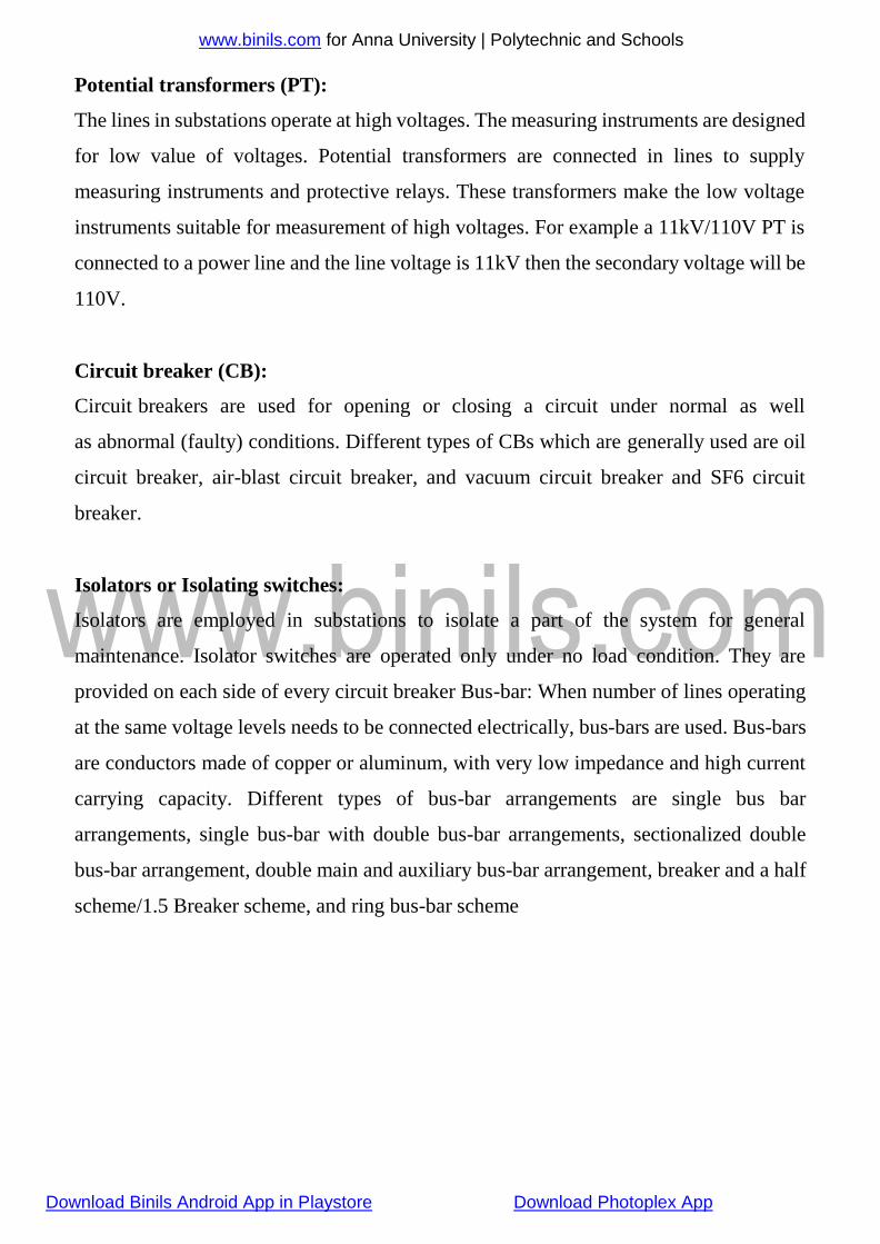
Potential transformers (PT):
The lines in substations operate at high voltages. The measuring instruments are designed
for low value of voltages. Potential transformers are connected in lines to supply
measuring instruments and protective relays. These transformers make the low voltage
instruments suitable for measurement of high voltages. For example a 11kV/110V PT is
connected to a power line and the line voltage is 11kV then the secondary voltage will be
110V.
Circuit breaker (CB):
Circuit breakers are used for opening or closing a circuit under normal as well
as abnormal (faulty) conditions. Different types of CBs which are generally used are oil
circuit breaker, air-blast circuit breaker, and vacuum circuit breaker and SF6 circuit
breaker.
Isolators or Isolating switches:
Isolators are employed in substations to isolate a part of the system for general
maintenance. Isolator switches are operated only under no load condition. They are
provided on each side of every circuit breaker Bus-bar: When number of lines operating
at the same voltage levels needs to be connected electrically, bus-bars are used. Bus-bars
are conductors made of copper or aluminum, with very low impedance and high current
carrying capacity. Different types of bus-bar arrangements are single bus bar
arrangements, single bus-bar with double bus-bar arrangements, sectionalized double
bus-bar arrangement, double main and auxiliary bus-bar arrangement, breaker and a half
scheme/1.5 Breaker scheme, and ring bus-bar scheme

www.binils.com for Anna University | Polytechnic and Schools
Download Binils Android App in Playstore Download Photoplex App
1.6 TYPES OF CONDUCTOR
1. Copper
Copper is an ideal material for overhead lines owing to its high electrical conductivity
and greater tensile strength. It is always used in the hard drawn form as stranded
conductor. Although hard drawing decreases the electrical conductivity slightly yet it
increases the tensile strength considerably. Copper has high current density i.e., the
current carrying capacity of copper per unit of Xsectional area is quite large. This leads
to two advantages. Firstly, smaller X- sectional area of conductor is required and
secondly, the area offered by the conductor to wind loads is reduced. Moreover, this metal
is quite homogeneous, durable and has high scrap value. There is hardly any doubt that
copper is an ideal material for transmission and distribution of electric power. However,
due to its higher cost and non-availability, it is rarely used for these purposes. Now a days
the trend is to use aluminium in place of copper.
2. Aluminium
Aluminium is cheap and light as compared to copper but it has much smaller conductivity
and tensile strength. The relative comparison of the two materials is briefed below:
(i) The conductivity of aluminium is 60% that of copper. The smaller conductivity of
aluminium means that for any particular transmission efficiency, the X-sectional area of
conductor must be
larger in aluminium than in copper. For the same resistance, the diameter of
aluminium conductor is about 1·26 times the diameter of copper conductor. The increased
X-section of aluminium exposes a greater surface to wind pressure and, therefore,
supporting towers must be designed for greater transverse strength. This often requires
the use of higher towers with consequence of greater sag.
(ii) The specific gravity of aluminium (2·71 gm/cc) is lower than that of copper (8·9
gm/cc).Therefore, an aluminium conductor has almost one-half the weight of equivalent
copper conductor. For this reason, the supporting structures for aluminium need not be
made so strong as that of copper conductor.

www.binils.com for Anna University | Polytechnic and Schools
(iii) Aluminium conductor being light, is liable to greater swings and hence larger cross-
arms are required.
(iv) Due to lower tensile strength and higher co-efficient of linear expansion of
aluminium, the sag is greater in aluminium conductors. Considering the combined
properties of cost, conductivity, tensile strength, weight etc., aluminium has an edge over
copper. Therefore, it is being widely used as a conductor material. It is particularly
profitable to use aluminium for heavy-current transmission where the conductor size
Download Binils Android App in Playstore Download Photoplex App
is large and its cost forms a major proportion of the total cost of complete installation.
3. Steel cored aluminium
Due to low tensile strength, aluminium conductors produce greater sag. This prohibits
their use for larger spans and makes them unsuitable for long distance transmission. In
order to increase the tensile strength, the aluminium conductor is reinforced with a core
of galvanised steel wires. The composite conductor thus obtained is known as steel cored
aluminium and is abbreviated as A.C.S.R. (aluminium conductor steel reinforced).
Steel-cored aluminium conductor consists of central core of galvanized steel wires
surrounded by a number of aluminium strands. Usually, diameter of both steel and
aluminium wires is the same. The X-section of the two metals are generally in the ratio
of 1 : 6 but can be modified to 1 : 4 in order to get more tensile strength for the conductor.
Fig. shows steel cored aluminium conductor having one steel wire surrounded by six
wires of aluminium. The result of this composite conductor is that steel core takes greater
percentage of mechanical strength while aluminium strands carry the bulk of current. The
steel cored aluminium conductors have the following
Advantages:
(i) The reinforcement with steel increases the tensile strength but at the same time keeps
the
composite conductor light. Therefore, steel cored aluminium conductors will produce
smaller sag and hence longer spans can be used.

www.binils.com for Anna University | Polytechnic and Schools
(ii) Due to smaller sag with steel cored aluminium conductors, towers of smaller heights
can be used.
Download Binils Android App in Playstore Download Photoplex App
4. Galvanised steel
Steel has very high tensile strength. Therefore, galvanised steel conductors can be used
for extremely long spans or for short line sections exposed to abnormally high stresses
due to climatic conditions. They have been found very suitable in rural areas where
cheapness is the main consideration. Due to poor conductivity and high resistance of
steel, such conductors are not suitable for transmitting large power over a long distance.
However, they can be used to advantage for transmitting a small power over a small
distance where the size of the copper conductor desirable from economic considerations
would be too small and thus unsuitable for use because of poor mechanical strength.
5. Cadmium copper
The conductor material now being employed in certain cases is copper alloyed with
cadmium. An addition of 1% or 2% cadmium to copper increases the tensile strength by
about 50% and the conductivity is only reduced by 15% below that of pure copper.
Therefore, cadmium copper conductor can be useful for exceptionally long spans.
However, due to high cost of cadmium, such conductors will be economical only for lines
of small X-section i.e., where the cost of conductor material is comparatively small
compared with the cost of supports.