
El ~ND - DTIC
74
r AO—A059 6*7 INCO INC MCLEAN VA F/s 9/2 STANDARD SGflWARE BASE (SSS) RELEASE III .(U) AL 76 T TRt$F . I NORIAN F30602—77—C—Ofls UNCLASSIF ICC INCOflO73—37I—Tft—aI-O(F) *AOC—Th— 71—167 It _ El ~ ND _____________________________________________________________________ Fit.. 12 :78
-
Upload
khangminh22 -
Category
Documents
-
view
0 -
download
0
Transcript of El ~ND - DTIC

rAO—A 059 6*7 INCO INC MCLEAN VA F/s 9/2STANDARD SGflWARE BASE (SSS) RELEASE I I I . ( U )
AL 76 T TRt$F. I NORIAN F30602—77—C—OflsUNCLASSIF ICC INCOflO73—37I—Tft—aI-O(F) *AOC—Th— 71—167 It
_El ~ND
_____________________________________________________________________ Fit..
12:78

‘ O 1~~ ~~2 8 ~~2.5I. L~
‘~~~~~ ~~~~~~
~ lIOI~2
I.’ ~~~~. ~ IHH~°
IOU ‘ 25
MI ;I~ l ~~ ‘ I l J I I ( J N ( I IA I~lII T I l i T J t . I . 1 . T . I . ii A

I! ,
>-
C-)
wU-


UNCLASSIFIEDSECURITY CL~~S5IF ICA T ION OF THIS PAGE (*7.o D.t. Ent. r.d.)
( 9 IREPORT DOCUMENTATION PAGE BEFORE COMPLETING FORMc~ f9~4~tfl(.S —J 2. GOVT ACCESSION NO. 3. R EC I P I EN T S C A T A L O G NUMSER
~~~~~~R—7 8—16 7 j _______________________________4. TITLE (mid Subflfl.)
___________ ,? 6) TyPE OF REPORT & WEAIO~~~E~~~’ER4O
JTA~~~~ D~SOFWARE~_BASE (~~~ ) JELEASE ~n~~~
7
cL ~~~~~~~~~~~~~~~~~~~~~~~ -
___________________________________________________ Irrunrs,ut-, E SB~ ~~B
_________ ~~ INC0/]~~73—378 —T R—26—D (F)
7. AU 1140 - - I_- se.. ,,,
~~~ ~~~~g b~~~ ~~~~ ~~~~~~~~~~~~-óO46~~~~~-~
1. PERFORMING ORGANIZAT ION NAME AND ADDRESS to . PROGRAM ELEMENT . P~oj~ cr , TASK
INCO, Inc. 3102577916 Westpark Drive 21830135McLean_VA__22101 ____________________________
11 . CONTROLLING OFFICE NAME AND ADDRESS ~~ ~~~~~~~~ f l .~~~~
Rome Air Development Center (IRDA) / 1 Ju1~ ~~78 /Griffiss AFB NY 13441 — -ri . NUMUt i~ oF P AGES
14. MONITORING AGENCY NAME & AODRE$1(It dllfrr.nt from Con trolling Ottic.) IS. SECURITY CLASS. (of hi. r.port)
Same UNCLASSIFIED
I -, IS..
1— N/AU~
I~~. DISTR ISUTION STATEMENT (of hi. Ropor t)
Approved for public release; distribution unlimited.
C.
17. DISTRISUTION STATEMENT (at A. .b.(roc t .nl.r.d In Block 20, it ditt.r.n t Ira., R.port)
Same
IL SUPPLEI4EN1A RY NOTES
RADC Project Engineer:Samuel Dicarlo (IRDA)
lI KE’,’ WORDS (C.ntlnu. on rov.r.. .id. it n.c..omy mid id.nIifr by block numb.,)
Automatic Data ProcessingComputer NetworkingComputer Programming
~ Computer Operating Systems2O. ’
~~~~~r R AC T (Conilnu. on r...r.. .id. It n.c...my mid Id.nUI~ bF block numb.,)-
The Standard Software Base (SSB) was developed over the past several yearsto provide a common inventory of modular software tools with which AN/GYQ—21(V)system users can quickly and effectively develop and implement data systemsunique to their site—specific requirements. The SSB provides common baselinesoftware to enable the AN/GYQ—2l (V) as a stand—alone , frontend , or communica—tion. processor. Release III provides a Termina l Transparent Display Language(TTDL) as the interface between user terminals and the SSB system.
) (Cont ’d)
OD ~~ 1473 EDITION OF I NOV 61 IS OCIOLETE UNCLASSIFIED ~~~ ‘~~~~ ‘
n c’ (~
“I SECURITY CLASSIFICATION OF THIS PAGE (WP,on D.fa tn.s,.d)
“ ‘~~ ~ ~~~ ‘Ø7 .~ v~—°

UNCLASSIFIEDSECURITY CLASSIFICATION OF THIS PAGE( ’Wk .,, 0.1. EnI.rad)
20 (Co nt ’d)
SSB utilizes a ~~ ateway manager~~capability to route all t ra f f i c within thesystem, separating the communications software from the applications software,thus providing a capability to implement~”gateways’~ to other systems andnetworks.
UNCLASSIFIEDSECURITY CLASSI FICATION OF THIS PAOE(1PPum 0.t. Ent.r.d)

TABLE OF CONTENTS
Page No.
1. INTRODUCTION
1.1 Purpose 1
1.2 The Technical Problem I
2. TECHNICAL APPROACU 2
2.1 Interim Operating Capability 2
2.2 Fully Operational Capability 2
3. RESULTS 3
3.1 Acceptance Testing 3
4. CON~~ NTS 3
S—it t
~~1

STANDARD SOFTWARE BASE (SSE) RELEAS E IIITEC~~ ICAL REPORT SU~~ ARY
INTRO DTJCTI ON
1.1 Purpose. The Standard Software Base (SSB) was developed over thepast several years to provide a co on inventory of modular software toolswith which AN/GYQ—21(V) system users could quickly and effectively developand implement data systems unique to their site—specific requirements.The specific objectives of the SSB system include:
a. Establishment of a comson standard technological softwarebase supporting the development of applications programs, and overallimplementation of AN/GTQ—21(V) systems.
b. Elimination of duplicate development efforts and shorteningimplementation schedules.
c. Development and delivery of comprehensive system documentationand software releases to user activities.
d. Development of a comprehensive training program to equip AirForce personnel with the knowledge required to develop mobile on—siteSSB training teams .
1.2 The Technical Problem . During 1973 and 1974, AFIS/IND conducted asurvey of USAF Intelligence Data Handling System (IDHS) modernizationprograms. The USAF programs included the implementation of the AN/GYQ—21(V) system as a stand—alone, front—end , or cOmmunications processor.All these programs used some form of systems software, many of whichshared co on features. To eliminate redundancy in development effortsand to realize both cost avoidances as well as cost savings , AFIS/INDcommissioned INCO , INC. in 1975 to develop common system software forAN/GYQ—21.(V) users. This effort evolved into what is now referred to asthe Standard Software Base, or SSB.
1.

TECHNICAL AP P ROACH
2.1 Interim Operating Capability. The RSX—II D Operating System wasselected as the co unity standard and retained in its vendor—releasedversions. This resolved the problem of providing a standard operatingsystem for AN/GYQ—21 (V) users and at the same time , permitted concentra-ting resources on the design of sub—executive modules which would extendthe capabilities of RSX—llD to accotamodate a wider range of tasks . Thesetasks included the development of communications networking, and terminaldevice interface software. Rome Air Development Center ’s TerminalOriented Support System (TOSS) was used to achieve interim communicationsnetworking and terminal device interface capabilities. Releases I and IIof the Standard Software Base were installed and implemedted using TOSScomponents.
2.2 Fully Operational Capab ility. The design development and implemen-tation of SSB Release III represented significant technical improvementsover the first two releases . Four major design enhancements wereinvolved :
(1) The Terminal Transparent Display Language (TTDL) replacedthe Interactive Support Capab ility CISC) as the interface betweenuser terminals and the SSB system . TTDL provides support for theIBM 3270, the UNIVAC 1652 , and the Model 40 Teletype terminals aswell as continued support for TTY—compatible terminals used inprevious releases. TTDL permits a prograa~ er to design simple orcomplex terminal screen displays without regard for the type ofterminal in use. In addition, TTDL supports concurrent use of anapplication progr am by more than one user. Under Releases I and IIfor example, if two intelligence analysts were to use BUILD function ,two copies of the programs supporting the function had to be readinto core to acco odate the two cases.
(2) A Gateway Manager concept was devised to route all t r a f f i cin the system and to separate co nunications software from applica-tions software.
(3) A WICS—compatible message format was developed to replacethe message forma t used in Releases I and II.
(4) A global library of shareable co ort routines was developedto access system files , tables , and data . This relieved progra ersof devising code to process data in the system . These routines wereused extensively in rewriting applications programina and in developingadditional gatew~ys.
2
-

Other significant chan’es to Release III included providing an interfacewith the Computer Assisted Tactical Intelligence System (CATIS) , anddeveloping additional gateways with which to access the DIAOLS and COINSsystems. CATIS—related enhancements included developing a two—step useraccess procedure which controls access to both CATIS and SSB ; a CATISgateway between CATIS and SSB ; and modifications to the AUTODIN gatewaywhich accoi odate the transmission and receipt of segmented messages andmessages from the DSSCS and GENSER networks. The gateways to the DIAOLSand COINS systems have been coded and laboratory tested but are not yetimplemented under Release III.
RESULTS
3.1 Acceptance Testing. SSB’Release III was subjected to DefenseCotmnunication Agency, Category III tests during the week of 13 February1978. The system satisfactorily passed all tests and is currently beinginstalled at two USAF E sites , at Schierstein , and Ramatein .
CO~ ff.NTS -
Source documentation for system development , implementation , technicaldiscussions , and operating instructions , are referenced in Section II ofthe SSB Release III Final Technical Report, 28 February 1978.
3
-

TABLE OF CONTENTS
Page No.
SECTION I. INTROD~ETION I—i
S ECTION II. MAJO R TECHNIC AL ACCOM PL IS R~ENT S I t — i
I . TECHNIC AL ACCOMPL IS FMENT U— I
a. TTDL Enhancements 11—1b . Gateway Manag ement and 11—2
Developmentc. Global Routines 11—3d. AFAITC Training 11—4e. System Installation 11—4
2. TECHNICAL DOCUMENTS 11—4
SECTION III. SSB RELEASE III CXrIS E NHANC~ ’fENT S I l l—I
1. THE CATIS GATEJAY I t t— i
a. Receipt and Conversion of AIJT ODIN 111—iMessages
b. Transmission of AUTODIN Messages 111—2 4c. Status and Recrie’ial of AIJTODIN 111—2
Messages
2. SECUR ITY ENHMC~~4ENT S 111—3
a. SIGNON 111—3b. SIGNOFF 111—4
3. CENTER SYSTEM CATIS—RELATF~) MOD~~~ECAT ION S 111—4
a. Priority—Ordered Message Delivery 111—4b. Expanded Message Processing 111—5
Capab ilitiesc. Accountability Enhancements 111—5
4. SSB RELEASE III AIJTOD IN GAT~ JAYS 111—5MOD IFIC AT IONS
a. TISGT A 4WT ODIN Receive Ga t eway 111—6b. The GENSER Transmit Gateway 111—6c. GENSE R Review and Validation 111—7
U t i l i t y
5. TTD L CAT I S—RELA TED MODThI CA TI ON S 111—8i
TABL E OF CONTENT S (Co nt’d)
Page No.
SECTION IV. STAN DA RD SOF~~ ARE BASE (SSB ) REL EASE lIt tV— IARCH ITECTUR E AND FEATURES
1. ARCHITECTUR E tv—i
a. Message Data S t ruc tu res IV—6b. Internal Data S t ruc tures IV— 15
2. SSB FEATURES IV—3 5
a. Message Preparation IV—35b . Message Transmission IV—35c. Message Receipt IV—3 5d. Messag e Review IV—4 2e. Message Retention tV—42f . Message Re tr ieval IV—4 2g . Editing Messages IV—42
3. SSB SUP~~ RT C~PABI L LTIES IV—4 2
S ECTION 7. ADAPTABI L ITY OF SSB RELEASE III V—i
S ECTION VI . ThIPL IC ATIONS FOR FUTURE DEVELOPME NT Vt— i
ii

LIST OF FIGURES
Fig ur e No. Titl e Page No.
tv— I SSB Release III Sys t em/Subsys t em IV—2IV—2 SSB Subsystem Relationships IV— 7IV—3 TCF Data Block tV—8IV—4 Fixed Header Block t V — t OtV—5 Ac counting Block IV— 12tV—6 Routing Block IV—i3tV— 7 Message Data Block tV—iAtV— 8 Nul l Message Data Block IV— 14IV— 9 Spacer Block IV— I SIV— 10 Precedence/Security Tab le (PS TFIL) tV— 18tV—I l Routing Info rma t ion File RIP BLOC 1~ IV—2 1
(512 Byte)IV—i 2 Rou t ing Info rmation File Entry IV—2 2tv—i 3 Gateway Options Table File (CO TFIL) IV—2 5tV—i A Terminal Directory Fil e tV—28tv—i s TISC~1 Table Directory IV—3 3tV—i t S Route Reference Tab le (RRT ) tV—34IV—1 7 Network Characteristics Table (NCT ) IV—3617—1 8 TISJO R Area IV—38
LIST OF TABLES
Table No. Title Page No.
tV— i SSB Mo dules IV—3IV—2 System Err Qr /St atus Messages tV— il
-
iii

•— i.,t~~ UAt— . \ J j
The va.Lu.e and significance of the SSB lies in i~s ~et~.g a common soft-ware base that provides sta.ndard system software , au~~ enting the RSX-1LDoperating system ~~ the ~u/’~Yc.-21(1), eliminates redundant de1elopmentefforts to develop on-line interactive terminal support capabilities, andprovides a means for communIcations between geographically remote sitesvia existing and planned co unication lines. The S3~ enables the indi-vidual sites to customize their system software by us ing only those modulesthat art~ necessary to operate its system, minimizing the demands on theresouzces of the AN/GYQ~-2l(7), and. still being assuzed of reliable and cen-trally suDported software . The SSB is the foundation or baseline softwarethat supports Intelligence Data handling Systems development and enhance -ment activities within the Rome Air Development Center Technology ?rogramObjective RLE, ‘IndIcations and Warning .”
As such, any future applicat ion developed for or by an operationaluser can be transferred much more easily from one site to another bec.~auseof the standardizatIon of software interfaces within the system and th~ease with which modules can be added to the SSB.
SX~4UEL S. DICARLOProject Engineer
iv

SECTION 1
I NTRODtE T ION
This document provides the Final Technical R e p o r t f o r the RomeAi: Developmen t Cente r ‘~~der Contract No. F30602—77—C—0046. Ther eport describes the research and development conduc t ed by INC O ,P~C . dur ing the period 26 August 1976 to 28 Febru a ry 1978 to enhancethe S t a n d a r d S o f t w a r e Base (SSB ) capabi l i ty es tabl ished w i t h SSBReleases I and I t to suppor t opera t ion of the AN /GYQ—21 (V)minic t~np uter sys tem.
Majo r achievements are desc ribed as both technicalacc~ npl is~m ent s and contract del iverables furn ished to the gove rr~nent .The a rch i tec tur e and special fea tures of SSB Release III a r ediscussed . The u t i l ity of the release for the AN/GYQ—21 (V) system andthe adaptab il it y of the system to meet unique requirements are alsoad dressed.
The last section of the report discusses possible technicald i r ec t i on to be pur sued in the f u tu r e .
Mr. S~~ DiCarlo , RADC , was the cognizant govertinent engineerdur ing th i s con t rac t period. Mr. Carl Compton , D i r e c t o r a t e ofIn te l l igence Data Ma n agement , Air Force Intelligence Service,Head quar te rs US AF, was the contracting of ficer’s tech nicalrepresentat ive f o r contractua l ac t ivi t i es .
I—1

SECTION It
MAJO R TECHNICAL ACCOMP LI S 1-ME NTS
This section of the Final Technical Repo rt describes themajor work accompl ished by INC O, INC . under contrac t ntsnberfl0602—77 .-C—0046. Major technical acccmp l i&tients and m a j o rtechnica l documents delivered to the goverrmen t are discussed .
1. TECHNIC AL ACC~ 4PLI S~ 1ENT S
SSB Release III represents a significant technical fin—provement over pr evious SSB releases. Four major desig n enhancementswere devel oped and impl emented. The Te rminal Transparent Disp layLanguage (T T DL ), replaced the Interactive Support Capab ility (ISC), asthe i n t e r f ace between user terminals and the SSB system. A GatewayManager concep t was devi sed to control the routing of all t r a f f i c inthe system and to separate commun ications and applications software.Several gateways w e r e written to interface wi th this ma n ager. AWIC S—compat ible message fo rma t wa s developed to replace the TISSCom~~~rt Fo rma t used in Releases I and II. The f o ur t h major enhancementwas the development of a shareable global lib rary of routines for useby all SSB modules.
A f t e r the initial SSB Release III software was developed , itwas enhanced to provide increased compatib ility with CATIS software.This work includ ed the development of a CATIS interface gateway;devel opment of a gateway to transmit GENSER messages in an off].irtemagnetic tape mode; extensions to the existing AUTODIN gateway insuppo rt of GENSER input, sectioned messages , and expanded rout ingrequirements; modifications to the center system to support expandedrouting security requirements; and modifications to several modules toeuppo rt expanded security and access capabilities. These technicale f f o r t s are desc r ib ed in Section III of this report .
a. T1~DL Enhancements
The TTDL s o f t w a r e package pr ovides support f o r the IBM3270 , the UNIVAC 1652, and the Model 40 Teletype terminals, as wel las continued support fo r the TTY—compatib le terminals used in previousreleases. TTD L permits the design of simple or complex input/outputdisplays f o r a v i r t u a l terminal screen by adapting the v i r t u a lterminal’ s character is t ics to those of the physical terminal uponwh ich art applicat ion is to be run . Additional ly , TTD L sup por tsm u l t i — u s e r applications progr ams , e .g . , r een t ran t progr ams. Tinder thisconcep t onl y one cop y of a given application program is required toaccommodate several sim ultaneous users. Under Release II and ISC f o rexampl e, i f two analysts w e r e using the BUILD fu n c t i o n at the sam et ime , two copies of the progr ams suppor t ing the fu n c t i o n wererequired .
tI— i

The TTDL sof tware package was in t e g r a t e d wi th SSB ,and the abil ity to support the tB?t 3270, UN IVAC 1652 , and MOD—40 Tele—type terminals as well as continued support for all TTY—compatibteterminals was impl emented. Concurrently , the TTDL/CATIS interfacepackage was tested and installed at the Bunke r—Ramo facility inJes tlake , Califo rnia. Wo rk on the MOD II versio n of TTDL began in May1977 , and was finished in October 1977. This modification to the basicTTD L capability was required to reduc e service time to .5 second orless to b e t t e r suppor t CATI S appl ica t ion programs , and wasspec i f i ca lly d i rec ted at the UNIVA C 1652 t e rm ina l .
b. Gateway Management and Development
Impl ementat ion of the Gatewa y Man ager concep t in thecentral system was completed in March 1977. By th i s tim e, the basicSS1~ application program set was also completed.
A ga teway was devel oped to handle unsectionedAUTODIN/DSSCS messag e t r a f f i c as part of the initial SSB Release IIIcapabi l ity . This work was completed in March 1977.
The 2780 Remote Job Entry gatewa y between the IBM 360and the AN / GYQ—2 1(v) was completed , tested , and integrated w i t h theSSB system dur ing March—April 1977.
Wo rk on the desig n and Imp lemen ta t i on of a baselinegateway for the Community On—Line Intelligence System (COINS ) netwo rkwas completed in Jun e 1977. Recommendations and a design were alsodevel oped f o r art expanded CO INS capab ility to suppo rt PACAFrequ i r emen t s, however, impl ementa t ion of th is capab ility was notaddressed dur ing the term of this contract.
An interact ive gateway was developed to access theDefense Intell igence Agency On—Line System (DIAOLS — TSS ) . Thegateway was ready f o r demonst ra t ion to AFI S/IND personnel in February1977.
An Interprocesso r Ga t eway (IPG ) was designed andimplemented . This gatewa y contains three separate modules: acommun ications line in te r face ; an SSB in te r face, and; an IDHS(C)—Itin ter face . The IPG can be configured with any two of the threemodules to serve as an SSB sys tem IPG , art I D R S ( C ) — t I IPG , o ’ as adirec t t ransfer interface in a processo r hosting SSB and I’~4S(C)—t .At the clos e of this contrac t only the SSS—t o—SSB c apab i l it y has beent ested .
The CATIS gatewa y was desig n ed to conver t messagesbetwe en the CATIS—produ c ed fo rma t eveloped joint ly by INCO andBunke r—R amo and the internal TISF1L—supp orted fo rma t used by SSB .
11- 2
The ga teway also supplies the queue ing and r ou t in g services neces-sary to a l low CATIS to tranmnit and receive messages through SSBcommunications software. In tegra t ion of th is gatewa y wi th the(~AT tS sys tem was c ompleted in Fe b ruary 1978.
A GENSER t raneni t / rece iv e capabi l i ty was required byCAT IS . The t r an mm i t capabil i ty was impl emented as a separate gateway.The CE NS ER gatewa y provides the in te r face wi th the SSB sys tem andwrites outgoing GENSER messages to magnetic tape for of fline review,v al i d a t i on , and trananission. Review and validation are accomplishedby the sepa rate u t i l i t y modules GE N UTY and GE NVAL , r espectively. TheGENSER gatewa y w i l l also acep t DSSCS messages in JANAP 128 tape fo r-mat as a commun ications backup capabi l i ty . Trananission is per-fo rmed a t a commun ications center and is not an SSB ~unction. Thiswo rk wa s comp leted in June 1977.
The Release III AU TOD IN gateway was modif ied f o r CATIS .Nu’nn r ou s detailed extens ions were made; the ability to suppor ttrananissiort and reception of multiple section r~~ssages and therec eption of GE NS ER messages was added. This gateway was incorpo ratedin to the standa rd SSB Release III software in October 1977.
Securi ty requirements made it necessary to manua llyreview messages for all GE NS ER dest inations befo re they werereleased for arty destination in the DSSCS system. This capabilityrequired modification of the center system modules, primarily TISMDM ,to route by pr iority and to receive positive acknowledgement beforereleasing lowe r priority trananissions of the same message. Thesemodifications were completed in May 1977.
The access controls for SSB so f tware were modif ied toallow controlled s~bsysten selection in order to incorporate the
CATISand SSS systems under the same set of access controls. At the sautetime, the access control module, SECT~)N, was rewritten. The securityrelated system files were reorganized and modified to reflect n~wae~ ess criteria for 8i.bsystem authoriza tion and terminal, overlay(characteristics of the U—1652).
c. Global Routines
The global lib rary of shareable common routines wascompleted in January 1977. The global lthrary was used in rewritingthe applications pr ograms and is currently being used in develop ingthe gateway progr~ns. All applicat ion programs excep t the S1~APRTp r i n t modul e are written in reentrant code to facilitate simultaneousus ‘~~.
11—3

d . ~~ A1TC Training
Two we ek s of t r a i n i n g was given to AFAITC personnel onthe SSB in October 1977. Th is included pr e sen ta t ion of a basic cour sewith specific training objectives for intelligence analysts, pro—grammars, in 1. comp uter operators. current SSB manuals .~~re pr ovidedfor use as stud y references and guides to hands—on use of thesystem in a laboratory setting . The objective of this trainingcourse was to provid e AFAITC personnel wi th sufficient knowledgeof SSB Release III and CATI S u tod i f ica t ions to pr epare fo rmal US AFtraining courses for SSB users.
e. System Installation
An interim operating vers ion of SSB Release III wasInstal led on the AFIS/IND 21(V) system in May 1977. Under thisversion, AFIS/IND tested basic system performance using the newcapabi l i ty to supp ort the MO D—4 0 Teletype and the IBM 3270 terminals.The AUTODIN gateway was tested successful ly using the Western Un ionProgrammable Te rminal Control ler (PTC ) and Analyt ics Telecoinntun I—cations Line Controller (TLC). Ca tegory III testing and cer-t i f i c a t i o n of SSB Release I L l was completed in Feb rua ry 1978. TheSSB Release I I I system was installed at Air Force sites in Ramsteinand Schierstein , Germany dur ing February 1978.
2. TECHNIC AL DOCUMENTS
The following technical documents were produc ed anddelivered between 9 September 1976 and 28 February 1978:
A0O 1 R&D Status Repcr t s
1 — 2 6 Aug 76 — 25 Jan 772 ‘- 26 Jan 77 — 25 Peb 773 — 2 6 Feb 77 — 25 Mar 774 — 26 Mar 77 — 25 Apr 775 — 26 Apr 77 — 25 May 776 — 26 May 77 — 25 Jun 777 — 26 Jun 77 — 25 Jul 778 — 26 Jul 77 — 25 Aug 779 — 26 Aug 77 — 26 Sep 7710 — 26 Sep 77 — 25 Oct 7711 — 26 Oct 77 — 25 Nov 7712 — 26 Nov 77 — 25 Dec 7713 — 26 Dec 77 — 25 Jan 7814 — 26 Jan 78 — 25 Feb 7815 — 26 Feb 78 — 28 Feb 78
11—4

A002 Technical Reports :
Interim — 25 August 1977Final — 28 Febru ary 1978
A004 Test and Impl ementat ion Plan28 February 1978
A005 Standard Sof tware Base ~eview Doct.~~ent1 Nov ember 1977
A006 SSB Program Specifications and Installa t ion Manual28 February 1978
AOO7 SSB User’s and Comp uter Opera tor’s Manuals28 Feb ruary 1978
SSB Ap pliction Progranmar’s Manual19 October 1977
A008 Test Analysis Repo rt28 Feb rua ry 1978
A009 Wo rk Plan29 Apr il 1977
11—5

SECTION III
SSB RELEASE III CATIS ENHANC~~dE NT S
A number of changes and additions w e r e made to the SSBRelease I I I sys tem in order to support the Computer Assisted TacticalIn te l l igence System ( C A T I S ) . The ob jec t ives of th is support w e r e topr ovid e the AU TOD IN gatewa y with the capab ility to t r an s m i t and toreceive DSSCS and GENSER traffic , arid to provide enhanced secur i tycontrols for the comb ined CATIS and SSB sys tems. The f ive areas oftechnical achievement discussed in this section are the CATIS G a t e w a y ,secur i ty enhancements , modif icat ions made to the SSB cen t ra ls upe rvi so ry group , modif icat ions to the SSB Release 111 ALJ TOD INga teway , and modi f ica t ions to the Terminal. Transparent DisplayLanguage , TTDL.
1. THE CATIS GAT~ JAY
The CATIS gatewa y has three basic f*mct ions. They are:1) rec eption of incoming AUTODIN messages and the conversion ofthose messages into CATI S—compatib le fo rmat ; 2) t ransmission ofCAllS—originated AUT ODIN messages , and ; 3) pr oviding CATIS wi th thestatus of incoming messages queued to the CATI S sys tem.
a. Receipt and Conversion of AUTODIN Messages
Incoming AUTOD IN messages are received by the AUTODINGateway and placed in the Messag e File (M SGPIL) on the system disk.If the gateway determines tha t a message is destined for CATISsof tware , the SSB Message Header Block is ma rked to show that themessage is addressed to a CATIS recipient. The gateway then passescontrol to the Messag e Distr ibut ion Modul e (TISMDM) . TISNDM examinesthe Messag e Reader Block , ac~ a owledge s the “toke n” route to CATIS, andthen passes control to the CATIS Gateway via a pr iority—struc t ur edcall, the CATIS Gateway retrieves the Messag e Reader Block aridconstructs a CAllS Control Block (CCB). The CCB contains the mes-sage destination, messag e or ig ina tor , the precedence and secur ityclassif icat ion at t r ibutes of the message , and the date— t ime—group oft ransmission. The c ompleted CCB becomes the f i r s t disk block of anR SX— I ID FCS f i l e wh ich is used to t ransfe r the massage to CAllS . TheCAllS Gatewa y then transfers the message tex t to the FCS f i l e . Whenthe FCS f i l e is closed , an entry is posted in the CAllS Gateway QueueFile C r 1 0 2 , 102] CATI SQUE .QUE ; 1). The CAllS Gatewa y then issues anRSX— 1 ID wakeup macro (RQST$ ) cal l to the appropriate CAllS modules ,TRIRP .
T4h ert TRIRP is read , to accep t the messag e , i t issues anRSX— I LD send data macro to the CAllS Gateway. The 13—wo rd data blockcontains only a f u n c t i o n code wh ich means , “Send to CAllS the highestp r i o r i t y input message on your que ue .” The CATIS Gateway complies
111—1
-4

with this request, passing the version number of the appropriate FCStransfer file in a 1 3—wo rd RSX— 1 ID send data bLock together w i t h afunction code meaning, “This is the highest pr iority input message.” Adifferent function code is returned if the queue is empty.
When CATIS s o f t w a r e completes the processing of eachmessag e , i t i t issue s a V SDR$ ma c ro back to the CAl lS Gateway, topermi t deletion of the processed AUTOD IN message. The macroparameters contain the version number of the AUTODEN messag e and af u n c t i on code indicating that processing is complete . The CAllSGateway then deletes the FCS file and deletes the associated entry inthe CATIS Gateway Queue File.
b . Transmission of AUTODIN Messages
CAllS s u p por t so f tware builds a message using FCS and afile descriptor block identical to that used in receiving messages.The message is then closed and a VSDR $ macro is issued to the CAllSGateway to transmit the message via ALJTODIN. Parameters specified ina b u f f e r passed in the VSDR$ cal l includ e the transmission func t ioncode and the ve rsion number of the FCS fi le.
When the CAllS Gateway receives the request fort ransmiss ion, i t constructs the SSB mesag e f rom the FCS message. Itthen que ue s the request by the pr iority contained in the CAllS Ga t ewayQueue File. When the request reaches the head of the t ransmi t que ue ,the CAl lS Gateway marks i t and issues a cal l to TISMD M . TISMDM thenpasses control of the messag e to the AUTODIN (DSSCS or GENSER ) Gatewayfor transmission, If the message cannot be transmitted, or isrejected , the CAllS Gateway is informed . In such cases, the CATISGateway determines whether or no t the message ~.s part of amul t i—segment CAllS—originated message. If it is , a f u r t h e rexamination is conduc t ed to determine if this is the f i r s t section ofthe segmented message. If the message is fo un d to be the f i r s tsection of a segmented message , the gateway advises the orig ina t ingCATIS module that the message was riot transmitted. If the message wasthe second , o r a si4,sequent section of a segmented message , the CAllSGateway rou tes the messag e to the SSB system conso le terminal f o rcorrec tion and retransmission via a stand—alone MCR task. In suchcases CAllS software is riot notified of the message transmissionfailure.
If ALJTODIN successfully transmits a CAllS—originatedmessag e , the CAllS Gateway deletes both i ts que ue entry and the FCSfile.
c. Status and Retrieva]. of AUTODIN Messages
Wh ile the CAllS Ga teway no tif ies CAllS so f twar e modulesof the arrival of AUTOD IN messages, i t is not like ly that CAllS can
111—2

nessages at the sa~ie rate at ~~~~ t:~ey arrive. Tores o lve t h i s d t f f i c u l t y , the CAllS ~ate~ay na tritains a prtorttyor d e red log of massag e en t r ies f o r all in com ing me ssages. Theseentries are maintained by this Log unti l the ga t ewa ;’ rece ivesnotificatio n to delete them . If a CAllS modul e Is er~3~~~ed i~ ?r~ —zessirtg a ~~ ssage when n o t I f I c a t i o n Is receIved that ano ther mas sag ehas arrived, the new nessag~ ~ay b e de fe r red by issu1n~ one of theR SX— 1 ID Receive Data macros. One of these macros m i st he used so thatR~ X— 1 LD W I L L r e t u rn the nodes changed to the CAllS Ga t ewa y wh en the73DR 3 macro is executed . To re t r iev e a nessage wh ich h a s ;.~end e f e r r ed , CATIS s o f t w a r e may call the CAllS Gateway using a ISDRSmacro requesting the status of the highest pr ior i ty messag e queued.Then the CATI S Gateway rece ives t h i s request , i t queries the CAl lS LogQueue FI le and passes the info~~ at io n back to the calling nodule in abuff er via a 750R5 macro. The module ma ;’ then retr ieve the massagef rom the FCS file, arid once finished , notify the gateway it basc ompleted processing .
2. SECUR I TY ENRANC~~4ENTS
The CAllS arid SSB systems were logically joined bycons idering them as s~tsystems of a larger system. The Release IllL OGO N modul e was r e w r i t t e n to Lnclud e a St h s y s t e m select ion menu. Themenu currently provides three options: CATIS, SSB , and EXIT. ThemodI f i ed LOGON modul e was renamed as S1GNON . In similar fashion , theLOGOF F module was renamed SIGNOFF. These two mo dules , SIGN ON andSIGNOF F , are cur r entl y the only SSB Release III appl ica t ions programsthat are compatible with the CATIS—specific version TTDL, which isre fe r red to as TTDL II.
a. SIGNON
For the most part , the SIGNOM modul e retains thefu n c t i o n s ma Intained by the LOGO N module. The m a j o r d i f fer e n cebetwe en these two modules is that SIGN ON uses a two phase systemaccess procedure whereas LOGON uses only one. Using LOGON, the userneed pr ovide only user i den t i f i c a t i on, name , an d passsa rd to accessthe SSB s y s t e m . Once these entries are ver i f ied , he is f re e to useany SSB f u n c t i o n as e i the r a general or pr ivileged user . SIGN ONimposes an addit ional control. in that users mus t be pr eviouslyau thor i zed to access specific st h s y s te ms, e .g . , SSB , CAllS , SAR2 . Theu s e r specifies the stbsyst en he wi shes to access. The selection ischecked by the secur ity monitor modul e , SEC~~N, to dete~~ine if theuser is au t hor ized . Alter three unsuccessful attempts to SIGNON thet e rm In a l is disc onnected from the system , thereby deny ing access toany syst en or st h s yst e m fu n c t i o n fu n c t i o n excep t SIGNON . To gainaccess t arvi o the r s y s t e m function, both phases of the SI GNO Npr ocess mus t b~ c~~np 1eted success fu l ly .
111—3
In addi t ion to the two—p hase acc ess proc ess , SIGNONalso Logs the time and the subsysc~ n accessed by the user.
b . SIGNOFF
SIGNOF F differs from LOGOFF in that a r iser may signoff from one sI.~ system and access another stbsystem to wh ich he isauthorized without the necessity of pe rforming phase one S GNONaga in . Prompts are issue d to de te rmine if the user wishes toterminate access to the entire system , or gain access to anothe rs~~ s yst e m . If t e r m i n a t i o n is signif ied , the terminal is disc on-nected fr om the system and re ini t ia l ized f o r a sth sequent SLGNONf u n c t i o n . If accessing anothe r s tbsystem is s ignif ied , the sth—system select ion process in SIGNON is ir i i t ia ted.
3. CENTER SYST~~a CAllS—RELA TED MODIFIC AT IONS
In order to suppo rt CATI S/ SSB operat ion , severalmodifications to cente r system supervisory modules were required ,pr imarily in the areas of message routing and accoun tability . Thesemodificatio ns included pr iority—ordered message delivery to gateways ,and expanded message processing and accountability procedures.
a. Priority—Ordered Message Delivery
The Message Distribution Module (TlS~~M) routesall messages between gateways in the SS~ system. The ~1eeworkCharacteristics Table (NCT) maps each routing netwo rk identity tothe appropriate gateway. A flag bit in the NCT is used to identifygateways wh ich are designated to receive pr iority routIng . TIS~~ Mevaluates messag e rout ing tokens to identI fy pr ior i ty—designatedga teways . TISMDM perfo rms a sequential sc an of des t inat ion tokensin a message , mark s each token , and compiles a list of netwo rkidentifiers found in the tokens. Prior to issuing an SRB to agateway, the list is scanned for the presence of pr iority—designatednetworks. The firs t one found reduces the list to one and the sc an ist e rmina ted . ~~ SRB wi l l be issued to the pr iority gatewa y only ,althoug h a lL tokens in the message will remain marked for their properdest inat ions . The pr iority gateway must return status to TISXDM toreliev e TISMDM of restart respo nsib ility for the message. At thispo int , the pr iority gateway is respo ns ible fo r the message until it isrouted to its other destinations. If the message is successfullydelivered , the pr iority gateway req uests TIS~WM to mark alldestination tokens addressed to the gateway as successful, arid toroute the message to all destinations. TISMDM exanines thedestination tokens and routes the message to all remaining des-tinations.
111—4
_________________________

If , for arty reason, the pr iority gatewa y could nottransmit the message , i t requests T1S~WM to ma rk all tokens asinsucceesful arid to r e t u r n the message to its o r i g i n a tor .
These changes to T1S~~M do not affect nori—CATIStOu t 1mg.
S. Expanded Message Processing Capab ilities
Three capabil i t ies w er e added to the SSB g lobal rou t ineLib rary to suppor t CATIS operation. They are: 1) Removal of res-trictions on the rusnber of destinations tha t may be specif ied in anessage; 2) Removal of the order r e s t r i c t i on which fo rmer ly existedbetween originator and destination blocks in a message, and ; 3)increasing the nianber of message type blocks that can be handled bythe system.
c. Accountabil i ty Enhancements
The Accountab ility Funct ions Modul e (TISAFM ) providesa central place for accoun t ab il i ty in handling disk resident TCFme ssages ( TI Sf lL) . Once a TCF message is built by the originatinggateway , onl y TISAFM Will make modificat ions to the message; all othermodules access the message as read—onl y. The token flag by te in alldes t ina t ion blocks is used to de termine the processing status as wellas any error conditions. Using this information, TISAFM will requesteither TISJO R onl y , or TISJOR and TIS~~ M to r e t u r n to the o r ig i n a t o rmessag e f i les processed w i t h error conditions , or message f i les fromgatews ys requiring posi t ive ackn owledgement. The positive acknowl-edgement f e a t u r e was added to support CAllS . TISAFM wa s also mo d-if ied to suppor t an expanded nt~~ber of dest inat ion tokens in a TCFmessage.
4. SSB RELEASE III AIJT ODIN GATEWAYS MODIFICATIONS
SSB Release III emp loys two AUTODIN gateways; one formessage transmission , the othe r fo r receipt of AIJTOD IN unsectionedme ssages. Both ga teways had to be modified to sup port CATISrequ i r ement s f o r the t ransmiss ion and receipt of sectioned AUTOD INmessages over the DSSCS and GENSER netwo rks.
The capabi l i ty to t ransmit sectioned messages wasaccommodated by processing sections of messages as indiv idualsing le—sect ion messages.
Incoming sectioned messages are detected by the CAllSGateway and rou t ed to a Sect ion—Order ing Modul e , SBGCOM . This modul et empora r i ly s tores messag e section n~snbers on disk u n t i l all sec t ionsof a message have been received , then notifies the CATIS Gateway. The
tii—5

CAT S ~atewa v , in tur n , assembles the s ect i ons ~it o a s ing le messag eand passe s the nessage to the CATLS system .
The operation of these two ~ateways is desc ribed in thef-o Llowi ng pa rag raphs .
a. TI SGTA ArJ TOD IN Receive Gatewa y
This gatewa y c o n v e r t s me ssages recei ,ed fr om an A~T ODL~S w i tching C en t e r in e i t he r ~SSCS o r GENS ER fo rm a t to SS3 Commonyo nnat. The converted messages are stored In the central message f Ilem a i n ta ined ott disk , and are accessible for processing hy th*~ SSBs y st e m . The receive gatewa y can accommodate a va r i e ty of messagetypes. These inc lude: DSSCS messages with a pr ecedence of flash—Override or l owe r , itt both narrative and Query/Response fo rmat;GENSER messages in either plain address or CODR ESS f o r m a t ; serv icemessages itt ei ther D SSCS or GENSER format; AUTu—CALL—BACK messages ine i the r DSSCS or GENS ER fo rmat originated at othe r SSB s i tes ; andcont ro l messages f rom the AU TOD IN swi tching center.
All incoming t r a f f i c is ex amined fo r errors int r ansmi s s ion message type , ari d fo r lxxtbedded control messages.When ev er errors are det ected , n o t i f ica t i o n is output to the systemconsole. Control messages are displ ayed at the system consoleimmediately upo n receipt. These include requests for initialization ,c a n c e l l at i on of t r an smiss ions, messag e r e j ec t ion notices , andackn owl edgement3 of lost t ransmiss ions .
Dur ing conversion of incoming AUT ODIN messages, T SGTAplaces netwo rk dependent and netwo rk independent info rma tion into theappropriate routing blocks in the message header. When all pr ocess inghas been completed , a message containing the message sequence nunberand identifying the user to whom it is addressed is output to thesystem console. When ever AUT O—C AL L—BACK messages are received , T SGT Abuilds art ackn owledgement message wh ich is passed to the MessageDis t r ibu t ion Modul e fo r s~.t sequent t ransmiss ion. When messages wi th af l a s h or h igher pr ecedence are rec eived , TSCTA outputs notificationof the arrival to the system console.
b. The GENSER Transmit Gateway
The GENSER Gateway d i s t ingu i shes betwe en CENSER andDSSCS (R&Y ) type messages. DS SCS messages are rou ted to tape if aspecial flag has been set by the CAllS gateway . This provides abackup capabi l i ty to the com~~in icatiort s hardware . CE N SER messages a reconstructed itt JANAP L28G forma t for output to magnetic tape. Thetapes are pr inted by an off—Line review u t i l i t y p rogr am f o r manua lacnep t~ince or rejection of each message. A record va l idat ion arid
111—6

r~ s~on s e util ity ~rogran is used to mark each messa~~ ~s a c c e p t a b l eo r not , and to issue a p p r o p r I a t e res~ o nses back t o 3’S B so t h a t .messag~ac c~ ’int ab t l i ty p rocedures may be pe r f nned.
The SS~ Message Distr t h i - : Ion ~4odul a (T I S?.~~1) r ece Ivesa ~ AL~ ~~~ transmission req uests from the CAT IS ~a tewa;’. SInceG E N S ’- R t r a f f i c is always revIewe d b e f o r e t r a n s mi s s i o n , any messagesr n u t ~~d , eI th e r ~~ Lusiveiy or in p a r t , ov e r the ‘~~~SER n e t w o ck a r eau t o ma t ical ly rou t ed to th e ~ENSE~ ‘r am m n i t ‘ a teway f o r ~ou r n a —iz a t i ) n and v a l i d a t i o n pr io r to any o t h e r 7r s c e ss i ng .
Dur ing the jour nal iz at i o n process , a tape volume direc-tory Is created on disk. Each ent ry in the directory cross—references333 messag e sequence numbers to the tape reel number of the tape towh ich the messages have b een wr i t t en . The ma intenance of the d ir e ct o ryrequires operato r interaction in that the correct tape must be mountedand placed on—line. The data re fe renced by the d i rec to ry is dumped to9—track , 800 bpi tape in a format suitable to Commun ication Centerr e q u i r e me n t s .
As CE NS ER messages are manual ly reviewed arid acceptedor rejected , the entr ies fo r the specified messages are deleted fromthe tape volume directo ry. The operato r uses an of f—line GENSERRevtew and Validation Utility (GR EY ) to review messages, and a‘Jalidation Response Module to accep t or reject messages. When amessag e is accep t ed , GREY cal ls the message Accoun tability ~~dule(TI SAFM ) to ma rk. the GEN SER des t ina t ion token in the message ascompleted . The Message Distribution Modul e (TI S~~M ) is then called tocomplete routing of any r ema in ing non— GE NS ER d e s t i n a t i o n tokens. ‘ he na messag e is r e j ec t ed , the GENSER Review and ‘lalidation u t i l i ty modu lei n s t r u c t s TL S AFM to ma rk a l l des t ina t ions as imsi~~c e s s fu j l andins t ruc ts T13~WM to re tur n the messag e to i t s o r ig ina to r f o r fu r t h e ract ion.
c. CENSER Review and Val ida t ion U t i l i t y
The GENSER Review and Val ida t ion Ut il i ty , GREY , is as tand—alone pro~ ran . It processes the message p l a c .d on tape b y theGEN S ER Secur i ty Gatew ay . GREY produc es a pr in tou t oL messages f o rreview b y com~~j n i cat ion center personnel . GREY requires no SSBservices; i t is ac tIva ted and run un der ope ra to r con t ro l .
Op e r a t I on s 7~~rsonnel s i gn i f y acceptance or r e j e c t i onof a mes sag e by us ing th e GE NS ER Va l ida t ion Respon se Mo dul e ( G V R ) .Op e r a t o r i n p ut s includ e the tape volume n u m b e r upon which the messag ere s ides, and a yes or no response. GVR passes t h i s i n f o r m a t i o n to the‘!ce s sage A c c o u n t a b i l i t y Mo dule .
111—7

:~~~~ .. •~A: 3—R :..A:!D ‘CD:F:cAT:G’~S
-~o d I f t c a t I o n s to the ~~~-~Ina ~ -ans?arem: Dis~lav .angua5~e‘~~T ) h ) fo r CA T S su p p o r t ~~r-~ divIded i n to wc .arge sub d i v i s i on s .
2 was modIfied t o 3 ’ipo’~ rt CA T S o p e r a t I o n , and TTD L ~~ wassce:: :i:al ly desIgned to meet the respon se tim e an d ~agin~
of CA TIS.
Mod~~fI :at io ns to TTD L I Included p r o v i d i n g suppo rt f o r the:~~ 32 ° 1 and ~~T 7AC 16 52 t e~~ inals , and the l~~i e n t at i o n ‘ofseveral new fea tures . These features Inc lude : h g pen. s t - _ o nand t e r m i n a t I on f ’mct ions f o r the UN VAC 1652; a w at chdog t i me r ;a p p l I c a t I o n progran suspend and resume fu m c t i on s ( no t cu r rently Inu se) ; de fau l t In i t i a l iz a t ion of retrieved data fields ; user validatIonof inp ut fields ; and an external b u f f e r fo r security purposes.
TTD L 11 is an adapta t ion and r e f in~~ ent of TTD L 1. Itspr imary purpose Is to im prove terminal response t imes to aC A T I S — r e o u i r e d leve.. t w a s written specifically for the UN 7AC 1652t e rmin al arid. does not includ e the d~~~~nic d e f i n i t i o n and re fo r m a t t I n gf e a t u res of T~~ L I. Displays are comp iled In advance and stored ond I 3k . The reader is re fe r red to the separate FInal Technlc a R e p o r tfo r f~r t h e r Info rmat ion on TTD L II (Cont rac t No. F3 060 2—77 —C — 0 0 4 6 ) .
SECTION IV
S TAN DA RD SOFTWARE BASE ( S S 3) REL E A SE LIIARCHITECTUR E AND FEATURES
1. ARCHITECTURE
SSB Release I I I cons i s t s of four m a j o r so f tware compo—nerits. They are the Terminal Transparent Display Grou p ( T T D L ) , theApp l i ca t ions Modules Group, the Gateway M anager Group, and theGateways Group. The f i r s t , TTD L , provides the i n t e r f a c e be twe end i f f e r e n t type s of terminals and the system. It enables thedesigner/ progranme r to develop simple or complex inp ut and outputdisplays for a virtual terminal displ ay sc reen. TTD L ’s sof twareadapts the vir tua l terrninal s characteristics to those of any physic alt e rminal on wh ich a terminal applications is run. The ApplicationsModules Group pr ovides the 1/0 terminal user w i t h a variety of messag ehandli ng f iztct ions sLc h as logging on to access the system , bui ldingand tran~~i tt i ng messages , and receiving and reviewing messag.~et r a f f i c . The Gatewa y Manager Gr oup interfaces all SSB appl icationssof tware w i t h non—app l ica t ions so f tware. It pr ovides central izedt r a f f i c control for the system and separates commun ications ,t e rmina l , and system so f tware from each other . This separation make spossib le the interface with other site—dependent systems suh asCAT IS. The Gatewa y Ma n ager concep t protects agains t unautho r izedaccess to SSB capabilities and files, and also provides for automaticj ou rna l i za t ion of incoming and ou tg o ing sys tem t r a f f i c . The GatewaysGrou p provides the actua l gateways , or interfaces, be tween SSB andexternal netwo rk s stc h as AtY TOD IN , CATIS , and the DIA on—line system(DIAO L S) . Figur e tV— i il lus t ra tes the interaction of each subsystemin SSB Release III. Table tV— I lists the individual modules thatcomprise SSB and their functions.
The SSB is art orderly and systema tic system architectur eproviding com~~ n netwo rk ing so f twa re for U. S. Air Force systems thatuse the AN/GYQ—21 (V) minicomputer. The SSB system provides users withso f twa re wh ich sa t isf ies their needs for netwo rk commun ications ,terminal support, system security , and maintenance.
I,
Modulari ty is the key element of SSB . Indiv idualcomma nds /agenc ies/ac t iv i t i es may use one or n~~re of the SSB softwaresu b s y s t e m s or ~~dules at their discretion. In tegra ted , tes ted , andval idated so f tware su b s y s t e m s are avai lable to assist users in thedevelopm ent of their respectiv e system/capabilities and to interneto r i n t e r f a c e w i t h othe r data f i l e s , da ta bases , and /o r int el l igen cesources within the commun Ity. As a resul t , users throughout theSSB—suppo rted commun ity can evaluate their mission requirements ,select only those SSB subsystems wh ich will suppo rt that miss ion ,and plan to f i l l the gaps with command/ agency u n i q u e so f tware . I t
IV- 1

U0
I q~~~~II •c;~ I
_
—I ~‘I~~1_. — ~~~~~ • a — a — a a — a
I ~::E ~
:E_ (I)I c1~— z
cia ).. — dle n =
EI *., ___
‘
I _____ ____________________ In_ _ _ _ _ _
_ _ _ I
I~~~~___ _ _ _ _ _ _ _ _ _ _ _ _ _ _ _ _ _ _ cI~JII-. ~ I Q 0— z ~~~~~~~~~~~~~ —
~r — ~~~~~~~~~~~~~~~~~~~— n . 0 ~d>4 — .~~ dl I
• m c s ~- r..i ~~~.. ~~~c.j
~~~~~~ ~~~ I~1)
I _ _ _ _ _ _ _ _ _
• I
_ I I ~
>~I ~~~~~~~~~~~~ ci. ‘c i- i~~z I ~— C., Zc i . = 0-~ c c I~~~~~~~~~~~....az*-~~n.
I I ~
I ~I
I a a afa ..J ~I
I
I
_ a.Ja a a a a
tv- 2

SUPERVISORY MODULES
NAME TITLE
TIS AFM Account ing F u n c t i o nTI SFL L Fi le Ma n agerTI SCBL Global R o u t i n e sTI S~~ M Inp ut B u f f e r M anagerTIS nIP Input Message Processo rTI SIN T System InitializationTISJO R Journalization ControlT tSLOG Message Ac countingTI S~~ M Messag e D i s t r i bu t i on Mo dul eTIS SAV Res ta r t/ Re cove ryTISSTS Status floduleTISTAP Tape Jour nalizatiort
MESSA GE HANDLING AND TERMINAL SU P PORT ~4DDULES
MESSAGE HANDLING MODULES (SSB Application Progrems)
NAME TITLE
GE NUTY GE NS ER Review U t i l i t yGE NVAL GENSER Validation UtilitySB ABL D BuildSBABTP Tape UnavailableSBADMP DumpS3~DSD Display D r i v e rSB~DSP Displ aySB A ~~ I Edi tSBAH LP HelpSBAH RJ His tory/Re trieve DiskSBAHRQ Hi s tory/ Re t r i eve QuerySBAHRT History/Retrieve TapeSBALOF LogoffSB~LON LogonSB APR T Print Ap pl icationsSBARET Re turnSBASND SendSBATAP Hist o ry / Retr iev e Tape
I n i t i a l i z a t i o nSBAUT I.. Ut ilitySB SPRT Pr int Service Mo dulesSEC~~ N Secur i ty M o n i t o r
Table t V — i . SSB Modu les
IV- 3

H
TERMI NAL SUPPORT ~~DUL ES (TTDL )
NAME TITLE
ADDr’TTT Add Name to—TIPAD DS TT Add Screen to—TIPA~ 10T After Flash lotificationAIM Application Interface ModuleAL IVS N Allocate V i r t u a l Screen NodeAP PE ND AppendBLDS A Build Screen Area3LK BlockBUFM ~.N B u f f e r Mange rB~~ ADD Byte Addi toncm~i~~ Check Inp utCLD Class Dependent RoutinesCLNS ’t~ Clean StackCLR N DE Clear NodeCMB~~~ Comma nd Bu f fer Ma n agerC”~~INT Command In te rp re te rCOM~VD CommandDATAB Data BlockD I S C O N DisconnectDI SL~~ Display Lib raryDKI O Disk Inpu t / Outpu tEP External Processo rEX!XFN Execute External FunctionEXTCMD External CommandFIEL DS Field Handling RoutinesFN~~ L Find Comma nd LineFN T)NTT Find Nex t Name s to TIPFNDS A Find Scree n Ar eaFNDSTT/FSTSTT Find Screen to TIP / Fi nd S t a r t Screen
to—TIPFN~TAB Find Conversion Tab NodeFNDTBN Find Tabling NodeFNDTN Find Terminal NodeFN DTTT Find Termi nal Type TableFRCPD Force ReadFRE~~JP Free Up TTDL ResourcesFR~ JSN Free Vi r tua l Screen NodeGE TPARX/GETT IP Get Packe d Address/Get TIP AddressGETS Get Info rmation from PCBGETSTT Get Screen to TIPGE TTN Get Terminal NodeGETINT Set Get Terminal Node Poin ter to TopROLDEL Hold DeleteIBM 327 0 IBM 2370 Rou t ines
Tab le tV— i . SSB Modules (Cont’d)
IV-4

TERMINAL SUPPO RT ~~DULE S (Cont ’d)
NAME TITLE
KLFLS H Kill FlashMAP~~I Ma pp Ing and Pr iority RoutinesMAPA PP Map In to Ap pl ica t Ion ProgranM04 Mod 40MOV OAT Move Data‘tSOUT Messag e OutPA~CtP Pack TIP AddressPASDSP Pass DisplayPCBDSP Process Cont ro l Modul ePlO Pr ima ry Inp u t /Outpu tPR~~RO Preprocesso rPSP PostprocessorPTNSTT Po int to Next Screen to TIPPTNNTT Point to Next Names to TIPRESAP P Rest .me Ap pl icationRTNAP P Re tur n App l icationSET~ J Set Read/Write Bit310 Secondary Input/OutputSIOC OM Sb G~inmonSLLDLL Single Linked List/Double Linked ListSRCH TK Search fc.~r Task Nam eSRCTVC X Search ListheadSU SDSP Suspend DisplayTE RM Terminate Appl ication Progr amTDLDIO TTDL Disk Input/OutputTINIT Terminal Initializa tion
~ 1RACT Terminal Action Required RoutinesTM R COM Te rminal Routines in Commo n1~1RNCM Terminal Routines not in CommonTSTPCB Test Process Control BlockTTY Teletype Terminal RoutinesUNIVAC 1652 UNIVAC 1652 RoutinesUNF T IP Unpack Terminal Independent Format
COMMUN IC ATIONS INTERFACE (GAT3JAY ) ~~DULE S
CAT ISC CATIS GatewayTISGT 6 AUT ODIN General Service GatewayTISGTA LWTOD LN Receive Gateway (DSSCS/GENS ER)T ISCT I AU TODEN Send Gatewa y ( D S S C S )T~ SGT 2 COINS .GatewayT1SGT 4 IBM 2780 Emulato rTtS~~ T Terminal Gatewa y ( Functions w i t h i n the
Supervisory Modules Group)
Table t V — I . SSB Modules ( C o n t ~ d )
tv-S

i.s Important to unde rstand tha t the user se lects and uses onl yS SB— sup po r ted so f tware s~.bsystmn s th a t are requr ed f o r his o p e r a t i o n ,thereby e l thina t ic ig excessive overhead . Figur e 17—2 , SSB Subsys temR e l a t i o n s h i p s , describes th i s mo dular concep t using ex i s t ing orplanned SSB st h s y st e n s to demo n s t r a t e how the s ths ;i s t em can ope ra t ealo n e o r with othe r s.bsystans, as required . The s t hs stems t i lu s t r a —t ed in F igur e IV—2 a re :
o Fi le Handl ing Services
o Computer Assis ted Tactic al In t e l l igence Sy s tem (CAT I S )
o Commun ications Processing and Message Handli ’~gSubsys tem
o Terminal Transparent Display Language ( TT D L ) .
In e f f e c t , a given user may select f rom the SS~3 those nodu-les or elements of commo n modules pertinent to tm ique r equ i remen t swith the assurance that they will: (1) interact with other SSBe lements, ( 2 ) serve and suppo rt unique applicat ions , (3) not Imposea burden of supe rfluous SSB modules or elements on his systemoperations, and (4) accrue benefits arising f r o m other common userr e q u i r e m e n t s and modernizat ion programs.
a. Message Data Structures
All massage data in the SSB system is ma intained ondisk files in a WIC S—cocapatib le fo rma t l~t own as the Common Format , orTCF. All massage traffic generated by an I/O terminal user fordistribution within internal or external networks is placed into TCFby the system. All traffic entering the SSB system from an externalnetwork is translated into TCF by the system.
Outgoing t r a f f i c is initially cons tructed itt TCF andremaina in that fo rm through jourrtalizatiori. A cop y of the TCFmessage is converted into network dependent format by the appropriategat eway modules and tranemttted in network—compatible format.In coming t r a f f i c is converted into TCF by the appr opr ia te gatewa ymodul e and rema ins in TCF through the journa lizat ion process.
Each TCF messag e is recorded as an indexed—sequentialdisk file un de r a messag e seq uence number assigned by the disk I/Oprocesso r , T 1SFIL.
Message traff ic in TCF is recorded under a logicalblock struc t ur e comprised of several type s of f ixed and va r i ab leL ength data blocks. Each physical block may accommodate up to 512byt es, or 256 words . Figur e IV—3 shows the general conf iguratio n ofan SSB TCF Data Block .
• IV-6

AN/GYQ—21 (V)
1STANDARD AN/GYQ-2l (V ) RSX—11D (Required) 1
FILE COMPUTER CO~~ UNICATION~HANDLING ASSISTED PROCESSINGSERVICES TACTICAL &
CO~~ UNICATIONS(Can operate SYSTEN—CATIS — HANDLING LINKS ASalone; how— REOU TR EDever , (Optional) • (Can opera terequired tor alone, how-.CATIS) ever ,
requir ed forCATIS)
I ITERMINAL TRANSPARENT DISPLAY LANGUAGE (TTDL) (required for
Terminal Support only)
_
Figure IV-2. SSB Subsystem Relationships
IV- 7

NetworkIndependent
F~~ ED ~~ADER CharacteristicsBLOCK (S tatic Area )
_ _
“T
~~~~~~~~~~~~
I
ACCOUNT INGBLOCK
_____________________
REQUIREDI —
ORIGINATORBLOCK
DESTINATIONBLOCK
_ _ _ _ _ _ _ _ _ _ _ _ _ _ -. 1~OPTIONAL I (DYNAMICDESTINATION I AREA )BLOCK(S)_____________________
OPTIONALMSG TYPE OR
SYSTEN SPECIF ICCONTROL BLOCKS
MESSAGEREQUIRED 1
~~!essageDATABLOCK V
— j Text
Figure IV—3 . TCF Data Block
IV- 8

(1) Fixed Header Block. The first block foreach TC~ ~nessag e is the Fixed Header Block . The f t r s t ~~ rd in t h i sS Lock c on t a t n s block type and massage d a t a length . The rematningwo rds in the b l o c k co n t a in ma ssage c o n t r o l da ta . 7nused 2 o rt lons oft h e bloc k a re ze r~~ f il led . Ftgur e :7—4 expL a ins the atruc tir e andc o nt e n t of Fixed He ader 3 1ocks.
( 2 ) Accoun t i ng Block. The f i r s t ‘~~rd in th i sS l o c k i d e n t i f i es i t s t y p e and l eng th . The r e m a tn i n g t~o wo rds c o n t at nt n f o r m a t t o n used by the Accountabili ty Modul e, TIS AFM . These datatnclud e the time the massage was processed by th e Messag e D i s t r i b u t i o n~todule , ~~M , and the accoun t ing fu n c t ton fl agwo rd used by ISAFM .Figur e I V—5 ti lu s tr a t e s the st r u c tu r e and conten t of an Accounting~ lock .
( 3 ) Rout ing Block. The Rout ing Blocks is thekey to the entire SSB system. Two types of Routing Blocks are used :one identifies the originator of a message, the other identifies thedest ination of a message. The Routing Blocks are accessed by the‘atewa y ~~nager modules to process all massage traffic in the system.Figure IV—6 illustrates the struc ture and content of the RoutingBlock.
(4) Message Data Block. The massage data5 lock contains the tex t portion of the TCF message. It is the lastblock of a message and is always present. If no data is to be sent ina message, a null message data block will be used. Figure IV— 7illustrates a Message Data Block .
(5 ) Null Message Data Block. The nul l messagedata block contattts only a 2—byt e block header and the massage datac oun t in the f ixed header contains zero. This block is used to signalth e end of TCF messages in which no data is to be sent.
All text blocks consist of serial data string sseparated by record ma rke rs and potent ia l ly ma rked as to the natur e ofthe text by opt ional markers. The entire 256—character ASCI I set maybe used . :~ orde r to allow these data, all separators and marke rs areevaluated as two cha rac te r strings as follows :
~ecord separato r — DL E , RSSta rt of Ne two rk dependent tex t — DLE , SOHS t a r t of n or t— NDF t e x t — D LE ,STXEnd of messag e tex t — DLE , ETXBinary DLE va lu e in tex t — DLE , DL E
Figure LY—8 illustrates a Null. Message Data Block .
IV— 9
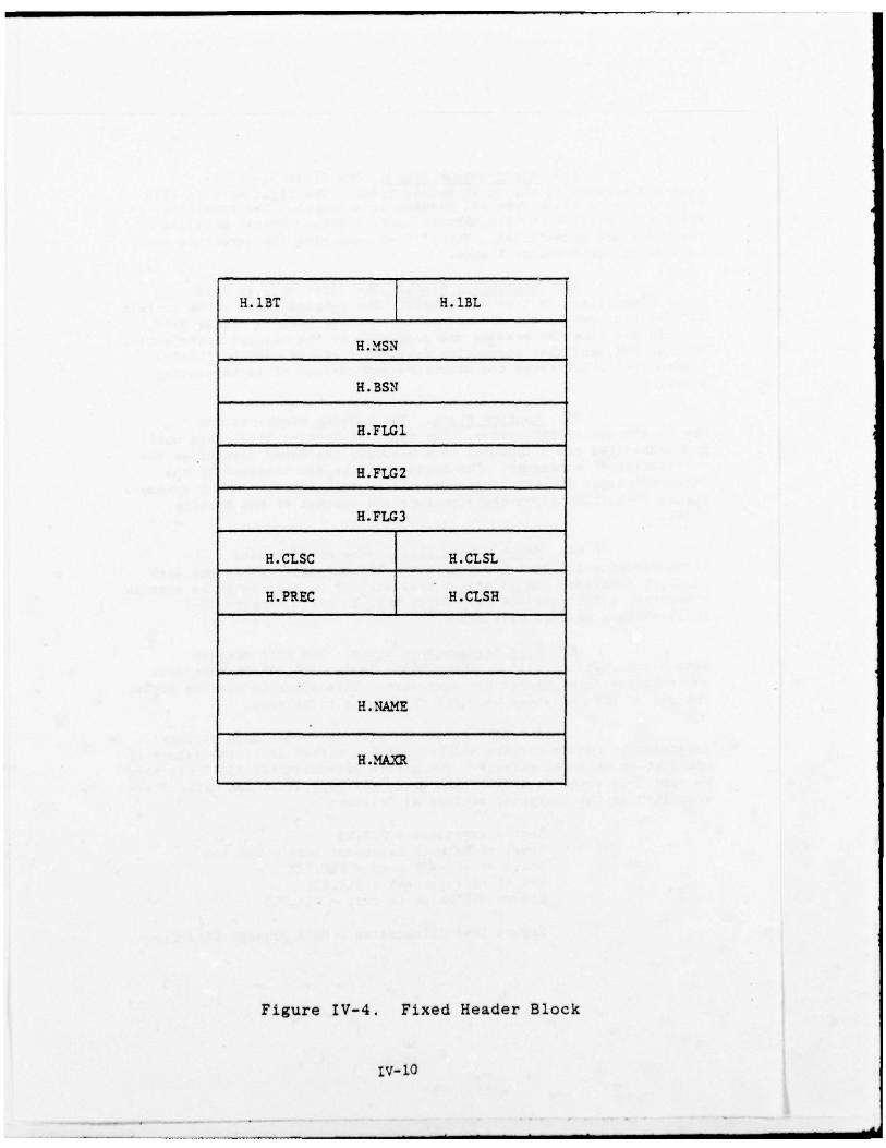
H.1BT H. 1BL
H.MSN
H. BSN
H. FtC 1
H. FLG2
H. FLG3
H.CLSC H.CLSL
H.PREC H.CLSH
H. NAME
H .MA~Q~
Figure IV-4. Fixed Header Block
LV— lO

DESCRIPTION OF STATIC ~2L. OFFSETSIN F HEADER AND ACCOUNT IN G BLOCICS
OFFSETNAME .MEANING
H.13L Fixed Header Message Block .angth Binary3.13T Fixed aeader Message 3locic. ype 3~ naryE.~~ N ~essage secuenc e n1. b e ~ BinaryE.3SN Block seque nce nt ber 3inarya.FLG1 Message characteristics flagvord B i t mas k
E.FLG1 Bit Dc! inittons
DT.NAR 0 — variable length records , na.rrattie (count ‘ )DT .CRD 1 — fixed length records , card image (countDT.7AR 2 — variable length records , ta pe/disk (coun t > 72)DT .FIX 3 — fixed length records , :ape/dtsk (count > SO )DT.BIN 4 — data uses full byte ~inar; code (no t supported
initially)3—15 open
B..PLG2 2fessage ch aracter istics flagword Bit mask
E.FLG3 Message characteristics flagword Bit
H .CL S Classification attributes Mixed binary/bytes
E.CLSL — Classi.f. level, binary 0—255L cLs c — Classif . compartments , 0—25 5H.CLSB. — Classif. handling attributes 0—255
a.PR.EC Precedence level, 0—235 Btnary
Message data character count Double word b~.naryOrigina tor f tle name RAD5OMaximt data record size Binary value
Figure IV-4 . Fixed Header Block (Coot.)
tv—il

H.23T H.2BL
H .MDMT
H. AIM
H.2BL Accounting message block lengthH.2BT Accounting message block typeH.~WMT Time message was processed by TIS~~M MIXED binaryH.AFN TISAFM coord ina tion flagword
Figure IV-5. Account ing Block
IV— ].2

KT.NZT
RT .NOD
Rr. PRO
RT.:rET RT.~~LD
aT.~~G
vartable length
) RT .ND F is the_________________________________________ offset of the
last byte
Routing Block Length, Words BinaryIT.T!? louting Block Type. BinaryRT.NOD Node tdentifying value Binary
~T.PRO Process Identifying value BinaryRT.U~~ User N.t’iork Id~.~nt i.fying value Binary2T .NET Net~ork~ Identifyin g value BinaryR~~~BL Valus Binary
r.YLC Routing entry flag byte , btt posittons as follows:
~~~~~~~ —200— This entr y processed by ~WM for~usuing purposes
~~~~~~ “100.’ This entry processed by indtca tedgateway ~uccessfuL1y
— 40’ This ent ry processed by indicatedgateway trnsucnes ifuily
RT.LA S — 1— Last routine entry in messageR~~~{riing f our bits availab le for net~zork dependen tic.f~~mation
Routing entry time Stamp , 2 words mixed b inary as pro videdby TIST~~f library uti litiesNe twork dep endent ftel d as defined by th e tar get network(optional) .
Figure IV-6 . Rou t ing Block

5 0
ME S SAGE
DATA
Message Data Block
Figur e IV— 7
NOTE:
(1) The length of the message data area is given infixed header block.
(2) The message data area may contain any S—bit character.
r5 0
Null Messag e Data Block
Figur e IV— 3
IV— 14

“ext w i l l be packe d (no short blocks excep t theL a s t ) to the 1en~th of the TCF d i s k b lock ing f a c t o r .
(~~) Spacer Block. A spacer block Is normal l yused to all~~i d i s k — r e s i d e n t messages to be fo r m a t t e d in a convenien t-lanner . ~~r ex~~sp l e , t h e user nay wish to p l a c e the messag e headeri n f , r ma t ion in one disk bLock and begin the messag e d a t a b lock in asepa r a t e block . tn t h i s case, the spacer block ~~uld be used to padt h e r~ na inder of the header disk block . Subseq uent references to themessag e ~~ul~ ignore the spacer block . (See Figure I V — 9 below. )
-
~~ LENGT H
FILLED
WITH
ASCI I
040’ _____
Spacer Block
Figure IV— 9
b . Internal Data Structures
The internal data structures of SSB are used toidentify users to the systen , identify internal and external rou t ingt a r g e t s , and s tore systmn info rmation and error messages. Theses t r u c t u r e s a re created on disk as e ithe r M SN TOS o r TISFI L f i l e s . TheTISFI L f i l e s are read into memory d yrt anical ly on an “as needed ” basis.The MS NTOS f i l e s are ei the r used to maintain the systen common area(TISCOM ) or they are read into memory as needed .
( 1) MSNTOS Files
MS NTOS f iles are c re ated by the MSNTOS fileh and ler. The MSNTOS file for TISCOM is used by T I S SAV to s to re theupdated SSB commo n area , TISCOM . The MSM TOS f i l e of sy st ~ nerror/status messages is a canned messag e file that is created atsysten generation tim e and thereafter accessed in read—only mode.
‘v— IS

( a ) TISCOM File
The TISCOM f i l e is used as a s torag e area f o rt h e SSB sy s ten common area ( T I SCOM ) . It is core—resident and resideswithin the area i~~own as BFRTSK . TISCOM is automatical ly overwrittenevery 30 seconds by the TtSSAV progr an .
(b) Svstexn Status File (STSFIL
The Sy st~~ S ta tus Fi le is a reserved area onfisk used f o r s tor ing all SSB error/status messages. Each messag e isassigned an ID and is referenced by the variou s SSB modules (bymessage ID) whenever an error or status report is detected dur ingsysten operation. Each message is allotted up to 64 by tes ofinfo rma tion. This file is not site—dependent but may be revised bythe systen progranmer . The messages stored in the file and thepurpose they serve are described in Table IV—2 .
(2) TISFIL Files
TISFIL is a file handling pr ogran wh ich maintainsa set of SSB files on the systen disk. Although each file isdiscussed as if it ~~re a separate entity , these files are in realityst h s e t s of one larger f i l e, TISFI L. FI L. Access to the TISFIL f i l e s isgained only throug h the TISFI L progran wh ich ma intains a completedesc r ip t i on of each f i le.
(a) Precedence/Security Table (PSTFIL)
The Precedence/ Secur ity Tab le is ad isk—resident file that contains all of the secur ity terms used by thesysten f o r data coding and display purposes . It is a randomstructured file created dur ing systen generation. It is logical lysthdivided into four m a j o r areas :
o Precedence
o Security classification level
o Security classification handling
o Security classificationc omparnn enta l iz a tion.
This file structur e is necessary because allop t ions in these four areas are carried internally in the systan asbinary value s wh ich must be encoded/decoded when displayed to a user.All disk blocks in this file contain a four—wo rd header block wh ichidentifies the starting block address of each of the four areas. Thefo rma t of the PSIFIL is shown in Figur e IV—1O.
IV—16

General error messages used by any module and displayedat the appropriate I/O device for the information of programmers :
SThSG 1, <t~~ D~~.ECTI~ Z FAILu RE LOC $ YT.1TtIAL 0— $ >S•r~fSG 2 , <RSX—LLD D~~ZCTIVE ?AILU~E LOC-$ V~~~UAL 0—s >
smsc ,3 , <DISX 1-0 PAILuR.E—FI zz FROCESSOR Z ZS~~SG 4 ,<NON SPEC~~’IC DATA ~~CEPTION LOC S 10 $S’~~SG 5 ,<DEVICE 1-0 PArLURE D EVICE - ‘ UN IT-& >
SThSG 6 ,<3ui~~.~. ALLOCATION FAILED SIZE -$ >S’~~SG 7 ,<TTSS—StSTL’~ ~~ITI.ALIZED Tt SCO~ 7 A $
Messages for gatewa y modules . They ar e included for
the token set of messages encountering processi ng problems :
S~~SG 11, < GATEWAY R.ECCTJRCE FAILURE ~~~$ >S~~ SG 12, < FATAL GATEWAY DAli ILLOGICAL ID-$ >
S’~~SG 13, < AirroniN ASC RLIZC~ (Bx ) c~s—s >S~~ SG 17 , < AIYrODIN MESSAGE NOT ACC~OWLZDGED (N~.X) CSN-S >
Status Indicator messages used within the Terminal
Gateway system and intended for user information :
STMSG 20, <MESSAGE PLACED ON INPUT QUEUE ,_ MSN— $ >STMSG 21, <ME SSAGE DELETED TR~)M INPUT Qu i.r~ ,MSN’.$ >STMSG 22 , <MESSAGE PLACED ON Otm’TJT QUEUE , MSN $ ‘
SThSG 2.3, < MESSAGE DELETED FROM OUTPUT Qu~u~ , MSN-$ >
ST~SG 25 , < MESSAGE DELETED FROM WORK PILE QUEUE, ‘fSN & >
S~~(SG 26 , < STATU S MESSAGE QUEUE ~~~ TY >SINSG 31, < MESSAGE RETURNED , MSN—6S’~fSG 32 , < MESSAGE RETULNED FOR UID—& , MSN & >S’~ fSG 33 , < DIPUT Qu~u~ FULL >S~~SG 35, < U ~~—& NOT REGI STERED IN US~~ D IRECTOR.! ‘
Messages used by th e RISTORY/RETRIEVE module fo r
both operator and user information :
STMSG 40 , < EISIORY — STATUS $ MSN—$ >S~~SG 42 , < MOUNT TAPE CONTA~~ ING DATE- >
S1~~SG 43 , ‘C INCORRECT TAPE MOUNTED >
S~~ SG 43 , < OPERATOR 1NTZ2.V~~TION NEEDED , 1D$ >
Table I V — 2 . System Er ro r/ S ta tus Messages
IV— 17

15 0PS.PRE
PS.CLL 2
PS.CLH BLOCK______________________________________ ~ HEADER
PS. CLC6
DATA RECORD 1 81
L DATARECORD ST DATA RECORD N f
15
PSR.~~1 PSR.ID 2
4
PSR.TL 6
PSR .TX
Data Rec or d Layout
HEADER OFFSETS:
PS.PRE — Pr eced enc e Starting Block NumberPS.CLL — Classification Level Starting Block NumberP S . C L H — Classification Handling Starting Block NumberPS.C ’LC — Classification Compar~~ ents S tarting Block Number
Figure IV-1O. Precedence/Secur ity Table (PSTFIL)
tV—18

DATA RECORD OFFSETS:
PS.REC — Data Record Starting Point
PSR.ID — Record Identifier Value (Binary)
PSR.~*~ — Abbreviated Entry Mnemonics (3 ASCII characters)
PSR.TL — Message Text Byte Count
PSR.TX — Starting Point for Message Text (up to 308 bytes)
PS.~OcR — Maximum Number of Data Records per block (16)
PSR.LN — Maximum Size of Text Data in Bytes (308).
Figure tV— iC . Precedence/Security Table (Cant . )
IV— 19

( b ) Rou t in g I n f o rm a t i on File (RIF FI L)
The Rout ing tn f o rrna t ion Fi le is ad i s k — r e s i d e n t rand om access f i l e created by T I S G E N dur ing sy s t~~generation. This fIle conta ins the info rma t ion required to fo rma tr o u t in g blocks f o r nessag e t ransm iss io n , and to decode rou t ing blocksf o r di splay a t an I / O device. The f i l e is used In conj u n c t i o n wi tht h e Gatewa y Op t ion s Table File (GOTFIL), and is accessed in read—onlynode by the Send , Display , and Print progr~~s. The f i le is c~ npr isedof 256—wo rd blocks , each containing 16 records , or entries. Eachentry contains tbe nane of either an SSB messag e d e s t i n a t i o n or ano r ig ina to r , a rou t ing toke n , and an ~~t r a w o r d . The struc tur e of the~tFFI L and its entries are illustrated in Figures IV—11 and IV—12.
A user may wi sh to send a message to anaddressee not contained in the RIFFIL who nevertheless is at a nodeserviced by a net— wo rk (e.g., LWTODIN ).
In this case, he may interactively specifythe network as his addressee. The SEND progran will search the RIFFILand find the netwo rk nane (e.g., AUT OD IN ), and use the mask byte tof~~ ther request entries to complete. a route. In the ATJTODIN case ,OT.!TO specifies that the ‘Routing Indicato r’ and ‘To Line’ must beentered by the user.
It is possible to have two or acre entriesidentical in eve ry respect excep t for nane In order to include sho r t e rmnemonics a t S END t ime . The f i r s t entry , in each case , will be theone displayed or pr inted , and shoul d be the ful ly—desc r ip t ive nane .
An entry naned LOC AL (or anything unique thata site wishes) should be the first RIFFIL entry . It will be used toreach local addressees when they are not ful ly or correctly specifiedin a message.
Cc ) Gateway Options Table File (GOTFIL)
Cer ta in external netwo rk s ( ATJT OD IN f o rexam ple) require additional info rmation for routing traffic tospecif ic netwo rk locations . This netwo rk—dependent i n f or m a t i o n is notprovid ed in the Rou t ing Info rmation File; it is pr ovided by entr ies Inthe Gateway Options Table File. The size of the GOTFIL depends on thenumber of gateways included in the systtsn and the number of entries(op t ions) required f o r each gateway. Ea:h gat ewa y is pe rmi t t ed av a r i a b l e number of en t r i e s . Each ent ry c o n s i s t s of th ree wo rds p lu s av~~r iab1 e— length f ie ld . The size of GO TFIL is ca lcu lat ed by addingtogethe r the size of each gatewa y en t ry p lus two wo rds per gateway.As an exam ple , AUT OD IN , the only gatewa y in the current vers ion of SSBr equ i r ing netwo rk—dependen t info rmation , occup ies sl igh t ly more than
IV— 2 0

0 WORD0
RIP ENTRY 1 16
RIP ENTRY 2 32
RIP ENTRY 3 48
RIF ENTRY 4 64
RIP ENTRY 5 80
RIF ENTRY 6 96
RIP ENTRY 7 112
RIP ENTRY 8
I
I ‘j~56
RIP ENTRY 16 I
Figure tV-il. Routing Information FileRIF BLOCK (512 Byte)
IV— 21

PS . NAN
22 BYTE NAMEFIELD
RI . NOD
RF.PRO
RF .NET RI.UID
RF.MS1(
CURRENTLY NOT IN USE
Figure IV-12. Rou t ing I n f o r m a t ion File E n t ry
IV— 22

D e s c r i p t I o n of RLF~~r L ~nt r i e s :
RIF Record O f f s e t s
RF .NA M — 2 2 b’,t e A SCI nan e of address( d n st i : -t at ion of o r i g I n a t o r ) .
R F . N O D — 16 bit b inary value f o r nodeupo n wh ich addressee 13 Located .
R F . P R O — 16 bit binary processing valuewhen level of address specifi:cionis applicab le.
RF.tJID — 8 bit binary user identif ica t ionvalue of addresse. This value mustcorrespo nd to ~tDs in theapp ropriate node’s user file.
RF.NET — 8 bit binary value for networkthroug h wh ich addressee isreached .
RF.~~K — 8 bit binary mask wh ich definesprocessing steps required to f u l l yspecify a route. For a particularnetwo rk , it specifies wh ich GO TYILoptions must be c~ npleted . In af ul ly specified routing entry , themask by t e shoul d have all bi ts cleared .Otherwise, the network gateway willdefine wi’~h bit bits to set. For theAU TOD IN netwo rk , the present designcal ls f o r se t t ing b i t 0 (i.e., OT .BT O)whenever a node is not ful ly qualified .It is necessary that stx h an entryexists fo r eacb g at e w ay .
Figur e IV—12. Routing Info rma~..ion File Entry (Cont’d)
IV— 23

oe 25 6— wo rd block . The st ru c tu r e of t he COTFIL is i l l u s t r a t e d InFig ur e P1— 13 .
Cd ) Terminal Director ” File (TEDFIL)
The Terminal Directory is a dis~—residenrfile containing the info rmation required for each te rn i ri al d ef i n e d Inthe system . It provides the device nane , tmtt number , and the secur i tyclassification level assigned to each terminal. The secur ic’, leve Lsd e f i n e d fo r the TEOFIL mus t correspo nd to the LeveLs describ ed in thePrecedence/ Secur ity Table. If these levels are in d i s ag reemen t , t hesystem will not deliver all the massages that may be au tho r ize f o r thet e rm i n a l . TEO F I L is a type 1 random file allocated and InitialIzed byTI SGEN. The s ize of the Terminal Di rec tory is dependent upo n thenumber of terminal entries and the accum ulated sizes of all entries.Each terminal defined in the systan occupies one entry in the T EDF L L.General ly, no entry is to cross a disk block b oundary , a nd ech newentry will start at the beginning of a block. Since the directory issearched sequentiall y , e ach entry contains an offset (relative tothe s t a r t of the disk block ) to the next entry. If the offset is zero( T D . E O B ) , It indicates that this is the last entry in this block andthe nex t terminal entry s t a r t s at the beginning of the nex t block . Ifthe offset is a minus one (TD.EOF), it s igni f ies the end of theterminal directory . The fo rmat of the Terminal Directory is shown inFigur e IV— 14.
(e) External Routing Indicator File (ERIFIL
The ERIP IL is a disk resident rand om f i l ec reated by TISGEN. It contains info rmation used by the AUTODINgateway. It is used by AUTODLN to correlate a TCF rou ting token wi thAUTODIN’s ‘Routing Indicato r’ and ‘To Line’ indicator. It is avariable size file dependent on the number of entries and size of eachent ry . Each entry is 15 bytes plus the number of characters in the‘To Line’ indicato r, up to a maximum of 28 bytes. A r ough coun t of40 entries per disk may be used for approximate sizing .
The ERIFIL is used in read—only mode by theAUTODIN gateway ex clusively. The TCF r o u t in g token tmist ma tch theequ iva len t toke n in the RIFFIL.
P1—24

tIORD B?T E
0 OT.IMC OT.OPT 0
1 —
OT. FB 1 OT.DSZ 1 2
2 OT. F33 OT. FB2 4
CHARACTER -BY - CH ARACTER
OT.OPT Option Number A binary value from I to 255spec i f ically ord er ed fo r eachgateway. These op tions will bedisplayed in numerical order fromlowest to highest. Thus, it is upto the gateway writer to arrangethe displays in an appropr ia teorder for the logical use by thegateway user. Since disp laysneed not be numbered sequential ly ,space should be l e f t fo r theinse r t ion of an tic ipa ted displays.
OT. LN C Max im um Number A b i n ar y value indicating theof Characers maximum number of characters to beto be Input read in as input. ~oth the Data
type (e.g., numeric , alpha , etc.)and whether of not the input fIeldm u s t be completely f i l l ed may bespecified by the contents ofOT. FBI.
OT .DS Z Display Size A b inary value ind ica t ing thetotal number of fixed charactersin the display field. This nuiberdoes not includ e the OT.INC value .Thus, to obta in the total numberof characters in the display f ield— (OT. D S Z ) 4 - ( O T . I N C) . Simi l a r ly ,t he size in by t e s u f the entryin the op t ions table — (OT .DS Z )- ’
6.(+I if the value is odd).
OT. 3F1 Inp ut A f l ag by t e , d esc r ibing the dataCharacteristics type and required length of theFlag input , to be used by “SEND” f o r a
p re l imina ry check of input datas yn tax .
Figure P/—13. Gateway Options Table File (GOTFIL)
IV—2 5

b i t s 0—3 Not used .Required leng th ‘~f inp ut f I e L d :i f 0 OT. NC is the naxI ~~um n um ber
of characters accepted asi n p u t . Less w il l also beaccepted .
i f — I OT .IN C conta in s t t eexact num ber of ch a r a c t e rswh Ich must be inp ut .
bIts 5—7 Data type of characters to beinput , and an op tion not to dis-play the prompt at present if allb its are not set.
h it 5 If set, indicates acceptance ofalp ha characters.
b it 6 If set, indicates acceptance ofnumeric characters.
b it 7 If set, indicates the acceptanceof special characters.
Th us, if only alp hanumeric charac-ter s are to be accepted , bits 5and 6 should be set (e.g. , 5—7— 011 ) .
OT.F32 If the value is greater than zero ,ent ry of t h i s f i eld is mandat ory .
If equa l to zero , en try of thefield is not mandatory.
OT.F33 This flag byt e is used to deter-mine if any additional fIelds inthe GO TYIL are ma ndato ry, based onfields alread y entered . Accord-ingly, for each option or fieldenter ed , th is byte , (~DT: FB 3 ),associated with that op tion, is‘OR ’ ad with the correspondingflag bytes for all of the otheroptions that ha~ie been entered .The resultant b i t pattern is thenc ompared with OT.F32 for all the
FIgure tV—i 3. ~atewa y Opt ions Table File (GOTFIL) (Cont ’d)
IV—26

options in the GO TFtL. If n a t c h —ing b i t s are set in bo th fl agb y tes f o r any o p t i o n , then thato p t i o n is also prompted f or , as ifit had originally been a nandacoryoption.
For ex~~ ple , a g a t e w a y user hasth r ee options , A , B , and C.When~ rer B j 3 selected the usermust also input A. However, A canbe selected wi thout B. Similarly Ccart be selected independent of Ao r B • The OT. FB2 and OT. F33could look alike .
OT. FB3 OT. F32
f o r A 0 0 0 0 0 0 0 0 0 0 0 0 0 0 0 1
f o r 8 0 0 0 0 0 0 0 1 0 0 0 0 0 0 0 1
f o r C 0 0 0 0 0 0 0 0 0 0 0 0 0 0 0 0
The OT.FB3 is ‘OR ’ed for alloptions for which valid input ~~sobtained . Then OT. F82 is checkedto be sure that all options con-t a in ing a corresponding set b i tcontained some valid input .
Bit 7 in OT. F32 is reserved f o rall input fields requi red if anaddressee iS not located in thedi rec to ry .
Figur e P7—13. Gatewa y Options Table Fi le ( G OT F IL ) (Cor t t ’d)
P1—27

15 b
1st TEB~IINAL ENTRY BLOCK 1
2nd TERMINAL ENTRY
lAST T!RM~~AL ENTRY BLOCK N
15
TD.NTO
TD.TDN 2
rD .TU N 4
TD .Arr 6
TD.TSL 8
TD.SHL TD.SCL l~TD.SVR l2N (N—256)
____________________________________________ N (N~c256)
TD .NTO — Nest Terminal Offset
TD.TDN - Terminal Devic e Nate
TD.TUN - Terminal Unit Numb er
TD.ATT — Terminal Attributes
TD.TSL — Terminal Security Level
TD.SCL — Security Compar~~ent Level
TD. SIU — Security Handling Level
TD .SVR — Star t of Var iable Reg ion
Fi gure IV— 14. Terminal Directory File
IV— 28

The followi ng info rmation comprises arou t ing entry :
Node
Routing J o Networksee RIFFIL for description
Token J o Pr ocess
UID
o Routing Indicato r — as the AUTODINprotocol requires for the addresss pecif ied by ROUTING TOI~~N above.
o To Line — as the AUTODIN p ro tocolreq uires for the addr ess specif ied byROUT ING TO~~N above.
( f ) AUTODIN Format Line File (AFLFIL)
The AFLFIL is a risk resident random filecreated by TISGEN. It contains info rmation used by the AUTODINgateway . It is used by AUTODIM to correlate its protocol with TCFprotocol. It correlates secur i ty classification levels , comparrmentsand handling codes, and content indicato r codes. AFLFIL is compo sedof a directory and seven sthfiles (tables).
General ly , the directory occupies 28 wo rds ofeach disk block . The r ana ining block space is assign ed to eachs tbf i l e in a contiguous manner. The f irs t s t h f il e is the AUTOD INLang uage Media Fo rma t ( o r LNF) table , occupyi ng three words. Thesecond is the security table, two words per entry. Each entry mus tma tch the PSTFIL classif icat ion level correspo nding entry . The thirdsthfile is the Pr 2cE~1er~ce Table , two words per entry , each entryma tched to the PS TFIL Precedence Table. The fou r th s~~fi1e is theOp—sig nal code, the f i f t h sth~~t1e, the Transnission Control Code( TCC ) table , assigns a TCC to a pair fo compar ent—handling codes.It is three wo rds per entry. The s ix th stht ile is the ContentIndicato r Code (dc) table, four wo rds per entry , assigning a CIC c odeto e- h ROUTING T(ZEN. The seventh , and last , s t h fi l e is the SVCtable , wh ich includes a ‘ outing toke n plus two wo rds per entry , usedfor default tokens s~~h as for service messages. A sim ulated (as theactual codes are classified) AFLFLL file at INCO took less than onedisk block . The AFLFIL is used in read—onl y mode by the AUTODINgateway ex clusively.
IV—29
The following information is needed tospecify an entry for each subfile in AFLFIL:
LMF TABL E
No info rma tion necessary
2 SECUR ITY TABLE
~ Binary value : as specifI ed inthe PS TFI L.
k ASCI I value: as AUT ODIN pro-tocol required f o r the correspondingclassif icat ion level that ma tches theBinary Value in the PS TFI L.
3 PR EC~~ENC E TABLE
~ Binary value : as specified inthe PS TFIL.
~ Opsignal ma tch: a binary num-ber matching the corresponding opsignalmatch in the OP—SIG TABLE next.
c Code: one letter as requiredby ALJT ODIN pro tocol for precedence andma tching the PS TFI L f o r the Binary value .
4 OP—S IG TABLE
A Opsig n al m a t c h : to ma tch theco rresponding opsignal ma tch in Precedencetable ab ove.
b ASCII value : 3 characters asrequired for the OP—SIGNAL by the AUTODINprotocol to match correspo nd ing value sin the Precedence table abov e and thePSTFIL.
IV—30

5 ICC TABL E
a C l a s s i f i c a t i on compar~ ne n t andhandl ing codes: Binary ~a1.ue s as spe c-i f i ed in the PS TFIL.
b ICC code: 3-character code asspecified by AUTO DI N protocol to ma tchthe PS TFIL f o r the b inary values .
6 CIC TABLE
a ROUTING TOI~~N: as spec if iedin the RIFFIL.
b CIC code : One le tter tospecify destination. Out of the 4 CICAUTODIN charac ters need ed , SSB has beengiven the freedom of choosing 2. SSB willuse 1 to specify originato r—UID and 1 fordestination—TJID. Thus, each routing tokenshoul d be assigned an alphabet ic char-acter .
7 SVC (also DFT ) TABL E
A ROUTING TOKEN: as specifiedin the RIFFIL.
~. Token ID:
ID I — correspo nds toa defaul t d e s t i n a t io ntoken.
ID 2 — correspo nds to adefau l t service des-t i n a t i o n token.
ID 3 — correspo nds to TISPGTpr inting destinationtoke n ( pres en tly TJI D~1).
(g ) TCF Message File (MSGFIL)
The TCF Message File is a reserved area ondisk used for tenpo rary storage of users messages, req uests orinquiries. Terminal user request messages are variable in l~ r~gth andwill require at least two disk blocks per s~ ssage. The first disk
P1—31

5lock contains the oessage header iflfo rmation while subsequent blocks:ntain the actua l message data. Each da t a block can contath up to5 L 2 . b ?tes . The s ize of t h i s f i l e is s i t e — d e p e n d e n t d i c t a t ed by t h et r a f f i c Load and l o n g — t e r m s to rag e r equ i renen t s .
( b ) R ou t in g~~/alue Assig nment Fi le ( TI SR O T J )
The Routing Value AssIgnment module (TISROC)Is an equate object file used to describ e netwo rk ID ialue s ands”mbolics p L i s the cur ren t nodal ID va lues and the i r symbolic labels.
( i ) Message R e t r i e v al Ar gum en t Fi le (ARGF IL)
The Message Retrieval Argument File isa type 1 TISFt L record wh ich occupies one block of disk space.APGF IL is used fo r tenpo rary storag e of the r e t r i eva l req uestarguments/qualifiers for the currently active message retrieval fromtape . Only one re t r ieval request may involve the tape at any g ivent i me. ‘~heri additional tape retrieval req uests are issued , the que ryprocesso r will retur n the request block to the operator indicatingth at tape retrieval is cur rently in progress.
(j) TISCOM Table
The TISCC?4 Table is a series of wordsidentifying the starting addresses of all the tables resid ing in theTISCOM area of B FRTSK . This table is the f i rs t table def ined inTI SCOM . It also contains the local node ID (site—dependent) and sizeof the TLSCOM area.
The TISCOM Table is def ined by a ser ies ofcard inp uts which identify all the table offsets plus the node ID.The node ID card is si te—depen dent and therefo re ous t be checked toens ’~~e that it agrees wi th the Node ID being SYSGE Nd . The fo rmat ofth e TIS~~~ Table is il lustrated in Figur e IV—l5.
(k) Route Reference Table (RRT)
The Route Reference Table (~ RT) is thepr imary routing table used by the Message Dis t r i bu t ion Modul e (TISMDM )to evaluate inter—systen messages. Each entry in th is table is threewo rds Long and contains info rma tion s~~h as the primary andalternate netwo rk numbers to be used in routing messages to the nodeidentified in word of the entry. There is one entry in t h i s tab lefor ev e ry node defined in the syst~ n . The fo rma t of t he R o u t eR e f e r e n c e TabLe is shown in Figur e IV—16.
tV—32

15NODE ID F~~~D EEADEE,SIZE OF TISCON
ROUTE R!FERE~CE TABLENETWORK CEARACTERISTICS TABLE
TISJOR AREA OFFSET MA.IORTIS~WM NODE POOL f ~NE’L’AORK CORE CC~C~U~ TCATION AREA OFFSETSSPARER~v-L~~J JOTTRNAL AREA
Below is a list of currently acceptable nodes:
Label Binaxy Value Sits N~~e
NOD .IN — 1. ;INCO OEV!LOP~ AL CE~T~~NOD.A1 —— 2 ;AFIS—INDOC ( SS3) CE~1T!RNOD • DI — 3 ; DLA ARL . EALL DL~NOD.SA —— 4 ;SAC (OPFUrr) DSSCS SYSTE4NOD.SC 5 ;SAC (oFFUTi) I&W DEVELOP-
l~~rrAL SYST~ fNOD.CO — 6 ;COMA DNOD.SK — 7 ;CINC~SA7E/AcDI (VAN—
SCUI~~ STEIN )NOD.US — 10 ;CI CUSAFE/AcD(USAFE I&J i72)
NOD .TIA —~~ II ;CINCUS,A.FE AFSSO ~INX & 497
NOD.EC — 12 ;C~~C~SET~CO~/ECADP—)NOD.RA — 13 ;RADC-tRDANOD . TA — 1.4 ; TAC / INNOD.TI — 1.5 ;9’rIS/ INT (L~~~ToN VA)NOD.PA — 16 ;CINCPACP/IN (HICKAN Ala)NOD . CN — 17 ; CINCNLVEUR/N- 2 (LONDON)NOD. CL — 20 ; CINCLANTCOM/J-2 (NORIOLK VA)NOD .JT — 21 ; PTD /~~~NOD .L1 — 22 ;CINC~SAEVRJIDHS (REIDEI.BEBC)NCD .~~I — 2.3 ;RANCOCX ARCNOD • SC — 24 ; AJSC /ANDRZWSNOD.PC — 25 ;CINCPACCI4/ 3—53NOD • N! — 26 ; NSA IT. ~~ADENOD .CS — 27 ;COINS SWtT~~,AaS
Figure LV—15. TISCOM Table Directory
IV—33

NODE ID
FLAG NETWORK ID 2
ALT . NET NtS~~ ER PRI NET NU~~ ER 4
R~~.NOD Nod. ID Nwiber Nod e ID value , binary value of0 — 216—1..
RL N!T Netvor’i ID Byte binary value identifying agiven nerj or!c. This value is usedin accessing the NCT table.
R.LFLG flag Byte Indicates the current status torouting nodes referenced by TISMDM.
Values:
Bit 0 (RR.ACT) — Route/Re.ference
*
entry is active
Bit 1—2 — Not used
Bit 3 (U•ALT) — Alternate entryis bein g used . When bit is setuse RR .ANN instead oi PLPNN
Bits 4—7 — Not used .
Zfl.PPN Pri Net Number Contains the primary networkni ber to be used in routingto this nods.
fl.ANN ALT. Met Mumber Contains the alter nate network.na ber to be used when alternaterouti ng to this node .
Figure IV—1 6. Rou te Reference Table (RRT )
IV—34

(1) Network Characteristics Table (NCT)
The Netwo rk Characteristics Table (NCT)provides the basic correspo ndence of netwo rk to actua l systensoftware. Also provided is any network to device correspondence usedby the netwo rk so f tware or any addi t ional ly c ommo n service st.x~h asTIS IBM and TISL1~1. The NCT tab le resides in the TISC~1 area and ispe riodical ly written to disk for restart purposes . The tab le fo rma t isshown in Figur e tV—li .
(m ) TISJOR Area
The TISJOR area of TISCOM containsinfo rma tion wh ich desc ribes the contents of the cur rent and previousmessage abstract files. The TISJOR area also holds jbsrract filesaturation info rmation, wh ich is used by the SSB jo~rrnaiizationprogr~~ (TI SJOR) to determine when to notify the operato r that themessag e abstrac t f i l e shoul d be journalized to type. The format ofthe TISJO R area is il lustrated in Figur e tV—IS.
2. SSB FEATURES
Release III of SSB provides users wi th the followi ngfumct ions to process message traffic:
a. Mëssage Preparation
SSE provides a s tandard fo rma t to build messages andprepare then for si.bsequent transmission to arty netwo rk suppor ted bySSB without regard for the protocol of the destination network.Message tex t may be input from the terminal keyboard or from arty otherI/O device s*.ch as disk, magnetic or paper tape, or a card reader.
b . Message T ransmission
A standard format is provided wh ich permits thet ran smission of messag e t r a f f i c to any netwo rk supported by SSB wi thcnin~ uum user let ow].edge of the protocol requirenents of the destinationnetwo rk . Suppl ene n tal fo rmats are automatical ly outpu t to the user ’sterminal whenever networks requiring additional routing info rmationare includ ed as destinatione in a message. ~~ssage po inters ‘nay bedeleted f r o m the user ’s output queue upo n t ran smission .
C . Message Receipt
All messages entering the SSB systen are automatical lyconverted into a standard forma t without regard fo r the protocolrequirenents of the originating netwo rk. Messages ‘nay be displayed at
IV— 35

DEVICE’ NA~~
UNIT N~~~ ER 2
FLAG MID 4
_____________________________________________ 6
_________________________________________ 8.
T~ O_________________________________________ 10.
12.
SIZE 14.
g RZAD~ TERM CHAR . 16.
NC .DE7 Device Name Two—character ASCII value speci—fying device name of the physicaldevice1 i.f any , associated withthe network.
NC .021T Unit Number Used in conjunction with NC .0EVto complete physical devicespecificat ion .
NC.NID Network ID Binary byte value cor respo ndingto value defined in RouteRef erence table (RR T) .
NC.PL G Flag Byte Bit 0 — Device specified is toread by TISIBN
Bit 1 — Network read /write datais handled by TISLPN
Bit 2 — When set core co un.icationarea exists for thisne twork
Bit 3 — When s.t core indicatessysr~~ has been restarted
Bit 4—6 UnusedBit 7 — Device is curren tly in
use when set.
Figure tV—i? . Network Characteristics Table (NCT)
iV—36
- -~~

NC.TXI Input Task RAD5a task f ile name of taskwhich handles network input da ta .
NC.TT.O Output Task Name R.AD5Ø task file name of taskdesignated to handle outgoingmessage data SR3 s.
NC.SZZ Buffer Size This word contains the maximumbuffer size in words required bythe dev~~e.
NC.I~~ T.~~~ ,al Char . Contains t~ ~erminal charac terrecognized by the device .
NC .RZD ~ Reads -~1~ um number of reads to hangon a. line .
Figure IV-17. Network Characteristics Table (Cont.)
tV—37

OFFSET
MSN OF PREVIOUS ABSTRACT JOR .PA
MSN OF CURRENT ABSTRACT JOR . CA
LOWEST MESSAG E MSN IN ABSTRACT JOR.LM
HIGHEST MESSAG E MSN IN ABSTRACT JOR. HM
TOTAL MESSAGES ABSTRACTED JOR.TM
FLAGS JOR.FG
SATURATION POINT IN FILE DATASET JOR. SP
CURRENT POSITION IN FILE DATASET JOR .CP
1! OF BLOCKS IN DATASET SAFETY MARGIN JOR.TB
I! OF ENTRIES IN DIRECTORY SAFETY MARGIN JOR.DB
CURR ENT POSITION IN DIRECTORY JOR.DP
SATURATION PO INT IN D IRECTORY JOR.DS
__________________________________________ JOR.LT
_______ LOW MDM TThfE
_______
IN ABSTRACT____________________________________________ JOR. RT
________
HIGH MOM T~~E ________
IN ABSTRACTJOR. HI
TAPE BUSY FLAG JOR .TP
UID FOR. JOURNAL REVIEW JOR.UI
OPEN T~~ E JOR .OT
CLOSE TDfE JOR.CT
Figure IV—18. TISJOR Area
IV—38
_ _ _ _

TISJOR Area O f f s e t s :
~SN of previous Word containing theabstract Message Sequence Number
~MSN) of the previousabstract file.
JOR. CA 2~f SM of curr ent Word containing the MSNabstract of the current abstract
file.
JC2.~~ Low ZfSN Word containing thelowest MSN in the currentabstract file.
JOLRM Righ ~~N Word containing the highestMEN in the current abstractfile.
J0R.~~ Total MSNs Word containing the totalnumber of MSNs in thecurr ent abstract f tie.
JOR.IG Flag Word Bit 0 (J OR.02)O — j ournal program
quiescent1 — journal program
(TISTJ~P) active
Bit 1 (JOR.03)
• - TISTAP has runjouznalizaeion inresponse to arequest.
1 • TISIAP has notrun j ournalizationin respons e to arequest.
3it 2 (J0L 04)O — Message saturation
point not exceeded .
Bit 3 (J0R.~ 5)0 • Directory saturation
point not exceeded .1 — Directory saturation
point exceeded .
Figure IV—i8. TISJOR Area (Cont.)
i~ —3 9
- -~~~~~

JOR.SP ~essage SaturatIon Word containing a numberPoint of bi.ock.s which can be used
by messages. When thisnumber is reached orexceeded , the message fileis said to be saturated .
JOR.~~ Current Message Word containing the totalPosition number of blocks which have
been used by messages sincethe message file was lastj ournalized.
JOLIB Message Safety Word containing the n~~ber
~ argin of message blocks which canbe used without checking
~~r message file roll-over .U this value is exceeded ,TISJOR must be called tocheck for file roll—over .
JOR .DB Directory Safety Word containing the number~ argin of entries which can be
made in the message direc-tory without checking fordirectory roll—over. Ifthis value is exceeded ,TISJOR must be called tocheck for message directoryroll—over.
JaR _OP Curr ent Word containing a pointerDirectory to the current entry thePosition message directory.
3CR_OS Directory Word containing the tot alSaturation number of directory entriesPoint which can be made with
impunity . When thisnumber is reached orexceeded, the message fileis said to be saturated .
JCR.LT Low Time Two word value holdingthe lowest time of amessage on the currentj ournal file .
JOR.~~ High Time Two word value holdIngthe highest time of amessage on the currentjournal, file.
Figure IV-18. TISJOR Area (Con t.)
IV—4O

JOR.TP Tape Busy Word indicatIngwhether or not thejournal file iscurrently being writtento tape.
Values:
• — Journal tape is notbeing written.
1 • Journal tape isbeing wri ,tten.
JCR .UI user identificatIon(VID) of analyst reques tingaccess to a j ournal tape.This is set by SBATAP andcleared by either S3A~~ Tor SLUT? .
301.01 Open Time Two word value showingthe time the messageabstract file was created .
JOR.CT Close Time Two word value showingthe time the messageabstract file was lastupdated .
Figure IV— ]8. TISJOR Area (Cont.)
Iv—4 1

a t~~rtnina l or o u r 9 u t to t~~e Lin e pr ~~ t er at t -~~ user’ s raquest.r ior ~s are ?r o~1i~~ed to sp e c i f y ~~i:h po r t i o n of a nessage (h ead er ,
t ext , netwo rk text ) are tc he ~ilspla;’ed or pr tn:ed . A 3 7 5 t ~~~~ st atu sf~ at:r e pr ovtdes the iser -
~~~. th n o t i f ~ ca :ion of nm ~ ~nc~~ ing r~es3agesaddressed to
‘~~ . Messag e Review
All massage t r a f f t c in the sy s t~~ oay he reviewed in ac~~~~~n fo rma t r e g a r dL e s s of t h e protocol of t h e o r i g i nat in g netwo rk .
~•~•~~_7 pr~ g~~~s are available to LI s t the con t en t s of bo th theinput and output queues. A status f t~ic t ion is avaIlable to list thetotal number of messages contained on each user’ s queues. Pr ivI legedusers (13LD<L1) may access the queues of any user and delete ortransfer massages as required. (Displ ay/Print is a pr imary posttranssissiort error/status tool.)
a. Message Retention
All traffic entering or leaving the syst~ ri isabstracted and journa.Lized on tape for future retrieval and reference.Messages may be saved f o r sth sequent t ran~~ issiort through theexpedient of the user sendth~ a massage to himself to insureabs traction and journalization.
f. Messa ge Retrieval
Messages scored on disk or journal tapes may be Listedor retr ieved at any time. The EISTOR? fuection includes optionswh ich either create listings of messages meeting user—specifIedcriteria , or restore user—specifIed massages to the user’s outputqueue .
g. Editing_Messages
All massages, i rrespective of the i r po int of o rig in ,may be revised or edited . The massage header may be re ta ined oraltered . Text may be altered , deleted f rom , or appended to anymessa ge . Options in the ~~tT f~~ ct iort permit single .haracter ,character string , and massage record manipula t ion . Protocolrequireseers of destination or originating netwo rk s impose norestrictions or requir~~ent3 upon the user. The orig ina l messageresains in t a c t ; the edited massage is assigned a nej message sequencenumber .
3. SSB SIJPPDRT CAP A BILITIE S
in addition to the basic massage processing f~z~ctions , SSBRelease I I I provides the foil og capabilities.
t’i— 42

a. Remote job entry to the ThM 360 computer via the 2780gatm~ay.
b. Secur ity monitoring of individual terminal andindividual user classif ication categories.
c. System access restricted to previous ly authorized usersand terminal devices.
d. Error detection and correction provisions to minimizetr a f f ic fl~~ interruptions.
e. ~zitoma tic journalization of all massage traffic toprevent potential loss of data wh en file saturationresults in over—writing the file, and to pr ovidesi te/systen managers wi th an accurate record ofthroughput , and termi nal and netwo rk utiliza t ion.
IV—43

SECTION V
ADAPTABILITY OF SSB RELEASE III
Although the complete set of SSB baseline modules isavailable to the user , certain modules may be eliminated whennot needed. For example, the D IAO LS gateway is valuable foranalys t— t o—D IAOLS data base comnnixi ication wi thin the system. Ifthere is no need for analysts to commun icate with DIAOLS , the gatewaym a y be eliminated . As gateways are added to the SSB , o nly those neededneeded at a specific site will be installed and run. If an applicationprogram is not of value at a particular site, it too may be eliminated.
A capability exists for a user to cons truc t his own gatewayfor use with the SSB. All disk I/O is handled through globalrou t ines and wi th additions to SSB system tables these gateways maybe used in conj unction with the SSB sof tware .
Application programs specific to a site may be wr i t t en usingthe SSB facilities suh as disk I/O (TISFIL), external buffers (1CMand BFRTSK), TTDL and the 1CM macros. The programs may be run inconjunction with SSB by inserting simple entries in the systemtables. The SSB Progranmar’s Manual provides the information requiredto add applications progr ams to the SSB system.
Site-wr i t ten application programs may be invoked from thecentral system to share data received over a commun ications line. Theuse of external buffers and general routing schemes inherent in theSSB design permit this capability.
With modifications to the AUTODIN gateway , the ability tohandle multiple AUTODIN lines can be included .
The DL—l 1 and BR— 1 569 drivers are general purpose modulesf o r other asynchronou s can min ications interfaces.
It is possible to screen analysts and/or terminals basedon data integrity criteria to allow only autho rized personnel toaccess parts of the syste.
Other oommuu ication systems (i.e., IDRSC II) may beinterfaced with SSB because of the common fo rmat used to storemessages and the gateway oriented architecture of the system.
The use of TTD L all~~s the incorporation of differentterminal device types without the necessity of modifying the SSBap plication programs.
V-i

SECTION VI
IMPL ICATIONS FOR FUTUR E DEVELOPMENT
SSB Release III is a stable software system of modulardesign wh ich permits selection and use of site—specific capabilitiesonly , or use of the entire system. SSB provies a wide range ofnetwo rking and com~mm icatioris func t i ons in a message—oriented system.These functions include massage routing and accountability ;journalization of incoming and outgoing traffic ; a ful l complement ofmessage hand ling functions for the intelligence analyst; and theability , through the use of ga teways, to access other networks andintelligence data handling systems independent of the data protocolrequir ements of sunh external systems.
Wh ile SSB is a stable sys tem , it has not yet under ReleaseIII reached its full potential. A number of enhancements could bemade to increase its fl exib ility , increase throughput times , andr educ e system operating costs.
First, a need exists for interfaces to a number of networksor systems not now possessing gateways. These include IDHS(C)—It, theDefense Dissemination Progr am sys tem and the ADCOM sy s t em. Fur therwo rk also needs to be done on some existing ga teways, includ ing COINS ,DIAOLS—TSS and the SSB gateways.
Second , the CATIS modifications which are currently uniqueto one vers ion of SSB , shoul d be me rged w i t h the basic SSB Release IIIsystem. This will, lowe r sof tware ma intenance coat. In particular TTDLneeds to be over—hauled , combining the generality and f l ex ib i l i ty ofTTD L I wi th the responsiveness of TTD L II.
Th ird , SSB installation procedures need to be simplified sothat field sites will require less technical expertise to maintainthe ir SSB installations.
Four th, as the number of SSB installations grows , a ‘morefo rmal ‘method of software configuration management control willbecome mandatory.
Since its inception in 1975, the Standard Software Base hasbeen ecl ip sed by fur ther reaching Air Force concepts of intelligencedata hand ling system mna rigemertt. As it stands today , SSB is a part ina vst~ h large r data handling system now referred to as the Common UserBaseline for the Intelligence Commun ity , or CUBIC . CUBIC encompassesnot only SSB , bu t other systems sIEh as CATIS, (Computer AssistedTactical Intelligence System), and SARP , (Storage and Retrieval Pro-cessor). CUBIC concepts, curren t capabilities, management philusophy ,and indicated directions for the future development of SSB/CUB IC ,are presented in the SSB Overview Document provided under separatecover. -
Vt-i

—~-1
-,


