'"Best Available Copy / - Defense Technical Information Center
Upload
khangminh22Category
view
2download
0
jD-R133 350 REPORT OF TESTS OF A COMPRESSOR CONFIGURATION OF DCH i/2BLADING(U) NAVAE POSTGRADUATE SCHOOL MONTEREY CAS J HIMES JUN 83
UNCLASSIFIED F/G 20/4 NL
EhhhhhmhmhiumEEEmEmEnnEEEEEEEEEImImI/mEnnEi/IEE/i/llllI~gggEEEEEEllEllEIhEllEEEllEEEEEEEEEEE

* . .- ru - -
._ lag-.
18-.
1.25.LA
MICRC-P R O
4634%
IIII II'
MICROCOPY RESOLUTION TEST CHART . " i
NAT W~ S lA OF STANOAHOS -IK3-A + -
'- A
} ... . ... ,...e.... . ,*+p : .- - +o o + _-. :.,,+ - l'l f
+ - t- i" i + e I' . - . +. " " " " " " " " " o
" " "
+ " " "" " +
+ • +' " "",.,, .''.'," - ,t,, ..- ' .".-[ ...-., "-..+' ...-.-. ,++-* ' ' .' ' . ' .. " .* -..- " ... + . " ". ' .. " - -., " '
*. + . ,+, * "- .* ,..,,,A-*. '. '.,.. ,.* .-+, ,. -. - . . .-. - .- . -.-.. - . .. . .. +.. - - - . . + .. . ..+.. . .
" . .m -""", .'"e "" , + """" . '* . " ++ , -"+"".' "•- +'"" +' " . - "+"""- ""+
- ""- "" . "+•A

NAVAL POSTGRADUATE SCHOOLMonterey, California
~OCT 1119 83 .
THESISAREPORT OF TESTS OF A COMPRESSORCONFIGURATION OF DCA BLADING
by -
Stephen J. Himes
June 1983
0...Thesis Advisor: R. P. Shreeve
Approved for public release: distribution unlimited.LA4
8~0 t~OT 034-

UNCLASSIFIEDSuCumtT CLASPIICAYIIS Oir THIS PAGE (ohma a~ _________________
WORTDOCUENTAiON AGEREAD ISTRUCTIONSru. l uuuuuw jL 1 Oovi ACCESSION MO. S. RECIPIENT'S CATALOG NUMBER
4. rgmga ( *tde. TYPE or REPORT a PERIOD COVERED
Report of Tests of a Compressor Master's ThesisConfiguration of DCA Blading June 1983
6. PERFORMING OR11. REPORT NUNBER
7. AU No a) I. CONTRACT OR GRANT NUNIZR(a)
Stephen J. Himes
9- U61F~~k111 *N MANIZA ION MNZ AND ADW 10I. PROGRAM ELEMENT. PROJECT, TASKNaval Postgraduate School AE OKUI UURMonterey, California 93940
I I- CONTROLLING OFFICE MNZ AND ADDRESS 12. REPORT DATE
Naval Postgraduate School June 1983Monterey, California 93940
14L MOITORING AGENCY WNK a AOOReS(if EUUW=# fto C.,hue*u Offic) IS. SECURITY CLASS. (of this "eport)
UnclassifiedS.. ECLSSIICATION/ DOWNGRADING
1i. DISTI111TIO10 SATEMENT (of We Atepmej
Approved for public release: distribution unlimited.
17. OISTRIUUTI@N SIATESMEN? (of * 860~a mftgd #a Week 20. It difwanuIdu Repwet)
I&. SUPPL611EN1TARY NOTES
19. KEYV WORDS6 OAII0 r ~a n~ * r~e aide it~ j, eom old*j Idfl#UF by' Week mmbf)
CascadeDCA Blading
*SL A9SYRAC? CCNES10M 4011 MWO S fmeevide @96 m 011ty Wpbe** emS..)Results of an experimental program to measure the per-
formance of a compressor stator cascade consisting of 20DCA blades of chord 5.01 inches, aspect ratio 2.0 and solid-ity 1.67 under conditions of varying incidence angle andReynolds number are reported. Flow quality and blade per-formance data were obtained using pneumatic probe surveysand surface pressure measurements. Changes in Reynolds
~ Pfu 143 S/fN OP02 L4 014- 661 UNOET CLASSIFIEDS/N 1O2.P.O~.e6I 1SECURITY CLASSIFICATION OF THIS PAGE (11hon Dwsow",t

Unclassified ii
(20. ABSTRACT Continued)
number in the range of 500,000 to 770,000 did not measurablyaffect either flow quality or blade performance. Changesin incidence angle over the range -15 to 10 degrees producedgenerally well behaved blade performance parameters.
.'
S'N 0102- LF. 014. 6601 2 ucasfe
guCURItv CLASSIFICAION OF THIS PAGE~~mbE ae.
~°--
' -. - * -*: -. °

Approved for public release: distribution unlimited.
REPORT OF TESTS OF A COMPRESSOR CONFIGURATION OF DCA BLADING
by
Stephen J. HimesLieutenant Commander, United States Navy
B. S. A. E. United States Naval Academy, 1974
Submitted in partial fulfillment of therequirements for the degree of
MASTER OF SCIENCE IN AERONAUTICAL ENGINEERING
from the
NAVAL POSTGRADUATE SCHOOL
June 1983
Author: _ _ _____
Approved by:/ j.3AcThesis Advisor
Chairman,Department/of Aeronautics
'""e~a1of Science and Engineering
3
: " :*-'& ';< ;":~~~~~~." :.... ."......,. ............ -.....- °.. .................. ::

1.7e
* * F - -- . o..- .°
ABSTRACT
' Results of an experimental program to measure the per-
formance of a compressor stator cascade consisting of 20 d/- , ,r-4r'
(DCA)blades of chord 5.01 inches, aspect ratio 2.0 and solid-
ity 1.67 under conditions of varying incidence angle and
Reynolds number are reported. Flow quality and blade per-
formance data were obtained using pneumatic probe surveys
and surface pressure measurements. Changes in Reynolds
number in the range of 500,000 to 770,000 did not measurably
->. affect either flow quality or blade performance. Changes
in incidence angle over the range -15 to 10 degrees produced
generally well behaved blade performance parameters. , ,:
4

TABLE OF*CONTENTS
I: ',. ,, INTRODUCTION ...... ..... .. '. . ... .* .** ..* ....... .. * * ,.-*, *,13
TEST FACILITY .. ................... ........ .. 15
A. H~IGH REYNOLDS NUMBER CASCADE ............ 15
1 . Wind Tunnxel ...... . ... . .. ....... . .. 1 5
2. PlenumModifications ...... ... .15
3. Cascade North Wall Composition ........ 15
4. Inlet Guide Vane Assembly .... ..... 15
. Test Section.................. ..... 16
B. INSTRUMENTATION ........................... .16
1. Survey Probes............... .. ....... 16
2. Reference Probes ............ ........ 16
3. Wall Pressure Taps........................ 16
4. Acquisition and Reduction System ......... 17
5. Measurement Uncertainty .................. 17
EXPERIMENTAL PROCEDURES .................. 18
A. GENERAL .... .......................... 18
2. Flow Geometry. ...... ............. ... .18
3. Reference Quantities .......... ...
4. Performance Parameter .............. 19
B. SPECIFIC TEST PROCEDURES ................ 19
1. Probe Calibration .............. ....... 19 ..192. Test Section Setup and Adjustment ........ 19
5
.Refereneuantities .. .. ........... ... 19 . .
B. PEC FI TE T ROC DUES .. ... .. . ......... 19 . . .. ..

3. Test Measurements ........................ 20
a. Blade-to-Blade Survey ...... 20
b. Spanwise Survey ....................... 21
c. Instrumented Blade PressureDistribution ............. 21
IV. TEST CASCADE AND PROGRAM OF TESTS ................. 22
A. CASCADE CONFIGURATION ........................ 22
1. Blading .................................. 22
B. TEST PARAMETERS .......................... 22
1. Incidence Angle .......................... 22
2. Reynolds Number ........................... 23
V. RESULTS ................................... 24
A. FLOW QUALITY ................................ 24
B. CASCADE PERFORMANCE ................... 24
C. TEST REPEATABILITY .......................... 24
VI. DISCUSSION ......... .................. 25
A. FLOW QUALITY ................................ 25
1. Uniformity ........... .............. 25
2. Periodicity .............................. 25
3. Pseudo Two-Dimensionality ........ 26
4. Effect of North Wall Composition ....... 26
B. CASCADE PERFORMANCE .................. 27
1. Effect of Reynolds Number ................ 27
C. TEST REPEATABILITY ............ . ........ 27
D. COMPARISON WITH CINA ....................... 28
VII. CONCLUSIONS .................................... 29
6
, , ' _ e~. ...> , '. . . .. . ****.. .............m lie m mmnnmmm Im ~ ~ ia -a ( -----...-... .-. --.'.." ., . ... ,,- ..- -.- ,. _..,.... ,-.... -

VIII. RECOMMENDATIONS ..... ..... .. .. .. .. .. .. .. .. ...... .31
A.PPENIDIX A ................. ....***...**-56
A. FLOW QUALITY DOCUMENTATION . . .5
3. Pseudo Two-Dimnsionalit ...... ..... 56
A. STORAGE OFEXPERIMENTALDTAo~ ......o..170
1. Storage Devices ....o- o o.170
a. Cassette Tape . ....... ... ooo. . . 170
b. File Naming Scheme ... oo_....o..170
2. Thesis Logbook .... ..... o.o. 172
B. PROBE CALIBRATION DATA o...o .......-. 172
APPENDIX C...... ... o.... o.o.oo- . . .. . .. . .. ..... o..174
LIST OF REFERENCES . .o..oooo. . ... .o. .. . .. o ............ 178
INITIAL DISTRIBUTION LIST ... .... ...... .... ..- o...180
7

LIST OF FIGURES
Figure
1. Test Facility Schematic ...... ........... 32
2. McGuire's PlenumModification .................... 33
3a. Cascade Test Section, Plexiglass Wall Installed ..34
3b. Cascade Test Section, Steel Wall Installed ....... 34
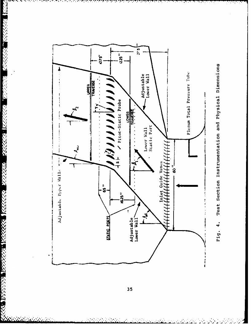
4. Test Section Instrumentation and PhysicalDimensions ........ ............... 35
5. Cascade Geometry, and Definition of Angles ....... 36
6. DCA Blade Pressure Tap Locations .............. 37
7. Photograph of Center Instrumented Blade .......... 38
8. AVDR versus Incidence Angle ...................... 39
9. Loss Coefficient versus Incidence Angle .......... 40
10. Deviation Angle versus Incidence Angle ........... 41
11. Static Pressure Coefficient versus IncidenceAngle ............................................ 42
12. AVDR versus Diffusion Factor ..................... 43
13. Loss Coefficient Parameter versus DiffusionFactor ........................................... 44
C.1. Blade Space Control Volume ...................... 174
C.2. Assumed Pressure Function ....................... 176
8
. . .

LIST OF TABLES
Table
I. Measurement Uncertainty .......................... 45
II. Cascade Performance Formulas ............... 46
III. Cascade Configuration Parameters ................ 48
IV. Test Blade Coordinates ........................... 49
V. Variable Test Parameters ......................... 50
.VI Flow Uniformity Summary . ...................... 51
VII. Flow Periodicity and Pseudo Two-Dimensionality Summary .. .... ...... .. ....... . ..... 54
VIII. Cascade Performance Summary .................. 55
B.1. Raw Data Storage ..... ............. ............. . 173
9

-.- ,., .. * -- -. . . . . . . • - . -
LIST OF SYMBOLS
ADVR Axial Velocity--Density RatioC fB Coefficient of force based on surface pressure
integration
C Coefficient of force based on momentum conservation
C Coefficient of static pressure rise
Cx PstatCoefficient of force in the x direction based onxB blade surface pressure integration
C Coefficient of force in the y direction based on-.- CyB-" yblade surface pressure integration
CCoefficient of force in the x direction based on
momentum conservation
CyM Coefficient of force in the y direction based onmomentum conservation
c Blade chord (inches)
D Diffusion factor
h. Spanwise depth of control volume at inlet (i = 1)1 or outlet (i = 2)
i Incidence angle (degrees)
0 [I0 Vcos~dx]/[ orefVrefcosadxl
k2 0V0/ref refC
P Pressure (in H20)
Q Dynamic Pressure (in H20)
s Blade-to-blade spacing (inches)
T Temperature (OR)
V Velocity (ft/sec)
W Relative velocity (ft/sec)
10

- ; . . .. .
X Velocity, non-dimensionalized by the "limiting"velocity, VT = V2 Cp Tt
x Coordinate in the blade-to-blade direction (inches)
.y Coordinate in the axial direction (inches)
z Coordinate in the. spanwise direction (inches)
- Air angle, measured in the blade-to-blade plane(degrees)
y Stagger angle (degrees)
6 Deviation angle (degrees)
a Solidity (c/s)
Pitch angle (of air flow), measured in thespanwise, blade-to-blade plane
*Blade camber angle (degrees)
[ cos362/2a cos2 $I] Loss coefficient parameter
wLoss coefficient
Subscripts
i Refers to traversing plane; i =1 for inlet,
i = 2 for outlet
p Pressure
plen Plenum (supply)
s Static
t Total
u In the blade-to-blade (x) direction
wz North wall, lower plane
1 Inlet plane
2 Outlet plane
4 11
' ' '"" " " * " ".*.... .' - U', " ' , '"" "" '". "". " - * *- "- "- "- " .'-' . -"
- " - . " "- "

ACKNOWLEDGMENTS
I would like to express my thanks and appreciation to
Dr. R. P. Shreeve, Director, Turbopropulsion Laboratory, for
his efforts in making this study a worthwhile and enjoyable
learning experience. Special notes of thanks go to Jim
Hammer, Kelly Harris, John Morris, Al McGuire and Friedrich
Neuhoff for their prompt and efficient assistance. Finally,
to my wife, Melissa and son, Michael, thank you for your
patience and support during the course of this study.
4..
12
7

I. INTRODUCTION
The on and off-design blade element performance of, and
flow through a double-circular-arc (DCA) compressor cascade
is being examined in a large subsonic cascade wind tunnel.
Tests are to be made subsequently of a controlled-diffusion
(CD) cascade configuration designed to replace it as the
midspan section of the stator of an axial transonic compressor.
Previous phases of the work involving tests with the
present DCA blading were reported by Cina [Ref. 1] and Molloy
[Ref. 2]. Cina's test results were considered to be prelim-
inary because the cascade flow was found not to be periodic
from one blade passage to the next, but was periodic from
blade pair to blade pair. As a result of Cina's work, a
modification to the inlet guide vane (IGV) assembly was made,
decreasing the space between vanes from 2 inches to 1 inch.
Molloy set out to repeat Cina's experiments, but encountered
IGV blade flutter (which resulted in some blade damage) when
adjusting the vanes with the cascade running. Facility modi-
fications were made which included first the installation
of plenum chamber turning vanes. This reduced the large
scale flow fluctuations which had prevented the use of tufts
to determine the cause of the flutter problem. Also, the
vane actuating mechanism was stiffened and new cascade oper-
ating procedures were adopted. Following these improvements,
13
I,
' " "" '"'" " " " ' " " " ". .. . .. ....: . - . ,. Z "i L .. . . . - ,:, ' . ?-

the immediate test objective was to document flow quality
and the performance of the reference DCA cascade. Added
features of the test program were to investigate the possible
effects of Reynolds number and to determine the degree of
repeatability of test data from run to run and also from
cascade build to build. Additionally, an improvement of
the analysis required to derive blade force coefficients
from probe survey data was attempted. In the absence of
wall suction, side wall boundary layer thickening from inlet
to outlet measurement planes causes the control volume to
take on a three-dimensional character. An attempt was made
to account for the additional pressure-area terms on the
control volume surfaces which accompany the streamtube con-
traction by using the Axial Velocity Density Ratio (AVDR)
and an assumed linear distribution of static pressure acting
on the streamtube walls. Details of this analysis are pre-
sented in Appendix C.
The following report documents a program of 20 tests
carried out using the DCA cascade following the facility
improvements. Results are given and are discussed, partic-
ularly from the viewpoint of flow quality and test repeat-
ability. Details of the results are summarized in figures,
tables and appendices. Appendix A contains flow quality
documentation, Appendix B, a description of experimental
data storage and Appendix C, a discussion of blade force
coefficient analysis.
14
. o . . . ..... ... ..

II. TEST FACILITY
i A. HIGH REYNOLDS NUMBER CASCADE1. Wind Tunnel
A schematic of the test facility as originally
configured is shown in Fig. 1. A complete description is
given in [Ref. 3].
2. Plenum Modifications
The plenum chamber (located in the basement of the
cascade building) has undergone successive modifications
to provide acceptably uniform inlet conditions measured at
the inlet guide vane station. Modifications conducted by
Bartocci [Ref. 4] and Moebius [Ref. 51 were supereded by
those of McGuire [Ref. 6]. McGuire's modification to the
plenum is illustrated in Fig. 2. McGuire's plenum modifi-
cation was in place for all tests reported herein.
3. Cascade North Wall Composition
A plexiglass north wall used during cascade tests
enabled McGuire to conduct a concurrent flow visualization
experiment. The regular steel wall was used for two of the
twenty test runs.
4. Inlet Guide Vane Assembly
The inlet guide vane assembly was the same as that
used by Molloy, with vanes at one inch spacing.
15
1 ' :" ;', ,; ,::;;i :;: : ;: ::: ;;;ii.:Li ;;; :: :; :- ;:

:1 -
5. Test Section
Views of the cascade test section are shown in Fig
3a, Fig. 3b, and Fig. 4. Fig. 3a shows the cascade test
section with the plexiglass wall installed and the DCA blade
row in place. Fig. 3b shows the test section with the steel
wall in place. Fig. 4 illustrates instrumentation placement
and physical dimensions.
B. INSTRUMENTATION
1. Survey Probes
Two United Sensor Corporation five-hole probes were
used for surveys at the upper and lower planes. A
DC-125-24-F-22-CD probe, serial number A981-2 was used at
the upper plane and a DA-125 probe, serial A847-1 was used
at the lower plane.
2. Reference Probes
Plenum chamber reference total pressure was sensed
using a pressure tube suspended in the plenum. Reference
static pressure was sensed using a static port located on
the lower portion of the cascade south wall. Redundancy
of reference pressures was provided by a standard pitot-
static probe located approximately 2 inches from the entrance
to the blade row at midspan and aligned with the inlet flow.
3. Wall Pressure Taps
Two rows of static pressure taps were located on
the cascade south wall 16.25 inches ahead and 6.5 inches
p..1
r'

behind mid-chord. Twenty taps per row spaced two inches
apart in the blade-to-blade direction, each connected to
a water manometer board, allowed visual inspection of the
inlet and outlet static pressure distributions.
4. Acquisition and Reduction System
Data was acquired, reduced and plotted using a
modified Hewlett Packard HP-3052A Data Acquisition System
[Ref. 7]. Two 48-port Scanivalves connected to a HP-9845A
desktop computer via a NPS/TPL HG-78K Scanivalve Controller
and a HP-98034A HP-IB Interface Bus allowed all probe and
reference pressures to use a single transducer. Blade sur-
face pressures were sensed by the second Scanivalve transducer.
The desktop computer acted as the system controller and used
acquisition, reduction and plotting software programs docu-
mented in [Ref. 8].
5. Measurement Uncertainty
Table I summarizes measurement uncertainties.
17

* 'a~.- ~. .. . . . . . . . . . . ..... .... . . . .. . .. . . . . . .
III. EXPERIMENTAL PROCEDURES
A. GENERAL
1. Flow Quality
Flow uniformity, periodicity, and pseudo two-
dimensionality criteria (which implies that area change is
Apermitted) must be satisfied before any calculated cascade
performance parameters can be considered meaningful. These
flow quality criteria are discussed extensively in [Ref. 9],
[Ref. 10] and [Ref. 11].
Uniformity generally describes the degree of con-
stancy of measured values in the blade-to-blade and spanwise
directions at the inlet plane and in the spanwise direction
at the outlet plane. Periodicity is indicated by a corre-
spondence of measured values from one blade space to the
next at the outlet plane. The pseudo two-dimensionality
condition is met when the integrated blade surface pressure
distribution gives a blade force vector coincident with the
blade force vector calculated using the principle of conser-
vation of momentum.
2. Flow Geometry
Definition of geometrical parameters describing flow
through a cascade are.given in Fig. 5. Angle measurements
were taken from a vertical reference line, clockwise being
positive.
18

3. Reference Quantities
To remove time dependency of inlet dynamic pressure
caused by atmospheric fluctuations and variations in blower
speed, each pressure measurement was referenced to plenum
conditions, a procedure validated earlier by Duval [Ref. 11].
4. Performance Parameters
Cascade performance parameters were calculated
using the formulas listed in Table II. Note that the effect
of AVDR on loss coefficient, static pressure rise coefficient,
diffusion factor and blade force coefficient derived from
momentum conservation was accounted for in each expression.
B. SPECIFIC TEST PROCEDURES
1. Probe Calibration
Prior to testing, both United Sensor five-hole probes
were calibrated in a free jet flow. The calibration was
represented using Zebner's analytical procedure [Ref. 121
and computer software developed by Neuhoff [Ref. 131.
2. Test Section Setup and Adjustment
Tests were conducted at constant stagger angle while
varying only air inlet angle and velocity magnitude. To
set an inlet condition, before starting the cascade the lower
end walls were set to the desired inlet air angle with end
wall spacings set to 1.5 inches (one-half blade space). The
IGVs were set to deliver the desired inlet air angle follow-
ing a schedule established in preliminary tests conducted
19
......... .. . . . .

T W T 7-. -C. Z.*- 7 . ' '-.Sr r rrr
4without test blades. Finally, upper end walls were posi-
tioned approximately. The cascade was started and the upper
end wall angles were fine-tuned to give a uniform static
pressure distribution at the outlet plane. A check of the
inlet air angle was made with the lower probe placed at mid-
span in the center of the blade-to-blade traverse. If
adjustment of the IGVs was required, the cascade was first
shut down, the IGVs were readjusted, the cascade was restarted
and the inlet air angle was checked again after the cascade
had stabilized at the inlet dynamic pressure required for
the test.1
3. Test Measurements
a. Blade-to-Blade Survey
Blade-to-blade surveys were conducted using the
upper and lower probes simultaneously. Both probes were
located at midspan with the lower probe trailing the upper
by two inches. Measurements were recorded over four adjacent
blade spaces located in the center portion of the cascade
test section. The two innermost blade spaces bracketed the
center blade which was instrumented with 39 pressure taps.
Survey points were spaced 0.25 inches apart over the outer-
moat spaces and at 0.125 inches over the two innermost spaces.
IInlet guide vane flutter similar to that reported by
Molloy [Ref. 21 reoccurred while adjusting the IGV assemblyat relatively high inlet dynamic pressure (about 17 inchesof water). Thus it is essential not to adjust the inletguide vanes while the cascade is operating.
20
.4 n
• oo o,, o, -. .. ....... ...

Closely spaced survey points over two blade passages in-
sured that one full blade wake would be surveyed with good
spatial resolution.
b. Spanwise Survey
Two spanwise surveys were carried out to estab-
lish the spanwise extent of uniform conditions. First,
measurements were taken with the upper probe 1 inch from
the suction side of the centermost blade and the lower probe
1 inch from the pressure side of the centermost blade. Once
the first spanwise traverse was complete, the upper probe
was placed 1 inch from the pressure side, the lower placed
1 inch from the suction side and the spanwise traverse was
repeated.
c. Instrumented Blade Pressure Distribution
After completing the blade-to-blade and spanwise
traverse, one or more sets of blade pressure distributiondata were recorded.
21

-- .-.. . . 6.
IV. TEST CASCADE AND PROGRAM OF TESTS
A. CASCADE CONFIGURATION
Constant parameters for the cascade configuration are
summarized in Table III.
1. Blading
Test blading consisted of twenty constant cross-
section double circular arc (DCA) blades of aspect ratio
2.0 and chord 5.01 inches. Coordinates for the test blades
are given in Table IV. Three of the twenty blades were in-
strumented with static pressure taps at midspan in order
to provide measurements of blade static pressure distribution.
The center blade contained 39 pressure taps while each adja-
cent blade had 6 taps. Adjacent blade instrumentation pro-
vided a measure of the uniformity of pressure distribution
from one blade to the next. Pressure tap locations for the
center instrumented blade are illustrated in Fig. 6. Fig. 7
shows a photo of the center instrumented blade.
B. TEST PARAMETERS
The results of 20 tests are reported for which the test
parameters are summarized in Table V.
1. Incidence Angle
Seven test values of incidence angle were chosen.
Five of the seven angles were approximately those reported
22
"S - ... ... .. .." ' . -- . . .'"o°,...-. ..... •. .,. .... ..-.. .•. ... '-..... ... °-•-

by Cina to allow a comparison to be made of corresponding
data sets.
2. Reynolds Number
In order to investigate the possible dependence of
cascade flow quality and performance on Reynolds number,
each incidence angle was tested at at least two Reynolds
numbers. The Reynolds number based on chord was varied be-
tween 491,000 and 773,000.
-I2
23
........

V. RESULTS
A. FLOW QUALITY
Uniformity, periodicity and pseudo two-dimensionality
were evaluated from data presented in Appendix A and are
summarized in Tables VI and VII.
B. CASCADE PERFORMANCE
Cascade performance is summarized in Figs. 8 through
13 and in Table VIII.
C. TEST REPEATABILITY
Run-to-run repeatability of cascade performance para-
meters is indicated in Figs. 8 to 13 by double-headed solid
arrows. The arrow indicates the observed range of the appli-
cable cascade performance parameter. Tunnel build-to-build
repeatability was investigated at the design incidence angle
of 2.2 degrees. Double-headed broken arrows indicate build-
to-build repeatability.
02
24
*0~ . o ' - "' -- - " • ° - q " ° • . .' . ° . " • " . . ~ " -. - .- . ..

VI. DISCUSSION
A. FLOW QUALITY
1. Uniformity
As seen in Table VI, the dynamic pressure, static
pressure, total pressure and non-dimensional velocity were
acceptably uniform over at least twenty percent of blade
span at the inlet and outlet planes, and over the entire
twelve inch blade-to-blade traverse at the inlet plane.
Inlet and outlet air angle were acceptably uniform
in the spanwise direction. Beta 1 was indicated to vary
slightly in the blade-to-blaee direction. The average total
change in Beta 1 from beginning to end of a 12 inch blade-
to-blade traverse was approximately one degree. Since ad-
justment of the inlet guide vane assembly with the cascade
running was prohibited, this variation was accepted. If
the IGV mechanism was stiffened further to allow adjustment
during cascade operation, strict uniformity of inlet air
angle would probably be assured.
2. Periodicity
With the exception of the most negative incidence
angle of -12.5 degrees, good periodicity was obtained over
the three centermost blades. Surface pressures from the
left, center and right blades were in excellent agreement
except at i = -12.5 degrees. Also, all flow parameters
25
.4

4: measured at the outlet plane at midspan were closely periodic
from one blade space to the next with the exception of the
most negative incidence angle.
3. Pseudo Two-Dimensionality
Despite the revision which was made to the calculation
of CfM, (the blade force coefficient derived from probe survey
data; Appendix C), agreement between CfM and CfB (the blade
force coefficient derived from surface pressure measurements),
was achieved in only about 50 percent of the tests (Table VII).
The problem is thought to lie in the calculation of the axial
component of CfM. An order of magnitude comparison of the
terms that make up the axial component CfM (Eqn. C. 14) re-
vealed that the first two terms were of order 1.0, the third
and fourth terms of order 10.0, and the fifth term of order
* 0.01. The difference between the first two pairs of terms,
however, were both less than order 1.0, with the pressure-
area integrals contributing the most. Thus, the value of
CfM was highly sensitive to small inaccuracies in the survey
data and too coarse spacing of data points. The more satis-
factory results obtained for the tangential components of
C fM can be explained because its evaluation does not involve
pressure-area integration terms.
4. Effect of North Wall Composition
At one incidence angle the more rigid and slightly
better-fitting steel wall was used. The resultant spanwise
distribution of flow parameters was generally indistinguishable
26

from the distributions obtained when using the plexiglass
S.' wall. (See Figs. A.51 to A.76 and.Figs. A.139 to A.144).
B. CASCADE PERFORMANCE
1. Effect of Reynolds Number
Figs. 8 to 13, and Appendix A show that varying
Reynolds number from approximately 500,000 to 770,000 had
no measurable effect on the blading performance or on the
cascade flow quality. This can probably be explained as
being due to the controlling influence of a leading edge
separation bubble on the suction side boundary layer transi-
tion [Ref. 6]. Conducting tests significantly above a pre-
scribed threshold Reynolds number is therefore unnecessary
for this blade set. It is noted that when operating at
Reynolds numbers of 500,000, adjustment of the IGV assembly
with the cascade running may be possible in the future after
further stiffening of the actuating mechanism.
C. TEST REPEATABILITY
Run-to-run repeatability of cascade performance para-
meters was satisfactory as was build-to-build repeatability.
The total uncertainties in the measurements of AVDR, loss
coefficient, deviation angle and static pressure rise co-
efficient were about 0.01, 0.005, 0.4 degree, and 0.02
respectively.
27
I
• . . . . -° . • ° " "* . *-°- " - , -' " -
D. COMPARISON WITH CINA
Figs. 8 through 13 each contain a broken line showing
the results of Cina's DCA cascade tests. Differences be-
tween the two data sets are apparent. Given a specific
incidence angle, Cina reported a lower loss coefficient,
deviation angle and AVDR, and higher static pressure rise
coefficient. Three contributing factors can be cited.
First, and most importantly, Cina operated with a different
IGV assembly that did not deliver periodic conditions blade-
passage to blade-passage. Secondly, he used a plenum which
gave less stable, more turbulent supply conditions. Finally,
the upper and lower traverse probes were carefully recalibrated
after Cina completed his tests.
28
. . .%..x. t.C.° C .J. - -- *.*-.**°

VII. CONCLUSIONS
Based on an examination of experimental data the
following conclusions are drawn.
1 1. The cascade flow was satisfactorily uniform.
Uniformity existed at the upper and lower planes over at
least 20% of blade span near midspan and at the lower plane
(midspan) in the blade-to-blade direction for all measured
flow parameters at all tested inlet conditions.
2. The cascade flow was satisfactorily periodic.
Periodicity existed at the upper plane (midspan) in the
blade-to-blade direction for all inlet conditions tested.
3. The cascade flow was not shown consistently to be
strictly pseudo two-dimensional. Accounting for streamtube
contraction due to side wall boundary layer thickening from
lower to upper measuring planes introduced additional small
terms into the equation for the axial force component. How-
ever, the calculation of the axial force is dominated by
the difference between two pressure-area integrals of much
greater magnitude.
4. Cascade performance parameters were not measurably
affected by varying Reynolds number in the range 500,000
to 770,000.
5. Test conditions can be repeated within an acceptable
uncertainty from run-to-run. Build-to-build conditions can
29.. . ,-.,.,..,.. '- - ,., -'.. ,' . ..• .. .,. . . .• .. .,
J" " I ' ' '. . ' - "r " - ; , . 'i ' • , , .: ". .'

also be successfully repeated.
6. Use of the plexiglass north wall instead of a steel
wall had no measurable effect on the results.
7. Inlet guide vanes cannot be safely adjusted with
the cascade operating.
30

VIII. RECOMMENDATIONS
It is recommended that the following actions be
considered.
1. The inlet guide vane assembly should be modified
to allow adjustment of the IGVs while the cascade is running.
2. Yaw balancing manometers should be inclined in order
to provide the experimenter with better inlet and outlet
air angle measurement sensitivity.
3. The motor driven yaw and spanwise positioning systems
mounted on the upper traverse caused a significant bending
moment to be placed on the probe blade-to-blade slide. No-
ticeable wear of the upper traverse mechanism took place
during the course of twenty test runs. Removal of the power
yaw and span drives in favor of a lighter-weight mount similar
to that at the lower plane is recommended.
4. Provide ready data file transfer from the HP-9845A
cassette tapes to the IBM 3033 computer so that advantage
can be taken of the DISSPLA graphics capability available
at the NPS Computer Center.
31

4C.)0
0
39
r
'-4JU I.)
.. E
I.- Ig I
m4.j>' I
332

.41
.. i..Tm
- 4-14t4
4C
0 to
33-

Fig. 3a. Cascade Test Section, Plexiglass WallIns tailed
Fig. 3b. Cascade Test Section, Steel WallInstalled
34
Aii
4'4-CA 1-4 $. (
1- 0 - 4-
9L.8
41 A
5E-
5% 35

0.r
~ 0,
'4.4J
Aa
Ci2
36r

I
i0
0.4
, 0 '.
gf-4
I, a
Ina
go 3U
"o "o % . ° ° % tt • • " • • • ° ° " -. .o • • , - . . . . -. . ..
' : :, - : , ..- - . .. .--o , ..,, .- -, ., ..o. , . . . , ., , , . ,. , - ..., . . .... • . . . . .

raye
01
4
38-
ziCD

w* t1.0r-
o 0 r_2 -
o 0D u--, 0 0
0 0 JW. 0 ) 00WC
0 v3'4 -
o% 0t~9-
4~~ 0 0 *.-
"o 0
4j-
14:
(U 0)
C 10W
.05- cc
r4:G
.9- .9-4
r- ).4 r_; I r4
6::4

0 0 CJ) e-40 0 4JI0 0
0 0) 0N
A 0C 0 C4
-. ~~ a. 3
0 0
o 0 CU co
0 0 3 -
AluTR~zea0 0 I-':IPTrn
04 LAl u
0 '0 (1)
04N. -- 4
£~u~I~.z~IV ur-o-in 0
I 3 r4U4
40

-77.
00 4J )
00 koP-00 v
00 U0
V V UU
0 00 U)
0000 I
'V.-r4 to
I t;
r34U)
~UT~ZUU p~nq-o1pC14~
m 00 W V___a9P 9 9TUV OT-uni 9U
44 41
:SeU

00 v
HOC
0 0
Siu~uae00 C.)qoapTn 0)4A~i-Fvia00u un---n Vr
Lim (3
a,4
4-4
0)-
OH)
-- S
S..A
C14
144
422

o 00 4.) 000 o00 o
v v4 ) 0)
a00
0 0 13 0
0
N 0
0>
u 4
051 0 C10
JI: 13 r-
.10..$41
13 0 0
CD 0
u-I H H H H - H H H
-* 43

co %0
0 0
0
0) 134.
Vz~~eu VIn-3-n -U
000
'.0 >A
414
0 $.4
rz4J.
L0~
0~~'44
a t4-4 4J
a44
44
0n
C)1NA0
7I4 00
4 44

TABLE 1. MEASUREMENT UNCERTAINTY
Item Description Method Uncertainty
x Blade-to-blade displacement Position -t.01 in.x a 0 in. West end p2tentiometerx - 60 in. East end
z Spanwise displacement Position ±.01 in.z - 0 in. North wall potentiometerz - 10 in. South wall on probe mount
t 1 Inlet flow yaw angle Angle vateuti- ±.2 deg.ometer on probemount (handadjustment)
3 2 Outlet flow yaw angle Angle potenti- ±.5 des.ometer on probe
mount (motordriven adj ustment)
P plen Plenum total pressure Tube in ±.01 in. H20ple. plenum chamber gauge
P Ztatic pressure at the Calibrated pneu- -..1 in. H'0test plane matic probe gauge
PWI Static pressure at Static tap on .Q1 in. H170x - 0 in., y - -16.25 in., North wall gaugez -0 in.
P Atmospheric pressure Mercury barometerATM
P Pressure Scanivalve ±.01 in. H20transducer gauge
45
-;, ................... _. . ..

(NN
41 o x ro' g 41 1.0
-x 0 r.c.- 4Nt to.5
41 0 0 -0. 4 ,0 0 '-4 Q.4
to co -u w
m r- a - 4 4
04 41 x x x x vax r-4W1 x x -4 -Ir4r4 N A
4i0 4.4 t44 N40 Q0) CD 11 9
4JJ 4.4
a 44 p44
124 aI0 a
r3,ra '-4
at o4
00
.9. 0 f-4
044
'4. r-4 4'
g-4*r *4 14la,
4.4 4Jo J
IU K0 *eI '.-
E-46
4.. .4 4 . .

.11
-. 4.1
N.. IcP
C.e,
+Ica pa
ol (A0 0,
4) P
41 -
0
e- 4) W
410UH0
C.-- 01)
414
(-44
4) -4 -4 4> 0-r4 ON4 I-4
IV 4141
0b4 > 410 0
0.447

TABLE III. CASCADE CONFIGURATION PARAMETERS
4
Constants
Blade type DCA
Number of blades 20
Spacing (inches) 3.0
Solidity 1.67
Thickness (% chord) 7.0
Camber angle (degrees) 45.72
Stagger angle (degrees) 14.27
.48
'
°,' 48
o""°°°"• .°° -.. .,'- •• -.- p ° . ° " ,4 ,, . .- .. . . . . .. . . . ... . . . . . .

TABLE IV. TEST BLADE COORDINATES
X-COORD. Y-PRESS. Y-SUCT.
" -0.044 0.000 0.000
-0.021 0.039
-" 0.013 -0.042
0.178 0.007 0.142
0.400 0.067 0.244
0.622 0.120 0.333
0.844 0.164 0.413
1.067 0.207 0.480
1.289 0.242 0.538
1.511 0.271 0.584
1.733 0.293 0.620
1.956 0.309 0.649
2.178 0.320 0.664
2.399 0.324 0.673
2.622 0.324 0.671
2.844 0.318 0.660
3.066 0.304 0.640
3.288 0.284 0.607
3.511 0.260 0.567
3.732 0.229 0.515
3.955 0.191 0.453
4.177 0.147 0.380
4.400 0.098 0.298
4.621 0.040 0.200
4.844 -0.022 0.0914.908 -0.042
J% 4.943 ----- 0.040
4.966 0.000 0.000
b'
49
V.

TABLE V. VARIABLE TEST PARAMETERS
Test B10 0 ReynoldsNumber Number
1 39.02 1.89 773,000
2 38.68 1.55 511,0003* 38.34 1.21 701,000
4 38.89 1.76 491,000
5 42.66 5.54 518,000
6 43.13 5.99. 771,000
7 45.92 8.79 768,000
8 45.89 8.76 493,000
9 31.32 -5.81 560,000
10 31.56 -5.57 503,000
11 27.90 -9.23 502,000
12 27.55 -9.58 626,000
13 39.28 2.15 545,000
14 39.40 2.27 676,000
15 39.16 2.03 527,000
16 39.36 2.23 604,000
17 35.50 -1.59 643,000
18 35.60 -1.50 525,000
19 24.74 -12.39 535,000
20 24.63 -12.5Q 611,000
*Note: Data from run number 3 not plottedbecause data set was judged to betoo coarse.
50
, .,, .,....,..:.- .....-.......... . -.-.-.....................-.................. •. .. .. ...... ... .. . ..

0.0 c 0f- 00 .0 -4 0 0 im C 0
44 0 u, 0 00 c) OD ' r- '00 0, 0 00
00
4.4
co "0 0 co 0
00 %'0 040 c C4 11 r- UL) e 1-4 r- r-l-4>.1 040C)C
4.8
0 4
%-4S
40.cal .0 41
>4 .04 44 8 .. r-4 .. -4 T v- M %T M% r-4 C4 r-4%
w- c' 0 I I
c Q00
0 0. -,)
-P4 > 0
1- V 0 cc .-
I-I 00 W .W -u- C1400 4 Cn C C1 v-4 ~ % -4-00 t-4 04
-.~~~C 44 4. ' 0 0 00a;0'4 ON 0
P4 V00
-J _ _ _ _P4

0
41 0 ) 0 0 r-0 0 r- 0 04 0 c'4r L
"4 0n V-1' 00 4 L O 00 r-4 0 00 r c -
-H41 0*0 -4 M~' v4I t-O C4 N L -Z(3 LA4
V-4 00 0 0 0 0) 014 1 11 11
(U 0~ 0% -.7L 04 C 4.. Cn rf4 04 -4 rLn O'-4
02 >
410)0 0
01 -4 01 r- ~ 4 C4 v-4 C 0C r-4" cCn 40%.D r-4 0
44 >1 N4 00 0 O ; 0 0 0 0 '-
0 0 0110 II I I I I I I
m 01 C'e4 M v4 M~4 On4" 0 4 - T -Nl00 c
-4 0 010 n 0 1 I 'C0c C 0c0
M cy -o8 08
.J 01 0.% N0C - % P N (4
0 C14 48 . 4 C 4w-I 0: ;C 1 ;C C4 "I AI 0 C1-4 ~ 01-a
* "4 ,4 l 0 00 0 00 0 C'052

0.I =1 0!* '-4u Cl!0 00 CNO CV!
0 A
'0 4
4to = II eg 1- 0. i i.
"4k 0 00*4 - %QO uC4 n -0 o F%Q ON~ (Ln i>.8 -.1
(U* w -1 I~s 0.-4 in4I 0.-I 00000000 8 1; 4 ;I.
4.80 1..0 > "q- P
Io
040V2 u
w 0 0 Hco. 4) 10
wae4 0f 0-. ul CV)-I 00. Cf Lr '-0 t0 -.0' rI " ti-I%
4cc C;8688
03- 00 e4 II -T II NO r-- IT CII0 4L T
0_ 8a ('4( 8~O 8 .4 8-'O 0I4 8 'c 8 8 800%.
cc) r-4N'I (.C' ~ (5 C l vI -iI 0
04.
0O 0l 4 O 4 r 4C)% I
- 09 00C!1
ra~r0
.. J OW 53

TABLE VII. FLOW PERIODICITY AND PSEUDO TWO-DIMENSION-ALITY SUMMARY*
Incidence Periodicity Pseudo Two-Dimensionalityangle based on blade based on blade force coef-(degrees) static pressures ficient diagrams
L magnitude(%) Ldirection(
-12.50 imperfect - 2.1 10.00
-12.39 imperfect 13.0 25.00
- 9.58 acceptable - 1.5 3.0
- 9.23 good 41.3 27.Q 0
- 5.81 good -19.1 7,50
- 5.57 good -20.0 3.50
- 1.59 good -25.2 24.50
- 1.50 good 16.5 22-5 °
02.27 good - 4.6 2.5°
2.23 good - 2.4 2.00
5.99 good - 0.7 7.00
5.54 good - 6.1 4.00
8.79 good - 3.4 1.50
8.76 good -16.2 0
*Note: Data from six additional runs at design incidence
angle are not presented.
54
< "'q" '-";<-"-> ".- ''- -. ; " "'-. -;- -';-; .; . . -."". . . . -. " . - - . .
S. = == ,,, .. , .... , .. . ..

0 0 00 00 00 00000000 00 00C00) 00 00 00 00000000 00 00c0 00 c0 00 00000000 00 00
Noc C %091" 'N -0 -0 ITc4 4 0% Ps.V4 '0%a%0 an %c L In a kn r, r. %c %uuu LninsU44lin -U
%AO Go O IT0 -4 C h7 -40 %0 ar.r- 1,0 m4 %00% (aN4 c 22"gn %a wl eq a -tt 4 0 om0%0 %0 %0 0-
OD 0% 21. C N% .-4 m V r, tC %20N C4 C4 12am .-i N.C4-4 Ln m .7 - r& u,%&Ain~ 6nu in %0%
g'-%0 2%C 0 4* Oin 0%N NN -00' 'tdt% -inm5Ln - T 4%-T r a%0 r, % f0 r% .r..Q-T r. r-ir- a00% 0%a47
Ui I I r1 r-.4 1-4 -4 4 -1 4 4 -6 4 -4 -I- 4 -4 -4II I 1 1 1 11 11 1 1 1 1
%QN 't U'1%0 r-..-4 m %T0 r- 4N04 02n w%C 1% ifr, It 1-4 4N T1 m7' 00 i 2wrw'n C4 t U%Tn al 0'0 ur'It .- 4 C4N 0 r 1'0 CIM " 00 %w 0 00.4 %0 0 MOD
En %a0 N4I- %T-Z 0% enC n f1Go 'T P-N C4NO%0 vi .7
Ch0 -40 r-4 00 co '-0 21-Nr4 ,V w u%a W tf20' at %N 00 s-f 0 %0N14-. -4'tw s-b MOw'4000
07 saG 1 40 NO00 L O r-P m 0?-. %0 -?P% r 00 a 0 0 4 14 M M 4 -4-4 sMIs-b s- C4N-4 C4 C4
0 C C0 00 s-I- s-Is- s4 4s s-I4 s-Is- 1;11; ; 1
0 .494 YG L r D000Go00o000P 0 0 OsI4CD 4 P r- r. C4C4 4-4 C404 04 4 - m -4- C-14n
Ni% 2r n4 02 %0 C CsM-If , . 0024- 02 00 0 OT w' IC4 ? 004' M D y m r -4 00 0-r, P 4 0%'t-N~-- C0.
cc0 0 00 00 00 00000000O 00 00r-4 4 4 .4 4 .4 ; 4 . 4
3 c 00 o0 00 00 00000000 00 00
w C, r r co in%0 0 0 0 m %0 -7w 't 0 5L &ca r m.' M -T 4ITN "7. 0N%Nw'O% an0% 0% tm .0 2
05 1-4 0 ; .7. e'n -T 0 w'2M 0s o -4 0 "0 00 o0r- in oNN4 C4 4 v141 -Isr-I r" " r4. .N .s-4f-4 mN C4 T I
.43. 00 00 00 00 00000000 00 00
ItN( 0't co%0 4' 0 0 w wUN"s4 -1 C4 No r- %nr. 0% fri' Nt C4-T o0r- (4 r,1-N4-4 %0 r%0 5% di IG
C4C 00 %0 90 inA o0 0000 0 0 u 00 c
or- r. c r% a. 00 c 0%14 0 0% 00%o0 0 r4g,-i *4 -4-0 V-4Is-I -4 s-IP-b r4 -4 qP
co0 s-40 't2 . s on r % 'D00 en Ns C -4' %T Ow'n%0%s19 n ' W!'! 0! 0 22 I -!W! I'--O P't'%ti 1 '
cm s-f- -440 00 00 4s-4s 4 4 -4 NN Ned4C4C
00% Go C" 6 0%0 0%r4 r- M '2w's0 % 04.* 0"50& w' N 005n L o(4 C4 CNN -40f 0 V a V r- P.
NN c4 a j% w;w . c45( c-s 4Nc4 s 4 w;U w 000 a
C"7 W,4 a . 00%ac N 170 %0 cca0 (n 0 N4QaW04 5(0' 25(4 LM M 02-2 sIO ("Is ITe00M4%0 % %a
- T 't' r4- LAs- v'4 05044400 2N a* ;USaIA ; v c ;V
55

APPENDIX A
A. FLOW QUALITY DOCUMENTATION
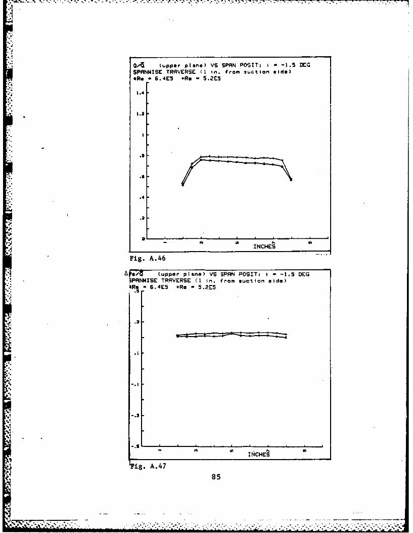
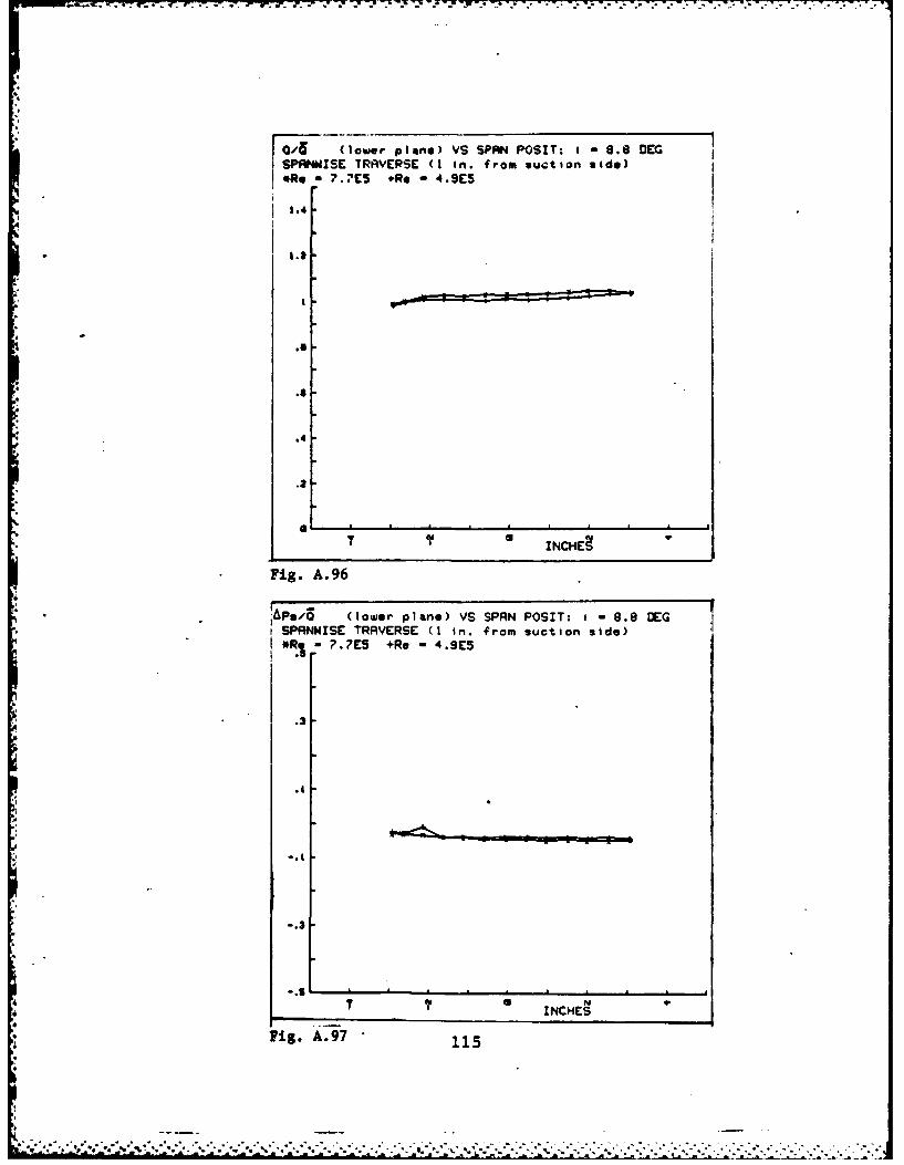
1. Uniformity
Uniformity of dynamic pressure (Q/Q), static pres-
sure (APs/Q), total pressure (APt/Q), non dimensional velocity
(X/X), and Beta for spanwise surveys at the inlet and outlet
planes and blade-to-blade surveys at the inlet plane at each
test condition are shown in Figs. A.1 through A.105. Photo-
graphs of upper and lower static pressure distributions for
each incidence angle and Reynolds number comprise Figs. A.106
to A.119.
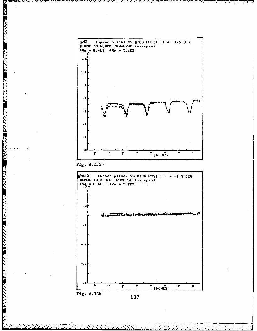
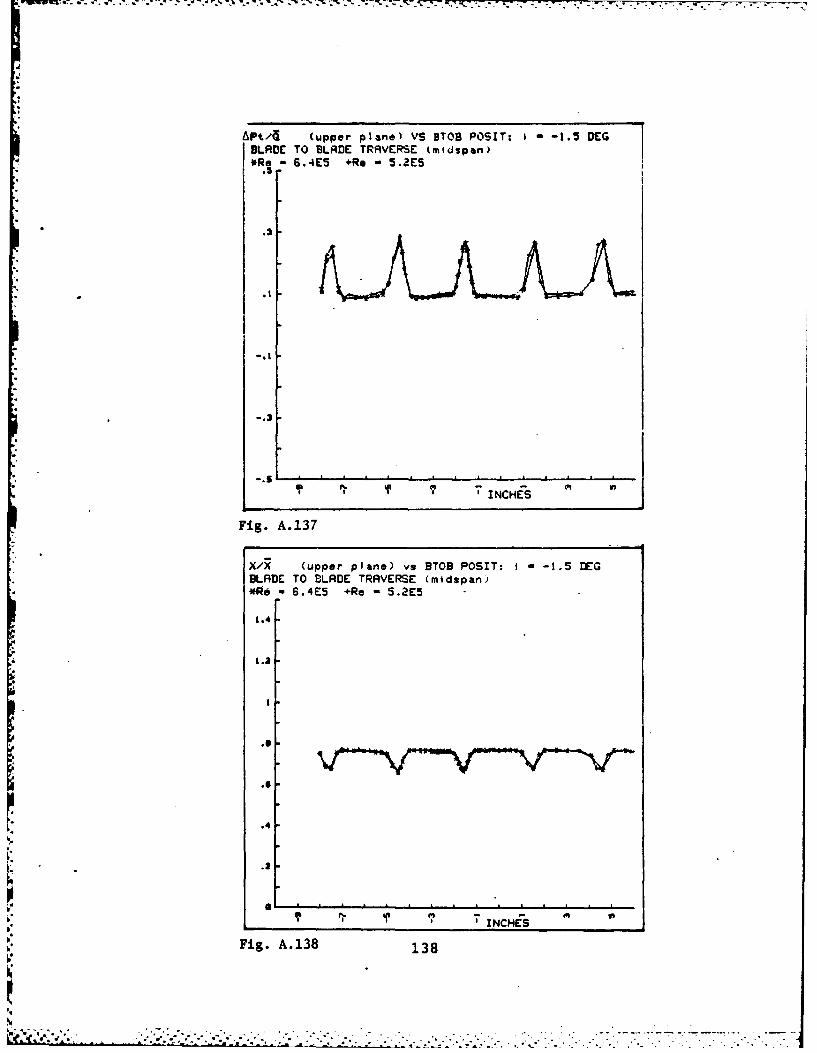
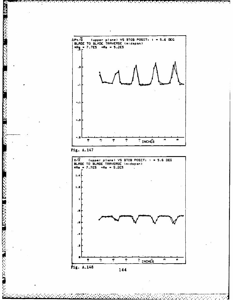
2. Periodicity
Periodicity of (Q/Q), (APs/Q), (APt/Q), (X/X) and
Beta for blade-to-blade surveys at the outlet plane and
adjacent blade pressure distribution for each test condition
are shown in Figs. A.120 through A.168.
3. Pseudo Two-Dimensionality
Blade force coefficients for each test condition
are plotted in Figs. A.169 to A.182.
4. Notation
The parameters plotted in Figs. A.1 to A.105 and
Figs. A.122 to A.154 are defined as follows:
56
- . 4 - - . . . - - -
- -4i-. . 4~

Parameter Meaning
Q/Q local value of Q 2
APs/Q (Ps - Pwd /5
APt/Q (Pplen - Pt) / 6
X/X local value of X/X
,
,1
2"Barred" quantities apply to the specific measurementplane and are calculated over a prescribed integration in-terval--usually one blade space.
57

Q'/ (upper plane) VS SPAN POSIT: I - -12.5 DCGSPANNISE TRAIVERSE (I on. from suction side)*Re G.IE5 +Re - 5.3E5
1.4
.2
- m m INCHES
Fig. A.1
APs41 (upper plane) VS SPAN POSIT: , - -12.5 DEG*. SPRNNISC TRAVERSE (1 in. from suction side)
*Re 6.IE5 +Re - 5.3E5
.58
',
!-.
i .1, . .
. . .d " " " - . . . .- . . . . . . •. . : . - ." ' T : 2 . -

APt A (copper piane) VS $PAN POSIT: I * -12.5 DEGSPANIlSl TRAVERSE (I In. from suction side)*Re -6.1E5 *Re -5.3E5
.5
"S--.. ...-.3
INCHES
Fig. A.3
XA.. (upper plane) VS SPAN POSIT: - -12.5 DEGSPRNISE TRAVERSE (1 in. from suction side)*Re - 6.IE5 +Re - 5.3E5
1.4, .
Fig I
S59
".6
:..4
" A e . .. ItCHES
"" Fig. A.4 .5
"" 5
. -.

TRI -6-; 7 %7
-ETA2 VS SPAN POSIT. - -12.5 DEGSPANWISE TRIVERSE (I in. from suction side)
*, - .E5 +Re - 5.3E5
-I
' I-3
.7INS
INCHES
Fig. A.5
6
* 60
", . *. . .- .- . .-.- - - -2 - - . - a. ;-.. --. -. . - :- --- - _ --- ..- \ - -. . . -. ...- .* . . . . ..

Q (lower planel VS SPAN POSIT: I - -12.5 DEG
.... SPRtNISE TRAVERSE ti in. from suction side)
*Re 6.IE5 +Re 5.3E5
1.4
1' INCHES
Fig. A.6
. (lower Plane) VS SPAN POSIT: t - -12.5 DEGSPRNNISE TRAVERSE (I in. from suction side)
*e,6.1E5 +Re 5.3ES.:-4
..
T -INCHES
Fig. A.7
.61
""~~~~ -r -A.I5+R ,
-.
.*INCHES
~ig. A. 7
%., ,-,.~ ,:,:... .... .-... ... .. . . .... .., . . **..~ .... ...- * . ..

4 P/ (lower plane) VS SPAN POSIT: I - 12.5 DEGSPANWISE TRAVERSE (I in. from suction side)Re 6IES . Re , 5.3E5.5
.3
_. INCHES
*Fig. A.8
X/X (lower plane) VS SPAN POSIT: I -12.5 DEGSPANWISE TRAVERSE (1 in. from suction side)*Re - 6.1E5 +Re - 5.3E5
"1.
1.2
4e
.41
-.. 4
4. .
INCHES
Fig. A.962
4'. . ...... . . ....... ...

42
-- t
-I3
INHE
Fig A.10
63L

La - W' . L.~ .. * . - .
* (lower plane) VS B0B POSIT: I - -12.5 DEG
BLADE TO BLADE TRAVERSE tmtdspan)
*Re * 6.|E5 +Re - 5.3E5
1.4
1.2
.5
.6
.4
.2
; TINCHES
Fig. A.11
iPs/; (lower plane) VS ETOB POSIT: I - -12.5 DEG
BLADE TO BLADE TRAVERSE (midspan)*Re - 6.1E5 +Re , 5.3E5
.5
.3
,1
7 "INCHES
Fig. A. 12
64
,, ,~~~~~~~~~~~~~~..,.--.'.,...,....- ,, ... ,...............,... ..... .............. •.....-... ..... ,.... ...-......... . .,S S * * * * .. .. * . . - . : . * x.*.. . .i *L . . . . . . . ., _L,,h. ,3., ,,m,.r.,e ,,,t , .a .' ,.,'

A Pt4 (lower plane VS 9TOB POSIT: - -12.5 DEGBLADE TO BLADE TRAVERSE tmidspan)
- 6.1E5 +Re - 5.3E5
: -"- N ' ?i NCINCHES
Fig. A. 13
XAZ (lower plane) VS BTOB POSIT: I - -12.5 DEGBLADE TO BLADE TRAVERSE (midspan)*Re - 6.IE5 +Re - 5.3E5
1.4
1.2
. 11
.4
.8
' INCHES
Fig. A. 14 65
. . . . .

DCTnl VS 8TOB POS!T: I: -12.5 DEGSLADE TO BLADE TRAVERSE (midspan)
Iq- G.IC5 +Re - 5.3E5
*% I
-Is-
1' 1'INCHES
.[
Fig. A.15
i"6
.L
'S
66
;,%' u-;4: .- ' ,',.1 - .: :.::2, .--..-- - . ...- .....-. -. , .-.. .-.-. . . . . . . . . ....

-q-. I N - - . . .
Q/ (upper plInel VS SPAN POSIT: - -9.5 DEGSPANWISE TRAVERSE (I in. from suction side)*Re 6.3E5 +Re - 5.0E5
" t1.4
1.2
* .8
.4.'.!
INCHES
Fig. A.16
A*pa,, - (upper plane) VS SPRN POSIT: i - -9.5 DEG
SPANWISE TRAVERSE (1 in. from suction side)*Re 6.3E5 +Re 5.0E5
.3
.3
-. S A.
INCHES
Fig. A.1767
,5 ,.: ,' .. '..,. ., ...-- -.- •__ _ _ .- •- . . .- . .

-7,.
APt.,1 (upper plane) VS SPHiN POSIT: 1 -9.5 DEGSPANNISE TRAVERSE (I in. from suction side)*Re = 6.3E5 +Re ".DE5
.3
--.
--.
": -. 5
) INCHES
Fig. A. 18"J
X/R (upper plane) VS SPAN POSIT: i - 9.5 DEGSPANNISE TRAVERSE (I in. from suction side)*Re - 6.3E5 +Re - 5.OE5
1.4
1.2
=.6
.4
.2
INCHES
Fig. A.19 68
- ; f ; ., , .: _ - .- , ...-., , ..... , ..... -... . .• . . . . . . ...

BETR2 VS SPAN POSIT: i - -9.5 DEGSPRNWISE TRAVERSE (i in. from suction side)*Re - 6.3E5 +Re - 5.0E5
IA aI
Fig. 2
N9
-- "-Fig. A. 20
Si.69
S.°
S'°" ,-"* . ." °.'. . " ** " "*''' " .'5 -" - *" " . "-. - ."..'5 ': . .." .. . ' " ', :" * 'i % "
; ' " , ; % : ': ; " - " , - " ." . : . ; " ": " - :. " , -: - - : .' '5 - . '

(O (lower plane) VS SPAN POSIT: * -9.5 DEGSPANWISE TRAVERSE (I in. from suction side)ORe - 6.3E5 +Rc - 5.E
1.4
°2
J4..
.4
.4!
7 I I I N
INCHES
Fig. A. 21
APs/d (lower plane) VS SPAN POSIT: I - -9.5 DEGSPANNISE TRAVERSE (I in. from suction side)
*Re - 6.3E5 +Re - 5.0E5
~.31
T "INCHES
Fig. A.2270
' -~~~.... .........
" -" " ' - ' '-"-". ' " ' "". . -"""", - " "" " -"-' ' '", " " " -"" " """"" '"•' " "-" -" " " "...4 ' -. 1 " ,m£, , ,, - . .. . . e .J , . .. ,. .. ..

APt/d (lower plane) VS SPAN POSIT: 1 -9.5 DEGSPANWISE TRAVERSE (I1 in. from suction side)*Re 6.3E5 +Re 5.0ES.3
.. 4
Fig .23
*R 6.E.+e3.E
3.4.
V 7 INCHES
Fig. A. 247

.,. .-
,, . .. ,,, . , . i, .;, . - -. . . . . . . ..... . .. o - - .. .- . . . . . . .
BETR! VS SPAN POSIT: -9.5 BEG
SPANWSE TRAVERSE k in. from suctIon side)*Re - 6.3E5 +Re . 5.OE5
-23
-25s
oS.
". -27-as
-31
-3
U 9.
'. .INCHES
Fig. A. 25
72
ell',", . ' ,', . .,. ", "- . - . - - . . . . . . .. I

Q/3 (lower plane) VS BSOB POSIT: t , -9.5 DEG
BLADE TO BLADE TRAVERSE (mldspan)*Re , 6.3E5 +Re ,5.0
1.4
'..4
1.2
5%
.2
9' TINCH ES C"
-Fig. A.26
APs/a. (lower plane) VS BTOB POSIT: t - -9.5 DEGBLADE TO BLADE TRAVERSE (midspan)*Re - 6.3E5 +Re - 5.OE5
1"'
!'.3
I 'INCHES
Fig. A.2773
i. ~~... . ... . ..

SAPt/ ' 'lower planel VS DTOB POSIT: I - -9.5 DEGBLADE TO BLADE TRAVERSE (midspan)*Re -*;.3E5 +Re , 5.OES
*R. .3S+e .E
-. 4
1. 91 ? 'INCHES i
Fig. A.28
X'7 (lower plane) VS BOB POSIT: I - -9.5 DEGBLADE TO BLADlE TRA VERSE (midspan)ieg - 5,3E5 +Re - 5.0E5
1.4
.6
.6
.4
.a
Fig. -A. 2974
.i . . . . . .. . " -- .". --- "- . . .. . .... . . . . . . . . ... .- .. .-

. ,. S, . tl . . --_ .. t, . Aj -.. ,,, 4 : .* .1, . T . --. . ,,J'.I. .2' . ... !
BETRI VS DTOB POSIT: I - -9.5 DEGBLADE TO BLADE TPAVERSE (midspan)*Re - 6.3E5 +Re - 5.0E5
•-27
-3
,-t
'INCHES
Fig. A. 30
pp, 75
p' - .- - - ' - 2." " - - - -. . . ....

" 0/a (upper plane) VS SPRN POSIT: t - -5.6 DEGSPRNNISE TRA]VERSE (I in. from suction side)
*Re - 5.6E5 +Re 5.0E5
.4
INCHES
._6
Fig. A.31
APs/ (upper plane) VS SPAN POSIT: I - -5.S DEG
SPRNNISE TRAVERSE (1 in. from suction side)*Re , 5.SE5 +Re - 5.8E5
.3
.2
.t
INCHES
Fig. A.3276

APt/4 (upper plano) VS SPAN POSIT: - -5.6 DEGSPANNISE TRAVERSE (I in. from suction side)*R 5.6E5 +Re 5 S.0E5
-.1
.3
-. 3
S' U/I N, Sl
INCHES
Fig. A.33
X/X (upper plane) VS SPAN POSIT: I - -5.6 DEGSPANWISE TRAVERSE (1 in. from suction side)*Re - 5.SE5 +Re - 3.OE5
1.4
1.2
.5.4
.2.'
% t INCHES% . 4
W.A
Fig.A.3477
.5! ..

"'i
BETR2 VS SPRN POSIT: I , -5.6 DEGSPANIISE TRAVERSE (I in. from suction side)*Re - 5.6E5 +Re., 5.0E5
S
-
!-
4'
INCHES
Fig. A.35
A
.9
78
.. . , ,, *:v,-..,-.- .- v.,,, .- ,'. , . . ". ". . ". .- .... .. : - .. *-,. ". . .-

*T. 7
Q/G (lower plane) VS SPAN POSIT: I -5.6 DEGSPRNW4SE TRAVERSE (I in. from suction side)*Re. 5.6E5 +Re - 5.0ES
1.4
I.'
t
.6
%
*,. .4t
IT 91 ('I ,INCHES
Fig. A.36
* IApsQ (lower plane) VS SPAN POSIT: 1 -5.6 DEGSPANNISE TRAVERSE (1 in. from suction side)*Re = 5.6E5 +Re - 5.OE5
.3
* .3 : - " : : :
-. 1
".3
IT ?INCHES
Fig. A.37
79

APt/a (lower plane) VS SPAN POSIT: t , -5.6 DEGSPANWISE TRAVERSE (1 on. from suction side)
S.6E5 +Re S.QE5
* .5
..1..
%..1
•' 9' • INCHES
Fig. A.38
X/i (lower plane) VS SPAN POSIT: I - -5.6 DEGSPANWISE TRAVERSE (I in. from suction side)*Re - 5.8E5 +Re - 5.0E5
1.4
1.2
.4
.2!
ZNCHES
Fig. A.39 80
,-:,;.-...:, ..... ,,-.-,,-..- ... .- ... .-. . . . .. " . . .. "-. . .... -- _= = = 1 ; I i ii i 4i i i d ~ i ; L . ' : " _, : " " - - . . . * . . .-. ."

•- 71
BETRI VS SPAN POSIT: I - -5.6 DEGSPRN4ISE TRAVERSE (I in. from suction side)*Re - 5.6E5 +Re l 5.0E5
-31
-33
-37T -. INCHES
Fig. A. 40
81
42. . . . . .. . l. . . . .. . .. ' . . . i l e "l ' . . . _ .l . . . . . .
". . , . .. • ". ' ', . . " . , " ,' ', . . " ", . . . . .' ' ., . . . . , , , . , . , " " • , " " .• , ,. " ,

0/6 (lower plane) VS BTOD POSIT: 1 -5.6 DEGBLADE TO BLADE TRAVERSE (midspan)*Re -5.GE5 +Re -5.OES
1.4
.4
INH
Fig. A.41
Ps,' (lower plane) VS BTOB POSIT: =-5.6 DEGBLADE TO BLADE TRAVERSE (midspan)*Re *5.6E5 +Re S .OE5
INHE
Fi.A4
.82

A Pt/, (lower plane) VS 8TOB POSIT: 1 -5.6 DEGBLADE TO BLADE TRAVERSE tmidspan)*Re o 5.6E5 +Re - 5.0E5
.2
°-.
.-.
S'" ? ' INCHES
F1g. A.43
XAZ (lower plane) VS BTOB POSIT: 1- -5.6 DEGBLADE TO BLADE TRAVERSE (midspan)*Re - 5.6E5 +Re - 5.0E5
1.4
1.2
N - '- f
,....'i IIrI N,.
F ig. A.44

BETRI VS BTOB POSIT: -5.6 DEG
BLADE TO BLRDE TRAVERSE (ntdspan)*Re , 5.6ES +Re , 5.OE5
-21
e-31
-33
-35
9' ' INCHES
Fig. A.45
3
8
1.~
:o84
S . . . . . . . . . '* * *'*. ..!* . .-,t. . -
".", (upper plane) VS SPAN POSIT: 1 -1.5 DEGSPRNWISE TRAVERSE (I in. from suction side)*Re , 6.4E5 +Re , 5.2E5
1.4
in 9
.o..
.4
.2
- I i N i
INCHES
Fig. A.46
/ !)/{ (upper" plane) VS SPRN POSIT: I - -1.5 DEG/PRNNISE TRAVERSE (1 in. from suction side)
* SRe - S.4E5 +Re - 5.2E5
,85
M.3.
.1
, .l
-. 1
q . 3 I I I I
(i,..A.47
85
.- ,-, . _ . . . . -..... .. . . . .. . ..... .. a .. .k f

(upper Plane) VS SPAN POSIT: f -1.5 DEGSPANWISE TRAVERSE (I in. from suction side)*Re 6.4E5 +Re -5.2E5
-. 1 ----
INCHES
Fig. A.48
X/X (upper plane) VS SPAN POSIT: i - -1.5 DEGSPANNISE TRAVERSE (I in. from suction side)*Re 6 .4E5 +Re -5.2E5
1.4
- 1.2
.. 4
Fig A.448

BC:TR2 VS SPAN POSIT: - -1.5 DEG
SPRNNISE T!RRVERSE (1 in. from suction side)eRg - 6,4E5 +Re - s.21"5
.5. -3
-4 I I I !
-ig.A- 5
487
-.4-- , , ; - . - , . , . ., ,: o '; . , - . , ' . , . , ,.' , ' . ' v . . . . , . , , . . , , , . . . - • - - . . - . . . ,

(lower plane) VS SPAN POSIT: 1 -1.5 DEGSPANNISE TRAVERSE (I In. from suction side)*Re , 6.4E5 +Re - 5.2E5
.4
.2
N i iI I
INCHES
Fig. A.51
iAPi8 (lower plane) VS SPAN POSIT: i - -1.5 DEGSPRNNISE TRAVERSE" (1 in. from suetion stde)
- 6.4E'5 +Re - 5.2E5
i I I ____
7 INCHES. .. .Fig. A. 52 8
,,, - . ',- ,-. •.,, ",• .,;,,,', ,,.' ." ,, ".. '- "..". " ' -. .•.".. . . .-.-.•...-.... ....... ,. .• ,.. . .-. .•... . . . . . . . . . ,,

Pt,' (lower plane) VS SPAN POSIT: 1 -1.5 DEG
SPRNWISE TRAVERSE (I in. from suction side)*Re , 6.4E5 +Re - 5.2E5
.2
-. 3
-• -°"N
,I INCHES
Fig. A.53
X/7 (lower plane) VS SPRN POSIT: I - 1.5 DEGSPRNWISE TRAVERSE (I in. from suction side)*Re - 6.4E5 +Re - 5.2E5
1.4
1.2
.11
.6
',€" I
INCHES
Fig. A.54 89

BETAI VS SPAN POSIT: I - -1.5 DEG
SPRNNISE TRAVERSE k| in. from suction side)*Re 6 6.4E5 +Re - 5.2E5
-33
4-4l 11 , , I a
-- 4 a " INCHEStT
Fig. A.55
4
90
7-- ..'. .,

7: 7
Q0/ (lower plartel VS BTOB POSIT: t , -1.5 DEGBLADE TO BLADE TRAVERSE (midspan)*Re 6.4E5 +Re , 5.2E5
1.4
3.01
.3
.4
*I .,
e~. 'INCHES
Fig. A.56
BLRDE TO BLADE TRAVERSE (mldspan)
*Re =6.4E5 +Re - 5.2E5
.2
.3
p..,
-. 2
Fig. A.57 9
- * -91

APt/'3 (lower- plan.) VS BTOD POSIT: -1.5 DEGBLADE TO BLADE TRAVERSE tmidspan)*eg 6.4E5 +Re S .ZES
.3
II~ I~ INCHES
Fig. A.58
X..Z (lower plans) VS BTOB POSIT: -1.5 DEGBLADE TO BLADE TRAVERSE (midspan)*eg - 6.E5 +Re -5.2E5
1.4
1.2
00 I~INCHes
Fig. A.59 92

BETRI VS BTOB POSIT: - -1.5 DEGBLADE TO BLADE TRSVERSE (mldspan)*Re * 6.4E5 +Re * 5.2E5
-34
-36
-39
* -421Ir4'INCHES 0
Fig. A.60
.9
-
'"
93

/ (upper plane) VS SPAN POSITi 1 2.2 DEGSPANWISE TRAVERSE (I in. from suction side)
* sRe-S.7E5(pl*-.ig1&ss wall) *Rs-6.0E5(sstee wall).
1.4
1.2
.2
J I
INCHES
Fig. A.61
APs/Q (upper plane) VS SPAN POSIT: i 2.2 DEGSPANWISE TRVRE(I in rmsuction side)*Re-6.?E5(plexiglass wall) +ReS6.0E5(steel wall)
.5
4. .3
-. 3
- Ut INCHES
Fig. A.62 94
V .. a . . . 7*7* ~ . . . ...... ' -.. . . . . . . .--

"Pt /4 (upper plane) VS SPAN POSIT: 1 2.2 DEGSPRNWISE TRAVERSE (1 in. from suction side)*Re,,G.ES(piexiglas$ wall) +Re,6.0ES(steel wall):3.5
.2
-. 3
INCHES
Fig. A.63
Xfx (upper plane) VS SPAN POSIT: I-2.2 DEGSPANWISE TRAVERSE (I in. from suction side)*Re-6.?E5(plexiglass wall) +Re6S.0E5(steel wall)
1.4
.4
. -INCHES
Fig. A.64
-. :X/ (uppr pane)VS PRN OSI: i 2. 9E
" SRNISETRVERE * i. romsutio sde.................................................................................
................. .......................................

FiD-i33 350 REPORT OF TESTS OF H C04PRESSOR CONFIGUJRATION OF DCA 2/2GLRDING(U) NAVAL POSTGRADUATE SCHOOL MONTEREY CRS J HINES JUN 83
UNCLASSIFIED F/G 28/4 NLEIIIEIIIIEIEI///////ll///l
IIIIEEEEIII
smmhmmhhmhhhulllllllll-lI

.. 1.,- lmh ,I,,, it. ,a .. ,. -a, -. .,, -,.,t -.. . _ . I' . , ;,.. . . . , ,... .... . . .
.*. A N .. t.a..4"s.°'..
-7.
1'-* -.
III&=.6 L~m140 12.0
11111 -q
1.5 I.
MVICOCOY RESOLUTION TEST CHARTJHAmMM KPIME of STANDMNM-196-A
2.2:
II .,, * % ,*, % 4,*, *,_,. .* - *,- .,. ,," ,3. .".. .",.'.... . . . . .-.... , ._... N,.". ." • •
, r c .. r r . ., v t *.* '.** ....%%

DETA2 VS SPAN POSIT: f 2 .2 DEGSPANWISE TRAVERSE (I in. from suction side)*R I 6.7ES(plexiglass wall) +Re.6.0E5(steel wall)
- INCHES
Fig. A.65
96

* - . . . . -. --- o -' 4- -* *° - -o o. .. ° *.
Q/ (lower plane) VS SPAN POSIT: 1 2.2 DEGSPANNISE TRAVERSE (U in. from suction side)SRe,-,.7E(plexiglass wall) +ReG.O'S(steel wall)
1.2
.6I
*q2 .6
:.'
"I.4
-.. .
V T INCHES
Fig. A.66
APOA (lower plane, VS SPAN POSIT: I - 2.2 DEGSPRNWISE TRAVERSE (I in. from suction side)*Re-6.?ES(plexiglass wall) *Ren6.3E5(steel wall)
.5I
.3
.t
-. 3
INCHES
1g. A.67 97

APt/! (lower plane) VS SPAN POSIT: t - 2.2 DGSPANNISE TRAVERSE (I tn. from suction side)*Re 6.E?5(plexiglass wall) Re-S.0E5(steel wall)
T INCHES '
Fig. A. 68
" X"R (lower plane) VS SPAIN POSIT: -2.2 DEGspAINNr TRRqVERSE (I in. from suction side)m~~Re-6.7E5(plexlglass wall) +Re-6.0E'5(steel wall I)
1.4
,.4
7 ?INCHESSFig. A.69 98
4, __________,_____,_____,________',____,__,_""__.,,'.-----.---_. -

BIETRI VS SPAN POSIT: 1 3.2 DEGSPANI4ISE TRRVERSE (I on. from suction side)*R 6j,.70E(plexiglass wall) Re-G.OErStsleel wall)
°27 -
-39
-41
-43
-45
T INCHE9
Fig. A.70
'I
1 99
'26,

Q41 (lower plane) VS 9'09 POSIT: 2 ,.2 DEGBLADC TO BLADE TRAVERSE (mtdspan)*Re,,$.lE53(pta~glass wall) *Re,6.0E(steel wall)
t.4
t.0
.4
* ,4
f. . . . _ . . . . .
I NCHES
Fig. A. 71
6Peo/Q (lower plane) VS 9TO POSIT: i " Z.2 DEGBLADE TO BLADE TRAVERSE (midspan)* Re=,6.?7(plexlglaus wall) +Re,,6.0 5(steel wall)
.5I
iTSNHO
Fig. A. 72 100
I,:',,,:_, ,,",,-....".",- :;.:;7 - .. "-. .,: .- .- -": - -. : . : :. : :. : :. , : . 4 .......

&Pt/5 (lower plans) VS STOB POSIT: 1 , 2.2 D]EG
BLRD TO BLADE TRAVERSE (midspan)6R,,.70r(plexiglas$ wualll Re-6.0E5(*teel wall)
.3.
.3
0-A
Si INCHES
Fig. A.73
X/R (lower plane) VS BTOB POSITt I - 2.2 DEGBLADE TO BLADE TRAVERSE (midepan)*Re-6.7ES(plexfglass wall) +Ro-G.OE5(steel wall)
1.4
1.2
t t.6
101

BETRI VS BTOB POSIT: I - 3.2 DEGBLADE TO BLRDE TRAVERSE (medspan)*Rei6.ME(plexiglass wall) RE-6.0ES(steel wall)
JA
-43
-451
1' ' INCHES
Fig. A.75
102

SQI (upper plane) VS SPAN POSITt - 5.6 DEGSPANWISE TRAVERSE tl In. from suction side)*Re 7.?ES +Re - 5.2E5
Fig A. 7. 6
A'S/ (uprpae.SSANPST6 . E
-.3
INCHES
Fig. A. 76
APs'O (upper plane) VS SPAN POSIT: I - 5.6 EGSPAI::SE TRAVERSE (1 in. from suction side)
- .71"5 +Re - 5.2E5
.1
4'. --.3TCH.
'Pi: ig. A.77 103
S..,

Apt/4 (upper plane) VS SPAN POSIT" I 5.6 DEGSPANWIS TRAVERSE k! In. from suction side)
- ?.E5 +Re 5.2E5
-A .1 prpae SSANPST . E
'a
,.1
1 .2
I - - I i ,I I
idn
6#6 INCHES
Fig. A.78
• X/X (upper plane) VS SPRN POSIT: I - 5.6 DEG~SPRNNISE TRAVERSE (1 in. from suction side)
rarea - 7ES +Re - 5,2E5
1.4
N .6
2.4
I1 a - S N , S
, ,, . INCHES
." PFig. A. 79..... 104
:, ....-....." ," i.....,"..:."..-........ .. .. . .. . . . . ...... ,.'.. ........ . . . . . .

BETA2 VS SPRN POSIT: i., 5.6 DEGSPANWISE TRRVERSE (I im. from suction side)*Re , ?.70C +Re . 5.2E5
4
'-4
I "NCHES
Fig. A.80
I1
.
~105a'
.. .IJ ] . . . .. .. _ , . . .

O/ri (lower plane) VS SPAN POSIT: 1 5.6 DEGSPAN ISE TRAVERSE (I in. from suction side)aRe - ?.?ES +Re - 5.2E5
1.4
..4
.3
* . (
.4
.2
A
INCHES
Fig. A.81
AP.'1 (lower plane) VS SPAN POSIT: I 5.6 DEGSPANNISE TRAVECRSE (1 in. from suc' tion side)aRe - 7.7E5 +Re ,, 5.2E5
.5
.3
.1
",S I I I I I-i -
T 9 • INCHES
' Fig. A.8210
'. 106

APt-l (lower plane) VS SPAN POSIT: 1 5 .6 BEGSPANWISE TRAVERSE (I tn. from suction side)
7R .7ES +Re 5 .2E5
%I2
INHE
Fig. A.83
XX (lower plane) VS SPAN POSIT: i 5.6 DEGSPANNISE TRAVERSE (I in. from suction side)
a *Re 7.7E5 +Re 5.2E5
1.4
INCHE
Fi. A8 0

BETA! VS. SPRN POSIT: - .6 DEGSPANWISE TRAVERSE (I in. from suction side)
* ?.7£5 ES c - 5.2E
II
-32
-41t
-43
4-4
-47CI
T INCHES
Fig. A.85
108
JI4'
-*,*

a/c slower plans) VS BTOB POSZT: 1 5.6 DEG
BLADE TO BLADE TRAVERSE tmidspan)*Re - ?.?E5 +Re - 5.2E5
1.4
.4
.INCHES
Fig. A.86
PS6' (lowe, plane) VS DTOB POSIT: 1 = 5.6 DEGBLADE TO BLADE TRAVERSE (midspan)*Re - 7.?E5 +Re 5.2E5
Fi.A
.109
- . -a-.I A'.-87-
-109
1
l - | , . , , +, + . r . . +. . , . " . + -.. 3 ,

Apt./d (lower plane) VS STOB POSITt I - 5.6 DEGBLADE TO BLADE TRAVERSE (midspan)*Re 7.7ES R.. 5.2E5
,. 1
Fig. A.88
X/ (lower plane) VS BTOB POSIT: I - 5.6 DEGBLADE TO BLADE TRAVERSE (midspan)*Re - 7.7E5 +Re- 5.2E5
1.4
*1.2
.3
.$
.4
.2
:'p.. Fig. A.89:," 110
..
-:,. .., ..'..: *,, .. .....,,..-. .......-.... ,-.. ... .-.. .*. . . *.. ..-. . . . .. ... . .. .... . . .. . . . .. -. .. .. . . .

-. KTRI VS BTOB POSIT: o 5.6 DEGBLADE To BLADE TRAVERSE (m~dspen)
OR 7.?E0 *Re -5.2ES
-4W
-43
-45
-471-4, I INCHES
Fig. A.90

V4 (ppr p~lan) VS SPAN POSIT 8 .9 DEG
*eg ? .?E5 +Re 4*S55
8.4
.4
L INCHES
Fig. A.91
IdIeg/5 (upper plane) VS SPAN POSIT: 8 .8 DEGSPANWISE TRAVERSE (1 in. from suction side)
7 .7E5 +Re -4.3E5
.3
.11

-.*T .# .. rL .''a i i "° . -s-- -- -
*1S.7
APt d (upper plane) VS SPAN POSIT: i , 9.8 DEGSPANUISE TRAVERSE (I in. from suction side)
7 ?,.7E5 +Re , 4.9E5
.A2
%%
C.,. -,t1
-.3
INCHES
Fig. A.93
XAZ (upper plane) VS SPAN POSIT: I - 8.8 DEG
;' SPRNNISE TRAVERSE (I in. from suction side)*Re - ?.7E5 +Re - 4.9ES
1.4
INCHES
113
/ t ; 'r ° i -,- " '
' J -, " ". ".'.'.' ' ' ,.... .' " . ."."'-" .' -. L".- "-

BETR2 VS SPRN POSIT: t - 8.8 DEGSPANW4ISE TRAVERSE (1 in. from suction side)
- 7.7E5 +Re 4.SES
-3.4..*°
INCHES
Fig. A.95
4114
:4
" " . .. '.S--.- ' ''' - . ' . '' - .' . . - -. + -. . ." -,-. "+ .- '' -. -
9, f* % 9,* .5%•*4o% . .• .•. • . -.- .+ - : - - ,
QI4 (lower plane) VS SPAN POSIT: I , 6.6 DEGSPANNISE TRRVERSE (I in. from suction side)*Re e ?.1ES +Re - 4.9E5
1.4
1.2
INCHES
Fig. A.96
APe/6 (lower plane) VS SPAN POSIT: I - . EGSPRNNISE TRAVERSE (I in. from suction side)
- ?.7E5 +Re - 4.SE5
.2
.1
-. A1
-.3
SLN* INCHES
Fig. A.9711
* " *. " . - % . . '. " " . . . *. . .'. . . .. .. -. '.." . .. . " . '"". "'. . " . . .5. " "

APt/d (lower plane) VS SPAN POSIT: * 8.8 DEGSPANWISE TRAVERSE (I in. from suction side)*R - ?.?E5 +Re - 4.9SC5
.. ,.3 -.
.-. 3
INCHES
Fig. A.98
X/X - (lower plane) VS SPAN POSIT: I - 8.8 DEGSPRNWISE TRAVERSE (I in. from suction side)*Re - ?.TES +Re - 4.9E5
1.4
1.2
.. 4
.6
.4,
.2
INCHES
L Fig. A.99 116
6 1w l l . . '. .4. * .. * . ..... - = ... . " - .116

DETRI VS SPRN POSIT: I - .8 DEGSPANNISE TRAVERSE (I in. from suction side)*Re ?.75 +Re , 4.9E5
-44
-40
4, -4u
,4" - - - '-'- '1
INCHES
- Fig. A. 100
1176I 1L *

0,'/ (lower plane) VS STOB POSIT: I , 8.8 DEGDLRDE TO BLADE TRAVERSE (midspan)*Re 7 7.?E5 +Re 4.9E5
1.4
s.a
.6
'P ? "INCHES
Fig. A. 101
Aps/3 (lower plane) VS STOB POSIT: -8.8 DEG
BLADE TO BLADE TRAVERSE (midspan)
*tRe= 7.7ES +Re -4.9E5
.$
.4 .
e.4
* '? INCHES
Fig. A. 102
.11

Apt/d (lower~ plane) VS BTOB POSIT: 0.U DEGSLADE TO BLADE TRAVERSE (midspan)
a7.7E5 +Re -4.9E5
1.4
-1
1 * INCHOS
Fig. A.104 1

I..:
BETRI VS DTOB POSIT: 0 ,.8 DEGBLADE TO BLADE TRAVERSE (midspan)*Re - 7.E5 +Re - 4.9E5
-40
-.3a
-44
-46
"I , -46, i I. i
9'- INCHES
Fig. A.105
.12a'
p..
m -.........." "' .' .•... .• . ' : .. .. . . . . . . . . . . . . . . . . . . . . ..

1 -12.50 0 Re =611,000
uper wall static lower wall Statizpressure distribution pressure distrbuition..
Fig. A.106
'S 01 -12.39 ,Re =535,000
I alsai oe alattt
Fig. A.107
121

-. 80 Re 626,000
Fig. A. 108
I=-9.23, Re -502,000
Fig. A.109122
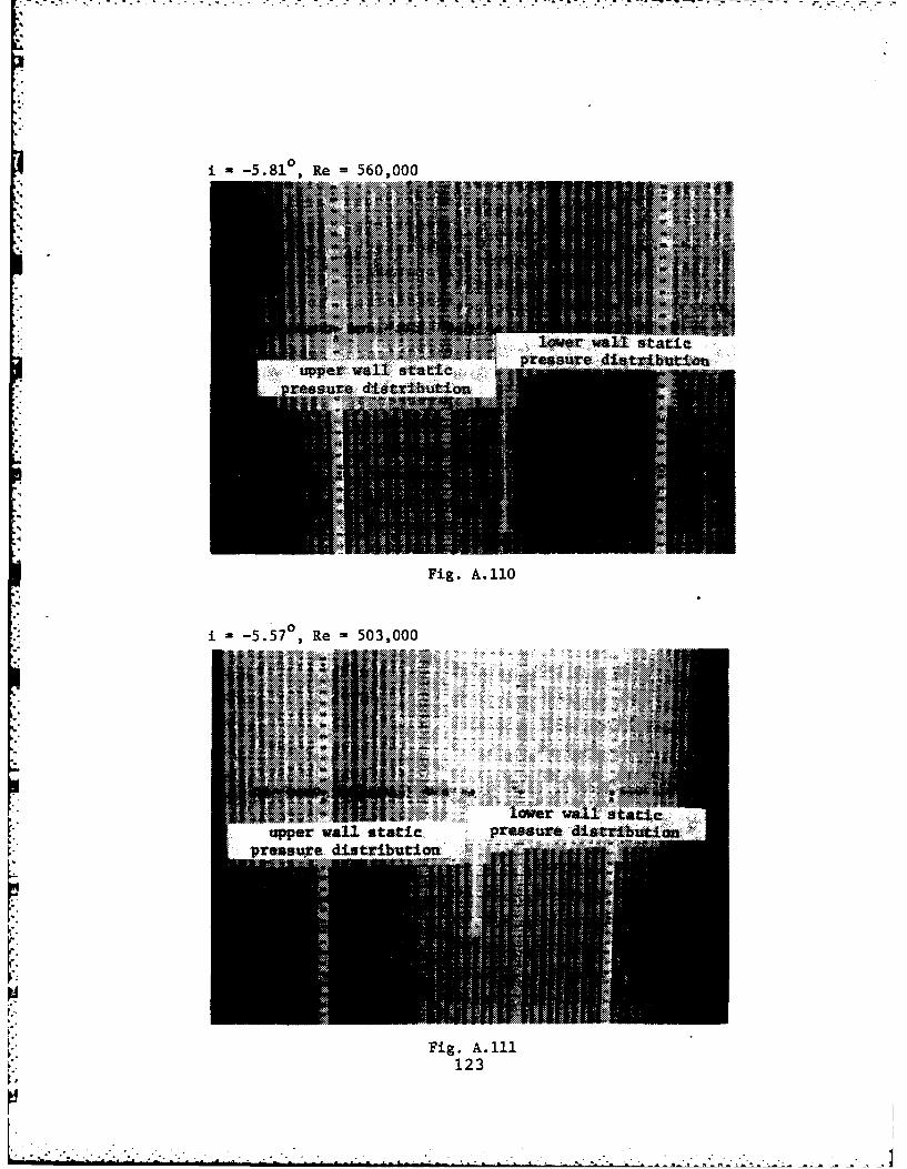
A.-5.81 0 Re =560,000
Fig. A.110
j ~.557,R 503,000
Fig. A.111123

1 -1.59 0 Re =643,000
~ .;~ lower wall s tatic~ tppr v11staicpressuire distribution.
pressure distribution
Fig. A.112
1 = 1 . 5 0 0 Re 525,000
IOW..a,. ~ *..-
. . . . . . . . . . . . . . . . . . . . .
pesr diti.to
Fig. A.113
124

i2.27 0Re 676,000
Fig. A.114
I .23 0 Re 604,000
44%
val taf
. . . . . . . ..... . . . . . . . . . .
Fig. A.115125

5.99*g0, Re -771,000
Fig. A.116
j 50,R 518,000
5.5 R
r-t
pressurig.dA.117
126

I-8.79 0 Re -768,000
upper wall static
resr isrbto
Fig. A.118
12

0/a (upper planei VS BTOB POSIT: - -12.5 DEGBLADE TO BLADE TRAVERSE (mtdspan).Re * 6.1E5 +Re - 5.3E5
1.4
t.1)
J'i..4
..
9'9''INCH S
Fig. A. 120
APs/Q (upper plane) VS BTOB POSIT: f t2.5 DEG
BLADE TO BLADE TRAVERSE (midspan)* 6.1E5 +Re - 5.3E5
,%F
ep t , I NCHOS =
Fig. A. 121 128
-.- 1

_~~ ~ ~ ~~~~ W- , . . /.% .,%..%" o%" ./
*.of
APt/d (upper plane' VS BTOB POSIT: I . -12.5 DEG
BLADE TO BLADE TRAVERSE (mdspn)
" "* 6.IE5 +Re 5.3E5
.3
.-.
'INCHES
X,3z (upper plane) VS BTOB POSIT: a--12.5 DEGBLADE TO BLADE TRAVERSE (midspan)*Re G .1ES +oRe -5.3E5
1.4 -
1.2
-
.4
a ka
, ;23 'INCHES '
Fig. A.12
"-12 XT
it-BRET L ETRVRE ri~a

ICTA2 VS BTOB POSIT: -1-2.5 DEGBLADE TO BLADC TRAVERSE (midspan)oR1 S.Ics +Re 5.3CS
0130

Q/d (upper plane' VS BTOB P')SIT: - -9.5 DEGBLADE TO BLADE TRAVERSE (midspan)*Re - 6.3C5 +Re - 5.0E5
1.4
* 1.2
~ 4 7 INCHES
Fig. A. 125
APS/3 (upper plane) VS BTOB POSIT: |--9.5 DEG
BLADE TO BLADE TRAVERSE (midspan)*Re - .3E5 +Re -00 E
.5
• .6
,.4
.. ;
9' ? 'INCHES
Fig. A.126 131
• ...... .
. .. . .. ...... :.. .. . .. .~ ~-.T: & -: . .. . . .

iPt/5 (upper plane) VS STOB POSIT: - -9.5 BEG
BLADE TO BLADE TRVERSE (mtdspan)
*Re - 6.3E5 +Re , 5.0E5.5
.3l
:'-.*
' -. 3
'.... ... .-.s
4' INCHES
Fig. A.127
X/R (upper plane) VS BTOB POSIT: - -9.5 DEG,.-. BLADE TO BLADE TRAVERSE (midspan)
*Re - 6.3E5 +Re - 5.0E5
1.4
1.2
~..
...
4I' 'INCHES
Fig. A.128 132
-132

BETR2 VS DTOB POSIT: t-9.S5 DEGBLADE TO BLADE TRAVERSE (midspan)*Re 6.3E5 +-Re -5.0E5
-- pl
66,

OAS (upper plane) VS BTOB POSIT: t -5.6 DEGBLADE TO BLADE TRAVERSE tmidspan)*Re S S.ES +Re - 5.OE5
.'
.8
.4!
9' INCHES
Fig. A.130
APs/3 - (upper plane) VS BTOB POSIT: - -5.6 DEGBLADE TO BLADE TRAVERSE (midspan)*Re - 5.6E5 +Re - 5.0 5.5
.3"
-.4
F'ig. A.131134
S
. .. . .
d .", . ..,/ ,. ,_ . .".,., - , , -. , .-. . .,, - ..,. - . . . . ..
,.; , . ,. ..-,,= . l.L -~
.. , , .i .' ,,, ,.- - . . . " - ".'.'""'
. . .'_" " - " , . , '

APt/o (upper plane) VS STOB POSIT: - -5.6 DEGBLADE TO BLADE TRAVEPSE (midspan)*Re 5.6E5 +Re - S.0E5
.3
- -.:
INCHES
Fig. A.132
X/7 (upper plane) VS BTOB POSIT: - -5.6 DEGBLADE TO BLADE TRAVERSE (midspan)*Re - 5.6E5 +Re - 5.0E5
1.4
1.2
.4
.2
9, ' 'INCHES
a:' #ig A.133'135

BETR2 VS STOB POSIT: -- 5.6 DEGBLADE TO BLADE TRAVERSE (midspan)
* *5.6E5 +Re 5.0E5
-33
o/d tupper plane) VS BOB POSITt - -1.5 DEGBLADE TO BLADE TRAVERSE (mldspan)*Re - 6.4E5 +Re -5,2E
I* 1.4
. . 135
*R .4
..
S " ? INCHES
Fig. A.135
tPs/1 (upper plane) VS 7TOB POSIT: I - -1.5 DEGBLADE TO BLADE TRAVERSE (midspan)~R. - B.4E'5 +Re - 5.2E:5
.$
I .2
.- I
~-.I,
I,.| • , I I NI I IS
"'Fig. A. 13613
" 137.
APt./d (upper plane) VS DTOB POSIT: I - -1.5 DEGBLADE TO BLADE TRAVERSE (ml dspan)*Re * 6.4E5 +Re. 5.2E5
.3
9' 9 ' INCHES
Fig. A.137
X/X (upper plane) vs BTOB POSIT: - -1.5 DEGBLADE TO BLADE TRAVERSE (midspan)*Re - 6.4E5 +Re - 5.2E5
1.4
12
.$
.4
9' ',;, ' TINCHES i
Fig. A.138 138pt*b.***l* . ..

BETR2 VS BTOB POSIT: 1 -1.5 DEG'BLADE TO BLADE TRAVERSE 'midspan)
6.4E5 +Re - 5.2E5
19
"o I
-3
%-°
.- Fig. A. 139
.0,,
139
4i.4
- ; , , * _' '_ " , 44, w '. . '" . J ', , '. - , '- . ', . '. '. .' , . ' ", ' . ., ' . ' ' . -. .- "

n0/ (upper plane) VS BTOB POSIT: - 2.2 DEGBLADE TO BLADE TRAVERSE (midspan)*Re,6.;'05(plexlglass wall) +R..6.0ES(stol wall)
.4
.2
9'~ 'INCHES
Fig. A.140
APs/ (upper plane) VS 9TOB POSIT: 2.2 DEGBLADE TO BLADE TRAVERSE (mtdspan)*Rj 6.?E5(plexiglass wall) +Re-6.0ES(steel wall)
.3
-.3
o..
i' 9 ' 'INCHES
Fig. A.141140

A Pt (upper plano) VS 9TOB POSIT: 3 * 2.2 DEGI BLADE TO BLADE TRAVERSE tmidspan)*R 6.7 plexiglass wall) ReS.OES(steel wall)
.. 3
;%'9
Fig. A. 142
'."X/X (upper plIan@) VS BTOB POSIT: !-2.2 DEG' BLADE TO BLADE: TRRVERSE (midspan)
*IRe-(;.27(plexiglass wall) +Re,,6.00:'($seel wall)1.4
1.2
...
--.3'INCHOS
Fig. A.1434141
. ... ,5" ,.'., . . : . . . . . . . . . . - ' : .

BCTA2 VS 9TOB POSIT: 1- .2 DEGBLADE TO BLADE TRRVERSE (midspan)
6Ro,,.70(pl qlas I wall) +R.W6.0E(st.el wall)
*1 4
.°
-:-a
N -3
. --- I . . . . ,NC, , , ,S
-.. Fig. A. 144
.4
.4.
,. 142
S. %

BILAD:E: TO BLADE TRAVERSE (midspan)': *Re 7, .7E5 +Re ,,5 .2 rS
1.4
*"-q,
1.2
q 7 INCHIFS
Fig. A.145
QPS/6 (upper plane) VS BTOB POSIT: * 5.6 DEGBLADE TO BLRDE TRAVERSE (midspan)
. *Re 7 7.7E5 +Re - 5.2ES
mI
e.3
Fig. A. 146 143
.4
_*..-,-,. ,..,- . .- - . ,..--- ., .. -.-- - . . .- -.- -. .
APt'o (upper plane) VS 9TOB POSIT: - 5.6 DEGBLADE TO BLADE TRAVERSE (midspan)
S,?.5 +Re , 5.2E5
II
':
-. INCHES
Fig. A. 147
X;X (upper plane) VS BTOB POSIT: i -5.6 DEG
BLADE TO BLADE TRAVERSE (midspan)*Re -7.705 +Re -5.2ES
.4
4.4
.11
.44
-i
A.148144
- -. -,.. , . . . .- .- - .- .- .- - . -. 3-t ., . ., , .-. • . . . .

BETRZ VS BTOB POSIT: I - 5.6 DEGBLADC TO BLADE TRAVERSE (midspan)
* ?cES +Re - 5.2E5
S
4 4
*I I I I I I I I
-3 wii
Fig. A. 149
14
145
,1;'+,' ,)." '"," - ." , ., ." -"." -. .' -. ' ,-.-.',. ' .' . +- ,. -' . ,". -- . , -. ' . + ."2 -:- : : :- -: -'.-

G'Q (upper plane) VS BTOB POSIT: 0 6.9 DEGBLADE TO BLADE TRAVERSE (midspan)*Re 7 .7lE5 +Re , 4.9E5
1.4
.2
.4-
9L INCHES
Fig. A.150
APe/t (upper plane) VS BTOB POSIT: - 9.8 DEGBLADE TO BLADE TRRVERSE (midspan)*Re - 7.7E5 + Re - 4.9E5
.. 4
-S.,,
; ? ' T INCHE'S
i. A.15114
'44
}.2,:N.,. 4.,' ,2 ; .T2 .- !. .-..i.i . :" - "' "' ' " " • • " " .. . -"' -

APt/i (upper plane) VS 9708 POSIT; 8.9 DEGBLADE TO BLADE TRAVERSE kmidspan)
*Re 7 .?E5 +Re 4.9E5
41 7 T INCHES L--A
Fig. A.152
X/X (upper plane) VS 9708 POSIT: 8 .8 DEGBLADE TO BLADE TRAVERSE (midspan)*Re ?.?E5 +Re 4.9E5
.'1.4
*7 1.
. ..4 . . . .
Pig. A.153 'INCHES
147

BETR2 VS BTOB POSIT: 8 -. 8 DEGBLRDC TO BLRDE TRVERSE (midspan*Re 7.70. eRg - 4.9E5
*,--I
.
s-s
9' TINCHES
Fig. A.154
148

Cp VS X/C: i - -12.50Re = 530,000R = Right Adjacent BladeL = Left Adjacent Blade0 = Pressure Side, Center Blade
1*0 Suction Side, Center Blade
o 0 00 X,'CA0 R 0.2 0.4 0.6 0.8 A 1 0
0oL , A A A
-1.0 0
100
Fig. A.155
l0
Cp VS X/C: i =-12.5°
Re = 610,000
1.0-
'Op
F^.. . o, .op. /
0 A 0 6
A IAA
Fig. A.156149
' 2 "'"" " " ";-".'"-"- -'' ' " "" . - '""-" -:.. . . . .,. ,....,- ....-. ... o. ,. ..:. . .. ... .. :., .--..- : .-. :: -. : . .-.-. .-.-. . -..

Cp VS X/C: i = -9.50Re = 500,000R = Right Adjacent BladeL = Left Adjacent Blade
1.0- 0 = Pressure Side, Center BladeA4 Suction. Side- Center Blade
CL A n .0 ' " X/C!501a 6iO O0'2 0.4 0.6 0.8 AlI. 0
"" 4
Fig. A.157
* .Cp VS X/C: i = -9.50Re = 630,000
1.0-
%A
9-Ci0 0 0O0f 0 /
o(.2 0.4 0.6 0.8
-1.0-0 A00_ _
. 0
Fig. A. 158150

Cp VS X/C: i = -5.60Re = 500,000R = Right Adjacent Blade
.. L = Left Adjacent Blade• .0 -Pressure Side, Center Blade1.0- = Suction Side, Center Blade
-~~ 0Q 0- 0 I o 0 0 Q0O. O- -O O O O Sx/c
U . 0.2 0.4 0.6 0.f aA 10
Fig. A. 159
.. o " z .
Cp VS X/C: i =-5.60
Re - 560,000
1.0-
"'0 0 " 0 0 r/c
00.2 0.4 .6 0. 1 Al.0
A A A A
Fig. A. 160
151
[ . .... .E b ;:-'. .. .-. . . ?-... 9 *.\'~% . .. .... . ." "-. .- - , -' - - "~ - - • " ...Il i l ~ mB am d ~ ~ m ,j. .di a *',... . *._ . . * .*, ..-. .. ,,- . • . ,. . .-. , . . .. ,. .

Cp VS X/C: i -1.50Re = 520,000R = Right Adjacent BladeL = Left Adjacent Blade
1.0) 0 = Pressure side, Center BladeA= Suc-tion- Side, Center Blade
eQ0 ) 0 00 o o 0 o 0 0k o ox/c000.2 0.4 0.6 A A 10
Fig. A. 161
Cp VS X/C: i -15=Re = 640,000
1.0
oof -0 A' 0/C0 00"J 0.2 0 .4 0.6 1 .D
AA
Fig. A.162152

Cp vs X/C: i 2.2°Re = 600,000R = Right Adjacent BladeL = Left Adjacent Blade
1.0- 0 = Pressure Side, Center Blade= Suction Side, Center Blade
co 0 0 00 0 0 0 a OR 00o
0.2 0.4 ,o.6, A 0.8 1.0
At
-1.0-
Fig. A. 163
Cp VS X/C: i =2.20Re = 670,000
1.0-
000 0 0 0 0 0 0
0 0.2 O.4 0.6
A A
-1.0"
Fig. A. 164153

*Cp VS X/C: 1 5.6 0Re - 520,000R = Right Adjacent BladeL - Left Adjacent Blade
10 0 = Pressure Side, Center Blade= Suction Side, Center Blade
CO 0 o 0 0 0 00 10 0 0
A A A A x/CU 0.2 0.4 0.6 A 0. 1.0
* Fig. A. 165
Cp VS X/C: i 5.6 0
Re = 770,000
1.0-
CO04~ 0 0 0 0 0 0 0 0Q000
00.2 0.4 0 *A 0.8 1.0
Fig. A.166154

Cp VS X/C: i = 8.80Re = 490,000R = Right Adjacent BladeL = Left Adjacent Blade
1.0- 0 = Pressure Side, Center BladeA = Suction Side, Center Blade
0 0 0 0 a 0 go 0 0 ,
A 41 A'5/C
.4
Fig. A. 167
. Cp VS X/C: i = 8.80
1.0.]Re = 770,000
"1.0-
0 0 0 0 0 0 0 0 0
0 0.2 0.4 A8 1.0
A ~A~0.8 I
-1.0-
A
A
Fig. A. 168155
, • .. - . , .. S. .. . . . .. . . . . --. . . . .

-
-
i- tan 1 + tan o2 )
1 = -1.2.5 d 2gres
Re = 611,000
* o.. -f
-I.L-
.*1
";; BI
Fig. A.169
156
,, .% ...,..-. -.- . .-... -... -. .-... . .... .. .. -. ..
* . . . - .
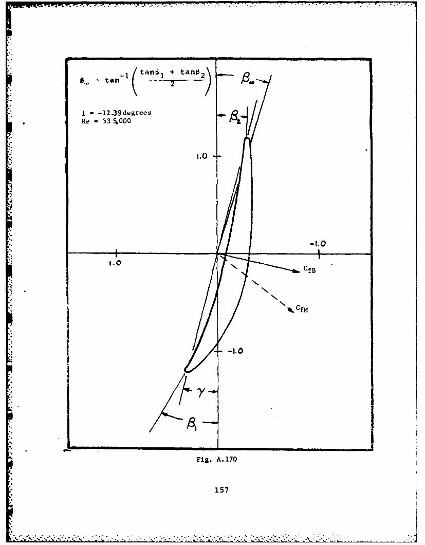
.. - tan- 1 (tan +tan
i = -12.3.9degreesRe = 535,000
1..0
II
I. 0 t \ Cfm.,.
CfB
,t
!NwN
i Fig. A. 170
157
FI. y

8a~=tan(.~ 23.
j=-9.58degreus
Re 626,000
1.0
1.0
Fi.A.7
* 158

4
+ tan 2tan- 2
i ==-9.23degreesRe 503,000
1.0
C fm1.0CB
4%
-4i
*'.
".
;- Fig. A. 172
159

.. . -.. ... ,
= tan- (LIIK Lan0 2 )2
i = -5.8lcdegrees -5
Re = 560,000
-1 0
,1.0
-f.Q.CfB
, -- C
Iy
Fig. A.173
160
.9

. .. . . - 7 - - -- -- r 7 . ,-. - • Y -. . - .
= a n + tan
o" - i = -5.57degreesRe = 5G3,000() "
1.00,:-1.1.
II
I': ." I
:•, CfB
Iq,
Fig. A.174
161

-~ ~~ aa~ tn~ o tank
i -1.59degrees
Re 643,000
1.0 jf
1 . c f
Fi.A.7
16

0,10 tan tfl~ + tano 2 \
1 -1.5 degreesRe =525,%000
.0
L
'I-
df
.1 f-.
Fig A..0
16

=tan
i =2.27 degcesRe 676,000)
-1.00
Fig A17
16
40 1.

. .S~ =. .. .. . .. .-
7tana1 + tn
i 2.23degreCsRe 604,000
iezj/
MI.16

n- tan + tanL
L; 5.99degrevsRe = 771,000
.0 --
/
CfB
1
r
Fig. A. 179.'--
166
It s. Sd9O2~

taLn81 + tanO~3__ II I I I I I I
i = 5.54degreesRe = 518,000
I.O
167
I
r.4
p.
I Fig. A. 180
167
'---~~~~~~.. ...--; .-.:..-,:..-.-.,........... .... ....... ... ;..........: .-.. :._...

tan tan. I +ta~i2
2I
8.79degree±s
=768,000
I..o
I -lfB9.0m
Fi.A 8
I6%

t 1ano + tan 0
8.76degreesRe 493,000
1.0
II / -1.0
-II
---.- C f B
l , -1.0
*y
•I
Fig. A.182
169
-' . ,'..',I : .' '.,N .- , ,''.-.'''.,''' . •" " ""'- -'-. .-" -. . ..--".'" '." ". ..""'. " '""""," "-"|

APPENDIX B
A. STORAGE OF EXPERIMENTAL DATA
1. Storage Devices
a. Cassette Tape
All raw and reduced data acquired during the
current study via the HP-3052A acsQiSition-system were stored
on cassette tape. Table B.1 summarizes the raw data file-
names according to inlet air angle and cassette tape number.
Tapes were filed with the Director, Turbopropulsion Laboratory,
Naval Postgraduate School, Monterey, Ca.
2 b. File Naming Scheme
All files were named using a six character alpha-
numeric code that allowed the investigator to immediately
identify stored data in any file and on what date it was
recorded. Here is how the code works.
1st character: Indicates the type of traverse conducted
("B"lade-to blade, "S"panwise or "I"nstrumented blade data).
2nd character: Indicates the "state" of the data set
(ra"W", re"D"uced or "F"inal).
3rd character: Indicates which probe was involved in
taking the data set, either "U"pper or "L"ower. No letter
here means that the probes acquired data simultaneously.
4th, 5th and 6th characters: These numbers indicate
the julian date in 1983 that the test run was conducted.
' " 1704 -" .. , - + .: + -. -. .. . -. .-..... .. . . . . . . . . . . . . . . . . . . . . .

* For example, a file containing data from a raw blade-to-
blade survey using the upper probe conducted on January 15,
1983 would be named BWU015. When upper and lower probes
were traversed together the "U"pper or "L"ower character
was dropped and the entire julian date filled the remaining
four spaces. For example, if the upper and lower probes
were both traversed in the blade-to-blade direction on Jan-
uary 15, 1983, the resultant raw data filename would be named
BW3015.
Sometimes, in order to completely describe a
reduced data file, parts of the julian date had to be sacri-
ficed. Raw data from a spanwise survey of the upper probe
one inch from the suction side of the centermost instrumented
blade conducted on February 1, 1983 would be named SWSU32
("S"panwise, ra"W", 1 inch from "S"uction side, "U"pper probe,
julian date 30"32"). It should be noted that when spanwise
surveys were conducted, both probes moved together. To pre-
clude interference of the lower probe wake with the upper
probe measurements, the upper probe was place 1 inch from
the suction side, and the lower probe was placed 1 inch from
the pressure side of the center blade. The composite data
file was named with the upper probe in mind, however, even
though the lower probe was stationed at a different blade-
to-blade position. For example, a raw spanwise survey named
SWS077 would show that the upper probe was 1 inch from the
171

.-. ~~ ... . . . .. .. . . . .. . .. .....
suction side of the center blade, while the lower probe was
1 inch from the pressure side.
Some specialized filenames reflect the type of
data stored. Referencing constants calculated for a test
conducted on February 15, 1983 would be named RC046A or
RC046B where the "A" would mean that the referencing constants
were calculated using the plenum total pressure and the lower
wall static pressure as reference total and static pressures.
"B" would indicate that the reference total and static pres-
sures were supplied by the pitot-static probe.
2. Thesis Logbook
A chronological log of the present study with notes
and printouts of all data files was deposited with the Director,
Turbopropulsion Laboratory.
B. PROBE CALIBRATION DATA
A folder documenting the calibration of United Sensor
probes serial number 847-1 and 981-2 was filed with the
Laboratory Manager, Turbopropulsion Laboratory. Non-dimensional
velocity (X) and pitch angle (PHI) calibration files for
both probes appear on each data storage cassette tape. Their
names reflect the file type and the applicable probe. For
example, the pitch angle calibration file for the 981 probe
is named "PH1981", the X velocity calibration file for the
847 probe is named "X847", and so on.
172

TABLE B.I. RAW DATA STORAGE
Raw Raw Raw TapeBTOB Spanwise Instrumented NumberData Data Blade Data
24.63 BW3144 SWS144 IW3144 11
24.74 BW3143 SWS143 IW3143 11
27.55 BW3123 SWS123 IW3123 7SWP123
27.90 BW3125 SWS125 IW3125 7SWP125
31.32 BW3119 SWS119 IW3119 6SWP19
31.56 BW3121 SWS121 IW3121 6SWP123
35.50 BW3138 SWS138 IW3138 10
35.60 BW3139 SWS139 IW139B 10
39.02 BWU077 SWU077 IW077 2BWL077 SWL077
38.68 BW3082 SW3082 IW082B 2
38.34 BW3097 SW3097 IW3097 3
38.89 BW3103 SW3103 IW3103 3
39.28 BW3127 SWS127 IW127B 8SWP127
39.40 BW3128 SWS128 IW3128 8SWP128
39.16 BW3129 SWS129 IW3129 9SWP129
39.36 BW3133 SWS133 IW3133 9
42.66 bw3109 swsi09 iw3109 4. swp109
43.13 BW3110 SI110 IWIIOB 4SWP 110
45.92 BW3114 SWS114 IW3114 5SWP114
45.89 bW3114 swsll4 iw3114 5swp114
173

APPENDIX C
EFFECT OF AVDR ON THE AXIAL FORCE COEFFICIENT DERIVED
FROM PROBE SURVEY DATA.
The notation used in this section follows [Ref. 14] and
[Ref. 15]. The application of the principle of momentum
-, conservation to the control volume shown in Fig. C.1 results
in the following expression for the resultant force on the
control volume;
R% A
.7.
Y ,---,vw -4
Figure C.I. Blade Space Control Volume
174
9, ~Jd!

In the enlarged view of the edge of curved surface a, the
unit outward normal vector, na-, is given by the relation
: CO 01 Ao = - sly% a( (c-2(C-2)
A
and similarly, on surface b, nb is given by
A AA SWO AnYl (C-3)
The elemental area "s" on the curved sidewall of the control
volume can be expressed as the projection of an element of
the base area dS, where
CI%"I dy" c (C-4)
so that,
d4 dxdy (C-5)
Resolving the elemental force, dF , acting on the curved
sidewalls of the control volume into normal and sheer compo-
nents gives_bA . A
J F = -PV d.4 - t d.A(CI (C-6)
Neglecting wall friction, T , the tangential force becomes:
Rvt Vu ,(cA?-V.VU)A
an ~ : i :~~z zSS?2~ VU A (C-7)Sand the axial force becomes:
SR,,,. S V. A - S f.\ JA,
CAI ~ A (C-8)
SL :. 0.
175
* :~ ~ ~ *.**.*.%,* *-.-.-.*.; .-.

Using Eq. (C-2), Eq. (C-3), Eq. (C-5) and Eq. (C-6),
dFL ly 4. CI 4 xS Cos oc)S f= -p cy (c-9)
and similarly,
which represent additional axial force components due to
pressure forces 9n the control volume side walls.
Equation (C-7) is identical to Eq. (B-3) of [Ref. 1] which
was derived for a strictly two-dimensional flow. Substitu-
tion of Eq. (C-9) and Eq. (C-10) into Eq. (C-8) yields,
. d(C-i1)
which contains a fifth axial force term not included by Cina,
and a modification of the first and third terms resulting
from the effects of AVDR.
Since the precise function p(y) is not known from
station 1 to station 2, a linear change of pressure with
y was assumed as depicted in Fig. C.2.
(D
Figure C.2. Assumed Pressure Function
The fifth term of Eq. (C-il) can then be approximated as:
-~~~ 2S (j(V~O f~ ][v. (C-12)176
" ,; ; . . . . .. . . . . . . . . .

Assuming that
.. S. AVDR - j ,AVDR d,,(C-13)
substitution of Eq. (C-13) and Eq. (C-12) into Eq. (C-I1)
yields, & a +3? '0 (,AV D )dx Jrva
S-f dx-(C- 14)
Equation (C-14) was reduced to force coefficient form
using procedures explained in [Ref. 1] and then incorporated
into existing software documented in (Ref. 81.
17
177
LIST OF REFERENCES
1. Cina, Frank S., Subsonic Cascade Wind Tunnel TestsUsing a Compressor Configuration of DCA Blades, M. S.Thesis: Naval Postgraduate School, Monterey, Ca., 1981.
2. Molloy, William D., Preliminary Measurements and CodeCalculations of Flow Through a Cascade of DCA Bladingat a Solidity of 1.67, M. S. Thesis, Naval PostgraduateSchool, Monterey, Ca., 1982.
3. Rose, Charles C., ard Guttormson, Darold L., Installationand Test of a Rectilinear Cascade, M. S. Thesis, NavalPostgraduate School, Monterey, Ca., 1964.
4. Bartocci, J. E., An investigation of the Flow Conditionsat the Lower Measurement Plane, and in the Plenum Chamberof the Rectilinear Cascade Test Facility, M. S. Thesis,Naval Postgraduate School, Monterey, Ca., 1966.
5. Moebius, Richard C., Analysis and Testing to Improvethe Flow from the Plenum of a Subsonic Cascade WindTunnel, M. S. Thesis, Naval Postgraduate School, Monterey,Ca., 1980.
6. McGuire, Alan G., Determination of Boundary Layer Transi-tion and Separation on Compressor Blades in a LargeSubsonic Cascade, M. S. Thesis, Naval Postgraduate School,Monterey, Ca., 1983.
7. 3052A System Library (9845A), Hewlett Packard Company,, 1978.
8. Turbopropulsion Laboratory, Naval Postgraduate School,Technical Note 80-03 (revised), Data Aquisition Programsfor the Subsonic Cascade Wind Tunnel, by D. A. Duval,1980 (revised by S. J. Himes, 1983).
9. NASA Report SP-36, Aerodynamic Design of Axial FlowCompressors, edited by Irving A. Johnson and RobertA. Bullock, 1965.
10. NASA Report 1016, Effect of Tunnel Configuration andTesting Technique on Cascade Performance, by John R.Erwin and James C. Emery, 1951.
178
, - .
11. Duval, David A., Evaluation of a Subsonic Cascade WindTunnel for Compressor Blade Testing, M. S. Thesis, NavalPostgraduate School, Monterey, Ca., 1980.
12. Contractor Report, Procedure and Computer Program forApproximation of Data (with Application to MultipleSensor Probes), by H. Zebner, August 1980.
13. Turbopropulsion Laboratory, Naval Postgraduate School,Technical Note 82-03, Computer Software for the Cali-bration of Pneumatic and Termperature Probes, by F.Neuhoff, September 1982.
14. Vavra, Michael H., Aero-Thermodynamics and Flow inTurbomachines, Krieger, 1974.
15. Class Notes, Aerotharmodynamics and Design of Turbo-machines, R. P. Shreeve, Professor, October 1982.
1
179

INITIAL DISTRIBUTION LIST
No. Copies
1. Defense Technical Information Center 2CameronStationAlexandria, VA 22314
2. Library, Code 0142 2Naval Postgraduate SchoolMonterey, CA 93940
3. Department Chairman, Code 67Department of AeronauticsNaval Postgraduate SchoolMonterey, CA 93940
4. Director, Turbopropulsion Laboratory, Code 67Sf 1Department of AeronauticsNaval Postgraduate SchoolMonterey, CA 93940
5. Mr. George DerderianNaval Air Systems CommandCode AIR-310EDepartment of the NavyWashington, D. C. 20360
6. Dr. A. D. WoodOffice of Naval ResearchEastern/Central Regional Office666 Summer StreetBoston, MA 02210
7. Chief, Fan and Compressor Branch(Attn: Nelson Sanger)NASA Lewis Research CenterMail Stop 5-921000 Brookpark RoadCleveland, OH 44135
8. LCDR S. J. Himes, USN4681 Revere RoadVirginia Beach, VA 23456
9. Turbopropulsion Laboratory Code 67 10Naval Postgraduate SchoolMonterey, CA 93940
180

Copyright © 2022 FDOKUMEN