Ifirla - Defense Technical Information Center
10
NASA Technical Memorandum 107348 Army Research Laboratory Technical Report ARL-TR-1251 Computerized Design and Analysis of Face-Milled, Uniform Tooth Height Spiral Bevel Gear Drives Faydor L. Litvin and Anngwo Wang University of Illinois at Chicago Chicago, Illinois R.F. Handschuh Vehicle Propulsion Directorate U.S. Army Research Laboratory Lewis Research Center Cleveland, Ohio C\J % •*» s Prepared for the Seventh International Power Transmission and Gearing Conference sponsored by the American Society of Mechanical Engineers San Diego, California, October 6-9,1996 National Aeronautics and Space Administration U.S. ARMY Ifirla RESEARCH LABORATORY iftSTRIBUTlON STATKMKNfir Approved for public release; Distribution Unlimited
-
Upload
khangminh22 -
Category
Documents
-
view
5 -
download
0
Transcript of Ifirla - Defense Technical Information Center

NASA Technical Memorandum 107348
Army Research Laboratory Technical Report ARL-TR-1251
Computerized Design and Analysis of Face-Milled, Uniform Tooth Height Spiral Bevel Gear Drives
Faydor L. Litvin and Anngwo Wang University of Illinois at Chicago Chicago, Illinois
R.F. Handschuh Vehicle Propulsion Directorate U.S. Army Research Laboratory Lewis Research Center Cleveland, Ohio
C\J
%
•*»
s Prepared for the Seventh International Power Transmission and Gearing Conference sponsored by the American Society of Mechanical Engineers San Diego, California, October 6-9,1996
National Aeronautics and Space Administration
U.S. ARMY
Ifirla RESEARCH LABORATORY
iftSTRIBUTlON STATKMKNfir
Approved for public release; Distribution Unlimited

COMPUTERIZED DESIGN AND ANALYSIS OF
FACE-MILLED, UNIFORM TOOTH HEIGHT SPIRAL BEVEL GEAR DRIVES
Faydor L. Litvin and Anngwo Wang Department of Mechanical Engineering
University of Illinois at Chicago
Chicago, linois
R. F. Handschuh Army Research Laboratory
NASA Lewis Research Center
Cleveland, Ohio
ABSTRACT Face-milled spiral bevel gears with uniform tooth height
are considered. An approach is proposed for the design of low-noise and localized bearing contact of such gears. The approach is based on the mismatch of contacting surfaces and permits two types of bearing contact either directed lon- gitudinally or across the surface to be obtained. A Tooth Contact Analysis (TCA) computer program was developed. This analysis was used to determine the influence of mis- alignment on meshing and contact of the spiral bevel gears. A numerical example that illustrates the developed theory is provided.
1 INTRODUCTION Two models for spiral bevel gears with uniform tooth
height were proposed by Litvin et al [6]. The generation of tooth surfaces of such gears is based on application: (i) of two cones that are in tangency along their common gener- atrix (model 1), and (ii) a cone and a surface of revolution that are in tangency along a common circle (model 2).The pinion and the gear are face-milled by head-cutters whose blades by rotation form the generating surfaces.
The generating surfaces provide conjugate pinion-gear tooth surfaces with a localized bearing contact that is formed by a set of instantaneous contact ellipses. The path of contact is directed across the surfaces in model 1 (fig. 1), and in the longitudinal direction in model 2 (fig. 2). The transmission errors are zero but only for aligned gear drives.
It is well known that misalignment of a gear drive causes the shift of the bearing contact and transmission errors. The transmission errors are one of the main sources of vibration. Therefore, the direct application of the models discussed above for generating surfaces is undesirable.
It was discovered that misalignment of a gear drive causes
an almost linear but discontinuous transmission function. However, such functions can be absorbed by a predesigned parabolic function of transmission errors. The interaction of the parabolic function and a linear function results a parabolic function with the same parabola coefficient [9]. Based on this consideration, it becomes necessary to mod- ify the process for generation discussed above to obtain a predesigned parabolic function of transmission errors. It was proposed in work [10] to obtain the desired parabolic function of transmission errors by executing proper nonlin- ear relations between the motions of the cradle and the gear (or the pinion) being generated. This approach requires the application of the CNC machines.
The purpose of this paper is to propose modifications of generating surfaces that will obtain: (i)a localized bearing contact that may be directed in the longitudinal direction or across the surface, and (ii)a predesigned parabolic function. These goals that will be proven later are obtained by the proper mismatch of the ideal generating surfaces shown in figs.l and 2. The mismatch of surfaces is achieved by appli- cation of modified generating surfaces shown in fig. 3. The modified generating surfaces are in point contact instead of tangency along a line that the ideal generating surfaces have. The desired parabolic function of transmission errors, the orientation of the path of contact, and the magnitude of the major axis of the contact ellipses are obtained by the proper determination of the curvature and the mean radius of the surface of revolution of the generating tool.
The meshing and contact of the tooth surfaces was sim- ulated by the TCA computer program developed by the authors. Numerical examples for the illustration of the pro- posed approach are considered.

2 METHOD FOR GENERATION OF CONJU- GATE PINION-GEAR TOOTH SURFACES Gear Generation:
The head-cutter for gear generation is provided with inner and outer straight-line blade (fig. 4), that form two cones while the blades are rotated about the Zla-axis of the head cutter. These cones will generate the convex and concave sides of the space of the gear, respectively.
We apply coordinate systems SC3, S2, Sm that are rigidly connected to the cradle of the generating machine, the gear and the cutting machine, respectively (figs. 5 and 6). The cradle with coordinate system SC3 performs rotation about the Zm-axis, and ^C2 is the current angle of rotation of the cradle (We take i = 2 in the designations of fig. 5). Coordinate system St3 is rigidly connected to the gear head- cutter that is mounted on the cradle. The installment of the head-cutter is determined with angle 92 and Sr2 = |0c20«2| (fig. 5(b)). The gear in the process for generation performs rotation about the Zb-axis of the auxiliary fixed coordinate system Sb that is rigidly connected to the Sm coordinate system (fig. 6). The installment of Sb with respect to Sm is determined with angle 72, where 72 is the angle of the gear pitch cone. The current angle of gear rotation is ip2 (fig. 6). Angles i>C3 and V"2 are related as
u, Cj = —- = sm 72 (1) Yc3 _
\j)2 U>2
The observation of this equation guaranties that the Xm- axis is the instantaneous axis of rotation of the gear in its relative motion with respect to the cradle. Pinion Generation;
The head-cutters for pinion generation are provided with separate blades that will generate the convex and concave sides of the space of the pinion, respectively (fig. 7). The pinion generating tool is installed on the cradle similarly to the installment of the gear generating cone (We take i = 1 in the designations of fig. 5). An auxiliary fixed coordinate system Sa is rigidly connected to the Sm coordinate system (fig. 8). The installment of Sa with respect to 5m is deter- mined with angle 71 of the pinion pitch cone. An imaginary process for the pinion generation for the purpose of simpli- fication of the TCA program is considered. The installment of coordinate system Sa with respect to Sm is determined in the real process of cutting by the angle 71 that is mea- sured clockwise, opposite to the direction shown in fig. 8. The pinion performs rotation about the Za-axis and ^1 is the current angle of rotation. The angles of rotation of the pinion and the cradle are related as
Axis Xm in accordance to equation (2) is the instanta- neous axis of rotation of the pinion in its relative motion with respect to the cradle.
— = sm 71 (2)
3 DERIVATION OF GEAR TOOTH SURFACE We consider that the gear head-cutter surface is repre-
sented in St3 by vector function Tt3(sg,6g), where s3 and Og are the surface parameters. A family of tool surfaces is generated in gear coordinate system S? while the cradle and the mounted tool and the gear perform the rotational mo- tions that are shown in figs. 5 and 6. The family of surfaces is represented in S2 by the matrix equation
T2{sg,0g, ^2) = M24(V,2)M6mMmC2(V'C3)Meat3rla(s,, 0g) = M2t2r,2(s,,0,)
(3) The product of matrices M2<3 is based on the coordinate
transformations from St3 to 52 (figs. 5 and 6). The deriva- tion of vector function rt3(sg,9g) is represented in Appendix 1.
The envelope to the family of surfaces T2(sg,0g,ij>2) is determined with equation (3) and the equation of meshing is [9]
Ne2-v^2) = /2(ss,^,V2) = 0 (4)
where NC2 is the normal to the generating surface, and
v£222') is the relative velocity of the tool with respect to the
gear. Vectors in equation (4) are represented in coordinate system SC3 ■
An alternative approach for the derivation of the equation of meshing is based on the consideration that the normal to the generating surface at a point of tangency of the con- tacting surfaces passes through the instantaneous axis of rotation.
Equations (3) and (4) represent the gear tooth surface by three related parameters. Taking into account that these equations are linear with respect to sg> we may eliminate sg and represent the gear tooth surface by two independent parameters, 0g and r\>i-
4 DERIVATION OF PINION TOOTH SURFACE The derivations are similar to those that have been de-
scribed in section 3. The family of generating surfaces is represented by the matrix equation
ri(Xp,0p,ipi) = Mi«(iiii)M8mMmCl(^I)MeitlriI(Apiflp) = Mitlrtl(Ap,0p)
(5) Here, rtl(Ap, 9P) is the vector function that represents the
generating surface ( Appendix 2 ), where Ap and 6P are the surface parameters.
The equation of meshing is
Nc1-v(tll) = /i(Ap,Op,^1)=0 (6)
Equations (5) and (6) represent the pinion tooth surface by three related parameters. After elimination of param- eter Xp we may represent the pinion tooth surface by two independent parameters, 6P and V>i ■
5 LOCAL SYNTHESIS The ideas of local synthesis are based on the following
considerations [9] : (1) The pinion and gear tooth surfaces are in tangency
at the mean contact point M that is in the middle of the contacting surface.
(2) The gear ratio is equal to the theoretical one. (3) Considering the principal curvatures of the contacting
surfaces, we have to provide in the neighborhood of M the following transmission function (fig. 9)
fa(<t>\) = -j^-h - 2m2i^i (7)
where im'2l is the parabola parameter of the predesigned parabolic function of transmission errors
(8) A<fo(^i) = -2m2i^i
(4) In addition it is necessary to provide the desired di- rection of the contact path.
All these goals can be achieved by the proper mismatch of the contacting surfaces of the pinion-gear tooth surfaces. The procedure of the local synthesis is as follows:
Step 1: We consider as given the surface of the head- cutter that generates the gear tooth surface. The head- cutter surface is a cone and is in line contact with the sur- face of the gear. One of such contact lines passes through the mean point M of tangency of the pinion and the tooth surfaces. Considering the surface of the gear head-cutter being as known, we determine at point M the principal curvatures and directions of the gear head-cutter.
Step 2: Our next goal is to determine at M the princi- pal curvatures k, and kq and directions of the gear tooth surface S2- We apply for this purpose the equations that have been proposed in [9] and represent the direct relations between the principal curvatures and directions for two sur- faces being in line contact.
Step 3: We consider at this step that gear and pinion tooth surfaces, S2 aRd Si, are in tangency at M. As a reminder the mismatched gear and pinion tooth surfaces are in point contact at every instant.
Unit vectors e, and eq represent the known directions of the principal directions on surface E2. The principal curvatures ks and kq on the gear principal directions are known. Our goal is to determine angle cri2 that is formed by vectors e/ and e, (fig. 10) and the principal curvatures kj and kh of the pinion tooth surface at point M. Unit vectors e/ and e^ represent the sought-for principal directions on the pinion tooth surface Si.
Step 4: The three unknowns: kf, kh and cr\2 can be determined using the approach developed in [9]. We use for this purpose the following system of three linear equations [9].
(«' = 1,2,3) (9) aavP + ai2vg1) = a<3
The augmented matrix formed by the coefficients an, an and a,3 is a skew-symmetric one [9]. Here, wj ' and v\ ' are the components of the velocity of the contact point that moves in the process of meshing over the pinion tooth sur- faces Si. Coefficients an, a,2 and a,3 are represented in terms of ks, kq, kj, kh, o\i and the parameters of motion. Coefficient a%% contains the derivative
m2i = TT (m2l(«£l))
where dfa
"»21 =
(10)
d<f>2 d<t>i (11)
Step 5: Equation system (9) represents a system of three linear equations in two unknowns: v, ' and vg '. Surfaces Si and S2 are in point contact, the path of contact has a definite direction, and the solution of equation system (9) with respect to v; ' and v) ' must be unique. Therefore, the rank of the augmented matrix formed by an, a,2 and a,3 is equal to two. This yields that
= F(kf, kh, ks, kq, <T12, m21) =0
(12)
The other relation between the coefficients an, a<2 and «to may be determined considering that
an an a13
ai2 «22 a23 <*13 «23 G33
Unrii = -fjT (13)
where r\\ is the assigned direction at M of the tangent to the path of contact on the pinion surface Si.
Using the relations between the coefficients of linear equa- tion (9) discussed above, we are able to determine the sought-for pinion principal curvatures kj, kh and orienta- tion angle 0-12.
Step 6: We consider now that pinion principal curvatures kj, kh and angle <xi2, and the principal directions e/ and eh on surface Si are known. The generating surface of the head-cutter is designed as a surface of revolution (fig. 3). The pinion head-cutter surface and the pinion tooth surface are in line contact at every instant. Using the direct relations between the principal curvatures and directions for two surfaces being in line contact [9], we may determine the principal curvatures of the pinion head-cutter. Then, the desired mismatch of the surfaces of the gear and the pinion will be obtained by the generation of the gear and the pinion by the designed head-cutters.

Step 7: Knowing the principal curvatures and directions of the pinion and gear tooth surfaces, the elastic approach of the surfaces, we may determine the orientation and the axes of the instantaneous contact ellipse [9].
6 TOOTH CONTACT ANALYSIS The purpose of TCA is to determine the influence of mis-
alignment on the shift of the bearing contact and the trans- mission errors. This goal is obtained by the simulation of meshing and contact of pinion and gear tooth surfaces of a misaligned gear drive.
We consider that the pinion and gear tooth surfaces are analytically represented in coordinate systems Si and 52 (see sections 3 and 4, respectively). The meshing of pinion and gear tooth surfaces is considered in fixed coordinate system Sh (figs. 11 and 12). Auxiliary fixed coordinate sys- tem Sa and Se are applied to describe the installment of the pinion with respect to Sh (fig. 11)- The pinion alignment error AAP is the pinion axial displacement. The misaligned pinion in the process of meshing with the gear performs ro- tation about Ze-axis. The current angle of rotation of the pinion is designated by <j>\ (fig. 11).
Auxiliary coordinate systems £j, Sc and Sd are applied to describe the installment of misaligned gear with respect to Sh • The errors of alignment are: the change A7 of the shaft angle (fig. 12), the offset AE and the gear axial dis- placement AAg (fig. 13). The misaligned gear performs rotation about the Z<j-axis, and <j>2 is the current angle of the gear rotation.
A TCA computer program was developed to simulate the meshing of pinion-gear tooth surfaces of the misaligned gear drive. The development of the TCA program is based on the following considerations:
Step 1. We consider that the pinion and gear tooth sur- faces and the surface unit normals are represented in coor- dinate system Si and S2 by vector functions
r,(0,-,V<,) (i= 1,2) (14)
n,(^,V,) (i= 1,2) (15)
where (öj, Vi) are the surface parameters. Step 2. We represent now the pinion-gear tooth surfaces
and their surface unit normals in coordinate system Sh, and take into account that the surfaces are in continuous tangency. Then we obtain the following equations
rhl\eul>u<f>1)-rh
2\e7,rJ>2,<l>2) = Q (16)
41)(öi,Vi)^)-42)(^)V2,^2) = 0 (17) Equations (16) and (17) represent the conditions that the
contacting surfaces at the point of tangency have a common position vector and a common surface unit normal. Equa- tions (16) and (17) yield a system of five independent scalar equations of the following structure
/i(*i,tfi,*i,fc,tfa,*a) = 0 UeC1 (»= 1..5) (18)
As a reminder vector equation (17) yields only two in-
dependent scalar equations and not three, since |n^ | =
|ni2)| = l. Step 3. System (18) of five nonlinear equations contains
six unknowns, but one of the unknowns, say <f>\, may be con- sidered as the input parameter. Our goal is the numerical solution of nonlinear equations (18) by functions
{0i(<l>i),M<f>i),02(<i>i),M<i>i),fo(<t>i)} € c1 (19)
The sought-for numerical solution is an iterative process that requires on each iteration the observation of the fol- lowing conditions [9] [3]:
(i) There is a set of parameters (the first guess)
p(e[o),4"\<f>[0)A0)A0\40)) (20) that satisfies the equation system (18).
(ii) The Jacobian taken at P differs from zero. Thus, we have
D{fuh,h,f4,h) A5=- ^0 (21)
Then, as it follows from the Theorem of Implicit Function System Existence, equation system (18) can be solved in the neighborhood of P by functions (19).
Using the obtained solution, we can determine the path of contact on the pinion-gear tooth surface, and the trans- mission errors caused by misalignment. The path of contact on surface £< (i = 1,2) is determined by the expressions
Ti(0i,1>i), ft(tfi), 1W1) (*' = 1,2) (22)
The transmission errors are determined by equation Ni
A<t>2 = <£2(<£l)--T7-<£l JV2
(23)
The dimensions and orientations of the instantaneous contact ellipse at the contact point may be determined con- sidering that the principal curvatures and directions of the contacting surfaces, and the elastic approach of the surface [9] are known.
7 NUMERICAL EXAMPLE The blank data is given in Table 1. The gear head-cutter is a cone (figs. 2, 3 and 4), the cut-
ter radius is designated by R3 (fig. 1), the radial setting of the head-cutter is |0CaOt2| (fig. 5(b)), and the installment angle is q2 (fig. 5). The data for the gear head-cutter that generates the gear concave side are represented in Table 2.
The parameters of the pinion head-cutter were deter- mined by application of the method of local synthesis (sec- tion 5). The data for the pinion head-cutter that gener- ates the pinion convex side are represented in Table 3. We
considered in the numerical examples the meshing of the gear tooth concave side with the pinion tooth convex side. Case 1 corresponds to the orientation of the bearing contact across the surface, case 2 corresponds to the orientation of the bearing contact in the longitudinal direction.
The application of TCA for the simulation of meshing and contact permits the determination of misalignment ef- fects on the transmission errors and the shift of the bearing contact. It has been shown that in the case of application of ideal generating surfaces (without mismatch, figs. 1 and 2) the errors of misalignment cause indeed discontinuous al- most linear transmission errors as shown in fig. 14 for shaft angle error A7. Similar functions of transmission errors are caused by errors AAV, AAg and AE. Table 4 shows the maximal transmission errors caused by misalignment.
The results of TCA for the properly mismatched gener- ating surfaces (see section 5) confirmed that a predesigned parabolic function indeed absorbs the transmission errors caused by misalignment, and the resulting function of trans- mission is a parabolic one (fig. 15). The absorption of linear function of transmission errors is carried out as well in other cases of misalignment: AAP, AAS and AE. The bearing contact of the drive is stabilized, and its shift is permissible (fig. 16). Model 2 of the gear drive (with longitudinal di- rection of the bearing contact) is preferable due to the lower level of transmission errors caused by misalignment.
8 CONCLUSION From the study conducted the following general conclu-
sions can be drawn: (1) An approach has been developed for the synthesis of
spiral bevel gears that provides: (i) localized bearing con- tact, and (ii) low level of transmission errors of a parabolic type. The approach developed permits two possible direc- tions of the bearing contact: across the tooth surface or in the longitudinal direction.
(2) A Tooth Contact Analysis (TCA) computer program for the investigation of the influence of misalignment on the shift of the bearing contact was developed.
(3) The low level of transmission errors, the parabolic type of the function of transmission errors, and the local- ization of the bearing contact are achieved by the proper mismatch of contacting surfaces.
(4) The influence of the following errors of alignment was investigated: (i) for axial displacement of the pinion, (ii) axial displacement of the gear, (iii) offset, and (iv) change of the shaft angle. These types of misalignment were proven to cause discontinuous almost linear functions of transmission errors, but they are absorbed by the predesigned parabolic function of transmission errors.
The results of this investigation show that a predesigned parabolic function can indeed absorb the linear functions
of transmission errors caused by misalignment. The design of gears with a longitudinal bearing contact (in comparison with the bearing contact across the surface) is preferable since a lower level of transmission errors can be obtained.
REFERENCES
[1] Dongarrd, J.J., Bunch, J.R., Moler, C.B., and Steward, G.W. 1979. UNPACK User's Guide, SIAM, Philadel- phia
[2] Favard, J. Course of Local Differential Geometry, Gauthier-Villars, Paris (in French, translated into Rus- sian)
[3] Korn, G.A. and Korn, T.M. 1968. Mathematics Hand- book for Scientists and Engineers, 2nd ed., McGraw- Hill, NY.
[4] Litvin, F.L. 1960, 1968. Theory of Gearing, 1st ed. (1960), 2nd ed. (1968). Nauka (in Russian)
[5] Litvin, F.L. 1969. Die Beziehungen Zwischen den Krümmungen der Zahnoberflächen bei Räumlichen Verzahnungen. Z. Angew. Math. Mech. 49: 685-690 (in German)
[6] Litvin, F.L. Pahman P. and Goldrich R.N. 1982, Math- ematical Models for the Synthesis and Optimization of Spiral Bevel Gear Tooth Surfaces, NASA CR-3553
[7] Litvin, F.L. 1989. Theory of Gearing, NASA Reference Publication 1212
[8] Litvin, F.L. and Zhang, Y. 1991. Local Synthesis and Tooth Contact Analysis of Face-Milled Spiral Bevel Gears. NASA Contractor Report 4342, AVS- COM Technical Report 90-C-028
[9] Litvin, F.L. 1994. Gear Geometry and Applied Theory, Prentice Hall
[10] Litvin, F. L. and Zhao, X. 1996. Computerized Design and Analysis of Face-milled, Uniform Tooth Height, Low-Noise Spiral Bevel Gear Drives, NASA Contractor Report 4704.
[11] More, Jorge J., Garbow, Burton S., and Hilstorm, Ken- neth E. 1980. User Guide for MINPACK-1, Argonne National Laboratory, Argonne, IL.
[12] Stadtfeld, H.J. 1993. Handbook of Bevel and Hypoid Gears. Rochester Institute of Technology
[13] Zalgaller, V.A. 1975. Theory of Envelopes, Nauka, Moscow (in Russian)
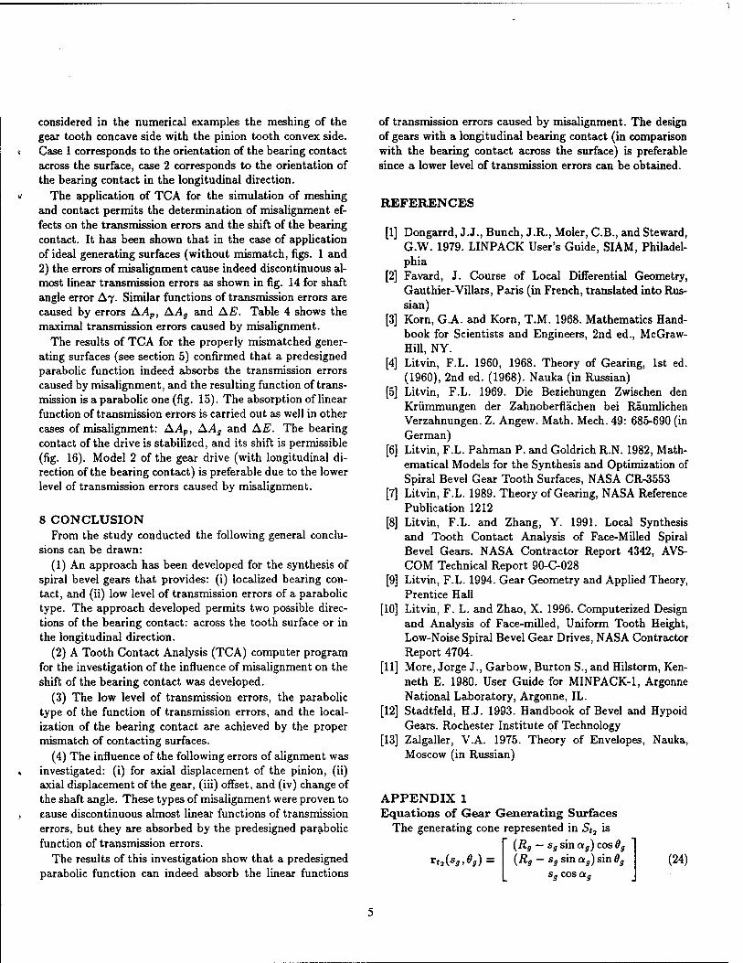
APPENDIX 1 Equations of Gear Generating Surfaces
The generating cone represented in St7 is (Rs — sg sin ag) cos 9g
*«3 (*».*») = (Rg — sg sin ag) sin 0g
sg cos ag
(24)
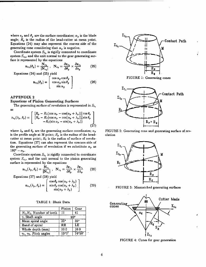
where sg and 0g are the surface coordinates; ag is the blade angle; Rg is the radius of the head-cutter at mean point. Equations (24) may also represent the convex side of the generating cone considering that ag is negative.
Coordinate system St3 is rigidly connected to coordinate system SC3, and the unit normal to the gear generating sur- face is represented by the equations
.(*,) = Ne
|Ne8, Equations (24) and (25) yield
NC2 = d6a dsa
ne,(6g) = cos ag cos 6g cos ag sin 9g
sin a „
(25)
(26)
rtl(Ap,0p) =
APPENDIX 2 Equations of Pinion Generating Surfaces
The generating surface of revolution is represented in 5«, as
[Rp — Äi(cos ap — cos(ap 4- Ap))] cos 0P
[Rp — Äi(cosQp — cos(ap + Ap))]sin#p
—Äi(sinap - sin(ap + Ap)) (27)
where Ap and 9p are the generating surface coordinates; ap
is the profile angle at M point; Rp is the radius of the head- cutter at mean point; R\ is the radius of surface of revolu- tion. Equations (27) can also represent the concave side of the generating surface of revolution if we substitute ap as 180»-ap.
Coordinate system Stl is rigidly connected to coordinate system SCl, and the unit normal to the pinion generating surface is represented by the equations
Ue,(Ap,0p) = _ dru drtl
^ " d6p x dXp |NcJ '
Equations (27) and (28) yield cos Op cos(ap + Ap)
(28)
nCl(Ap,0p) sin0pcos(ap + Ap) sin(ap + Ap)
(29)
TABLE 1: Blank Data
Pinion Gear N\,N2, Number of teeth 11 41 7, Shaft angle 90° Mean spiral angle 35° 35° Hand of spiral RH LH Whole depth (mm) 10.0 10.0 7i, 72, Pitch angles 15°1' 74°59'
Contact Path
FIGURE 1: Generating cones
Contact Path
FIGURE 2: Generating cone and generating surface of rev- olution
FIGURE 3: Mismatched generating surfaces
Generating cones
Cutter blade
It.
FIGURE 4: Cones for gear generation

Zm>ZCi
(a) (b )
FIGURE 5: Coordinate systems Sc and S„
Y„.Y
°b50
2.Om Gear pitch cone
Z,
FIGURE 6: Coordinate systems Sm, 5j and 52
U)
b ) ? 1
lif R
FIGURE 7: (a)Convex (inside blade) and (b)concave {out- side blade) sides of the generating blades and generating surfaces of revolution
FIGURE 8: Coordinate systems Sm, Sa and S\
(a) (b) Ideal transmission
<Pz\ function
^1 h ^ ,
i » * *i
S
kh
M <Pi
FIGURE 9: Transmission function and predesigned parabolic function of transmission errors, ^i-pinion rota- tion angle; <£2-gear rotation angle; A^2-transmission error
FIGURE 10: Unit vectors of principal directions of surfaces £2 and Si
TABLE 2: Parameters and Installment of Gear Head- Cutter on gear concave side
ag, Blade angle 20° Rg, Cutter radius at mean point (mm) 78.52 5r2, Radial setting (mm) 70.53 92j Installment angle -62°14'

TABLE 3: Parameters and Installment of the Pinion Head- Cutter on pinion convex side
Y^Y ,Y. d' c ' h
Case 1 Case 2
ap 20° 20°
91 -61°51' -51°24'
INPUT
m 171" 92°
m'21 -1.3e-3 -1.2e-3
Afa -10.94 -10.09
OUTPUT M (79.88, 0.39, 0.17) (77.83, 1.64, 0.72)
Äp(mm) 78.0 64.7
ßi(mm) 235.0 765.0
la (mm) 12.54 4.5
TABLE 4: Maximum Transmission Errors for Generating Surfaces with Mismatch
A<j>2 in arc sec. Case 1 Case 2
AAP = 0.1mm 8.8 16.2 AA„ = 0.1mm 11.5 12.5 AE = 0.1mm 11 15 AT = 3' 10.7 13.5
Za'Ze'Zl
(a) (b) FIGURE 11: Simulation of pinion misalignment AAP
w.
j^r °c'0b>°h
(a ) (b ) FIGURE 12: Simulation of gear misalignment A?
(a)
Zd>Ze»Z2
(b) FIGURE 13: Simulation of gear misalignment AE and AAg
I 2 1
< -1
-2
-3 -4
-50 -40 -30 -20 -10 0 10 20 30 40 50 * i (Deg)
FIGURE 14: Transmission errors for a misaligned gear drive with ideal surfaces: A7 = 3 arc min.
¥ 2
I 0 w -2 IS mA
-8 -10
-60 -50 -40 -30 -20 -10 0 10 20 30 40 50
+ , 0*8)
FIGURE 15: Transmission errors for a misaligned gear drive with mismatched gear tooth surfaces: A7 = 3 arc min.
FIGURE 16: Longitudinal bearing contact for a misaligned gear drive (A7 = 3 arc min.)

REPORT DOCUMENTATION PAGE Form Approved OMB No. 0704-0188
Public reporting burden for this collection of information is estimated to average 1 hour per response, including the time for reviewing instructions, searching existing data sources, gatheringaid maintaining the data needed, and completing and reviewing the collection of information Send comments regarding this burden^estimate «^^ «ff« **;8
Collection of information, Including suggestions for reducing this burden, to Washington Headquarters Services, Directorate for Information Operations and Reports. 1215 Jefferson Darf?Highway SurteTlZoTArlington, VA 22202-4302. aSd to the Office of Management and Budget. Papeiwork Reduction Profcct 0704-0188). Washington. DC 20503.
1. AGENCY USE ONLY (Leave blank) REPORT DATE
October 1996 3. REPORT TYPE AND DATES COVERED
Technical Memorandum
4. TITLE AND SUBTITLE
Computerized Design and Analysis of Face-Milled, Uniform Tooth Height Spiral Bevel Gear Drives
6. AUTHOR(S)
Faydor L. Litvin, Anngwo Wang, and R.F. Handschuh
7. PERFORMING ORGANIZATION NAME(S) AND ADDRESS(ES) NASA Lewis Research Center Cleveland, Ohio 44135-3191 and Vehicle Propulsion Directorate U.S. Army Research Laboratory Cleveland, Ohio 44135-3191
9. SPONSORINGMONITORING AGENCY NAME(S) AND ADDRESS(ES)
National Aeronautics and Space Administration Washington, D.C. 20546-0001 and U.S. Army Research Laboratory Adelphi, Maryland 20783-1145
S. FUNDING NUMBERS
WU-505-62-36 1L162211A47A
8. PERFORMING ORGANIZATION REPORT NUMBER
E-10499
10. SPONSORING/MONITORING AGENCY REPORT NUMBER
NASATM-107348 ARL-TR-1251
11 SUPPLEMENTARY NOTES Prepared for the Seventh International Power Transmission and Gearing Conference sponsored by the American Society of Mechanical Engineers, San Diego, California, October 6-9,1996. Faydor L. Litvin and Anngwo Wang, University of Illinois at Chicago, Depart- ment of Mechanical Engineering, Chicago, Illinois 60680; R.F. Handschuh, Vehicle Propulsion Directorate, U.S. Army Research Laboratory, NASA Lewis Research Center. Responsible person, R.F. Handschuh, organization 2730, (216) 433-3969.
12a. DISTRIBUTION/AVAILABILITY STATEMENT |l2b. DISTRIBUTION CODE
Unclassified -Unlimited Subject Category 37
This publication is available from the NASA Center for AeroSpace Information, (301) 621-0390.
13. ABSTRACT (Maximum 200 words)
Face-milled spiral bevel gears with uniform tooth height are considered. An approach is proposed for the design of low- noise and localized bearing contact of such gears. The approach is based on the mismatch of contacting surfaces and permits two types of bearing contact either directed longitudinally or across the surface to be obtained. A Tooth Contact Analysis (TCA) computer program was developed. This analysis was used to determine the influence of misalignment on meshing and contact of the spiral bevel gears. A numerical example that illustrates the developed theory is provided.
14. SUBJECT TERMS
Gears; Transmissions; Spiral bevel gears
17. SECURITY CLASSIFICATION OF REPORT
Unclassified
18. SECURITY CLASSIFICATION OF THIS PAGE
Unclassified
19. SECURITY CLASSIFICATION OF ABSTRACT
Unclassified
15. NUMBER OF PAGES
10 16. PRICE CODE
A02 20. LIMITATION OF ABSTRACT
NSN 7540-01-280-5500 Standard Form 298 (Rev. 2-89) Prescribed by ANSI Std. 239-18 298-102