ADA165038.pdf - Defense Technical Information Center
379
7-i..5 838 SPACE HNRBOK(U) AIR MINISTRY LONDON (ENGLAND) C 0 COCHRAN ET AL. JAN 85 AU-i8 U.3CLASSIFIED F/6 15/7 MI.
-
Upload
khangminh22 -
Category
Documents
-
view
3 -
download
0
Transcript of ADA165038.pdf - Defense Technical Information Center

7-i..5 838 SPACE HNRBOK(U) AIR MINISTRY LONDON (ENGLAND)C 0 COCHRAN ET AL. JAN 85 AU-i8
U.3CLASSIFIED F/6 15/7 MI.
'"" 1 5.0 M lHIIII ii LA-
A -
ICPIESLTO TES CHIRN TII1N ~AL IRA]O TA- 13A
" ' ,'. 2- -°''. r , " .,j." ... ,. ' ' ," "''. '" " . . .' " " " " " " ' -"-" '. "' '" " ." " a' " , " ' " "'"" -"-1.1"" '
00If)f
ELECTEMAR0 7
5 It
to V' -..- .
I -AX'
mg* STSE.E
&Wovd fo pubic vleas
Dittto4Ulmw
AU-18
Space Handbook
Prepared by
AIR COMMAND AND STAFF COLLEGE
Edited byLt Col Curtis D. Cochran
Lt Col Dennis M. GormanMaj Joseph D. Dumoulin
AIR UNIVERSITY PRESSAIR UNIVERSITY (AU)
MAXWELL AIR FORCE BASE, ALABAMA 36112-5532January 1985
-- --.- .'
" '%,"."o. '" "."." .. .
Twelfth Revision, January 1985Eleventh Revision. August 1977Tenth Revision, July 1974Ninth Revision, July 1972Eighth Revision. July 1970Seventh Revision. July 1969Sixth Revision, July 1968Fifth Revision, July 1967Fourth Revision, July 1966Third Revision. July 1965Second Revision, July 1964First Revision, July 1963First Edition. December 1962
This publication has been reviewed and approved by competent personnel of the
preparing command in accordance with current directives on doctrine, policy,essentiality, propriety, and quality.
This publication has been reviewed by security and policy review authorities and is cleared for public release.
This document is the property of the United States Government and is not to be reproduced in whole or in part
without permission of ACSC/EDCW, Maxwell AFB, Alabama 36112
Sovemn ent Printin Officejashin ton DC 2 02
Vag .

nn rr rr r~ ur rrCr o n -e n- t s .-. .
Foreword ................................................................... xi
Preface ..................................................................... xiii
Chapter I
-The Space Environment)THE UNIVERSE ............................................................ I-I1THE MILITARY SPACE ENVIRONMENT ...................................... 1-3
Electromagnetic Radiation.................................................. 1-5Meteoroids and Micrometeoroids ............................................ 1-6Solar Activity ........................................................... -7 .. 1-7The Van Allen Radiation Belt ............................................... 1-9Cosmic Rays ............................................................ 1-10Radiation Hazard Summary................................................ 1-10
MILITARY SPACE RESEARCH .............................................. 1-10Energetic Particle Research.................................................I1-IlSpacecraft Charging ...................................................... 1-13Geomagnetism........................................................... 1-13Space Forecasting ........................................................ 1-13Solar Radio Astronomy Research ........................................... 1-14
Chapter 2
ObtlMechanics~
MOTION OF BODIES IN ORBIT .............................................. 2-1Linear Motion ........................................................... 2-2Angular Motion .......................................................... 2-3 -
LAWS OF MOTION ......................................................... 2-4Kepler's Laws............................................................ 2-4Newton's Laws ........................................................... 2-6Force as Measured in the English System...................................... 2-6Energy and Work ........................................................ 2-8Newton's Laws of Universal Gravitation....................................... 2-9
CON IC SECTIONS.......................................................... 2-10Conic Sections and the Coordinate Systems.................................... 2-IlEllipse ................................................................. 2-13
ENERGY AND MOMENTUM ................................................ 2-15Mechanical Energy ....................................................... 2-I5Linear and Angular Momentum............................................. 2-17
THE TWO-BODY PROBLEM................................................. 2-18 ...........
Physical Interpretation of the Two-Body Trajectory Equation..................... 2-19 \Elliptical Trajectory Parameters.............................................jl-
Wi Availabikiy Codes
2Avail andfIorDist Speal

Two-Body Trajectory Definitions and Geometry................................ 2-23EARTH SATELLITES...................................... ................. 2-24L.OCATING BODIES IN SPACE............................................... 2-27SATELLITE GROUND TRACKS.............................................. 2-29
2'SPACE MANEUVERS....................................................... 2-37Altitude Change.......................................................... 2-37Plane Change............................................................ 2-39Combined Maneuvers ..................................................... 2-40
PERTlURBATIONS.......................................................... 2-41Third Body Effects ....................................................... 2-41Effects of Oblate Earth .................................................... 2-41D~rag Effects ............................................................ 2-44
EQUATIONS PERTAINING TO BODIES IN MOTION ........................... 2-46SOME USEFUL EQUATIONS OF ORBITAL MECHANICS ....................... 2-46
Chapter 3
Propulsion Systems) -
-THEORY OF ROCKET PROPULSION ......................................... 3-IThrust.................................................................. 3-3Noul1es and Expansion Ratio ............................................... 3-4Altitude Effects and Thrust Parameters........................................ 3.5Mission Velocity Requirements .............................................. 3-5
*Specific Impulse.......................................................... 3-5- ~Mass Ratio.............................................................. 3-7
Thrust-to-Weight Ratio.................................................... 3-9*-IDEAL VEHICLE VELOCITY CHANGE........................................ 3-9
ACTUAL VEHICLE VELOCITY CHANGE...................................... 3-10PARKING ORBITS.......................................................... 3-13
ROCKET PROPELLANTS ................................................... 3-13-Theoretical Performance of Chemical Propellants............................... 3-13Theoretical Specific Impulse ....... I......................................... 3-14Density Impulse.......................................................... 3-17Total Impulse ........................................................... 3-17Characteristics and Performance of Propellants................................. 3-18
CHEMICAL ROCKET ENGINES.............................................. 3-27Liq uid- Propellant Engines ................................................. 3-28Solid- Propellant Rocket Motors............................................. 3-29' Thrust Vector Control .................................................... 3-30Thrust Termination....................................................... 3-30Engine Cooling .......................................................... 3-31Noliles ................................................................ 3-33Improvements ........................................................... 3-34
ADVANCED PROPULSION TECHNIQUES..................................... 3-35Need for Advanced Designs ................................................ 3-35Nuclear Rocket .......................................................... 13-35Low Thrust Rockets ...................................................... 13-35Ion Propulsion Theory .................................................... 13-38
SUMMARY ................................................................ 3-48PROPULSION SYMBOLS .................................................... 3-49
. SOME USEFUL PROPULSION EQUATIONS................................... 3-49
MA-
I.KJe
Chapter 4
Space Vehicle Electrical Power)PRODUCING POWER IN THE SPACE ENVIRONMENT .......................... 4-ITYPES OF SPACE ELECTRICAL POWER SYSTEMS............................ 4-2
Electrochemical Systems ................................................... 4-2Solar-Powered Systems .................................................... 4-5Nuclear Systems.......................................................... 4-8Safety.................................................................. 4-13
SELECTION OF POWER SYSTEMS........................................... 4-14
Chapter 5
Guidance and Control)GUIDANCE, NAVIGATION. AND CONTROL TECHNIQUES ...................... 5-1
Navigation............................................................... 5-1Guidance................................................................ 5-4Control................................................................. 5-4Guidance. Navigation, and Control Functions .................................. 5-5Boost and Injection ....................................................... 5-5Inertial Sensing .......................................................... 5-5Inertial Navigation ........................................................ 5-7Inertial Guidance ......................................................... 5-7Thrust Vector Control .................................................... 5-IlRecapitulation........................................................... 5-13
IN-ORBIT ATTITUDE CONTROL............................................. 5-14Orbiting Astronomical Observatory Attitude Control ............................ 5-14Orbiting Astronomical Observatory Attitude Hold .............................. 5-14
HARDWARE IMPLEMENTATIONS........................................... 5-17Radar/ Radio Tracking .................................................... 5-17Inertial Systems/Sensors .................................................. 5-18Star Trackers............................................................ 5-20Horizon Sensors ......................................................... 5-20
SATELLITE TELEMETRY, TRACKING. AND COMMANDING ................... 5-21Telemetry .............................................................. 5-21Tracking............................................................... 5-21Commanding........................................................... 5-21Computers ............................................................. 521
Chapter 6
Active US Space Launch Vehicles and Upper Stages -
SPACE LAUNCH VEHICLES................................................. 6-1Scout .................................................................. 6-1Delta .................................................................. 6-3Atlas ................................................................... 6-5Titan .................................................................. 6-7
UPPER STAGES............................................................ 6-7 -
Ascent Agena............................................................ 6-9Centaur ................................................................ 6-9Delta Second Stage....................................................... 6-1l
S..T
-S . .. -. . . . . . . . . . . . . . . . . . . . . . .
Transtage............................................................... 6-12Payload Assist Module.................................................... 6-12Inertial Upper Stage ...................................................... 6-13Summary............................................................... 6-15
Chapter?7I - ~Global Communications)
-'COMMUNICATION SATELLITES ............................................. 7-1Objectives............................................................... 7-1Reliability............................................................... 7-1High Capacity ........................................................... 7-2Flexibility............................................................... 7-2Minimum Delay.......................................................... 7-2
SURVEY OF TYPES OF COMMUNICATION SATELLITES ........................ 7-2VPassive Reflector ......................................................... 7-2 *
Active Repeater .......................................................... 7-3Medium-Altitude System................................................... 7-3Synchronous-Altitude System ............................................... 7-3
CO NSTR A INTS..................................................... 7-3Natural Constraints .................................................... ... 7-3Design Limitations ....................................................... 7-4Data Processing and Modulation ............................................ 7-4Line-of-Sight Transmission ................................................. 7-4
.7 ~~Space Attenuation ........................................................ 7-7Noise .................................................................. 7-8M odulation .. . . . . . . . . . . . . . . . . . . . . . . . . . . . . . . . . '-9Bandwidth .............................................................. 7-10
MILITARY COMMUNICATIONS ............................................. 7-10COMMERCIAL COMMUNICATIONS ......................................... 7-Il
INTELSATIV........................................................... 7-11WESTAR .............................................................. 7-IlINTELSAT IV-A......................................................... 7-IlRCA-SATCOM.......................................................... 7-12
*MARISAT ............................................................. 7-13COMSTAR............................................................. 7-14
SUMMARY ................................................................ 7-15
Chapter 8'Atmospheric Penetration) -
BALLISTIC TRAJECTORIES ................................................. 8-IGeometry and Assumptions................................................. 8-2Equations of Motion (Ballistic Trajectory) ..................................... 8-2
*.HEATING AND DECELERATION............................................. 8-6*Heating................................................................. 8-6
Deceleration.............................................................89-10LIFTING VEHICL.ES........................................................ 8-13
Advantages and Disadvantages.............................................. 8-13v :Lift and Area Factors ..................................................... 8-13
Glide Analysis........................................................... 9-14
CO %('. IIS...................................................... .. -16
VI2

Chapter 9
Directed Energy Systems
LASER DESIGN AND DEVELOPMENT........................................ 9-1Basic Ideas.............................................................. 9-ILaser Creation ........................................................... 9-7Beam Propagation........................................................ 9-13Summary ............................................................... 9-16
TYPES OF LASERS......................................................... 9-17Solid-State Lasers........................................................ 9-17Gas Lasers .............................................................. 9-18Semiconductor Lasers..................................................... 9-19Liquid Lasers .......................................................... 9-20
C hem calLas rs ... .... ... ... ... ... .... ... ... ... ... .... ... ... ... 9-2
Chieia Lasers.......................................................... 9-20Feexier Lasers ........................................................ 9-21 -.
LASER APPLICATIONS..................................................... 9-22Communications......................................................... 9-22Laser Radar........................................................ .... 9-23Surveillance ............................................................. 9-24Instrumenation ....................................... .. ............. .. 9-24Weaponry .............................................................. 9-25
PARTICLE BEAM DESIGN AND DEVELOPMENT ............................. 9-25Basic Ideas.............................................................. 9-25Beam Creation............................9-29Beam Propagation ...................... ................................. 9-32Implications............................................................. 9-41Summary ............................................................... 9-42
TARGET DAMAGE......................................................... 9-42Basic Ideas.............................................................. 9-43The 10 Kilojoule Criterion.................................................9-45Damage Thresholds .................................................... .. 9-46Summary ............................................................... 9-59
Chapter to
Reliability Of Space Systems,PROBABILITY.............................................................. 10-I
Mutually Exclusive Events.................................................. 10-2Contingent Probabilities ................................................... 10-2Guide for the Solution of Probability Problems ................................ 10.5
RELIABILITY .............................................................. 10-5Calculating the Reliability of a System from the Reliability of its Parts............... 10-6Improving a Low Reliability................................................ 10-7
Chapter I I
Bioastronautics
PHYSIOLOGICAL STRESSES................................................ 11-2Physical Environment ..................................................... 11-2Mechanical Environment................................................... 11-5
~~7_1

V..
LIFE SU PPO R I EQ U'IPM EN . .................................................. I1-1(, B io m ed ical ...... ...... ...... .............. .... .. .. .... ........ .............. Il -Il
E co lo g ica l . . . . . .. . . .. . . .. .. . . .. .. .. .. .. . . . . .. .. . . . . .. . . .. . . .. . . .. .. .. . . . . . . . . I 1
( hapter 12
Militar. Space Systems)
SYSTEM S A NI) PROG RA M S ..................................... .............. 12-1* - Space W arning System ........................................................ 12-1
M ilitary Space Communications Systems ........................................ 12-2Navigation S~stems ......................................................... 12-6Defense M eteorological Satellite Program ....................................... 12-8Space T est Program .......................................................... 12-10
SPAC E SU RVEILLAN CE ........................................................ 12-10D edicated Sensors ............................................................ 12- I%Collateral Sensors ..................................................... ...... 12-12C ontributing Sensors .......................................................... 12-12
System Im provem ents ......................................................... 12-12
Chapter 13
Space Transportation System)
SYSTEM MANAGEMENT AND CAPABILITIES .................................. I,-
* SIHUTTLE CO M PO NEN IS ....................................................... 13-4O rb iter .... ........ ...... ........ .... .. ...... .. ........ .. ........ ..... ... .... 13-6E xterna l T an k ............ .................................................. 13-9Solid-Propellant R ocket Boosters ............................................... 13-10
LAUNCH OPERATIONS AND GROUND SIJPPORI .............................. 13-10
Chapter 14
Space Support ()rganizations) .
NArIONAL AERONAUTICS AN) SPACE AI)MINISIRATION .................... 14-1
National Aeronautics and Space Administration Headquarters ..................... 14-1Field Installaions ........................................................... 14-2
U NITE) SIA IES AIR FO RCF ................................................... 14-4Nort -he Samcan Aeopaeomm~ mand.................4-4The Space Com m and ............................................ ............ 4-4
""North American Aerospace lDclense Co mmaand ............. ...................... 14-5
A ir Force System s C om m and .................................................. 14-6
Chapter 15
Space Policy and I)octrine -
NA I IONAI. IN1ERFSIS ....................................................... I -ISPACE LAW ........................................ .............. . ......... 5-IN A FIO N .Ai SPA C E PO LI .Y ..................................................... 15 4
F a rly P o lic .. . .. . . . . . . . . . . . . . . . . . . . . . . . . . . . . . . . . . . . . . . . . . . . . . . . . . . . . . . . . . . . . j _sInterven ing Y ea rs .............. ......................... .......... ..... ...Carter Administration Space Pohic ........................................... ,Reagan Adm inistration Spad e Po'hc\ ......................... ................. I
I)epartm ent of l)ctense S pace oI :l' ........... ............... ..... ... ...... -
A ir F orce S pace P o ic ...... ...... ..... ........ .........
4 g . . .
"-.
%,., " -"" " ",- - -- ... .., ~. '."" -..-.

AIR FORCE SPACE DOCIR INE .................................................. 15-12
SUMMARY ........................................................... 15-14
APPENDIXES
[HE DEORBITING PROBLEM ......... A-IDETERMINATION OF THF ANGIE BETWEEN TWO ORBITAL PLANES ........... B-I
SIG NS AND SY M BOLS ........................................................... C-I
r
t.
-,
p .. . p . -
'.4 p --
. . . . . ,pp p
p..". " . _r.' '' p ..- <,:.'. ' ".• _t 4 ."-" . - " ...""' " ".. ".. .. ',• ' * . .-- ., ..*-,'" ",""', p "' ' '," .'''
foreword
The Air Force has been in space for twenty-five years. In that short time spacehas evolved from an arena for technological experiments to the point that spacesystems are now an integral part of our military force structure. Our militaryforces depend on satellites for a wide range of critical functions- communications,weather forecasting, navigation, warning, and treaty verification. Further, aneven greater role for military space activities is evident from our national spacepolicy, the President's strategic defense initiative, and expanding operationalrequirements.
Historically, our professional military education system has been at the forefrontin addressing new challenges. Space is no exception. Air University published thefirst Space Handbook in 1962, and has done a great job in keeping pace with therapid technological changes characteristic of space systems and operations.
This Handbook is an excellent reference document. To the novice, it providesa basic understanding of the physical laws and principles of the space environment,
* and background into the evolution of space policy and doctrine. To the spaceprofessional, it provides a stimulus for new ideas and concepts.
JAMES V. HARTINGERGeneral, USAFCommander
Preface
This text is prepared and revised* by the Electronic Warfare and Space Divisionof the Air Command and Staff College. The Space Handbook serves as a text forresident courses within Air University. As such, the text is written at an intermediatelevel of academic difficulty but with considerable depth of detail.
The text supports the following general objectives of the resident courses:1. To provide the students with an introduction to the basic physical laws and
principles which permit and limit space operations.2. To provide the students familiarization with the objectives of the national
space effort; current Soviet and US operations in space; and the organizations thatsupport the US space effort.
3. To provide insights regarding the significance of space operations on militarycapability and to stimulate thought on new ideas and concepts so that the studentsmay apply their knowledge in the performance of space planning and operationalduties.
Recommendations for improvements of the Space Handbook, and request forcopies, should be sent to ACSC/EDCW, Maxwell AFB AL 36112-5542.
xiii
L
Chapter I
THE SPACE ENVIRONMENT
For thousands of years people have looked at the heavens and wondered. What are the stars?What are the planets? The moon? The shooting stars? Why and how do these heavenly bodies move?Answers derived from superstition, philosophy, religion, and fear abound in the literature andfolklore of all people. Only recently in the world's history have observation and experimentationprovided answers. Even these answers are tentative. The success of the first manned lunar landing,Apollo 11, was truly a milestone in the search for understanding that continues at a quickening pace.
Today there are at least two ways of looking at the space environment. The first is the magnificentlook-the look that sees space as the whole universe in terms of both matter and energy. The secondis the practical look-the look that sees space as another region in which people have begun travel.The former staggers the imagination and stimulates both wonder and reverence. The latter is theimmediate concern of the military.
* This chapter will start with a brief discussion of the universe as we believe it to be today. We willpresent the near-earth space characteristics that have immediate military importance as well.
THE UNIVERSE
People live on an earth that is one of nine planets in separate orbits around a star called the sun. Inaddition to the planets, the Solar System contains more than 30 natural satellites, a variable numberof artificial satellites, about thirty thousand asteroids, a hundred billion comets and countless specksof dust. These numbers seem impressive. But the sun, which is the master of the entire system, is moreimpressive. It contains 99.9 percent of the matter in the Solar System.
The nearest stellar neighbor to the sun is a star called Alpha Centauri, a conspicuous double starthat is visible from the southern hemisphere. About two degrees from it is Proxima Centauri, soInamed because it was once thought to be even nearer than Alpha Centauri. This group of three stars is
about 4.3 light years from the sun. That is, it takes light, traveling at 186,000 miles per second, about4.3 years to reach the Solar System. It would take over 100,000 years for a spacecraft travelling at25,000 miles per hour to make the trip. To date, the fastest people have ever travelled is about 25,000miles per hour. It is clear that a person cannot live long enough to travel to the nearest star. This is thepresent status of such travel. In the future, greater speeds, or perhaps the contraction of time, which
4Q Dr Albert Einstein predicted, may make such travel a reality.Another way to visualize these immense distances is to imagine the sun as represented by a golf ball.
On this scale a pair of golf balls that are a fraction of a mile apart and 500 miles away would representAlpha Centauri. Proxima Centauri would be a grain of sand about 25 miles from the pair of golfballs. Some of the other closest stars are:
Barnard's Star ............................................. 6.1I light years
Wolf 359.................................................. 8 light years
Sirius..................................................... 8.6 light years
Z61-"

Procyon ...................................................... II light years
V ega ......................................................... 27 light years
But these are only the sun's nearest neighbors. Betelgeuse is 300 light years away. Polaris (the NorthStar) is 600 light years away. Yet all of these are only a few of a vast array of stars that form a groupcalled the Milky Way.
The name given to a large group of stars, dust, and gas that stay together in a structure is a galaxy.The Milky Way is simply the view from earth of the galaxy in which the sun is one star. Figure I-I is aview of the Milky Way as it would appear from the side. Figure 1-2 is its appearance from above.These are artist's conceptions, because we cannot take such pictures from inside the galaxy. The Milky
Way is approximately 100.000 light years in diameter. The Solar System is located in one of the spiralarms of the galaxy, about 30,000 light years from the center.
How many stars are there in this magnificent structure? No one knows the exact answer. DrHarlow Shapley estimates the number at approximately 200 billion. All of these are in motion around
the center of the galaxy. At the distance of the Solar System from the center of the galaxy, the speedof revolution is about 135 miles per second or about 486,000 miles per hour. Even at this tremendousspeed, it takes the sun 220 million years to make one trip around the galactic center. Stars closer to the
center move faster and those farther from the center move more slowly.Beyond the Milky Way the telescopes show other objects. What are they? Gas? Dust? Stars? In the
year 1755 Immanuel Kant suggested that these were "island universes"-other galaxies similar to theMilky Way, each consisting of billions of stars. It was not until 1917 that an astronomer using theMount Wilson telescope identified a star in one of the objects beyond the Milky Way.
Today we know that these objects are other galaxies. Some have diameters in the order of 7,000light years. Others have diameters even greater than the Milky Way-about 150,000 light years. Thesmaller ones probably contain a billion stars. The larger ones may contain two hundred billion ormore. How many galaxies are there in the universe? The answer must be an estimate, and the mostrecent one is huge - -one hundred billion! Finally, if one asks the question, "How many stars are therein the universe?" the answer is approximately 1021 stars! Although no one can imagine this number,
L
I- .
Figure I-1. Milky Way galaxy (sideview).
1-2
. . ." ," --@1' ' ' ' ' ' - , . -," , ' .. , ° .. '= ,- ' " .- .. " -" - ,. - . - . . , " .
-4
I-
I .gure 1-2 Milkv Way galaxy (lop %ie%%).
0 Sir James Jeans has prouided an analogy which helps. He suggests that the number of stars in theuniverse is something like all the grains of sand on all the beaches of all the earth.
To complete the modern idea of this stupendous structure, scientists believe the whole thing isexpanding. Every galaxy is rushing away from every other galaxy at tremendous speed! The mostdistant galaxy visible in a telescope is racing away at about 75.000 miles per second or 270 millionmiles per hour.
THE MILITARY SPACE ENVIRONMENT
Most of the space discussed abo%e has little military importance today. However, the near-earthspace is important for man\ military operations. Its characteristics set boundary conditions on boththe operations conducted and the equipment required. We will devote the remainder of this chapter tothe ha/ards and physical conditions of near-earth space. We will not define"near-earth" precisely, butwe understand it to mean not more than 100 million miles from earth. The sun is approximately 93million miles away. lhus the sun, the inner planets, and the space between them is the concern of thissection. Emphasis ".ill he upon this side of the moon.
The beginning of space is the first topic for consideration. It does not begin at the surface of theearth because that is where the atmosphere begins. At an altitude of 10,000 feet the oxygen pressure ofthe atmosphere is not great enough to keep people efficient over a long period of time. Many peoplebecome acclimati/ed to altitudes ol 10.000 feet and higher. But for a person who lives near sea level,the ox gen pressure at levels ahose 10,000 feet is insufficient to sustain active and efficientperformanc.c I huIs. the Air iorce requires the use of supplemental oxygen by crew members ataltitudes ah e I10.)00 feet.
Approximacl one-half ot the earth's atmosphere is below an altitude of three miles. At an altitudeof approximatelN nine nimiles supplemental oxygen fails as a sufficient aid to sustain human life. Herethe combined pressure of carbon dixide and water %apor in the lungs equals the outside atmospherepressure and breathing cannot take place without supplemental pressure. At this altitude pressurecabins or pr,,sure suits hecomi a necessity.
..
-3
7 .....,. . . . .. . . . ... . . . ' .S , , . , ., . :. . ... ., , , . . , .. . . . . . .. .-.-..-:.,. ,,. ,~~~~~~~~~.......... ............. .... . . .... ,.,,., ,.,, ..... ,..
I , ..- , -' '. " '- . ". . .".' . . .4 "", . ,." . - ' .. ' S, 'S- ." - ," . . . ."., ,",, -'. -. " .- " - ' ' . . -, -
The vapor pressure of a person's body fluids is about 47 millimeters of mercury. As soon as theatmospheric pressure drops to this level, bubbles of water vapor and other gases appear in the bodyfluids. This means literally that the blood will boil. The gas bubbles first appear on the mucousmembranes of the mouth and eyes and later in the veins and arteries. This would happen to an.unprotected person at an altitude of 12 miles. However, supplemental pressure will suppress this evil. *
At 15 miles compressing the outside air to pressurize a cabin is no longer effective. At that altitudethe air density is about one twenty-seventh of the sea level value. Compressing this thin air is not animpossible task but it certainly is an uneconomical task. Further, the act of compressing air wouldinvolve undesirable heat transfer to the air. Finally, at this altitude the atmosphere contains asignificant percentage of ozone. If the aircraft compresses the ozone it would poison the cabinatmosphere. Above this altitude the cabin or space suit must have a supply of both oxygen andpressure independent of the outside atmosphere. As far as people are concerned, space begins I5 milesabove the earth's surface. Above this altitude they must take everything they need with them. Theenvironment will supply them with neither food nor air. They need a sealed environment containing
necessary supplies from earth.Five miles further out, at the 20-mile level, is the operating limit for turbojet engines. At 28 milesj
ramjet engines do not have enough air to operate. Above this altitude the craft must supply theengines with both a fuel and an oxidizer. Thus, to a propulsion engineer, 28 miles above the earth isthe beginning of space. Above this, the engineer must use rockets. In one sense space begins at 50miles. Flight above this altitude earns a crew member the right to wear astronaut's wings.
In 1964, a New York law firm asked the Air Force Office of Aerospace Research to define thebeginning of space. This scientific organization based the answer on aerodynamic forces. Usually,aeronautical engineers can neglect such forces acting on ballistic reentry vehicles, lifting reentryvehicles, and boost-glide orbital vehicles at altitudes above 100 kilometers or 62 miles. Thus for the
* aeronautical engineer concerned with lift and drag, space may begin at 62 miles.At approximately 100 miles above the earth is a region of darkness and utter silence. This is the
region of the black sky. The stars appear as brilliant points of light, and between them is absoluteblack because there is not enough air to scatter light. Neither is there enough air to carry sound orshock waves. There are no sonic booms.
Another reference frame for the question of the boundary of outer space is that of internationallaw. Lt Col Robert H. Farris did a detailed study of this matter. He points out that the three treaties
-, . -on space avoid an explicit altitude that defines the limit of space. However, in conventional andcustomary law, the major space powers accept "the lowest perigee attained by orbiting space vehiclesas the present lower boundary of outer space". A potential challenge to this acceptance occurred in
* December 1976 when eight countries on the equator issued declarations of sovereignty over thesynchronous orbit positions above their countries. Further, Colombia, Uganda, Brazil, Ecuador,Congo People's Republic, Indonesia, Kenya, and Zaire stated they would defend such areas. As of1980 the major nations of the world consider these claims to be null and void under international law.These nations consider space to be international territory.
From the above discussion it is clear that there are many answers to the question, "Where doesspace begin?" The acceptable answer depends upon the reference frame in which the question is asked.
"Is space really nothing?" The answer is "no". Surprising amounts of matter fill it and energy floodsit. Consider the density of matter by starting up from the earth's surface. At the surface theconcentration of particles in air is about a million, million, million particles per cubic centimeter(I0'8 /cm 3). There is a decrease in particle density with altitudes and the average figures given are onlyapproximate. An average figure for the zone between 7 miles and 50 miles is about I0' 4/cm 3l. From 50miles to 600 miles an average figure is about a million particles per cubic centimeter (106/ cm3). From600 miles to 1200 miles there are still approximately 100 particles per cubic centimeter. We will findapproximately one particle per cubic centimeter above 1,200 miles. This is certainly far from nothing.There are localized conditions that cause a much higher particle density. We will discuss some of theseconditions later. Electromagnetic energy in many forms floods all of space. This energy comes fromthe sun, the stars in the Milky Way, and even other galaxies in the universe.
VV r1-

From another point of view, space is "not much." Consider air pressure. At the earth's surface thepressure varies around 760 millimeters of mercury. Above 1,200 miles the pressure is much less than
one millimeter of mercury. It probably is around 10-12 to 10- 16 Torr.* This pressure is so low that
scientists often call it a "hard vacuum." It causes some unexpected phenomena. We will discuss a few
of these later as illustrations.In the atmosphere at least a single layer of absorbed gas covers any metal. In a hard vacuum this
film of gas bleeds into space. Metals touching each other tend to weld together. I n the atmosphere this
doesn't happen because the thin film of air acts as a lubricant keeping the metals apart. To prevent .
this "cold welding" in space, scientists must take special measures.
Some metals are stronger in a hard vacuum. If a crack forms in a metallic surface when airsurrounds the metal, molecules of air immediately enter the crack. Chemical reaction with the metal
occurs. If the reaction product is more voluminous than the original crack, a wedging action occurs
and enlarges the crack. In a hard vacuum a chemical reaction causing an enlargement of a crack does
not occur. Thus some metals may be stronger in space than they are on earth.
To study space effects such as the above, it is useful to simulate a hard vacuum on earth. Late in
1965 the Air Force completed a large aerospace environmental simulation chamber at the Arnold
Engineering Development Center in Tennessee.
Electromagnetic Radiation
Visible light, ultra-violet, X rays, infrared, radio, and other forms of energy can travel through thehard vacuum of space as electromagnetic radiation. This term refers to the fact that radiation consists
of a varying electric and a varying magnetic field. Together these fields form a wave. It is possible to
transmit such a wave through a vacuum. This transmission does not require the presence ofa material
medium. This form of energy floods all of space. Its intensity varies with proximity to the sun, or to a
star.Notice in figure 1-3 that visible light covers only a very narrow band in the spectrum of electro-
magnetic energy. The entire spectrum ranges from frequencies of about l04 Hertz up to about 1024
Hertz.
10 4 106 106 10
7 i08 09 1010 1011 1012 1013 1014 Hertz
.............
.-- ' 2.... '....... '....... '....... . ... ....... .. ....... RE .......i .> -,
106 16 10 103 162 10 1 101 1-2 10- 104 CM
RADIO WINDOW
."
-11015 011 1017 I09
e 1010 1 102021 1022 1023 10
24
11 .... ...... . ........ ................S ULTRA "P'. SEC:::GAMMA'ONDARY COSMIC RAYSI l :T ..":::.: ::,.. ::: :~~i:. " :
............. . ... ..."..-.....
S 03 102 10 1 1 i@2 103 10 4 10
.0 106
/OPTICAL WINDOW0
I ANGSTROM (A) - 10 METERS
Figure 1-3. Spectrum ot electromagnetic energy ,
*A Iorr 1% the iame as one mllrmele r of mercur It is named in h nr o I orrc lh, and is i- mmon h ued in I- p c ss i fi - t-ll me l ciii
1-5
. ,, .. .. , . .. '-, .. ,..o.. .... /%2" . '" , , .,. .. , . .. , ,... ... ,.'............................-..•."...,...............". '% . '. .
d6. . . .Z?,.., ..
- , . ,-- - - - - . . .. -'U 7-, - .- , _ a -. . ' , = - R sr ' _ . ,- ,. . ,''t . r-,; r., .. -.. b-'-
, ' Both people and machines have limits of heat and cold they can withstand for any given period oftime. In space, the temperature of an unprotected object will rise rapidly on the sunlit side tounacceptable levels, while simultaneously dropping on the shaded side. Various types of materials toreflect sunlight and insulate the vehicle or astronaut are necessary to maintain acceptabletemperatures. Further, equipment generates heat that the spacecraft must reject or dump by somemeans. In a vacuum, radiating the excess heat into space is the only way to do this. The thermal
.-, design of spacecraft, tankage, space suits-in fact, the entire system-must take the heat balance intocareful consideration.
Meteoroids and Micrometeoroids
The three terms "meteoroid," "meteor," and "meteorite" have similar meaning and often people usethem interchangeably. Meteroid refers to a particle, large or small, moving in space. When ameteoroid enters the atmosphere and begins to glow, we call it a meteor. If that same particle survivesthe trip through the atmosphere and hits the earth, we call the remnant a meteorite. Some meteoroids
.f-: "must be very large because people have found some with masses of several tons. Most meteoroids arequite small. We call these extremely small meteoroids micrometeoroids.
Meteoroids and micrometeoroids move with speeds varying from about 30,000 miles per hour to160,000 miles per hour. At these speeds, impact between a satellite and a large meteoroid would becatastrophic. Impacts between micrometeoroids and a satellite would not be catastrophic but coulderode the satellite's surface. This erosion is a potentially serious hazard to optical surfaces, or to the
:.' material surfaces used for temperature control and heat exchange.The meteorite material in orbit around the Sun in the vicinity of Earth's orbit consists of rocky or
iron particles, with densities of about 3 and 8 gm/cm3 respectivelv. Many of these particlesScombine into clusters or small sections. We call the remainder the meteoric background or sporadic
meteorites. Measurements indicate that the density of dust particles near the earth is higher than theinterplanetary background by a significant amount. This material could be dust particles separatedfrom the moon, or interplanetary particles captured by earth's gravity.
Mysteriously, several satellites have ceased to function, and there is some conjecture that." meteoroid impact damage may have been the cause. Scientists have studied extensively the
probability of meteoroid and micrometeoroid impact. They have employed many methods. Theyhave captured micrometeoroids so small that it would take about 125 of them to equal the thicknessof a piece of paper and have studied them with an electron microscope. The Pegasus satellites,Explorer XXIII and Explorer XVI, are examples of satellites used to study the problem. The Pegasussatellites reported the number of penetrations of their panel materials. Aluminum was one type ofpanel material.
Explorer XVI, launched December 16, 1962, reported 62 meteoroid penetrations in 7 months ofspace travel. Over 150 micrometeoroids hit Mariner IV on its trip to Mars. These and other data haveled to the conclusion that the probability of a satellite being hit by very small micrometeoroids is highand of being hit by catastrophically large ones is small.
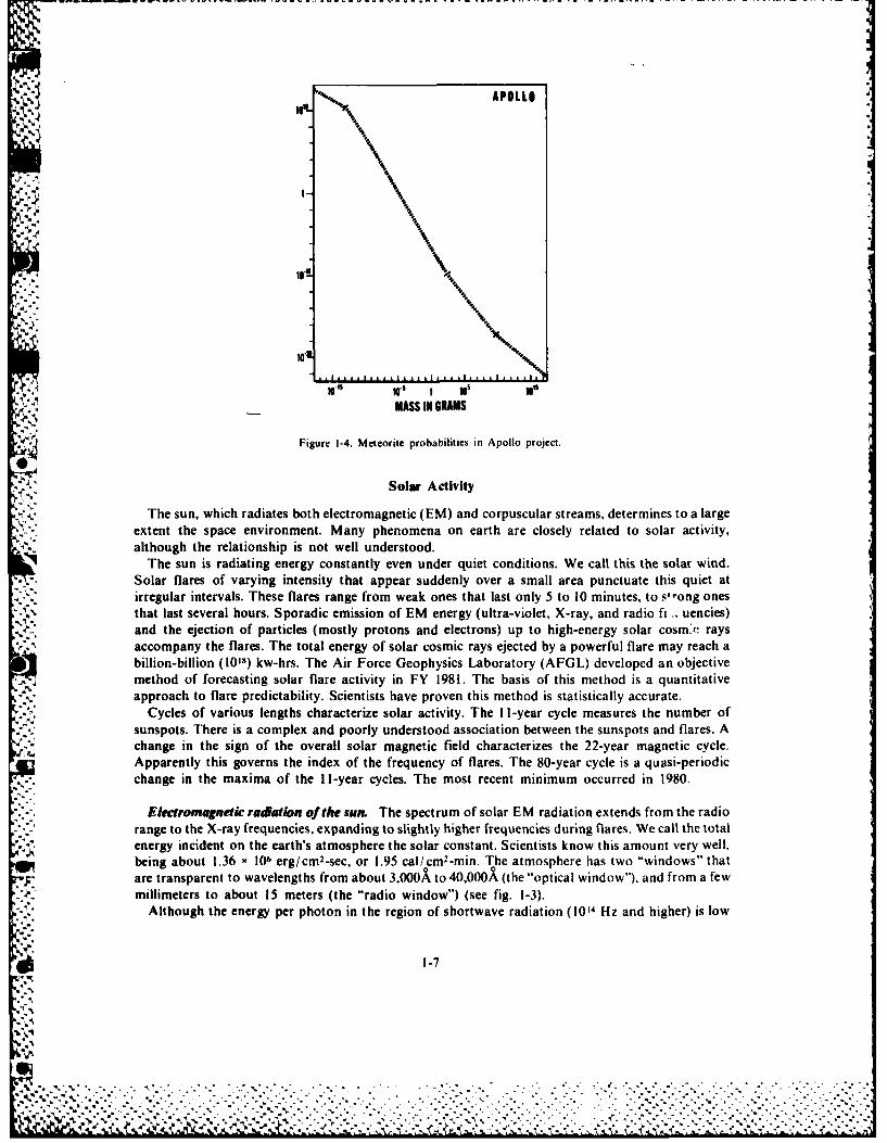
Figure 1-4 provides some idea of the hit probabilities involved in the Apollo project. The basis forthe probabilities is an estimated vehicle cross section of 10 square meters and an exposure of 10 days.The horizontal axis shows mass of the meteoroids or micrometeoroids in grams. About five gramsequals the weight of a nickel. The vertical axis is probability scaled until the axis reaches the figureone. This figure means that a meteoroid or micrometeoroid is certain to hit the vehicle. Above that,the scale means number of hits in a 10-day period. Notice that the probability of collision with a
particle that weighs 10-1 grams is 1.0. This kind of particle would penetrate about 0.05 cm into analuminum skin.
In general, the problem of meteoroid hazard is not as great as was thought, but it is not negligible.IV Space suits and capsules provide protection. The possibility of a catastrophic hit remains: therefore,
scientists are continuing extensive studies.
1-6
% ""."":%"' -?/- "*"" " -.. ","'-"""' '' "" ' """". -"" "'/ ,'" "" . " % - " - '"-"-
APOLLO
J.. "°°r..
10. N.
14-15 10s5 1 105 Ioa
MASS IU GRAMS
Figure 1-4. Meteorite probabilities in Apollo project.
Solar Activity-.. The sun, which radiates both electromagnetic (EM) and corpuscular streams, determines to a large
extent the space environment. Many phenomena on earth are closely related to solar activity,although the relationship is not well understood.
The sun is radiating energy constantly even under quiet conditions. We call this the solar wind.Solar flares of varying intensity that appear suddenly over a small area punctuate this quiet atirregular intervals. These flares range from weak ones that last only 5 to 10 minutes, to s'-ong onesthat last several hours. Sporadic emission of EM energy (ultra-violet, X-ray, and radio ft .. uencies)and the ejection of particles (mostly protons and electrons) up to high-energy solar cosm'r raysaccompany the flares. The total energy of solar cosmic rays ejected by a powerful flare may reach abillion-billion (1018) kw-hrs. The Air Force Geophysics Laboratory (AFGL) developed an objective
J .method of forecasting solar flare activity in FY 1981. The basis of this method is a quantitativeapproach to flare predictability. Scientists have proven this method is statistically accurate.
Cycles of various lengths characterize solar activity. The I I-year cycle measures the number ofsunspots. There is a complex and poorly understood association between the sunspots and flares. Achange in the sign of the overall solar magnetic field characterizes the 22-year magnetic cycle.Apparently this governs the index of the frequency of flares. The 80-year cycle is a quasi-periodicchange in the maxima of the I I-year cycles. The most recent minimum occurred in 1980.
Electromagnetic radiation of the sun. The spectrum of solar EM radiation extends from the radiorange to the X-ray frequencies, expanding to slightly higher frequencies during flares. We call the totalenergy incident on the earth's atmosphere the solar constant. Scientists know this amount very well,being about 1.36 x 10⁶ erg/cM2 -sec, or 1.95 cal/cm2-min. The atmosphere has two "windows" thatare transparent to wavelengths from about 3,000X to 40,000A (the "optical window"), and from a fewmillimeters to about 15 meters (the "radio window") (see fig. 1-3).
Although the energy per photon in the region of shortwave radiation (10 4 Hz and higher) is low
1-7
i° '. ,
.° .,.

compared to the corpuscular ionizing radiation, the total energy transport is much higher due to thegreater flux. This radiation can be very harmful to an unprotected person, and can change the surfaceproperties of various materials.
The radiation received from the sun is constantly changing due to the sun's 27-day rotation period.Since the sur is not a solid, the period of the rotation is really an average. The sun rotates taster nearits equator than at higher latitudes, and the rotation varies with time. We do not know the reasons forthe changes in rotation rates..T he radio emission of the sun is quite complex. The sun emits three general classes of energy in this
frequency range. First, there is a constant background over the whole radio spectrum from the "quiet"sun. Second, there is a slowly changing component related to sunspots. Ihird, there is sporadicemission related to centers of activity, such as flares.
Corpuscular radiation of the sun. We can divide the corpuscular radiation of the sun intoconstant, continuous emission of particles-the solar wind--and sporadic expulsion of intensivestreams of plasma and charged particles-the corpuscular streams and solar cosmic rays. ' hisdivision is arbitrary, reflecting the dependence on time of these types of radiation. It emphasi7es theconstant existence of the solar wind and variations in its velocity and density that never fall below theminimum values of 250km/sec and 0.5 particles/cm3 at the level of the earth's orbit. Scientistsgenerally consider separately, as solar corpuscular streams, the stronger streams of solar plasmaobserved sporadically, that is, the reinforced streams of the solar wind. They introduced this conceptbefore the discovery of the solar wind to explain various geo physical pheno mena that co rrelated withcertain phenomena on the sun. The solar corpuscular streams reach velocities of about 1,600 km/secat particle densities up to 100/cm 3. After their formation, these intense streams move through thequiet. slow portions of the solar wind, disrupt the stable structure of interplanetary space, and causevarious disturbances. The solar wind and corpuscular streams are the most important components ofsolar corpuscular radiation, and determine conditions in interplanetary space.
Solar corpuscular radiation causes the sun to lose an average of a million tons of matter per second,which corresponds to 10-22 solar masses per second, assuming spherical symmetry of the solar wind.However, other published data indicate that the solar wind is not spherically symmetrical.
Another type of corpuscular radiation, solar cosmic rays, consists of high-energy charged particles(from 30 to 50 keV/nucleus to several GeV/nucleus). Recent studies indicate that every brightchromospheric flare on the sun probably generates solar cosmic rays.
Solar cosmic rays are apt tools for the study of interplanetary space. They illuminate the solarsystem and allow determination of its various characteristics. After large solar flares, great fluxes ofsolar cosmic rays sometimes represent a serious radiation danger for space flight.
Solar wind. Because of the high temperature of the sun's corona, protons and electrons beyond acertain distance from the sun acquire velocities in excess of the escape velocity from the sun. I hus thereis a continuous outward flow of charged particles in all directions from the sun. We ca!l this the solarwind. It is a plasma wind, rather than a gas wind. Its velocity and density vary with sunspot activity.During the time of sunspot minimum at the Earth's distance from the Sun, the density is about 100 S.particles per cubic centimeter. The speed is about 300 miles per second. At sutnspot maximum the
. corresponding density is approximately 10,000 particles per cubic centimeter, and the sp l!d is ab1out900 miles per second. When the solar wind encounters the earth's magnetosphere, it flo\s arokind the
magnetosphere, which becomes flattened in the process. On the dark side of the eatth, themagnetosphere becomes elongated.
rhe energy of the particles in the solar wind is not high. We do not expect any ha/aid to the peopleon earth from this wind. However, it is either the cause of or a contributor to. the aurota that
* 41illuminates the polar night sky. Within the past few years, scientists hase combined giound-basedobservations with information that rockets and earth satellites acquired to proNvidc an explanation ofthe previously batfling beauty. The magnetosphere of the earth acts like a giant, ::athod!, ra tube.directing charged particles from the solar wind into beams and focusing them on th alo thb\ polar
V','"
k4~ pg.~p-).pd. . ~~.,, p ... .. ..
regions. The aurora is a fluorescent luminosity produced by the electrons and protons of the solarwind which strike atoms and molecules of oxygen and nitrogen high in the atmosphere of the polarregion.
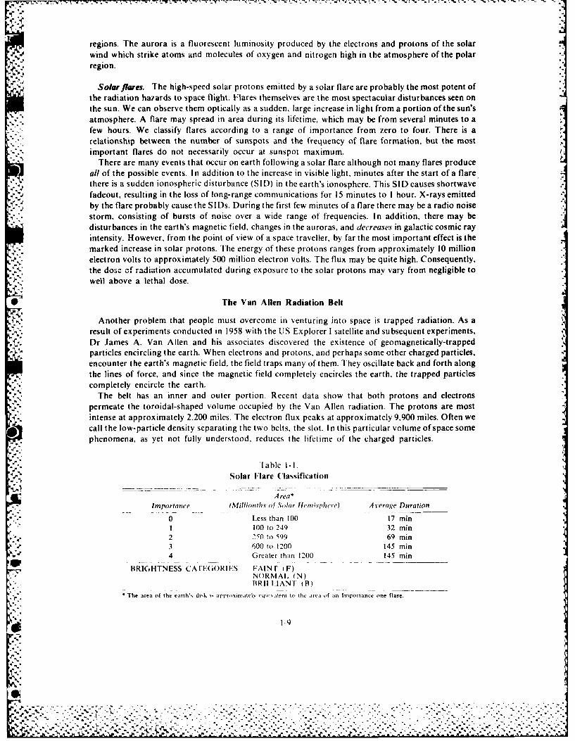
*, r Solarflexes. The high-speed solar protons emitted by a solar flare are probably the most potent ofthe radiation hazards to space flight. Flares themselves are the most spectacular disturbances seen onthe sun. We can observe them optically as a sudden, large increase in light from a portion of the sun'satmosphere. A flare may spread in area during its lifetime, which may be from several minutes to afew hours. We classify flares according to a range of importance from zero to four. There is arelationship between the number of sunspots and the frequency of flare formation, but the mostimportant flares do not necessarily occur at sunspot maximum.
There are many events that occur on earth following a solar flare although not many flares produceall of the possible events. In addition to the increase in visible light, minutes after the start of a flarethere is a sudden ionospheric disturbance (SID) in the earth's ionosphere. This SIL) causes shortwavefadeout, resulting in the loss of long-range communications for 15 minutes to I hour. X-rays emittedby the flare probably cause the SIDs. During the first few minutes of a flare there may be a radio noisestorm, consisting of bursts of noise over a wide range of frequencies. In addition, there may bedisturbances in the earth's magnetic field, changes in the auroras, and decreases in galactic cosmic rayintensity. However, from the point of view of a space traveller, by far the most important effect is themarked increase in solar protons. The energy of these protons ranges from approximately 10 millionelectron volts to approximately 500 million electron volts. The flux may be quite high. Consequently,the dose of radiation accumulated during exposure to the solar protons may vary from negligible towell above a lethal dose.
[ The Van Allen Radiation Belt
Another problem that people must overcome in venturing into space is trapped radiation. As aresult of experiments conducted in 1958 with the US Explorer I satellite and subsequent experiments,Dr James A. Van Allen and his associates discovered the existence of geomagnetically-trappedparticles encircling the earth. When electrons and protons, and perhaps some other charged particles,encounter the earth's magnetic field, the field traps many of them. They oscillate back and forth alongthe lines of force, and since the magnetic field completely encircles the earth, the trapped particlescompletely encircle the earth.
The belt has an inner and outer portion. Recent data show that both protons and electronspermeate the toroidal-shaped volume occupied by the Van Allen radiation. The protons are mostintense at approximately 2.200 miles. The electron flux peaks at approximately 9,900 miles. Often wecall the low-particle density separating the two belts, the slot. In this particular volume of space somephenomena, as yet not fully understood, reduces the lifetime of the charged particles.
" able I-ISolar Flare (lasification
Area*Importance (Millionths of Solar llfpi.vphcre) A verage Duration
0 Less than 100 17 min1 100 to 249 32 min2 250 t 599 69 min3 600 to 1200 145 min4 Greater than 1200 145 min
BRIGH-INESS CAIEGORIES FAIN r (F)NORMAt. (N)BRIILIANT (B)
* The area of the earth', diok i, appr,,xinmatel, cqm aleni to the a ,of an ImpoTlance one nare.
'--9
'.V'.: ; . . ..:. -. ,,. .- .- .- .v .. .-- . . .. . . - .. - .. - -- .. -. ;- -;-: - . .. .- ,-.-
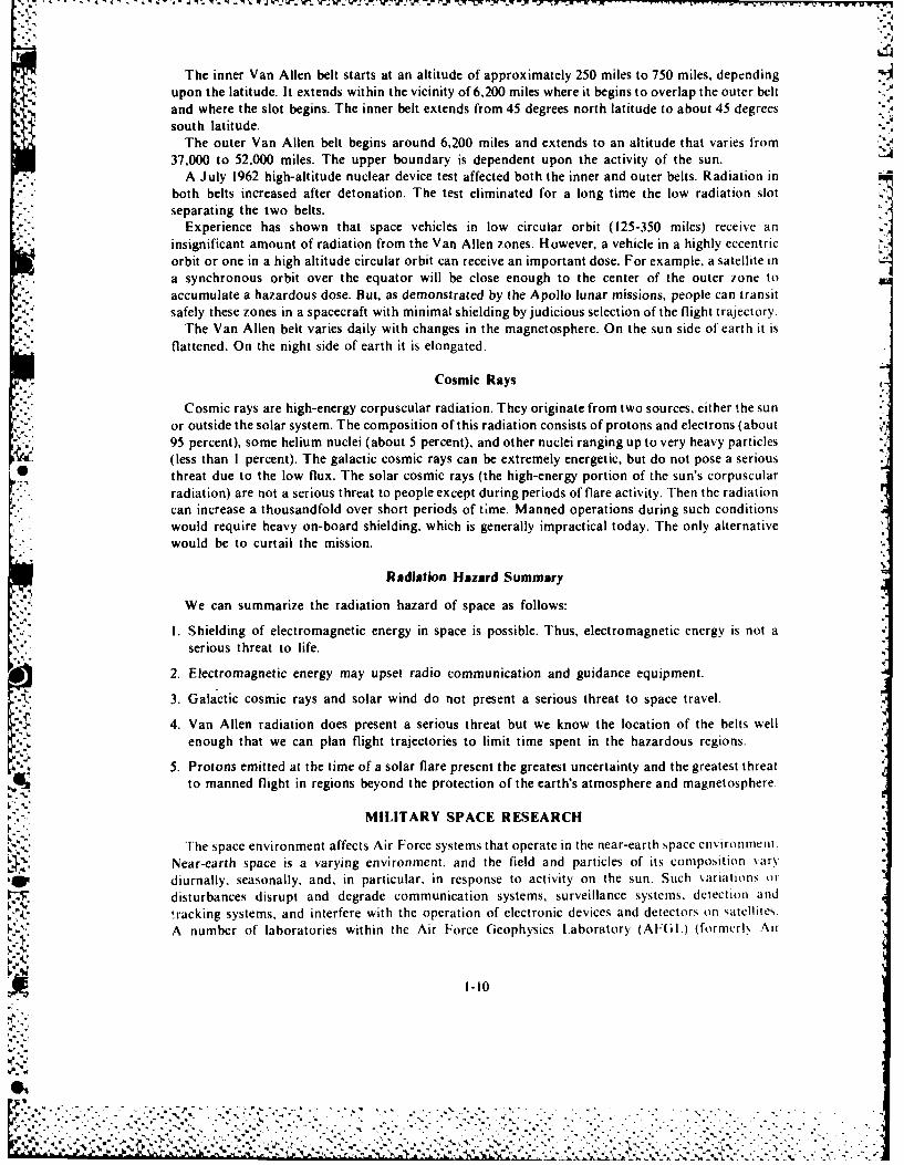
*The inner Van Allen belt starts at an altitude of approximately 250 miles to 750 miles, dependingupon the latitude. It extends within the vicinity of 6,200 miles where it begins to overlap the outer beltand where the slot begins. The inner belt extends from 45 degrees north latitude to about 45 degreessouth latitude.
The outer Van Allen belt begins around 6,200 miles and extends to an altitude that varies from37,000 to 52,000 miles. The upper boundary is dependent upon the activity of the sun.
A July 1962 high-altitude nuclear device test affected both the inner and outer belts. Radiation inboth belts increased after detonation. The test eliminated for a long time the low radiation slotseparating the two belts.
Experience has shown that space vehicles in low circular orbit (125-350 miles) receive aninsignificant amount of radiation from the Van Allen zones. However, a vehicle in a highly eccentricorbit or one in a high altitude circular orbit can receive an important dose. For example, a satellite ina synchronous orbit over the equator will be close enough to the center of the outer zone to
,- accumulate a hazardous dose. But, as demonstrated by the Apollo lunar missions, people can transit"-4 safely these zones in a spacecraft with minimal shielding by judicious selection of the flight trajectory.
The Van Allen belt varies daily with changes in the magnetosphere. On the sun side of earth it isflattened. On the night side of earth it is elongated.
Cosmic Rays
Cosmic rays are high-energy corpuscular radiation. They originate from two sources, either the sunor outside the solar system. The composition of this radiation consists of protons and electrons (about95 percent), some helium nuclei (about 5 percent), and other nuclei ranging up to very heavy particles(less than I percent). The galactic cosmic rays can be extremely energetic, but do not pose a serious
threat due to the low flux. The solar cosmic rays (the high-energy portion of the sun's corpuscularradiation) are not a serious threat to people except during periods of flare activity. Then the radiationcan increase a thousandfold over short periods of time. Manned operations during such conditionswould require heavy on-board shielding, which is generally impractical today. The only alternativewould be to curtail the mission.
Radiation Hazard Summary
We can summarize the radiation hazard of space as follows:
I. Shielding of electromagnetic energy in space is possible. Thus, electromagnetic energy is not aserious threat to life.
2. Electromagnetic energy may upset radio communication and guidance equipment.
3. Galactic cosmic rays and solar wind do not present a serious threat to space travel.
4. Van Allen radiation does present a serious threat but we know the location of the belts wellenough that we can plan flight trajectories to limit time spent in the hazardous regions.
5. Protons emitted at the time of a solar flare present the greatest uncertainty and the greatest threatto manned flight in regions beyond the protection of the earth's atmosphere and magnetosphere.
MILITARY SPACE RESEARCH
The space environment affects Air Force systems that operate in the near-earth space enironfient.
Near-earth space is a varying environment, and the field and particles of its composition sarv
diurnally, seasonally, and, in particular, in response to activity on the sun. Such variations or
disturbances disrupt and degrade communication systems, surveillance systems, detection and
-racking systems, and interfere with the operation of electronic devices and detectors on satellites.A number of laboratories within the Air Force Geophysics Laboratory (AFGI.) (forncrl. Air
1-10
a,.J. [ . .,, .- - - .-,.--.,- -............... ,,..............
• % -- ' .' .- '. ;' "." - " .* . :'. . -. '. -'-. . '."" - . a .' - "' - "--,- '-. --"'.- ".-.. '. . "'. " ';
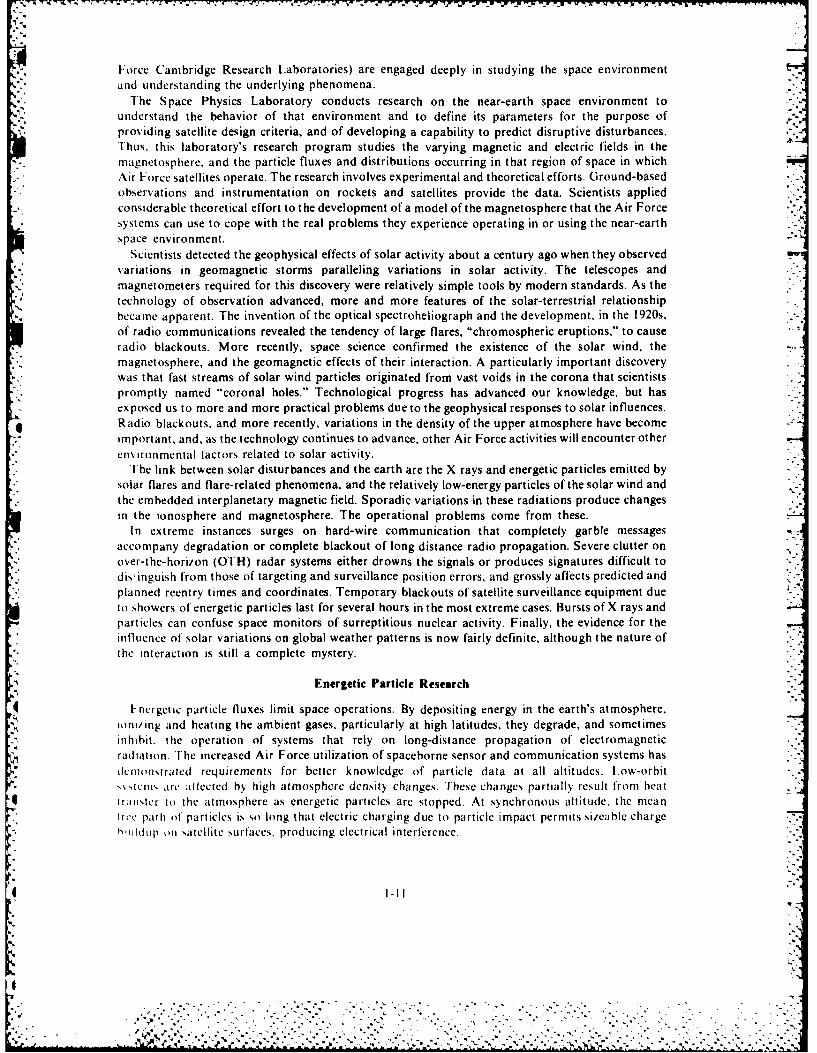
Force Cambridge Research Laboratories) are engaged deeply in studying the space environmentand understanding the underlying phenomena.
The Space Physics Laboratory conducts research on the near-earth space environment tounderstand the behavior of that environment and to define its parameters for the purpose ofproviding satellite design criteria, and of developing a capability to predict disruptive disturbances.Thus, this laboratory's research program studies the varying magnetic and electric fields in themagnetosphere, and the particle fluxes and distributions occurring in that region of space in whichAir Force satellites operate. The research involves experimental and theoretical efforts. Ground-based
- observations and instrumentation on rockets and satellites provide the data. Scientists appliedconsiderable theoretical effort to the development of a model of the magnetosphere that the Air Forcesystems can use to cope with the real problems they experience operating in or using the near-earthspace environment.
Scientists detected the geophysical effects of solar activity about a century ago when they observed- variations in geomagnetic storms paralleling variations in solar activity. The telescopes and'-. magnetometers required for this discovery were relatively simple tools by modern standards. As the
technology of observation advanced, more and more features of the solar-terrestrial relationshipbecame apparent. The invention of the optical spectroheliograph and the development, in the 1920s,of radio communications revealed the tendency of large flares, "chromospheric eruptions," to cause
. radio blackouts. More recently, space science confirmed the existence of the solar wind, the% magnetosphere, and the geomagnetic effects of their interaction. A particularly important discovery
* . was that fast streams of solar wind particles originated from vast voids in the corona that scientists* promptly named "coronal holes." Technological progress has advanced our knowledge, but has
exposed us to more and more practical problems due to the geophysical responses to solar influences.Radio blackouts, and more recently, variations in the density of the upper atmosphere have become
* important, and, as the technology continues to advance, other Air Force activities will encounter otherenvironmental factors related to solar activity.
The link between solar disturbances and the earth are the X rays and energetic particles emitted bysolar flares and flare-related phenomena, and the relatively low-energy particles of the solar wind andthe embedded interplanetary magnetic field. Sporadic variations in these radiations produce changesin the ionosphere and magnetosphere. The operational problems come from these.
In extreme instances surges on hard-wire communication that completely garble messagesaccompany degradation or complete blackout of long distance radio propagation. Severe clutter onover-the-horizon (OTH) radar systems either drowns the signals or produces signatures difficult todis: inguish from those of targeting and surveillance position errors, and grossly affects predicted and -
planned reentry times and coordinates. Temporary blackouts of satellite surveillance equipment dueto showers of energetic particles last for several hours in the most extreme cases. Bursts of X rays andparticles can confuse space monitors of surreptitious nuclear activity. Finally, the evidence for theinfluence of solar variations on global weather patterns is now fairly definite, although the nature ofthe interaction is still a complete mystery.
Energetic Particle Research
Fnergetic particle fluxes limit space operations. By depositing energy in the earth's atmosphere.ioni/ing and heating the ambient gases, particularly at high latitudes, they degrade, and sometimes
inhibit, the operation of systems that rely on long-distance propagation of electromagneticradiatton. The increased Air Force utilization of spaceborne sensor and communication systems hasdcmon,trated requirements for better knowledge of particle data at all altitudes. L.ow-orbit'ANtcrtw arc aftected by high atmosphere den.sity changes. rhese changes partially result from heattran,,Icr to the atmosphere as energetic particles are stopped. At synchronous altitude, the meanlicc path ol particles is so long that electric charging due to particle impact permits simable charge ."'
hiilIdup on satellite surfaces, producing electrical interference.
I-I
................................................................ . *
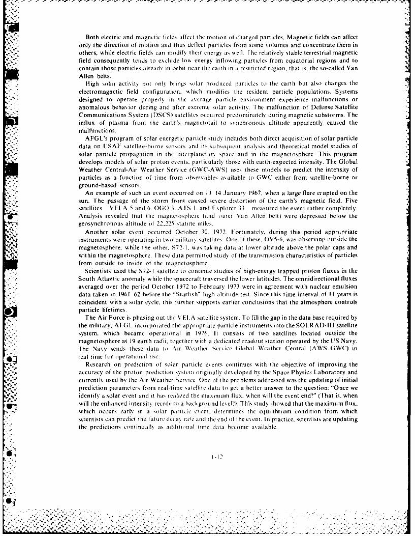
Both electric and magnetic fields affet the motion of charged particles. Magnetic fields can affectonly the direction of motion and thus deflect particles from some volumes and concentrate them inothers, while electric fields can modify their energ as well. Ihe relatively stable terrestrial magneticfield consequently tends to exclude low energy inflo%%ing particles from equatorial regions and tocontain those particles already in orbit near the eaith in a restricted region, that is, the so-called VanAllen belts.
High solar activitv not onlv brings solar produced particles to the earth but also changes the
electromagnetic field configuration, which modifies the resident particle populations. Systemsdesigned to operate properly in the a\erage particle enironment experience malfunctions oranomalous behavior during and after extreme solar activity. The malfunction of Defense SatelliteCommunications System (DSCS) satellites occurred predominately during magnetic substorms. Theinflux of plasma from the earth's inagnctotail to synchronous altitude apparently caused themalfunctions.
AFGL's program of solar energetic particle study includes both direct acquisition of solar particledata on USAF satellite-borne sensors and its s uhscquent analysis and theoretical model studies ofsolar particle propagation in the interplanetary space and in the magnetosphere This programdevelops models of solar proton events, particularlv those with earth-expected intensity. The GlobalWeather Central-Air Weather Service (GWC-AWS) uses these models to predict the intensity ofparticles as a function of time from observables axailable to GWC either from satellite-borne orground-based sensors.
An example of such an event occurred on 13 14 January 1967, when a large flare erupted on thesun. The passage of the storm front caused severe distortion of the earth's magnetic field. Fivesatellites VEI.A 5 and 6, O(() 3, AIS I, and Explorer 33 measured the event rather completely.Analysis rexealed that the magnetosphere (and outer Van Allen belt) were depressed below thegeosynchronous altitude ol 22.225 statute miles.
Another solar event occurred October 30, 1972. Fortunately, during this period apprurriateinstruments were operating in tvk o militai v satellites. One of these, OV5-6. was observing outside themagnetosphere. while the other, S72-1, was taking data at lower altitude above the polar caps andwithin the magnetosphere. Ihese data permitted study of the transmission characteristics of particlesfrom outside to inside of the magnetosphere.
Scientists used the S72-1 satellite to continue studies of high-energy trapped proton fluxes in theSouth Atlantic anomaly while the spacecraft traversed the lower latitudes. The omnidirectional fluxesaveraged over the period October 1972 to February 1973 were in agreement with nuclear emulsiondata taken in 1961 62 before the "Starfish" high altitude test. Since this time interval of II years is
, ;coincident with a solar cycle, this further supports earlier conclusions that the atmosphere controlsparticle lifetimes.
The Air Force is phasing out the VEI.A satellite system. To fill the gap in the data base required bythe military, AFG. incorporated the appropriate particle instruments into the SOLRAD-HI satellitesystem, which became operational in 1976. It consists of two satellites located outside themagnetosphere at 19 earth radii, together sith a dedicated readout station operated by the UIS Navy.I'he Navy sends these data to Air Weather Service (;lobal Weathcr Central (AWSGWC) inreal time for operational use.
Research on prediction of solar particle esents continues with the objective of improving theaccuracy of the proton prediction sxsteni originally developed by the Space Physics Laboratory and
currently used by the Air Weather Service One of the problems addressed was the updating of initialprediction parameters from real-time satellite data to get a better answer to the question: "Once weidentify a solar event and it has reali/ed the maximum flux. when will the event end?" (That is, whenwill the enhanced intensity recede to a background leel?). Ihis study showed that the maximum flux.which occurs early in a solar particle c~ent, determines the equilibrium condition from whichscientists can predict the future dcca% rate and the end of the esent. In practice. scientists are updatingthe predictions cont inuallv as additional time data become available.
.1.2-.,
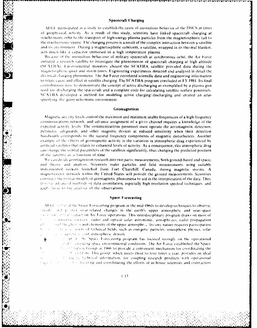
Spacecraft Charging
Al I I pa I I( paled Iin at st lid N to cstahblish Ithle ca use (it anomalous behia ior- ot th lie D(5 at timeisof gcoph\ sical itcti it\. As at result of this study, scientists have linked spacecraft charging atSN trehriois orhi to the t ransport of hg-energy plasma particles from the magnetospheric tail toitic sN aci mi ous , egimec. I hie charging process is a result of the complex interaction between a satellite
4and itN cit ron ieat lDuiIng a miagnetospheric su bstorm, a satellite, wrapped in its t hermnal blanket.acts mauch like I Lipaitor10 immersed in a high temperature plasma.
liscao [ic aittomritis behlax our of' military spacecraft at synchronous orbit, the Air Foreiliti tted a scvc satellite to investigate the phenomenon of spacecraft charging at high altitudeS( At Ifl\. I-m~itoninttal monitors aboard the SCATHA satellite provided data (luring themaIw1a'IjIpj1li it i rt and storm times. Engineering experiments detected and analyied in detail the
cl., ira., al chari ing phenomena. I hie Air Force correlated scientific data and engineering infor mationto relte cas and effe'ct inl Satellite charging. The SCATHA program concluded Ii FY 198 1. Its final
hit luions cr (1c to demonstrate thle concept of active discharging as exemplified by a plasma guniiised to( disk harging the spacecraft and a complete code for calculating satellite surface potentials.S(A I lf.\ dc% eloped a mnethod for modeling active charging,,discharging and created an atlasspecit\ing I lie geosv nchroiious environment.
Ceomagnetism
Magnectic aci.A lt. lexels control the maximum and minimum usable frequencies of'a high frequencycoiitnicatitils nit ark, and advance assignment of a given channel requires a knowledge of' theCX[)peeled acti\ lx C\ eS. [he comimu nicat ions personnel must operate the aeromagnetic detection,
* perimeti -ifteguads, and other magnetic devices at reduced sensitivity when their detectionhaald\ dih ~I. crrsponlds to the natural frequency components of magnetic disturbances. Anothercxalinpic I)! he,, ctled of geomlagnetic actix ity is the variation in atmospheric drag experienced bN
*~,, ,,tti it rclite5 t hat I elates to enhianced levels of activity. As a consequence, this atmospheric drag-IlIl~lige the Ili h~tal par ameiters of the satellites significantly, thus changing the predicted position
% liat the Nsl.11cit as ar finaction ot time." L i~ dieid igeomitgai.srnl research into two parts: measurements, both ground-based and space,
and hlcai s anid allilivs! Scientists make particles and field measurements using suitablyns( L Iu~ttedl i ackets launched from [ort Churchill. Canada. (during magnetic strirms. Aliiigirl~llc- meternet s ork \kithin the U nited States will provide the groundl measurements. scientists
wi i.hc.. ii im.dels atl geomagnetic phenomena to aid in the interpretation of the data. I hey.1d tic IkI dl af data assimilation, especially high resolution spectral techniques, and
.pl :liil Il hit (irhs~ t the observations.
Space F'orecasting
*\I m. .. . 1( akt Ic l cirting program Ii the mnid-1lOs to des elop tchniqacs to observe.1t .. i'. Ir relted changes Ii the eart h's tipper at mosphere and( near-space
* I f.r.1 M '\ Xii V or cc operat ions I his interd iseipl inar,, program drtay. s oil most ofa ma.iadr and optical sorlar astrononlN. as trap h~sics, ad io propagation
I" lk " IAll ,heniirslrs ri h ipper at nrosphi- Its %er' nature requrspttcpt~1 'A 1 1 etchMaiat fields, such ats errerget ic particles, ionospheric physics, solar
oi . id atmospheric densrtNIV ;i I 'spateL I oretasting progani has tenused sitng ' N ll the iqperational
I .i.~c~ig pa,. cnmixirnnenial conditions [ he Ai Urrice established the Space" .10 ((11 rip a1966 ito pros ide a eonsenienit mechanism lt cooritfinatitig the
Y 't I hi groupi11 % fsillh meets, threec to tour t imes a \sear. pr o\ Ides an idealk' htrmal itormiatiri. tar erupting research prod ucts Is ith operational
1t iinv aid coordinitting the etfrts at irn-house scientists atnd kmntr actors

working in a broad spectrum of related scientific disciplines. In addition to the AFGL task scientists,representatives from Air Weather Service, National Oceanic and Atmospheric Administration(NOAA), Naval Research Laboratory (NRL), Electronic Systems Division (ESD), and SpaceDivision of the Air Force Systems Command are periodically invited to participate at these meetingsto coordinate related activities within their organizations.
Space forecasters face the task of predicting the occurrence of bursts of electromagnetic radiationand energetic particles from the sun, and specifying the effects of these bursts on the earth'satmosphere. These effects include absorption of radio waves in the ionosphere, geomagneticdisturbances, auroral activity, enhanced airglow levels, and atmospheri- density variations.
Through the efforts of the Space Forecasting Coordination Group, the Air Force has identifiedspecific problem areas related to existing and planned operational space environmental supportrequirements and initiated programs to solve them.
Solar Radio Astronomy Research
Research has shown that one of the best tools for studying solar activity is the radio emission.Apart from the spectrally narrow optical region, radio offers the only other spectral window for solarobservations from the ground. Its quantitative data provide reliable predictors for geophysicalphenomena. Continuing research provides an increasing number of associations, which help inunderstanding the mechanisms of the sun.
A balanced program of research satisfies operational needs by providing significant observationaldata and by investigating how the data are correlated with ionospheric and geophysical parameters.The solar radio astronomy research program at AFGL makes patrol-type (low angular resolution)measurements of the quiet sun and bursts, and high resolution measurements of active regions.
Absolute accuracy in the measurement of quiet-sun radio emission has become an operationalnecessity. The slowly varying component of solar radio emission relates well to atmospheric neutraldensity, which causes drag on space vehicles. Therefore, radio data provide an input to satelliteposition calculations. Recent results indicate that longer or shorter wavelength data may, at certainperiods of the solar cycle, lead to better neutral-density predictions than the use of the traditional 10-cm wavelength data. The DOD widely uses the quiet-sun data for calibration of DOD telemetry-range antenna systems an a routine basis. For this application, the calibrators require day-to-dayconsistency and maintenance of this patrol data.
The Air Weather Service, through its Space Environmental Support System (SESS), disseminatesthe data. AFGL works closely with AWS in both operational and research applications. SagamoreHill is the principal station of the Air Force solar radio network, continuously developing techniquesand providing calibration for the other stations. A second generation solar radio network known asthe Radio Solar Telescope Network (RSTN) is in the procurement stage, with AFGL responsible forengineering direction. Partly completed stations of the network at Manila, Athens, and Hawaii (allinstrumented by AFGL) now complement the Sagamore Hill station.
BIB LI OGRAPH Y
Air Force Cambridge Research Laboratories. A FCRl. in Space. Bedford. Mass.: Office of Aerospace Research, 1967.Report on Research at AFCRL. July 1972-1974. AFCRL-TR-75-0288, May 1975.
Calin. Melkin and Oleg G. Gacnko. ed. Foundations of Space Biologir and Medicine. NASA Scientific and Technical
Information Office, Washington. D.C.: US Government Printing Office, 1975.Cosby, William A. and Robert G. lyle. The Meteoroid Environment and its Effects on Materials and Equipment. Washington,
D.C US Government Printing Office, 1965.Farris. Robert H. The Problem of Delimitation in Space Law. PhD Diss., Notre Dame University. 1974.Flinders. Dale J "The Space Forecasting System Confluence of Military and Scientific Interests." Air University Review
(November-December 1969) 37 50.Fourth Weather Wing. 4WWM 105-1. Foreiasting Solar Activities and Geophysical Responses. Solar Forecasting Facility
Headquarters. I[nt Al-B. (olo, 28 Junc 1968.
1-14
4"...

Fourth Weather Wing, 4WWP l05-1. Guide to Solar Geophi-sical Ac-tivity. 4WW Headquarters. Ent AFB, Col..I February 1969.
Glasstone. Samuel. Sourcehook on the Space Sciences. New York: D. Van Nostrand Co.. 1965.* Howard. Robert. "The Rotation of the Sun." Scientific American. (April 1975):106 114.
Office of Aerospace Research. "The Videometer, a New Instrument for Solar Flare Analysis.- OAR Research Review. vol. 9.no. I (1970):7.
Parker. E.N. -The Sun." Scientific American. (September 1975):42 50.Seaborn, H.T.. ed. TRW Space Log. vol 8, no. 3 (Fall 1968).-State Department Monitors Sovereignty Claim." Aviation Week and Space Technology. (20 December 1976):29.
* Van Allen. James A. "Interplanetary Particles and Fields." Scientific American. (September 1975):160 173.Zimmerman. Frank J. Meteoroid Threat to Extra vehicular Spacesuite Assemblies. Aerospace Medical Research L~aboratory.
AFSC. Wright-Patterson AFB, Ohio. AMRL-TR-68-86, June 1969.
%Np.%
ORBITAL MECHANICS
The study of trajectories and orbits of vehicles in space is not a new science but is the applicationof the concepts of celestial mechanics to space vehicles. Celestial mechanics, which is mainly concernedwith the determination of trajectories and orbits in space, has been of interest to people for a longtime. When the orbiting bodies are man-made (rather than celestial), the topic generally is known asorbital mechanics.
The early Greeks postulated a fixed earth with the planets and other celestial bodies moving aroundthe earth, a geocentric universe. About 300 B.C., Aristarchus of Samos suggested that the sun was
1% fixed and that the planets, including the earth, were in circular orbits around the sun. BecauseAristarchus' ideas were too revolutionary for his day and age, the people rejected them, and thegeocentric theory continued to be the accepted theory. In the second century A.D., Ptolemy amplifiedthe geocentric theory by explaining the apparent motion of the planets by a "wheel inside a wheel"
0 arrangement. According to this theory, the planets revolve about imaginary planets, which in turnrevolve around the earth. It is surprising to note that, even though Ptolemy considered the system asgeocentric, his calculations of the distance to the moon were in error by only 2 percent. Finally, in theyear 1543, some 1800 years after Aristarchus had proposed a heliocentric (sun-centered) system, aPolish monk named Copernicus published his De Revolutionibus Orbium Coelesium, which again
* proposed the heliocentric theory. This work represented an advance, but there were still some
inaccuracies in the theory. For example, Copernicus thought that the orbital paths of all planets werecircles and that the centers of the circles were displaced from the center of the sun.
The next step in the field of celestial mechanics was a giant one made by a German astronomer,Johannes Kepler (1571-1630). After analyzing the data from his own observations and those of theDanish astronomer Tycho Brahe, Kepler stated his three laws of planetary motion.
A contemporary of Kepler's, named Galileo, proposed some new ideas and conducted experiments,the results of which finally caused acceptance of the heliocentric theory. Newton expanded andimproved some of Galileo's ideas. These became the foundation for Newton's three laws of motion.
Newton's laws of motion, with his law of universal gravitation, made it possible to provemathematically that Kepler's laws of planetary motion are valid.I
Kepler's and Newton's work brought celestial mechanics to its modern state of development, andthe major improvements since the days of Newton have been mainly in mathematical techniques,which make orbital calculations easier.
Because the computation of orbits and trajectories is the basis for predicting and controlling themotion of all bodies in space, this chapter describes the fundamental principles of orbital mechanics,which is the basis for these computations. It shows how these principles apply to the orbits andtrajectories used in space operations.
MOTION OF BODIES IN ORBIT
Bodies in space move in accordance with defined physical laws. We can analyze orbital paths byapplying these laws to specific cases. Orbital motion is different from motion on the surface of the
2-1
%i1-6
w%

earth. However, we can transfer many concepts and terms, and we can apply similar logic in bothcases. An understanding of simplified linear and angular motion will permit a more thoroughappreciation of a satellite's path in space.
- '* Linear Motion
We observe bodies in space to be continuously in motion because they are in different positions atdifferent times. In describing motion, it is important to use a reference system. Otherwise,misunderstanding and inaccuracies are likely to result. For example, a passenger on an airliner maysay that the stewardess moves up the aisle at a rate of about 5 ft per sec, but, to the person on theground, the stewardess moves at a rate of the aircraft's velocity plus 5 ft per sec. The person in the airand the person on the ground are not using the same reference system. Describing movement along astraight line, called rectilinear motion, will simplify the matter of a reference system for the present.
We can describe rectilinear motion in terms of speed, time, and distance. Speed is the distancetraveled in a unit of time, or the time rate of change of distance. An object has uniform speed when it
moves over equal distances in equal periods of time. Speed does not describe motion completely. We
can describe motion more accurately if we give a direction as well as a speed. A speedometer tells howfast an automobile is going. If we associate a direction with speed, we can describe the motion as avelocity. A velocity has both a magnitude (speed) and a direction, and it is a vector quantity.
Uniform speed in a straight line is not the same as uniform speed along a curve. If a body has5j s"
uniform motion along a straight line for a given time, the equation v t.- represents velocity.In the equation, s. is the initial position, sf is the final position, t. is the initial time, and tf is the final
time. More simply, the velocity is the change in position divided by the change in time. The unitsof velocity are distance divided by time, such as feet per second or knots (nautical miles per hour).*
Since velocity is a vector quantity, we may treat it mathematically or graphically as a vector.If velocity is not constant from point to point (that is, if either direction or speed is changed),
there is acceleration. Acceleration, which is also a vector quantity, is the time rate of change of4 velocity. The simplest type of acceleration is one in which the motion is always in the same direction,
and the velocity changes equal amounts in equal lengths of time. If this occurs, the acceleration isconstant, and we can describe the motion as being uniformly accelerated.
The equation a., = defines the average acceleration, over the specified time interval.
A good example of a constant acceleration is that of a free-falling body in a vacuum near thesurface of the earth. Scientists have measured this acceleration as approximately 32.2 ft per secper sec, or 32.2 ft per sec2. We usually give it the symbol g. Since an acceleration is a change in velocityover a period of time, its units are ft/sec2, or more generally, a length over a time squared. Actually,constant acceleration rarely exists, but we can adapt the concepts of constant acceleration tosituations where the acceleration is not constant.
The following three equations are useful in the solutions of problems involving linear motion:
1. s = t4at2
2. vf v,+ at
3. 2as = V( V-
where s is linear displacement, v,, is initial linear velocity. vf is final linear velocitv, a is constant~. -'linear acceleration, and t is the time interval.
*The nauticai mile (NMi) is one minute of a great circle and is approximately 6.08(0 feet or LI S Niatutc infles
* 2-2
.@ . . .. .
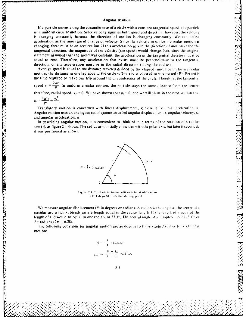
Angular Motion
If a particle moves along the circumference of a circle with a constant tangential speed, the part icleis in uniform circular motion. Since velocity signifies both speed and direction. howeer, the velocityis changing constantly because the direction of motion is changing constantly. We can defineacceleration as the time rate of change of velocity. Since the velocity in uniform circular motion ischanging, there must be an acceleration. If this acceleration acts in the direction of motion called thetangential direction, the magnitude of the velocity (the speed) would change. But. since the original
statement assumed that the speed was constant, the acceleration in the tangential direction must beequal to zero. Therefore, any acceleration that exists must be perpendicular to the tangentialdirection, or any acceleration must be in the radial direction (along the radius).
Average speed is equal to the distance traveled divided by the elapsed time. For uniform circularmotion, the distance in one lap around the circle is 2Trr and is covered in one period (P). Period isthe time required to make one trip around the circumference of the circle. Therefore, the tangential
2irrr -speed v, =--p-- In uniform circular motion, the particle stays the same distance from the center.
therefore, radial speed, v, = 0. We have shown that a, 0; and we A, ill shoA in the next section that
a 4r 2r v,2
Angular motion uses an analogous set of quantities called angular displacemient. 0; angular ,elocitN., .;
and angular acceleration, a.In describing angular motion, it is convenient to think of it in terms of the rotation of a radius
arm (r), as figure 2-1 shows. The radius arm initially coincided with the polar axis, but later(t seconds),it was positioned as shown.
r s- r
I= 1 radian
0
Figure 2-1. Position of radius arm as rolaed one radian(57.3 degrees) from the starting pomt
We measure angular displacement (0) in degrees or radians. A radian is the angle at the center of acircular arc which subtends an arc length equal to the -adius length. If the length of s equaled thelength of r, 0 would be equal to one radian, or 57.30 . The central angle of a complete circle is 360> or27r radians (27r = 6.28).
The following equations for angular motion are analogous to those Audied cmrht tl rc-tilinearmotion:
0 - radiansr
06 - ,
-~, -- t rad se:tj to
2-3
............................ ,.--: ., .. '--,,.-,............ ..'-.- ........ ..... •. ..-..........- .... .. r.,. ........... , -.. '. . . - . , - . . , ' . - . -. . .... ,,
% % .. .. .. ..
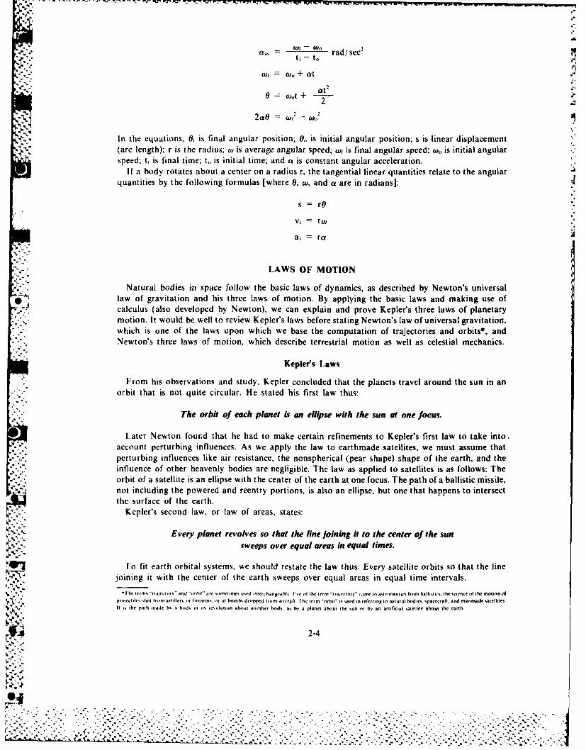
K-f - W
a35 = Of W0 rad/ see'tI - to
cut = t+ at" " "-" of = (,, + a
' 0 = ,,,att + -- -;
- 2 tf = 2 - o2
* In the equations, 01 is final angular position; 0. is initial angular position; s is linear displacement1' (arc length); r is the radius; ow is average angular speed; wr is final angular speed; ow,, is initial angular
speed, tt is final time; to is initial time; and at is constant angular acceleration.If a body rotates about a center on a radius r, the tangential linear quantities relate to the angular
quantities by the following formulas [where 0, w, and a are in radians]:
s rO
Vt rw
at ra
LAWS OF MOTION
Natural bodies in space follow the basic laws of dynamics, as described by Newton's universallaw of gravitation and his three laws of motion. By applying the basic laws and making use ofcalculus (also developed by Newton), we can explain and prove Kepler's three laws of planetarymotion. It would be well to review Kepler's laws before stating Newton's law of universal gravitation,which is one of the laws upon which we base the computation of trajectories and orbits*, andNewton's three laws of motion, which describe terrestrial motion as well as celestial mechanics.
Kepler's Laws
From his observations and study, Kepler concluded that the planets travel around the sun in anorbit that is not quite circular. He stated his first law thus:
The orbit of each planet is an ellipse with the sun at one focus.
Later Newton found that he had to make certain refinements to Kepler's first law to take into.account perturbing influences. As we apply the law to earthmade satellites, we must assume thatperturbing influences like air resistance, the nonspherical (pear shape) shape of the earth, and theinfluence of other heavenly bodies are negligible. The law as applied to satellites is as follows: Theorbit of a satellite is an ellipse with the center of the earth at one focus. The path of a ballistic missile,not including the powered and reentry portions, is also an ellipse, but one that happens to intersectthe surface of the earth.
Kepler's second law, or law of areas, states:
Every planet revolves so that the line joining it to the center of the sunsweeps over equal areas in equal times.
To fit earth orbital systems, we should restate the law thus: Every satellite orbits so that the linejoining it with the center of the earth sweeps over equal areas in equal time intervals.
f he terms "troletirs" and "orbit" are sometrimes used ntercthangcahl I %r. of the term "tralectory" came to astronautics from ballistics, the science of the motion ofproectiles shot from artillerm ot lirearms. or of homh dropped from aircraft I he term "orbit is used in referring to natural bodes. spacecraft, and manmade satelltesIt is the path made bs a hod, in its reolutiin about another bods. as hb a planet about the sun or bv an artificial satellite about the earth
2-4
: " "" " " "'" " " "" .. '" ."% " " """. ." ""' " " "" . " ' . ." "' ~ • " "% " " . .. ' '""" -'' " -
r ." , . .... .. .. .. . .,,.,,,' ... . . .- , . , . .. " .' ., .. . . -, .. .'. '. ". " '" " .- ,. , ,.", .. . . . . ,., -. , .... .,., ". • .- . ., ,- ...
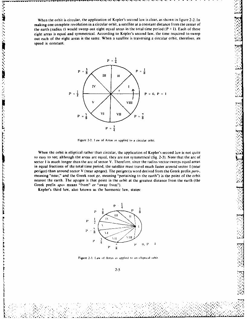
When the orbit is circular, the application of Kepler's second law is clear, as shown in figure 2-2. Inmaking one complete revolution in a circular orbit, a satellite at a constant distance from the center of
* ~the earth (radius r0 would sweep out eight equal areas in the total time period (P = ). Each of these .:'.
eight areas is equal and symmetrical. According to Kepler's second law, the time required to sweepout each of the eight areas is the same. When a satellite is traversing a circular orbit, therefore, its3 speed is constant.
P 3 1
rP P 0 t, P I1
P 3
Figure 2-2- Law of Areas as applied to a circular orbit.
When thc orbit is elliptical rather than circular, the application of Kepler's second law is not quiteso easy to see; although the areas are equal, they are not symmetrical (fig. 2-3). Note that the arc ofsector I is much longer than the arc of sector V. Therefore, since the radius vector sweeps equal areas
- in equal fractions of the total time period, the satellite must travel much faster around sector I (near* perigee) than around sector V (near apogee). The perigee (a word derived from the Greek prefix peri-,
meaning "near," and the Greek root ge, meaning "pertaining to the earth") is the point of the orbit* nearest the earth. The apogee is that point in the orbit at the greatest distance from the earth (the
Greek prefix apo- means "from" or "away from").Kepler's third law, also known as the harmonic law, states:
P
P
\l.- 8\l
Figure 2-3 Law of Areais as appiedl to an ellipticail orhit.7
2-5
A.~, AV -A-
The squares of the sidereal periods' of any two planets are toeach other as the cubes of their mean distances from the center of the suit
To fit an earth orbital system, we should restate Kepler's third law as follows: the squares of the* periods of the orbits of two satellites are proportional to each other as the cubes of their mean
distances from t he center of the earth. The mean distance is the length of the semimajor axis (a) of theellipse, which is an average of the distances to perigee and apogee. In a circular orbit, the mean -
= distance is the radius, r.
Newton's Laws
While Kepler was working out his three laws of planetary motion, Galileo, an Italian physicist and ,Lastronomer, was studying the effects of gravity on falling bodies. Newton drew upon the work of both
-' Kepler and Galileo to formulate his laws of motion.Newton's first law states:
Every body continues in a state of rest or of uniform motion in a straight line,unless it is compelled to change that state by a force imposed upon it.
In other words, a body at rest tends to remain at rest, and a body in motion tends to remain inmotion unless an outside force acts upon it. We refer to this law sometimes as the law of inertia.
The second law of motion as stated by Newton says:
When a force is applied to a body, the time rate of change of momentum* is proportional to, and in the direction of, the applied force.
If the mass remains constant, we can write this law as F = Ma.Newton's third law of motion is the law of action and reaction:
For every action there is a reaction that &s equal in magnitude butopposite in direction to the action.
If body A exerts a force on body B, then body B exerts an equal force in the opposite direction onbody A.
Force as Measured in the English System
Newton stated the thiree laws of motion in terms of four quantities: force, mass, length, and time.Three of these, length, time, and either force or mass, may be completely independent. We define thefourth in terms of the other three by Newton's second law. Since Newton did not know the units andrelative values of these quantities, Newton stated his second law as a proportionality. Assuming thatmass does not change, we can state this proportionality as F ma. If we select the proper units, wecan write this statement as an equation:
F =ma
We use the following in the metric system of measurement:
6F (dynes) m (grams) times a (centimeters per second per second)F (newtons) m (kilograms) times a (meters per second per second)
*The period of a planet about the sun
2-6
%............................................

The most common force experienced is that of weight, the measure of the body's gravitationalattraction to the earth or other spatial body. Since this attraction is toward the center of the earth.
% weight, like any force, is a vector quantity. When the only force concerned is weight, we normallycall the resulting acceleration g, the acceleration due to gravity. For this special case, we can writeNewton's second law as: U
W Mg
We can use this equation as a definition of mass. The value of g near the surface of the earth isapproximately 32.2 feet per second per second; g is a vector quantity since it is directed always towardthe center of the earth. If we express the weight, W, in pounds, rearranging gives:
M W (pounds)g (ft Isec2
A slug is the term used for the unit of mass in this equation. Note that mass is a scalar quantity* and isan inherent property of the amount of matter in a body. Mass is independent of the gravitationalfield, whereas weight is dependent upon the field, the position in the field, and the mass of the bodybeing weighed.
Finally, we can write Newton's second law as:
F (pounds) M (slugs) times a (ft/sec2)
The following example shows the use of this system of units and the magnitude of the slug.
A package on earth weighs 161 pounds.
Find:
i. its mass in slugs.
2. the force necessary to just lift it vertically from a surface.
3. the force necessary to accelerate it 10 ft/sec2 on a smooth, level surface.
4. its weight if it were on the moon; assume the value of "g" there is 1/6 of that value hereon the earth.
5. its mass on the moon.
Solution:
I. M (slugs) =W = 161 pounds lugsg 32.2 ft/sec2
2. F= W= Mg =(5 slugs)(32.2 ft/sec 2) 161 pounds'The force must be applied upwards, in the direction opposite to weight.
3. F = Ma = (5 slugs)(l0 ft/sec2) = 50 pounds
(5 32.2 24. Win=n , M gm.. = (5 slugs)-" ft/sec ) = 26.83 pounds
5. M mn =W . 26.83 pounds 5 slugsgm,,,,n 32.2 ft/ sec'
6
*A scalh" quantity has magnitude only. in contrast to a vector quantity which has magnitude and direction
* 2-7
4,,
.......... ... ... .. . .........,s
A. -
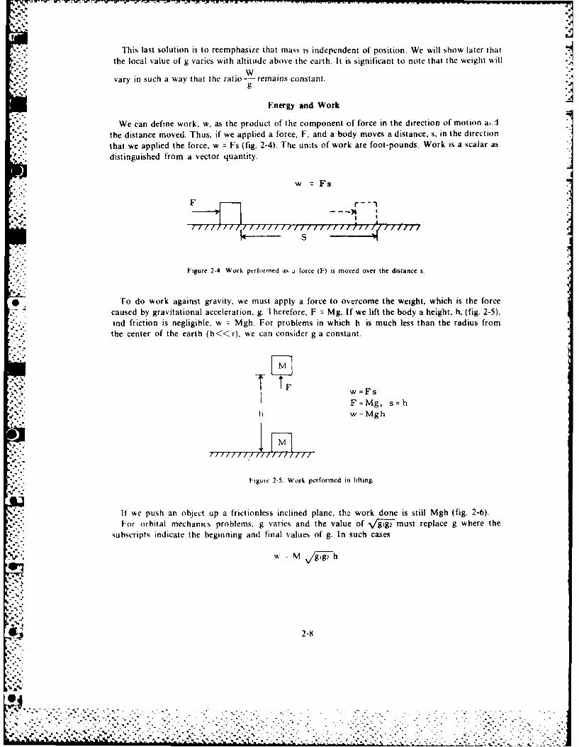
This last solution is to reemphasize that mass is independent of position. We will show later thatthe local value of g varies with altitude above the earth. It is significant to note that the weight will
vary in such a way that the ratio -remains constant.
Energy and Work
We can define work, w, as the product of the component of force in the direction of motion a,':
the distance moved. Thus, if we applied a force, F, and a body moves a distance, s, in the directionthat we applied the force, w = Fs (fig. 2-4). The units of work are foot-pounds. Work is a scalar as
distinguished from a vector quantity.
F- r- -
r S
Figure 2-4. Work performed as a force (F) is moved over the distance s.
* To do work against gravity, we must apply a force to overcome the weight, which is the forcecaused by gravitational acceleration, g. Therefore, F = Mg. If we lift the body a height, h, (fig. 2-5),ind friction is negligible, w = Mgh. For problems in which h is much less than the radius fromthe center of the earth (h«<< r), we can consider g a constant.
I ,w =FsI. F=Mg, s=h
w=Mgh
777-7Tm,77117-
Figure 2-5. Work performed in lifting.
If wke push an object up a frictionless inclined plane, the work done is still Mgh (fig. 2-6).For orbital mechanics problems, g varies and the value of \gl2 must replace g where the
subscripts indicate the beginning and final values of g. In such cases
w - M gg, h
2-8i%
, .. .... 5 5... .. . S.,
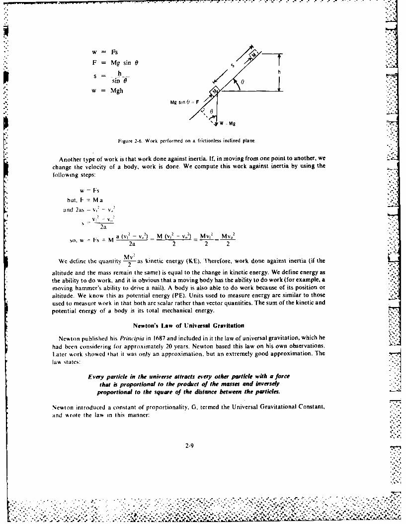
w S F%
F =Mg sin 0
_ h ht
sinG o
Mg sin() - F
'W -Mg
[.. Figure 2-6. Work performed on a frictionless inclined plane.
Another type of work is that work done against inertia. If, in moving from one point to another, we
change the velocity of a body, work is done. We compute this work against inertia by using thefollowing steps:
w =Fs
but, F- M a
and 2as V1-
2aa (vC -V1)1 M (vi -V.) Mv1
2 Mv02
ow Fs M 2a 2 2 2
Mw2We define the q.uantity 2as kinetic energy (KE). Therefore, Work done against inertia (if the
altitude and the mass remain the same) is equal to the change in kinetic energy. We define energy as*the ability to do work, and it is obvious that a moving body has the ability to do work (for example, a
moving hammer's ability to drive a nail). A body is also able to do work because of its position oraltitude. We know this as potential energy (PE). Units used to measure energy are similar to thoseused to measure work in that both are scalar rather than vector quantities. The sum of the kinetic andpotential energy of a body is its total mechanical energy.
Newton's Law of Universal Gravitation
Newton published his Principia in 1687 and included in it the law of universal gravitation, which hehad been considering for approximately 20 years. Newton based this law on his own observations.Later work showed that it was only an approximation. but an extremely good approximation. The
law states:Every particle in the universe attracts every other particle with a force
that is proportional to the produict of the masses and Iniverselyproportional to the square of the distance between the particles.
Newton introduced a constant of proportionality, G, termed the Universal Gravitational Constant,and %rote the law in this manner:
2-9
% %'

F GmIm 2
Cavendish first determined the value of G, the Universal Gravitational Constant, in a classicalexperiment using a torsion balance. The value of G is quite small (G = 6.6695 X 10⁻⁸ cgs units). Inmost problems the mass of one of the bodies is quite large. It is convenient to combine G and thelarge mass, mi, into a new constant, u (mu), which we define as the gravitational parameter. Thisparameter has different values depending upon the value of the large mass, mi. If mi refers to theearth, the gravitational parameter, p, will apply to all earth satellite problems. However, if the
S"problem concerns satellites of the sum or other large bodies, p will have a different value basedon the mass of that body.
If we simplify the law of gravitational attraction by combining G and mi and by adjusting theresults for the English engineering unit system, we obtain the following:
'n = ftsec-
F =--m (Where F is lb force and n is slugs)r
If this expression is equated to the expression of Newton's second law of motion, as it appliesin a gravitational field, we see that:
F = mg =-4m01, r-
and after dividing by the unit mass, m, we obtain:
Thus, the value of g varies inversely as the square of the distance from the center of the attractingbody.
For problems involving earth satellites, the following two constants are necessary for a properS'.solution:
G mc, =Awth = 14.08 X 101'5ft2sec2
r, (radius of earth) 20.9 X 106 ft
We must use the formulas with proper concern for the units involved, and the value given for)A applies only to bodies attracted to the earth.
Before applying Newton's law of universal gravitation to the solution of problems, we shouldconsider the possible paths that a body in unpowered flight must follow through space.
CONIC SECTIONS
°I Ihe (Freek mathematicians studied the conic sections, and, since then, scientists have accumulateda body of knowledgc concerning them. They have assumed new significance in the field of astronautics
S-. because a conic section can represent any free-flight trajectory. The study of conic sections, or conics,s part of anal'tic geometry, a branch of mathematics that brings together concepts from algebra.geometry. and trigonometry.
2-10
. -,, " , ", -~. .... . ....... ... ._
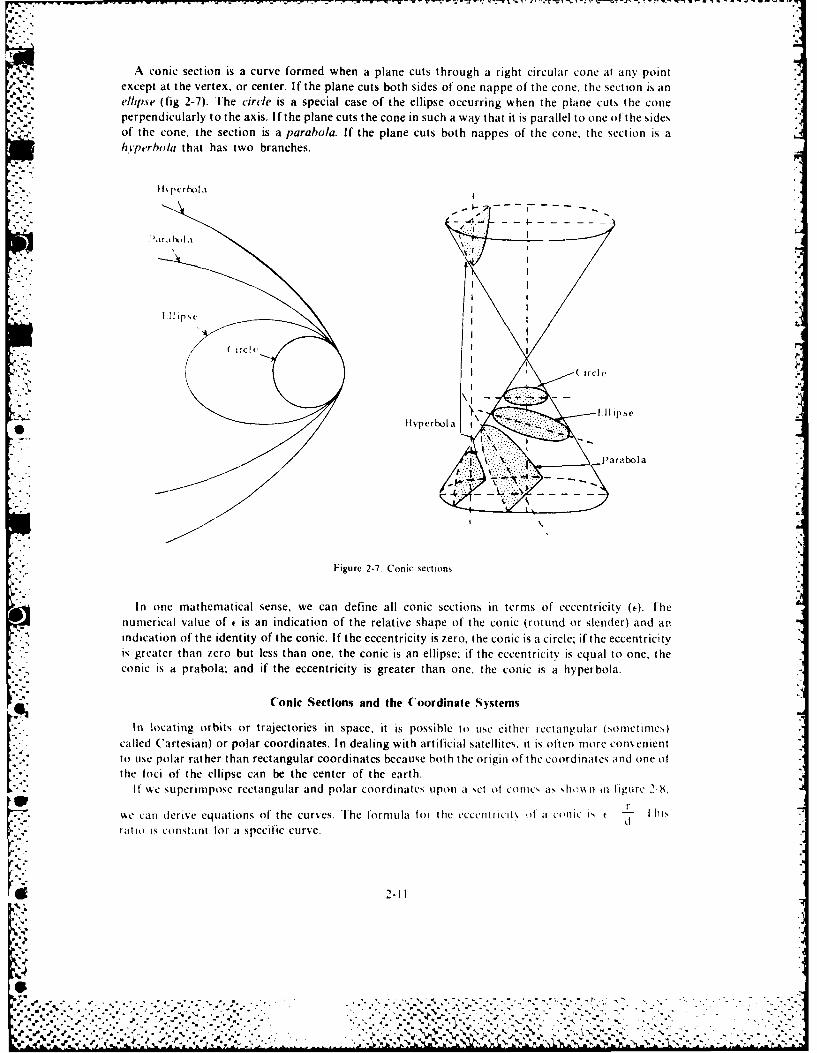
A conic section is a curve formed when a plane cuts through a right circular cone at any point
except at the vertex, or center. If the plane cuts both sides of one nappe of the cone, the section is anellipse (fig 2-7). The circle is a special case of the ellipse occurring when the plane cuts the coneperpendicularly to the axis. If the plane cuts the cone in such a way that it is parallel to one of the sidesof the cone, the section is a parabola. If the plane cuts both nappes of the cone, the section is ahyperbola that has two branches.
-- %.="- t pcr hola .
- 4- -
"a r I,
I I
I"( irci c
.......... if\ -* Ei-pse .
Hlyperbola
I ' ~ parabola
,-,
Figure 2-7. Conic sections.
In one mathematical sense, we can define all conic sections in terms of eccentricity (c). [henumerical value of t is an indication of the relative shape of the conic (rotund or slender) and anindication of the identity of the conic. If the eccentricity is zero, the conic is a circle; if the eccentricityis greater than zero but less than one, the conic is an ellipse. if the eccentricity is equal to one, theconic is a prabola; and if the eccentricity is greater than one, the conic is a hyperbola.
Conic Sections and the Coordinate Systems
In locating orbits or trajectories in space, it is possible to use either iectangtular (somet Imes) .called Cartesian) or polar coordinates. In dealing with artificial satellites, it is often more conenientto use polar rather than rectangular coordinates because both the origin of the coordinates and one ofthe foci of the ellipse can be the center of the earth.
If %kc superimpose rectangular and polar coordinates upon a set of conics at s i n {igurc I-8,"I-
. c can derive equations of the curves. The formula for the ecccntriclt. , o a conlL" is f I hllsd
- ratio i; constant for a specific curve.
. .
%LI
• : ,",. - " . ."" . , . ' , - ,, . " , " "•". . . - , -e, , . .. " . . ", . ., " - . '. ." , ••% .",.'' .' " .. .. " ""+ "" .''" . " ' ' '" " " ." . : ' . .' . L -N . , .-. \. ,. ., . . ."- . . .. ,A.A
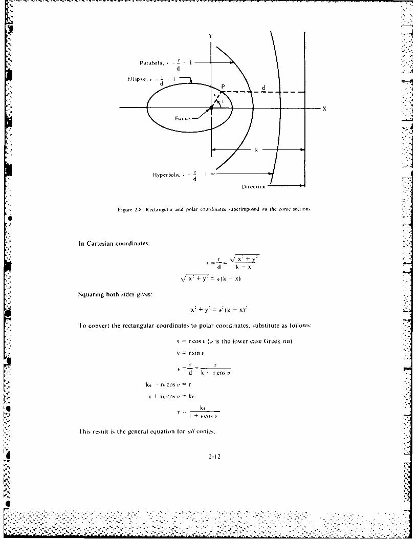
.5r
-x
Figure 2-9. Recta.ngular and polar coordinates superimpo~sed on the conic sections.
In Cartesian coordinates:
d k-x
f77~ ~k -X)
Squaring both sides gives:
X2 + y2 =) -
To convert the rectangular coordinates to polar coordinates, Substitute as f'ollows:
x rcos v 0, is the lower case Greek nlu)
v r sin v'
-r r
d k r rcos v
-t rf cos v r
r + rt cos v=k
+ ( + Cos 1
This result is the general equation for till cotnics.
2-12
-- 1 7 'l
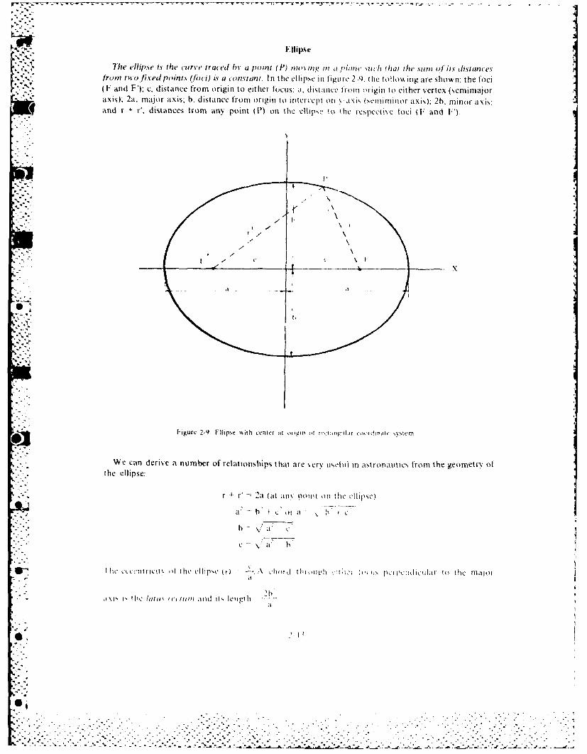
Ellipse
-he ellipse is the curve traced hi. a ,oint (P) noviplt , iP a Niuch that the sutm ofits distancesftom ito fixed point. (hoici) is a constant. In the ellipse in I igi e 2-9 the htolos ing are shown: the foci(F and F); c, distance from origin to eit her focus a, distance I rom origin to eit her vertex (semimajoraxis); 2a. major axis; b. distance fron origin to intercept oil -axis (semnimi nor axis): 2h. minor axis;and r + r', distances from any point (P) on the ellips,, to tihe iespeketie loci (F and ').
X
F igure 2-9. Fttcpse with 7eniter at origin olt ocrzanpnlir cirdinie sstem
We can derive a number of relationships that are xerv us eful in astronautics from the geometry ot* - the ellipse:
r 4-r' "a (at all\ point onl tile Illille)
ha C oIa
;-,. -: C .- \
" " " cinrci\ teehc" ~ -- -\ chit i, i \ -ih;:i cciiu]rt h ao
h |
I figurlllcl )tt e 2 llipse ,i L -hctritoll h ,ir h,;'t~gia !t' iirl,ll to il(:tem
A\Is , th e /iiti fl., Itoc and it, IetltiIs,.'_ "s,' - V
-'.- -" -- +--"
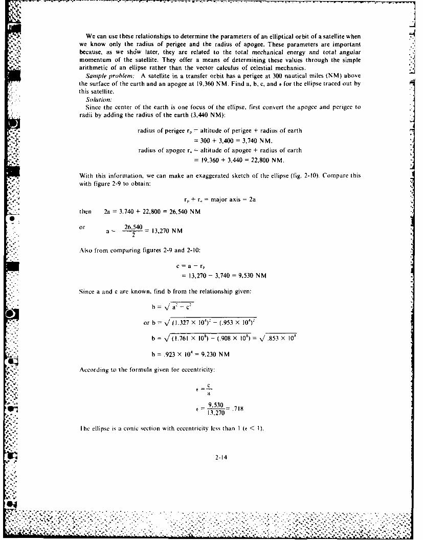
J
We can use these relationships to determine the parameters of an elliptical orbit of a satellite whenwe know only the radius of perigee and the radius of apogee. These parameters are important-because, as we shd;w later, they are related to the total mechanical energy and total angularmomentum of the satellite. They offer a means of determining these values through the simplearithmetic of an ellipse rather than the vector calculus of celestial mechanics.
Sample problem: A satellite in a transfer orbit has a perigee at 300 nautical miles (NM) abovethe surface of the earth and an apogee at 19,360 NM. Find a, b, c, and t for the ellipse traced out bythis satellite.
Solution:Since the center of the earth is one focus of the ellipse, first convert the apogee and perigee to
radii by adding the radius of the earth (3,440 NM):
- -radius of perigee rp altitude of perigee + radius of earth
= 300 + 3,400 = 3,740 N M.radius of apogee r. = altitude of apogee + radius of earth
= 19,360 + 3,440 = 22,800 NM.
With this information, we can make an exaggerated sketch of the ellipse (fig. 2-10). Compare this* with figure 2-9 to obtain:
r. + r, =major axis =2a
then 2a 3,740 + 22,800 = 26,540 N M
or 26 540a ~13,270 N M
Also from comparing figures 2-9 and 2-10:
c =a - r
= 13,270 - 3,740 =9,530 N M
*Since a and c are known, find b from the relationship given:
b \/a 2 _c
or b 41~.327 X 104)2' - (.953 X 104)1
b (1.761 X 10⁸) - (.908 X 108) v'.853 X 10'
bJ = .923 X 104 = 9,230 NM
r According to the formula give.n for eccentricity:
9 530 .113,270
I he ellipse is a conic section with eccentricity less than I (t < 1).
2-14
%. . .
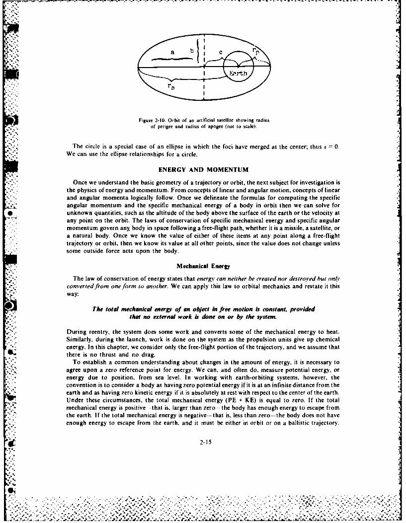
* ~ ~ ~ ~ ~ ~ ~ b rr ~ --- -- ----- ~
Figure 2-10. Orbit of an artificial satellite showing radiusof perigee and radius of apogee (not to scale).
The circle is a special case of an ellipse in which the foci have merged at the center; thus C. 0.We can use the ellipse relationships for a circle.
ENERGY AND MOMENTUM
Once we understand the basic geometry of a trajectory or orbit, the next subject for investigation isthe physics of energy and momentum. From concepts of linear and angular motion, concepts of linearand angular momenta logically follow. Once we delineate the formulas for computing the specificangular momentum and the specific mechanical energy of a body in orbit then we can solve for
* unknown quantities, such as the altitude of the body above the surface of the earth or the velocity atany point on the orbit. The laws of conservation of specific mechanical energy and specific angularmomentum govern any body in space following a free-flight path, whether it is a missile, a satellite, or
* a natural body. Once we know the value of either of these items at any point along a free-flighttrajectory or orbit, then we know its value at all other points, since the value does not change unlesssome outside force acts upon the body.
Mechanical Energy
The law of conservation of energy states that energy can neither be created nor destroyved but only,convertedftrm one form to another. We can apply this law to orbital mechanics and restate it thisway:
0 The total mechanical energy' of an object in free motion is constant, providedthat no external work is done on or by the system.
During reentry, the system does some work and converts some of the mechanical energy to heat.Similarly, during the launch, work is done on the system as the propulsion units give up chemicalenergy. In this chapter, we consider only the free-flight portion of the trajectory, and we assume thatthere is no thrust and no drag.
To establish a common understanding about changes in the amount of energy, it is necessary toagree upon a zero reference point for energy. We can, and often do, measure potential energy, orenergy due to position, from sea level. In working with earth-orbiting systems, however, theconvention is to consider a body as having zero potential energy if it is at an infinite distance from theearth and as having zero kinetic energy if it is absolutely at rest with respect to the center of the earth.Under these circumstances, the total mechanical energy (PE + KE) is equal to zero. If the totalmechanical energy is positive-that is, larger than zero-the body has enough energy to escape fromthe earth. If the total mechanical energy is negative-that is, less than zero-the body does not haveenough energy to escape from the earth, and it must be either in orbit or on a ballistic trajectory.
2-15
SI%. .. .. L
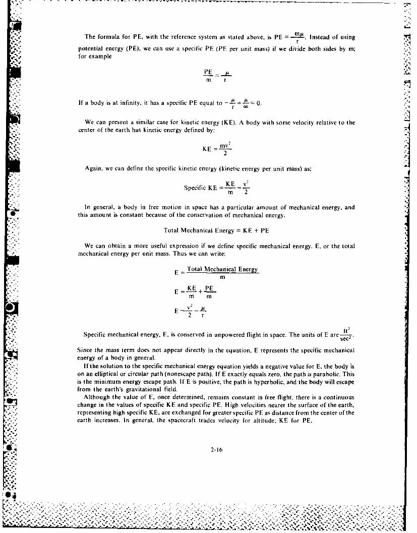
The formula for PE, with the reference system as stated above, is PE = M Instead of usingr
. potential energy (PE), we can use a specific PE (PE per unit mass) if we divide both sides by m;for example
m r
If a body is at infinity, it has a specific PE equal to _.. 0.r
We can present a similar case for kinetic energy (KE). A body with some velocity relative to thecenter of the earth has kinetic energy defined by:
KE = mv2 I
Again, we can define the specific kinetic energy (kinetic energy per unit mass) as:
KE v' a
Specific KE =E v2
In general, a body in free motion in space has a particular amount of mechanical energy, and*" this amount is constant because of the conservation of mechanical energy.
Total Mechanical Energy = KE + PE
We can obtain a more useful expression if we define specific mechanical energy, E, or the totalmechanical energy per unit mass. Thus we can write:
Total Mechanical EnergyE =
m
E KE + PEm mv2
E v I.2 r
It 2Specific mechanical energy, E, is conserved in unpowered flight in space. The units of E are-.,,...
sec2•
Since the mass term does not appear directly in the equation, E represents the specific mechanicalenergy of a body in general.
If the solution to the specific mechanical energy equation yields a negative value for E, the body ison an elliptical or circular path (nonescape path). If E exactly equals zero, the path is parabolic. Thisis the minimum energy escape path. If E is positive, the path is hyperbolic, and the body will escapefrom the earth's gravitational field.
Although the value of E, once determined, remains constant in free flight, there is a continuouschange in the values of specific KE and specific PE. High velocities nearer the surface of the earth,representing high specific KE, are exchanged for greater specific PE as distance from the center of theearth increases. In general, the spacecraft trades velocity for altitude; KE for PE.
2-16
S-" " -" " . '. . -'.- . -. --" --' . - - .... . . -.-- . ," - ' .-' " " ' ' . . .' ' ' ' ' " ' . ' . . .N%,.,.% -..... ....-........ , -.. -.- .... .... .. ..... .< ..-. ... .- .. -.-,. . ,..,,., ... ... , .- -.... :
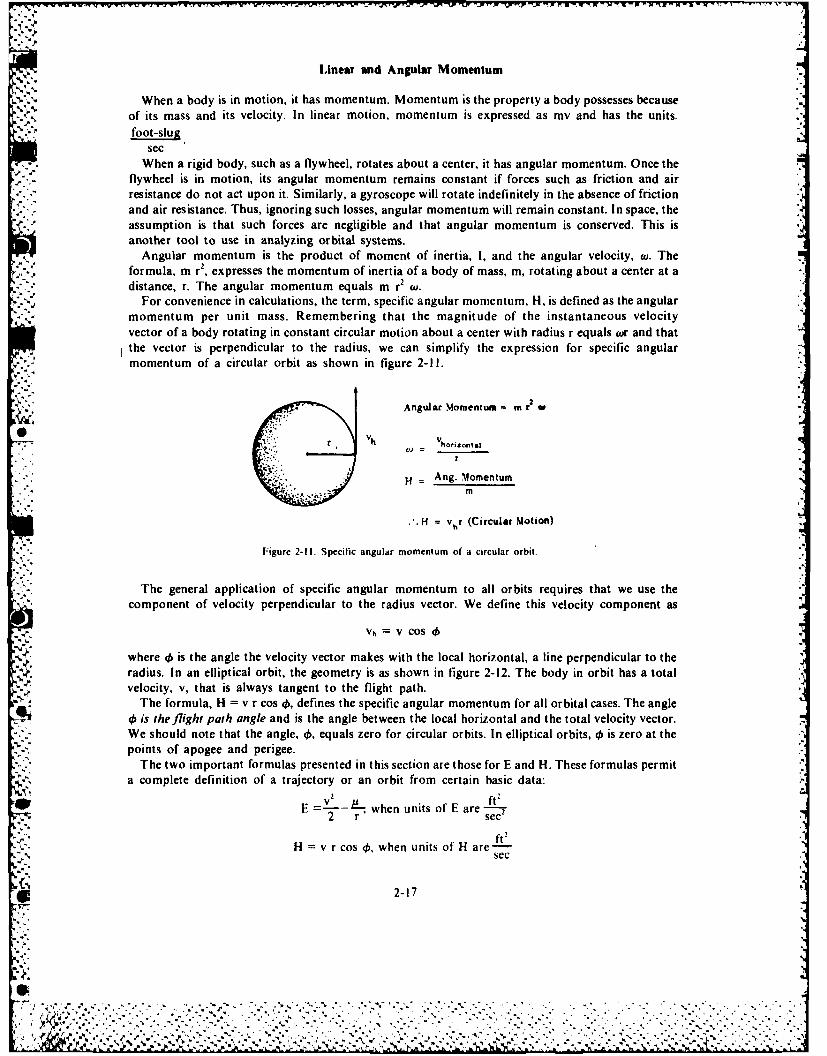
Linear and Angular Momentum
When a body is in motion, it has momentum. Momentum is the property a body possesses becauseof its mass and its velocity. In linear motion, momentum is expressed as my and has the units.foot-slug
secWhen a rigid body, such as a flywheel, rotates about a center, it has angular momentum. Once the
flywheel is in motion, its angular momentum remains constant if forces such as friction and air* resistance do not act upon it. Similarly, a gyroscope will rotate indefinitely in the absence of friction
and air resistance. Thus, ignoring such losses, angular momentum will remain constant. In space, theassumption is that such forces are negligible and that angular momentum is conserved. This isanother tool to use in analyzing orbital systems.
Angular momentum is the product of moment of inertia, 1, and the angular velocity, W. Theformula, mn r', expresses the momentum of inertia of a body of mass, m, rotating about a center at adistance, r. The angular momentum equals mn r' to.
For convenience in calculations, the term, specific angular momentum, H, is defined as the angularmomentum per unit mass. Remembering that the magnitude of the instantaneous velocityvector of a body rotating in constant circular motion about a center with radius r equals wr and thatthe vector is perpendicular to the radius, we can simplify the expression for specific angularmomentum of a circular orbit as shown in figure 2-1l.
.,.* Angular Momentum =m 2
r
... -Ang. Momentum
m
H v,r (Circular Motion)
Figure 2-11. Specific angular momentum of a circular orbit.
The general application of specific angular momentum to all orbits requires that we use the
component of velocity perpendicular to the radius vector. We define this velocity component as
vh = V COS 4
where 4$ is the angle the velocity vector makes with the local horizontal, a line perpendicular to theradius. In an elliptical orbit, the geometry is as shown in figure 2-12. The body in orbit has a totalvelocity, v, that is always tangent to the flight path.
The formula, H = v r cos 45, defines the specific angular momentum for all orbital cases. The angle4is the flight path angle and is the angle between the local horizontal and the total velocity vector.
We should note that the angle, 46, equals zero for circular orbits. In elliptical orbits, 0 is zero at thepoints of apogee and perigee.
The two important formulas presented in this section are those for E and H. These formulas permita complete definition of a trajectory or an orbit from certain basic data:
2 ftE when units of E are -f
*2 r' sec
co v O , when units of H fte2sec
2-17
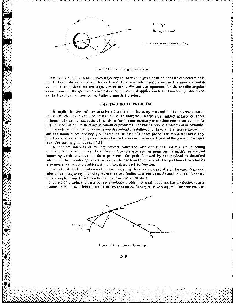
" H = vhr
but vh V COSO
H - yr cos 0 (General orbit)
h"1
ingure 2-12. Specific angular momentum.
If v e k now v, r, and h for a giren trajectory (or orbit) at a given position, then we can determine Eand ti. In the absence of outside forces, E and H are constants; therefore we can determine v, r, and 0
.-.*at any other position on the trajectory or orbit. We can use equations for the specific angularmomentum and the specific mechanical energy in practical application to the two-body problem andto the free-flight portion of the ballistic missile trajectory.
THE TWO BODY PROBLEM
It is implicit in Newton's law of universal gravitation that every mass unit in the universe attracts,and is attracted by, every other mass unit in the universe. Clearly, small masses at large distancesinfinitesimally attract each other. It is neither feasible nor necessary to consider mutual attraction of alarge mnmber of bodies in many astronautics problems. The most frequent problems of astronauticsin, oh e o nly two interacting bodies: a missile payload or satellite, and the earth. In these instances, the
. , sun and moon effects are negligible except in the case of a space probe. The moon will noticeably, affect a space probe as the probe passes close to the moon. The sun will control the probe if it escapes
from the earth's gravitational field.
[ he primary interests of military officers concerned with operational matters are launchinga missile from one point on the earth's surface to strike another point on the earth's surface andlaunching earth satellites. In these problems, the path followed by the payload is describedadequately by considering only two bodies, the earth and the payload. The problem of two bodiesis termed the two-body problem: its solution dates back to Newton.
It is fortunate that the solution of the two-body trajectory is simple and straightforward. A generalsolution to a trajectory involving more than two bodies does not exist. Special solutions for thesemore complex trajectories usually require machine calculation.
.4,-. Figure 2-13 graphically describes the two-body problem. A small body m2. has a velocity, v, at a"'.4 distance. r, fromn the origin chosen as the center of mass of a very massive body, mi. The problem is to
2-0
J% %'
|%
b~~~~~~~~ % ." . " . % * % % , " .". '. . .. . . .o ," . . .% . " . , " - ". . . • % , • ° "_N P-Y-f.F
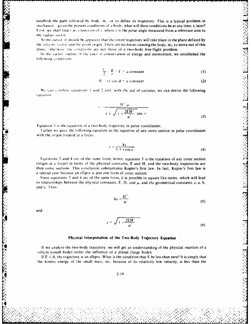
- - ---- ]--'',
estahlish the path hollosed b\ hod%, i. or to define its trajectory. This is a typical problem in'mechanic. gi en the present conditions ot a hody. %hat will these conditions be at any time, t, later?I rr.i. 4c ,,hall ind r a% a tiuntion of t. %4 here v is the polar angle measured from a reference axis toihe radius %ectot
\t the outsil. it should bt apparent that ihe entire trajectory will take place in the plane defined bythe cloiit\ ctoi ind the point origin I here are no forces causingthe body, m2, to move out of thisplant: ,ihc\,isc the coniditions ate not those of a two-body free-flight problem.
In the carhcr authnc d the iatk, ot conser\ation of energy and momentum, we established the* toilo.r lng o.tildit I. uts
M : 1' = a constant (I)
2 r
II r cos h = a constant (2)
c tni i ,,hiihinc tCielateiq', I ,and 2 aind. Aith the aid of calculus, we can derive the following
I-F
d 2EH"2
I + I + ------- -- cos V,I+ (3)
"tquation 3 is the equation of a twt)-body trajectory in polar coordinates.Farlier \,e gase the hollosing equation as the equation of any conic section in polar coordinates
%kith the origin located at it focus:
ktr I + (cos V (4)
Fqt:itions 3 and 4 are of the same form; hence, equation 3 is the equation of any conic section(origin at a focus) in terms of the physical constants, E and H. and the two-body trajectories arethen conic sections. [his conclusion substantiates Kepler's first law. In fact, Kepler's first law isa special case because an ellipse is just one form of conic section.
Since equations 3 and 4 arc of the same form, it is possible to equate like terms, which will leadto relationships between the physical constants, E, H, and tu. and the geometrical constants. t, a, b,and c. Ihus:
H"',." u(5)
and
+=- (6)
Ph)sical Interpretation of the Two-Body Trajectory Equation
If we analv/e the two-body trajectory, we will get an understanding of the physical reaction of a%ehicle (small body) under the influence of a planet (large body).
If E < 0. the trajectory is an ellipse. What is the condition that E be less than zero'? It is simply thatthe kinetic energy of the small mass. m,, because of its relatively low velocity, is less than the
2-19
.............................................-- * p ... .
magnitude of its potential energy. Therefore, the body cannot possibly go all the way to infinity; thatis. it cannot go to a point where a larger body no longer attracts it -where the potential energy is zero.The smaller mass cannot escape. It must remain "captured" by the force field of the larger body.
-:Therefore, the force field of the larger body will turn the smaller mass toward the larger body. In !keeping with the idea of potential energy, the smaller body will always fall toward the more massivebody. When this particular balance of energy exists, the trajectory is elliptical with one focuscoincident with the center of mass of the larger body. In the actual physical case, the larger body willhave a finite size: that is, it will not be a point mass, and this ellipse may intersect the surface of thelarger body as it does in the case of a ballistic missile. If the velocity is sufficiently high, and itsdirection proper, the ellipse may completely encircle the central body, the condition of the satellite.
If E = 0, the kinetic energy exactly equals the magnitude of the potential energy, and the smallmass, m2, has just enough energy to travel to infinity, away from the influence of the central body, andcome to rest there. The small body will follow a parabolic path to infinity. The velocity that weassociate with this very special energy level is also v'ery special. It is commonly called the "escape
velocity."We can calculate escape velocity by setting E =0 in the mechanical energy equation I as follows:
2v~ - EA2 r
V- =(2 JL)
r~ (7)
.11hus, we can see that escape velocity decreases with distance from the center of the earth. At theearth's surface.
,/2LF 2 )4 .08)10~!l /
vr, L 0 9 ) ( 1 0 " ft) j
4'-v_, 1 36,700 ft7/ sec.
If the velocity of the small mass exceeds escape velocity, which will be the case if E > 0, it willfollow a hyperbolic trajectory to infinity. In practice, infinity is a large distance at which the earth'sattractive force is insignificant, and there the mass will have some residual velocity. In a mathematicalsense, the body would continue to have velocity at infinity. In a physical sense, it would have velocityrelative to the earth at any large distance from the earth.
Considering the sounding rocket, only the straight-line, degenerate conic is a possible trajectory.But, again, the value of E will determine whether escape is possible; if E < 0, the straight-linetrajectory cannot extend to infinity. If E = 0 or E > 0, the straight line will extend to infinity.
-'a Example Problem. The first US "moon shot," the Pioneer 1, attained a height of approximately61,410 nautical miles above the earth's surface. Assuming that the Pioneer had been a sounding
* . rocket (a rocket fired vertically), and assuming a spherical, nonrotating earth without atmosphere,calculate the following.
I. E (total specific energy)2. Impact velocity (earth's surface)
2-20
'IA'%
Solution: Given 0
I. At apogee (greatest distance from earth):
Altitude (above earth's surface) = 61,410 NM
Earth radius = 3,440 NM
Velocity = 0 (Only for a sounding rocket)
r = altitude + earth's radius
r (61,410 + 3,440 NM = 64,850 NM
V (14.08) (10)- se2
(64,850) NM (6,080) ft
E 3.57 x 10' ft!sec2 Answer A
2. Since the specific energy is constant,
At the earth's surface:
r = 3,440 NM
E = 3.57 X 10' ft2/sec.
E =v- --2 r
1'f _v2 (14.08)(l103.57 X 107 f t , v - 140 (0' t )s e c - .
sec" 2 ft(3,440) NM (6.080)
v = 2[( 157 X 10') + (67.4 X 10')] 2(63.8 X 10⁷) ft" sec 2
v = 35,700 ft/sec Answer
This is the approximate burnout velocity of the vehicle. As the surface escape velocity is36.700 ft,' sec, it is clear that Pioneer I did not attain escape velocity, and so it returned to earth.
Elliptical Trajectory Parameters
While parabolic and hyperbolic trajectories, especially the latter, are of interest in problems ofinterplanetary travel, elliptical trajectories comprise the ballistic missile and satellite cases, whichare of current military interest. It is important to relate the dimensions of an ellipse (a, b, and c) tothe physical constants (E, H, and p) as we previously did for .
We presented the relationship, r. + r, 2a, earlier, If we applied this equation to point P infigure 2-14,
+k Cs (V 0 at P) "-
ker =I + ecos ( , atP"
r I+ and r= a - c. Then,lk"
I+(8) ,
But t =-: therefore, substituting c (.a into 8,
2-21
.4
'. -,'. " .- Z . '.''..'..' ' " .'. '. '- ' ,-.' .'- -.. , ... ." " . .-. '. ;,,+- '° " ,' .' .' ,- ,'+ -' " , + .- •. °-,'-. "" .-. '...+. ,- ."4"" '--5.
,,-, .4- - . , ... .- ,..... ... .- . . , . .. . ., . .. -,. .+ .. . . ,.. . + ,. '. , . : . . . . ,,.. - , . , . . . +. -. : .
,\ .'-..,',,'....+ ."' +'.. "-..: '..f.... , .,. -. ,.'....'.-... ,.. .. .. , .. °.. .' -.. . -", "--" , ... ... .. . + .... ",- ""-.-..-.. . '-," . .- " . . . . . . . ." . . ...
A -.- * ' + + +,'',%- -, , , ,-,-. .. ,- .- . , .- ,..+. ,.- --. , ,-- , +(, , +",---. - .- -
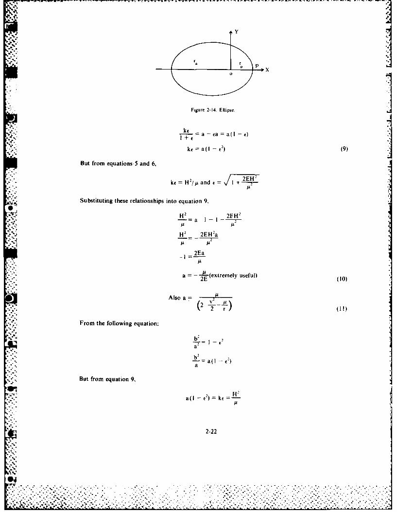
,y1
": . Figure 2-14. Ellipse.
a' - e a
+Y4.... r
ke a( I - e) (9)
But from equations, 5 and 6,
ke = 2 / ande= E+
Substituting these relationships into equation 9,
H2 2EH'a 2A AA
H2 2EH'a
JLA- 2Ea
A
a = - (extremely useful)2E (10)
A lso a --- ' (2 v ...2 .- -I-)
2. L.2 r l( 1)
From the following equation:
b-2
nt -- aI -C)a-b2
-:- a
But from equation 9,
H2
a(I el = c A
2-22
*Cl
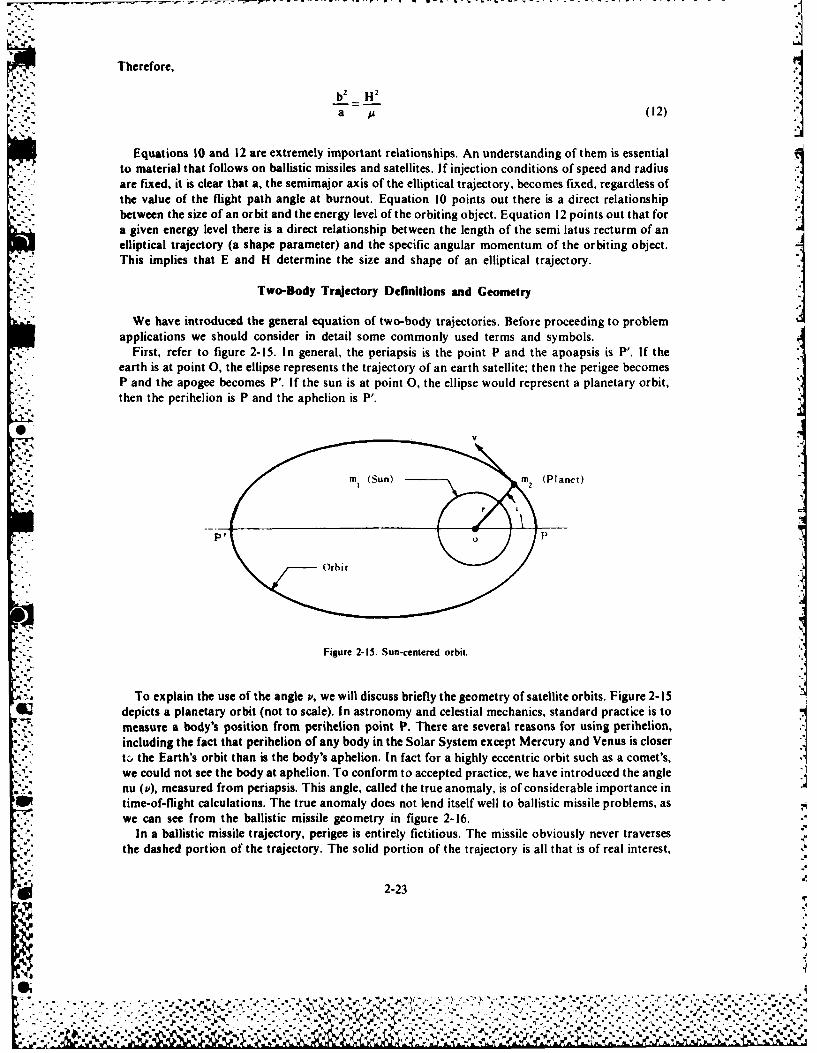
Therefore,
b2 H2 Ia A (12)
Equations 10 and 12 are extremely important relationships. An understanding of them is essentialto material that follows on ballistic missiles and satellites. If injection conditions of speed and radiusare fixed, it is clear that a, the semimajor axis of the elliptical trajectory, becomes fixed, regardless ofthe value of the flight path angle at burnout. Equation 10 points out there is a direct relationshipbetween the size of an orbit and the energy level of the orbiting object. Equation 12 points out that fora given energy level there is a direct relationship between the length of the semi latus recturm of anelliptical trajectory (a shape parameter) and the specific angular momentum of the orbiting object.This implies that E and H determine the size and shape of an elliptical trajectory.
Two-Body Trajectory Definitions and Geometry
We have introduced the general equation of two-body trajectories. Before proceeding to problemapplications we should consider in detail some commonly used terms and symbols.
First, refer to figure 2-15. In general, the periapsis is the point P and the apoapsis is P'. If the
earth is at point 0, the ellipse represents the trajectory of an earth satellite; then the perigee becomesP and the apogee becomes P. If the sun is at point 0, the ellipse would represent a planetary orbit,
* . then the perihelion is P and the aphelion is P'.
m (Sun) m2 (Planet)
PO P
Orbit
Figure 2-15. Sun-centered orbit.
To explain the use of the angle ', we will discuss briefly the geometry of satellite orbits. Figure 2-15depicts a planetary orbit (not to scale). In astronomy and celestial mechanics, standard practice is tomeasure a body's position from perihelion point P. There are several reasons for using perihelion,
. including the fact that perihelion of any body in the Solar System except Mercury and Venus is closertc, the Earth's orbit than is the body's aphelion. In fact for a highly eccentric orbit such as a comet's,we could not see the body at aphelion. To conform to accepted practice, we have introduced the anglenu (P), measured from periapsis. This angle, called the true anomaly, is of considerable importance in
* time-of-flight calculations. The true anomaly does not lend itself well to ballistic missile problems, aswe can see from the ballistic missile geometry in figure 2-16.
In a ballistic missile trajectory, perigee is entirely fictitious. The missile obviously never traversesthe dashed portion of the trajectory. The solid portion of the trajectory is all that is of real interest,
2-23

.1 Trajectory -
Figure 2-16. Ballistic missile trajectory.
_--,..•
and this portion is in the second and third quadrants of the angle v. Then it is convenient to define anangle 0, measured counterclockwise from apogee (apoapsis, in general), such that
v = + 7r. (13)
Normally, 0 will have values in the first and fourth quadrants. From 13, it is clear that we caninterchange derivatives of v and 0. By substituting 13 into 4, we can find the equation of a conicsection in terms of 0,
St +os v I + cos(0+ 7r)
ker =r I - ecos0'
.%
With this understanding of the relationship between v and 0, we can use P conveniently whenworking with satellite and space trajectories and 0 when working with ballistic missiles.
EARTH SATELLITES
During their free-flight trajectory, satellites and ballistic missiles follow paths described by the two-$ body equation. For a satellite to achieve orbit, we must add enough energy to the vehicle so that the
ellipse does not intersect the surface of the earth. However, we must not add enough energy to allowthe vehicle to escape. Therefore, the ellipse and the circle are the paths of primary interest.
The orientation, shape, and size of orbits are important to the accomplishment of prescribedmissions. Therefore, eccentricity (e), major axis (2a), minor axis (2b), and distance between the foci(2c) are of interest. It is necessary to know the relationships of these geometric values to the orbitalparameters to make an analysis of an orbit. For example, it is helpful to remember that:
rp (radius at perigee) = a - c
r. (radius at apogee) = a + c
rp + r. = 2a '-
c
a
a2
b2 + C2
a. •
2-24
% - . . . -. . .. . - .. .. . . . .. ..
-,,,.,,'..:.- -.,. .,.; ,.,:,-.,:. ,- , :. ...:, .:.. .... ,- .. ...,.-.- ..-.. .. _. ., ... ... ..:,2-.1. .. -.. ......d,
-. Specific mechanical energy, E, and specific angular momentum, H, are of primary concern whenwe discuss elliptical and circular orbits. If there are no outside forces acting on a vehicle in an orbit,the specific mechanical energy and the specific angular momentum will have constant values,
:8. regardless of position in the orbit.* This means that if we know E and H at one point in orbit, we know them at each and every other
point in orbit. If we know radius r, speed v, and flight angle 4) at a given position, we can determine Eand H from:
E V-i
2 r 2a
H = r cos 4
~ ~. If we know the values of E and H for a particular orbit, and we are to determine the speed andflight path angle at a certain point in the orbit, we can solve the energy equation for v, and then, theangular momentum equation for .
The equations for the speed in circular and elliptical orbits are important. The equation forcircular speed is:
r
~ .. ~ The equation for elliptical speed is:
r a%
Another equation that is important in the analysis of orbits is the equation for orbital period.For a circular orbit the distance around is the circumference of the circle, which is 21rr. Therefore,the period, which equals the distance around divided by the speed, is:
P 21rrv
V. Now, substitute for v the speed in circular orbit:
r
P 27rr
Multiply numerator and denominator of the right hand side by V'7
27rr ../r 2 7rr3
rSr
Using the principle of Kepler's third law, replace r by the mean distance from the focus, whichequals the semnimajor axis a. and the equation becomes
* 2-25
'N..
% ..........................................
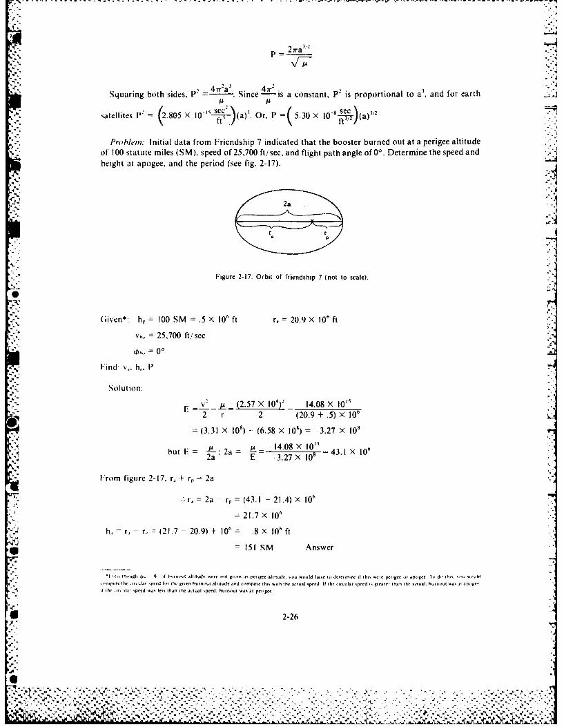
,/---P 27ra'"
-a-A
P2 47r a 3 47rSquaring both sides, Since is a constant, P2 is proportional to a', and for earth
satellites P' = (2.805 X 10 "--).(a). Or, P 5.30 X --- (a)
Prohem: Initial data from Friendship 7 indicated that the booster burned out at a perigee altitudeof 100 statute miles (SM), speed of 25,700 ft/sec, and flight path angle of 0 ° . Determine the speed andheight at apogee, and the period (see fig. 2-17).
Figure 2-17. Orbit of friendship 7 (not to scale).
Given*: h, = 100 SM .5 X 10" ft r,=20.9 X 106 ft
vt,, = 25,700 ft/sec;" 0b6,, = 0 °
Find v. hi, P
Solution:
E v- - (2.57 X 10⁴ 14.08 X 1I2 r 2 (20.9 + .5) X 10-
= (3.31 X 10') - (6.58 x 10') = -3.27 X 10'
but E = E; 2a E - 14.08 X 10 4 X
2a2 E -3.27X i08 =43X1 x 10
From figure 2-17, r. + r, = 2a
r, = 2a - r, = (43.1 - 21.4) X 106
= 21.7 X 10⁶
h, - r., - r, = (21.7 - 20.9) + 106 = .8 X 106 ft
= 151 SM Answer
"l en th.iugh 6. 0 I hstni altitude -. re not giren is perigee altitude. vou would hae to determine 0 this, ere perigee ir apgee I, di' It, -1U " ,old
,npr the iircular speed fot the gten hurntut altitude and compare th, .ith the actual speed If the circular speed iR greater than the ilctual, burnout %a, at ipoger
It the . ircl speed wa, er, than the actual speed. burnout was at perigee
2-26
64
-.". .. r . , . . . . . . . . . . . . . . - - . . ,... . . . . . . . . .
. i r, 1 ,
(2.57 X 10')(21.4 x 10"),21.7 0 25.400 ft sec
-'z'' =17,300 mph A nswker
'(2 I' - a9- 2805 X 10 z (21.6 X 10 ft) t-e = 28.1 X 10⁶ sec'
1) 5.3 0 × 10' sec = 88 3 rain A nswer
St is interesting to compare the computed apogee and period results with the actual orbit (laterdata ga~e a higher accuracy for burnout conditions):
Iem A ctual figures Computed .figures
V.. . .......... 25,728 ft, sec 25,700 ft/sec
h .... ........... 97.695 SM too SM
h . ........ ... 158.85 SM 151 SM
.................. 88.483 min 88.3 min
lrom the foregoing problem, it is evident that the principles and relatively simple algebraicexprcssions presented thus far are extremely important. They enable one to analyze a trajectory or
* orbit rather completely. We have confined the discussion to the two dimensional orbital plane.Before discussing some of the more interesting facets of orbital mechanics, it is necessary to properlylocate a payload in three dimensions.
LOCATING BODIES IN SPACE
In one of the coordinate systems for space used by engineers and scientists, the origin is the centerof the earth. This is a logical choice since the center of the earth is a focus for all earth orbits.
- ,, With the center of the coordinate system established, we must have a reference frame on which tomake angular measurements with respect to the center. The reference frame should be regular inshape, and it should he fixed in space. A sphore satisfies the requirement of a regular shape. The sphereoi the earth would be handy reference if it were fixed in space, but it rotates constantly. Therefore, weuse the celestial sphere to satisfy the requirement for a reference frame. This is a nonrotating sphere ofinfinite radius whose center coincides with the center of the earth and whose surface contains theprojection of the celestial bodies as they appear in the sky (fig. 2-18). The celestial equator is apro ection of the earth's equator on the celestial sphere. We can project the track of a satellite on thecelestial sphere by extending the plane of the orbit to its intersection with the celestial sphere.
After we have defined the center of the system and the celestial equator, we need a reference as astarting point for position measurements. We can find this point by passing a line from the center ofthe earth through the center of the sun to the celestial equator. This point, determined at the instant%%inter changes into spring, is the vernal equinox (fig. 2-19).
Alter w e ha.e established the references for the coordinates system. we must locate the orbititself lhe first item of importance is right ascension. (). of the ascending node, which we defineas the arc ol the celestial equator measured eastward from the vernal equinox to the ascendingnode (fig. 2-18). [he ascending node is the point where the projection of the satellite path crosses
2-27
~~~~~~~~~~~~~~~~~~~~~~~~~~~..'.. . ",%, .. .'. . ~. -. -.. '- _-,, .- ,, .. " ................ .. ... ....... •.-......._.......%% " ' '')' '',_, -",""": .: ' ':' .. ','.", ," ."-" ?-. ,","',"•%, .-.":''.''"-:' :",'"e","" '° ".
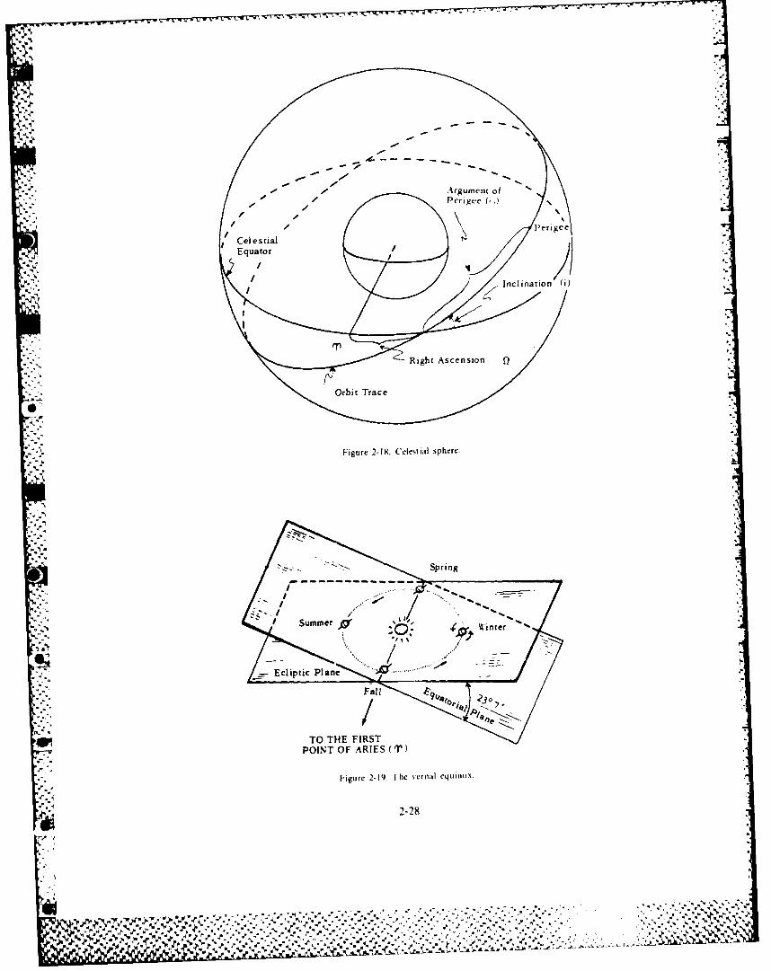
• °5
.'. 4 , 4
Argument of ""
Perigee
Celestial
Perge
~~Equator..
."
Inclinatio n (i)
""
~Right Ascension
•
". ".
Orbit Trace
,
- L
,-..-
.-
Figure 2-18. Celestial sphere..-
Spring
-"6.- "
":WiSnten
." 't
......-
,.
- - -
.. .Ecliptic
P n ......
0?
TO THE FIRSTPOINT OF ARIES ('T)
SFigure 2-19 I he sernal equinox
'* .4 2-28
'-% 4 * .4
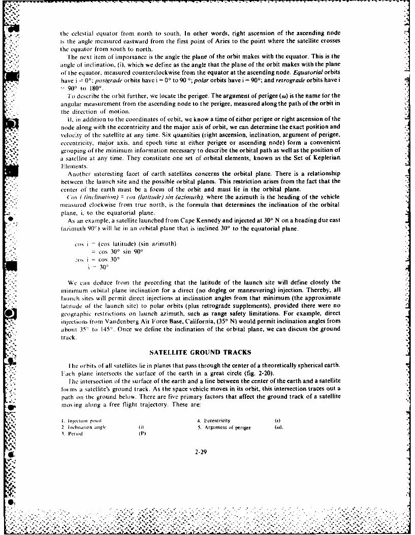
thle celestial equator from north to south. In other words, right ascension of the ascending nodeis the angle measured eastward from the first point of Aries to the point where the satellite crossesthe equator from south to north.
[he next item of importance is the angle the plane of the orbit makes with the equator. This is theangle of inclination, (i). which we define as the angle that the plane of the orbit makes with the planeof the equator, measured counterclockwise from the equator at the ascending node. Equatorial orbitshave i ( 0',Posigrade orbits have i = 00 to 90 0; polar orbits have i = 900; and retrograde orbits have
-900 to 1800.To describe the orbit further, we locate the perigee. The argument of perigee (w) is the name for the
angular measurement from the ascending node to the perigee, measured along the path of the orbit inthe direction of motion.
It-, in addition to the coordinates of orbit, we know a time of either perigee or right ascension of thenode along with the eccentricity and the major axis of orbit, we can determine the exact position andvelocity of the satellite at any time. Six quantities (right ascension, inclination, argument of perigee.eccentricity, major axis, and epoch time at either perigee or ascending node) form a convenientgrouping of the minimum information necessary to describe the orbital path as well as the position ofa satellite at any time. They constitute one set of orbital elements, known as the Set of KeplerianE lemnent s.
Another interesting facet of earth satellites concerns the orbital plane. There is a relationshipbetween the launch site and the possible orbital planes. This restriction arises from the fact that thecenter of the earth must be a focus of the orbit and must lie in the orbital plane.
Cos i (inclination) = cs (latitude) sin (azimutih), where the azimuth is the heading of the vehiclemeasured clockwise from true north, is the formula that determines the inclination of the orbitalplane, i. to the equatorial plane.
As an example, a satellite launched from Cape Kennedy and injected at 300 N on a heading due east(a/imnuth 90') will lie in an orbital plane that is inclined 300 to the equatorial plane.
i = (eos latitude) (sin azimuth)= cos 30' sin 901
'Os i cos 30'=300
We can deduce from the preceding that the latitude of the launch site will define closely theminimium orbital p~lane inclination for a direct (no dogleg or maneuvering) injection. Thereby, alllaunch sites will permit direct injections at inclination angles from that minimum (the approximatelatitude of the launch site) to polar orbits (plus retrograde supplements), provided there were nogeographic restrictions on launch azimuth, such as range safety limitations. For example, directinjections from Vandenberg Air Force Base, California, (350 N) would permit inclination angles fromabout 35' to 1450. Once we define the inclination of the orbital plane, we can discuss the groundtrack.
. N SATELLITE GROUND TRACKS
I1 he orbits of all satellites lie in planes that pass through the center of a theoretically spherical earth.Fach plane intersects the surface of the earth in a great circle (fig. 2-20).
I he intersection of the surface of the earth and a line between the center of the earth and a satelliteforms a satellite's ground track. As the space vehicle moves in its orbit, this intersection traces out apath on the ground below. There are five primary factors that affect the ground track of a satellite
* moving along a free flight trajectory. These are:
1Injectionl point 4. Eccentricity W.%2 I nclination angle (0t 5. Argument of perigee (W).
3Period (In)
2-29
~1'
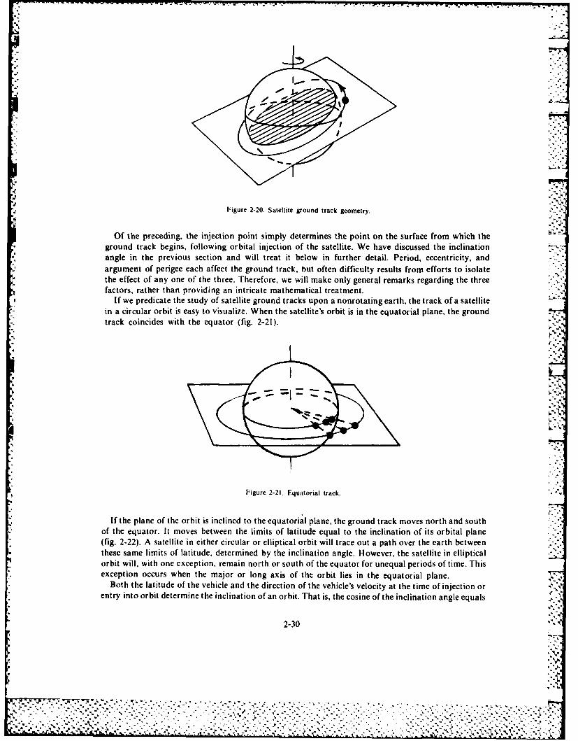
Figure 2-20. Satellite ground track geometry.
Of the preceding, the injection point simply determines the point on the surface from which theground track begins, following orbital injection of the satellite. We have discussed the inclination
* angle in the previous section and will treat it below in further detail. Period, eccentricity, andargument of perigee each affect the ground track, but often difficulty results fronm efforts to isolatethe effect of any one of the three. Therefore, we will make only general remarks regarding the threefactors, rather than providing an intricate mathematical treatment.
If we predicate the study of satellite ground tracks upon a nonrotating earth, the track of a satellitei n a circular orbit is easy to visualize. When the satellite's orbit is in the equatorial plane, the groundtrack coincides with the equator (fig. 2-21).
Figure 2-21. Equattorial track.
If the plane of the orbit is inclined to the equatorial plane, the ground track moves north and southof the equator. It moves between the limits of latitude equal to the inclination of its orbital plane(fig. 2-22). A satellite in either circular or elliptical orbit will trace out a path over the earth betweenthese same limits of latitude, determined by the inclination angle. However, the satellite in ellipticalorbit will, with one exception. remain north or south of the equator for unequal periods of time. Thisexception occurs when the major or long axis of the orbit lies in the equatorial plane.
Both the latitude of the vehicle and the direction of the vehicle's velocity at the time of injection orentry into orbit determine the inclination of an orbit. That is, the cosine of the inclination angle equals
2-30
-%,
:: • ....
..,.. .,.. . . .
. . . . .Of hepreedngth ineto on sipl deemie thon onth sufc rmwhc h
• .I grun trc .eis olwn ria neto ftestlie ehv icse h nnto .

Figure 2-22. North-South travel limits.
the cosine of the latitude times the sine of the azimuth (when we measure it from the north). Theminimum inclination that an orbital plane can assume is the number of degrees of latitude at whichinjection occurs. This minimum inclination occurs when the direction of the vehicle's velocity is dueeast or west at the time of injection. If the vehicle's direction at injection into orbit is any directionother than east or west, the inclination of the orbital plane will increase (fig. 2-23).
Figure 2-23. Injection-inclination geometry.
On a flat map of the earth, satellite ground tracks appear to have different shapes than on a sphere.The ground track for a vehicle in an inclined circular or elliptical orbit appears as a sinusoidal tracewith north-south limits equal to the inclination of the orbital plane (fig. 2-24).
When we consider the earth's rotation, visualizing a satellite's ground track becomes more complex.A point on the equator moves from west to east more rapidly than do points north and south of theequator. Their speeds are the speed of a point on the equator times the cosine of their latitude.Satellites in circular orbit travel at a constant speed. However, when the orbit is inclined to theequator, the component of satellite velocity that is effective in an easterly or westerly direction
6' varies continuously throughout the orbital trace (fig. 2-25). As the satellite crosses the equator, itseasterly or westerly component of velocity is its instantaneous total velocity times the cosine of its
W% ~ angle of inclination. Whc-i it is at the most northerly or southerly portion of its orbit, its easterly or9.. westerly component equals its total instantaneous velocity.
2-31
.............................................. .:.6%
- 4 Vb~'Pq~%

F. .. Figure 2-24. Ground track on flat, nonrotating earth map.I
Figure 2-25. Effective east/west component of satellite velocity.
In elliptical orbits only the horizontal velocity component contributes to the satellite's ground track.Further complication results because the inertial or absolute speed of the satellite varies throughoutthe elliptical path (fig. 2-26).
Figure 2-26. Variation of velocity magnitude in an elliptical orbit.
2-32
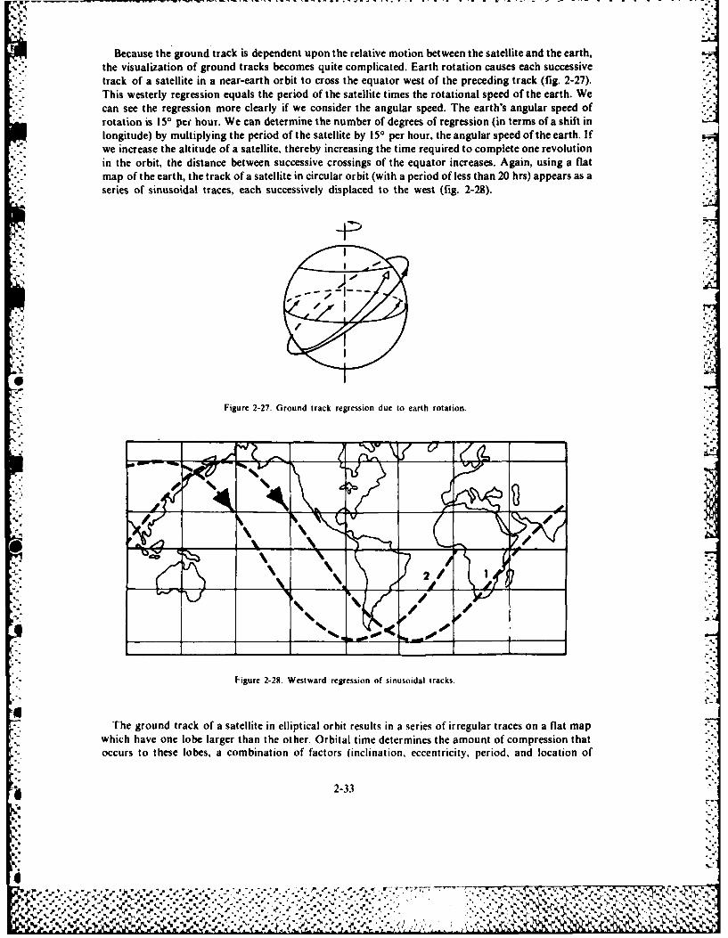
Because the ground track is dependent upon the relative motion between the satellite and the earth,the visualization of ground tracks becomes quite complicated. Earth rotation causes each successivetrack of a satellite in a near-earth orbit to cross the equator west of the preceding track (fig. 2-27).This westerly regression equals the period of the satellite times the rotational speed of the earth. Wecan see the regression more clearly if we consider the angular speed. The earth's angular speed ofrotation is 150 per hour. We can determine the number of degrees of regression (in terms of a shift inlongitude) by multiplying the period of the satellite by 150 per hour, the angular speed of the earth. Ifwe increase the altitude of a satellite, thereby increasing the time required to complete one revolutionin the orbit, the distance between successive crossings of the equator increases. Again, using a flatmap of the earth, the track of a satellite in circular orbit (with a period of less than 20 hrs) appears as a
* series of sinusoidal traces, each successively displaced to the west (fig. 2-28).
2 J#
000
Figure 2-28. Westward regression of sinusoidal tracks.
The ground track of a satellite in elliptical orbit results in a series of irregular traces on a flat mapwhich have one lobe larger than the other. Orbital time determines the amount of compression thatoccurs to these lobes, a combination of factors (inclination. eccentrtcity, period, and location of
2-33
U.%0%%
% _____________________
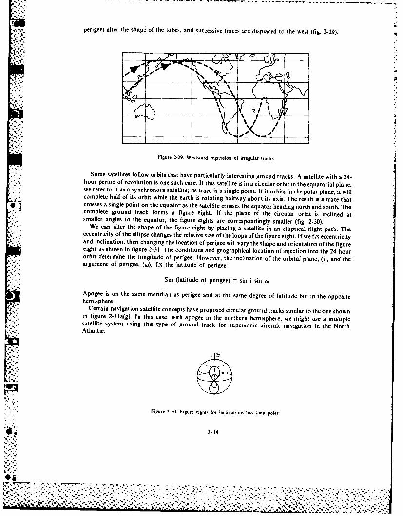
perigee) alter the shape of the lobes, and successive traces are displaced to the west (fig. 2-29).
i:0
2i
'YI
Figure 2-29. Westward regression of irregular tracks.
Some satellites follow orbits that have particularly interesting ground tracks. A satellite with a 24-hour period of revolution is one such case. If this satellite is in a circular orbit in the equatorial plane,.'we refer to it as a synchronous satellite; its trace is a single point If it orbits in the polar plane, it will,.
- . complete half of its orbit while the earth is rotating halfway about its axis. The result is a trace that .; • crosses a single point on the equator as the satellite crosses the equator heading north and south. The
%'- complete ground track forms a figure eight. If the plane of the circular orbit is inclined at:, smaller angles to the equator, the figure eights are correspondingly smaller (fig. 2-30).~eccentricity of the ellipse changes the relative size of the loops of the figure eight. If we fix eccentricity
and inclination, then changing the location of perigee will vary the shape and orientation of the figureeight as shown in figure 2-31. The conditions and geographical location of injection into the 24-hourorbit determine the longitude of perigee. However, the inclination of the orbital plane, (i), and theargument of perigee, (wu), fix the latitude of perigee:
' '"-"Sin (latitude of perigee) =sin i sin tu
[A] Apogee is on the same meridian as perigee and at the same degree of latitude but in the opposite: ,- ,hemisphere.
!' 'iCertain navigation satellite concepts have proposed circular ground tracks similar to the one shown,..in figure 2-31a(g). In this case, with apogee in the northern hemisphere, we might use a multiple
satellite system using this type of ground track for supersonic aircraft navigation in the North!'i-': : Atlantic.
:II
JJ
Figure 2-30. F Wgure eights for inclinations less than polar.
---- I2-34SiohceuA e
horpro o eouin soeschcs.I hi aeltei nacrclrobt nteeutoilpaewerfrt t sasnhoou aelt; t rc sa igepit.I tobt i h oa pae twl
copeehl-fisori hl h at i oaighlwyabu t xs h esl sataeta
- crosses a singl point.,. :..., on_- the.. equato as,..the .. satellit crose th equato heading north, an soth. The..,,-., ..
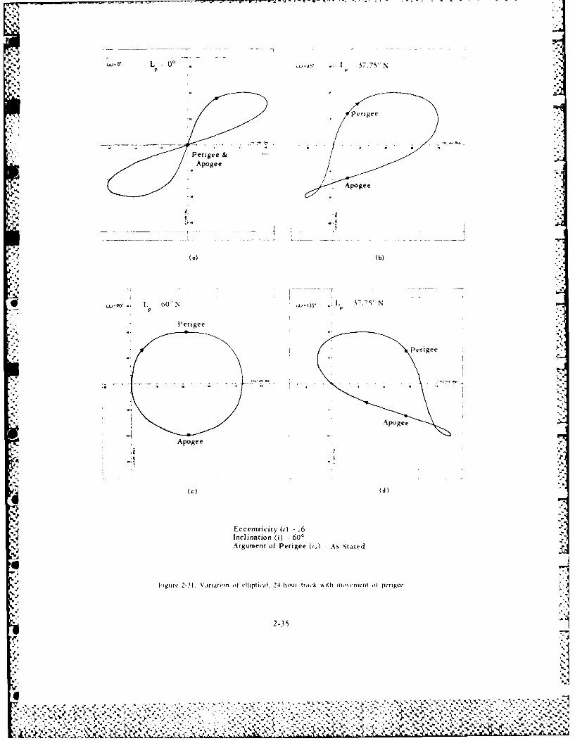
L 00 I. 37.75" N
L Perigee
Perigee &
"- Apogee
4
! Eccentricity ( ) :- .6Inclination (i) 7. 600Argument of Perigee (P) As Stated
F" I- gurc 2-3l Vitrimion of tclhplicd, 24-hour trac~k o~tth aIr flro~tr 0 perigee
~2-35 Ec e trct (or -.
..46
. % % - , ' ,, .1! . . 0 . ' , "A

UJ10 L =0~.22 L -. 37.75c~ Sp P
Apoge
Peerigee
zI
Eccentrictyerigee.
Inclination (i) = 600Argument of Perigee ((o) =As Stated
F-igure 2-31a. Variation of elliptical. 24 hour track with movement of perigee. continued.
2-36
I;V
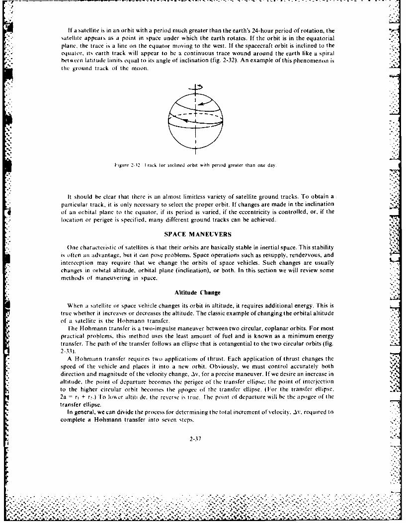
W* '- -
A.
If a satellite is in an orbit with a period much greater than the earth's 24-hour period of rotation, thesatellite appears as a point in space under which the earth rotates. If the orbit is in the equatorialplane, the trace is a line on the equator moving to the west. If the spacecraft orbit is inclined to the -<
equator, its earth track will appear to be a continuous trace wound around the earth like a spiralhetweien latitude limits equal to its angle of inclination (fig. 2-32). An example of this phenomenon isthe ground track of the moon.
Figure 2-32 1 rack for inclined orbit with period greater than one day.
It should be clear that there is an almost limitless variety of satellite ground tracks. To obtain a "particular track, it is only necessary to select the proper orbit. If changes are made in the inclinationof an orbital plane to the equator, if its period is varied, if the eccentricity is controlled, or, if thelocation or perigee is specified, many different ground tracks can be achieved.
SPACE MANEUVERS
One characteristic of satellites is that their orbits are basically stable in inertial space. This stabilityis often an advantage, but it can pose problems. Space operations such as resupply, rendezvous, andinterception may require that we change the orbits of space vehicles. Such changes are usuallychanges in orbital altitude, orbital plane (inclination), or both. In this section we will review somemethods of maneuvering in space.
Altitude Change
When a satellite or space vehicle changes its orbit in altitude, it requires additional energy. This istrue whether it increases or decreases the altitude. The classic example of changing the orbital altitudeof a satellite is the Htohmann transfer.
ihe Hlohmann transfer is a two-impulse maneuver between two circular, coplanar orbits. For mostpractical problems, this method uses the least amount of fuel and is known as a minimum energytransfer. The path of the transfer follows an ellipse that is cotangential to the two circular orbits (fig.2-33).
A Hohmann transfer requires two applications of thrust. Each application of thrust changes thespeed of the vehicle and places it into a new orbit. Obviously, we must control accurately both
* direction and magnitude of the velocity change, Av, for a precise maneuver. If we desire an increase inaltitude, the point of departure becomes the perigee of the transfer ellipse: the point of interjection'",to the higher circular orbit becomes the itpogee of the transfer ellipse. (For the transfer ellipse.
2a = ri + r2.) To Io er altitt.de, the reverse is true. -he point of departure will be the apogee of thetransfer ellipse.
In general, we can divide the process for determining the total increment of velocity, Av. required tocomplete a Hohmann transfer into seven steps.
2-37
- ? ;. .. ::. 2 .: :j:~o.-:..%" %
!,. .- ,, . €' ,e .' ' ," ." ' .' ." .' . .' ,',.'., ., -.- ' ." °" .' ." ." ', .-t,. " r,...,-.-- .- ., -. -.. - ... ¢ -- °- -. 'o -. -, -...... .M.

1. Determine the velocity the vehicle has in the initial orbit.
2. Determine the velocity required at the initial point in the transfer orbit. Iri a
3. Solve for the vector difference between the velocities found in steps I and 2.
4. Find the velocity the vehicle has at the final point in the transfer ellipse.
v2 \/hI or V ,ftr2 a r2
5. Compute the velocity required to keep the vehicle in the final orbit.
~Vc2r2
U6. Find the vector difference between the velocities found in steps 4 and 5.
7. Find the total Av for the maneuver by adding the Av from step 3 to the Av from step 6.
ellipse
.I.. J
-VAV
-S.
Figure 2-33.
From a practical point, once we know the required Av, we can compute the amount of propellant
required for the maneuver from A-= iLIn W In mass ratio, as discussed in chapter 3.
2-38
% f'tf..,t~'t.f.f . ..- ff-ff'ff*. : -- f
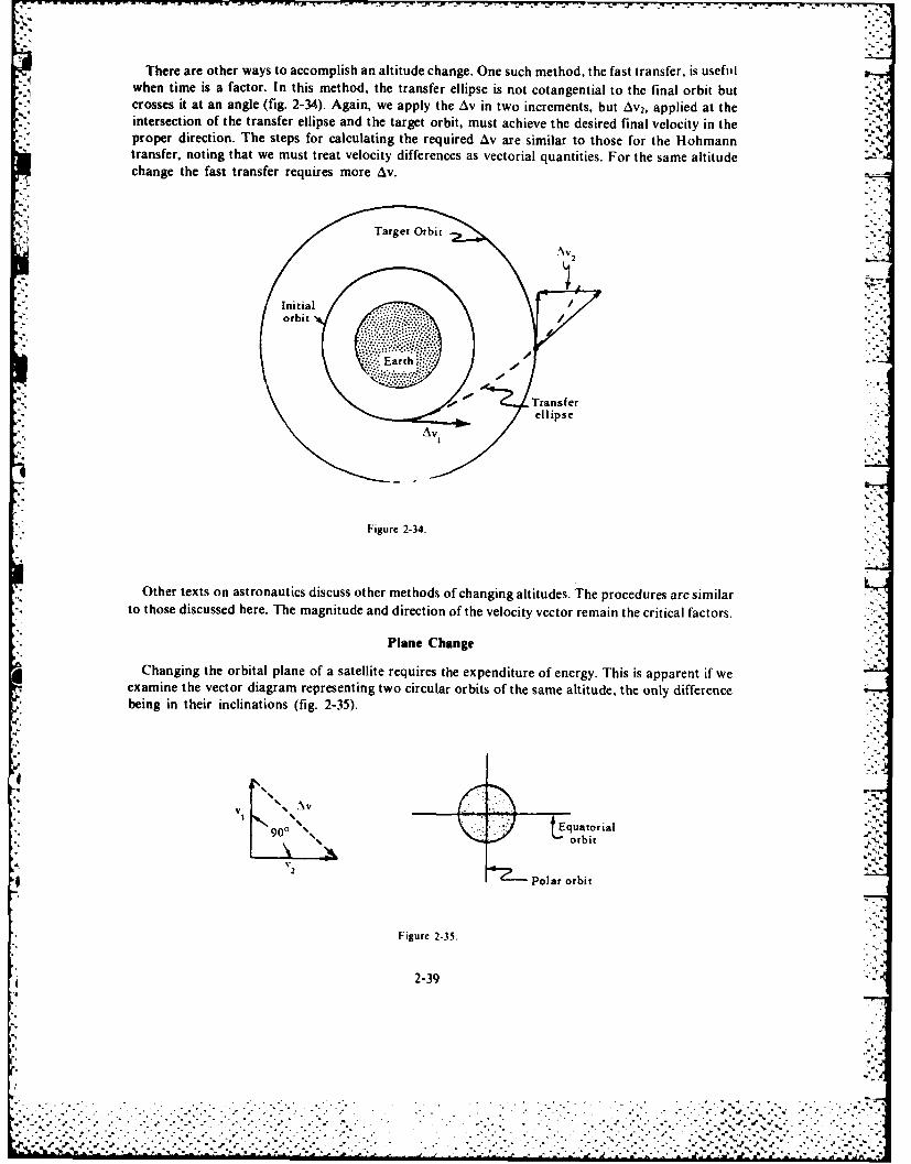
There are other ways to accomplish an altitude change. One such method, the fast transfer, is usefIllwhen time is a factor. In this method, the transfer ellipse is not cotangential to the final orbit butcrosses it at an angle (fig. 2-34). Again, we apply the Av in two increments, but Av 2, applied at theintersection of the transfer ellipse and the target orbit, must achieve the desired final velocity in theproper direction. The steps for calculating the required Av are similar to those for the Hohmanntransfer, noting that we must treat velocity differences as vectorial quantities. For the same altitudechange the fast transfer requires more Av.
Frget 2-34.
*: totoedsusdhr.Temgiueaddrcino/h eoi y vetrreanth rtia acos
v .2
orbirbi
"- ellipse -'
Figure 2-34.
Other texts on astronautics discuss other methods of changing altitudes. The procedures are similar
to those discussed here. The magnitude and direction of the velocity vector remain the critical factors. '"
Plane ChangeChanging the orbital plane of a satellite requires the expenditure of energy. This is apparent if we
examine the vector diagram representing two circular orbits of the same altitude, the only difference -"
being in their inclinations (fig. 2-35).
VIN 0"'% J f Equatorial.P:?'r
| 90 %, , ""orbit .,:
v 7-'---Polar orbit
Figure 2-35.
2-39
W . ......... .. ... .... . .. -. S ,. - . ,, S ..- , .
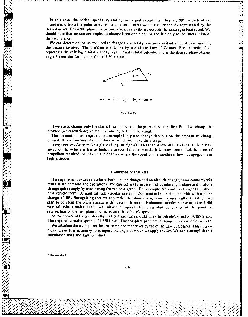
In this case, the orbital speeds, v, and V2, are equal except that they are 900, to each other.Transferring from the polar orbit to the equatorial orbit would require the Av represented by thedashed arrow. For a 900 plane change (an extreme case) the Av exceeds the existing orbital speed. Weshould note that we can accomplish a change from one plane to another only at the intersection ofthe two planes.
We can determine the Av required to change the orbital plane any specified amount by examining L
the vectors involved. The problem is solvable by use of the Law of Cosines. For example, if vi irepresents the existing orbital velocity, V2 the final orbital velocity, and af the desired plane change
angle,* then the formula in figure 2-36 results.
2VI
V
AV 2 = V
2 + V- 2v v cos c&
1 2 1 2
Figure 2-36.
If we are to change only the plane. then v, V2 and the problem is simplified. But, if we change thealtitude (or eccentricity) as well, yR and v2 will not be equal.
The amount of A1v required to accomplish a plane change depends on the amount of changedesired, It is a function of the altitude at which we make the change.
It requires less Av to make a plane change at high altitudes than at low altitudes because the orbitalspeed of the vehicle is less at higher altitudes. In other words, it is more economical, in terms ofpropellant required, to make plane changes where the speed of the satellite is low-at apogee, or athigh altitudes.
Combined Maneuvers
If a requirement exists to perform both a plane change and an altitude change, some economy willresult if we combine the operations. We can solve the problem of combining a plane and altitudechange quite simply by considering the vector diagram. For example, we want to change the altitudeof a vehicle from 100 nautical mile circular orbit to 1,500 nautical mile circular orbit with a planechange of 100. Recognizing that we can make the plane change more economically at altitude, weplan to combine the plane change with injection from the H-ohmann transfer ellipse into the ,0V nautical mile circular orbit. We initiate a typical Hohmann alaitude change at the point ofintersection of the two planes by increasing the vehicle's speed.
At the apogee of the transfer ellipse ( 1,500 nautical mile altitude) the vehicle's speed is 19,800 ft sec.The required circular speed is 21,650 ft/sec. The complete problem. at apogee, is seen in figure 2-37.
We calculate the Av required for the combined maneuver by use of the Law of Cosines. This is: A~V4,055 ft/sec. It is necessary to compute the angle at which we apply the Asv. We can accomplish thiscalculation with the Law of Sines.
See appendix S.
2-40
P.
-- . .... . . . . . . . . . . . . .
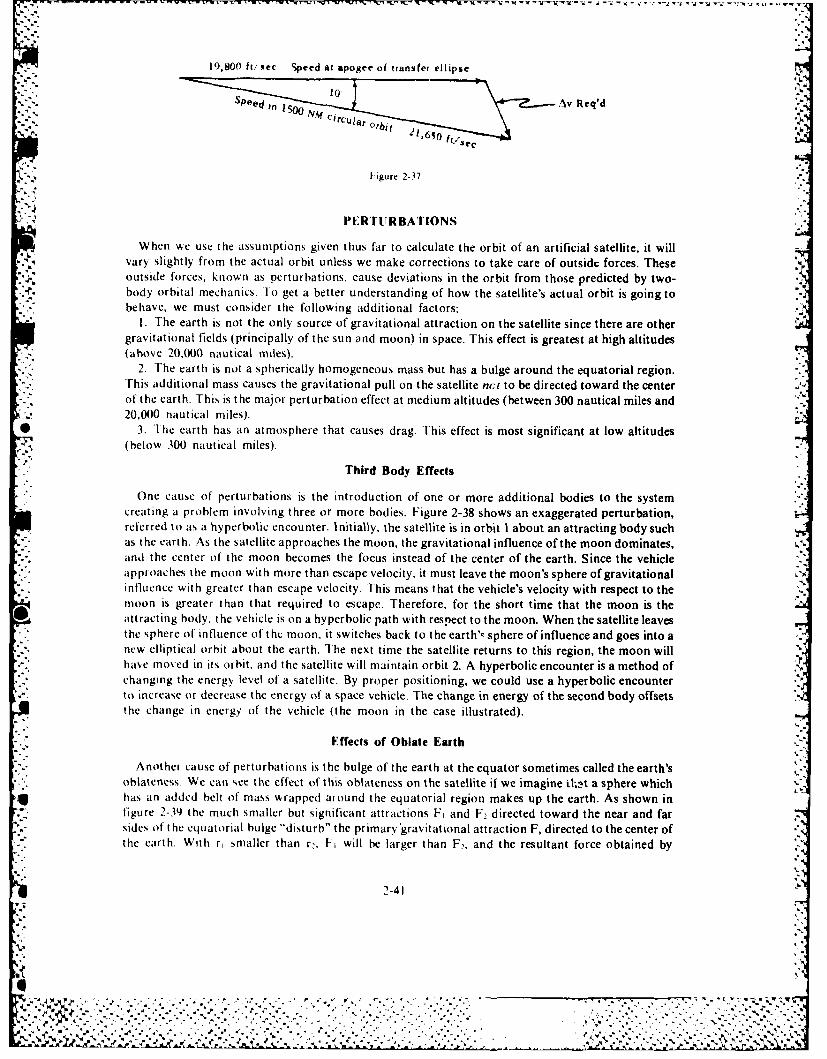
19,800 ft/ %ec Speed at apogee of transfer ellipse
10L
Av Req'd
circuar Obi' I.65
Figure 2-37.
'I.' PERTURBATIONS
When we use thle assumptions given thus far to calculate the orbit of an artificial satellite, it willvary slightly from the actual orbit unless we make corrections to take care of outside forces. Theseoutside forces, known as perturbations, cause deviations in the orbit from those predicted by two-body orbital mechanics. To get a better understanding of how the satellite's actual orbit is going tobehave, we must consider the following additional factors:
1. The earth is not the only source of gravitational attraction on the satellite since there are othergravitational fields (principally of the sun and moon) in space. This effect is greatest at high altitudes(above 20.000 nautical miles).
2. The earth is not a spherically homogeneous mass but has a bulge around the equatorial region.This additional mass causes the gravitational pull on the satellite nct to be directed toward the centerof the earth.. This is the major perturbation effect at medium altitudes (between 300 nautical miles and20,000 nautical miles).
* 3. 1The earth has an atmosphere that causes drag. This effect is most significant at low altitudes(below 300 nautical miles).
Third Body Effects
One cause of perturbations is the introduction of one or more additional bodies to the systemcreating a problem involving three or more bodies. Figure 2-38 shows an exaggerated perturbation,referred to as a hyperbolic encounter. Initially, the satellite is in orbit I about an attracting body suchas the earth. As thle satellite approaches the moon, the gravitational influence of the moon dominates,and the center of the moon becomes the focus instead of the center of the earth. Since the vehicle
*approaches the moon with more than escape velocity, it must leave the moon's sphere of gravitational6* influence with greater than escape velocity. 'This means that the vehicle's velocity with respect to the
moon is greater than that required to escape. Therefore, for the short time that the moon is theattracting body, the vehicle is on a hyperbolic path with respect to the moon. When the satellite leavesthe sphere of influence of the moon, it switches back to the earth'--sphere of influence and goes into anew elliptical orbit about the earth. The next time the satellite returns to this region, the moon will
* have moved in its orbit, and the satellite will maintain orbit 2. A hyperbolic encounter is a method ofchanging the energ level of a satellite. By proper positioning, we could use a hyperbolic encounter
* to increase or decrease the energy of a space vehicle. The change in energy of the second body offsetsthe change in energy of the vehicle (the moon in the case illustrated).
Effects of Oblate Earth
Another cause of perturbations is the bulge of the earth at the equator sometimes called the earth'soblateness. We can see the effect of this oblateness on the satellite if we imagine 0int a sphere whichhas an added belt of mass wrapped around the equatorial region makes up the earth. As shown infigure 2-39) the much smaller but significant attractions F, and F2 directed toward the near and farsides of t he equatorial bulge "disturb" the prim ary gravitatitonal attraction F, directed to the center ofthe earth. With r, smaller than r2, F, will be larger than F2, and the resultant force obtained by
2-41
4 ' 4 i \ * . .d, ., J". .
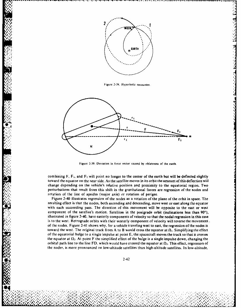
Figure 2-38. Hyperbolic encounter.
r 2 F,
Figure 2-39. Deviation in force vector caused by oblateness of the earth.
combining F. F1, and F2 Will point no longer to the center of the earth but will be deflected slightlytoward the equator on the near side. As the satellite moves in its orbit the amount of this deflection willchange depending on the vehicle's relative position and proximity to the equatorial region. Twoperturbations that result from this shift in the gravitational forces are regression of the nodes androtation of the line of apsides. (major axis) or rotation of perigee.
Figure 2-40 illustrates regression of the nodes as a rotation of the plane of the orbit in space. Theresulting effect is that the nodes, both ascending and descending, move west or cast along the equatorwith each succeeding pass. The direction of this movement will be opposite to the east or westcomponent of the satellite's motion. Satellites in the posigrade orbit (inclinations less than 90'),illustrated in figure 2-40, have easterly components of velocity so that the nodal regression in this caseis to the west. Retrograde orbits with their westerly component of velocity will reverse the movementof the nodes. Figure 2-41 shows why, for a vehicle traveling west to east, the regression of the nodes istoward the west. The original track from A to B would cross the equator at l. Simplifying the effectof the equatorial bulge to a single impulse at point E, the spacecraft moves the track so that it crossesthe equator at f12. At point F the simplified effect of the bulge is a single impulse down, changing theorbital path line to the line FD, which would have crossed the equator at 013. This effect, regression ofthe nodes, is more pronounced on low-altitude satellites than high-altitude satellites. In low-altitude,
2-42
-U%-%
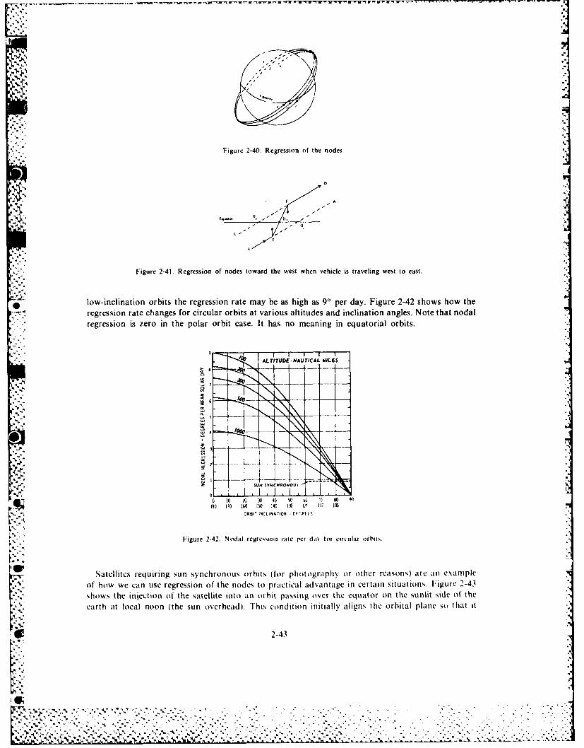
Figure 2-40. Regression of the nodes.
IF IN-i A
Figure 2-41. Regression of nodes toward the west when vehicle is traveling west to east.
low-inclination orbits the regression rate may be as high as 90 per day. Figure 2-42 shows how theregression rate changes for circular orbits at various altitudes and inclination angles. Note that nodal
regression is zero in the polar orbit case. It has no meaning in equatorial orbits.
ALTITUDE.NA TICAL IILE S
SUN tYMCCEONOLIL
IO0 10 0 I 0 40 50 D 1 sO O180 110 160 150 140 11 0 I ( IF (A
ORBIT NCtINATIQ1 -CF -Pt i
Figure 2-42. Nodal regression rate per dai, for circulat orbits.
Satellites requiring sun synchronous orbits (for photography or other reasons) are an example
of how we can use regression of the nodes to practical advantage in certain situations, Figure 2-43shows the injection of the satellite into an orbit passing over the equator on the sunlit side of theearth at local noon (the sun overhead). lhis condition initially aligns the orbital plane so that it
2-43
k..
:..L
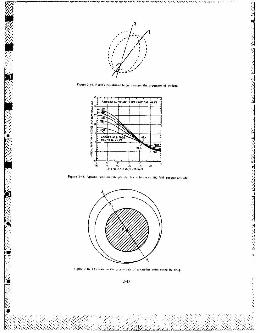
EQ'. !"J - IL*' Is
".- | ,1 ,, /'I .. . .'' " I
%-%
Figure 2-44. Earth's equatorial bulge changes the argument of perigee.]
PERIGEE ALTITUDE IiS O0 NAUTICAL MILES
200
APOGEE ALTITUDE .4NAUTICAL MAILESli
2-45 5 1
ORBITAL I4CLNATION - FCOQEES
Figure 2-45. Apsidal rotation rate per daN for orbits with 100 NM perigee altitude.
3,
'5
F igure 2-46. l)ecrcasm iic he ecent ricat lY ota satellite orbit cased by drag.
-2-45
L """"A ''" '":""""' " '"' '' "" "'"" " " " " '" " -'" " '""" ":":
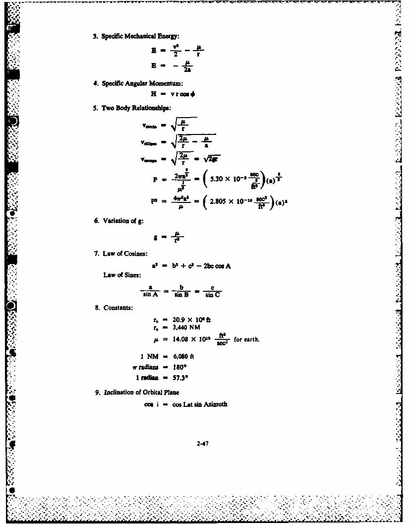
3. Specific Mechanical Energ:B " _"
* - 2 r -
4. Specific Angular Momentum:H - vroos#
5. Two Body Relationships:V~~dus ms q4:/--* i
a.'.k
v.,,. - - a+iF:
1&411"g r
+..+..p - --s 5.30 X 10- 8 a T'1
_. 0-2.805 X 10⁻¹⁵ (a)"
." 6. Variation of g:
r2
7. Law of Cosines:
a - bt + cP - 2bcc9ALaw of Sines:
a b c "..sinA sinB -i- C
8. Constants:
r. - 20.9 X 100oftr, - 3,440 NM
-.!- 14.08 X 101 5 - for earth.
1 NM - 6,080ft.,radians - 1800
I radiam - $7.3°
9. Inclination of Orbital Plane
cos i - cos Lat sin Azimuth %
2-47
': '-..'-:.-',.-.-..- -".-+.-i 9 i-' ....- +.'-.-. . . ..-.. ..-.. .--- -, - . -", ; --.. -, .- , . .-.- - - --- v
* . - i I n -~ I a -- . . . . . . . - -- a.. .. . .

BIB I. IOGRAPH Y
Berman, Arthur I. The PhYsical Principles of Astronautics. New York: John Wiley and Sons, Inc.. 1961.Department of Astronautics, US Air Force Academy. Astronautris. Elements of Free Flight Trajectories. US Air Force
Academy, 1%1.Ehricke _ Kraft. Environment and Space Mechanics. Vol. I of Space Flight. Princeton, N.J.: Van Nostrand and Co. 1960.
Dynamics. Vol. 2 of Space Flight. Princeton, N.J.: Van Nostrand and Co.. 1960.Ely, Lawrence D. Space Science for .he Layman. Springfield. Ill.: Charles C. Ihomas Co., 1967.
4 El'Yasberg, P.E. Introduction to the Theory of Flight of Artificial Earth Satellites. (Translated from Russian.) Jerusalem:Israel Program for Scientific Translations, 1967.
Fowles, Grant R. Analytical Mechanics. Chicago: Holt. Rinehart, and Winston. 1963.Glasstone. Samuel. Sourcebook on the Space Sciences. Princeton, N.J.. Van Nostrand Co., 1965.Koestler. Arthur. The Sleepwalkers. New York: The MacMillan Co.. 1959.LeGalley, Donald P. Guidance. Navigation. Tracking, and Space Ph. i-it Vol. 3 of Ballistic Missile and Space Technofogi.
New York: Academic Press, 1960.. Ruppe, Harry 0. Introduction to Astronautics. New York: Academic Press, 1966.
Szebehely, Victor G. Celestial Mechanicv and Astrodinamu . Vol. 14 of the Progress in A , mauts.s and Aeronaotits
New York: Academic Press. 1964. H____ _ Theory of Orbits. New York: Academic Press. 1967.
US Naval Academy. Space Flight Handbook. Washington D.C.: US Government Printing Office, 1962. (NAVPERS 92988).
4o'
N
,- °
N %
4 .,
. '°.,
.4,%
2-4X
yA .,. yi ,,.~~.,
.,". '.. .,,-. ... ..- . ',. ,. . ' ,. . , ... ;. .. ..',.- '.. .-. .... ... .. .. . . . . . ..,- ...,
4 ,4 4..A, ,.,,,e r' , "'.. ,; ' ,,,. ., ,: r ":?,7,=,3 "".} ' ,. ,"."x .•,.,..., .",.,- -,r-,,\,"" :',;," '' - . ."",1;
Chapter 3
PROPULSION SYSTEMS
Throughout history, the methods of propulsion that people have been able to control have allowedthem to go faster, farther, and higher. Today they use rockets to send payloads into space. A spacemission needs a launch vehicle or booster that will withstand high acceleration and aerodynamic
forces as it lifts the payload from the surface of the earth. To be successful, the mission requiresadequate ground equipment to launch and track the flight vehicle, propulsion and guidance to place iton the desired trajectory, reliable electric power sources, and communication equipment to send databack to earth. Finally, mission success requires trained personnel who follow correct procedures toensure that all subsystems operate properly.
Rocket propulsion is vital in any successful space program. Without it, there would be no payloads:41 in space. Because the scope of the rocket propulsion field is far too extensive, we cannot treat it
comprehensively in a single chapter. Therefore, we cover only a limited number of topics in this* chapter. These topics include the theory of rocket propulsion, rocket propellants, types of chemical
rocket engines, and advanced propulsion techniques.
THEORY OF ROCKET PROPULSION
Newton's three laws of motion apply to all rocket-propelled vehicles. They apply to gas jets used forattitude control, small rockets used for stage separation or for trajectory correction, and large rocketsused to launch a vehicle from the surface of the earth. They apply to nuclear, electric, and other
* advanced types of rockets, as well as to chemical rockets. Newton's laws of motion are stated brieflyas follows:
* .1. Bodies in uniform motion, or at rest, remain so unless acted upon by an external unbalanced force.
2. The force required to accelerate a body is proportional to the product of the mass of the body and the,acceleration desired.
3. To every action there is an equal and opposite reaction.
In relating these laws to propulsion, we may paraphase and simplify them. For example, the first
law says, in effect, that the engines must be adequate to overcome the inertia of the launch vehicle.The engines must be able to start the vehicle moving and accelerate it to the desired velocity. Anotherway of expressing this for a vertical launch is to say that the engines must develop more pounds ofthrust than the vehicle weighs. Some space missions require slowing the vehicle or changing itsdirection. We must apply an unbalanced force to accomplish these tasks. Newton's first law isuniversal and therefore applies not only to a vehicle at rest on a planet, but also to a vehicle in the so-
* called "weightless" condition of free flight.We must consider several forces when applying the second law. For example, the accelerating force
is the net force acting on the vehicle. This means if we launch a I100,000-pound vehicle vertically fromthe earth with a I 50.000-pound thrust engine, there is a net force at launch of 50,000 pounds-the
* 3-1
....................... --------------------------------------

F'I.
difference between engine thrust and vehicle weight. Here the force of gravity is acting opposite to the
direction of the thrust of the engine.Propellants comprise approximately 90 percent of the vehicle's weight at launch. The engines
expend propellants as they run, decreasing the vehicle weight. Therefore, the net force acting on thevehicle increases, and the vehicle accelerates rapidly.
Figure 3-1 shows the acceleration and the resulting velocities attained during powered flight. The
acceleration and velocity are low at launch and just after launch due to the small net force acting at
that time. Both acceleration and velocity increase rapidly as the engine burns the propellants. When
the vehicle shuts off the first stage engine and staging occurs, acceleration drops sharply. When the
second stage engine ignites, acceleration and velocity will increase again. As the upper stage rocketengines burn more propellants, rapid increases in acceleration and velocity occur. When the vehicle
reaches the correct velocity (speed and direction) and altitude for the mission, it terminates the thrust.
Acceleration drops to zero after thrust termination, or burnout, and the vehicle begins free flight. Forvehicles with three, four, or more stages, similar changes appear in both the acceleration and velocityeach time staging occurs. Staging a vehicle increases the velocity in steps to the high values requiredfor space missions.
/A
* V/i iIo-
0 TIME 0 TIME
Figure 3-1. Powered flight of a typical two-stage rocket.
Newton's second law also applies to a vehicle in orbit. Since the vehicle is in a "weightless"condition, the acceleration for a given thrust depends on the vehicle mass, because the vehicle still hasmass even though it is "weightless." Remember that mass is the quantity of matter in a body, whereasweight is the force exerted on a given mass by a gravitational field. The mass of a body is the sameeverywhere, but its weight depends on its mass, the gravitational field, and its position in thegravitational field.
A given thrust will give a large acceleration to a vehicle with a small mass or a small acceleration toa vehicle with a large mass. Fven a very small thrust (0. I pound or less) operating for a long time canaccelerate an earth-orbiting vehicle to the velocities needed to go to the other planets of our SolarSystem. The section of this chapter on low-thrust engines discusses such propulsion systems.
% n I o relate Newton's third. or "action-reaction," law to rocket propulsion, consider what happens inthe rocket motor (fig. 3-2). All rockets develop thrust by expelling particles (mass) at high velocityfrom their exhaust no/iles. The effect of the ejected exhaust appears as a reaction force, called thrust,acting in a direction opposite to the direction of the exhaust.
2,1 Today. practically all exhaust no/,les, whether for a liquid- or a solid-propellant rocket, use someform of the de I.a% al (com erging-dts erging) no//le. It accelerates the exhaust products to supersonicvelocities hv onserting ,ome of the thermal energy of the hot gases into kinetic energy.
k"--2
' %"
64l
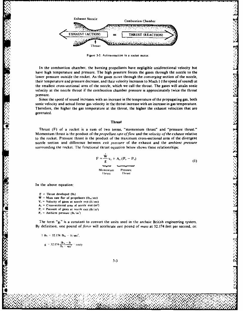
Exhaust Nozzle Combustion Chamber
6 EXHAUST (ACTION) = THRUST (REACTION)
Figure 3-2. Action-reaction in a rocket motor.
In the combustion chamber, the burning propellants have negligible unidirectional velocity buthave high temperature and pressure. The high pressure forces the gases through the nozzle to thelower pressure outside the rocket. As the gases move through the converging section of the nozzle,their temperature and pressure decrease, and their velocity increases to Mach I (the speed of sound) atthe smallest cross-sectional area of the nozzle, which we call the throat. The gases will attain sonicvelocity at the nozzle throat if the combustion chamber pressure is approximately twice the throatpressure.
Since the speed of sound increases with an increase in the temperature of the propagating gas, bothsonic velocity and actual linear gas velocity in the throat increase with an increase in gas temperature.Therefore, the higher the gas temperature at the throat, the higher the exhaust velocities that aregenerated.
Thrust
Thrust (F) of a rocket is a sum of two terms, "momentum thrust" and "pressure thrust."Momentum thrust is the product of the propellant rate offlow and the velocity of the exhaust relativeto the rocket. Pressure thrust is the product of the maximum cross-sectional area of the divergentnozzle section and difference between exit pressure of the exhaust and the ambient pressuresurrounding the rocket. The functional thrust equation below shows these relationships:
F - v, + A, (P, - P,)
Momentum Pressurethrust Thrust
In the above equation:
F = Thrust developed (lb,)= Mass rate flor of propellants (lb,/sec)
V, = Velocity of gases at nozzle exit (ft/sec)A, = Cross-sectional area of nozzle exit (in)P, = Pressure of gases at norile exit (Ib/in2)P, Ambient pressure (lbin:)
The term "g," is a constant to convert the units used in the archaic British engineering system.By definition, one pound of force will accelerate one pound of mass at 32.174 feet per second, or:
I lb, = 32.174 lb, - ft, sec.
lb -- ft3= 2 174 ... .. = unityIb sec"
3-3
Wk
"" "'.. . ".. . " '" " " : " " ' ,h .. .. :,,) ,, ,. - .. ..., ..,,.... .. . ,[ o ...- ., . .. .. - . ,, , . ', . ... - -. -.-.. ,. . .,,. -.,-,,.:,%• , ' ,-" :''- ':' .-.'."'"- -''.''." -. ; ".-'- "'.:,' ..- ''-.-3-': ., ."" .. ,''"''- ....% ,, %.
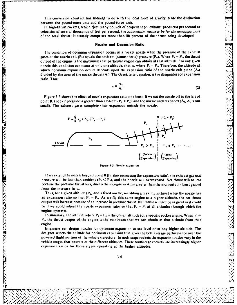
This conversion constant has nothing to do with the local force of gravity. Note the distinctionbetween the pound-mass unit and the pound-force unit.
In high-thrust rockets, which eject many pounds of propellant (P: exhaust products) per second atvelocities of several thousands of feet per second, the momentum ihrust is by far the dominant partof the total thrust. It usually comprises more than 80 percent of the thrust being developed.
Nozzles and Expansion Ratio
The condition of optimum expansion occurs in a rocket nozzle when the pressure of the exhaustgases at the nozzle exit (Pe) equals the ambient (atmospheric) pressure (P.). When P. = P., the thrustoutput of the engine is the maximum that particular engine can obtain at that altitude. For any givennozzle this condition can occur at only one altitude, that is, where P, = P.. Therefore, the altitude atwhich optimum expansion occurs depends upon the expansion ratio of the nozzle exit plane (A)-divided by the area of the nozzle throat (A,). The Greek letter, epsilon, is the designator for expansionratio. Thus:
At (2)
Figure 3-3 shows the effect of nozzle expansion ratio on thrust. If we cut the nozzle off to the left ofpoint B, the exit pressure is greater than ambient (P. > Po), and the nozzle underexpands (A0 / A, is toosmall). The exhaust gases complete their expansion outside the nozzle.
F" + B (P. = P) -: .
F= Ve +A (P.-P)
P
Thrust "€-' -- P. > P. I P. < P --- .._.-( Under- (over.
Expanded) (Expanded)
Figure 3-3. Notile expansion. .
If we extend the nozzle beyond point B (further increasing the expansion ratio), the exhaust gas exitpressure will be less than ambient (P, < P.), and the nozzle will overexpand. Net thrust will be lessbecause the pressure thrust loss, due to the increase in A., is greater than the momentum thrust gainedfrom the increase in v,.
Thus, for a given altitude (P.) and a fixed nozzle, we obtain a maximum thrust when the nozzle hasan expansion ratio so that P, = P,. As we fly this same engine to a higher altitude, the net thrustoutput will increase because of an increase in pressure thrust. Net thrust will not be as great as it couldbe if we could adjust the nozzle expansion ratio so that P, = Po at all altitudes through which theengine operates.
In summary, the altitude where P, = P. is the design altitude for a specific rocket engine. When P =P. the thrust output of the engine is the maximum that we can obtain at that altitude from thatengine.
Engineers can design nozzles for optimum expansion at sea level or at any higher altitude. Thedesigner selects the altitude for optimum expansion that gives the best average performance over thepowered flight portion of the vehicle trajectory. In multistage rockets the expansion ratios vary in thevehicle stages that operate at the different altitudes. These multistage rockets use increasingly higherexpansion ratios for those stages operating at the higher altitudes.
.-4...,, .
K' -,,
.-. 4
w, %
IL -.',.".......- "• -- • .'. ". -."." "-."..-:- . .". ... . .'.- • :'. .-" . " :." .-' " "- - ." - ... '....' .'.' -.-7.'7
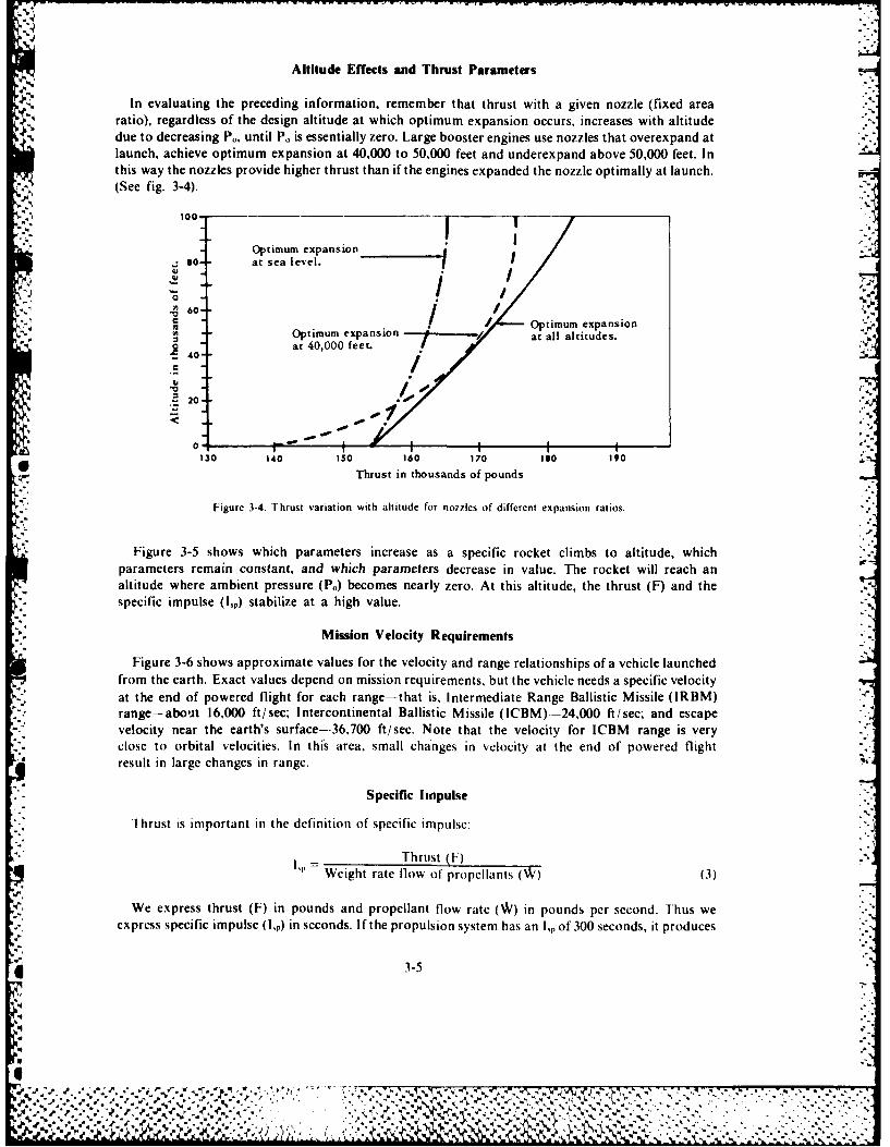
Altitude Effects and Thrust Parameters
In evaluating the preceding information, remember that thrust with a given nozzle (fixed arearatio), regardless of the design altitude at which optimum expansion occurs, increases with altitude
due to decreasing P., until P, is essentially zero. Large booster engines use nozzles that overexpand atlaunch, achieve optimum expansion at 40,000 to 50,000 feet and underexpand above 50,000 feet. Inthis way the nozzles provide higher thrust than if the engines expanded the nozzle optimally at launch. -
(See fig. 3-4).
100-
Optimum expansion
so-- at sea level.
.0 .' ,o .-~ .~ 60-)
S /- Optimum expansion- Optimum expansion at all altitudes.
40 at 40,000 feet. -.
:~ ~~ ~~O - _ -.-- ',~ ~ oi
/n7I
"~0
0 130 140 150 160 170 IM0 190
Thrust in thousands of pounds
Figure 3-4. Thrust variation with altitude for nonzles of different expansion ratios.
Figure 3-5 shows which parameters increase as a specific rocket climbs to altitude, whichparameters remain constant, and which parameters decrease in value. The rocket will reach analtitude where ambient pressure (P.) becomes nearly zero. At this altitude, the thrust (F) and thespecific impulse (lp) stabilize at a high value.
Mission Velocity Requirements
Figure 3-6 shows approximate values for the velocity and range relationships of a vehicle launchedfrom the earth. Exact values depend on mission requirements, but the vehicle needs a specific velocityat the end of powered flight for each range-that is, Intermediate Range Ballistic Missile (IRBM)range-about 16,000 ft/sec; Intercontinental Ballistic Missile (ICBM)--24,000 ft/sec; and escapevelocity near the earth's surface--36,700 ft/sec. Note that the velocity for ICBM range is veryclose to orbital velocities. In this area, small changes in velocity at the end of powered flightresult in large changes in range.
Specific Impulse
Thrust is important in the definition of specific impulse:
Thrust (F)=Weight rate flow of propellants (W) (3)
We express thrust (F) in pounds and propellant flow rate ( in pounds per second. Thus weexpress specific impulse (I,p) in seconds. If the propulsion system has an I, of 300 seconds, it produces
3-5
2..
'4 : . ., " - ' - . . . . . , ' . . . .. ' , , - . * ., ' , ,-. . • .'., ' , ..I, . . ."' ' - ,, ,, ' . ',r , . . , . .- "
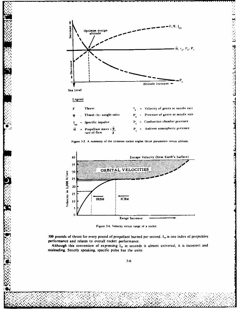
Optimum ein--- ,''
~ *4 altitude Opp
Sea evelAltitude increase -
Legend
F Thrust Ve = Velocity of gases at nozzle exit
*Thrust -to -weight ratio P = Pressure of gases at nozzle exit
I =Specific impulse p = Combustion chamber pressure
- Propellant mass P_ P = Ambient atmospheric pressurerate of flow 9
Figure 3-5. A summary of the common rocket engine thrust parameters versus altitude.
40 Escape Velocity (Near Earth's Surface)
...... ~........ ..... ::::.. .
35 .-- ---
. PIES .*30 ORBITA L VELOCIIE
S 25 *: :..
'a...,..~20
, 15
uIRBM ICBM.10
0Range Increase
Figure 3-6. Velocity versus range of a rocket.
300 pounds of thrust for every pound of propellant burned per second. 1,~ is one index of propulsiveperformance and relates to overall rocket performance.
Although this convention of expressing 1,~ in seconds is almost universal, it is incorrect and
misleading. Strictly speaking, specific pulse has the units:
Gd 3-6
lp=lbr - sec
lb,
The physical significance of 15, becomes clear when we use metric tits instead. Writing Newton's5'law, F ma,
a.Newton's (nt) kg= isecr
&P Thrust nt inMass rate flow kg/ sec sec
Hence, I,~ is simply the gas velocity V3 in equation 1.Increasing I, improves the propulsion system's ability to increase vehicle velocity. This is the
reason we quote the l1p frequently to compare the performance of similar propulsion systems. Weshould not use ip alone to compare chemical with electrical or other dissimilar propulsion systems.
In designing a propulsion system, engineers must consider many compromises because of the manyinterrelated parameters. However, when they design a chemical propulsion system only to improveI,, there are two basic approaches. One is to design a better rocket engine. The other is to use betterpropellants. We discuss these two methods later in this chapter.
Maus Ratio
Mass ratio is a structural design parameter. It relates to propulsion because the difference betweeninitial (or launch) and final (or empty) vehicle weights is the weight of propellant expended.
Initial Weight - Weight at Engine Start WIMass rai Final Weight -Weight at Engine Shutdown W2 (4)
For example, a single-stage, World War 11 rocket had a mass ratio of 3 to I (expressed asT) and a
range of approximately 200 miles. We computed the mass ratio for the rocket using these figures:
Item Launch Weight Empty Weight(Ib) (1b)
Payload............................................. 2000 2,000Propellants.......................................... 16000 0Other dry weight....................................... 6.000 6,000
Total 24,000 8.000
MasrtoLaunch Weight 24,000 3Empty Weight 8,000 1
It appeared that the way to propel a payload to greater ranges was to build bigger and betterrockets. A bigger rocket could carry more propellants, permit longer thrust time, and achieve greater
velocities and ranges. In improving the above rocket, the following ICBM design evolved:
Weight* Item (1?')
Payload................................... 200 (note decrease in payload)
Propellants................................. 1,254.000* Dry weight.................................. 29.800
Launch Weight............................... 1,284.000
a 3-7
.16 _____ _______________
W (1,284,000 Ib) 42.8Mass ratio--W, (30,000 Ib) I
Obviously, mass ratio had to increase markedly to achieve ICBM ranges. Single-stage rockets ha'c10not achieved high mass ratios. A good single stage rocket may have a-i-mass ratio. The use ot
multistage rockets has increased mass ratios. The following ICBM, based on design criteria stimilai to,but slightly better than, the World War II rocket, shows the way that staging increascs mass ratio.
Item Weight(1b)
Third Stage
Payload 200l)ry weight 800 = Vehicle weight at engine cutoff (W:I (1,000 I)
Stage "eight Propellant 2,500I otal 3,500 Vehicle weight at engine start (W.
Second stagePayload 3.500 Vehicle weight at engine cutoft (W .0 (0 000 h)
Stage weight Dry weight 6,500Propellant 25.000
lotal 35.000 Vehicle weight at engine start (Wt
First stagePayload 3500Dry weight 30,000J Vehicle weight at engine cutoff (W2) (65.000 Ih)
Stage Propellant 162,500rotal 227.500 = Vehicle weight at engine start (WO,
This rocket carried the 200-pound payload to ICBM ranges just as the scaled-up rocket wepreviously described, but it had a gross weight at launch of only 227,500 pounds about 17.7 percentof that of the scaled-up rocket. In the figures above, we use the initial weights (W I and tinal weights(W 2) for each stage to calculate the mass ratio for each stage operation. Remember, for each stage theinitial weight is the weight of the vehicle when it starts the stage's engine, and the final wveight is the
,.. weight of the vehicle when the vehicle shuts off the stage's engine. We must consider three mass iatios.
The third mass ratio is for the final stage only:
W, 3,500 lb 3.5"[hird-stage mass ratio - W . 500 Lb I 35
irs geW 2 1,00 l. lb I
The second mass ratio is for the remainder of the %chicle for second-stagc opclatio,:
35.000 lb 3.5Second-stage 0ass ratiol 10,000 lb 1[7
The first mass ratio is for the whole vehicle for first-stage opelation:
227,500 lb 3.5First-stage mass rat 65.000 lb I __
The overall mass ratio of a multistage rocket is the product ot th( -.tae tn ts, tto, I o,' c.in the three-stage rocket thte ot rall mass ratio is:
*3-8
%
-. %,# -. ,.~
N ". , , .' - . -, , - , ' . ," t\ " - ' . - , ., ',, 'v . . . . , ' , . .. " " , " , .- * . *"," - - -,' " " . ' - - - . . .. " . - - ' " - . " . " , ...
Overall mass ratio _ I -
Staging reduces the launch size and weight of the %ehicle required for a specific mission and aids in
achieving the high velocities necessary for ICBM and space missions. The velocity of the multistage
vehicle at the end of powered flight is the sum of velocity increases produced by each of the various
stages. We add the increases because the upper stages start with velocities imparted to them by the
lower stages.
Thrust-to-Weight Ratio
We express the comparison of engine thrust-to-vehicle weight as a thrust-to-weight ratio (T).
I hrust (I-)VWeight ol Iehiclc (W) (5)
"5
A vehicle launched vei tically cannot lift off the surface of the earth unless W is greater than I (F > W).
The larger the value of I, the higher the initial vehicle acceleration.
a = ('' -- I) g's (6)
The ' of the Minuteman missile is approximately 2, and its initial acceleration is about I g, comparedwith a Titan II missile with a T of about 1.4 and an initial acceleration of about 0.4g.
IDEAL VEHICLE VELOCITY CHANGE
Specific impulse and mass ratio directly affect vehicle velocity. The vehicle performance equationshows how specific impulse and mass ratio relate to the magnitude of the ideal velocity change (Avi)of each stage at burnout or thrust termination. p
Av, = 1, g,. tn (MASS RATIO) (7)
lhe ideal Av is the Ielocit\ change the rocket would attain if there were no gravity, no drag, and if theearth did not rotate'.
Scientists derived this simplified equation from Newton's second law. Generally, they use it to find
approximate Av's. [he equation will not provide the exact Av, since atmospheric drag, the earth'srotation. and the changing effects of gravity will cause variations. A precise solution is a computercalculation, but this equation gives a reasonable approximation. Due to losses, the actual Av's ofearth-latnched vehicles %kill be 4.000 to 6.000 ft sec lower than those computed with this equation.
,lhey will xarN with launch latitude and atimuth as well. ,:Equation 7 shows Av to be directly proportional to two factors: 1, and the natural logarithm (In)
of the mass ratio (MR). In other \words, increasing either 1, or MR, or both, can achieve higher Av's.
*[he equation does not consider physical siue of the rocket or propulsion system. Therefore, in theory,
different si/e rockets with identical 1., and MR would achieve the same ideal Av. Obviously, larger
payloads require larger vehicles and higher thrust engines to achieve the same range or velocity.Ihe 'g" in the equation cotnes from the conxcsion of mass to weight at the surface of the earth.
Calculations in space usc an altitude I ,. \xhich includes the increase in thrust with altitude butmeasures A' at the uiilaco l, the earth. I herefore g is alm<avs 32.2 ft. sec' in propulsion calculations.
Uquation 7 applies to all Tocke! ,chiLItc,, F-or a one-stage rocket the Av would be the final velocity
at thrust termination I. ith the niss, ritio bajsed on launch and burnout conditions. In multistage-rockets. the ideal Av is the sjmIi ofh t .ie d. eloped hx the xarious stages, with the I, and MR of
each stage used to coomptc the A. lot hat ,tagi ''s burning time.
I?.... ,..
....
Engineers may use the equation to compute Av for all space vehicles, including those with a stop
and restart capability. When the vehicle applies power in flight, a mass ratio combining initial andfinal weights of the space vehicle for each powered phase is used in the calculations.
ACTUAL VEHICLE VELOCITY CHANGE
We can express actual launch vehicle velocity as:
Av. = , - Av, + V, (8)
In this equation:
Av, = Actual Av
Av, = Ideal Av (from equation 7)
Av, = Loss in Av (gravity and drag)
v, = Variation in Av due to earth's rotation
Equation 7 may solve two types of problems. We have presente6 these problems on the succeeding
pages. We can use math tables or the graph in figure 3-7 to determine natural logarithms. Notethat, since the graph is actually a plot of natural logarithm (In) values, we may extend it to 2accommodate values beyond the limits shown. We have plotted the graph so that mass ratios are onthe vertical axis and the natural logarithms are on the horizontal axis. For example, if (WI/W 2 ) = 8,
* we find this on the vertical axis. Then we find In of 8 = 2.08 on the horizontal axis.Now, we will discuss some sample rocket performance calculations. Scientists launched a rocket
from the earth with an initial weight (WI) of 296,000 pounds. At the end of powered flight, its finalweight (W 2) was 40,000 pounds. Assuming no earth rotation and no velocity lost due to drag orgravity, calculate the magnitude of the ideal velocity (or Av,) at the end of powered flight. Assume avalue of specific impulse
1,= 300 sec
Use the equation: Av, I,P g In W
Math table method Graph method
a. Substitute a. Transpose equation to read:
296,000 .1V, W 'r % (300)(32.2) In - I n
40,000 (l,) (gJ W2
.%, = (300) (32.2) In 7.4
b. Find: In 7.4 in table. b. Calculate value of W W, W2
c. Ihen: 296,000 = .
Av, = (300) (32.2) (2.0) 40,000
Av, = 19.320 ft sec
c. Use chart, figure 3-7.
d. Enter the graph whereWjiW, =7.4 and then
3-10
,-4.,-,.9.Z
e. Read the value of:
2.0(,,,) (g)
f. Then, solving for Av,-2'A Av, = ( I,p) (g,) (2. 0)
Av, = (300) (32.2) (2.0)Av, = 19,320 ft/sec
This is a sample problem for changing an orbit. The following is a sample problem for finding thepropellants to make a change in orbit.
A space vehicle is coasting in orbit. It has a restart capability and 3,500 pounds of propellants onboard. We desire a change in orbit. Calculate the propellant required for the orbit change andwhcther we can complete the maneuver based on the following data.
Av = 14,170 ft/sec = Magnitude of velocity change required to achieve the new orbit
I, = 400 sec = Specific impulse of the vehicle's engine at altitude
W= 5,000 lb = Current weight of the vehicle in orbit (measured at the surface of the earth)
g = 32.2 ft = Acceleration due to gravity at earth's surface~see2
I. Ue the equation: Av. = I, g, In (W,/W 2 ) (There are no drag or gravity losses in space soA~V, AV.) "a
2. Iranspose to read: AV g In 1W,5,, (,d) (gJ) V.'-
3. Solve for value of: Av (l,) (g,)Av 14,170 - I [ therefore 1. 1 In(W,/' WA
• (, (g,) (400) (32.2) %
4. Complete solution by either of following methods
Math table method Graph method
a. Since: ln(W,,'W2) = 1.1 a. Use graph, figure 3-7.
b. Enter the graph where:Av (I,H~gj = 1.1 and then read
b. Then: W,' W, = 3.0 the value of W,/W 2, which is 3.0
c. Then solving for W,: c. Then solving for W2:
W, 5,000 W _ 5,0005.00 1,667 lb W, ----- 67l3.0 3.0 3 .0 l
d. For both above methods, let W, = lb of propellants consumed;
e. Then: W, = W, - W, = 5,000 - 1.667 = 3,333 lb of propellants consumed.
We can make the orbital change because the amount of propellants required is less than the 3,500pounds that are available.
* 3-11
% v.d% eor
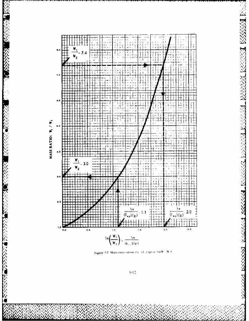
7.4.
7.0- - -
jj-4-
I-T
4jU...)..
4.0
2W
9.0.
20-4-
AVA .~(

),,*5.,.~i
PARKING ORBITS
Most missions that proceed beyond earth orbit begin by placing a payload into a parking orbitaround tile earth. The time in the parking orbit is used to wait for appropriate phase angles, for
*. adjustments in launch windows, or for verifying equipment performance before proceeding onthe next leg of the mission.
ihe optimum for a parking orbit from a drag and gravity standpoint lies somewhere between 85and 100 nautical miles. The choice of 100 nautical miles allows optimum time in orbit for a manned
chicle.Although the prediction of' orbital lifetime is as yet an inexact science, these approximate values
illustrate the choices available for parking orbits:
A lltitude (nautical miles) Expected Time in Orbit (Days)
. 85 V/210O0 3150 15200 200300 4.000
ROCKET PROPEILANTS
Propellants are the working substances that rocket engines use to produce thrust. These substancesmay be liquid, solid, or gas, but the use of liquids or solids permits a particular rocket to carry morechemical energy. [he space vehicle would require large, bulky tanks that contain only a small massof' compressed gas.ocris section of the text considers only working substances that are accelerated by the energy
released in their own chemical combustion (burning). The process involves a fuel and oxidizerreacting chemically to produce high-temperature, high-pressure gases. We call such fuels andoxidli/ets chemical propellants. Two chemical propellant subject areas are important: theoreticalperformance characteristics and energy content.
* Theoretical Performance of Chemical Propellants
"" ( onsider a simplified picture of what happens in a rocket combustion chamber and nozzle (fig.3-8). Burning the propellants releases large amounts of energy and produces high-temperature, high-pressure gases. [he high temperature at point A in the combustion chamber is associated with veryiapid motion of the gas molecules. These molecules have high speeds but move in random directions.As they approach the no/zle throat (B), their motion is less random, and they move toward the nozzleexit. At the no,,:le exit (C), the largest velocity component of the molecules is parallel to the nozzleaxis. I he combustion chamber converts the chemical energy of the propellants to high-temperaturerandom motion of the gas molecules, and the nozzle orients the velocity or kinetic energy (energy ofmotion) that gives the rocket its thrust.
As pointed out before, the velocity change of a space vehicle is a function of specific impulse ( lp)and mass ratio. A higher I,, increases the magnitude of the vehicle Av for a given mass ratio or
*:: decreases the mass ratio necessary for a given vehicle Av. Thus, I,r is a measure of how well an engineeonPcerts chemical ncnrgy into velocity.
Since each mission in space is associated with a required Av. I., determines if it is possible to, %I prforn a space mission with the mass ratios that are obtainable. For example, a mission to launch
'f rom the earth, land on the moon, and return to earth requires a series of Av's totaling about 59.000miles per hour. If the engines use propellants with low I, and can produce Av's of only 55,000 milespet hour tor a particular mass ratio or payload, the space vehicle cannot complete the mission. Weneed engines and propellants with higher I, for more difficult space missions.
3-13
_ .,'..,. .. I. '.',, :+ ., .q '., .-. : -. " .. -. . ,' .'. ~ (* ~ * v-.. ... ." 7. .: .":.-
V , " ' - .. ," V,-. -m *
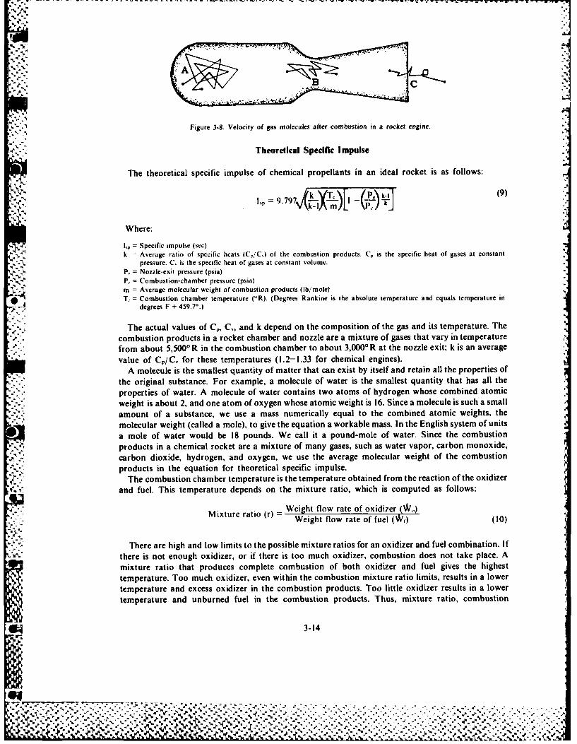
Figure 3-8. Velocity of gas molecules after combustion in a rocket engine.
Theoretical Specific Impulse
The theoretical specific impulse of chemical propellants in an ideal rocket is as follows:
1" = .7 k(9)I = m) P,'kI
Where:
1, = Specific impulse (sec)k =Average ratio of specific heats (C./Cj of the combustion products. Cp is the specific heat of gases at constant
pressure. C, is the specific heat of gases at constant volume.P. = N07zle-CXit pressure (psia)P, = Co mbust ion-cha mber pressure (psia)m = Average molecular weight of combustion products (lb/ mole)T, = Combustion chamber temperature (0R). (Degrees Rankine is the absolute temperature and equals temperature in
4 degrees F + 459.7'.)
The actual values of C,., C,, and k depend on the composition of the gas and its temperature. Thecombustion products in a rocket chamber and nozzle are a mixture of gases that vary in temperaturefrom about 5,5000'R in the combustion chamber to about 3,0000 R at the nozzle exit; k is an averagevalue of CP/IC, for these temperatures (1.2-1.33 for chemical engines).
A molecule is the smallest quantity of matter that can exist by itself and retain all the properties ofthe original substance. For example, a molecule of water is the smallest quantity that has all theproperties of water. A molecule of water contains two atoms of hydrogen whose combined atomicweight is about 2, and one atom of oxygen whose atomic weight is 16. Since a molecule is such a smallamount of a substance, we use a mass numerically equal to the combined atomic weights, themolecular weight (called a mole), to give the equation a workable mass. In the English system of unitsa mole of water would be 18 pounds. We call it a pound-mole of water. Since the combustionproducts in a chemical rocket are a mixture of many gases, such as water vapor, carbon monoxide,carbon dioxide, hydrogen, and oxygen, we use the average molecular weight of the combustionproducts in the equation for theoretical specific impulse.
The combustion chamber temperature is the temperature obtained from the reaction of the oxidizerand fuel. This temperature depends on the mixture ratio, which is computed as follows:
=Weight flow rate of oxidizer W)Mixture ratio (r) = Weight flow rate of fuel (W)(10)
There are high and low limits to the possible mixture ratios for an oxidizer and fuel combination. Ifthere is not enough oxidizer, or if there is too much oxidizer, combustion does not take place. Amixture ratio that produces complete combustion of both oxidizer and fuel gives the highesttemperature. Too much oxidizer, even within the combustion mixture ratio limits, results in a lowertemperature and excess oxidizer in the combustion products. Too little oxidizer results in a lowertemperature and unburned fuel in the combustion products. Thus, mixture ratio, combustion
3-14
% % .. % 1. 1....... . ..". . ......d
%I % .: -%e .
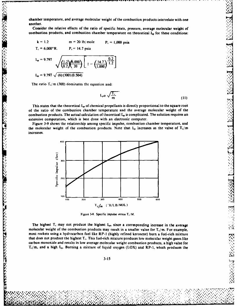
chamber temperature, and average molecular weight of the combustion products interrelate with oneanother.
Consider the relative effects of the ratio of specific heats, pressure, average molecular weight ofcombustion products, and combustion chamber temperature on theoretical ILp for these conditions:
k = 1.2 m = 20 lb/mole P 1,000 psiaT, = 6,000'R. P, = 14.7 psia -
lp =9.797 '4 0.21
k,0.2I 20) -2'0l,000 "
1,p = 9.797 %/(6) (300) (0.504)
The ratio T./m (300) dominates the equation and:
m (ii) _T.
This states that the theoretical I,p of chemical propellants is directly proportional to the square rootof the ratio of the combustion chamber temperature and the average molecular weight of thecombustion products. The actual calculation of theoretical lsp is complicated. The solution requires anextensive computation, which is best done with an electronic computer.
Figure 3-9 shows the relationship among specific impulse, combustion chamber temperature, andr"- the molecular weight of the combustion products. Note that lp increases as the value of Tc/m
increases.
400
300
C..
e000"
100 200 300 400 500 600
Tc/m (>R/LB/MOL)
Figure 3-9. Specific impulse versus T,/M.
The highest T, may not produce the highest I,, since a corresponding increase in the average %molecular weight of the combustion products may result in a smaller value for Tc/m. For example,most rockets using a hydrocarbon fuel like RP-l (highly refined kerosene) burn a fuel-rich mixturethat does not produce the highest Tc. This fuel-rich mixture produces low molecular weight gases likecarbon monoxide and results in low average molecular weight combustion products, a high value forT,/m, and a high lp. Burning a mixture of liquid oxygen (LOX) and RP-l, which produces the
3-15
% ,
-. . .. . . . . . . . . . . . . .
. . . . . . . . . . . . . . . . . . . . . . .
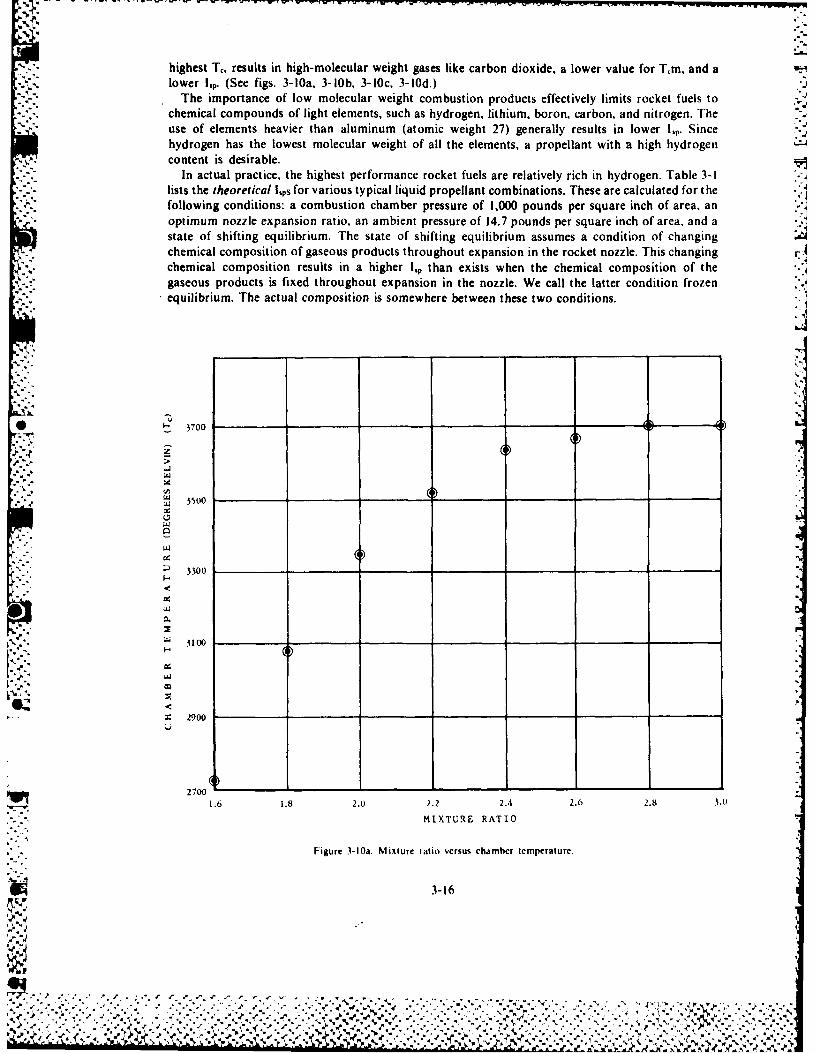
%*" 4
-~ -~highest T,, results in high-molecular weight gases like carbon dioxide, a lower value for T~m, and alower I. (See figs. 3-10a, 3-l0b, 3-10c, 3-10d.)
The importance of low molecular weight combustion products effectively limits rocket fuels tochemical compounds of light elements, such as hydrogen, lithium, boron, carbon, and nitrogen. Theuse of elements heavier than aluminum (atomic weight 27) generally results in lower I,, Sincehydrogen has the lowest molecular weight of all the elements, a propellant with a high hydrogencontent is desirable.
In actual practice, the highest performance rocket fuels are relatively rich in hydrogen. Table 3-1lists the theoretical lIps for various typical liquid propellant combinations. These are calculated for thefollowing conditions: a combustion chamber pressure of 1,000 pounds per square inch of area, anoptimum nozzle expansion ratio, an ambient pressure of 14.7 pounds per square inch of area, and astate of shifting equilibrium. The state of shifting equilibrium assumes a condition of changingchemical composition of gaseous products throughout expansion in the rocket nozzle. This changing rAchemical composition results in a higher I., than exists when the chemical composition of thegaseous products is fixed throughout expansion in the nozzle. We call the latter condition frozenequilibrium. The actual composition is somewhere between these two conditions.j
S3700_ _
LL 3500
00
.29-0
27300 ______
1.6 1.8 2.0 2.2 2.4 2.6 2.8 3.0
MIXTURE RATIO
Figure 3-10a. Mixture ratio versus chamber temperature.
3-164
5..' 4.,,
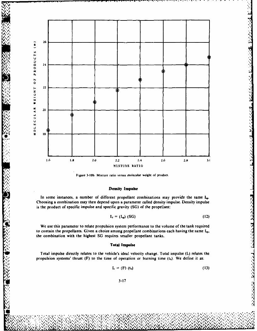
'-., -,. ... .. -.
-. 26
U_a 24
20
U
1.6 1.8 2.0 2.2 2.4 2.6 2.8 3.-
14IX'1U1t RATIO
Figure 3-lOb. Mixture ratio versus molecular weight of product.
Density Impulse
In some instances, a number of different propellant combinations may provide the same I,p.Choosing a combination may then depend upon a parameter called density impulse. Density impulseis the product of specific impulse and specific gravity (SG) of the propellant:
Id = (hp) (SG) (12)
We use this parameter to relate propulsion system performance to the volume of the tank requiredto contain the propellants. Given a choice among propellant combinations each having the same I,,the combination with the highest SG requires smaller propellant tanks.
Total Impulse
*I Total impulse directly relates to the vehicle's ideal velocity change. Total impulse (1,) relates thepropulsion systems' thrust (F) to the time of operation or burning time (th). We define it as:
'C I, = (F) (th) (13)
3-17PIT- .'--'
l ,''',", "?.' -, '' .";..' ... , - .. ,' ,. . . ' ". ". :, ', . ,' . . ". ,'.",.'. '.'..". ".; ... \'\'" .""..' ".' "".,''L '' ','".,"-, , ,'.,' ', .. . P - ".'_ ,.... ,-.' ' ., " -,-r,,._'., .. ' '," .-. ,'',"' ',.' , ,, " ', ] ,,".:',,"." -'.."-' .V-'..
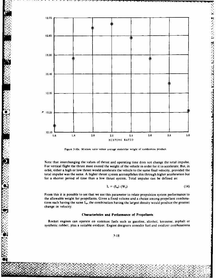
12.75 ___ __
12.65 _____________________
4 ~~~~~~~12.55_____________
12.45____ __
12.35 ______
' 12.25__ _ _ __ _ _ _
12.15 _ _ _ _
1.6 1.8 2.0 2.2 2.4 2.6 2.8 3.0
MIXTURE RATIO
Figure 3-10c. Mixture ratio versus average molecular weight of combustion product.
Note that interchanging the values of thrust and operating time does not change the total impulse.For vertical flight the thrust must exceed the weight of the vehicle in order for it to accelerate. But, inorbit, either a high or low thrust would accelerate the vehicle to the same final velocity, provided thetotal impulse was the same. A higher thrust system accomplishes this through higher acceleration butfor a shorter period of time than a low thrust system. Total impulse can be defined as:
'4' From this it is possible to see that we use this parameter to relate propulsion system performance tothe allowable weight for propellants. Given a fixed volume and a choice among propellant combina-
4' tions each having the same l,p, the combination having the largest density would produce the greatestchange in velocity.
Characteristics and Performance of Propellants
Rocket engines can operate on common fuels such as gasoline, alcohol, kerosene, asphalt orsynthetic rubber, plus a suitable oxidizer. Engine designers consider fuel and oxidizer combinations
L 1-18
LZ .~ . ? p."
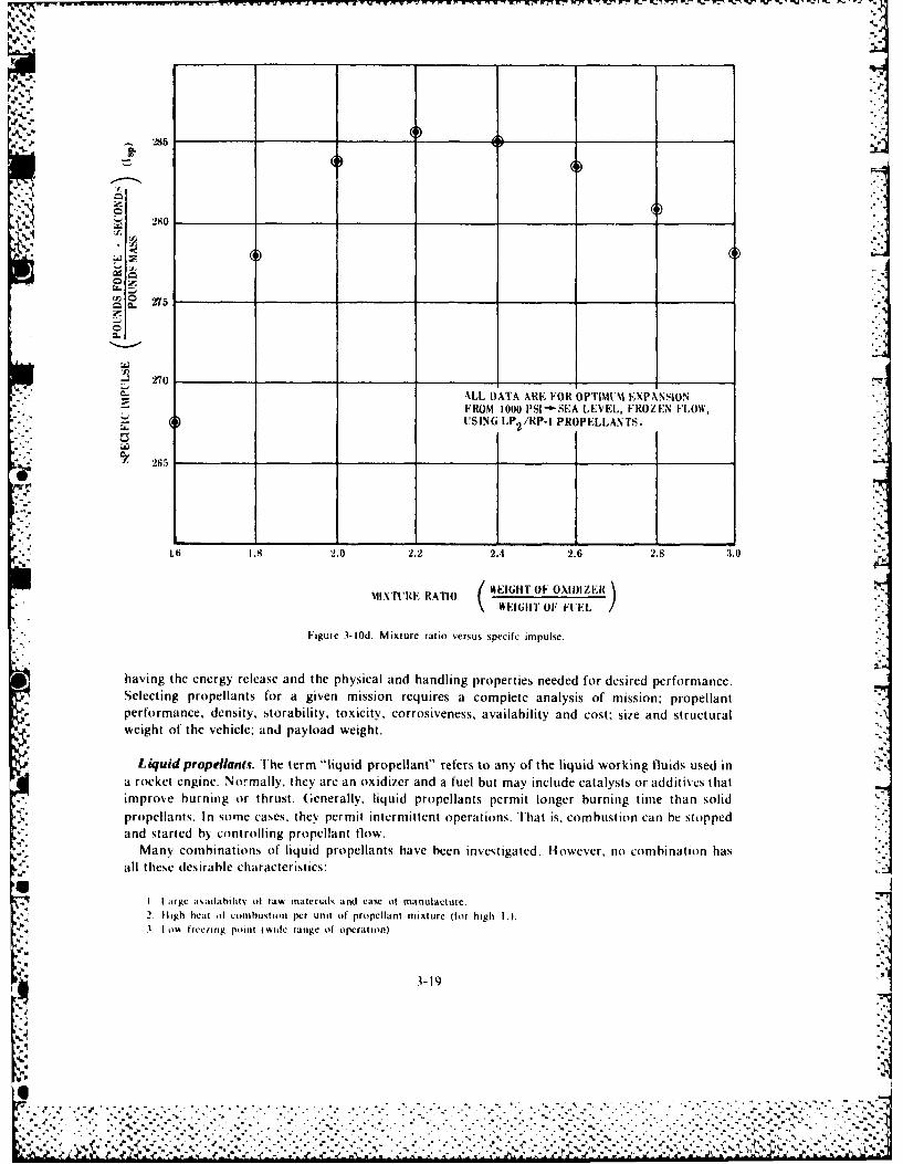
"" ,'
-Q- COz 275
0
• " " •ALL DATA ARE FOR OPT|MVM EXPANSION
I.'-" ' - FROM 1000 PSI'-SEA LEVEL, FROZEN FLOW',1. ...- rSING LP 2!RP-1 PROPELLANTS.
265
L ,6 1._ 2.0 2.2 2.4 2.6 2.8 U.0
T ALL EIGHT OF OXIIZER.-
WEIGHT OF FDIZ-
Figure 3-10d. Mixture ratio versus specifc impulse.
having the energy release and the physical and handling properties needed for desired performance.Selecting propellants for a given mission requires a complete analysis of mission: propellantperformance. density, storability, toxicity, corrosiveness, availability and cost: size and structuralweight of the vehicle; and payload weight.
Liquid propellans. The term "liquid propellant" refers to any of the liquid working fluids used ina rocket engine. Normally, they are an oxidizer and a fuel but may include catalysts or additives thatimprove burning or thrust. (enerally. liquid propellants permit longer burning time than solidpropellants. In some cases, they permit intermittent operations. That is. combustion can be stoppedand started by controlling propellant flow.
Many combinations of liquid propellants have been investigated. However, no combination hasall these desirable characteristics:
I I arge a ailahilitv ot rat materials and ease of manufacture.2. Iigh heat of combustion per unit of propellant mixture (for high Vl.
o3 % I ow Irc ng point ( widic range of operation).
t3-19
44". .",%I' ft
,, ,~~~~~~ ~~~~~~~~~~..... -.- ....- ...... -.................. . ,. ,... -. -.. .- , . , , ...... j
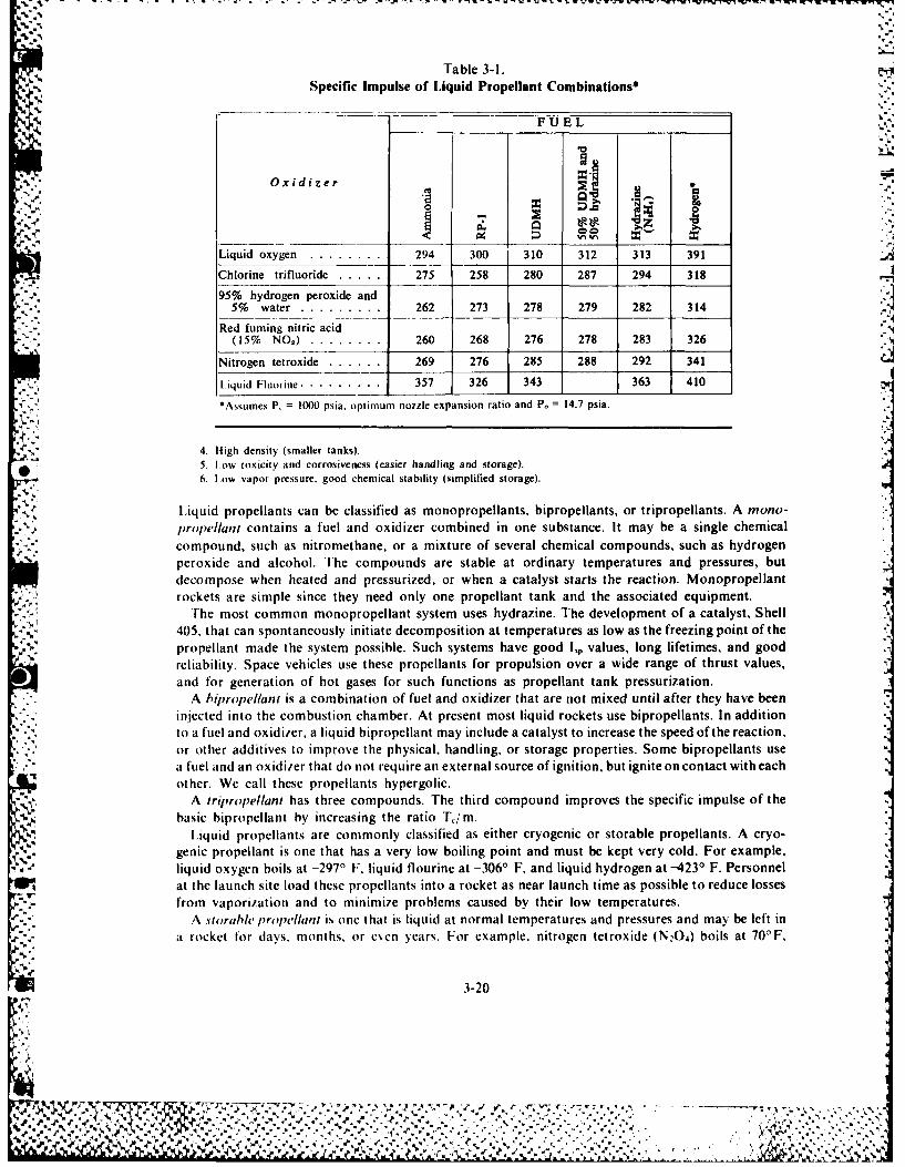
Table 3-I.Specific Impulse of Liquid Propellant Combinations*
., FUEL
Oxidizer" ." 0 - ..
__ __,_ >,- 0
Liquid oxygen ........ 294 300 310 312 313 391
C Chlorine trifluoride ..... 275 258 280 287 294 318
95% hydrogen peroxide and5% water ............ 262 273 278 279 282 314
Red fuming nitric acid(15% NO2) ............ 260 268 276 278 283 326
Nitrogen tetroxide ...... 269 276 285 288 292 341
liquid Fluorine ...... . 357 326 343 363 410*Assumes P, = 1000 psia, optimum nozzle expansion ratio and P. = 14.7 psia.
r. '
4. High density (smaller tanks).5. Low toxicity and corrosiveness (easier handling and storage).
, 6. Low vapor pressure, good chemical stability (simplified storage).
Liquid propellants can be classified as monopropellants, bipropellants, or tripropellants. A mono-,propellani contains a fuel and oxidizer combined in one substance. It may be a single chemical
; -. * compound, such as nitromethane, or a mixture of several chemical compounds, such as hydrogenperoxide and alcohol. The compounds are stable at ordinary temperatures and pressures, butdecompose when heated and pressurized, or when a catalyst starts the reaction. Monopropellantrockets are simple since they need only one propellant tank and the associated equipment.
The most common monopropellant system uses hydrazine. The development of a catalyst, Shell405, that can spontaneously initiate decomposition at temperatures as low as the freezing point of thepropellant made the system possible. Such systems have good l, values, long lifetimes, and goodreliability. Space vehicles use these propellants for propulsion over a wide range of thrust values,and for generation of hot gases for such functions as propellant tank pressurization.
A hipropellant is a combination of fuel and oxidizer that are not mixed until after they have beeninjected into the combustion chamber. At present most liquid rockets use bipropellants. In addition
to a fuel and oxidi/er, a liquid bipropellant may include a catalyst to increase the speed of the reaction,or other additives to improve the physical, handling, or storage properties. Some bipropellants usea fuel and an oxidizer that do not require an external source of ignition, but ignite on contact with eachother. We call these propellants hypergolic.
A iripropellant has three compounds. The third compound improves the specific impulse of the, basic bipropellant by increasing the ratio Tim.
Liquid propellants are commonly classified as either cryogenic or storable propellants. A cryo-genic propellant is one that has a very low boiling point and must be kept very cold. For example,liquid oxygen boils at -297' F, liquid flourine at -36' F, and liquid hydrogen at -4231 F. Personnel
at the launch site load these propellants into a rocket as near launch time as possible to reduce lossesfrom vaporization and to minimize problems caused by their low temperatures.
A storable p ropellant is one that is liquid at normal temperatures and pressures and may be left ina rocket for days. months, or even years. For example, nitrogen tetroxide (N20 4 ) boils at 700F,
3-20IVJ.
~~~~~~~~~~~~.-. .. .- ... =.:-..... ." -...... -,."- ._,. .. o...,..... .- •..... , , '...,. .. ,. '4-. *. * .* .
"
unsymmetrical dimethyldrazine (UDM H) at 1460 F, and hydrazine (N 2H4) at 2360 F. However, theterm storable refers to storing propellants on earth. It does not consider the problems of storage -'
, .9. ~ in space.Many rocket engines use one of the cryogenic propellants, liquid oxygen (La 2), with RP- 1. The H-I -
and F- engines of the NASA Saturn vehicles used this combination as do the engines of the ThorIRBM and Atlas ICBM missiles.
Liquid hydrogen (LH2) and liquid oxygen (L0 2) comprise a cryogenic bipropellant. Upper stageengines, such as the RL-10 (Centaur engine) and the J-2 of the Saturn V, use this bipropellant.
The 50 percent UDMH-50 percent hydrazine fuel (Aerozine 50) with nitrogen tetroxide (N 20 4)
oxidizer is the storable hypergolic bipropellant used in the Titan Ill. It is classified as abipropellant since the fuel contains two compounds to improve handling properties rather than
Table 3-1 shows the improved performance of cryogenics. As a group, they have higher I., thanthe storable propellants.
The I,p values in table 3-1 represent the maximum theoretical values for normal test conditions,which include engine operation at sea level. Actual engines using these propellants at sea level achieve85 to 92 percent of these values. Engines operating near design altitude frequently achieve specificimpulses that exceed these values.
For example, one version of the Atlas engine using RP-I and L0 2 was designed for optimum,. expansion at 100,000 feet of altitude. The I, of this engine is 215 seconds at sea level and 309 seconds
at 80,000 feet, compared with the 300 seconds listed in table 3-1. Scientists must analyze this l,'reported for rocket engines, especially if it is much higher than the values in table 3-1. This analysisdetermines the altitude and other conditions for which the values are tabulated.
Several of the liquid propellants have theoretical I, approximately one-third higher than theO conventional L0 2 and RP-l. L0 2 (liquid hydrogen) with LH2 and LFz (liquid fluorine) with LH 2 are
examples of bipropellants called high-energy propellants. The term "high energy" evolved fromefforts to develop high-performance propellants. All the upper stages of large launch vehicles likethe Saturn IB and Saturn V used these propellants.
Chamber pressure, altitude, and nozzle expansion ratio all affect engine performance, as weexplained earlier. We can show clearly this effect on engine performance if you will consider figure3-Il. The dashed curves give 1, values for a L0 2 1 LH2 propellant combination at differing values ofchamber pressure and expansion ratio. (The SSME curves are for the Space Shuttle main engines.)Notice first that a higher Pc gives higher l, for any value of e. Second, there is an optimum e for any P,at sea level. This optimum value increases with increasing Pc. The solid curve, which is for expansionto vacuum, portrays the effect of altitude. Notice that this curve lies above the dashed curves for all eand continues to increase to the right.
A comparison of the theoretical performance of the SSME and J-2 engines at increasing altitudealso shows these effects. The higher P. and e of the SSME gives significantly better values of L
, ... (fig. 3-12). .High-energy propellants in the upper stages of large rockets increase the payload or the mission
4 .capability of the vehicle. Consider two three-stage launch vehicles with the same initial gross weight(table 3-2). One has high-energy propellants in the upper stages; the other has conventional L0 2 andRP-I in the upper stages. The one using high-energy propellants can carry a heavier payload for agiven mission, or can perform a more difficult mission with the same payload. A three-stage vehiclewith a gross weight of about one million pounds will have the theoretical payloads shown. For
..*. mission number I, the vehicle using conventional propellants has less than half the payload of the onewith high-energy propellants. For mission number 3, the conventional vehicle has only one-third thepayload of the high-energy vehicle. Also, the conventional vehicle has the same payload (9 tons) for
* mission number 2 that the high-energy one has for mission number 3. Increasing the number of stagesof the vehicle with LO 2h/ RP-I will increase the payload for the same initial gross weight, but will not
approach that of the high-energy propellant vehicle.Engineers design cryogenic fuel tanks differently from those for conventional fuel. Hydrogen tanks
3-21
t4,.. ,:,. ,/:., .. • ., : :: .', " •., ". ". . ... "....'. - . .' .',< . - . '. .. ... , .. , .',..'',1..'. ". -..-. '.,
.ii.. ,. . ' . . .- . ~ - ' ' . ." . . ' 7 ." ." " . -" ." . ., ," ' -. . • . .
I- ,'. ,.,U.*---.. j : . .. . ...... * :,.:
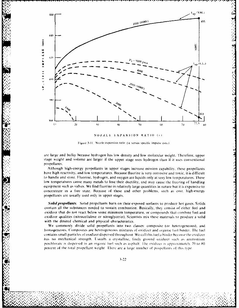
460 Sp (VAC)
460 , 455-~/
..*
440
* I 'II
/. .. p- 5000__Psia s(..
-96
x .-n:
*. -.. " -S'
(SVS
''41
"" 363
16 N.
IfI( 20 30 40 50 60 70 77.s 80t
N NOZZ1FE EX1ANSI0N RATO 1 ) "3
Figure 3-11I. Not.,e expansion ratio ( c- versus specific impulse (scc.)
., , are large and bulky because hydrogen has low density and low molecular weight. lherefore, upper
.'. ."stage wreight and volume are larger if the upper stage uses hydrogen than it' it uses conventional-"-"" propellants. "-" "Although high-energy propellants in upper stages increase mission capabifly, these propellants ., . .'. have high reactivity. and low temperatures. Because fluorine is very corrosive and toxic, it is difficult,,i to handle and store. Fluorine, hydrogen, and oxygen are liquids only at very low temperatures. These
low temperatures cause many metals to lose their ductility, and may cause the freo'ing of handling
i ,' ,' equipment such as valves. We find fluorine in relatively large quantities in nature but it is expensive to ." ,k concentrate in it free state. Because of these and other problems, such its cost, high-energy
' '-',propellants are usually used only in tipper stages.
A., S- olid propellants . Solid propellants burn on their exposed surfaces to produce hot gases. Solids-~contain all the substances needed to sustain combustion. Basically, they' consist of either fuel and
.'],-," oxidi,,er that do not react below some minimum temperature, or compounds that combine fuel and ,,'." ".oxidizer qualities (nitrocellulose or nitroglycerin). Scientists mix these materials to produce a solid 1,Z"- "with the desired chemical and physical characteristics.r,],-,.We commonly divide solid propellants into two classes: composite (or heterogeneous), and
?,,,5, ho logneo s. 'om osicsare heterogeneous miXture, 01' OXidi/Cr Mid or ganllC hill(] I c CLfi . contains small particles of oxidi/er dispersed throughout. Wecall this Iluel ait ld(cr bocaMV'e the oxidi/cr• - hits no mechanical strength. Ulsuallk a crystalline, tinel. ground oxidiier sutch its, amnmoniun lPec hlorate is dispcis0 d In a11 olganlic 4lul such ts asphalt. I hc oxdi/ci is aplroximatel 70 to So
: V staeegt and olue aoa relareif, thce upper tlarge ue hydroet if t use, convniona
. . . .p.. ...
Altoughh-eergpr antinupprsage ncrease m"ssion ca y t
haehg% eciiy n o eprtrs eas loiei eycroieadtxc ti ifclto hadl and stre Floieyrgn n xgnaelqisol tvr o eprtrs hs
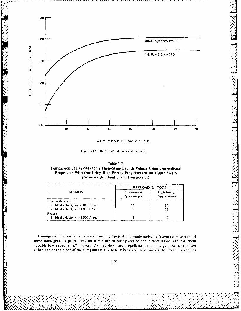
400450
300
S24J 400
Tl350 3-2.
PALA IN ON
300 , --
20 40 60 80 100 120 140
A LTITtPD E h), 100 Of[ FT. ':!
Figure 3-12. Effect of altitude on specific impulse. i
Table 3-2.'--* '('omparison of Payloads for a Fhree-Stage Launch Vehicle Using Conventional ".
Propellants With One Using High-Energy Propellants in the Uipper Stages -(G;ross weight about one million pounds) -
PAYLOAD IN TONS "-__
MISSION Conventional High-EnergyUpper Stages Upper Stages
Low earth orbit* 1. Ideal velocity - 30,000 ft/sec 15 32
2. Ideal velocity - 34,000 ft/sec 9 21Escape
3. Ideal velocity 41,000 ft/sec 9
4Homogeneous propellants have oxidizer and the fuel in a single molecule. Scientists base most ofthese homogeneous propellants on a mixture of nitroglycerine and nitrocellulose, and call them"double-base propellants." The term distinguishes these propellants from many gunpowders that useeither one or the other of the components as a base. Nitroglycerine is too sensitive to shock and has
3-23
%'
7 -A1165 38 SPACE HANDBOOK(U) AIR MINISTRY LONDON (ENGLAND)
2
C D COCHRAN ET AL. JAN 85 AU-i8
UNCLASSIFIED F/6 15/7 m
.'9
S1,5
'F,' ~1.0 1 , 128 1
,IIN Illl -
- --- IN1 i111111.8
111111.251_L
MICROCOPY RESOLUTION TEST CHARTTNATI()NAL RURFAU OF STANDARDS- 963-A
7:-f
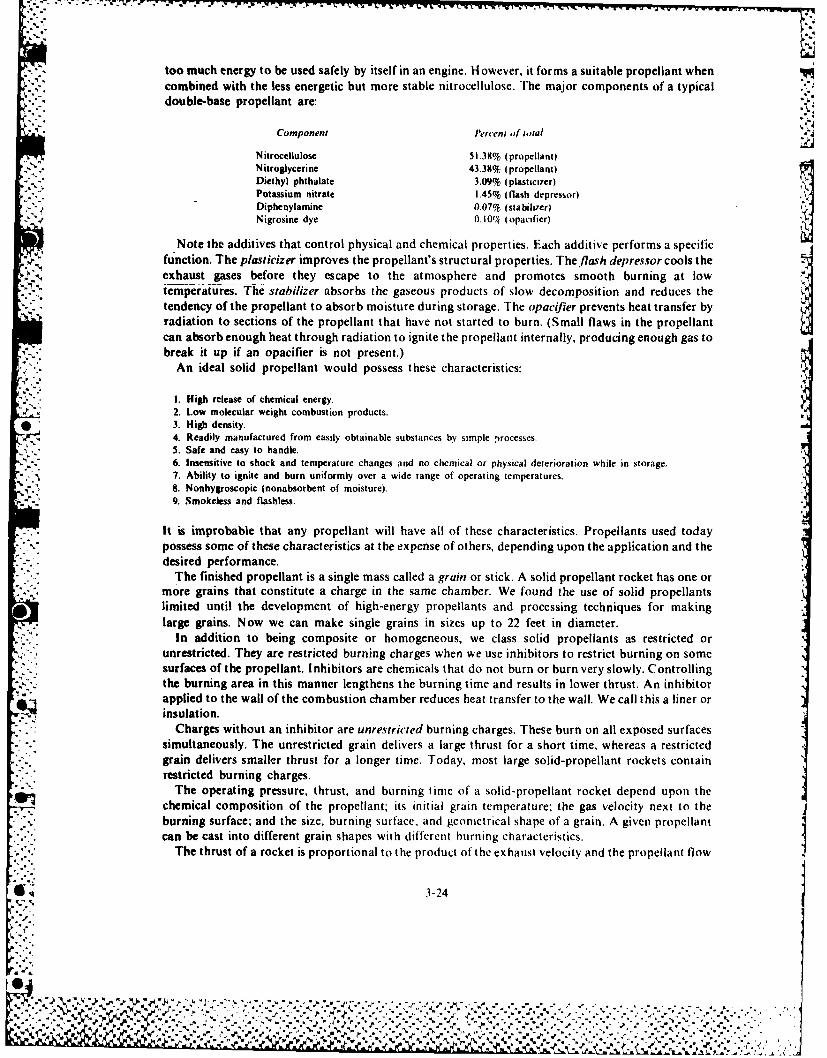
too much energy to be used safely by itself in an engine. H owever, it forms a suitable propellant whencombined with the less energetic but more stable nitrocellulose. Trhe major components of a typical
* double-base propellant are:
Component Percent )f gcoial
Nitrocellulose 51.38% (propellant)Nitroglycerine 43.38% (propellant)Diethyl phthalate 3.09% (plasticizer)Potassium nitrate 1.45% (flash depressor)
Diphenylamine 0.07% (stabilizer)2Nigrosine dye 0.10(7( (opacifier)
Note the additives that control physical and chemical properties. Each additive performs a specificfunction. The plasticizer improves the propellant's structural properties. The/lash depressor cools the
exhaust gases before they escape to the atmosphere and promotes smooth burning at lowtemperatures. The stabilizer absorbs the gaseous products of slow decomposition and reduces the Itendency of the propellant to absorb moisture during storage. The opacifier prevents heat transfer byradiation to sections of the propellant that have not started to burn. (Small flaws in the propellantcan absorb enough heat through radiation to ignite the propellant internally, producing enough gas tobreak it up if an opacifier is not present.)
An ideal solid propellant would possess these characteristics: I
1. High release of chemical energy.2. Low molecular weight combustion products.
*3. High density.4. Readily manufactured from easily obtainable substances by simple processes.5. Safe and easy to handle.6. Insensitive to shock and temperature changes and no chemical or physical deterioration while in storage.7. Ability to ignite and burn uniformly over a wide range of operating temperatures.B. Nonhygroscopic (nonabsorbent of moisture).9. Smokeless and flashless.
It is improbable that any propellant will have all of these characteristics. Propellants used todaypossess some of these characteristics at the expense of others, depending upon the application and thedesired performance.
The finished propellant is a single mass called a grain or stick. A solid propellant rocket has one ormore grains that constitute a charge in the same chamber. We found the use of solid propellants
* limited until the development of high-energy propellants and processing techniques for makinglarge grains. Now we can make single grains in sizes up to 22 feet in diameter.
In addition to being composite or homogeneous, we class solid propellants as restricted orunrestricted. They are restricted burning charges when we use inhibitors to restrict burning on somesurfaces of the propellant. Inhibitors are chemicals that do not burn or burn very slowly. Controllingthe burning area in this manner lengthens the burning time and results in lower thrust. An inhibitorapplied to the wall of the combustion chamber reduces heat transfer to the wall. We call this a liner orinsulation.
Charges without an inhibitor are unrestricted burning charges. These burn on all exposed surfacessimultaneously. The unrestricted grain delivers a large thrust for a short time, whereas a restrictedgrain delivers smaller thrust for a longer time. Today, most large solid-propellant rockets containrestricted burning charges.
The operating pressure, thrust, and burning timie of a solid- propellant rocket depend upon thechemical composition of the propellant; its initial grain telmperature; the gas velocity next to the
% ~burning surface; and the size, burning surface, and geomnetrical shape of a grain. A given propellantcan be cast into different grain shapes with different hurning characteristics.
The thrust of a rocket is proportional to the product of the exhaust velocity and the propellant flow
3-24
%
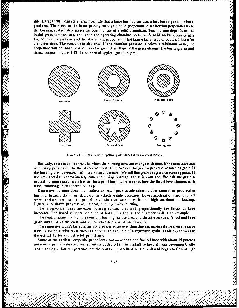
rate. Large thrust requires a large flow rate that a large burning surface, a fast burning rate, or both,produces. The speed of the flame passing through a solid propellant in a direction perpendicular tothe burning surface determines the burning rate of a solid propellant. Burning rate depends on theinitial grain temperature, and upon the operatifig chamber pressure. A solid rocket operates at ahigher chamber pressure and thrust when the propellant is hot than when it is cold, but it will burn fora shorter time. The converse is also true. If the chamber pressure is below a minimum value, thepropellant will not burn. Variation in the geometric shape of the grain changes the burning area andthrust output. Figure 3-13 shows several typical grain shapes.
Cylinder Bored Cylinder Rod and Tube
C:ruciform Internal Star Multigrain
iiue 113, 1, pical solid propellant giain shapes shown in cross section.
Basically, there are three ways in which the burning area can change with time. If the area increasesas burning progresses, the thrust increases with time. We call this grain a progressive burning grain. Ifthe burning area decreases with time, thrust decreases. We call this grain a regressive burning grain. Ifthe area remains approximately constant during burning, thrust is constant. We call the grain aneutral burning grain. I n each case, the type of burning determines how the thrust level changes withtime, following initial thrust buildup.
Regressive burning does not produce as much peak acceleration as does neutral or progressiveburning, because the thrust decreases as vehicle weight decreases. Lower accelerations are requiredwhen rockets are used to propel payloads that cannot withstand high acceleration loading.Figure 3-14 shows progressive, neUtral, and regressive burning.
The progressive grain increases burning surface area and proportionally the thrust as timeincreases. *rhe bored cylinder inhibited at both ends and at the chamber wall is an example.
The neutral grain maintains a constant burning surface area and thrust over time. A rod and tubegrain inhibited aut the ends and at the chamber wall is an example.
The regressive grain's burning surface area decreases over time thus decreasing thrust over the sametime. A cylinder with both ends inhibited is an exauitple of a regressive grain. Table 3-3 shows thetheoretical Ir for typical solid propellants.
Some of the earliest composite propellants had an asphalt and fuel oil base with about 75 percentpotassium perchiorate oxidizer. Scientists added oil to the asphalt to keep it from becoming brittleand cracking at low temperature, but the resultant propellant became soft and began to flow at high
* 3-25
........... .............................. ,-.......e.. ..
%. . . . . .%. .N
. . . . . . . . . . . . . . . . . . . . . . ... ..- -. .. . ~ -.. .. .. ,
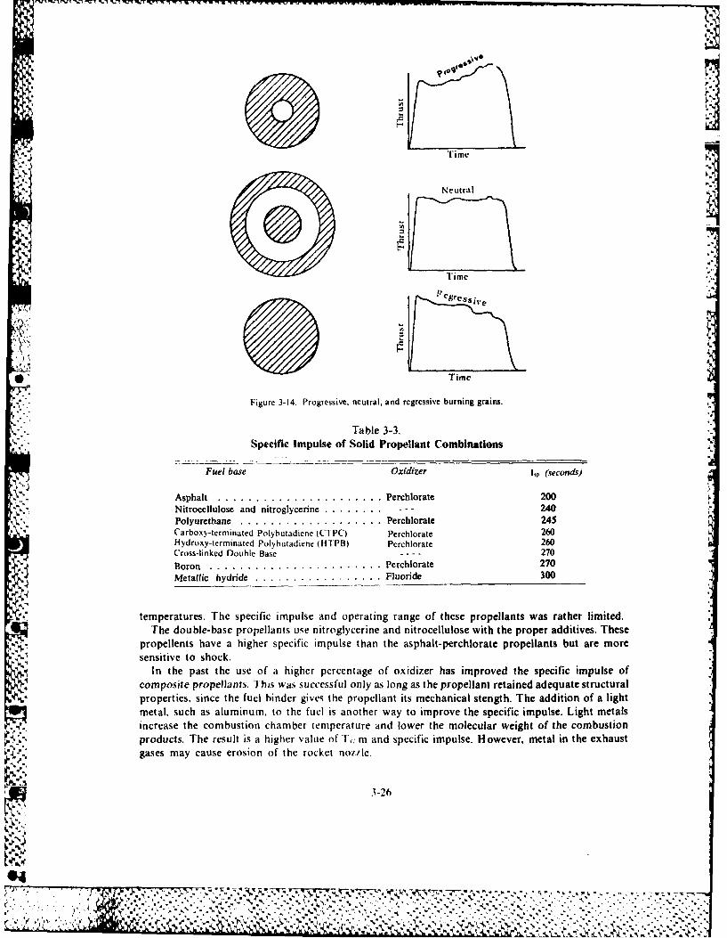
• " Time
"-" "Figure 3-14. Progressive, neutral, and regressive burning grains. ,
" - . . T a b l e 3 -3 . ..,".-Specific Impulse of Solid Propellant Combinations
r ")r ".)Fuel base Oxidizer ILp (seconds)
.',Asphalt . .. .. .. .. .. .. .. .. .. . .. Perchlorate 200- Nitrocellulose and nitroglycerine . .. .. . .. - - - 240
,",Polyurethane .. .. .. .. .. .. .. .. . .. Perchlorate 245i Carboxy-terminated Polybutadiene (C1rPC) Perchlorate 260
vlHydroxy-terminated Polybutadiene (1-17PB) Perchlorate 260Cross-linked Double Base -- -270
,,Boron .. .. .. .. .. .. .. .. .. .. . .. Perchlorate 270Metallic hydride .. .. .. .. .. .. .. . .. Fluoride 300
temperatures.,h specific impulse adoperating range ofthese propellants wasrahrlmtd
l The double-base propellants use nitroglycerine and nitrocellulose with the proper additives. These,' ' propellents have a higher specific impulse than the asphait-perchlorate propellants but are more
: ,' ',4sensitive to shock.
V
' . In the past the use of a higher percentage of oxidizer has improved the specific impulse of:' ,3, composite propellants. This was successful only as long as the propellant retained adequate structuralt properties, since the fuel hinder gives the propellant its mechanical stength. The addition of a light
::I~imetal, such as aluminum, to the fuel is another way to improve the specific impulse. Light metals_. .. increase the combustion chamber temperature and lower the molecular weight of the combustion?.' ' products. The result is a higher value of T,, m and specific impulse. However, metal in the exhaust-k .- ,gases may cause erosion of the rocket nozzle.
3-26
0 Ta 0 '5
Fiue31.Prgesvnetaadrersiebrnn ris
Tabl.3-3' : " ' ...... U~ 'b "2'5 -' ' ' Specific Impulse of' ' Solid P" x.ropllnCombina. :, ','tios s," ,. -,-,-- .
'. ', , • /T,.n] '" - " ' Fuel', base O-x--idize-r t'. '' ,' '" '* "'% '*' '' " .' , "' " (seconds)" " ° '" -- '. "
,. ' •' '" ,"." 7,"",.'" ;"" Asphalt.........................."....Pe"r•ch - .lo"rate 200"",-.", "" " '" "." ." '"-'. "-'-. ,'

Replacing the inert fuel binder with a high-energy fuel binder containing oxygen (double-basepropellants) further increases specific impulse. Some of the propellants used today combine a double-base propellant with a composite propellant and a metal fuel.
As a group, the solid propellants have a lower specific impulse than the liquid propellants, but theyhave the advantages of simplicity, instant readiness, low cost, potential for higher acceleration, andhigh density compared to the start-stop capability, high energy, regenerative cooling, and availabilityof the liquid propellants.
Hybrid propellants. We can combine some of the advantages of liquid and solid propellants in ahybrid rocket. In a hybrid engine, we store a liquid (usually oxidiier) in one container while we store asolid (usually fuel) in a second (see fig. 3-22). The separation of propellants in a hybrid eliminates the
dependence of burning time on the grain temperature. The absence of oxidizer in the solid grain rimproves its structural proprties. The hybrid combines the start-stop advantages of liquid propellantswith the high density, instant readiness, and potentially high acceleration of the solid propellants. It isa relatively simple system with high performance. Solid fuel lithium, suspended in a plastic base,burned with a mixture of fluorine and oxygen (FLOX) produces a theoretical lp of about 375seconds.
Storage in space. Propellant storage in space is one of the problems that scientists must considerin selecting the chemical propellants for space propulsion. The system may use the propellants
5 "intermittently over long periods of time, or it may store them for months prior to peforming onemaneuver. In space, the propellants no longer have the protection of the earth's atmosphere. They
must perform in a hostile environment that includes a hard vacuum, thermal radiation from the sun,,, energetic particles such as cosmic rays, and meteoroid bombardment.
Measures are necessary to protect propellants from deterioration or loss by evaporation. It is
important to protect liquid propellants from evaporation and to ensure that components are
leakproof. Solid propellants must be protected from radiation that affects their burning rate andphysical properties. Radiation may cause changes in liquid propellants. Propulsion systems must
withstand temperature extremes when one side faces the sun and the other the coldness of space.They must also be protected from micrometeoroid damage. These are a few of the problems caused
by the space environment. We need additional research and testing to define all the effects of spact
environment on propellants.
CHEMICAl. ROCKET ENGINES
In the previous section we discussed in detail the basic method of improving [,p by using more
energetic propellants. Designing a better engine for a given propellant is the second basic method.Using only one method for improvement cannot solve the problem of achieving higher specificimpulse. Frequently both methods are used to produce the best results.
This section describes a few typical examples of liquid propellant, solid propellant, and hybridpropellant engines, and suggests a few of the many possible design improsements. We have limitedthe material to the large and comparatively high-thrust rockets.
We may classify chemical rockets by several different methods, one of which refers to the type of
propellants used. We should remember the groups showsn in igufe 3-15 when we make comparisons
and discuss methods for improving performance. because the different groups have differentcharacteristics.
In general, when we need fast reaction (a in militai, l( 'fiI.tld, case of handling and simplicity of"A. operation are paramount. In such applications. solid pmopclla it or ,toiablc liquid propellant engines
are preferred.For space missions requiring restarts. controllabilit., or high I,, liquid propellant engines are
generally best. For any particular mission. theme must he trdc-ofls made to determine the best
engines suited for that mission. The h brid engines are attenpts to combine the advantages of both
% ~1-27
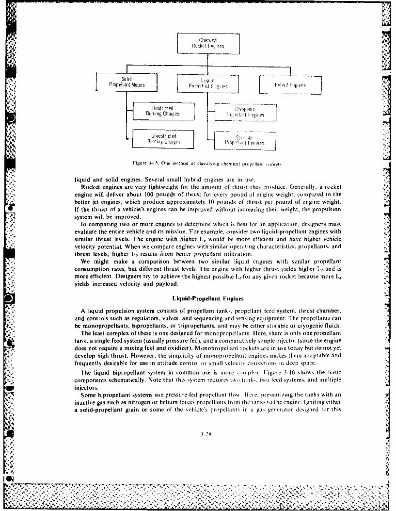
Che:;icalRocket F'iijincs
I Soh_ I L___
I Propellant Motors I P llt Er1cirles bIv! f Flig sel ........... Pr opel I it F i ie
Restricted CrIogelcBur nig Charges Fr[)oella i c F ltieS
Unrestricted .. ---1Burning C'narpes Prop,,t FdleI
Figure 3-15. One method of classitying chemical propellant iockei .
liquid and solid engines. Several small hybrid engines are in use.Rocket engines are very lightweight for the amount of thrust they produce. Generally, a rocket 4-
engine will deliver about 100 pounds of thrust for every pound of engine weight, compared to thebetter jet engines, which produce approximately 10 pounds of thrust per pound of engine weight.
If the thrust of a vehicle's engines can be improved without increasing their weight, the propulsionsystem will be improved.
In comparing two or more engines to determine which is best for an application, designers mustevaluate the entire vehicle and its mission. For example, consider two liquid-propellant engines withsimilar thrust levels. The engine with higher lp would be more efficient and have higher vehiclevelocity potential. When we compare engines with similar operating characteristics, propellants, andthrust levels, higher hp results from better propellant utilization.
We might make a comparison between two similar liquid engines with similar propellantconsumption rates, but different thrust levels. The engine with higher thrust yields higher 1,p and ismore efficient. Designers try to achieve the highest possible l, for any given rocket because more i,Pyields increased velocity and payload.
Liquid-Propellant Engines
A liquid propulsion system consists of propellant tanks, propellant feed system, thrust chamber,and controls such as regulators, valves, and sequencing and sensing equipment. The propellants canbe monopropellants, bipropellants, or tripropellants, and may be either storable or cryogenic fluids.
5'S"". The least complex of these is one designed for monopropellants. Here, there is only one propellant
tank, a single feed system (usually pressure-fed), and a comparatively simple injector (since the enginedoes not require a mixing fuel and oxidizer). Monopropellant rockets are in use today but do not yetdevelop high thrust. However, the simplicity of monopropellant engines makes thern adaptable andfrequently desirable for use in attitude control or small ,elociiv coriections in deep space.
The liquid bipropellant system in common use is more ,mpl,:x Figure 3-16 shows the basiccomponents schematically. Note that this system requires t No tanks, two feed systems, and multipleinjectors.
Some bipropellant systems use pressure-fed propellant llos. Here. pressurizing the tanks with aninactive gas such as nitrogen or helium forces propellants trom the tanks to the engine. Igniting eithera solid-propellant grain or some of the vehicle's propellant,, in a gas generator designed for this
0i- rrv-*.JV' - 'S
e .'--....... ..- "- -...- ." ..-...-.........-.. ..-...... -.... ....- ,... .,..,..'.,- -. ,. .-.-.- ;-.......- .. - .. . . . . - -. -.. ., '. ', . - -
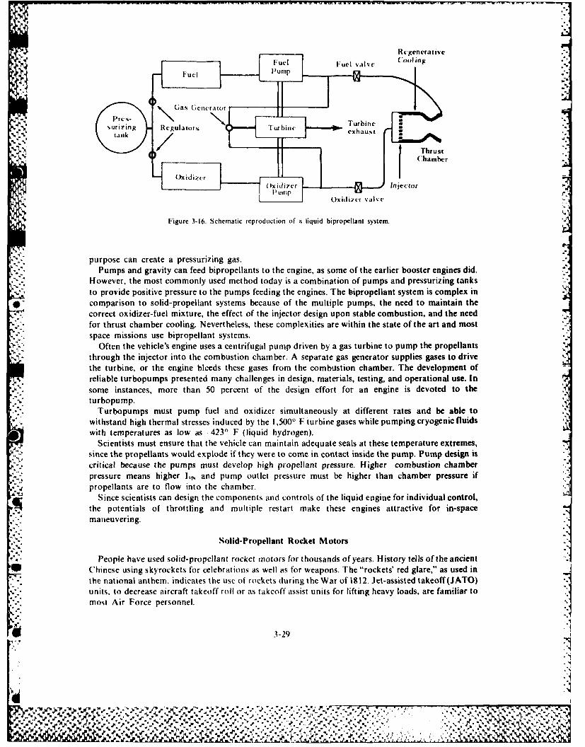
Rgenerativeii Fuel Pump
Pres-Gas Generator
. ,. Turbine
surizing Rcgulator Turbinetank exhaus
, Thrust
OxidzerChamber
Oxidizer Injectorfl u 1p ,
O)xidizrer valve
'5-.'
Figure 3-16. Schematic reproduction of a liquid bipropellant system.
purpose can create a pressurizing gas.- Pumps and gravity can feed bipropellants to the engine, as some of the earlier booster engines did.*, However, the most commonly used method today is a combination of pumps and pressurizing tanks
to provide positive pressure to the pumps feeding the engines. The bipropellant system is complex incomparison to solid-propellant systems because of the multiple pumps, the need to maintain thecorrect oxidizer-fuel mixture, the effect of the injector design upon stable combustion, and the needfor thrust chamber cooling. Nevertheless, these complexities are within the state of the art and mostspace missions use bipropellant systems.
Often the vehicle's engine uses a centrifugal pump driven by a gas turbine to pump the propellantsthrough the injector into the combustion chamber. A separate gas generator supplies gases to drivethe turbine, or the engine bleeds these gases from the combustion chamber. The development ofreliable turbopumps presented many challenges in design, materials, testing, and operational use. Insome instances, more than 50 percent of the design effort for an engine is devoted to theturbopump.
".. Turbopumps must pump fuel and oxidizer simultaneously at different rates and be able towithstand high thermal stresses induced by the 1,500' F turbine gases while pumping cryogenic fluidswith temperatures as low as 423' F (liquid hydrogen).
Scientists must ensure that the vehicle can maintain adequate seals at these temperature extremes,since the propellants would explode if they were to come in contact inside the pump. Pump design iscritical because the pumps must develop high propellant pressure. Higher combustion chamberpressure means higher Lp, and pump outlet pressure must be higher than chamber pressure ifpropellants are to flow into the chamber.
Since scientists can design the components and controls of the liquid engine for individual control,the potentials of throttling and multiple restart make these engines attractive for in-spacemaneuvering.
Solid-Propellant Rocket Motors
People have used solid-propellant rocket motors for thousands of years. History tells of the ancientChinese using skyrockets for celebrations as well as for weapons. The "rockets' red glare," as used inthe national anthen, indicates the use of rockets during the War of 1812. Jet-assisted takeoff(JATO)units, to decrease aircraft takeoff roll or as takeoff assist units for lifting heavy loads, are familiar tomost Air Force personnel.
3-29
,,* -. . .. .. . ,, .. . . . . . . . . .* .. . . . ...-. ...,. .... I ,:.

The solid-propellant rocket is comparatively simple. The major components are: the case, whichholds the propellants and is the combustion chamber; the igniter; and the converging-diverging nozzle(fig. 3-17). Because of its simplicity, the solid motor is inherently more reliable and cheaper to
A produce than the liquid rocket engine. However, solid motors generally have a lower lsp than the
liquid engines.
Aft Closure and Nozzle Assembly
V. (Converging.Diverging Type)
'A-'
- incr \lo'~blc \o.'ilv
Figure 3-17. A solid propellant rocket motor
As mentioned earlier in the propellant section, the use of additives, new chemicals, and design ofhigh volumetric loading propellant grains is improving the Isp of solids. The other approach for
* increasing performance is to increase the mass ratio of the motor. Scientists and engineers haveexpehded much energy in this area by designing cases that are lightweight and stronger. Researchseems to point to two possible solutions: either make lightweight but strong cases of metals, such astitanium, or design filament-wound cases of fiberglass or nylon tape impregnated with epoxy-typeglues.
We can make the filament-wound cases even lighter if we design reinforced propellant grains toassist in supporting the vehicle. We can form these reinforced grains by molding the propellantaround aluminum or other metal additive wires. The engine consumes these reinforcing materialsduring combustion. Reinforced grain motors are usually regressive burning so that combustion
* chamber pressure will decrease near the end of burning to allow the use of very lightweight cases.* Today industry can make both liquid and solid motors in a variety of sizes from very small attitude
control and docking motors up to millions of pounds of thrust.
Thrust Vector Control
To accomplish attitude and directional control of a rocket, moving the engines or deflecting theexhaust gases is necessary. We call this thrust vector control. The use of flexible mountings orgimbals for the engine controls the thrust vector for the main and vernier liquid engines. Hydraulicor pneumatic cylinders deflect the engines to achieve the desired thrust vector.
In soiid motors, deflecting or swiveling the entire motor is impractical because this amounts tomoving the entire stage. Engineers must control thrust vectors at the nozzles in solid motors. Thev' haveused the following methods: movable nozzles; controllable vanes in the nozzles, jetavators (slip ring orcollar at the nozzle exit), or injection of fluid (gas or liquid) into nozzles to deflect the exhaust flow andaccomplish flight path or altitide changes (see fig. 3-)8). These are only a few of the methods used.
Thrust Termination
~~**5.~Stopping the flow of propellants is all that is necessary to accomplish thrust termination. Since
scientists can cause this to be done in a reproducible sequence, the residual thrust generated during,
La 3-30

-: JET EVATOFR JET VANES
SF(ONDAFRY GAS INJECTION ISWIVEL ED NOZZL E
* Figure 3-18. Methods of thrust vector control (TVC) for solid motors.
and shortly after, engine cutoff will be a known quantity. They can design liquid engines so that a ratevariance in propellant flow into the engine can change the thrust level within limits.
In solid motors thrust termination is also simple (fig. 3-19). If we reduce the combustion chamberpressure below the critical pressure value for that particular motor, it will blow itself out, in effect.Blowing of nozzles, blowing out the aft end of the motor, or using thrust termination ports to vent nthe pressure out the sides of the case are some methods used to reduce the chamber pressure andterminate thrust. However, the thrust termination is not instantaneous. L-ow levels of thrust maycontinue for several minutes because of residual burning in the remaining solid grain. We mustconsider the residual burning characteristics of each type of motor when we need a very acct'- tecutoff velocity.
Engine Cooling
The combustion chamber of a rocket engine contains gases at temperatures in excess of 5,000' F.The walls of the combustion chamber and the nozzle absorb large amounts of heat. Some provisionto dissipate heat must be made otherwise, as the walls and nozzle absorb the heat, the wall
45 temperature of the engine increases, and the strength of the structural material decreases. Since theamount of heat absorbed is highest in the nozzle throat, special attention is given to this region.
Most liquid engines are either partially or completely cooled. We cannot fire uncooled liquidrockets for periods greater than approximately 25 seconds. If combustion temperatures were low, itmight be possible to use an uncooled engine for longer periods of time; but usually such is not the casein large engines. Cooling methods include regenerative, water, film, sweat (transpiration). radiation.and ablative cooling.
Regenerative cooling circulates fuel or oxidizer through small passageways between the inner andouter walls of the combustion chamber, throat, and nozzle. Transferring cools thle engine andincreases the energy of the propellant before it is injected into the combustion chamber. IThe addition
* 3-31
O'I

_41
FORE -END VENTING NOZZLE EJECTION
AFT.- END VENTING & GAS DEFLECTION FORE.- END VENTING &QUENCH
AFT -END VENTING WITH MANIFOLDS __ CHAMBER DESTRUCTION
Figure 3-19. Methods of thrust termination of solid motors.
of energy to the propellant slightly increases the velocity of the exhaust gases and improves engineperformance.
Water cooling is regenerative cooling, except that water circulates instead of the fuel oxidizer.Water cooling is widely used in static test stand firings, but not in flight vehicles.
Film cooling provides a thin fluid film to cover and protect the inner wall of the engine. Theinjection of small quantities of the fuel, oxidizer, or a nonreactive fluid at a number of points along
4' the hot surface forms a protective film on the inner walls. The fluid flows along the wall and absorbsheat by evaporation. The engine can use film cooling with regenerative cooling for critical parts of theengine where regenerative cooling alone is not sufficient.
Sweat or transpiration cooling uses a porous material for the inner wall of the engine. Thecoolant is passed through this porous wall and is distributed over the hot surface. It is difficult todistribute the coolant uniformly over the surface because the combustion gas pressure decreasesbetween the combustion chamber and the nozzle exit. Manufacturing porous materials so that theyare uniform throughout is difficult, but is being done successfully, and transpiration cooling isbeing used in some applications.
Radiation cooling removes heat from the engine and radiates it to space. Some current liquidr-. engines use a regeneratively-cooled nozzle to the 10:1 expansion ratio point and a radiation-cooled
extension from that point to the end of the nozzle. This type is lighter than it would be if regenerative
E. 3-32
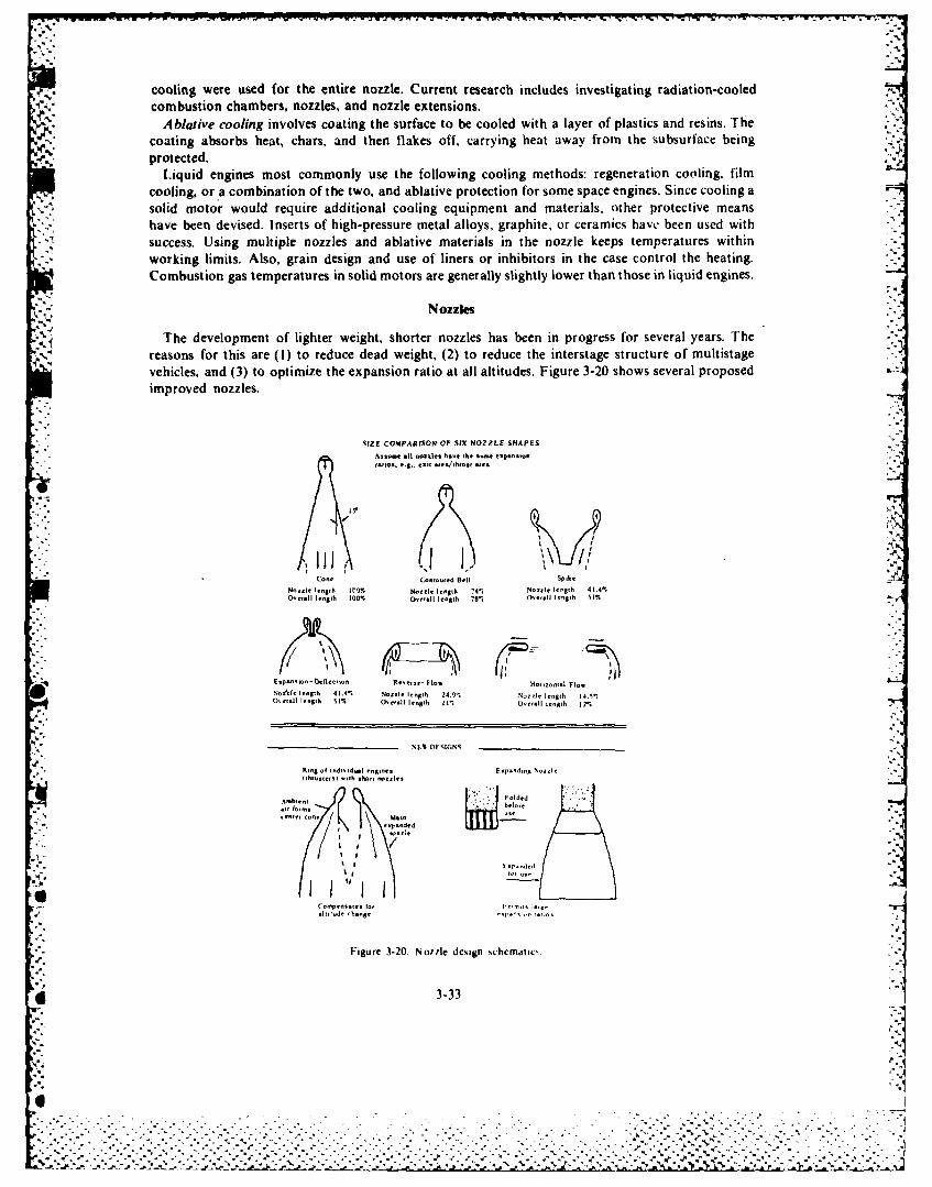
cooling were used for the entire nozzle. Current research includes investigating radiation-cooledcombustion chambers, nozzles, and nozzle extensions.
Ablative cooling involves coating the surface to be cooled with a layer of plastics and resins. Thecoating absorbs heat, chars, and then flakes off, carrying heat away from the subsurface beingprotected.
Liquid engines most commonly use the following cooling methods: regeneration cooling, filmcooling, or a combination of the two, and ablative protection for some space engines. Since cooling asolid motor would require additional cooling equipment and materials, other protective meanshave been devised. Inserts of high-pressure metal alloys, graphite, or ceramics have been used withsuccess. Using multiple nozzles and ablative materials in the nozzle keeps temperatures withinworking limits. Also, grain design and use of liners or inhibitors in the case control the heating.Combustion gas temperatures in solid motors are generally slightly lower than those in liquid engines.
Nozzles
The development of lighter weight, shorter nozzles has been in progress for several years. Thereasons for this are (I) to reduce dead weight, (2) to reduce the interstage structure of multistagevehicles, and (3) to optimize the expansion ratio at all altitudes. Figure 3-20 shows several proposedimproved nozzles.
SIZE COMPARISON OF SIX NOZZLE SHAPESAntone n~l tnozntea Ena,. t n *nt elpt~nton "
w.t,. e.S.. . en ., ,on ne:
jjj - \ ,,
Cone Coanoued Bell Spik e
Nozzle Ienglh 8I'O Nt,=le length 74% Noutl ln9,Ih 41.4%Ooe,.ll lenglh 100% O"t.ni lenatth 78% O"'.li length 51%r
Enpottwot-O{ flcto Rn~tt-Pot lHo,,uotnl l ot
Noi fe lenlh 41.4% Nooule ltn$th 24 N1ot leng#h 14.5.Oe.ll len lhA, 1% Ovell l 21"h 1Oernll letn h 12%
S DESIGNS
Rtg of .nddt,d- I en,n, Epotd.t No-ile
..b,e a''
Folded
' . ndd
1' 1 I .... . I.,
e I I
Figure 3-20. Noule design schematio. I~3-33
." ' ." ,ri,.
,..- - ..*".- -.:.--. 1 -'.. .- ." -' -- - --.. --- -.' -- . .-.. --'-: .-..--'".. " .:--.- - - ...5...'-..:. ,-...-- ': .V '. -" .',. - .. ..
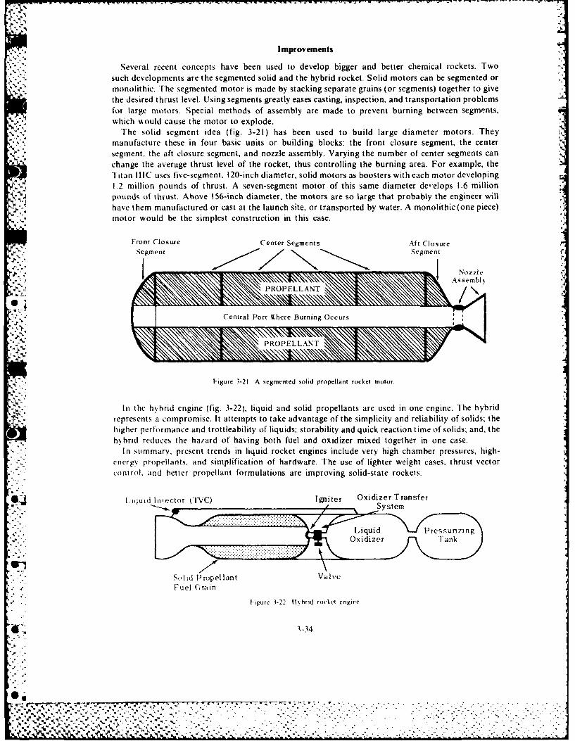
Improvements
Several recent concepts have been used to develop bigger and better chemical rockets. Twosuch developments are the segmented solid and the hybrid rocket. Solid motors can be segmented ormonolithic. The segmented motor is made by stacking separate grains (or segments) together to givethe desired thrust level. Using segments greatly eases casting, inspection, and transportation problemsfor large motors. Special methods of assembly are made to prevent burning between segments,which would cause the motor to explode.
The solid segment idea (fig. 3-21) has been used to build large diameter motors. Theymanufacture these in four basic units or building blocks: the front closure segment, the centersegment, the aft closure segment, and nozzle assembly. Varying the number of center segments canchange the average thrust level of the rocket, thus controlling the burning area. For example, theITitan IIIC uses five-segment. 120-inch diameter, solid motors as boosters with each motor developing1.2 million pounds of thrust. A seven-segment motor of this same diameter deelops 1.6 millionpounds of thrust. Above 156-inch diameter, the motors are so large that probably the engineer willhave them manufactured or cast at the launch site, or transported by water. A monolithic(one piece)motor would be the simplest construction in this case.
Front Closure Center Segments Aft ClosureSegment Segment o
. ! ~ ~PROPELLANT" N"
Figure 3-21 A segmented solid propellant rocket motor.
In the hybrid engine (fig. 3-22), liquid and solid propellants are used in one engine. The hybridrepresents a compromise. It attempts to take advantage of the simplicity and reliability of solids; thehigher performance and trottleability of liquids; storability and quick reaction time of solids: and, thehybrid reduces the haiard of having both fuel and oxidizer mixed together in one case.
In summary, present trends in liquid rocket engines include very high chamber pressures, high-energN propellants, and simplification of hardware. The use of lighter weight cases, thrust vectorcontrol, and better propellant formulations are improving solid-state rockets.
Li quid Iector (TVC) Igniter Oxidizer Transfer• /System
....... e -,. .... .... ... , ..., , ., , ,
,Oxidiz-e"r T an k
SoIld Propel lant ValveFuel Gr in
tigure 3-22 It 10 id rocket engine
E1 3-34
@• _ _ __%
- Ai..% S\,is'.
ADVANCED PROPULSION TECHNIQUES
As mission requirements approach or exceed the limits of chemical rockets, new propulsiontechniques must be investigated. The new techniques will obey Newton's laws just as thecontemporary techniques do, but they will use different energy sources and hardware to produce thepropulsive force. This force will still be the reaction of the vehicle to mass being ejected at highvelocity.
Need for Advanced Designs
The need for advanced designs becomes readily apparent as engineers consider velocity limitationsof chemical rockets. Figure 3-23 shows these limitations for single and multistage vehicles. The graphsinclude both 1,02 RP 1, as well as the higher energy combination L0 2/LH2. Payload fraction is thepayload weight divided by the gross weight of the vehicle.
Since there is a practical limit to the number of stages that researchers can use to increase mass ratios,consider that Lp is proportional to T. m. Remember also that Tc and m interact and influence eachother in a combustion process. If T, and m were independent, scientists could vary them so that theresulting ratio would be higher. The value for m is about 20 in present chemical engines.* If theyreduce m, a higher performance engine results.
Nuclear Rocket
One program that has followed this approach is the nuclear rocket. It has increased the theoreticalL, to more than 800 seconds-double that of current -hemical engines. Figure 3-24 shows a schematicreproduction of a typical nuclear, solid core, thermal reactor engine. Since liquid hydrogen is thepropellant, thrust levels are comparable to upper stage chemical engines using hydrogen.
Initially the nuclear rocket was a joint Atomic Energy Commission-USAF project but became anAEC-NASA program of two phases. The early reactor core design phase, using the Kiwi A and Breactors, reached completion in September 1964. The second phase involved developing the flightconfiguration engine known as the nuclear engine for rocket vehicle application (NERVA). The USAir Force planned preliminary flight tests for ballistic trajectory flights with the NERVA functioningas an upper stage main engine. Many areas of study and research are necessary before the nuclear
. rocket is ready for production. Among these are starting at altitude, and radiation and neutronheating that may affect the payloads, propellants, and structural materials. Engineers and Scientists
,' ive ground tested a more advanced increased density reactor called Phoebus, and they haveconsidered a flyable engine configuration. However, the government has not funded this research andthere is no work being done.
One theoretical improvement is a high-density reactor using fast neutrons. This type of reactor is* expected to produce higher performance levels in a smaller package than the thermal (or slow)
reactors mentioned above. Another improvement that may prove feasible at some time in the future isa gas core reactor, in which the operating temperature (Tc) could be much higher. This increase intemperature would occur because of the elimination of the solid core or fuel elements used in slow andfast reactors. These structural elements are temperature limited.
low Thrust Rockets
Chemical engines produce high thrust for a short time (minutes), and nuclear reactor engines yieldhigh thrust for hours. Each produces acceleration that stops when the propellant is exhausted.
I here are other engines that produce only small amounts of thrust, but they do so for months, or
ccn years. Ihrust acting for long periods can produce final velocities much higher than thoseproduced b chemical or reactor engines.
m~,~' .1 . e I ,,r Nthp irt tC b n ng-ti.f e ,SSM I ). * )-h uas 1 0, 1 H., is about 10 to 12 at maximum I,
14 3-35
-'xi--..-
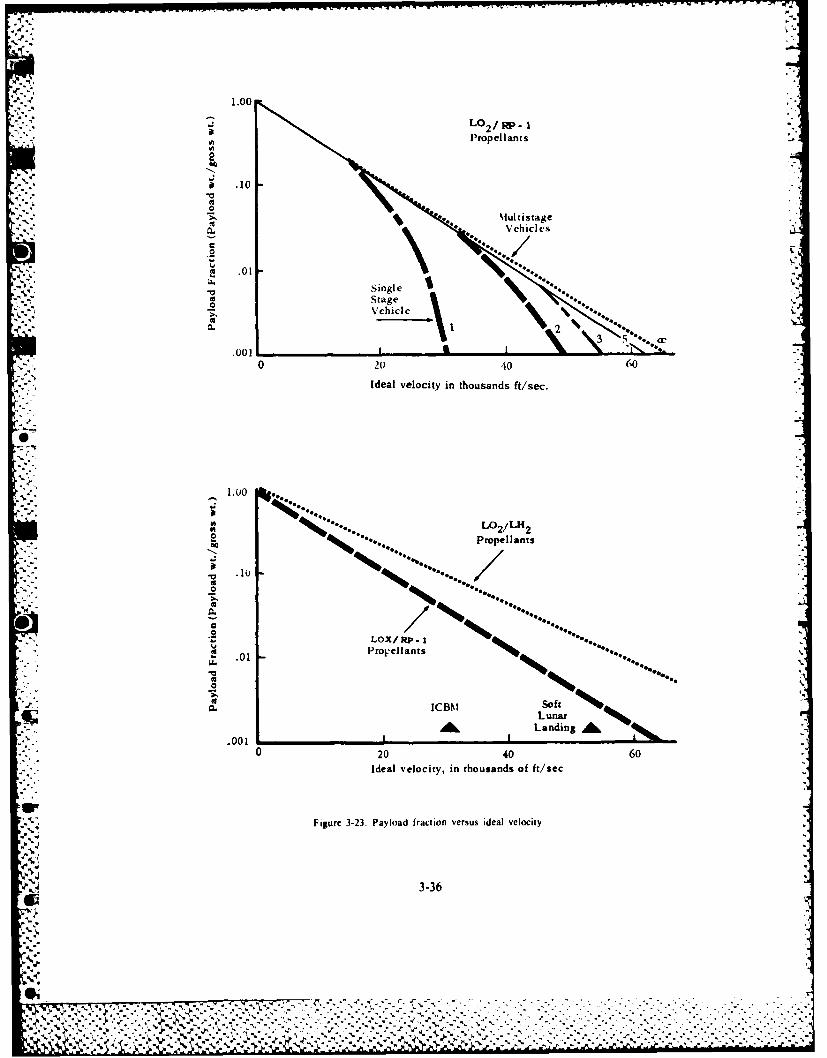
S .10
.0
.001
1.001
o 2040 60Idea velcityinPt opelldatse
00
to .01PProeelaats
AL Landin A&
00
Idea veoiy ntouad ff/e
.2~ LO/R~
% AlLAA-

Prp la t a k...
Pump
Turbine
Shel
Turbine Exhaust
Nozzle Cooling
Figure 3-24. A nuclear rocket. -7
31-37
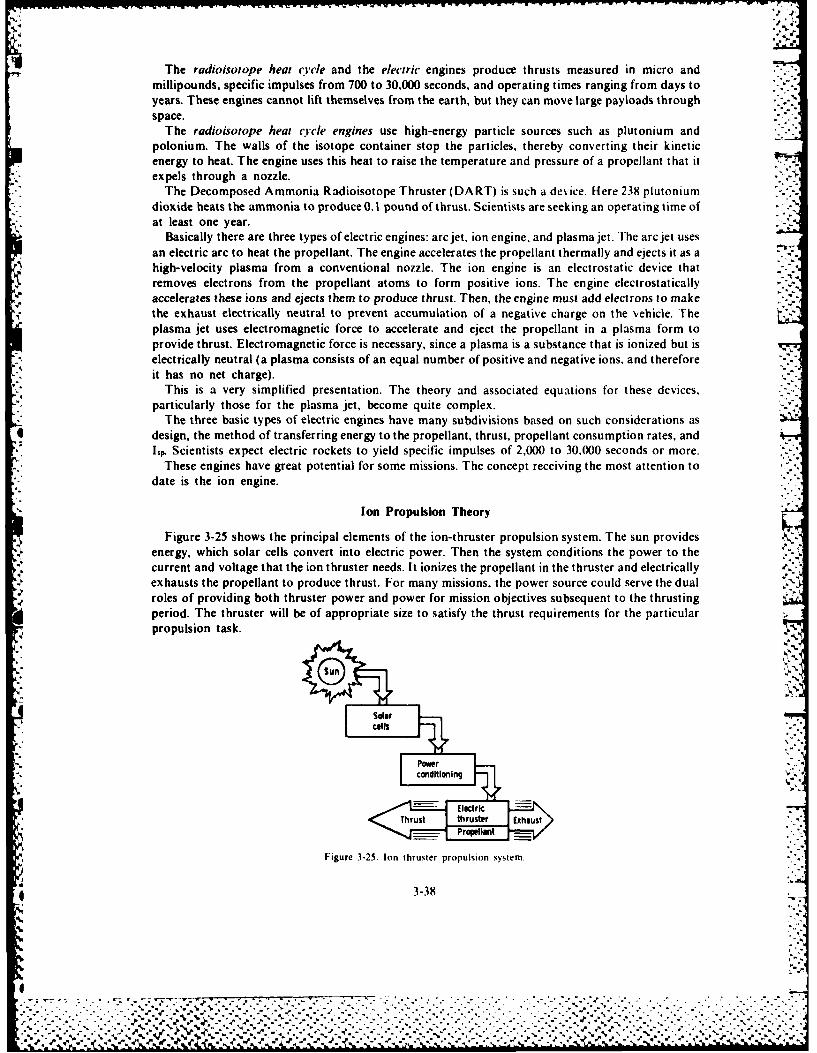
The radioisotope heat ucle and the electric engines produce thrusts measured in micro andmillipounds, specific impulses from 700 to 30,000 seconds, and operating times ranging from days toyears. These engines cannot lift themselves from the earth, but they can move large payloads throughspace.
The radioisotope heat cycle engines use high-energy particle sources such as plutonium andpolonium. The walls of the isotope container stop the particles, thereby converting their kineticenergy to heat. The engine uses this heat to raise the temperature and pressure of a propellant that itexpels through a nozzle.
The Decomposed Ammonia Radioisotope Thruster (DART) is such a device. Here 238 plutoniumdioxide heats the ammonia to produce 0. 1 pound of thrust. Scientists are seeking an operating time ofat least one year.
Basically there are three types of electric engines: arc jet, ion engine, and plasma jet. The arc jet usesan electric arc to heat the propellant. The engine accelerates the propellant thermally and ejects it as ahigh-velocity plasma from a conventional nozzle. The ion engine is an electrostatic device thatremoves electrons from the propellant atoms to form positive ions. The engine electrostaticallyaccelerates these ions and ejects them to produce thrust. Then, the engine must add electrons to makethe exhaust electrically neutral to prevent accumulation of a negative charge on the vehicle. Theplasma jet uses electromagnetic force to accelerate and eject the propellant in a plasma form toprovide thrust. Electromagnetic force is necessary, since a plasma is a substance that is ionized but iselectrically neutral (a plasma consists of an equal number of positive and negative ions, and thereforeit has no net charge).
This is a very simplified presentation. The theory and associated equations for these devices,particularly those for the plasma jet, become quite complex.
The three basic types of electric engines have many subdivisions based on such considerations ,asdesign, the method of transferring energy to the propellant, thrust, propellant consumption rates, andLp. Scientists expect electric rockets to yield specific impulses of 2,000 to 30,000 seconds or more.
These engines have great potential for some missions. The concept receiving the most attention todate is the ion engine.
Ion Propulsion Theory
Figure 3-25 shows the principal elements of the ion-thruster propulsion system. The sun providesenergy, which solar cells convert into electric power. Then the system conditions the power to thecurrent and voltage that the ion thruster needs. It ionizes the propellant in the thruster and electricallyexhausts the propellant to produce thrust. For many missions, the power source could serve the dualroles of providing both thruster power and power for mission objectives subsequent to the thrustingperiod. The thruster will be of appropriate size to satisfy the thrust requirements for the particularpropulsion task.
Solarcalls
% .-. ~c o n d iti o nn g,"
Tht thruster ExhausPropellant •,
Figure 3-25. Ion thruster propulsion system.
3-38
4',
44
%.......... .... .................................- ,.-..-........". . . : . ., * " . . - " ' . ,"- -. .. . ... ,...... . . . ..... . . ...... . .. . ,, -

The main advantage of using electric propulsion is that the electric energy added to the exhaustpropellant greatly increases its velocity, or specific impulse, hence electric propulsionproduces more thrust with the same propellant flow rate. Figure 3-26 shows the mass of propellantrequired to produce a given thrust decreases with increasing specific impulse. However, theincreasingly massive power plant required to accelerate the exhaust to higher velocities offsets thesaving in propellant mass. Figure 3-27 shows this increase in power plant mass. The spacecraftachieves the maximum payload at the optimum specific impulse, where the sum of the propellant andpower plant mass is a minimum. Figure 3-28 shows this.
Figure 3-28 indicates that at low Specific iL..Pulse the propellant mass can be excessively large, whileat high specific impulse the power plant mass becomes excessive. Between these two extremes is a
- a'-broad useful range where sufficient payload remains for design of a practical spacecraft. As definedby figure 3-28, payload includes the mass of the spacecraft itself and the useful payload. The optimumvalue of specific impulse to maximize payload usually is between 2.000 and 5.000 seconds, and thusthe optimum value of exhaust velocity is between 20,000 and 50,000 meters per second. The spacecrafteasily achieves this range of exhaust velocity with ion thrusters and, as we discuss later, this rangeresults in strong increases in spacecraft payload over a large variety of missions.
~Propellant
.00,
0 Specific impulse =Mo
Figure 3-26. EfeMafprplansas/nspecific impulsewihperlnadd.
U - powrpant
-,0 specific impulse -WW
Figure 3-27. Mass/specific impulse with towtal adedf.
3-3
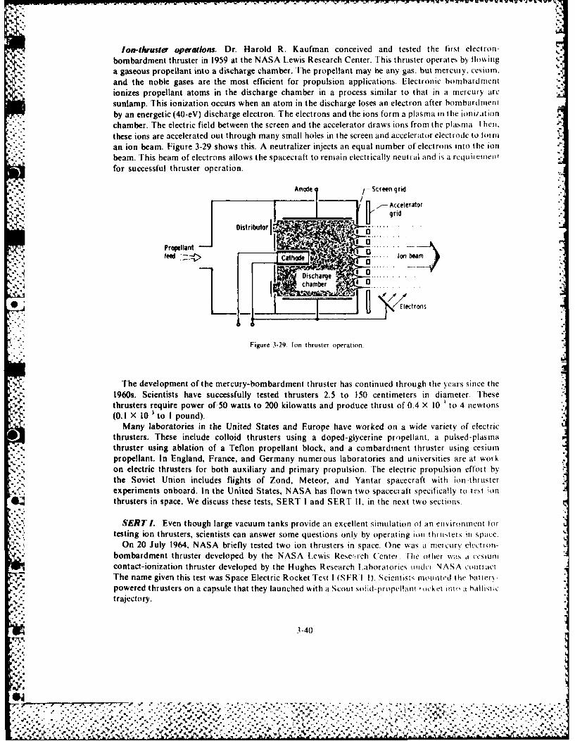
Ion-thruster operations. Dr. Harold R. Kaufman conceived and tested the first electron-
bombardment thruster in 1959 at the NASA Lewis Research Center. This thruster operates by flowinga gaseous propellant into a discharge chamber. The propellant may be any gas. but mercury, cesium,
and the noble gases are the most efficient for propulsion applications. Electronic bombardmentionizes propellant atoms in the discharge chamber in a process similar to that in a mercury arcsunlamp. This ionization occurs when an atom in the discharge loses an electron after bombardmentby an energetic (40-eV) discharge electron. The electrons and the ions form a plasma in the ionization
chamber. The electric field between the screen and the accelerator draws ions from the plasma. I hen,
these ions are accelerated out through many small holes in the screen and accelerator electrode to o rnin
an ion beam. Figure 3-29 shows this. A neutralizer injects an equal number of electrons into the ionbeam. This beam of electrons allows the spacecraft to remain electrically neutral and is a requietien-
for successful thruster operation.
Anoe - Screen grid"(""I ......../--Accelerator
",- grid
Distributor I ,_I ... .. riI
Propellant --.- efeed cathode I onbem
Discharge'.,,,L chamber .
Figure 3-29. Ion thruster operation.
The development of the mercury-bombardment thruster has continued through the years since the1960s. Scientists have successfully tested thrusters 25 to 150 centimeters in diameter. Thesethrusters require power of,50 watts to 200 kilowatts and produce thrust of 0.4 X 10 to 4 newtons(0.1 X 10-' to I pound).
Many laboratories in the United States and Europe have worked on a wide variety of electricthrusters. These include colloid thrusters using a doped-glycerine propellant, a pulsed-plasmathruster using ablation of a Teflon propellant block, and a combardment thruster using cesiumpropellant. In England, France, and Germany numerous laboratories and universities are at workon electric thrusters for both auxiliary and primary propulsion. The electric propulsion effort bythe Soviet Union includes flights of Zond, Meteor, and Yantar spacecraft with ion-thrusterexperiments onboard. In the United States, NASA has flown two spacecraft specifically to tet ionthrusters in space. We discuss these tests, SERT I and SERT !1, in the next two sections.
SERT I. Even though large vacuum tanks provide an excellent simulation o an environment lortesting ion thrusters, scientists can answer some questions only by operating ion thmntets in space.
On 20 July 1964, NASA briefly tested two ion thrusters in space. One was a mercury elvctron-'bombardment thruster developed by the NASA Lewis Resc!,rch Center. fhe other was a cesium
contact-ionization thruster developed by the Hughes Research l.aboratorics tindut NASA contraclThe name given this test was Space Electric Rocket Test I (SFRI I). Scientists moonted the hatter\-
- powered thrusters on a capsule that they launched with a Scout soid-propcl Inr rnckt t i t o hallist ictrajectory.
3-40
f.S9
¢ ,IN%
."""'''- -...-' ' ." ," " ."."' ."",".' .- . . """""" -. , . ., ' " ." .". " . " ",:""% "r"""' "' . : -.-. '. ' .% ."
% % % - .. - . . • • - . 1.
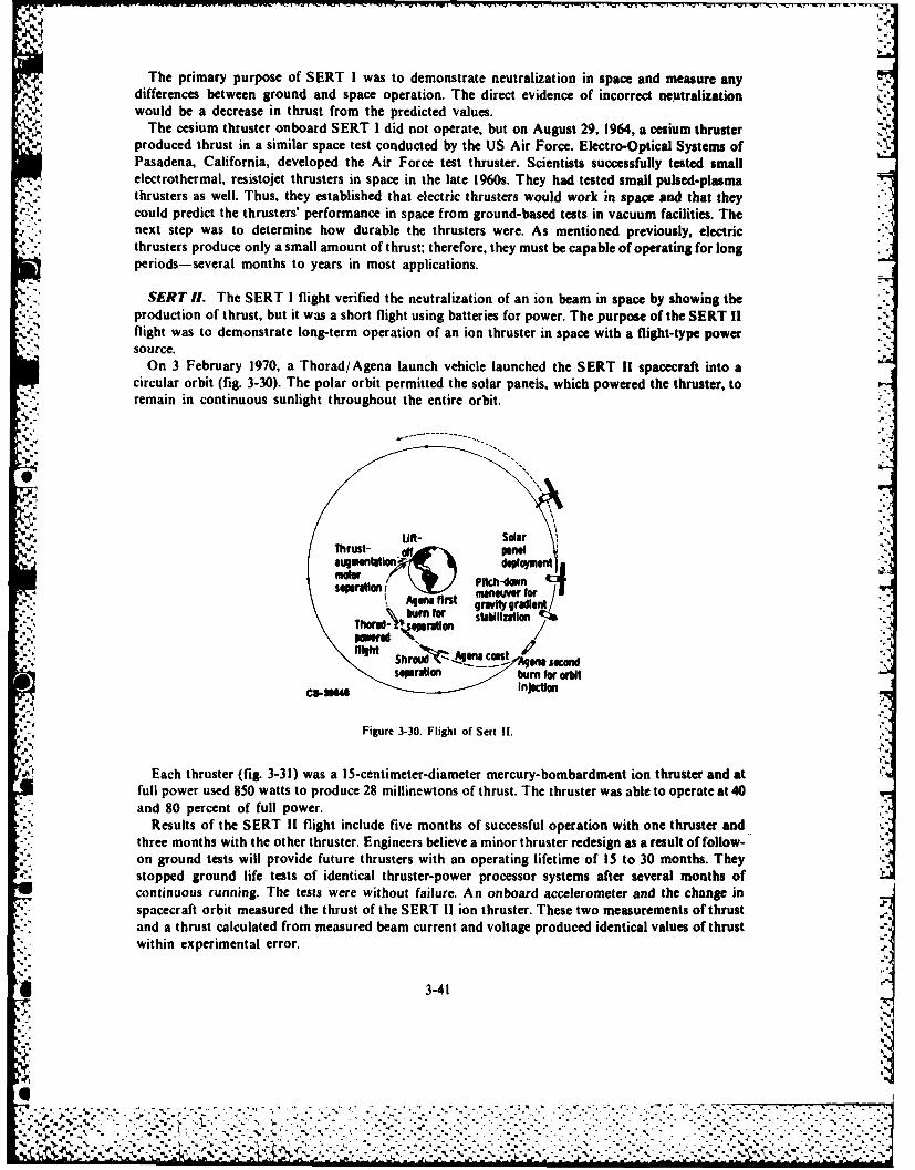
The primary purpose of SERT I was to demonstrate neutralization in space and measure anydifferences between ground and space operation. The direct evidence of incorrect neutralizationwould be a decrease in thrust from the predicted values.
The cesium thruster onboard SERT I did not operate, but on August 29, 1964, a cesium thrusterproduced thrust in a similar space test conducted by the US Air Force. Electro-Optical Systems of APasadena, California, developed the Air Force test thruster. Scientists successfully tested small
* electrothermal, resistojet thrusters in space in the late 1960s. They had tested small pulsed-plasmathrusters as well. Thus, they established that electric thrusters would work in space and that theycould predict the thrusters' performance in space from ground-based tests in vacuum facilities. Thenext step was to determine how durable the thrusters were. As mentioned previously, electricthrusters produce only a small amount of thrust; therefore, they must be capable of operating for longperiods-several months to years in most applications.
" SERT ff. The SERT I flight verified the neutralization of an ion beam in space by showing the,production of thrust, but it was a short flight using batteries for power. The purpose of the SERT IIflight was to demonstrate long-term operation of an ion thruster in space with a flight-type powersource.
On 3 February 1970, a Thorad/Agena launch vehicle launched the SERT 1! spacecraft into acircular orbit (fig. 3-30). The polar orbit permitted the solar panels, which powered the thruster, to
. remain in continuous sunlight throughout the entire orbit.
~m "
Fugigur d-0 lgto eploymen
Maim~e Plth-down ," ..an w for '
"-um f ., or stailzaio 4t 4ro
*. Resltrofth-SETfllight of Sest o n n
onl growe un ed tet w prod ure thrusteran of ae to ont theyad8co cntinuousrun Th t ower br t
spaccraftuorbit(measured3thewthust of the SERT I ion thruer.Thse-omrmeasurento thrustdaandl aowthrusd calculatd from esrdba urnnotg produced identicalvalues of thrust.Tetrsrwaabeoopaeat4win eperienta l error.
Results of the SERT 11 flight include five months of successful operation with one thruster and ',"":'-:three months with the other thruster. Engineers believe a minor thruster redesign as a result of follow-,..: on ground tests will provide future thrusters with an operating lifetime of 15 to 30 months. They *:• - stopped ground life tests of identical thruster-power processor systems after several months of..- t. Jcontinuous running. The tests were without failure. An onboard accelerometer and the change in"-- spacecraft orbit measured the thrust of the SERT 1I ion thruster. These two measurements of thrust
and a thrust calculated from measured beam current and voltage produced identical values of thrust-,: ~within experimental error. .,
3-41
t".''. " • '" " " " "" % '7" ~~~~~~~~~... ... ..... ..... .. ..-.-.-... ....... "...-.-.. ".."... "-'.-'.-',. .-.-
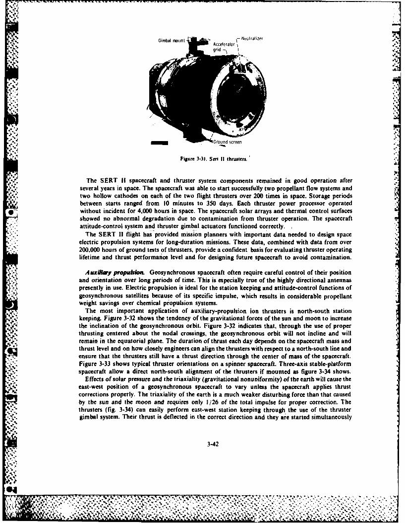
, Gimbal mount- Accelerator Neuralze
grid -\ I ' . "
Cround screen
Figure 3-31. Seri II thrusters.
The SERT If spacecraft and thruster system components remained in good operation afterseveral years in space. The spacecraft was able to start successfully two propellant flow systems andtwo hollow cathodes on each of the two flight thrusters over 200 times in space. Storage periodsbetween starts ranged from 10 minutes to 350 days. Each thruster power processor operatedwithout incident for 4,000 hours in space. The spacecraft solar arrays and thermal control surfacesshowed no abnormal degradation due to contamination from thruster operation. The spacecraftattitude-control system and thruster gimbal actuators functioned correctly.
The SERT ii flight has provided mission planners with important data needed to design spaceelectric propulsion systems for long-duration missions. These data, combined with data from over200,000 hours of ground tests of thrusters, provide a confident basis for evaluating thruster operatinglifetime and thrust performance level and for designing future spacecraft to avoid contamination.
'A. Auxilidvy propublio. Geosynchronous spacecraft often require careful control of their positionand orientation over long periods of time. This is especially true of the highly directional antennaspresently in use. Electric propulsion is ideal for the station keeping and attitude-control functions ofgeosynchronous satellites because of its specific impulse, which results in considerable propellantweight savings over chemical propulsion systems.
The most important application of auxiliary-propulsion ion thrusters is north-south stationkeeping. Figure 3-32 shows the tendency of the gravitational forces of the sun and moon to increasethe inclination of the geosynchronous orbit. Figure 3-32 indicates that, through the use of properthrusting centered about the nodal crossings, the geosynchronous orbit will not incline and willremain in the equatorial plane. The duration of thrust each day depends on the spacecraft mass andthrust level and on how closely engineers can align the thrusters with respect to a north-south line andensure that the thrusters still have a thrust direction through the center of mass of the spacecraft.Figure 3-33 shows typical thruster orientations on a spinner spacecraft. Three-axis stable-platformspacecraft allow a direct north-south alignment of the thrusters if mounted as figure 3-34 shows.
Effects of solar pressure and the triaxiality (gravitational nonuniformity) of the earth will cause the* east-west position of a geosynchronous spacecraft to vary unless the spacecraft applies thrust
corrections properly. The triaxiality of the earth is a much weaker disturbing force than that causedby the sun and the moon and requires only 1/26 of the total impulse for proper correction. Thethrusters (fig. 3-34) can easily perform east-west station keeping through the use of the thrustergimbal system. Their thrust is deflected in the correct direction and they are started simultaneously
3-42
.4% *Y .d . -Ig ,:, ,, c , "" " .- '." """ """%:"-' """

Evenu'
correctiswere nd made
Figure 3-32. Effects of gravitational forces on geosynchronous orbit.
North-Southtine
3-4
.S9
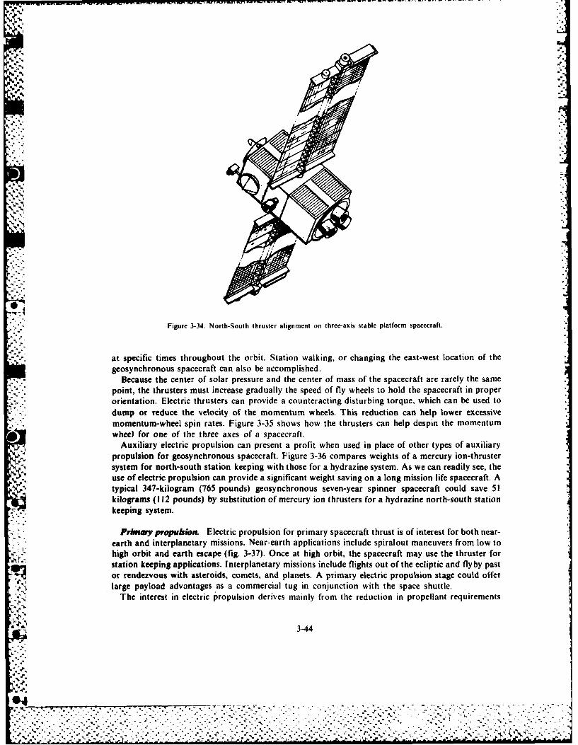
iN
Figure 3-34. North-South thruster alignment on three-axis stable platform spacecraft.
at specific times throughout the orbit. Station walking, or changing the east-west location of thegeosynchronous spacecraft can also be accomplished.
Because the center of solar pressure and the center of mass of the spacecraft are rarely the samepoint, the thrusters must increase gradually the speed of fly wheels to hold the spacecraft in properorientation. Electric thrusters can provide a counteracting disturbing torque, which can be used todump or reduce the velocity of the momentum wheels. This reduction can help lower excessivemomentum-wheel spin rates. Figure 3-35 shows how the thrusters can help despin the momentumwheel for one of the three axes of a spacecraft.
Auxiliary electric propulsion can present a profit when used in place of other types of auxiliarypropulsion for geosynchronous spacecraft. Figure 3-36 compares weights of a mercury ion-thrustersystem for north-south station keeping with those for a hydrazine system. As we can readily see, theuse of electric propulsion can provide a significant weight saving on a long mission life spacecraft. Atypical 347-kilogram (765 pounds) geosynchronous seven-year spinner spacecraft could save 51kilograms (112 pounds) by substitution of mercury ion thrusters for a hydrazine north-south stationkeeping system.
Primiy propulsion. Electric propulsion for primary spacecraft thrust is of interest for both near-earth and interplanetary missions. Near-earth applications include spiralout maneuvers from low tohigh orbit and earth escape (fig. 3-37). Once at high orbit, the spacecraft may use the thruster forstation keeping applications. Interplanetary missions include flights out of the ecliptic and flyby past
large payload advantages as a commercial tug in conjunction with the space shuttle.
The interest in electric propulsion derives mainly from the reduction in propellant requirements
-',, . ..,
0.
o r i S r c t e-
geosn...n...saceraf.ca als e accopihed
,-.."...........,heNcente....................................o............................................
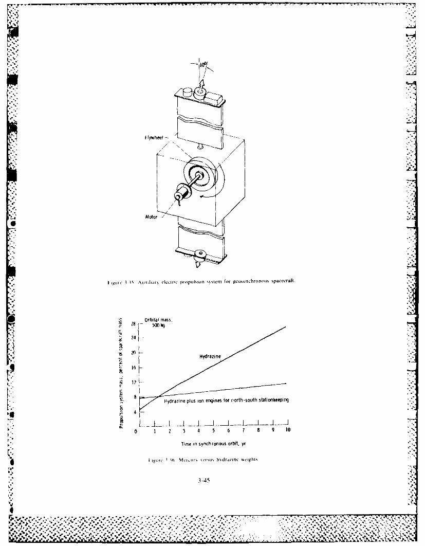
-100
Flywheel
Motor
1 ie ; 5 '\k. lxar, electric propullsion sieeni for geosynchronois spacecraft.
Orbital mass,E~ 500 k
Hydrazinle plus ion engines for r'orth -south stationkeeping
-0 1 2 3a 4 5 6 7 8 9 10" -
Time in synchronous orbit. yr
4 I'gtirc I I Mtr-,ui ci'u hdra/inc wcights
3-45
ob %% .
_* 4 1 * Wx ~ . 27:-t'+''+::"'"++: *.', .".,'. '- ,..'" :"'"" .": ',.'2.."+"."'""'" "" ;' " "."'';''% ""' "'"' ""+Y'+- .''2% J
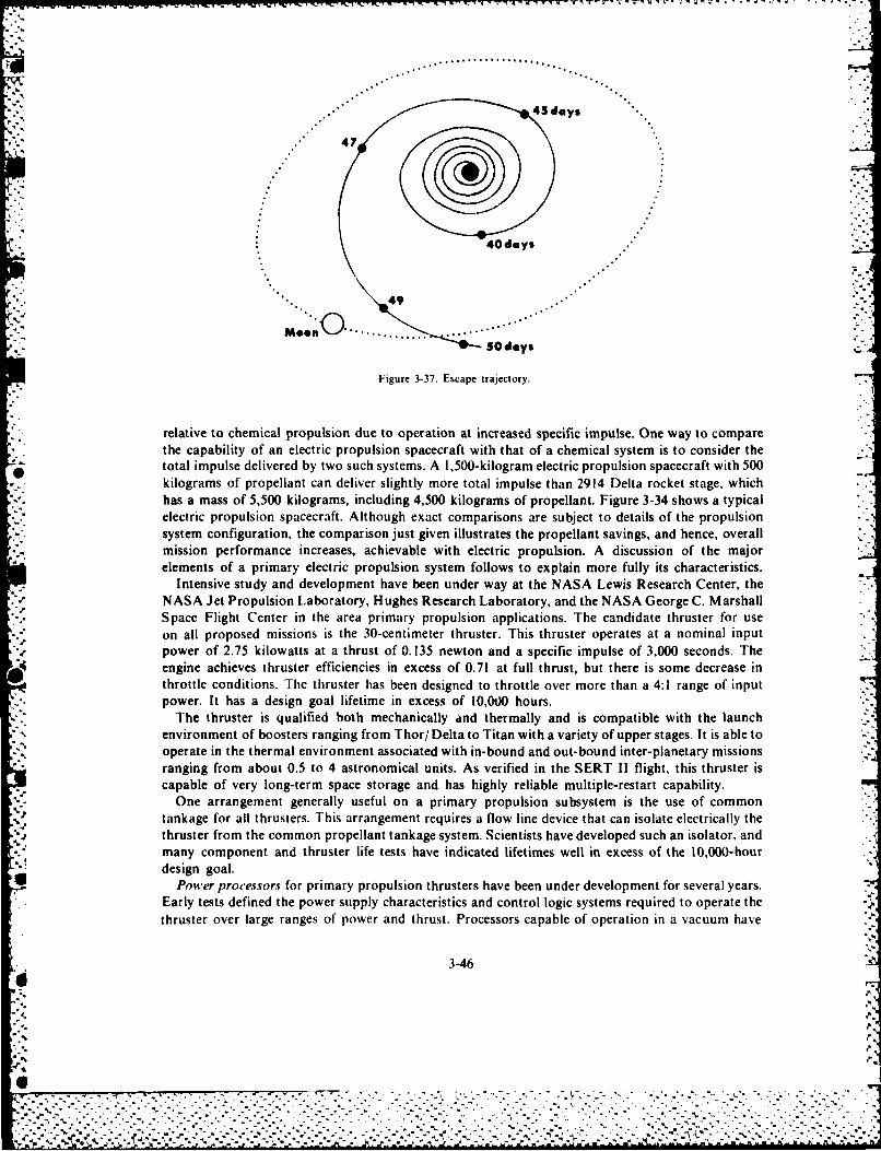
r~wrr w.Trrv".7 -,. . .- I . . . . _ I
43 days
IV 47
40days
49
M.e0n O ..... ....
50 days
Figure 3-37. Escape trajectory.
relative to chemical propulsion due to operation at increased specific impulse. One way to comparethe capability of an electric propulsion spacecraft with that of a chemical system is to consider thetotal impulse delivered by two such systems. A 1,500-kilogram electric propulsion spacecraft with 500kilograms of propellant can deliver slightly more total impulse than 2914 Delta rocket stage, whichhas a mass of 5,500 kilograms, including 4,500 kilograms of propellant. Figure 3-34 shows a typicalelectric propulsion spacecraft. Although exact comparisons are subject to details of the propulsionsystem configuration, the comparison just given illustrates the propellant savings, and hence, overallmission performance increases, achievable with electric propulsion. A discussion of the majorelements of a primary electric propulsion system follows to explain more fully its characteristics.
Intensive study and development have been under way at the NASA Lewis Research Center, theNASA Jet Propulsion Laboratory, Hughes Research Laboratory, and the NASA George C. MarshallSpace Flight Center in the area primary propulsion applications. The candidate thruster for useon all proposed missions is the 30-centimeter thruster. This thruster operates at a nominal inputpower of 2.75 kilowatts at a thrust of 0. 135 newton and a specific impulse of 3,000 seconds. Theengine achieves thruster efficiencies in excess of 0.71 at full thrust, but there is some decrease inthrottle conditions. The thruster has been designed to throttle over more than a 4:1 range of input.power. It has a design goal lifetime in excess of 10,000 hours.
The thruster is qualified both mechanically and thermally and is compatible with the launch -
environment of boosters ranging from Thor/ Delta to Titan with a variety of upper stages. It is able tooperate in the thermal environment associated with in-bound and out-bound inter-planetary missionsranging from about 0.5 to 4 astronomical units. As verified in the SERT 11 flight, this thruster iscapable of very long-term space storage and has highly reliable multiple-restart capability.
One arrangement generally useful on a primary propulsion subsystem is the use of common%tankage for all thrusters. This arrangement requires a flow line device that can isolate electrically thethruster from the common propellant tankage system. Scientists have developed such an isolator, andmany component and thruster life tests have indicated lifetimes well in excess of the 10,000-hour
%1 design goal.Power processors for primary propulsion thrusters have been under development for several years.
Early tests defined the power supply characteristics and control logic systems required to operate thethruster over large ranges of power and thrust. Processors capable of operation in a vacuum have
3-46
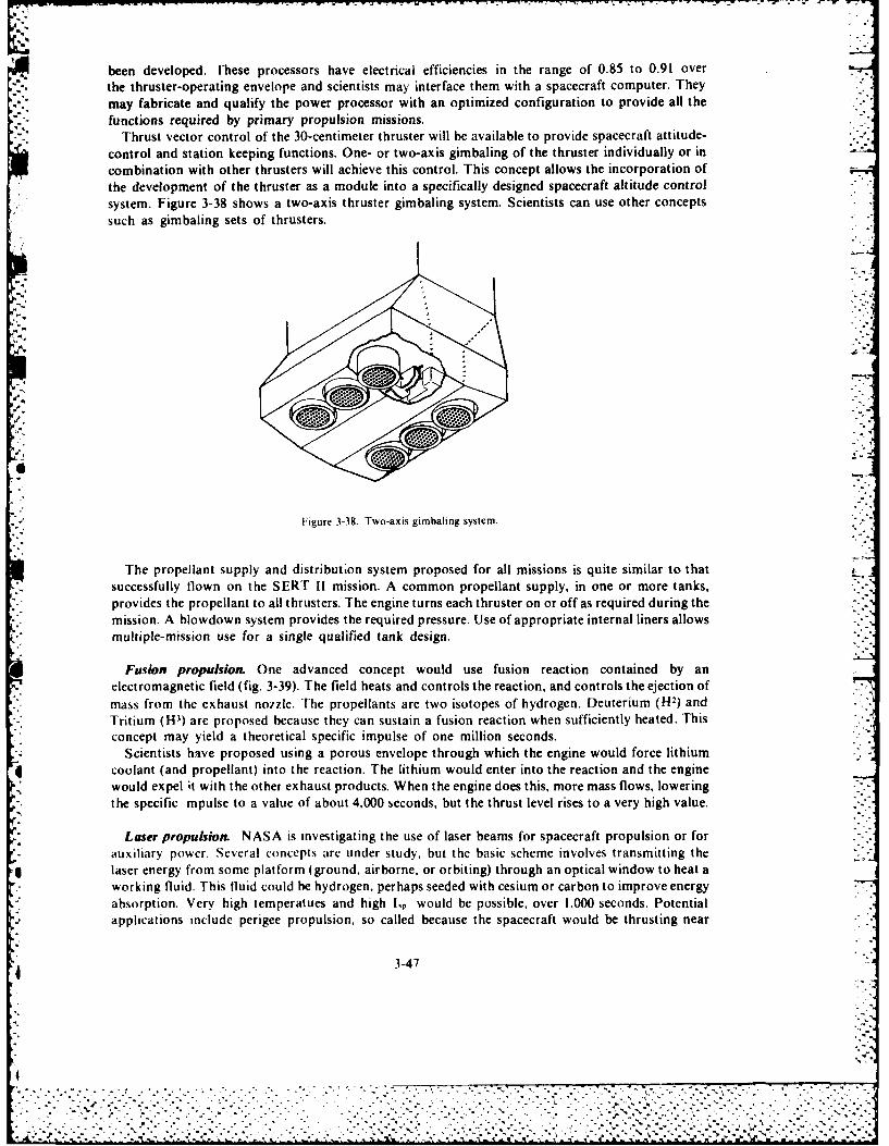
been developed. Uhese processors have electrical efficiencies in the range of 0.85 to 0.91 overthe thruster-operating envelope and scientists may interface them with a spacecraft computer. Theymay fabricate and qualify the power processor with an optimized configuration to provide all thefunctions required by primary propulsion missions.
Thrust vector control of the 30-centimeter thruster will be available to provide spacecraft attitude-control and station keeping functions. One- or two-axis gimbaling of the thruster individually or incombination with other thrusters will achieve this control. This concept allows the incorporation ofthe development of the thruster as a module into a specifically designed spacecraft altitude controlsystem. Figure 3-38 shows a two-axis thruster gimbaling system. Scientists can use other conceptssuch as gimbaling sets of thrusters.
Figure 3-38. Twa-axis gimbaling system.
The propellant supply and distribution system proposed for all missions is quite similar to that- successfully flown on the SERT 11 mission. A common propellant supply, in one or more tanks,
provides the propellant to all thrusters. The engine turns each thruster on or off as required during themission. A blowdown system provides the required pressure. Use of appropriate internal liners allows
* multiple- mission use for a single qualified tank design.
Fusion propulsion. One advanced concept would use fusion reaction contained by an- electromagnetic field (fig. 3-39). The field heats and controls the reaction, and controls the ejection of
mass from the exhaust nozzle. The propellants are two isotopes of hydrogen. Deuterium (H-2) and- Tritium (H-') are proposed because they can sustain a fusion reaction when sufficiently heated. This* concept may yield a theoretical specific impulse of one million seconds.
Scientists have proposed using a porous envelope through which the engine would force lithium4 coolant (and propellant) into the reaction. The lithium would enter into the reaction and the engine
would expel it with the other exhaust products. When the engine does this, more mass flows, lowering- the specific mpulse to a value of about 4,000 seconds, but the thrust level rises to a very high value. -
Loser propulsion NASA is investigating the use of laser beams for spacecraft propulsion or for.-
* auxiliary power. Several concepts are under study, but the basic scheme involves transmitting the* laser energy from some platform (ground, airborne, or orbiting) through an optical window to heat a
working fluid. This fluid could be hydrogen, perhaps seeded with cesium or carbon to improve energyabsorption. Very high temperatues and high I~p would be possible, over 1,000 seconds. Potential
- applications include perigee propulsion, so called because the spacecraft would be thrusting near
4 3-47
.
~ Qjj-j.2" x .
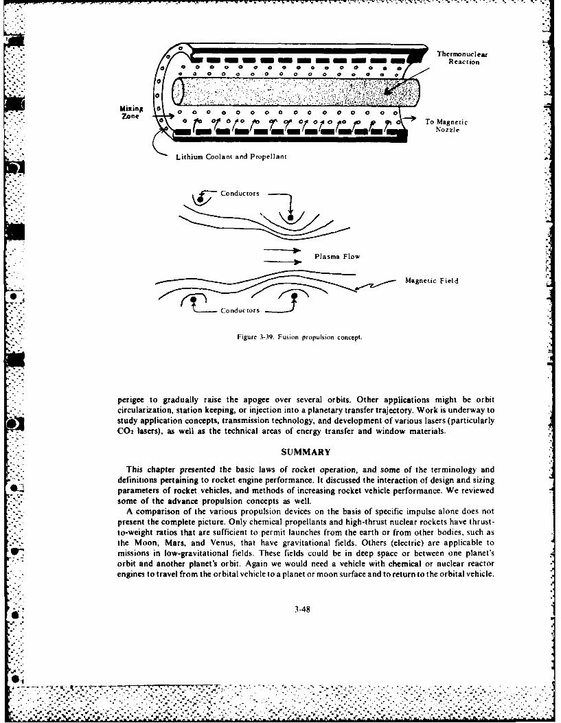
Thermonucleara Reactiona *0 0 a 0 a 0 0 0 0 0 0 a 0 * 0
*0 0 0 0 0 0 0 0 0 0 0 a a 0 a
0
" . -:.Miin a %
Zone c 0(0(~ /b 0.t~o To Magnetic
-m""Nozzle
Lithium Coolant and Propellant
Conductors
Plasma Flow
Magnetic Field
Cnutor s
Figure 3-39. Fusion propulsion concept.
perigee to gradually raise the apogee over several orbits. Other applications might be orbitcircularization, station keeping, or injection into a planetary transfer trajectory. Work is underway tostudy application concepts, transmission technology, and development of various lasers (particularly
0 C02 lasers), as well as the technical areas of energy transfer and window materials.
SUMMARY
This chapter presented the basic laws of rocket operation, and some of the terminology anddefinitions pertaining to rocket engine performance. It discussed the interaction of design and sizingparameters of rocket vehicles, and methods of increasing rocket vehicle performance. We reviewedsome of the advance propulsion concepts as well.
* -A comparison of the various propulsion devices on the basis of specific impulse alone does notpresent the complete picture. Only chemical propellants and high-thrust nuclear rockets have thrust-to-weight ratios that are sufficient to permit launches from the earth or from other bodies, such asthe Moon, Mars, and Venus, that have gravitational fields. Others (electric) are applicable tomissions in low-gravitational fields. These fields could be in deep space or between one planet'sorbit and another planet's orbit. Again we would need a vehicle with chemical or nuclear reactorengines to travel from the orbital vehicle to a planet or moon surface and to return to the orbital vehicle.
3-48
% . .. . .-- -
O .. -- --
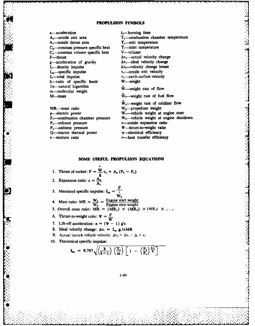
PROPULSION SYMBOLS
a-acceleration tb-burning timeA.-nozzle exit area T,--combustion chamber temperatureA,--nozzle throat area Te4xit temperature
6C,--constant pressure specific heat T,-inlet temperatureC,-constant volume specific heat V-volume 7F-thrust Av.,-actual velocity changeg-acceleration of gravity Av,--ideal velocity changeId--delsity impulse Avre-velocity change lossesI.0-specific impulse v.--nozzle exit velocityIt-total iplevr"-eartb surface velocityk-ratio ospcfcheats W-wight rt ffoIn-natural logarithmrn-molecular weightM-mass We-weight rate of fuel flow
*,-weight rate of oxidizer flowMR-mass ratio Wv--propeflant weightp-electric power WI-vehicle weight at engine startPr-combustion chamber pressure W2-vehicle weight at engine shutdown
*P.--exhaust pressure c--nozzle expansion ratioPe--ambient pressure 'IF-thrust-to-weight ratio
* Q-reactor thermal power il-electrical efficiencyr-mixture ratio v-heat transfer efficiency
SOME USEFUL PROPULSION EQUATIONS
1. Thrust of rocket: F = 'v, + A, P, - P0 )
2. Expansion ratio: e = ___
F* 3. Measured specific impulse: I.,,=
WV4. Mass ratio: MR = W1 = Engine start weight
W2 Engine stop weight5. Overall mass ratio: MR = (MR,) X (MR 2 ) X (MR.,) X...
6. Thrust-to-weight ratio: sk = Fw7. Lift-off acceleration: a =(I-1)g's
8. Ideal velocity change: Av, = I., *InMR9. Actual launch vehicle velocity: Av. Av, - 1 +v,
10. Theoretical specific impulse:
or= 9.79 7. (~K. k T. i- P
0- 3-49
'. 7_e_

11. Mixture ratio: r = °
wvt12. Density impulse: Id = (I.,p) X (SO)
13. Total impulse: It = (F) X (t) = (Ip) (W,)14. Total Av (multistage vehicle): Avt = Av1 + Av2 +AvS + • • •
~BIBLIOGRAPHY
Billman, Kenneth W. "Laser Energy Conversion." Astronautics and Aeronautics (July-August 1975:56.Clark, K. E. "Survey of Electric Propulsion Capability." J. Spacecraft 12 (November 1975).Dipprey, Duane F. "Liquid Propellant Rockets." Chemistrr in Space Research. Robert F. Landel and Alan Rembaun, ed.
New York: American Elsevier Publishing Co., 1912.Finke. R. C. Current NASA Ion Propulsion Technology. NASA Report TMS-71612, October, 1974.Hesse, W. J. and N. V. S. Mumford, Jr. Jet Propulsion for Aerospace Applications. New York: Pitman Co.. 1964.Lewis Research Center. Electric Propulsion for Spacecraft. Cleveland, Ohio, Lewis Research Center (NASA), 1974.Mead, F. B., ed. Advanced Propulsion Concepts-Project Outgrowth. Edwards AFB, Calif., Air Force Rocket Propulsion
Laboratory. AFRPL-TR-72-31. June 1972.Minovitch, M. A. Performance Analysis of a Laser-Propelled Interorbital Transfer Vehicle. NASA Report CR-134966.
February 1976.Papilou, D. D. Frontiers in Propulsion Research. Laser. Matter-Antimatter, Excited Helium. Energy Exchange. Thermo-
nuclear Fusion. NASA Jet Propulsion Laboratory, TM 33-722, 15 March 1975.* Pedersen. E. S. Nuclear Energy in Space. Englewood Cliffs, N.J.: Prentice-Hall, 1964.
Schwenk. F. C. "Propulsion for Space: The Nuclear Rocket." TRW Space Log 7 (Spring 1967):2-24.Shapiro, A. H. The Dynamics and Thermodynamics of Compressible Fluid Flow. New York: The Ronald Press Co., 1953.Stuhlinger, E. Ion Propulsion for Space Flight. New York: McGraw-Hill, 1964.
" -. Sutton, G. P. Rocket Propulsion Elements. New York: Wiley and Sons, 1964.Yafee. Michael L. "Lasers Investigated for Space Propulsion." Aviation Week and Space Technology (21 April 1975):47.Zucrow, M. J. Aircraft and Missile Propulsion. New York: Wiley and Sons, 1958.
3-50
*1
... ..
Chapter 4
SPACE VEHICLE ELECTRICAL POWER
The availability of electrical power has been partially responsible for the successful operation offlight vehicles in space. In general, a space vehicle has neither utility nor purpose without some form
-: of electrical power, which is the lifeblood of a space vehicle, vital to the needs of both passengers andequipment. These needs include power requirements for communications, data gathering andhandling, vehicle attitude control, guidance and control, life support equipment, and many otherareas. With few exceptions, all space vehicles without electrical power..become useless debris. Thespace vehicle electrical power subsystem is, therefore, one of the most important spacecraft elements.Its design often dictates the active functions that a space vehicle can perform. Furthermore, in thefuture some space vehicles will use electrical power to energize electrical space propulsion systems.
Three government agencies that have researched space electrical power systems are the Air ForceGeophysics Laboratory, the Air Force Aero Propulsion Laboratory, and NASA Marshall SpaceFlight Center.
In this chapter, we discuss three areas pertaining to space vehicle electrical power: electrical powergeneration in space, energy sources and associated energy conversion devices, and the evaluation andcomparison of specific power subsystems.
PRODUCING POWER IN THE SPACE ENVIRONMENT
The space environment consists of a near vacuum (10-12 Torr at 7,000 nautical miles) containingboth charged and uncharged particles; electric, magnetic, and gravitational fields; and electro-magnetic radiation from both galactic and extragalactic sources. These and other environmentalfactors find the space power design and systems engineer working with vastly tighter constraints thanthe conventional power engineer. A discussion of some of the problems of producing electrical powerincludes the following areas:
1. Removal of waste heat. A critical and ever-present problem in space vehicles is the disposal ofwaste heat produced by power generation and power conditioning equipment. Earth-based systems -
for generating electrical power can use convection, conduction, and radiation to remove excess heat.However, the virtual absence of matter around a space vehicle makes radiation the only economicalmeans of waste heat disposal. But, space is an inefficient heat sink; hence, large radiators miustsometimes be employed, imposing severe weight and volume penalties. Besides these penalties.a large radiator increases the possibility of meteoroid damage.
2. Meteoroid bombardment. A possible vexing problem is potential catastrophic equipmentfailure resulting from puncture by meteoroids moving at relative velocities as high as 150,000 miles01
* per hour. Although the probability of this occurrence is statistically quite negligible, we must considerthe potential damage or erosion effects of meteoroid bombardment.
3. Very high sacuutm. Operating space systems in a very high vacuum (skhich some require)
q 4-1
. .7
exposes them to problems of cold welding, outgassing, and leakage. Furthermore, rotating equipmentrequires lubricants that will not sublimate. Some components require a pressurized environment.
4. Radiation. Among the radiation hazards are cosmic rays, solar proton emissions, and intenseultraviolet and infrared radiation. However, the most serious radiation hazards of space flight to bothequipment and people are the geomagnetic-trapped Van Allen radiation fields and the solarcorpuscular radiation associated with solar flares. This radiation can cause serious damage to solarcells and semiconductors as well as people. Presently, shielding is considered the most suitabletechnique for protecting power systems from these radiation hazards.
'.' 5. Weightlessness. In earth-based electrical power generation systems, we use the force of gravityon a body (weight) in the separation of vapors from liquids in boiling and condensing fluids, inconvective heat transfer, and in separation of gases from liquids. Since we use these various processesoften in generating electrical power, systems cannot use components or processes that operate onlywith "'this end up."
6. Temperature variation. Earth-based systems operate with relatively small temperaturevariations. In space the temperature of components within the power system may vary throughextreme ranges because of solar heating and heat generated by the system itself. The power output ofchemical batteries is very sensitive to temperature change. In general, the efficiency of a chemicalbattery decreases as its temperature decreases, but the output of solar cells increases as theirtemperature decreases. Also, the useful life of other electrical components depends on theoperating temperature.
7. l.aunch environment. Earth-based systems for generating electrical power do not operate
under adverse conditions. Engineers must design the delicate components of space systems towithstand the high acceleration and vibration of the launch phase.
8. Kinetic perturbations. Scientists have fixed the structure of earth-based systems for generatingelectrical power solidly to the earth to counteract any unbalanced forces developed by moving parts.Space vehicles will change attitude due to forces such as those produced by armatures rotating at highspeeds or the movement of sun-oriented solar arrays. Counteracting these forces adds to thecomplexity of the flight vehicle.
Man% other problems. combined with the areas we have already discussed, make the task ofelectrical power generation in space truly a very difficult one from an engineering design point of
ic". Among them are the limited or nonexistent repair capabilities, the very high premium placed onzi.initirm ,eight, long life, and high reliability, and the inherent low efficiency of energy devices.
TYPES OF SPACE ELECTRICAL POWER SYSTEMS
By their energy sources, we can categorize the electrical power systems for space applications intoareas of electrochemical, solar, or nuclear. We may categorize them further into static or dynamic
energy con ersion systems. Static systems of current interest include batteries, fuel cells, andj iphoto.oltaic. thermoelectric and thermionic devices. Dynamic energy conversion systems consist ofeither turbine or reciprocating engines coupled to electric generators. The engines would operate on
* .- " thermal energy derived from either the sun, a nuclear reactor or isotopes, or the combustion of
chemical fuels. Now we will discuss each of these systems in greater detail.
Electrochemical Systems
.': Batteries, fuel cells, and chemical-dynamic systems represent the electrochemical power systems. Of
these, the batteries have played the most important role in furnishing space power until recently.
4-2
4, J_
-W-TW W ,7 . I. W.-w. .-w1 - MTW 0 - T'- -
Virtually every space vehicle launched has contained one or more batteries. The reason for their use isthat they are very reliable. Furthermore, they are cheap, simple, and available.
vS. Batteries. There exist two types of batteries: primary cells and secondary batteries. Generally, we" ' consider primary batteries as one-cycle batteries since they get no recharging after discharging. This
type of battery converts chemical energy directly to electrical energy. The greatest utility of theprimary battery as a source of electrical power is either in launch vehicles or in space vehicles thathave very short missions. This type of battery is also useful for special applications such as providingpyrotechnic power to energize explosive bolts to separate vethicle stages.
The primary battery used most frequently in space applications and having the highest energydensity of batteries in common use is the silver-zinc battery. It consists of silver-silver oxide and zincelectrodes immersed in a potassium hydroxide electrolyte. Its useful energy density is in the range of20 to 100 watt-hours per pound depending upon the discharge rate. This means we must provide 10 to50 pounds of batteries for each kilowatt-hour required. Research is being done on advanced primarycells using more energetic anode materials, such as lithium, magnesium, and aluminum, that mayprovide energy densities in the neighborhood of 150 watt-hours per pound.
However, primary batteries have a limited life, determined by the active composition materials. Ingeneral, primary batteries are used extensively for space electrical power requirements of a few7milliwatts to approximately one kilowatt for periods less than a week. For example, the Mecuryspacecraft of 1962 and 1963 received power from 150 pounds of silver-zinc primary batteries. Becausethe time in orbit of these craft was not very long, the use of primary batteries was adequate. Similarly,the lunar module received power from silver-zinc batteries as did the Apollo command module duringthe critical reentry and post landing periods.
Space vehicles that use solar-powered energy conversion systems need secondary (or storage)0 batteries if they require power during solar dark periods. Except for the initial charge, the chemical
reaction within secondary batteries provides a means to store the electricity produced by the sun'senergy rather than acting as a primary energy source. The most widely-used secondary battery inspace applications is the nickle-cadmium battery. The advantages of this type battery in comparisonto other secondary cells are its demonstrated superior reliability over large numbers of duty cycles,small voltage excursions, high-charge rate acceptances, low-temperature operation, and long shelflife. However, one disadvantage of the nickel-cadmium battery is its low-energy density. Typicalenergy densities are from 2 to 15 watt-hours per pound, depending upon the required lifetime andcharging rate. Thus, for applications that do not require long lifetimes, we use either silver-cadmiumor silver-zinc batteries quite often because of their higher energy densities.
New secondary batteries, which are actually hybrid battery-fuel cell devices, are now underdevelopment. These hybrids use conventional battery positive electrodes in combination with a fuelcell negative electrode. The result is higher weight energy density and potentially longer life. Thevolume energy density however is lower because of the increased celi volume required to storehydrogen gas at pressures of about 500 pounds per square inch of area. Nickel-hydrogen and silver-hydrogen batteries are examples.
Conventional cells using aqueous electrolytes are close to the limits of development. Consequently,scientists are directing their high- performance battery research to nonaqueous electrolytes, whichpermit the use of highly active electrode materials such as the alkali metals.
Current research is primarily with some fundamental problems of ambient temperature, non-aqueous electrolytes, and the problem of containing concerned chemical reactions with standard freeenergies in the 100 Kcal/ mole range. The problem of direct chemical reaction of the constituents
* 5. ~ of the cell relates to the thermodynamics of the system and the rates of various reactions involved.The presence of trace impurities, especially water, is an important determinant of corrosion rates.
* Therefore, scientists have devoted much effort to purification and analysis techniques and themanipulation of solvents and solutions in a dry atmosphere. A major difficulty raised by almostall nonaqueous electrolytes is low conductance, which limits the discharge rate of a battery. Conduct-ance mechanisms are immensely complex, involving such related properties as viscosity, dielectric
4-3
'.%
I.............................L
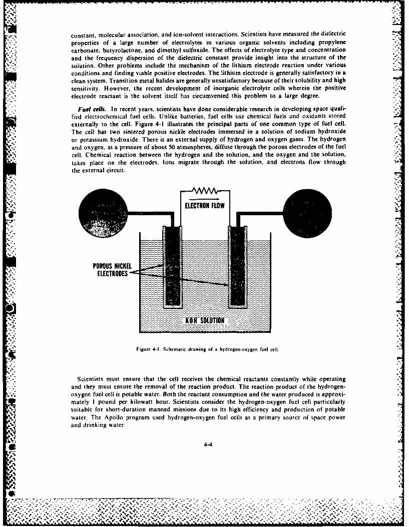
constant, molecular association, and ion-solvent interactions. Scientists have measured the dielectricproperties of a large number of electrolytes in various organic solvents including propylenecarbonate, butyrolactone, and dimethyl sulfoxide. The effects of electrolyte type and concentrationand the frequency dispersion of the dielectric constant provide insight into the structure of thesolution. Other problems include the mechanism of the lithium electrode reaction under variousconditions and finding viable positive electrodes. The lithium electrode is generally satisfactory in aclean system. Transition metal halides are generally unsatisfactory because of their solubility and highsensitivity. However, the recent development of inorganic electrolyte cells wherein the positiveelectrode reactant is the solvent itself has circumvented this problem to a large degree.
"' Fuel cells. In recent years, scientists have done considerable research in developing space quali-fied electrochemical fuel cells. Unlike batteries, fuel cells use chemical fuels and oxidants storedexternally to the cell. Figure 4-1 illustrates the principal parts of one common type of fuel cell.The cell has two sintered porous nickle electrodes immersed in a solution of sodium hydroxideor potassium hydroxide. There is an external supply of hydrogen and oxygen gases. The hydrogenand oxygen, at a pressure of about 50 atmospheres, diffuse through the porous electrodes of the fuelcell. Chemical reaction between the hydrogen and the solution, and the oxygen and the solution,takes place on the electrodes. Ions migrate through the solution, and electrons flow through -
the external circuit.
.°
POROUS NICKEL"
Figure 4-1. Schematic drawing of a hydrogen-oxygen fuel cell.
Scientists must ensure that the cell receives the chemical reactants constantly while operatingand they must ensure the removal of the reaction product. The reaction product of the hydrogen-oxygen fuel cell is potable water. Both the reactant consumption and the water produced is approxi-mately I pound per kilowatt hour. Scientists consider the hydrogen-oxygen fuel cell particularlysuitable for short-duration manned missions due to its high efficiency and production of potablewater. The Apollo program used hydrogen-oxygen fuel cells as a primary source of space powerand drinking water.
*4-4
a %
d' " " " " ' '
" '"
"" " '
" " ' '" ' ' '
'' ' " " " ' " " "- " ' '' '
Generally, energy densities or specific weight figures for fuel cells are somewhat meaningless%%%- : because their magnitude varies considerably according to the operating time. This is because the
weight of any given fuel cell i, practically invariant to the time of operation. On the other hand.
the chemical reactant weight is directly proportional to the required operating time and electricalload. From a weight standpoint, fuel cells are highly competitive for applications requiring approxi-mately 10 kilowatts or less of power for operating periods of a few days to three months. Power
densities of 200 to 900 watt-hours per pounu are within current fuel cell technology for such opera-,"?-* tional times.
Fuel cells can operate either as an open cycle system or as a regenerative, closed cycle, system.'The open cycle system can yield high current but only for the time that the supply of hydrogen
and oxygen lasts. Increased operating time necessitates increased supply reactants with an accompany-ing increase in the size and weight ot the tanks. In a regenerative system, the system could use energyfrom some other source, such as solar cells, to produce hydrogen and oxygen from the water formedin the fuel cells. Such a systen, it perfected, could have an operational lifetime of several years.However, only the open-cycle systeni has been qualified so far and regenerative fuel cells are notcurrently being considered loi n.icr tin a pplicat ions.
Chemical dynamic. Chemi,.al d namic systems convert the energy available from a chemically-
fueled combustion engine into electrical power by mechanical means. Such a system falls at the lowerend of the power level-duration selection curve because of its relatively high rate of fuel consumption,which is two to three times that of fuel cells. However, this type of system generates AC power atuseful voltage and frequenc,, simlplil, ing power conditioning requirements. For high-power systems,approximately 10 kilowatts and higher, it tends to be lighter, more rugged, and considerably less
temperature sensitive than electrochernical systems.Although chemically fueled combustion engines have been extensively exploited for ground and
aeronautical applications, ballistit. or space efforts have been limited primarily to systems
development. The propellants most frequently considered are hydrogen-oxygen, hydrazine, andthe broader category of solid propellants.
It had been planned to use chemically-fucled combustion engines in both the Navaho and Dinosoarprograms. Although the goveinuiet has terminated both of these programs, many space power
engineers still believe that the clhemictal engine will have a weight advantage over the fuel cell foroperational time requirements of less than two weeks.
Solar Powered Systems
One result of the fusion intt ino taking place in the sun is the release of an enormous amount
of energy. A considerable amount o this energy occupies the eletromagnetic radiation spectrumfor approximately ',4 micron to Imicrons (or millionths of a meter). A small fraction of this energylies in the invisible untra ,iolet egion About half of it is the visible light; the rest is infrared, whichaccounts for the sun's heat.
At a distance of one astrononitoal unit (At;). the average amount of solar energy, the "solar
constant." is approximately 1 0 ,atts it ol sut tace aligned at right angles to the sun's radiation.At other than one All, the energ% a'%,ttlablc equals the inverse square of the distance in All (betweenthe sun and the point of intCrtst) ti nes [th solai constant at one Al. Thus, in the vicinity of Saturn.
almost 10 AU from the sun, the a ailablc solai energy is only approximately 1.30 watts1 ft2. whichis 1/100 of the a\,ailahle enctg\ Ist ahe the earth's surface.
There are basicall\ two prinirN to .ersion concepts that have been considered seriously
as a means of conventing solhi CenrgN to space electrical power, photovoltaic and thermal. Of these,
the scientists have gi\en the ptinip 1i attention to the photovoltaic concept. Presently this concept
provides the basisfu tot iw onust ct.inio soi .e of electrical power for unmanned spacecraft.
Photovoltaic. I he pli(to%( Ilt,ai c tlc.t! is ihe generation of a 'oltage by photons (the smallest
quanta of light) incident ,on .t piopcri.t tcated surface that lies near the junction of two layers
4-5
,. .. ... ...................................... •..,._..... ........ ........ ,.... .... .,*.?,-C;' , -- " " * " . - - " . " - . " " - " " . . , - " • " .. . .- - " -" . .-
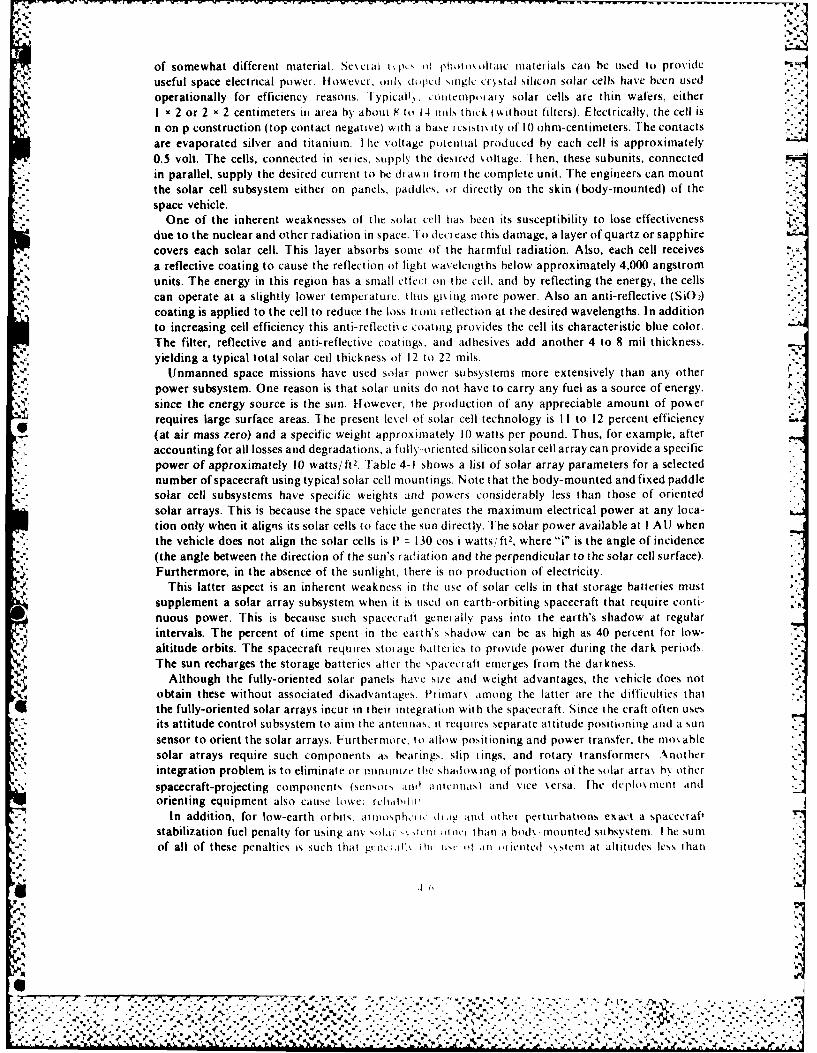
~. V
of somewhat different material. Seveial ti if photo\ oltaic materials can be used to provide
useful space electrical power. llowevc, oiil, d,,pLd ,iiglc cistal silicon solar cells have been used
operationally for efficiency reasons. I ypica . oniciripoary solar cells are thin wafers, eitherI , 2 or 2 x 2 centimeters in area by about X to 14 oils thick (" ithout filters). Electrically, the cell isnon p construction (top contact negative) with a base restis t.ity of 10 ohm-centimeters. The contactsare evaporated silver and titanium. I he voltage potential produced by each cell is approximately
0.5 volt. The cells, connected in series, supply the desired voltage. I hen, these subunits, connectedin parallel, supply the desired current to be dnan from the complete unit. The engineers can mountthe solar cell subsystem either on panels, paddies, or directly on the skin (body-mounted) of the
.: space vehicle.One of the inherent weaknesses of the -solar cell has been its susceptibility to lose effectiveness
due to the nuclear and other radiation in space. !o deci ease this damage, a layer of quartz or sapphire
covers each solar cell. This layer absorbs some of the harmful radiation. Also, each cell receivesa reflective coating to cause the reflection of light wavelengths below approximately 4,000 angstromunits. The energy in this region has a small effect on the cell, and by reflecting the energy, the cellscan operate at a slightly lower temperature, thus gi'ing more power. Also an anti-reflective (SiO 2)coating is applied to the cell to reduce the loss hrn reflection at the desired wavelengths. In additionto increasing cell efficiency this anti-reflectiN c coating provides the cell its characteristic blue color.The filter, reflective and anti-reflective coatings, and adhesives add another 4 to 8 mil thickness,yielding a typical total solar ceil thickness of 12 to 22 mils. -
*e. Unmanned space missions have used solar power subsystems more extensively than any other J.-
power subsystem. One reason is that solar units do not have to carry any fuel as a source of energy,since the energy source is the sun. However, the production of any appreciable amount of powserrequires large surface areas. The present level of solar cell technology is I I to 12 percent efficiency(at air mass zero) and a specific weight approximately 10 watts per pound. Thus, for example, after
* accounting for all losses and degradations, a fully-oriented silicon solar cell array can provide a specificpower of approximately 10 watts/ft2 . Fable 4-1 shows a list of solar array parameters for a selectednumber of spacecraft using typical solar cell mountings. Note that the body-mounted and fixed paddlesolar cell subsystems have specific weights and powers considerably less than those of orientedsolar arrays. This is because the space vehicle generates the maximum electrical power at any loca-tion only when it aligns its solar cells to face the sun directly. The solar power available at I AU whenthe vehicle does not align the solar cells is 1 = 130 cos i watts/ft2, where "i" is the angle of incidence(the angle between the direction of the sun's radiation and the perpendicular to the solar cell surface).Furthermore, in the absence of the sunlight, there is no production of electricity.
This latter aspect is an inherent weakness in the use of solar cells in that storage batteries mustsupplement a solar array subsystem when it is used on earth-orbiting spacecraft that require conti-nuous power. This is because such spacecraft generally pass into the earth's shadow at regularintervals. The percent of time spent in the earth's shadow can be as high as 40 percent for low-altitude orbits. The spacecraft requires storage baiteies to provide power during the dark periodsThe sun recharges the storage batteries atter the spacecraft emerges from the darkness.
Although the fully-oriented solar panels have site and weight advantages, the vehicle does notobtain these without associated disadvantages. ltinarv among the latter are the difficulties that
6l the fully-oriented solar arrays incur in their integration with the spacecraft. Since the craft often usesits attitude control subsystem to aim the antennas, it requires separate attitude positioning and a sunsensor to orient the solar arrays. Furthermore, to allow positioning and power transfer, the nimoablesolar arrays require such components as bearings, slip tings, and rotary transformers Anotherintegration problem is to eliminate or ninn11/tn the shadowing of portions of the solar arra\ b\ other
spacecraft-projecting components (scnsoits and iitllas) and vice versa. The dcplloxment andorienting equipment also cause lowe; rheltibi ii
In addition, for low-earth orbits, at uiospwi i' dia t and other perturbations exact a spacecraf-stabilization fuel penalty for using any ot d it icm .ict than it bod\. mounted suhsvstem. I he sumof all of these penalties is such that gtttiil, i lt usc (t aii tiientd ,\stnem at altitudes less than
'..4,'
- -,-
%- V4- ..
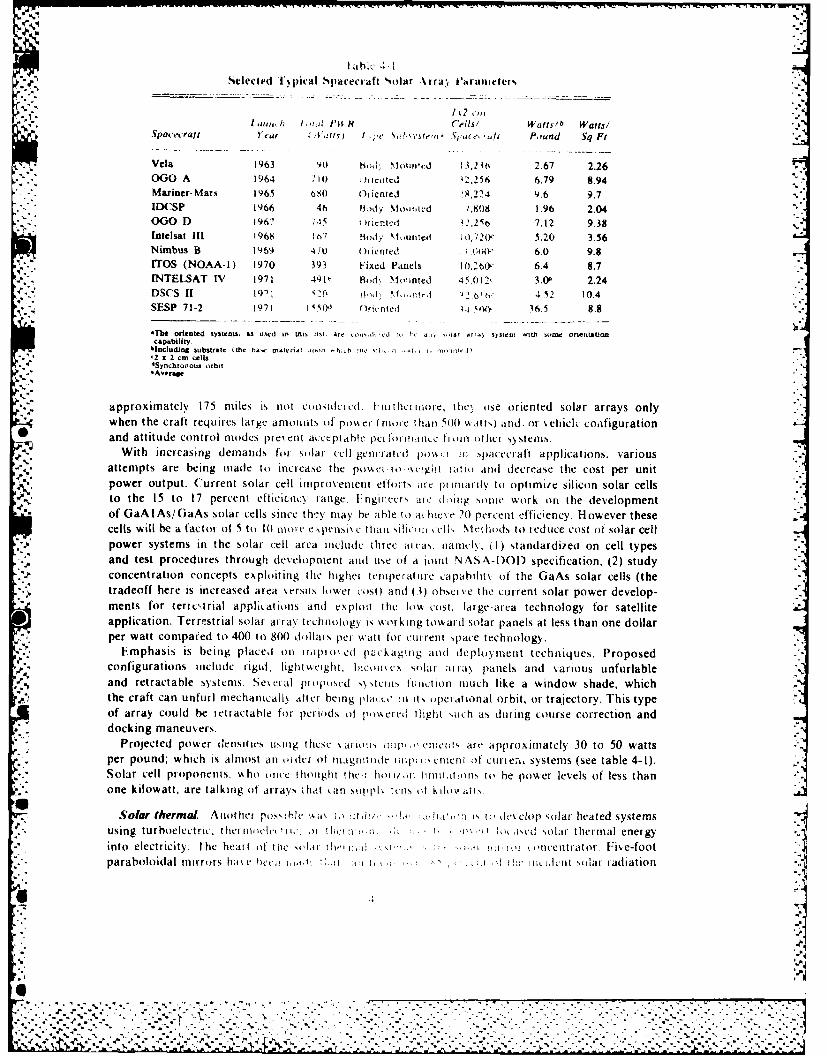
I ahN i -ISelected Fq iieal Spacecraft Soliar %rfa-, h'rameters
I k7 ,II atm, h lial. Pil, R Cells' Wafts/b Wauil
Sa'tratYear 14!tv) ; e Aii?.' t're',il Sp ecf Pound Sq Ft
Vela 1963 V90 hod: Nloiii .: 13,2 it% 2.67 2.26OG00 A 1964 ,1() - ,ncitcd 42,256 6.79 8.94M Mariner- KIar 1965 610) Oriented $,2 9.6 9.7
*IDCSP 1966 46 B~ody Nlomiied /,808 1.96 2.04000 D 1967 7.15 1 riented z2.25r) 7.12 9.38
*Intelsat 111 1968 lis t? OdY NII1iltA! I o,720c 5.20 3.56Nimbus B 11969 41U Ofiented I 1.00W& 6.0 9.8rrOS, (NOAA1) 1970 393 Fixed Panels 10.260, 6A4 8.7
*INTELSAT IV 1971 4911, Bodk Miounted 45.012, 3.We 2.24DSCS 11 19': -S-C 1-1,d -. 6 1 4,52 10.4SFSP 71-2 1971 1 Od0 (Irinte(i1 'W 16.5 8.8
41The oriented system, s. u id in thisl~ist. Ai tt - r at~, -iar ,riao ssien with sont orienttion )capability
blncluding substrate (the haw-, mo a i- r~i u h~h ic~ ie i , -I" ite'2 a 2 cm cells.4
5yncbronous ,rbit*Avera~e
approximately 175 niles is tnot coiisidt icd (I.I itlhiimore, the'. ose oriented solar arrays onlywhen the craft requirCs large amiounts of' posi, ei I rila e hail 5001 \A atts I and., or % hiclk coaifiguration
0and attitude control modes pre\ cut ac:,ceptble IpCiI ltidiiec' t ill at he[ s) stelams.With increasing demrands fai sol uar cell- genteraltuil poin spacecraft applications, various
attempts are being made to increase the possel to ".eigit lttti and decrease the cost per unitpower output. Current solar cell improvenment effoits arc p1 i~rav to optimniie silicon solar cellsto the 15 to 17 percent efficienicy range. E ngilreers i doing someW work (In the dlevelopmentof GaA lAs/GaAs solar cells since th- y may he ahle it a hicee21) percent efficiency. However thesecells will be a factor of i tit 101 ma e e isoc I haim silficz: I c! MeNt hods to redutce cost at solar cell
* power systems in the solar cell area inlclude three ill eas. namly. (1) standardizeu on cell typesand test procedures through development and use at a jolint N ASA-D)OD specification, (2) studyConcentration concepts exploiting the highei templeraturle capahilitN of the GaAs solar cells (thetradeoff here is increased area verstis lower cost) and (3) ahsci cc the current solar power develop-ments for terres trial appi tatmons and exploit the low cost, large-area technology for satelliteapplication. Terrestrial solar array tcchimolagy is working toward solar panels at less than one dollarper watt compared to 400 it 800 dollar s per w,,att for cur rent space technology.
* Emphasis is being placed oil inipi ii'ed pickagmlg aiid deploymnent techniques. Proposedconfigurations include rigid, liglit~s ight. hicoit.\ solar iii panels and various unfurlableand retractahle systems. Ses era! pioplosed s\ stelils Iiiilion rilUch like a window shade, which-the craft can unfutIrl echanically after being place.', in its operational orbit, or trajectory. This typeof array could be retractable for p~eriod1s of )il\mercd Hlight such as duiring course correction anddocking maneuvers.
Projected power densitivs uising theset \ariotis tio .acnitt art- approximately 30 to 50 watts* per pound; which is almost an aider ot utaglitnie iii1 enitent of cuirten, systems (see table 4-I).*Solar cell proponents, NA ho once thouight Oiit hof inr iiltti.itions to he power levels of less than
one kilowatt. are talkinig of' arraNs zhet (.an stiipl, tells tit .ihov at s
Aohrpos.. lcI k4ak io itih/-!s is - , i h's clap :olar heated systemsusig trbolecric t el lloict! w,)I hc :1 i li! ii k~cd solar t hermal energy
into electricity. Hi heart of' thme ,okli i iri-i! -. ,, ii.i -. oi ( - a oucentrator. Fiv-e-foot*paraboloidal mirror s hiti\ e hvci, t., 1:1 hI Ii '1 1 t lit !lic ictit solar radiation
through an aperature of 0.5 inch diameter. I hi, would provide approximately two kilowatts of heaton a thermionic converter at 2,000' Kelvin. Increased power can be obtained by using solarconcentrators that are composed of many petallike segments or that expand like umbrellas. Thisconstruction enables the creation of diameters up to approximately 50 feet with correspondinglyhigher power output.
Although estimates indicate that weight and cost advantages over other power systems maybe possible, this is vet to be verified. In recent years, the government has either cancelledor cut back severely all major solar thermal programs. However, some interest still remains, sincethis type system would be more resistant to charged particle radiation and could operate closerto the sun than solar cell arrays. Conventional silicon solar cells do not function properly at tempera-tures in excess of 150' C.
Solar concentrator systems, coupled with thermal energy storage systems and heat pipes, arebeing considered for the spacecraft whose energy requirement is for thermal rather than electricalpower. This is in addition to the solar concentrator systems' use as a heat source for conversion toelectrical power. The energy storage system employs the freezing and melting of high-power density(100 to 200 watt hours, pounds) salts for thei mal energy storage, and it uses high-temperature sodiumheat pipes to transfer the heat from the concentrator through the energy storage system to the usingspacecraft subsystem. During the sunlit portion of a satellite's orbit, an optical concentrator focusessunlight on the cannister, melting the solid inside it. During shaded portions of the orbit, the moltenmaterial freezes, giving its heat to the temperature-sensitive components to maintain a propertemperature balance. Aluminum aid alkah Iluorides have been studied as possible heat absorbingsolids, and Inconel cannister, as containers for the solid.
Nuclear Systems
1 he Atomic Energy Commission (AF C) and its successor, the Energy Research and Develop-ment Administration (ERDA). deseloped nuclear electric power systems under the Systems forNuclear AuxiliarN Poer (SNAP) progiam. I he objective of the program was to develop compact,lightweight, and reliable energy units and electrical power conversion devices for space, sea, and landuses. Since the Air Force was interested in long-life, lightweight, electrical power generation systemsfor use in space. it requested the \FC to dceelop such systems. The AEC initiated the SNAPprogram in 1955. During the litetime ol the SN ,P program, it served both the Air Force and NASA.
.. , Although no longer in operation. the SNAtP program was successful in reaching most of its objectives.Under the SNAP program. R I)A de elopcd radioiosotope and nuclear reactor systems. The odd-
numbered SNAP, such as SN All-3. used a radioiostope as an energy source, and the even-numberedSNAP. such as SNAP-8. used a nuciear reactor as an energy source. We describe some of the radio-iosotope and reactor s stems dclorcd tor space applications in the following sections.
Radiosotope. I he basis for the ,,tioistopc concept tor utili~ing nuclear energy to provide spacepower is the phenomenon oft adioactis iit the spontaneous decay of unstable atoms. Nuclei emissionof electrically-charged alpha partiiJes. beta particles, and gamma rays accompanies this radioactivedecay. The alpha particles are posit iean arc the same as the nucleus of the normal helium atom,two protons and two neutrons. I he beta patrt.les are negative and are identical to electrons. Thedesignator,. alpha and beta, mei tcrm, hit iscr from the period when it had been determined thatthere were radioattic emanations. hwl thii atoomic identity had not been determined. Gamma rays.which often accompan% tad oa 'i ic khi ng., aire high-etnergy penetrating electromagnetic radiation.I ike high-energy X-ra s,. gaini r i , a he 'Cr harrtul to biological tissues. In large quantities.gamma rays will damage strutto . male msals is elI.
The half-life of the patlt illa, .dioatcti" material expresses the rate of the radioactive decayprocess. It is a characteristic ot eakh 1, 0risotopos species and is independent of the quantity of materialor the time at ws hich the dtita', et'i kliciti ire ,taited. I hus. the half-life of a radioisotope isthat time at " hith it,, at is% hiN t .' t ,, o -. " hail o! its original % alue beginning with anN gx enstarting tirfe
L 1 4- ,h
e, *V.7
,- , ,' : '.'-. . . . " ,, . . . . . . - . . . , - , , . . .- * *'. . . . . , .- .. . . . , . . . . . , . - .
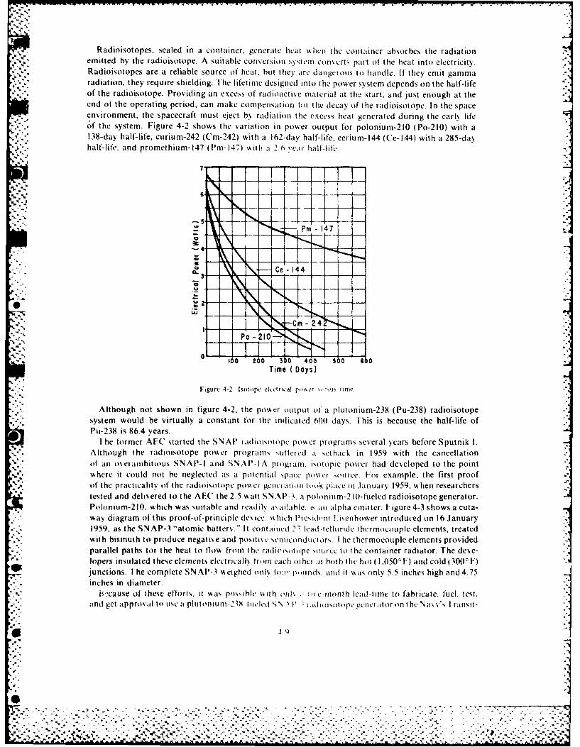
Radioisotopes, sealed in a container, generate heat whlen thle container absorbes the radiationemitted by the radioisotope. A suitable conversion system convecrts part of* the heat into electricity.Radioisotopes are a reliable source of' heat, hut they .ire danigerous to handle. If they emlit gammaradiation, they require shielding. The lifetime designed into the power system depends on the half-lifeof the radioisotope. Providing an excess of' radioactive material at thle start, and just enough at theend of the operating period, can make compensation toi thle deeav of the radioisotope. In the spaceenvironment, the spacecraft must eject by radiation the excess heat generated during thle early life
* of" the system. Figure 4-2 shows the variation in power output for polonium-210 (Po-210) with a138-day half-life, curium-242 (Cm-242) with a 162-day half'-life, cerium-144 (Ce-l44) with a 285-dayhalf-life, and promethium- 147 (Pm-I471) A~ith a 2.6 vemi halfflife.,
4. 4
C e' 1 4-i
CmC
100 200 3 0 400 500 600Time ( Days)
Figure 4-2 Isotope elcoiricaiI pss r rt i~su' ne
Although not shown in figure 4-2. the powser output ot a plutonium-238 (Pu-238) radioisotopesystem would be virtually a constant f'or the indicated 600 days. Tiisbcause the half-life ofPu-238 is 86.4 years.
-1he former AFC started the SNAP~ radioisotope powecr programs sexeral years before Sputnik 1.Although the radioisotope power programs sutlercd at e-t hack in 1959 with the cancellationof an oxeranihiti ous SNAP-I and SN AP'- A program. I sotopic power had developed to the point"shere it could not be neglected ats a potential space po~'ker source. For example, the first proof
%.A. of* the practicality of the radioisotope poxk er genrion t ook place inI January 1959, when researcherstested and delive .red to the AEC' the 2.5 v. att SNAI'-3. aI polonium-2 10-f'ueled' radioisotope generator.Polonium-2 10. %which was suitable and readily i'. ailable. is an Alpha emitter. Figure 4-3 shows a cuta-way diagram of' this proof-of-princi ple de\uce \% hich President 1. iseiihower introduced on 16 January1959. as the SNAP-3 "atomic hatter.' .- it contlained 27 lead -relluride thermocouple elements, treatedwit h bismuthI t o prod uce negat ive a nd pos it i \e scrrIIe OondII Ct Ors. I hie t her mocou ple elements providedparallel paths (or the heat to flows from the radivisotope source to0 lie container radiator. The deve-lopers insul)at ed Ithese elemen ts elect rical I (%Ir or vac h ot her at bot h thec h ot ( 1,050' F) a nd cold (3000 F)ju nctions. T he complet e S N AP- 3 % eighed on Ik loi!i ,t rnds. aid( , it ss o nly 5.5 inches high a nd 4.75inches in diameter.
locause of these efforts. rt w~its possible %k it h 0Tn\lx.ixc-month lead-t me to fabricate, fuel, test.and get approx alt 1se LSapliitorr1Uinr2 X tiwldc I tlosooecee io o NsV I ransit-
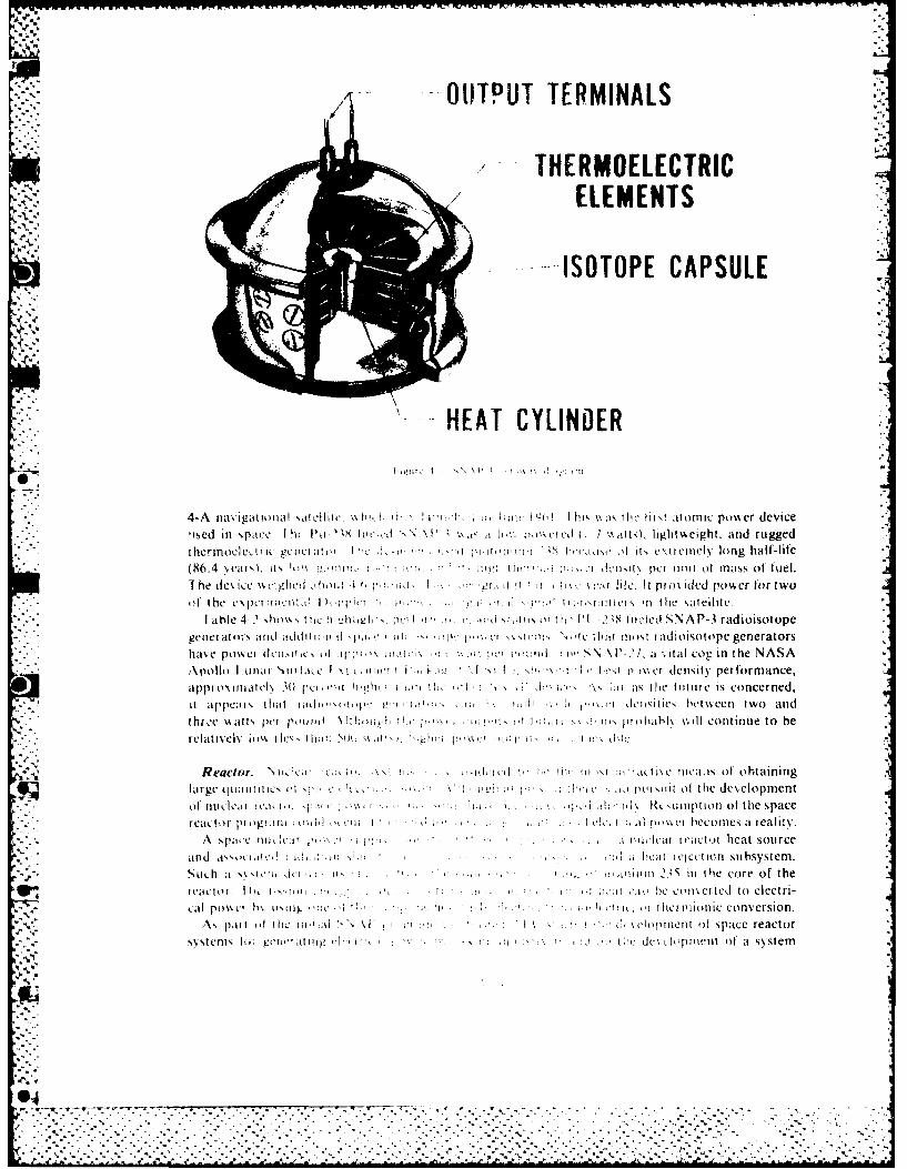
OUTPUT TERMINALS
THERMOELECTRIC2. ELEMENTS
ISOTOPE CAPSULE
HEAT CYLINDER
4-A na\ igatioiuil atlillic. Nh 111, 1! ir. ki a, 1a ii hiix 1lv %\,o, ihc ha.'. atomic power device'ised in .~pace I h It l-~~ tIe \Pc ~ i. lw:. nokcicul1 7 ,Nium0, lightsmeight. arid rugged
*thermoclc .tyic gcimC1!i'! I I-,-' ! 1 0 i It( 'at't o itsI cmI r elI\ long half-life* - (86.4 i.ax.ts ko It~i l:a . - aw e . k it n im of miss of fuel.
1he deukc kkL1rigci !hii ht.' I ila it t li'. la ife. It pi. idcd powcr lortwoof the c\pcl~itito I hli
T '1! ; iI' inii I tlm ltt the satellite.
-I able 42 Ihioik,, Iic mh iwti p 1-!a 1 ' :1: (1 x 1 is o ) 1Iv811d S NA P-3 rad ioisot opegeaeratuirs atid tkiditwiil dI' 'i *' ....!- ' .Icm I 'l illt niost ladioisotope generatorshav~e po\%et dci'iiic, idirpi''. wmiiaa'''''a i's N \ P-2 1, a .ital cog in the NASA:\Polla I ana;1a \IHIl,iLC I\1 Li mlrla' I ii' I l x1 ' i'hripi density performance,apprimintcI\ 30i pcion i il in th' N' i - 5k ii at, lie tutuie is concerned,
- ~it appcma' Ilit ai' i'p ' I'''*' dIcimcz t'tetwcr two aridthre:e "satt pet [1iaad \ 1 m' 'I ' ~l'' tIabl\ %,.ill continue to be
- relIati% ev It~ it\ c,,' I i;w r[(W .'-A 'kc~ 1 1,'i.i .' Ia' c'
Reactor. Niiic lk',i t-I~ ihii w,,tkt [ x isc Ica~is of obtaininglarge quawlte tIC it 'I, ' <oc a ' put siat ol the development
Of nulctcai I C'1' i '111 h v ~ a.- .' i ii '' - .d a~iliptiorI of the spacereattor piogilm ild i'i' f; i I I p o'i' \; en tx bec o mes a rea I it
A sparec mi,li 1' -, -~2.1 ,iT ' . . ini uai ictot heat sourceand axxcird i.:' , . . ., ;i . a healrccrion subsystem.Such a xs'l it IL!i ix .5-.. . aima w2,5 in the core of the
reaictor Ih I tix'.im ''. I V o' H I I.: 1.11 ":it he ciih ttcet to electri-cal oss~ bx ixl~~. l~ t '2' I. ' . a I 'a ithcitlintc conversion.
v ~~A, ptt it the Iwfilil K\1' '' of.' . 7''-'I 5tlfci !spatce reactor
s~stenis Ioi gorL ii if' i I il' '. .o tvcc's'Aitnt of at 5)stemn
-..
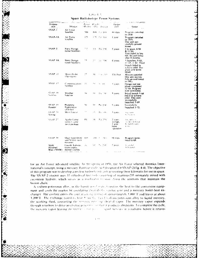
Space Rail i oisot pe Vosier s ~stens
[Fveigna- F i 0.!eugnlion %fission fifoI ' 0,A I. I; if Status
SNAP- I Air [orceSatellite ~ loo 611) cI1i 61 lays 'i ogrrm canceled
in 1958.SNAP-lA Air Force 's t~ I ytiar Program canceled
Saitel lite in 1959.One unit suc-cessfully groundtested.
SNAP- -3 Navy Naviga- Pu 1 .1, 20 5 years 2 in space. 6/61tional Satellites & 11/61.
First failed in late60s. Second failedafter 8 months.
SNAP 9A Navy Naviga 75 2 , F S 6 yf-ars I launches; 9/63.Tional Satellitr-s 12 61, :.64. Third
;B1t11h failed to:,.jiive orbit. Pro-grant new termi-nated.
SNA P I I stowl Plotbe 2 12 - 120 lavi Mission canceled.I Su, eyor i One unit success-
fully ground testedin 196Z,.
SNAU 1 7 ,riiiii~ii~- <~ yeats Diesign and test\aielztephase completed
12 '64. ProgramAP 19now tertnated.
SN~t IS Weathet 'Ii i P Ia 5years Initial launch 5/68Satellite failed to achieve
orbit. Two unit%successfullylaunched 5/69.
N NAP IS4 Planetary ilti P,,1 2 18 5 vcars Successfully
Pioneer Exploratiotn launched 3/72.o Flv-by)
P \iq kl Mi, lIric an,15 fears
"I- 11 21 Apollo Llinac (c0 I'll, 5' 2 lat1110;111 14;111' itlirage, - l I ~me-l package Iyear Sc'h.1.
iiiar'Pecation
SN ~ P ~ Sortlisil )1 i) 1111 .all I it() 11.sys Program termi-and N \SN'si nated 6/69.
MMt iscolti Laborsta .' I,7i yeals -I aflundred tories experi-N III hWatt I HWI mentasl s~ttelltte
to~r alt Air Fotrce adv ancedl sattelle lit th- pliu 1t P) t Silhe Air [orce selected Atomics Inter-naitionl's concept. ulsing it met cutv -Rwl aii t., I i w trl lesittd it SN A P-2 ( fig. 4-4). i-he objectiveot this progr am was to deverlop at littceeil I ullil2,li r1, j1121 P11171 .11111 three kilowatts for use in space.
he S NAI \- 2 reactor tises 37 1 inhtdl ii il11 1 Il~ tilt Il Illnium-235 tttimatelv mixed withili oniunl hvdridle. Which sct~vC as Ih ili% 011 415 h i i the nectitrons that maintain thefis sion chain.
A viodititnpotalsslu tllot . itt the 11lilld 1tl 7, isti thle heat to tile conversion equip-ment andi _ools the reactor hV 6cti iitinp 1
I o cil andill a mcctrv boiler-heat ex--ainger filhe coolant cIt'Stilt- colt .11 " 1, "1 MIP' i ttt~vIIP i td leaves at about
1.2(11) ~ ~ ~ ~ ~ ~ ~ ~ ~ ~ ~ l, 1- eexhnellt\It hi-tI--I.I lllililil iotwtini illot, to liquid tiercury.thle i,%orking Iluid. cotiveltitig ;h liiwfIi . 11, Ihi~l~ %;( 5it; I lie mnetrclort vapor expandsthrou)tgh a tiirfitilioI dse a'e-t, 0- .iclht it lotlti-', a lectrieitv. lo complete the cycle,'1 ieh iv ipr elui / J! l1 ltl li ii t adiator tbefore it returns
.0 .
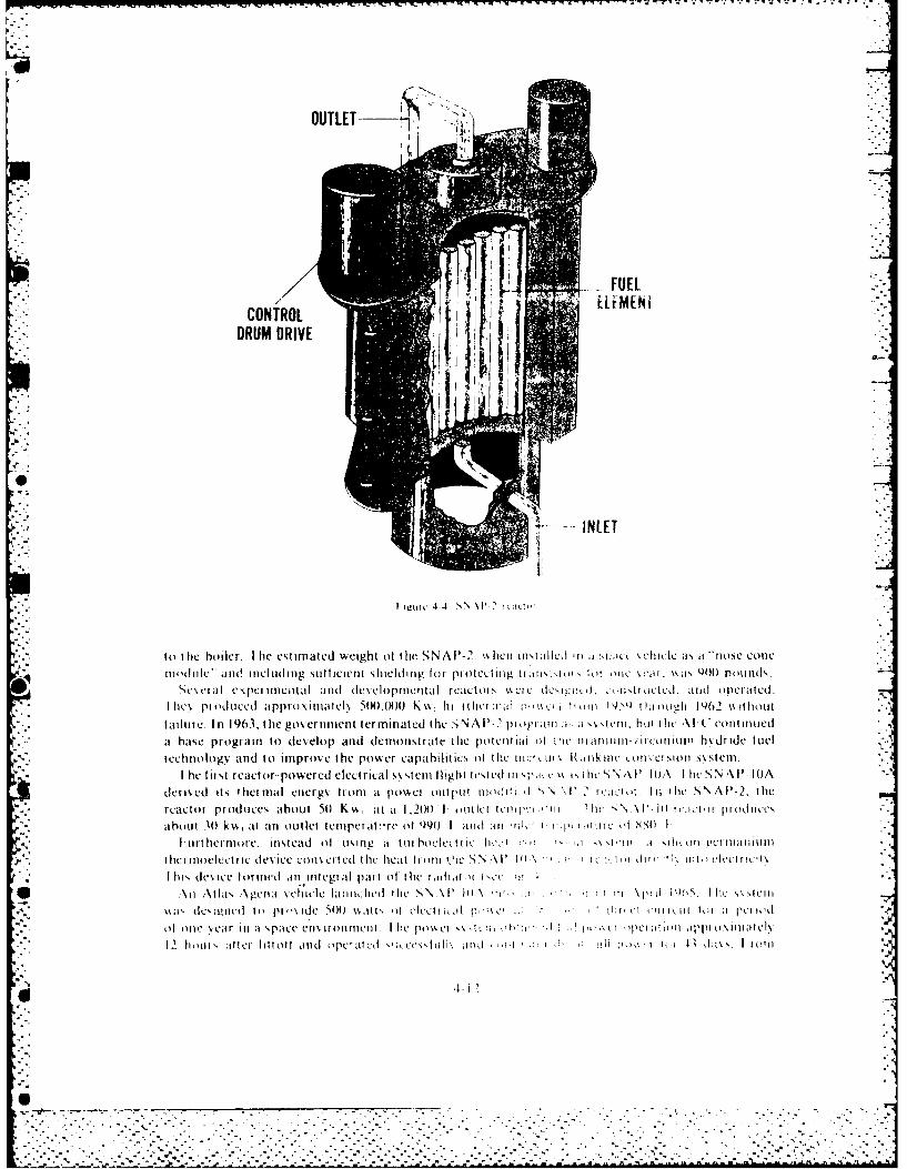
DRUM DRIVE
I ig'uic 4-4 Vs Wt
to the boiler. I hie estimated weight of the SNAIP-2. I,\ hen insilled Ii I ,[ic( %chiclc as, it *rrose conemiodule" and including sufficient shielding tot protectinig tI ,oinl1 !0I One sear, \as Q00l Pounds.
W4Sesetal e\perinicoltal and deveclopmntatil reC~tors W,1( eicd eieirtr IIteOd. aitd OpeIated.I tic i p it Idneed itp prto.\it tclk 5100( K I,\ it ItIltia I pa c! I m 19S ti oI;~ I mwI1 92 \\I to u!
fi Itre In 1903, thte government term in ated thle ,)NAI'-_' p opi arnI a-. I, sstein. hot thie '\l-C continuedbt ase programn to develop and demonstrate the potentlial 0I :11C naIIIiui-icin hydride fuel
technology and to imnprove the power capahi lit ics of the ocr~ Lli%-R H ukIC uiwoil \ ci0 sioiysteml.
I he fitst react or- powered electrical s stemi flight tested Ili q)ic %~I. h Ile S N AF P WA I lie'sNA P-lIOA
dens ecd its thermal energy front at poswci output nuodrti d ', \I' litio I th SN AP-2, thereactr proucesabout 501 K\A, at it 1,201) 1 outlet tuic*i i N\'ltTatrpot~e
about11 301 kk, aIt aln outlet1 teirt!re of 49() 1 and mi ril 'r I, l" Orl t 880 1
1 urthermoie. Instead ofi using at tuihoclee ilc lie'p -r-r'I -. r-r. I.iru iiuuln
the: Iuoelectric dies ice cons cited thel hecat It oil) Oic SN A 11 1i ,' c' ri> it cleecfiitil
I is, dlesice formied an integral part of the radial o I, c
S An A\tlas .\geira seh1icle lairicheul the SNAP Ili N ' W ! I \I'[ i0 111, N NI'CIuI
ssal dCs~iuet li 11p'%I dc 500t 'srs if cl'it- . o J r1ed it i i lo a pcilid
ofone il'ear li at space enrminmentllclt Ilire possei ssA"i Lw hr) )I)ktl )p tilt" oipiiiiielI,
12 luoui, .iftci littoti arid opcrircd ;Ind cess'til mII r I I I Ji s . I I [ ita
KA
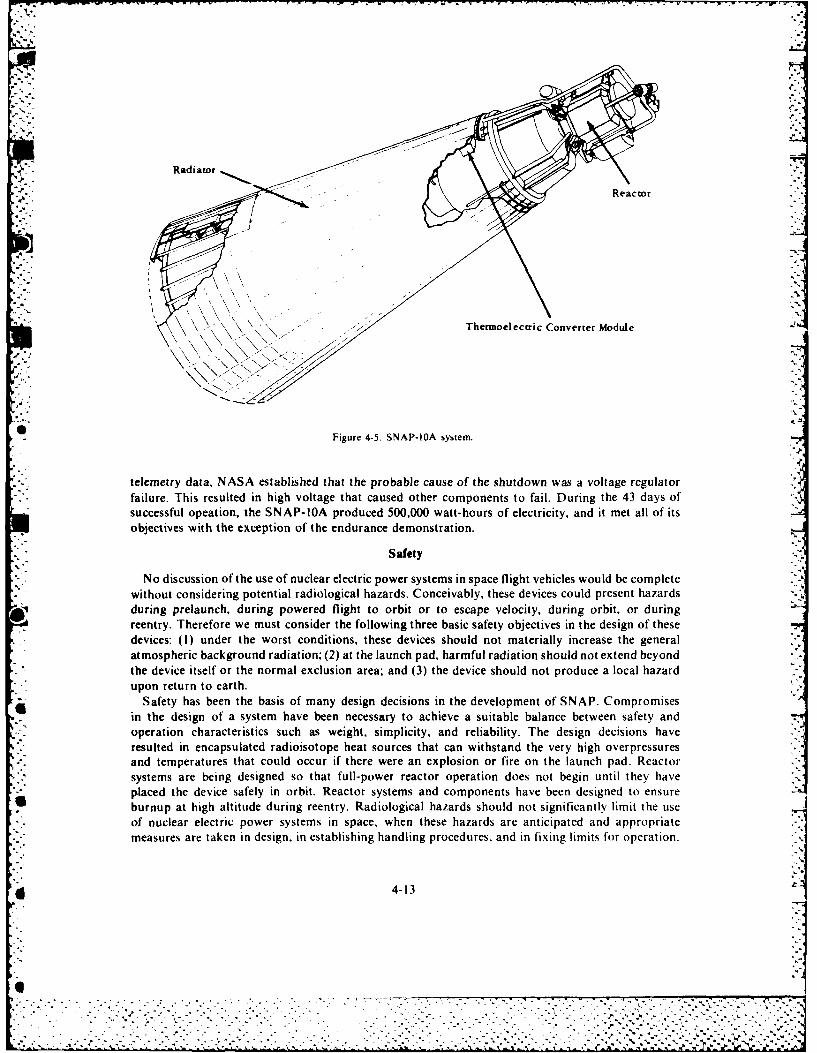
Radiatorf')'[" " - "°Reactor "'
)
Figure 4-5. SNAP-bA system.
telemetry data, NASA established that the probable cause of the shutdown was a voltage regulatorfailure. This resulted in high voltage that caused other components to fail. During the 43 days ofsuccessful opeation, the SNAP-IOA produced 500,000 watt-hours of electricity, and it met all of itsobjectives with the exception of the endurance demonstration.
Safety
No discussion of the use of nuclear electric power systems in space flight vehicles would be completewithout considering potential radiological hazards. Conceivably, these devices could present hazardsduring prelaunch, during powered flight to orbit or to escape velocity, during orbit, or duringreentry. Therefore we must consider the following three basic safety objectives in the design of thesedevices: (1) under the worst conditions, these devices should not materially increase the generalatmospheric background radiation; (2) at the launch pad, harmful radiation should not extend beyondthe device itself or the normal exclusion area; and (3) the device should not produce a local hazardupon return to earth.
Safety has been the basis of many design decisions in the development of SNAP. Compromisesin the design of a system have been necessary to achieve a suitable balance between safety andoperation characteristics such as weight, simplicity, and reliability. The design decisions haveresulted in encapsulated radioisotope heat sources that can withstand the very high overpressuresand temperatures that could occur if there were an explosion or fire on the launch pad. Reactorsystems are being designed so that full-power reactor operation does not begin until they haveplaced the device safely in orbit. Reactor systems and components have been designed to ensureburnup at high altitude during reentry. Radiological hazards should not significantly limit the useof nuclear electric power systems in space, when these hazards are anticipated and appropriatemeasures are taken in design, in establishing handling procedures. and in fixing limits for operation.
Sro 4-li
devies:(I)undrthwostondtios,_tesedevcesshoudntmterallinceasthgeera

SELECTION OF POWER SYSTEMS
The selection of a power system is primarily a function of the space mission and its power require-ments in magnitude and duration. However, there is a host of other factors, including economicconsiderations, size and weight. orbital altitude, reliability, and requirements for attitude control.All of these factors make the selection and design of a power system for each specific space missiona custom built affair.
While many types of space power systems are possible, the primary system has been the solar photo-voltaic/secondary battery system. Future systems are likely to continue utilizing this combinationwith advanced components such as lightweight metal-gas batteries, higher efficiency solar cells, andincreased life for all power system components.
Although radioisotope systems operate in the same power levels and mission duration times 6""
as solar cell/ battery systems, their potential seems to be limited to special missions where uniqueradiation hardening, deployment, or energy requirements may be necessary. We can only considernuclear reactor systems when we require a very high-level power, and even then they must competewith solar concentrator/thermal energy systems for these as yet unspecified applications. For theshort duration power requirements, primary batteries will continue to dominate although we mightuse fuel cells for certain specific applications.
B I1BL I OGR A PH V
"Advanced Space Reactor Concept." Space Worhl November 1970.Austin, L.., ed. Fuel ('ells. A Review ol Government-Spon.sored Research 1950 /964 (NASA-SP-120I. Washington D.C.
Scientific and Technical Information )ivision. Office ot Technology Utilization, NASA, 1967.Boreti, J.E. "Power Systems," Space/Aeronautics. Research and Development issue (31 July 1968):85 90.Corliss. Williams R. and Robert L. Mead. "Power from Radioisotopes." Space World (May 1970):41 45.Crossley, P.A. Review and Evaluation of Past Solar Cell Development Efforts (NASA-CR-86979). Princeton. N..I: )aid
Sarnoff Research Center, Astro-Electronics Applied Research L.aboratory, 1967.Francis, Howard 1. Space Batteries (NASA-SP-5004). NASA. 1964.Glasstone, Samuel. Sourcehook on the Space Sciences. Princeton. N.J.: Van Nostrand Co., 1965.Gylfe. J.D. and R.E. Wimmer. Reactor-Thermoelectric Power Systems.or Unmanned Satellite Applications, Technical
Paper, Intersociety Energy Conversion Conference, Los Angeles, Calif. September 1966. .14Halocy, D.S., Jr. The Coming Age of Solar Energy. New York: Harper and Row, 1963.Hanchett. James. "Whither Now, SNAP-8," Neileonics. Vol. 25, no. 5 (May 1967):54--57.
Hough, W. W. The Ef[.'ct of" Launch Time on the Per firmance of a Solar Arrav/Batterr Electrical Power S'stem"(NASA-CR-88404). Washington D.C.: Bellcom, Inc., 1967.
"Huge Solar Array for Space Station." Space World (March 1971):50."Ion Engine to be Tested in Orbit." Space World (June 1969):7.Klass, P.J. "Gains Cited in Thin Film Solar Cell Efforts." Aviation Week and Space Technology (26 August 1968).Mackay, Donald B. l)esign (of Space Power Plants.Englewood Cliffs, N.J.: Prentice-Hall, 1963."New Modular Space Power System Under Study." Space World(July 1971): 36 37."New Windowshade (of Solar Cells) to Harness Sunlight for Satellite Power," Space World (December 1970):38."Nuclear Energy in Space and the Grand Tour," Chemistrv (I February 1969):20."Providing Perpetual Power," Space World (December 1970):36 44.Scientific and Technical Division, NASA. "Space Power Systems Advanced Technology Conference." (NASA-SP-131).-
Washington D.C.: Scientific and Technical Division of NASA, 1966.Snyder. Nathan W., ed. "Energy Conversion for Space Power." Paper presented at ARS Space Power Conference, Santa
Monica, Calif. 1960. Published in Progress in Astronautics and Rocketry, vol. 3. New York: Academic Press, 1961."Space Power Systems." Paper presented at ARS Space Power Conference. Santa Monica, Calif. 1960.
Published in Progress in Astronautics and Rocketry. Vol. 4. New York: Academic Press, 1961."Spaceship Power 'On Full'." Space World(July 1971):12 15.
"Space Station: Key to the Future." Space World (February 1971):6-44.Szcgo, George C. and J. Edward Taylor, eds. "Space Power Systems Engineering." Paper presented at American Institute
of Aeronautics and Astronautics Aerospace Power Systems Conference, Philadelphia, Pa. 1964. Published in Progressin Astronautics and Aeronaticts. Vol. 16. New York: Academic Press, 1966. 7,-7:-
Zipkin, Morris A. and Russell N. Edwards. eds. "Power Systems for Space Flight." Paper presented at American RocketSociety Space Conference. Santa Monica. Calif. 1962. Published in Progress in Astronautics and Aeronauticc. vol. II,New York: Academic Press. 1963.
4-14
or, 7,.1
" . " " " " '14 " - .'- " -' " - .' " " " ",. . .- """. -' " " " '" "'' '' " . . ..' .' ''"- , " "" .' '.'.%:
Chapter 5
GUIDANCE AND CONTROL
The three processes of ICBM warhead delivery on target, satellite placement in and maintenance
on orbit, and the recovery of a vehicle from space have one thing in common. Some form of guidance,navigation, and control (GNC) is required.9
Navigation is the determination of the current state of motion of the vehicle, that is, position,velocity, and attitude. We determine this state with reference to some mission-dependent coordinatessuitable for defining the motion of the vehicle. Guidance is the computation of corrective actions to
* change from the navigation-determined vehicle state to a required vehicle state. The required state* will depend on particular mission requirements. Mission requirements may specify a required
present state, for example, a particular orbit; or an objective, for example, rendezvous at a pointin space from which we can compute the present required state. Control is the application ofcorrective maneuvers to obtain the changes commanded by guidance.
We might define three broad categories of space missions as ground-to-ground (missile) missions,earth satellite missions, and deep space missions. Since we have conducted deep space missions togain basic knowledge pertaining to our universe, and they are not directly of a military nature asyet, we will not discuss their requirements for GNC. The matrix of figure 5-1 sets forth the main
* GNC functions for the various phases of the first two mission types mentioned previously. Thefollowing sections contain an expanded discussion of two representative functions from this matrix.However, we begin with a general discussion of some techniques used to perform guidance,navigation, and control.
GUIDANCE, NAVIGATION, AND CONTROL TECHNIQUES
One of the basic elements necessary for success in space, be it military or nonmilitary, is an 4
infallible navigational system. You can imagine the inoperability of any space mission without it.This section discusses the various techniques used in successful space navigation.
Navigation
Navigation computes the present state of the vehicle from measured values of selected physical '.i
quantities. This statement implicitly requires a known relationship between each particularmeasured quantity and the variables used to define the vehicle state. Frequently, the state-definingvariables are not measured directly. Navigation measurements include optical sightings, phaseshifts and time delays of radio waves, reaction of inertial sensors to motion, and combinationsof these.
Optical sightings provide angle information as measured between the line of sight of an opticalinstrument and some other established direction in space. The other direction may be anotheroptical line of sight, or a direction established by orientation of an inertial ly-stabi lized platform,among others. We may compute position and attitude from such angle information.
Radio navigation, measuring radio-signal phase shifts and time delays. can provide informationon range, range rate, and direction of the line of sight between the transmitters and vehicle. We can
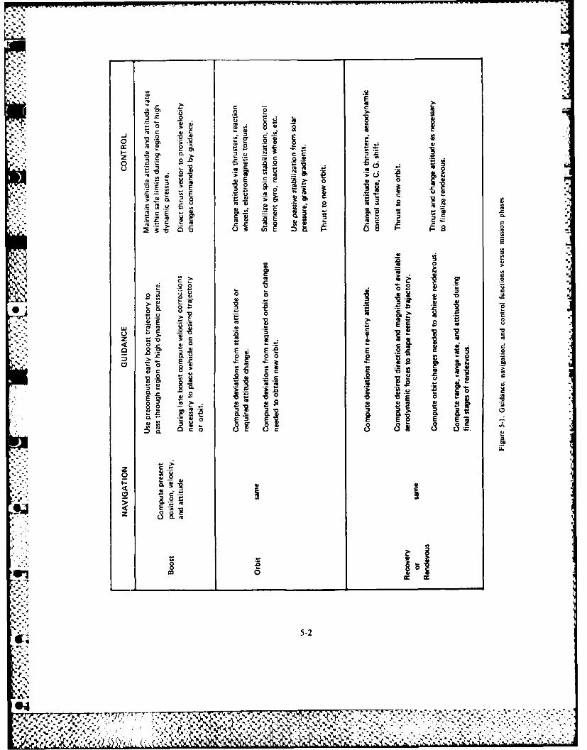
a'
-o
!! t - %
b:!-: ..
o >. W~ .2oj~
.,..0:.:.. 'a.
m 2. 3 C
'4 -
•0 _ 0:..C:,z4, -. - '-- ,.- , , 4
> EE 0: CL m ~ ~ ~
W a,
0 o
0)0
m a- UI
0 Uo
-u 0 >- c
-) ._ C, _V t;'D >C g.
E E e E .2 Cc0 0 0 .
E Ez E ._, 4: 3.
0 F 4S* . .0
0.-~'o E~ E E
:..U.. -c
Z CL
0 ~ I
22
j. 3
"a...'.
£1 5-2.°
,':.:
-a :-
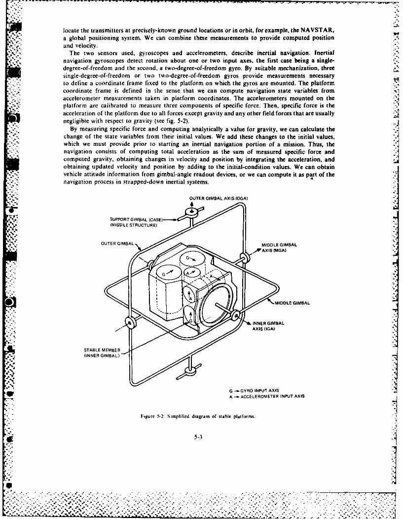
locate the transmitters at precisely-known ground locations or in orbit, for example, the NAVSTAR,a global positioning system. We can combine these measurements to provide computed positionand velocity.
The two sensors used, gyroscopes and accelerometers, describe inertial navigation. [nertialnavigation gyroscopes detect rotation about one or two input axes, the first case being a single-degree-of-freedom and the second, a two-degree-of-freedom gyro. By suitable mechanization, threesingle-degree-of-freedom or two two-degree-of-freedom gyros provide measurements necessaryto define a coordinate frame fixed to the platform on which the gyros are mounted. The platformcoordinate frame is defined in the sense that we can compute navigation state variables fromaccelerometer measurements taken in platform coordinates. The accelerometers mounted on theplatform are calibrated to measure three components of specific force. Then, specific force is theacceleration of the platform due to all forces except gravity and any other field forces that are usuallynegligible with respect to gravity (see fig. 5-2).
By measuring specific force and computing analytically a value for gravity, we can calculate thechange of the state variables from their initial values. We add these changes to the initial values,which we must provide prior to starting an inertial navigation portion of a mission. Thus, thenavigation consists of computing total acceleration as the sum of measured specific force andcomputed gravity, obtaining changes in velocity and position by integrating the acceleration, andobtaining updated velocity and position by adding to the initial-condition values. We can obtainvehicle attitude information from gimbal-angle readout devices, or we can compute it as part of thenavigation process in strapped-down inertial systems.
OUTER GIMBAL AXIS OGA)
SUPPORT GIMBAL ICASE)-.-4w(MISSILE STRUCTURE)
OUTER GIMBAL
0 MIDDLE GIMBAL
gINNER GIMBAL
,,AX IS (GA)
STABLE MEMBER
GG -- GYRO INPUT AXIS
= •...Figure 5-2 Simplified diagram of stable platforms.
; g 5-3
%" W
%I
.• = .
.... ~~~ - ACEEOEE INPUT .. . .. . X .IS ,..,-
"" "~ ~ ~ ~ ~~~~~~~~~~Fgr """"""5'°• - °' °" " " "" °"'-.-...o -2--. liie diga of ' stabl pltfm. . """' ":_.,,'..'.", ,".".- ' , ,.".,'. , . ..5-'3 . . . ... .. . . . - - - . . .
We can combine the above types of navigation measurements, in a hybrid configuration, takingadvantage of the best features of each. Of special importance in recent years is the optimal combining
of various linearized measurements to yield a best estimate of the navigation-state variables. This isKalman, or optimal, filtering.
Guidance
Guidance is the process of comparing the measured navigation state with a required one and thencomputing commands to correct differences between the two. The mission controllers mightcompute continuously the required navigation state based on mission objectives or on the presentvalue of a navigation state predetermined as a function of time. For purposes of defining corrections,the state variables conveniently break out into two distinct types of motion: translational motionfor the position and velocity variables and rotational motion for the attitude variables. Using this
* .~ breakdown, the guidance computations yield required velocity corrections (translation) andrequired attitude changes (rotation). The velocity correction may be the so-called velocity to begained, that is, the velocity increment presently necessary to have the vehicle pass througha given point in space at a later time. It may be the velocity correction necessary to get the vehicleback on a prescribed trajectory. Attitude change could be the rotation of the vehicle back to adesired stable alignment or the rotation from one attitude to another attitude, perhaps to look at adifferent star.
Control
Control is the application of forces to the vehicle to drive the state variables to required values. In
E discussing control, it is convenient to use the translation and rotation aspects of the vehicle motionas we did with guidance.
Basically, translation control is the directing of a control force to bring about a commandedvelocity change. Two methods are available generally. For control outside the atmosphere, thespacecraft controls the thrust direction and burn time of a rocket motor to generate a desired velocitychange. Less used is an additional control of the magnitude of the thrust. For motion inside theatmosphere, for example, during reentry, the possibility of using aerodynamic forces exists. Byproviding attitude control on a vehicle that can develop lift, mission control can orient the lift anddrag vectors to bring about desired velocity changes.
Applying torques to the vehicle or using the conservation of angular momentum can accomplishattitude control. Two common ways to apply torques are use of reaction control jets and aerodynamiccontrol surfaces. Less obvious torques acting on an orbiting vehicle are gravity gradient torquesand electromagnetic torques due to interaction with the earth's magnetic field. In the frictionlessenvironment of space, the very slight difference in gravity acting on portions of the satellite thatare at different distances from the earth is sufficient to apply torques on the satellite. For a longsatellite, the tendency is to have the long axis point to the earth. The satellite will oscillate about thisdirection unless some form of damping is used-to reduce the oscillations to zero. Similarly. the
5. interaction of electrical currents inside the satellite with the earth's magnetic field can cause thesatellite to rotate in the frictionless environment.
The spacecraft can use conservation of angular momentum to control vehicle attitude. Byincreasing the angular velocity of an inertia reaction wheel inside the vehicle, the vehicle will rotate
5- in the opposite direction to conserve the total angular momentum of the satellite. This is therotational form of Newton's third law, which states that an action by the vehicle on the wheel producesan equal and opposite reaction from the wheel on the vehicle (assuming no external torques on thevehicle). Similarly, applying a torque to a gyro inside the vehicle can make the gyro precess. Thisprecession is a change of angular momentum and requires, by Newton's third law, an oppositechange in angular momentum, which comes about by the vehicle rotating appropriately. We
should note that it is possible to saturate both devices such that they cannot accept any more input
5-4
M1
% -~K *5-~* * 5- .-
angular momentum. When this happens, applying torques to the vehicle from other sources suchas jets or electromagnetic interaction desaturates the device.
GUIDANCE, NAVIGATION, AND CONTROL FUNCTIONS
.4'-.,The first item from the matrix of figure 5-1 that we will discuss in expanded form is the boost orinjection phase. We will use the GNC of a ballistic missile to focus on this mission phase.
Boost and Injection
*In its simplest form, a modern ballistic missile weapon system has two major parts, namely, abooster rocket of one or more stages and a warhead housed in a protective structure of particularshape to survive a high-speed reentry passage back through the atmosphere. We recognize that
* there are three distinct phases of flight. The first is powered flight from launch, which acceleratesthe missile upward through the earth's atmosphere and down range toward the target, to rocketthrust termination at the warhead release point at high velocity above the atmosphere. The secondis the ballistic coast of the warhead in a free-fall trajectory in the vacuum of space. The third is thereentry of the warhead back through the atmosphere.
The forces acting on the rocket determine the motion of the weapon through these three phases.The large propulsive force of the rocket accelerates the payload in a direction opposite to that of theexhausted gases of the burning propellant. During the atmospheric passage of the rocket boostand warhead reentry phases, large aerodynamic forces of drag and lift affect the motion. Duringall the phases, the force of gravity pulls the vehicle toward the center of the earth.
Only the rocket propulsive force is under direct control to affect the aim of the weapon. Theq accuracy of a ballistic missile depends upon the ability to steer the rocket thrust so that the position,
speed, and direction of motion at thrust termination are precisely those to establish a trajectory that7will hit the target. But the accuracy also depends upon the ability to predict the motions in thefree-coasting trajectory and the ability to specify target location coordinates accurately.
The guidance of a ballistic missile booster rocket requires the accurate measurement of motionsas they occur during rocket-powered flight. The process of measurement can utilize either radioor radar techniques to measure the motions directly or inert ial-sen sing techniques to measureforces causing the motion.
By using radar stations and radio-ranging equipment located on accurate baseline arrays, andinterrogating cooperative transponder beacons on the missile, radiation sensing can provide almostmicrometer precision in the measurement of location and velocity of the burning rocket. Somecharacteristics of these radiation-sensing methods are undesirable, especially for a weapon system.An obvious drawback is that the ground stations are complex, conspicuous, and, therefore,vulnerable to enemy countermeasure activity. For this reason, the guidance of modern ballisticmissile rockets has depended upon, and caused remarkable advances in, the technology of inertial -sensing. Inertial sensing is completely self-contained, having no active or passive radiation contactwith the outside world.
Inertial Sensing
The principle of inertial sensing depends upon the direct measurement of force acting on a testmass inside an instrument known as an accelerometer. There are two prime forces acting on theaccelerometer's test mass. One is the force of gravity. The other is the inert ial-reaction force,
-Q primarily from the propulsion system. The latter causes an equal and opposite force on the test massby a spring attached between the mass and the accelerometer case. As both of these forces have
* direction and magnitude, we must treat them analytically as vectors.The vector force of gravity. F11, on the test mass is proportional to both the magnitude of the
mass, m. and to the magnitude of the local acceleration of gravity, g. and has the direction of thelocal force of gravity:
=Mg.()
5-5
J, 1? .1, %.
Components within the instrument measure the vector inertial reaction force, T. The vector sumof the gravity and spring forces is the total force on the test mass causing its motion and itsproportional to the net acceleration of the test mass,
1. + T. = m-a (2)
Solving for this acceleration and substituting equation I gives
a -g-~ a~i+ (3)
This is the fundamental equation of inertial navigation. 7 is the acceleration of the test mass.and therefore, is the acceleration of the missile. _g is the local acceleration of gravity, which isaccurately known as a function of the position of the vehicle. Considering only the earth's attraction,
g = -GM, (4)
where GM, is the earth gravitational constant and T is the position vector of the missile relativeto the earth's center.
The term T./m in equation 3 is the specific force (force per unit mass) measured by the-, accelerometer, and has units of acceleration. This specific force equals the acceleration due to
directly applied forces. The directly applied forces are those from the rocket propulsion, aero-dynamic lift and drag, and any other miscellaneous externally applied forces except that of gravity.
We must emphasize this important point of inertial guidance: the accelerometer cannot measurethe component of acceleration due to the force of gravity. We must determine this part of motionanalytically from the known magnitude and direction of gravity as a function of position.
From the basic equation of inertial navigation, equation 3, we can determine the total localacceleration as the vector sum of the accelerometer-measured specific force and the analytically-determined acceleration of gravity, such as given in equation 4, as a function of missile position.
* We can integrate this equation once to get velocity and position as embodied in the constants
of integration.At this point, some of the practical aspects of implementation need introducing. Equation 3 is a
vector equation. Equipment to deal with this equation will operate on vector componentsrepresented in an appropriate reference coordinate frame. Suitable reference coordinate framesthat make equation 3 true are nonrotating and nonaccelerated in the sense that the center of theearth is nonaccelerated, being in free-fall in its motion in the Solar System. For ballistic missileinertial guidance, it is common practice to implement the acceleration equation in an earth-centerednonrotating coordinate frame. It is a common practice to mount accelerometers on a gyroscopically-stabilized platform so that the accelerometer specific-force output signals are directly componentsof acceleration in a nonrotating coordinate frame.
By the action of conservation of angular momentum of their rapidly spinning wheels, gyroscopescan generate signals proportional to the angular displacement in space of their cases. If the gyrosare mounted suitably on a stable platform, such as the three-degree-of-freedom, gimbal-supportedmember figure 5-2 represents, the gyro signals become attitude-error signals for servo electronics.These electronics can drive gimble-axis torque motors to keep the inner gimbal spatially nonrotatingin spite of the rotations of the missile and stable platform support structure. It will hold an orientationin space established by an initial alignment process accomplished on the ground before launch. Theangular rotations, measured by mechanical-to-electrical angle signal generators mounted on eachaxis of the gimbal system, are the components of missile angular motion with respect to thereference orientation determined by the prelaunch alignment. These are the rotational outputs, roll,pitch, and yaw, of the inertial sensing. The translational outputs are the components of specificforce measured by the accelerometers mounted on the nonrotating platform.
5-6
7-*
E. ¢%

Gyroscopes and accelerometers are the basic instruments of inertial sensing. There have beenmany successful design approaches of these instruments, incorporating a variety of ingeniousfeatures, motivated towards optimizing various measures of performance. Figure 5-3 is a cutawayview of the single-axis gyroscope used in Apollo spacecraft guidance. (The term, single axis, refersto the fact that the gyro is sensitive to input angular motion only about a single axis.) The platformrequires three of these, with the orthogonally-oriented input axes, for stabilization. Figure 5-4 showsa cutaway view of the single-axis pendulous accelerometer, also used in Apollo guidance. The test
- -. -:mass is configured as a single-axis pendulum, restrained by torque feedback to a reference angularposition with respect to the case. The torque required is the measure of specific force. Three of theseinstruments with orthogonally-oriented input axes are necessary to measure all components of theIspecific force. Figure 5-5 shows implementation of a complete gimbal-supported stable-platform
Inertial Navigation
The use of inertial sensing to guide a missile rocket can take a number of different forms. We havechosen a conceptually simple form for illustration. It involves several steps. The first step integratesthe basic equation of inertial sensing to produce explicit signals representing missile translationalvelocity and position. We call this process inertial navigation, and illustrate it in figure 5-6. Sincethe accelerometers do not measure the components of acceleration due to gravity forces, these arecomputed separately and added to the accelerometer signals as shown. The integration of this netacceleration, the left side of equation 3, is the velocity change. The addition of this change to theinitial velocity at launch results in the indicated-velocity output signal. The indicated position change(provided by the integration of the indicated velocity) added to the initial position gives the netindicated position signal from inertial navigation. Since local-gravity acceleration is a knownfunction of missile position as equation 4 gives, then the indicated position is the necessary input tothe gravity-acceleration computer. All variables are vectors, but the components perform the actual
implementation. There are three outputs of this inertial navigator, namely, indicated thrustacceleration, indicated velocity, and indicated position. The inertial guidance function described
* in the next section uses all three.
Inertial Guidance
The function of inertial guidance is to steer the rocket thrust to achieve the desired terminalcondition. During passage of a ballistic missile rocket up through the atmosphere, the objective
v of steering is to control the motion to pass safely through the period of high-aerodynamic loading.During this period, the missile can tolerate only a small angle of attack and still maintain controland structural integrity. It is usual to steer this early phase through an angle history that is apredetermined function of time from launch. Once safely out of the atmosphere, the guidancesteering is motivated to reach computed rocket-cutoff conditions.
Figure 5-7 represents a block diagram for one concept of ballistic missile inertial guidance. Notethat we have abbreviated !he previous figure for inertial navigation and represented it by a box onthe left of figure 5-7. Guidance must steer the rocket so that it will release the warhead on one of themany trajectories that will hit the target. The input to the box labeled "required velocity computer"specifies the target to the system. The function of this box is to compute the required velocity vectorthe missile should have at the present position and instant of time so that the warhead, if releasedto coast free now, would be on a trajectory having the desired properties. The difference betweenthe required velocity and the present indicated velocity is the velocity the rocket will gain. If therocket's steering is proper, the rocket will reduce the gained velocity towards zero. When it achieveszero, the missile control should cut off the rocket engine thrust as shown by sending the thrust-termination signal. The steering strategy illustrated aims the missile so that the direction of theepresent measured thrust acceleration is parallel to the direction of the velocity that the rocket willgain, thus assuring that all components of the velocity that the rocket will gain will be reduced to
5-7
'px
p2",
I 1-IM24.
'U'.'C
4..
"SI
'1'
-.
CV'4>'
.. ' '~
ttN4CU.4
CC'Ca
' .N
I-.,
U'hr-.4 Li..
A'
~
"'Va'
623
I~. . ~ 4
5-8
'9
4..*9

~4~:
4%~
N" -.4..
6~~*~4.
'4
-A
a
6.*
lb -4.-
4-
4 .. .t-4.)~ 4.
4%
*
4.
5..9 4
.4.
4~4,
<KK'y~~-- {y.C ~ .'W. ., . H' . 2.-.... m~..< '.- '*-.ffi-..* -. ~ -
4
'.1.
* . q
A
.4.-44-
.4,
U0
U
U
U
U
-44.,4~.- 44~
444t4
I - 44-
4~- -~
""'4
5-10
~4
'44.'.
.4,.. V*j4*
4'.
IIhA~
'V:-~-~
INDICATEDTHRUST
ACCELERATION
MISSILE INDICATED
ATTITUDE VELOCITY
SIGNALS INITIAL INITIALVELOCITY POSITION TO
INETIA SIGNALSEACCELERATION
% ." -ACCE LEROMETE R INDICATED "
"J"INERTIAL SIGNALS SUM INTEG RATION sm INTEGRATION su
. . VEHICLE ACCELERATION
VEHICLEDUE TO.MOTION GRAVITY
GRAVITYCOMPUTER
Figure 5-6. Inertial navigation.
zero simultaneously as desired. The steering computer causes the thrust acceleration to be parallelto the velocity that the rocket will gain by creating an angular-velocity command vector that willcause the missile to rotate the thrust vector towards the velocity-to-be-gained vector. This angular-
* velocity command goes to the missile's autopilot or thrust vector control system described in thefollowing section. This is one representation of a particular guidance scheme called velocity-to-be-gained steering.
This seems an appropriate place to comment on the powerful implementations of the simple eventof the guidance system thrust termination signal. A ballistic missile, with its high-performancerocket stages and associated equipment, depends upon many complex systems working successfullyto complete its mission. If the guidance system senses that all three components of the velocitythat the rocket will gain have passed sufficiently close to zero simultaneously so as to generate thethrust-termination signal, then there should be almost no failure anywhere in the whole missilesystem up to that time that will affect the performance of the weapon significantly. The onlyoutright failure that would mislead such interpretation is the logic and circuitry generating thethrust-termination signal itself. Once signal generation occurs, we are assured that everything elseworked as intended, including most of the guidance system as well. The event of three componentsof velocity arriving at zero simultaneously with a significant failure in achieving the velocitycomponents correctly or in measuring them properly is nearly impossible. Large degradation inperformance, not outright failure, in the inertial sensing instruments could fool this criterion ofindicated success, but experience with these instruments and simple analysis show that such asituation is most rare compared to the many other possible failure modes elsewhere in the missilesystem. If the thrust termination signal occurs and the thrust actually ceases as sensed by theaccelerometers, then the system has sent the weapon successfully on its intended free-fall ballistictrajectory. We can use such a signal to arm the warhead with the assurance that there is negligiblechance that it will go awry and explode far from the intended target. If there is no generated signal,the missile could send a simple one-bit coded signal to the ground to indicate failure and the needfor another launch against that target.
Thrust Vector Control
Thrust vector control is the closed-loop process that keeps the vehicle from tumbling under thehigh forces of engine thrust and accepts turning or guidance steering commands to change the
5-I1
• % 1
---.-.-.S-'- .: ._ _"_._,_ _ _ _ __._ __-_ _,_ _....." .. -... s - . . ."."-. . . - . .'- . . . . " - . " . -- -. - .-.-. ' .-.
.'' ., . .,,.,. - . . ' "v ,.''. ' . - ."..-'- . ,..- -.. ... ." . '-.. -' -"-" . .-. " -" ';. - ." . -. -" .',. -... ."- .. "%". 4 . ." '"" ''"""' ", -h " " """ "" - """. ". . ". ." " . "" ', " . " ".p ." " ' , . ' -
0r
cr U Z
X u_ 0
cccr
2
< >
-z L
zcUwu
wZZ
25-C2cc c
X .-. . . . . . .
.
1-.-'
direction of the applied rocket acceleration. For liquid-fueled rockets, the engine is relatively small,and the use of an engine swivel or gimbal arrangement to deflect these forces from the center of themass achieves control torques. For solid-fueled engines, the thrust chamber contains all thetnburned propellant, and a gimbal mounting of the whole chamber is not practical. Other meansof torque control such as jet vanes, jetavators, nozzle swivel, or gas injection can deflect the hot gasstream without moving the thrust chamber itself.I hese methods provide control torques about pitch and yaw axes perpendicular to the long axis,
the roll axis, of the rocket. Multiple engines or nozzles at the base of the rocket are common, andengineers can offset the thrust from each engine or nozzle differentially to provide torque controlabout the roll axis. Otherwise, they can array special small thrusters on the side of the missile for
roll control.-Figure 5-8 illustrates a typical thrust vector control loop. The input to this system is the signal
front guidance proportional to the desired angular velocity of the thrust direction to reduce thethrust-direction error towards zero. This angular velocity command is compared with the actualmi ssile angular velocity presently existing. Rate gyroscopes measure this actual missile angular%clocity [he difference becomes the missile-angular-velocity error that the box labeled dynamiccontrol amplifies and treats with dynamic compensation filtering. The output of this box is thecommand to the torque control deflecting the thrust such as described previously. The missileresponds to the applied torque according to its moments of inertia and the other dynamic properties.I he rate gyroscopes sense the resulting angular motion to close the control loop.
STEERINGANGULAR ANGULAR
vE LOCI TY VELOCITY THRUST MISSILECOMMAND ERROR DYAI OQE DRCINORIENTATION• . ... O, ERE --1CONTROL C1IONTROL
"... INDICATED
k/ ANGULAR
VELOCITY FRATE SENSING ]
~GYROS l
Figure 5-8. Thrust vector control.
I he dynamic compensation of such loops can be a complex design process. We can treat the,nisile as a rigid body in design only rarely, and the effects of body bending and fuel and oxidizer
sloshing in tanks can cause large and usually destabilizing torques. Another effect with a very
descriptive name is that of engine "tail wagging," where large gimballed engines have moments ofinertia comparable to the rest of the missile. Commands to move the engine (the tail) result inconsiderable motion of the missile itself (the dog). And finally, in the flight through the atmosphere,the elfects of aerodynamic forces are considerable and destabilizing.
I he thrust-vector-control design must recognize these destabilizing effects so that the dynamicerror in following guidance commands is sufficiently small. This requirement is particularly tightnear thrust termination. If the missile has high-angular velocities at this time or is not followingsteering commands accurately, then all three components of the desired velocity will not passsimultaneously through their correct values for engine cutoff. Residual velocity error causes missat the target if not subsequently corrected.
Recapitulation
A booster rocket propels a ballistic missile to a high velocity above the atmosphere, where the
5-13
04
r'~. .. = .. .'. . .. . -..... . '. .". "..°.. • ..-... ." , . . . . . = -- .• - ,,' ,- , , ,dd' _
missile releases the warhead to coast free in a ballistic path before it reenters the atmosphere.Guidance of this weapon to hit a specific target occurs only during the rocket-boost phase, whichextends over only the first few minutes of flight. Guidance measurements utilize inertial-sensingtechniques. Inertial sensing is the application of Newton's laws as they operate in gyroscopes andaccelerometers to measure all components of missile rotational-motion changes and all componentsof missile translational-motion changes due to all forces on the missile except gravity. Navigating.or determining missile position and velocity by inertial sensing, requires the analytical determinationof that component of missile motion due to the force of gravity acting upon it. Moreover, since the
.7 inertial sensing can measure only changes in the missile motion, the initial conditions of position(launch location) and velocity must be provided externally before launch. Guidance calculationsdetermine the direction to steer the rocket so that the velocity and position approach those conditions
- ~' compatible with a free-fall coast to the target identified to the guidance system at launch. Therocket-autopilot thrust-vector-control system responds to the ;4adance steering commands to
-~ control the direction of rocket thrust with respect to the missile in a stable fashion. When the missileachieves the proper conditions of position and velocity, the guidance system signals termination ofrocket propulsion and releases the warhead. Now flying under the influence of gravity alone, thewarhead coasts in the vacuum of space in an elliptical path until it enters the earth's atmospherewhere it may slow considerably before being triggered to explode at the target.
IN-ORBIT ATTITUDE CONTROL
The second item for expanded discussion is in-orbit attitude control. We use the NASA OrbitingAstronomical Observatory (OAO) for the illustration.
Orbiting Astronomical Observatory Attitude Control
Two astronomy experiments are aboard the OAO-C. First is a Princeton University experiment- . (PEP) that uses a 32-inch telescope to examine interstellar media by measuring the media absorptive- - characteristics in the ultraviolet spectrum using stars as light sources. The second experiment is the
University College, London, experiment that uses three small telescopes to measure X rays. Both* ' experiments require attitude-hold control during a measurement and attitude-change control
(slewing) when it is time to observe in a new direction. Figure 5-9 depicts the basic operation of bothmodes of attitude control.
Orbiting Astronomical Observatory Attitude Hold
The basic requirement for attitude hold is maintaining the vehicle at or very near a desiredorientation in inertial space, for example, orientation referenced to the "fixed" stars. Measurement
0 of small rotation-angle deviations from the prescribed attitude is necessary for control.For the PEP experiment, the 32-inch telescope measures two attitude-error angles about the pitch
and yaw axes of the vehicle. These angles are the small rotations of the telescope boresight, forexample, the vehicle roll axis away from a star line of sight (see fig. 5-10). An inert ial- reference unit(IRU) measures error angle about the roll axis. The IRU is a set of three gyroscopes strapped downto the satellite with their three input axes aligned with the yaw, pitch, and roll axes. During periodswhen the telescope cannot observe the star, the IRU measures pitch and yaw error angles. For theX-ray experiment, the IRII measures error angles for all three axes.
Given the measured error angles, the attitude-hold control system rotates the vehicle to drive theerror angles to zero. Fine momentum wheels (FMW) and the magnetic unloading system (MLJS)
accomplish these attitude correction rotations.Each FMW can rotate the vehicle about the wheel axis of revolution. The physical principle
* behind use of a FMW is the conservation of angular momentum. The following equation expresses-e ~this principle: Liu, + lw. =constant. In this equation L, and 1., are the vehicle and wheel moments
of inertia about the controlled axis, and w,, and oi, are the vehicle and wheel angular velocities about
5-14
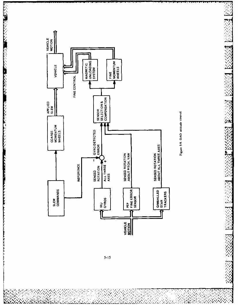
LU_j Z
ujO0
LU-i
0LU LU-j U'
oU c
Cc.
LU
LUL
0.-LU c
a-~ -J -
Lu W 0 0cn (n a
DU
8 0 X w 0 4.'
0 o0w
cc cc x> ir < CI
LU 0
cc 'I -'U.
LL5-(n
.* . * . -.-w
CC *r 9L
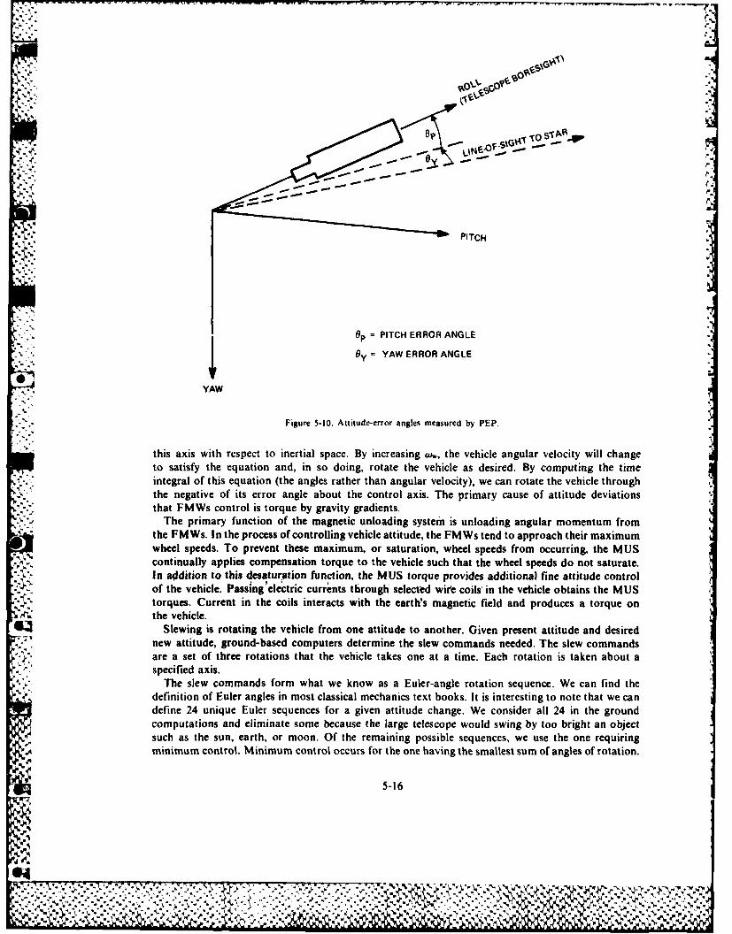
,~~~~~ , . vsc ,.\G
opTOS'g..p
PITCH
OP = PITCH ERROR ANGLE
"y = YAW ERROR ANGLE
0.YAW
Figure 5-10. Altitude-error angles measured by PEP.
this axis with respect to inertial space. By increasing (w, the vehicle angular velocity will changeto satisfy the equation and, in so doing, rotate the vehicle as desired. By computing the timeintegral of this equation (the angles rather than angular velocity), we can rotate the vehicle throughthe negative of its error angle about the control axis. The primary cause of attitude deviationsthat FMWs control is torque by gravity gradients.
-' "The primary function of the magnetic unloading system is unloading angular momentum fromthe FMWs. In the process of controlling vehicle attitude, the FMWs tend to approach their maximumwheel speeds. To prevent these maximum, or saturation, wheel speeds from occurring, the MUScontinually applies compensation torque to the vehicle such that the wheel speeds do not saturate.In addition to this desaturation function, the MUS torque provides additional fine attitude controlof the vehicle. Passing electric currents through selected wire coils' in the vehicle obtains the MUStorques. Current in the coils interacts with the earth's magnetic field and produces a torque onthe vehicle.
Slewing is rotating the vehicle from one attitude to another. Given present attitude and desirednew attitude, ground-based computers determine the slew commands needed. The slew commandsare a set of three rotations that the vehicle takes one at a time. Each rotation is taken about aspecified axis.
The slew commands form what we know as a Euler-angle rotation sequence. We can find thedefinition of Euler angles in most classical mechanics text books. It is interesting to note that we candefine 24 unique Euler sequences for a given attitude change. We consider all 24 in the groundcomputations and eliminate some because the large telescope would swing by too bright an objectsuch as the sun, earth, or moon. Of the remaining possible sequences, we use the one requiringminimum control. Minimum control occurs for the one having the smallest sum of angles of rotation.
5-16
.. 4 #4%
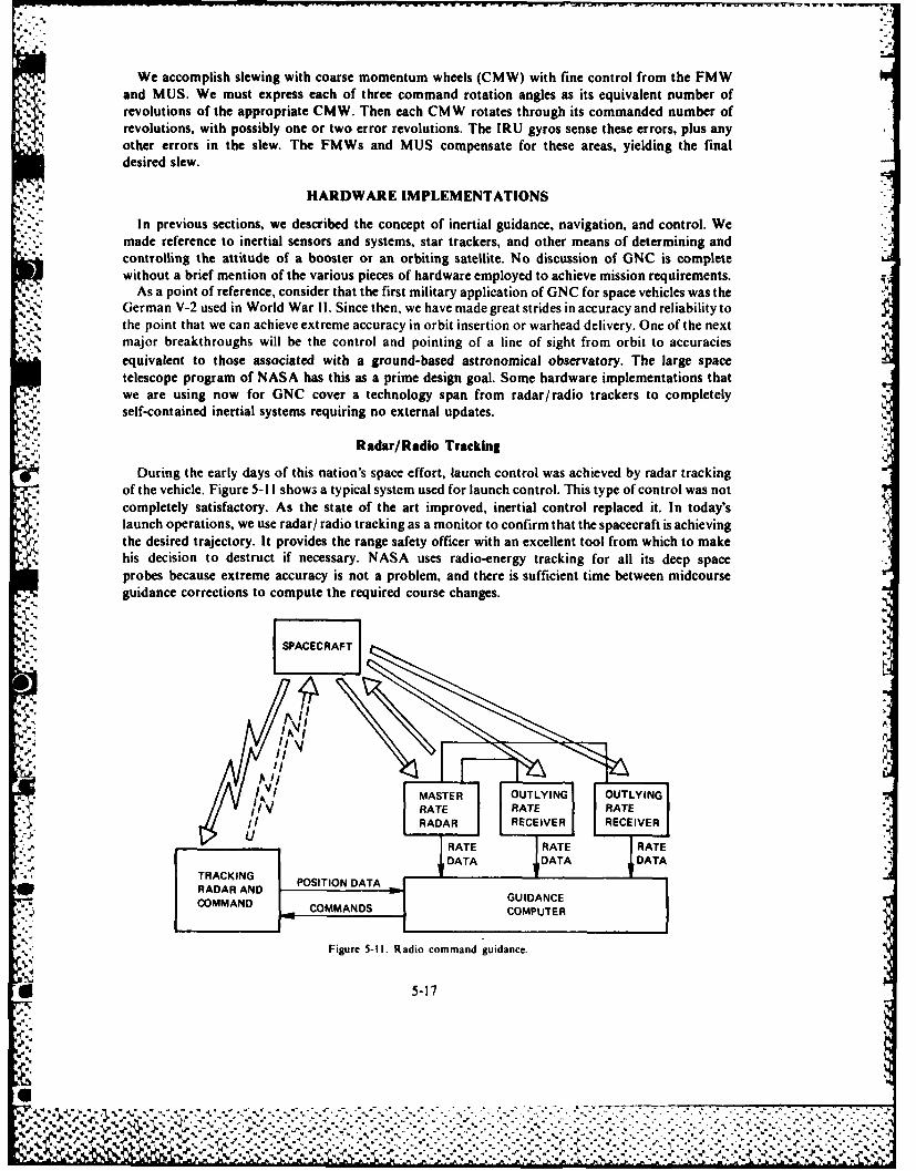
We accomplish slewing with coarse momentum wheels (CMW) with fine control from the FMWand MUS. We must express each of three command rotation angles as its equivalent number ofrevolutions of the appropriate CMW. Then each CMW rotates through its commanded number ofrevolutions, with possibly one or two error revolutions. The IRUJ gyros sense these errors, plus anyother errors in the slew. The FMWs and MUS compensate for these areas, yielding the finaldesired slew.
HARDWARE IMPLEMENTATIONS
In previous sections, we described the concept of inertial guidance, navigation, and control. Wemade reference to inertial sensors and systems, star trackers, and other means of determining andcontrolling the attitude of a booster or an orbiting satellite. No discussion of GNC is completewithout a brief mention of the various pieces of hardware employed to achieve mission requirements.
As a point of reference, consider that the first military application of GNC for space vehicles was theGerman V-2 used in World War 11. Since then, we have made great strides in accuracy and reliability tothe point that we can achieve extreme accuracy in orbit insertion or warhead delivery. One of the nextmajor breakthroughs will be the control and pointing of a line of sight from orbit to accuraciesequivalent to those associated with a ground-based astronomical observatory. The large spacetelescope program of NASA has this as a prime design goal. Some hardware implementations thatwe are using now for GNC cover a technology span from radar/ radio trackers to completelyself-contained inertial systems requiring no external updates.
Radar/Radio Tracking
During the early days of this nation's space effort, launch control was achieved by radar trackingof the vehicle. Figure 5-11 showa a typical system used for launch control. This type of control was notcompletely satisfactory. As the state of the art improved, inertial control replaced it. In today'slaunch operations, we use radar/ radio tracking as a monitor to confirm that the spacecraft is achieving
r the desired trajectory. It provides the range safety officer with an excellent tool from which to make4 ,, his decision to destruct if necessary. NASA uses radio-energy tracking for all its deep space
probes because extreme accuracy is not a problem, and there is sufficient time between midcourseguidance corrections to compute the required course changes.
SPAEAFT
I J ASTE OULYIN OUTYIN
I\4
TRI POITO MATRAULINTUTYN
ii RADAR ANREIACER RCIE
COMMAND COMMANDS COMPUTER
Figure 5-Il. Radio command guidance.
* 5-17
%~~- .. . ...
Z, - . . . , . . -
Inertial Systems/Sensors
With the exception noted pertaining to deep space probes, all of today's space missions rely oninertial systems for GNC for launch. Depending on the mission, the spacecraft will use inertialsensing for the orbit phase. For reentry, the spacecraft may use inertial sensing depending on themission and the aerodynamic characteristics of the vehicle. The command module for Apollomaintained the inertial system in operation until splash down. At present there are three mechaniza-tions in use, namely, gimballed, strapdown, and floated ball. Each of these has its own advantages anddisadvantages depending on mission requirements: cost, performance, and reliability, to name a few.
The gimballed system is the one used most frequently because it represents the one with thegreatest technology background. As we described in previous sections, it consists of three single-degree-of-freedom gyros and a pair of two-degree-of-freedom gyros and three accelerometers -
mounted on a platform in such a way that the instrument input axes are mutually perpendicular tosense motion about or along the X, Y, and Z axes of the inner gimbal. The gyros and associatedservo loops drive the inner, middle, and outer gimbals to maintain the instrument stable regardless I,*.
of vehicle angular motion. Each gimbal has an electrical-mechanical readout device to measure gimbalposition. We use these gimbal angles as inputs, along with acceleration data, to a computer thatgenerates guidance commands, navigation information, and compensation for inertial sensor errors. ~This last function is necessary because no one has made a perfect instrument as yet. However, we canpredict its errors. With a knowledge of gyro and accelerometer error, it is possible to compensate forthese crrors during operation. A classic example of the use of a gimballed inertial system is its use inMinuteman, transport aircraft, and submarines.
As its name implies, a strapdown system mounts all of the sensors directly to the vehicle structure.The output of each set of sensors, gyros, and accelerometers is body angular rotation about the X. Y,and Z axes and specific force along the respective axis. These data are input to a digital computer that,in addition to the normal GNC function, converts body-referenced information to a suitablenagitation frame. The "gimbal system" is resident in the computer as an attitude transformation.Strapdown systems trade mechanical precision and manufacturing cost for a more complex digitalcomputer. The decision process for the selection of gimballed versus strapdown is a complex oneinvolving many factors. In general, we will choose a gimballed implementation if we require highaccuracy and cost is not a driving factor.
We can compare the floated-ball configuration to a combination of both the previous implemen-tations. The floated-ball configuration contains the inertial sensors and their associated electronics 110within a spherical structure that floats in a temperature-controlled sphere in such a way that theinstrument ball is neutrally buoyant. Hydraulic torque motors accomplish the centering of the ballwith respect to the sphere. These motors make the ball rotate in response to gyro-generated controlsignals as the vehicle rotates. An associated digital computer provides GNC computations as in theprevious implementations, as well as sensor compensation. The great advantage to this configurationis the high degree of protection provided the inertial sensors when they encounter high "g" loads.Figure 5-12 is an exploded view of such a system.
Many applications do not require a three-axis inertial measurement unit or system. As an example,the Saturn launch vehicle for Apollo employs a triple-redundant three-axis rate gyro package togenerate body rate information for the flight control autopilot. The triple redundancy providedthe required Apollo reliability by voting the outputs of each gyro. If the spacecraft requires moreaccurate data than it can secure from a rate gyro, we will use a single-degree-of-freedom rateintegrating gyro in a torque feedback mode. In this mode, the spacecraft amplifies the gyro output -
and uses it to drive its null to zero. The current required to do this is a measure of attitude change,and, as it is generally in digital form, provides a convenient input for a digital guidance/ control ,
computer.For a long time, aircraft have used two-degree-of-freedom instruments for autopilot applications
and vertical reference. Until the 1970s, they were used very little for space vehicles because of,performance limitations. Since then, their performance has improved greatly and many spacecraft
5-I187
%AV.y*. ~ ~ $- .Q..-.
P Ps-S *%4 J.A ~ -' P ;'
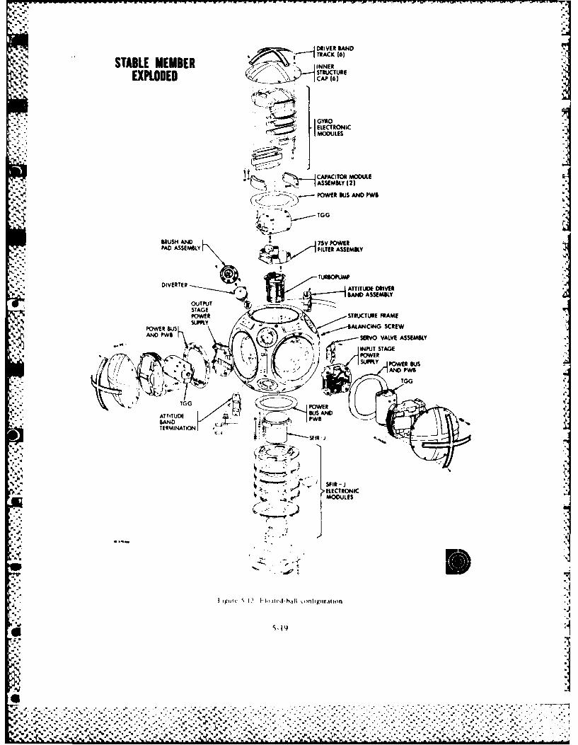
D~RIVER BANDTRACK (6)
STABLE MEMBER INNEREXPLODED C CAP (6)
..,,j GYROS. •ELECTRONICMODULES
JCAPACITOR MODULE
~~IASSEMBL (2)S ...-- POWER BUS AND PWBl
lTGG
BRUSH AND .75V POWERPAD ASSEMBLY FILTER ASSEMBLY
DIVERTERTURBOPUMP~~-* DATTTERUDE DRIVER
* OUTPUTSTAGEPOWER STRUCTURE FRAME
POWER BUsSUPPLY ALANCING SCREWAND PWB SERVO VALVE ASSEMBLY
- --INPUT STAGE
rPOWER
,- ." TGG POWER" i
ATTITUDE B AND E U
TERMINATIOW
k . ... •'
~' J ~SPIR - JELECTRONIC',~; v ~ MODULES
i, Igur 12 I'ltlcd-hall oliptgir lilon
L
* 5-19
II .
are using them in both gimballed and strapdown configurations. They have the advantage of having.3' one axis with a redundant sensor, which the system designer can use to advantage. If the spacecraft
requires high reliability about one axis, engineers can configure the system in such a way that twogyro outputs indicate rotations about the critical axis.
The laser gyro is another sensor receiving increasing notice. This instrument has the potential ofequaling the performance of "iron" gyros with the advantage, in theory, of no moving mechanicalparts with the exception of a possible dithering subassembly. Aircraft and tactical weapons have
A flown prototype instruments with encouraging success. Effort is underway to apply a Laser IMU for
space application.%6 Accelerometers for space applications do not differ greatly from those required for aircraft use.
Engineers are concentrating their development efforts on improving the accuracy and resolutionand on reducing the magnitude of error terms. In general, the sensing element is a dampedspring-restrained mass that is driven to null by electrical means. Its output is digital and, dependingon the instrument design, will indicate either velocity or acceleration. If the output is velocity, we willcall the instrument a velocity meter or an integrating accelerometer. The more accurate instrumentstake this form. -
.~ .. Finally, industry and DOD laboratories are applying considerable effort to develop multisensorinstruments. These are units that provide both acceleration and angular-rate information from oneinstrument. As of the middle 1970s, engineers had laboratory tested a number of concepts, andfabricated one single-axis platform incorporating a multisensor. The prime motivation behindthe development of these instruments was an attempt to reduce overall systems cost. Theirperformance precludes their application to medium- or high -performance mission requirements.
Star Trackers
*These instruments are used to track a star and measure its direction with respect to thebase on which the inertial system is mounted. In conjunction with a computer, their purpose is to
* - determine the spacecraft's position and attitude in space. By using a series of measurements, theobservers try to compensate for the buildup of errors in an inertial system. As there is no definedhorizon, a space sextant (star tracker) measures the angle between two stars and a near body todetermine two lines of position. A series of measurements is made using many combinations tosecure an accurate position. The sensor commonly used is a vidicon tube whose photoconductivesensor is sensitive to star emissions. In operation, the vidicon is part of a closed-loop servo thatautomatically tracks and measures the position of a selected star with respect to the inertial system.A series of measurements provides the data from which vehicle position is determined. The processof determining position is similar to that used for aircraft navigation using a bubble sextant and sightreduction tables. In a spacecraft, the process is automatic, and the sight reduction tables convertto stored ephemeris data for the stars of interest.
Horizon Sensors
These instruments are used to sense the earth's horizon or limb, and their output is employed tomaintain a satellite's position, generally the pitch axis, fixed with respect to the earth's center.Reaction wheels, control-moment gyros, or gas jets accomplish control of pitch-axis position,depending on the design of the vehicle. The sensor, mounted at the focal plane of an optical system,is sensitive to infrared radiation present at the earth's limb. A rotating shutter or light chopper
4. within the optical system modulates the radiation received by the infrared sensor and serves tos generate a phase-sensitive error signal used to control the satellite pitch axis. Generally, this type
of sensor is used when stabilization requires moderate accuracy.
5-20
SATELLITE TELEMETRY, TRACKING, AND COMMANDING
1' The three functions involved in satellite control are telemetry, tracking, and commanding (T"TC).All satellites regardless of their mission or capability require TTC. Taken in logical order, first, wemust be able to locate a satellite in space and track it; second, we must be able to communicate orcommand the satellite to perform various functions; and third, we must be able to obtain data fromthe satellite (telemetry).
The heart of satellite telemetry, tracking, and commanding for the DOD is the Satellite Test Center(STC) located in Sunnyvale, California. The STC performs TTC functions through seven remotetracking stations located around the world. Air Force Satellite Control Facility (AFSCF) is thename for the entire network of remote tracking stations (RTS) and the STC.
Telemetry
Satellite telemetry is measurements taken by remote sensor. on a satellite and transmitted to aground station. The two basic classifications of telemetry are state-of-health data and payload data.
* ~ State-of-health data pertains to the satellite itself. Ground control uses it to determine the operationalstatus of the satellite and its equipment. Payload data pertains to the mission of the satellite.
Tracking
Satellite tracking involves locating a specific satellite in time and space and following its movementas a function of time. The purpose of tracking is to enable the sending of commands, to acquiretelemetry, and to provide data for orbit determination. Elevation, azimuth, range, and range rate
0 are the measurements used in satellite tracking to determine the position of a satellite as a functionot time.
Commanding
* . Commanding is the method of controlling the satellite from the ground while the satellite is in theline of sight of a ground station. The STC generates most commands and relays them over landlines, submarine cables, microwave relay, and satellite links to the RTS. Later, upon direction, theRTS sends them to the satellite. Table 5-1 gives a typical list of satellite command functions. Thetwo types of commands are real-time and stored program. The satellite receives and acts on thereal-time commands immediately. Stored program commands activate satellite systems and sensorswhile the satellite is not in line of sight of an RTS. The four primary modes of transmitting thesecommands are single, block, repetitive, and timed repetitive.
A single command is the transmission of only one command word. An example would be aturn-on command. A block command is a group of single commands represented by a single
* command number. The repetitive command is a single or block command that the RTS retransmitscontinuously until there is command verification or the transmission efforts reach a selected number.A timed repetitive command is the least frequently used method of command transmission. Usingthis method, the RTS transmits a block or single command for a specific period of time.
5-21
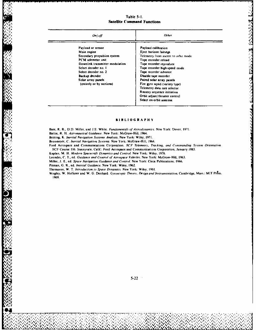
- - - - - - - - - - - - -
Table 5-I.Satellite Command Functions
On/off Other
Payload or sensor Payload calibrationMain engine Eject horizon fairingsSecondary propulsion system Telemetry from ascent to orbit modePCM telemeter unit Tape recorder reloadDownlink transmitter modulation Tape recorder reproduceSelect decoder no. I Tape recorder high-speed modeSelect decoder no. 2 Tape recorder advanceBackup decoder Disable tape recorderSolar array panels Paired solar array panels(entirely or by sections) Fire gyro squid (variety type)
Telemetry data rate selectorReentry sequence initiationOrbit adjust/thruster controlSelect on-orbit antenna
SI BILIOGRA PH V
Bate. R. R., D.D. Miller, and J.E. White. Fundamentals of Astrodnamics. New York: Dover, 1971.Battin. R. H. Astronautical Guidance. New York: McGraw-Hill, 1964.Britting. K. Inertial Navigation Systems Analysis. New York: Wiley, 1971.Broxmeyer, C. Inertial Navigation Sy-stems. New York: McGraw-Hill, 1964.
. Ford Aerospace and Communications Corporation. SCF Telemetry. Tracking, and Commanding Si-stem Orientation.SCF Course 116. Sunnyvale. Calif.: Ford Aerospace and Communications Corporation, January 1983.
Kaplan, M. H. Modern Spacecrqft Dynamics and Control. New York: Wiley, 1976."." : leondes, C. T.. ed. Guidance and Control of Aerospace Vehicles. New York: McGraw-Hill. 1963.
*- Miller, J. E., ed. Space Navigation Guidance and Control. New York: Circa Publications, 1966.Pitman, G. R., ed. Inertial Guidance. New York: Wiley. 1962.Thomason, W. T. Introduction to Space Dnamics. New York: Wiley, 1961.Wrigley, W. Hollister and W. G. Denhard. GVroscopic TheorV. Design and Instrumentation. Cambridge. Mass.: MIT Prgss,
1969.
NNy5-22
4% ....
"-;_-." .-'--'-"..'-.-.'-.'-.'-.:-. -.- .-..- i- -...... L- .. ..':-":-'2-" -- .---. .I. - -,..,.-L.. -.. ..-. ;-:- - ,.- ,' -':--:- -':- -' - .:'..'.-'.:-.--..4. ',' ,, - e " , " . " ." . " . " . . " . " ..- . -. " - ' . : - . '" , r . . " . " . " .
",. , " %% " " •- - " " - " - . ,- -. -- %% %%% ', -*% .- ,%%-
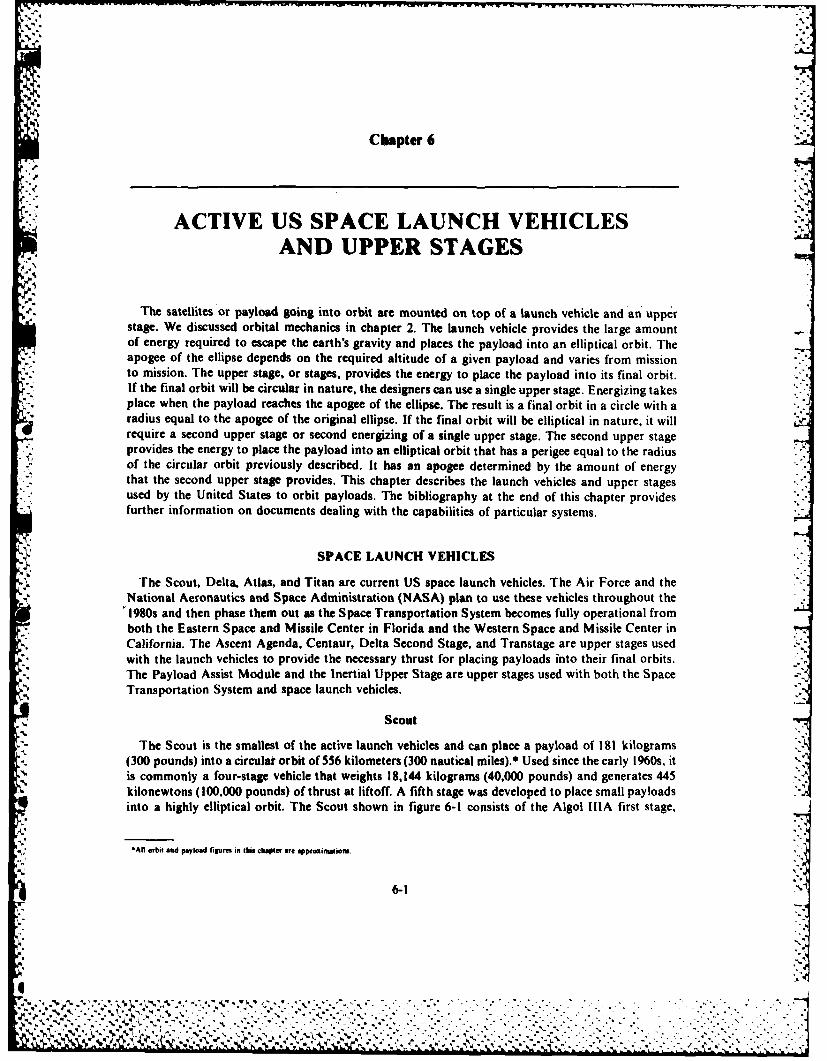
Chapter 6
ACTIVE US SPACE LAUNCH VEHICLESAND UPPER STAGESmo
The satellites or payload going into orbit are mounted on top of a launch vehicle and an upperstage. We discussed orbital mechanics in chapter 2. The launch vehicle provides the large amountof energy required to escape the earth's gravity and places the payload into an elliptical orbit. Theapogee of the ellipse depends on the required altitude of a given payload and varies from missionto mission. The upper stage, or stages, provides the energy to place the payload into its final orbit.If the final orbit will be circular in nature, the designers can use a single upper stage. Energizing takesplace when the payload reaches the apogee of the ellipse. The result is a final orbit in a circle with aradius equal to the apogee of the original ellipse. If the final orbit will be elliptical in nature, it willrequire a second upper stage or second energizing of a single upper stage. The second upper stageprovides the energy to place the payload into an elliptical orbit that has a perigee equal to the radiusof the circular orbit previously described. It has an apogee determined by the amount of energythat the second upper stage provides. This chapter describes the launch vehicles and upper stagesused by the United States to orbit payloads. The bibliography at the end of this chapter providesfurther information on documents dealing with the capabilities of particular systems.
SPACE LAUNCH VEHICLES
The Scout, Delta, Atlas, and Titan are current US space launch vehicles. The Air Force and theNational Aeronautics and Space Administration (NASA) plan to use these vehicles throughout the1980s and then phase them out as the Space Transportation System becomes fully operational fromboth the Eastern Space and Missile Center in Florida and the Western Space and Missile Center inCalifornia. The Ascent Agenda, Centaur, Delta Second Stage, and Transtage are upper stages usedwith the launch vehicles to provide the necessary thrust for placing payloads into their final orbits.The Payload Assist Module and the Inertial Upper Stage are upper stages used with both the SpaceTransportation System and space launch vehicles.
Scout
The Scout is the smallest of the active launch vehicles and can place a payload of 181 kilograms(300 pounds) into a circular orbit of 556 kilometers (300 nautical miles).* Used since the early 1960s, itis commonly a four-stage vehicle that weights 18,144 kilograms (40,000 pounds) and generates 445kilonewtons (100,000 pounds) of thrust at liftoff. A fifth stage was developed to place small payloadsinto a highly elliptical orbit. The Scout shown in figure 6-1 consists of the Algol IlA first stage,
*All orbit anid payload flgure in this chapter are approxinatsonu.
%- .F%
%
% .. .
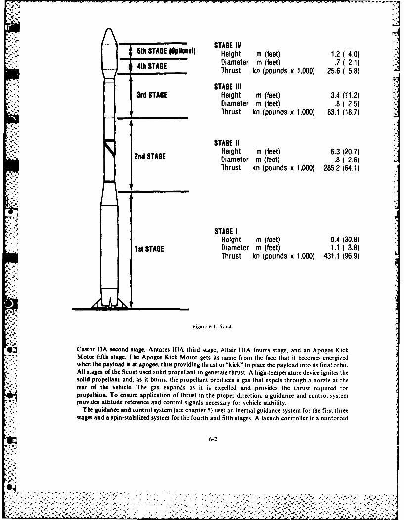
w.I STAGE IV--: 6th STAGE IOptlonali STGE"51__TAGE______al Height m (f eet) 1.2(4.0)4t Diameter m (feet) .7 (2.1)4th__TA6E Thrust kn (pounds x 1,000) 25.6 ( 5.8)
STAGE III3rd STAGE Height m (feet) 3.4 (11.2)
Diameter m (feet) .8 ( 2.5) 4_' Thrust kn (pounds x 1,000) 83.1 (18.7)
:-; .; STAGE 11I Height m (feet) 6.3 (20.7)
2nd STAGE Diameter m (feet) .8 (2.6)Thrust kn (pounds x 1,000) 285.2 (64.1)
STAGE IHeight m (feet) 9.4 (30.8)
I st STAGE Diameter m (feet) 1.1 ( 3.8)Thrust kn (pounds x 1,000) 431.1 (96.9)
Figure 6-1. Scout.
Castor 11A second stage, Antares IliA third stage, Altair IliA fourth stage, and an Apogee KickMotor fifth stage. The Apogee Kick Motor gets its name from the face that it becomes energizedwhen the payload is at apogee. thus providing thrust or "kick" to place the payload into its final orbit.All stages of the Scout used solid propellant to generate thrust. A high-temperature device ignites thesolid propellant and, as it burns, the propellant produces a gas that expels through a nozzle at therear of the vehicle. The gas expands as it is expelled and provides the thrust required forpropulsion. To ensure application of thrust in the proper direction, a guidance and control systemprovides attitude reference and control signals necessary for vehicle stability.
The guidance and control system (see chapter 5) uses an inertial guidance system for the first threestages and a spin-stabilized system for the fourth and fifth stages. A launch controller in a reinforced
6-2
• ,,......., ....... .-. '- ..-..-.-- .".'.'--.-. - .-...........-.... "...'...'......"....•". . " "* ". "a %, * " ''. %, % . - - " , ' . .'. -. ". -'. % . ° .' ,,." % " ". - . '. -' , - -"- • -.~~~~~~~~~~~~~~~~~~~~~~~~~~~..*.". . .o. .P.. . ... . .... -. . ...- "....... ..... , ,,. ...--. =%.%%-...
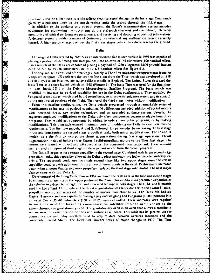
structure called the blockhouse transmits a direct electrical signal that ignites the first stage. Commandsgiven by a guidance timer on the launch vehicle ignite the second through the fifth stages.
In addition to the guidance and control system, the Scout's instrumentation system includesequipment for monitoring the subsystems during prelaunch checkout and countdown, telemetrymonitoring of critical performance parameters, and receiving and decoding of destruct information.A destruct system provides a means of destroying the vehicle if any malfunction presents a safetyhazard. A high-energy charge destroys the first three stages before the vehicle reaches the ground.
Delta
The original Delta created by NASA as an intermediate size launch vehicle in 1959 was capable ofplacing a payload of 272 kilograms (600 pounds) into an orbit of 185 kilometers (100 nautical miles).
g4 Later models of the Delta are capable of placing a payload of 1,270 kilograms (2,800 pounds) into anorbit of 296 by 35,786 kilometers (160 x 19,323 nautical miles) See figure 6-2.
The original Delta consisted of three stages; namely, a Thor first stage and two upper stages from theVanguard program. (JS engineers derived the first stage from the Thor, which was developed in 1958and deployed as an intermediate range ballistic missile in England. The United States first used thebasic Thor as a space launch vehicle in 1958 (Pioneer 1). The basic Thor was used for the final timein 1980 (Block 5D- I of the Defense Meteorological Satellite Program). The basic vehicle wasmodified to increase its payload capability for use in the Delta configuration. They modified the
Vanguard second stage, which used liquid propellants, to improve its guidance system and its control* during unpowered portions of the flight. They used the third stage motor without modification.
From this baseline configuration, the Delta vehicle progressed through a remarkable series ofmodifications to increase its payload capabilities. Modifications included addition of rocket motors
* with increased thrust, new engine technology, and an upgraded guidance system. Usually, theengineers employed modifications to the Delta only when components became available from otherprograms. They would get components by adding to orders from other programs, or by makingmodifications. This approach ensured minimum costs of modifying the Delta to meet new missionrequirements. The first two models, A and B. followed this philosophy by increasing the first stagethrust and lengthening the second stage propellant tank, both minor modifications. The C and Dmodels were the first to incorporate thrust augmentation during first stage operation. Thrustaugmentation included bolting three Castor I solid-propellant motors to the Thor first stage. Themotors were ignited at lift-off and Jettisoned after they consumed their propellant. These versionsincorporated an improved third stage solid-propellant motor from the Scout program.
The Delta E began using a restart capability in the second stage. Combined with larger second stagepropellant tanks. this capability allowed the Delta to place payloads into higher circular and ellipticalorbits. The spacecraft could use the single second stage like two upper stages since the restartcapability could provide additional thrust at two different points in the orbit. Performance increasedagain when a motor that carried more propellant replaced the third stage solid motor. The next majorchange came with the Delta L.
Development of the Long Tank Thor in 1968 increased the tank sizes in the first and second stages -
by eliminating a tapering on the upper portion of the Thor. This modification permitted expansion ofq the vehicles to a diameter of eight feet and increased tankage in both stages. The L, M, and N models
used the Long Tank Thor, replaced the thrust augmentation of the Castor I with the Castor Il solid-propellant motor, and increased the number of motors from three to six. The Delta M6 had sixCastor 11 motors and was capable of placing a payload weighing 454 kilograms (1,000 pounds) intoan orbit 296 x35.786 kilometers (160 x19,323 nautical miles). These increases were requiredto meet the need for launching communication satellites into the orbit known as the
* geosynchronous or geostationary orbit. The geostationary orbit is an orbit that allows a satellite toremain over the same location on the earth surface at all times. This orbit has its greatest use forcommunication and relay satellites used to acquire data between overseas locations and thecontinental United States. The Delta saw4 another series of major changes in 1972. The Thor
* 6-3

PA OAO (Typical)
t STAGE 3
STAGE 2
STAGE 1
STAGE0 -TI
3914 3910/PAM 3920/PAM
STAGE III 2
Height m (feet) 2.1 7.0) 20 (6.7) 2.0 6 7!Diameter m (feet) .9 3.1) 1.3 ( 4.2) 1.3 42)"Thrust kn (pounds x 1,000) 65.8 14.8) 84.5 (19.0) 84.5 19.0)
STAGE IIHeight m (feet) 5.0 16.4) 5.0 (16.4) 5.0 16.4)Diameter m (feet) 2.4 8.0) 2.4 ( 8.0 24 8 0)Thrust kn (pounds x 1,000) 41.8 9.4) 41.8 (9.4) 41 8 94)
STAGE IHeight m (feet) 22.5 73.7) 22.5 73.7) 22.5 73.7)Diameter m (feet) 2.4 8.0) 2,4 8.0) 2.4 8.0)Thrust kn (pounds x 1,000) 921.0 (207.0) 921.0 (207.0) 921.0 (207 0)
STAGE 0Height m (feet) 11.7 (38.3) 117 38.3) 117 33Diameter m (feet) .9 (3.0) 9 30) 9 30)Thrust kn (pounds x 1,000) 378.0 (85.0) ea 378.0 85.0) ea 378.0 85.0) ea
Figure 6-2 Delta
was strengthened structurally to accommodate nine Castor II motmrs. Engineers added the Irawita.c- - engine developed for the Titan launch vehicle to the Iecond tage: and I eplaced the i ,lt1mcric,1
designations with letter designations. Space program personnel knc, these configu;ations a theDelta 903 and 904. Late in 1972, the four-digit number replatced th,, m emcr'al dc i I) It)t
6-4
................
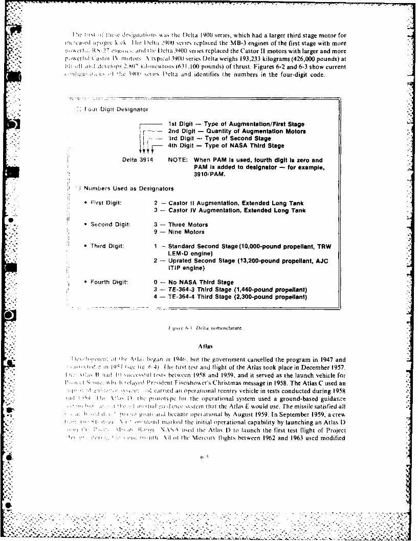
h n :tlic'e dcs~grilituriN '~As the Delta 1900 series, which had a larger third stage motor for1!C! rc&.ed a 'Oguc k!CK I Ilie I )Ot~ 2900 Series replaced the MB-3 engines of the first stage with more
v rt s- 27 mu.~.aid the Delta 3900 series replaced the Castor 11 motors with larger and morep~ieru (Lasim 1% notors~ N typical 3900 series Delta weighs 193,233 kilograms (426,000 pounds) atlit 01 ait, dclops 2,80' kdilnc~toii (63 1,100 pounds) of thrust. Figures 6-2 and 6-3 show current
ic N e 901 ,c.Iles l)elta and identifies the numbers in the four-digit code.
loit- Digit Designator
F - 1st Digit - Type of Augmentation/First Stager -~ 2nd Digit - Quantity of Augmentation Motors
-- 3rd Digit - Type of Second Stage4th Digit - Type of NASA Third Stage
Delta 3914 NOTE: When PAM Is used, fourth digit Is zero andPAM Is added to designator - for exampie,
* 3910/PAM.
7Ntimbers Used as Designators
* Frst Digit: 2 - Castor 11 Augmentation, Extended Long Tank3 - Castor IV Augmentation, Extended Long Tank
* Second Digit: 3 -- Three Motors9 - Nine Motors
*Third Digit: 1 - Standard Second Stage (10,000-pound propeilant, TRWLEM-D engine)
2 - Uprated Second Stage (13,200-pound propellant, AJC* I iTIP engine)
*Fourth Digit: 0 -No NASA Third Stage3 -. TE-364-3 Third Stage (1,440-pound propellant)4 - TE-364-4 Third Stage (2,300-pound propellant)
I ipirc 6-1 D~cira nomenclatture.
Atlas
4I .r net.': of hi li: began ill 1 940, hut the government cancelled the program in 1947 andi-lt ii 195 1 , i'.e 0-64) 1 lie first test and flight of the Atlas took place in December 1957.
I: ' itB hild 10 I ',utce\ul tests between 1958 and 1959. and it served as the launch vehicle for'11t, "Ill hr tt dart Presiilent Fisenhowker's Christmas message in 1958. The Atlas C used an
!,vill e'irriedl an operational reentry vehicle in tests conducted during 1958i. A Va" ; the 1p oiot\ pe foi the o~perational system used a ground-based guidan~ce
1171f ~ 111 ni ti tld wanric ooint that the Atlas F would use. The missile satisfied all11 .), kl i piill 'iak mid hecanm' uperttional by August 1959. In September 1959, a crew!1 t itirV I or!:l ritril utked the initial operational capability by launching an Atlas D)
* I I01 - . R;I'i in N \ A\ usedl the At las 1) to launch the first test flight of Projectdi"lu 'VI tint h \II ut the Me~rry flights between 1962 and 1963 used moditied
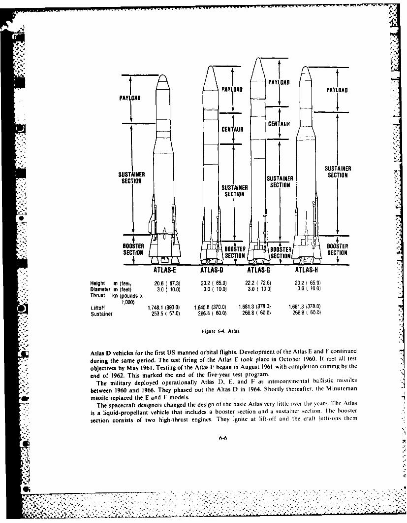
CADYLOAD
PAt P AD
CENTAUR CENTAUR
I SUSTAINERSUSTAINER ISUSTAINER SECTION
SECTIO SUSAINER SECTIONSECTION
BOOSTER BOOSTERBOOSTER BOOSTERTSECTION SECTIONSECIO SECTTION
ATLAS-E ATLAS-U ATLAS-G ATLAS-H
Height m (feei, 20.6 ( 67.3) 20.2 ( 65.9) 22.2 (72.6) 20.2 (65.9)Diameter m (feet) 3.0 (10.0) 3.0 (10.0) 3.0 (10.0) 3.0 (10.0)Thrust kn (pounds x
1,000)
Liftoff 1,748.1 (393.0) 1,645.8 (370.0) 1,681.3 (378.0) 1,681.3 (378.0)Sustainer 253.5 (57.0) 266.8 (60.0) 266.8 (60.0) 266.8 (60.0)
Figure 6-4. Atlas.
Atlas D vehicles for the first US manned orbital flights. Development of the Atlas E and F continuedduring the same period. The test firing of the Atlas E took place in October 1960. It met all test
objectives by May 1961. Testing of the Atlas F began in August 1961 with completion coming by the
end of 1962. This marked the end of the five-year test program.The military deployed operationally Atlas D, E, and F as intercontinental ballistic missiles
between 1960 and 1966. They phased out the Altas D in 1964. Shortly thereafter, the Minuteman
missile replaced the E and F models.The spacecraft designers changed the design of the basic Atlas very little over the years. The Atlas
is a liquid-propellant vehicle that includes a booster section and a sustainer section. I he booster
section consists of two high-thrust engines. They ignite at lift-off and the craft Jettisons them
6-6
_-.°.
'"5~
-;,.-'....': .,. ",, . ... ,:.. . .. . .- .. .,.,_....,.:. ,. .. .,. ,. ,.' ' -.' " " ...... ,.. .,.
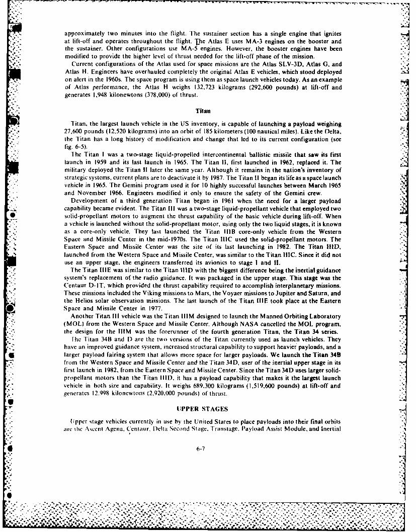
approximately two minutes into the flight. The sustainer section has a single engine that ignitesat lift-off and operates throughout the flight. The Atlas E uses MA-3 engines on the booster and
'. the sustainer. Other configurations use MA-5 engines. However, the booster engines have beenmodified to provide the higher level of thrust needed for the lift-off phase of the mission.
Current configurations of the Atlas used for space missions are the Atlas SLV-3D, Atlas G, andAtlas H. Engineers have overhauled completely the original Atlas E vehicles, which stood deployedon alert in the 1960s. The space program is using them as space launch vehicles today. As an example
- .of Atlas performance, the Atlas H weighs 132,723 kilograms (292,600 pounds) at lift-off andgenerates 1,948 kilonewtons (378,000) of thrust.
Titan ITitan, the largest launch vehicle in the US inventory, is capable of launching a payload weighing
27,600 pounds (12,520 kilograms) into an orbit of 185 kilometers (100 nautical miles). Like the Delta,the Titan has a long history of modification and change that led to its current configuration (seefig. 6-5).
The Titan I was a two-stage liquid-propelled intercontinental ballistic missile that saw its firstlaunch in 1959 and its last launch in 1965. The Titan !1, first launched in 1962, replaced it. Themilitary deployed the Titan If later the same year. Although it remains in the nation's inventory ofstrategic systems, current plans are to deactivate it by 1987. The Titan !1 began its life as a space launchvehicle in 1965. The Gemini program used it for 10 highly successful launches between March 1965and November 1966. Engineers modified it only to ensure the safety of the Gemini crew.
Development of a third generation Titan began in 1961 when the need for a larger payloadL capability became evident. The Titan Ill was a two-stage liquid-propellant vehicle that employed two• solid-propellant motors to augment the thrust capability of the basic vehicle during lift-off. When
a vehicle is launched without the solid-propellant motor, using only the two liquid stages, it is knownas a core-only vehicle. They last launched the Titan IlIB core-only vehicle from the WesternSpace and Missile Center in the mid-1970s. The Titan IIIC used the solid-propellant motors. TheEastern Space and Missile Center was the site of its last launching in 1982. The Titan HID,launched from the Western Space and Missile Center, was similar to the Titan IIIC. Since it did notuse an upper stage, the engineers transferred its avionics to stage I and If.
The Titan IIIE was similar to the Titan IID with the biggest difference being the inertial guidancesystem's replacement of the radio guidance. It was packaged in the upper stage. This stage was theCentaur D-IT, which provided the thrust capability required to accomplish interplanetary missions.These missions included the Viking missions to Mars, the Voyaer missions to Jupiter and Saturn, andthe Helios solar observation missions. The last launch of the Titan IIIE took place at the Eastern
. Space and Missile Center in 1977.Another Titan Il vehicle was the Titan IIIM designed to launch the Manned Orbiting Laboratory
(MOL) from the Western Space and Missile Center, Although NASA cancelled the MOL program,the design for the IIIM was the forerunner of the fourth generation Titan, the Titan 34 series.
The Titan 34B and D are the two versions of the Titan currently used as launch vehicles. Theyhave an improved guidance system, increased structural capability to support heavier payloads, and alarger payload fairing system that allows more space for larger payloads. We launch the Titan 34Bfrom the Western Space and Missile Center and the Titan 34D, user of the inertial upper stage in itsfirst launch in 1982, from the Eastern Space and Missile Center. Since the Titan 34D uses larger solid-propellant motors than the Titan IIID. it has a payload capability that makes it the largest launchvehicle in both size and capability. It weighs 689,300 kilograms (1,519,600 pounds) at lift-off andgenerates 12.998 kilonewtons (2,920.000 pounds) of thrust.
LIPPER STAGES
Upper stage vehicles currently in use by the United States to place payloads into their final orbitsare the Ascent Agena, Centaur. )elta Second Stage, Transtage, Payload Assist Module, and Inertial
6-7
%\ %
.le _ . .. . . . . • . . • . . . . . . . . . ..
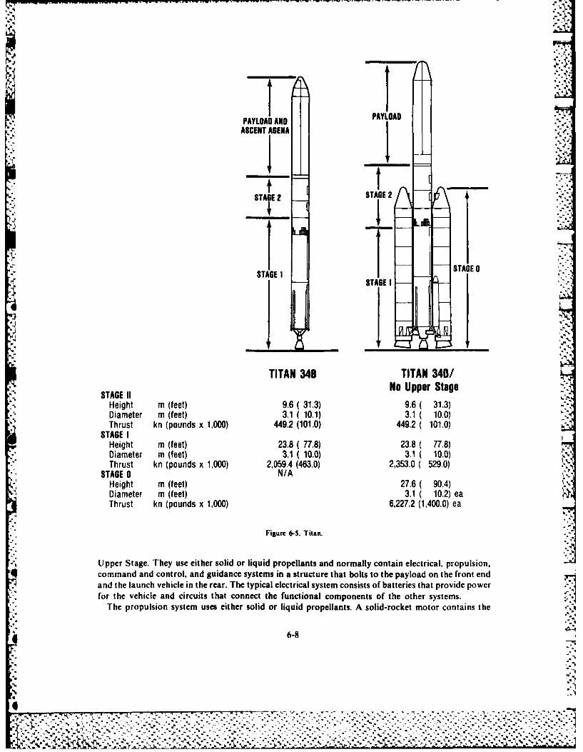
PYODAND PALOA2ASCENT AGENAI
STAGE 2 STAGE 2
STAGE III STAGE 1
TITAN 34B TITAN 340/STAGE IINo Upper Stage
Height 11fe)96(313 . 13Diamete m (feet) 3.1( (1.1) 3.1 ( 1.0)Thruett kn (pounds 3,004.2 ( 101) 44.2 ( 10.0)
STGEs I (onsx100 4.2(0-)492(110Height mIfe)2. 7.)2. 78Dimete m (feet) 23.1 (10.0) 23.1 ( 10.0)Thruste kn (pounds x3,0),5.4 (463.0) 233.0 ( 529.0)TGEs 0 n (pudN/A0) ,5. 4302330(590HeTght m (fe)/76A 04Diamete m (f eet) 37.1 ( 10.2) eThrust k n (pounds x 1,000) 6,227.2 (1,400.0) ea
Figure 6-5. Titan.
Upper Stage. They use either solid or liquid propellants and normally contain electrical, propulsion,4 command and control, and guidance systems in a structure that bolts to the payload on the front end
and the launch vehicle in the rear. The typical electrical system consists of batteries that provide powerfor the vehicle and circuits that connect the functional components of the other systems.
The propulsion system uses either solid or liquid propellants. A solid-rocket motor contains the
4 6-8
solid propellant. Therefore, the solid propellant does not require a tank. Once ignited, the~ .*.propellant burns until all of it is consumed. The solid-propellant system is a one-burn system since it
cannot be used for additional firings. However, scientists can design liquid-propellant systems toincorporate a restart feature. These liquid-propellant systems can be monopropellant or bipropellant(see chapter 3). They carry tanks containing the propellants necessary for the mission. A commandand control system issues the command that ignites the propulsion system.
~ ~,The command and control system contains components that receive commands from the groundcontrol station or an on-board guidance computer and relay them to other upper stage systems forexecution. The command and contro)l system energizes the other systems by issuing commands
V..'.through electrical circuits to the propulsion system. These commands control the ignition of thepropellant and termination of thrust for liquid systems. It provides commands to maintain thestability of the upper stage throughout the mission.
The guidance system, the "brains" of the upper stage, provides position, velocity, and accelerationdata to the command and control system to ensure the issuance of commands at the proper time. Itprovides data that ground control personnel use to monitor flight performance.
- * Ascent A ge..
-The Titan 34B, currently launched from the Western Space and Missile Center, uses the AscentAgena that was the upper stage for the Titan IIIB from 1966 to 1975. The vehicle is capable ofproviding the thrust required to place a payload weighing 3,600 kilograms (7,940 pounds) into acircular orbit of 185 kilometers (100 nautical miles). See figure 6-6.
The Ascent Agena consists of propulsion, electrical, guidance and control, and communicationsystems. The propulsion system includes two tanks that carry the liquid propellant required to
* develop its thrust and an adapter section that houses the liquid-rocket engine. The system can beoperated twice during a single mission. It can provide 75.6 kilonewtons (17,000 pounds) of thrust over atotal operating time of 240 seconds. The electrical system supplies and distributes power to operate thevehicle from launch to completion of the mission. The guidance and control system consists of aninertial guidance section that feeds information on position and velocity to the control section thatsteers both the Titan and the Ascent Agena. The communications system transmits performance data,provides tracking signals, and receives command signals issued from the ground to direct the vehicle.
Centaur
Development of the Centaur began in 1958. Its first launch on an Atlas occurred in 1963. In 1969and 1972, the Centaur was modified to increase reliability and redundancy (the use of twocomponents to perform the same function and increase the probability of success). See figure 6-7.
The current operational Centaur, the D-IA, consists of an equipment module, propulsion system,and an adapter. The equipment module provides the interface with the payload on the forward end,mounting for the avionics, and an interface with the adapter at the rear end. The propulsion systemuses two liquid-propellant rocket engines and has a multiple burn capability. It can produce 133.4kilonewtons (30,000 pounds) of thrust over a total operating time of 444 seconds. The system hastankage for 13,950 kilograms (30,750 pounds) of propellant. Also housed in the equipment moduleare the tanks and engines, the inertial guidance system, and the control system that provides forcommand and control of the Centaur and Atlas throughout the mission. At the rear of the equipmentmodule is the mounting surface that interfaces with the adapter that provides the structuralconnection between the Centaur and the forward end of the Atlas.
When the Centaur and the Atlas SLY-3D launch vehicles are used together, the Centaur canproduce the upper stage thrust required to place a payload of 1,995 kilograms (4,400 pounds) into anorbit of 185 x35,786 kilometers (100 x 19,323 nautical miles). Although the Centaur is compatible
% with the Titan IIIE, the Atlas G is the only other launch vehicle that currently uses the Centaur.
6-9
.... ................................ 1.% A'.~
% :-K:- .IK :~ & iK. .v ~
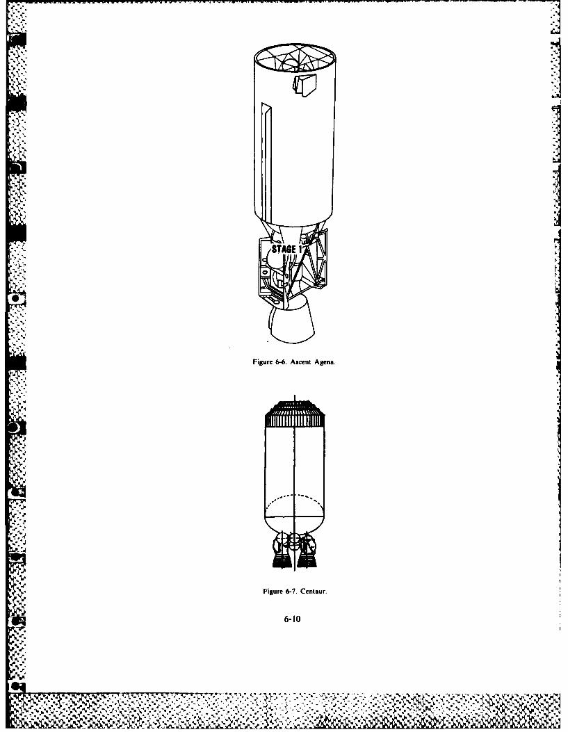
* S8ABE I
Figure 6-6. Ascent Agena.
Figure 6-7. Centaur.
-*V
6-t
A7-.Ir

Delta Second Stage
The Delta Second Stage comes in two configurations and both are compatible with the Delta 3900series of launch vehicles. The standard second stage can provide the thrust required to place a payloadof 1 .111 kilograms (2,450 pounds) into an orbit 296 x 35,786 kilometers (160 x 19,323 nautical miles).The improved second stage can provide the thrust required to place a payload of 1,270 kilograms(2,800 pounds) into the same orbit. Both the standard and improved second stages have essentially thesame components. The only difference is the size of the liquid-rocket engine and propellant tanks.Batteries charged prior to lift-off provide the electrical power required to perform the mission (see fig.6-8).
In addition to the electrical system, the Delta Second Stage includes propulsion and guidance andcontrol systems. The propulsion system for the standard second stage consists of a bipropellant
N) IIIV
N
STANDARD IMPROVED
! "
Figure 6-8 Delta Second Stage
6-11 I
% .
~. . . . . . . . . . . .
liquid-rocket engine that produces thrust by the chemical reaction caused by combining two liquids inthe engine's thrust chamber. The engine is capable of multiple starts. It produces 41.9 kilonewtons(9,425 pounds) of thrust over a total operating time of 322 seconds. It carries 4,536 kilograms (10,000pounds) of propellant in the two storage tanks as well. In the improved second stage, the expansionratio of the engine is increased, providing for more efficient performance, increasing the capability ofthe storage tanks by 1,451 kilograms (3,200 pounds), and increasing the total operating time to 444seconds. Although the changes increase the thrust of the improved second stage by only 0.1kilonewtons (20 pounds). the changes significantly increase overall performance as reflected in thepayload weight-to-orbit numbers. The inertial guidance system provides the information for both firstand second stage control. The Delta Second Stage issues commands to the Delta First Stage togimbal, or move, the main engine in the pitch and yaw directions. Control of the second stage is much
9 the same.
Transtage
The Titan IIIC used the Transtage from 1965 until 1982. Currently, the Titan 34D uses it as anupper stage. It consists of a control module and a propulsion module. It can produce the thrustrequired to place a payload of 1,859 kilograms (4,100 pounds) into a circular orbit of 35,786kilometers (19,323 nautical miles). See figure 6-9.
The control module uses an inertial guidance section to deliver position and velocity data to thedigital guidance computer. Then the computer issues the commands required to control both theTitan launch vehicle and the Transtage. These commands include the information necessary tojettison the solid-propellant motors strapped to the Titan, terminate the Titan thrust, and separate therranstage and payload from the Titan. The module issues the commands required to control thefiring of the propulsion module. Also it provides the electrical energy required by the guidance and
0 control section and the propulsion module.The propulsion module contains two propellant tanks, a pressurization unit, the structure to
support the equipment, and two hydraulically-controlled liquid-rocket engines. The fuel is fed tothe engines by opening valves that allow the fuel to enter the thrust chamber. The engines have anunlimited restart capability and produce 71.7 kilonewtons (16,000 pounds) of thrust over a totaloperating time of 440 seconds.
Payload Assist Module
Either the Delta launch vehicle or the Space Transportation System (STS) can use the PayloadAssist Module (PAM). When used with these two, the PAM has similar mechanical interfaces andfunctional operations. The module consists of the payload attach fitting, STAR-48 solid-rocketmotor, spin table, cradle, and airborne support equipment (see fig. 6-10).
* ['he payload attach fitting provides the means of attaching the payload to the PAM solid-rocketmotor, and it is the mounting location for the PAM subsystems. The engineers bolt theSTAR-48 solid-rocket motor to the base of the payload attach fitting. It is the propulsive element ofthe module. Off-loading, or putting in less solid propellant during manufacture, adjusts the motor for aparticular mission. The spin table provides rotational velocity to the PAM / payload combination forstabili/ation during nonpowered portions of the nlight and during the solid-rocket motor burn. Thecradle, used only on ST1S missions, mounts in the cargo hay of the orbiter and supports both the PAMand the payload. Since the airborne support equipmcnt provides the interface with the STS electricaland safety systems, it is used only on S1S missions.
When the Delta uses it, the PAM provides the thrust required to place a payload of 1,270 kilograms(2.800 pounds) into an orbit of 296 -35,786 kilometers (160 x 19,323 nautical miles). When used with
* the STS, it provides the thrust required to place a payload of 1.052 kilograms (2,320 pounds) into anorbit 296 -35,796 kilometers (160 19,323 nautical miles) from the nominal STS orbit of 296kilometers (160 nautical miles).
6-12
7.67
% ~ %/',C* *A%AS X.LLL'~
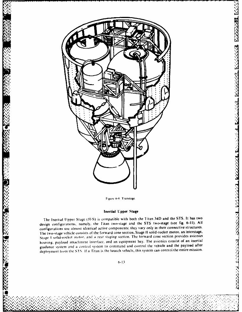
%~IFigur j-.T a s a e
InrtalUperStg
Th.nrilU pr tg U1i o pail ihbt teTtn3Dadth-T .I a w
deig c'S.rtinnm ltefia w -tg n h T wosae(e i.61) l
cofgrtosueam s dnialatv o pnns hyvr nl ntercnetv tutrs
6-13S
%SFgr -. Tasae
Inetia . .pe Stage. .
%h nrilUprSae(U)i optbewihbt h ia 4 n h T.I a w
'pdsincolguaios nmly heTta wosag ndte T tostg (e fg 6IIZ l

Figure 6-10. Payload Assist Module.
6-1
46
The payload attachment interface, the same for either a Titan or STS mission, provides the mountingsurface for attaching the payload. The equipment bay houses the telemetry and tracking systems andthe batteries that supply electrical power.
The propulsion system consists of a large solid-rocket motor in the rear and a similar but smallersolid-rocket motor in the forward position. Each solid-rocket motor contains electromechanicalactuators to move the nozzle for control of the vehicle during poweted flight. For Titan missions, theengineers can off-load each motor during the manufacturing process to ensure the correct amount ofpropellant for a particular mission. A reaction control system provides vehicle control duringunpowered portions of the flight. On Titan flights, the rear staging section provides the electrical andmechanical interface with the Titan launch vehicle. On STS flights, the rear staging section providesthe mechanical interface to the cradle mounted in the orbiter bay and the airborne supportequipment provides the electrical interface.
When the Titan 34D uses the IUS, it can provide the thrust required to place a payload of 1,859kilograms (4,100 pounds) into an orbit 296 x 35.786 kilometers (160 x 19,323 nautical miles). Whenthe STS uses it, the inertial upper stage can place a payload of 2,267 kilograms (5,000 pounds) into
V' an orbit of 35,786 kilometers (19,323 nautical miles) from the nominal STS orbit of 296 kilometers(160 nautical miles).
Summary
The space launch vehicles described in this chapter are not compatible with all the upper stages (seetable 6-1). However, the combinations of launch vehicles and upper stages available give the payloadplanner a wide-choice of payload capabilities (see table 6-2). The STS will replace the vehiclesdescribed in this chapter eventually because of its greater weight-to-orbit capability. However, these
* •vehicles have served as the launch vehicles for the United States since the beginning of the spaceprogram in the 1960s and will continue to be used until the end ot the 1980s.
BIB LI 0 G R A PH V
Aerospace Industries Association of America, Inc. Aerospace Fats and Figures 1982-83. New York: McGraw-Hill, 1982Boeing Aerospace Company. Inertial Upper Stage User's Guide. Seattle. Wash.: Boeing Aerospace Company. 1980.General Dynamics Convair Division. Centaur Mission Planners Guide. San Diego, Calif.: General Dynamics Corp., 1977.
4".%: General Dynamics Convair Division. General Dynamics Convair I)ivision Space Transportation Systens. San Diego, Calif.:General Dynamics Corp.. 1982.
Martin Marietta Denver Aerospace. Titan Launch Vehicles. Denver, Colo.: Martin Marietta Denver Aerospace Corp.. 1982.Martin Marietta Denver Aerospace, Titan 348/341) .Spaccraft User's Guide. )enver. Colo.: Martin Marietta Denver
Aerospace Corp., 1982.McDonnell Douglas Astronautics Company. PAM-1 ) ("serv Requirements )onument. Huntington Beach. Calif.
* McDonnell Douglas Astronautics Co., 1982.McDonnell Douglas Astronautics Company, The Delta I au, It I 'hi(l,. Pait. I'resl, and Future. Huntington Beach.
Calif.: McDonnell Douglas Astronautics Co., 1981.
'is,'
R4
%
6-15IS
P ,:'.', '. , .,-,-t.+ . .. ., ... , .. -, . . _ __-_ __-."_ _- . . ' -. , . - " - • . ,,+

--------------
.7-'
4,o, ass
.. - ... .
--, , _ ,.
4
--0 ., -
- ', '- .'-
~Z
:3 -V'~ - -.
- " .
I'
6-16~
"i - - '
4',.- 7 ,
i.4'
._ _ _ _ _ _ _ _ _ _-__ _ _ _ _ _ _ _ _ _ _ _ _ _ _ _
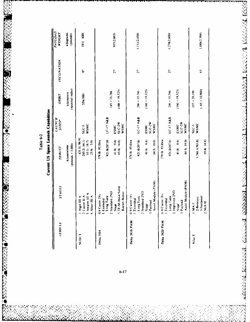
.~.,., .w
A -
Q.J -P 0'p.N
-. 44
- .ciLA
Q6
0 -. -CL
CL <0 .J 7IL
oc EN N EN30
6-17S E
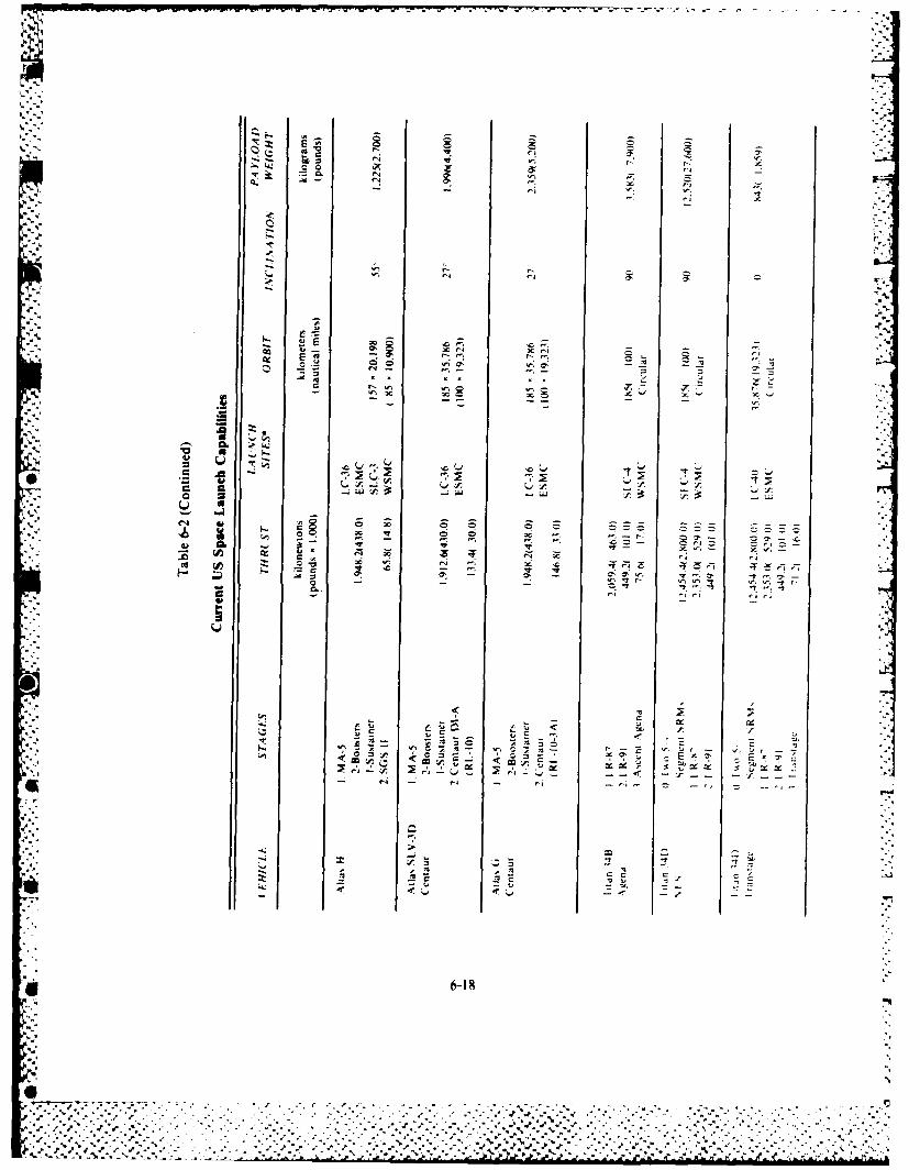
4,'-
L4-• . -,- ..
: 0 0 . ra
..-. - '- ,
w' 4r...
%- r4
.4,, "'
*¢ ... .. .,. "- '
o .ca-- 'c-
., .: . . -_I .., - ,. - , ,_. . , -, . .
."[,,;', ,,-, - .
4.,: - _ _-4,
u) -
oo
6-18
alL
. -. *,* -,... ,4 - , . ., ,. - . - . . .. =- . . . . . . . .. . .
* . .. . .. . " z • . .-- 0 l i '..-' - -1I °l - l d l
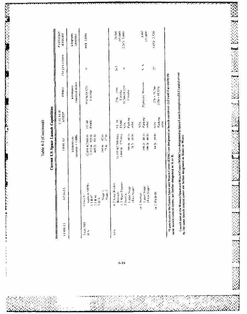
I ''~ ~. . .7I . .- C Cl '~* ~. - Cl
~ CC - -
- t l~.~ ~ C,
- .7
-. 7 Cl
- q~
U
* 4 C
- C- -~
C ~ .~ ~ U ~C C~ -~ ~
-. ~ S0
- - - U
7-. E ~* 0 Z
-~ C. ~-, C -~
.v * .1~ -, -~= 7-'~ UU
.3UC ZZ ~
Ca r.,~
'-4 4' - - -
U Cl 7-~ Cl r. U'0 N
C. C Cl ICZ Cl ~ .C.C .7 u
2~ C~ .t ~. cr C 00.0 ~ --
~ .7~.7 -
3 u~.- ~4' we < .- U
U-CC
A
*0'-,~U C 0 4
- .C IU.--~ ~ U~U U
-~ -Cl - -~ 04~ , U
-~ ~ ' f C~' c~
E ~ z1704 --
Cl Cl ~ ~
.C tO-0 .r.r- .- -u
I,*~.C U
.C~ ~5~0 *e~
- .7 0,~ C
- 1f .2
L .0.
b
6-19
- ..
. . . .
* -. I ** - ** . . . * - - - . -.. *
Chapter 7
GLOBAL COMMUNICATIONS
CLosely associated with the guidance and control system for a space vehicle is the communications"N stem. Since the early part of the present century when Marconi developed his "wireless" telegraph,peop!k have been sending messages through space. Today, the means exist already for communicatinga , ait as the known limits of the Solar System. The problems that the space communications engineermust solve are not involved with the generation and propagation of electromagnetic waves, but ratherwith problems that arise because of the complexity of the system components and the nature of theho'.t % ehicle. Such problems are those involved in allowing for the cubage and mass of the equipmentin the host vehicle and in generating electrical power in space.
COMMUNICATION SATELLITES
"Satellitt" systems provide global command and control networks and permit the simultaneous.- transmission of a greater number and variety of high-quality messages. In addition, there is a higher
degree otf reliable transmission and a greater degree of survivability designed into the system.In this age of jet aircraft, nuclear power, and moon rockets, present communication facilities "
simply have become outmoded. These facilities have served well and will continue to do so in theluture, but they are not good enough. They are unable to handle the greatly increased volume ofctoniunications. Present communications are disrupted easily. A slight increase in solar flare activitycan cause radio communication blackout between Europe and North America. A fishing trawler may _J
C tI accidentally the North Atlantic telephone cable. Although these events present difficult problemsto civilian communications, the implications of even temporary communication isolation from therest o the world are far more serious for a military commander.
Objectives
W/hat should be some of the major objectives in developing a system of communication satellites?
)nc objective is reliable communications that provide uninterrupted service over long periods. TheNvstem should have .,igh capacity with capability for handling large volmes of all types of traffic. It
should be flexible to serve the maximum number of potential users. There should be minimum delayin transmission. We will discuss each of these factors in more detail, and compare the communication;atellite %kith some existing facilities.
Reliability
I wo t. pes of reliabilitv are of interest. The first is propagation reliability. The high-frequency (H F)hmid has aissaav been subject to the vagaries of the ionospheric layers that surround the earth. Thus,,onl\ a portion of this band actually is usable at any given time over a particular path. In addition,in'iItipath etects seriously limit the amount of information that we can transmit over a given channel..dded to these limitations are the blackouts that may result from ionospheric disturbances caused by'lnspi,, ativity. High-altitude nuclear explosions can introduce similar disturbances. We are forced
7-1
- 7.
%% %
. . - .--. %
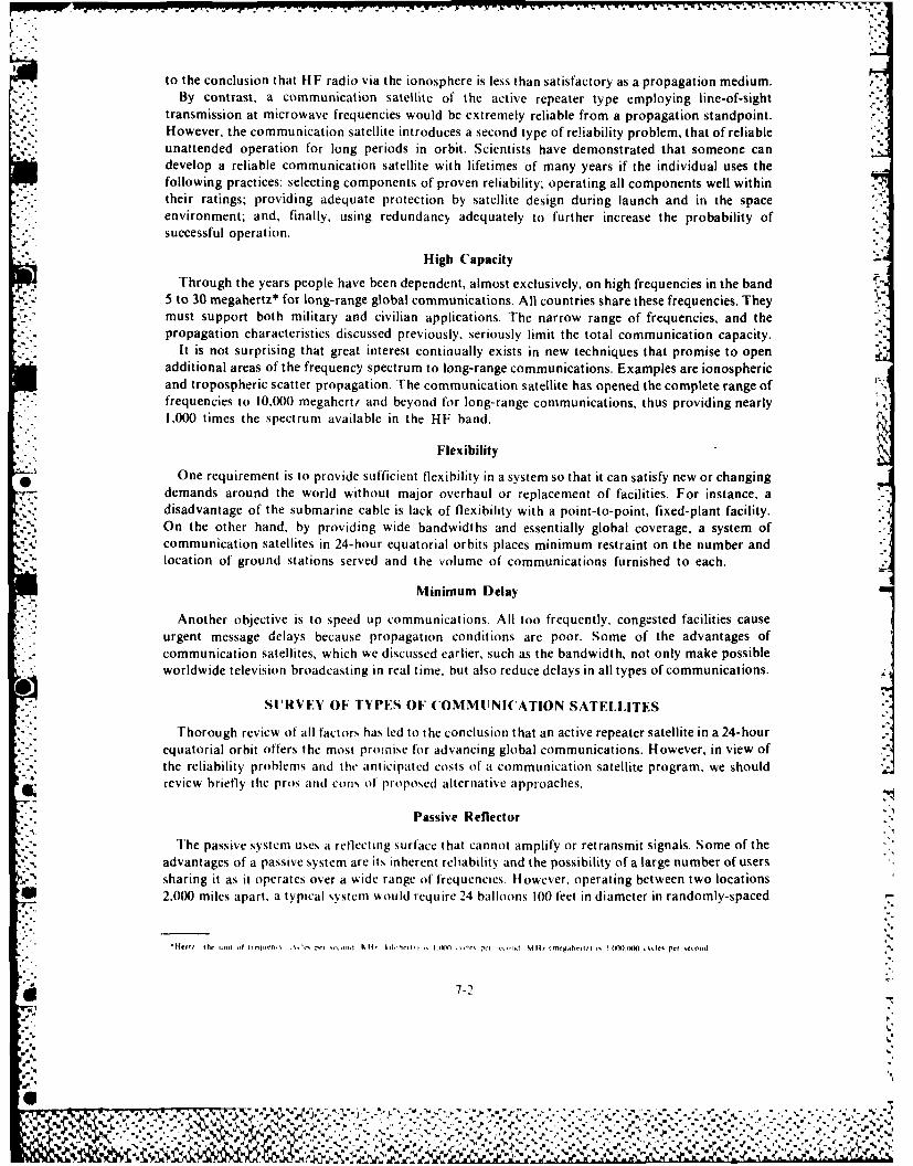
I.T
to the conclusion that HF radio via the ionosphere is less than satisfactory as a propagation medium.By contrast, a communication satellite of the active repeater type employing line-of-sight
transmission at microwave frequencies would be extremely reliable from a propagation standpoint.However, the communication satellite introduces a second type of reliability problem. that of reliableunattended operation for long periods in orbit. Scientists have demonstrated that someone candevelop a reliable communication satellite with lifetimes of many years if the individual uses the
* following practices: selecting components of proven reliability; operating all components well within* their ratings, providing adequate protection by satellite design during launch and in the space
environment; and, finally, using redundancy adequately to further increase the probability ofsuccessful operation.
High Capacity
Through the years people have been dependent, almost exclusively, on high frequencies in the band5 to 30 megahertz* for long-range global communications. All countries share these frequencies. Theymust support both military and civilian applications. The narrow range of frequencies, and thepropagation characteristics discussed previously, seriously limit the total communication capacity.
It is not surprising that great interest continually exists in new techniques that promise to openadditional areas of the frequency spectrum to long-range communications. Examples are ionosphericand tropospheric scatter propagation. The communication satellite has opened the complete range offrequencies to 10,000 megahertz and beyond for long-range communicat ions, thus providing nearly1,000 times the spectrum available in the HF band.
Flexibility
One requirement is to provide sufficient flexibility in a system so that it can satisfy new or changingdemands around the world without major overhaul or replacement of facilities. For instance, adisadvantage of the submarine cable is lack of flexibility with a point-to-point, fixed-plant facility.On the other hand, by providing wide bandwidths and essentially global coverage, a system ofcommunication satellites in 24-hour equatorial orbits places minimum restraint on the number andlocation of ground stations served and the volume of communications furnished to each.
Minimum Delay
Another objective is to speed up communications. All too frequently, congested facilities causeurgent message delays because propagation conditions are poor. Some of the advantages ofcommunication satellites, which we discussed earlier, such as the bandwidth, not only make possibleworldwide television broadcasting in real time, but also reduce delays in all types of communications.
SURVEV OF TYPES OF COMMUNICATION SATELLITES
Thorough review of all factors has led to the conclusion that an active repeater satellite in a 24-hourequatorial orbit offers the most promise for advancing global communications. However, in view ofthe reliability problems and the anticipated costs of a communication satellite program, we shouldreview briefly the pros and con-, of proposed alternative approaches.
Passive Reflector
The passive system uses a reflecting surface that cannot amplify or retransmit signals. Some of theadvantages of a passive system are its inherent reliability and the possibility of a large number of userssharing it as it operates over a wide range of frequencies. However, operating between two locations
* 2.000 miles apart. a typical systemr wsould require 24 balloons 100 feet in diameter in randomly-spaced
* 7-2
-~~~ .0 ~

orbits at 3,000 miles altitude for an outage time of I percent. The system would require substantiallymore satellites to provide longer range or wider coverage than the sample cited. Therefore, such ~ ~satellites do not appear to be an economical solution to providing truly global communications.ON
The passive reflector satellites would be more attractive if they could be stabilized in attitude,permitting use of more efficient reflecting surfaces, or could synchronize the satellite orbits to reducethe required number of satellites. However, then the satellites cease to be passive and reliability is nolonger inherent in the system.
Active Repeater
Active communications satellites receive signals, translate them in frequency, and amplify andretransmit the signal at a higher power level. We can consider them repeater stations in space. The use 4~
of active communications satellites makes possible the use of smaller ground terminals. This enhancesflexibility of military operations. Because of the increased radiated power over that of the passivereflector, the transmission path loss is not as great a problem. Therefore, we can place the activesatellites in orbit at much higher altitudes. Because the number of satellites required to providecontinuous coverage for a number of ground terminals varies as the orbit altitude changes, the higherwe place the system, the fewer number of satellites it requires to provide this continuous coverage. -
Medium-Altitude System
Continuous coverage from medium altitude would require from 18 to 24 satellites in orbit. Eventhen, there would be a switching problem at the ground terminal as one satellite passed from view anda new one approached to take its place. The ground terminals require steerable antennas as well ascomputing equipment to calculate the trajectories and furnish look-angles (acquisition data) forantenna orientation.
A major advantage of the medium altitude system is that it simplifies orbit injection and does notrequire precise position stabilization. The booster requirements are not as great either.
Synchronous-Altitude System
Because of the earth's rotation, three satellites at an altitude of 19,360 nautical miles and equallyspaced in 24-hour equatorial orbit appear to remain fixed to an observer on the earth. The highaltitude of the synchronous orbit (fig. 7-I) makes each satellite visible from 40 percent of the earth'ssurface. Since the satellite appears to be motionless in the sky, service may begin or continue withonly one satellite in orbit and functioning. However, in actual operation, we would need four or sixoperating satellites to provide the desired coverage. Although this number is less than the requirementfor a medium altitude system, the synchronous altitude system has a much greater boosterrequirement. The reason for the increased booster requirement is the necessity to interjectapproximately the same amount of satellite weight at a much greater altitude.
CONSTRAINTS
To appreciate the capabilities of space communications more fully, we need to consider the naturalconstraints and design limitations.
Natural Constraints
The natural constraints include line of sight, space attenuation, and noise. To operate, there must* be a line of sight established between the transmitter and the receiver. The transmitting antenna
* radiates power that is distributed over an always expanding portion of a spherical surface. The -
resulting decrease in power density (power per unit area) reduces the energy that the receiving antenna* captures. We know this as space attenuation. Various sources introduce noise at each stage of the
communications process. The communications mediums used to send the signals and the receiver
7-3
....................................... . . . . . . . . . . . . . . . . . . . . . . . .
.. . .. . .. . .. . .. . .. . . . . . . . . .
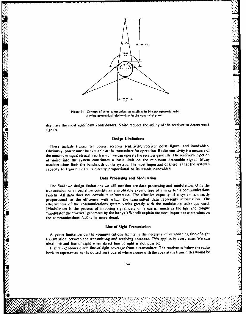
170 19,360 NM
9..
-Am
Figure 7-1. Concept of three communication satellites in 24-hour equatorial orbit.showing geometrical relationships in the equatorial plane.
itself are the most significant contributors. Noise reduces the ability of the receiver to detect weak* signals.
Design Limitations
These include transmitter power, receiver sensitivity, receiver noise figure, and bandwidth.
Obviously, power must be available at the transmitter for operation. Radio sensitivity is a measure ofthe minimum signal strength with which we can operate the receiver gainfully. The receiver's injectionof noise into the system constitutes a basic limit on the minimum detectable signal. Manyconsiderations limit the bandwidth of the system. The most important of these is that the system'scapacity to transmit data is directly proportional to its usable bandwidth.
Data Processing and Modulation
The final two design limitations we will mention are data processing and modulation. Only thetransmission of information constitutes a profitable expenditure of energy for a communicationssystem. All data does not constitute information. The effective capacity of a system is directlyproportional to the efficiency with which the transmitted data represents information. Theeffectiveness of the communications system varies greatly with the modulation technique used.(Modulation is the process of imposing signal data on a carrier much as the lips and tongue.modulate" the "carrier" generated by the larnyx.) We will explain the most important constraints onthe communications facility in more detail.
Line-of-Sight Transmission
A prime limitation on the communications facility is the necessity of establishing line-of-sighttransmission between the transmitting and receiving antennas. This applies in every case. We canobtain virtual line of sight when direct line of sight is not possible.
Figure 7-2 shows direct line-of-sight coverage from a transmitter. The receiver is below the radio,-, horizon represented by the dotted line (located where a cone with the apex at the transmitter would be
7-4
%<
, . , . . . .... , . ., . . .. . ,. . . ., , . ., ., . . .. ., . " 3..""" .?-. " "- ." " . ', ." '-." . '-"". '.-'."' "-"' " "-". "-"," -,' ";. e .':" ¢ , - ""¢." ." "? "". ' . ", ',A , '
Ig
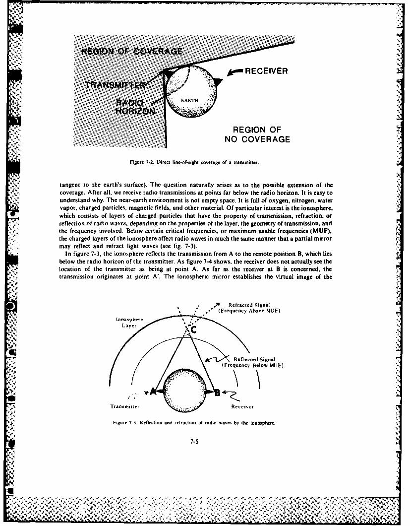
.. .... N RECEIVER.... .. .. ..
.,,... ......
Figure 7-2, Direct line-of-sight coverage of a transmitter. 2I
. ' tangent to the earth's surface). The question naturally arises as to the possible extension of the.. coverage. After all, we receive radio transmissions at points far below the radio horizon. It is easy to
'Y" understand why. The near-earth environment is not empty space, it is full of oxygen, nitrogen, water',~vapor, charged particles, magnetic fields, and other material. Of particular interest is the ionosphere,
which consists of layers of charged particles that have the property of transmission, refraction, or- -. reflection of radio waves, depending on the properties of the layer, the geometry of transmission, and
the frequency involved. Below certain critical frequencies, or maximum usable feunis(U)
* .. the charged layers of the ionosphere affect radio waves in much the same manner that a partial mirror* .-i may reflect and refract light waves (see fig. 7-3).
* , In figure 7-3, the ionosphere reflects the transmission from A to the remote position B, which liesbelow the radio horizon of the transmitter. As figure 7-4 shows, the receiver does not actually see the
' location of the transmitter as being at point A. As far as the receiver at B is concerned, thei transmission originates at point A'. The ionospheric mirror establishes the virtual image of the
.. ... - Refracted Signal
Fige 7 (Frequency Above MUF)
tagn toth oert'ssure)Thqusinntrlyaieasttepoibexesonftecoeae fe ll, ye riv radi trnmsin at ponsfrblwterdohrzntiayt
unestn wy henarerh.nirnetsn t emt spc.I s ulo xyentogn ae
o oReflected Signal athe f c i(Frequency Betow MUF)
y r n figure 7-h Reflection and refraction of radio waves by the ionosphere.
~7-5
location o'- th-..e',..- transmitter ,a- beinat.oi-tA..As..'r..st.e.ec.. . ,. .- .is- -c c-r t-. asi.o o.nt at pi '. h i..p,. mi.. e l the virtual .. of the
P" Re-". Signal
... ~~Feqec Abov MUF)*,~*J--

D VIRTUAL Refracted "Ray"SOUkCE
- Effective Ionospheric Mirror
A Reflected "Ray"
Figure 7-4. Virtual image of a transmitter established by reflection from the ionosphere.
physical transmitter at point C'. Thus, we have established a line of sight between a virtual source at.~' ~.A' and the receiver at B. We have fulfilled the requirement of line-of-sight transmission from the
transmitter to the receiver.This is analogous to seeing around a corner by means of a mirror as figure 7-5 shows. With the
mirr or arranged as shown, we do not see the object at its actual position but at a virtual position thatoptical geometry determines. Remember in using this analogy that, in the case of the ionosphere, the
~rJ virtual source is not so well-defined as the actual source is. The virtual source has become enlarged.The turbulent condition of the ionosphere has blurred its boundaries.
This "method of mirrors" seems to solve the problem in a simple way. Nature furnished thereflecting medium, so why look for a better scheme? However, we need something better. Being in aconstant state of flux, the ionosphere is unreliable as a transmission medium. The properties of theionosphere vary from year to year, from day to day, and even from hour to hour (see fig. 7-6). Also,energy in the maximum usable frequencies reflected from the ionosphere is too low to provide thedesired information-carrying capacity on a channel using three frequencies. (The higher the carrierfrequency, the higher the data capacity of the channel.) We desire use for carrier frequencies of anorder-of- magnitude higher than the MUF of ionospheric reflection technique permit.
Vircual Image(Apparent Position of Object)
~., .~ 1 Obct
f rBUILING
observer
Figure 7-5. Virtual image of an object formed by reflection in a mirror.
7-6
% % % %
"A
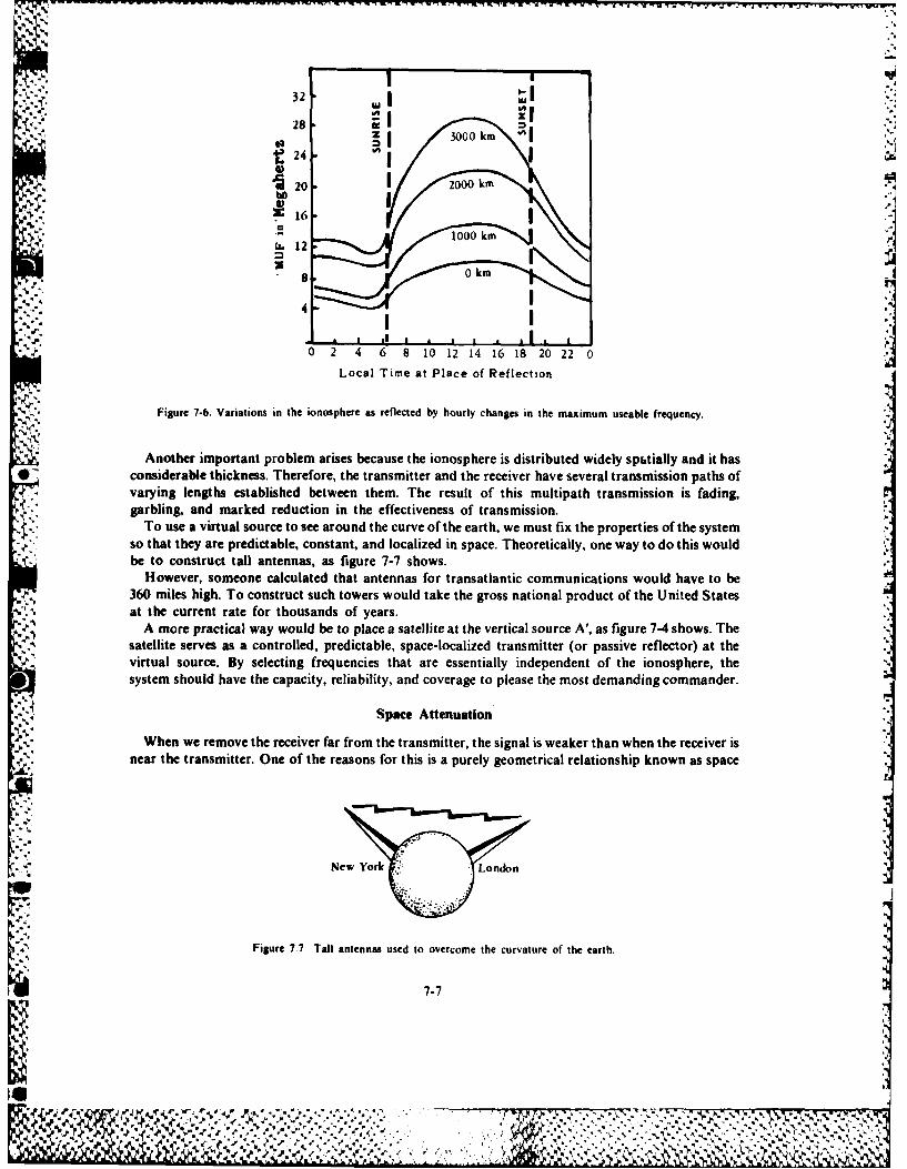
32 .. L4
', Z 30CO oo km
-L-1
8 0 km
9, '4
I I", . , , , m .
S
02 4 65 8 10 12 14 16 18 20 220
Local Time at Place of Reflection
Figure 7-6. Variations in the ionosphere as reflected by hourly changes in the maximum useable frequency.-S.2
Another important problem arises because the ionosphere is distributed widely spatially and it has*considerable thickness. Therefore, the transmitter and the receiver have several transmission paths of
varying lengths established between them. The result of this multipath transmission is fading,garbling, and marked reduction in the effectiveness of transmission.
To use a virtual source to see around the curve of the earth, we must fix the properties of the systemso that they are predictable, constant, and localized in space. Theoretically, one way to do this would
- -, be to construct tall antennas, as figure 7-7 shows.However, someone calculated that antennas for transatlantic communications would have to be
360 miles high. To construct such towers would take the gross national product of the United Statesat the current rate for thousands of years.
A more practical way would be to place a satellite at the vertical source A', as figure 7-4 shows. Thesatellite serves as a controlled, predictable, space-localized transmitter (or passive reflector) at thevirtual source. By selecting frequencies that are essentially independent of the ionosphere, thesystem should have the capacity, reliability, and coverage to please the most demanding commander.
Space Attenuation
When we remove the receiver far from the transmitter, the signal is weaker than when the receiver isnear the transmitter. One of the reasons for this is a purely geometrical relationship known as space
New York - ~ London
Figure 7.7 Tall antennas used to overcome the curvature of the earth.
7-7
I ,; ,r-',,.E,:.,;,F,, ,, '. ¢.';,, ' ,,. ... ; :; .. ..,.. .w ". . .' :-'- "'". ,. ,/.. .-, .;,- , .5 , ,' '.. ;.." ., ,, ',. w, 'Xr' " , % ..r- , . , . .%, %/" .' -" " " - . i . . ." ' ' . (j j " * " " " " . ' ' ' ' ' ' ' ' . ' ' . ' i
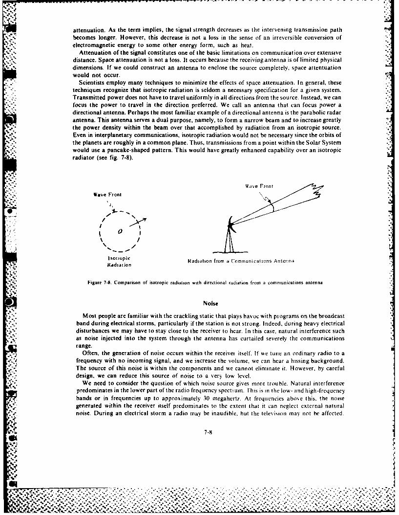
attenuation. As the term implies, the signal strength decreases as the intervening transmission pathbecomes longer. However, this decrease is not a loss in the sense of an irreversible conversion ofelectromagnetic energy to some other energy form, such as heat.
V.,, Attenuation of the signal constitutes one of the basic limitations on communication over extensivedistance. Space attenuation is not a loss. It occurs because the receiving antenna is of limited physical
V % dimensions. If we could construct an antenna to enclose the source completely, space attentuationwould not occur.
Scientists employ many techniques to minimize the effects of space attenuation. In general, thesetechniques recognize that isotropic radiation is seldom a necessary specification for a given system.Transmitted power does not have to travel uniformly in all directions from the source. Instead, we canfocus the power to travel in the direction preferred. We call an antenna that can focus power adirectional antenna. Perhaps the most familiar example of a directional antenna is the parabolic radarantenna. This antenna serves a dual purpose, namely, to form a narrow beam and to increase greatly
* ., the power density within the beam over that accomplished by radiation from an isotropic source.Even in interplanetary communications, isotropic radiation would not be necessary since the orbits ofthe planets are roughly in a common plane. Thus, transmissions from a point within the Solar Systemwould use a pancake-shaped pattern. This would have greatly enhanced capability over an isotropicradiator (see fig. 7-8).
Wav Fon
Wave Front
* 0
1 .Isotroioc Radiation from a Communications Antenna
Figure 7-8. Comparison of isotropic radiation with directional radiation from a communications antenna.
Noise
Most people are familiar with the crackling static that plays havoc with programs on the broadcastband during electrical storms, particularly if the station is not strong. Indeed, during heavy electricaldisturbances we may have to stay close to the receiver to hear. In this case, natural interference suchas noise injected into the system through the antenna has curtailed severely the communicationsrange.
Often, the generation of noise occurs within the receiver itself, If we tune an ordinary radio to afrequency with no incoming signal, and we increase the volume, we can hear a hissing background.The source of this noise is within the components and we cannot eliminate it. However, by carefuldesign, we can reduce this source of noise to a very low level.
We need to consider the question of which noise source gives more trouble. Natural interferencepredominates in the lower part of the radio frequency spectrum. I'his is in the low- and high-frequencybands or in frequencies up to approximately 30 megaherti. At frequencies above this, the noise
V generated within the receiver itself predominates to the extent that it can neglect external natural.. r' noise. During an electrical storm a radio may be inaudible, hut the television may not be affected.
0., .4
N,..'% %
I ? *4. . -
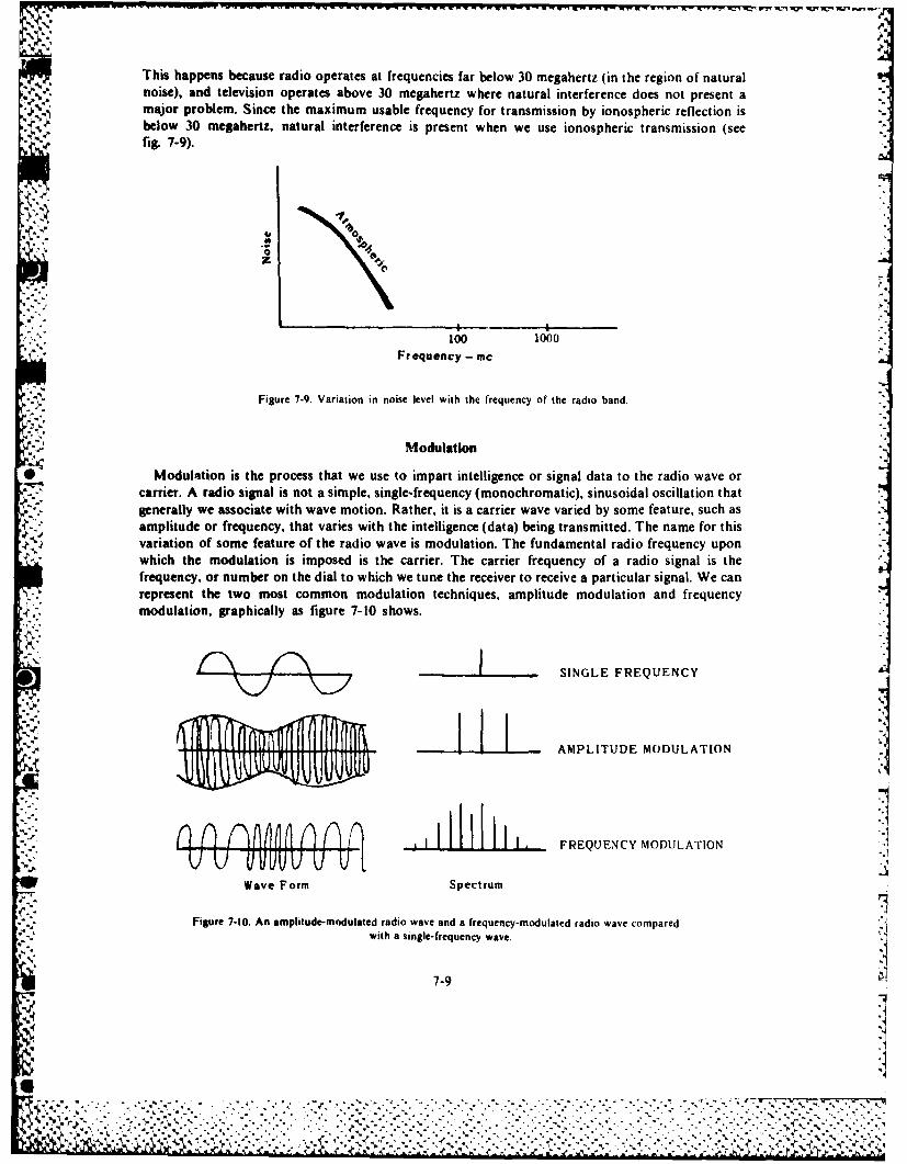
This happens because radio operates at frequencies far below 30 megahertz (in the region of natural* .~' .~ noise), and television operates above 30 megahertz where natural interference does not present a
major problem. Since the maximum usable frequency for transmission by ionospheric reflection isbelow 30 megahertz, natural interference is present when we use ionospheric transmission (see
.9 fig. 7-9).
00
100 1000Fr equency - mnc
Figure 7-9. Variation in noise level with the frequency of the radio band.
Modulation
* Modulation is the process that we use to impart intelligence or signal data to the radio wave orcarrier. A radio signal is not a simple, single-frequency (monochromatic), sinusoidal oscillation thatgenerally we associate with wave motion. Rather, it is a carrier wave varied by some feature, such asamplitude or frequency, that varies with the intelligence (data) being transmitted. The name for thisvariation of some feature of the radio wave is modulation. The fundamental radio frequency uponwhich the modulation is imposed is the carrier. The carrier frequency of a radio signal is thefrequency. or number on the dial to which we tune the receiver to receive a particular signal. We canrepresent the two most common modulation techniques, amplitude modulation and frequencymodulation, graphically as figure 7-10 shows.
-L - SINGLE FREQUENCY
-I~f44±N~l'4I~~fff44f4~-. -~ .1AMPLITUDE MODULATION
n1llI. FREQUENCY MODULATION
Wave Form Spectrum
Figure 7-10. An amplitude-modulated radio wave and a frequency- mod ulated radio wave comparedwith a s ingle- frequency wave.
%,
7-9
..............................................................% % . .
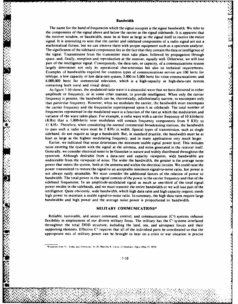
Bandwidth
The name for the band of frequencies which the signal occupies is the signal bandwidth. We refer tothe components of the signal above and below the carrier as the signal sidebands. It is apparent thatthe receiver window, or bandwidth, must be at least as large as the signal itself to receive the entiresignal. It is interesting to note that the carrier and sideband components of a radio signal are not amathematical fiction, but we can observe them with proper equipment such as a spectrum analyzer.
.-. The significance of the sideband components lies in the fact that they contain the data or intelligence ofthe signal. Transmission from the transmitter must take place, followed by propagation throughspace, and, finally, reception and reproduction at the receiver, equally well. Otherwise, we will losepart of the intelligence signal. Consequently, the data rate, or capacity, of a communications systemlargely determines not only its operational characteristics but also its technical requirements.Examples of bandwidths required for common types of communications service are 100 hertz forteletype, a low capacity or low data-rate system; 3,000 to 5,000 hertz for voice communications; and6,000,000 hertz for commercial television, which is a high-capacity or high-data-rate system
* containing both aural and visual detail.As figure 7-10 shows, the modulated ratio wave is a sinusoidal wave that we have distorted in either
amplitude or frequency, or in some other manner, to provide intelligence. When only the carrierfrequency is present, the bandwidth can be, theoretically, infinitesimally narrow, to encompass onlythat particular frequency. However, when we modulate the carrier, the bandwidth must encompassthe carrier frequency and the frequencies superimposed upon it as sidebands. The total number offrequencies represented in the modulated wave is a function of the rate at which the modulation andvariance of the wave takes place. For example, a radio wave with a carrier frequency of 10 kilohertz(KHz) that a 1,000-hertz tone modulates will contain frequency components from 9 KHz to
*P I I KHz. Therefore, when considering the normal commercial broadcasting stations, the bandwidthto pass such a radio wave must be 2 KHz in width. Special types of transmission, such as single
""' sideband, do not require as large a bandwidth. But, in standard practice, the bandwidth must be atleast as large as the highest modulating frequency, and in many applications very much larger.
Earlier, we indicated that noise determines the minimum usable signal power level. This includesnoise entering the system with the signal at the antenna, and noise generated in the receiver itself.Generally, we consider electrical noise to be Gaussian in nature and widely distributed throughout thespectrum. Although desirable from a data-rate and capacity viewpoint, wide bandwidths areundesirable from the viewpoint of noise. The wider the bandwidth, the greater is the average noisepower that enters the system, both at the antenna and within the electrical circuits. We could raise thepower transmitted to restore the signal to an acceptable minimum signal-to-noise ratio, but power isnot always easily attainable. We must consider the additional factors of the relation of power tobandwidth. The total power in the signal consists of the power in the carrier frequency and that of the
• sideband frequencies. In an amplitude-modulated signal as much as one-third of the total signalpower resides in the sidebands, and we must transmit the entire bandwidth or we will lose part of the
, . intelligence. Quite obviously, wide bandwidth, which high data rates and high capacity require, needs
high power to maintain a usable signal-to-noise ratio. In summary, the high data rates require large. bandwidths and high power and the average noise power is proportional to bandwidth.
MILITARY COMMUNICATIONS*
Reliable, survivable, and secure command, control, and communications (C-1) systems enhanceflexibility in employment of our diverse military focus. The military has the C- systems interlacedthroughout the total DOD structure, including the land, sea, and aerospace forces and theirsupporting elements. Effective C' requires that all of the individual parts be coordinated so that theappropriate mix of military power can be brought to bear on a crisis or war situation in precise
,'.4
*Fxirwed from "C. Todav and If ,rorw." hN Dr Malcolm R (urnr. C4,-m.nde,, liv,, (may 15. 1975)
7-10
*%.-
411'
y%
response to and under the positive control of the proper national authorities. These C -1 systems shouldbe interoperable and capable of providing rapid and secure communications between a variety oflevels of command, between forces of the various services, and between the United States and itsallies.
The ability to exercise command and control of our forces has become increasingly significantduring recent years due to the increasing complexity of the tasks facing us, coupled with decreasing
force levels.The 1)OD is acquiring and deploying communications satellite systems that primarily address three
fundamental communication areas. These are:
0 CI of nuclear-capable forces for which a general-war survivable system is required. AFSATCOMfulfills this requirement.
* Support of the Worldwide Military Command and Control System (WWMCCS) using a day-to-day global system that provides protected strategic connectivity between major bases andcommand centers, large Navy ships, and advanced airborne command posts. This is the primemission of the Defense Satellite Communications System (DSCS).
* Fleet communications modernization using a global system to serve the beyond-the-horizoncommunication needs of ships, antisubmarine warfare aircraft, and other mobile forces.[his is FLTSATCOM. For more information on these systems, see chapter 8.
COMMERCIAL COMMUNICATIONS
In July 1963, NASA launched the world's first synchronous communications (SYNCOM) satellite* into orbit. The purpose of NASA's SYNCOM program was to demonstrate the feasibility of
synchronous orbit satellite communications. Since then, there have been more than 31 commercialsatellites put into orbit. A very large percentage of these are either operating or on an orbital reserve.We will discuss six major systems in operation today.
INTELSAT IV
First launched in 1971, seven of these large high-capacity communications satellites are on orbit.The satellites have steerable antennas that can be aimed to cover selected areas on earth. Each satellitehas an average capacity of 6,000 telephone channels or 12 simultaneous color television channels, orvarious combinations of telecommunications traffic including DATA, TELEX, and FACSIMILE(see fig. 7-11).
WESTAR
NASA launched America's first domestic communications satellite for Western Union on 13 April1974. NASA launched the fifth in the series in 1982. Scientists designed the satellites to relay voice,video, and data communications to the continental United States and Alaska, Hawaii, andPuerto Rico. Each satellite has a capacity of 7,000 two-way voice circuits or 12 simultaneous color TVchannels. On-orbit design lifetime for each satellite is seven years (see fig. 7-12).
INTEISAT IV-A
September 1975 was the date of the launching of the first of a new series of INTELSAT satellites. It
had nearly twice the communications capability of its predecessor. A spot beam antenna system on theIV-A satellites permits reuse of the same frequency by spatial separation of the beams. Thisseparation allows use of one set of frequencies in North and South America and reuse of the samefrequencies in Europe and Africa. Each satellite has capacity for 11,000 voice channels or 20simultaneous color TV thannels (see fig. 7-13).
7-11
- '.,- " " -" " " "" • ". ... . . .' "" "" ' " - • - ." ".%" " " " ' " "
" "
%. ... %........, .
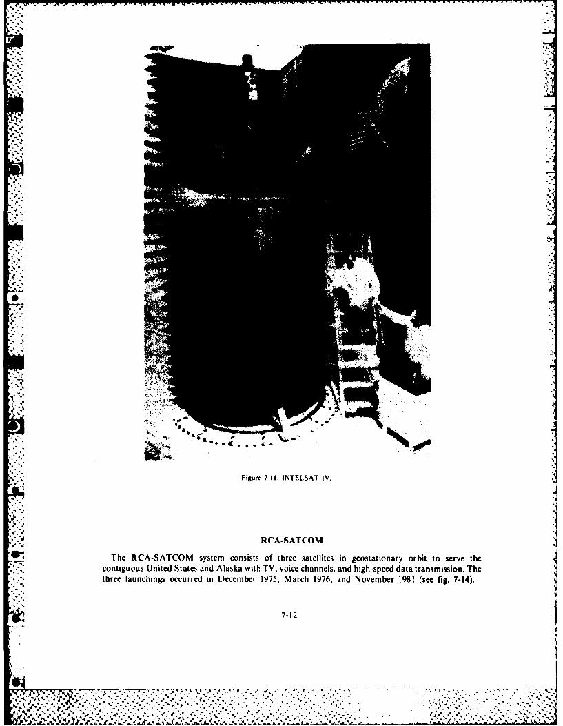
7-1
4.C
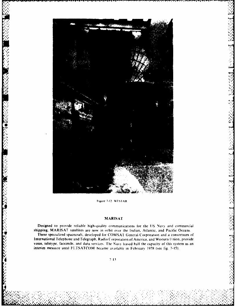
MARISAT
Designed to provide reliable high-quality communications for the US5 NavyN and commercial*shipping, MARISAT satellites are now in o rbit o~cr the Indian, Atlantic, and Pacific Oceans.* These specialiied spacecraft, developed for ('OMSA I (General Corporation and a consortium of* International Telephone and'Telegraph. Radio Corporation of America, and Western Union, provide* voice, teletype. facsimile, and data services. Fhe Navv leased half the capacity of this system as an
interim measure until I1.TSATCOM became asailahle in February 1978 (see fig. 7-15).
7-13
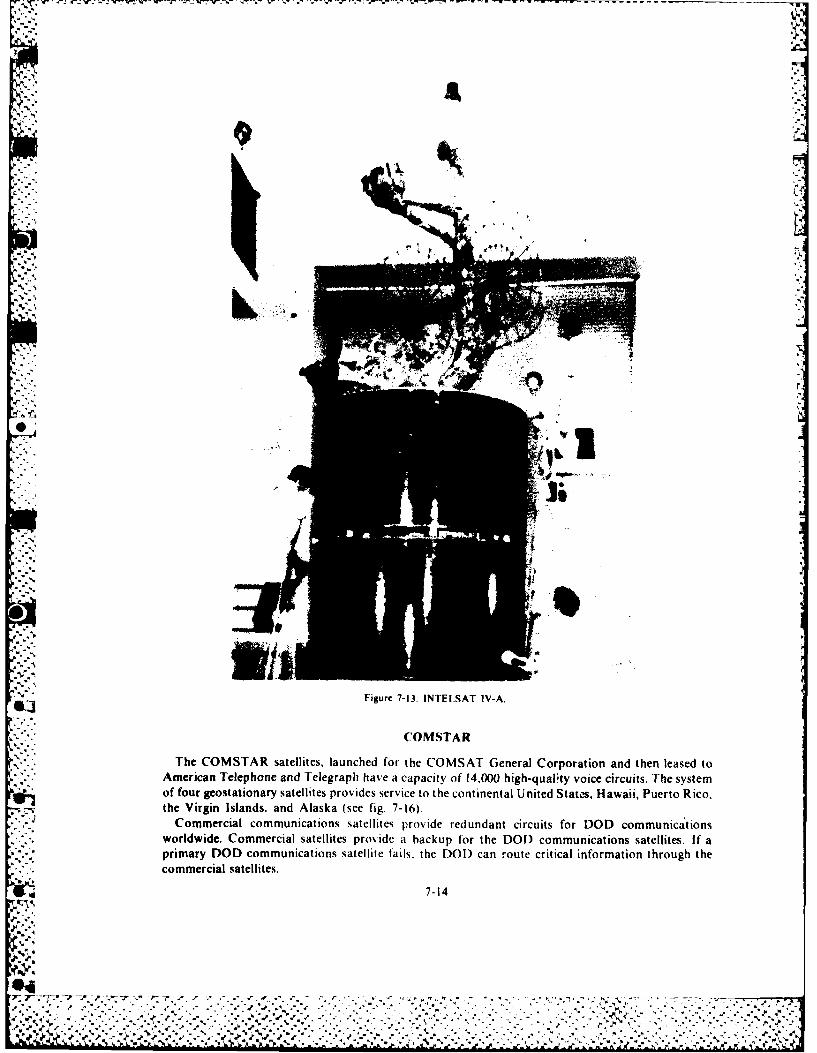
Figure 7-13. INTESAT IV-A
COMSTAR
The COMSTAR satellites, launched for the COMSAT General Corporation and then leased toAmerican Telephone and Telegraph have a capacity of 14,000 high-quality voice circuits. The systemof four geostationary satellites provides service to the continental United Statms Hawaii, Puerto Rico,the Virgin Islands. and Alaska (see fig. 7-16).
Commercial communications satellites provide redundant circuits for DOD communica tionsworldwide. Commercial satellites provide a backup for the DOD communications satellites. If aprimary DOD communications satellite fails, the DOI) can moute critical information through thecommercial satellites.
7-14
.. N . . . . ....
% *-% %
"_ 'z -- r AZ.-A
9] .. .N N.* ,.

7 -A165 838 SPACE NANDBOOK(U) AIR MINISTRY LONM (ENGLAND) 3/(C D COCNRAN ET AL. JAN 85 AU-18
UNCLASSIFIED F/G 15/7 U
/hEED/EEEEE//EEIIEIIIIEEEIIEElllEEEEllEllIElhllE~lllhEEEElll~lEEEEEEEEE/EEEEEEilEEEE
ILIL IEI1 112.
I" J IIII I 11111-
IIIL25 1111- 1.
MICROCOPY RESOLUTION TEST CHARTNATVINAL RURFAU OF STANDARDS- 963-A
I,'I.1

00
Figure 7-14. RCA-SATCOM.
SUMMARY
The demand for DOD and commercial satellite systems to meet many diverse communicationsrequirements is increasing steadily. Satellite systems offer a number of distinct advantages that themilitary can exploit for military uses. For example, they can provide very-long-distancecommunication to areas that are virtually isolated or lacking in significant commercial facilities. Theyare capable of supporting very-high-data rates for applications involving intelligence data. Forcontingency operations, the use of transportable, or mobile, terminals permits rapid extension of
7-15
% %
3C
"1
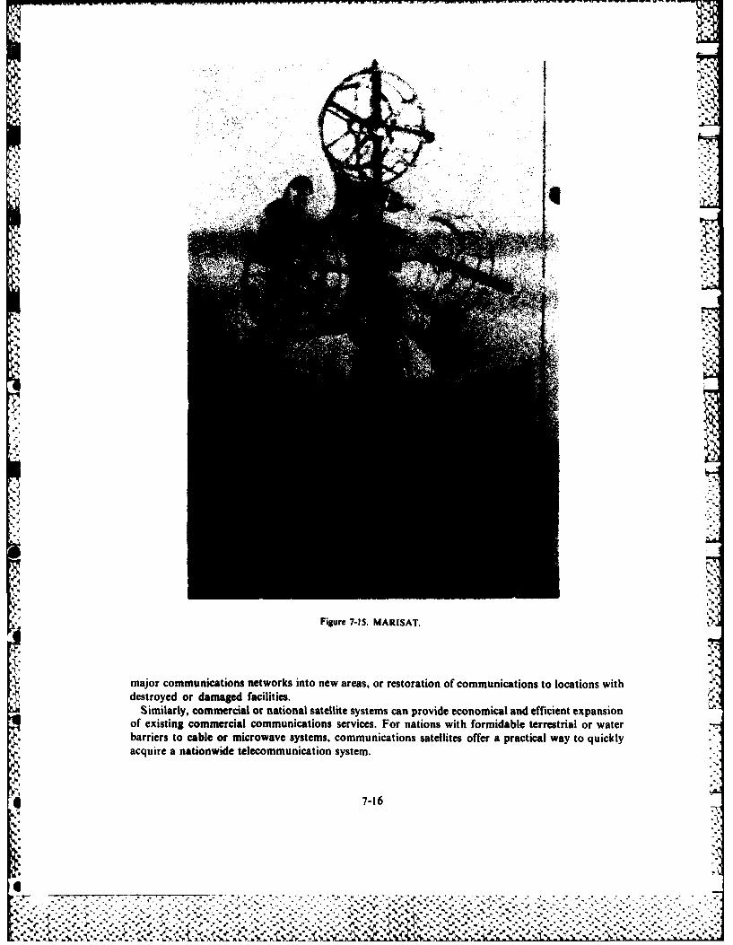
I...
[g -
-1. AIST
." major communications networks into new areas, or restoration of communications to locations with"-: destroyed or damaged facilities.. " ; Similarly, commercial or national satellite systems can provide economical and efficient expansion ''.:q of existing commercial communications services. For nations with formidable terrestrial or water;.:. :barriers to cable or microwave systems, communications satellites offer a practical way to quickly:: ,:acquire a nationwide telecommunication system.
7-16.-? .
A-I. A-1
Figur 7-I. MAISAT
r.- .- . . - .-"-- . .major . .comncain network i". nto.. new area,. .,_'_.. or rstortio of. commuications to locations - with.,..,' ' ....-5'' , .5 ., .5- . , . .. .. , - ....- .. ,.X'.,: . . . '. . ". ". . . " . " . ".
It." ,. . .'." , ' destroyed , . o...r., dam ge faciite.' , ,.€ ,. . ,. .# ;€ ,_ _ _ . . . . - , _'., . .'. . - .
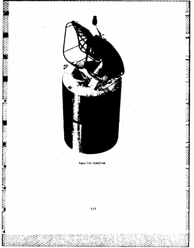
"
-J"
N jVIA';
0
f .J.
'"4
.4'.
Figure 7-16. COMSTAR.
.4--
._:.
[I

BIBLIOGRAPHY
Bond, Frederick E. Overview-DOD SATCOM Systems. Washington D.C.: Defense Communications Agency, USGovernment Printing Office, 1974.
"Communication Satellites." Space World (December 70):24-29.Corliss, William R. Putting Satellites to Work. Washington D.C.: NASA, 1968.Darley, R. "Orbiting Relays: Synchronous Communications Satellites." Electronics World 79 (February):40-41.Dunlap, Orrin E., Jr. Communications in Space, New York: Harper and Row, 1970.Filipowsky, Richard F. and Eugene 1. Muehldorf. Space Communications S;'stems. Englewood Cliffs. N.J.: Prentice-Hall 1965.Fink, D.E. "NATO SATCOM Nears Operational Status." Aviation Week and Space Technology 92 (I June 70):20-21."INTELSAT IV." Space World (April 71):59.
', "INTELSAT IV-Newest Series of Commercial Communications Satellites." Signal 25 (April 71):4345.-" Jaffe, Leonard. Communications in Space. New York: Holt, Rinehart, and Winston, 1966.
Johnsen, K. "Major Decisions Face SATCOMs." Aviation Week and Space Technology 94 (8 March 71):53-54.Klass, P.J. "New DOD SATCOMS Nearing Launch." Aviation Week and Space Technology 94 (II January 71):4041.
- • "LES (Lincoln Experimental Sateltites)-An Advance in Space Communications." Signal 23 (February 69):18-21.Lowry, R.M., Jr. "Military Satellite Communications." Signal 25 (February 69):18-21.
-. Mueller, George Edwin and E.R. Spangler. Communication Satellites. New York: John Wiley and Sons, Inc., 1964."Project Diana-First Man-Made Signals Bounced Off Moon." Signal 25 (March 71):66. ""Spacecraft Details: COMSAT Corporation." Space World 59 (November 68): 19."Special Report on Communications Satellites." Aviation Week and Space Technology 95 (23 August 71 ):28-36."The Global Satellite Communications System." Interavia 26 (October 71):1165-1168.US Congress. House. Committee on Government Operations. Government use of Satellite Communications-1968.90th Cong, 2d sess., 1968. H. Rept. 1836.Von Braun, Wehrner. "Now at Your Service The World's Most Talkative Satellite." Popular Science 198 (May 71):56-57.Wall, V.W. "Military Communication Satellites." Astronautics and Aeronautics 6 (4 April 68):52-57.
73,8
I'
_; 7-18
,,- -1 kK:: *":
* Chapter 8
ATMOSPHERIC PENETRATION
Not long ago, no one knew whether it was possible to bring a vehicle safely back from space.Today successful atmospheric penetration is routine. The state of the art in ballistic missile reentryvehicles has progressed rapidly and has reached the third generation of aerodynamic shapes.Scientists have developed and tested manned and unmanned lifting body craft. Because the liftingbody shape permits a high degree of maneuverability during reentry, its application to ballisticmissile reentry vehicles and operational spacecraft will provide considerable flexibility in missionplanning.
A thorough knowledge of the factors involved in atmospheric penetration is the basis for therapid progress in that field. This chapter will try to give the student an appreciation of these factors.The chapter includes a discussion of the characteristics of ballistic trajectories in the atmosphere, thenature of aerodynamic and heating loads, and some characteristics of lifting vehicles.
This chapter includes parameters that are not representative of modern intercontinental ballistic* missile (ICBM) cones. These cones are highly streamlined and spend a short time in the atmosphere
before impact. The emphasis is on vehicles that are characteristic of manned operations enteringfrom near-earth orbits at velocities of approximately 25,000 ft/sec. When we make reference tostreamlined ICBM cones for comparison, you should understand these cones are relatively bluntcompared to current designs. The intent is to present fundamentals in a simplified manner.
In the vacuum of space, the thrust, velocity vector, and gravitational force govern the trajectory* of a vehicle. Aerodynamic forces that cause heating due to air friction modify the vehicle in the* atmosphere. Thus, as vehicles return from space flight, aerodynamic forces come into effect. We
cannot use the relatively simple orbital relationships alone for predicting a trajectory. The equationsof motion must consider the vehicle characteristics and nonlinear drag terms. These includeatmospheric drag, a function of velocity squared (vi) and atmospheric density (p), a function ofaltitude.
BALLISTIC TRAJECTORIES
Assume that a manned vehicle has been in an elliptical orbit about the earth, and that the vehiclehas applied thrust to change its orbit to intersect the earth's atmosphere. As the vehicle enters theatmosphere, aerodynamic drag affects the trajectory. This raises some important questions for thosewho must recover the space vehicle and for the crew inside. The basic consideration of this sectionconcerns the nature of the characteristics of ballistic trajectories in the atmosphere.
For an accurate analysis of a trajectory, we must consider many factors. These include vehiclecharacteristics, atmospheric entry angle, atmospheric density, variation of density with altitude,wind, earth rotation, earth curvature, and gravity. Since some of the factors such as velocity anddensity are changing constantly during the ballistic flight in the atmosphere, we consider the analysisin very small increments. Such computations are laborious when done manually. Therefore, we use
9 computers to analyze trajectories. Even the computer does not produce exact solutions becausewe never know the predominant factors, velocity and density, exactly. The purpose of this section
v is to analyze the forces that influence motion of a vehicle.
8-1
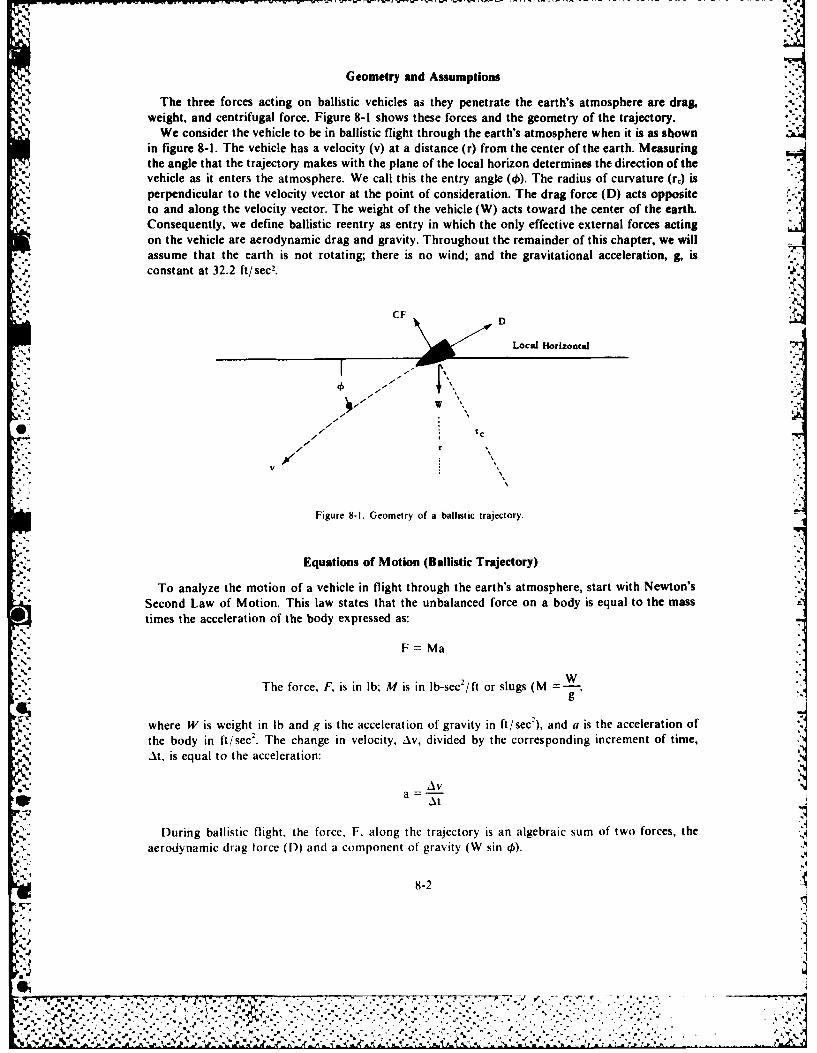
Geometry and Assumptions
The three forces acting on ballistic vehicles as they penetrate the earth's atmosphere are drag.weight, and centrifugal force. Figure 8-1 shows these forces and the geometry of the trajectory.
We consider the vehicle to be in ballistic flight through the earth's atmosphere when it is as shownin figure 8-1. The vehicle has a velocity (v) at a distance (r) from the center of the earth. Measuringthe angle that the trajectory makes with the plane of the local horizon determines the direction of thevehicle as it enters the atmosphere. We call this the entry angle (4). The radius of curvature (re) isperpendicular to the velocity vector at the point of consideration. The drag force (D) acts oppositeto and along the velocity vector. The weight of the vehicle (W) acts toward the center of the earth.Consequently, we define ballistic reentry as entry in which the only effective external forces actingon the vehicle are aerodynamic drag and gravity. Throughout the remainder of this chapter, we will
* assume that the earth is not rotating; there is no wind; and the gravitational acceleration, g, isconstant at 32.2 ft/sec2.
CF Local Horizo tal
- r
V
Figure 8-1. Geometry of a ballistic trajectory.
Equations of Motion (Ballistic Trajectory)
To analyze the motion of a vehicle in flight through the earth's atmosphere, start with Newton'sSecond Law of Motion. This law states that the unbalanced force on a body is equal to the masstimes the acceleration of the body expressed as:
F Ma
WThe force, F, is in lb; M is in lb-sec2 /ft or slugs (M =
where W is weight, in lb and g is the acceleration of gravity in ft/ sec2 ), and a is the acceleration ofN., the body in ft/sec2 . The change in velocity, Av, divided by the corresponding increment of time,
'V At, is equal to the acceleration:
~AVa
During ballistic flight, the force, F, along the trajectory is an algebraic sum of two forces, theaerodynamic drag force (D) and a component of' gravity (W sin 0).
8-2
4.4
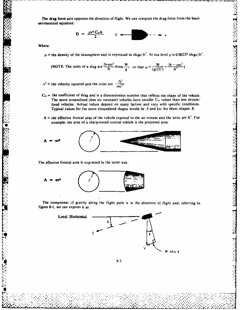
The drag force acts opposite the direction of flight. We can compute the drag force from the basicaeronautical equation:
D - pv2 CDA2 w-
Where:
p the density of the atmosphere and is expressed in slugs/ ft3. At sea level p is 0.00237 slugs/ ft'.
(NOTE: The units of a slug are t from---,g so that p = W lf
2 ft2
v the velocity squared and the units are - j
C) = the coefficient of drag and is a dimensionless number that reflects the shape of the vehicle.The more streamlined (less air resistant) vehicles have smaller CD values than less stream-lined vehicles. Actual values depend on many factors and vary with specific conditions.Typical values for the more streamlined shapes would be .5 and for the blunt shapes .8.
A = the effective frontal area of the vehicle exposed to the air stream and the units are ft2. Forexample, the area of a sharp-nosed conical vehicle is the projected area:
0r J$I
A ffi-..
The effective frontal area is expressed in the same way.
A--mI 00The component of gravity along the flight path is in the direction of flight and, referring to
figure 8-1, we can express it as
Local Horizontal
wW sin
8-3
%
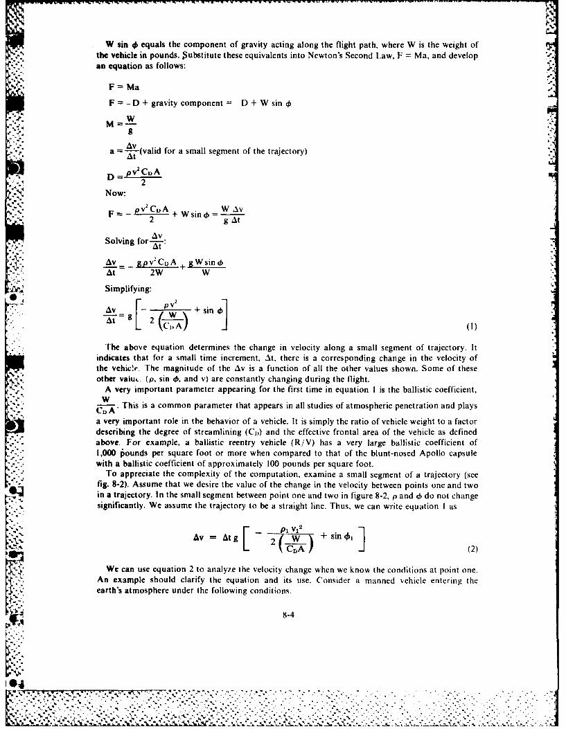
t~n .?' W sin 0 equals the component of gravity acting along the flight path, where W is the weight of .e
the vehicle in pounds. $ubstitute these equivalents into Newton's Second Law, F = Ma, and developan equation as follows:
F = Ma
F = - D + gravity component = - D + W sin 4)1'-; M=w
a -(valid for a small segment of the trajectory)At
', D pvCDA
-: Now: 2
, pv 2 Ci A W AvF + Wgsin g At
AvSolving for-: :
AV _ gpv2 CuA + gWsin4)
At 2W W
Simplifying:
SV + sin[. L(Pv wAt 2 A
The above equation determines the change in velocity along a small segment of trajectory. Itindicates that for a small time increment, At, there is a corresponding change in the velocity ofthe vehicVe. The magnitude of the Av is a function of all the other values shown. Some of theseother valu.. (p. sin 4, and v) are constantly changing during the flight.
A very important parameter appearing for the first time in equation I is the ballistic coefficient,CDA This is a common parameter that appears in all studies of atmospheric penetration and plays
a very important role in the behavior of a vehicle. It is simply the ratio of vehicle weight to a factordescribing the degree of streamlining (C,,) and the effective frontal area of the vehicle as definedabove. For example, a ballistic reentry vehicle (R/V) has a very large ballistic coefficient of1,000 6ounds per square foot or more when compared to that of the blunt-nosed Apollo capsulewith a ballistic coefficient of approximately 100 pounds per square foot.
To appreciate the complexity of the computation, examine a small segment of a trajectory (seefig. 8-2). Assume that we desire the value of the change in the velocity between points one and twoin a trajectory. In the small segment between point one and two in figure 8-2, p and 4) do not changesignificantly, We assume the trajectory to be a straight line. Thus, we can write equation I as
I -. - P1 vi2W + sin 01AV = At +2 W
C-A (2)
We can use equation 2 to analyze the velocity change when we know the conditions at point one.An example should clarify the equation and its use. Consider a manned vehicle entering theearth's atmosphere under the following conditions.
8-4
I~dN.
-. 0 .* .
i% %' 't ' " - -. l ' " - "-" . ' ' ' " ' " .' , - ' '
"". ... " " " " "" " " ," "" " " ..
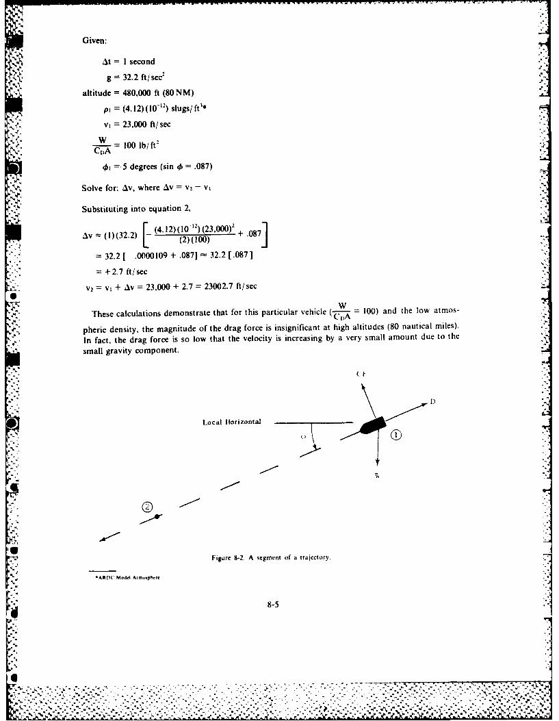
Given:
At = I second
g = 32.2 ft/sec2
altitude = 480,000 ft (80 NM)
p, = (4.12)(10 - ") slugs/ft3*
v =23,000 ft/sec
-- W _100 lb/ft2 -
@ =5 degrees (sin 4 = .087)
Solve for: Iv, where AV = V2 - Vt
Substituting into equation 2, .'
AV l)(32.2) (4.12)(10 -12) (23,000)2 + .087Av = (I(32.2)(2)(100)
:
= 32.2 [ -. 0000109 + .087] 32.2 [.087]
= + 2.7 ft/sec
V2 = V I + Av = 23,000 + 2.7 23002.7 ft/sec0
These calculations demonstrate that for this particular vehicle (-- = 100) and
pheric density, the magnitude of the drag force is insignificant at high altitudes (80 nautical miles).
In fact, the drag force is so low that the velocity is increasing by a very small amount due to the
small gravity component.
Local Horizontal
Figure 8-2. A segment of a trajectory.
*ARDC Model Aumi phere
d 8-5
....... %
" ' . . .. . . • . - . . . - - - " , . - ," ' . " . -. .. .. . - . - . -. - 4- , "'• , " ,. .% - . - , " ,
,, "';",'-," ." .-.-.- ,- •"--. '-".. .". .. ,,." "...',..'..,.'".".".•.. .--. ".-'. .•-.."--.'-.". .". ."." ""-.. .- ".. .-.. . .".'- '..',.:.. ..; ;.;:.:::::;,:.;::..:.: .: .::;:....:..:;.::. :,.::..:..:: .: :. ..:.::. -:..-..::.,...-:.- -.-.::,.,.. -::, ... ... , .,.
HEATING AND DECELERATION
Heating rates and deceleration loads are the most important effects of entry into the atmosphere.These effects are most severe when there is a combination of high atmospheric density and highvehicular velocity. The most critical condition for a vehicle upon entry would involve steep entryangle and high approach velocity.
A vehicle approaching the earth's atmosphere possesses a great amount of potential energy (PE)and kinetic energy (KE). While penetrating the earth's atmosphere, the vehicle loses very little PEin relation to the loss in KE. Therefore, scientists consider all lost energy as a KE loss. KE is afunction of V2. Thus, due to the high entry velocities, the vehicle must dispel large amounts of KEas it reduces velocity to a safe impact value for manned vehicles. It is vital to dispel the energy to
'~\ ,~*prevent vehicle or payload destruction.The velocity of the vehicle at atmospheric entry depends on the mission. If the spacecraft initiates
reentry from near-earth orbit, then the velocity at atmospheric entry closely approximates that ofthe orbital velocity. The velocity of a reentering ICBM warhead is approximately the same as thevelocity at burnout of the booster. Entry from lunar missions involves velocities of 35,000 to36,000 ft/ sec. Regardless of the mission, the entry velocity will be very high and only very largeretrothrust forces will change it a significant amount. This would lead to severe payload penalties.H owever, the spacecraft could use small retrothrust forces that allow a shallow entry angle at a lessercost in terms of weight. Instead of large retrothrust forces, the vehicle uses the atmosphere to slowdown. A shallow entry angle tends to limit to high altitudes the region of high velocity. However, theentry angle influences other factors. Shallow entry angles reduce atmospheric peak heating ratesand vehicle peak deceleration loads. Vehicle heat loads may be greater for shallow entry anglesand impact accuracy is less with shallow entry angles.
The heating and deceleration loads are a function of entry angle, velocity, and density. Theremainder of this section will deal with the interrelationship among these factors and their influenceupon heating and deceleration.
Heating
* Assume a manned vehicle enters the earth's atmosphere at 24,000 ft/sec and uses atmosphericbraking. Even under optimized configuration and entry angle, approximately 3,000*F will be theminimum vehicle surface temperature that we can expect during peak heating. The temperaturecould reach 20,0000 F for steep entry angles. Two questions that arise are: what heats the vehicleand how is it protected from the intense heat?
During atmospheric penetration, aerodynamic drag transforms KE into thermal energy, heatingthe air surrounding the vehicle. Simply, the penetrating vehicle gets hot because it is close to theheat source, namely, the air. The amount of heat transferred to the vehicle depends on thecharacteristics of the air flow near it. If all the heat in the air were transferred into the vehicle, therewould be more than enough to vaporize the vehicle unless the designers constructed the vehicle froma material that could either withstand extremely high temperatures or could eliminate the heat asit is produced. The following paragraphs will give a method of determining the approximate heatingwithout going into a complex computer-derived solution.
A4tmospheric heating rate. Theory holds that the heating rate is a function of the change in KEof the vehicle. We can evaluate the rate of KE change by using the following equation for KE:
KE Mv22
In a smaill segment of the trajectory, the change in KE (AKE) per unit of time is:
8-6
'p2.
'.t!.
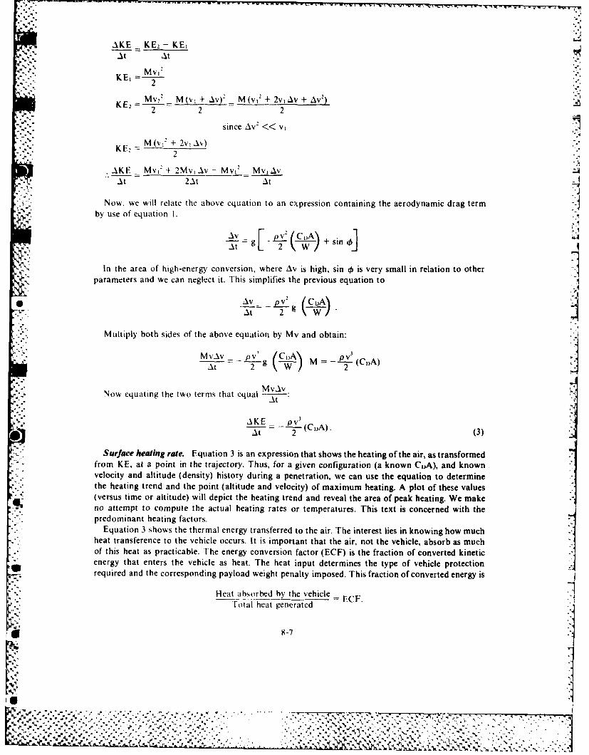
AKE KE - KEiAt At
Mv
KE2 Mv M(v + Av)_ M(v 2 + 2v1 Av + AV2)2 2 2
since Av2 << v, .
M(vJ" + 2v, A%)KU2- 2
AKE _ Mv, + 2Mv, Av - MvK Mv Av" t 2At At
Now, we will relate the above equation to an expression containing the aerodynamic drag termby use of equation I.
'.9
At 2g _ + sin(A
41, 1In the area of high-energy conversion, where Av is high, sin 0 is very small in relation to otherparameters and we can neglect it. This simplifies the previous equation to
0 AV pv 2 .(CA
Multiply both sides of the above equation by Mv and obtain:
Mvv gv (C-i M- v(IA
At g 2 (C,A)~M vAv '
Now equating the two terms that equal --A-:
AKE _ - v (C )A).At 2 (3)
Surface heating rate. Equation 3 is an expression that shows the heating of the air, as transformedfrom KE, at a point in the trajectory. Thus, for a given configuration (a known CIA), and knownvelocity and altitude (density) history during a penetration, we can use the equation to determinethe heating trend and the point (altitude and velocity) of maximum heating. A plot of these values(versus time or altitude) will depict the heating trend and reveal the area of peak heating. We makeno attempt to compute the actual heating rates or temperatures. This text is concerned with thepredominant heating factors.
Equation 3 shows the thermal energy transferred to the air. The interest lies in knowing how muchheat transference to the vehicle occurs. It is important that the air, not the vehicle, absorb as muchof this heat as practicable. The energy conversion factor (ECF) is the fraction of converted kineticenergy that enters the vehicle as heat. The heat input determines the type of vehicle protectionrequired and the corresponding payload weight penalty imposed. This fraction of converted energy is
Heat absorbed by the vehicle = ECFFotal heat generated
* X-7
-.'.,'. .• . .. , ,' • .. . . ,.- .,.. . •- .- . ... , ., . * - .-.-
• .. ", " . ", " , " , .. ' . ... ". ". ., ": ., "v. ; ." : ," .. .. , ." : ." ,"' ," ' , . '
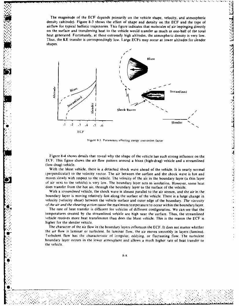
The magnitude of the ECF depends primarily on the vehicle shape, velocity, and atmosphericdensity (altitude). Figure 8-3 shows the effect of shape and density on the ECF and the type ofairflow for typical ballistic trajectories. This figure indicates that molecules of air impinging directlyon the surface and transferring heat to the vehicle would transfer as much as one-half of the totalheat generated. Fortunately, at these extremely high altitudes, the atmospheric density is very low.Thus, the KE transfer is correspondingly low. Large ECFs may occur at lower altitudes for slendershapes.
-.6 ' B k nt Streamlined
r Shock Waves
,, Slender N, "• 1 .2 .3 .4 .5 .6
• .. ECF.-
Figure 8-3. Parameters affecting energy conversion factor. j.4
Figure 8-4 shows details that reveal why the shape of the vehicle has such strong influence on theECF. This figure shows the air flow pattern around a blunt (high-drag) vehicle and a streamlined(low-drag) vehicle.
With the blunt vehicle, there is a detached shock wave ahead of the vehicle. It is nearly normal(perpendicular) to the velocity vector. The air between the surface and the shock wave is hot andmoves slowly with respect to the vehicle. The velocity of the air in the boundary layer (a thin layerof air next to the vehicle) is very low. The boundary layer acts as insulation. However, some heatdoes transfer from the hot air, through the boundary layer to the surface of the vehicle.
With a streamlined vehicle, the shock wave is almost parallel to the air stream, and the air in theboundary layer is moving relatively fast along the surface of the vehicle. There is a large change invelocity (velocity shear) between the vehicle surface and outer edge of the boundary. The viscosityof the air and the shearing action cause the maximum temperature to occur within the boundary layer.
6 The rate of heat transfer is different for vehicles of different configuration. We can see that thetemperatures created by the streamlined vehicle are high near the surface. Thus, the streamlinedvehicle receives more heat transference than does the blunt vehicle. This is the reason the ECF is
* - higher for the slender vehicle.The character of the air flow in the boundary layers influences the ECF. It does not matter whether
the air flow is laminar or turbulent. In laminar flow, the air moves smoothly in layers (lamina).Turbulent flow has the characteristic of irregular, eddying, or fluctuating flow. The turbulentboundary layer occurs in the lower atmosphere and allows a much higher rate of heat transfer to
S-" the vehicle.
8--A
", . ° - - -
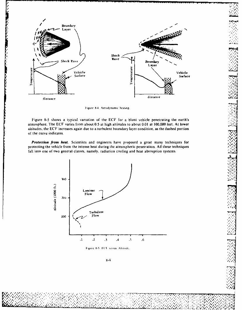
* ISoc,'/ Boundary* / .r-2--Lye
Shock Wave Boadae
, Vehicle VehicleSurface Surface
distance distance
Figure 9-4. Aerodynamic heating.
Figure 8-5 shows a typical variation of the ECF for a blunt vehicle penetrating the earth'satmosphere. The ECF varies from about 0.5 at high altitudes to about 0.01 at 100,000 feet. At loweraltitudes, the ECF increases again due to a turbulent boundary layer condition, as the dashed portionof the curve indicates. ",.
Protection from heat. Scientists and engineers have proposed a great many techniques forprotecting the vehicle from the intense heat during the atmospheric penetration. All these techniques -
fall into one of two general classes, namely, radiation cooling and heat absorption systems.
o LaminarFlow
200 "
Turbulent100 Flow
.1 .2 .3 .4 .5 .6
Figure X-5 FC U' eru , Altiude.
8-9 I"-- 4 ' .°3° ." -" , "- • .,"." " , • o' , .-' '-,- , -,-- -V --- .. U, .
, ,. -,.\.-, -.. ' " . , .. . ,, , "." ,",-. " .:, ' ' .. '... .: .7 7. ,. . ,- . . . .. . , - ,-K,. - . ' .,, - - ., ,: , .. ... -. .: ,: . , . ... , , . , .. , , .. . , .... . .. .. . .. , ., .. ,., . .. , , .. .: , ,... .. > ,& ,,,., ,,
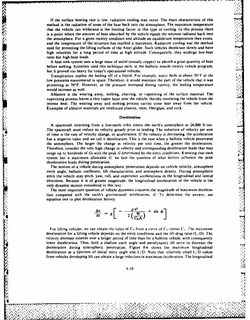
If the surface heating rate is low, radiation cooling may occur. The main characteristic of thismethod is the radiation of some of the heat back into the atmosphere. The maximum temperaturethat the vehicle can withstand is the limiting factor in this type of cooling. In this process thereis a point where the amount of heat absorbed by the vehicle equals the amount radiated back intothe atmosphere. For a given reentry condition and altitude an equilibrium temperature then exists,and the temperature of the structure has reached a maximum. Radiation cooling was the methodused for protecting the lifting surfaces of the Asset glider. Such vehicles decelerate slowly and havehigh velocities for a long period of time at high altitude. Consequently, they undergo low-heatrates but high-heat loads.
A heat sink system uses a large mass of metal (usually copper) to absorb a great quantity of heatbefore melting. Scientists used this technique early in the ballistic missile reentry vehicle program.but it proved too heavy for today's operational vehicles.
Transpiration implies the boiling off of a liquid. For example, water boils at about 70oF at thelow pressures encountered in space. Therefore, it would maintain the part of the vehicle that it wasprotecting at 701F. However, as the pressure increased during reentry, the boiling temperaturewould increase as well.
Ablation is the wearing away, melting, charring, or vaporizing of the surface material. Thevaporizing process leaves a thin vapor layer near the vehicle, thereby insulating the vehicle from theintense heat. The wearing away and melting process carries some heat away from the vehicle.Examples of ablative materials are reinforced plastics, resin, fiberglass, and cork.
Deceleration
A spacecraft returning from a low-earth orbit enters the earth's atmosphere at 24,000 ft/sec.The spacecraft must reduce its velocity greatly prior to landing. The reduction of velocity per unitof time is the rate of velocity change, or acceleration. If the velocity is decreasing, the accelerationhas a negative value and we call it deceleration. This is the case when a ballistic vehicle penetrates . .the atmosphere. The larger the change in velocity per unit time, the greater the deceleration.Therefore, consider the very high change in velocity and corresponding deceleration loads that mayrange up to hundreds of Gs with the peak G determined by the entry conditions. Knowing that eachsystem has a maximum allowable G. we face the question of what factors influence the peakdeceleration loads during penetration.
The motion of a vehicle during atmospheric penetration depends on vehicle velocity, atmosphereentry angle, ballistic coefficient, lift characteristics, and atmosphere density. During atmosphericentry the vehicle may pitch, yaw, roll, and experience accelerations in the longitudinal and lateraldirections. Because it is of greater magnitude, the longitudinal deceleration of the vehicle is theonly dynamic motion considered in this text.
The most important question of vehicle dynamics concerns the magnitude of maximum decelera-tion compared with the earth's gravitational acceleration, G. To determine the answer, useequation one to plot deceleration history.
F +AV + sin 4]
For lifting vehicles, we can obtain the value of CD from a curve of CI, versus Ct. The maximum Ideceleration for a lifting vehicle depends on the entry conditions and the lift-drag ratio (L/D). Thevelocity decrease extends over a longer period of time than for a ballistic vehicle, with consequently '41
lower deceleration. Thus, both a shallow entry angle and aerodynamic lift serve to decrease the4 deceleration during atmospheric penetration. Figure 8-6 shows the maximum longitudinal
deceleration as a function of initial entry angle and L/D. Note that relatively small L/D valuesfrom vehicles developing lift can obtain a large reduction in maximum deceleration. The longitudinal
~8-10
,. ---..,,%,b
,-. . -. .. ,-'- -. -'. - - •" .:.:,'. ' -'''. . '. " "-.' ","." " '" ' 2" : '. ., '.':- _r ,...,," ,- .. -... " .. '.. ,.-,
. ° ., " " " -. . ° . - •.- " . .% ,- - ". , .'. . .- - - ..- , , .. . .-". . '.. . , . . - ." .. .' . -' - ,. ..%*
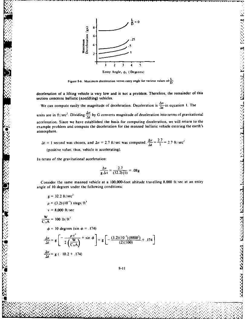
25
G 4-
.. '
2 1
2 3 4. 5
Entry Angle, 0, (Degrees)
Figure 8-6. Maximum deceleration versus entry angle for various values of-.
deceleration of a lifting vehicle is very low and is not a problem. Therefore, the remainder of thissection concerns ballistic (nonlifting) vehicles.
We can compute easily the magnitude of deceleration. Deceleration is A-in equation I. TheAvtAV .
units are in ft/sec2 . Dividing- T by G converts magnitude of deceleration into terms of gravitational
acceleration. Since we have established the basis for computing deceleration, we will return to the., example problem and compute the deceleration for the manned ballistic vehicle entering the earth's
atmosphere.
Av 2.7
At = I second was chosen, and Av = 2.7 ft/sec was computed. 2.7 ft/sec'
(positive value; thus, vehicle is accelerating).
In terms of the gravitational acceleration:
vAV 2.7 08
gAt (32.2)(1) -
Consider the same manned vehicle at a 100,000-foot altitude travelling 8,000 ft/ sec at an entryangle of 10 degrees under the following conditions:
g = 32.2 ft/sec2
p = (3.2)(10 - 5) slugs/ft
v = 8,000 ft/sec
W = 100 lb/ft2
C,)A
45 = 10 degrees (sin 4 = .174)
A_ _v + sin [ (3.2) (10-) (80002)'41 -a t 2 W (2)(00) : .174
AVg 10.2 + .174)
S8-Il
%I%I
1% A
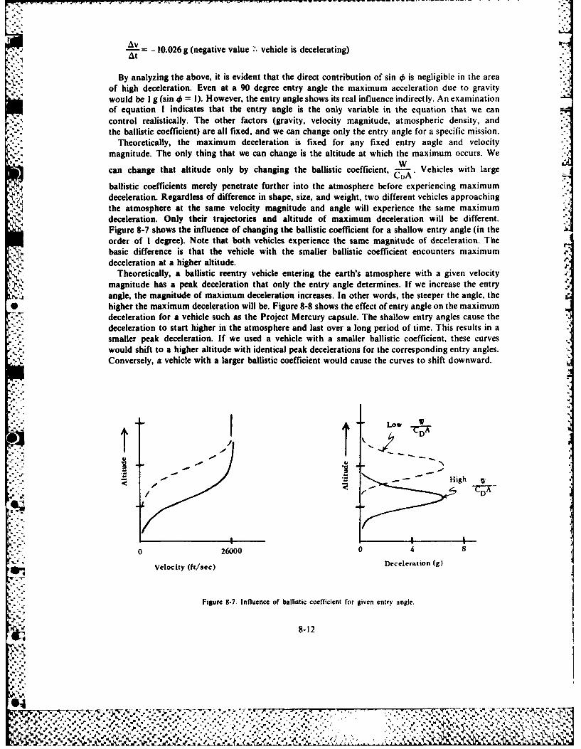
rA-~ = -10.026 g (negative value ~.vehicle is decelerating)
By analyzing the above, it is evident that the direct contribution of sin 46 is negligible in the areaof high deceleration. Even at a 90 degree entry angle the maximum acceleration due to gravitywould be I g (sin 40 = 1). However, the entry angle shows its real influence indirectly. An examinationof equation I indicates that the entry angle is the only variable in the equation that we cancontrol realistically. The other factors (gravity, velocity magnitude, atmospheric density, andthe ballistic coefficient) are all fixed, and we can change only the entry angle for a specific mission.
- Theoretically, the maximum deceleration is fixed for any fixed entry angle and velocitymagnitude. The only thing that we can change is the altitude at which the maximum occurs. We
can change that altitude only by changing the ballistic coefficient, &!.Vehicles with large
ballistic coefficients merely penetrate further into the atmosphere before experiencing maximumdeceleration. Regardless of difference in shape, size, and weight, two different vehicles approachingthe atmosphere at the same velocity magnitude and angle will experience the same maximumdeceleration. Only their trajectories and altitude of maximum deceleration will be different.Figure 8-7 shows the influence of changing the ballistic coefficient for a shallow entry angle (in theorder of I degree). Note that both vehicles experience the same magnitude of deceleration. Thebasic difference is that the vehicle with the smaller ballistic coefficient encounters maximumdeceleration at a higher altitude.
Theoretically, a ballistic reentry vehicle entering the earth's atmosphere with a given velocity41, magnitude has a peak deceleration that only the entry angle determines. If we increase the entry
angle, the magnitude of maximum deceleration increases. In other words, the steeper the angle, the* higher the maximum deceleration will be. Figure 8-8 shows the effect of entry angle on the maximum
deceleration for a vehicle such as the Project Mercury capsule. The shallow entry angles cause thedeceleration to start higher in the atmosphere and last over a long period of time. This results in asmaller peak deceleration. If we used a vehicle with a smaller ballistic coefficient, these curveswould shift to a higher altitude with identical peak decelerations for the corresponding entry angles.Conversely, a vehicle with a larger ballistic coefficient would cause the curves to shift downward.
ALow __t CDA
5- - High W
/~ A-D
0 26000 0 4 8
velocity (ht/Sec) Deceleration (g)
Figure 8-7. Influence of ballistic coefficient for given entry angle.
4,." 8-12
A.
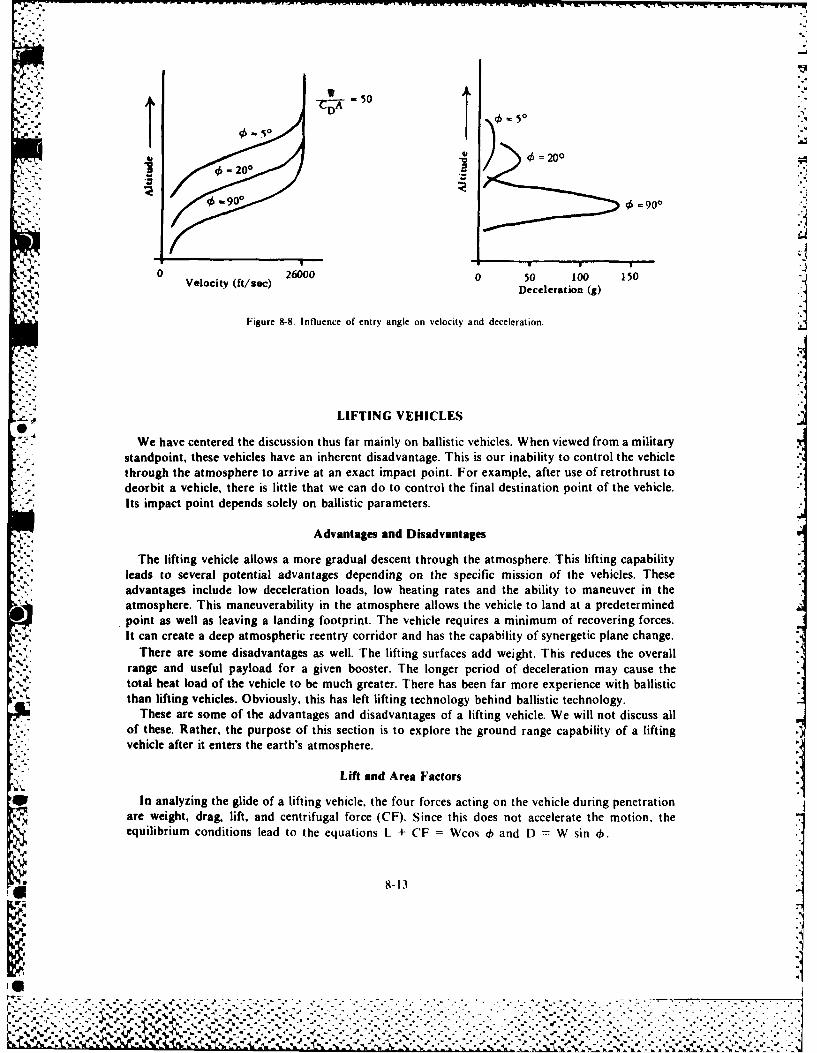
-50VA. A
DD 0
I. 20000
0.=900 4 =900
0 Vlct f/e)26000 0 50 100 150Veloity(ft/ec)Deceleration (g)
Figure 8-8. Influence of entry angle on velocity and deceleration. .LIFTING VEHICLES
We have centered the discussion thus far mainly on ballistic vehicles. When viewed from a militarystandpoint, these vehicles have an inherent disadvantage. This is our inability to control the vehiclethrough the atmosphere to arrive at an exact impact point. For example, after use of retrothrust todeorbit a vehicle, there is little that we can do to control the final destination point of the vehicle.Its impact point depends solely on ballistic parameters.
Advantages and Disadvantages
The lifting vehicle allows a more gradual descent through the atmosphere. This lifting capabilityleads to several potential advantages depending on the specific mission of the vehicles. Theseadvantages include low deceleration loads, low heating rates and the ability to maneuver in theatmosphere. This maneuverability in the atmosphere allows the vehicle to land at a predeterminedpoint as well as leaving a landing footprint. The vehicle requires a minimum of recovering forces.It can create a deep atmospheric reentry corridor and has the capability of synergetic plane change.
There are some disadvantages as well. The lifting surfaces add weight. This reduces the overallrange and useful payload for a given booster. The longer period of deceleration may cause thetotal heat load of the vehicle to be much greater. There has been far more experience with ballisticthan lifting vehicles. Obviously, this has left lifting technology behind ballistic technology.
These are some of the advantages and disadvantages of a lifting vehicle. We will not discuss allof these. Rather, the purpose of this section is to explore the ground range capability of a liftingvehicle after it enters the earth's atmosphere.
Lift and Area Factors
* In analyzing the glide of a lifting vehicle, the four forces acting on the vehicle during penetrationare weight, drag, lift, and centrifugal force (CF). Since this does not accelerate the motion, theequilibrium conditions lead to the equations L + CF Wcos d) and D W sin .
K.%% . . . . .
%A..
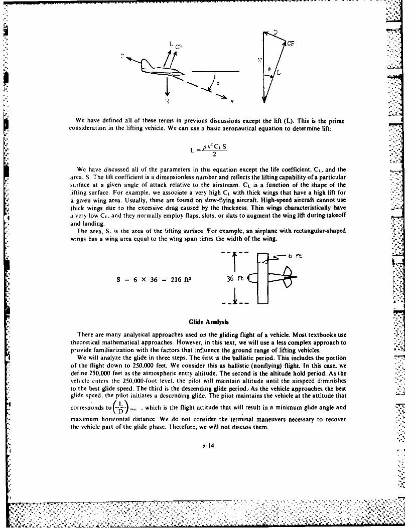
DL C-' CF
We have defined all of these terms in previous discussions except the lift (L). This is the primeconsideration in the lifting vehicle. We can use a basic aeronautical equation to determine lift:
L = V2 L2
We have discussed all of the parameters in this equation except the life coefficient, CL, and thearea. S. The lift coefficient is a dimensionless number and reflects the lifting capability of a particularsurface at a given angle of attack relative to the airstreaml. CL is a function of the shape of the -
lifting surface. For example, we associate a very high CL with thick wings that have a high lift fora given wing area. Usually, these are found on slow-flying aircraft. High-speed aircraft cannot usethick wings due to the excessive drag caused by the thickness. Thin wings characteristically havea very low C1, and they normally employ flaps, slots, or slats to augment the wing lift during takeoffand landing.
The area, S, is the area of the lifting surface. For example, an airplane with rectangular-shapedwings has a wing area equal to the wing span times the width of the wing.
S=6 X36 2161 2 36 ft
Glide Analysis
There are many analytical approaches used on the gliding flight of a vehicle. Most textbooks useItheoretical mathematical approaches. However, in this text, we will use a less complex approach toprovide familiarization with the factors that influence the ground range of lifting vehicles.
We will analyze the glide in three steps. The first is the ballistic period. This includes the portionof the flight down to 250,000 feet. We consider this as ballistic (nonflying) flight. In this case, wedefine 250,000 feet as the atmospheric entry altitude. The second is the altitude hold period. As thevehicle enters the 250,000-foot level, the pilot will maintain altitude until the airspeed diminishesto the best glide speed. The third is the descending glide period.- As the vehicle approaches the bestglide speed, the pilot initiates a descending glide. The pilot maintains the vehicle at the attitude that
e ~corresponds to(4~a which is the flight attitude that will result in a minimum glide angle and
maximum horizontal distance. We do not consider the terminal maneuvers necessary to recover .
the vehicle part of the glide phase. Therefore, we will not discuss them.
8-1 4
W,-
-rv. 7:-7- %
'J-* -A. I%
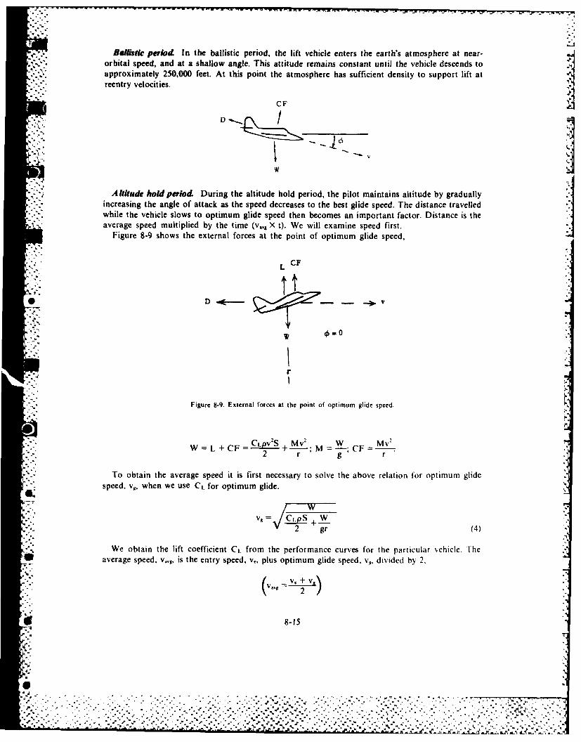
Balistic period In the ballistic period, the lift vehicle enters the earth's atmosphere at near-orbital speed, and at a shallow angle. This attitude remains constant until the vehicle descends toapproximately 250,000 feet. At this point the atmosphere has sufficient density to support lift at
' :: reentry velocities.
CF D]w
Altitude hold period During the altitude hold period, the pilot maintains altitude by gradually,.'-- increasing the angle of attack as the speed decreases to the best glide speed. The distance travelled
*"-. while the vehicle slows to optimum glide speed then becomes an important factor. Distance is theaverage speed multiplied by the time (v,,, X t). We will examine speed first.
Figure 8-9 shows the external forces at the point of optimum glide speed,
L':, CF" L
* D . .--
b.5,
Figure 8-9. External forces at the point of optimum glide speed.
W=L+CF CLPVS + Mv 2 W M2 r g r
To obtain the average speed it is first necessary to solve the above relation for optimum glidespeed, vt, when we use Ct. for optimum glide.
v -='7 . I "%
2 gr (4)
We obtain the lift coefficient Ct. from the performance curves for the particular ',ehicle. Theaverage speed, vv,, is the entry speed, v., plus optimum glide speed, v,, divided by 2.
I v! v, + v,2/
* 8-15
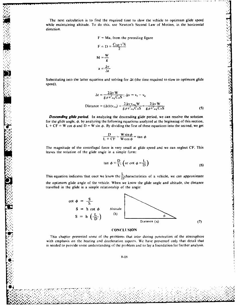
-4 .
The next calculation is to find the required time to slow the vehicle to optimum glide speed.. while maintaining altitude. To do this, use Newton's Second Law of Motion, in the horizontal%
direction.
F = Ma, from the preceding figure
F = Cp v52 .2
ga
At At
Substituting into the latter equation and solving for At (the time required to slow to optimum glidespeed),
_ •At = 2AvWSg pv 2 CDS ;A -v
Distance (t) (v,) = 2AvvW 2AvWt g) PVag C)S - g PV7a .CDS (5)
Descending glide period. In analyzing the descending glide period, we can resolve the solution
for the glide angle, , by analyzing the following equations analyzed at the beginning of this section,L + CF = W cos 0 and D = W sin ,. By dividing the first of these equations into the second, we get
9% D Wsino =.r. L + CF W cos 4 t
The magnitude of the centrifugal force is very small at glide speed and we can neglect CF. Thisleaves the solution of the glide angle in a simple form:
tan =-2) o cot 4)--. D (6)
LThis equation indicates that once we know the-characteristics of a vehicle, we can approximate
Dthe optimum glide angle of the vehicle. When we know the glide angle and altitude, the distancetravelled in the glide is a simple relationship of the angle:
cot ) =-
S = h cot 4) Altitude
L (h)
Distance (s) (7)
CONCLUSION
This chapter presented some of the problems that arise during penetration of the atmospherewith emphasis on the heating and deceleration aspects. We have presented only that detail thatis needed to provide some understanding of the problem and to lay a foundation for further analysis.
8-16
... %
,.-.. . .. . . . . . . . . . . . . . . . ........ . . . . . . . . . . . . . . . . . . . . .
~BIBLIOGRAPHY
Duncan, Robert C. Dy)namics of Atmospheric Entry. New York: McGraw-Hill, 1962.Ely, Lawrence D. Return from Space. Springfield, Ill.: Charles C. Thomas, 1966.Gasley, Carl., Jr., "Deceleration and Heating of a Body Entering a Planetary Atmosphere." in Vistas in Astronautics,
Astronautics Symposium, 1957. New York: Peragamon Press, 1958.L.a Galley. Donald P. Ballistic Missile and Space Technology Reentry and Vehicle Design. Vol. 4. New York: Academic Press,
196%Loh, W.T.H. Dynamics and Thermodynamics of Planetary Entry. Englewood Cliffs, N.J.: Prentice-Hall, 1963.Morros. CT., L.D. Ely and M.R. Smith. Ballistic Missile andAerospace Technology Reentry. New York: Academic Press, 1961.
* , RAND Corporation. Aerodynamic Aspects of Future Space Vehicles and Implications for Testing. Washington D.C.: RANDCorporation, 1967.
Atmospheric Entry of Manned Vehicles. Santa Monica, Calif.: RAND Corporation. 1960.A.n Introduction to Astronautics. Vol. I, Santa Monica, Calif.: RAND Corporation (1958): 10.1 10.32
Truitt, Robert W. Fundamentals of Aerodynamic Heating. New York: Ronald Press. 1960.
.1
I I
8-17
%1
[ .- .. .. .. ....... ,. - . -.. . .... :. .,..... .,,,%,....L..I
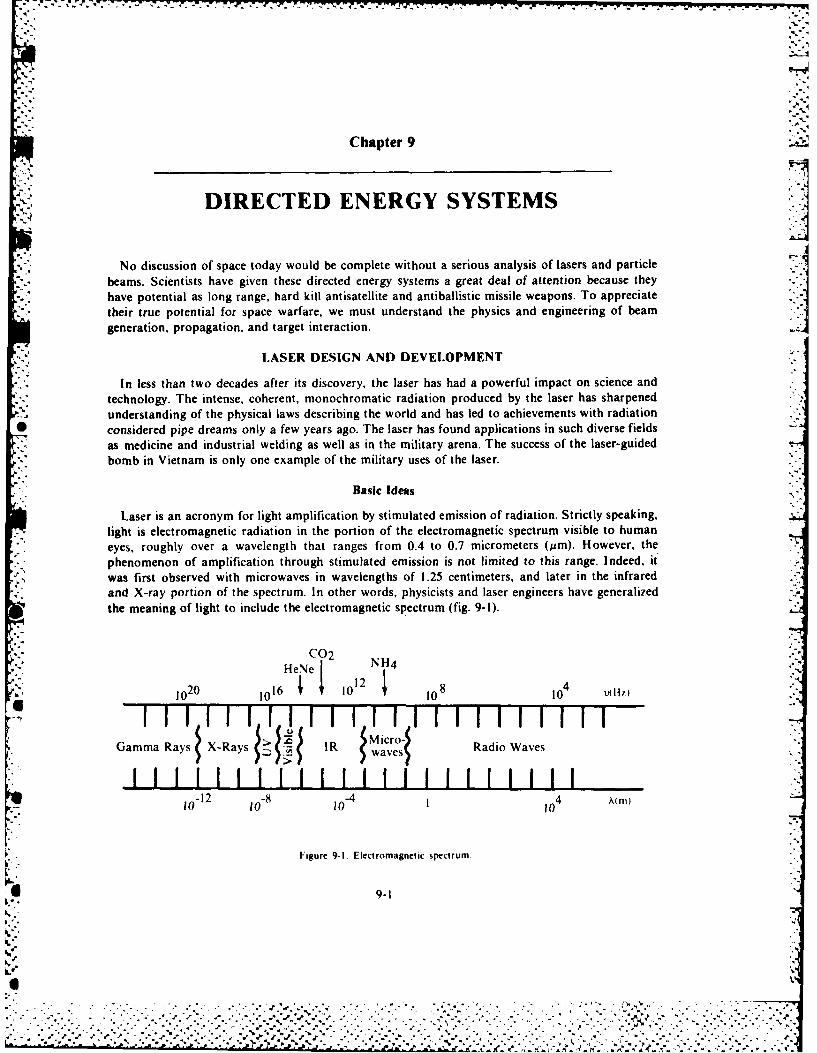
°-
,.V -. 7-71
Chapter 9
DIRECTED ENERGY SYSTEMS
No discussion of space today would be complete without a serious analysis of lasers and particlebeams. Scientists have given these directed energy systems a great deal of attention because theyhave potential as long range, hard kill antisatellite and antiballistic missile weapons. To appreciate
their true potential for space warfare, we must understand the physics and engineering of beamgeneration, propagation, and target interaction.
LASER DESIGN AND DEVELOPMENT
In less than two decades after its discovery, the laser has had a powerful impact on science andtechnology. The intense, coherent, monochromatic radiation produced by the laser has sharpenedunderstanding of the physical laws describing the world and has led to achievements with radiation
* considered pipe dreams only a few years ago. The laser has found applications in such diverse fieldsas medicine and industrial welding as well as in the military arena. The success of the laser-guidedbomb in Vietnam is only one example of the military uses of the laser.
Basic Ideas
Laser is an acronym for light amplification by stimulated emission of radiation. Strictly speaking,light is electromagnetic radiation in the portion of the electromagnetic spectrum visible to humaneyes, roughly over a wavelength that ranges from 0.4 to 0.7 micrometers (Mm). However, the
phenomenon of amplification through stimulated emission is not limited to this range. Indeed, itwas first observed with microwaves in wavelengths of 1.25 centimeters, and later in the infraredand X-ray portion of the spectrum. In other words, physicists and laser engineers have generalizedthe meaning of light to include the electromagnetic spectrum (fig. 9-1).
C02 .H"HeNe..
1o20 1016 1012010108 104 1tz).
(MicoGamma Rays X-Ras> IR wave-, Radio Waves
10 2 10 0 4 104 M)
Figure 9-1. Electromagnetic spectrum.
. a9-1
R6',:
LO.
-'I " " '"""" .-,-., - ' """, - -.". .; ,' - ." , . " "" - " ' • " "" , , "". " "' . ''e """ " ; . °" '"' . - - - - . . '
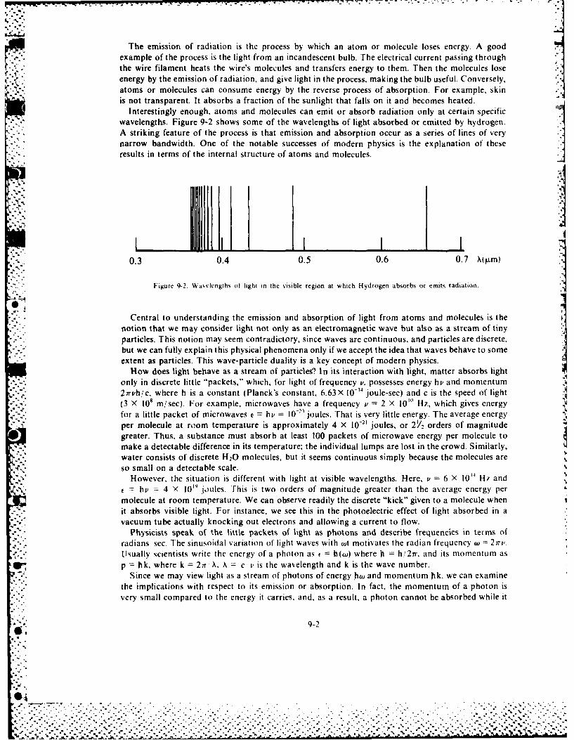
The emission of radiation is the process by which an atom or molecule loses energy. A goodexample of the process is the light from an incandescent bulb. The electrical current passing throughthe wire filament heats the wire's molecules and transfers energy to them. Then the molecules lose
~' .- ~.*energy by the emission of radiation, and give light in the process, making the bulb useful. Conversely,atoms or molecules can consume energy by the reverse process of absorption. For example, skinis not transparent. It absorbs a fraction of the sunlight that falls on it and becomes heated.
Interestingly enough, atoms and molecules can emit or absorb radiation only at certain specificwavelengths. Figure 9-2 shows some of the wavelengths of light absorbed or emitted by hydrogen.
Astriking feature of the process is that emission and absorption occur as a series of lines of veryanarrow bandwidth. One of the notable successes of modern physics is the explanation of theseresults in terms of the internal structure of atoms and molecules.
0.3 0.4 0.5 0.6 0.7 X(lim)
Figure 9-2. Wa~elengths of light in the %isible region at which Hydrogen absorbs or emits radiation.
0,Central to understanding the emission and absorption of light from atoms and molecules is the
notion that we may consider light not only as an electromagnetic wave but also as a stream of tinyparticles. This notion may seem contradictory, since waves are continuous, and particles are discrete,but we can fully explain this physical phenomena only if we accept the idea that waves behave to someextent as particles. This wave-particle duality is a key concept of modern physics.
How does light behave as a stream of particles? In its interaction with light, matter absorbs lightonly in discrete little "packets," which, for light of frequency v, possesses energy hi' and momentum21rvh/c, where h is a constant (Planck's constant, 6.63X 10⁴ joule-sec) and c is the speed of lightJ(3 X l08 m/sec). For example, microwaves have a frequency v =2 X l0'0 H7, which gives energyVfor a little packet of microwaves e =h v 10-" joules. That is very little energy. The average energyper molecule at ro~om temperature is approximately 4 X 10-21 joules, or 2V/2 orders of magnitudegreater. Thus, a substance must absorb at least 100 packets of microwave energy per molecule tomake a detectable difference in its temperature; the individual lumps are lost in the crowd. Similarly,water consists of discrete H 20 molecules, but it seems continuous simply because the molecules areso small on a detectable scale.
However, the situation is different with light at visible wavelengths. Here, v = 6 X 10"~ Hz andt=hi' = 4 X 10¹⁹ joules. This is two orders of magnitude greater than the average energy per
molecule at room temperature. We can observe readily the discrete "kick" given to a molecule whenit absorbs visible light. For instance, we see this in the photoelectric effect of light absorbed in avacuum tube actually knocking out electrons and allowing a current to flow.
- - Physicists speak of the little packets of light as photons and describe frequencies in terms ofradians sec. The sinusoidal variation of' light waves with wt motivates the radian frequency w =27ri'.Usually scientists write the energy of' a photon as c h(wu) where h h, 27r. and its momentum asp =hk, where k =27r A. A = c v' is the wavelength and k is the wave number.
Since we may view light as a stream of photons of energy hw and momentum hik, we can examinethe implications with respect to its emission or absorption. In fact, the momentum of a photon isvery small compared to the energy it carries, and, as a result, a photon cannot be absorbed while it
9-2
Cd.
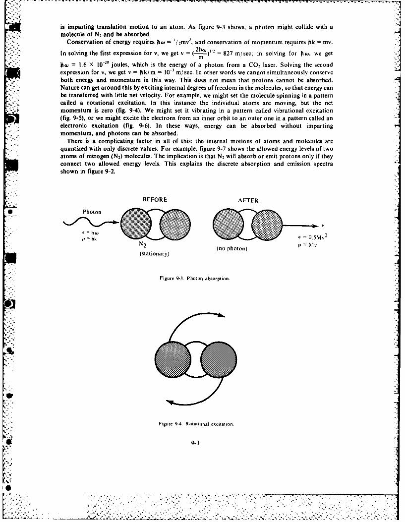
-.- - V..
is imparting translation motion to an atom. As figure 9-3 shows, a photon might collide with amolecule of N2 and be absorbed.
Conservation of energy requires bJ = I/2mv 2, and conservation of momentum requires bk = mv.In solving the first expression for v, we get v =(---w) = 827 m/sec; in solving for O, we get
= 1.6 X 10⁻²° joules, which is the energy of a photon from a CO 2 laser. Solving the secondexpression for v, we get v = kik/m = l - rn/sec. In other words we cannot simultaneously conserveboth energy and momentum in this way. This does not mean that protons cannot be absorbed.Nature can get around this by exciting internal degrees of freedom in the molecules, so that energy canbe transferred with little net velocity. For example, we might set the molecule spinning in a patterncalled a rotational excitation. In this instance the individual atoms are moving, but the netmomentum is zero (fig. 9-4). We might set it vibrating in a pattern called vibrational excitation(fig. 9-5), or we might excite the electrons from an inner orbit to an outer one in a pattern called anelectronic excitation (fig. 9-6). In these ways, energy can be absorbed without impartingmomentum, and photons can be absorbed.
There is a complicating factor in all of this: the internal motions of atoms and molecules arequantized with only discrete values. For example, figure 9-7 shows the allowed energy levels of twoatoms of nitrogen (N2) molecules. The implication is that N2 will absorb or emit protons only if theyconnect two allowed energy levels. This explains the discrete absorption and emission spectrashown in figure 9-2.
BEFORE AFTER
*Photon
V
f =hwo"
p =hk c- . 0.5MvN2 (no photon) =V
(stationary)
Figure 9-3. Photon absorption.
.......'...
Figure 9-4. Rotational excitation.
9-3
4,N
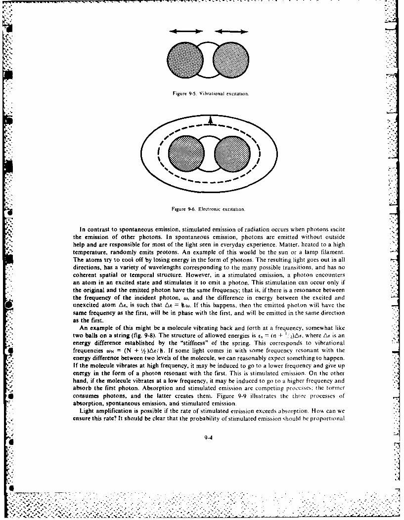
.. .. .. + u . ,- '= ', . *V* -. = - . °. .. L ° _ . o 1 . ,, v- x- - -. -- , -.. .
~/
* * *
Figure 9-5. Vibrational excitation.
Figure 9-6. Electronic excitation.
In contrast to spontaneous emission, stimulated emission of radiation occurs when photons incitethe emission of other photons. In spontaneous emission, photons are emitted without outsidehelp and are responsible for most of the light seen in everyday experience. Matter, heated to a hightemperature, randomly emits protons. An example of this would be the sun or a lamp filament.The atoms try to cool off by losing energy in the form of photons. The resulting light goes out in alldirections, has a variety of wavelengths corresponding to the many possible transitions, and has nocoherent spatial or temporal structure. However, in a stimulated emission, a photon encountersan atom in an excited state and stimulates it to emit a photon. This stimulation can occur only ifthe original and the emitted photon have the same frequency; that is, if there is a resonance between .
the frequency of the incident photon, w, and the difference in energy between the excited and* unexcited atom At, is such that At = Otw. If this happens, then the emitted photon wilt have the
same frequency as the first, will be in phase with the first, and will be emitted in the same directionas the first.
An example of this might be a molecule vibrating back and forth at a frequency, somewhat liketwo balls on a string (fig. 9-8). The structure of allowed energies is t. = (n + ,)Ac, where At is anenergy difference established by the "stiffness" of the spring. This corresponds to vibrationalfrequencies (ON = (N + 1/2 )Aei)1. If some light comes in with some frequency resonant with theenergy difference between two levels of the molecule, we can reasonably expect something to happen.If the molecule vibrates at high frequency, it may be induced to go to a lower frequency and give upenergy in the form of a photon resonant with the first. This is stimulated emission. On the otherhand, if the molecule vibrates at a low frequency, it may be induced to go to a higher frequency andabsorb the first photon. Absorption and stimulated emission are competing processes: the former
* consumes photons, and the latter creates them. Figure 9-9 illustrates the three processes ofabsorption, spontaneous emission, and stimulated emission.
Light amplification is possible if the rate of stimulated emission exceeds absorption. How can weensure this rate? It should be clear that the probability of stimulated emission should be proportional
-9-4
'.e J%- .. d
"oo -+ , %,. ." "+.% -° " ° . ." + . . , • +' o- . .- . + • +. °° ° - , .. ° . .. . . ., . . . . • - .- "..- . • ., • ."+° '..° - .
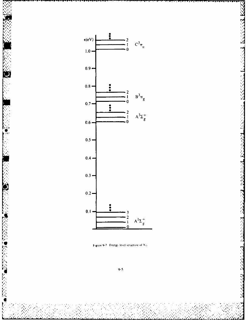
1.00
0.90
0.9-
0.8- 0
-21 3y
0.76 * 0 g.
0.50
0.4
0.3-
0.2-
0.1- 3
2 y
Figure 9-7 Fniergp leIe %tructure of N,.
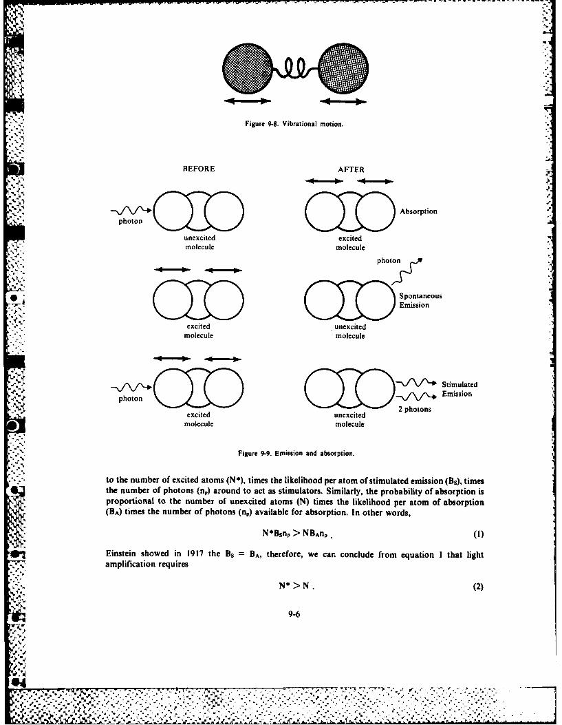
Figure 9-.Vbaioa oin
B AFTER
iFigure 9-8. Vibrational motion.
i- I BEFORE AFTER-
pooGDAbsorption "w'%, 'photon ='
unexcited excitedmolecule molecule
photo
OJO SpontaneousG W, .Emission
excited unexcitedmolecule molecule
Stimulated
photon Emissioni2 photons
excited unexcitedmolecule molecule
Figure 9-9. Emission and absorption.
to the number of excited atoms (N*), times the likelihood per atom of stimulated emission (Bs), timesthe number of photons (np) around to act as stimulators. Similarly, the probability of absorption isproportional to the number of unexcited atoms (N) times the likelihood per atom of absorption(BA) times the number of photons (np) available for absorption. In other words,
N*Bsnp > NBAnp (i)
In Einstein showed in 1917 the Bs = BA, therefore, we can conclude from equation I that lightamplification requires
N* > N. (2)
9-6
W ,
. ' . ,. "..-"'"d. .. .
- .. . .
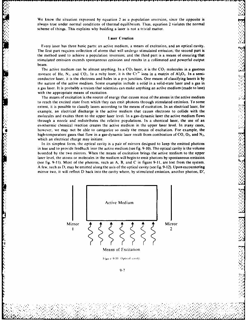
We know the situation expressed by equation 2 as a population inversion, since the opposite isalways true under normal conditions of thermal equilibrium. Thus, equation 2 violates the normal
- - . scheme of things. This explains why building a laser is not a trivial matter.
%' laser Creation
Every laser has three basic parts: an active medium, a means of excitation, and an optical cavity.*-.., The first part requires collection of atoms that will undergo stimulated emission; the second part is
the method used to achieve a population inversion. and the third part is a means of ensuring thatstimulated emission exceeds spontaneous emission and results in a collimated and powerful output
* beam.The active medium can be almost anything. In a CO 2 laser, it is the CO 2 molecules in a gaseous
mixture of He, N2 , and CO 2. In a ruby laser, it is the Cr'* ions in a matrix of A120 3. In a semi-conductor laser, it is the electrons and holes in a p-n junction. One means of classifying lasers is by
" the nature of the active medium. Some examples include a solid in a solid-state laser and a gas in'. a gas laser. It is probably a truism that scientists can make anything an active medium (made to lase)
with the appropriate means of excitation.The means of excitation is the source of energy that causes most of the atoms in the active medium
to reach the excited state from which they can emit photons through stimulated emission. To some- extent, it is possible to classify lasers according to the means of excitation. In an electrical laser, for
example, an electrical discharge is the active medium that causes electrons to collide with themolecules and excites them to the upper laser level. In a gas-dynamic laser the active medium flowsthrough a nozzle and redistributes the relative populations. In a chemical laser, the use of anexothermic chemical reaction creates the active medium in the upper laser level. In many cases,however, we may not be able to categorize so easily the means of excitation. For example, thehigh-temperature gases that flow in a gas-dynamic laser result from combustion of CO, 02, and N2,which an electrical charge may initiate.
In its simplest form, the optical cavity is a pair of mirrors designed to keep the emitted photonsin line and to provide feedback into the active medium (see fig. 9-10). The optical cavity is the volumebounded by the two mirrors. When the means of excitation brings the active medium to the upperlaser level, the atoms or molecules in the medium will begin to emit photons by spontaneous emission(see fig. 9-1 I). Most of the photons, such as A, B, and C in figure 9-11, are lost from the system.A few, such as D, may be emitted along the axis of the optical cavity (see fig. 9-12). Upon encounteringmirror two, it will reflect D back into the cavity where, by stimulated emission, another photon, D',
Active Medium
Mirror Mirror
Means of Excitation
|'ipret 9-11} Op|tical t',1%l , -1
9-7
". ''.5 . . . - . . ...,- '-.+. ,-, . . - '. .-. '*.- - " , -', ,'-- . . , ' --." , .- ','?,' - .--.-.. .- - . ---- ,"

--- --J----
Ic-Mirror Mirror
Figure 9-11. Optical cavity with spontaneous emission.
4~\/J\~D'
Mirror Mirror2
Figure 9-12. Optical cavity with feedback.
will emerge in step with D. D and D' can continue to generate more photons, since mirror one feedsthem back into the cavity. This process results in a large buildup of photons running parallel to theaxis of the cavity. Of course, a practical laser needs some output. Thus, in real devices, one of themirrors is partially transmitting so that only a few of the photons are fed back to continue
- - stimulated emission. Photons that escape comprise the actual laser beam.Creation of a population inversion is no small task, since all systems in nature tend to relax to the
thermal equilibrium. Therefore, to make a population inversion, we must excite the atoms ormolecules of the active medium into the upper laser level at a rate greater than they can decay tolower levels. What are some of the ways that excited molecules can decay to lower levels? One wayis the spontaneous emission of photons. Obviously, the rate of spontaneous emission will increaseif the energy difference between the two levels increases, since a population inversion more stronglyviolates the natural order of things as At goes up. Indeed, the spontaneous emission rate A fromone level to another can be related to the stimulated emission rate B between these levels by
8 r (At)"
A ~ . =j-B. (3)
This explains why, traditionally, lasers have advanced from lower to higher frequencies. At the
microwave frequencies, where laser action was first observed, excessive spontaneous emission is
9-8
NIL
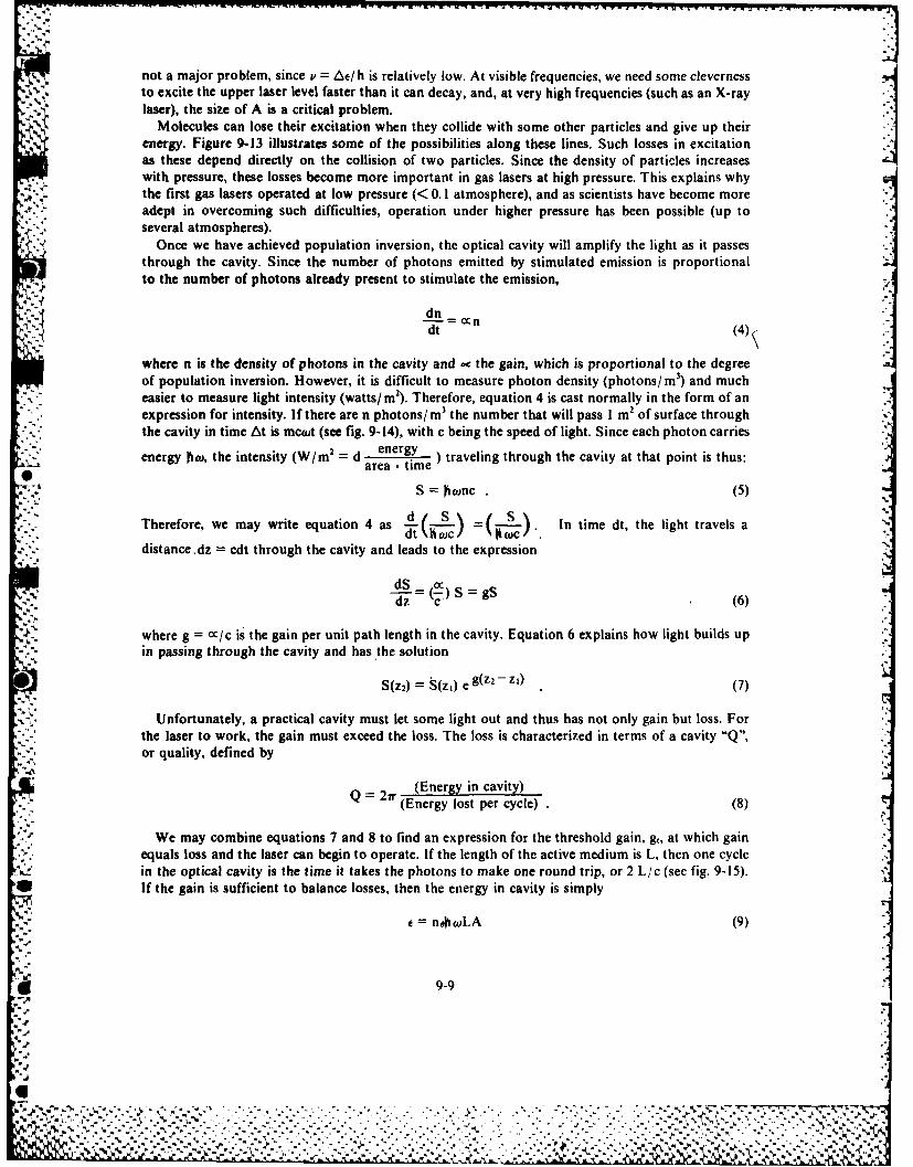
not a major problem, since v = Ae/ h is relatively low. At visible frequencies, we need some clevernessto excite the upper laser level faster than it can decay, and, at very high frequencies (such as an X-raylaser), the size of A is a critical problem.
Molecules can lose their excitation when they collide with some other particles and give up theirenergy. Figure 9-13 illustrates some of the possibilities along these lines. Such losses in excitationas these depend directly on the collision of two particles. Since the density of particles increaseswith pressure, these losses become more important in gas lasers at high pressure. This explains whythe first gas lasers operated at low pressure (< 0. I atmosphere), and as scientists have become more
adept in overcoming such difficulties, operation under higher pressure has been possible (up to" several atmospheres).
Once we have achieved population inversion, the optical cavity will amplify the light as it passesthrough the cavity. Since the number of photons emitted by stimulated emission is proportionalto the number of photons already present to stimulate the emission,
dt
where n is the density of photons in the cavity and ec the gain, which is proportional to the degreeof population inversion. However, it is difficult to measure photon density (photons/ M 3) and mucheasier to measure light intensity (watts/ in2). Therefore, equation 4 is cast normally in the form of anexpression for intensity. If there are n photons/ m3 the number that will pass I m2 of surface throughthe cavity in time At is mcwt (see fig. 9-14), with c being the speed of light. Since each photon carries
energy ftah the intensiye d en ) traveling through the cavity at that point is thus:
S = wnc (5)
Therefore, we may write equation 4 as = . In time dt, the light travels a
distance dz cdt through the cavity and leads to the expression
dS _c S gS(i - C(6)
where g = oc/c is the gain per unit path length in the cavity. Equation 6 explains how light builds up-- '- in passing through the cavity and has the solution
S(z2) = S(z1 ) eg(z2-z2 (7)
Unfortunately, a practical cavity must let some light out and thus has not only gain but loss. Forthe laser to work, the gain must exceed the loss. The loss is characterized in terms of a cavity "Q",or quality, defined by
(Energy in cavity)Q = 2w (Energy lost per cycle) . (8)
We may combine equations 7 and 8 to find an expression for the threshold gain, g', at which gainequals loss and the laser can begin to operate. If the length of the active medium is L, then one cyclein the optical cavity is the time it takes the photons to make one round trip, or 2 L/c (see fig. 9-15).If the gain is sufficient to balance losses, then the energy in cavity is simply
= n@0wLA (9)
9-9
[*. '.\ ,, ', -. /. ". . ". ",. . .'- . . .. " .,. . ... , . -, . . •. .-: ..-. -. ....- -. '-. * . ' - .- .- ', , ,- ,,,,
iZ. ,.
l,. ,rT. , , '. , ',, .".'.' , ,'. b .. ,..%r •.-'-.-..> ..-. .- '-'. . - '..- , ... o,- ,, . ha i, h~h l. '.,,,,, ,". N' .%
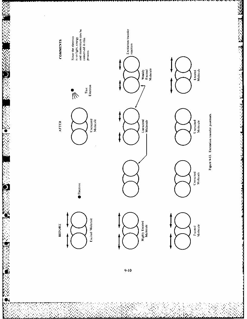
9 .
I- 0U 0
~~ - ~~ E k
0 A- C0~.
I9..
C I~0
kIy
w ~
LI.. UO UC
* C
0I CC
LII
U
LI.CU-~0
UC
C0
UU
LII
1. S
I Ii.3 1 I I
9.
9-10
* .-..
:-. ~. *~. S~ *.
*--------------------. 9. ,.~..'*'*9*S.* * *** 5-. 9. ~ ~.. . * -
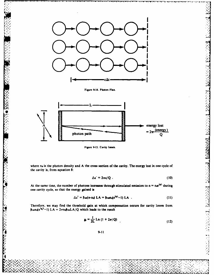
-- I
221 [ , cat :-
Figure 9-14. Photon Flux.
L
A energy lost
,'L ~~photon path- =2:,
Figure 9-15. Cavity IoseL
where no is the photon density and A the cross section of the cavity. The energy lost in one cycle of
the cavity is, from equation 8:
A = 2r /Q (10)
At the same time, the number of photons increases through stimulated emission to n n~eL duringone cavity cycle, so that the energy pined is
"'" ~At+ = tagn-n,) LA = ome2IL-l) LA. 1I ."
Therefore, we may find the threshold gain at which compensation occurs for cavity losses from
ftmn4 e2NL-l) LA = 2innoLA/Q which leads to the result
= 2 Ln (I + 2r/Q) (12)
9-11
%,.
. .,- -4
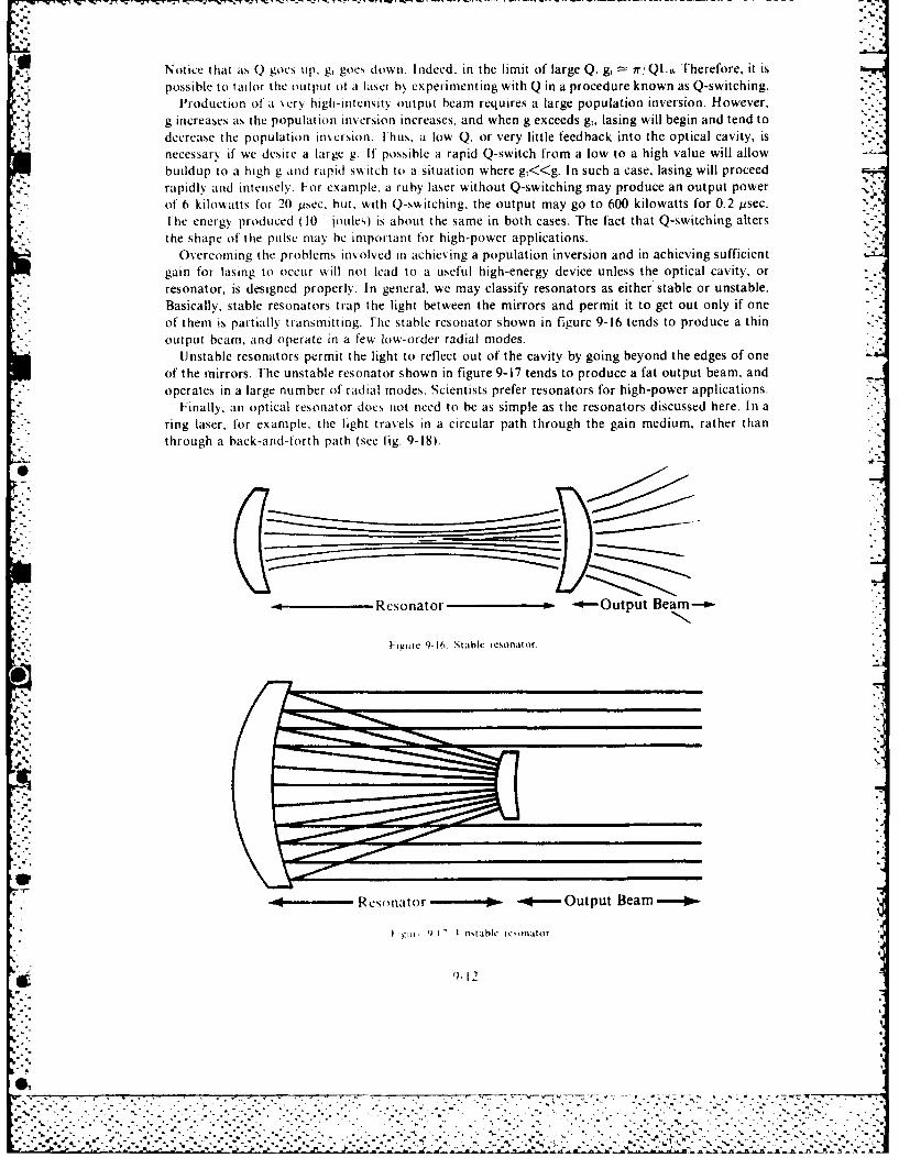
Notice that as Q goes up, g, goes down. Indeed, in the limit of large Q, g, n-, Q.io. Therefore, it ispossible to tailor the output of a laser by experimenting with Q in a procedure known as Q-switching.
Production ol a %cry high-intensity output beam requires a large population inversion. However,g increases as the population irversion increases, and when g exceeds g, lasing will begin and tend todecrease the population invcrsion. Ihus, a low Q, or very little feedback into the optical cavity, isnecessary if we desire a large g. If possible a rapid Q-switch from a low to a high value will allowbuildup to a high g and rapid switch to a situation where g,<<g. In such a case, lasing will proceedrapidly and intensely. For example, a ruby laser without Q-switching may produce an output powerof 6 kilowatts for 20 psec, but. with Q-switching, the output may go to 600 kilowatts for 0.2 psec.Hie energy produced ( 10 joules) is about the same in both cases. The fact that Q-switching alters
the shape of the pulse may be important for high-power applications.Overcoming the problems involved in achieving a population inversion and in achieving sufficient
gain for lasing to occur will not lead to a useful high-energy device unless the optical cavity, orresonator, is designed properly. In general, we may classify resonators as either stable or unstable.Basically, stable resonators trap the light between the mirrors and permit it to get out only if oneof them is partially transmitting. Fhe stable resonator shown in figure 9-16 tends to produce a thinoutput beam, and operate in a few low-order radial modes.
Unstable resonators permit the light to reflect out of the cavity by going beyond the edges of oneof the mirrors. The unstable resonator shown in figure 9-17 tends to produce a fat output beam, andoperates in a large number of radial modes. Scientists prefer resonators for high-power applications.
Finally, an optical resonator does not need to be as simple as the resonators discussed here. In aring laser, for example, the light travels in a circular path through the gain medium, rather thanthrough a back-and-forth path (see fig. 9-18).
Resonator P- -*--Output Beam--a.
"itire 9-16. Stable resonator.
Reso nator -*- Output Beam
| , t I' I nstahle ie.onator
1- 12
0 ,. - -" - " -3 . --' ". ------ " " '-': - ' -. "- ,. " ", -: - .- '-" -''- --. - ''' " -'- .- . -:
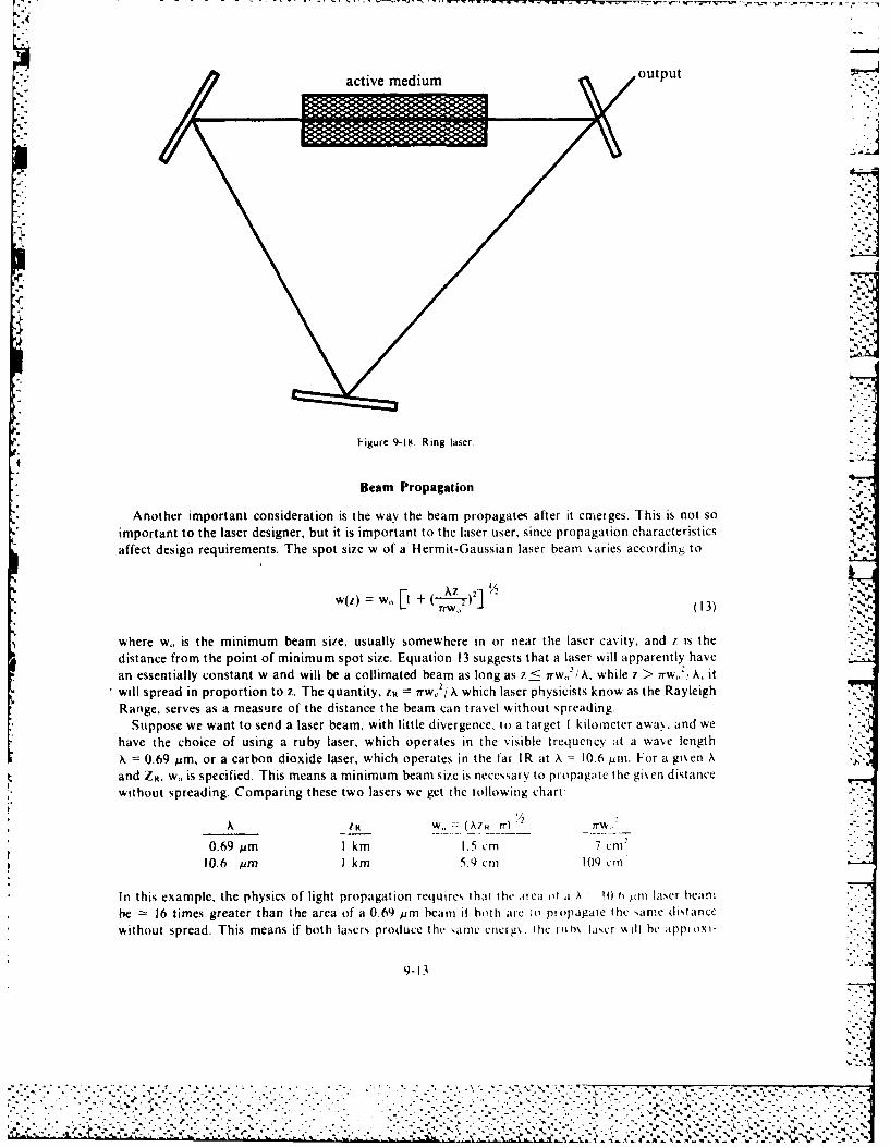
oupu
,°.
~~~~active medium ,u .
112
Figure -18. Rig.laser
whAnother imotant nsideratio sise, wsay tohee pnropgaeafr it emsergs avis n is nthso
,Az .'/ - 1
whrF~ stemnmmba ig ualyre wh. igaer ino-ea h.asrc-iy n 7i h
distance from the point of minimum spot size. Equation 13 suggests that a laser will apparently havean essentially constant w and will be a collimated beam as long as z < irw. 2' 1A, while 7 > irw,,2 IA, itwill spread in proportion to z. The quantity, zP irwo/ A which laser physicists know as the RayleighRange. serves as a measure of the distance the beam can travel without spreading.
Suppose we want to send a laser beam, with little divergence, to a target I kilometer away, and wehave the choice of using a ruby laser, which operates in the visible frequcncv at a wave length
X 0.69 pm, or a carbon dioxide laser, which operates in the far IR at A 10.6 M. F-or a given Aand ZR, w,, is specified. This means a minimum beam s ie is necessary to propagate the gien distancewithout spreading. Comparing these two lasers we get the kollowing charta
112
A R W.,,(A7 R 7r 7rW,'
0.69 um I km 1. 5 cm 7 cm'10.6 um I k in 5.9 cmi 109 cmn
In this example, the physics of light propagation requires ihat the sreua o a A e !lg " .laser beam
be 16 times greater than the area of a 0.69 rm beanm it both are to propagate the same distance
without spread. This means if both lasers produce the oarne cncrg. the ruh laser iI he appi-o.i-
9-13* . - ,**..............
... ' . . . . ......... ''I>?m-1.*m7 :* "-.
* .0.6'i1§~~ .... km 5.9 0L.q c m
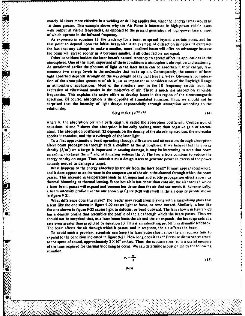
mately 16 times more effective in a welding or drilling application, since the (energy/ area) would be16 times greater. This example shows why the Air Force is interested in high-power visible laserswith output at visible frequencies, as opposed to the present generation of high-power lasers, mostof which operate in the infrared frequency.
As expressed in equation 13, the tendency for a beam to spread beyond a certain point, and forthat point to depend upon the initial beam size is an example of diffraction in optics. It expressesthe fact that any attempt to make a smaller, more localized beam will offer no advantage becausethe beam will spread sooner as it becomes smaller, if all other factors are equal.
Other conditions besides the laser beam's natural tendency to spread affect its applications in the*2-.~atmosphere. One of the most important of these conditions is atmospheric absorption and scattering.
As mentioned earlier the photons of light in the laser beam can be absorbed if their energy, IV W,connects two energy levels in the molecules that make up air. Consequently, the amount of laser
light absorbed depends strongly on the wavelength of the light (see fig. 9-19). Obviously, considera-tinof the abopinspectrum ofair is just as important as consideration of the Rayleigh Range
in atmospheric applications. Most of the structure seen in the IR frequency results from the* - excitation of vibrational modes in the molecules of air. There is much less absorption at visible
frequencies. This explains the active effort to develop lasers in this region of the electromagneticspectrum. Of course, absorption is the opposite of stimulated emission. Thus, we should not besurprised that the intensity of light decays exponentially through absorption according to therelationship .
S(Z2) = (Z1) e A02zlil (14)
where k, the absorption per unit path length, is called the absorption coefficient. Comparison ofequations 14 and 7 shows that absorption is basically nothing more than negative gain or attenu-
* ation. The absorption coefficient (k) depends on the density of the absorbing medium, the molecularspecies it contains, and the wavelength of the laser light.
To a first approximation, beam spreading through diffraction and attenuation through absorption* affect beam propagation through such a medium as the atmosphere. If we believe that the energy
density (J/m 2) on a target is important in causing damage, it may be interesting to note that beamspreading increases the m2 and attenuation reduces the J. The two effects combine to reduce theenergy density on target. Thus, scientists must design lasers to generate power in excess of the poweractually needed to damage a target.
What happens to the energy absorbed by the air from the laser beam? It must appear somewhere,and it does appear as an increase in the temperature of the air in the channel through which the beampasses. This increase in temperature leads to an important and subtle propagation effect known asthermal blooming or thermal lensing. Since hot air is less dense than cold air, the air through whicha laser beam passes will expand and become less dense than the air that surrounds it. Schematically,a beam intensity profile like the one shown in figure 9-20 will result in the air density profile shownin figure 9-21.
What difference does this make? The reader may recall from playing with a magnifying glass thata lens like the one shown in figure 9-22 causes light to focus, or bend inward. Similarly, a lens likethe one shown in figure 9-23 causes light to defocus, or bend outward. The lens shown in figure 9-23has a density profile that resembles the profile of the air through which the beam passes. Thus we
should not be surprised that, as a laser beam heats the air and the air expands, the beam spreads at arate even greater than predicted by equation 13. This is an interesting problem in dynamic feedback.IThe beam affects the air through which it passes, and in response, the air affects the beam.
To avoid such a problem, scientists can keep the laser pulse short, since the air requires time toexpand to the condition indicated in figure 9-21I. How long does it take? Pressure disturbances travelat the speed of sound, approximately 3 X 104 cm/sec. Thus, the acoustic time, r., is a useful measureof the time required for thermal blooming to occur. We can determine acoustic time by the following
equation,
ww
.941
bou
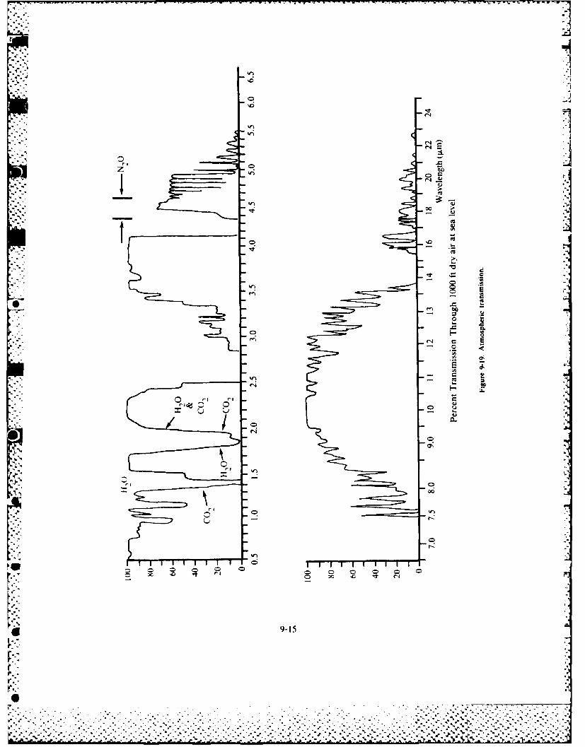
4..
o
r4
sI.~
Zr. 0 ]L
0 Ct
- U
00
'UVt 0 'C 'U- I-
'U
'~ .2-~
0.C
o.C
0C.9 .(
U'
-- 'U
e-~a ~I- irCUo ~
- I..U
0
-4 oR
000
0
I.-.-
I I II II II I I
00 'C .~ 0 0 0 0 0 0
0 00 'C "U r4
9-Is
I.
r
6 ____________
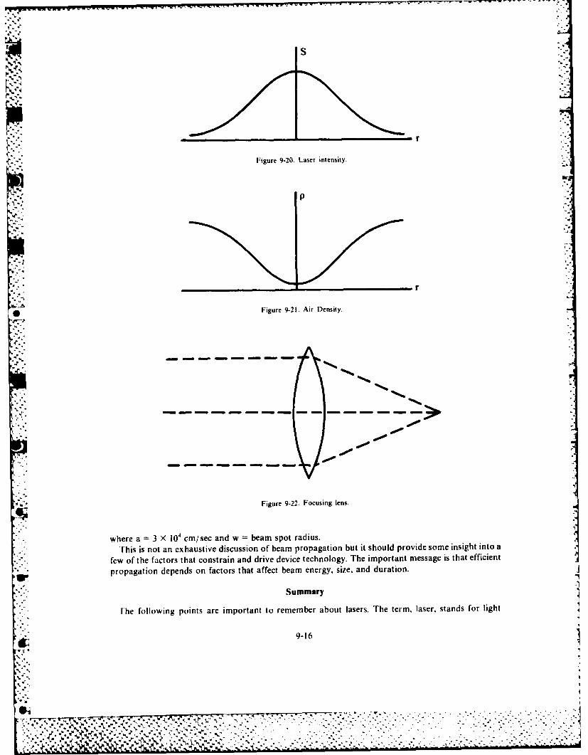
Figure 9-20. Laser intensity.
p
* Figure 9-21. Air Density.
Figure 9-22. Focusing lens.
where a =3 X 10 CM/ sec and w beam spot radius.This is not an exhaustive discussion of beam propagation but it should provide some insight into a
* few of the factors that constrain and drive device technology. The important message is that efficient
propagation depends on factors that affect beam energy. sue, and duration.
Summary
Fhe following points are important to remember about lasers. The term, laser, stands for light '9-16
A. _ _ __ _ _ _ __ _ _ .
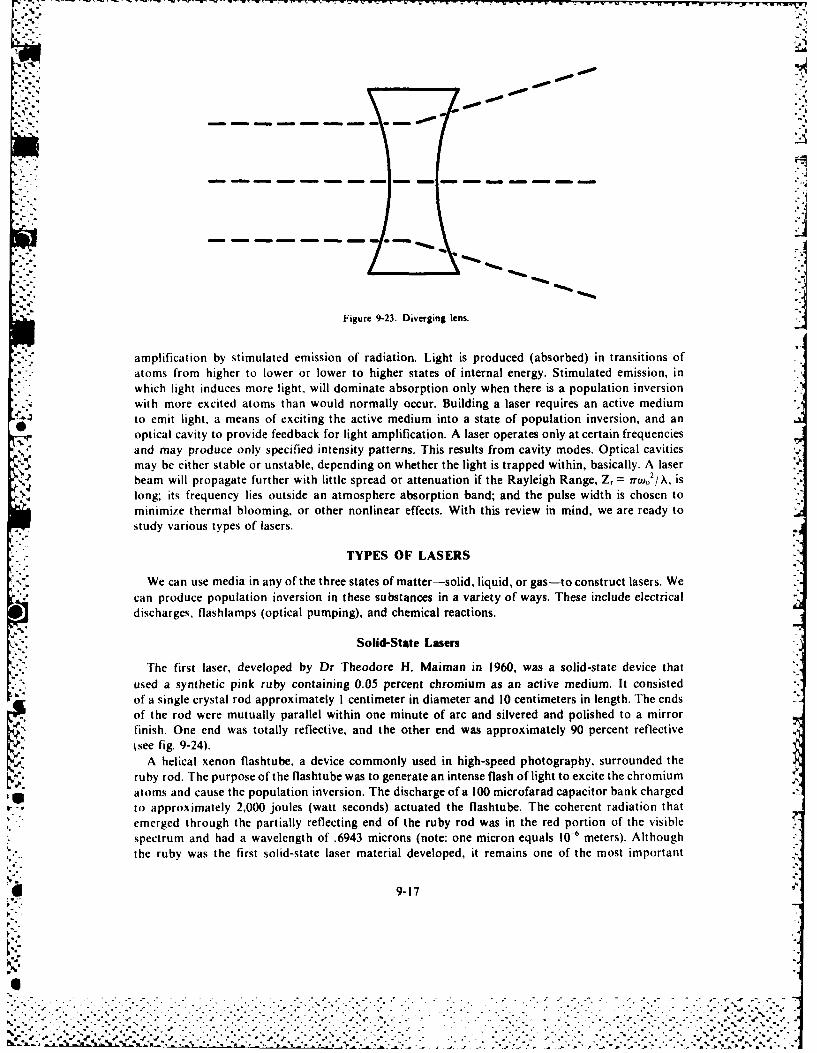
U V . .. V .
Figure 9-23. Diverging lens.
amplification by stimulated emission of radiation. Light is produced (absorbed) in transitions ofatoms from higher to lower or lower to higher states of internal energy. Stimulated emission, inwhich light induces more light, will dominate absorption only when there is a population inversionwith more excited atoms than would normally occur. Building a laser requires an active mediumto emit light, a means of exciting the active medium into a state of population inversion, and anoptical cavity to provide feedback for light amplification. A laser operates only at certain frequenciesand may produce only specified intensity patterns. This results from cavity modes. Optical cavities
may be either stable or unstable, depending on whether the light is trapped within, basically. A laserbeam will propagate further with little spread or attenuation if the Rayleigh Range, Z, = irr.02/A, islong; its frequency lies outside an atmosphere absorption band; and the pulse width is chosen tominimize thermal blooming, or other nonlinear effects. With this review in mind, we are ready tostudy various types of lasers.
TYPES OF LASERS
We can use media in any of the three states of matter-solid, liquid, or gas-to construct lasers. Wecan produce population inversion in these substances in a variety of ways. These include electricaldischarges, flashlamps (optical pumping), and chemical reactions.
Solid-State Lasers
The first laser, developed by Dr Theodore H. Maiman in 1960, was a solid-state device thatused a synthetic pink ruby containing 0.05 percent chromium as an active medium. It consistedof a single crystal rod approximately I centimeter in diameter and 10 centimeters in length. The endsof the rod were mutually parallel within one minute of arc and silvered and polished to a mirror
finish. One end was totally reflective, and the other end was approximately 90 percent reflective'see fig. 9-24).A helical xenon flashtube, a device commonly used in high-speed photography, surrounded the
ruby rod. The purpose of the flashtube was to generate an intense flash of light to excite the chromiumatoms and cause the population inversion. The discharge of a 100 microfarad capacitor bank chargedto approximately 2,000 joules (watt seconds) actuated the flashtube. The coherent radiation thatemerged through the partially reflecting end of the ruby rod was in the red portion of the visiblespectrum and had a wavelength of .6943 microns (note: one micron equals 10-6 meters). Althoughthe ruby was the first solid-state laser material developed, it remains one of the most important
9-17
- - - - - - - -.-... - .-
. . .. . . . . ........ + . t. ..... i .. . .-3 . • .. ." - . l ,. I+I I•,"
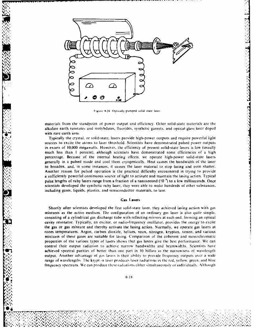
materials from the standpoint ot pow4er output and efficiency. Other solid-state materials are thealkaline earth tunstates and molvbdates. fluorides, synthetic garnets, and optical glass laser doped
.with rare earth ions.Typically the crystal, or solid-state, lasers provide high-power outputs and require powerful light
sources to excite the atoms to laser threshold. Scientists have demonstrated pulsed power outputsin excess of 10,000 megawatts. However, the efficiency of present solid-state lasers is low (usuallymuch less than I percent). although scientists have demonstrated some efficiencies of a highpercentage. Because of the internal heating effects, we operate high-power solid-state lasersgenerally in a pulsed mode and cool them cryogenically. Heat causes the bandwidth of the laserto broaden, and, in some instances, it causes the laser material to stop lasing and even shatter.Another reason for pulsed operation is the practical difficulty encountered in trying to providea sufficiently powerful continuous source of light to activate and maintain the lasing action. Typicalpulse lengths of ruby lasers range from a fraction of a nanosecond (10-9) to a few milliseconds. Oncescientists developed the synthetic ruby laser, they were able to make hundreds of other substances,including gases. liquids, plastics, and semiconductor materials, to lase.
Gas Lasers
Shortly after scientists developed the first solid-state laser, the t achieved lasing action with gasmixtures as the active medium. [he configuration of an ordinary gas laser is also quite simple.consisting of a cylindrical gas discharge tube with reflecting mirrors at each end, forming an opticalcavity resonator. Typically, an exciter, or radio-frequency oscillator, provides the energy to excitethe gas or gas mixture and thereby activate the lasing action. Normally, we operate gas lasers atroom temperatures. Argon, carbon dioxide, helium, neon, nitrogen. krypton. xenon, and various
mixtures of these gases are suitable for lasing. Comparison of the coherent and monochromaticproperties of the various types of lasers shows that gas lasers give the best performance. We cancontrol their output radiation to achieve narrow bandwidths and beamwidths. Scientists haveachieved spectral purities of better than one part in 10 billion in the narrowness ot wavelengthoutput. Another ad antage of pas lasers is their ahility to pro ide frequency out puts ox r a %iderange of wavelengths. d he krypthn laser producst laser radiations in the red, yellow, green. and hluefrequency specturm. We can produce these radiations either simultaneously or indi idualln. athough
9-18
... ... . . . . .
..................... m
prprie fte aiu.tpso.lsr.hosta.gslsrsgv.h.bs.eromne.W a
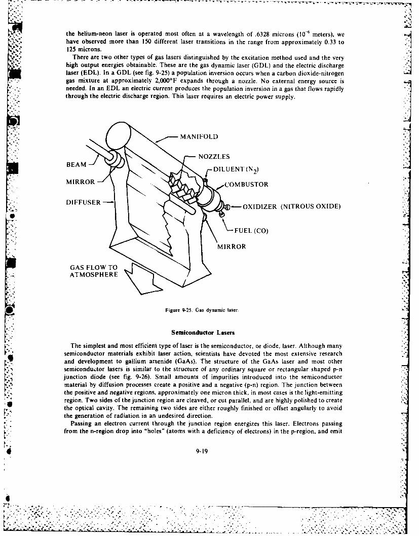
the helium-neon laser is operated most often at a wavelength of .6328 microns (10-6 meters), wehave observed more than 150 different laser transitions in the range from approximately 0.33 to125 microns.
There are two other types of gas lasers distinguished by the excitation method used and the veryhigh output energies obtainable. These are the gas dynamic laser (GDL) and the electric dischargelaser (EDL). In a GDL (see fig. 9-25) a population inversion occurs when a carbon dioxide-nitrogengas mixture at approximately 2,000°F expands through a nozzle. No external energy source isneeded. In an EDL an electric current produces the population inversion in a gas that flows rapidlythrough the electric discharge region. This laser requires an electric power supply.
t, _ x NOZZLES
'- ; BEAM/ DILU ENT (N2)Ill ~ MIRROR .-. :.
COMBUSTOR
- OXIDIZER (NITROUS OXIDE)
FUEL (CO)
MIRROR
GAS FLOW TOATMOSPHERE
0 Figure 9-25. Gas dynamic laser.
Semiconductor Lasers
The simplest and most efficient type of laser is the semiconductor, or diode, laser. Although manysemiconductor materials exhibit laser action, scientists have devoted the most extensive researchand development to gallium arsenide (GaAs). The structure of the GaAs laser and most othersemiconductor lasers is similar to the structure of any ordinary square or rectangular shaped p-njunction diode (see fig. 9-26). Small amounts of impurities introduced into the semiconductormaterial by diffusion processes create a positive and a negative (p-n) region. The junction betweenthe positive and negative regions, approximately one micron thick, in most cases is the light-emittingregion. Two sides of the junction region are cleaved, or cut parallel, and are highly polished to createthe optical cavity. The remaining two sides are either roughly finished or offset angularly to avoidthe generation of radiation in an undesired direction.
Passing an electron current through the junction region energizes this laser. Electrons passingfrom the n-region drop into "holes" (atoms with a deficiency of electrons) in the p-region, and emit
9-19
. . . . . .. .. .
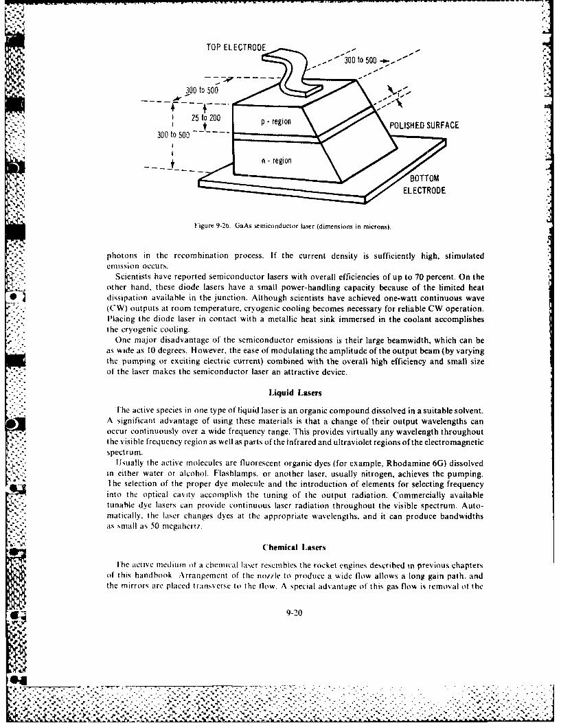
TOP ELECTRODE
300 to 500 o.-5300 to 00
25t 20p- region
." _ POLISHED SURFACE300 to 500 --
"1~~ ---- _-region
ELECTRODE
Figure 9-26. GaAs semiconductor laser (dimensions in microns).
photons in the recombination process. If the current density is sufficiently high, stimulatedemission occurs.
Scientists have reported semiconductor lasers with overall efficiencies of up to 70 percent. On theother hand, these diode lasers have a small power-handling capacity because of the limited heat
- dissipation available in the junction. Although scientists have achieved one-watt continuous wave(CW) outputs at room temperature, cryogenic cooling becomes necessary for reliable CW operation.Placing the diode laser in contact with a metallic heat sink immersed in the coolant accomplishesthe cryogenic cooling.
One major disadvantage of the semiconductor emissions is their large beamwidth, which can beas wide as 10 degrees. However, the ease of modulating the amplitude of the output beam (by varyingthe pumping or exciting electric current) combined with the overall high efficiency and small size
-. -, of the laser makes the semiconductor laser an attractive device.
Liquid Lasers
J 'he active species in one type of liquid laser is an organic compound dissolved in a suitable solvent.A significant advantage of using these materials is that a change of their output wavelengths can
. occur continuously over a wide frequency range. This provides virtually any wavelength throughoutthe visible frequency region as well as parts of the infrared and ultraviolet regions of the electromagneticspectrum.
Usually the active molecules are fluorescent organic dyes (for example, Rhodamine 6G) dissolvedin either water or alcohol. Flashlamps, or another laser, usually nitrogen, achieves the pumping.The selection of the proper dye molecule and the introduction of elements for selecting frequencyinto the optical cavity accomplish the tuning of the output radiation. Commercially available
-K-- tunable dye lasers can provide continuous laser radiation throughout the visible spectrum. Auto-matically, the laser changes dyes at the appropriate wavelengths, and it can produce bandwidthsas small as 50 megahertz.
Chemical l.asers
lhe active medium of a chemicai laser resembles the rocket engines described in previous chaptersof this handbook. Arrangement of the notile to produce a wide flow allows a long gain path. andthe mirrors are placed transverse to the flow. A special advantage of this gas flow is removal of the
9-20
.4
- .", . - - - -' . - -.. . . . . : :- , 2
1 1 -. --. . . . . . . , .. ' ..
l /. ' 4 . ,. " ".- ' - . ' .- ' - . - .. ,,' €.- _ " ' ' p.. ' '% ' ' -.- ' . " '. " ,*, . ... ,, "-

V -
spent laser molecules from the active region as well as the excess heat generated by the chemical~ :~ reaction. The hydrogen fluoride laser is typical of most high-energy chemical lasers.
The fuels in this device are molecular hydrogen (H2) and molecular fluorine (FA) First, the F2 isdissociated thermally into fluorine atoms (F) in a plenum chamber prior to entrance into the rocketnozzle. Then the F and H., are injected into the flow through separate banks of small nozzles.As the effects of diffusion and turbulent flow cause the F and H2 to mix, the following reactionoccurs: H2 + F - HF* + H.
HF* represents excited hydrogen fluoride. The energy of the reaction is deposited in upper(vibrational) states of the HF molecules, and lasing occurs around 2.7 microns in the near-infraredregion of the spectrum. The overall efficiency of such devices is high, amounting to several percent :of the available chemical energy. The high frequency laser is capable of continuous operation at
very high levels of power.A
Eximer Lasers
The eximer laser is an elect rically-pumped device. Electrons from an electron gun ionize atoms of arare gas like krypton (positively) and a halogen like flourine (negatively). The ionized atoms combineto form an "excited dimer" or "eximer" that can be made to lase. Typical eximer lasers, like krypton,fluoride, and xenon chloride, lase at ultraviolet wavelengths. Eximer lasers have been around for
* several years. However, they have not shown the potential for either the high energy or the light* weight necessary for weapon use. Scientists have studied them extensively for use in laser isotope
separation.
Free Electron Lasers
The free electron laser (FEI.) uses the fact that, when a beam of electrons is accelerated, that is,bent, sped up. or slowed down, it emits electromagnetic radiation in a direction tangential to theacceleration. The wavelength of the radiation emitted depends on the energy of the beam and thestrength of the accelerating force. Usually, the effect is seen in synchrotron particle accelerators wherestrong magnets bend relativistic (very high energy) electron beams into a circle. We call the radiationproduced "synchrotron radiation." -This radiation can be very intense and spectrally pure, but it isonly spontaneous emission. 'True laser radiation consists of stimulated emission produced when aphoton interacts with an excited electron and stimulates it to emit a second photon identical to thefirst, traveling in the same direction as the first.
'To build an FEL. a beam of electrons is not bent, but accelerated and decelerated in a straight lineusing a modulated magnetic field called a wiggler or undulator. If a laser beam with a wavelength
* matching the electron beam energy/ magnetic field strength parameters is directed along the electronbeam path. it will stimulate the electrons to emit radiation and be amplified. Alternatively, if mirrorsare placed along the path of the electron beam, an optical resonator can be formed producing a self-generated laser beam. Since the wavelength is dependent only on the electron energy and the magneticfield strength, and the electrons are free and not bound to specific energy bands, theoretically, theFEL can produce or amplify any wavelength from the far infrared to the hard ultraviolet.
'The first FEL amplifier was demonstrated at Stanford University in the early 1970s. Since then,scientists have directed considerable work toward the two goals of building FEL resonators andachieving short wavelengths. However, as of December 1983, only four FELs in the free world hadoperated with resonators. rhe first two ran in 1976 at long wavelengths. One was a 3 micronmidinfrared laser at Stanford University and the other was a 400 micron extreme far-infrared laserbuilt by Columbia University and the Naval Research Laboratory. The second pair ran in 1983. Onewas a 0.63 micron red-orange laser operated in France and the other was a 1.6 micron near-infraredlaser operated at Stanford University. The pace of progress is increasing, and, in particular, Frenchexperiments have produced some encouraging surprises. However, the technology is still in itsinfancy. High power, beam quality, and efficiency have not been demonstrated. However, FELshold great promise because of their inherent tunability and potential efficiency.
9-21
d
LASER APPLICATIONS
The most frequent potental application evoked by the word laser in many minds is some type of-2weapon ordeath ray. However, use of the laser as a destructive or lethal device is only one of its
>2C possible applications. Its other potential uses touch almost every field of endeavor, includingcommunication, chemistry, biology, astrophysics, and industrial processes.
The laser has personal applications as well. For example, doctors can restore or save sight byperforming a delicate laser operation called a retinal weld. This technique has become a routineoperation in which photocoagulation with a suitable short but intense pulse of laser light welds thetorn or injured retina to its support. The laser has shown some promise in the treatment of eye tumorsand skin cancers. In fact, as a light knife, the laser may someday make bloodless surgery possible.
Laser properties have supported other fantastic accomplishments. Only two years after scientistsdeveloped the laser, a ruby laser, considerably smaller and less sophisticated than current ruby lasers,
* 04-.shot a series of pulses to the moon, 240,000 miles away. The laser beam illuminated a spot less thantwo miles in diameter and reflected back to earth with enough strength for measurement by sensitiveelectronic equipment. In comparison, the beam of a high-quality spotlight would spread to thousandsof miles if it could reach that far. Moon-landing spacecraft used television cameras to photographlaser beams directed from earth to the moon. The spacecraft relayed the pictures back to earth.Interestingly, the laser outputs were less than three watts, illustrating the modest power required by alaser beam.
Obviously, we cannot include a discussion of all current and potential laser applications in thishandbook. Therefore, we have confined our treatment of lasers to major military and spaceapplications. Fields of particular interest to the military are communication, laser radar systems,
-~ surveillance, instrumentation, and weaponry.
.- 1*Communications
The laser has major potential for use in the field of communicatio-n. The amount of informationthat we can encode (modulate) on an electromagnetic carrier is directly proportional to the frequency
*of the carrier wave. Because of the extremely high frequencies generated by lasers, they have anenormous potential capacity as transmitters of information. For example, a bandwidth of oneoperation on a 1015 hertz laser carrier wave provides an information bandwidth of 10,000 gigahertz.This information bandwidth is several orders of magnitude wider than the total frequency spectrumof the radio.
Another significant advantage is the coherence of the laser beam. This equates to high-antennagains and permits high-data-rate communications over vast distances. Laser techniques areapparently within the state of the art for use in obtaining near real-time television pictures atinterplanetary distances of 100 million miles.
Because of the spectral purity of laser radiations, effective optical filter techniques can provide ahigh degree of discrimination against natural background radiations from the sun, stars, and
planetary bodies. The highly-collimated laser beam provides the capability of generating jamresistant, secure communication. Those trying to intercept a transmitted laser communications linkcan intercept only if they operate on a direct line joining the transmitter and receiver. *
Laser communications offer a possible solution to the problem of radio blackout encountered byreentering spacecraft. Already, scientists have demonstrated in laboratory experiments, that, unlikeradio waves, laser radiations will penetrate hot ionized gases or plasmas equivalent to reentryplasmas.
- Use *of the laser for communications is subject to several limitations. Laser radiations arevulnerable to absorption and dispersion by atmospheric particles, particularly during periods of rain,snow, or fog. Combined with line-of-sight constraints these atmospheric effects limit terrestrial point-to-point communications to distances of some 30 to 40 miles. Only specialized links are candidates forterrestrial point-to-point circuits because major communication systems cannot tolerate randomoutages (even short interruptions in service cause chaos). Two examples of such communication
9-22

circuits are secure or covert communication and data links in nuclear test environments.Although repeaters that provide amplification and refocusing can eliminate the line-of-sight
problem, we cannot eliminate the atmospheric effects. However, one means of circumventing theatmospheric aberrations is to beam the laser energy in hollow pipes that are either evacuated or filledwith transparent and inert gases. These pipes with laser amplifiers every 50 to 100 miles and internalreflecting surfaces to bend the beams as necessary, could span the entire country with lasercommunications networks similar to existing gas and oil pipelines. Several short-distanceexperimental systems are already in existence in the United States, France, and the Soviet Union.Atmospheric aberrations or line-of-sight limitations would not affect pure space communicationsbecause of the near vacuum of space.
Other disadvantages of laser communications include the difficulties associated with pointing thevery narrow transmitted laser beam and the problems of acquisition and tracking at the receiving end.
Even disregarding the relatively low efficiency of most lasers, the efficiency of the receiving devices andother modulating and demodulating subsystems is lower at laser frequencies than at radio andmicrowave frequencies.
L.aser Radar
Numerous existing or potential laser applications use the radar principle. These applications varyfrom simple hand-carried range finders for surveying or battlefield ranging to sophisticated space-tracking and detection systems. Other potential functions include spacecraft signature analysis
,- (measurement of target length, si7e, and shape), altimetry, automatic space rendezvous and docking,calibration of space track radars by simultaneous tracking of targets, terrain clearance, and obstacleavoidance.
In principle, laser radar closely resembles conventional microwave radar. Scientists direct pulses oflaser energy toward a target. and measure the time elapsed between the pulses and their reflectedreturns. They determine the range directly from the product of the known speed of the laser energy(the speed of light) and the elapsed time. The difference between the two systems is due primarily tothe higher laser frequency. The elements of the laser radar are merely the optical analogy of theirmicrowave counterparts.
The range resolution of a pulsed radar system depends on the sharpness of the leading edge of thepulse and the accuracy in measuring the transit time of the two-way pulse. This highly collimated laserbeam permits range measurements in environments where conventional radars fail because of theirwider beams. For example, reflections from target background clutter render conventional firecontrol radars in low-flying aircraft useless at attack angles of less than approximately 15 degrees.Laser systems can provide tracking data during the launch and initial flight phase of space vehicleswhen ground clutter reduces the effectiveness of conventional radar.
In a space-tracking role near the earth, conventional radar can determine range to an accuracy ofapproximately 100 feet; the laser narrows the error to approximately 25 feet. With cooperativesatellites equipped with special mirrored corner reflectors, accuracies are better than 10 feet at thisdistance. Scientists have demonstrated successful ranging on a cooperative satellite at ranges of 1,000miles.
Laser radars were particularly effective in supplementing the Baker-N unn cameras that were usedon several satellite-tracking networks. When the spacecraft was traveling in the earth's shadow, theyprovided range information in addition to illumination for photography. Since the Baker-Nunn
- camera provided angular coordinates, the additional range information specifies the position vectorof the spacecraft at the time of observation.
Another advantage of the laser is the modest optical lens aperture required to concentrate itsemitted beam. By using a visible laser, a lens one loot in diameter can pro% ide a one-minute (of arc)beam. In comparison, the FPQ-6 radar used in a spacc-tracking role requires an antenna 30 feet in
. diameter to produce a 24-minute (of arc) beam. A ngular resoiutiton is a function of the narrowness ofthe radiated beam. Because of the narrow bean present target a/imuth and elevation angle resolution
........ ... ....... 4.. "- """-- "- "•-..---.. "- - i -- 1;
shows an improvement of at least an order of magnitude over conventional radars.convenommnctinhoel, ae radar Thes inldetedivcutencu ra tagesadanfrteresrial apmpliaions.oAsneninacmuiatosloevrae radar. hhsnldhedfiutnasirn sev e diadantgesri l coppiarionsto
expsur totheattntatins nd beratinscaused by the atmosphere, particulary under adverse
Surveillance
The military can use lasers for such surveillance functions as imaging, multicolor sensing, moving
target indication, and illumination of covert photography. Competing technologies are passiveIinfrared, side-looking radar, and conventional photography. Laser systems offer advantages of betterresolution than passive infrared and side-looking radar and more covert night operation thanconventional photography.
The covert nature of an active laser surveillance system is based on two factors: it provides its ownillumination and it uses a narrow pinpoint beam in a rapid sequential scanning process. In providingcoherent self-illumination, it permits operation under day and night conditions. The highly collimatedradiation permits a high degree of covert position even when frequencies are used in the visible range,and use of frequencies in the visible infrared or ultraviolet spectrum would further enhance covertoperations. Military forces can use the laser in such a special application as terrain profile, or contour.mapping. It could improve spacecraft signature analysis as well.
Another important area where the laser may improve present capabilities is underwatersurveillance. Although scientists know the attentuation of light transmission to be several orders ofmangitude greater than sound waves (sonar application), the use of laser energy in the blue-greepregion of the visible frequency spectrum provides hope that we can develop viable underwater
* surveillance systems. Seawater offers the least attenuation to these frequencies, and the sensitivity oflaser radiation detection devices is highest in the same frequency range. Scientists are aiming presentresearch at minimizing problems of backscattering due to suspended organisms and minerals, as wellas water.
Instrumentation
Many interesting laser applications have been made in instrumentation. These applicationsinclude radar and gun bore sight alignment techniques, optical computers and data processing,wideband high-resolution recording, techniques for measuring vibration of' spacecraft in simulatedflight tests, and visual display technology, which promises to produce screen sizes at least an orderof magnitude greater than present TV-type displays.
Another fascinating area is holography, a means of storing (making a hologram) and reproducing.Jat will, a three-dimensional image of an object or scene. We can produce holograms in black andwhite or color. The reconstructed, stored image is a virtual image floating in space some distancebehind the hologram. If the observers chattge viewing positions, they literally, can look around theobject or elements in the scene. The broad range of potential applications of holography almost rivalsits parent field of laser applications.
Another potentially valuable use of the laser involves the laser gyro, which does not depend uponthe properties of inertia. Since the laser gyro has a rugged and simple design with no moving partsincluding gimbals, scientists can attach it rigidly to a vehicle. Its other advantages include thecapability to operate in environments of extremely high acceleration and to perform almostinstantaneously after being switched on.
The laser gyro is based on the principle that rotation of the optical cavity about its axis will causefrequency differences to develop between two simultaneous contrarotating laser beams in a closed-loop optical cavity since the frequency of laser operation is a function of cavity length. If the optical
:-%7 path is stationary, the two contrarotating beams take the same time to traverse the loop, and theirfrequencies are the same. If we rotate the gyro about its axis, we shorten the effective length of thepath for one beam and lengthen the path of the other. This causes the frequency of one beam to
£ 9-24
1-7
increase and the other to decrease, and we may observe the resulting difference by optical heterodynetechniques. The magnitude of the difference is proporti, al to the rate of rotation. Scientists canposition three planar laser gyros orthogonally to provide information on pitch, roll, and yaw.
Weaponry
Shortly after the invention of the laser, it became apparent that if high-energy laser weapon -
systems could be developed, they would have some particularly attractive features. For example,since light travels at a speed of 186,000 miles per second, the lethal fluxes would arrive at targetsalmost instantaneously, and there would be no requirement to lead the targets unless they were located
* very great distances from the weapons. The military could use laser weapons for selective engagementof single targets in the midst of numerous friendly vehicles. Unlike nuclear weapons, laser weapons -
would not disturb large segments of air space and would not destroy indiscriminately all vehicleswithin their lethal range.
A high-energy laser weapon system is a system that attempts to inflict damage on an aerospacevehicle by placing large amounts of energy on a small area. The result is a thermal kill, such asweakening and eventual rupture of structural components, ignition or combustion of flammablematerials, or destruction of thermally sensitive items in vital components.
Initially, scientists considered solid-state lasers (large ruby rods or large yttrium aluminum garnet
rods known as YAG) suitable for high-energy laser applications. Indeed, they could achieve shortpulses of very high power with these lasers. However, internal heating of the crystal resulted infracture of the crystal long before it could deliver damaging amounts of energy to the target. Furtherdevelopment was necessary.
Scientists and engineers solved the problem in 1967 with the invention of the carbon dioxide GDL,or CO,2 GDL. The CO2 GDL, the first GDL that appeared scalable to very high energies, has pavedthe way for serious consideration of a high-energy laser weapon system. In recent years, scientistshave developed other gas-phase systems, including the carbon dioxide EDL, the carbon monoxide[DI, the deuterium fluoride chemical laser, the hydrogen fluoride chemical laser, and several others.
Military leaders have studied many different targets to determine their vulnerability to ahypothetical laser weapon system. At one end of the spectrum, numerous items, such as infraredsensors, are exceptionally vulnerable to laser radiation, particularly when the radiation affects theband normally accepted and processed by the sensor. At the other end of the spectrum, scientists have
* designed such items as ballistic missile reentry vehicles to survive very high temperature* environments, thus, they are more difficult for the laser's thermal kill mechanism to damage.
- . Numerous attractive targets appear to lie between these two extremes.
PARTICLE BEAM DESIGN AND DEVELOPMENT
Charged particle beams (CPB) are not useful as weapons in space, but an understanding of their7generation and propagation in the atmosphere is still important. After all, neutral particle beamscannot be accelerated unless they first exist as CPBs in the accelerator. An understanding of thephysics of charged particle beams will explain, to some degree, why they cannot propagate from the
* atmosphere into space, cannot propagate for any useful range as weapons in space if generated there,and cannot be accurately pointed in space because of the earth's magnetic field. This explanation
*shows as well why neutral particle beams cannot propagate in the atmosphere. but might achieveuseful weapon ranges in space.
Basic Ideas
Usually charged particles consist of' electrons with negative Lharges and protons with positivecharges. Both have a charge of magnitude 1.6 X 10 "' coulombs, but their masses are quite different.An electron has a mass of 9.11 X 10-" kilograms, and a proton has a mass of 1.67 X 10 kilogramsapproximately 1.000 times greater. Since the particles are charged. we can accelerate them to very
d 9-25
"p.
rhigh energy with a suitable electric field. The amount of energy received by an electron during
acceleration across a potential of one volt is called an electron volt (eV). It is equal to 1.6 X 10' 9 joules.This convenient unit of energy for CPB problems is used almost exclusively in the literature onthe subject.
Accelerating particles of a given charge in an electric field of given strength is reasonably straight-forward, but some knowledge of relativistic dynamics is necessary to understand what happens tothe particles at high energy. The speed of a particle cannot exceed the speed of light, and strangethings happen when the particle approaches this limit. The effective mass of the particle changes.If m is the mass of the particle at rest (called rest mass), then its mass at velocity v is
m' = ym (16)
where
.v I - v2/c2 (17)
In equation 17, we can see that y I and, m' m as long as v < c. As v approaches c, m' increaseswithout bound.
What is the impact of this effect on the laws of motion? We can rewrite Newton's law as follows
dvF = ma ='m - --
- - dt• (18)
This relates applied force to particle acceleration, but at relativistic velocities, m is no longer constantand we must write equation 18 in the more general form
dP d mv dF = _ = -Ymv
dt dmt - d t - (19)
where P is the particle momentum. As v gets closer and closer to c, an applied force is effectiveprimarily in changing 'y rather than v, since there is an upper boundary to how high it can go. Thisleads to the question of definition regarding the energy of a relativistic particle. The kinetic energy
* . •of a nonrelativistic particle is
T mv (20)
The equivalent formula for a relativistic particle ism.1
T(y- I)imc2 . (21)
At first glance, it is difficult to see the relationship between equations 20 and 21: but at Slow speed,
v /c ) -
(22)
so that for V <<C.
T = (y - I ) me (I - - -mc I myC
;. 9-26
4
z ............... ... ...... ...... ,... . . ', """ . ,
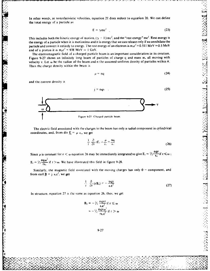
- .- . . . - -, .-
In other words, at nonrelativistic velocities, equation 21 does reduce to equation 20. We can definethe total energy of a particle as
;"E = 3,mc 2 (23)
This includes both the kinetic energy of motion, (-y - I ) mc, and the "rest energy" mc 2. Rest energy is
the energy of a particle when it is motionless and it is energy that we can release only if we annihilate the
particle and convert it entirely to energy. The rest energy of an electron is mc 2= 0.511 MeV =0.5 MeV
*and of a proton it is mpc2 = 938 MeV = I GeV.The electromagnetic field of a charged particle beam is an important consideration in its creation.
*- Figure 9-27 shows an infinitely long beam of particles of charge q and mass m, all moving with
velocity v. Let w be the radius of the beam and n the assumed uniform density of particles within it.
Then the charge density within the beam is
p = nq (24)
and the current density is 5
j= nqv (25)
I Figure 9-27 Charged particle beam.
The electric field associated with the charges in the beam has only a radial component in cylindrical
coordinates, and, from div E = p! t, we get
I a = p nqr "-r , (26)
:jnqr .Since p is constant for r < w equation 26 may be immediately integrated to give E, /2"-o if r <,
qWr 2
E, = 2 if r> u. We have illustrated this field in figure 9-28.re,
Similarly, the magnetic field associated with the moving charges has only 0 - component, andfrom curl B j i eoc, we get
-r(rB,)- 2-(27)r , (27)
In structure, equation 27 is the same as equation 26, thus, we get
B. - nq'r if r < w
- /q ifr> w
reoc
9-27
%
e
< %o"
*%
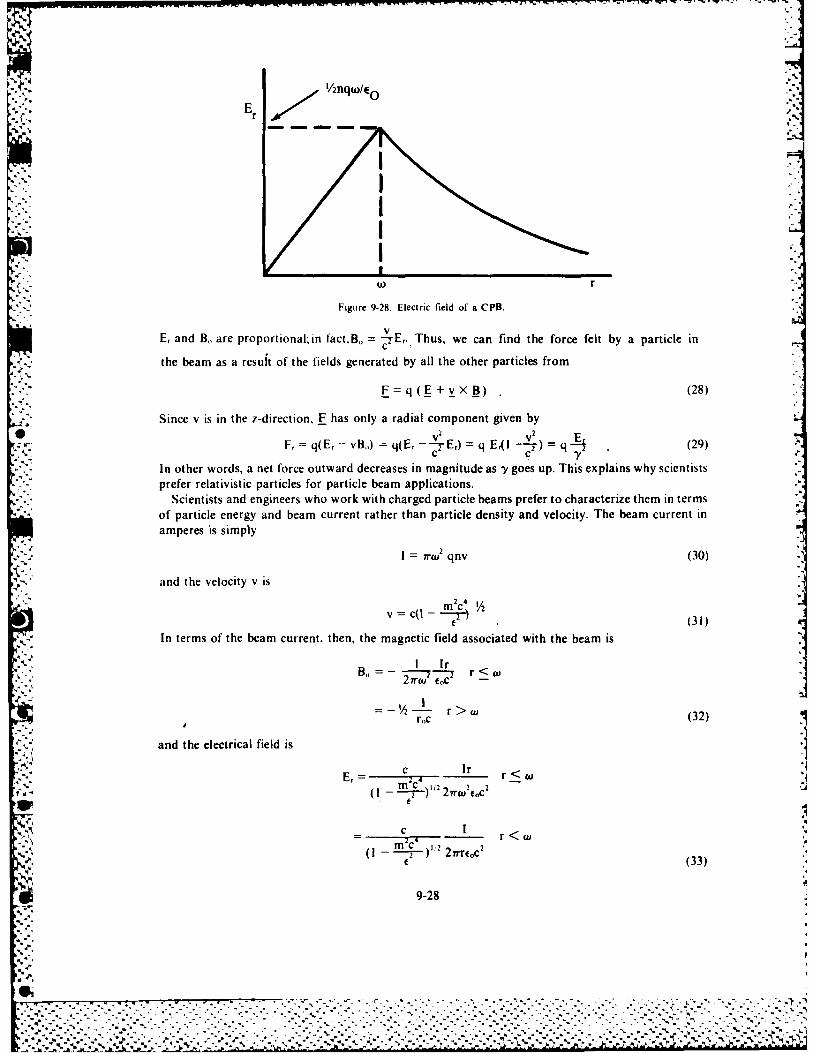
.-.. t/nqt/ , - - ,
-
Err
Figure 9-28. Electric field of a CPB.
v
E, and B,, are proportional, in fact.Bo = 7E,. Thus, we can find the force felt by a particle in
the beam as a result of the fields generated by all the other particles from
F = q ( + v X B) (28)
,. Since v is in the z-direction. F has only a radial component given byV E,F, = q(E, - vB) = q(E---1-E,) = q E41l -- Y) = (29)
c C 7 YIn other words, a net force outward decreases in magnitude as -/ goes up. This explains why scientistsprefer relativistic particles for particle beam applications.
Scientists and engineers who work with charged particle beams prefer to characterize them in termsof particle energy and beam current rather than particle density and velocity. The beam current inamperes is simply
I= 7 o 2 qnv (30)and the velocity v is
v c(I - c 4'/2(31)
In terms of the beam current, then, the magnetic field associated with the beam is
. I Ir r<-. B= -'/2 --- T r o
r, (32)
and the electrical field isc Ir
'~~~, r < ! -- (v iz2rwec
-Itl) 1 22 2r
c I
-2 - (33)
i 9-28
,1 ._-
-.......
L l.. . . . . . . .
K'-',,-'" .'''-..,- '.,." : ,- " .' ; "- ."- '." 7 -. ."-" "-" ." "-." - -" -.- ''-.-'''.-.'''- ''..."....-..-.-.-.".-.'.- -.-. '.'
I % "/ .'''"-..2,:e. '. ',-. ..-'- .,'-.'-'-' :.-. -.-".- .,.-.--.':--..,:,". .,',-. .'-.-'-. -. ,- c -' -.. ,-
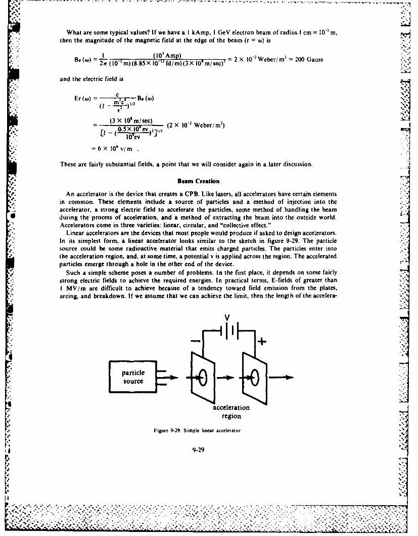
-. What are some typical values? If we have a I kAmp, I GeV electron beam of radius I cm = 10 " m, -
then the magnitude of the magnetic field at the edge of the beam (r = cu) is
B'''I (10, Amp) 2
" B0 21r (0' m) (8.85 X 10⁻² fd/m)(3 X 10' m/sec)2 2 X 10 Weber/ -- 200 Gauss
and the electric field is
cEr(0=0 2 4 Be (t )m-c \1/2
(3 X 10'mlsec) 0-(3 X '~ m/ sec (2 X 10- Weber/ m 2)
(0-(OX5iOev) 2 ./2-"I IO ev
=6X10⁶v/m
These are fairly substantial fields, a point that we will consider again in a later discussion.
Beam Creation
An accelerator is the device that creates a CPB. Like lasers, all accelerators have certain elementsin common. These elements include a source of particles and a method of injection into theaccelerator, a strong electric field to accelerate the particles, some method of handling the beam
* during the process of acceleration, and a method of extracting the beam into the outside world.Accelerators come in three varieties: linear, circular, and "collective effect."In Linear accelerators are the devices that most people would produce if asked to design accelerators.In its simplest form, a linear accelerator looks similar to the sketch in figure 9-29. The particlesource could be some radioactive material that emits charged particles. The particles enter intothe acceleration region, and, at some time, a potential v is applied across the region. The acceleratedparticles emerge through a hole in the other end of the device.
Such a simple scheme poses a number of problems. In the first place, it depends on some fairly*i strong electric fields to achieve the required energies. In practical terms, E-fields of greater than 0
I MV/m are difficult to achieve because of a tendency toward field emission from the plates,arcing, and breakdown. If we assume that we can achieve the limit, then the length of the accelera-
particle _source
acceleration
region
Figure 9-29. Simple linear accelerator. -'
9-29
V ... ., .-, -, • . . . . . .. .. ., . .,, .. ,, .. . . . ,. . • . . . .. ,''-- , , . . . . . . .*,\ ,-,. .,
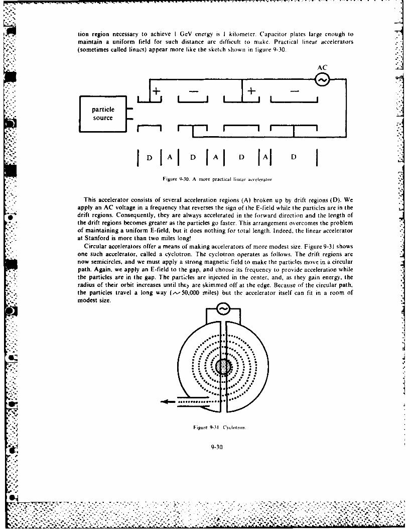
-
tion region necessary to achieve I GeV energy is I kilometer. Capacitor plates large enough to
maintain a uniform field for such distance are difficult to make. Practical linear accelerators(sometimes called linacs) appear more like the sketch shown in figure 9-30.
AC
-'.+ -- "--
particlesource
JD A D IAI D IAl D I
Figure 9-30. A more practical linear accelerator.
This accelerator consists of several acceleration regions (A) broken up by drift regions (D). Weapply an AC voltage in a frequency that reverses the sign of the F-field while the particles are in thedrift regions. Consequently, they are always accelerated in the forward direction and the length ofthe drift regions becomes greater as the particles go faster. This arrangement overcomes the problemof maintaining a uniform E-field, but it does nothing for total length. Indeed, the linear acceleratorat Stanford is more than two miles long!
Circular accelerators offer a means of making accelerators of more modest size. Figure 9-31 showsone such accelerator, called a cyclotron. The cyclotron operates as follows. The drift regions arenow semicircles, and we must apply a strong magnetic field to make the particles move in a circularpath. Again, we apply an E-field to the gap, and choose its frequency to provide acceleration whilethe particles are in the gap. The part;cles are injected in the center, and, as they gain energy, theradius of their orbit increases until they are skimmed off at the edge. Because of the circular path,the particles travel a long way (,.-50,000 miles) but the accelerator itself can fit in a room ofmodest size.
%. ..
,
' Figure 931 Cyclotron.
.- .9-30
-•-%
: - . --, : ----.'-.' , - -. - ". ", .. . .'. .. 4" . . .-.- -: "- • -. :- ". 4. , .- ''. '-- .-'," ,'.'.'','',"'- . ","..','..
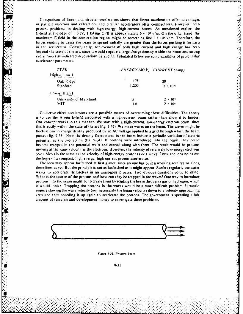
Comparison of linear and circular accelerators shows that linear accelerators offer advantagesin particle injection and extraction, and circular accelerators offer compactness. However, bothpresent problems in dealing with high-energy, high-current beams. As mentioned earlier, the
* E-field at the edge of I GeV, I kAmp CPB is approximately 6 x10⁶ v/m. On the other hand, themaximum E-field in the acceleration region might be something like I x106 v/rn. Therefore, theforces tending to cause the beam to spread radially are greater than the forces pushing it forwardin the accelerator. Consequently, achievement of both high current and high energy has beenbeyond the state of the art, since it would require a large charge density within the beam and strongradial forces as indicated in equations 32 and 33. Tabulated below are some examples of present dayaccelerator parameters.
TYPE ENERGY(MeV) CURRENT(Ainp)High-e, L~ow I
Oak Ridge 178 20
t.W ihStanford 1,200 3 x10⁻²
University of Maryland 5 2 x 04*MIT 1.6 2 x10⁴
Collect ive-effect accelerators are a possible means of overcoming these difficulties. The theoryis to use the strong E-field associated with a high-current beam rather than allow it to hinder.One concept works in this manner. We start with a high-current, low-energy electron beam, since
* this is easily within the state of the art (fig. 9-32). We make waves on the beam. The waves might befluctuations in charge density produced by an AC voltage applied to a grid through which the beampasses (fig. 9-33). Now the density fluctuations in the beam induce a periodic variation of electricpotential in the z-direction (fig. 9-34). If protons were introduced into the beam, they could
V. become trapped in the potential wells and carried along with them. The result would be protonsmoving at the same velociy as the electrons. However, the velocity of relatively low-energy electrons(~- I MeV) is the same as the velocity of high-energy protons (^-I GeV). Thus, the idea holds outthe hope of a compact, high-energy, high-current proton accelerator.
The idea may appear farfetched at first glance, since no one has built a working accelerator alongthese lines as yet. But the principle is not as farfetched as it might appear. Surfers regularly use waterwaves to accelerate themselves in an analogous process. Two obvious questions come to mind:What is the source of the protons and how can they be trapped in the waves? One way to introduce
* protons into the beam might be to create them by sending the beam through a gas of hydrogen, whichit would ionize. Trapping the protons in the waves would be a more difficult problem. It wouldrequire slowing the wave velocity (not necessarily the beam velocity) down to a velocity approachingzero and then speeding it up again to accelerate the protons. The government is spending a fairamount of research and development money to investigate these problems.
Figure 9-32. Electron beam.
6 9-31
%5
%. %% . . . . .
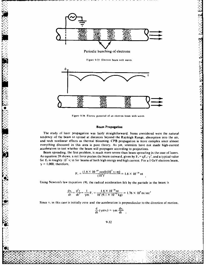
- -,rr----r-or-,-- ,-- ---
-;.. .,: .*..
Periodic bunching of electrons
Figure 9-33. Electron beam with waves.
Fgr 9-4 E4... *". .fljJ
sq.-'. ,....
,"'-" Figure 9-34. Electric potential of an electron beam with waves. <
Beam Propagation
The study of laser propagation was fairly straightforward. Items considered were the natural Vtendency of the beam to spread at distances beyond the Rayleigh Range, absorption into the air,and such nonlinear effects as thermal blooming. CPB propagation is more complex since almosteverything discussed in this area is pure theory. As yet, scientists have not made high-currentaccelerators to test whether the beam will propagate according to projections.
Beam spreading, the first problem, is much more severe than beam spreading in the case of lasers.As equation 29 shows, a net force pushes the beam outward, given by F, = qE,/3 2 , and a typical valuefor E, is roughly 10' v/rm for beams of both high energy and high current. For a I GeV electron beam,- = 1,000; therefore,
Fr (1.6 X 10-'* coul)(10 7 v/m) - 10(101)2 .X.6× nt
Using Newton's law (equation 19), the radical acceleration felt by the particle in the beam is
dv, d2r 1 1.6 X 10- nt:.- F. - - = 1.76 X 10⁹ m/ sec2d d- F 101(9.1 X 10⁻³¹kg)
Since v, in this case is initially zero and the acceleration is perpendicular to the direction of motion,
- "d dv,-(YmVr) = yimdt dt
9-32
LiL .. i.',
Therefore, we can estimate the time it takes a beam With a I centimeter radius to double in size as
td~~~ = ~ ' 2.5 X 10O" sec
IDuring this time, the beam will travel a distanceI
il V- IdCia (3 X 10' m; sec) (2.5 X 10⁻⁶ sec) =750 m.
Therefore, we cannot expect an electron beam to go more than a kilometer without doubling in size* and reducing its intensity (W in 2) by a factor of four. For protons, the situation is worse. In that
case, in, is greater than mr. but -y -2 and F, and dv,/ dt are also greater, giving a double distance of_d 3m.
Based on these simple examples, we might conclude that charged particle beams are not viable
candidates as weapons, since any realistic application would require much greater ranges. In fact,such a conclusion would be correct in outer space where there would be nothing to limit the beamIfrom spreading under its own internal forces.
For applications ir the air, ionization may be a means of avoiding the spreading tendency of thebeam. As the ionizing process proceeds, the beam soon finds itself propagating, not through neutralair, but through a channel of ionized gas having high conductivity. Under these circumstances,charges will flow in such a way that the E-field is neutralized on the interior, leaving the imbalancein the net charge only on the surface. Figure 9-35 illustrates this sequence of events, known as chargeneutralization. We can show that the characteristic time for charge neutralization is 7~ ,, .[he conductivity of a gas used in this process is
ne
m p (34)
Where n is the electron density, e and m the electron charge and mass, and P the frequency ofelectron collisions of the heavy particles (ions or neutrals) that retard their flow. If we assumethat the beam ionizes all standard temperature and pressure (STP) air, then n 3 X 10²
1/ m' andV 0 1', Sec giving a =8.43 X 10' mho,'m and r. = 10-'5 sec. This time is very short compared
to the doubling time for beam size presented earlier. Thus, we can conclude that charge neutralizationmay prevent catastrophic beam spreading. The exact dynamics of the process are still the objectof research, both theoretical and, to the extent possible, experimental.
What will happen to the beam after charge neutralization? The charge density within the beamwill be zero, but the current density will not. This means that the repulsive E, has been eliminated,but the attractive has not (see equation 32). Now the beam will feel a net inward force, and pinchdown. At beam edge w, this inward magnetic force is
c- 7rvwE0. (35)
What is the influence of' this force on the size of the beam? Eventually, the small sideways motion,which relates to the temperature of the beam particles, will produce an outward pressure to counterthe inward magnetic force, and the beam will stabilize as illustrated in figure 9-36.
* The preceding discussion shows that a CPB begins to expand under the repulsion of its chargesA as it enters the atmosphere, but it contracts after it ionit--s the air and charge neutralization occurs.
As the beam propagates, it will encounter particles of air. In scattering from the particles of air,* the beam particles will pick up more sideways motion, and increase in the beam temperature will
cause it to begin spreading again. In other words, as scattering heats up the beam, it will expandand expend energy in working against the compressive magnetic field. Thus,
9-33
000000
Beam Air(a) Beam particles encounter air molecules as they exit the accelerator
+ 000
+ J000 _ +
5'*_2
+ +±+000
(b) Beam particles strike the air molecules and ionize them, leaving aIconducting plasma behind the head of the beam
+6 + + + +
+ + + + + ++ + + + + +
(c) Charges of like sign are repelled from the beam volume, while thoseof opposite sign are attracted. The net result is that the charge densitygoes to zero, and a radial electric field which once looked like this,
wr
now looks like this,
2 ErResult: Particles on the
Abeam interior do not tend* to spread.
W r
a) ematlsnFigure 9- Charge neutraliation.
9-34
%. . .. ..®..
4, + + + 4-
% O O+ + ++ +
P"711
"O- " - - Outward pressure-- ft -- from slight side-
--- -ways motion.
Inward magnetic force02
_ It 2 TWtt
Figure 9-36. Steady-state beam radius.
dQ = dW (36)
where dQ is an increment of random energy (temperature) added to the beam through scatteringand dW is an increment of work through beam expansion. A glance at each side of equation 36shows that the work done is
dW = F dw (37)
if the beam expands from a radius a to (w + dw) against a compressive force F, where the force feltper unit of length of beam is
F= rrw2nb -T"( r l)c rvwoparticles force perper unit particlelength (38)
It is important to note that the number of particles per unit length in the beam is a constant. As w goesup, nb goes down in such a way that rW2 nb remains fixed. Similarly, the beam current is independentof beam size. Consequently, equations 37 and 38 indicate that
9dW = )
where
C 7rw 2 nhql- =) (CT irveo
is a constant. What about the dQ term in equation 36? As the beam propagates, it will encounter-* air molecules in direct proportion to the distance it travels. Thus, we can conclude that
dQdQ =(- -)dz (41)
9-35
-.
. . . .. . . . . . . . . . . . . . . . . . . . ..-. .
where dQ/dz, the random energy of motion transferred to the beam per unit path length, is a
constant. By substituting equations 39 and 40 into equation 36, we find
dz w .(42)
We may solve equation 42 for the variation for wu with z to find
dd
wwo ,= ( -7) t (43)
We know equation 43 as the Nordseick Equation. It shows that the beam expands exponentially
with distance, with the rate of expansion being directly proportional to (dQ/dz) and inverselyproportional to I through the constant C as equation 40 shows. One consequence is that a minimumcurrent is necessary to achieve a given range with little beam spread and that the minimum current
required increases with range. This explains why large beam currents are required for long-range
propagation. All of this is summarized conveniently in figure 9-37, which is a schematic representa-
tion of beam radius as a function of range.
-,expansion due
to coulomb" '-': repulsion
charge neutralization,
followed by contraction
to the Bennett radius
Nordseick
expansion
C T N
Figure 9-37. Beam siue versus range (not to scale).
What if we choose the beam parameters so that little expansion will occur over the range desiredfor some application? Does this mean that the beam will propagate for long ranges? This is not true.
S.w As is true of lasers, beam expansion is only part of the story. Beam particles suffer loss of energy
when they encounter air molecules. This process is analogous to the absorption of photons froma laser.
Energy loss in atmospheric encounters can be a key limitation to the usefulness of CPBs. Whena particle of the beam encounters a molecule of air, it can lose energy by one of three processes:ionization, bremsstrahlung, or nuclear interactions. Ionization of air molecules by the beam particlesforms the conducting channel responsible for charge neutralization and CPB propagation. Ioniza-tion has disadvantages as well as advantages, since every ionizing process requires that a beamparticle must lose an amount of energy equal to the ionization potential, approximately 10-20 eV.
9-36
S -v - , - . *'., '. - . ." , " ' * . . .:,",. - . , . , -" .' . -- -,- '. ,
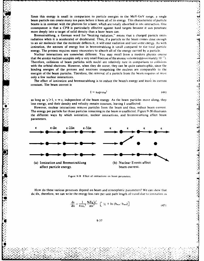
Since this energy is small in comparison to particle energies in the MeV-GeV range, a singlebeam particle can create many ion pairs before it loses all of its energy. This characteristic of particlebeams is in contrast with the photons for a laser, which are totally absorbed in onc interaction. One .' 2consequence is that a CPB is particularly effective against hard targets because it can penetratemore deeply into a target of solid density than a laser beam can.
Bremsstrahlung, a German word for "braking radiation," means that a charged particle emitsradiation when it is accelerated or decelerated. Thus, if a particle in the beam comes close enoughto an air molecule that the molecule deflects it, it will emit radiation and lose some energy. As withionization, the amount of energy lost in bremsstrahlung is small compared to the total particleenergy. The process requires many encounters to absorb all of the energy carried by a particle.
Nuclear interactions are somewhat different. You may recall from a modern physics coursethat the atomic nucleus occupies only a very small fraction of the atomic volume (approximately 10 '2).Therefore, collisions of beam particles with nuclei are relatively rare in comparison to collisionswith the orbital electrons. However, when they do occur, they can be quite catastrophic, since thebinding energies of the protons and neutrons comprising the nucleus are comparable to theenergies of the beam particles. Therefore, the removal of a particle from the beam requires at Most
Snonly a few nuclear interactions.The effect of ionization and bremsstrahlung is to reduce the beam's energy and leave its current
constant. The beam current is n4
%I nbqvrw 2 (44)
as long as y > I, v c, independent of the beam energy. As the beam particles move along, theylose energy, and their density and velocity remain constant, leaving I unaffected.
However, nuclear interactions remove particles from the beam and thus, reduce beam current.The energy per particle for those particles remaining in the beam is unaffected. Figure 9-38 illustratesthe different ways by which ionization, nuclear interactions, and bremsstrahlung affect beamparameters.
c-Ac c-2Ac c-3Ac c C E E
(a) Ionization and Bremsstrahlung (b) Nuclear Events affect~affect particle energy. beam current.
Figure 9-38. Effect of interactions on beam parameters.
How do these various processes depend on beam and atmospheric parameters? We can show that
de/dx, therefore, we can write the energy loss rate per unit path length of travel due to ionhlatiot as
S2de I NZq e' I
41/2 my+ I n b
9-37
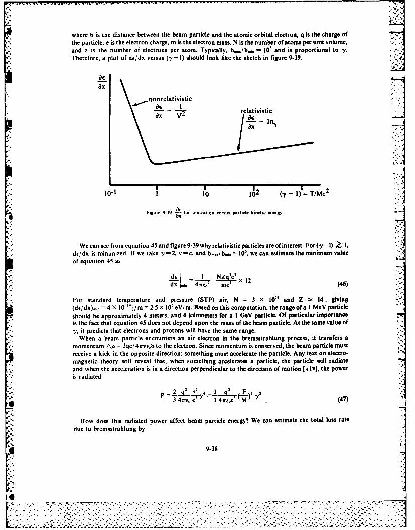
where b is the distance between the beam particle and the atomic orbital electron, q is the charge ofthe particle, e is the electron charge, m is the electron mass, N is the number of atoms per unit volume,and z is the number of electrons per atom. Typically, b,,./b,,. O 10' and is proportional to -y.Therefore, a plot of de/dx versus (y- 1) should look like the sketch in figure 9-39.
Ox
non relativisticde I relativisticOx V /_
ax 1.
10-I I 10 1 2 (y - I) T/Mc 2
Figure 9-39. .- for ionization versus particle kinetic energy.
We can see from equation 45 and figure9-39why relativistic particlesareof interest. For('-!) 1 ,de/dx is minimized. If we take y=2, v c, and b../ bmin 10s, we can estimate the minimum valueof equation 45 as
de I N ae2 2T ~ X 12dx 1mmo 4re0 mc (46)
For standard temperature and pressure (STP) air, N = 3 X 10' and Z 14, giving(de/dx)mn = 4 X 10-' 4 j/ m = 25 X 1O'eV/ m. Based on this computation, the range of a I MeV particleshould be approximately 4 meters, and 4 kilometers for a I GeV particle. Of particular importanceis the fact that equation 45 does not depend upon the mass of the beam particle. At the same value ofy, it predicts that electrons and protons will have the same range.
When a beam particle encounters an air electron in the bremsstrahlung process, it transfers amomentum Ap = 2qe/4irveob to the electron. Since momentum is conserved, the beam particle mustreceive a kick in the opposite direction; something must accelerate the particle. Any text on electro-magnetic theory will reveal that, when something accelerates a particle, the particle will radiateand when the acceleration is in a direction perpendicular to the direction of motion [ Iv], the poweris radiated
p = fq- q2.= . () ,
41re, c" 4irec M (47)
How does this radiated power affect beam particle energy? We can estimate the total loss ratedue to bremsstrahlung by
9-38
"".... ...". "",'."..."."............".-' ---. - .- -,- - ".--."-.."~tsx~ '"-..-'-? ,.,...
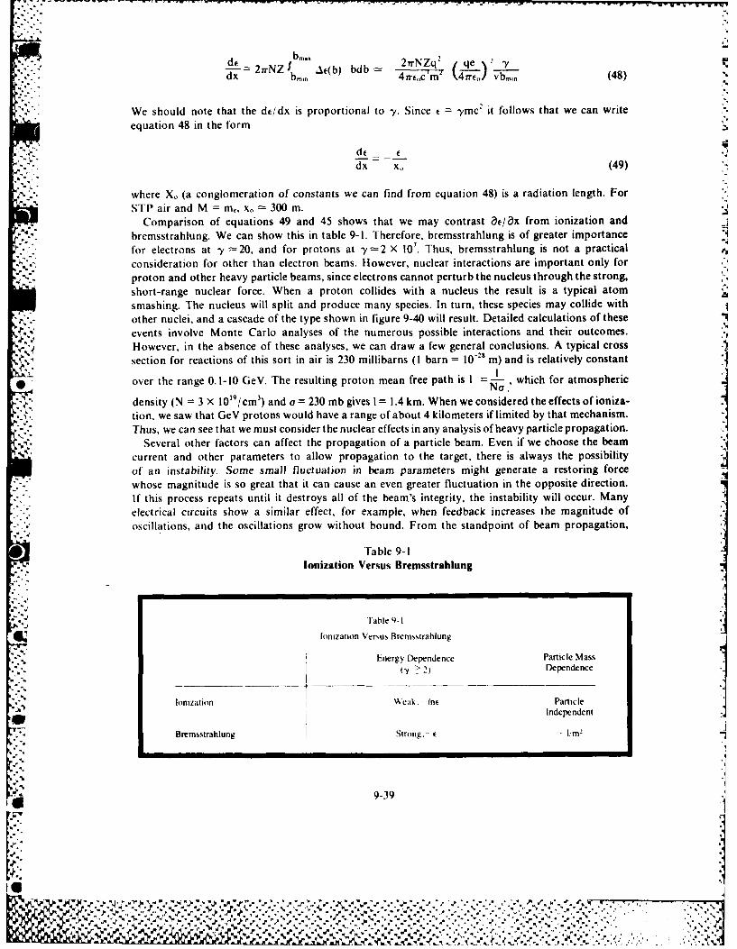
--mA. 2frNZq2 qe Y2NZ At(b) bdb - -t -
dx bm. 4 frf,,c m \4rGirt vbmin (48) %
We should note that the dt/dx is proportional to y. Since t =ymc' it follows that we can write
equation 48 in the form
dt. tdx x, (49)
where X. (a conglomeration of constants we can find from equation 48) is a radiation length. ForSIP air and M =m., x, 300 m.
Comparison of equations 49 and 45 shows that we may contrast e/ax from ionization andbremsstrahlung. We can show this in table 9-1. Therefore, bremsstrahlung is of greater importancefor electrons at -y 20, and for protons at y=2 X 10'. Thus, bremsstrahlung is not a practicalconsideration for other than electron beams. However, nuclear interactions are important only forproton and other heavy particle beams, since electrons cannot perturb the nucleus through the strong,short-range nuclear force. When a proton collides with a nucleus the result is a typical atomsmashing. The nucleus will split and produce many species. In turn, these species may collide withother nuclei, and a cascade of the type shown in figure 9-40 will result. Detailed calculations of theseevents involve Monte Carlo analyses of the numerous possible interactions and their outcomes.However, in the absence of these analyses, we can draw a few general conclusions. A typical cross
% section for reactions of this sort in air is 230 millibarns (I barn 10- m) and is relatively constant~I0 over the range 0.1-10 GeV. The resulting proton mean free path is I = .' which for atmospheric
density (N = 3 X 10'9/cm t ) and a = 230 mb gives I = 1.4 km. When we considered the effects of ioniza-tion, we saw that GeV protons would have a range of about 4 kilometers if limited by that mechanism.
Thus, we can see that we must consider the nuclear effects in any analysis of heavy particle propagation.Several other factors can affect the propagation of a particle beam. Even if we choose the beam
current and other parameters to allow propagation to the target, there is always the possibilityof an instability. Some small fluctuation in beam parameters might generate a restoring forcewhose magnitude is so great that it can cause an even greater fluctuation in the opposite direction.
"* . If this process repeats until it destroys all of the beam's integrity, the instability will occur. Many
electrical circuits show a similar effect, for example, when feedback increases the magnitude ofoscillations, and the oscillations grow without bound. From the standpoint of beam propagation,
Table 9-1Ionization Versus Bremsstrahlung
J Table 9-I
Ionization Versus Brernsslrahlung
Energy Dependence Particle MassY > 2) Dependence
Ionizatiotn Weak. Inf ParticleAD Independent
Bremsstrahlung Strong, E m-
.1
.1
9-39
%!
2"2
.,, , :., \, .. . . *,.. . . . . , , , . . - . . - .. .. . .... . ..- *,, .... ..
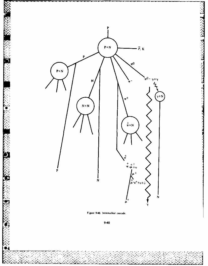
Ap
P+N-y+N
*+ +IT .1k +U
p
+
4'Y
Figure 9-40. Intranuclear cascade.
9-40
*4%
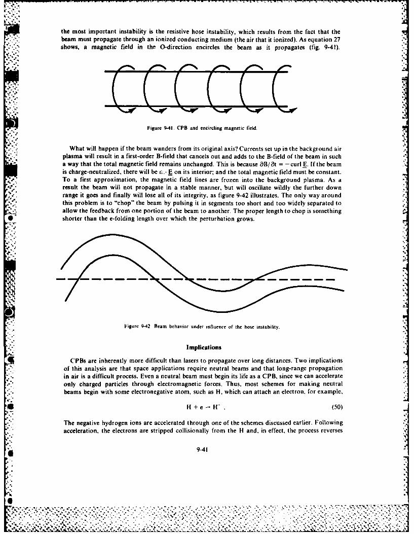
r Ithe most important instability is the resistive hose instability, which results from the fact that the
-. beam must propagate through an ionized conducting medium (the air that it ionized). As equation 27m-, shows, a magnetic field in the O-direction encircles the beam as it propagates (fig. 9-41).
'-.-
Figure 9-41. CPB and encircling magnetic field.
J .What will happen if the beam wanders from its original axis? Currents set up in the background airplasma will result in a first-order B-field that cancels out and adds to the B-field of the beam in sucha way that the total magnetic field remains unchanged. This is because B/St = -curl E. If the beamis charge-neutralized, there will be r,, E on its interior; and the total magnetic field must be constant.To a first approximation, the magnetic field lines are frozen into the background plasma. As aresult the beam will not propagate in a stable manner, but will oscillate wildly the further downrange it goes and finally will lose all of its integrity, as figure 9-42 illustrates. The only way aroundthis problem is to "chop" the beam by pulsing it in segments too short and too widely separated toallow the feedback from one portion of the beam to another. The proper length to chop is something
* shorter than the e-folding length over which the perturbation grows.
-- 2...
Figure 9-42. Beam behavior under influence of the hose instability.
Implications
CPBs are inherently more difficult than lasers to propagate over long distances. Two implications- . of this analysis are that space applications require neutral beams and that long-range propagation
- in air is a difficult process. Even a neutral beam must begin its life as a CPB, since we can accelerateonly charged particles through electromagnetic forces. Thus, most schemes for making neutralbeams begin with some electronegative atom, such as H, which can attach an electron, for example,
H + e - . (50)
The negative hydrogen ions are accelerated through one of the schemes discussed earlier. Followingacceleration, the electrons are stripped collisionally from the H and, in effect, the process reverses
9-41a7
Pg N
21=
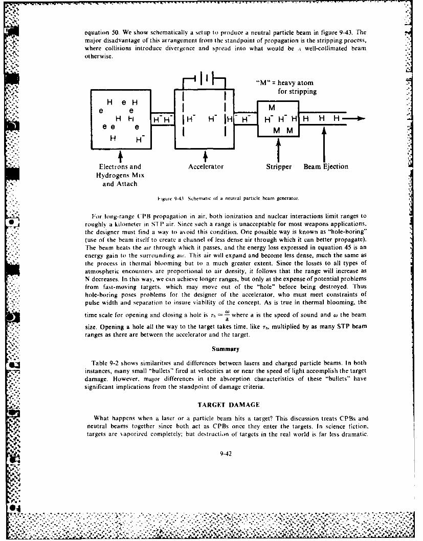
equation 50. We show schematically a setup to produce a neutral particle beam in figure 9-43. Themajor disadvantage of this arrangement from the standpoint of propagation is the stripping process,where collisions introduce divergence and spread into what would be .t well-collimated beamotherwise.
___________ ' I Hj"M'9 heavy atom
HeH Ifor stripping
e eIIe e e -
H H_
Electrons and Accelerator Stripper Beam EjectionHydrogens Mix
and Attach
H-gure 9-41 Schematic of a neutral particle beam generator.
For long-range (PB propagation in air. hoth ionization and nuclear interactions limit ranges toroughly a kilometer in SIP air. Since such a range is unacceptable for most weapons applications.the designer must find a way to avoid this condition. One possible way is known as "hole-boring"(use of the beam itself to create a channel of less dense air through which it can better propagate).The beam heats the air through which it passes, and the energy loss expressed in equation 45 is anenergy gain to th urudn i.This air will expand and become less dense, much the same as
the process in thermal blooming but to a much greater extent. Since the losses to all types ofatmospheric encounters are proportional to air density, it follows that the range will increase asN decreases. In this way, we can achieve longer ranges, but only at the expense of potential problemsfrom fast-moving targets. which may move out of the "hole" before being destroyed. Thushole-boring poses problems for the designer of the accelerator, who must meet constraints ofpulse width and separation to insure viability of the concept. As is true in thermal blooming, the
time scale for opening and closing a hole is Th =.iwhere a is the speed of sound and w the beama
-- size. Opening a hole all the way to the target takes time, like Th, multiplied by as many STP beam-. ~..ranges as there are between the accelerator and the target.
Summary
Table 9-2 shows similarities and differences between lasers and charged particle beams. In both* instances, many small "bullets" fired at velocities at or near the speed of light accomplish the target
damage. However, major differences in the absorption characteristics of these "bullets" havesignificant implications from the standpoint of damage criteria.
TARG;ET DAMAGE
What happens when a laser or a particle beam hits a target? This discussion treats ('PBs andneutral beams together since both act as CPBs once they enter the targets. In science fiction.targets are vaporized completely; but destruction of targets in the real world is far less dramatic.
9-42
-4J.-A%
'p.%9"%
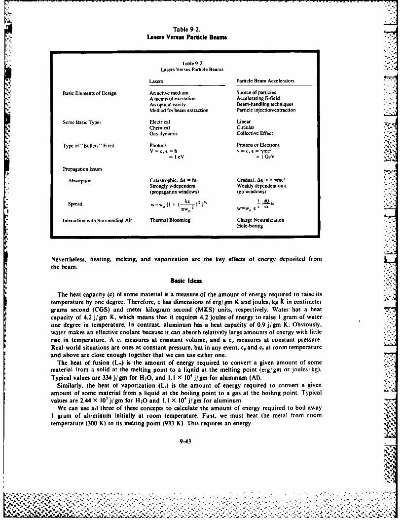
Table 9-2.Lasers Versus Particle leams
Table 9-2Lasers Versus Particle Beams .
Lasers Particle Beam Accelerators
Basic Elements of Design An active medium Source of particlesA means of excitation Accelerating E-fieldAn optical cavity Beam-handling techniquesMethod for beam extraction Particle injection/extraction
Some Basic Types Electrical LinearChemical CircularGas-dynamic Collective Effect
Type of" Bullets'" Fired Photons Protons or ElectronsV = c, e = h v = c, e = Ymc2
=leV =IGeV
Propagation Issues
Absorption Catastrophic, Ae = hi Gradual, A* >> Ymc2
Strongly v-dependent Weakly dependent on E(propagation windows) (no windows)
Spread w=w \+ ( 2 I2w ,H+IFWO 2 w=w0 e c dz
Interaction with Surrounding Air Thermal Blooming Charge NeutralizationHole-boring
Nevertheless, heating, melting, and vaporization are the key effects of energy deposited fromthe beam.
Basic Ideas
The heat capacity (c) of some material is a measure of the amount of energy required to raise itstemperature by one degree. Therefore, c has dimensions of erg/gm K and joutes/ kg k in centimetergrams second (CGS) and meter kilogram second (MKS) units, respectively. Water has a heatcapacity of 4.2 j/gm K, which means that it requires 4.2 joules of energy to raise I gram of waterone degree in temperature. In contrast, aluminum has a heat capacity of 0.9 j/gm K. Obviously,water makes an effective coolant because it can absorb relatively large amounts of energy with littlerise in temperature. A c, measures at constant volume, and a c, measures at constant pressure.Real-world situations are ones at constant pressure, but in any event, cp and c, at room temperatureand above are close enough together that we can use either one.
The heat of fusion (L.) is the amount of energy required to convert a given amount of somematerial from a solid at the melting point to a liquid at the melting point (erg/gm or joules/ kg).Typical values are 334 j/gm for H20, and 1. 1 X 10' j/gm for aluminum (Al).
Similarly, the heat of vaporization (L.) is the amount of energy required to convert a givenamount of some material from a liquid at the boiling point to a gas at the boiling point. Typicalvalues are 2.44 X 10' j/gin for H20 and 1.1 X 10⁴ j/igm for aluminum.
We can use ad three of these concepts to calculate the amount of energy required to boil awayI gram of aluminum initially at room temperature. First, we must heat the metal from roomtemperature (300 K) to its melting point (933 K). This requires an energy
9-43
%. ..
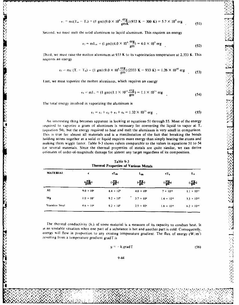
Len. mc(T. -- T) = (I gin) (9.0 X 10⁶ erg )(933 K - 300 K) =5.7 X 10⁹ erg .,
gmK (5)
Second. we must melt the solid aluminum to liquid aluminum. This requires an energy
t-2 = mL., = (I gm)(4.0 X 10 erg) = 4.0 X 10⁹ erggm (52)
Third, we must raise the molten aluminum at 933 K to its vaporization temperature at 2,333 K. Thisrequires an energy
3 mc (T, - Tm) = (I gm)(9.0 X 10⁶ erg) (2333 K - 933 K) = 1.26 X 10'0 erg
gm (53)
Last, we must vaporize the molten aluminum, which requires an energy
t4 =M., gm) l erg) .I X 10 erggm m (54)
The total energy involved in vaporizing the aluminum is
El= E + 2 + 3 + f = 1.32 X 10" erg (55) .
An interesting thing becomes apparent in looking at equations,51 through,55. Most of the energyrequired to vaporize a gram of aluminum is necessary for converting the liquid to vapor at T.(equation 54), but the energy required to heat and melt the aluminum is very small in comparison.[his is true for almost all materials and is a manifestation of the fact that breaking the bondsholding atoms together as a solid or liquid requires more energy than simply heating the atoms and -.
making them wiggle faster. Table 9-3 shows values comparable to the values in equations,51 to,54tor several materials. Since the thermal properties of metals are quite similar, we can deriveestimates of order-of-magnitude damage for almost any target regardless of its composition.
Table 9-3Thermal Properties of Various Metals
MATERIAl. C cTm Lm cTv Lv
e e"_ .erg(cg rg) L..5rI4 (Cr3,
" gm gm gm 3m -,
At 9.0. 100 8.4 - 109 4.0 - 109 7 x 10¹⁰ I.I 10"
Mg 1.0 10, 9.2 - 109 3.7 - 109 1.4 - 1010 5.3 - 1010
Stainless Steel 46 4 106 9.2 , 101 2.5 - 109 1.6 , 1010 62 101"
The thermal conductivity (kj of some material is a measure of its capacity to conduct heat. Itis an unstable situation when one part of a substance is hot and another part is cold. Consequently,energy will flow in proportion to any existing temperature gradient. The flux of energy (W/mlresulting from a temperature gradient gradT is
u = - k~gradT (56)
9-44
., ," % -,,
.,'''i4', .. _:.4-: . .., .... .. .. .,. . ,%< . .
where k, is the thermal conductivity.
-div u =kV2T (7
gives the increase or decrease in energy density (w/m') from this flow of energy in some region ofspace. Since
Ae p c AT
2L) (4 Lm mn (kk (k) (58)
relates the energy density to the temperature through the heat capacity, we can convert equation, 57to a differential equation for the temperature distribution in some substance. This equation is
X=. ZV T = DV2 T (59)
where D( M 2 / sec) is known as the thermal diffusivity. The elements, k,, p, and C can vary quite ;bit from one material to another, but D is generally between (11)Xl 4 2 sec for most 0
* substances. Equation,59 is the heart of any target damage analysis that involves examination ofthe place where the weapon deposits energy, the method by which it deposits the energy, the effectof thermal conduction, and temperatures required to inflict damage.
Hard or soft target damage depends on the definition of damage and thle temperature necessary Wto achieve that damage. For example, we consider a satellite blinded by a very small increase intemperature as soft. On the other hand, we consider reentry vehicles designed to withstand thehigh temperatures associated with reentry into the earth's atmosphere as very hard.
We have limited this analysis to hard targets in developing damage criteria for several reasons.First, the estimates are very conservative, since a laser or CPB with sufficient energy to damage ahard target will certainly have enough energy to damage a soft one. Second, analysis of hard targetsproduces very general results. Since damage to hard targets basically involves melting or vaporizingand is relatively insensitive to the type of material (see table 9-3), we can make reasonable estimateswithout specifying the target in much detail. However, soft targets are soft in different ways, and
*it would require much time and space to specify the nature of the target and the engagement scenario.%Thus, a bonus of this approach is that the discussion involves unclassified material. Finally, we canuse analysis of this type to establish damage thresholds for any target.
The 10 Kilojoule Criterion
NWe can draw an amazing conclusion from the previous discussion; I0 oles, properly applied,Pwill destroy almost anything. We base this conclusion upon two premises. First, vaporizing I gram
of almost anything requires approximately l joules (see table 9-3); second, removal of I gram ofmaterial from some vital spot will destroy almost any target. The second premise is the mostdifficult to accept. Practically all solid matter has a density of approximately I gin/ cm3; thus, weare eliminating only a very small amount (--lcm~) or breaking only a few of the bonds that holdthe atoms of some substance together. However, removal of I cm' from an appropriate spot onalmost anything will destroy it. For example, we can destroy an airplane by igniting its fuel.which requires putting a hole through the aircraft skin and the fuel tank. The total thickness ofsurfaces to be penetrated is undoubtedly less than I cm requiring energy (on target) of less than104 joules. When a bullet penetrates a target, it pushes the target material aside, and breaks bonds71only along a thin line of volume much less than I cm'. Many more examples are possible, but the
9-45 4
% P

point is that we can scrape up and weigh the remains of any target and never find more than a gramor so missing.
If the preceding arguments are not convincing, we might consider the fact that weapons systemsthroughout history have delivered energy on the order of O'joules. For example, an ordinary rifleround has a muzzle velocity of 3,000 ft/ sec or 9. 1 X 104 cm/ sec and mass of 180 grains, or 11.8 grams.Such a round has kinetic energy of
='2mv 5Xl joules (60)
within a factor of 2 to the 0'joules mentioned in this discussion. A more ancient example is theRoman siege catapult. According to a recent article in Scientific American, a typical catapultfired a stone with a mass of approximately 20 kilograms over a range of some 200 meters. If weassume that the firing of the stone at an angle of 45 degrees to the vertical of the range, we cancalculate the kinetic energy of such a stone as
104X ljoules (61)
within an order of magnitude of our damage criterion. A recent article in the Journal ofApplied Physics provides a more futuristic example. R. F. Benjamin and G. T. Schappert reportthat they used a laser pulse containing about 40i of energy to create a hole with a diameter ofapproximately, 50 pinin a glass wall I jsm thick. The volume of the hole was approximately 2 X 108 cm'.The energy req uired to vaporize I cm' of glass with such a laser would be approx imately 2 X Il03 joules.Once more, we can see that the typical value of 0'joules is not too unreasonable. The obviousconclusion from this is that a viable weapon against hard targets must deliver 104 joules as a minimum
* to a target volume of I cm3 in a time too short for the target to get rid of the energy. Any seriousweapon must fire much more than 10' joules to compensate for losses suffered on the way to thetarget, and it must fire a sufficient number of times to compensate for the probability that it willnot strike a vital spot on the first shot.
Damage Thresholds
We have shown in the discussion thus far the amount of energy required to inflict damage. It hasprovided a transport equation (equation'59) to determine the path taken by the energy from thepoint where it is deposited. We can combine these two elements to determine the thresholds at whichlasers and charged particle beams will damage targets. A damage threshold involves the threefactors of energy, area, and time. For example, a bomb releases a fixed amount of energy overa time of limited duration. However, as the burst of energy expands, it spreads over a larger andlarger area, so that the pressure (force/area) felt by a target decreases with distance from the bomb,
*1 and, at some range, the target is safe. A laser beam firing over a shorter range than the RayleighRange has a constant cross-sectional area. However, the energy in the beam will decrease withdistance because of atmospheric absorption, and may fall below the level of energy necessaryfor damage (especially if a cloud blocks the way). The sun delivers '5,000 i/cm2 to the earth'ssurface in a 12-hour period, and this amount of energy is close enough to the 10 kilojoule criterionto produce some dramatic effects. What prevents it from killing people? Too much time is involved.Inert objects can get rid of the energy through radiation or thermal conduction, and living organismshave time to sweat, move into the shade, or use other cooling strategies.
Since energy, area, and time enter into all damage thresholds, usually the threshold is expressedin terms of beam intensity (W/CM2 ), which accounts for all three factors. In keeping with thisprevious analysis, the energy absorbed per unit area should be something like 10' j/cm
2 . An
appropriate time scale depends on whether lasers or particle beams are involved because theydeposit their energy in different ways. To understand why this is true, we must examine the inter-action of lasers and particle beams with solid targets.
9-46
#4%...............................p,%

Interadion of lasers with solids. A substance absorbs laser light when the photon energy of thelaser connects two energy levels of the substance. Thus, analysis of what happens to the energy
- Llevels of atoms and molecules when they come together to form solids should clarify the interactiont-, of laser light with solids. As a general rule, aggregations of atoms have more degrees of freedom* than individual atoms., For example, a single atom has only electronic degrees of freedom
(see fig. 9-44), but a diatomic molecule has electronic, vibrational, and rotational degrees offreedom (see fig. 9-45). Thus, we would expect that a solid, much like a macromolecule of -- 1026
atoms, should have many degrees of freedom and many corresponding energy levels. It should bemuch more likely to absorb a photon. The conclusion that a photon is lucky to be absorbed in agas. and lucky to be transmitted in a solid, is a conclusion that reflects experience and intuition.
When two atoms are brought together to form a molecule, they perturb each other so that theirindividual energy levels split and become a group somewhere near the level of the original individualatoms (see fig. 9-46). When numerous atoms are brought together, there are so many possibilitiesthat the individual lines blend together into bands separated by energy gaps. Within the band, allenergies correspond to allowed states, and, in the gaps, there are no allowed states (see fig. 9-47).
.- I
Figure 9-44. Degrees of freedom in a single atom.
Figure 9-45 Degrees of fieedom in a diatomic molecule.
i' i
Atom A Atom B Molecule AB
I gurc ) 4h , om " R and molecular energy le els
9-47
S 7
%?
'. • -"+++"-+ • "q t- * w... *4• 4m4m4 "
" ... - -•. . . ..•T 9. . . .- . . . , . . . . .1 .-.
+ ° , . .
° " , - . ,'. . . . . ... -. .. . .. .. . . .. + .... .. " ." .
. % l + I i+
+ m m + , % ". + " , '+ i - .m
" . + • " i • * • + . . , + - . . * . . - ,N
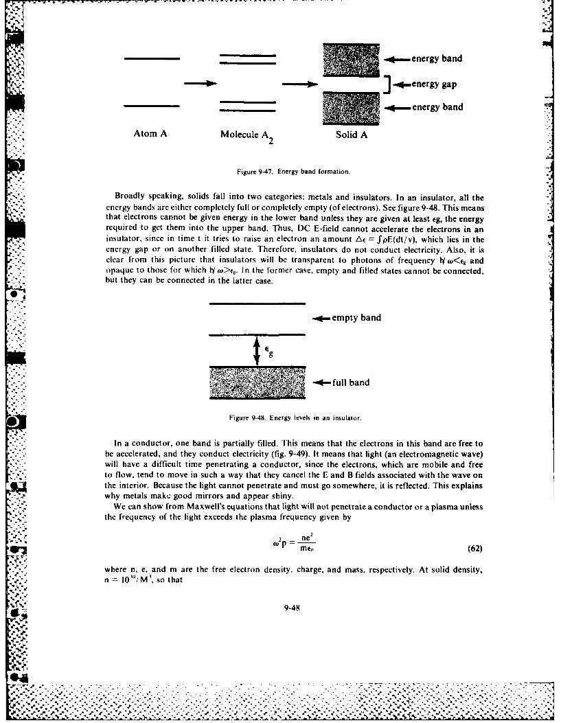
- ~__ _. -energy band* -energy gap
.-- energy band
Atom A Molecule A2 Solid A
Figure 9-47. Energy band formation.
Broadly speaking, solids fall into two categories: metals and insulators. In an insulator, all thet,.%., ~ energy bands are either completely full or completely empty (of electrons). See figure 9-48. This means
* that electrons cannot be given energy in the lower band unless they are given at least eg, the energyrequired to get them into the upper band. Thus, DC E-field cannot accelerate the electrons in aninsulator, since in time t it tries to raise an electron an amount Ae = fpE(dt/v), which lies in the
-..- energy gap or on another filled state. Therefore, insulators do not conduct electricity. Also, it isclear from this picture that insulators will be transparent to photons of frequency lIy (O<f andopaque to those for which h(o >g. In the former case, empty and filled states cannot be connected,but they can be connected in the latter case.
.-- empty band
$E
"* -full band
Figure 9-48. Energy levels in an insulator.
In a conductor, one band is partially filled. This means that the electrons in this band are free tobe accelerated, and they conduct electricity (fig. 9-49). It means that light (an electromagnetic wave)will have a difficult time penetrating a conductor, since the electrons, which are mobile and freeto flow, tend to move in such a way that they cancel the E and B fields associated with the wave onthe interior. Because the light cannot penetrate and must go somewhere, it is reflected. This explainswhy metals make good mirrors and appear shiny.
We can show from Maxwell's equations that light will not penetrate a conductor or a plasma unlessthe frequency of the light exceeds the plasma frequency given by
2 new P m(62)
where n, e, and m are the free electron density, charge, and mass, respectively. At solid density,n 10"'/M', so that
9-48
. .. . . . . . . . . . . .
%:~~
. . .. . . . . . . . . . . . . . ..**% *. *~ * ' * . . . . . . . . . . .
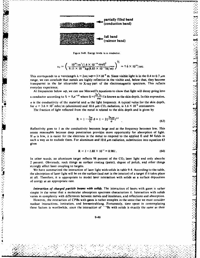
[" -'.." ,
.. ,
partially filled band(conduction band)
" i full band
(valence band)
*. ,Figure 9-49. Energy levels in a conductor.
( 10 30 /m 3 (l.6X O-'cou,) 2
p 9.11 X 10⁻³ kg(8.85 X 10-'fd/m) = i 6 X 0' 6/sec.
This corresponds to a wavelength X = 21rc/cp=3X 10-8 m. Since visible light is in the 0.4 to 0.7 14mrange, we can conclude that metals are highly reflective in the visible and, below that, they becometransparent in the far ultraviolet to X-ray part of the electromagnetic spectrum. This reflects
everyday experience.-*.At frequencies below wp, we can use Maxwell's equations to show that light will decay going into
-X/s2c'e.a conductor according to S = Soe -/ where S =(- ) is known as the skin depth. In this expression,
a is the conductivity of the material and tu the light frequency. A typical value for the skin depth,for a = 3.6 X 10' mho/m (aluminum) and 10.6 pm CO 2 radiation, is 1.6 X 10⁻⁶ centimeters.
The fraction of light reflected from the metal is related to the skin depth and is given by
R 2 12"1 2l(1-oo),/2C a 1 (63)
Reflectivity goes to I as the conductivity becomes large and as the frequency becomes low. Thisseems reasonable because deep penetration provides more opportunity for absorption of light.If w is low, it is easier for the electrons in the metal to respond to the applied E and M fields insuch a way as to exclude them. For aluminum and 10.6 pm radiation, substitution into equation 63gives
R =I - 1.88 X 10-2 =0.981. (64)
In other words, an aluminum target reflects 98 percent of the CO2 laser light and only absorbs2 percent. Obviously, such things as surface coating (paint), degree of polish, and other thingsstrongly affect laser coupling to targets.
We have summarized the interaction of laser light with solids in table 9-4. According to the table,the absorption of laser light will be on the surface (and not in the interior) of a target if it takes placeat all. Therefore, it is appropriate to model laser interaction with solids as a surface depositionof energy at an appropriate rate.
Interaction of charged particle beams with solids. The interaction of lasers with gases is rathersimple in the sense that a molecular absorption spectrum characterizes it. Interaction with solids
varies in complexity with differences between metals and insulators, and reflections and absorption.
However, the interaction of CPBs with gases is rather complex in the sense that we must considernuclear interactions, ionization, and bremsstrahlung. Fortunately, time spent in contemplatingthese factors is worthwhile, since the interaction of -'Bs with solids is exactly the same as their
9-49
"7"
* ... ,.. . . . . - . -. . .-. , . . . . , .. . . , . .. . , . .. . . . . . ., , -. . : -
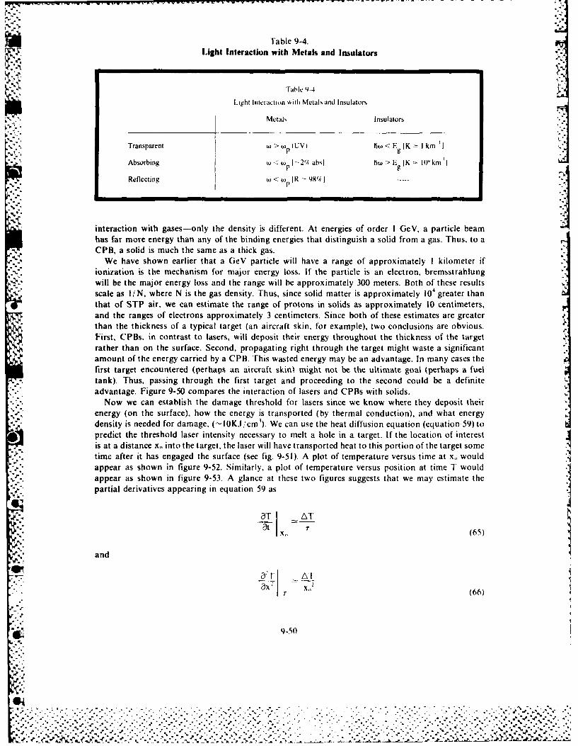
Fable 9-4.Light Interaction with Metals and Insulators
Table 9-4
Light Intetaction A ith Metals and Insulators
Metals Insulators
Transparent W > W (UV) h g < E (K I kn.
Absorbing <p 1--2 absJ ho > E K Okm 'l 'I
pRefecting Io<t~ R 9t9;
interaction with gases-only the density is different. At energies of order I GeV, a particle beamhas far more energy than any of the binding energies that distinguish a solid from a gas. Thus, to aCPB, a solid is much the same as a thick gas.
We have shown earlier that a GeV particle will have a range of approximately I kilometer ifionization is the mechanism for major energy loss. If the particle is an electron. bremsstrahlungwill be the major energy loss and the range will be approximately 300 meters. Both of these resultsscale as I/N, where N is the gas density. Thus, since solid matter is approximately 104 greater thanthat of STP air, we can estimate the range of protons in solids as approximately 10 centimeters,and the ranges of electrons approximately 3 centimeters. Since both of these estimates are greaterthan the thickness of a typical target (an aircraft skin, for example), two conclusions are obvious.First, CPBs. in contrast to lasers, will deposit their energy throughout the thickness of the targetrather than on the surface. Second, propagating right through the target might waste a significantamount of the energy carried by a CPB. This wasted energy may be an advantage. In many cases thefirst target encountered (perhaps an aircraft skin! might not be the ultimate goal (perhaps a fueltank). Thus. passing through the first target and proceeding to the second could be a definite
advantage. Figure 9-50 compares the interaction of lasers and CPBs with solids.Now we can establish the damage threshold for lasers since we know where they deposit their
energy (on the surface), how the energy is transported (by thermal conduction), and what energy- density is needed for damage, ("-I0KJ/cm ). We can use the heat diffusion equation (equation 59)to
predict the threshold laser intensity necessary to melt a hole in a target. If the location of interestis at a distance x. into the target, the laser will have transported heat to this portion of the target sometime after it has engaged the surface (see fig. 9-51). A plot of temperature versus time at x,, would
appear as shown in figure 9-52. Similarly, a plot of temperature versus position at time T wouldappear as shown in figure 9-53. A glance at these two figures suggests that we may estimate the
partial derivatives appearing in equation 59 as
AT,m'
4itC 7"
x1 (65)
.. : and
ar ATI "ax - X11T (66)
b *'a 9-50
. .-
. . .. " + " . . - . ff l 1 ." .imi¢'~~~~~~~~.."." .. . .. .. .. .. .. i.,+ .. #. .. . .. .. . . . . ....- ,.... .... -. •. +. ..-. -. ,.pt-, ,,...
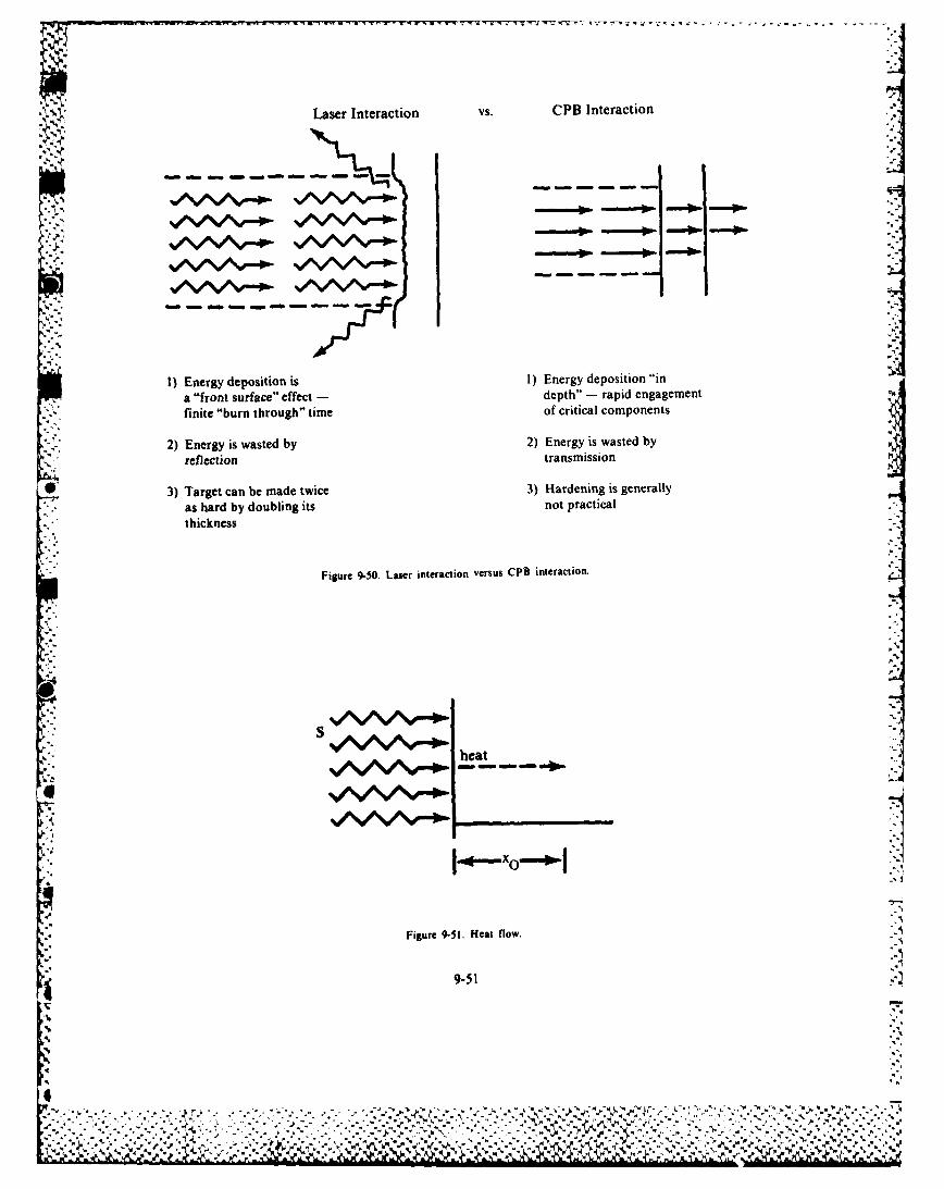
% J"
Laser Interaction VS. CPB Interaction
1) Energy deposition is 1) Energy deposition "ina "front surface" effect - depth" -- rapid engagement
£',"finite "burn through" time of critical componentsini
as hard by doubling its not practical "
fthickness uf c
Figure 9-50. Laser interaction versus CPB interaction.
WS
heat
• .--
Figure 9-51. Heat flow.
A
9-51
Im
IC..V4I~* V',4 .P .. '.. ... . 4- '~4 ,'V%
M.? IL a' " '' N

T
' t
Figure 9-52 1 emperature '.ersus time at a given position.
T
xox
Fgure 9-53 remperature versus position at a given time.
Substituting these estimates into equation 59, we find
ATTAT-=D x -(67)
We can solve equation 67 for the time. T, necessary for heat to dtffuse a distance x
r xo2 /D (68)
or the distance, xo, to which heat will penetrate in time, r,
1 Xo (Dr) t' (69)
Equation 69 shows that, in time, T. a laser beam of radius w, will heat a volume
V = rrwzxo = 7rw-' (Dr)1 /1 2 (70)
IDuripg 111s time. the beam will have deposited an energy
F -- f-wST (71)
% here S is the heam intensity (W mI).
('o nlcquetittl. the heated region %kill have an energy density
1: V Sr (Pr)2 S(r, 1)) 1 2 (72)
9-52
• . ,- . ".r ,:' -. " ",. €I.. "*.. "". . ..,. ... . ... -. .". .... .... ..".".-.- '. '. . '+ _' .' . . -" '- - .
.+ . .; .i.i .. ii.., .. .+i.+..5. <,... +. + '' 'J " I"" "2"i' 'I ' -''" ' " - " "\ %.".-.•"'i" - - *" ' S***" " *"*+'" • '-**" ' "* ,,.'-
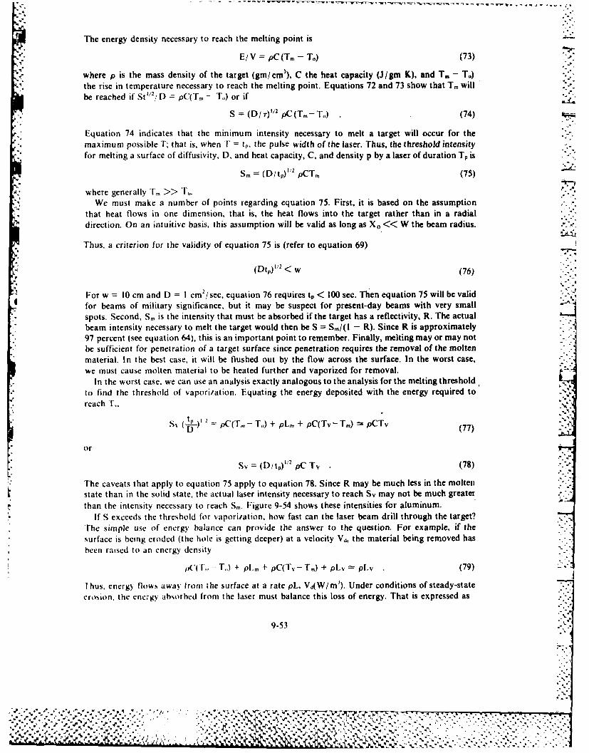
The energy density necessary to reach the melting point is
E/V = pC(T - T.) (73)
where p is the mass density of the target (gm/cm), C the heat capacity (J/gm K), and T. - T.)I the rise in temperature necessary to reach the melting point. Equations 72 and 73 show that Tm will
be reached if St "2/D = pC(T, - T.) or if
S = (D/r)"2 pC(Tm -T,,) (74)
Equation 74 indicates that the minimum intensity necessary to melt a target will occur for the- maximum possible T; that is, when T = t, the pulse width of the laser. Thus, the threshold intensity
for melting a surface of diffusivity, D, and heat capacity, C, and density p by a laser of duration T, is
Sm = (D/t)' /2 pCTm (75)
where generally T >> To.We must make a number of points regarding equation 75. First, it is based on the assumption
that heat flows in one dimension, that is, the heat flows into the target rather than in a radialdirection. On an intuitive basis, this assumption will be valid as long as X. << W the beam radius.
Thus, a criterion for the validity of equation 75 is (refer to equation 69)
(Dtp) 1/2 < w (76),.,
For w 10 cm and D I cm2i sec, equation 76 requires tp < 100 sec. Then equation 75 will be validfor beams of military significance, but it may be suspect for present-day beams with very small -"
spots. Second, Sm is the intensity that must be absorbed if the target has a reflectivity, R. The actualbeam intensity necessary to melt the target would then be S = Sm/(l - R). Since R is approximately97 percent (see equation 64), this is an important point to remember. Finally, melting may or may notbe sufficient for penetration of a target surface since penetration requires the removal of the moltenmaterial. In the best case, it will be flushed out by the flow across the surface. In the worst case,we must cause molten material to be heated further and vaporized for removal.
In the worst case, we can use an analysis exactly analogous to the analysis for the melting threshold,to find the threshold of vaporization. Equating the energy deposited with the energy required toreach T_
D pC(T. - To) + pL, + pC(Tv- Tm) pCTv (77)
or
Sv (D/t,)" 2 pC Tv (78)
The caveats that apply to equation 75 apply to equation 78. Since R may be much less in the moltenstate than in the solid state, the actual laser intensity necessary to reach Sv may not be much greaterthan the intensity necessary to reach Sm. Figure 9-54 shows these intensities for aluminum.
If S exceeds the threshold for vaporization, how fast can the laser beam drill through the target?'he simple use of energy balance can provide the answer to the question. For example, if thesurface is being eroded (the hole is getting deeper) at a velocity Vd, the material being removed hasbeen raised to an energy density
pc( , - T) + pl.n + pC(Tv- Tm) + pLy pLy (79)
I hus, energy flows away from the surface at a rate pL, Vd(W/m"). Under conditions of steady-stateerosion, the energy absorbed from the laser must balance this loss of energy. That is expressed as
9-53
- °
%'
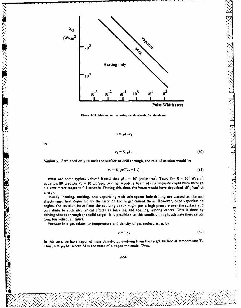
so
(W/cm 2 )
10 5 4to
Ole
Heating only
i-- 10100-.'2
4
10 110 3 10 2 Io--! 10 0 to01 10 2 ,
I I I . I I IPulse Width (sec)
Figure 9-54. Melting and vaporization thresholds for aluminum.
S PLVVd
or
Vd=S/pL, (80)
Similarly, if we need only to melt the surface to drill through, the rate of erosion would be
Vd = S/p(CTm+ L.) (81)
What are some typical values? Recall that pL, = 104 joules/crni3 . Thus, for S = 101 W/cm 2,
equation 80 predicts Vd = 10 cm/sec. In other words, a beam of this intensity could burn through
a I centimeter target in 0. 1 seconds. During this time, the beam would have deposited 10' j cm2 ofenergy.
Usually, heating, melting, and vaporizing with subsequent hole-drilling are classed as thermal
effects since heat deposited by the laser on the target caused them. However, once vaporization
begins, the reaction force from the evolving vapor might put a high pressure over the surface and
contribute to such mechanical effects as buckling and spalling, among others. This is done by
driving shocks through the solid target. It is possible that this condition might alleviate these rather
long burn-through times.
Pressure in a gas relates to temperature and density of gas molecules, n, by
p = nkt (82)
In this case, we have vapor of mass density, p,, evolving from the target surface at temperature T.
Thus, n = p,j M, where M is the mass of a vapor molecule. Thus,
9-54
4%
6 %-'' " , ' - - - "
"-" " - - - "
. "' -- " - .-
.'-.
' --
'.
'. . . . . . .: - " -* - " ' ' " ".. . .- " " " - " . -
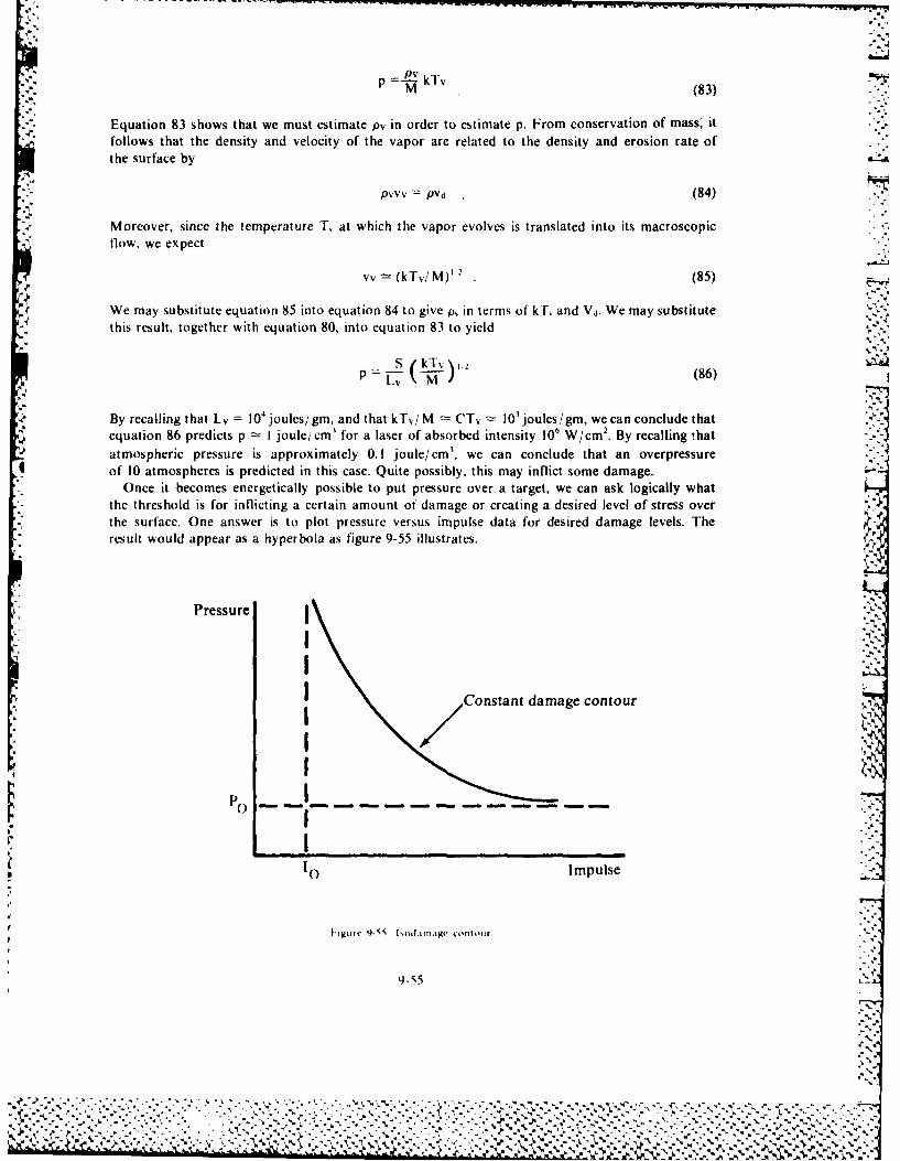
p -k( 8 3 )
Equation 83 shows that we must estimate pv in order to estimate p. From conservation of mass' itfollows that the density and velocity of the vapor are related to the density and erosion rate ofthe surface by
pvvv = pvd (84)
Moreover, since the temperature T, at which the vapor evolves is translated into its macroscopicflow, we expect
vv = (kTv/M) 1 2 (85)
We may substitute equation 85 into equation 84 to give p, in terms of kL and Vd. We may substitutethis result, together with equation 80, into equation 83 to yield
i'
P v ) (86)
By recalling that Lv = 10 4 joules/gm, and that k'l,, M t CTv l I0'joulesigm, we can conclude thatequation 86 predicts p = I joule/ cm' for a laser of absorbed intensity 106 W/cm2. By recalling thatatmospheric pressure is approximately 0.1 joule/cm' . we can conclude that an overpressure
4 of 10 atmospheres is predicted in this case. Quite possibly, this may inflict some damage.'* Once it becomes energetically possible to put pressure over a target, we can ask logically what
the threshold is for inflicting a certain amount of damage or creating a desired level of stress overthe surface. One answer is to plot pressure versus impulse data for desired damage levels. Theresult would appear as a hyperbola as figure 9-55 illustrates.
Pressure !I
I Constant damage contour
P()II
PC)... .... . . . . ..-. . ..- - - - -
I"I ::1O Impulse
I" l
Iigure - t iod.tr11atge Contour
9-55%
- ."-V °
+ p + ! J+. ,J . . .m • +. + . + ? .- Y .. . '++ + - -- . -" " : ',..- r r P" '" " +" " " .. . -.. ... ".
Impulse is the integral of force over time or approximately
I = p-W2 tp (87)
Therefore, the data obtained would take the form
(p -po) (pt -!/rw 2) D (88)
% where the constants po, lo, and D would depend on the type of target as well as the desired level of." damage. Equation 88 is in accord with earlier discussions. We can trade off pressure and application
time, but we must exceed certain thresholds for each to inflict the desired damage.What are the implications regarding damage thresholds? For pressures far in excess of P",
equation 88 is approximately
p2t =D (89)
However, if a laser of intensity S vaporizes a surface, we know the pressure (see equation 86).Substituting equation 86 into equation 89, we get
S2 kTv ,.M = t (90)
Thus, the intensity necessary to achieve the level of damage specified by the constant D is
• " S,,= L ['DM 1/2,:
.rT_74 (91)
Interestingly. Si, is proportional to I/ V , just as S. and Sr were (see equations 75 and 78).Figure 9-56 shows these results and lines of constant 10 to 1,000 j/cm2 within which most pulsedlasers lie. The figure shows why heating and melting occur with long pulse or continuous wavelasers, and impulse delivery occurs with pulses shorter than approximately 10 Asec.
Damage thresholds for particle beams are more straightforward to calculate than those forlasers, because of the in-depth deposition of energy. We showed earlier that each particle in thebeam loses energy at some rate, a&/ax, as it passes through the target. If the particle passes througha region of thickness, x, the energy lost within the region will be (St./ax)Ax. Now the number ofparticles/cm 2/sec entering the region is simply
nv = I/ Trw2q (92)
where n, v, I, w, and q are, respectively, the particle density, velocity, current, radius, and chargeassociated with the beam (see equation 30). Thus, the total rate of energy deposition wherever thebeam passes through the target is
At I at=nv-=- -(-) w/ m IAx 7rw'q ax (93)
* -" A CPB deposits energy at a rate given by equation 93 within a long cylinder of radius w passingthrough the target. What are the orders of magnitude involved? In STP air a typical value of aet/ax,is approximately 4 X 10-16 j/cm if ionization is the dominant mechanism for energy loss. Sinceaae/cx is proportional to target density, a comparable value in a solid target of density 10' times thedensity of air would be 4 X 10- j/cm. Therefore, a beam of protons of current I 1,000 amphereand radius w = I centimeter would deposit energy at a rate
9-56
4. "-.a+','""-"-.-'-''+'?', ? .+ .+. ','. " .,, . , . ,:..,'' ''... _.,,' ./..... ,'," "."."''.. .,...'% , +.,,.
1o6-
101
10 14-
10
'-46-
102
0-1 0 0108 106 10 10 c
Pulse Width (sec)
Figure 9-56. Target damage thresholds
j 01A p( 0 m 8 X 10' W /cm ' (94)
At the rate given by equation 94, how long would it take to vaporize a hole through the target?
If vaporization requires approximately 104 i/cm' (see equation 55), the time to vaporize the target
would be approximately
8V )<1 W 1.25 X 10 sec, (5
* 9-57
F6i
........................- %

or approximately 10 tisec. This is a fairly short time to drill all the way through a target. incomparison with the 0.1 second required for a 104 W/cm' laser beam to drill its way througha target of I cm thickness.
Should we worry about thermal conduction with CPBs? After all, heat will flow radially out of
the cylinder being heated by the beam, and will produce a temperature profile similar to the profile
shown in figure 9-57.
*. Figure 9-57. Temperature profile in a target heated by CPB.
The temperature in the center will rise until the flow of radial heat equals the rate of energydeposition from the beam. Energy is deposited within the beam volume and flows through its
• ' surface.
,', u = - K~gradT, (W/cm() (96)
where K, is the thermal conductivity, gives the flow rate out of the surface (see equation 56). [husa target of thickness, I, will reach a steady-state temperature when
,TW2I u 2irwt (97)
Energy/Sec Volume Energy/sec Area
Volume Area
2 (98)
A glance at figure 9-56 suggests that we estimate the temperature gradient in equation 96 as
gradT -LT/w (99)
Substitution of equation 99 into equation 96 and 98 permits solution of equation 98 1or l as
-. K, (100
E 9-58
% %%
By recalling that the thermal diffusivity, D, is K. C~, (see equation 59), we can express equation 100 as
6 DC, (101)
What kind of F is predicted by equation 101? Using i 8 X 10 W/cm3 from equation 94, and taking
w I cm, D 1CM 2 sec. p I gmi cm' and C =lI gmK, we get
8 X 10" W cm, (I1cm') =X 0K(cm /sec) (I jgmK) (I gm/ cm)
This is a temperature many orders of magnitude greater than the vaporization point of any
substance. Therefore, the target will have vaporized long before thermal conduction can carry any
energy away. larget damage is exceedingly simple with CPBs as opposed to lasers. We can use
- -equation 93 to calculate the energy deposition rate, determine the energy necessary to achieve thedesired level of damage, and ensure that the beam bears upon the target long enough to deliver the
required energy. Without the propagation issues, this discussion of damage applies equally to
neutral particle beams striking a target in space.
Summary
The following summary of key ideas can be helpful in estimating damage criteria for almost any
proposed weapon system. However, we can use them to make specific estimates for lasers and
particle beams as well. A good all-purpose damage criterion is to achieve an energy density of
1 04 j;CM I within the target. Lasers deposit their energy on the target surface. A metallic surface7;4 may reflect a large traction, approximately 90 percent of the incident energy. Thermal conduction
carries the deposited energy into the interior of the target. The target will begin to melt, or vaporize,when the beam intensity exceeds S,,, (,,r V) = (D/t,)' pC Tm (or Tv). If Sv is exceeded, the target will
be eroded at a velocity, V,1 = S/1.,. Above Sv, both mechanical and thermal damage is possible.
CPBs deposit the~ir energy throughout the target volume. A large fraction of the incident energy maypass through the target. The target will vaporize when the beam duration is such that it,> IO0 i/cm3 .
Thermal conduction is unimportant in ('PB interactions.
BI B 1. 10 G. R A P H Y
'Advanced Space Laser -Spaceflighi (April 1970). 161.
Allen, I eslie. Essenuali: of I asirs. Oxford. N.Y. Pergamon Press. 1969.
"Applied Optics," P'ro.eedings of the IEF 1.(October 1966).
Baker. Charles F - Laser Display I echnology.- IEEE Spei trumn (December 1968):39 50.
% ~ Benjamin. Robert F and Gottiried I . Schappert. "Prepulse Damage to T arget and Alignment Verification." Journal of
Applied Plh'isitv So 0Januiry 79).7
Birnbaum. Ueorge. O)ptical Masers. l'hi.%ical Printiples. New York: rhe Academic Press. 1964.
4 Bloom. Arnold I . Gas l.gsers. New York: Wiley. 1969.
Brotherton. Manfred. Mfasers and .asers. How Ihev W4ork. What Thei- Do. New York: McGraw-Hill Co., 1964.
Brown. Ronald. Lasers, To,,lv of Wodern Teihn,,logi. Garden City. N.Y.: Doubledav and Sons. 1968.
Burs. F. P "Ifigh-Power I asers I heir Performance I imitations, and Future." IEEE.Spectrum (March 1967):1 15.
Clallen. W Russell. D~onald C O'Shea. and William 1. Rhodes. lItroduct ion to L~asers and Their Applications. Reading.
Mass.. Addison-Wedse ,. 1977
Carroll. John M. lhe Sloui of he I astr. New York: [Dutton, 1970.116 Carslaw. Horation S. and .1. C. Jlaeger. (Condu, tion of Heat in Solids. London: Oxford University Press. 1948.
tDasidsoin. Ronald C. rheori )i \,nneutral Plasma%.. New York: Benjamin-Cummings Press. 1974.
Eisberg. R obert M. Funidarnentali; ,f Mi~odern I'loit, , New Y orki Wiley. 1967.
E lion. Herbert A I aser Siterni and Artpliat iv Ox Iord. N. Y.: Pergamon Press. 1967.
Fishlock. D~avid. .4 Guide to the I aver I ondon M acl~onald and Co.. 1967.%
9-59
b%

r "Giant Pancakes of Laser Light to Measure Precise Distance to Moon." Space World (Oct 1%99):30-32.Gray, E. E.. ed. American Institute Physics Handbook. New York: McGraw-Hill, 1957.llerriott, Donald R. "Applications of Laser Light." Scientific American (Sep 1968): 140-154.Jackson, J. D. Classical Electrodynamics. New York: Wiley, 1962.Kittel. Charles. Introduction to Solid State Physics. 3d ed., New York: Wiley, 1966.Lengyel, Bela A. Lasers. 2d ed.. New York: Wiley, 1971.Parmentola. John and Kosta Tsipis. "Particle Beam Weapons." Scientific American 240 (April 1979):54.Robinson. Clarence A. "Air Force Emphasizes Laser Weapons." Aviation Week (30 October 1978):51.Robinson, Clarence A. "Key Beam Weapons Tests Slated." Aviation Week (9 October 1978): 42.Robinson, Clarence A. "Power Generation Key to Beam Weapon Development." A viation Week (6 Nov 7R):51.Seigman. Anthony E. An Introduction to Lasers and Masers. New York: McGraw-Hill, 1971.Robinson. Clarence A. "US Pushes Development of Beam Weapons." Aviation Week (2 Oct 78):14.Wade, Nicholas. "Particle Beams as ABM Weapons: General and Physicists Differ." Science. 196 (22 Apr 1977): 407.Wade. Nicholas. "Charged Debate Erupts over Russian Beam Weapon." Science. 1% (27 May 1977):957-960.
" 4'
9-6
'S%
'4",%
'I%
Chapter 10
RELIABILITY OF SPACE SYSTEMS
1 he development of the digital computer has made possible a high degree of accuracy incomputations for space research and engineering and has increased overall efficiency. In theoperation of any space system, accuracy and efficiency are paramount. The same is true for anyballistic missile system. Since these systems are all very expensive, operational failure is extremelycostly. In addition, the success of the system is always very important not only to the Air Forcebut also to the nation as a whole. Each space shot carries with it the prestige of the United States,
and the very survival of the free world may rest upon the reliability of missile systems.The advent of missiles and space systems has outmoded the "fly and fix" philosophy. Good
systems must operate when fired. We must keep holds and mission aborts to a minimum. Toaccomplish this end, both manufacturers and operators of space systems must pay more attentionthan ever before to the reliability of the system as a whole. This requirement poses two criticalproblems, how to measure the reliability and how to increase the reliability. We will discuss bothof these problems in this chapter. As a prelude, it is necessary to study the subject of probability,at least in its simplest form. Reliability is a term meaning the probability that equipment willperform a required function under specified conditions, without failure, for a specified period oftime. Notice that reliability is a probability. It is a probability related to a system under specifiedconditions and for a specified time.
PROBABILITY
We can define the probability that a given event will occur as the number of ways in which theevent can occur, divided by the number of ways the event can occur plus the number of ways the
S event can fail to occur.If N, is the number of ways in which a given event, A, can occur and N r is the number of ways in
which the event can fail to occur, then the probability of occurrence of the event is
P(A) =N./ (N. + N,).(I
The probability of the event not occurring is
P(notA)=Nr/(N,+ Nr) .(2)
* .It is obvious from the definition of probability that values of probability range from 0 to 1.A 0 probability represents an impossibility, whereas a probability of I represents an absolutecertainty.
We can find another important relationship from the definition of probability by addingequations I and 2. The equation resulting is
P(A) +P(not A)= I1 (3)
-.. 7
V~- T I TqK I .I.......-
However, we must meet two conditions before we can usC the three equations given above. Wemust know the number of possible outcomes in a particular event, and we must know the possibleoutcomes that are favorable (or unfavorable) to the event.
We can illustrate probability by rolling a pair of unbiased dice. For example, what is the% probability of obtaining a 7 in one roll? To answer this question, consider one roll as an event and
then count the number of ways that the event can result in rolling a 7. The possible ways to succeedare to obtain the following combinations: I and6. 2 and 5, 4 and 3, 3and4. 5and2. or6and l.ihus,there are six ways to succeed. The total number of ways that the event can occur is 36. and thenumber of ways in which the event can occur and fail is 30. Therefore:
N, 6 6 1N,+ N6+ 30 36 6_____ - 30 30 5
In situations dealing with a limited number of items, such as dice, cards, and coins, it is relativelysimple to count the possible events and meet the above conditions. However, in many instances.the number of possible outcomes is too great to count, or the final result will depend upon thefavorable or unfavorable outcomes of more thani one event. In cases like these, we must use otherequations and theorems to calculate probabilities.
Mutually Exclusive Events
We say that two or more events are mutually exclusive if one, and only one, event can occurat one time. In a mutually exclusive sequence, the probability that either one or another of the
6 events will occur equals the sum of the probabilities of occurrence of the individual events. Wecan make a mathematical statement of this rute. It will read
P (A or B) P (A) + P(B) (4)
We can extend this equation to include any number of mutually exclusive events. A simple problemcan show the application of this rule very well. Consider a box containing one white ball, one redball, and three black balls. What is the probability of drawing a red or white ball in one draw?We can effect the successful accomplishment of this endeavor in two ways: drawing a red ball ordrawing a white ball. We can draw only one of these on any one trial. This is a case of mutuallyexclusive events. Consequently, the probability is the sum of the probabilities of drawing a redball and drawing a white ball. From equation 1, these are one out of five in each case. Therefore, theprobability of drawing either ared or awhite ball is, by equation 4. P (red or white) I i; + 1 /5 2;5.We can find the probability of drawing a black ball as follows:
F'(red or white) + P(black) = I
P (black) =I -2j5 =3,5
Contingent ProbabilitiesSuppose the undertaking is some large endeavor consisting ofai nunmher of separate events. If success
or failure of the endeavor depends upon success or failure of each of the events in the endeavor, theprobability of the endeavor depends on the probability of the events. I f this is t he case, we combine theprobabilities for each of the events by multiplying them, not by adding themn. We obtain the probabilityof success or failure for the endeavor by multiplying the probabilities Of suICCess or failure for each of theevents in the endeavor. Suppose the endeavor is to launch at Saturn booster. Success or failurc in thisendeavor depends on the success or failure of a very large number oA events. hut we will simplify the
10-2
csarI plr h.x disumsing the success of first-stage performance. Ifthe probability of success in fueling is .9and the piovhahtlit of successful ignition is .8, what is the probability of success in the endeavorSince,ucc.N m the cnttcasa depends on success in both eents, we can compute the answer by multiplyingthe pi obabilitie, of success lor the two e\ents. Thus, probability of a successful launch equals .9 times .8ori.
" ~Sometimes, success in an endeavor may depend on failure in one or more of the component events.Ioi example, to succeed in getting from the base to the bomb release line, an aircrew must fail to abort,fail to be shot do%% n. and fail to make a gross navigational error. In some cases, success in the endeavor-depends on success in some events and failure in other events.
We may classilf exents further as being either independent or dependent. Independent events are([lose in which the outcome of one event does not affect the outcome of any other event in the endeavor.l)cpcndent ccnts are those in which the outcome of one event does influence the outcome of othercents in the endeavor.
(ontingent independent (successful occurrence). The first example of contingent probabilities iscoMtingcnt independent (successful occurrence). What is the probability of drawing two black ballshorn a box containing three black balls and two white balls, if we make two draws and we replace theball drawn before the second draw? In this instance, the endeavor consists of two events, and the.iiccesltI outcomC of the endeavor depends on being successful in each event, that is, in drawing ablack hall each time. The events are independent in that the first draw will not affect the second draw,smcec %e %%ill replace the ball. The probability of drawing two black balls is the product of theprobabilities of drawing a black ball each time. The probability of drawing a black ball is three out offive in each instance. Therefore,
* P(2 black) P(black) X P(black)= 3/5 X 3/5= 9/25 or 36 percent
(ontingent dependent (successful occurrence). The second example is contingent dependent(successful occurrence). What is the probability of drawing two black balls from the box if we do notreturn to the box the first ball drawn? This problem is similar to the first example except that the eventsare dependent, since the probability on the second draw is dependent on the outcome of the first draw.Ihe probability of getting a black ball on the second draw is either three out of four or one out of two,depending on whet her or not we drew a black ball the first time. The probability of drawing a black ballthe t irst time is threeout offive. Ifthe ball is black, then the probability that the second ballwillbeblackisn out 1of tso. [ ie probability that both balls will be black is the product of these two probabilities:
P(black then black) = 3/5 X 1/2
= 3/10 or 30 percent
I hus far, the examples have been such that the successful occurrence of an endeavor depended on the.successful occurrence of the separate events. There are endeavors in which the nonoccurrence, orfailure, of an endeavor depends on the nonoccurrence, or failure, of the separate events.
Contingent dependent (success and failure). This third example of probabilities illustratescontingent dependent (success and failure). What is the probability of drawing at least one black ball int%% o dias, if we do not return the first ball drawn to the container?To draw at least one black ball, we donot nccd to (fraw a black ball on each attempt. Rather, not drawing at least one black ball in thecideax or depends on not drawing a black ball on each attempt. Since we did not replace the first ball,the ccnts arc dependent. We can solve the problem in the following manner:
10-3
% b..
- . . . .
P (no black then no black) = P (no black) X P (no black)= 2/5 X 1/4= 1/ 10 or 10 percent.
If the probability of not getting a black ball is one out of ten, then the probability of obtaining at leastone black ball is I- 1/ 10 = 9/ 10 or 90percent.
Contingent independent (success and failure). The fourth example of probability illustratescontingent independent (success or failure). What is the probability of drawing at least one black ballfrom the container in two draws if we return the first ball drawn to the container? This example is
N'. similar to the examples of contingent dependent (success or failure) except that the events are nowindependent, since the first draw does not influence the second draw. For simplicity, we may definesuccess as the act of obtaining a black ball. Then, failure is the inability to obtain a black ball and wedenote this by Pf.
P (no black, no black) = P1f X Pr2
P (no black, no black) = 2/5 X 2/5P (no black, no black) = 4/ 25 or 16 percent
P (at least one black) = I - .16= .84 or 84 percent
We can combine the preceding as follows:
P (at least one black) = I - P (no black, no black)
Since Pf equals P, we can write this as
P (at least one black) I -(p,)2
For the general case, we can write the equation as
P (at least one A) =I P P(no A )n (5)
Equation 5 gives the probability of at least one occurrence in aseries of n repeated trials. Wecan useequation 5 to calculate the number of trials necessary to achieve a given probability of at least oneoccurrence. In space systems, as we will explain later, we can use it to calculate the reliability of
* . ~'redundant systems.
Minimum probability. The fifth example illustrates minimum probability. How many draws mustwe make from a container of three black balls and two white balls to have a minimum probability of 90percent of obtaining at least one black ball? We can solve the problem by using equation 5.
P (at least one black) = I - P (no black)".90 = I - (.4)n
-1+.90 =- (.4)n.10 = (A4)n
n n2.51
10-4
%~i .%
-4%
%4 -;*74
Therefore, it would take three draws to have a minimum probability of 90 percent of drawing at least* one black ball.
Guide for the Solution of Probability Problems
We have included the following step-by-step guide for the solution of probability problems to make iteasier for you, the user, to organize your problem solving. If used as recommended, without skippingsteps. you should find it much easier to solve probability problems.
Step) I. Define success for the problem under consideration.
Sitep 2. Does success in the endeavor depend upon the outcome of a series of events?
o If no, compute the single probability and you have solved the problem.
e If yes. go to step 3.
Siep 3. Are these events mutually exclusive? Does being successful in one way rule out beingsuccessful in any other way?
* If yes, determine the probabilities of success for the several mutually exclusive events thatmay happen. 'The sum of the probabilities of success of the several events equals the probabilityof success in the endeavor, and you have solved the problem.
*If no, go to step 4.
Step 4. Does success in the endeavor require success in each event?
*If yes, determine the probability of success in each event. The product of the probabilitiesof. success in each event equals the probability of success in the erideavor and you have solvedthe problem.
elIf no, go to step 5.
Step 5. Does success in the endeavor require nonsuccess in each event?
*If yes. determine the probability of failure in each event. The product of the probabilities offailure in each event equals the probability of success in the endeavor, and you have solved theproblem.
*If no, go to step 6.
Step 6. Does success in the endeavor require success in some of the events and failure in others?
*If yes, determine the probabilities of success for those events where success in the endeavordepends upon success in the events; determine the probabilities of failure for those events wheresuccess in the endeavor depends upon failure in the events. The product of these probabilitiesis the probability of success in the endeavor, and you have solved the problem.
0 If no, then failure in the endeavor must depend on failure in each of the events. Then, it isnecessary to determine the probability of failure in each event. The product of the probabilitiesof failure in the events equals the probability in the endeavor. You can find the correspondingprobability of success by using the following formula: P, = I - Pf (where P, probability of successin the endeavor and P, probability of failure).
RELIABILITY
Suppose mission support personnel have fueled and checked a booster for a spacecraft, and
10-5
%1 %~
%AJLA %. % :1&~~.>~-4
the countdown is complete. All systems are "go." Will the booster and its spacecraft actually performtheir mission without failure for the specified period of time? Actual experience shows that, under theseconditions, some do, and some do not. However, before the actual launch, the directors of a projectwant a good estimate of the chances of success, or of the reliability of the system.
Suppose a booster is in the process of design, development, and production. With the thousands ofcomponent parts that must be assembled into an operating system, the assemblers will make somemistakes both in the design and in the process of production to meet design specifications. What canthey do to measure the reliability of a design and of the component parts that enter into the finishedproduct? Reliability, which is a word that is becoming more and more associated with both spacesystems and missile systems, is a probability idea. As we stated earlier, it is the probability that a systemwill perform a required function under specified conditions, without failure, for a specified period oftime. We can apply this idea to a complex system consisting of a multistage booster, a spacecraft withmore than one stage, and a recovery system. We can apply it to one stage of a system or one componentpart, such as a transistor or a valve.
Calculating the Reliability of a System from the Reliability of its Parts
Even though a system may have as many as 30,000 parts, assume a simple system consistingof 10 parts for purposes of illustration. Assume that we have measured the reliability of each partand found it to be .90. If the system is to operate, each of the parts must operate. Therefore, theprobabilities of success are contingent upon the successful operation of each part. What is thereliability of this simple system? Clearly, it is (.90)' ° = .35.
At first glance, .90 seems like a rather good reliability. However, if the reliability is no greaterthan .90, even a 10-component system becomes much too unreliable. A 30,000-component systemwould have ridiculously low reliability. What can be done? First, the component parts of a systemmust have reliabilities much higher than .90. Assume a 10-component system in which each parthas a reliability of .99. Now the reliability of the simple system is (.99).. = .905. Suppose thereliability of the parts is .999. Now the reliability of the 10-part system becomes (.999) ") = .991.
Now think of a system with 10.000 parts. One important conclusion from the simple example isimmediately apparent. If reliability in a real system is to be around .90, the reliability of the partsmust be very high indeed. Scientists and engineers must design and test, redesign and retest, all ofthe parts until their reliability approaches 100 percent. In a recent symposium on reliability,engineers talked about the reliability of parts of .9999 and higher.
Methods for measuring. Sometimes, engineers can compute the reliability of the equipment byfirst measuring the failure rate. For example, they might test a part for a booster by selectinga number of parts at random and starting them to operate under conditions that approximatedthe actual conditions of expected operation as closely as possible. Suppose that one part failed each100 hours of operation on the average. Then, the failure rate, f, would be 0.01 per hour.
Another, and more common, procedure is to measure the mean time before failure (MTBF)N,.- and calculate the failure rate from this. For example, suppose the first part failed to operate after
40 hours, then more and more of the parts began to fail, but the last sample did not fail until300 hours had passed. From this, we can calculate easily the mean, or average, time of operation
I _ Ibefore failure. Suppose it is 100 hours. Then f MTBF 100 hours .01 per hour.
If we know the failure rate and the desired operating time of the part, we can calculate theprobability that each part will operate for this time by using the formula P, = e-" (where I1, isreliability, f is failure rate, and t is time of desired operation). For example, if a piece of equipmenthad a failure rate of 0.001 per hour and we expected it to operate for ten hours, its reliability wouldbee (01"'MI = e M =. 0.99.
Advantages and disadvantages of the procedure. Industrial firms widely use the procedure
10-6
V,~I,~ ... , .~ -V- h
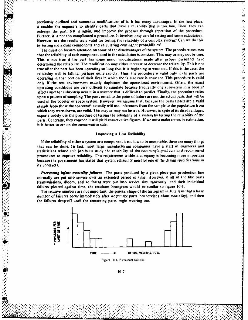
previously outlined and numerous modifications of it. It has many advantages. In the first place,it enables the engineers to identify parts that have a reliability that is too low. Then, they canredesign the part, test it again, and improve the product through repetition of the procedure.Further, it is not too complicated a procedure. It involves only careful testing and some calculation.However, are the results truly valid for testing the reliability of a complex system? Can we do thisby testing individual components and calculating contingent probabilities?
The question focuses attention on some of the disadvantages of the system. The procedure assumesthat the reliability of each component used in the calculation is constant. This may or may not be true.This is not true if the part has some minor modifications made after proper personnel have
~. ~,determined the reliability. The modification may either increase or decrease the reliability. This is nottrue after the part has been operating so long that it is beginning to wear out. If this is the case, thereliability will be falling, perhaps quite rapidly. Thus, the procedure is valid only if the parts areoperating in that portion of their lives in which the failure rate is constant. This procedure is validonly if the test environment exactly duplicates the operational environment. Often, the exactoperating conditions are very difficult to simulate because frequently one subsystem in a boosteraffects another subsystem near it in a manner that is difficult to predict. Finally, the procedure reliesupon a process of sampling. The parts tested to the point of failure are not the actual parts that will beused in the booster or space system. However, we assume that, because the parts tested are a valid
* sample from those the spacecraft actually will use, inferences from the sample to the population fromK which they weredrawn, are valid. This may or may not be true. However, in spite of its disadvantages,
experts widely use the procedure of testing the reliability of a system by testing the reliability of theIparts. Generally, they concede it will yield conservative figures. If we must make errors in estimation,it is better to err on the conservative side.
Improving a Low Reliability
* If the reliability of either a system or a component is too low to be acceptable, there are many things* that can be done. In fact, most large manufacturing companies have a staff of engineers and
statisticians whose sole job is to study the reliability of the company's products and recommendprocedures to improve reliability. This requirement within a company is becoming more importantbecause the government has stated that system reliability must be one of the design specifications inits contracts.
* /"Preventing 1*181,1 mortality failures. The parts produced by a given piece-part production linenormally are put into service over an extended period of time. However, if all of the like parts(transmissions, diodes, and so forth) were put into service simultaneously, and their individualfailures plotted against time, the resultant histogram would be similar to figure 10-1.
The relative numbers are not important; the general shape of the histogram is. It tells us that a largenumber of failures occur immediately after we put the parts into service (infant mortality), and thenthe failures drop-off until the remaining parts begin wearing out.
.cc
TIME - ~ WEEKS. MONTHS. ETC.
Figure 10-1. Piece-part failures.
10-7
%~~ .... 1 7
To cull out these early failures, engineers must perform extensive screening tests in very severeconditions. Common aerospace industry tests include testing throughout the piece-parts range ofoperation, testing at very high and low levels of vibration, and complete X-ray examinations of eachpart.
Usually, this testing increases the cost of the parts as much as 10 to 20 times the original cost,depending on the degree of testing required. We must take care to avoid overtesting lest we encounterpremature end-of-life failures.
Providing reliability through quality control. In the process of manufacturing a part. a shopforean ay lok t a esin an deide hatif he made a small change, it would be easier tofabrcat andwoud beas ood.Whe theformanadopts the change, often the part turns out to be
just asgood only in the sense that it will work. However, the change may have degraded seriously itsreliability. To overcome this natural tendency of workers and foremen to try to improve a product,when they are not in a position to know whether a change is an improvement or not, many companiesforbid any changes at levels of management beneath that of the design engineers. Configuration
- , management is the name for this process of controlling changes.Another type of quality control action consists of correcting the faulty design of a part that tests at
a low reliability. This should be the work of the design engineer, not of the shop worker. In makingthe correction, the company must consider the part not only as an entity but also as an integral part ofa larger operation.
Sometimes a part functions with high reliability only if it is absolutely clean. Dust, dirt, grease,hair, or other debris, even in the smallest quantity, may cause the part to fail. Examples of such partsare valves, pumps, and lines used to handle liquid oxygen. When foreign particles seriously affectreliability, often a company must use elaborate precautions in the manufacturing and handling of the
* part. The company may hold the workroom under positive atmospheric pressure so that no outsideair will seep in. The company ensures the filtering and conditioning of all incoming air. At the sametime, all workers wear gloves and special clothing. They must handle the part with special tools. Thecompany has devised special cleaning procedures that are enforced rigidly. Finally, the companycontrols and inspects packaging very carefully. In fact, the workers undertake the whole process in anenvironment as clean and sterile as that of the hospital operating room.
Often there is a relationship between poor reliability of a part of a subsystem and lack of employeediscipline. Humans become careless. Quite naturally, a few mistakes are made. In the manufacture ofspace and missile systems mistakes and carelessness are too costly. Most companies not only havetraining programs that impress upon workers the need for good working discipline, but they havecontinuing programs that encourage attention to detail and a sense of responsibility as well.
Quality control is in itself a large subject. We commented on it because it is one of the mostimportant methods for improving the reliability of a part, subsystem, or system.
Providing reliability through testing. While the company intends for piece-part screening toensure that they install only good parts into a subsystem, and for quality control procedures to ensurethat the parts are made and installed correctly, the real test of success is whether the parts work as aunit in the overall space vehicle. The aerospace industry, recognizing that they cannot fix spacecrafton-orbit, has instituted an extensive series of unit, subsystem, and total system tests.
Whether a black box is a guidance computer, telemetry set, or other part, the company subjectseach box to testing through or beyond its full range of operation and at the extremes of temperature,pressure, vibration, and acoustics that it will experience during actual flight. Only after successfulcompletion of these tests will the company install the unit in the next higher level system.
Further, the first unit or subsystem off a new production line is normally a qualification test unit, orqua) unit. The company will overstress the unit in all of the above areas to ensure that they overdesign
*N it. After successfully completing the qua] test, the company will declare that the production line unitsare flight qualified.
The complete systems test is the final testing done on a spacecraft. It is in keeping with thc AirForce's factory-to-pad concept of operations. During systems test, the company will run the entire
10-8
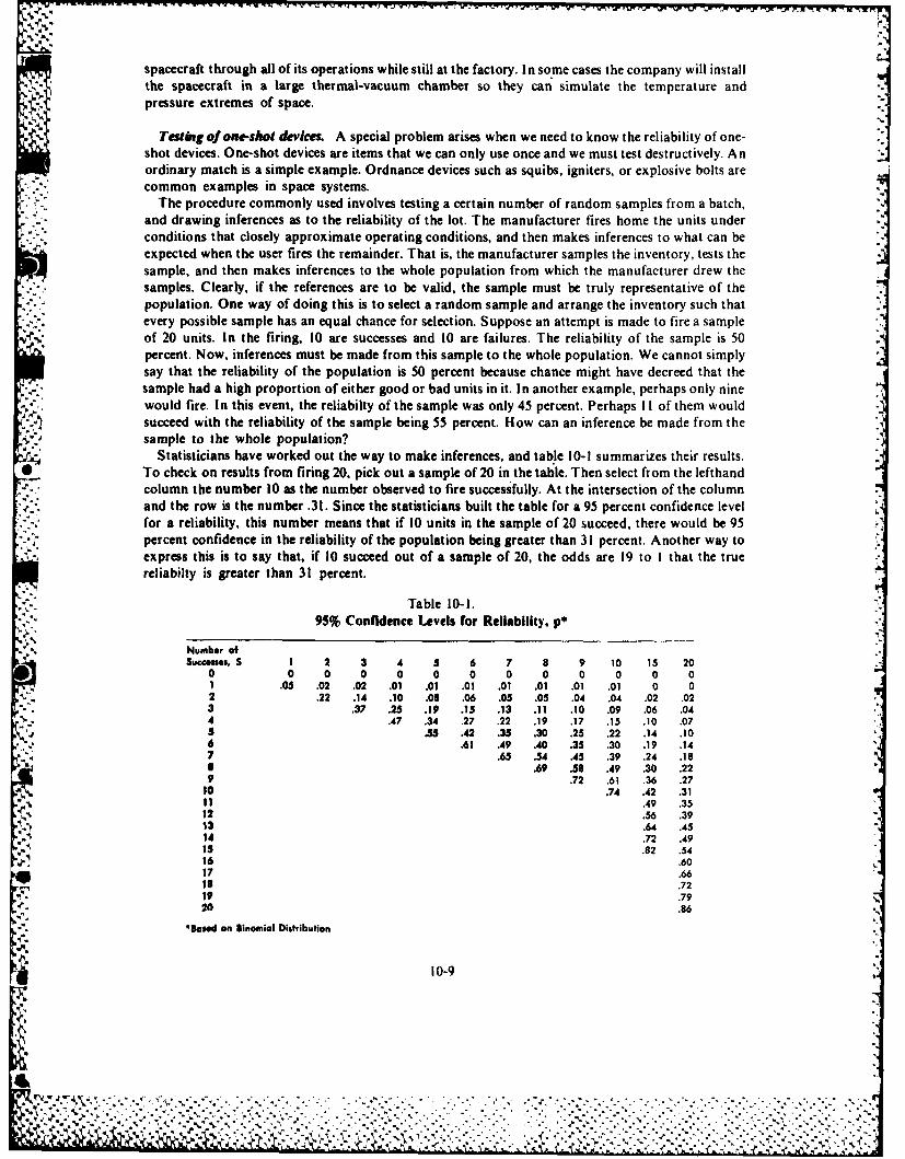
spacecraft through all of its operations while still at the factory. In so me cases the company will installthe spacecraft in a large thermal-vacuum chamber so they can simulate the temperature and
* pressure extremes of space.
Test ig of one-shot devices. A special problem arises when we need to know the reliability of one-shot devices. One-shot devices are items that we can only use once and we must test destructively. Anordinary match is a simple example. Ordnance devices such as squibs, igniters, or explosive bolts arecommon examples in space systems.
The procedure commonly used involves testing a certain number of random samples from a batch,-- . and drawing inferences as to the reliability of the lot. The manufacturer fires home the units under
conditions that closely approximate operating conditions, and then makes inferences to what can beexpected when the user fires the remainder. That is, the manufacturer samples the inventory, tests thesample, and then makes inferences to the whole population from which the manufacturer drew the
* samples. Clearly, if the references are to be valid, the sample must be truly representative of thepopulation. One way of doing this is to select a random sample and arrange the inventory such thatevery possible sample has an equal chance for selection. Suppose an attempt is made to fire a sampleof 20 units. In the firing, 10 are successes and 10 are failures. The reliability of the sample is 50percent. Now, inferences must be made from this sample to the whole population. We cannot simplysay that the reliability of the population is 50 percent because chance might have decreed that thesample had a high proportion of either good or bad units in it. In another example, perhaps only ninewould fire. In this event, the reliabilty of the sample was only 45 percent. Perhaps I I of them wouldsucceed with the reliability of the sample being 55 percent. How can an inference be made from thesample to the whole population?
Statisticians have worked out the way to make inferences, and tab 'le 10-1 summarizes their results.* To check on results from firing 20, pick out a sample of 20 in the table. Then select from the lefthand
column the number 10 as the number observed to fire successfully. At the intersection of the columnand the row is the number .31. Since the statisticians built the table for a 95 percent confidence levelfor a reliability, this number means that if 10 units in the sample of 20 succeed, there would be 95percent confidence in the reliability of the population being greater than 31 percent. Another way toexpress this is to say that, if 10 succeed out of a sample of 20, the odds are 19 to I that the truereliabilty is greater than 31 percent.
Table 10-1.
Numbe 95%Confidence Levels for Reliability, p*
NubrofSucceses, S 1 2 3 4 5 6 7 8 9 10 15 20
0 0 0 0 0 0 0 0 0 0 0 0 01.05 .02 .02 .01 .01 .01 .01 .01 .01 .01 0 0
2 .22 .14 .10 .08 .06 .05 .05 .04 .04 .02 .023 X3 .25 .19 .15 .13 .11 .10 .09 .06 .044 .47 .34 .27 .22 .19 .17 .15 .10 .075 .5 .42 .35 .30 .25 .22 .14 .106 .61 .49 .40 .35 .30 .19 .147 .65 .54 .45 .39 .24 .18I A .9 .58 .49 .30 .229 .72 .61 .36 .27
10.74 .42 .3111 .49 .3512 .56 .3913 .64 .4514 .72 .49is .82 .54
"p'916 .6017 .66
ris .7219 .7920 .86
41. *ased on Binomial Distribution
10-9
-1
Other tables are available for other confidence levels, even as high as 99 percent confidence.However, we will continue to use the 95 percent table for illustration. Another way of looking at thesituation is that if we repeated the sampling process many times, each time taking a sample of 20 unitsand each time using the table to make inferences from the sample to the population, the result would
- -- be right 95 percent of the time. There would still be a 5 percent chance that the inferences would bewrong.
Use of redundancy. Another method of improving reliability is the use of redundancy. Designersmay design certain critical parts of a system so that two, or more, alternate or redundant parts areprovided. They combine these parts in such a way that the system fails only if both, all three, or allfour of the parts fail. In other words, the designers combined the parts in such a manner that thesystem will function if at least one of the redundant parts operate properly.
The calculation of reliabiilty for a redundant portion of a system is exactly the same as thecalculation we used in the illustration of contingent independent (success and failure) undercontingent probabilities. Suppose a company has expended all the effort under product control, andstill a part has a reliability of only .90. The engineers may decide that they will use two such parts,combined in parallel, to improve the reliability. What is the probability that at least one of these partswill function as planned? Clearly, success of the system does not depend upon success of both parts.The probability of failure for each part is I -.90 .10. The probability that both parts will fail is (. 10)2
.0 1. The probability that at least one part will operate is I - .0 1 = .99. Thus by use of a two-pathredundant subsystem, they have improved the reliability of the part from .90 to .99.
There are disadvantages to this plan. Using two parts instead of one increases weight, an item ofgreat importance in space and missile systems, and increases cost. However, it is a plan often usedbecause ;I has many advantages already mentioned. If a two-path redttndant system is good, why not
* use a three-, four-, or five-path redundant system? Usually, this is not done because the weight andcost penalties increase with redundancy. Further, the gain follows a law of diminishing returns. Usingtwo parts in parallel instead of one part increased the reliability by 9 percent in the example we gave.However, using three parts in parallel instead of two increased the reliability by only 0.9 percent.There may be circumstances under which a gain of 0.9 percent will compensate for the weight andpenalties incurred. Thus, the decision to use redundancy and how much redundancy to use -is a matterof judgment on the part of the design engineer.
Results. On programs that require many piece-parts, we must make a trade-off among severalfactors. We must consider the high costs associated with extensive screening, testing redundantsystems, or acceptance of a certain risk by reducing the amount and/or degree of severity of thetesting to reach a cost level compatible with the available funding. This can be a very critical decision,and the total success or failure of a multimillion dollar program may depend on where we make thecompromise.
Figure 10-2 is a graph of the success (in percentage) of our US launch vehicles since 1957. While thedata are only for launch vehicles and do not include the spacecraft, the success of the reliabilityprograms instituted by the government and industry is clear. In fact, the major spin-off of the US '
space program may be the reliabilty techniques that it developed.
* 10-10
I-.
J. r
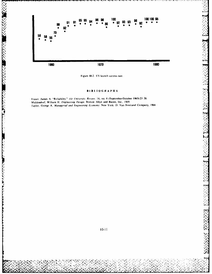
O°o...
95 95 94 o go9 O06 10100959 9 69 0 92 93 93go99928
0 82 • [[70 " "
59 58 55 0
I.o
-.-
1960 1970 1980
Figure 10-2. US launch success rate.
B I B I. 10 G R A PH V
Fraser, James A. "Reliability." Air Universinv Review. 16, no. 6 (September-October 1965):23 28.Middendorf, William H. Engineering Design. Boston: Allyn and Bacon, Inc., 1969.
* ITaylor, George A. Managerial and Engineering Econom. New York: D. Van Nostrand Company, 1964.
IV
' .%
9 -$
I
I¢ .P i mb , , ,, . , o w .. ,. .. ,', ,, ,' .", '," *. ,.-,*-,, .* , ..,. ."." ". % " . " ,,'. -. ' . . - . .." . . - " " , ," % - " - " .. - - ' . "•.... . .. " -. ' , " • - ,
A -1
Chapter II
BIOASTRONAUTICS
The broad scientific field of bioastronautics had its origin many years ago in the daring adventuresof men who left the surface of the earth to explore the atmosphere surrounding the earth. Early in
these attempts, people learned that flight in the atmosphere presented hazards to life never before
encountered. Balloons descended with dead crew members and experimental animals. Later, pilots ofairplanes were found dead in the wreckage of their crafts. There were many speculations as to the
causes of these tragedies, but little was known other than the fact that high altitude presented a lower
barometric pressure and a corresponding reduction of oxygen and nitrogen partial pressures. If travel
in the atmosphere were to progress, we needed to learn a great deal about the cause and effect of the
atmospheric environment. At this time, the medical services and physiological and biologicalresearchers launched extensive investigations to determine the characteristics of the environment and
A the effects of this environment on people. In their research, they relied in part on the work of Claude
* Bernard, a famous physiologist, who, in 1878, wrote:
She higher animals really have two environments an outside environment in which the organism is situated and the
inside environment in which the tissue elements live. The living organism does not really exist in the outside world (i.e..in the atmosphere if it breathes) but in the liquid inside world formed by the circulating organic liquid which surrounds
and bathes all the tissue elements. The internal environment surrounding the organs, the tissues and their elements,
never varies; atmosphere changes cannot penetrate beyond it, and it is therefore true to say that the physical conditions
of environment are unchanging in a higher animal. Each one is surrounded by this invariable world, which is, as it were,an atmosphere proper to itself in an ever changing world outside. Here we have an organism which has enclosed itself ina kind of hothouse. The perpetual changes of external conditions cannot reach it. It is not subject to them but is free andindependent. All the vital mechanisms, however varied they may be, have only one object, that of preserving constant
-. "' the conditions of life in the internal environment.j..
Claude Bernard was saying that the cell (the unit of living organisms) as found in tissues and organs
(muscles. heart, lungs, and liver, among others) of higher animals must remain in a relatively stableenvironment, regardless of the external environmental changes surrounding the organism. We knowthat the external environment lies outside people and includes such influences as air pressure,
humidity, temperature, odors, vibrations, noise, and acceleration.The internal environment consistsof conditions within the body that affect the activities of cells, tissues, and organs. These internal
t' conditions include such influences as body temperature, blood oxygen, carbon dioxide in the blood.
and blood chemistry in general. Human beings can withstand moderate changes in the external
environment without any deterioration in performance primarily because their internal environmentsare kept reasonably constant by regulatory mechanisms controlled by the central nervous system.
These mechanisms provide for exchanges with the external environment to maintain bodytemperature and blood chemistry, among other things, within rather narrow limits. This %hole
process of maintaining a relatively constant internal environment is called homeostasis.
In certain instances, changes in the external environment can prove too extreme for the regulatorymechanisms. In such cases, these mechanisms are unable to maintain a constant internal
environment, and there results a deterioration in the performance of the sense organs. central nervous
system, and/or muscles and glands. When the human being is a part of the man-machine system. the
% NLAINa
,<' ~.. . .. ... . .. . ....--......... ., .... ,. . ......., . , , ,' , , A:4 I~.A. " ' . , . .' ' ' . . . . + . . +.---". ., ,.-. . ' ".-" ',-
-.%I
%performance of the system deteriorate, as well. I his is essentially what the early aviation physiologistsand aviation medical personnel had to work within the infancy of their endeavor. Since their
.- beginning they have amassed a large volume of information designing or outlining all of the knownparameters of the external environment and their effects on a person's internal environment and
• regulatory mechanisms. Ihey have detailed definite tolerance limits to external forces forphysiological functions in the human.
Therefore, we have known values oi quantities of physiological functions that we can apply to aknown value or quantity of external environmental stress. If the value of the physical stressor exceedsthe ability of the body to adjust to it, we must reduce the stress or provide some support to theregulatory mechanisms of people for them to tolerate the stress and remain homeostatic.
Now that we have entered the new space age and people are attempting to fly in the hostileenvironment of space, again we look to the psychological research field for help in meeting the stressesplaced on people by travel in this new environment. This field of study is called bioastronautics,which is the study of the physiological and psychological problems facing people in space travel.
Bioastronautics is a generic term that encompasses several related disciplines. One convenientbreakout divides bioastronautics into the three fields of bioresearch, bioengineering. and
-- bioenvironmental efforts. Bioresearch includes biomedicine and biology. Biomedicine is the study ofthe adaptiveness and tolerance of people to space operations. Biology is the study of living organisms,for example, insects, plants, fungi. Bioengineering is divided into bioinstrumentation andpeople, system integration. The aim of the former is to develop the appropriate instruments for lifesciences research. Ihe aim of the latter is to determine the optimum uses of a person's capabilities in
" .'., space missions. Finally, bioenvironmentalists develop the technology for highly reliable life support--:. .and protective systems to sustain people on space flights. Bioastronautics is not the exclusive domain-'. ." of any one field or skill. It covers a wide category of specialties and requires the disciplined, integrated
efforts of engineers, physicians, research physiologists, technicians, and support personnel to succeed.The problems arc many, but, thanks to the diligent research of physiologists and medical personnel,
some of the answers to these problems in space flight were available long before humankind's firstorbital flight. Ihese answers were based on the data gathered in the preceding 50 years of aviationmedicine and physiological research. Thus, although the name bioastronautics is new, the techniquesand procedures used to determine people's tolerance to external stress are well known, and spaceflight by people is relatively predictive and safe as a result. T1o understand these parameters morefully, we must look at the major physiological stresses placed on people during space flight.
P'll YSIOI.OGI('AI STRESSES
As mentioned earlier, changes i the external environment may at times be very severe and tooextreme for a person's regulatory mcchanisms. I hese changes cause stress on these mechanisms.which is nothing more t han pushing the homeostatic levels of people to the tolerance limits or beyond.As people venture into space, tIhey arc exposed to a series of stresses, each of which could prohibitmanned space flight if no corrective mcasures are available. This section discusses most of the majorenvironmental stress parameters, how the% affect people, and how such forces are overcome so thatpeople can maintain bodily functions within homeostatic limits. In general. there are two types ofenvironment in which changes can cause severe stress the physical and the mechanical. Changes inatmospher,,: conditions cause stresses in the physical environment and operation of the space vehiclecauses stresses in ht nclianical ens iionmcnt. \ wil discuss each of these en\ ironments separatcl..
'lh sical Environment
An atmosphere approxmiatclv I10) riles thicl, surrounds the earth. This atmosphere pro\ides
ambient pressures. teniperatuitr,, humidit ., and ceftain gases required in our normal environment.Also, it provides a shield w hi'h p. c\ , ' ittn mattr an( radiant cnerg, from reaching the earth'ssurface.
As people progress, toi tlic so rht e the11 eaith upward through the sea of air, the atmospheric
1a
.4
,',.'~
* pressure, gas concentrations, and humidity decrease and the temnperature varies widely. Above theatmsphrepeoleare no logrpoetdfrom meteorites and various forms of radiant energy that
we indin pac. Tesechagesin the external physical environment are too extreme for our
At etree atitdesand n sace peplerequire a sealed cabin or suit that provides an adequatepartial pressure of oxygen (02) for tissue oxygenation. The cabin may contain nitrogen, which makesup 80 percent of the earth's atmosphere. Early US space vehicles contained 100 percent 02 at
5 pund pe sqareinch, simplifying gas control and capsule engineering. Absence of nitrogeneliminated the possibility of altitude sickness, where dissolved inert gas in tissues forms bubblesbringing on severe medical consequences. The disadvantages of the five pounds per square inch 02atmosphere include increased fire hazards and a tendency to produce anemia. There is evidence thatexposure over extended durations of 5.0 pounds per square inch (284 millimeters of mercury Hg) pureoxygen may prove to be toxic. To avoid the toxic effect of 100 percent oxygen at 5 pounds per squareinch, Skylab used a 70 percent oxygen and 30 percent nitrogen mixture to provide an oxygen partialpressure equivalent to 20 percent at one atmosphere. The space shuttle is designed to operate at 14.7pounds per square inch (one atmosphere) with 80 percent nitrogen and 20 percent oxygen.
Heat ad humidity. A person's internal heat regulatory mechanisms tend to keep the body at aconstant temeprature of 98.60 F. Normally, the body loses heat constantly through the lungs andskin. However, if a person needs to lose more heat to maintain constant body temperature. theregulatory mechanisms come into play to increase the heat loss. These mechanisms include dilation ofthe blood vessels near the skin (bringing more blood near the surface of the skin) and perspiration,which increases heat loss due to evaporation. Conversely, if a person's environment cools and theperson needs to conserve heat, perspiration stops and the blood vessels constrict. In addition, if the
* cold becomes extreme, reflex shivering causes the muscles to produce more heat. Normally, a nudebody can maintain thermal balance easily if the environmental temperature is 701 to 801 F and therelative humidity is approximately 45 percent.
In spacecraft operation, many factors come into play. The flux of heat energy is large, and the* -regulatory mechanisms employed by people to maintain body temperature are inhibited. The sources
of heat energy, other than from people themselves; include the electronic equipment in the vehicle.friction beat as the vehicle leaves or reenters the atmosphere. and heat energy from the sun, which an
V- atmosphere no longer dissipates before it reaches the vehicle. Because the heat sources produce a highheat load and a person's normal heat loss mechanisms are reduced, people require additionalprotection. Special suits are worn under the pressure suit to provide circulating water to help dissipatethe heat, and air conditioners provide additional protection by regulating the ambient cabintemperature.
Contaminants. Contaminants, such as carbon dioxide and methane, among others, become aproblem in space capsules due to the confined space and the sealed characteristics of the vehicles. Wemust consider all atmospheric substances to be toxic if introduced into the body in amounts greaterthan some threshold value. Therefore, we must treat each contaminant individually in terms of itsown threshold value. In all cases, both concentration and the time of exposure are critical conditions.The scope of this chapter does not cover the multitude of contaminants that are possible in a spacecapsule. Therefore, we may say that we must keep all substances normal to a space cabin environmentat nontoxic levels even to the point of removing some substances entirely.
Radiation. We discussed the types of radiation that people encounter in space in the chapter onspace environment (chapter 1). This chapter discusses the hazards to pcople from the wide range ofradiant energy to which they will be exposed when they leave the protective blanket of. thc earth'satmosphere. The ultraviolet. visible, and infrared radiations found in ,pace could cause problems for
* the members of the crew if they were unprotected. However, the spacecraft. their suits, and protectivevisors have eliminated almost entirely all hazards from these radiations.
-the main hazards to life are the ionizing radiations and their effect on li% ing cells. A consideratnon
* 11-3
4J.
'k 1
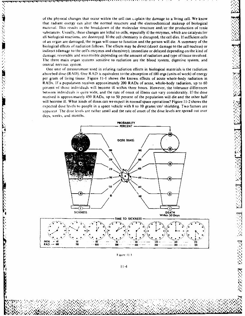
of the physical changes that occur within the cell can LAplain the damage to a living cell. We knowthat radiant energy can alter the normal structure and the electrochemical makeup of biologicalmaterial. This results in the breakdown of the molecular structure and/or the production of toxicsubstances. Usually, these changes are lethal to cells, especially if the enzymes, which are catalysts forall biological reactions, are destroyed. If the cell chemistry is disrupted, the cell dies. If sufficient cellsof an organ are damaged, the organ will cease to function and the person will die. A summary of thebiological effects of radiation follows. The effects may be direct (direct damage to the cell nucleus) orindirect (damage to the cell's enzymes and chemistry); immediate or delayed depending on the kind ofdamage: reversible and irreversible depending on the amount of radiation and type of tissue involved.I he three main organ systems sensitive to radiation are the blood system, digestive system, andcentral nervous system.
One unit of measurement used in relating radiation effects in biological materials is the radiationabsorbed dose (RAD). One RAD is equivalent to the absorption of 100 ergs (units of work) of energyper gram of living tissue. Figure 11-I shows the known effects of acute whole-body radiation inRADs. If a population receives approximately 200 RADs of acute, whole-body radiation, up to 60percent of those individuals will become ill within three hours. However, the tolerance differences
C, between individuals is quite wide, and the rate of onset of illness can vary considerably. If the dosereceived is approximately 450 RADs, up to 50 percent of the population will die and the other halfwill become ill. What kinds of doses can we expect in normal space operations? Figure 11-2 shows the ,.
expected dose levels to people in a space vehicle with 8 to 10 grams/cm 2 shielding. Two factors areapparent. The dose levels are rather small and the rate of onset of the dose levels are spread out overdays, weeks, and months.
PROBABILITYPERCENT
lo I
DOSE (RAD)
300 Soo
210 .460'-'.
150/ 340
180
SICKNESS DEATHWithin 30 Days
TIME TO SICKNESS
MI 05 07 010 8 270..... 7211 00 S1- -40," ,0 3-0 200o 0--
11-4-- I, 4 " - . -:x ., . * ... ~ -
M I -- 0"504.. . N . . .- ... -.. . .180 ... . 4 -
RA .0 O0 - " 0 . . .. 00 . . . .30 . . . ..2 0 . .. I0%
I-i~tu e I'C-
77n-I65 838 SPACE HNDBOOK(U) AIR MINISTRY LONDON (ENOLAND)VC D COCHRAN ET AL. JAN 85 RU-iS
UNCLASSIFIED F/6 15/7 UL
EEELi/IIIIEIEIEEIIEEEEEEEEEEEEEE/hEEEEEEEIIIIEEEEEEEEEE//EEEEEEEI
I.
:. 9*.
1.0 Us IliI -
.
ilII 128 1252
L611111 1.
1111140 111112.6
**,**' ,",
91.8
MICROCOPY RESOLUTION TEST CHARTNATIONAL AIJAFAL] OF STANDARDS 1963A
A-6~ *
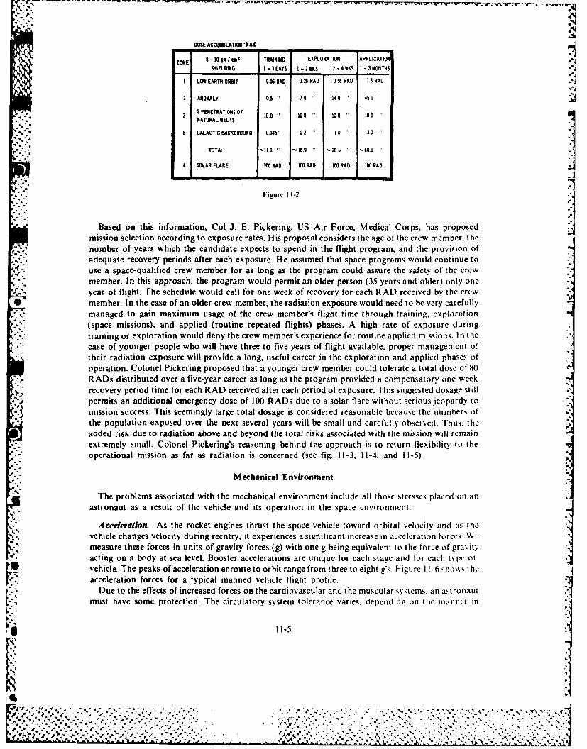
DOSE ACCUNULATION"R AD
ZONE 9-10 lI/ a TRAINING EXPLORATION APPLICATIONSHiELDiNG I - 3DAYS I -2WIKS 2 -IR KS I - 3 MONThS,,,
1 LOW EARTH ORB!T 006 RAO 0.26 RAD 0 56 RAD 18 RAD
2 ANOMALY 0.5 70 " 140 450
2"PENETRATIONS OF 100 100 100NATURAL BELTS
5 GALACTIC BACKGROUND 0.045" 0.2 10 3.0
TOTAL -11.0 " -18.0 -26u -60.0
4 SOLAR FLARE 100 RAO 100 RAO 100 RAD 100 RAO
Figure 11-2.
Based on this information, Col J. E. Pickering, US Air Force, Medical Corps, has proposedmission selection according to exposure rates. His proposal considers the age of the crew member, thenumber of years which the candidate expects to spend in the flight program, and the provision ofadequate recovery periods after each exposure. He assumed that space programs would continue to
2<: use a space-qualified crew member for as long as the program could assure the safety of the crewmember. In this approach, the program would permit an older person (35 years and older) only one
"" year of flight. The schedule would call for one week of recovery for each RAD received by the crew*member. In the case of an older crew member, the radiation exposure would need to be very carefullyr' managed to gain maximum usage of the crew member's flight time through training, exploration
(space missions), and applied (routine repeated flights) phases. A high rate of exposure duringtraining or exploration would deny the crew member's experience for routine applied missions. In thecase of younger people who will have three to five years of flight available, proper management oftheir radiation exposure will provide a long, useful career in the exploration and applied phases ofoperation. Colonel Pickering proposed that a younger crew member could tolerate a total dose of 80RADs distributed over a five-year career as long as the program provided a compensatory one-weekrecovery period time for each RAD received after each period of exposure. This suggested dosage stillpermits an additional emergency dose of 100 RADs due to a solar flare without serious jeopardy tomission success. This seemingly large total dosage is considered reasonable because the numbers of
* the population exposed over the next several years will be small and carefully observed. Thus, theadded risk due to radiation above and beyond the total risks associated with the mission will remain
. extremely small. Colonel Pickering's reasoning behind the approach is to return flexibility to theoperational mission as far as radiation is concerned (see fig. 11-3, 11-4. and 11-5).
Mechanical Environment
The problems associated with the mechanical environment include all those stresses placed on anV". astronaut as a result of the vehicle and its operation in the space environment.
Acceleration. As the rocket engines thrust the space vehicle toward orbital velocity and as thevehicle changes velocity during reentry, it experiences a significant increase in accelerati-n forces. Wemeasure these forces in units of gravity forces (g) with one g being equivalent to the force of gravityacting on a body at sea level. Booster accelerations are unique for each stage and for each type (t,vehicle. The peaks of acceleration enroute to orbit range from three to eight g's. Figure I -6 sho\ks theacceleration forces for a typical manned vehicle flight profile.
Due to the effects of increased forces on the cardiovascular and the muscular systems. an astronautmust have some protection. The circulatory system tolerance varies, depending on the manner in
11-5
V. %
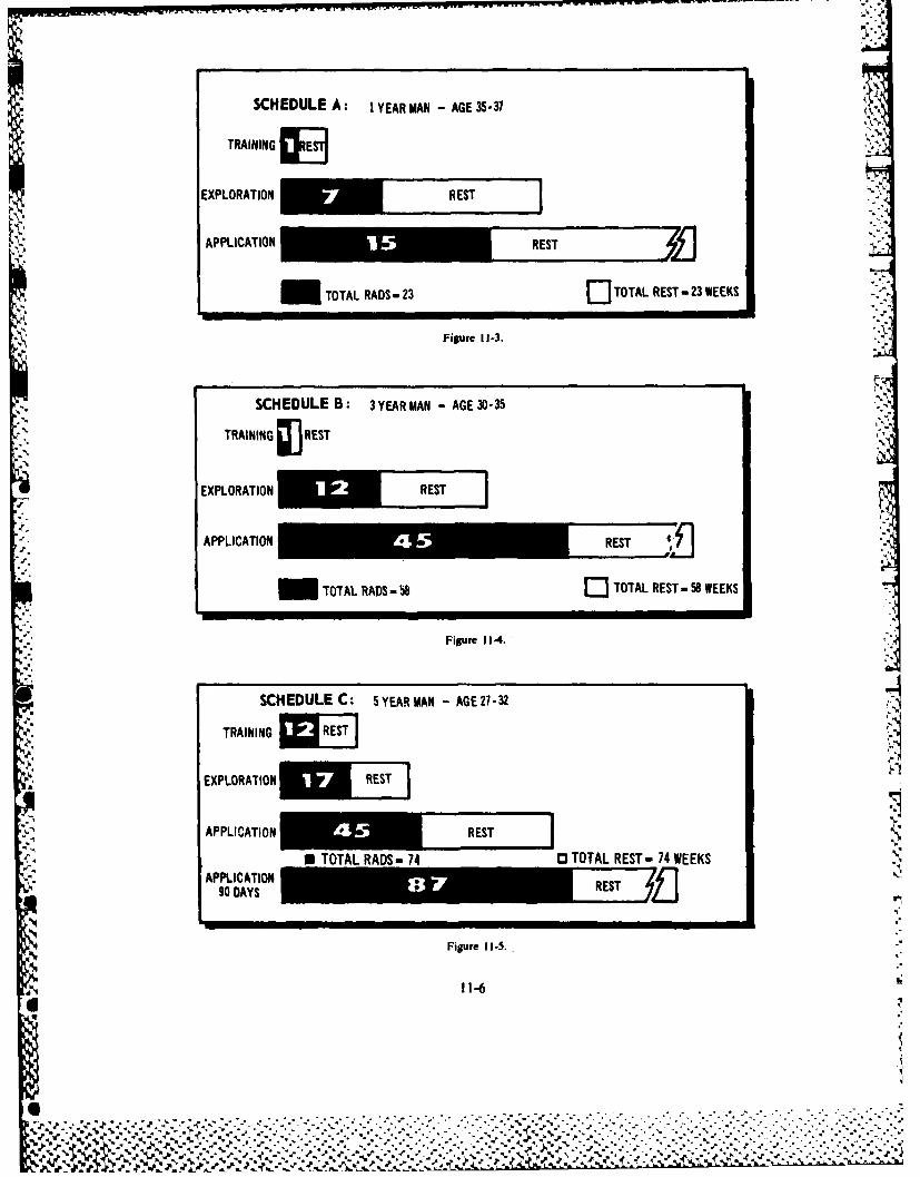
SCHEDULE A: I1YEAR MN -AGE 35-37
TRAINING
EXPLORATION REST
APPLICATION RS
M TOTAL RADS -23 ElTOTAL REST -23 WEEKS
Figure 11-3.
SCHEDULE B: 3 YEAR MAN -AGE 30-35
TRAINING WREST
EXPLORATION REST IAPPLICATION *REST
TOTAL RADS b8 TOTAL REST-58 WEEKS
Figure 11-4.
SCHEDULE C: 5YEAR MAN -AGE 27-32
TRAINING RS
EXPLORATIONm i iAPPLICATION
90 DAYSREST
-11-
TOAAS-4TTL'2 0 RST -1 WEEK
1%%
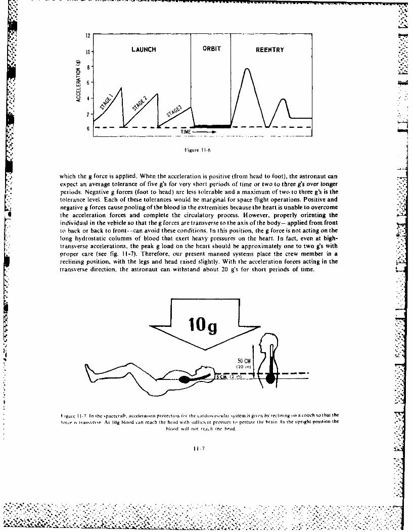
12
10- LAUNCH ORBIT REENTRY
-JI
Z)
2
Figure 11-6
which the g force is applied. When the acceleration is positive (from head to foot), the astronaut can
expect an average tolerance of five g's for very short periods of time or two to three g's over longerperiods. Negative g forces (foot to head) are less tolerable and a maximum of two to three g's is thetolerance level. Each of these tolerances would be marginal for space flight operations. Positive andnegative g forces cause pooling of the blood in the extremities because the heart is unable to overcomethe acceleration forces and complete the circulatory process. However, properly orienting theindividual in the vehicle so that the g forces are transverse to the axis of the body-applied from frontto back or back to front--can avoid these conditions. In this position, the g force is not acting on thelong hydrostatic columns of blood that exert heavy pressures on the heart. In fact, even at high-transverse accelerations, the peak g load on the heart should be approximately one to two g's withproper care (see fig. 11-7). Therefore, our present manned systems place the crew member in areclining position, with the legs and head raised slightly. With the acceleration forces acting in thetransverse direction, the astronaut can withstand about 20 g's for short periods of time.
50 CMC
~(2) in)
I igurc II-7 In the %pacecrafl, acceleration protection for the cardiovacular ystern is given by reclining on a couch so that thetoro i% trans% er~e At lOg blood can reach the head with 1ullicicnt pressure to perfuse the brain In the upright position the
blood will not rcath tie head
11-7
... -.a.- , . . - - , , , , - , . .- . . - . . . . . . , .... . . . . . .
!' " ' '"" "', *,' . , '. '-,",, ,'o - .7'a-', ... . *,. . .'*.", .. a ',' . -' -' " " .' . . .',. ' .. . ' .", ' ' .

The arms, legs, and head present difficult problems under high-acceleration forces. For example,the astronaut cannot control the arms efficiently if g forces exceed about four g's. The hand and -
% fingers have tolerance levels of about seven to nine g's. The astronaut's control and operation of thespacecraft would be limited or impossible if the astronaut used conventional aircraft controls.
% Therefore, engineers devised new controls and control locations so that the astronaut would have nodifficulty operating the vehicle under high-acceleration forces. The astronaut can use devices such asside-stick controls, which keep the arm rigid but allow hand movement, for pitch, roll, and yaw of thespace vehicle.
Vibration. A space launch and the rapid flight through successive layers of the atmosphere canexoean astronaut to rather severe vibrations from the rocket engines and buffeting in the
atmospeeVitosae sd-to-side jostling motions and up and down bouncing. The astronaut ismost sensitive to vibration frequencies of 4 to 10 cycles per second because the major internal organshave a natural resonance frequency in this range. When the organs become resonant with thevibrations of the space vehicle, severe pain, nausea, headaches, and dizziness are common symptoms.The organs begin to tear away from the mesentery holding them in place. Therefore, scientists andengineers must eliminate or dampen the vibrations in the frequency range of 4 to 10 cycles per secondto make space flight safe for the astronauts. Under present power and flight schedules used in mannedflight, we can control sufficiently the vibration problems. They produce no serious drawbacks to theprogram. -
Noise. Noise has been a problem for people for a long time, but never before has the intensity beenso great as the noise produced by space boosters. We know that people working in noisyenvironments develop a restricted deafness in the frequency range of the noise. It is necessary to placevery rigorous protective controls on workers, including the use of ear plugs and ear muffs. The
0 maximum tolerance to noise for people is about 140 to 1S0 decibels, at which level permanent damageto the hearing mechanism will occur if exposure continues for approximately one minute. Spaceboosters produce noise levels of 145 to 175 decibels. The solution to the noise problem involves usingsome of the natural physical conditions of space vehicles. For example, the capsule is placed on the endof the booster away from the rocket motors. The distance, which lessens the noise, reduces the decibellevel in the capsule. Also, the materials in the vehicle, including the skin, structure, propellants, andoxidizers, as well as the equipment on board the spacecraft, help lessen the noise intensity. Finally, thespace suit, which is worn during the operation of the first stage booster, has sound and vibrationreduction materials throughout the suit and in the helmet. The manned space programs haveemployed these techniques successfully, and the program has kept the noise level in all vehicles wellwithin the limits of safe operation.
Weightlessness. 'There were many anxieties concerning the effects of weightlessness on peopleoperating in space. These ranged from fear of falling, nausea, and injury to the more complexphysiological considerations, such as disruption of normal biological functions. The increase in our
:2 knowledge and experience have dispelled most of these anxieties. Although we have learned much* '' about the effects of weightlessness on people, we still must proceed cautiously as we expand our
capability. At the present time, we can divide the problems posed by weightlessness into twocategories: psychological and physiological.
[he pshychological problems are many and varied. Factors such as isolation, restraint, andconfinement apparently have presented no particular problems in flights to date. However, as weanticipate longer flights, these three factors may present some serious problems. This was emphasizedby Col Frank Borman on the Apollo 8 lunar orbiting mission, when he said, "We found several thingswe think need to be improved. I think that we need to concern ourselves with proper engineering forbetter body waste disposal systems. We have to provide showers on board. We have to have some sortof entertainment, television or canned tapes. We have to look into better foods. We have to realizethat when you put a man on orbit for 60 days, or perhaps even longer, you have to pay more attentionthan we have in the past to the basic creature confiorts. "'The Skylab flights used such suggestionsw~ith good results.
11-8
'5V..
. %
§AL1
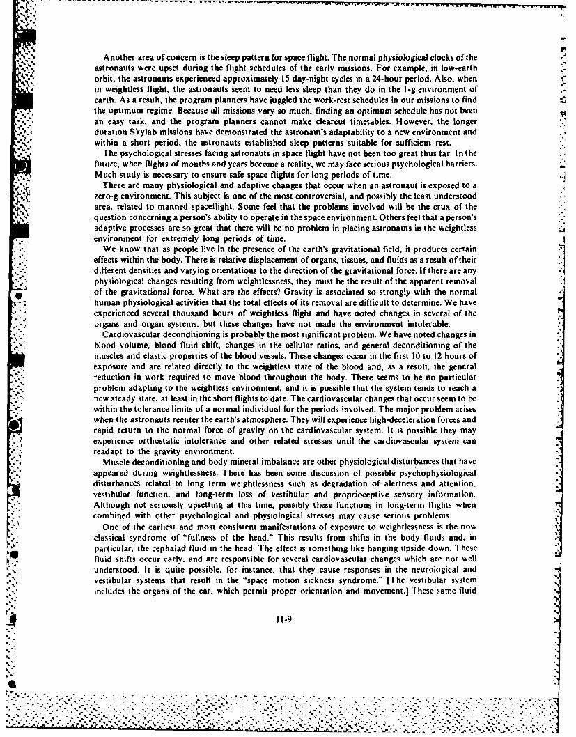
-~N M, S ... ,
Another area of concern is the sleep pattern for space flight. The normal physiological clocks of theastronauts were upset during the flight schedules of the early missions. For example, in low-earthorbit, the astronauts experienced approximately 15 day-night cycles in a 24-hour period. Also, whenin weightless flight, the astronauts seem to need less sleep than they do in the 1-g environment ofearth. As a result, the program planners have juggled the work-rest schedules in our missions to find
*the optimum regime. Because all missions vary so much, finding an optimum schedule has not been Van easy task, and the program planners cannot make clearcut timetables. H owever, the longerduration Skylab missions have demonstrated the astronaut's adaptability to a new environment andwithin a short period, the astronauts established sleep patterns suitable for sufficient rest.
{~'The psychological stresses facing astronauts in space flight have not been too great thus far. In thefuture, when flights of months and years become a reality, we may face serious psychological barriers.Much study is necessary to ensure safe space flights for long periods of time.
There are many physiological and adaptive changes that occur when an astronaut is exposed to azero-g environment. This subject is one of the most controversial, and possibly the least understoodarea, related to manned spaceflight. Some feel that the problems involved will be the crux of thequestion concerning a person's ability to operate in the space environment. Others feel that a person'sadaptive processes are so great that there will be no problem in placing astronauts in the weightlessenvironment for extremely long periods of time.
We know that as people live in the presence of the earth's gravitational field, it produces certaineffects within the body. There is relative displacement of organs, tissues, and fluids as a result of theirdifferent densities and varying orientations to the direction of the gravitational force. If there are any -
physiological changes resulting from weightlessness, they must be the result of the apparent removalof the gravitational force. What are the effects? Gravity is associated so strongly with the normal
-~ human physiological activities that the total effects of its removal are difficult to determine. We have.7% experienced several thousand hours of weightless flight and have noted changes in several of the* organs and organ systems, but these changes have not made the environment intolerable.
Cardiovascular deconditioning is'probably the most significant problem. We have noted changes inblood volume, blood fluid shift, changes in the cellular ratios, and general deconditioning of themuscles and elastic properties of the blood vessels. These changes occur in the first 10 to 12 hours ofexposure and are related directly to the weightless state of the blood and, as a result, the generalreduction in work required to move blood throughout the body. There seems to be no particularproblem adapting to the weightless environment, and it is possible that the system tends to reach anew steady state, at least in the short flights to date. The cardiovascular changes that occur seem to bewithin the tolerance limits of a normal individual for the periods involved. The major problem ariseswhen the astronauts reenter the earth's atmosphere. They will experience high-deceleration forces andrapid return to the normal force of gravity on the cardiovascular system. It is possible they mayexperience orthostatic intolerance and other related stresses until the cardiovascular system canreadapt to the gravity environment.
Muscle deconditioning and body mineral imbalance are other physiological disturbances that haveappeared during weightlessness. There has been some discussion of possible psychophysiologicaldisturbances related to long term weightlessness such as degradation of alertness and attention,vestibular function, and long-term loss of vestibular and proprioceptive sensory information.Although not seriously upsetting at this time, possibly these functions in long-term flights whencombined with other psychological and physiological stresses may cause serious problems.
One of the earliest and most consistent manifestations of exposure to weightlessness is the nowclassical syndrome of "fullness of the head." This results from shifts in the body fluids and, inparticular, the cephalad fluid in the head. The effect is something like hanging upside down. These
e fluid shifts occur early, and are responsible for several cardiovascular changes which are not wellunderstood. It is quite possible, for instance, that they cause responses in the neurological andvestibular systems that result in the "space motion sickness syndrome." [The vestibular systemincludes the organs of the ear, which permit proper orientation and movement.] These same fluid
11-9
6 - . . .
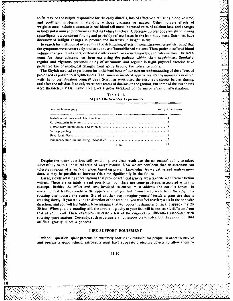
shifts may be the culprit responsible for the early diuresis, loss of effective circulating blood volume,and postflight problems in standing without dizziness or nausea. Other notable effects ofweightlessness include a decrease in red blood cell mass, increased rates of calcium loss, and changesin body potassium and hormones affecting kidney function. A decrease in total body weight followingspaceflights is a consistent finding and probably reflects losses in the lean body mass. Scientists havedocumented inflight changes in posture and increases in height as well.
In search for methods of overcoming the debilitating effects of weightlessness, scientists found thatthe symptoms were remarkably similar to those of immobile bed patients. These patients suffered bloodvolume changes, fluid shifts, orthostatic intolerance, weakened muscles, and calcium loss. The treat-ment for these ailments has been exercising the patients within their capabilities. Similarly,regular and vigorous preconditioning of astronauts and regular in-flight physical exercise haveprevented the physiological changes from going beyond the tolerance limits.
The Skylab medical experiments form the backbone of our current understanding of the effects ofprolonged exposure to weightlessness. That mission involved approximately 11/2 man-years in orbil.,with the longest duration being 84 days. Scientists scrutinized the astronauts closely before, during,and after the mission. Not only were there teams of doctors on the ground, but some of the astronautswere themselves MDs. Table Il-I gives a gross breakout of the major areas of investigation.
Table 1l-l.Skylab Life Sciences Experiments
Area of Investigation No. of lxpelriu'ttt "
Nutrition and musculoskeletal function ............................................ 4
C ardiovascular function ......................................................... 2
Hematology. immunology. and cNtology ........................................... 6
Neurophysiology ............ ............................................ 2
Behavioral effects .............................................................. I
Pulmonary function and energy metabolism ....................................... 2
Fotal 17
Despite the many questions still remaining, one clear result was the astronauts' ability to adaptsuccessfully to this unnatural state of weightlessness. Now we are confident that an astronaut cantolerate missions of a year's duration, based on present knowledge. As we gather and analyze moredata, it may be possible to increase this time significantly in the future.
Large, slowly rotating space stations that provide artificial gravity are a favorite with science fiction, writers. These are certainly a real possibility, but there are some problems associated with this
concept. Besides the effort and cost involved, scientists must address the coriolis forces. In
oversimplified terms, coriolis is the apparent force you feel if you try to walk from the edge of rotating disc toward the center. Stated another way, imagine yourself inside a giant tire that isrotating slowly. If you walk in the direction of the rotation, you will feel heavier; walk in the oppositedirection, and you will feel lighter. Now imagine that we reduce the diameter of the tire approximately20 feet. When you are standing still, the apparent gravity at your feet will be noticeably different fromthat at your head. These examples illustrate a few of the engineering difficulties associated withrotating space stations. Certainly, such problems are not impossible to solve, but they point out thatartificial gravity is not a panacea.
LIFE SUPPORT EQUIPMENT
Without question, space presents an extremely hostile environment for people. In order to surviveand operate a space vehicle, astronauts must have adequate protective devices to allow them to
1-10
%5'
l ... . . . . .. . . . .. .. . . - ," . *
..... , , ..... ... .................... , ... .=.. .
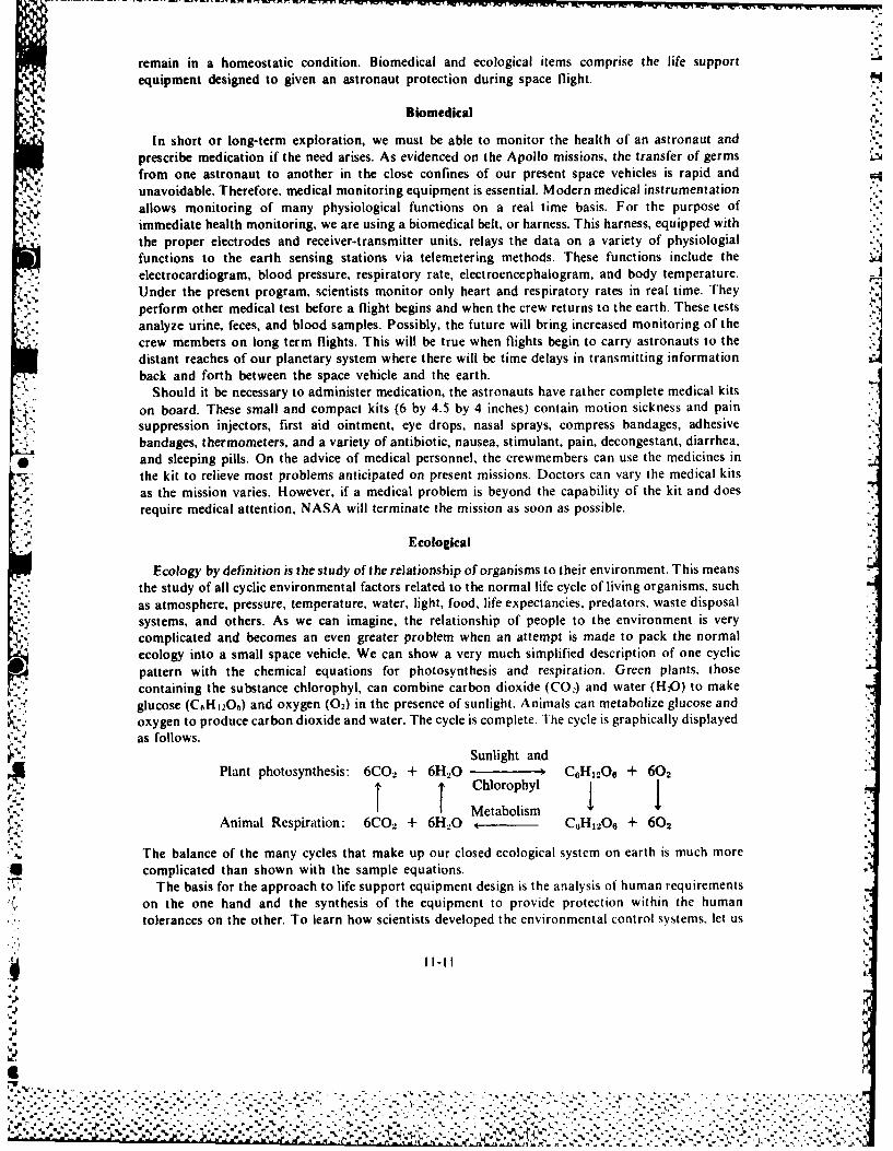
remain in a homeostatic condition. Biomedical and ecological items comprise the life supportequipment designed to given an astronaut protection during space flight.
4, Biomedical
In short or long-term exploration, we must be able to monitor the health of an astronaut andprescribe medication if the need arises. As evidenced on the Apollo missions, the transfer of germsfrom one astronaut to another in the close confines of our present space vehicles is rapid andunavoidable. Therefore, medical monitoring equipment is essential. Modern medical instrumentationallows monitoring of many physiological functions on a real time basis. For the purpose ofimmediate health monitoring, we are using a biomedical belt, or harness. This harness, equipped withthe proper electrodes and receiver-transmitter units, relays the data on a variety of physiologialfunctions to the earth sensing stations via telemetering methods. These functions include theelectrocardiogram, blood pressure, respiratory rate, electroencephalogram, and body temperature.Under the present program, scientists monitor only heart and respiratory rates in real time. Theyperform other medical test before a flight begins and when the crew returns to the earth. These testsanalyze urine, feces, and blood samples. Possibly, the future will bring increased monitoring of thecrew members on long term flights. This will be true when flights begin to carry astronauts to thedistant reaches of our planetary system where there will be time delays in transmitting informationback and forth between the space vehicle and the earth.
Should it be necessary to administer medication, the astronauts have rather complete medical kitson board. These small and compact kits (6 by 4.5 by 4 inches) contain motion sickness and painsuppression injectors, first aid ointment, eye drops, nasal sprays, compress bandages, adhesive
bandages, thermometers, and a variety of antibiotic, nausea, stimulant, pain, decongestant, diarrhea,and sleeping pills. On the advice of medical personnel, the crewmembers can use the medicines inthe kit to relieve most problems anticipated on present missions. Doctors can vary the medical kitsas the mission varies. However, if a medical problem is beyond the capability of the kit and doesrequire medical attention, NASA will terminate the mission as soon as possible.
Ecological
Ecology by definition is the study of the relationship of organisms to their environment. This meansthe study of all cyclic environmental factors related to the normal life cycle of living organisms, suchas atmosphere, pressure, temperature, water, light, food, life expectancies, predators, waste disposal %systems, and others. As we can imagine, the relationship of people to the environment is verycomplicated and becomes an even greater problem when an attempt is made to pack the normalecology into a small space vehicle. We can show a very much simplified description of one cyclicpattern with the chemical equations for photosynthesis and respiration. Green plants, thosecontaining the substance chlorophyl, can combine carbon dioxide (CO 2) and water (H20) to makeglucose (C(H 120 6) and oxygen (02) in the presence of sunlight. Animals can metabolize glucose andoxygen to produce carbon dioxide and water. The cycle is complete. The cycle is graphically displayedas follows.
Sunlight andPlant photosynthesis: 6CO. + 6R20 - CIH120 + 602
Chlorophyl
S MetabolismAnimal Respiration: 6CO 2 + 61.,0 < CH 1206 + 602
The balance of the many cycles that make up our closed ecological system on earth is much morecomplicated than shown with the sample equations.
The basis for the approach to life support equipment design is the analysis of human requirementson the one hand and the synthesis of the equipment to provide protection within the humantolerances on the other. To learn how scientists developed the environmental control systems, let us
%.
" . - , --..- , ' " , " ,, , ,, " . " ) , - - . , ', -".-,. - -- - . " - - " " . "-

first discuss the food, oxygen, and water requirements for people.As we show in figure 11-8, in an open ecological system, a person has a requirement for
Z approximately 22.7 pounds of oxygen, 4.7 pounds of water, and 1.3 pounds of food per day. At thesame time, a person produces an equivalent weight of waste products, including 20.7 pounds ofoxygen, 5.2 pounds of water. and 2.2 pounds of carbon dioxide. At present, it is impossible to carry
these stored materials on space missions because of the weight involved. Scientists have made someII progress in weight saving in the food program. Because of the mechanical problems of eating food~.. ~.during weightlessness in orbit, special preparation and packaging is necessary.
OXYGEN - WATER - FOOD EXCHANGE
INPUT LBS/DAY OUTPUT LBS/DAY
OXYGEN (02) 22.7 20.7 (0 2)
WATER (H 20) 4.7 5.2 (H 20)
2.2 WATER VAPOR3.rUIN
FOOD 1.3 2.2 CARBON DIOXIDE (CO2(3000KCALDAY)0.6 SOLID WASTE
28.7 28.7
Figure 11-8.
-. Our food system consists of dehydrated foods prepared by a process of freeze-drying. Then,processors package this water-free food in special plastic bags. The astronauts can rehydrate the food
- . from the hot or cold water on board the spacecraft or, in the case of some items, by saliva in themouth. This current food system has the advantages of Ling bacteria-free, lightweight, easily stored,and easily prepared. When rehydrated, the food is tasty and nutritious. klowever, it still has thedisadvatange, inherent in an open ecological system, of being impractical from the viewpoint of longflights of months and years. Therefore, scientists must design some system of regenerating or growingfood from the materials on board the spacecraft for future long-term missions.
Trhe meals on Skylab were more palatable than those of previous manned programs. This was dueprimarily to advancements in technology that allowed the inclusion of frozen and canned foods.
The Skylab food system had to meet the rigid requirements and objectives of medical experiments
V that demand precise knowledge of nutrient intake. The food system provided the energy requirementsV of each individual astronaut based on body weight and age. The ration insured a daily intake between
750 and 850 milligrams of calcium, 1,500 to 1,700 milligrams of phosphorous, 3,000 to 6,000miligrams of sodium, 300 to 400 milligrams of magnesium, and 90 to 125 grams of protein. Eachastronaut maintained a constant level of intake of these controlled nutrients within 2 percent.Scientists baselined the diet to provide at least the dietary allowances of carbohydrates, minerals,vitamins, and fats recommended by the National Academy of Science.
Nutritionists stored approximately 950 kilograms (2,100 pounds) of food and accessories for allan three manned visits aboard the workshop prior to launch. They secured the frozen food items in the
five food freezers. and the other food items in lockers on the floor of the workshop at launch. Later,the SL-2 crew placed the food items in assigned locations during the activiation period. Crew
11-12
.....................................................
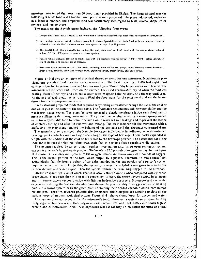
members taste tested the more than 70 food items provided in Skylab. The items aboard met thefollowing criteria: food was a familiar kind; portions were processed to be prepared, served, and eatenin a familiar manner; and prepared food was satisfactory with regard to taste, aroma, shape, colortexture, and temperature.
The meals on the Skylab menu included the following food types:
I. Dehydrated which includes ready-to-eat rehydratable foods with a moisture content reduced to less than three percent.
2. Intermediate moisture which includes precooked, thermally-stabilized, or fresh food with the moisture contentreduced so that the final moisture content was approximately 10 to 20 percent.
3- Fhermostabilized which includes precooked, thermally-stabilized, or fresh food with the temperatures reducedbelow 23°C ( 10°F) prior to launch to retard spoilage.
4. Frozen which includes precooked fresh food with temperature reduced below -400C (40
0 F) before launch to- "retard spoilage and maintained in freezers.
5. Beverages which include rehydratable drinks including black coffee, tea, cocoa, cocoa-flavored instant breakfast,grape drink, limeade. lemonade, orange drink, grapefruit drink, cherry drink, and apple drink.
Figure 11-9 shows an example of a typical three-day menu for one astronaut. Nutritionists pro- Lvided one portable food tray for each crewmember. The food trays (fig. 11-10) had eight foodcavities-four for large food cans and four for small cans. Three of the large cavities were heated. Theastronauts set the timer and turned on the warmer. They used a removable tray lid when the food washeating. Each of the trays and lids had a color code. Magnets held the utensils to the tray until used.At the end of each meal, the astronauts filled the food trays for the next meal and set the heatertimers for the appropriate intervals.
Each astronaut prepared foods that required rehydrating at mealtime through the use of the cold orhot water gun in the center of the food table. The food table pedestal housed the water chiller and thewardroom water heater. The manufacturers installed a plastic membrane inside each food can toprevent spillage in the iero-g environment. They fitted the membrane with a one-way spring-loadedvalve for rehydratable food to permit the addition of water without leakage and to prevent the escapeof contents during and after lid removal and mixing. The crew member slit the membrane with aknife, and the membrane retained the balance of the contents until the astronaut consumed them.
The manufacturers packaged rehydratable beverages individually in collapsed accordion-shapedbeverage packs, which varied in length according to the type of beverage. These packs expanded inlength with the addition of the cold or hot water to the beverage powder. The astronauts sat at thefood table in special thigh restraints with their feet in portable foot restraints while eating.
The oxygen required by an astronaut requires investigation also. In an open ecological system,oxygen is a person's largest waste product. We breath in 22.7 pounds of oxygen per day, but, as figure11-8 shows, we use only nine percent of the oxygen inhaled and throw away 20.7 pounds of oxygen.This is the larges; portion of the total waste output by a person. Therefore, to make spaceflighteconomically feasible from a weight of storables standpoint, the gas portion of a person's system -requires better treatment. To do this, the system processes the exhaled waste gases to remove thecarbon dioxide and water vapor. Then the system returns the remaining oxygen to the astronaut.
On earlier space flights, all of which were of relatively short duration when compared with extendedspace travel, it has been simpler and more convenient to carry the entire oxygen supply in cylinders 7and to remove excess carbon dioxide with lithium hydroxide absorbers. Numerous and successful
experiments during the last two decades have shown the practicability of oxygen replenishment byplants in a closed system, with the green plants obtaining their needed carbon dioxide from humanmetabolism. Therefore, research physiologists, engineers, and biologists are working to close all thevarious loops of an open ecological system. Figure I 1-I1 shows closed loops for oxygen and water.
This system does not account for the astronaut's food. However, a system can produce food byusing algae or bacteria where these organisms will convert CO 2 and H20 wastes into foods high inprotein and carbohydrates, Also, these organisms will use (as they do on earth) the urine and fecal
11-13
5,
- %
" "-"." """'" -" ,,7 " -""- -" """" ,";, - ", -"""". " .. ' -' . . .... ..- - , -.... . . . - . . ..- -%.%..'' ~ ~ ~ O % ' ' . - . - . • - , " "" " - - " - 3 ", ' ' - ' - - - - . . , - .+ ' ' " . - • % , , , . . - " - " - "- , . . • . . ' . . - -
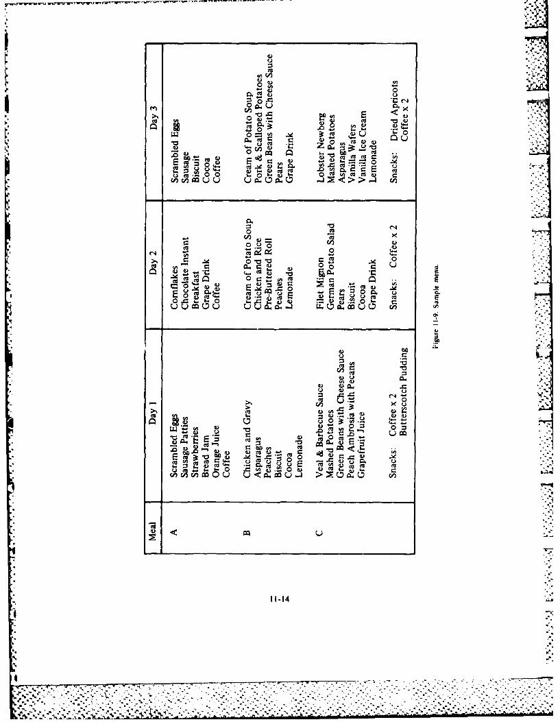
0 )
0 C
OQ Z o
F.Q *0 cc
4)4)n cn 00UU u 0>> E
0 0
aU CO ~ 0040, 0
(NJ -~ 4 z
E 0 ~ m0 0-0 u1 2) 0~ 4 0
u0 u- - cou E
41
012
- c .00~ M)I2
00 Do..04
4)4
000 >
CA En 0" u u u -
11-14 .4-
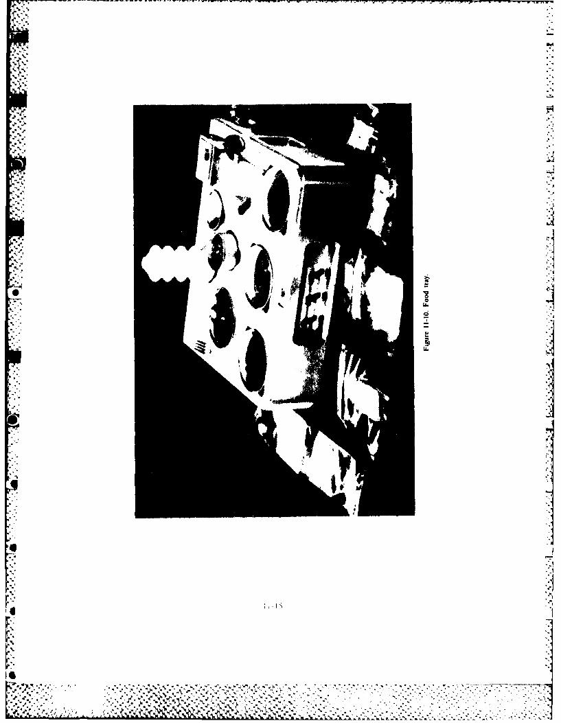
IV-.
~ V~
I
~4
-p
* I0
U
U.
I
* 2
~iE1
* ~. ~.** - ., .4'.. . *
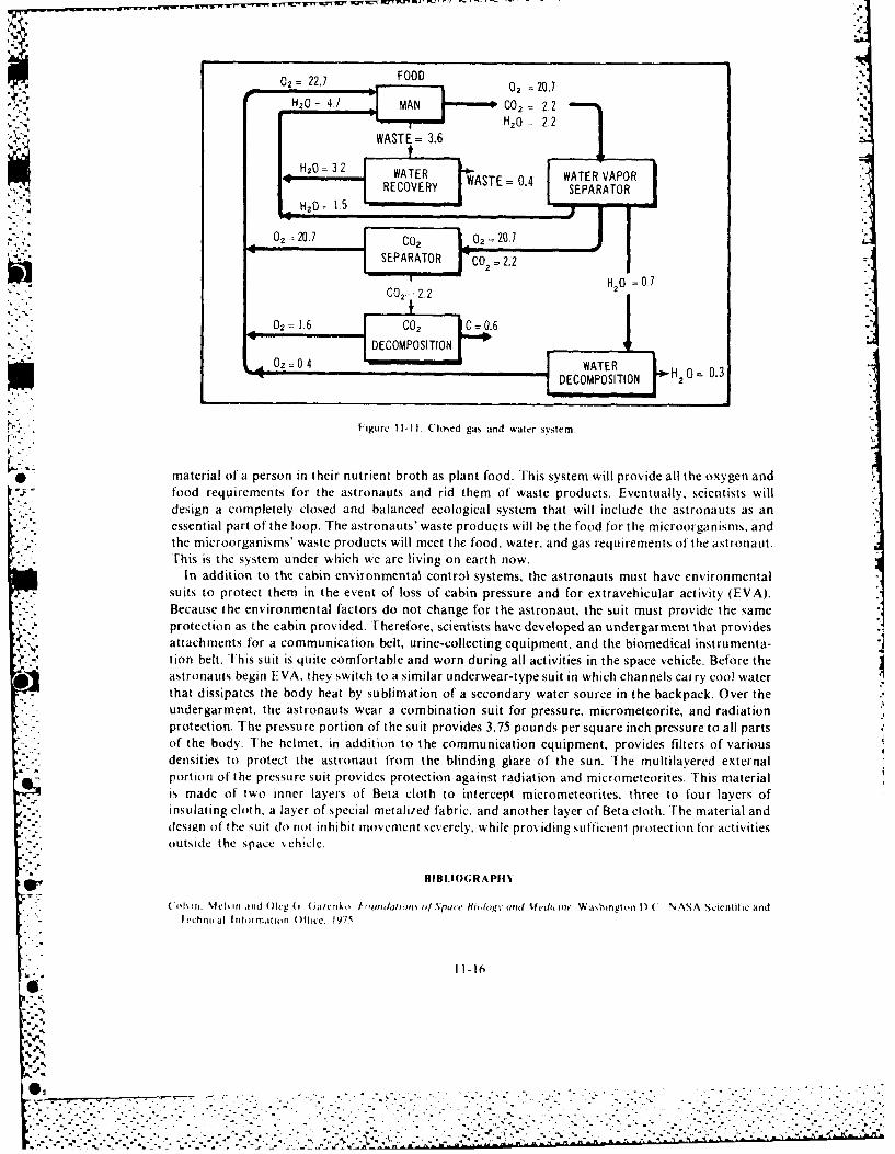
FOOD
DEOSH20 IT4 C02 N22",,: ,HO = 2,2"
~WASTE= 3.6
H20 =32 WATER WATER VAPOR::l ~ ~~RECOVERY SE:4 SEPARATOR- " ,d H20 1 .5 ! m
Our 20.7 C o 0a 2 ase-' [SEPARATOR rco _2.2 =.
'" " CO2- 2.2 H 0 0
", -. " DECOMPOSITION ;02 O, 0.4 'WATER Ho .
" ~~DECOMPOSITION H 0 - .
[.P " ", ,Figure I1I-11. ('lo ,ed gas and water system. n
* material of a person in their nutrient broth as plant food. This system will provide all the oxygen andfood requirements for the astronauts and rid them of waste products. Eventually, scientists willdesign a completely closed and balanced ecological system that will include the astronauts as anessential part of the loop. The astronauts' waste products will be the food for the microorganisms, andthe microorganisms' waste products will meet the food, water, and gas requirements of the astronaut.This is the system under which we are living on earth now.
In addition to the cabin environmental control systems. the astronauts must have environmentalsuits to protect them in the event of loss of cabin pressure and for extravehicular activity (EVA).Because the environmental factors do not change for the astronaut, the suit must provide the sameprotection as the cabin provided. Therefore, scientists have developed an undergarment that providesattachments for a communication belt, urine-collecting equipment, and the biomedical instrumenta-tion belt. [his suit is quite comfortable and worn during all activities in the space vehicle. Before theastronauts begin EVA, they switch to a similar underwear-type suit in which channels carry cool waterthat dissipates the body heat by sublimation of a secondary water source in the backpack. Over theundergarment, the astronauts wear a combination suit for pressure, micrometeorite, and radiationprotection. The pressure portion of the suit provides 3.75 pounds per square inch pressure to all partsof the body. The helmet, in addition to the communication equipment, provides filters of variousdensities to protect the astronaut from the blinding glare of the sun. The multilavered externalportion of the pressure suit provides protection against radiation and micrometeorites. This materialis made of two inner layers of Beta cloth to intercept micrometeorites, three to four layers ofinsulating cloth, a layer of special metalized fabric, and another layer of Beta cloth. The material anddesign of the suit do not inhibit movement severely, while providing sufficient protection for activitiesoutside the space %chicle.
RIBI.Io(;RAP1111
o n. %el' in ind ()leg ( (ii/Crk o 1 , l'ntdatI m -Jo'd )jSja(c /l, ai .ed iaWi Was hng on I) ( NASA Scientific and
Iechnical Irrnfrm,,ltn Office. lf7s
I 1-166o
I .
O : . . . .- -- - . - , ,- .-... . -- ., --- . ,- . , -: -,, -'.. / " " " -" - . . " .- - . . ' T - . .:-T - -_.' - -- "- - -- .- . -- .- -, - : . -- . '. . . .' .- " .- . - - - . " - " .- . ' . " - ' . . '. - -. - - -- - -.- ' ' ...

6- 4% V* V
Gerathewohl. Siegfried J. Principles of Bioastronautics. New York: Prentice-Hall, 1963.Langley. Louis L. Outline of Phvsiology. New York: McGraw-Hill, 1961.Morgan, Clifford T. Human Engineering Guide to Equipment D)esign. New York: McGraw-Hill. 1963.Morgenthaler. George W. and Gerald E. Simonson. Ski-lab Science Experiments: Proceedings of a Si'mposiumf of the 140th
Meeting of the American Association for the Advancement ojSuence. Tartana, Calif.: AAS Publications Office. 1975.National Aeronautics and Space Administration. Compendium of Human Responses ito the .4erospace Environment. August
19 21. 1970. NASA Contract Report 1205. Washington D.C.: National Aeronautics and Space Administration. November
- - National Aeronautics and Space Administration. Fifth Symposium on the Role of the Vestibuilar Organs in Space Exploration.National Aeronautics and Space Administration Special Paper 314. Washington D.C.: National Aeronautics and Space
~ Parker. James F.. Jr and Vita R. West. Bioastronautics Data Book. 2d ed. National Aeronautics and Space AdministrationSpecial Paper 3006. Washington l).C.: National Aeronautics and Space Administration. 1973.
Robinson. Douglas H. The D)angerous SkY. Seattle: University of Washington Press. f973.
r_4
4 11-17
.

Chapter 12
MILITARY SPACE SYSTEMS
Historically, military operations have evolved successively through the areas of land, sea surface,underwater, air, and space. Each new area of operation has been important to total militarycapability, and the optimum military posture requires proper cross support and cooperation. Astechnologies advance, the emphasis on the various regimes and the nature of their interlockingvaries, but no new operational medium has, in itself, provided a panacea for solving all militaryproblems. The Department of Defense (DOD) has been analyzing constantly the military contribu-tions that they can obtain from space operations. The DOD is trying to strike a proper balancebetween developments in the newly-opened regime of space and military efforts in the older regimesof land, sea, and air. According to AFM 1-6, Aerospace Basic Doctrine, Miliiar ' Space Doctrine,"To achieve their full potential, space systems and operations must be integrated fully withinexisting military forces to become part of the total force structure."
There is a limitation on the DOD in developing space systems that could threaten the securityof other nations. U nder the terms of the outer space treaty, which went into force on 10 October 1967,the United States agreed not to place weapons of mass destruction in outer space or in orbit aroundthe earth. The treaty bans military maneuvers on celestial bodies. As a result, the DOD is using
- - the medium of space for warning, surveillance, communication, navigation, and weather systemsto assist in maintaining an effective deterrent posture.
SYSTEMS AND PROGRAMS
In this section we will describe some of the space programs undertaken with the active participa-tion of the [)OD and Air Force. These programs range from those of immediate peacetime value,such as communication satellites, to those with potential military application.
Space Warning System
One ot the best examples of using space systems to augment surface systems would be to provide anearly warnfing of an intercontinental ballistic missile (ICBM) attack. Already, operational earlywarning satellites are in geostationary orbits to warn of an ICBM or Fractional OrbitingBombardment System (FOBS) attack and to warn of a submarine-launched ballistic missile(SI.BM) attack on the continental United States. We have one satellite stationed over the EasternHemisphere and twvo over the Western Hemisphere.
[ he eastern satellite would provide the first warning of an ICBM raid on the United States bythe Soviet Union or the Peoples Republic of China. The Ballistic Missile Early Warning System
K. (BMEWS) would verify this warning. The capability to correlate data from BMEWS, satellites, andother sources provides a highly credible warning of attack. The western satellites provide the first
___ warning of' SLBM launches against the United States with verification provided by FSPS -77,FPS 85, and FPS 115 radars.
d 12-1
% *.2 - *

Military Space Communications Systems
Space communications systems can augment ground-based command and control systems.Basically, a command and control system is a composite of equipment, skills, and techniquescapable of performing the clearly-defined function of enabling a commander to exercise continuouscontrol of the forces and weapons in all situations. It provides the commander with the informationneeded to make operational decisions and with a means for disseminating those decisions.
As advancements are made in technology, the Air Force is using this technology to develop acommunications satellite system that is more jam resistant, provides two-way communicationsamong mobile units, tactical aircraft, the national command authorities, and the strategic forces.The complexity, range, and speed of military systems continue to increase. As the need for positivecommunications becomes critical, space-based systems will provide an ever increasing amountof communications.
There are five military space communication programs that the Space Division (SD) of the AirForce Systems Command is managing. These include the Defense Satellite Communications System(DSCS), the Fleet Satellite Communications System (FLTSATCOM), the Air Force SatelliteCommunications System (AFSATCOM), the Satellite Data System (SDS). and Milstar.
Defense Satellite Communications System. Phase 11 of the DSCS is a second generation programthat has replaced the successful initial DSCS (see fig. 12-1). The space portion of DSCS I! consistsof spin-stabilized advanced communications satellites in synchronous orbit around the earth.Being significantly more powerful than the previous satellites, the phase If spacecraft providehigh-capacity, super high-frequency (SHF) secure voice and data links for the Worldwide MilitaryCommand and Control System (WWMCCS). They support terminal deployments for contingencies;restoration of disrupted service overseas; presidential travel; global connectivity for the Diplomatic
4 •Telecommunications Service; and transmission to the continental United States of some surveillance,.. intelligence, and early warning data.
The DSCS 11 operational system consists of four active satellites and two spares orbiting theearth. Each satellite contains propulsion systems for orbit reposition to support contingency
- "* operations. Ground command can steer the two dish-shaped antennas on DSCS I. The antennascan concentrate their electronic beams on small areas of the earth's surface for intensified coverageto link small, portable ground stations into the communication system.
In Phase Ill, the antenna design allows the user to switch between fixed earth-coverage antennasand multiple beam antennas (see fig. 12-2). The latter will provide an earth-coverage beam as wellas electrical steerable area and narrow-coverage beams. In addition, a steerable transmit dishantenna will provide a spot beam with increased radiated power for users with small receivers.In this way the communication system will tailor the communication beams to suit the needsof different size user terminals almost anywhere on the surface of the earth. The DSCS II satellitehas a cross-dipole transmit antenna and a flatback cavity spiral receiver antenna as a part of theAir Force Satellite Communication (AFSATCOM) program link with the strategic alert forces.The first Phase III satellite was launched in October 1982, but the complete Phase II system isstill being developed.
Presently, the Satellite Control Facility (SCF) at Sunnyvale, California. handles the conimu-nication capabilities and positioning of DSCS ii through a worldwide network of SCF stations.The planners and designers of the DSCS Ill system will design it so that selected Defense Communi-cations Agency (DCA) managed satellite configuration control elements (SCCE) will haxe theability to control both the satellite's communication capabilities and its position as well. The currentoperation plan for DSCS III requires that the SCCE assume the primary role in controlling thesatellite communications systems with the AFSCF continuing to perform the functions ofcontrolling the other satellite systems and maintaining the proper satellite orbit as in DSCS II. Thiswill increase the flexibility of DSCS by providing a more direct response to communications sxstem
, - user requirements and by providing DSCS III with backup capability for the SCF, should it everbe needed.
12-2
AA -1_ "
.4,
I¢_':: " . . .. -..' " A. 1 ', '.- - .-. ". - .- . . - - . .' -- . - - - " - - - ..-- . -'- . . . ".-.. - .
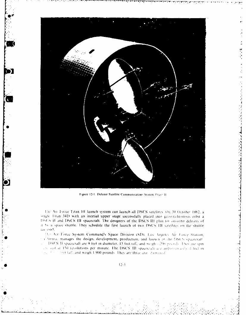
Figure 12-1. Defense Satellite Communications Ss stern P his
hc %it 1 orce 'I itan III launch systemn can launch all I)S(S .satcllitcs tn 10) ()Li oher 1982. aI~ Ittil 341) ' '.it h anl inertial upper stage successfully placed into gckis, nk-hi oti in orbit a11" SI and I SCS Ill spacecraft. The designers of' the 1)SCS IIl plan ti on-m hil dcei e tit
o.o
L~~ I Ir Iorcc S~ steni Command's S pace Division (Sl).* Lo, %ngk): Ati I l,( S tat ion,41 ij.r ni, atiinges thc design, development. production. and laun, h o s'ti&&&D i(,
'S5( I I s pacc r ft are 91t te i n dIi am e t r,3f e) lt til a n 11 a h n ~ i (I %k Ii i 1,)i I SO rce oliitions per minute. I[he l)S(S III p OTi ! ptc<T
!,ll nd scigzh 1 .90(0 pouinds 1 h, aric thrxi i ii A
*" "
*
I
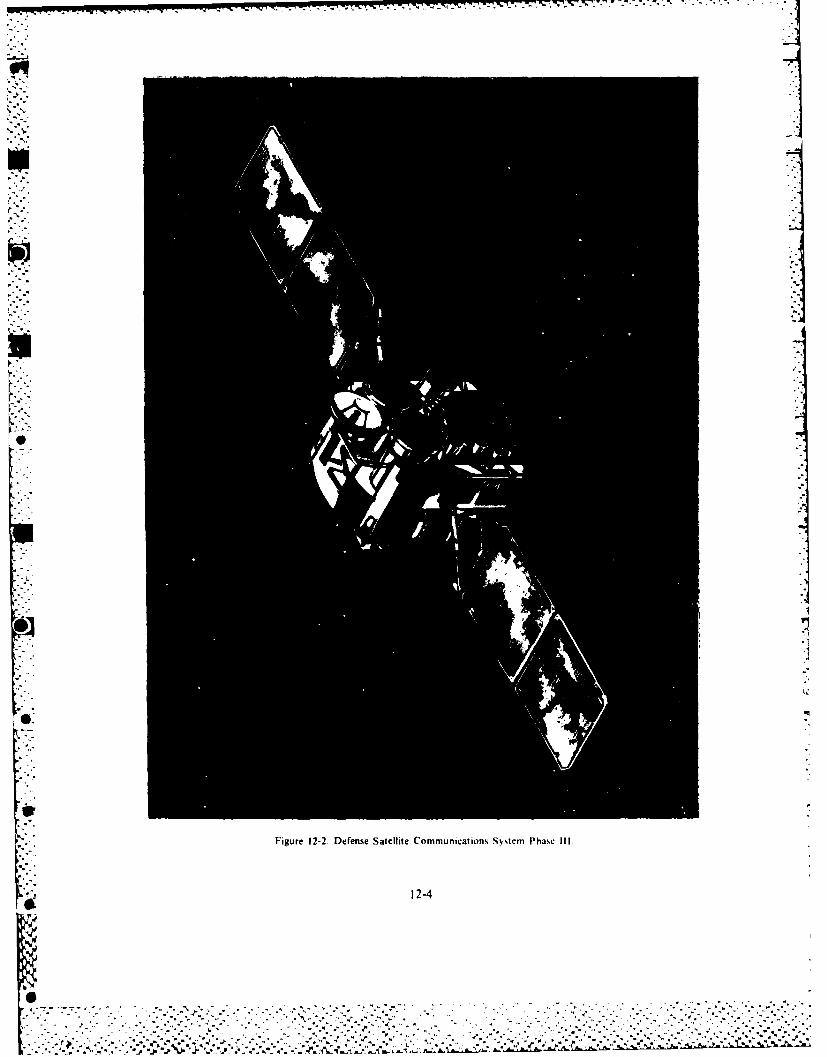
N-
12-'4
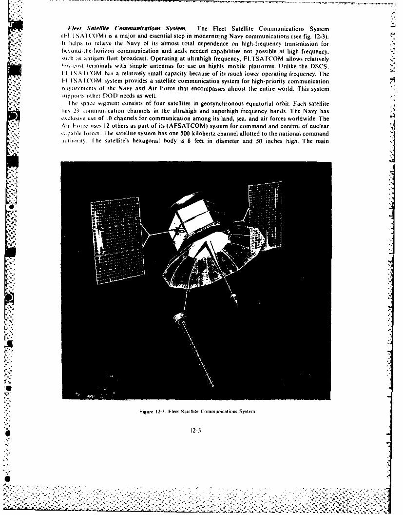
Fleet Satellite Communications System. The Fleet Satellite Communications System(-1 ISACOM) is a major and essential step in modernizing Navy communications (see fig. 12-3).It helps to relieve the Navy of its almost total dependence on high-frequency transmission forhe" b',od-the-horiion communication and adds needed capabilities not possible at high frequency,Stich as antijam fleet broadcast. Operating at ultrahigh frequency, FI.TSATCOM allows relativelytmv,-clst terminals with simple antennas for use on highly mobile platforms. Unlike the DSCS,II IS A I('(M has a relatively small capacity because of its much lower operating frequency. The-I -I SA I COM system provides a satellite communication system for high-priority communication
r cqutremlents of the Navy and Air Force that encompasses almost the entire world. This systemSupports other DO) needs as well.
I he space segment consists of four satellites in geosynchronous equatorial orbit. Each satellitehas 23 communication channels in the ultrahigh and superhigh frequency bands. The Navy hasexclusise use of 10 channels for communication among its land, sea, and air forces worldwide. TheAir Iorce uses 12 others as part of its (AFSATCOM) system for command and control of nuclearC,pable torces. I he satellite system has one 500 kilohertz channel allotted to the national command,aulio, %. I he satellite's hexagonal body is 8 feet in diameter and 50 inches high. The main
Fige 1 ej
i2-5 jN
..
4'.i
'4.
4,
Figure 12-3. Fleet Satellite Communicatio ns System
* 12-5
- -° ° ° , ° ° . °- °. ° - . . ° . °. . ..... .. . . -.. °. . .,, M . I i . °.

parabolic transmit antenna is 16 feet in diameter with an 80 inch solid center surrounded by wiremesh screen. The designers of the satellite mounted a 13.5 foot stepped helical receiving antenna,13 inches in diameter at the base, outside the edge of the antenna dish. The satellite and its ApogeeKick motor with propellant weigh approximately 4,100 pounds.
The ground segment of the FLTSATCOM system consists of communications links amongdesignated and mobile users, including most US Navy ships and selected Air Force and Navyaircraft, as well as global ground stations.
The Atlas-Centaur serves as the launch rocket for each FLTSATCOM spacecraft. After theAtlas-Centaur places each vehicle in an elliptical orbit, an onboard solid-fuel Apogee Kick motorlofts the satellite into geosynchronous orbit. A body-fixed momentum wheel interacts withmonopropellant hydrazine thrusters to provide three-axis attitude stabilization and point thesatellite's antennas at the earth's center. Hydrazine jets allow the user to change the satellite'slocation in orbit. •
The Naval Electronics Systems Command has overall program management responsibility.The program office at Space Division (SD) manages the acquisition of the space segment of theprogram.
Air Force Satellite Communications System. A general war-survivable satellite communicationssystem for command, control, and communications (C3 ) of our nuclear capable forces must withstandmassive physical and jamming attacks in the execution of its mission. This is the goal of theAFSATCOM program. The AFSATCOM-I, which has a modest antijam capability, consists ofAir Force transponders installed on host satellites. AFSATCOM transponders on the SatelliteData System (SDS) are providing north polar coverage. Transponders on the FLTSATCOMsatellites will provide equatorial coverage. Transponders installed on additional satellites in theSDS and FLTSATCOM provide proliferation of coverage to increase survivability. The Air Force
7. is planning for AFSATCOM 1i, which will emphasize a major upgrade in antijam capabilityand improvement in satellite physical survivability.
AFSATCOM will employ short, low-speed messages for force execution, force report back, andforce redirection. The use of such teletype messages coupled with suitable antijam techniques willpermit relatively simple ultrahigh frequency low-power terminals aboard our operational vehiclesto reliably and securely communicate by satellites that large land-based jammers stress.
Satellite Data System. The SDS Program is a multipurpose communications satelli- programthat provides polar coverage for command and control of the strategic forces. Addi,,, nally, itprovides a high-data date communications link between the remote tracking station of Thule,Greenland, and the Satellite Control Facility at Sunnyvale, California.
Navigation Systems
Navigation is essential to military commands for precise delivery of weapons on designated targets,deployment of troops, and scheduled rendezvous of units at designated objectives. Increases inthe military's mobility and in the sophistication and accuracy of their weapons have created therequirement to improve position-fixing and navigation capabilities. This and the worldwidedistribution of military operations requires a navigation system with all-weather global coverage.At present, there are many navigation aids of various types that provide position-fixing capabilities
"- over great sections of the earth for a large number of users.
Doppler shft influence. A major breakthrough in navigation procedures came with the firstSoviet Sputnik in 1957 when scientists noted that a graphical frequency plot of the "beeps" receivedfrom the satellite formed a characteristic curve of Doppler shift. As a satellite approaches or recedesfrom a tracking station, the transmitted radio frequency appears to change. The amount of thisDoppler shift, or change, is dependent upon the relative position of the tracking station with respect
12-6
. ....j., .. , . .L,.-., .-, . . . . . . .. .
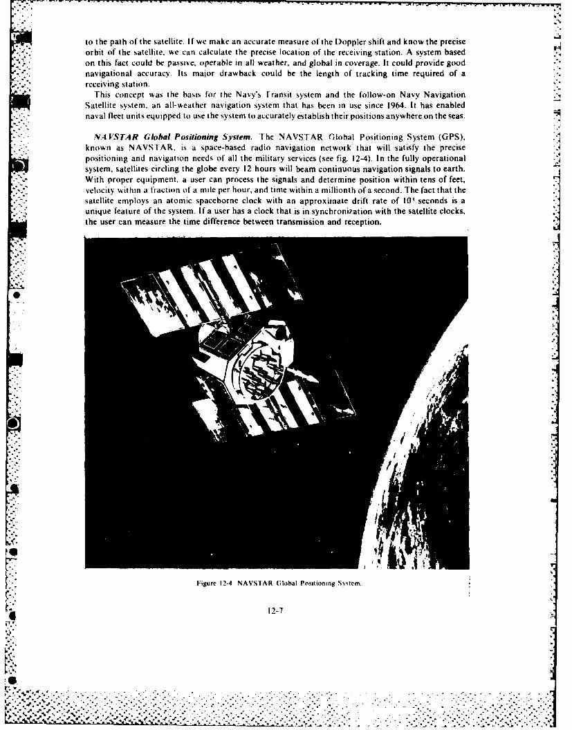
r c -, ,.- -
to the path of the satellite. If we make an accurate measure of the Doppler shift and know the precise
orbit of the satellite, we can calculate the precise location of the receiving station. A system based
on this fact could be passive, operable in all weather, and global in coverage. It could provide good -"
-'". navigational accuracy. Its major drawback could be the length of tracking time required of areceiving station.
rhis concept was the basis for the Navy's Fransit system and the follow-on Navy NavigationSatellite system, an all-weather navigation system that has been in use since 1964. It has enablednaval fleet units equipped to use the system to accurately establish their positions anywhere on the seas.
NA VSTAR Global Positioning System. The NAVSTAR Global Positioning System (GPS).
_- . known as NAVSTAR, is a space-based radio navigation network that will satisfy the precisepositioning and navigation needs of all the military services (see fig. 12-4). In the fully operationalsystem. satellites circling the globe every 12 hours will beam continuous navigation signals to earth.With proper equipment, a user can process the signals and determine position within tens of feet,
velocity within a fraction of a mile per hour, and time within a millionth of a second. The fact that thesatellite employs an atomic spaceborne clock with an approximate drift rate of 10+ seconds is aunique feature of the system. If a user has a clock that is in synchronization with the satellite clocks,the user can measure the time difference between transmission and reception.
Figure 12-4. NAVS tAR Global Positioning Svstemn.
12-7
• .. , -
S ....-. i,..v
io -
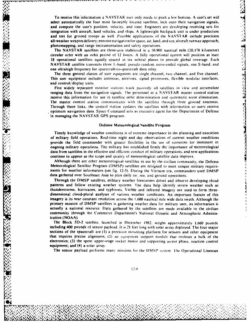
LI.' -II
To receive this information a NAVSTAR user only needs to push a few buttons. A user's set willselect automatically the four most favorably located satellites, lock onto their navigation signals,and compute the user's position, velocity, and time. Engineers are developing receiving sets for
..r integration with aircraft, land vehicles, and ships. A lightweight backpack unit is under productionand test for ground troops as well. Possible applications of the NAVSTAR include precisionall-weather weapon delivery; enroute navigation for space, air, land, and sea; aircraft runway approach;photomapping; and range instrumentation and safety operations.
The NAVSTAR satellites are three-axis stabilized in a 10,900 nautical mile (20,178 kilometer) -
circular orbit with an orbit period of 12 hours. A fully operational system will position at least18 operational satellites equally spaced in six orbital planes to provide global coverage. EachNAVSTAR satellite transmits three i-band, pseudo-random noise-coded signals, one S-band, and ,one ultrahigh frequency for spacecraft-to-spacecraft data relay.
The three general classes of user equipment are single channel, two channel, and five channel.This user equipment includes antennas, receivers, signal processors, flexible modular interfaces,and control/display units. I
Five widely separated monitor stations track passively all satellites in view and accumulate %ranging data from the navigation signals. The personnel at a NAVSTAR master control stationreceive this information for use in satellite orbit dctermination and systematic error elimination.The master control station communicates with the satellites through three ground antennas.Through these links, the control station updates the sateflites with information so users receiveoptimum navigation data. Space Command acts as executive agent for the Department of Defensein managing the NAVSTAR GPS program.
-.
Defense Meteorological Satellite Program
Timely knowledge of weather conditions is of extreme importance in the planning and executionof military field operations. Real-time night and day observations of current weather conditionsprovide the field commander with greater flexibility in the use of resources for imminent orongoing military operations. The military has established firmly the importance of meteorologicaldata from satellites in the effective and efficient conduct of military operations, and new applicationscontinue to appear as the scope and quality of meteorological satellite data improve.
Although there are other meteorological satellites in use by the civilian community, the DefenseMeteorological Satellite Program (DMSP) satellites are designed to meet unique military require-ments for weather information (see fig. 12-5). During the Vietnam era, commanders used DMSPdata gathered over Southeast Asia to plan daily air. sea, and ground operations.
Through the DMSP satellites, military weather forecasters detect and observe developing cloudpatterns and follow existing weather systems. The data help identify severe weather such asthunderstorms, hurricanes, and typhoons. Visible and infrared imagery are used to form three-dimensional cloud-plural analyses of various weather conditions. An important feature of thisimagery is its near constant resolution across the 1,600 nautical mile wide data swath. Although theprimary mission of DMSP satellites is gathering weather data for military uses, its information isactually a national resource. Data gathered by the satellites are made available to the civiliancommunity through the Commerce Department's National Oceanic and Atmospheric Adminis-tration (NOAA).
The Block 5D-2 satellite, launched in December 1982. weighs approximately 1,660 poundsincluding 400 pounds of sensor payload. It is 21 feet long with solar array deployed. The four majorsections of the spacecraft are (I) a precision mounting platform for sensors and other equipmentthat requires precise alignment; (2) an equipment support module that encloses a bulk of theelectronics; (3) the spent upper-stage rocket motor and supporting ascent phase, reaction controlequipment; and (4) a solar array.
The sensor payload performs many missions for the I)MSP svstcm -1 he Operational Linescan
12-X
[% %-
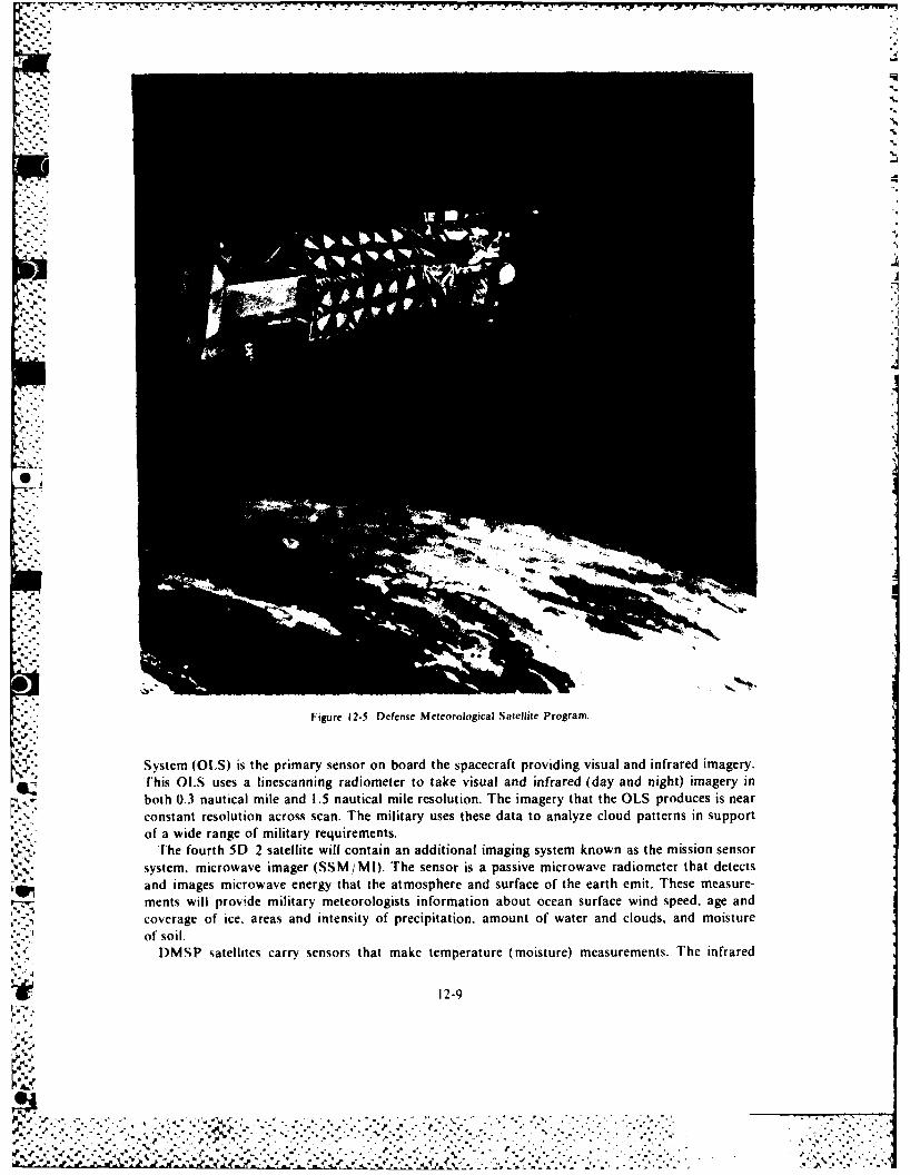
.-.
.j
Figure 12-5. Defense Meteorological Satellite Program.
System (OLS) is the primary sensor on board the spacecraft providing visual and infrared imagery.This OLS uses a linescanning radiometer to take visual and infrared (day and night) imagery inboth 0.3 nautical mile and 1.5 nautical mile resolution. The imagery that the OLS produces is nearconstant resolution across scan. The military uses these data to analyze cloud patterns in supportof a wide range of military requirements.
The fourth 5D 2 satellite will contain an additional imaging system known as the mission sensor
system. microwave imager (SSM/MI). The sensor is a passive microwave radiometer that detectsand images microwave energy that the atmosphere and surface of the earth emit. These measure-ments will provide military meteorologists information about ocean surface wind speed, age and
coverage of ice. areas and intensity of precipitation, amount of water and clouds, and moistureof soil.
DMSP satellites carry sensors that make temperature (moisture) measurements. The infrared
12-9
.i'. ° ' ' -"
". , '- , , '- - - ° ' .- , ., ' " " -" , ," " - -' . - . . . ' " ' . .
.. ..1' ' ' ". . . . .. " ' . . ." % " " " ',' " " . . .. " ". . . . " .[ - [" i
% % - " % " ' % ' " " i" *, . . r " "'. . ' " o ,
temperature/ moisture sounder measures infrared radiation emitted from different heights withinthe atmosphere, allowing forecasters to plot curves of temperature and water vapor versus attitude.The satellite uses a microwave temperature sounder to measure microwave radiation emitted from
A. different heights within the atmosphere. This instrument allows forecasters to plot curves oftemperature versus altitude even over cloudy regions of the globe.
The DMSP satellite uses another group of three sensors to make measurements of the earth'sionosphere. It uses the first one, known as a precipitating electron and proton spectrometer, to 7count electrons and protons at different energies spiralling down (precipitating) along the magneticfield lines. The military, among others, uses these data to forecast accurately the location and
'*. intensity of the aurora and to aid radar operations and long-range ground communications in theNorthern Hemisphere. A second sensor measures energy in the high-energy gamma and X-ray portionof the spectrum, which are responsible for the aurora. A third ionospheric sensor, the ionosphericplasma monitor, measures electron and ion densities and temperatures at spacecraft altitude.Ionospheric weather modules use data from the sensor to predict the state of the ionosphere as itaffects communication and navigation.
Launched on Atlas boosters, two of these Block 513-2 satellites orbit at any one time. They orbit -
at an approximate altitude of 450 nautical miles in near-polar, sun-synchronous orbits. Each scansa 1,600 mile wide area and can image the entire earth every 12 hours.
DMSP satellites record data throughout their orbits on tape recorders and play the data backto ground stations. The satellites are also capable of providing weather data on real-time basisto the Air Weather Service and Navy terminals, which provide military commanders in the fieldwith photographic-quality prints of cloud cover four times a day.
The Air Force Space Division, Los Angeles Air Force Station, California, manages the design,development, production, and launch of these spacecraft. The 1000 Satellite Operations Groupof the Space Command operates the DMSP system command and control functions.
Space Test Program
In May 1965 the director of defense research and engineering established the DOD Space TestProgram (STP), (originally called the Space Experiments Support program), with the Air Forceas executive agency. Initially, the director chartered the program to support developmental andpreoperational payload. However, it later increased the scope of the program to include the researchpayloads supported previously by the Office of Aerospace Research. Since its first launch in 1967,the STP has flown successfully more than 95 payloads on 21 different spacecraft missions. Theprogram has support from all 3 services as well as 30 different laboratories and program offices.They are responsible for work on ballistic missile defense, communications, geodesy, navigation,atmospheric research, space object identification, solar physics, spacecraft subsystem develop-ment, radar calibration, and particle and radiation studies.
SPACE SURVEILLANCE
When the Soviet Union launched SPUTNIK I on 4 October 1957, the United States became aware-\ that it had little capability to detect, track, or identify man-made objects in space. This realization
led to an intensive effort to create and maintain a system of sensors to keep track of satellites.This effort continues today. The mission of the US space surveillance system is to detect, track, andmaintain surveillance of all military payloads in space. The space surveillance network of ground-
- -. based sensor systems accomplishes this through data collection. The network uses this data toclassify and identify all detected objects, maintain an accurate and current catalog of space objects,and provide data reports to military and civilian agencies and to the scientific community. Thesedata reports consist of orbital and signature data on space objects. They provide new space launchdetection and tracking, foreign satellite function identification, satellite maneuver identification.collision avoidance information, data on satellite transiting of specific geographical areas, spaceobject reentry impact points, warning of attack on US space assets, targeting information for the
M 12-10
%.
Zo
.................... ~. .. .. . .. .. .
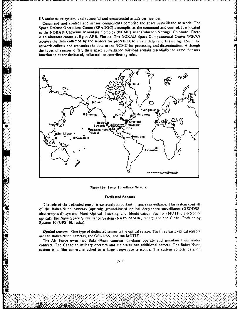
..- X
US antisatellite system, and successful and unsuccessful attack verification.Command and control and sensor components comprise the space surveillance network. The
Space Defense Operations Center (SPADOC) accomplishes the command and control. It is locatedin the NORAD Cheyenne Mountain Complex (NCMC) near Colorado Springs, Colorado. Thereis an alternate center at Eglin AFB, Florida. The NORAD Space Computational Center (NSCC)receives the data collected by the sensors for processing to create data reports (see fig. 12-6). Thenetwork collects and transmits the data to the NCMC for processing and dissemination. Althoughthe types of sensors differ, their space surveillance missions remain essentially the same. Sensorsfunction in either dedicated, collateral, or contributing roles.
M0* * Thule
*Clea e
Fylingdales, *Shemya Parcs St Marga
Taegu Beale Millstone San Vito
%Kaena Point lOSan Miguel * %Maui
*Kwajalein *niu
Ascension
6
------- NAVSPASUR
Figure 12-6. Sensor Surveillance Network.
Dedicated Sensors
The role of the dedicated sensor is extremely important in space surveillance. This system consists
of the Baker-Nunn cameras (optical); ground-based optical deep-space surveillance (GEODSS,
electro-optical) system; Maui Optical Tracking and Identification Facility (MOTIF, electronic-
optical); the Navy Space Surveillance System (NAVSPASUR, radar); and the Global PositioningSystem-10 (GPS-10, radar).
Opticalsensors. One type of dedicated sensor is the optical sensor. The three basic optical sensorsare the Baker-Nunn cameras, the GEODSS, and the MOTIF.
The Air Force owns two Baker-Nunn cameras. Civilians operate and maintain them undercontract. The Canadian military operates and maintains one additional camera. The Baker-Nunnsystem is a film camera attached to a large deep-space telescope. The system collects data on
12-II
,.%>"" " "."e .- %, , - .'- -'14,- . "." "' " .-- " "3', -, "- - - - ' -"-'' - ". . - ''''""- " .."'."£ ",
satellites ranging in altitude from 3,000 nautical miles to geosynchronous (22,000 nautical miles)and beyond. The film data collection sites at Edwards AFB, California; St. Margarets, New-foundland, Canada; and San Vito, Italy, transmit the data to the NCMC in two to four hours aftercollection. Film processing and analysis requires most of this time.
The Air Force owns three GEODSS sites with a fourth and fifth site programmed. A civiliancontractor operates and maintains this system. The developers of the GEODSS designed it tocollect data from 3,000 nautical miles to beyond 22,000 nautical miles as does the Baker-Nunncamera. The GEODSS sites, unlike the Baker-Nunn, provide the data in near-real time to theNCMC. GEODSS uses a low-light-level TV camera, computers. and large telescopes. GEODSSis more sensitive than the Baker-Nunn in that it can track smaller and dimmer objects, and collectspace object identification (SOI) signature data. The site locations are Socorro, New Mexico;Maui, Hawaii; Taegu, South Korea; and Diego Garcia (Indian Ocean). The Air Force has notselected a site for the programmed fifth site.The MOTIF site is an Air Force owned site, colocated with GEODSS at Maui, Hawaii. MOTIF
possesses technical capabilities similar to GEODSS. The site is contractor operated and maintained.
Radars. The Navy Space Surveillance (NAVSPASUR) system is a network of sensors, knownas radiometric interferometers, stretching from Georgia to California. Three transmitters, six - 'receiver sites, and a control center make up the NAVSPASUR system. The newest addition to thespace surveillance network is the AN/GPS-10 radar located at San Miguel, Republic of thePhilippines. The radar is Air Force operated and contractor maintained. The GPS-10 radar is theonly Air Force radar dedicated to the space surveillance mission.
Collateral Sensors
Some sensors have the capability of performing more than one task at a time and have spacesurveillance missions as secondary missions. The military considers sensors having this capabilityas part of the space surveillance network. SPADOC tasks these sensors for observational data aslong as this assignment does not interfere with their primary mission. These sensors are responsibleto NORAD for their primary mission and are called collateral sensors. The nominal range of thesensors is in the near-earth arena up to approximately 3,000 nautical miles. The exception is theFPS -85 at Eglin AFB, Florida, that can operate at higher altitudes. The sensor types and locationsinclude the AN/FPS 85, phased array, at Eglin AFB, Florida; Cobra Dane at Shimya, Alaska;BMEWS at Clear, Alaska, Thule, Greenland, and Flyingdales, England; PARCS, phased array, atConcrete, North Dakota; AN/FPS-79 at Princlik, Turkey; and the Pave Paws, phased array, atOtis ANGB, Massachusetts, and Beale AFB, California.
Contributing Sensors
Contributing sensors are those not under NORAD's operational control. However, they doprovide observational data on satellites on a contributing basis. The Air Force Eastern Test Rangeunder the Eastern Space and Missile Center at Patrick AFB, Florida, and the Air Force WesternTest Range under the Western Space and Missile Center at Vandenberg AFB, California,receive data from and contribute data to the space surveillance network. The MassachusettsInstitute of Technology Lincoln Laboratory complex at Westford, Massachusetts, contributesdata as well as the Kiernan Reentry Measurement System (KREMS) located at Kwajalein Atoll.The sensor names and site locations include Kaena Point, Hawaii; ALTAIR and ALCOR sensorsat Kwajalein Atoll; the Millstone and Haystack sensors at Westford, Massachusetts; and others onAntigua Island and Ascension Island.
System Improvements
The baseline space surveillance system is undergoing improvement. Areas being improved are
12-12
I.q
sur\ iability; command, control, and communications; identification capability; coverage; trackingaccuracy; and processing. lhe improvements include additions and replacements, upgrades to thesensor and communications systems, and a major upgrade of the processing and sensor-taskingsystems.
Sexeral radars are due for upgrades. The BMEWS radar upgrade will provide smaller rangeresolution and better tracking accuracy, attack assessment, and count capability. PAVE PAWSupgrades "ill track smaller payloads associated with MIRVs and will get a more accurate counttor attack assessment purposes. There will be an upgrade to NAVSPASUR. It will includereceiver transmitter moderniations that will increase the range to above 18,000 kilometers.('-hand upgrades to Antigua and Ascension will enhance the search capabilities.
Some other improxements to the system include an addition of the Compensated Imaging System(('IS) to the telescope at the ARPA Main Optical System (AMOS); Improved Radar CalibrationSstetns (IRCS) at the three BMEWS radars, the FPS-79, GPS-10, and FPS-85; Charge Coupled,I)evice (CCD) cameras in the GEODSS system for improved search rate, sensitivity, and reliability;,rtc-ot-the-art computer replacements; improved communications terminals at each missile-%karfling site; implementation of SPADOC Phase IV; and addition of secure voice terminals atall missile-%arning and space-surveillance sites. In the future the Air Force plans to deploy space-based space surveillance systems to enhance the survivability and endurability of the spaces r, eilance network.
B I B I. I 0 G R A P H V
.tenr. R chard, Ma) (en. "Space Irom a Fighter Pilot's Point of View." Astronautics andAeronautis. (April 1976):33.O- Miller. hair "'S Mo ,es to upgrade Missile Warning." A,4tation Week andSpae Technologr. (2 December 1974):16.
• 'Nra Weather Satcllitc Series Planned." .4viation Week and Space Te(hnologi. (15 July 1974):16.Nichols, t)Did A , ('apt "the Defense Meteorological Satellite Program" pticalEngineering 14, no.4. (July August 1975):
271.I'apafo,/,i. I-tank, It 'ol and ('apt Neal Anderson. ")OI)'s Space lest Program." .'i ronautics and Aeronautics.
.1 unc 1974) 42. 4
Sla,. Alton ).. I t (en "New Aircraft and Missiles" Su plemrent to the Air Force Pou/ ' Letter for Commanders.I am 1970Y 10,'
'rltlth. )ouglas. Miaj and C'apt Willian ('riss, "N..\VS tA R (lobal Positioning System." A.stronautic' and Aeronautics.(April 1976):26.
Stelling. Henry B. Ir., Maj Gen. "NASA-t)Ot)-tJSAF- and the Space Shuttle." Supletnen to the Air Force Policy Letter..•• , ifr ('Ctonanders (Nosember 1975).7
S~,..-I' S Air Force. AFM I 6. tiflitari Spee IOotrime. October 1913.
"'"' i :, .'
,' 12-1-
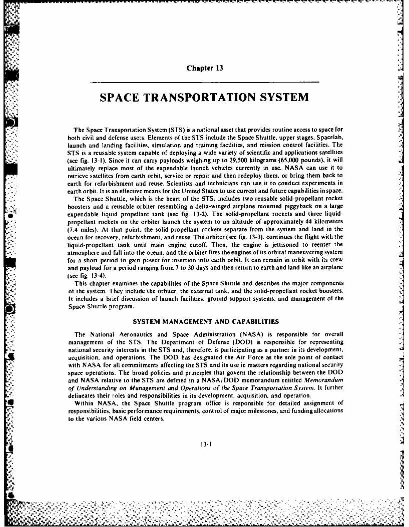
Chapter 13
SPACE TRANSPORTATION SYSTEM
The Space Transportation System (STS) is a national asset that provides routine access to space forboth civil and defense users. Elements of the STS include the Space Shuttle, upper stages, Spacelab,launch and landing facilities, simulation and training facilities, and mission control facilities. The
* STS is a reusable system capable of deploying a wide variety of scientific and applications satellites(see fig. 13-1). Since it can carry payloads weighing up to 29,500 kilograms (65,000 pounds), it willultimately replace most of the expendable launch vehicles currently in use. NASA can use it toretrieve satellites from earth orbit, service or repair and then redeploy them, or bring them back toearth for refurbishment and reuse. Scientists and technicians can use it to conduct experiments inearth orbit. It is an effective means for the United States to use current and future capabilities in space.
The Space Shuttle, which is the heart of the STS, includes two reusable solid-propellant rocketboosters and a reusable orbiter resembling a delta-winged airplane mounted piggyback on a large
* expendable liquid propellant tank (see fig. 13-2). The solid-propellant rockets and three liquid-propellant rockets on the orbiter launch the system to an altitude of approximately 44 kilometers(7.4 miles). At that point, the solid-propellant rockets separate from the system and land in theocean for recovery, refurbishment, and reuse. The orbiter (see fig. 13-3). continues the flight with theliquid- propellant tank until main engine cutoff. Then, the engine is jettisoned to reenter theatmosphere and fall into the ocean, and the orbiter fires the engines of its orbital maneuvering systemfor a short period to gain power for insertion into earth orbit. It can remain in orbit with its crewand payload for a period ranging from 7 to 30 days and then return to earth and land like an airplane(see fig. 13-4).
This chapter examines the capabilities of the Space Shuttle and describes the major componentsof the system. They include the orbiter, the external tank, and the solid-propellant rocket boosters.It includes a brief discussion of launch facilities, ground support systems, and management of theSpace Shuttle program.
SYSTEM MANAGEMENT AND CAPABILITIES
The National Aeronautics and Space Administration (NASA) is responsible for overall
management of the STS. The Department of Defense (DOD) is responsible for representingnational security interests in the STS and, therefore, is participating as a partner in its development,acquisition, and operations. The DOD has designated the Air Force as the sole point of contact
space operations. The broad policies and principles that govern the relationship between the DODand NASA relative to the STS are defined in a NASA/DOD memorandum entitled Memorandumof Understanding on Management and Operations of the Space Transportation Svsieni. It furtherdelineates their roles and responsibilities in its development, acquisition, and operation.
* Within NASA, the Space Shuttle program office is responsible for detailed assignment ofresponsibilities, basic performance requirements, control of major milestones, and funding allocationsto the various NASA field centers.
13-1
-0V
-VAA
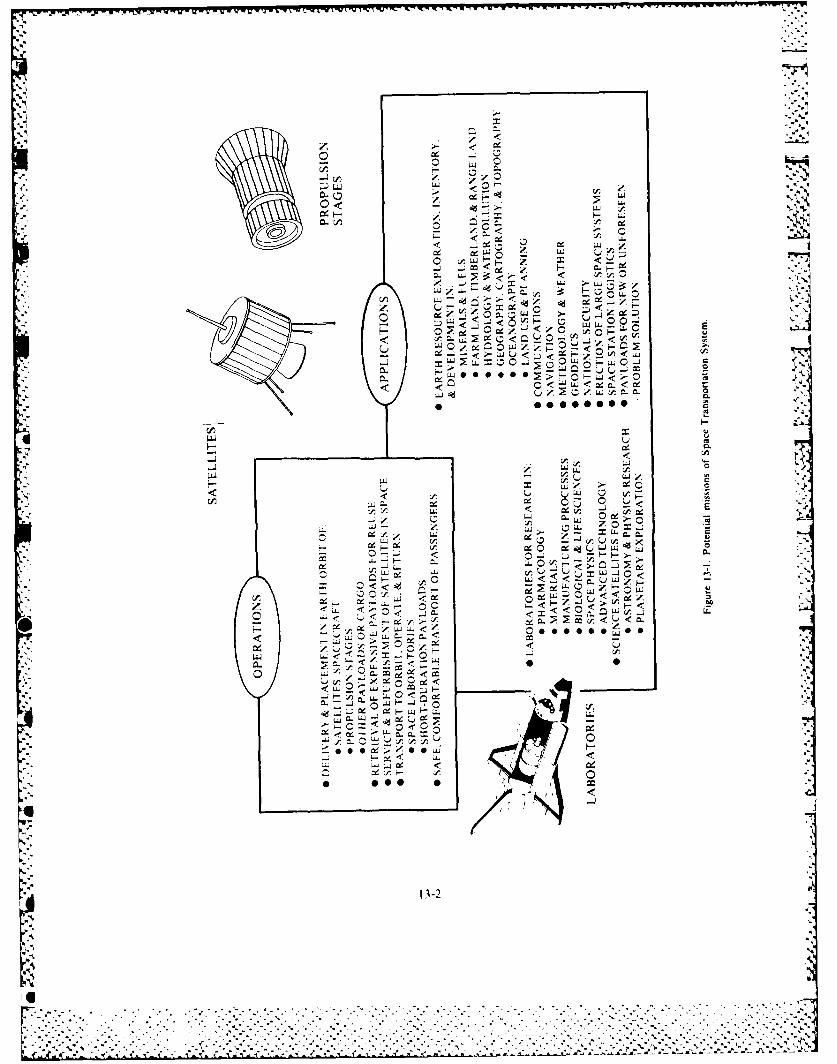
~~~~~~~-~~~~~F INC v . ~ -w~w srrw' %U ~% C
V.'J
co <
-W a -
< ~ #. UJ
00 000 0
>. C)
cr u
4~~~ -- -. UrJ
< < LL.
tr.0
LLLU
<~~ C - C
C.
Lj L)z V
Ct '-~r,13-2
~~>CtIL
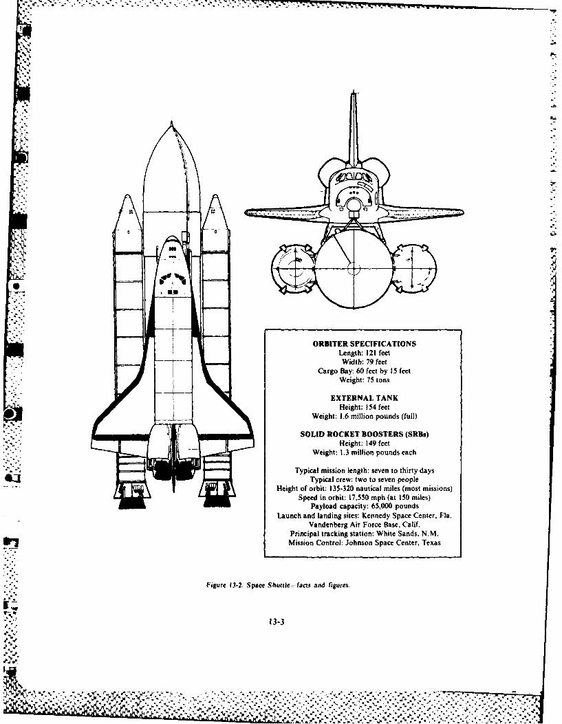
7, 7
gU
ORBITER SPECIFICATIONSLength: 121 feetWidth: 79 feet
Cargo Bay: 60 feet by 15 feetWeight: 75 tons
EXTERNAL TANKHeight: 154 feet
Weight: 1.6 million pounds (full)
SOLID ROCKET BOOSTERS (SRBs)Height: 149 feet
Weight: 1.3 million pounds each
Typical mission length: seven to thirty daysTypical crew: two to seven people
Height of orbit: 135-320 nautical miles (most missions)Speed in orbit: 17,550 mph (at 150 miles)
Payload capacity: 65,000 poundsLaunch and landing sites: Kennedy Space Center. Fla.
Vandenberg Air Force Base, Calif.Principal tracking station: White Sands, N.M.Mission Control: Johnson Space Center, Texas
Figure 13-2. Space Shuttle-facts and figures.
13-3
4.4.10
%~
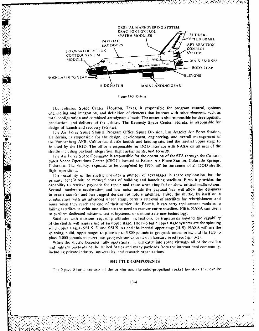
,. ... d ,.
ORBITAL MANEUVERING SYSTEM,REACTION CONTROLSYSTEM MODULES RUDDER,
.SPEED BRAKE
BAY OORSAFT REACTION
FORWARD REACTION CONTROL.
CONTROL SYS ['EM SSE
* - MODLE *.MAIN ENOINES
J -*--BODY FLAP
NOSEID HATCNH(iAR MAIN LANDING GEAR
Figure 13-3. Orbiter.
The Johnson Space Center, Houston, Texas, is responsible for program control, systemsengineering and integration, and definition of elements that interact with other elements, such astotal configuration and combined aerodynamic loads. The center is also responsible for development.production, and delivery of the orbiter. The Kennedy Space Center, Florida, is responsible fordesign of launch and recovery facilities.
The Air Force Space Shuttle Program Office, Space Division, Los Angeles Air Force Station,
0 California, is responsible for the design, development, engineering, and overall management ofthe Vandenberg AFB, California, shuttle launch and landing site, and the inertial upper stage tobe used by the DOD. The office is responsible for DOD interface with NASA on all uses of the
P shuttle including payload integration, flight assignments, and security.
The Air Force Space Command is responsible for the operation of the STS through the Consoli-dated Space Operations Center (CSOC) located at Falcon Air Force Station, Colorado Springs.Colorado. This facility, expected to be completed by 1990, will be the center of all DOD shuttleflight operations.
The versatility of the shuttle provides a number of advantages in space exploration, but theprimary benefit will be reduced costs of building and launching satellites. First, it provides thecapability to retrieve payloads for repair and reuse when they fail or show critical malfunctions.Second, moderate acceleration and low noise inside the payload bay 'will allow the designersto create simpler and less rugged designs for future satellites, Third, the shuttle, by itself or incombination with an advanced upper stage, permits retrieval of satellites for refurbishment and _reuse when they reach the end of their service life. Fourth, it can carry replacement modules tofailing satellites in orbit and eliminate the need to recover entire satellites. Fifth, NASA can use itto perform dedicated missions, test subsystems, or demonstrate new technology. IZ
Satellites with missions requiring altitudes, inclinat;ons, or trajectories beyond the capabilityof the shuttle will require use of an upper stage. The two basic upper stage systems are the spinning 7solid upper stages (SSIJS D and SSUS A) and the inertial upper stage (IUS). NASA will use thespinning, solid, upper stages to place up to 3,800 pounds in geosynchronous orbit, and the IUS toplace 5.000 pounds or more into geosynchronous orbit or planetary orbit (see fig. 13-2).
When the shuttle becomes fully operational, it will carry into space virtually all of the civilianand military payloads of the United States and many payloads from the international community.including private industry, universities, and research organizations.
SHUTTLE COMPONENTS
_r JThe Space Shuttle consists of the orbiter and the solid-propellant rocket boosters that can be
13-4
-2 %
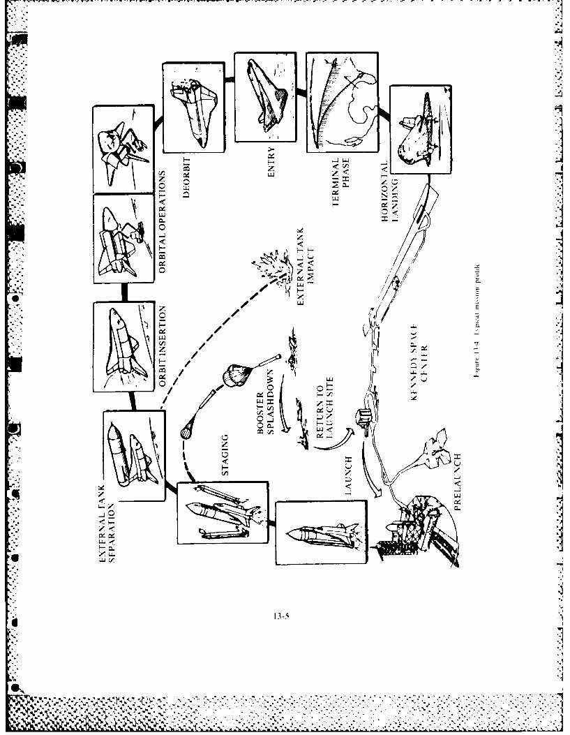
* . U<
LW1
'iU
m LL.
L~CL
135
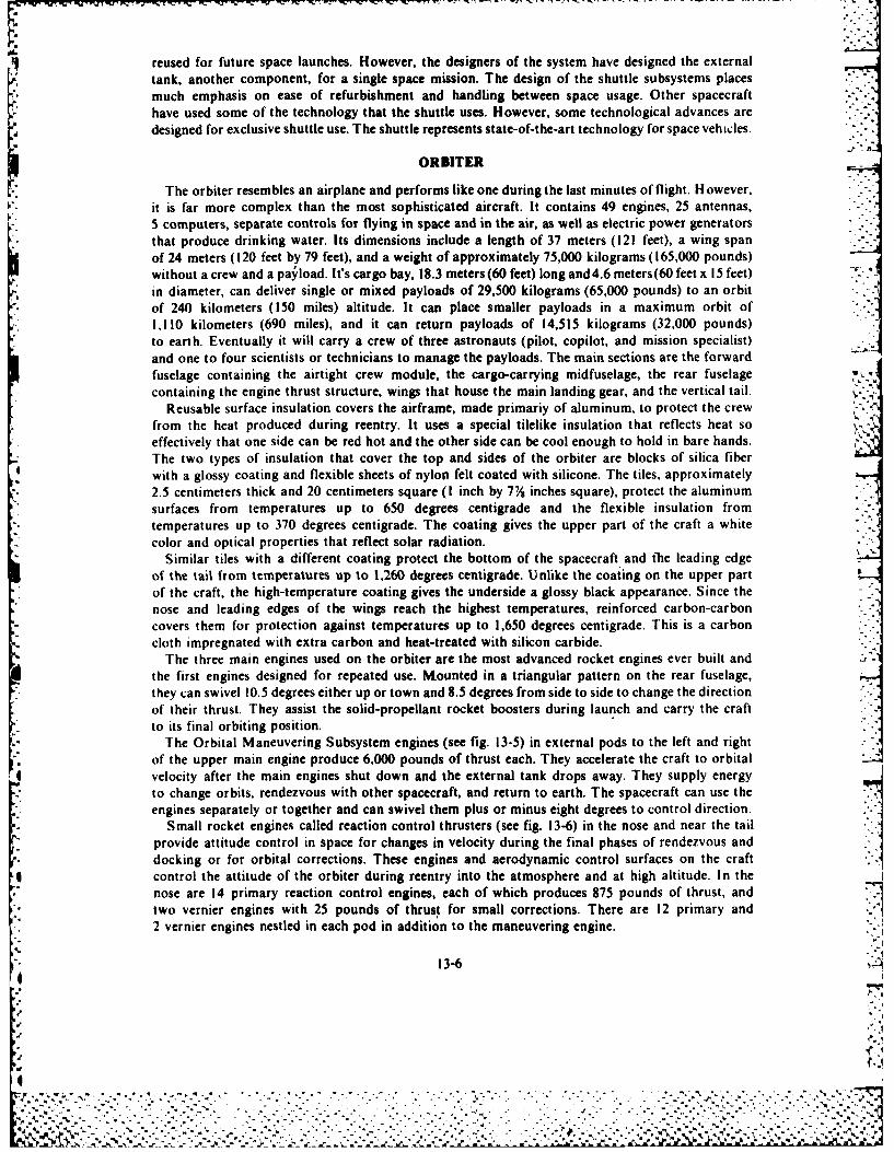
reused for future space launches. However, the designers of the system have designed the externaltank, another component, for a single space mission. The design of the shuttle subsystems placesmuch emphasis on ease of refurbishment and handling between space usage. Other spacecrafthave used some of the technology that the shuttle uses. However, some technological advances aredesigned for exclusive shuttle use. The shuttle represents state-of-the-art technology for space vehicles.
ORBITER
The orbiter resembles an airplane and performs like one during the last minutes of flight. However,it is far more complex than the most sophisticated aircraft. It contains 49 engines, 25 antennas,5 computers, separate controls for flying in space and in the air, as well as electric power generatorsthat produce drinking water. Its dimensions include a length of 37 meters (121 feet), a wing spanof 24 meters ( 120 feet by 79 feet), and a weight of approximately 75,000 kilograms ( 165,000 pounds)wit hout a crew and a pa~load. I t's cargo bay, 18.3 meters (60 feet) long and 4.6 meters (60 feet x 15 feet)in diameter, can deliver single or mixed payloads of 29,500 kilograms (65,000 pounds) to an orbitof 240 kilometers (150 miles) altitude. It can place smaller payloads in a maximum orbit of1, 110 kilometers (690 miles), and it can return payloads of 14,515 kilograms (32,000 pounds)to earth. Eventually it will carry a crew of three astronauts (pilot, copilot, and mission specialist)and one to four scientists or technicians to manage the payloads. The main sections are the forwardfuselage containing the airtight crew module, the cargo-carrying midfuselage, the rear fuselagecontaining the engine thrust structure, wings that house the main landing gear, and the vertical tail.
Reusable surface insulation covers the airframe, made primariy of aluminum, to protect the crewfrom the heat produced during reentry. It uses a special tilelike insulation that reflects heat so y
effectively that one side can be red hot and the other side can be cool enough to hold in bare hands.The two types of insulation that cover the top and sides of the orbiter are blocks of silica fiberwith a glossy coating and flexible sheets of nylon felt coated with silicone. The tiles, approximately2.5 centimeters thick and 20 centimeters square (I inch by 7Y% inches square), protect the aluminumsurfaces from temperatures up to 650 degrees centigrade and the flexible insulation fromtemperatures up to 370 degrees centigrade. The coating gives the upper part of the craft a whitecolor and optical properties that reflect solar radiation.
Similar tiles with a different coating protect the bottom of the spacecraft and the leading edgeof the tail from temperatUres Up to 1,260 degrees centigrade. Unlike the coating on the upper partof the craft, the high-temperature coating gives the underside a glossy black appearance. Since thenose and leading edges of the wings reach the highest temperatures, reinforced carbon-carboncovers them for protection against temperatures up to 1,650 degrees centigrade. This is a carboncloth impregnated with extra carbon and heat-treated with silicon carbide.
The three main engines used on the orbiter are the most advanced rocket engines ever built andthe first engines designed for repeated use. Mounted in a triangular pattern on the rear fuselage,they can swivel 10.5 degrees either up or town and 8.5 degrees from side to side to change the directionof their thrust. They assist the so lid- propellant rocket boosters during launch and carry the craftto its final orbiting position.
The Orbital Maneuvering Subsystem engines (see fig. 13-5) in external pods to the left and rightof the upper main engine produce 6,000 pounds of thrust each. They accelerate the craft to orbital
4 velocity after the main engines shut down and the external tank drops away. They supply energyto change orbits, rendezvous with other spacecraft, and return to earth. The spacecraft can use theengines separately or together and can swivel them plus or minus eight degrees to control direction.
Small rocket engines called reaction control thrusters (see fig. 13-6) in the nose and near the tailprovide attitude control in space for changes in velocity during the final phases of rendezvous anddocking or for orbital corrections. These engines and aerodynamic control surfaces on the craftcontrol the attitude of the orbiter during reentry into the atmosphere and at high altitude. In thenose are 14 primary reaction control engines, each of which produces 875 pounds of thrust, andtwo vernier engines with 25 pounds of thrust for small corrections. There are 12 primary and2 vernier engines nestled in each pod in addition to the maneuvering engine.
13-6
Z. %

u <
CAS
f.00
f-ULLT
13-7
~.. ~ .c~ h..7.0
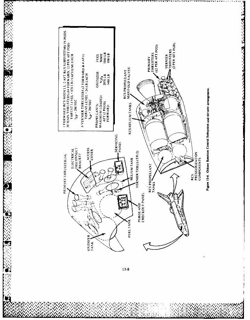
0. <ca < < LL..
C.., gZf
<~L. < 0C 1-0
4 e c C LLJ Zt-0
" -LL cD L 0-
000
N1 ceW LLU U
w~~ > )> Lu c .
C0 u L
AI
LL3-
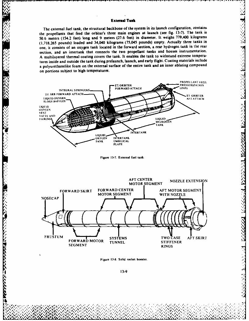
Extenal Tank
The external fuel tank, the structural backbone of the system in its launch configuration, contains
the propellants that feed the orbiter's three main engines at launch (see fig. 13-7). The tank is
50.6 meters (154.2 feet) long and 9 meters (27.6 feet) in diameter. It weighs 779,400 kilograms(1,718,265 pounds) loaded and 34,040 kilograms (75,045 pounds) empty. Actually three tanks in
one, it consists of an oxygen tank located in the forward section, a rear hydrogen tank in the rear
section, and an intertank that connects the two propellant tanks and houses instrumentation.
A multilayered thermal coating covers the tank. It enables the tank to withstand extreme tempera-
tures inside and outside the tank during prelaunch, launch, and early flight. Coating materials include
a polyurcthanelike foam on the external surface of the entire tank and an inner ablating compoundon portions subject to high temperatures.
PROPELLANT FEED,
ET/ORBITER PRESSURIZATIONINTEGRAL STRINGERS FRADATC IE
ET, SRB FORWARD ATTACH ' - El ORBIER
LIQUID OXYGEN AT ARBTACSLOSH BAFFLES
A T C :
LIQUIDOXYGENVENrVALVE ANDFAIRING LIQUIDI HYDROGEN".
TANK¢
INTERTANKLIQUID
EN INTERTANKTANK UMBILICAL
PLATE
Figure 13-7 External fuel tank.
AFT CENTER NOZZLE EXTENSIONMOTOR SEGMENT
,FORWARD CENTER AFT MOTOR SEGMENTMOTOR SGETWITH NOZZLE
I. • NOSECAP \
F~i U. T. I
FRUSU SYSTEMS TWO CASE AFT SKIRTFORWARD MOTOR TUNNEL STIFFENERSEGMENT RINGS
Figure 13-8. Solid rocket booster.
* 13-9
% 1
0~]
t ",, - - - - - - --"-".- -"''".i J . . ,' - - - - - - - - - --"" ---"- -".- - --"---'- -. "- .- "- "-- "' . .% ""'. . - " .. " - - "- - . " .
"ea. ' .- . " .' / ., l j% '. ' 1 -? •. . . .. - ' . ".S . '. " . . ". ' .,' . .. ' . .. .' .. " ... ' .. . " .. . " .... ' .
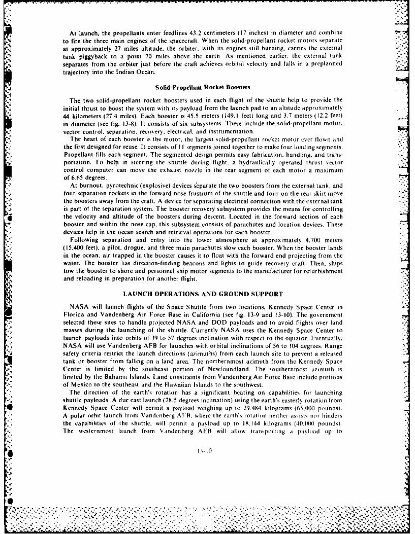
At launch, the propellants enter feedlines 43.2 centimeters (17 inches) in diameter and combine -
to fire the three main engines of the spacecraft. When the solid-propellant rocket motors separateat approximately 27 miles altitude, the orbiter, with its engines still burning, carries the externaltank piggyback to a point 70 miles above the earth As mentioned earlier, the external tankseparates from the orbiter just before the craft achieves orbital velocity and falls in a preplannedtrajectory into the Indian Ocean.
Solid-Propellant Rocket Boosters .-
j The two solIid- propellant rocket boosters used in each flight of the shuttle help to provide theinitial thrust to boost the system with its payload from the launch pad to an altitude approximately44 kilometers (27.4 miles). Each booster is 45.5 meters ( 149.1 feet) long and 3.7 meters ( 12.2 feet)in diameter (see fig. 13-8). It consists of six subsystems. These include the sol id- propellant motor.vector control, separation. recovery, electrical, and instru mentat ion.
2The heart of each booster is the motor, the largest solid-propellant rocket motor ever flown and -
the first designed for reuse. It consists of I I segmetnts joined together to make four loading segments.Propellant fills each segment. The segmented design permits easy fabrication, handling, and trans-portation. To help in steering the shuttle during flight, a hydraulically operated thrust vectorcontrol computer can move the exhaust nozzle in the rear segment of each motor a maximumof 6.65 degrees.
At burnout, pyrotechnic (explosive) devices sleparate the two boosters from the external tank, andfour separation rockets in the forward nose frustrum of the shuttle and four on the rear skirt movethe boosters away from the craft. A device for separating electrical connection with the external tankis part of the separation system. The booster recovery subsystem provides the means for controlling
d the velocity and altitude of the boosters during descent. Located in the forward section of eachbooster and w ithin the nose cap, this subsystem consists of parachutes and location devices. Thesedevices help in the ocean search and retrieval operations for each booster.
Following separation and entry into the lower atmosphere at approximately 4.700 meters(15,400 feet), a pilot, drogue, and three main parachutes slow each booster. When the booster landsin the ocean, air trapped in the booster causes it to float with the forward end projecting from thewater. The booster has direction-finding beacons and lights to guide recovery craft. Then, shipstow the booster to shore and personnel ship motor segments to the manufacturer for refurbishmentand reloading in preparation for another flight.
LAUNCH OPERATIONS AND GROUND SUPPORT
NASA will launch flights of the Space Shuttle from two locations, Kennedy Space Center inFlorida and Vandenberg Air Force Base in California (see fig. 13-9 and 13-10). The governmentselected these sites to handle projected NASA and DOD payloads and to avoid flights over landmasses during the launching of the shuttle. Currently NASA uses the Kennedy Space Center tolaunch payloads into orbits of 39 to 57 degrees inclination with respect to the equator. Eventually.NASA will use Vandenberg AFB for launches with orbital inclinations of 56 to 104 degrees. Range%safety criteria restrict the launch directions (azimuths) from each launch site to prevent a releasedtank or booster from falling on a land area. The northernmost azimuth from thle Kennedy SpaceCenter is limited by the southeast portion of Newfoundland. The southernmost azimuth islimited by the Bahama Islands. Land constraints from Vandenberg Air Force Base include portionsof Mexico to the southeast and the Hawaiian Islands to the southwest.
The direction of the earth's rotation has a significant bearing on capabilities for launchingshuttle payloads. A due east launch (28.5 degrees inclination) using the earth's easterly rotation fromKennedy Space Center will permit a payload weighing up to 29.484 kilograms (65.000) pounds).A polar orbit launch from Vandenberg AFB, where the earth's rotation neither assists nor hinders
* the capabilities of the shuttle, will permit a payload up to 18,144 kilograms (40.000 pounds).The westernmost launch from 'Vandenberg AFB will allow transporting a paloadi uIP to
* 13-It)
6%
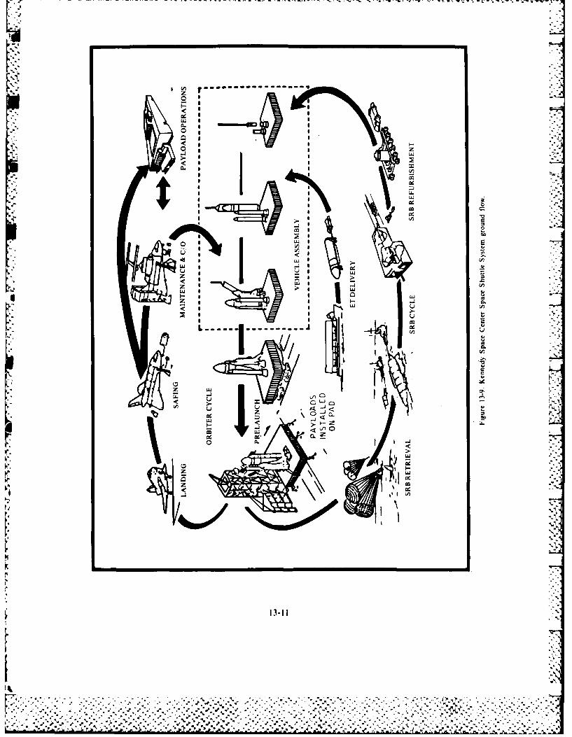
Li::I
o Io
LLWIC-)zj
< Wz ~
I UU I~ L a
< <
~ a a CL
13-11
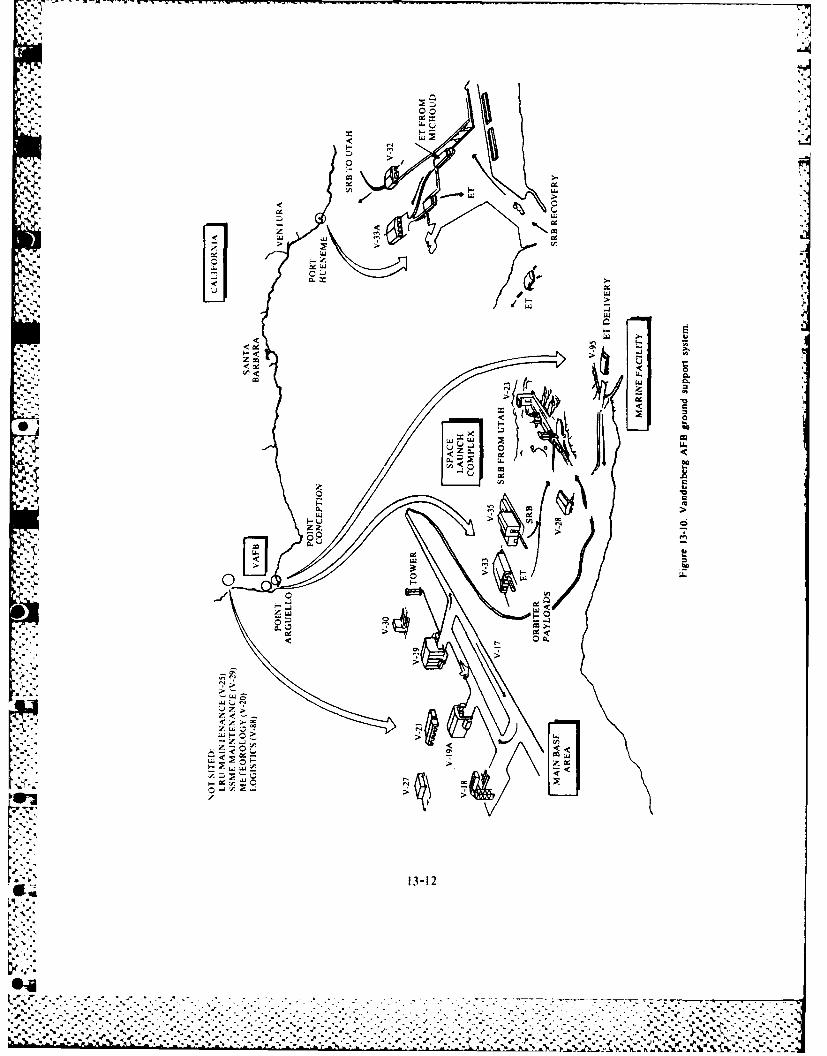
0 0
LL..
-j LSW
.9j4.z ujI
... ~L -j ~iJU
0 ~ '~L-
<31
*~~~~~~ cd:-:y-.-*<
14,515 kilograms (32,000 pounds) into orbit. This is possible because the earth runs counter tothe westerly launch azimuth. (Figure 13-11 shows the launch azimuth and inclination limits from
Vandenberg Air Force Base and Kennedy Space Center.)When an orbiter returns to earth from its mission in space, it lands at the Kennedy Space Center
(see fig. 13-9) located near the shuttle launch pad or at Vandenberg Air Force Base, California.
The runway used by the shuttle is approximately twice the length and width of runways used at
commercial airports. The shuttle runway is 4,572 meters (15,000 feet) long, 19.4 meters (300 feet)
wide, and 40.5 centimeters (16 inches) thick at the center. The runway includes safety overruns of
305 meters (1,000 feet) at each end. The runway has a slope of 61 centimeters (24 inches) from the
centerline to the edge. This slope of the concrete, plus small (0.63 centimeters or 0.25 inch) grooves
cut into the runway every 2.85 centimeters (1.25 inches) across, provide rapid drainage and a
more skid resistant surface. There is an aircraft apron, or ramp, 168 meters (550 feet) by 149 meters
(490 feet) attached near the southeastern end of the runway. The mate/demate device located on the
northeastern corner of the ramp lifts the orbiter for attachment to. or removal from, its Boeing 747
carrier aircraft for ferrying operations and provides movable platforms for access to certain
orbiter components.A sophisticated microwave scanning-beam landing system guides the orbiter automatically to
a safe landing. Since the craft lacks propulsion during the landing phase, its high-speed glide must
bring it in for a perfect landing the first time. An additional ground support system at Vandenberg
Air Force Base, California (see fig. 13-10), will have facilities for assembly and checkout of payloads,
the launch vehicle, and launch and recovery support activities. If possible, the support equipment,
systems, and procedures will be compatible with the design of the ground systems at the Kennedy
Space Center.
B 1 B 1.10 GRAPH V
Allaway. Howard. The Space Shuttle At Work. Washington D.C.: National Aeronautics and Space Administration, 1979.
Berry, F. Clifton. "Space is a Place." Interview with Lt Gen Richard C. Henry, Space Division. Air ForceSystems Command.
Air Force. (June 1982):36-42.Boggs, Wallace H. and Samuel I Beddingfield. "Moonport to Space." Astronautics and Aeronautics. (August 1982):28-41.
Rockwell International. Spate Shuttle Srstem Sununary. Rockwell, Md.: Rockwell International Corporation, January 1978.
Schlitz, William P. "Supporting the Space Shuttle: The Blue-Suit Contribution." Air Force. (June 1982):44-51.
Space Shuttle 1980. Washington D.C.. United States Government Printing Office. January 1980.
"U- o~. . . . .
- 13-13
W h I 4 . V,
. - ' , ,. , , " , . ' " - .. ' ". .. .-,* :' "Y - -'.' . -' - . , , . '%
' . . . .
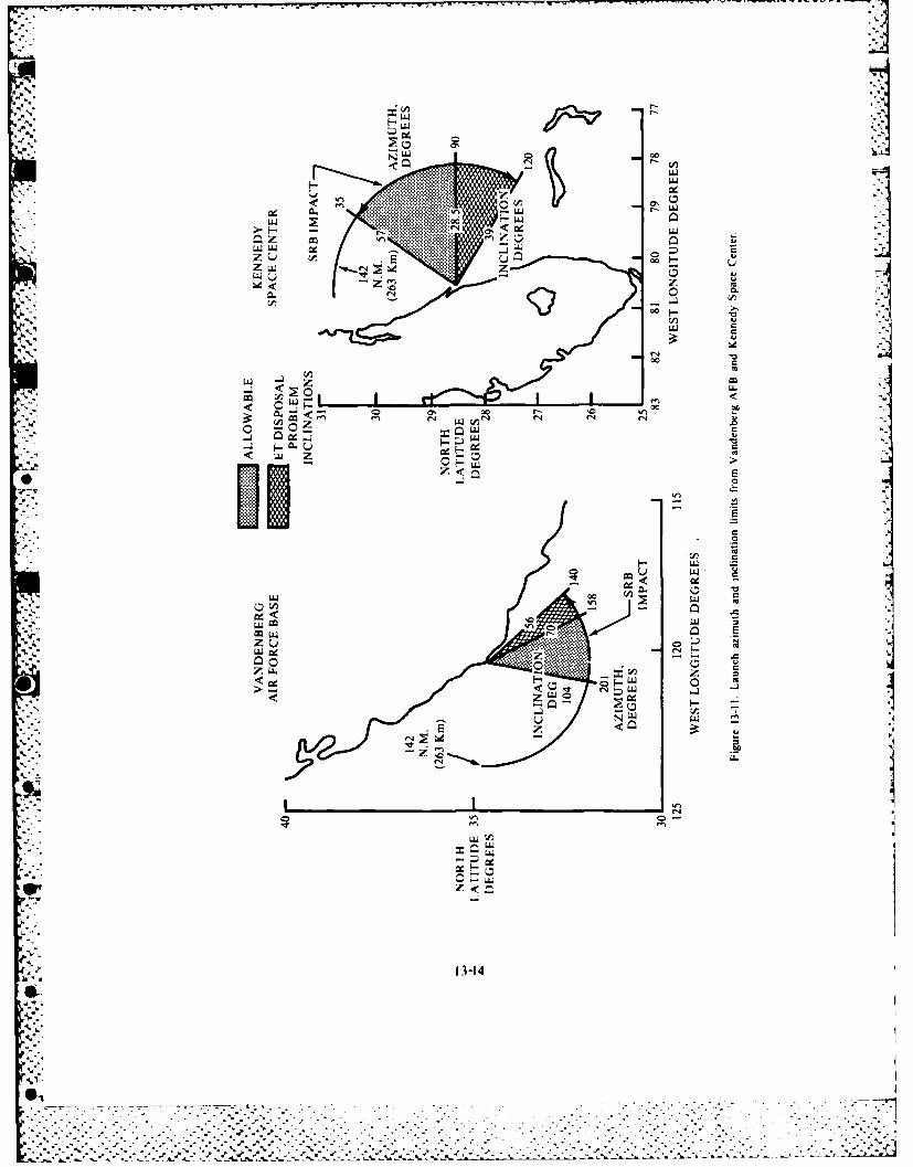
LLI
0.J U0
000
r4.
00 00
M
*i z
LLL.
C.j < o <.'w04.
LI > I0-M
13-14
V6
-- - - -. . . . - -
LL m.
W~~~~~~~~~ -. ° -
Chapter 14
SPACE SUPPORT ORGANIZATIONS
There are numerous and diverse organizations throughout the United States that are active in
space operations, research, and support. A complete listing would require a document as thick
as this text, and would include such organizations as independent laboratories; colleges and ,,.-
universities; local, state, and federal government agencies; private companies; research foundations;and many more.
The intent of this chapter is to briefly outline the two major US organizations that provide thevast majority of our space activity, namely, the US Air Force and the National Aeronautics and
Space Administration (NASA). Even these two organizations will not be described completelysince each has components that are not involved in space or space-related activities and theseorganizations are in a constant state of flux. .
NATIONAL AERONAUTICS AND SPACE ADMINISTRATION r
The National Aeronautics and Space Act of 1958 (72 Stat. 426; 42 U.S.C. 2451 et seq.) as amended
established NASA. The principle statutory functions of NASA are to conduct research for the
solution of problems of flight within and outside the earth's atmosphere; to develop, construct,
test, and operate aeronautical and space vehicles; to conduct activities required for the exploration
of space with manned and unmanned vehicles; to arrange for the most effective utilization of the
scientific and engineering resources of the United States with other nations engaged in aeronautical
and space activities for peaceful purposes; and to provide for the widest practicable and appropriate
dissemination of information concerning NASA's activities and their results. Congress established
these functions to carry out its policy of devoting space activities to peaceful purposes for the
benefit of all mankind.
National Aeronautics and Space Administration Headquarters
Responsibility for planning, coordination, and control of NASA programs are vested in itsadministrator. Directors of NASA's field installations are responsible for execution of NASA's
programs, largely through contract with research, de\,elopnient, and manufacturing enterprises.Government-employed scientists, engineers, and technicians conduct a broad range of research and
development activities in NASA's field installations. lhcsc activities ealuate new concepts andphenomena and maintain the competence required to manage contracts with private enterprises.
Planning, direction, and management of NASA's research and development programs are the
responsibility of the program offices that report to. and receive overall guidance and direction
from. the administrator. The overall planning and direction of institutional operations at the field
installation and management of agencywide institutional resources are the responsibility of the
appropriate institutional associate administrator under the overall guidance and direction ofthe administrator.
The program offices include Aeronautics and Space I echnology. Space and Science Applications,Space Transportation System. and Space Tracking and )ata Systems. A hrief description of theprogram responsibilities of these offices folilows.
14-I
It- -1101 me-- 'r e
Aeronautics and Space Technology. The Office of Aeronautics and Space Technology isresponsible for the conduct of programs to develop advanced technology to enable and enhancean aggressive pursuit of national objectives in aeronautics and space; to demonstrate the feasibilityof this advanced technology. when necessary; to ensure its early use; to apply technology developedin the aeronautics and space programs; and to coordinate the application of NASA capabilitiesand facilities to programs of other agencies to accomplish energy-related research and developmenton a reimbursable basis. The office also coordinates the agency's total advanced research andtechnology program to ensure its overall adequacy and to avoid undesirable duplication.
Space Science and Applications. This office is responsible for NASA's efforts to understand theorigin, evolution, and structure of the universe and the dynamic processes that shape the earth andits environment. It plans and implements programs leading to the study of earth as a planet andthe solution of national problems. It coordinates the program between various governmentagencies, foreign interests, and the private sector in an effort to ensure the maximum exploitationof space science opportunities and the application of space science and-technology to furtherknowledge and enhance life on earth.
In the achievement of its objectives, this office conducts research and development in astrophysics,earth and planetary exploration, environmental observations, life sciences, materials processingin space, communications, information systems, and Spacelab flight. The office utilizes the SpaceTransportation System automated spacecraft, sounding rockets, balloons, aircraft, and ground-based research in conducting the program. It is responsible for NASA contacts with the SpaceScience Board of the National Academy of Sciences and other science advisory groups.
Space Transportation Systems. This office is responsible for advancing the Space Shuttle andcarrying out space transportation and other associated programs. It is responsible for planning,directing, and acquiring all elements of the space transportation system. The office manages,directs, and coordinates all US civil launch capabilities and US Spacelab development, procure-ment, and operations. It has the responsibility for developing and implementing necessary policyfor all users of the space transportation system; and developing detailed plans, schedules, andresource requirements for space flight program objectives.
* Space Tracking and Data Systems. This office is responsible for providing tracking, dataacquisition and processing, and communication support to all NASA flight projects. Types offlight projects supported include sounding rockets, research aircraft, earth orbital and suborbitalmissions, lunar and planetary spacecraft, deep space probes, and the Space Shuttle program.To provide such support the office plans, implements, and operates a worldwide network of fixedand mobile tracking facilities for acquiring data, a centralized control center complex for directingmissions, a large-scale data processing facility, and an integrated communications network for
-* data transmission.
Field Installations
.4 A brief description of the principal and supporting roles of NASA's field installations follows. _
Ames Research Center, Moffett Field. California. A list of this center's areas of responsibilityinclude fundamental aerodynamics; shorthaul aircraft technology; rotocraft technology; compu-tat ional techniques; human factors research; computer science research; aeronautical flight
* .research; remotely- p iloted vehicle research; flight simulation; technical support to militaryaviation, airborne science and applications; planetary entry; planetary spacecraft developmentand mission operations; life sciences; space transportation passenger selection criteria; astronomicalobservation techniques; shuttle orbiter development support; and advanced space vehicleconfigurations technology.
14-2
1- -., I. . , - - *. .. ---
.2.,
- - - --- - .'~- r'~rC------------------r -v Wrri--r-w -7
-,. , '%
!....:
Goddard Space Flight Center, Greenbelt, Maryland. This center is responsible for earthorbital spacecraft development and flight operations; tracking and data acquisition systems andsupport operations; spacelab payloads; space physics and astronomy payloads and science; and
." upper atmospheric research. Its responsibility includes applications and research development inweather and climate, earth dynamics, earth resources, communications; information systemstechnology, sounding rocket and payload development, procurement, and operations, balloons;launch vehicle procurement; planetary science; and sensors and experiments in environmentalmonitoring and ocean dynamics.
Jet Propulsion Laboratory, Pasadena, California. This laboratory is operated under contract -by the California Institute of Technology. Its research areas include planetary spacecraft developmentand mission operations; tracking and data acquisition for deep space operations, lunar/planetaryscience; upper atmospheric research; science and applications spacecraft development; earthand ocean dynamics; teleoperator technology; guidance and control technology; energy technologyfor civil applications; space physics payloads and science; space astronomy payloads and science;
.. sensor and data acquisition systems and technology; and information systems technology.
Lyndon B. Johnson Space Center, Houston, Texas. This center is responsible for mannedspace vehicles and supporting technology; flight operations including flight control; life sciences;lunar and planetary geosciences; earth resources surveys; technology experiments in space;and energy systems.
John F. Kennedy Space Center, Kennedy Space Center, Florida. This center works with -.-
expendable vehicle launch operations; Space Transportation System (STS) ground operations; andSTS sustaining engineering. It must collaborate with such elements of the Department of Defenseas the Eastern Test Range and Corps of Engineers to avoid unnecessary duplication of launchfacilities, services, and capabilities.
Langley Research Center, Hampton, Virginia. This center carries out research on long-haulaircraft technology; general aviation aircraft/commuter aircraft technology; fundamental aero-dynamics; acoustics and noise reduction; aerospace vehicle structures and materials; aerothermo-dynamics; sensors and instruments; flight crucial electronics and aircraft control systems;technical support to military aviation; advance space vehicle configurations technology; sensorand data acquisition technology; technology experiments in space; atmospheric services tech-nology; hypersonic propulsion systems; planetary entry technology; computational fluid dynamics;upper atmospheric research; and launch vehicle procurement.
Lewis Research Center, Cleveland, Ohio. This center's responsibilities include research on airbreathing propulsion systems; engine materials and structures; tructural dynamics; turbomachineryaerodynamics combustion; propulsion controls; power transmission; military support; tribology;internal engine computational fluid dynamics; and high-temperature engine instrumentation. Otherareas of responsibility are launch vehicle procurement; space propulsion systems technology; spaceenergy processes and systems technology; energy technology and applications; high-powercommunications; and ground transportation system research.
George C. Marshall Space Flight Center, Huntsville. Alabama. This center works withpropulsion systems; manned space vehicle development; Spacelab mission management andpayload definition; specialied automated spacecraft: space processing; space vehicle structuresand materials; energy technology and applications; and satellite power system definition.
National Space Technology Laboratories, BaN St. Louis, Mississippi. These laboratoriesconduct research on static test firing of large space and launch ehicle-engines. They house certain
14-:
.y"
~~~~~~~. .. ... . . . ... ,. .,- - - . . .. . . . . . . . . .. . .. . , , . . . . , . . . .:
environmental research and earth resources activities of NASA and other governmental agenciesas well, with emphasis on the use of space technology and associated managerial and techntaldisciplines.
UNITED STATES AIR FORCE .5.
The National Aeronautics and Space Act of 1958 begins with the statement:,3
The Congress hereby declares that it is the policy of the United States that acti itics in space should he dct',,cdA' to peaceful purposes for the benefit of mankind.
I he Congress declared that the general welfare and security of the United States require that adcqiirprovision be made for aeronautical and space activities. The Congress further declares that such adihitCeSshall be the responsibility of. and shall be directed by, a civilian agency exercising control o.er aeronauticaland space activities sponsored by the United States, except that activities peculiar to or primarily aso,'iatedwith the deselopment of weapon systems, military operations, or defense to the United States (Including theresearch and development necessary to make effective provision for the defense of the Inited Stat ) shallbe the responsibility of. and shall be directed by, the Department of Defense; and that determinatimi a, i,which such agency has responsibility for and direction of any such activity shall he made h, the ['resident
Fhe US Air Force has conducted, and is conducting, most of the Department of- Defense (DI)1))space activities. Although DOD space missions are not exclusively the responsibility of the US AirForce (the US Navy's Fleet Satellite Communications handles some), the US Air Force is l)lYsexclusive agent for the launching of all DOD payloads and for the STS (Space Shuttle)
The Space Command
*l The Space Command was established as a major command on I September 1992 It is artoperational command designed to carry out national space policy that enhances militarycapabilities for defense of the United States.
Mission and tasks. I he Space Command has a current operational mission that entails themission of aerospace defense and a far-reaching agenda for future space activities. It will developspace strategies and operational concepts that address such factors as orbit selection, positionmanagement, orbital force structure, and others. It will also promote a comprehensive documen-tation of the Soviet space threat.
Space Command will handle the possible future task of operating the US antisatellite system whenit is deployed. 'This system will represent a necessary element in deterrence. In the CheyenneMountain Complex near Colorado Springs, there is a strong nucleus of space expertise as well asfacilities, communication. and computer capabilities to carry out space missions. This nucleus,combined with resources acquired from the Air Force Systems Command. Strategic Air Command.and Air Force Communications Command. will provide the initial ingredients of the Space Command.
The operational requirements of commanders in the field will be a major concern of the SpaceCommand. The command %k ill incorporate space assets into joint-service exercises. Present operationalplans call for land, air, and sea contingencies. The Space Command will integrate space activitiesinto these plans.I he Space Command will actiely influence Air Force technology development efforts by acting
as a catalyst between the operational and technological worlds. In this role, the command %illreviewk existing programs and add impetus to the development of promising new technologies.A current technology review effort involves high-energ., lasers and associated laser developmentprograms. 5..
4!l °The survivability of space systems will be a major area of the Space Command effort Militartvforces are dependent on space systems. These must he available when needed in crises andconflicts. I he Space (ommand's survivability efforts will be directed towyard vulnerable node-,,such as launch sites: tracking. telemetry, and commanding facilities: associated cotlnk icatii)s
14-4
., .,*, 5 ..
. .... . , - . ~ -... , .- . .. . . . . - , . . . - . - - . , - . , . . , . - . ,. . - . ,
network-, and spacecraft.Space medicine is another important challenge. Space sickness and the malfunction of the
spacesuits during the fifth shuttle flight underscore the effect that problems with the spaceenvironment and life support systems have in our ability to operate in space. The Space Commandsurgeon will press for research efforts to understand the space environment and for design improve-ments to increase the use of people in space.
The availability of people with the requisite technical training and education is another concern.In the future, one of the biggest limiting factors could be the lack of skilled people in the spacedisciplines. As a priority task, the Space Command will oversee training for Air Force spaceactivities and monitor and create added opportunities for career development to ensure qualifiedpeople in sufficient numbers are available to meet the Air Force's needs. To meet this need, a spacesystems major at the Air Force Academy has been implemented. The Academy implemented it forschool year 1984. The Air Force Institute of Technology (AFIT) currently offers a master's degree
in space operations management at Wright-Patterson Air Force Base, Ohio, and the Space Command
will be promoting enrollment to meet future needs. 7It is clear that space is the place for the future, and that more military missions can be supported
*from space. Space-based systems could alter the basic premises of national strategy. In the nuclearJera, it has been all offense- land- based bombers and missiles and missile-carrying submarines.Now, space may provide viable options-alternate investment opportunities -to change thisequation and put greater emphasis on strategic defense.
The establishment of Space Command is occurring at the right time, in the right place, with the
right people, and the entire Air Force is excited about it. The Space Command is a major stepItoward meeting the president's policy goal of having a space program that will strengthen nationalsecurity. The Space Command motto, Guardians of the High Frontier, symbolizes the importanceof space to the national security, and underscores our commitment to leadership in this expandingmedium.
Organization. In addition to the space facilities in Cheyenne Mountain the Space Commandwill manage and operate the worldwide space surveillance and missile warning radars and opticalsystems. The Air Force has assigned the Satellite Early Warning system and the DefenseMeteorological Satellite program to the Space Command as well.
- - -The command will be responsible for the Consolidated Space Operations Center (CSOC) near* '- Colorado Springs when completed. The CSOC will control operational spacecraft and plan,- . manage. and control all DOD shuttle flights. It will be the focal point of military space operations.
The recently activated Space Technology Center in Albuquerque, New Mexico, is responsiblefor unique space technical disciplines. It will ensure technological leadership in areas critical toUS security. Now the Air Force can process all space systems from basic technology throughdevelopment, acquisition, launch, and on-orbit checkout by the Space Division of Air ForceSystems Command to on-orbit control by Space Command.
Space Command gi'.es the Air Force an operational command to manage, control, and protectspace assets. It will provide a much closer relationship between the research and developmentcommunity and the operational world. Space Command will provide a focus for centralized plans,consolidated requirements, and the needs of operational commanders. It will provide the operationalpull to go along with the technology push that has been dominant in the space world.
F, North American Aerospace Defense CommandThe United States and Canada continue a lasting partnership in the defense of North America.
This partnership has evolved into a deep and abiding friendship providing the essential ingredientto the collective security of our two countries. The organization that implements this defensearrangement is the North American Aerospace Defense Command (NORAD).
NOR AD is the first binational command to be established within North America. It provides
14-5
J
. r
the cooperative defense planning and organizing wherein the governments of Canada and theUnited States place military forces under a single commander --CINCNORAD. The NORM)
* organization melds multiservice and multinational elements into an effective combat force.CINCNORAD reports to the president through the Joint Chiefs of Staff and secretary of defense
and to the Canadian prime minister through the Canadian chief of defense staff and minister of'A national defense. The commander's duties and responsibilities are parallel in the United States
and Canada. The NOR AD headquarters has the normal six-deputate joint staff. Canadian Forces-: and members of the United States Air Force, Army, Navy, and Marine Corps occupy key NOR AD
staff positions. The NORAD commander heads a binational joint force comprised of integratedcomponents of a US specified command and the air defense elements of the Canadian Forces AirCommand. In addition, the NORAD commander is also commander in chief. Aerospace D)efenseCommand (ADCOM) the US specified command and commander of Space Command. T'heADCOM commander's responsibilities include operational command of the aerospace defenseof the CONUS and Alaska under circumstances requiring unilateral aerospace defense actionsby the United States. In brief. ADCOM is NORAD less the Canadians.
Air Force Systems Command
Air Force Systems Command, established I April 1961. is responsible for the rapid advancementof aerospace technology and its adaptation into operational aerospace systems. The command isorganized into divisions, centers, national test ranges, laboratories, and research and development
- - offices.Product divisions develop, test, and procure systems and equipment. They contain system
program and project offices and operate as subcommands. These may include a system engineeringand technical integration contractor, which operates as a nonprofit corporation established toadvise the Air Force on system engineering and technical direction. The nonproduct divisionsanalyze and evaluate technological threats; conduct biotechnology research, development, andeducation programs; and provide contracting liaison.
The centers and two national ranges provide development, test, and evaluation facilities for thecommand. They have other specialized facilities such as rocket test stands, wind tunnels andsimulators. sled test tracks, and electronic test ranges. The two national ranges have the capability
* to form a single global tracking network for intercontinental ballistic missiles (ICBMs), spacesatellites, launch vehicles, and space probes.
The laboratories and Air Force Office of Scientific Research (AFOSR), Boiling Air Force Base.* . D.C.. in addition to providing research and development support to system and equipment* * acquisition programs of the product divisions, constantly seek to improve the foundation of
advanced technology. Special funds exist to support opportunistic research and development that.because of timing or other circumstances, is not funded during the normal budgeting cycle. TheAFOSR grant authority is unique in the Air Force.
Space Division. The Space Division. headquartered in Los Angeles, California, with launchand tracking systems worldwide, has the responsibility for the space systems. This responsibilityencompasses engineering, test, program management. installation, launch, on-orbit tracking, andcommand and control.
The Space [Division manages the design, launch, and on-orbit command and control of' militaryspacecraft. The unit plays a major development role in the ground terminal segment of' spacesystems. T1oday's space systems support communications, early warning. meteorology. surveillance.and navigation needs of operational commands. The Space Division overseas the spacecrafttechnology development programs and space defense programs as well.
Space launch boosters are a major element of the mission. In addition to being responsible forcurrent expendable boosters such as Atlas and Titan, the Space Division is the DOD's managerfor military activities in the national space transportation system. While the National Aeronautics
14-6
* and Space Administration (NASA) manages the overall space shuttle program, the Space Division* is responsible for integration of military payloads and the operation of the west coast spaceport
* at Vandenberg Air Force Base, California. It is responsible for developing the inertial upper stageto propel payloads from low-earth orbits of the shuttle to high-altitude orbits as well.
* . Space Divrision units include the Space Missile Test Organization, the Air Force Satellite ControlFacility, and the Manned Space Flight Support Group.
Space and Missile Test Organization. The Space and Missile Test ()rganiiation (SAMTO).through its two operational units, the Eastern Space and Missile Center and the Western Space andMissile Center, provides flight-test management for DOD-directed ballistic missile and spaceprograms. It manages more than 20 satellite launches a year from Vandenberg AFB. California,and Cape Canaveral. Florida, as well as a variety of ICBM ballistic tests. The centers operate the
* Eastern and Western Test Ranges. which stretch around the world. SAMTO supervises a vast arrayof data-gathering sites scattered throughout its ranges in support of its test programs and those ofthe Strategic Air Command. National Aeronautics and Space Administration, and othergovernment agencies.
Air Force Space Technology Center. The Air Force Space Technology Center (AFSTC) islocated at Kirtland Air Force Base, New Mexico, and operates under the Space Division. AFSTCwas activated in October 1982 as the Air Force focal point for space technology planning anddevelopment. It coordinates technology programs for space missions, ensuring correct technologicalchoices and investment strategy.
The center manages three AFLC laboratories. These are the Air Force Weapons Laboratory,Kirtland Air Force Base, New Mexico; Air Force Geophysics Laboratory, Hanscom Air Force
6 Base. Massachusetts; and Air Force Rocket Propulsion Laboratory, Edwards Air Force Base,California. The laboratories perform research and development for the Air Force and nonmilitary
- - organizations in their respective disciplines. The center integrates the space technology efforts- . of the laboratories to explore military space capabilities and the needs of future space systems.4", The center is a focal point for information about the scope and progress of space-related
deielopments in electronics hardening and laser research, rocket propulsion, and the earth and* .. space environments.
The center, in conjunction with other Space Division elements and Space Command, correlatesresearch results with systems demonstration needs and identifies key technology areas for long-rangeLplans. The Space Technology Center cooperates with the National Aeronautics and Space Admin-istration and other military agencies on joint efforts to develop routine, reliable, and survivablespacecraft.
- I Air Force Satellite Control Facility. The Air Force Satellite Control Facility (AFSCF) providesorbital support for the research, development, test and evaluation, and operation of DOD spacesystemns and, as required, NASA and NATO programs. From its headquarters at Sunnyvale.California, it operates a worldwide network of tracking stations.
;' Mlanned Space Flight Support Group. This unit is located at the Johnson Space Center.H-ouston, Texas. It is responsible for developing the capability to plan and control D)01 spacetransportation system missions and to ensure that those missions are secure. It will manage theacquisition phase of the Shuttle Operations and Planning Center portion of the ConsolidatedSpace Operations Center. The group will train personnel to directly support the command andcontrol of I)OD space shuttle missions and transition those personnel to the Shuttle Operations
6 and Planning Center.
Electronic Systems Division. This division, located at IL. G1. Hanscom l-ield. Massachusetts. isresponsible for developing. acquiring, and delivering electronic systems and equipment for the
* 14-7
I-%
I% 2S.*
.5. ~~~~~A A.~ .-.. S*
command, control, and communications functions of aerospace forces. These systems take manyforms, such as undersea communications cable around the Indochina peninsula, line-of-sightand tropospheric scatter communications throughout the Mediterranean, the underground NORADcombat operations center, long-range radars to warn of missile and aircraft attack, the air defensecontrol net for the North American continent, equipment for improved weather forecasting, thefree world's satellite detection and tracking network, and experimental satellites for the developmentof communications satellite technology.
Roame A&a Developmet Center. The Rome Air Development Center (RADC), located atGriffiss AFB, New York, is the principal organization charged with Air Force research and
development programs in information sciences; intelligence; and command, control, and communi-cations. RADC mission areas include communications; electromagnetic guidance and control;surveillance of ground and aerospace objects; intelligence data collection and handling; informationsystems technology; ionospheric propagation; solid-state sciences; microwave physics; andelectronic reliability, maintainability, and compatibility.
ArNold Engieerli Devdeopmmt Ceter. Located at Arnold AFS, Tennessee, the ArnoldEngineering Development Center (AEDC), currently valued at more than $940 million, containsthe most advanced and largest complex of aerospace flight simulation test facilities in the freeworld. Its mission is to ensure that aerospace hardware, which includes aircraft, missiles, spacecraft,jet and rocket propulsion systems, and other components, will work right the first time they fly.The three major facilities of the center contain some 40 test units in which the engines can simulateflight conditions from sea level to altitudes of 1,000 miles and from subsonic velocities to morethan 20,000 miles per hour. Equipment being tested ranges in size from small-scale models tofull-scale vehicles with propulsion systems installed and operating.
AIr Force WrIgh Aer'aatulal Laboratores. The Air Force established the Wright Aero-nautical Laboratories (AFWAL) at Wright-Patterson AFB, Ohio, on I July 1975. It consists of acommand and staff element with four laboratories: Air Force Avionics Laboratory, Air ForceAero Propulsion Laboratory, Air Force Flight Dynamics Laboratory, and Air Force MaterialsLaboratory.
The mission of the AFWAL is to plan and to execute USAF exploratory development, advanceddevelopment, and selected research and engineering development programs for flight vehicles,aeropropulsion, avionics, and materials, and the US Air Force manufacturing methods program.It provides support within its areas of technical competence for planning, developing, and operatingaerospace systems to Air Force, Department of Defense (DOD), and other government agencies.
BIBLIOGRAPHY 11A U-23. US Air Force Commands and Agencies: Basic Information, 1983-84. Maxwell AFB, Ala.: Air U niversity Press. 1983.
United States Government Manual. 1982/83. Washington. D.C.: US Government Printing Office, I July 1982.
14-8
- .. 0
Chapter 15
SPACE POLICY AND DOCTRINE
Space policy defines in broad terms the basic goals and principles of the US space program. Spacepolicy is shaped by national interests and security objectives and constrained by fiscal considerationsand US objectives under international law. Perhaps policy formulation is the most critical element ofthe national planning process because it provides the framework for the subsequent developmentof military space strategy and the identification of future system requirements.
This chapter examines the basic tenets of US space policy, the national interests and securityobjectives that shape it, and the international legal regime that constrains it. The chapter summarizesDOD and Air Force space policies, which are derived from national space policy, and concludes withan analysis of those fundamental doctrinal principles that guide the conduct of military spaceactivities.
NATIONAL INTERESTS
The nation's fundamental national interests have remained constant while the threats and circum-stances facing the United States, and the capabilities needed to meet them, have changed over time.Though variously defined, they are four in number.
The first of these is national survival. It is the most basic of the national interests. Without it,no other interest has relevance. This includes preservation of freedom, political identity, and theinstitutions that provide their foundation (that is, the Constitution and the rule of law). The second isterritorial integrity. This includes the protection of the territory of the United States, its citizens, andits vital interests abroad from armed attack. The third fundamental interest is economic well-being.We must be assured of access to foreign markets and overseas resources to maintain the strength ofthe US industrial, agricultural, and technological base. The fourth is a favorable world order. Thismeans an international order that is not inimical to US interests or democratic institutions, economicdevelopment, and self-determination. Like the land, sea, and air mediums, space conceptually gives anew opportunity to further and protect US national interests in all four areas.
SPACE LAW
Though shaped by national interests, the development of space policy is constrained, nevertheless,by the US objectives under international law. Typically, but not exclusively, these obligations areembodied in bilateral or multilateral treaties signed and ratified by the United States. As such they arebinding and as much a part of US law as provisions of the Constitution or statutes enacted byCongress.
Table 15-1 summarizes those international agreements that presently constrain US militaryactivities in space and describes the nature of each constraint. Briefly stated, the following activitiesare prohibited or otherwise constrained as indicated:
*The appropriation by claim of sovereignty, use or occupation, or any other means, of anyportion of outer space to include the moon and celestial bodies.
'~:e.
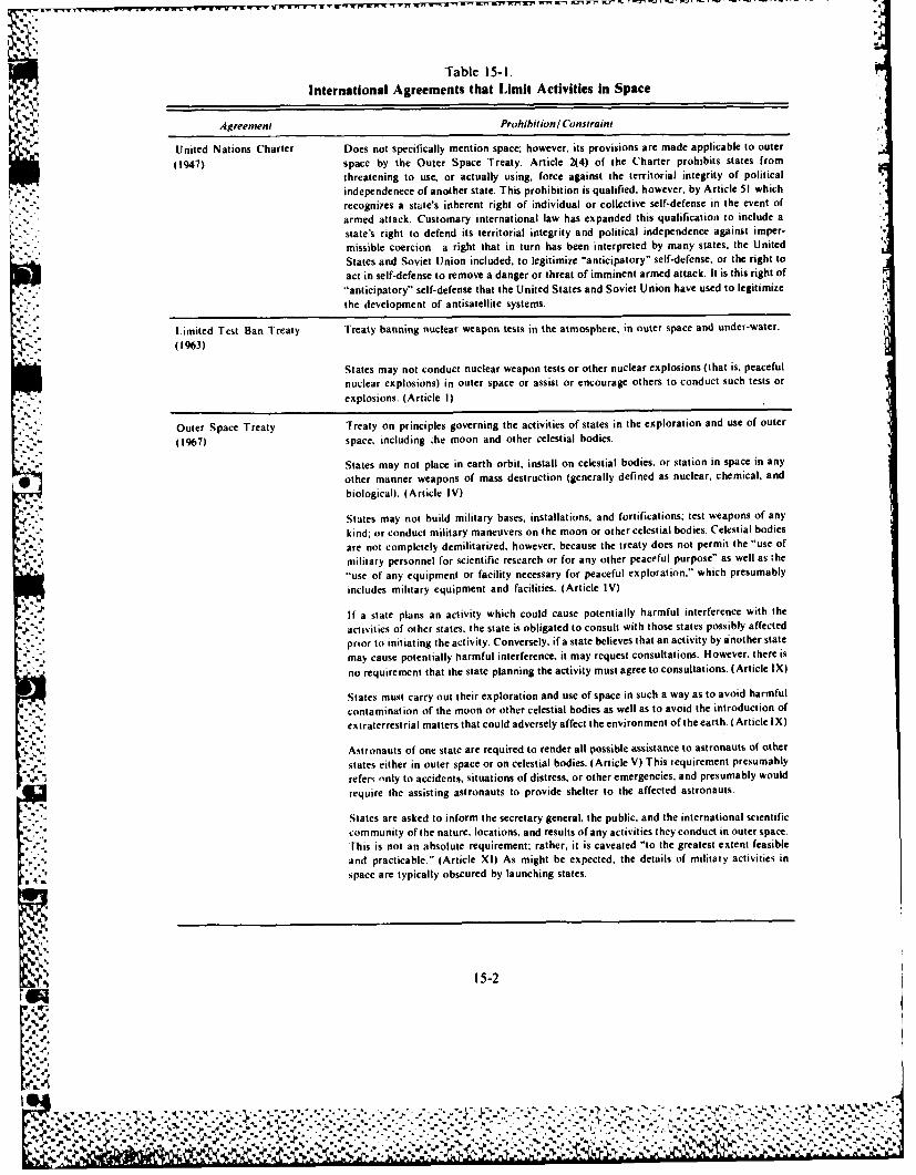
Table 15-I.International Agreements that Limit Activities In Space
Agreement Prohibition/ Constraint
United Nations Charter Does not specifically mention space; however, its provisions are made applicable to outer
(1947) space by the Outer Space Treaty. Article 2(4) of the Charter prohibits states fromthreatening to use. or actually using, force against the territorial integrity of politicalindependenece of another state. This prohibition is qualified, however, by Article 51 whichrecognizes a state's inherent right of individual or collective self-defense in the event ofarmed attack. Customary international law has expanded this qualification to include astate's right to defend its territorial integrity and political independence against imper-missible coercion-a right that in turn has been interpreted by many states, the UnitedStates and Soviet Union included, to legitimize "anticipatory" self-defense, or the right to
act in self-defense to remove a danger or threat of imminent armed attack. It is this right of"anticipatory" self-defense that the United States and Soviet Union have used to legitimize
the development of antisatellite systems.
Limited Test Ban Treaty Treaty banning nuclear weapon tests in the atmosphere, in outer space and under-water.
(1963)
States may not conduct nuclear weapon tests or other nuclear explosions (that is, peacefulnuclear explosions) in outer space or assist or encourage others to conduct such tests or
explosions. (Article I)
Outer Space Treaty Treaty on principles governing the activities of states in the exploration and use of outer
(1967) space, including ;he moon and other celestial bodies.
States may not place in earth orbit, install on celestial bodies, or station in space in any
other manner weapons of mass destruction (generally defined as nuclear, chemical, and
biological). (Article IV)
States may not build military bases, installations, and fortifications: test weapons of any
kind; or conduct military maneuvers on the moon or other celestial bodies. Celestial bodiesare not completely demilitarized, however, because the treaty does not permit the "use of
military personnel for scientific research or for any other peaceful purpose" as well as the
"use of any equipment or facility necessary for peaceful exploration," which presumablyincludes military equipment and facilities. (Article IV)
If a state plans an activity which could cause potentially harmful interference with the
activities of other states, the state is obligated to consult with those states possibly affected
prior to initiating the activity. Conversely, if a state believes that an activity by a nother state
may cause potentially harmful interference, it may request consultations. However, there is
no requirement that the state planning the activity must agree to consultations. (Article IX)
States must carry out their exploration and use of space in such a way as to avoid harmful
contamination of the moon or other celestial bodies as well as to avoid the introduction ofextraterrestrial matters that could adversely affect the environment of the earth. (Article IX)
Astronauts of one state are required to render all possible assistance to astronauts of other
states either in outer space or on celestial bodies. (Article V) This requirement presumably
refers only to accidents, situations of distress, or other emergencies, and presumably wouldrequire the assisting astronauts to provide shelter to the affected astronauts.
States are asked to inform the secretary general, the public, and the international scientificcommunity of the nature. locations, and results of any activities they conduct in outer space.
This is not an absolute requirement; rather, it is caveated "to the greatest extent feasible
and practicable." (Article XI) As might be expected, the details of military activities inspace are typically obscured by launching states.
15-2
"4.."
". . -' .. . ...,..,-...-....
J..
%1 ' 4 .
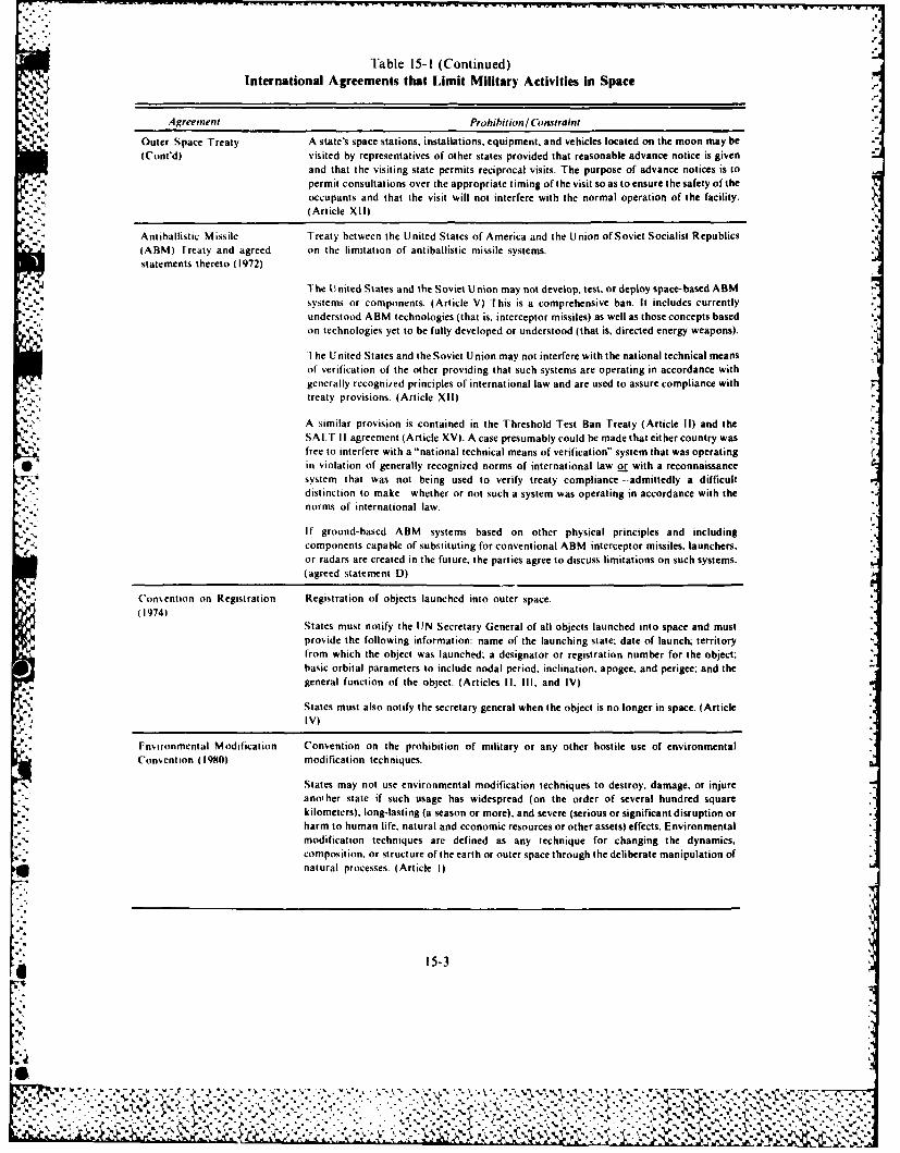
Table 15-1 (Continued)International Agreements that Limit Military Activities in Space
V Agreement Prohibjition! IConstraintOuter Space Treaty A state's space stations. installations, equipment, and vehicles located on the moon may be(Cont'd) visited by representatives of other states provided that reasonable advance notice is given
and that the visiting state permits reciprocal visits. The purpose of advance notices is topermit consultations over the appropriate timing ofthevisit soas toensure the safety oftheoccupants and that the visit will not interfere with the normal operation of the facility.(Article XII)
Antiballistic Missile Treaty between the United States of America and the Union of Soviet Socialist Republics(ARM) I reaty and agreed on the limitation of antiballistic missile systems.statements thereto (1972)
The U nited States and the Soviet Union may not develop, test, or deploy space- based ARMsystems or components. (Article V) This is a comprehensive ban. It includes currently
* understood ARM technologies (that is. interceptor missiles) as well as those concepts basedon technologies yet to be fully developed or understood (that is. directed energy weapons).
The U nited States and the Soviet Union may not interfere with the national technical meansof verification of the other providing that such systems are operating in accordance withgenerally recognized principles of international law and are used to assure compliance withtreaty provisions. (Article XII)
A similar provision is contained in the Threshold Test Ban Treaty (Article 11) and theSALT I I agreement (Article XV). A ease presumably could be made that either country wasfree to interfere with a "national technical means of verification" system that was operating
* in violation of generally recognized norms of international law or with a reconnaissance* system that was not being used to verify treaty compliance --admittedly a difficult
distinction to make whether or not such a system was operating in accordance with thenorms of international law.
If ground-based ABM systems based on other physical principles and including1' components capable of substituting for conventional ARM interceptor missiles, launchers,
or radars are created in the future, the parties agree to discuss limitations on such systems.(agreed statement D)
('onsention on Registration Registration of objects launched into outer space.(1974)
States must notify the UN Secretary General of all objects launched into space and mustprovide the following information: name of the launching state: date of launch; territoryfrom which the object was launched; a designator or registration number for the object;basic orbital parameters to include nodal period, inclination, apogee, and perigee; and thegeneral function of the object. (Articles 11, Ill, and IV)
States must also notify the secretary general when the object is no longer in space. (ArticleIV)
Fnsironmental Modification Convention on the prohibition of military or any other hostile use of environmental*Cons ent ion (19810) modification techniques.
States may not use environmental modification techniques to destroy, damage. or injureanoiher state if such usage has widespread (on the order of several hundred squarekilometers). long-lasting (a season or more), and severe (serious or significant disruption orharm to human life, natural and economic resources or other assets) effects. Environmentalmodification techniques are defined as any technique for changing the dynamics,composition. or structure of the earth or outer space through the deliberate manipulation ofnatural processes. (Article 1)
15PN.
0Threatening to use or actually force against the territorial integrity and political independenceof another state.
0Testing nuclear weapons or other nuclear explosive devices, even peaceful nuclear devices.
*Placing in earth orbit, installing on celestial bodies, or stationing in space in any other mannerweapons of mass destruction (generally defined as nuclear, chemical, or biological).
*Building military bases, installations, or fortifications on the moon or other celestial bodies.
e Testing weapons of any kind on the moon or other celestial bodies.
0 Conducting military maneuvers on the moon or other celestial bodies.
0 Developing, testing, or deploying space-based antiballistic missile (ABM) systems orcomponents (for example, missions, launchers, or radars).
*Developing future ground-based ABM systems based on physical principles other than andincluding components capable of substituting for conventional ABM interceptor missiles,launches, or radars without first discussing with the Soviet Union possible limitations on suchsystems.
*Interfering with Soviet national technical means of verification provided such systems areoperating in accordance with generally recognized principles of international law and are in factbeing used to verify provisions of the ABM Treaty, SALT, and Threshold Test Ban Treaty.
0 Initiating activities that could cause harmful interference with the activities of other stateswithout first consulting with those states.
0 Causing harmful contamination of the moon or other celestial bodies.
o Using environmental modification techniques to destroy, damage, or injure another state.
* Launching space objects without notifying the Secretary General of the United Nations.
One of the fundamental truths of international law is that if an act is not prohibited specifically,then that act is permitted. Therefore, though the list of prohibited acts is sizable, in the aggregate thereare very few legal restrictions on the use of space for nonaggressive military purposes. Therefore,international law permits implicitly the performance of traditional military support functions such assurveillance, reconnaissance, navigation, meteorology, and communications. It permits thedeployment of military space stations; the testing and deployment in earth orbit of nonnuclear, non-ABM weapon systems, the use of space for individual and collective self-defense and any conceivableactivity not specifically prohibited or otherwise constrained.
A second and equally fundamental truth is that, in most instances, treaties are designed to regulateactivities between the signatories during peacetime only. Unless the international agreement statesclearly that its provisions are designed to apply or become operative during hostilities, or thesignatories can deduce this from the treaty's content, they must presume that armed conflict willresult in the suspension or termination of the applicability of a treaty's provisions. This is particularlytrue for treaties whose purpose is to disarm or limit quantities oif arms maintained by signatories.Thus, in time of hostilities, the scope of permissible military space activities broadens significantly.
NATIONAL. SPACE POI.IV'
The origin and development of the nation's space policy is interesting and extremely important. Ifwe are to understand the evolution of the present policy and predict the future course of space policy,we must begin with a brief survey of its origin and evolution.
15-4
*%-~~~ . %
~~~* - . -- *N~~,** 1~V VAR J - - - - . ? ~ *
Early Policy
The launch of Sputnik I on 4 October 1957 had an immediate and dramatic impact on theformulation of US space policy. Though the military had expressed an interest in space technology asearly as the mid-l940s, a viable US satellite program failed to emerge for several reasons. Theseinclude intense interservice rivalry; military preoccupation with the development of ballistic missilesthat prevented a sufficiently high funding priority from being assigned to proposed space systems; iand, perhaps most importantly, national leadership that failed initially to appreciate the strategic andinternational implications of emerging satellite technology, and when it did, was committed to anopen and purely scientific space program.
Sputnik I changed all that. It resulted in the first official US government statement that spaceindeed was of military significance. This was a 26 March l958 statement by President Eisenhower'sscience advisory committee that the development of space technology, in addition to being requiredby human curiosity, scientific knowledge, and the maintenance of national prestige, was importantfor the "defense of the United States" as well. Congress recognized quickly that space activity waspotentially vital to the national security. The following language of House Resolution 1770 reflectedthis.
This country is not unmindful of what these Soviet achievements (in space) mean in terms of mulitary defense.... Ballisticmissiles already travel for a considerable part of their path through near outer space and can arrive virtually withoutwarning to deliver their devastating thermonuclear warheads. The United States must have a strong capability in the use
-. of outer space, both as a deterrent to military use of space vehicles against this country and as an aid in developingantimissile techniques. Satellite (operations) will have important implications for guarding the peace. On the one hand.they are adjuncts to weapon systems related to the deterrent power, and, on the other, they represent importanttechniques for inspection and policing, in accordance with any disarmament scheme which may be negotiated in the
* years to come.*
The first official national space policy was embodied in the National Aeronautics and Space Act of1958. It declared that the policy of the United States was to devote space activities to peacefulpurposes for the benefit of all mankind, mandated separate civilian and national security spaceprograms, and created a new agency, the National Aeronautics and Space Administration (NASA).to provide direction to and exercise control over all US space activities except those "peculiar to orprimarily associated with the development of weapons systems, military operations, or the defense
-5 of the United States." The Department of Defense (DOD) was to be responsible for, and to direct,these latter activities. A legislative basis for DOD responsibilities in space was provided early in thespace age. The act established a mechanism for coordinating and integrating military and civilianresearch and development, encouraged significant international cooperation in space, and calledfor preserving the role of the United States as a leader in space technology and its application.
The policy framework for a viable space program was thus in place. In fact, the principlesenunciated by the National Aeronautics and Space Act, which included peaceful focus on the use ofspace, separation of civilian and national security space programs, emphasis on internationalcooperation, and preservation of a space role, have become basic tenets of the US space program. Allpresidential space directives issued since 1958 have reaffirmed these basic tenets. However, what was
% missing was a space program of substance. The Eisenhower Administration's approach toimplementing the new space policy can be characterized as conservative, cautious, and constrained.Early DOD and NASA plans for advanced manned space flight programs were disapprovedconsistently. Instead the administration preferred to concentrate on unmanned, largely scientific
missions and to proceed with those missions at a measured pace. It was left to subsequentadministrations to give the policy substance.
*1959 US Code C~ongress and Administration News. )161-3tt62
* 15-%
I%

Intervening Years
Two presidential announcements- one by John F. Kennedy on 25 March 1961 and the second byRichard M. Nixon on 7 March 1970--were instrumental in providing the needed focus to America'sspace program. The Kennedy statement was crafted during a period of intense national introspection.The Soviet Union had just launched, and successfully recovered, the world's first cosmonaut. ThoughYuri Gagarin spent just 89 minutes in orbit, his accomplishment electrified the world and caused theUnited States to question its scientific and engineering skills and its entire educational system. TheAmerican response-to land a man on the moon and return him safely to earth bounded US spacegoals for the remainder of the decade. Prestige and international leadership were clearly the main
* objective of the Kennedy space program. However, the generous funding that accompanied theApollo program had important residual benefits as well. It permitted the buildup of US spacetechnology and the establishment of an across-the-board space capability to include planetaryexploration, scientific endeavors, commercial applications, and military support systems.
However, as the decade of the 1960s drew to a close, a combination of factors, including domesticunrest, an upopular foreign war, and inflationary pressures, forced the nation to reassess the relativepriority of the space program as compared to other national needs. It was against this backdrop thatPresident Nixon made his long-awaited space policy statement in March 1970. It was a carefullyconsidered and carefully worded statement that was clearly aware of political realities and the moodof Congress and the public. It said, in part:
Space expenditures must take their proper place within a rigorous system of national priorities. .. What we do in spacefrom here on in must become a normal and regular part of our national life and must therefore be planned inconjunction with all of the other undertakings which are also important to us.*
0 Though spectacular lunar and planetary voyages continued until 1975, largely as a result of2. budgetary decisions made during the mid-1960s, it was clear that the Nixon administration
considered the space program of intermediate priority and could not justify increased investment orthe initiation of large new projects. It viewed space as a medium for exploiting and extending thetechnological and scientific gains that had already been realized. The emphasis was on practical spaceapplications to include worldwide communications and meteorological systems. earth resourcesurveys, and scientific stellar and solar observations. Military surveillance satellites and navigationssystems received increased emphasis as well.
One major new space initiative was undertaken during the 1970s. It was to have a far greater impacton the nation's space program than originally envisioned. The 1972 decision to proceed withdevelopment of a space shuttle was made for three principal reasons: a reusable vehicle promised todrastically reduce operational launch costs; the project would employ up to 40,000 aerospaceworkers-an important consideration in a presidential election year; and DOD expressed interest inthe concept. It was inevitable that development problems would arise given the high technologicalrisk associated with the program. When they did, and particularly when they began to manifest
themselves in terms of cost overruns and schedule slippage, and to impact adversely already austerescientific and applications programs, it became apparent that no Americans would be launched into
- . space for the remainder of the decade. The US space program had lost much of its early momentum.
Carter Administration Space Policy
Early in the Carter administration, a series of interdepartmental studies were conducted to addressthe malaise that had befallen the nation's space effort. These studies addressed apparentfragmentation and possible redundancy among the civil and national security sectors of the US spaceprogram and sought to develop a coherent recommendation for a new national space policy. 'The
@1 product of these efforts matured in the spring and fall of 1978, and resulted in two presidentialdirectives (PD) -PD 37 on national space policy and P1) 42 on cik il space policy.
h,~,s , , %, ,,,,ndl Sp-~ P-w 7 Ma,,h 1970
4-1 4---"N

PD-37 reaffirmed the basic policy principles contained in the National Aeronautics and Space Actof 1958, and. for the first time, spelled out in coherent fashion the broad objectives of the US spaceprogram and the specific guidelines governing civil and national security space activitics. The Reaganadministration embodied most of these objectives and guidelines in its space policy. Therefore, we willdiscuss them in detail later.
PD-37 was important from a military perspective because it contained the initial, though tentative.indications that a shift was occurring in the national security establishment's views on space.Traditionally, they had viewed space as a force enhancer, that is, as a medium in which to deployW
:~ systems to increase the effectiveness of land, sea, and air forces. Although the focus of the Carteradministration space policy was clearly on restricting the weaponization of space, PD 37 reflected anappreciation of the importance of space systems to national survival, a recognition of the Sovietthreat to those systems, and a willingness to push ahead with development of an antisatellite (ASAT)capability in the absence of verifiable and comprehensive international agreements restricting suchsystems. In ot words, space was beginning to be viewed as a potential warfighting medium.
Whereas PD-37 addressed the space program in its totality. PD 42 was directed exclusively at thecivil space community and was designed to set the direction for US efforts over the next decade.However, it was devoid of any long-term space goals, preferring instead to state that the nation would
2 pursue a balanced evolutionary strategy of space applications, space science, and explorationactivities. The absence of a more visionary policy reflected clearly the continuing developmental
5, problems with the shuttle and the resulting commitment of larger than expected resources.
* Reagan Administration Space Policy
National Security Decision Directive 42 (NSDD-42), publicly announced by President Reagan on4 July, 1982, embodies current national space policy. It supersedes all previous presidential spacepolicy directives.
Basic goals. NSDD -42 reaffirms a national commitment to the exploration and use of space in= support of the national well-being. It establishes the basic goals of US space policy as strengthening
US security, maintaining US space leadership, obtaining economic and scientific benefits throughspace exploitation, expanding the investment and involvement of the US private sector in civil spaceand space-related activities, promoting international cooperative activities in the national interest.and cooperating with other nations in maintaining the freedom of space for activities that enhance the
4 security and welfare of the entire human race.
Principles. NSDD 42 outlines broad principles that are to serve as the basis for the future USspace program. For the most part, these principles have characterized, historically, the conduct of USspace activities. These principles include five basic commitments. First, a commitment to the
* exploration and use of space by all nations for peaceful purposes and for the benefit of all people. Forthe first time, NSDD 42 defines peaceful purposes to permit activities in pursuit of national securitygoals. Second, there is a commitment to conduct international cooperative space-related activitiesthat achieve scientific, political, economic, or national security benefits for the United States. Third,
.%.. here is a commitment to pursue activities in space in support of the United States' inherent right ofself-defense. Fourth. there is a commitment to develop Space Transportation System (STS)capabilities and capacities to meet appropriate rnational needs and to make the STS available tocommercial and governmental users, both domestic and foreign. This includes the recognition thatthe STS is the primary space launch system for national security and civil government missions. Fifth,there is a commitment to continue to study space arms control options and to consider verifiable
*and equitable arms control measures that 'would ban, or otherwise limit, testing and deploymentof specific weapons provided those measures are compatible with US national security.
Other broad principles include a rejection of' national claims to sovereignty over any portion of'Sspace and celestial bodies as well as a rejection of any limitations on the fundamental right to acquire 7V., data from space, There is a recognition that space systems are national property and have the right to
N 15-7
%~%
pass through and operate in space without interference, and that the United States would viewIpurposeful interference as an infringement on its sovereign rights. Z-* These principles stress the encouragement of domestic commercial exploitation of space
capabilities, technology, and systems for national economic benefit provided such exploitation isconsistent with national security concerns, treaties, and international agreements. There is a mandate .-
included that the national security and civil segments of the national space program closelycoordinate, cooperate, and exchange information to avoid unnecessary duplication.
Specific policy guidance. In addition to outlining the basic goals and broad principles of the USK,'. space program, NSDD-42 provides specific policy guidance. The following is some specific guidance
as it applies to military activities.The United States will conduct activities in space deemed necessary to national security. These
activities will support such functions as command and co, trol, communication, navigation,environmental monitoring, warning, surveillance, and self-defense.p The United States will pursue survivability and endurance of space systems, including all systemelements, commensurate with their planned use in crisis and conflict, with the threat, and with theavailability of other assets to perform the mission. Deficiencies are to be identified and eliminated.The United States will undertake a long-term program to pr, vide more assured survivability andend urance.
Development of an antisatellite (ASAT) capability is to proceed with a goal of operational
deployment. The primary purposes of a US ASAT capability are to deter threats to the United Statesand allied space systems and within limits of international law, it is to deny any adversary the use ofspace-based systems that support hostile military forces.
Another specific policy guidance concerns attack warning. It states that the United States willdevelop and maintain an integrated attack warning, notification, verification, and contingencyreaction capability that can detect and react effectively to threats to US space systems. Uniquenational security considerations may require developing special Purpose launch capabilities.r
Several policy guidelines concerning the STS have been established. The STS is to be afforded thedegree of survivability aiid security protection required for a critical national resource. The firstpriority of the STS program is to make the system fully operational and cost effective in providingroutine access to space. However, national security missions will receive STS launch priority withthe DOD in operational control of national security miss ions. Enhancement of STS operationalcapability, upper stages, and methods of deploying and retrieving payloads is to be pursued asnational requirements are defined. The design of US government spacecraft will be such that they cantake advantage of the unique capabilities of the STS. Transition to the shuttle is to be completed asexpeditiously as practical.
The single statement of national policy that could most influence the future direction of militaryactivities in space and that clearly reflects the transition to a space warfighting perspective, resides inNSDI) 85, dated 25 March 1983. In this document, President Reagan states as his long-term goal theelimination of the threat presently jxased by nuclear ballistic missiles. This is an objective he hopes toachieve by reducing US reliance on the threat of retaliation by strategic nuclear forces and bysimultaneously increasing the contribution of strategic defensive foi ces. T hough specific systems arenot identified, it is recognized generally that space-based systems will play a significant role in thisvision in the future.
Department of Defense Space Policy
~7jjDOD directive 5 100. 1, dated 31 December 1958, provides that the "Department of Defense shall
maintain and employ armed forces . .. to insure, by timely and effective military action, the securityJof the U nited States, its possessions, and areas vital to its interests (and) to uphold and advance thenational policies and interests of the United States." The directive does not explicitly mention space.However, neither does it exclude the use of space to further national security. Therefore, togetherwith the National Aeronautics and Space Act, this directive provides a solid foundation for theK ~ ~military use of spa.e. 1-
I "4.4%
The most recent statement of DOD space policy occurred on 22 June 1982. Though released prior~ V to NSDD-42. the DOD policy is fully consistent with and supports the principles contained in the
national space policy. Table 15-2 summarizes the DOD space policy and shows how it relates to and~ 'N seeks to implement national policy.
Air Force Space Policy
The earliest recorded statement of Air Force policy regarding space occurred on 15 January 1948,when Gen Hoyt S. Vandenberg stated "The USAF, as the service dealing primarily with airweapons -es peci ally strategic-has logical responsibility for the satellite." As reflected in GeneralVandenberg's statement, traditionally, Air Force leaders have viewed space as a medium in which theAir Force would have principal mission responsibilities. This view was perhaps best articulated byformer Air Force Chief of Staff Gen Thomas D. White, when he coined the term "aerospace" in thefollowing testimony before the House Committee on Science and Astronautics in February 1959:
S ince t here is no d ividing li ne, no nat ural barrier se pa rat ing these two areas (ai r and space), t here can be no operat ionalboundary between them. Thus air and space comprise a single continuous operational field in which the Air Force mustcontinue to function. The area is aerospace. .
Though the Air Force had staked its claim to inherent rights in space, it was possibly the least* capable of the military services during the late-1950s to accomplish the space mission. The
government had given the Navy the responsibility for launching America's first satellite. This wasProject Vanguard. After several disheartening attempts, they placed a satellite in orbit in March 1958.The Army had launched successfully the first US space system, known as Explorer 1, in January 1958,
kr and had assembled an impressive array of scientific and engineering talent under the leadership of Dr* Werhner von Braun to work on a new, more capable launch system-the Saturn booster. By contrast,
_ 7 the Air Force had not attempted the launch of even a single space system.However, the years from 1958 through 1961 were watershed years for the Air Force. The creation
of NASA in 1958 prompted the transfer of a number of scientific space programs from the militaryservices, primarily from the Army and Navy, to the new civilian agency. The late- 1959 decision by thesecretary of defense to assign responsibility to the Air Force for booster development and payloadintegration provided the foundation for the emerging Air Force space program and indirectly resultedin the transfer of the Army's Saturn program to NASA. However, the key decision was made in early1961 when the Secretary of Defense McNamara, in an effort to eliminate duplication and competitionamong the services, assigned all space research and development projects to the Air Force. The onlyexceptions were the Navy's Transit navigation satellite system and the Army's Advent communica-tions satellite program. Though it was subsequently to be modified in 1970 to permit assignment ofresponsibility for space programs on a case-by-case basis, this 1961 decision catapulted the Air Forceinto a leadership position in the development, acquisition, operation, and use of military spacesystems.
No single document prescribes Air Force space policy. However, a collection of documents,developed at various times in response to the growing US dependence on space systems and thegrowing Soviet threat to the free use of space, provides broad guidance to Air Force activities indeveloping plans, requirements. and programs for space systems. These documents include two chiefof staff letters, dated 9 May 1977 and I July 1983. and the March 1983 Air Force Space Plan.
These documents acknowledge that the Air Force has exclusive responsibilities in space in certainareas. These responsibilities include the protection of the right to free use of space by providing spacesuperiority; the responsibility for all other DOD space systems vital to performing Air Forcemissions; the development of space-based weapons if such weapons respond to national securityrequirements; and the responsibility for all DOD space support activities encompassing launch, on-
-~ orbit control, and space systems acquisition. The document acknowledges that, as the DOD executiveagent for liaison with NASA, the Air Force accepts its responsibilities to closely coordinate andcooperate on projects of mutual interest.
* 15-9
% V.
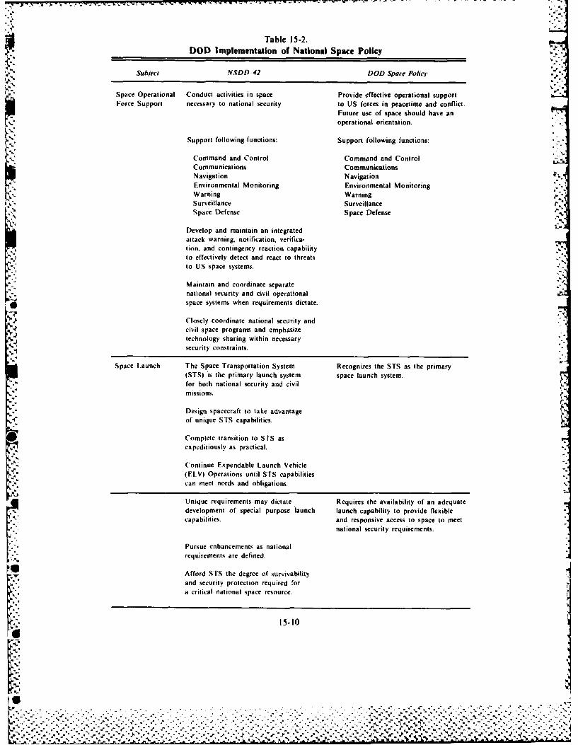
Table 15-2.J,.DOD Implementation of National Space Policy
Subject NSDD-42 DOD Space Policr d.2
Space Operational Conduct activities in space Provide effective operational supportForce Support necessary to national security to US forces in peacetime and conflict.
Future use of space should have anoperational orientation.
Command and Control Command and Control
Corn municat ions CommunicationsNavigation NavigationEnvironmental Monitoring Environmental MonitoringWarning WarningSurveillance SurveillanceS pace Defense Space Defense
Develop and maintain an integratedattack warning, notification, verifica-tion, and contingency reaction capabilityto effectively detect and react to threatsto US space systems.
Maintain and coordinate separatenational security and civil operationalspace systems when requirements dictate.
Closely coordinate national security andcivil space programs and emphasizetechnology sharing within necessarysecurity constraints.
Space Launch The Space Transportation System Recognizes the STS as the primary(STS) is the primary launch system space launch system.for both national security and civilmissions.
I:.Design spacecraft to take advantageof unique STS capabilities.Complete transition to STS as
expeditiously as practical.
Continue Expendable Launch Vehicle
(ELV) Operations until STS capabilitiescan meet needs and obligations.
Unique requirements may dictate Requires the availability of an adequatedevelopment of special purpose launch launch capability to provide flexiblecapabilities, and responsive access to space to meet
national security requirements.
Pursue enhancements as nationalrequirements are defined.
Afford STS the degree of survivabilityand security protection required fora critical national space resource.
15-10
-A....t
%-., -. -.-, . , . , . - - - - . - . . .~%
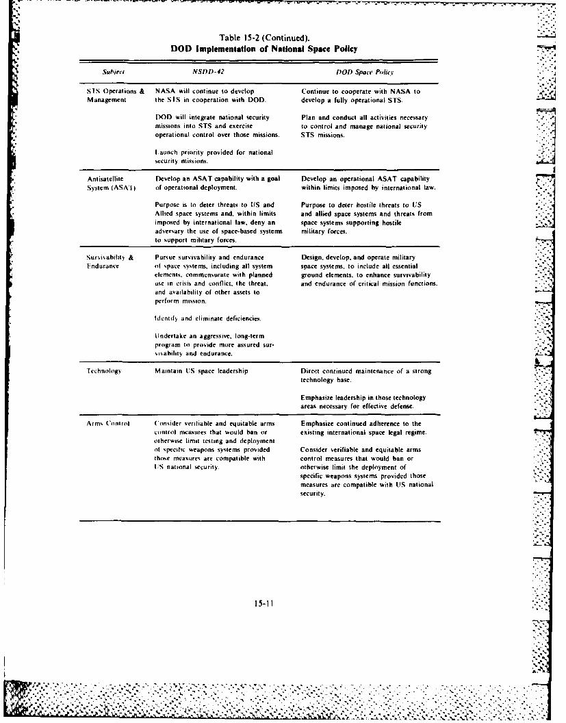
Table 15-2 (Continued).DOD Implementation of National Space Policy
SubjectNSI)I-42 DOD Space Policy'
SIS Operations & NASA will continue to develop Continue to cooperate with NASA toManagement the STS in cooperation with DOD. develop a fully operational STS.
DOD will integrate national security Plan and conduct all activities necessarymissions into STS and exercise to control and manage national securityoperational control over those missions. STS missions.
Launch priority provided for national hAntisatellite Develop an ASAT capability with a goal Develop an operational ASAT capabilitySystem (ASAT) of operational deployment, within limits imposed by international law.
Purpose is to deter threats to US and Purpose to deter hostile threats to US 7Allied space systems and, within limits and allied space systems and threats fromimposed by international law, deny an space systems supporting hostileadversary the use of space-based systems military forces.to support military forces.
Surisahility & Pursue survivability and endurance Design, develop, and operate militaryEndurance of space systems, including all system space systems, to include all essential
elements, commensurate with planned ground elements, to enhance survivabilityuse in crisis and conflict, the threat, and endurance of critical mission functions.and availability of other assets toperform mission.
ldentif and eliminate deficiencies.
Undertake an aggressive, long-termprogram to provide more assured sur-visability and endurance.
fcchnolog Maintain US space leadership Direct continued maintenance of a strongtechnology base.
Emphasize leadership in those technologyareas necessary for effective defense.
Arms Control Consider verifiable and equitable arms Emphasize continued adherence to thecontrol measures that would ban or existing international space legal regime.otherwise limit testing and deploymentof specific weapons systems provided Consider verifiable and equitable armsthose measures are compatible with control measures that would ban orUIS national security, otherwise limit the deployment of
specific weapons systems provided thosemeasures are compatible with US nationalsecurity.
15-11
'4 5,

Of the three policy documents, the most comprehensive is the Air Force Space Plan. It does three* things. It provides broad guidance affecting future Air Force investment and management strategy
for space activities; provides a vehicle to implement national and DOD space policies; and identifies,and resolves, where possible, issues affecting Air Force use of the space environment. Thoughcontaining details that require the document to be classified, the basic thrust of the space plan isunclassified, that is, that space is a place, not a mission. Therefore, as with the other environments ofthe land, sea, and air, the systems deployed in space have the potential to perform combat or combatsupport missions. We can divide these missions into four broad categories: space control, forceapplication, force enhancement, and space support.
Space control encompasses those combat missions that provide freedom of action in space forfriendly forces while denying it to an enemy. It embodies the concept of space superiority and consistsof two parts, counterspace operations and space interdiction. Counterspace operations are thosespaceborne or terrestrial operations conducted to gain control of and dominance over the spacemedium. Included are measures to ensure that friendly space forces have freedom of action throughspace. Space interdiction includes operations conducted against the enemy's space lines ofcommunication (space systems used to support or participate in military operations) that could beused to support operations against friendly forces.
Force application is concerned with combat missions conducted from space against terrestrialtargets, primarily. The objective would be the influencing of a conflict. Force application from spacecould potentially encompass traditional Air Force combat missions such as strategic offense anddefense, interdiction of enemy forces, and close support, among others.
Force enhancement includes combat support missions involving the use of space systems toimprove the effectiveness of surface, sea, air, and space forces. It includes such support functions ascommunications; surveillance (that is, tactical warning and meteorology); reconnaissance, navigation
* and positioning; mapping, charting, and geodesy-, and search and rescue aids.The final broad category is space support. This encompasses combat support missions involving all
necessary prelaunch preparations, as well as the activities involved with deploying and sustainingspace systems. It includes such functions as space launch and recovery (the preparation, buildup.launch, deployment, and if necessary, retrieval of space systems as well as the space transporter); andorbit transfer (operations involving the use of propulsive stages to maneuver satellites from their initialorbit to their final mission orbit). It includes on-orbit control (operations to plan, direct, and sustaindeployed military space systems) and management, planning, and operations support activities(manpower, training, safety, education, and logistics support).
Historically, military space power has concentrated on combat support missions, specifically forceenhancement-type missions. Systems performing functions such as communications, environmentalobservation, photoreconnaissance. tactical warning, and navigation dominate the military spaceprogram. The dilemma that presently confronts military space planners is that these systems havebecome so capable and in some instances so important to the conduct of terrestrial militaryoperations that their unhindered use could prove decisive in future conflicts. Therefore, we arelikely to see a change in mission emphasis in the coming years. The space control role will probablybe increasingly pursued as a means to ensure that UtS and allied forces can operate freely in spacewhile being in a position to deny the same freedom to an enemy. In addition, technology now enablesspace systems to complement traditional methods of bringing force to bear upon an enemy. Thefuture is likely to witness a more balanced mixture of the four space roles.
AIR FORCE SPAC'E DOCTRINE
Though the government had articulated national. 1)01, and Air Force space policies in one formator another for better than two decades, the Air Force did not have a space doctrine until it published
* AFM 1 6, Aerospace Basic Doctrine. Afilitarv Space Doctrine, on 15 October 1982. We can attributethe long delay, at least partially, to the nature of' doctrine and the influence of history on its
15-12
0%
.................................. %-% % .
development. JCS Publication I defines doctrine as -fundamental principles by which the military -
forces guide their actions in support of objectives. It is authoritative but requires judgment inapplication." Professor 1. B. Holley, Jr, of Duke University, provided a shorter and perhaps more 4workable definition when he stated that "military doctrine is what is officially believed and taughtabout the best way to conduct military affairs." Gen Thomas D. White stated that doctrine is basedpartially on history but that it is also very dynamic.
In the development of superior air leadership, the education process cannot treat air doctrine as a set of abstract* principles to be learned by rote, like mathematical formulas, and dutifully filed away for future reference. Air Force
doctrine is made up. not of abstraction, but of dynamic living truths forged in the heat of combat and tested in thecrucible of war.
Historical experience influences official doctrine and anticipated developments in warfightingshape it. The fact that military experience in space has been limited and the absence of any "dynamicliving truths forged in the heat of combat" undoubtedly help to explain the lapse of 20years beforethe Air Force published its first official space doctrine.
Though published prior to the Air Force Space Plan and the July 1983 chief of staff statement onAir Force space policy, AFM 1 6 nevertheless clearly reflects the changing emphasis in the militaryuse of space. The authors recognized the inherent benefits to be gained by any nation that chooses toexploit the military advantages of space. They specifically chartered the Air Force "to provide forcesfor controlling space operations and gainig and maintaining space superiority." These are missionsessential to preserve free access to, and transmit through, space for peaceful purposes for both themilitary and the civil sectors.
AFM 1 6 summarizes those principles that form the basis for Air Force responsibilities in space.These principles include preserving space for peaceful purposes by providing appropriate military
0 force for deterrent operations in space. This military force must be ensured by developing spacesystems that support national security objectives and integrating those systems into the militarystructure to increase effectiveness, readiness, reliability, survivability, and sustainability of warfight-ing systems. At the same time, the Air Force must ensure that the goals for military space use areclearly defined and understood and that close coordination and cooperation with NASA and the civilsector on space projects of mutual interest and benefit are carried out.
These principles lead to the creation of many Air Force responsibilities in space. In the area ofdevelopment, the Air Force is responsible for developing forces for conducting military operationswithin the unified or specified command structure and providing operational concepts andemployment tactics to integrate space system support into these unified and specified commands. Thisincludes the developing of the plans, programs, policy, and implementation and employmentstrategies to integrate space forces into the US military posture. The Air Force must develop,operate, sustain, and employ space systems, including increasing the effectiveness, readiness, andsurvivability of weapon systems, to ensure the capability to deter and resolve conflict on termsfavorable to the United States, It must ensure the needed education and training programs forindividuals directing space forces as well.
In the area of management, the Air Force is responsible for managing military space operations.This includes the launch, command and control, on-orbit sustainment, and the refurbishment ofmilitary space needs throughout the DOD, NASA, and other governmental departments andbranches.
The Air Force must sustain the potential for military operations by applying superior space-relatedtechnologies. This would include capabilities for collecting, processing, and disseminatinginformation as well as planning for deployment and employment of military space forces. The AirL. Force will accomplish this by encouraging innovation to take advantage of advances in science andtechnology; developing and maintaining capability to provide research and development, testing,engineering, and life cycle support for space systems; developing the technology base and research,development, and acquisition policies that accommodate procurement requirements for space systems;and providing the acquisition service authorized by DOD as well as other executive services. The Air
15-13

Force must encourage innovation to take advantage of advances in technology in all of these areas.The Air Force is charged with providing space-based surveillance, warning, and attack assessment
to alert national command authorities and military commanders of impending or potential attacksagainst the United States, its allies, or their forces. This extends to include negating enemy attacks to,from, in, or through space.
% Finally, the Air Force is responsible for ensuring that space is considered as a medium from whichAir Force missions and tasks potentially can be accomplished. This will be done by ensuring thatspace programs are clearly understood and fiscally attainable; providing requirements and advocacyfor military space systems; and providing programming data, operational strategies, andrequirements information to justify financial support for military space programs.
With respect to potential warfighting missions, AFM 1 6 contains this statement: "Space-basedweapon systems could contribute to deterrence in peacetime and to more rapid conflict terminationor increased survivability in war." Although it acknowledges potential warfighting missions, AFM1-6 further states that employment of military space systems will depend on such operation con-siderations as reliability, survivability, security, and flexibility; their effectiveness compared toalternative solutions; and the impact of combined surface and space operations on national securityobjectives. -
C In looking to the future, AFM I-6 specific four areas of growth in military space activities.
e Expansion of space support operations with on-orbit resources that include space stations,shuttle, orbital transfer vehicles, energy generators, and manufacturing processes.
V.. e Development and continued evolution of quick reaction launch capabilities with shortturnaround from more survivable launch facilities.
* Development of the capability to support multipurpose operations in space (such operationscould include space-to-space, space-to-earth, and earth-to-space activities).
* Development of space systems for rapid termination of any military conflict..
SUMMARY
The responsibilities of the Air Force in space include a large and growing number of functions thatcontribute to the defense of the United States. Space operations are important elements of a credibledeterrent to armed conflict. In the near-term, should deterrence fail, space operations will help resolve
a conflict on acceptable terms to the United States by providing various kinds of information andsupport to military force.In the.future, it is possible that space systems will provide the decisive edgein countering threa s to our national interests.-"rhe Air Force regards military operations in space among its prime responsibilities and conductsthese operations according to the letter and spirit of existing treaties and international law,Inresponse to national direction, it must ensure freedom of access to space for peaceful pursuitslncarrying out aerospace missions for defense of the United States, it uses space systems to performunique, economical, and effective functions to enhance the nation's land, sea, and air forces. It servesclient relationships in the management of space programs and meets user priorities established by theDepartment of Defense. In view of the growing threat to the free use of space and the critical role ofspace operations in the defense of the United States, the Air Force has moved toward increasedinstitutionalization of military space missions so that the Department of Defense can draw clear linesof responsibility for accomplishing these missions. !,t. ,- (,,. -
. I B. 1OG R A P H Y
Arms Control and Disarmament Agency. Arms Control and I)isarmament .4greet'wens. Arms Control and DisarmamentAgency. Washington. D.C.. 1982.
Bridge, Robert I... It Col. "International Law and Military Activities in Outer Space.' Akron I-al Reviewt 13. no. 4. Spring1980:649 664.
15-14
7.
lP
,> .:-. .,-. -. :-'.:..:.4 ,-: ' ' - - - _ .. -.',. .. ... .. .-- ... '-'.'

Butler, A. J. Lt Col. "Peaceful Use and Self-Defense in Outer Space." Prot eeding. oj the 1983 Srmposium on Militarr SpaceCommunications and Operations. USAF Academy, 2 4 August 1983:87 92.
Convention on Registration of Ohject.s launched into Outer Space. 28 UST 695. TIAS no. 8480, 14 January 1978.
Department of Defense. Defense Guidance. FY 1986-1990. Department of Defense, Washington, D.C.. 2 March 1984.Department of Defense. )epartment of I)efense Space Policy. Washington. D.C., 22 June 1982.Department of Defense. D01) Directive 1500.1 as Amended. Washington, D.C., 31 December 1958.Department of the Air Force. United States Air Force Space Plan. Department of the Air Force. Washington, D.C.. March
1983.Futrell, Robert F. Ideas. Concepts. Doctrine: A Historr of Basic Thinking in the UnitedState.% Air Force. 1907-1964. Maxwell
Air Force Base, Alabama. Air University. 1971.Gabriel. Charles A., Gen. Air Force Space Role.s and R'sponsibiihties. Letter to all major commands and special agency
commanders, I July 1983., Hungerford, John B., Jr, Maj. "Organiation for Military Space A Historical Perspective." Air Command and Staff College
report number 82-1235, Maxwell Air Force Base, Alabama. Air University, March 1982.National Aeronautich and Space Act of 1958. as Amended. Public Law 85-568, 72 Stat. 426. 29 July 1958.National Securitv )ecisi n Directive Number 42. National Space Policy. White House, Washington, D.C., 4 July 1982.Office of Technology Assessment. Civilian Space Polict and Applications. Office of Technology Assessment, Washington
D.C.. June 1982.Office of the White House Press Secretary. White House Fact Sheet. US Civil Space Polici. Office of the White House Press
Secretary, Washington. D.C., II October 1978.
United Nations Charter. 26 June 1945.United States Air Force. Aerospace Ba.ic Doctrine. Militari Space Doctrine AFM I 6. Department of the Air Force.
Washington, D.C., IS October 1982.United States Air Force Historical Division Liaison Office. The Threshold oI Space-The Air Force in the National Space
Program. 1945-1959. United States Air Force Historical Division liaison Office, Washington. D.C.. September 1960.
15-15 I
.', A
,, . . .
.JJ"
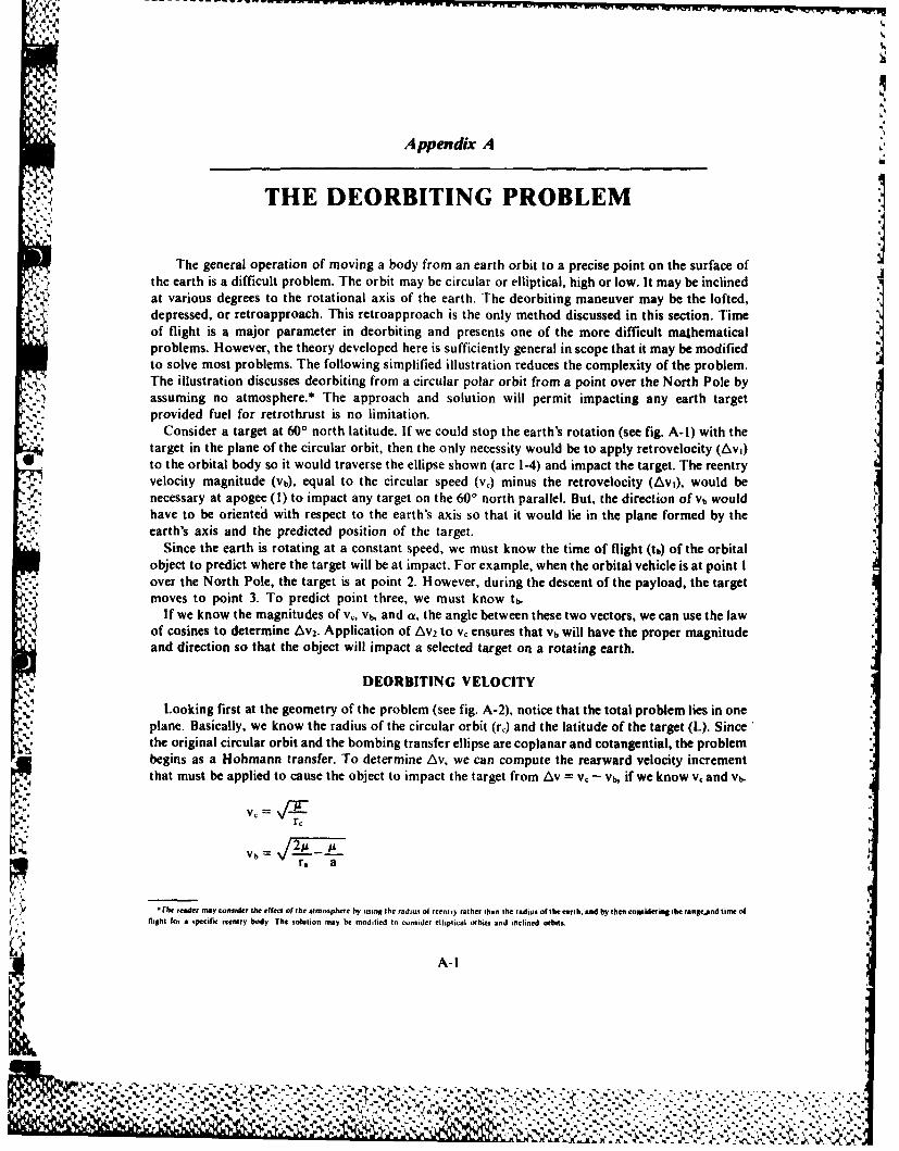
Appendix A
THE DEORBITING PROBLEM
The general operation of moving a body from an earth orbit to a precise point on the surface ofthe earth is a difficult problem. The orbit may be circular or elliptical, high or low. It may be inclinedat various degrees to the rotational axis of the earth. The deorbiting maneuver may be the lofted,
..- depressed, or retroapproach. This retroapproach is the only method discussed in this section. Timeof flight is a major parameter in deorbiting and presents one of the more difficult mathematicalproblems. However, the theory developed here is sufficiently general in scope that it may be modifiedto solve most problems. The following simplified illustration reduces the complexity of the problem.The illustration discusses deorbiting from a circular polar orbit from a point over the North Pole byassuming no atmosphere.* The approach and solution will permit impacting any earth targetprovided fuel for retrothrust is no limitation.
Consider a target at 60' north latitude. If we could stop the earth's rotation (see fig. A-I) with thetarget in the plane of the circular orbit, then the only necessity would be to apply retrovelocity (Avi)to the orbital body so it would traverse the ellipse shown (arc 1-4) and impact the target. The reentryvelocity magnitude (vb), equal to the circular speed (vc) minus the retrovelocity (Avi), would benecessary at apogee (I) to impact any target on the 600 north parallel. But, the direction of Vb would
'. have to be oriented with respect to the earth's axis so that it would lie in the plane formed by theearth's axis and the predicted position of the target.
Since the earth is rotating at a constant speed, we must know the time of flight (tb) of the orbitalobject to predict where the target will be at impact. For example, when the orbital vehicle is at point Iover the North Pole, the target is at point 2. However, during the descent of the payload, the targetmoves to point 3. To predict point three, we must know tb.
If we know the magnitudes of vc, vb, and a, the angle between these two vectors, we can use the lawof cosines to determine Av2. Application of Av2 to vc ensures that Vb will have the proper magnitudeand direction so that the object will impact a selected target on a rotating earth.
DEORBITING VELOCITY
Looking first at the geometry of the problem (see fig. A-2), notice that the total problem lies in oneplane. Basically, we know the radius of the circular orbit (r.) and the latitude of the target (L). Since
. the original circular orbit and the bombing transfer ellipse are coplanar and cotangential, the problembegins as a Hohmann transfer. To determine iv, we can compute the rearward velocity incrementthat must be applied to cause the object to impact the target from Av = vc - vh, if we know vc and vb.
vh- 2r, a
"The resder mayconsider the effect of the atmosphere by using the radius of reentry rather than the radius of the earth. and by then considering the rangeand time ofI e, fltght fo~r a specific reentry body, The solution may be modified to consider elliptical orbit% and inclined orbit,.
A-I
L%
-1 0 I4~s-C.~. - * ~ S ...
A %. % .
- a '. , . _ _ _
Since r,= a + c a (I + e), ab r,
(r:1 7,1b - = (1 A --
Then Vb = r r,
Write the general equation of the conic as ke = r (1 + e cos v) and evaluate at the two known points,r.* and r., noting that at impact cos v = - cos Ot = - sin L, and at retrofire cos (1801) = - 1.
Then ke = r, (I - Eb sin L) = r. (I - eb)"',: Solving for eb. -
Eb (r. - r, sin L) = r. - r,
r. - r, sin L
To find eb, and in turn, the magnitude of vb, we need to know only the latitude of the target and theattitude circular orbit. Suppose there is a satellite in &500 nautical mile circular polar orbit. When theorbital vehicle arrives directly over the North Pole, it is desired to deorbit an object that will impact at60' north latitude. Assuming that the earth has no atmosphere and is nonrotating, what retrovelocityis necessary?
- ra - r. _ (23.94 X 106 ft) - (20.9 X 106 ft)
r. - r, sin L (23.94 X 106 ft) - (20.9 X 106 ft) sin 600
fb = :520
V - /14.08 ( 10' 5 ft3=sec 2 (I - 520)r. 23.94 X 106 ft
vb = 16,790 ft/sec
Av = vc - Vb = 24,240 ft/sec - 16,790 ft/sec
Av = 7,450 ft/sec
Looking again at the geometry, note that there is a satellite in a 500 nautical mile circular, polarorbit with v. = 24,240 ft/sec. A retrovelociy increment, Av, equal to 7,450 ft/sec was applied. Thisprovided a magnitude vb = 16,790 ft/sec so that now the object follows arc 1-2 and impacts on 600
'.4 north latitude.Figure A-3 provides a graph of velocity versus latitude to determine the magnitude of vb. The graph
is for a specific altitude, for release over the North pole, and for no atmosphere. Included are moregeneral graphs in figures A-4 and A-5.
DEORBIT TIME OF FLIGHT
As the bomb falls from apogee, the target moves toward the east due to earth rotation. Its speed is1520 cos L ft/sec, so the necessity to compute accurately the time to bomb, tN, is readily apparent.
First, look at the problem in schematic figure A-I. Recall that at the time the vehicle is over theNorth Pole at point I, the target is at point 2. Thus, we must know tb so that we can predict thelocation of point 3. If we know the meridian that point 3 will be on, and the meridian with which thecircular orbit coincides at the instant of deorbit, then we can determine the angle, a, by subtraction.
There are several methods for computing t, from release to impact. The general time of flight|,: method is presented here.
" - *Or, is radius of the earth, but radius of reentry could be used if desired.
A-2
r , r
• l i~ ::::::::::*:::::::::
North Pole
v Av
.. . .. . ........ .... ...
0 0
U-A-3
4%
* %
A Ie
4 .. V b A V
1 -T.4,
II
A-4
90NORTH POLE
85Deorbir Velocity Versus Target Latitude500 N.M. Circular Polar Orbit
s0 Deorbit from Point Over North PoleNo Atmosphere
75
70
65
60
w
350
Sw
Z 45
J 40
S33
-j
z2 5
o 5
z 20) b a( ~)V, 24,24D ft/sec
= ,
15ur A-.t,
tOO
5
EQUATOR0
0 2 4 6 a 10 121 116 18 20 2224 26KDearbit velocity (vb) in Thousands ft./sc.
Figure A-3.
.,- A-5
- . ,-,, . ., , ,. ., .. <. .--.- .. .............. .................................. '-:.,
M. 7
Potnt Over North Pole in Circular Orbit
10
4o40
120
11 30 . .. ....
30 I X1*-
480
. .. . . .
.4i5 0 .. .. . .. .
4. ...... ....~ .. .. ..
VV
M M ~ 0 0 0 0 0 0 0
44p0
11J, Iiii I .........
>WU U 5
r r r r r -, --
tt- 2 =%)(u, e sin u2) - (u, - t sin u,)
Since position I corresponds to apogee:
u, =
r, sin u, = 0
~Then th = t 1 2 = u, o - fO sin u, - 7r) ,
a 1a -I+ ft. '
-_ -cosO0 _ - sin Lcos U, - cos 0, 1 - ft sin L
All of these parameters are familiar except u, which is the eccentric anomaly (see fig. A-6). If aperpendicular is dropped through the target to the major axis of the ellipse, it intersects a circle(withthe center at C, and the diameter equal to the major axis of the ellipse) at point Q. By definition, angleBCQ is u, the eccentric anomaly. The radius of the circular orbit, ra, is given. We can calculate vh and
- -. he from formulas previously given.Working with the same example that we used to illustrate deorbiting velocity, we will tabulate tt,
from only two known quantities, the altitude of the satellite and the latitude of the target. A satellite isin a, 500 nautical mile circular polar orbit. Find the time of flight, t, from directly over the North Poleto a target on the 60° north parallel:
ra ,- rr =(23.94 X10 6 ft)-(20.9 X 106 ft)
r. - re sin L (23.94 X 106 ft) - (20.9 106 ft) sin 600
fb = .520
( ,/ 14.08 X l0' ft3/sec 2( - 520).(" 23.94 X 106 ft
vh = 16,790 ft/sec
ra 23.94 X 106 ft =15.78 X 10" ft
*I + th 1.520
.- - sin L .520 - sin 60 -Scosu - sin L I - 520 sin 60 -
Noting u, lies between 1800 and 2700:
u, = 3600 - 129.60 = 230.40 4.084 radians
th N= .[u, - ft, sin u,-i7]
:, ' + X'/ (15.78 X 106 ft)+
S14.08 10 ft/sec 084 - ;520 sin 230.4 ° - 3.1416]
th = 676 sec = 11.27 min
Figure A-7 shows th in minutes versus a plot of target latitude. Once again we must recognize thatthis chart is for a specific orbital altitude and no atmosphere. See also the more general graph in
figure A-8.Consider impacting a target at 600 north latitude and 300 east longitude. The plane of the satellite is
coincident with the 700 east meridian. This means that, when the satellite is at point one and the targetis at point two. the angle between the target and orbital plane is 400. However, the target is moving. Itmoves at:
A-8
I, - - ,- .-. + .• , , ,- , . ,- . ... . -, .-. .. . +- ,-,-:-:-..-.,
°-r.-:.-.,2-.4.. ..,/*%*,:.
[ , ,'4'
TIME OF FLIGHT GEOMETRY
01*
rB
Z .., . %, II "
Sap
Figure A-6.
A-9
--- I
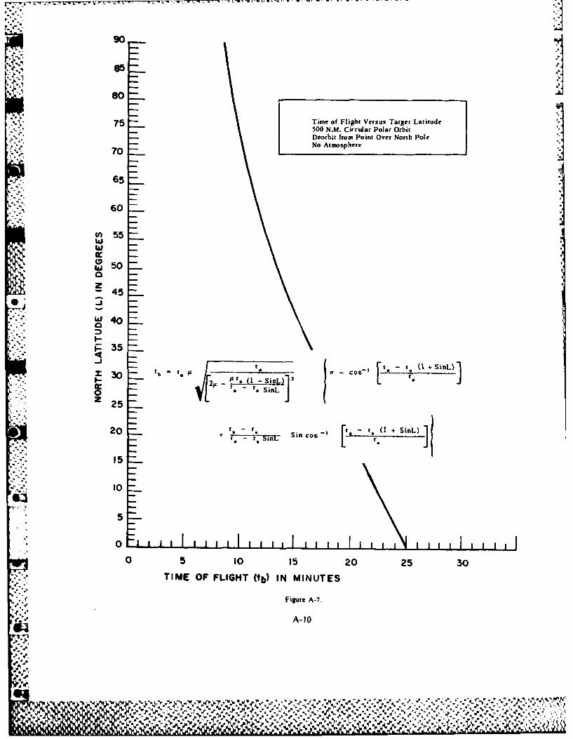
90
75 Time of Flight Versus Target Latitude500 N.M. Curcular Polar Orbit
Deorbit from Point Over North Pole70 No Atmosphere
055
w 5
w 0
z-45
p 35
tr 1, (1_+____X 30 tb r9 Cos_________
w a .*SinL J20 .~sir Sin cos r - + J15
10
5
0LL0 5 10 15 20 25 30
TIME OF FLIGHT (tb) IN MINUTES
Figure A-7.
'r..e A-10
4
a,-.
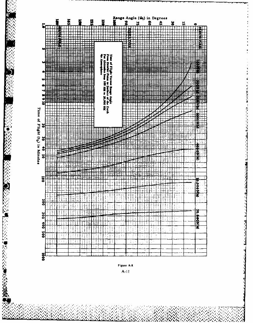
il Ranige Angle (0t) in Degree.
If L. II-
. . . - - - - - --
.- -. .........
. .~f . . L .l . J __
. . . . . . .
...........- - - - - - - - - -
L 2-r'7-
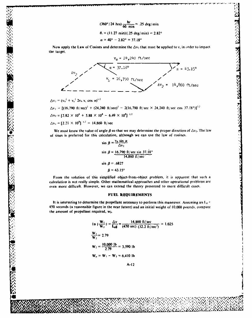
'i hr(360-/24 hrs)..-L .25 deg/min, (360 ° 24 hrs)60 rain,.
0, = (11.27 min)(.25 deg/min) 2.820
a= 400 - 2.82* =37.180
Now apply the Law of Cosines and determine the Av 2 that must be applied to v, in order to impactthe target.
v. = 211,2110 rt/sec
S37.1 0 43.150
7 b = 16,790 rt/sec /
, 7 : 14,860 ft/sec
Av, = (V h' + v,' 2vh v, cos a)"'
Av = [(16.790 ft/sec)2 + (24,240 ft/sec)' - 2(16,790 ft/sec X 24,240 ft/sec cos 37.18°)]""
• ' 6V2 = [2.82 X 10' + 5.88 X 10' - 6.49 X 1081 ,/226Av2=[(221 f 101e 240 14e860 ft/secs7 )
We must know the value of angle P so that we may determine the proper direction of Av2. The lawof sines is preferred for this calculation, although we can use the law of cosines.
Vb sin a-sin =AV,
sin /.= 16,790 ft/sec sin 37.18 °
14,860 ft/sec
sin j3= .6827
j3 = 43.150
From the solution of this simplified object-from-object problem, it is apparent that such acalculation is not really simple. Other mathematical approaches and other operational problems areeven more difficult. However, we can extend the theory presented to more difficult cases.
FUEL REQUIREMENTS
It is interesting to determine the propellant necessary to perform this maneuver. Assuming an I,450 seconds (a reasonable figure in the near future) and an initial weight of 10.000 pounds, computethe amount of propellant required, w .
W1 t~v - 14,860 ft /sec 02-f W--2-) =lpg (450 sec) (32.2 ft/sec2) 1.025
W'- = 2.79• i W2
10,000 lbW2 =2.79 3,590 lb
. , W = W, - W 2 6,410 lb
A-l2
,%I

- - -. flfl~~r4~flr,. ww~w .. . ... ........
This weight ofpropellantrepresentsWE 6400 = 64.1 percent of the weight in orbit prior to
maneuvering. By restricting the plane change (side range) to a = 7.18*, Av2 = 7,875 ft/sec,
W,= 4,190 lb, and -=41.9 percent.In summary, recall that we gave the altitude of a satellite in a circular orbit and a time when the
satellite was over the North Pole. A target was selected and no earth atmosphere was assumed. Fromthe theory, we calculated the required velocity for a deorbiting object and predicted the position of thetarget at the time of impact. With this information and the use of the laws of sines and cosines, wecalculated the magnitude of retrovelocity and the direction to deorbit on target. We computed the.amount of propellant as well.
'A-1
-4,
'°4.
A- 13
. :- . o • • . • =o .* ,= 4 . .- • = - - . " .- = % .* .. . . . . .- . -*4 4. .= - . - . - . *
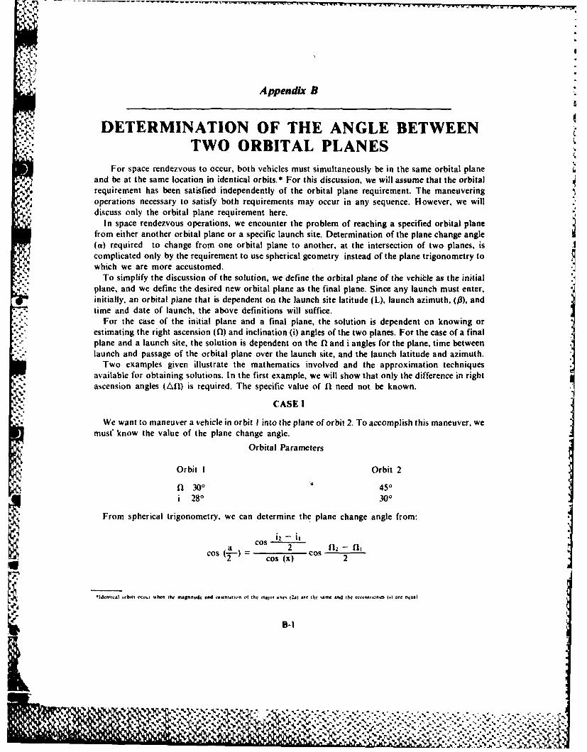
Appendix B
DETERMINATION OF THE ANGLE BETWEENTWO ORBITAL PLANES
For space rendezvous to occur, both vehicles must simultaneously be in the same orbital planeand be at the same location in identical orbits.* For this discussion, we will assume that the orbitalrequirement has been satisfied independently of the orbital plane requirement. The maneuveringoperations necessary to satisfy both requirements may occur in any sequence. However, we will
a, discuss only the orbital plane requirement here.In space rendezvous operations, we encounter the problem of reaching a specified orbital plane
from either another orbital plane or a specific launch site. Determination of the plane change angle(a) required to change from one orbital plane to another, at the intersection of two planes, iscomplicated only by the requirement to use spherical geometry instead of the plane trigonometry towhich we are more accustomed.
To simplify the discussion of the solution, we define the orbital plane of the vehible as the initialplane, and we define the desired new orbital plane as the final plane. Since any launch musl enter,initially, an orbital plane that is dependent on the launch site latitude (L), launch azimuth, (p3), andtime and date of launch, the above definitions will suffice.
For the case of the initial plane and a final plane, the solution is dependent on knowing orestimating the right ascension (0) and inclination (i) angles of the two planes. For the case of a finalplane and a launch site, the solution is dependent on the (I and i angles for the plane, time betweenlaunch and passage of the orbital plane over the launch site, and the launch latitude and azimuth.
Two examples given illustrate the mathematics involved and the approximation techniquesavailable for obtaining solutions. In the first example, we will show that only the difference in rightascension angles (All) is required. The specific value of nl need not be known.
CASE I
We want to maneuver a vehicle in orbit I into the plane of orbit 2. To accomplish this maneuver, wemust* know the value of the plane change angle.
Orbital Parameters
Orbit I Orbit 2
fl 300 It 450i 280 300
From spherical trigonometry, we can determine the plane change angle from:
~i2 - itcos 2 -fosa 2 c ) 1
Cos'-) - cos (x) Cos 2
*Identical orhlt occur when the manitude and orientaiion of the major a s 12m) are the same and the ectcenl,ictt, WI) arc equal
B-I
-. -~ -: -.- % %
" -2_ 3b0:k ,3 k % ' ' T ,' . i£, " , '', -.,:."7, .." .- ,- ,."' -'--" '-,'- ,--"-"'.',,'.,'- , - .3.
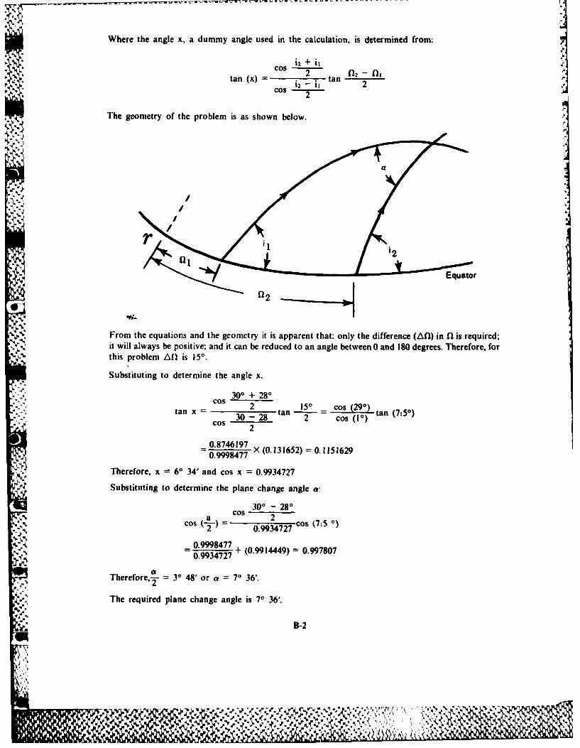
Where the angle x, a dummy angle used in the calculation, is determined from:C s i2 + it
cos Q 2
tan (x) 2 itan 2COS 2
The geometry of the problem is as shown below.
'-:qustor
fl2
From the equations and the geometry it is apparent that: only the difference (All) in fl is required;it will always be positive; and it can be reduced to an angle between 0 and 190 degrees. Therefore, forthis problem A0 is 15' .
Substituting to determine the angle x.300 + 280
COS 2 150 cos (290)tan x tantn-7:0Cos 30 - 28 2 cos (10) tan (750)cos 2
0.8746197 652) = 0. 1151629
0.9998477 " (-.5
Therefore, x 60 34' and cos x = 0.9934727
Substituting to determine the plane change angle a:
300 - 280a cos 2cos 0.9934727 COS (75
_ 0.99984770.9934727 + (0.9914449) = 0.997807
Therefore,2 30 48' or a = 70 36'.
The required plane change angle is 70 36'.
B-2
.%"
I
CASE 11
A spacecraft on a launch vehicle at Cape Kennedy (L = 28") must attain orbit in a plane that has asouthwest-northeast orientation and an inclination angle of 300. Ideally, the vehicle would be
v launched and injected along the required azimuth angle, when the desired orbital plane was directly' over the launch site. However, this is a very difficult timing problem. The spacecraft/launch vehicle
combination has limited velocity change capabilities, which narrows the launch window. A launchoccurring within this window of time will permit injection into an initial parking orbit and asubsequent plane change maneuver to the desired orbital plane.
1.- Because of launch delays, the launch site passed through the desired final orbital plane eightminutes prior to lift-off. Since the launch vehicle guidance was programmed prior to launch, thespacecraft will be injected into an initial parking orbit, and then it must make a plane change to thedesired final orbital plane. The programmed launch azimuth angle is 790 . What is the value of theplane change angle required to complete the mission? The apparent unknowns are the initial orbitinclination angle, and the All.
lo find the inclination angle of this parking orbit, use the equation for inclination angle of thelaunch:
cos i = cos (L) sin(fi) cos (28) sin (790) = 0.8660
'4 Iherefore, i = 30' for the parking orbit. It is possible to approximate Afl using the earth's rate ofrotation.
rotation ra 360 360 = 0.250/mmin24 hrs (24 X 60) min
For the situation of equal inclination angles, the Afl equals the time between launch and passage ofthe final orbital plane overhead, multiplied by the earth's rotation rate:*
Ail = 0.25°/min X 8 min = 2 0
-. A. By making use of the same equations used for case one, the plane change angle a will beapproximately 10.
4LIST OF SYMBOLS
a - Plane Change Angley/ 3-Azimuth Angle
Ai - Difference in Right Ascension Angles(I-- Right Ascension Anglei - Inclination Angle
L - Angle of Latitudex -- Dummy Angle
Subscripts
I. Left hand orbital plane.2. Right hand orbital plane.
Superscripts* Dummy Variable
-l or the ac it nonequal in.l] ntton angles, I is necessary h, add a term Al1All t it .* ' Foth rnlrnatron angle% in the same quadrant
4 Int~iation angles in diflerenl quadrants
Al.' must he pos"tcIo find ihe Z''S use
sin an, iu CI o (0tl
%i In
tan cI I t
I hen the total All equals the All due tor the earths rotation plus the AU' due to the difference in inclrnaton angles
B-3
L.,_

Appendix C
SIGNS AND SYMBOLS
S. .' MATHEMATICAL SIGNS AND SYMBOLS
+ plus or minus, positive or negative '/f nth root
is not equal to an nth power of "a"
is identical to a'" reciprocal of nth power of a
, approximately equal to =
> greater than> greater than or equal to log, logio common logarithm< less than In, log, natural logarithm< less than no n degrees
less than or equal to n' n minutes; n feet
- similar to n" n seconds; n inchesc varies as, proportional to f(x) function of x
approaches as a limit Ax increment of x
infinity dx, differential of x.. therefore ax partial differential of x
square root I summation of
f symbol for integration
GREEK ALPHABET
Alpha A a Iota I L Rho P p
Beta B (3 Kappa K K Sigma I a
Gamma I' -y Lambda A A Tau T "
Delta a 6 Mu M y Upsilon Y v
Epsilon E e Nu N v Phi 4 4)
Zeta Z 4 Xi - Chi X x
Eta H 17 Omicron 0 o Psi 'V 41
Theta ) 0 Pi 11 ir Omega [1 V
C-I
.4 4- .
C.LOSSARV OF SVMBOI.S
a semimajor axis of ellipse; average linear acceleration
b semiminor axis of ellipseI bo subscript for burnout conditions
c distance between focus and center of ellipse
e base of natural logarithm, = 2.718
g local acceleration due to gravity, = 32.2 ft/sec2 at the surface of the earth
h altitude, height above surface of earth
h, altitude of apogeehp altitude of perigee
i angle of inclination
p electric power
r radius length; mixture ratio
r, radius to apogee
r, radius of earth, = 3440 NM 20.9 X 106 ft
r, radius to perigee
s linear displacement
t time in seconds
u eccentric anomaly
v linear speed, velocity magnitude
v. nozzle exit velocity
Av increment or change of speed
w work in foot-pound force
A area
A, nozzle exit area
C,, coefficient of drag
C, coefficient of lift
I) atmospheric drag
E specific mechanical energy in ft'/sec
C-2
Ig.. .,.. .:. . .. . .... ... ., ......' .... ... .. , ., .- . ..,. ",' ' ' ' - . . ." . . ,. . . . . . .. " . - • " • ". .. - • - 2

F focus of ellipse; force in pounds; thrust in pounds
G Universal Gravitational Constant, = 10.69 X 10¹⁰ tO/lb mass-sec2
H specific angular momentum in ft12/sec
1, specific impulse in seconds
I total impulse in pound-seconds
K F kinetic energy
I aerodynamic lift; latitude
M mass in slugs
M mass flow rate
N M nautical miles, = 6080 feet
P period of revolution, pressure
PE potential energy
Q ballistic trajectory parameter; reactor thermal power
W weight in pounds force
W weight flow rate
average angular acceleration
6 very small change or error
eccentricity; expansion ratio
r7 electrical efficiency
0 angular displacement
A longitude
y gravitational parameter, = 14.08 X 10" ft3/sec 2 for earth
V true anomaly; heat transfer efficiency
ir conversion constant, = 3.1416; 7r radians = 1800
p atmospheric density, slugs/ft'
r flight path angle, elevation angle of velocity vector
qi free flight range angle
w argument of perigee; average angular speed
A increment of
k thrust to weight ratio
C-3
1986-631-028/20652 AUGAFS,AL(860747)3000
.4
. - ,. . . ".' * x- • . ( ' . ¢ . ,* • "" ' "- *" * • )

w.,w~.wnrrr-,- - -
.o~.
'1
p..- *~
I
II~