Defense Technical Information Center Compilation Part Notice
Upload
khangminh22Category
view
5download
0
AD-760 563
DUAL DIAMETER ROLLER BEARING - 3.5MILLION DN-600F
John Rumberger, et al
Franklin Institute Research Laboratories
Prepared for:
Air Force Aero Propulsion Laboratory
May 1973
DISTRIBUTED BY:
National Technical Infomati ServiceU, S. DEPARTMENT OF COMMERCE5285 Port Royal Road, Springfield Va. 22151

I
I
j AFAPL-TR-73-23
0 .DUAL DIAMETER ROLLERBEARING - 3.5 MILLION DN-600OF
I John RumbargerEdmund FilettiJames DunfeeDavid Gubernick
i _Franklin Institute Research Laboratory
I TECHNICAL REPORT AFAPL-TR-73-23
I May 1973
I Approved for public release:distribution unl-imited
Reprduced by
NATIONAL TECHNICALINFORMATION SERVICE
S~SVrlnCF;e1d VA 27| 15
Air Force Aero Propulsion LaboratoryAir Force Systems Command
Wright-Patterson Air Force Base, Ohio
Details of illustrations InIJ& document may be befter
-atudied on microfichet IDD
Inn -ILL UU LILi

.. 1
UNCLASSIFIED
Sc'I, tnt.• ( .jn....st atit-n
DOCUMENT CONTROL DATA . R & D,"It 1, 1.I., 1.. h,, ,,1 ,. h.. I tll ,. .,h.I d).. cI,,,d.'I.,• ..innu.ct.•ij ,,,. It be ei•,erid Whcl . t tl,n c.',.al ,eyp,a. , . %I. .,ihed)
20th & The Parkway 2b Gko ...Philadelphia, Pa. 19103 NIA
DUAL DIAMETER ROLLER BEARING - 3.5 MILLION DN-600OF
4 7 7I •-(Cli-T'IVI NOTES (7
ype .4 f,.r tt,1,d inCIjVd' ate)s)
Final Report, June 23, 1971 - December 31, 1972- l,OQt" (I.,ant name,. middle a,w,,,... last ,iDmr)
John Rumberger Edmund FilettiJames Dunfee David Gubernick
II. 14,POPT OA L 70. TO'AI 140 o0 P&GCS jib NO or nrrs
May 1973 1731 7 70-0111'A., CONTRACT O GRANT NO 9h. ORj.AI* lOt'S nEPORYT NUA 'RI
F-33615-71-C-1883l b.. "Noc, No F-C3132
'39. OTWICR 64EPORT *jOISl (Any other tnumbers that Wity be ai.i.1l4n
Task No. 304806 'hi tp")
AFAPL-TR-73-23I.; ISTRIOIJ'ION STATEMENT
Approval for public release: distribution unlimited
It SUPPLEMENTARY NOTES 2I SPONSORING MILITARY ACTIVITY
Details if ilius ,'ations in Air Force Aero Propulsion Laboratorythis Oicument may be better Air Force Systems Command
studied onu t mirofiche erWright-Patterson Air Force Base, Ohio
Five gas turbine engine mainshaft roller bearing configurations were investigatedfor capability of sustained performance at DN values (Bore in mm x Speed in RPM)from 2 million to 3.5 million and normal operating temperatures to 600*F. Aunique Dual Diameter Roller was selected for the final analysis of stress andlubrication parameters, design and fabrication. A 140 =' Bore Dual DiameterRoller Bearing operated successfully for- 30 min. continuous operation at 25,000 RPM(3.5 million DN) with stabilized outer race temperatures above 525*F. Lubricationwas with Polyphenyl Ether 5P4E in an air environment.
I
DD I-'1473 (PAG ) UNCLASSIFIEDS/N 010I.807-6801 q"f Security Classatication

UNCLASSIFIED".'e'urttV Cl~,•,i If tion
KfY WotOS LINK A LIN(K w LINK C
NOLE wy .OLK WI ROLIE w'
Elastohydrodynamic Lubrication }-Dual Diameter RollerPolyphenyl EtherMIL-L-78083.5 Million DN600°F
_ I
DD "0,..1473 (BACK)(PAE) UNCLASSIFIEvA
)ecurtity Classification

BEAIN - 3. ILOND-w*
III
II
°i DUAL DIAMETER ROLLER
ii BEARING -3.5 MILLION DN-6L0°F
I John RumbargerEdmund FilettiJames DunfeeDavid Gubernick
IApproved for public release:
distribution unlimited
II
III ,

I
IFOREWORDI
This report was prepared by the Franklin Institute Research Labora-
I tories, 20th and Benjamin Franklin Parkway, Philadelphia, Pa. 19103
under USAF Contract F-33615-71-C-1883. The work was administered under
the direction of the Air Force Aero Propulsion Laboratory:, with Mr. John
f Jenkins and Mr. M. R. Chasman (AFAPL/SFL) acting as project engineeir~i
S1972.This report covers work conducted from 23 June 1971 - 31 December
I The Franklin Institute Research Laboratories was prime contractor
and performed all of the analysis and design. The prototype test bearings
1 were manufactured by the Bower Bearing Div., Federal-Mogul Corp.,
1 Detroit, Mich. The protot3pe testing was accomplished by subcontractor
Midwest Aero Industries Div., Pure Carbon Company, Saint Mary's, Pa.
The testing was under the direction of Mr. Donald Moyer of MAIC.
Publication of this re,)ort does not constitute Air Force Approval
of the report's findings or conclusions. It is published only for the
I exchange and stimulation of ideas.
IHOWARD F. JONES, CHIEFLubrication BranchFuels and Lubrication Division
I -ii-

- i
ABSTRACT
Five gas turbine engine mainshaft roller bearing configurations wereinvestigated for capability of sustained performance at DN valuesI (Bore in mm x Speed in RPM) f -om 2 million to 3.5 million and normal operat-ing temperatures to 600*F. A unique Dual Diameter Roller was selectedfor the final analysis of stress and lubrication parameters, design andfabrication. A 140 mm Bore Dual Diameter Roller Bearing operated success-fully for 30 min. continuous operation at 25,000 RPM (3.5 million DII)with stabilized outer race temperatures above 525°F. Lubrication waswith Polyphenyl Ether 5P4E in an air environment.
T
IIII
II
I -iii-

II
j CONTENTS
i Section Titie Page
I INTRODUCTION.......... . . . . . . . . . . . . . . 1
II SELECTION OF PRELIMINARY CONFIGURATION. . . . . . . . . . 4
1. Candidate Bearing Configurations ........ 4
2. Load Life Paramelr;c Study ............... . 13
3. Cage-Slip and Horsepower Loss Study . . . . ..... 17
4. Series Hybrid Bearing . . . . . . . . . . ..... 21
5. Selection of Dual Diameter Roller Bearing . . .... 26
III LUBRICANT SELECTION . ................. . 27
IV DUAL DIAMETER BEARING AN4ALYSIS AND DESIGN . . . . . . . . 32
,. Design Considerations ...... . . . . . . . . . . 32
2. Inner Race Stresses. . . . . . . . . . . . .... 35
3. Lubrication . . . . . . . . . . . . . . . 36
4. Performance Analysis. .. . . . ... ... . 40
5. EHD Parameters. ...... . . . . . .... . 48
6. Design Drawings . . . ............ . . .. 48
V DUAL DIAMETER BEARING FABRICATION . . . . . . . . . . .. 57
VI DUAL DIAMETER BEARING TESTS ............... 651 . Test Rig . . . . . . . . . . . . . . . . . .. . . . 65
2. MIL-L-7808, Test Bearing Al . . . . . . . . . . . . . 69
I 3. 5P4E, Test Bearing Al . . . . . . . . . . . . .. . 69
4. 5P4E, Test Bearing C3 . . . . . . . . . . . . .. ... 82
I.VII CONCLUSIONS. .. ... .. . .. .. ... 9#6. * . 87
APPENDIX I -TEST LOGS . . . . . . . . . . . . . . . . . . 88
Preceding page blank

CONTENTS (CONT'D.)
Section Title Page
APPENDIX II - GAS TURBINE ENGINE MAINSHAFT ROLLERBEARING-SYSTEMS ANALYSIS . . . . . . . .1I
VIII REFERENCES . . . . . . . . . . . . . . . . . . . . . . 175
vi

FIGCURES
Figure N/o. Ti tie Page
l(a) Solid Rollers - Inner Land Riding Cage. .... ........ 5
l(b) Solid Rollers - Outer Land Riding Cage. . . . . . . . . 6
1(c) Hollow Roller Concept . . . . . . . . . . . . . . . . . 7
1(d) Series Hybrid Bearing . . . ................. .. . 9
"2 Dual Diameter Roller Bearing Configuration. . . . . . . 10
3 Kinematics of Dual Diam. Roller . . . . . . . . . . . . 11
4 Relative Kinematics of Two Diimeter Roller . .. . . . . 12
5 Bearing Life vs. Roller Diam. (Hollow Rollers) ..... 15
(6 Bearing Life vs. Roller Diam. (Pual Diam. Rollers). . . 16
7 Cage Slip % vs. Radial Load . . . . . . . . . . . . . . 20
8 Cage Speed in RPM vs. Radial Load. ........ .. 22
9 HP Loss vs. Speed . . . . . . . . . . . . . . . . . . . 23
10 Friction Loss vs. Speed Ratio, MIL-L-7808 Oil . . , . . 25
11 Bearing Life with 5P4E Lubricant. . . . . . . . . . . . 30
12 Inner Race Maximum Tangetial Stress Vs. Shaft Speed . . 34
13 Finite Element Analysis of Inner RaceTangential Stresses at 4.0 x 10⁶ DN .......... 37
14 Thermal Nodes and Methods of Lubrication. . . . . . . . 39
15 Effect of Oil Flow Upon Outlet Temperature andBearing Power Loss. ............... ... 42
16 Dual Diameter Roller Bearing FrictionalHorsepower Losses .............. . . ..... 46
Vii

FIGURES
Figure No. Title Page
17 Two-Diameter Roller Bearing Assembly .... .......... 52
18 Inner Ring, Two Diameter Roller Bearing ........... 53
19 Outer Ring, Two Diameter Roller Bearing ........... 54
20 Two Diameter Roller ......... ... ... ... ... ..... 55
21 Cage, Two Diameter Roller Bearing ............... 56
22 Dual Diameter Roller Bearing Assembly ............. 58
23 Bearing No. C3 Inner Race Circularity ............. 60
24 Bearing No. C3 Inner Raceway Contour .... .......... 61
25 Bearing No. C3 Outer Race Circularity ............ 62
26 Bearing No. C3 Outer Raceway Contour .... .......... 63
27 Typical Dual-Diameter Roller Crown Profile Traces. ... 64
28 Dual Diameter Roller Bearing Test Stand ............ 66
29 Dual Diameter Roller Bearing Instrumentation . . .... 67
30 Cross Section of Dual Diameter Bearing Test ........ 68
31 Test Bearing No. 1, AT vs. Speed, MIL-L-7808 G . . ... 71
32 Test Bearing No. 1, AT vs. Speed, Polyphenyl Ether,5P4E .......... ......................... 74
33 Test Bearing No. 1, Inner Race Failure ............ 75
34 Test Bearing No. 1, Outer Race Cage Roller AssemblyFailure ........................... . . . i6
35 Failed Rollers ....... ................ .. .. 77
36 Test Bearing No. 1, Outer Ring Failure ......... 78
Viiiviii -•

II
FIGURESIFigure No. Title Pags
37 Test Bearing No. 1 Cage Failure ..... ........... 79
38 Test Bearing No. 2 AT vs. Speed, PolyphenylEther, 5P4E . ...................... .. 4
39 Second Dual Diameter Test Bearing .... ........... 85
I ix

1W-
TABLES
Table No. Title Poge
I Bearing Operating Requirements. . . . . . . . . . .. . 2.
II Duty Cycle at 4.0 x lO6 DN ............... 14
III Schedule of Computer Runs ................... 18
IV Summary of Computer Results .......... ... ... ... 19
V Summary of Test Results ..................... .. 28
VI Propertiez of Test Lubricants .................. 29
VIX Lubricant Properties Used in the Analysis. . .
VIII Properties of M-50 Hardened to RC-60 Per VASCOTechnical Bulletin ......... ............. 35
IX Inner Race Tangential Stress (ksi) ............... . 8
X Effect of Oil Flow Rate on Bearing Performance ..... 41
X1 Oil Flow Rate vs. Speed (DN) ...... .............. 41
XII Summary ot Performance Analysis Computer Runs ......... 43
XIII Surw:ary of Temperature Profiles for Dual DiameterRoller Bearing .......... ... ... ... ... ... ..... 45
XIV Symmary of Cage Analysis ...... ................ 47
XV Traction Values - Outer Race Contact - Unloaded Rollers. 49
XVI Traction Values - Outer RNce Contact - MlaximumLoaded Rollers ......... .................... 50
XVII Tract io, Values - Inner Race Contact - MaximumLoaC~d Rollers........... ......... . . 51
XVIII Sunit .y of Test Bearing Dimensional Tolerances . . . . . 59
XIX Data Summary Sheet First Test Bearing - MIL-L-7808 Oil . 70

I!I1 TABLES
Table No. Title Page
IXX Data Summary Sheet First Test Bearing - PolyphenylEther 5P4E ......... ...................... 73
XXI Thermal Analysis of First Test Bearing Conditions"with 5P4E ............. .................... 81
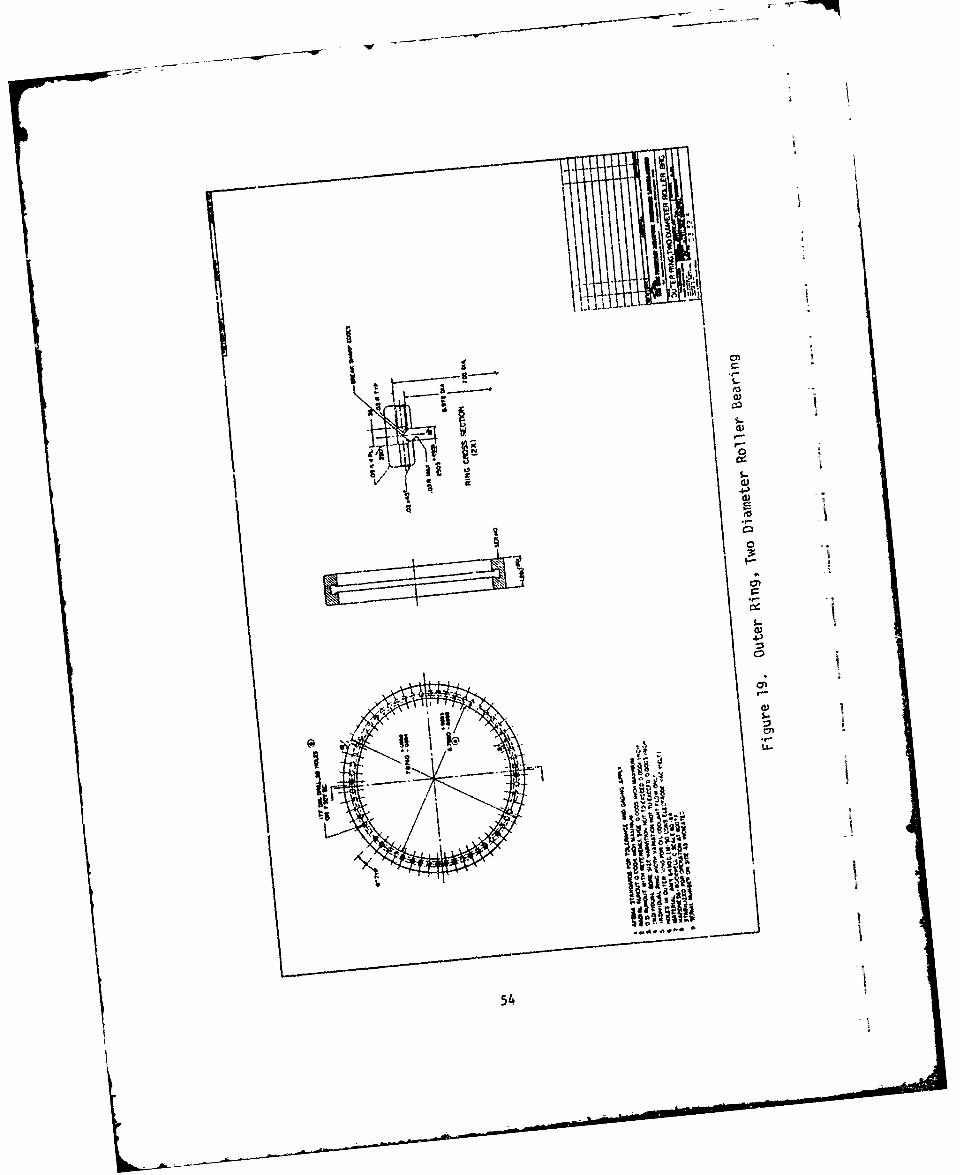
XXII Data Summary Sheet, Second Test Bearing PolyhenylEther 5P4E .......... ..................... 83
x
I.
II
I xi
SECTION I
INTRODUCTION
The objective of this research program was to develop a long life,
high speed roller bearing design for future high performance turbine
engines. The bearing must be capable of sustained performance at DN
values from 2.0 x 10 to above 3.5 x 10 and normal operating tempera-
tures to 60C F while maintaining the rotating shafts within the neces-
sary tolerance for optimum compressor and turbine performance.
The trends in turbine engine technology are toward increased rota-
tional speed, larger bearing diameters and increased bearing temperature.
It is anticipated that bearing DN requirements (bearing bore mm x rpm)
'•will grow from the current 2 x 10⁶ or lesE to greater than 3.5 x 10⁶ in
th.: 1980's. Efforts to increase bearing DN capability are currently
aimed at ball bearings. Approaches being investigated for ball bearings
include hollow balls and compliant races. The roller bearing has re-
ceived very little attention. Efforts which have focused on roLler be.z-
ings indicate that variations in roller bearing geometry such as the
dual diameter roller and hollow rollers, show promise for significant
increases in bearing performance. Improved ball and roller bearing
I capability is required for future systems.
Known current roller bearing types were investigated in order to
I select a preliminary configuration for further development. The selec-
tion was based on the potential of each type to meet the capabilities
shown in Table I. A bearing bore of 140 mm was selected for this
preliminary configuration study.
SThe results of the preliminary configuration study resulted in the
selection of the dual diameter roller bearing concept for further con-
sd
L leain hsslcinwsbsduo oe aesed bandi

the dual diameter bearing which result in signiiican-ly lowei L.-:
mechanic losses (viscous loss due to shearing of the oil). These lower
drags or losses in turn result in a lower cage slip threshold.
Table I
BEARING OPERATING REQUIREMENTS
Normal Opcrat.ng Temperature 6000 F
Operating Temperature Range -65 to +8000 F
Normal Operating DN (mm x rpm) 4.0 x 10⁶
Operating Radial Load Range (lb.) 0 to 2000
L 0 Life, Hr. (greater than) 1000
Radial Deflection at Max. Load, (in.) 0.010
Minimum Heat Generation
The dual diameter roller bearing configuration was subjected to a
thorough analysis from which a final design was developed. A complete
systems analysis incorporating the latest available elastohydrodynamic
lubrication Lechnology and including fluid drag forcea and thermal ek-
fects was accomplished by means of a digital computer program (Reference
1). This analysis was used to finalize the bearing design and determine
operating clearances and oil flow or lubrication requirements of the
bearing. Complete detailed working drawings of the prototype test bear-
ings are contained in the body of this report.
Six prototype dual diameter roller bearings were manufacturea by
the Federal-Mogul Corporation, Bower Bearings Div., Detroit, Michigan,
to the drawings and specifications contained in this report. A summary
of inspection data relating to dimensional quality of the test bearings
is also included.
Two dual diameter prototype roller bearings were tested by the
Midwest Aero Industries Div., Pere Carbon Co., St. Mary's, Pa. on a
special high speed mainshaft test rig. The test bearings were operated
2

- - -•-
I
Ii initially with MIL-L-7808 lubricant at 250*F oil inlet and then later1! with Folyphenyl Ether 5P4E lubricant at 6000 F.
I
i
1
I
I
_1,3

SECTION Hi
SELECTION OF PRELIMINARY CONFIGURATION
1. CANDIDATE BEARING CONFIGURATIONS
Five basic concepts or candidate bearing configurations, as shown
on Figure l(a-d), were investigated. The reasons f)r considering the
various configurations are listed below:
a. Solid rollers - inner land riding cage: The i:-'- land ridingcage solid roller concept, Figure la, is one of the most com-manly used mainshaft roller bearing designs. This deaign con-sists of an inner race with two integral shoulders to guidethe roller complement. The one piece fully machined cage hasclose clearance and rides on an oil film in contact with thelands on the inner race. The outar race is a sleeve construc-tion which allows complete axial freedom of the inner raceand roller complement. It is common in some designs to providecoolant flow through slots under the inner race since the innerrace operating temperature is approximately 50*F hotter thanthe outer race operating temperature. An advantage of thistype of cage construction is the fact that friction in the cageto land areas will help to drive the cage at synchronous orepicyclic speed.
b. Solid roller - outer land riding cage: This outer land rid-ing concept, Figure ib, is very similar to the concept above;the main difference being that the integral guiding flangesand the cage to race land guidance are on the outer race.This bearing configuration is also common in modern jet engines.The advantage of this type of construction is better retentionof oil at the outer race contact (due to centrifugal forces)under momentary oil starvation. Also some engine applicationsare more easily assembled with this type of roller guidance.It should be noted that in this configuration the friction inthe cage to ].and surfaces is a dissipative effect which willtend to place a drag on the cage and add to the cage slippingtendency.
c. Hollow roller concept: The roller bearing concept is shown inFigure Ic. This concept can be applied to either an innerland riding cage or an outer land riding cage configuration.Basically the use of a hollow roller reduces the outer race toroller loading. The centrifugal force on the outer race due to
4

Ir
I
ROLLER DIAMETER
O.375"_5 0 < 0.625"
"190 MMOUTER"DIAM.-U R -
(7.4803") ;~
TO250 MM
- - (9.8425w)
* NOE RACEPITCH4 DIAM.COOLING SLOTS
WIDTH 24-42MM
(0.9449:')
140 MM(5.51186)
BORE DIAM.
Figure 1(a). Solid Rollers - Inner Land Riding Cage
I1I

24-42 MM WIDTH
190 -250 MM
OUTER DIAM. .
6.500"- 7.75"PITCH DIAM.
4(
LUNDER RACECOOLING SLOTS
140 MM
BORE
Figure i(b). Solid Rollers - Outer Land Riding Cage
I-
"---
6H

D- -d
I
II1
190MM -•
OUTER -;-:••:! -
S HOLES -_.6.500"4PITCH DIIM.
LUNDER RACECOOLING SLOTS
140 MMBORE DIAM.
HOLLOW ROLLER CONCEPTIi (Reduce Roll Moss)
FI Figure 1(c). Hollow Roller Concept
If I
1

the cage and roller complement rotative speed results in signifi-cant contact loading. Hollow rollers of less mass than solidrollers are found to be beneficial. A note of caution is indi-cated in that prior exoerience shows that too thin a wall sectionin the hollow rollers will lead to roller breakage due to reversebending of the rings. Thus mass reduction must be compromisedwith ring bending fatigue properties. Attempts have been made inthe past to use three or more oversized hollow rollers equallyspaced in a solid roller complement to provide rollers whichare always .nder load an( essentially drives the cages up to cyc-lic speed. The effect which was analyzed in the preliminaryselection of configurations was the mass reduction effectonly.
d. Series hybrid bearing: The series hybrid bearing is a relativelynew concept, Figure id, for reducing the effective speed ofrotation at the inner race of a mainshaft roller bearing. Thisconcept consists r< a rolling element bearing and an iil filmjournal bearing in series. The inner race of the roller bear-ing is separated from the outer surface of the rotating shaftby means of the hydrodynamic oil film bearing. Both bearingscarry the full radial load, however, the inner race of therolling bearing will rotate at some intermediate speed to theshaft speed resulting in a lower effective DN operating regimefor the roller bearing- The sped reduction is the main ad-vantage of this configuration. Additional under race coolingof the inner race can also be accomplished if locating oilfilm thrust bearing surfaces are built as pumps to supply ad-ditional coolant flow under the inner race. These locatingthrust bearings to maintain the location of the inner race arenot shown on Figure ld. The main disadvantage is the obviousone of mechanical complexity.
e. Dual diameter rnoler concept: The dual diameter roller con-cept is shown in Figure 2. This is basically a wagon wheelshaped roller with a large central diameter and two smallerdiameters which look very much like an axle through the mainwheel. The purpose of this configuration is to reduce cageoperating speed. A reduction in cage orbita; speed resultsin a significant reduction of the outer race to roller contactload due to centrifugal effects.
The relative kinematics of a conventional roller bearing and a dual
diameter roller bearing are shown in Figure 3. The large outer diameter
of the two-diameter roller contacts the inner race surface. The small
roller diameters of the two-diameter roller contact the outer race sur-
face. The effects of the relative kinematics are show6n graphically in
Figure 4. With a small roller (50% of the major roller diameter) it can
8

I.T
-* ROLLER BEARING
190 M:..BRG.
OUTERDIAM.
"HYDRODYNAMIC=- - ,,-- OILS HOLES OIL FILM BEARING
UNDER RACECOOLING _*I -
140 MMSHAFT DIAM.
SERIES HYBRID BEARING(Reduce Roller Elearing
Inner Race Speed)
Figure 1(d). Series Hybrid Bearing
1
I1
- -- 'S -~

OUTER II
DIAM.
i4~ PITCH
DIAM.
140 MMBORE DIAM.
Figure 2. Dual Diameter Roller Bearing Configuration
10

I
';2,
•-Solid Roller Two Diam. Poiller
= "• = D ! E y ' = d / E .} = d / DS R R
ow( + ) (1+ )
R ° 2 (y)-4
-- 1--- R
,•~W 2 (ycR ( )(r
Assumes ?ero Slip
Figure 3, Kinematics of Dual Diam., Roller
Sj
Li 1 (1- ,1 - y

I 4 i---- - . .
Wk I';/•(RsOL I) Ratio of Roller Speeds
W,' /WC(S)
06[004Ii
II
120 = 0077 Ratiolof Cage Speeds
%O• 06 0.7t 0.8 0 9 1 0
D
Figure 4. Relative Kinematics of Dual Diameter Roller
12

be seen that for the same inner race speed, a cage rotative speed 1/3
less than that of the conventional bearing can be achieved. At the same
time the roller rocative speed about its own axis is about 313 greater
in the dual diameter roller than in the conventional roller design.
This increased roller rotative speed enhances the entrainment velocity
which is important in the development of a full elastohydrodynamic oil
film in the contacts. Higher entrainment velocities of the two-diameter
"roller will essentially result in thicker EHD oil films in the contact.
Thus a 4.0 x 10⁶ DN bearing of the two-diameter roller configuration will
result in cage rotative speeds and resulting centrifugal effects at the
roller to outer race contact comparable to those found in a 2.67 x 10⁶
DN bearing of conventional design.
2. LOAD-LIFE PARAMETRIC STUDY
Initial calculationo indinated that the requirements for greater
than 1,000 hours L-10 operating life at 4.0 x 10 DN could not be
achieved with 2,000 lbs. radial load. The 2,000 lb. load is repre-
sentative of momentary maneuvering loads and not intended as a long
time operating load condition for design of mainshaft hearings. The
duty cycle given in Table II was used for the parametric study.
A special short length computer program was used for the parametric
study and consisted of a full load deflection analysis of the bearing
with elastohydrodynamic films in the race roller contacts. The ERD
film thicknesses were computed per the classical isothermal Dowson-
Higginson formulas (Reference 2). This is a simplification in that no
cage slip was considered4 However, for the purposes of load life studies
this is a valid assumption especially for preliminary configuration
selection. The three radial loads identified in Table II were used to
analyze the operating L-l0 life and the results were prorated over the
percentages of operating times (Reference 3). The figures presented
j are in terms of the prorated life over tba duty cycle,
!13II

Table II
DUTY CYCLE AT 4.0 x 10⁶ DN
% Time Radial Load
10 2000 pou,.'s
20 1000 pounds
70 500 pounds
The parametric studies were run with the following assumptions:
"* Constant pitch diameter 6.50 inches - E
"* Number of rollers = n times E divided by 1.5 times D
"* Effective length of contact = roller diameter (D)6"* 4 x 10 DN (28,740 shaft rpm at 140 mm bore)
"o Dual diameter roller .8D outer length, .5D inner length
The L-10 prorated bearing life over the entire duty cycle in hours
for the hollow roller concept is shown in Figure 5 where bearing life is
plotted as a function of roller diameter. The bottom curve on Figure 5
represents a solid roller of the configurations described in Figure la
and lb. A similar plot of the L-10 prorated bearing life over the duty
cycle for the dual diameter roller bearing is shown in Figure 6. An
obvious knee in the curves is apparent for all of the roller concepts
at a roller diameter of 0.5 inches. This can be explained in terms cf
the exponential reduction in life with increasing load. The larger
diameter rollers have a higher outer race contact load becaus- of in-
creased centrifugal force and over 0.5 inch roller diameter this increase
in centrifugal effects is greater than tne corresponding increase in
dynamic capacity of the roller race contact.
The results of the parametric study in terms of the design goal of
more than 1,000 hours L-10 life are (a) roller diameter must be 0.5 inches
or less for all configurations, (b) solid rollcrs are nct acceptable in
any diameter size, (a) hollow rollers should be 0.5 to 0.7 hollow, (d) dual
diameter rollers with 0.5 to 0.6 small to large diameter roller ratio
14

I 1FOR HOLLOW ROLLERS
4d/D
"" 0.7
.6103 I
4
3-o!
11
SOI
2
to - , I I ,I I!0 0.2 0.4 0.6 0.8 1.0 1.2 1.4
DIAMETER (IN.)
Figure 5. Bearing Life vs. Roller Diam. (Hollow Rollers)
15, t

FOR 2-DIAMETER ROLL
tO/
0
wIL 4~=0.7
z
w 000
0 0.2 0.4 0.6 0.8 1.0 1.2DIAMETERS (IN.)
Figure 6. Bearing Life vs. Roller Diani. (Dual Diam. Rollers)
16

I are of interest, (e) the requirement for 0.01 inches maximum radial de-
formation under 2,000 lbs. load indicates that hollow rollers over 0.7
f hollowness are not recammended. The parametric life study also shows
that L-10 fatigue life Tan ve a limiting factor at 4.0 x 10⁶ DN
ji operation.
1 3. CAGE-SLIP AND HORSEPOWER LOSS STUDY
The most promising confiigurations resulting from the parametric
study were used in a full EHD coL.puter analysis (Reference I) containing
the latest available elastohy!rodynamic (EHD) technology (Reference 4).
The majority of the computer runs were made with MIL-L-7808 oil at 250*F
oil inlet temperature. One check run each for a single diamete and
a dual diameter roller configuration were made with Polyphenyl Ether
SP4E lubricant at 500*F oil inlet temperature. The actual run data is
summarized in Table III, which also covtains a summary of results includ-
ing percentage cage slip and horsepower dissipation. More detailed
information is summarized in Table IV. L-J0 life, roller load, film
thickness, and specific film thickness data as well as sliding speeds
"at both the outer and inner races are given for the maximum loaded roller.
The primary problem encountered in high speed mainshaft roller
bearings is cage slip. This is the phenomena which results in high
7 sliding velocities between the rollers and the inner race contacts.
Severe glazing and micro-pitting results in bearing failure. The full
EHD computer analysis gives detailed information regarding slip condi-
tions. Figure 7 shows the percentage cage slip as a function of radial
load for various operating conditions. An inner race land riding cage
I with hollow rollers has corqiderable slip and is used as a reference
point in Figure 7. Seven hundred pounds radial load are required for
j non-slip or synchronous running of the cage. The outer race land riding
hollow roller design has considerably higher slip than any of the other
configurations and only one check run is plotted on Figure 7. The bene-
ficial effects of having the frictional torque and the cage land con-
tact acting as a driving torque indicates that an inner land riding cage
17

-. *- .I1- 0) C DJ
fn. C:) .C') w -w t
4- () o C)Or.C~ D CDCOLn
JLLO. C')C)0.- - %D LO U) Cv)
0D0 4J Cv L ) r,) m r-.c Q.-ý (\i.-ýtfo ______V) 00 C\
9-- cJ:* O-L A ' L CO A~' O
C" rC) kD a% LA C"4 Ln CO
V) (n M) M- V-0. ) iP'-c V)L LA V,
.S- 4-1 LO ULA LA L LA LA LO LA) LA LA LA LA
0 to
LLI LL. LL-
(1)coCLJ Co 00 00 00 00 co cc l0 LL 00C)-M i L d*Cý CO C CO CO CO CO COO..ý* CO0-rCO C)
C> JN LA N-) N-N - N- N- r- LA Nl- U) N- N-
fa C.) G
0 LA
0.0 0 0 0 0 0 0 0 0 0 0
C-)~~V ___________
Gn
ea n LA to en) m' m' m' m' m' m' m C') m
C 4-3 C
0.D 0
5-000
M O'O r M <
01

dw -= -Cr
u IW 1) l ) C
Ln ~ ~ 0N 0 n D r- c) q-L v r
aL LLA M 04 D LACNJ ~ C' 1.0 *. N0m C
(c) x -z Lo C-; C\J CO Ný Ný N
L.J-Jt, u-ON. C'I OC.- q*, C')
C) 00 CO DC C') 4 -a=4 _2 ' cn N 7% LA f- LA% .- .- c) z L A
4~ f% . ..U) - ~ .- * 0 00.-N O O O O
LaS ccA 'N1. 10-- CO' aL
r%. LC) U- q:: LAC'))~~N O
-.* LO C~ C- )C1 Cc A
0zC C)a CO A.L N ~~ O LC)Co
0 E - 0 10 C 0.0 . . C .
UL "
C)Y N..- 0~ CC) LA %D) C ') a%0 CO w'C -i C') C') N.-m.-.- r ý-N fl N) W N
. -M ) f" - ) cc) LO' MU ) ko 00 M LA rU
0 ) -j M M '. 0.-NJC\ - N
'.0 '.0 CV) c') 0 C') CV) 0% V ') .
(n0 0 0 0 0 0 C,0 0 0
C~
M Nn C) to Lm '0 N. CO 0n 0 m - N>c~~~~ ~ ~ ~ -0 kot m m-m'n m C
-i j z o M M n M M M9KiC lC >aC C Dc DaC D

-i~- -i :
0: L0ca w 0-il
-1 - 0 cw w
-2o : r 2 = 0o
0 -ý 1
000
0=~ 0 0
00
200

configuration should be considered. For this reason all dual diameter
roller computer runs were made with an inner land riding cage configura-
tion. The dual diameter roller bearing has significantly less cage
slip as shown on Figure 7. Another way to represent sliding or cage slip
is to show the reduction in cage rpm as a function of radial load.
This is given in Figure 8. It is immediately apparent that the hollow
f roller inner-land-riding cage speed or a single diameter roller bearing
concept cage speed is considerably higher than the corresponding cage
ipeedi for the dual diameter roller concept. Aq e,;ident in Figure 8, a
much lower load is required to prevent sliding or -age slip in the dual
diameter roller concept.
An object of the present study is to minimize heat generation in
the bearing. An indication of heat generation is the computed horse-
power loss of the bearing. As shown on Figure 9, the horsepower losses
for both the inner land riding cage configurations (single diameter
roller and dual diameter roller) are essentially the same. Horsepower
losses are expected to be somewhat lower with the use of Polyphenyl
Ether 5P4E lubricant as compared to MIL-L-7808 oil. The oil viscosity
of the 5P4E at 500'F is less than that of the 7808 at 250 0 F. Viscous
drag lcsses predominate in the bearing at 4.0 x 10⁶ DN. Therefore, lower
oil viscosity (at synchronous cagc speed) will result in less power loss.
4. SERIES HYBRID BEARING
The series hybrid bearing concept, Figure ld, consists of an oilfilm bearing between the inner race of the roller bearing and the shaft.
- • The concept is one of speed sharing or speed reduction. The rotative
speed of the roller bearing inner race is determined by the frictional
torque of the oil film journal bearing matching the frictional torque
of the roller bearing. The advantage of speed sharing is the fact that
reduction speed on the inner race of the roller bearing results in a
lower operating DN speed regime.
A three lobe oil film hydrodynamic bearing was considered for this
application. Satisfactory bearing stability (absence of half-frequency
21

01 cr-I Ja:i
0h ODc.>
al: at O C (D
0 0, 2
a: 0
00
o 0m4
w 00
aas
0.0it)0
00 0
0 0
00
(Vw&i) a3dS 3SV:)
22

, II
70-
j A HOLLOW ROLLER - INNER LAND RIDING60- 0 2 DIAM ROLLER
NOT SHADED MIL-L-7808 LUBESHADED POLYPHENOL ETHER 5P4E
50-
40-
•- 666 LB
20 - 11!•- 333 LB RADIAL
"10
0
0 1.0 2.0 3.0 4.0 5.0S~SPEED 106 ON
S~Figure 9. Horsepower Loss vs. Speed
023
20 0... ... ' 3 3.LB.RA IA " II

whirl) can be obtained with this type of bearing. Good inherent
stability was shown to exist under a shaft weight of 35 lbs. (represent-
ing an anticipated test rig shaft). This stability decreases as shaft
weight increases, however, satisfactory stability for the bearing under
study could be obtained up to 200 lbs. shaft weight. Minimum oil films
on the order 0.001 inch can be anticipated under light 200 lb. loadings.
The oil films would reduce to 0.0004 inches under the maximum 2,000
lbs. applied external load. The frictional torque of a three-lobe jour-
nal bearing was computed. The roller bearing inner race, Figure ld,
when supported on an oil film journal bearing only, would be completely
free to move axially with respect to the shaft. Thus locating oil film
bearings would be required to maintain the position of the roller bear-
ing inner race. Locating thrust loads would be small. One approach
is to use a conical type bearing (Reference 5). A pair of thrust bear-
ings operating against the face of the roller bearing inner race were
envisioned as a series of step pad thrust surfaces. The frictional
torque of such surfaces amounted to approximately 15 or 20% of the over-
all, journal bearing friction. This amount was added to the oil film
bearing system torques.
The operation of the journal bearing would be in the turbulent
regime and factors for the computation of turbulent friction are usu-
ally applied to laminar friction estimates. This approach was used in
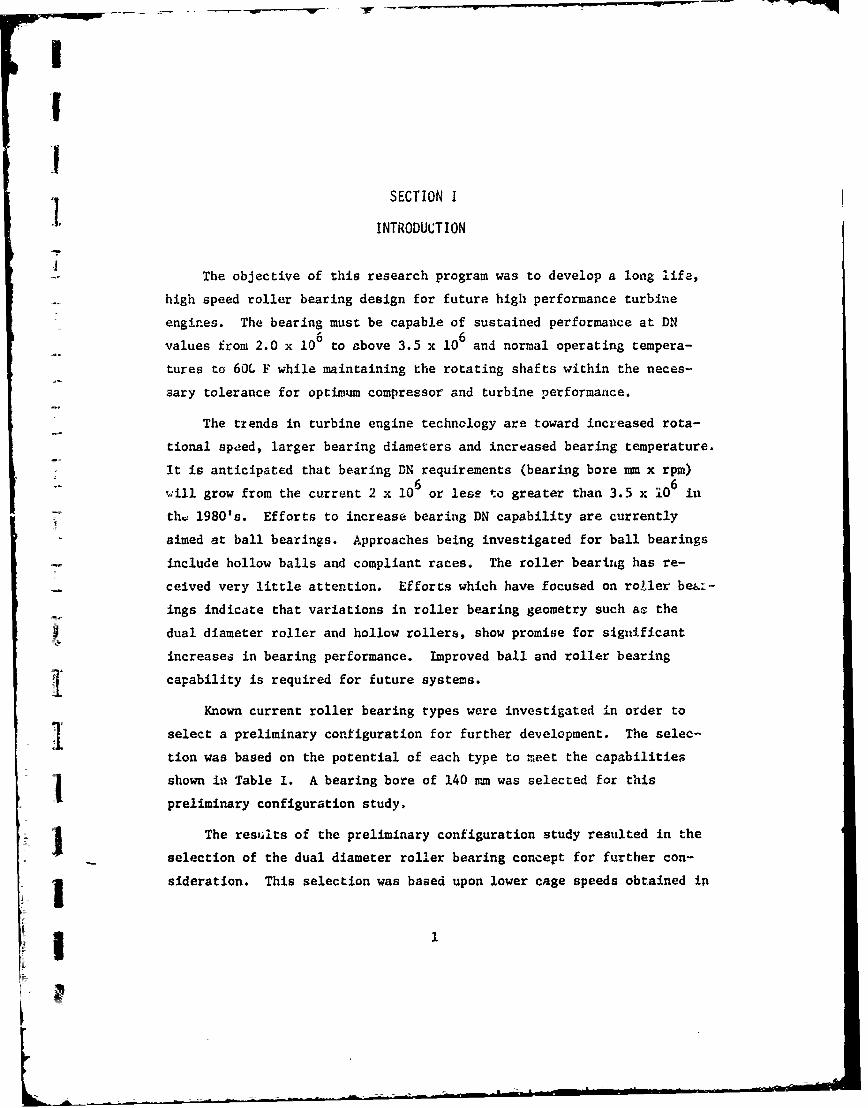
arriving at the total journal bearing friction curve. The friction loss
vs. speed ratio for MIL-L-78C8 oil at 2500 is shown in Figure 10. The
solid lines indicate the friction torque expressed in inch pounds of the
oil film journal and thrust bearing surfaces is a function of the ratio
of the roller bearing inner race speed to shaft speed. The dashed curve
represents the frictional torque of the inner land riding cage hollow
roller bearing configuration. The point of intersection of these two
frictional torque curves defines the operating speed of the roller bear-
ing inner race. It is seen in Figure 10 that the present bearing system
would result in a speed ratio of 0.84. Recent work by NASA (Reference
5) with a series hybrid concept using a ball thrust bearing and an oil
24
2n
700
A604
500
zS400-
cc -LOAD=2000 LBS0
-3001 OFLUIL FILMBEARING TORQUE
"INNER LAND RIDING
"CAGE -HOLLOW ROLLER
200- 333 LBS LOAD
W8LOAD=200LBS
100- ROLLERS ýBEARING
TORQUE
]oi - - ... T- -- "
0 0.2 0.4 0.6 0.8 1.0 1.2
-I WB/ WS
Figure 10. Friction Loss vs. Speed Ratio, MIL-L-7808 Oil
25
I

film thrust bearing surface resulted in a speed sharing ratio of ap-
proximately 0.66 at best. The analysis is highly dependent upon accurate
calculation of frictional torques. The frictional torques even in the
turbulent regime of the fluid bearing has been fairly well established
and correlated with experimental results and can be considered rea'istic.
High speed roller bearing torque needs to be carefully verified to de-
termine the anticipated speed sharing ratio. It is possible to add
frictional torque to the roller beari'ig concepts by increasing the a.-ount
of oil forced through the bearing. Thus, it is possible by raising the
frictional torque of the roller bearing to obtain a more favorable speed
sharing ratio as could be seen by raising the curve on Figure 10. How-
ever, any reductions in roller bearing torque would result in reductiCA
in the anticipated speed sharing ratio.
5. SELECTION OF DUAL DIAMETER ROLLER BEARING
The dual diameter roller bearing concept, Figure 2, with an inner
land riding cage was recommended for the thorough design auitlyz{s,
fabrication and prototype testing. Selection of the dual diameter rol-
let bearing concept was based upon the lower cage speeds obtained which
rosult in significantly less cage slip.
The series hybrid bearing concept is interesting but was not recom-
mended for further study under the present program. Operation of the
series hybrid bearing design is highly dependent upon accurat' determina-
"tion of roller bearing friction torque. The horsepower loases of both
conventional and dual diameter roller bearing concepts, Figure 9, are
shown to be essentially the same. Therefore the selection of a roller
bearing configuration for further development at this time does not
affect future consideration of development of the series hybrid bearing
concept.
26

I
!1
SECTION III
I LUBRICANT SELECTION
A summary of full scale bearing test results of 8 candidate high
temperature (600'F) lubricants is given in Table V, which was taken from
Reference 6. All of the lubricants in this study were operated with an
inerting blanket of nitrogen gas. Another recent study (References 7
and 8) considered five candidate high temperature lubricants. In this
case Table VI, all of the lubricants were again protected by an inert
nitrogen blanketing gas with the exception of Polyphenyl Ether 5P4E.
The Polyphenyl Ether was operated in an oxygen atmosphere. The only
advanced lubricant showing reasonable success without special inert
oxidation protection i1 the 5P4E Polyphenyl Ether. Figure 11 is a
reproduction of a report of bearing fatigue life experiments with Poly-
phenyl Ether (Reference 8). Indicationi are that Polyphenyl Ether is
an acccptable high temperature lubricant up to 600*F but that the failure
mode may be one of moderate glazing and micropitting of the races and
rolling elements. This is attributed to thinner EH) lubricant films in
the operating race and roller contacts. The various bearing configura-
tions were analyzed wich 5P4E Polyphenyl Ether at 5000F to determine the
operating specific film thicknesses in the roller race contacts.
The properties of MIL-L-7808 and Polyphenyl Ether lubricants are
discussed in the elastohydiodynamic lubrication preliminary design
i uanual (Reference 4). Additional data (Reference 9) regarding high pres-
sure viscometer experiments witn Polyphenyl Ether 5P4E were also used
for estimating properties of this lubricant at 500*F. Lubricant data
as a function of operating tempere nre is given in Table VII for the
I MIL-L-7808 atid 5P4E lubricants. This :"ta as a function of temperature
is consistent with the extrapolation routines of Reference 4.
127

C <C
m- 0)6- N41
T 0 0(D. 4) L)
0) >4-0O 4-5
0"0)
OLL IT1T- C" CI
:3 O 0 '0- 0
mO 0
0). C~ -- - 1
1- -0 -; 1- -0 'M
:. 9- - - 0 .- &-
(I)0 cx.4
c-0. - C . 4- *- .CLI CL 4J 0 h C0
">0 0~ 0- 0. 0)
I- Ai- 0. 0L - 0
0 '' 4 0. 0 uu 0-) C L . *.
- 0- cA 4 0I- 4 L!0) ~ -i "
I- C 4- .£ 4 I-C28

IMP- 7P- 4
t0 0 S
UC4J0 O
4)f 0 0 *n T -Tf~( U" 00-~r~(-
U-
4- N 0 M -N
( U t
E) C 0 S0SI - ~ O
tn 0 0
-? LA. a a
C. 0o -Z -o
u LiU c U- -l a.
.- * *o m m4
N4Ix 0h- NT I A Nn - -
c ~ co C:.0.. u 0 0m w
Mi c
C 0 -0> C~ 0C 4)>. 0 0: 0r 0 C
A LA 1 .0 '. (x LA-u 4-. 0 LL. . >. >
00 0) 4) ) M%-) 4) . J U 0 0 4
IC LA 4)Li 0 0 CI L 4 0 0 0I-- L.4 L A LA Xf 41 4-o CL -'X -C c LA LA LA :r= -: CI
- 0 4)4 L j >0go
4j4
AU %D 0 0 C14 m ) LTC14 N Zq -q a w .
-j V .. L L~29~ -?~ vC.

95 0-BO-so-
60~
E ioL - o/ / Fatigue failure •Estimat o e dl efpaiu e ntllfE,- Suspended test
".A-/ - - s pediced lifeS4.. ./- (based on fatigue faiures)e
I-" " " -- AF81MA - predicted life
2L.L11. ! L LII.L -.WLIJI4 6 8 10 20 40 60 80100 200 40060
BEARING LIFE. MILLIONS OF INNER-RACE REVOLUTIONS
Figure 11. Bearing Life with 5P4E Lubricant
Rolling-element fatigue life of 120-mm bore angular-contact ball bearings run with polyphenyl ether lubricant.Material, AISI M-50 steel; thrust load, 4365 lb; speed,12,000 rpm; temperature, 600°F air environment; [failureindex, 2 out of 26.]
30

-I- 4qý --I000000 031 000000f4000000 0901-4~ ~ ~ ~ M D D-4% 7 4 -1 LANN N-4 0 o 3 0 0 0 h A mo
AJJ
00000000o o C'
It I00t066600O0000 5 00900000. , i-4 0o-t) C4 14-4 -I
w~ -4-4 M~ IAN WA Q'04 0fl -4%
r-. .- .- .- .- . .
I- ~ 24 *
0 0"4
0 000000 00000 0t 0,' 0 0 0000J - l:
-j P. (7 Dc (ýL
'-4
000000 0~-'-4 000000 to C14 000000M n
(U m n-nme 000 0 - 00 0000com%D N 5?0'JD
00 R RW ý?000000I
0000 0. x 000000
0000000 0 0- o ,Uýa l0000000 000000
'T -400 D 00 N 0000009:A IA 00o1I0AO cmC: % 1 A o 0-H 0 D tr- P D% .) - n (4 -
C% 4C' ~CAC ?' AI
u I q n3i55t 0
(1)

SECTIONI IV
DUAL DIAMETER BEARING ANALYSIS AND DESIGN
1. DESIGN CONSIDERATIONS
The dual diameter roller bearing concept was selected as a result
of the preliminary configuration study. Selection was based upon the
lower cage speeds obtained which will result In significantly less cage
slip. The orbital cage speed of the dual diameter roller bearing with
a diameter ratio of 0.5 will result in a 1/3 reduction of cage speed as
seen by Figure 4. A major roll diameter of 0.5 inches was selected as
an optimum basid on Figure 6. The resulting estimated bearing life (under
the duty cycle ot Table II) would be 5,000 hours L-10 life shown on Figure 6.
This is well in exctss of the design goal of 1,000 hours.
The primary problem encountered in high speed mainshaft roller bear-
ings is cage slip. This is a phenomena which results in high sliding
velocities between rollers and inner race contacts. Severe glazing and
micropitting results in bearing failure. The minimum radial load to
prevent skid or cage slip in the dual diameter roller bearing is 333 lbs.
as shown on Figures 7 and 8. This minimum radial load was used in the
design and performance evaluation calculations. Heavier radial loads will
result in reduced bearing fatigue life, but do not endanger tne bearing
from a skid or cage slip standpoint and are of relatively minor interest.
It is essential to assure that cage slip will not occur under operating
conditions. A complete systems analysis (Reference 1) incorporating the
latest available elastohydrodynamic lubrication technology (Reference 4)
and including fluid drag forces and thermal effects were selected as the
best approach to achieve a practical design.
32
r
K

- -- ------------------
I2. INNER RACE STRESSES
J A study of the effect of inner race thickness and total interference
fit betwen the inner race and shaft (with the hollow test shaft) to deter-
mine race circumferential, hoop or tangential tension stresses was conducted
using standard ring formulas. Race radial thickness over 0.25 inches has
"little effect upon reducing circumferential tangential stresses. Race
thicknesses less than 0.250 inches radial thickness can result in unacceptably
high stresses. Therefore the inner race thickness should meet or exceed
0.25 inches.
High shaft speeds (up to 28,600 rpm) will create significant circumfer-
ential, hoop or tangential stresses in the inner race. Figure 12 shows a
magnitude of this maximum tangential stress as a function of shaft speed
S=° expressed both in rpm and DN values for the 140 mm bore bearing. Approx-
imately 50,000 psi tangential stress can be anticipated at 4.0 x 10⁶ DN
with the 0.25 inch thick race of the prototype bearing design.
Approximate physical properties of H-50 fully hardened steel are given
in Table VIII. The material is brittle at room temperature and care must be
exercised to prevent over-stressing. The material does become more ductile
as temperature increases. The effect of stresses due to speed, Figure 12,
and stresses due to interference fit are essentially additive. Approximately
0.012 inches diametral interference fit would be required at room temperature
- to assure a working interference fit of 0.001 at 4.0 x 10⁶ DN operation.
This heavy interference fit would result in almost 60,000 psi tangential
ring stresses initially. It was decided to compromise with a lesser inter-
ference fit at room temperature (0.0063 inches) and allow the inner race to6
become loose with respect to the shaft at approximately 3.0 x 10 DN. Key
slots in the inner race allow the race to be axially clamped and p'revent
relative rotation of the race and shaft. The loose fit between: "nner rac'.
and haf atspeds oer .0 10DN will keep the inner race tangential
I stresses to less than 60,000 psi.High tensile ring stresses may have a detrimental effect on inner race
I rolling contact fatigue. Thermal gradients may also cause the interference
1 33

:so
140
t
120-
0n 5.512
)2100
w
s-80 t=0.20
wz
20
20 tzO.1
o IxiO6 2x10⁶ 3xlO6 4x10⁶ 5XlO6 ON
I I I I - I J0 7,200 14,300 21,400 28,600 RPM
SHAFT SPEED
Figure 12. Inner Race Maximum Tangential Stress vs. Shaft Speed
34

I
1
TABLE VIII
IT PROPERTIES OF M-50 HARDENED TO RC-60
Per VASCO Technical Bulletin
Property Room 1 BM. W00F
Tensile ULT. (psi) 411,500 345,000
Tensile Yield (psi) 388,000 262,500
Elongation (0.5" gauge) (M) 2 6
Red. of Area (M) 2 17
1

fit to increase (depending upon the amount of under inner race cooling).
Therefore every effort was made to limit inner race tangential streses
at maxim -, and 500*F operation. A partially hollow or compliant
inner race sign Figure 13 was selected to provide access for the under
and through inner race lubrication scheme. The beam bending compliancy
may also provide relief from thermal lockup or thermal preloading at high
temperature and high speed operation.
An existing FIRL finite element computer program was used to evaluate
the tangential ring stresses in the actual Inner race design at 4.0 x 1066and 3.5 x 10 DN. Figure 13 illustrates the inner race model and the
location of various tangential stresses. The stress values of Figure 13
are in good agreement with the approximate solutions used to obtaini the
values in Figure 12. It is readily apparent that stresses on the order
of 57,000 psi will occur in the inner race at 4.0 x 10⁶ DN. Stress level
will drop to approximately 44,000 psi maximum at 3.5 x 10 DN (25,000 rpm).
A third case was analyzed where circumferential line loads were applied in
the vicinity of the roller inner race contacts to simulate stress conditions
under 500 lb. external radial load. It can be seen from Table IX that the
stress values range between a high of 43,000 psi and a low of 29,000 psi.
The only available data to date for M-50 steel at 500"F in reverse bending
f•:igue (Reference i0) indicates a life which is asymptotic at 60,000 psi
1-.ding stresses beyond 108 cycles. The fluctuation of inner race bending
stresses are all unidirectional and remain tensile as shown in Table IX
and do not exceed a maximum value of 43,000 psi. The inner race compliant
section calculates to have adequate reverse bending fatigue properties.
3. LUBRICATION
The method of lubrication for the dual diamecer roller bearing is
illustrated in Figure 14. Jet oil is introduced to ap undercut in the
test shaft as shown. Oil then passes through the shaft to the undercut
portion of the inner race whic1 -cts as an oil reservoir. Centrifugal
force resulting from shaft rotation then provides pressure to force a
flow of oil through orifice holes in the inner race. This oil is then
36

I Ar
I F1°s
4 ci
.I . . . . . . .-
4-) S
l 1 a a ,
L- L

"TABLE IX
INNER RACE TANGENTIAL STRESS (KSI)
Loading/Element No. 1 10 81 90 171 208 215 270 370 402 392
4.0 x 10⁶ DN 55 55 55 53 55 57 52 57 51 55 51
3.5 x 10⁶ DN 42 41 42 41 41 43 40 44 39 43 39
3.5 x 10⁶ DN500 lbs. 37 23 36 33 37 40 36 41 38 43 39
Radial Load
38

I0
zz
.-JI~
-io
toI

introduced to the underside of the cage and is furthsr circulated through-
out the bearing by the pumping action of the rollers, Auxiliary jet oil
lubrication into the sides or faces of the bearing can also be provided
as necessary to obtain satisfactory cooling.
Three computer analysis runs were executed using three different flow
rates (6.1, 12.0 and 18.0 lbs./min.) of 5P4E at 5000 F oil inlet temperature.
The minimum load to prevent skid of 333 lbs. anid the top design shaft speed
of 28,560 rpm (4.0 x 10⁶ DN) were used. A complete thermal analysis was
included in the solutions. A summary of the effects of oil Clow upon
bearing performance is given in Table X and shown graphically in Figure 15.
Examination of Figure 15 shows no clear maxima or minima characteristics.
It is evident that increased oil flow rate results in reduced outlet tempera-
ture and increased bearing horsepower loss. The outlet oil temperature
shows some indication of leveling out below 6 lbs. per minute, but at
unacceptably high values in excess of 700*F. Increasing the oil flow
from 6 to 12 lbs. per minute drops the outlet oil temperature by 51.8 0 F.
Increasing the oil flow from 12-18 lbs. per minute drops the outlet oil
temperature by only 22.3*F.
An oil flow rate of 12 lbs./min. was selected an the design point.
This flow can be obtained with 6 orifices of 0.028 inches diameter. The
calculated oil outlet temperature of 4.0 x 10⁶ DN is 598.5*F which is
consistent with th. program goal of 600'F operation. Table XI gives the
resulting oil flow rates for 5P4E at 500'F oil inlet and MIL-L-7808 at
250°F oil inlet as a function of shaft speed.
4. PERFORMANCE ANALYSIS
Eight computer solutions were executed at various shaft speeds with
5P4E and MIL-L-7808 oil lubricant under a constant bearing radial load
of 333 pounds. A summary of these computer runs and performance results
are contained in Table XI1. Initial fit-up conditions are 0.0063 inches
shrink fit between bearing inner race and the shaft and 0.011 inches initial
(machined or ground) diametral clearance. All of the solutions summarized
in Table XII included a full thermal analysis consisting of 21 thermal modes
described in Figure 14. Description of the node locations and the temperature
40

TABLE X
EFFECT OF OIL FLOW RATE ON BEARING PERFORMANCE
SRun 2P 3P 4P
Flow (lbs/min) 6.1 12.0 18.0HP (loss) 21.7 23.53 25.4Temp. Out 650.3 598.5 576.2of Brg. (OF)Sump. Temp. (*F) 608.1 561.8 544.4
Shaft Speed 28,560 RPM (4.0 x I06 DN)Lubricant: 5P4E @500*F oil inletRadial Load: 333 lbs
TABLE XI
OIL FLOW RATE VS. SPEED (DN)
Oil Flow Rate lbs/minLubricant Inlet Temp. OF 4.OxlO6 DU 3.OxlO6 DH 2.0xl06 DN 1.0xl0 6 DNPolyphenyl 500 12.0 9.03 6.05 3.0Ether 5P4E
PIL-L-7808 250 8.98 6.82 4.60 2.33
Six 0.028" Diam. Orificies in Inner Race
141

00IID
Ncl 8o
vo +oo o
U. 0-
OD 100 ..)0In *1 t 4
0 D
42 =

oo0- cc%
- 0 '.D Ch m' L
o -
Ln ccNanr-)
CL' a -% 0 .% r
CO a c;1 C*4C
(ne'-4
'0-0o -* 0 r0 c-
a. L .en . Cc
UM
-S a C
C' U % -7 0"
9L en 0

profiles for the 8 performance runs are summarized in Table XIII.
The temperatures when using the Polyphenyl Ether 5P3M lubricant are
acceptable at all speeds. The average oil temperature within the bearing
(node 11) at 4.0 x 10⁶ DN operation of 631.9*F is acceptable for short
duration test runs. Operating temperatures with MIL-L-7808 oil are not
acceptable and auxiliary side jet lubrication was required during the
initial checkout test runs with this lubricant.
The predicted frictional horsepower losses are shown in Figure 16 as
a function of the speed parameter DN. Horsepower losses are also summarized
in Table XII. A total loss of 22.6 horsepower was predicted at 4.0 x 10⁶ DN
using Polyphenyl Ether 5P4E at 500OF oil inlet temperatures.
Radial displacements are summarized in Table XII and include one half
of the operating internal clearance in the bearing. The specifications
require that the total radial displacement not exceed 0.010 inches under
2000 lbs. radial load. An additional elastic deflection between rollers
and raceways of 0.0006 inches should be added to the values in Table XII
to adjust for the difference between the 333 lb. analysis load and the
2000 lb. specific-tion load. All total displacement values are well below
(less than half) maximum allowable values. The largest radial displacements
occur at the lowest shaft speeds. The effects of shaft speed and thermal
effects in the bearing tend to decrease diametial clearance. A summary of
the fluid film forces and roller contact forces acting on the cage are
given in Table XIV. It is evident ffom the table that the dr.ving torque
resulting from the loaded rollers coatacting the cage pockets is not
sufficient to prevent serious cage slip at 4.0 x 10⁶ DN operation. The
fluid film drag on the inner surface and inner race to cage land is necessary
to drive the cage at speed and prevent cage slip. An outer riding cage
with resultant fluid drag torques at the outer race land contacts would
result in significant cage slip at 4.0 x 10⁶ DN. Roller to cage web contact
forces of 10.3 pounds are predicted at the maximum DN operation.
44

- o- mm.4Ne.J A Cý ýý0 0 mwcc' c'JeJ -JC'4 c'Mm A~ r, C,
I V 0N UCNILf " N% -qC4NNC4C4NNN 1 4V 4N N
U)I : DL%% D--rc n0 - %0 '00' On 0 U-%4 . .. - ..- co a%
'0 co.-c30 ~ c 4 L l 0 j0. CL. O N t- nC Cýl. CJLý L~~ (ý (CC' CV' tV'SC ýCýrý ýrý C'.x O f-00C- - , % -%D( ý 0~4 04C14N C 0 r- 0 1- 0 CO
.0 a''.c' Lr'S %UU'9. cl '.-oCý 7 9 C9~ - 0ý t- La CL-P l TNa 4U%-r- -:2 001 Oc's 00 f- 0-0O N ,Lf' 0 0 U'S
CD m ' I4" m~W- m~ m~ (V I T- 7-r- mmmmmC nmm
Ir-
< %D LC'SJ.4ý C9 "m com- - D 0- m' m C'n -: N. CV5 04.r co' -T ('44 0 C'. a,
w 0co - 0%D -TA 0; .0ý -0 001ý_;0L ; 4 0 A rz 4.0
x- co C 1-r;;.0L ND- AJ%% L A D T-T- - T A0LC14 t~ Ln Lr 0
ujL - T- T -r- T- 07_r- -T -ý 0T --704-r _:r-- T -: .41 -A
%0 "N 0 %0 M * N%3C o fV
0. 2 C9 Qý 4)* -. 00 ý 7P
X a- f- -: - C-4 - : : C4-: N -N £.L -4 C4 S -o-
I.. LL .- .) .4 .. . . . . .0- 7
LLa. x-rML - - -,0N 1- %0 -ý 0 %.0- L T . -T f- 6ON'4%-mU NL L M% a 0L%% LA LA 1-.4A 4). Lr LF 4% *4 -4) q% UN WA
OR,4 -X a.4)%a4)MN4.%0 r - 0 0E4~ T r -00
CL. -T W% 0 n ' * 7) 4 %DaCf0 ID 0 t3%N C0*4- .L-C 5 CD 0.'O SD %D44T)UN
w0 0 0 O C - '.U~ C 45~ )L.
-'C36 -1) L~. 0:d- )- 0 4 L- U -U4.4.5Lr
in L-r~ o C 4. CC- 41' 0.0. 0
co -0 0 U
4 - - - 0 41 L. 4 4) 1 4)41 au 4) LU .
o: C U V' U '0 4- .c C' 0- 41. C%4L'.0 m -' m m S D 30- 3 zm m 0 uuc -V4 . (4J A .t
= mcmm t '4-CL45)(A C -4-U A LC

30
333 Ibs RADIAL LOAD
25
20
7808250°F INLET
HP
15-
-I
105P4E500°F INLET
5-
00 1 2 3 4x 10⁶
DN
Figure 16. Dual Diameter Roller BearingFrictional Horsepower Losses
46

.0- cr c 0 0-
CI' U'- -o co
4. 0 04 N.0 Lco
C.'-r" C4 1m -~ 0 C.
%0
00 O.N r.'00 C. '.000 ON ON C -TN- -LA
-1.i . -
UN 00 cN C4 A
U, ~ CL - gr.'.X~ui Nr c o .'
'. 0 u00-. W- OA 0D LA' LLA(V 1
0- 4.O. 01 c*U u.' NT 0l M4~
Co LL.
@34)03. S- m mVI
In > c
0 L >CL U 0 0--.c:1-0 A .E~ 7 c 3 @o .l TO Ci u ID 1 0 = 40 Q z C. 0- 'U di-.~ I-j L.CI-' - *; v L O OM- @3 M 0) m'U
s- m u u t--@3 L2.~ 0 0 0 Il 'm Lo - 3 0 )04 U@c M) cn @3m' E C 3 (a' ~ 3) - U
o 12-. ..J 0~ in 0. ' LC v @3D 00 .-. 4
to In m U'
47

5. EHD IDA1METERS
The o,,ter race to roller contact EHD conditions for unloaded rollers
are summaL td in Table XV. The outer race to roller conditions for the
maximum loaded roller in each case are summarized in Table XVI. The inner
race contact EHD conditions for the maximum loaded roller are summarized
in Table XVII.
Thin elastohydrodynamic (EHD) oil films (less than 3.0 x 10⁻⁶ inches)
are predicted with Polyphenyl Ether 5P4E lubricant at 500*F oil inlet tempera-
ture for the bearing. The calculate'd oil inlet temperature at the entraice
to the EHD contacts are given in the appropriate tables. The Lhin EHD
films result in low (approximately 0.25) specific film values. Specific
film thickness is the ratio of the actual oil film thickness to the root
mean square of the contacting surface finishes. Operation at 600 0 F or
higher temperatures with 5P4E lubricant can be expected to result in surface
oriented damage or distress prior to any evidence of classical sub-surface
oriented fatigue damage.
Somewhat thicker EHD films are predicted with 4IIL-L-7808 oil applied
to the bearing at 2500 F. The specific films are approximately 1.0 which
is still in the surface related distress region of operation.
The sliding contribution to the total traction values between roller
and race contacts is predominant for both contacts of the maximum loaded
rollers (Tables XVI and XVII). The rolling contribution to the total
traction is significant at the outer race contact of the unloaded rollers,
Table XV. All of the rolling contacts are in the low slip (sliding velocities
less than 1.0 inches per second) region, with the exception of 1.0 x 10⁶ DN
operation with 5P4E lubricant.
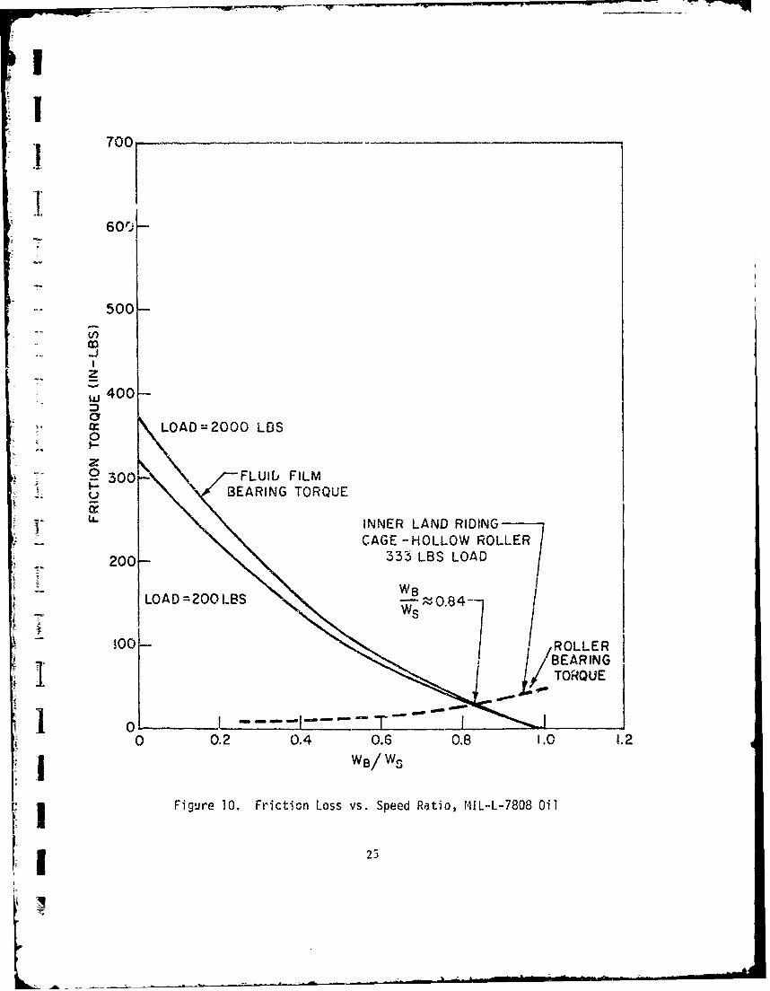
6. DESIGN DRAWINGS
The five drawings (Figures 17-21) comiletely describe the final design
of the dual diameter roller bearing. i
ii48 -

US - -'r a a 0-a
[l 9.21-. %D 00 en~s
-:r C4 U1% -T cc 0
- @ 0 C! U% No~
a a ý L& a ' :L
No No00 0DNoN 00
UN- ON -:r 'I D
t f 00' 0 - 0~
CD~
C a
00 0, 000t 4 3
o ~ f I PI
c C 1- 01m r - .< U'' 0 '
uU 0fa 01 ~ 0 @.
0.0-L Ofl@ @ ON~0 f
C)- 4 -u0
Lon I-. Io 8 -Z 0, f f - - @ fI0t ON.. ff i t
mI K % 00 0 0 0
Nm O in M = 01 0 n0. , (ff8 a a . In f% fNa Cp~ - m C2 -% L 0%
I -0 C2
@4- M4 C4 @4 d 1 n @
1.2. f12 ino COOU% U% #A V%
04

-00
c. C4 t.m
.t tr% 0 0 0 00
LL. x 000
CCU 0V%4:0 00
CD .-- m- U 0 inSL. % A m C4 7 U : 1
1~ .I E I
aa'C.- -
x C.'U-0 f 0 C
-J w
0000 0O 000
woc
lc. C
C) ~ -C g
M r% m L
L'0
0r%
~I2I, 0000
wj 4" u o o4-W -4W -W4 MIr _8 01 4 0- AL I' L01 Mi W% wt W% r. K. r,
50

LA O C4 0 C -It iý co
V% ~ ~ -7 m-n'a%
1:ý 0 a000 0 00 0
4'
04. * . 1: . *1 W
w 0 o -T eq a r- -:r %Li) ILn LA UL A Ln m ' m f m- N~0
LI) Eo~ %oo
00 0 000
.4D LA.?: % %.%
10 10. C. 0. 0.
u -W A L% V4 co0-*4 rJ %D A % OCC 0 .? . 0 CfL)
'nbr4 -tf N-4%-X~
0)
0 IS
LL)aL A MA No '0
00 00
.O z v %0% ~ ,0
;3, ~ ~ g 0a' L00C %%LILi -- C
- U-
N~. E%a'. L% N4 'a- 0%.0- :PN' -a
00040 0 %000
K~~ ~ x x
4-W M 4 -T M C4
51

,I ,
I ~ I:i
II [ Ii
H_I,!-'!
/ _ _ _ _ __~ .1
I' ! 9_ - ' l .-"- +
* II'--
a)
-1 -n
4:1:

o
all i
!ijI1 • NIi-x
1 I U
l!WI'
53-
I w!t'.i
455
I.-
its
I-
I--
54)

I
-n I:~l
'1'
I
I A
II , kj •
4, -i- ' :
I ,
I ! a
Ii~IBS-sti

- --- -- --
i, II:IF a_
' 1.
itJ!5 6' -O
S,. _ .9 -
09- ),
!1
____ • 0
\.--•Ea
56a
-!

SECTION V
DUAL DIAMETER BEARING FABRICATION
Six prototype test bearings Figure 22 were fabricated to the design
drawings (Figures 17-21) by the Bower Bearing Div., Federal-Mogul Corporation,
Detroit, Mich. A summary of the six prototype bearing .dimensional sizes
and variations are given in Table XVIII.
The inner race roller path circularity and contour for test bearingNo. 3 are shown in Figures 23 and 24 and are representative of all of the
bearings. The circularity and raceway contour of the outer race roller
path are shown in Figures 25 and 26 for test bearing No. 3.
The roller design for the dual diameter roller, Figure 20, is not
an easy shape to produce. However, the test bearing rollers were centerless
ground and crcwns were maintained within drawing limits on all three roller
portions, as shown by the typical rollet traces, Figure 27.
All material specifications, silver plating, balance, etc., are given
in the design drawings, Figures 17-21. All prototype bearings met or exceeded
the design drawing requirements.
57

7W~A~rr~a w
-~g;~~= tn
1-i
v V vCi-i
58

Table XVIII
sarlel Number At 111 C) Ah is F6
Inner Reiwo - €11312-2
0.1. %I1, 6.00364 6.00385 6.00395 6.00394 6.00345 6.0030
Taper 0.000020 0.00040 0.000070 0.000070 0.000020 0.000038
Out-of-*bwed 0.000050 0.000050 0.000050 0.000050 0.000050 0.000050
Bors Leand 5.51160 5.51160 5.51165 5.51170 5.51165 5.51165
lore Land 5.57160 5.511, 5 5.57165 5.51170 5.51165 .51165
Out-of-oiound 0.000050 0.00015 0.00015 0.00015 0.00015 0.00015
Concantrlc 0.00010 0.00025 0.00015 0.00013 0.00012 0.00010
Width l.h4955 I.h495I I.4955 I.4955 i.4954 I.4954
0.0. Surface Finish 2M 2-112/3AA 2/2-1/2AA 1-1/2/2AA 1I1/2/•M 2AA
outer P s - € 032-2
0.0. SIs 7.S739 7.8736 7.6738 7.8736 7.8739 7.8738
Taper 6.001 0.0001 0.0001 0.0001 0.0001 0.0001
Out-of-?otAd 0.0001 0.001 0.0001 O.00'i 0.0001 0.0001
1.,. Track 6.76416 6.76414 6.76416 6.16420 6.75416 6.76412
Out-of-buond 0.00015 0.00015 0.00015 0.00015 O.OOOlS 0.0001
Taper 0.000050 ,OOOO50 0.000050 0.000050 0.000050 0.000050
Concentric 0.00010 0.000050 0.00015 0.00015 .O00IO 0.0010
Flae*" Opening 0.250 0.250 0.2512 0.2508 0.2508 0.2511
Parallel Faew to Wall 0.00015 .0001 0.00015 0.00015 0.00015 0.00015
Perlllel il to Walt 0.0001 0.0001 0.0001 0.0001 0.00015 0.0001
1.D. Surface Finish SM kAA 5" SM 3-1/2/4&A 41/SM
Flage Surface Ion 2m 2-1/2/3MA 2/1-1/2AA 1-1/2/2AA i-I/2/2AA 2AA
Ca82 - €313-5S
0.0. SIil (A) 6.6436,6/.6M2 6.4428/6.6434 6.6423/6.6438 4.6426/6.6430 6.6427/6.6433 6.64221/6.6418
0.0. Slia (8) 6.6434/6.6444 6.6427/6.6432 6.6424/6.6436 6.0427/6.6432 6.6424/6.6433 6.6423/6.4424
0.Q. Out-of-lound .0006/.001 .0006/.0005 .0013/.0012 .0004/.0005 . ""0/.0005 .0003/.0001
i.0. Slea (A) 6.0404/6.0415 6.0408/6.0412 6.0408/6.0414 6.0410/6.0417 6.0408/6.0412 6.0412/6.0422
1.0. Six (8) 6.0408/6.0412 6.0408/6.0412 C:0404/4.0412 6.040"/6.0413 6.0#40516.0412 6.0411/6.042
(,4scentrI 10/00 .001 TIR .00I TiR .001 TIR .0012 TI1 .0012 TIR .000T 14
Squereness .001 TIA .001 TIR .0011 TIR .001 TIP .00105 TIR .0008 TIR
Width 1.057 1.0572 1.05$5 1.055 1.055 1.055
Cage Balanca 0.2-0.3 0.3-0.1 0.4-0.3 0.2-0.2 0.5-0.3 0.5-0.1
Pkt. Fig. from Side -. 0004 -. 0004 -. 0004
itoItrs - C]I1 -4l~rge 0.0. .SO0d1.49Y)95
Out-of-osund .000050 mex.
Width .2500/.2501
Width Sq. w 5 00 .00010 sn.
* hI to .1"o0 .00010 NOR.
Sall 00 .24975/.24"925
0ut of* mond .000050 max.
Length nM50/.24"I1Fern t1. v .25 0G .0012 ma.
Overell Legth .7500/.710
3 Doa's Comnentrlc 0.000050 TIR
Finish Dles 3 11S
Finish ad 5 WS
ASSSUS11 0IAMCLIAAMICI 0.010) 0.0103 0.0102 0.0102 0.0103 0.0102
j9

-\ ~>~k- jNri.2-.
- .-
60

.4 U
a I'. IA.-a * .
.1 *I a �
I I p..j
* * I * -'-aa a
* -...... -I-.I aa * a a .
.*� T72�I 4 a; I.
....-.--..-.- ,--- AZ- -�
* aa
� � I .
'I L.a I .1.-� I
a ItI
Ii.. 0
1 I � =N I a* iii � - d)- a --- �'---�-: �
* EL
�IjC
__ F4%aB
I�i 111.1* In I
ill a �
-8 4 C
a 00)I � * at �
-#17?-- 4-.- - - --
��I* � j' J* . Ii� I ***� � I a I a-. I-
'IA !d..L..
-I tI� t't :1:'-1� �j ' I
1 7 * r.t' 111II...* ., p.! III� 2- �
�'II�'�i
al a �
c-c. * I *
61

-4a3
'- -. CD
- --- %--
62

I'
A A i I I it
-- -~ . . . .. -- -. . .. i .
I I i7 '-I
.- , , ,- , ,
IB L _•, _I_., , ,;-, --
63 !::,
" I I
r---
I. .-~+A -I I,'.=- -i
I j1 ! I ,iLL! __LL--- z i
"I I _
S= - ° -' II " • -,- 1

ii
44a
- -•
LL
SiAt-
-t-t--I i - - -l---.A-h -t~-- -4-/--.0Wt t -P I -1 - -- .. 2..-;• " /
- 0 M.... I.....!-.! -...--..- ' -. ,
-J' - ... -- 1 - .-• . - I l
-' i. ), "e-
..
.w -' -: . .-
Figure 27. Typical Dual Diameter RollerCrown Profile Traces
b44
-- S --- =--_ _ -

I
ISECTION VI
I DUAL DIAMETER BEARING TESTS
± 1. TESY RIG
-• The dual diameter bearing testing was performed at Midwest Aero
Industries, Div. Pure Czrbon Co., St. Mary's, Pa., on an existing 250 hp
drive test stand with an eddy current clutch and speed increaser gear box.
The test rig is shown in Figures 28 and 29. A cross-sectional drawing of
the rig is given in Figure 30. The numbered locations correspond to the
thermocouple temperature readings of the actual test data. All of the
original test log sheets are contained in the Appendix.
The test rig consists of a short hollow shaft supported by two 75 mm
bore slave roller bearings. The dual diameter roller bearing, 140 mm brre,
is supported midway between the Lwo blave bearings. Radial load is applied
by pulling upward on the test bearing housing through a large ring as shown
on Figure 30. Oil to the dual diameter bearing is introduced through three
-o orifices, location No. 1, and jeted to a scoop on the test shaft. The oil
then travels to the recess under the dual diameter bearing, up through the
bearing, out into the rig cavity, and exits the drain through points 2 and
4. The test shaft is driven by a splined quill shaft between the rig and
the speed increaser gear box. The area for the quill shaft drive is shown
with the cover removed in Figure 28. The entire test head shown in Figure 30
and a transition cone covering the quill drive shaft are cantilevered from
the speed increaser gear box, as can be seen in Figures 28 and 29.
Two prototype dual diameter roller bearings were tested under the
current contract. The first bearing was operated with MIL-L-7808 oil
at approximately 250*F inlet temperature to gain a feel for the pcwer losses
and general operation of the bearing with a known lubricant. The first test
bearing was then operated with Polyphenyl Ether 5P4E lubricant at approximately
1 65
1 - i• I • i

ixi
0i
-Aj-
dosAt
S..Je-
66U
or,

IIIIj
CA
670

TEST WARINGOIL IN
O 0
-UILL SHAFT--
FROM DRIVE
SII
TEST BEEIING TEST m CARiNS
OILOUT NE. OIL OUT FOT
Figure 30. Cross Section of DualDiameter Bearing Test
L 68
161

16500*F oil inlet temperatures u,2 to and including 3.25 x 10 DN operation.
The second test bearing was operated with Polyphenyl Ether 5P4E lubricant
at approximately 500*F oil inlet temperature and successfully completed 30
minutes of continuous operation at 3.5 x 10⁶ DN (25,000 rpm) with stabilized
Stemperatures. The second test bearing . ts then subjected to a series C
rapid acceleration/deceleration tests and removed for visual inspection.
2. MlL-L-7808, TEST BEARING Al
A data s.,z..-_'y sheet for the operation of the first test bearing s/n
No. Al is shown in Table XIX. The bearing outer race and front and rear
drain oil temperature increases as a function of bearing speed for the
testing shown in Figure 31.
Twenty-five minutes of successful operation at 3.50 x 10⁶ DN was
obtained (see runs 49 and 50), The bearing wae removed from the test cell
and visually inspected. The inner race, rollers and outer race showed some
discoloration due to operating at 300'F average outer race temperatures.
The rolling surfaces looked to be in ex, llent condition with only the
•- normal amount of burnishing to be expected after complecion of 13 hours
and 40 minutes accumulated running time.
The cage was found to be badly worn on the inner land riding diameters
- over approximately a 35 degree arc on both lands. The woni areas had
penetrated the silver plating and significantly aeformed the steel. The
worn areas were directly under one of the cage pins used for cage speed
instrumentation. It appeared that the cage had excessive mass unbalance
in operation which led to the localized wear*,tg c. the inner land surfaces.
The s/n N•. Al cage was not reused. The in-er race, ouzer race and roller
=umplement howe, er were in excellent condition and were reused jr the
second set of tests.
3. 5P4E, TEST BEARING Al
s/n No. Al bearing with the s/n No. B2 cage was assembled in the test
I rig for the high temperature Polyphenyl Ether test. A data summary sheet
I69
L7

o <1 J CV I
rId
IIIn
-LL I- Iv-4 12 1014 0
LLJ t,)
-- ~ N.-,-. -v - - -
M~ kn A %A %A kn C o %A oz-a oi %
tI I N" o i 04O I ý
L It
70

: 160
DUAL DIAMETER ROLLER BEARING
1140 PART NO. C3132 S/N AOO1
TEST COND!TIONS:LUBRICANT - MIL-L-7808GLUBE FLOW RATE - 8.5 LB/MIN
120 LUBE SUPPLY TEMP - 250OFRADIAL LOAD - 480 LBS
LEGEND:SOBEARING OUTER RACE
O LUBE OUT FRONT100 - LUBE OUT REAR
-LEAST SQUARES LINE
-~0
-80-
w
6-140-
'2 0
01 /-20-4 0 a
0 0.5 1.0 ;.5 2.0 2.5 I,,o 3.5 4.0I BLARING SPEED-MILLION bN
Figure 21. Test Bearing No. 1, AT
vs. Speed, IIL-L-7808

is given in Table XX. The temperature differentials in the bearing for I
the outer race and drain temperatures are shown on Figure 32. The bearing
was initially operated up to and including 3.0 x 10 6 DN operation, At
this point the Polyphenyl Ether lubricant was being pumped back through the
quill shaft Figure 30, to the gear box ane iixing with MIL-L-7808 oil in
the gear box system. The rig was shut down and lube system changed so that
the gear box as well as the test head would operate on 5P4E lubricant and
would avoid the loss of excessive amounts of the test ci!. Testing was
then resumed and resulted in the second set of curves as shown on Figure 32.
Successful operation of the test bearing was accomplished up to and
including 3.25 x 1O6 DN operatica. After approximately 10 minutes operation
at 3.50 x 10 6 DN operation (run No. 86), the bearing failed abruptly as
evidenced by a seizure and a dead stop of thf- test shaft. The failed test
bearing was then removed for visual examination. The inner race had
separated and formed into two circumferential halves approximately in the
center of the race. The rings had also snapped open at a location corre-
sponding to one of the key slots as shown in Figure 33. A considerable
amount of debris was trapped between the inner race cavity and the shaft.
Figure 34 is a photograph of the rollers, cage and outer race assembly
still in the onlter race loading ring, The rollers all had a flat surface
on the major diameter which presumably was caused when the rollers locked
up and braked the inner race to a complete halt. Several of the rollers
are showi: on Figure 35. All of the rollers had at least one of the small
diameters separated from the body ol' the roller as shown in Figure 35 and
in several cases both minor diameters had beien separated. Subsequent
metallurgical examination of the fractured surfaces supports the fact that
the small diameters were twisted or torqued out of the major diameter.
They were not reversed bending fatigue failures. Complete seizure of the
inner race creating sufficient friction to -rind flat from the rollers
(as shown in Figure 35) would create tremendous torques on the minor rollerdiameters. The outer race is shown in Figure 36 and the cage is shown In
Figure 3?. The cage suffered serious distortion as would be anticipated.
7i

III
J A -
Ii, lo .lI I!,
LL.~
w- ý:- QPS
-LY I i
Lflt~~~j 73

160DUAL DIAMETER ROLLER BEARINGSPART NO. C3132 S/N AQOJ with B002 CAGETEST CONDITIOP:
140 - LUBRICANT - POLYPHENYL ETHER 5P4ELUBE FLOW RATE - 9.5 LB/MINLUBE SUPPLY TEMP - 480oFRADIAL LOAD - 470 LBS
120 LEGEND:
0 BEARING OUTER RACEO LUBE OUT FRONTA LUBE OUT REAR
100- -- LEAST SQUARES LINEOPEN Ist RUN 11/6/72
LL SHADED 2nd RUN 11/7/72
~80--
CL60 /"",,
c o /00./4 0
40 A0A'00
/°-20 -- 0-
-40- . ý I I
0 0.5 1.0 1.5 2.0 2.5 3.0 3.5 4.0BEARING SPEED -MILLION DN
Figure 32. Test Bearing No. 1, AT vs.Speed, Polypheny! Ether, 5P4E
74

IO
I7
IA.keC
Fiue3. TsIBaigN.1IneI~e alr
I7

-low- _ _ _
Figure 34. Test Bearing No. I Outer RaceCage Roller Assembly Failure
76

I
I
1 C
SI.-U,*-oaJ
U-
LA-5-
0,
S
IIII1 77

Figure 36. Test Bearing No. 1 Outer Ring Failure
78

I I b
I Figure 3117. Test Bearing No. I Cage Failure
79

The test bearing Al accumulated a total of 24 hours operation at
various speeds of which 10 hours and 20 minutes were with the Polyphenyl
Ether lubricant at high temperature. The failure of the inner race,
Figure 33, can be explained by two possible failure modes, the first
being thermal lockup of the bearing where the growth of the inner race
both thermally and due to centrifugal forces exceeds the growth rate of
the outer race resulting in internal diametral preload. Roller bearings
are exceptionally stiff and small amounts of diametral preload (on the
order of 0.0002 inches or more) can result in very high roller loddings.
Greatly increased roller loading6 at the inner race contact (see Figure 17)
would then undoubtedly fail in reverse bending fatigue. The second possible
failure mode is that sufficient clearance did remain in the bearing and
that failure cf the inner race was due entirely to reverse bending fatigue.
The finite element analysis of the inner ring as shown on Figure 13 and
summarized in Table IX did not indicate that excessive stress variation
would be anticipated at 3.5 x 10⁶ DN operation. Therefore, thermal lockup
was suspected. The fact that the bearing did operate for approximately 10
minutes at the higher speed level, however, is not indicative of thermal
lockup. Thermal lockup occurs very rapidly after an increase of speed.
The concern over thermal lockup was resolved by additional thermal
analysis of the test bearing operating conditions. The initial thermal
gradieiits in the bearing for design purposes did not include any effects of
external energy being introduced into the system because of dissipation
in the slave bearing. Table XXI shows the results of the thermal analysis
with external energy introduced at node 21 on the shaft surface external
to the test bearing. Also the effect of insulation around the outer diameter
or outer surface of the test head was introduced into this analysis. The
results of the improved thermal analysis for the actual load, speed and
lubricant supply conditions of the test agree closely with the observed
temperatures of Table XX. The outer race temperature per analysis (node
18), was 527.86°F as compared to average observed outer race temperatures of L520*F. The total AT to the oi'. by analysis in Table XXI was (node 11)
soi80
K

- ------ ------
IL 0U) f-09IK l 4L ~ n- . c.t
IoA -rcm0mA )c rW rnC . LLn% - ý94 %a r c r cv)-rcca.t0ro -J cc vr -t 4c -r qr OLic ) f-I*
LL 0t). r nUlL r ,.L r)L r f ' r U* Ot t) c LLO C
0
t:) It 1 11 it 11 11 If 11 11 1i 11 It It 1t ti If it 11Ii it 1 11 It I
0
S9-
0 4-) D3 -::'4J Wn tA u -4 4. X ~ D
I<- 4-) Z ~ (LC.CL
D- C~ -- W1- 1- M'- 0 ;_I- 4.J 0 Q4 J %ý -4 .J
4-I 0 u I..- 0 <-w I.-
wL I- W- W Z - Z LDJ~ < L - 4 = s- .1-.1
a = xu 0. 4-0"IW o%."A
0 0- 1.-l X ! i D -Z'.1 LiI- .D
-n 1, _j _jJ r.
< < < u W- Q w Ll 00 u 0 -. nl x C
X) = < i -- a. . L
.r9, ''UXC V 0DZDý
1 -z'IX== WJI A A JL A JJ JWý -L l
81

5550 less oil inlet temperature of 470° resulting in an 850 AT to the
oil. This compares very favorably to the 90' average of the oil out
front and oil out rear of Table XX. The calculated internal diametral
clearance in the bearing under the thermal gradients shown in Table XXI
is 0.0051 inches. This nuwber includes all thermal and centrifugal growths.
A number of variations in the assumptions of the thermal analysis such as
percentage air oil mixture, etc. were tried and found to have little effect
on the thermal gradients in the bearing. Therefore thle conclusion was
reached that the bearing did not fail due to thermal lockup but rather
failed due to reverse bending fatigue of the undercut inner race. The
finite element analysis summarized in Table IX would indicate that the
stress variations with roller loading should not have exceeded the long
term life value in reverse bending fatigue. nowever, the te:.t bearing at
the point of failure had experienced 39.7 x 10⁶ cycle'. of stress or ,oller
load variations between rollers and inner races with both HIL-L-7808 and
the 5P4E lubricant. The values were essentially equal with each type of
oil. The decision was made to proceed with testing of the second bearing
on the assumption that thermal lockup was not the failure mode and to
limit the bearing load to no more than 500 pounds so as not to significantly
increase the danger of failure due to reverse bending fatigue.
4. 5P4E, TEST BEARING C3
The second test bearing, Serial No. C3, was assembled in the rig
for high temperature testing with 5P4E lubricant. A summary data sheet
of the test is givan in Table XXII and the AT's as a function of speed
are plotted in Figure 38. This bearing achieved 30 minute3 of temperature
stabilized operation at 3.5 x 10⁶ DN (25,000 rpm) under a 471 lb. radial
load. The only variation in test conditions over the first test bearing
was the addition of an auxiliary jet towards the rear of the bearing at
the inner race and cage land contact. This auxiliary jet supplied approxi-
mately 2 lbs. per minute oil flow of the total reported in the test log.
The test bearing was then subjected to fouxr rapid acceleration and
deceleration tests between 1.5 x 10⁶ DIN and 3.5 x 10⁶ DN in 15 seconds each.
82
It
x 1o
tI fuA ry, rt N
1 %0 en I
a. "z
I .
I I' - Ii ~'t_~ I*
I 83

140
DUAL DIAMETER ROLLER BEARINGSPART NO. C3132
1201- TEST CONDITION:LUBRICANT-LUBE FLOW RATE-LUBE SUPPLY TEMP-
100 RADIAL LOAD-
LEGENDBEARING OUTER RACEO LUBE OUT FRONT
80- ALUBE OUT REAR-LEAST SQUARES LINE
0
a.
w 60-
Acn4O 0
CID~ ~ ~ AA.0000000A
0I-
-20-
-40-
-60L0 0.5 1.0 1.5 2.C 2.5 3.0 3.5 4.0
BEARING SPEED -MILLION ON
Figure 38. Tes-t Bearing No. 2 AT vs.Speed, Polyphenyl Ether, 5P4E
84

I
The second test bearing is shown in Figure 39. All of the race
and roller operating surfaces were in excellent condition. The cage was
in good condition and showed even burnished wear areas in the cage roller
to pocket contacting surfaces. With the exception of the riding land,
the cage was in e:icellent condition. The. silver plate was not worn through
at any position and very little discoloration was noticed. The cage inner
SI land riding surfaces however were discolored over a 900 arc indicating
insufficient lubricant to the cage lands. The inner race show6 a uniformly
burnished area in the center of the race where the rollers contacted.
Distress is noted in the cage land riding areas on the inner race. The
outer race was in excellent condition. There was some indication in the
discoloration due to temperature that the rear of the bearing was cooler
than the front face of the bearing. This can be attributed to the auxiliary
oil jet directed at the rear face of the bearing.
The Po.yphenyl Ether 5P4E lubricant used in the test was supplied by
the Aero Propulsion Laboratory, Wright-Patterson Air Force Base. Some
of the fluid was new fluid and some of the fluid furnished was reconstituted
fluid. It was noted that when new 5P4E fluid was added to the oil sump,
that foaming of the oil occurred for a period of 10 to 20 minutes and then
S-subsided. This foaming did not occur wheu reconstituted 5P4E fluid was
added to the sump. The foaming action did not seem to have any effect upon
bearing operation.
I
II
85
I

CD=
TV-~
0 A
01
86-

SECTION VII
I CONCLUSIONS
The second dual diameter roller bearing successfully operated for
30 minutes of stabilized tcx.erature operation at a shaft speed of 25,000
rpm. This is 3.5 x 10⁶ DN operation of a 140 = bore bearing. External
radial load was 471 lbs. and the lubricant was 5P4F Polyphenyl Ether at
japproximately 500*F oil inlet temperature.
The failure of tie first test bearing was attributed to reverse bend-
ing fatigue of the M-50 steel inner race at high speed and 600*F operating
temperatures. V'ie calculated stress levels were below known allowable
stress levels for ±..'g term operation. This suggests that additional
carefully controlled reverse bending fatigue data is required for M-50
bearing steels for elevated temperature operation. Any future test5 of
the dual diameter should use a solid inner race, eliminating the undercut,
The lubrication method of introducing the oil to a cavity in the
inner race and through orifices directly into the bearing intering was
S•enerally successful, however distress and wear was observed at the
j : age inner land riding surface.
The suc.essful operation of the second test bearing establishes
Sthe validity of the design approach. A complete systems analysis using
existing state-of-the-art elastohydrodynamic technology, fluid mechanics,
Stheory and thermal analysis techniques,-can be used to design a completely
new bearing concept ad-enable initial prototype testing to be successful
at speeds and temperatures beyond the realm of current experience.
87

APPE14DIX I
TEST LOGS
14 __ _ __ _ _ N 21..Z A
*10 t, 'ý *i . 11)
S -. LiIl
W41 IiI ~ k~f~T~i~~i: M
4i j. faj
IcI
88

. , -~~t WE-n__
Is~ ITil
kIýl
Lt U

Ilkel
ra a* cl *a (I
I r iA
CIL
Tqa $A a '3 b
ia I;Zlg I N
97 tvtune at 1%
lb **1 1:1-
R
fk IN tl f. f4 "I m %a
14 fli ef 1ýj C, 14* V
Hl -J, 1 1 1
'da
ti
fi SI 1A
Ck
tAAn . -
. I z
A vj
Ld
!21 04
A
90
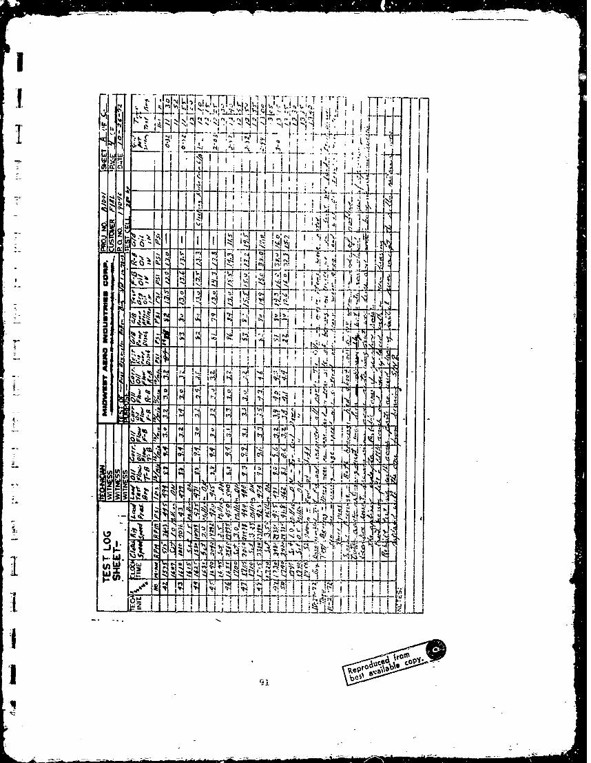
Z I60 .~r IIN
I
i~itj ii * %
A4~~ ftiIN4.I~4
" 4 tI1 ~ -- N i F41~I*~*I~ I
1 14 "'dl N1'1
N11' 1:6 Q
j- ~J~t~ i! i:i:= i 1 i

I ----ol1! -
I '4'.J
LA t
M I N
U a tOi
A 9A
K tA----~--~ -

C"
I2 l 747h ' , :fzI~~ T ~ve
I~t n ii -I illi - +
-I-ii I
t. ~ t. ri AIT w % A V
w - .1 -ýIU tk"Q-Z1, I
IIW -1*
1 93

LTIT
4;t
L- in-

Tw_
_ _ _
II4
all I.i~i 4T1T1
&J ~ k ri ~ (.'F
41 irk1
Is
t4 I Sl4
IV
'141 I9.,11it

1 61
W _L
ka -Z
ILI
II
It
41ý1
96i

TI-
41 v
ZLjt
rI.i.
16
IN
-1qq
97

'- -
I~dii d'~t ~ I -
~~' IVI~
tt .Zi-~ !~J~
__ _ _ _ _ _ tz, .1 T4 .9*
-i W4 *%
Uid 1% *v4 N- '~i.
1.4i
K - 48K _v

t~ Il
Aytr4 -01 i
±j
I 1 4
piI11
II0 x 1:1 014A 499

7Aw
FrFI
4L-IX0I
F T- I
I v
410

I~~1 F'IF~J4J
TI.
14OI I I~ :1 1 1
iit
10.1

-A 1
41~ .1tI
I*~ ~~~~ :444:~-- .j~
-I oil
ii ~ .' I' b
ri1
102

II
411
1J
aAI tT
611
IJ
IL
'1103

-7 -.
r. ..
I,' A.Lt, ~
C,~
NII
440
-~-~-.-

CI
H il
10

-4-1
w u wEL - ~I~; I '
LI T~1 -jI&,, I JI
".40 it I IF h M, i
lii d 1L)iLA InU~p
IAI
Jill I.j ii ~ Iti i
ItI
ITHI
106

I [A !42!
VIA
II
Il1 N0

ýAIs
C4
Its I 'I
Id!rlI F-
Jow IsL tn Cl
ck: Is., ILYloMA _,c I
tI, W 1 "4. 4
6 IQ I Al Iý 014 !! A d
fj ga r 0
I P0z
A4
I ZI -ocl
(n in fit!
z z z
ro
U) tAi wW 812 t "Z
ý4 J LASfiu- -FFffT-n-'iT-F IT ý,i i
108

I:X
Fi N is ijN..IL
I _a
110

21!
:14:
i aW.I
I Ir i
%'i* a'~ ~
411I 1
fA
01I
q.Ja 1 ~ u
w 3: iit
1.10

IT
HIM
1 10
ItI
IIU"1

I21
APPENDIX II
GAS TURBINE EN GINE I4AINSIIAFT
ROLLER BEARING - SYSTEM ANALYSIS
By
1 J. H. Rumbarger, Principal Engineer, Member ASMEE. G. Filetti, Se~iior Staff Engineer, Member ASI4FD. Guternick Student, Drexel University, Coop Employee, FIRL
a The Franklin Institute Research LaboratoriesPhiladelphia, Pennsylvania
Submitted to
Lubrication Division of ASME
I For Publication (without presentation) in
Journal of Lubrication Technology
August 1972.
I
112]

'I
ABSTRACT -
An interdiciplinary systems analysis is prerented for high-speed gas turbine engine mainshaft roller bearings which will enablethe designer to meet the demands for ever higher rotative speeds andoperating temperatures. The latest elastohydrodynamic experimental Itraction data is included. Analytical results cite a need for better -'
definition of the rolling fricticn portion of the total traction. Afluid mechanics model for the detailed analysis of fluid drags is developedbased upon a turbulent vortex-dominated flow and includes the effect of Ilubricant flow through the bearing. Typical cage equilibrium solutionsshow evidence of possible unstable operation. A complete thermal analysisincluding dynamic and thermal effects upot, bearing dimensions and resultingclearances is also included. Heat transfir coefficients are given indetail. Shaft power loss and cage slip predictions as a function ofload, speed, and lubricant supply correlate well with available experi- -mental data.
I
-t
I
II
I
1131
-I

F NoLIST OF FIGURiS
S1 1 Surface Velocities and Relative Rotational Speeds ofit Raceways and Rollers Including Slip at Each Contact
asaResultof Cage Slip ...... . . . . . . . . j 38
-2 Forces and Moments Acting on a Loaded Roller ..... 39
T 3 Forces and Moments Acting on an Unloaded Roller . . . 40
4 Solution Techniques Flow Chart. . . . . . . . . . . . 41
5 5 Roller Clearance Distribution in Cage . . . . . . . . 42
6 Mathematical Model of Horizontal and VerticalRelative Velocity Distributions in Roller-Shoulder•-Contact . . . . . . . . . . . . . . . . . . . . . . . 43
7 Roller Bearing Cage Speed Correlation . . . . . . . . 44
8 Influence of Oil/Air Ratio on Each Solution ..... 45
9 Influence of Oil/Air Ratio on Each Solution . . . . . 46
LIST OF TABLES
Table No.
I Dimensional Models . . . . . . . . . . . . . . . . . . 47
2 Description of Thermal Anlalysis by Nodes . . . . . . . 48
S3 Typica l Thermal Analysis ........ . 49
4 Typical EHD Film Thickness and Traction Values . . . . 50
114

I
INI N'lJUCTICN
The use of elastohydrodynamic lubrication theory for rolling
bearing a. alysis was first suggested by Dowson and Higginson[. The
first use of digital computers for the anal)jis of high speed roller[2]
bearing performance was by Parris2. The Harris paper presented an
analytical method to predict skidding in high-speed roller bearings. The
influence of the amount of lubricant sup-ly on cage and roller motion in
high speed roller bearings was experimentai.ly described and analytically[3] [43discussed by Boness]. A refinement was introduced by Poplawski with
the solutiou of all of the loaded rollers under the varying load pattern
resulting from external radial load. He also introduced a fluid "churning"
loss and cage pilot surface friction formulations.
All of the previous analytical work used the Dowson-Higginson[I]
isother'mal elastohydrodynamic (EHD), formulation. A recent comprehensive
review of EHD theory and experimental data by McGrew, et al[S] resulted
in selection ane recommendation of the latest and most applicable EHD
formulations. This preliminary EHD design manual[5 1 also presents
c-mputer subroucines for the calculation of oil film thickness including
thermal effects developed by Cheng and EHD traction subroutines fitted
j •to available disk machine experimental data.
The present paper presents a system analysis of a high-speed
roller bearing under radial loading as commonly used -n gas turbine engine
mainshafts. Oil film thickness, traction, and hydrodynamic pressure forces
acting in an elastohydrodynamic roller-race contact are computed accordingE 51to the latest available techniques - A complete fluid mechanics model
is developed in order to more accurately predict the fluid drag losses
acting upon roller, race, and cage moving surfaces. Turbulent vortex-i
dominated flow theory is used to calculate boundary layer stresses. Finally,
U a complete thermal analysis is described.
115

=1
Combining the resulting thermal deformations with deformations of the
bearing components due to centrifugal growth completely defines changes
in critical bearing operating parameters at each step of the iterative
solution process. The thickness of an EUD oil film is determined by the
temperature and viscosity at the inlet to the contact. This inlet oil
temperature is very sensitive to the temperature gradients which exist
within the bearing. Oil viscosity changes and dimensional-changes through-
out the bearing as a function of temperatures are included, The thermal
solution as expected is dependent upon lubricant flow rate, method of
application (under inner race, thorough bearing, etc.) aid external heat
paths.
LOAD AND SPEED EQUILIBRIUM
Elastohydrodynamic Pressure Forces and Tractions
The surface velocities and reldtive rotational speeds of rollers
and raceways are shown in Fig. 1 and follow the nomenclature of Harris[
Sliding velocities, V and V are defined as positive when the surface
velocity of the raze is greater than the surface velocity of the roller
and is equal to their difference. The rolling or entrainment velocities
U and U are always positive and defined as the average of raceway andV oj
roller bý._.ace velocities. The sliding velocities and entrainment velocities
are made dimensionless by introduction of the fluid entrance viscosity,
nel reduced modulus of elasticity, E', and equivalent cylinder radius, R,
for each contact as suggested by Dowson
Forces and moments acting on a loaded roller are shown in Fig. 2
and those acting on an unloaded roller are shown in Fig. 3. The effect of
cage orbital speed, wc, is to create a dynamic body force on the roller
acting radially outwards. Figs. 2 and 3 use D'Alembert's principle[7] to
represent the summation of this roller body forces as an inertia force
CF* acting through the center mass of the rollers.
1 2 JCF* I M EW (.02F " r c
-2-
116 1

Thus Figs. 2 and 3 are free body diagrams of the roller in
static and dynamic steady state equilibrium with all static and dynamicS~forces shown.
Fluid pressure forces Qij and Q oJ tending to translate the
roller relative to the raceways are described by Dawson, etali] and
approximated by Harris12 1 for synthetic lubricants as:
Q 18.4 (l-y) G-0 .3 U 0.7(2,- (2)
Q o 18.4 (4-y)G 0 3 UG"7jo
Traction forces Tij and T consist of fluid frictional drag
forces as described by elastohydrodynamic lubrication theory. They con-
sist of rolling and slliAng friction forces. Using the Harris 2 approx-
mation for and Q they are expressed as:ij oj
-9. 2d 0.7 £jE' TiJ fV(T P)ijij ij i V e iijiT (3)
T -9.2G Uo0t7 E'R + ]Vo f(Te)Po
o ooj
The coefficient of traction, f, for the sliding portion has
been obtained by experiment from disk. machines. This coefficient has
been curve fitted to existing data by McGrew, etal[5] as a function of
three dimensionless parameters GI, G2 , G3 and is represented symbolically
as:
asT f(Te) FIG1, G2 ' G3' 30-C) - 0.001 (Te-86"F) (4)
where "e is the temperature, F, at the entrance to the EHD contact. The
three dimensionless paramuters (given in the nomenclature) express shear
i rate effects, thermal heating effects, and pressure viscosity effects,respectively. Graphs And computer subroutines for the traction coeffi-
cient, f, are given in reference, [5] and are not reveated in-this paper.
IR 117

It should be noted that this representation of experimentally obtained
traction data is extrapolated for both high and low sliding velocities to
make the data useful over a wide range for the analysis of bearing systems.
At smell values of G1 all curves of, f, have a 450 slope. This corresponds
to the fact that at small sliding speeds the frictional coefficient variesI
linearly with sliding speed.
Poj and Pij are raceway normal forces transmitted to the roller
by the external bearing load. Fadd is a force resulting from contact
between the roller and the guiding shoulders of the raceway. 11 is .2
symbolic representation of all of the fluid resisting moments acting on the
roller. Fcj is loading due to the cage. A loaded roller, Fig. 2, which
drives the cage results in a positive value of Fcj as shown. An unloaded
roller is driven by the cage as shown in Fig. 3. A retarding torque is
always present as a result of rubbing coulomb friction between tloe roller
and cage pocket.
Load Roller Equilibrium
Summation of forces in the horizontal and vertical directions,
Fig. 2, for the loaded roller must equal zero for steady state translating
equilibrium.
Qi + T4 Q T -F (F5)ii j oj oj cJ- add (5
PiJ + CF - jF P =0 (6)ijcj oj
Summation of moments about the roller axis of rotation, Fig. 2,
must equal zero for steady state rotary motion eqtilibrium: (The term
Fadd resulting from roller end contact with the guiding shoulder is des-
cribed later by Eq. (36).
d d d arT ijI+T oj - PFcT-Mri 0 0=1rj Dt (7)
The equations of equilibrium for Z.e unloaded roller are similar
and can easily be derived-from Fig. 3. (Also Ref. (2]). A
-4-118
dW6ý

EHD Oil Fi!m Thickness
The average oil film thickness in the Hertzian zone is computed
according to the Dowson, etali] isothermal theory for line contact and
modified with the C'eng[6 thermal correction factor, VT" 5] The film thick-
ness is determined by the lubricant velocity, n at the inlet.
h= 1. 6 G 0.6 U 0.R T (8)h- 0.13
Roller Load Distribution
The summation of all inner race loadings, Pij, equals the applied
external radial load, F . For simplicity,the solution will be given in ax
a' single degree of freedom, along X. Then:
F x- cos 0 - LD (9)
j = 2 j .7 (10)where cos 0j (10
Cage Equilibrium
Steady state rotation of the cage requires that the summation
of all fluid film forces and roller to cage forces acting on the cage be
in equilibrium. The sum of the moments of all of the fluid film forces
acting on the cage surfaces and taken about the center of bearing rotation
will be represented symbolically by i and will be considered to be a dragor retarding moment when expressed in the positive sense. An inner land
j riding cage will develop a driving torque in the land, which helps to dri,'e
the cage. An outer land riding cage develops a drag torque in the lands.
An unloaded roller by definition has a negative cage force F , Fig. 3.
A loaded roller has either a psotive driving cage force, Fc, or a negative
drag force, per Eq. (5) and Fig. 2.
w8=• •E (Fcj ifc 0 -. Ic _: (ii _
J=l c
-5.
119
TO

Method of Soluti,, (
A flow chart of the method of solution is given in Fig. 4. The
solution consists of six nested single degree of freedom iterative loops.
Two convergence schemes are used. Load distribution solutions are solved
using classical Newton-Raphson matrix inversion techniques[8] Roller
speed and cage speed solutions use a modified time step solution because
of the multiple valued traction function.
Equations (7) and (11) are written as inequalities where
the right hand side is the prcduct of the polar moment of inertia and the
first time derivative of the rotational speed. The desired steady state
solution will occur when the right hand side vanishes. The magnitude
and sign of the right hand side Js used to compute the increment of cage
or roller speed. Roller inertias dre small, and extremely small time
steps would be required for solution. A modified time step in the form -
of cage or roller speed steps proportional to the right hand side (or
moment unbalance) are used for the solution. Initial step size is deter-
mined by experience to minimize computer execution time. Changes in speed
regiems (DN values) and change of lubricant usually requ" es an adjustment
in step size.
Determination of Loaded RollersI
The radial displacement, 6, at any location angle, tj, is:
Xcosd. Pd2 x (12)
where x' is a constant deviation from a true circular profile.
A plus value of x' means a radially outward deviation of the inner race
or a radial inward deviation of the outer race at Location 4, or the jalgebraic sum of deviations of both races from a true circular profile.
An elliptical out-of-round race or any race shape in general 1 can be
described by specifying values of x' for every location angle, Oj.
I-.6-
120

A quaitity, 6TOTAL' is defined as the total defleccion require-
weat for an unloaded roller assuming that it is initially in dry line contact
(no MHb film, no roller load, no bearing clearance) with both inner and
j outer races.
6TOTAL = - h- hl - 6ROT +6CF (13)U U U U U
"I where: 6o= F 9/io (14)u KoJ
-:- 8/9 !5
K = 11.4 x 10⁶ z (15)
6 is the elastic compression or approach of the roll center-0
- line towards a distant point -ra the outer race using the Palmgren
approximation.
h is the EHD film thickness at the outer race contact per0
Eq. (8).
1 hI is the EHD film thickness at the inner race contact perS~U
Eq. (8) with a load of P /it-- 1.0 lbs./inch.ii ij ij
6•ROT is the increase in diameter of the unloaded roller causedU
by rotation, wrj' about its own axis. (See Table 1).~rj
Sis the compression of a hollow roller as a ring due to theCF
inertia force CF
6 CF*r3 u.467 (16)u Er k 2 1,
r - the mean radius -;f the hollow roller (in.)4
I - area moment of Inertia of the ring section (in.,)
-7-1 121

A
Determination of a loaded roller is then made by;
t6 < TOTAL Pij = 0 U LOADED
j z(17)6 > 6 P > 0 LOADED
TOTAL ijj
Eq. (17) states that if the total radial di.placement, 60, is
greater than the radial displacement value, 6TOTAL of an unloaded roller;
then the roller is loaded. If do > 6TOTAL then P/ij/Aj must equal or
exceed 1.0 Wb/inch. This test is made at each roller location as shown by
iteration loop 4, Fig. 4, for the radial load solution.
Solution of a Loaded Roller
The solution of a loaded roller according to Eq; (5), (6), and
(7) is accomplished by means of two nested iterations #5-Iuoer Race Roll
Load, Pij and #6-Roll Speed, wrj, as shown in Fig. 4.
The inner loop #6 to determine roll speed w (by means of Eq.(7)) is solved using the modified time step technique described above.
This solution requires a known value of the inner race load, Pij"
The inner race loading, Pip of a loaded roller is determined
by using Newton-Raphson iteration (loop 5 of Fig. 4) and assuming an initial
value of Pij an then calculating corrections to it. An initial value can
be closely determined from the external radial load and using Stribeck's
constant for the maximum roller load. .
The cage to roller contact force F is solved directly from Eq.ci
(5) for a given value of wrj. Roller speed is determined by iteratively
solving Eq. (7) with a modified time step or incremental values of wrj"
The solution of Eq. (7) is very sensitive to small changes to torques about
the roll axis.
The ijFcj tena of Eq. (6) is neglected in the s:lurion. The 1coulcmb coefficient of friction p is usually less than 0.1. The traction
coefficient in the EID contact, f(T e), is always less than 0.1 and usually
122 -
!
=i

II
less than .01. Thiss the F term is always less than 1% and usually
less than 0.1% of Poj.
The relationship of radial displacement, x, of the inner ring
upon a loaded roller is:
6 +6 -h + 6 4 6 6 - Xcos P + Ld _ X,oj ij - ioJ CF r rot1 2-X •0=c 1
Where6 aCnd6 refer to a hollow roller and are omitted from
Eq. (18) when solving solid rollers. 6 is the ring compression of a
hollow roller per Timoshenko[ 1 13 as:
6 Crj (19)
C r 2 r2 2 1 e F2 III +RaEe (0rr£I 2i (2 +21--rt
Subsequent values of P are then:
6c
PJ4P- (Pu] f 16 P ij] (21)
Solution of Eq. (18) using corrected values of P from Eq. (21)
is rapid and n~o convergence difficulties have been encountered.
The load carried by each loaded roller is determined by the
Radial load solution loop No. 4 of Fig. 4. .q. (9) is solved by Newton-
Raphson iteration using the radial displacement, x of Eq. (18) as the
variable. An initial value of x is computed using an assumptin- for the
value of Pij, Eqs. (6, 15, and 16), assuming pure rolling ( no slip) for
-9-
123

the maximum loaded roller speed,and cage speeed. Subsequent values of
x are! j(X)p+! = (X)p - I CLD (2 2
ax (22 -
Solution of Eq. (9) using the corrected values of x is rapid
and no convergence difficulties have been encountered.
A
124
VI
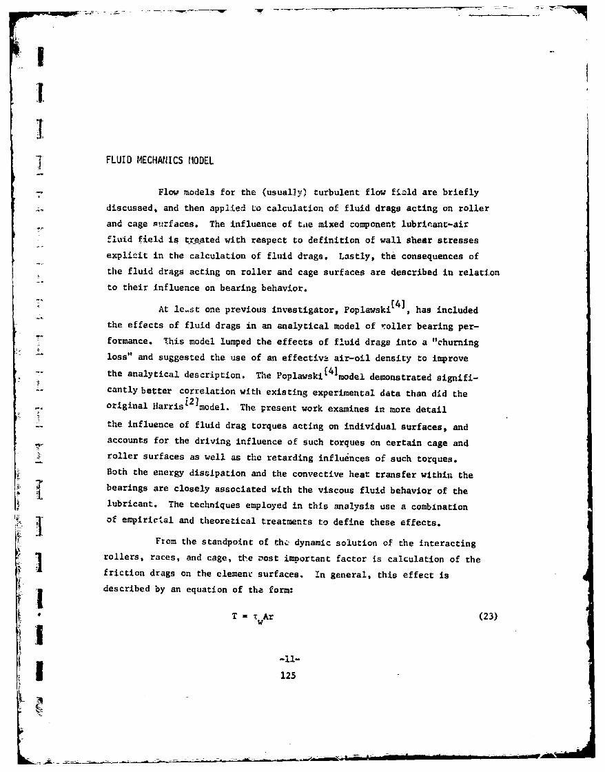
I
T FLUID MECHANICS MODEL
Flow models for the (usual.1y) turbulent flow fi;ld are brieflydiscussed, and then applied Lo calculation of fluid drags acting on rollerand cage surfaces. The influence of tae mixed component lubricant-airflvid field is treated with respect to definition of wall shear stressesexplLitt in the calculation of fluid drags. Lastly, the consequences ofthe fluid drags acting on roller and cage surfaces are described in relationto their influence on bearing behavior.
At le.st one previous investigator, Poplawski , has includedthe effects of fluid drags in an analytical model of roller bearing per-formance. This model lumped the effects of fluid drags into a "churning
loss" and suggested the use of an effectiv_-, air-oil density to improve
the analytical description. The Poplawski[4 model demonstrated signifi-cantly better correlation with existing experimental data than did theoriginal Harris[ 21 model. The present work examines in more detail
. the influence of fluid drag torques acting on individual surfaces, andaccounts for the driving influence of such torques on certain cage androller surfaces as well as the retarding influences of such torques.Both the energy dissipation and the convective heat transfer within thebearings are closely associated with the viscous fluid behavior of thelubricant. The techniques employed in this analysis use a combination
of empirictal and theoretical treatments to define these effects.
From the standpoint of thz? dynamic solution of the interactingrollers, races, and cage, the vost important factor is calculation of the
friction drags on the elemenr surfaces. In general, this effect isdescribed by an equation of the form:
T -tAr (23)w
I125

where T is the drag torque acting over the element surface,
A is the surface area,
r is the reference radius from the center of rotation,
r is the wall shear stress
The description of the wall shear stress is a function of the
fluid properties, the motion of the surface with respect to the fluid
body, and the proximity of other surfaces influenced by the same fluid.
Regarding the last mentioned, close clearances between rotating members
of the bearing have especially strong influences.
Fritz[ 1 2 ]has investigated the wall shear stress phenomenon in
journal bearings with vortex turbulent flow. Examination of typical
roller-cage clearance to roller radius ratios, and Reynolds and Taylor
numbers :epresentative of I x 106 DN and higher bearing operation clearly
place such fluid flows in the turbulent-vortex regime as defined by
Fritz[12] and illustrated for a typical case in his Fig. 3. For surface
finishes and bearing dimensions typical of 1 x 10⁶ DN and higher roller
bearings, the flows representative of cage surfaces appears to be in the
couette turbulence regime.
Wall shear stress for a surface rotating in a viscous fluid is Adefined by the relation [131:
2Tw = f(1/2 o U (24)
where U = mass average velocity of fluid
P = fluid density
f = friction factor
For this correlation, U = r2
[12
The applicable friction factors from Fritz [12, and curve
fitted for computer analysis' are: |
1. TaJ0.539474 ( 5LL
-12-
126
-~ ----- z-~

for the vortex-turbulent corre-Lation and
f LNr2-00
for the couette turbulent correlation.
I Here,
N Rev is the Reynolds number (27)Re Vm
N an "q is the Taylor number (28)
and •
fL N 16 is the laminar friction factor (29)Re-r
A--
Should calculation yield a Reynolds number less than 2500, or a Taylor
j number less than 41, a circumstance virtually impossible In high speed
roller bearings, the appropriate friction factor then can be taken as
Sthe laminar friction factor fL"
In addition to the fluid drag acting on the cylindrical sur-
i faces, the roller ends or cage sides provide an additional source of
drag. Per Refs. [13] and [14] for a rotating disk wetted on both sides,
the total moment resulting from fluid drag about the disk centerline isS~ given by:
1 1 2 5MT p r C (30)
whr7/1NReI for laminar flow, NRe 300,000
where CNe /0196/ 5 for turbulent flow, NRe > 300,000 (31)
I where here NRe = (32)
-13-
1 127

4PL_-7-_ 1 W ------- - -
i
'For hollow rollers and for the cage, account must be taken of
the areas pertinent to the calculations by modifying the radius factor
of the disk equation to the form:
r5 r 3 (r2 2r o = ort r - (3 ) 33)
where
r is- the outer radiusout _
rin is the inside radius
This is at least trur to a good approximation in the case of the roller,
since examination of .he integral from which a closed form solution of (30)is derived shows that approximately 75% of the total moment contribution
comes from the area defined by the outer 50% of the roller radius. Inthe case of the cage, the "disk" torque acting on the cage side surfaces
is less justifiable on theoretical grounds, but the calculated effect has
been shown to be small with respect to the cylindrical surface contribu- A
tion in this instance.
Basic to the above calculations is the realization that high-
speed roller bearings never are completely flooded with lubricant, and
seldom are more than 15 to 20% full of oil within the bearing for very
high speed operation. Indeed, an excess of oil within the bearing hasbeen conclusively shown by Boness to produce adverse effects on bearing
[31operation '. MZotion of the many moving parts within the bearing, in
particular the pumping action of the rollers, will tend to induce an air
oZl mixture within the bearing. lueristically, it can be argued that for pureviscosity effects in a turbulent regime, this phenomenon wi]l have little
tendency to change the fluid behavior from that of a flooded bearing, -J
since in general such effects are confined to relatively thin boundary
layers adjacent to the surfaces. Further, the turbulent mechanisms ofmomentum and energy transfer depends on physical displacement of fluid
particles. However, the density or inertia effects of the air oil
-14-128
L
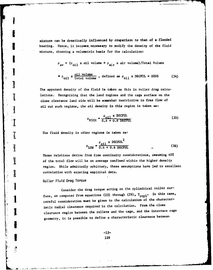
II
mixture can be drastically influenced by comparison to that of a flooded
bearing. Hence, it becomes necessary to modify the density of the fluid
mixture, choosing a volumetric basis for the calculation:
Pav = (Poil x oil volume + pair x air volume) /Total Volume
~ oil volumea x Toto l volume defined as p oi x DECFUL - DENS (34)
The apparent density of the fluid is taken as this in roller drag calcu-
lations. Recognizing that the land regions and the cage surface on the
close clearance land side will be sooewhat restrictive to free flow of
SI oil out such regions, the oil density in this region is taken as:
P x DECFUL"I PHiGH 3 0.4 + 0. EC5)
The fluid density in other regions is taken as-
PLW oil x DECFUL 2(6
LOW -0.4 + 06 DECFUL (36)
These relations derive from flow continuity considerations, assuming 40%
of the total flow will be on average confined within the higher density
region. While admittedly arbitrary, these assumptions have led to excellent
correlation with existing empirical data.
Roller Fluid Drag Torque
Consider the drag torque acting on the cylindrical roller sur-
face, as computed from equations (23) through (29), Try 1 e In this case,
careful consideration must be given to the calculation of the character-
istic radial clearance required in the calculation. From the close
I clearance region between the rollers and the cage, and the interrace cage
geometry, it is possible to define a characteristic clearance between
-15-129L

the rollers and the surrounding elements. Figure 5 illustrates the
geometry. This clearance is defined by:
C=C i* [ C(O)de (37)c CH 2T-)
Circumference
Five distinct zones must be considered in the calculation on each semi- ]cylindrical half of the roller. Rollers are assumed to be in contact with
either the leading cage pocket surface (driving roller) or the lagginig Icage pocket surface (driven roller). Generally, rollers carrying load I
are driving rollers and unloaded rollers are always cage-driven. Com-
paring the two roller surfaces, therefore, the only zone not symmetric |
with respect to the radial ray through the roller center is Zone III,
where the entire diametral pocko-c clearance is taken as 10 uf the roller
radius. Calculation of the clearance is then straightforward, given
dimensions of the cage, rollers, and races.
Similarly, the drag torque acting on the roller ends, Tred* fis computed directed from Equations (30) through (33). For all roller _
calculations, the appropriate density is computed from Eqnation (34).
While not totally fluid mechanical in origin, the sensitive Inature of the roller equilibrium sclution requires consideration of the
influence of the contact beti. -en the roller and the guiding shouldersof the cage in the torque equilibrium sr ition. Computer results show
this effect to contribute generally 5 to 10% of total roller drag moment.
Further, for a roller guided on the outer race shoulder, this moment can
either drive or retard the roller, depencaing on the distribution of relative Ilocal velocities between roller and shoulder. The calculation requires
the assumption of a coulomb coefficient of friction between the roller
and shoulders, generally taken as 0.05 to 0.08 for a well lubricated-
contact. While strictly an integral over the contact area, the moment
can be closely approximated by dividing the contact area into a number
of horizontal and vertical strips or lamina as shown in Figure 6 for a
A.3
130

roller guided on the outer race. A similar situation exists for a roller
guided on the inner race, but the appropriate relative kinematics must
be used. Further, for the inner race guided roller, the local race
speed always exceeds the local roller speed, and hence always produces
a net driving jue on the roller. The moment contribution, Tadd' of
the contact tc a roller moment is then given by
F N V - V SO2
Ta CA =.GRi H I L k- 2 kj (38)ad AG [N-1 (VRi - VHji) 'Ij r•j i A. rjk
The second term always produces a retarding moment, while the sign of
the first term, at least for an outer race guided roller, is dependent
on the velocity distribution over the contact region.
The resultant vertical force is self-equilibrating, since the
velocity distribution is asymmetric with respect to the radial ray through
the roller center. However, the horizontal resultant can be either posi-
tive or negative, and contributes to the contact force between the rollerand the cage, as evidenced in Equation (5). This resultant force is given
by
F iFN IV V- -Fadd (V Vi j, (39)AG il vHjl)
Note that these quantities are funLtions of velocity, and must be deter-
j mined at each roller iteration. Since FiG is constant in any given pro-
blem, the derivatives of F.dd and Td are not involved In any of theadd add
Newton-Raphson iterations.
The contact force between the roller ends and the guiding race
"shoulder, FjG acts in the direction of the roller axis. Such a force can
arise from a variety of sources. Among these are differential pressureacting across the bearing, cage angular misalignments, roller skewing
due to gyroscopic moments, and unbalances in the various rotating mem-
bers which give rise to dynamic forces between the roller and the guiding
shoulder.
-17-
131

In this formulation of the problem, the contact force was assumed
to arise from e' rential pressure resulting from crossflow of lubricant
through and oui the bearing. This axial crossflow was assumed to be
superimposed on L.,e swirling turbulent flow pattern existing in the annular
spaces between the rollers, cage, and races. In traversing the distance
auLvss the bearing, the resistance to flow in the roller axis direction,
and hence the diffeiential pressure across the bearing, will depend not A
only on the a-cial flow, but also on the flow in the tangential direction.
We assume the same turbulent flow mechanism to be operating in both the #
axial and tangential directions. This leads, after some manipulation,
to a differential pressure relation
fp k Ew U6p 2 -- c (40)
where p A
k. is the peripheral length of a typical crossflow passage
E is the bearing pitci diameter
V is a "length of peripheral surface averaged" circumferentialvelocity
WC is the cage angular speed
L is the bearing length
Ax is the area of a typical crosflow passage
Calculation of the friction factor uses the Blasius relation [13]
f 0.3164/(/N) (41)
where here
4V ANRe k v (42)
p
1i-18-132

It is assumed that this differential preosure acts uniformly on the cage
side and the roller disk area exposed to the crossflow. Defining this
area as Ap, finally,
F FjG = 6p A (43)
which is the force apprcpriate to Equations (38) and (39/.
The total fluid drag moment,M acting on the roller in Equation
1• •(7) is ther. calculated as:
Mrj =Trayl -ýTrend ±-T add (44)
I Note, while the first two terms are always positive in this formulation,
the algebraic *sigh of Tad in determnined by the relative velocity dis-
Itribution, as discussed above.
SI C'je Fluid Drag Torque
The fluid drag torque acting on the cage is composed of the
I fluid torques acting on the inner and outer cage surfaces, the cage sides,and the cage land surface. Its influence in the equilibrium solution
for the cage is indicated in Equation (11) by the quantity It.
SI Calculation of the four component drag torques proceeds directly
from Equations (23) through (29) for the inner and outer cage surfaces
1 and for lands, and from EquatL ns (30) through (33) for the cage sides.
The appropriate radii and clearances for these calculations are the local
cage surface radii and clearances between adjacent surfaces. Fluid
I densities in the various regions are computed from Equation (35) and(36). Dimensional changes with speed and thermal effects resulting from
j Idissipation are insignificant in these calculations, except in the case
of close land clearances.
The total drag moment acting on the cage is then computed from
V c cout c in caide Tcland (133 +T
-- - ------. -- g- -

Note that since the total drag moment positive sense is in the direction
of retarding cage motion, the outer surface and side torque terms are
always positive. The inner surface drag torque always acts to increase
cage speed and is hence always negative. The sign of the land surface
torque is positive for an outer land riding cage and negative for an
inner land riding cage.
Influence of Fluid Dral Torques on Solution
Figure 7 compares the predictions of three analytical models
with samples of previously published test data of rolle: bearing cage
slip as a function of applied radial load. The present model demonstrates
almost exact correlation with this data across the load range for which
data is available. Close correlation is shown by the Poplawski [ 4]model,
which uses a simplified fluid drag correlaticn. The Harris model
matches closely the trend of the test data, but differs significantly inthe magnitude of slip predicted across the load range. In addition to
the correlaiion shown for an outer land riding cage, the present modelhas also accurately predicted the experimentally measured cage slip ofan inner land riding'cage bearing.
Power dissipations predicted by the model closely match availablerig data. Shaft horsepower dissipation is computed by summing alltorques acting on the inner race. The prediction and distribution ofthese dissipative losses is essential for accurate determination ofthermal gradients and operating temperatures.. Predictions for two con-
ventional roller bearings analyzed for comparison are summarized below.Uperation was approximately 2.0 x 10⁶ Di.
Experimental Power Computer PowerBearing Dissipation, Hp Dissipation, Hp
130 MM Bore 5.80 6.94
115 M Bore 4.25 3.89
Data courtesy of Boeing Co., Vertol Division, Philadelphia, Pa.Data courtesy of Midwest Aero Industries, Div. Pure Carbon Co., St. ma~ys,
Pa. -20- A
134

Both bearings were operated at near synchronous condition.
This calculation is extremely sensitive to the amount of lubricant within
the bearing, estimated at between 10 to 15% by volume by the test agency.
The 100 MM bearing was analyzed for 15% oil-to-air ratio within the bearing,
-and the 115 MM bearing was analyzed for a 10% oil-to-air ratio. It will
Sbe noted that the results bracket the experimertal data, being high for
the higher oil/air ratio and low for the lower oil/air ratio. A rrpeat
I of this analysis taking both bearings at about a13% oil/air ratio would
yield results matching the experimental data.
I The foregoing illustrates generally the sensitivity of the
solution to fluid drag influences. As further illustration, consider
Figure 8 which compares two cage error curves as functions of cage speed
for all other conditions the same. For this relatively low speed applica-
tion, a difference of 10% in oil/air ratio produced a 2% difference in
-! cage slip.
The shape of the cage error curve, of Figure 8, provides a
I possible further insight into the bi-stable operation of bearings noted
I by some investigators. Dr. Ehrich [15] noted this phenomenon, and
j hypothosized Its origin as systematic changes in bearing clearances
coupled with dynamic phenomenon of shaft rotation. The cage error vs
I speed curve always has the same characteristic shape, for which three
solutions are possible when slip occurs. One root Is always close to
Ssynchronous, where the sreep slope of the error-speed curve requires
successive predictions at small slip valves to obtain a solutions.
Other solutions are possible if the. error curve changes sign at less
i o than synchronous speed (two possible additional solutions), or if
the error curve is tangent to the abscissa of one point. Since the magnitudes
I •of the errors are strong functions of speed and load, and to a lesser extent
of oil/air ratio, it is possible that for some combination of thesevariables the bearing operation may oscillate between two closely spaced
roots. This might occur as thermally induced dimensional changes in
internal diametral and close land clearances change the operating
-21-

conditions of the bearing. juch operation has been demonstrated using
the present model with thermal and dynamic effects considered. One
computer run found about 3% slip on the first iteration (without thermal
gradients), but sought the synchronous solution when the results of
thermal gradients resulting from the first iteration were reflected in
the second. While not conclusive at this time, this subject bears
extensive further investigationg with comparison to Lctual test data as
it becomes available.
Is
--
-I-j
-22-136 -

DIMENSIONAL MODEL
The model accounts for changes which occur during bearing
operation as a result of dynamic (centrifugal effects) and thermal
JI deformations. The effects considered to be most significant are:
I * Changes in bearing internal diaetral clearance (mc) withdynamic and thermal deformations and with shrink fit betweenthe inner race and the shaft.
S• Changes in bearing internal diametral clearance (IDC) due tochanges in roller (especially hollow rollers) diameL.-r withdynamic and thermal growth.
9 Changes in close clearance guiding cage/race lands withthermal and dynamic deformations, and for an inner landriding cage, changes in the clearance with shrink fit
Sl between shaft and inner race.
- The use of simple closed form expressions to predict the
dynamic and thermal dimensional changes occurring in bearing members is
desirable, since this greatly simplifies the system analysis. Predictions
of such deforma,:±ons, on the other hand, must be more than order of mag-
nitude accurate to realistically describe the influence of such operation
dependent variables on bearing performance. In the process of model
selection, estimates of defor's.tions from available closed form solutions
J were compared to the results . more sophisticated analyses, using finite
element computer solutions of typical bearing element geometries.
Dynamic Deformations
The dynamic deformation models selected for the races, rollers,
and cage are given in Table 1. and are obtained from standard theory of
elasticity sources. (16 and 17] Comparison of finite element solutions
for A 0.50 "diameter hollow roller with a 0.25" diameter hole showed
closest agreement with the generalized plane strain solution. At roller
1 Jspeeds of 150,000 RPM and higher, a ± 4% bulging and contraction of the
outer surface near the roller edges was calculated in the finite element
solution. This cannot be predicted by any of the closed form solutions,
however, since it is common prac~ice to crown rollers, this iariation is
-23-137

not considered significant. Frr a solid roller, little comparative
difference was noted for any of the -losed form deformation relations,
and hence a plane stress relation was used for simplicity.
Both the inner and outer surface deformations of the inner
race, are significant. The deformation of the inner surface contributes
to change in the shrink fit between the race and the snaft, and deformation
of the outer surface influences both the bearing IDC and the land clearance !
of an inner land riding cage. The closed form dynamic deformation relation
best describing the behavior of both race surfaces was found to be the
plane strain relation. These relations generally predict deformation within
5% of the finite element results even at extreme speed, providing race
undercuts or other irregular ries such as guiding shoulders are small.
The shaft outer surface deformation is also significant in that
it contributes to change in shrink fit. While not checked against a
finite element model, the shaft conforms to the basic assumption3 of the
plane strain relation.
The deformations of the cage land surfaces are significant iti
the determination of clearances required in the calculation of cage land
fluid viscous drag. Agreement of closed form predictions with the results jof finite element modeling were within 15 to 20% for this deformation for
all closed form solutions. Hlowever, the calculation of the fluid viscous
drag has been determined Lo be insensitive to this variation, changing
only about 2% at maximum speed. This larger deviation is the result of
the inability of the closed form solutions to account for the difference
in cage surface and land diameters or to account for bending deformations
resulting from the additional mass of the land protrusions. Over the
relatively narro," land width, the land surface deformation is fortunately
quite uniform, as predicted by finite element analysis. The closed form
solution best matching the finite element results, within the limitations
discussed, was th- plane stress formation.
Shrink fit (A) between the inner race and shaft acts to 4e-
crease the bearing internal diametral clearance (TDC), as compared to
-24-
138
K__ _

the IDC of an unmounted assembled bearing. Also, for an inner land
I riding cage bearing, the shrink fit decreases the close land clearance.
An extenaive treatment of .this subject is contained in references [18].Ii Thermal Deformations
The model used for calculations [16] of thermal deformations
ST assumes an axisymmetric temperature distribution, uniform end deforma-
tions and cylindrical geometry. The radial deformation of the ith bear-
- ing surface, having inner radius, r,, and outer radius, ro, is given by:
6T 2ar r 0 2ariJ -T (2 r 2 )1r
6T F2- J T rdr F 2-r2( out- ref 2 L 0I 4
(Ti ref) n r j - (46), ! L L2~nI 2 J2
The above relations are known to be quite accurate within the
governing assumptions. No attempt has been made to date to confirm it,
detail cheir accuracy for this application. Comparison of thermal growth
predictiors to the limited empirical data available to the authors shows
reasonable agreement of the magnitude of these deformations.
When applying the above to prediction of the thermal growth of
the outer race, it must be noted that no radial constraint is included
I �n the formulation. This is typical of th.e test environment of roller
bearings -where loading is accomplished through an external yoke, but
growth of the outer race is otherwise unconstrained. Other application
-25-j 139

riii|
of this type of analysis must consider any radial constraint appropriate
to the application, particularly because of the possibility of bearing
thermal lock-up.
From the above, it follows that when the surface temperatures
of all bearing elements are known, the thermal deformations of the bearing
members are completely defined. ATHERMAL ANALYSIS
Problem Formulation
The temperature field within the bearing must be known in order
to compute thermal deformations. With the basic assumption of axisymmetric Itemperature distribution, the techniques of performing such an analysis
are well known. Harris [19] has applied heat transfer techniques to the
determination of bearing temperature distributions. The technique
presented here will basical.y follow this presentation, with additionalJ
emphasis on the calculation and distribution of power dissipation within
the bearings and on calculation of convective conductances or heat transfer
coefficients appropriate to the calculation.
All three modes of heat transfer, conduction, conveetion, and
radiation can operate between bearing members and between the bearing
and its environment. Conduction is a linear phenomenon. Convection is -
basicaily non-linwar in that the convective conductance is strongly
velocity and temperature dependent. However, in the iterative solution
technique used, Fig. 4, velocity is fixed at each step of the iteration.
Temperature dependence is mainly reflected in fluid property changes.
Since the iterative scheme employs the updated temperatures from the
previous temperature iteration soli .ion in the convective conductance
calculations for the current temperature solution, the convective mode
formulation is linear at each temperature iteration. Radiation heat J
transfer depends on differences of forth powers of surface temperatures,
and is hence always non-linear. The forms of the conductive, convective, U!
[!
-26-140

Iand radiation heat transfer equations respectively are:
in11 & 1 i; hollow cylindrical body of length
I rs - I a , in radial directionHc ond ij (47)
""iT ; axial dire;-tion, through area AT overSAL distance AL
H convi h k A ATij (48)
H4- ( o__. (49)
__ nA A
m F m,n s n
where
a - Boltzmann radiation constant
(m dnd n are the emissivities associated with the m th andS~thn surfaces, respectively.
= view factor of nth surface seen from mth surfacem,n
These equations are basic, and arf derived in any standard heat transfer
I text, such as reference [20].
The radiation mode of heat transfer becomes significant only
Sfor temperature differ v-. of the order of 1000F and higher. For normal
bearing operation, such conditions do not ex.st within the bearing. How-
ever, heat transfer by this mode can be significant between the bearing
and its environment, and must be included.
I Formulation of the heat traesfer problem requires discretizing
the bearing elements into a set of nodes, and writing a Kirchkoff energy
balance at each node. The power dissipation occurring within the bearing
-27-
141

acts as the driving potential, and must be computed and distributed among
the nodes. Fig. 9 defines the nodal pattern used in this analysis. In
this model, provisions are made for coolant flow through the outer race
and through the shaft, and for lubricant to be flowing both through the
bearing and under the inner race. Any of these flows except the flow -i
through the bearing may be set to zero. The coolant through the outer
race, and the lubricant flows under the race and through the bearing are
assumed to mix external to the bearing, and to wash the inner surface of
the chamber, the shaft, and the exterior of the bearing. The environment
external to the bearing assumes the assembly to be enclosed in a test
chamber, and to be loaded through an external yoke extending through the
chamber. The governing equations are then of the form, for nodes i 1
to 21,
21 NiHi H+ I Qk wc 1 (50) j
jal kal
Here H is the energy transfer between nodes i and J, and the Qk are theijdissipations, external energy inputs, energy transfer to coolant or
lubricant flows, or losses from a typical node i. Ni is the total number I
of 0k at node i. Table 2 illustrates the flow of energy between all
nodes, and defines the Qk qoantities at each node. The explicit forms of
the equations defined generally by (50) are derivable directly from ATable 2. Note that all energy fluxes other than losses are assumed to
enter each node. The temperature differences of equations (47), (48) 1and (49) may thus be uniformly taken at (Tj - Ti) at each node i.
The energy balances of equations (50) are equated to the error I
functions cis where ci approaches zero for the steady state equilibrium
set of temperatures. At each temperature iteration, Fig. 4, in the bearing
solution, ;..is non-linear set of equations is solved by Newton-Raphson
iteration techn:-'es. As an initial guess of the temperature field to j}start the iterative process, setting all temperatures equal to the previous
-28-142

I value of bearing oil temperature, T11 , has been found to produce rapid
convergence. To implement the Newton-Raphson solution scheme, the set of
I equations (50), with the 11,J quantities expressed in terms of equations
S(47), (48), and (49) must be rewritten in the form
T +A 4 3k B (51)
ii iUj k , k
k-1
Here the Aij are thermal admittances for terms originating from convection
I and conduction, and A*ij are thermal admittances for terms originating
from radiation. N! is the total number of quantities, Qk at node i not
SI explicitly containing temperature, and Bk are constanta originating from
such sources as products of lubricant mass flow rates, specific heats,
and inlet temperatures. The non-linear set of equations (51) for £ 1
to 21 is then directly solvable for the temperature field using the Newton-
Raphson solution technique.
Power Dissipation
As previously stated, the driving potentials which result in
thermal deformations are the power dissipations occurring within the
I bearing. These arise from fluid boundary layer and coulomb friction
phenomenon. The distribution of the component dissipations is shown in
Table 2. The total power expended within the bearing must appear at the
shaft surface, since this is the driven member, and is easily calculated
as the sum of all roller to inner race tractions and the sum of the fluid
drags acting on the inner race and shaft surfaces (including land torques
for an inner land riding cage). Shaft power loss is an important design
factor and one that until now could only be estimated emperically based
upon test experience.
Power dissipations at specific nodes, shown in Table 2, are
also easily calculated. Roller to race contact dissipation is the productIm o0 the EdD traction and the sliding velocity in the contact. Fluid drag
-29-
1 3.
-~ - -

moments are a. ribed by the fluid mechanics model.
Ext 4i energy input such as energy dissipations by slave j
bearings supporting the shaft in test apparatus, other supporting bearings
in an engine, energy input from turbine gasses, etc., must be calculated
separately and introduced as heat sources or sinks at the appropriate
nodes of Table 2. I
Heat Transfer Coefficients
Correct values of the heat transfer coefficients, or more
properly the convective conductances, used in the thermal analysis are
essential to obtaining a representative solution. While standard tech-|
niques of determining these quantities can be used for non-rotating sur-
faces, the shaft, cage, and roller surfacen pose a special problem.
3jorklund[ 2 1] has investigated the problem for the case of concentri-
rotating cylinders. The techniques and correlations of this source will
be used here.
For two concentric rotatin- cylinders, with the annular space
between them containing a viscous fluid, the critical Taylor number for
both is given by 3
48.7 2 +r 'r5)_ __ _ _ _ __ _ _
N Ta cr ý 1 1 ] + .000561(I- rl-n(l+ C .0571 fi+'- 0.625 -S + 0(52)
L 5I lt5 L -5 L5- 0.625 r 5L
where
,, _S Speed ratio (53)
C - radial clearance between inner race and inner ca"e surfacesor between inner race surface and cage land surrace for an Linner land riding cage.
-30- 1144 1

f The Taylor number for this condition is given by
N T- (Rwc/0) (54)NTa R (4
where
we - kinematic viscosity of fluid
R - radius of inner rotating member
J • for inner race to cage condition,
c for outer race to cage condition
I •The Nusselt number for pure conductance through the fluid is given by
I and the ratio of the local Nusselt number to the conduction Nusselt number
is given by
NTT1 - 3. NC 1/2
N N , NTa N Tacrn Oi I r5Ncr c r oj -. 5-(56)
"N Nu 41.1+ [NTar- NTa 3.5 C
cond n nfOk r 5
Finally, the convective conductance is given by
'I' h - N (57)C NU
I where kf - thermal conductivity of the fluid.
For the inner cylinder rotating only,
N~u 1/2N Nu 0.175 NTa (58)N NUcond a
I applies as an alternate to equation (53).
-31-
1145

Here the appropriate C is the radial clearance between the outer race
and cage outer surface or cage lands for an outer land riding cage.
Equations (52) through (58) can be used directly to obtain the appropriate
coefficients for the race and cage cylindrical surfaces. Over the ver-
tical cage surfaces, an average of the coefficients of the bounding
cylindrical surfaces is recommended. These relations also define the
coefficient values on the roller surfaces, using equation (58) and the
average ro~ler clearance defined by equation (37). In all of the above
calculations, the tluid density used for the calculation of the kinematic
viscosity should be computed as discussed in equations (34-36). The t
variation of fluid properties with temperature must also be considered,
updating the fluid properties at each step of the iterative solution.
Coefficients for the outer bearing surfaces and the chamber
inner and outer surfaces are computed from a correlati3n suggested by
Jakob [22 for natural convection of fluils in contact with horizontal
cylinders
0.25 Skf D3yg At
h =0.525 r (59)fjI
where
D - diameter of cylinderr
y = coefficient of volumetric expansion
g - gravitational acceleration
ad = thermal diffusivity
At - absolute value of temperature difference betweensurface and bulk fluid temperature
For condition inside the chamber, the fluid properties appropriate to
the calculation are those of the lubricant, since the bearing outer sur- [Iface, the shaft, and the inner chamber wall are assumed to be washed
with the mixed oil. The temperature difference should be taken between f
the surface temperature in question and the mixed lubricant temperature,
I which is computed from
T 6 c• p T6 + ;l cpl T1 +;16 16 1 16 (60)lave (i... + in1 -(; lwee(6 c P6 + ci Cpil + ;16 c16d
where
is the mass flow rate of the i th lubricant
cpP is the specific heat of the ith lubricant at Temperature Ti
I For the outer chamber surface, the appropriate fluid properties are those
of air, and the temperature difference is taken between the chamber wall
Sand the external ambient. For external circulation of air over thechamber, forced ccnvection relations must be used, for which standard
formulations can be obtained from Kays(23]
The shaft surface coefficients can be obtained from equations
1 (52) through (58), using equation (58) rather than equation (56), ifcare is taken to use mass averaged fluid properties. The resulting
prediction will be higher than the actual coefficient value. The clear-
ance required here is the difference between shaft and chamber radii.
This result should be checked against the prediction of equation (59),
uhich prDvides a lower bound on the coefficient value, and engineering
judgement used to choose the proper valve of the coefficient.
SThe heat transfer coefficient for the external surface of the
loading yoke depends on the geometry of the member. Generally, this can
be treated as a fin heated at the root, and standard correlations applied,
such as those of reference 120].
I Sample Themal Analysis Results
The results of the thermal analyais of a conventional 'Anner
land riding roller bearing operating at 2 x 10⁶ DN are siArized in Table 3.
The guiding shoulders for the rollers were on tne outer race. Two cases
-33-• I147

iii
A
are compared, for conditions with and without under race cooling.
This analysis was accomplished using specified operating values of IDC
and land clearances, and hence the results are quite comparable for cage
slips and power dissipations. The original conditions necessary to achieve
the specified operating conditions were computed from the results of the
thermal analysis and considering dynamic influences, and are summarizedt
in Table 3 along with results pertinent to the thermal analysis.
The results shown in Table 3 are consistent, showing generally
lower temperatures for the case with additional cooling, and a higher
oil temperature rise for the reduced cooling case. Also, with under race
cooling t!e temperature difference from the inner to the outer race is
13.7*F, as compared to a temperature difference of 34.7°F for the case
of no under race cooling. These results are in general agreement with
measured values for comparable bearing operating conditions.
DISCUSSION OF APPLICATIO4 OF EXPERIMENTAL TRACTION DATA AND ROLLERKINEMATICS
Typical traction values for several roller bearings from 65mm
bore to 140mm bore and for shaft speeds from 1.0 X 10⁶ DH through 4.0 X 10⁶
DN with MIL-L-7808 oil are presented in Table 4, for unloaded and the
maximum loaded roller contacts. All tabulated values were computed with
the full EHD, fluid mechanics, dimensional, and thermal models described
in this paper.
A roller always rotates near a pure rolling condition (low
sliding velocity) at the outer race contact of a roller bearing with inner
race or shaft rotation. Sliding velocities from near zero to 3 in/sec are
typical as shown in Tables 4a and 4b for outer-race contact.
An unloaded roller, Table 4a, rotates about its own axis at an
angular speed slightly less than the angular speed required for pure
rolling at the outer race contact. Positive sliding (outer race relative
surface velocity is greater than the roller surface velocity) always
occurs and is in the range of near zero to 3 in/sec. The rolling portion
-34-
148 =

II
oR the total traction value is significant and cannot be ignored. Indeed
fthe rolling portion can even predominate as shown by the ratio of rolling
traction to total traction in Table 4a.
A loaded roller which produces a cage driving force rotates
about its own axis at an angular speed slightly greater than the angular
J speed required for pure rolling at the outer race contact. Negative
sliding occurs and is in the range of near zero to -3 in/sec as shown in
Table 4b. The maximum loaded roller and most of the loaded rollers in the
bearing have negative sliding at the outer race. Occasionally a lightly
loaded roller or rollers near the entry and exit from the radial load zone
will have positive sliding at the outer race contact. Such rollers result
in a net drag on the cage similar to completely unloaded rollers. In all
cases the rolling portion of the total traction is significant and cannot
be ignored.
A loaded roller always has positive sliding at the inner race
contact. Typical values are shown in Table 4c. A bearing operating at
essentially epicyclic cage speed (no cage slip) has very low values of
sliding velocity (< 3 in/sec) at the inner race contact and the rolling
pornion of the total traction is significant. A bearing operating with
measureable cage slip can develop high values of positive sliding velocity
"at the inner race contact as shown in Table 4c. In these cases the sliding
portion of the traction reaches a ceiling value and again the rolling
portion of the total traction value is significant and cannot be ignored.
A high speed roller bearing with elastohydrodynamic oil films
cannot operate under a pure rolling condition. An examination of the
J •traction formulation of Eq. (3) shows that ýor zero sliding vehocities the
traction at both inner and outer races would be negative and no equilibrium
1 •solution can occur as shown in Fig. 2. Some cage slip (however small)
must occur.
-35-
149

RECOMMENDATIONS
1. Experimental data defining the rolling portion of the total
traction force in an EHD contact is needed. The accuracy and usefulness
of a complete systems analysis of a high speed roller bearing is very
dependent upon good rolling friction data.
Archord and Crook have stated that for loads which develop
essentially 1.ara±lel surfaces in the Hertzian contact and at speeds of
sliding above a few centimeters per second, the sliding component of
traction predominates and the rolling component can be ignored. This
assumption has been generally accepted and has led to an emphasis upon
obtaining twin disk traction data only for sliding conditions by current
researchers.
Typical twin disk machines (with equal size disks) measure only
the sliding contribution to the total traction in an EHD contact. Be-
cause of disk symmetry the data is also symmetric abcut zero slidingspeeds, i.e., the traction value vanishes at zero sliding and reversal
of tb* relative slidina direction reverses the direction of the traction.
The rolling portion of tue total traction is very 3mall compared to max-
imum traction values. The instrumentation of existing traction machines
"is not desigued to measure small magnitudes of rolli-Ltg traction, indeed
the contribution of rolling traction is calibrated-out along with disk Isupport bearing friction. Symmetry of test machine geometry leads to
symmetry of results. Special attention to non-symmetrical bench rig
design and instrumentation is required. A
2. Cage dynamics need to be explored and better defined both -j
experimentally and analytically. Bi-stable [15] operation is shown
to be possible by the present analysis.
JI
-36-150

- -! .. I IIEI
S III ACKNOWLEDGEMENT
The authors express their thanks to The Franklin Institute
Research Laboratories for sponsoring development of the computer program
and preparation of this paper.
UA.
L
I
-37-1 151

- - -~- -w ~ --- --- w-----------
i.
FIGURES
138
1
I
I
11
-38-15

"I
2 r
I
7 Ij
E
Figuire 1. Surface Velocities and Relative Rotational Speeds ofRaceways and Rollers Including Slip at Each Contactas a Result of Cage Slip
11

P.j
-ii
- T o j F-h o j
0- Q oij %,.CF" ; FC j
,'hvC.
T ij-
-- -- __ / N O T E : Fadd S H O W N F O R ,i /Pj ROLLER GUIDED ON
OUTER RACE
_ -i
Figure 2. Forces and Moments Acting on a Loaded Roller I_Iii
- [I-40-
154

hojooJ
NOTE: Fadd SHOWN FORROLLER GUIDED ONOUTERRAC
Figure 3. Farces and Moments Acting on an Unloaded Roller
-41-
155

~et~mmo Lelcat Prriisa~t Parametest
Fo. QOg Cap $aid C. Ee Is LosE C oo..en
Role Speed soj un
1. 3.A SOLVIO DIK I JULO AC MDOE L L
if irf I~~c% Preo pv toll at END I Race Tm.nCeptSiteralao Effe tsfSiTo.a nd Cenrifga
Forcs g 11rin JO an Ca toLoa Cl a nrgaz l
2. CSE OLUT ON FedLOe ogs: e~~o ~tiCameur f~v Srf~sVeloitie
It_____________________ W.cto Go flmThcooTrcto
I ~ aclt FluidL Losse SOUiE onslt Rouler 1r140o waive
e.~ ~w ~~dO4 ~ Incl4w":g allini ofti b enrs i blie
Ro .0ea ifr Unloaded Rollers.t II IC$*tMFCP
- Inc Is$ Railing Frcto oatot BetI ITest f*taLIadedal ValueI .INE RCal IOU Ge LORD hic and
6. MrUton SPE iD jos.NI I - Loudi~ria sf
Co ou I I nitia l T Valvq e .
Call ED Usin fiee tonRbpnsfroactiw.Ceons nt grCalculaeFluidLosses._______
fltt on man tter
It ed o *rn Ste ffn wlsa.
Coqeto Tomouto Load Eque tot CaonI ~ ~ ~ kl Using Wdiiadfiv St. Ttnoive
Cenergcs ive fi's)valve of Pt
I te10.in'o usoing is(b -etA fl
L- -- altlal ( r. ContactInlet Stiffes.
Figur 4. ol uttaT~WE onl~ Teciue Clwahatp
Mai 1"Ilo 7ld e O -4 2-COM "M61s rm) olo 156v

z NUMBER OF ROLLERSDCI =INNER DIA. CAGEDCO- OUTER DIA.CAGE
Em PITCH DIA.t80' __
""z C'=AVERAGE BROACIEDPOCKET CLEARANCE
S /i • "•" DC1/2 /( El2 ~~DCO/2 " .•
Figure 5. Roller Clearance Distribution in Cage
2L
1-43-
-J 157
K _

1
N HORIZONTAL STRIPS
SISRI Aji =AREA OF ith STRIP
ViA(;iAG= TOTAL CONTACT AREA
+ •CENTER OF ith STRIP7 i th._.____R
VRi= VELOCITY OF RACE AT
Vp. i=VELOCITY Q.F ROLLERr AT CENTER OF ith STRIP
j
Vvjk S VERTICAL STRIPS
AVjk ?AREA OF kth STRIPri
VVjk = VELOCITY OF ROLLER.kth AT CENTER OF
kth STRIP
+
Figure 6. Mathematical Model of Horizontal and Vertical RelativeVelocity Distfibutions in Roller-Shoulder Contact
-44-
158

I
I ROLLER BEARING CAGE SPEED CORRELATIONMIL-L- 7808D
15,100 RPM.o00" MOUNTED INTERNAL CLEARANCE
OUTER RACE RIDING CAGE7000 .. . [12
V ORIGINAL HARRIS
6000 - - FDL/EPICYCLIC CAGE SPEEDS1 •ooo ...i | - -- -,,_-. --
1• .,•.,-""O0..X 0^ -I 54000--1 / -i'''
50007 -
43000
I %I .' •I.00/ 800 1200] 0 00 40 e0
wCL I POPLAWSKI -ROLL DRAG + CAGE DRAG0- xI ~ 3000
09I 2001 X FIRL MODEL
100 0 EXPERIMENTAL DATA
0 400 800 1200 1600 2000 2400 2800RADIAL LOAD (Ibs)
I *DATA -COUrt0SyP Of ROEING COMPANYV;FRT0L 01VISIOf4PHILADELPHIA, PA,
Figure 7. Roller Bearing Cage Speed CorrelationI -45-
L5

(ei/NI) 3flomoi 80183 M39V000 0 0 0 0
0 in 40 -
40
0 I I
ww
4n U
S-4.1
U) 0
0 0
/0 I1.1 - 0
+ 0
j 0 W
oww
CYC
49'
0 0 ~ z ZC) .z 0: in
t5 C m
U 0
-46 00C 0 F160W0 -
0 z W 5 j .K 1:Ný

S• •- -• - •l•-'-'--w - - lw - -l
• -I~ l~
I
iI
I il
I I
-47--
161
1 1 )
2iI A. I
I :- '.'0.
I -
I 16
I 09

-Ir ---
SI
ISI
I-I
V !_ I A LE
IN
I
gI
[!
1 162

II
f -~ -~NN0
.4.4
NI.
N+L.
I.. F. 24v I~N cm 4
cc 0
+i N
16 S.. +M+1 N L NQb NIILN 0
*0,IaxI- Q% -R L
Ix -S-60 s Nioj ~ -
b - 'A
IV - 6 CV 4c c.
0. 0. 0. I0v.
C~ c a0- C I4~EU EUVA
NEa 6 tLU .
U) U) A -49-j .- 'D 41 416 3 4

Table 2DESCRIPTION OF rHERIIAL ANALYSIS BY NODES
$set TtS~fel 101111
Watio e adhe ml 0w et1im With 11111191 TYP ESrg' *Asip'mant NOW
I loers poft goo1911 2,21 cV 4 .6 A141 (T~ ToolI' Cooilant tiow tfttUII hollow shoft,
2 IfnrW ots v4 o --1 0 Ingsio~rwas fit~,4(a),awoo C awra of ?a 4 TjI ouate Weit Serfea 4(3 6) far A£ 0 lniSt fit on Shefn
C
4 swear u,. . 4,0eais~si of imer. j(6).6(d) tV 6*2 eetr~efe of T4 S ts
S middle U02lnof "toIg~ld& of 6(s)(a),6 a) sides ofNot emsMinset hAm 4,7,13 C
Woloudr fts coolant al(ig C .%,(T 3 7)Gl flow amlias .eds? Ifther roea.
7 um 94er ofp Too Side ; $Mose it gV 1/6 4S%-.CepAatr Sutrfe. t)tor liews land ridlip aspld
CC 1/ ,t-sl ~ fO ) %31 .Laua" avaego at To Tf ag
side airfoea
9 flse lvlefas" of Ca iwil CV :/j @eIrCabe-IAr Surfsa" J3lseipagiss dwil te C"106*'lOC V. trisggle Whee roller end Aspe
IsSublte 1rtaaof atoCp i(ii CV I~ (ji VVA-el Velma (Ttss))
i2,ih 3. 2/I %12 Ca.aeL ( W ae
It Oil Vllgive loating 7,.,@i~~4 CV tit * *,iCl,i(T,..iu Oi i. lteg hr
i/3 Og1;.Loods 4 keo of Seurfe"
i/ar4i~i~tbas94LtIK Lis TrestleoIII %LK-w is 111111 Vaioslit
ito fals? It CV 1/2 %t 1shllesrhem ( J)1/4 Qs&,uIlwiar Maea
Is 014a Session af Too Sids of 1i CV 1/4 04uLesart~ Sae"iWW Sees, (bletss Pall) S.? C
14 PINA? Sopte.aft of at er s A CV I/Ps 4suiag4vear AW.(Ifollor P,*u) i5S
is twate (tasla.') Irfest *f oetAr 16 CV i)IgUdt6losa 14.17C
IS blato RO h las Coolin thu5i.17.l8,19.111 CV 416. AigC,15(T131 -1161 ail fiow tMWvl out*!' rieusesIt IMat (41014f) $Vrhtt. 01 SOAr It tv
Seas 11.11 CIo fl"?larto ofra oute blat e 6,1 1 6,*i Cv
It CAheow VIISlc SktstCsS~ae) Ai 1) ae4tpetl enarity iftet tromIC Ma s "r prs. sells, sic.
N Load Vons fast ISC 4WjtV.A"lset Air.If abser oheft Surfs" huots from .~i~S(iI CV tt(1cia.ealselaalltu
Dutestlg~j)j3 C) sist sit ned.,two tiwe t i
-50-
16 4

Table 3TYPICAL THERM.L ANSLYSIS
Bearing I Lubricant Data
I Pitch disaster - 6.512 in.Roller diameter - 0.5 In.
Operating IDC - .002 in.Operating radial land clearance - 0.015 In.Lubricant - HIL-L-7808D
Lubricant flow rates - 6 1b/lin through tearing (both runs)
6 b/min unL-r rAce (2nd run only)
Lbb•:cant inler taeperature - 250*F
Radial load - 333 lb
Shaft speed - 14,2&) rpm
Oil/air ratio in bea:Ing - 15%
"1= Temperature Distribttion (Ref. Fig. 9)
Temperature, "7No Under-Race Under Race
Nod& Loration Coolins Cooling
1 Inner shaft coolant
2 Inner shaft surface 361.5 295.83 Outer shaft surface at bearing "r.7 293.64 Inner race at shaft . 8 310.75 Under-cut surface ot inner race 362.5 314.66 Under race coolant - 265.9
S7 Inner race beyond roller coa.tact 361.7 317.1
8 Cale at the land 380.8 370.39 Calle Inner surface 393.1 383.1
1 10 Cage outer su:rface 392.9 383.011 Intetman lubricant to bearing 330.7 318.312 Rillern 351.3 339.2'1 13 Inner race at rollers 367.5 324.8.1. 14 Inner surface of outer race 329.9 30;,215 Inner cooled surface cuter race 329.9 307..16 Outer race lubricant ..
O 7 Outer cooled aurface outor race 329.8 306.218 Bearmw cuter didaetsr 329.4. IC2.619 Chamber wal: (inner aide) 309.0 273.7
20 Loeding bolt (strut) root 281.8 :60.121 Shaft (external to bearing) 335.3 293.1
No Under-lace 11ith Under-RaceCooli CCol1j
Percent cags flip 32.5 33.7
Pow-r dissipation, H 7.09 7.15I pInitial ehrin0 fit, in. 0.0082 0 0088Machined Im. IA. 0.0097 0.0089
Mounted IDC. in. 0.0024 0.0011M.'hincd diamecral land clearance, in. 0.0037 0.0035Mounted diecmtor land clgat -to., n. 0.0029 0.0027
-51-165

Table 4
TYPICAL EIID FILM THICKHESS AND TRACTION VALUES
4a -
OUTER RACE CONTACT OF UNLOADED ROLLERS
Sild~oc 3 .Ila
1.9 11.0 11111 2.6n 11 ;. 9w 4~S 1.1511 - 6.31 0.4311 NU. 21 1031 4-7 1 6.494 cms 4311 11.73,3. 6 :4011111, s .ell Ise I~i 6.69?e * M .13 3. 1 S.1 1 13.390, gmit 3.3$ 81.3
1.0ul 1333 a~ Jet. 3 .1 C l."t 3.4? ii 601 0 L- C4611.2.L 3..",t 11 2 .
4b
OUTER RACE CONTACT OF MAXIMUM LOADED ROLLER
11, as -41 i OW 4 -. 04.1 .4. -710.20 113 ie 2 1. 1, 1,1 AL 0.0 .i. 1t3.0.-AA 34. 0,5 -*S.M! - SAN1 1i s.4 1 47 n OW 1 6~ 1 .30. Impt1 34g. L"3i_ 0 ek 11% i ' S W .611 .1 LOS ji.L $10 1113,L?1 14 4.W 1~ 31
#.1."" 3111 .-1.1011 115.1 S.4c21 - 4.639 *0.631 - M.1 1 .1 in. 136 .4 066 1C 41.1310 to", 321 6.6so.l ,11 3 e3- 4c IS., M -4 .061 -6.16 - 5.611.3 8. 0 too -06 1"M1 P 4.3" to a s~ a6 ."6
41.011 34t133 40.06 34' 11 .941.413 31.141 Cl* 6.12 - * .? me4 I"l4- V66 0.W3 26 us1 0.63'
4cI
1.1 ~ ~ INE 18.06 CONAC OiFl MAXI. cOADE ROLL . .3 .333. )01-CCER .0 4.?3363
6. cci 1) c ) 1.3 3.06 .36 * .13 * N 1? 31 314353 1 #us"m, 1 06
4.5 ~ ~ ~ ~ ~ ~ ~ ~ ~ ~ ~ ~ ~ ~ ~~~~~~i 113)113~16. sl 01 * .3 W *, 36 3-~~ 6 ~a4 1.. 16 660.S~ ~~~~~ ~~~ ~~~~~~ hit F").61'3494066 -16? - 3 .34 21 30 31 36 6.3 .. 3 .7-
ýq 013t ca1411. Ift) ite) th * t- $we tim . We Le
1. s 1 is I 3 3th., SAN 41~.3141 . 7 H1 Ill 11o-o 40 41 a46 4. a 6 :% $me, 0.3 1 c m e,'* m 'o
4.9 ft. 156 .14.3 31.? 614 8. .066 *o cell -61 4 3 106 M6.V711 44 4S.14 mot, 1 31
6*9 0A 660 4* 064".9 11.44f slits - 3.131 3 3 wU. hi.611401 36 41.16 9-l 1 1
-52-
166-

NOMENCLATURE
Load &Speed Equilibrium
b asemi-width of Hertzian contact -in.
Cr a hollow roller ring deflection constant -in/lb.
CF = centrifugal force acting on roller -lb.
d roller diameter - in.
"E pitch diameter of bearing In.
EYb = Modulus of elasticity - alb./in .
2E' reduced Modulus -E /(-o)ym
M(-e) coefficient of traction at temperature Te
Fddd = contact force on roller from guiding race shoulder (lb.)
F icage to roller force - lb.c
- radial external load -lb.
G material parametericit l
G1IGZ,G3 -parameters to determine f(Te)
n yV
eG1 hz (Shear Rate Effects)
F aglo olelore- b
P h
B 1 n-z e Sea Vat 2es
-G (Thermal heating effects)
G- a P (Pressure viscosity effect)3 hz
-53-
167
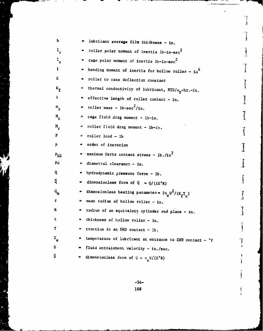
h M lubricant average film thickness - in.
Ir roller polar moment of inertia lb-in-sec2
I W cage polar moment of inertia lb-in-sec 2
I - bending moment of inertia for hollow roller - 4
K a roller to race deflection constant
Kf = thermal conductivity of lubricant, BTU/oF-hr -ft.
£a effective length of roller contact - in.
m r roller mass - lb-sec2 /in.
M = cage fluid drag moment - lb-in.
Mr = roller fluid drag moment - lb-in.
P = roller load - lb
P - order of iteration
PHZ a maximum Hertz contact stresa - lb./in2
Pd - diametral clearance - in.K Q - hydrodynamic pressure force - lb.
- dimensionless form of Q ft Q/(ZE'R)
% = dimensionless heating parameter= 2neU2 /(KfTe)
r = mean radius of hollow roller - in.
R = radius of an equivalent cylinder and plane- in.
t * thickness of hollow roller - in.
T " traction in an EHD contact - lb.
T temperature of lubricant at entrance to EHD contact -Fe
U - fluid entrainmenL velocity - In./sec.
SU - dimensionless form of U in Vi(E'R)!e
-54-
168

,I
V -sliding velocity -in./sec.
V =dimensionless form of V - neV/(E'R)
SW -dimensionless load - P/(ZE'R)
X = radial displacement of inner race - in.
X 0 deviation of races from true circular form- in.
z atotal number of rollers
c pressure viscosity exponent - in 2 /lb.
8 temperature viscoeity coefficient - *F
y ratio of roller diameter to bearing pitch diameter
n ,j ngular location of roller, deg.
M thermal reduction factor for EHD film thickness
I Q angular velocity of inner race, rad/sec.
Wc angular velocity of cage, rad/sec
W r a angular velocity of roller, rad/sec.
a lubricant absolute viscosity - lb.-sec/'.n. 2
I - coulomb coeff of sliding friction
60 roller - outer race deflection -in.
6 roller - inner race deflection - in.
I6 hollow roller deflection from CF - in.SCF
6 ROT M roller diametral expansion from wr - in.
j 6TOTAL total deflection of an unloaded roller - in.
6• - relative movement of races at - in.
a -poison's ratio
I-55-
169

SUBSCRIPTS
i - inner race contact
o = outer race contact Iv roller number or location
u - an unloaded roller
e - entrance region of EHD contact
Fluid Mechanics
A Surface Area in. 2
AG Total contact area between roller and guiding shoulders in.2
A Hji Area of ith horizontal lamina in.2
A Roller and cage surfacp arpa within typical crossflow passage iP exposed to c2oasflow in.
AVjk Area of kth vertical lamina in. 2
A Cross sectional area of a typical crossflow passage in. 2
C Radial clearance, in.
C' Clearance of cage pocket and roller, in.
CN Laminar or turbulent correlation factor for disk rotating ina viscous fluid
IFiG Contact force between roller and race guiding shoulder lb
f Friction factor 2fL Laminar friction factor
--L 2oaring length i
Z Peripherel length of a typical crossflow passage in.
1ý Moment about center line of a disk rotating in a viscousfluid in-lb,
-56-
170

S,N Number of horizontal ImAina
N Re Reynold's number (Defined in Text)
j NTa Taylor number (Def!-ed in Text)
r Reference radius in.A ith
r~ Distance from roller center to i horizontal lamina in.
ri Inner radius
r Outer radius• 0
rvjk Distance from radial ray through roller center to kth lamina in.
S Number of vertical lamina
6 Crossflow differential pressure lb/in.2pT Drag torque in.-lb
T Moment contribution of contact force to roller drag momentTadd in.-lb
Tcland Fluid drag moment on cage lands in.-lb
T Fluid drag moment on cage sides in.-lbT- cside
Trend Moment contribution of roller ends to roller drag momentre.-lb
T Moment =:ontribution of roller surface to roller drag momentrcyl in.-lb
U Mass average velocity of fluid in./sec
V Peripheral crossflow surface average velocity in./sec
V Velocity of roller at i th horizontal lamina in./sec
VRi Velocity of race at ith horizontal lamina in./sec
VVjk Velocity of roller at kh vertical lamina in./sec
U Coulomb coefficient of fricticn between rolle: and race guid-ing shoulderr
V Fluid Kinemetic visosity in. 2/sec
2 4P Fluid mass density lb sec /in.
Tw Wall shear stress, lb/in.'-57-
S171

Thermal Analysis and Dimensional Model
a roller inner radius, in. iBk energy rate constants in formulation of thermal problem,
ref. equation (48), Btu/sec. jb roller outer radius, in.
C radial clearance between cylindrical surface - in. 4c specific heat of lubricant or coolent associated with iPi thermal node - Btu/lb°F. I
T Radiation view factor between mt and n surfacem,n
g gravitational acceleration, 386.4 in./aec2 jHij energy transfer between nodes i and j Btu/sechk conyective conductance associated with kth surface Btu/sec-
in.Z OF
IDC bearing internal diametral clearance - in. jk thermal conductivity - Btu/sec in. OF
kf thermal conductivit, of fluid - Btu/sec in. F0
P s generic length of cylindrical surface - in.
mi lubrican: or coolent flow rate of ith thermal node - lb/sec.
N total number of component dissipations, external energy inputs,energy transfer to coolent or lubricant flows, and losses at =
ith thermal node.
Ni' total subset of Ni not exp±icity containing temperature. I
NTa Taylor Number for pure conduction through a fluid. I
cond
NTa critical Taylor number at speed ratio n.crnn
rL radius of iuner race at land for an inner land riding cage -rradius of oucer race at land for an outer land riding sage-in.
T mixed lubricant temperature -Fave
-58-
172

m T temperature of i th thermal node - OF.
T ref initial uniform reference temperature of all bearing elements - 'F
a coefficient of thermal expansion - in./in. OF.
Sad thernal diffusivity - in. 2 /sec.
kinematic viscosity of fluid - in. 2/sec.
Y coefficient of volumetric expansion - 1/'F.
A Tij Temperature difference between i th and j th thermal nodes,S Tj-Ti, - OF.
At absolute temperature differe.,ce between surface and fluid.
6 T. thermal deformation of the ith surface of a bearing member,I (see Figure 1) - in.
C ci energy error function at ith temperature node for Newton-Raphson solution of temperature field in beariug - Btu/sec.
1 emissivity of mth surface.
coulomb coefficient of friction between rollers and cage.
I ratio of c3ge tr shaft angular relocities.
V Poisson's ratio
U Boltzmann radiation constant - Btu/se," in. 2 OR'
II
l -59-
173

II12. Fritz, R. J., Friction Factors for Use in Analysis of Journal Bearings
with Vortex Turbulent Flow, KAPL-M-6546, G. E. Knolls Atomic PowerLaboratory, U. S. Atomic Energy Commission, Contract No. F 1. -109
Eng-52.
13. Schlichting, Dr. H., Boundary Layer Theory, Fourth Edition, McGrawHill Book Co., Inc., 1960.
14. Goldstein, S.,Modern Developments in Fluid Dynamics, Vol. I and II,Dover Publications, Inc., 1965.
15. Ehrich, F. F., Bistable Vibration of Rotors in Bearing Clearance,presented at the winter annual meeting, ASME Machine Design Division,Chicago, Ill., Nov. 7-11, 1965.
16. Timoshenko and Goodier, "Theory of Elasticity," McGraw Hill Book Co.Inc., 1956.
37. Wang, "Applied Elasticity," McGraw Hill Book Co. Inc., 1953.
18. "New Departure A•alysis of Stresses and Deflection," Vol. 1, 1946.New Departure Division of G.M. Corp. Bristol, Conn.
19. Harris, T. A., "Rolling Bearing Analysis," John Wiley and Sons, Inc.,1966.
20. Eckert, E. R. G. and Drake, R. M., "Heat and Mass Transfer, SecondEdition, McGraw Hill Book Co. Inc., 1959.
21. Bjorklund, I. S. and Kays, W. M., "Heat Transfer Between ConcentricRotating Cylinders," ASME Journal of Heat Transfer, Aug. 1959,Pages 175-186.
22. Jakob, H., Hawkins, G. A., "Elements'.i near Transfer and Insulation,"John Wiley & Sons Inc., Second Ed3lion, 1950.
23. Kays, W. M., "Corrective HeaL and Mass Transfer,' McGraw Hill Book Co.Inc., 1966.
-61-175

SECTION VIII
REFERENCES
1. Rumberger, J. H., et.a'.., Gas Turbine Engine Mainshaft RollerBearing - Systems Analysis", Submitted to Lubr. Div. ASMEfor publication in Tranr. ASME, Jrnl. of Lubr. Tech. 1973.
2. Dowson, D. and Higginson, G. R., "Elastohydrodynamic Lubrication -
The 7 :indamentals of Roller Gear Lubrication") Pergamon Press,New York, 1966.
3. Palmgren, A., "Ball and Roller Bearing Engineering", S. H.Borbank and Company, Third Edition, 1959.
4. McGrew, J. M., et. a]., "Elastohydrodynamic Lubrication - PreliminaryDesign Manual", Technical Report AFAPL-TR-70-27, Air Force AeroPropulsion Laboratory, Air Force Systems Command, Wright PattersonAir Force Base, November 1970.
5. Nypan, L. J., et.al., "Optimal Speed Sharing Characteristics ofa Series Hybrid Bearing", Trans. ASME, Jrnl. of Lub. Tech., Vol.95, Series F, No. 1, January 1973, pp. 76-81.
6. Peacock, L. A., and Rhodes, W. L., "High Temperature LubricantScreening Tests", SKF Industries, NASA CR 72615, September 1969,for NASA Lewis Research Center, Cleveland, Ohio.
7. Parker, R. .J., Bamberger, E. N., and Zaretsky, E. V., "BearingTorque and 2atigue Life Studies with Several Lubricants for Usein the Ravge 5000 to 700 0F", NASA Technical Note, TN-D-3948,May 1967.
8. Bamberger, E. N., Zaretsky, E. V., and Anderson, W. J., "Effectof Three Advanced Lubricants on High Temperature Bearing Life",ASME Jrnl. of Lub. Tech. Vol. 92, Series F, No. 1, January 1970,pp. 23-33.
9. Chasman, M. R., "Latest Avariable 5P4E High Pressure ViscometrvData", telephone conversation 10/1/71, Aero Propulsion Laboratory,WPAFB, Ohio.
10. Bamberger, E. N. - "Unpublished Information (1955) on reversedbending fatigue properties of Air Melt M-50 at 500°'F" - TelephoneZonversation -. Nov. 1972.
176I

I
SECTION VIII (Cont'd)
IREFERENCES
11. 'IRL Computer Program, FEBOR, Finite Element Analysis Program for
Bodies of Revolution Subjected to Axisyrmetric Loading - Program No.52-4.
I
I!I
II
II
177I
Copyright © 2022 FDOKUMEN