Efficient New Testing Methods for Analyzing the Condition of ...
14
Article Efficient New Testing Methods for Analyzing the Condition of Gas-Insulated Switchgear Author Andreas Nenning, Omicron electronics GmbH, Klaus Abstract The energy supply sector is another area in which an ongoing trend away from purely time-based towards condition-based maintenance has been observed. To be able to carry out a rapid analysis in space-saving gas-insulated switchgear (GIS), a plant operator requires devices and testing methods that perform the analyses in an efficient, non-invasive way. This paper describes new measurement methods that enable timing measurements in GIS installations without having to take the installations out of service. This minimizes the downtimes associated with circuit breaker testing and enables potential time and cost savings.
-
Upload
khangminh22 -
Category
Documents
-
view
2 -
download
0
Transcript of Efficient New Testing Methods for Analyzing the Condition of ...
Article
Efficient New Testing Methods for Analyzing the Condition of Gas-Insulated Switchgear
Author Andreas Nenning, Omicron electronics GmbH, Klaus
Abstract The energy supply sector is another area in which an ongoing trend away from purely time-based towards condition-based maintenance has been observed. To be able to carry out a rapid analysis in space-saving gas-insulated switchgear (GIS), a plant operator requires devices and testing methods that perform the analyses in an efficient, non-invasive way. This paper describes new measurement methods that enable timing measurements in GIS installations without having to take the installations out of service. This minimizes the downtimes associated with circuit breaker testing and enables potential time and cost savings.
© OMICRON 2018 Page 2 of 13
Efficient New Testing Methods for Analyzing the Condition of Gas-Insulated Switchgear The energy supply sector is another area in which an ongoing trend away from purely time-based towards condition-based maintenance has been observed. This new approach is seen as a way of. The condition of all critical plant components is analyzed at regular intervals, a process that takes up very little time. The results of the analysis are then used to identify those components that do in fact need some maintenance. To be able to carry out a rapid analysis like this in space-saving gas-insulated switchgear (GIS) in as universal a manner as possible, a plant operator requires devices that perform the analyses efficiently, that is, generally speaking, in a non-invasive way.
In-Service Testing Options
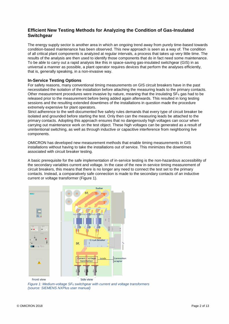
For safety reasons, many conventional timing measurements on GIS circuit breakers have in the past necessitated the isolation of the installation before attaching the measuring leads to the primary contacts. Other measurement procedures were invasive by nature, meaning that the insulating SF6 gas had to be released prior to the measurement before being added again afterwards. This resulted in long testing sessions and the resulting extended downtimes of the installations in question made the procedure extremely expensive for plant operators. Strict adherence to the well-documented five safety rules demands that every type of circuit breaker be isolated and grounded before starting the test. Only then can the measuring leads be attached to the primary contacts. Adopting this approach ensures that no dangerously high voltages can occur when carrying out maintenance work on the test object. These high voltages can be generated as a result of unintentional switching, as well as through inductive or capacitive interference from neighboring live components. OMICRON has developed new measurement methods that enable timing measurements in GIS installations without having to take the installations out of service. This minimizes the downtimes associated with circuit breaker testing. A basic prerequisite for the safe implementation of in-service testing is the non-hazardous accessibility of the secondary variables current and voltage. In the case of the new in-service timing measurement of circuit breakers, this means that there is no longer any need to connect the test set to the primary contacts. Instead, a comparatively safe connection is made to the secondary contacts of an inductive current or voltage transformer (Figure 1).
Figure 1: Medium-voltage SF6 switchgear with current and voltage transformers (source: SIEMENS NXPlus user manual)
© OMICRON 2018 Page 3 of 13
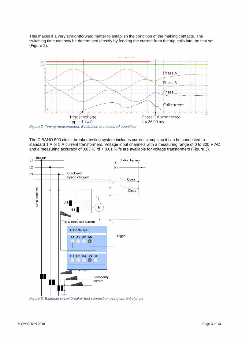
This makes it a very straightforward matter to establish the condition of the making contacts. The switching time can now be determined directly by feeding the current from the trip coils into the test set (Figure 2).
Figure 2: Timing measurement: Evaluation of measured quantities
The CIBANO 500 circuit breaker testing system includes current clamps so it can be connected to standard 1 A or 5 A current transformers. Voltage input channels with a measuring range of 0 to 300 V AC and a measuring accuracy of 0.03 % rd + 0.01 % fs are available for voltage transformers (Figure 3).
Figure 3: Example circuit breaker test connection using current clamps
© OMICRON 2018 Page 4 of 13
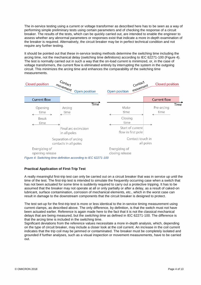
The in-service testing using a current or voltage transformer as described here has to be seen as a way of performing simple preliminary tests using certain parameters and of checking the response of a circuit breaker. The results of the tests, which can be quickly carried out, are intended to enable the engineer to assess whether any abnormal parameters or responses exist that indicate a more in-depth examination of the breaker is required. Alternatively, the circuit breaker may be in perfect technical condition and not require any further testing. It should be pointed out that these in-service testing methods determine the switching time including the arcing time, not the mechanical delay (switching time definitions) according to IEC 62271-100 (Figure 4). The test is normally carried out in such a way that the on-load current is minimized, or, in the case of voltage transformers, the current flow is eliminated entirely by interrupting the system in the outgoing circuit. This minimizes the arcing time and enhances the comparability of the switching time measurements.
Figure 4: Switching time definition according to IEC 62271-100
Practical Application of First-Trip Test A really meaningful first-trip test can only be carried out on a circuit breaker that was in service up until the time of the test. The first-trip test is intended to simulate the frequently occurring case when a switch that has not been actuated for some time is suddenly required to carry out a protective tripping. It has to be assumed that the breaker may not operate at all or only partially or after a delay, as a result of caked-on lubricant, surface contamination, corrosion of mechanical elements, etc., which in the worst case can result in damage to the downstream components that the circuit breaker is designed to protect. The test set-up for the first-trip test is more or less identical to the in-service timing measurement using current clamps, as described above. The only difference, by definition, is that the switch must not have been actuated earlier. Reference is again made here to the fact that it is not the classical mechanical delays that are being measured, but the switching time as defined in IEC 62271-100. The difference is that the arcing time is included in the switching time. Significant deviations from the reference values necessitate a more in-depth analysis, which, depending on the type of circuit breaker, may include a closer look at the coil current. An increase in the coil current indicates that the trip coil may be jammed or contaminated. The breaker must be completely isolated and grounded if further analyses, such as a visual inspection or movement measurements, have to be carried out.
© OMICRON 2018 Page 5 of 13
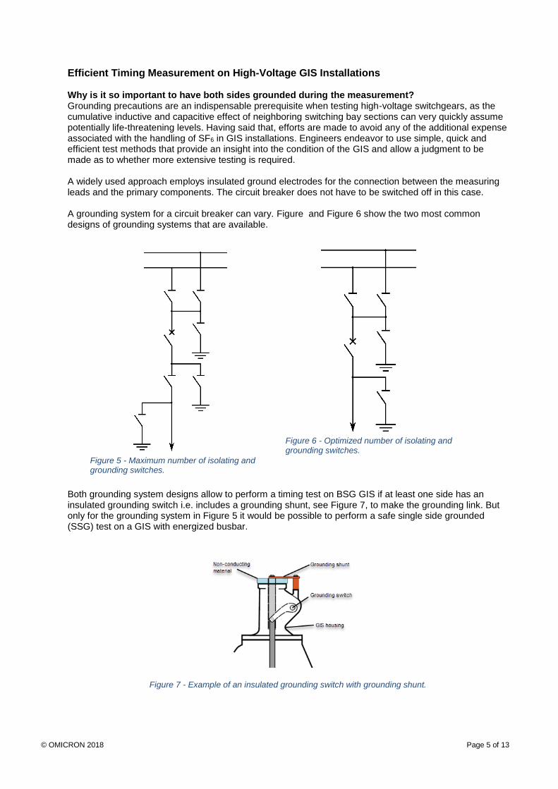
Efficient Timing Measurement on High-Voltage GIS Installations Why is it so important to have both sides grounded during the measurement? Grounding precautions are an indispensable prerequisite when testing high-voltage switchgears, as the cumulative inductive and capacitive effect of neighboring switching bay sections can very quickly assume potentially life-threatening levels. Having said that, efforts are made to avoid any of the additional expense associated with the handling of SF6 in GIS installations. Engineers endeavor to use simple, quick and efficient test methods that provide an insight into the condition of the GIS and allow a judgment to be made as to whether more extensive testing is required. A widely used approach employs insulated ground electrodes for the connection between the measuring leads and the primary components. The circuit breaker does not have to be switched off in this case. A grounding system for a circuit breaker can vary. Figure and Figure 6 show the two most common designs of grounding systems that are available.
Both grounding system designs allow to perform a timing test on BSG GIS if at least one side has an insulated grounding switch i.e. includes a grounding shunt, see Figure 7, to make the grounding link. But only for the grounding system in Figure 5 it would be possible to perform a safe single side grounded (SSG) test on a GIS with energized busbar.
Figure 7 - Example of an insulated grounding switch with grounding shunt.
Figure 5 - Maximum number of isolating and grounding switches.
Figure 6 - Optimized number of isolating and grounding switches.
© OMICRON 2018 Page 6 of 13
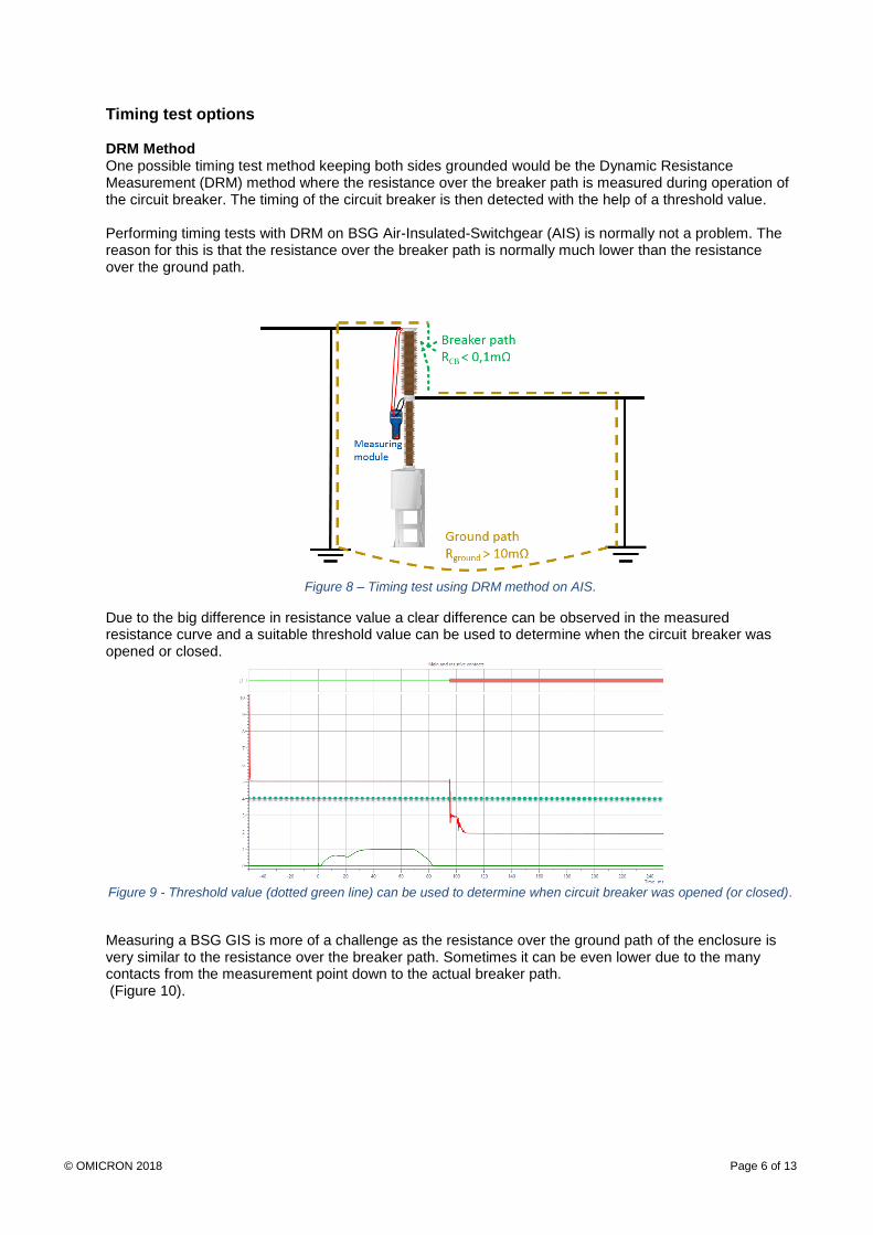
Timing test options DRM Method One possible timing test method keeping both sides grounded would be the Dynamic Resistance Measurement (DRM) method where the resistance over the breaker path is measured during operation of the circuit breaker. The timing of the circuit breaker is then detected with the help of a threshold value. Performing timing tests with DRM on BSG Air-Insulated-Switchgear (AIS) is normally not a problem. The reason for this is that the resistance over the breaker path is normally much lower than the resistance over the ground path.
Figure 8 – Timing test using DRM method on AIS.
Due to the big difference in resistance value a clear difference can be observed in the measured resistance curve and a suitable threshold value can be used to determine when the circuit breaker was opened or closed.
Figure 9 - Threshold value (dotted green line) can be used to determine when circuit breaker was opened (or closed).
Measuring a BSG GIS is more of a challenge as the resistance over the ground path of the enclosure is very similar to the resistance over the breaker path. Sometimes it can be even lower due to the many contacts from the measurement point down to the actual breaker path. (Figure 10).
© OMICRON 2018 Page 7 of 13
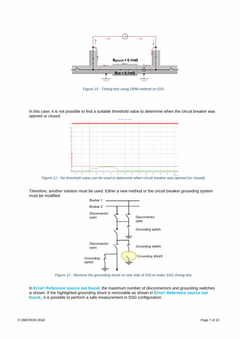
Figure 10 - Timing test using DRM method on GIS.
In this case, it is not possible to find a suitable threshold value to determine when the circuit breaker was opened or closed.
Figure 11 - No threshold value can be used to determine when circuit breaker was opened (or closed).
Therefore, another solution must be used. Either a new method or the circuit breaker grounding system must be modified.
Figure 12 - Remove the grounding shunt on one side of GIS to make SSG timing test.
In Error! Reference source not found. the maximum number of disconnectors and grounding switches is shown. If the highlighted grounding shunt is removable as shown in Error! Reference source not found., it is possible to perform a safe measurement in SSG configuration.
© OMICRON 2018 Page 8 of 13
Figure 13 - Example of an insulated grounding switch with removable grounding shunt.
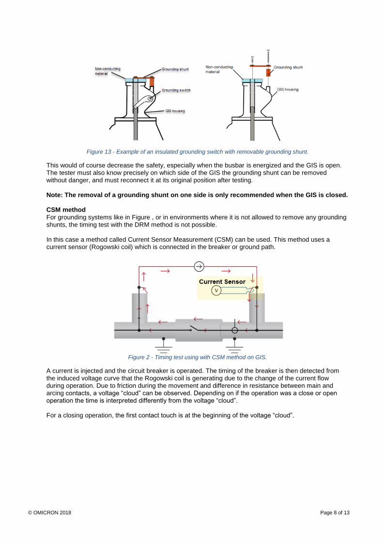
This would of course decrease the safety, especially when the busbar is energized and the GIS is open. The tester must also know precisely on which side of the GIS the grounding shunt can be removed without danger, and must reconnect it at its original position after testing. Note: The removal of a grounding shunt on one side is only recommended when the GIS is closed. CSM method For grounding systems like in Figure , or in environments where it is not allowed to remove any grounding shunts, the timing test with the DRM method is not possible. In this case a method called Current Sensor Measurement (CSM) can be used. This method uses a current sensor (Rogowski coil) which is connected in the breaker or ground path.
Figure 2 - Timing test using with CSM method on GIS.
A current is injected and the circuit breaker is operated. The timing of the breaker is then detected from the induced voltage curve that the Rogowski coil is generating due to the change of the current flow during operation. Due to friction during the movement and difference in resistance between main and arcing contacts, a voltage “cloud” can be observed. Depending on if the operation was a close or open operation the time is interpreted differently from the voltage “cloud”. For a closing operation, the first contact touch is at the beginning of the voltage “cloud”.

© OMICRON 2018 Page 9 of 13
Figure 15 - Timing measurement with CSM during closing operation (red dotted line).
For an opening operation, the contact separation is at the end of the voltage “cloud”.
Figure 3 - Timing measurement with CSM during opening operation (red dotted line).
The question is of course if the results are comparable between the new CSM method and the well-known DRM method. For this reason, comparative measurements have been performed to verify this. Comparison between CSM and DRM This comparison was made on a 245 kV GIS with each phase in a separate enclosure. This substation was energized but had a grounding system like in Figure so that it was possible to open the grounding shunt on one side to perform the SSG DRM.
© OMICRON 2018 Page 10 of 13
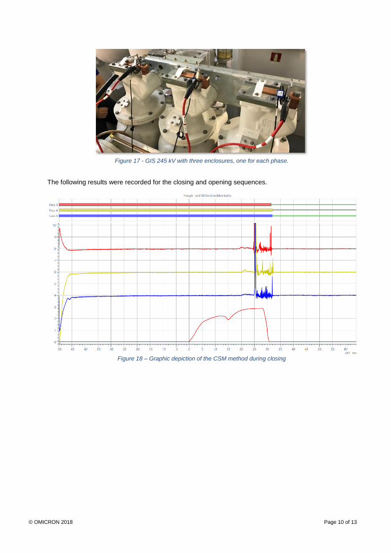
Figure 17 - GIS 245 kV with three enclosures, one for each phase.
The following results were recorded for the closing and opening sequences.
Figure 18 – Graphic depiction of the CSM method during closing
© OMICRON 2018 Page 11 of 13
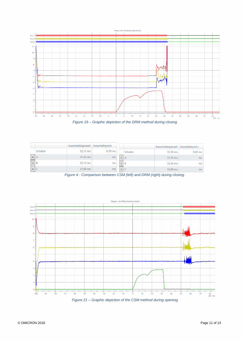
Figure 19 – Graphic depiction of the DRM method during closing
Figure 4 - Comparison between CSM (left) and DRM (right) during closing.
Figure 21 – Graphic depiction of the CSM method during opening
© OMICRON 2018 Page 12 of 13
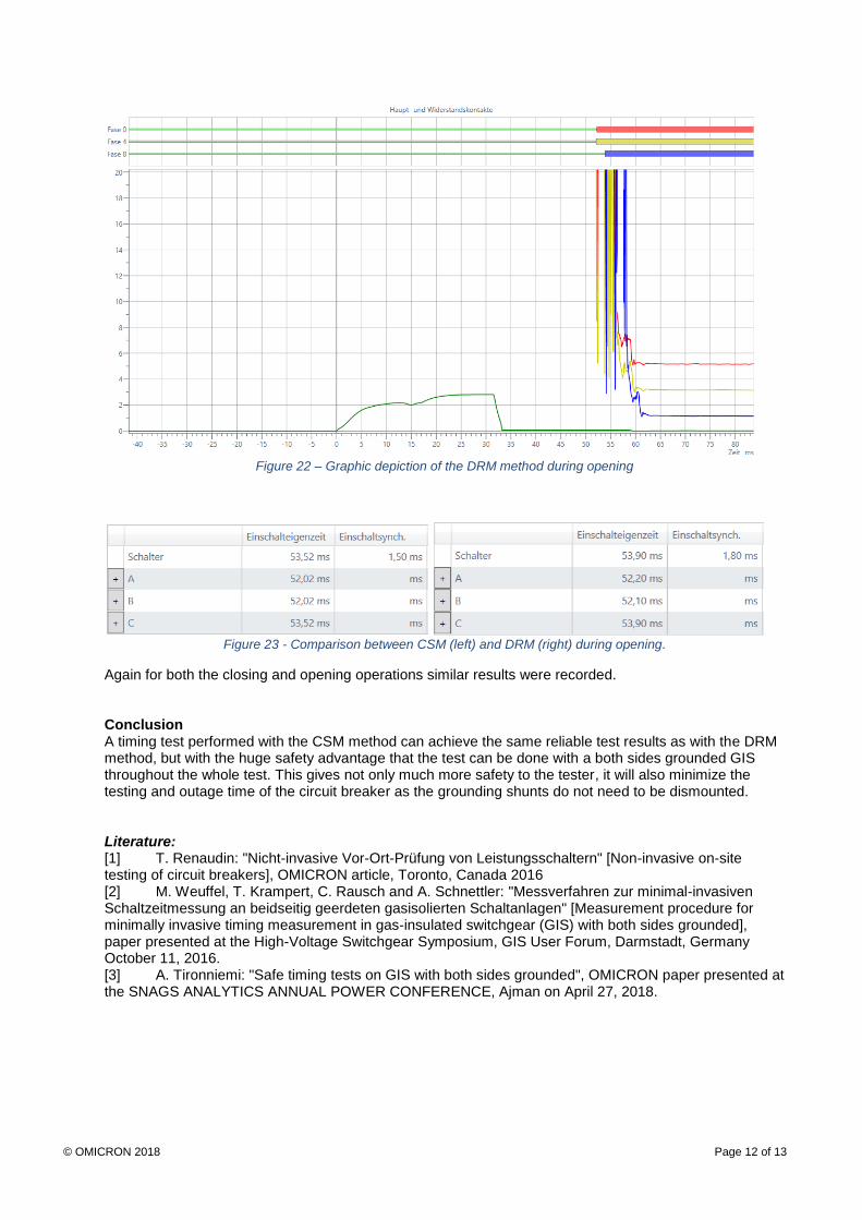
Figure 22 – Graphic depiction of the DRM method during opening
Figure 23 - Comparison between CSM (left) and DRM (right) during opening.
Again for both the closing and opening operations similar results were recorded. Conclusion A timing test performed with the CSM method can achieve the same reliable test results as with the DRM method, but with the huge safety advantage that the test can be done with a both sides grounded GIS throughout the whole test. This gives not only much more safety to the tester, it will also minimize the testing and outage time of the circuit breaker as the grounding shunts do not need to be dismounted. Literature: [1] T. Renaudin: "Nicht-invasive Vor-Ort-Prüfung von Leistungsschaltern" [Non-invasive on-site testing of circuit breakers], OMICRON article, Toronto, Canada 2016 [2] M. Weuffel, T. Krampert, C. Rausch and A. Schnettler: "Messverfahren zur minimal-invasiven Schaltzeitmessung an beidseitig geerdeten gasisolierten Schaltanlagen" [Measurement procedure for minimally invasive timing measurement in gas-insulated switchgear (GIS) with both sides grounded], paper presented at the High-Voltage Switchgear Symposium, GIS User Forum, Darmstadt, Germany October 11, 2016. [3] A. Tironniemi: "Safe timing tests on GIS with both sides grounded", OMICRON paper presented at the SNAGS ANALYTICS ANNUAL POWER CONFERENCE, Ajman on April 27, 2018.

© OMICRON 2018 Page 13 of 13
Andreas Nenning, OMICRON electronics GmbH, Klaus, Austria, obtained a degree in automation engineering and mechatronics from the Vorarlberg University of Applied Sciences in Dornbirn (Austria). He has been product manager for CIBANO 500, the new circuit breaker test system from OMICRON, since September 2013. He started his career at the Stadtwerken Feldkirch in Austria before going on to obtain a master's degree at the Vorarlberg University of Applied Sciences in Dornbirn. He then worked abroad for several years as an application engineer and project manager, eventually returning to Austria to take up a post as product manager in the decentralized renewable energies division. Andreas is a member of the "Cigré Working Group A2.32" (non-intrusive processes for assessing the condition of circuit breakers). [email protected], www.omicronenergy.com
www.omicronenergy.com
OMICRON is an international company serving the electrical power industry with innovative testing and diagnostic solutions. The application of OMICRON products allows users to assess the condition of the primary and secondary equipment on their systems with complete confidence. Services offered in the area of consulting, commissioning, testing, diagnosis and training make the product range complete.
Customers in more than 140 countries rely on the company’s ability to supply leading-edge technology of excellent quality. Service centers on all continents provide a broad base of knowledge and extraordinary customer support. All of this together with our strong network of sales partners is what has made our company a market leader in the electrical power industry.
For more information, additional literature, and detailed contact information of our worldwide offices please visit our website.
© OMICRON