Analyzing fractal antennas using 4nec2 software
10
Analyzing fractal antennas using 4nec2 software Ms. Abha Agrawal Mukesh Bhardwaj HOD, Electronics & Communication Department, Assistant Prof., Electronics & Communication Deptt. , Applied College of Management & Engineering, Applied College of Management & Engineering, Vill - Mitrol, Palwal, Vill - Mitrol, Palwal, Haryana, INDIA Haryana, INDIA Abstract-Previous antennas designs are based on Euclidean geometry have fixed shape along with constraints in radiation pattern, reflection coefficient, vswr, smith chart. So far the application military or other fields fractal antennas are being design and used for particular applications. Here. In this research paper we have analyzed fractal antennas using 4nec2 software. Keywords - fractal antenna, 4nec2 software, radiation pattern. I. INTODUCTION In this paper we analysed various parameters like radiation pattern, reflection coeff. VSWR, smith chart, stub matching. Using 4nect2 software . For this particular case of fractal antenna designs like MIC2, MIC3, random and future research can be on comparison with other antennas like Yagi-Uda or horn, rhombic etc. We also used freely downloadable plotting software GNUPLOT for plotting 3-d plots of various patterns. II. FRACTAL ANTENNAS Fractals are complex geometric designs that repeat themselves or their statistical properties on many scales and are thus the self similar. Fractals were first defined by Mandelbrot as a way of classifying complex geometric structure that have non- integer dimensionality which posses inherent self similarity or self affinity with in their geometrical structure. While
-
Upload
nithamirpur -
Category
Documents
-
view
0 -
download
0
Transcript of Analyzing fractal antennas using 4nec2 software
Analyzing fractal antennas using 4nec2software
Ms. Abha Agrawal Mukesh BhardwajHOD, Electronics & Communication Department, Assistant Prof., Electronics & Communication Deptt. , Applied College of Management & Engineering, Applied College of Management & Engineering,Vill - Mitrol, Palwal, Vill - Mitrol, Palwal,Haryana, INDIA Haryana, INDIA
Abstract-Previous antennas designsare based on Euclidean geometryhave fixed shape along withconstraints in radiation pattern,reflection coefficient, vswr,smith chart. So far theapplication military or otherfields fractal antennas are beingdesign and used for particularapplications. Here. In thisresearch paper we have analyzedfractal antennas using 4nec2software.
Keywords - fractal antenna, 4nec2software, radiation pattern.
I. INTODUCTION
In this paper we analysedvarious parameters like radiationpattern, reflection coeff. VSWR,smith chart, stub matching. Using4nect2 software . For thisparticular case of fractal
antenna designs like MIC2, MIC3,random and future research can beon comparison with other antennaslike Yagi-Uda or horn, rhombicetc. We also used freelydownloadable plotting softwareGNUPLOT for plotting 3-d plots ofvarious patterns.
II. FRACTAL ANTENNAS
Fractals are complex geometricdesigns that repeat themselves ortheir statistical properties onmany scales and are thus the selfsimilar.
Fractals were firstdefined by Mandelbrot as a wayof classifying complex geometricstructure that have non- integerdimensionality which possesinherent self similarity or selfaffinity with in theirgeometrical structure. While
6
Analyzing fractal antennas using 4nec2 software February 21, 2011
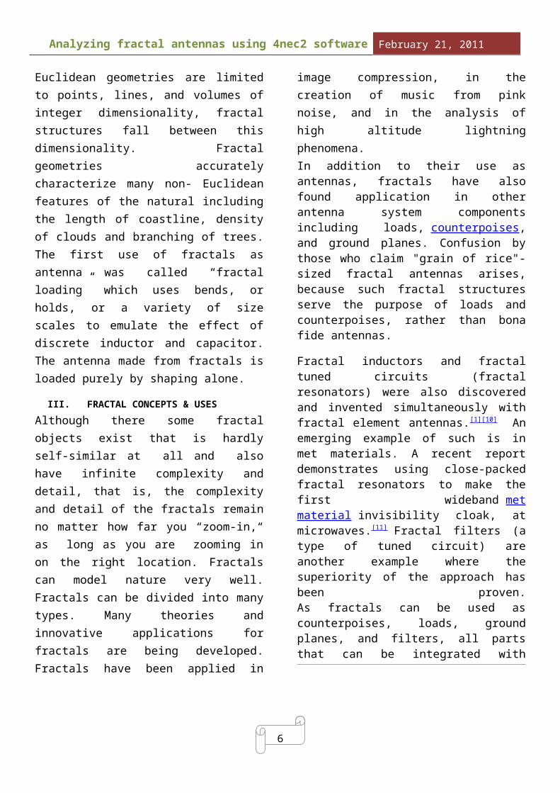
Euclidean geometries are limitedto points, lines, and volumes ofinteger dimensionality, fractalstructures fall between thisdimensionality. Fractalgeometries accuratelycharacterize many non- Euclideanfeatures of the natural includingthe length of coastline, densityof clouds and branching of trees.The first use of fractals asantenna was called “fractalloading” which uses bends, orholds, or a variety of sizescales to emulate the effect ofdiscrete inductor and capacitor.The antenna made from fractals isloaded purely by shaping alone.
III. FRACTAL CONCEPTS & USESAlthough there some fractalobjects exist that is hardlyself-similar at all and alsohave infinite complexity anddetail, that is, the complexityand detail of the fractals remainno matter how far you “zoom-in,“as long as you are zooming inon the right location. Fractalscan model nature very well.Fractals can be divided into manytypes. Many theories andinnovative applications forfractals are being developed.Fractals have been applied in
image compression, in thecreation of music from pinknoise, and in the analysis ofhigh altitude lightningphenomena.In addition to their use asantennas, fractals have alsofound application in otherantenna system componentsincluding loads, counterpoises,and ground planes. Confusion bythose who claim "grain of rice"-sized fractal antennas arises,because such fractal structuresserve the purpose of loads andcounterpoises, rather than bonafide antennas.
Fractal inductors and fractaltuned circuits (fractalresonators) were also discoveredand invented simultaneously withfractal element antennas.[1][10] Anemerging example of such is inmet materials. A recent reportdemonstrates using close-packedfractal resonators to make thefirst wideband metmaterial invisibility cloak, atmicrowaves.[11] Fractal filters (atype of tuned circuit) areanother example where thesuperiority of the approach hasbeen proven.As fractals can be used ascounterpoises, loads, groundplanes, and filters, all partsthat can be integrated with

6
Analyzing fractal antennas using 4nec2 software February 21, 2011
antennas, they are consideredparts of some antenna systems andthus are discussed in the contextof fractal antennas.
III. Fractal constructions
Among usual antennas used intoday’s data transfer there arealso different types of antennasused. First publications aboutelectrodynamics characteristicsof fractal structures werepublished in 1980′s , but firstpractical approach appeared after10 years. Dr. Nathan Cohenprofessor of boston universitydesigned, engineered and patentedmany practical fractal antennasolutions and founded FractalAntenna Systems � in 1995.
As Nathan states in centre ofBoston there were forbidden touse external antennas in city sohe managed to hide antenna withindesign of amateur radio station.He took aluminium foil and madeantenna as decoration accordingto Van Koch figure:
This figure builds as follows:first line (length is z) is cutin 3 even pieces z/3. In themiddle the triangle is formedwith same side lengths z/3 andsame angles. This way we getsingle element template. Thenrepeat this process with othersegments where sizes diminishes 3times (z/9) then follows again 3times (z/27) and so on. This wayfractal size does not change.
Today fractalantenna technology is in earlystages, because engineers aredoing empirical experiments tofind out what geometricalstructures give better results.During these experiments theyfound out that using ordinarytype antenna templates buildingfractals give better gaincoefficient. Like this antennatype:
This type of structure is so called recursive tree. Each new iteration multiply branches by two and lowers resonance frequency. So using iterations itis possible to use antenna at

6
Analyzing fractal antennas using 4nec2 software February 21, 2011
lower frequencies without increasing antenna size.
Dipole antennas usually havenarrow band-about 2.4% aroundfrequency carrier. If5th iteration is used then thisparameter grows up to 3.1%. If 3Dtree is used (when there are 4branches used instead of 2) thenthis parameter grows up to 12.7%.
Besides Dipole antennas there areresonant loop antennas used. Loopantennas are build using Kochfigures:
Ordinary frame antennas have lowinput impedance what makesdifficult to connect to feeder.Fractal loops allow increasingimpedance even for frequencieslower resonance and this wayeffectiveness increases.Another thing what makes fractalantennas so attractive is thatthey can be fabricated using PCBmaking methods. Because ofcompact size they can be putdirectly on PCB inside like cellphone.
Additionally to narrow bandantennas there one type ofantennas wide band. These areSierpinski antennas are frequencyindependent and have severalbands of resonance and can becompared to log-periodic andspirals. Frequency independenceis a result of retaining similarshape at many scales. Sierpinskifractal doesn’t requireadditional space while frequencyband grows as it happens withspiral and log-periodic antennas:
Sierpinski fractal antennas can be successfully used in automotive where transparent antennas are sticked to the frontwindow (or other) and can receivemultiple bands independently to standard and country.
Another widely used example is cell phones. They are long time using internal fractal antennas:
6
Analyzing fractal antennas using 4nec2 software February 21, 2011
IV a. SOME KEY BENEFITS OFFRACTALS
Very broad band and multi-band frequency response thatdrives from inherentproperties of fractalgeometry of the antenna.
Compact size compared toantenna of conventionaldesigns.
Mechanical simplicity androbustness; thecharacteristics of thefractal antenna are obtaineddue to its geometry.
Design to particular multifrequency characteristicscontaining specified stopband.
Fractal shaping benefits acompact antenna is on theorder of two or four timessmaller than conventionalantenna designs.IV b. WHERE’S THE ADVANTAGE
In electronics warfare,disrupting communication is adaunting task because of plethoraof frequency range available to ahostile toe.Most of the other antenna is notwide band but multiple bandcompromises that preventallowance for future capabilitywhen environment change.In this application, the wideband capability of fractalantenna allows the smallerantenna that have from 10:1 to200:1 band width that can handlemoderate to high power.
V. 4nec2 SOFTWARE ANALYSIS RESULTS
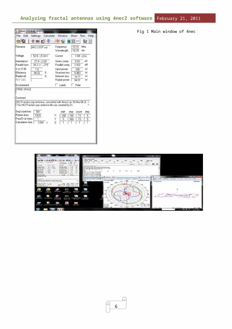
The 4nec2 tool is a windows- andNec-2 or Nec-4 based tool forboth the starting and experiencedantenna modeler that can be usedto create, view and check yourantenna geometry structure andgenerate, display and comparenear- and far-field radiationpatterns. Also SWR, input impedance,F/B- and/or F/R-ratio for a range offrequencies on a linear or logarithmicgraph (or Smith-Chart) can be displayed.
Fig. 1. Shows the main window of 4nec2 software used for fractal antenna analysis and fig. 2 shows analysis process done by 4nec2 software.
6
Analyzing fractal antennas using 4nec2 software February 21, 2011
Fig 1 Main window of 4nec

6
Analyzing fractal antennas using 4nec2 software February 21, 2011
Fig. 2 Analysis process of 4nec2 software for the fractal antenna
3-D structure of fractal antenna or any other antenna can be viewed in 3-D viewer.
Fig.3 3-D structure offractal antenna
VI. GRAPHS
Fig.3 shows the Total gain,Horizontal gain and vertical gainin dBi as multipattern with thefractal antenna structure at thecentre. Variation in gain patterncan be observed by increasing ordecreasing the antenna structuresize by using up and down arrowkey respectively.
Far-field pattern.
The most used calculationprobably will be the default far-
field pattern calculation. Thispattern determines in whichdirection you antenna system willradiate/receive best and in whichdirection signal is supressed. Itmay also be used for signal-coverage studies andinterference-level analysis. Whenthe default far-field (full,horizontal or vertical) patternis requested one must specify theresolution to use. Thisresolution value defines thestepsize increments for thePhi/Azimuth and Theta/Elevationangles.When a ground(plane) isinvolved, only the upper halve ofthe ‘radiation-sphere’ iscalculated.
6
Analyzing fractal antennas using 4nec2 software February 21, 2011
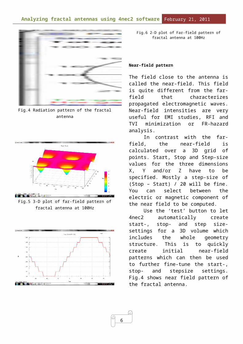
Fig.4 Radiation pattern of the fractalantenna
Fig.5 3-D plot of far-field pattern offractal antenna at 100Hz
Fig.6 2-D plot of Far-field pattern offractal antenna at 100Hz
Near-field pattern The field close to the antenna iscalled the near-field. This fieldis quite different from the far-field that characterizespropagated electromagnetic waves.Near-field intensities are veryuseful for EMI studies, RFI andTVI minimization or FR-hazardanalysis. In contrast with the far-field, the near-field iscalculated over a 3D grid ofpoints. Start, Stop and Step-sizevalues for the three dimensionsX, Y and/or Z have to bespecified. Mostly a step-size of(Stop – Start) / 20 will be fine.You can select between theelectric or magnetic component ofthe near field to be computed. Use the ‘test’ button to let4nec2 automatically createstart-, stop- and step size-settings for a 3D volume whichincludes the whole geometrystructure. This is to quicklycreate initial near-fieldpatterns which can then be usedto further fine-tune the start-,stop- and stepsize settings.Fig.4 shows near field pattern ofthe fractal antenna.

6
Analyzing fractal antennas using 4nec2 software February 21, 2011
Fig. 5 Near Field pattern offractal antenna
Fig.6 shows 2-d plot of near field pattern of fractal antenna and fig.7 shows 3-D plot of near field pattern of the antenna. 2-D& 3-D plots can be observed usingfreely downloadable GNUPLOT software and including it in 4nec2 software.
Fig.7 2-D plot of near field of fractal antenna
Fig.8 3-D plot of near field of fractal antenna
VII. CONCLUSIONWe analyzed the fractal antennausing 4nec2 software tool forvarious fractal configuration
VIII. FUTURE WORKFor the future communicationsystem, the cognitive radios thatrequire vast band width with oneantenna and input files of 4nec2can be edited to change antennastructure according to the needor requirement.
IX.REFERENCES
1. Fawwaz J. Jibrael, Faez F. Shareefand Wafaa S Mummo,2008 . Small Size and dual band of Qudratic Koch Dipole Fractal antenna Design. American Journal of Applied Sciences.
2. Nathan Cohen, August 2005. Fractals’ new era in military antenna design. Defence Electronics Mag..www.rfdesign.com
3. Arpan Mondal,2010. Miniaturized and dual band hybrid Koch Dipole

6
Analyzing fractal antennas using 4nec2 software February 21, 2011
Antenna fractal Design. Proceedings of the international joint journal Conference on Engg &Technology (IJJCET).
4. 4nec2 software and GNUPLOT software freely downloadable from the INTERNET.