Multipoint spectroscopic analyzing & imaging method
56
FACULTY OF ENGINEERING AND SUSTAINABLE DEVELOPMENT . Multipoint spectroscopic analyzing & imaging method Provakar Paul June 2013 Master’s Thesis in Electronics Master’s Program in Electronics/Telecommunications Examiner: Dr. José Chilo Supervisor: Prof. Anders Rydberg and Dr. Dragos Dancila
-
Upload
khangminh22 -
Category
Documents
-
view
3 -
download
0
Transcript of Multipoint spectroscopic analyzing & imaging method

FACULTY OF ENGINEERING AND SUSTAINABLE DEVELOPMENT .
Multipoint spectroscopic analyzing & imaging method
Provakar Paul
June 2013
Master’s Thesis in Electronics
Master’s Program in Electronics/Telecommunications
Examiner: Dr. José Chilo
Supervisor: Prof. Anders Rydberg and Dr. Dragos Dancila

Provakar Paul Multipoint spectroscopic analyzing & imaging method
i
‘’If I have a thousand ideas and only one turns out to be good, I am satisfied’’
-Alfred Nobel

Provakar Paul Multipoint spectroscopic analyzing & imaging method
ii
Abstract
Spectroscopy is a technique as the interaction of different radiation spectrum with matter to analysis of
a sample. This thesis work proposed two methods are multiple pointes spectroscopies analyzing then
imaging detection methods for solid samples. Developed method one is using Ultraviolet (UV),
Visible (Vis) and Infrared (IR) detection. Where detection was assembled with deuterium as well
tungsten-halogen lamp source (which were able to generate 175 nm to 3300 nm wavelength), a manual
X-Y stepper for scan an inhomogeneous biological sample, optical design beside Indium gallium
arsenide (InGaAs) detection unit was used of Lamda 950 by PerkingElmer. Second improved
methodology is Vis detection imaging of samples. In Vis detection imaging was constructed with
Helium-Neon (HeNe) red laser as a source (able to generate 632.8 nm wavelengths), a silicon pin
photodiode detector, lens, multimeter, X-Y positioner stepper motors to scan samples. The work show
successfully detected and imaged of water, fresh leaf, brain phantom in addition 3mm horizontal and
1.5 mm vertical cooper line. The thesis works proposed methods has obtained accurate results of all
the samples detection specifically has devised imaging of samples. This spectroscopic process is
suitable for any type of liquid, solid also gas detecting moreover imaging approach can be applicable
in any type of inhomogeneous matter.

Provakar Paul Multipoint spectroscopic analyzing & imaging method
iii
.

Provakar Paul Multipoint spectroscopic analyzing & imaging method
iv
Acknowledgements
This master thesis research was done at Uppsala University, Department of Engineering Sciences and
I would like to thanks Professor Anders Rydberg who give me chance to work in the Microwave
Engineering group. I would like to express my sincere thanks to Dr. Dragos Dancila, who was always
helpful and available for discussion throughout all the stages of the project and for providing me all
the materials and required facilities to the necessary research work. His constant guidance and
motivation has helped me bring out this thesis work in its current shape. Also I wish to thank and
acknowledge Dr. Robin Augustine of this group for his time, invaluable help, assistance and patience
during the course of this thesis. In addition, I would like to acknowledge Solid State Electronics PhD
student Patrik Ahlberg for help to understand Lamda 950 by PerkingElmer equipment and Dr. Seibt
Wolfgang (Staff retied) for Project in Fiber Optic equipment and Jonatan Bagge for technical service.
Furthermore I would like to thanks Dr. José Chilo for his encouragement and becoming my examiner.
I also like to express my gratitude to Professor Edvard Nordlander, Niclas Björsell, Per Ängskog for
being such nice teacher and Mikael Krigh departmental secretary for all the help in administrative
matters. Thanks to my friends Juan Alfaro, Danial, Erif, Dhayalini and all my classmates of University
of Gävle.
Most of all, I would like to thanks my mum, dad and brother for support, encouragement and praying
for my success in each and every step of my life, I extent my deep appreciation to my beloved partner
Jessica Persson and the most important treasure of my life our daughter Alva.

Provakar Paul Multipoint spectroscopic analyzing & imaging method
v

Provakar Paul Multipoint spectroscopic analyzing & imaging method
vi
Table of contents Abstract ................................................................................................................................................... ii
Acknowledgements ................................................................................................................................ iv
List of Table .......................................................................................................................................... vii
List of Figure ........................................................................................................................................ viii
Chapter 1:Introduction ............................................................................................................................ 1
1.1 Background: ...................................................................................................................................... 1
1.2 Current research and present problem in this area ............................................................................ 2
1.3 Thesis Goal and Outline: ................................................................................................................... 3
Chapter 2:Theory ..................................................................................................................................... 4
2.1 Spectroscopy ................................................................................................................................. 4
2.2 The Electromagnetic Radiation ..................................................................................................... 6
2.3 Radiation energy............................................................................................................................ 7
2.4 Application of UV, VIS and IR radiation ...................................................................................... 8
Chapter 3: Methods and Measurments .................................................................................................. 12
3.1 Method 1: Lamp is a source of UV-Vis-IR Spectroscopy........................................................... 12
3.1.1.1 UV, VIS and IR Sources ....................................................................................................... 13
3.1.1.2 Optical design and Sampling configurations ......................................................................... 16
3.1.1.3 UV, VIS and IR Detectors ..................................................................................................... 16
3.1.2. Measurements, Absorption and Transmittance ...................................................................... 17
3.1.2.1. UV Spectra measurement of: Water, Leaf, Brain Phantom. ................................................ 18
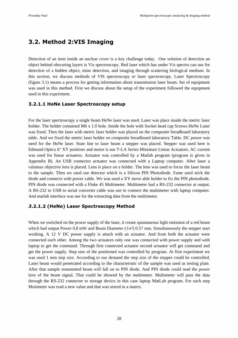
3.2. Method 2:VIS Imaging ............................................................................................................... 28
3.2.1.1 HeNe Laser Spectroscopy setup ............................................................................................ 28
3.2.1.2 (HeNe) Laser Spectroscopy Methord .................................................................................... 28
3.2.1.6 T-LA Series miniature linear actuators with built-in controllers .......................................... 30
3.2.2 Laser base imaging of Leaf, Phantom and hidden object: ........................................................ 33
Chapter 4: Discussion and Conclusion .................................................................................................. 38
References: ............................................................................................................................................ 40
Appendix-A: Matlab Programs ............................................................................................................ 42
Appendix-B: Used equipments and manuals ........................................................................................ 45

Provakar Paul Multipoint spectroscopic analyzing & imaging method
vii
List of Table
Table 2.1. Descristion about energy transitions of different radiation spectra . ...................................... 8
Table 2.2. The Approximate electromagnetic region .............................................................................. 8
Table 2.3. Calculation of stretching frequencies for different types of bonds ...................................... 10
Table 3.1. Descristion about Composite Breadboard Laboratory Table. .............................................. 30
Table 3.2. Description about the actuators. ........................................................................................... 31

Provakar Paul Multipoint spectroscopic analyzing & imaging method
viii
List of Figure
Figure 1.1: Block diagram of an analytical instrument showing of Spectroscopy. ................................. 2
Figure 2.1: Show the connection between Transmittance and Absorbance ............................................ 4
Figure 2.2: Radiation of light on solid .................................................................................................... 5
Figure 2.3: The Electromagnetic Spectrum . ........................................................................................... 6
Figure 2.4: Modes of vibration and bending of water molecule. ............................................................ 9
Figure 3.1.a: Block diagram of lamp is a source of UV-Vis-IR Spectroscopy system . ....................... 14
Figure 3.1.b: The peak wavelength and total radiated amount vary with temperature. ....................... 15
Figure 3.3.a: UV spectra absorbance and transmission measurement of water .................................... 19
Figure 3.3 b: Absorbance coefficients of leaf and water with UV spectrometer. ................................. 19
Figure 3.3.c:. Absorbance and Transmission coefficient leaf with UV radiation of brain phantom ..... 20
Figure 3.4.a: Vis spectra absorbance and transmission measurement of water. .................................... 22
Figure 3.4.b: Absorbance and Transmission coefficient leaf with Vis spectrometer. ........................... 22
Figure 3.4.c:. Lamp VIS spectroscopy of Leaf with specific absorption at five different spot. ............ 23
Figure 3.4.d: Vis Absorbance and Transmission coefficient phantom .................................................. 23
Figure3.5.a: IR spectra absorbance and transmission measurement of water ....................................... 25
Figure3.5.b: IR spectra absorbance and transmission measurement of leaf. ......................................... 26
Figure3.5.c: IR spectra absorbance and transmission measurement of phantom .................................. 27
Figure 3.2.a: Block Diagram of Laser bias VIS spectroscopy setup. .................................................... 29
Figure 3.2.b: Lab setup of Laser bias VIS spectroscopy. ...................................................................... 32
Figure 3.6: (a) HeNe laser image of leaf (b) Brain Phantom. ............................................................... 35
Figure 3.6: (c) Image diagram cooper line ........................................................................................... 36
Figure 3.7: (a) A plat leaf and sample which (b) Absorbance Spectra of leaf . .................................... 36
Figure 3.8: Absorption coefficient leaf and water with UV/Vis/IR spectrometer. ................................ 37
Figure3.9: Absorbance and transmittance measurement ...................................................................... 37

Provakar Paul Multipoint spectroscopic analyzing & imaging method
1
Chapter 1: Introduction
1. 1Background:
From the beginning of science till today, there is a considerable interest in finding more and more
details in biological sample, objects or areas on the surrounding world as biologists want to know the
construction of the cells, bacteria, and viruses. Major focuses for material engineers are to know the
inhomogeneity and imperfections in metals, crystals, and ceramics. Geologists are curious about the
details of rocks, minerals, and fossils. The important interested of doctors are to examine neurons from
brain cells or detect cancer cells. Much Research in analytic chemistry is to detailed study of some
substances. In order to get solution of those above interest some of the best- known useful methods
are ultrasound imaging, magnetic resonance imaging (MRI), microscopic imaging, imaging using X-
rays and different radiation type spectrometer. In ultrasound imaging, a sound wave of 20 KHz applies
to body and reflected echo is use for effective imaging. For MRI magnetic field and radio wave
63MHz to 85MHz for imaging while x-ray radiation uses x-ray imaging [1].
The electromagnetic spectrum Ultraviolet (UV), Visible (Vis) and Infrared (IR) is covered the
radiation wavelength region from 175nm to 3300nm. And spectroscopy is the study of interaction of
light or radiation with matter. The word spectroscopy has two parts: spectro which refers to
electromagnetic spectrum and skopeo which in Greek means the eye can see [2]. The instruments
packages which are used in spectroscopy analysis are called spectrometer. There are five essential
components required for most spectrometers. These are as follows:
I. A source or sources of electromagnetic radiation.
II. A means for selecting a narrow band filter of wavelengths.
III. A stepper or holder facilities for holding the sample
IV. A device or devices capable of measuring the intensity of the radiation beam transmitted
through the sample.
V. A display or output device to show the image or to recode the measured data in a suitable
form.
The approaches have used in this study aims to use nanometer wavelength radiation to detect examine
detail inside a biological sample and other object detection.

Provakar Paul Multipoint spectroscopic analyzing & imaging method
2
Figure 1.1: Block diagram of an analytical instrument showing of Spectroscopy.
1.2 Thesis goal
The IR radiation was discovered in 1800 by Herschel, UV radiation was the first to come into general
use during the 1930s, 1947 Wright and Hersher developed double beam dispersive IR
spectrophotometer and in 1983-spectra Tech and Digitab developed the commercial microspectro
photometer [2]. However in Uppsala University, Microwave group Johannes Hjerdt June 8, 2011 did a
research title: ‘’near field measurement of biological tissues using millimeter wave/THz frequencies’’.
In Johannes research Biological tissues have been imaged using terahertz and millimeter wave
radiation generated by millimeter wave extenders and focused by collimating polyethylene lenses,
dielectric probe and a resonator. But there were several limitation of that work like, it was took too
much time to scan a matter, could not detect extreme detail inside a biological sample. At KTH under
supervision of Professor Faris Gelmukhanov a research tittle ‘’Ultrafast X-ray spectroscopy with
applications in molecular and material science’’ in Period: 2006-01-01 - 2008-12-31 had done. Where
free electron lasers was used a source, the work was focused of material detection but not for
biological sample detection [3].
Although at present there are different spectrometers commercially available with market to examine
single point biological sample. Previous work has focused only on one point spectroscopic detection
of biological sample [4]. Unfortunately current biological or molecule observing instrument are not
capable to scan certain area, instruments are big in size, expensive in addition take too much time to
detect an object further more they cannot detect very small molecules and often technically difficult to
perform. An alternative approach of spectroscopy is necessary. In this report the two type of
spectroscopic instrument setup is use for detect and scan a biological. In the first approach is different
lamp base UV, Vis and IR spectroscopic detection and second approach is laser source base Vis
spectroscopic detection and. These spectroscopy techniques fall into the category of absorption or
transmittance spectroscopy. As this term suggests, these analytic techniques or imaging involve
absorption of specific energies of electromagnetic radiation which correspond exactly in energy to
specific excitations within the sample molecule being examined.

Provakar Paul Multipoint spectroscopic analyzing & imaging method
3
1.3 Thesis Outline:
This master thesis work is about developed two methods or instruments setup for multipoint
inhomogeneous biological sample detection and imaging. In this work one setup using Ultraviolet
(UV), Visible (Vis) and Infrared (IR) spectra to analysis for characterizing different sample is used,
another instruments setup is for imaging different biological sample and hidden objects using Vis
Spectra. The primary focus of the thesis was choose correct instruments and settled instruments setup
to detecting biological sample (neuron from brain tissue). The research work presented in this thesis is:
I. Method of Biological sample imaging using Laser Vis radiation and 2D scan imaging using
manual or motor control stepper.
II. Method of Biological sample analyzing using UV, Vis, IR radiation and 2D scan using manual
stepper.
Chapter 2 is presupposed about physical background on spectroscopic analyzing system and related
theory about electromagnetic spectrum. Different objects or molecules absorb different wavelengths of
electromagnetic radiation and undergo different energetic radiation, range is non-ionizing. Suppose
Water has a high dielectric constant at IR wavelengths, which makes it suitable for spectroscopic
imaging of tissue or other material.
Chapter 3 is describes contribute two methods of the thesis and measurements. At first part of this
describe first method is multipoint UV, Vis and IR detection for spectroscopy analyzing
instrumentation, setup and measurements. Method one UV/Vis/IR multipoint spectroscopy is support
both liquid and solid sample measurement. Then we took water, a green fresh leaf, brain phantom
sample and observed UV, Vis and IR spectra full analyzing is showed. Second method is about
Helium Neon laser base Vis Spectroscopy technique for imaging of any kind of biological sample or
hiding object. In this method light source of different wavelength of the spectroscopic system pass
through the sample and PIN photo diode detector measures the power, MATLab program is used to
plot an image of the sample.
Finally chapter 4 of the report is conclusion where summary of the work, mapping achievements also
idea of future research are given and challenges to consider.

Provakar Paul Multipoint spectroscopic analyzing & imaging method
4
Chapter 2: Theory
This master thesis used two methods to solve the given task so one needs to understand the physical
background to these approaches.
2.1 Spectroscopy
Spectroscopy is a way of analyzing spectra, basics of the technique is radiation. This method is
broadly used to examine and characteristic of atoms, molecules and ions. In this thesis, UV/VIS/IR
radiation has been used for recognition of solid and liquid. The spectroscopy measuring instrument
setup is called spectrometer [4]. Spectrometer has two sections, source and detector. Spectrum is a set
of lines resulting from the decomposition of a complex light; more generally, it shows the intensity
distribution of an electromagnetic wave as a function of frequency energy. When an atom is heated,
one of its electrons from its outermost layers (or more rarely the internal layers) goes from ground
level to a higher energy level which is called level of the excited state [5]. When the electron goes to
lower energy level, it re-emits the energy as light (photon).
2.1.1 UV, Vis and IR Spectroscopy for liquid
If we take any kind of liquid sample using this spectroscopy system, we can measure the percentage of
transmittance. It means percentage of light beam transmitted through the sample from source to
detector. By use the value of transmittance to calculate the absorbance of that liquid sample. Beer's
law is to calculate the absorption of light. Figure 2.1 shows a beam from source radiated with power
P0, after passing through a sample solution absorption occurred the beam of radiation leaving the
sample has radiant power P. So we can easily calculate absorbance from percentage transmittance
data. So, there is no absorption, then absorbance is zero, and then transmittance is 100%.
If the entire beam is fully absorbed, then transmittance is zero.
Figure 2.1: Show the connection between Transmittance and Absorbance

Provakar Paul Multipoint spectroscopic analyzing & imaging method
5
Figure 2.2: Radiation of light on solid
2.1.2 UV-Vis-IR Spectroscopy for solid
Several numbers of situations happen when a radiation or beam of light falls on a solid sample. Figure
2.2 showed the situating may happen.
2.1.2.1 Transmittance measurements
There are several barriers we have to face during transmittance measurements of a solid. If the surface
of the solid sample is convex or concave then the beam will deviate. If the surface is not smooth then
also the beam will be deviated. Another important reason for beam deviating is refraction. Because of
the property of a solid sample beam can be diffused in different direction. Use a special kind of
equipment called integrating sphere we can measure the direct transmittance, diffused and deviated
beam power. Figure 2.2 is diagram of transmittance measurements of solid, where 𝐼0 is incident beam,
that passes through a solid sample and we got 𝐼1, which is transmittance beam.
Transmittance, T = P / P0
% Transmittance, %T = 100 T
P= incident beam power.
P0 =Radiated beam power.
Absorbance,
A = log10 P0 / P
A = log10 1 / T
A = log10 100 / %T
A = 2 - log10 %T

Provakar Paul Multipoint spectroscopic analyzing & imaging method
6
Figure 2.3: The Electromagnetic Spectrum [6].
2.1.2.2 Measuring absorbance for a solid sample
I. When an incident beam fall on a solid sample the beam will ether reflected or transmitted.
II. We can calculated that %Absorbance+%R+%T=100% (R=reflectance and T= transmittance)
III. So Absorbance will be, %Absorbance=100%-%R-%T.
2.2 The Electromagnetic Radiation
It is known that moving electrical charges induce magnetic fields and, inversely, that changes of the
magnetic field create an electric field [7]. Vibrating electrical charges therefore cause a periodic
change of electromagnetic fields, which propagate as electromagnetic waves linearly into space with
the speed of light [8]. Depending on their appearance or their effect on material and on human senses,
one speaks of various types of radiation (e.g. light, heat, X-rays) which differ from one another only
with regard to wavelength or frequency but which are identical physically. The Wavelength range of
the electromagnetic spectrum comprises a wide scale ranging from radio waves to gamma rays (figure
2.3).
In the classical treatment, electromagnetic radiation can be considered as a propagating wave of
electrical energy with an orthogonal magnetic component oscillating exactly the same frequency.
Electromagnetic radiation can be described by either its frequency or wavelength. These values are
inversely proportional to each other being related by the following equation :
U
V
Gamma Rays
X-
Rays V
I
S
Infrared Microwave Radio
wave
BL GN YL OR RD
0.0001nm 10 nm 100 0nm 1 m 1 mm
400 nm 700 nm 600 nm

Provakar Paul Multipoint spectroscopic analyzing & imaging method
7
𝜆𝑣 = 𝑐 (2.1)
Where,𝜆 = 𝑤𝑎𝑣𝑒𝑙𝑒𝑛𝑔𝑡ℎ,
𝑣 = 𝑓𝑟𝑒𝑞𝑢𝑒𝑛𝑐𝑦 𝑜𝑓 𝑡ℎ𝑒 𝑒𝑙𝑐𝑡𝑟𝑜𝑚𝑎𝑔𝑛𝑒𝑡𝑖𝑐 𝑟𝑎𝑑𝑖𝑎𝑡𝑖𝑜𝑛,
𝑐 = 𝑠𝑝𝑒𝑒𝑑 𝑜𝑓 𝑙𝑖𝑔ℎ𝑡 3 × 10⁸𝑚𝑠−1 [9].
Electromagnetic spectrum has been divided in many bands of frequencies (figure 2.3) which are of
great importance in technological applications. The radio band has been widely used for radio,
television, radar etc., and the use of optical band is now underway [8].
a. Ultraviolet (UV) radiation
UV radiation naturally occurring radiation is more energetic and shorter wavelength than visible light.
The human eye cannot perceive it. There are three forms of UV radiation: UV-A (315-380 nm long
wave), UV-B (280-315 nm short wave) and UV-C (100-280 nm extremely short waves). All three
come in different proportions before the sunlight. Normally found only UV-A and UV-B rays to the
earth's surface [9], the UV-C fraction is absorbed by the ozone layer.
b. Visible (VIS) radiation
VIS radiation is electromagnetic radiation, which is visible to humans. The wavelength range is
between 380 nm and 780 nm. Each of these wavelengths is corresponding to a color. Red: 620-700
nm, Orange: 592-620 nm, Yellow: 578-592 nm, Green: 500-578 nm, Blue: 446-500 nm and Violet:
400-446 nm.
c. Infrared (IR) radiation
The range of electromagnetic radiation with wavelengths of 780 nm to 1 mm is known as infrared
radiation. Infrared (IR) radiation is also called heat radiation, is part of the optical radiation. Infrared
radiation is divided in the short-wave IR-A radiation with a wavelength range of 780 to1400
nanometers, the IR-B radiation 1400 to 3000 nanometers and the long-wave portion of the IR-C
radiation 3000 nanometers to 1 millimeter. The most important natural source of IR radiation is the
sun [10]. IR radiation has a 50 percent share of the solar radiation that reaches the ground. The
absorption of the radiation by the atmosphere contained in the gases, such as natural and artificial
water, carbon dioxide, ozone, methane, and chlorofluorocarbons (CFCs) leads to the additional heating
of the earth. This process is crucial for the heat balance of the earth.
2.3 Radiation energy
The electromagnetic radiation is the emission of radiation in the visible region by heated material such
as e.g. the radiation of a white-hot tugsten wire of a lamp. Then too, energy released during a chemical
reaction can be emitted as radiation. Thus, electromagnetic radiation is an energy carrier. Energy and
radiation frequency have the following relationship:
ℎ. 𝑣 = ℎ.𝑐
𝜆 (2.2)
The parameter ℎ = 6.626 × 10⁻³⁴𝐽𝑠 [13] is the planck constant and c the speed of light.

Provakar Paul Multipoint spectroscopic analyzing & imaging method
8
Table 2.1.Descristion about energy transitions of different radiation spectra [2] .
Radiation spectrum Energy Transitions
X-rays Bond Breaking
Ultraviolate (UV) Electronic
Visible (Vis) Electronic
Infrared (IR) Vibrational
Microwave Rotational
Radio frequencies Nuclear Spain, Electron Spin
Radiation frequency and energy are therefore directly proportional to one another. The position of
various types of radiation in the total electromagnetic spectrum also reflects their energy: the short-
wave or high-frequency gamma rays posse high energy, while the long-wave radio waves have low
energy.
2.4 Application of UV, VIS and IR radiation
Since every different type of band has a different nature frequency of vibration and since the same
type of band is two different compounds is the slightly different environment, no two molecules of
different structure will have exactly the same electromagnetic absorption pattern or spectrum.
Although some of the frequencies absorbed in the two cases might be the same, in no case of two
different molecules will their infrared spectra is identical. Thus the electromagnetic spectra or UV, Vis
or IR spectrum can be used for molecular much as a fingerprint can be used for humans. By
comparing the infrared spectra of two substances thought to identical, one can establish whether or not
they in fact are identical. It their infrared spectra coincide peak for peak (absorption to absorption) in
most cases two substance will be identical.
Second and more important use of the infrared spectrum is that it gives structural information about a
molecule. The absorptions of each type of bond (N-H, O-H, C-X, C-O, C-C etc.) are regularly found
only in certain small portions of the vibrational infrared region.
Table2.2. The Approximate electromagnetic region where various common type of bonds absorb [6].
Frequency (cm-1)
4000 -2500 2501-2000 2001-1800 1801-1650 1651-1550 1551-650
O-H
N-H
C-H
C⁼C
C⁼N
X⁼C⁼Y
Very
few band C⁼O C⁼N
C⁼N
C-C1
C-O
C-N
2500-4000 4000-5000 5000-5500 5500-6100 6100-6500 6500-15.4
Wavelength𝝀 (nm)

Provakar Paul Multipoint spectroscopic analyzing & imaging method
9
Figure 2.4: Modes of vibration and bending of water molecule.
The potential to extract material characteristics that are unavailable using other frequency bands is one
of the primary motivations for the development of UV, VIS and IR radiation sources. Astronomy and
space research has been one of the strongest driver for UV, VIS and IR radiation research due to the
vast amount of information available concerning the presence of abundant molecules such as oxygen,
water and carbon monoxide in stellar dust clouds, comets and planets [11].
2.4.1 The Modes of Vibration and bending
The simples types or modes of vibrational motion in a molecule which are IR, Vis or UV radiation
active, that is, give rise to absorptions, are the stretching and bending modes.
The vibration described in figure 2.4 above is the fundamental absorptions of water molecule. They
arise from excitation from the ground state to the lowest energy excited state. Usually the spectrum is
complicated because of the presence of weak overtone, combination and difference. Overtone result
from excitation from the ground state to higher energy states, which correspond to integral multiples
of the frequency of the fundamental (v). When two vibrational frequencies in a molecule couple to
give rise to a vibration of a new frequency within the molecule, and when such a vibration is radiation
active, it is called a combination band.
Difference bands are similar to combination bands. The observed frequency, in this case, results from
the difference between the two interacting bands. Overtone, combination and difference bands can be
calculated by using manipulations of frequencies in wavenumbers by multiplication, addition and
subtraction respectively.
2.4.2 Material characterization
Almost any compound having covalent bonds, whether organic or inorganic, will be found to absorb
various frequencies of electromagnetic radiation in the different electromagnetic region of the
spectrum. A major application of UV, VIS and IR radiation is the material characterization using
spectroscopy systems. UV, VIS and IR radiation spectroscopy is capable of highly sensitive gas
detection down to part-per-million sensing of methyl chloride [12] and determining the carrier
concentration and mobility of doped semiconductors such as GaAs and silicon wafers. It may even be
used for ‘watching paint dry’. Another important application of UV, VIS and IR spectroscopy is high
temperature superconductor characterization [13].

Provakar Paul Multipoint spectroscopic analyzing & imaging method
10
We will now consider how bond strength and masses of the atoms bonded together affect the UV, Vis
and IR absorption frequency. For the sake of simplicity, we will restrict the discussion to a simple
heteronuclear diatomic molecule (two different atoms) and its stretching vibration. A diatomic
molecules can be considered as two vibration masses connected by a spring. The bond distance
continually changes, but equilibrium or average bond distance can be defined. Whenever the spring is
stretched or compressed beyond this equilibrium distance, the potential energy of the system will
increase.
The Hooke’s Law of expression given above may be transformed in the following way to a very useful
equation:
�̅� =1
2πc√
𝑘
𝜇 (2.3)
�̅�=frequency in cm-1
c=velocity of light =3x1010cm/sec
k= force constant in dynes/cm
𝜇 =𝑚1 ∗𝑚2
𝑚1+𝑚2; 𝑚𝑎𝑠𝑠𝑒𝑠 𝑜𝑓 𝑎𝑡𝑜𝑚𝑠 𝑖𝑛 𝑔𝑟𝑎𝑚𝑠 (2.4)
𝑜𝑟 𝑀1 𝑀2
(𝑀1+𝑀2)(6.02𝑥1023); 𝑚𝑎𝑠𝑠𝑒𝑠 𝑜𝑓 𝑎𝑡𝑜𝑚𝑠 𝑖𝑛 𝐴𝑀𝑈 (2.5)
6.02𝑥1023= Avogrado’s number. From the denominator of the reduced mass expression 𝜇 by taking
its square root, one obtains the expression:
�̅� =7.76x10¹¹
2πc√
𝑘
𝜇 (2.6)
�̅�(𝑐𝑚−1) = 4.12√𝑘
𝜇 (2.7)
𝑀1 𝑀2
(𝑀1+𝑀2); Where 𝑀1 𝑎𝑛𝑑 𝑀2 are atomic weights, K= force constant in dynes/cm.
Table2.3. Calculation of stretching frequencies for different types of bonds
𝐶 = 𝐶
�̅�(𝑐𝑚−1) = 4.12√𝑘
𝜇 [From equation 2 7]
𝑘 = 10𝑥105(double bond)
𝜇 =𝑀𝐶 𝑀𝐶
(𝑀𝐶 + 𝑀𝐶)=
(12 )(12)
(12 + 12)= 6
�̅�(𝑐𝑚−1) = 4.12√10𝑥105
6= 1682𝑐𝑚−1 𝑐𝑎𝑙𝑐𝑙𝑢𝑎𝑡𝑒𝑑
�̅� = 1682𝑐𝑚−1
𝐶 − 𝐻
�̅�(𝑐𝑚−1) = 4.12√𝑘
𝜇 [From equation 2 7]
𝑘 = 5𝑥55 (for single bond)

Provakar Paul Multipoint spectroscopic analyzing & imaging method
11
𝜇 =𝑀𝐶 𝑀𝐻
(𝑀𝐶 + 𝑀𝐻)=
(12 )(1)
(12 + 1)= 0.923
�̅�(𝑐𝑚−1) = 4.12√5𝑥55
6= 3032 𝑐𝑚−1 𝑐𝑎𝑙𝑐𝑙𝑢𝑎𝑡𝑒𝑑
�̅� = 3032 𝑐𝑚−1
2.4.3 UV, VIS and IR radiation for imaging
Pulsed UV, VIS and IR radiation imaging is use for imaging semiconductors, organic solvents,
cancerous tissue, flames and many more [14]. Phase-sensitive spectroscopic images, which hold the
potential for material identification or functional imaging is the main attraction of UV, VIS and IR
imaging. Imaging dry dielectric substances including paper, plastic and ceramics is done well using
UV, VIS and IR imaging systems as these materials are non-absorbing in this frequency range.
Different materials may be easily discriminated on the basis of their refractive index, which is
extracted from the UV, VIS and IR phase information. UV, VIS and IR imaging systems find
important application in security screening and manufacturing quality control as many materials that
are opaque at optical frequencies. High resolution imaging of insulation used to insulated spaces
shuttle fuel tanks can be obtained using UV, VIS and IR imaging.
2.4.4 UV, VIS and IR radiation for Biomedical Application
UV, VIS and IR radiation have broad applicability in biomedical fields of research like cancer
detection, drug discovery, genetic analysis and many others [16]. The collective vibrational modes of
many proteins and DNA molecules are predicted to occur in the UV, VIS and IR radiation range. The
complex refraction index of pressed pellets consisting of DNS and other bimolecular have been
determined and found to show absorption consistent with a large density of low frequency IR active
modes [18]. UV, VIS and IR Spectroscopy have shown the capability to differentiate between single
and double stranded DNA due to associated changes in refractive index. It has also been demonstrated
that a UV, VIS and IR radiation sensing system is capable of detecting DNA mutations of a single
base pair with femtomol sensitivity. A future biomedical application of UV, VIS and IR radiation has
find broad application in trace gas sensing and proteomics [17].

Provakar Paul Multipoint spectroscopic analyzing & imaging method
12
Chapter 3: Methods and Measurements:
The experiments were conducted two different instrument setup, method 1: was lamp source UV, Vis
and IR and method 2: was laser base Vis setup. Both experiment methods, used equipment, why the
equipment are selected and result are described in this chapter; following is the flowchart of work:
3.1 Method 1: Lamp is a source of UV-Vis-IR
Spectroscopy
Spectroscopic imaging and analysis was carried out using two different lamp sources and a detector
unit. The lamp light source generated UV, Vis and IR wavelength radiation and they was focused
using optical lens setup lastly transmitted radiation beam was measured. The sample holder was
placed immediately after the optical lens setup. And the detection unit was next to the sample holder.
4. Measerments
3. Selection equipment and Develop controlling, data reading and imaging Matlab programs
2. Propose Methors of given task:
1. Thesis's given task: Multipoint spectroscopic analyzing & imaging method of Biological Samples
a. Multipoint Spectroscopic analysis
Matlab Program
Calibration
b. Laser base imaging
Matlab Program Calibration
Uv, Vis & IR measurement
of: Water, Leaf, Brain
Phantom.
Leaf, Brain Phantom, Hiding
objects detection imaging.

Provakar Paul Multipoint spectroscopic analyzing & imaging method
13
Two different lamp sources were used to generate different wavelength range. The instrumental
foundations of UV, Vis and IR spectroscopy was for observing the electromagnetic absorption spectra.
One needs to measure electromagnetic radiation transmitted through the sample. The transmittance of
a medium is defined as the ratio of transmitted to incident radiation power. UV, Vis and IR
spectroscopy is important because of the information content in the spectrum. The UV, Vis and IR
spectroscopy has become most important analytic methods for analytical chemists and other imaging
process. The UV light or Vis /NIR radiation are very resourceful accessories for transmittance and
reflectance measurements on almost any solid or biological sample. In this part, the transmittance
measurement is made between 175 to 3300nm. Figure 3.1 show the block diagram of lamp is a source
of UV-Vis-IR Spectroscopy system. Following equipment ware used in this method:
i. UV, Vis and IR source. Tungsten-halogen visible lamp and Deuterium ultraviolet lamp.
ii. Optical design and sampling configuration.
iii. Detection unit InGaAs photodiode.
The advantage of using above equipment and more detail about method of analyzing the biological
sample and hidden object are descried in bellow.
3.1.1.1 UV, VIS and IR Sources
A perfect source is very important for spectroscopic imaging and analyzing. There are different
instrument are found to generate short wavelengths. But we have to investigate before select a product
to use as a UV, Vis and IR source. There are number of reason consider before chose tungsten-halogen
visible Lamp and Deuterium ultraviolet Lamp in this method, which are describe bellowt. Production
and detection of UV, VIS and IR radiation was a challenge till the 1990’s due to lack of high power
and cost. However rapid development and research on high-speed electronics, laser, visible Lamp, UV
lamp and materials enabled to generate UV, VIS and IR radiation. Different radiation sources use
different techniques to generate them and they can be classified as broadband pulses techniques,
narrowband techniques or continues wave (CW) techniques. Two sources are used in UV/Vis/NIR
spectrometers cover the range of wavelength from 175 to 3300 nm.

Provakar Paul Multipoint spectroscopic analyzing & imaging method
14
Figure3.1.a block diagram of lamp is a source of UV-Vis-IR Spectroscopy system [18].
a. Tungsten-halogen visible Lamp
A commercial Tungsten-halogen visible Lamp is used to generate 360 to 3300 nm wavelength.
According to the specification tungsten lamp have guarantee of thermal radiators. The advantage of
thermal radiators: wave is generated by warming metal. When the metal is warmer brighter the light
produced. Changing the warm level different wavelength can be generated. Introducing current inside
the solid metal body more or less bright light is generated. The main principal of generating different
wavelength is same as blackbody radiation. As to the method of the blackbody emission, current go
through the metal body of the lamp and radiation increase the fourth power. When the current follow
increases simultaneously the temperature increases. In figure 3.2 the relation between peak wavelength
and ration amount of temperature is described. At the highest temperature 5500k can achieve red light
or 750nm wavelength radiation.
During read light emission the current flow inside the metal body is most high. By controlling the
current follow inside metal body or tuning inside the lamp different wavelength radiation are
generated. According to the figure 3.2 at temperature 5000k the green light wavelength is shifting and
going lower wavelength then red radiation. It is change is continuing which is shown in the figure. For
measurements above 360nm compact tungsten halogen sources in a quantz envelope are nowadays
preferred. Tungsten halogen lamps contain a small quantity of iodine vapor within the quartz envelope
housing the tungsten filament. When molecules of this compound strike the hot tungsten filament
decomposition occurs and tungsten metal is redeposited. The life time of this lamp is about 900 to
10,000 hours. Detailed Specifications:
i. Wavelength Range 360 to 3300 nm.
ii. Dimensions9.0 x 5.0 x 3.2 cm.
iii. Bulb Lifetime900 hrs. (Standard), 10,000 hrs. (long-life).
iv. Power Output 6.5 W.

Provakar Paul Multipoint spectroscopic analyzing & imaging method
15
Figure 3.1.b the peak wavelength and total radiated amount vary with temperature [18].
b. Deuterium ultraviolet Lamp
An available commercial deuterium ultraviolet Lamp is use to generate 175 to 400 nm wavelength.
According to the specification inside deuterium lamp there is deuterium gas. When the deuterium gas
inside the lamp is warmer higher the UV wavelength is produced. Changing the warming level
different UV wavelength can be generated. Introducing current inside the cathode of the lamp more or
less bright light is generated. For measurements below 320nm a deuterium arc source is used as this
emits has continues spectrum below 400nm. Special filters are often included in the optical path when
a tungsten halogen lamp is being used below 400nm.
Detailed Specifications
i. Wavelength Rang 175 to 400 nm.
ii. Dimensions9.0 x 5.0 x 3.2 cm.
iii. Bulb Lifetime900 hrs. (Standard), 10,000 hrs. (long-life).
iv. Power Output 6.5 W.

Provakar Paul Multipoint spectroscopic analyzing & imaging method
16
3.1.1.2 Optical design and Sampling configurations
The UV, Vis and IR Spectroscopy operate on the ‘single beam’ principle, with one beam passing
through the sample (figure 3.1). The spectrometer has two source lamps, one emitted light at UV range
and other in range of Vis /IR. The light emitted by the source first passes through a monochromatic
diffraction grating. That is breaking down light into its components wavelengths; in the same way as a
prism. The radiation beam is then focused onto a detector which measures the ration of the intensities
of the two beams and the difference is automatically converted and plotted out as the absorbance.
Instruments usually have a full scale deflection for A=2, which means that the strongest ration of 𝐼0
𝐼
that the instrument can tolerated is 100. For optical design lamda 950 which has made by
perkingElmer is used. Inside Lamda 950 has a 200 mm mix sphere optical design (Figure 3.1). There
is a holder for liquid sample and it is transmittance. The light beam can easily pass through the holder
and measure at predictable detector. The integrating sphere will detect all direction light which has
passed by liquid sample.
3.1.1.3 UV, VIS and IR Detectors
High sensitive detection method was needed to detect the low output power of UV, VIS and IR
radiation sources which was affected by high levels of thermal background radiation in the spectral
range. Direct detectors based on thermal absorption which is a common method used for broadband
detection require cooling to reduce the thermal background. Advance in superconductor research has
produced extremely sensitive bolometer which can be used to detect UV, VIS and IR radiation wave.
Although detection speeds are currently limited to 1ms, high speed designs are proposed. Heterodyne
sensors are used in applications where very high sensor spectral resolution is required. Narrow band
detectors such as electronic resonator detectors, based on the fundamental frequency of plasma waves
in field effect transistor have been demonstrated up to UV, VIS and IR [5].
The function of the detector is to respond to radiation falling on the sensing surfaces and to provide an
electrical signal which is proportional to the intensity of that radiation. Two main types of detectors
are currently used in UV/Vis/IR spectrometers. Silicon photodiodes are now replacing the phototubes
and photovoltaic cells incorporated in older instruments. Early silicon photodiodes had poor sensitivity
below 400 nm but modern developments have improved their sensitivity so that they can now be used
to below 250nm. For maximum sensitivity at low energies the photomultiplier tube is used in more
expensive instruments. Photomultiplier tube is used in more expensive instruments. Photomultipliers
have the advantage that they can be made to respond over the whole range from 190 to 950nm. They
need a high-voltage supply connected to the various dynodes within the tube that are used to amplify
the initial electron emission from the photocathode surface. Many modern instruments now used diode
array detectors.

Provakar Paul Multipoint spectroscopic analyzing & imaging method
17
a. InGaAS photodiode
Indium gallium arsenide (InGaAs) photodiode meet the most demanding requirements of read the data
from 400nm to 1700nm. The advantages of InGaAs photodiode was their low noise and the achievable
bandwidths. Key Features
I. It was achieved high sensitivity
II. high shunt resistance
III. low noise
IV. low capacity
V. high reliability
And typical applications of photodiode there for it was choose:
I. IR sensors
II. Optical Communications
III. Measurement & Control Technology
IV. Process Instrumentation
V. Temperature Measurement
3.1.2. Measurements, Absorption and Transmittance spectra of water,
leaf and Phantom:
Water is a crucial element and it is the main constituent for all living organisms. It is the most
significant and essential factor for all kind of biological cell, inside living cell water present is 60% to
95%. So it is important to understand absorption spectrum of water molecule. Its unique structure
gives it properties that subsequently give it many various biological roles. Water molecules are
dipolar, have covalent bond, electron are not equally shared and this all create hydrogen bonding
between atoms [8]. So the structure gives many important properties such as waters thermal, high
surface tension, incompressibility and cohesiveness. Those give it many useful biological roles such as
being a solvent, a coolant, an insulator, as support a lubricant and reagent. Plants have been in
operation since life first began, leaves are the core of plants life: main functions of leaves are
photosynthesis (food manufacture system for plants), interchange of gases (exchange of oxygen and
carbon dioxide occurs during photosynthesis and respiration), vaporization of water, storage food, and
vegetative properties (some leaf produce buds and that can produce new plants). Inside leaf there is
organic solvent which is chlorophyll. There are two types of chlorophyll one is chlorophyll a (chl a)
another is chlorophyll b (chl b). Inside all leaf in the world we will found either chl a or chl b, they
have extremely characteristic absorption spectra. Both chl a and chl b have maximum absorption at the
wavelength 640 and 660 nm of visible region. It is important to absorbance measure of leaf sample.
We will do Lamp VIS spectroscopy of Leaf at five different spot. We used brain phantom as a sample
because it is interesting to analyzing brain sample with our instrument setup. Spectroscopic analyzing
technology development could be useful in a therapeutic context, i.e. addressing diseases for which no
curative therapeutic route exists today (such as Alzheimer's disease, ALS and Parkinson's disease,PD).
In the same time, the results could be used to better monitor treatment and trials on new drugs.

Provakar Paul Multipoint spectroscopic analyzing & imaging method
18
3.1.2.1. UV Spectra measurement of: Water, Leaf, Brain
Phantom.
a. Water:
Full spectrum UV spectra radiation of water is shown in Figure 3.3 a. We took a transparent
disposable plastic cuvette. This cuvette was transparent in UV radiation. Fill the cuvette with water
then was placed that in holder inside UV/Vis/IR spectrometer system. Different wavelength’s
radiation was penetrated the water in cuvette after that detector measure the energy level of the signal.
At figure 3.3 a 𝜆 200 to 380 nm absorptions is almost zero from 225 nm which mean close to 100%
transmission. During water transmission experiment the result shows, the energy levels of UV
radiation were absorbed by water molecules. There is a certain rule at losing this energy level. UV
radiations had loosed individual energy level because water has its own absorption spectra. Figure. 3.3
strong absorptions tailing off into the normally inaccessible region below 225nm are detected because
a property which is made good use of by photosynthesis and allowing production of both biomass and
oxygen.
b. Leaf
When a beam from UV source fall on leaf surface, the incident beam will ether reflected or
transmitted. And we can easily calculate absorbance (A) from percentage of transmittance (T) data,
which is A =2 - log10 %T. The absorbance result of leaf at 175nm to 350 nm is shown in figure-3.3 b.
If we observed the UV region absorbance spectra of leaf sample, there is remarkable high absorption
at UV region compare to IR and VIS region. Chlorophyll which is dominant in leaf has strong
absorbance of UV spectrum. Leaf has other compound like cellulose, lignin and carbohydrates this
make UV radiation limited then VIS radiation. For leaf UV Spectra 175-350 nm, absorption of
Radiated Energy level was more compounds.
c. Brain Phantom:
A peak in the spectrum at a given wavelength corresponds to absorption of energy at this wavelength
by the type of molecules; for some molecules, more than one area of absorption is observed. If we
observed the UV region absorbance spectra of brain phantom sample, there is remarkable high
absorption at UV wavelength 200nm to 250nm regions figure 3.3 c. There is much different type of
compounds in biological tissue and this different type of molecules which is dominant in phantom has
strong absorbance of visible spectrum. Water is the most abundant organic in any part biological
sample. The absorption spectrum of brain phantom is shown in Figure over the wavelength 175-
400nm. Between 175nm to 200 nm the absorption coefficient increased and a peak at about 180 nm,
over the wavelength 300 to 400nm region is relatively low absorption and continuously decreasing.

Provakar Paul Multipoint spectroscopic analyzing & imaging method
19
Figure 3.3.a: UV spectra absorbance and transmission measurement of water
Figure 3.3 b:. Absorbance coefficients of leaf and water with UV spectrometer.

Provakar Paul Multipoint spectroscopic analyzing & imaging method
20
Figure 3.3.c:. Absorbance and Transmission coefficient leaf with UV radiation of brain phantom
3.1.2.2. Vis Spectra measurements of: Water, Leaf, Brain
Phantom
a. Water
Full spectrum Vis spectra radiation of water is shown in Figure 3.4.a. We were taken a transparent
disposable plastic cuvette. This cuvette was transparent in Vis radiation. Fill the cuvette with water
then place that in holder inside Vis spectrometer. Vis wavelength’s radiation were penetrated the water
in cuvette after that detector measure the energy level of the signal. At Figure 3.4.b 𝜆 380 to 800 nm
absorptions is almost zero and transmission is almost 100%. Water is color less, so wave beam do not
absorb in the visible region. During water transmission experiment the result shows, the energy levels
of Vis radiation are absorbed by water molecules. There is a certain rule at losing this energy level.
Water transmission is almost 90% to 'visible' light region, a property which is made good use of by
photosynthesis and allowing production of both biomass and oxygen. Vis spectra region absorption
and transmission spectra are almost uniform.
b. Leaf
The Vis absorbance result of leaf is shown in figure-3.4.b. We observed there is remarkable high
absorption at VIS region compare to IR region. Chlorophyll which is dominant in leaf has strong
absorbance of visible spectrum. Leaf has other compound like cellulose, lignin and carbohydrates this

Provakar Paul Multipoint spectroscopic analyzing & imaging method
21
make UV and IR radiation limited then VIS radiation. For leaf Vis Spectra 650 to 680 nm, absorption
of Radiated Energy level was more compounds, and we saw 1 peak at 659nm, because of chlorophyll
A inside the leaf we have that peak. A fresh leaf contains 80- 90 % water of its weight. Figure 4.6
showed combined absorption coefficient of leaf and fresh water.
Figure 3.4.c is result of absorbance VIS spectroscopy with Lamp source. We had scanned the leaf with
manual stepper and step size was 5mm. Reason of took such a big step size is the spot size of the VIS
lamp source beam. The spot size of tungsten-halogen visible Lamp beam after passing the optical
design of Lamda 950 by perkingElmer was 5 x 10 mm. We scan about 25x10 mm area of leaf sample
and took transmittance data of 5 different spot’s which is plotted at figure 3.4.c. We observed leaf had
absorbs most energy from wavelengths of orange-red light region then the violet-blue light region. So
the main one peak we can see at orange-red light region which is around 632.8 nm. Leaf absorbance
spectra is minimal after 700nm at Vis range.
c. Phantom
The absorbance measurement of brain phantom, wavelength (λ [nm]) against absorbance (A) is plotted
in figs 3.3.d is plotted. The absorbance (A) is the logarithm of the ration of the intensity of the incident
radiation (𝐼0) to that of the transmitted radiation (𝐼). When a beam from Vis source fall on brain
Phantom, the incident beam will ether reflected or transmitted. And we can easily calculate absorbance
(A) from percentage of transmittance (T) data, which is A =2 - log10 %T. Measurements of brain
Phantom have been described because it is present almost same characteristic of biological brain
sample. So it is very important to understand the absorbance of Vis radiation of phantom. A peak in
the spectrum at a given wavelength corresponds to absorption of energy at this wavelength by the type
of molecules; for some molecules, more than one area of absorption is observed. If we observed the
Vis region absorbance spectra of brain Phantom sample, there is remarkable high absorption at VIS
wavelength 632.8 nm regions. There is much different type of compounds in biological tissue and this
different type of molecules which is dominant in phantom has strong absorbance of visible spectrum.
Water is the most abundant organic in any part biological sample. The absorption spectrum of brain
phantom is shown in Figure 3.4.d over the wavelength 400-1000nm. Between 580nm to 650 nm the
absorption coefficient increased and a peak at about 630 nm, over the wavelength 650 to 1000 nm
region is relatively low absorption and continuously decreasing. The region of 400 to 580 nm is
slightly decreasing but there is no peak at that part.

Provakar Paul Multipoint spectroscopic analyzing & imaging method
22
Figure 3.4.a. Vis spectra absorbance and transmission measurement of water.
Figure 3.4.b:. Absorbance and Transmission coefficient leaf with Vis spectrometer.

Provakar Paul Multipoint spectroscopic analyzing & imaging method
23
Figure 3.4.c:. Lamp VIS spectroscopy of Leaf with specific absorption at five different spot.
Figure 3.4.d:. Vis Absorbance and Transmission coefficient phantom

Provakar Paul Multipoint spectroscopic analyzing & imaging method
24
3.1.2.3. IR Spectra measurements of: water, leaf, brain
phantom.
a. Water:
IR spectra radiation of water is shown in Figure 3.3. We had taken a transparent disposable plastic
cuvette. This cuvette is transparent in UV to IR radiation. Fill the cuvette with water then place that in
holder inside IR spectrometer. Different wavelength’s radiation penetrated the water in cuvette after
that detector measure the energy level of the signal. At figure 3.5.a 𝜆 800 to 3300 nm absorptions
spectra, this is very complex. In IR region we found two spikes at 1000nm and 1100 nm region, which
are due to water molecules. After 1200 nm wave beam is absorb in the IR region, the energy levels are
absorbed by water molecules. There is a certain rule at losing this energy level. IR radiations have
loosed individual energy level because water has its own absorption spectra. Figs. 3.5a strong
absorptions tailing off into the normally inaccessible region below 1200nm are detected. Water
transmission is almost 0% to 1400nm to 3300nm region, a property which is made worst use of by
photosynthesis and allowing production of both biomass and oxygen. At IR Spectra, absorption of
Radiated Energy level is more complain to VIS and UV spectra.
b. Leaf:
When a beam from IR source fall on leaf surface, the incident beam will ether reflected or transmitted.
And we can easily calculate absorbance (A) from percentage of transmittance (T) data, which is A =2 -
log10 %T. The absorbance result of leaf at 705nm to 3300 nm is shown in figure-3.5.b. If we observed
the IR region absorbance spectra of leaf sample, there is remarkable high absorption at VIS region
compare to IR region. Chlorophyll which is dominant in leaf has less absorbance of IR spectrum. Leaf
has other compound like cellulose, lignin and carbohydrates this make IR radiation limited then VIS
radiation. For leaf IR Spectra 2000-3300nm, absorption of Radiated Energy level was more
compounds, but we saw 2 peaks at 1400nm and 1800nm. A fresh leaf contains 80-90 % water of its
weight. Figure 3.5.b showed combined absorption coefficient of leaf and fresh water.
c. Brain phantom
The absorbance measurement of brain phantom, wavelength (λ [nm]) against absorbance (A) is plotted
in figs 3.5a is plotted. The absorbance (A) is the logarithm of the ration of the intensity of the incident
radiation (𝐼0) to that of the transmitted radiation (𝐼). When a beam from Vis source fall on brain
Phantom, the incident beam will ether reflected or transmitted. And we can easily calculate absorbance
(A) from percentage of transmittance (T) data, which is A =2 - log10 %T. Measurements of brain
Phantom have been described because it is present almost same characteristic of biological brain
sample. So it is very important to understand the absorbance of IR radiation of phantom. A peak in the
spectrum at a given wavelength corresponds to absorption of energy at this wavelength by the type of
molecules; for some molecules, more than one area of absorption is observed. If we observed the IR
region absorbance spectra of brain Phantom sample, there is remarkable high absorption at IR
wavelength 1375 nm, 1800nm, 3200nm regions. There is much different type of compounds in
biological tissue and this different type of molecules which is dominant in phantom has strong
absorbance of IR spectrum. Water is the most abundant organic in any part biological sample. The
absorption spectrum of brain phantom is shown in Figure 3.5.c over the wavelength 800-3300nm.
Without the peak the absorption coefficient is mostly constant

Provakar Paul Multipoint spectroscopic analyzing & imaging method
25
Figure3.5.a: IR spectra absorbance and transmission measurement of water

Provakar Paul Multipoint spectroscopic analyzing & imaging method
26
Figure3.5.b: IR spectra absorbance and transmission measurement of leaf.

Provakar Paul Multipoint spectroscopic analyzing & imaging method
27
Figure3.5.c: IR spectra absorbance and transmission measurement of phantom
Provakar Paul Multipoint spectroscopic analyzing & imaging method
28
3.2. Method 2:VIS Imaging
Detection of an item inside an unclear cover is a key challenge today. One solution of detection an
object behind obscuring layers is Vis spectroscopy. Red laser which has under Vis spectra can use for
detection of a hidden object, mine detection, and imaging through scattering biological medium. In
this section, we discuss methods of VIS spectroscopy or laser spectroscopy. Laser Spectroscopy
(figure 3.1) means a process for getting information about transmission laser beam. Set of equipment
was used in this method. First we discuss about the setup of the experiment followed the equipment
used in this experiment.
3.2.1.1 HeNe Laser Spectroscopy setup
For the laser spectroscopy a single beam HeNe laser was used. Laser was place inside the metric laser
holder. The holder contained M6 x 1.0 hole. Inside the hole with Socket head cap Screws HeNe Laser
was fixed. Then the laser with metric laser holder was placed on the composite breadboard laboratory
table. And we fixed the metric laser holder on composite breadboard laboratory Table. DC power was
need for the HeNe laser. State line to laser beam a stepper was placed. Stepper was used here is
Edmund Optics 6" XY positioer and motor is use T-LA Series Miniature Linear Actuators. AC current
was used for linear actuators. Actuator was controlled by a Matlab program (program is given in
Appendix B). An USB connector actuator was connected with a Laptop computer. After laser a
valumax objective lens is placed. Lens is place on a holder. The lens was used to focus the laser beam
to the sample. Then we used our detector which is a Silicon PIN Photodiode. Fame used stick the
diode and connects with power cable. We was used a XY move able holder to fix the PIN photodiode.
PIN diode was connected with a Fluke 45 Multimeter. Multimeter had a RS-232 connector at output.
A RS-232 to USB to serial converter cable was use to connect the multimeter with laptop computer.
And matlab interface was use for the extracting data from the multimeter.
3.2.1.2 (HeNe) Laser Spectroscopy Method
When we switched on the power supply of the laser, it create spontaneous light emission of a red beam
which had output Power 0.8 mW and Beam Diameter (1/e²) 0.57 mm. Simultaneously the stepper start
working. A 12 V DC power supply is attach with an actuator. And from both the actuator were
connected each other. Among the two actuators only one was connected with power supply and with
laptop to get the command. Through first connected actuator second actuator will get command and
get the power supply. Step size of the positioned was controlled by program. At first experiment we
was used 1 mm step size. According to our demand the step size of the stepper could be controlled.
Laser beam would penetrated according to the characteristic of the sample was used as testing plate.
After that sample transmitted beam will fall on to PIN diode. And PIN diode could read the power
lave of the beam signal. That could be showed by the multimeter. Multimeter will pass the data
through the RS-232 connecter to storage device in this case laptop MatLab program. For each step
Mutimeter was read a new value and that was stored in a matrix.

Provakar Paul Multipoint spectroscopic analyzing & imaging method
29
Figure 3.2.a:. Block Diagram of Laser bias VIS spectroscopy setup.
The steppers were worked in our case forward and return backward. If our stepper had to scan a
sample then it would work like first forward then one step down and then come backward. Advantage
of this type of scanning was actuator need not to go 0 modes again and again. This process saves time.
In Matlab programming we had used a special command to make shifting. So when we was put the
value from the multimeter to matlab it was give to right place. When we was read the image it was not
be reversed.
3.2.1.3 Helium-Neon (HeNe) Laser
In this experiment a Helium-Neon (HeNe) Laser was used as a source. HeNe Laser (Figure shown at
Appendix A) can emit red light beam which has wavelengths of 632.8 nm with 1 mW power. HeNe
laser built with Helium and Neon gas which ratio is 10:1. In experiment the laser beam passes through
test plates and detector measured power level of the signal. HeNe laser has very good power and
thermal stability because of its robust tube design. The red laser is TEM00 mode at 632.8 nm.
Metric Laser Holder: to mount the Newport’s Helium-Neon (HeNe) Laser a metric laser holders of
Edmund Optics was used. This holder is fully metallic made. It had two mount ring (Mounting hole
are M6 x 1.0) which was fixed and easily adjustable. Figure is shown at Appendix A.
3.2.1.4 Composite Breadboard Laboratory Table
A Stainless Steel composite breadboard ultra-light table was used to fixe all the equipment during this
experiment. This was a light table. The weight of the table was about 20kg. Top part of the steel table
was full with XY tapped holes. Each hole was M6 x 1.0.

Provakar Paul Multipoint spectroscopic analyzing & imaging method
30
Table 3.1Descristion is about composite breadboard laboratory table.
Length (inches) 47
Width (inches) 19
Thickness (mm) 50
Flatness (mm) 0.13
Core Cell Area (cm2) ≤ 3
Construction Stainless Steel (400 Series) Top and Bottom
Plates, Plated Steel Honeycomb Core, High
Pressure Laminate Core Sidewalls
Mounting Threads (765) 1/4-20 Tapped on 1" Centerlines, on 1.5"
Corners
Weight (lbs) 62
3.2.1.5 X Y Positioner and Stepper Motors
XY positioned was used during the measurement it was required to scan a particular area. For
measurement with high spatial resolution, equipment with good accuracy was required. Choosing a
XY positioner main considering fact was the pitch distance. Small pitch length can give better spatial
resolution to scan a test plates. If the pitch length was very small then it was difficult to use it
manually. So smart choose was a motor stepper. With motor stepper it was easy to get accuracy step
size. In this laser spectroscopy experiment Edmund Optics 6" XY positioner was used. To scan (sweep
objects with the single beam, probe or resonator) the device under testing an XY positioner was
constructed by using equipment of two actuators, two translation stages and on Z-axis bracket. Feature
of Edmund Optics 6" XY positioner:
i. 2" Travel in each positioner.
ii. It was smooth, ball Bearing Movement
iii. Controlled by Zaber's T-LA60 actuators
The preloaded ball design permits low friction linear movement with no backlash or side play, on
hardened stainless steel balls and ways [7].
3.2.1.6 T-LA Series miniature linear actuators with built-in controllers
X -Y Positioner was controlled by two Zaber’s T-LA60 Series Miniature Linear Actuators. It was
translation distances of 60 mm with a resolution of 0.1 µm (depending on translation speed). Built in
controllers, possibility to connect in a daisy chain and was used only one power supply for up to 3
actuators were some of the abilities of the T-LA60. T-LA Series Miniature Linear Actuators with
Built-in controllers Matlab program was used to control the actuators. In bellow table the specification
of the actuators is give.

Provakar Paul Multipoint spectroscopic analyzing & imaging method
31
Table3.2. Description about the actuators.
Specification Value
Microstep Size (Default Resolution) 0.09921875 µm
Integrated Controller Yes
Travel Range 60 mm
Accuracy +/- 16 µm
Repeatability < 1 µm
Backlash < 6 µm
Maximum Speed 4 mm/s
Minimum Speed .0009302 mm/s
Speed Resolution .0009302 mm/s
Maximum Current Draw 300 mA
Power Supply 12-16 VDC
Motor Steps Per Rev 48
Motor Type Stepper (2 phase)
Axes of Motion 1
Power and Com LEDs Yes
Weight 0.15 kg
3.2.1.7 Valumax Objective Lens
The MV-40X Valumax Microscope Objective Lens is was to reduce and focus the beam point. The
lens was placed in contact with the X Y Positioner and Stepper. The lens was 40x magnification, 0.65
numerical aperture, 4.4 mm focal length, and 5.7 mm clear aperture. It was expose conjugate at 188
mm. It was antireflection at Vis radiation area.
i. The exposed effective focus 1 mm.
ii. Could be used at radiation range 350 to 750 nm.
iii. It was worded at the distance -1 mm.
3.2.1.8 Silicon PIN Photodiode
In detector part a high speed and high sensitive PIN photodiode BP104 by Vishay Semiconductors
was used [8]. BP104 photodiode was detect the electromagnetic energy of HeL Laser which was pass
through the sample. This diode was contained large active area combined with flat case. Also it was
highly sensitive. This diode was stitched to a plate and attach with move able holder. To read the
electromagnetic energy it was connected with a digital multimeter. Features:
i. Sensitive Area was 7.5mm2
ii. It was design for high photo sensitivity.
iii. Fast response was obtained from this photodiode.
iv. Pin diode was delivered in a plastic case.

Provakar Paul Multipoint spectroscopic analyzing & imaging method
32
Figure 3.2.b: Lab setup of Laser bias VIS spectroscopy.
3.2.1.8 Digital Multimeter
To read the signal power level from the PIN photodiode accurately a digital mulimeter was used. In
the experiment fluke 45 digital duel display multimeter was selected. The multimeter was combined
with a RS interface. Therefore it was easy to connect with laptop to control and read the values. A RS
-232 to usb convert connector was used for laptop interface. And Matlab program was controlled and
read value from the multimeter. Features of the digital multimeter:
i. It was providing different function with dual display
ii. It was possible to measure true-RMS Voltage and Current (AC as well as DC)
iii. The facilitation of RS-232 was available.
iv. Measurements value was displayed in dB.

Provakar Paul Multipoint spectroscopic analyzing & imaging method
33
3.2.2 Laser base imaging of Leaf, Phantom and hidden
object:
a. Leaf:
Laser spectroscopy image of leaf sample demonstrate at figure 3.6.a Sample diameter was 10x10 mm
middle of the sample leaf the major vein midrib. We had scan the leaf sample with step size .25 mm.
Reason of took step size .25mm was the spot size of the VIS HeNe laser source beam. The diameter of
HeNe red laser beam spot size was 2 mm after passing Valumax Objective Lens diameter of beam
spot become .25 mm, 40x40 steps was needed to cover the full scanning of the sample. Midrib had
less water concentration, for .25mm laser beam it was not possible to penetrate. But leaf’s lamina (the
flattened green extended part) had more water concentration and thin so laser beam were
transmittance. We got a 40x40 pixels matrix of data by 3 hours to complete full spectroscopy imaging.
We took a green color plant leaf for experiment, green color leaf contain more chlorophylls. At Figure
3.7 𝜆 175 to 2000 nm absorptions spectrum is shown and we observed wave beam’s fluctuating
absorbance spectra at visible region. At IR region absorbance spectra is all most constant. Spectral
bandwidth varied 1nm at Vis region and 10 nm at IR region during the measurement. We have
compared the absorption spectra of leaf with water. In comparison graph we clearly found water have
almost zero absorbance because UV/Vis/IR radiation are not absorbed by water molecules. But for
leaf UV/Vis/IR radiation are absorbed by leaf cell because at leaf cell chlorophylls present. In figure
3.7 b at 450nm to 600 nm we see a valley at absorbance which is due to present of chlorophylls at leaf.
At 450nm to 600nm absorbance is less so more transmission. But we can see some pick at seatrain
wave range. At near-infrared range which is 780 to 3300 nm absorbance is very strong but it is not
uniform. Laser spectroscopy image of leaf showed at figure 3.6 a Sample diameter was 10x10 mm.
The diameter of HeNe red laser beam spot size was 2 mm after passing Valumax Objective Lens
diameter of beam spot become.25 mm, 40x40 steps was needed to cover the full scanning of the
sample.
b. Brain Phantom
Laser spectroscopy image of brain phantom sample demonstrate at figure 3.6 (b) Sample diameter was
10x10 mm middle. We had scan the sample with step size .25 mm. Reason of took step size .5 mm
was the spot size of the VIS HeNe laser source beam. The diameter of HeNe red laser beam spot size
was 2 mm after passing Valumax Objective Lens diameter of beam spot become .25 mm, 40x40 step
was needed to cover the full scanning of the sample. We took a white color brain phantom for
experiment. At figure 3.4.c 𝜆 300 to 800 nm absorptions spectrum is shown and we observed
fluctuating absorbance spectra at visible region. It was due to water and white pigment. Spectral
bandwidth varied 1nm at Vis region during the measurement. At 450nm to 800nm absorbance is less
so more transmission. But we could see some pick at seatrain wave range but it is not uniform. Laser
spectroscopy image of phantom showed at figure 3.6.b Sample diameter was 10x10 mm. The diameter
of HeNe red laser beam spot size was 2 mm after passing Valumax Objective Lens diameter of beam
spot become .25 mm, 40x40 step was needed to cover the full scanning of the

Provakar Paul Multipoint spectroscopic analyzing & imaging method
34
c. Object detection
Detect of an object behind obscuring layer is one of the challenge, in this thesis work HeNe Laser
spectroscopy system is use to detection and imaging. It has been noted that a short pulse which
penetrates through obscuring layers may be scattered by the layers and the object. Then, the received
signal scattered from the object and from the layers can be separated in time and therefore, detection
of the object hidden behind the scattering layer may be possible.
Vis imaging with HeNe laser source:
The detection and imaging of 1.5 mm vertical cooper line was experimented. When a beam from Vis
source fall detection object, the incident beam will ether reflected or transmitted. Figure 3.6 c.is result
of VIS spectroscopy with laser source. Laser spectroscopy of hidden object diameter was 3mm
horizontal and 1.5 mm vertical cooper line on a glass plate which dimension is 72 mm in horizontal
and 26mm in vertical.
We had scan the object sample with step size .25 mm. Reason of took step size .25mm was the spot
size of the VIS HeNe laser source beam. The diameter of HeNe red laser beam spot size was 2 mm
after passing Valumax Objective Lens diameter of beam spot become .25 mm, 40x40 step was needed
to cover the full scanning of the sample. Glass is transparent so laser beam can full transparent
through the glass but cooper is not transparent to laser beam, for laser beam it was not possible to
penetrate. We got a 40x40 pixels matrix of data. It took 3 hours to complete full spectroscopy imaging
because Fluke 45 digital multimeter took time to read data from detector.

Provakar Paul Multipoint spectroscopic analyzing & imaging method
35
(a)
(b)
Figure 3.6: (a) HeNe laser (at wavelength 632.8 nm) image process diagram of carolina poplar leaf sample
(10x10mm) with step size 0.25mm. (b) HeNe laser (at wavelength 632.8 nm) image process diagram of tissue
Brain Phantom (18x20mm) with step size 0.5mm.

Provakar Paul Multipoint spectroscopic analyzing & imaging method
36
(c)
Figure 3.6: (c) image process diagram to detect object ( about 3mm horizontal and 1.5 mm vertical cooper line)
with step size 0.25mm.
Figure 3.7: (a) A plat leaf and sample which is 52 x 52 mm. (b) Absorbance Spectra of leaf sample at 174nm to
3300nm.

Provakar Paul Multipoint spectroscopic analyzing & imaging method
37
Figure 3.8 Absorption coefficient leaf and water with UV/Vis/IR spectrometer.
Figure3.9: UV, Vis & IR radiation absorbance and transmittance measurement of water.

Provakar Paul Multipoint spectroscopic analyzing & imaging method
38
Chapter 4:Discussion and Conclusion
UV, Vis and IR Spectroscopy and Vis imaging are important because of the high information content
and it has variety of possibilities for sample measurement and imaging. Scientists are always
interested to see detail inside an object; special interest is on biological organs. There are number of
ways to observed biological organs or objects, like microscopic or vivo imaging or spectroscopic
imaging. In this thesis work, two methods have been proposed spectroscopic imaging of different
biological sample and hidden object with different wavelength have been experimented. UV/Vis/IR
Spectroscopy cover the radiation wavelength region from 175nm to 3300nm, in this work He-Ne laser
can emit visible red light 632.8 nm, tungsten-halogen visible Lamp can emits 360 nm to 3300 nm and
Deuterium ultraviolet Lamp can emits 175 to 400 nm wavelength is used. Light source of different
wavelength of the spectroscopic system pass through the sample and detector measures the power,
after using image plotting an image of the sample is generated.
4.1 Mapping about Method 1 measurements:
(a).Water: Water spectroscopy, we have scanned the water sample at IR, VIS and UV wavelength
from 200nm to 3300nm. In different wavelength water sample reacted differently. At UV spectrum
from 200 to 400nm water is almost 100% transparent or almost 0% absorbance. Water has no color so
it is normal; at Vis spectra from 300 to 800nm water is more that 90% transparent. However IR reason
is from 800nm to 3300 nm, water absorption spectra at IR is much complex. IR spectra have some
common sub division like near Inferred, short wavelength infrared, mid wavelength and far
wavelength. In this sub division water reacts differently, at short wavelength from 1450 nm water
absorption increase significantly. But at near infrared from 750 nm to 1450 nm water transmission are
different and have found two peaks due to water molecules.
(b) Leaf: For leaf spectroscopy, we know chlorophyll is main organic molecule inside leaf. And in a
fresh leaf there is almost 80% water. So leaf spectroscopy characteristic is maintained by this two
chlorophyll and water. We have scanned the leaf sample at IR, VIS and UV wavelength from 200nm
to 3300nm. In different wavelength leaf sample reacted differently. At UV spectrum from 200 to
400nm water is almost 0% transparent or almost 100% absorbance. IR spectra sub division near
Inferred, short wavelength infrared, mid wavelength and far wavelength leaf absorption is almost
same, from 800m to 3300 nm. However there is two peaks pick due to water molecules at 1450 nm
and 1750nm. Water is a colorful object due to present chlorophyll. And due to sunlight and other in
some leaf we can find chlorophyll A and other chlorophyll B. Vis spectra from 300 to 800nm we
found a peak at 632.5 due to chlorophyll A. which is red spectra of visible reason.
(c) Brain Phantom: We took a white color brain phantom for experiment. 𝜆 300 to 800 nm
absorptions spectrum have been observed fluctuating absorbance spectra at visible region. It is due to
water and white pigment. Spectral bandwidth varied 1nm at Vis region during the measurement. At
450nm to 800nm absorbance is less so more transmission. But we can see some pick at seatrain wave
range but it is not uniform

Provakar Paul Multipoint spectroscopic analyzing & imaging method
39
4.2 Mapping about Method 2 measurements:
HeNe laser (at wavelength 632.8 nm) image process diagram of carolina poplar leaf sample
(10x10mm) with step size 0.25mm had been imaged. And a diagram of tissue Brain Phantom
(18x20mm) with step size 0.5mm successfully imaged. Lastly we had detected object (about 3mm
horizontal and 1.5 mm vertical cooper line) with step size 0.25mm.
4.3 Achievement and Future work:
This thesis work is perfect in the field of spectroscopic imaging and detection of any type of biological
and chemical liquid, solid or gas. He-Ne laser, tungsten-halogen visible Lamp and Deuterium
ultraviolet Lamp source photo detector diode used and perfectly worked. This is a very simple and use
full spectroscopic analyzing and detection method also cost effective, efficient, robust technique for
biological sample. This is an improved detection system for detect a hidden object also. Main focus of
the thesis is detection and imaging: which significantly had done in this thesis work. One important
contribution of this work is appropriate data accusation in UV, Vis and IR spectra.
The limitation about this spectroscopic system is big spot size of source wave: we cannot make
imaging of an object less than 0.25mm. For leaf, brain phantom and object detection we have scan the
sample 0.25mm step so it ought not possible to detect anything less than that. If we can use better
optical lens after source and focus that source beam small then we can get data of very small area. And
we can make image of an object more detail. In future we can use a lens after the source such we can
make the source spot size small. Also we can make the instrument setup such a way so we can
measure the reflection power from the sample. This work we have only measure the transmittance, it
will be interesting to measure reflection from a sample.

Provakar Paul Multipoint spectroscopic analyzing & imaging method
40
References: [1] J.-Ming Jin, Theory and Computation of Electromagnetic Fields, Wiley-IEEE Press, Nov 2010, pp.
12-30.
[2] D. M. Pozar, Microwave Engineering, 4th ed, New York: Princeton; Jan. 2012, pp.20-80.
[3] C. A. Balanis, Antenna Theory: Analysis and Design, 3rd ed, Wiley; 2005, pp. 30-51.
[4] P. Rusch and R. Harig. “3-D Reconstruction of Gas Clouds by Scanning Imaging IR Spectroscopy
and Tomography’’, IEEE sensors journal, Vol. 10, no. 3, Mar. 2010,pp. 71-80.
[5] Y. Ung, Lin, Bernd M “Dual-Mode Terahertz Time-Domain Spectroscopy System’’, IEEE
Transactions on terahertz and technology, vol. 3, March. 2012.
[6] K. Shimamura, K. Michigami, B. Wang and K. Komurasaki, “Photo in IN Precursor of laser
induced plasma by ultraviolet radiation’’ IEEE Plasma Science (ICOPS), May. 2011.
[7] S. M. Wentworth, Fundamentals of Electromagnetics with Engineering Applications. John Wiley
& Sons, July. 2006, pp. 45-68.
[8] C. Elachi and V. Zyl, Introduction to the physics and techniques of remote sensing, 2nd ed, John
Wiley & Sons, Apr. 2006, pp. 95-119.
[9] C. N. Banwell,Fundamentals of Molecular & Spectroscopy, Mcgraw-Hill Education (India) Pvt
Limited, Jan. 1994, pp.48-95.
[10] M. Thomas, Ultraviolet and visible spectroscopy, Analytical chemistry by open learning, 2nd ed,
Apr. 2000, pp. 214-249.
[11] B. C. Smith, Fundamentals of Fourier Transform Infrared Spectroscopy, CRC Press LLC,
May.1996, pp 128-170.
[12] F. Diedrich, J. C. Bergquist, and D. J. Wineland , “ Laser Cooling to the Zero-Point Energy of
Motion’’, The American Physical Society,Vol-4, Jan. 1989, pp. 406-406.
[13] B. Ferguson and X.C. Zhang, “Materials for terahertz science and technology’’, Nature
Materials, vol. 1, 2002, pp. 26-33.
[14] P. G. Coble, “Characterization of marine and terrestrial DOM in seawater using excitation-
emission matrix spectroscopy,’’ Marine Chemistry, Vol.45, Jan.1996, pp. 335–346.
[15] P. Grodzinski, M. Silver and L. K Molnar, “Nanotechnology for cancer diagnostics: promises and
challenges,’’ US National Library of Medicine, Vol. 6, May. 2006, pp. 307-318.
[16] Y. Liu, C. Sullivan, G. Fang, A. Cox and X. Li, “Molecular signaling involved in low doses of
arsenic-promoted cell proliferation’’, Oxford Journals, Life Sciences & Mathematics & Physical
Sciences,Vol. 42 1, Feb 2001, pp.19-66.
[17] H.Kang , A. C. Trondoli , G. Zhu , “Near-Infrared Light-Responsive Core–Shell Nanogels for
Targeted Drug Delivery’’, ACS Nano, Aug. 2011, pp. 94–99.

Provakar Paul Multipoint spectroscopic analyzing & imaging method
41
[18] Helium-Neon (HeNe) Lasers, “Newport Corporation,USA’’, May. 2009, www.newport.com.
[19] He-Ne Laser Mount, “Holmarc Opto-Mechatronics (P) Ltd,UK’’, Jan. 2011, www.holmarc.com.
[20] Objective Lenses, “Newport Corporation, USA’’, Apr. 2011, www.newport.com.
[21] High-Precision XY Positioning System, “Piezo Nano Positioning’’, 2010, www.pi.ws
[22] Miniature Linear Actuator, “Zeber Techologies’’, May 2011, www.zaber.com.
[23] Silicon Pin Photodiode, “Vishay Techologies, Germany’’, May 1999, www.vishay.de
[24] Fluke 45 Bench Meter dual display, “Fluke Techologies, USA’’, 1995, www.fluke.se.
[25] LAMBDA 950, “PerkinElmer Inc., 1998, www.perkinelmer.com.

Provakar Paul Multipoint spectroscopic analyzing & imaging method
42
Appendix-A
Below are the the matlab codes to control the equipment , acquire data from multimeter
and imaging.
**************************
clear all, close all,
load matrix_04-07-2012_4.mat
image(64*matrix/max(max(matrix)));
colormap(jet);
threshold = graythresh(matrix);
bw = im2bw(matrix,threshold);
image(64*bw);
colormap(gray);
%imshow(bw)
%%%%%%%%%%%%%%%%%%%%%%%%%%%%%%%%%
%only steper forward and backwrd.
clear all; clc;
m=32; n=36; %image will be m x n pixels
% m rows, n columns
matrix=zeros(m,n);
%evenrow=0;
actual_value=0;
s=initialize_serial();
t=initialize_serial_move();
% for stepper
step_length_mm = .5;
data = step_length_mm*10000;
data_N=data;
temp_6 = uint32(data/256^3);
data = data-256^3*temp_6
temp_5 = uint32(data/256^2);
data = data-256^2*temp_5
temp_4 = uint32(data/256^1);
data = data-256^1*temp_4
temp_3 = data
home_all = [ 0 1 0 0 0 0 ];
move_1 = [1 21 temp_3 temp_4 temp_5 temp_6];
move_2f = [2 21 temp_3 temp_4 temp_5 temp_6];
move_2b = [2 21 0 236 255 255];
home_1 = [1 1 0 0 0 0];
home_2 = [2 1 0 0 0 0];
for x=1:m
for y=1:n
fwrite (t, move_2f);
pause(0.3);
actual_value=get_value(s);
matrix(x,y)=actual_value;
end
fwrite (t,move_1);
for y=n:-1:1
fwrite (t, move_2b);
pause(0.3);

Provakar Paul Multipoint spectroscopic analyzing & imaging method
43
actual_value=get_value(s);
matrix(x,y)=actual_value;
end
fwrite (t,move_1);
end
close_serial_port;
image(64*matrix/max(max(matrix)));
colormap(jet);
%%%%%%%%%%%%%%%%%%%%%%%%%%%%%%%%%%%%%%%%%%
function [v] = get_value(s)
%s = serial('COM6');
%fopen(s);
% v=rand(1);
%CMD='VAL1?';
%CMD='*RST; VDC; VAL1?';
CMD='VAL1?';
fprintf(s,CMD);
%pause(3);
eco=fscanf(s);
out=fscanf(s);
cmd_chk=fscanf(s);
%pause(2)
out=out(1:end-2);
%pause(3);
% out = fscanf(s);
% pause(3);
% out = fscanf(s);
%v=out;
%fclose (s);
%delete(s);
v=str2num(out);
end
%%%%%%%%%%%%%%%%%%%%%%%%%%%%%%%%%%%%%%%%%%
function s=initialize_serial()
s = serial('COM6');
fopen(s);
CMD='*RST; VDC; RANGE 3; RATE F; TRIGGER 1';
fprintf(s,CMD);
%pause(1);
eco=fscanf(s);
check=fscanf(s);
%%%%%%%%%%%%%%%%%%%%%%%%%%%%%%%
subplot (2,1,1), plot(LA (1:end,1),LA(1:end,2)),xlabel(
'Wavelength(\lambda),nm.') ylabel(
'Absorbance(A)'), subplot (2,1,2), plot(LT (1:end,1),LT(1:end,2)),xlabel(
'Wavelength(\lambda),nm') ylabel(
'Transmittance(T)'),
%%%%%%%%%%%%%%%%%%%%%%%%
subplot (2,1,1), plot(Auv (1:end,1),Auv(1:end,2)),xlabel(

Provakar Paul Multipoint spectroscopic analyzing & imaging method
44
'Wavelength(\lambda),nm.') ylabel(
'Absorbance(A)'), subplot (2,1,2), plot(Tuv (1:end,1),Tuv(1:end,2)),xlabel(
'Wavelength(\lambda),nm') ylabel(
'Transmittance(T)'), %%%%%%%%%%%%%%%%%%%%%%
subplot (2,1,1), plot(Avis (1:end,1),Avis(1:end,2)),xlabel(
'Wavelength(\lambda),nm.') ylabel(
'Absorbance(A)'), subplot (2,1,2), plot(Tvis (1:end,1),Tvis(1:end,2)),xlabel(
'Wavelength(\lambda),nm') ylabel(
'Transmittance(T)'),
%%%%%%%%%%%%%%%%
subplot(3,2,1), plot(AirA (1:end,1),AirA(1:end,2)),xlabel(
'Wavelength(\lambda),nm.') ylabel(
'Absorbance(A)'), subplot (3,2,2), plot(TirA (1:end,1),TirA(1:end,2)),xlabel(
'Wavelength(\lambda),nm.') ylabel(
'Transmittance(T)'), subplot (3,2,3), plot(AirB (1:end,1),AirB(1:end,2)),xlabel(
'Wavelength(\lambda),nm.') ylabel(
'Absorbance(A)'), subplot (3,2,4), plot(TirB (1:end,1),TirB(1:end,2)),xlabel(
'Wavelength(\lambda),nm.') ylabel(
'Transmittance(T)'), subplot (3,2,5), plot(AirC (1:end,1),AirC(1:end,2)),xlabel(
'Wavelength(\lambda),nm.') ylabel(
'Absorbance(A)'), subplot (3,2,6), plot(TirC (1:end,1),TirC(1:end,2)),xlabel(
'Wavelength(\lambda),nm.') ylabel(

Provakar Paul Multipoint spectroscopic analyzing & imaging method
45
Appendix-B
Used Equipment at Laser Spectoscopy
1. HeNe lasers Newport. [18]
specification of
laser.
Specifications
Model R-31007
Wavelength 632.8 nm Output Power 1 mW
Beam Diameter (1/e²) 0.58 mm Polarization 500:1
Noise 1.2 % Spatial Mode TEMoo
Longitudinal Mode 1084 MHz Beam Divergence Full Angle 1.41 mrad
Power Requirements 120/240 VAC, 50/60 Hz Suggested Laser Mount ULM or ULM-TILT
Laser Head 7.00 L x 1.75 D in. Beam Drift <0.05 mrad
2. Laser holder[19]
3. Breadboard Table

Provakar Paul Multipoint spectroscopic analyzing & imaging method
46
4. x-y sample scanar [21]
5. 5” Stages for Linear
Actuators[22]
6. Valumax objective lens
By Newport[20]
7. Digital multimeter by FLUK[24]
8. Lamda 950 by
PerkingElmer [25]

Provakar Paul Multipoint spectroscopic analyzing & imaging method
47
9. Manual stepper
10. Liquid
holder
11. pin diode
holder