A SYSTEMATIC FRAMEWORK FOR ANALYZING THE ...
164
A SYSTEMATIC FRAMEWORK FOR ANALYZING THE SECURITY AND PRIVACY OF CELLULAR NETWORKS A Dissertation Submitted to the Faculty of Purdue University by Syed Rafiul Hussain In Partial Fulfillment of the Requirements for the Degree of Doctor of Philosophy December 2018 Purdue University West Lafayette, Indiana
-
Upload
khangminh22 -
Category
Documents
-
view
2 -
download
0
Transcript of A SYSTEMATIC FRAMEWORK FOR ANALYZING THE ...

A SYSTEMATIC FRAMEWORK FOR ANALYZING THE SECURITY AND
PRIVACY OF CELLULAR NETWORKS
A Dissertation
Submitted to the Faculty
of
Purdue University
by
Syed Rafiul Hussain
In Partial Fulfillment of the
Requirements for the Degree
of
Doctor of Philosophy
December 2018
Purdue University
West Lafayette, Indiana

ii
THE PURDUE UNIVERSITY GRADUATE SCHOOL
STATEMENT OF DISSERTATION APPROVAL
Dr. Elisa Bertino, Chair
Department of Computer Science
Dr. Sonia Fahmy
Department of Computer Science
Dr. Ninghui Li
Department of Computer Science
Dr. Mike Atallah
Department of Computer Science
Dr. Omar Chowdhury
Department of Computer Science, University of Iowa
Approved by:
Dr. Voicu S. Popescu
Head of the Graduate Program

iii
In dedication to my parents and my wife who love me unconditionally.

iv
ACKNOWLEDGMENTS
I owe to many people who directly or indirectly helped me to touch this milestone.
At first, I sincerely thank my adviser, committee members, mentors, professors, col-
laborators, and colleagues for their never-ending and invaluable support, advice and
guidance that helped me to reach the end of this long but rewarding journey. I am
also grateful to all the staffs of the computer science department and graduate school
who made this journey less stressful and pleasant. I am forever in debt to every
individual from whom I have learned no matter to what extent.
Words can only do so much to thank my sister, brother-in-law, and my two won-
derful nieces for their continuous encouragement for my graduate study, but my words
would be incomplete without directly acknowledging them for taking care of my par-
ents during my absence at home. I want to express my deepest gratitude to my
parents for their unconditional love and support. None of my achievements would
have been possible without their countless sacrifices and infinite patience to give me
the best possible education.
Last but not least, no words is enough to thank my lovely wife, Shagufta Mehnaz,
for her never-ending support, sacrifice, understanding, encouragement, and patience
throughout my Ph.D. years. I am grateful to her for spending numerous hours to
discuss my research problems, for having belief in me, and for being the greatest
supporter of my crazy ideas. I feel blessed for having her by my side during my peaks
and valleys. Her very presence is calming at even the most stressful moments. I am
so fortunate I get to share my life with her and I enjoy every bit of growing together.

v
TABLE OF CONTENTS
Page
LIST OF TABLES . . . . . . . . . . . . . . . . . . . . . . . . . . . . . . . . . . x
LIST OF FIGURES . . . . . . . . . . . . . . . . . . . . . . . . . . . . . . . . . xi
ABSTRACT . . . . . . . . . . . . . . . . . . . . . . . . . . . . . . . . . . . . . xiii
1 INTRODUCTION . . . . . . . . . . . . . . . . . . . . . . . . . . . . . . . . 1
1.1 Insecurity of Cellular Communication . . . . . . . . . . . . . . . . . . . 1
1.2 A Vision for Secure Cellular Network and the Key Research Direction . 2
1.3 Challenges in the Analysis of Cellular Networks . . . . . . . . . . . . . 3
1.4 Existing Efforts . . . . . . . . . . . . . . . . . . . . . . . . . . . . . . . 3
1.5 Dissertation Focus . . . . . . . . . . . . . . . . . . . . . . . . . . . . . 4
1.6 Thesis Statement . . . . . . . . . . . . . . . . . . . . . . . . . . . . . . 5
1.7 Contributions . . . . . . . . . . . . . . . . . . . . . . . . . . . . . . . . 5
1.7.1 A Systematic Framework for Analyzing Security and Privacyof Cellular Networks . . . . . . . . . . . . . . . . . . . . . . . . 5
1.7.2 Identification of Privacy Attacks on the 4G and 5G CellularPaging Protocols Using Side Channel Information . . . . . . . . 6
1.7.3 Securing the Insecure Connection Bootstrapping in CellularNetworks: The Root of all Evil . . . . . . . . . . . . . . . . . . 7
1.7.4 Hardening against Privacy Attacks Exploiting Side-Channel In-formation . . . . . . . . . . . . . . . . . . . . . . . . . . . . . . 8
1.8 Dissertation Outline . . . . . . . . . . . . . . . . . . . . . . . . . . . . 8
2 BACKGROUND . . . . . . . . . . . . . . . . . . . . . . . . . . . . . . . . . 10
2.1 LTE Network Architecture . . . . . . . . . . . . . . . . . . . . . . . . . 10
2.1.1 Corresponding EPC Components in 5G . . . . . . . . . . . . . . 12
2.2 Bootstrapping Signals . . . . . . . . . . . . . . . . . . . . . . . . . . . 13
2.3 Network Time/Frame Synchronization in LTE . . . . . . . . . . . . . . 14

vi
Page
2.4 UE’s Cell Section and Initial Connection Establishment . . . . . . . . . 15
2.5 Attach Procedure . . . . . . . . . . . . . . . . . . . . . . . . . . . . . . 15
2.5.1 Registration Procedure in 5G . . . . . . . . . . . . . . . . . . . 17
2.6 Paging Procedure . . . . . . . . . . . . . . . . . . . . . . . . . . . . . . 17
2.6.1 Paging Synchronization . . . . . . . . . . . . . . . . . . . . . . . 18
2.6.2 Calculating Paging Occasion in 5G . . . . . . . . . . . . . . . . 20
2.6.3 Abstraction of Paging . . . . . . . . . . . . . . . . . . . . . . . 20
2.7 Detach Procedure . . . . . . . . . . . . . . . . . . . . . . . . . . . . . . 21
3 LTEInspector: A SYSTEMATIC APPROACH FOR ADVERSARIAL TEST-ING OF 4G LTE . . . . . . . . . . . . . . . . . . . . . . . . . . . . . . . . . 22
3.1 Design Overview of LTEInspector . . . . . . . . . . . . . . . . . . . . . 26
3.1.1 High-Level Approach . . . . . . . . . . . . . . . . . . . . . . . . 27
3.1.2 LTEInspector Components . . . . . . . . . . . . . . . . . . . . . 28
3.1.3 Example Demonstrating LTEInspector’s Effectiveness . . . . . . 31
3.1.4 Implementation . . . . . . . . . . . . . . . . . . . . . . . . . . . 35
3.2 LTEInspector Findings . . . . . . . . . . . . . . . . . . . . . . . . . . . 36
3.2.1 Attacks Against Attach Procedure . . . . . . . . . . . . . . . . 36
3.2.2 Attacks Against Paging Procedure . . . . . . . . . . . . . . . . 40
3.2.3 Attacks Against Detach Procedure . . . . . . . . . . . . . . . . 44
3.2.4 Attack Chaining . . . . . . . . . . . . . . . . . . . . . . . . . . 46
3.2.5 Prior Attacks Detected by LTEInspector . . . . . . . . . . . . . 48
3.3 Validation of Attacks with Testbed . . . . . . . . . . . . . . . . . . . . 48
3.3.1 Testbed Setup and Assumption Validation . . . . . . . . . . . . 49
3.3.2 Validation using Custom-built Network . . . . . . . . . . . . . . 52
3.3.3 Validation using Commercial Mobile Phones . . . . . . . . . . . 54
3.4 Discussion . . . . . . . . . . . . . . . . . . . . . . . . . . . . . . . . . . 57
3.5 Summary . . . . . . . . . . . . . . . . . . . . . . . . . . . . . . . . . . 58
4 PRIVACY ATTACKS TO THE 4G AND 5G CELLULAR PAGING PRO-TOCOLS USING SIDE CHANNEL INFORMATION . . . . . . . . . . . . . 60

vii
Page
4.1 ToRPEDO Attack . . . . . . . . . . . . . . . . . . . . . . . . . . . . . 63
4.1.1 Problem setting . . . . . . . . . . . . . . . . . . . . . . . . . . . 63
4.1.2 Adversary Model . . . . . . . . . . . . . . . . . . . . . . . . . . 64
4.1.3 High-level Intuition of the Attack . . . . . . . . . . . . . . . . . 66
4.1.4 Two Simple Attacks . . . . . . . . . . . . . . . . . . . . . . . . 67
4.1.5 The ToRPEDO Attack with Likelihood Analysis . . . . . . . . . . . 69
4.1.6 Discussions . . . . . . . . . . . . . . . . . . . . . . . . . . . . . 72
4.2 The PIERCER Attack for 4G . . . . . . . . . . . . . . . . . . . . . . . . . 73
4.2.1 Attack Surface . . . . . . . . . . . . . . . . . . . . . . . . . . . 73
4.2.2 Curious Case of Paging Containing IMSIs . . . . . . . . . . . . 74
4.2.3 Attack Description . . . . . . . . . . . . . . . . . . . . . . . . . 76
4.2.4 Discussion . . . . . . . . . . . . . . . . . . . . . . . . . . . . . . 77
4.3 The IMSI Cracking Attack for 4G and 5G . . . . . . . . . . . . . . . . 77
4.3.1 5G-SUPI/IMSI Representation and Information Leakage . . . . 77
4.3.2 The IMSI-Cracking Attack Against 4G . . . . . . . . . . . . . . 79
4.3.3 The IMSI-Cracking Attack Against 5G . . . . . . . . . . . . . . 82
4.4 Testbed setup . . . . . . . . . . . . . . . . . . . . . . . . . . . . . . . . 85
4.5 ToRPEDO Evaluation . . . . . . . . . . . . . . . . . . . . . . . . . . . . . 86
4.5.1 Evaluation Setting . . . . . . . . . . . . . . . . . . . . . . . . . 86
4.5.2 Baseline for Likelihood Variant of ToRPEDO . . . . . . . . . . . . 87
4.5.3 Identifying Victim’s Presence with ToRPEDO . . . . . . . . . . . . 88
4.5.4 Sensing Victim’s Absence with ToRPEDO . . . . . . . . . . . . . . 93
4.6 Validating PIERCER and IMSI-Cracking Attacks . . . . . . . . . . . . . . . 93
4.6.1 PIERCER Evaluation . . . . . . . . . . . . . . . . . . . . . . . . . 93
4.6.2 IMSI-Cracking Evaluation . . . . . . . . . . . . . . . . . . . . . . 94
4.7 Discussion . . . . . . . . . . . . . . . . . . . . . . . . . . . . . . . . . . 95
4.8 Summary . . . . . . . . . . . . . . . . . . . . . . . . . . . . . . . . . . 96

viii
Page
5 INSECURE CONNECTION BOOTSTRAPPING IN CELLULAR NET-WORKS: THE ROOT OF ALL EVIL . . . . . . . . . . . . . . . . . . . . . 97
5.1 Introduction . . . . . . . . . . . . . . . . . . . . . . . . . . . . . . . . . 97
5.2 Problem Description . . . . . . . . . . . . . . . . . . . . . . . . . . . 101
5.2.1 Threat Model . . . . . . . . . . . . . . . . . . . . . . . . . . . 101
5.2.2 Deployment Constraints . . . . . . . . . . . . . . . . . . . . . 102
5.2.3 Scope and Problem Statement . . . . . . . . . . . . . . . . . . 103
5.3 Potential Solutions for Broadcast Authentication . . . . . . . . . . . . 104
5.3.1 Infeasible Symmetric Key-based Broadcast Authentication Mech-anisms . . . . . . . . . . . . . . . . . . . . . . . . . . . . . . . 105
5.3.2 Asymmetric Key-based Broadcast Authentication (PKI) . . . 106
5.4 Optimized PKI Scheme . . . . . . . . . . . . . . . . . . . . . . . . . . 109
5.4.1 PKI-level Optimizations . . . . . . . . . . . . . . . . . . . . . 109
5.4.2 Protocol-level Optimizations . . . . . . . . . . . . . . . . . . . 110
5.4.3 Cryptographic scheme-level Optimization . . . . . . . . . . . . 112
5.4.4 Countermeasure for Relay Attacks . . . . . . . . . . . . . . . 114
5.5 Evaluation . . . . . . . . . . . . . . . . . . . . . . . . . . . . . . . . . 117
5.5.1 Testbed Setup . . . . . . . . . . . . . . . . . . . . . . . . . . . 117
5.5.2 Evaluation Results . . . . . . . . . . . . . . . . . . . . . . . . 118
5.6 Security Analysis . . . . . . . . . . . . . . . . . . . . . . . . . . . . . 123
5.7 Discussion . . . . . . . . . . . . . . . . . . . . . . . . . . . . . . . . . 124
5.8 Summary . . . . . . . . . . . . . . . . . . . . . . . . . . . . . . . . . 125
6 HARDENING AGAINST PRIVACY ATTACKS EXPLOITING SIDE-CHANNELINFORMATION . . . . . . . . . . . . . . . . . . . . . . . . . . . . . . . . 126
6.1 Solution Space Exploration for ToRPEDO . . . . . . . . . . . . . . . . . 128
6.1.1 Protocol-level Defenses . . . . . . . . . . . . . . . . . . . . . . 128
6.1.2 Signature-based Defense . . . . . . . . . . . . . . . . . . . . . 130
6.2 Our Proposed Noise-based Countermeasure . . . . . . . . . . . . . . . 131
6.3 Evaluation of Noise-based Countermeasure . . . . . . . . . . . . . . . 132

ix
Page
6.4 Summary . . . . . . . . . . . . . . . . . . . . . . . . . . . . . . . . . 134
7 RELATED WORK . . . . . . . . . . . . . . . . . . . . . . . . . . . . . . . 135
8 CONCLUSION AND FUTURE RESEARCH DIRECTIONS . . . . . . . . 139
REFERENCES . . . . . . . . . . . . . . . . . . . . . . . . . . . . . . . . . . . 141

x
LIST OF TABLES
Table Page
2.1 UE Identities used in 4G and 5G networks. . . . . . . . . . . . . . . . . . . 11
2.2 Sub-frame index s . . . . . . . . . . . . . . . . . . . . . . . . . . . . . . . 20
3.1 CPV Properties used in the motivating example. . . . . . . . . . . . . . . 32
3.2 MC properties used in the motivating example. . . . . . . . . . . . . . . . 32
3.3 attacksummary . . . . . . . . . . . . . . . . . . . . . . . . . . . . . . . . . 43
3.4 Prior attacks (related to attach, detach, and paging procedures) that aredetected/not detected by LTEInspector. . . . . . . . . . . . . . . . . . . . . 49
3.5 Configuration parameters captured from Operator’s system info block type 1messages. . . . . . . . . . . . . . . . . . . . . . . . . . . . . . . . . . . . . 51
3.6 Victim UE’s responses to different types of detach. . . . . . . . . . . . . . 55
4.1 Number of paging imsi messages observed by a single UE for different net-work operators. . . . . . . . . . . . . . . . . . . . . . . . . . . . . . . . . . 73
5.1 Overhead in bytes per field in SIB1 message due to extra bytes added forauthentication. N/A denotes that the field is not broadcast in SIB1 whenusing the given scheme. . . . . . . . . . . . . . . . . . . . . . . . . . . . 118
5.2 Overhead in bytes per field in SIB2 message due to extra bytes added forauthentication. N/A denotes that the field is not broadcast in SIB2 whenusing the given scheme. . . . . . . . . . . . . . . . . . . . . . . . . . . . 119
5.3 The time it takes by the CN, MME, and base station to generate therequired signatures. Note that CN’s Signature and MME’s signature aregenerated at offline whereas only eNodeB’s signature is generated at run-time/online. . . . . . . . . . . . . . . . . . . . . . . . . . . . . . . . . . . 120
5.4 The time taken by a UE to verify each individual signature when usingECDSA-192 and ECDSA-224. . . . . . . . . . . . . . . . . . . . . . . . . 121
5.5 The total time taken by a UE to verify the authenticity of the base sta-tion, i.e., to verify the signatures included in SIB1 and SIB2 messages fordifferent signature schemes. . . . . . . . . . . . . . . . . . . . . . . . . . 122
6.1 defensecomparison . . . . . . . . . . . . . . . . . . . . . . . . . . . . . . 134
xi
LIST OF FIGURES
Figure Page
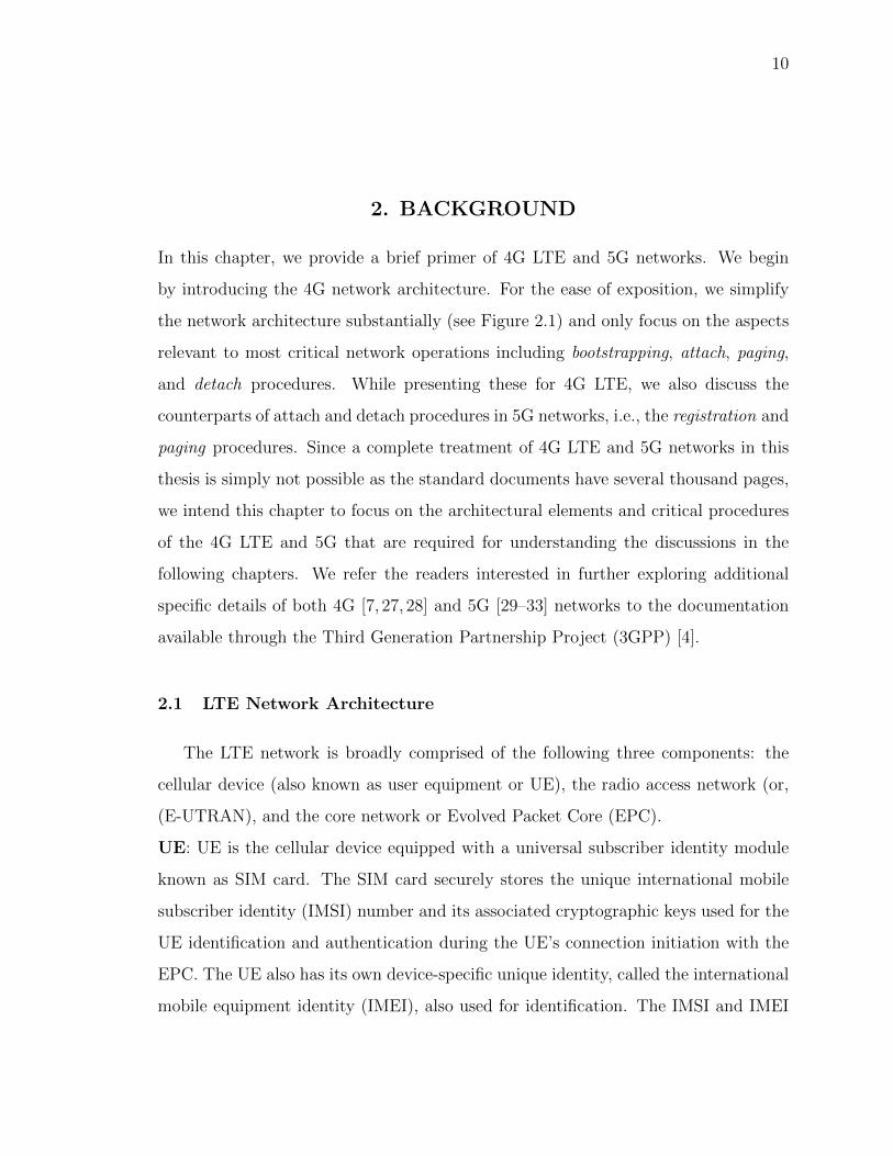
2.1 The LTE Network Architecture . . . . . . . . . . . . . . . . . . . . . . . . 11
2.2 Network time/frame synchronization, and paging frame and paging occa-sion calculation. . . . . . . . . . . . . . . . . . . . . . . . . . . . . . . . . . 14
2.3 Attach, paging, and detach procedures of 4G LTE. . . . . . . . . . . . . . 16
3.1 Architecture of LTEInspector . . . . . . . . . . . . . . . . . . . . . . . . . 26
3.2 A simplified LTE ecosystem model. . . . . . . . . . . . . . . . . . . . . . . 31
3.3 Authentication synchronization failure attack. . . . . . . . . . . . . . . . . 37
3.4 Traceability attack using security mode command. . . . . . . . . . . . . . . 39
3.5 Detach attack using paging. . . . . . . . . . . . . . . . . . . . . . . . . . . 41
3.6 (a) Indiscriminately- (b) targeted- detach/downgrade a UE using the net-work initiated detach request message. . . . . . . . . . . . . . . . . . . . . 44
3.7 Authentication relay attack . . . . . . . . . . . . . . . . . . . . . . . . . . 45
3.8 Experiment setup for custom-built network. . . . . . . . . . . . . . . . . . 52
4.1 Distribution of paging delay i.e., the time between the event of initiatinga phone call or SMS and the event of reaching a paging message to thereceiver for that phone call/SMS. . . . . . . . . . . . . . . . . . . . . . . . 64
4.2 IMSI-Cracking attack in 4G . . . . . . . . . . . . . . . . . . . . . . . . . . . 81
4.3 IMSI-Cracking attack in 5G . . . . . . . . . . . . . . . . . . . . . . . . . . . 83
4.4 Average number of paging message, PS record, and CS record arrivals inany PFI within one paging cycle during peak-time of a day. . . . . . . . . 87
4.5 Accuracy and number of trials against thresholds for ToRPEDO using VoLTEcalls during the peak hour (around noon) of a day. . . . . . . . . . . . . . 88
4.6 Accuracy and number of trials against the selected observation intervalsand threshold value (in order of magnitude) for ToRPEDO using VoLTE callsduring the peak hour of a day. Observation interval for filtering = 98 %,observation interval for counting = 95 %, threshold (in orders of magni-tude) for likelihood = 4. . . . . . . . . . . . . . . . . . . . . . . . . . . . . 89
xii
Figure Page
4.7 Accuracy and number of trials against the selected observation intervalsand threshold value (in order of magnitude) for ToRPEDO using VoLTE callsduring the off-peak time of a day. Observation interval for filtering =98%, observation interval for filtering = 98%, threshold (in orders of mag-nitude) for likelihood= 3. . . . . . . . . . . . . . . . . . . . . . . . . . . . 90
4.8 Accuracy and number of trials against the selected observation intervalsand threshold value (in order of magnitude) for ToRPEDO using CSFB callsduring the off-peak time of a day. Observation interval for filtering =98%, observation interval for filtering = 98%, threshold (in orders of mag-nitude) for likelihood= 2. . . . . . . . . . . . . . . . . . . . . . . . . . . . 90
4.9 Accuracy and number of trials against the selected observation intervalsand threshold value (in order of magnitude) for ToRPEDO using CSFB callsduring the off-peak time of a day. Observation interval for filtering =98%, observation interval for filtering = 98%, threshold (in orders of mag-nitude) for likelihood= 2. . . . . . . . . . . . . . . . . . . . . . . . . . . . 91
5.1 Initial PKI Scheme. . . . . . . . . . . . . . . . . . . . . . . . . . . . . . . 107
5.2 Proposed PKI Scheme. . . . . . . . . . . . . . . . . . . . . . . . . . . . . 108
5.3 Content of SIB1 and SIB2 after protocol-level optimization for securebroadcast authentication . . . . . . . . . . . . . . . . . . . . . . . . . . . 111
5.4 Content of SIB1 and SIB2 after cryptographic scheme-level optimizationfor secure broadcast authentication . . . . . . . . . . . . . . . . . . . . . 113
5.5 Computation of ∆t bounds . . . . . . . . . . . . . . . . . . . . . . . . . . 116
5.6 End-to-end delay induced by different digital signature schemes againstbaseline. For ease of comparison, Y-axis represents the log of the delay inmilliseconds. . . . . . . . . . . . . . . . . . . . . . . . . . . . . . . . . . . 123
6.1 Effectiveness and overhead of our proposed noise-based defense mechanism.133

xiii
ABSTRACT
Hussain, Syed Rafiul PhD, Purdue University, December 2018. A Systematic Frame-work For Analyzing the Security and Privacy of Cellular Networks. Major Professor:Elisa Bertino.
Cellular networks are an indispensable part of a nation’s critical infrastructure.
They not only support functionality that are critical for our society as a whole (e.g.,
business, public-safety message dissemination) but also positively impact us at a
more personal level by enabling applications that often improve our quality of life
(e.g., navigation). Due to deployment constraints and backward compatibility issues,
the various cellular protocol versions were not designed and deployed with a strong
security and privacy focus. Because of their ubiquitous presence for connecting billions
of users and use for critical applications, cellular networks are, however, lucrative
attack targets of motivated and resourceful adversaries.
In this dissertation, we investigate the security and privacy of 4G LTE and 5G
protocol designs and deployments. More precisely, we systematically identify design
weaknesses and implementation oversights affecting the critical operations of the net-
works, and also design countermeasures to mitigate the identified vulnerabilities and
attacks. Towards this goal, we developed a systematic model-based testing framework
called LTEInspector. LTEInspector can be used to not only identify protocol design
weaknesses but also deployment oversights. LTEInspector leverages the combined rea-
soning capabilities of a symbolic model checker and a cryptographic protocol verifier
by combining them in a lazy fashion. We instantiated LTEInspector with three critical
procedures (i.e., attach, detach, and paging) of 4G LTE. Our analysis uncovered 10
new exploitable vulnerabilities along with 9 prior attacks of 4G LTE all of which have
been verified in a real testbed. Since identifying all classes of attacks with a unique
xiv
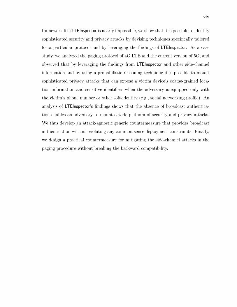
framework like LTEInspector is nearly impossible, we show that it is possible to identify
sophisticated security and privacy attacks by devising techniques specifically tailored
for a particular protocol and by leveraging the findings of LTEInspector. As a case
study, we analyzed the paging protocol of 4G LTE and the current version of 5G, and
observed that by leveraging the findings from LTEInspector and other side-channel
information and by using a probabilistic reasoning technique it is possible to mount
sophisticated privacy attacks that can expose a victim device’s coarse-grained loca-
tion information and sensitive identifiers when the adversary is equipped only with
the victim’s phone number or other soft-identity (e.g., social networking profile). An
analysis of LTEInspector’s findings shows that the absence of broadcast authentica-
tion enables an adversary to mount a wide plethora of security and privacy attacks.
We thus develop an attack-agnostic generic countermeasure that provides broadcast
authentication without violating any common-sense deployment constraints. Finally,
we design a practical countermeasure for mitigating the side-channel attacks in the
paging procedure without breaking the backward compatibility.

1
1. INTRODUCTION
Cellular networks have not only enabled instantaneous and inexpensive communica-
tion among people living in any part of the world, but have also been a major enabling
factor for the modernization of infrastructures and application sectors, such as trans-
portation infrastructure, agriculture, education, health, government and business.
Cellular networks are, therefore, considered as a nation’s critical infrastructure. The
proliferation of low-cost cellular devices, the explosive growth of high-bandwidth mo-
bile applications (such as audio and video), and the overall mobile connectivity by the
end users have resulted in increased complexity and challenging requirements against
such networks, and thus fueling the demand for continuous network evolution. As a
result, even after decades of their emergence with the first generation protocol (1G),
cellular communication protocols have been evolving in terms of speed, technology,
frequency, data capacity, and latency to enhance quality of services and thus have be-
come the driving force behind many advancements. For instance, the first generation
(1G) enabled the basic analog voice communication, while the second generation (2G)
enabled digital voice communication and dealt with capacity and coverage. The third
generation (3G) ushered in mobile data, and provided multimedia support whereas
the fourth generation (4G) paved the way for widespread mobile Internet usage and
access to a wide range of telecommunication services. The fifth generation (5G) is
going to revolutionize mobile and Internet-of-Things (IoT) markets by assuring better
connectivity, reduced latency, and enhanced security to smart cellular devices.
1.1 Insecurity of Cellular Communication
Though cellular networks have been evolving every 10 years with newer generation
of access technologies, the security and privacy safeguards for such critical infrastruc-

2
ture have not kept pace with its growing importance. Because of their ubiquitous
presence and use for critical applications (e.g., emergency alert systems), cellular
networks have been attractive attack targets for malicious parties. For instance, re-
sourceful adversaries (e.g., nation states, foreign intelligence agencies, terrorists) can
rely on an ingenious range of attack strategies and wreak havoc by exploiting vul-
nerabilities of the cellular network ecosystem (e.g., surveillance [1], cyberwarfare [2]).
The potential of such attacks is exacerbated by the increasingly wide adoption of
cellular communication enabled smart devices [3] and systems (e.g., autonomous ve-
hicles) which often reside in individuals’ personal space. If cellular networks are
not adequately protected, the damage may result in huge losses of dollars, strategic
advantage, and even of human lives.
1.2 A Vision for Secure Cellular Network and the Key Research Direction
We envision a future in which the security and resiliency of cellular networks will
be unquestionable and will not crumble even against the strongest possible adver-
saries. Achieving this goal will require advances in many research directions. Among
them the foremost research direction is the secure system design and rigorous veri-
fication of the desirable security and privacy properties of the system. Since many
vulnerabilities in the implementations arise from specification misinterpretation and
evaluation in isolation, it is, therefore, also critical to investigate the existing design
and deployments of cellular networks for detecting potential vulnerabilities.
The 3rd Generation Partnership Project (3GPP) [4] develops the standard/speci-
fication of cellular communication protocols and provides guidelines for conformance
testing [5] which only evaluates if the implementation is compliant with the speci-
fications. While such testing approaches have been shown to be useful for checking
functional requirements, gaps in the protocol design and insufficient checking for the
adversary entry points have resulted in the discovery of new vulnerabilities. There-
3
fore, it is imperative to analyze the security and privacy of cellular network standards
and thus ensure their resiliency against powerful attackers.
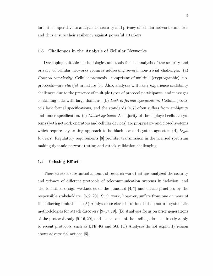
1.3 Challenges in the Analysis of Cellular Networks
Developing suitable methodologies and tools for the analysis of the security and
privacy of cellular networks requires addressing several non-trivial challenges: (a)
Protocol complexity : Cellular protocols—comprising of multiple (cryptographic) sub-
protocols—are stateful in nature [6]. Also, analyses will likely experience scalability
challenges due to the presence of multiple types of protocol participants, and messages
containing data with large domains. (b) Lack of formal specification: Cellular proto-
cols lack formal specifications, and the standards [4, 7] often suffers from ambiguity
and under-specification. (c) Closed systems : A majority of the deployed cellular sys-
tems (both network operators and cellular devices) are proprietary and closed systems
which require any testing approach to be black-box and system-agnostic. (d) Legal
barriers : Regulatory requirements [8] prohibit transmission in the licensed spectrum
making dynamic network testing and attack validation challenging.
1.4 Existing Efforts
There exists a substantial amount of research work that has analyzed the security
and privacy of different protocols of telecommunication systems in isolation, and
also identified design weaknesses of the standard [4, 7] and unsafe practices by the
responsible stakeholders [6, 9–20]. Such work, however, suffers from one or more of
the following limitations: (A) Analyses use clever intuitions but do not use systematic
methodologies for attack discovery [9–17,19]; (B) Analyses focus on prior generations
of the protocols only [9–16,20], and hence some of the findings do not directly apply
to recent protocols, such as LTE 4G and 5G; (C) Analyses do not explicitly reason
about adversarial actions [6].

4
1.5 Dissertation Focus
It is evident that the state-of-the-art of systematic analysis frameworks and vulner-
ability mitigation techniques for ensuring the resilience of cellular standards against
attacks are far away from the security level that we want to achieve. In this disser-
tation, we, therefore, first address the following research question: is it possible to
develop a systematic framework for scrutinizing different protocols in the cellular net-
work standard to uncover vulnerabilities that can be shown to be realizable in practice
by an adversary?
Designing a uniform framework for verifying all classes of (security and privacy)
properties and exploring all kinds of attacks for such complex cellular systems is an
undecidable problem. Though fine-grained protocol-behavior abstraction (including
low-level details) of the massive cellular systems may be capable of identifying a wide
range of attacks, it is likely to trigger the state explosion problem which would make
the analysis intractable. The coarse-grained behavior abstraction, on the other hand,
facilitates efficient reasoning but is unable to identity the side-channel attack vectors.
In this dissertation, we, therefore, address the second research question: is it possible
to identify side-channel attacks in a particular sub-protocol of the cellular system by
leveraging insights drawn from a systematic approach and by exploiting sophisticated
probabilistic reasoning techniques?
While systematic analysis helps identifying the root causes of the vulnerabilities,
mitigation techniques are required to augment the inventory of defense mechanisms.
Attack-specific countermeasures, or in other words, hot-patches to a particular vul-
nerability have been shown to be fruitful for an already deployed cellular system
whereas attack-agnostic countermeasures seal-off the root cause of a class of vulnera-
bilities and require major overhaul to the protocol standard and thus are difficult to
integrate with the already deployed system. Hence, in this dissertation, we address
the third research question: is it possible to design attack-agnostic countermeasures
5
that can be incorporated into both the current and the newer generations of cellular
networks without breaking the backward compatibility?
Note that we address these research questions from the perspective of 4G and 5G
networks and our proposed techniques are general enough to adapt for both older and
newer generations of cellular networks.
1.6 Thesis Statement
In this doctoral thesis, we demonstrate that: (i) carefully designed systematic
framework can soundly and scalably discover the vulnerabilities in closed systems and
is useful in evaluating cellular networks to understand how well they ensure security
and privacy; (ii) the use of sophisticated techniques tailored for specific sub-protocols
makes it possible to identify side-channel attacks in cellular networks; and (iii) attack-
specific countermeasures often do not hold under detailed security analysis, whereas
attack-agnostic and clean-slate defense techniques are more effective in mitigating the
root cause of many active attacks; however, they require careful optimization and en-
gineering to keep the protocol overhead low while at the same time assuring backward
compatibility.
1.7 Contributions
In this dissertation, we make the following contributions
1.7.1 A Systematic Framework for Analyzing Security and Privacy of
Cellular Networks
We investigate the security and privacy of the three critical procedures of the 4G
LTE protocol (i.e., attach, detach, and paging), and in the process, uncover poten-
tial design flaws of the protocol and unsafe practices employed by the stakeholders.
For exposing vulnerabilities, we propose a model-based testing approach LTEInspector
6
which lazily combines a symbolic model checker and a cryptographic protocol verifier
in the symbolic attacker model. Using LTEInspector, we have uncovered 10 new at-
tacks along with 9 prior attacks, categorized into three abstract classes (i.e., security,
user privacy, and disruption of service), in the three procedures of 4G LTE. Notable
among our findings is the authentication relay attack that enables an adversary to
spoof the location of a legitimate user to the core network without possessing ap-
propriate credentials. To ensure that the exposed attacks pose real threats and are
indeed realizable in practice, we have validated 8 of the 10 new attacks and their ac-
companying adversarial assumptions through experimentation in a real testbed. Note
that LTEInspector is generalized enough that it works like a plug-and-play analysis
tools for both older and newer generations of cellular networks which drew atten-
tion [21–26] from all over the world and paved the way to make a real impact through
collaborating with the leading cellular stakeholders (e.g., Qualcomm and Intel).
1.7.2 Identification of Privacy Attacks on the 4G and 5G Cellular Paging
Protocols Using Side Channel Information
The cellular paging (broadcast) protocol strives to balance between a cellular
device’s energy consumption and quality-of-service by allowing the device to only pe-
riodically poll for pending services in its idle, low-power state. For a given cellular
device and serving network, the exact time periods when the device polls for services
(called the paging occasion) are fixed by design in the 4G/5G cellular protocol. In this
work, we show that the fixed nature of paging occasions can be exploited by an adver-
sary to associate a victim’s soft-identity (e.g., phone number, Twitter handle) with
its paging occasion, with only a modest cost, through an attack dubbed ToRPEDO. Con-
sequently, ToRPEDO can enable an adversary to infer a victim’s coarse-grained location
information, inject fabricated paging messages, and mount denial-of-service attacks.
We also demonstrate that, in 4G and 5G, it is plausible for an adversary to retrieve a
victim device’s persistent identity (i.e., IMSI) with a brute-force IMSI-Cracking attack

7
while using ToRPEDO as an attack sub-step. Our further investigation on 4G paging
protocol deployments also identified an implementation oversight of several network
providers which enables an adversary to launch an attack, named PIERCER, for asso-
ciating a victim’s phone number with its IMSI; subsequently allowing targeted user
location tracking. All of our attacks have been validated and evaluated in the wild
using commodity hardware and software.
1.7.3 Securing the Insecure Connection Bootstrapping in Cellular Net-
works: The Root of all Evil
Current cellular ecosystem lacks authentication in its bootstrapping signaling and
it allows a malicious, fake base station to lure unsuspecting cellular device to con-
nect to it which can then enable the adversary to launch many known active attacks.
Though several efforts have been undertaken to detect fake base stations and also to
protect the privacy of subscribers’ permanent identifier (IMSI/IMEI), very little has
been done to empower cellular devices to authenticate legitimate base stations. The
3GPP is aware of the danger of unauthenticated broadcast signals and has outlined
two possible approaches—based on symmetric and asymmetric key cryptography—
to mitigate this insecurity. These authentication approach-sketches, however, are not
incorporated in the recent generation of the protocol (5G). The rationale for not incor-
porating broadcast authentication in 5G is, however, not clear. In addition, it is not
clear what would be the challenges and trade-offs required for the deployment of such
authentication approaches within the 5G protocols. In this work, we, thereby, first
develop clean-slate designs of these two approaches and evaluate their efficacy from a
purely technical point of view. Based on our initial evaluation, we observed that the
approach based on symmetric key cryptography does not provide the desired level of
assurances whereas the approach based on Public-key Infrastructure (PKI) is feasible
without breaking the backward compatibility. Further evaluation on a real test-bed
shows that it is feasible to deploy a light-weight PKI-based authentication mechanism
8
leveraging precomputation of digital signatures without incurring substantial latency
and bandwidth overhead.
1.7.4 Hardening against Privacy Attacks Exploiting Side-Channel Infor-
mation
The fixed nature of paging occasions in 4G and 5G networks is a fundamental
weakness which the adversary may exploit to associate a victim’s soft identity, e.g.,
phone number or Twitter Handle with its paging occasion. This further enables the
adversary to perform ToRPEDO attack through which the adversary can infer a victim’s
coarse-grained location information, inject fabricated paging messages, and mount
denial-of-service attacks. In this work, we first explore the solution space against the
ToRPEDO attack and then outline a clean-slate countermeasure making the paging oc-
casions and the identities anonymous to any devices. Our initial evaluation, however,
reveals the impractical overhead incurred by this solution which leads us to develop a
viable noise-based countermeasure in which a legitimate base station carefully injects
fake paging messages containing legitimate devices’ TMSIs. We evaluated its efficacy
with real network traces for different operators. In our evaluation, we observed that
with ∼ 600 fake paging messages injected within ∼ 40 seconds interval can prevent
the adversary to perform the ToRPEDO attack with as many as ∼ 500 phone calls.
1.8 Dissertation Outline
The remainder of this dissertation is organized as follows:
Chapter 2 provides a background on 4G LTE and 5G networks. Chapter 3 presents
LTEInspector, a model-based testing approach, for analyzing the security and the
privacy of 4G LTE networks. Chapter 5 demonstrates how the adversary exploits the
fixed paging occasion of a device to perform a number of privacy attacks. Chapter 5
describes the PKI-based lightweight broadcast authentication scheme for preventing
fake base stations. Chapter 6 addresses the side channel attacks uncovered in the

9
paging procedure. Chapter 7 presents the state-of-the-art summary of the related
work. Finally, Chapter 8 provides a discussion of concluding remarks and future
research directions.
10
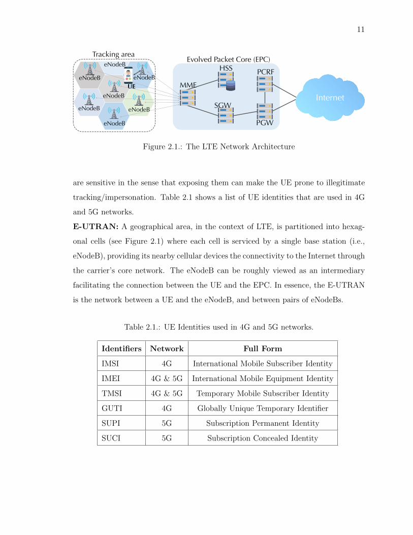
2. BACKGROUND
In this chapter, we provide a brief primer of 4G LTE and 5G networks. We begin
by introducing the 4G network architecture. For the ease of exposition, we simplify
the network architecture substantially (see Figure 2.1) and only focus on the aspects
relevant to most critical network operations including bootstrapping, attach, paging,
and detach procedures. While presenting these for 4G LTE, we also discuss the
counterparts of attach and detach procedures in 5G networks, i.e., the registration and
paging procedures. Since a complete treatment of 4G LTE and 5G networks in this
thesis is simply not possible as the standard documents have several thousand pages,
we intend this chapter to focus on the architectural elements and critical procedures
of the 4G LTE and 5G that are required for understanding the discussions in the
following chapters. We refer the readers interested in further exploring additional
specific details of both 4G [7, 27, 28] and 5G [29–33] networks to the documentation
available through the Third Generation Partnership Project (3GPP) [4].
2.1 LTE Network Architecture
The LTE network is broadly comprised of the following three components: the
cellular device (also known as user equipment or UE), the radio access network (or,
(E-UTRAN), and the core network or Evolved Packet Core (EPC).
UE: UE is the cellular device equipped with a universal subscriber identity module
known as SIM card. The SIM card securely stores the unique international mobile
subscriber identity (IMSI) number and its associated cryptographic keys used for the
UE identification and authentication during the UE’s connection initiation with the
EPC. The UE also has its own device-specific unique identity, called the international
mobile equipment identity (IMEI), also used for identification. The IMSI and IMEI
11
MME
HSS
SGW
PCRF
PGW
Evolved Packet Core (EPC)
InternetUE
eNodeB
eNodeB
eNodeB
eNodeB
eNodeB
eNodeB
eNodeB
Tracking area
Figure 2.1.: The LTE Network Architecture
are sensitive in the sense that exposing them can make the UE prone to illegitimate
tracking/impersonation. Table 2.1 shows a list of UE identities that are used in 4G
and 5G networks.
E-UTRAN: A geographical area, in the context of LTE, is partitioned into hexag-
onal cells (see Figure 2.1) where each cell is serviced by a single base station (i.e.,
eNodeB), providing its nearby cellular devices the connectivity to the Internet through
the carrier’s core network. The eNodeB can be roughly viewed as an intermediary
facilitating the connection between the UE and the EPC. In essence, the E-UTRAN
is the network between a UE and the eNodeB, and between pairs of eNodeBs.
Table 2.1.: UE Identities used in 4G and 5G networks.
Identifiers Network Full Form
IMSI 4G International Mobile Subscriber Identity
IMEI 4G & 5G International Mobile Equipment Identity
TMSI 4G & 5G Temporary Mobile Subscriber Identity
GUTI 4G Globally Unique Temporary Identifier
SUPI 5G Subscription Permanent Identity
SUCI 5G Subscription Concealed Identity

12
EPC: We now describe those EPC components of 4G LTE that are relevant to our
discussion, i.e., the MME (Mobility Management Entity) and the HSS (Home Sub-
scriber Server).
(1) Mobility Management Entity (MME): The MME manages attach (includ-
ing authentication and key agreement), paging, and detach procedures of the UEs in
a particular tracking area (formed by a set of hexagonal cells). It is also responsible
for keeping track of the locations of the UEs residing in its designated tracking area.
(2) Home Subscriber Server (HSS): The HSS stores UEs’ identities (e.g., IMSI
and IMEI) and subscription data (e.g., QoS profile) along with the cryptographic
master keys from which it generates the authentication challenges and the symmetric
session keys for each subscriber.
Other EPC components include the Serving-Gateway (SGW), the PCRF (Policy
and Charging Rules Function) server, and the Packet Data Network Gateway (P-GW)
which are responsible for enabling incoming and outgoing services (phone calls and
SMS). 4G LTE provides packet switch (PS) services for Internet access and VoLTE
(Voice over LTE) phone calls. It also supports circuit switch (CS) voice services using
the Circuit-Switched Fallback (CSFB) technique which moves UEs from 4G to 3G
network to access 3G voice services, and then returns them to the 4G network.
2.1.1 Corresponding EPC Components in 5G
5G has introduced a service-driven network architecture and included a number of
new core elements to efficiently meet diversified service requirements. A major portion
of the 5G architecture is, however, similar to 4G which induces a deep similarity
between some EPC components of the 4G and 5G core networks. A majority of
control-plane interactions between the UE and the core network are thus equivalent
for 4G and 5G. We, therefore, briefly discuss the 5G network components that are
equivalent to MME and HSS in 4G:

13
(1) Access and Mobility Management Function (AMF): The AMF supports
registration (resp, attach in 4G) management, connection management, mobility man-
agement, access authentication and authorization, and security context management.
(2) Unified Data Management (UDM): The UDM supports generation of Au-
thentication and Key Agreement (AKA) credentials, user identification handling, ac-
cess authorization, and subscription management.
2.2 Bootstrapping Signals
Synchronization Signals. Primary Synchronization Signal (PSS) and Secondary
Synchronization Signal (SSS) are two specific physical layer signals that are used for
radio frame synchronization and physical cell identification.
Master Information Block (MIB). A base station periodically (every 40 ms)
broadcasts master info block messages to advertise the existence of the network irre-
spective of any user’s presence in a cell area. Therefore, the very first step for a UE to
gain initial access to the network is to read the master info block (MIB) message that
includes the downlink channel bandwidth, configuration parameters for decoding sub-
sequent messages, and the current system frame number (SFN) for UE’s time/frame
synchronization with the network. We further elaborate the discussion on SFN and
time/frame synchronization in Section 2.3.
System Information Block (SIB). A base station also periodically (every 80
ms) broadcasts system info block type 1 message that includes information regarding
whether a UE is allowed to access the cell. It also defines the scheduling of the other
system info block messages (e.g., system info block type 2), and carries cell ID, mobile
country code (MCC), mobile network code (MNC), tracking area code (a tracking area
consists of multiple cells), mapping information for other system info block messages.
14
146 147 148 149 150 151
0 1 2 3 4 5 6 7 8 9
Paging Frame10 ms
DRX Cycle (128 Radio Frames)
PFI 128 Radio Frames
18 19 20 21 22 23
0 1 2 3 4 5 6 7 8 9 Paging Occasion Subframes
Paging Frame
SFNs10 ms
0 1 2 3SFNs10 ms
4 5 6 7 1020 1021 1022 1023...
MIB MIB
.........
533 .......661 789 .......917..............21 .......149 277.......405.......
Figure 2.2.: Network time/frame synchronization, and paging frame and paging oc-
casion calculation.
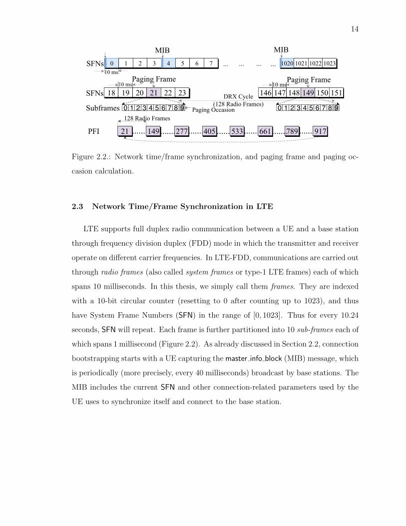
2.3 Network Time/Frame Synchronization in LTE
LTE supports full duplex radio communication between a UE and a base station
through frequency division duplex (FDD) mode in which the transmitter and receiver
operate on different carrier frequencies. In LTE-FDD, communications are carried out
through radio frames (also called system frames or type-1 LTE frames) each of which
spans 10 milliseconds. In this thesis, we simply call them frames. They are indexed
with a 10-bit circular counter (resetting to 0 after counting up to 1023), and thus
have System Frame Numbers (SFN) in the range of [0, 1023]. Thus for every 10.24
seconds, SFN will repeat. Each frame is further partitioned into 10 sub-frames each of
which spans 1 millisecond (Figure 2.2). As already discussed in Section 2.2, connection
bootstrapping starts with a UE capturing the master info block (MIB) message, which
is periodically (more precisely, every 40 milliseconds) broadcast by base stations. The
MIB includes the current SFN and other connection-related parameters used by the
UE uses to synchronize itself and connect to the base station.

15
2.4 UE’s Cell Section and Initial Connection Establishment
The cellular device scans the frame synchronization signals broadcast by nearby
base stations in the frequency bands that the device is allowed to operate on and
for each frequency it identifies the strongest among all the suitable/acceptable cells.
A suitable/acceptable cell is the one for which the measured cell attributes satisfy
the cell selection criteria. When an acceptable cell is found, the UE camps on that
cell and initiates the cell reselection procedure, if required. The UE reads the MIB
message sent by the selected cell, and synchronizes the time. The UE learns the
connection-related parameters’ values from the SIB messages after which it initiates
connection (as shown in Figure 2.3) to the base station (at the radio resource control
or RRC layer) and to the core network (at Network Access Stratum or NAS layer).
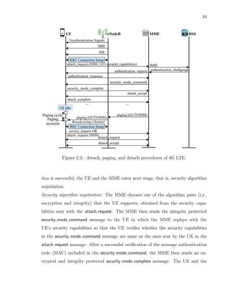
2.5 Attach Procedure
When a UE wants to connect to the EPC (e.g., at the time of device reboot),
the UE starts off by establishing a (RRC-layer) connection (see Figure 2.3) with the
eNodeB whose signal power it perceives to be the highest. As we illustrate later, this
step (i.e., connecting to the highest powered eNodeB) can be exploited to set up
a malicious eNodeB, prevalently in the context of IMSI catchers [18, 20]. Once the
UE has established a connection with the eNodeB, the attach procedure can proceed
according to the following four stages.
Identification: The UE starts the attach procedure by sending the attach request mes-
sage to the MME through the eNodeB (see Figure 2.3). The UE includes its identity,
i.e., the IMSI/IMEI and its security capabilities (e.g., supported cipher suites) in this
attach request message in plaintext.
Authentication: For verifying the authenticity of the UE, the MME, upon reception
of an authentication challenge generated by the HSS, sends an authentication request
message including this challenge to the UE. The UE using its master key solves the
challenge and sends an authentication response message to the UE. If the authentica-
16
RRC Connection Setupattach_request (IMSI, UE's security capabilities)
authentication_requestauthentication_response
security_mode_command
security_mode_completeattach_accept
attach_complete
UE MMEeNodeB
UE Idle... ...
paging (GUTI/IMSI)paging (GUTI/IMSI)
Broadcasting Channel
Paging cyclePagingoccasion
detach_requestdetach_accept
service_request ORattach_request (IMSI)
RRC Connection Setup
HSS
IMSIauthentication_challgenge
Synchronization SignalsMIB
SIB
Figure 2.3.: Attach, paging, and detach procedures of 4G LTE.
tion is successful, the UE and the MME enter next stage, that is, security algorithm
negotiation.
Security algorithm negotiation: The MME chooses one of the algorithm pairs (i.e.,
encryption and integrity) that the UE supports, obtained from the security capa-
bilities sent with the attach request. The MME then sends the integrity protected
security mode command message to the UE in which the MME replays with the
UE’s security capabilities so that the UE verifies whether the security capabilities
in the security mode command message are same as the ones sent by the UE in the
attach request message. After a successful verification of the message authentication
code (MAC) included in the security mode command, the MME then sends an en-
crypted and integrity protected security mode complete message. The UE and the

17
MME then create a shared security context, i.e., the shared keys for protecting con-
fidentiality and integrity of the future message exchanges.
Secure temporary identifier exchange: The MME then sends an encrypted and integrity-
protected attach accept message which includes a temporary identity called GUTI
(Globally Unique Temporary Identity)1 for the UE. TMSI is randomly assigned by
the MME to an UE and is local to a tracking area, and so it has to be updated each
time the UE moves to a new geographical area. The MME can also update a UE’s
TMSI if it desires to do so. To limit the exposures of sensitive IMSI/IMEI, the TMSI
is used in all subsequent communications between the UE and the eNodeB/MME.
The UE concludes the attach procedure by sending an attach complete message. The
UE and the eNodeB then also create a security context by generating a pair of shared
keys for their secure communication.
2.5.1 Registration Procedure in 5G
Except for the identification phase, the registration procedure in 5G is similar to
the attach procedure in 4G. Instead of sending the IMSI in the registration request
(resp., attach request for 4G) message, in 5G the UE sends a randomized encryption of
the SUPI (Subscription Private Identifier). The SUPI is a SIM card-specific persistent
identity for a UE in 5G. The UE uses the core network’s public key to encrypt its
SUPI (the encrypted SUPI is referred to as SUCI or Subscription Concealed Identifier)
whereas the UDM in 5G core network uses the private key for decrypting the SUCI.
2.6 Paging Procedure
When a UE is not actively communicating with a base station, it enters an idle,
low-energy mode for conserving battery power. When the UE is in the idle mode,
the base station uses the paging protocol to notify the UE about emergencies (e.g.,
1GUTI = MME identifier + TMSI (Temporary Mobile Subscriber Identity). The MME/eNodeBuses few bytes of GUTI as TMSI to represent the temporary identifier. Therefore, for simplifyingthe discussion, we use the terms TMSI and GUTI interchangeably in the rest of the thesis.
18
Tsunami warning) or pending network services (e.g., incoming calls, SMS, or other
services). This is called Discontinuous Reception (DRX).
Service paging. For notifying an idle UE about a pending service, if smart paging is
used, the MME first asks the UE’s last connected base station to broadcast a paging
message for the UE. If there is no response from the UE, then the MME asks all
base stations in its tracking area to broadcast the paging message through a Paging
Control Channel (PCCH). For non-smart paging, the first step is skipped. If the UE
still does not respond, it is assumed that the UE either left the tracking area or is
not communicating to the network.
Paging messages. A paging message contains between 1 and 16 paging records.
Each paging record notifies one UE that there are incoming services for it. Such a
record contains the MME identifier, the domain (PS or CS), and the target UE’s
paging identity, which can be either the IMSI or the TMSI, determined by the MME.
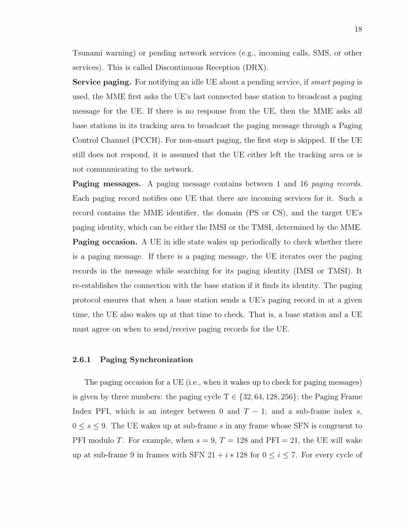
Paging occasion. A UE in idle state wakes up periodically to check whether there
is a paging message. If there is a paging message, the UE iterates over the paging
records in the message while searching for its paging identity (IMSI or TMSI). It
re-establishes the connection with the base station if it finds its identity. The paging
protocol ensures that when a base station sends a UE’s paging record in at a given
time, the UE also wakes up at that time to check. That is, a base station and a UE
must agree on when to send/receive paging records for the UE.
2.6.1 Paging Synchronization
The paging occasion for a UE (i.e., when it wakes up to check for paging messages)
is given by three numbers: the paging cycle T ∈ {32, 64, 128, 256}; the Paging Frame
Index PFI, which is an integer between 0 and T − 1; and a sub-frame index s,
0 ≤ s ≤ 9. The UE wakes up at sub-frame s in any frame whose SFN is congruent to
PFI modulo T . For example, when s = 9, T = 128 and PFI = 21, the UE will wake
up at sub-frame 9 in frames with SFN 21 + i ∗ 128 for 0 ≤ i ≤ 7. For every cycle of

19
T frames (of total length 10T ms), the UE needs to wake up for only 1 ms. We now
explain how these numbers are computed.
Paging Cycle (T). The base station broadcast a proposed value for T. The UE can
choose to use that value or propose another value, in which case the minimum
of these two values are chosen.
Paging Frame Index (PFI). Computing the PFI requires the UE’s UE ID, defined
as:
UE ID = IMSI mod 1024.
In addition, it requires another public parameter (nB) set by the base station,
and chosen from the set {4T, 2T,T, T2, T4, T8, T16, T32}. PFI is defined using the
following formula:
PFI =T
N× (UE ID mod N) where N = min(T, nB).
Equivalently,
PFI =
UE ID mod T when T ≤ nB
TnB× (UE ID mod nB) when T > nB
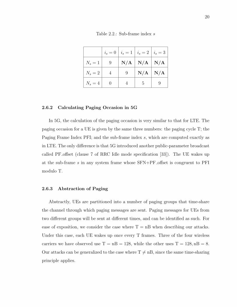
Sub-frame Index. The sub-frame index s can be calculated using the lookup Ta-
ble 2.2 where
Ns = max
(1,
nB
T
); is =
⌊UE ID
N
⌋mod Ns.
Note that when nB ≤ T and Ns = 1, all UEs will use sub-frame 9. When
nB = 2T, a UE uses either sub-frame 4 or sub-frame 9, depending on whether
its UE ID is even or odd. When nB = 4T, the UEs are partitioned into 4
groups, each using one sub-frame.
Example. An example is shown in Figure 2.2 illustrating the calculation of the PFI,
the System Frame Numbers during which the UE should wake up, and the sub-frame
index, where nB=T=128 and UE ID=21.
20
Table 2.2.: Sub-frame index s
is = 0 is = 1 is = 2 is = 3
Ns = 1 9 N/A N/A N/A
Ns = 2 4 9 N/A N/A
Ns = 4 0 4 5 9
2.6.2 Calculating Paging Occasion in 5G
In 5G, the calculation of the paging occasion is very similar to that for LTE. The
paging occasion for a UE is given by the same three numbers: the paging cycle T; the
Paging Frame Index PFI; and the sub-frame index s, which are computed exactly as
in LTE. The only difference is that 5G introduced another public-parameter broadcast
called PF offset (clause 7 of RRC Idle mode specification [33]). The UE wakes up
at the sub-frame s in any system frame whose SFN+PF offset is congruent to PFI
modulo T.
2.6.3 Abstraction of Paging
Abstractly, UEs are partitioned into a number of paging groups that time-share
the channel through which paging messages are sent. Paging messages for UEs from
two different groups will be sent at different times, and can be identified as such. For
ease of exposition, we consider the case where T = nB when describing our attacks.
Under this case, each UE wakes up once every T frames. Three of the four wireless
carriers we have observed use T = nB = 128, while the other uses T = 128, nB = 8.
Our attacks can be generalized to the case where T 6= nB, since the same time-sharing
principle applies.

21
2.7 Detach Procedure
The UE/MME can choose to terminate the established connection by generating
a detach request including the cause of detach. In response to the detach request, the
UE/MME is expected to send a detach accept message.
22
3. LTEInspector: A SYSTEMATIC APPROACH FOR
ADVERSARIAL TESTING OF 4G LTE
The adoption of Fourth generation Long Term Evaluation (4G LTE)—the de facto
standard for cellular telecommunication—has seen a stable growth in recent years,
replacing prior generations due to its promise of improved assurances (e.g., higher
bandwidth, reliable connectivity, enhanced security). 4G LTE has not only influenced
our society as a whole but also made impact at a more personal level by enabling
applications that often improve our quality of life. 4G LTE are also often used for
quickly broadcasting public safety/warning messages in the case of natural (e.g., hur-
ricane) or man-made (e.g., toxic gas emission) disasters. Although different aspects
of 4G LTE have been investigated [17, 34] using ad hoc analysis techniques, there is
no concerted effort/framework to systematically inspect the 4G LTE standard/spec-
ification for identifying security and user privacy vulnerabilities. The grand vision of
this work is to develop a framework which can enable automated analysis of the 4G
LTE standard for finding weaknesses and operational oversight that can be exploited
by adversaries for violating the inherent security, user privacy, and service guarantees
desired from 4G LTE networks.
Problem and scope. The 4G LTE protocol can be viewed as an amalgamation
of multiple critical procedures, such as attach, paging, detach, handover, and calls
— to name a few. Each of these procedures is complex and requires an in-depth
security and privacy analysis of its own. Among the different procedures, attach,
paging, and detach are critical for the correct and reliable functionality of the other
procedures. For instance, without a correct and secure attach procedure (i.e., the
initial secure connection setup), the security bootstrapping process is likely to be
vulnerable; this may have serious consequences, such as man-in-the-middle attacks,
spurious mobile billing, or even life threatening risks. This work described in this

23
chapter thus addresses the following central research question: is it possible to develop
a systematic approach for scrutinizing the attach, detach, and paging procedures to
uncover vulnerabilities that can be shown to be realizable in practice by an adversary?
Approach. For analyzing the critical procedures of 4G LTE, in this work, we pro-
pose LTEInspector which employs a property-driven adversarial model-based testing
philosophy. LTEInspector considers the standard symbolic adversary model (alterna-
tively known as the Dolev-Yao model [35]) for its analysis. LTEInspector takes the
relevant 4G LTE abstract model M and a desired property ϕ, and tries to find a
violation of ϕ in M. The set of properties that LTEInspector aims to check include
authenticity (e.g., disallowing impersonation), availability (e.g., preventing service de-
nial), integrity (e.g., restricting unauthorized billing), and secrecy of user’s sensitive
information (e.g., preventing activity profiling).
As a prerequisite of LTEInspector’s analysis, we first construct the 4G LTE ecosys-
tem model by consulting the standard [4, 7]. Our model M (publicly available
in https://github.com/relentless-warrior/LTEInspector) captures the abstract
functionality (ignoring low-level implementation details) of the 4G LTE ecosystem—
only relevant to the analysis of the three procedures—as synchronous communicating
finite state machines (FSM). Each FSM captures the stateful functionality of a pro-
tocol participant’s (i.e, user’s cellular device and the core network) at the Non-Access
Stratum (NAS) protocol layer [4, 7]. The two FSMs communicate with each other
through public (adversary-controlled) communication channels by sending each other
NAS layer messages.
Our analysis is an instance of the parameterized system verification problem (i.e.,
parameterized by the number of protocol participants) which is generally undecid-
able [36]; achieving both soundness and completeness is thus impossible. Conse-
quently, we follow the conventional method of aiming for soundness instead of com-
pleteness, that is, if our approach reports a violation, it is indeed a violation; we can-
not, however, detect all violations. Also, checking compliance of the protocol model
against desired security and privacy properties often requires simultaneously reason-

24
ing about: (Ê) temporal ordering of different events/actions (i.e., trace properties
such as response properties [37]), (Ë) cryptographically-protected messages and con-
structs (e.g., encryption, hashing), and (Ì) other rich constraints (e.g., linear integer
arithmetic constraints). General purpose model checkers [38,39] have shown promise
in successfully reasoning about properties concerning Ê and Ì. Cryptographic proto-
col verifiers [40–45], although proficient in verifying cryptography related properties,
for tractability reasons only provide primitive support at best for properties concern-
ing Ê and Ì. This naturally leads us to the question: is it possible to get the best of
both these techniques?
To this end, LTEInspector lazily (or, on an on-demand basis) combines the reason-
ing powers of a symbolic model checker and a cryptographic protocol verifier. To the
best of our knowledge, in the context of 4G LTE, the use of symbolic model checking
and a cryptographic protocol verifier to reason about rich temporal trace properties
is novel. In this approach, we first abstract away all cryptography-related constructs
from the modelM and the desired property ϕ and only reason about aspects Ê and
Ì of the ϕ (denoted by ϕabs). For any violation of ϕabs in M, the symbolic model
checker would yield a counterexample π demonstrating the violation. Now, π may
include adversary actions which may not be realizable due to cryptographic assump-
tion violations (e.g., constructing a valid ciphertext of a message without possessing
the encryption key). To rule out such cases, for each adversary action in π, we query
a cryptographic protocol verifier to check the action’s feasibility with accordance to
the cryptographic assumptions. In case all adversary actions in π turn out to be
feasible, we can report π to be a feasible vulnerability. If, however, there exists one
adversary action in π which is not feasible, we refine the property ϕabs to rule out
traces in which the adversary takes that action. The analysis is then run again with
the refined property. For further confidence, we validate π by concretely executing it
in a testbed.
Finally, we show the application of a technique we call attack chaining in which
seemingly low-impact attacks are stitched together to yield a damaging high-impact

25
attack. We show its successful application by chaining together attacks, exposed
using LTEInspector, to allow an adversary to carry out an authentication relay attack
in the 4G LTE network.
Findings. Notable among our findings is the authentication relay attack which en-
ables an adversary to connect to the core networks—without possessing any legitimate
credentials—while impersonating a victim cellular device. Through this attack the
adversary can poison the location of the victim device in the core networks, thus
allowing setting up a false alibi or planting fake evidence during a criminal investiga-
tion.
Other notable attacks reported in this work enable an adversary to obtain user’s
coarse-grained location information and also mount denial of service (DoS) attacks.
In particular, using LTEInspector, we obtained the intuition of an attack which enables
an adversary to possibly hijack a cellular device’s paging channel with which it can
not only stop notifications (e.g., call, SMS) to reach the device but also can inject
fabricated messages resulting in multiple implications including energy depletion and
activity profiling.
Contributions. In summary, this work makes the following technical contributions:
(1) We propose LTEInspector—a systematic model-based adversarial testing approach—
that leverages the combined power of a symbolic model checker and a protocol verifier
for analyzing three critical procedures (i.e., attach, detach, and paging) of the 4G
LTE network. The general principle employed by LTEInspector is to be tool-agnostic,
that is, it can be instantiated through any generic symbolic model checker and cryp-
tographic protocol verifier.
(2) We show the effectiveness of our approach in finding new vulnerabilities as well
as 9 prior attacks. Our approach has contributed to exposing 10 new attacks.
(3) We show that the majority of our new attacks (i.e., 8 out of 10) are realizable
in practice through experimentation in a low cost (i.e., $3, 900), real test-bed while
adhering to ethical, legal, and moral practices.

26
3.1 Design Overview of LTEInspector
In this section, we first present our threat model, and then describe the ma-
jor components of LTEInspector’s architecture (see Figure 3.1). Finally, we explain
LTEInspector’s adversarial-testing approach with a concrete example.
UE state machine
MME state machine
Adversarial model instrumentor
Threat instrumented abstract LTE ecosystem model
Model checker
Desired prop. from standard
The image part with relationship ID rId3 was not found in the file.
Counter-example
Crypto. protocol verifier
Domain knowledge
Testbed
Property violated
Property verified
Attacks
Figure 3.1.: Architecture of LTEInspector
Adversary model. For our analysis, we consider a Dolev-Yao-style network ad-
versary Adv+c [35] with the following capabilities: (A-1) It can drop or modify any
messages in the public communication channel. (A-2) It can impersonate a legitimate
protocol participant and can inject messages in the public communication channel on
the victim’s behalf. (A-3) It adheres to all cryptographic assumptions. For instance,
Adv+c can decrypt an encrypted message only if it possesses the decryption key.
Cryptographic constructs are considered to be perfectly secure in this model.
Our choice of Adv+c is motivated by the following three aspects: (1) Adv+c is
very powerful and any protocol that is secure against it, is likely to be secure in
weaker threat models; (2) Automatic tools can analyze protocols in this model (e.g.,
ProVerif [40], Tamarin [41]); (3) It is often possible to realize (a majority of the)

27
Adv+c capabilities in our context. We do not adopt the computational model [46,47]
as proving properties in this model often requires manual intervention.
3.1.1 High-Level Approach
LTEInspector in an on-demand basis combines the reasoning power of a general
purpose model checker (MC) and a cryptographic protocol verifier (CPV). We first
construct a protocol model in the propositional logic level and use a MC [38, 39] to
check for violations of the abstracted input property. Along with the propositional
level abstraction, we also abstract away cryptographic constructs from the model
and the input property. During checking compliance of the model with respect to the
property with a MC, as part of abstracting the cryptographic constructs, we carry out
our analysis with respect to an adversary Adv−c which is the cryptography-agnostic
version of the Adv+c. Any counterexample generated by the MC hence may not
be feasible due to such an abstraction. To rule out such infeasible counterexamples,
we check the feasibility of the counterexample with a cryptographic protocol verifier
(CPV) [40, 41] which although operates on the first-order logic level can only verify
certain types of queries. In the case CPV cannot find an attack, we refine the input
property to rule out such spurious counterexamples.
One natural question readers may have is that why do not we use a CPV [40,41]
to begin with. This is because the level of abstraction and the scope with which we
model the protocol enables us to efficiently reason about rich temporal trace properties
(e.g., safety and liveness [37]). CPVs, even though can support unbounded parallel
sessions, cryptographically sophisticated adversaries, and rich constructs, for the sake
of tractability often limit their analyses to specific syntactic forms of safety proper-
ties (e.g., correspondence [48], secrecy [49]) which may not be sufficient for capturing
all the desired properties we have observed. In the same vein, for tractability rea-
sons, CPVs do not allow us to model the rich constructs (e.g., constraints on linear
integer arithmetic) on which a MC can reason very efficiently, for instance, authen-

28
tication desynchronization vulnerability described in our running example. Finally,
even infeasible counterexamples may give us insights about other possible attacks.
3.1.2 LTEInspector Components
We now describe the major components of LTEInspector.
Abstract LTE model. We model the LTE protocol from the point of view of two
participants: a UE and an MME. Although there are other protocol participants (e.g.,
eNodeBs, HSS), for ease of modeling, we combine their functionality inside the MME
as their identity distinction does not impact the analysis of the attach, detach, and
paging procedures. Also, we only consider the NAS layer messages between the two
entities1.
We abstractly model only the portion of the 4G LTE protocol that is relevant to
the analysis of attach, detach, and paging procedures—without fine-grained imple-
mentation details—as two synchronous communicating finite state machines (FSM)
(denoted byMvanilla). The two FSMs inMvanilla (one for the UE and another for the
MME) communicate with each other by sending messages through public communica-
tion channel. We model the communication channel between the two FSMsMUE and
MMME with two uni-directional channels; one fromMUE toMMME and another from
MMME toMUE. The choice of two unidirectional channels instead of a single bidirec-
tional channel is not only for modeling convenience but also for effortlessly modeling
weaker adversaries than Adv+c during adversary model instrumentation (e.g., only
one direction of the public channel to be adversary controlled).
To keep the analysis tractable, in Mvanilla, we do not model message data with
arbitrarily large domains. For instance, the attach request message can possibly con-
tain IMSI as a data; in our model, we do not capture the IMSI and just model
attach request as a possible message type. We, however, model message data-dependent
1Although paging messages are Radio Resource Control (RRC) protocol layer messages [4,7], as wemodel the core network and the base-station as a single entity, without loss of generality, we simplifythe modeling by considering paging messages as NAS layer messages in our abstract model.
29
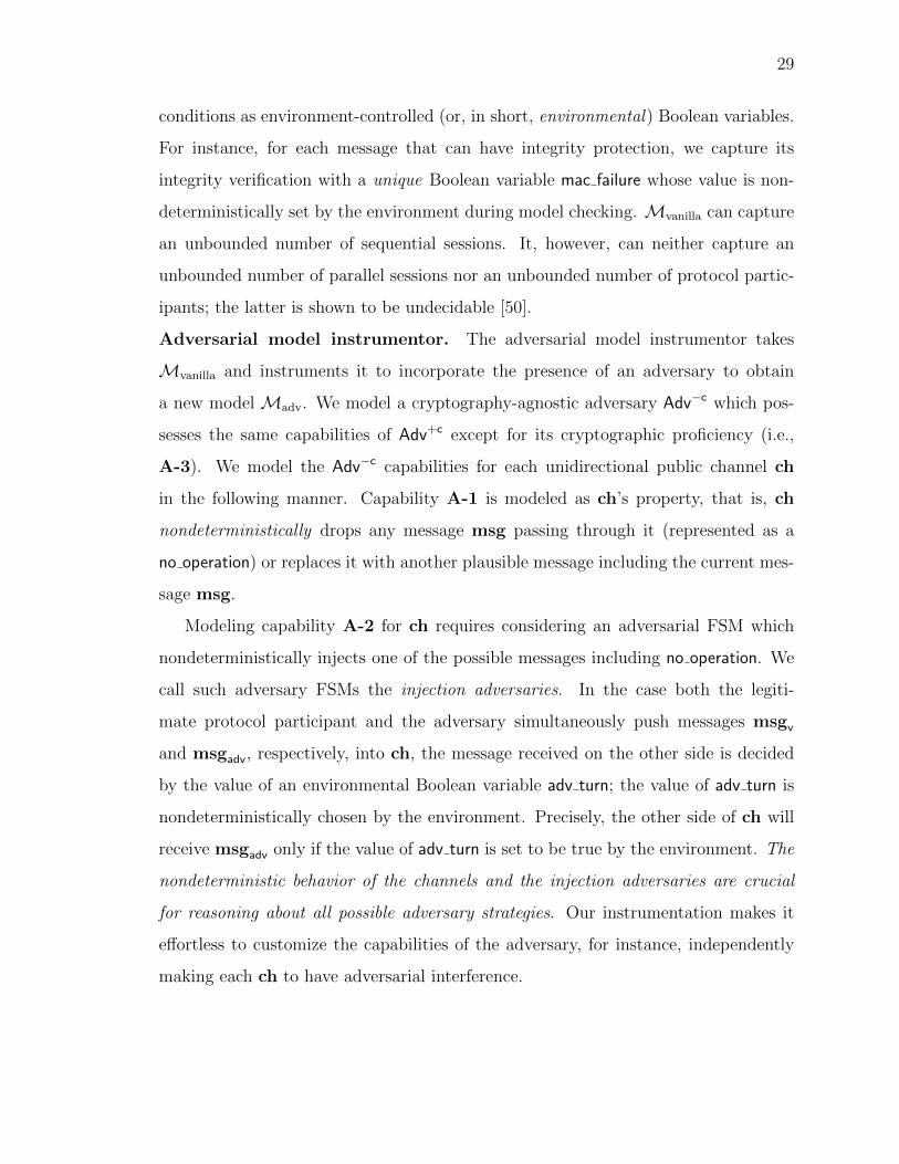
conditions as environment-controlled (or, in short, environmental) Boolean variables.
For instance, for each message that can have integrity protection, we capture its
integrity verification with a unique Boolean variable mac failure whose value is non-
deterministically set by the environment during model checking. Mvanilla can capture
an unbounded number of sequential sessions. It, however, can neither capture an
unbounded number of parallel sessions nor an unbounded number of protocol partic-
ipants; the latter is shown to be undecidable [50].
Adversarial model instrumentor. The adversarial model instrumentor takes
Mvanilla and instruments it to incorporate the presence of an adversary to obtain
a new model Madv. We model a cryptography-agnostic adversary Adv−c which pos-
sesses the same capabilities of Adv+c except for its cryptographic proficiency (i.e.,
A-3). We model the Adv−c capabilities for each unidirectional public channel ch
in the following manner. Capability A-1 is modeled as ch’s property, that is, ch
nondeterministically drops any message msg passing through it (represented as a
no operation) or replaces it with another plausible message including the current mes-
sage msg.
Modeling capability A-2 for ch requires considering an adversarial FSM which
nondeterministically injects one of the possible messages including no operation. We
call such adversary FSMs the injection adversaries. In the case both the legiti-
mate protocol participant and the adversary simultaneously push messages msgv
and msgadv, respectively, into ch, the message received on the other side is decided
by the value of an environmental Boolean variable adv turn; the value of adv turn is
nondeterministically chosen by the environment. Precisely, the other side of ch will
receive msgadv only if the value of adv turn is set to be true by the environment. The
nondeterministic behavior of the channels and the injection adversaries are crucial
for reasoning about all possible adversary strategies. Our instrumentation makes it
effortless to customize the capabilities of the adversary, for instance, independently
making each ch to have adversarial interference.

30
General-purpose Model Checker (MC). MC takes as inputMadv and a desired
abstract property ϕ, and checks to see whether all possible executions ofMadv (con-
sidering all possible values of the environmental variables) satisfy ϕ. In the case MC
finds an execution π of Madv which violates ϕ, MC outputs π as an evidence of the
violation (also, known as the counterexample). π includes the adversary actions which
were used to violate ϕ, and alternatively, can be viewed as the attack strategy. The
Adv−c used when model checking Madv does not have the necessary cryptographic
proficiency of Adv+c (i.e., A-3), and hence π can violate cryptographic assumptions,
making it unrealizable in practice. We rule out such spurious πs through the following
process.
Validating counterexamples with CPV. For a given counterexample π, we check
each sub-step of π that requires manipulating some crytographically-protected mes-
sage type. We model each small sub-step in a CPV, denoted as Mcrypto. We then
pose a query to CPV that will be violated in Mcrypto only if the Adv+c has the specific
capability that π requires. For few message types, such as, paging, we know from the
3GPP standard that there are no confidentiality and integrity protections; for those
message types we do not invoke the CPV.
Testbed experimentation. Once both MC and CPV adjudicate a given π to be
feasible, we try to realize this attack in a testbed. This is essential because π may
not be realizable in practice due to possible technical safeguards. Any π validated in
the testbed experiment can thus be considered a vulnerability. We built a testbed
using low-cost software defined radios and open-source LTE software stack having a
price tag of around $3, 900 which we would argue is within the reach of a motivated
adversary.
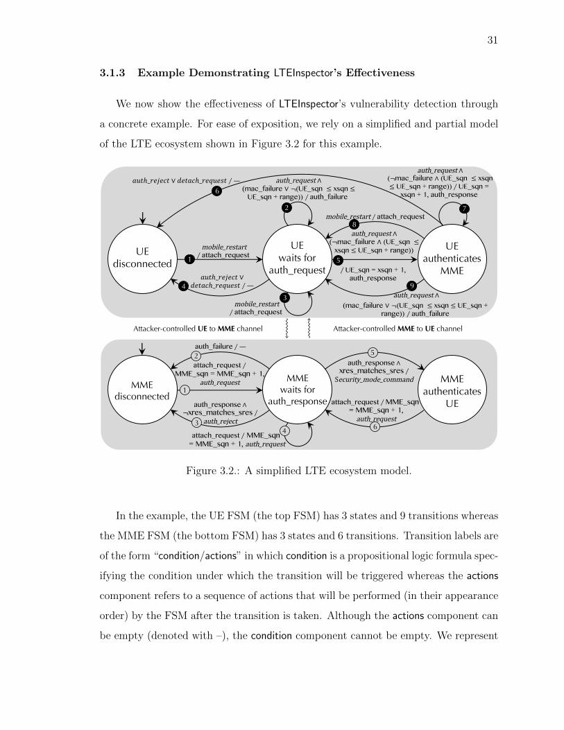
31
3.1.3 Example Demonstrating LTEInspector’s Effectiveness
We now show the effectiveness of LTEInspector’s vulnerability detection through
a concrete example. For ease of exposition, we rely on a simplified and partial model
of the LTE ecosystem shown in Figure 3.2 for this example.
UEdisconnected
mobile_restart∕ attach_request
1
auth_request ∧(¬mac_failure ∧ (UE_sqn ≤
xsqn ≤ UE_sqn + range))
∕ UE_sqn = xsqn + 1, auth_response
5
mobile_restart ∕ attach_request 8
auth_request ∧(mac_failure ∨ ¬(UE_sqn ≤ xsqn ≤
UE_sqn + range)) ∕auth_failure 2
auth_request ∧(¬mac_failure ∧ (UE_sqn ≤ xsqn≤ UE_sqn + range)) ∕ UE_sqn =
xsqn + 1, auth_response
7
567ℎ_9:;:<7 ∨ =:75<ℎ_9:>6:?7 ∕—6
auth_request ∧(mac_failure ∨ ¬(UE_sqn ≤ xsqn ≤ UE_sqn +
range)) ∕auth_failure
9567ℎ_9:;:<7 ∨
=:75<ℎ_9:>6:?7 ∕—4
mobile_restart∕ attach_request
3
UEwaits for
auth_request
UEauthenticates
MME
MMEdisconnected
attach_request ∕MME_sqn = MME_sqn + 1,
auth_request1
MMEwaits for
auth_response
MMEauthenticates
UE
auth_failure ∕—2
auth_response ∧¬xres_matches_sres ∕
auth_rejectattach_request ∕ MME_sqn
= MME_sqn + 1, auth_request
auth_response ∧xres_matches_sres ∕Security_mode_command
attach_request ∕MME_sqn = MME_sqn + 1,auth_request
UEDisconnected
UEwait for
auth request
UEauthenticates
MME
mobile restart/attach request
Àauth request ^(mac failure _ ¬(ue sqn xsqn ue sqn + range))
/auth failure
Ãmobile restart/attach request
Õ(auth reject _ detach request)/�
Œauth request ^(¬mac failure ^ (ue sqn xsqn
< ue sqn + range)/ue sqn = xsqn + 1, auth response
œ(auth reject _ detach request)/�
–auth request ^(¬mac failure ^ (ue sqn xsqn
< ue sqn + range))/ue sqn = xsqn + 1, auth response
—mobile restart/attach request
“auth request ^(mac failure _ ¬(ue sqn xsqn ue sqn + range))
/auth failure
MMEDisconnected
MMEwait for
auth response
MMEauthenticates
UE
¿attach request/mme sqn = mme sqn + 1,
auth request
¡auth failure/�
¬auth response ^¬xres matches sres/auth reject
√attach request/mme sqn = mme sqn + 1, auth request
ƒauth response ^xres matches sres/
security mode command
≈attach request/mme sqn =mme sqn + 1, auth request
Attacker controlledUE to MME
channel
Attacker controlledMME to
UE channel
Attacker-controlled UE to MME channel Attacker-controlled MME to UE channel
34
5
6
Figure 3.2.: A simplified LTE ecosystem model.
In the example, the UE FSM (the top FSM) has 3 states and 9 transitions whereas
the MME FSM (the bottom FSM) has 3 states and 6 transitions. Transition labels are
of the form “condition/actions” in which condition is a propositional logic formula spec-
ifying the condition under which the transition will be triggered whereas the actions
component refers to a sequence of actions that will be performed (in their appearance
order) by the FSM after the transition is taken. Although the actions component can
be empty (denoted with –), the condition component cannot be empty. We represent
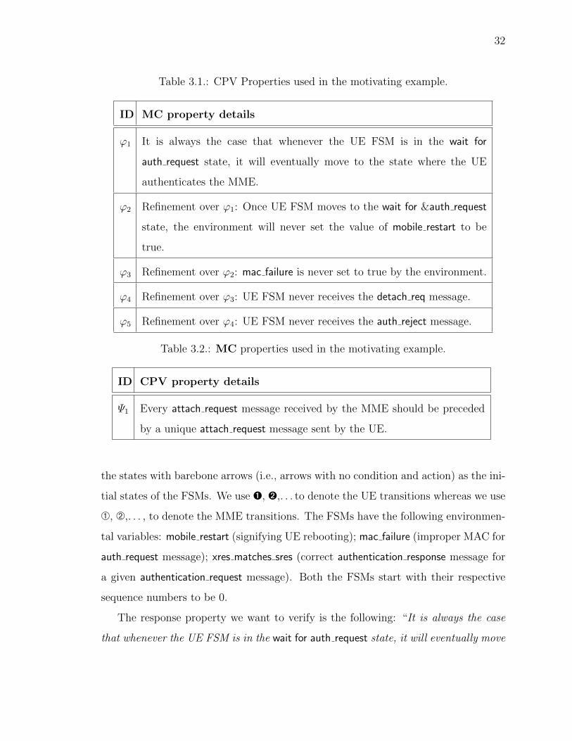
32
Table 3.1.: CPV Properties used in the motivating example.
ID MC property details
ϕ1 It is always the case that whenever the UE FSM is in the wait for
auth request state, it will eventually move to the state where the UE
authenticates the MME.
ϕ2 Refinement over ϕ1: Once UE FSM moves to the wait for &auth request
state, the environment will never set the value of mobile restart to be
true.
ϕ3 Refinement over ϕ2: mac failure is never set to true by the environment.
ϕ4 Refinement over ϕ3: UE FSM never receives the detach req message.
ϕ5 Refinement over ϕ4: UE FSM never receives the auth reject message.
Table 3.2.: MC properties used in the motivating example.
ID CPV property details
Ψ1 Every attach request message received by the MME should be preceded
by a unique attach request message sent by the UE.
the states with barebone arrows (i.e., arrows with no condition and action) as the ini-
tial states of the FSMs. We use Ê, Ë,. . . to denote the UE transitions whereas we use
À, Á,. . . , to denote the MME transitions. The FSMs have the following environmen-
tal variables: mobile restart (signifying UE rebooting); mac failure (improper MAC for
auth request message); xres matches sres (correct authentication response message for
a given authentication request message). Both the FSMs start with their respective
sequence numbers to be 0.
The response property we want to verify is the following: “It is always the case
that whenever the UE FSM is in the wait for auth request state, it will eventually move
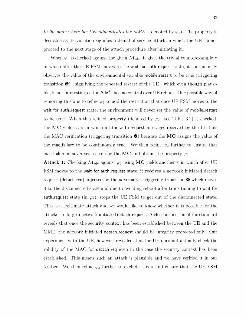
33
to the state where the UE authenticates the MME” (denoted by ϕ1). The property is
desirable as its violation signifies a denial-of-service attack in which the UE cannot
proceed to the next stage of the attach procedure after initiating it.
When ϕ1 is checked against the givenMadv, it gives the trivial counterexample π
in which after the UE FSM moves to the wait for auth request state, it continuously
observes the value of the environmental variable mobile restart to be true (triggering
transition Ì)—signifying the repeated restart of the UE—which even though plausi-
ble, is not interesting as the Adv+c has no control over UE reboot. One possible way of
removing this π is to refine ϕ1 to add the restriction that once UE FSM moves to the
wait for auth request state, the environment will never set the value of mobile restart
to be true. When this refined property (denoted by ϕ2—see Table 3.2) is checked,
the MC yields a π in which all the auth request messages received by the UE fails
the MAC verification (triggering transition Ë) because the MC assigns the value of
the mac failure to be continuously true. We then refine ϕ2 further to ensure that
mac failure is never set to true by the MC and obtain the property ϕ3.
Attack 1: CheckingMadv against ϕ3 using MC yields another π in which after UE
FSM moves to the wait for auth request state, it receives a network initiated detach
request (detach req)–injected by the adversary—triggering transition Í which moves
it to the disconnected state and due to avoiding reboot after transitioning to wait for
auth request state (in ϕ2), stops the UE FSM to get out of the disconnected state.
This is a legitimate attack and we would like to know whether it is possible for the
attacker to forge a network initiated detach request. A close inspection of the standard
reveals that once the security context has been established between the UE and the
MME, the network initiated detach request should be integrity protected only. Our
experiment with the UE, however, revealed that the UE does not actually check the
validity of the MAC for detach req even in the case the security context has been
established. This means such an attack is plausible and we have verified it in our
testbed. We then refine ϕ3 further to exclude this π and ensure that the UE FSM

34
never receives the network initiated detach request; as a result, we obtain the refined
property ϕ4.
Attack 2: We then check Madv against ϕ4, and it yields another similar π in which
the UE FSM receives an auth reject message (triggering transition Í); this moves the
FSM to the disconnected state. Again, one needs to determine whether the adversary
can fabricate an auth reject message. A close inspection of the standard revealed that
the auth reject message is never integrity protected and our experimentation validated
it. In a similar way, we refine ϕ4 to exclude any auth reject message and obtain our
final property ϕ5.
Attack 3: Finally, checkingMadv against ϕ5 with MC results in a very interesting π
in which the adversary sends the range (a UE-specific constant non-negative integer)
number of fake attach request messages to the MME, before the UE reboots and sends
the attach request. After receiving each attach request message, the MME increases
its own sequence number (according to transitions À and Ã) and uses the value of the
sequence number to provide replay protection to the auth request message which it
sends to the UE. As the UE is still in the disconnected state (with its sequence number
0, i.e., UE sqn = 0) and there is no transition that is triggered by the auth request
when the UE is in the disconnected state (see Figure 3.2), these auth request messages
are ignored. Then the UE observes a mobile restart (triggering transition Ê) and sends
an attach request to the MME which the adversary allows to reach the MME. After
the MME receives it (transitions À, Ã, and Å), the MME as usual responds with
an auth request with the sequence number range + 1. The adversary also allows the
auth request from the MME to reach the UE. Upon receiving the message, the UE
checks for mac failure (which cannot be true as we excluded it while refining ϕ2 to
obtain ϕ3) and checks whether the received sequence number from MME (denoted
with xsqn) satisfies the following: UE sqn ≤ xsqn ≤ UE sqn+range; this condition
will fail as xsqn = range + 1 resulting in the UE not being able to attach with
the MME. To ensure that validity of the π, one has to verify whether the Adv−c
can inject a fake attach request message; we use the CPV to validate it. We pose

35
an injective-correspondence [48] query, Ψ1 (shown in Table 3.2) which asserts that
every attach request message received by the MME should be preceded by a unique
attach request message sent by the UE. The CPV produced an attack in which the
adversary injected an attach request; validating the desired sub-step of π. We have
also observed the feasibility of this attack in our testbed. We call this attack the
authentication synchronization failure attack; this attack is also applicable
against a recent proposal for defeating IMSI catchers [20]. One of the challenges
of detecting such an attack through CPVs is to precisely capture the sanity check
corresponding to the sequence number. It is not immediately clear to us how one
would directly capture such a requirement in the CPV in a fine-grained fashion. The
MC, however, can efficiently reason about such requirement precisely. This shows
the effectiveness of combining a MC with a CPV for attack discovery.
This example demonstrates the analysis power of LTEInspector’s approach, that is,
based on the violation of a single desired property (and, its refinements) LTEInspector
was able to find three different attacks which have been shown to be realizable in
practice. As we will demonstrate later, Attacks 1 or 2 can be stitched with a relay
attack to yield the authentication relay attack.
3.1.4 Implementation
We now discuss some additional details of LTEInspector.
MC and CPV: We instantiate LTEInspector’s MC component with NuSMV [38]
and use ProVerif [40] for CPV.
Model. We manually construct the abstract LTE model by consulting the 3GPP
standard [4, 7]. Our model has a total of 13 states and 107 transitions. Our current
model and the respective properties are publicly available at https://github.com/
relentless-warrior/LTEInspector.
Properties. Our properties were extracted from the 3GPP standard [4,7]. We have
tested Madv against 14 properties in total in which 7 properties were analyzed with

36
NuSMV whereas 7 properties were analyzed with ProVerif. Note that, we do not
claim our list of properties to be exhaustive.
3.2 LTEInspector Findings
In this section, we highlight the findings of LTEInspector. For readers’ convenience,
we have provided a summary of the attacks and their implications in Table 3.3.
3.2.1 Attacks Against Attach Procedure
We now present our findings on the attach procedure.
A-1 Authentication Synchronization Failure Attack
This attack exploits the UE’s sequence number sanity check to disrupt its attach
procedure. Precisely, the adversary interacts with the HSS through the MME to
ensure that the sequence numbers of the UE and the HSS are out-of-sync. As a result,
the authentication challenge received through the legitimate auth request message fails
the UE’s sanity check and consequently is discarded by the UE.
Adversary assumptions. For successfully carrying out this attack, the adversary
is required to set up a malicious UE and also is required to the know the victim UE’s
IMSI. Such a threat is very practical and has been validated through experimentation
in our testbed (see Section 3.3.1).
Detection. We exposed this attack by first model checking Madv with respect to a
refinement ϕ5 of the following property: “It is always the case that whenever the UE
FSM is in the wait for auth request state, it will eventually move to the state where
the UE authenticates the MME” (see Table 3.2 for details). We observed a violation
of ϕ5 inMadv where the Adv−c fabricates attach request messages and sends them to
the MME. To validate the Adv−c’s capability of forging an attach request message,

37
we leverage ProVerif which showed that forging attach request messages are possible;
validating the feasibility of the attack.
𝐼𝑀𝑆𝐼attach_request (𝐼𝑀𝑆𝐼)𝑛 + 1
𝑅𝐴𝑁𝐷, 𝐴𝑈𝑇𝑁, 𝑋𝑅𝐸𝑆, 𝐶𝐾,𝐼𝐾, (𝑆𝑄𝑁 = 𝑛 +𝑚 + 1)
authentication_requestfor 𝑋𝑆𝑄𝑁 = 𝑛 +𝑚 + 1
attach_request (𝐼𝑀𝑆𝐼)
authentication_failure(𝑠𝑦𝑛𝑐 𝑓𝑎𝑖𝑙𝑢𝑟𝑒)
attach_request (𝐼𝑀𝑆𝐼)
attach_request (𝐼𝑀𝑆𝐼)
𝐼𝑀𝑆𝐼
𝐼𝑀𝑆𝐼
𝐼𝑀𝑆𝐼
𝑺𝑸𝑵 < 𝑿𝑺𝑸𝑵 ≰ 𝑺𝑸𝑵+ 𝒓𝒂𝒏𝒈𝒆
𝑛 + 2
𝑛 + 𝑚𝑛 + 𝑚 + 1
MaliciousUE
VictimUE
MME HSS
𝑆𝑆𝑄𝑁 :
Figure 3.3.: Authentication synchronization failure attack.
Attack description: The steps of this attack are shown in Figure 3.3. It is very
similar to the description of Attack 3 in Section 3.1.3 with one caveat. It is just
not sufficient to send the same attach request message m times (where m > range).
The malicious UE needs to send different security capabilities (by selecting differ-
ent encryption and integrity protection algorithms) in successive attach request mes-
sages. This is crucial as the HSS only processes an attach request message only if
one or more of the information elements in the current attach request message differs
from the already received one. In which case, in accordance to subclause 5.5.1.2 of
3GPP standard [27], the previously initiated attach procedure is aborted and the
new attach request message is processed (including, the increment of the sequence
number).
Re-synchronization: When the sequence number sanity check fails on the UE
side, it sends an auth failure message (cause: sync. failure) to the EPC with AUTS
parameter containing the UE’s current sequence number resulting in the EPC to re-
synchronize its sequence number. Even after re-synchronization, the adversary can
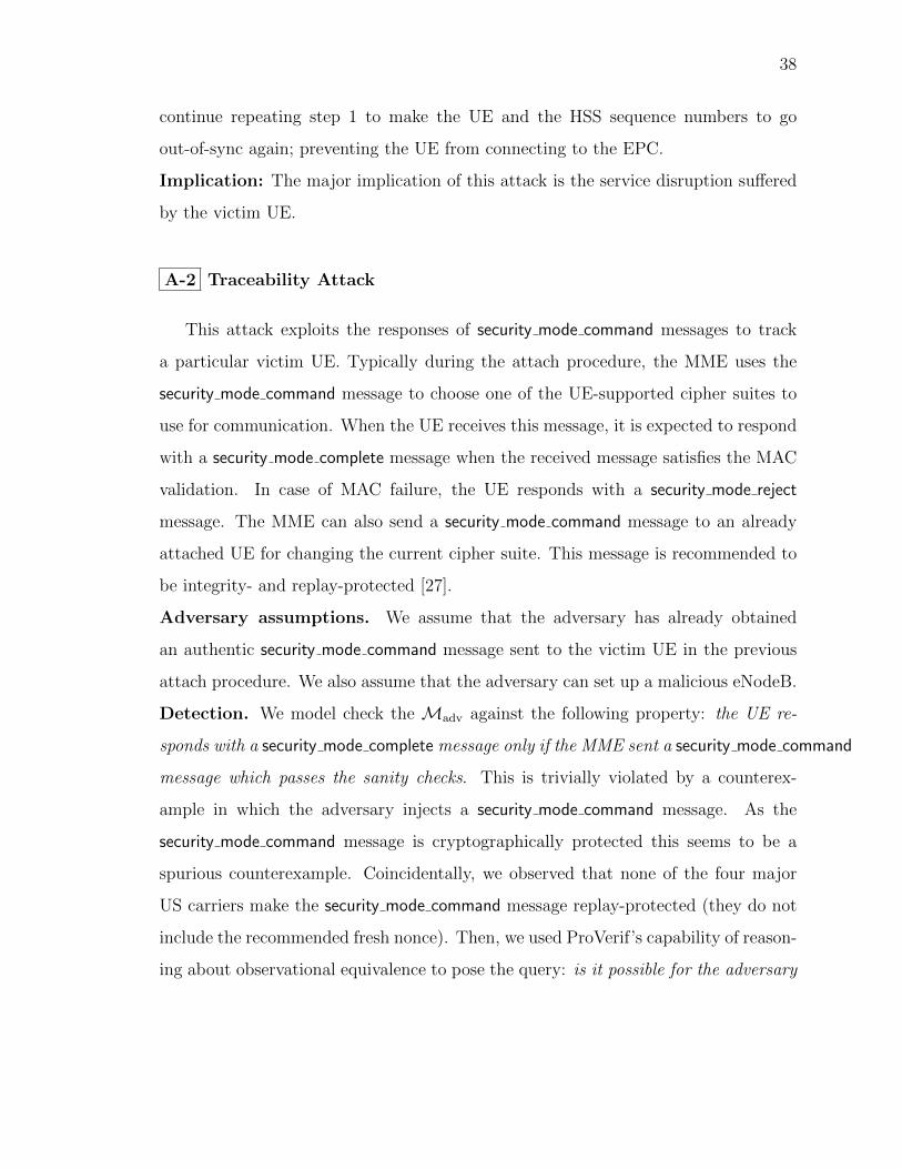
38
continue repeating step 1 to make the UE and the HSS sequence numbers to go
out-of-sync again; preventing the UE from connecting to the EPC.
Implication: The major implication of this attack is the service disruption suffered
by the victim UE.
A-2 Traceability Attack
This attack exploits the responses of security mode command messages to track
a particular victim UE. Typically during the attach procedure, the MME uses the
security mode command message to choose one of the UE-supported cipher suites to
use for communication. When the UE receives this message, it is expected to respond
with a security mode complete message when the received message satisfies the MAC
validation. In case of MAC failure, the UE responds with a security mode reject
message. The MME can also send a security mode command message to an already
attached UE for changing the current cipher suite. This message is recommended to
be integrity- and replay-protected [27].
Adversary assumptions. We assume that the adversary has already obtained
an authentic security mode command message sent to the victim UE in the previous
attach procedure. We also assume that the adversary can set up a malicious eNodeB.
Detection. We model check the Madv against the following property: the UE re-
sponds with a security mode complete message only if the MME sent a security mode command
message which passes the sanity checks. This is trivially violated by a counterex-
ample in which the adversary injects a security mode command message. As the
security mode command message is cryptographically protected this seems to be a
spurious counterexample. Coincidentally, we observed that none of the four major
US carriers make the security mode command message replay-protected (they do not
include the recommended fresh nonce). Then, we used ProVerif’s capability of reason-
ing about observational equivalence to pose the query: is it possible for the adversary
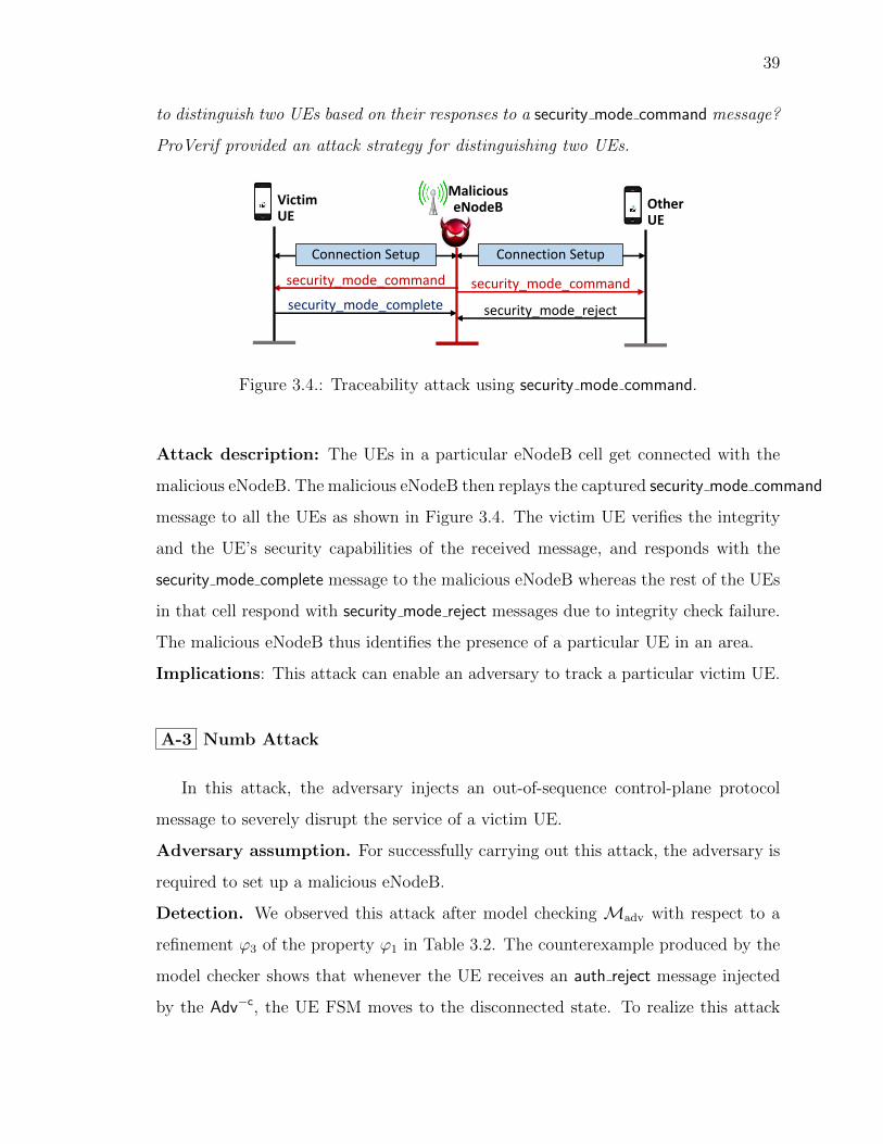
39
to distinguish two UEs based on their responses to a security mode command message?
ProVerif provided an attack strategy for distinguishing two UEs.
Connection Setup
MaliciouseNodeBVictim
UE
Connection Setup
security_mode_command security_mode_command
security_mode_complete security_mode_reject
OtherUE
Figure 3.4.: Traceability attack using security mode command.
Attack description: The UEs in a particular eNodeB cell get connected with the
malicious eNodeB. The malicious eNodeB then replays the captured security mode command
message to all the UEs as shown in Figure 3.4. The victim UE verifies the integrity
and the UE’s security capabilities of the received message, and responds with the
security mode complete message to the malicious eNodeB whereas the rest of the UEs
in that cell respond with security mode reject messages due to integrity check failure.
The malicious eNodeB thus identifies the presence of a particular UE in an area.
Implications: This attack can enable an adversary to track a particular victim UE.
A-3 Numb Attack
In this attack, the adversary injects an out-of-sequence control-plane protocol
message to severely disrupt the service of a victim UE.
Adversary assumption. For successfully carrying out this attack, the adversary is
required to set up a malicious eNodeB.
Detection. We observed this attack after model checking Madv with respect to a
refinement ϕ3 of the property ϕ1 in Table 3.2. The counterexample produced by the
model checker shows that whenever the UE receives an auth reject message injected
by the Adv−c, the UE FSM moves to the disconnected state. To realize this attack

40
the Adv−c has to be able to inject auth reject message which is feasible as the message
is not cryptographically protected according to the standard.
Attack description: As soon as the victim UE connects with the malicious eNodeB,
the malicious eNodeB sends an auth reject message to the victim UE irrespective of
the context of the victim UE.
Implications: Along with the most straightforward implication of severe service
disruption, this finding may be chained with another attack (possibly, some form of
impersonation attack) which requires the UE to be inactive or re-initiate the attach
procedure. We have observed that upon reception of the auth reject message in one of
the popular cellular device, the UE first detaches itself from the network, completely
shuts down all cellular activities, and does not even attempt to downgrade/connect
to 3G/2G networks. In this situation, even re-insertion of SIM card does not allow
the victim UE to connect to the EPC again. The victim UE remains in such a numb
state until the user restarts her UE.
3.2.2 Attacks Against Paging Procedure
In this section, we present attacks that we have exposed against the paging pro-
cedure.
Adversary assumptions. For the following attacks on the paging procedure, the
adversary needs to setup a malicious eNodeB and also needs to know the victim
UE’s IMSI. For the linkability attack, we assume the adversary knows the previous
pseudo-IMSIs (or, in short, PMSIs2) [20].
Detection. We obtain the intuition for the paging channel hijacking attack (P-
1) after observing our model Madv’s violation of the following property: the UE
sends a service request only if the MME has sent a paging message that is pending.
2To protect against IMSI catching attacks, Broek et al. [20] proposed an enhancement over the 3GPPstandard where the IMSI is replaced with a changing pseudonym, called Pseudo-IMSI or PMSI, thatonly the SIMs HSS can link to the SIMs identity. Therefore, instead of sending the IMSI, the UEuses different PMSIs in different attach request messages. To the best of our knowledge, support forPMSIs have not been implemented in 4G LTE.

41
The model checker produces a counterexample in which the Adv−c injects a paging
message. After consulting the standard [27], we observed that paging messages do
not have any cryptographic protection. This signifies that an adversary can inject
paging messages. The rest of the attacks in this section are direct consequences of the
paging channel hijacking attack.
MaliciouseNodeB
VictimUE
paging (IMSI/old PMSI)
attach_request (IMSI/new PMSI)
eNodeB
Idle
Detached
Figure 3.5.: Detach attack using paging.
P-1 Paging Channel Hijacking
For hijacking the paging channel, the malicious eNodeB operates in the same
frequency band as the legitimate eNodeBs so that the victim UE does not perceive
any network changes. The malicious eNodeB then broadcasts fake empty paging
messages in the shared paging channel. However, a UE does not listen to the paging
channel continuously for incoming paging messages. It usually remains in the sleep
state and wakes up in its paging cycle for pending paging message. Therefore, it is
crucial for the adversary to make its eNodeB’s paging cycle same as the victim UE’s.
Detailed synchronization procedure is presented in Section 3.3.
Although both malicious and legitimate eNodeBs broadcast the paging messages
at the same time intervals, the UE only responds to the first received message. To
address this challenge, the malicious eNodeB broadcasts paging messages with higher
signal power. Thereby, the adversary hijacks the victim UE’s paging channel and
makes the victim UE unable to receive legitimate paging messages from the MME.
This means that the victim does not receive any service (e.g., incoming phone call-

42
s/SMS) notifications which would result in customer dissatisfaction, revenue loss and
reputation damage of the network operators. One of the interesting consequences of
this attack is that the victim UE is completely unaware of paging channel hijacking
which lets the adversary silently drop incoming services.
P-2 Stealthy kicking-off Attack
The steps of this attack are shown in Figure 3.5 and described as follows:
After hijacking the victim UE’s paging channel, the malicious eNodeB creates
a paging message with one paging record consisting of the victim UE’s IMSI. The
adversary sets other fields of the paging record similar to an original paging message.
Upon reception of the paging message with IMSI, the victim UE finds its IMSI in
the first paging record. As a result, it first disconnects from the EPC and then
sends an attach request message. This attack can also be used as a prerequisite of the
authentication relay attack. The major implication of this attack is service disruption.
P-3 Panic Attack
In this attack, the adversary wants to inject fake emergency paging messages to a
large number of UEs. The adversary thus sends a paging message with empty records
but with fake emergency warnings. To ensure that such a fake paging message reaches
a large number of UEs, the adversary keeps broadcasting this message for all possible
paging occasions of the legitimate eNodeB. This can create artificial emergency which
can be exploited by malicious parties for hiding their agenda.
P-4 Energy Depletion Attack
The idea of this attack is to make the victim UE perform expensive cryptographic
operations. One way to achieve this is to force the UE to keep carrying out the
expensive attach procedure over and over again, by sending a paging message with

43
Table 3.3.: Summary of our findings ( =validated, =partially validated, =not
validated) of the reported attacks.
IDAttack
name
Affected
proce-
dure
Adversary as-
sumptions
Assumption
validation
Standard/
Stake-
holder
slip-up
New
at-
tack?
Detection
process
Notable implica-
tions
Vali-
dated
Setup
cost
A-1
Auth.
sync.
failure
AttachKnown IMSI,
malicious UE
IMSI [17],
Sec-
tion 3.3.1
3GPP Yes LTEInspectorDenial-of-attach or
Denial-of-services.
$2600
(2 US-
RPs)
A-2 Traceability Attach
Valid
security mode
command, mali-
cious eNodeB
Section 3.3.1
Operational
networks,
mobile
devices
Inspired
by [14]LTEInspector
Coarse-grained lo-
cation information
leakage.
$2600
(2 US-
RPs)
A-3
Numb
using
auth reject
AttachMalicious eN-
odeBSection 3.3.1 3GPP Yes LTEInspector
Denial of all cellular
services.
$1300
(1
USRP)
A-4Auth. re-
layAttach
Known IMSI,
malicious eN-
odeB
IMSI [17];
Sec-
tion 3.3.1
3GPP, op-
erational
networks
Yes
LTEInspector,
attack chain-
ing
Reading incom-
ing/outgoing mes-
sages of victim,
stealthy denial of
all/selective services,
location history
poisoning.
$3900
(3 US-
RPs)
P-1
Paging
channel
hijacking
Paging
Known IMSI,
malicious eN-
odeB
IMSI [17],
Sec-
tion 3.3.1
3GPP Yes
Intuition from
LTEInspector,
domain
Knowledge
Stealthy denial of in-
coming services.
$1300
(1
USRP)
P-2
Stealthy
kicking-
off
Paging
Known IMSI,
malicious eN-
odeB
IMSI [17],
Sec-
tion 3.3.1
3GPP Yes
Consequence
of P-1, do-
main knowl-
edge
Detaching a victim
from the network sur-
reptitiously.
$1300
(1
USRP)
P-3 Panic PagingMalicious eN-
odeBSection 3.3.1 3GPP Yes
Consequence
of P-1, do-
main knowl-
edge
Life threatening
impact against mass
people, e.g., artificial
chaos for terrorist
activity.
$1300
(1
USRP)
P-4Energy
depletionPaging
Known IMSI,
GUTI, mali-
cious eNodeB
IMSI [17];
GUTI [12],
Sec-
tion 3.3.1
3GPP
Inspired
by [51,
52]
Consequence
of P-1, do-
main knowl-
edge
Battery depletion.
$1300
(1
USRP)
P-5 Linkability PagingKnown IMSI or
old pseudo-IMSISection 3.3.1
3GPP,
enhanced
AKA [20]
Yes ProVerif only
Coarse-grained lo-
cation information
leakage
$1300
(1
USRP)
D-1
Detach/
Down-
grade
Detach
Malicious eN-
odeB, known
IMSI (for tar-
geted version)
IMSI [17];
Sec-
tion 3.3.1
3GPPInspired
by [17]
LTEInspector,
attack chain-
ing (for tar-
geted version)
Denial of services/-
Downgrade to
2G/3G.
$1300
(1
USRP)
IMSI between two successive attach procedures. In case the adversary knows the
GUTI of the victim [12], it can send a paging message with GUTI which the UE
responds with a cryptographically-involved service request message.
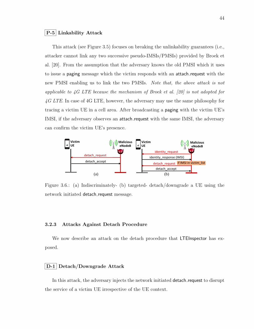
44
P-5 Linkability Attack
This attack (see Figure 3.5) focuses on breaking the unlinkability guarantees (i.e.,
attacker cannot link any two successive pseudo-IMSIs/PMSIs) provided by Broek et
al. [20]. From the assumption that the adversary knows the old PMSI which it uses
to issue a paging message which the victim responds with an attach request with the
new PMSI enabling us to link the two PMSIs. Note that, the above attack is not
applicable to 4G LTE because the mechanism of Broek et al. [20] is not adopted for
4G LTE. In case of 4G LTE, however, the adversary may use the same philosophy for
tracing a victim UE in a cell area. After broadcasting a paging with the victim UE’s
IMSI, if the adversary observes an attach request with the same IMSI, the adversary
can confirm the victim UE’s presence.
MaliciouseNodeB
VictimUE
detach_request
detach_accept
MaliciouseNodeB
(a) (b)
VictimUE
identity_request
identity_response (IMSI)
detach_request
detach_accept
if IMSI in victim_list
Figure 3.6.: (a) Indiscriminately- (b) targeted- detach/downgrade a UE using the
network initiated detach request message.
3.2.3 Attacks Against Detach Procedure
We now describe an attack on the detach procedure that LTEInspector has ex-
posed.
D-1 Detach/Downgrade Attack
In this attack, the adversary injects the network initiated detach request to disrupt
the service of a victim UE irrespective of the UE context.

45
Adversary assumptions. The adversary needs to setup a malicious eNodeB and
also needs to know the IMSI of the victim.
Detection. Attack detection is similar to the numb attack.
Attack description. The steps of this attack are shown in Figure 3.6(a). When-
ever the victim UE connects to the malicious eNodeB, it sends a network initiated
detach request message which force the UE to move to the disconnected state and to
send detach accept message.
Targeted variant of detach/downgrade attack. This attack (see Figure 3.6(b))
can be adopted to a more targeted setting in which the adversary targets specific
UEs. For the targeted variation, before the detach request is sent, the eNodeB will
send an identity request message which the UE will respond with an identity response
message containing the UE’s IMSI. If the IMSI is in the attacker’s victim list, it will
send the detach request, otherwise, it will ignore that UE.
Implications: Along with its direct consequence of severe service disruption, this
finding can be stitched with another attack (possibly, some form of impersonation
attack) which requires the UE to be inactive and re-initiate the attach process.
𝑆 = 𝑠 ∀𝑖 ∈ 𝐼 where𝑠 = 𝑖, 𝐾, 𝑆𝑄𝑁
𝐼𝑀𝑆𝐼, 𝐾, 𝑆𝑄𝑁
attach_request (𝐼𝑀𝑆𝐼,
UE Network capabilities)𝐼𝑀𝑆𝐼
𝑅𝐴𝑁𝐷, 𝐴𝑈𝑇𝑁, 𝑋𝑅𝐸𝑆,𝐶𝐾, 𝐼𝐾 (𝑆𝑄𝑁 = 𝑛)authentication_request
(𝑅𝐴𝑁𝐷, 𝐴𝑈𝑇𝑁) 𝑓𝑜𝑟 𝑆𝑄𝑁 = 𝑛
attach_request (𝐼𝑀𝑆𝐼,
UE Network capabilities)
(authentication_request(𝑅𝐴𝑁𝐷, 𝐴𝑈𝑇𝑁) 𝑓𝑜𝑟 𝑆𝑄𝑁 = 𝑛
authentication_response(𝑆𝑅𝐸𝑆𝑆𝑄𝑁= 𝑛)
authentication_response
(𝑆𝑅𝐸𝑆𝑆𝑄𝑁= 𝑛)
MME waiting for response from malicious UE
Verify: 𝑆𝑅𝐸𝑆𝑆𝑄𝑁= 𝑛 = 𝑋𝑅𝐸𝑆𝑆𝑄𝑁=𝑛
attach_complete
attach_complete
MaliciousUE Victim UE Malicious
eNodeB MME HSS
paging (IMSI) or detach_request
… …
Figure 3.7.: Authentication relay attack

46
3.2.4 Attack Chaining
We now demonstrate the application of the attack chaining technique through the
authentication relay attack.
A-4 Authentication Relay Attack
In this attack, one of our exposed attacks (e.g., paging with IMSI) is stitched with
a relay attack with which an adversary impersonates the victim UE to connect to the
EPC without possessing proper credentials, and in the process, spoof the victim UE’s
location in the core networks.
Adversary assumptions. For this attack, the adversary is required to setup a
malicious eNodeB (eNodeBadv) and a malicious UE (UEadv), and also needs to know the
IMSI of the victim UE. We assume there is a private channel between the eNodeBadv
and the UEadv.
Attack description. In this attack, the adversary impersonates an already attached
victim UE (UEvic) to connect to the EPC by collaborating with the eNodeBadv and
the UEadv. Suppose the UEvic is already attached with the legitimate eNodeB denoted
by eNodeBbenign. The attack can be broken down into two main goals: (i) Force UEvic
to disconnect from the EPC; (ii) UEadv pretends to be UEvic to connect to the EPC.
Disconnecting UEvic from the EPC : For disconnecting the UEvic from the EPC,
we use our paging with IMSI attack. This can also be achieved with our network
initiated detach request or auth reject attacks.
UEadv connecting to the EPC by impersonating as UEvic: As the UEvic detached
itself from the EPC due to a paging with IMSI message, it will try attach to the
eNodeB with the highest signal strength; which is the eNodeBadv. The UEvic will send
an attach request message mreq to the eNodeBadv which the eNodeBadv forwards to
the UEadv. The UEadv then sends the same attach request mreq to the eNodeBbenign.
The legitimate MME will send an authentication challenge c to the UEadv through
the eNodeBbenign upon receipt of mreq. The UEadv will forward the c to the eNodeBadv

47
which the eNodeBadv will send to the UEvic. After the UEvic receives c, unaware that
the eNodeBadv sent it, it will solve the challenge c to generate the correct response r.
The UEvic will then send r to the eNodeBadv which it will forward to the UEadv. The
UEadv then will use r to respond to the MME challenge. Using the same principle,
the UEadv will finish the rest of the steps of the attach procedure.
Discussion. Unlike a typical man-in-the-middle attack, the adversary in this at-
tack can neither decrypt the encrypted traffic between the victim UE and the core
networks, nor can inject valid encrypted traffic unless the service provider blatantly
disregards the standard’s security recommendations and choose a weak-/no- security
context during connection establishment.
Implications: The implications of this attack include:
(1) Deception: The adversary deceives the victim into believing that the UEvic is
connected to the core network.
(2) Location History Poisoning: Since the UEadv does not need to be in the
same tracking area as the UEvic, it can authenticate itself to the EPC from a different
tracking area and thus provide misleading location information about the UEvic. Thus,
the UEadv can poison the location history of the UEvic by performing this attack
successively from different tracking areas. As a result, a fugitive or criminal hiding
in one location can deceive the core network into believing that the criminal has
attached to the core network from a different location.
(3) Loss of confidentiality: The security mode command message sent by the
MME during the attach procedure includes the selected cipher (EEA0-EEA7) and in-
tegrity protection (EIA0-EIA7) algorithms of the MME. By observing the security mode command
messages of all four major network providers in the US, we have observed that
at least one carrier (OP-I) never used encryption (i.e., uses EEA0—no
cipher). Note that, to keep the four major US network operators anonymous, we
use pseudonyms (i.e., OP-I, OP-II, OP-III, OP-IV) to identify them. We have ob-
served this insecure practice multiple times in two different geographical locations.
48
The adversary hence can learn the UEvic’s conversation, SMSs, and data through the
UEadv and the eNodeBadv. We reported this to the affected carrier which has now been
addressed.
(4) Complete or Selective DoS: Using this attack, the UEadv and the eNodeBadv
can relay the incoming/outgoing traffic of the UEvic and the EPC. Therefore, the
UEadv and the eNodeBadv can deny the UEvic’s phone-calls/SMS/data-transfers com-
pletely/selectively. Consequently, the operational network is deprived of the charges
for the incoming/outgoing calls and SMSs.
(5) Profiling victim’s service usage: Since all the incoming/outgoing communi-
cations of the UEvic take place through the UEadv and the eNodeBadv, the adversary
can profile the service usage pattern (i.e., patterns of phone calls, SMSs, data) of the
victim.
3.2.5 Prior Attacks Detected by LTEInspector
In addition to the new attacks, LTEInspector is capable of detecting 9 [13–15, 17,
20,53] out of 13 prior attacks (see Table 3.4) that are relevant in the context of attach,
detach, and paging procedures. The previous attacks [12, 16, 17] that LTEInspector
cannot detect exploit one of the following which LTEInspector currently does not
support: (1) message data, (2) multiple instances of UEs or MMEs, (3) other layers’
(e.g., RRC layer) messages, (4) 2G/3G procedures that are different from 4G LTE,
(5) properties about sets of traces, and (6) performance related parameters (e.g., data
transmission and reception rate).
3.3 Validation of Attacks with Testbed
In this section, we describe the verification of the new attacks (along with their ad-
versarial assumptions) detected by LTEInspector. We have tried to exercise restraint—
conforming to best practices—in validating the effectiveness of the different vulnera-

49
Table 3.4.: Prior attacks (related to attach, detach, and paging procedures) that are
detected/not detected by LTEInspector.
# Prior attackDete-
ctedHow/Why?
1 Downgrade using tau reject [17] Yes LTEInspector.
2 Denial of all services [17] Yes LTEInspector.
3 Denial of selected services [17] NoDo not model data for
attach request.
4
Location tracking through mapping
user’s phone number/social network ID
to GUTI [12,17].
NoDo not model multiple in-
stance of UEs.
5 IMSI catching [20] Yes LTEInspector.
6 Fine-grained location exposure [17] NoDo not model RRC layer
messages.
7DoS exploiting race condition with
paging response [53] in 2GYes LTEInspector.
8Service hijacking exploiting race condition
with paging response [53] in 2GYes LTEInspector.
9Linkability using TMSI reallocation
command [15] in 3GYes LTEInspector.
10Linkability of IMSI to GUTI using
paging request [14] in 3GYes LTEInspector.
11 Linkability using auth sync failure [14] in 3G Yes LTEInspector.
12 Man-in-the-Middle in 2G [13] Yes LTEInspector.
13 Man-in-the-Middle in 3G [16] No Do not model data.
bilities while maintaining the validation process meaningful. To limit the impact of
our attacks, we use both a custom-built LTE network and commercial networks with
a logical Faraday cage [17].
3.3.1 Testbed Setup and Assumption Validation
We now describe our testbed setup for attack validation.

50
Malicious eNodeB Setup
We have used a Universal Software-defined Radio Peripheral device (i.e., USRP
B210 [54]) connected to an Intel Core i7 machine running Ubuntu 14.04 as the
hardware component and OpenLTE [55], an open source LTE protocol stack imple-
mentation, to set up a malicious eNodeB which costs around $1300 for the dedicated
hardware (i.e., excluding the core i7 machine). We used OpenLTE’s LTE Fdd enodeb
application which simultaneously acts as a bare-minimal eNodeB, a mobility man-
agement entity (MME), and a home subscriber server (HSS). We have implemented
support for the detach procedure in OpenLTE as it originally had support for the
attach procedure only. We have also instrumented OpenLTE to inject different fabri-
cated messages (e.g., network initiated detach request message) when necessary. For
validating attacks against the paging procedure, we use srsLTE [56] which we en-
hanced to support eNodeB-initiated paging messages; its original support only in-
cluded MME-initiated paging messages.
eNodeB configuration. Our malicious eNodeB can impersonate the legitimate eN-
odeB of a network operator (i.e., OP-I to OP-IV) by broadcasting system info block type 1
messages with higher signal power. For successful impersonation, these messages must
include parameter values that are equal to that of an operator’s legitimate eNodeB.
The adversary uses a UE with the operator’s SIM to learn the parameters in the
system info block type 1 messages sent by the operator’s eNodeB. In our setup, we
use both our custom-built sniffer and QXDM [57] to sniff the incoming and outgoing
LTE messages on a consumer UE to learn the operator’s parameters. Table 3.5 shows
the parameters that we capture from the operator eNodeB’s system info block type 1
messages. We use them to configure the malicious eNodeB with OpenLTE.
Learning IMSI/IMEI. As soon as the victim UE is forced to connect with the
malicious eNodeB, the malicious eNodeB sends an identity request (IMSI/IMEI) mes-
sage to the victim UE which responds with the identity response message including
its IMSI/IMEI.

51
Table 3.5.: Configuration parameters captured from Operator’s
system info block type 1 messages.
Parameters Description
band The frequency band number of the network operator.
dl earfcn E-UTRA absolute radio frequency channel number.
mcc Mobile country code specific to a country.
mnc Mobile network code specific to a network operator.
p0 nominal pucch Power control parameter.
p0 nominal pusch Power control parameter.
q rx lev min Used for cell re-selection.
q hyst Used for cell re-selection
DRX cycle Paging cycle
Learning GUTI. We use the well-known set intersection technique to find the GUTI
as described in [12].
Malicious UE Setup
We use a USRP B210 [54] running srsUE [58] (open source protocol stack imple-
mentation for UE) as the malicious UE which costs around $1300.
Victim UEs and EPC Networks
We have used 3 different models of LTE-capable mobile phones and the 4 ma-
jor network operators in the US. For the authentication relay and authentication
synchronization failure attacks, the adversary requires a malicious UE to send mes-
sages to a commercial EPC. Since this is a violation of the Federal Communications
Commission’s (FCC) regulations [8], we use our custom-built network (as the EPC)
and a USIM (Universal Software Identity Module) instead of commercial EPCs and

52
their SIMs, respectively. Our custom-built network similar to [59], operates on an
experimental licensed spectrum.
Victim UE with mobile phone and USIM
Malicious UE with 𝑼𝑺𝑹𝑷𝟏 and no SIM
Attach procedure between victimUE and malicious eNodeB
eNodeB and EPC with 𝑼𝑺𝑹𝑷𝟑
Attach procedure
Malicious eNodeBwith 𝑼𝑺𝑹𝑷𝟐 and OpenLTE/srsLTE
HSSMMEeNodeB
OpenLTE
between malicious UEand legitimate eNodeB
Figure 3.8.: Experiment setup for custom-built network.
Sniffer setup
We have built a low-cost, real-time LTE channel decoder (costs around $1300)
using USRP [54] as the hardware whereas we used Owl [60] and srsLTE [56] as
the software components. Our sniffer identifies the new c-RNTI (a lower-layer UE
identifier) of a UE that joins the cell, and then decodes the unencrypted downlink
messages from the MME/eNodeB.
Attack setup cost. Since different attacks (e.g., A-4 and P-1) require different at-
tack setups, we list only the dedicated hardware cost for individual attack in Table 3.3.
which shows $3900 as the maximum cost required to validate the attacks.
3.3.2 Validation using Custom-built Network
We now discuss how we successfully verified the authentication synchronization
failure and authentication relay attacks in our custom-built network (See Figure 3.8).

53
A-1 Authentication Synchronization Failure Attack
In our verification setup, the malicious UE (using the victim UE’s IMSI) sent
100 attach request messages (with different security configurations) to the legitimate
MME. After the attack step, we reboot the victim UE which initiated the attach pro-
cedure by sending an attach request message for which it received an authentication request
message from the MME. In response to that message, using our sniffer we observed
that the victim UE responded with an auth failure message (with cause sync. failure);
confirming our attack.
A-4 Authentication Relay Attack
For this attack, we built a relay channel (See Figure 3.8) between the malicious
UE (USRP1) and the malicious eNodeB (USRP2) using the Wi-Fi interfaces of the
machines co-located with those USRPs. We also configured both the malicious
eNodeB and the legitimate eNodeB to broadcast different tracking areas in their
system info block type 1 messages. After performing the attack steps, we observed
that both the victim and malicious UE received the same attach accept message and
also completed the attach procedure. From the logs of the legitimate EPC and using
the tracking area numbers, we confirmed that only the malicious UE was connected
with the legitimate MME. On the other hand, although the victim UE was actually
connected with the malicious EPC, it was deceived to realize that it was connected
with the legitimate EPC. Thus, the legitimate EPC was duped about the actual
location of the legitimate UE; confirming the attack.
We have also successfully verified the authentication synchronization failure and
relay attacks with OpenEPC [61], which is a licensed prototype implementation of
the 3GPP Evolved Packet Core (EPC).

54
3.3.3 Validation using Commercial Mobile Phones
For all the other attacks (except A-1 and A-4), we use commercial network
operators’ (e.g., OP-I) SIMs for the victim UE and a malicious eNodeB as discussed
in Section 3.3.1).
A-2 Traceability Attack
For this attack verification, we use multiple UEs among which one of them is des-
ignated as the victim UE; the one being tracked. First, using the sniffer, we capture a
legitimate security mode command message sent by the MME to the victim UE during
a benign interaction. We decoded the captured security mode command message and
extracted all its field values including the MAC. For tracing, the malicious eNodeB
then injected fabricated security mode command messages to all the UEs using the
extracted field values. We observed that in response to the injected messages only
the victim UE responded with the security mode complete message whereas the rest
of UEs responded with a security mode reject message; confirming our attack. Note
that, the malicious eNodeB may not always have success with this attack when it
does not receive security mode complete messages from any of the UEs. This can be
attributed to either the victim UE’s absence in that cell area or the victim UE’s use
of a different a cipher suite.
This attack can also be performed for a specific user with only the knowledge of
victim’s phone number. The adversary first determines the victim UEs GUTI and her
paging occasion using [12], and then hijacks her paging channel using P-1. Now the
adversary initiates phone calls to victim’s phone number which trigger the MME to
send paging messages to the victim’s UE. However, the victim UE’s unresponsiveness
due to P-1 causes the MME to send paging with IMSI (subclause 5.5.3.2.7 [7]) which
the adversary may intercept. In case the attacker receives multiple such paging with
IMSI, he would use the set intersection technique [12] to uniquely identify the victim
UE’s IMSI. The adversary then performs the traceability attack as follows—(i) forces

55
the victim UE to complete an attach procedure with the legitimate EPC; (ii) captures
a valid security mode command message; (iii) and finally replays that message to all
nearby UEs.
A-3 Numb Attack and D-1 Detach/Downgrade Attack
For verifying both these attacks, we made the malicious eNodeB inject auth reject
and network initiated detach request (with different causes) messages in different
stages of the protocol, and observed the UE responses to these messages. For auth reject
messages, we observed a complete unresponsiveness of the victim UE until the SIM
is re-inserted and the mobile phone is rebooted. Our observation of victim UE’s
responses in reaction to the detach request messages (with different causes) are sum-
marized in Table 3.6.
Table 3.6.: Victim UE’s responses to different types of detach.
Detach Type Our observation of victim UE’s response
Re-attach requiredNo cellular signals (shows “No Service”). Requires mobile restart or
SIM re-insert to get the 4G LTE back again.
Re-attach not re-
quired
Detaches from 4G LTE. Immediately downgrades to 3G/2G and sends
attach request to the 3G/2G network.
IMSI detach Does not detach from the 4G LTE network.
P-1 Paging Channel Hijacking Attack
Successfully carrying out this attack first requires determining the victim UE’s
paging cycle/occasions. To this end, we captured and decoded the system info block type 1
and attach request messages—sent in plaintext by the carrier’s eNodeB and the vic-
tim UE, respectively, and learned the parameters relevant for computing the victim
UE’s paging occasion (e.g., DRX cycle, IMSI). The malicious eNodeB then injected

56
fake paging messages (with no paging records) at the paging occasions of the victim
UE. We observed that the victim UE only received the fake paging messages instead
of the legitimate messages.
After hijacking the victim UE’s paging channel, we allowed two senders to place
phone calls and send SMSs to victim’s phone number triggering the (benign) MME
to send multiple paging messages to the victim UE. We observed that the victim did
not receive any of the legitimate paging messages, i.e., the service notifications. The
victim’s unresponsiveness was also noticed on the sender-side.
P-2 Stealthy Kicking-off Attack
For this attack, instead of injecting empty paging messages, the malicious eNodeB
fabricated the paging messages with a paging record containing the victim UE’s IMSI.
As soon as the victim UE received this message, we observed that it locally detached
itself from the network and sent an attach request, confirming the attack.
P-3 Panic Attack
To inject fake paging messages to arbitrary neighboring UEs, the malicious eN-
odeB broadcasted paging messages at all possible paging occasions. Each of these
paging messages had the ETWS (earthquake and tsunami warning system) bits set
to provide the UEs an alert notification. Upon receiving such alert notification, a
UE looks for the actual warning message which the eNodeB broadcasts through the
system information block type 10 or 11 or 12 messages. Since such warning messages
may be received by other mobile phones which are not subject to our experiment, we
refrained the malicious eNodeB from sending the actual warning messages.

57
P-4 Energy Depletion Attack
We quantitatively measure the UE’s energy depletion due to this attack. In par-
ticular, we leverage the strong correlation between energy consumption with message
transmission rate [62]. We essentially measured the message transmission rate in the
benign and attack case, and drew conclusions about energy consumption. To realize
this attack, we configured the malicious eNodeB to broadcast paging message with
the victim’s GUTI at every third paging occasion (i.e., ∼ 3 seconds) of the victim
UE. Upon reception of this paging message, we observed that the victim UE sent an
encrypted and integrity protected service request message to the malicious eNodeB.
We also carried out this attack where the paging message included the victim’s IMSI
in which case, however, the victim initiated the attach procedure. For the paging with
GUTI, we carried out the attack for an hour and observed that the victim sent 1200
service request messages. In the benign case (measured from 4G LTE traces [63]),
however, on average the UE responds to 156 (std. dev. 14.27) paging messages .
Roughly, the energy depletion due to this attack ∼ 8 times to that of the benign
condition. The attacker can make it worse, in case it chooses to inject the paging
with GUTI in every paging occasion.
3.4 Discussion
Properties amenable to our analysis. LTEInspector can reason about temporal
trace properties (with cryptographic constructs) of both safety and liveness variations.
Our current model cannot handle properties that require reasoning about sets of traces
(e.g., noninterference) instead of a single trace. For such properties, we mainly rely
on the protocol verifier.
Defenses. We deliberately do not discuss defenses for the observed attacks as retro-
spectively adding security into an existing protocol without breaking backward com-
patibility often yields band-aid-like-solutions which do not hold up under extreme
scrutiny. It is also not clear, especially, for the authentication relay attack whether

58
a defense exists that does not require major infrastructural or protocol overhaul. A
possibility is to employ a distance-bounding protocol; realization of such protocol is,
however, rare in practice [64]. This motivates us to further investigate the feasibility
of symmetric-key based or public-key cryptography-based solutions (see Chapter 5)
to prevent this attack.
Limitations. Although LTEInspector suggests a systematic approach, it currently
requires human intervention, for instance, deciding which sub-steps of the counterex-
ample is required to be modeled in ProVerif and how. Also, our FSM extraction is
currently manual and the extracted FSMs are not complete. In the same vein, the
list of properties we have checked is not exhaustive. Our current model also does not
capture all the data embedded in the messages.
Threat to Validity. Our manually extracted FSMs from the 3GPP standard may
not reflect the behavior of real operational networks. Inaccuracies in the FSMs may
induce false positives, although, we have not observed any. Due to ethical considera-
tions, we limit our experiments to a custom-built network for some attack validations
which may not faithfully capture the operational network behavior.
3.5 Summary
In this chapter, we propose LTEInspector which employs an adversarial model-
based testing philosophy for exposing attacks against three critical procedures of 4G
LTE. LTEInspector harnesses the strengths of both a symbolic model checkers and a
protocol verifier and is demonstrated to be effective in finding 10 novel and 9 prior
attacks. We have also validated most of our attacks (i.e., 8 out of 10) in a testbed. Our
proposed framework is general enough that it can be easily extended for analyzing
the security and privacy of 5G networks as well.
Based on the findings by LTEInspector, we further focus into analyzing the quan-
titative and side-channel properties of a specific a procedure, i.e., paging for both 4G
59
and 5G networks (see Chapter 4) and devise a probabilistic reasoning technique to
identify side-channel attacks.
60
4. PRIVACY ATTACKS TO THE 4G AND 5G CELLULAR
PAGING PROTOCOLS USING SIDE CHANNEL
INFORMATION
In cellular networks, when a device is not actively communicating with a base station,
it enters an idle, low-energy mode to conserve battery power. When there is a phone
call or an SMS message for the device, it needs to be notified. This is achieved by
the paging protocol, which strives to achieve the right balance between the device’s
energy consumption and quality-of-service (e.g., timely delivery of services such as
phone calls). When there is pending service(s) for a device, the network’s Mobile
Management Entity (MME) asks base station(s) to broadcast a paging message, which
includes the Temporary Mobile Subscriber Identity (TMSI) of the device. TMSI is
randomly assigned by the MME for the device, and it is recommended that the TMSI
for a device should be changed frequently.
Kune et al. [12] showed that a user’s presence in a geographical area can be iden-
tified by a sniffing attack that exploits the fact that in practice the TMSI is changed
infrequently. An attacker can place multiple phone calls to the victim device in a short
period of time and sniffs the paging messages. If the most frequent TMSI among
the paging messages appears frequently enough, then the attacker concludes that the
victim device is present. Shaik et al. [17] found that paging messages can be triggered
with SMS as well as notifications from instant messengers; consequently, the same
attack in [12] can be mounted by these means. These attacks exploit the deployment
weakness that the TMSI is infrequently changed. Kim et al. [34] showed that some
deployments choose the new TMSI predictably even when it is changed. Furthermore,
such attacks can be made stealthy in the sense that the attacker can make phone calls
and send SMS messages that trigger paging messages without alerting the user of the
victim device.

61
The natural defense to these attacks is to change TMSI frequently and use ran-
dom, unpredictable values for new TMSI. This renders existing attacks ineffective.
However, in this work, we show that even if TMSI is changed each time a device
connects to the network (so that the next paging message will use a different and un-
related TMSI), it is possible to carry out a similar attack to verify whether a victim
user is present in a geographical cell.
We propose the ToRPEDO attack, which is able to verify whether a victim device is
present in a geographical cell with less than 10 calls, even under the assumption that
TMSI changes after each call. Furthermore, in the process, the attacker learns exactly
when a device wakes up to check for paging messages and 7 bits of information of
the device’s International Mobile Subscriber Identity (IMSI). This knowledge enables
two other new attacks that lead to full recovery of the device’s IMSI.
When TMSI is changed each time, it appears that one can no longer link a call
made by the attacker and the resulting paging message. The key insight under our
novel attack is that the paging protocol requires synchronization between the base
station and the device. The LTE paging protocol uses a paging cycle of T frames, each
of which is 10ms long. The default value of T is 128. Each device has a Paging Frame
Index (PFI), which is determined by its IMSI, and the device wakes up only once
during a paging cycle, at the frame indexed by its PFI. The base station broadcast
the paging message for the device at these frames. When multiple calls for a device
are made, their corresponding paging messages will occur in frames indexed by the
same Paging Frame Index (PFI). When the base rate of paging messages is low, that
is, paging messages only appear in a small fraction of all frames, the attacker can
identify which PFI is “too busy”, and is thus the victim device’s PFI.
PIERCER attack for 4G. Our investigation of paging protocol deployments revealed
that in some exceptional cases, contrary to conventional wisdom and 3GPP recom-
mendations, some service providers use IMSIs instead of TMSIs in paging messages
to identify devices with pending services. A simple manual testing revealed that it
is possible to give the service provider the impression that the exceptional case is

62
occurring which forces it to reveal the victim’s IMSI. We exploited this weakness to
design the PIERCER (Persistent Information ExposuRe by the CorE netwoRk) attack
which enables an attacker with knowledge of the victim’s phone number, a sniffer,
and a fake base station in the victim’s cell to associate the victim device’s IMSI with
its phone number while using ToRPEDO as an attack sub-step. The dangers of PIERCER
are well known. Precisely, PIERCER can enhance prior attacks, which require knowl-
edge of victim’s IMSI, to a level where just knowing the victim’s phone number is
sufficient [13,16–18,65].
IMSI-Cracking attack for 4G/5G. We also observed that ToRPEDO enables an attacker
with the knowledge of the victim’s phone number to retrieve the victim’s IMSI by
launching a brute-force attack. For US subscribers, IMSIs can be represented as 49-
bit binary numbers. IMSI’s leading 18-bits (i.e., the mobile country code and the
mobile network code) can be obtained from phone number using paid, Internet-based
home location register lookup services [66]. Identifying victim’s paging occasion with
ToRPEDO additionally leaks the trailing 7 IMSI bits for US subscribers leaving 24 bits
for the attacker to guess. Using a brute-force attack and two oracles (one for 4G and
another for 5G) we designed, the attacker can guess the victim’s IMSI in less than 13
hours.
Attack validation. We have verified ToRPEDO against 3 Canadian service providers
and all the US service providers. PIERCER, on the other hand, has been verified against
one major US service provider and 3 major service providers of a South Asian country.
We have also noticed the presence of IMSIs in paging messages delivered by two
Chinese, and one Russian service providers and speculate that PIERCER may be feasible
for those service providers.
Contributions. This work makes the following contributions:
• We present the ToRPEDO attack that exploits a 4G/5G paging protocol weak-
ness to enable an attacker that knows a victim’s phone number to identify the
victim’s presence in a particular cellular area and in the process identify the
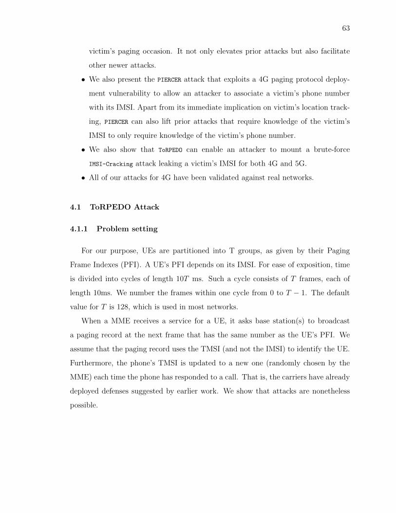
63
victim’s paging occasion. It not only elevates prior attacks but also facilitate
other newer attacks.
• We also present the PIERCER attack that exploits a 4G paging protocol deploy-
ment vulnerability to allow an attacker to associate a victim’s phone number
with its IMSI. Apart from its immediate implication on victim’s location track-
ing, PIERCER can also lift prior attacks that require knowledge of the victim’s
IMSI to only require knowledge of the victim’s phone number.
• We also show that ToRPEDO can enable an attacker to mount a brute-force
IMSI-Cracking attack leaking a victim’s IMSI for both 4G and 5G.
• All of our attacks for 4G have been validated against real networks.
4.1 ToRPEDO Attack
4.1.1 Problem setting
For our purpose, UEs are partitioned into T groups, as given by their Paging
Frame Indexes (PFI). A UE’s PFI depends on its IMSI. For ease of exposition, time
is divided into cycles of length 10T ms. Such a cycle consists of T frames, each of
length 10ms. We number the frames within one cycle from 0 to T − 1. The default
value for T is 128, which is used in most networks.
When a MME receives a service for a UE, it asks base station(s) to broadcast
a paging record at the next frame that has the same number as the UE’s PFI. We
assume that the paging record uses the TMSI (and not the IMSI) to identify the UE.
Furthermore, the phone’s TMSI is updated to a new one (randomly chosen by the
MME) each time the phone has responded to a call. That is, the carriers have already
deployed defenses suggested by earlier work. We show that attacks are nonetheless
possible.

64
0 1,000 2,000 3,000 4,000 5,000 6,000 7,000 8,0000
2
4
6
8
10
12
14
16
18
20
22
Milliseconds
Frequency
(a) Histogram of paging delay for SMS.
0 1,000 2,000 3,000 4,000 5,000 6,000 7,000 8,000
0
0.1
0.2
0.3
0.4
0.5
0.6
0.7
0.8
0.9
1
Time required to receive a paging message
CDF
(b) Cumulative Distribution Function of paging
delay for SMS.
6800 7200 7600 8000 8400 8800 9200 96000
0.5
1
1.5
2
2.5
3
3.5
4
4.5
5
Milliseconds
Frequency
(c) Histogram of paging delay for VoLTE phone
calls.
6800 7200 7600 8000 8400 8800 9200 96000
0.1
0.2
0.3
0.4
0.5
0.6
0.7
0.8
0.9
1
Time required to receive a paging message
CDF
(d) Cumulative Distribution Function of paging
delay for VoLTE phone calls.
Figure 4.1.: Distribution of paging delay i.e., the time between the event of initiating
a phone call or SMS and the event of reaching a paging message to the receiver for
that phone call/SMS.
4.1.2 Adversary Model
We assume that the adversary knows the soft identity of the target UE ut, such
as the phone number, e-mail address, or social network handler of ut. The adversary

65
also knows the geographical area that ut is likely to be in (called the target area), and
sets up a sniffer (built with a Universal Software-defined Radio Peripheral (USRP))
in that area to listen on the paging broadcast channel. That is, the adversary can
make a good guess about the geographical location of ut, although the guess does not
need to be correct. Through the attack, the adversary is able to find out whether
the guess is correct or not. Also note that the adversary can carry out this attack
simultaneously in multiple geographical areas at once against a target ut, provided
that the adversary is willing to spend the resources for doing so.
The goal of the adversary is to (i) confirm whether or not ut is indeed in the target
area, and (ii) when ut is in the area, identify the UE’s PFI (which we use PFIt to
denote), which also yields information about the phone’s IMSI.
The adversary can make a call to ut to trigger a paging message for ut, and listens
to the paging broadcast channel. While we use the term “make a call” to describe the
adversary’s action, the action could take the form of VoLTE or CSFB calls, SMS’s,
tweets, and so on.
The adversary can repeat this process of making a call and listening for paging
messages multiple times. We note that these calls do not need to be made continu-
ously. The adversary can wait between calls. The only restriction is that if the total
duration of the attack is too long, then the UE may have moved out of the target
area during that time.
To assess the effectiveness of such location tracking attacks, we consider the fol-
lowing criteria: (1) identification accuracy: when ut is present in the area, the rate
with which the attack outputs the correct PFI, (2) presence accuracy: when ut is not
present in the area, the rate with which the attack correctly concludes that ut is not
present, and (3) the number of calls required for the attacking algorithm to reach a
decision.

66
4.1.3 High-level Intuition of the Attack
The intuition behind the attack is as follows. Let us assume, for the moment, that
there is no other paging message in the system. When the adversary makes a call to
ut, there are two cases. Case one: If ut is in the area, a paging message will be sent,
and the adversary will also see the paging message at a particular PFI. Case two: ut
is not in the area, then there will be no paging message, and the adversary will not
see any paging message. By making a single call to ut and checking whether there is
a corresponding paging message, the adversary can infer whether ut is in the target
area or not, and, if ut is, what is its PFI.
The challenge of the attack is that the assumption that there is no other paging
message in the system is unrealistic. When there are other paging messages, it is
difficult for an adversary to associate a call she made with a particular paging record.
Recall that we assume that the TMSI (instead of the IMSI) is used in a paging
record, and the TMSI changes each time a UE connects to the base station. The
only information to associate a call with its corresponding paging record is timing.
The paging record should be sent soon after the adversary makes a call. We call the
interval between the time the adversary makes a call and the time the paging record
is sent the paging delay. Unfortunately for the adversary, the paging delay is affected
by many factors, and is randomized from the adversary’s perspective. Furthermore,
there are paging records for other UEs in the area, as well as other services for ut
that are not from the adversary. What the adversary needs to do is to test whether
paging records due to adversary-initiated calls are present for each PFI in the noise
of paging records generated by the background processes.
One way to establish an association between calls and the resulting paging records
is obtain a probability distribution of paging delays, and then establish a delivery
window. Let us call the time that the adversary makes a call 0, then the delivery
window is given by two times tb, te. Any paging record received after tb and before te
is considered to be in the delivery window. The choice of tb, te needs to be carefully

67
made. A window that is too narrow will miss associated paging records. On the other
hand, if a window that is too wide, one increases the probability that paging records
resulted from the background sources as associated with the call.
The distributions of paging delays differ based on the type of services, e.g., phone
calls, SMS, or tweets. They are also dependent on the cell area and the load. The
adversary can get a distribution of paging delays for each type of service, either by
using historical knowledge, or by estimating the distributions for a particular incoming
service before actually carrying out attacks. In Section 4.1.6, we discuss how to obtain
empirical distributions.
Figures 4.1 shows the empirical distributions of paging delays we observed in our
experiments. Fig.4.1(a) and (b) show the histogram and cumulative distribution for
paging delay of SMS. Fig.4.1(c) and (d) show the same for VoLTE calls. We made 500
calls for each. From the figure, one can observe that paging delays for SMS messages
are between approximately 2.8 and 5.3 seconds, whereas the paging delays for VoLTE
phone calls are between approximately 6.8 and 9.4 seconds.
4.1.4 Two Simple Attacks
Because of the background traffic of paging messages, the adversary is unable to
use a single call to carry out the attack, and needs to make multiple calls. When the
adversary makes multiple calls over time, she expects to see a paging message after
each call, and all the paging messages are delivered in frames with the same number.
Here the adversary relies on the observation that the base rate of paging messages in
each frame is typically low. We first present two simple attacks.
Filtering
The Filtering attack assumes perfect delivery of paging messages, that is, it is
assumed that each time the adversary makes a call, a paging message will be reliably
received during the delivery window. Starting with the set of all possible PFI values,
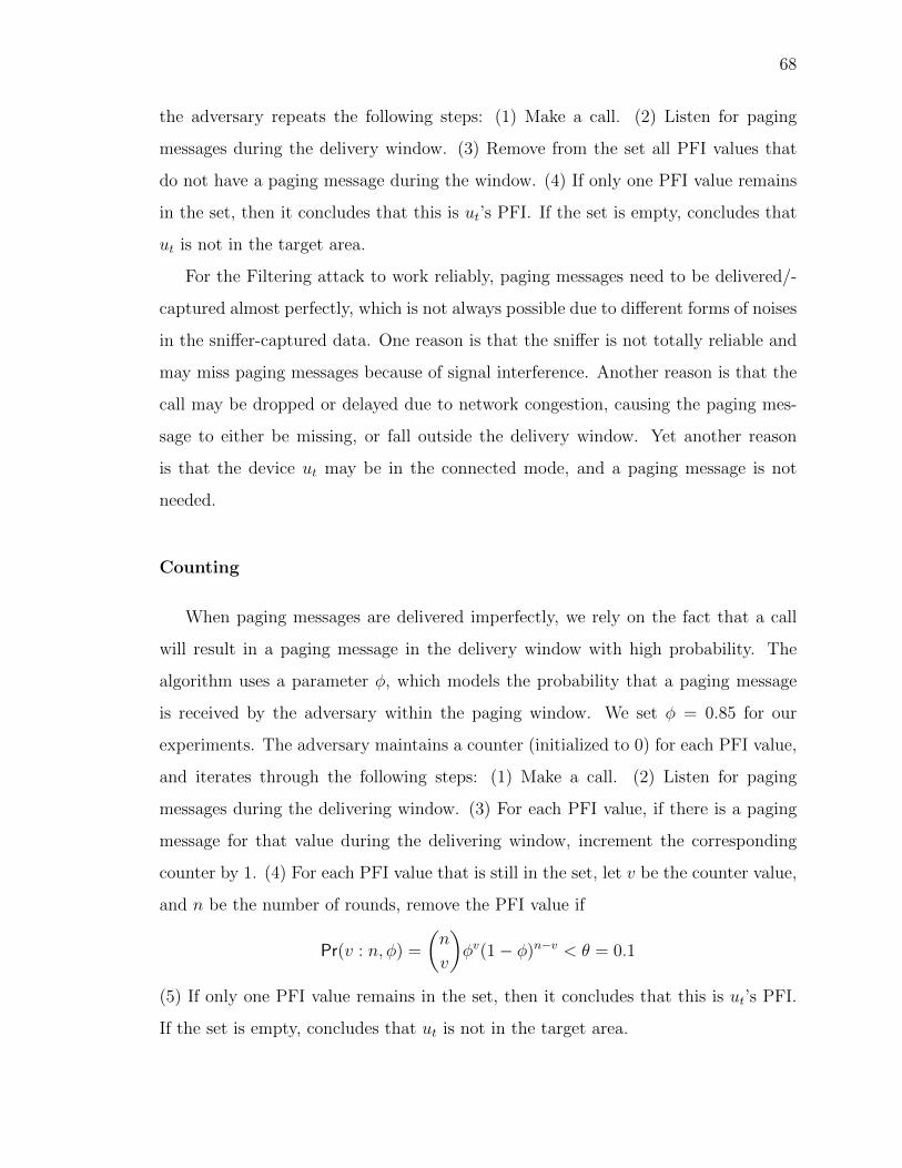
68
the adversary repeats the following steps: (1) Make a call. (2) Listen for paging
messages during the delivery window. (3) Remove from the set all PFI values that
do not have a paging message during the window. (4) If only one PFI value remains
in the set, then it concludes that this is ut’s PFI. If the set is empty, concludes that
ut is not in the target area.
For the Filtering attack to work reliably, paging messages need to be delivered/-
captured almost perfectly, which is not always possible due to different forms of noises
in the sniffer-captured data. One reason is that the sniffer is not totally reliable and
may miss paging messages because of signal interference. Another reason is that the
call may be dropped or delayed due to network congestion, causing the paging mes-
sage to either be missing, or fall outside the delivery window. Yet another reason
is that the device ut may be in the connected mode, and a paging message is not
needed.
Counting
When paging messages are delivered imperfectly, we rely on the fact that a call
will result in a paging message in the delivery window with high probability. The
algorithm uses a parameter φ, which models the probability that a paging message
is received by the adversary within the paging window. We set φ = 0.85 for our
experiments. The adversary maintains a counter (initialized to 0) for each PFI value,
and iterates through the following steps: (1) Make a call. (2) Listen for paging
messages during the delivering window. (3) For each PFI value, if there is a paging
message for that value during the delivering window, increment the corresponding
counter by 1. (4) For each PFI value that is still in the set, let v be the counter value,
and n be the number of rounds, remove the PFI value if
Pr(v : n, φ) =
(n
v
)φv(1− φ)n−v < θ = 0.1
(5) If only one PFI value remains in the set, then it concludes that this is ut’s PFI.
If the set is empty, concludes that ut is not in the target area.

69
4.1.5 The ToRPEDO Attack with Likelihood Analysis
The Counting attack does not use the information of how many paging records
arrive in each frame (only whether there is at least one paging record), nor does it
use the information about the timing of the message’s arrival. From Figure 4.1, we
can see that even though the delivery window for SMS goes roughly from 2.8 to 5.4
seconds, a paging message is much more likely to arrive at, e.g., 4 seconds, than at 5.3
seconds. We now present the ToRPEDO attack, which utilizes all information to conduct
a likelihood analysis and decide the PFI of ut.
Let the time at which the adversary makes a call be t = 0. ToRPEDO takes as input
F (·), the cumulative distribution of paging delay. That is, if the paging message
corresponding to the call is received at all, then with probability F (t), it will be
received by time t. Let tm be the smallest t such that F (t) = 1. Then the adversary
listens for c cycles after making a call, where c is computed as follows:
c =
⌈tm
10T ms
⌉,
For each i ∈ [0..T− 1], during the whole observation period, there are c frames with
SFN congruent to i modulo T. Let vi,j (where 0 ≤ i < T and 1 ≤ j ≤ c) denote
the number of paging records received at the j-th frame that has SFN congruent to
i modulo T. The time for vi,j can be computed as:
time(i, j)=
0 when j == 0
((j−1)T+i−b)·10ms when j≥1, b≤ i
(j · T+i−b)·10ms when j≥1, b>i
(4.1)
where
b = S0 mod T, where S0 is the SFN when the call occurs
denotes the frame index within the length-T cycle at the time the call is made.
For each i, we compute the likelihood of observing the sequence V = vi,1, vi,2, · · · , vi,cwhen PFIt 6= i and when PFIt = i. When PFIt 6= i, the sequence V is due to the back-
ground paging records. We use the Poisson Distribution to model the probability

70
that we observe a certain number of paging records in a given frame. The Poisson
distribution expresses the probability of a given number of events occurring in a fixed
interval of time if these events occur with a known constant rate and independently
of the time since the last event. The Poisson distribution is parameterized by a base
rate λb, which the adversary can estimate empirically.
We use `′i to denote the likelihood of observing vi,1, vi,2, · · · , vi,c when PFIt 6= i. It
can be computed as:
`′i =c∏j=1
Pr[P (λb) = vi,j
](4.2)
Here P (λb) is a Random Variable following the Poisson distribution with parameter
λb.
We use `i to denote the likelihood of observing the sequence V when PFIt = i. To
compute `i, we need to consider two cases.
• First it may be that even though PFIt = i, the paging message is not observed.
This happens with probability 1 − φ, where φ is the same parameter as used
in the Counting attack. It is an estimation of the probability that a paging
message is received within the delivery window.
• Second, the paging record may be delivered during any of the c cycles, and we
have to sum up the likelihood of each case. The likelihood of the paging record
being delivered during the j-th cycle is a product of 3 probabilities: (1) the
probability that the delay for the paging message is such that the message arrives
at the j-th cycle; (2) the probability that we observe vi,j records given that the
paging record arrives in this cycle (i.e., the background contributes vi,j − 1
paging records; (3) observations of vi,k where k 6= j are from the background.
Thus `i can be computed as follows:

71
`i = (1− φ)c∏j=1
Pr[P (λb) = vi,j
]+ φ
c∑j=1
(F (time(i, j))−F (time(i, j−1)))
× Pr[P (λb) = vi,j−1
] c∏k=1,k 6=j
Pr[P (λb) = vi,k
](4.3)
where:
φ is the same parameter as used in the counting attack
P (λb) is a Random Variable following the Poisson
distribution with parameter λb
F is the CDF of paging delay given in Fig. 4.1
time is defined in Eq.(4.1)
Computing the global likelihood of a PFI to be the victim’s PFI. After
making each call, the adversary computes the global likelihood, Li for each i = PFI,
0 ≤ i < T to belong to the ut. The adversary also computes the global likelihood,
L−1 for the case that ut is not present. The global likelihood Li and L−1 after making
n calls is computed as follows:
Li =∏
n trials
`i
T−1∏m=0,m 6=i
`′m
L−1 =∏
n trials
T−1∏m=0
l′m
(4.4)
After each new trial, if the maximum global likelihood (Li) for any i becomes
significantly larger (i.e., by an order of a set threshold value τ) than the second
largest global likelihood value, the adversary identifies i as the PFI of the ut. If −1
is identified this way, it concludes that ut is not in the area.
Limax Lj,where j 6= i
≥ 10τ (4.5)

72
4.1.6 Discussions
Estimating empirical distributions of paging delays. We assume that the
adversary A owns a UE, uA1 that is a subscriber of the target network located at cell
area c. Furthermore, the adversary knows uA1 ’s IMSI and TMSI, which is feasible
in many cases through cellular debugging tools such as MobileInsight [63]. A thus
can compute the PFI value for uA1 . Using another adversary-controlled UE, uA2 , the
adversary sends N phone calls, N SMS, or N tweets to uA1 and observes the time (in
milliseconds) required to receive paging messages at uA1 for the corresponding phone
calls, SMS and tweets. Using these observations, A can establish an empirical paging
delay distribution for each service. Note that it is necessary to wait for the device to
move to the idle mode before making the next call, otherwise paging messages will not
be triggered. For our experiment, we choose the conservative value of ∼ 40 seconds
between two consecutive calls (or, SMS/tweets) to ensure this is the case.
Clandestine Location Tracking The adversary can carry out ToRPEDO, clandes-
tinely, i.e., without alerting the human user using ut. For example, a phone call can
be made silent [17, 34] in 4G LTE by making a call and then terminating it in a few
seconds. In this case, the base station will broadcast a paging message, but the phone
will not ring because the call is hanged up before the call establishment procedure
succeeds. Similarly, SMS and other messages can be made silent.
Dealing with smart and non-smart paging. Wireless providers generally use
non-smart paging (all base stations in a tracking area broadcast paging messages)
for VoLTE phone calls, and smart paging (only one base station broadcasts paging
messages) for SMS services. The adversary can thus choose which one to use based
on whether adversary is certain of the exact location of ut.

73
Table 4.1.: Number of paging imsi messages observed by a single UE for different
network operators.
CarrierTotal hours of ob-
servation
Total number of
paging with IMSI
Percentage of paging
with IMSI
US-1 44 hours 171 0.274 %
CH-1 10 hours 8 3.404 %
CH-2 7 hours 1 0.028 %
US-MVNO-1 15 hours 78 0.324 %
US-MVNO-2 18 hours 146 0.336 %
RU-1 4 hours 2 3.175 %
4.2 The PIERCER Attack for 4G
This section describes the PIERCER attack that enables an attacker to associate a
victim’s phone number with its IMSI by exploiting a deployment oversight of service
providers we have discovered.
4.2.1 Attack Surface
Our investigation towards PIERCER began due to an observation we made while
inspecting the network traces of different service providers’ paging protocol deploy-
ment. The traces we analyzed were contributed by devices across the world in the
MobileInsight [63] platform. In those traces [63], we observed that a non-negligible
amount of paging messages originating from 1 major US network operator, 2 Chinese
network operators, 1 Russian network operator, and 2 US mobile virtual network
operators [67] contain IMSI as the identifier (in short, paging imsi). A summary of
the results are presented in Table 4.1.
Some of these observed paging imsi messages, however, were not intended for the
UEs that actually contributed the traces. They rather were intended for other UEs
sharing the same paging occasion as the trace-contributing UEs. Due to the lack of
contextual information about UEs for which the observed paging imsi messages were
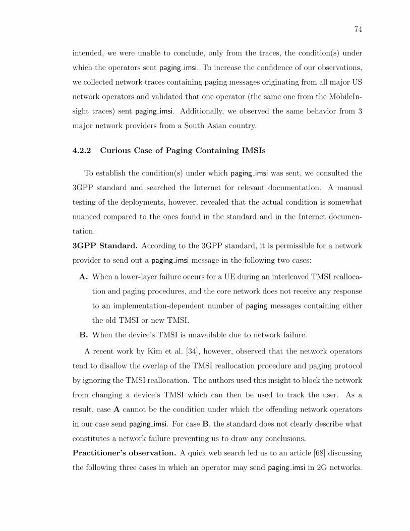
74
intended, we were unable to conclude, only from the traces, the condition(s) under
which the operators sent paging imsi. To increase the confidence of our observations,
we collected network traces containing paging messages originating from all major US
network operators and validated that one operator (the same one from the MobileIn-
sight traces) sent paging imsi. Additionally, we observed the same behavior from 3
major network providers from a South Asian country.
4.2.2 Curious Case of Paging Containing IMSIs
To establish the condition(s) under which paging imsi was sent, we consulted the
3GPP standard and searched the Internet for relevant documentation. A manual
testing of the deployments, however, revealed that the actual condition is somewhat
nuanced compared to the ones found in the standard and in the Internet documen-
tation.
3GPP Standard. According to the 3GPP standard, it is permissible for a network
provider to send out a paging imsi message in the following two cases:
A. When a lower-layer failure occurs for a UE during an interleaved TMSI realloca-
tion and paging procedures, and the core network does not receive any response
to an implementation-dependent number of paging messages containing either
the old TMSI or new TMSI.
B. When the device’s TMSI is unavailable due to network failure.
A recent work by Kim et al. [34], however, observed that the network operators
tend to disallow the overlap of the TMSI reallocation procedure and paging protocol
by ignoring the TMSI reallocation. The authors used this insight to block the network
from changing a device’s TMSI which can then be used to track the user. As a
result, case A cannot be the condition under which the offending network operators
in our case send paging imsi. For case B, the standard does not clearly describe what
constitutes a network failure preventing us to draw any conclusions.
Practitioner’s observation. A quick web search led us to an article [68] discussing
the following three cases in which an operator may send paging imsi in 2G networks.

75
The considered cases, however, focus on the GSM network instead of the newer 4G
LTE network.
1. When the VLR (Visitor Location Registry)—similar functionality as in MME—
uses a volatile storage to store the different IMSI-TMSI mappings, a VLR restart
would induce an inaccessible IMSI-TMSI mappings. When VLR restarts, any
paging will be with IMSI.
2. If the VLR has a limited amount of RAM, a user’s IMSI-TMSI mapping may be
evicted when a new mapping needs to be inserted. Any paging for users whose
mapping are not in the RAM will be with IMSI.
3. The IMSI-TMSI mapping is expired for users who have not shown activity for a
long time. Any paging for users whose IMSI-TMSI mappings have expired will
result in paging imsi.
The infrastructure that supports the newer protocol versions arguably does not have
the same limitation of using an unreliable, small volatile storage to store the IMSI-
TMSI mapping for devices. This argument is further strengthened by our observation
that network operators always try with 1-2 paging tmsi messages before trying with a
paging imsi. This means that network operators usually do not lose the IMSI-TMSI
mappings neither because of limited volatile storage nor due to network nodes’ abrupt
restart. Nonetheless, the findings by Shaik et al. [17] who observed that operators did
not change TMSIs for some devices for up to 7 days also invalidates the practitioner’s
observation of paging with IMSI for 2G networks.
Manual testing. Since neither the standard nor the web article [68] provided a
convincing condition to why the network may send paging imsi, we resort to a man-
ual testing approach. We first collected traces in a cellular device UEtest equipped
with the offending networks SIM card while placing phone calls from another cellular
device periodically at a regular interval. We, however, did not see any paging imsi
intended for UEtest. This led us to conclusion that paging imsi is sent only under
exceptional/error cases.

76
One of the exceptional cases we considered is to block UEtest from receiving the
paging message from the network. To block UEtest from receiving the paging message,
we rely on a prior attack called paging channel hijacking [65]. We also established a
sniffer to pick up any paging message containing the victim’s IMSI.
We observed that if we call UEtest but do not let the corresponding paging message
in the VoLTE/packet switch domain (PS domain) to reach the UEtest, the offending
network retries to send the paging messages in the PS domain twice. After two unsuc-
cessful retries in the PS domain, it then sends a paging imsi in the non-VoLTE/circuit
switch domain (CS domain). We validated this by matching the IMSI with UEtest’s
IMSI. We repeated this multiple times to observe the same consistent behavior. This
led us to the complete attack design of PIERCER described below.
4.2.3 Attack Description
The threat model and PIERCER attack steps are given below.
Threat Model. For PIERCER, we assume an attacker who knows the victim’s phone
number, and can set up a paging message sniffer and a fake base station (with higher
signal strength) in any cell including the victim’s.
Description. An attacker initiates PIERCER by identifying the victim’s paging occa-
sion and current cell-level location with ToRPEDO. The attacker then installs a paging
message sniffer and a fake base station in the victim’s cell. After which the attacker
hijacks the victim’s paging channel and then places a single silent phone call. As
discussed above, vulnerable operators will send paging imsi after several failed at-
tempts with paging tmsi (due to hijacked paging channel). The attacker’s sniffer can
capture the IMSI when paging imsi is sent; completing the attack. The attacker may
repeat the last step to gain higher confidence.

77
4.2.4 Discussion
Impact. PIERCER can also enhance the attacker capability to effectively mount some
prior attacks that require the knowledge of the victim’s IMSI [13,16,17,65].
Defense. The defense for PIERCER is to ensure that the network operator never sends
the paging imsi message.
Observation. We attempted PIERCER with SMS or Twitter messages to no avail. We
speculate that unlike phone calls SMS or Twitter does not have real-time require-
ments.
4.3 The IMSI Cracking Attack for 4G and 5G
We now present the bruteforce IMSI cracking attack, and also describe the ora-
cles we have exploited for 4G and 5G paging protocols to decide whether a guessed
IMSI belongs to the victim device. It is natural to question the rationale of design-
ing a brute-force IMSI cracking attack for 4G where other legitimate means (e.g.,
identity request) are available to retrieve the victim’s IMSI in the clear. We wanted
to demonstrate that the attack is feasible even when the IMSI is never released in the
clear, as in 5G, where the IMSI (or, SUPI) is encrypted with the operators’ public
key. In fact, it is more efficient for 5G as one does not need to wait for the appropriate
PFI.
Threat Model: For the cracking attack, we assume the adversary to have the same
capabilities as described in the PIERCER attack in Section 4.2.3.
4.3.1 5G-SUPI/IMSI Representation and Information Leakage
Representation. The persistent SIM card-specific identity in 5G is called the Sub-
scriber Permanent Identifier (SUPI). SUPI [69] can be either of the IMSI form or of
the network access identifier (NAI) form. For our discussion, we focus on IMSI which

78
is not only used in 5G but also used in 4G to uniquely identify the subscriber for
authentication.
IMSIs are represented as a 15-digit (14-digit for Europe) binary-coded decimal
(BCD). The first 3 digits (resp., 2 digits for Europe) of an IMSI represent the mobile
country code (MCC) whereas the next 3 digits (same in Europe) represent the mobile
network code (MNC) identifying the specific network operator. The rest of the 9 BCD
digits of IMSI, called mobile subscription identification number (MSIN), are unique
to the subscriber.
Leakage. (1) Given a user’s phone number, it is possible to look up the MCC
and MNC (i.e., the first 5/6 BCD-digits) corresponding to that device using paid,
Internet-based home location register lookup services [66]. This leaves 9 BCD-digits
of the IMSI for the adversary to guess.
(2) Recall that, the last 10 bits of the IMSI are used for calculating the paging
occasion of a device. In that calculation, however, the IMSI is considered to be a
14-/15-digit decimal number instead of a BCD number. Without loss of generality, if
network operator base stations have T=nB=128 then calculating the victim’s paging
occasion will leak the last 7 bits of the victim’s IMSI.
We will describe how these two forms of leakage can be combined by the adversary
to decrease the search space of the brute-force search. For example, suppose that the
IMSI the attacker intends to crack belongs to a US subscriber. The current maximum
value of MCC for US subscribers is 316 whereas the maximum value of MNC is 990. If
we consider the rest of the 9 digits of the IMSI to be 9, then the corresponding decimal
number’s (i.e., 316990[9]9) binary representation yields a 49-bit binary number whose
leading 18 bits and the trailing 7 bits are known to the attacker, leaving only 24 bits
for him to guess which would take the attacker 224 (i.e., ∼ 16.77 million) guesses in
the worst case.
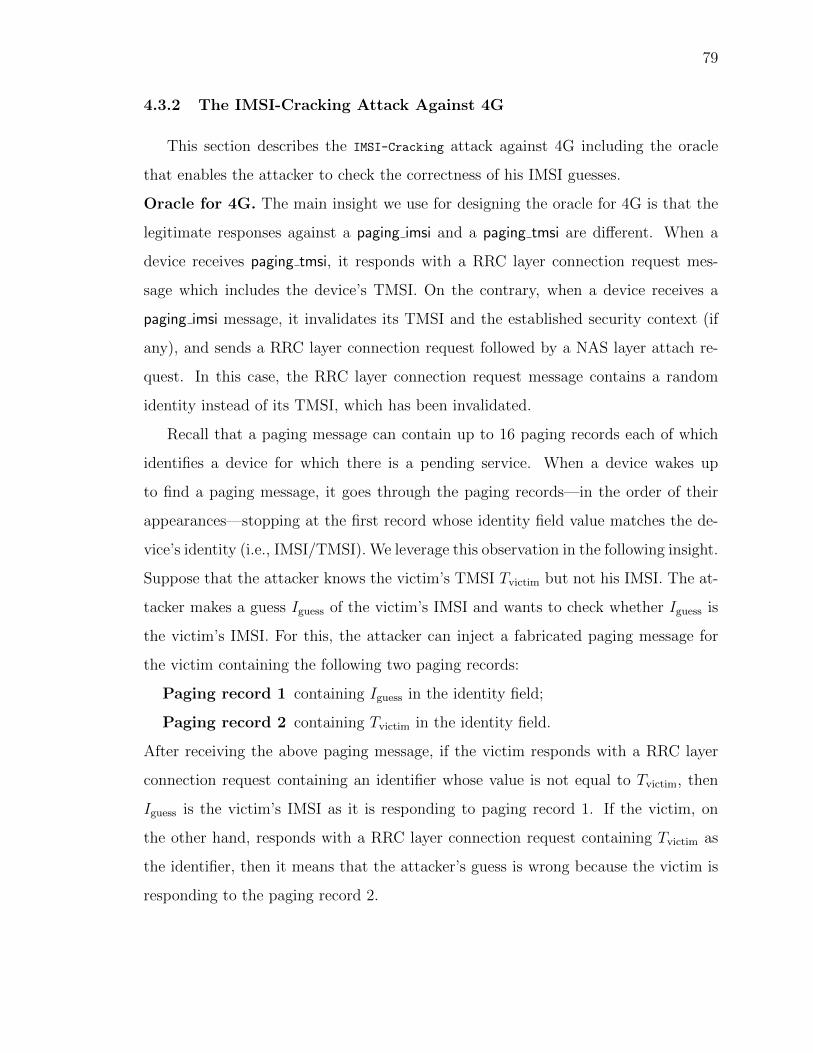
79
4.3.2 The IMSI-Cracking Attack Against 4G
This section describes the IMSI-Cracking attack against 4G including the oracle
that enables the attacker to check the correctness of his IMSI guesses.
Oracle for 4G. The main insight we use for designing the oracle for 4G is that the
legitimate responses against a paging imsi and a paging tmsi are different. When a
device receives paging tmsi, it responds with a RRC layer connection request mes-
sage which includes the device’s TMSI. On the contrary, when a device receives a
paging imsi message, it invalidates its TMSI and the established security context (if
any), and sends a RRC layer connection request followed by a NAS layer attach re-
quest. In this case, the RRC layer connection request message contains a random
identity instead of its TMSI, which has been invalidated.
Recall that a paging message can contain up to 16 paging records each of which
identifies a device for which there is a pending service. When a device wakes up
to find a paging message, it goes through the paging records—in the order of their
appearances—stopping at the first record whose identity field value matches the de-
vice’s identity (i.e., IMSI/TMSI). We leverage this observation in the following insight.
Suppose that the attacker knows the victim’s TMSI Tvictim but not his IMSI. The at-
tacker makes a guess Iguess of the victim’s IMSI and wants to check whether Iguess is
the victim’s IMSI. For this, the attacker can inject a fabricated paging message for
the victim containing the following two paging records:
Paging record 1 containing Iguess in the identity field;
Paging record 2 containing Tvictim in the identity field.
After receiving the above paging message, if the victim responds with a RRC layer
connection request containing an identifier whose value is not equal to Tvictim, then
Iguess is the victim’s IMSI as it is responding to paging record 1. If the victim, on
the other hand, responds with a RRC layer connection request containing Tvictim as
the identifier, then it means that the attacker’s guess is wrong because the victim is
responding to the paging record 2.
80
The complete attack. The attacker starts off by using the ToRPEDO attack to iden-
tify the victim’s coarse-grained location, paging occasion, and the current TMSI. Note
that, the victim’s paging occasion can be shared by multiple non-targeted users in-
ducing an implicit K-anonymity set where (K-1) is the number of non-targeted users
sharing the victim’s paging occasion. The attacker then hijacks the victim’s (and, also
the other K-1 users’) paging channel as described by prior work [65]. The attacker
creates a fabricated paging message containing 16 paging records where the first 15
records contain different IMSI guesses from the adversary whereas the last paging
record contains the victim’s TMSI as the identifier.
For each fabricated paging message, if the attacker receives an RRC layer connec-
tion request with the victim’s TMSI, then it means that none of the 15 IMSI guesses
belong to the victim. On the other hand, if the attacker does not receive a RRC
layer connection request with the victim’s TMSI, it suggests that one of the 15 IMSI
guesses belongs to the victim, although the attacker does not know which one it is.
Also, as the victim received paging imsi, it would invalidate the current TMSI. To
narrow down which of the 15 guessed IMSIs belongs to the victim, the attacker stops
the paging channel hijacking attack and lets the victim connect to the legitimate base
station.
Then the attacker again uses ToRPEDO to identify the victim’s current TMSI de-
noted by T cvictim. Suppose the victim’s IMSI belongs to the following set: G =
{I iguess|1 ≤ i ≤ 15} identified from the previous guess. Again, the attacker hijacks
the paging channel of the victim including the other devices sharing the same paging
occasion. Then the attacker sends a maximum of 15 paging messages each of which
contains two paging records. For the first paging message, the first record contains
I1guess ∈ G as the identifier whereas the second record contains T cvictim. Similarly, for the
second paging message, the first record contains I2guess ∈ G as the identifier whereas
the second record contains T cvictim, and so on. For the jth paging message where
1 ≤ j ≤ 15, if the attacker receives an RRC layer connection request with a random
identifier, then it suggests that the guess Ijguess belongs to the victim, concluding a

81
TORPEDO
TORPEDO
UEvic eNodeBadveNodeBbenign
2Sends Fabricated Paging Messsage with
IMSI guesses and current TMSI
1
's IMSI was not in 15 guessesUEvic
RRC Layer connectionrequest with TMSI
Repeat step 2 withother 15 IMSI guesses
3
4
's IMSI was in 15 guessesUEvic
RRC Layer connectionrequest not with TMSI
connects to legitimate base stationUE
Sends Fabricated Paging Messsage withIMSI guess and current TMSI
RRC Layer connectionrequest with TMSI
's IMSI was not guessedUEvic
Repeat step 8 withother IMSI guess
's IMSI was guessedUEvic
RRC Layer connectionrequest not with TMSI
5
7
6
8
9
10
11
Paging Messages with15 IMSI guesses
Filtering out incorrectguesses from paging
message
Figure 4.2.: IMSI-Cracking attack in 4G
successful attack. Figure 4.2 shows the detailed message flows for the IMSI-Cracking
attack in 4G.
82
4.3.3 The IMSI-Cracking Attack Against 5G
This section presents the oracle needed for carrying out the IMSI-Cracking attack
against 5G.
Oracle for 5G. We leverage three main insights to design the oracle for 5G. (i)
The core network’s responses to a registration request message (resp., attach request
message in 4G) is different depending on whether the message contains a valid IMSI.
If the core network receives a registration request message with a non-existent/invalid
IMSI, the network issues a registration reject (cause #9: UE identity cannot be de-
rived by the network) message (clause 5.5.1.2.5 of the 5G NAS standard [31]) to the
device, whereas the network sends an auth request message (challenge) in response to
a registration request message with an existent/valid IMSI. (ii) There is a one-to-one
relationship between the cryptographic master key (K) and the IMSI of each device
in the network which means that a device equipped with IMSIi cannot solve an au-
thentication challenge cj derived from Kj of the device with IMSIj, where i 6= j. (iii)
A device’s response to a valid auth request message is different from the response to
an invalid auth request message. For an auth request message, the device responds
with an auth response message if it can solve the challenge; otherwise, it responds
with an auth failure message with an indication to the message authentication code
(MAC) or the sequence number verification failure.
If a device’s initial registration request message (containing MCC, MNC and the
encrypted MSIN of the user) is not integrity protected, the network initiates an au-
thentication procedure with the device (clause 6.4.6 of 5G Security Architecture [30]).
The encrypted MSIN, also called concealed subscription identifier (SUCI), is a func-
tion of the home network’s public key (CNpub key) and the MSIN of the user, i.e.,
SUCI = f(CNpub key,MSIN). We leverage this observation in the following insight.
Suppose the attacker knows the core network’s public key provisioned in the attacker-
controlled SIM card/UE, and makes a guess Iguess of the victim’s IMSI and wants to
check whether Iguess is victim’s IMSI. For this, the attacker calculates SUCIguess cor-
responding to the Iguess and sends a fabricated registration request message to the

83
core network. Let I be set of all valid/active IMSIs for a test network. After receiv-
ing the registration request message, if the network responds with a registration reject
message, it means that Iguess /∈ I. If the network, on the contrary, responds with
a auth request message, it signifies that Iguess ∈ I and the attacker considers Iguess
as a potential candidate of the victim’s IMSI. To validate such a guess, the attacker
forwards the auth request message to the victim’s device. If the victim responds with
an auth failure message indicating a MAC verification failure, the attacker infers that
the auth request message generated by the network is not for the victim’s IMSI and
thus that Iguess is not the victim’s IMSI. If the device, on the other hand, responds
with an auth response message, the attacker infers that the Iguess is the victim’s IMSI.
UEvic UEadveNodeBadv eNodeBbenign
registration_rejectregistration_request
( )mreq
stores eNodeBadv
mreq RRC layerconnectionestablished
registration_request ( )mguess
Network
auth_request ( )c
Guess contained IMSIU ′ sEvicauth_response
Guess did not contain IMSIU ′ sEvicauth_failure
registration_request ( )mreq
auth_request ( )cvictim
auth_responseAdversary willguess another
IMSI
12
3 4
56
78
910
11
Repeat Step 5with different
IMSI
Figure 4.3.: IMSI-Cracking attack in 5G
The complete attack. Like the IMSI-Cracking attack in 4G, the attacker first identi-
fies the victim’s paging occasion. The attacker also sets up a man-in-the-middle type

84
relay [65, 70] between the victim device and the legitimate core network (as shown
in Figure 4.3) to inject fabricated messages as well as to relay legitimate messages.
Like in [65, 70], the relay consists of a malicious eNodeB, denoted by eNodeBadv,
impersonating a legitimate eNodeB, denoted by eNodeBbenign, towards the victim’s
device and a malicious UE, denoted by UEadv, impersonating victim’s device towards
the legitimate core network. In the following UEvic denotes the victim legitimate UE.
Without loss of generality, we use the term eNodeB to refer to a base station for both
4G and 5G.
Disconnect UEvic from the EPC : For disconnecting UEvic from the legitimate net-
work, the attacker uses a registration reject message sent by eNodeBadv.
Store UEvic’s registration request: As UEvic detaches itself from the EPC due to a
registration reject, it tries to attach to the eNodeB with the highest signal strength;
which is eNodeBadv. UEvic sends a registration request message mreq to eNodeBadv which
eNodeBadv stores for later use.
Send an initial registration request message containing Iguess to the EPC : UEadv
establishes a RRC layer connection with eNodeBbenign and sends a non-integrity pro-
tected registration request message mguess containing Iguess to the core network.
Relay auth request to UEvic: In response tomguess, the network sends an auth request
(i.e., a challenge c) to UEadv which UEadv forwards to UEvic through eNodeBadv. After
UEvic receives c, unaware that eNodeBadv sent it, it tries to solve the challenge c to
generate the correct response r. If UEvic cannot solve the challenge, UEvic sends an
auth failure message to eNodeBadv. By identifying an auth failure message in response
to c, the attacker infers that Iguess is not the victim’s IMSI and then tries with Inextguess.
For the attack to be successful, a challenge has to be addressed. We describe the
challenge below and the steps taken to address it.
Addressing the challenge of two consecutive auth failure by UEvic: If a device fails
to verify the MAC or sequence number for two consecutive auth request messages,
the device downgrades to previous generations (e.g., 3G/2G) of cellular networks.
This would prevent the attacker from being able to continue probing the network
85
and UEvic with two different IMSIs. We address this challenge by letting the attacker
send a mreq message between two consecutive mguess messages. After a trial with
mreq, UEadv, therefore, sends the mreq (obtained from eNodeBadv) to the core net-
work. In response to mreq, the network sends a valid auth request message (cvictim) for
UEvic which eNodeBadv and UEadv relay to UEvic. UEvic solves the challenge and sends
auth response r to eNodeBadv which will not be relayed to the legitimate network.
UEvic then sends a new mguess with another Iguess and repeats the above steps by
interleaving mguess and mreq messages. If eNodeBadv receives an auth response message
r for an Iguess, eNodeBadv is able to infer that Iguess belongs to the victim, concluding
a successful attack.
4.4 Testbed setup
We now describe our testbed that we used for validating ToRPEDO, PIERCER, and
IMSI-Cracking attacks in 4G.
Paging sniffer. For sniffing broadcast messages we set up a sniffer using a Uni-
versal Software-defined Radio Peripheral device, i.e., USRP B210 [54] (costs as low
as $1300) connected to an Intel Core i7 machine running Ubuntu 16.04 as the hard-
ware component and srsLTE [56], an open source LTE protocol stack implementation.
We modified the srsLTE’s pdsch ue application to enable the sniffer to periodically
(∼ 10 minutes) switch its decoding mode between the master info block and the paging
channels. Thus the sniffer periodically synchronizes the network time/frame simi-
lar to commercial-off-the-shelf (COTS) UEs and reliably computes the SFN value
for a received paging message. We also use the sniffer to capture and decode the
system info block type 1 and system info block type 2 messages and learn the param-
eters relevant for computing the victim UE’s paging occasion (e.g., paging cycle and
nB).
Malicious eNodeB. We use another USRP B210 [54]) connected to an Intel Core
i7 machine running Ubuntu 16.04 as the hardware component and srsENB [56], an
open source LTE protocol stack implementation for eNodeB, to set up a malicious
86
eNodeB. We modified the srsENB to allow the malicious eNodeB to broadcast paging
messages without any paging request from a legitimate MME. There are other more
economial options for setting up a rogue eNodeB using LimeSDR [71] (costs as low
as $200) which has also been shown to be effective [72].
4.5 ToRPEDO Evaluation
In this section, we validate and evaluate the filtering, counting, and likelihood
variants of ToRPEDO.
Effectiveness metrics. For assessing the effectiveness of all variants of ToRPEDO, we
use the following metrics: (1) accuracy (defined below), and (2) number of trials
(i.e., calls/SMSs) required to correctly identify a victim UE’s paging occasion. We
also evaluate the same for the case when the victim is not present in a cell area.
accuracy =total # attacks - # mis-identification
total # attacks∗ 100%
4.5.1 Evaluation Setting
We evaluated the ToRPEDO variants in both peak (12:00 PM noon) and off-peak
(12:00 AM midnight) times as the paging message distribution tends to vary with
time of day [12, 34]. We also carried out the attacks in two different geographical
locations, although we present results from one location due to space constraints. In
the similar vein, we include results for only one major US network provider (i.e., US-
I)1 as we have mostly observed the same trends for the rest of the network providers
in both US and Canada.
We have considered both VoLTE and CSFB phone calls while validating ToRPEDO
variants. Similarly, we also considered paging in both PS and CS domains. We
particularly considered paging with CS domain as our analysis of network traces
from 34 different service providers [63] revealed that 14 of them use paging with CS
1To keep the four major US network operators anonymous, we use pseudonyms (i.e., US-I, US-II,US-III, US-IV) to identify them.

87
domain. Finally, we demonstrate ToRPEDO variants’ effectiveness in identifying the
victim’s presence and also absence in a cell.
0 10 20 30 40 50 60 70 80 90 100 110 1200
0.02
0.04
0.06
0.08
0.1
0.12
0.14
0.16
0.18
0.2
0.22
0.24
0.26
0.28
0.3
0.32
Paging occasion (PFI)
Exp
ectedNumber
ofPagingMessages
(a) Paging message base rate
(λpagingb ).
0 10 20 30 40 50 60 70 80 90 100 110 1200
0.05
0.1
0.15
0.2
0.25
0.3
0.35
0.4
0.45
Paging occasion (PFI)
Exp
ectedNumber
ofPSRecords
(b) PS record base rate (λpsb ).
0 10 20 30 40 50 60 70 80 90 100 110 1200
0.001
0.002
0.003
0.004
0.005
0.006
0.007
0.008
0.009
0.01
0.011
Paging occasion (PFI)
Exp
ectedNumber
ofCSRecords
(c) CS record base rate (λcsb ).
Figure 4.4.: Average number of paging message, PS record, and CS record arrivals in
any PFI within one paging cycle during peak-time of a day.
4.5.2 Baseline for Likelihood Variant of ToRPEDO
Carrying out the likelihood variant of ToRPEDO requires the attacker to establish a
baseline paging message (resp., records) distribution. For the baseline, the attacker
first uses a sniffer to capture paging messages received at different PFIs for 15 min-
utes. The adversary then computes the following Poisson distribution parameters: (i)
λpagingb = average number of paging message arrivals for any PFI within one paging
cycle (T ); (ii) λPSb average number of PS record arrivals for any PFI within one paging
cycle; and (iii) λCSb = average number of CS record arrivals for any PFI within one
paging cycle. Figures 4.4(a), 4.4(b), and 4.4(c) show the average number of paging
message, PS record and CS record arrivals, respectively, in any PFI within one pag-
ing cycle during peak time. For the rest of this section, we will use: λpagingb = 0.26,
λPSb = 0.34, and λCSb = 0.0065 which we observed in our testing location.

88
4.5.3 Identifying Victim’s Presence with ToRPEDO
We now describe validation results of ToRPEDO variants with different trial types
(e.g., VoLTE phone call, SMS).
VoLTE Call
0.92 0.93 0.94 0.95 0.96 0.97 0.98 0.99Observation time length of paging message
(for filtering and counting)
60
65
70
75
80
85
90
95
100
Accu
racy
(Filt
erin
g an
d Co
untin
g)
FilteringCounting
1.0 1.5 2.0 2.5 3.0 3.5 4.0 4.5 5.0Threshold for Likelihood approach
(in orders of magnitude)
93
94
95
96
97
98
99
100
Accu
racy
(Lik
elih
ood)
Likelihood
(a) No missing paging.
0.92 0.93 0.94 0.95 0.96 0.97 0.98 0.99Observation time length of paging message
(for filtering and counting)
15
20
25
30
35
40
45
50
Accu
racy
(Filt
erin
g an
d Co
untin
g)
FilteringCounting
1.0 1.5 2.0 2.5 3.0 3.5 4.0 4.5 5.0Threshold for Likelihood approach
(in orders of magnitude)
60
70
80
90
100
Accu
racy
(Lik
elih
ood)
Likelihood
(b) 15% missing paging
Figure 4.5.: Accuracy and number of trials against thresholds for ToRPEDO using VoLTE
calls during the peak hour (around noon) of a day.
Parameter selection. Carrying out ToRPEDO variants requires fixing few parameters.
For the filtering and counting variants the important parameter is the observation
interval. Given a time period, an observation interval of 0.95 means that 95% of the
observed paging messages arrived within the considered time period. The observation
interval can be computed from the histogram of the paging delay similar to ones in
Figure 4.1(a). In the similar vein, the necessary parameter for likelihood variant of
ToRPEDO is the threshold value τ . τ is used to compare the likelihood of the two PFIs
with highest likelihood values.
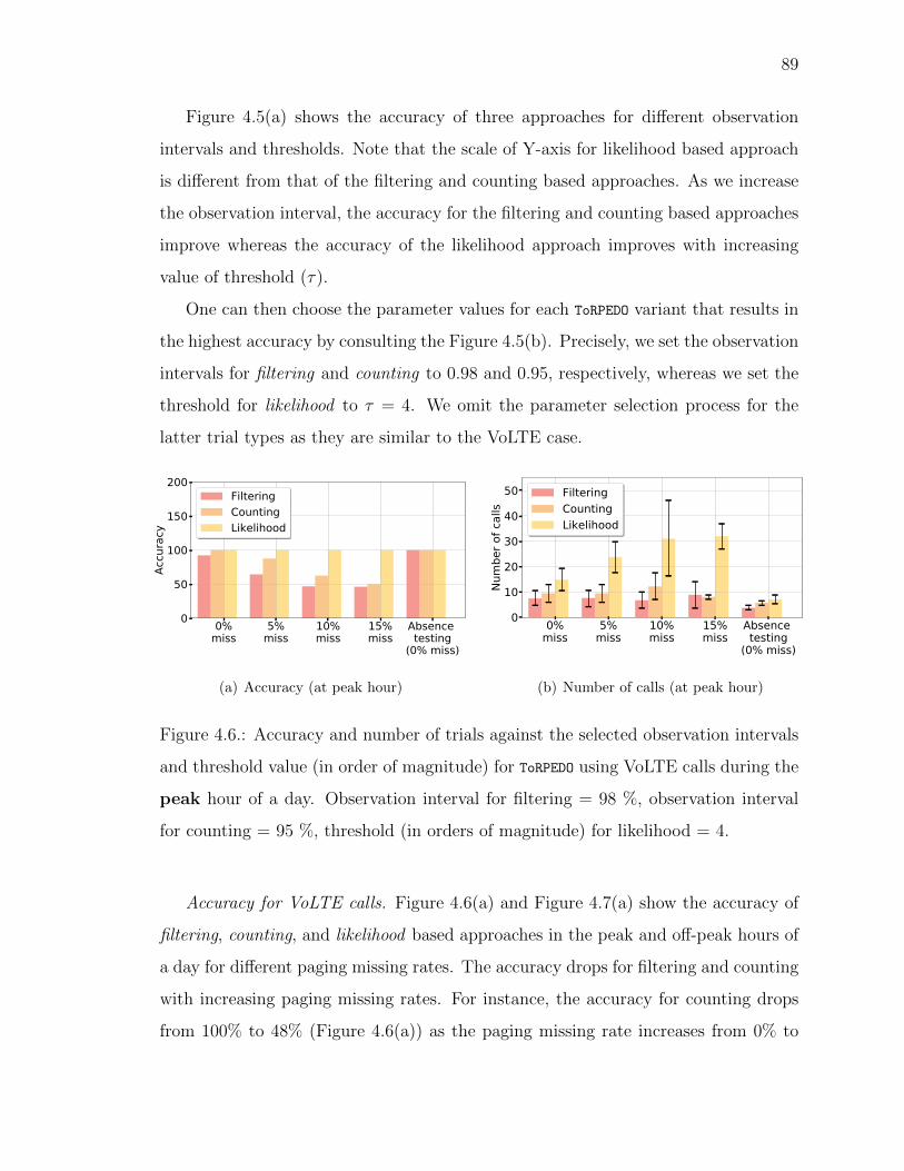
89
Figure 4.5(a) shows the accuracy of three approaches for different observation
intervals and thresholds. Note that the scale of Y-axis for likelihood based approach
is different from that of the filtering and counting based approaches. As we increase
the observation interval, the accuracy for the filtering and counting based approaches
improve whereas the accuracy of the likelihood approach improves with increasing
value of threshold (τ).
One can then choose the parameter values for each ToRPEDO variant that results in
the highest accuracy by consulting the Figure 4.5(b). Precisely, we set the observation
intervals for filtering and counting to 0.98 and 0.95, respectively, whereas we set the
threshold for likelihood to τ = 4. We omit the parameter selection process for the
latter trial types as they are similar to the VoLTE case.
0%miss
5%miss
10%miss
15%miss
Absence testing
(0% miss)
0
50
100
150
200
Accu
racy
FilteringCountingLikelihood
(a) Accuracy (at peak hour)
0%miss
5%miss
10%miss
15%miss
Absence testing
(0% miss)
0
10
20
30
40
50Nu
mbe
r of c
alls
FilteringCountingLikelihood
(b) Number of calls (at peak hour)
Figure 4.6.: Accuracy and number of trials against the selected observation intervals
and threshold value (in order of magnitude) for ToRPEDO using VoLTE calls during the
peak hour of a day. Observation interval for filtering = 98 %, observation interval
for counting = 95 %, threshold (in orders of magnitude) for likelihood = 4.
Accuracy for VoLTE calls. Figure 4.6(a) and Figure 4.7(a) show the accuracy of
filtering, counting, and likelihood based approaches in the peak and off-peak hours of
a day for different paging missing rates. The accuracy drops for filtering and counting
with increasing paging missing rates. For instance, the accuracy for counting drops
from 100% to 48% (Figure 4.6(a)) as the paging missing rate increases from 0% to

90
0%miss
5%miss
10%miss
15%miss
Absence testing
(0% miss)
0
50
100
150
200
Accu
racy
FilteringCountingLikelihood
(a) Accuracy (at off-peak hour)
0%miss
5%miss
10%miss
15%miss
Absence testing
(0% miss)
0
5
10
15
Num
ber o
f cal
ls
FilteringCountingLikelihood
(b) Number of trials (at off-peak hour)
Figure 4.7.: Accuracy and number of trials against the selected observation intervals
and threshold value (in order of magnitude) for ToRPEDO using VoLTE calls during the
off-peak time of a day. Observation interval for filtering = 98%, observation interval
for filtering = 98%, threshold (in orders of magnitude) for likelihood= 3.
0%miss
5%miss
10%miss
15%miss
0
50
100
150
Accu
racy
FilteringCountingLikelihood
(a) Accuracy (at off-peak hour)
0%miss
5%miss
10%miss
15%miss
0
5
10
15Nu
mbe
r of c
alls
FilteringCountingLikelihood
(b) Number of calls (at off-peak hour)
Figure 4.8.: Accuracy and number of trials against the selected observation intervals
and threshold value (in order of magnitude) for ToRPEDO using CSFB calls during the
off-peak time of a day. Observation interval for filtering = 98%, observation interval
for filtering = 98%, threshold (in orders of magnitude) for likelihood= 2.
15% whereas the accuracy for likelihood approach remains 100% for all paging missing
rates.
Number of VoLTE calls required. Figure 4.6(b) and Figure 4.7(b) show the number
of silent VoLTE phone calls that an adversary requires in the peak and off-peak hours
of a day for successful identification of victim’s PFI using filtering, counting, and
likelihood based approaches for different paging missing rates. The number of silent

91
0%miss
5%miss
10%miss
15%miss
0
50
100
150
Accu
racy
FilteringCountingLikelihood
(a) Accuracy (at off-peak hour)
0%miss
5%miss
10%miss
15%miss
0.0
2.5
5.0
7.5
10.0
12.5
Num
ber o
f cal
ls
FilteringCountingLikelihood
(b) Number of trials (at off-peak hour)
Figure 4.9.: Accuracy and number of trials against the selected observation intervals
and threshold value (in order of magnitude) for ToRPEDO using CSFB calls during the
off-peak time of a day. Observation interval for filtering = 98%, observation interval
for filtering = 98%, threshold (in orders of magnitude) for likelihood= 2.
phone calls for likelihood increases with increasing paging missing rates whereas the
number of silent calls for filtering and counting remains consistently low for all paging
missing rates. This is because both the filtering and counting approach removes the
victim’s PFI from the set of candidate PFIs (as discussed in Section 4.1) if the paging
is missed for a silent call or a couple of silent calls. In contrast, likelihood based
approaches take the error rate into account and thus require additional silent phone
calls to reach the threshold (e.g., τ = 4 for likelihood) in the case where paging
messages are missed. Note that, since the base paging rate during off-peak hours is
significantly lower than that of the peak hours, the adversary requires less number of
phone calls at off-peak hours as shown in Figure 4.7(b). For instance, the adversary
requires only ∼ 5 silent phone calls with likelihood approach (for no missing paging
rate) at off-peak hours which increases to ∼13 calls at peak hours.
CSFB Phone Call
For the network operators which choose to generate mobile terminated CSFB call
for the callee based on VoLTE capability of the callee device and the network, the
adversary takes into account both the PS and CS records in the paging messages

92
after a silent phone call for filtering, counting, and likelihood based approaches. In
contrast, for other types of network the adversary considers only the CS records for
inferring victim’s PFI.
Accuracy for CSFB calls. Figure 4.8(a) and Figure 4.9(a) show the accuracy of
filtering, counting, and likelihood based approaches during peak and off-peak time
for different paging missing rates. In general, the accuracy trend for CSFB calls is
similar to that for the VoLTE calls as shown in Figure 4.6(a) and Figure 4.7(a).
Number of CSFB calls required. Figure 4.8(b) and Figure 4.8(b)show the number
of silent VoLTE phone calls that an adversary requires at peak and off-peak time
for successfully identifying victim’s PFI using filtering, counting, and likelihood based
approaches for different paging missing rates. Since the base rate of CS domain
records significantly lower (as low as 0.0065 for any PFI within one paging cycle), the
number of silent CSFB phone calls using all three approaches is significantly lower
than that of the VoLTE phone calls as shown in Figure 4.6(b) and Figure 4.7(b).
The results signify that it is easier to identify the victim’s PFI and its presence if the
victim UE or the serving eNodeB are not VoLTE capable. One implication could be
that for locations where eNodeBs are not VoLTE capable, it may be easier to identify
a particular user’s presence with only a small number of phone calls.
SMS and Tweets
We successfully validated ToRPEDO using SMS and tweets (by mentioning victim’s
Twitter handle). The accuracy for SMS and Tweets follow the similar trend of phone
calls. The number of required trials, however, was much lower because of a smaller
paging delay (3-5 seconds as shown in Figure 4.1(a)). We omit the results for space
constraints.

93
4.5.4 Sensing Victim’s Absence with ToRPEDO
We also perform the ToRPEDO attack when the victim device and the adversary’s
sniffer are not in the same tracking area and evaluate the accuracy and the number of
silent calls required for identifying victim’s absence during the peak and off-peak hours
of a day. The accuracy of filtering, counting, and likelihood based approaches follow
a trend similar to identifying victim’s PFI (i.e., presence) as shown in Figure 4.6(a)
and Figure 4.7(a). Figure 4.6(b) and Figure 4.7(b) show that the adversary with
likelihood based approach requires slightly less number of calls (8 calls for threshold,
τ = 4) during peak hours for identifying victim’s absence whereas it requires ∼13
calls for identifying victim’s PFI (i.e., presence) as shown in Figure 4.6.
4.6 Validating PIERCER and IMSI-Cracking Attacks
In this section, we describe our validation process of PIERCER and IMSI-Cracking
attacks for 4G.
4.6.1 PIERCER Evaluation
The goal of our PIERCER validation is to determine how many calls the adversary
needs to reliably retrieve the victim UE’s IMSI given its phone number and PFI
(assumed to be obtained with ToRPEDO attack). We describe the validation process for
US-I only, although similar behavior was observed for three other network operators
of a South Asian country.
Paging channel hijacking. After identifying the victim’s PFI, we carried out
the paging channel hijacking attack by faithfully following the steps described in
Chapter 3.3.
The attack. Once the victim’s paging channel was hijacked, we made a single
phone call to the victim’s phone number which caused the legitimate eNodeB/MME
to first send a paging tmsi in the PS domain for the victim UE. Once a paging tmsi

94
is issued, we observed that the US-I network sets a timer for the response and the
maximum paging attempt to 2. Since the victim is unaware of the actual paging tmsi
message, the timer at MME expires because of UE’s unresponsiveness. We then
observed that the MME initiates another paging tmsi in the PS domain and continues
to do so until it reaches the maximum paging attempt. Upon expiration of retries,
the MME of US-I first sends paging tmsi in the CS domain and then, when its timer
expires, it broadcasts the paging imsi in the CS domain. If the adversary now makes a
second phone call, the MME initiates another paging tmsi in the CS domain without
trying with the PS domain first, and then, upon expiration of the timer, the MME
broadcasts paging imsi again validating our attack.
Total call trials. Excluding the phone calls needed for the prerequisite ToRPEDO
attack, we validated that indeed a single phone call was sufficient to expose the
victim’s IMSI.
4.6.2 IMSI-Cracking Evaluation
The goal of our IMSI-Cracking attack’s evaluation is to determine the time and
the number of paging messages that an adversary needs to make to identify the
victim’s IMSI given that the adversary knows the victim’s phone number (in our
case, MCC=310 and MNC=260 retrieved from [66]), PFI (in our case, 21), and TMSI
(using techniques from [12,17]).
The adversary faithfully follows the paging channel hijacking attack as demon-
strated in Chapter 3.3, and computes the Imaxguess and Imin
guess, i.e, the maximum and
minimum possible IMSI values (in binary) that have the value 310260 in 18-bits
MSB and the value 21 in 8-bits LSB. We found Imaxguess = 310260999999381 and
Iminguess = 310260000000021 for the given PFI, MCC, and MNC. We started with Imax
guess
in descending order and fabricated paging messages with 14 Iguesss each. Note that,
though the standard specifies that up to 16 paging records can be accommodated
into a single paging message, we observed that our test UE device accepts paging

95
messages containing at most 15 paging records which indicates a deviation from the
standard and an interoperability issue.
Number of paging messages. To identify the victim’s IMSI (=310260628687893),
the attacker needed to try a total of 2900876 IMSIs and thus sent 207206+14 =
207220 paging messages through the malicious eNodeB.
Time requirement. We set the values of paging cycle T and nB to 128 for hijacking
paging channel and therefore, sent one paging message every 1.28 seconds. The total
time required to crack the victim’s IMSI was 74 hours. We performed this experiment
for 7 days in the off-peak hours. Note that the attack can be expedited by at most
32 times by setting the value of nB = T32
.
4.7 Discussion
Threat to validity. The empirical evaluations reported in this chapter were carried
out in multiple locations during both peak and off-peak hours. As cellular network
behavior is highly dependent on the cell area, load, and equipment, some of the
numbers (or, findings) reported here may not exactly match up when reproduced in
other locations with different equipment.
Limitations. For ToRPEDO to be successful, an attacker needs to have a sniffer in
the same cellular area as the victim. If the number of possible locations that the
victim can be in is large, the expense of installing sniffers (i.e., $200 each) could be
an impediment to carrying out a success attack. In a similar vein, for a successful
PIERCER, the attacker needs to have a paging message sniffer and also a fake base station
which would cost around $400. The IMSI-Cracking attack for 4G will be feasible only
in cases where the attacker can carry out his attack without the victim noticing that
his device is not receiving any notifications, for instance, when the victim is sleeping
at night. ToRPEDO and IMSI-Cracking attacks on 5G were not validated due to the lack
of deployed networks.
Responsible disclosure. We are in the process of reaching out to the affected
network operators that are verifiably vulnerable to PIERCER. We are also reaching out to

96
3GPP standard’s committee for responsibly disclosing the ToRPEDO and IMSI-Cracking
attacks.
4.8 Summary
This chapter sheds light on an inherent design weakness of the 4G/5G cellular
paging protocol which can be exploited by an attacker to not only obtain the victim’s
paging occasion but also to identify the victim’s presence in a particular cell area
just from the victim’s soft-identity (e.g., phone number, Twitter handle) with a novel
attack called ToRPEDO. We also demonstrate that ToRPEDO can enable an attacker to
exploit a deployment oversight of several network operators to retrieve a victim’s
IMSI from his phone number using the PIERCER attack. To further provide evidence
of ToRPEDO’s potency, we show that it empowers an attacker to launch a brute-force
IMSI-Cracking attack through the use of two novels oracles we designed for 4G and
5G, respectively. Each of these attacks can also be leveraged to enhance prior attacks.
All of our attacks have been validated in realistic setting for 4G using cheap software-
defined radio and open-source protocol stack.
We leverage the findings in Chapter 3 and Chapter 4 and investigate plausible
countermeasures in the next chapter addressing broadcast authentication for ripping
out the root cause of many active attacks identified in the previous chapters.

97
5. INSECURE CONNECTION BOOTSTRAPPING IN
CELLULAR NETWORKS: THE ROOT OF ALL EVIL
5.1 Introduction
A cellular device’s connection to the operator’s network starts off by the device
scanning for appropriate signals broadcast by nearby base stations. Among the avail-
able base stations, the device selects to initiate the connection to the one that emits
signals with the highest strength. Once the device connects to the base station, the
base station then plays the role of a trusted intermediary enabling the device to seam-
lessly communicate with the core network. Unfortunately, no mechanism currently
exists with which a device can verify the legitimacy of the base station. This lack
of authentication allows adversaries to install rogue base stations which lure unsus-
pecting devices to connect to them [17,73]. Forcing devices to establish a connection
with a rogue (or, fake) base station is often the necessary first step for the adversary
to carry out other destructive attacks [9, 11, 13, 14, 16, 17, 65, 70]. Although this fun-
damental connection bootstrapping weakness is widely acknowledged, there does not
seem to be a conscious effort in mitigating this even in the new 5G standard [29]. This
work aims to fill this gap by proposing an authentication mechanism for enhancing
the security of connection bootstrapping.
Existing work: Unlike the majority of the existing research [14, 15, 19, 53, 65, 70,
74, 75], which focuses on identifying security weaknesses of cellular networks, there
are only a few proposals that focus on misbehaving base stations [18, 76–78]. The
most relevant to our work is the proposal by Li et al. [76], named FBS-Radar, which
collects spam messages (and, its accompanying meta-data) received by end-users to
identify the location of base stations. On the other hand, Zhuang et al. [77] developed
FBSleuth which uses Radio Frequency Fingerprinting to establish forensic evidence of

98
a base station’s misbehavior. These prior efforts, however, cannot alleviate the root
cause that allows adversaries to lure devices into connecting to fake base stations to
begin with: insecure bootstrapping.
Challenges: To ensure the effectiveness and feasibility of any retrospective authen-
tication mechanism that addresses the insecure bootstrapping problem, it is crucial
that such mechanism maintains backward compatibility without requiring a major
overhaul of the cellular protocol or infrastructure. More concretely, any effective
mechanism has to decide for which bootstrapping signals of the base station it will
provide authentication guarantees while taking into consideration the quality of ser-
vice guarantees, overhead of the base stations and cellular devices, bandwidth over-
head, scheduling restrictions, and maximum transmission unit (MTU).
Approach: Conceptually, one can consider the following two possible approaches
for providing bootstrapping authentication: one based on the TESLA [79] protocol
and the another based on Public Key Infrastructure (PKI). TESLA is a broadcast
authentication protocol in which multiple time-synchronized receivers (i.e., cellular
devices) must authenticate messages periodically broadcast by a sender (i.e., base sta-
tion). TESLA uses symmetric cryptographic functions (MAC) to achieve asymmetric
properties using delayed key disclosure and one-way key chains. TESLA, however,
relies on a pre-existing authenticated channel for its own bootstrapping which is not
available in our context, making it ineffective.
In the PKI-based approach, each base station will be equipped with a public and
private key pair. Any broadcast signal emitted by a specific base station will be
digitally signed by its private key. Any cellular device that has access to the base
station’s public key can then verify that the bootstrapping signal is indeed emitted by
the claimed base station. To realize such an approach, the cellular device is required
to verify the authenticity of a base station’s public key. This is achieved by the base
station sending a public-key certificate chain (e.g., X.509 [80]) to prove its public-key’s
authenticity. In our context, we consider a 3-length public-key certificate chain where
only two of them are transmitted during bootstrapping. The first certificate of the

99
chain (i.e., trust anchor) is self-signed by the network operator’s private key and is
stored in the device’s subscriber identity module (SIM) card. The second certificate
in the chain—signed by the network operator’s private key—belongs to the mobility
management entity or MME [4] (resp., Access and Mobility Management Function
or AMF in 5G [29]) which is responsible for a set of base stations in a designated
tracking area. The final certificate in the chain belongs to the base station and is
digitally signed by the MME’s private key.
At face value, implementing the PKI-based authentication mechanism seems like
a straightforward proposition. In reality, however, realizing an implementation of the
authentication mechanism requires addressing several deployment constraints. Due
to the restriction on the broadcast packet size, we observed that even a single vanilla
X.509 certificate does not fit into a packet. Similarly, another relevant issue one
needs to consider for a successful deployment is the revocation of a base station’s
public key prior to its expiration date, especially, in exceptional cases (e.g., private
key leak). This is a relevant threat as the adversary can gain physical access to the
base stations which are often left unguarded. Typical revocation mechanisms (e.g.,
certificate revocation list and online certificate status protocol) are ineffective in our
context as they require connectivity which the device is attempting to gain in the
first place. The final challenge one would have to address is to protect against relay
or replay attacks which have been shown to be extremely effective in case of cellular
networks [65,70]. We address these challenges in the following manner.
Certificate size: To overcome the packet size constraint, we construct a very
lightweight certificate containing only the fields necessary in our context (e.g., identity,
public-key, expiration date, the digital signature, location of the base station).
Revocation: We avoid an explicit revocation mechanism by proposing base station
certificates to have a small expiration (e.g., <10 minutes). This can severely limit the
attack window with which an adversary can exploit the leakage of a base station’s
private key.

100
Relay-/replay-attack protection: For preventing relay-/replay-attacks, we intro-
duce a location-dependent, configurable parameter that influences the validity period
of a given broadcast message and in turn can control the exploitation window.
The final issue we need to address for the realization of an effective and secure
authentication mechanism is the choice of digital signature scheme. Our choice of
a digital signature impacts three different aspects: (a) Signature size; (b) Signature
generation time; (c) Signature verification time. This is also known as the trilemma
of digital signatures and a scheme can only optimize (i.e., minimize) two of these as-
pects. In our instantiation, we choose to optimize aspects (a) and (b) while sacrificing
(c). The rationale of optimizing aspect (a) is clear as this will minimize the overhead
of the packet size. We optimize aspect (b) instead of aspect (c) because a device typ-
ically will verify signatures for one session whereas the base station keeps generating
signatures for the bootstrapping signals based on its schedule (e.g., ∼80 milliseconds).
Optimizing aspect (b) will decrease the computation and energy overhead for the base
station significantly.
Implementation: We implemented our PKI-based broadcast authentication for 4G
LTE (since no open-source 5G implementation is available) in a real test-bed using
software-defined radios and open-source 4G LTE protocol stack [54, 56]. For digi-
tal signature schemes, we consider ECDSA [81], BGLS [82], and SCRA-BGLS [83]
(BGLS signature generation optimized with offline pre-computation). In our evalua-
tion, we observed that our mechanism imposes only moderate overhead with respect
to additionally transmitted bytes (e.g., ∼220 bytes) and connection time (e.g., ∼28
milliseconds).
Impact: In the recent 5G proposal, a PKI is already introduced for protecting against
IMSI catching attacks [17, 73, 84] by requiring devices to encrypt their IMSIs/IMEIs
with the network operator’s public key during communication. The current work goes
a step further by extending the existing 5G PKI to allow devices to authenticate base
stations and in the process preventing a substantial amount of existing attacks—also
applicable to 5G—which stem from the insecure bootstrapping process. As 5G is still

101
awaiting deployment, incorporating a defense such as ours is feasible and can go a
long way in securing the cellular ecosystem.
Contributions. In summary, the work makes the following contributions.
• We propose an optimized PKI-based authentication mechanism that enables a
cellular device to authenticate a base station during connection bootstrapping.
Our defense can protect against many high-profile attacks against the cellu-
lar network including the notorious IMSI-catching attack and DNS redirection
through man-in-the-middle relays.
• We implemented our scheme on a real test-bed using software-defined radios
and open-source protocol stack.
• Our evaluation on the real test-bed shows that our approach only has a moderate
overhead with respect to the number of transmitted bytes, signature generation
time for the base station, and the connection establishment overhead for the
device. From a purely technical point-of-view, it is feasible to incorporate our
scheme in a real network.
5.2 Problem Description
In this section, we first present our adversary model, then identify the constraints
imposed by both the stakeholders and the cellular ecosystems that need to be re-
spected by a defense, and finally formulate the problem we address in this work.
5.2.1 Threat Model
In our threat model, the adversary has the following capabilities:
Eavesdropping or tampering with protocol messages. We consider the adver-
sary to have the capability of establishing a man-in-the-middle relay [65,70] which in
turn may allow him to drop, modify, eavesdrop, and forward messages transmitted
between benign protocol participants (e.g., legitimate devices and base stations) in
the public channel while respecting cryptographic assumptions.
102
Impersonating a legitimate base station. We also consider an active adversary
who can install and run its own base station with the same capabilities as a legitimate
one. In addition, the fake base station can impersonate a legitimate base station and
thus can force a victim device to connect to it by broadcasting MIB and SIB messages
in the victim UE’s frequency with a higher signal strength than the legitimate base
station. We make the assumption that the adversary can learn legitimate values
for MIB and SIB messages by eavesdropping the public channels where these are
broadcast.
Other assumptions. We assume that the adversary cannot physically tamper with
the SIM card, base station, or the core network to obtain the sensitive information,
e.g., cryptographic keys. Side-channel attacks and denial-of-service (DoS) attacks due
to wireless signal jamming are considered out of the scope of this work.
5.2.2 Deployment Constraints
For a defense to be deemed deployable and feasible, there are certain constraints
which it must respect. These constraints are imposed by both the cellular protocol/e-
cosystem and its stakeholders (e.g., network operators), and are discussed below.
Cellular protocol/ecosystem. For a solution to be viable in the perspective of
the ecosystem itself, the following constraints must be met: (CE1) Additional bytes
added for supporting authentication must not exceed the MTU; (CE2) Backward
compatibility should not be compromised, that is, legacy devices should be able
to connect to the base station without authentication; (CE3) The computational
overhead must not introduce delays in the message broadcast schedule; (CE4) The
authentication mechanism must not rely on a pre-existing authenticated channel.
Cellular stakeholder. Unlike the cellular network ecosystem constraints, the fol-
lowing constraints imposed by cellular stakeholders are directly/indirectly related
to revenues and are expected to be fulfilled by any potential defense: (CS1) The
additional bytes added in the control-plane messages due to authentication must
be minimized; (CS2) The authentication verification (resp., authentication material
103
generation) overhead must not cause downtime or delays; (CS3) The defense must
not require major overhauls in the protocol/infrastructure.
5.2.3 Scope and Problem Statement
Lack of authentication of the MIB and SIB messages enables the adversary to
spoof a legitimate base station. The adversary exploiting this deeply rooted vulner-
ability can lure an unsuspecting cellular device to connect to it and then carry out
specific attacks using unauthenticated messages exclusively sent to the victim device.
We identify the following two types of defense mechanisms that could prevent such
attacks. (i) Attack-specific defenses attempt to thwart a particular discovered vulner-
ability. For instance, ignoring unauthenticated and out-of-order auth reject messages
can protect devices from denial-of-service attacks as demonstrated in Chapter 3. (ii)
Generic defenses, on the contrary, prevents the root cause of a vulnerability which
may be exploited by multiple attacks. In our context, such a defense would be to
prevent adversaries from forcing the UE to connect to the fake base station in the
first place by making possible for the UE to authenticate base stations. Naturally,
the former types of defenses protect devices only from a very specific set of discov-
ered attacks due to adversary’s use of fake base stations. There are, however, many
other attacks that exploit the capability of setting up a fake base station [65]; such
an attack-specific defense cannot thwart these and hence such a case-by-case defense
cannot be a practical solution. It is thus clear that, because to its wider applicabil-
ity, a generic defense mechanism is critical for the security of the cellular networks.
Designing such a mechanism is the focus of the current work.
Protocol versions. Our discussion, although mainly focusing on the 4G LTE and
5G versions of the cellular protocol, is generalizable to older protocol versions (e.g.,
3G/2G).
Which messages to authenticate? A cellular device may authenticate either (i)
the broadcast MIB and SIB messages, or (ii) the exclusive connection setup mes-
sage (i.e., the rrc connection setup message in step 5 of Figure 2.3) to connect to a

104
legitimate base station. When the device is in the idle mode (i.e., no radio activ-
ity), however, it only captures the MIB and SIB messages and camps on a cell for
receiving paging messages without setting up any explicit connection with the base
station. Since paging messages along with MIB and SIB messages do not have any
integrity/authenticity protection, the adversary can inject fake emergency alerts us-
ing fabricated SIB and paging messages [65]. Such attacks in device’s idle mode are
hard to prevent without ensuring the authenticity of MIB and SIB messages. Au-
thenticating the rrc connection setup message, on the other hand, implicitly requires
authenticating the SIB messages (through MAC) received before. Since at bootstrap-
ping time the UE and the base station do not share a session key, it is not clear which
key to use for generating the MAC. In light of the above discussion, it is therefore
clear that broadcast (i.e., MIB, SIBs) messages are the natural choice for authenti-
cating a base station and the root of trust for establishing a secure connection to the
base station and consequently with the core network.
Problem Statement. Formally, in this work, we aim to design and evaluate a
secure connection bootstrapping mechanism for cellular devices by providing authen-
tication guarantee and integrity protection to MIB and SIB broadcast-messages while
conforming to the aforementioned constraints (i.e., CE1-CE4 and CS1-CS3).
5.3 Potential Solutions for Broadcast Authentication
In this section, we discuss two candidate mechanisms that can possibly provide
the authenticity and integrity protection for bootstrapping signals/messages trans-
mitted by the base stations. One of these mechanisms is based on symmetric key
cryptography whereas the other is based on public key cryptography. Conceptually,
both mechanisms are capable of providing cellular devices the necessary method for
authenticating base stations. We discuss their relative merits and demerits in the
context of deployment.

105
5.3.1 Infeasible Symmetric Key-based Broadcast Authentication Mecha-
nisms
One infeasible but straightforward symmetric key based approach for providing
broadcast authentication is to use Message Authentication Codes (MAC) [85]. At
its core, a MAC-based authentication mechanism can provide the integrity protec-
tion for the broadcast messages without incurring substantial computational or space
overhead. Having an effective MAC-based authentication mechanism, however, boils
down to effective key management. Sharing a single symmetric key between all devices
and base stations is not viable as the adversary can extract the key and subsequently
bypass the security. Having a pre-shared key between each pair of device and base
station, on the other hand, is infeasible with respect to key management and storage
requirements.
Another promising symmetric key based (i.e., MAC-based) authentication mech-
anism is the TESLA protocol [79]. It has particularly been shown to be effective for
sensor networks. It addresses the broadcast authentication problem, for a setting in
which there is a single sender but multiple receivers, through the use of delayed key
disclosure and one-way key chains. Due to its promised security guarantees, we qual-
itatively analyze its feasibility with respect to the deployment constraints of cellular
networks.
TESLA Protocol Description.
In TESLA, the sender and the receivers are considered to be loosely time-synchronized.
The sender uses the elements of a hash chain (in the reverse order) and a pseudo-
random function to create a one-time symmetric key to generate a MAC for the
broadcast signals. Each key for verification is released at a stipulated later point
of time until which the message in need of authentication is required to be buffered
on the receiver side. Note that, for receivers and the sender to go through a loose
time synchronization procedure, an authenticated channel is assumed to exist apriori

106
through which the sender sends the key disclosure schedule that allows the receivers
to estimate when a certain key will be disclosed.
TESLA for Cellular Networks.
For applying TESLA in our context, we have to first accomplish the required time
synchronization between the sender and receivers. Fortunately, time synchronization
is inherently provided by cellular networks through the use of MIB messages. The
next challenge of applying TESLA is to satisfy its assumption of a pre-existing au-
thenticated channel to share the disclosure delay and initial key commitment with the
receivers. This suggests that the base station should include this information inside a
MIB message while ensuring its authenticity and integrity. Without such guarantees,
a fake base station can simply broadcast its own TESLA protocol parameters, which
a cellular device will not be able to distinguish from a legitimate one. One possible
approach of addressing this challenge is to use some form of digital signatures. This
would require the base station to have a public-key whose authenticity can be verified
by the device with the use of a PKI and a trust anchor stored in the device. The
use of digital signatures and PKI, however, undermines the actual purpose of using
a symmetric key based approach. Moreover, for TESLA to work, the base station
always needs to send an additional message (e.g., SIB3) that discloses the key used for
generating MAC of the previous messages (e.g., SIB2). In addition, due to its delayed
key disclosure, cellular devices have to wait for other key disclosing SIB messages be-
fore establishing the connection inducing a substantial delay in the initial connection
setup with the core network. In summary, due to its latency overhead and reliance
on a PKI, we conclude that TESLA is an infeasible mechanism for our domain.
5.3.2 Asymmetric Key-based Broadcast Authentication (PKI)
In this section, we briefly present a high-level overview of a PKI-based secure
bootstrapping mechanism that we envision and then outline the challenges one has

107
to address for achieving an optimal PKI-based broadcast authentication scheme for
cellular networks.
Global CA Certificate
Self-signed
CN's Certificate
SN's Certificate
BS' Certificate
CA-signed
SN-signed
CN-signed
Figure 5.1.: Initial PKI Scheme.
High-level Overview of PKI-based Solution
In our initial attempt at developing a PKI-based solution, we consider the follow-
ing stakeholders: the core network/network operator (denoted with CN); the serving
network or MME (denoted with SN); the base station (denoted with BS). We consider
each of these entities to possess a public-key, secret-key pair of the form 〈P, S〉. Each
of these entities also has a public-key certificate (e.g., X.509 certificate) which maps
its identity to the public-key (See Figure 5.1). The BS’ certificate is digitally signed
by the secret key of the serving network (i.e., SSN). Similarly, the serving network’s
certificate is digitally signed by the CN’s private key (i.e., SCN). We also consider a
global certificate authority (CA) which also has a self-signed certificate which will be
stored in the device’s memory and will be used as the trust anchor, that is, the CA’s
secret key will be used to digitally sign the CN’s certificate. Once such a PKI is estab-
lished, it is possible to provide a mechanism through which a device can authenticate
a base station.
In such a mechanism (see Figure 5.2), for authenticating a specific bootstrapping
message m, the base station (i.e., BSj) using its secret key SBSj will generate the

108
signature sigm of m and will append the signature (e.g., sigSIB for a SIB message)
and the certificate-chain 〈sigm, certBSj , certSNi, certCN〉 to m. Once the device receives
m, its digital signature, and the certificate chain, it will first verify the certificate
chain and then will verify m’s digital signature. Legacy devices in which signature
verification mechanisms are not present or will be too demanding, on the other hand,
can safely ignore both the signature and certificate chain.
MME/AMF (Serving Network)
UE Base Station
9
Core Network
Generate secret key (SCN) and selfsigned certificate (certCN)
1Preload UE with certCN
2
Generate publicsecret keypair (PSN, SSN)
3
sigCN 4
Generate publicsecret keypair (PBS, SBS)
5
sigSN 6
SIB1, sigsib1, certBS, certSN
11SIB2, sigsib2, certBS, certSN
7MIB, sigMIB, certBS, certSN
Verify MIB
Verify SIB1 10
8
Verify SIB2 12RRC Layer Connection Setup
NAS Layer Connection Setup
Figure 5.2.: Proposed PKI Scheme.
Deployment challenges. Realizing the above straightforward mechanism in
practice, however, requires us to address the following challenges. (i) There is an
upper-limit on the size of MIB and SIB messages which imposes an upper-limit on
the size of the certificate chain. Since the size of a X.509-based certificate [80] is
prohibitively large, it is nearly impossible to fit the X.509 certificate-chain in a single
MIB/SIB message. We have empirically validated this claim. (ii) It is not clear how
would one facilitate certificate revocation in our setting. (iii) The broadcast signals
along with the digital signature can be relayed/replayed by a Man-in-the-Middle
(MitM) relay attacker possibly luring devices to connect to a fake base station. (iv)
109
The base station frequently broadcasts the MIB and SIB messages (e.g., SIB is sent
every 80 ms) and hence to maintain this transmission schedule the packet construction
overhead including the signature generation time should be minimized.
5.4 Optimized PKI Scheme
In this section, we discuss how we address the above challenges by optimizing the
proposed scheme from three dimensions: (1) PKI-level, (2) protocol-level, and (3)
cryptographic scheme-level.
5.4.1 PKI-level Optimizations
Realigning trust anchor. As the device inherently has to trust the core network,
one can provision the SIM card to use the core network’s certificate as the trust anchor
instead of the glocal CA’s certificate. This has the added benefit of decreasing the
certificate chain length which in turn reduces the message size and computation time
for verifying the chain. In case of roaming, the SIM card can be equipped with (or,
delivered over-the-air) the certificates belonging to the roaming network operators.
This is particularly feasible due to the recent introduction of eSIM cards [86].
A Lightweight Design of Certificate. A general X.509 certificate is equipped with
many different fields and extensions which are not particularly relevant to our context
and hence can easily be omitted. We, therefore, propose a specialized certificate
format only containing the following necessary fields:
certCN = PCN,MCC,MNC, extcertCN
certSNi= PSNi
, SN ID, extcertSNi, sigCN
certBSj = PBSj ,CELL ID, locBSj , extcertBSj , sigSNi
where, MCC and MNC form the unique network ID, SN ID and CELL ID respectively
represent the unique identities of SNi and BSj, locBSj denotes the physical location
(i.e., latitude and longitude) of BSj, and extcertCNand extcertSNi indicate the certificate

110
expiration time for CN and SNi, respectively. The core network’s signature for SNi
(i.e., sigCN), and the SNi’s signature for BSj (i.e., sigSNi) are computed as follows:
sigCN = sign(〈PSNi, SN ID, extcertSNi 〉, SCN)
sigSNi= sign(〈PBSj ,CELL ID, locBSj , extcertBSj 〉, SSNi
)
where sign(m,K) function generates the digital signature of a given message m with
respect to a secret key K.
Certificate revocation. Instead of an explicit revocation mechanism (e.g., CRL,
OCSP), we rely on short-lived certificates (e.g., <10 minutes) for the base stations.
The exact validity period of base station certificates is left as an implementation
parameter and its value directly influences the exploitation window size when base
stations are compromised.
5.4.2 Protocol-level Optimizations
Since including authentication material increases both the packet size and com-
putational time on the base station and device sides, we minimize the overhead by:
(a) Providing authentication guarantees for only critical messages; (b) Aggregating
authentication of multiple messages; (c) Limiting the certificate chain transmission.
Authenticating Critical Broadcast Signals
Ideally, all broadcast messages should be authenticated, however, such an ap-
proach can be impractical due to its substantial communication and computational
overhead requirement. We thus only provide authentication guarantees for a limited
number of bootstrapping messages.
Messages requiring authentication. During bootstrapping, frame synchroniza-
tion signals and MIB provide instructions on how to decode subsequent SIB messages
and thus enable devices to achieve current system frame time synchronization with
the base station. The SIB messages, on the other hand, provide information neces-

111
sary for connection establishment. Therefore, if only SIB messages are authenticated
instead of frame synchronization and MIB messages, an adversary may only achieve
a DoS attack by jamming the network through desynchronizing the frames, which,
as mentioned earlier, is out of the scope of this work. Thus, we do not provide
authentication for frame synchronization and MIB messages.
Which SIBs to authenticate?. According to the 3GPP standard, there are 13
System Information Block (SIB) messages (i.e., SIB1-13) characterized by the type of
information they carry. SIB1 provides the essential information regarding the radio
access network (RAN) and includes a broadcast schedule for subsequent SIB mes-
sages. Authenticating SIB1 thus guarantees that devices will obtain legitimate access
information along with a legitimate broadcast schedule. Otherwise, the adversary
could inject fake scheduling information as well as fake SIBs which would enable him
to broadcast fake emergency alerts using SIB1 and SIB10-11 messages. Therefore,
SIB1 requires authentication and integrity protection.
SIB2 immediately follows SIB1 and provides the necessary information for ini-
tiating the attach procedure (i.e., initial connection with the base station and the
core network). Since SIB2 contains critical information for connecting to the base
station, we provide authentication for this message. Protection for the other SIBs is
not mandatory as they are not critical to connection bootstrapping.
Original SIB1 (3GPP) P"#$ CELL_ID loc"#$ sig#+,ext012345$ P#+, SN_ID sig6+ext012357,SIB1Base Station’s Certificate (cert"#$) Serving Network’s Certificate (cert#+,)
Original SIB2 (3GPP) T1 9:SIB2 sig#;"<
Figure 5.3.: Content of SIB1 and SIB2 after protocol-level optimization for secure
broadcast authentication
Minimizing certificate chain transmission
Since SIB1 and SIB2 are sent in the same radio frame, the probability of one of
the certificates in the chain getting revoked between SIB1 and SIB2 is negligible. The

112
base station thus transmits the certificate chain with SIB1 message only, and expects
the device to use the same base station public key for authenticating SIB2 signature.
In the extreme case, revocation happens between SIB1 and SIB2, the base station
can include the new certificate chain in SIB2 and its presence can be indicated by a
single bit.
Aggregating authentication
Since a base station broadcasts SIB1 and SIB2 in the same radio frame (1 radio
frame = 10 ms) but in a different subframe (1 subframe = 1 ms), and the cellular
device does not initiate the connection with the base station before receiving SIB2, we
propose to authenticate SIB1 and SIB2 messages together instead of authenticating
them individually. Thus, the base station includes the certificate-chain in the SIB1
message whereas the digital signature authenticating SIB1 and SIB2 (i.e., sigSIB2)
is included in the SIB2 message. Precisely, sigSIB2 = sign(〈SIB1 || SIB2〉, SBSj) (See
Figure 5.3).
The device, therefore, should buffer the SIB1 message and verify both messages
only after the reception of the SIB2 message. The device is also required to verify
the certificate-chain included in the SIB1 message using certCN provisioned in the
SIM card. This aggregated authentication of SIB1 and SIB2 reduces the time, com-
putational resources, and communication overhead otherwise incurred by individual
authentications of SIB1 and SIB2 messages.
5.4.3 Cryptographic scheme-level Optimization
The choice of digital signature schemes can not only influence the security provided
by a mechanism but also the overhead incurred due to the size of the signature, time to
generate and verify a signature. As mentioned before, we aim to maintain respectable
security (i.e., 112-bit) while optimizing for signature sizes and signature generation
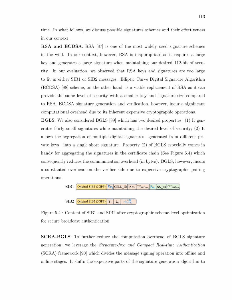
113
time. In what follows, we discuss possible signatures schemes and their effectiveness
in our context.
RSA and ECDSA. RSA [87] is one of the most widely used signature schemes
in the wild. In our context, however, RSA is inappropriate as it requires a large
key and generates a large signature when maintaining our desired 112-bit of secu-
rity. In our evaluation, we observed that RSA keys and signatures are too large
to fit in either SIB1 or SIB2 messages. Elliptic Curve Digital Signature Algorithm
(ECDSA) [88] scheme, on the other hand, is a viable replacement of RSA as it can
provide the same level of security with a smaller key and signature size compared
to RSA. ECDSA signature generation and verification, however, incur a significant
computational overhead due to its inherent expensive cryptographic operations.
BGLS. We also considered BGLS [89] which has two desired properties: (1) It gen-
erates fairly small signatures while maintaining the desired level of security; (2) It
allows the aggregation of multiple digital signatures—generated from different pri-
vate keys—into a single short signature. Property (2) of BGLS especially comes in
handy for aggregating the signatures in the certificate chain (See Figure 5.4) which
consequently reduces the communication overhead (in bytes). BGLS, however, incurs
a substantial overhead on the verifier side due to expensive cryptographic pairing
operations.
Original SIB1 (3GPP) P"#$ CELL_ID loc"#$ ext+,-./0$ P#12 SN_ID ext+,-.032SIB1
Original SIB2 (3GPP) T1 45SIB2 sig#9":;<<
Figure 5.4.: Content of SIB1 and SIB2 after cryptographic scheme-level optimization
for secure broadcast authentication
SCRA-BGLS: To further reduce the computation overhead of BGLS signature
generation, we leverage the Structure-free and Compact Real-time Authentication
(SCRA) framework [90] which divides the message signing operation into offline and
online stages. It shifts the expensive parts of the signature generation algorithm to

114
the offline key-generation phase. The online signature generation phase leverages the
pre-computed values from the offline phase and lightweight cryptographic operations.
In what follows, we briefly discuss how the SCRA algorithm works for generating
SIB2’s signature (i.e., sigaggSIB2).
1) Key Generation (Offline): The offline stage is executed just once when the
base station starts. A d-bit hash of SIB1 || SIB2 can be thought of as L equal chunks
of b bits each such that b · L = d. A signature is computed for each b-bit integer
concatenated with its corresponding index i and a predefined padding using the base
station’s secret-key SBSj . A pre-computed sub-message/signature table Γ is generated
and stored at the sender’s side.
2) Signature Generation: For the SIB2 message, the sender computes the cryp-
tographic hash of SIB1 || SIB2 and divides it into L chunks. It then fetches the
corresponding signatures from the table Γ. Finally, it combines the signatures from
the pre-computed table efficiently according to the base scheme.
3) Signature Verification: Upon reception of SIB1 and SIB2, the cellular device
computes the hash of SIB1 || SIB2 and runs the verification algorithm on the signature
and the hash using the public keys PBSj , PSNi, and PCN among which PBSj and PSNi
are included in SIB1 message and PCN is provisioned in the SIM card.
5.4.4 Countermeasure for Relay Attacks
Since not all control-plane cellular protocol messages are cryptographically pro-
tected, a fake base station fBS relaying/replaying bootstrapping messages from a
legitimate base station can lure devices to connect to fBS and then can launch dif-
ferent attacks [65, 70]. Digital signatures alone cannot protect against such threats.
For thwarting relay attack, one would ideally need to deploy a distance-bounding
protocol which, however, has been shown to be difficult to realize in practice [64]. To
address such issue, we coarsely approximate a distance-bounding protocol by allowing
each bootstrapping message to be valid for only a short period of time severely limiting
the attack opportunity.

115
In our approximation, we consider each SIB2 message to contain the following
three additional fields: Tgen specifying the time which the SIB2 message was con-
structed; a location-dependent parameter ∆t; locBSj denoting the latitude and longi-
tude of the base station. If a device receives an SIB2 message at time Ti, it would
consider it valid if and only if Ti − Tgen < ∆t. A fake base station can only success-
fully relay a legitimate SIB2 if it can ensure that the relayed SIB2 message reaches
the device within ∆t time of Tgen. Under an appropriate ∆t value, due to triangle
inequality, one can avoid the threat of a relay attack (See Figure 5.5(b)).
Computing an exact value for ∆t is non-trivial as it requires taking location-
dependent signal interference into consideration which is very hard to approximate
due to environment dynamics. We, however, show how to approximate lower and
upper bounds of ∆t which we envision a base station would calculate periodically.
Our bound calculation requires the following constants.
• CBS : The time difference between when an SIB2 is generated (Tgen) and trans-
mitted. A significant portion of this time will likely be spent on signature
generation.
• CS: Transmission time of SIB2 from memory to network.
• CR: Time required by the device to receive and store an SIB2 message.
• R : Base station’s broadcast radius in some unit d.
• S : Time required to cover one unit of distance (d = 1) at the speed of light.
Lower bound : The lower bound of ∆t (denoted by ∆TL) can be approximated
by the maximum time required by an SIB2 message to travel from a legitimate base
station to a device. This would require the device to be located at the farthest point
from the legitimate base station within the cell. Figure 5.5(a) represents the scenario
described above. In such a case, the network delay can be computed as (R ∗ S); note
that, S is not the speed of light. Hence, ∆TL = CBS + (R ∗ S) + CS + CR.

116
R
(a) Illustration for calculating the lower bound of
∆t
R1
R2LegitimateFake
Victim UE
(b) Illustration for calculating the upper bound of
∆t.
Figure 5.5.: Computation of ∆t bounds
Upper bound : The upper bound of ∆t (denoted by ∆TU) can be approximated
by the minimum time required by a fake base station to successfully relay/replay a
legitimate SIB2 message to a device. This scenario is shown in Figure 5.5(b). In
this case, suppose that the distance between the legitimate and fake base station is
R1 whereas the distance between the fake base station and the device is R2. As the
SIB2 message is sent twice (once by the legitimate base station and then by the fake
base station requiring a time of 2CS) and also, received twice (once by the fake base
station and then by the cellular device requiring a time of 2CR). Therefore, the total
time required for the SIB2 message to travel from a legitimate base station to the
device through the fake base station can be computed as: ∆TU = CBS + ((R1 +R2) ∗
S) + 2(CS + CR).
Selecting a value for ∆t: Ideally, the total distance from the legitimate base station
to the fake base station (R1) and from the fake base station to the victim device
(R2) cannot be less than R, i.e., (R1+R2) ≥ R due to triangle inequality. Moreover,
the scenario in Figure 5.5(b) requires an extra round of message transmission and
117
reception incurring a cost of 2(CS + CR) unit of time. Therefore, it is evident that
∆TL << ∆TU, and we need to select a value for ∆t such that the following condition
is satisfied: ∆TL < ∆t < ∆TU .
5.5 Evaluation
This section starts by describing our testbed setup, followed by the results of four
sets of experiments used to evaluate and compare the proposed signature schemes
in our PKI-based defense: 1) Overhead in bytes for SIB1 and SIB2; 2) End-to-end
delay; 3) Signature generation time; 4) Signature verification time. We conclude by
analyzing the time and storage requirements for the offline phase of SCRA-BGLS
scheme.
5.5.1 Testbed Setup
Setup with 4G LTE (Why not 5G?). We chose to set up the testbed for 4G
LTE mainly due to the following reasons: (1) there are currently no open-source
implementations of 5G UE, base station, and core network available; and (2) the
bootstrapping broadcast signals (i.e., the frame synchronization, MIB, and SIB sig-
nals) and the initial connection setup procedures for both 4G and 5G are identical.
Hence, the overhead and security guarantees induced by our optimized PKI scheme
in 4G LTE will likely transfer to 5G.
Base station and core network setup. We use a USRP B210 [54]) as the hardware
component connected to an Intel Core i7 machine running Ubuntu 16.04. We used
srsLTE [56], an open-source LTE protocol stack implementation, for establishing the
base station and core network. We set up the base station and the core network in
the same machine with srsENB [56] and srsEPC, respectively. We enhanced srsENB
to allow signatures, public keys, and other necessary fields in SIB1 and SIB2 as
non-critical extensions. By loading them as non-critical extensions, next-generation

118
UEs can adopt our defense while legacy devices simply ignore such fields, thereby
maintaining backward compatibility.
UE setup. We use a similar USRP B210 [54] connected to an Intel Core i7 ma-
chine running srsUE [58] (open-source protocol stack implementation for UE) as the
next generation UE which costs around $1300. We enhanced srsUE to follow our
mechanism.
Why not actual UE? Since commercial 4G LTE modems’ firmware are closed
source, sending a patch containing our proposed solution is unachievable. To verify
the backward compatibility of our solution, we use commercial off the shelf (COTS)
phones which do not process the signatures and other critical fields in the SIB1 and
SIB2 messages and thus are not affected by our proposed scheme.
Table 5.1.: Overhead in bytes per field in SIB1 message due to extra bytes added for
authentication. N/A denotes that the field is not broadcast in SIB1 when using the
given scheme.
SIB1
Field ECDSA-192 ECDSA-224 BGLS SCRA-BGLS
MME Public Key 49 57 85 85
MME Public Key Expiration 4 4 4 4
MMEI 3 3 3 3
eNodeB Public Key 49 57 85 85
eNodeB Public Key Expiration 4 4 4 4
MME Signature 56 64 N/A N/A
CN Signature 56 64 N/A N/A
Total 221 253 181 181
5.5.2 Evaluation Results
We evaluate the effectiveness of our proposed defense with respect to the following
metrics. We consider four digital signature schemes: (i) ECDSA-192, (ii) ECDSA-

119
Table 5.2.: Overhead in bytes per field in SIB2 message due to extra bytes added for
authentication. N/A denotes that the field is not broadcast in SIB2 when using the
given scheme.
SIB2
Field ECDSA-192 ECDSA-224 BGLS SCRA-BGLS
Timestamp 4 4 4 4
Delta 2 2 2 2
Longitude 2 2 2 2
Latitude 2 2 2 2
SIB1+SIB2 Signature 56 64 N/A N/A
Aggregated Signatures N/A N/A 29 29
Total 66 74 39 39
224, (iii) BGLS, and (iv) SCRA-BGLS for comparing our proposed PKI scheme with
the baseline implementation which does not include broadcast authentication.
(I) Overhead in bytes. Table 5.1 and Table 5.2 show the byte overhead per field
in SIB1 and SIB2 messages for ECDSA-192, ECDSA-224, BGLS, and SCRA-BGLS
digital signature schemes. Table 5.1 shows that ECDSA-192 and ECDSA-224 require
SIB1 to include two 56-byte and two 64-byte signatures of CN and MME, respectively,
whereas the BGLS and SCRA-BGLS calls for no signature at all in SIB1 message.
Since the base station with BGLS and SCRA-BGLS schemes aggergate CN’s signature
(sigCN) and MME’s signature (sigSNi) with SIB2’s signature, SIB1 message does not
induce additional overhead resulting from signatures.
Table 5.2 shows that SIB2 message with ECDSA-192 and ECDSA-224 schemes
include one 56-byte and one 64-byte signatures, respectively, whereas both BGLS
and SCRA-BGLS add only a small signature of size 29-byte to SIB2. This can be
attributed to the capability of BGLS to generate compact signatures as well as to
aggregate them into just one small signature. This means that BGLS and SCRA-

120
BGLS induce significantly smaller communication overhead than ECDSA-192 and
ECDSA-224.
(II) Signature generation time. Two of the three signatures (i.e., CN Signature,
MME Signature) in our optimized PKI scheme are computed by CN and MME offline
and are shared with the base station at base station boot up time. These signatures
can be used until the expiration time for each key is reached.
Table 5.3 shows the computation overhead, i.e., the time required for generating
CN’s and MME’s signature offline with four different signature schemes and the cor-
responding time required for generating base station’s signature at runtime. Since
SCRA-BGLS takes lowest signature generation time (0.084 ms) and results in the
smallest signature size (29-bytes) among four different schemes, we arguably prefer
SCRA-BGLS over other schemes for computing CN’s and MME’s signatures offline.
Table 5.3.: The time it takes by the CN, MME, and base station to generate the
required signatures. Note that CN’s Signature and MME’s signature are generated
at offline whereas only eNodeB’s signature is generated at runtime/online.
AlgorithmCN Signature MME Signature eNodeB Signature
Avg. (ms) SD (ms) Avg. (ms) SD (ms) Avg. (ms) SD (ms)
ECDSA-192 1.14 0.24 0.83 0.139 0.48 0.7
ECDSA-224 1.20 0.01 1.19 0.02 1.21 0.02
BGLS 1.74 0.49 1.92 0.54 3.08 1.08
SCRA-BGLS 0.084 0.007 0.082 0.004 0.084 0.006
Due to the relay/replay protection, the timestamp and the signature of eNodeB
for authenticating SIB1 and SIB2 have to be recomputed prior to every broadcast.
Table 5.3 demonstrates that ECDSA-224 with larger key size induces longer latency
(1.21 ms) than ECDSA-192 (0.48 ms) for generating eNodeB’s signature on SIB1
and SIB2 whereas SCRA-BGLS induces significantly smaller (shortest among all)
latency (0.084 ms) than BGLS (3.08 ms) because SCRA-BGLS minimizes the number
of expensive cryptographic operations at runtime by offloading them to the offline

121
phase. Since the base station using BGLS aggregates the signatures of CN, MME, and
eNodeB into one signature in SIB2 without leveraging the pre-computed signatures
of small chunks, the time required to generate the aggregated signature using BGLS
is higher than the rest.
Table 5.4.: The time taken by a UE to verify each individual signature when using
ECDSA-192 and ECDSA-224.
AlgorithmVerify CN Signature Verify MME Signature Verify eNodeB Signature
Avg. (ms) SD (ms) Avg. (ms) SD (ms) Avg. (ms) SD (ms)
ECDSA-192 1.26 0.15 1.31 0.18 1.32 0.16
ECDSA-224 2.27 0.19 2.26 0.21 2.27 0.23
(III) Signature verification time. With both ECDSA-192 and ECDSA-224, the
UE verifies the signatures of CN, MME, and eNodeB individually. Table 5.4 shows the
time individual signature verification takes for ECDSA-192 and ECDSA-224. Owing
to higher key size, ECDSA-224 induces two times higher verification time (∼2.25 ms)
than ECDSA-192 does (∼1.30 ms) for a single signature.
Table 5.5 shows the total time taken by a UE to verify the signatures when using
different schemes. The signature verification time at UE, however, is significantly
higher than the signature generation time (Table 5.3) at the base station due to the
fact that the base station can reuse precomputed signatures whereas the UE must
verify all three signatures separately. To avoid this, when using ECDSA-192, the UE
could maintain pairing of signatures and the public keys of base station and MME
in memory so that once these are verified, the UE can look them up on a table and
avoid signature verification for subsequent messages.
Since, in both BGLS and SCRA-BGLS, a UE has to perform expensive bilinear
pairing checks for verifying a signature, they both have significantly higher verification
time (17.81 ms and 119.19 ms, respectively) than ECDSA-192 (3.81 ms) and ECDSA-
224 (6.81 ms). Note that in BGLS there are only two pairing calculations whereas
in SCRA-BGLS there are 32 pairing calculations for which SCRA-BGLS induces the
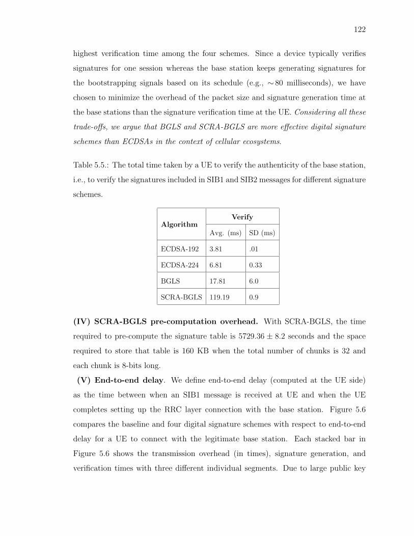
122
highest verification time among the four schemes. Since a device typically verifies
signatures for one session whereas the base station keeps generating signatures for
the bootstrapping signals based on its schedule (e.g., ∼ 80 milliseconds), we have
chosen to minimize the overhead of the packet size and signature generation time at
the base stations than the signature verification time at the UE. Considering all these
trade-offs, we argue that BGLS and SCRA-BGLS are more effective digital signature
schemes than ECDSAs in the context of cellular ecosystems.
Table 5.5.: The total time taken by a UE to verify the authenticity of the base station,
i.e., to verify the signatures included in SIB1 and SIB2 messages for different signature
schemes.
AlgorithmVerify
Avg. (ms) SD (ms)
ECDSA-192 3.81 .01
ECDSA-224 6.81 0.33
BGLS 17.81 6.0
SCRA-BGLS 119.19 0.9
(IV) SCRA-BGLS pre-computation overhead. With SCRA-BGLS, the time
required to pre-compute the signature table is 5729.36 ± 8.2 seconds and the space
required to store that table is 160 KB when the total number of chunks is 32 and
each chunk is 8-bits long.
(V) End-to-end delay. We define end-to-end delay (computed at the UE side)
as the time between when an SIB1 message is received at UE and when the UE
completes setting up the RRC layer connection with the base station. Figure 5.6
compares the baseline and four digital signature schemes with respect to end-to-end
delay for a UE to connect with the legitimate base station. Each stacked bar in
Figure 5.6 shows the transmission overhead (in times), signature generation, and
verification times with three different individual segments. Due to large public key
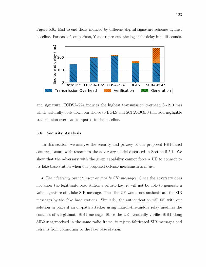
123
Figure 5.6.: End-to-end delay induced by different digital signature schemes against
baseline. For ease of comparison, Y-axis represents the log of the delay in milliseconds.
and signature, ECDSA-224 induces the highest transmission overhead (∼ 210 ms)
which naturally boils down our choice to BGLS and SCRA-BGLS that add negligible
transmission overhead compared to the baseline.
5.6 Security Analysis
In this section, we analyze the security and privacy of our proposed PKI-based
countermeasure with respect to the adversary model discussed in Section 5.2.1. We
show that the adversary with the given capability cannot force a UE to connect to
its fake base station when our proposed defense mechanism is in use.
• The adversary cannot inject or modify SIB messages. Since the adversary does
not know the legitimate base station’s private key, it will not be able to generate a
valid signature of a fake SIB message. Thus the UE would not authenticate the SIB
messages by the fake base stations. Similarly, the authentication will fail with our
solution in place if an on-path attacker using man-in-the-middle relay modifies the
contents of a legitimate SIB1 message. Since the UE eventually verifies SIB1 along
SIB2 sent/received in the same radio frame, it rejects fabricated SIB messages and
refrains from connecting to the fake base station.
124
• The adversary cannot replay/relay SIB2 messages. Since most of the parameters
in the SIB1 and SIB2 messages are constant, our proposed solution uses the times-
tamp t as a nonce for generating non-deterministic signatures. The UE identifies the
freshness of any SIB2 message using the t and the ∆t parameters of the message.
Computing freshness in this way would give the UE a performance edge since the
UE will neither require storing previous SIB1 messages nor checking the signatures
associated with the messages. With the relay/replay protection incorporated into our
proposed PKI cheme, the UE will be able to prevent DNS redirection and phishing
attacks [70].
• The adversary cannot inject other control-plane protocol messages usually sent
after MIB and SIB. With our proposed solution a UE is able to identify fake base
stations by verifying the authenticity of the SIB messages, it never establishes the
RRC layer connection to the fake base station. This thwarts the fake base station from
injecting unauthenticated malicious messages. The UE, therefore, with our solution in
place will not expose its IMSI, or downgrade to 3G/2G or enable its location tracking
by attackers.
However, the adversary can still sniff messages sent by the legitimate parties and can
overhear IMSI in the attach request and the identity response messages. This type of
IMSI catching attack is very hard to detect since the adversary does not leave any
footprints. The upcoming 5G, however, solves this problem by enabling a UE to
encrypt its IMSI while sending attach request or identity request message to the core
network.
5.7 Discussion
In this section, we discuss two salient aspects of our proposed countermeasure.
GPS Time. One important limitation with our proposed solution is the requirement
for precise time synchronization without the usage of SIB messages which essentially
leads to the requirement of GPS time capability for cellular devices.
125
Asymmetric cryptography in 5G. In 5G, the cellular device is already provisioned
with the public key of the core network using which the device encrypts its IMSI while
sending the IMSI in an over-the-air (OTA) message. This prevents devices’ IMSIs
from getting exposed to the IMSI-Catchers [18]. Such PKI for 5G already in place
should enable the cellular ecosystem to seamlessly adopt our proposed PKI scheme for
achieving secure connection bootstrapping that protects cellular devices from most of
the active attacks including IMSI-Catching attacks.
5.8 Summary
In this work, we investigate cryptography-backed authentication mechanisms to
prevent adversaries, from luring unsuspecting cellular devices to connect to malicious
base stations. We accomplish this by enabling next generation cellular devices to
authenticate the legitimacy of a base station, prior to connection. We overcome the
constraints imposed by both the ecosystem and stakeholders, and design an optimized
PKI scheme. We leverage precomputation-based digital signature generation algo-
rithms and employ different domain-specific optimizations to address the trilemma
imposed by digital signatures. We then implement our mechanism and observe that
our authentication scheme with the best performing digital signature algorithm im-
poses moderate overhead in bytes (∼220 bytes) and minimal overhead connection
time wise (∼28 ms), all while maintaining backwards compatibility.
Even with a PKI-based countermeasure in place, the adversary can still circumvent
such defenses to perform ToRPEDO attack for which we continue our investigation of
countermeasures against the side-channel attacks in the following chapter.

126
6. HARDENING AGAINST PRIVACY ATTACKS
EXPLOITING SIDE-CHANNEL INFORMATION
Rreceiving and transmitting radio packets as part of the cellular communication pro-
tocol are arguably two of the most demanding functions of a cellular device with
respect to energy consumption. Therefore, to save device energy, the cellular proto-
cols allow a device to transition to a low-power, idle state when the network detects
a predefined period of cellular inactivity from the device. It is, however, crucial to
ensure that when the device is in such an idle state, it does not overlook any pending
network services (e.g., phone call). This is where the cellular paging protocol comes
into play. The paging protocol strives to achieve the right balance between the de-
vice’s energy consumption and quality-of-service (e.g., timely delivery of services such
as phone calls). When a device is in idle state, paging messages are used to notify
a device for incoming phone calls, SMS, or data services. The device in idle state,
therefore, wakes up periodically to poll for paging messages. For a given cellular de-
vice and the serving network, the exact time periods (i.e., the paging occasions) when
the device polls for incoming paging messages are fixed. As we observed in Chapter
5 that this fixed nature of paging occasions is a fundamental weakness in both 4G
and 5G which the adversary may exploit to associate a victim’s soft identity, e.g.,
phone number or Twitter Handle with its paging occasion. This further enables the
adversary to perform ToRPEDO attack through which the adversary can infer a victim’s
coarse-grained location information, inject fabricated paging messages, and mount
denial-of-service attacks.
Existing efforts against location tracking attacks that exploit paging pro-
tocol. Recent studies [12, 17] exploit the deployment weakness of infrequent and
predictable changes in the device’s TMSI [34] which would allow an adversary to
identify a user’s presence in a geographical area. To achieve that the adversary places
127
multiple phone calls to victim’s phone number which forces the network to expose
the victim’s TMSI in the broadcast paging messages. Though [12,17] have suggested
frequent reallocation of TMSI as a possible mitigation technique, the adversary can
still identify a user’s presence by circumventing the proposed countermeasure with
our ToRPEDO attack. Even encrypted/anonymized TMSI or changing victim’s TMSI
after every VoLTE call cannot circumvent the ToRPEDO attack.
Challenges. The sheer mitigation of such side-channel attack requires a concerted ef-
fort from all cellular stakeholders as it warrants for changes in the standard. However,
the vulnerability is so deeply rooted in the protocol that designing a clean-slate so-
lution against such attack would pose the following requirements— (1) change other
procedures of the protocol, (2) break the backward compatibility, and (3) induce
performance loss— which would undermine the actual motivation of the paging pro-
cedure. Therefore, any countermeasure to prevent such side-channel attacks needs to
address the following challenges: (a) backward compatibility for legacy devices, and
(b) overhead induced due to enhanced security.
Our work. With the challenges in mind, we first explore the solution space against
ToRPEDO attack in two dimensions— (1) protocol-level defense that remove the root
cause of the attack, and (2) detection of the attack’s (behavioral) signature. Our
clean-slate design of the protocol-level countermeasure aims to make the paging occa-
sions and the identities in the paging messages unpredictable for any device. However,
this solution requires to change the protocol which in turn breaks the backward com-
patibility. In addition, changing paging occasions and identifiers after every paging
message turns out to be practically unrealizable since it incurs prohibitive compu-
tational and memory overhead and unreasonable energy cost. All these limitations
induce to shift our focus to a more practical approach based on noises by which a
legitimate base station carefully injects fake paging messages containing legitimate
devices’ TMSIs. We evaluated its efficacy with real network traces for different oper-
ators. In our evaluation, we observed that with ∼ 600 fake paging messages injected

128
within ∼ 40 seconds interval can prevent the adversary to perform the ToRPEDO attack
with as many as ∼ 500 phone calls.
Contribution. To summarize, this work makes the following contributions.
• We propose a lightweight and noise-based countermeasure that raises the bar
for the attackers without changing the protocol or breaking the backward com-
patibility.
• We implement and evaluate our proposed countermeasure with real network
traces and demonstrate the efficacy of the countermeasure with respect to re-
siliency against the ToRPEDO attack and overhead due to added security.
6.1 Solution Space Exploration for ToRPEDO
It is only natural to consider countermeasures that primarily focus on either
thwarting the root cause (i.e., fixed paging occasion) of ToRPEDO or defending against
ToRPEDO through the detection of its (behavioral) signature. Such a view induces the
following two categories of defenses, referred to as Protocol-level and Signature-based
countermeasures. However, as we discuss below, these categories of countermeasures
are ineffective due to deployment constraints. This inspired us to design a counter-
measure which prevents the adversary from retrieving accurate side channel infor-
mation through the addition of noise. We call this the Noise-based countermeasure
and demonstrate that it can effectively thwart ToRPEDO without incurring substantial
overhead.
6.1.1 Protocol-level Defenses
The main philosophy of protocol-level defenses is thwarting the root cause of
ToRPEDO, that is, to ensure that a UE’s paging occasion does not remain fixed in a
particular cell area. Having the paging occasion rely on the TMSI instead of the
IMSI can be a plausible solution. At a first glance, it seems that this solution would

129
work, but a recent study [17] has shown that network operators do not change TMSI
frequently and even when they do, the TMSI remains predictable [34]. As most
network operators reallocate the TMSI only after the CSFB, a TMSI would remain
fixed for a device until a CSFB is executed. This may give the adversary ample time
to launch ToRPEDO using VoLTE calls, SMS, or data services. Another naive solution
would be to ensure that a device’s TMSI is reallocated after it receives a paging
message. Such a solution, however, is infeasible in practice due to its high energy
demand for a device and high protocol overhead.
Another effective and seemingly plausible solution could potentially attempt to
induce unpredictability of the following: (i) the identifier included in the paging mes-
sage; (2) the paging occasion of a UE in a cell. To introduce randomness, however,
it is crucial to ensure that both the UE and the eNodeB (and also the MME) share
a common source of randomness from which to generate subsequent pseudorandom
numbers to be used as both the identifier and paging occasion. We discuss the high-
level design of this countermeasure to qualitatively compare it with our proposed
countermeasure.
Unpredictable identifiers with unpredictable paging occasions. In this scheme,
the core network and the device use TMSI as the seed for bootstrapping a sequence
of pseudo random numbers, R. Instead of including TMSI in the ith paging message,
the eNodeB would include a fresh pseudo TMSI (PTMSI) that would be the ith ele-
ment in a chain of random numbers from the start, i.e., Ri. At a first approximation,
it seems this approach has the advantage that both parties do not have to store a
significant amount of information. Due to the network unreliability, however, it is
plausible that paging messages are lost and as a consequence the two parties may
become desynchronized. Addressing such a case would require the device to maintain
a window of possible random values to match against the value received with the
paging message. Supporting this corner case would impose substantial runtime and
energy overhead which obviate the actual design motivation of paging procedure to
conserve more energy and thus may be infeasible in practice.

130
In the similar vein, one can use the TMSI as a seed for generating a sequence
of n pseudo-random numbers r1, . . . , rn on both the device and eNodeB sides during
connection initiation. The eNodeB will include a PTMSI 〈ri, i〉 instead of the TMSI in
the paging message. Once the device receives the PTMSI 〈r, j〉, it extracts the index
j and checks to see whether r matches the jth random number that it had generated
during bootstrapping. This approach chooses to invest on the storage side to decrease
the runtime overhead of checking whether the PTMSI belongs to the device.
To make the paging occasion unpredictable, in the jth round of paging, a random
value rIndj is generated from a seed (which is a shared secret between the device and
the eNodeB established during the connection initiation) and is used as an offset to
make the device’s paging frame number unpredictable. The device would wake up
on every system frame number SFN if the following holds: SFN mod T ≡ T × j +
PFIndex + rIndj where j ≥ 0.
The cellular paging protocol is, however, designed so to enable a UE to receive
paging messages without going through the connection bootstrapping [27,31]. With-
out a successful bootstrapping, it is not clear how the UE and the eNodeB (resp.,
the MME) could establish the necessary shared, random seeds. Even when this de-
ployment constraint is ignored, deploying this defense would require major overhaul
in both the UE and network operator sides.
6.1.2 Signature-based Defense
Another dimension of defense that can be adopted by the network operators would
be to use machine learning algorithms and deep packet inspection techniques to de-
velop a signature of the ToRPEDO attack (e.g., a lot of silent calls or SMS on the victim’s
phone number within a particular time interval) and preventing ToRPEDO by applying
countermeasures (e.g., rate-limiting) whenever such a signature is detected [91–96].
An adversary, however, may evade the detection of such signatures by increasing
delays between subsequent phone calls. Along with the resource overhead on the net-

131
work operator side, another critical challenge of deploying such a defense is to balance
the detection rate without compromising the quality of service for benign users.
6.2 Our Proposed Noise-based Countermeasure
We now describe our noise-based countermeasure which raises the bar for attackers
to infer a user’s paging occasion.
The high-level idea. The basic idea of our proposed countermeasure is to increase
the current paging rate (λcpaging) of all paging occasions to a certain level (λe) so that
the adversary would need a high number of silent calls to sufficiently differentiate
the paging rate of victim’s paging occasion from others. To increase the paging rate,
we propose that an eNodeB injects new paging messages at the paging occasions
for which the paging rate is relatively lower than expected rate (λe). The eNodeB
will also add new paging records to both the actual paging messages (note that, at
most 16 paging records can be sent in a single paging message) and the noisy paging
messages to increase the current base rate of paging records.
Noisy paging messages. An intuitive and seemingly practical choice for creating
noisy paging messages would be to use fake/non-existing TMSIs so that the current
devices in the network do not respond to the noisy paging messages containing the
fake TMSIs. However, the adversary may distinguish the fake paging records by
identifying the messages/TMSIs for which there is no response from the devices.
Although identifying fake paging messages is exceedingly difficult, we do not rule
out this possibility and thereby propose an eNodeB to add existing TMSIs for which
the actual paging messages were recently (e.g., previous 10 minutes) requested by
the network. Such noisy paging messages with legitimate TMSIs may cause a device
to respond to the additional paging messages for which there is no actual pending
incoming services.
CS (circuit-switch) domain records. As shown in ToRPEDO attack validation,
the base rate of paging containing CS records is substantially low. Consequently,
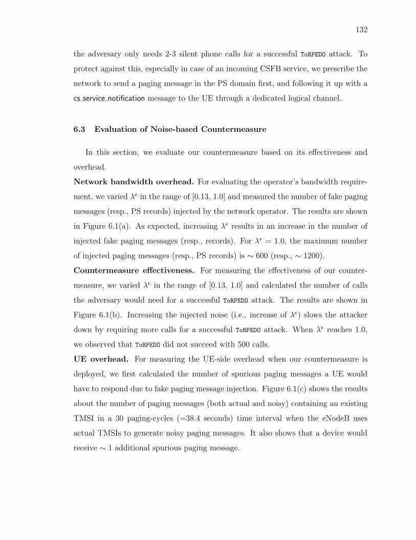
132
the adversary only needs 2-3 silent phone calls for a successful ToRPEDO attack. To
protect against this, especially in case of an incoming CSFB service, we prescribe the
network to send a paging message in the PS domain first, and following it up with a
cs service notification message to the UE through a dedicated logical channel.
6.3 Evaluation of Noise-based Countermeasure
In this section, we evaluate our countermeasure based on its effectiveness and
overhead.
Network bandwidth overhead. For evaluating the operator’s bandwidth require-
ment, we varied λe in the range of [0.13, 1.0] and measured the number of fake paging
messages (resp., PS records) injected by the network operator. The results are shown
in Figure 6.1(a). As expected, increasing λe results in an increase in the number of
injected fake paging messages (resp., records). For λe = 1.0, the maximum number
of injected paging messages (resp., PS records) is ∼ 600 (resp., ∼ 1200).
Countermeasure effectiveness. For measuring the effectiveness of our counter-
measure, we varied λe in the range of [0.13, 1.0] and calculated the number of calls
the adversary would need for a successful ToRPEDO attack. The results are shown in
Figure 6.1(b). Increasing the injected noise (i.e., increase of λe) slows the attacker
down by requiring more calls for a successful ToRPEDO attack. When λe reaches 1.0,
we observed that ToRPEDO did not succeed with 500 calls.
UE overhead. For measuring the UE-side overhead when our countermeasure is
deployed, we first calculated the number of spurious paging messages a UE would
have to respond due to fake paging message injection. Figure 6.1(c) shows the results
about the number of paging messages (both actual and noisy) containing an existing
TMSI in a 30 paging-cycles (=38.4 seconds) time interval when the eNodeB uses
actual TMSIs to generate noisy paging messages. It also shows that a device would
receive ∼ 1 additional spurious paging message.
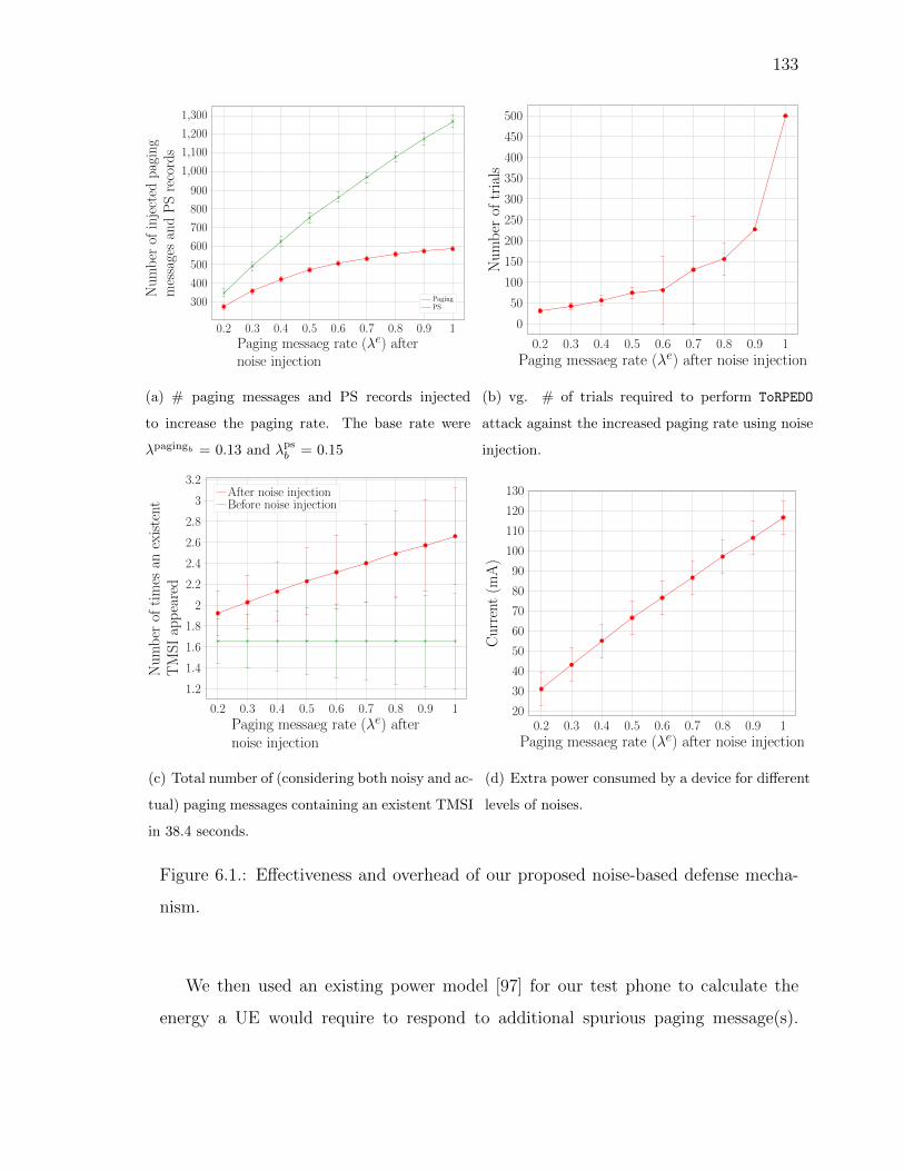
133
0.2 0.3 0.4 0.5 0.6 0.7 0.8 0.9 1
300
400
500
600
700
800
900
1,000
1,100
1,200
1,300
Paging messaeg rate (λe) afternoise injection
Number
ofinjected
paging
messagesandPSrecords
PagingPS
(a) # paging messages and PS records injected
to increase the paging rate. The base rate were
λpagingb = 0.13 and λpsb = 0.15
0.2 0.3 0.4 0.5 0.6 0.7 0.8 0.9 1
0
50
100
150
200
250
300
350
400
450
500
Paging messaeg rate (λe) after noise injection
Number
oftrials
(b) vg. # of trials required to perform ToRPEDO
attack against the increased paging rate using noise
injection.
0.2 0.3 0.4 0.5 0.6 0.7 0.8 0.9 1
1.2
1.4
1.6
1.8
2
2.2
2.4
2.6
2.8
3
3.2
Paging messaeg rate (λe) afternoise injection
Number
oftimes
anexistent
TMSIappeared
After noise injectionBefore noise injection
(c) Total number of (considering both noisy and ac-
tual) paging messages containing an existent TMSI
in 38.4 seconds.
0.2 0.3 0.4 0.5 0.6 0.7 0.8 0.9 120
30
40
50
60
70
80
90
100
110
120
130
Paging messaeg rate (λe) after noise injection
Current(m
A)
(d) Extra power consumed by a device for different
levels of noises.
Figure 6.1.: Effectiveness and overhead of our proposed noise-based defense mecha-
nism.
We then used an existing power model [97] for our test phone to calculate the
energy a UE would require to respond to additional spurious paging message(s).
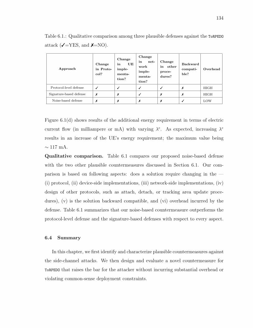
134
Table 6.1.: Qualitative comparison among three plausible defenses against the ToRPEDO
attack (3=YES, and 7=NO).
Approach
Change
in Proto-
col?
Change
in UE
imple-
menta-
tion?
Change
in net-
work
imple-
menta-
tion?
Change
in other
proce-
dures?
Backward
compati-
ble?
Overhead
Protocol-level defense 3 3 3 3 7 HIGH
Signature-based defense 7 7 3 7 7 HIGH
Noise-based defense 7 7 7 7 3 LOW
Figure 6.1(d) shows results of the additional energy requirement in terms of electric
current flow (in milliampere or mA) with varying λe. As expected, increasing λe
results in an increase of the UE’s energy requirement; the maximum value being
∼ 117 mA.
Qualitative comparison. Table 6.1 compares our proposed noise-based defense
with the two other plausible countermeasures discussed in Section 6.1. Our com-
parison is based on following aspects: does a solution require changing in the —
(i) protocol, (ii) device-side implementations, (iii) network-side implementations, (iv)
design of other protocols, such as attach, detach, or tracking area update proce-
dures), (v) is the solution backward compatible, and (vi) overhead incurred by the
defense. Table 6.1 summarizes that our noise-based countermeasure outperforms the
protocol-level defense and the signature-based defenses with respect to every aspect.
6.4 Summary
In this chapter, we first identify and characterize plausible countermeasures against
the side-channel attacks. We then design and evaluate a novel countermeasure for
ToRPEDO that raises the bar for the attacker without incurring substantial overhead or
violating common-sense deployment constraints.

135
7. RELATED WORK
In this section, we discuss existing efforts that focus on the security, privacy, and
availability of cellular networks. In this context, although prior work has extensively
investigated the security and privacy issues of 2G and 3G protocols [10–12, 74, 75],
there is less work that addresses the same concerns for the 4G LTE [17] and 5G
networks.
The closest to LTEInspector’s approach is by Tu et al. [6] which focus on identify-
ing non-trivial interactions—using an explicit-state model checker [39]—between the
different control-plane protocol layers of LTE. Unlike LTEInspector, their approach,
however, can neither explicitly reason about adversarial actions nor can support cryp-
tographic constructs.
Man-in-the-Middle Attacks: Meyer et al. [16] exploit the null integrity of the
security mode command message in 3G networks to perform a man-in-the-middle at-
tack. In contrast, our authentication relay attack in 4G LTE allows the adversary
to connect to the EPC without nullifying the security capabilities. In this attack
the adversary, however, cannot decrypt or inject valid encrypted messages unless the
operator uses a weak or no security context. Rupprecht et al. [59] used an implemen-
tation bug in a particular LTE dongle (Huawei E3276 USB Dongle) to demonstrate a
man-in-the-middle attack for 4G LTE.The 3GPP standard [27] strictly prohibits on
using null integrity algorithm by the 4G LTE capable UEs.
IMSI Catching Attacks: The IMSI catching attacks [9, 98, 99] still prevail for 4G
LTE networks as they did for 2G and 3G networks. In contrast to traditional IMSI
catchers where the adversary forces the UE to expose the IMSI/IMEI, the PIERCER
demonstrated in this thesis forces the network to expose the user’s IMSI/IMEI and
thus uniquely maps a phone number to its IMSI which was supposed to be only
possible by law enforcement agencies with operators’ cooperation. Although the
136
security-conscious cellular stakeholders may have had a hunch about the plausibility
of the 4G IMSI-Cracking attack, to the best of our knowledge, we are the first to
develop and demonstrate a complete attack in both 4G and 5G.
Linkability Attacks: Arapinis et al. [14] exploit the paging messages with GUTI
for linking the IMSI to the GUTI in 3G protocols. In contrast, by using paging
message with IMSI in 4G LTE we demonstrate how an adversary along with other
attacks (discussed in Section 3.2.2) can link the IMSIs in 3GPP [27] and the old
PMSI with the new PMSI in the enhanced Authentication and Key Agreement (AKA)
mechanism [20].
Traceability Attacks: Arapinis et al. [15] showed a traceability attack by exploit-
ing an implementation bug in the 3G network which violates the 3GPP standard
recommendation of adopting new temporary identity for the UE with a tracking area
change. In another work, Arapinis et al. [14] demonstrate another traceability at-
tack in which the adversary replays the auth request for the victim UE to all the
UEs in an area and detects the presence of the victim UE from the cause of the
error (MAC failure or SQN synchronization failure). In contrast, our traceability
attack with the security mode command procedure exploits the missing nonces in
security mode command, a different implementation bug of the commercial networks.
Location tracking through TMSI. The 3GPP standard [4] suggests to use TMSI
and change it frequently to hide users’ IMSI/IMEIs. However, prior work [12,17] has
shown that an adversary can still exploit the operational network’s misconfiguration
of frequent TMSI change, and thus track a user by uniquely mapping a phone number
to its TMSI which often does not get replaced even for three days [17]. The most
recent work [34] along this direction exposes operational networks’ vulnerability of
not properly randomizing the TMSIs while reallocating them to the subscribers. As a
result, some of the bytes are fixed [53] between the old and new TMSIs through which
the adversary can still infer the new TMSI and track the subscriber. In contrast, our
ToRPEDO exploits protocol standard’s vulnerability of choosing fixed paging frames for
a subscriber which makes all the network operators vulnerable to this attack.

137
Denial-of-Service (DoS) Attacks: Shaik et al. [17] demonstrate 3 DoS attacks
against UEs in which downgrading to 3G/2G and denial of all network services are
performed with the same tracking area update reject message with just two different
causes. In contrast, our DoS attacks use four new techniques as discussed in Sec-
tion 3.2. As opposed to the DoS attacks against the UE, Jover et al. [19] discuss a
DoS attack against the EPC using a compromised UE/eNodeB that sends huge num-
ber of attach request messages to the EPC and thus takes the EPC down. Jermyn
et al. [100] show a similar DoS attack and simulate a set of compromised UEs that
exhaust the victim UEs’ traffic capacity. Golde et al. [53] exploit a race condition in
the paging message responses in 2G networks that enables a malicious UE to send the
paging response message before the victim UE, and thus preventing the victim UE
from receiving incoming phone calls/SMS.
Data Stealing Attacks: Kim et al. [101] and Li et al. [102] address the vulnerabil-
ities of VoLTE call setup and show caller spoofing, over-billing, and denial-of-service
attacks. In contrast, our focus is on attach, detach and paging procedures of 4G LTE
and 5G protocols. Sahin et al. [91] study the possible techniques to detect and mea-
sure an interconnect telecom fraud that diverts a normal phone call without explicit
authorization to voice over IP chat application. Sahin et al. [92] also systematically
survey different types of telephony frauds and propose a comprehensive taxonomy of
these frauds.
Fake base station detection. To detect fake base stations acting as IMSI-catchers,
Dabrowski et al. [18] propose to use stationary hardware units to scan frequency
bands, collect cellular data and find anomalous communication patterns. This, how-
ever, has the limitation of requiring expensive hardware units and scalability. In
addition, Borgaonkar et al. demonstrate that such signature-based fake base detec-
tion schemes are susceptible to new attack variants [103]. Dabrowski et al. [104] also
look into detecting such fake devices using the operator side data and combine both
client and operator side detections which, however, are vulnerable since the data is
generated and analyzed after the cellular devices connect to the IMSI-catchers. Li

138
et al. [76] use crowdsourced data to detect fake base stations that broadcast fake
SMS messages to scam the victims. Though they have promising results in this very
specific scenario, there exists two important limitations: First, there is little to no
ground truth available for this type of attack. Second, they can only detect fake base
stations with known communication patterns that broadcast fake SMS messages [76].
Ney et al. [105] propose to solve this problem using sensors mounted in vehicles. This
solution comes with the benefit that no subscribers need to connect to such devices to
create traces which otherwise could later serve as a basis to detect them and instead
use the data collected by these sensors. This, however, suffers from the limitation
that such sensors would be expensive to deploy and would cause the scalability issues.
Preventing exposure of IMSI. Khan et al. [106] propose a solution to conceal
the IMSI using Identity Based Encryption and provide authentication. This, how-
ever, comes with the challenge of imposing computation overhead at the Home Sub-
scriber Network since it would require a public-private key pair for each subscriber.
Pseudonym-based IMSI concealment techniques [20,107,108] might prevent the expo-
sure of IMSI, however, the attacker could still perform downgrade attacks, and thus
expose the IMSI through 4G/3G.
Mutual Authentication. The root cause of IMSI-catchers is the failure to authen-
ticate the fake base station prior to connection. A common approach to this problem
is a PKI-based solution that fully relies on certificates. A common theme in these
solutions, is the core network acting as a CA and in the process, signs certificates
for every MME/AMF in the network [109–111]. These solutions, however, impose a
significant computational overhead at the base station and induce high communica-
tion overhead due to the lack of optimizations in authenticating a broadcast message.
Though this solution proves to be computationally feasible, the IMSI can be still
exposed due to the failure of SIB message’s authentication.
139
8. CONCLUSION AND FUTURE RESEARCH
DIRECTIONS
In this dissertation, we develop principled security and privacy analysis frameworks
for cellular networks and design countermeasures against fake base stations and side
channel attacks.
We propose LTEInspector which employs an adversarial model-based testing phi-
losophy for exposing attacks against three critical procedures of 4G LTE. LTEInspector
harnesses the strengths of both a symbolic model checkers and a protocol verifier and
is demonstrated to be effective in finding 10 novel and 9 prior attacks. We have also
validated most of our attacks (i.e., 8 out of 10) in a testbed.
Our work on side-channel attacks sheds light on an inherent design weakness of
the 4G/5G cellular paging protocol which can be exploited by an attacker to not only
obtain the victim’s paging occasion but also to identify the victim’s presence in a
particular cell area just from the victim’s soft-identity (e.g., phone number, Twitter
handle) with a novel attack called ToRPEDO. We also demonstrate that ToRPEDO can
enable an attacker to exploit a deployment oversight of several network operators to
retrieve a victim’s IMSI from his phone number using the PIERCER attack. To further
provide evidence of ToRPEDO’s potency, we show that it empowers an attacker to launch
a brute-force IMSI-Cracking attack through the use of two novels oracles we designed
for 4G and 5G, respectively. Each of these attacks can also be leveraged to enhance
prior attacks. All of our attacks have been validated in realistic setting for 4G using
cheap software-defined radio and open-source protocol stack.
We also investigate countermeasures for preventing adversaries, from luring unsus-
pecting cellular devices to connect to malicious base stations, by empowering the cel-
lular device to authenticate legitimate base stations. We accomplish this by enabling
next generation cellular devices to authenticate the legitimacy of a base station, prior

140
to connection. We overcome the constraints imposed by both the ecosystem and
stakeholders, and design an optimized PKI scheme. We leverage precomputation-
based digital signature generation algorithms and employ different domain-specific
optimizations to address the trilemma imposed by digital signatures.
Finally, as part of our investigation on the cellular paging protocol, we also design
and evaluate a novel countermeasure for ToRPEDO that raises the bar for the attacker
without incurring substantial overhead or violating common-sense deployment con-
straints.
Future work. In future, we would like to explore the following four directions: (i)
extend our tool to support the analysis of other procedures and protocol layers (e.g.,
RRC and PDCP) messages; (ii) automating some of the manual tasks in LTEInspector;
(iii) enrich the model features and analysis of LTEInspector to handle message data;
(iv) explore other forms of side channel information, exposed by cellular network
protocols, that can be exploited to launch novel security and privacy attacks; (v)
evaluate the performance of different signature generation/verification schemes in
authenticating broadcast messages in cellular networks; and finally (vi) design a clean-
slate and backward compatible countermeasure against the side-channel attacks on
the paging procedure.

REFERENCES

141
REFERENCES
[1] Hackers Are Tapping Into Mobile Networks’ Backbone, New Re-search Shows, https://www.forbes.com/sites/parmyolson/2015/10/14/hackers-mobile-network-backbone-ss7.
[2] Hackers Take Down the Most Wired Country in Europe, https://www.wired.com/2007/08/ff-estonia/.
[3] Major DDoS Attacks Involving IoT Devices, https://www.enisa.europa.eu/publications/info-notes/major-ddos-attacks-involving-iot-devices.
[4] 3GPP Standard, www.3gpp.org.
[5] LTE; Evolved Universal Terrestrial Radio Access (E-UTRA) and EvolvedPacket Core (EPC); Common test environments for User Equipment(UE) conformance testing (3GPP TS 36.508 version 12.3.1 Release12), https://www.etsi.org/deliver/etsi ts/136500 136599/136508/12.03.01 60/ts 136508v120301p.pdf.
[6] G.-H. Tu, Y. Li, C. Peng, C.-Y. Li, H. Wang, and S. Lu, “Control-plane protocolinteractions in cellular networks,” in Proceedings of the 2014 ACM Conferenceon SIGCOMM. ACM, 2014, pp. 223–234.
[7] 3GPP Standard. Release 12., http://www.3gpp.org/specifications/releases/68-release-12.
[8] Cellular Service, https://www.fcc.gov/wireless/bureau-divisions/mobility-division/cellular-service.
[9] D. Abodunrin, Y. Miche, and S. Holtmanns, “Some dangers from 2g networkslegacy support and a possible mitigation,” in Communications and NetworkSecurity (CNS), Sept 2015, pp. 585–593.
[10] P. P. C. Lee, T. Bu, and T. Woo, “On the detection of signaling dos attacks on3g wireless networks,” in 26th International Conference on Computer Commu-nications (INFOCOM), May 2007, pp. 1289–1297.
[11] N. Golde, K. Redon, and R. Borgaonkar, “Weaponizing Femtocells: The Effectof Rogue Devices on Mobile Telecommunications,” in Proceedings of the 19thAnnual Network & Distributed System Security Symposium, Feb. 2012.
[12] D. F. Kune, J. Koelndorfer, and Y. Kim, “Location leaks on the gsm air inter-face,” in NDSS, 2012.
[13] I. Androulidakis, “Intercepting mobile phone calls and short messages usinga gsm tester,” in 18th Conference on Computer Networks, Ustron, Poland,A. Kwiecien, P. Gaj, and P. Stera, Eds., 2011, pp. 281–288.

142
[14] M. Arapinis, L. Mancini, E. Ritter, M. Ryan, N. Golde, K. Redon, and R. Bor-gaonkar, “New privacy issues in mobile telephony: Fix and verification,” inProceedings of the 2012 ACM Conference on Computer and CommunicationsSecurity, ser. CCS ’12. ACM, 2012, pp. 205–216.
[15] M. Arapinis, L. I. Mancini, E. Ritter, and M. Ryan, “Privacy throughpseudonymity in mobile telephony systems,” in NDSS, 2014.
[16] U. Meyer and S. Wetzel, “A man-in-the-middle attack on umts,” in Proceedingsof the 3rd ACM Workshop on Wireless Security, ser. WiSe ’04. ACM, 2004,pp. 90–97.
[17] A. Shaik, J. Seifert, R. Borgaonkar, N. Asokan, and V. Niemi, “Practical attacksagainst privacy and availability in 4g/lte mobile communication systems,” in23nd Annual Network and Distributed System Security Symposium, NDSS, SanDiego, CA, USA, February 21-24, 2016.
[18] A. Dabrowski, N. Pianta, T. Klepp, M. Mulazzani, and E. Weippl, “Imsi-catchme if you can: Imsi-catcher-catchers,” in Proceedings of the 30th Annual Com-puter Security Applications Conference, ser. ACSAC ’14. ACM, 2014, pp.246–255.
[19] R. P. Jover, “Security attacks against the availability of lte mobility networks:Overview and research directions,” in Wireless Personal Multimedia Commu-nications (WPMC), 2013 16th International Symposium on, June 2013, pp.1–9.
[20] F. van den Broek, R. Verdult, and J. de Ruiter, “Defeating imsi catchers,” inProceedings of the 22Nd ACM SIGSAC Conference on Computer and Commu-nications Security, ser. CCS ’15. ACM, 2015, pp. 340–351.
[21] Attacks on 4G LTE Networks Could Send Fake Emergency Alerts, https://technews.acm.org/archives.cfm?fo=2018-03-mar/mar-16-2018.html.
[22] New Research Exposes Vulnerabilities in Cellular Networks, https://www.cs.purdue.edu/news/articles/2018/vulnerabilities-in-4G-LTE-networks.html.
[23] The Security of Cellular Connections, https://www.nytimes.com/2018/08/10/technology/personaltech/security-wifi-lte-data.html.
[24] New LTE attacks can snoop on messages, track locationsand spoof emergency alerts, https://www.zdnet.com/article/new-lte-attacks-eavesdrop-on-messages-track-locations-spoof-alerts/.
[25] 4G LTE pried open to reveal a slew of new protocol-level attacks, https://www.theregister.co.uk/2018/03/05/4g lte protocol vulnerabilities/.
[26] 4G LTE networks vulnerability allows adversaries to send fakeemergency alerts, http://www.homelandsecuritynewswire.com/dr20180405-4g-lte-networks-vulnerability-allows-adversaries-to-send-fake-emergency-alerts.
[27] 3GPP. Non-Access-Stratum (NAS) protocol for Evolved Packet System (EPS);Stage 3 Specification 3GPP TS 24.301 version 12.8.0 Release 12., [Online].Available: http://www.3gpp.org/dynareport/24301.htm.

143
[28] 3GPP. Evolved Universal Terrestrial Radio Access (E-UTRA) and Evolved Uni-versal Terrestrial Radio Access Network (EUTRAN); overall description; stage2, Specification 3GPP TS 36.300 version 12.4.0 Release 12., [Online]. Available:http://www.3gpp.org/dynareport/36300.htm.
[29] 3GPP Release 15, http://www.3gpp.org/release-15.
[30] 5G; Security architecture and procedures for 5G System (3GPP TS 33.501 ver-sion 15.1.0 Release 15), https://www.etsi.org/deliver/etsi ts/133500 133599/133501/15.01.00 60/ts 133501v150100p.pdf.
[31] 5G; Non-Access-Stratum (NAS) protocol for 5G System (5GS); Stage 3 (3GPPTS 24.501 version 15.0.0 Release 15)., https://www.etsi.org/deliver/etsi ts/124500 124599/124501/15.00.00 60/ts 124501v150000p.pdf.
[32] 5G; NR; Radio Resource Control (RRC); Protocol specification (3GPPTS 38.331 version 15.2.1 Release 15)., https://www.etsi.org/deliver/etsi ts/138300 138399/138331/15.02.01\ 60/ts 138331v150201p.pdf.
[33] 3rd Generation Partnership Project; Technical Specification Group Radio Ac-cess Network; V15.0.0 NR; (2018-06) User Equipment (UE) procedures in Idlemode and RRC Inactive state (Release 15), http://www.3gpp.org/DynaReport/38304.htm.
[34] B. Kim, S. Bae, and Y. Kim, “Guti reallocation demystified: Cellular locationtracking with changing temporary identifier,” in 25th Annual Network and Dis-tributed System Security Symposium, NDSS, San Diego, CA, USA, February18-21, 2018.
[35] D. Dolev and A. C. Yao, “On the security of pub-lic key protocols,” Stanford, CA, USA, Tech. Rep., 1981,http://www.ncstrl.org:8900/ncstrl/servlet/search?formname=detail&id=oai
[36] K. R. Apt and D. C. Kozen, “Limits for automatic verification of finite-stateconcurrent systems,” Inf. Process. Lett., vol. 22, no. 6, pp. 307–309, May 1986.
[37] Z. Manna and A. Pnueli, “A hierarchy of temporal properties (invited paper,1989),” in Proceedings of the ninth annual ACM symposium on Principles ofdistributed computing. ACM, 1990, pp. 377–410.
[38] A. Cimatti, E. M. Clarke, F. Giunchiglia, and M. Roveri, “Nusmv: A newsymbolic model verifier,” in Proceedings of the 11th International Conferenceon Computer Aided Verification, ser. CAV ’99. London, UK, UK: Springer-Verlag, 1999, pp. 495–499.
[39] G. Holzmann, Spin Model Checker, the: Primer and Reference Manual, 1st ed.Addison-Wesley Professional, 2003.
[40] B. Blanchet, “Modeling and verifying security protocols with the applied picalculus and proverif,” Foundations and Trends in Privacy and Security, vol. 1,no. 1-2, pp. 1–135, 2016.
[41] S. Meier, B. Schmidt, C. Cremers, and D. Basin, “The tamarin prover for thesymbolic analysis of security protocols,” in Proceedings of the 25th InternationalConference on Computer Aided Verification (CAV). Springer-Verlag, 2013, pp.696–701.

144
[42] A. Armando and et al., “The avispa tool for the automated validation of internetsecurity protocols and applications,” in Proceedings of the 17th InternationalConference on Computer Aided Verification, ser. CAV’05. Springer-Verlag,2005, pp. 281–285.
[43] J. Bengtson, K. Bhargavan, C. Fournet, A. D. Gordon, and S. Maffeis, “Re-finement types for secure implementations,” ACM Trans. Program. Lang. Syst.,vol. 33, no. 2, pp. 8:1–8:45, Feb. 2011.
[44] G. Lowe, “Breaking and fixing the needham-schroeder public-key protocol usingfdr,” in Proceedings of the Second International Workshop on Tools and Algo-rithms for Construction and Analysis of Systems, ser. TACAs ’96. Springer-Verlag, 1996, pp. 147–166.
[45] C. J. Cremers, “Unbounded verification, falsification, and characterization ofsecurity protocols by pattern refinement,” in Proceedings of the 15th ACM Con-ference on Computer and Communications Security, ser. CCS ’08. ACM, 2008,pp. 119–128.
[46] A. C. Yao, “Theory and application of trapdoor functions,” in Proceedings ofthe 23rd Annual Symposium on Foundations of Computer Science, ser. SFCS’82. IEEE Computer Society, 1982, pp. 80–91.
[47] J.-K. Tsay and S. F. Mjølsnes, “A vulnerability in the umts and lte authenti-cation and key agreement protocols,” in Proceedings of the 6th MMM-ACNS.Springer-Verlag, 2012, pp. 65–76.
[48] B. Blanchet, “Automatic verification of correspondences for security protocols,”Journal of Computer Security, vol. 17, no. 4, pp. 363–434, Jul. 2009.
[49] M. Abadi and B. Blanchet, “Analyzing Security Protocols with Secrecy Typesand Logic Programs,” in 29th Annual ACM SIGPLAN - SIGACT Symposiumon Principles of Programming Languages (POPL 2002). Portland, Oregon:ACM Press, Jan. 2002, pp. 33–44.
[50] E. A. Emerson and K. S. Namjoshi, “Reasoning about rings,” in Proceedings ofthe 22Nd ACM SIGPLAN-SIGACT Symposium on Principles of ProgrammingLanguages (POPL). ACM, 1995, pp. 85–94.
[51] R. Racic, D. Ma, and H. Chen, “Exploiting mms vulnerabilities to stealthilyexhaust mobile phone’s battery,” in Securecomm and Workshops, Aug 2006, pp.1–10.
[52] J. Serror, H. Zang, and J. C. Bolot, “Impact of paging channel overloads orattacks on a cellular network,” in Proceedings of the 5th ACM Workshop onWireless Security, 2006, pp. 75–84.
[53] N. Golde, K. Redon, and J.-P. Seifert, “Let me answer that for you: Exploit-ing broadcast information in cellular networks,” in Proceedings of the 22NdUSENIX Conference on Security, 2013, pp. 33–48.
[54] USRP B210, https://www.ettus.com/product/details/UB210-KIT.
[55] OpenLTE, http://openlte.sourceforge.net/.

145
[56] srsLTE, https://github.com/srsLTE.
[57] Qxdm Professional Qualcomm Extensible Diagnostic-Monitor, www.qualcomm.com/media/documents/files/qxdm-professional-qualcomm-extensible-diagnostic-monitor.pdf.
[58] srsUE, https://github.com/srsLTE/srsUE.
[59] D. Rupprecht, K. Jansen, and C. Popper, “Putting lte security functions to thetest: A framework to evaluate implementation correctness,” in Proceedings ofthe 10th USENIX Conference on Offensive Technologies, ser. WOOT’16, 2016,pp. 40–51.
[60] N. Bui and J. Widmer, “Owl: A reliable online watcher for lte control channelmeasurements,” in Proceedings of the 5th Workshop on All Things Cellular:Operations, Applications and Challenges, ser. ATC ’16. ACM, 2016, pp. 25–30.
[61] OpenEPC, www.openepc.com.
[62] P. Y. Kong, “Power consumption and packet delay relationship for heteroge-neous wireless networks,” IEEE Communications Letters, vol. 17, no. 7, pp.1376–1379, July 2013.
[63] Y. Li, C. Peng, Z. Yuan, J. Li, H. Deng, and T. Wang, “Mobileinsight: Extract-ing and analyzing cellular network information on smartphones,” in Proceedingsof the 22nd Annual International Conference on Mobile Computing and Net-working, ser. MobiCom ’16, 2016, pp. 202–215.
[64] K. B. Rasmussen and S. Capkun, “Realization of rf distance bounding,” in Pro-ceedings of the 19th USENIX Conference on Security, ser. USENIX Security’10,2010, pp. 25–25.
[65] S. R. Hussain, O. Chowdhury, S. Mehnaz, and E. Bertino, “Lteinspector: A sys-tematic approach for adversarial testing of 4g lte,” in 25th Annual Network andDistributed System Security Symposium, NDSS, San Diego, CA, USA, February18-21, 2018.
[66] HLRLOOKUPS, https://www.hlr-lookups.com/.
[67] F. Zarinni, A. Chakraborty, V. Sekar, S. R. Das, and P. Gill, “A first look atperformance in mobile virtual network operators,” in Proceedings of the 2014Conference on Internet Measurement Conference, ser. IMC ’14. ACM, 2014,pp. 165–172.
[68] H. Welte, The reason why you see paging by IMSI in real-world GSM net-works, http://laforge.gnumonks.org/blog/20100628-the reason for paging byimsi, 2010.
[69] 5G; System Architecture for the 5G System (3GPP TS 23.501 version 15.2.0 Re-lease 15)., https://www.etsi.org/deliver/etsi ts/123500 123599/123501/15.02.00 60/ts 123501v150200p.pdf.
[70] D. Rupprecht, K. Kohls, T. Holz, and C. Popper, “Breaking LTE on layer two,”in IEEE Symposium on Security & Privacy (SP). IEEE, May 2019.
146
[71] USRP B210, https://www.crowdsupply.com/lime-micro/limesdr.
[72] A. Shaik, R. Borgaonkar, S. Park, and J.-P. Seifert, “On the impact of roguebase stations in 4g/lte self organizing networks,” in Proceedings of the 11thACM Conference on Security & Privacy in Wireless and Mobile Networks, ser.WiSec ’18. New York, NY, USA: ACM, 2018, pp. 75–86. [Online]. Available:http://doi.acm.org/10.1145/3212480.3212497
[73] J. Ooi and N. Neninger, “Imsi catchers and mobile security,” 2015.
[74] P. Traynor, M. Lin, M. Ongtang, V. Rao, T. Jaeger, P. McDaniel, andT. La Porta, “On cellular botnets: Measuring the impact of malicious deviceson a cellular network core,” in Proceedings of the 16th ACM Conference onComputer and Communications Security (CCS), 2009, pp. 223–234.
[75] P. Traynor, P. McDaniel, and T. La Porta, “On attack causality in internet-connected cellular networks,” in Proceedings of 16th USENIX Security Sympo-sium, 2007, pp. 21:1–21:16.
[76] Z. Li, W. Wang, C. Wilson, J. Chen, Q. Chen, T. Jung, L. Zhang, K. Liu, X. Li,and Y. Liu, “Fbs-radar: Uncovering fake base stations at scale in the wild,”2017.
[77] Z. Zhuang, X. Ji, T. Zhang, J. Zhang, W. Xu, Z. Li, and Y. Liu,“Fbsleuth: Fake base station forensics via radio frequency fingerprinting,” inProceedings of the 2018 on Asia Conference on Computer and CommunicationsSecurity, ser. ASIACCS ’18, 2018, pp. 261–272. [Online]. Available:http://doi.acm.org/10.1145/3196494.3196521
[78] K. Nohl, Mobile Self Defense, 31.
[79] A. Perrig, R. Canetti, J. Tygar, and D. Song, “The tesla broadcast authentica-tion protocol,” in Cryptobytes 5, 2005.
[80] D. Cooper, S. Santesson, S. Farrell, S. Boeyen, R. Housley, andW. Polk, “Internet X.509 Public Key Infrastructure Certificate and CertificateRevocation List (CRL) Profile,” Internet Requests for Comments, Tech. Rep.5280, May 2008. [Online]. Available: http://www.ietf.org/rfc/rfc5280.txt
[81] D. Johnson, A. Menezes, and S. Vanstone, “The elliptic curve digital signaturealgorithm (ecdsa),” International journal of information security, vol. 1, no. 1,pp. 36–63, 2001.
[82] D. Boneh, C. Gentry, B. Lynn, and H. Shacham, “Aggregate and verifiablyencrypted signatures from bilinear maps,” in International Conference on theTheory and Applications of Cryptographic Techniques. Springer, 2003, pp.416–432.
[83] A. A. Yavuz, A. Mudgerikar, A. Singla, I. Papapanagiotou, and E. Bertino,“Real-time digital signatures for time-critical networks,” IEEE Transactionson Information Forensics and Security, vol. 12, no. 11, pp. 2627–2639, 2017.
[84] Cell-Site Simulators/IMSI Catchers., https://www.eff.org/pages/cell-site-simulatorsimsi-catchers.

147
[85] J. Katz, A. J. Menezes, P. C. Van Oorschot, and S. A. Vanstone, Handbook ofapplied cryptography. CRC press, 1996.
[86] Embedded SIM Remote Provisioning Architecture (Version 1.1).
[87] R. L. Rivest, A. Shamir, and L. Adleman, “A method for obtaining digital sig-natures and public-key cryptosystems,” Communications of the ACM, vol. 21,no. 2, pp. 120–126, 1978.
[88] A. B. Association et al., “Public key cryptography for the financial servicesindustry: The elliptic curve digital signature algorithm,” American NationalStandard X, vol. 9, 1999.
[89] D. Boneh, C. Gentry, B. Lynn, and H. Shacham, “Aggregate and verifiably en-crypted signatures from bilinear maps,” in Advances in Cryptology — EURO-CRYPT 2003, E. Biham, Ed. Berlin, Heidelberg: Springer Berlin Heidelberg,2003, pp. 416–432.
[90] A. A. Yavuz, A. Mudgerikar, A. Singla, I. Papapanagiotou, and E. Bertino,“Real-time digital signatures for time-critical networks,” IEEE Transactionson Information Forensics and Security, vol. 12, no. 11, pp. 2627–2639, Nov2017.
[91] M. Sahin and A. Francillon, “Over-the-top bypass: Study of a recent telephonyfraud,” in Proceedings of the 2016 ACM SIGSAC Conference on Computer andCommunications Security, ser. CCS ’16. ACM, 2016, pp. 1106–1117.
[92] M. Sahin, A. Francillon, P. Gupta, and M. Ahamad, “Sok: Fraud in telephonynetworks,” in 2nd IEEE European Symposium on Security and Privacy,April 26-28, 2017, Paris, France, Paris, France, 2017. [Online]. Available:http://www.eurecom.fr/publication/5055
[93] H. Li, X. Xu, C. Liu, T. Ren, K. Wu, Z. W. Cao, Xuezhi, Z. Y. Yu, andD. Song, “A machine learning approach to prevent malicious calls over telephonynetworks,” in Proceedings of the 2018 IEEE Symposium of Security and Privacy.IEEE, 2018.
[94] B. Reaves, L. Blue, H. Abdullah, L. Vargas, P. Traynor, and T. Shrimpton,“Authenticall: Efficient identity and content authentication for phone calls,”in 26th USENIX Security Symposium (USENIX Security 17). Vancouver, BC:USENIX Association, 2017, pp. 575–592. [Online]. Available: https://www.usenix.org/conference/usenixsecurity17/technical-sessions/presentation/reaves
[95] B. Reaves, L. Blue, D. Tian, P. Traynor, and K. R. Butler, “Detecting smsspam in the age of legitimate bulk messaging,” in Proceedings of the 9thACM Conference on Security & Privacy in Wireless and Mobile Networks,ser. WiSec ’16. New York, NY, USA: ACM, 2016, pp. 165–170. [Online].Available: http://doi.acm.org/10.1145/2939918.2939937
[96] S. Sinha, M. Bailey, and F. Jahanian, “Improving spam blacklisting through dy-namic thresholding and speculative aggregation,” in Proceedings of the Networkand Distributed System Security Symposium, NDSS 2010, San Diego, Califor-nia, USA, 28th February - 3rd March 2010.
148
[97] X. Chen, J. Meng, Y. C. Hu, M. Gupta, R. Hasholzner, V. N. Ekambaram,A. Singh, and S. Srikanteswara, “A fine-grained event-based modem powermodel for enabling in-depth modem energy drain analysis,” Proc. ACM Meas.Anal. Comput. Syst.
[98] R. Borgaonkar and S. Udar, “Understanding imsi privacy,” in BlackHat, 2014.
[99] K. Nohl, “Mobile self-defense.” [Online]. Avail-able: https://events.ccc.de/congress/2014/Fahrplan/system/attachments/2493/original/Mobile Self Defense-Karsten Nohl-31C3-v1.pdf
[100] J. Jermyn, G. Salles-Loustau, and S. Zonouz, “An analysis of dos attack strate-gies against the lte ran,” vol. 3, 2014, pp. 159–180.
[101] H. Kim, D. Kim, M. Kwon, H. Han, Y. Jang, D. Han, T. Kim, andY. Kim, “Breaking and fixing volte: Exploiting hidden data channels and mis-implementations,” in Proceedings of the 22Nd ACM SIGSAC Conference onComputer and Communications Security, ser. CCS ’15. New York, NY, USA:ACM, 2015, pp. 328–339.
[102] C.-Y. Li, G.-H. Tu, C. Peng, Z. Yuan, Y. Li, S. Lu, and X. Wang, “Insecurityof voice solution volte in lte mobile networks,” in Proceedings of the 22Nd ACMSIGSAC Conference on Computer and Communications Security, ser. CCS ’15.New York, NY, USA: ACM, 2015, pp. 316–327.
[103] S. Park, A. Shaik, R. Borgaonkar, A. Martin, and J.-P. Seifert, “White-stingray: Evaluating IMSI catchers detection applications,” in 11th USENIXWorkshop on Offensive Technologies (WOOT 17). Vancouver, BC: USENIXAssociation, 2017. [Online]. Available: https://www.usenix.org/conference/woot17/workshop-program/presentation/park
[104] A. Dabrowski, G. Petzl, and E. R. Weippi, “The messenger shoots back: Net-work operator based imsi catcher detection,” in International Symposium onResearch in Attacks, Intrusions, and Defenses. Springer, Cham, 2016, pp.279–302.
[105] P. Ney, I. Smith, G. Cadamuro, and T. Kohno, “Seaglass: enabling city-wideimsi-catcher detection,” in Proceedings on Privacy Enhancing Technologies,2017, pp. 39–56.
[106] M. Khan and V. Niemi, “Concealing imsi in 5g network using identity basedencryption,” in axXiv preprint arXiv:1708.01868, 2017.
[107] Protecting IMSI and User Privacy in 5G Networks, www.ericsson.com/res/docs/2016/protecting-imsi-and-user-privacy-in-5g-networks.pdf.
[108] M. S. A. Khan and C. J. Mitchell, “Trashing imsi catchers in mobile networks,”in Proceedings of the 10th ACM Conference on Security and Privacy in Wirelessand Mobile Networks, 2017, pp. 207–218.
[109] X. Yi, E. Okamoto, and K. Y. Lam, “An optimized protocol for mobile net-work authentication and security,” in ACM SIGMOBILE Mobile Computingand Communications Reviews, vol. 2, 1998, pp. 37–39.
149
[110] Y. Zheng, “An authentication and security protocol for mobile computing,” inMobile Communications. Springer US, 1996, pp. 249–267.
[111] C.-C. Lee, I.-E. Liao, and M.-S. Hwang, “An extended certificate-based authen-tication and security protocol for mobile networks.” in Information Technologyand Control, vol. 38, 2009.