Free vibration and buckling analyses of functionally graded beams with edge cracks
International Journal of Solids and Structures 48 (2011) 2987–2999
Contents lists available at ScienceDirect
International Journal of Solids and Structures
journal homepage: www.elsevier .com/locate / i jsols t r
Dynamic fracture behavior of functionally graded magnetoelectroelastic solidsby BIEM
Tsviatko Rangelov a,⇑, Yonko Stoynov b, Petia Dineva c
a Institute of Mathematics and Informatics, Bulgarian Academy of Sciences, Sofia 1113, Bulgariab Faculty of Applied Mathematics and Informatics, Technical University of Sofia, Sofia 1000, Bulgariac Institute of Mechanics, Bulgarian Academy of Sciences, Sofia 1113, Bulgaria
a r t i c l e i n f o
Article history:Received 3 March 2011Received in revised form 23 May 2011Available online 2 July 2011
Dedicated to Professor Dietmar Gross in theoccasion of his 70th birthday
Keywords:Functionally graded magnetoelectroelasticsolidAnti-plane cracksBIEMGIF
0020-7683/$ - see front matter � 2011 Elsevier Ltd. Adoi:10.1016/j.ijsolstr.2011.06.016
⇑ Corresponding author. Tel.: +359 (0) 2979 2845;E-mail addresses: [email protected], rangelov
a b s t r a c t
Dynamic anti-plane fracture problem of an exponentially graded linear magnetoelectroelastic plane witha finite impermeable crack subjected to time-harmonic SH-waves is solved. Directions of wave propaga-tion and material inhomogeneity are chosen in an arbitrary way. The fundamental solution for the cou-pled system of partial differential equations with variable coefficients is derived in a closed form by thehybrid usage of both an appropriate algebraic transformation for the displacement vector and the Radontransform. The formulated boundary-value problem is solved by a nonhypersingular traction boundaryintegral equation method (BIEM). The collocation method and parabolic approximation for the unknowngeneralized crack opening displacements are used for the numerical solution of the posed problem. Quar-ter point elements placed next to the crack-tips ensure properly modeling the singular behavior of thefield variables around the crack tip. Fracture parameters as stress intensity factor, electric field intensityfactor and magnetic field intensity factor are computed. Intensive simulations reveal the sensitivity of thegeneralized intensity factors (GIF) at the crack-tips to the material inhomogeneity, characteristics of theincident wave, coupling effects, wave-material and wave-crack interaction phenomena.
� 2011 Elsevier Ltd. All rights reserved.
1. Introduction
A wide class of single crystals, see Sirotin and Shaskolskaya(1982), and new composite materials, see Nan et al. (2008), possesssimultaneously piezoelectric, piezomagnetic and magneto-electriceffects and they are classified as magnetoelectroelastic (MEE)materials. These multifunctional materials, known also as multifer-roic ones, see Erenstein et al. (2006), can produce direct andinverse magnetoelectric (ME) effect first reported by Suchtelen(1972). The direct effect is the appearance of an electric polariza-tion upon applied magnetic load, while the converse one revealsthe magnetic properties of the material subjected to an electricfield. Usually these materials are multiphasic and have piezoelec-tric and piezomagnetic phase, see Nan et al. (2008), Liu and Huang(2005), Chue and Hsu (2008). The ME effect results from the elasticinteraction between two phases. The following mechanism for thisinteraction exists: (a) when a magnetic field is applied, the piezo-magnetic phase changes its shape and provokes mechanical strain,which passes through the piezoelectric phase and results in anelectrical polarization; (b) when electric load is applied, the piezo-electric phase transforms it to an elastic strain passing through the
ll rights reserved.
fax: +359 (0) 2971 [email protected] (T. Rangelov).
piezomagnetic phase which converts the mechanical energy intomagnetic one. There exist natural single-phase multiferroic mate-rials, but their magnetoelectric responses are either relativelyweak or occur at very low temperature. In contrast, man-mademultiferroic composites based on piezoelectric and magnetic oxideceramics typically yield giant magnetoelectric coupling aboveroom temperature. This fact makes these composites ready fornew technological applications as electric packaging components,sensors and actuators, acoustic/ultrasonic devices, hydrophones,and transducers.
The composites are highly sensitive to the presence of manufac-turing and service-related defects (microcracks, voids, impurities,etc.) that can reach a critical size during service and thus compro-mise the structure safety. Also when the MEE material is per-formed by a laminate structure, see Nan et al. (2008), internalstress is accumulated between layers and delamination failurecan occurs, see Chue and Hsu (2008), due to incompatible struc-tural and thermal properties. To overcome the sharp interfaceand reduce stress concentration between layers, the concept forfunctionally graded materials (FGM) was proposed in the lastyears, see Ma and Lee (2009). To enhance the promising applica-tions, it is necessary to better understanding this new class of mul-tifunctional intelligent composite materials in the context of theirfracture state evaluation.

2988 T. Rangelov et al. / International Journal of Solids and Structures 48 (2011) 2987–2999
Composite materials and structures are under different loadingconditions like static, time-harmonic and impact loads. A literaturereview for fracture problems of homogeneous and graded MEEmaterials shows the following state. Solutions of static fractureanti-plane problems can be found in Spyropoulos et al. (2003),Wang and Mai (2003), Wang and Mai (2004), Wang and Mai(2007), Garcia-Sanchez et al. (2007), Song and Sih (2003) for homo-geneous solids, and in Zhou et al. (2005a), Ma et al. (2007), Lee andMa (2010), Wang and Niraula (2009) for graded composites. Theo-retical analysis of in-plane static problem for inhomogeneous MEEmedia is presented in Ma and Lee (2009). Evaluation of dynamicfrequency dependent fracture behaviour of in-plane homogeneouscomposites has been done in Rojas-Diaz et al. (2008), Rojas-Diazet al. (2009), Rojas-Diaz et al. (2010), while time dependent frac-ture problems are investigated in Wunsche et al. (2010), Zhonget al. (2009). Dynamic anti-plane transient SH-wave propagationin homogeneous cracked MEE solids is studied in Li (2005), Suet al. (2007), Yong and Zhou (2007), while the behaviour of thesame material under time-harmonic SH – wave loading is dis-cussed in Zhou and Wang (2006), Zhou et al. (2005b), Stoynovand Rangelov (2009), Zhou and Wang (2005), Zhou et al. (2004).Anti-plane dynamic time-harmonic SH-wave propagation prob-lems for graded MEE composites are solved in Zhang et al.(2007), Liang (2008), Zhou and Wang (2008), Li and Lee (2009),and anti-plane transient SH-wave propagation are solved in Fengand Su (2006, 2007). The most of the obtained results are for cracksin an infinite plane, see Rojas-Diaz et al. (2009), Rojas-Diaz et al.(2010), in a strip Zhang et al. (2007), Feng and Su (2006), in a plateWunsche et al. (2010), Feng and Su (2007), or in a half-plane Chueand Hsu (2008), Zhou and Wang (2008). Crack interaction prob-lems are considered in Zhou and Wang (2004), Wang and Niraula(2009), Zhong et al. (2009), Zhou and Wang (2006), Zhou et al.(2005b), Zhou et al. (2004), Liang (2008). Within the frameworkof the dynamic theory of linear magnetoelectroelasticity, the scat-tering of anti-plane SH waves by an interfacial crack is investigatedin Zhong and Li (2010). In Zhou et al. (2006), the dynamic couplingbehavior of two parallel interface cracks in magnetoelectroelasticmaterial plane under harmonic anti-plane shear stress waves isstudied by Schmidt method. The dynamic interaction of two collin-ear interface cracks between two dissimilar functionally gradedpiezoelectric/piezomagnetic material strips subjected to the anti-plane shear harmonic stress waves is investigated in Zhang et al.(2007). Feng and Su (2006) analyzed the dynamic anti-plane prob-lem for a functionally graded magnetoelectroelastic strip contain-ing an internal crack perpendicular to the boundary, under bothimpermeable or permeable boundary conditions on the crack faces.Yong and Zhou (2007) studied the transient anti-plane problem ofa magnetoelectroelastic strip containing a crack vertical to theboundary. Feng et al. (2006) investigated the scattered field of SHwaves by a magnetoelectroelastic cylindrical inclusion partiallydebonded from its surrounding magnetoelectroelastic material,which have potential application to non-destructive detection ofdebonding between two dissimilar materials and the forecast ofpossible growth of debonds under dynamic loading. Different elec-tromagnetic boundary conditions on the crack face and their influ-ence on the fracture state of the solid are discussed in Wang andMai (2007). The most often used computational methods in thefield are: (a) combination of integral transform technique with asingular integral equation method, see Zhang et al. (2007), Zhanget al. (2008), Feng and Su (2006), Feng and Su (2007); (b) a mesh-less method based on local Petrov–Galerkin approach in Sladeket al. (2008), Sladek et al. (2010); (c) time domain traction BIEMwith linear spatial discretization by Galerkin method and lineartemporal discretization by the collocation method in Wunscheet al. (2010) for the solution of the in-plane homogeneous prob-lem; (d) hypersingular traction BIEM and dual BEM in Rojas-Diaz
et al. (2009), Rojas-Diaz et al. (2010) for the solution of in-planecracked problems in homogeneous materials.
The solution of general boundary value problems for continu-ously inhomogeneous magnetoelectroelastic solids requiresadvanced numerical tool due to the high mathematical complexityarising from the electro-magneto-elastic coupling plus smooth var-iation of material characteristics.
The aim of this paper is to propose nonhypersingular tractionBIEM for the solution of the problem for wave propagation in asmooth exponentially inhomogeneous MEE plane with a finitecrack subjected to an incident SH-wave.
The mechanical model for a single crack subjected to incidentwave propagating in an infinite MEE plane is useful in the follow-ing three aspects:
� The solution of general boundary-value problem for continu-ously inhomogeneous magnetoelectroelastic solid requiresadvanced numerical methods due to high mathematical com-plexity. The simple geometry of the considered in the paperproblem is its privilege and it is appropriate to be used as abenchmark example when new computational tool is proposed;� The studied problem gives an useful information about the
dynamic generalized stress concentration near the crack-tipdue to the incident wave, without additional influences thatcome from other boundaries. The interpretation of the obtainedeffects is useful for a comparison with effects coming from morecomplex crack scenario;� Even when a crack in a finite solid is studied, the corresponding
solution can be validated by the solution for a single crack in aplane using the truncation of the extended external solid’sboundary.
The directions of crack orientation, material inhomogeneity andwave propagation are chosen in an arbitrary way. The BIEM tech-nique is based on a frequency dependent fundamental solution de-rived analytically by the usage of an appropriate algebraictransformation for the displacement vector and the Radon trans-form. To the best of the authors’ knowledge the nonhypersingulartraction BIEM for the solution of the dynamic anti-plane fractureproblem of an exponentially graded MEE composite has not beenproposed.
The paper is organized as follows: The statement of the problemis given in Section 2. The formulation of the problem by non-hyper-singular traction boundary integral equations (BIEs) and derivationof the fundamental solution is presented in Section 3. A series ofnumerical results for different examples is presented in Section4, followed by a discussion and some conclusions in Section 5.
2. Problem statement
In a Cartesian coordinate system Ox1x2x3 consider an infinitetransversely isotropic functionally graded linear MEE solid withits axis of symmetry and poling axis both along the Ox3 direction.A single straight crack C = C+ [ C� with half-length c is embeddedin the plane x3 = 0. SH-wave polarized in Ox3 axis and propagating inthe plane x3 = 0 under an incident angle h with respect to the Ox1
axis presents the anti–plane mechanical time-harmonic load withfrequency x, see Fig. 1. In what follows the common multiplier eixt
is suppressed because of the time-harmonic behavior of all fieldquantities. Additionally, in-plane electric and magnetic load withthe same frequency are applied. The only non-vanishing fields arethe out-of-plane mechanical displacement u3(x,x), the in-planeelectrical displacement Di(x,x), electric field Ei(x,x), magneticinduction Bi(x,x) and magnetic field Hi(x,x), i = 1, 2, x = (x1,x2).The characteristic frequencies for elastic and electromagnetic
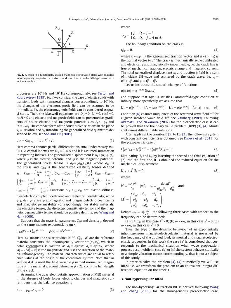
Fig. 1. A crack in a functionally graded magnetoelectroelastic plane with materialinhomogeneity properties – vector a and direction a under SH-type wave withincident angle h.
T. Rangelov et al. / International Journal of Solids and Structures 48 (2011) 2987–2999 2989
processes are 104 Hz and 107 Hz correspondingly, see Parton andKudryavtsev (1988). So, if we consider the case of elastic solids withtransient loads with temporal changes correspondingly to 104 Hz,the changes of the electromagnetic field can be assumed to beimmediate, i.e. the electromagnetic fields can be considered as qua-si-static. Then, the Maxwell equations are Di,i = 0, Bi,i = 0, rotE = 0,rotH = 0 and electric and magnetic fields can be presented as gradi-ents of scalar electric and magnetic potentials as Ei = �/,i andHi = �u,i. The compact form of the constitutive relations in the planex3 = 0 is obtained by introducing the generalized field quantities de-scribed below, see Soh and Liu (2005)
riK ¼ CiKJluJ;l; x 2 R2 n C; ð1Þ
Here comma denotes partial differentiation, small indexes vary as i,l = 1, 2, capital indexes are K, J = 3, 4, 5 and it is assumed summationin repeating indexes. The generalized displacement is uJ = (u3,/,u),where / is the electric potential and u is the magnetic potential.The generalized stress tensor is riJ = (ri3,Di,Bi), where ri3 isthe stress and CiJKl is the generalized elasticity tensor defined
as: Ci33l ¼c44; i ¼ l0; i – l
�; Ci34l ¼ Ci43l ¼
e15; i ¼ l0; i – l
�; Ci35l ¼ Ci53l ¼
q15; i ¼ l0; i – l
�; Ci44l ¼
�e11; i ¼ l0; i – l
�; Ci45l ¼ Ci54l ¼
�d11; i ¼ l0; i – l
�;
Ci55l ¼�l11; i ¼ l0; i – l
�. Functions c44, e15, e11 are: elastic stiffness,
piezoelectric coupled coefficient and dielectric permittivity, whileq15, d11, l11 are piezomagnetic and magnetoelectric coefficientsand magnetic permeability correspondingly. For stable materials,the elasticity tensor, the dielectric permittivity tensor and the mag-netic permeability tensor should be positive definite, see Wang andHan (2006).
Suppose that the material parameters CiJKl and density q dependon the same manner exponentially on x
CiKJlðxÞ ¼ C0iKJle
2<a;x>; qðxÞ ¼ q0e2<a;x>: ð2Þ
Here <,> means the scalar product in R2; C0iJKl; q0 are the reference
material constants, the inhomogeneity vector a = (a1,a2), which inpolar coordinates is written as a1 = jajcosa, a2 = jajsina, wherejaj ¼
ffiffiffiffiffiffiffiffiffiffiffiffiffiffiffiffia2
1 þ a22
qis the magnitude and a is the direction of the mate-
rial inhomogeneity. The material characteristics are equal to refer-ence values at the origin of the coordinate system. Note that inSection 4 it is used the field variable b named normalized magni-tude of the material gradient defined as b = 2jajc, c is the half-lengthof the crack.
Assuming the quasielectrostatic approximation of MEE materialin the absence of body forces, electric charges and magnetic cur-rent densities the balance equation is
riK;i þ qKJx2uJ ¼ 0: ð3Þ
where
qQJ ¼q; Q ¼ J ¼ 3;0; Q ; J ¼ 4 or 5:
�
The boundary condition on the crack is
tJ jC ¼ 0: ð4Þ
where tJ = riJni is the generalized traction vector and n = (n1,n2) isthe normal vector to C. The crack is mechanically self-equilibratedand electrically and magnetically impermeable, i.e. the crack line isfree of mechanical traction, electric charge and magnetic current.The total generalized displacement uJ and traction tJ field is a sumof incident SH-wave and scattered by the crack wave, i.e. uJ ¼uin
J þ uscJ and tJ ¼ tin
J þ tscJ .
Let us introduce the smooth change of functions
uðx;xÞ ¼ e�<a;x>Uðx;xÞ: ð5Þ
and suppose that U(x,x) satisfies Sommerfeld-type condition atinfinity, more specifically we assume that
U3 ¼ oðjxj�1Þ; U4 ¼ oðe�jajjxjÞ; U5 ¼ oðe�jajjxjÞ for jxj ! 1: ð6Þ
Condition (6) ensures uniqueness of the scattered wave field usc fora given incident wave field uin, see Vainberg (1989). FollowingAkamatsu and Nakamura (2002) for the piezoelectric case it canbe proved that the boundary value problem (BVP) (3), (4) admitscontinuous differentiable solutions.
After applying the transform (5) to Eq. (3), the following systemwith constant coefficients is obtained, see Dineva et al. (2011) forthe piezoelectric case :
C0iJKlUK;il þ ðq0
JKx2 � C0
iJKljaj2ÞUK ¼ 0: ð7Þ
Eliminating U4 and U5 by inserting the second and third equation of(7) into the first one, it is obtained the reduced equation for themechanical displacement
U3;ii þ k2U3 ¼ 0; ð8Þ
where
k2 ¼ x2q0
a0� jaj2; a0 ¼
det M0
e011l0
11 � d0211
and
M0 ¼c440 e0
15 q015
e015 �e0
11 �d011
q015 �d0
11 �l011
0BB@
1CCA:
Denote x0 ¼ jajffiffiffiffia0q0
q, the following three cases with respect to the
frequency can be determined:(a) x > x0, in this case k2 > 0; (b) x = x0, in this case k2 = 0; (c)
x < x0, in this case k2 < 0.Thus, the type of the dynamic behaviour of an exponentially
inhomogeneous magnetoelectroelastic material is governed bythe frequency of the applied load, its inertial and magnetoelectro-elastic properties. In this work the case (a) is considered that cor-responds to the mechanical situation when wave propagationprocess occur, while in case (b) or (c) the system behaves staticallyor a simple vibration occurs correspondingly, that is not a subjectof this study.
In order to solve the problem (3), (4) numerically we will useBIEM, i.e. we transform the problem to an equivalent integro-dif-ferential equation on the crack C.
3. Non-hypersingular BIEM
The non-hypersingular traction BIE is derived following Wangand Zhang (2005) for the homogeneous piezoelectric case,

2990 T. Rangelov et al. / International Journal of Solids and Structures 48 (2011) 2987–2999
Rangelov et al. (2008) for the inhomogeneous piezoelectric caseand Stoynov and Rangelov (2008), Stoynov and Rangelov (2009)for the MEE case.
For uJ; u�JK , where u�JK is the fundamental solution of (3), we ap-ply the Green’s formula in the domain XRnXe, where XR is a diskwith large radius R and Xe is a small neighborhood of C. Applyingthe representation formulae for the generalized displacement gra-dient uK,l, following Wang and Zhang (2005) an integro-differentialequation on oXR [ oXe is obtained, see Stoynov and Rangelov(2008). Using condition (6) the integrals over oXR go to 0 forR ?1. Taking the limit e ? 0, i.e. x ? C and using the boundarycondition (4), i.e. tsc
J ¼ �tinJ on C, the following system of BIE that
is equivalent to the BVP (3), (4) is obtained
�tinJ ðx;xÞ ¼ CiJKlðxÞniðxÞ
ZCþðr�gPKðx; y;xÞMuP;gðy;xÞh
�qQPðyÞx2u�QKðx; y;xÞMuPðy;xÞÞdkl
�r�kPKðx; y;xÞMuP;lðy;xÞinkðyÞdC; x 2 Cþ: ð9Þ
where r�iJQ ¼ CiJMlu�MQ ;l is the fundamental solution for the stress ten-sor, DuJ ¼ uJjCþ � uJ jC� is the generalized crack opening displace-ment (COD), x = (x1,x2), y = (y1,y2) denote the field point and thesource point respectively. Eq. (9) is a traction non-hypersingularBIE on the crack line C for the unknown DuJ. Once a solution ofthe generalized crack opening displacement is obtained, the gener-alized displacement uJ can be obtained at every point in R2nC byusing the corresponding representation formulae, see Stoynov andRangelov (2009). The boundary value problem defined in Section2 is transformed into a system of BIE (9) and the key role for thisis being played by the fundamental solution of the wave Eq. (3) withvariable coefficients.
3.1. Fundamental solution
A fundamental solution of (3) is defined as a solution of theequation
r�iJM;i þ qKJx2u�KM ¼ �dJMdðx; nÞ; ð10Þ
where d(x,n) is the Dirak’s function and dJM is the Kroneker symbol.For the considered type of inhomogeneity the fundamental solutionis obtained in Stoynov and Rangelov (2008). For completeness’ sakethe derivation of this fundamental solution will be discussedshortly. First, the smooth transform u�KM ¼ e�<a;x>U�KM applied to(10) leads to the following equation
C0iJKiU
�KM;ii þ ½q0
JKx2 � C0
iJKia2i �U
�KM ¼ �e�<a;n>dJMdðx; nÞ: ð11Þ
Second, applying the Radon transform Rðf Þ ¼ f̂ ðs;mÞ ¼Rþ1�1 f ðxÞd
ðs� < x;m >Þdx, see Zayed (1996) to both sides of (11) and havingin mind that only m, jmj = 1 are used for the inverse Radon trans-form we get
ðM0@2s þ CÞbU� ¼ F: ð12Þ
where bU� ¼ RðU�Þ, and C; bU�; F are
C ¼
q0x2 � c044jaj
2 �e015jaj
2 �q015jaj
2
�e015jaj
2 e011jaj
2 d011jaj
2
�q015jaj
2 d011jaj
2 l011jaj
2
0BBB@
1CCCA;
bU� ¼bU�33
bU�34bU�35bU�43
bU�44bU�45bU�53
bU�54bU�55
0BBB@
1CCCA; F ¼ �e�<a;n>
d 0 0
0 d 0
0 0 d
0BB@
1CCA:
Due to the condition x > x0 the solutions of (12) are
bU�33 ¼ �e�<a;n> 12ika0
eikjs�sj; bU�34 ¼ bU�43 ¼ �e�<a;n> A2ika0
eikjs�sj;
bU�44 ¼ �e�<a;n> A2
2ika0eikjs�sj � 1
2�e011 jaj
ejajjs�sj� �
;
bU�35 ¼ bU�53 ¼ �e�<a;n> B2ika0
eikjs�sj;
bU�45 ¼ bU�54 ¼ �e�<a;n> AB2ika0
eikjs�sj þ d011
2�e011
l011jaj e
jajjs�sj� �
;
bU�55 ¼ �e�<a;n> B2
2ika0eikjs�sj � 1
2jajd02
11�e0
11l02
11þ 1
l011
� �ejajjs�sj
� �:
ð13Þ
where in addition to previously used notations a0 ¼ �c044 þ
�e0215
�e011; k ¼ffiffiffiffiffiffiffiffiffiffiffiffiffiffiffiffiffiffiffiffiffiffi
q0x2
a0� jaj2
qthe following notations are used:
s ¼< n;m >; �c044 ¼ c0
44 þq02
15
l011
; �e015 ¼ e0
15 �d0
11q015
l011
;
�e011 ¼ e0
11 �d02
11
l011
; A ¼ l011e0
15 � q015d0
11
l011e0
11 � d0211
; B ¼ q015e0
11 � d011e0
15
l011e0
11 � d0211
:
The third step is to apply the inverse Radon transform, i.e. R�1 f̂ ¼f ðxÞ ¼ 1
4p2
Rjmj¼1 Kf̂ ðs;mÞjs¼<x;m>dm, where Kf̂ ðs;mÞ ¼
Rþ1�1
@r f̂ ðr;mÞs�r dr
and to obtain functions U�JK and correspondingly the fundamentalsolution u�JK .
3.2. Free-field solution
The free-field solution uinJ and its traction tin
J on the crack line Cis obtained using the wave decomposition method. With thechange of function (5) for uin
J we have an equation with constantcoefficients for
UinJ ¼ pJe
ik<x;g>; ð14Þ
where g = (g1,g2), jgj = 1 is a wave propagation direction, pJ is thepolarization vector and k is the wave number. Replacing uin
J in Eq.(3) and solving the linear system of equations we obtain
uinJ ¼ pJe
<x;�aþikg>; p3 ¼ 1; p4 ¼ A; p5 ¼ B: ð15Þ
For the traction on the crack we get
tin3 ¼
det M0
e011l0
11 � d0211
< �aþ ikg; n > e<x;aþikg>; tin4 ¼ 0; tin
5 ¼ 0:
ð16Þ
3.3. GIF evaluation
The dynamic fracture state of MEE material is characterized bythe leading term of the asymptotic of the generalized displacementand the generalized traction near the crack-tips presented by thegeneralized stress intensity factor. For the considered MEE mediaGIFs are stress intensity factor, electric field intensity factor andmagnetic field intensity factor. Note that the mechanical stressintensity factor KIII, electrical displacement KD and magnetic dis-placement KB are obtained directly from the traction values aheadthe crack-tip, see Suo et al. (1992) for the piezoelectric case and forthe straight crack on Ox1, C = (�c,c) they are
KIII ¼ limx1!�c
t3
ffiffiffiffiffiffiffiffiffiffiffiffiffiffiffiffiffiffiffiffiffiffiffi2pðx1 � cÞ
p;
KD ¼ limx1!�c
t4
ffiffiffiffiffiffiffiffiffiffiffiffiffiffiffiffiffiffiffiffiffiffiffi2pðx1 � cÞ
p;
KB ¼ limx1!�c
t5
ffiffiffiffiffiffiffiffiffiffiffiffiffiffiffiffiffiffiffiffiffiffiffi2pðx1 � cÞ
p:
ð17Þ
For the normal incident wave, using the constitutive equations (1)the following representations for the electric field E2 and magneticfield H2 hold
T. Rangelov et al. / International Journal of Solids and Structures 48 (2011) 2987–2999 2991
E2 ¼det M2
det M; H2 ¼
det M3
det M; ð18Þ
where
M ¼c44 e15 q15
e15 �e11 �d11
q15 �d11 �l11
0B@
1CA; M2 ¼
c44 t3 �q15
e15 t4 d11
q15 t5 l11
0B@
1CA;
M3 ¼c44 �e15 t3
e15 e11 t4
q15 d11 t5
0B@
1CA:
The electric field intensity factor KE and the magnetic field intensityfactor KH are evaluated with formulae
KE ¼ limx1!�c
E2ffiffiffiffiffiffiffiffiffiffiffiffiffiffiffiffiffiffiffiffiffiffiffi2pðx1 � cÞ
p;
KH ¼ limx1!�c
H2
ffiffiffiffiffiffiffiffiffiffiffiffiffiffiffiffiffiffiffiffiffiffiffi2pðx1 � cÞ
p:
ð19Þ
In formulas (17) and (19) tJ and E2, H2 are calculated at the point(x1,0) close to the crack-tip.
The asymptotic behaviour of the mechanical stress rij, electricdisplacement Di and electric field Ei, magnetic induction Bi andmagnetic field Hi in the vicinity of a crack–tip can be describedin terms of GIF: KIII, KD, KE and KB, KH correspondingly, see Sladeket al. (2010).
4. Numerical realization
The numerical procedure for the solution of the boundary valueproblem follows the numerical algorithm developed and validatedin Rangelov et al. (2008) for the inhomogeneous piezoelectricmaterial and in Stoynov and Rangelov (2009) for the homogeneousMEE case. The crack C is discretized by quadratic boundary ele-ments (BE) away from the crack-tips and special crack-tip quar-ter-point BE near the crack-tips to model adequately the
0
0.4
0.8
1.2
1.6
0.3 0.5 0.7 0.9 1.1 1.3
IIIK* K
0
0.4
0.8
1.2
1.6
0.3 0.5
IIIK*
Fig. 2. SIF K�III versus normalized frequency X of normal incident SH wave propagatingmagnitude b = 0.4 and inhomogeneity direction according to crack line: (a) a = p/2 ; (b)
asymptotic behavior of the displacement and the traction. Apply-ing the shifted point scheme, the singular integrals converge inCauchy principal value (CPV) sense, since the smoothness require-ments DuJ 2 C1+c(C), 0 < c < 1 of the approximation are fulfilled.Due to the specific form of the fundamental solution as an integralover the unit circle, all integrals in (9) are two dimensional. In gen-eral, there appear two types of integrals - regular integrals and sin-gular integrals, the latter including a weak ‘‘lnr’’ type singularityand also a strong ‘‘1r ’’ type singularity. The regular integrals aresolved using Quasi Monte Carlo method, while the singular inte-grals are solved by a combined method – partially analytically asCPV integrals. After discretization procedure an algebraic linearcomplex system of equations is obtained and solved. The programcodes based on Mathematica and FORTRAN are created followingthe above outlined procedure.
In the numerical examples the crack C with half-lengthc = 5 mm, occupying an interval (�c,c) on Ox1 axis is considered.The crack is divided into 7 BE with lengths correspondingly:l1 = l7 = 0.15c, l2 = � � � = l6 = 0.34c, 1st BE is a left quarter point BE,7th BE is a right quarter point BE and the rest BE are ordinaryBEs. The three materials, used in numerical examples, have thefollowing reference properties: piezoelectric material BaTiO3 (elas-tic stiffness c0
44 ¼ 43ðGPaÞ, dielectric permittivity e011 ¼ 11:2
10�10ðC2=Nm2Þ, piezoelectric coefficient e015 ¼ 11:6ðC=m2Þ, density
q0 = 5.8 103(kg/m3)); piezomagnetic material CoFe2O4 (elasticstiffness c0
44 ¼ 45:3ðGPaÞ, dielectric permittivity e011 ¼ 0:08 10�10
ðC2=Nm2Þ, magnetic permeability l011 ¼ �590 10�6ðNs2=C2Þ,
piezomagnetic coefficient q015 ¼ 550ðN=AmÞ, density q0 = 7.5
103(kg/m3)) and magnetoelectroelastic composite BaTiO3/CoFe2O4.It is assumed that the material constants kc of the composite madeof BaTiO3 as an inclusion with material constants ki and CoFe2O4 asa matrix with material constants km are defined as kc = 0.5(ki + km),see Song and Sih (2003), and the magnetoelectric constantd0
11 ¼ 5:2 10�12ðNs=VCÞ is chosen based on the micro-mechanicalmodel, proposed in Li (2005).
0
0.4
0.8
1.2
1.6
0.3 0.5 0.7 0.9 1.1 1.3
III*
0.7 0.9 1.1 1.3
in exponentially graded anisotropic elastic plane with normalized inhomogeneitya = 0, left crack tip; (c) a = 0, right crack tip.

2992 T. Rangelov et al. / International Journal of Solids and Structures 48 (2011) 2987–2999
4.1. Validation test examples
The described numerical scheme is validated by three bench-mark examples describing fracture behaviour of a straight crackin an infinite plane subjected to a normal incident time-harmonicSH-wave in three different kinds of material, more specifically: (a)graded elastic anisotropic, see Daros (2010); (b) graded piezoelec-tric, see Rangelov et al. (2008); (c) homogeneous MEE composite,see Stoynov and Rangelov (2009). Note that in all three examplesit is used the numerical scheme and the program code for coupledMEE material. The test example for the pure elastic material isobtained at assumption that piezoelectric e0
15, piezomagnetic q015
and magnetoelectric d011 coupling coefficients are zero, while the
test example concerning piezoelectric material is obtained at zeropiezomagnetic and magnetoelectric coefficients. All the rest coeffi-cients are as for the MEE composite.
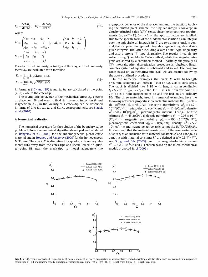
Fig. 2 shows the normalized SIF K�III ¼KIII
tin3
ffiffiffiffipcp versus the normal-
ized frequency X = ck0, where k0 ¼ffiffiffiffiffiffiffiffiffiffiffiffiffiffiffiffiffiffiffiffiffiffiq0x2
a0� jaj2
q; a0 ¼ c0
44, forgraded elastic anisotropic material with following characteristics:
c044 ¼ 27:1ðGPaÞ; q0 ¼ 7:55 103ðkg=m3Þ, inhomogeneity function
e2<a,x> with a1 ¼ b cos a2c and a2 ¼ b sin a
2c ; b ¼ 0:4; a ¼ p=2 in Fig. 2aand a = 0 in Fig. 2b and c concerning SIF K�III for left and right cracktip correspondingly. A comparison of the authors’ results withBIEM solutions obtained in Daros, 2010 demonstrates the accuracyof the proposed numerical scheme. The maximal percentage differ-ence between authors’ solutions and those in Daros, 2010 is notmore than 9%.
Analogous comparison but for piezoelectric material PZT 6B isshown in Fig. 3a–c , where comparison has been done with BIEMresults given in Rangelov et al. (2008). In this case a0 ¼c0
44 þe02
15e0
11; c0
44 ¼ 27:1ðGPaÞ; e015 ¼ 4:6ðC=m2Þ and e0
11 ¼ 36 10�10
ðC2=Nm2Þ . The close results shown in Fig. 3 demonstrate the highaccuracy of the proposed non-hypersingular traction BIEM.
0
0.4
0.8
1.2
1.6
0.3 0.5 0.7 0.9 1.1 1.3
IIIK* IIK*
0
0.4
0.8
1.2
1.6
0.3 0.5 0.7
IIIK*
Fig. 3. SIF K�III versus normalized frequency X of normal incident SH wave propagatmagnitude b = 0.4 and inhomogeneity direction according to crack line: (a) a = p/2 ; (b)
Note that the results in Daros (2010), presented in Fig. 2 andthose in Rangelov et al. (2008) shown in Fig. 3 are obtained by5 BE, while the results in the present study are obtained by 7BE. Moreover we have done numerical experiments with 15 BEand conclude that the results are very close to those obtainedby 7 BE. This is the reason we use in the simulations the meshof 7 BE.
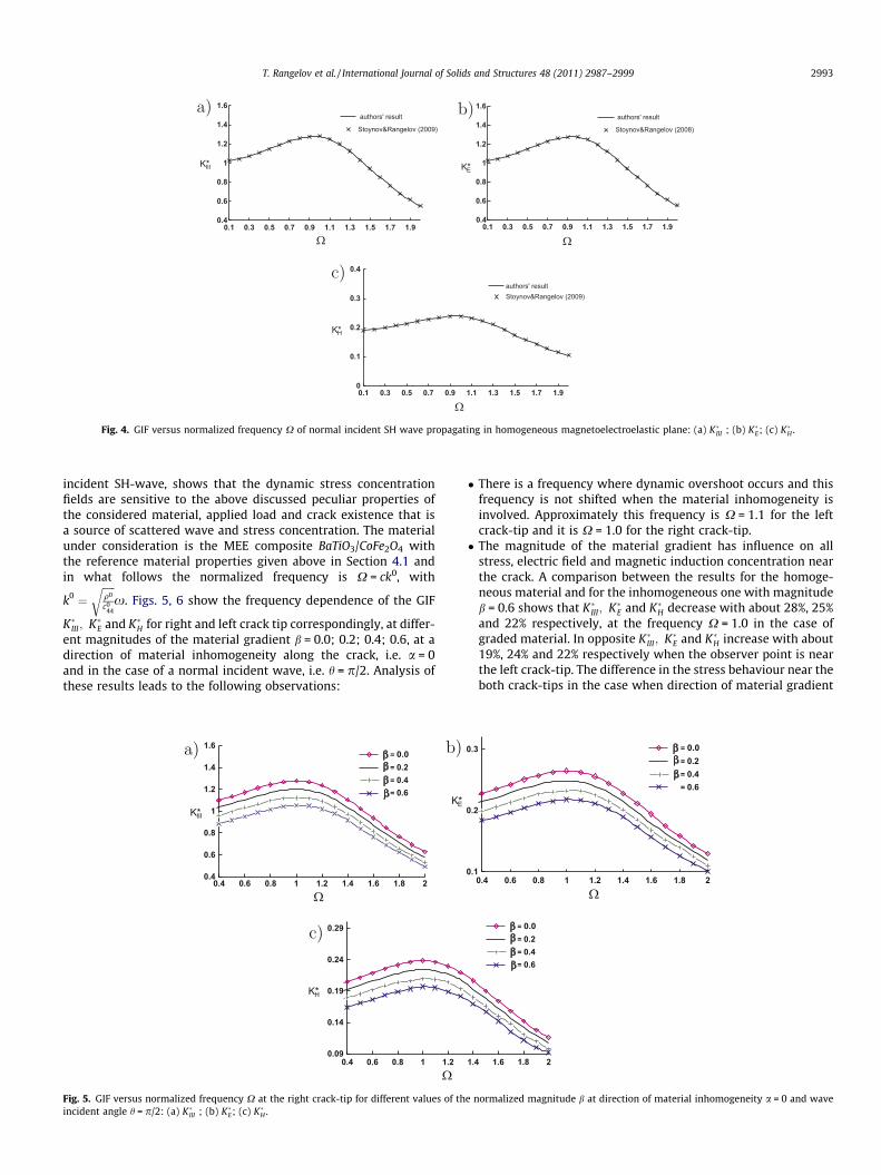
The third test example concerns the case of homogeneous MEEcomposite BaTiO3/CoFe2O4. Normalized GIFs as mechanical stress
K�III , electric field intensity factor K�E ¼10KE
tin3
ffiffiffiffipcp and magnetic field
intensity factor K�H ¼104KHtin3
ffiffiffiffipcp , are plotted in Fig. 4a–c correspondingly.
Results published in Stoynov and Rangelov (2009) for homoge-neous composite are compared with solutions obtained by the pro-posed numerical algorithm with zero magnitude of the materialinhomogeneity. Fig. 4 demonstrates very close results for thehomogeneous and for the inhomogeneous MEE material obtainedby the proposed numerical scheme in the case the inhomogeneityvector a is equal to 0. All results in Figs. 2–4 reveal that the pro-posed computational tool for calculation of GIF for crackedsmoothly inhomogeneous MEE composite works accurately andresults converge in the considered frequency interval.
4.2. Simulation examples
The aim of the simulation study conducted here is to show hownear-field characteristics as GIF are influenced by the followingkey parameters: (a) incoming wave characteristics – frequencyand direction of wave propagation; (b) type of material scale ofinhomogeneity and its specific properties as magnitude and direc-tion of material gradient; (c) the type and properties of the me-chanic-electric-magnetic load; (d) the coupled nature of thematerial.
Specifically, our numerical BIEM solution of the BVP in questioninvolving a finite crack in an infinite graded MEE plane under an
0
0.4
0.8
1.2
1.6
0.3 0.5 0.7 0.9 1.1 1.3
I
0.9 1.1 1.3
ing in exponentially graded piezoelectric plane with normalized inhomogeneitya = 0, left crack tip; (c) a = 0, right crack tip.
0.4
0.6
0.8
1
1.2
1.4
1.6
0.1 0.3 0.5 0.7 0.9 1.1 1.3 1.5 1.7 1.9
IIIK*
0.4
0.6
0.8
1
1.2
1.4
1.6
0.1 0.3 0.5 0.7 0.9 1.1 1.3 1.5 1.7 1.9
EK*
0
0.1
0.2
0.3
0.4
0.1 0.3 0.5 0.7 0.9 1.1 1.3 1.5 1.7 1.9
HK*
Fig. 4. GIF versus normalized frequency X of normal incident SH wave propagating in homogeneous magnetoelectroelastic plane: (a) K�III ; (b) K�E; (c) K�H .
T. Rangelov et al. / International Journal of Solids and Structures 48 (2011) 2987–2999 2993
incident SH-wave, shows that the dynamic stress concentrationfields are sensitive to the above discussed peculiar properties ofthe considered material, applied load and crack existence that isa source of scattered wave and stress concentration. The materialunder consideration is the MEE composite BaTiO3/CoFe2O4 withthe reference material properties given above in Section 4.1 andin what follows the normalized frequency is X = ck0, with
k0 ¼ffiffiffiffiffiq0
c044
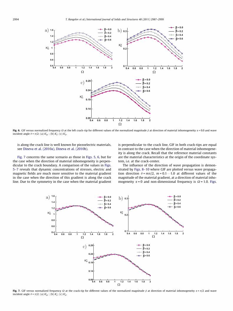
rx. Figs. 5, 6 show the frequency dependence of the GIF
K�III; K�E and K�H for right and left crack tip correspondingly, at differ-ent magnitudes of the material gradient b = 0.0; 0.2; 0.4; 0.6, at adirection of material inhomogeneity along the crack, i.e. a = 0and in the case of a normal incident wave, i.e. h = p/2. Analysis ofthese results leads to the following observations:
0.4
0.6
0.8
1
1.2
1.4
1.6
0.4 0.6 0.8 1 1.2 1.4 1.6 1.8 2
= 0.0
= 0.2
= 0.4
= 0.6
IIIK*K
0.09
0.14
0.19
0.24
0.29
0.4 0.6 0.8 1 1.2
HK*
Fig. 5. GIF versus normalized frequency X at the right crack-tip for different values of tincident angle h = p/2: (a) K�III ; (b) K�E; (c) K�H .
� There is a frequency where dynamic overshoot occurs and thisfrequency is not shifted when the material inhomogeneity isinvolved. Approximately this frequency is X = 1.1 for the leftcrack-tip and it is X = 1.0 for the right crack-tip.� The magnitude of the material gradient has influence on all
stress, electric field and magnetic induction concentration nearthe crack. A comparison between the results for the homoge-neous material and for the inhomogeneous one with magnitudeb = 0.6 shows that K�III; K�E and K�H decrease with about 28%, 25%and 22% respectively, at the frequency X = 1.0 in the case ofgraded material. In opposite K�III; K�E and K�H increase with about19%, 24% and 22% respectively when the observer point is nearthe left crack-tip. The difference in the stress behaviour near theboth crack-tips in the case when direction of material gradient
0.1
0.2
0.3
0.4 0.6 0.8 1 1.2 1.4 1.6 1.8 2
= 0.0
= 0.2
= 0.4
= 0.6
E*
1.4 1.6 1.8 2
= 0.0
= 0.2
= 0.4
= 0.6
he normalized magnitude b at direction of material inhomogeneity a = 0 and wave
0.4
0.6
0.8
1
1.2
1.4
1.6
0.4 0.6 0.8 1 1.2 1.4 1.6 1.8 2
= 0.0
= 0.2
= 0.4
= 0.6
IIIK*
0.1
0.2
0.3
0.4 0.6 0.8 1 1.2 1.4 1.6 1.8 2
EK*
= 0.0
= 0.2
= 0.4
= 0.6
0.09
0.14
0.19
0.24
0.29
0.4 0.6 0.8 1 1.2 1.4 1.6 1.8 2
= 0.0
= 0.2
= 0.4
= 0.6
HK*
Fig. 6. GIF versus normalized frequency X at the left crack–tip for different values of the normalized magnitude b at direction of material inhomogeneity a = 0.0 and waveincident angle h = p/2: (a) K�III ; (b) K�E; (c) K�H .
2994 T. Rangelov et al. / International Journal of Solids and Structures 48 (2011) 2987–2999
is along the crack line is well known for piezoelectric materials,see Dineva et al. (2010a), Dineva et al. (2010b).
Fig. 7 concerns the same scenario as those in Figs. 5, 6, but forthe case when the direction of material inhomogeneity is perpen-dicular to the crack boundary. A comparison of the values in Figs.5–7 reveals that dynamic concentrations of stresses, electric andmagnetic fields are much more sensitive to the material gradientin the case when the direction of this gradient is along the crackline. Due to the symmetry in the case when the material gradient
0.4
0.6
0.8
1
1.2
1.4
1.6
0.4 0.6 0.8 1 1.2 1.4 1.6 1.8 2
= 0.0
= 0.2
= 0.4
= 0.6
IIIK*
0.09
0.14
0.19
0.24
0.29
0.4 0.6 0.8 1
HK*
Fig. 7. GIF versus normalized frequency X at the crack-tip for different values of the nincident angle h = p/2: (a) K�III ; (b) K�E; (c) K�H .
is perpendicular to the crack line, GIF in both crack-tips are equalin contrast to the case when the direction of material inhomogene-ity is along the crack. Recall that the reference material constantsare the material characteristics at the origin of the coordinate sys-tem, i.e. at the crack-center.
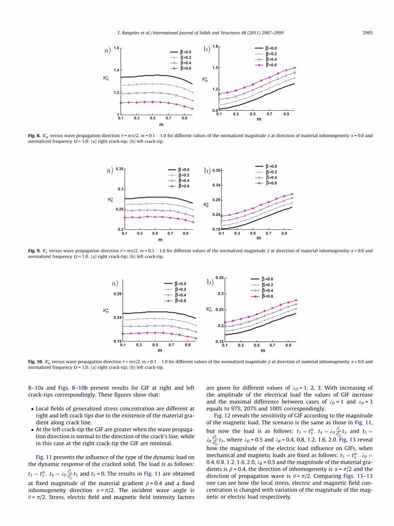
The influence of the direction of wave propagation is demon-strated by Figs. 8–10 where GIF are plotted versus wave propaga-tion direction h = mp/2, m = 0.1� � �1.0 at different values of themagnitude of the material gradient, at a direction of material inho-mogeneity a = 0 and non-dimensional frequency is X = 1.0. Figs.
0.1
0.2
0.3
0.4 0.6 0.8 1 1.2 1.4 1.6 1.8 2
= 0.0
= 0.2
= 0.4
= 0.6
EK*
1.2 1.4 1.6 1.8 2
= 0.0
= 0.2
= 0.4
= 0.6
ormalized magnitude b at direction of material inhomogeneity a = p/2 and wave
1
1.2
1.4
1.6
0.1 0.3 0.5 0.7 0.9
=0.0=0.2=0.4=0.6
IIIK*
m
0.9
1.2
1.5
1.8
0.1 0.3 0.5 0.7 0.9
=0.0=0.2=0.4=0.6
IIIK*
m
Fig. 8. K�III versus wave propagation direction h = mp/2, m = 0.1� � �1.0 for different values of the normalized magnitude b at direction of material inhomogeneity a = 0.0 andnormalized frequency X = 1.0: (a) right crack-tip; (b) left crack-tip.
0.2
0.25
0.3
0.35
0.1 0.3 0.5 0.7 0.9
=0.0=0.2=0.4=0.6
EK*
m
0.19
0.24
0.29
0.34
0.39
0.1 0.3 0.5 0.7 0.9
=0.0=0.2=0.4=0.6
EK*
m
Fig. 9. K�E versus wave propagation direction h = mp/2, m = 0.1� � �1.0 for different values of the normalized magnitude b at direction of material inhomogeneity a = 0.0 andnormalized frequency X = 1.0: (a) right crack-tip; (b) left crack-tip.
0.19
0.24
0.29
0.1 0.3 0.5 0.7 0.9
=0.0=0.2=0.4=0.6
HK*
m
0.15
0.2
0.25
0.3
0.35
0.1 0.3 0.5 0.7 0.9
=0.0=0.2=0.4=0.6
HK*
m
Fig. 10. K�H versus wave propagation direction h = mp/2, m = 0.1� � �1.0 for different values of the normalized magnitude b at direction of material inhomogeneity a = 0.0 andnormalized frequency X = 1.0: (a) right crack-tip; (b) left crack-tip.
T. Rangelov et al. / International Journal of Solids and Structures 48 (2011) 2987–2999 2995
8–10a and Figs. 8–10b present results for GIF at right and leftcrack-tips correspondingly. These figures show that:
� Local fields of generalized stress concentration are different atright and left crack tips due to the existence of the material gra-dient along crack line.� At the left crack-tip the GIF are greater when the wave propaga-
tion direction is normal to the direction of the crack’s line, whilein this case at the right crack-tip the GIF are minimal.
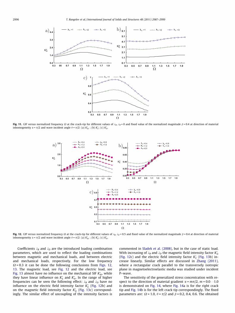
Fig. 11 presents the influence of the type of the dynamic load onthe dynamic response of the cracked solid. The load is as follows:
t3 ¼ tin3 ; t4 ¼ kD
e011
e015
t3 and t5 = 0. The results in Fig. 11 are obtained
at fixed magnitude of the material gradient b = 0.4 and a fixedinhomogeneity direction a = p/2. The incident wave angle ish = p/2. Stress, electric field and magnetic field intensity factors
are given for different values of kD = 1, 2, 3. With increasing ofthe amplitude of the electrical load the values of GIF increaseand the maximal difference between cases of kD = 1 and kD = 3equals to 97%, 207% and 100% correspondingly.
Fig. 12 reveals the sensitivity of GIF according to the magnitudeof the magnetic load. The scenario is the same as those in Fig. 11,
but now the load is as follows: t3 ¼ tin3 ; t4 ¼ kD
e011
e015
t3 and t5 ¼kB
l011
q015
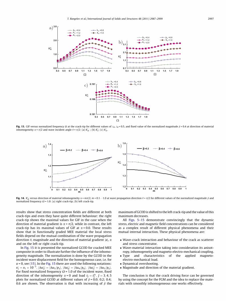
t3, where kD = 0.5 and kB = 0.4, 0.8, 1.2, 1.6, 2.0. Fig. 13 reveal
how the magnitude of the electric load influence on GIFs, whenmechanical and magnetic loads are fixed as follows: t3 ¼ tin
3 ; kD ¼0:4;0:8;1:2;1:6;2:0, kB = 0.5 and the magnitude of the material gra-dients is b = 0.4, the direction of inhomogeneity is a = p/2 and thedirection of propagation wave is h = p/2. Comparing Figs. 11–13one can see how the local stress, electric and magnetic field con-centration is changed with variation of the magnitude of the mag-netic or electric load respectively.
0.8
1.8
2.8
3.8
0.3 0.5 0.7 0.9 1.1 1.3 1.5 1.7 1.9
IIIK*
=0.4 =0.8=1.2 =1.6=2.0
B
B
B
B
B
0.05
0.25
0.45
0.65
0.85
0.3 0.5 0.7 0.9 1.1 1.3 1.5 1.7 1.9
=0.4 =0.8=1.2 =1.6=2.0
B
B
B
B
B
EK*
0.1
0.3
0.5
0.7
0.9
0.3 0.5 0.7 0.9 1.1 1.3 1.5 1.7 1.9
HK*
=0.4 =0.8=1.2 =1.6=2.0
B
B
B
B
B
Fig. 12. GIF versus normalized frequency X at the crack-tip for different values of kB, kD = 0.5 and fixed value of the normalized magnitude b = 0.4 at direction of materialinhomogeneity a = p/2 and wave incident angle h = p/2: (a) K�III ; (b) K�E; (c) K�H .
0.4
1.4
2.4
3.4
4.4
0.3 05 0.7 0.9 1.1 1.3 1.5 1.7 1.9
IIIK*
=1 =2 =3DDD
0.1
1.1
2.1
3.1
4.1
5.1
6.1
0.3 0.5 0.7 0.9 1.1 1.3 1.5 1.7 1.9
EK*
=1 =2 =3DDD
0.2
0.4
0.6
0.8
1
0.3 0.5 0.7 0.9 1.1 1.3 1.5 1.7 1.9
HK*
=1 =2 =3DDD
Fig. 11. GIF versus normalized frequency X at the crack-tip for different values of kD, kB = 0 and fixed value of the normalized magnitude b = 0.4 at direction of materialinhomogeneity a = p/2 and wave incident angle h = p/2: (a) K�III ; (b) K�E; (c) K�H .
2996 T. Rangelov et al. / International Journal of Solids and Structures 48 (2011) 2987–2999
Coefficients kB and kD are the introduced loading combinationparameters, which are used to reflect the loading combinationsbetween magnetic and mechanical loads, and between electricand mechanical loads, respectively. For the low frequencyX = 0.3 it can be done the following conclusions from Figs. 12,13. The magnetic load, see Fig. 12 and the electric load, seeFig. 13 almost have no influence on the mechanical SIF K�III , whilethey have linear influence on K�E and K�H . In the range of higherfrequencies can be seen the following effect: kB and kD have noinfluence on the electric field intensity factor K�E (Fig. 12b) andon the magnetic field intensity factor K�H (Fig. 13c) correspond-ingly. The similar effect of uncoupling of the intensity factors is
commented in Sladek et al. (2008), but in the case of static load.With increasing of kB and kD the magnetic field intensity factor K�H(Fig. 12c) and the electric field intensity factor K�E (Fig. 13b) in-crease linearly. Similar effects are discussed in Zhang (2011),where a rectangular crack parallel to the transversely isotropicplane in magnetoelectroelastic media was studied under incidentP–wave.
The sensitivity of the generalized stress concentration with re-spect to the direction of material gradient a = mp/2, m = 0.0� � �1.0is demonstrated on Fig. 14, where Fig. 14a is for the right cracktip and Fig. 14b is for the left crack tip correspondingly. The fixedparameters are: X = 1.0, h = p/2 and b = 0.2, 0.4, 0.6. The obtained
1
1.1
1.2
1.3
1.4
0 0.1 0.2 0.3 0.4 0.5 0.6 0.7 0.8 0.9 1m
=0.2 =0.4 =0.6
IIIK*
1.2
1.3
1.4
1.5
1.6
0 0.1 0.2 0.3 0.4 0.5 0.6 0.7 0.8 0.9 1
=0.2 =0.4 =0.6
m
IIIK*
Fig. 14. K�III versus direction of material inhomogeneity a = mp/2, m = 0.1� � �1.0 at wave propagation direction h = p/2 for different values of the normalized magnitude b andnormalized frequency X = 1.0: (a) right crack-tip; (b) left crack-tip.
0.8
1.8
2.8
3.8
0.3 0.5 0.7 0.9 1.1 1.3 1.5 1.7 1.9
=0.4 =0.8=1.2 =1.6=2.0
D
D
D
D
D
IIIK*
0.1
1.1
2.1
3.1
0.3 0.5 0.7 0.9 1.1 1.3 1.5 1.7 1.9
=0.4 =0.8=1.2 =1.6=2.0
D
D
D
D
D
EK*
0.181
0.186
0.191
0.3 0.5 0.7 0.9 1.1 1.3 1.5 1.7 1.9
=0.4 =0.8=1.2 =1.6=2.0
D
D
D
D
D
HK*
Fig. 13. GIF versus normalized frequency X at the crack-tip for different values of kD, kB = 0.5, and fixed value of the normalized magnitude b = 0.4 at direction of materialinhomogeneity a = p/2 and wave incident angle h = p/2: (a) K�III ; (b) K�E; (c) K�H .
T. Rangelov et al. / International Journal of Solids and Structures 48 (2011) 2987–2999 2997
results show that stress concentration fields are different at bothcrack-tips and even they have quite different behaviour: the rightcrack-tip shows the maximal values for GIF in the case when thedirection of material gradient is a = p/2, while in contrast, the leftcrack-tip has its maximal values of GIF at a = 0.0. These resultsshow that in functionally graded MEE material the local stressfields depend on the mutual combination of the wave propagationdirection h, magnitude and the direction of material gradient jaj, aand on the left or right crack-tip.
In Fig. 15 it is presented the normalized GCOD for cracked MEEcomposite in order to illustrate further the influence of the inhomo-geneity magnitude. The normalization is done by the GCOD in theincident wave displacement field for the homogeneous case, i.e. fora = 0, see (15). In the Fig. 15 there are used the following notations:x�1 ¼ x1 10�3; jDu�3j ¼ jDu3=p3j; jDu�4j ¼ jDu4=p4j; jDu�5j ¼ jDu5=p5j.For fixed normalized frequency X = 1.0 of the incident wave, fixeddirection of the inhomogeneity a = 0 and load tJ ¼ tin
J ; J ¼ 3;4;5plots for normalized GCOD at different values of b = 0.0; 0.2; 0.4;0.6 are shown. The observation is that with increasing of b the
maximum of GCOD is shifted to the left crack-tip and the value of thismaximum decreases.
All Figs. 5–15 demonstrate convincingly that the dynamicstress, electric and magnetic field concentrations can be consideredas a complex result of different physical phenomena and theirmutual internal interaction. These physical phenomena are:
� Wave-crack interaction and behaviour of the crack as scattererand stress concentrator.� Wave-material interaction taking into consideration its anisot-
ropy, inhomogeneity and magneto-electro-mechanical coupling.� Type and characteristics of the applied magneto-
electro-mechanical load.� Dynamical overshooting.� Magnitude and direction of the material gradient.
The conclusion is that the crack driving force can be governedby using the concept for the FGM and the idea to replace the mate-rials with smoothly inhomogeneous one works effectively.

0.5
1
1.5
2
2.5
3
-5 -4 -3 -2 -1 0 1 2 3 4 5
1x*
3u*Δ| |
=0.0=0.2=0.4=0.6
0.5
1
1.5
2
2.5
3
5 4 3 2 1 0 1 2 3 4 5
4u*Δ| |
1x*
=0.0=0.2=0.4=0.6
0.5
1
1.5
2
2.5
3
5 4 3 2 1 0 1 2 3 4 5
5u*Δ| |
=0.0=0.2=0.4=0.6
1x*
Fig. 15. GCOD along the crack line for normalized frequency X = 1.0 and different values of the normalized magnitude b at direction of material inhomogeneity a = 0 andwave incident angle h = p/2: (a) jDu�3j; (b) jDu�4j; (c) jDu�5j.
2998 T. Rangelov et al. / International Journal of Solids and Structures 48 (2011) 2987–2999
5. Conclusion
A dynamic fracture analysis of exponentially inhomogeneousMEE materials subjected to time-harmonic anti-plane mechanicaland in-plane electromagnetic loads is presented in this study.The fundamental solutions are derived in a closed form by theRadon transform and implemented in the non-hypersingulartraction BIEM. Program codes in Mathematica and Fortran aredeveloped for the numerical solution. The simulations results showthe sensitivity of the GIFs on the type of the material, materialinhomogeneity characteristics, coupled nature of MEE continuaand properties of the applied dynamic electro-magneto mechanicalload. The presented method can be successfully used for solution ofthe more complex problems of inclined cracks, cracks witharbitrary shapes, crack interactions, cracked finite MEE solids andcomposites with different combinations of piezoelectric and piezo-magnetic constituents.
Acknowledgement
The authors acknowledge the support of the Bulgarian NationalScience Fund under the Grant No. DID 02/15 and the support ofTechnical University of Sofia under the Grant No. 102 NI 218-11.
References
Akamatsu, M., Nakamura, G., 2002. Well-posedness of initial-boundary valueproblems for piezoelectric equations. Appl. Anal. 81, 129141.
Chue, C.H., Hsu, W.H., 2008. Antiplane internal crack normal to the edge of afunctionally graded piezoelectric/piezomagnetic half plane. Meccanica 43, 307–325.
Daros, C.H., 2010. On modelling SH-waves in a class of inhomogeneous anisotropicmedia via the Boundary Element Method. ZAMM-Z. Angew. Math. Mech. 90 (2),113–121.
Dineva, P., Gross, D., Müller, R., Rangelov, T., 2010a. BIEM analysis of dynamicallyloaded anti-plane cracks in graded piezoelectric finite solids. Int. J. Solids Struct.47, 3150–3165.
Dineva, P., Gross, D., Müller, R., Rangelov, T., 2010b. Time-harmonic crack problemsin functionally graded piezoelectric solids via BIEM. Eng. Fract. Mech. 77, 1101–1115.
Dineva, P., Gross, D., Müller, R., Rangelov, T., 2011. Dynamic stress and electric fieldconcentration in a functionally graded piezoelectric solid with a circular hole.ZAMM-Z. Angew. Math. Mech. 91 (2), 110–124.
Erenstein, W., Mathur, N.D., Scott, J.F., 2006. Multifferitic and magnetoelectricmaterials. Nature 442, 759–765.
Feng, W., Su, R., 2006. Dynamic internal crack problem of a functionally gradedmagneto-electro-elastic strip. Int. J. Solids Struct. 43, 5196–5216.
Feng, W., Su, R., 2007. Dynamic fracture behaviors of cracks in a functionally gradedmagneto-electro-elastic plate. Eur. J. Mech. A/Solids 26, 363–379.
Feng, W.J., Su, R.K., Liu, Y.Q., 2006. Scattering of SH waves by an arc-shaped interfacecrack between a cylindrical magneto-electro-elastic inclusion and matrix withthe symmetry of 6 mm. Acta Mech. 183, 81–102.
Garcia-Sanchez, F., Rojas-Diaz, R., Saez, A., Zhang, C., 2007. Fracture ofmagnetoelectroelastic composite materials using boundary element method(BEM). Theor. Appl. Fract. Mech. 47, 192–204.
Lee, J.M., Ma, C.C., 2010. Analytical solutions for an antiplane problem of twodissimilar functionally graded magnetoelectroelastic half-planes. Acta Mech.212, 21–38.
Li, X.F., 2005. Dynamic analysis of a cracked magneto-electro-elastic medium underanti-plane mechanical and in-plane electric and magnetic impacts. Int. J. SolidsStr. 42, 3185–3205.
Li, Y.D., Lee, K.Y., 2009. Dynamic responses of a crack in a layered gradedmagnetoelectroelastic sensor subjected to harmonic waves. Acta Mech. 204,217–234.
Liang, J., 2008. The dynamic behaviour of two parallel symmetric cracks infunctionally graded piezoelectric/piezomagnetic materials. Arch. Appl. Mech.78, 443–464.
Liu, H.K., Huang, J.H., 2005. Piezoelectric and magnetic properties of PZT-(Ni0:284Zn0:549Cu0:183) Fe1984O4 composites. J. Mater. Sci. 40, 1979–1985.
Ma, C.C., Lee, J.M., 2009. Theoretical analysis of in-plane problem in functionallygraded nonhomogeneous magnetoelectroelastic bimaterials. Int. J. Solids Struct.46, 4208–4220.
Ma, L., Li, J.R., Abdelmoula, J., Wu, L.Z., 2007. Mode III crack problem in afunctionally graded magnetoelectroleastic strip. Int. J. Solids Struct. 44, 5518–5537.
Nan, C.W., Bichurin, M.I., Dong, S., Viehland, D., 2008. Multiferroic magnetoelectriccomposites: historical perspective, status, and future directions. J. Appl. Phys.103 (3), pp. 031101–1–35.
Parton, V.Z., Kudryavtsev, B.A., 1988. Electromagnetoelasticity, Piezoelectrics andElectrically Conductive Solids. Gordon and Breach Sci. Publish, New York.
Rangelov, T., Dineva, P., Gross, D., 2008. Effect of material inhomogeneity on thedynamic behavior of cracked piezoelectric solids: a BIEM approach. ZAMM-Z.Angew. Math. Mech. 88, 86–99.
T. Rangelov et al. / International Journal of Solids and Structures 48 (2011) 2987–2999 2999
Rojas-Diaz, R., Saez, A., Garcia-Sanchez, F., Zhang, C., 2008. Time-harmonic Green’sfunctions for anisotropic magnetoelectroelasticity. Int. J. Solids Struct. 45, 144–158.
Rojas-Diaz, R., Saez, A., Garcia-Sanchez, F., Zhang, C., 2009. Dynamic crackinteractions in magnetoelectroelastic composite materials. Int. J. Fract. 157(1–2), 119–130.
Rojas-Diaz, R., Saez, A., Garcia-Sanchez, F., Zhang, C., 2010. Analysis of crackedmagnetoelectroelastic composites under time-harmonic loading. Int. J. SolidsStruct. 47, 71–80.
Sirotin, Y.I., Shaskolskaya, M.P., 1982. Fundamentals of Crystal Physics. Mir Publ,Moskow.
Sladek, J., Sladek, V., Solek, P., Pan, E., 2008. Fracture analysis of cracks in magneto-electro-elastic solids by the MLPG. Comput. Mech. 42, 697–714.
Sladek, J., Sladek, V., Solek, P., Zhang, C., 2010. Fracture analysis in continuouslynonhomogeneous magneto-electro–elastic solids under a thermal load by theMLPG. Int. J. Solids Struct. 47, 1381–1391.
Soh, A.K., Liu, J.X., 2005. On the constitutive equations of magnitoelectroelasticsolids. J. Intell. Mater. Syst. Struct. 16, 597–602.
Song, Z.F., Sih, G.C., 2003. Crack initiation behavior in magneto-electro-elasticcomposite under in - plane deformation. Theor. Appl. Fract. Mech. 39, 189–207.
Spyropoulos, C.P., Sih, G.C., Song, Z.F., 2003. Magnetoelectroelastic composite withpoling parallel to plane of line crack under out-of-plane deformation. Theor.Appl. Fract. Mech. 40, 281–289.
Stoynov, Y., Rangelov, T., 2008. Time-harmonic behaviour of anti-plane cracks ininhomogeneous magnetoelectroelastic solid. Compt. Rend. Acad. Bulg. Sci. 62(2), 175–186.
Stoynov, Y., Rangelov, T., 2009. Time-harmonic crack problems inmagnetoelectroelastic plane by BIEM. J. Theor. Appl. Mech. 39 (4), 73–92.
Su, R.K., Feng, W.J., Liu, J., 2007. Transient response of interface cracks betweendissimilar magneto-electro-elastic strips under out-of-plane mechanical and in-plane magneto-electrical impact loads. Compos. Struct. 78, 119–128.
Suchtelen, V.J., 1972. Product properties: a new application of composite materials.Philips Res. Rep. 27, 28–37.
Suo, Z., Kuo, C., Barnett, D., Willis, J., 1992. Fracture mechanics for piezoelectricceramics. J. Mech. Phys. Solids 40, 739–765.
Vainberg, B.R., 1989. Asymptotic Methods in Equations of Mathematical Physic. CRCPress, New York.
Wang, B., Han, J., 2006. Discussion on electromagnetic crack face boundaryconditions for the fracture mechanics of magneto-electro-elastic materials.Acta Mech. Sinica 22, 233–242.
Wang, B.L., Mai, Y.W., 2003. Crack-tip field in piezoelectric/piezomagnetic media.Eur. J. Mech. A/Solids 22, 591–602.
Wang, B.L., Mai, Y.W., 2004. Fracture of piezoelectromagnetic materials. Mech. Res.Commun. 31, 65–73.
Wang, B.L., Mai, Y.W., 2007. Applicability of the crack-face electromagneticboundary conditions for fracture of magnetoelectroelastic materials. Int. J.Solids. Struct. 44, 387–398.
Wang, B.L., Niraula, O.P., 2009. Two collinear antiplane cracks in functionally gradedmagnetoelectroelastic composite materials. Mech. Comput. Mater. 45 (6), 583–596.
Wang, C.Y., Zhang, C., 2005. 2D and 3D dynamic Green’s functions and time-domainBIE formulations for piezoelectric solids. Eng. Anal. BE 29, 454–465.
Wunsche, M., Saez, A., Garcia-Sanchez, F., Zhang, C., 2010. Cracks inmagnetoelectroelastic solids under impact loading. Key Eng. Mater., 377–380.
Yong, H.D., Zhou, Y.H., 2007. Transient response of a cracked magnetoelectroelasticstrip under anti-plane impact. Int. J. Solids. Struct. 44, 705–717.
Zayed, A., 1996. Handbook of Generalized Function Transformations. CRC Press,Boca Raton, Florida.
Zhang, P.W., 2011. Dynamic fracture of a rectangular limited-permeable crack inmagneto-electro-elastic media under a time-harmonic elastic P-wave. Int. J.Solids. Struct. 48, 553–566.
Zhang, P.W., Zhou, Z.G., Wang, B., 2007. Dynamic behaviour of two collinearinterace cracks between two dissimilar functionally graded piezoelectric/piezomagnetic material strips. Appl. Math. Mech. 28, 615–625, English Edition.
Zhang, P.W., Zhou, Z.G., Wu, L.Z., 2008. Behaviour of three parallel non-symmetricmode III cracks in a functionally graded material plane. J. Mech. Eng. Sci. 222,2311–2330.
Zhong, X.C., Li, X.F., 2010. Interfacial crack between a magnetoelectroelastic solidand an elastic material. Mech. Adv. Mater. Struct. 17 (2), 134–144.
Zhong, X.C., Liu, F., Li, X.F., 2009. Transient response of a magnetoelectroelastic solidwith two collinear dielectric cracks under impacts. Int. J. Solids. Struct. 46,2950–2958.
Zhou, Z.G., Wang, B., 2004. Two parallel symmetry permeable cracks in functionallygraded piezoelectric /piezomagnetic materials under anti-plane shear loading.Int. J. Solids. Struct. 41, 4407–4422.
Zhou, Z.G., Wang, B., 2005. Scattering of harmonic anti-plane shear waves by aninterface crack in magneto-electro-elastic composites. Appl. Math. Mech. 26,17–26, English Edition.
Zhou, Z.G., Wang, B., 2006. Dynamic behaviour of two parallel symmetry cracks inmagneto-electro-elastic composites under harmonic anti-plane waves. Appl.Math. Mech. 27, 583–591, English Edition.
Zhou, Z.G., Wang, B., 2008. An interface crack between two dissimilar functionallygraded piezoelectric/piezomagnetic material half infinite planes subjected tothe harmonic anti-plane shear stress waves. Int. J. Appl. Electromagn. Mech. 27,117–132.
Zhou, Z.G., Wang, B., Sun, Y.G., 2004. Two collinear interface cracks in magneto-electro-elastic composites. Int. J. Eng. Sci. 42, 1155–1167.
Zhou, Z.G., Wu, L., Wang, B., 2005a. The behavior of a crack in functionally gradedpiezoelectric/piezomagnetic materials under anti-plane shear loading. Arc.Appl. Mech. 74 (8), 526–535.
Zhou, Z.G., Wu, L., Wang, B., 2005b. The dynamic behaviour of two collinearinterface cracks in magneto-electro-elastic material. Eur. J. Mech. A/Solids 24,253–262.
Zhou, Z.G., Wu, L., Wang, B., 2006. The dynamic behavior of two parallel interfacecracks in magneto-electro-elastic materials under the harmonic anti-planeshear stress waves. Strength Fract. Complexity 4 (3), 169–184.
Copyright © 2022 FDOKUMEN


![chapter – 21 solids [surface area and volume of 3-d solids]](https://static.fdokumen.com/doc/165x107/632737f8051fac18490e22eb/chapter-21-solids-surface-area-and-volume-of-3-d-solids.jpg)