projections of solids - SVECW
202
PROJECTIONS OF SOLIDS 1. TYPES OF SOLIDS I. POLYHEDRA A solid that has all faces as flat surfaces and are polygons. A. Regular Polyhedra All faces shall be regular polygons of the same size and shape, and the solid itself shall be symmetrical all around. • Tetrahedron has 4 equilateral triangles of the same size • Hexahedron (cube) has 6 equal sqares • Octahedron has 8 equilateral triangles of the same size • Dodecahedron has 12 regular pentagons of the same size • Icosahedron has 20 equilateral triangles of the same size
-
Upload
khangminh22 -
Category
Documents
-
view
0 -
download
0
Transcript of projections of solids - SVECW

PROJECTIONS OF SOLIDS
1. TYPES OF SOLIDS
I. POLYHEDRA
A solid that has all faces as flat surfaces and are polygons.
A. Regular Polyhedra
All faces shall be regular polygons of the same size and shape, and
the solid itself shall be symmetrical all around.
• Tetrahedron has 4 equilateral triangles of the same size
• Hexahedron (cube) has 6 equal sqares
• Octahedron has 8 equilateral triangles of the same size
• Dodecahedron has 12 regular pentagons of the same size
• Icosahedron has 20 equilateral triangles of the same size

A. Irregular Polyhedra
At least one face is either an irregular polygon or a different shaped
polygon than the other faces.
a) Prisms
Has two similar polygons of the same size and parallel to one
another as bases, the corresponding sides of which are
connected by means of parallelograms.
A regular prism is the one that has regular polygons as bases.
An irregular prism is the one that has irregular polygons as
bases.
A right prism is the one that has the axis perpendicular to the
bases.
An oblique prism is the one that has the axis inclined to the
bases.

b) Pyramids
Has one polygon as a base, the sides of which are connected
to triangles that are also joined together side by side and have
one common apex.
A regular pyramid is the one that has a regular polygon as
base.
An irregular pyramid is the one that has an irregular polygon as
base.
A right pyramid is the one that has the axis perpendicular to the
base.
An oblique pyramid is the one that has the axis inclined to the
base.

II. SOLIDS OF REVOLUTION
Solid that are generated by rotating a plane about a line for one revolution.
A. Cylinder
Generated by rotating a rectangle about one of its side for one
complete revolution. Has two flat and one single curved surface.
B. Cone
Generated by rotating a right angled triangle about one of its
perpendicular arms for one complete revolution. Has one flat and
one single curved surface.
C. Sphere
Generated by rotating a semi-circle about its diameter for one
complete revolution. Has a double curved surface only.

2. POSSIBLE POSITIONS
A. Position of Axis w.r.t. H.P.
• Parallel to the H.P.
• Perpendicular to the H.P.
• Inclined to the H.P.
B. Position of Axis w.r.t. V.P.
• Parallel to the V.P.
• Perpendicular to the V.P.
• Inclined to the V.P.

POSITIONS OF A SOLID WITH RESPECT TO THE TWO PLANES
1. Axis parallel to both planes
2. Axis perpendicular to one plane (must be parallel to the other plane)
i. Axis perpendicular to the H.P. (must be parallel to the V.P.)
ii. Axis perpendicular to the V.P. (must be parallel to the H.P.)
3. Axis Inclined to one plane and parallel to the other plane
i. Axis inclined to the H.P. and parallel to the V.P.
ii. Axis inclined to the V.P. and parallel to the H.P.
4. Axis inclined to both planes ( Out of Syllabus )

ALWAYS DRAW THE VIEW IN
WHICH THE TRUE SIZE AND
SHAPE OF THE BASE IS SEEN

yx
a
c
d
e
c'e' a'
d'
o'
p
o
b'
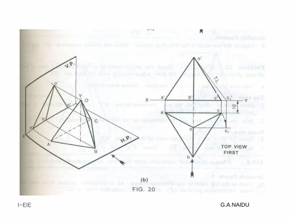
Problem : A Pentagonal pyramid of base 25mm Side and axis 50mm long , is resting on
HP on it’s base .Draw Projections of the Solid.
Pentagonal Pyramid – 1 base
1 Position of Solid
On HP
On xy FV
Infront of VP (Assume )
Below xy TV
2 Condition of Solid
Base on HP ( Nothing but
Axis Perpendicular to HP and
Parallel to VP ) , So True
Shape = TV.
3. Condition of Side / Edge /
Corner
Not Mentioned in the Problem

Example 1:
A pentagonal prism of 25 mm side of base and axis 50 mm long, has its axis parallel to boththe planes. One rectangular face of the prism makes an angle of 30o with the V.P. Draw itsprojections.
yx

Example 1:
A pentagonal prism of 25 mm side of base and axis 50 mm long, has its axis parallel to boththe planes. One rectangular face of the prism makes an angle of 30o with the V.P. Draw itsprojections.
yx
x1
y1

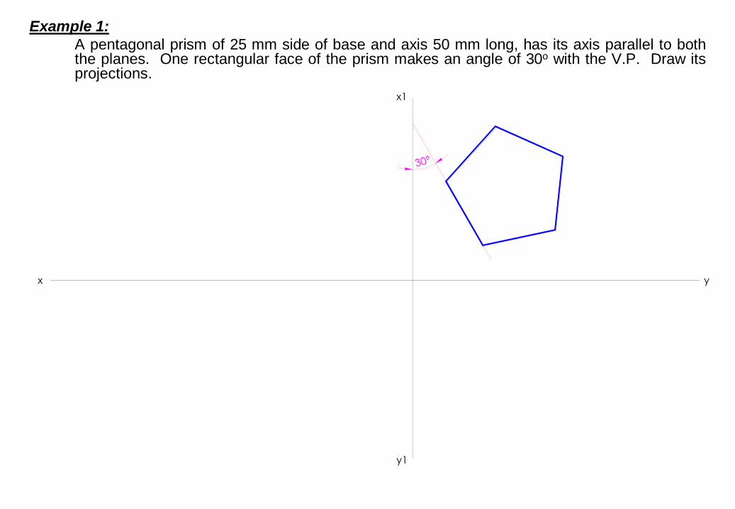
Example 1:
A pentagonal prism of 25 mm side of base and axis 50 mm long, has its axis parallel to boththe planes. One rectangular face of the prism makes an angle of 30o with the V.P. Draw itsprojections.
yx
x1
y1
30°
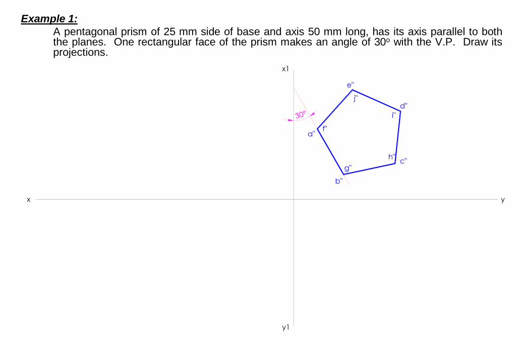
Example 1:
A pentagonal prism of 25 mm side of base and axis 50 mm long, has its axis parallel to boththe planes. One rectangular face of the prism makes an angle of 30o with the V.P. Draw itsprojections.
yx
x1
y1
30°

Example 1:
A pentagonal prism of 25 mm side of base and axis 50 mm long, has its axis parallel to boththe planes. One rectangular face of the prism makes an angle of 30o with the V.P. Draw itsprojections.
yx
x1
y1
30°
a"
b"
c"
d"
e"
Example 1:
A pentagonal prism of 25 mm side of base and axis 50 mm long, has its axis parallel to boththe planes. One rectangular face of the prism makes an angle of 30o with the V.P. Draw itsprojections.
yx
x1
y1
30°
a"
b"
c"
d"
e"
f"
g"
h"
i"
j"

Example 1:
A pentagonal prism of 25 mm side of base and axis 50 mm long, has its axis parallel to boththe planes. One rectangular face of the prism makes an angle of 30o with the V.P. Draw itsprojections.
yx
x1
y1
30°
a"
b"
c"
d"
e"
f"
g"
h"
i"
j"

Example 1:
A pentagonal prism of 25 mm side of base and axis 50 mm long, has its axis parallel to boththe planes. One rectangular face of the prism makes an angle of 30o with the V.P. Draw itsprojections.
yx
x1
y1
30°
a"
b"
c"
d"
e"
f"
g"
h"
i"
j"

Example 1:
A pentagonal prism of 25 mm side of base and axis 50 mm long, has its axis parallel to boththe planes. One rectangular face of the prism makes an angle of 30o with the V.P. Draw itsprojections.
yx
x1
y1
30°
a"
b"
c"
d"
e"
a'
d'
e'
c'
b'
f"
g"
h"
i"
j"
Example 1:
A pentagonal prism of 25 mm side of base and axis 50 mm long, has its axis parallel to boththe planes. One rectangular face of the prism makes an angle of 30o with the V.P. Draw itsprojections.
yx
x1
y1
30°
a"
b"
c"
d"
e"
a'
d'
e'
c'
b' g'
h'
j'
i'
f'f"
g"
h"
i"
j"

Example 1:
A pentagonal prism of 25 mm side of base and axis 50 mm long, has its axis parallel to boththe planes. One rectangular face of the prism makes an angle of 30o with the V.P. Draw itsprojections.
yx
x1
y1
30°
a"
b"
c"
d"
e"
a'
d'
e'
c'
b' g'
h'
j'
i'
f'f"
g"
h"
i"
j"

Example 1:
A pentagonal prism of 25 mm side of base and axis 50 mm long, has its axis parallel to boththe planes. One rectangular face of the prism makes an angle of 30o with the V.P. Draw itsprojections.
yx
x1
y1
30°
a"
b"
c"
d"
e"
a'
d'
e'
c'
b' g'
h'
j'
i'
f'f"
g"
h"
i"
j"

Example 1:
A pentagonal prism of 25 mm side of base and axis 50 mm long, has its axis parallel to boththe planes. One rectangular face of the prism makes an angle of 30o with the V.P. Draw itsprojections.
yx
x1
y1
30°
a"
b"
c"
d"
e"
a'
d'
e'
c'
b' g'
h'
j'
i'
f'f"
g"
h"
i"
j"

Example 1:
A pentagonal prism of 25 mm side of base and axis 50 mm long, has its axis parallel to boththe planes. One rectangular face of the prism makes an angle of 30o with the V.P. Draw itsprojections.
yx
x1
y1
30°
a"
b"
c"
d"
e"
a'
d'
e'
c'
b'
a
b
c
d
e
g'
h'
j'
i'
f'f"
g"
h"
i"
j"
i
h
j
f
g

Example 1:
A pentagonal prism of 25 mm side of base and axis 50 mm long, has its axis parallel to boththe planes. One rectangular face of the prism makes an angle of 30o with the V.P. Draw itsprojections.
yx
x1
y1
30°
a"
b"
c"
d"
e"
a'
d'
e'
c'
b'
a
b
c
d
e
g'
h'
j'
i'
f'f"
g"
h"
i"
j"
i
h
j
f
g

Example 1:
A pentagonal prism of 25 mm side of base and axis 50 mm long, has its axis parallel to boththe planes. One rectangular face of the prism makes an angle of 30o with the V.P. Draw itsprojections.
yx
x1
y1
30°
a"
b"
c"
d"
e"
a'
d'
e'
c'
b'
a
b
c
d
e
g'
h'
j'
i'
f'f"
g"
h"
i"
j"
i
h
j
f
g

Example 1:
A pentagonal prism of 25 mm side of base and axis 50 mm long, has its axis parallel to boththe planes. One rectangular face of the prism makes an angle of 30o with the V.P. Draw itsprojections.
yx
x1
y1
30°
a"
b"
c"
d"
e"
a'
d'
e'
c'
b'
a
b
c
d
e
g'
h'
j'
i'
f'f"
g"
h"
i"
j"
i
h
j
f
g

Example 1:
A pentagonal prism of 25 mm side of base and axis 50 mm long, has its axis parallel to boththe planes. One rectangular face of the prism makes an angle of 30o with the V.P. Draw itsprojections.
yx
x1
y1
30°
a"
b"
c"
d"
e"
a'
d'
e'
c'
b'
a
b
c
d
e
g'
h'
j'
i'
f'f"
g"
h"
i"
j"
i
h
j
f
g

Example 2:
A pentagonal prism of 25 mm side of base and axis 50 mm long, has its base in the H.P. Onerectangular face of the prism is perpendicular to the V.P. Draw its projections.
yx

Example 2:
A pentagonal prism of 25 mm side of base and axis 50 mm long, has its base in the H.P. Onerectangular face of the prism is perpendicular to the V.P. Draw its projections.
yx

Example 2:
A pentagonal prism of 25 mm side of base and axis 50 mm long, has its base in the H.P. Onerectangular face of the prism is perpendicular to the V.P. Draw its projections.
yx
a
b
c
d
e
f
g
h
i
j

Example 2:
A pentagonal prism of 25 mm side of base and axis 50 mm long, has its base in the H.P. Onerectangular face of the prism is perpendicular to the V.P. Draw its projections.
yx
a
b
c
d
e
f'
f
g
h
i
j
g'h'
i' j'
c'
e'
b'
a'd'

Example 3:
A pentagonal prism of 25 mm side of base and axis 50 mm long, has a side of base in theH.P. The axis of the prism is inclined at 45o to the H.P. and parallel to the V.P. Draw itsprojections.
yx

Example 3:
A pentagonal prism of 25 mm side of base and axis 50 mm long, has a side of base in theH.P. The axis of the prism is inclined at 45o to the H.P. and parallel to the V.P. Draw itsprojections.
yx
a
b
c
d
e
f
g
h
i
j
p
o

Example 3:
A pentagonal prism of 25 mm side of base and axis 50 mm long, has a side of base in theH.P. The axis of the prism is inclined at 45o to the H.P. and parallel to the V.P. Draw itsprojections.
yx
a
b
c
d
e
f'
f
g
h
i
j
g'h'
i' j'
c'
e'
b'
a'd'
p'
o'
p
o

Example 3:
A pentagonal prism of 25 mm side of base and axis 50 mm long, has a side of base in theH.P. The axis of the prism is inclined at 45o to the H.P. and parallel to the V.P. Draw itsprojections.
yx
a
b
c
d
e
f'
f
g
h
i
j
g'h'
i' j'
c'
e'
b'
a'd'
p'
o'
p
o
d'
p'
h'
g'
j'
f'
o'
c'
e'
b'a'
i'
45°

Example 3:
A pentagonal prism of 25 mm side of base and axis 50 mm long, has a side of base in theH.P. The axis of the prism is inclined at 45o to the H.P. and parallel to the V.P. Draw itsprojections.
yx
a
b
c
d
e
f'
f
g
h
i
j
g'h'
i' j'
c'
e'
b'
a'd'
p'
o'
p
o
d'
p'
h'
g'
j'
f'
o'
c'
e'
b'a'
i'
a
b
c
e
d
g
f
h
j
i45°
op

I-EIE G.A.NAIDU
UNIT-III
PROJECTION OF SOLIDS

I-EIE G.A.NAIDU
TYPES OF SOLIDS
• Solids are classified into
i) polyhedra
ii) solid of revolution
iii) Frustums and truncated solids
Polyhedron: A solid which is bounded by plane surfaces is called polyhedron

I-EIE G.A.NAIDU
Right Regular Polyhedron : if the axis of a
polyhedron is Perpendicular to the end
faces and if all its faces are having the
same size and shape. It is a Right Regular
Polyhedron

I-EIE G.A.NAIDU

I-EIE G.A.NAIDU

I-EIE G.A.NAIDU

I-EIE G.A.NAIDU

I-EIE G.A.NAIDU

I-EIE G.A.NAIDU

I-EIE G.A.NAIDU

I-EIE G.A.NAIDU

I-EIE G.A.NAIDU

I-EIE G.A.NAIDU

I-EIE G.A.NAIDU

I-EIE G.A.NAIDU
I-EIE G.A.NAIDU

I-EIE G.A.NAIDU

I-EIE G.A.NAIDU

I-EIE G.A.NAIDU

I-EIE G.A.NAIDU

I-EIE G.A.NAIDU

I-EIE G.A.NAIDU

H
3-D DRAWINGS CAN BE DRAWN
IN NUMEROUS WAYS AS SHOWN BELOW.
ALL THESE DRAWINGS MAY BE CALLED
3-DIMENSIONAL DRAWINGS,
OR PHOTOGRAPHIC
OR PICTORIAL DRAWINGS.
HERE NO SPECIFIC RELATION
AMONG H, L & D AXES IS MENTAINED.
H
NOW OBSERVE BELOW GIVEN DRAWINGS.
ONE CAN NOTE SPECIFIC INCLINATION
AMONG H, L & D AXES.
ISO MEANS SAME, SIMILAR OR EQUAL.
HERE ONE CAN FIND
EDUAL INCLINATION AMONG H, L & D AXES.
EACH IS 1200 INCLINED WITH OTHER TWO.
HENCE IT IS CALLED ISOMETRIC DRAWING
H
L
IT IS A TYPE OF PICTORIAL PROJECTION
IN WHICH ALL THREE DIMENSIONS OF
AN OBJECT ARE SHOWN IN ONE VIEW AND
IF REQUIRED, THEIR ACTUAL SIZES CAN BE
MEASURED DIRECTLY FROM IT.
IN THIS 3-D DRAWING OF AN OBJECT,
ALL THREE DIMENSIONAL AXES ARE
MENTAINED AT EQUAL INCLINATIONS
WITH EACH OTHER.( 1200)
PURPOSE OF ISOMETRIC DRAWING IS TO UNDERSTAND
OVERALL SHAPE, SIZE & APPEARANCE OF AN OBJECT PRIOR TO IT’S PRODUCTION.
ISOMETRIC DRAWING TYPICAL CONDITION.

ISOMETRIC AXES, LINES AND PLANES:
The three lines AL, AD and AH, meeting at point A and making
1200 angles with each other are termed Isometric Axes.
The lines parallel to these axes are called Isometric Lines.
The planes representing the faces of of the cube as well as
other planes parallel to these planes are called Isometric Planes.
ISOMETRIC SCALE:
When one holds the object in such a way that all three dimensions
are visible then in the process all dimensions become proportionally
inclined to observer’s eye sight and hence appear apparent in lengths.
This reduction is 0.815 or 9 / 11 ( approx.) It forms a reducing scale which
Is used to draw isometric drawings and is called Isometric scale.
In practice, while drawing isometric projection, it is necessary to convert
true lengths into isometric lengths for measuring and marking the sizes.
This is conveniently done by constructing an isometric scale as described
on next page.
H
A
SOME IMPORTANT TERMS:

ISOMETRIC VIEW ISOMETRIC PROJECTION
H H
TYPES OF ISOMETRIC DRAWINGS
Drawn by using Isometric scale
( Reduced dimensions )
Drawn by using True scale
( True dimensions )
450
300
0
1
2
3
4
0
1
2
3
4
Isometric scale [ Line AC ]
required for Isometric Projection
A B
C
D
CONSTRUCTION OF ISOM.SCALE.
From point A, with line AB draw 300 and
450 inclined lines AC & AD resp on AD.
Mark divisions of true length and from
each division-point draw vertical lines
upto AC line.
The divisions thus obtained on AC
give lengths on isometric scale.

SHAPEIsometric view if the Shape is
F.V. or T.V.
TRIANGLE
A
B
RECTANGLED
C
HD
A
B
C
A
B
D
C
H
1
2
3
A
B3
1
2
A
B
3
1
2
A
B
H
1
2 3
4
PENTAGON
A
B C
D
E 1
2
3
4
A
B
C
D
E
1
2
3
4
A
B
C
DE
ISOMETRIC OF
PLANE FIGURES
AS THESE ALL ARE 2-D FIGURES
WE REQUIRE ONLY TWO ISOMETRIC AXES.
IF THE FIGURE IS FRONT VIEW, H & L
AXES ARE REQUIRED.
IF THE FIGURE IS TOP VIEW, D & L AXES ARE
REQUIRED.
Shapes containing Inclined lines should
be enclosed in a rectangle as shown. Then first draw isom. of that rectangle and
then inscribe that shape as it is.
1

1
4
2
3
A B
D C
ZSTUDY
ILLUSTRATIONS
DRAW ISOMETRIC VIEW OF A
CIRCLE IF IT IS A TV OR FV.
FIRST ENCLOSE IT IN A SQUARE.
IT’S ISOMETRIC IS A RHOMBUS WITH
D & L AXES FOR TOP VIEW.
THEN USE H & L AXES FOR ISOMETRIC
WHEN IT IS FRONT VIEW.
FOR CONSTRUCTION USE RHOMBUS
METHOD SHOWN HERE. STUDY IT.
2

25 R
100 MM
50 MM
ZSTUDY
ILLUSTRATIONS
DRAW ISOMETRIC VIEW OF THE FIGURE
SHOWN WITH DIMENTIONS (ON RIGHT SIDE)
CONSIDERING IT FIRST AS F.V. AND THEN T.V.
IF TOP VIEW
IF FRONT VIEW
3

CIRCLE
HEXAGON
SEMI CIRCLE
ISOMETRIC OF
PLANE FIGURES
AS THESE ALL ARE 2-D FIGURES
WE REQUIRE ONLY TWO ISOMETRIC
AXES.
IF THE FIGURE IS FRONT VIEW, H & L
AXES ARE REQUIRED.
IF THE FIGURE IS TOP VIEW, D & L
AXES ARE REQUIRED.
SHAPE IF F.V. IF T.V.
For Isometric of Circle/Semicircle use Rhombus method. Construct Rhombus
of sides equal to Diameter of circle always. ( Ref. topic ENGG. CURVES.)
For Isometric of
Circle/Semicircle
use Rhombus method.
Construct it of sides equal
to diameter of circle always.
( Ref. Previous two pages.)
4

1
2
3
4
A
B
C
DE
1
2
3
4
A
B
C
DE
ISOMETRIC VIEW OF
PENTAGONAL PYRAMID
STANDING ON H.P.
(Height is added from center of pentagon)
ISOMETRIC VIEW OF BASE OF
PENTAGONAL PYRAMID
STANDING ON H.P.
ZSTUDY
ILLUSTRATIONS
5

H
1
2
3
4
A
B
C
D
E
ZSTUDY
ILLUSTRATIONS
ISOMETRIC VIEW OF
PENTAGONALL PRISM
LYING ON H.P.
ISOMETRIC VIEW OF
HEXAGONAL PRISM
STANDING ON H.P.
6

ZSTUDY
ILLUSTRATIONS
CYLINDER LYING ON H.P.
CYLINDER STANDING ON H.P.
7

ZSTUDY
ILLUSTRATIONS
HALF CYLINDER
LYING ON H.P.
( with flat face // to H.P.)
HALF CYLINDER
STANDING ON H.P.( ON IT’S SEMICIRCULAR BASE)
8

ZSTUDY
ILLUSTRATIONS
ISOMETRIC VIEW OF
A FRUSTOM OF SQUARE PYRAMID
STANDING ON H.P. ON IT’S LARGER BASE.
40 20
60
X Y
FV
TV
9

ISOMETRIC VIEW
OF
FRUSTOM OF PENTAGONAL PYRAMID
STUDY
ILLUSTRATION
1
23
4
y
A
B
C
D
E
40 20
60
x
FV
TV
PROJECTIONS OF FRUSTOM OF
PENTAGONAL PYRAMID ARE GIVEN.
DRAW IT’S ISOMETRIC VIEW.
SOLUTION STEPS:
FIRST DRAW ISOMETRIC
OF IT’S BASE.
THEN DRAWSAME SHAPE
AS TOP, 60 MM ABOVE THE
BASE PENTAGON CENTER.
THEN REDUCE THE TOP TO
20 MM SIDES AND JOIN WITH
THE PROPER BASE CORNERS.
10
ZSTUDY
ILLUSTRATIONS
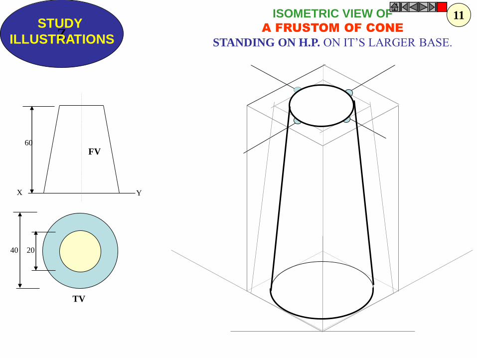
ISOMETRIC VIEW OF
A FRUSTOM OF CONE
STANDING ON H.P. ON IT’S LARGER BASE.
FV
TV
40 20
60
X Y
11

ZSTUDY
ILLUSTRATIONS
PROBLEM: A SQUARE PYRAMID OF 30 MM BASE SIDES AND
50 MM LONG AXIS, IS CENTRALLY PLACED ON THE TOP OF A
CUBE OF 50 MM LONG EDGES.DRAW ISOMETRIC VIEW OF THE PAIR.
12

a
b
cop
p
a
b
c
o
ZSTUDY
ILLUSTRATIONS
PROBLEM: A TRIANGULAR PYRAMID
OF 30 MM BASE SIDES AND 50 MM
LONG AXIS, IS CENTRALLY PLACED
ON THE TOP OF A CUBE OF 50 MM
LONG EDGES.
DRAW ISOMETRIC VIEW OF THE PAIR.
SOLUTION HINTS.
TO DRAW ISOMETRIC OF A CUBE IS SIMPLE. DRAW IT AS USUAL.
BUT FOR PYRAMID AS IT’S BASE IS AN EQUILATERAL TRIANGLE,
IT CAN NOT BE DRAWN DIRECTLY.SUPPORT OF IT’S TV IS REQUIRED.
SO DRAW TRIANGLE AS A TV, SEPARATELY AND NAME VARIOUS POINTS AS SHOWN.
AFTER THIS PLACE IT ON THE TOP OF CUBE AS SHOWN.
THEN ADD HEIGHT FROM IT’S CENTER AND COMPLETE IT’S ISOMETRIC AS SHOWN.
13

ZSTUDY
ILLUSTRATIONS
50
50
30 D
30
10
30
+
FV
TV
PROBLEM:
A SQUARE PLATE IS PIERCED THROUGH CENTRALLY
BY A CYLINDER WHICH COMES OUT EQUALLY FROM BOTH FACES
OF PLATE. IT’S FV & TV ARE SHOWN. DRAW ISOMETRIC VIEW.
14

ZSTUDY
ILLUSTRATIONS
30
10
30
60 D
40 SQUARE
FV
TV
PROBLEM:
A CIRCULAR PLATE IS PIERCED THROUGH CENTRALLY
BY A SQUARE PYRAMID WHICH COMES OUT EQUALLY FROM BOTH FACES
OF PLATE. IT’S FV & TV ARE SHOWN. DRAW ISOMETRIC VIEW.
15

ZSTUDY
ILLUSTRATIONS
XY
30 D50 D
10
40
20
40
FV
TV
F.V. & T.V. of an object are given. Draw it’s isometric view.
16

P
r
RR
r
P
C
C = Center of Sphere.
P = Point of contact
R = True Radius of Sphere
r = Isometric Radius.
R
r
P
r
R
C
r
r
ISOMETRIC PROJECTIONS OF SPHERE & HEMISPHERE
450
300
TO DRAW ISOMETRIC PROJECTION
OF A HEMISPHERE
TO DRAW ISOMETRIC PROJECTION OF A SPHERE
1. FIRST DRAW ISOMETRIC OF SQUARE PLATE.
2. LOCATE IT’S CENTER. NAME IT P.
3. FROM PDRAW VERTICAL LINE UPWARD, LENGTH ‘ r mm’
AND LOCATE CENTER OF SPHERE “C”
4. ‘C’ AS CENTER, WITH RADIUS ‘R’ DRAW CIRCLE.
THIS IS ISOMETRIC PROJECTION OF A SPHERE.
Adopt same procedure.
Draw lower semicircle only.
Then around ‘C’ construct
Rhombus of Sides equal to
Isometric Diameter.
For this use iso-scale.
Then construct ellipse in
this Rhombus as usual
And Complete
Isometric-Projection
of Hemi-sphere.
ZSTUDY
ILLUSTRATIONS
Isom. Scale
17

P
r
R
r
r50 D
30 D
50 D
50
450
300
PROBLEM:
A HEMI-SPHERE IS CENTRALLY PLACED
ON THE TOP OF A FRUSTOM OF CONE.
DRAW ISOMETRIC PROJECTIONS OF THE ASSEMBLY.
FIRST CONSTRUCT ISOMETRIC SCALE.
USE THIS SCALE FOR ALL DIMENSIONS
IN THIS PROBLEM.
ZSTUDY
ILLUSTRATIONS
18
a
b c
d1
23
4
o
1’
4’3’
2’
1
2
4
3
X Y
ZSTUDY
ILLUSTRATIONS
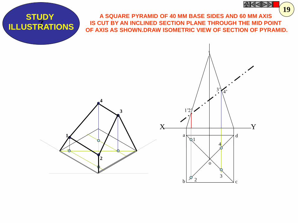
A SQUARE PYRAMID OF 40 MM BASE SIDES AND 60 MM AXIS
IS CUT BY AN INCLINED SECTION PLANE THROUGH THE MID POINT
OF AXIS AS SHOWN.DRAW ISOMETRIC VIEW OF SECTION OF PYRAMID.
19

ZSTUDY
ILLUSTRATIONS
X Y
50
20
25
25 20
O
O
F.V. & T.V. of an object are given. Draw it’s isometric view.
20

ZSTUDY
ILLUSTRATIONS
x y
FV
TV
35
35
10
302010
40
70
O
O
F.V. & T.V. of an object are given. Draw it’s isometric view.
21

ZSTUDY
ILLUSTRATIONS
x y
FV
SV
TV
30
30
10
30 10 30
ALL VIEWS IDENTICAL
F.V. & T.V. and S.V.of an object are given. Draw it’s isometric view.
22

x y
FV SV
TV
ZSTUDY
ILLUSTRATIONS
1040 60
60
40
ALL VIEWS IDENTICAL
F.V. & T.V. and S.V.of an object are given. Draw it’s isometric view.
24

x y
FV SV
TV
ALL VIEWS IDENTICAL
40 60
60
40
10
F.V. & T.V. and S.V.of an object are given. Draw it’s isometric view.Z
STUDY
ILLUSTRATIONS
25

ORTHOGRAPHIC PROJECTIONS
FRONT VIEW
TOP VIEW
L.H.SIDE VIEW
x y
20
20
20
50
20 20 20
20
30
O
O
F.V. & T.V. and S.V.of an object are given. Draw it’s isometric view.Z
STUDY
ILLUSTRATIONS
26

40 20
30 SQUARE
20
50
60
30
10
F.V.S.V.
O
O
F.V. and S.V.of an object are given.
Draw it’s isometric view.Z
STUDY
ILLUSTRATIONS
27

40
10
50
80
10
30 D 45
FV
TV
O
O
F.V. & T.V. of an object are given. Draw it’s isometric view.ZSTUDY
ILLUSTRATIONS
28

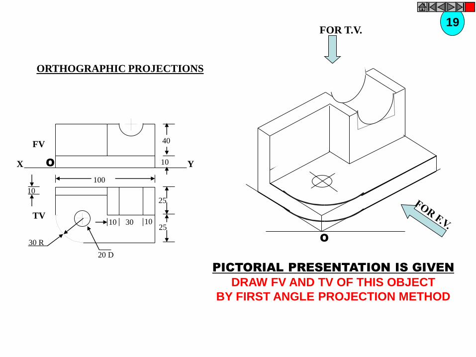
O
FV
TV
X YO
40
10
25
25
30 R
10
100
103010
20 D
F.V. & T.V. of an object are given. Draw it’s isometric view.ZSTUDY
ILLUSTRATIONS
29

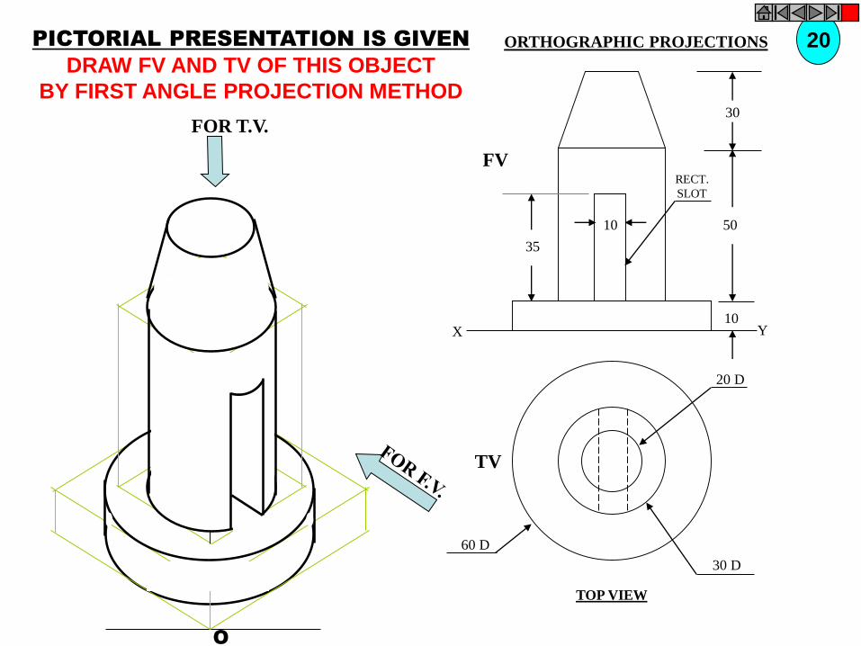
O
O
10
30
50
10
35
20 D
30 D
60 D
FV
TV
X Y
RECT.
SLOT
F.V. & T.V. of an object are given. Draw it’s isometric view.ZSTUDY
ILLUSTRATIONS
30

O
10
O
40
25 15
25
25
25
2580
10
F.V. S.V.
F.V. and S.V.of an object are given. Draw it’s isometric view.ZSTUDY
ILLUSTRATIONS
31

O
450
X
TV
FV
Y
30 D
30
40
40
4015
O
F.V. & T.V. of an object are given. Draw it’s isometric view.Z
STUDY
ILLUSTRATIONS
32

O
O
20
2015
30
60
30
20
20
40
100
50
HEX PART
F.V. and S.V.of an object are given.
Draw it’s isometric view.Z
STUDY
ILLUSTRATIONS
33

O
O
10
10
30
10
30
4020
80
30
F.V.
T.V.
X Y
F.V. & T.V. of an object are given. Draw it’s isometric view.ZSTUDY
ILLUSTRATIONS
34

FV LSV
X Y
10
O
FV LSV
X Y
10 10 15
25
25
1050O
F.V. and S.V.of an object are given.
Draw it’s isometric view.
ZSTUDY
ILLUSTRATIONS
35
36
NOTE THE SMALL CHZNGE IN 2ND FV & SV.
DRAW ISOMETRIC ACCORDINGLY.

YX
F.V. LEFT S.V.
30 20 2010
15
15
1530
50
10
15O
O
F.V. and S.V.of an object are given.
Draw it’s isometric view.
ZSTUDY
ILLUSTRATIONS
37

30
40
10
60
30
40
F.V. S.V.
O
O
F.V. and S.V.of an object are given.
Draw it’s isometric view.Z
STUDY
ILLUSTRATIONS
38
ISOMETRIC PROJECTIONS
• A type of pictorial projection in which all the three dimensions of a solid are seen in such a
way that all of them are equally shortened.
• The actual sizes can be measured from them.

• If a cube is placed on one of its corners on the ground with a solid diagonal perpendicular
the V.P., the front view is the isometric projection of the cube.
yx
a'
d'
c'
LG
b'
a
b
c
d
e
f
g
h
e' f' g'
h'
e'
f' h'
a'
b'
d'
g'
c'
a c
b
dh
e
f
g
a
g
c
f
b d
h
a'
b'
c'
d'
e'
f'
g'
h'
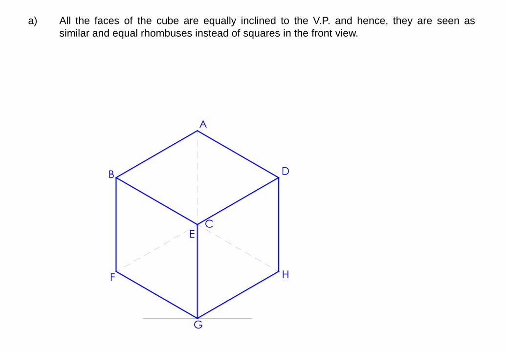
a) All the faces of the cube are equally inclined to the V.P. and hence, they are seen as
similar and equal rhombuses instead of squares in the front view.
A
B
C
D
E
F
G
H
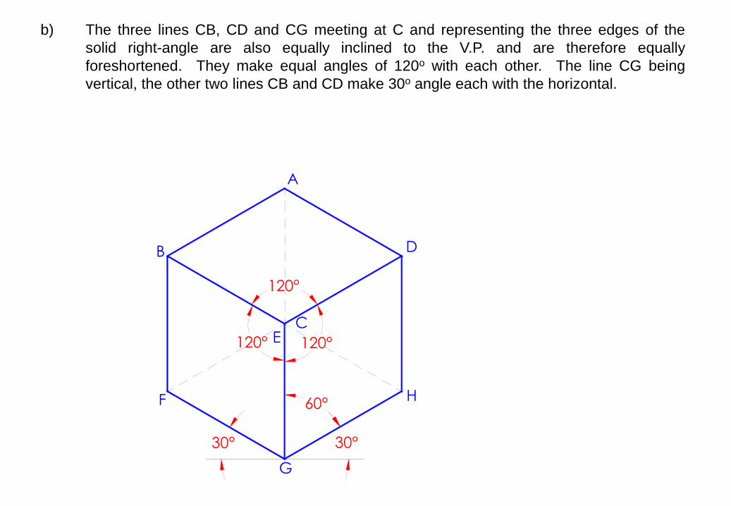
b) The three lines CB, CD and CG meeting at C and representing the three edges of the
solid right-angle are also equally inclined to the V.P. and are therefore equally
foreshortened. They make equal angles of 120o with each other. The line CG being
vertical, the other two lines CB and CD make 30o angle each with the horizontal.
A
B
C
D
E
F
G
H
30°30°
60°
120°
120°
120°

c) All other lines representing the edges of the cube are parallel to one or the other of the
three lines CB, CD and CG, and are also equally foreshortened.
A
B
C
D
E
F
G
H
30°30°
60°
120°
120°
120°

d) The diagonal BD of the top face is parallel to the V.P. and hence, retains its true length.
A
B
C
D
E
F
G
H
30°30°
60°
120°
120°
120°

e) The three lines CB, CD and CG meeting at the point C and making 120o angles with each
other are known as isometric axes.
A
B
C
D
E
F
G
H
30°30°
60°
120°
120°
120°

f) The lines parallel to the isometric axes are known as isometric lines.
A
B
C
D
E
F
G
H
30°30°
60°
120°
120°
120°

g) The planes made by the isometric axes and all other planes parallel to them are known as
isometric planes.
A
B
C
D
E
F
G
H
30°30°
60°
120°
120°
120°
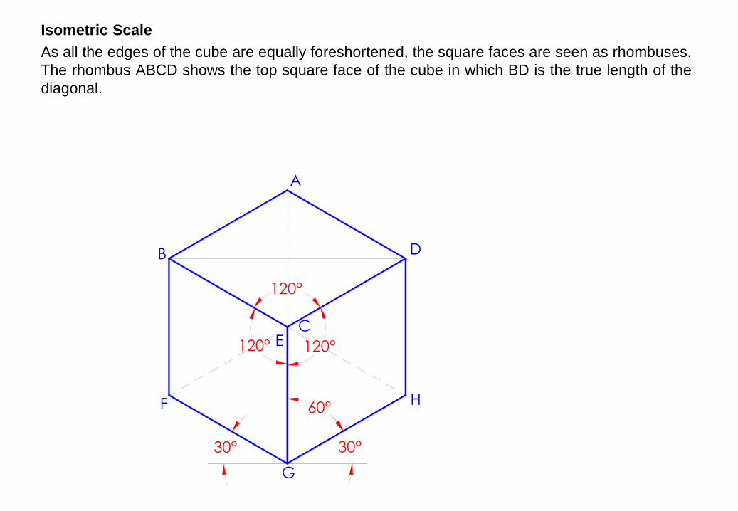
Isometric Scale
As all the edges of the cube are equally foreshortened, the square faces are seen as rhombuses.
The rhombus ABCD shows the top square face of the cube in which BD is the true length of the
diagonal.
A
B
C
D
E
F
G
H
30°30°
60°
120°
120°
120°

The square A1BC1D shows the true size and shape of the top surface of the cube.
BA1 shows the true length of BA.
A
B
C
D
E
F
G
H
30°30°
60°
120°
120°
120°
A1
C1
30°45°
O
In triangle ABO, BO / BA = cos 30o
In triangle A1BO, BO / BA1 = cos 45o
Therefore, BA / BA1 = cos 45o / cos 30o
= 0.8165
Isometric length / true length = 0.8165
Hence Isometric lengths are 0.8165 times
the true lengths.

If the reduction in dimensions is taken into account, the drawing is known as isometric projection.
If however, the reduction in dimensions is disregarded for simplicity then the drawing will be
known as isometric drawing or isometric view.
ISOMETRIC PROJECTION ISOMETRIC VIEW

Example 1:
The front view of a quadrilateral whose surface is parallel to the V.P. is given. Draw its isometric
view.
A B
C
D

Example 1:
The front view of a quadrilateral whose surface is parallel to the V.P. is given. Draw its isometric
view.
A B
C
D EF

Example 1:
The front view of a quadrilateral whose surface is parallel to the V.P. is given. Draw its isometric
view.
A B
C
D EF
b
f

Example 1:
The front view of a quadrilateral whose surface is parallel to the V.P. is given. Draw its isometric
view.
A B
C
D EF
b
f
d

Example 1:
The front view of a quadrilateral whose surface is parallel to the V.P. is given. Draw its isometric
view.
A B
C
D EF
b
f
dH
G

Example 1:
The front view of a quadrilateral whose surface is parallel to the V.P. is given. Draw its isometric
view.
A B
C
D EF
b
f
dH
G
h
gc

Example 1:
The front view of a quadrilateral whose surface is parallel to the V.P. is given. Draw its isometric
view.
A B
C
D EF
b
f
dH
G
h
gc

Example 2:
The top view of a quadrilateral whose surface is parallel to the H.P. is given. Draw its isometric
view.
B
C
D EF H
G

Example 2:
The top view of a quadrilateral whose surface is parallel to the H.P. is given. Draw its isometric
view.
B
C
D EF
a
b
H
G
e
f
h g
cd

Example 3:
The front view of a circle whose surface is parallel to the V.P. is given. Draw its isometric view.

Example 3:
The front view of a circle whose surface is parallel to the V.P. is given. Draw its isometric view.
A B
D C

Example 3:
The front view of a circle whose surface is parallel to the V.P. is given. Draw its isometric view.
A B
D C1
2
3
4
5
6
7
8

Example 3:
The front view of a circle whose surface is parallel to the V.P. is given. Draw its isometric view.
A B
D C1
2
3
4
5
6
7
8

Example 3:
The front view of a circle whose surface is parallel to the V.P. is given. Draw its isometric view.
A B
D
a
C1
2
3
4
5
6
7
8
b
c
d

Example 3:
The front view of a circle whose surface is parallel to the V.P. is given. Draw its isometric view.
A B
D
a
C1
2
3
4
5
6
7
8
b
c
d
1
3
5
7

Example 3:
The front view of a circle whose surface is parallel to the V.P. is given. Draw its isometric view.
A B
D
a
C1
2
3
4
5
6
7
8
b
c
d
1
3
5
7
2
4
6
8

Example 3:
The front view of a circle whose surface is parallel to the V.P. is given. Draw its isometric view.
A B
D
a
C1
2
3
4
5
6
7
8
b
c
d
1
3
5
7
2
4
6
8

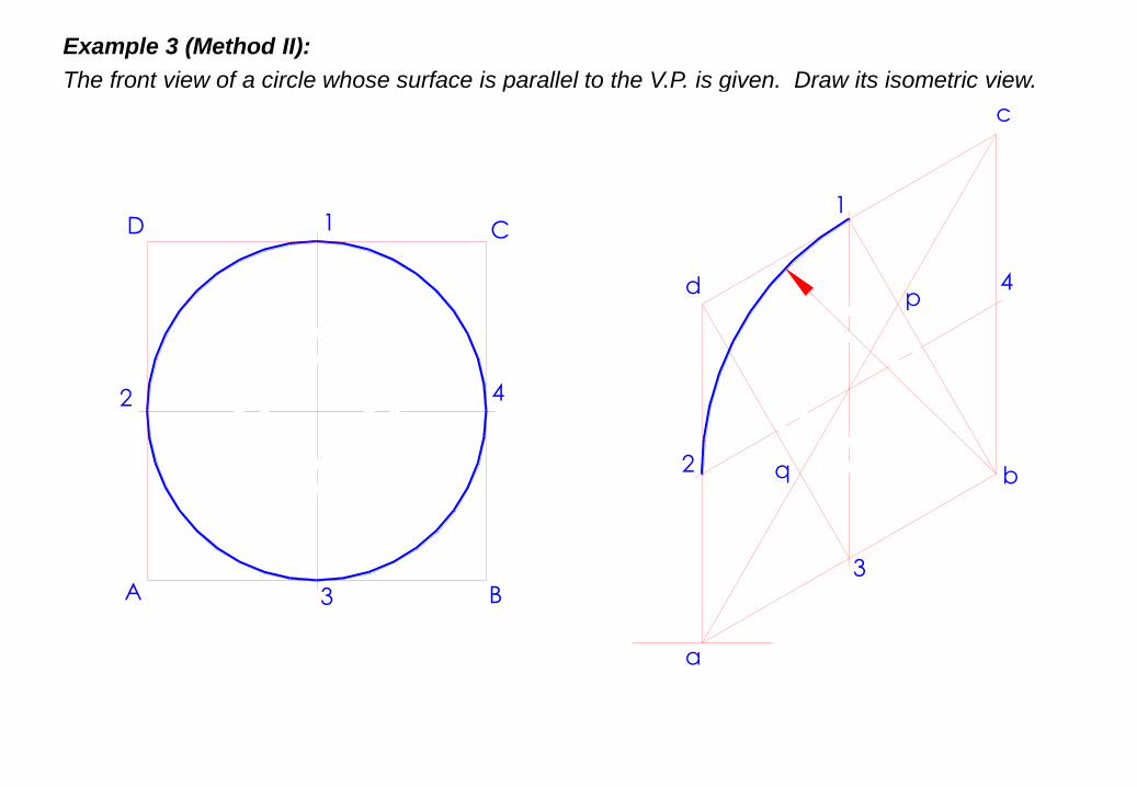
Example 3 (Method II):
The front view of a circle whose surface is parallel to the V.P. is given. Draw its isometric view.
A B
D C1
2
3
4

Example 3 (Method II):
The front view of a circle whose surface is parallel to the V.P. is given. Draw its isometric view.
A B
D
a
C1
2
3
4
b
c
d
1
2
3
4

Example 3 (Method II):
The front view of a circle whose surface is parallel to the V.P. is given. Draw its isometric view.
A B
D
a
C1
2
3
4
b
c
d
1
2
3
4

Example 3 (Method II):
The front view of a circle whose surface is parallel to the V.P. is given. Draw its isometric view.
A B
D
a
C1
2
3
4
b
c
d
1
2
3
4p

Example 3 (Method II):
The front view of a circle whose surface is parallel to the V.P. is given. Draw its isometric view.
A B
D
a
C1
2
3
4
b
c
d
1
2
3
4p
q
Example 3 (Method II):
The front view of a circle whose surface is parallel to the V.P. is given. Draw its isometric view.
A B
D
a
C1
2
3
4
b
c
d
1
2
3
4p
q

Example 3 (Method II):
The front view of a circle whose surface is parallel to the V.P. is given. Draw its isometric view.
A B
D
a
C1
2
3
4
b
c
d
1
2
3
4p
q

Example 3 (Method II):
The front view of a circle whose surface is parallel to the V.P. is given. Draw its isometric view.
A B
D
a
C1
2
3
4
b
c
d
1
2
3
4p
q

Example 3 (Method II):
The front view of a circle whose surface is parallel to the V.P. is given. Draw its isometric view.
A B
D
a
C1
2
3
4
b
c
d
1
2
3
4p
q

a
b
c
d

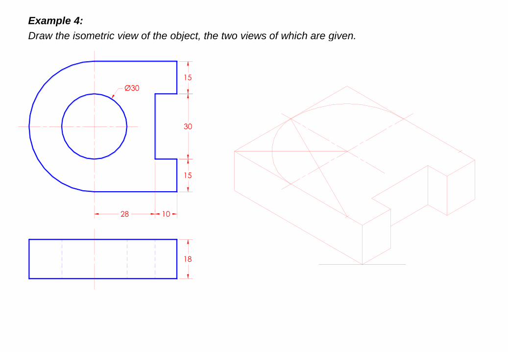
Example 4:
Draw the isometric view of the object, the two views of which are given.
1028
15
30
15
Ø30
18

Example 4:
Draw the isometric view of the object, the two views of which are given.
1028
15
30
15
Ø30
18

Example 4:
Draw the isometric view of the object, the two views of which are given.
1028
15
30
15
Ø30
18

Example 4:
Draw the isometric view of the object, the two views of which are given.
1028
15
30
15
Ø30
18

Example 4:
Draw the isometric view of the object, the two views of which are given.
1028
15
30
15
Ø30
18

Example 4:
Draw the isometric view of the object, the two views of which are given.
1028
15
30
15
Ø30
18

Example 4:
Draw the isometric view of the object, the two views of which are given.
1028
15
30
15
Ø30
18

Example 4:
Draw the isometric view of the object, the two views of which are given.
1028
15
30
15
Ø30
18

Example 4:
Draw the isometric view of the object, the two views of which are given.
1028
15
30
15
Ø30
18

Example 4:
Draw the isometric view of the object, the two views of which are given.
1028
15
30
15
Ø30
18

Example 4:
Draw the isometric view of the object, the two views of which are given.
1028
15
30
15
Ø30
18

Example 4:
Draw the isometric view of the object, the two views of which are given.
1028
15
30
15
Ø30
18

Example 4:
Draw the isometric view of the object, the two views of which are given.
1028
15
30
15
Ø30
18
Example 4:
Draw the isometric view of the object, the two views of which are given.
1028
15
30
15
Ø30
18

Example 4:
Draw the isometric view of the object, the two views of which are given.
1028
15
30
15
Ø30
18

Example 4:
Draw the isometric view of the object, the two views of which are given.
1028
15
30
15
Ø30
18

Example 4:
Draw the isometric view of the object, the two views of which are given.
1028
15
30
15
Ø30
18

Example 4:
Draw the isometric view of the object, the two views of which are given.
1028
15
30
15
Ø30
18

Example 4:
Draw the isometric view of the object, the two views of which are given.
1028
15
30
15
Ø30
18

Example 4:
Draw the isometric view of the object, the two views of which are given.
1028
15
30
15
Ø30
18

Example 4:
Draw the isometric view of the object, the two views of which are given.
1028
15
30
15
Ø30
18

Example 4:
Draw the isometric view of the object, the two views of which are given.
1028
15
30
15
Ø30
18

Example 4:
Draw the isometric view of the object, the two views of which are given.
1028
15
30
15
Ø30
18

Example 4:
Draw the isometric view of the object, the two views of which are given.
1028
15
30
15
Ø30
18

Example 4:
Draw the isometric view of the object, the two views of which are given.
1028
15
30
15
Ø30
18

DRAWINGS:
( A Graphical Representation)
The Fact about: If compared with Verbal or Written Description,
Drawings offer far better idea about the Shape, Size & Appearance of
any object or situation or location, that too in quite a less time.
Hence it has become the Best Media of Communication
not only in Engineering but in almost all Fields.

Drawings
(Some Types)
Nature Drawings
( landscape,
scenery etc.)Geographical
Drawings
( maps etc.)
Botanical Drawings
( plants, flowers etc.)
Zoological Drawings
(creatures, animals etc.)
Portraits
( human faces,
expressions etc.)
Engineering Drawings,
(projections.)
Machine component DrawingsBuilding Related Drawings.
Orthographic Projections(Fv,Tv & Sv.-Mech.Engg terms)
(Plan, Elevation- Civil Engg.terms)
(Working Drawings 2-D type)
Isometric ( Mech.Engg.Term.)
or Perspective(Civil Engg.Term)
(Actual Object Drawing 3-D)

ORTHOGRAPHIC PROJECTIONS:
Horizontal Plane (HP),
Vertical Frontal Plane ( VP )
Side Or Profile Plane ( PP)
Planes.Pattern of planes & Pattern of views
Methods of drawing Orthographic Projections
Different Reference planes are
FV is a view projected on VP.
TV is a view projected on HP.
SV is a view projected on PP.
AndDifferent Views are Front View (FV), Top View (TV) and Side View (SV)
IMPORTANT TERMS OF ORTHOGRAPHIC PROJECTIONS:
IT IS A TECHNICAL DRAWING IN WHICH DIFFERENT VIEWS OF AN OBJECT
ARE PROJECTED ON DIFFERENT REFERENCE PLANES
OBSERVING PERPENDICULAR TO RESPECTIVE REFERENCE PLANE
123

θº
غ
A.V.P.
to Hp & to Vp
PLANES
PRINCIPAL PLANES
HP AND VP
AUXILIARY PLANES
Auxiliary Vertical Plane
(A.V.P.)
Profile Plane
( P.P.)
Auxiliary Inclined Plane
(A.I.P.)
1

THIS IS A PICTORIAL SET-UP OF ALL THREE PLANES.
ARROW DIRECTION IS A NORMAL WAY OF OBSERVING THE OBJECT.
BUT IN THIS DIRECTION ONLY VP AND A VIEW ON IT (FV) CAN BE SEEN.
THE OTHER PLANES AND VIEWS ON THOSE CAN NOT BE SEEN.
HP IS ROTATED DOWNWARD 900
AND
BROUGHT IN THE PLANE OF VP.
PP IS ROTATED IN RIGHT SIDE 900
AND
BROUGHT IN THE PLANE OF VP.
X
Y
X Y
VP
HP
PP
FV
ACTUAL PATTERN OF PLANES & VIEWS
OF ORTHOGRAPHIC PROJECTIONS
DRAWN IN
FIRST ANGLE METHOD OF PROJECTIONS
LSV
TV
PROCEDURE TO SOLVE ABOVE PROBLEM:-
TO MAKE THOSE PLANES ALSO VISIBLE FROM THE ARROW DIRECTION,
A) HP IS ROTATED 900 DOUNWARD
B) PP, 900 IN RIGHT SIDE DIRECTION.
THIS WAY BOTH PLANES ARE BROUGHT IN THE SAME PLANE CONTAINING VP.
PATTERN OF PLANES & VIEWS (First Angle Method)
2
Click to view Animation On clicking the button if a warning comes please click YES to continue, this program is safe for your pc.

Methods of Drawing Orthographic Projections
First Angle Projections MethodHere views are drawn
by placing object
in 1st Quadrant( Fv above X-y, Tv below X-y )
Third Angle Projections MethodHere views are drawn
by placing object
in 3rd Quadrant.
( Tv above X-y, Fv below X-y )
FV
TV
X Y X Y
G L
TV
FV
SYMBOLIC
PRESENTATION
OF BOTH METHODS
WITH AN OBJECT
STANDING ON HP ( GROUND)
ON IT’S BASE.
3
NOTE:-HP term is used in 1st Angle method
&
For the same
Ground term is used
in 3rd Angle method of projections

FOR T.V.FIRST ANGLE
PROJECTION
IN THIS METHOD, THE OBJECT IS ASSUMED TO BE SITUATED IN FIRST QUADRANT
MEANS ABOVE HP & INFRONT OF VP.
OBJECT IS INBETWEEN
OBSERVER & PLANE.
ACTUAL PATTERN OFPLANES & VIEWS
IN FIRST ANGLE METHOD
OF PROJECTIONS
X Y
VP
HP
PP
FV LSV
TV
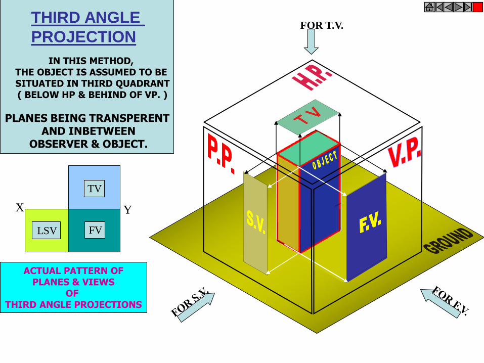
FOR T.V.
IN THIS METHOD, THE OBJECT IS ASSUMED TO BE SITUATED IN THIRD QUADRANT( BELOW HP & BEHIND OF VP. )
PLANES BEING TRANSPERENT AND INBETWEEN
OBSERVER & OBJECT.
ACTUAL PATTERN OFPLANES & VIEWS
OF THIRD ANGLE PROJECTIONS
X Y
TV
THIRD ANGLE
PROJECTION
LSV FV

ORTHOGRAPHIC PROJECTIONS{ MACHINE ELEMENTS }
OBJECT IS OBSERVED IN THREE DIRECTIONS.
THE DIRECTIONS SHOULD BE NORMAL
TO THE RESPECTIVE PLANES.
AND NOW PROJECT THREE DIFFERENT VIEWS ON THOSE PLANES.
THESE VEWS ARE FRONT VIEW , TOP VIEW AND SIDE VIEW.
FRONT VIEW IS A VIEW PROJECTED ON VERTICAL PLANE ( VP )
TOP VIEW IS A VIEW PROJECTED ON HORIZONTAL PLANE ( HP )
SIDE VIEW IS A VIEW PROJECTED ON PROFILE PLANE ( PP )
AND THEN STUDY NEXT 26 ILLUSTRATED CASES CAREFULLY.
TRY TO RECOGNIZE SURFACES
PERPENDICULAR TO THE ARROW DIRECTIONS
FIRST STUDY THE CONCEPT OF 1ST AND 3RD ANGLE
PROJECTION METHODS

x y
FRONT VIEW
TOP VIEW
L.H.SIDE VIEW
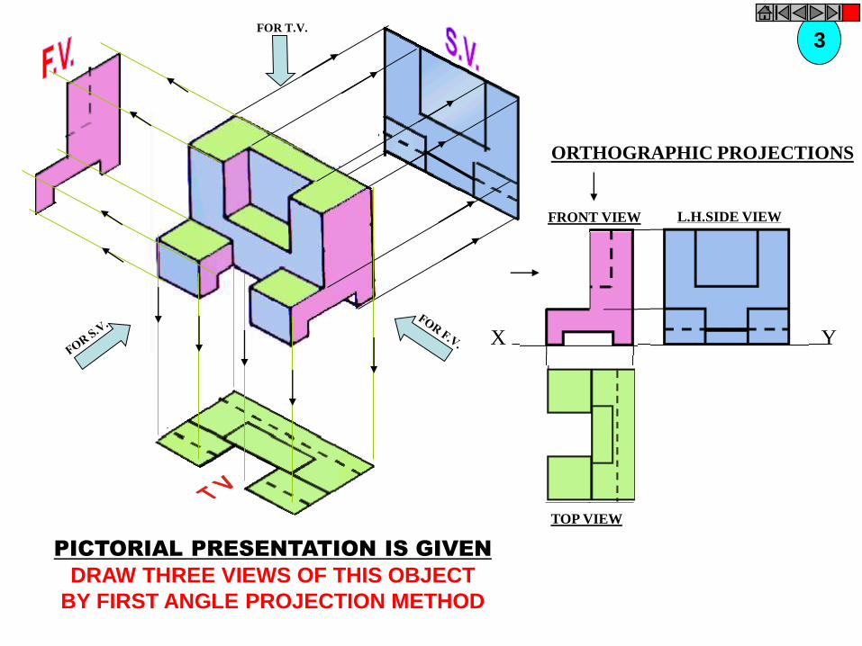
FOR T.V.
PICTORIAL PRESENTATION IS GIVEN
DRAW THREE VIEWS OF THIS OBJECT
BY FIRST ANGLE PROJECTION METHOD
ORTHOGRAPHIC PROJECTIONS
1

FOR T.V.
X Y
FRONT VIEW
TOP VIEW
L.H.SIDE VIEW
ORTHOGRAPHIC PROJECTIONS
PICTORIAL PRESENTATION IS GIVEN
DRAW THREE VIEWS OF THIS OBJECT
BY FIRST ANGLE PROJECTION METHOD
2
FOR T.V.
ORTHOGRAPHIC PROJECTIONS
X Y
FRONT VIEW
TOP VIEW
L.H.SIDE VIEW
3
PICTORIAL PRESENTATION IS GIVEN
DRAW THREE VIEWS OF THIS OBJECT
BY FIRST ANGLE PROJECTION METHOD
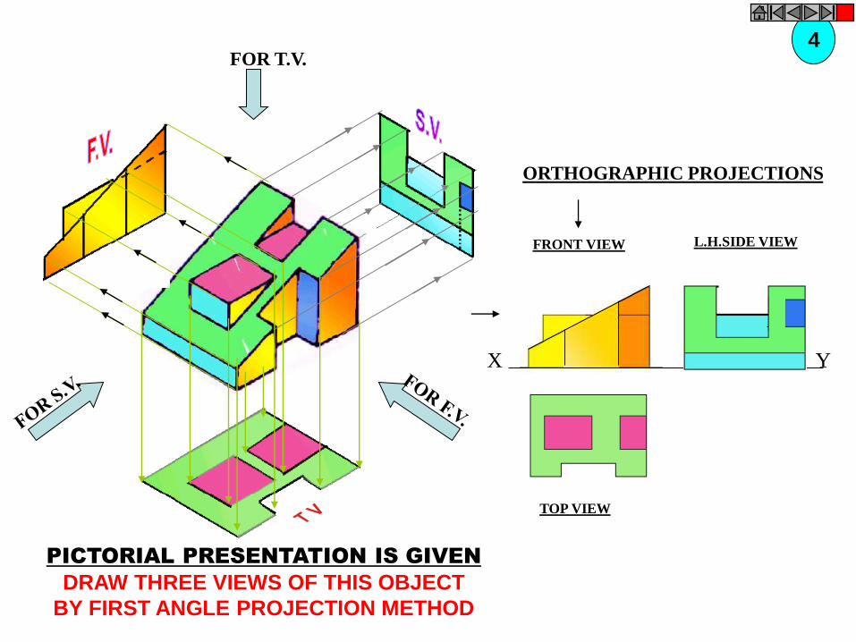
FOR T.V.
ORTHOGRAPHIC PROJECTIONS
FRONT VIEW
TOP VIEW
L.H.SIDE VIEW
X Y
4
PICTORIAL PRESENTATION IS GIVEN
DRAW THREE VIEWS OF THIS OBJECT
BY FIRST ANGLE PROJECTION METHOD

FOR T.V.
ORTHOGRAPHIC PROJECTIONS
FRONT VIEW
TOP VIEW
L.H.SIDE VIEW
X Y
5
PICTORIAL PRESENTATION IS GIVEN
DRAW THREE VIEWS OF THIS OBJECT
BY FIRST ANGLE PROJECTION METHOD

FOR T.V.
ORTHOGRAPHIC PROJECTIONS
FRONT VIEW
TOP VIEW
L.H.SIDE VIEW
X Y
6
PICTORIAL PRESENTATION IS GIVEN
DRAW THREE VIEWS OF THIS OBJECT
BY FIRST ANGLE PROJECTION METHOD

FRONT VIEW
TOP VIEW
L.H.SIDE VIEW
X Y
FOR T.V.
ORTHOGRAPHIC PROJECTIONS
7
PICTORIAL PRESENTATION IS GIVEN
DRAW THREE VIEWS OF THIS OBJECT
BY FIRST ANGLE PROJECTION METHOD

ZSTUDY
ILLUSTRATIONS
X Y
50
20
25
25 20
FOR T.V.
PICTORIAL PRESENTATION IS GIVEN
DRAW THREE VIEWS OF THIS OBJECT
BY FIRST ANGLE PROJECTION METHOD
8
ORTHOGRAPHIC PROJECTIONS
FRONT VIEW
TOP VIEW

FOR T.V.
PICTORIAL PRESENTATION IS GIVEN
DRAW THREE VIEWS OF THIS OBJECT
BY FIRST ANGLE PROJECTION METHOD
9
ORTHOGRAPHIC PROJECTIONS
FRONT VIEW
TOP VIEW
L.H.SIDE VIEW
X Y

FOR T.V.
PICTORIAL PRESENTATION IS GIVEN
DRAW THREE VIEWS OF THIS OBJECT
BY FIRST ANGLE PROJECTION METHOD
10ORTHOGRAPHIC PROJECTIONS
FRONT VIEW
TOP VIEW
L.H.SIDE VIEW
X Y

FOR T.V.
PICTORIAL PRESENTATION IS GIVEN
DRAW THREE VIEWS OF THIS OBJECT
BY FIRST ANGLE PROJECTION METHOD
11ORTHOGRAPHIC PROJECTIONS
FRONT VIEW
TOP VIEW
L.H.SIDE VIEW
X Y

FOR T.V.
PICTORIAL PRESENTATION IS GIVEN
DRAW THREE VIEWS OF THIS OBJECT
BY FIRST ANGLE PROJECTION METHOD
12
ORTHOGRAPHIC PROJECTIONS
FRONT VIEW
TOP VIEW
L.H.SIDE VIEW
X Y

ZSTUDY
ILLUSTRATIONS
x y
FV35
35
10
TV
302010
40
70
O
FOR T.V.
PICTORIAL PRESENTATION IS GIVEN
DRAW FV AND TV OF THIS OBJECT
BY FIRST ANGLE PROJECTION METHOD
13
ORTHOGRAPHIC PROJECTIONS

ZSTUDY
ILLUSTRATIONS
SV
TV
yx
FV
30
30
10
30 10 30
ALL VIEWS IDENTICAL
FOR T.V.
PICTORIAL PRESENTATION IS GIVEN
DRAW THREE VIEWS OF THIS OBJECT
BY FIRST ANGLE PROJECTION METHOD
14
ORTHOGRAPHIC PROJECTIONS
x y
FV SV
ZSTUDY
ILLUSTRATIONS
TV
1040 60
60
40
ALL VIEWS IDENTICAL
FOR T.V.
PICTORIAL PRESENTATION IS GIVEN
DRAW THREE VIEWS OF THIS OBJECT
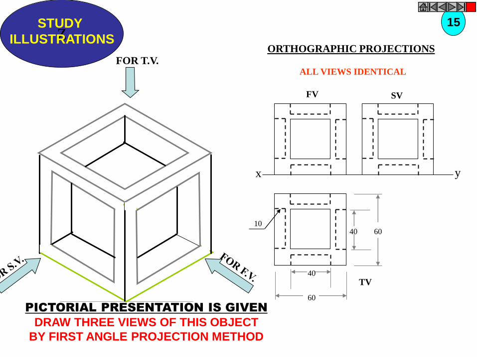
BY FIRST ANGLE PROJECTION METHOD
15
ORTHOGRAPHIC PROJECTIONS

FOR T.V.
PICTORIAL PRESENTATION IS GIVEN
DRAW THREE VIEWS OF THIS OBJECT
BY FIRST ANGLE PROJECTION METHOD
16ORTHOGRAPHIC PROJECTIONS
x y
FV SV
ALL VIEWS IDENTICAL
40 60
60
40
10
TOP VIEW

40 20
30 SQUARE
20
50
60
30
10
F.V.S.V.
O
PICTORIAL PRESENTATION IS GIVEN
DRAW FV AND SV OF THIS OBJECT
BY FIRST ANGLE PROJECTION METHOD
17
ORTHOGRAPHIC PROJECTIONS
FRONT VIEW L.H.SIDE VIEW
X Y

50
80
10
30 D
TV
O
FOR T.V.
PICTORIAL PRESENTATION IS GIVEN
DRAW FV AND TV OF THIS OBJECT
BY FIRST ANGLE PROJECTION METHOD
18ORTHOGRAPHIC PROJECTIONS
40
10
45
FV
OX Y
X Y
FV
O
40
10
10
TV
25
25
30 R
100
103010
20 D
O
PICTORIAL PRESENTATION IS GIVEN
DRAW FV AND TV OF THIS OBJECT
BY FIRST ANGLE PROJECTION METHOD
19
ORTHOGRAPHIC PROJECTIONS
FOR T.V.
O
20 D
30 D
60 D
TV
10
30
50
10
35
FV
X Y
RECT.
SLOT
FOR T.V.
PICTORIAL PRESENTATION IS GIVEN
DRAW FV AND TV OF THIS OBJECT
BY FIRST ANGLE PROJECTION METHOD
20ORTHOGRAPHIC PROJECTIONS
TOP VIEW

O O
40
25
80
F.V.
10
15
25
25
25
25
10
S.V.
PICTORIAL PRESENTATION IS GIVEN
DRAW FV AND SV OF THIS OBJECT
BY FIRST ANGLE PROJECTION METHOD
21
ORTHOGRAPHIC PROJECTIONS

450
X
FV
Y
30
40
TV
30 D
40
4015
O
FOR T.V.
PICTORIAL PRESENTATION IS GIVEN
DRAW FV AND TV OF THIS OBJECT
BY FIRST ANGLE PROJECTION METHOD
22ORTHOGRAPHIC PROJECTIONS

O
O
20
2015
40
100
30
60
30
20
20
50
HEX PART
PICTORIAL PRESENTATION IS GIVEN
DRAW FV ABD SV OF THIS OBJECT
BY FIRST ANGLE PROJECTION METHOD
23
ORTHOGRAPHIC PROJECTIONS
FRONT VIEW L.H.SIDE VIEW

O
10
30
10
80
30
T.V.
O
10
30
4020
F.V.
X Y
FOR T.V.
PICTORIAL PRESENTATION IS GIVEN
DRAW FV AND TV OF THIS OBJECT
BY FIRST ANGLE PROJECTION METHOD
24ORTHOGRAPHIC PROJECTIONS
FRONT VIEW
TOP VIEW

LSV
Y
25
25
1050
FV
X
10 10 15
O
PICTORIAL PRESENTATION IS GIVEN
DRAW FV AND LSV OF THIS OBJECT
BY FIRST ANGLE PROJECTION METHOD
25
ORTHOGRAPHIC PROJECTIONS

YX
F.V. LEFT S.V.
20 2010
15
15
1530
10
30
50
15
O
PICTORIAL PRESENTATION IS GIVEN
DRAW FV AND SV OF THIS OBJECT
BY FIRST ANGLE PROJECTION METHOD
26
ORTHOGRAPHIC PROJECTIONS


![chapter – 21 solids [surface area and volume of 3-d solids]](https://static.fdokumen.com/doc/165x107/632737f8051fac18490e22eb/chapter-21-solids-surface-area-and-volume-of-3-d-solids.jpg)