Optimizing Rubberized Open-graded Friction ... - eScholarship
Upload
independentCategory
view
1download
0
Available online at www.sciencedirect.com
International Journal of Mechanical Sciences 45 (2003) 519–539
A new beam nite element for the analysis of functionallygraded materials
A. Chakrabortya, S. Gopalakrishnana ;∗, J.N. Reddyb
aDepartment of Aerospace Engineering, Indian Institute of Science, Bangalore 560012, IndiabDepartment of Mechanical Engineering, Texas A&M University, College Station, TX 77843-3123, USA
Received 17 April 2002; received in revised form 12 March 2003; accepted 24 March 2003
Abstract
A new beam element is developed to study the thermoelastic behavior of functionally graded beam structures.The element is based on the rst-order shear deformation theory and it accounts for varying elastic andthermal properties along its thickness. The exact solution of static part of the governing di2erential equationsis used to construct interpolating polynomials for the element formulation. Consequently, the sti2ness matrixhas super-convergent property and the element is free of shear locking. Both exponential and power-lawvariations of material property distribution are used to examine di2erent stress variations. Static, free vibrationand wave propagation problems are considered to highlight the behavioral di2erence of functionally gradedmaterial beam with pure metal or pure ceramic beams.? 2003 Elsevier Science Ltd. All rights reserved.
Keywords: Functionally graded materials; Stress pattern; Wave propagation; High frequency; Finite-element method
1. Introduction
An ideal material combines the best properties of metals and ceramics—the toughness, electricalconductivity, and machinability of metals, and the low density, high strength, high sti2ness, andtemperature resistance of ceramics. Demands for such materials come from the automotive indus-try (lightweight and strong materials would increase fuel e<ciency and last longer), electronics,telecommunications, and the aerospace and defense industries. In recent years, these types of ad-vanced materials are no longer dreams but properly conceived and developed. By varying percentage
∗ Corresponding author. Tel.: +91-80-309-2757; fax: +91-80-360-0134.E-mail address: [email protected] (S. Gopalakrishnan).
0020-7403/03/$ - see front matter ? 2003 Elsevier Science Ltd. All rights reserved.doi:10.1016/S0020-7403(03)00058-4
520 A. Chakraborty et al. / International Journal of Mechanical Sciences 45 (2003) 519–539
Nomenclature
u0 axial displacement of reference planew0 transverse displacement of reference plane� rotation about Y -axis�(z) coe<cient of thermal expansionDT temperature rise/fallxx axial strain�xz shear strainE(z) Young’s modulusG(z) shear modulus�xx axial stress�xz shear stressP(z) representative of material property parameterPt P(z) at topmost layerPb P(z) at bottommost layer� parameter of exponential variationn parameter of power-law variationh beam depthL length of the beamA cross-sectional area of the beamS element strain energy functional%(z) densityT element kinetic energy functionalIk ; k = 0; 1; 2 mass momentsAij; Bij; Dij integrated sti2ness coe<cientsATij; BTij integrated elasto-thermal coe<cientsNx, Vx and Mx axial force, shear force and bending moment�, " shear-Hexure and axial-Hexure coupling parameter non-dimensional parameter in shape function[ℵ(x)] shape function matrix{u} element displacement vector{u} nodal displacement vector{F} nodal mechanical force vector{R} nodal thermal force vector[K]; [M ] element sti2ness and mass matrix{u} coe<cient of displacement vector in transformed domainkj wave numberscg group wave speed
content of two or more materials spatially, new materials can be formed which will have desiredproperty gradation in spatial directions. The gradation in properties of the material reduces thermalstresses, residual stresses, and stress concentration factors.
A. Chakraborty et al. / International Journal of Mechanical Sciences 45 (2003) 519–539 521
Graded materials are also required to adhere two di2erent materials in structures subjected todi2erent loading environments (thermal and mechanical). In the absence of any graded material atthe interface, there is a high chance that debonding will occur at some extreme loading conditions, beit static, dynamic, or thermal load. Cracks are likely to initiate at interfaces and grow into the weakermaterial section. Residual stresses can be developed due to the di2erence in coe<cients of thermalexpansion of the materials. Gradually varying the volume fraction of the constituents rather thanabruptly changing them over an interface can resolve these problems. Functionally graded materials(FGMs) are materials or structures in which the material properties vary with location in such a wayas to optimize some function of the overall FGM. The matrix alloy (the metal), the reinforcementmaterial (the ceramic), the volume, shape, and location of the reinforcement, and the fabricationmethod can all be tailored to achieve particular desired properties.FGM has gained widespread applicability as thermal-barrier structures, wear- and corrosion-resistant
coatings other than joining dissimilar materials [1]. FGMs consisting of metallic and ceramic com-ponents are well-known to improve the properties of thermal-barrier systems, because cracking ordelamination, which are often observed in conventional two-layer systems, are avoided due to thesmooth transition between the properties of the components in FGMs. In another application ofFGM in thin-walled members like plates and shells, which are used in reactor vessels, turbines andother machine parts are susceptible to failure from buckling, large amplitude deHections, or excessivestresses induced by thermal or combined thermomechanical loading. Functionally gradient coatingson these structural elements may help reduce the failures.The literature on the response of such advanced materials to dynamic and impact loadings (se-
vere mechanical environments) are limited in numbers. Analyses of shear deformable plate withthrough-thickness material property variation in the presence of the von KParmPan non-linearity arecarried out by Reddy and Chin [2], Praveen and Reddy [3], Reddy [4] and Reddy and Hsu [5]. Tothe best of authors’ knowledge, no nite-element formulation is available in the literature for FGMbeams. In this paper, we take a novel approach of developing an FGM beam nite element by de-riving the approximation functions from the exact general solution to the static part of the governingequations. These solutions are then used to construct accurate shape functions which result in exactsti2ness matrix and a mass matrix that captures mass distribution more accurately compared to anyother existing beam nite elements. Thus, the element is an e<cient tool for modeling structuralsystems to study wave propagation phenomena that results due to high frequency and low durationforcing (impact loading).Exact sti2ness matrices were developed earlier for Herman–Mindlin rod [6], rst-order shear de-
formable composite beam [7], rst- and higher-order shear deformable isotropic beam [8,9] andbeam with Poissons contraction [10]. In this approach, the shape functions are not only a functionof length of the beam but also depend upon cross-sectional and material properties. The degree ofinterpolating polynomials for eld variables is dictated by order of the governing di2erential equa-tion, which attributes to the super-convergent property of the elements (i.e., the nodal values of thestatic solution are exact).Analysis of FGM involves consideration of temperature change during mechanical loading, which
also imparts thermal loading of signi cant amount because of mismatch in thermal coe<cientsbetween metallic and ceramic materials. Praveen and Reddy [3] have already dealt with this problemsfor static and transient loading. El-Abbasi and Meguid [11] analyzed the thermoelastic behavior offunctionally graded plates and shells. In the present work, e2ect of the temperature rise/fall is
522 A. Chakraborty et al. / International Journal of Mechanical Sciences 45 (2003) 519–539
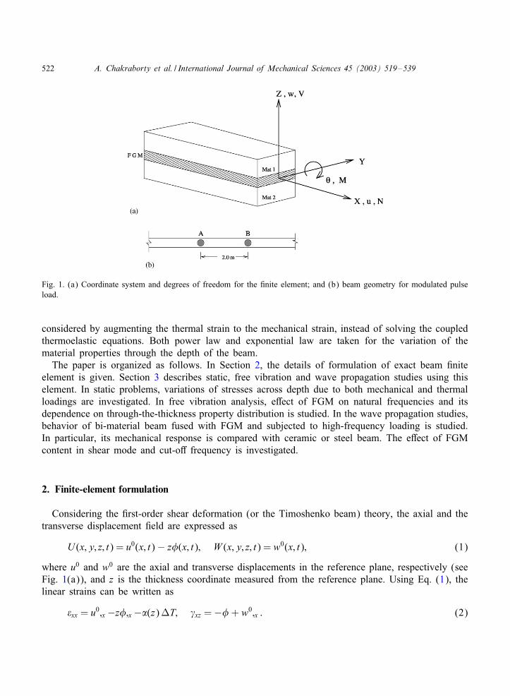
Fig. 1. (a) Coordinate system and degrees of freedom for the nite element; and (b) beam geometry for modulated pulseload.
considered by augmenting the thermal strain to the mechanical strain, instead of solving the coupledthermoelastic equations. Both power law and exponential law are taken for the variation of thematerial properties through the depth of the beam.The paper is organized as follows. In Section 2, the details of formulation of exact beam nite
element is given. Section 3 describes static, free vibration and wave propagation studies using thiselement. In static problems, variations of stresses across depth due to both mechanical and thermalloadings are investigated. In free vibration analysis, e2ect of FGM on natural frequencies and itsdependence on through-the-thickness property distribution is studied. In the wave propagation studies,behavior of bi-material beam fused with FGM and subjected to high-frequency loading is studied.In particular, its mechanical response is compared with ceramic or steel beam. The e2ect of FGMcontent in shear mode and cut-o2 frequency is investigated.
2. Finite-element formulation
Considering the rst-order shear deformation (or the Timoshenko beam) theory, the axial and thetransverse displacement eld are expressed as
U (x; y; z; t) = u0(x; t)− z�(x; t); W (x; y; z; t) = w0(x; t); (1)
where u0 and w0 are the axial and transverse displacements in the reference plane, respectively (seeFig. 1(a)), and z is the thickness coordinate measured from the reference plane. Using Eq. (1), thelinear strains can be written as
xx = u0;x −z�;x −�(z)DT; �xz =−�+ w0;x : (2)
A. Chakraborty et al. / International Journal of Mechanical Sciences 45 (2003) 519–539 523
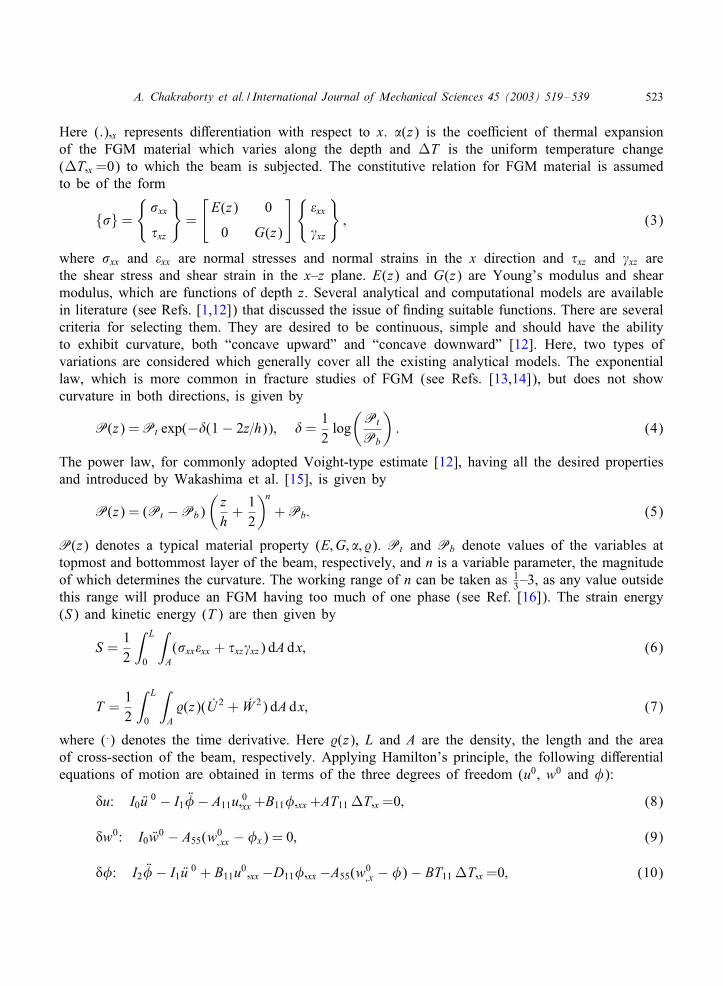
Here (:);x represents di2erentiation with respect to x. �(z) is the coe<cient of thermal expansionof the FGM material which varies along the depth and DT is the uniform temperature change(DT;x =0) to which the beam is subjected. The constitutive relation for FGM material is assumedto be of the form
{�}={
�xx
�xz
}=
[E(z) 0
0 G(z)
]{xx
�xz
}; (3)
where �xx and xx are normal stresses and normal strains in the x direction and �xz and �xz arethe shear stress and shear strain in the x–z plane. E(z) and G(z) are Young’s modulus and shearmodulus, which are functions of depth z. Several analytical and computational models are availablein literature (see Refs. [1,12]) that discussed the issue of nding suitable functions. There are severalcriteria for selecting them. They are desired to be continuous, simple and should have the abilityto exhibit curvature, both “concave upward” and “concave downward” [12]. Here, two types ofvariations are considered which generally cover all the existing analytical models. The exponentiallaw, which is more common in fracture studies of FGM (see Refs. [13,14]), but does not showcurvature in both directions, is given by
P(z) =Pt exp(−�(1− 2z=h)); �=12log
(Pt
Pb
): (4)
The power law, for commonly adopted Voight-type estimate [12], having all the desired propertiesand introduced by Wakashima et al. [15], is given by
P(z) = (Pt −Pb)(
zh+
12
)n
+Pb: (5)
P(z) denotes a typical material property (E;G; �; %). Pt and Pb denote values of the variables attopmost and bottommost layer of the beam, respectively, and n is a variable parameter, the magnitudeof which determines the curvature. The working range of n can be taken as 1
3–3, as any value outsidethis range will produce an FGM having too much of one phase (see Ref. [16]). The strain energy(S) and kinetic energy (T ) are then given by
S =12
∫ L
0
∫A(�xxxx + �xz�xz) dA dx; (6)
T =12
∫ L
0
∫A%(z)(U 2 + W 2) dA dx; (7)
where (:) denotes the time derivative. Here %(z), L and A are the density, the length and the areaof cross-section of the beam, respectively. Applying Hamilton’s principle, the following di2erentialequations of motion are obtained in terms of the three degrees of freedom (u0, w0 and �):
�u: I0 Wu 0 − I1 W�− A11u;0xx +B11�;xx +AT11 DT;x =0; (8)
�w0: I0 Ww0 − A55(w0; xx − �x) = 0; (9)
��: I2 W�− I1 Wu 0 + B11u0;xx −D11�;xx −A55(w0; x − �)− BT11 DT;x =0; (10)
524 A. Chakraborty et al. / International Journal of Mechanical Sciences 45 (2003) 519–539
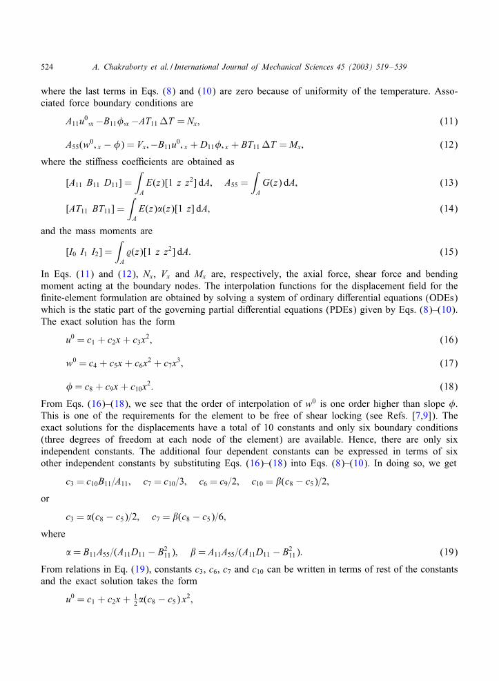
where the last terms in Eqs. (8) and (10) are zero because of uniformity of the temperature. Asso-ciated force boundary conditions are
A11u0;x −B11�;x −AT11 DT = Nx; (11)
A55(w0; x − �) = Vx;−B11u0; x + D11�; x + BT11 DT =Mx; (12)
where the sti2ness coe<cients are obtained as
[A11 B11 D11] =∫AE(z)[1 z z2] dA; A55 =
∫AG(z) dA; (13)
[AT11 BT11] =∫AE(z)�(z)[1 z] dA; (14)
and the mass moments are
[I0 I1 I2] =∫A%(z)[1 z z2] dA: (15)
In Eqs. (11) and (12), Nx, Vx and Mx are, respectively, the axial force, shear force and bendingmoment acting at the boundary nodes. The interpolation functions for the displacement eld for the nite-element formulation are obtained by solving a system of ordinary di2erential equations (ODEs)which is the static part of the governing partial di2erential equations (PDEs) given by Eqs. (8)–(10).The exact solution has the form
u0 = c1 + c2x + c3x2; (16)
w0 = c4 + c5x + c6x2 + c7x3; (17)
�= c8 + c9x + c10x2: (18)
From Eqs. (16)–(18), we see that the order of interpolation of w0 is one order higher than slope �.This is one of the requirements for the element to be free of shear locking (see Refs. [7,9]). Theexact solutions for the displacements have a total of 10 constants and only six boundary conditions(three degrees of freedom at each node of the element) are available. Hence, there are only sixindependent constants. The additional four dependent constants can be expressed in terms of sixother independent constants by substituting Eqs. (16)–(18) into Eqs. (8)–(10). In doing so, we get
c3 = c10B11=A11; c7 = c10=3; c6 = c9=2; c10 = "(c8 − c5)=2;
or
c3 = �(c8 − c5)=2; c7 = "(c8 − c5)=6;
where
�= B11A55=(A11D11 − B211); " = A11A55=(A11D11 − B2
11): (19)
From relations in Eq. (19), constants c3, c6, c7 and c10 can be written in terms of rest of the constantsand the exact solution takes the form
u0 = c1 + c2x + 12�(c8 − c5) x2;
A. Chakraborty et al. / International Journal of Mechanical Sciences 45 (2003) 519–539 525
w0 = c4 + c5x + 12c9x
2 + 16"(c8 − c5)x3;
�= c8 + c9x + 12"(c8 − c5)x2: (20)
In matrix form
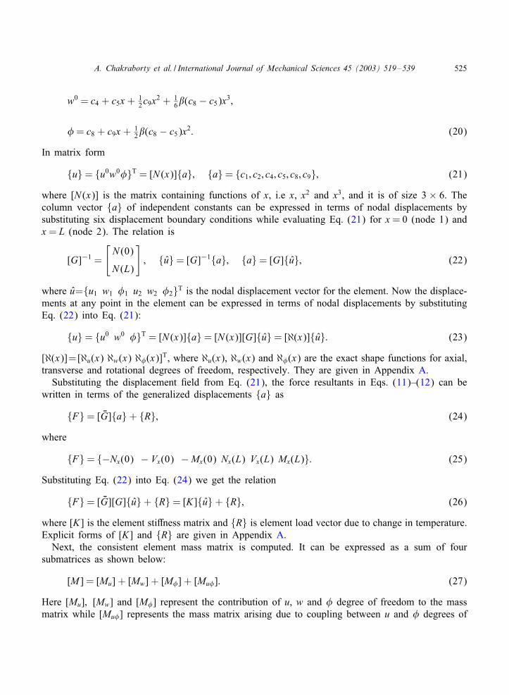
{u}= {u0w0�}T = [N (x)]{a}; {a}= {c1; c2; c4; c5; c8; c9}; (21)
where [N (x)] is the matrix containing functions of x, i.e x, x2 and x3, and it is of size 3× 6. Thecolumn vector {a} of independent constants can be expressed in terms of nodal displacements bysubstituting six displacement boundary conditions while evaluating Eq. (21) for x= 0 (node 1) andx = L (node 2). The relation is
[G]−1 =
[N (0)
N (L)
]; {u}= [G]−1{a}; {a}= [G]{u}; (22)
where u={u1 w1 �1 u2 w2 �2}T is the nodal displacement vector for the element. Now the displace-ments at any point in the element can be expressed in terms of nodal displacements by substitutingEq. (22) into Eq. (21):
{u}= {u0 w0 �}T = [N (x)]{a}= [N (x)][G]{u}= [ℵ(x)]{u}: (23)
[ℵ(x)]=[ℵu(x) ℵw(x) ℵ�(x)]T, where ℵu(x), ℵw(x) and ℵ�(x) are the exact shape functions for axial,transverse and rotational degrees of freedom, respectively. They are given in Appendix A.Substituting the displacement eld from Eq. (21), the force resultants in Eqs. (11)–(12) can be
written in terms of the generalized displacements {a} as
{F}= [ YG]{a}+ {R}; (24)
where
{F}= {−Nx(0) − Vx(0) −Mx(0) Nx(L) Vx(L) Mx(L)}: (25)
Substituting Eq. (22) into Eq. (24) we get the relation
{F}= [ YG][G]{u}+ {R}= [K]{u}+ {R}; (26)
where [K] is the element sti2ness matrix and {R} is element load vector due to change in temperature.Explicit forms of [K] and {R} are given in Appendix A.Next, the consistent element mass matrix is computed. It can be expressed as a sum of four
submatrices as shown below:
[M ] = [Mu] + [Mw] + [M�] + [Mu�]: (27)
Here [Mu]; [Mw] and [M�] represent the contribution of u, w and � degree of freedom to the massmatrix while [Mu�] represents the mass matrix arising due to coupling between u and � degrees of
526 A. Chakraborty et al. / International Journal of Mechanical Sciences 45 (2003) 519–539
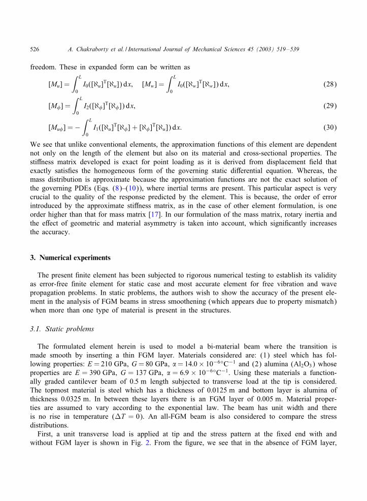
freedom. These in expanded form can be written as
[Mu] =∫ L
0I0([ℵu]T[ℵu]) dx; [Mw] =
∫ L
0I0([ℵw]T[ℵw]) dx; (28)
[M�] =∫ L
0I2([ℵ�]T[ℵ�]) dx; (29)
[Mu�] =−∫ L
0I1([ℵu]T[ℵ�] + [ℵ�]T[ℵu]) dx: (30)
We see that unlike conventional elements, the approximation functions of this element are dependentnot only on the length of the element but also on its material and cross-sectional properties. Thesti2ness matrix developed is exact for point loading as it is derived from displacement eld thatexactly satis es the homogeneous form of the governing static di2erential equation. Whereas, themass distribution is approximate because the approximation functions are not the exact solution ofthe governing PDEs (Eqs. (8)–(10)), where inertial terms are present. This particular aspect is verycrucial to the quality of the response predicted by the element. This is because, the order of errorintroduced by the approximate sti2ness matrix, as in the case of other element formulation, is oneorder higher than that for mass matrix [17]. In our formulation of the mass matrix, rotary inertia andthe e2ect of geometric and material asymmetry is taken into account, which signi cantly increasesthe accuracy.
3. Numerical experiments
The present nite element has been subjected to rigorous numerical testing to establish its validityas error-free nite element for static case and most accurate element for free vibration and wavepropagation problems. In static problems, the authors wish to show the accuracy of the present ele-ment in the analysis of FGM beams in stress smoothening (which appears due to property mismatch)when more than one type of material is present in the structures.
3.1. Static problems
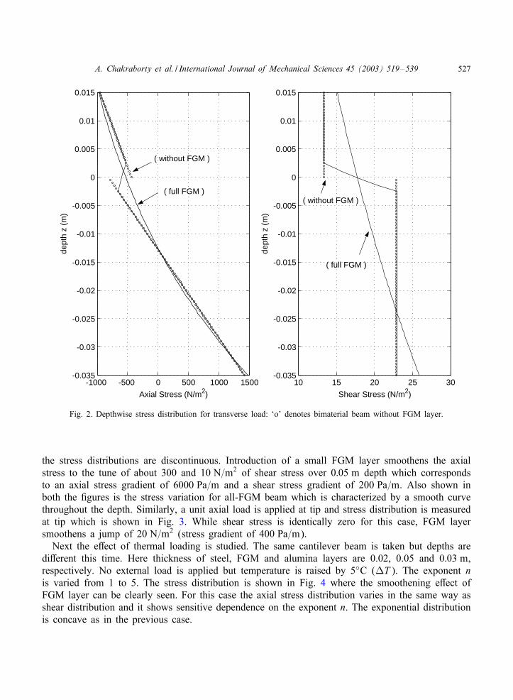
The formulated element herein is used to model a bi-material beam where the transition ismade smooth by inserting a thin FGM layer. Materials considered are: (1) steel which has fol-lowing properties: E =210 GPa, G=80 GPa, �=14:0× 10−6◦C−1 and (2) alumina (Al2O3) whoseproperties are E = 390 GPa, G = 137 GPa, � = 6:9 × 10⁻⁶◦C−1. Using these materials a function-ally graded cantilever beam of 0:5 m length subjected to transverse load at the tip is considered.The topmost material is steel which has a thickness of 0:0125 m and bottom layer is alumina ofthickness 0:0325 m. In between these layers there is an FGM layer of 0:005 m. Material proper-ties are assumed to vary according to the exponential law. The beam has unit width and thereis no rise in temperature (DT = 0). An all-FGM beam is also considered to compare the stressdistributions.First, a unit transverse load is applied at tip and the stress pattern at the xed end with and
without FGM layer is shown in Fig. 2. From the gure, we see that in the absence of FGM layer,
A. Chakraborty et al. / International Journal of Mechanical Sciences 45 (2003) 519–539 527
-1000 -500 0 500 1000 1500 -0.035
-0.03
-0.025
-0.02
-0.015
-0.01
-0.005
0
0.005
0.01
0.015
Axial Stress (N/m2)
dept
h z
(m)
10 15 20 25 30 -0.035
-0.03
-0.025
-0.02
-0.015
-0.01
-0.005
0
0.005
0.01
0.015
Shear Stress (N/m2)
dept
h z
(m)
( without FGM )
( without FGM ) ( full FGM )
( full FGM )
Fig. 2. Depthwise stress distribution for transverse load: ‘o’ denotes bimaterial beam without FGM layer.
the stress distributions are discontinuous. Introduction of a small FGM layer smoothens the axialstress to the tune of about 300 and 10 N=m2 of shear stress over 0:05 m depth which correspondsto an axial stress gradient of 6000 Pa=m and a shear stress gradient of 200 Pa=m. Also shown inboth the gures is the stress variation for all-FGM beam which is characterized by a smooth curvethroughout the depth. Similarly, a unit axial load is applied at tip and stress distribution is measuredat tip which is shown in Fig. 3. While shear stress is identically zero for this case, FGM layersmoothens a jump of 20 N=m2 (stress gradient of 400 Pa=m).Next the e2ect of thermal loading is studied. The same cantilever beam is taken but depths are
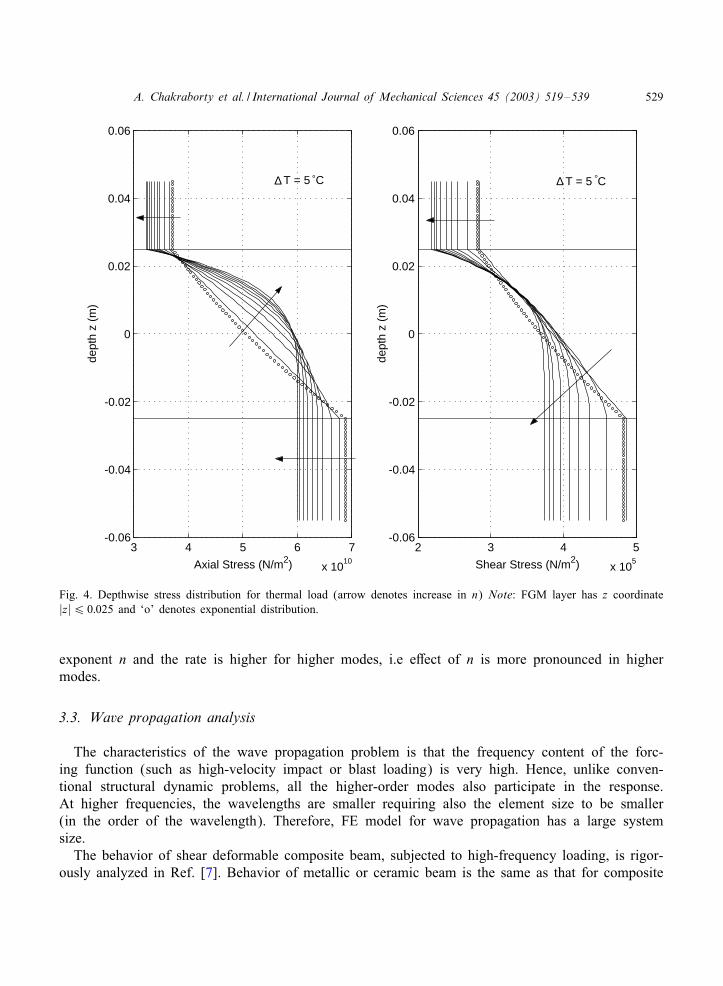
di2erent this time. Here thickness of steel, FGM and alumina layers are 0.02, 0.05 and 0:03 m,respectively. No external load is applied but temperature is raised by 5◦C (DT ). The exponent nis varied from 1 to 5. The stress distribution is shown in Fig. 4 where the smoothening e2ect ofFGM layer can be clearly seen. For this case the axial stress distribution varies in the same way asshear distribution and it shows sensitive dependence on the exponent n. The exponential distributionis concave as in the previous case.

528 A. Chakraborty et al. / International Journal of Mechanical Sciences 45 (2003) 519–539
-20 0 20 40 60 -0.035
-0.03
-0.025
-0.02
-0.015
-0.01
-0.005
0
0.005
0.01
0.015
Axial Stress (N/m2)
dept
h z
(m)
( without FGM )
( full FGM )
Fig. 3. Depthwise stress distribution for axial load: ‘o’ denotes bimaterial beam without FGM layer.
3.2. Free vibration studies
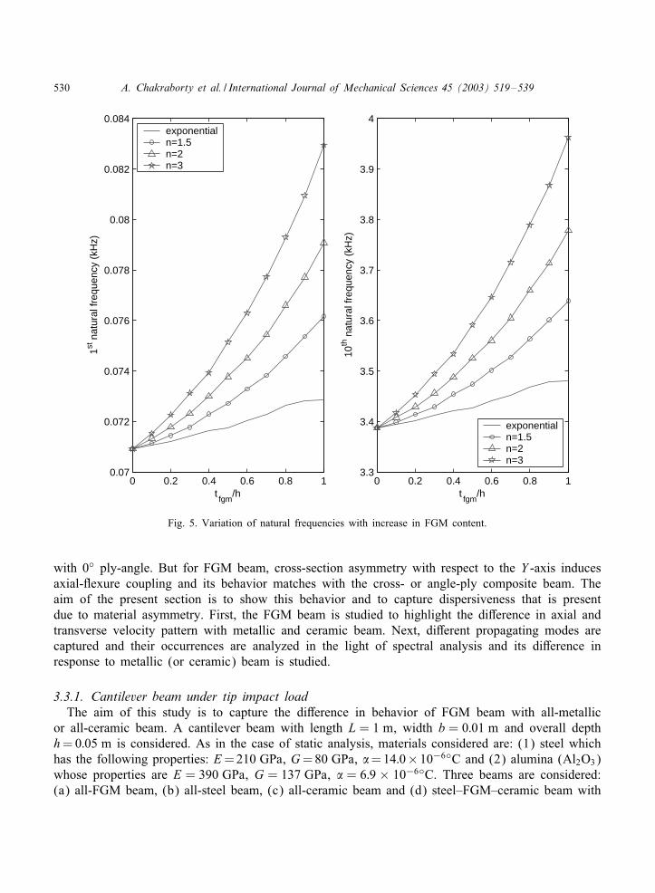
In the presence of FGM layer, there exists coupling both in sti2ness and mass moments, whichmanifests through non-zero coupling coe<cients B11 and I1. These two parameters inHuence sti2nessand mass matrix in such a way that it is ultimately reHected in natural frequencies of that beam.To study this e2ect, a xed beam of 1:0 m length and 0:01 m2 cross-section is taken. Thickness ofFGM layer (tFGM) is varied from 0% to 100% depth to see their relative e2ects on free vibration.The FGM layer is always placed at the mid-depth and thickness of ceramic and steel layer istaken to be the same. Material properties for ceramic and steel are as taken before. The beam ismodeled with 100 elements, which results in a system size of [297× 6], where 6 is half bandwidth.Fig. 5 shows variation of rst and tenth natural frequencies with di2erent ratios of thickness ofFGM to total depth (h). Property distribution through FGM layer is varied according to exponential(Eq. (4)) and power law (Eq. (5)) for di2erent values of the exponent n. As seen in the gure,exponential law gives lowest natural frequencies which increases with increase in the value of theexponent. Also, rate of increase of frequencies with increase in FGM content increases with the
A. Chakraborty et al. / International Journal of Mechanical Sciences 45 (2003) 519–539 529
3 4 5 6 7
x 1010
-0.06
-0.04
-0.02
0
0.02
0.04
0.06
Axial Stress (N/m2)
dept
h z
(m)
∆ T = 5 ° C
2 3 4 5
x 105
-0.06
-0.04
-0.02
0
0.02
0.04
0.06
Shear Stress (N/m2)
dept
h z
(m)
∆ T = 5 ° C
Fig. 4. Depthwise stress distribution for thermal load (arrow denotes increase in n) Note: FGM layer has z coordinate|z|6 0:025 and ‘o’ denotes exponential distribution.
exponent n and the rate is higher for higher modes, i.e e2ect of n is more pronounced in highermodes.
3.3. Wave propagation analysis
The characteristics of the wave propagation problem is that the frequency content of the forc-ing function (such as high-velocity impact or blast loading) is very high. Hence, unlike conven-tional structural dynamic problems, all the higher-order modes also participate in the response.At higher frequencies, the wavelengths are smaller requiring also the element size to be smaller(in the order of the wavelength). Therefore, FE model for wave propagation has a large systemsize.The behavior of shear deformable composite beam, subjected to high-frequency loading, is rigor-
ously analyzed in Ref. [7]. Behavior of metallic or ceramic beam is the same as that for composite
530 A. Chakraborty et al. / International Journal of Mechanical Sciences 45 (2003) 519–539
0 0.2 0.4 0.6 0.8 10.07
0.072
0.074
0.076
0.078
0.08
0.082
0.084
tfgm
/h
1st n
atur
al fr
eque
ncy
(kH
z)
exponentialn=1.5 n=2 n=3
0 0.2 0.4 0.6 0.8 13.3
3.4
3.5
3.6
3.7
3.8
3.9
4
tfgm
/h
10th
nat
ural
freq
uenc
y (k
Hz)
exponentialn=1.5 n=2 n=3
Fig. 5. Variation of natural frequencies with increase in FGM content.
with 0◦ ply-angle. But for FGM beam, cross-section asymmetry with respect to the Y -axis inducesaxial-Hexure coupling and its behavior matches with the cross- or angle-ply composite beam. Theaim of the present section is to show this behavior and to capture dispersiveness that is presentdue to material asymmetry. First, the FGM beam is studied to highlight the di2erence in axial andtransverse velocity pattern with metallic and ceramic beam. Next, di2erent propagating modes arecaptured and their occurrences are analyzed in the light of spectral analysis and its di2erence inresponse to metallic (or ceramic) beam is studied.
3.3.1. Cantilever beam under tip impact loadThe aim of this study is to capture the di2erence in behavior of FGM beam with all-metallic
or all-ceramic beam. A cantilever beam with length L = 1 m, width b = 0:01 m and overall depthh=0:05 m is considered. As in the case of static analysis, materials considered are: (1) steel whichhas the following properties: E=210 GPa, G=80 GPa, �=14:0×10−6◦C and (2) alumina (Al2O3)whose properties are E = 390 GPa, G = 137 GPa, � = 6:9 × 10⁻⁶◦C. Three beams are considered:(a) all-FGM beam, (b) all-steel beam, (c) all-ceramic beam and (d) steel–FGM–ceramic beam with
A. Chakraborty et al. / International Journal of Mechanical Sciences 45 (2003) 519–539 531
0 50 100 150 200 250 300
-0.4
-0.2
0
0.2
0.4
0.6
0.8
1
1.2
Time (µ sec)
Load
(N
)
0 20 40 60 80 1000
0.5
1
1.5
2
2.5x 10 -5
Frequency (KHz)
Fre
quen
cy A
mpl
itude
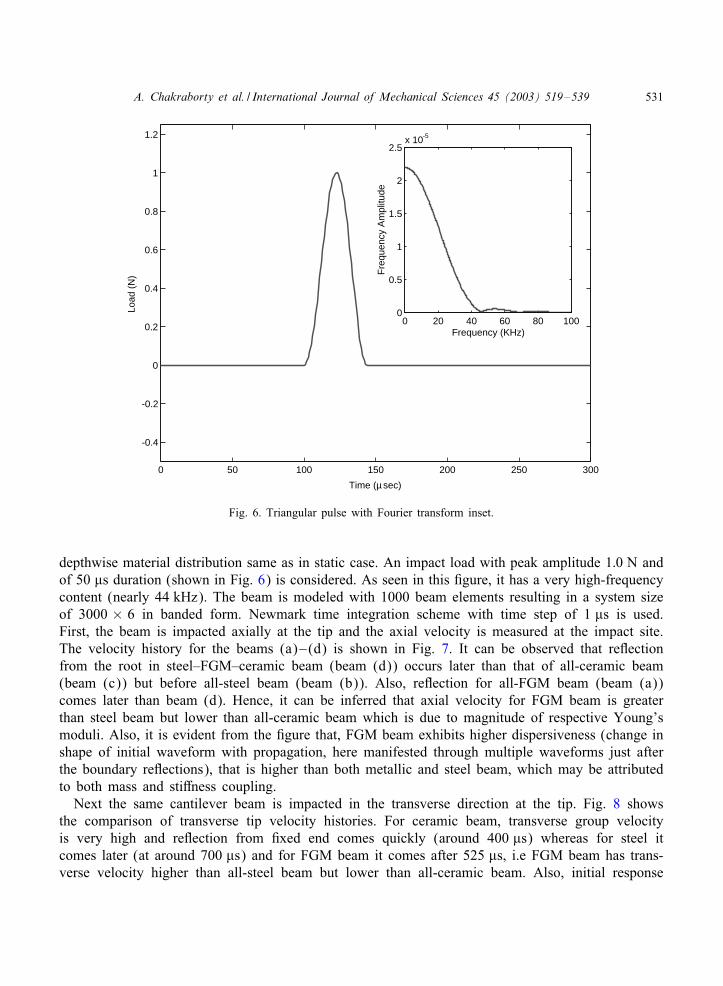
Fig. 6. Triangular pulse with Fourier transform inset.
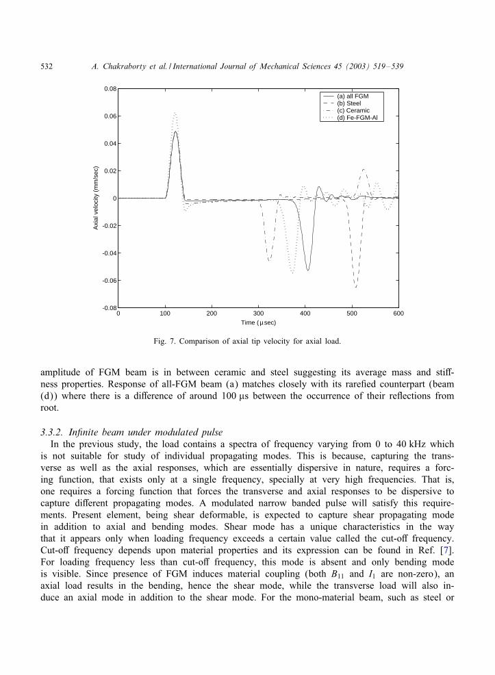
depthwise material distribution same as in static case. An impact load with peak amplitude 1:0 N andof 50 �s duration (shown in Fig. 6) is considered. As seen in this gure, it has a very high-frequencycontent (nearly 44 kHz). The beam is modeled with 1000 beam elements resulting in a system sizeof 3000 × 6 in banded form. Newmark time integration scheme with time step of 1 �s is used.First, the beam is impacted axially at the tip and the axial velocity is measured at the impact site.The velocity history for the beams (a)–(d) is shown in Fig. 7. It can be observed that reHectionfrom the root in steel–FGM–ceramic beam (beam (d)) occurs later than that of all-ceramic beam(beam (c)) but before all-steel beam (beam (b)). Also, reHection for all-FGM beam (beam (a))comes later than beam (d). Hence, it can be inferred that axial velocity for FGM beam is greaterthan steel beam but lower than all-ceramic beam which is due to magnitude of respective Young’smoduli. Also, it is evident from the gure that, FGM beam exhibits higher dispersiveness (change inshape of initial waveform with propagation, here manifested through multiple waveforms just afterthe boundary reHections), that is higher than both metallic and steel beam, which may be attributedto both mass and sti2ness coupling.Next the same cantilever beam is impacted in the transverse direction at the tip. Fig. 8 shows
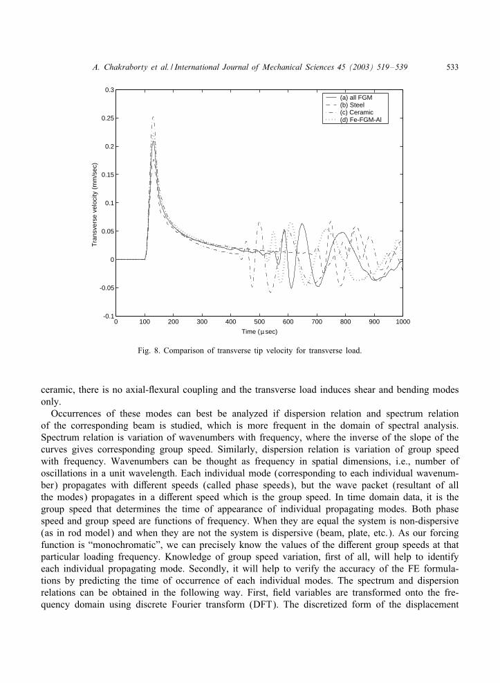
the comparison of transverse tip velocity histories. For ceramic beam, transverse group velocityis very high and reHection from xed end comes quickly (around 400 �s) whereas for steel itcomes later (at around 700 �s) and for FGM beam it comes after 525 �s, i.e FGM beam has trans-verse velocity higher than all-steel beam but lower than all-ceramic beam. Also, initial response
532 A. Chakraborty et al. / International Journal of Mechanical Sciences 45 (2003) 519–539
0 100 200 300 400 500 600 -0.08
-0.06
-0.04
-0.02
0
0.02
0.04
0.06
0.08
Time (µ sec)
Axi
al v
eloc
ity (
mm
/sec
)(a) all FGM (b) Steel (c) Ceramic (d) Fe-FGM-Al
Fig. 7. Comparison of axial tip velocity for axial load.
amplitude of FGM beam is in between ceramic and steel suggesting its average mass and sti2-ness properties. Response of all-FGM beam (a) matches closely with its rare ed counterpart (beam(d)) where there is a di2erence of around 100 �s between the occurrence of their reHections fromroot.
3.3.2. In;nite beam under modulated pulseIn the previous study, the load contains a spectra of frequency varying from 0 to 40 kHz which
is not suitable for study of individual propagating modes. This is because, capturing the trans-verse as well as the axial responses, which are essentially dispersive in nature, requires a forc-ing function, that exists only at a single frequency, specially at very high frequencies. That is,one requires a forcing function that forces the transverse and axial responses to be dispersive tocapture di2erent propagating modes. A modulated narrow banded pulse will satisfy this require-ments. Present element, being shear deformable, is expected to capture shear propagating modein addition to axial and bending modes. Shear mode has a unique characteristics in the waythat it appears only when loading frequency exceeds a certain value called the cut-o2 frequency.Cut-o2 frequency depends upon material properties and its expression can be found in Ref. [7].For loading frequency less than cut-o2 frequency, this mode is absent and only bending modeis visible. Since presence of FGM induces material coupling (both B11 and I1 are non-zero), anaxial load results in the bending, hence the shear mode, while the transverse load will also in-duce an axial mode in addition to the shear mode. For the mono-material beam, such as steel or
A. Chakraborty et al. / International Journal of Mechanical Sciences 45 (2003) 519–539 533
0 100 200 300 400 500 600 700 800 900 1000 -0.1
-0.05
0
0.05
0.1
0.15
0.2
0.25
0.3
Time (µ sec)
Tra
nsve
rse
velo
city
(m
m/s
ec)
(a) all FGM (b) Steel (c) Ceramic (d) Fe-FGM-Al
Fig. 8. Comparison of transverse tip velocity for transverse load.
ceramic, there is no axial-Hexural coupling and the transverse load induces shear and bending modesonly.Occurrences of these modes can best be analyzed if dispersion relation and spectrum relation
of the corresponding beam is studied, which is more frequent in the domain of spectral analysis.Spectrum relation is variation of wavenumbers with frequency, where the inverse of the slope of thecurves gives corresponding group speed. Similarly, dispersion relation is variation of group speedwith frequency. Wavenumbers can be thought as frequency in spatial dimensions, i.e., number ofoscillations in a unit wavelength. Each individual mode (corresponding to each individual wavenum-ber) propagates with di2erent speeds (called phase speeds), but the wave packet (resultant of allthe modes) propagates in a di2erent speed which is the group speed. In time domain data, it is thegroup speed that determines the time of appearance of individual propagating modes. Both phasespeed and group speed are functions of frequency. When they are equal the system is non-dispersive(as in rod model) and when they are not the system is dispersive (beam, plate, etc.). As our forcingfunction is “monochromatic”, we can precisely know the values of the di2erent group speeds at thatparticular loading frequency. Knowledge of group speed variation, rst of all, will help to identifyeach individual propagating mode. Secondly, it will help to verify the accuracy of the FE formula-tions by predicting the time of occurrence of each individual modes. The spectrum and dispersionrelations can be obtained in the following way. First, eld variables are transformed onto the fre-quency domain using discrete Fourier transform (DFT). The discretized form of the displacement
534 A. Chakraborty et al. / International Journal of Mechanical Sciences 45 (2003) 519–539
0 10 20 30 40 50 60 70 80 90 100 -50
0
50
100
150
200
kFes k
fgms
kAl
2O
3
s
Wav
enum
ber
k j (m
-1)
kFeb
kfgmb
kFea
kAl
2O
3
a
kfgma
Frequency ω (kHz)
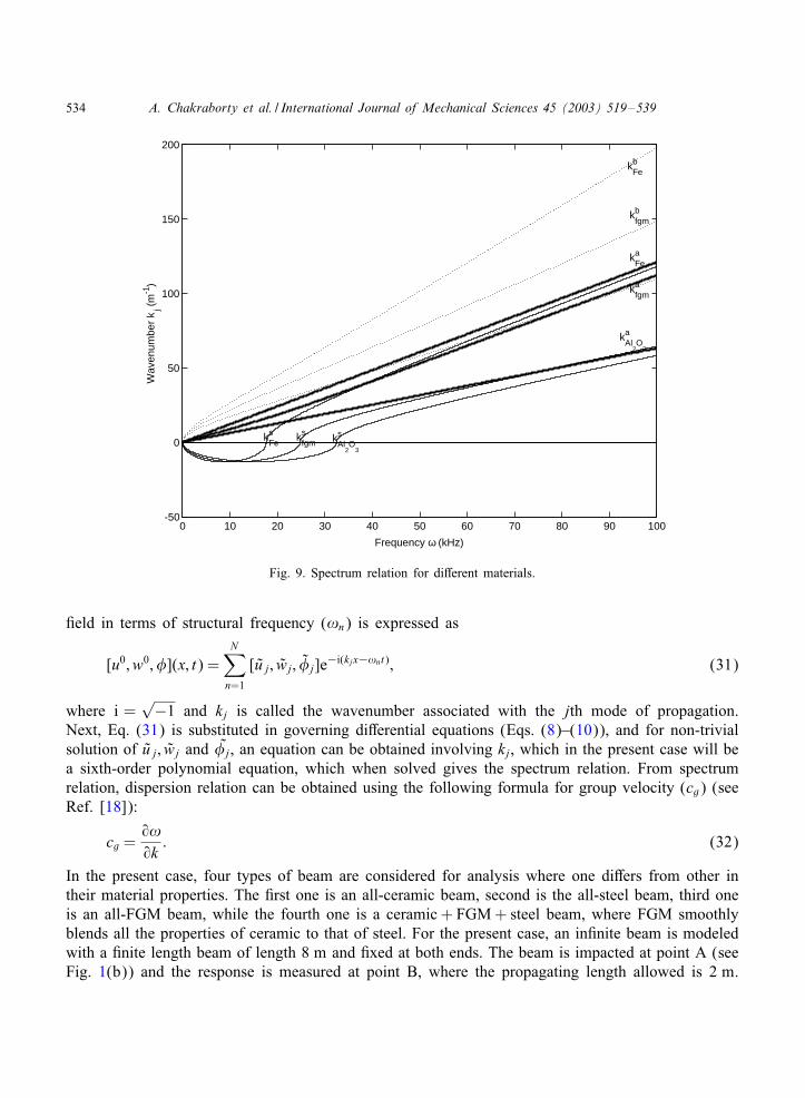
Fig. 9. Spectrum relation for di2erent materials.
eld in terms of structural frequency (!n) is expressed as
[u0; w0; �](x; t) =N∑
n=1
[u j; wj; �j]e−i(kjx−!nt); (31)
where i =√−1 and kj is called the wavenumber associated with the jth mode of propagation.
Next, Eq. (31) is substituted in governing di2erential equations (Eqs. (8)–(10)), and for non-trivialsolution of u j; wj and �j, an equation can be obtained involving kj, which in the present case will bea sixth-order polynomial equation, which when solved gives the spectrum relation. From spectrumrelation, dispersion relation can be obtained using the following formula for group velocity (cg) (seeRef. [18]):
cg =9!9k : (32)
In the present case, four types of beam are considered for analysis where one di2ers from other intheir material properties. The rst one is an all-ceramic beam, second is the all-steel beam, third oneis an all-FGM beam, while the fourth one is a ceramic + FGM+ steel beam, where FGM smoothlyblends all the properties of ceramic to that of steel. For the present case, an in nite beam is modeledwith a nite length beam of length 8 m and xed at both ends. The beam is impacted at point A (seeFig. 1(b)) and the response is measured at point B, where the propagating length allowed is 2 m.
A. Chakraborty et al. / International Journal of Mechanical Sciences 45 (2003) 519–539 535
10 20 30 40 50 60 70 80 900
2000
4000
6000
8000
10000
12000
Frequency ω kHz
Gro
up S
peed
(m
/s)
CFeb
Cfgmb
CAl
2O
3
b
CAl
2O
3
s
CAl
2O
3
a
Cfgma
CFea
CFes C
fgms
load
Fig. 10. Dispersion relation for di2erent materials: applied load is also shown.
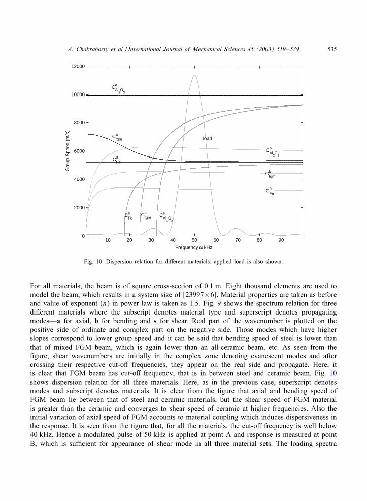
For all materials, the beam is of square cross-section of 0:1 m. Eight thousand elements are used tomodel the beam, which results in a system size of [23997×6]. Material properties are taken as beforeand value of exponent (n) in power law is taken as 1.5. Fig. 9 shows the spectrum relation for threedi2erent materials where the subscript denotes material type and superscript denotes propagatingmodes—a for axial, b for bending and s for shear. Real part of the wavenumber is plotted on thepositive side of ordinate and complex part on the negative side. Those modes which have higherslopes correspond to lower group speed and it can be said that bending speed of steel is lower thanthat of mixed FGM beam, which is again lower than an all-ceramic beam, etc. As seen from the gure, shear wavenumbers are initially in the complex zone denoting evanescent modes and aftercrossing their respective cut-o2 frequencies, they appear on the real side and propagate. Here, itis clear that FGM beam has cut-o2 frequency, that is in between steel and ceramic beam. Fig. 10shows dispersion relation for all three materials. Here, as in the previous case, superscript denotesmodes and subscript denotes materials. It is clear from the gure that axial and bending speed ofFGM beam lie between that of steel and ceramic materials, but the shear speed of FGM materialis greater than the ceramic and converges to shear speed of ceramic at higher frequencies. Also theinitial variation of axial speed of FGM accounts to material coupling which induces dispersiveness inthe response. It is seen from the gure that, for all the materials, the cut-o2 frequency is well below40 kHz. Hence a modulated pulse of 50 kHz is applied at point A and response is measured at pointB, which is su<cient for appearance of shear mode in all three material sets. The loading spectra

536 A. Chakraborty et al. / International Journal of Mechanical Sciences 45 (2003) 519–539
0 100 200 300 400 500 600 700 -2
-1
0
1
-1
0
1
2
s ba
Time (µ sec)
Tra
nsve
rse
velo
city
(m
/s)×
10 -
6
Fe-FGM-Al
FGM-full
Fig. 11. Transverse velocity history at B for modulated transverse load applied at A: lled circle denotes occurrences ofdi2erent modes predicted by dispersion relation.
are superposed in dispersion relation for easy evaluation of the magnitudes of di2erent propagatingspeeds, which can be used to check the response obtained from FE analysis.Responses of the all-FGM beam and blended-FGM beam are shown in Fig. 11. Three separate
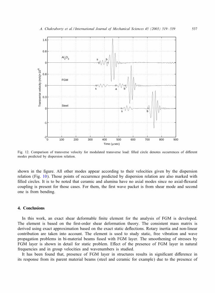
wave forms can be seen in that gure which denotes three di2erent propagating modes. From dis-persion relation it is clear that the rst one is shear mode, second one axial mode and third oneis bending mode. Here axial mode appears due to the presence of coupling in FGM beam. Fromdispersion relation of ceramic + FGM+ steel beam, occurrence of di2erent modes is estimated. Forexample, shear speed of FGM beam at 50 kHz is around 8245:6 m=s and the time taken for thismode to travel a length of 2 m is around 242:55 �s and added to that initial padding of 100 �sin the load history sums up to 342:55 �s which is exactly the occurrence of shear mode in Fig.11. This point and similarly other points (calculated from dispersion relation) for other modes areplotted with lled circle in that gure, which ensures the validity of present element for analysisof bi-materials with FGM. It can be seen that there is a little di2erence between the behavior ofall-FGM beam and blended-FGM beam. As in the previous case, the shear speed is slightly lower,while the axial mode travels faster.Next, responses of steel and ceramic beam are compared to that of an all-FGM beam and the
result is shown in Fig. 12. Dispersion relation predicts that shear speed of FGM beam is greaterthan ceramic beam and hence it should appear before shear mode of ceramic beam which is clearly
A. Chakraborty et al. / International Journal of Mechanical Sciences 45 (2003) 519–539 537
0 100 200 300 400 500 600 700 800 900 -2
-1
0
0.3
0
0.8
0
0.8
1.6
s b
s b
s ba
Time (µ sec)
Tra
nsve
rse
velo
city
(m
/s)×
10 -
6
Al2O
3
FGM
Steel
Fig. 12. Comparison of transverse velocity for modulated transverse load: lled circle denotes occurrences of di2erentmodes predicted by dispersion relation.
shown in the gure. All other modes appear according to their velocities given by the dispersionrelation (Fig. 10). Those points of occurrence predicted by dispersion relation are also marked with lled circles. It is to be noted that ceramic and alumina have no axial modes since no axial-Hexuralcoupling is present for those cases. For them, the rst wave packet is from shear mode and secondone is from bending.
4. Conclusions
In this work, an exact shear deformable nite element for the analysis of FGM is developed.The element is based on the rst-order shear deformation theory. The consistent mass matrix isderived using exact approximation based on the exact static deHections. Rotary inertia and non-linearcontribution are taken into account. The element is used to study static, free vibration and wavepropagation problems in bi-material beams fused with FGM layer. The smoothening of stresses byFGM layer is shown in detail for static problem. E2ect of the presence of FGM layer in naturalfrequencies and in group velocities and wavenumbers is studied.It has been found that, presence of FGM layer in structures results in signi cant di2erence in
its response from its parent material beams (steel and ceramic for example) due to the presence of
538 A. Chakraborty et al. / International Journal of Mechanical Sciences 45 (2003) 519–539
coupled sti2ness and inertial parameters. Static models show that it is an e2ective way to smoothenstress jumps in bi-material beams. Its free vibration behavior is remarkable and di2erent designsof these materials will result in signi cant variation in its natural frequencies. Its behavior in wavepropagation, in general, is average of the two constitutive materials that it blends. Cut-o2 frequencyof beam with FGM layer lies between its parent material beams, although shear speed of FGMapplied beam is higher than any of those mono-material beam because of high coupling inertialterms.
Appendix A.
�= B11A55=(A11D11 − B211); " = A11A55=(A11D11 − B2
11); = 1=(1 + "L2=12):
The elements of the exact shape function are:
ℵu11 = (1− x=L); ℵu
12 = 6� (x=L− 1)x; ℵu13 = 3� (x − L)x;
ℵu14 = x=L; ℵu
15 =−ℵu12; ℵu
16 = ℵu13;
ℵw11 = 0; ℵw
12 = ("L3 + 12L− 12x + 2"x3 − 3"x2L)=L;
ℵw13 = x ("L3 + 6L− 6x + "x2L− 2x"L2)=L; ℵw
14 = 0;
ℵw15 =−x (−12 + 2"x2 − 3"xL)=L; ℵw
16 = x (−6L+ "x2L− x"L2 + 6x)=L;
ℵ�11 = 0; ℵ�
12 = 6x"(−L+ x) =L;
ℵ�13 = (3"x2L+ "L3 + 12L− 4x"L2 − 12x) =L; ℵ�
14 = 0;
ℵ�15 =−ℵ�
12;ℵ�16 = x(3"xL− 2"L2 + 12) =L:
Non-zero elements of the {R} vector are:
R1 = DT AT11; R3 =−DT BT11; R4 =−DT AT11; R6 = DT BT11:
Non-zero entries of the element sti2ness matrix [K] are:
K11 =A11
L=−K14; K13 =−B11
L=−K16;
K22 =A55 L
=−K25; K23 =A55 2
= K26;
K33 =D11
L+
A55 L4
= K66; K34 =−K13; K35 =−K23;
K36 =−D11
L+
A55 L4
;
K44 = K11; K46 = K13; K55 = K22; K56 =−k23:
A. Chakraborty et al. / International Journal of Mechanical Sciences 45 (2003) 519–539 539
References
[1] Suresh S, Mortensen A. Fundamentals of functionally graded materials. London: IOM Communications Ltd., 1998.[2] Reddy JN, Chin CD. Thermomechanical analysis of functionally graded cylinders and plates. Journal of Thermal
Stresses 1998;26(1):593–626.[3] Praveen GN, Reddy JN. Nonlinear transient thermoelastic analysis of functionally graded ceramic–metal plates.
International Journal of Solids Structures 1998;35(33):4457–76.[4] Reddy JN. Analysis of functionally graded plates. International Journal of Numerical Methods in Engineering
2000;47:663–84.[5] Reddy JN, Hsu YS. E2ects of shear deformation and anisotropy on the thermal bending of layered composite plates.
Journal of Thermal Stresses 1980;3:475–93.[6] Gopalakrishnan S. A deep rod nite element for structural dynamics and wave propagation problems. International
Journal of Numerical Methods in Engineering 2000;48:731–44.[7] Chakraborty A, Mahapatra DR, Gopalakrishnan S. Finite element analysis of free vibration and wave propagation in
asymmetric composite beams with structural discontinuities. Composite Structures 2002;55(1):23–36.[8] Khedir AA, Reddy JN. An exact solution for the bending of thin and thick cross-ply beams. Composite Structures
1997;37:195–203.[9] Reddy JN. On locking-free shear deformable beam nite elements. Computer Methods in Applied Mechanics and
Engineering 1997;149:113–32.[10] Chakraborty A, Gopalakrishnan S. Poisson’s contraction e2ects in a deep laminated composite beam. Mechanical
Advances in Materials and Structures, in press.[11] El-Abbasi N, Meguid SA. Finite element modeling of the thermoelastic behavior of functionally graded plates and
shells. International Journal of Computer Engineering Science 2000;1(1):151–65.[12] Markworth AJ, Ramesh KS, Parks Jr WP. Modelling studies applied to functionally graded materials. Journal of
Material Science 1995;30:2183–93.[13] Kim J, Paulino GH. Finite element evaluation of mixed mode stress intensity factors in functionally graded materials.
International Journal for Numerical Methods in Engineering 2002;53:1903–35.[14] Zhang Ch, Savaidis A, Savaidis G, Zhu H. Transient dynamic analysis of a cracked functionally graded material by
a BIEM. Computational Materials Science 2003;26:167–74.[15] Wakashima K, Hirano T, Niino M. Space applications of advanced structural materials. ESA 1990;SP-303:97.[16] Nakamura T, Wang T, Sampath S. Determination of properties of graded materials by inverse analysis and
instrumented indentation. Acta Materialia 2000;48(17):4293–306.[17] Strang G, Fix GJ. An analysis of nite element method. Englewood Cli2s, NJ, USA: Prentice-Hall, 1973.[18] Doyle JF. Wave propagation in structures. New York: Springer, 1998.
Copyright © 2022 FDOKUMEN