Case Study of a Functionally Graded Aluminum Part - MDPI
9
applied sciences Article Case Study of a Functionally Graded Aluminum Part Elisa Fracchia 1 ID , Silvia Lombardo 2 and Mario Rosso 3, * 1 Department of Applied Science and Technology (DISAT), Politecnico di Torino, Viale T. Michel 5, 15121 Alessandria, Italy; [email protected] 2 Fonderie Officine Meccaniche Tonno (F.O.M.T) S.p.A., Viale Lidice, 8, Grugliasco, 10095 Torino, Italy; [email protected] 3 Department of Applied Science and Technology (DISAT), Politecnico di Torino, C.so Duca degli Abruzzi 24, 10129 Torino, Italy * Correspondence: [email protected]; Tel.: +39-011-0904-604 Received: 31 May 2018; Accepted: 5 July 2018; Published: 10 July 2018 Abstract: The growing interest in aluminum alloys is due to the excellent ductility and mechanical strength, especially in relation with their lightness. These properties make aluminum alloys one of the most used and competitive materials in the automotive sectors. In fact, at the present day, automotive components must guarantee high mechanical and thermal properties in order to ensure low emissions of the vehicle. Despite that, harsh operating conditions can lead to a rupture in aluminum components, especially if subjected to both thermal and mechanical loads. In this panorama, aluminum functionally graded materials (FGMs) could be introduced, in order to produce a single piece with different properties that fulfill all the piece requirements. In this work, considering the typical application of the aluminum alloys as engine pistons, FGMs are realized by sequential gravity casting with the piston alloy EN AB 48000 and the alloy EN AB 42100. Tensile tests on these bi-metal parts give good results in terms of mechanical strength, elongation rates and alloys bonding. Keywords: aluminum FGM; gravity casting; sequential casting; mechanical properties 1. Introduction Functionally graded materials (FGMs) are advanced engineering composite materials that exhibit a spatial gradient in composition and/or morphology with the aim to satisfy specific requirements. There are three different types of FGMs [1]: chemical composition gradient FGMs, microstructural gradient FGMs and porosity gradient FGMs. In the chemical composition gradient FGMs, the chemical composition is gradually varied along the spatial position into the material. The microstructure gradient FGMs are characterized by a microstructural variation into the same material: the microstructure is tailored with the aim to obtain the required properties in certain parts of the piece. Finally, in the porosity gradient FGMs, the porosity changes with the space position into the material, changing pore shape and/or their size. These materials found applications in a variety of field, such as aerospace, nuclear, electrical, biomedical, defense and automotive sectors [1–3]. There are several methods to obtain FGMs: gas-based methods, liquid-phase methods and solid-phase methods [2], and among all this production processes, metallic FGMs are commonly obtained with centrifugal casting, squeeze casting, gravity casting, investment casting, sintering and infiltration techniques [4,5]. Within the casting process panorama, gravity casting is one of the simplest methods to produce FGMs. This process employs a permanent mould, commonly realized in steel. The mould is opportunely coated with a protective paint and then pre-heated at a certain temperature that must be constant in order to facilitate the cast-removal. The cast production sequence involves different steps: (i) mould cleaning; (ii) casting process; (iii) cast extraction; and (iv) sprue cut. Appl. Sci. 2018, 8, 1113; doi:10.3390/app8071113 www.mdpi.com/journal/applsci
-
Upload
khangminh22 -
Category
Documents
-
view
8 -
download
0
Transcript of Case Study of a Functionally Graded Aluminum Part - MDPI

applied sciences
Article
Case Study of a Functionally Graded Aluminum Part
Elisa Fracchia 1 ID , Silvia Lombardo 2 and Mario Rosso 3,*1 Department of Applied Science and Technology (DISAT), Politecnico di Torino, Viale T. Michel 5,
15121 Alessandria, Italy; [email protected] Fonderie Officine Meccaniche Tonno (F.O.M.T) S.p.A., Viale Lidice, 8, Grugliasco, 10095 Torino, Italy;
[email protected] Department of Applied Science and Technology (DISAT), Politecnico di Torino,
C.so Duca degli Abruzzi 24, 10129 Torino, Italy* Correspondence: [email protected]; Tel.: +39-011-0904-604
Received: 31 May 2018; Accepted: 5 July 2018; Published: 10 July 2018�����������������
Abstract: The growing interest in aluminum alloys is due to the excellent ductility and mechanicalstrength, especially in relation with their lightness. These properties make aluminum alloys one of themost used and competitive materials in the automotive sectors. In fact, at the present day, automotivecomponents must guarantee high mechanical and thermal properties in order to ensure low emissionsof the vehicle. Despite that, harsh operating conditions can lead to a rupture in aluminum components,especially if subjected to both thermal and mechanical loads. In this panorama, aluminum functionallygraded materials (FGMs) could be introduced, in order to produce a single piece with differentproperties that fulfill all the piece requirements. In this work, considering the typical applicationof the aluminum alloys as engine pistons, FGMs are realized by sequential gravity casting with thepiston alloy EN AB 48000 and the alloy EN AB 42100. Tensile tests on these bi-metal parts give goodresults in terms of mechanical strength, elongation rates and alloys bonding.
Keywords: aluminum FGM; gravity casting; sequential casting; mechanical properties
1. Introduction
Functionally graded materials (FGMs) are advanced engineering composite materials thatexhibit a spatial gradient in composition and/or morphology with the aim to satisfy specificrequirements. There are three different types of FGMs [1]: chemical composition gradient FGMs,microstructural gradient FGMs and porosity gradient FGMs. In the chemical composition gradientFGMs, the chemical composition is gradually varied along the spatial position into the material.The microstructure gradient FGMs are characterized by a microstructural variation into the samematerial: the microstructure is tailored with the aim to obtain the required properties in certain partsof the piece. Finally, in the porosity gradient FGMs, the porosity changes with the space position intothe material, changing pore shape and/or their size. These materials found applications in a variety offield, such as aerospace, nuclear, electrical, biomedical, defense and automotive sectors [1–3].
There are several methods to obtain FGMs: gas-based methods, liquid-phase methods andsolid-phase methods [2], and among all this production processes, metallic FGMs are commonlyobtained with centrifugal casting, squeeze casting, gravity casting, investment casting, sinteringand infiltration techniques [4,5]. Within the casting process panorama, gravity casting is one of thesimplest methods to produce FGMs. This process employs a permanent mould, commonly realizedin steel. The mould is opportunely coated with a protective paint and then pre-heated at a certaintemperature that must be constant in order to facilitate the cast-removal. The cast production sequenceinvolves different steps: (i) mould cleaning; (ii) casting process; (iii) cast extraction; and (iv) sprue cut.
Appl. Sci. 2018, 8, 1113; doi:10.3390/app8071113 www.mdpi.com/journal/applsci

Appl. Sci. 2018, 8, 1113 2 of 9
This casting process causes a certain grade of defects, intrinsically generated by the process [6], and thefinal properties of castings are related to defects as well as to die design and microstructures.
Parameters that could affect the casting process causing defects are: (i) temperatures (pouring,pre-heat); (ii) time (pouring, melt holding, degasification); (iii) material and thickness of themould-coating; (iv) mould design; and (v) pouring velocity. The types of defects and their ranking ingravity casting were classified in [7] as: (i) gas/air porosity, about 45%; (ii) shrinkage, 44%; (iii) fillingrelated problems, 38%; (iv) cracks, 33%; (v) inclusions, 28%; and (vi) metal/die interactions, 23%.
Focusing on the combination FGM-automotive applications, and considering the high presence ofthe aluminum alloys in this sector [8], it is certainly possible to combine the aluminum alloys withthe concept of FGM [9–12]. In fact, aluminum alloys are considered as very interesting materials,because of their lightweight, especially if compared with ferrous alloys, which lead to an importantdecrease in fuel consumption reducing the polluting emissions, and their high specific resistance andductility [13,14]. Particularly, FGMs in the automotive industries could be used for engine pistons [9],leaf springs [15] and many other applications. Focusing on the piston production techniques, the mostemployed processes are casting and forging [16–21]. In [22], Park et al. optimized the forging processto produce aluminum pistons employing aluminum powder; in the research [23], high performancepistons were produced by additive manufacturing; and in [24], the forging process was performedon the piston-wrought-alloy EN AW 4032 (AlSi12,5MgCuNi). In [9], a microstructure-gradient FGMaluminum piston was produced by centrifugal casting: the hypereutectic alloy A390 was melted andpoured into a spinning mould, and the design of the die leads to obtain a strong segregation of theprimary silicon particles on the head portion of the piston that leads to an increase in wear and hardness.Similarly, with the same producing process, Huang et al. [25] realized a chemical-composition-gradientFGMs with AlSi18CuMgNi alloy.
Engine pistons are commonly produced employing aluminum–silicon alloys because of theirhigh mechanical resistance at high temperature and good fatigue behavior [16,25–32]. Particularly,the most widely used piston alloy is the EN AC 48000. However, this alloy exhibits poor ductility andlow elongation at rupture that could lead to fatigue failure in the piston skirt. This can be avoided byrealizing a FGM employing a more ductile alloy in the skirt and a mechanical and thermal resistantalloy in the piston crown. In this paper, a chemical-composition-gradient FGM for automotive pistonwas prepared by sequential gravity casting using the piston alloy (EN AC 48000) in contact with a moreductile composition (EN AC 42100). This FGM was made focusing on the process variables and theirinfluence on the mechanical properties obtained.
2. Materials and Methods
2.1. Materials
FGM was realized by gravity casting using two different aluminum alloys: EN AC 48000(AlSi12CuNiMg) and EN AC 42100 (AlSi7Mg0.3) with the compositions reported in Table 1.
Table 1. Alloy composition [33].
EN AC 48000 (AlSi12CuNiMg)
Elements Si Fe Cu Mn Mg Ni Zn Ti AlMin (%) 10.5 - 0.8 - 0.8 0.7 - -
Res.Max (%) 13.5 0.7 1.5 0.35 1.5 1.3 0.35 0.25
EN AC 42100 (AlSi7Mg0.3)
Elements Si Fe Cu Mn Mg Zn Ti AlMin (%) 6.5 - - - 0.25 - -
Res.Max (%) 7.5 0.19 0.05 0.10 0.45 0.07 0.25

Appl. Sci. 2018, 8, 1113 3 of 9
The AlSi12CuNiMg alloy, also known as a piston alloy, is commonly used to produce piston inthe automotive sector. It has eutectic composition and the maximum elongation at rupture of about1%. On the other hand, the AlSi7Mg0.3 alloy is a hypoeutectic aluminu-silicon alloy that containsa small amount of Mg and could reach 8% of elongation at rupture. Cu and Mg are added to increasethe mechanical properties as a result of the precipitation strengthening after heat treatment, while Ni,added in the piston alloy, increases the high temperature resistance [34].
2.2. Methods
An aluminum FGM was obtained with the sequential gravity casting of the composition A(AlSi7Mg0.3) followed by the composition B (AlSi12CuNiMg). Overall, five types of manual castingswere performed using a mould (made in heat treated steel) that permitted to obtain square bars of25 mm × 125 mm × 15 mm. Optimization of the casting process included: (i) selection of the pouringorder for the two compositions; (ii) casting temperatures of the alloys; (iii) waiting time between thesequential castings; and (iv) mould temperature.
The pouring order depends on the alloy-gap between solidus and liquidus temperatures.As previously demonstrated by DSC analysis (Differential Scanning Calorimetry) and detailedin [10,11], the hypoeutectic alloy (AlSi7Mg0.3) was the first poured composition for its larger gap ofsolidification (Figure 1).
Appl. Sci. 2018, 8, x FOR PEER REVIEW 3 of 9
1%. On the other hand, the AlSi7Mg0.3 alloy is a hypoeutectic aluminu-silicon alloy that contains a small amount of Mg and could reach 8% of elongation at rupture. Cu and Mg are added to increase the mechanical properties as a result of the precipitation strengthening after heat treatment, while Ni, added in the piston alloy, increases the high temperature resistance [34].
2.2. Methods
An aluminum FGM was obtained with the sequential gravity casting of the composition A (AlSi7Mg0.3) followed by the composition B (AlSi12CuNiMg). Overall, five types of manual castings were performed using a mould (made in heat treated steel) that permitted to obtain square bars of 25 mm × 125 mm × 15 mm. Optimization of the casting process included: (i) selection of the pouring order for the two compositions; (ii) casting temperatures of the alloys; (iii) waiting time between the sequential castings; and (iv) mould temperature.
The pouring order depends on the alloy-gap between solidus and liquidus temperatures. As previously demonstrated by DSC analysis (Differential Scanning Calorimetry) and detailed in [10,11], the hypoeutectic alloy (AlSi7Mg0.3) was the first poured composition for its larger gap of solidification (Figure 1).
Figure 1. Differential Scanning Calorimetry (DSC) analysis [10].
The DSC curve of the hypoeutectic alloy presents two peaks: the eutectic temperature and the liquidus temperature (as can be seen in Figure 1). This gap of solidification permits to obtain a barrier effect for the second alloy (with eutectic composition) when poured, due to the solidification of the alpha-phase of the first alloy that avoids the mixing of the composition. At the same time, it is important to perform the second casting during the solidification temperature gap of the first alloy, in order to allow a metallurgical bond due to the mixing of the Si-rich phase of the second poured alloy inside the interdendritic channels of the first one.
Casting temperatures of the alloys must ensure the bonding of the two compositions avoiding the premature solidification of the first alloy poured. The waiting time between the sequential castings depends on both the temperature gap liquidus-solidus for the two alloys and the casting temperature of the alloys; in fact, this time must permit the bond of the alloys at the interfaces avoiding the mixing of the compositions. The mould temperature influences the degassing process: the higher the temperature of the mould, the faster the elimination of the humidity is.
For all these reasons, alloy temperatures were set at 710 °C (AlSi7Mg0.3) and 750 °C (AlSi12CuNiMg), with a mould temperature of 400 °C and several waiting time in the range of 10–50 s, to investigate their effect on the bonding region. No modification or refining was performed during the melting.
After the casting process, qualitatively RX analysis (X-ray radioscopic inspection) was carried out to evaluate the bonding rate, the porosity and the inclusion grade into the casted parts, especially at the interfaces between the two compositions. These observations were conducted by a Bosello High Technology Industrial X-Ray system on the casted parts.
Tensile tests were done by a ZWICK ROELL machine with the aim to evaluate the resistance of the joint between the alloys for different elapsing time. Each casting specimen was machined into the typical dog-bone shape. Considering the composite nature of the FGMs and the possibility to obtain
EN AC 42100 EN AC 48000
Figure 1. Differential Scanning Calorimetry (DSC) analysis [10].
The DSC curve of the hypoeutectic alloy presents two peaks: the eutectic temperature and theliquidus temperature (as can be seen in Figure 1). This gap of solidification permits to obtain a barriereffect for the second alloy (with eutectic composition) when poured, due to the solidification of thealpha-phase of the first alloy that avoids the mixing of the composition. At the same time, it is importantto perform the second casting during the solidification temperature gap of the first alloy, in order toallow a metallurgical bond due to the mixing of the Si-rich phase of the second poured alloy inside theinterdendritic channels of the first one.
Casting temperatures of the alloys must ensure the bonding of the two compositions avoiding thepremature solidification of the first alloy poured. The waiting time between the sequential castingsdepends on both the temperature gap liquidus-solidus for the two alloys and the casting temperatureof the alloys; in fact, this time must permit the bond of the alloys at the interfaces avoiding themixing of the compositions. The mould temperature influences the degassing process: the higher thetemperature of the mould, the faster the elimination of the humidity is.
For all these reasons, alloy temperatures were set at 710 ◦C (AlSi7Mg0.3) and 750 ◦C (AlSi12CuNiMg),with a mould temperature of 400 ◦C and several waiting time in the range of 10–50 s, to investigatetheir effect on the bonding region. No modification or refining was performed during the melting.
After the casting process, qualitatively RX analysis (X-ray radioscopic inspection) was carried outto evaluate the bonding rate, the porosity and the inclusion grade into the casted parts, especially atthe interfaces between the two compositions. These observations were conducted by a Bosello HighTechnology Industrial X-Ray system on the casted parts.
Appl. Sci. 2018, 8, 1113 4 of 9
Tensile tests were done by a ZWICK ROELL machine with the aim to evaluate the resistance ofthe joint between the alloys for different elapsing time. Each casting specimen was machined intothe typical dog-bone shape. Considering the composite nature of the FGMs and the possibility toobtain two specimens for each FGM casted, which lead to perform a better statistical analysis of theresults, it was decided to realize rectangular-shape specimens, following the standard ASTM B557-15for samples preparation and the ASTM E8 for testing methods. After tensile tests, the fracture surfaceswere observed with the scanning electron microscope (SEM), Leo 1450VP.
3. Results and Discussion
3.1. RX Analysis
RX images of the most representative samples were shown in Figure 2. In the middle of thespecimens, inclusions and gas porosities that appear white were observed, as well as reported in [35],particularly in the EN AC 48000.
Appl. Sci. 2018, 8, x FOR PEER REVIEW 4 of 9
two specimens for each FGM casted, which lead to perform a better statistical analysis of the results, it was decided to realize rectangular-shape specimens, following the standard ASTM B557-15 for samples preparation and the ASTM E8 for testing methods. After tensile tests, the fracture surfaces were observed with the scanning electron microscope (SEM), Leo 1450VP.
3. Results and Discussion
3.1. RX Analysis
RX images of the most representative samples were shown in Figure 2. In the middle of the specimens, inclusions and gas porosities that appear white were observed, as well as reported in [35], particularly in the EN AC 48000.
After the waiting time of ten seconds, the interface appeared sharp. After twenty seconds, the solidification of the first alloy was interrupted by the casting of the second one that led to the formation of an interaction layer with the re-melting of the interface of the first poured alloy. Over thirty seconds, the interface area appeared sharp with a high grade of porosity and oxide films [36,37]. The interaction region where the two alloys met became inhomogeneous for excessive waiting time, as shown in part #5 of Figure 2.
Figure 2. Sample interfaces EN AC 48000/EN AC 42100 obtained with RX analysis after sequential gravity casting at different conditions of waiting time. AlSi12CuNiMg is the dark grey part (the lower part for each image) while the other one is AlSi7Mg0.3.
3.2. Tensile Tests
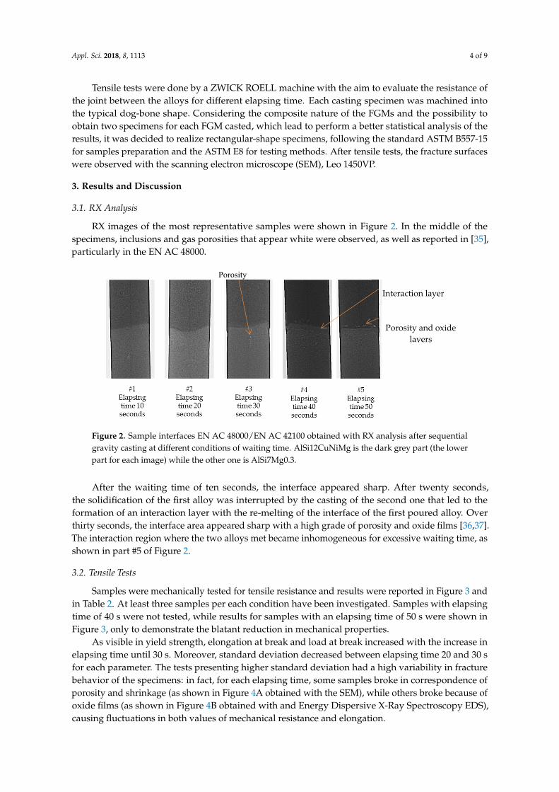
Samples were mechanically tested for tensile resistance and results were reported in Figure 3 and in Table 2. At least three samples per each condition have been investigated. Samples with elapsing time of 40 s were not tested, while results for samples with an elapsing time of 50 s were shown in Figure 3, only to demonstrate the blatant reduction in mechanical properties.
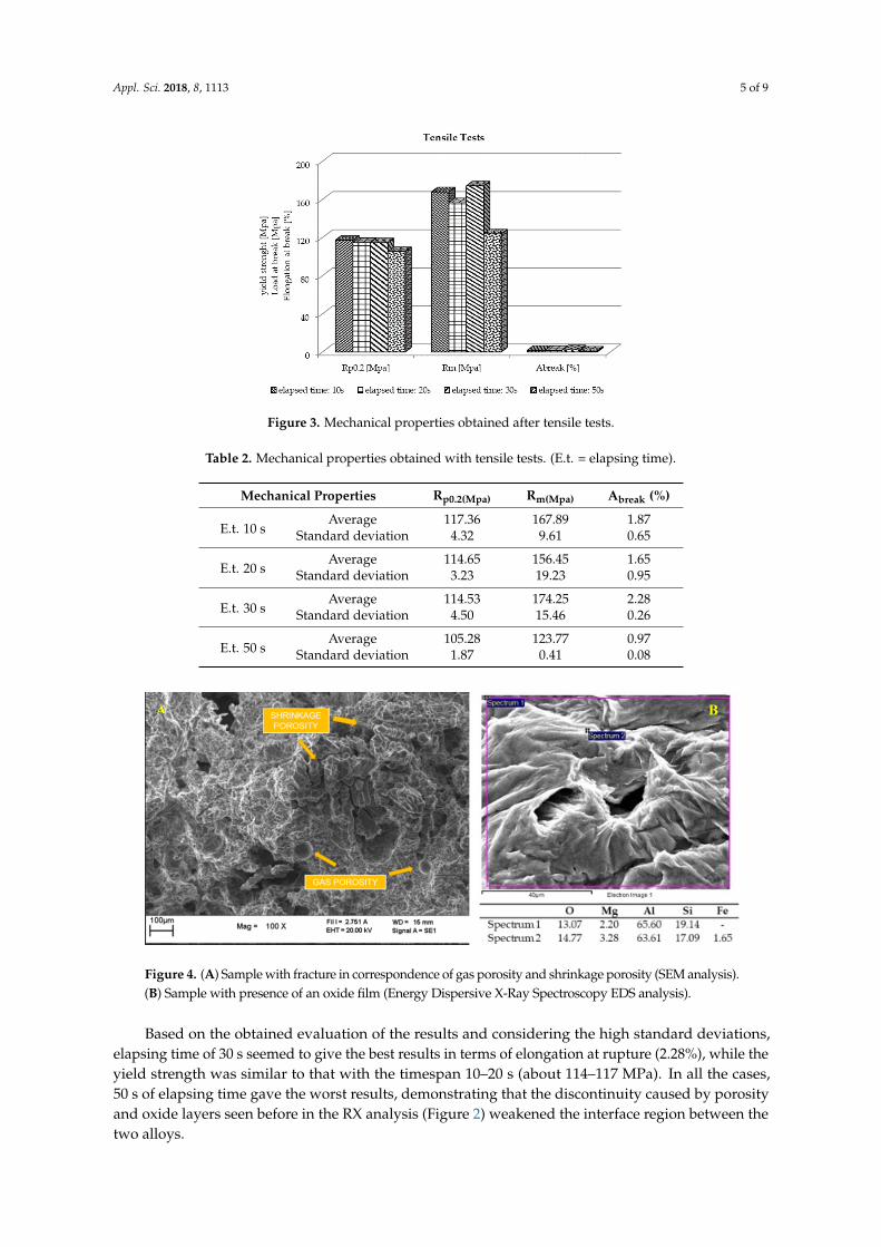
As visible in yield strength, elongation at break and load at break increased with the increase in elapsing time until 30 s. Moreover, standard deviation decreased between elapsing time 20 and 30 s for each parameter. The tests presenting higher standard deviation had a high variability in fracture behavior of the specimens: in fact, for each elapsing time, some samples broke in correspondence of porosity and shrinkage (as shown in Figure 4A obtained with the SEM), while others broke because of oxide films (as shown in Figure 4B obtained with and Energy Dispersive X-Ray Spectroscopy EDS), causing fluctuations in both values of mechanical resistance and elongation.
Porosity and oxide layers
Interaction layer
Porosity
Figure 2. Sample interfaces EN AC 48000/EN AC 42100 obtained with RX analysis after sequentialgravity casting at different conditions of waiting time. AlSi12CuNiMg is the dark grey part (the lowerpart for each image) while the other one is AlSi7Mg0.3.
After the waiting time of ten seconds, the interface appeared sharp. After twenty seconds,the solidification of the first alloy was interrupted by the casting of the second one that led to theformation of an interaction layer with the re-melting of the interface of the first poured alloy. Overthirty seconds, the interface area appeared sharp with a high grade of porosity and oxide films [36,37].The interaction region where the two alloys met became inhomogeneous for excessive waiting time, asshown in part #5 of Figure 2.
3.2. Tensile Tests
Samples were mechanically tested for tensile resistance and results were reported in Figure 3 andin Table 2. At least three samples per each condition have been investigated. Samples with elapsingtime of 40 s were not tested, while results for samples with an elapsing time of 50 s were shown inFigure 3, only to demonstrate the blatant reduction in mechanical properties.
As visible in yield strength, elongation at break and load at break increased with the increase inelapsing time until 30 s. Moreover, standard deviation decreased between elapsing time 20 and 30 sfor each parameter. The tests presenting higher standard deviation had a high variability in fracturebehavior of the specimens: in fact, for each elapsing time, some samples broke in correspondence ofporosity and shrinkage (as shown in Figure 4A obtained with the SEM), while others broke because ofoxide films (as shown in Figure 4B obtained with and Energy Dispersive X-Ray Spectroscopy EDS),causing fluctuations in both values of mechanical resistance and elongation.
Appl. Sci. 2018, 8, 1113 5 of 9Appl. Sci. 2018, 8, x FOR PEER REVIEW 5 of 9
Figure 3. Mechanical properties obtained after tensile tests.
Table 2. Mechanical properties obtained with tensile tests. (E.t. = elapsing time).
Mechanical Properties Rp0.2(Mpa) Rm(Mpa) Abreak (%)
E.t. 10 s Average 117.36 167.89 1.87 Standard deviation 4.32 9.61 0.65
E.t. 20 s Average 114.65 156.45 1.65 Standard deviation 3.23 19.23 0.95
E.t. 30 s Average 114.53 174.25 2.28 Standard deviation 4.50 15.46 0.26
E.t. 50 s Average 105.28 123.77 0.97 Standard deviation 1.87 0.41 0.08
Figure 4. (A) Sample with fracture in correspondence of gas porosity and shrinkage porosity (SEM analysis). (B) Sample with presence of an oxide film (Energy Dispersive X-Ray Spectroscopy EDS analysis).
Based on the obtained evaluation of the results and considering the high standard deviations, elapsing time of 30 s seemed to give the best results in terms of elongation at rupture (2.28%), while the yield strength was similar to that with the timespan 10–20 s (about 114–117 MPa). In all the cases, 50 s of elapsing time gave the worst results, demonstrating that the discontinuity caused by porosity and oxide layers seen before in the RX analysis (Figure 2) weakened the interface region between the two alloys.
3.3. Fracture Surfaces
A B
Figure 3. Mechanical properties obtained after tensile tests.
Table 2. Mechanical properties obtained with tensile tests. (E.t. = elapsing time).
Mechanical Properties Rp0.2(Mpa) Rm(Mpa) Abreak (%)
E.t. 10 sAverage 117.36 167.89 1.87
Standard deviation 4.32 9.61 0.65
E.t. 20 sAverage 114.65 156.45 1.65
Standard deviation 3.23 19.23 0.95
E.t. 30 sAverage 114.53 174.25 2.28
Standard deviation 4.50 15.46 0.26
E.t. 50 sAverage 105.28 123.77 0.97
Standard deviation 1.87 0.41 0.08
Appl. Sci. 2018, 8, x FOR PEER REVIEW 5 of 9
Figure 3. Mechanical properties obtained after tensile tests.
Table 2. Mechanical properties obtained with tensile tests. (E.t. = elapsing time).
Mechanical Properties Rp0.2(Mpa) Rm(Mpa) Abreak (%)
E.t. 10 s Average 117.36 167.89 1.87 Standard deviation 4.32 9.61 0.65
E.t. 20 s Average 114.65 156.45 1.65 Standard deviation 3.23 19.23 0.95
E.t. 30 s Average 114.53 174.25 2.28 Standard deviation 4.50 15.46 0.26
E.t. 50 s Average 105.28 123.77 0.97 Standard deviation 1.87 0.41 0.08
Figure 4. (A) Sample with fracture in correspondence of gas porosity and shrinkage porosity (SEM analysis). (B) Sample with presence of an oxide film (Energy Dispersive X-Ray Spectroscopy EDS analysis).
Based on the obtained evaluation of the results and considering the high standard deviations, elapsing time of 30 s seemed to give the best results in terms of elongation at rupture (2.28%), while the yield strength was similar to that with the timespan 10–20 s (about 114–117 MPa). In all the cases, 50 s of elapsing time gave the worst results, demonstrating that the discontinuity caused by porosity and oxide layers seen before in the RX analysis (Figure 2) weakened the interface region between the two alloys.
3.3. Fracture Surfaces
A B
Figure 4. (A) Sample with fracture in correspondence of gas porosity and shrinkage porosity (SEM analysis).(B) Sample with presence of an oxide film (Energy Dispersive X-Ray Spectroscopy EDS analysis).
Based on the obtained evaluation of the results and considering the high standard deviations,elapsing time of 30 s seemed to give the best results in terms of elongation at rupture (2.28%), while theyield strength was similar to that with the timespan 10–20 s (about 114–117 MPa). In all the cases,50 s of elapsing time gave the worst results, demonstrating that the discontinuity caused by porosityand oxide layers seen before in the RX analysis (Figure 2) weakened the interface region between thetwo alloys.

Appl. Sci. 2018, 8, 1113 6 of 9
3.3. Fracture Surfaces
Analysis of the fracture post-tensile tests showed various defects, especially for higher elapsingtime. Shrinkage porosities, gas porosity and oxide layers were detected in more details in Table 3,which was also because of the surface turbulence associated with the filling of the mould as wellas in [38].
Table 3. Surface fractures for each elapsing time.
Elapsing Time E.t. Fracture Surfaces Fracture Details
E.t.10s: fragile fracturesin the AlSi7Mg0.3 causedby shrinkage porosity.
Appl. Sci. 2018, 8, x FOR PEER REVIEW 6 of 9
Analysis of the fracture post-tensile tests showed various defects, especially for higher elapsing time. Shrinkage porosities, gas porosity and oxide layers were detected in more details in Table 3, which was also because of the surface turbulence associated with the filling of the mould as well as in [38].
As expected [10], most of the fractures happened in the weakest alloy (AlSi7Mg0.3). In just one case (E.t. 50 s), the sample reached rupture exactly into the bonding layer because of high presence of slag that weakened the meeting area.
Table 3. Surface fractures for each elapsing time.
Elapsing Time E.t.
Fracture Surfaces Fracture Details
E.t.10s: fragile fractures in the AlSi7Mg0.3 caused by shrinkage porosity.
E.t.20s: fragile fractures in the AlSi7Mg0.3 caused by oxide and porosity.
E.t.30s: fracture in the AlSi7Mg0.3 caused by small quantity of gas porosity.
E.t.50s: fragile fractures at the interface area caused by oxide, shrinkage and gas porosity.
#1A
#2A
#3A #3B
#2B
#4B #4A
GAS POROSITY
#1B
E.t.20s: fragile fracturesin the AlSi7Mg0.3 causedby oxide and porosity.
Appl. Sci. 2018, 8, x FOR PEER REVIEW 6 of 9
Analysis of the fracture post-tensile tests showed various defects, especially for higher elapsing time. Shrinkage porosities, gas porosity and oxide layers were detected in more details in Table 3, which was also because of the surface turbulence associated with the filling of the mould as well as in [38].
As expected [10], most of the fractures happened in the weakest alloy (AlSi7Mg0.3). In just one case (E.t. 50 s), the sample reached rupture exactly into the bonding layer because of high presence of slag that weakened the meeting area.
Table 3. Surface fractures for each elapsing time.
Elapsing Time E.t.
Fracture Surfaces Fracture Details
E.t.10s: fragile fractures in the AlSi7Mg0.3 caused by shrinkage porosity.
E.t.20s: fragile fractures in the AlSi7Mg0.3 caused by oxide and porosity.
E.t.30s: fracture in the AlSi7Mg0.3 caused by small quantity of gas porosity.
E.t.50s: fragile fractures at the interface area caused by oxide, shrinkage and gas porosity.
#1A
#2A
#3A #3B
#2B
#4B #4A
GAS POROSITY
#1B
E.t.30s: fracture in theAlSi7Mg0.3 caused bysmall quantity of gasporosity.
Appl. Sci. 2018, 8, x FOR PEER REVIEW 6 of 9
Analysis of the fracture post-tensile tests showed various defects, especially for higher elapsing time. Shrinkage porosities, gas porosity and oxide layers were detected in more details in Table 3, which was also because of the surface turbulence associated with the filling of the mould as well as in [38].
As expected [10], most of the fractures happened in the weakest alloy (AlSi7Mg0.3). In just one case (E.t. 50 s), the sample reached rupture exactly into the bonding layer because of high presence of slag that weakened the meeting area.
Table 3. Surface fractures for each elapsing time.
Elapsing Time E.t.
Fracture Surfaces Fracture Details
E.t.10s: fragile fractures in the AlSi7Mg0.3 caused by shrinkage porosity.
E.t.20s: fragile fractures in the AlSi7Mg0.3 caused by oxide and porosity.
E.t.30s: fracture in the AlSi7Mg0.3 caused by small quantity of gas porosity.
E.t.50s: fragile fractures at the interface area caused by oxide, shrinkage and gas porosity.
#1A
#2A
#3A #3B
#2B
#4B #4A
GAS POROSITY
#1B
E.t.50s: fragile fracturesat the interface areacaused by oxide,shrinkage and gasporosity.
Appl. Sci. 2018, 8, x FOR PEER REVIEW 6 of 9
Analysis of the fracture post-tensile tests showed various defects, especially for higher elapsing time. Shrinkage porosities, gas porosity and oxide layers were detected in more details in Table 3, which was also because of the surface turbulence associated with the filling of the mould as well as in [38].
As expected [10], most of the fractures happened in the weakest alloy (AlSi7Mg0.3). In just one case (E.t. 50 s), the sample reached rupture exactly into the bonding layer because of high presence of slag that weakened the meeting area.
Table 3. Surface fractures for each elapsing time.
Elapsing Time E.t.
Fracture Surfaces Fracture Details
E.t.10s: fragile fractures in the AlSi7Mg0.3 caused by shrinkage porosity.
E.t.20s: fragile fractures in the AlSi7Mg0.3 caused by oxide and porosity.
E.t.30s: fracture in the AlSi7Mg0.3 caused by small quantity of gas porosity.
E.t.50s: fragile fractures at the interface area caused by oxide, shrinkage and gas porosity.
#1A
#2A
#3A #3B
#2B
#4B #4A
GAS POROSITY
#1B
As expected [10], most of the fractures happened in the weakest alloy (AlSi7Mg0.3). In just onecase (E.t. 50 s), the sample reached rupture exactly into the bonding layer because of high presence ofslag that weakened the meeting area.

Appl. Sci. 2018, 8, 1113 7 of 9
Table 3 shows details about microstructures and EDX analysis for four surface fractures:(#1) The sample with E.t. 10s broke in the weakest alloy, presenting shrinkage porosity in different
areas of the surface (Table 3 #1B).(#2) The sample with E.t. 20 s broke in the weakest alloy but close to the interface (in the presence
of Cu and Ni in the EDS analysis). As shown in Table 3 #2B, an oxide layer was detected.(#3) The sample with E.t. 30 s broke in the weakest alloy and presents the highest elongation.
The surface is free from macro defects, as shown in Table 3 #3B.(#4) Surface fracture of the sample with E.t. 50 s was characterized by shrinkage porosity,
with typical dendrite structures, gas porosity and oxide layers (Table 3 #4A, #4B).
4. Conclusions
Sequential gravity castings of FGMs in aluminum alloys were performed. The elapsing timebetween the casting of the two alloys was chosen as a priority parameter in order to optimize theprocess obtaining effective bonding between the two compositions.
After various casting processes at different elapsing time up to 50 s, tensile tests were madeto characterize the bonding behavior in each casting. Tests showed an increase in the mechanicalstrength after 20 s and then a decrease before 30 s. For shorter time, the alloys were mixed together ina larger and not defined area: the FGM goal was lost and the final mechanical properties were weaker.In order to maintain the alloys and their peculiar properties divided, the optimized time was between20 and 30 s.
Certainly, the mechanical properties obtained were in line with results of previous work [10],with an increase in the mechanical resistance and the yield strength. Most of the fractures occurred inthe AlSi7Mg0.3 region, which has lower mechanical resistance than AlSi12CuNiMg. The presence ofthe hypoeutectic alloy permitted to reach an elongation of 2%.
Overall, it appeared that only the presence of oxide and slag has caused fracture at the interfaceof the alloys. High elapsing time emphasizes this trend: long E.t. does not allow an effective remeltingof the AlSi7Mg0.3 surface and the oxide scale, if present, remains confined into the interface area,transforming it into a weak point.
These results could be further enhanced by improving the cleanliness of the bath to remove someoxide concerns and applying a heat treatment.
Author Contributions: Conceptualization, M.R. and S.L.; methodology, S.L. and E.F.; RX analysis, S.L.;investigation and tensile tests, E.F.; data curation, E.F.; writing of the original draft preparation, E.F.; supervision,M.R.; project administration, M.R.
Funding: This research received no external funding.
Conflicts of Interest: The authors declare no conflicts of interest.
References
1. Mahamood, R.M.; Akinlabi, E.T. Types of Functionally Graded Materials and Their Areas of Application.In Mining, Metallurgy and Materials Engineering; Springer: Cham, Switzerland, 2017.
2. Naebe, M.; Shirvanimoghaddam, K. Functionally graded materials: A review of fabrication and properties.Appl. Mater. Today 2016, 5, 223–245. [CrossRef]
3. Khan, S. Analysis of Tribological Applications of Functionally Graded Materials in Mobility Engineering.Int. J. Sci. Eng. Res. 2015, 6, 1150–1160.
4. Sobczak, J.J.; Drenchev, L. Metallic Functionally Graded Materials: A Specific Class of Advanced Composites.J. Mater. Sci. Technol. 2013, 29, 297–316. [CrossRef]
5. Singh, S.; Singh, R. Development of functionally graded material by fused deposition modelling assistedinvestment casting. J. Manuf. Process. 2016, 24, 38–45. [CrossRef]
6. Malhotra, V.; Kumar, Y. Study of Process Parameters of Gravity Die Casting Defects. Int. J. Mech. Eng. Technol.2016, 7, 208–211.

Appl. Sci. 2018, 8, 1113 8 of 9
7. Bonollo, F.; Fiorese, E.; Timelli, G.; Arnberg, L.; Adamane, A.C.R. StaCast project: From a survey of Europeanaluminium alloys foundries to new standards on defect classification and on mechanical potential of castingalloys. In Proceedings of the 71st World Foundry Congress: Advanced Sustainable Foundry, WFC 2014,Bilbao, Spain, 19–21 May 2014.
8. Fridlyander, I.N.; Sister, V.G.; Grushko, O.E.; Berstenev, V.V.; Sheveleva, L.M.; Ivanova, L.A. Aluminumalloys: Promising materials in the automotive industry. Met. Sci. Heat Treat. 2002, 44, 365–370. [CrossRef]
9. Arsha, A.G.; Jayakumar, E.; Rajan, T.P.D.; Antony, V.; Pai, B.C. Design and fabrication of functionally gradedin-situ aluminium composites for automotive pistons. Mater. Des. 2015, 88, 1201–1209. [CrossRef]
10. Rosso, M.; Lombardo, S.; Gobber, F. Sequential gravity casting in functionally graded aluminum alloysdevelopment. In Light Metals; Springer: Cham, Switzerland, 2017.
11. Lombardo, S.; Peter, I.; Rosso, M. Gravity casting of variable composition Al alloys: Innovation and newpotentialities. In Proceedings of the Aluminum Two Thousand World Congress and International Conferenceon Extrusion and Benchmark ICEB 2017, Verona, Italy, 20–24 June 2017.
12. Di Ciano, M.; Caron, E.J.F.R.; Weckman, D.C.; Wells, M.A. Interface Formation During FusionTM Casting ofAA3003/AA4045 Aluminum Alloy Ingots. Metall. Mater. Trans. B Process Metall. Mater. Process. Sci. 2015, 46,2674–2691. [CrossRef]
13. Cui, J.; Roven, H.J. Recycling of automotive aluminum. Trans. Nonferr. Met. Soc. China 2010, 20, 2057–2063.[CrossRef]
14. Płonka, B.; Kłyszewski, A.; Senderski, J.; Lech-Grega, M. Application of Al alloys, in the form of cast billet,as stock material for the die forging in automotive industry. Arch. Civ. Mech. Eng. 2008, 8, 149–156. [CrossRef]
15. Mehta, D.U.; Roy, D.K.; Saha, K.N. Nonlinear Analysis of Leaf Springs of Functionally Graded Materials.Procedia Eng. 2013, 51, 538–543.
16. European Aluminium Association. The Aluminium Automotive Manual; European Aluminium Association:Bruxelles, Belgium, 2013; pp. 1–17.
17. Bonollo, F.; Urban, J.; Bonatto, B.; Botter, M. Gravity and low pressure die casting of aluminium alloys:A technical and economical benchmark. Metall. Ital. 2005, 5, 23–32.
18. Kuhlman, G.W. Forging of aluminum alloys. In ASM Handbook, Volume 14A: Metalworking: Bulk Forming;Semiatin, S.L., Ed.; ASM: Almere, The Netherlands, 2005; pp. 299–312.
19. Umezawa, O.; Takagi, H.; Sekiguchi, T.; Yamashita, T.; Miyamoto, N. Novel process development withcontinuous casting and precise forging for AL-SI alloys to produce an engine piston. Ceram. Trans. 2009, 207,189–200.
20. Choi, J.I.; Park, J.H.; Kim, J.H.; Kim, S.K.; Kim, Y.H.; Lee, J.H. A study on manufacturing of aluminumautomotive piston by thixoforging. Int. J. Adv. Manuf. Technol. 2007, 32, 280–287. [CrossRef]
21. Hosokawa, H.; Higashi, K. Materials design for industrial forming process in high-strain-rate superplasticAl-Si alloy. Mater. Res. Innov. 2001, 4, 231–236. [CrossRef]
22. Park, J.O.; Kim, K.J.; Kang, D.Y.; Lee, Y.S.; Kim, Y.H. An experimental study on the optimization of powderforging process parameters for an aluminum-alloy piston. J. Mater. Process. Technol. 2001, 113, 486–492.[CrossRef]
23. Barbieri, S.G.; Giacopini, M.; Mangeruga, V.; Mantovani, S. A Design Strategy Based on TopologyOptimization Techniques for an Additive Manufactured High Performance Engine Piston. Procedia Manuf.2017, 11, 641–649. [CrossRef]
24. Balducci, E.; Ceschini, L.; Morri, A.; Morri, A. EN AW-4032 T6 Piston Alloy After High-Temperature Exposure:Residual Strength and Microstructural Features. J. Mater. Eng. Perform. 2017, 26, 3802–3812. [CrossRef]
25. Huang, X.; Liu, C.; Lv, X.; Liu, G.; Li, F. Aluminum alloy pistons reinforced with SiC fabricated by centrifugalcasting. J. Mater. Process. Technol. 2011, 211, 1540–1546. [CrossRef]
26. Nicoletto, G.; Riva, E.; di Filippo, A. High temperature fatigue behavior of eutectic Al-Si-Alloys used forpiston production. Procedia Eng. 2014, 74, 157–160. [CrossRef]
27. Dutta, S.; Kaiser, M.S. Recrystallization kinetics in Aluminum piston. Procedia Eng. 2014, 90, 188–192.[CrossRef]
28. Mbuya, T.O.; Sinclair, I.; Moffat, A.J.; Reed, P.A.S. Micromechanisms of fatigue crack growth in castaluminium piston alloys. Int. J. Fatigue 2012, 42, 227–237. [CrossRef]
29. Zeren, M. The effect of heat-treatment on aluminum-based piston alloys. Mater. Des. 2007, 28, 2511–2517.[CrossRef]

Appl. Sci. 2018, 8, 1113 9 of 9
30. Ma, C.; Cheng, D.; Zhu, X.; Yan, Z.; Fu, J.; Yu, J.; Liu, Z.; Yu, G.; Zheng, S. Investigation of a self-lubricatingcoating for diesel engine pistons, as produced by combined microarc oxidation and electrophoresis. Wear2018, 394–395, 109–112. [CrossRef]
31. European Aluminmium Association. Aluminium in Cars; European Aluminmium Association: Bruxelles,Belgium, 2011; Volume 10.
32. Dyzia, M. Aluminum matrix composite (AlSi7Mg2Sr0.03/SiCp) pistons obtained by mechanical mixingmethod. Materials 2018, 11, 14.
33. UNI Ente Nazionale Italiano di Unificazione. UNI EN 1706’; UNI Ente Nazionale Italiano di Unificazione:Geneva, Switzerland, 2010; p. 30.
34. Stadler, F.; Antrekowitsch, H.; Fragner, W.; Kaufmann, H.; Pinatel, E.R.; Uggowitzer, P.J. The effect of mainalloying elements on the physical properties of Al-Si foundry alloys. Mater. Sci. Eng. A 2013, 560, 481–491.[CrossRef]
35. Pirovano, R.; Mascetti, S. Tracking of collapsed bubbles during a filling simulation Die-casting. Metall. Ital.2016, 6, 37–40.
36. Dispinar, D.; Campbell, J. Porosity, hydrogen and bifilm content in Al alloy castings. Mater. Sci. Eng. A 2011,528, 3860–3865. [CrossRef]
37. Dispinar, D.; Akhtar, S.; Nordmark, A.; di Sabatino, M.; Arnberg, L. Degassing, hydrogen and porosityphenomena in A356. Mater. Sci. Eng. A 2010, 527, 3719–3725. [CrossRef]
38. El-Sayed, M.A.; Hassanin, H.; Essa, K. Effect of casting practice on the reliability of Al cast alloys. Int. J. CastMet. Res. 2016, 29, 350–354. [CrossRef]
© 2018 by the authors. Licensee MDPI, Basel, Switzerland. This article is an open accessarticle distributed under the terms and conditions of the Creative Commons Attribution(CC BY) license (http://creativecommons.org/licenses/by/4.0/).