Mechanical and thermal stresses in a functionally graded rotating disk with variable thickness due...
16
Mechanical and thermal stresses in a functionally graded rotating disk with variable thickness due to radially symmetry loads Mehdi Bayat a, * , M. Saleem b, c , B.B. Sahari a , A.M.S. Hamouda d , E. Mahdi e a Mechanical and Manufacturing Engineering Department, University Putra Malaysia, 43400 UPM, Serdang, Selangor, Malaysia b Aerospace Engineering Department, University Putra Malaysia, 43400 UPM, Serdang, Selangor, Malaysia c Department of Applied Mathematics, Z.H. College of Engineering and Technology, AMU, Aligarh 202002, India d Mechanical and Industrial Engineering Department, Qatar University, Doha, Qatar e Aerospace Engineering Department, International Islamic University, Selangor, Malaysia article info Article history: Received 9 December 2006 Received in revised form 28 April 2008 Accepted 4 December 2008 Keywords: Rotating disk Variable thickness Thermoelasticity Functionally graded material abstract Rotating disks have many applications in the aerospace industry such as gas turbines and gears. These disks normally work under thermo mechanical loads. Minimizing the weight of such components can help reduce the overall payload in aerospace industry. For this purpose, a rotating functionally graded (FG) disk with variable thickness under a steady temperature field is considered in this paper. Thermo elastic solutions and the weight of the disk are related to the material grading index and the geometry of the disk. It is found that a disk with parabolic or hyperbolic convergent thickness profile has smaller stresses and displacements compared to a uniform thickness disk. Maximum radial stress due to centrifugal load in the solid disk with parabolic thickness profile may not be at the center unlike uniform thickness disk. Functionally graded disk with variable thickness has smaller stresses due to thermal load compared to those with uniform thickness. It is seen that for a given value of grading index, the FG disk having concave thickness profile is the lightest in weight whereas the FG disk with uniform thickness profile is the heaviest. Also for any given thickness profile, the weight of the FG disk lies in between the weights of the all-metal and the all-ceramic disks. Ó 2008 Elsevier Ltd. All rights reserved. 1. Introduction Functionally graded materials (FGMs) are those in which the volume fraction of the two or more materials is varied continuously as a function of position along certain dimension(s) of the structure [1,2]. These materials which are mainly constructed to operate in high temperature environments find their application in aerospace, turbine rotors, flywheels and gears just to mention a few. As the use of FGMs increases, new methodologies need to be developed to characterize, analyze and design structural components made of these materials. FGMs are usually made of a mixture of ceramic and metals. The ceramic constituent of the material provides the high temperature resistance due to its low thermal conductivity. The ductile metal constituent, on the other hand, prevents fracture caused by stress due to high temperature gradient in a very short period of time [3]. The rotating disks subjected to mechanical and thermal loads have been studied in both linear and nonlinear forms. In linear analysis, researchers mainly used infinitesimal elasticity theory (see e.g. [4]) for the study of isotropic or anisotropic disks of uniform thickness profiles. In nonlinear case, the scientific litera- ture mainly focused on three aspects namely nonlinear geometry, material and analysis. Although many earlier studies on rotating disks (see e.g. [5] and the references there in) considered disks with uniform thickness, later several authors (see e.g. [6–9]) considered the nonlinear geometry of the rotating disks emphasizing the importance of the variable thickness. Recent studies [10,11] indicated that stresses in rotating disks (annular or solid) with variable thickness were much lower than those in a uniform thickness disk at the same angular velocity. Unlike these studies where disks were subjected to mechanical loads only, many studies can be seen in the literature (see e.g. [12–16]) with disks subjected to thermal load only. Liter- ature also contains studies on FGM disks subjected to thermo mechanical loading. Ruhi et al. [17] presented a semi-analytical solution for thick- walled finitely-long cylinders made of FGMs under thermo mechanical load. Fukui and Yamanaka [18] studied the effects of the gradation of components on the strength and deformation of thick- walled FG tubes under mechanical load such as internal pressure * Corresponding author. Tel.: þ60 3 8946 7533; fax: þ60 3 8656 6061. E-mail address: [email protected] (M. Bayat). Contents lists available at ScienceDirect International Journal of Pressure Vessels and Piping journal homepage: www.elsevier.com/locate/ijpvp 0308-0161/$ – see front matter Ó 2008 Elsevier Ltd. All rights reserved. doi:10.1016/j.ijpvp.2008.12.006 International Journal of Pressure Vessels and Piping 86 (2009) 357–372
-
Upload
independent -
Category
Documents
-
view
0 -
download
0
Transcript of Mechanical and thermal stresses in a functionally graded rotating disk with variable thickness due...

lable at ScienceDirect
International Journal of Pressure Vessels and Piping 86 (2009) 357–372
Contents lists avai
International Journal of Pressure Vessels and Piping
journal homepage: www.elsevier .com/locate/ i jpvp
Mechanical and thermal stresses in a functionally graded rotatingdisk with variable thickness due to radially symmetry loads
Mehdi Bayat a,*, M. Saleem b,c, B.B. Sahari a, A.M.S. Hamouda d, E. Mahdi e
a Mechanical and Manufacturing Engineering Department, University Putra Malaysia, 43400 UPM, Serdang, Selangor, Malaysiab Aerospace Engineering Department, University Putra Malaysia, 43400 UPM, Serdang, Selangor, Malaysiac Department of Applied Mathematics, Z.H. College of Engineering and Technology, AMU, Aligarh 202002, Indiad Mechanical and Industrial Engineering Department, Qatar University, Doha, Qatare Aerospace Engineering Department, International Islamic University, Selangor, Malaysia
a r t i c l e i n f o
Article history:Received 9 December 2006Received in revised form28 April 2008Accepted 4 December 2008
Keywords:Rotating diskVariable thicknessThermoelasticityFunctionally graded material
* Corresponding author. Tel.: þ60 3 8946 7533; faxE-mail address: [email protected] (M. Bayat
0308-0161/$ – see front matter � 2008 Elsevier Ltd.doi:10.1016/j.ijpvp.2008.12.006
a b s t r a c t
Rotating disks have many applications in the aerospace industry such as gas turbines and gears. Thesedisks normally work under thermo mechanical loads. Minimizing the weight of such components canhelp reduce the overall payload in aerospace industry. For this purpose, a rotating functionally graded(FG) disk with variable thickness under a steady temperature field is considered in this paper. Thermoelastic solutions and the weight of the disk are related to the material grading index and the geometry ofthe disk. It is found that a disk with parabolic or hyperbolic convergent thickness profile has smallerstresses and displacements compared to a uniform thickness disk. Maximum radial stress due tocentrifugal load in the solid disk with parabolic thickness profile may not be at the center unlike uniformthickness disk. Functionally graded disk with variable thickness has smaller stresses due to thermal loadcompared to those with uniform thickness. It is seen that for a given value of grading index, the FG diskhaving concave thickness profile is the lightest in weight whereas the FG disk with uniform thicknessprofile is the heaviest. Also for any given thickness profile, the weight of the FG disk lies in between theweights of the all-metal and the all-ceramic disks.
� 2008 Elsevier Ltd. All rights reserved.
1. Introduction
Functionally graded materials (FGMs) are those in which thevolume fraction of the two or more materials is varied continuouslyas a function of position along certain dimension(s) of the structure[1,2]. These materials which are mainly constructed to operate inhigh temperature environments find their application in aerospace,turbine rotors, flywheels and gears just to mention a few. As the useof FGMs increases, new methodologies need to be developed tocharacterize, analyze and design structural components made ofthese materials.
FGMs are usually made of a mixture of ceramic and metals. Theceramic constituent of the material provides the high temperatureresistance due to its low thermal conductivity. The ductile metalconstituent, on the other hand, prevents fracture caused by stressdue to high temperature gradient in a very short period of time [3].
The rotating disks subjected to mechanical and thermal loadshave been studied in both linear and nonlinear forms. In linear
: þ60 3 8656 6061.).
All rights reserved.
analysis, researchers mainly used infinitesimal elasticity theory(see e.g. [4]) for the study of isotropic or anisotropic disks ofuniform thickness profiles. In nonlinear case, the scientific litera-ture mainly focused on three aspects namely nonlinear geometry,material and analysis.
Although many earlier studies on rotating disks (see e.g. [5] andthe references there in) considered disks with uniform thickness,later several authors (see e.g. [6–9]) considered the nonlineargeometry of the rotating disks emphasizing the importance of thevariable thickness. Recent studies [10,11] indicated that stresses inrotating disks (annular or solid) with variable thickness were muchlower than those in a uniform thickness disk at the same angularvelocity. Unlike these studies where disks were subjected tomechanical loads only, many studies can be seen in the literature(see e.g. [12–16]) with disks subjected to thermal load only. Liter-ature also contains studies on FGM disks subjected to thermomechanical loading.
Ruhi et al. [17] presented a semi-analytical solution for thick-walled finitely-long cylinders made of FGMs under thermomechanical load. Fukui and Yamanaka [18] studied the effects of thegradation of components on the strength and deformation of thick-walled FG tubes under mechanical load such as internal pressure

Fig. 1. Configuration of a thin disk with variable thickness.
M. Bayat et al. / International Journal of Pressure Vessels and Piping 86 (2009) 357–372358
with plane strain conditions. Fukui et al. [19] extended theirprevious work by considering a thick-walled FG tube underuniform thermal loading. They investigated the effect of gradedcomponents on residual stresses.
In recent years, application of non-homogeneous material suchas FGMs in rotating disks increased and many studies focused onFG rotating disks of uniform thickness with thermo mechanicalloading. Durodola and Attia [20,21] provided a finite elementanalysis for FG rotating disks using commercial software. Consid-ering disks of non-homogeneous orthotropic materials such asthose obtained through non-uniform reinforcement of metalmatrix by long fibers, they considered three types of gradationdistribution of the Young’s modulus E in the hoop direction relativeto matrix material modulus. Kordkheili and Naghdabadi [22] pre-sented a semi-analytical thermo elastic solution for hollow andsolid rotating axisymmetric disks made of functionally gradedmaterials under plane stress condition. They compared theirresults with Durodola and Attia [20,21] under the centrifugalloading.
Jahed and Sherkatti [23] applied the variable material proper-ties (VMP) method to obtain stresses in an inhomogeneousrotating disk with variable thickness under steady temperaturefield assuming the material properties as field variables. Thespatial distributions of field variables were found in an iterativemanner. Jahed and Shirazi [24] used VMP method to evaluate thetemperature in a rotating disk during heating and cooling. Farshiet al. [25] used VMP method to obtain an optimum profile of aninhomogeneous non-uniform rotating disk. Jahed et al. [26]analyzed an inhomogeneous disk model to achieve minimumweight of the disk with variable thickness. Using the VMP method,stresses were obtained in the rotating disk under a steadytemperature field.
In the present paper, a thin FG disk of variable thickness (Fig. 1)subjected to centrifugal body and thermal loading is considered.Plane stress condition and the symmetry with respect to the axisand the mid-plane are assumed. The main aim of this investigationis to enhance the understanding of the elastic behavior of hollowand solid FG disks subjected to thermo mechanical loading andrelate this behavior to some basic factors such as material propertygradation and the geometry of the disks under appropriate (free–free or fixed–free type) boundary conditions. This study alsoinvestigates the question how do grading and geometry of the disksrelate to their weight and hence to their optimum design. Based on
Fig. 2. Thickness profiles of FG disk (a)
the form of the power-law distribution for the mechanical prop-erties of the constituent components and the thickness profilefunction, semi-analytical method is employed in this paper toobtain the thermo elastic solutions for the non-dimensionaltemperature distribution and the displacement field in the disks.
In semi-analytical method, the radial domain of the disk isdivided into some virtual sub-domains where, in each sub-domain,the mechanical property is assumed to be constant. Thisassumption yields the governing equilibrium equations in eachsub-domain as ordinary differential equations with constantcoefficients whose general solution can be written involving certainunknowns. These unknowns can be determined as solution ofsystem of linear algebraic equations obtained by imposing thecontinuity conditions at the interface of the adjacent sub-domainstogether with global conditions. Increasing the number of sub-domains (divisions) in the radial direction increases the accuracy inthe solution.
2. Gradation relation
In this study, the property variation P of the material in the FGdisk along the radial direction is assumed of the following form[17,22,27]:
PðrÞ ¼ ðPo � PiÞ�
r � ri
ro � ri
�n
þPi; ri < r < ro (1a)
Here Po and Pi are the corresponding properties of the outer andinner faces of the disk; ro and ri are the outer and inner radii of thedisk, respectively; n� 0 is the volume fraction exponent (also calledgrading index in this paper). The power-law for Eq. (1a) is widelyaccepted and reflects a simple rule of mixtures in terms of thevolume fraction of the materials. This study assumes Poisson’s ration to be constant and the elastic modulus E, thermal conductivity K,thermal coefficient of expansion a and density r to be variedaccording to the gradation relation of Eq. (1a), for example, theassumed form for the modulus of elasticity E is:
EðrÞ ¼ ðEo � EiÞ�
r � ri
ro � ri
�n
þEi; ri < r < ro (1b)
It may be noted that the same grading index n has been used inthis study while defining the material properties for the modulus ofelasticity, thermal conductivity, thermal coefficient and the density.
concave (b) linear and (c) convex.

tk
tk+1
tk-1
R(k)
(k+1)th
division
Ro= 1.0
kth division
(k-1)th
division
Ri
Fig. 3. Dividing radial domain into some finite sub-domains.
M. Bayat et al. / International Journal of Pressure Vessels and Piping 86 (2009) 357–372 359
This assumption is made in this study just for the mathematicalsimplicity without losing any generality on the numerical results.
The thickness profile h of the disk is assumed to vary radially andis considered of the following two types:
Parabolic : hðrÞ ¼ ha
�1� q
�rro
�m1�
(2a)
Hyperbolic : hðrÞ ¼ ho
�rro
��m2
(2b)
Here q, m1 and m2 are geometric parameters such that 0� q< 1,m1>0 and m2 can be positive or negative; ha in Eq. (2a) and ho inEq. (2b) are, respectively, the thickness at the axis of the disk and atthe outer radius of the disk. A uniform thickness disk can beobtained from Eq. (2a) by setting q¼ 0. A linearly decreasingthickness can be obtained for q s 0 and m1¼1. In Eq. (2a), thethickness of the disk is characterized by the order of the parabolam1. The profile is concave if m1<1 and it is convex if m1>1.Different forms of the thickness profiles are shown in Fig. 2.
In Eq. (2b), the thickness of the disk is characterized by the orderof the hyperbola m2. The profile is divergent when m2< 0 andconvergent when m2> 0. The constant thickness can be obtainedby setting m2¼ 0. It may be noted that the hyperbolic convergentprofile obtained from Eq. (2b) with m2> 0 is similar to the onegiven in Fig. 2(a).
Just for a future reference, another important parameter, i.e. theratio of the weight of the FG disk, W, and the weight of all-ceramicdisk of same size, Wc, denoted by W/Wc can be defined as
WWc¼
R rori
r�ðro � riÞ
�r�riro�ri
�nþri
��1� q
�rro
�m1�
drR rori
r�
rc
�1� q
�rro
�m1��
dr; (2c)
with rc denoting the density of the all-ceramic disk. W/Wc will beused to compare the weights of FG disks with the weight of all-ceramic disk in the following sections.
3. Thermo elastic equations
Consider a thin hollow axisymmetric FG disk with variablethickness with inner radius ri and outer radius ro, as shown inFig. 1. The disk rotates at an angular velocity u and is subjectedto thermal loading DT(r) from steady state condition. Theproblem is assumed to be plane stress. Due to axial symmetryassumptions in geometry and loading, cylindrical coordinatesystem (r, q, z) is used. The inner and outer surfaces of the FGdisk are assumed to be metal-rich and ceramic-rich, respectively.Between these two surfaces material properties vary according toEq. (1a).
It may be mentioned that although a metal-rich at the innersurface and ceramic-rich at the outer surface gradient have beenconsidered for all the disks in this paper, the method of solutionthat has been followed is independent of such a gradient and maybe applied to other gradients as well. However, several applications
Table 1Different cases of thickness profiles.
Eq. (2a) q s 0, m1<1 q s 0, m1¼1
Case (a)Concave
Case (b)Linear
Eq. (2b) m2< 0 m2¼ 0
Case (a)Hyperbolic divergent
Case (b)Constant thickness
considered in this paper such as an FG disk mounted on a shaft-support justify consideration of metal-rich inner surface of thedisks. Also for an FG disk mounted on shaft-support, ductility playsan important role and thus the metal dominated inner surface ofthe disk may further be justified.
Using the infinitesimal theory of elasticity and the rotationalsymmetry, the strain–displacement and stress–strain relationsare
3r ¼dudr; 3q ¼
ur
and
sr ¼EðrÞ�
1� n2�ð3r þ n3q � ð1þ nÞaðrÞDTðrÞÞ
sq ¼EðrÞ�
1� n2�ð3q þ n3r � ð1þ nÞaðrÞDTðrÞÞ
where u is the radial displacement, E is the modulus of elasticityand n is the Poisson’s ratio.
Substitution of these relations in the equation of motion [28]
ddrðhðrÞrsrÞ � hðrÞsq þ hðrÞrðrÞu2r2 ¼ 0
yields the Navier equation for the radial displacement as
rhrErd2udr2 þ
�rEr
dhr
drþ rhr
dEr
drþ Erhr
�dudr
þ�
nErdhr
drþ nhr
dEr
dr� 1
rErhr
�uþ
�1� n2
�hrrrr2u2
� rð1þ nÞdðhrErarDTrÞdr
¼ 0 ð3Þ
q s 0, m1>1 q¼ 0
Case (c)Convex
Case (d)Constant thickness
m2> 0 m2¼�1
Case (c)Hyperbolic convergent
Case (d)Linear
0.2 0.3 0.4 0.5 0.6 0.7 0.8 0.9 10
0.1
0.2
0.3
0.4
0.5
0.6
0.7
0.8
0.9
1
R
Non
dim
ensi
onal
Tem
pera
ture
Cha
nge a: q = 0.96, m1 = 0.5
b: q = 0.80, m1 = 1.0 c: q = 0.4151965, m1= 3.0
n=5.0d: Constant Thickness d
c
b
a
Fig. 4. Non-dimensional temperature change along the radius of the disk for given temperatures in the inner and outer surfaces.
M. Bayat et al. / International Journal of Pressure Vessels and Piping 86 (2009) 357–372360
Here, for brevity, symbols hr, Er, rr, ar and DTr have been used for thefunctions h(r), E(r), r(r), a(r) and DT(r), respectively. In Eq. (3), thedisplacement u is a function of r only due to axial symmetry andthe plane stress condition.
4. Boundary conditions
4.1. Hollow disk free–free
The following traction conditions on the inner and outersurfaces of the rotating hollow disk must be satisfied.
sr ¼ 0; r ¼ ri and sr ¼ 0; r ¼ ro (4)
4.2. Hollow disk fixed–free
u ¼ 0; r ¼ ri and sr ¼ 0; r ¼ ro (5)
Table 2Variation of non-dimensional weight with grading index n and thickness profile.
Thickness profile(Parabolic type),Eq. (2a)Cases
Values of weight ratio, W/Wc, (Eq. (2c))
Full-ceramic (n¼ 0) n¼ 0.2 n¼ 1.5 n¼ 5.0 Full-metal(n/N)
a (Concave) 1.0 0.9037 0.6515 0.5294 0.4737b (Linear) 1.0 0.9178 0.6864 0.5552 0.4737c (Convex) 1.0 0.9317 0.7219 0.5820 0.4737d (Uniform) 1.0 0.9389 0.7444 0.6032 0.4737
4.3. Solid disk
Conditions to be satisfied for a solid rotating disk are
u ¼ 0; r ¼ 0 and sr ¼ 0; r ¼ ro (6)
5. Non-dimensionalization
Navier Eq. (3) and the boundary conditions for Eqs. (4)–(6) canbe written in non-dimensionalized form by using the following setof variables:
R ¼ rro;HR ¼
hr
ho;U ¼ u
uo; ER ¼
Er
Eo; rR ¼
rr
ro;
aR ¼a
ao;DTR ¼
DTDTo
(7)
where
uo ¼ror3
ou2
Eoþ roaoDTo:
The non-dimensional form of Eq. (3) is then given by
RHRERd2UdR2 þ
�RER
dHR
dRþ RHR
dER
dRþ ERHR
�dUdR
þ�
nERdHR
dRþ nHR
dER
dR� 1
RERHR
�U þ ror3
ou2
uoEo
�1� n2
�HRrRR2
�aoDToro
uoRð1þ nÞ d
dR
�ERHRaRDTR
�¼ 0; (8)
where
ER ¼�
1� ERi
��R� Ri
1� Ri
�n
þERi;
rR ¼�
1� rRi
��R� Ri
1� Ri
�n
þrRi;
aR ¼�
1� aRi
��R� Ri
1� Ri
�n
þaRi;Ri ¼
ri
ro;
HR ¼ 1� qRm1 orHR ¼ R�m2
(9)
5.1. Non-dimensional boundary conditions
5.1.1. Hollow disk free–freeFor this case, conditions for Eq. (4) reduce to
sR ¼ER
1� n2
�dUdRþ n
UR� ð1þ nÞaoDToro
uoaRDTR
�¼ 0 R ¼ Ri;
sR ¼ 0; R ¼ 1 ð10Þ
M. Bayat et al. / International Journal of Pressure Vessels and Piping 86 (2009) 357–372 361
5.1.2. Hollow disk fixed–free
U ¼ 0;R ¼ Ri and sR ¼ 0;R ¼ 1 (11)
5.1.3. Solid diskConditions for Eq. (6) become
U ¼ 0;R ¼ Ri ¼ 0 and sR ¼ 0;R ¼ 1 (12)
It should be noted that the study of Eq. (8) in non-dimension-alized form makes the absolute values of properties and the loadingspeed unimportant.
6. Thermo elastic solution
6.1. Semi-analytical solution
A closed-form solution of Eq. (8) with variable coefficientsseems to be difficult if not impossible to obtain. Hence, in this studya semi-analytical method for the solution of Eq. (8) is attempted. Inthis method, a disk is divided into some virtual sub-domains (saym), with t(k) denoting the radial-width of the kth sub-domain asshown in Fig. 3. Evaluating the coefficients of Eq. (8) at R¼ R(k), themean radius of the kth division, an ordinary differential equationwith constant coefficients is obtained which is assumed to be validin kth sub-domain. That is
0
0.02
0.04
0.06
0.08
0.1
0.12
0.14
0.16
0.18
0.2
Non
dim
ensi
onal
Rad
ial S
tres
s N
ondi
men
sion
al R
adia
l Str
ess
b, Ceramic
b, n=0.2
b,n=1.5
a, Ceramica, n=0.2
a, n=1.5 a, n=5.0 a
0.2 0.3 0.4 0.5
0.2 0.3 0.4 0.50
0.05
0.1
0.15
0.2
0.25
0.3
0.35
c, Ceramic
c, n=0.2
c, n
c
c, Metald, n=5.0
d, Metal
d, Ceramic
d, n=0.2d, n=1.5
a
b
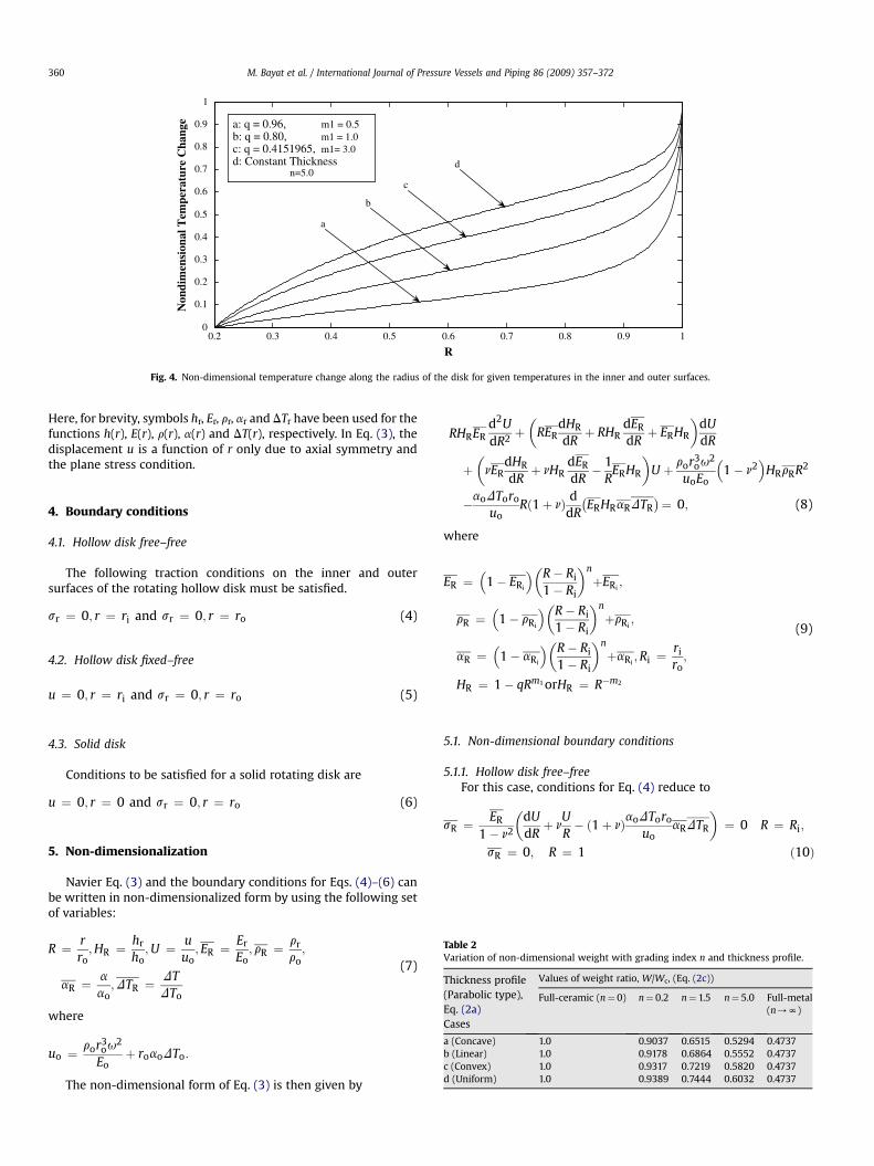
Fig. 5. Non-dimensional radius stress sR due to thermo mechanical load in the hollow diskand the geometric parameters q and m1. (i) Concave and linear thickness profiles, (ii) conv
cðkÞ1
d2
dR2 þ cðkÞ2d
dRþ cðkÞ3
!UðkÞ þ cðkÞ4 ¼ 0; (13)
where
cðkÞ1 ¼ RðkÞHRðkÞERðkÞ
cðkÞ2 ¼ RðkÞERðkÞdHR
dR
����R¼RðkÞ
þRðkÞHRðkÞdER
dR
����R¼RðkÞ
þHRðkÞERðkÞ
cðkÞ3 ¼ nERðkÞdHR
dR
����R¼RðkÞ
þnHRðkÞdER
dR
����R¼RðkÞ
� 1RðkÞ
HRðkÞERðkÞ
cðkÞ4 ¼ ror3ou2
uoEo
�1� n2
�HRðkÞrRðkÞ
�RðkÞ
�2
�aoDToro
uoRðkÞð1þ nÞdðHRERaRDTRÞ
dR
����R¼RðkÞ
(14)
The temperature distribution DTR in Eq. (14) can be deter-mined from thermal analysis discussed in the next section.Using the above technique, Eq. (8) with variable coefficients ischanged into a system of m ordinary differential equations withconstant coefficients with m being the number of virtual sub-domains.
The solution for Eq. (13) can be written in the form of
b, n=5.0
b, Metal
, Metal
a: q = 0.96, m1 = 0.5b: q = 0.80, m1 = 1.0
0.6 0.7 0.8 0.9 1
R
0.6 0.7 0.8 0.9 1
R
=1.5
, n=5.0
c: q = 0.4151965, m1 = 3.0d: Constant Thickness
(free–free) with variable thickness (Eq. (2a)) for different values of the grading index nex and uniform thickness profiles.

0.08
0.1
0.12
0.14
0.16
0.18
0.2
0.22
0.24
b, Ceramic
b, n=0.2
b,n=1.5
b, n=5.0
b, Metala, Ceramic
a, n=0.2
a, n=1.5 a, n=5.0
a, Metal
c, Ceramicc, n=0.2
c, n=1.5
c, n=5.0
c, Metal
c: q = 0.4151965, m1 = 3.0d: Constant Thickness
d, n=5.0
d, Metal d, Ceramic
d, n=0.2
d, n=1.5
Non
dim
ensi
onal
Rad
ial D
ispl
acem
ent
Non
dim
ensi
onal
Rad
ial D
ispl
acem
ent
0.1
0.15
0.2
0.25
0.3
0.35
0.2 0.3 0.4 0.5 0.6 0.7 0.8 0.9 1
R
0.2 0.3 0.4 0.5 0.6 0.7 0.8 0.9 1
R
a: q = 0.96, m1 = 0.5b: q = 0.80, m1 = 1.0
a
b
Fig. 6. Non-dimensional radial displacement U in the hollow disk (free–free) with variable thickness (Eq. (2a)) for different values of the grading index n and the geometricparameters q and m1. (i) Concave and linear thickness profiles, (ii) convex and uniform thickness profiles.
M. Bayat et al. / International Journal of Pressure Vessels and Piping 86 (2009) 357–372362
UðkÞ ¼ XðkÞ1 exp�
lðkÞ1 R�þ XðkÞ2 exp
�lðkÞ2 R
��
cðkÞ4
cðkÞ3
; (15)
where XðkÞ1 and XðkÞ2 are unknown constants for kth sub-domain and
lðkÞ1 ; l
ðkÞ2 ¼ �
cðkÞ2 �ffiffiffiffiffiffiffiffiffiffiffiffiffiffiffiffiffiffiffiffiffiffiffiffiffiffiffiffiffiffiffiffiffiffiffiffi�
cðkÞ2
�2�4cðkÞ3 cðkÞ1
r
2cðkÞ1
It may be noted that the solution for Eq. (15) is valid for
RðkÞ � tðkÞ
2� R � RðkÞ þ tðkÞ
2(16)
where R(k) and t(k) are the mean radius and the radial-width of thekth sub-domain, respectively. The unknowns XðkÞ1 and XðkÞ2 can bedetermined by applying the necessary conditions between eachtwo adjacent sub-domains. For this purpose, the continuity of theradial displacement U as well as radial stress sR is imposed at theinterfaces of the adjacent sub-domains. These continuity condi-tions at interfaces are
UðkÞ���R¼RðkÞþtðkÞ
2
¼ UðkÞ���R¼Rðkþ1Þ�tðkþ1Þ
2
sðkÞR
���R¼RðkÞþtðkÞ
2
¼ sðkÞR
���R¼Rðkþ1Þ�tðkþ1Þ
2
(17)
The continuity conditions for Eq. (17) together with the globalboundary conditions for Eqs. (10), (11) or (12) yield a set of linearalgebraic equations in XðkÞ1 and XðkÞ2 . Solving these equations for XðkÞ1and XðkÞ2 and substituting them in Eq. (15), the displacementcomponent U(k) is determined in each sub-domain. Increasing thenumber of divisions improves the accuracy of the results.
6.2. Thermal analysis
If the prescribed surface temperatures imposed on inner andouter sides of FG disk are
DTR ¼ DTi ¼ 0 at R ¼ Ri (18a)
DTR ¼ DTo ¼ 1:0 at R ¼ Ro ¼ 1:0 (18b)
and the variation of temperature is assumed to occur in the radialdirection only, then solving the steady state heat transfer equation
RHRKRd2DTR
dR2 þ�
HRKR þ RKRdHR
dRþ RHR
dKR
dR
�dDTR
dR¼ 0;
(19)
through the radial direction carries out the thermal analysis. In Eq.(19) KR is the non-dimensional thermal conductivity coefficient.
0
0.05
0.1
0.15
0.2
0.25
0.3
0.35
0.4
0.45
b, Ceramic
b, n=0.2
b, n=1.5
b, n=5.0 b, Metal
a, Ceramic
a, n=0.2
a, n=1.5
a, n=5.0a, Metal
a: q = 0.96, m1 = 0.5 b: q = 0.80, m1 = 1.0
0
0.1
0.2
0.3
0.4
0.5
0.6
0.7
0.8
d, Ceramic
d, n=0.2
d,n=1.5
d, n=5.0
c, Ceramic
c, n=0.2
c, n=1.5
c, n=5.0c, Metal
c: q = 0.4151965, m1 = 3.0d: Constant Thickness
d, Metal
Non
dim
ensi
onal
Rad
ial S
tres
s N
ondi
men
sion
al R
adia
l Str
ess
0.2 0.3 0.4 0.5 0.6 0.7 0.8 0.9 1
R
0.2 0.3 0.4 0.5 0.6 0.7 0.8 0.9 1
R
a
b
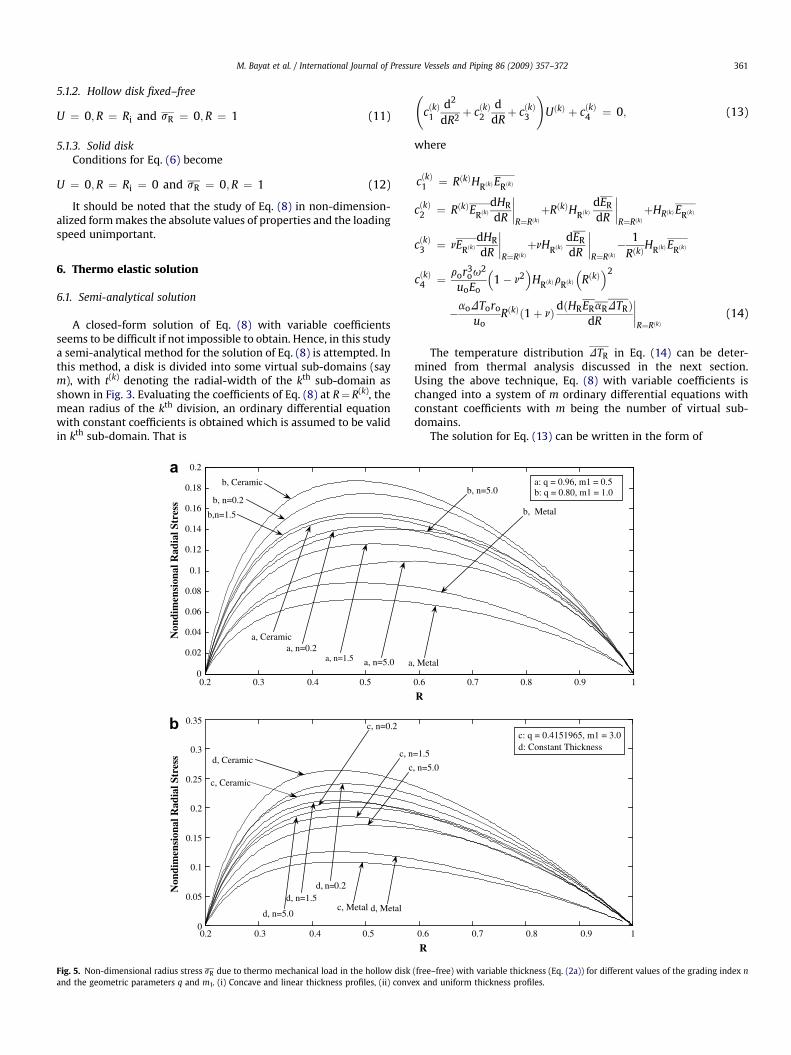
Fig. 7. Non-dimensional radius stress sR in the hollow disk (fixed–free) with variable thickness (Eq. (2a)) for different values of the grading index n and the geometric parameters qand m1. (i) Concave and linear thickness profiles, (ii) convex and uniform thickness profiles.
M. Bayat et al. / International Journal of Pressure Vessels and Piping 86 (2009) 357–372 363
Assuming that KR varies along the disk radius only according tomaterial property relation for Eqs. (1a) and (1b)
KR ¼�1� Ki
��R� Ri
1� Ri
�n
þKi; Ri < R < 1; (20)
Eq. (19) is also solved using the same semi-analytical method asproposed in the previous section. For this purpose, the coefficientsof Eq. (19) are evaluated at R¼ R(k), mean radius of kth division andthe ODE with constant coefficients valid only in kth sub-domainturns out to be
c1d2
dR2þ c
ddR
!DTRðkÞ ¼ 0 (21)
where
c1 ¼ RðkÞHRðkÞKRðkÞ
c2 ¼ HRðkÞKRðkÞ þ RðkÞHRðkÞdKR
dR
����R¼RðkÞ
þRðkÞKRðkÞdHR
dR
����R¼RðkÞ
;
k ¼ 1;2;3;.;m (22)
The exact solution of Eq. (21) can be written in the form
DTRðkÞ ¼ XðkÞ1 þ XðkÞ2 exp��Rc2
c1
�(23)
where XðkÞ1 and XðkÞ2 are unknown constants for kth division. Theseunknowns are determined by applying the necessary boundaryconditions between each two adjacent sub-domains. The conti-nuity of the temperature and its gradient are imposed at theinterfaces of the adjacent sub-domains. These continuity condi-tions at the interfaces are
DTR
��R¼Rkþtk
2¼ DTR
��R¼Rkþ1� tkþ1
2
dDTR
dR
����R¼Rkþtk
2
¼ dDTR
dR
����R¼Rkþ1� tkþ1
2
(24)
The continuity conditions (Eq. (24)) together with the globalboundary conditions (Eqs. (18a) and (18b)) yield a set of linearalgebraic equations in terms of XðkÞ1 and XðkÞ2 . Solving these equa-tions for XðkÞ1 and XðkÞ2 , temperature DTR can be determined in eachradial sub-domain.
7. Numerical results
For numerical illustration of the elastic solutions of this study,three cases are considered, namely, hollow disk free–free, hollowdisk fixed–free and solid disk. The analysis is conducted usingaluminum as inner surface metal and Zirconia as outer surfaceceramic, the same as considered in [22,27]. The material propertiesand the prescribed surface temperatures are

0.02
0.04
0.06
0.08
0.1
0.12
0.14
0.16
0.18
0.2
0.22
Non
dim
ensi
onal
Cir
cum
fere
ntia
l Str
ess
Non
dim
ensi
onal
Cir
cum
fere
ntia
l Str
ess
b, Ceramic
b, n=0.2b, n=1.5
b, n=5.0
b, Metal
a, Ceramic
a, n=0.2a, n=1.5
a, n=5.0 a, Metal
a: q = 0.96, m1 = 0.5b: q = 0.80, m1 = 1.0
0.05
0.1
0.15
0.2
0.25
c, Ceramic
c, n=0.2c, n=1.5
c, n=5.0
c, Metalc: q = 0.4151965,m1 = 3.0d: Constant Thickness
d, n=5.0d, Metal
d, Ceramic
d, n=0.2d, n=1.5
0.2 0.3 0.4 0.5 0.6 0.7 0.8 0.9 1
R
0.2 0.3
0.3
0.4 0.5 0.6 0.7 0.8 0.9 1
R
a
b
Fig. 8. Non-dimensional circumferential stress sq in the hollow disk (fixed–free) with variable thickness (Eq. (2a)) for different values of the grading index n and the geometricparameters q and m1. (i) Concave and linear thickness profiles, (ii) convex and uniform thickness profiles.
M. Bayat et al. / International Journal of Pressure Vessels and Piping 86 (2009) 357–372364
Ei ¼ EAl ¼ 70:0 GPa; Eo ¼ ECer ¼ 151:0 GPa;
ri ¼ rAl ¼ 2700:0kgm3; ro ¼ rCer ¼ 5700:0
kgm3;
ai ¼ aAl ¼23:0� 10�6
�C; ao ¼ aCer ¼
10:0� 10�6
�C;
Ki ¼ KAl ¼ 209:0W
m �C; Ko ¼ KCer ¼ 2:0
Wm �C
;
n ¼ 0:3 (25)
DTo ¼ 1:0;DTi ¼ 0:0
A hollow disk with Ro¼ 5Ri or a solid disk subjected to uniformcentrifugal force and thermal loading is considered and the resultsfor displacements, stresses and strains are presented in a non-dimensional form.
Different cases for the thickness profiles used in these illustra-tions obtained from Eqs. (2a) and (2b) are listed in Table 1 whereasthe non-dimensionalized temperature distribution in the FG diskwith variable thickness (Eq. (2a)) is given in Fig. 4.
The elastic deformation of the FG disk with variable thicknessdue to thermo mechanical load is determined. The effects of thegrading index n and different thickness profiles on the non-dimensional weight of the hallow disk with parabolic thicknessprofile are shown in Table 2. It is seen that the all-ceramic disk is the
heaviest whereas the full-metal disk is the lightest. The weight ofthe FG disk is in between the all-ceramic and all-metal values.
The effect of the thickness profile on the weight can be shown bycomparing the weight values for the same value of the gradingindex n. It is seen that hollow FG disk with concave thickness profilehas smaller weight compared to that with other thickness profiles.To show the effect of the grading index n on the weight, disks withthe same thickness profile are considered. It is noticed that theweights of FG disks lie in between ðrAl=rCer ¼ 2700=5700 ¼Þ0.4737 and 1. In this study the density of ceramic is greater than thedensity of aluminum. It can be noted that for materials such thatrAl=rCer > 1, the weight of FG disk can be made even smaller thanthe full-metal disk.
It may be mentioned here that the method of solution consid-ered in this study is general in nature and is not limited to gradientsconsidered in this study only but can be applied to other gradientsas well.
7.1. Results for thermo mechanical loading
7.1.1. Hollow disk [free–free]Fig. 5 illustrates the non-dimensional radial stresses due to
thermo mechanical load for different values of the grading index nand the geometric parameters q and m1.
It can be seen from Fig. 5(i) and (ii) that for each type of thicknessprofile (see Table 1); the non-dimensional radial stresses take

0.2 0.3 0.4 0.5 0.6 0.7 0.8 0.9 1
0.05
0.1
0.15
0.2
0.25
0.3
0.35
0.4
R
0.2 0.3 0.4 0.5 0.6 0.7 0.8 0.9 1
R
Non
dim
ensi
onal
Equ
ival
ent
Stre
ss
Non
dim
ensi
onal
Equ
ival
ent
Stre
ss
b,n=1.5
b, n=5.0
b, Metal
a, n=1.5
a, n=5.0
a, Metal
a:q = 0.96, m1 = 0.5b:q = 0.80, m1 = 1.0
0.1
0.2
0.3
0.4
0.5
0.6
0.7
d,n=1.5
c, n=5.0
d, Metal
c, n=1.5
d, n=5.0
c, Metal
c:q = 0.4151965, m1 = 3.0d:Constant Thickness
d,Ceramic
d, n=0.2
c, Ceramic
c, n=0.2
b,Ceramic
b, n=0.2
a, Ceramic
a, n=0.2
a
b
Fig. 9. Non-dimensional equivalent stress seq(seq ¼ffiffiffiffiffiffiffiffiffiffiffiffiffiffiffiffiffiffiffiffiffiffiffiffiffiffiffiffiffiffiffiffis2
r þ s2q� srsq
q) in the hollow disk (fixed–free) with variable thickness (Eq. (2a)) for different values of the grading index n
and the geometric parameters q and m1. (i) Concave and linear thickness profiles, (ii) convex and uniform thickness profiles.
M. Bayat et al. / International Journal of Pressure Vessels and Piping 86 (2009) 357–372 365
maximum value for full-ceramic disk and minimum for full-metaldisk and for different FG disks these stresses occur in between. It isseen that hollow FG disk with variable thickness has smaller radialstresses compared to those with uniform thickness [20,22]. For thechosen values of the geometric parameters q and m1 in Fig. 5(i) and(ii), it is observed that FG disk with concave profile has smaller stress.
7.2. Results for mechanical loading
7.2.1. Parabolic thickness7.2.1.1. Hollow disk [free–free]. Fig. 6(i) and (ii) show the non-dimensional radial displacement in the FG disk along its radius fordifferent values of the grading index n and the geometric param-eters q and m1 [Eq. (2a)].
As it is expected, the radial displacement values for full-metal(Aluminum) disk are greater than those for full-ceramic (Zirconia)disk due to higher modulus of elasticity of the latter. Also, it isobserved that the radial displacement increases with the increaseof the grading index n from zero (homogenized Zirconia disk) up toits maximum value and then decreases to its minimum value forn/N (homogenized Aluminum disk). Thus, for a given pair ofmaterials, there is a particular volume fraction for which the radialdisplacement attains its maximum value under a uniform centrif-ugal loading. Comparing with the results of [20,22], it can be saidthat the radial displacement for the FG disk for each of the cases (a),
(b) and (c) considered is smaller than that corresponding case withuniform thickness.
Results of Fig. 6 can be summarized to conclude that the hollowFG disk with concave thickness profile is better than those withother thickness profiles. This result is similar to the one reported in[26].
7.2.1.2. Hollow disk [fixed–free]. The stress distributions for FG diskwith variable thickness mounted on a rigid shaft, for differentvalues of the grading index n and the geometric parameters q andm1 are presented in Figs. 7 and 8.
It is seen that for all the cases (a), (b), (c) and (d) considered inFig. 7(i) and (ii) for rotating disk, the maximum radial stresses withfixed–free conditions occur at the inner surface and they are greaterthan their corresponding values with free–free conditions given inFig. 6(i) and (ii). Comparing different thickness profiles, a concavedisk is found to have its maximum stress smallest. It can also beseen that mounted FG disks with variable thickness have smallerradial stresses compared to those with uniform thickness. It isnoted that for some specific values of the grading index n themaximum of the radial stresses are larger than those for full-ceramic.
The circumferential stresses are shown in Fig. 8(i) and (ii). Formounted FG disk with concave thickness profile the stress issmaller than those with other thickness profiles, i.e. linear or

0.1 0.2 0.3 0.4 0.5 0.6 0.7 0.8 0.9 10
0.05
0.1
0.15
0.2
0.25
R
0.1 0.2 0.3 0.4 0.5 0.6 0.7 0.8 0.9 1
R
b, Ceramic
b, n=0.2
b, n=1.5
b, n=5.0
b, Metal
a, Ceramica, n=0.2
a, n=1.5
a, n=5.0
a, Metal
a: q = 0.96, m1 = 0.5b: q = 0.80, m1 = 1.0
0
0.05
0.1
0.15
0.2
0.25
0.3
0.35
0.4
0.45c, Ceramicc, n=0.2
c, n=1.5
c, n=5.0
c, Metal
c: q = 0.4151965, m1 = 3.0d: Constant Thickness
d, n=5.0
d, Metal
d, Ceramic
d, n=0.2
d, n=1.5
Non
dim
ensi
onal
Rad
ial S
tres
sN
ondi
men
sion
al R
adia
l Str
ess
a
b
Fig. 10. Non-dimensional radius stress sR in the solid disk with variable thickness (Eq. (2a)) for different values of the grading index n and the geometric parameters q and m1.(a) Concave and linear thickness profiles, (b) convex and uniform thickness profiles.
M. Bayat et al. / International Journal of Pressure Vessels and Piping 86 (2009) 357–372366
convex. It is noticed that close to the outer surface the circumfer-ential stresses for FG disk are larger than those for full-ceramic disk.For some specific values of the grading index n the circumferentialstresses may have a local minimum close to the inner surface. Thegraphs of Fig. 8(i) and (ii) suggest that the circumferential stresses
0
0.05
0.1
0.15
0.2
0.25
0.3
0.35
Non
dim
ensi
onal
Rad
ial S
tres
s
b, Cerami
b, n=0.2
b,n=1.5
b, n=5.0b
a, Cerami
c, n=0.2
a, n=1.5
a, n=5.0 a, Metal
a, n=0.2
c, n=1.5
0.2 0.3 0.4 0.5
Fig. 11. Non-dimensional radius stress sR in the hollow disk (free–free) with variable thickne
for mounted FG disks with variable thickness are smaller comparedwith those with uniform thickness.
Fig. 9(i) and (ii) show the non-dimensional equivalent stress inthe FG disk for different values of the grading index n and thegeometric parameters q and m1.
c
, Metal
ca: m2 = - 1.0b: m2 = 0.0c: m2 = 1.0
c, Metal
c, Ceramic
c, n=5.0
0.6 0.7 0.8 0.9 1
R
ss (Eq. 2(b)) for different value of the grading index n and the geometric parameter m2.

0
0.2
0.4
0.6
0.8
1
1.2
1.4
1.6
1.8
2
b, Ceramic
b, n=0.2
b,n=1.5
b, n=5.0
b, Metal
a, Ceramic
c, n=0.2
a, n=1.5 a, n=5.0
a, Metal
a: m2 = - 1.0b: m2 = 0.0c: m2 = 1.0
c, Metal
c, Ceramic
a, n=0.2
c, n=1.5c, n=5.0
Non
dim
ensi
onal
Rad
ial S
tres
s
0.2 0.3 0.4 0.5 0.6 0.7 0.8 0.9 1
R
Fig. 12. Non-dimensional radial stress sR in the hollow disk (fixed–free) with variable thickness (Eq. 2(b)) for different value of the grading index n and the geometric parameter m2.
M. Bayat et al. / International Journal of Pressure Vessels and Piping 86 (2009) 357–372 367
It is evident from Fig. 9(i) and (ii) that the full-metal mounteddisks have smaller equivalent stresses in comparison to FG disks.Here again, the FG disk with concave thickness profile has smallerequivalent stress compared to linear or convex profiles. Further-more, FG disks with variable thickness given by Eq. (2a) have smaller
0
0.1
0.2
0.3
0.4
0.5
a
b
b, n=5.0
a, Ceramic
a, n=5.0
a, Metal
a: q = 0.96, m1 = 0.5b: q = 0.80, m1 = 1.0
0
0.2
0.4
0.6
0.8
1
c, Ceramic
c, n=5
c, Metal
d, n=5.0
d, Metald, Ceramic
d, n=1
Non
dim
ensi
onal
Rad
ial S
tres
sN
ondi
men
sion
al R
adia
l Str
ess
0.2 0.3 0.4 0.5
0.2 0.3 0.4 0.5
Fig. 13. Non-dimensional radius stress sR due to thermal load in the hollow disk (free–freegeometric parameters q and m1. (i) Concave and linear thickness profiles, (ii) convex and u
equivalent stresses compared to uniform thickness disks. It can beseen that the equivalent stress in full-ceramic disk for all types ofthickness profiles except concave profile decreases with the increasein R while for the disk with concave thickness profile it increasescloser to the outer surface. This phenomenon illustrates the effect of
b, n=0.2
b,n=1.5
a, n=0.2a, n=1.5
c, n=0.2c, n=1.5
.0
c: q = 0.4151965, m1 = 3.0d: Constant Thickness
d, n=0.2
.5
0.6 0.7 0.8 0.9 1
R
0.6 0.7 0.8 0.9 1
R
) with variable thickness (Eq. 2(a)) for different values of the grading index n and theniform thickness profiles.
0
0.1
0.2
0.3
0.4
0.5
0.6
0.7
a, Ceramic
a, n=0.2
a,n=1.5a, n=5.0
b, n=0.2
b, n=1.5
b, n=5.0
a: q = 0.96, m1 = 0.5b: q = 0.80, m1 = 1.0
a, Metal
0
0.5
1
1.5
2
d, Ceramic
c, n=0.2
d,n=1.5
d, n=5.0
c, Ceramic
d, n=0.2
c, n=1.5c, n=5.0
c, Metal
c: q = 0.4151965, m1 = 3.0d: Constant Thickness
d, Metal
Non
dim
ensi
onal
Rad
ial S
tres
sN
ondi
men
sion
al R
adia
l Str
ess
0.2 0.3 0.4 0.5 0.6 0.7 0.8 0.9 1
R
0.2 0.3 0.4 0.5 0.6 0.7 0.8 0.9 1
R
a
b
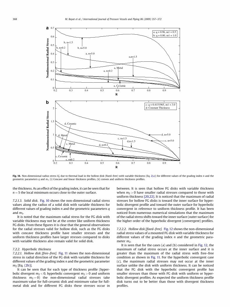
Fig. 14. Non-dimensional radius stress sR due to thermal load in the hollow disk (fixed–free) with variable thickness (Eq. 2(a)) for different values of the grading index n and thegeometric parameters q and m1. (i) Concave and linear thickness profiles, (ii) convex and uniform thickness profiles.
M. Bayat et al. / International Journal of Pressure Vessels and Piping 86 (2009) 357–372368
the thickness. As an effect of the grading index, it can be seen that forn¼ 5 the local minimum occurs close to the outer surface.
7.2.1.3. Solid disk. Fig. 10 shows the non-dimensional radial stressvalues along the radius of a solid disk with variable thickness fordifferent values of grading index n and the geometric parameters qand m1.
It is noted that the maximum radial stress for the FG disk withvariable thickness may not be at the center like uniform thicknessFG disks. From these figures it is clear that the general observationsfor the radial stresses valid for hollow disk, such as the FG diskswith concave thickness profile have smaller stresses and theuniform thickness profiles have larger stresses compared to diskswith variable thickness also remain valid for solid disk.
7.2.2. Hyperbolic thickness7.2.2.1. Hollow disk [free–free]. Fig. 11 shows the non-dimensionalstress in radial direction of the FG disk with variable thickness fordifferent values of the grading index n and the geometric parameterm2 [Eq. (2b)].
It can be seen that for each type of thickness profile (hyper-bolic divergent m2< 0, hyperbolic convergent m2> 0 and uniformthickness m2¼ 0) the non-dimensional radial stresses takemaximum value for full-ceramic disk and minimum value for full-metal disk and for different FG disks these stresses occur in
between. It is seen that hollow FG disks with variable thicknesswhen m2> 0 have smaller radial stresses compared to those withuniform thickness [20,22]. It is noticed that the maximum of radialstresses for hollow FG disks is toward the inner surface for hyper-bolic divergent profile and toward the outer surface for hyperbolicconvergent in reference to uniform thickness profile. It has beennoticed from numerous numerical simulations that the maximumof the radial stress shifts toward the inner surface (outer surface) forthe higher order of the hyperbolic divergent (convergent) profiles.
7.2.2.2. Hollow disk [fixed–free]. Fig. 12 shows the non-dimensionalradial stress values of a mounted FG disk with variable thickness fordifferent values of the grading index n and the geometric para-meter m2.
It is seen that for the cases (a) and (b) considered in Fig. 12, themaximum of radial stress occurs at the inner surface and it isgreater than the maximum of the radial stress with free–freecondition as shown in Fig. 11. For the hyperbolic convergent case(c), the maximum radial stresses may not occur at the innersurface unlike the disk with uniform thickness. It can be noticedthat the FG disk with the hyperbolic convergent profile hassmaller stresses than those with FG disk with uniform or hyper-bolic divergent profiles. As expected the uniform thickness profiledisk turns out to be better than those with divergent thicknessprofiles.

0.2 0.3 0.4 0.5 0.6 0.7 0.8 0.9 1-0.8
-0.7
-0.6
-0.5
-0.4
-0.3
-0.2
-0.1
0
0.1
0.2
0.3
R
Non
dim
ensi
onal
Cir
cum
fere
ntia
l Str
ess
Non
dim
ensi
onal
Cir
cum
fere
ntia
l Str
ess
b, n=0.2
b,n=1.5b, n=5.0
a, Ceramic
a, n=0.2
a, n=1.5a, n=5.0
a, Metal
a: q = 0.96, m1 = 0.5b: q = 0.80, m1 = 1.0
-1
-0.5
0
0.5
1
c, n=0.2
d,n=1.5
d, n=5.0
c, Ceramic
d, n=0.2
c, n=1.5
c, n=5.0
c, Metal
c: q = 0.4151965, m1 = 3.0d: Constant Thickness
d, Metal
d, Ceramic
a
b
0.2 0.3 0.4 0.5 0.6 0.7 0.8 0.9 1
R
Fig. 15. Non-dimensional circumferential stress sq due to thermal load in the hollow disk (fixed–free) with variable thickness (Eq. (2a)) for different values of the grading index nand the geometric parameters q and m1. (i) Concave and linear thickness profiles, (ii) convex and uniform thickness profiles.
M. Bayat et al. / International Journal of Pressure Vessels and Piping 86 (2009) 357–372 369
7.3. Results for thermal loading
7.3.1. Parabolic thickness7.3.1.1. Hollow disk [free–free]. Fig. 13 illustrates the non-dimensional radial stresses due to thermal loading for differentvalues of the grading index n and the geometric parameters q andm1 [Eq. (2a)].
It is seen that for FG disk radial stress due to thermal load maynot occur in between the radial stresses for full-ceramic and full-metal disks. The FG disk with concave thickness profile has smallerradial stress compared to linear or convex profile disk. It is notedthat for some specific values of the grading index n and for specificthickness profile, radial stresses in FG disk may be smaller thanthose for full-ceramic.
Results of Fig. 13 can be summarized to conclude that thehollow FG disk with concave thickness profile is better than thosewith other thickness profiles. This result is similar to the onereported in [7].
7.3.1.2. Hollow disk [fixed–free]. The radial stress distributions dueto thermal load for FG disk with variable thickness mounted ona rigid shaft for different values of the grading index n and thegeometric parameters q and m1 are presented in Fig. 14.
It is seen that for specific values of the grading index n and forspecific thickness profile the maximum radial stresses may not
occur at the inner surface. Comparing different thickness profiles,a concave profile disk is found to have its maximum stress smallest.It can also be seen that mounted FG disks with variable thicknesshave smaller radial stresses compared to that with uniform thick-ness. It is noted that for some specific values of the grading index nthe radial stresses are smaller than those for full-ceramic and full-metal.
The circumferential stress distributions due to thermal load forFG disk with variable thickness mounted on a rigid shaft fordifferent values of the grading index n and the geometric parame-ters q and m1 are presented in Fig. 15.
As it is expected, the circumferential stress values for full-ceramic (Zirconia) disk are smaller than those for full-metal(Aluminum) disk due to higher thermal coefficient of expansion ofthe latter. The circumferential stress at the inner surface for the FGdisk with concave thickness profile is smallest in comparison withother thickness profiles, i.e. linear or convex. For the specific valuesof the grading index n (n¼ 5.0 in the figure) the maximum of thecircumferential stresses may not be at the inner surface. The graphsof Fig. 15 suggest that the circumferential stresses for hollow FGdisks with variable thickness are smaller compared to those withuniform thickness [20,22].
Fig. 16(i) and (ii) show the non-dimensional equivalent stressdue to thermal load in the FG disk for different values of the gradingindex n and the geometric parameters q and m1.

0.1
0.2
0.3
0.4
0.5
0.6
0.7
0.8
Non
dim
ensi
onal
Equ
ival
ent
Stre
ss
Non
dim
ensi
onal
Equ
ival
ent
Stre
ss
b, n=0.2b,n=1.5
b, n=5.0
a, Ceramic
a, n=0.2a, n=1.5
a, n=5.0
a, Metal
a: q = 0.96, m1 = 0.5b: q = 0.80, m1 = 1.0
0
0.2
0.4
0.6
0.8
1
1.2
1.4
1.6
1.8
2
d, n=0.2
c,n=1.5
d, n=5.0c, Ceramic
c, n=0.2
d, n=1.5
c, n=5.0
c, Metal
c: q = 0.4151965, m1 = 3.0d: Constant Thickness
d, Metalc, Ceramic
0.2 0.3 0.4 0.5 0.6 0.7 0.8 0.9 1
R
0.2 0.3 0.4 0.5 0.6 0.7 0.8 0.9 1
R
a
b
Fig. 16. Non-dimensional equivalent stress seq due to thermal load in the hollow disk (fixed–free) with variable thickness (Eq. (2a)) for different values of the grading index n andthe geometric parameters q and m1. (i) Concave and linear thickness profiles, (ii) convex and uniform thickness profiles.
M. Bayat et al. / International Journal of Pressure Vessels and Piping 86 (2009) 357–372370
It is evident from Fig. 16(i) and (ii) that the full-ceramic mounteddisks have smaller equivalent stresses in comparison to FG disks. It isnoted that for some specific values of the grading index n (n¼ 1.5 inthe figure) and the concave thickness profile the equivalent stressmay be constant for the most part of the disk. The FG disks withconcave thickness profile have smaller equivalent stresses comparedto disks with linear or convex profiles. Furthermore, FG disks withvariable thickness have smaller equivalent stresses in comparison todisks with uniform thickness. It can be seen that the equivalentstress in pure material (full-ceramic or full-metal) disk first increasesand then decreases with the increase in the value of R but for FGdisks the behavior is different. For the disks with concave and linearthickness profiles there is a local minimum close to the outer surface.
7.3.1.3. Solid disk. Fig. 17 shows the non-dimensional radial stressvalues due to thermal load along the radius of a solid disk withvariable thickness for different values of grading index n and thegeometric parameters q and m1.
It is noted that the maximum radial stress for the FG solid diskwith variable thickness may not be at the center unlike theuniform thickness FG disks. From these figures it is clear that thegeneral observations valid for hollow disks such as the FG hollowdisks with concave thickness profiles have smaller stressescompared to those with uniform thickness profiles also remainvalid for solid disk.
8. Conclusions
An analysis of functionally graded rotating disks with variablethickness is presented. Two types of thickness profiles are consid-ered namely parabolic and hyperbolic. Different cases consideredunder these categories are concave, linear and convex thicknessprofiles in the parabolic type and convergent and divergent in thehyperbolic type. Thermo elastic stresses for the solid disk and thehollow disks with both free–free and fixed–free boundary condi-tions are obtained. The effects of the grading index n and theparameters related to the geometry of the disk, i.e. q, m1 and m2 (seeEqs. (2a) and (2b)) on the radial stresses are investigated. Numericalresults are presented for the FG disk using aluminum as the innersurface metal and Zirconia as outer surface ceramic. These results arecompared with those for rotating disks with uniform thickness.
Some general observations of this study can be summarized asfollows:
B For the same value of the grading index n, the hollow FG diskwith the concave thickness profile is the lightest in weight andthe disk with uniform thickness profile is the heaviest.
B Maximum values of radial stresses due to thermo mechanicalloading in FG hollow disks with variable thickness under free–free condition remain in between the maximum values forhomogenized disks. Contrary to this, radial stresses for FG disks

0.1 0.2 0.3 0.4 0.5 0.6 0.7 0.8 0.9 10
0.1
0.2
0.3
0.4
0.5
0.6
0.7a
b
R
0.1 0.2 0.3 0.4 0.5 0.6 0.7 0.8 0.9 1
R
Non
dim
ensi
onal
Rad
ial S
tres
s N
ondi
men
sion
al R
adia
l Str
ess
b, n=0.2
b,n=1.5
b, n=5.0
a, Ceramica, n=0.2
a, n=1.5
a, n=5.0
a, Metal
a: q = 0.96, m1 = 0.5b: q = 0.80, m1 = 1.0
0
0.2
0.4
0.6
0.8
1
1.2
1.4
1.6
d, n=0.2
d,n=1.5
d, n=5.0
c, Ceramic
c, n=0.2
c, n=1.5
c, n=5.0
c, Metal
c: q = 0.4151965, m1 =3.0b: Constant Thickness
d, Metald, Ceramic
Fig. 17. Non-dimensional radius stress sR due to thermal load in the solid disk with variable thickness (Eq. (2a)) for different values of the grading index n and the geometricparameters q and m1. (i) Concave and linear thickness profiles, (ii) convex and uniform thickness profiles.
M. Bayat et al. / International Journal of Pressure Vessels and Piping 86 (2009) 357–372 371
due to thermal load may not occur in between the radialstresses for full-ceramic and full-metal disks.
B The effect of thickness profile is to shift the location and valueof the maximum stress. The maximum radial stress due tomechanical load for the solid FG disks having same gradingindex but different thickness profiles (i.e. concave, linear orconvex, see Eq. (2a)) may not be at the center unlike FG diskswith uniform thickness. There exist combinations of values ofparameters related to thickness profiles of the hollow FG diskswith free–free boundary condition for which the radial stress(due to centrifugal load) can attain its maximum at a radialdistance greater than the half of the radius to be more specificat R> 0.55 with R denoting the non-dimensional radius of thedisk, i.e. R ¼ r=ro.
B FG disk with concave thickness profile has smaller stresses dueto centrifugal or thermal load than the disk with linear, convexor uniform thickness profile when the same grading isconsidered for all the disks.
B Mounted FG disks can have larger radial stress due to centrif-ugal loading than full-ceramic disk at the inner surface forsome specific grading index values n. Unlike this, for somespecific values of grading index n mounted FG disk may havesmaller radial stress due to thermal load than full-ceramic disk.
B Unlike FG disks with uniform thickness, maximum radialstress due to centrifugal or thermal load for the solid FG
disk with variable thickness (Eq. (2a)) may not be at thecenter.
B Contrary to the results for mounted FG disks with uniformthickness, maximum radial stresses due to centrifugal load inmounted FG disks with hyperbolic convergent profile may notoccur at the inner surface. Also hollow FG disks with hyperbolicconvergent profile have smaller stresses due to centrifugal loadcompared to those with uniform thickness.
B For any variable thickness profile considered in this study, theequivalent stresses due to thermal or centrifugal load in mountedFG disks are smaller than those in disks with uniform thickness.
From the semi-analytical solution for FG disks given in thisstudy it can be suggested that an efficient and optimal design of theFG disk calls for a variable section being thicker at the hub andtapering down to a smaller thickness toward the periphery.
References
[1] Reddy JN. Analysis of functionally graded plates. International Journal ofNumerical Methods in Engineering 2000;47:663–84.
[2] Suresh S, Mortensen A. Fundamentals of functionally graded materials.London: IOM Communications Limited; 1998.
[3] Reddy JN, Wang CM, Kitipornchai S. Axisymmetric bending of functionallygraded circular and annular plate. European Journal of Mechanics A/Solids1999;18:185–99.

M. Bayat et al. / International Journal of Pressure Vessels and Piping 86 (2009) 357–372372
[4] Tang S. Elastic stresses in rotating anisotropic disks. International Journal ofMechanical Sciences 1968;11:509–17.
[5] Tutuncu N. Effect of anisotropy on stresses in rotating discs. InternationalJournal of Mechanical Sciences 1995;37(8):873–81.
[6] Eraslan AN. Elastic–plastic deformation of rotating variable thickness annulardisks with free, pressurized and radially constrained boundary conditions.International Journal of Mechanical Sciences 2003;45:643–67.
[7] Eraslan AN, Argeso H. Limit angular velocities of variable thickness rotatingdisks. International Journal of Solids and Structures 2002;39:3109–30.
[8] Guven U. Elastic–plastic stresses in a rotating annular disk of variable thick-ness and variable density. International Journal of Mechanical Sciences1992;34(2):133–8.
[9] Reddy TY, Srinath H. Elastic stresses in a rotating anisotropic annular disk ofvariable thickness and variable density. International Journal of MechanicalSciences 1974;16:85–9.
[10] Eraslan AN, Orcan Y. Elastic–plastic deformation of a rotating disk of expo-nentially varying thickness. Mechanics of Materials 2002;34:423–32.
[11] Orcan Y, Eraslan AN. Elastic–plastic stresses in linearly hardening rotatingsolid disks of variable thickness. Mechanics Research Communications2002;29:269–81.
[12] Noda N, Tsuji T. Steady thermal stresses in a plate of functionally gradientmaterial with temperature-dependent properties. Transactions of the JapanSociety of Mechanical Engineers Series A 1991;57:625–31.
[13] Obata Y, Noda N, Tsuji T. Steady thermal stresses in a functionally gradientmaterial plate. Transactions of the Japan Society of Mechanical Engineers1992;58:1689–95.
[14] Tanaka N, Tanaka Y, Watanabe H, Poterasu VF, Sugano Y. An improved solutionto thermo elastic material design in functionally gradient materials: scheme toreduce thermal stresses. Computer Methods in Applied Mechanics and Engi-neering 1993;109:377–89.
[15] Praveen GN, Chin CD, Reddy JN. Thermo elastic analysis of functionallygraded ceramic–metal cylinder. Journal of Engineering Mechanics 1999;125:1259–67.
[16] Zimmerman RW, Lutz MP. Thermal stresses and thermal expansion ina uniformly heated functionally graded cylinder. Journal of Thermal Stresses1999;22:177–88.
[17] Ruhi M, Angoshtari A, Naghdabadi R. Thermoelastic analysis of thick-walledfinite-length cylinders of functionally graded materials. Journal of ThermalStresses 2005;28:391–408.
[18] Fukui Y, Yamanaka N. Elastic analysis for thick-walled tubes of functionallygraded material subjected to internal pressure. JSME International JournalSeries I 1992;35(4):379–85.
[19] Fukui Y, Yamanaka N, Wakashima K. The stresses and strains in a thick-walledtube for functionally graded material under uniform thermal loading. JSMEInternational Journal Series A 1993;36(2):156–62.
[20] Durodola JF, Attia O. Deformation and stresses in FG rotating disks. CompositeScience and Technology 2000;60:987–95.
[21] Durodola JF, Attia O. Property gradation for modification of response ofrotating MMC disks. Materials Science and Technology 2000;16:919–24.
[22] Kordkheili SAH, Naghdabadi R. Thermoelastic analysis of a functionally gradedrotating disk. Composite Structures 2006;79:508–16.
[23] Jahed H, Sherkatti S. Thermoelastic analysis of inhomogeneous rotating diskwith variable thickness. In: Proceedings of the EMAS conference of fatigue.Cambridge, England; 2000.
[24] Jahed H, Shirazi R. Loading and unloading behavior of thermoplastic disk.International Journal of Pressure Vessels and Piping 2001;78:637–45.
[25] Farshi B, Jahed H, Mehrabian A. Optimum design of inhomogeneous non-uniform rotating disks. International Journal of Computers and Structures2004;82:773–9.
[26] Jahed H, Farshi B, Bidabadi J. Minimumweight design of inhomogeneous rotatingdiscs. International Journal of Pressure Vessels and Piping 2005;82:35–41.
[27] Bayat M, Saleem M, Sahari BB, Hamouda AMS, Mahdi E. Analysis of func-tionally graded rotating disks with variable thickness. Mechanics ResearchCommunications 2008.
[28] Timoshenko SP, Goodier JN. Theory of elasticity. 3rd ed. Singapore: McGraw-Hill; 1984.