Dynamic fracture parameters and constraint effects in functionally graded syntactic epoxy foams
Upload
independentCategory
view
0download
0
Composite Structures 89 (2009) 167–176
Contents lists available at ScienceDirect
Composite Structures
journal homepage: www.elsevier .com/locate /compstruct
Effect of a functionally graded interlayer on three-dimensional elasticdeformation of coated plates subjected to transverse loading
M. Kashtalyan *, M. MenshykovaCentre for Micro- and Nanomechanics (CEMINACS), School of Engineering, University of Aberdeen, Aberdeen AB24 3UE, UK
a r t i c l e i n f o
Article history:Available online 18 July 2008
Keywords:Functionally graded materialCoatingPlateThree-dimensional elasticity theory
0263-8223/$ - see front matter � 2008 Elsevier B.V. Adoi:10.1016/j.compstruct.2008.07.007
* Corresponding author. Tel./fax: +44 1224 272519E-mail address: [email protected] (M. Kas
a b s t r a c t
Conventional coatings, which usually consist of one or two homogeneous layers deposited on a substrate,are susceptible to cracking and debonding due to the mismatch of thermomechanical properties betweenthe coating and the substrate. To overcome this disadvantage and increase resistance of coatings to func-tional failure, the concept of functionally graded material (FGM) is being actively explored in coatingdesign. Although an FGM coating certainly eliminates the abrupt change in material properties and stressdiscontinuity at the coating/substrate interface, it may be not an optimal solution to the problem.
This paper investigates the bending response of coated plates subjected to transverse loading withfunctionally graded interlayer between the substrate and the top coat. The Young’s modulus of the inter-layer is assumed to vary exponentially through the thickness. The analysis employs three-dimensionalelasticity solution for a functionally graded rectangular plate, recently developed by the first author,and is valid of plate of any thickness-to-length ratio. A comparative study of coated plates with and with-out an FGM interlayer is carried out, and the dependence of stress and displacement fields in the plate onthe stiffness gradient in the coating is examined and discussed.
� 2008 Elsevier B.V. All rights reserved.
1. Introduction
Functionally graded material (FGM) refers to a heterogeneouscomposite material with gradient compositional variation of theconstituents from one surface of the material to the other whichresults in continuously varying material properties. The conceptof FGM, initially developed for super heat resistant materials tobe used in space planes or nuclear fusion reactors [1], is now ac-tively explored in a variety of engineering applications includingenergy conversion, dental and orthopaedic implants, sensors andthermogenerators, wear resistant coatings and joining of dissimilarmaterial. A number of reviews dealing with various aspects ofFGMs have been published over the years [2–5].
As far as coatings are concerned, incorporation of FGMs intocoating design can help eliminate the mismatch of thermomechan-ical properties between the coating and the substrate, whichmakes conventional one- or two-layer coatings susceptible tocracking and debonding, and thus increase the resistance of coat-ings to functional failure. Currently, a number of approaches togenerate FGM coatings for specific applications and/or loading con-ditions are being developed by materials scientists [6–10].
Fracture of FGM coatings has been a focus of numerous theoret-ical studies [11–22], with contact response also receiving someattention [23–26]. These investigations were carried out in the
ll rights reserved.
.htalyan).
context of two-dimensional elasticity, and in all of them, except[19,20], the thickness of the substrate was assumed to be infinite.
Although an FGM coating certainly eliminates the abruptchange in material properties and stress discontinuity at the coat-ing/substrate interface, it may be not an optimal solution to theproblem. While investigating interface cracking between ceramicand/or FGM coating and a substrate under antiplane shear loading,Jin and Batra [13] found that when the shear modulus of the coat-ing is higher than that of the substrate, the coating system with ahomogeneous top coat and a thin FGM interlayer reduces the stressintensity factor more significantly than the single layered FGMcoating.
Using an FGM interlayer (bond coat) between the substrate andthe top coat instead of a single layered FGM coating may be advan-tageous in many situations, however mechanical behaviour ofcoating/substrate systems with FGM interlayer has received con-siderably less attention in the literature. Choi [27–29] investigatedstatic and dynamic fracture behaviour of a coating/substrate sys-tem with graded interlayer. Stress intensity factors were calculatedfor a crack in the substrate located normally to the interface underfrictional Hertzian contact loading [27], a normal crack in the coat-ing under antiplane shear impact [28] and an oblique edge crack inthe coating under antiplane shear deformation [29]. Thermoelasticcontact problem for a coating/substrate system with graded inter-layer was investigated by Choi and Paulino [30]. A rigid flat punchwas assumed to slide over the surface of the coating involving fric-tional heat generation, and the exponential variation of the elastic
x
zy
),( yxQ
S
CTC
IL
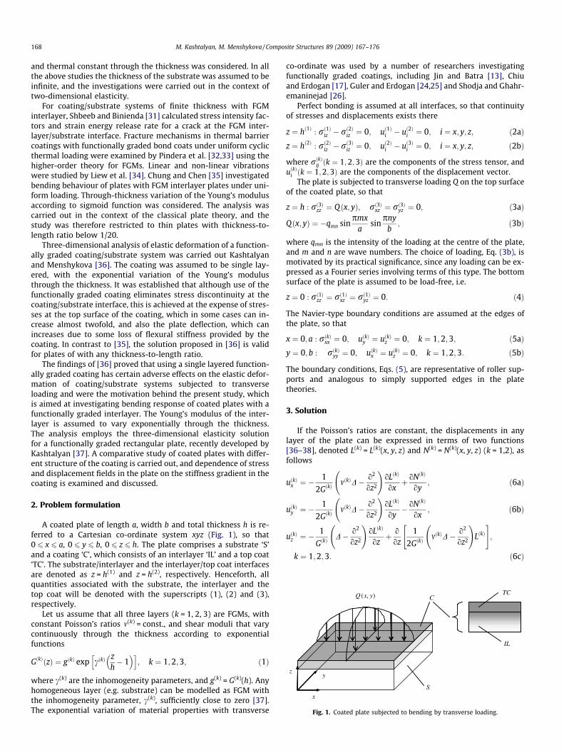
Fig. 1. Coated plate subjected to bending by transverse loading.
168 M. Kashtalyan, M. Menshykova / Composite Structures 89 (2009) 167–176
and thermal constant through the thickness was considered. In allthe above studies the thickness of the substrate was assumed to beinfinite, and the investigations were carried out in the context oftwo-dimensional elasticity.
For coating/substrate systems of finite thickness with FGMinterlayer, Shbeeb and Binienda [31] calculated stress intensity fac-tors and strain energy release rate for a crack at the FGM inter-layer/substrate interface. Fracture mechanisms in thermal barriercoatings with functionally graded bond coats under uniform cyclicthermal loading were examined by Pindera et al. [32,33] using thehigher-order theory for FGMs. Linear and non-linear vibrationswere studied by Liew et al. [34]. Chung and Chen [35] investigatedbending behaviour of plates with FGM interlayer plates under uni-form loading. Through-thickness variation of the Young’s modulusaccording to sigmoid function was considered. The analysis wascarried out in the context of the classical plate theory, and thestudy was therefore restricted to thin plates with thickness-to-length ratio below 1/20.
Three-dimensional analysis of elastic deformation of a function-ally graded coating/substrate system was carried out Kashtalyanand Menshykova [36]. The coating was assumed to be single lay-ered, with the exponential variation of the Young’s modulusthrough the thickness. It was established that although use of thefunctionally graded coating eliminates stress discontinuity at thecoating/substrate interface, this is achieved at the expense of stres-ses at the top surface of the coating, which in some cases can in-crease almost twofold, and also the plate deflection, which canincreases due to some loss of flexural stiffness provided by thecoating. In contrast to [35], the solution proposed in [36] is validfor plates of with any thickness-to-length ratio.
The findings of [36] proved that using a single layered function-ally graded coating has certain adverse effects on the elastic defor-mation of coating/substrate systems subjected to transverseloading and were the motivation behind the present study, whichis aimed at investigating bending response of coated plates with afunctionally graded interlayer. The Young’s modulus of the inter-layer is assumed to vary exponentially through the thickness.The analysis employs the three-dimensional elasticity solutionfor a functionally graded rectangular plate, recently developed byKashtalyan [37]. A comparative study of coated plates with differ-ent structure of the coating is carried out, and dependence of stressand displacement fields in the plate on the stiffness gradient in thecoating is examined and discussed.
2. Problem formulation
A coated plate of length a, width b and total thickness h is re-ferred to a Cartesian co-ordinate system xyz (Fig. 1), so that0 6 x 6 a, 0 6 y 6 b, 0 6 z 6 h. The plate comprises a substrate ‘S’and a coating ‘C’, which consists of an interlayer ‘IL’ and a top coat‘TC’. The substrate/interlayer and the interlayer/top coat interfacesare denoted as z = h(1) and z = h(2), respectively. Henceforth, allquantities associated with the substrate, the interlayer and thetop coat will be denoted with the superscripts (1), (2) and (3),respectively.
Let us assume that all three layers (k = 1, 2, 3) are FGMs, withconstant Poisson’s ratios m(k) = const., and shear moduli that varycontinuously through the thickness according to exponentialfunctions
GðkÞðzÞ ¼ gðkÞ exp cðkÞzh� 1
� �h i; k ¼ 1;2;3; ð1Þ
where c(k) are the inhomogeneity parameters, and g(k) = G(k)(h). Anyhomogeneous layer (e.g. substrate) can be modelled as FGM withthe inhomogeneity parameter, c(k), sufficiently close to zero [37].The exponential variation of material properties with transverse
co-ordinate was used by a number of researchers investigatingfunctionally graded coatings, including Jin and Batra [13], Chiuand Erdogan [17], Guler and Erdogan [24,25] and Shodja and Ghahr-emaninejad [26].
Perfect bonding is assumed at all interfaces, so that continuityof stresses and displacements exists there
z ¼ hð1Þ : rð1Þiz � rð2Þiz ¼ 0; uð1Þi � uð2Þi ¼ 0; i ¼ x; y; z; ð2aÞz ¼ hð2Þ : rð2Þiz � rð3Þiz ¼ 0; uð2Þi � uð3Þi ¼ 0; i ¼ x; y; z; ð2bÞ
where rðkÞij ðk ¼ 1;2;3Þ are the components of the stress tensor, anduðkÞi ðk ¼ 1;2;3Þ are the components of the displacement vector.
The plate is subjected to transverse loading Q on the top surfaceof the coated plate, so that
z ¼ h : rð3Þzz ¼ Qðx; yÞ; rð3Þxz ¼ rð3Þyz ¼ 0; ð3aÞ
Qðx; yÞ ¼ �qmn sinpmx
asin
pnyb
; ð3bÞ
where qmn is the intensity of the loading at the centre of the plate,and m and n are wave numbers. The choice of loading, Eq. (3b), ismotivated by its practical significance, since any loading can be ex-pressed as a Fourier series involving terms of this type. The bottomsurface of the plate is assumed to be load-free, i.e.
z ¼ 0 : rð1Þzz ¼ rð1Þxz ¼ rð1Þyz ¼ 0: ð4Þ
The Navier-type boundary conditions are assumed at the edges ofthe plate, so that
x ¼ 0; a : rðkÞxx ¼ 0; uðkÞy ¼ uðkÞz ¼ 0; k ¼ 1;2;3; ð5aÞy ¼ 0; b : rðkÞyy ¼ 0; uðkÞx ¼ uðkÞz ¼ 0; k ¼ 1;2;3: ð5bÞ
The boundary conditions, Eqs. (5), are representative of roller sup-ports and analogous to simply supported edges in the platetheories.
3. Solution
If the Poisson’s ratios are constant, the displacements in anylayer of the plate can be expressed in terms of two functions[36–38], denoted L(k) = L(k)(x, y, z) and N(k) = N(k)(x, y, z) (k = 1,2), asfollows
uðkÞx ¼ �1
2GðkÞmðkÞD� o2
oz2
!oLðkÞ
oxþ oNðkÞ
oy; ð6aÞ
uðkÞy ¼ �1
2GðkÞmðkÞD� o2
oz2
!oLðkÞ
oy� oNðkÞ
ox; ð6bÞ
uðkÞz ¼ �1
GðkÞD� o2
oz2
!oLðkÞ
ozþ o
oz1
2GðkÞmðkÞD� o2
oz2
!LðkÞ
" #;
k ¼ 1;2;3: ð6cÞ
M. Kashtalyan, M. Menshykova / Composite Structures 89 (2009) 167–176 169
From Eqs. (6) and the constitutive equations for an isotropic inho-mogeneous material (see Appendix A), the components of the stresstensor can be expressed in terms of functions L(k) and N(k) as
rðkÞzz ¼o2
ox2 þo2
oy2
!2
LðkÞ; ð7aÞ
rðkÞxz ¼ �o2
ox2 þo2
oy2
!o2LðkÞ
oxozþ GðkÞ
o2NðkÞ
oyoz; ð7bÞ
rðkÞyz ¼ �o2
ox2 þo2
oy2
!o2LðkÞ
oyoz� GðkÞ
o2NðkÞ
oxoz; ð7cÞ
rðkÞxx ¼ mðkÞo2
oy2 Dþ o4
ox2oz2
!LðkÞ þ 2GðkÞ
o2NðkÞ
oxoy; ð7dÞ
rðkÞyy ¼ mðkÞo2
ox2 Dþ o4
oy2oz2
!LðkÞ � 2GðkÞ
o2NðkÞ
oxoy; ð7eÞ
rðkÞxy ¼ � mðkÞD� o2
oz2
!o2LðkÞ
oxoy� GðkÞ
o2
ox2 �o2
oy2
!NðkÞ;
k ¼ 1;2;3: ð7fÞ
Functions L(k) = L(k)(x, y, z) and N(k) = N(k)(x, y, z) in Eqs. (6) and (7)must satisfy the following partial differential equations
D1
GðkÞDLðkÞ
� �� 1
1� mðkÞD� o2
oz2
!LðkÞ
d2
dz2
1
GðkÞ
� �¼ 0; ð8aÞ
DNðkÞ þ ddz
ln GðkÞðzÞ oNðkÞ
oz¼ 0; k ¼ 1;2;3: ð8bÞ
It was shown by Plevako [38] that if functions L(k) and N(k) allowseparation of variables in the form
LðkÞðx; y; zÞ ¼ wðkÞ1 ðx; yÞ/ðkÞ1 ðzÞ; NðkÞðx; y; zÞ ¼ wðkÞ2 ðx; yÞ/
ðkÞ2 ðzÞ; ð9Þ
then Eqs. (8a,b) can be transformed into the Helmholz’s equationfor functions wðkÞ1 ðx; yÞ and wðkÞ2 ðx; yÞ, and the forth- and the sec-ond-order ordinary differential equations for functions /ðkÞ1 ðzÞ and/ðkÞ2 ðzÞ.
The form of functions wðkÞ1 ðx; yÞ and wðkÞ2 ðx; yÞis influenced by theapplied load and the boundary conditions on the edges of the plate.For sinusoidal loading, Eq. (3b), and Navier-type boundary on theedges, Eqs. (5a,b), they can be chosen as [36,37]
wðkÞ1 ðx; yÞ ¼ sinpmx
asin
pnyb
; wðkÞ2 ðx; yÞ
¼ cospmx
acos
pnyb
; k ¼ 1;2;3: ð10Þ
Then boundary conditions on the edge, Eqs. (5a,b) are satisfied ex-actly for any numbers n, m. The form of functions /ðkÞ1 ðzÞ and /ðkÞ2 ðzÞdepends on the functional variation of the shear moduliG(k) = G(k)(z). When the shear moduli G(k) = G(k)(z) of the substrate(k = 1), the interlayer (k = 2), and the top coating (k = 3) are expo-nential functions of the thickness co-ordinate in the form of Eq.(1), then Eqs. (8a,b) are reduced to the following ordinary differen-tial equations with constant coefficients [36,37] with respect tofunctions /ðkÞ1 ðzÞ and /ðkÞ2 ðzÞ
h4 d4/ðkÞ1
dz4 � 2cðkÞh3 d3/ðkÞ1
dz3 þ ½cðkÞ2 � 2a2h2�h2 d2/ðkÞ1
dz2
þ 2a2cðkÞh3 d/ðkÞ1
dzþ a2h2 a2h2 þ mðkÞ
1� mðkÞcðkÞ
2� �
/ðkÞ1 ¼ 0; ð11aÞ
h2 d2/ðkÞ2
dz2 þ cðkÞhd/ðkÞ2
dz� a2h2/ðkÞ2 ¼ 0; k ¼ 1;2;3: ð11bÞ
Here a is a coefficient of the Helmholz’s equation
a ¼ pffiffiffiffiffiffiffiffiffiffiffiffiffiffiffiffiffiffiffiffiffiffiffiffiffiffiffiffiffi
ma
� �2þ n
b
� �2r
: ð12Þ
Following standard procedure, solutions to Eqs. (11a,b) are found as
/ðkÞ1 ðzÞ ¼ h4 expcðkÞz2h
� �
� AðkÞ1 coshkðkÞz
hcos
lðkÞzhþ AðkÞ2 sinh
kðkÞzh
coslðkÞz
h
"
þAðkÞ3 coshkðkÞz
hsin
lðkÞzhþ AðkÞ4 sinh
kðkÞzh
sinlðkÞz
h
#; ð13aÞ
/ðkÞ2 ðzÞ ¼ h2 exp � cðkÞz2h
� �AðkÞ5 cosh
bðkÞzhþ AðkÞ6 sinh
bðkÞzh
" #: ð13bÞ
Here AðkÞj (j = 1, . . ., 6; k = 1, 3) are eighteen arbitrary constants thatcan be determined from the stress and displacement continuityconditions at the interfaces, Eq. (2), and the boundary conditionson the top and bottom surfaces of the plate, Eqs. (3) and (4). Coef-ficients k(k) and l(k), and b(k), are the roots of characteristic equa-tions corresponding to Eqs. (11a) and (11b), respectively.Expressions for them are given in Appendix B.
Substitution of functions wðkÞ1 ðx; yÞ and wðkÞ2 ðx; yÞ, Eq. (10), andfunctions /ðkÞ1 ðzÞ and /ðkÞ2 ðzÞ, Eqs. (13a,b), into Eq. (9) and then intoEqs. (6), (7) gives the following expressions for displacements andstresses in a functionally graded coating/substrate system of finitethickness under transverse sinusoidal loading with exponentialdependences of the shear moduli on the thickness co-ordinate
uðkÞx ¼X6
j¼1
AðkÞj UðkÞx;j ðzÞ cospmx
asin
pnyb
; ð14aÞ
uðkÞy ¼X6
j¼1
AðkÞj UðkÞy;j ðzÞ sinpmx
acos
pnyb
; ð14bÞ
uðkÞz ¼X6
j¼1
AðkÞj UðkÞz;j ðzÞ cospmx
asin
pnyb
: ð14cÞ
rðkÞzz ¼X6
j¼1
AðkÞj PðkÞzz;jðzÞ sinpmx
asin
pnyb
; ð15aÞ
rðkÞxz ¼X6
j¼1
AðkÞj PðkÞxz;jðzÞ cospmx
asin
pnyb
; ð15bÞ
rðkÞyz ¼X6
j¼1
AðkÞj PðkÞyz;jðzÞ sinpmx
acos
pnyb
; ð15cÞ
rðkÞxx ¼X6
j¼1
AðkÞj PðkÞxx;jðzÞ sinpmx
asin
pnyb
; ð15dÞ
rðkÞyy ¼X6
j¼1
AðkÞj PðkÞyy;jðzÞ sinpmx
asin
pnyb
; ð15eÞ
rðkÞxy ¼X6
j¼1
AðkÞj PðkÞxy;jðzÞ cospmx
acos
pnyb
; k ¼ 1;2;3: ð15fÞ
Functions UðkÞi;j and PðkÞrt;j are specified in Appendix C.
4. Results and discussion
To validate the developed three-dimensional solution for acoated plate with a functionally graded interlayer, it is comparedto the three-dimensional solutions available in the literature, forexample to the solution for an isotropic homogeneous plate[39,40]. Stresses and displacements in the homogeneous platecan be obtained from the proposed solution for a coated plate witha graded interlayer by numerically setting c(k) ? 0 in Eqs. (14) and(15). Table 1 shows the normalised out-of-plane displacement G0uz
qh
in the coated plated with a graded interlayer and the homogeneous
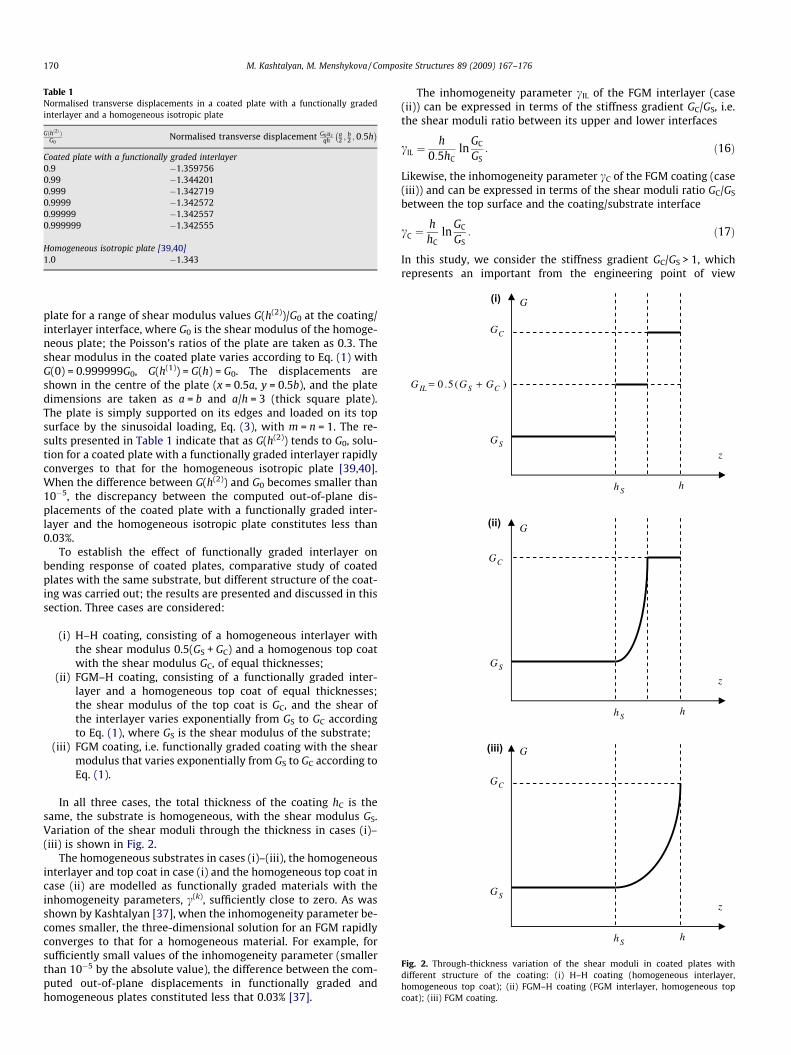
Table 1Normalised transverse displacements in a coated plate with a functionally gradedinterlayer and a homogeneous isotropic plate
Gðhð2Þ ÞG0
Normalised transverse displacement G0 uzqh
a2 ;
b2 ; 0:5h
� �Coated plate with a functionally graded interlayer0.9 �1.3597560.99 �1.3442010.999 �1.3427190.9999 �1.3425720.99999 �1.3425570.999999 �1.342555
Homogeneous isotropic plate [39,40]1.0 �1.343
(i)
(ii)
(iii)
G
SG
CG
Sh h
z
G
SG
CG
Sh h
z
G
SG
CG
)(5.0 CSIL GGG +=
Sh h
z
Fig. 2. Through-thickness variation of the shear moduli in coated plates withdifferent structure of the coating: (i) H–H coating (homogeneous interlayer,homogeneous top coat); (ii) FGM–H coating (FGM interlayer, homogeneous topcoat); (iii) FGM coating.
170 M. Kashtalyan, M. Menshykova / Composite Structures 89 (2009) 167–176
plate for a range of shear modulus values G(h(2))/G0 at the coating/interlayer interface, where G0 is the shear modulus of the homoge-neous plate; the Poisson’s ratios of the plate are taken as 0.3. Theshear modulus in the coated plate varies according to Eq. (1) withG(0) = 0.999999G0, G(h(1)) = G(h) = G0. The displacements areshown in the centre of the plate (x = 0.5a, y = 0.5b), and the platedimensions are taken as a = b and a/h = 3 (thick square plate).The plate is simply supported on its edges and loaded on its topsurface by the sinusoidal loading, Eq. (3), with m = n = 1. The re-sults presented in Table 1 indicate that as G(h(2)) tends to G0, solu-tion for a coated plate with a functionally graded interlayer rapidlyconverges to that for the homogeneous isotropic plate [39,40].When the difference between G(h(2)) and G0 becomes smaller than10�5, the discrepancy between the computed out-of-plane dis-placements of the coated plate with a functionally graded inter-layer and the homogeneous isotropic plate constitutes less than0.03%.
To establish the effect of functionally graded interlayer onbending response of coated plates, comparative study of coatedplates with the same substrate, but different structure of the coat-ing was carried out; the results are presented and discussed in thissection. Three cases are considered:
(i) H–H coating, consisting of a homogeneous interlayer withthe shear modulus 0.5(GS + GC) and a homogenous top coatwith the shear modulus GC, of equal thicknesses;
(ii) FGM–H coating, consisting of a functionally graded inter-layer and a homogeneous top coat of equal thicknesses;the shear modulus of the top coat is GC, and the shear ofthe interlayer varies exponentially from GS to GC accordingto Eq. (1), where GS is the shear modulus of the substrate;
(iii) FGM coating, i.e. functionally graded coating with the shearmodulus that varies exponentially from GS to GC according toEq. (1).
In all three cases, the total thickness of the coating hC is thesame, the substrate is homogeneous, with the shear modulus GS.Variation of the shear moduli through the thickness in cases (i)–(iii) is shown in Fig. 2.
The homogeneous substrates in cases (i)–(iii), the homogeneousinterlayer and top coat in case (i) and the homogeneous top coat incase (ii) are modelled as functionally graded materials with theinhomogeneity parameters, c(k), sufficiently close to zero. As wasshown by Kashtalyan [37], when the inhomogeneity parameter be-comes smaller, the three-dimensional solution for an FGM rapidlyconverges to that for a homogeneous material. For example, forsufficiently small values of the inhomogeneity parameter (smallerthan 10�5 by the absolute value), the difference between the com-puted out-of-plane displacements in functionally graded andhomogeneous plates constituted less that 0.03% [37].
The inhomogeneity parameter cIL of the FGM interlayer (case(ii)) can be expressed in terms of the stiffness gradient GC/GS, i.e.the shear moduli ratio between its upper and lower interfaces
cIL ¼h
0:5hCln
GC
GS: ð16Þ
Likewise, the inhomogeneity parameter cC of the FGM coating (case(iii)) and can be expressed in terms of the shear moduli ratio GC/GS
between the top surface and the coating/substrate interface
cC ¼hhC
lnGC
GS: ð17Þ
In this study, we consider the stiffness gradient GC/GS > 1, whichrepresents an important from the engineering point of view
M. Kashtalyan, M. Menshykova / Composite Structures 89 (2009) 167–176 171
scenario of a soft substrate protected by a much stiffer coating. Thechosen values of GC/GS do not necessarily represent certain materi-als, but are rather used to establish the effect of the coating struc-ture and the stiffness gradient on stress and displacement fieldsin the coated plates. The Poisson’s ratios of the substrate and thecoating in all there cases are taken as 0.3, and the total thicknessof the coating is hC = 0.2h.
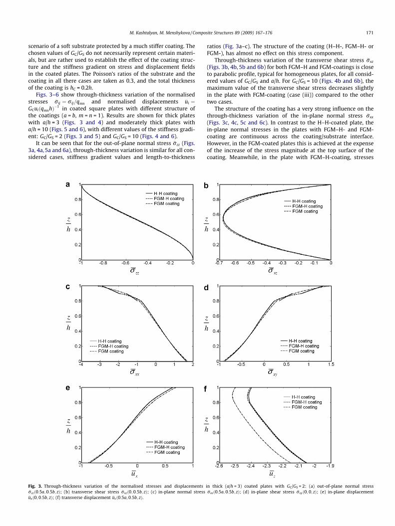
Figs. 3–6 show through-thickness variation of the normalisedstresses �rij ¼ rij=qmn and normalised displacements �ui ¼GCuiðqmnhÞ�1 in coated square plates with different structure ofthe coatings (a = b, m = n = 1). Results are shown for thick plateswith a/h = 3 (Figs. 3 and 4) and moderately thick plates witha/h = 10 (Figs. 5 and 6), with different values of the stiffness gradi-ent: GC/GS = 2 (Figs. 3 and 5) and GC/GS = 10 (Figs. 4 and 6).
It can be seen that for the out-of-plane normal stress �rzz (Figs.3a, 4a, 5a and 6a), through-thickness variation is similar for all con-sidered cases, stiffness gradient values and length-to-thickness
Fig. 3. Through-thickness variation of the normalised stresses and displacements�rzzð0:5a;0:5b; zÞ; (b) transverse shear stress �rxzð0; 0:5b; zÞ; (c) in-plane normal stress�uxð0; 0:5b; zÞ; (f) transverse displacement �uzð0:5a; 0:5b; zÞ.
ratios (Fig. 3a–c). The structure of the coating (H–H-, FGM–H- orFGM-), has almost no effect on this stress component.
Through-thickness variation of the transverse shear stress �rxz
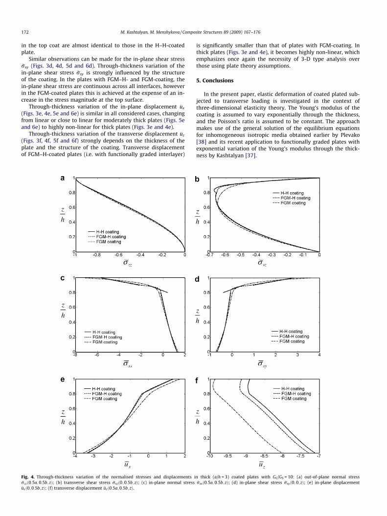
(Figs. 3b, 4b, 5b and 6b) for both FGM–H and FGM-coatings is closeto parabolic profile, typical for homogeneous plates, for all consid-ered values of GC/GS and a/h. For GC/GS = 10 (Figs. 4b and 6b), themaximum value of the transverse shear stress decreases slightlyin the plate with FGM-coating (case (iii)) compared to the othertwo cases.
The structure of the coating has a very strong influence on thethrough-thickness variation of the in-plane normal stress �rxx
(Figs. 3c, 4c, 5c and 6c). In contrast to the H–H-coated plate, thein-plane normal stresses in the plates with FGM–H- and FGM-coating are continuous across the coating/substrate interface.However, in the FGM-coated plates this is achieved at the expenseof the increase of the stress magnitude at the top surface of thecoating. Meanwhile, in the plate with FGM–H-coating, stresses
in thick (a/h = 3) coated plates with GC/GS = 2: (a) out-of-plane normal stress�rxxð0:5a; 0:5b; zÞ; (d) in-plane shear stress �rxyð0; 0; zÞ; (e) in-plane displacement
172 M. Kashtalyan, M. Menshykova / Composite Structures 89 (2009) 167–176
in the top coat are almost identical to those in the H–H-coatedplate.
Similar observations can be made for the in-plane shear stress�rxy (Figs. 3d, 4d, 5d and 6d). Through-thickness variation of thein-plane shear stress �rxy is strongly influenced by the structureof the coating. In the plates with FGM–H- and FGM-coating, thein-plane shear stress are continuous across all interfaces, howeverin the FGM-coated plates this is achieved at the expense of an in-crease in the stress magnitude at the top surface.
Through-thickness variation of the in-plane displacement �ux
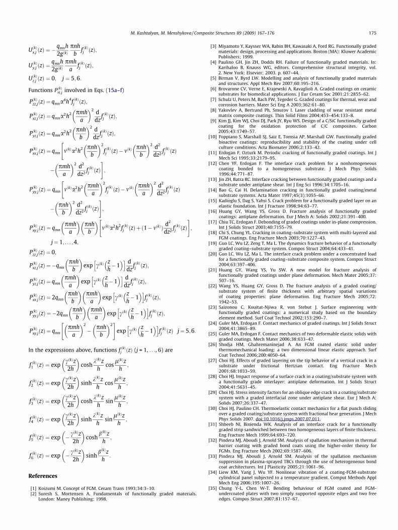
(Figs. 3e, 4e, 5e and 6e) is similar in all considered cases, changingfrom linear or close to linear for moderately thick plates (Figs. 5eand 6e) to highly non-linear for thick plates (Figs. 3e and 4e).
Through-thickness variation of the transverse displacement �uz
(Figs. 3f, 4f, 5f and 6f) strongly depends on the thickness of theplate and the structure of the coating. Transverse displacementof FGM–H-coated plates (i.e. with functionally graded interlayer)
Fig. 4. Through-thickness variation of the normalised stresses and displacements i�rzzð0:5a;0:5b; zÞ; (b) transverse shear stress �rxzð0; 0:5b; zÞ; (c) in-plane normal stress�uxð0; 0:5b; zÞ; (f) transverse displacement �uzð0:5a;0:5b; zÞ.
is significantly smaller than that of plates with FGM-coating. Inthick plates (Figs. 3e and 4e), it becomes highly non-linear, whichemphasizes once again the necessity of 3-D type analysis overthose using plate theory assumptions.
5. Conclusions
In the present paper, elastic deformation of coated plated sub-jected to transverse loading is investigated in the context ofthree-dimensional elasticity theory. The Young’s modulus of thecoating is assumed to vary exponentially through the thickness,and the Poisson’s ratio is assumed to be constant. The approachmakes use of the general solution of the equilibrium equationsfor inhomogeneous isotropic media obtained earlier by Plevako[38] and its recent application to functionally graded plates withexponential variation of the Young’s modulus through the thick-ness by Kashtalyan [37].
n thick (a/h = 3) coated plates with GC/GS = 10: (a) out-of-plane normal stress�rxxð0:5a; 0:5b; zÞ; (d) in-plane shear stress �rxyð0; 0; zÞ; (e) in-plane displacement
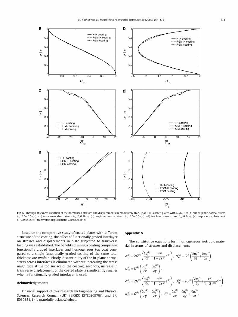
Fig. 5. Through-thickness variation of the normalised stresses and displacements in moderately thick (a/h = 10) coated plates with GC/GS = 2: (a) out-of-plane normal stress�rzzð0:5a;0:5b; zÞ; (b) transverse shear stress �rxzð0; 0:5b; zÞ; (c) in-plane normal stress �rxxð0:5a; 0:5b; zÞ; (d) in-plane shear stress �rxyð0; 0; zÞ; (e) in-plane displacement�uxð0; 0:5b; zÞ; (f) transverse displacement �uzð0:5a; 0:5b; zÞ.
M. Kashtalyan, M. Menshykova / Composite Structures 89 (2009) 167–176 173
Based on the comparative study of coated plates with differentstructure of the coating, the effect of functionally graded interlayeron stresses and displacements in plate subjected to transverseloading was established. The benefits of using a coating comprisingfunctionally graded interlayer and homogeneous top coat com-pared to a single functionally graded coating of the same totalthickness are twofold. Firstly, discontinuity of the in-plane normalstress across interfaces is eliminated without increasing the stressmagnitude at the top surface of the coating; secondly, increase intransverse displacement of the coated plate is significantly smallerwhen a functionally graded interlayer is used.
Acknowledgements
Financial support of this research by Engineering and PhysicalSciences Research Council (UK) (EPSRC EP/E020976/1 and EP/E030351/1) is gratefully acknowledged.
Appendix A
The constitutive equations for inhomogeneous isotropic mate-rial in terms of stresses and displacements
rðkÞzz ¼2GðkÞouðkÞz
ozþ mðkÞ
1�2mðkÞeðkÞ
!; rðkÞxz ¼GðkÞ
ouðkÞx
ozþouðkÞz
ox
!;
rðkÞyz ¼GðkÞouðkÞy
ozþouðkÞz
oy
!;
rðkÞxx ¼2GðkÞouðkÞx
oxþ mðkÞ
1�2mðkÞeðkÞ
!; rðkÞyy ¼2GðkÞ
ouðkÞy
oyþ mðkÞ
1�2mðkÞeðkÞ
!;
rðkÞxy ¼GðkÞouðkÞx
oyþouðkÞy
ox
!; eðkÞ ¼ouðkÞx
oxþouðkÞy
oyþouðkÞz
oz:

Fig. 6. Through-thickness variation of the normalised stresses and displacements in moderately thick (a/h = 10) coated plates with GC/GS = 10: (a) out-of-plane normal stress�rzzð0:5a;0:5b; zÞ; (b) transverse shear stress �rxzð0; 0:5b; zÞ; (c) in-plane normal stress �rxxð0:5a; 0:5b; zÞ; (d) in-plane shear stress �rxyð0; 0; zÞ; (e) in-plane displacement�uxð0; 0:5b; zÞ; (f) transverse displacement �uzð0:5a;0:5b; zÞ.
174 M. Kashtalyan, M. Menshykova / Composite Structures 89 (2009) 167–176
Appendix B
Roots of characteristic equation corresponding to Eq. (11a)
kðkÞ
lðkÞ
!¼
ffiffiffiffiffiffiffiffiffiffiffiffiffiffiffiffiffiffiffiffiffiffiffiffiffiffiffiffiffiffiffiffiffiffiffiffiffiffiffiffiffiffiffiffiffiffiffiffiffiffiffiffiffiffiffiffiffiffiffiffiffiffiffiffiffiffiffiffiffiffiffiffiffiffiffiffiffiffiffiffiffiffiffiffiffi12�bðkÞ
2 þffiffiffiffiffiffiffiffiffiffiffiffiffiffiffiffiffiffiffiffiffiffiffiffiffiffiffiffiffiffiffiffiffiffiffiffiffiffiffiffiffiffiffiffiffiffiffiffiffiffiffibðkÞ
4 þ cð4Þ2a2h2 mðkÞ1� mðkÞ
r !vuut :
Roots of characteristic equation corresponding to Eq. (11b)
bðkÞ ¼
ffiffiffiffiffiffiffiffiffiffiffiffiffiffiffiffiffiffiffiffiffiffiffiffifficðkÞ2
4þ a2h2
s:
Appendix C
Functions UðkÞi;j involved in Eqs. (14a–c).
UðkÞx;j ðzÞ ¼ �qmnh2gðkÞ
pmha
exp �cðkÞzh� 1
� �h i
� �mðkÞa2h2f ðkÞj ðzÞ þ ðmðkÞ � 1Þ d2
dz2 f ðkÞj ðzÞ" #
;
UðkÞy;j ðzÞ ¼ �qmnh2gðkÞ
pnhb
exp �cðkÞzh� 1
� �h i
� �mðkÞa2h2f ðkÞj ðzÞ þ ðmðkÞ � 1Þ d2
dz2 f ðkÞj ðzÞ" #
;
UðkÞz;j ðzÞ ¼ �qmnh2gðkÞ
pmha
exp �cðkÞzh� 1
� �h i
� ðmðkÞ � 1Þ �cðkÞd2
dz2 f ðkÞj ðzÞ þd3
dz3 f ðkÞj ðzÞ !"
�a2h2 ðmðkÞ � 2Þ ddz
f ðkÞj ðzÞ � mðkÞcðkÞf ðkÞj ðzÞ� �#
; j ¼ 1; . . . ;4;
M. Kashtalyan, M. Menshykova / Composite Structures 89 (2009) 167–176 175
UðkÞx;j ðzÞ ¼ �qmnh2gðkÞ
pnhb
f ðkÞj ðzÞ;
UðkÞy;j ðzÞ ¼qmnh2gðkÞ
pmha
f ðkÞj ðzÞ;
UðkÞz;j ðzÞ ¼ 0; j ¼ 5;6:
Functions PðkÞrt;j involved in Eqs. (15a–f)
PðkÞzz;jðzÞ ¼ qmna4h4f ðkÞj ðzÞ;
PðkÞxz;jðzÞ ¼ qmna2h2 pmha
� �2 ddz
f ðkÞj ðzÞ;
PðkÞyz;jðzÞ ¼ qmna2h2 pnhb
� �2 ddz
f ðkÞj ðzÞ;
PðkÞxx;jðzÞ ¼ qmn mðkÞa2h2 pnhb
� �2
f ðkÞj ðzÞ� mðkÞpnh
b
� �2 d2
dz2 f ðkÞj ðzÞ"
� pmha
� �2 d2
dz2 f ðkÞj ðzÞ#;
PðkÞyy;jðzÞ ¼ qmn mðkÞa2h2 pmha
� �2
f ðkÞj ðzÞ� mðkÞpmh
a
� �2 d2
dz2 f ðkÞj ðzÞ"
� pnhb
� �2 d2
dz2 f ðkÞj ðzÞ#;
PðkÞxy;jðzÞ ¼ qmnpmh
a
� �pnh
b
� �mðkÞa2h2f ðkÞj ðzÞþ ð1� mðkÞÞ d2
dz2 f ðkÞj ðzÞ" #
;
j¼ 1; . . . ;4;
PðkÞzz;jðzÞ ¼ 0;
PðkÞxz;jðzÞ ¼�qmnpnh
b
� �exp cðkÞ
zh�1
� �h i ddz
f ðkÞj ðzÞ;
PðkÞyz;jðzÞ ¼ qmnpmh
a
� �exp cðkÞ
zh�1
� �h i ddz
f ðkÞj ðzÞ;
PðkÞxx;jðzÞ ¼ 2qmnpnh
b
� �pmh
a
� �exp cðkÞ
zh�1
� �h if ðkÞj ðzÞ;
PðkÞyy;jðzÞ ¼ �2qmnpnh
b
� �pmh
a
� �exp cðkÞ
zh�1
� �h if ðkÞj ðzÞ;
PðkÞxy;jðzÞ ¼ qmnpmh
a
� �2
� pnhb
� �2" #
exp cðkÞzh�1
� �h if ðkÞj ðzÞ j¼ 5;6:
In the expressions above, functions f ðkÞj ðzÞ (j = 1, . . ., 6) are
f ðkÞ1 ðzÞ ¼ expcðkÞz2h
� �cosh
kðkÞzh
coslðkÞz
h;
f ðkÞ2 ðzÞ ¼ expcðkÞz2h
� �sinh
kðkÞzh
coslðkÞz
h;
f ðkÞ3 ðzÞ ¼ expcðkÞz2h
� �cosh
kðkÞzh
sinlðkÞz
h;
f ðkÞ4 ðzÞ ¼ expcðkÞz2h
� �sinh
kðkÞzh
sinlðkÞz
h;
f ðkÞ5 ðzÞ ¼ exp � cðkÞz2h
� �cosh
bðkÞzh
;
f ðkÞ6 ðzÞ ¼ exp � cðkÞz2h
� �sinh
bðkÞzh
:
References
[1] Koizumi M. Concept of FGM. Ceram Trans 1993;34:3–10.[2] Suresh S, Mortensen A. Fundamentals of functionally graded materials.
London: Maney Publishing; 1998.
[3] Miyamoto Y, Kaysser WA, Rabin BH, Kawasaki A, Ford RG. Functionally gradedmaterials: design, processing and applications. Boston (MA): Kluwer AcademicPublishers; 1999.
[4] Paulino GH, Jin ZH, Dodds RH. Failure of functionally graded materials. In:Karihaloo B, Knauss WG, editors. Comprehensive structural integrity, vol.2. New York: Elsevier; 2003. p. 607–44.
[5] Birman V, Byrd LW. Modelling and analysis of functionally graded materialsand structures. Appl Mech Rev 2007;60:195–216.
[6] Brovarone CV, Verne E, Krajewski A, Ravaglioli A. Graded coatings on ceramicsubstrates for biomedical applications. J Eur Ceram Soc 2001;21:2855–62.
[7] Schulz U, Peters M, Bach FW, Tegeder G. Graded coatings for thermal, wear andcorrosion barriers. Mater Sci Eng A 2003;362:61–80.
[8] Yakovlev A, Bertrand Ph, Smurov I. Laser cladding of wear resistant metalmatrix composite coatings. Thin Solid Films 2004;453–454:133–8.
[9] Kim JJ, Kim WJ, Choi DJ, Park JY, Ryu WS. Design of a C/SiC functionally gradedcoating for the oxidation protection of C/C composites. Carbon2005;43:1749–57.
[10] Foppiano S, Marshall SJ, Saiz E, Tomsia AP, Marshall GW. Functionally gradedbioactive coatings: reproducibility and stability of the coating under cellculture conditions. Acta Biomater 2006;2:133–42.
[11] Erdogan F, Ozturk M. Periodic cracking of functionally graded coatings. Int JMech Sci 1995;33:2179–95.
[12] Chen YF, Erdogan F. The interface crack problem for a nonhomogeneouscoating bonded to a homogeneous substrate. J Mech Phys Solids1996;44:771–87.
[13] Jin ZH, Batra RC. Interface cracking between functionally graded coatings and asubstrate under antiplane shear. Int J Eng Sci 1996;34:1705–16.
[14] Bao G, Cai H. Delamination cracking in functionally graded coating/metalsubstrate systems. Acta Mater 1997;45(3):1055–66.
[15] Kadioglu S, Dag S, Yahsi S. Crack problem for a functionally graded layer on anelastic foundation. Int J Fracture 1998;94:63–77.
[16] Huang GY, Wang YS, Gross D. Fracture analysis of functionally gradedcoatings: antiplane deformation. Eur J Mech A: Solids 2002;21:391–400.
[17] Chiu TC, Erdogan F. Debonding of graded coatings under in-plane compression.Int J Solids Struct 2003;40:7155–79.
[18] Chi S, Chung YL. Cracking in coating–substrate system with multi-layered andFGM coatings. Eng Fracture Mech 2003;70:1227–43.
[19] Guo LC, Wu LZ, Zeng T, Ma L. The dynamics fracture behavior of a functionallygraded coating–substrate system. Compos Struct 2004;64:433–41.
[20] Guo LC, Wu LZ, Ma L. The interface crack problem under a concentrated loadfor a functionally graded coating–substrate composite system. Compos Struct2004;63:397–406.
[21] Huang GY, Wang YS, Yu SW. A new model for fracture analysis offunctionally graded coatings under plane deformation. Mech Mater 2005;37:507–16.
[22] Wang YS, Huang GY, Gross D. The fracture analysis of a graded coating/substrate system of finite thickness with arbitrary spatial variationsof coating properties: plane deformation. Eng Fracture Mech 2005;72:1942–53.
[23] Saizonou C, Kouitat-Njiwa R, von Stebut J. Surface engineering withfunctionally graded coatings: a numerical study based on the boundaryelement method. Surf Coat Technol 2002;153:290–7.
[24] Guler MA, Erdogan F. Contact mechanics of graded coatings. Int J Solids Struct2004;41:3865–89.
[25] Guler MA, Erdogan F. Contact mechanics of two deformable elastic solids withgraded coatings. Mech Mater 2006;38:633–47.
[26] Shodja HM, Ghahremaninejad A. An FGM coated elastic solid underthermomechanical loading: a two dimensional linear elastic approach. SurfCoat Technol 2006;200:4050–64.
[27] Choi HJ. Effects of graded layering on the tip behavior of a vertical crack in asubstrate under frictional Hertzian contact. Eng Fracture Mech2001;68:1033–59.
[28] Choi HJ. Impact response of a surface crack in a coating/substrate system witha functionally grade interlayer: antiplane deformation. Int J Solids Struct2004;41:5631–45.
[29] Choi HJ. Stress intensity factors for an oblique edge crack in a coating/substratesystem with a graded interfacial zone under antiplane shear. Eur J Mech A:Solids 2007;26:337–47.
[30] Choi HJ, Paulino CH. Thermoelastic contact mechanics for a flat punch slidingover a graded coating/substrate system with fractional hear generation. J MechPhys Solids 2007. doi:10.1016/j.jmps.2007.07.011.
[31] Shbeeb NI, Binienda WK. Analysis of an interface crack for a functionallygraded strip sandwiched between two homogeneous layers of finite thickness.Eng Fracture Mech 1999;64:693–720.
[32] Pindera MJ, Aboudi J, Arnold SM. Analysis of spallation mechanism in thermalbarrier coating with graded bond coats using the higher-order theory forFGMs. Eng Fracture Mech 2002;69:1587–606.
[33] Pindera MJ, Aboudi J, Arnold SM. Analysis of the spallation mechanismsuppression in plasma-sprayed TBCs through the use of heterogeneous bondcoat architectures. Int J Plasticity 2005;21:1061–96.
[34] Liew KM, Yang J, Wu YF. Nonlinear vibration of a coating-FGM-substratecylindrical panel subjected to a temperature gradient. Comput Methods ApplMech Eng 2006;195:1007–26.
[35] Chung Y-L, Chen W-T. Bending behaviour of FGM coated and FGM-undercoated plates with two simply supported opposite edges and two freeedges. Compos Struct 2007;81:157–67.

176 M. Kashtalyan, M. Menshykova / Composite Structures 89 (2009) 167–176
[36] Kashtalyan M, Menshykova M. Three-dimensional elastic deformation of afunctionally graded coating/substrate system. Int J Solids Struct 2007;44: 5272–88.
[37] Kashtalyan M. Three-dimensional elasticity solution for bending offunctionally graded rectangular plates. Eur J Mech A: Solids 2004;23:833–54.
[38] Plevako VP. On the theory of elasticity of inhomogeneous media. J Appl MathMech 1971;35:806–13.
[39] Vlasov BF. On one case of bending of rectangular thick plate. VestnikMoskovskogo Universiteta. Seriia matematiki, mekhaniki, astronomii, fiziki ikhimii 1957;2:25–34.
[40] Ambartsumyan SA. Theory of anisotropic plates: strength, stability andvibrations. Stamford (CT): Technomic Publishing; 1970.
Copyright © 2022 FDOKUMEN