Chapter 2. Material Selection Manual for Dense Graded ...
20
Chapter 2. Material Selection Manual for Dense Graded Bituminous Mixes (DBM/BC) C2: C2.1 General Regardless of the mixture classification, the same degree of design, production and construction control procedures should be used to ensure proper performance of the pavement. All quality pavements should be engineered to contain requirements for the following items: ▪ properly selected asphalt binder grades for the climate and traffic; ▪ aggregate characteristics including material quality and gradation; ▪ HMA volumetric requirements; and ▪ HMA performance criteria, if warranted. The amount of aggregates for asphalt concrete mixtures is generally 90 to 95 percent by weight and 75 to 85 percent by volume. Aggregates are primarily responsible for the load supporting capacity of a pavement. Aggregate has been defined as any inert mineral material used for mixing in graduated particles or fragments. It includes sand, gravel, crushed stone, slag, screenings, and mineral filler. Selecting an aggregate material for use in an asphalt concrete depends upon the availability, cost, and quality of the material, as well as the type of construction that is intended. C2.2 Materials (a) Bitumen The bitumen should be viscosity grade paving bitumen complying with the Indian Standard Specification IS: 73, Table 2.10. Table 2.1 : Viscosity Grade and their general applications Viscosity Grade )VG) General Applications VG -40 (40-60 Penetration ) Use of Highly Stressed Areas like intersection, toll both, truck parking VG -30 (50-60 Penetration ) Use for paving mostly VG -20 (60-80 Penetration ) Use for paving in cold climate, high altitude region, hilly terrain VG -10 (80-100 Penetration ) Use in spraying applications and for paving in very cold regions (b) Coarse Aggregates The coarse aggregates should consist of crushed rock, crushed gravel or other hard material retained on the 4.75 mm sieve(for NMAS 35.5mm, 26.5mm & 19mm) or 2.36mm sieve(for NMAS 13.2mm). They should be clean, hard, and durable, of cubical shape, free from dust and soft or friable matter, organic or other deleterious substances. Where crushed gravel is proposed for use as aggregate, not less than 90 percent by weight of the crushed material retained on the 4.75 mm sieve should have at least two fractured faces.(Ref. Table 1.2.) (c) Fine Aggregates Fine aggregates should consist of crushed or naturally occurring mineral material, or a combination of the two, passing the 4.75 mm sieve(for NMAS 35.5mm, 26.5mm & 19mm) or 2.36mm sieve(for NMAS 13.2mm) and retained on the 75-micron sieve. These should be clean, hard, durable, dry and free from dust, and soft or friable matter, organic or other deleterious matter. Natural sand should not be allowed in binder courses. However, natural sand up to 50 percent of the fine aggregate may be allowed in base courses.(Ref. Table 1.2.) (d) Filler Filler should consist of finely divided mineral matter such as rock dust, hydrated lime or cement. The filler should be free from organic impurities and have a plasticity Index not greater than 4. The Plasticity index requirement should not apply if filler is cement or lime. Where the aggregates fail to
-
Upload
khangminh22 -
Category
Documents
-
view
0 -
download
0
Transcript of Chapter 2. Material Selection Manual for Dense Graded ...

Chapter 2. Material Selection
Manual for Dense Graded Bituminous Mixes (DBM/BC)
C2
:
C2.1 General
Regardless of the mixture classification, the same degree of design, production and construction
control procedures should be used to ensure proper performance of the pavement. All quality
pavements should be engineered to contain requirements for the following items:
▪ properly selected asphalt binder grades for the climate and traffic;
▪ aggregate characteristics including material quality and gradation;
▪ HMA volumetric requirements; and
▪ HMA performance criteria, if warranted.
The amount of aggregates for asphalt concrete mixtures is generally 90 to 95 percent by weight and 75
to 85 percent by volume. Aggregates are primarily responsible for the load supporting capacity of a
pavement. Aggregate has been defined as any inert mineral material used for mixing in graduated
particles or fragments. It includes sand, gravel, crushed stone, slag, screenings, and mineral filler.
Selecting an aggregate material for use in an asphalt concrete depends upon the availability, cost, and
quality of the material, as well as the type of construction that is intended.
C2.2 Materials
(a) Bitumen
The bitumen should be viscosity grade paving bitumen complying with the Indian Standard
Specification IS: 73, Table 2.10.
Table 2.1 : Viscosity Grade and their general applications
Viscosity Grade )VG) General Applications
VG -40 (40-60 Penetration ) Use of Highly Stressed Areas like intersection, toll both, truck
parking
VG -30 (50-60 Penetration ) Use for paving mostly
VG -20 (60-80 Penetration ) Use for paving in cold climate, high altitude region, hilly terrain
VG -10 (80-100 Penetration ) Use in spraying applications and for paving in very cold regions
(b) Coarse Aggregates
The coarse aggregates should consist of crushed rock, crushed gravel or other hard material retained on
the 4.75 mm sieve(for NMAS 35.5mm, 26.5mm & 19mm) or 2.36mm sieve(for NMAS 13.2mm). They
should be clean, hard, and durable, of cubical shape, free from dust and soft or friable matter, organic or
other deleterious substances. Where crushed gravel is proposed for use as aggregate, not less than 90
percent by weight of the crushed material retained on the 4.75 mm sieve should have at least two
fractured faces.(Ref. Table 1.2.)
(c) Fine Aggregates
Fine aggregates should consist of crushed or naturally occurring mineral material, or a combination of
the two, passing the 4.75 mm sieve(for NMAS 35.5mm, 26.5mm & 19mm) or 2.36mm sieve(for
NMAS 13.2mm) and retained on the 75-micron sieve. These should be clean, hard, durable, dry and
free from dust, and soft or friable matter, organic or other deleterious matter. Natural sand should not be
allowed in binder courses. However, natural sand up to 50 percent of the fine aggregate may be allowed
in base courses.(Ref. Table 1.2.)
(d) Filler
Filler should consist of finely divided mineral matter such as rock dust, hydrated lime or cement. The
filler should be free from organic impurities and have a plasticity Index not greater than 4. The
Plasticity index requirement should not apply if filler is cement or lime. Where the aggregates fail to

Chapter 2. Material Selection
Manual for Dense Graded Bituminous Mixes (DBM/BC)
C2
:
meet the requirements of the water sensitivity test(80% as min. retained tensile strength, AASHTO
T283) , then 2 percent by total weight of aggregate, of hydrated lime should be used and percentage of
fine aggregate reduced accordingly.
C2.3 Lift thickness and aggregate size
Nominal aggregate size dictates lift thickness, so minimum lift thickness and aggregate size should
always be considered together. Minimum lift thickness should be at least 3 times the nominal
maximum aggregate size to ensure aggregate can align themselves during compaction to achieve
required density and also to ensure mix is impermeable. Therefore, the desired lift thickness can direct
the decision on nominal aggregate size to use.
The maximum lift thickness is dependent also upon the type of compaction equipment that is being
used. When static steel-wheeled rollers are used, the maximum lift thickness that can be properly
compacted is 75mm. When pneumatic or vibratory rollers are used, the maximum thickness of lift that
can be compacted is almost unlimited. Generally, lift thicknesses are limited to 150 or 200 mm.
Proper placement becomes a problem in lifts thicker than 150 or 200 mm.
MS-2 : Asphalt Mix Design Method, 7th Edition,Asphalt Institute has recommendations on the
minimum thickness for a single lift of dense-graded asphalt mixtures are four times the nominal
maximum aggregate size (NMAS) for all mixtures with the exception of “fine” graded mixtures that
may be placed at three times the NMAS. Historical pavement thickness guidelines of two times the
“top size” are inappropriate for NMAS-defined gradations and are susceptible to poor pavement
performance.
Thickness of uncompacted asphalt = designed lift thickness x target density /mix loose density
Table 2.2: The limits on permissible lift thickness with reference of IRC :111:2009,
Specification for Dense Graded Bituminous Mixes and the New York State Highway Design
Manual
Specification Purpose No. of Layers Minimum lift
thickness
Maximum lift
thickness
DBM Base/Binder
Course. Overlay
for
Strengthening
Single or
Multiple
For NMAS 35.5mm :
100mm
For NMAS 26.5mm:
75mm
For NMAS
35.5mm : 150mm
For NMAS
26.5mm: 150mm
Bituminous
Concrete(BC)/
Wearing Course Single For NMAS 19mm :
60mm
For NMAS 13.2 mm:
40mm
For NMAS 19mm
: 75mm
For NMAS 13.2
mm: 50mm
C2.4 Consensus Aggregate Properties
Asphalt Institute_MS2_7th Edition_Asphalt Institute Mix Design Statement : “Certain aggregate
characteristics are critical to well-performing HMA and have been widely acknowledged by a wide
range of industry experts.”
These characteristics are called the “consensus” properties and are as follows: coarse aggregate
angularity (CAA), fine aggregate angularity (FAA), flat and elongated particles (F&E), and clay
content (SE value).
C.2.4.1 Coarse aggregate angularity
Coarse aggregate angularity (CAA) ensures a high degree of aggregate internal friction for rutting
resistance by specifying a minimum percentage of angular particles in the asphalt mixture. The test
method is ASTM D 5821, “Determining the Percentage of Fractured Particles in Coarse Aggregate.”

Chapter 2. Material Selection
Manual for Dense Graded Bituminous Mixes (DBM/BC)
C2
:
The test method determines the percentage of aggregate pieces larger than the #4 sieve (4.75 mm)
meeting specified angularity criteria, either by mass or particle count. The reporting format gives both
the percentage of aggregate with one or more fractured faces and with two or more fractured faces. For
example, a reported value of “85/80” indicates that 85 percent of the sample has one or more fractured
faces and 80 percent has two or more fractured faces. Table 2.3 gives the required minimum values for
coarse aggregate angularity as a function of traffic level and position within the pavement.
C.2.4.2 Fine aggregate angularity
Fine aggregate angularity (FAA) ensures a high degree of fine aggregate internal friction and rutting
resistance. It is defined as the percent of air voids present in loosely compacted aggregates smaller than
the #8 sieve (2.36 mm). The test method specified is AASHTO T 304, “Uncompacted Void Content of
Fine Aggregate.” This property is influenced by particle shape, surface texture and grading. Higher void
contents typically mean more fractured faces. In the test procedure, a sample of fine, washed and dried
aggregate is poured into a small calibrated cylinder through a standard funnel (Figure 2.1).
Figure 2.1 : Fine Aggregate Angularity Apparatus
By measuring the mass of fine aggregate (F) in the filled cylinder of known volume (V), the void
content can be calculated as the difference between the cylinder volume and fine aggregate volume
collected in the cylinder. The fine aggregate bulk (dry) specific gravity (Gsb) is used to compute the fine
aggregate volume. Table 2.3 gives the required minimum values for fine aggregate angularity
(Uncompacted Void Content of Fine Aggregate) as a function of traffic level and position within the
pavement.
C.2.4.3 Flat and elongated particles
Figure 2.2 Measuring Flat and Elongated Particles

Chapter 2. Material Selection
Manual for Dense Graded Bituminous Mixes (DBM/BC)
C2
:
Flat and elongated particles (F&E) is the percentage by mass or by particle count of coarse aggregates
that have a maximum-to-minimum dimension ratio greater than 5:1 (or other ratio, depending on the
agency specification). Flat and elongated particles are undesirable because they have a tendency to
break during construction and under traffic and they tend to reduce VMA. The test procedure used is
ASTM D4791, which deals with flat and elongated particles, and is performed on coarse aggregate
larger than the #4 sieve (4.75 mm). The procedure uses a proportional caliper device (Figure 2.2) to
measure the dimensional ratio of a representative sample of aggregate particles. In Figure 2.2, the
aggregate particle is first placed with its largest dimension between the swinging arm and fixed post at
position (A). The swinging arm then remains stationary while the aggregate is placed between the
swinging arm and the fixed post at position (B). If the aggregate passes through this gap, then it is
counted as a flat and elongated particle. Maximum values for flat and elongated particles specified in
AASHTO M 323 are given in Table 2.3.
The criteria for these consensus aggregate properties are based on traffic level and position within the
pavement structure. Materials near the pavement surface subjected to high traffic levels require more
stringent consensus properties. The criteria are intended to be applied to a proposed aggregate blend
rather than individual components.
Table 2.3: Aggregate Consensus Properties Requirements
Design
ESALs1
(In Millions)
Coarse Aggregate
Angularity
(CAA) (Percent),
minimum
Un-compacted Void
Content of Fine
Aggregate Angularity
(FAA) (Percent),
minimum
Sand
Equivalent
(SE)
(Percent),
minimum
Flat and
Elongated3 '
(F&E)
(Percent),
maximum ≤100 mm > 100 mm ≤100 mm > 100 mm
< 0.3 55/- -/- - - 40 -
0.3 to < 3 75/- 50/- 40 40 40 10
3 to < 10 85/802 60/- 45 40 45 10
10 to < 30 95/90 80/75 45 40 45 10
≥30 100/100 100/100 45 45 50 10
NOTES:
1. Design ESALs are the anticipated traffic level expected on the design lane over a 20-year period.
Regardless of the actual design life of the roadway, determine the design ESALs for 20 years to choose
the appropriate aggregate criteria.
2. 85/80 denotes that 85 percent of the coarse aggregate has one or more fractured faces and 80 percent
has two or more fractured faces.
3. Criterion based upon a 5:1 maximum-to-minimum ratio.
C.2.4.4 Clay content (sand equivalent)
Clay content, more commonly described as sand equivalent (SE), is a percentage of clay material
measured on the aggregate fraction that is finer than a #4 sieve (4.75 mm). It is measured by AASHTO
T 176, “Plastic Fines in Graded Aggregates and Soils by Use of the Sand Equivalent Test (ASTM
D2419).” or IS 2720 Part 37. A sample of fine aggregate is mixed with a flocculating solution in a
graduated cylinder and agitated to loosen clayey fines present in and coating the aggregate (Figure 2.3).
The flocculating solution forces the clay material into suspension above the granular aggregate. After a
settling period, the cylinder height of suspended clay and settled sand is measured. The sand equivalent

Chapter 2. Material Selection
Manual for Dense Graded Bituminous Mixes (DBM/BC)
C2
:
value is computed as the ratio of the sand to clay height readings, expressed as percentage. In essence,
this determines how sandy the fine aggregate fraction is.
Figure 2.3 Sand Equivalent Test
C2.5 Source aggregate properties
In addition to the consensus aggregate properties, certain other aggregate characteristics are critical.
However, critical values of these properties could not be reached by consensus because needed values
are source specific. Consequently, a set of source properties is recommended. Specified values are
established by local agencies. While these properties are relevant during the mix design process, they
may also be used for source acceptance control. Those properties are toughness, soundness and
deleterious materials.
C2.5.1 Toughness
Toughness tests estimate the resistance of coarse aggregate to abrasion and mechanical degradation
during handling, construction and in-service. The most common toughness test is the Los Angeles
Abrasion test IS:2386 Part IV which measures the percent loss of material from the coarse aggregate
fraction of a standardized test sample. It is performed by subjecting the coarse aggregate, usually larger
than the #8 sieve (2.36 mm), to tumbling and the impact and grinding by steel spheres. The test result is
the mass percentage of coarse material lost during the test due to the mechanical degradation. The
maximum allowable loss value is Table 2.4. The higher the value, the more friable the coarse aggregate,
and the greater the breakdown (degradation) of the aggregate from quarrying through stockpiling, HMA
manufacturing and under the rollers. The lower the value, the better the skid resistance and tire chain
wear resistance of the pavement.
C2.5.2 Soundness
Soundness tests estimate the resistance of aggregates to in-service weathering. The most common test is
Soundness of Aggregate By Use of Sodium Sulfate or Magnesium Sulfate (IS:2386 Part V) which
measures the percent loss of material from an aggregate blend. It can be performed on both coarse and
fine aggregate. The test is performed by exposing an aggregate sample to repeated immersions in
saturated solutions of sodium or magnesium sulfate followed by oven drying. One immersion and
drying is considered one soundness cycle. During the drying phase, salts precipitate in the permeable
void space of the aggregate. Upon re-immersion, the salt rehydrates and exerts internal expansive forces
that simulate the expansive forces of freezing water. The test result is total percent loss over various

Chapter 2. Material Selection
Manual for Dense Graded Bituminous Mixes (DBM/BC)
C2
:
sieve intervals for a required number of cycles. The maximum allowable loss value is Table 2.4 for five
cycles. Magnesium sulfate testing is typically more aggressive than sodium sulfate testing. It is typical
for magnesium sulfate loss to be greater than sodium sulfate loss on the same aggregate.
C2.5.3 Deleterious materials
Deleterious materials are defined as the mass percentage of contaminants such as clay lumps, shale,
wood, mica and coal in the blended aggregate. The most common deleterious materials test is Clay
Lumps and Friable Particles in Aggregate (IS:2386 Part I). The analysis can be performed on both
coarse and fine aggregate. The test is performed by wet sieving aggregate size fractions over specified
sieves. The mass percentage of material lost as a result of wet sieving is reported as the percent of clay
lumps and friable particles. A wide range of criteria for maximum allowable percentage of deleterious
particles exists. The maximum allowable value is Table 2.4.
Table 2.4: Aggregate Source Properties for DBM/BC
Property Test Specification Method of Test
Deleterious materials:
Cleanliness (dust)
Grain size analysis Max 5% passing 0.075
mm sieve
IS:2386 Part I
Toughness/Strength Los Angeles Abrasion
Value or
Aggregate Impact
Value
DBM : Max 35%
BC : Max. 30%
DBM: Max 27%
BC : Max. 24%
IS:2386 Part IV
Durability Soundness either:
Sodium Sulphate or
Magnesium Sulphate
Max 12%
Max 18%
IS:2386 Part V
Polishing Polished Stone Value Min 55 BS:812-114
Water Sensitivity Retained Tensile
Strength*
Min 80% AASHTO 283
Water Absorption Water Absorption Max 2% IS:2386.Part Ill
Stripping Coating and Stripping
of Bitumen Aggregate
Mix
Minimum retained
coating 95%
IS: 6241
*If the minimum retained tensile test strength falls below 80 percent, use of anti-stripping agent is
recommended to meet the requirement.
C2.6 Gradation
It has long been established that the gradation of the aggregate is one of the factors that must be
carefully considered in the design of asphalt paving mixtures. The purpose for establishing and
controlling aggregate gradation is to provide a sufficient volume of voids in the asphalt-aggregate
mixture to accommodate the proper asphalt film thickness on each particle and provide the design air
void system to allow for thermal expansion of the asphalt within the mix. Minimum voids in the
mineral aggregate (VMA) requirements have been established that vary with the nominal maximum
aggregate size to help assure the correct volume of effective binder exists for each mix type.

Chapter 2. Material Selection
Manual for Dense Graded Bituminous Mixes (DBM/BC)
C2
:
The gradation of each aggregate material utilized in a mixture should be conducted using the washed
sieve analysis procedures designated in IS:2386 Part I or ASTM C117 and C136 to properly account
for the #200 material. The results should be reported as an accumulative percent passing each
respective specified sieve size and reported to the nearest whole percent passing. The exception is the
percent passing the #200 sieve (0.075 mm), which should always be calculated and reported to the
nearest 0.1 percent passing .
Control points
The control points define the type of mix and act as master ranges between which gradations must pass.
Control points are placed at the nominal maximum size, an intermediate size (2.36 mm), and the
smallest size (0.075 mm). Control point limits vary depending on the nominal maximum aggregate size
of the design mixture as shown in Table 2.5.
Table 2.5: Gradation requirement
Composition for BC DBM
Nominal Maximum
aggregate size(NMAS)
13.2 mm 19 mm 26.5 mm 35.5 mm
Gradation Type (Ref. Table1.1)
IS Sieve (mm) Cumulative % by weight of total aggregate
passing
45 100
37.5 100 95-100
26.5 100 90-100 63-93
19 100 90-100 71-95 -
13.2 90-100 59-79 56-80 55-75
9.5 70-88 52-72 - -
4.75 53-71 35-55 38-54 38-54
2.36 42-58 28-44 28-42 28-42
1.18 34-48 20-34 - -
0.6 26-38 15-27 - -
0.3 18-28 10-20 7-21 7-21
0.15 12-20 5-13 - -
0.075 4-10 2-8 2-8 2-8
To avoid gap grading, the combined aggregate gradation should not vary from the lower limit on one
sieve to higher limit on the adjacent sieve.
Typically, multiple stockpiles of aggregate are blended to meet the final specified requirements. A
washed sieve analysis must be performed on every aggregate ingredient to be utilized in the mixture in
order to calculate the final aggregate blend in the mixture to be designed. Most aggregate specifications
are based on the final blend of the mixture.
Calculating a blended gradation, assuming all aggregate fractions have a similar Bulk Specific Gravity
(Gsb):
P = (A × a) + (B × b) + (C × c) + . . .
where,
P = the blended percent passing for a given sieve
A,B,C, = the percent passing a sieve for an individual stockpile

Chapter 2. Material Selection
Manual for Dense Graded Bituminous Mixes (DBM/BC)
C2
:
a,b,c, = proportion of stockpile to be added in the blend, where total = 1.00.
The above-mentioned gradation and blending operations result in an aggregate size distribution based
on percentage of mass. Volumetric properties such as air voids and VMA are directly impacted by the
amount and size of aggregate particles and the resulting packing characteristics in the final mixture. A
gradation can give insight to the final volumetric properties in a particular mixture.
However, when the specific gravities of the individual aggregates differ or vary significantly (by 0.20
or more), the blended gradation, based on the mass of the aggregates, may have different volumetric
characteristics when compared to an equivalent gradation of materials having similar specific gravities.
Consider the following example where we are given two different mixtures to compare. They both have
similar gradations by mass and equivalent aggregate shape, strength and texture. One mix contains
aggregates of similar specific gravity and the other contains aggregates of widely differing specific
gravity. Based on the gradation, it would be reasonable to assume that the resulting volumetric
properties would be similar, but the actual number and sizes of particles in the mixture are not similar
and the resulting volumetrics in the compacted mixture will be different.
Table 2.6: Grading Requirements for Mineral Filler
IS sieve (mm) Cumulative Percent Passing by
Weight of Total Aggregate
0.6 100
0.3 98-100
0.075 85.-100
Field-produced mixtures with significantly different aggregate specific gravities than those used in
the mix design will also yield different hot mix volumetric properties. This is one of the reasons why
most specifications require a new mix design when the source (and characteristics) of any of the mix
ingredients are changed.
Chapter 2. Material Selection
Manual for Dense Graded Bituminous Mixes (DBM/BC)
C2
:
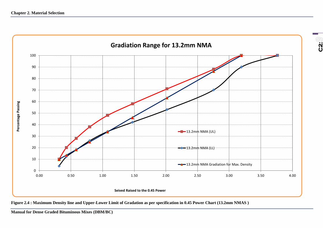
Figure 2.4 : Maximum Density line and Upper-Lower Limit of Gradation as per specification in 0.45 Power Chart (13.2mm NMAS )
0
10
20
30
40
50
60
70
80
90
100
0.00 0.50 1.00 1.50 2.00 2.50 3.00 3.50 4.00
Pe
rce
nta
ge P
assi
ng
Seived Raised to the 0.45 Power
Gradiation Range for 13.2mm NMA
13.2mm NMA (UL)
13.2mm NMA (LL)
13.2mm NMA Gradiation for Max. Density

Chapter 2. Material Selection
Manual for Dense Graded Bituminous Mixes (DBM/BC)
C2
:
Figure 2.5 : Maximum Density line and Upper-Lower Limit of Gradation as per specification in 0.45 Power Chart (19 mm NMAS )
0
10
20
30
40
50
60
70
80
90
100
0.00 0.50 1.00 1.50 2.00 2.50 3.00 3.50 4.00
Pe
rce
nta
ge P
assi
ng
Seived Raised to the 0.45 Power
Gradiation Range for 19mm NMA
19mm NMA (UL)
19mm NMA(LL)
19mmNMA Gradiation for Max. Density

Chapter 2. Material Selection
Manual for Dense Graded Bituminous Mixes (DBM/BC)
C2
:
Figure 2.6 : Maximum Density line and Upper-Lower Limit of Gradation as per specification in 0.45 Power Chart (26.5mm NMAS )
0
10
20
30
40
50
60
70
80
90
100
0.00 1.00 2.00 3.00 4.00 5.00 6.00
Pe
rce
nta
ge P
assi
ng
Seived Raised to the 0.45 Power
Gradiation Range for 26.5mm NMA
26.5mm NMA (UL)
26.5mm NMA (LL)
26.5mm NMA Gradiation for Max. Density

Chapter 2. Material Selection
Manual for Dense Graded Bituminous Mixes (DBM/BC)
C2
:
Figure 2.7 : Maximum Density line and Upper-Lower Limit of Gradation as per specification in 0.45 Power Chart (35.5mm NMAS )
0
10
20
30
40
50
60
70
80
90
100
0.0 1.0 2.0 3.0 4.0 5.0 6.0
Pe
rce
nta
ge P
assi
ng
Seived Raised to the 0.45 Power
Gradiation Range for 35.5mm NMA
35.5mm NMA (UL) 35.5mm NMA (LL) 35.5mm NMA Gradiation for Max. Density

Chapter 2. Material Selection
Manual for Dense Graded Bituminous Mixes (DBM/BC)
C2
:
C2.7 Specific gravity
The specific gravity of an aggregate is the ratio of the weight of a unit volume of material to the weight
of the same volume of water at 73.4°F (23.0°C). This property is used in mix volumetric calculations
for voids determination. Also, bulk specific gravities are used in the computations for adjusting
quantities of the aggregate components that are to be used in an HMA mix because of the differing
specific gravities of various aggregates.
The three generally accepted types of specific gravities for aggregate use in hot mix asphalt are the
following:
• apparent specific gravity (Gsa);
• bulk (dry) specific gravity (Gsb); and
• effective specific gravity (Gse).
Apparent specific gravity considers the volume as being the volume of the aggregate itself. It does not
include the volume of any pores or capillaries that become filled with water after a 15- to 19-hour
soaking. Bulk (dry) specific gravity considers the overall volume of the aggregate particle, including
the pores that become filled with water after a 15- to 19-hour soaking.
The effective specific gravity considers the overall volume of the aggregate excluding the volume of
pores that absorb asphalt. Whereas bulk and apparent specific gravities can relate to individual
aggregates or combined aggregates, effective specific gravity relates exclusively to the total combined
aggregate structure in a mix of HMA.
The accuracy of specific gravity measurements for mix designs is important. Unless specific gravities
are determined to four significant figures (three decimal places), an error in air voids value of as
much as 0.8 percent can occur. The Asphalt Institute recommends the use of weigh scales whose
sensitivity will allow a mix batch weighing 1,000 to 5,000 grams to be measured to an accuracy of 0.1
gram.
C2.7.1 Bulk (dry) specific gravity of aggregate
It is recommended that the bulk (dry) specific gravity (Gsb) of each aggregate be determined on
samples submitted for mix design. Some stockpiles will be essentially coarse (retained on the No. 4
[4.75 mm] sieve), some will be fine (passing the No. 4 [4.75 mm] sieve) and some will have both
coarse and fine portions.
Determining coarse aggregate Gsb
The coarse Gsb is determined using AASHTO T 85 or ASTM C127. The size of the test sample is
specified and determined by the nominal maximum aggregate size. This procedure requires that the dry
aggregate be saturated to determine the volume of the aggregate plus the water-permeable voids.
𝐺𝑠𝑏 = 𝑚
𝑣𝜌=
𝑚𝑎𝑠𝑠 𝑜𝑓 𝑜𝑣𝑒𝑛 𝑑𝑟𝑦 𝑎𝑔𝑔𝑟𝑒𝑔𝑎𝑡𝑒
(𝑣𝑜𝑙𝑢𝑚𝑒 𝑜𝑓 𝑎𝑔𝑔𝑟𝑒𝑔𝑎𝑡𝑒 + 𝑤𝑎𝑡𝑒𝑟 𝑝𝑒𝑟𝑚𝑒𝑎𝑏𝑙𝑒 𝑣𝑜𝑖𝑑𝑠 )𝑥 𝜌
Notice that this equation mirrors the equation in the test procedure:
𝐺𝑠𝑏 = 𝐴
𝐵 − 𝐶
where:
Gsb = bulk (dry) specific gravity of the aggregate
A = mass of the oven-dry test sample

Chapter 2. Material Selection
Manual for Dense Graded Bituminous Mixes (DBM/BC)
C2
:
B = mass of the saturated surface-dry (SSD) test sample in air
C = mass of the saturated sample in water
(ρ is not shown because its numerical value is 1)
Therefore, B–C = volume of the aggregate plus the water-permeable voids.
Determining fine aggregate Gsb
The fine Gsb is determined using AASHTO T 84 or ASTM C128. The dry aggregate is again saturated
to account for the volume of the aggregate plus the water-permeable voids. Note that the procedure
allows saturation by the addition of 6 percent moisture as an alternative to total submersion. This
option allows the aggregate to be dried to an SSD condition much quicker than using the submerged
option. If the designer is using aggregates with a high water absorption (3-4 percent), the Asphalt
Institute recommends total submersion. After the fine aggregate has been dried to a saturated surface-
dry (SSD) condition (as specified in AASHTO T 84), the volume of the SSD fine aggregate is
determined by submerging the sample in a volumetric flask (pycnometer) for de-airing. It is suggested
in AASHTO T 84 to remove the fine aggregate and water from the pycnometer and dry to a constant
mass. The determination of the dry mass of the aggregate in this manner can be messy, has the potential
for loss of material and results in a sample that is covered with water and will take a long time to dry.
The procedure allows a sample of the same mass (± 0.2 grams) to be obtained at the time the SSD
material is placed in the pycnometer. This second sample can then be used to determine the oven-dry
mass quicker and more easily.
Figure 2.8 Illustration of Displaced Water Volume
𝐺𝑠𝑏 = 𝑚
𝑣𝜌=
𝑚𝑎𝑠𝑠 𝑜𝑓 𝑜𝑣𝑒𝑛 𝑑𝑟𝑦 𝑎𝑔𝑔𝑟𝑒𝑔𝑎𝑡𝑒
(𝑣𝑜𝑙𝑢𝑚𝑒 𝑜𝑓 𝑎𝑔𝑔𝑟𝑒𝑔𝑎𝑡𝑒 + 𝑤𝑎𝑡𝑒𝑟 𝑝𝑒𝑟𝑚𝑒𝑎𝑏𝑙𝑒 𝑣𝑜𝑖𝑑𝑠 )𝑥 𝜌=
𝐴
𝐵 + 𝑆 − 𝐶
where:
A = mass of the oven-dry test sample
B = mass of the pycnometer filled with water
S = mass of the saturated surface-dry (SSD) specimen
C = mass of pycnometer with specimen and water to calibration mark
This time, B + S – C = volume of the aggregate plus the water-permeable voids as shown in Figure
2.8.
Determining mineral filler Gsb
The bulk specific gravity of mineral filler is difficult to determine accurately. However, the apparent
specific gravity (Gsa) of mineral filler is more easily determined. This can be done for filler only, as the

Chapter 2. Material Selection
Manual for Dense Graded Bituminous Mixes (DBM/BC)
C2
:
amount of mineral filler added is typically small and the difference between Gsb and Gsa is relatively
small. DOR approval would be necessary for this substitution
Determining the composite Gsb for one stockpile
For stockpiles that include both a coarse and fine fraction, one value must be determined for the stockpile. The
average Gsb can be calculated as follows:
𝐺𝑠𝑏 = 𝑃𝑐𝑜𝑎𝑟𝑠𝑒 + 𝑃𝑓𝑖𝑛𝑒
𝑃𝑐𝑜𝑎𝑟𝑠𝑒
𝐺𝑐𝑜𝑎𝑟𝑠𝑒+
𝑃𝑓𝑖𝑛𝑒
𝐺𝑓𝑖𝑛𝑒
where:
Gsb = bulk (dry) specific gravity of the aggregate
Pcoarse = percentage by weight retained on the No. 4 (4.75 mm) sieve
Pfine = percentage by weight passing the No. 4 (4.75 mm) sieve
Gcoarse = bulk (dry) specific gravity of the coarse fraction
Gfine = bulk (dry) specific gravity of the fine fraction
Determining the Gsb for the aggregate blend
Once the bulk (dry) specific gravity for each stockpile has been determined, the combined bulk (dry) specific
gravity for the total aggregate blend is calculated as follows:
𝐺𝑠𝑏 = 𝑃1 + 𝑃2 + … + 𝑃𝑛
𝑃1
𝐺1+
𝑃2
𝐺2+ … +
𝑃𝑛
𝐺𝑛2
where:
Gsb = bulk (dry) specific gravity of the aggregate
P1, P2, Pn = percentages by weight of aggregates 1, 2, through n
G1, G2, Gn = bulk (dry) specific gravity of aggregates 1, 2, through n
This equation is useful for estimating Gsb during trials in the design process. The calculated coarse and fine Gsb
can be verified by batching the combined aggregates, splitting them on the 4.75-mm sieve and determining the
coarse and fine Gsb for the design. This process of splitting the aggregate blend on the 4.75- mm sieve and only
running Gsb values on the coarse and fine fractions of the blend is often utilized for mix design verification and
quality control testing on plant-produced mix in the field.
The equation format for calculating the combined bulk (dry) specific gravity uses the weighted harmonic mean.
This method is necessary because the criteria being averaged involve a ratio. In this case, the percentages are all
by weight, but the specific gravity is a ratio of the density of the material to the density of water. The equation for
calculating the combined average absorption uses the weighted arithmetic mean, because each absorption is a
percentage by weight, with no supplemental ratio involved.
Calculate the Gsa and absorption for the aggregate blend
Laboratory testing to determine the bulk specific gravity (Gsb) also provides data to easily determine two
additional aggregate properties, the apparent specific gravity (Gsa) and the water absorption of the aggregate.
These calculations are not required to determine mixture volumetric properties; however, they are valuable tools
for the mix designer to monitor. The absorption of the aggregate indicates several characteristics of the final
mixture. Highly absorptive aggregates will require additional binder to fill the permeable voids in the aggregate,
which increases cost. It is not uncommon for aggregates to absorb a binder amount equal to 40–80 percent of the
water-permeable voids.

Chapter 2. Material Selection
Manual for Dense Graded Bituminous Mixes (DBM/BC)
C2
:
Gsa is the ratio of the mass of the oven-dry aggregate to the volume of the aggregate excluding the volume of the
voids occupied by absorbed water. The Gsa volume is less than the volume used to calculate the Gsb; therefore, the
Gsa value will always be larger than the Gsb value.
𝐺𝑠𝑎 = 𝑚
𝑣𝜌=
𝑚𝑎𝑠𝑠 𝑜𝑓 𝑜𝑣𝑒𝑛 𝑑𝑟𝑦 𝑎𝑔𝑔𝑟𝑒𝑔𝑎𝑡𝑒
(𝑏𝑢𝑙𝑘 𝑣𝑜𝑙𝑢𝑚𝑒 𝑜𝑓 𝑎𝑔𝑔𝑟𝑒𝑔𝑎𝑡𝑒 − 𝑣𝑜𝑙𝑢𝑚𝑒 𝑜𝑓 𝑤𝑎𝑡𝑒𝑟 − 𝑝𝑒𝑟𝑚𝑒𝑎𝑏𝑙𝑒 𝑣𝑜𝑖𝑑𝑠 )𝑥 𝜌= 2.700
Notice that this equation mirrors the equation in the test procedure:
𝐺𝑠𝑎 = 𝐴
𝐴 − 𝐶
where:
Gsa = apparent specific gravity of the aggregate
A = mass of the oven-dry test sample
C = mass of the saturated sample in water
(ρ is not shown because its numerical value is 1)
Therefore, A − C = apparent volume of the aggregate minus the water-permeable voids.
Water absorption (A) :The amount of water absorption is also easily determined from the Gsb test data. The
absorptiveness of aggregate is of significant interest to the mixture designer and specifier. Absorption can be an
indicator regarding aggregate quality along with increased binder demand. The binder absorption is typically 40–
80 percent of the water absorption rate. The water absorption rate is calculated by the following equation as
outlined in AASHTO T 85.
𝐴𝑑𝑠𝑜𝑟𝑝𝑡𝑖𝑜𝑛, % = (𝐵 − 𝐴)
𝐴 𝑥 100
where:
B = mass of the saturated surface-dry sample
A = mass of the oven-dry test sample
In order to determine these values for the total blend of aggregate, the methodology used will depend on the
manner in which the Gsb was determined. If Gsb testing was conducted on individual stockpiles, then the Gsa and
absorption will need to be determined for each stockpile and then combined to determine the final values for the
blend. If individual Gsb samples were determined for the coarse and fine fractions of any individual stockpile, then
the below equation can be used to determine the Gsa and absorption values for blend.
𝐺𝑠𝑎 = 𝑃1 + 𝑃2 + … + 𝑃𝑛
𝑃1
𝐺1+
𝑃2
𝐺2+ … +
𝑃𝑛
𝐺𝑛2
where:
Gsa = apparent specific gravity of the aggregate blend
P1, P2, Pn = percentages by weight of aggregates 1, 2, through n
G1, G2, Gn = apparent specific gravity of aggregates 1, 2, through n
𝐴𝑏 = 𝑃1𝐴1 + 𝑃2𝐴2 + … + 𝑃𝑛𝐴𝑛
100
where:
Ab = Water absorption of the aggregate blend
P1, P2, Pn = percentages by weight of aggregates 1, 2, through n
A1, A2, An = absorption of aggregates 1, 2, through n
If Gsb data are determined directly from the blend (during a mixture verification or a field sample obtained from
the belt carrying aggregate into the plant), the designer can simply use the below equation to directly determine
the Gsb, Gsa and absorption data for the blend.
𝐺𝑠𝑏 = 𝑃𝑐𝑜𝑎𝑟𝑠𝑒 + 𝑃𝑓𝑖𝑛𝑒
𝑃𝑐𝑜𝑎𝑟𝑠𝑒
𝐺𝑐𝑜𝑎𝑟𝑠𝑒+
𝑃𝑓𝑖𝑛𝑒
𝐺𝑓𝑖𝑛𝑒
Chapter 2. Material Selection
Manual for Dense Graded Bituminous Mixes (DBM/BC)
C2
:
where:
Gsb = apparent specific gravity of the aggregate blend
Pcoarse = percentage by weight retained on the No. 4 (4.75 mm) sieve
Pfine = percentage by weight passing the No. 4 (4.75 mm) sieve
Gcoarse = apparent specific gravity of the coarse fraction of blend
Gfine = apparent specific gravity of the fine fraction of blend
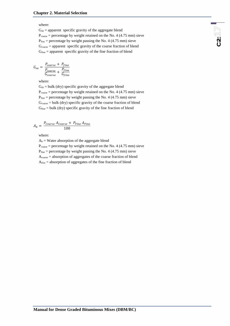
𝐺𝑠𝑎 = 𝑃𝑐𝑜𝑎𝑟𝑠𝑒 + 𝑃𝑓𝑖𝑛𝑒
𝑃𝑐𝑜𝑎𝑟𝑠𝑒
𝐺𝑐𝑜𝑎𝑟𝑠𝑒+
𝑃𝑓𝑖𝑛𝑒
𝐺𝑓𝑖𝑛𝑒
where:
Gsb = bulk (dry) specific gravity of the aggregate blend
Pcoarse = percentage by weight retained on the No. 4 (4.75 mm) sieve
Pfine = percentage by weight passing the No. 4 (4.75 mm) sieve
Gcoarse = bulk (dry) specific gravity of the coarse fraction of blend
Gfine = bulk (dry) specific gravity of the fine fraction of blend
𝐴𝑏 = 𝑃𝐶𝑜𝑎𝑟𝑠𝑒 𝐴𝐶𝑜𝑎𝑟𝑠𝑒 + 𝑃𝐹𝑖𝑛𝑒 𝐴𝐹𝑖𝑛𝑒
100
where:
Ab = Water absorption of the aggregate blend
Pcoarse = percentage by weight retained on the No. 4 (4.75 mm) sieve
Pfine = percentage by weight passing the No. 4 (4.75 mm) sieve
Acoarse = absorption of aggregates of the coarse fraction of blend
Afine = absorption of aggregates of the fine fraction of blend

Chapter 2. Material Selection
Manual for Dense Graded Bituminous Mixes (DBM/BC)
C2
:
C2.8 Bituminous Binder
C.2.8.1 Choice of Bitumen Binder
a) As per IS 73:2013
Bitumen shall be classified into four grades based on the viscosity, and suitability recommended for
maximum air temperature as given below:
Table 2.7: Recommended Bitumen based on maximum air temperature
NOTE — This is the 7 day average maximum air temperature for a period not less than 5 years from
the start of the design period.
b) As per DoR Specification:
Selection criteria for viscosity grade bitumen, based on highest and lowest daily mean temperatures at a
particular site, Table 2.8.
Table 2.8:Selection Criteria for Viscosity-Graded (VG) Paving Bitumen Based on Climatic
Conditions
Lowest Daily Mean Air
Temperature, °C
Highest Daily Mean Air Temperature, °C
Less than 20°C 20 to 30°C More than 30°C
More than -10°C VG-10 VG-20 VG-30
-10°C or lower VG-10 VG-10 VG-20
c) As per IRC
Table 2.9: Selection Criteria for Viscosity-Graded (VG) Paving Bitumen Based on Climatic
Conditions and Traffic (Ref. of IRC:37:2012)
Maximum Average
Air Temperature °C
Traffic (CVD) Bituminous
Course
Grade of Bitumen to be used
≤ 30 °C ≤ 1500 commercial
vehicles per day
BM, DBM
and BC
VG 10/VG20
< 40 °C For all types of traffic BM. DBM,
SDBC and
BC
VG 30
≥ 40 °C Heavy Loads,
Expressways
msa >30msa
DBM.
SDBC, BC
VG 40 bitumen for wearing
course as well as binder course
• IRC: 111-2009 (29) recommends VG-40 bitumen, if commercial vehicle exceeds 2000 per lane per day.
• For signalized intersection, two grades higher binder is recommended. If the most suitable binder is VG
30 for 450 to 1500 CVPD, VG 40 should be selected for higher volume of commercial vehicles.
Note : The final selection of the VG should be done considering the recommendation as per above 3
tables.
Grade Penetration Suitable for 7 day Average
Maximum Air Temperature, °C
(1) (2) (3)
VG10 80-100 < 30
VG20 60-80 30-38
VG30 50-70 38-45
VG40 40-60 > 45

Chapter 2. Material Selection
Manual for Dense Graded Bituminous Mixes (DBM/BC)
C2
:
C.2.8.2 Material Requirement
The paving bitumen binder shall be homogenous and shall not foam when heated to
175°C.
Table : 2.10 : Bitumen property requirements (ref. IS: 73:2013)
SN Characteristics
Method
of Test,
ref.to
Unit
Paving Grades
VG 10 VG 20 VG 30 VG 40
Min Max Min Max Min Max Min Max
1 Penetration at 25°C,
100g, 5 Sec.,
IS 1203
- 1978
0.1
mm 80 60 45 35
2 Absolute Viscosity
at 60 °C,
IS 1206:
(Part2) Poise
800 1200 1600 2400 2400 3600 3200 4800
3 Kinematic Viscosity
at 135 °C,
IS 1206:
(Part3) cSt
250 300 350 400
4 Flash point,
Cleveland open cup, IS 1209 °C
220 220 220 220
5 Solubility in
trichloroethylene,
IS 1216:
1978
% by
mass 99 99 99 99
8 Softening Point,
(R&B),
IS 1205:
1978 °C
40 45 47 50
7 Test on residue from
thin –film oven
test/RTFOT
IS
1206:
(Part2)
1) Viscosity ratio at
60 °C
4 4 4 4
2) Ductility at 25
°C, after thin-film
oven test
75 50 40 25
Table 2.11 : Material Test Frequency
TESTS FREQUENCY
• Quality of Binder as per IS73( paving bitumen)/; penetration,
Absolute and Kinematic viscosity, flash point, ductility, solubility
in Trichloroethylene, Softening point, Tests on residue from rolling
thin film oven, Viscosity ratio at 60°C, Ductility
• AIV/LAA, Flakiness and Elongation index, Soundness test (SSS),
• Sand equivalent, Plasticity Index, Polished stone value
• Certificates from suppliers.
• One set of tests for each 50,000 litres of supply or part of it
• Once per 500 cum and
change in source.
• Once test for each source and change in source.

Chapter 2. Material Selection
Manual for Dense Graded Bituminous Mixes (DBM/BC)
C2
:
C.2.8.2 Sampling and Criteria for Conformity
Lot
In any consignment, all the containers of paving grade bitumen binders of same category and grade
from the same batch of manufacture should be grouped to constitute a lot. The number of containers to
be selected at random from the lot shall depend upon the size of the lot given in Table 2.
Table 2.12 Scale of Sampling
S. No. Lot Size
No. of
Containers
to be Selected
(1) (2) (3)
i) Up to 50 3
ii) 51-150 5
iii) 151-500 7
iv) 501 and above 10
From each of the containers selected, an average sample representative of the material in the container
shall be drawn in accordance with the methods prescribed in IS 1201, taking all the precautions
mentioned therein. All these samples from individual containers shall be stored separately.
Tests
All the individual samples shall be tested for absolute viscosity at 60°C, penetration and softening
point tests. For the remaining characteristics, a composite sample prepared by mixing together equal
quantities of paving grade bitumen, sampled, as the case may be, from all individual samples taken
from each sample container, shall be tested.
Criteria for Conformity
The lot should be considered as conforming to the requirements of this standard, if the below
conditions are satisfied.
From the test results of absolute viscosity at 60°C, penetration and softening point, the mean
( X ) and the range (R) shall be calculated. The following conditions shall be satisfied:
a) [ x –0.6R] shall be greater than or equal to the minimum specification limit specified in
Table 2.10, and
b) [ x + 0.6R] shall be less than or equal to the maximum specification limit specified in
Table 2.10.
The composite sample when tested should satisfy the corresponding requirements of the
characteristics given in Table 2.10.