Analytical, experimental and numerical study of a graded ...
Upload
khangminh22Category
view
0download
0
Continuum Mech. Thermodyn.https://doi.org/10.1007/s00161-021-00994-5
ORIGINAL ARTICLE
Vera Petrova · Siegfried Schmauder
Thermal fracture of functionally graded thermal barriercoatings with pre-existing edge cracks and multiple internalcracks imitating a curved interface
Received: 13 November 2020 / Accepted: 19 February 2021© The Author(s) 2021
Abstract This work is devoted to the problem of thermal fracture of a functionally graded coating on ahomogeneous substrate (FGC/H) with an emphasis on the analysis of a special system of cracks that simulatesa curved interface. The FGC/H structure contains the pre-existing crack system in the FGC, both edge cracks(which are often seen in FGC/H structures) and internal cracks. The stress intensity factors are calculated.(Generally, both Mode I and Mode II are nonzero.) Then, using the appropriate fracture criterion for mixed-mode fracture conditions, the crack propagation direction (so-called fracture angles) and critical loads, whenthis propagation is initiated, are determined. The application of fracture criteria requires knowledge of thefracture toughness near the crack tips. Thus, it is assumed that the fracture toughness of an FGC, as wellas other material properties, continuously varies through the thickness of the coating. For multiple cracks,it is also important to know the weakest crack that starts to propagate first, and the initial direction of thisgrowth. Therefore, the main attention is paid to the evaluation of the fracture angles for the cracks for differentparameters of the FGC/H structure. Both cases of a homogeneous semi-infinite medium with a system ofcracks imitating a curved interface and FGC/H structures with identical crack systems are studied.
Keywords Thermal fracture · System of cracks · Functionally graded coatings · Fracture toughness ·Fracture angles
1 Introduction
Thermal barrier coatings (TBCs), in particular functionally graded coatings (FGCs), are used in differentengineering structures, and the most important one is the application in components where protection againstelevated temperatures is required. An example of this application is gas turbine engine parts in which TBCsprotect metal parts from overheating and melting [1]. Functionally graded materials (FGMs) are special typesof composite materials, the properties of which gradually change along a spatial coordinate. This is achievedby creating variations in material compositions and/or structures. The application of FGC as thermal barriercoatings helps to reduce thermal residual stresses and increases the fracture resistance of the coating.
However, under very high temperatures and complexmechanical loadings, complicated diffusion, oxidationand mechanical interaction processes occur in FGCs structures. As a result of oxidative processes, a thermalgrowing oxide (TGO) layer is formed [1–3]. As reported in the literature [4–6], the oxide layer can serve as
Communicated by Marcus Aßmus, Victor A. Eremeyev and Andreas Öchsner.
V. Petrova (B) · S. SchmauderIMWF, University of Stuttgart, Pfaffenwaldring 32, Stuttgart 70569, GermanyE-mail: [email protected]; [email protected]
V. PetrovaVoronezh State University, University Sq.1, Voronezh 394006, Russia
V. Petrova, S. Schmauder
a source of fracture (cracking). Besides, cracks can occur as a result of initial defects or microcracks duringmanufacturing. Previous investigations [5–9] have revealed that thermal fracture of FGCs is significantlyaffected by a complex crack interaction mechanism, e.g., interacting cracks can enhance or suppress thepropagation of each other. Therefore, the study of fracture of FGCs is important for a better understanding ofthe fracture resistance of graded coatings.
The interface or oxide layer between coatings and a substrate is rarely perfectly flat. This is usually a wavy,rough interface [4,10,11]. The problem of the roughness of the interface between coatings and a substratehas received a lot of attention in the literature. Different aspects of this problem were discussed in numerouspublications, e.g., see [4,9–12]. Experimental studies of thermal barrier coatings [4] have reported that a roughinterface leads to a higher interface toughness, and the contribution of friction at the interface between theTBC and bond coat may be the cause of this effect. An analytical theoretical study of a wavy non-damagedinterface between a thin film and a substrate is presented in [12]. The film thickness and interface roughnessare in the nanometer range. The perturbation technique was used within the first-order approximation, wherethe ratio between the maximum deviation of the interface from the flat state and a perturbation wavelengthis considered as a small parameter. The numerical analysis [12] has shown that the interface stress reducesthe stress concentration factor, when the residual interface stresses are neglected. This effect decreases whenthe size of interface asperities (the width and depth), stiffness of the covering film and curvature radius ofcavities increase. In [13], analytical solutions are presented for a periodic set of edge dislocations and pointforces interacting with a planar traction-free surface of a semi-infinite elastic solid. The fundamental solutionsobtained in [13] can be used for applying the boundary integral equation method to an analysis of defectssuch as cracks and inhomogeneities, periodically distributed at the nanometer distance from the boundary.In [14], a rate-dependent cohesive zone model was presented with a novel traction-separation law with thecapability to simulate heat conduction through the interface. The applications of cohesive elements to an FEsimulation to describe the cracking of a coating and the delamination of this cracked coating from the substratematerial at high temperatures were demonstrated. Interface crack problems were also theoretically studied in[15] for Mode III interface cracks and in [16] for an interface crack and multiple internal cracks in infiniteFGM/H bimaterials under thermo-mechanical loading. Flat interfaces were considered in [15,16]. In [11], anexperiment and finite element analysis modeling was used to study the influence of a temperature gradientacross an YSZ topcoat on the thermal cyclic lifetime of this TBC. A study of the effect of interface roughnesson the strain energy release rate and surface cracking behavior in air plasma sprayed thermal barrier coatingsystem was presented in [10]. The extended FEM and periodic boundary conditions were used. Predictions forthe stress field and the driving force of multiple surface cracks in the film/substrate system were presented. Itwas shown that the interface roughness significantly affects the strain energy release rate, the interfacial stressdistribution, and the crack formation patterns.
The present work is devoted to the thermal fracture problem for a functionally graded coating on a homo-geneous substrate (FGM/H). The model presented in authors’ previous papers [17–20] is used in this study inan extension to a special crack system. The present FGC/H structure contains a pre-existing system of cracksin the FGC. In addition to edge cracks, there are internal/interface cracks imitating a partially wavy interface.The coordinates of the centers of these internal cracks are located on a straight line parallel to the surface, butthe inclination angles of these cracks vary symmetrically from 0◦ to a certain angle; see Fig. 1. TheMode I andMode II stress intensity factors are calculated. Then, using the appropriate fracture criterion for mixed-modefracture conditions, the crack propagation direction and the critical loads at which this propagation begins aredetermined. For multiple cracks, it is also important to know the weakest crack that starts to propagate first,and the initial direction of this growth, which may indicate the interface roughness in the case of interfacecracks. Therefore, the main attention is paid to the evaluation of the fracture angles for the cracks for differentparameters of the FGC/H structure. In addition to the FGC/H structures, a homogeneous semi-infinite mediumwith an identical crack system is also studied as a special case.
This paper is organized as follows. Section 2 presents the description of the problem, namely the geometryof the problem, the properties of functionally graded coatings and the corresponding load on the crack faces.Section 3 describes the solution of the problem, which includes the main singular integral equations, determi-nation of stress intensity factors, fracture angles and critical loads. Section 4 presents the results for two cases:for a particular case for a homogeneous medium and for an FGC/TGO/H structure. The parametric resultsare analyzed with respect to stress intensity factors, fracture angles and critical loads for a special system ofcracks, that is, edge cracks and internal-interface cracks, imitating a partly curved weakened interface. Theconclusions are presented in Sect. 5.
Thermal fracture of functionally graded thermal barrier
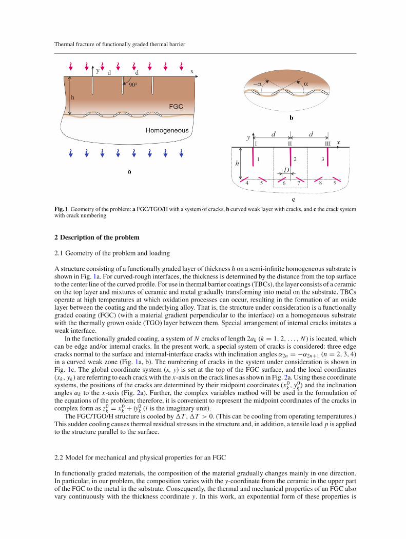
Fig. 1 Geometry of the problem: a FGC/TGO/H with a system of cracks, b curved weak layer with cracks, and c the crack systemwith crack numbering
2 Description of the problem
2.1 Geometry of the problem and loading
A structure consisting of a functionally graded layer of thickness h on a semi-infinite homogeneous substrate isshown in Fig. 1a. For curved-rough interfaces, the thickness is determined by the distance from the top surfaceto the center line of the curved profile. For use in thermal barrier coatings (TBCs), the layer consists of a ceramicon the top layer and mixtures of ceramic and metal gradually transforming into metal on the substrate. TBCsoperate at high temperatures at which oxidation processes can occur, resulting in the formation of an oxidelayer between the coating and the underlying alloy. That is, the structure under consideration is a functionallygraded coating (FGC) (with a material gradient perpendicular to the interface) on a homogeneous substratewith the thermally grown oxide (TGO) layer between them. Special arrangement of internal cracks imitates aweak interface.
In the functionally graded coating, a system of N cracks of length 2ak (k = 1, 2, . . . , N ) is located, whichcan be edge and/or internal cracks. In the present work, a special system of cracks is considered: three edgecracks normal to the surface and internal-interface cracks with inclination angles α2n = −α2n+1 (n = 2, 3, 4)in a curved weak zone (Fig. 1a, b). The numbering of cracks in the system under consideration is shown inFig. 1c. The global coordinate system (x, y) is set at the top of the FGC surface, and the local coordinates(xk, yk) are referring to each crackwith the x-axis on the crack lines as shown in Fig. 2a. Using these coordinatesystems, the positions of the cracks are determined by their midpoint coordinates (x0k , y
0k ) and the inclination
angles αk to the x-axis (Fig. 2a). Further, the complex variables method will be used in the formulation ofthe equations of the problem; therefore, it is convenient to represent the midpoint coordinates of the cracks incomplex form as z0k = x0k + iy0k (i is the imaginary unit).
The FGC/TGO/H structure is cooled by �T , �T > 0. (This can be cooling from operating temperatures.)This sudden cooling causes thermal residual stresses in the structure and, in addition, a tensile load p is appliedto the structure parallel to the surface.
2.2 Model for mechanical and physical properties for an FGC
In functionally graded materials, the composition of the material gradually changes mainly in one direction.In particular, in our problem, the composition varies with the y-coordinate from the ceramic in the upper partof the FGC to the metal in the substrate. Consequently, the thermal and mechanical properties of an FGC alsovary continuously with the thickness coordinate y. In this work, an exponential form of these properties is

V. Petrova, S. Schmauder
Fig. 2 Geometry of the problem: a coordinate systems connected with cracks and b edge and internal cracks with fracture angles
used:
αt (y) = αt1 exp(ε(y + h)), E(y) = E1 exp(ω(y + h)), −h ≤ y ≤ 0. (1)
Here, αt is the coefficient of thermal expansion, and E is Young’smodulus with non-homogeneity parameters εand ω, respectively. E1 and αt1 stand for the thermal and mechanical properties of the homogeneous substrate.Poisson’s ratio is assumed to be constant and is equal to the value of the homogeneous substrate. The valuesof the dimensionless inhomogeneity parameters εh and ωh (h is the thickness of the FGC) are obtained fromEq. (1) as follows:
εh = ln(αt2/αt1), αt2 = αt (y)|y=0 , αt1 = αt (y)|y=−h , (2)
ωh = ln(E2/E1), E2 = E(y)|y=0 , E1 = E(y)|y=−h . (3)
Since the exponential law was chosen for the material parameters αt and E , it is reasonable to use theexponential law also for the fracture toughness, e.g., see [21]. Thus, the fracture toughness of a functionallygraded material can be written as follows:
KIc(y) = KIc1 exp(γ (y + h)), (4)
where γ is the inhomogeneous parameter of the fracture toughness. The non-dimensional value γ h is obtainedas
γ h = ln(KIc2/KIc1), KIc2 = KIc(y)|y=0 , KIc1 = KIc(y)|y=−h . (5)
In the local coordinate system (xn , yn) connected with the nth crack, the function KIcn is written as
KIcn(xn) = KIc1 exp(γ (h + y0n − xn sin βn)). (6)
Similar expressions are also written for αt and E in the local coordinates (xn, yn).
2.3 Loadings on the crack faces
With changing the temperature, e.g., an FGM/H structure is cooled on�T , the residual stresses are arising dueto mismatch in the coefficients of thermal expansion [22,23]. In the presented model, the inhomogeneity ofFGMs is taken into account through continuously varying residual stresses, and these stresses are the following[21]:
σ Txx (y) = [αt (y) − αt1]�T E(y), σ e
xx (y) = [E(y)/E1 − 1]σ 0xx , σ
0xx = p, (7)
αt1 and E1 are, respectively, the thermal expansion coefficient and Young’s modulus of a homogeneoussubstrate material and at the interface, αt (y) and E(y) are defined by Eq. (1).
The method of superposition is used to solve this problem, so that loads at infinity are reduced to thecorresponding loads on the crack faces. Thus, the tensile load is reduced to the load pn on the crack surfacesand written in complex form as
pn = σn − iτn = p(1 − exp(2iβn))/2 = p f (βn) (n = 1, 2, . . . , N ). (8)

Thermal fracture of functionally graded thermal barrier
In the common case of FGMs, the full load on the nth crack consists of pn , σ Tn and σ e
n (Eq. (7)), where theindex “n” denotes that the functions are written in the local coordinate system (xn ,yn) connected with the nthcrack:
pn + σ en + σ T
n = exp(ω(h + y0n − xn sin βn)) [p f (βn)
+ Q exp(ε(h + y0n − xn sin βn)) − Q]
(n = 1, 2, . . . , N ),
Q = αt1�T E1. (9)
It is assumed that p = Q, or an additional loading parameter p/Q should be considered.
3 Solution of the problem
3.1 Singular integral equations
The boundary value problem of elasticity for a system of N cracks is reduced to a system of N singularintegral equations [24] with respect to the unknown functions g′
n(x) containing the shear [un] and normal [vn]displacement jumps on the nth crack line. These equations are written in “Appendix A” (Eq. (A.1)–(A.6)).
The singular integral equations (A.1) are solved numerically based on the Gauss–Chebyshev quadrature.Different versions of this method were used for the solution, the effectiveness of which has been proven inmany studies [25]. In the present work, the version described in [24] is used, and the solution scheme for thismethod is given in “Appendix B”.
3.2 Stress intensity factors
The stress intensity factors at tips of the nth crack are obtained from the following formulas:
K±nI − i K±
nI I = ∓ limη→±1
√πan
√1 − η2 g′
n(η) (10)
Here, the signs “+” and “−“ refer to the right and left crack tips, respectively. an is the half-length of the crack.In general, the SIFs can be written as
KIn − i K I In = p√
πan(kIn − ikI I n). (11)
3.3 Stress intensity factors, fracture angles and critical loads
For predicting the crack growth and the determination of the direction of this growing crack, the criterion ofmaximum circumferential stresses [26] is used. According to this criterion, the crack deflection angle φ (or theso-called fracture angle, as shown in Fig. 2b), the critical stress intensity factor and then the critical stressesare calculated from the following relations:
φn = 2 arctan
[(KIn −
√K 2
I n + 8K 2I I n
)/4KI In
], (12)
Keqn ≡ cos3(φn/2) (KIn − 3KI In tan(φn/2)) = KIc, ti p or K
eqn = KIc, ti p. (13)
Using a single crack subjected to a load p normal to the crack line as a reference crack with the stressintensity factor
K 0 = p√
πa, (14)
the corresponding critical load is obtained as
p0 = KIc1/√
πa, (15)
where a = maxn=1,...,N an .

V. Petrova, S. Schmauder
By substituting (11) into condition (13), the critical loads are obtained as
pcr n = KIc(y)√πan
1
cos3(φn/2) (kIn − 3kI In tan(φn/2))
or
pcr np0
= exp(γ (h + y0n − xn sin βn))
cos3(φn/2) (kIn − 3kI In tan(φn/2))
√a√an
, (16)
where p0 is defined by Eq. (15) and KIc by Eqs. (4) and (6).The fracture angle φn is shown in Fig. 2b. First, the angle of the crack propagation (fracture angle) in Eq.
(12) is obtained using the results of the calculated stress intensity factors (Eq. (10)). Next, the local fracturestability is evaluated by Eq. (13). Then, the critical loads are obtained near the crack tips (Eq. (16)). Finally,the weakest crack or crack tip is defined from the condition
Pcr = minn
pcr n/p0 (n = 1, 2, . . . , N ). (17)
4 Results: stress intensity factors, fracture angles and critical loads for a system of interacting cracks
Figure 1a shows the geometry, which is used for numerical example. Three edge cracks are normal to thesurface, and the internal cracks have inclination angles α2n = −α2n+1 (n = 2, 3, 4) in the curved weak zone.The crack patterns, consisting of edge and internal cracks, have been observed in experiments reported in theliterature, e.g., see [5,8]. Table 1 introduces the coordinates of the crack centers. According to this definitionof coordinates, when the distance d between the edge cracks changes, the distance between the pairs of cracks4 and 5, 6 and 7, 8 and 9 also changes. The simplest repeating "crack pattern" in our crack system consists ofone edge crack and two internal cracks. There are three such subsystems: pattern I includes cracks 1, 4 and 5,II—cracks 2, 6 and 7, and III—cracks 3, 8 and 9; see Fig. 1c. Pattern II is an inner one with two neighboringpatterns I and III. The behavior of pattern II may reflect the behavior of these cracks in a periodic crack systemwith a repeating pattern II. The results for these subsystems will be done in the following sections.
The results are presented for the following parameters: the width of the coating is h = 2.5mm, the distancebetween the edge cracks is d = 2, 4, 6 (mm), and D = 0.25 mm; the dimensionless parameters are used in thenumerical calculations: h/a, d/a and D/a, where a = max an (n = 1, 2, . . . , 9). Results are also obtainedfor other values for cracks and distances, which are not shown here, but are mentioned in some cases in thediscussion. In the following figures, the dimensionless distance d/a is denoted by d . The sizes of cracks are:edge cracks an = 1 mm (n = 1, 2, 3), internal cracks an = 0.22 mm (n = 4, 5, . . . , 9); an denotes thehalf-length of the nth crack. In the calculations the non-dimensional size is used an/a, a = max an . Thefollowing designations are also used: aedge and aint for edge and internal cracks, respectively.
The stress intensity factors (SIFs) are used in dimensionless form: kI,I I = KI,I I /K 0, where K 0 =p(πa)1/2 is the SIF for a single crack (Eq. (14)). A single edge crack of half-length a, normal to the surfaceof the layer, has SIF equal to KI = 1.58p(πa)1/2. This definition for SIFs is more convenient for theconsidered mixed system of internal and edge cracks than the commonly used one for the SIF for an edgecrack: KI = 1.12p(2πa)1/2, where 2a is the full length of the edge crack.
Further, two cases are considered: a particular case of a homogeneous semi-infinite medium and a case ofa FGC/H structure. In both cases, the values of stress intensity factors and fracture angles are approximatelythe same for the following cracks: for crack 4 and 9, for crack 5 and 8, for crack 6 and 7. The critical loadsare also approximately the same for the listed cracks. Therefore, the results are presented not for all internalcracks, but mostly for cracks 4, 5 and 6.
4.1 Homogeneous semi-infinite medium
4.1.1 Stress intensity factors (SIFs)
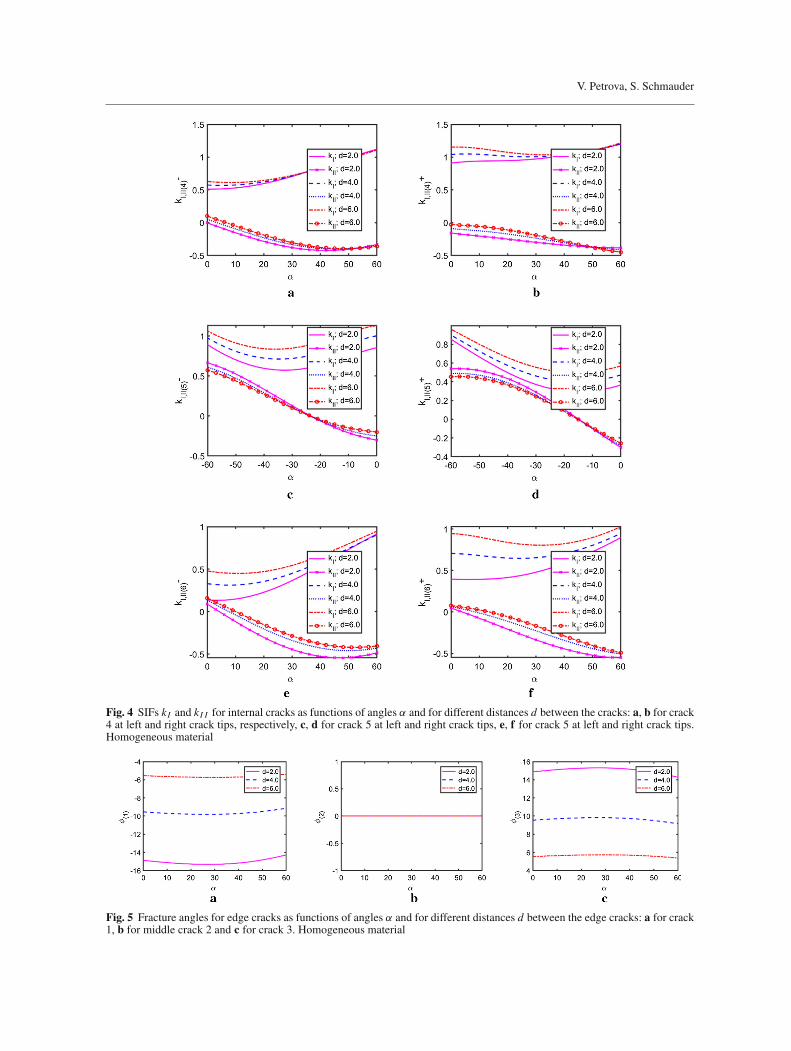
Figure 3 presents the dimensionless stress intensity factors (SIFs) kI,I I for edge cracks depending on α, 0◦ ≤α ≤ 60◦, and for different distances d/a. The SIFs for internal cracks are shown in Fig. 4 as functions of α,
Thermal fracture of functionally graded thermal barrier
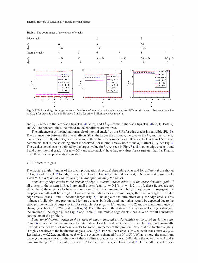
Table 1 The coordinates of the centers of cracks
Edge cracks 1 2 3
x0k 0 d 2dy0k −a1 −a2 −a3
Internal cracks 4 5 6 7 8 9
x0k −D D d − D d + D 2d − D 2d + Dy0k −h −h −h −h −h −h
Fig. 3 SIFs kI and kI I for edge cracks as functions of internal crack angles α and for different distances d between the edgecracks; a for crack 1, b for middle crack 2 and c for crack 3. Homogeneous material
and k−I,I I refers to the left crack tips (Fig. 4a, c, e), and k+
I,I I—to the right crack tips (Fig. 4b, d, f). Both kIand kI I are nonzero; thus, the mixed-mode conditions are realized.
The influence of α (the inclination angle of internal cracks) on the SIFs for edge cracks is negligible (Fig. 3).The distance d/a between the cracks affects SIFs: the larger the distance, the greater the kI , and the value kItends to kI = 1.58, while kI I tends to zero, to the values for a single crack. Besides, kI less than 1.58 for allparameters, that is, the shielding effect is observed. For internal cracks, both α and d/a affect kI,I I ; see Fig. 4.The weakest crack can be defined by the largest value for kI . As seen in Figs. 3 and 4, outer edge cracks 1 and3 and outer internal crack 4 for α = 60◦ (and also crack 9) have largest values for kI (greater than 1). That is,from these cracks, propagation can start.
4.1.2 Fracture angles
The fracture angles (angles of the crack propagation direction) depending on α and for different d are shownin Fig. 5 and in Table 2 for edge cracks 1, 2, 3 and in Fig. 6 for internal cracks 4, 5, 6 (remind that for cracks4 and 9, 5 and 8, 6 and 7 the values of φ are approximately the same).
Behavior of edge cracks in the system of edge + internal cracks relative to the crack deviation path. Ifall cracks in the system in Fig. 1 are small cracks (e.g., an = 0.1/a, n = 1, 2, . . . , 9, these figures are notshown here) the edge cracks have zero or close to zero fracture angles. Thus, if they begin to propagate, thepropagation path will be straight. However, as the edge cracks become larger, the fracture angles for outeredge cracks (crack 1 and 3) become larger (Fig. 5). The angle α has little effect on φ for edge cracks. Thisinfluence is slightly more pronounced for large cracks, both edge and internal, as would be expected due to thestronger interaction of large cracks. For example, for aedge = 1/a and aint = 0.22/a, the maximum range ofchange φ is about 1◦ or 7% for d = 2 (Fig. 5). The influence of the distance d between cracks on φ is stronger:the smaller d , the larger φ; see Fig. 5 and Table 3. The middle edge crack 2 has φ = 0◦ for all consideredparameters of the problem.
Behavior of internal cracks in the system of edge + internal cracks relative to the crack deviation path.Figure 6 shows the fracture angles φ for internal cracks at left and right crack tips, and Fig. 9a, b schematicallyillustrates the behavior of internal cracks for some parameters of the problem. Note that the fracture angle φis highly sensitive to the inclination angle α; see Fig. 6. For collinear cracks (α = 0) with crack sizes aedge =1/a and aint = 0.22/a, and distance d = 2, the φ value is changed from 0◦ to 50◦. What is more, the maximumvalue φ has inner cracks in the row of these collinear cracks, i.e., cracks 5–8, while the outer cracks 4 and 9have smaller φ, 0◦ for the outer tips and 18◦ for the inner ones; see Figs. 6 and 9a. For small internal cracks
V. Petrova, S. Schmauder
Fig. 4 SIFs kI and kI I for internal cracks as functions of angles α and for different distances d between the cracks: a, b for crack4 at left and right crack tips, respectively, c, d for crack 5 at left and right crack tips, e, f for crack 5 at left and right crack tips.Homogeneous material
Fig. 5 Fracture angles for edge cracks as functions of angles α and for different distances d between the edge cracks: a for crack1, b for middle crack 2 and c for crack 3. Homogeneous material
Thermal fracture of functionally graded thermal barrier
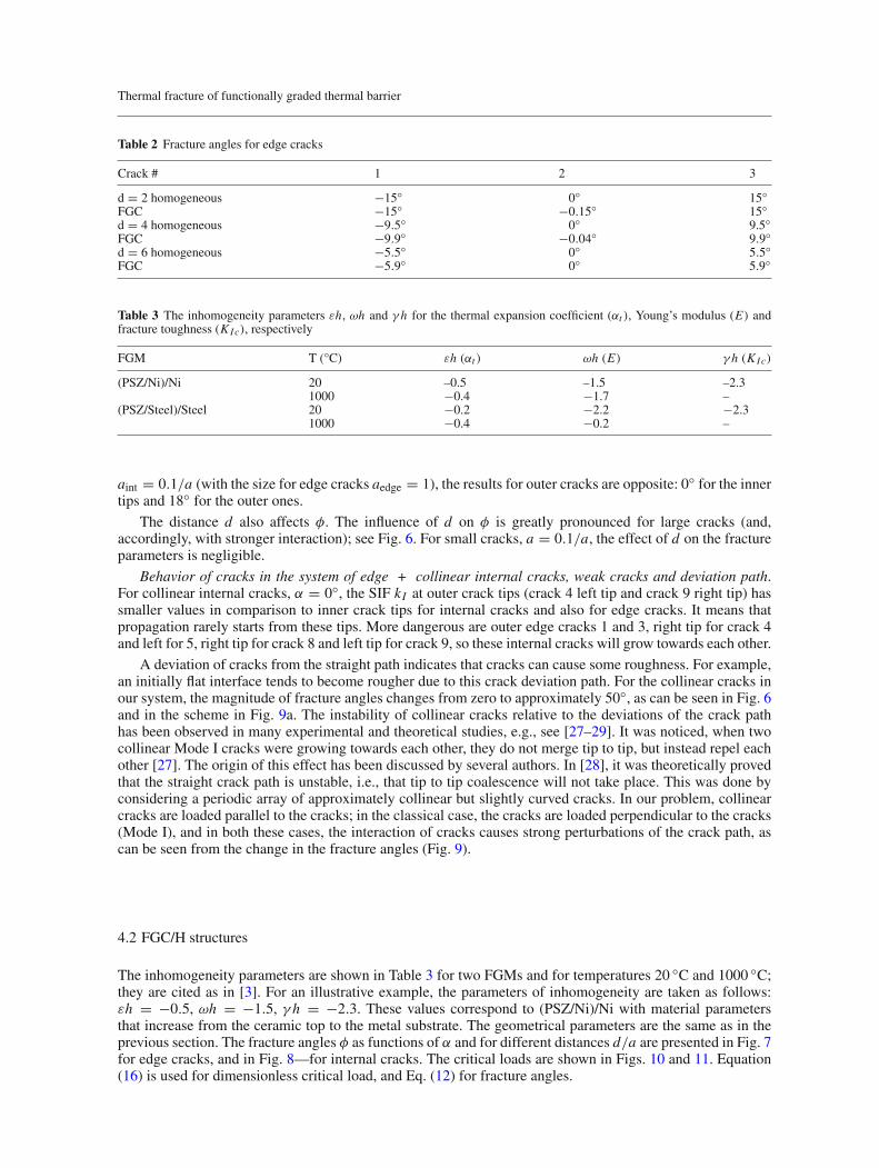
Table 2 Fracture angles for edge cracks
Crack # 1 2 3
d = 2 homogeneous −15◦ 0◦ 15◦FGC −15◦ −0.15◦ 15◦d = 4 homogeneous −9.5◦ 0◦ 9.5◦FGC −9.9◦ −0.04◦ 9.9◦d = 6 homogeneous −5.5◦ 0◦ 5.5◦FGC −5.9◦ 0◦ 5.9◦
Table 3 The inhomogeneity parameters εh, ωh and γ h for the thermal expansion coefficient (αt ), Young’s modulus (E) andfracture toughness (KIc), respectively
FGM T (°C) εh (αt ) ωh (E) γ h (KIc)
(PSZ/Ni)/Ni 20 –0.5 –1.5 –2.31000 −0.4 −1.7 –
(PSZ/Steel)/Steel 20 −0.2 −2.2 −2.31000 −0.4 −0.2 –
aint = 0.1/a (with the size for edge cracks aedge = 1), the results for outer cracks are opposite: 0◦ for the innertips and 18◦ for the outer ones.
The distance d also affects φ. The influence of d on φ is greatly pronounced for large cracks (and,accordingly, with stronger interaction); see Fig. 6. For small cracks, a = 0.1/a, the effect of d on the fractureparameters is negligible.
Behavior of cracks in the system of edge + collinear internal cracks, weak cracks and deviation path.For collinear internal cracks, α = 0◦, the SIF kI at outer crack tips (crack 4 left tip and crack 9 right tip) hassmaller values in comparison to inner crack tips for internal cracks and also for edge cracks. It means thatpropagation rarely starts from these tips. More dangerous are outer edge cracks 1 and 3, right tip for crack 4and left for 5, right tip for crack 8 and left tip for crack 9, so these internal cracks will grow towards each other.
A deviation of cracks from the straight path indicates that cracks can cause some roughness. For example,an initially flat interface tends to become rougher due to this crack deviation path. For the collinear cracks inour system, the magnitude of fracture angles changes from zero to approximately 50◦, as can be seen in Fig. 6and in the scheme in Fig. 9a. The instability of collinear cracks relative to the deviations of the crack pathhas been observed in many experimental and theoretical studies, e.g., see [27–29]. It was noticed, when twocollinear Mode I cracks were growing towards each other, they do not merge tip to tip, but instead repel eachother [27]. The origin of this effect has been discussed by several authors. In [28], it was theoretically provedthat the straight crack path is unstable, i.e., that tip to tip coalescence will not take place. This was done byconsidering a periodic array of approximately collinear but slightly curved cracks. In our problem, collinearcracks are loaded parallel to the cracks; in the classical case, the cracks are loaded perpendicular to the cracks(Mode I), and in both these cases, the interaction of cracks causes strong perturbations of the crack path, ascan be seen from the change in the fracture angles (Fig. 9).
4.2 FGC/H structures
The inhomogeneity parameters are shown in Table 3 for two FGMs and for temperatures 20 ◦C and 1000 ◦C;they are cited as in [3]. For an illustrative example, the parameters of inhomogeneity are taken as follows:εh = −0.5, ωh = −1.5, γ h = −2.3. These values correspond to (PSZ/Ni)/Ni with material parametersthat increase from the ceramic top to the metal substrate. The geometrical parameters are the same as in theprevious section. The fracture angles φ as functions of α and for different distances d/a are presented in Fig. 7for edge cracks, and in Fig. 8—for internal cracks. The critical loads are shown in Figs. 10 and 11. Equation(16) is used for dimensionless critical load, and Eq. (12) for fracture angles.
V. Petrova, S. Schmauder
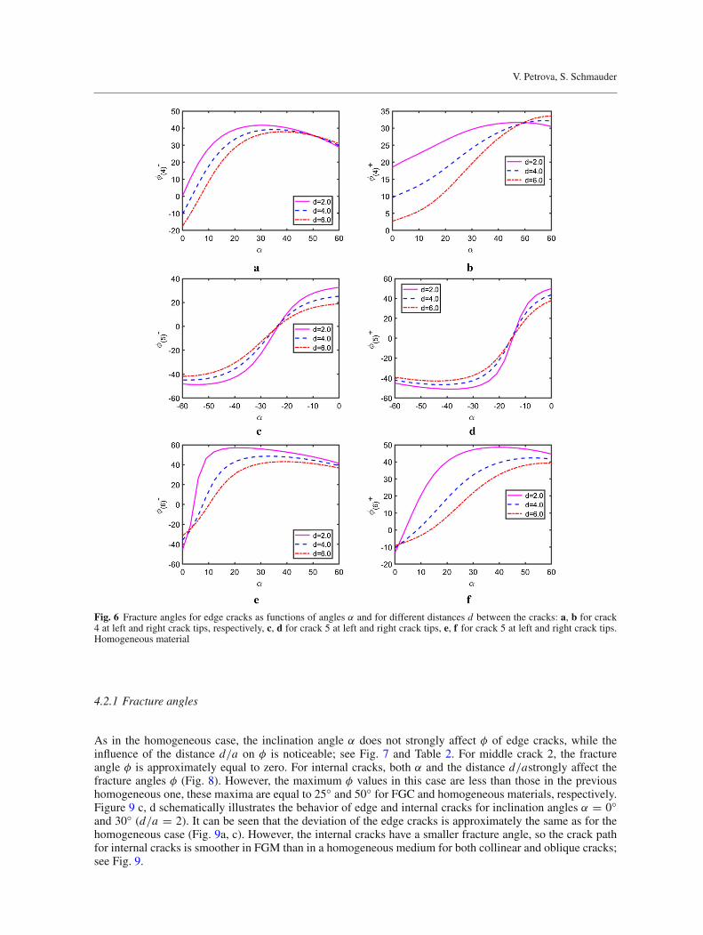
Fig. 6 Fracture angles for edge cracks as functions of angles α and for different distances d between the cracks: a, b for crack4 at left and right crack tips, respectively, c, d for crack 5 at left and right crack tips, e, f for crack 5 at left and right crack tips.Homogeneous material
4.2.1 Fracture angles
As in the homogeneous case, the inclination angle α does not strongly affect φ of edge cracks, while theinfluence of the distance d/a on φ is noticeable; see Fig. 7 and Table 2. For middle crack 2, the fractureangle φ is approximately equal to zero. For internal cracks, both α and the distance d/astrongly affect thefracture angles φ (Fig. 8). However, the maximum φ values in this case are less than those in the previoushomogeneous one, these maxima are equal to 25◦ and 50◦ for FGC and homogeneous materials, respectively.Figure 9 c, d schematically illustrates the behavior of edge and internal cracks for inclination angles α = 0◦and 30◦ (d/a = 2). It can be seen that the deviation of the edge cracks is approximately the same as for thehomogeneous case (Fig. 9a, c). However, the internal cracks have a smaller fracture angle, so the crack pathfor internal cracks is smoother in FGM than in a homogeneous medium for both collinear and oblique cracks;see Fig. 9.

Thermal fracture of functionally graded thermal barrier
Fig. 7 Fracture angles φ for edge cracks as functions of angles α and for different distances d between the cracks: a for crack 1,b for middle crack 2 and c for crack 3. FGC/H structure
Fig. 8 Fracture angles φ for internal cracks as functions of angles α and for different distances d between the cracks; a, b forcrack 4 at left and right crack tips, respectively; c, d for crack 5 at left and right crack tips, e, f for crack 5 at left and right cracktips. FGC/H structure
V. Petrova, S. Schmauder
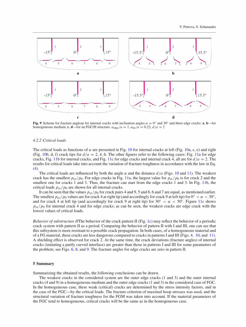
Fig. 9 Scheme for fracture anglesφ for internal cracks with inclination angles α = 0◦ and 30◦ and three edge cracks: a, b—forhomogeneous medium; c, d—for an FGC/H structure. aedge/a = 1, aint/a = 0.22, d/a = 2
4.2.2 Critical loads
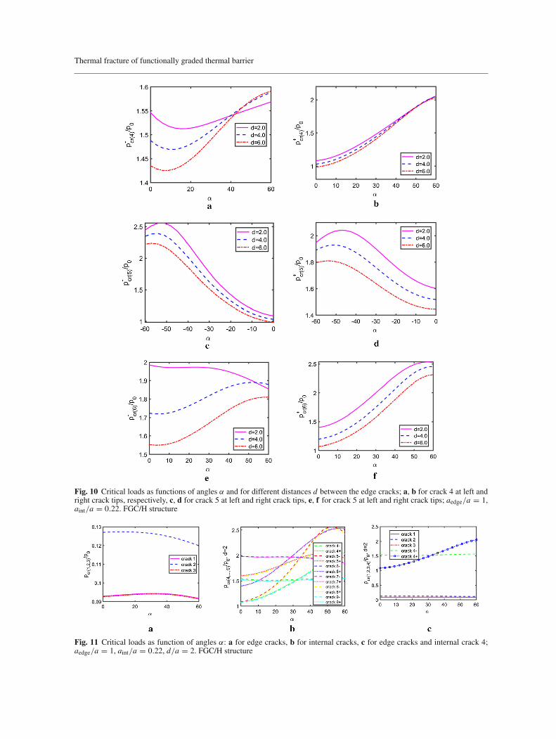
The critical loads as functions of α are presented in Fig. 10 for internal cracks at left (Fig. 10a, c, e) and right(Fig. 10b, d, f) crack tips for d/a = 2, 4, 6. The other figures refer to the following cases: Fig. 11a for edgecracks, Fig. 11b for internal cracks, and Fig. 11c for edge cracks and internal crack 4, all are for d/a = 2. Theresults for critical loads take into account the variation of fracture toughness in accordance with the law in Eq.(4).
The critical loads are influenced by both the angle α and the distance d/a (Figs. 10 and 11). The weakestcrack has the smallest pcr/p0. For edge cracks in Fig. 11a, the largest value for pcr/p0 is for crack 2 and thesmallest one for cracks 1 and 3. Thus, the fracture can start from the edge cracks 1 and 3. In Fig. 11b, thecritical loads pcr/p0 are shown for all internal cracks.
It can be seen that the values pcr/p0 for crack pairs 4 and 9, 5 and 8, 6 and 7 are equal, as mentioned earlier.The smallest pcr/p0 values are for crack 4 at right tip (and accordingly for crack 9 at left tip) for 0◦ < α < 30◦,and for crack 4 at left tip (and accordingly for crack 9 at right tip) for 30◦ < α < 50◦. Figure 11c showspcr/p0 for internal crack 4 and for edge cracks; as can be seen, the weakest cracks are edge crack with thelowest values of critical loads.
Behavior of substructure IIThe behavior of the crack pattern II (Fig. 1c) may reflect the behavior of a periodiccrack system with pattern II as a period. Comparing the behavior of pattern II with I and III, one can see thatthis subsystem is more resistant to a possible crack propagation. In both cases, of a homogeneous material andof a FGmaterial, these cracks are less dangerous compared to cracks in patterns I and III (Figs. 4, 10, and 11).A shielding effect is observed for crack 2. At the same time, the crack deviations (fracture angles) of internalcracks (imitating a partly curved interface) are greater than those in patterns I and III for some parameters ofthe problem; see Figs. 6, 8, and 9. The fracture angles for edge cracks are zero in pattern II.
5 Summary
Summarizing the obtained results, the following conclusions can be drawn.The weakest cracks in the considered system are the outer edge cracks (1 and 3) and the outer internal
cracks (4 and 9) in a homogeneous medium and the outer edge cracks (1 and 3) in the considered case of FGC.In the homogeneous case, these weak (critical) cracks are determined by the stress intensity factors, and inthe case of the FGC—by the critical loads. The fracture criterion of maximal hoop stresses was used, and thestructural variation of fracture toughness for the FGM was taken into account. If the material parameters ofthe FGC tend to homogeneous, critical cracks will be the same as in the homogeneous case.
Thermal fracture of functionally graded thermal barrier
Fig. 10 Critical loads as functions of angles α and for different distances d between the edge cracks; a, b for crack 4 at left andright crack tips, respectively, c, d for crack 5 at left and right crack tips, e, f for crack 5 at left and right crack tips; aedge/a = 1,aint/a = 0.22. FGC/H structure
Fig. 11 Critical loads as function of angles α: a for edge cracks, b for internal cracks, c for edge cracks and internal crack 4;aedge/a = 1, aint/a = 0.22, d/a = 2. FGC/H structure
V. Petrova, S. Schmauder
The fracture angles at the crack tips determine the initial crack paths. These values are strongly influencedby geometric parameters (i.e., crack sizes, distances between the cracks as well as inclination angles). Besides,the inhomogeneity of the FGC also affects the fracture angles. In the considered FGC/H structure, the deviationof cracks from their straight path will be less than that in a homogeneous semi-infinitemediumwith an identicalcrack system.
Considering the system of internal collinear cracks, which can imitate a flat interface, it should be notedthat the cracks deviate from their straight path, thus these cracks lead to some roughness of the interface. Inthe case of a homogeneous medium, this roughness is more pronounced than that in the case of FGCs, becauseof the larger fracture angles of these collinear cracks (Fig. 9a, c).
A system of inclined cracks, imitating a partly curved interface, tends to increase the roughness of theinterface in the case of a homogeneous medium (Fig. 9b). However, in the case of the FGC/H system, there isa tendency towards smoothing out the interface roughness (Fig. 9d).
The detailed study of the representative crack patterns, which are observed in thermal barrier coatings, canhelp find ways to improve the fracture resistance of FGC/H structures.
Acknowledgements The authors would like to acknowledge the financial support of the German Research Foundation underGrant SCHM 746/209-1.
Open Access This article is licensed under a Creative Commons Attribution 4.0 International License, which permits use,sharing, adaptation, distribution and reproduction in any medium or format, as long as you give appropriate credit to the originalauthor(s) and the source, provide a link to the Creative Commons licence, and indicate if changes were made. The images or otherthird party material in this article are included in the article’s Creative Commons licence, unless indicated otherwise in a creditline to the material. If material is not included in the article’s Creative Commons licence and your intended use is not permittedby statutory regulation or exceeds the permitted use, you will need to obtain permission directly from the copyright holder. Toview a copy of this licence, visit http://creativecommons.org/licenses/by/4.0/.
Funding OpenAccess funding enabled and organized by Projekt DEAL. This studywas funded byGerman Research Foundationunder Grant SCHM 746/209-1.
Declarations
Ethical approval This article does not contain any studies with human participants or animals performed by any of the authors.
Appendix A: Singular integral equations
The boundary value problem of elasticity for a system of cracks is reduced to a system of singular integralequations [24]:
an∫
−an
g′n(t)dt
t − x+
N∑
k=1k =n
ak∫
−ak
[g′k(t)Rnk(t, x) + g′
k(t)Snk(t, x)]dt = πpn(x), |x | < an, n = 1, 2, . . . , N ,
an∫
−an
g′n(t)dt = 0 (for internal cracks),
g′n(x) = 2μ
i(κ + 1)
∂
∂x([un] + i[vn]) . (A.1)
The number of equations N is equal to the number of cracks. The unknown functions g′n(x) contain the shear
[un] and normal [vn] displacement jumps on the nth crack line, μ = E/2(1 + ν) is the shear modulus, E isYoung’s modulus, ν is Poisson’s ratio, κ = 3 − 4ν for the plane strain state, and κ = (3 − ν)/(1 + ν) for theplane stress state. An overbar ¯(...) denotes the complex conjugate. In Eq. (A.1), the functions pn are knownfunctions determined by the load on the crack lines (Eq. (9)). The regular kernels Rnk(t,x) and Snk(t,x) containthe geometry of the problem and are written as
Rnk(t, x) = (1 − δnk)Knk(t, x) + eiαk
2
{1
Xn − T̄k+ e−2iαn
X̄n − Tk
Thermal fracture of functionally graded thermal barrier
+(T̄k − Tk)
[1 + e−2iαn
(X̄n − Tk)2− 2e−2iαn (Xn − Tk)
(X̄n − Tk)3
]}, (A.2)
Snk(t, x) = (1 − δnk)Lnk(t, x) + e−iαk
2
[Tk − T̄k
(Xn − T̄k)2+ 1
X̄n − Tk− e−2iαn Xn − Tk
(X̄n − Tk)2
], (A.3)
Tk = teiαk + z0k Xn = xeiαn + z0n, (A.4)
and
δnk ={0 for n = k1 for n = k
with kernels Knk(t,x) and Lnk(t,x)
Knk(t, x) = eiαk
2
(1
Tk − Xn+ e−2iαn
T k − Xn
), (A.5)
Lnk(t, x) = e−iαk
2
(1
T k − Xn+ Tk − Xn
(T k − Xn)2e−2iαn
), (A.6)
which are the same as for the system of cracks in an infinite plane. Additional terms (in addition to Knk andLnk) in Eqs. (A.2) and (A.3) take into account the influence of the edge of the half plane. αn is the inclinationangle of nth crack to the x-axis; z0n is the coordinate of the center of crack in the global coordinate system(x,y); see Fig. 2a.
Appendix B: Numerical solution
The singular integral equations (A.1) are solved numerically based on the Gauss–Chebyshev quadrature.Different versions of this method are used for the solution, and the effectiveness of the method has been provenin many studies [25]. In the present work, the version described in [24] is applied.Equation (A.1) is rewritten in dimensionless form with the non-dimensionless coordinates ξ = t/ak andη = x/an , where 2ak is the length of the kth crack. The unknown function g′
n(η) presents as
g′n(η) = un(η)/
√1 − η2, (B.1)
where the function un(η) is a bounded continuous function in the segment [−1, 1] and 1/√1 − η2 is the
weight function, which is taking into account the square root singularities at the crack tips. For an edge crack,the function g′
n(η) possesses a singularity less than 1/√1 + η at the edge point η = −1; this condition is
accounted for as un(−1) = 0.UsingGauss’s quadrature formulae for regular and singular integrals, the singular integral equations are reducedto the following system of NxM (N—number of cracks, M—number of nodes) algebraic equations
1
M
M∑
m=1
N∑
k=1
[uk(ξm)Rnk(ξm, ηr )+ uk(ξm)Snk(ξm, ηr )]
= πpn(ηr ),
M∑
m=1
(−1)mun(ξm) tan2m − 1
4Mπ = 0 (for edge cracks) or
M∑
m=1
un(ξm) = 0 (for internal cracks),
(n = 1, 2, . . . , N ; r = 1, 2, . . . , M − 1),
ξm = cos2m − 1
2Mπ(m = 1, 2, . . . , M), ηr = cos
π r
M(r = 1, 2, . . . , M − 1). (B.2)
M is the total number of discrete points of the unknown functions un(η) on the segment [−1, 1]. By applyingthe conjugate operation to the system (B.2), additional NxM equations are obtained, i.e., 2NxM equationsshould be solved, where N is the number of cracks.
V. Petrova, S. Schmauder
The functions un(η) are calculated by the interpolation formula:
un(η) = 2
M
M∑
m=1
un(ξm)
M−1∑
r=0
Tr (ξm)Tr (η) − 1
M
M∑
m=0
un(ξm) (B.3)
Tr are Chebyshev polynomials of the first kind.Taking into account Eqs. (10) and (B.1), the stress intensity factors are obtained as:
K+I n − i K+
I I n = −√πanun(+1) = pn
√πan
1
M
M∑
m=1
(−1)mun(ξm) cot2m − 1
4Mπ,
K−I n − i K−
I I n = √πanun(−1) = pn
√πan
1
M
M∑
m=1
(−1)M+mun(ξm) tan2m − 1
4Mπ, n = 1, 2, . . . , N .(B.4)
Here the signs “+” and “−“ refer to the right and left crack tips, respectively.The functions (B.3) written for η = ±1
un(1) = 1
M
M∑
m=1
(−1)m+1un(ξm) cot2m − 1
4Mπ
un(−1) = 1
M
M∑
m=1
(−1)M+mun(ξm) tan2m − 1
4Mπ
are used in the calculation of SIFs (Eq. (B.4)).
References
1. Clarke, D., Oechsner, M., Padture, N.: Thermal-barrier coatings for more efficient gas-turbine engines. MRS Bull. 37,891–941 (2012)
2. Hille, T.S., Turteltaub, S., Suiker, A.S.J.: Oxide growth and damage evolution in thermal barrier coatings. Eng. Fract. Mech.78, 2139–2152 (2011)
3. Zhou, Y.C., Hashida, T.: Coupled effects of temperature gradient and oxidation on thermal stress in thermal barrier coatingsystem. Int. J. Solids Struct. 38(24–25), 4235–4264 (2001)
4. Kagawa, Y., Tanaka, M., Hasegawa, M.: Interface delamination analysis of dissimilar materials: Application to thermalbarrier coatings. In: Schmauder, S., et al. (eds.) Handbook of Mechanics of Materials, pp. 1373–1412. Springer, Singapore(2019)
5. Rangaraj, S., Kokini, K.: Multiple surface cracking and its effect on interface cracks in functionally graded thermal barriercoatings under thermal shock. Trans. ASME J. Appl. Mech. 70, 234–245 (2003)
6. Hille, T.S., Suiker, A.S.J., Turteltaub, S.: Microcrack nucleation in thermal barrier coating systems. Eng. Fract. Mech. 76,813–825 (2009)
7. Zhou, B., Kokini, K.: Effect of surface pre-crack morphology on the fracture of thermal barrier coatings under thermal shock.Acta Mater. 52, 4189–4197 (2004)
8. Gilbert, A., Kokini, K., Sankarasubramanian, S.: Thermal fracture of zirconia–mullite composite thermal barrier coatingsunder thermal shock: an experimental study. Surf. Coat. Technol. 202(10), 2152–216 (2008)
9. Gilbert, A., Kokini, K., Sankarasubramanian, S.: Thermal fracture of zirconia–mullite composite thermal barrier coatingsunder thermal shock: a numerical study. Surf. Coat. Technol. 203, 91–98 (2008)
10. Zhang, W.X., Fan, X.L., Wang, T.J.: The surface cracking behavior in air plasma sprayed thermal barrier coating systemincorporating interface roughness effect. Appl. Surf. Sci. 258, 811–817 (2011)
11. Dong, H., Yang, G.-J., Cai, H.-N., Ding, H., Li, C.-X., Li, C.-J.: The influence of temperature gradient across YSZ on thermalcyclic lifetime of plasma-sprayed thermal barrier coatings. Ceram. Int. 41(9), 11046–11056 (2015)
12. Kostyrko, S., Grekov, M., Altenbach, H.: Stress concentration analysis of nanosized thin-film coating with rough interface.Continuum Mech. Thermodyn. 31, 1863–1871 (2019). https://doi.org/10.1007/s00161-019-00780-4
13. Grekov, M.A., Sergeeva, T.S., Pronina, Y.G., Sedova, O.S.: A periodic set of edge dislocations in an elastic semi-infinitesolid with a planar boundary incorporating surface effects. Eng. Fract. Mech. 186, 423–435 (2017)
14. Nordmann, J., Naumenko, K., Altenbach, H.: Cohesive zone models—theory, numerics and usage in high-temperatureapplications to describe cracking and delamination. In: Naumenko, K., Krüger, M. (eds.) Advances in Mechanics of High-Temperature Materials, Advanced Structured Materials, vol. 117, pp. 131–168. Springer, Cham. (2020). https://doi.org/10.1007/978-3-030-23869-8_7
15. Petrova, V., Schmauder, S., Ordyan, M., Shashkin, A.: Revisit of antiplane shear problems for an interface crack: does thestress intensity factor for the interface Mode III crack depend on the bimaterial modulus? Eng. Fract. Mech. 216, 106524(2019)

Thermal fracture of functionally graded thermal barrier
16. Petrova, V., Schmauder, S.: FGM/homogeneous bimaterials with systems of cracks under thermo-mechanical loading: anal-ysis by fracture criteria. Eng. Fract. Mech. 130, 12–20 (2014)
17. Petrova, V., Schmauder, S.: Modeling of thermo-mechanical fracture of FGMs with respect to multiple cracks interaction.Phys. Mesomech. 20, 241–249 (2017)
18. Petrova, V., Schmauder, S.: A theoretical model for the study of thermal fracture of functionally graded thermal barriercoatings. Proc. Struct. Integr. 23, 407–412 (2019)
19. Petrova, V., Schmauder, S.: A theoretical model for the study of thermal fracture of functionally graded thermal barriercoatings with a system of edge and internal cracks. Theor. Appl. Fract. Mech. 108, 102605 (2020)
20. Petrova, V., Schmauder, S.: Analysis of interacting cracks in functionally graded thermal barrier coatings. Proc. Struct. Integr.28, 608–618 (2020)
21. Jin, Z.-H., Batra, R.C.: Some basic fracture mechanics concepts in functionally graded materials. J. Mech. Phys. Solids 44,1221–1235 (1996)
22. Afsar, A.M., Sekine, H.: Crack spacing effect on the brittle fracture characteristics of semi-infinite functionally gradedmaterials with periodic edge cracks. Int. J. Fract. 102, L61–L66 (2000)
23. Tohgo, K., Iizuka, M., Araki, H., Shimamura, Y.: Influence of microstructure on fracture toughness distribution in ceramic-metal functionally graded materials. Eng. Fract. Mech. 75, 4529–4541 (2008)
24. Panasyuk, V., Savruk, M., Datsyshin, A.: Stress Distribution near Cracks in Plates and Shells. Naukova Dumka, Kiev (1976).(in Russian)
25. Erdogan, F., Gupta, G.: On the numerical solution of singular integral equations. Q. Appl. Math. 29, 525–534 (1972)26. Erdogan, F., Sih, G.C.: On the crack extension in plates under plane loading and transverse shear. J. Basic Eng. 85, 519–527
(1963)27. Cortet, P.-P., Huillard, G., Vanel, L., Ciliberto, S.: Attractive and repulsive cracks in a heterogeneous material. J. Stat. Mech.
Theory Exp. 10, P10022 (2008). https://doi.org/10.1088/1742-5468/2008/10/P1002228. Melin, S.: Why do cracks avoid each other? Int. J. Fract. 23, 37–45 (1983)29. Melin, S.: Which is the most unfavourable crack orientation? Int. J. Fract. 51, 255–263 (1991)
Publisher’s Note Springer Nature remains neutral with regard to jurisdictional claims in published maps and institutionalaffiliations.
Copyright © 2022 FDOKUMEN